
Practical exercise DNS and NATasc/doc/RCOMP/2018-2019/PL15.pdfCisco Packet Tracer 1. Practical...
13
1/13 Instituto Superior de Engenharia do Porto (ISEP) – Licenciatura em Engenharia Informática (LEI) – Redes de Computadores (RCOMP) – André Moreira (ASC) Redes de Computadores (RCOMP) – 2018/2019 Laboratory Class Script – PL15 Exercises - NAT and ACLs. Reflexive ACLs. DNS (Domain Name System). Cisco Packet Tracer 1. Practical exercise – DNS and NAT Download the following Packet Tracer diagram (pl15-a.pkt). All IP addresses and routeing tables are already settled. All end nodes are using DNS server 191.17.0.3, however, the DNS service is not active yet. The right side network is private, therefore, is not known to the internet, namely by Router 2. Also, NAT configuration on Router 3 is not yet deployed, you may check communications with the right side network are not possible for now. 1.1. Setup NAT on Router 3 to meet the following objectives: a) Configure dynamic NAT with overload to allow all private nodes access to the internet. (config)#interface Fa0/0 (config-if)#ip nat inside (config)#interface Fa0/1 (config-if)#ip nat outside (config)#no access-list 5 (config)#access-list 5 permit 192.168.0.0 0.0.0.255 (config)#ip nat inside source list 5 interface Fa0/1 overload b) Configure static NAT to allow internet access to the HTTP service on private server 192.168.0.4. The internet access should be available at public address 12.0.0.2, TCP port number 80. (config)#ip nat inside source static tcp 192.168.0.4 80 12.0.0.2 80
Transcript of Practical exercise DNS and NATasc/doc/RCOMP/2018-2019/PL15.pdfCisco Packet Tracer 1. Practical...
1/13 Instituto Superior de Engenharia do Porto (ISEP) – Licenciatura em Engenharia Informática (LEI) – Redes de Computadores (RCOMP) – André Moreira (ASC)
Redes de Computadores (RCOMP) – 2018/2019
Laboratory Class Script – PL15
Exercises - NAT and ACLs.
Reflexive ACLs.
DNS (Domain Name System).
Cisco Packet Tracer
1. Practical exercise – DNS and NAT
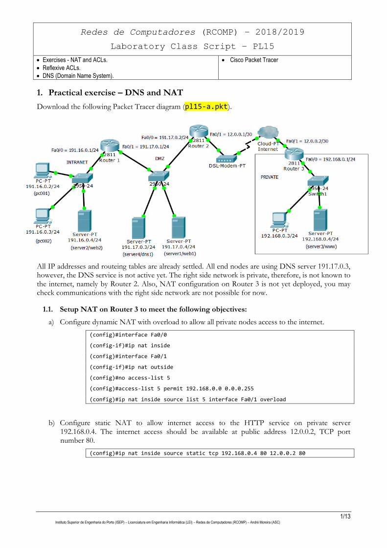
Download the following Packet Tracer diagram (pl15-a.pkt).
All IP addresses and routeing tables are already settled. All end nodes are using DNS server 191.17.0.3, however, the DNS service is not active yet. The right side network is private, therefore, is not known to the internet, namely by Router 2. Also, NAT configuration on Router 3 is not yet deployed, you may check communications with the right side network are not possible for now.
1.1. Setup NAT on Router 3 to meet the following objectives:
a) Configure dynamic NAT with overload to allow all private nodes access to the internet.
(config)#interface Fa0/0
(config-if)#ip nat inside
(config)#interface Fa0/1
(config-if)#ip nat outside
(config)#no access-list 5
(config)#access-list 5 permit 192.168.0.0 0.0.0.255
(config)#ip nat inside source list 5 interface Fa0/1 overload
b) Configure static NAT to allow internet access to the HTTP service on private server 192.168.0.4. The internet access should be available at public address 12.0.0.2, TCP port number 80.
(config)#ip nat inside source static tcp 192.168.0.4 80 12.0.0.2 80
2/13 Instituto Superior de Engenharia do Porto (ISEP) – Licenciatura em Engenharia Informática (LEI) – Redes de Computadores (RCOMP) – André Moreira (ASC)
1.2. Thoroughly check connectivity.
a) Perform ICMP echo request tests between all end nodes, you will check private nodes are not accessible by public nodes, but elsewhere tests will be successful, including echo requests from private nodes to public nodes.
b) Now, go to pc001 (191.16.0.2) and open the Web Browser
Access URL http://191.16.0.4
Access URL http://191.17.0.4
Access URL http://192.168.0.4 (this will fail because the server’s address is private)
Access URL http://12.0.0.2 (thanks to static NAT the private server is available here)
c) Now, go to the right side private PC (192.168.0.3) and open the Web Browser
Access URL http://191.16.0.4
Access URL http://191.17.0.4
Access URL http://192.168.0.4
Access URL http://12.0.0.2 (this will fail)
The last test fails because packets are entering through an inside interface and after static NAT they would be exiting through an equally inside interface, we already know NAT is not applied it this cases.
1.3. Activate and configure DNS service on server 191.17.0.3/24.
Create A records for names: pc001, pc002, server1, server2, server3 and server4
Attention: because the DNS server is public, server3 A record must be the public address (12.0.0.2).
Create CNAME records for names: web1, web2, dns1 and www.
1.4 Check communications again, but now using DNS names instead of IP addresses
a) Go to pc001 (191.16.0.2), open the Command Prompt and run:
ping web1 ping web2 ping dns ping www
b) Yet on pc001 (191.16.0.2), open the Web Browser and access:
- http://web1 - http://web2 - http://www
Now, the same tests from the private network.
c) On the right side private PC (192.168.0.3) and open the Command Prompt and run:
ping web1 ping web2 ping dns ping www
d) On the same PC (192.168.0.3), open now the Web Browser and access:
- http://web1 - http://web2 - http://www
3/13 Instituto Superior de Engenharia do Porto (ISEP) – Licenciatura em Engenharia Informática (LEI) – Redes de Computadores (RCOMP) – André Moreira (ASC)
We already knew this last test was fated to fail because the name resolves to address 12.0.0.2.
Nodes on the right side private network are not able to access the local web server by DNS name. How could this issue be solved?
2. Practical exercise – Access Control Lists
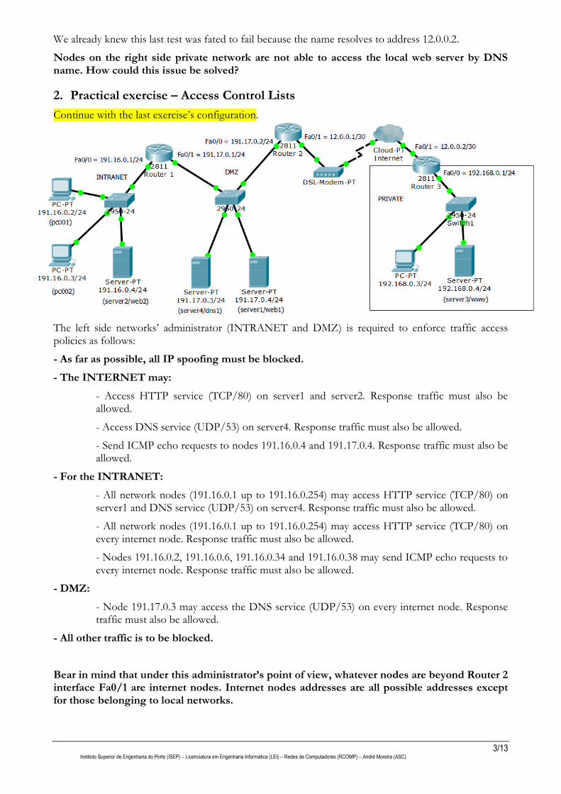
Continue with the last exercise’s configuration.
The left side networks’ administrator (INTRANET and DMZ) is required to enforce traffic access policies as follows:
- As far as possible, all IP spoofing must be blocked.
- The INTERNET may:
- Access HTTP service (TCP/80) on server1 and server2. Response traffic must also be allowed.
- Access DNS service (UDP/53) on server4. Response traffic must also be allowed.
- Send ICMP echo requests to nodes 191.16.0.4 and 191.17.0.4. Response traffic must also be allowed.
- For the INTRANET:
- All network nodes (191.16.0.1 up to 191.16.0.254) may access HTTP service (TCP/80) on server1 and DNS service (UDP/53) on server4. Response traffic must also be allowed.
- All network nodes (191.16.0.1 up to 191.16.0.254) may access HTTP service (TCP/80) on every internet node. Response traffic must also be allowed.
- Nodes 191.16.0.2, 191.16.0.6, 191.16.0.34 and 191.16.0.38 may send ICMP echo requests to every internet node. Response traffic must also be allowed.
- DMZ:
- Node 191.17.0.3 may access the DNS service (UDP/53) on every internet node. Response traffic must also be allowed.
- All other traffic is to be blocked.
Bear in mind that under this administrator’s point of view, whatever nodes are beyond Router 2 interface Fa0/1 are internet nodes. Internet nodes addresses are all possible addresses except for those belonging to local networks.
4/13 Instituto Superior de Engenharia do Porto (ISEP) – Licenciatura em Engenharia Informática (LEI) – Redes de Computadores (RCOMP) – André Moreira (ASC)
2.1. Designing access lists
When designing access lists to a complex access policies scenario, many alternative solutions are possible, yet best solutions are usually achieved by blocking traffic as close to the source as possible. This implies enforcing ACL on input traffic.
One simple systematic approach is traversing every router’s interface, and for each, analyse which traffic should be let in and which should be blocked.
So in this specific scenario we have four interfaces to analyse inbound traffic:
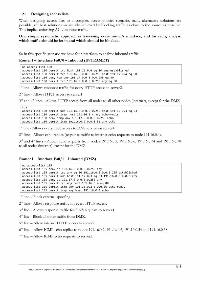
Router 1 – Interface Fa0/0 – Inbound (INTRANET)
no access-list 100 access-list 100 permit tcp host 191.16.0.4 eq 80 any established access-list 100 permit tcp 191.16.0.0 0.0.0.255 host 191.17.0.4 eq 80 access-list 100 deny tcp any 191.17.0.0 0.0.0.255 eq 80 access-list 100 permit tcp 191.16.0.0 0.0.0.255 any eq 80
1st line - Allows response traffic for every HTTP access to server2.
2nd line - Allows HTTP access to server1.
3rd and 4th lines - Allows HTTP access from all nodes to all other nodes (internet), except for the DMZ.
(…) access-list 100 permit udp 191.16.0.0 0.0.0.255 host 191.17.0.3 eq 53 access-list 100 permit icmp host 191.16.0.4 any echo-reply access-list 100 deny icmp any 191.17.0.0 0.0.0.255 echo access-list 100 permit icmp 191.16.0.2 0.0.0.36 any echo
1st line - Allows every node access to DNS service on server4.
2nd line - Allows echo replies (response traffic to internet echo requests to node 191.16.0.4).
3rd and 4th lines - Allows echo requests from nodes 191.16.0.2, 191.16.0.6, 191.16.0.34 and 191.16.0.38 to all nodes (internet) except for the DMZ.
Router 1 – Interface Fa0/1 – Inbound (DMZ)
no access-list 105 access-list 105 deny ip 191.16.0.0 0.0.0.255 any access-list 105 permit tcp any eq 80 191.16.0.0 0.0.0.255 established access-list 105 permit udp host 191.17.0.3 eq 53 191.16.0.0 0.0.0.255 access-list 105 deny ip 191.17.0.0 0.0.0.255 any access-list 105 permit tcp any host 191.16.0.4 eq 80 access-list 105 permit icmp any 191.16.0.2 0.0.0.36 echo-reply access-list 105 permit icmp any host 191.16.0.4 echo
1st line – Block external spoofing.
2nd line - Allows response traffic for every HTTP access.
3rd line - Allows response traffic for DNS requests to server4.
4th line - Block all other traffic from DMZ.
5th line – Allow internet HTTP access to server2.
6th line – Allow ICMP echo replies to nodes 191.16.0.2, 191.16.0.6, 191.16.0.34 and 191.16.0.38.
7th line – Allow ICMP echo requests to server2.
5/13 Instituto Superior de Engenharia do Porto (ISEP) – Licenciatura em Engenharia Informática (LEI) – Redes de Computadores (RCOMP) – André Moreira (ASC)
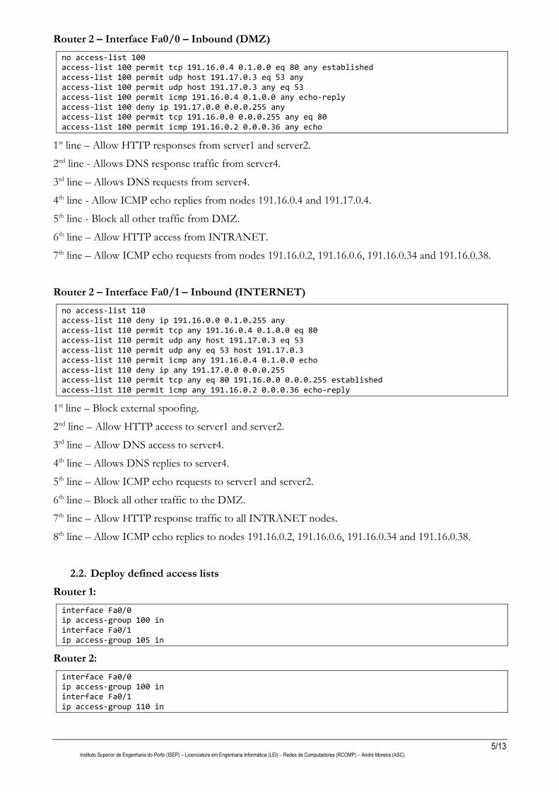
Router 2 – Interface Fa0/0 – Inbound (DMZ)
no access-list 100 access-list 100 permit tcp 191.16.0.4 0.1.0.0 eq 80 any established access-list 100 permit udp host 191.17.0.3 eq 53 any access-list 100 permit udp host 191.17.0.3 any eq 53 access-list 100 permit icmp 191.16.0.4 0.1.0.0 any echo-reply access-list 100 deny ip 191.17.0.0 0.0.0.255 any access-list 100 permit tcp 191.16.0.0 0.0.0.255 any eq 80 access-list 100 permit icmp 191.16.0.2 0.0.0.36 any echo
1st line – Allow HTTP responses from server1 and server2.
2nd line - Allows DNS response traffic from server4.
3rd line – Allows DNS requests from server4.
4th line - Allow ICMP echo replies from nodes 191.16.0.4 and 191.17.0.4.
5th line - Block all other traffic from DMZ.
6th line – Allow HTTP access from INTRANET.
7th line – Allow ICMP echo requests from nodes 191.16.0.2, 191.16.0.6, 191.16.0.34 and 191.16.0.38.
Router 2 – Interface Fa0/1 – Inbound (INTERNET)
no access-list 110 access-list 110 deny ip 191.16.0.0 0.1.0.255 any access-list 110 permit tcp any 191.16.0.4 0.1.0.0 eq 80 access-list 110 permit udp any host 191.17.0.3 eq 53 access-list 110 permit udp any eq 53 host 191.17.0.3 access-list 110 permit icmp any 191.16.0.4 0.1.0.0 echo access-list 110 deny ip any 191.17.0.0 0.0.0.255 access-list 110 permit tcp any eq 80 191.16.0.0 0.0.0.255 established access-list 110 permit icmp any 191.16.0.2 0.0.0.36 echo-reply
1st line – Block external spoofing.
2nd line – Allow HTTP access to server1 and server2.
3rd line – Allow DNS access to server4.
4th line – Allows DNS replies to server4.
5th line – Allow ICMP echo requests to server1 and server2.
6th line – Block all other traffic to the DMZ.
7th line – Allow HTTP response traffic to all INTRANET nodes.
8th line – Allow ICMP echo replies to nodes 191.16.0.2, 191.16.0.6, 191.16.0.34 and 191.16.0.38.
2.2. Deploy defined access lists
Router 1:
interface Fa0/0 ip access-group 100 in interface Fa0/1 ip access-group 105 in
Router 2:
interface Fa0/0 ip access-group 100 in interface Fa0/1 ip access-group 110 in
6/13 Instituto Superior de Engenharia do Porto (ISEP) – Licenciatura em Engenharia Informática (LEI) – Redes de Computadores (RCOMP) – André Moreira (ASC)
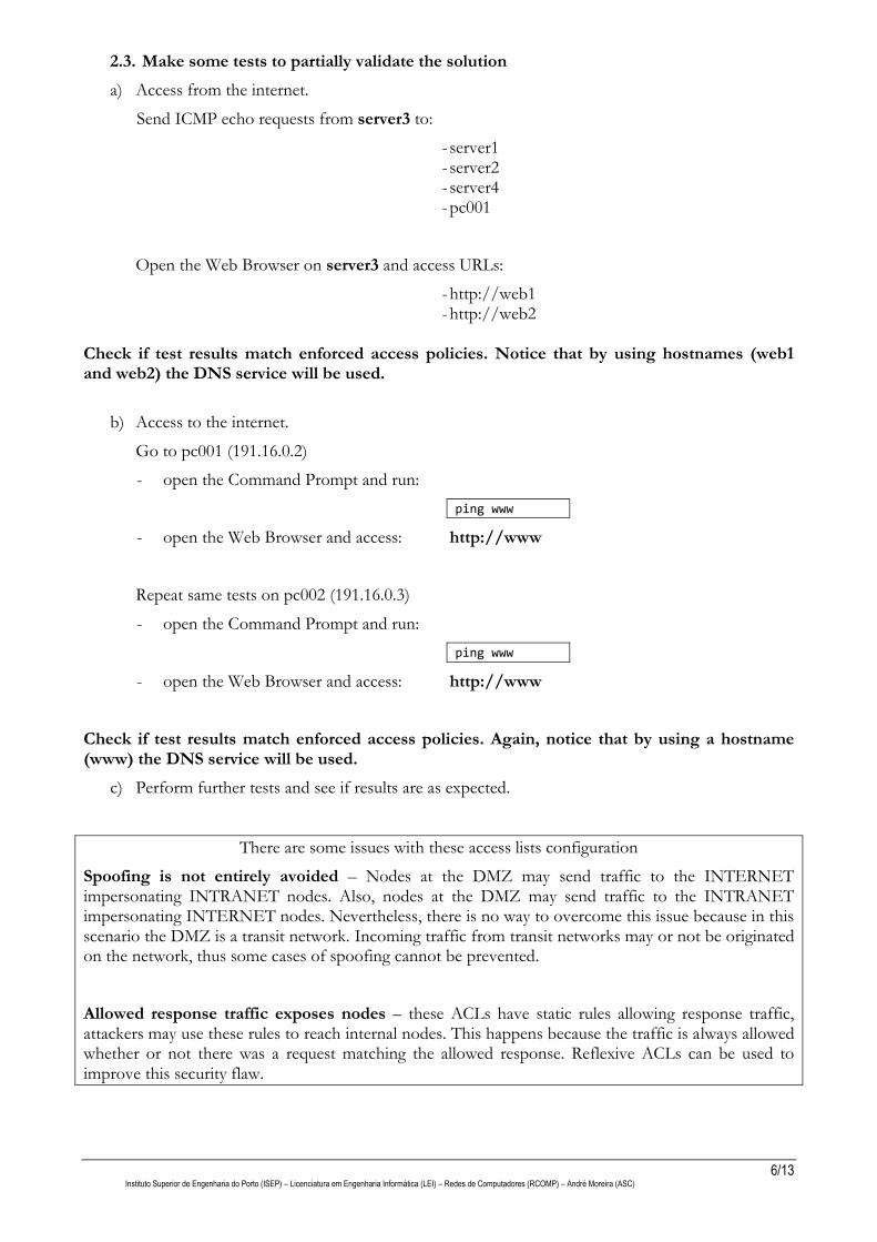
2.3. Make some tests to partially validate the solution
a) Access from the internet.
Send ICMP echo requests from server3 to:
- server1 - server2 - server4 - pc001
Open the Web Browser on server3 and access URLs:
- http://web1 - http://web2
Check if test results match enforced access policies. Notice that by using hostnames (web1 and web2) the DNS service will be used.
b) Access to the internet.
Go to pc001 (191.16.0.2)
- open the Command Prompt and run:
ping www
- open the Web Browser and access: http://www
Repeat same tests on pc002 (191.16.0.3)
- open the Command Prompt and run:
ping www
- open the Web Browser and access: http://www
Check if test results match enforced access policies. Again, notice that by using a hostname (www) the DNS service will be used.
c) Perform further tests and see if results are as expected.
There are some issues with these access lists configuration
Spoofing is not entirely avoided – Nodes at the DMZ may send traffic to the INTERNET impersonating INTRANET nodes. Also, nodes at the DMZ may send traffic to the INTRANET impersonating INTERNET nodes. Nevertheless, there is no way to overcome this issue because in this scenario the DMZ is a transit network. Incoming traffic from transit networks may or not be originated on the network, thus some cases of spoofing cannot be prevented.
Allowed response traffic exposes nodes – these ACLs have static rules allowing response traffic, attackers may use these rules to reach internal nodes. This happens because the traffic is always allowed whether or not there was a request matching the allowed response. Reflexive ACLs can be used to improve this security flaw.
7/13 Instituto Superior de Engenharia do Porto (ISEP) – Licenciatura em Engenharia Informática (LEI) – Redes de Computadores (RCOMP) – André Moreira (ASC)
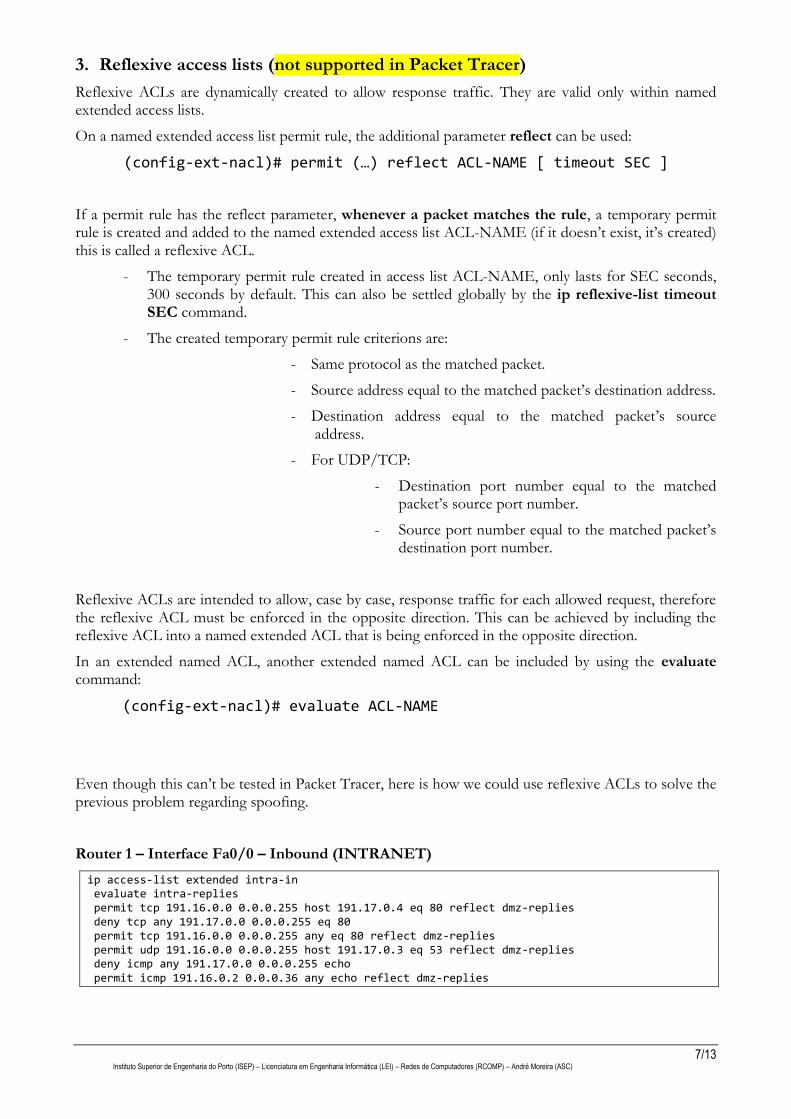
3. Reflexive access lists (not supported in Packet Tracer)
Reflexive ACLs are dynamically created to allow response traffic. They are valid only within named extended access lists.
On a named extended access list permit rule, the additional parameter reflect can be used:
(config-ext-nacl)# permit (…) reflect ACL-NAME [ timeout SEC ]
If a permit rule has the reflect parameter, whenever a packet matches the rule, a temporary permit rule is created and added to the named extended access list ACL-NAME (if it doesn’t exist, it’s created) this is called a reflexive ACL.
- The temporary permit rule created in access list ACL-NAME, only lasts for SEC seconds, 300 seconds by default. This can also be settled globally by the ip reflexive-list timeout SEC command.
- The created temporary permit rule criterions are:
- Same protocol as the matched packet.
- Source address equal to the matched packet’s destination address.
- Destination address equal to the matched packet’s source address.
- For UDP/TCP:
- Destination port number equal to the matched packet’s source port number.
- Source port number equal to the matched packet’s destination port number.
Reflexive ACLs are intended to allow, case by case, response traffic for each allowed request, therefore the reflexive ACL must be enforced in the opposite direction. This can be achieved by including the reflexive ACL into a named extended ACL that is being enforced in the opposite direction.
In an extended named ACL, another extended named ACL can be included by using the evaluate command:
(config-ext-nacl)# evaluate ACL-NAME
Even though this can’t be tested in Packet Tracer, here is how we could use reflexive ACLs to solve the previous problem regarding spoofing.
Router 1 – Interface Fa0/0 – Inbound (INTRANET)
ip access-list extended intra-in evaluate intra-replies permit tcp 191.16.0.0 0.0.0.255 host 191.17.0.4 eq 80 reflect dmz-replies deny tcp any 191.17.0.0 0.0.0.255 eq 80 permit tcp 191.16.0.0 0.0.0.255 any eq 80 reflect dmz-replies permit udp 191.16.0.0 0.0.0.255 host 191.17.0.3 eq 53 reflect dmz-replies deny icmp any 191.17.0.0 0.0.0.255 echo permit icmp 191.16.0.2 0.0.0.36 any echo reflect dmz-replies
8/13 Instituto Superior de Engenharia do Porto (ISEP) – Licenciatura em Engenharia Informática (LEI) – Redes de Computadores (RCOMP) – André Moreira (ASC)
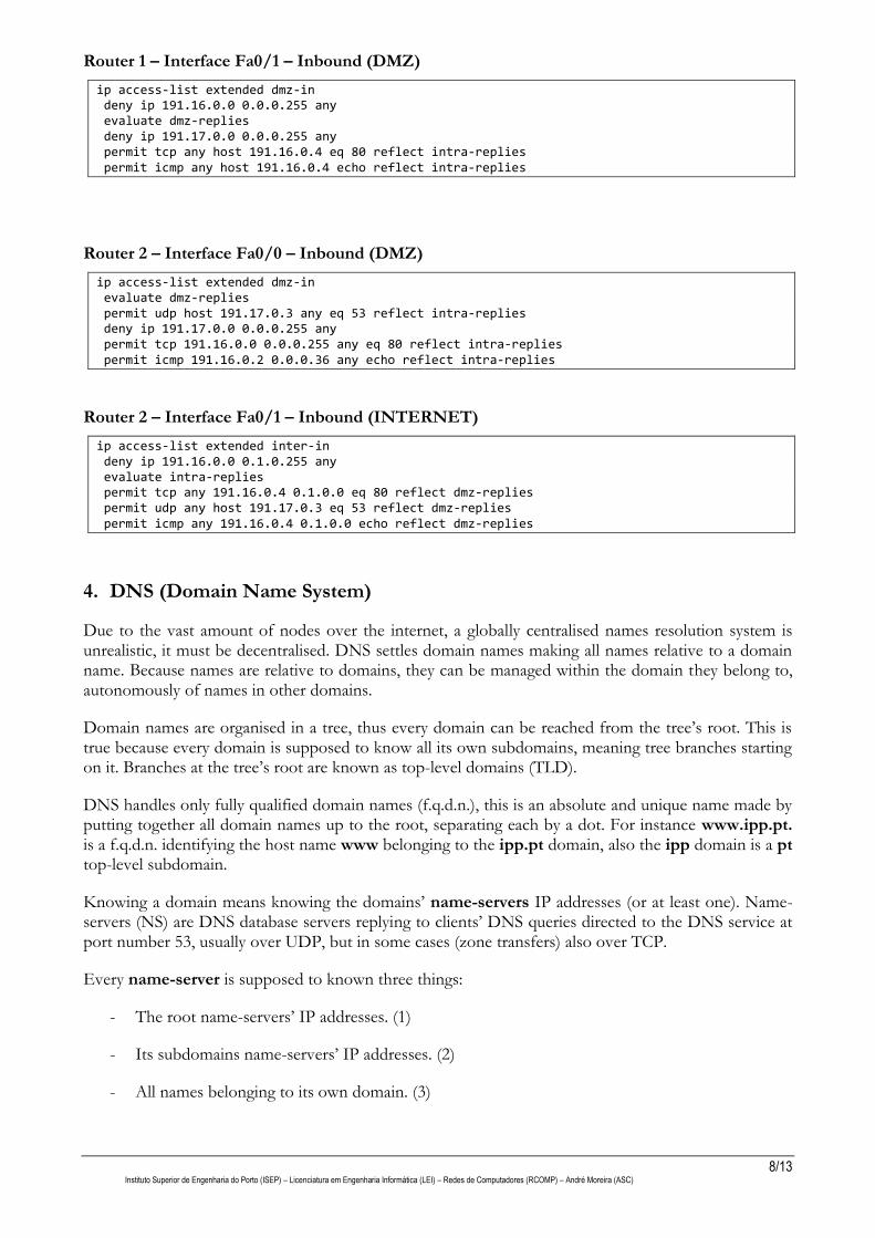
Router 1 – Interface Fa0/1 – Inbound (DMZ)
ip access-list extended dmz-in deny ip 191.16.0.0 0.0.0.255 any evaluate dmz-replies deny ip 191.17.0.0 0.0.0.255 any permit tcp any host 191.16.0.4 eq 80 reflect intra-replies permit icmp any host 191.16.0.4 echo reflect intra-replies
Router 2 – Interface Fa0/0 – Inbound (DMZ)
ip access-list extended dmz-in evaluate dmz-replies permit udp host 191.17.0.3 any eq 53 reflect intra-replies deny ip 191.17.0.0 0.0.0.255 any permit tcp 191.16.0.0 0.0.0.255 any eq 80 reflect intra-replies permit icmp 191.16.0.2 0.0.0.36 any echo reflect intra-replies
Router 2 – Interface Fa0/1 – Inbound (INTERNET)
ip access-list extended inter-in deny ip 191.16.0.0 0.1.0.255 any evaluate intra-replies permit tcp any 191.16.0.4 0.1.0.0 eq 80 reflect dmz-replies permit udp any host 191.17.0.3 eq 53 reflect dmz-replies permit icmp any 191.16.0.4 0.1.0.0 echo reflect dmz-replies
4. DNS (Domain Name System)
Due to the vast amount of nodes over the internet, a globally centralised names resolution system is unrealistic, it must be decentralised. DNS settles domain names making all names relative to a domain name. Because names are relative to domains, they can be managed within the domain they belong to, autonomously of names in other domains.
Domain names are organised in a tree, thus every domain can be reached from the tree’s root. This is true because every domain is supposed to know all its own subdomains, meaning tree branches starting on it. Branches at the tree’s root are known as top-level domains (TLD).
DNS handles only fully qualified domain names (f.q.d.n.), this is an absolute and unique name made by putting together all domain names up to the root, separating each by a dot. For instance www.ipp.pt. is a f.q.d.n. identifying the host name www belonging to the ipp.pt domain, also the ipp domain is a pt top-level subdomain.
Knowing a domain means knowing the domains’ name-servers IP addresses (or at least one). Name-servers (NS) are DNS database servers replying to clients’ DNS queries directed to the DNS service at port number 53, usually over UDP, but in some cases (zone transfers) also over TCP.
Every name-server is supposed to known three things:
- The root name-servers’ IP addresses. (1)
- Its subdomains name-servers’ IP addresses. (2)
- All names belonging to its own domain. (3)
9/13 Instituto Superior de Engenharia do Porto (ISEP) – Licenciatura em Engenharia Informática (LEI) – Redes de Computadores (RCOMP) – André Moreira (ASC)
With this knowledge, every domain’s name-server on the tree can be reached. By knowing at least one root name-server (1), any domain’s name-server within the tree can be reached (2).
4.1. Basic DNS records
DNS stores different data categories in appropriate record types. Every record is identified by a DNS name, but it may hold different kinds of data. Different DNS record types are represented by mnemonics.
Most strait forward DNS records are used to map node names into network node addresses, the A record maps a node name to an IPv4 address, the AAAA record maps a node name to an IPv6 address.
One other very useful record type is CNAME, it maps a node name to another node name defined by an A or AAAA record. CNAME records are often used to represent mean full names like for instance www and ftp, and associate them to node names providing the corresponding services.
4.2. The NS (name server) record
NS records are responsible for making the DNS tree work as a whole. They map a domain name to a node name, but they have a special meaning, they mean the node is a name-server of the mapped domain name. So, root name-servers will have NS records for all top-level domains, in turn, each top-level domain name-server will have NS records for each of its own subdomains and so on.
Take for instance the dei.isep.ipp.pt domain, this name belongs to the isep.ipp.pt domain and is also an isep.ipp.pt subdomain, thus in the isep.ipp.pt DNS database there will be NS records mapping the dei.isep.ipp.pt domain name into node names, these node names are dei.isep.ipp.pt domain’s name servers.
Nodes pointed by NS records are servers providing the DNS service on UDP/TCP port number 53, this service must be publicly available to any node over the internet so they can query it and retrieve records belonging to the domain.
4.3.Glue records
NS records are used to keep the DNS tree together, they link a domain to each of its subdomains’ name-servers. This is why, starting from a root NS, any NS for any domain can be ultimately reached.
Though, to query a name-server, its IP addresses is required, and NS records provide only the node’s name. So after getting the name server node’s name by querying the NS record, the node name must be then queried to get the corresponding node address (A/AAAA records).
This would turn to be an issue if the node’s address record was defined only within the subdomain itself. The point is, we are trying to get the subdomain’s name-server address because it’s required to resolve names within the subdomain. If getting the subdomain’s name-server address requires resolving a name within the domain, then there’s a circular dependency that would cause a deadlock.
This is overcome by adding records on the parent domain mapping the subdomains name-servers node names into IP addresses. They are called a glue records, they are standard A or AAAA records but they are copied to an unusual location: the parent domain name server.
Take the following scenario, the dei.isep.ipp.pt domain’s name-server is node name ns.dei.isep.ipp.pt and it has address 193.136.62.3, then on isep.ipp.pt domain name-servers we would store two records:
10/13 Instituto Superior de Engenharia do Porto (ISEP) – Licenciatura em Engenharia Informática (LEI) – Redes de Computadores (RCOMP) – André Moreira (ASC)
NS record mapping dei.isep.ipp.pt into node name ns.dei.isep.ipp.pt
A record mapping ns.dei.isep.ipp.pt into IPv4 address 193.136.62.3
The second record is called a glue record, it’s misplaced because it should be on dei.isep.ipp.pt name-servers and not isep.ipp.pt name-servers, but does the trick. Thanks to it, we can query an isep.ipp.pt name-server and get, not only the dei.isep.ipp.pt name-server node name, but also its address (193.136.62.3).
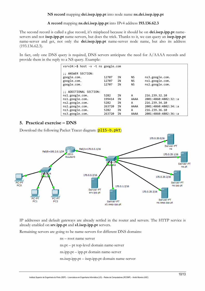
In fact, only one DNS query is required, DNS servers anticipate the need for A/AAAA records and provide them in the reply to a NS query. Example:
vsrv24:~$ host -v -t ns google.com ;; ANSWER SECTION: google.com. 12707 IN NS ns3.google.com. google.com. 12707 IN NS ns1.google.com. google.com. 12707 IN NS ns2.google.com. ;; ADDITIONAL SECTION: ns1.google.com. 5282 IN A 216.239.32.10 ns1.google.com. 199414 IN AAAA 2001:4860:4802:32::a ns2.google.com. 5282 IN A 216.239.34.10 ns2.google.com. 263720 IN AAAA 2001:4860:4802:34::a ns3.google.com. 5282 IN A 216.239.36.10 ns3.google.com. 263720 IN AAAA 2001:4860:4802:36::a
5. Practical exercise – DNS
Download the following Packet Tracer diagram (pl15-b.pkt)
IP addresses and default gateways are already settled in the router and servers. The HTTP service is already enabled on srv.ipp.pt and s1.isep.ipp.pt servers.
Remaining servers are going to be name-servers for different DNS domains:
ns – root name server
ns.pt – pt top-level domain name-server
ns.ipp.pt – ipp.pt domain name-server
ns.isep.ipp.pt – isep.ipp.pt domain name-server
11/13 Instituto Superior de Engenharia do Porto (ISEP) – Licenciatura em Engenharia Informática (LEI) – Redes de Computadores (RCOMP) – André Moreira (ASC)
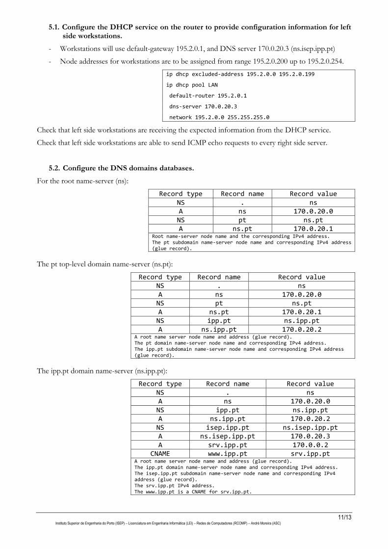
5.1. Configure the DHCP service on the router to provide configuration information for left side workstations.
- Workstations will use default-gateway 195.2.0.1, and DNS server 170.0.20.3 (ns.isep.ipp.pt)
- Node addresses for workstations are to be assigned from range 195.2.0.200 up to 195.2.0.254.
ip dhcp excluded-address 195.2.0.0 195.2.0.199
ip dhcp pool LAN
default-router 195.2.0.1
dns-server 170.0.20.3
network 195.2.0.0 255.255.255.0
Check that left side workstations are receiving the expected information from the DHCP service.
Check that left side workstations are able to send ICMP echo requests to every right side server.
5.2. Configure the DNS domains databases.
For the root name-server (ns):
Record type Record name Record value NS . ns A ns 170.0.20.0 NS pt ns.pt A ns.pt 170.0.20.1
Root name-server node name and the corresponding IPv4 address. The pt subdomain name-server node name and corresponding IPv4 address (glue record).
The pt top-level domain name-server (ns.pt):
Record type Record name Record value NS . ns A ns 170.0.20.0 NS pt ns.pt A ns.pt 170.0.20.1 NS ipp.pt ns.ipp.pt A ns.ipp.pt 170.0.20.2
A root name server node name and address (glue record). The pt domain name-server node name and corresponding IPv4 address. The ipp.pt subdomain name-server node name and corresponding IPv4 address (glue record).
The ipp.pt domain name-server (ns.ipp.pt):
Record type Record name Record value NS . ns A ns 170.0.20.0 NS ipp.pt ns.ipp.pt A ns.ipp.pt 170.0.20.2 NS isep.ipp.pt ns.isep.ipp.pt A ns.isep.ipp.pt 170.0.20.3 A srv.ipp.pt 170.0.0.2
CNAME www.ipp.pt srv.ipp.pt A root name server node name and address (glue record). The ipp.pt domain name-server node name and corresponding IPv4 address. The isep.ipp.pt subdomain name-server node name and corresponding IPv4 address (glue record). The srv.ipp.pt IPv4 address. The www.ipp.pt is a CNAME for srv.ipp.pt.
12/13 Instituto Superior de Engenharia do Porto (ISEP) – Licenciatura em Engenharia Informática (LEI) – Redes de Computadores (RCOMP) – André Moreira (ASC)
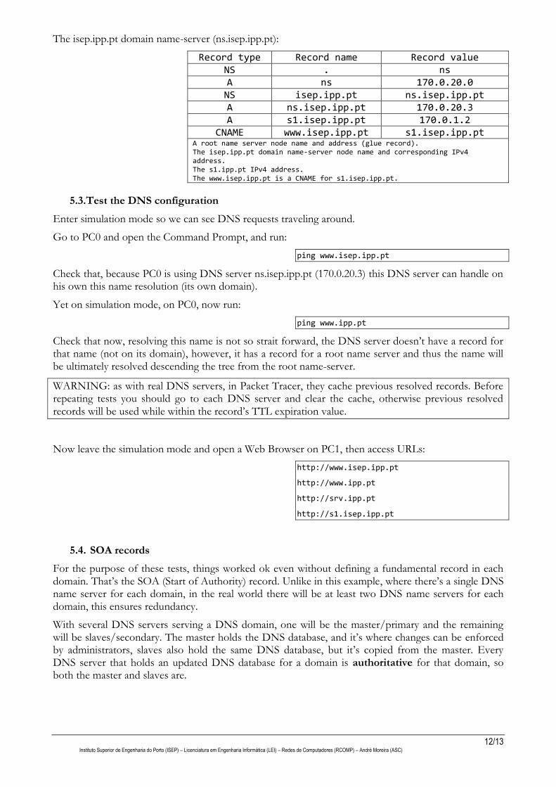
The isep.ipp.pt domain name-server (ns.isep.ipp.pt):
Record type Record name Record value NS . ns A ns 170.0.20.0 NS isep.ipp.pt ns.isep.ipp.pt A ns.isep.ipp.pt 170.0.20.3 A s1.isep.ipp.pt 170.0.1.2
CNAME www.isep.ipp.pt s1.isep.ipp.pt A root name server node name and address (glue record). The isep.ipp.pt domain name-server node name and corresponding IPv4 address. The s1.ipp.pt IPv4 address. The www.isep.ipp.pt is a CNAME for s1.isep.ipp.pt.
5.3.Test the DNS configuration
Enter simulation mode so we can see DNS requests traveling around.
Go to PC0 and open the Command Prompt, and run:
ping www.isep.ipp.pt
Check that, because PC0 is using DNS server ns.isep.ipp.pt (170.0.20.3) this DNS server can handle on his own this name resolution (its own domain).
Yet on simulation mode, on PC0, now run:
ping www.ipp.pt
Check that now, resolving this name is not so strait forward, the DNS server doesn’t have a record for that name (not on its domain), however, it has a record for a root name server and thus the name will be ultimately resolved descending the tree from the root name-server.
WARNING: as with real DNS servers, in Packet Tracer, they cache previous resolved records. Before repeating tests you should go to each DNS server and clear the cache, otherwise previous resolved records will be used while within the record’s TTL expiration value.
Now leave the simulation mode and open a Web Browser on PC1, then access URLs:
http://www.isep.ipp.pt
http://www.ipp.pt
http://srv.ipp.pt
http://s1.isep.ipp.pt
5.4. SOA records
For the purpose of these tests, things worked ok even without defining a fundamental record in each domain. That’s the SOA (Start of Authority) record. Unlike in this example, where there’s a single DNS name server for each domain, in the real world there will be at least two DNS name servers for each domain, this ensures redundancy.
With several DNS servers serving a DNS domain, one will be the master/primary and the remaining will be slaves/secondary. The master holds the DNS database, and it’s where changes can be enforced by administrators, slaves also hold the same DNS database, but it’s copied from the master. Every DNS server that holds an updated DNS database for a domain is authoritative for that domain, so both the master and slaves are.

13/13 Instituto Superior de Engenharia do Porto (ISEP) – Licenciatura em Engenharia Informática (LEI) – Redes de Computadores (RCOMP) – André Moreira (ASC)
Global settings regarding the DNS domain features, including master-slave synchronization, are established by the domain’s SOA record. The SOA record’s name is the domain’s name, and it holds the following data:
The name of the master/primary DNS server of the domain.
The domain’s administrator mail box (with @ converted to a dot).
Refresh interval in seconds: after how long should slaves fetch a new database from the master, counting from when the last one was obtained.
Retry time in seconds: if the slave fails to fetch the database from the master, how long after should it retry the operation.
Expiry time in seconds: if the slave fails to fetch the database from the master, how long after it should stop announcing it’s authoritative for the domain.