delft hydraulics - COB
73
Transcript of delft hydraulics - COB
B406
prepared for:
CDR/COB
TBM Tweede Heinenoordtunnel;Functional Checks on the Instrumentationand Data-Acquisition System at Barendrecht
May 1997
delft hydraulics
TBM -THT; Functional Checks at Barendrecht B406 May 1997
Titel en sub-titel:TBM Tweede Heinenoordtunnel; Functional Chec-ks on the Instrumentation and Data-AcquisitionS stem at arend echt
Da~um rapport:
Schrijver(s):Taal, W. en Blok, B.W.G.
Type rapport:
COB/KIOo-document nummer:
Naam en adres opdrachtgever:Centrum Ondergronds BouwenPostbus 420
Opmerkingen:Dit ra ort eeft de testresultaten weer van de tweede van twee e lande testweken.
Samenvatting rapport:Dit rapport behandelt de controles van de TBM-instrumentatie. De tests vonden plaats inweek 2 en volgende, 1997 op de bouwplaats in Barendrecht. De doelstelling was controlevan de goede werking. De resultaten zullen ook worden gebruikt als referentie gedurendehet boorproces. De meeste testresultaten waren positief. Enkele tests konden niet wordengecompleteerd.
Relationele rapporten:Spaargaren, D.A., Concept Specificatie Instrumentatie TBM Tweede Heinenoordtunnel,KlOO-W-003, maart 1995.Spaargaren, D.A., TBM Tweede Heinenoordtunnel; Specification and Procurement Planfor Instrumentation and Data-acquisition System, KlOO-W-002, August 1995.Taal, W. and Blok, B.W.G.: TBM Tweede Heinenoordtunnel; Functional Checks on the
oClassificatie:Intern COB-rapport
Classificatie dezepagina: Nee
Aantal blz:71
Prijs:
1
2 de
ir. J.D van d n Bunt
ir. J.D. van den Bunt
Namens opdracht-gever
Pa-raaf
Versie Datum Namens opdracht-
1 7
18.07.1997
drs W van
delft hydraulics
TBM -THT; Functional Checks at Barendrecht B406 May 1997
Title and sub-title: Author(s):TBM Tweede Heinenoordtunnel; Functional Taal, W. and Blok, B.W.G.Checks on the Instrumentation and Data-Acquisition Svstem at Barendrecht
Date report: Type report:Mav 1997 Interim- reoort
Reportnumber contractor: CoB/KlOO-report number:B406 KlOO-W-055
Project manager(s) contractor: Project attendant principal:ir. J.D. van den Bunt drs. W. van Schelt
Project attendant contractor:ir. J.D. van den Bunt
Name and address contractor: Name and address principal:Delft Hydraulics Centrum Ondergronds BouwenP.O. Box 177 P.O. Box 4202600 MH Delft 2800 AK GoudaThe Netherlands The Netherlands
Remarks:This report describes the results of the second of two olanned test-weeks.
Summary of report:This report deals with the pre-commissioning tests on the TBM instrumentation. Thetests were carried out in week 2 and the following weeks, 1997 at the Barendrecht-site. The tests were primarily aimed at fact finding, the results will also be used asreference during operational use of the TBM. Most test results were positive. A fewtests could not be completed.
Relational reports:Spaargaren, D.A., Concept Specificatie Instrumentatie TBM Tweede Heinenoordtun-nel, K100-W-003, maart 1995.Spaargaren, D.A., TBM Tweede Heinenoordtunnel; Specification and ProcurementPlan for Instrumentation and Data-acquisition System, KlOO-W-002, August 1995.
Taal, Wand Blok, B.W.G.: TBM Tweede Heinenoordtunnel; Functional Checks onthe Instrumentation and Data-acquisition Svstem, K100-W-046. October 1996.
Keywords: Distribution:Tunnel Boring Machine. instrumentation. test CaB-committee K100
Classification: Classification this page: Number of pages: Price:Internal CaB-report No
71
Version Date On behalf of contrac- Initi- On behalf of Ini-tor ~ orincioal tials
1 (drft) 05.05.1997 ir. J.D. van den Bunt 1a- drs. W. van Schelt noa? V-i I
drs. W. van Schelt 6~2 (fnI) 18.07.1997 ir. J.D. van den Bunt ~,delft hydraulics
TBM -THT; Functional Checks at Barendrecht B406 May 1997
Auteursrechten
Alle rechten voorbehouden. Niets uit deze uitgave mag worden verveelvoudigd, opgeslagen ineen geautomatiseerd gegevensbestand of openbaar gemaakt, in enige vorm of op enige wijze,hetzij elektronisch, mechanisch, door fotokopieën, opnamen of op enig andere manier, zondervoorafgaande schriftelijke toestemming van de CUR/CaB.Het is toegestaan overeenkomstig artikel 15a Auteurswet 1912 gegevens uit deze uitgave teciteren in artikelen, scripties enboeken, mits de bron op duidelijkewijze wordt vermeld, alsmedede aanduiding van de maker, indien deze in de bron voorkomt. Rapport KlOO-W-055TBMTweede Heinenoordtunnel; Functional Checks on the Instrumentation and Data-AcquisitionSystem at Barendrecht, 1997, CUR/CaB, Gouda."
AansprakelijkheidCUR/CaB en degenen die aan deze publikatie hebben meegewerkt, hebben een zo grootmogelijke zorgvuldigheid betracht bij het samenstellen van deze uitgave. Nochtans moet demogelijkheid niet worden uitgesloten dat er toch fouten en onvolledigheden in deze uitgavevoorkomen. Ieder gebruik van deze uitgave en gegevens daaruit is geheel voor eigen risico vande gebruiker en CUR/CaB sluit, mede ten behoeve van al diegenen die aan deze uitgave hebbenmeegewerkt, iedere aansprakelijkheid uit voor schade diemocht voortvloeien uit het gebruik vandeze uitgave en de daarin opgenomen gegevens, tenzij de schade mocht voortvloeien uit opzetof grove schuld zijdens CUR/CaB en/of degenen die aan deze uitgave hebben meegewerkt.
delft hydraulics
TBM -THT; Functional Checks at Barendrecht B406 May 1997
VOORWOORD
Kennis en ervaring op het gebied van ondergronds bouwen in zachte grond is belangrijk alsNederland de actualiteit wil volgen en de (inter)nationale positie van de Nederlandse ontwerpersen bouwers wil handhaven.Door een breed forum van partijen uit bedrijfsleven, overheid en kennis instituten is in 1994 hetImpulsprogramrna Kennisinfrastructuur Ondergronds Bouwen opgesteld.
Het doel van dit Impulsprogramma is te komen tot een duurzame versterking van de kennisinfra-structuur. De kern van deze kennisinfrastructuur vormt het Centrum Ondergronds Bouwen(COB), dat onderzoek en ontwikkelingen op het gebied van ondergronds bouwen initieert encoördineert. COB maakt gebruik van de werkwijze en infrastructuur van het CivieltechnischCentrum Uitvoering Research en Regelgeving (CUR) te Gouda. De activiteiten van het COBworden uitgevoerd onder de noemer CUR/COB. Een leerstoel "Ondergronds Bouwen" aan deTU Delft is nauw gelieerd aan het COB.In CUR/COB participeert een breed scala aan bedrijven, branche-organisaties, onderzoeksinstel-lingen, wetenschappelijke instituten en overheden.Via een bijdrage van de Interdepartementale Commissie voor het Economisch Structuurbeleid(ICES) in het Impulsprogramma stimuleert de overheid de totstandkoming van deze kennisinfra-structuur.
Het onderzoek en ontwikkelingswerk van CUR/COB worden verricht in het kader van eenomvattend uitvoeringsprogramma.Dit uitvoeringsprogramma kent in eerste instantie vier thema's, te weten "Boren in zachtegrond", "Verkennen, voorspellen en monitoren", "Economische tunnelbouw" en "Construeren,beheren en onderhouden".De thema's worden ingevuld met uit te voeren onderzoeks- en ontwikkelingsprojecten.Een belangrijk project binnen het eerste thema is het "Praktijkonderzoek Boortunnels "(CUR/COB-uitvoeringscommissie K 100). De kern van dit project bestaat uit een intensievemonitoring van de twee Praktijkprojecten Boortunnels, de Tweede Heinenoordtunnel en deBotlekspoortunnel. Door middel van deze monitoring worden bestaand instrumentarium voorverkenning van de ondergrond en voorspellingsmodellen voor het gedrag van constructie engrond getoetst.
Voorliggend werkdocument "TBM Tweede Heinenoordtunnel; Functional Checks on theInstrumentation and Data-Acquisition System at Barendrecht" is onder verantwoordelijkheid vandeze commissie tot stand gekomen en moet gezien worden als uitvoeringsonderdeel van het Meeten Instrumentatieplan.
delft hydraulics
TBM •THT; Functional Checks at Barendrecht B406 May 1997
De samenstelling van de commissie, De kwaliteitsgroep bestond uit het Superclusterdie dit rapport heeft voorbereid, was: BoortechnologievanKlOOendeWerkgroepMonitoring
van BTL:
ir. K.J. Bakker, voorzitterdrs. W. van Schelt, secretarisir. P.H.J. Ackermansdr.ir. P. van den Bergir. J.P.M. Boling. H.J. Hagenir. N.D. Joustraing. H. de Kruijffing. A. van de Meentir. S. den Oudenir. H.C. Peerdemaning. A.A. Properir. S.F. de Rondeir. L.E.B. Saathofir. E.A.H. Teunissening. R.W.P. Uitermarktir. S. den Oudenir. A.C. Versluisir. H.I. Vosprof.dr.ir. J.F. Agema, mentor CDRir. J.N. Altenburg, coördinator COB
ir. F. W.I. van Vliet, voorzitterir. A. Bezuijenir. H.A. Greve, BTLir. M.A. van de Griendt, BTLir. R.W.M.G. Heijmans, BTLir. A.G.M. Knibbeler, BTLir. M.P. Quaak, BTLdrs. W. van Schelt, Projectbureau Boortunnelsir. P.A.A. Roelands, BTLir. E.A.H. Teunissening. R.W.P. Uitermarktir. G.M. Wolsink, BTL
Samenstelling van Projectbureau Boortunnels:ir. K.J. Bakkerir. P.S. Jovanovicir. A.J.M. Köstersing. E.A. Kwastir. L.B.J. van Oldenielir. J.W. Plekkenpoldrs. W. van Schelt
mei 1997
delft hydraulics
Projectbureau Boortunnels
TBM -THT; Functional Checks at Barendrecht B406 May 1997
Contents
1 Introduetion
1.1 Terms of reference .
1- 1
1- 1
1.2 Scope of this Report 1 - 1
Conditions for the tests2
3 Hardware tests . . . . . . . . . . . . . . . . . . . . . . . . . . . . . . . . . . .
3.1
3.2
3.3
3.4
3.5
3.6
3.7
Cables slip-ring .
Cables for radio-transmission TRlRCl and TR/RC2
Data-communication cable to Monitoring Cabin
Instrument Cabinet . . . . . . . . . . . . . . . . . . . . . . . . . . . .
Pressure sensors PI to P16
Temperature transmitter Tl
Density sensors Dl and D2
2-1
3 - 1
3 - 1
3 - 1
3 - 1
3-2
3-2
3-2
3-2
3.8 Reference, position and direction signals 3 - 3
3.9
4
Noise and hum measurements
Software tests
4.1 Loop-back test
4.2
4.3
4.4
4.5
5
Download test
Offload test
Monitoring test .
TBM-COB communication protocol
Comments on the "Conditions of the tests"
3-3
4-1
4-1
4-1
4-2
4-2
5-1
6 Shorteomings . . . . . . . . . . . . . . . . . . . . . . . . . . . . . " 6 - 1
7 Comments on test results hardware 7 - 1
delft hydraulics
TBM -THT; Functional Checks at Barendrecht B406 May 1997
delft hydraulics
List of Figures
Figure 1Figure 2Figure 3Figure 4
Diagram 07906Diagram 07907Diagram 07866Diagram 07866
Armexes Testresults hardware
ii
TBM - THT; Functinal Checks at Barendrecht B406 May 1997
1 Introduction
1.1 Terms of reference
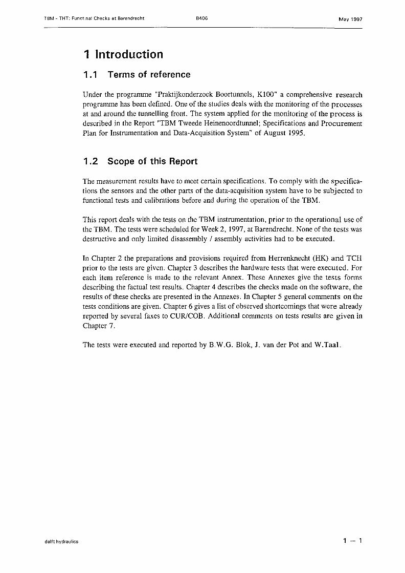
Under the programme "Praktijkonderzoek Boortunnels, KlOO" a comprehensive researchprogramme has been defined. One of the studies deals with the monitoring of the processesat and around the tunnelling front. The system applied for the monitoring of the process isdescribed in the Report "TBM Tweede Heinenoordtunnel; Specifications and ProcurementPlan for Instrumentation and Data-Acquisition System" of August 1995.
1.2 Scope of this Report
The measurement results have to meet certain specifications. To comply with the specifica-tions the sensors and the other parts of the data-acquisition system have to be subjected tofunctional tests and calibrations before and during the operation of the TBM.
This report deals with the tests on the TBM instrumentation, prior to the operational use ofthe TBM. The tests were scheduled for Week 2, 1997, at Barendrecht. None ofthe tests wasdestructive and only limited disassembly / assembly activities had to be executed.
In Chapter 2 the preparations and provisions required from Herrenknecht (HK) and TCHprior to the tests are given. Chapter 3 describes the hardware tests that were executed. Foreach item reference is made to the relevant Annex. These Annexes give the tests formsdescribing the factual test results. Chapter 4 describes the checks made on the software, theresults of these checks are presented in the Annexes. In Chapter 5 general comments on thetests conditions are given. Chapter 6 gives a list of observed shortcomings that were al readyreported by several faxes to CUR/COB. Additional comments on tests results are given inChapter 7.
The tests were executed and reported by B.W.G. Blok, J. van der Pot and W.Taal.
delft hydraulics 1 - 1
TBM • THT; Functinal Checks at Barendrecht B406 May 1997
2 Conditions tor the tests
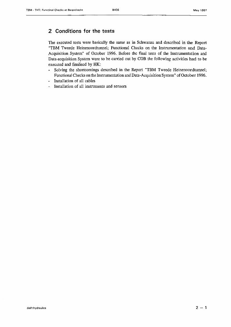
The executed tests were basically the same as in Schwanau and described in the Report"TBM Tweede Heinenoordtunnel; Functional Checks on the Instrumentation and Data-Acquisition System" of October 1996. Before the final tests of the Instrumentation andData-acquisition System were to be carried out by COB the following activities had to beexecuted and finalised by HK:- Solving the shortcomings described in the Report "TBM Tweede Heinenoordtunnel;
Functional Checks on the Instrumentation and Data-AcquisitionSystem" of October 1996.- Installation of all cables- Installation of all instrurnents and sensors
delft hydraulics 2 - 1
TBM - THT; Functinal Checks at Barendrecht B406 May 1997
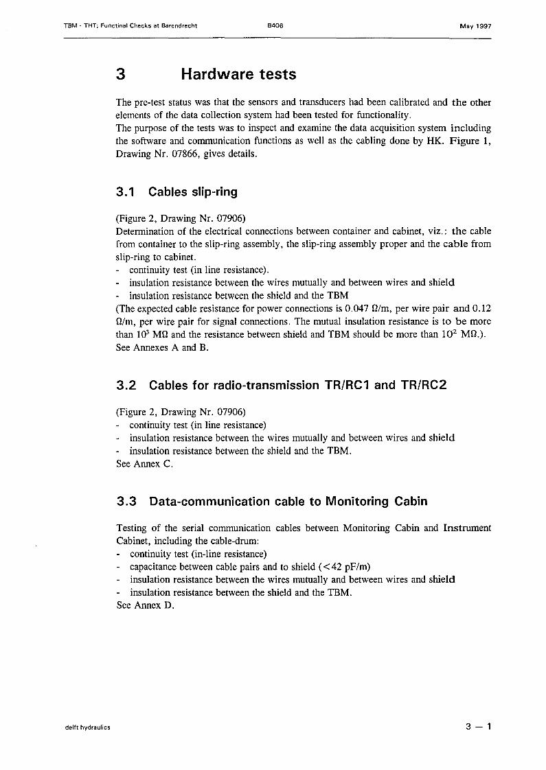
3 Hardware tests
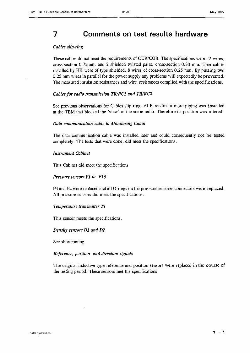
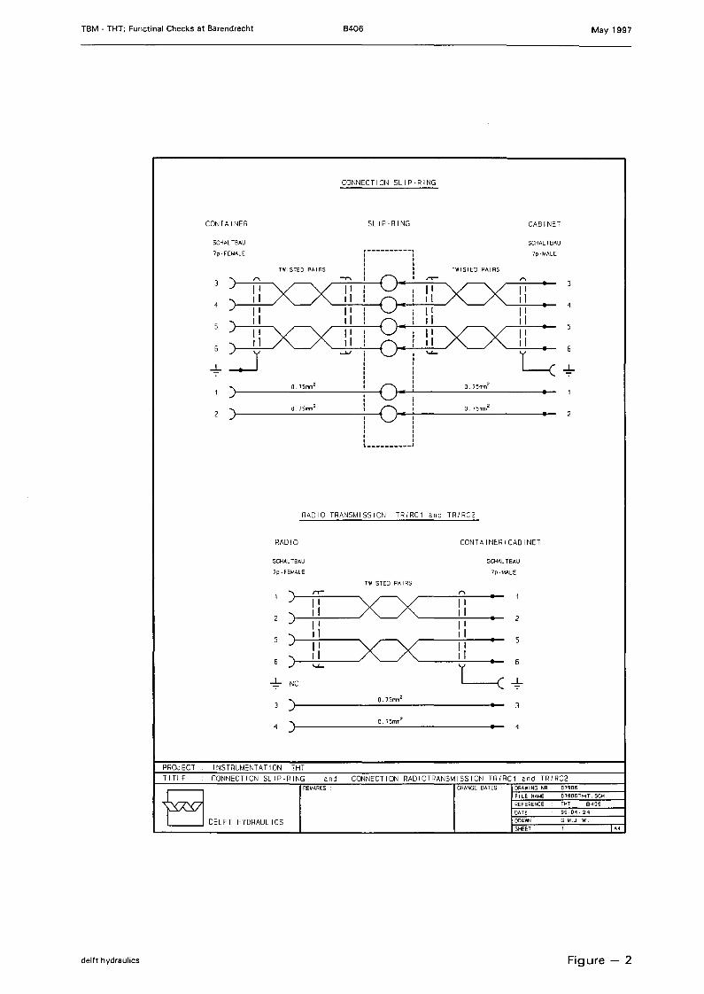
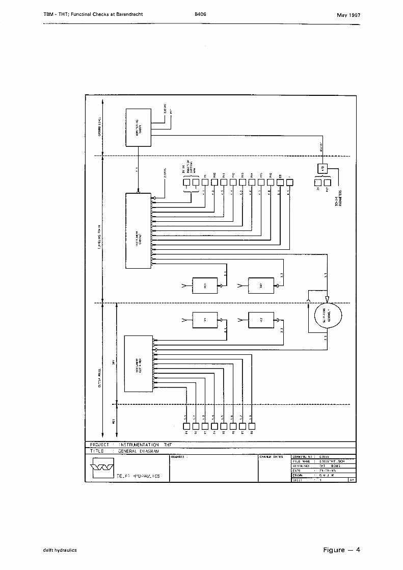
The pre-test status was that the sensors and transducers had been calibrated and the otherelements of the data collection system had been tested for functionality.The purpose of the tests was to inspeet and examine the data acquisition system includingthe software and communication functions as weIl as the cabling done by HK. Figure 1,Drawing Nr. 07866, gives details.
3.1 Cables slip-ring
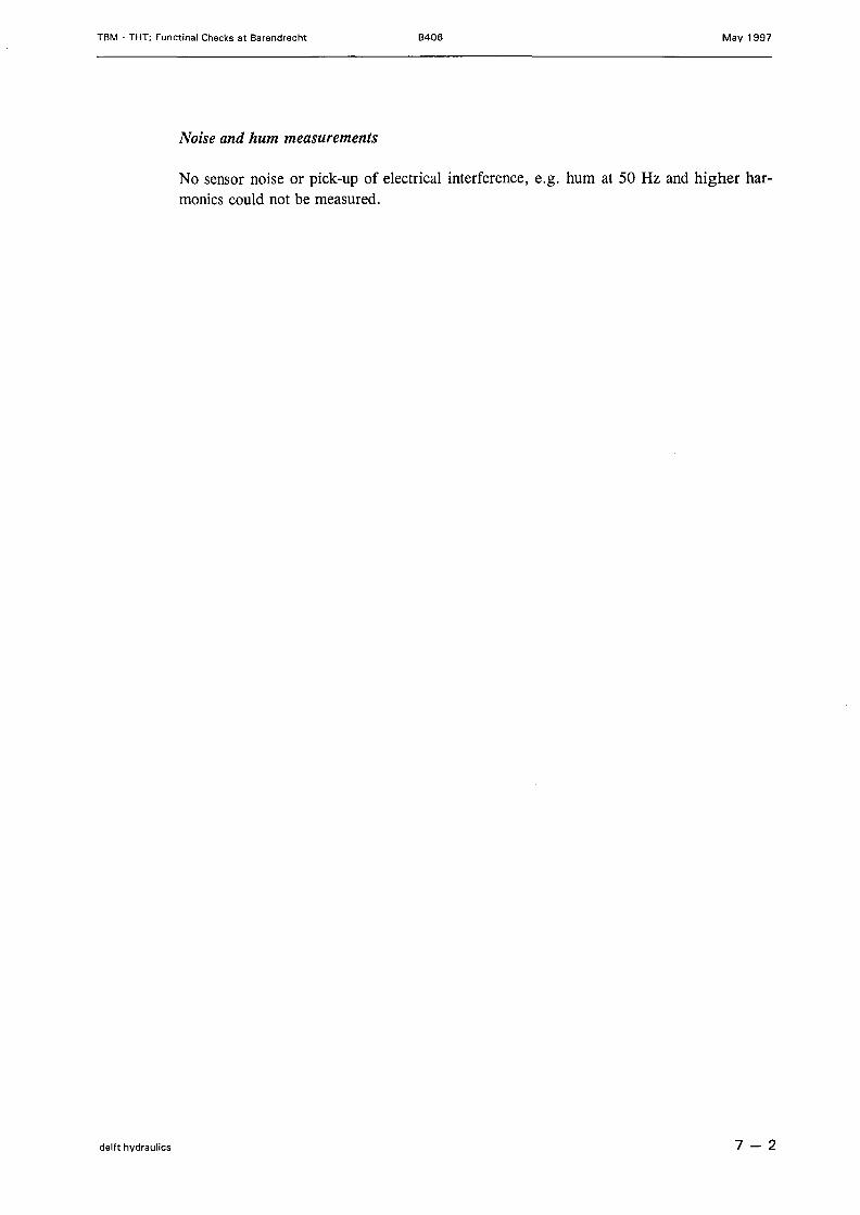
(Figure 2, Drawing Nr. 07906)Determination of the electrical connections between container and cabinet, viz.: the cablefrom container to the slip-ring assembly, the slip-ring assembly proper and the cable fromslip-ring to cabinet.- continuity test (in line resistance).- insulation resistance between the wires mutually and between wires and shield- insulation resistance between the shield and the TBM(The expected cable resistance for power connections is 0.047 Olm, per wire pair and 0.12Dim, per wire pair for signal connections. The mutual insulation resistance is to be morethan 103 MD and the resistance between shield and TBM should be more than 102 MD.).See Annexes A and B.
3.2 Cables tor radio-transmission TR/RC1 and TR/RC2
(Figure 2, Drawing Nr. 07906)- continuity test (in line resistance)- insulation resistance between the wires mutually and between wires and shield- insulation resistance between the shield and the TBM.See Annex C.
3.3 Data-communication cable to Monitoring Cabin
Testing of the serial communication cables between Monitoring Cabin and InstrumentCabinet, including the cab Ie-drum:- continuity test (in-line resistance)- capacitance between cable pairs and to shield (<42 pF/m)- insulation resistance between the wires mutually and between wires and shield- insulation resistance between the shield and the TBM.See Annex D.
delft hydraulics 3 - 1
TBM - THT; Functinal Checks at Barendrecht B406 May 1997
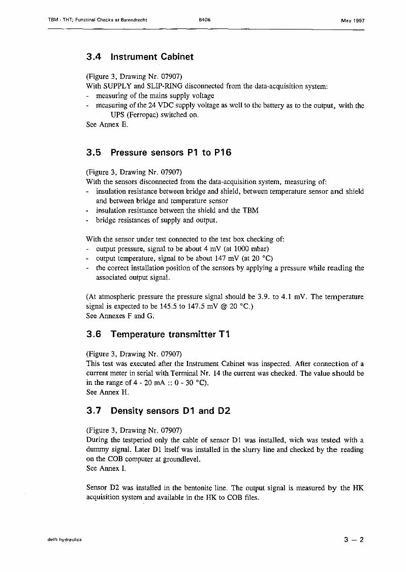
3.4 Instrument Cabinet
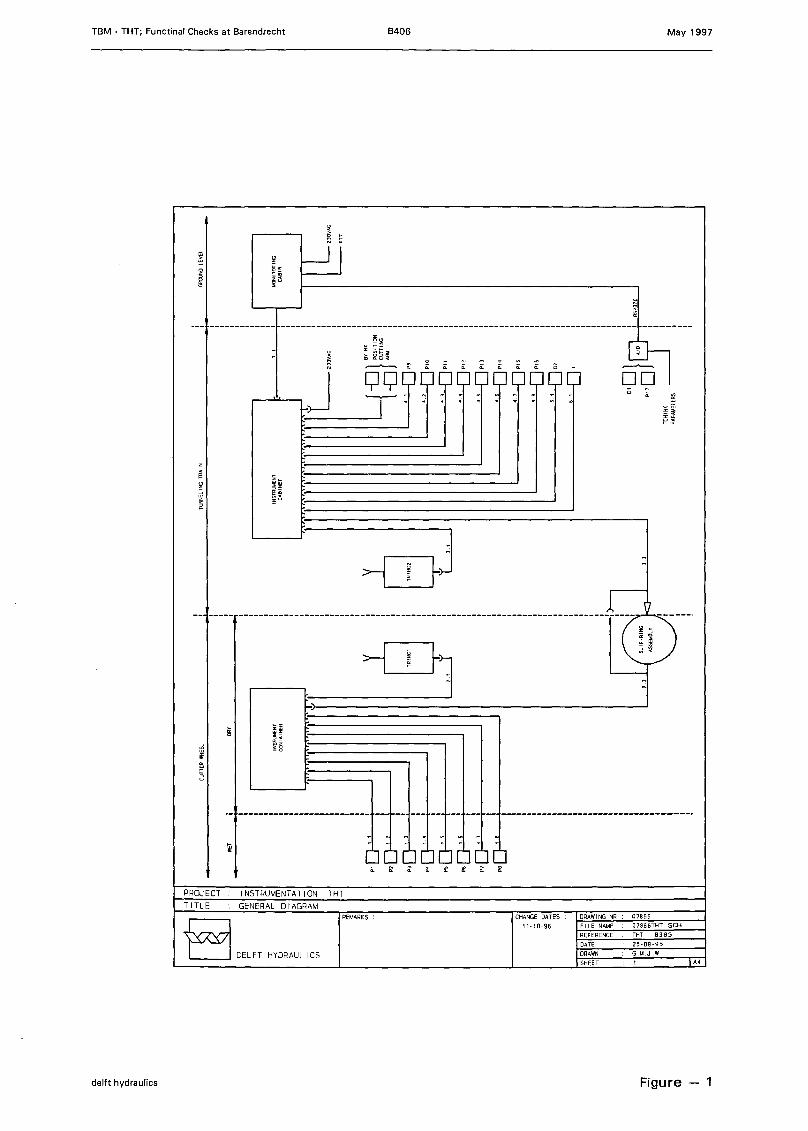
(Figure 3, Drawing Nr. 07907)With SUPPL Y and SLIP-RING disconnected from the data-acquisition system:- measuring of the mains supply voltage- measuring of the 24 VDC supply voltage as well to the battery as to the output, with the
UPS (Ferropac) switched on.See Annex E.
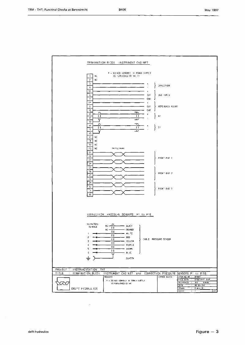
3.5 Pressure sensors P1 to P16
(Figure 3, Drawing Nr. 07907)With the sensors disconnected from the data-acquisition system, measuring of:- insulation resistance between bridge and shield, between temperature sensor and shield
and between bridge and temperature sensor- insulation resistance between the shield and the TBM- bridge resistances of supply and output.
With the sensor under test connected to the test box checking of:- output pressure, signal to be about 4 mV (at 1000 mbar)- output temperature, signal to be about 147 mV (at 20°C)- the correct installation position of the sensors by applying a pressure while reading the
associated output signal.
(At atmospheric pressure the pressure signal should be 3.9. to 4.1 mV. The temperaturesignal is expected to be 145.5 to 147.5 mV @ 20°C.)See Annexes F and G.
3.6 Temperature transmitter T1
(Figure 3, Drawing Nr. 07907)This test was executed after the Instrument Cabinet was inspected. After conneetion of acurrent meter in serial with Terminal Nr. 14 the current was checked. The value should bein the range of 4 - 20 mA :: 0 - 30°C).See Annex H.
3.7 Density sensors D1 and D2
(Figure 3, Drawing Nr. 07907)During the testperiod only the cable of sensor Dl was installed, wich was tested with adummy signal. Later Dl itself was installed in the slurry line and checked by the readingon the COB computer at groundlevel.See Annex I.
Sensor D2 was installed in the bentonite line. The output signal is measured by the HKacquisition system and available in the HK to COB files.
delft hydraulics 3-2
TBM - THT; Functinal Checks at Barendrecht B406 May 1997
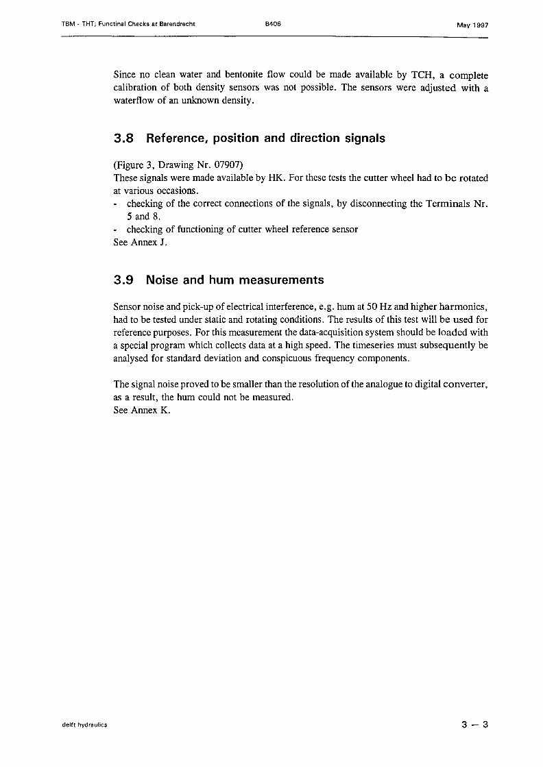
Since no clean water and bentonite flow could be made available by TCH, a completecalibration of both density sensors was not possible. The sensors were adjusted with awaterflow of an unknown density.
3.8 Reference, position and direction signals
(Figure 3, Drawing Nr. 07907)These signals were made available by HK. For these tests the cutter wheel had to be rotatedat various occasions.- checking of the correct connections of the signals, by disconnecting the Terminals Nr.
5 and 8.- checking of functioning of cutter wheel reference sensorSee Annex J.
3.9 Noise and hum measurements
Sensor noise and piek-up of electrieal interference, e.g. hum at 50 Hz and higher harmonies,had to be tested under statie and rotating conditions . The results of this test will be used forreference purposes. For this measurement the data-acquisition system should be loaded witha special program whieh collects data at a high speed. The timeseries must subsequently beanalysed for standard deviation and conspieuous frequency components.
The signal noise proved to be smaller than the resolution ofthe analogue to digital converter,as a result, the hum could not be measured.See Annex K.
delft hydraulics 3-3
TBM - THT; Functinal Checks at Barendrecht B406 May 1997
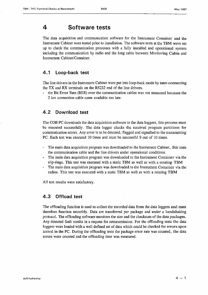
4 Software tests
The data acquisition and communieation software for the Instrument Container and theInstrument Cabinet were tested prior to installation. The software tests at the TBM were setup to check the communieation processes with a fully installed and operational systemincluding the communieation by radio and the long cable between Monitoring Cabin andInstrument Cabinet/Container.
4.1 Loop-back test
The line drivers in the Instrument Cabinet were put into loop-back mode by inter-connectingthe TX and RX terminals on the RS232 end of the line drivers.- the Bit Error Rate (BER) over the communieation cab les was not measured because the
2 km conneetion cable came available too late.
4.2 Download test
The COB PC downloads the data acquisition software to the data loggers, this process mustbe executed successfully. The data logger checks the received program partitions forcommunieation errors. Any error is to be detected, flagged and signalled to the transmittingPC. Each test was executed 10 times and must be successful 9 out of 10 times.
- The main data acquisition program was downloaded to the Instrument Cabinet, this teststhe communieation cable and the line drivers under operational conditions.
- The main data acquisition program was downloaded to the Instrument Container via theslip-rings. This test was executed with astatic TBM as weIl as with a rotating TBM
- The main data acquisition program was downloaded to the Instrument Container via theradios. This test was executed with a statie TBM as weIl as with a rotating TBM
All test results we re satisfactory.
4.3 Offload test
The offloading function is used to collect the recorded data from the data loggers and musttherefore function smoothly. Data are transferred per package and under a handshakingprotocol. The offloading software monitors the size and the checksum of the data packages.Any detected fault results in a request for retransmission. For the offloading tests the dataloggers were loaded with a weIl defined set of data whieh could be checked for errors uponarrival in the PC. During the offloading tests the package error rate was counted, the dataerrors were counted and the offloading time was measured.
delft hydraulics 4 - 1
TBM - THT; Functinal Checks at Barendrecht B406 May 1997
- The test data were offloaded from the Instrument Cabinet, this tests the communicationcable and the line drivers under operational conditions.
- The test data we re offloaded from the Instrument Container via the slip-rings, This testwas executed with a static TBM as weIl as with a rotating TBM.
- The test data were offloaded from the Instrument Container via the radios. This test wasexecuted with a statie TBM as weIl as with a rotating TBM.
Via the 'direct' conneetion to cabinet and sliprings connetion to container virtually na errorswere detected.During radio communication with rotating TBM several retransmissions were observed.Therefore the position of the statie radio was altered. Still some retransmissions by radioare necessary but since all data are checked by the handshaking protocol and reread whenneeded no loss of data is experienced.
All test results were satisfactory.
4.4 Monitoring test
The operation of the data acquisition systems can be monitored in real time by the monitorfunction. This is user initiated, displayed data are not recorded. The performance of thisfunction depends upon the sustained refresh rate on the display. The monitor function collectspackages of fixed size from the data logger. During the tests the number of packages perminute and the package error rate were tested over an interval of 5 minutes. The monitortest was executed for a package of 8 values and for all sensor signals of Container andCabinet.
- The monitor test was executed on the Instrument Cabinet, this tests the communicationcable and the line drivers under operational conditions.
- The monitor test was executed on the Instrument Container via the slip-rings, This testwas executed with statie TBM as weIl as with a rotating TBM.
- The monitor test was executed on the Instrument Container via the radios. This test wasexecuted with astatic TBM as weIl as with a rotating TBM.
All test results were satisfactory. Package update rate was weIl within 2 packages per second.Package error rate was 0 for direct line and slibring. During radio communication withrotating TBM several retransmissions were observed.
4.5 TBM-COB communication protocol
The TBM data are transmitted to the CaB "HK-DATA PC" via aserial connection. TheCaB "HK-DATA PC" receives the TBM data and records these on disk. The communicationprocesses between HK-PC and CaB "HK-DATA PC" are not controlled by handshaking.The communication tests require that both PC's are operational and are running the propersoftware.
The communieation was tested using the V24 test mode of the S97 software, running at theHKPC.
delft hydraulics 4-2
TBM - THT; Functinal Checks at Barendrecht B406 May 1997
Communication was subsequently tested while running the 597 program in standard operationmode.Both test series yielded satisfactory results.
delft hydraulics 4-3
TBM - THT; Functinal Checks at Barendrecht B406 May 1997
5 Comments on the "Conditions of the tests"
At the start of the tests on January 6, 1997, it appeared that HK had failed to fulfil the"Conditions for the tests" at the following items:
The data communication cable was installed later and could consequently not be testedcompletely
The nuclear density meters we re not installed. Installation took place in the course of thetesting period
The original inductive type reference and position sensors were not replaced. This wasdone later in the course of the testing period.
delft hydraulics 5 - 1
TBM • THT; Functinal Checks at Barendrecht B406 May 1997
6 Shortcomings
Overview of shortcomings of the COB-instruments as observed during the testperiod:
Since no clean water and bentonite flow could be made available by TCR, a completecalibration of both density sensors was not possible. The sensor were adjusted with awaterflow of an unknown density.
delft hydraulics 6 - 1
TBM • THT; Functinal Checks at Barendrecht B406 May 1997
7 Comments on test results hardware
Cables slip-ring
These cables do not meet the requirements of CDR/COB. The specifications were: 2 wires,cross-section 0.75mm, and 2 shielded twisted pairs, cross-sectïon 0.30 mmo The cablesinstalled by HK were of type shielded, 8 wires of cross-section 0.25 mmo By putting two0.25 mm wires in parallel for the power supply any problems will expectedly be prevented.The measured insulation resistances and wire resistances complied with the specifications.
Cablesfor radio transmission TRlRCI and TRlRC2
See previous observations for Cables slip-ring. At Barendrecht more piping was installedat the TBM that blocked the 'view' of the statie radio. Therefore its position was altered.
Data communication cable to Monitoring Cabin
The data communication cable was installed later and could consequently not be testedcompletely. The tests that were done, did meet the specifications.
Instrument Cabinet
This Cabinet did meet the specifications
Pressure sensors PI to Pl6
P3 and P4 were replaced and all O-rings on the pressure sensores connectors were replaced.All pressure sensors did meet the specifications.
Temperature transmitter Tl
This sensor meets the specifications.
Density sensors Dl and D2
See shortcoming.
Reference, position and direction signals
The original inductive type reference and position sensors we re replaced in the course ofthe testing period. These sensors met the specifications.
delft hydraulics 7 - 1
TBM - THT; Functinal Checks at Barendrecht B406 May 1997
Noise and hum measurements
No sensor noise or piek-up of eleetrieal interferenee, e.g. hum at 50 Hz and higher har-monies eould not be measured.
delft hydraulics 7-2
TBM • THT; Functinal Checks at Barendrecht B406 May 1997
delft hydraulics
~ .~ ~
~~~~~~~
PROJECTTITLE
~~~~§~~
~~ ~ • • • • • . • s
INSTRUMENTATION THTGENERAL DIAGRAM
REMMIKS CHANGE OA TES11-10-96
DELFT HYDRAULICS
DO
DRAW I NG N!=lFILE NAI.r1E
REFERENCE
DATE
ORAWN
SHEET
07866
07866THT. SCH
THT 8385
25-08-95
G,t.!,J .W.
t A4
Figure - 1
TBM - THT; Functinal Checks at Barendrecht B406 May 1997
delft hydraulics
PROJECTTI TLE
CONNECTION SLIP-RING
CONTAINER SLIP-RING CABINET
SCHALTBAU
lp-FEMALE
SCHALTBAU
Jp -MALEr----------,IIIII, TWISTED PAIRSTW I STEO PA I R5
...L
1111J >O< ~ g: ' >eX
jI111111
i I :~
O.75mm2) o_._Js_mm_' O·)•... 0_.l_s_mm_' ,_ ..•O...__~-----0-.-J5-rrm-'----- __-
IIII II IL J
RADIO TRANSMISSION TR/RC1 and TR/RC2
RADIO CONTAINER/CABINET
SCHAL TBAU SCHAL TBAU
lp-FEMALE lp-MALE
TWISTED PAIRS
~
,.. rv :11 >0< 1111 1111 11
~
11 1111 >0< I' :11 11u.... L--c...L NC ...L
-:- -:-
) O.75rrm2 •) O.75rrmz
4 •
INSTRUMENTATION THTCONNECTION SLIP-RING and
REMARKS :
CONNECTION RADIOTRANSMISSION TR/RC1 and TR/RC2CHANGE DATES: DRAWING NR
FI LE NAME
REFERENCE
DA.TE
DRAWN
SHEETDELFT HYDRAULICS
...L
•
07906
0790GTHT. SCH
THT 8406
96-0"-24G.M.J.W.
1 A4
Figure - 2
TBM . THT; Functinal Checks at Barendrecht B406 May 1997
delft hydraulics
PROJ ECT
TITLE
TERMINATION BLOCK INSTRUMENT CABINET
,~DO NOT CONNECT I f POWER SVPPL YNC IS fVRN I SHED BY HK I I
NC
} DIRECT ION
5' }DUT J60 IMP/V
GND
8' }9 DUT REfERENCE POINT
io GND
111"\ """'T'\
}11 11 DI12 ....uIJ
1"\ """'T'\
}1411 11 TI
15 ....u16
17 NC
18 NC
19 NC
20 Ne 1WISTEO PAIRS
21
)22fRONT - END I
23
24
25
)26fRONT -END 2
2J
28
29 I30fRONT-END 3
31
32
CONNECTION PRESSURE SENSORS P 1 to P16
SCHAL T8AV 1"\
Jp-MALE NC BLACK11
Ne ORANGE11
WHI TE• I1• RED11 CA8LE PRESSVRE SENSOR• YELLOW
• 11PVRPLE
I1• BRQWNI1
BLUE
...L ) Y SCREEN-:-
INSTRUMENTATION THT
TERMINATION BLOCK INSTRUMENT CABINET and CONNECTION PRESSURE SENSORS P1 to P16REMARI\S
It = DO NOT CONNECT I F POWER SUPPl Y
I 5 ~URNI SHED 8r Hl::
DELFT HYDRAULICS
CHANGE DATES DRAWI NG NFl
FilE NAME
REFERENCE
DATE
ORAWN
SHEET
07907
079D7THT SCH
THT 8"106
96-04-24
G.M.J ,W.
I A4
Figure - 3
TBM - THT; Functinal Checks at Barendrecht B406 May 1997
~ ~2~
tij ~§~,.......-...... ~ ~ ~ ~ ~ ~ ~ ~ ~
J Sfj ö ~'"
r
~
z:;g
~~\1
~ ~d
:
~J ;J~ ~
'". ~
g
PROJECT INSTRUMENTAT ION THTT IHE GENERAL DIAGRAM
BREMARKS
DELFT HYDRAULICS
CHANGE OAlES ORAWING NR .
FILE NAME
REFERENCE
DATE
DRAWN
SHEET
07866
D7866THr.SCHTHl 8385
25-08-95
G.M.J W.,
delft hydraulics Figure - 4
TBM • THT; Functinal Checks at Barendrecht B406 May 1997
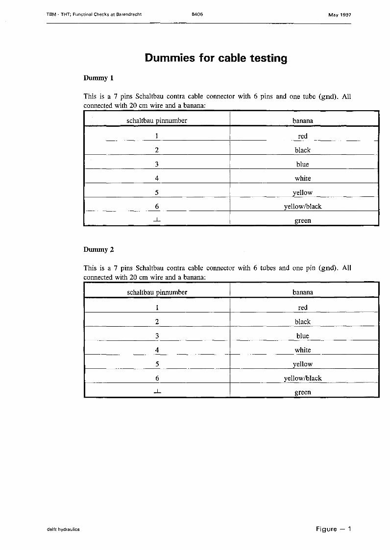
Dummies for cable testing
Dummy!
This is a 7 pins Schaltbau contra cable connector with 6 pins and one tube (gnd). Allconnected with 20 cm wire and a banana:
schaltbau pinnumber banana
1 red
2 black
3 blue
4 white
5 yellow
6 yellow/black...L green
Dummy 2
This is a 7 pins Schaltbau contra cable connector with 6 tubes and one pin (gnd). Allconnected with 20 cm wire and a banana:
schaltbau pinnumber banana
1 red
2 black
3 blue
4 white
5 yellow
6 yellowlblack...L green
delft hydraulics Figure - 1
TBM - THT; Functinal Checks at Barendrecht B406 May 1997
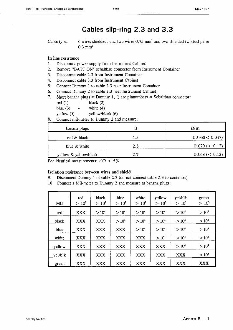
Cables slip-ring 2.3 and 3.3
Cable type: 6 wires shielded, viz: two wires 0,75 mrrr' and two shielded twisted pairs0.3 mnf
In line resistance1. Disconneet power supply from Instrument Cabinet2. Remove "BATT ON" schaltbau connector from Instrument Container3. Disconneet cable 2.3 from Instrument Container4. Disconneet cable 3.3 from Instrument Cabinet5. Conneet Dummy 1 to cable 2.3 near Instrument Container6. Conneet Dummy 2 to cable 3.3 near Instrument Cabinet7. Short banana plugs at Dummy 1, 0 are pinnumbers at Schaltbau connector:
red (1) black (2)blue (3) white (4)yellow (5) - yellow/black (6)
8. Conneet mû-meter to Dummy 2 and measure:
banana plugs U Olm
red & black 1.5 0.038( < 0.047)
blue & white 2.8 0.070 « 0.12)
yellow & yellow/black 2.7 0.068 « 0.12)For identical measurements: ClR < 5%
Isolation resistance between wires and shield9. Disconneet Dummy 1 of cable 2.3 (do not conneet cable 2.3 to container)10. Conneet a Mû-meter to Dummy 2 and measure at banana plugs:
red black blue white yellow yellbik greenMU > 103 > 103 > 103 > 103 > 103 > 103 > 103
red XXX > 104 > 104 > 104 > 104 > 104 > 104
black XXX XXX > 104 > 104 > 104 > 104 > 104
blue XXX XXX XXX > 104 > 104 > 104 > 104
white XXX XXX XXX XXX > 104 > 104 > 104
yellow XXX XXX XXX XXX XXX > 104 > 104
yel/blk XXX XXX XXX XXX XXX XXX > 104
green XXX XXX XXX XXX XXX XXX XXX
delft hydraulics Annex B - 1
TBM • THT; Functinal Checks at Barendrecht B406 May 1997
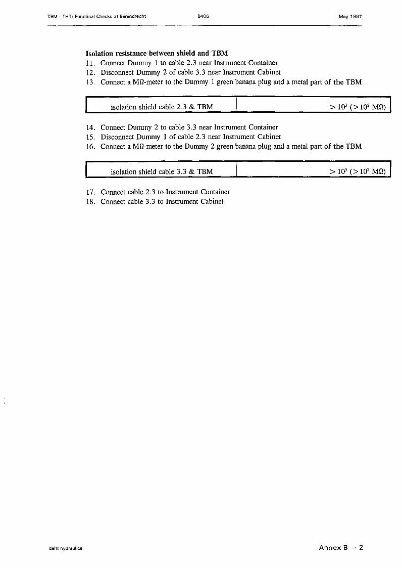
Isolation resistance between shield and TBM11. Conneet Dummy 1 to cable 2.3 near Instrument Container12. Disconneet Dummy 2 of cable 3.3 near Instrument Cabinet13. Conneet a MD-meter to the Dummy 1 green banana plug and a metal part of the TBM
isolation shield cable 2.3 & TBM
14. Conneet Dummy 2 to cable 3.3 near Instrument Container15. Disconneet Dummy 1 of cable 2.3 near Instrument Cabinet16. Conneet a MD-meter to the Dummy 2 green banana plug and a metal part of the TBM
isolation shield cable 3.3 & TBM
17. Conneet cable 2.3 to Instrument Container18. Conneet cable 3.3 to Instrument Cabinet
delft hydraulics Annex B - 2
TBM - THT; Functinal Checks at Barendrecht B406 May 1997
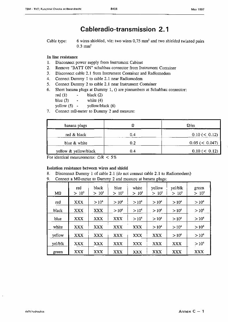
Cableradio-transmission 2. 1
Cable type: 6 wires shielded, viz: two wires 0,75 mm' and two shielded twisted pairs0.3 mm'
In line resistance1. Disconneet power supply from Instrument Cabinet2. Remove "BATT ON" schaltbau connector from Instrument Container3. Disconneet cable 2.1 from Instrument Container and Radiomodem4. Conneet Dummy 1 to cable 2.1 near Radiomodem5. Conneet Dummy 2 to cable 2.1 near Instrument Container6. Short banana plugs at Dummy 1, 0 are pinnumbers at Schaltbau connector:
red (1) black (2)blue (3) white (4)yellow (5) - yellow/black (6)
7. Conneet mû-meter to Dummy 2 and measure:
banana plugs D I nim
red & black 0.4 0.10 « 0.12)
blue & white 0.2 0.05 « 0.047)
yellow & yellow/black 0.4 0.10 « 0.12)For identical measurements: ~R < 5 %
Isolation resistance between wires and shield8. Disconneet Dummy 1 of cable 2.1 (do not connect cable 2.1 to Radiomodem)9. Conneet a MD-meter to Dummy 2 and measure at banana plugs:
red black blue white yellow yel/blk greenMD > 103 > 103 > 103 > 103 > 103 > 103 > 103
red XXX > 104 > 104 > 104 > 104 > 104 > 104
black XXX XXX > 104 > 104 > 104 > 104 > 104
blue XXX XXX XXX > 104 > 104 > 104 > 104
white XXX XXX XXX XXX > 104 > 104 > 104
yell ow XXX XXX XXX XXX XXX >1Q4 > 104
yellblk XXX XXX XXX XXX XXX XXX > 104
green XXX XXX XXX XXX XXX XXX XXX
delft hydraulics Annex C - 1
TBM - THT; Functinal Checks at Barendrecht B406 May 1997
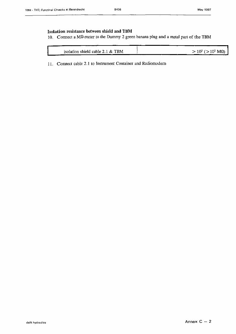
Isolation resistance between shield and TBM10. Conneet a MD-meter to the Dummy 2 green banana plug and a metal part of the TBM
isolation shield cable 2.1 & TBM
11. Conneet cable 2.1 to Instrument Container and Radiomodem
delft hydraulics Annex C - 2
TBM - THT; Functinal Checks at Barendrecht B406 May 1997
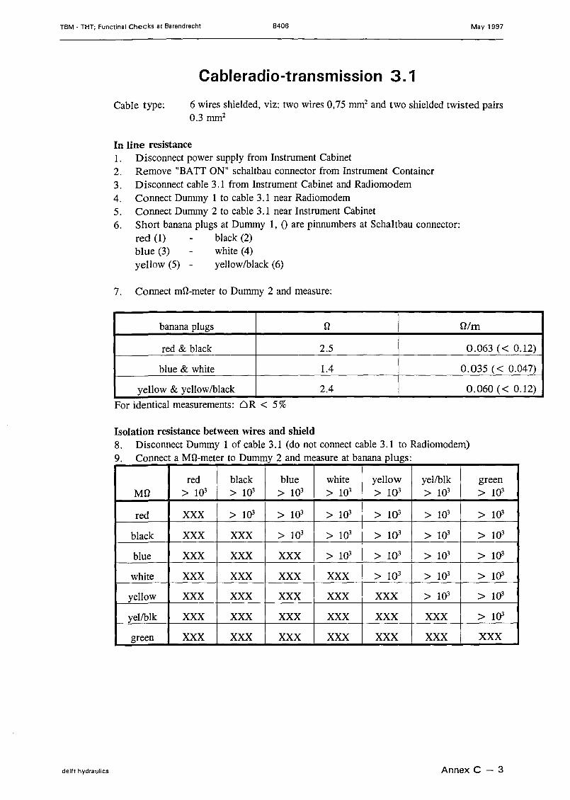
Cableradio-transmission 3. 1
Cable type: 6 wires shielded, viz: two wires 0,75 mnf and two shielded twisted pairs0.3 mm'
In line resistance1. Disconneet power supply from Instrument Cabinet2. Remove "BATT ON" schaltbau connector from Instrument Container3. Disconneet cable 3.1 from Instrument Cabinet and Radiomodem4. Conneet Dummy 1 to cable 3.1 near Radiomodem5. Conneet Dummy 2 to cable 3.1 near Instrument Cabinet6. Short banana plugs at Dummy 1, 0 are pinnumbers at Schaltbau connector:
red (1) black (2)blue (3) white (4)yell ow (5) - yellow/black (6)
7. Conneet mû-meter to Dummy 2 and measure:
banana plugs D Olm
red & black 2.5 0.063 « 0.12)
blue & white 1.4 0.035 « 0.047)
yellow & yellow/black 2.4 0.060« 0.12)
For identical measurements: öR < 5%
Isolation resistance between wires and shield8. Disconneet Dummy 1 of cable 3 .1 (do not conneet cable 3.1 to Radiomodem)9. Conneet a MD-meter to Dummy 2 and measure at banana plugs:
red black blue white yellow yellbik greenMD > 103 > 103 > 103 > 103 > 103 > 103 > 103
red XXX > 103 > 103 > 103 > 103 > 103 > 103
black XXX XXX > 103 > 103 > 103 > 103 > 103
blue XXX XXX XXX > 103 > 103 > 103 > 103
white XXX XXX XXX XXX > 103 > 103 > 103
yell ow XXX XXX XXX XXX XXX > 103 > 1Q3
yellbik XXX XXX XXX XXX XXX XXX > 103
green XXX XXX XXX XXX XXX XXX XXX
delft hydraulics Annex C - 3
TBM - THT; Functinal Checks at Barendrecht B406 May 1997
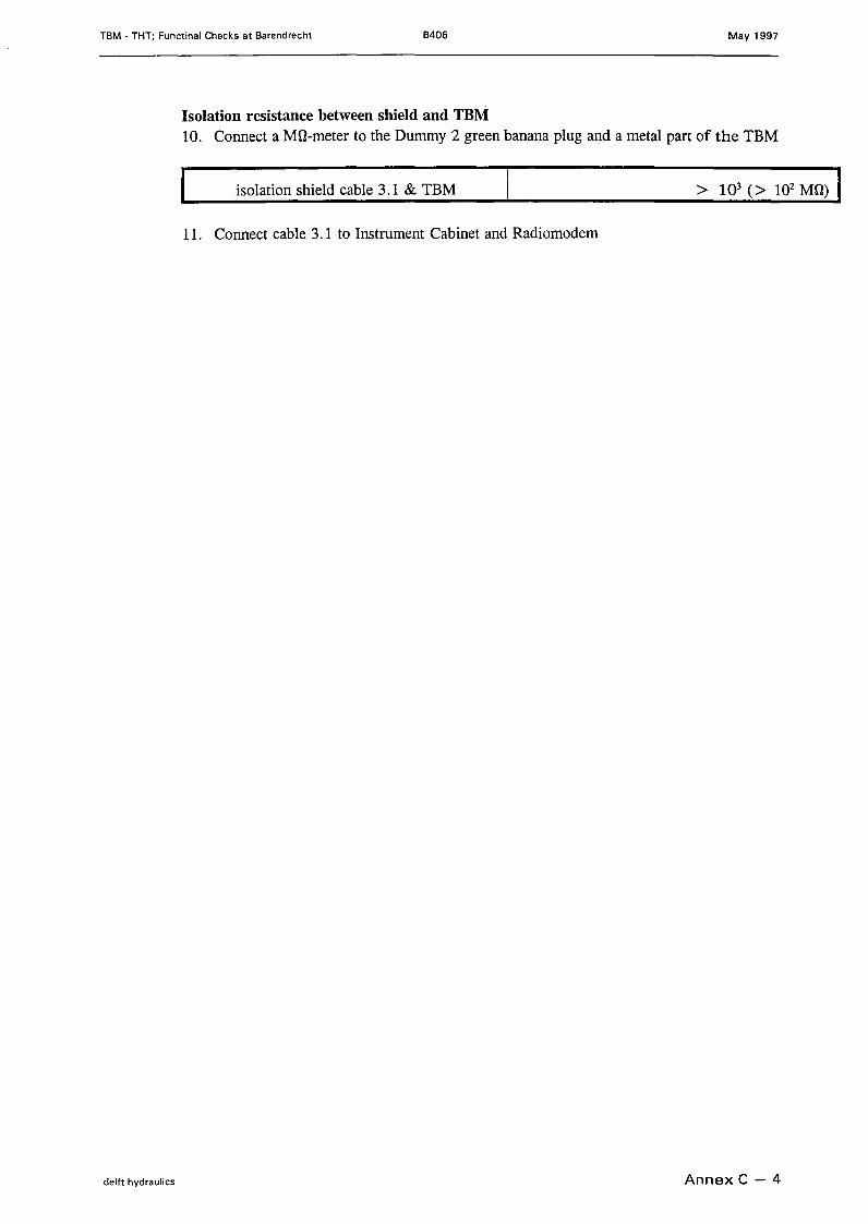
Isolation resistance between shield and TBM10. Conneet a Mû-meter to the Dummy 2 green banana plug and a metal part of the TBM
isolation shield eable 3.1 & TBM
11. Conneet eable 3.1 to Instrument Cabinet and Radiomodem
delft hydraulics Annex C - 4
TBM • THT; Functinal Checks at Barendrecht B406 May 1997
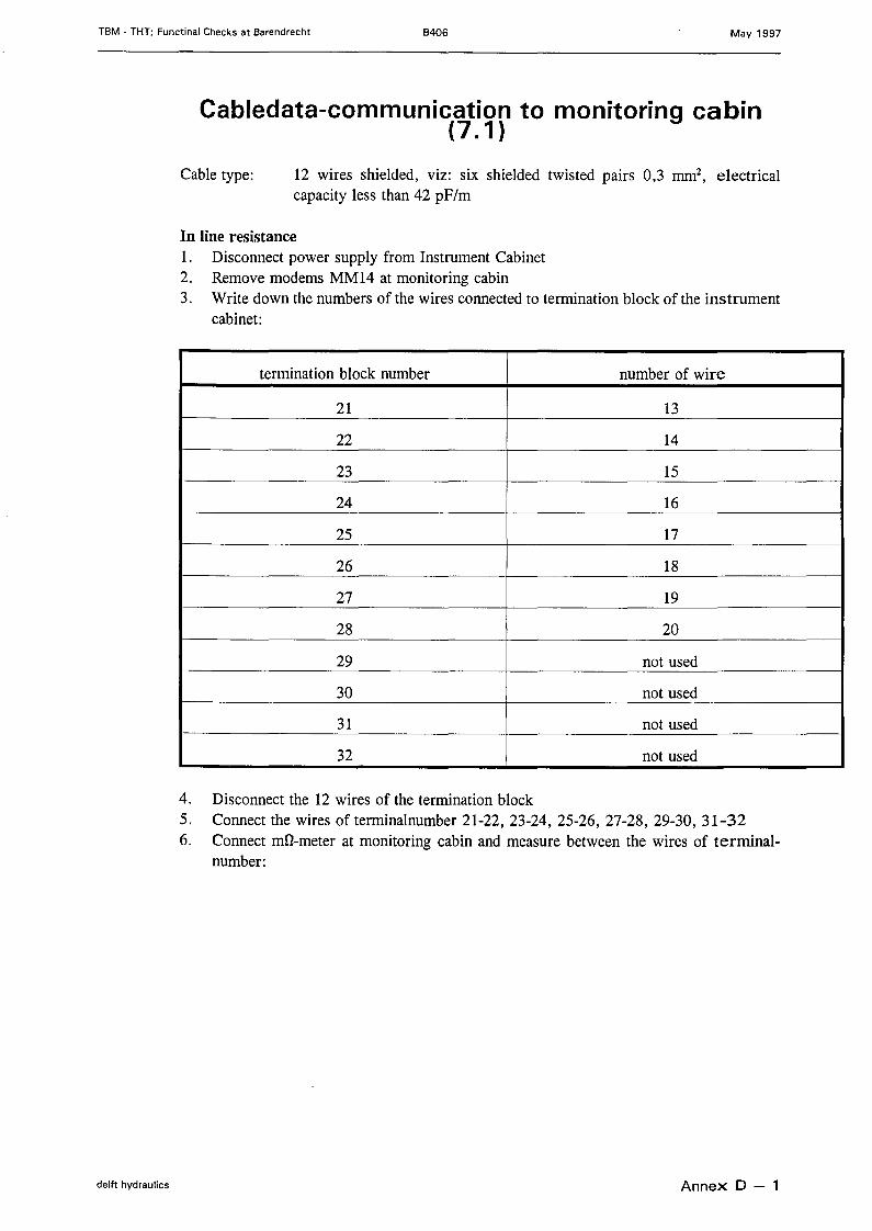
Cabledata-communication to monitoring cabin(7.1)
Cable type: 12 wires shielded, viz: six shielded twisted pairs 0,3 mm', e1eetriealeapacity less than 42 pF/m
In line resistance1. Diseonneet power supply from Instrument Cabinet2. Remove modems MM14 at monitoring eabin3. Write down the numbers of the wires eonneeted to termination bloek of the instrument
eabinet:
termination bloek number number of wire
21 13
22 14
23 15
24 16
25 17
26 18
27 19
28 20
29 not used
30 not used
31 not used
32 not used
4. Diseonneet the 12 wires of the termination bloek5. Conneet the wires of terminalnumber 21-22, 23-24, 25-26, 27-28, 29-30, 31-326. Conneet mû-meter at monitoring eabin and measure between the wires of terminal-
number:
delft hydraulics Annex 0 - 1
TBM - THT; Functinal Checks at Barendrecht B406 May 1997
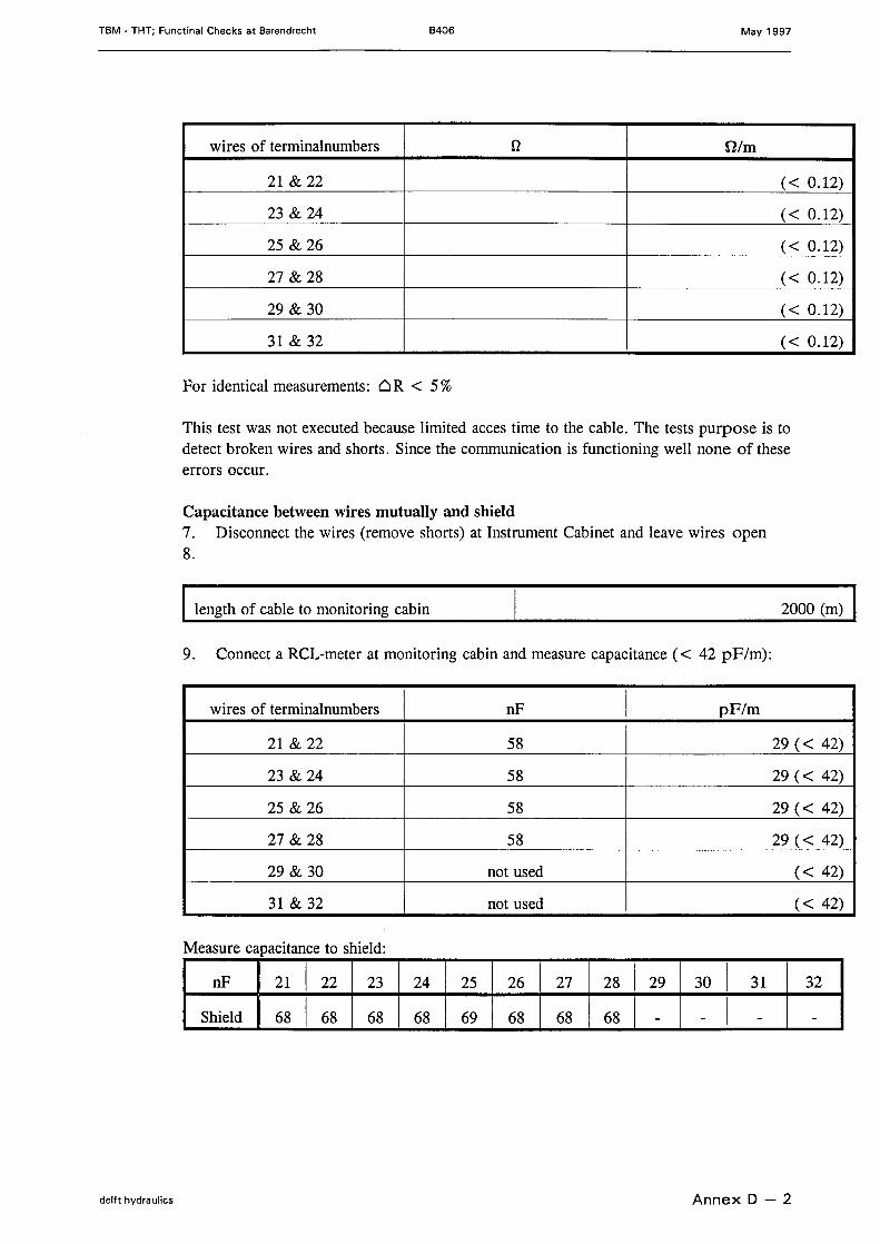
wires of terminalnumbers n Olm
21 & 22 « 0.12)
23 & 24 « 0.12)
25 & 26 « 0.12)
27 & 28 « 0.12)
29 & 30 « 0.12)
31 & 32 « 0.12)
For identical measurements: 6R < 5%
This test was not executed because limited acces time to the cabie. The tests purpose is todetect braken wires and shorts. Since the communication is functioning weIl none of theseerrors occur.
Capacitance between wires mutually and shield7. Disconneet the wires (remove shorts) at Instrument Cabinet and leave wires open8.
length of cable to monitoring cabin 2000 (m)
9. Conneet a RCL-meter at monitoring cab in and measure capacitance « 42 pF/m):
wires of terminalnumbers nF pF/m
21 & 22 58 29 « 42)
23 & 24 58 29 « 42)
25 & 26 58 29 « 42)
27 & 28 58 29 « 42)
29 & 30 not used « 42)
31 & 32 not used « 42)
Measure capacitance to shield:
nF 21 22 23 24 25 26 27 28 29 30 31 32
Shield 68 68 68 68 69 68 68 68 - - - -
delft hydraulics Annex D - 2
TBM - THT; Functinal Checks at Barendrecht B406 May 1997
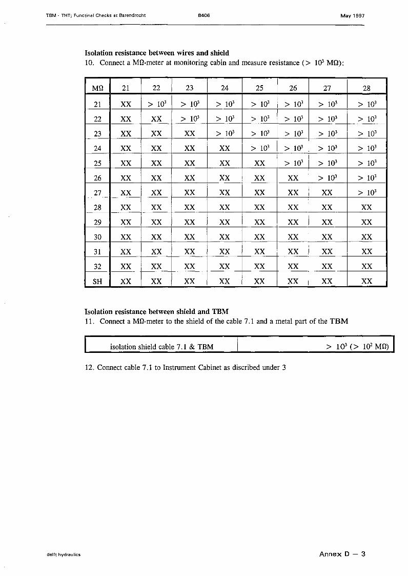
Isolation resistance between wires and shield10. Conneet a Mû-meter at monitoring cabin and measure resistance (> 103 MD):
MO 21 22 23 24 25 26 27 28
21 XX > 103 > 103 > 103 > 103 > 103 > 103 > 103
22 XX XX > 103 > 103 > 103 > 103 > 103 > 103
23 XX XX XX > 103 > 103 > 103 > 103 > 103
24 XX XX XX XX > 103 > 103 > 103 > 103
25 XX XX XX XX XX > 103 > 103 > 103
26 XX XX XX XX XX XX > 103 > 103
27 XX XX XX XX XX XX XX > 103
28 XX XX XX XX XX XX XX XX29 XX XX XX XX XX XX XX XX30 XX XX XX XX XX XX XX XX31 XX XX XX XX XX XX XX XX32 XX XX XX XX XX XX XX XXSH XX XX XX XX XX XX XX XX
Isolation resistance between shield and TBM11. Conneet a Mû-meter to the shield of the cable 7.1 and a met al part of the TBM
isolation shield cable 7.1 & TBM
12. Conneet cable 7.1 to Instrument Cabinet as discribed under 3
delft hydraulics Annex 0 - 3
TBM • THT; Functinal Checks at Barendrecht B406 May 1997
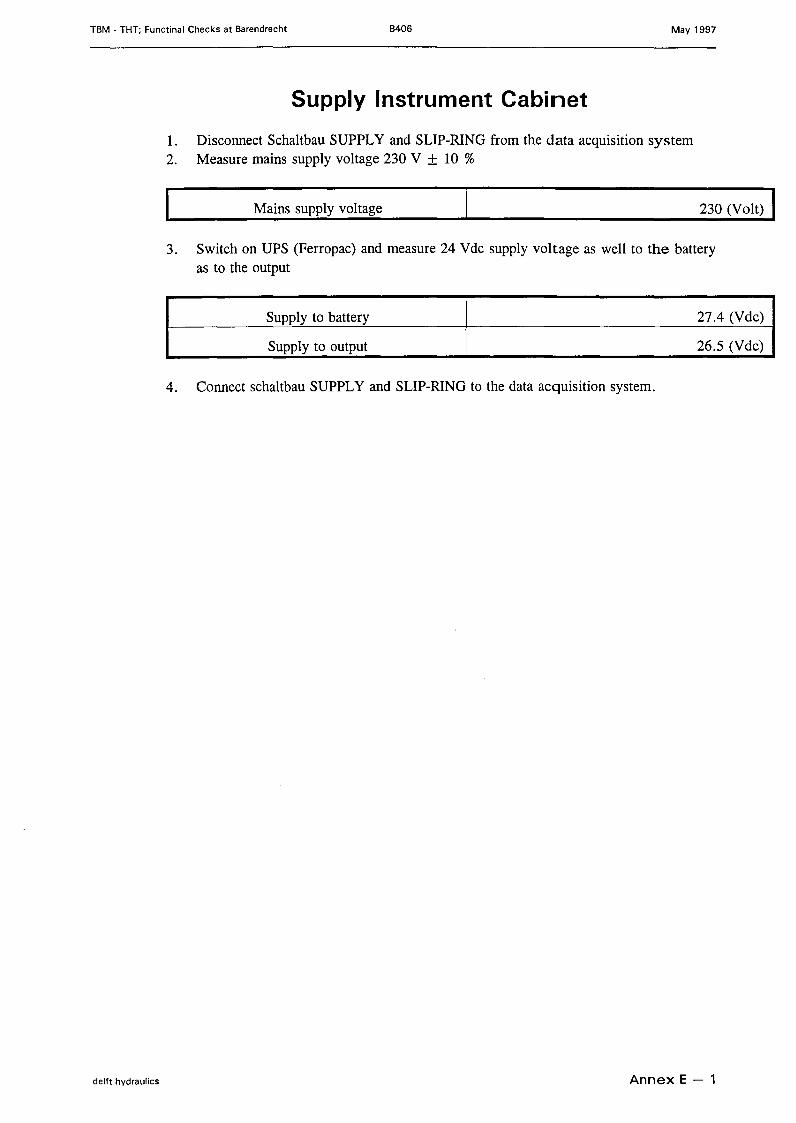
Supply Instrument Cabinet
1. Disconneet Schaltbau SUPPLY and SLIP-RING from the data acquisition system2. Measure mains supply voltage 230 V ± 10 %
Mains supply voltage 230 (Volt)
3. Switch on UPS (Ferropac) and measure 24 Vdc supply voltage as weIl to the batteryas to the output
Supply to battery
Supply to output
27.4 (Vdc)
26.5 (Vdc)
4. Conneet schaltbau SUPPLY and SLIP-RING to the data acquisition system.
delft hydraulics Annex E - 1
TBM - THT; Functinal Checks at Barendrecht B406 May 1997
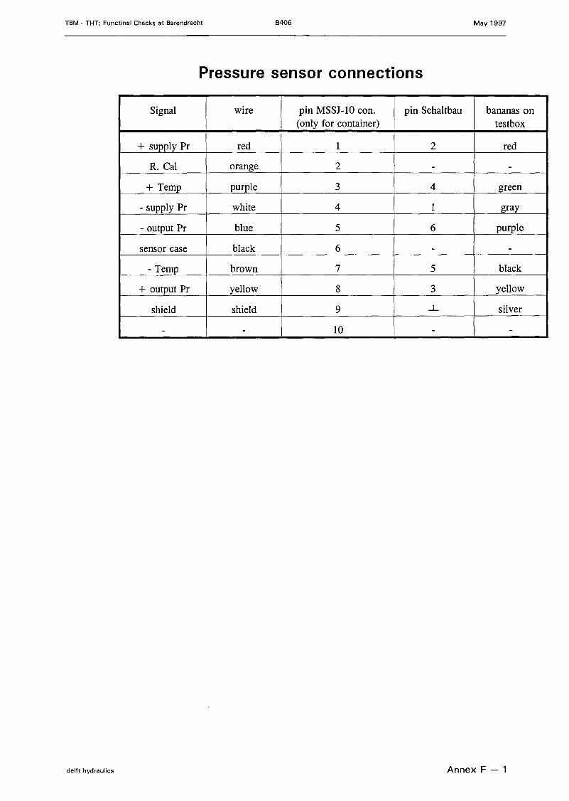
Pressure sensor connections
Signal wire pin MSSJ-lü con. pin Schaltbau bananas on(only for container) testbox
+ supply Pr red 1 2 red
R. Cal orange 2 - -
+ Temp purple 3 4 green
- supply Pr white 4 1 gray
- output Pr blue 5 6 purple
sensor case black 6 - -
- Temp brown 7 5 black
+ output Pr yell ow 8 3 yellow
shield shield 9...L silver
- - 10 - -
delft hydraulics Annex F - 1
TBM - THT; Functinal Checks at Barendrecht B406 May 1997
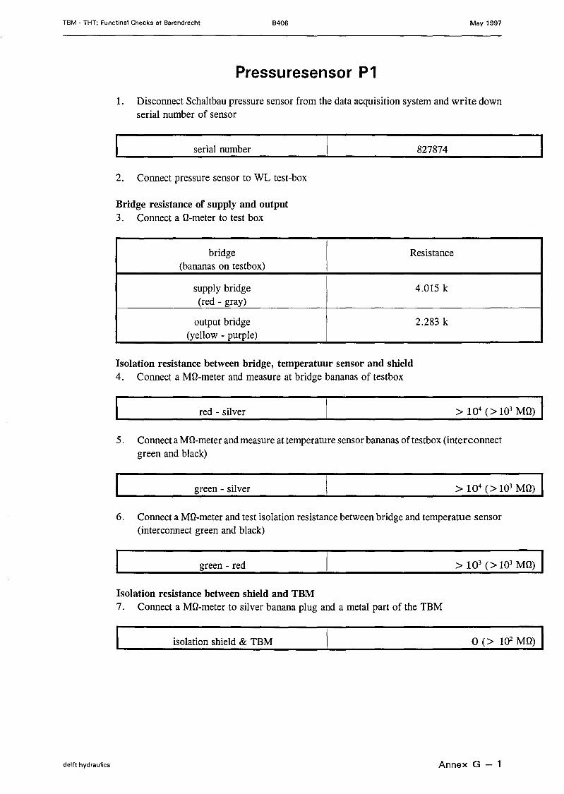
Pressuresensor P1
1. Disconneet Schaltbau pressure sensor from the data acquisition system and write downserial number of sensor
serial number 827874
2. Conneet pressure sensor to WL test-box
Bridge resistance of supply and output3. Conneet a O-meter to test box
bridge Resistance(bananas on testbox)
supply bridge 4.015 k(red - gray)
output bridge 2.283 k(yeIIow - purple)
Isolation resistance between bridge, temperatuur sensor and shield4. Conneet a Mû-meter and measure at bridge bananas of testbox
red - silver
5. Conneet a Mû-meter and measure at temperature sensor bananas of testbox (interconnectgreen and black)
green - silver
6. Conneet a Mû-meter and test isolation resistance between bridge and temperatue sensor(interconnect green and black)
> 103 (> 103 MO) Igreen - red
Isolation resistance between shield and TBM7. Conneet a Mû-rneter to silver banana plug and a metal part of the TBM
isolation shield & TBM 0(> 102 MO) I
delft hydraulics Annex G - 1
TBM - THT; Functinal Checks at Barendrecht B406 May 1997
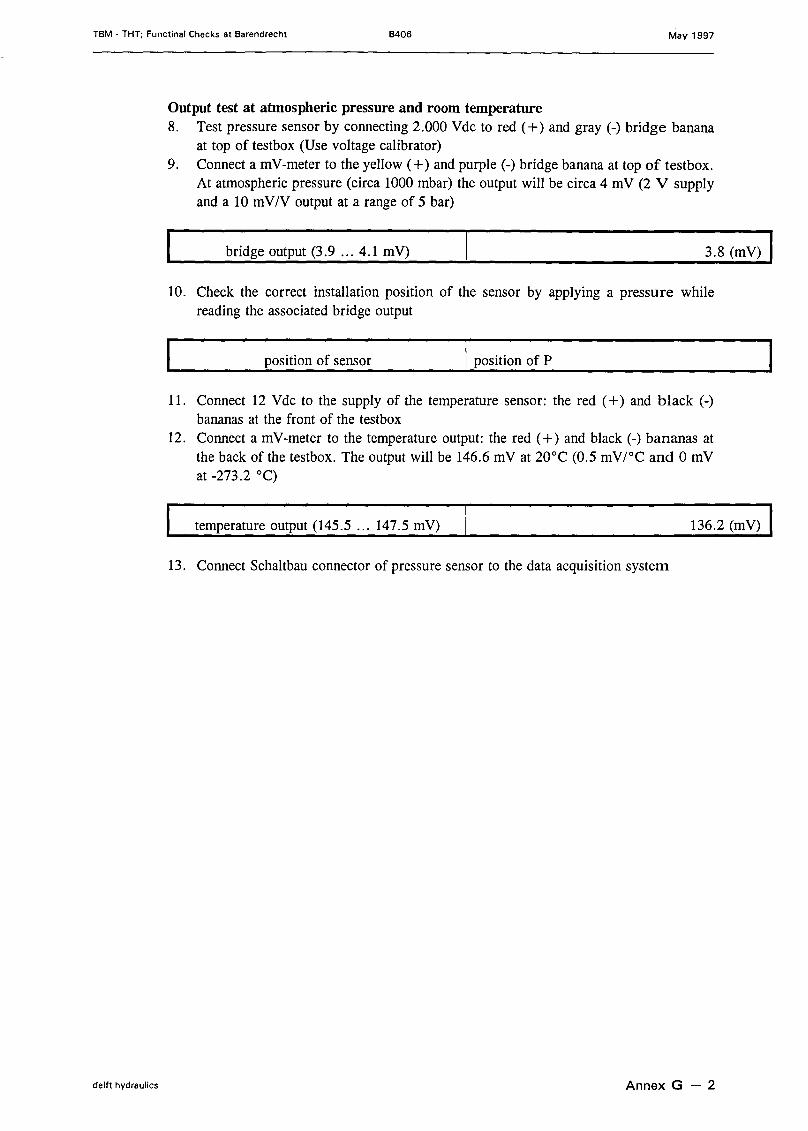
Output test at atmospheric pressure and room temperature8. Test pressure sensor by connecting 2.000 Vdc to red (+) and gray (-) bridge banana
at top of testbox (Use voltage calibrator)9. Conneet a mV-meter to the yell ow (+) and purple (-) bridge banana at top of testbox.
At atmospheric pressure (circa 1000 mbar) the output will be circa 4 mV (2 V supplyand a 10 mV/V output at a range of 5 bar)
bridge output (3.9 ... 4.1 mV) 3.8 (mV)
10. Check the correct installation position of the sensor by applying a pressure whilereading the associated bridge output
position of sensor I position of P
11. Conneet 12 Vdc to the supply of the temperature sensor: the red (+) and black (-)bananas at the front of the testbox
12. Conneet a mV-meter to the temperature output: the red (+) and black (-) bananas atthe back of the testbox. The output will be 146.6 mV at 20°C (0.5 mV/oC and 0 mVat -273.2 0c)
temperature output (145.5 ... 147.5 mV) 136.2 (mV)
13. Conneet Schaltbau connector of pressure sensor to the data acquisition system
delft hydraulics Annex G - 2

TBM - THT; Functinal Checks at Barendrecht B406 May 1997
Pressure sensor P2
1. Disconneet Schaltbau pressure sensor from the data acquisition system and write downserial number of sensor
serial number 827875
2. Conneet pressure sensor to WL test-box
Bridge resistance of supply and output3. Conneet a ü-meter to test box
bridge Resistance(bananas on testbox)
supply bridge 3.892 k(red - gray)
output bridge 2.268 k(yell ow - purple)
Isolation resistance between bridge, temperatuur sensor and shield4. Connect a Mü-meter and measure at bridge bananas of testboxI red - silver 1----------->-10-4-( >-1-03-M-Ü-)-
5. Conneet a Mû-meter and measure at temperature sensor bananas of testbox (interconnectgreen and black)
green - silver
6. Conneet a Mû-meter and test isolation resistance between bridge and temperatue sensor(interconnect green and black)
green - red
Isolation resistance between shield and TBM7. Connect a Mü-meter to silver banana plug and a met al part of the TBM
I isolation shield & TBM I 0(> 102 Mü) I
delft hydraulics Annex G - 3

TBM - THT; Functinal Checks at Barendrecht B406 May 1997
Output test at atmospheric pressure and room temperature8. Test pressure sensor by connecting 2.000 Vdc to red (+) and gray (-) bridge banana
at top of testbox (Use voltage calibrator)9. Conneet a mV-meter to the yeIlow ( +) and purple (-) bridge banana at top of testbox.
At atmospheric pressure (circa 1000 mbar) the output wiII be circa 4 mV (2 V supplyand a 10 mV/V output at a range of 5 bar)
bridge output (3.9 ... 4.1 mV) 3.85 (mV)
10. Check the correct instaIlation position of the sensor by applying a pressure whilereading the associated bridge output
position of sensor I position of P
11. Conneet 12 Vdc to the supply of the temperature sensor: the red (+) and black (-)bananas at the front of the testbox
12. Conneet a mV-meter to the temperature output: the red (+) and black (-) bananas atthe back of the testbox. The output wiII be 146.6 mV at 20°C (0.5 mV/oC and 0 mVat -273.2 0c)
temperature output (145.5 ." 147.5 mV) 136.4 (mV)
13. Conneet Schaltbau connector of pressure sensor to the data acquisition system
delft hydraulics Annex G - 4
TBM - THT; Functinal Checks at Barendrecht B406 May 1997
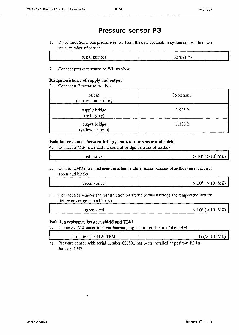
Pressure sensor P3
1. Disconneet Schaltbau pressure sensor from the data acquisition system and write downserial number of sensor
serial number 827891 *)
2. Conneet pressure sensor to WL test-box
Bridge resistance of supply and output3. Conneet a O-meter to test box
bridge Resistance(bananas on testbox)
supply bridge 3.935 k(red - gray)
output bridge 2.280 k(yell ow - purple)
Isolation resistance between bridge, temperatuur sensor and shield4. Connect a MO-meter and measure at bridge bananas of testbox
I red - silver I5. Conneet a MD-meter and measure at temperature sensor bananas of testbox (interconnect
green and black)
green - silver
6. Conneet a MD-meter and test isolation resistance between bridge and temperatue sensor(interconnect green and black)
green - red > 104 (> 103 MO) IIsolation resistance between shield and TBM7. Connect a MD-meter to silver banana plug and a metal part of the TBM
I isolation shield & TBM I 0 (> 102 MO) I*) Pressure sensor with serial number 827891 has been installed at position P3 in
January 1997
delft hydraulics Annex G - 5
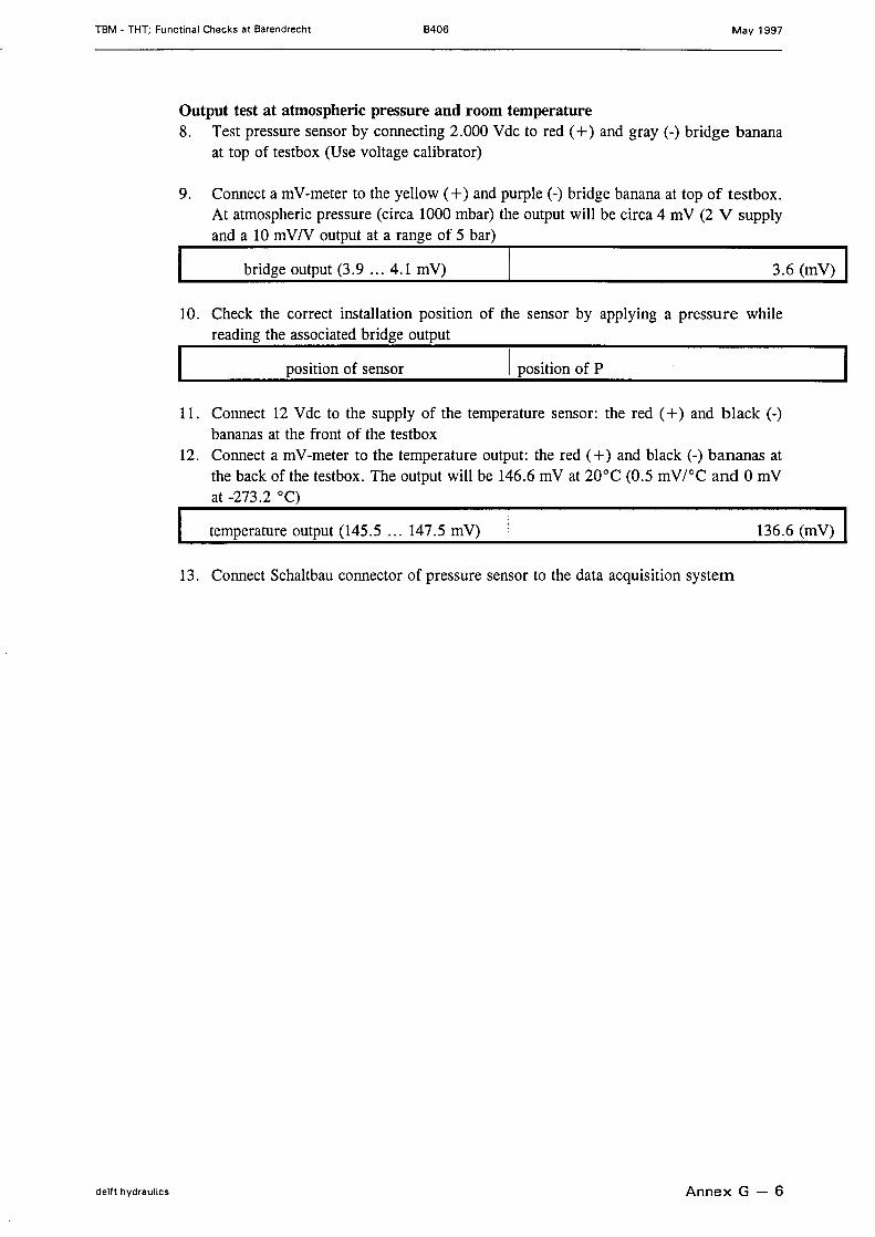
TBM • THT; Functinal Checks at Barendrecht B406 May 1997
Output test at atmospheric pressure and room temperature8. Test pressure sensor by connecting 2.000 Vdc to red (+) and gray (-) bridge banana
at top of testbox (Use voltage calibrator)
9. Conneet a mV-meter to the yellow (+) and purple (-) bridge banana at top of testbox.At atmospheric pressure (circa 1000 mbar) the output will be circa 4 mV (2 V supplyand a 10 mVIV output at a range of 5 bar)
bridge output (3.9 ... 4.1 mV) 3.6 (mV)
10. Check the correct installation position of the sensor by applying a pressure whilereading the associated bridge output
position of sensor I position of P
11. Conneet 12 Vdc to the supply of the temperature sensor: the red (+) and black (-)bananas at the front of the testbox
12. Conneet a mV-meter to the temperature output: the red (+) and black (-) bananas atthe back of the testbox. The output will be 146.6 mV at 20°C (0.5 mV/oC and 0 mVat -273.2 0c)
temperature output (145.5 ... 147.5 mV) 136.6 (mV)
13. Conneet Schaltbau connector of pressure sensor to the data acquisition system
delft hydraulics Annex G - 6
TBM - THT; Functinal Checks at Barendrecht B406 May 1997
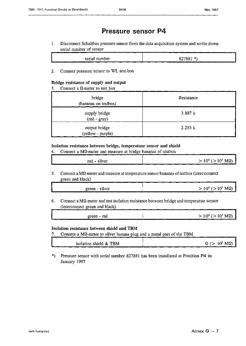
Pressure sensor P4
1. Disconneet Schaltbau pressure sensor from the data acquisition system and write downserial number of sensor
serial number 827881 *)
2. Conneet pressure sensor to WL test-box
Bridge resistance of supply and output3. Conneet a O-rneter to test box
bridge Resistance(bananas on testbox)
supply bridge 3.887 k(red - gray)
output bridge 2.255 k(yell ow - purple)
Isolation resistance between bridge, temperatuur sensor and shield4. Connect a MD-meter and measure at bridge bananas of testbox
I red - silver 1~~~~~~~~~~~~~~~~~~~~~>~~1~04~~(>~~1~03~M~~D~)~
5. Conneet a MD-meter and measure at temperature sensor bananas of testbox (interconnectgreen and black)
green - silver
6. Conneet a MD-meter and test isolation resistance between bridge and temperatue sensor(interconnect green and black)
green - red
Isolation resistance between shield and TBM7. Connect a MD-meter to silver banana plug and a metal part of the TBM
I isolation shie1d & TBM I 0(> 102 MD) I*) Pressure sensor with serial number 827881 has been installated at Postition P4 in
January 1997
delft hydraulics Annex G - 7
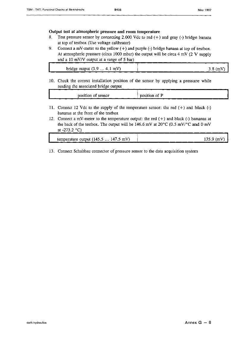
TBM • THT; Functinal Checks at Barendrecht B406 May 1997
Output test at atmospheric pressure and room temperature8. Test pressure sensor by connecting 2.000 Vdc to red (+) and gray (-) bridge banana
at top of testbox (Use voltage calibrator)9. Conneet a mV-meter to the yellow (+) and purple (-) bridge banana at top of testbox.
At atmospheric pressure (circa 1000 mbar) the output will be circa 4 mV (2 V supplyand alOm VIV output at a range of 5 bar)
bridge output (3.9 ... 4.1 mV) 3.8 (mV)
10. Check the correct installation position of the sensor by applying a pressure whilereading the associated bridge output
position of sensor I position of P
11. Conneet 12 Vde to the supply of the temperature sensor: the red (+) and black (-)bananas at the front of the testbox
12. Conneet a mV-meter to the temperature output: the red (+) and black (-) bananas atthe back of the testbox. The output will be 146.6 mV at 20°C (0.5 mVfOC and 0 mVat -273.2 0c)
temperature output (145.5 ... 147.5 mV) 135.9 (mV)
13. Conneet Schaltbau connector of pressure sensor to the data acquisition system
delft hydraulics Annex G - 8

TBM - THT; Functinal Checks at Barendrecht B406 May 1997
Pressure sensor PS
1. Disconneet Schaltbau pressure sensor from the data acquisition system and write downserial number of sensor
serial number 827880
2. Conneet pressure sensor to WL test-box
Bridge resistance of supply and output3. Conneet a O-meter to test box
bridge Resistance(bananas on testbox)
supply bridge 3.875 k(red - gray)
output bridge 2.288 k(yellow - purple)
Isolation resistance between bridge, temperatuur sensor and shield4. Connect a MO-meter and measure at bridge bananas of testboxI red - silver ,------------1-0-4 -( >-1-03-M-O-)-
5. Conneet a Mû-meter and measure at temperature sensor bananas of testbox (interconnectgreen and black)
green - silver
6. Conneet a Mû-meter and test isolation resistance between bridge and temperatue sensor(interconnect green and black)
green - red > 104 (> 103 MO) IIsolation resistance between shield and TBM7. Connect a MO-meter to silver banana plug and a metal part of the TBM
I isolation shield & TBM I 0 (> 102 MO) I
delft hydraulics Annex G - 9

TBM - THT; Functinal Checks at Barendrecht B406 May 1997
Output test at atmospheric pressure and room temperature8. Test pressure sensor by connecting 2.000 Vdc to red (+) and gray (-) bridge banana
at top of testbox (Use voltage calibrator)9. Conneet a mV-meter to the yeIIow (+) and purple (-) bridge banana at top of testbox.
At atmospheric pressure (circa 1000 mbar) the output wiII be circa 4 mV (2 V supplyand a 10 mV/V output at a range of 5 bar)
bridge output (3.9 ... 4.1 mV) 3.8 (mV)
10. Check the correct instaIIation position of the sensor by applying a pressure whilereading the associated bridge output
position of sensor I position of P
11. Conneet 12 Vdc to the supply of the temperature sensor: the red (+) and black (-)bananas at the front of the testbox
12. Conneet a mV-meter to the temperature output: the red (+) and black (-) bananas atthe back of the testbox. The output will be 146.6 mV at 20°C (0.5 mV/oC and 0 mVat -273.2 0c)
temperature output (145.5 ... 147.5 mV) 135.8 (mV)
13. Conneet Schaltbau connector of pressure sensor to the data acquisition system
delft hydraulics Annex G - 10
TBM - THT; Functinal Checks at Barendrecht B406 May 1997
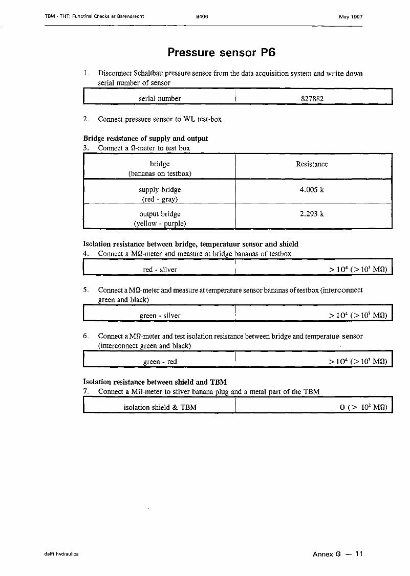
Pressure sensor P6
1. Disconneet Schaltbau pressure sensor from the data acquisition system and write downserial number of sensor
serial number 827882
2. Conneet pressure sensor to WL test-box
Bridge resistance of supply and output3. Conneet a O-merer to test box
bridge Resistance(bananas on testbox)
supply bridge 4.005 k(red - gray)
output bridge 2.293 k(yellow - purple)
Isolation resistance between bridge, temperatuur sensor and shield4. Connect a MQ-meter and measure at bridge bananas of testboxI red - silver 1----------->-I-O-4-(->-1O-3-M-Q-)-
5. Conneet a Mû-meter and measure at temperature sensor bananas of testbox (interconnectgreen and black)
green - silver
6. Conneet a Mû-rneter and test isolation resistance between bridge and temperatue sensor(interconnect green and black)
green - red
Isolation resistance between shield and TBM7. Connect a MQ-meter to silver banana plug and a metal part of the TBM
I isolation shield & TBM I 0(> 102 MQ) I
delft hydraulics Annex G - 11
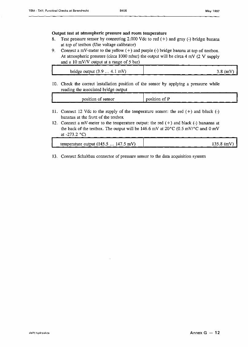
TBM - THT; Functinal Checks at Barendrecht B406 May 1997
Output test at atmospheric pressure and room temperature8. Test pressure sensor by connecting 2.000 Vdc to red (+) and gray (-) bridge banana
at top of testbox (Use voltage calibrator)9. Conneet a mV-meter to the yellow (+) and purple (-) bridge banana at top of testbox.
At atmospheric pressure (circa 1000 mbar) the output will be circa 4 mV (2 V supplyand a 10 mV/V output at a range of 5 bar)
bridge output (3.9 ... 4.1 mV) 3.8 (mV)
10. Check the correct installation position of the sensor by applying a pressure whilereading the associated bridge output
position of sensor I position of P
11. Conneet 12 Vdc to the supply of the temperature sensor: the red (+) and black (-)bananas at the front of the testbox
12. Conneet a mV-meter to the temperature output: the red (+) and black (-) bananas atthe back of the testbox. The output will be 146.6 mV at 20°C (0.5 mV/oC and 0 mVat -273.2 0c)
temperature output (145.5 ... 147.5 mV) 135.8 (mV)
13. Conneet Schaltbau connector of pressure sensor to the data acquisition system
delft hydraulics Annex G - 12

TBM - THT; Functinal Checks at Barendrecht B406 May 1997
Pressure sensor P7
1. Disconneet Schaltbau pressure sensor from the data acquisition system and write downserial number of sensor
serial number 827883
2. Conneet pressure sensor to WL test-box
Bridge resistance of supply and output3. Conneet a ü-meter to test box
bridge Resistance(bananas on testbox)
supply bridge 3.894 k(red - gray)
output bridge 2.285 k(yell ow - purple)
Isolation resistance between bridge, temperatuur sensor and shield4. Connect a MD-meter and measure at bridge bananas of testbox
I red - silver I
5. Conneet a MD-meter and measure at temperature sensor bananas of testbox (interconnectgreen and black)
green - silver
6. Conneet a MD-meter and test isolation resistance between bridge and temperatue sensor(interconnect green and black)
> 104 (> 103 Mü) Igreen - red
Isolation resistance between shield and TBM7. Connect a MD-meter to silver banana plug and a metal part of the TBM
I isolation shield & TBM I 0(> 102 Mü) I
delft hydraulics Annex G - 13

TBM - THT; Functinal Checks at Barendrecht B406 May 1997
Output test at atmospheric pressure and room temperature8. Test pressure sensor by connecting 2.000 Vdc to red (+) and gray (-) bridge banana
at top of testbox (Use voltage calibrator)9. Conneet a mV-meter to the yellow (+) and purple (-) bridge banana at top of testbox.
At atmospheric pressure (circa 1000 mbar) the output will be circa 4 mV (2 V supplyand a 10 mV/V output at a range of 5 bar)
bridge output (3.9 ... 4.1 mV) 3.9 (mV)
10. Check the correct installation position of the sensor by applying a pressure whilereading the associated bridge output
position of sensor I position of P
11. Conneet 12 Vde to the supply of the temperature sensor: the red (+) and black (-)bananas at the front of the testbox
12. Conneet a mV-meter to the temperature output: the red (+) and black (-) bananas atthe back of the testbox. The output will be 146.6 mV at 20°C (0.5 mV/oC and 0 mVat -273.2 0c)
temperature output (145.5 ... 147.5 mV) 136.4 (mV)
13. Conneet Schaltbau connector of pressure sensor to the data acquisition system
delft hydraulics Annex G - 14
TBM • THT; Functinal Checks at Barendrecht B406 May 1997
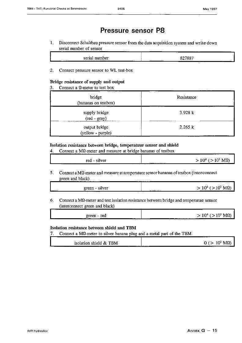
Pressure sensor PB
1. Diseonneet Sehaltbau pressure sensor from the data aequisition system and write downserial number of sensor
serial number 827887
2. Conneet pressure sensor to WL test-box
Bridge resistance of supply and output3. Conneet a a-meter to test box
bridge Resistanee(bananas on testbox)
supply bridge 3.928 k(red - gray)
output bridge 2.265 k(yell ow - purple)
Isolation resistance between bridge, temperatuur sensor and shield4. Conneet a Ma-meter and measure at bridge bananas of testbox
I red - silver I
5. Conneet a Ma-meter and measure at temperature sensor bananas of testbox (interconneetgreen and blaek)
green - silver
6. Conneet a Ma-meter and test isolation resistanee between bridge and temperatue sensor(intereonneet green and blaek)
green - red > 104 (> 103 Ma) IIsolation resistance between shield and TBM7. Conneet a Ma-meter to silver banana plug and a metal part of the TBM
I isolation shield & TBM I 0 (> 102 Ma) I
delft hydraulics Annex G - 15
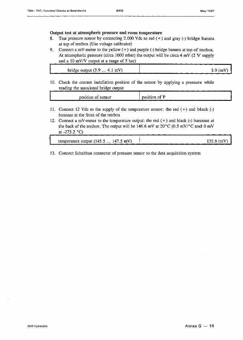
TBM - THT; Functinal Checks at Barendrecht B406 May 1997
Output test at atmospheric pressure and room temperature8. Test pressure sensor by connecting 2.000 Vdc to red (+) and gray (-) bridge banana
at top of testbox (Use voltage calibrator)9. Conneet a mV-meter to the yell ow (+) and purple (-) bridge banana at top of testbox.
At atmospheric pressure (circa 1000 mbar) the output will be circa 4 mV (2 V supplyand a 10 mV/V output at a range of 5 bar)
bridge output (3.9 ... 4.1 mV) 3.9 (mV)
10. Check the correct installation position of the sensor by applying a pressure whilereading the associated bridge output
position of sensor I position of P
11. Conneet 12 Vdc to the supply of the temperature sensor: the red (+) and black (-)bananas at the front of the testbox
12. Conneet a mV-meter to the temperature output: the red (+) and black (-) bananas atthe back of the testbox. The output will be 146.6 mV at 20°C (0.5 mV/oC and 0 mVat -273.2 0c)
temperature output (145.5 ... 147.5 mV) 135.6 (mV)
13. Conneet Schaltbau connector of pressure sensor to the data acquisition system
delft hydraulics Annex G - 16
TBM • THT; Functinal Checks at Barendrecht B406 May 1997
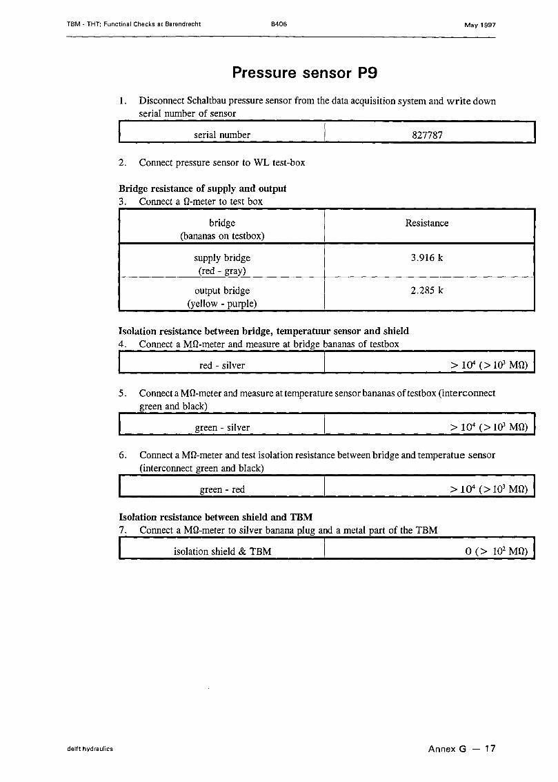
Pressure sensor P9
1. Disconneet Schaltbau pressure sensor from the data acquisition system and write downserial number of sensor
serial number 827787
2. Conneet pressure sensor to WL test-box
Bridge resistance of supply and output3. Conneet a û-meter to test box
bridge Resistance(bananas on testbox)
supply bridge 3.916 k(red - gray)
output bridge 2.285 k(yellow - purple)
Isolation resistance between bridge, temperatuur sensor and shield4. Connect a MD-meter and measure at bridge bananas of testbox
I red - silver I5. Conneet a MD-meter and measure at temperature sensor bananas of testbox (interconnect
green and black)
green - silver
6. Conneet a MD-meter and test isolation resistance between bridge and temperatue sensor(interconnect green and black)
green - red > 104 (> 103 MD) IIsolation resistance between shield and TBM7. Connect a MD-meter to silver banana plug and a metal part of the TBM
I isolation shield & TBM I 0 (> 102 MD) I
delft hydraulics Annex G - 17

TBM • THT; Functinal Checks at Barendrecht B406 May 1997
Output test at atmospheric pressure and room temperature8. Test pressure sensor by connecting 2.000 Vdc to red (+) and gray (-) bridge banana
at top of testbox (Use voltage calibrator)9. Conneet a mV-meter to the yellow (+) and purple (-) bridge banana at top of testbox.
At atmospheric pressure (circa 1000 mbar) the output will be circa 4 mV (2 V supplyand alOm V/V output at a range of 5 bar)
bridge output (3.9 ... 4.1 mV) 3.8 (mV)
10. Check the correct installation position of the sensor by applying a pressure whilereading the associated bridge output
position of sensor I position of P
11. Conneet 12 Vdc to the supply of the temperature sensor: the red (+) and black (-)bananas at the front of the testbox
12. Conneet a mV-meter to the temperature output: the red (+) and black (-) bananas atthe back of the testbox. The output will be 146.6 mV at 20°C (0.5 mV/oC and 0 mVat -273.2 0c)
temperature output (145.5 ... 147.5 mV) 136.5 (mV)
13. Conneet Schaltbau connector of pressure sensor to the data acquisition system
delft hydraulics Annex G - 18

TBM - THT; Functinal Checks at Barendrecht B406 May 1997
Pressure sensor P10
1-. Disconneet Schaltbau pressure sensor from the data acquisition system and write downserial number of sensor
serial number 827788
2. Conneet pressure sensor to WL test-box
Bridge resistance of supply and output3. Conneet a û-meter to test box
bridge Resistance(bananas on testbox)
supply bridge 3.925 k(red - gray)
output bridge 2.269 k(yell ow - purple)
Isolation resistance between bridge, temperatuur sensor and shield4. Connect a MD-meter and measure at bridge bananas of testboxI red - silver ,----------->-10-4-(->-1O-3-M-Ü-)-
5. Conneet a MD-meter and measure at temperature sensor bananas oftestbox (interconnectgreen and black)
green - silver
6. Conneet a MD-meter and test isolation resistance between bridge and temperatue sensor(interconnect green and black)
green - red > 104 (> 103 Mü) IIsolation resistance between shield and TBM7. Connect a MD-meter to silver banana plug and a metal part of the TBM
I isolation shield & TBM I 0 (> 102 Mü) I
delft hydraulics Annex G - 19

TBM - THT; Functinal Checks at Barendrecht B406 May 1997
Output test at atmospheric pressure and room temperature8. Test pressure sensor by connecting 2.000 Vdc to red (+) and gray (-) bridge banana
at top of testbox (Use voltage calibrator)9. Conneet a mV-meter to the yell ow (+) and purple (-) bridge banana at top of testbox.
At atmospheric pressure (circa 1000 mbar) the output will be circa 4 mV (2 V supplyand a 10 mV/V output at a range of 5 bar)
bridge output (3.9 ... 4.1 mV) 3.8 (mV)
10. Check the correct installation position of the sensor by applying a pres su re whilereading the associated bridge output
position of sensor I position of P
11. Conneet 12 Vdc to the supply of the temperature sensor: the red (+) and black (-)bananas at the front of the testbox
12. Conneet a mV-meter to the temperature output: the red (+) and black (-) bananas atthe back of the testbox. The output will be 146.6 mV at 20°C (0.5 mV/oC and 0 mVat -273.2 0c)
temperature output (145.5 ... 147.5 mV) 136.1 (mV)
13. Conneet Schaltbau connector of pressure sensor to the data acquisition system
delft hydraulics Annex G - 20

TBM • THT; Functinal Checks at Barendrecht B406 May 1997
Pressure sensor P11
1. Diseonneet Sehaltbau pressure sensor from the data aequisition system and write downserial number of sensor
serial number 827789
2. Conneet pressure sensor to WL test-box
Bridge resistance of supply and output3. Conneet a û-meter to test box
bridge Resistanee(bananas on testbox)
supply bridge 3.946 k(red - gray)
output bridge 2.277 k(yell ow - purple)
Isolation resistance between bridge, temperatuur sensor and shield4. Conneet a MD-meter and measure at bridge bananas of testbox
I red - silver 1~~~~~~~~~~~~~~~~~~~~~>~~1 0~4~(~>~~1O~3~M~~D~)~
5. Conneet a MD-meter and measure at temperature sensor bananas oftestbox (interconneetgreen and blaek)
green - silver
6. Conneet a MD-meter and test isolation resistanee between bridge and temperatue sensor(intereonneet green and blaek)
green - red > 104 (> 103MD) IIsolation resistance between shield and TBM7. Conneet a MD-meter to silver banana plug and a metal part of the TBM
I isolation shield & TBM I 0 (> 102 MD) I
delft hydraulics Annex G - 21
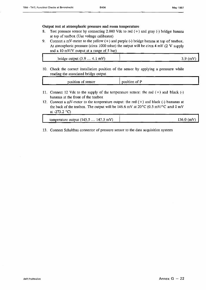
TBM - THT; Functinal Checks at Barendrecht B406 May 1997
Output test at atmospheric pressure and room temperature8. Test pressure sensor by connecting 2.000 Vdc to red (+) and gray (-) bridge banana
at top of testbox (Use voltage calibrator)9. Conneet a mV-meter to the yell ow (+) and purple (-) bridge banana at top of testbox.
At atmospheric pressure (circa 1000 mbar) the output will be circa 4 mV (2 V supplyand a 10 mV/V output at a range of 5 bar)
bridge output (3.9 ... 4.1 mV) 3.9 (mV)
10. Check the correct installation position of the sensor by applying a pressure whilereading the associated bridge output
position of sensor I position of P
11. Conneet 12 Vdc to the supply of the temperature sensor: the red (+) and black (-)bananas at the front of the testbox
12. Conneet a mV-meter to the temperature output: the red (+) and black (-) bananas atthe back of the testbox. The output will be 146.6 mV at 20°C (0.5 mV/oC and 0 mVat -273.2 0c)
temperature output (145.5 ... 147.5 mV) 136.0 (mV)
13. Conneet Schaltbau connector of pressure sensor to the data acquisition system
delft hydraulics Annex G - 22

TBM - THT; Functinal Checks at Barendrecht B406 May 1997
Pressure sensor P12
1. Disconneet Schaltbau pressure sensor from the data acquisition system and write downserial number of sensor
serial number 827790
2. Conneet pressure sensor to WL test-box
Bridge resistance of supply and output3. Conneet a û-meter to test box
bridge Resistance(bananas on testbox)
supply bridge 3.865 k(red - gray)
output bridge 2.264 k(yell ow - purple)
Isolation resistance between bridge, temperatuur sensor and shield4. Connect a MD-meter and measure at bridge bananas of testbox
I red - silver I5. Conneet a MD-meter and measure at temperature sensor bananas oftestbox (interconnect
green and black)
green - silver
6. Conneet a MD-meter and test isolation resistance between bridge and temperatue sensor(interconnect green and black)
green - red
Isolation resistance between shield and TBM7. Connect a MD-meter to silver banana plug and a metal part of the TBM
I isolation shield & TBM I o (> 102 MD) I
delft hydraulics Annex G - 23

TBM • THT; Functinal Checks at Barendrecht B406 May 1997
Output test at atmospheric pressure and room temperature8. Test pressure sensor by connecting 2.000 Vdc to red (+) and gray (-) bridge banana
at top of testbox (Use voltage ealibrator)9. Conneet a mV-meter to the yeIIow (+) and purple (-) bridge banana at top of testbox.
At atmospheric pressure (circa 1000 mbar) the output will be circa 4 mV (2 V supplyand a 10 mV/V output at a range of 5 bar)
bridge output (3.9 ... 4.1 mV) 4.0 (mV)
10. Check the correct instaIIation position of the sensor by applying a pressure whilereading the associated bridge output
position of sensor I position of P
11. Conneet 12 Vdc to the supply of the temperature sensor: the red (+) and black (-)bananas at the front of the testbox
12. Conneet a mV-meter to the temperature output: the red (+) and black (-) bananas atthe back ofthe testbox. The output wiII be 146.6 mV at 20°C (0.5 mV/oC and 0 mVat -273.2 0c)
temperature output (145.5 ... 147.5 mV) 135.5 (mV)
13. Conneet Schaltbau connector of pressure sensor to the data acquisition system
delft hydraulics Annex G - 24

TBM - THT; Functinal Checks at Barendrecht B406 May 1997
Pressure sensor P13
1. Disconneet Schaltbau pressure sensor from the data acquisition system and write downserial number of sensor
serial number 827791
2. Conneet pressure sensor to WL test-box
Bridge resistance of supply and output3. Conneet a O-meter to test box
bridge Resistance(bananas on testbox)
supply bridge 4.009 k(red - gray)
output bridge 2.265 k(yell ow - purple)
Isolation resistance between bridge, temperatuur sensor and shield4. Connect a MO-meter and measure at bridge bananas of testboxI red - silver 1----------->-10-4-(->-1O-3-M-O-)-
5. Conneet a Mû-meter and measure at temperature sensor bananas of testbox (interconnectgreen and black)
green - silver
6. Conneet a Mû-meter and test isolation resistance between bridge and temperatue sensor(interconnect green and black)
> 104 (> 103 MO) Igreen - red
Isolation resistance between shield and TBM7. Connect a MO-meter to silver banana plug and a metal part of the TBM
I isolation shield & TBM I 0(> 102 MO) I
delft hydraulics Annex G - 25
TBM - THT; Functinal Checks at Barendrecht 8406 May 1997
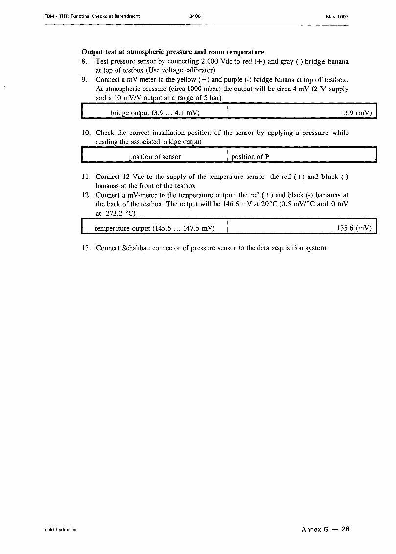
Output test at atmospheric pressure and room temperature8. Test pressure sensor by connecting 2.000 Vdc to red (+) and gray (-) bridge banana
at top of testbox (Use voltage calibrator)9. Conneet a mV-meter to the yellow (+) and purple (-) bridge banana at top of testbox.
At atmospheric pressure (circa 1000 mbar) the output will be circa 4 mV (2 V supplyand a 10 mV/V output at a range of 5 bar)
bridge output (3.9 ... 4.1 mV) 3.9 (mV)
10. Check the correct installation position of the sensor by applying a pressure whilereading the associated bridge output
position of sensor I position of P
11. Conneet 12 Vdc to the supply of the temperature sensor: the red (+) and black (-)bananas at the front of the testbox
12. Conneet a mV-meter to the temperature output: the red (+) and black (-) bananas atthe back of the testbox. The output will be 146.6 mV at 20°C (0.5 mV/oC and 0 mVat -273.2 0c)
temperature output (145.5 ... 147.5 mV) 135.6 (mV)
13. Conneet Schaltbau connector of pressure sensor to the data acquisition system
delft hydraulics Annex G - 26

TBM • THT; Functinal Checks at Barendrecht B406 May 1997
Pressure sensor P14
1. Disconneet Schaltbau pressure sensor from the data acquisition system and write downserial number of sensor
serial number 827792
2. Conneet pressure sensor to WL test-box
Bridge resistance of supply and output3. Conneet a O-meter to test box
bridge Resistance(bananas on testbox)
supply bridge 3.973 k(red - gray)
output bridge 2.291 k(yellow - purple)
Isolation resistance between bridge, temperatuur sensor and shield4. Connect a MO-meter and measure at bridge bananas of testboxI red - silver 1----------->-1-04-( >-1-03-M-O-)-
5. Conneet a MD-meter and measure at temperature sensor bananas of testbox (interconnectgreen and black)
green - silver
6. Conneet a MD-meter and test isolation resistance between bridge and temperatue sensor(interconnect green and black)
green - red > 104 (> 103 MO) IIsolation resistance between shield and TBM7. Connect a MD-meter to silver banana plug and a metal part of the TBM
I isolation shield & TBM I 0 (> 102 MD) I
delft hydraulics Annex G - 27

TBM • THT; Functinal Checks at Barendrecht B406 May 1997
Output test at atmospheric pressure and room temperature8. Test pressure sensor by connecting 2.000 Vdc to red (+) and gray (-) bridge banana
at top of testbox (Use voltage calibrator)9. Conneet a mV-meter to the yellow (+) and purple (-) bridge banana at top of testbox.
At atmospheric pressure (circa 1000 mbar) the output will be circa 4 mV (2 V supplyand a 10 mV/V output at a range of 5 bar)
bridge output (3.9 ... 4.1 mV) 3.9 (mV)
10. Check the correct installation position of the sensor by applying a pressure whilereading the associated bridge output
position of sensor I position of P
11. Conneet 12 Vdc to the supply of the temperature sensor: the red (+) and black (-)bananas at the front of the testbox
12. Conneet a mV-meter to the temperature output: the red (+) and black (-) bananas atthe back of the testbox. The output will be 146.6 mV at 20°C (0.5 mV/oC and 0 mVat -273.2 0c)
temperature output (145.5 ... 147.5 mV) 135.5 (mV)
13. Conneet Schaltbau connector of pressure sensor to the data acquisition system
delft hydraulics Annex G - 28

TBM - THT; Functinal Checks at Barendrecht B406 May 1997
Pressure sensor P15
1. Disconneet Schaltbau pressure sensor from the data acquisition system and write downserial number of sensor
serial number 827795
2. Conneet pressure sensor to WL test-box
Bridge resistance of supply and output3. Conneet a Q-meter to test box
bridge Resistance(bananas on testbox)
supply bridge 4.061 k(red - gray)
output bridge 2.285 k(yellow - purple)
Isolation resistance between bridge, temperatuur sensor and shield4. Connect a MQ-meter and measure at bridge bananas of testboxI red - silver 1----------->-1-0-4 -(->-1-0-3-M-Q-)-
5. Conneet aMû-meter andmeasure at temperature sensor bananas of testbox (interconnectgreen and black)
green - silver
6. Conneet a Mû-meter and test isolation resistance between bridge and temperatue sensor(interconnect green and black)
green - red > 104 (> 103 MQ) IIsolation resistance between shield and TBM7. Connect a MQ-meter to silver banana plug and a metal part of the TBM
I isolation shield & TBM I 0 (> 102 MQ) I
delft hydraulics Annex G - 29
TBM - THT; Functinal Checks at Barendrecht B406 May 1997
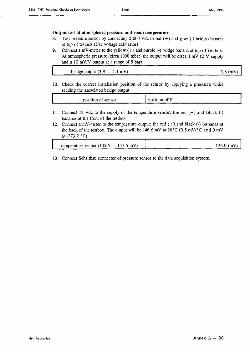
Output test at atmospheric pressure and room temperature8. Test pressure sensor by connecting 2.000 Vdc to red (+) and gray (-) bridge banana
at top of testbox (Use voltage calibrator)9. Conneet a mV-meter to the yellow (+) and purple (-) bridge banana at top of testbox.
At atmospheric pressure (circa 1000 mbar) the output will be circa 4 mV (2 V supplyand a 10 mV/V output at a range of 5 bar)
bridge output (3.9 ... 4.1 mV) 3.8 (mV)
10. Check the correct installation position of the sensor by applying a pressure whilereading the associated bridge output
position of sensor I position of P
11. Conneet 12 Vdc to the supply of the temperature sensor: the red (+) and black (-)bananas at the front of the testbox
12. Conneet a mV-meter to the temperature output: the red (+) and black (-) bananas atthe back of the testbox. The output will be 146.6 mV at 20°C (0.5 mV/oC and 0 mVat -273.2 0c)
temperature output (145.5 ... 147.5 mV) 136.0 (mV)
13. Conneet Schaltbau connector of pressure sensor to the data acquisition system
delft hydraulics Annex G - 30
TBM - THT; Functinal Checks at Barendrecht B406 May 1997
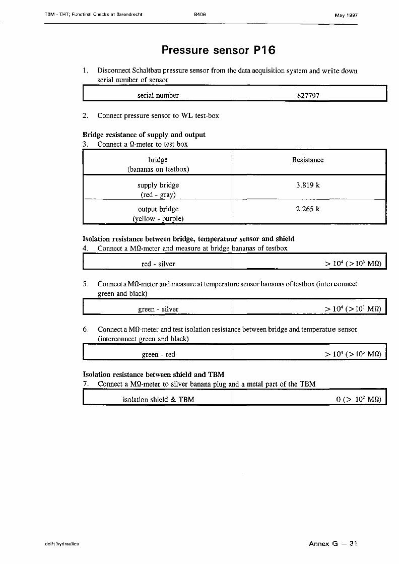
Pressure sensor P16
1. Disconneet Schaltbau pressure sensor from the data acquisition system and write downserial number of sensor
serial number 827797
2. Conneet pressure sensor to WL test-box
Bridge resistance of supply and output3. Conneet a O-meter to test box
bridge Resistance(bananas on testbox)
supply bridge 3.819 k(red - gray)
output bridge 2.265 k(yell ow - purple)
Isolation resistance between bridge, temperatuur sensor and shield4. Connect a MO-meter and measure at bridge bananas of testboxI red - silver 1----------->-10-4-(->-1O-3-M-O-)
5. Conneet a Mû-meter and measure at temperature sensor bananas of testbox (interconnectgreen and black)
green - silver
6. Conneet a Mû-meter and test isolation resistance between bridge and temperatue sensor(interconnect green and black)
> 104 (> 103 MO) Igreen - red
Isolation resistance between shield and TBM7. Connect a MO-meter to silver banana plug and a metal part of the TBM
I isolation shield & TBM [ 0(> 102 MO) I
delft hydraulics Annex G - 31
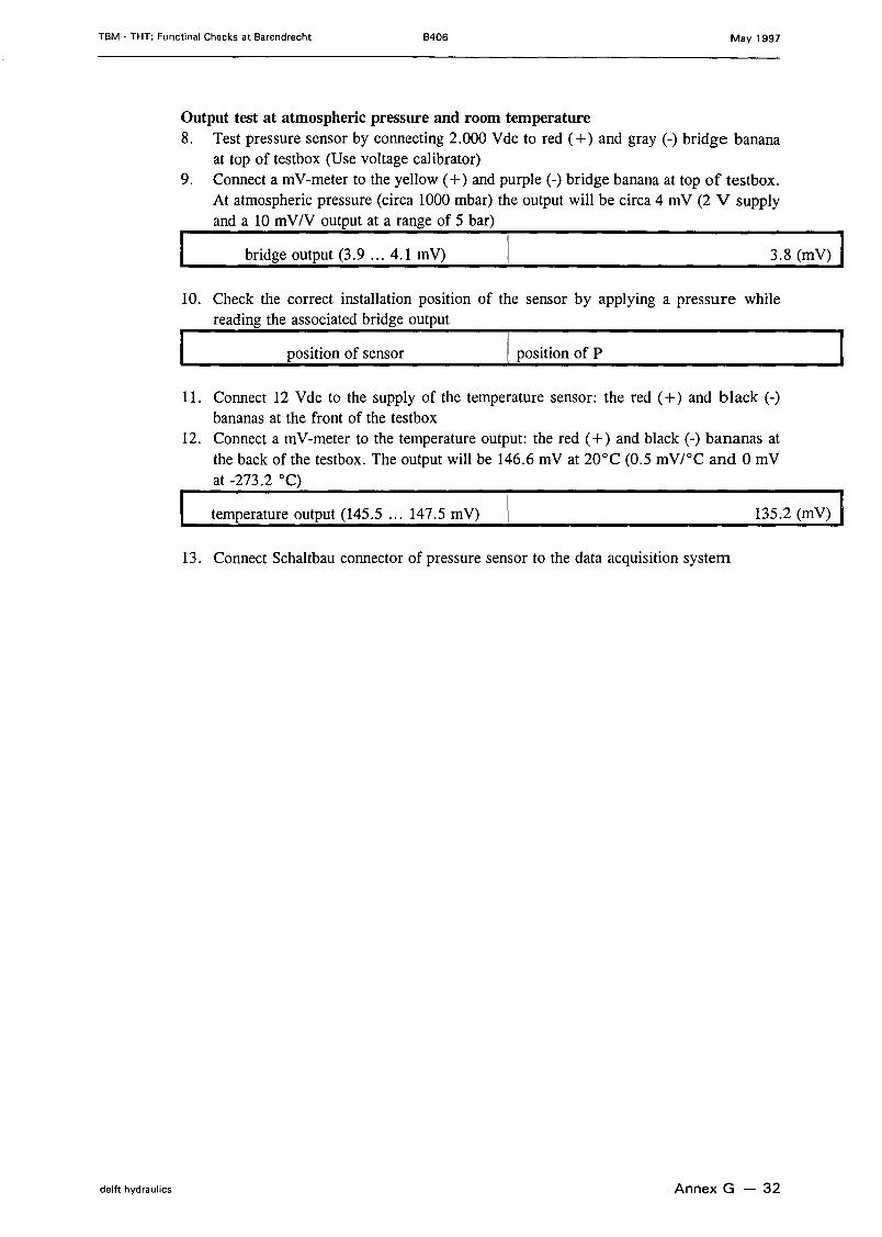
TBM • THT; Functinal Checks at Barendrecht B406 May 1997
Output test at atmospheric pressure and room temperature8. Test pressure sensor by connecting 2.000 Vdc to red (+) and gray (-) bridge banana
at top of testbox (Use voltage calibrator)9. Conneet a mV-meter to the yellow (+) and purple (-) bridge banana at top of testbox.
At atmospheric pressure (circa 1000 mbar) the output will be circa 4 mV (2 V supplyand a 10 mV/V output at a range of 5 bar)
bridge output (3.9 ... 4.1 mV) 3.8 (mV)
10. Check the correct installation position of the sensor by applying a pressure whilereading the associated bridge output
position of sensor I position of P
11. Conneet 12 Vdc to the supply of the temperature sensor: the red (+) and black (-)bananas at the front of the testbox
12. Conneet a mV-meter to the temperature output: the red (+) and black (-) bananas atthe back of the testbox. The output will be 146.6 mV at 20°C (0.5 mV/oC and 0 mVat -273.2 0c)
temperature output (145.5 ... 147.5 mV) 135.2 (mV)
13. Conneet Schaltbau connector of pressure sensor to the data acquisition system
delft hydraulics Annex G - 32
TBM - THT; Functinal Checks at Barendrecht B406 May 1997
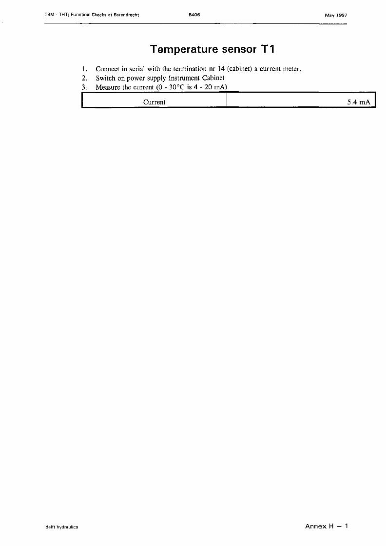
Temperature sensor T 1
1. Conneet in serial with the termination nr 14 (cabinet) a current meter.2. Switch on power supply Instrument Cabinet3. Measure the current (0 - 30°C is 4 - 20 mA)I Current 1---------------s-.-4-m-A-1
delft hydraulics Annex H - 1
TBM - THT; Functinal Checks at Barendrecht B406 May 1997
delft hydraulics
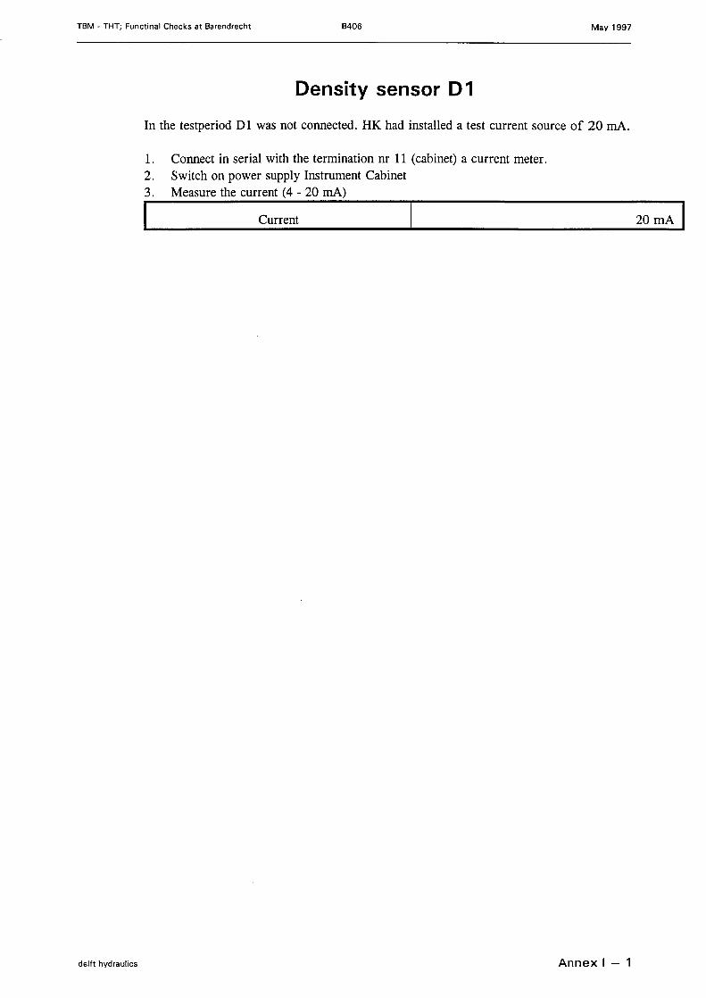
Density sensor D1
In the testperiod Dl was not connected. HK had installed a test current souree of 20 mA.
1. Conneet in serial with the termination nr 11 (cabinet) a current meter.2. Switch on power supply Instrument Cabinet3. Measure the current (4 - 20 mA)
I Current
Annex 1- 1
20 mA I
TBM - THT; Functinal Checks at Barendrecht B406 May 1997
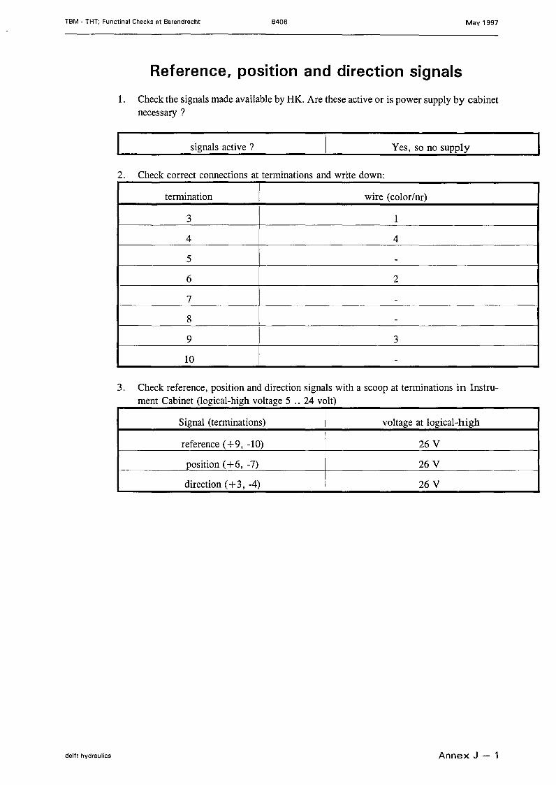
Reference, position and direction signals
1. Check the signals made available by HK. Are these active or is power supply by cabinetnecessary ?
signals active ? Yes, so no supply
2. Check correct connections at terminations and write down:
termination wire (color/nr)
3 1
4 4
5 -
6 2
7 -
8 -
9 3
10 -
3. Check reference, position and direction signals with a scoop at terminations in Instru-ment Cabinet (logical-high voltage 5 .. 24 volt)
Signal (terminations) voltage at logical-high
reference ( + 9, -10) 26 V
position (+6, -7) 26 V
direction ( + 3, -4) 26 V
delft hydraulics Annex J - 1
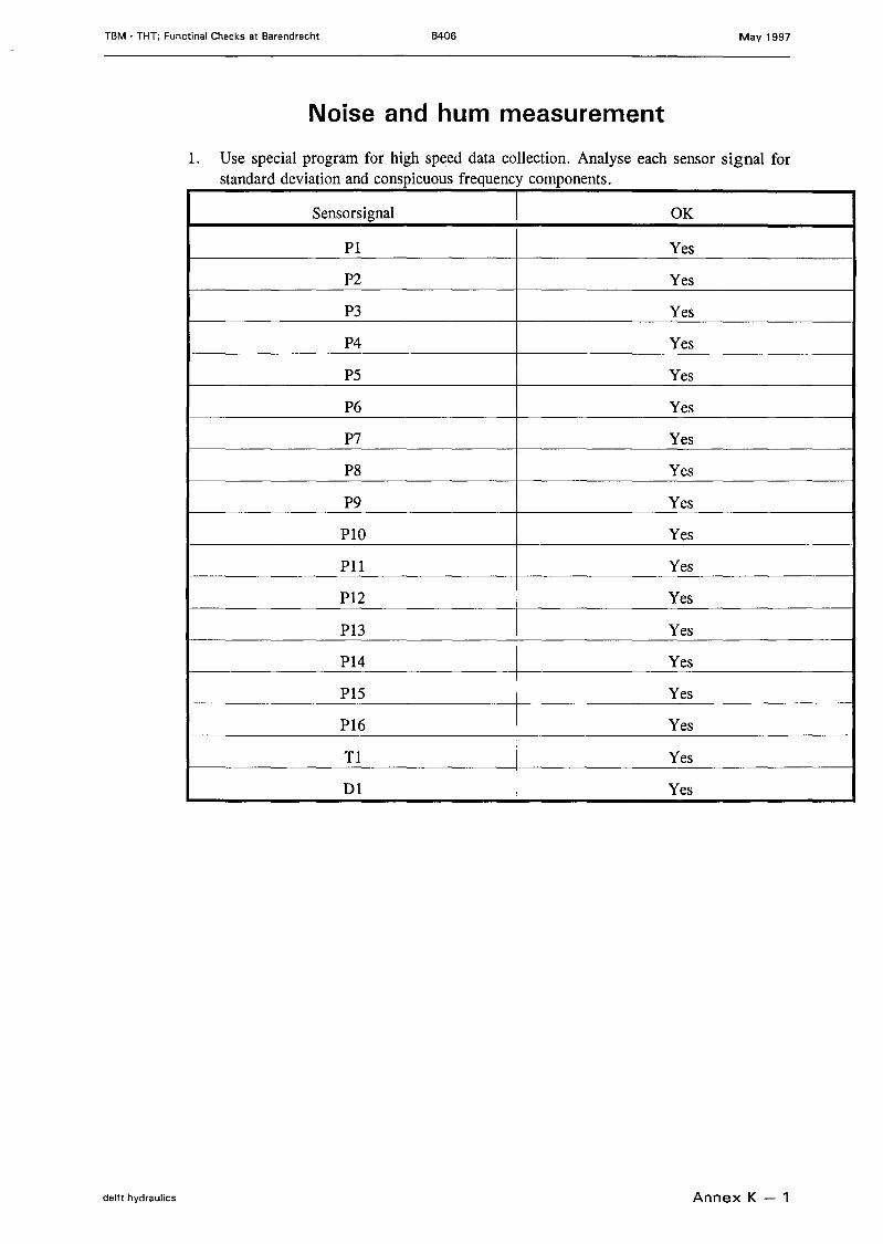
TBM • THT; Functinal Checks at Barendrecht B406 May 1997
Noise and hum measurement
1. Use special program for high speed data collection. Analyse each sensor signal forstandard deviation and conspicuous frequency components.
Sensorsignal OKPI Yes
P2 Yes
P3 Yes
P4 Yes
P5 Yes
P6 Yes
P7 Yes
P8 Yes
P9 Yes
PlO Yes
Pll Yes
P12 Yes
P13 Yes
P14 Yes
P15 Yes
P16 Yes
Tl Yes
Dl Yes
delft hydraulics Annex K - 1