WFC Whispering Fan Coilen schakelschema’s Legende Schoonmaak, onderhoud, wisselstukken Opsporen...
68
MANUALE DI INSTALLAZIONE, USO E MANUTENZIONE DEI VENTILCONVETTORI FAN COIL INSTALLATION, USE AND MAINTENANCE MANUAL MANUEL D’INSTALLATION, D’UTILISATION ET D’ENTRETIEN DES VENTILO-CONVECTEURS HANDBUCH FÜR INSTALLATION, GEBRAUCH UND WARTUNG DER GEBLÄSEKONVEKTOREN MANUAL DE INSTALACIÓN, USO Y MANTENIMIENTO DE LOS VENTILADORES CONVECTORES HANDLEITUNG VOOR DE INSTALLATIE, HET GEBRUIK EN HET ONDERHOUD VAN DE VENTILATORS-CONVECTORS 14012011 Z18159 Copyright © 2010 by WATERKOTTE GmbH, Herne Subject to change without notice. WFC Whispering Fan Coil - RETHERMO Comfort - WICHTIG! Bei Regleranschluss unbedingt die Position der Kabelbrücken im Schaltplan beachten!
Transcript of WFC Whispering Fan Coilen schakelschema’s Legende Schoonmaak, onderhoud, wisselstukken Opsporen...
MANUALE DI INSTALLAZIONE,USO E MANUTENZIONE DEI VENTILCONVETTORI
FAN COIL INSTALLATION,USE AND MAINTENANCE MANUAL
MANUEL D’INSTALLATION, D’UTILISATIONET D’ENTRETIEN DES VENTILO-CONVECTEURS
HANDBUCH FÜR INSTALLATION, GEBRAUCHUND WARTUNG DER GEBLÄSEKONVEKTOREN
MANUAL DE INSTALACIÓN, USO Y MANTENIMIENTODE LOS VENTILADORES CONVECTORES
HANDLEITUNG VOOR DE INSTALLATIE, HET GEBRUIKEN HET ONDERHOUD VAN DE VENTILATORS-CONVECTORS
14012011 Z18159
Cop
yrig
ht ©
201
0 by
WAT
ER
KO
TTE
Gm
bH, H
erne
Sub
ject
to c
hang
e w
ithou
t not
ice.
WFCWhispering Fan Coil
- RETHERMO Comfort -
WICHTIG!Bei Regleranschluss unbedingt die Position der Kabelbrücken im Schaltplan beachten!
2
ScopoIdentificazione macchinaTrasportoPesie dimensioni unità imballataNote generali alla consegnaAvvertenze generaliRegole fondamentali di sicurezzaPrescrizioni di sicurezzaLimiti di impiegoSmaltimentoCaratteristiche tecnicheInstallazione meccanicaCollegamento idraulicoCollegamenti elettrici
Comandi e schemi elettriciLegenda
Pulizia, manutenzione, ricambiRicerca guastiPerdite di carico lato acqua
ApplicationIdentifying the applianceTransportWeightsand dimension packed unitGeneral notes on deliveryGeneral warningsFundamental safety rulesSafety rulesOperating limitsWaste disposalTechnical characteristicsMechanical installationHydraulic connectionsElectrical connectionsElectricalcontrols and wiring diagramsLegendCleaning,maintenance and spare partsTroubleshootingPressure drop table
226
688
1012161618222430
3234
626466
226
688
1012161618222430
3234
626466
INDICE
SCOPO
INDEX
APPLICATION
PRIMA DI INSTALLAREL’APPARECCHIO
LEGGERE ATTENTAMENTEQUESTO MANUALE
CAREFULLYREAD THIS MANUALBEFORE INSTALLING
THE APPLIANCEI Ventilconvettori sono stati ideati,progettati e costruiti per riscalda-re/raffrescare qualsiasi ambientecivile, industriale, commerciale esportivo.
L’apparecchionon può essere impiegato:• per il trattamento dell’aria all’aperto• per l’installazione in ambienti umidi• per l’installazione in atmosfere esplosive• per l’installazione in atmosfere corrosive
Verificare che l’ambiente in cuiè installato l’apparecchio noncontenga sostanze che generinoun processo di corrosione dellealette in alluminio.
Gli apparecchi sono alimentati conacqua calda/fredda a seconda chesi voglia riscaldare o raffrescarel’ambiente.
L’apparecchio non è destinato adessere usato da persone (bambinicompresi) le cui capacità fisiche,sensoriali o mentali siano ridotte,oppure con mancanza di esperienzao di conoscenza, a meno che esseabbiano potuto beneficiare, attra-verso l’intermediazione di una perso-na responsabile della loro sicurezza,di una sorveglianza o di istruzioniriguardanti l’uso dell’apparecchio.
I bambini devono essere sorvegliatiper sincerarsi che non giochino conl’apparecchio.
The fan coils are conceived, designedand produced to heat/cool all civil,industrial, commercial or sportspremises.
The appliancemay not be used:• for outdoor air treatment
• for installation in moist rooms
• for installation in explosive atmospheres• for installation in corrosive atmospheres
Make sure that the environmentwhere the appliance is installeddoes not contain substancesthat cause the corrosion of thealuminium fins.
The units are supplied with hot orcold water, depending on whetherthe environment is to be heatedor cooled.
This appliace is not intended foruse by persons (including children)with reduced physical, sensory ormental capabilities, or lack ofexperience and knowledge, unlessthey have been given supervisionor instruction concerning use of theappliance by a person responsiblefor their safety.
Children should be supervised toensure that they do not play withthe appliance.
Copyright © 2010 by:WATERKOTTE GmbHGewerkenstraße 15, 44628 Herne, Germany
All rights reserved. Reproduction, duplication as well as translation of this publication, or excerpts therefrom, require prior written approval by WATERKOTTE GmbH.
Illustrations and diagrams serve as explanatory description and shall not be used as drawings for construction, offers or installation.
All specifications comply with the state of technology at time of printing; we reserve the right to make changes that serve technical progress.
This publication has been prepared with all reasonable care. WATERKOTTE GmbH does not assume any liability for remai-ning errors or omissions, or for possible damages.
3
ButIdentification des machinesTransportPoidset dimensions de l’unité emballéeRemarques générales pour la livraisonGénéralitésRègles fondamentales de sécuritéConsignes de securitéLimites d’emploiÉliminationCaractéristiques techniquesInstallation mécaniqueRaccordement hydrauliqueBranchements électriquesCommandeset schémas électriquesLégendeNettoyage,entretien et pièces de rechangeDépannagePertes de charge côté eau
ZweckbestimmungKennzeichnung des GerätsTransportGewichtund Dimensionen verpacktes GerätAllgemeine Hinweise zur LieferungAllgemeine HinweiseGrundsätzliche SicherheitsvorschriftenSicherheitsvorschriftenEinsatzgrenzenEntsorgungTechnische MerkmaleMechanische InstallationWasseranschlussElektroanschlüsse
Steuerungen und SchaltpläneLegende
Reinigung, Wartung, ErsatzteileFehlersucheWasserseitige Druckverluste
ObjetivoIdentificación máquinaTransportePesoy dimensión unidad embaladoNotas generales para la entregaAdvertencias generalesNormas fundamentales de seguridadPrescripciones de seguridadLímites de usoEliminaciónCaracterísticas técnicasInstalación mecánicaConexión hidráulicaConexiones eléctricasMandosy esquemas eléctricosLeyenda
Limpieza, mantenimiento, recambioBúsqueda de averíasPérdidas de carga lado agua
DoelIdentificatie apparaatTrasportoPesie dimensioni unità imballataAlgemene opmerkingen bij de leveringAlgemene voorschriftenBelangrijke veiligheidsvoorschriftenVeiligheids-voorschriftenGebruikslimietenAfdankingTechnische karakteristiekenMechanische installatieHydraulische aansluitingElektrische aansluitingenBedieningenen schakelschema’sLegendeSchoonmaak,onderhoud, wisselstukkenOpsporen defectenWaterlekken
226
688
1012161618222430
3234
626466
226
688
1012161618222430
3234
626466
226
688
1012161618222430
3234
626466
226
688
1012161618222430
3234
626466
TABLE DES MATIÈRES INHALT ÍNDICE INHOUD
BUT ZWECKBESTIMMUNG OBJETIVO DOEL
AVANT D’INSTALLERL’APPAREIL
LIRE ATTENTIVEMENTCE MANUEL
BEVOR DAS GERÄTINSTALLIERT WIRD, SOLLTEDIESES HANDBUCH SORG-FÄLTIG GELESEN WERDEN
ANTES DE INSTALAREL APARATO
LEA ATENTAMENTEESTE MANUAL
VÓÓR DE INSTALLATIEVAN HET APPARAAT
NEEMT U AANDACHTIGDEZE HANDLEIDING DOOR
Les ventilo-convecteurs ont été conçuset construits pour chauffer/rafraîchirn’importe quelle ambiance civile,industrielle, commerciale et sportive.
L’appareil ne peut pas être utilisé:• pour le traitement de l’air en plein air• être installé dans des locaux humides• être installé dans des atmosphères explosives• être installé dans des atmosphères corrosives
Vérifier que la pièce dans laquellel’appareil est installé ne contientpas de substances pouvant en-gendrer la corrosion des ailettesen aluminium.
Les appareils sont alimentés avecde l’eau chaude/froide selon qu’onveut chauffer ou rafraîchir l’ambiance.
L’appareil n’est pas prévu pour êtreutilisé par des personnes (y comprisles enfants) dont les capacités physi-ques, sensorielles ou mentales sontréduites, ou dénuées d’expérienceou de connaissance, sauf si ellesont pu bénéficier, par l’intermédiaired’une personne responsable deleur sécurité, d’une surveillance oud’instructions préalables concernantl’utilisation de l’appareil.
Il convient de surveiller les enfantspour s’assurer qu’ils ne jouent pasavec l’appareil.
Die Gebläsekonvektoren wurdenkonzipiert, entworfen und gebaut,um zivil, industriell, gewerblich undzu sportlichen Zwecken genutzteRäume zu heizen bzw. zu kühlen.
Die Geräte dürfen nichteingesetzt werden für:• die Aufbereitung der Luft im Freien• die Installation in feuchten Räumen• die Installation in explosiver Atmosphäre• die Installation in korrosiver Atmosphäre
Überprüfen, dass der Raum, indem das Gerät installiert wird,keine Stoffe enthält, die einenKorrosionsprozess der Aluminium-rippen bewirken.
Je nachdem, ob der Raum geheiztoder gekühlt werden soll, werdendie Geräte mit warmem oder kaltemWasser versorgt.
Dieses Gerät ist nicht dafür bestimmt,durch Personen (einschließlich Kinder),mit eingeschränkten physischen,sensorischen oder geistigen Fähig-keiten oder mangels Erfahrungund/oder mangels Wissen benutztzu werden, es sei denn sie werdendurch eine für ihre Sicherheitzuständige Person beaufsichtigtoder erhielten von ihr Anweisungen,wie das Gerät zu benutzen ist.
Kinder sollten beaufsichtigt werden,um sicherzustellen, dass sie nichtmit dem Gerät spielen.
Los fan coils han sido diseñados,proyectados y construidos paracalentar/refrescar toda clase deambiente domestico, industrial,comercial y deportivo.
Los aparatosno se pueden usar para:• el tratamiento del aire al aire libre• su instalación en locales húmedos• su instalación en atmósferas explosivas• su instalación en atmósferas corrosivas
Compruebe que la estancia en laque se está instalado el aparatono contenga sustancias quegeneren un proceso de corro-sión de las aletas de aluminio.
Los aparatos están alimentados conagua caliente/fría según se deseecalentar o refrescar el ambiente.
Este aparato no debe ser utilizadopor personas (incluidos niños) cuyascapacidades físicas, sensoriales omentales estén disminuidas o quecarezcan de experiencia y cono-cimientos, al no ser que ellas hayanpodido beneficiar, a través de laintermediación de una personaresponsable de su seguridad, deuna vigilancia o de instruccionesrelativas al uso del aparato.
Los niños han de vigilarse paraasegurarse de que no jueguen conel aparato.
De ventilatorconvectors werdenontworpen om privé-ruimtes, industriële,commerciële en sportieve ruimteste verwarmen/af te koelen.
De ventilators-convectorsmag niet worden gebruikt:• voor de zuivering van de buitenlucht• voor installatie in vochtige ruimten• voorinstallatie in ruimten waar ontploffingsgevaar heerst• voor installatie in corrosieve omgevingen
Controleer of de omgeving waarinhet apparaat geïnstalleerd is geenstoffen bevat die een roestprocesvan de aluminium ribben op gangbrengen.
De apparaten worden gevoed metwarm/koud water, naargelang mende ruimte wenst af te koelen of teverwarmen.
Het apparaat is niet bestemd voorgebruik door personen (kindereninbegrepen) met beperkte fysieke,sensoriële of mentale capaciteitenof met onvoldoende ervaring ofkennis, tenzij ze gebruik hebbenkunnen maken, dankzij het toedoenvan iemand die verantwoordelijk isvoor hun veiligheid, van toezichtof aanwijzingen over het gebruikvan het apparaat.
Kinderen dienen onder toezicht testaan om zich ervan te verzekerendat zij niet met het apparaat spelen.
4
A bordo di ogni singola macchinaè applicata l’etichetta di identifica-zione riportante i dati del costrut-tore ed il tipo di macchina.
L’etichetta è posizionata sul latodei comandi elettrici, all’internodell’apparecchio.
Each unit is supplied with anidentification plate giving detailsof the manufacturer and the typeof appliance.
The label is located inside theappliance on the electric controlsside.
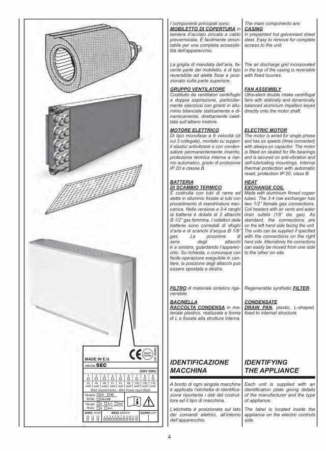
I componenti principali sono:MOBILETTO DI COPERTURA inlamiera d’acciaio zincata a caldopreverniciata. È facilmente smon-tabile per una completa accessibi-lità dell’apparecchio.
La griglia di mandata dell’aria, fa-cente parte del mobiletto, è di tiporeversibile ad alette fisse e posi-zionato sulla parte superiore.
GRUPPO VENTILATORECostituito da ventilatori centrifughia doppia aspirazione, particolar-mente silenziosi con giranti in allu-minio bilanciate staticamente e di-namicamente, direttamente calet-tate sull’albero motore.
MOTORE ELETTRICODi tipo monofase a 6 velocità (dicui 3 collegate), montato su suppor-ti elastici antivibranti e con conden-satore permanentemente inserito,protezione termica interna a riar-mo automatico, grado di protezioneIP 20 e classe B.
BATTERIADI SCAMBIO TERMICOÈ costruita con tubi di rame edalette in alluminio fissate ai tubi conprocedimento di mandrinatura mec-canica. Nella versione a 3-4 ranghila batteria è dotata di 2 attacchiØ 1/2” gas femmina. I collettori dellebatterie sono corredati di sfoghid’aria e di scarichi d’acqua Ø 1/8”gas. La posizione di serie degli attacchiè a sinistra, guardando l’apparec-chio. Su richiesta, o comunque confacile operazione eseguibile in can-tiere, la posizione degli attacchi puòessere spostata a destra.
FILTRO di materiale sintetico rige-nerabile.
BACINELLARACCOLTA CONDENSA in ma-teriale plastico, realizzata a formadi L e fissata alla struttura interna.
The main components are:CASINGIn prepainted hot galvanised sheetsteel. Easy to remove for completeaccess to the unit.
The air discharge grid incorporatedin the top of the casing is reversiblewith fixed louvres.
FAN ASSEMBLYUltra-silent double intake centrifugalfans with statically and dynamicallybalanced aluminium impellers keyeddirectly onto the motor shaft.
ELECTRIC MOTORThe motor is wired for single phaseand has six speeds (three connected)with always-on capacitor. The motoris fitted on sealed for life bearingsand is secured on anti-vibration andself-lubricating mountings. Internalthermal protection with automaticreset, protection IP 20, class B.
HEATEXCHANGE COILMade with aluminium finned coppertubes. The 3-4 row exchanger hastwo 1/2” female gas connections.Coil headers with air vents and waterdrain outlets (1/8” dia. gas). As standard, the connections areon the left hand side facing the unit.The units can be supplied if specifiedwith the connections on the righthand side. Alternatively the connectionscan easily be moved from one sideto the other on site.
Regenerable synthetic FILTER.
CONDENSATEDRAIN PAN, plastic, L-shaped,fixed to internal structure.
IDENTIFICAZIONEMACCHINA
IDENTIFYINGTHE APPLIANCE
5
Une étiquette d’identification estappliquée sur chaque machine; elleindique les données du constructeuret le type de machine.
Cette étiquette se trouve sur lecôté des commandes électriques,à l’intérieur de l’appareil.
Jedes Gerät ist mit einem Typen-schild gekennzeichnet, auf demdie Daten des Herstellers und derTyp des Geräts angegeben sind.
Das Schild befindet sich auf derSeite der elektrischen Steuerungen,im Geräteinnern.
Cada máquina lleva una placa deidentificación en la que figuran losdatos del fabricante y el tipo demáquina de que se trata.
La etiqueta está emplazada en ellado de los dispositivos de acciona-miento eléctricos, dentro del aparato.
Aan boord van elk apparaat wordteen identificatielabel aangebrachtmet de gegevens van de fabrikanten het type machine.
De label wordt aangebracht op dezijkant van de elektrische bedieningen,aan de binnenkant van het apparaat.
Les composants principaux sont:CARROSSERIE en tôle d’acierzinguée à chaud prépeinte. Elle estfacilement démontable, ce qui offreune accessibilité totale à l’appareil.
La grille de refoulement de l’air, quifait partie de la carrosserie, est dutype réversible à ailettes fixes et setrouve sur la partie supérieure.
GROUPE VENTILATEURConstitué par des ventilateurs centri-fuges à double aspiration, particuliè-rement silencieux, avec des turbinesen aluminium équilibrées statique-ment et dynamiquement, directe-ment fixées sur l’arbre moteur.
MOTEUR ÉLECTRIQUEDe type monophasé à 6 vitesses(dont 3 raccordées), monté sursupports antivibratiles et avec con-densateur permanent, protectionthermique à réarmement auto-matique, protection IP 20 et classe B.
BATTERIED’ÉCHANGE THERMIQUEConstruite avec des tubes en cuivreet des ailettes en aluminium fixéesaux tubes par dudgeonnage méca-nique. Dans la version à 3-4 rangs,la batterie est équipée de deuxraccords Ø 1/2” gaz femelle. Lescollecteurs des batteries sont dotésde purgeurs d’air et de sorties d’eauØ 1/8” gaz. Laposition standard des raccords est àgauche, quand on regarde l’appareil.Sur demande ou par une simpleopération pouvant être pratiquée enchantier, la position des raccordspeut-être déplacée à droite.
FILTRE en matière synthétiquerégénérable.
BAC DE RECUPERATIONDES CONDENSATS, en matièreplastique, réalisé en forme de “L“et fixé à la structure interne.
Das Gerät setzt sich hauptsächlichaus folgenden Bauteilen zusammen:GEHÄUSE aus feuerverzinktem undvorlackiertem Stahlblech. Das Gehäusekann vollständig abgenommen werden,um ungehindert Zugang zum Gerätzu haben.
Das Ausblasgitter mit festen Luft-leitlamellen, das Teil des Gehäusesist, ist umsteckbar und befindet sichauf der Geräteoberseite.
GEBLÄSEBestehend aus besonders geräu-scharmen, doppelseitig saugendenRadialventilatoren mit statisch unddynamisch ausgewuchteten Lauf-rädern aus Aluminium, direkt aufder Antriebswelle sitzend.
ELEKTROMOTOREinphasenmotor mit sechs Drehzahl-stufen (drei davon werkseitingangeschlossen), auf elastischenSchwingungsdämpfern montiertund mit permanent eingeschaltetemKondensator, Wärmeschutz mit auto-matischer Rückstellung, SchutzartIP 20, Klasse B.
WÄRMETAUSCHER-BATTERIEBestehend aus Kupferrohren mitmaschinell aufgezogenen Aluminium-lamellen. Die 4-reihigen Wärme-tauscher sind mit zwei Anschlüssenmit Innengewinde ø 1/2” versehen.Die Sammler der Wärmetauschersind mit Entlüftungsöffnungen undWasserablass-Anschlüssen ø 1/8” versehen. Serienmäßigbefinden sich die Anschlüsse vonvorne gesehen links. Auf Anfrageoder mit einem einfachen Eingriffder direkt vor Ort durchgeführtwerden kann, können die Anschlüsseauf die rechte Seite verlegt werden.
FILTER aus regenerierbaremSynthetikmaterial.
An der Innenstruktur befestigte,L-förmige KONDENSATWANNEaus Kunststoff.
Los componentes principales son:MUEBLE DE COBERTURA enplancha de acero zincada en ca-liente prebarnizada. Es fácilmentedesmontable para tener accesocompleto al aparato.
La rejilla de impulsión del aire, queforma parte del mueble, es del tiporeversible con aletas fijas y estáemplazada en la parte superior.
GRUPO VENTILADORFormado por ventiladores centrífu-gos de doble aspiración, particular-mente silenciosos. Los rodetes sonen aluminio balanceados, estáticay dinámicamente, y ensambladosdirectamente en el eje motor.
MOTOR ELÉCTRICOEl motor eléctrico es monofásico con6 velocidades (de las cuales 3 rela-cinadas), montado sobre soporteselásticos amortiguadores de vibra-ciones y con condensador perma-nentemente activado, proteccióntérmica de rearme automático, gradode protección IP 20 y clase B.
BATERÍADE INTERCAMBIO TÉRMICOSe compone de tubos de cobre yaletas en aluminio fijadas a los tu-bos con un procedimiento de man-drilado mecánico. En la variante con3-4 filas la batería tiene 2 conexionesØ 1/2” gas hembra. Los colectoresde las baterías tienen alivios de airey descargas de agua Ø 1/8” gas.La posición predeterminadade las conexiones es en la parteizquierda mirando al aparato desdeenfrente. De todas maneras apetición, con una operación fácilrealizable en la obra, es posibledesplazar a la derecha la posiciónde las conexiones.
FILTRO en material sintéticoregenerable.
BARDEJADE CONDENSADOS, en materialplástico, con forma de “L” y asegu-rada a la estructura interna.
De voornaamste onderdelen zijn:BEHUIZINGVan het gemengde type in warm-verzinkte voorbeschilderde staalplaten.Is gemakkelijk demonteerbaar vooreen complete toegankelijkheid vanhet apparaat.
De luchtrooster maakt deel uit vande behuizing, is omkeerbaar, voorzienvan vaste ribben en bevindt zich aande bovenzijde.
VENTILATORGROEPSamengesteld door centrifuge-ventilators met dubbele aanzuiging,bijzonder geluidloos met statisch endynamisch uitgebalanceerde schoepenin aluminium, rechtstreeks bevestigdop de aandrijfas van de motor.
ELEKTRISCHE MOTOREenfasige, met 6 snelheden (waarvan3 aangesloten), gemonteerd op trilvrijeelastische dragers met ingebouwdepermanente condensator, thermischebeveiliging met automatische reset,beschermingsdraad IP20 en classi-ficatie B.
BATTERIJWARMTEWISSELINGSamengesteld uit koperen buizenen aluminium ribben die met eenmechanisch procédé aan de buizenbevestigd zijn. Voor de versie met3-4 rangen is de batterij voorzienvan 2 vrouwelijke gasaansluitingenvan Ø 1/2” . De collectors van debatterijen zijn uitgerust met lucht-uitlaten en waterafvoerpijpen vanØ 1/8” gas. De seriële positievan de aansluitingen is links, alsmen vóór het apparaat staat. Opverzoek, kunnen de aansluitingennaar rechts worden verplaatst. Dezehandeling is gemakkelijk uit te voerenter plaatse.
Herbruikbare FILTER in synthetischmateriaal.
OPVANGBAKCONDENSATIEWATER, uitgevoerdin L-vorm en vastgemaakt aan debinnenstructuur.
IDENTIFICATIONDES MACHINES
KENNZEICHNUNGDES GERÄTS
IDENTIFICACIÓNDE LA MÁQUINA
IDENTIFICATIEAPPARAAT
6
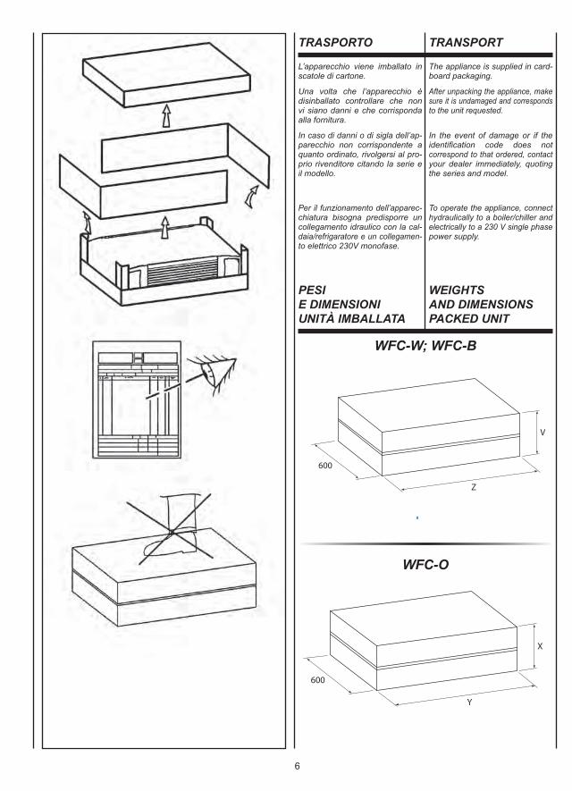
WFC-W; WFC-B
WFC-O
TRASPORTO TRANSPORT
L’apparecchio viene imballato inscatole di cartone.
Una volta che l’apparecchio èdisinballato controllare che nonvi siano danni e che corrispondaalla fornitura.
In caso di danni o di sigla dell’ap-parecchio non corrispondente aquanto ordinato, rivolgersi al pro-prio rivenditore citando la serie eil modello.
Per il funzionamento dell’apparec-chiatura bisogna predisporre uncollegamento idraulico con la cal-daia/refrigaratore e un collegamen-to elettrico 230V monofase.
The appliance is supplied in card-board packaging.
After unpacking the appliance, makesure it is undamaged and correspondsto the unit requested.
In the event of damage or if theidentifi cation code does notcorrespond to that ordered, contactyour dealer immediately, quotingthe series and model.
To operate the appliance, connecthydraulically to a boiler/chiller andelectrically to a 230 V single phasepower supply.
PESIE DIMENSIONIUNITÀ IMBALLATA
WEIGHTSAND DIMENSIONSPACKED UNIT
Copyright 2010 by WATERKOTTE GmbH – Ände
rungen vorbehalten – Foto: Stratego/Photocase.c
om
WFCWhispering Fan Coil- Komfort-Wärme im Winter - Komfort-Klimakühlung im SommerLeistungsbereich bis 3,2 kW bei Luft 22 °C - Wasser 35 °CLeistungsbereich bis 4,8 kW bei Luft 22 °C - Wasser 40 °CKühlleistungsbereich bis 7,3 kW bei Luft 26 °C - Wasser 7 °CLieferbar in 9 Baugrößen für sämtliche gängigen Anordnungen.
+ ultra leise, hocheffi zient+ 3-stufi g regelbar+ energiesparende Ventilatorantriebe+ Umluftfi lter für bessere Hygiene+ elektrostatischer Allergikerfi lter (Option)
WFC Fan Coils - konzipiert für den Wohn- und Geschäftsbereich, Versorgung hydraulisch.Effizienzoptimiert für Niedertemperaturbetrieb mit Wärmepumpen-Systemlösungen. Temperaturniveau nahe der Fußboden-Flächenheizung - optimal für Klima-Kühlung im Sommer.
Die Innovation für Wärmepumpen-Systemlösungen
7
WFC-W; WFC-B
Peso - Weight - Poids - Gewicht - Peso - Gewicht (kg)1 2 3 4 5 6 7 8 9Mod.
Ran
ghi
Row
sR
angs
Rei
hen
Fila
sR
ange
n
XY
260720
260820
260820
260820
2601035
2601035
2601250
2901250
2901250
Mod.Dimensioni - Dimensions - Dimensions - Dimensionen - Dimensión - Afmetingen (mm)1 2 3 4 5 6 7 8 9
VZ
260720
260820
2601035
2601035
2601250
2601250
2601465
2901465
2901465
Mod.Dimensioni - Dimensions - Dimensions - Dimensionen - Dimensión - Afmetingen (mm)1 2 3 4 5 6 7 8 9
WFC-O
Peso - Weight - Poids - Gewicht - Peso - Gewicht (kg)1 2 3 4 5 6 7 8 9Mod.
Ran
ghi
Row
sR
angs
Rei
hen
Fila
sR
ange
n
TRANSPORT TRANSPORT TRANSPORTE TRANSPORT
L’appareil est emballé dans desboîtes en carton.
Après avoir déballé l’appareil, contrôlerqu’il n’a subi aucun dommage etqu’il correspond bien à la fourniture.
En cas de dommages ou si le siglede l’appareil ne correspond pas àce qui a été commandé, s’adresserau revendeur en indiquant la sérieet le modèle.
Pour le fonctionnement de l’appareil,prévoir un raccordement hydrauliqueà la chaudière/centrale d’eau glacéeet un raccordement électrique 230 Vmonophasé.
Das Gerät wird in Kartons verpackt.
Kontrollieren Sie beim Auspackensofort, ob das Gerät unversehrt ist,und ob es mit den Angaben in denVersandpapieren übereinstimmt.
Falls Schäden festgestellt werdensollten, oder wenn die Artikelnummernicht mit dem bestellten Gerät über-einstimmt, wenden Sie sich bitte anIhren Händler. Geben Sie bei Rück-fragen immer Serie und Geräte-modell an.
Für den Betrieb des Geräts ist einWasseranschluss zum Heizer/Kühlersowie ein Stromanschluss (230 Veinphasig) erforderlich.
El aparato viene embalado en cajade cartón.
Cuando se desembala el aparato,es preciso comprobar que no tengadesperfectos y que se correspondacon el suministro previsto.
En caso de daños o de sigla delaparato no correspondiente con ladel pedido, dirigirse al revendedorindicando la serie y el modelo.
Para la operación del aparato espreciso predisponer un enlacehidráulico con la caldera/refrigera-dor y un enlace eléctrico mono-fásico de 230V.
Het apparaat wordt in een kartonnendoos verpakt.
Eens het apparaat van zijn verpakkingontdaan, controleert u de integriteiten conformiteit van het apparaat.
In geval van beschadigingen, ofindien het apparaat niet overeenkomtmet de bestelling, wendt u zich totuw verkoper, met vermelding vanhet serienummer en het model.
Om het apparaat in werking testellen, moet u een aansluitingvoorzien met de warmwaterketel/koelkast, een eenfasige elektrischeaansluiting van 230V.
POIDS ETDIMENSIONS DEL’UNITE EMBALLEE
GEWICHTUND DIMENSIONENVERPACKTES GERÄT
PESOY DIMENSIÓNUNIDAD EMBALADO
GEWICHTEN AFMETINGENVERPAKTE EENHEID
4 14 18 24 25 27 28 34 45 46
4 11 17 22 23 25 26 31 41 42
8
Dopo aver aperto e tolto l’imballo,accertarsi che il contenuto sia quellorichiesto e che sia integro. In casocontrario, rivolgersi al rivenditoreove si è acquistato l’apparecchio.
I ventilconvettori sono stati studiatiper riscaldare e/o condizionare gliambienti e devono quindi essereutilizzati solamente per questo. Siesclude qualsiasi responsabilità peri danni eventuali causati da un usoimproprio.
Questo libretto deve accompagna-re sempre l’apparecchio in quantoparte integrante dello stesso.
Ogni riparazione o manutenzionedell’apparecchio deve essere ese-guita da personale specializzato equalificato.
Non si risponde in caso di danniprovocati da modifiche o manomis-sioni dell’apparecchio.
After removing the packaging, makesure the contents are as requestedand not damaged. If this is not thecase, contact the dealer where youbought the appliance.
The fan coils have been designedfor room heating and/or air conditioningand must be used exclusively for thatpurpose. We declines all responsibilityfor damage caused by their improperuse.
This booklet is an integral part ofthe appliance and must alwaysaccompany the unit.
All repairs or maintenance must beperformed by qualified specialists.
We declines all responsibility fordamage caused by modificationsor tampering with the unit.
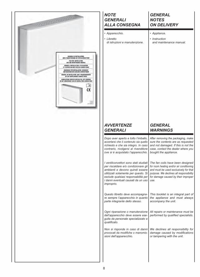
• Apparecchio.
• Libretto di istruzioni e manutenzione.
• Appliance.
• Instruction and maintenance manual.
NOTEGENERALIALLA CONSEGNA
GENERALNOTESON DELIVERY
AVVERTENZEGENERALI
GENERALWARNINGS
9
Après avoir ouvert et retiré l’em-ballage, s’assurer que le contenuest conforme et qu’il est en parfaitétat. En cas contraire s’adresser aurevendeur où l’appareil a été acheté.
Les ventilo-convecteurs ont été conçuspour chauffer et/ou climatiser lespièces et ne doivent être destinés qu’àcet usage. Il exclut toute responsableen cas de dommages causés parun emploi anormal.
Cette notice doit toujours accompa-gner l’appareil car elle en fait partieintégrante.
Toutes les réparations ou entretiensde l’appareil doivent être effectuéspar le SAV ou par un technicienspécialisé.
On décline toute responsabilité encas de dommages provoqués pardes modifications ou altérations del’appareil.
Nach dem Auspacken kontrollieren,ob der Inhalt der Bestellung entsprichtund unversehrt ist. Im gegenteiligenFall wenden Sie sich an Ihren Händler.
Die Klimakonvektoren wurden zurHeizung und Klimatisierung vonRäumen entwickelt und dürfen folglichausschließlich zu diesem Zweckverwendet werden. Die Firma haftetnicht für eventuelle Schäden, diedurch den unzweckmäßigen Gebrauchverursacht werden.
Diese Betriebsanleitung ist wesent-licher Bestandteil des Gerätes undmuss folglich immer zusammen mitdiesem verwahrt werden.
Alle Reparaturen oder Wartung-sarbeiten müssen durch Personalder Firma oder andere fachlichqualifizierte Techniker erfolgen.
Die Firma haftet nicht für solcheSchäden, die durch die Veränderungoder die Manipulierung des Gerätsentstehen.
Después de haber retirado el em-balaje, comprobar que el contenidosea el solicitado y que esté intacto.En caso contrario, dirigirse al esta-blecimiento donde se ha compradoel aparato.
Los fan coils se han estudiado paracalentar y/o acondicionar las habita-ciones y no deben usarse para otrofin. Declinamos cualquier respon-sabilidad por los posibles dañosdebidos a un uso inadecuado.
Este manual debe acompañarsiempre al aparato ya que formaparte del mismo.
Todas las reparaciones o mante-nimiento del aparato deberán serrealizadas por personal especia-lizado y cualificado.
No se hace responsable en casode daños provocados por modi-ficaciones o manipulaciones delaparato.
Na de verpakking te hebbenverwijderd, controleren of de inhoudervan correct en onbeschadigd is.Is dit niet het geval, contact opnemenmet de verkoper of waar het apparaatwerd aangekocht.
De ventilatorconvectors werdenontworpen voor de verwarmingen/of koeling van ruimten, en dienenuitsluitend hiervoor te worden gebruikt.Wij kunnen niet aansprakelijk wordengesteld voor eventuele schade diehet gevolg is van een verkeerdgebruik van het apparaat.
Deze handleiding dient het apparaatsteeds te vergezellen, omdat heter wezenlijk deel van uitmaakt.
Reparaties of onderhoud van hetapparaat dienen uitgevoerd teworden door gespecialiseerd enopgeleid personeel.
Wij kunnen niet aansprakelijk wordengesteld voor schade die voortvloeituit aangebrachte wijzigingen.
• Appareil.
• Instructions d’installation et d’entretien.
• Gerät.
• Gebrauchs- und Wartungsanleitung.
• Aparato.
• Manual de instrucciones y mantenimiento.
• Apparaat.
• Handleiding voor het gebruik en het onderhoud.
REMARQUESGENERALES POURLA LIVRAISON
ALLGEMEINEHINWEISEZUR LIEFERUNG
NOTASGENERALESPARA LA ENTREGA
ALGEMEINEOPMERKINGENBIJ DE LEVERING
GENERALITESALLGEMEINEHINWEISE
ADVERTENCIASGENERALES
ALGEMENEVOORSCHRIFTEN
10
È vietato l’utilizzo del ventilconvet-tore da parte di bambini o di per-sone inabili e senza assistenza.
È pericoloso toccare l’apparecchioavendo parti del corpo bagnate edi piedi nudi.
Non effettuare nessun tipo di inter-vento o manutenzione senza averprima scollegato l’apparecchio dal-l’alimentazione elettrica.
Non manomettere o modificare idispositivi di regolazione o sicu-rezza senza essere autorizzati esenza indicazioni.
Non torcere, staccare o tirare icavi elettrici che fuoriescono dal-l’apparecchio anche se lo stessonon è collegato all’alimentazioneelettrica.
Non gettare o spruzzare acquasull’apparecchio.
Non introdurre assolutamente nien-te attraverso le griglie di aspirazio-ne e mandata aria.
Non rimuovere nessun elementodi protezione senza aver primascollegato l’apparecchio dall’ali-mentazione elettrica.
Non gettare o lasciare il materialeresiduo dell’imballo alla portata deibambini perché potenziale causadi pericolo.
Non installare in atmosfera esplo-siva o corrosiva, in luoghi umidi,all’aperto o in ambienti con moltapolvere.
Fan coils must never be used bychildren or unfit persons withoutsupervision.
It is dangerous to touch the unitwith damp parts of the body andbare feet.
Always unplug the unit from themains power supply before carryingout any type of operation ormaintenance.
Never tamper with or modifyregulation and safety deviceswithout prior authorisation andinstructions.
Never twist, detach or pull powercables, even when the unit isunplugged from the mains powersupply.
Never throw or spray water on theunit.
Never introduce foreign objectsthrough the air intake and dischargegrids.
Never remove protective elementswithout first unplugging the unitfrom the mains power supply.
Do not throw packaging materialaway or leave it within reach ofchildren as it may represent ahazard.
Do not install in explosive, corrosiveor damp environments, outdoorsor in very dusty rooms.
REGOLEFONDAMENTALIDI SICUREZZA
FUNDAMENTALSAFETY RULES
11
Le ventilo-convecteur ne doit pasêtre utilisé par des enfants ou despersonnes inaptes non assitées.
Il est dangereux de toucherl’appareil si on a des parties ducorps mouillées ou les pieds nus.
N’effectuer aucun intervention surl’appareil sans l’avoir débranchéau préalable.
Ne pas altérer ou modifier lesdispositifs de réglage ou de sécuritésans autorisation et sans instructions.
Ne pas tordre, détacher ou tirerles câbles électriques qui sortentde l’appareil même si celui-ci estdébranché.
Ne pas jeter ou vaporiser de l’eausur l’appareil.
Ne rien introduire à travers lesgrilles d’aspiration et de soufflagede l’air.
N’enlever aucune protection sansavoir au préalable débranchél’appareil.
Ne pas jeter ou laisser l’emballageà la portée des enfants car il peutreprésenter un danger.
Ne pas installer l’appareil dans uneatmosphère explosive ou corrosive,dans des lieux humides, dehors oudans des pièces où il y a beaucoupde poussière.
Der Klimakonvektor darf weder vonKindern, noch von Personen, dienicht mit seiner Bedienung vertrautsind, benutzt werden.
Das Gerät darf weder barfuß nochmit nassen oder feuchten Körper-teilen berührt werden.
Das Gerät darf erst gewartet werden,nachdem die Spannungsversorgungunterbrochen wurde.
Die Regel- und Sicherheitsein-richtungen dürfen ohne vorherigeGenehmigung Firma und derenAnleitung nicht verändert odermanipuliert werden.
Die aus dem Gerät kommendenStromkabel dürfen nicht gezogen,getrennt, verdreht werden, auchdann nicht, wenn das Gerät nicht andas Stromnetz angeschlossen ist.
Das Gerät darf nicht mit Wasserin Berührung kommen.
Keine Gegenstände durch die Luft-gitter stecken.
Die Schutzelemente dürfen erstdann entfernt werden, nachdem dieSpannungsversorgung unterbrochenwurde.
Das Verpackungsmaterial mussvorschriftsmäßig entsorgt werden,und darf nicht in die Reichweitevon Kindern gelangen, da es einepotentielle Gefahrenquelle darstellt.
Das Gerät darf nicht in explosiveroder korrosiver Atmosphäre, imFreien oder in Räumen mit starkerStaubbelastung installiert werden.
Se prohibe el uso del fan coil a losniños y a las personas incapaci-tadas no asistidas.
Es peligroso tocar el aparato te-niendo partes del cuerpo mojadasy con los pies descalzos.
No efectuar ningún tipo de inter-vención o mantenimiento sin antesde haber desconectado el aparatode la corriente eléctrica.
No manipular o modificar los dispo-sitivos de regulación o de seguridadsin la autorización y indicaciones.
No torcer, desconectar o tirar delos cables eléctricos que salen delaparato, aunque éste estuviera de-sconectado de la corriente eléctrica.
No tirar o vaporizar agua sobre elaparato.
No introducir absolutamente nadaa través de las rejillas de aspira-ción y descarga de aire.
No retirar ningún elemento de pro-tección sin antes haber desco-nectado el aparato de la corrienteeléctrica.
No tirar o dejar al alcance de losniños el material de embalaje yaque es una fuente potencial depeligro.
No instalar en una atmósferaexplosiva o corrosiva, en lugareshúmedos, al aire libre o en lugarescon mucho polvo.
De ventilatorconvector dient niette worden gebruikt door kinderenof onbekwame personen, zondertoezicht.
Het is gevaarlijk het apparaat aante raken wanneer delen van hetlichaam nat zijn of men op blotevoeten loopt.
Verricht geen handelingen ofonderhoud aan het apparaatvooraleer dit werd losgekoppeldvan het elektriciteitsnet.
De regel- of veiligheidsinrichtingenworden niet gehanteerd of gewijzigdzonder toelating.
De stroomkabels die uit het appa-raat steken, worden niet gekneld,losgekoppeld of onder trekspanninggebracht, zelfs wanneer het appa-raat niet aangesloten is op hetelektriciteitsnet.
Zorg ervoor dat het apparaat nietin contact komt met water.
Zorg ervoor dat niets door deaanzuig- en luchtinlaatrooster kandringen.
Verwijder geen enkele beveiligingalvorens het apparaat losgekoppeldte hebben van het elektriciteitsnet.
Laat het verpakkingsmateriaalniet rondslingeren of binnen hetbereik van kinderen, omdat hetgevaarlijk kan zijn.
Stel het apparaat niet op in eenexplosieve of corrosieve omgeving,op een vochtige plaats, buiten ofin ruimten met veel stof.
RÈGLESFONDAMENTALESDE SÉCURITÉ
GRUNDSÄTZLICHESICHERHEITS-VORSCHRIFTEN
NORMASFUNDAMENTALESDE SEGURIDAD
BELANGRIJKEVEILIGHEIDS-VOORSCHRIFTEN
12
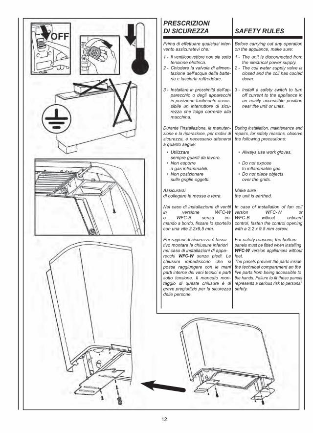
Prima di effettuare qualsiasi inter-vento assicuratevi che:
1 - Il ventilconvettore non sia sotto tensione elettrica.2 - Chiudere la valvola di alimen- tazione dell’acqua della batte- ria e lasciarla raffreddare.
3 - Installare in prossimità dell’ap- parecchio o degli apparecchi in posizione facilmente acces- sibile un interruttore di sicu- rezza che tolga corrente alla macchina.
Durante l’installazione, la manuten-zione e la riparazione, per motivi disicurezza, è necessario attenersia quanto segue:
• Utilizzare sempre guanti da lavoro. • Non esporre a gas infiammabili. • Non posizionare sulle griglie oggetti.
Assicurarsidi collegare la messa a terra.
Nel caso di installazione di ventilin versione WFC-W o WFC-B senza co-mando a bordo, fissare lo sportellocon una vite 2,2x9,5 mm.
Per ragioni di sicurezza è tassa-tivo montare le chiusure inferiorinel caso di installazioni di appa-recchi WFC-W senza piedi. Le chiusure impediscono che si possa raggiungere con le mani parti interne dei vani tecnici e parti sotto tensione. Il mancato mon-taggio di queste chiusure è di grave pregiudizio per la sicurezza delle persone.
Before carrying out any operationon the appliance, make sure:
1 - The unit is disconnected from the electrical power supply.2 - The coil water supply valve is closed and the coil has cooled down.
3 - Install a safety switch to turn off current to the appliance in an easily accessible position near the unit or units.
During installation, maintenance andrepairs, for safety reasons, observethe following precautions:
• Always use work gloves.
• Do not expose to inflammable gas. • Do not place objects over the grids.
Make surethe unit is earthed.
In case of installation of fan coilversion WFC-W or WFC-B without onboardcontrol, fasten the control openingwith a 2.2 x 9.5 mm screw.
For safety reasons, the bottompanels must be fitted when installingWFC-W version appliances without feet.The panels prevent the parts insidethe technical compartment an thelive parts from being accessible tothe hands. Failure to fit these panelsrepresents a serious risk to personalsafety.
PRESCRIZIONIDI SICUREZZA SAFETY RULES
13
Avant d’effectuer toute intervention,s’assurer que:
1 - Le ventilo-convecteur n’est pas sous tension électrique.
2 - Fermer la vanne d’alimentation de l’eau de la batterie et la laisser refroidir.3 - Installer à proximité du ou des appareils et dans une position facilement accessible un inter- rupteur de sécurité pour couper le courant de la machine.
Pendant l’installation, l’entretienet la réparation, pour des raisonsde sécurité, il est nécessaire derespecter ce qui suit:
• Utiliser toujours des gants de travail. • Ne pas exposer à des gaz inflammables. • Ne placer aucun objet sur les grilles.
S’assurer que la mise à la terrea été effectuée.
En cas d’installation de ventil enversion WFC-W ou WFC-B sans commandeà bord, fixer l’ouverture pour lacommande avec une vis 2,2 x 9,5mm.
Pour des raisons de sécurité il estimpératif de monter les protectionsinférieures en cas d’installationd’appareils WFC-W sans pieds.
Les protections empêchent d’ac-céder aux compartiments techni-ques et aux parties sous tension. L’absence de ces protections peut avoir de graves conséquences sur la sécurité des personnes.
Vor Durchführung irgendwelcherEingriffe:
1 - Sicherstellen, dass der Gebläse- konvektor nicht unter Spannung steht.2 - Das Wassereinlassventil der Batterie schließen und abkühlen lassen.3 - An einer gut zugänglichen Stelle in der Nähe des Geräts bzw. der Geräte einen Sicherheitsschalter installieren, der die Stromzufuhr zum Gerät unterbricht.
Aus Gründen der Sicherheit sindwährend der Installation, Wartungund Reparaturen, die folgendenVorschriften einzuhalten:
• Stets Arbeitshandschuhe tragen. • Keinen feuergefährlichen Gasen aussetzen. • Nichts auf die Ausblasgitter stellen.
Vergewissern Sie sich, dass dasGerät korrekt geerdet wird.
Bei Installation der Ventil-konvektorenin der Ausführung WFC-W oder WFC-B ohne Steuerung die Klappe mit einerSchraube zu 2,2 x 9,5mm befestigen.
Aus Sicherheitsgründen müssenbei der Installation von Geräten WFC-W ohne Füße die unteren Verschlüsse unbedingt montiert werden. Die Verschlüsse verhin-dern den Zugriff auf die Gerätein-nenteile und die unter Spannung stehenden Teile mit den Händen. Wenn diese Verschlüsse nicht mon-tiert werden, ist die Personensicherheit stark beeinträchtigt.
Antes de efectuar cualquier ope-ración es preciso comprobar que:
1 - El fan coil no está alimentado eléctricamente.2 - Cerrar la válvula de alimenta- ción del agua de la batería y dejar que se enfríe.
3 - Instalar cerca del aparato o de los aparatos, en una posición a la que se acceda fácilmente, un interruptor de seguridad que desconecte la alimentación de la máquina.
Durante la instalación, el manteni-miento y repación, por motivos deseguridad, es necesario atenersea los siguiente:
• Usar siempre guantes de trabajo. • No exponer a gases inflamables. • No dejar objetos sobre las rejillas.
Comprobar siempre queesté conectada la toma de tierra.
En caso de instalar ventil en versiónWFC-W o WFC-B sin mando a bordo, fijar la apertura de comando con un tor-nillo de 2,2 x 9,5 mm.
Por razones de seguridad es obli-gatorio montar los cerramientosinferiores en caso de instalacionesde aparatos WFC-W sin pies. Los cerramientos impiden que se puedan alcanzar con las manos las partes internas de las aper-turas técnicas y las partes bajo tensión. No realizar el montaje de estos cerramientos supone un grave perjuicio para la seguridad de las personas.
Alvorens u een handeling uitvoert aanhet apparaat, vergewis u ervan dat:
1 - De ventilatorconvector niet onder elektrische spanning staat.2 - De watertoevoerklep van de batterij gesloten is. Laat deze laatste afkoelen.
3 - Installeer vlakbij het apparaat of de apparaten een makkelijk bereikbare noodschakelaar die de stroomtoevoer naar de machine onderbreekt.
Tijdens de installatie, het onderhouden de reparaties, is het uit veiligheids-overwegingen noodzakelijk na televen wat volgt:
• Gebruik altijd werkhandschoenen. • Niet blootstellen aan brandbare gassen. • Geen voorwerpen op de roosters plaatsen.
Zorgvoor een aardaansluiting.
In het geval van installatie van ventil inde versie WFC-W of WFC-B zonder bediening aan boord, de klep vastma-ken met eenschroef 2,2 x 9,5mm.
Om veiligheidsredenen is hetnoodzakelijk om de onderste sluitingente monteren in het geval van installatiesvan WFC-W-apparaten zonder voetjes.De sluitingen voorkomen dat detechnische onderdelen en onderdelendie onder stroom staan van binneninmet de handen aangeraakt kunnenworden. Het niet monteren van dezesluitingen brengt de veiligheid vande personen ernstig in gevaar.
CONSIGNESDE SECURITE
SICHERHEITS-VORSCHRIFTEN
PRESCRIPCIONESDE SEGURIDAD
VEILIGHEIDS-VOORSCHRIFTEN
14
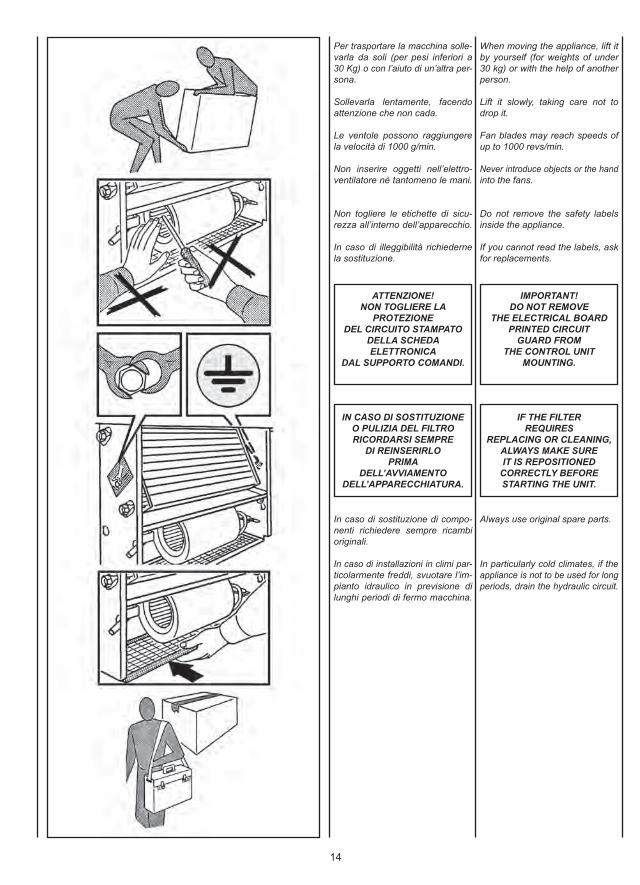
Per trasportare la macchina solle-varla da soli (per pesi inferiori a30 Kg) o con l’aiuto di un’altra per-sona.
Sollevarla lentamente, facendoattenzione che non cada.
Le ventole possono raggiungerela velocità di 1000 g/min.
Non inserire oggetti nell’elettro-ventilatore nè tantomeno le mani.
Non togliere le etichette di sicu-rezza all’interno dell’apparecchio.
In caso di illeggibilità richiedernela sostituzione.
When moving the appliance, lift itby yourself (for weights of under30 kg) or with the help of anotherperson.
Lift it slowly, taking care not todrop it.
Fan blades may reach speeds ofup to 1000 revs/min.
Never introduce objects or the handinto the fans.
Do not remove the safety labelsinside the appliance.
If you cannot read the labels, askfor replacements.
ATTENZIONE!NON TOGLIERE LA
PROTEZIONEDEL CIRCUITO STAMPATO
DELLA SCHEDAELETTRONICA
DAL SUPPORTO COMANDI.
IMPORTANT!DO NOT REMOVE
THE ELECTRICAL BOARDPRINTED CIRCUIT
GUARD FROMTHE CONTROL UNIT
MOUNTING.
IN CASO DI SOSTITUZIONEO PULIZIA DEL FILTRORICORDARSI SEMPRE
DI REINSERIRLOPRIMA
DELL’AVVIAMENTODELL’APPARECCHIATURA.
IF THE FILTERREQUIRES
REPLACING OR CLEANING,ALWAYS MAKE SUREIT IS REPOSITIONED
CORRECTLY BEFORESTARTING THE UNIT.
In caso di sostituzione di compo-nenti richiedere sempre ricambioriginali.
In caso di installazioni in climi par-ticolarmente freddi, svuotare l’im-pianto idraulico in previsione dilunghi periodi di fermo macchina.
Always use original spare parts.
In particularly cold climates, if theappliance is not to be used for longperiods, drain the hydraulic circuit.
15
Pour transporter la machine, lasoulever tout seul (pour des poidsinférieurs à 30 kg) ou avec l’aided’une autre personne.
La soulever lentement, en faisantattention qu’elle ne tombe pas.
Les ventilateurs peuvent atteindrela vitesse de 1000 tr/mn.
Ne pas introduire d’objets dans leventilateur, et surtout pas les mains.
Ne pas retirer les étiquettes desécurité à l’intérieur de l’appareil.
Si les étiquettes sont illisibles, endemander d’autres exemplaires.
Für den Transport kann das Gerätalleine (für Gewicht unter 30 kg)oder zu zweit angehoben werden.
Langsam und vorsichtig anheben,damit es nicht herabfällt.
Die Laufräder können eine Drehzahlvon 1.000 U/min. erreichen.
Stecken Sie keine Gegenstände inden Ventilator, und greifen Sie erstrecht nicht mit den Händen hinein.
Die Sicherheitsetiketten im Geräte-innern dürfen nicht entfernt werden.
Falls Sie unleserlich sind, müssensie ersetzt werden.
Para desplazar la máquina bastauna persona (para pesos inferioresa los 30 Kg) o dos.
Levantarla despacio teniendo cui-dado en no soltarla.
Los ventiladores pueden alcanzaruna velocidad de 1000 r.p.m.
No introducir objetos en el ventila-dor ni tanto menos las manos.
No quitar las etiquetas de seguri-dad presentes dentro del aparato.
Si se estropean hasta quedar ile-gibles es preciso sustituirlas.
Voor het transport, heft u de machinealleen (voor gewichten kleiner dan30kg) of met de hulp van iemandanders.
Hef de machine traag op, zonderte laten vallen.
De propellers kunnen een snelheidvan 1000 t/min. halen.
Steek geen voorwerpen of handenin de elektronventilator.
Verwijder de veiligheidslabels aan debinnenkant van het apparaat niet.
Als de labels niet leesbaar zijn, laatu ze vervangen.
ATTENTION!NE PAS RETIRERLA PROTECTION
DU CIRCUIT IMPRIMEDE LA CARTE
ELECTRONIQUEDU SUPPORT
DES COMMANDES.
ACHTUNG!DIE SCHUTZABDECKUNG
DER GEDRUCKTENSCHALTUNG DER PLATINE
DARF NICHTVON DER HALTERUNGDER STEUERUNGEN
GENOMMEN WERDEN.
ATENCIÓN!NO QUITAR LA PROTECCIÓN
DEL CIRCUITO IMPRESODA LA TARJETAELECTRÓNICADEL SOPORTEDEL CONTROL.
OPGELET!VERWIJDER
DE BEVEILIGING VAN HETGEDRUKTE CIRCUIT
VAN DE ELEKTRONISCHESCHAKELING NIET
AN DE BEDIENINGSBASIS.
EN CASDE REMPLACEMENT OU
DE NETTOYAGE DU FILTRE,NE JAMAIS OUBLIER
DE LE REMETTREAVANT DE METTRE
L’APPAREIL EN MARCHE.
BEI ERSATZ ODERREINIGUNG DES FILTERSNICHT VERGESSEN, DEN
FILTER VOR DEMERNEUTEN EINSCHALTEN
DES GERÄTS WIEDEREINZUBAUEN.
EN CASO DE SUSTITUCIÓNO DE LIMPIEZA DEL FILTRO
ACORDARSE SIEMPREDE COLOCARLO DE NUEVO
EN SU SITIO ANTESDE PONER EN MARCHA
EL APARATO.
ALS U DE FILTERVERVANGT
OF SCHOONMAAKT,PLAATST U HEM STEEDS
TERUG VOORU HET APPARAAT
IN WERKING STELT.
Si l’on doit remplacer des compo-sants, demander toujours des piècesde rechange originales.
En cas d’installation dans des climatsparticulièrement froids, vidangerl’installation hydraulique lorsqu’onprévoit de longues périodes d’arrêtde la machine.
Verlangen Sie immer Originaler-satzteile.
Bei Installation in einem besonderskalten Klima muss der Wasser-kreislauf entleert werden, wenn dasGerät für längere Zeit nicht benutztwird.
En caso de sustitución de compo-nentes, pedir siempre repuestosoriginales.
En caso de instalación en climasparticularmente fríos, vaciar lainstalación hidráulica si se prevénlargos plazos de parada de lamáquina.
Bij de vervanging van onderdelen,vraagt u steeds naar originelewisselstukken.
Voor een installatie in een bijzonderekoude omgeving, ledigt u dehydraulische installatie als u voorzietdat de machine gedurende eenlange periode niet zal werken.
16
I dati fondamentali relativi al ventil-convettore e allo scambiatore dicalore sono i seguenti:
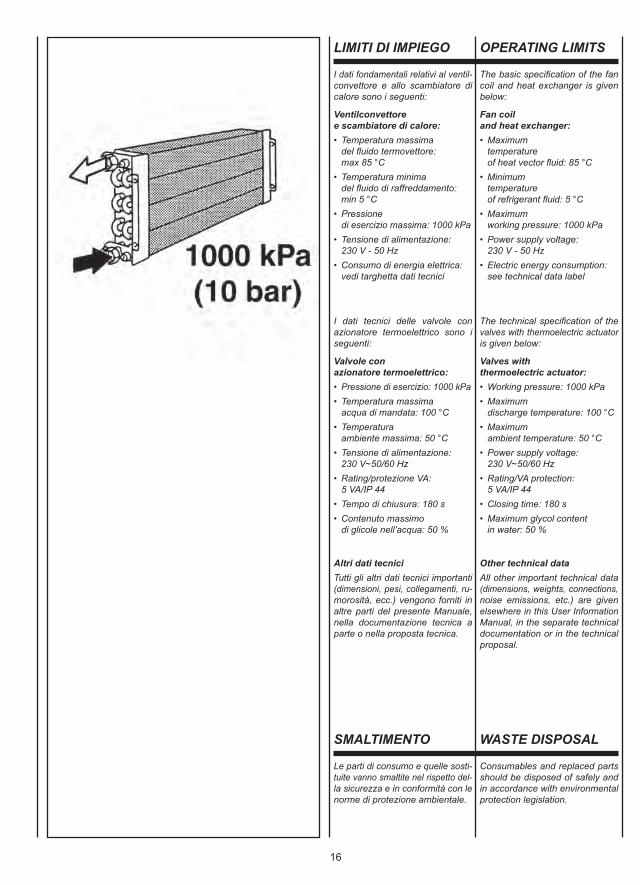
Ventilconvettoree scambiatore di calore:• Temperatura massima del fluido termovettore: max 85 °C• Temperatura minima del fluido di raffreddamento: min 5 °C• Pressione di esercizio massima: 1000 kPa• Tensione di alimentazione: 230 V - 50 Hz• Consumo di energia elettrica: vedi targhetta dati tecnici
I dati tecnici delle valvole conazionatore termoelettrico sono iseguenti:
Valvole conazionatore termoelettrico:• Pressione di esercizio: 1000 kPa• Temperatura massima acqua di mandata: 100 °C• Temperatura ambiente massima: 50 °C• Tensione di alimentazione: 230 V~50/60 Hz• Rating/protezione VA: 5 VA/IP 44• Tempo di chiusura: 180 s• Contenuto massimo di glicole nell’acqua: 50 %
Altri dati tecniciTutti gli altri dati tecnici importanti(dimensioni, pesi, collegamenti, ru-morosità, ecc.) vengono forniti inaltre parti del presente Manuale,nella documentazione tecnica aparte o nella proposta tecnica.
The basic specification of the fancoil and heat exchanger is givenbelow:
Fan coiland heat exchanger:• Maximum temperature of heat vector fluid: 85 °C• Minimum temperature of refrigerant fluid: 5 °C• Maximum working pressure: 1000 kPa• Power supply voltage: 230 V - 50 Hz• Electric energy consumption: see technical data label
The technical specification of thevalves with thermoelectric actuatoris given below:
Valves withthermoelectric actuator:• Working pressure: 1000 kPa• Maximum discharge temperature: 100 °C• Maximum ambient temperature: 50 °C• Power supply voltage: 230 V~50/60 Hz• Rating/VA protection: 5 VA/IP 44• Closing time: 180 s• Maximum glycol content in water: 50 %
Other technical dataAll other important technical data(dimensions, weights, connections,noise emissions, etc.) are givenelsewhere in this User InformationManual, in the separate technicaldocumentation or in the technicalproposal.
LIMITI DI IMPIEGO OPERATING LIMITS
SMALTIMENTO
Le parti di consumo e quelle sosti-tuite vanno smaltite nel rispetto del-la sicurezza e in conformità con lenorme di protezione ambientale.
WASTE DISPOSAL
Consumables and replaced partsshould be disposed of safely andin accordance with environmentalprotection legislation.
17
Les caractéristiques fondamentalesdu ventilo-convecteur et de l’échan-geur de chaleur sont les suivantes:
Ventilo-convecteuret échangeur de chaleur:• Température maximale du fluide caloporteur: 85 °C maxi• Température minimale du fluide de refroidissement: 5 °C mini• Pression de marche maximale: 1000 kPa• Tension d’alimentation: 230 V - 50 Hz• Consommation d’énergie électrique: voir plaquette données techniques
Les données techniques dessoupapes à actionneur thermo-électrique sont les suivantes:
Vannes àcommande thermoélectrique:• Pression de marche: 1000 kPa• Température de refoulement maximale: 100 °C• Température ambiante maximale: 50 °C• Tension d’alimentation: 230 V~50/60 Hz • Degré de protection: 5 VA/IP 44
• Temps de fermeture: 180 s• Contenu maximal de glycol dans l’eau: 50 %
Autres données techniquesToutes les autres caractéristiquestechniques importantes (dimen-sions, poids, raccordements, bruitetc.) sont indiquées dans d’autresparties de ce livret, dans la docu-mentation technique à part ou dansla proposition technique.
Die Daten der Einsatzgrenzen des Klimakonvektors und der Wärme-tauscher:
Klimakonvektorund Wärmetauscher:• Max. Temperatur des Kältemediums: 85 °C
• Min. Temperatur der Kühlflüssigkeit: 5 °C
• Max. Betriebsdruck: 1000 kPa
• Versorgungsspannung: 230 V - 50 Hz • Energieverbrauch: siehe Typenschild
Die technischen Daten der thermo-elektrischen Ventile:
Ventile mitthermoelektrischer Steuerung:• Betriebsdruck: 1000 kPa• Max. Auslasstemperatur: 100 °C• Max. Raumtemperatur: 50 °C• Versorgungsspannung: 230 V~50/60 Hz• Rating/Sicherung VA: 5 VA/IP 44• Verschlusszeit: 180 s• Max. Glykolanteil im Wasser: 50 %
Weitere technische DatenAlle anderen wichtigen technischenDaten (Abmessungen, Gewichte,Anschlüsse, Geräuschpegel, usw.)sind an anderen Stellen diesesHandbuchs, in der separaten tech-nischen Dokumentation oder in denAngebotsunterlagen enthalten.
Los datos fundamentales relativosal ventilador convector y al intercam-biador de calor son los siguientes:
Ventilador convectore intercambiador de calor:• Temperatura máxima del fluido termovector: máx. 85 °C• Temperatura mínima del fluido de enfriamiento: mín. 5 °C• Máxima presión de ejercicio: 1000 kPa• Tensiones de alimentación: 230 V - 50 Hz• Consumo de energía eléctrica: ver placa de datos técnicos
Los datos técnicos de las válvulascon accionador termoeléctrico sonlos siguientes:
Válvulas conaccionador termoeléctrico:• Presión de ejercicio: 1000 kPa• Temperatura máxima del agua descargada: 100 °C• Temperatura ambiental máxima: 50 °C• Tensión de alimentación: 230 V~50/60 Hz • Rating/protección VA: 5 VA/IP 44• Tiempo de cierre: 180 s• Contenido máximo de glicol en el agua: 50 %
Otros datos técnicosTodos los otros datos técncicos im-portantes (eida, pesos, conexiones,ruido, etc.) se dan en otras partesdel presente Manual, en la docu-mentación técnica.
De belangrijke gegevens met betrekking tot de ventilator-convector en de warmtewisselaar:
Ventilator-convectoren warmtewisselaar:• Maximumtemperatuur Vloeistof Thermovector: max. 85 °C• Minimumtemperatuur koelvloeistof: min. 5 °C• Maximale bedrijfsdruk: 1000 kPa
• Voedingsspanning: 230 V - 50 Hz• Elektrisch energieverbruik: zie plaatje met technische gegevens
De technische gegevens van dekleppen met thermo-elektrischeinschakeling:
Kleppen met thermo-elektrische inschakeling:• Bedrijfsdruk: 1000 kPa• Maximale watertemperatuur voor inlaat: 100 °C• Maximale omgevingstemperatuur: 50 °C• Voedingsspanning: 230 V~50/60 Hz• Rating/VA-bescherming: 5 VA/IP 44• Sluitingstijd: 180 s• Maximaal glycolgehalte water: 50 %
Andere technische gegevensAlle andere belangrijke technischegegevens (afmetingen, gewichten,aansluitingen, lawaai, enz.) wordengeleverd in andere delen van deHandleiding, in de technischedocumentatie of door het technischpersoneel.
LIMITES D’EMPLOI EINSATZGRENZEN LÍMITES DE USO GEBRUIKSLIMIETEN
ÉLIMINATION ENTSORGUNG ELIMINACIÓN AFDANKING
Les consommables et les piècesremplacées doivent être éliminésen respectant les règles de sécu-rité et les normes de protection del’environnement.
Verbrauchsteile und ersetzte Teilemüssen vorschriftsmäßig entsorgtwerden.
Las partes de consumo y las quese sustituyen se eliminan respe-tando la seguridad y de acuerdocon las normas de protección delmedio ambiente.
De verbruiksonderdelen en vervangenonderdelen worden afgedankt metrespect voor de veiligheidsvoorschriftenen overeenkomstig de milieuwetgeving.
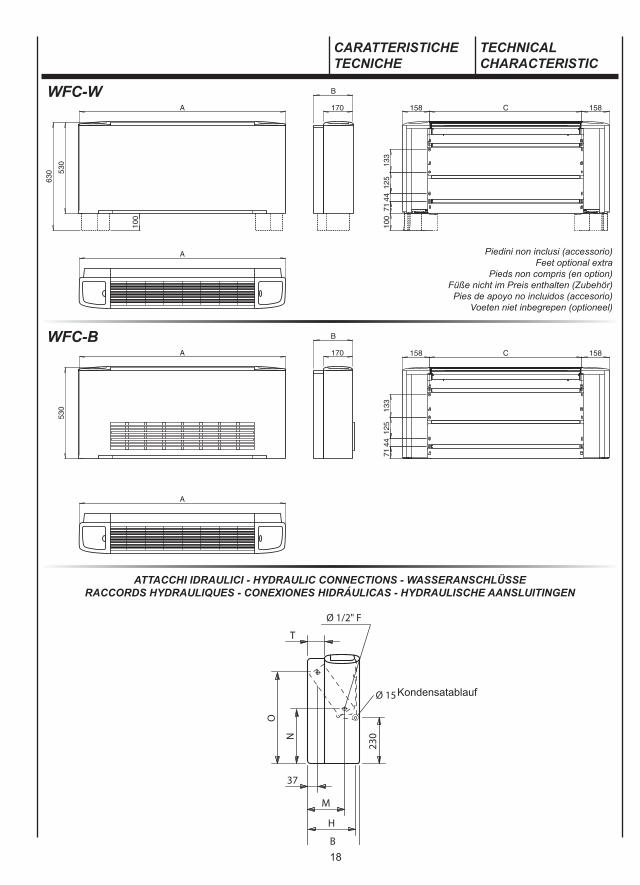
18
WFC-W
WFC-B
ATTACCHI IDRAULICI - HYDRAULIC CONNECTIONS - WASSERANSCHLÜSSERACCORDS HYDRAULIQUES - CONEXIONES HIDRÁULICAS - HYDRAULISCHE AANSLUITINGEN
CARATTERISTICHETECNICHE
TECHNICALCHARACTERISTIC
Piedini non inclusi (accessorio)Feet optional extra
Pieds non compris (en option)Füße nicht im Preis enthalten (Zubehör)Pies de apoyo no incluidos (accesorio)
Voeten niet inbegrepen (optioneel)
Kondensatablauf
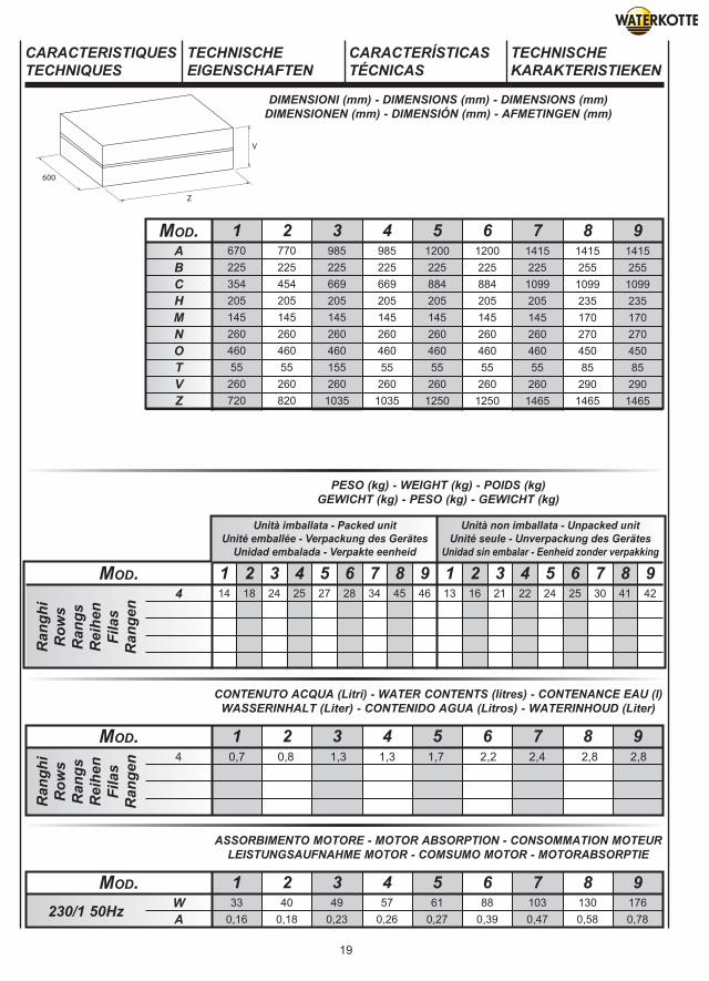
19
ABCHMNOTVZ
67022535420514526046055
260720
77022545420514526046055
260820
985225669205145260460155260
1035
98522566920514526046055260
1035
1200225884205145260460552601250
1200225884205145260460552601250
14152251099205145260460552601465
14152551099235170270450852901465
14152551099235170270450852901465
1 2 3 4 5 6 7 8 9Mod.
1 2 3 4 5 6 7 8 933
0,1640
0,1849
0,2357
0,2661
0,2788
0,391030,47
1300,58
1760,78
WA
Mod.230/1 50Hz
13 16 21 22 24 25 30 41 4214 18 24 25 27 28 34 45 461 2 3 4 5 6 7 8 91 2 3 4 5 6 7 8 9
Unità imballata - Packed unitUnité emballée - Verpackung des Gerätes
Unidad embalada - Verpakte eenheid
4Mod.
Ran
ghi
Row
sR
angs
Rei
hen
Fila
sR
ange
n
Unità non imballata - Unpacked unitUnité seule - Unverpackung des Gerätes
Unidad sin embalar - Eenheid zonder verpakking
1 2 3 4 5 6 7 8 9Mod.
Ran
ghi
Row
sR
angs
Rei
hen
Fila
sR
ange
n
CARACTERISTIQUESTECHNIQUES
TECHNISCHEEIGENSCHAFTEN
CARACTERÍSTICASTÉCNICAS
TECHNISCHEKARAKTERISTIEKEN
DIMENSIONI (mm) - DIMENSIONS (mm) - DIMENSIONS (mm)DIMENSIONEN (mm) - DIMENSIÓN (mm) - AFMETINGEN (mm)
PESO (kg) - WEIGHT (kg) - POIDS (kg)GEWICHT (kg) - PESO (kg) - GEWICHT (kg)
CONTENUTO ACQUA (Litri) - WATER CONTENTS (litres) - CONTENANCE EAU (l)WASSERINHALT (Liter) - CONTENIDO AGUA (Litros) - WATERINHOUD (Liter)
ASSORBIMENTO MOTORE - MOTOR ABSORPTION - CONSOMMATION MOTEURLEISTUNGSAUFNAHME MOTOR - COMSUMO MOTOR - MOTORABSORPTIE
4 0,7 0,8 1,3 1,3 1,7 2,2 2,4 2,8 2,8
20
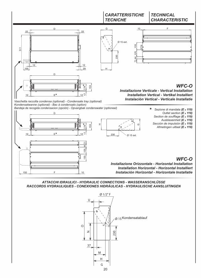
WFC-OInstallazione Verticale - Vertical Installation
Installation Vertical - Vertikal InstalliertInstalación Vertical - Verticale Installatie
WFC-OInstallazione Orizzontale - Horizontal Installation
Installation Horizontal - Horizontal InstalliertInstalación Horizontal - Horizontale Installatie
ATTACCHI IDRAULICI - HYDRAULIC CONNECTIONS - WASSERANSCHLÜSSERACCORDS HYDRAULIQUES - CONEXIONES HIDRÁULICAS - HYDRAULISCHE AANSLUITINGEN
CARATTERISTICHETECNICHE
TECHNICALCHARACTERISTIC
Sezione di mandata (E x 119)Outlet section (E x 119)
Section de soufflage (E x 119)Ausblaseinheit (E x 119)
Sección de impulsión (E x 119)Afmetingen uitlaat (E x 119)
*
Vaschetta raccolta condensa (optional) - Condensate tray (optional)Kondensatwanne (optional) - Bac à condensats (option)Bandeja de recogida condensacion (opción) - Opvangbak condenswater (optioneel)
Kondensatablauf

21
1 2 3 4 5 6 7 8 933
0,1640
0,1849
0,2357
0,2661
0,2788
0,391030,47
1300,58
1760,78
WA
Mod.230/1 50Hz
37433035421820514526046065
260720
47443045421820514526046065
260820
68964566921820514526046065
260820
68964566921820514526046065260820
904860884218205145260460652601035
904860884218205145260460652601035
111910751099218205145260460652601250
111910751099248235170270450952901250
111910751099248235170270450952901250
DEFGHMNOUXY
1 2 3 4 5 6 7 8 9Mod.
1 2 3 4 5 6 7 8 9Mod.
Ran
ghi
Row
sR
angs
Rei
hen
Fila
sR
ange
n
CARACTERISTIQUESTECHNIQUES
TECHNISCHEEIGENSCHAFTEN
CARACTERÍSTICASTÉCNICAS
TECHNISCHEKARAKTERISTIEKEN
DIMENSIONI (mm) - DIMENSIONS (mm) - DIMENSIONS (mm)DIMENSIONEN (mm) - DIMENSIÓN (mm) - AFMETINGEN (mm)
PESO (kg) - WEIGHT (kg) - POIDS (kg)GEWICHT (kg) - PESO (kg) - GEWICHT (kg)
CONTENUTO ACQUA (Litri) - WATER CONTENTS (litres) - CONTENANCE EAU (l)WASSERINHALT (Liter) - CONTENIDO AGUA (Litros) - WATERINHOUD (Liter)
ASSORBIMENTO MOTORE - MOTOR ABSORPTION - CONSOMMATION MOTEURLEISTUNGSAUFNAHME MOTOR - COMSUMO MOTOR - MOTORABSORPTIE
1 2 3 4 5 6 7 8 91 2 3 4 5 6 7 8 9
Unità imballata - Packed unitUnité emballée - Verpackung des Gerätes
Unidad embalada - Verpakte eenheid
Mod.
Ran
ghi
Row
sR
angs
Rei
hen
Fila
sR
ange
n
Unità non imballata - Unpacked unitUnité seule - Unverpackung des Gerätes
Unidad sin embalar - Eenheid zonder verpakking
4 11 17 22 23 25 26 31 41 42 10 15 20 21 23 24 28 38 39
4 0,7 0,8 1,3 1,3 1,7 2,2 2,4 2,8 2,8
22
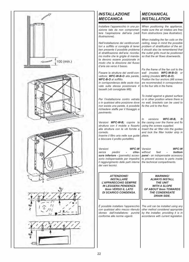
INSTALLAZIONEMECCANICA
Installare l’apparecchio in una po-sizione tale da non compromet-tere l’aspirazione dell’aria (vediillustrazione).
Nell’installazione dei ventilconvet-tori a soffitto si consiglia di tenerben presente il possibile problemadi stratificazione dell’aria; ricordia-mo inoltre che le griglie di manda-ta devono essere posizionate inmodo che la direzione del flussod’aria sia verso il basso.
Fissare la struttura del ventil-con-vettore; WFC-W-B-O alla parete,WFC-B-O al soffitto.In corrispondenza delle asole rica-vate sulla stessa posizionare 4tasselli (viti consigliate M8).
Per l’installazione contro vetratao in qualsiasi altra posizione dovenon esista una parete, è possibilerichiedere staffe per il fissaggio apavimento.
Versioni WFC-W-B; coprire lastruttura con il mobile e fissarloalla struttura con le viti fornite acorredo.Inserire il filtro aria nelle sue guidee bloccare il profilo portafiltro.
Versioni WFC-W senza piedini - chiu-sura inferiore - (pannello) acces-sorio indispensabile per impedireil raggiungimento delle parti internedei vani tecnici.
MECHANICALINSTALLATION
When positioning the appliance,make sure the air intakes are freefrom obstructions (see illustration).
When installing the fan coils on theceiling, keep in mind the possibleproblem of stratification of the air; it should also be remembered thatthe outlet grills must be positionedso that the air flows downwards.
Fix the frame of the fan coil to thewall (models WFC-W-B-O) orceiling (models WFC-B-O).Position the four anchors (M8 screwsare recommended) in correspondenceto the four slits in the frame.
To install against a glazed surfaceor in other position where there isno wall, brackets can be used tofix the unit to the floor.
In versions WFC-W-B, fitthe casing over the frame and fixusing the screws supplied.Insert the air filter into the guidesand lock the filter holder strip inplace.
Version WFC-W without feet - bottompanel - an indispensable accessoryto prevent access to parts insidethe technical compartments.
ATTENZIONE!INSTALLARE
L’APPARECCHIO SEMPREIN LEGGERA PENDENZA
8mm VERSO IL LATODI SCARICO CONDENSA.
WARNING!ALWAYS INSTALL
THE UNITWITH A SLOPE
OF ABOUT 8mm TOWARDSTHE CONDENSATE
DRAIN SIDE.
È possibile installare l’apparecchiocon qualsiasi altro mezzo ritenutoidoneo dall’installatore; purchèconforme alle norme vigenti.
The unit can be installed using anyother method considered appropriateby the installer, providing it is inaccordance with current legislation.
23
INSTALLATIONMECANIQUE
MECHANISCHEINSTALLATION
INSTALACIÓNMECÁNICA
MECHANISCHEINSTALLATIE
Installer l’appareil dans une positionn’empêchant pas l’aspiration de l’air(cf. illustration).
Lorsqu’on installe des ventilo-con-vecteurs au plafond il est conseilléde prendre en compte le problèmepossible de stratification de l’air;nous rappelons en outre que lesgrilles de soufflage doivent êtreplacées de façon à ce que le fluxd’air soit dirigé vers le bas.
Fixer la structure du ventilo-con-vecteur; celle des WFC-W-B-O à laparoi et celle des WFC-B-O au plafond.Positionner, au niveau des trousoblongs pratiqués dans la structure,quatre chevilles à expansion (visconseillées M8).
Pour l’installation contre une baievitrée ou dans une quelconqueautre position où il existe pas deparoi, on peut demander des pattespour la fixation au sol.
Versions WFC-W-B couvrir lastructure avec la carrosserie enfixant cette dernière à la structure,avec les vis fournies de série.Insérer le filtre à air dans ses guideset bloquer le profilé porte-filtre.
Version WFC-W sans pieds - fennetureinférieure - accessoire indispensablepour empêcher d’atteindre les partiesintérieures des compartiments tech-niques.
Das Gerät muss so installiert werden,dass die Luftansaugung nicht beein-trächtigt wird (siehe Darstellung).
Bei der Deckeninstallation vonKlimakonvektoren sollte unbedingtdas potentielle Problem der Luft-stratifikation berücksichtigt werden;außerdem erinnern wir daran, dassdie Ausblasgitter so positioniertsein müssen, dass der Luftstromnach unten gerichtet ist.
Der Rahmen des GebläsekonvektorsWFC-W-B-O an der Wand bzw. WFC-B-O der an der Decke befestigen.An den Schlitzen 4 Dübel anbringen(empfohlene Schrauben M8).
Für die Installation gegen eineverglaste Fläche oder in einersonstigen Stellung, in der keineWand vorhanden ist, können Bügelfür die Befestigung am Bodenangefordert werden.
Ausführungen WFC-W-B: dieGerätestruktur mit dem Gehäuseabdecken. Das Gehäuse mit denmitgelieferten Schrauben an demRahmen befestigen.Den Luftfilter in seine Führungeneinschieben und das Filter-Halteprofilbefestigen.
Version WFC-W ohne Füße - mit unteremVerschluss - ein unerlässlichesZubehör, um den Zugriff auf dieinneren Komponenten zu verhindern.
Instalar el aparato en una posicióntal que no se impida la aspiracióndel aire (ver dibujo).
En la instalación de los ventilado-res convectores de techo se reco-mienda tener muy presente el po-sible problema de estratificacióndel aire; además recordamos quelas rejillas de impulsión tienen quecolocarse de modo que la direccióndel flujo de aire sea hacia abajo.
Asegurar la estructura del fan coil;WFC-W-B-O a la pared, WFC-B-O altecho.En correspondencia con las ranurasque lleva colocar 4 tacos de expan-sión (tornillos aconsejados M8).
Para la instalación contra crista-leras o en cualquier otra posicióndonde no haya una pared, es po-sible solicitar unos estribos parala sujeción al suelo.
Variantes WFC-W-B; cubrir laestructura con el mueble y asegu-rarlo a la estructura con los tornillosincluidos en el suministro.Introducir el filtro del aire en susguías correspondientes y bloquearel perfil porta-filtro.
Versiones WFC-W sin pies - cierreinferior - accesorio indispensablepara impedir alcanzar las partesinternas de las aperturas técnicas.
Installeer het apparaat in een positiedie de luchtaanvoer niet in hetgedrang brengt (zie illustratie).
Bij de installatie van plafond-ventilator-convectors is hetaangeraden rekening te houden methet probleem van luchtstratificatie;wij herinneren er u tevens aan datde luchtroosters op die maniergeplaatst moeten worden, dat deluchtstroom naar onder is gericht.
Bevestig de structuur van de ventilator-convector; WFC-W-B-O aan de wand,WFC-B-O aan het plafond.Steek 4 pluggen in de gatenaangebracht in de structuur(aanbevolen schroeven M8).
Voor een installatie aan eenglaswand ofin een andere positiewaar geen wand aanwezig is, zijnkrammen beschikbaar voor debevestiging aan de vloer.
Versies WFC-W-B; bedek destructuur met de behuizing enbevestig deze aan de structuur metbehulp van de bijgeleverde schroeven.Schuif de luchtfilter in zijn geleidersen blokkeer het profiel van defilterhouder.
Versie WFC-W zonder voetjes - onderste sluiting - (paneel) onmi-sbaar accessoire om het bereiken van interne delen in de technischeruimtes te voorkomen.
ATTENTION!INSTALLER
TOUJOURS L’APPAREILAVEC UNE LEGERE PENTE
DE 8mm VERSLE COTE D’EVACUATION
DES CONDENSATS.
ACHTUNG!DAS GERÄT MUSS IMMER
IN LEICHTER (8 mm)NEIGUNG IN RICHTUNGKONDENSATAUSLASSINSTALLIERT WERDEN.
ATENCIÓN!INSTALAR EL APARATO
SIEMPRE CONUNA LIGERA PENDIENTEDE 8mm HACIA EL LADO
DE DESCARGADEL CONDENSADO.
OPGELET!INSTALLEER HET APPARAAT
STEEDS MET EEN LICHTEHELLING VAN 8 mm NAAR
DE ZIJDE WAARHET CONDENSATIEVOCHT
WORDT AFGEVOERD.
L’installeur pourra installer l’appareilavec n’importe quel autre moyenjugé approprié, à condition qu’il soitconforme aux normes en vigueur.
Das Gerät kann mit jedem anderen,vom Installateur für zweckmäßigerachteten Mittel installiert werden,jedoch immer unter der Voraussetzung,dass die Installation den einschlägigenBestimmungen entspricht.
Es posible instalar el aparato concualquier otro medio consideradoadecuado por el instalador; siem-pre y cuando cumpla con las nor-mas vigentes.
Het is mogelijk het apparaat teinstalleren met om het even welkinstrument dat door de monteurgeschikt wordt geacht, mits nalevingvan de van kracht zijnde normen.
24
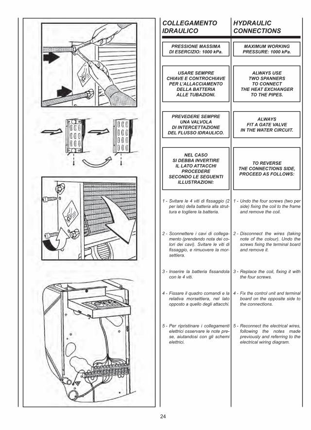
COLLEGAMENTOIDRAULICO
1 - Svitare le 4 viti di fissaggio (2 per lato) della batteria alla strut- tura e togliere la batteria.
2 - Sconnettere i cavi di collega- mento (prendendo nota dei co- lori dei cavi). Svitare le viti di fissaggio, e rimuovere la mor- settiera.
3 - Inserire la batteria fissandola con le 4 viti.
4 - Fissare il quadro comandi e la relativa morsettiera, nel lato opposto a quello degli attacchi.
5 - Per ripristinare i collegamenti elettrici osservare le note pre- se, aiutandosi con gli schemi elettrici.
HYDRAULICCONNECTIONS
1 - Undo the four screws (two per side) fixing the coil to the frame and remove the coil.
2 - Disconnect the wires (taking note of the colour). Undo the screws fixing the terminal board and remove it.
3 - Replace the coil, fixing it with the four screws.
4 - Fix the control unit and terminal board on the opposite side to the connections.
5 - Reconnect the electrical wires, following the notes made previously and referring to the electrical wiring diagram.
PRESSIONE MASSIMADI ESERCIZIO: 1000 kPa.
MAXIMUM WORKINGPRESSURE: 1000 kPa.
USARE SEMPRECHIAVE E CONTROCHIAVEPER L’ALLACCIAMENTO
DELLA BATTERIAALLE TUBAZIONI.
ALWAYS USETWO SPANNERS
TO CONNECTTHE HEAT EXCHANGER
TO THE PIPES.
PREVEDERE SEMPREUNA VALVOLA
DI INTERCETTAZIONEDEL FLUSSO IDRAULICO.
ALWAYSFIT A GATE VALVE
IN THE WATER CIRCUIT.
NEL CASOSI DEBBA INVERTIRE
IL LATO ATTACCHIPROCEDERE
SECONDO LE SEGUENTIILLUSTRAZIONI:
TO REVERSETHE CONNECTIONS SIDE,PROCEED AS FOLLOWS:
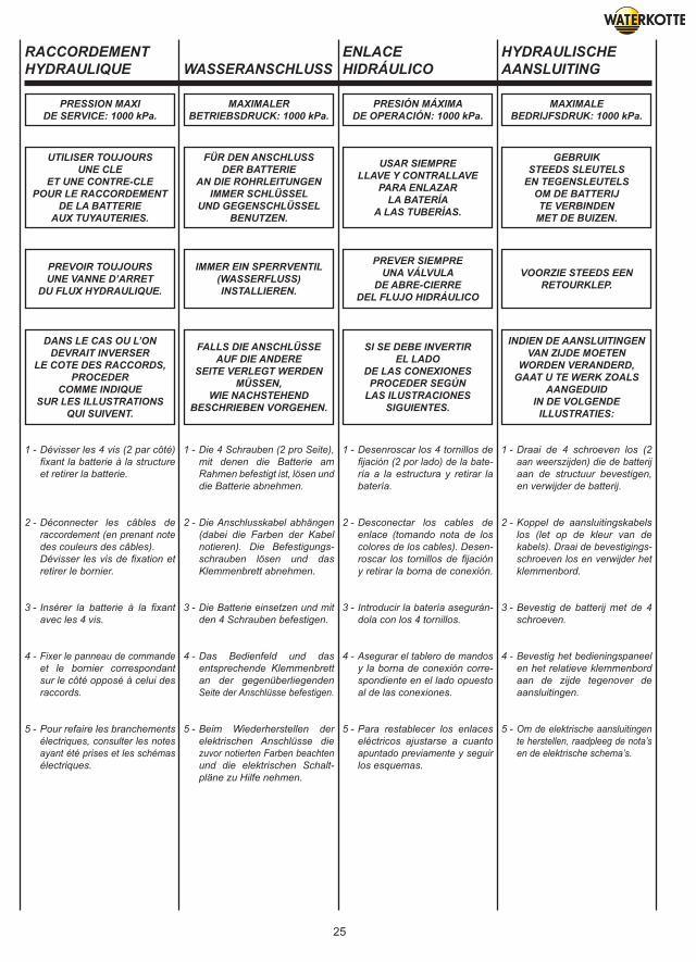
25
RACCORDEMENTHYDRAULIQUE WASSERANSCHLUSS
ENLACEHIDRÁULICO
HYDRAULISCHEAANSLUITING
1 - Dévisser les 4 vis (2 par côté) fixant la batterie à la structure et retirer la batterie.
2 - Déconnecter les câbles de raccordement (en prenant note des couleurs des câbles). Dévisser les vis de fixation et retirer le bornier.
3 - Insérer la batterie à la fixant avec les 4 vis.
4 - Fixer le panneau de commande et le bornier correspondant sur le côté opposé à celui des raccords.
5 - Pour refaire les branchements électriques, consulter les notes ayant été prises et les schémas électriques.
1 - Die 4 Schrauben (2 pro Seite), mit denen die Batterie am Rahmen befestigt ist, lösen und die Batterie abnehmen.
2 - Die Anschlusskabel abhängen (dabei die Farben der Kabel notieren). Die Befestigungs- schrauben lösen und das Klemmenbrett abnehmen.
3 - Die Batterie einsetzen und mit den 4 Schrauben befestigen.
4 - Das Bedienfeld und das entsprechende Klemmenbrett an der gegenüberliegenden Seite der Anschlüsse befestigen.
5 - Beim Wiederherstellen der elektrischen Anschlüsse die zuvor notierten Farben beachten und die elektrischen Schalt- pläne zu Hilfe nehmen.
1 - Desenroscar los 4 tornillos de fijación (2 por lado) de la bate- ría a la estructura y retirar la batería.
2 - Desconectar los cables de enlace (tomando nota de los colores de los cables). Desen- roscar los tornillos de fijación y retirar la borna de conexión.
3 - Introducir la batería asegurán- dola con los 4 tornillos.
4 - Asegurar el tablero de mandos y la borna de conexión corre- spondiente en el lado opuesto al de las conexiones.
5 - Para restablecer los enlaces eléctricos ajustarse a cuanto apuntado previamente y seguir los esquemas.
1 - Draai de 4 schroeven los (2 aan weerszijden) die de batterij aan de structuur bevestigen, en verwijder de batterij.
2 - Koppel de aansluitingskabels los (let op de kleur van de kabels). Draai de bevestigings- schroeven los en verwijder het klemmenbord.
3 - Bevestig de batterij met de 4 schroeven.
4 - Bevestig het bedieningspaneel en het relatieve klemmenbord aan de zijde tegenover de aansluitingen.
5 - Om de elektrische aansluitingen te herstellen, raadpleeg de nota’s en de elektrische schema’s.
PRESSION MAXIDE SERVICE: 1000 kPa.
MAXIMALERBETRIEBSDRUCK: 1000 kPa.
PRESIÓN MÁXIMADE OPERACIÓN: 1000 kPa.
MAXIMALEBEDRIJFSDRUK: 1000 kPa.
UTILISER TOUJOURSUNE CLE
ET UNE CONTRE-CLEPOUR LE RACCORDEMENT
DE LA BATTERIEAUX TUYAUTERIES.
FÜR DEN ANSCHLUSSDER BATTERIE
AN DIE ROHRLEITUNGENIMMER SCHLÜSSEL
UND GEGENSCHLÜSSELBENUTZEN.
USAR SIEMPRELLAVE Y CONTRALLAVE
PARA ENLAZARLA BATERÍA
A LAS TUBERÍAS.
GEBRUIKSTEEDS SLEUTELS
EN TEGENSLEUTELSOM DE BATTERIJTE VERBINDEN
MET DE BUIZEN.
PREVOIR TOUJOURSUNE VANNE D’ARRET
DU FLUX HYDRAULIQUE.
IMMER EIN SPERRVENTIL(WASSERFLUSS)INSTALLIEREN.
PREVER SIEMPREUNA VÁLVULA
DE ABRE-CIERREDEL FLUJO HIDRÁULICO
VOORZIE STEEDS EENRETOURKLEP.
DANS LE CAS OU L’ONDEVRAIT INVERSER
LE COTE DES RACCORDS,PROCEDER
COMME INDIQUESUR LES ILLUSTRATIONS
QUI SUIVENT.
FALLS DIE ANSCHLÜSSEAUF DIE ANDERE
SEITE VERLEGT WERDENMÜSSEN,
WIE NACHSTEHENDBESCHRIEBEN VORGEHEN.
SI SE DEBE INVERTIREL LADO
DE LAS CONEXIONESPROCEDER SEGÚN
LAS ILUSTRACIONESSIGUIENTES.
INDIEN DE AANSLUITINGENVAN ZIJDE MOETEN
WORDEN VERANDERD,GAAT U TE WERK ZOALS
AANGEDUIDIN DE VOLGENDE
ILLUSTRATIES:
26
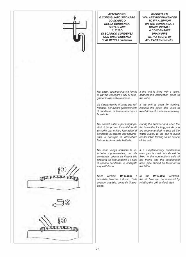
Nel caso l’apparecchio sia fornitodi valvola collegare i tubi di colle-gamento alla valvola stessa.
Se l’apparecchio è usato per raf-freddare, per evitare gocciolamentodi condensa, isolare le tubazioni ela valvola.
Nei periodi estivi e per lunghi pe-riodi di tempo con il ventilatore di-sinserito, per evitare formazioni dicondensa all’esterno dell’apparec-chio, si consiglia di intercettarel’alimentazione della batteria.
Nel caso venga richiesta la va-schetta supplementare, raccoltacondensa, questa va fissata allastruttura dal lato attacchi e il tubodi scarico condensa va collegatoa quest’ultima.
Nelle versioni WFC-W-B èpossibile invertire il flusso d’ariagirando la griglia, come da illustra-zione.
If the unit is fitted with a valve,connect the connection pipes tothe valve.
If the unit is used for cooling,insulate the pipes and valve toavoid drops of condensate forming.
During the summer and when thefan is inactive for long periods, youare recommended to shut off thewater supply to the coil to avoidcondensation forming on the outsideof the unit.
If a supplementary condensatedrain pan is used, this should befixed to the connections side ofthe frame and the condensatedrain pipe should be fastened tothe latter.
In the WFC-W-B versions,the air flow can be reversed byrotating the grill as illustrated.
ATTENZIONE!È CONSIGLIATO SIFONARE
LO SCARICODELLA CONDENSA,
INSTALLAREIL TUBO
DI SCARICO CONDENSACON UNA PENDENZA
DI ALMENO 3 cm/metro.
IMPORTANT!YOU ARE RECOMMENDED
TO FIT A SIPHONON THE CONDENSATE
DRAIN. INSTALLA CONDENSATE
DRAIN PIPEWITH A SLOPE OF
AT LEAST 3 cm/metre.
27
Si l’appareil est équipé d’une vanne,brancher les tuyauteries de raccorde-ment à cette même vanne.
Si on utilise l’appareil pour rafraîchir,isoler les tuyauteries et la vanneafin d’éviter des égouttements decondensats.
Pendant l’été et lorsque le ventilateurreste longtemps débranché, il estconseillé d’isoler l’alimentation de labatterie afin d’éviter les formationsde condensation à l’extérieur del’appareil.
Si le bac supplémentaire (de récupé-ration des condensats) est demandé,il doit être fixé à la structure du côtédes raccords et le tuyau d’évacuationdes condensats doit être raccordéà ce bac.
Dans les versions WFC-W-B,on peut inverser le flux d’air entournant la grille (cf. illustration).
Falls das Gerät mit Ventil ausgestattetist, die Anschlussleitungen mit demVentil verbinden.
Wenn das Gerät zum Kühlen benutztwird, müssen die Rohrleitungen und das Ventil isoliert werden, umein Heraustropfen von Kondens-wasser zu vermeiden.
Im Sommer und wenn der Ventilatorfür längere Zeit nicht benutzt wird,empfiehlt sich, die Zuleitung zurBatterie zu sperren, damit sichaußen am Gerät kein Kondens-wasser bildet.
Falls eine zusätzliche Kondensat-wanne verlangt wird, wird diese aufder Anschlussseite am Rahmenbefestigt und die Kondensatablauf-leitung wird daran angeschlossen.
Bei den Ausführungen WFC-W-B kann der Luftstrom umgekehrtwerden, indem das Ausblasgitterwie auf der Abbildung dargestelltumgedreht wird.
Si el aparato lleva válvula, conectarlos tubos de enlace con la propiaválvula.
Si se usa el aparato para enfriar,para evitar goteos de condensadoes preciso aislar las tuberías y laválvula.
En las temporadas veraniegas ycuando se prevea dejar apagadoel ventilador por mucho tiempo,para evitar formaciones de con-densado al exterior del aparato seaconseja interceptar el agua dealimentación de la batería.
En el caso de que se requiera lapileta suplementaria, de recogidadel condensado, es preciso fijarlaa la estructura por el lado conexionesy el tubo de descarga del conden-sado debe conectarse a esta última.
En las variantes WFC-W-B es posible invertir el flujo del airegirado la rejilla, como mostrado enel dibujo.
Indien het apparaat uitgerust is meteen klep, sluit u de buizen rechtstreeksaan op de klep.
Als het apparaat wordt gebruikt omaf te koelen, en om het druppelenvan condenswater te voorkomen,isoleert u de buizen en de klep.
In de zomermaanden en indiende ventilator lange tijd niet wordtgebruikt, is het raadzaam de voedingvan de batterij te onderbreken, omde vorming van condensatievochtaan de buitenkant van het apparaatte voorkomen.
Als voor het opvangen van hetcondensatievocht het gebruik vaneen bijkomende opvangbak wordtgevraagd, wordt deze bevestigdaan de structuur, aan de zijde vande aansluitingen; de afvoerbuiswordt aangesloten aan deze laatste.
Voor de versies WFC-W-B kande luchtstroom worden omgedraaiddoor het roostertje te draaien zoalsbeschreven in de illustratie.
ATTENTION!IL EST CONSEILLE DE
SIPHONER L’EVACUATIONDES CONDENSATS
ET D’INSTALLER LE TUYAUD’EVACUATION
DES CONDENSATSAVEC UNE PENTE
D’AU MOINS 3 cm/m.
ACHTUNG!DER KONDENSATAUSLASS
SOLLTE MÖGLICHST MITEINEM SIPHON VERSEHEN,
UND DIE KONDENSAT-ABLAUFLEITUNG
MIT EINER NEIGUNG VONMINDESTENS 3 cm/MeterINSTALLIERT WERDEN.
ATENCIÓN!SE ACONSEJA COLOCAR
UN SIFÓN EN LA DESCARGADEL CONDENSADO,INSTALAR EL TUBO
DE DESCARGADEL CONDENSADO
CON UNA PENDIENTE DEPOR LO MENOS 3 cm/metro.
OPGELET!HET IS RAADZAAM
DE AFVOERBUIS VAN HETCONDENSATIEVOCHT
TE HEVELEN,EN DE AFVOERBUIS
TE INSTALLEREN MET EENHELLING VAN MINSTENS
3 cm/meter.
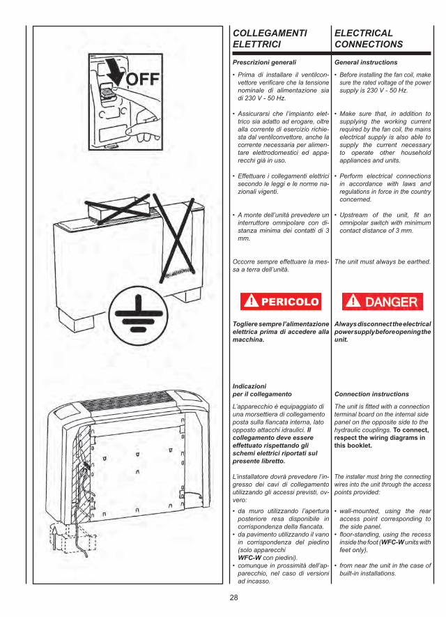
28
COLLEGAMENTIELETTRICI
Prescrizioni generali
• Prima di installare il ventilcon- vettore verificare che la tensione nominale di alimentazione sia di 230 V - 50 Hz.
• Assicurarsi che l’impianto elet- trico sia adatto ad erogare, oltre alla corrente di esercizio richie- sta dal ventilconvettore, anche la corrente necessaria per alimen- tare elettrodomestici ed appa- recchi già in uso.
• Effettuare i collegamenti elettrici secondo le leggi e le norme na- zionali vigenti.
• A monte dell’unità prevedere un interruttore omnipolare con di- stanza minima dei contatti di 3 mm.
Occorre sempre effettuare la mes-sa a terra dell’unità.
Togliere sempre l’alimentazioneelettrica prima di accedere allamacchina.
Indicazioniper il collegamento
L’apparecchio è equipaggiato diuna morsettiera di collegamentoposta sulla fiancata interna, latoopposto attacchi idraulici. Il collegamento deve essere effettuato rispettando gli schemi elettrici riportati sul presente libretto.
L’installatore dovrà prevedere l’in-gresso dei cavi di collegamentoutilizzando gli accessi previsti, ov-vero:
• da muro utilizzando l’apertura posteriore resa disponibile in corrispondenza della fiancata.• da pavimento utilizzando il vano in corrispondenza del piedino (solo apparecchi WFC-W con piedini).• comunque in prossimità dell’ap- parecchio, nel caso di versioni ad incasso.
ELECTRICALCONNECTIONS
General instructions
• Before installing the fan coil, make sure the rated voltage of the power supply is 230 V - 50 Hz.
• Make sure that, in addition to supplying the working current required by the fan coil, the mains electrical supply is also able to supply the current necessary to operate other household appliances and units.
• Perform electrical connections in accordance with laws and regulations in force in the country concerned.
• Upstream of the unit, fit an omnipolar switch with minimum contact distance of 3 mm.
The unit must always be earthed.
Always disconnect the electricalpower supply before opening theunit.
Connection instructions
The unit is fitted with a connectionterminal board on the internal sidepanel on the opposite side to thehydraulic couplings. To connect,respect the wiring diagrams in this booklet.
The installer must bring the connectingwires into the unit through the accesspoints provided:
• wall-mounted, using the rear access point corresponding to the side panel.• floor-standing, using the recess inside the foot (WFC-W units with feet only).
• from near the unit in the case of built-in installations.
29
BRANCHEMENTSELECTRIQUES
ELEKTRO-ANSCHLÜSSE
CONEXIONESELECTRICAS
ELEKTRISCHEAANSLUITINGEN
Instructions
• Avant d’installer le ventilo-con- vecteur vérifier que la tension d’alimentation nominale est de 230 V - 50Hz.
• S’assurer que la puissance de l’installation électrique est suffi- sante pour fournir le courant de marche pour le ventilo-convecteur ainsi que le courant nécessaire pour alimenter les électroménagers et les appareils déjà utilisés.
• Effectuer les branchements électriques selon la législation et les normes nationales en vigueur.
• En amont de l’unité prévoir un interrupteur unipolaire avec distance minimum des contacts de 3 mm.
Il faut toujours effectuer la mise àla terre de l’unité.
Débrancher toujours la machineavant d’y accéder.
Indicationspour le raccordement
L’appareil est équipé d’un bornier de raccordement placé sur le côté intérieur, du côté opposé aux raccords hydrauliques. Le raccordement doit être effectué en respec-tant les schémas électriques donnés dans cette notice.
L’installateur devra prévoir l’entréedes câbles de raccordement en uti-lisant les accès prévus, c’est-à-dire:
• sur le mur en utilisant l’ouverture postérieure disponible près du côté.• au sol à travers le pied (seule- ment appareils WFC-W avec pieds).• toujours à proximité de l’appa- reil, dans le cas de versions à encastrer.
Allgemeine Anweisungen
• Vor der Installation des Klima- konvektors sicherstellen, dass die nominale Versorgungs- spannung 230 V - 50 Hz beträgt.
• Sicherstellen, dass die Elektro- anlage in der Lage ist, neben dem Klimakonvektor auch die anderen Haushaltsgeräte zu versorgen.
• Die Elektroanschlüsse müssen gemäß der einschlägigen Gesetze und Vorschriften hergestellt werden.
• Dem Gerät einen allpoligen Schalter mit einer Kontaktöffnung von mindestens 3 mm vorschalten.
Das Gerät vorschriftsmäßig erden.
Vor dem Zugriff auf das Geräte-innere stets die Spannungs-versorgung unterbrechen.
Anleitungenfür den Anschluss
Das Gerät ist mit einer Anschluss-klemmleiste ausgestattet, die ander inneren Seitenwand, gegenüberden Wasseranschlüssen unter-gebracht ist. Für den Anschlussmüssen die in dieser Betriebs-anleitung enthaltenen Schal-tpläne befolgt werden.
Der Installateur muss die Durch-gänge der Anschlusskabel an denvorhergesehenen Stellen ausführen,und zwar:
• Von der Wand her unter Verwendung der hinteren Öffnung auf Höhe der Seitenwand.• Vom Boden her unter Verwendung des Hohlraums im Innern des Fußes (nur bei den Geräten WFC-W mit Füßen).• bei Einbaugeräten in jedem Fall in der Nähe des Geräts.
Prescripciones generales
• Antes de instalar el ventilador convector verificar que la tensión nominal de alimentación sea de 230 V - 50 Hz.
• Asegurarse de que la instalación eléctrica sea apta para distribuir, además de la corriente de ejer- cicio requerida por el ventilador convector, la corriente necesaria para alimentar electrodomésticos que ya se estuvieran usando.
• Efectuar las conexiones eléctri- cas de acuerdo con las leyes y las normativas nacionales vigentes.
• Prever, más arriba de la unidad, un interruptor omnipolar con una distancia mínima de los contac- tos de 3mm.
Realizar siempre la toma de tierrade la unidad.
Retirar siempre la corriente eléctri-ca antes de acceder a la máquina.
Indicacionespara la conexión
El aparato está equipado con unacaja de bornes de conexión situa-da en el lateral interno, en el ladoopuesto a las conexiones hidráuli-cas. La conexión se tiene querealizar respetando los esque-mas eléctricos que figuran en el presente manual.
El instalador deberá prever la en-trada de los cables de conexiónusando los accesos previstos, esdecir:
• desde la pared usando la aper- tura posterior disponible en el lateral.• desde el suelo usando la aber- tura existente bajo el pie (sólo para los aparatos WFC-W con pies).• de cualquier forma cerca del aparato, en el caso de versiones empotradas.
Algemene voorschriften
• Alvorens de ventilatorconvector te installeren, wordt gecontroleerd of de nominale voedingsspanning gelijk is aan 230V - 50 Hz.
• Waak erover dat de elektrische installatie in staat is om, naast de bedrijfstroom vereist door de ventilatorconvector, de nodige energie te leveren voor de voeding van de reeds in gebruik zijnde huishoudtoestellen en apparaten.
• De elektrische aansluitingen uitvoeren volgens de geldende nationale wetgevingen en normen.
• Stroomopwaarts van de eenheid wordt een meerpolige schakelaar voorzien met een minimale afstand tussen de polen van 3 mm.
De eenheid moet in elk geval wordenuitgerust met een aardaansluiting.
Koppel altijd eerst de elektrischevoeding los alvorens aan hetapparaat te komen.
Aanwijzingenvoor de aansluiting
Het apparaat is uitgerust met een aansluitklemmenbord dat zichaan de binnenkant bevindt, op de wand tegenover de hydraulische aansluitingen. De aansluiting dient te worden uitgevoerd conform de schakel-schema’s in deze handleiding.
De monteur zal een kabelingangmoeten verwezenlijken door detoegangen die voorzien werden tegebruiken, d.w.z.:
• aan de muur door de beschikbare opening achteraan te gebruiken, overeenstemmend met de zijkant.• aan de grond door de holte in overeenstemming met het voetje te gebruiken (alleen WFC-W- toestellen met voetje).• in elk geval in de nabijheid van het apparaat, voor ingepaste versies.
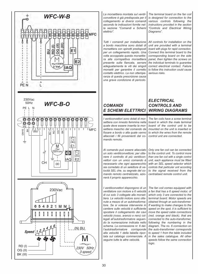
30
La morsettiera montata sul ventil-convettore è già predisposta per ilcollegamento ai diversi comandisecondo le indicazioni fornite nel-la sezione “Comandi e Schemielettrici”.
Tutti i comandi per installazionea bordo macchina sono dotati dimorsettiera con spinotti predispostiper un collegamento rapido. Unavolta accoppiata questa morsettie-ra alla corrispettiva morsettierapresente sulla fiancata, serrareadeguatamente le viti dei singolimorsetti per garantire il correttocontatto elettrico. La non ottempe-ranza di questa prescrizione causauna grave condizione di pericolo.
The terminal board on the fan coilis designed for connection to thevarious controls following theinstructions provided in the section“Controls and Electrical WiringDiagrams”.
All controls for installation on theunit are provided with a terminalboard with plugs for rapid connection.Connect this terminal board to thecorresponding board on the sidepanel, then tighten the screws onthe individual terminals to guaranteecorrect electrical contact. Failureto follow this instruction could causeserious risks.
COMANDIE SCHEMI ELETTRICI
ELECTRICALCONTROLS ANDWIRING DIAGRAMS
I venticonvettori sono dotati di mor-settiera con innesto femmina nellaquale deve essere inserita la mor-settiera maschio del comando dafissare a bordo o alla quale vannoallacciati i fili provenienti dal co-mando remoto.
Al comando può essere allacciatoun solo ventilconvettore; per otte-nere il controllo di più ventilcon-vettori con un unico comando ènecessario che ogni apparecchiosia corredato di un selettore di ve-locità SEL che, su segnale del co-mando remoto centralizzato, azio-nerà il proprio apparecchio.
I ventilconvettori dispongono di unventilatore con motore a 6 velocitàdi cui solo 3 collegate alla morset-tiera. Le velocità motore sono otte-nute a mezzo di un autotrasforma-tore. Se si volesse intervenire incantiere sulle velocità è sufficientespostare il collegamento dei cavivelocità (rosso, arancio e nero) col-legati all’autotrasformatore seguen-do la numerazione indicata nelloschema. La connessione nr. 6 del-l’autotrasformatore corrispondealla velocità 1 della tabella ripor-tata sul catalogo commerciale. Aseguire tutte le altre velocità.
The fan coils have a screw terminalboard in which the male terminalboard of the control unit to bemounted on the unit is inserted orto which the wires from the remotecontrol unit are connected.
Only one fan coil can be connectedto the control unit. To control morethan one fan coil with a single controlunit, each appliance must be fittedwith an SEL speed selector whichcontrols that particular unit accordingto the signal received from thecentralised remote control unit.
The fan coil comes equipped witha fan that has a 6 speed motor, ofwhich only 3 are connected to theterminal board. Motor speeds areobtained through an auto-transformer.If wanting to make changes to thespeed on the spot, it is sufficient tomove the speed cable connections(red, orange and black), that areconnected to the auto-transformer,following the numbering in thediagram. The no. 6 connection onthe auto-transformer correspondsto speed 1 from the table includedin the sales catalogue. All otherspeeds follow the same connectionlogic.
WFC-W-B
WFC-B-O
31
Le bornier monté sur le ventilo-convecteur est déjà prêt pour laconnexion des différentes com-mandes selon les instructions fourniesdans la section “Commandes etSchémas électriques”.
Toutes les commandes à installerà bord de la machine sont muniesd’un bornier avec des bornes àbranchement rapide. Quand cebornier est raccordé au borniercorrespondant placé sur le côté,serrer les vis de chaque bornierpour garantir un bon contact élec-trique. Ne pas se conformer à cetteprescription pourrait causer ungrave danger.
Die am Klimakonvektor montierteKlemmleiste ist bereits für denAnschluss der verschiedenenSteuerungen gemäß der Anleitungendes Kapitels “Steuerungen undSchaltpläne” vorbereitet.
Alle am Gerät zu installierendenSteuerungen sind mit Klemmleistemit Steckerstiften für den problem-losen Anschluss ausgestattet.Nachdem die Steckerklemmleistemit der entsprechenden Buchsen-klemmleiste an der Seitenwandverbunden ist, die Schrauben dereinzelnen Klemmen fest anziehen,damit der elektrische Kontaktgewährleistet wird. Die Unterlassungdieser Vorschrift kann schwerwiegendeGefahrensituationen verursachen.
La caja de bornes montada sobreel ventilador convector ya está pre-parada para la conexión a los distin-tos mandos de acuerdo con lasindicaciones dadas en la sección“Mandos y Esquemas eléctricos”.
Todos los mandos que se instala-rán en la máquina estarán provi-stos de caja de bornes con clavijaspreparadas para una conexiónrápida. Una vez que esta caja debornes esté acoplada a la caja debornes correspondiente situada enel lateral, apretar adecuadamentelos tornillos de cada borne paragarantizar un contacto eléctricocorrecto. El no observar esta pre-scripción puede ocasionar un granriesgo.
Het klemmenbord gemonteerd opde ventilatorconvector is al uitgerustvoor de verbinding met de verschillendebedieningen volgens de aanwijzingenin de afdeling “Bedieningen enelektrische schema’s”.
Al de bedieningen voor de installatieaan boord, zijn voorzien van eenklemmenbord met pennen vooreen vlugge verbinding. Wanneerhet klemmenbord aan het over-eenkomstige klemmenbord op dezijkant gekoppeld is, de schroevenvan de klemmen aanspannen omhet correct elektrisch contact teverzekeren. Dit voorschrift nietnaleven, kan zeer gevaarlijk zijn.
COMMANDESET SCHEMASELECTRIQUES
STEUERGERÄTEUND SCHALTPLÄNE
MANDOSY ESQUEMASELÉCTRICOS
BEDIENINGENEN ELEKTRISCHESCHEMA’S
Les ventilo-convecteurs sont équipésd’un bornier à vis dans lequel doitêtre branché le bornier mâle de lacommande à fixer sur le ventilo-convecteur ou auquel doivent êtreraccordés les conducteurs provenantde la commande à distance.
A la commande ne peut être raccordéqu’un seul ventilo-convecteur. Pourobtenir le contrôle de plusieursventilo-convecteurs avec une seulecommande, il faut que chaqueappareil soit équipé d’un sélecteurde vitesse SEL. Sur signal de lacommande à distance centralisée,chaque sélecteur actionnera l’ap-pareil sur lequel il est installé.
Les ventilo-convecteurs disposentd’un ventilateur équipé d’un moteurà 6 vitesses dont seulement 3 sontbranchés sur le bornier. Les vitessesdu moteur sont obtenues au moyend’un autotransformateur. Si l’onvoulait intervenir sur le chantier surles vitesses il suffit de déplacer lebranchement des câbles de lavitesse (rouge, orange et noir) reliésà l’autotransformateur en suivant lanumération indiquées sur le schéma.La connexion n.6 de l’autotransformateurcorrespond à la vitesse 1 du tableaumentionné sur le catalogue commercial.Ainsi de suite pour toutes les autresvitesses.
Die Gebläsekonvektoren sind miteinem Schraubklemmenbrett ausgestattet, in das das am Gerät zu befestigende Steuerungsklem-menbrett gesteckt werden muss bzw. an das die von der Fernsteue-rung kommenden Drähte angeschlos-sen werden müssen.
An der Steuerung kann nur einGebläsekonvektor angeschlossenwerden. Um mehrere Gebläse-konvektoren mit einer einzigenSteuerung zu bedienen, muss jedesGerät mit einem Drehzahlwähl-schalter SEL ausgestattet werden,der auf Signal der zentralisiertenFernbedienung sein Gerät betätigt.
Die Gebläsekonvektoren besitzeneinen Gebläsemotor mit 6 Drehzahl-stufen, von denen nur 3 an dieKlemmleiste angeschlossen sind.Die Motordrehzahlen werden übereinen Spartransformator geregelt.Sollen die Drehzahlen vor Ort geändertwerden, genügt es, die Anschlüsseder am Spartransformator angesch-lossenen Drehzahlkabel (rot, orangeund schwarz) zu versetzen und dabeidie im Plan angegebene Nummerierungzu beachten. Anschluss Nr. 6 desSpartransformators entsprichtDrehzahl 1 der im Verkaufskatalogabgedruckten Tabelle. Analog füralle anderen Drehzahlen.
Los ventiloconvectores están dota-dos de regleta de bornes con tor-nillos en la que debe introducirseel borne macho del mando a fijara bordo o a la que se conectan loscables procedentes del mando adistancia.
Con el control es posible conectarun solo fan coil. Para lograr con-trolar varios fan coils mediante unsolo control es preciso que cadaaparato tenga un selector de velo-cidad, SEL el cual, sobre la basede la señal del mando a distanciacentralizado, accionará al propioaparato.
Los ventiloconvectores cuentancon un ventilador con motor de 6velocidades, de las cuales sólo 3conectadas al bornero. Las veloci-dades del motor se obtienen me-diante un autotransformador. Si enla obra se desea intervenir sobrelas velocidades, es suficiente de-splazar la conexión de los cablesde velocidad (rojo, anaranjado ynegro) conectados al autotransfor-mador siguiendo la numeración quese muestra en el esquema. La co-nexión nr. 6 del autotransformadorcorresponde a la velocidad 1 de latabla presente en el catálogo co-mercial. Y así sucesivamente paralas otras velocidades.
De ventilatorconvectors zijn voorzienvan een klemmenbord met schroevenwaarin het mannelijke klemmenbordvan de bediening dat aan boordbevestigd moet worden of waaraan desnoeren die uit de afstandsbedieningkomen vastgekoppeld moeten worden.
Aan de bediening kan slechtséén ventilatorconvector wordengekoppeld; om meerdere ventilator-convectors te bedienen met éénenkele bediening, moet elk apparaatuitgerust zijn met een snelheids-schakelaar SEL die, op een signaalvan de centrale afstandsbediening,zijn aangesloten apparaat in werkingstelt.
De ventilators-convectors beschikkenover een ventilator met motor op6 snelheden, waarvan slechts 3aangesloten op het klemmenbord.De motorsnelheden worden verkregendoor middel van een autotransformator.Indien men op de werf wenst in tegrijpen op de snelheden, volstaat hetde aansluiting van de snelheidkabels(rood, oranje en zwart) aangeslotenop de autotransformator te verplaatsenvolgens de nummering aangeduid inhet schema. De aansluiting nr. 6 vande autotransformator komt overeen metde snelheid 1 van de tabel vermeld opde commerciële catalogus. Werk naaranalogie voor alle andere snelheden.
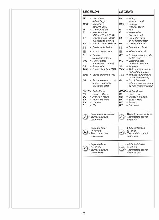
32
MC = Morsettiera del cablaggioMFC = Morsettiera del FAN COILM = MotoventilatoreE = Valvola acqua (IMPIANTO A 2 TUBI)E1 = Valvola acqua CALDA o resistenza elettricaE2 = Valvola acqua FREDDA
= Estate - aria fredda
= Inverno - aria calda
CH = Cambio stagionale esternoIAQ = Filtro elettrico o resistenza elettricaSA = Sonda ariaTMM = Sonda di minima TMM
TME = Sonda di minima TME
Q1 = Sezionatore con un polo protetto da fusibile (raccomandato)
GNYE = Giallo/VerdeRD = Rosso = MinimaOG = Arancio = MediaBK = Nero = MassimaBN = MarroneBU = Blu
MC = Wiring terminal boardMFC = Fan coil terminal boardM = FanE = Water valve (two tube unit)E1 = Hot water valve or electrical heaterE2 = Cold water valve
= Summer - cold air
= Winter - warm air
CH = External season mode switch-overIAQ = Electronic fi lter or electrical heaterSA = Air probeTMM = TMM low temperature (cut-out thermostat)TME = TME low temperature (cut-out thermostat)Q1 = Circuit breakers with one pole protected by fuse (recommended)
GNYE = Yellow/GreenRD = Red = LowOG = Orange = MediumBK = Black = HighBN = BrownBU = Dark blue
LEGENDA LEGEND
A• Impianto senza valvole• Termostatazione sul motore
A• Without valves installation• Thermostatic control on the fan
B• Impianto 2 tubi (1 valvola)• Termostatazione sulla valvola
B• 2-tube installation (1 valve)• Thermostatic control on the valve
C• Impianto 4 tubi (2 valvole)• Termostatazione sulle valvole
C• 4-tube installation (2 valves)• Thermostatic control on the valves
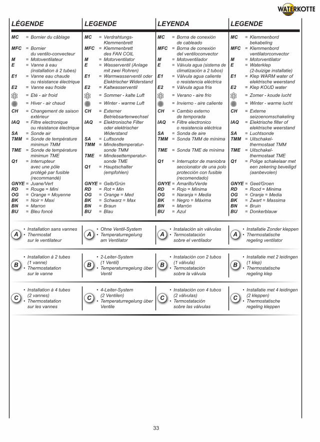
33
MC = Bornier du câblage
MFC = Bornier du ventilo-convecteurM = MotoventilateurE = Vanne à eau (installation à 2 tubes)E1 = Vanne eau chaude ou résistance électriqueE2 = Vanne eau froide
= Eté - air froid
= Hiver - air chaud
CH = Changement de saison extérieurIAQ = Filtre electronique ou résistance électriqueSA = Sonde airTMM = Sonde de température minimun TMMTME = Sonde de température minimun TMEQ1 = Interrupteur avec une pôle protégé par fusible (recommandé)GNYE = Juane/VertRD = Rouge = MiniOG = Orange = MoyenneBK = Noir = MaxiBN = MarronBU = Bleu foncé
MC = Verdrahtungs- KlemmenbrettMFC = Klemmenbrett des FAN COILM = MotorventilatorE = Wasserventil (Anlage mit zwei Rohren)E1 = Warmwasserventil oder Elektrischer WiderstandE2 = Kaltwasserventil
= Sommer - kalte Luft
= Winter - warme Luft
CH = Externer BetriebsartenwechselIAQ = Elektronische Filter oder elektrischer WiderstandSA = LuftsondeTMM = Mindesttemperatur- sonde TMMTME = Mindesettemperatur- sonde TMEQ1 = Hauptschalter (empfohlen)
GNYE = Gelb/GrünRD = Rot = MinOG = Orange = MedBK = Schwarz = MaxBN = BraunBU = Blau
MC = Borna de conexión de cableadoMFC = Borna de conexión del ventiloconvectorM = MotoventiladorE = Válvula agua (sistema de climatización a 2 tubos)E1 = Válvula agua caliente o resistencia eléctricaE2 = Válvula agua fría
= Verano - aire frio
= Invierno - aire caliente
CH = Cambio externo de temporadaIAQ = Filtre electronico o resistencia eléctricaSA = Sonda de aireTMM = Sonda TMM de mínima
TME = Sonda TME de mínima
Q1 = Interruptor de maniobra seccionator de una polo protección con fusible (recomendado)GNYE = Amarillo/VerdeRD = Rojo = MínimaOG = Naranja = MediaBK = Negro = MáximaBN = MarrónBU = Azul
MC = Klemmenbord bekabelingMFC = Klemmenbord ventilatorconvectorM = MotorventilatorE = Waterklep (2-buizige installatie)E1 = Klep WARM water of elektrische weerstandE2 = Klep KOUD water
= Zomer - koude lucht
= Winter - warme lucht
CH = Externe seizoenomschakelingIAQ = Elektrische fi lter of elektrische weerstandSA = LuchtsondeTMM = Uitschakel- thermostaat TMMTME = Uitschakel- thermostaat TMEQ1 = Polige schakelaar met een zekering beveiligd (aanbevolen)
GNYE = Geel/GroenRD = Rood = MinimaOG = Oranje = MediaBK = Zwart = MassimaBN = BruinBU = Donkerblauw
LÉGENDE LEGENDE LEYENDA LEGENDE
A• Installation sans vannes• Thermostat sur le ventilateur
A• Ohne Ventil-System• Temperaturregelung am Ventilator
A• Instalación sin válvulas• Termostatación sobre el ventilador
A• Installatie Zonder kleppen• Thermostatische regeling ventilator
B• Installation à 2 tubes (1 vanne)• Thermostatation sur le vanne
B• 2-Leiter-System (1 Ventil)• Temperaturregelung über Ventil
B• Instalación con 2 tubos (1 válvula)• Termostatación sobre la válvula
B• Installatie met 2 leidingen (1 klep)• Thermostatische regeling klep
C• Installation à 4 tubes (2 vannes)• Thermostatation sur les vannes
C• 4-Leiter-System (2 Ventilen)• Temperaturregelung über Ventile
C• Instalación con 4 tubos (2 válvulas)• Termostatación sobre las válvulas
C• Installatie met 4 leidingen (2 kleppen)• Thermostatische regeling kleppen
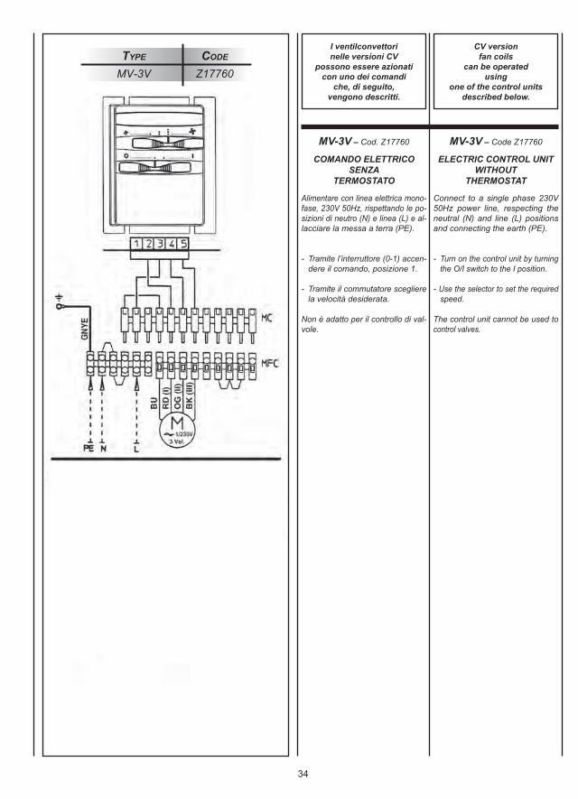
34
Type Code
MV-3V Z17760
Alimentare con linea elettrica mono-fase, 230V 50Hz, rispettando le po-sizioni di neutro (N) e linea (L) e al-lacciare la messa a terra (PE).
- Tramite l’interruttore (0-1) accen- dere il comando, posizione 1.
- Tramite il commutatore scegliere la velocità desiderata.
Non è adatto per il controllo di val-vole.
Connect to a single phase 230V50Hz power line, respecting theneutral (N) and line (L) positionsand connecting the earth (PE).
- Turn on the control unit by turning the O/I switch to the I position.
- Use the selector to set the required speed.
The control unit cannot be used tocontrol valves.
MV-3V – Cod. Z17760 MV-3V – Code Z17760
I ventilconvettorinelle versioni CV
possono essere azionaticon uno dei comandi
che, di seguito,vengono descritti.
CV versionfan coils
can be operatedusing
one of the control unitsdescribed below.
COMANDO ELETTRICOSENZA
TERMOSTATO
ELECTRIC CONTROL UNITWITHOUT
THERMOSTAT
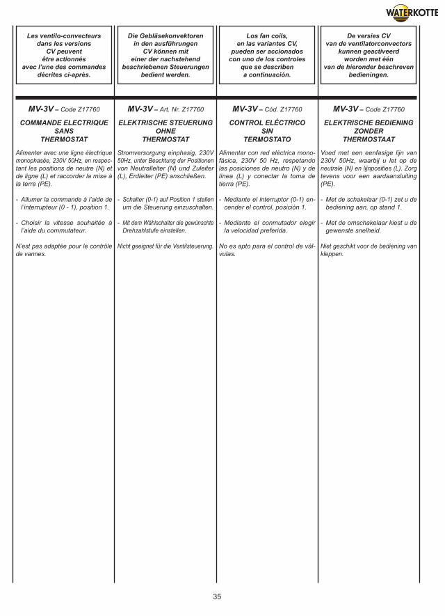
35
Alimenter avec une ligne électriquemonophasée, 230V 50Hz, en respec-tant les positions de neutre (N) etde ligne (L) et raccorder la mise àla terre (PE).
- Allumer la commande à l’aide de l’interrupteur (0 - 1), position 1.
- Choisir la vitesse souhaitée à l’aide du commutateur.
N’est pas adaptée pour le contrôlede vannes.
Stromversorgung einphasig, 230V50Hz, unter Beachtung der Positionenvon Neutralleiter (N) und Zuleiter(L), Erdleiter (PE) anschließen.
- Schalter (0-1) auf Position 1 stellen um die Steuerung einzuschalten.
- Mit dem Wählschalter die gewünschte Drehzahlstufe einstellen.
Nicht geeignet für die Ventilsteuerung.
Alimentar con red eléctrica mono-fásica, 230V 50 Hz, respetandolas posiciones de neutro (N) y delínea (L) y conectar la toma detierra (PE).
- Mediante el interruptor (0-1) en- cender el control, posición 1.
- Mediante el conmutador elegir la velocidad preferida.
No es apto para el control de vál-vulas.
Voed met een eenfasige lijn van230V 50Hz, waarbij u let op deneutrale (N) en lijnposities (L). Zorgtevens voor een aardaansluiting(PE).
- Met de schakelaar (0-1) zet u de bediening aan, op stand 1.
- Met de omschakelaar kiest u de gewenste snelheid.
Niet geschikt voor de bediening vankleppen.
MV-3V – Code Z17760 MV-3V – Art. Nr. Z17760 MV-3V – Cód. Z17760 MV-3V – Code Z17760
Les ventilo-convecteursdans les versions
CV peuventêtre actionnés
avec l’une des commandesdécrites ci-après.
Die Gebläsekonvektorenin den ausführungen
CV können miteiner der nachstehend
beschriebenen Steuerungenbedient werden.
Los fan coils,en las variantes CV,
pueden ser accionadoscon uno de los controles
que se describena continuación.
De versies CVvan de ventilatorconvectors
kunnen geactiveerdworden met één
van de hieronder beschrevenbedieningen.
COMMANDE ELECTRIQUESANS
THERMOSTAT
ELEKTRISCHE STEUERUNGOHNE
THERMOSTAT
CONTROL ELÉCTRICOSIN
TERMOSTATO
ELEKTRISCHE BEDIENINGZONDER
THERMOSTAAT
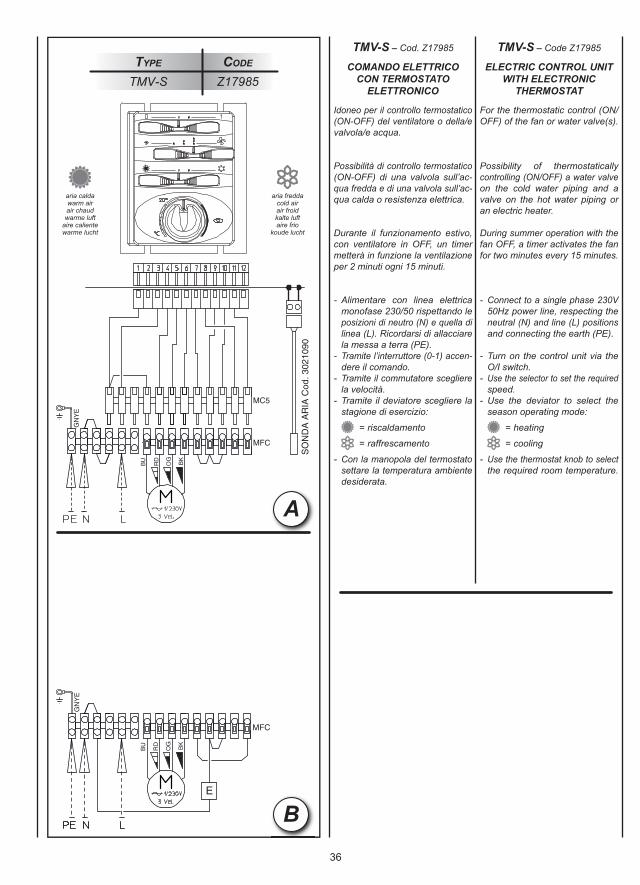
36
Idoneo per il controllo termostatico(ON-OFF) del ventilatore o della/evalvola/e acqua.
Possibilità di controllo termostatico(ON-OFF) di una valvola sull’ac-qua fredda e di una valvola sull’ac-qua calda o resistenza elettrica.
Durante il funzionamento estivo,con ventilatore in OFF, un timermetterà in funzione la ventilazioneper 2 minuti ogni 15 minuti.
- Alimentare con linea elettrica monofase 230/50 rispettando le posizioni di neutro (N) e quella di linea (L). Ricordarsi di allacciare la messa a terra (PE).- Tramite l’interruttore (0-1) accen- dere il comando.- Tramite il commutatore scegliere la velocità.- Tramite il deviatore scegliere la stagione di esercizio:
= riscaldamento
= raffrescamento
- Con la manopola del termostato settare la temperatura ambiente desiderata.
For the thermostatic control (ON/OFF) of the fan or water valve(s).
Possibility of thermostaticallycontrolling (ON/OFF) a water valveon the cold water piping and avalve on the hot water piping oran electric heater.
During summer operation with thefan OFF, a timer activates the fanfor two minutes every 15 minutes.
- Connect to a single phase 230V 50Hz power line, respecting the neutral (N) and line (L) positions and connecting the earth (PE).
- Turn on the control unit via the O/I switch.- Use the selector to set the required speed.- Use the deviator to select the season operating mode:
= heating
= cooling
- Use the thermostat knob to select the required room temperature.
Type Code
TMV-S Z17985
TMV-S – Cod. Z17985 TMV-S – Code Z17985
COMANDO ELETTRICOCON TERMOSTATO
ELETTRONICO
ELECTRIC CONTROL UNITWITH ELECTRONIC
THERMOSTAT
aria caldawarm airair chaudwarme luft
aire calientewarme lucht
aria freddacold airair froidkalte luftaire frio
koude lucht
B
A
+TMM+TMMA
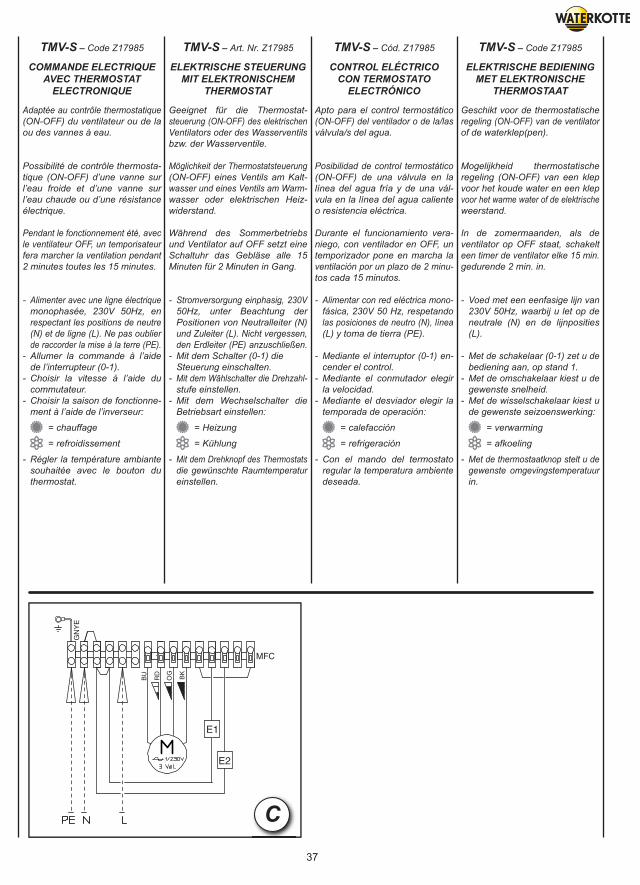
37
Adaptée au contrôle thermostatique(ON-OFF) du ventilateur ou de laou des vannes à eau.
Possibilité de contrôle thermosta-tique (ON-OFF) d’une vanne surl’eau froide et d’une vanne surl’eau chaude ou d’une résistanceélectrique.
Pendant le fonctionnement été, avecle ventilateur OFF, un temporisateurfera marcher la ventilation pendant2 minutes toutes les 15 minutes.
- Alimenter avec une ligne électrique monophasée, 230V 50Hz, en respectant les positions de neutre (N) et de ligne (L). Ne pas oublier de raccorder la mise à la terre (PE).- Allumer la commande à l’aide de l’interrupteur (0-1).- Choisir la vitesse à l’aide du commutateur.- Choisir la saison de fonctionne- ment à l’aide de l’inverseur:
= chauffage
= refroidissement
- Régler la température ambiante souhaitée avec le bouton du thermostat.
Geeignet für die Thermostat-steuerung (ON-OFF) des elektrischenVentilators oder des Wasserventilsbzw. der Wasserventile.
Möglichkeit der Thermostatsteuerung(ON-OFF) eines Ventils am Kalt-wasser und eines Ventils am Warm-wasser oder elektrischen Heiz-widerstand.
Während des Sommerbetriebsund Ventilator auf OFF setzt eineSchaltuhr das Gebläse alle 15Minuten für 2 Minuten in Gang.
- Stromversorgung einphasig, 230V 50Hz, unter Beachtung der Positionen von Neutralleiter (N) und Zuleiter (L). Nicht vergessen, den Erdleiter (PE) anzuschließen.- Mit dem Schalter (0-1) die Steuerung einschalten.- Mit dem Wählschalter die Drehzahl- stufe einstellen.- Mit dem Wechselschalter die Betriebsart einstellen:
= Heizung
= Kühlung
- Mit dem Drehknopf des Thermostats die gewünschte Raumtemperatur einstellen.
Apto para el control termostático(ON-OFF) del ventilador o de la/lasválvula/s del agua.
Posibilidad de control termostático(ON-OFF) de una válvula en lalínea del agua fría y de una vál-vula en la línea del agua calienteo resistencia eléctrica.
Durante el funcionamiento vera-niego, con ventilador en OFF, untemporizador pone en marcha laventilación por un plazo de 2 minu-tos cada 15 minutos.
- Alimentar con red eléctrica mono- fásica, 230V 50 Hz, respetando las posiciones de neutro (N), línea (L) y toma de tierra (PE).
- Mediante el interruptor (0-1) en- cender el control.- Mediante el conmutador elegir la velocidad.- Mediante el desviador elegir la temporada de operación:
= calefacción
= refrigeración
- Con el mando del termostato regular la temperatura ambiente deseada.
Geschikt voor de thermostatischeregeling (ON-OFF) van de ventilatorof de waterklep(pen).
Mogelijkheid thermostatischeregeling (ON-OFF) van een klepvoor het koude water en een klepvoor het warme water of de elektrischeweerstand.
In de zomermaanden, als deventilator op OFF staat, schakelteen timer de ventilator elke 15 min.gedurende 2 min. in.
- Voed met een eenfasige lijn van 230V 50Hz, waarbij u let op de neutrale (N) en de lijnposities (L).
- Met de schakelaar (0-1) zet u de bediening aan, op stand 1.- Met de omschakelaar kiest u de gewenste snelheid.- Met de wisselschakelaar kiest u de gewenste seizoenswerking:
= verwarming
= afkoeling
- Met de thermostaatknop stelt u de gewenste omgevingstemperatuur in.
TMV-S – Code Z17985 TMV-S – Art. Nr. Z17985 TMV-S – Cód. Z17985 TMV-S – Code Z17985
COMMANDE ELECTRIQUEAVEC THERMOSTAT
ELECTRONIQUE
ELEKTRISCHE STEUERUNGMIT ELEKTRONISCHEM
THERMOSTAT
CONTROL ELÉCTRICOCON TERMOSTATO
ELECTRÓNICO
ELEKTRISCHE BEDIENINGMET ELEKTRONISCHE
THERMOSTAAT
C
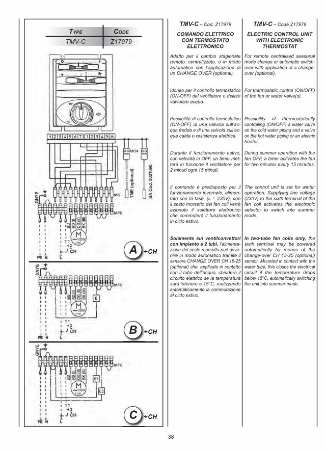
38
+CH+CHB
+CH+CHC
+CH+CHA
Adatto per il cambio stagionaleremoto, centralizzato, o in modoautomatico con l’applicazione diun CHANGE OVER (optional).
Idoneo per il controllo termostatico(ON-OFF) del ventilatore o della/evalvola/e acqua.
Possibilità di controllo termostatico(ON-OFF) di una valvola sull’ac-qua fredda e di una valvola sull’ac-qua calda o resistenza elettrica.
Durante il funzionamento estivo,con velocità in OFF, un timer met-terà in funzione il ventilatore per2 minuti ogni 15 minuti.
Il comando è predisposto per ilfunzionamento invernale, alimen-tato con la fase, (L = 230V), conil sesto morsetto del fan coil verràazionato il selettore elettronicoche commuterà il funzionamentoin ciclo estivo.
Solamente sui ventilconvettoricon impianto a 2 tubi, l’alimenta-zione del sesto morsetto può avve-nire in modo automatico tramite ilsensore CHANGE OVER CH 15-25(optional) che, applicato in contattocon il tubo dell’acqua, chiuderà ilcircuito elettrico se la temperaturasarà inferiore a 15°C, realizzandoautomaticamente la commutazioneal ciclo estivo.
For remote centralised seasonalmode change or automatic switch-over with application of a change-over (optional).
For thermostatic control (ON/OFF)of the fan or water valve(s).
Possibility of thermostaticallycontrolling (ON/OFF) a water valveon the cold water piping and a valveon the hot water piping or an electricheater.
During summer operation with thefan OFF, a timer activates the fanfor two minutes every 15 minutes.
The control unit is set for winteroperation. Supplying line voltage(230V) to the sixth terminal of thefan coil activates the electronicselector to switch into summermode.
In two-tube fan coils only, thesixth terminal may be poweredautomatically by means of thechange-over CH 15-25 (optional)sensor. Mounted in contact with thewater tube, this closes the electricalcircuit if the temperature dropsbelow 15°C, automatically switchingthe unit into summer mode.
Type Code
TMV-C Z17979
TMV-C – Cod. Z17979 TMV-C – Code Z17979
COMANDO ELETTRICOCON TERMOSTATO
ELETTRONICO
ELECTRIC CONTROL UNITWITH ELECTRONIC
THERMOSTAT
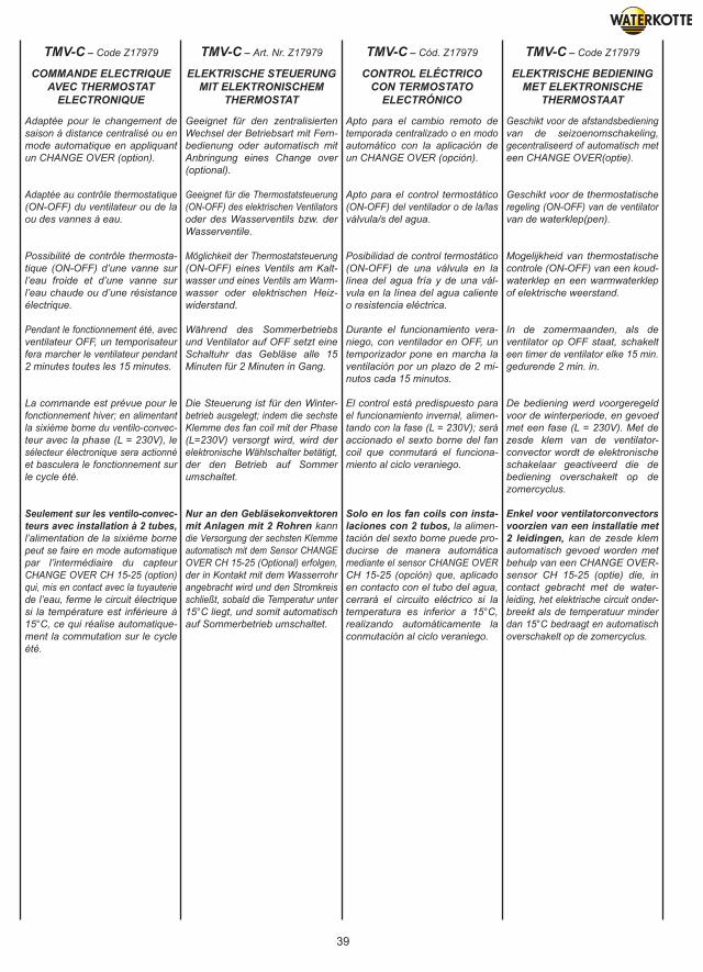
39
Adaptée pour le changement desaison à distance centralisé ou enmode automatique en appliquantun CHANGE OVER (option).
Adaptée au contrôle thermostatique(ON-OFF) du ventilateur ou de laou des vannes à eau.
Possibilité de contrôle thermosta-tique (ON-OFF) d’une vanne surl’eau froide et d’une vanne surl’eau chaude ou d’une résistanceélectrique.
Pendant le fonctionnement été, avecventilateur OFF, un temporisateurfera marcher le ventilateur pendant2 minutes toutes les 15 minutes.
La commande est prévue pour lefonctionnement hiver; en alimentantla sixième borne du ventilo-convec-teur avec la phase (L = 230V), lesélecteur électronique sera actionnéet basculera le fonctionnement surle cycle été.
Seulement sur les ventilo-convec-teurs avec installation à 2 tubes,l’alimentation de la sixième bornepeut se faire en mode automatiquepar l’intermédiaire du capteurCHANGE OVER CH 15-25 (option)qui, mis en contact avec la tuyauteriede l’eau, ferme le circuit électriquesi la température est inférieure à15°C, ce qui réalise automatique-ment la commutation sur le cycleété.
Geeignet für den zentralisiertenWechsel der Betriebsart mit Fern-bedienung oder automatisch mitAnbringung eines Change over(optional).
Geeignet für die Thermostatsteuerung(ON-OFF) des elektrischen Ventilatorsoder des Wasserventils bzw. derWasserventile.
Möglichkeit der Thermostatsteuerung(ON-OFF) eines Ventils am Kalt-wasser und eines Ventils am Warm-wasser oder elektrischen Heiz-widerstand.
Während des Sommerbetriebsund Ventilator auf OFF setzt eineSchaltuhr das Gebläse alle 15Minuten für 2 Minuten in Gang.
Die Steuerung ist für den Winter-betrieb ausgelegt; indem die sechsteKlemme des fan coil mit der Phase(L=230V) versorgt wird, wird derelektronische Wählschalter betätigt,der den Betrieb auf Sommerumschaltet.
Nur an den Gebläsekonvektorenmit Anlagen mit 2 Rohren kanndie Versorgung der sechsten Klemmeautomatisch mit dem Sensor CHANGEOVER CH 15-25 (Optional) erfolgen,der in Kontakt mit dem Wasserrohrangebracht wird und den Stromkreisschließt, sobald die Temperatur unter15°C liegt, und somit automatischauf Sommerbetrieb umschaltet.
Apto para el cambio remoto detemporada centralizado o en modoautomático con la aplicación deun CHANGE OVER (opción).
Apto para el control termostático(ON-OFF) del ventilador o de la/lasválvula/s del agua.
Posibilidad de control termostático(ON-OFF) de una válvula en lalínea del agua fría y de una vál-vula en la línea del agua calienteo resistencia eléctrica.
Durante el funcionamiento vera-niego, con ventilador en OFF, untemporizador pone en marcha laventilación por un plazo de 2 mi-nutos cada 15 minutos.
El control está predispuesto parael funcionamiento invernal, alimen-tando con la fase (L = 230V); seráaccionado el sexto borne del fancoil que conmutará el funciona-miento al ciclo veraniego.
Solo en los fan coils con insta-laciones con 2 tubos, la alimen-tación del sexto borne puede pro-ducirse de manera automáticamediante el sensor CHANGE OVERCH 15-25 (opción) que, aplicadoen contacto con el tubo del agua,cerrará el circuito eléctrico si latemperatura es inferior a 15°C,realizando automáticamente laconmutación al ciclo veraniego.
Geschikt voor de afstandsbedieningvan de seizoenomschakeling,gecentraliseerd of automatisch meteen CHANGE OVER(optie).
Geschikt voor de thermostatische regeling (ON-OFF) van de ventilatorvan de waterklep(pen).
Mogelijkheid van thermostatischecontrole (ON-OFF) van een koud-waterklep en een warmwaterklepof elektrische weerstand.
In de zomermaanden, als deventilator op OFF staat, schakelteen timer de ventilator elke 15 min.gedurende 2 min. in.
De bediening werd voorgeregeldvoor de winterperiode, en gevoedmet een fase (L = 230V). Met dezesde klem van de ventilator-convector wordt de elektronischeschakelaar geactiveerd die debediening overschakelt op dezomercyclus.
Enkel voor ventilatorconvectorsvoorzien van een installatie met2 leidingen, kan de zesde klemautomatisch gevoed worden metbehulp van een CHANGE OVER-sensor CH 15-25 (optie) die, incontact gebracht met de water-leiding, het elektrische circuit onder-breekt als de temperatuur minderdan 15°C bedraagt en automatischoverschakelt op de zomercyclus.
TMV-C – Code Z17979 TMV-C – Art. Nr. Z17979 TMV-C – Cód. Z17979 TMV-C – Code Z17979
COMMANDE ELECTRIQUEAVEC THERMOSTAT
ELECTRONIQUE
ELEKTRISCHE STEUERUNGMIT ELEKTRONISCHEM
THERMOSTAT
CONTROL ELÉCTRICOCON TERMOSTATO
ELECTRÓNICO
ELEKTRISCHE BEDIENINGMET ELEKTRONISCHE
THERMOSTAAT
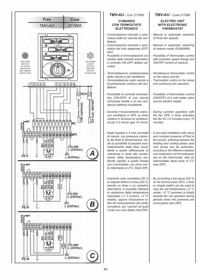
40
C
A
B
- Commutazione manuale o auto- matica delle tre velocità del ven- tilatore.- Commutazione manuale o auto- matica del ciclo stagionale (EST- INV).- Possibilità di termostatazione con cambio della velocità automatico e controllo ON-OFF della/e val- vola/e.
- Termostatazione contemporanea delle valvole e del ventilatore.- Termostatazione sulle valvole e funzionamento continuo del ven- tilatore.
- Possibilità di controllo termosta- tico (ON-OFF) di una valvola sull’acqua fredda e di una resi- stenza elettrica riscaldante.
- Durante il funzionamento estivo, con ventilatore in OFF, un timer metterà in funzione la ventilazio- ne per 2,5 minuti ogni 15 minuti.
- Negli impianti a 4 tubi corredati di valvole, con presenza costan- te dei fl uidi di alimentazione, esi- ste la possibilità di passare auto- maticamente dalla fase riscal- dante a quella raffrescante (o viceversa) in base allo scosta- mento della temperatura am- biente rispetto a quella fi ssata con il termostato; con zona mor- ta intermedia di 2°C (Vedi DIP).
- Inserendo sulla morsettiera (IN 1) un segnale elettrico di linea (230 V), tramite un timer o un semplice interruttore, è possibile ottenere la variazione della temperatura impostata (-3 °C inverno, +3 °C estate), oppure l’esclusione to- tale del funzionamento del ventil- convettore, per i periodi nei quali i locali non sono abitati (Vedi DIP).
- Manual or automatic selection of three fan speeds.
- Manual or automatic switching of season mode (SUM/WIN).
- Possibility of thermostatic control with automatic speed change and ON/OFF control of valve(s).
- Simultaneous thermostatic control on the valves and fan.- Thermostatic control on the valves and continuous fan operation.
- Possibility of thermostatic control (ON/OFF) of a cold water valve and an electric heater.
- During summer operation with the fan OFF, a timer activates the fan for 2,5 minutes every 15 minutes.
- In four-tube installations with valves and constant presence of fl uid in the circuits, switching between the heating and cooling phase (and vice versa) can be automatic, according to the difference between room temperature and the temperature set on the thermostat, with an intermediate dead zone of 2°C (see DIP).
- By connecting a line signal (230 V) on the terminal board (IN1), a timer or simple switch can be used to vary the set temperature (-3 °C winter, +3 °C summer) or totally exclude fan coil operation during periods when the premises are unoccupied (see DIP).
Type Code
TMV-AU Z17885
TMV-AU – Cod. Z17885 TMV-AU – Code Z17885
COMANDOCON TERMOSTATO
ELETTRONICO
ELECTRIC UNITWITH ELECTRONIC
THERMOSTAT
aria caldawarm airair chaudwarme luft
aire calientewarme lucht
aria freddacold airair froidkalte luftaire frio
koude lucht
41
- Commutation manuelle ou auto- matique des trois vitesses du ventilateur.- Commutation manuelle ou auto- matique du cycle saisonnier (été- hiver).- Possibilité de thermostatage avec changement de la vitesse auto- matique et contrôle ON-OFF de la ou des vannes.
- Thermostatation simultanée des vannes et du ventilateur.- Thermostatation sur les vannes et fonctionnement continu du ventilateur.
- Possibilité de contrôle thermo- statique (ON-OFF) d’une vanne sur l’eau froide et d’une résistance électrique de chauffage.
- Pendant le fonctionnement été, avec le ventilateur OFF, un tempo- risateur fera marcher la ventilation pendant 2,5 minutes toutes les 15 minutes.
- Dans les installations à 4 tuyau- teries équipées de vannes, avec présence constante des fluides d’alimentation, on a la possibilité de passer automatiquement de la phase de chauffage à celle de rafraîchissement (et vice versa) sur la base de l’écart entre la température ambiante et celle réglée sur le thermostat, avec une zone morte intermédiaire de 2°C (cf. DIP).
- En branchant sur le bornier (IN1) un signal électrique de ligne (230 V), par l’intermédiaire d’un tempori- sateur ou d’un simple interrupteur, on peut obtenir la variation de la température programmée (moins 3 °C hiver, plus 3 °C été) ou l’ex- clusion totale du fonctionnement du ventilo-convecteur pendant les périodes durant lesquelles les locaux ne sont pas habités (cf. DIP).
- Manuelle oder automatische Umschaltung der drei Drehzahl- stufen des Ventilators.- Manuelle oder automatische Umschaltung der Betriebsart (SOMMER/WINTER).- Möglichkeit der Thermostat- regelung mit automatischem Wechsel der Drehzahlstufe und ON-OFF-Kontrolle des Ventils bzw. der Ventile.- Gleichzeitige Temperaturregelung der Ventile und des Ventilators.- Temperaturregelung der Ventile und Dauerbetrieb des Ventilators.
- Möglichkeit der Thermostat- steuerung (ON-OFF) eines Ventils am Kaltwasser und eines elektrischen Heizwiderstands.
- Während des Sommerbetriebs und Ventilator auf OFF setzt eine Schaltuhr das Gebläse alle 15 Minuten für 2,5 Minuten in Gang.
- Bei den mit Ventilen ausgestatteten Anlagen mit 4 Rohren mit konstanter Präsenz der Versorgungsflüssig- keiten, ist die Möglichkeit gegeben, je nach der Abweichung der Raum- temperatur im Vergleich zu der am Thermostat eingegebenen Temperatur automatisch von der Heiz- zur Kühlphase (und umgekehrt) überzugehen, mit einem Übergangs-Totbereich von 2°C (siehe DIP-Schalter).
- Wenn am Klemmenbrett (IN1) ein elektrisches Netzsignal (230 V) eingesetzt wird, kann mit einer Schaltuhr oder einem einfachen Schalter die am Thermostat ein- gestellte Temperatur (minus 3 °C beim Winterbetrieb, plus 3 °C beim Sommerbetrieb) geändert, oder der Betrieb des Gebläsekonvektors für die Perioden, in denen die Räume unbewohnt sind, ganz ausgeschlossen werden (siehe DIP-Schalter).
- Conmutación manual o auto- mática de las tres velocidades del ventilador.- Conmutación manual o auto- mática del ciclo de temporada (VER-INV).- Posibilidad de regulación termo- stática con cambio automático de la velocidad y control ON-OFF de la/s válvula/s.
- Termostatación de las válvulas y los ventiladores al mismo tiempo.- Termostatación sobre las válvulas y funcionamiento contínuo del ventilador.
- Posibilidad de control termostá- tico (ON-OFF) de una válvula en la línea del agua fría y de una resistencia eléctrica calefactora.
- Durante el funcionamiento vera- niego, con ventilador en OFF, un temporizador pone en marcha la ventilación durante 2,5 minutos cada 15 minutos.
- En las instalaciones con 4 tubos provistos de válvulas, con pre- sencia constante de los fluidos de alimentación, cabe la posibi- lidad de pasar automáticamente desde la fase calefactora a la refrescadora (y viceversa) según la diferencia entre la temperatu- ra ambiente y la determinada con el termostato; con zona muerta intermedia de 2 °C (ver DIP).
- Aplicando en la borna de conexión (IN 1) una señal eléctrica de línea (230 V), mediante un temporiza- dor o un simple interruptor es posible conseguir la variación de la temperatura establecida (me- nos 3 °C invierno, más 3 °C ve- rano), o la exclusión total del fun- cionamiento del fan coil durante los periodos en que no se utilizan los cuartos (ver DIP).
- Manuele of automatische instelling van de drie snelheden van de ventilator.- Manuele omschakeling van de seizoencycli (ZOMER-WINTER).
- Mogelijke thermostatische regeling met automatische regeling van de snelheid en ON-OFF controle van de klep(pen).
- Gelijktijdige thermostatische regeling kleppen en ventilator.- Thermostatische regeling kleppen en constante werking van de ventilator.
- Mogelijke thermostatische regeling (ON-OFF) van een klep voor het koud water en een elektrische weerstand voor de verwarming.
- In de zomermaanden, als de ventilator op OFF staat, schakelt een timer de ventilator elke 15 min. gedurende 2 min. in.
- Voor de installaties met 4 leidingen uitgerust met kleppen en met een constante aanwezigheid van voedingsvloeistoffen, kan auto- matisch worden overgeschakeld van de verwarmende fase naar de afkoelende fase (of vice versa) in functie van het verschil tussen de omgevingstemperatuur en de thermostatisch ingestelde temperatuur; met een dode tussen- zone van 2°C (zie dimschakelaar).
- Door naar het klemmenbord (IN1) een elektrisch lijnsignaal (230 V) te sturen, met behulp van een timer of een eenvoudige schakelaar, kan de variatie worden bekomen van de ingestelde temperatuur (-3 °C in de winter, +3 °C in de zomer), ofwel de totale uitschakeling van de ventilatorconvector in de periodes waarin de lokalen niet bewoond zijn (zie dimschakelaar).
TMV-AU– Code Z17885 TMV-AU – Art. Nr. Z17885 TMV-AU – Cód. Z17885 TMV-AU – Code Z17885
COMMANDEAVEC THERMOSTAT
ELECTRONIQUE
STEUERUNGMIT ELEKTRONISCHEM
THERMOSTAT
CONTROLCON TERMOSTATO
ELECTRÓNICO
BEDIENINGMET ELEKTRONISCHE
THERMOSTAAT
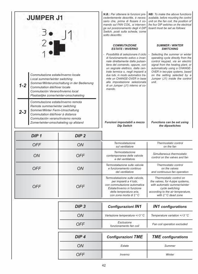
42
N.B.: Per ottenere le funzioni pre-cedentemente descritte, è neces-sario che, prima di fissare il co-mando sul FAN COIL, si interven-ga sul posizionamento degli 4 DIPSwitch, posti sulla scheda, comesotto descritto:
COMMUTAZIONEESTATE / INVERNO
- Possibilità di selezionare il ciclo di funzionamento estivo o inver- nale direttamente dalla pulsan- tiera del comando, oppure, con un segnale elettrico, dalla cen- trale termica o, negli impianti a due tubi, in modo automatico tra- mite un CHANGE-OVER in base alla impostazione selezionata di un Jumper (J1) interno al co- mando.
Funzioni impostabili a mezzoDip Switch
NB: To make the above functionsavailable, before mounting the controlunit on the fan coil, the position ofthe four DIP switches on the electricalboard must be set as follows:
SUMMER / WINTERSWITCHING
- Selecting the summer or winter operating cycle directly from the control keypad, via an electric signal from the heating plant, or automatically using a CHANGE- OVER in two-pipe systems, based on the setting selected by a Jumper (J1) inside the control unit.
Functions can be set usingthe dipswitches
1-2
2-3
Commutazione estate/inverno localeLocal summer/winter switchingSommer/Winterumschaltung in der Bedienung Commutation été/hiver localeConmutación Verano/Invierno localPlaatselijke zomer/winter-omschakeling
Commutazione estate/inverno remotaRemote summer/winter switchingSommer/Winter Ferm-UmschaltungCommutation été/hiver à distanceConmutación verano/invierno remotaZomer/winter-omschakeling op afstand
OFF ON
DIP 1 DIP 2
ON OFF
OFF ON
OFF OFF
ON
DIP 3
OFF
Termostatazionesul ventilatore
Thermostatic controlon the fan
Termostatazionecontemporanea delle valvole
e del ventilatore
Simultaneous thermostaticcontrol on the valves and fan
Termostatazione sulle valvolee funzionamento continuo
del ventilatore
Thermostatic controlon the valves
and continuous fan operation
Termostatazione sulle valvole,per impianti a 4 tubi,
con commutazione automaticaEstate/Inverno in funzione
della temperatura aria,con zona morta di 2 °C
Thermostatic control onthe valves, for 4-pipe systems,with automatic summer/winter
cycle switchingaccording to the air temperature,
with 2 °C dead zone
Variazione temperatura +/-3 °C Temperature variation +/-3 °C
Esclusionefunzionamento fan coil Fan coil operation excluded
Configurazioni IN1 IN1 configurations
ON
DIP 4
OFF
Estate Summer
Inverno Winter
Configurazioni TME TME configurations
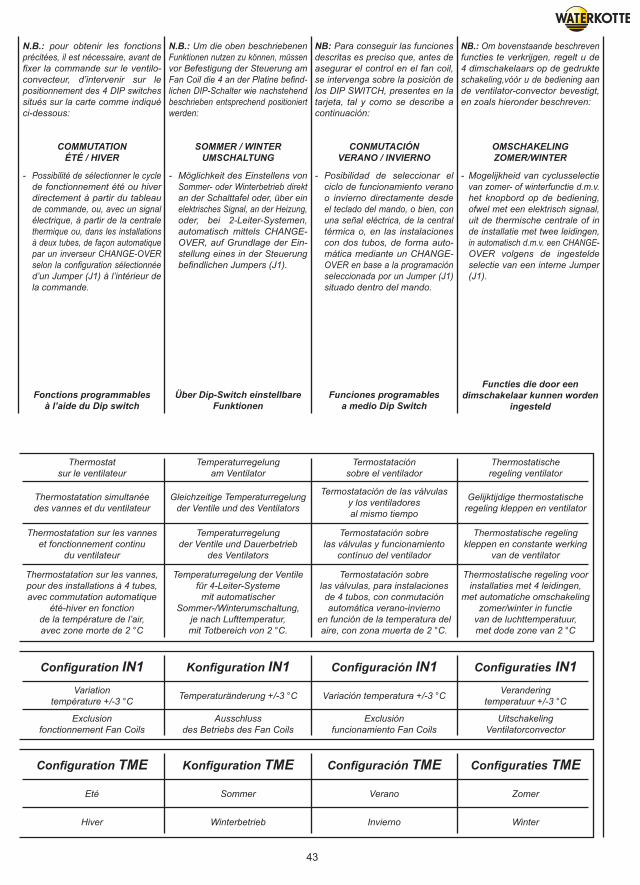
43
N.B.: pour obtenir les fonctionsprécitées, il est nécessaire, avant defixer la commande sur le ventilo-convecteur, d’intervenir sur lepositionnement des 4 DIP switchessitués sur la carte comme indiquéci-dessous:
COMMUTATIONÉTÉ / HIVER
- Possibilité de sélectionner le cycle de fonctionnement été ou hiver directement à partir du tableau de commande, ou, avec un signal électrique, à partir de la centrale thermique ou, dans les installations à deux tubes, de façon automatique par un inverseur CHANGE-OVER selon la configuration sélectionnée d’un Jumper (J1) à l’intérieur de la commande.
Fonctions programmablesà l’aide du Dip switch
N.B.: Um die oben beschriebenenFunktionen nutzen zu können, müssenvor Befestigung der Steuerung amFan Coil die 4 an der Platine befind-lichen DIP-Schalter wie nachstehendbeschrieben entsprechend positioniertwerden:
SOMMER / WINTERUMSCHALTUNG
- Möglichkeit des Einstellens von Sommer- oder Winterbetrieb direkt an der Schalttafel oder, über ein elektrisches Signal, an der Heizung, oder, bei 2-Leiter-Systemen, automatisch mittels CHANGE- OVER, auf Grundlage der Ein- stellung eines in der Steuerung befindlichen Jumpers (J1).
Über Dip-Switch einstellbareFunktionen
NB: Para conseguir las funcionesdescritas es preciso que, antes deasegurar el control en el fan coil,se intervenga sobre la posición delos DIP SWITCH, presentes en latarjeta, tal y como se describe acontinuación:
CONMUTACIÓNVERANO / INVIERNO
- Posibilidad de seleccionar el ciclo de funcionamiento verano o invierno directamente desde el teclado del mando, o bien, con una señal eléctrica, de la central térmica o, en las instalaciones con dos tubos, de forma auto- mática mediante un CHANGE- OVER en base a la programación seleccionada por un Jumper (J1) situado dentro del mando.
Funciones programablesa medio Dip Switch
NB.: Om bovenstaande beschrevenfuncties te verkrijgen, regelt u de4 dimschakelaars op de gedrukteschakeling,vóór u de bediening aande ventilator-convector bevestigt,en zoals hieronder beschreven:
OMSCHAKELINGZOMER/WINTER
- Mogelijkheid van cyclusselectie van zomer- of winterfunctie d.m.v. het knopbord op de bediening, ofwel met een elektrisch signaal, uit de thermische centrale of in de installatie met twee leidingen, in automatisch d.m.v. een CHANGE- OVER volgens de ingestelde selectie van een interne Jumper (J1).
Functies die door eendimschakelaar kunnen worden
ingesteld
Thermostatsur le ventilateur
Temperaturregelungam Ventilator
Termostataciónsobre el ventilador
Thermostatischeregeling ventilator
Thermostatation simultanéedes vannes et du ventilateur
Gleichzeitige Temperaturregelungder Ventile und des Ventilators
Termostatación de las válvulasy los ventiladoresal mismo tiempo
Gelijktijdige thermostatischeregeling kleppen en ventilator
Thermostatation sur les vanneset fonctionnement continu
du ventilateur
Temperaturregelungder Ventile und Dauerbetrieb
des Ventilators
Termostatación sobrelas válvulas y funcionamiento
contínuo del ventilador
Thermostatische regelingkleppen en constante werking
van de ventilator
Thermostatation sur les vannes,pour des installations à 4 tubes,avec commutation automatique
été-hiver en fonctionde la température de l’air,avec zone morte de 2 °C
Temperaturregelung der Ventilefür 4-Leiter-Systeme
mit automatischerSommer-/Winterumschaltung,
je nach Lufttemperatur,mit Totbereich von 2 °C.
Termostatación sobrelas válvulas, para instalacionesde 4 tubos, con conmutaciónautomática verano-invierno
en función de la temperatura del aire, con zona muerta de 2 °C.
Thermostatische regeling voorinstallaties met 4 leidingen,
met automatiche omschakelingzomer/winter in functie
van de luchttemperatuur,met dode zone van 2 °C
Variationtempérature +/-3 °C Temperaturänderung +/-3 °C Variación temperatura +/-3 °C Verandering
temperatuur +/-3 °C
Exclusionfonctionnement Fan Coils
Ausschlussdes Betriebs des Fan Coils
Exclusiónfuncionamiento Fan Coils
UitschakelingVentilatorconvector
Configuration IN1 Konfiguration IN1 Configuración IN1 Configuraties IN1
Eté Sommer Verano Zomer
Hiver Winterbetrieb Invierno Winter
Configuration TME Konfiguration TME Configuración TME Configuraties TME
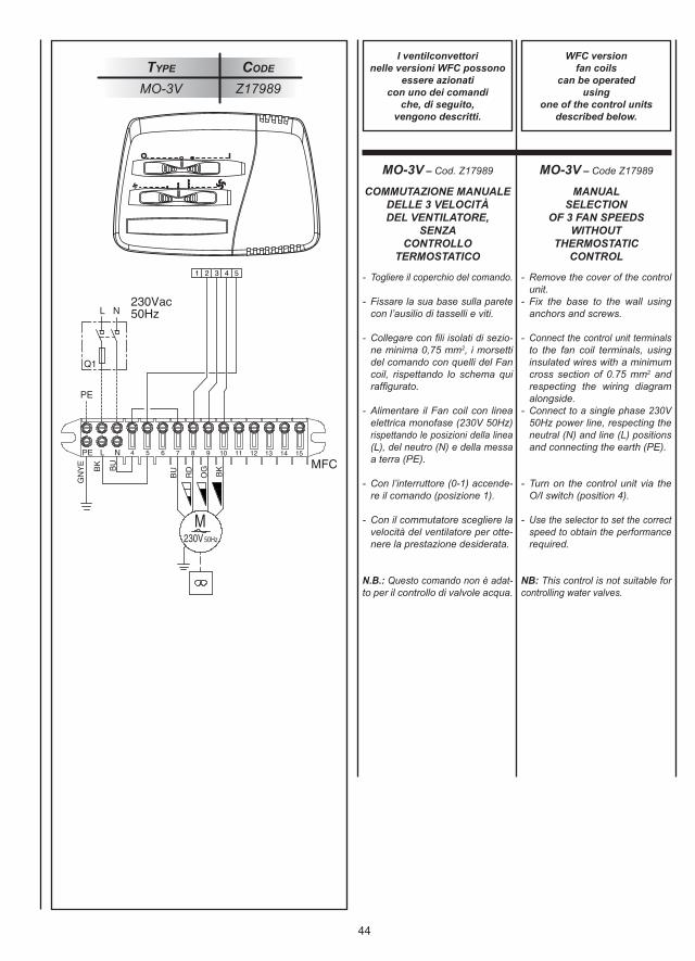
44
Type Code
MO-3V Z17989
- Togliere il coperchio del comando.
- Fissare la sua base sulla parete con l’ausilio di tasselli e viti.
- Collegare con fili isolati di sezio- ne minima 0,75 mm2, i morsetti del comando con quelli del Fan coil, rispettando lo schema qui raffigurato.
- Alimentare il Fan coil con linea elettrica monofase (230V 50Hz) rispettando le posizioni della linea (L), del neutro (N) e della messa a terra (PE).
- Con l’interruttore (0-1) accende- re il comando (posizione 1).
- Con il commutatore scegliere la velocità del ventilatore per otte- nere la prestazione desiderata.
N.B.: Questo comando non è adat-to per il controllo di valvole acqua.
- Remove the cover of the control unit.- Fix the base to the wall using anchors and screws.
- Connect the control unit terminals to the fan coil terminals, using insulated wires with a minimum cross section of 0.75 mm2 and respecting the wiring diagram alongside.- Connect to a single phase 230V 50Hz power line, respecting the neutral (N) and line (L) positions and connecting the earth (PE).
- Turn on the control unit via the O/I switch (position 4).
- Use the selector to set the correct speed to obtain the performance required.
NB: This control is not suitable forcontrolling water valves.
MO-3V – Cod. Z17989 MO-3V – Code Z17989
I ventilconvettorinelle versioni WFC possono
essere azionaticon uno dei comandi
che, di seguito,vengono descritti.
WFC versionfan coils
can be operatedusing
one of the control unitsdescribed below.
COMMUTAZIONE MANUALEDELLE 3 VELOCITÀDEL VENTILATORE,
SENZACONTROLLO
TERMOSTATICO
MANUALSELECTION
OF 3 FAN SPEEDSWITHOUT
THERMOSTATICCONTROL
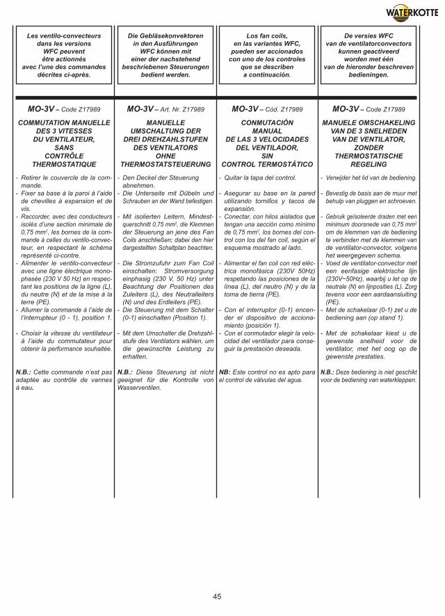
45
- Retirer le couvercle de la com- mande.- Fixer sa base à la paroi à l’aide de chevilles à expansion et de vis.- Raccorder, avec des conducteurs isolés d’une section minimale de 0,75 mm2, les bornes de la com- mande à celles du ventilo-convec- teur, en respectant le schéma représenté ci-contre.- Alimenter le ventilo-convecteur avec une ligne électrique mono- phasée (230 V 50 Hz) en respec- tant les positions de la ligne (L), du neutre (N) et de la mise à la terre (PE).- Allumer la commande à l’aide de l’interrupteur (0 - 1), position 1.
- Choisir la vitesse du ventilateur à l’aide du commutateur pour obtenir la performance souhaitée.
N.B.: Cette commande n’est pasadaptée au contrôle de vannesà eau.
- Den Deckel der Steuerung abnehmen. - Die Unterseite mit Dübeln und Schrauben an der Wand befestigen.
- Mit isolierten Leitern, Mindest- querschnitt 0,75 mm2, die Klemmen der Steuerung an jene des Fan Coils anschließen; dabei den hier dargestellten Schaltplan beachten.
- Die Stromzufuhr zum Fan Coil einschalten: Stromversorgung einphasig (230 V, 50 Hz) unter Beachtung der Positionen des Zuleiters (L), des Neutralleiters (N) und des Erdleiters (PE).- Die Steuerung mit dem Schalter (0-1) einschalten (Position 1).
- Mit dem Umschalter die Drehzahl- stufe des Ventilators wählen, um die gewünschte Leistung zu erhalten.
N.B.: Diese Steuerung ist nichtgeeignet für die Kontrolle vonWasserventilen.
- Quitar la tapa del control.
- Asegurar su base en la pared utilizando tornillos y tacos de expansión.- Conectar, con hilos aislados que tengan una sección como mínimo de 0,75 mm2, los bornes del con- trol con los del fan coil, según el esquema mostrado al lado.
- Alimentar el fan coil con red eléc- trica monofásica (230V 50Hz) respetando las posiciones de la línea (L), del neutro (N) y de la toma de tierra (PE).
- Con el interruptor (0-1) encen- der el dispositivo de acciona- miento (posición 1).- Con el conmutador elegir la velo- cidad del ventilador para conse- guir la prestación deseada.
NB: Este control no es apto parael control de válvulas del agua.
- Verwijder het lid van de bediening.
- Bevestig de basis aan de muur met behulp van pluggen en schroeven.
- Gebruik geïsoleerde draden met een minimum doorsnede van 0,75 mm2
om de klemmen van de bediening te verbinden met de klemmen van de ventilator-convector, volgens het weergegeven schema.- Voed de ventilator-convector met een eenfasige elektrische lijn (230V~50Hz), waarbij u let op de neutrale (N) en lijnposities (L). Zorg tevens voor een aardaansluiting (PE).- Met de schakelaar (0-1) zet u de bediening aan (op stand 1).
- Met de schakelaar kiest u de gewenste snelheid voor de ventilator, met het oog op de gewenste prestaties.
N.B.: Deze bediening is niet geschiktvoor de bediening van waterkleppen.
MO-3V – Code Z17989 MO-3V – Art. Nr. Z17989 MO-3V – Cód. Z17989 MO-3V – Code Z17989
Les ventilo-convecteursdans les versions
WFC peuventêtre actionnés
avec l’une des commandesdécrites ci-après.
Die Gebläsekonvektorenin den Ausführungen
WFC können miteiner der nachstehend
beschriebenen Steuerungenbedient werden.
Los fan coils,en las variantes WFC,
pueden ser accionadoscon uno de los controles
que se describena continuación.
De versies WFCvan de ventilatorconvectors
kunnen geactiveerdworden met één
van de hieronder beschrevenbedieningen.
COMMUTATION MANUELLEDES 3 VITESSES
DU VENTILATEUR,SANS
CONTRÔLETHERMOSTATIQUE
MANUELLEUMSCHALTUNG DER
DREI DREHZAHLSTUFENDES VENTILATORS
OHNETHERMOSTATSTEUERUNG
CONMUTACIÓNMANUAL
DE LAS 3 VELOCIDADESDEL VENTILADOR,
SINCONTROL TERMOSTÁTICO
MANUELE OMSCHAKELINGVAN DE 3 SNELHEDENVAN DE VENTILATOR,
ZONDERTHERMOSTATISCHE
REGELING
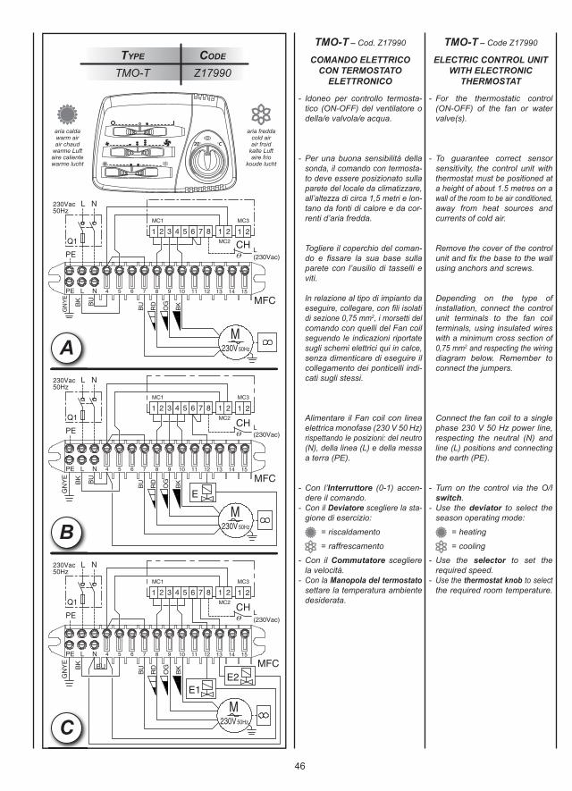
46
Type Code
TMO-T Z17990
C
B
- Idoneo per controllo termosta- tico (ON-OFF) del ventilatore o della/e valvola/e acqua.
- Per una buona sensibilità della sonda, il comando con termosta- to deve essere posizionato sulla parete del locale da climatizzare, all’altezza di circa 1,5 metri e lon- tano da fonti di calore e da cor- renti d’aria fredda.
Togliere il coperchio del coman- do e fi ssare la sua base sulla parete con l’ausilio di tasselli e viti.
In relazione al tipo di impianto da eseguire, collegare, con fi li isolati di sezione 0,75 mm2, i morsetti del comando con quelli del Fan coil seguendo le indicazioni riportate sugli schemi elettrici qui in calce, senza dimenticare di eseguire il collegamento dei ponticelli indi- cati sugli stessi.
Alimentare il Fan coil con linea elettrica monofase (230 V 50 Hz) rispettando le posizioni: del neutro (N), della linea (L) e della messa a terra (PE).
- Con l’Interruttore (0-1) accen- dere il comando.- Con il Deviatore scegliere la sta- gione di esercizio:
= riscaldamento
= raffrescamento
- Con il Commutatore scegliere la velocità.- Con la Manopola del termostato settare la temperatura ambiente desiderata.
- For the thermostatic control (ON-OFF) of the fan or water valve(s).
- To guarantee correct sensor sensitivity, the control unit with thermostat must be positioned at a height of about 1.5 metres on a wall of the room to be air conditioned, away from heat sources and currents of cold air.
Remove the cover of the control unit and fi x the base to the wall using anchors and screws.
Depending on the type of installation, connect the control unit terminals to the fan coil terminals, using insulated wires with a minimum cross section of 0,75 mm2 and respecting the wiring diagram below. Remember to connect the jumpers.
Connect the fan coil to a single phase 230 V 50 Hz power line, respecting the neutral (N) and line (L) positions and connecting the earth (PE).
- Turn on the control via the O/I switch. - Use the deviator to select the season operating mode:
= heating
= cooling
- Use the selector to set the required speed.- Use the thermostat knob to select the required room temperature.
COMANDO ELETTRICOCON TERMOSTATO
ELETTRONICO
ELECTRIC CONTROL UNITWITH ELECTRONIC
THERMOSTAT
TMO-T – Cod. Z17990 TMO-T – Code Z17990
A
aria caldawarm airair chaud
warme Luftaire calientewarme lucht
aria freddacold airair froid
kalte Luftaire frio
koude lucht
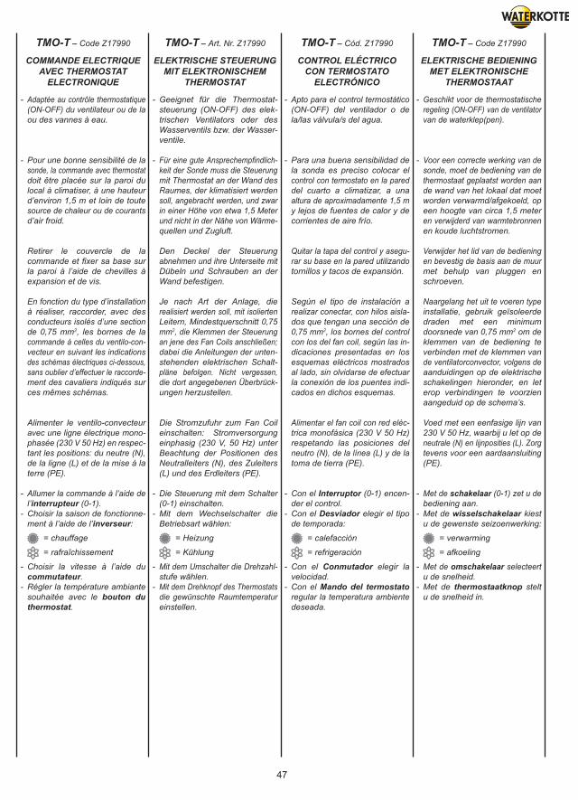
47
- Adaptée au contrôle thermostatique (ON-OFF) du ventilateur ou de la ou des vannes à eau.
- Pour une bonne sensibilité de la sonde, la commande avec thermostat doit être placée sur la paroi du local à climatiser, à une hauteur d’environ 1,5 m et loin de toute source de chaleur ou de courants d’air froid.
Retirer le couvercle de la commande et fixer sa base sur la paroi à l’aide de chevilles à expansion et de vis.
En fonction du type d’installation à réaliser, raccorder, avec des conducteurs isolés d’une section de 0,75 mm2, les bornes de la commande à celles du ventilo-con- vecteur en suivant les indications des schémas électriques ci-dessous, sans oublier d’effectuer le raccorde- ment des cavaliers indiqués sur ces mêmes schémas.
Alimenter le ventilo-convecteur avec une ligne électrique mono- phasée (230 V 50 Hz) en respec- tant les positions: du neutre (N), de la ligne (L) et de la mise à la terre (PE).
- Allumer la commande à l’aide de l’interrupteur (0-1).- Choisir la saison de fonctionne- ment à l’aide de l’inverseur: = chauffage
= rafraîchissement
- Choisir la vitesse à l’aide du commutateur.- Régler la température ambiante souhaitée avec le bouton du thermostat.
- Geeignet für die Thermostat- steuerung (ON-OFF) des elek- trischen Ventilators oder des Wasserventils bzw. der Wasser- ventile.
- Für eine gute Ansprechempfindlich- keit der Sonde muss die Steuerung mit Thermostat an der Wand des Raumes, der klimatisiert werden soll, angebracht werden, und zwar in einer Höhe von etwa 1,5 Meter und nicht in der Nähe von Wärme- quellen und Zugluft.
Den Deckel der Steuerung abnehmen und ihre Unterseite mit Dübeln und Schrauben an der Wand befestigen.
Je nach Art der Anlage, die realisiert werden soll, mit isolierten Leitern, Mindestquerschnitt 0,75 mm2, die Klemmen der Steuerung an jene des Fan Coils anschließen; dabei die Anleitungen der unten- stehenden elektrischen Schalt- pläne befolgen. Nicht vergessen, die dort angegebenen Überbrück- ungen herzustellen.
Die Stromzufuhr zum Fan Coil einschalten: Stromversorgung einphasig (230 V, 50 Hz) unter Beachtung der Positionen des Neutralleiters (N), des Zuleiters (L) und des Erdleiters (PE).
- Die Steuerung mit dem Schalter (0-1) einschalten. - Mit dem Wechselschalter die Betriebsart wählen:
= Heizung
= Kühlung
- Mit dem Umschalter die Drehzahl- stufe wählen.- Mit dem Drehknopf des Thermostats die gewünschte Raumtemperatur einstellen.
- Apto para el control termostático (ON-OFF) del ventilador o de la/las válvula/s del agua.
- Para una buena sensibilidad de la sonda es preciso colocar el control con termostato en la pared del cuarto a climatizar, a una altura de aproximadamente 1,5 m y lejos de fuentes de calor y de corrientes de aire frío.
Quitar la tapa del control y asegu- rar su base en la pared utilizando tornillos y tacos de expansión.
Según el tipo de instalación a realizar conectar, con hilos aisla- dos que tengan una sección de 0,75 mm2, los bornes del control con los del fan coil, según las in- dicaciones presentadas en los esquemas eléctricos mostrados al lado, sin olvidarse de efectuar la conexión de los puentes indi- cados en dichos esquemas.
Alimentar el fan coil con red eléc- trica monofásica (230 V 50 Hz) respetando las posiciones del neutro (N), de la línea (L) y de la toma de tierra (PE).
- Con el Interruptor (0-1) encen- der el control.- Con el Desviador elegir el tipo de temporada:
= calefacción
= refrigeración
- Con el Conmutador elegir la velocidad.- Con el Mando del termostato regular la temperatura ambiente deseada.
- Geschikt voor de thermostatische regeling (ON-OFF) van de ventilator van de waterklep(pen).
- Voor een correcte werking van de sonde, moet de bediening van de thermostaat geplaatst worden aan de wand van het lokaal dat moet worden verwarmd/afgekoeld, op een hoogte van circa 1,5 meter en verwijderd van warmtebronnen en koude luchtstromen.
Verwijder het lid van de bediening en bevestig de basis aan de muur met behulp van pluggen en schroeven.
Naargelang het uit te voeren type installatie, gebruik geïsoleerde draden met een minimum doorsnede van 0,75 mm2 om de klemmen van de bediening te verbinden met de klemmen van de ventilatorconvector, volgens de aanduidingen op de elektrische schakelingen hieronder, en let erop verbindingen te voorzien aangeduid op de schema’s.
Voed met een eenfasige lijn van 230 V 50 Hz, waarbij u let op de neutrale (N) en lijnposities (L). Zorg tevens voor een aardaansluiting (PE).
- Met de schakelaar (0-1) zet u de bediening aan.- Met de wisselschakelaar kiest u de gewenste seizoenwerking:
= verwarming
= afkoeling
- Met de omschakelaar selecteert u de snelheid.- Met de thermostaatknop stelt u de snelheid in.
COMMANDE ELECTRIQUEAVEC THERMOSTAT
ELECTRONIQUE
ELEKTRISCHE STEUERUNGMIT ELEKTRONISCHEM
THERMOSTAT
CONTROL ELÉCTRICOCON TERMOSTATO
ELECTRÓNICO
ELEKTRISCHE BEDIENINGMET ELEKTRONISCHE
THERMOSTAAT
TMO-T – Code Z17990 TMO-T – Art. Nr. Z17990 TMO-T – Cód. Z17990 TMO-T – Code Z17990
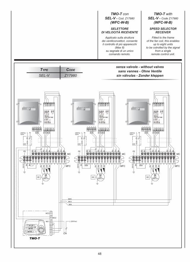
48
senza valvole - without valvessans vannes - Ohne Ventile
sin válvulas - Zonder kleppenType Code
SEL-V Z17980
Applicato sulla strutturadei ventilconvettori, consenteil controllo di più apparecchi
(Max 8)su segnale di un unico
comando remoto.
Fitted to the frameof the fan coil, this enables
up to eight unitsto be cotrolled by the signal
from a singleremote control unit.
SELETTOREDI VELOCITÀ RICEVENTE
SPEED SELECTORRECEIVER
TMO-T conSEL-V – Cod. Z17980
(WFC-W-B)
TMO-T withSEL-V – Code Z17980
(WFC-W-B)
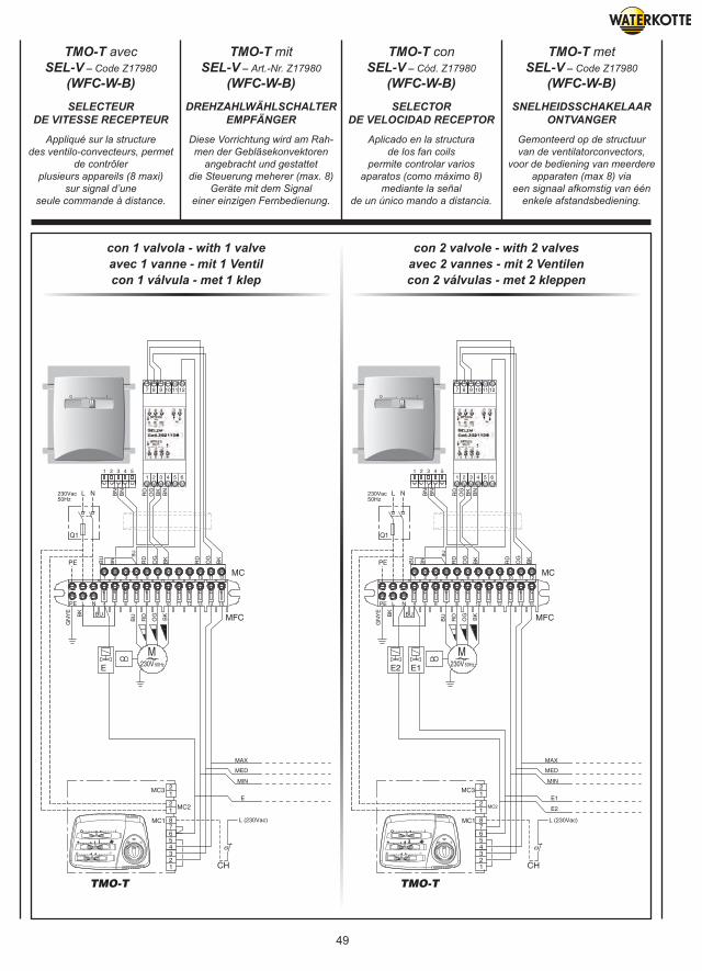
49
con 1 valvola - with 1 valveavec 1 vanne - mit 1 Ventilcon 1 válvula - met 1 klep
con 2 valvole - with 2 valvesavec 2 vannes - mit 2 Ventilencon 2 válvulas - met 2 kleppen
Appliqué sur la structuredes ventilo-convecteurs, permet
de contrôlerplusieurs appareils (8 maxi)
sur signal d’uneseule commande à distance.
Diese Vorrichtung wird am Rah-men der Gebläsekonvektoren
angebracht und gestattetdie Steuerung meherer (max. 8)
Geräte mit dem Signaleiner einzigen Fernbedienung.
Aplicado en la structurade los fan coils
permite controlar variosaparatos (como máximo 8)
mediante la señalde un único mando a distancia.
Gemonteerd op de structuurvan de ventilatorconvectors,
voor de bediening van meerdereapparaten (max 8) via
een signaal afkomstig van éénenkele afstandsbediening.
SELECTEURDE VITESSE RECEPTEUR
DREHZAHLWÄHLSCHALTEREMPFÄNGER
SELECTORDE VELOCIDAD RECEPTOR
SNELHEIDSSCHAKELAARONTVANGER
TMO-T avecSEL-V – Code Z17980
(WFC-W-B)
TMO-T mitSEL-V – Art.-Nr. Z17980
(WFC-W-B)
TMO-T conSEL-V – Cód. Z17980
(WFC-W-B)
TMO-T metSEL-V – Code Z17980
(WFC-W-B)
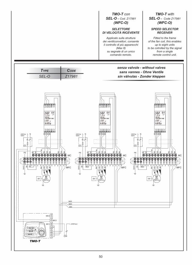
50
senza valvole - without valvessans vannes - Ohne Ventile
sin válvulas - Zonder kleppenType Code
SEL-O Z17981
Applicato sulla strutturadei ventilconvettori, consenteil controllo di più apparecchi
(Max 8)su segnale di un unico
comando remoto.
Fitted to the frameof the fan coil, this enables
up to eight unitsto be cotrolled by the signal
from a singleremote control unit.
SELETTOREDI VELOCITÀ RICEVENTE
SPEED SELECTORRECEIVER
TMO-T conSEL-O – Cod. Z17981
(WFC-O)
TMO-T withSEL-O – Code Z17981
(WFC-O)
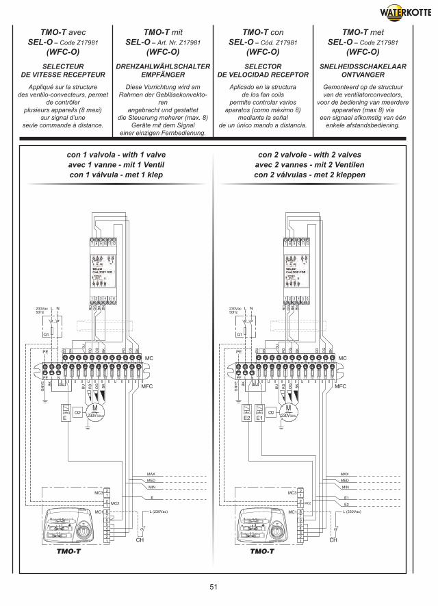
51
con 1 valvola - with 1 valveavec 1 vanne - mit 1 Ventilcon 1 válvula - met 1 klep
con 2 valvole - with 2 valvesavec 2 vannes - mit 2 Ventilencon 2 válvulas - met 2 kleppen
Appliqué sur la structuredes ventilo-convecteurs, permet
de contrôlerplusieurs appareils (8 maxi)
sur signal d’uneseule commande à distance.
Diese Vorrichtung wird am Rahmen der Gebläsekonvekto-
renangebracht und gestattet
die Steuerung meherer (max. 8)Geräte mit dem Signal
einer einzigen Fernbedienung.
Aplicado en la structurade los fan coils
permite controlar variosaparatos (como máximo 8)
mediante la señalde un único mando a distancia.
Gemonteerd op de structuurvan de ventilatorconvectors,
voor de bediening van meerdereapparaten (max 8) via
een signaal afkomstig van éénenkele afstandsbediening.
SELECTEURDE VITESSE RECEPTEUR
DREHZAHLWÄHLSCHALTEREMPFÄNGER
SELECTORDE VELOCIDAD RECEPTOR
SNELHEIDSSCHAKELAARONTVANGER
TMO-T avecSEL-O – Code Z17981
(WFC-O)
TMO-T mitSEL-O – Art. Nr. Z17981
(WFC-O)
TMO-T conSEL-O – Cód. Z17981
(WFC-O)
TMO-T metSEL-O – Code Z17981
(WFC-O)
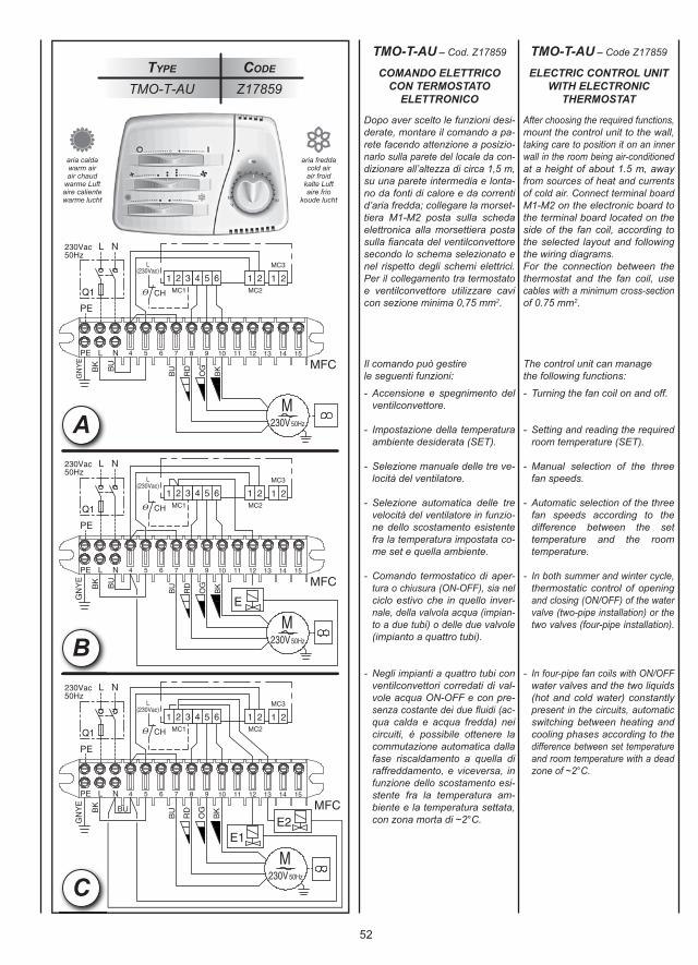
52
Type Code
TMO-T-AU Z17859
C
A
B
Dopo aver scelto le funzioni desi-derate, montare il comando a pa-rete facendo attenzione a posizio-narlo sulla parete del locale da con-dizionare all’altezza di circa 1,5 m,su una parete intermedia e lonta-no da fonti di calore e da correntid’aria fredda; collegare la morset-tiera M1-M2 posta sulla schedaelettronica alla morsettiera postasulla fi ancata del ventilconvettoresecondo lo schema selezionato enel rispetto degli schemi elettrici.Per il collegamento tra termostatoe ventilconvettore utilizzare cavicon sezione minima 0,75 mm2.
Il comando può gestirele seguenti funzioni:
- Accensione e spegnimento del ventilconvettore.
- Impostazione della temperatura ambiente desiderata (SET).
- Selezione manuale delle tre ve- locità del ventilatore.
- Selezione automatica delle tre velocità del ventilatore in funzio- ne dello scostamento esistente fra la temperatura impostata co- me set e quella ambiente.
- Comando termostatico di aper- tura o chiusura (ON-OFF), sia nel ciclo estivo che in quello inver- nale, della valvola acqua (impian- to a due tubi) o delle due valvole (impianto a quattro tubi).
- Negli impianti a quattro tubi con ventilconvettori corredati di val- vole acqua ON-OFF e con pre- senza costante dei due fl uidi (ac- qua calda e acqua fredda) nei circuiti, è possibile ottenere la commutazione automatica dalla fase riscaldamento a quella di raffreddamento, e viceversa, in funzione dello scostamento esi- stente fra la temperatura am- biente e la temperatura settata, con zona morta di ~2°C.
After choosing the required functions,mount the control unit to the wall,taking care to position it on an innerwall in the room being air-conditionedat a height of about 1.5 m, awayfrom sources of heat and currentsof cold air. Connect terminal boardM1-M2 on the electronic board tothe terminal board located on theside of the fan coil, according tothe selected layout and followingthe wiring diagrams.For the connection between thethermostat and the fan coil, usecables with a minimum cross-sectionof 0.75 mm2.
The control unit can managethe following functions:
- Turning the fan coil on and off.
- Setting and reading the required room temperature (SET).
- Manual selection of the three fan speeds.
- Automatic selection of the three fan speeds according to the difference between the set temperature and the room temperature.
- In both summer and winter cycle, thermostatic control of opening and closing (ON/OFF) of the water valve (two-pipe installation) or the two valves (four-pipe installation).
- In four-pipe fan coils with ON/OFF water valves and the two liquids (hot and cold water) constantly present in the circuits, automatic switching between heating and cooling phases according to the difference between set temperature and room temperature with a dead zone of ~2°C.
COMANDO ELETTRICOCON TERMOSTATO
ELETTRONICO
ELECTRIC CONTROL UNITWITH ELECTRONIC
THERMOSTAT
TMO-T-AU – Cod. Z17859 TMO-T-AU – Code Z17859
aria caldawarm airair chaud
warme Luftaire calientewarme lucht
aria freddacold airair froid
kalte Luftaire frio
koude lucht
53
Après avoir choisi les fonctionsvoulues, monter la commandemurale en veillant à la placer sur lemur du local à conditionner à unehauteur de 1,5 m environ, sur unecloison et loin de sources de chaleuret de courants d’air froid; connecterle bornier M1-M2 placé sur la carteélectronique au bornier placé surle flanc du ventilo-convecteur selonle schéma sélectionné et en respec-tant les schémas électriques.Pour la connexion entre thermostatet ventilo-convecteur utiliser descâbles de section minimum 0,75 mm2.
La commande peut gérerles fonctions suivantes:
- Mise en marche et arrêt du ventilo-convecteur.
- Programmation de la température ambiante voulue (SET).
- Sélection manuelle des trois vitesses du ventilateur.
- Sélection automatique des trois vitesses du ventilateur en fonction de l’écart existant entre la tempé- rature programmée et la tempé- rature ambiante.
- Commande thermostatique d’ou- verture ou de fermeture (ON-OFF), en cycle été comme en cycle hiver, de la vanne eau (installation à deux tubes) ou des deux vannes (installation à quatre tubes).
- Dans les installations à quatre tubes avec des ventilo-convec- teurs munis de vannes eau ON- OFF et avec la présence constante des deux fluides (eau chaude et eau froide) dans les circuits, il est possible d’obtenir la commutation automatique de la phase chauffage à celle de refroidissement, et vice versa, en fonction de l’écart entre la température ambiante et la température programmée, avec une zone morte de ~2°C.
Nachdem die gewünschten Funktioneneingestellt wurden, das Steuer-gerät an einer Innenwand in einerHöhe von zirka 1,5 m und fern vonWärmequellen und Kaltluftströmenmontieren; die Klemmleiste M1-M2an der Elektronikplatine gemäß desgewählten Schemas und unter Ein-haltung der Schaltpläne mit derKlemmleiste an der Seite des Lüft-ungskonvektors verbinden.Für die Verbindung zwischenThermostat und LüftungskonvektorDrähte mit einem Querschnitt vonmin. 0,75 mm2 benutzen.
Das Steuergerät kann diefolgenden Funktionen verwalten:
- Ein- und Ausschalten des Lüft- ungskonvektors.
- Einstellung der gewünschten Raumtemperatur (SET).
- Manuelle Einstellung der drei Ventilatordrehzahlen.
- Automatische Einstellung der drei Ventilatordrehzahlen entsprechend der Abweichung zwischen ein- gestellter Set Temperatur und der effektiven Raumtemperatur.
- Thermostatsteuerung des Wasser- ventils (ON-OFF) bei 2-Leiter- Systemen, oder der beiden Wasser- ventile bei 4-Leiter-Systemen in Kühl- und Heizbetrieb.
- Bei 4-Leiter-Systemen mit Lüft- ungskonvektoren mit Wasser- ventilen ON-OFF und bei ständiger Präsenz der beiden Flüssigkeiten (Warmwasser und Kaltwasser) in den Kreisen, ist die automatische Umschaltung von Heiz- zu Kühl- betrieb und umgekehrt möglich, je nach der vorliegenden Abweichung zwischen Raumtemperatur und eingestellter Temperatur, mit einem Totbereich von ~2°C.
Después de haber elegido las fun-ciones deseadas, montar el mandode pared poniendo atención encolocarlo en la pared del local aacondicionar a una altura de 1,5 maproximadamente, en un tabiquey lejos de las fuentes de calor y delas corrientes de aire frío; conectarla caja de bornes M1-M2 situadasobre la tarjeta electrónica a la cajade bornes situada en el lado delventilador convector según el esque-ma seleccionado y respetando losesquemas eléctricos.Para la conexión entre el termo-stato y el ventilador convector usarcables con una sección mínim de0,75 mm2.
El mando puede gestionarlas siguientes funciones:
- Encendido y apagado del venti- lador convector.
- Introducción de la temperatura ambiente deseada (SET).
- Selección manual de las tres velocidades del ventilador.
- Selección automática de las tres velocidades del ventilador en función de la diferencia existente entre la temperatura introducida como set y la temperatura ambiente.
- Mando termostático de abertura o cierre (ON-OFF), tanto en el ciclo de verano como en el de invierno, de la válvula de agua (instalación con dos tubos) o de las dos válvulas (instalación con cuatro tubos).
- En las instalaciones con cuatro tubos con ventiladores convec- tores equipados con válvulas de agua ON-OFF y con presencia constante de los dos fluidos (agua caliente y agua fría) en los cir- cuitos, se puede obtener la con- mutación automática de la fase de calentamiento a la de enfria- miento, y viceversa, en función de la diferencia existente entre la temperatura ambiente y la tem- peratura instaurada, con una zona muerta de ~2°C.
Na de functies te hebben gekozen,de bediening aan de muur bevestigen.Er aandacht aan besteden dat hijgemonteerd wordt op de wand vanhet lokaal, dat moet verwarmd/afgekoeld worden, op een hoogtevan circa 1,5 meter en ver vanwarmtebronnen en koude lucht-stromingen; het klemmenbord M1-M2op de gedrukte schakelingenverbinden met het klemmenbord opde zijkant van de ventilatorconvectorvolgens het gekozen schema ende elektrische schema’s.Voor de verbinding tussen dethermostaat en de ventilatorconvector,kabels gebruiken met een minimum-doorsnede van 0,75 mm2.
De bediening kan de volgendefuncties in werking stellen:
- In- en uitschakeling van de ventilatorconvector.
- Instelling van de gewenste kamer- temperatuur (SET).
- Manuele selectie van de drie versnellingen van de ventilator.
- Automatische selectie van de drie versnellingen van de ventilator in functie van de deviatie tussen de ingestelde temperatuur en de kamertemperatuur.
- Thermostatische regeling (ON- OFF), zowel in de zomer- als in de wintercyclus, van de waterklep (installatie met 2 leidingen) of van de twee kleppen (installatie met 4 leidingen).
- In de installaties met 4 leidingen, met ventilatorconvectors voorzien van waterkleppen ON-OFF en met constante aanwezigheid van de twee vloeistoffen (warm water en koud water) in de circuits, is het mogelijk de automatische omschakeling te verkrijgen van de verwarmfase naar de afkoelfase en omgekeerd in functie van de deviatie tussen de ingestelde temperatuur en de kamer- temperatuur, met dode zone van ~2°C.
COMMANDE ELECTRIQUEAVEC THERMOSTAT
ELECTRONIQUE
ELEKTRISCHE STEUERUNGMIT ELEKTRONISCHEM
THERMOSTAT
CONTROL ELÉCTRICOCON TERMOSTATO
ELECTRÓNICO
ELEKTRISCHE BEDIENINGMET ELEKTRONISCHE
THERMOSTAAT
TMO-T-AU – Code Z17859 TMO-T-AU – Art. Nr. Z17859 TMO-T-AU – Cód. Z17859 TMO-T-AU – Code Z17859
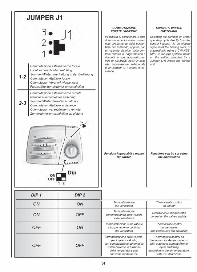
54
1-2
2-3
Commutazione estate/inverno localeLocal summer/winter switchingSommer/Winterumschaltung in der Bedienung Commutation été/hiver localeConmutación Verano/Invierno localPlaatselijke zomer/winter-omschakeling
Commutazione estate/inverno remotaRemote summer/winter switchingSommer/Winter Fern-UmschaltungCommutation été/hiver à distanceConmutación verano/invierno remotaZomer/winter-omschakeling op afstand
ON ON
DIP 1 DIP 2
ON OFF
OFF ON
OFF OFF
Termostatazionesul ventilatore
Thermostatic controlon the fan
Termostatazionecontemporanea delle valvole
e del ventilatore
Simultaneous thermostaticcontrol on the valves and fan
Termostatazione sulle valvolee funzionamento continuo
del ventilatore
Thermostatic controlon the valves
and continuous fan operation
Termostatazione sulle valvole,per impianti a 4 tubi,
con commutazione automaticaEstate/Inverno in funzione
della temperatura aria,con zona morta di 2°C
Thermostatic control onthe valves, for 4-pipe systems,with automatic summer/winter
cycle switchingaccording to the air temperature,
with 2°C dead zone
COMMUTAZIONEESTATE / INVERNO
- Possibilità di selezionare il ciclo di funzionamento estivo o inver- nale direttamente dalla pulsan- tiera del comando, oppure, con un segnale elettrico, dalla cen- trale termica o, negli impianti a due tubi, in modo automatico tra- mite un CHANGE-OVER in base alla impostazione selezionata di un Jumper (J1) interno al co- mando.
Funzioni impostabili a mezzoDip Switch
SUMMER / WINTERSWITCHING
- Selecting the summer or winter operating cycle directly from the control keypad, via an electric signal from the heating plant, or automatically using a CHANGE- OVER in two-pipe systems, based on the setting selected by a Jumper (J1) inside the control unit.
Functions can be set usingthe dipswitches
55
Thermostatsur le ventilateur
Temperaturregelungam Ventilator
Termostataciónsobre el ventilador
Thermostatischeregeling ventilator
Thermostatation simultanéedes vannes et du ventilateur
Gleichzeitige Temperaturregelungder Ventile und des Ventilators
Termostatación de las válvulasy los ventiladoresal mismo tiempo
Gelijktijdige thermostatischeregeling kleppen en ventilator
Thermostatation sur les vanneset fonctionnement continu
du ventilateur
Temperaturregelungder Ventile und Dauerbetrieb
des Ventilators
Termostatación sobrelas válvulas y funcionamiento
contínuo del ventilador
Thermostatische regelingkleppen en constante werking
van de ventilator
Thermostatation sur les vannes,pour des installations à 4 tubes,avec commutation automatique
été-hiver en fonctionde la température de l’air,avec zone morte de 2°C
Temperaturregelung der Ventilefür 4-Leiter-Systeme
mit automatischerSommer-/Winterumschaltung,
je nach Lufttemperatur,mit Totbereich von 2°C.
Termostatación sobrelas válvulas, para instalacionesde 4 tubos, con conmutaciónautomática verano-invierno
en función de la temperatura del aire, con zona muerta de 2°C.
Thermostatische regeling voorinstallaties met 4 leidingen,
met automatiche omschakelingzomer/winter in functie
van de luchttemperatuur,met dode zone van 2°C
COMMUTATIONÉTÉ / HIVER
- Possibilité de sélectionner le cycle de fonctionnement été ou hiver directement à partir du tableau de commande, ou, avec un signal électrique, à partir de la centrale thermique ou, dans les installations à deux tubes, de façon automatique par un inverseur CHANGE-OVER selon la configuration sélectionnée d’un Jumper (J1) à l’intérieur de la commande.
Fonctions programmablesà l’aide du Dip switch
SOMMER / WINTERUmschaltung
- Möglichkeit des Einstellens von Sommer- oder Winterbetrieb direkt an der Schalttafel oder, über ein elektrisches Signal, an der Heizung, oder, bei 2-Leiter-Systemen, automatisch mittels CHANGE- OVER, auf Grundlage der Ein- stellung eines in der Steuerung befindlichen Jumpers (J1).
Über Dip-Switch einstellbareFunktionen
CONMUTACIÓNVERANO / INVIERNO
- Posibilidad de seleccionar el ciclo de funcionamiento verano o invierno directamente desde el teclado del mando, o bien, con una señal eléctrica, de la central térmica o, en las instalaciones con dos tubos, de forma auto- mática mediante un CHANGE- OVER en base a la programación seleccionada por un Jumper (J1) situado dentro del mando.
Funciones programablesa medio Dip Switch
OMSCHAKELINGZOMER/WINTER
- Mogelijkheid van cyclusselectie van zomer- of winterfunctie d.m.v. het knopbord op de bediening, ofwel met een elektrisch signaal, uit de thermische centrale of in de installatie met twee leidingen, in automatisch d.m.v. een CHANGE- OVER volgens de ingestelde selectie van een interne Jumper (J1).
Functies die door eendimschakelaar kunnen worden
ingesteld

56
TMO-T-AU conSEL-V – Cod. Z17980
(WFC-W-B)
TMO-T-AU withSEL-V – Code Z17980
(WFC-W-B)
Applicato sulla strutturadei ventilconvettori, consenteil controllo di più apparecchi
(Max 8)su segnale di un unico
comando remoto.
Fitted to the frameof the fan coil, this enables
up to eight unitsto be cotrolled by the signal
from a singleremote control unit.
SELETTOREDI VELOCITÀ RICEVENTE
SPEED SELECTORRECEIVER
senza valvole - without valvessans vannes - Ohne Ventile
sin válvulas - Zonder kleppenType Code
SEL-V Z17980
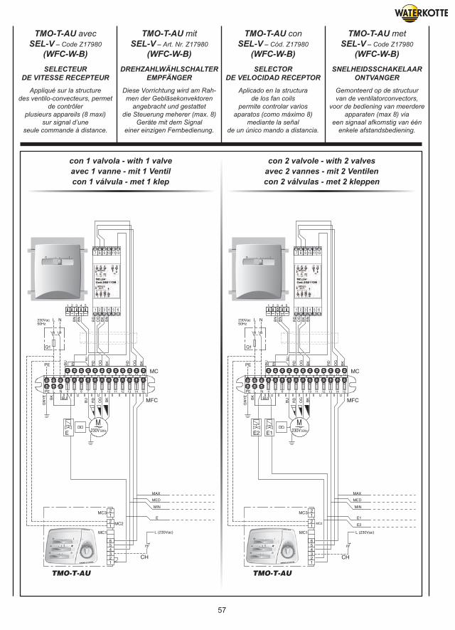
57
TMO-T-AU avecSEL-V – Code Z17980
(WFC-W-B)
TMO-T-AU mitSEL-V – Art. Nr. Z17980
(WFC-W-B)
TMO-T-AU conSEL-V – Cód. Z17980
(WFC-W-B)
TMO-T-AU metSEL-V – Code Z17980
(WFC-W-B)
Appliqué sur la structuredes ventilo-convecteurs, permet
de contrôlerplusieurs appareils (8 maxi)
sur signal d’uneseule commande à distance.
Diese Vorrichtung wird am Rah-men der Gebläsekonvektoren
angebracht und gestattetdie Steuerung meherer (max. 8)
Geräte mit dem Signaleiner einzigen Fernbedienung.
Aplicado en la structurade los fan coils
permite controlar variosaparatos (como máximo 8)
mediante la señalde un único mando a distancia.
Gemonteerd op de structuurvan de ventilatorconvectors,
voor de bediening van meerdereapparaten (max 8) via
een signaal afkomstig van éénenkele afstandsbediening.
SELECTEURDE VITESSE RECEPTEUR
DREHZAHLWÄHLSCHALTEREMPFÄNGER
SELECTORDE VELOCIDAD RECEPTOR
SNELHEIDSSCHAKELAARONTVANGER
con 1 valvola - with 1 valveavec 1 vanne - mit 1 Ventilcon 1 válvula - met 1 klep
con 2 valvole - with 2 valvesavec 2 vannes - mit 2 Ventilencon 2 válvulas - met 2 kleppen
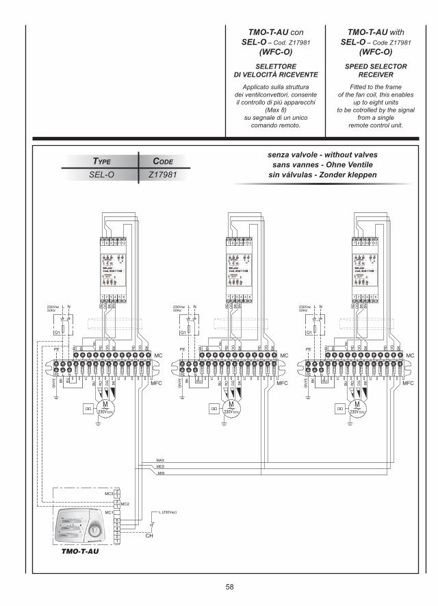
58
senza valvole - without valvessans vannes - Ohne Ventile
sin válvulas - Zonder kleppenType Code
SEL-O Z17981
Applicato sulla strutturadei ventilconvettori, consenteil controllo di più apparecchi
(Max 8)su segnale di un unico
comando remoto.
Fitted to the frameof the fan coil, this enables
up to eight unitsto be cotrolled by the signal
from a singleremote control unit.
SELETTOREDI VELOCITÀ RICEVENTE
SPEED SELECTORRECEIVER
TMO-T-AU conSEL-O – Cod. Z17981
(WFC-O)
TMO-T-AU withSEL-O – Code Z17981
(WFC-O)
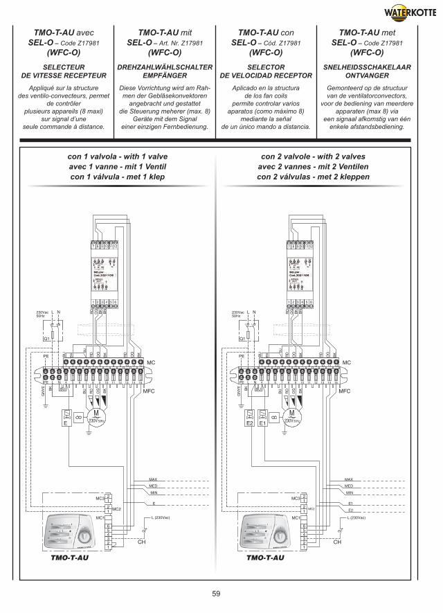
59
con 1 valvola - with 1 valveavec 1 vanne - mit 1 Ventilcon 1 válvula - met 1 klep
con 2 valvole - with 2 valvesavec 2 vannes - mit 2 Ventilencon 2 válvulas - met 2 kleppen
Appliqué sur la structuredes ventilo-convecteurs, permet
de contrôlerplusieurs appareils (8 maxi)
sur signal d’uneseule commande à distance.
Diese Vorrichtung wird am Rah-men der Gebläsekonvektoren
angebracht und gestattetdie Steuerung meherer (max. 8)
Geräte mit dem Signaleiner einzigen Fernbedienung.
Aplicado en la structurade los fan coils
permite controlar variosaparatos (como máximo 8)
mediante la señalde un único mando a distancia.
Gemonteerd op de structuurvan de ventilatorconvectors,
voor de bediening van meerdereapparaten (max 8) via
een signaal afkomstig van éénenkele afstandsbediening.
SELECTEURDE VITESSE RECEPTEUR
DREHZAHLWÄHLSCHALTEREMPFÄNGER
SELECTORDE VELOCIDAD RECEPTOR
SNELHEIDSSCHAKELAARONTVANGER
TMO-T-AU avecSEL-O – Code Z17981
(WFC-O)
TMO-T-AU mitSEL-O – Art. Nr. Z17981
(WFC-O)
TMO-T-AU conSEL-O – Cód. Z17981
(WFC-O)
TMO-T-AU metSEL-O – Code Z17981
(WFC-O)
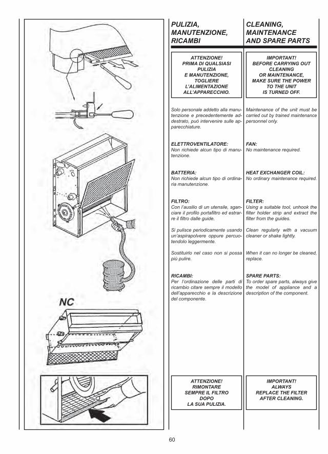
60
ATTENZIONE!PRIMA DI QUALSIASI
PULIZIAE MANUTENZIONE,
TOGLIEREL’ALIMENTAZIONE
ALL’APPARECCHIO.
IMPORTANT!BEFORE CARRYING OUT
CLEANINGOR MAINTENANCE,
MAKE SURE THE POWERTO THE UNIT
IS TURNED OFF.
ATTENZIONE!RIMONTARE
SEMPRE IL FILTRODOPO
LA SUA PULIZIA.
IMPORTANT!ALWAYS
REPLACE THE FILTERAFTER CLEANING.
PULIZIA,MANUTENZIONE,RICAMBI
Solo personale addetto alla manu-tenzione e precedentemente ad-destrato, può intervenire sulle ap-parecchiature.
ELETTROVENTILATORE:Non richiede alcun tipo di manu-tenzione.
BATTERIA:Non richiede alcun tipo di ordina-ria manutenzione.
FILTRO:Con l’ausilio di un utensile, sgan-ciare il profilo portafiltro ed estrar-re il filtro dalle guide.
Si pulisce periodicamente usandoun’aspirapolvere oppure percuo-tendolo leggermente.
Sostituirlo nel caso non si possapiù pulire.
RICAMBI:Per l’ordinazione delle parti diricambio citare sempre il modellodell’apparecchio e la descrizionedel componente.
CLEANING,MAINTENANCEAND SPARE PARTS
Maintenance of the unit must becarried out by trained maintenancepersonnel only.
FAN:No maintenance required.
HEAT EXCHANGER COIL:No ordinary maintenance required.
FILTER:Using a suitable tool, unhook thefilter holder strip and extract thefilter from the guides.
Clean regularly with a vacuumcleaner or shake lightly.
When it can no longer be cleaned,replace.
SPARE PARTS:To order spare parts, always givethe model of appliance and adescription of the component.
61
ATTENTION!AVANT
TOUTE OPERATIONDE NETTOYAGE ET
D’ENTRETIEN,COUPER L’ALIMENTATION
DE L’APPAREIL.
ACHTUNG!VOR BEGINN
VON REINIGUNGS- UNDWARTUNGSEINGRIFFEN
MUSS DIE STROMZUFUHRZUM GERÄT
UNTERBROCHEN WERDEN.
ATENCIÓN!ANTES DE EFECTUAR
CUALQUIER OPERACIÓNDE LIMPIEZA
Y MANTENIMIENTOCORTAR LA ALIMENTACIÓN
PARA EL APARATO.
OPGELET!VOOR ELKE
SCHOONMAAK- ENONDERHOUDSBEURT,DE STEKKER VAN HET
APPARAAT UIT HETSTOPCONTACT TREKKEN.
ATTENTION!APRES L’AVOIR NETTOYE,
NE JAMAIS OUBLIERDE REMONTER
LE FILTRE.
ACHTUNG!NICHT VERGESSEN,DEN FILTER NACHDER REINIGUNG
WIEDER EINZUBAUEN.
ATENCIÓN!DESPUÉS DE LIMPIARLO
VOLVER A MONTARSIEMPRE EL FILTRO
EN SU SITO.
OPGELET!HERPLAATS DE FILTER
STEEDS NA EENSCHOONMAAKBEURT.
NETTOYAGE,ENTRETIEN ET PIECESDE RECHANGE
REINIGUNG,WARTUNG UNDERSATZTEILE
LIMPIEZA,MANTENIMIENTOY REPUESTOS
SCHOONMAAK,ONDERHOUD,WISSELSTUKKEN
Seul le personnel chargé de l’entretienet ayant été formé dans ce but peutintervenir sur les appareils.
VENTILATEUR:Ne nécessite aucun type d’entretien.
BATTERIE:Ne nécessite aucun type d’entretien.ordinaire.
FILTRE:Au moyen d’un outil, décrocher leprofilé porte-filtre et retirer le filtrede ses guides.
Doit être nettoyé périodiquementà l’aide d’un aspirateur ou en lefrappant légèrement.
Le remplacer lorsqu’il n’est pluspossible de le nettoyer.
PIECES DE RECHANGE:Pour la commande des piècesde rechange, indiquer toujours lemodèle de l’appareil et la descriptiondu composant.
Nur das mit der Wartung betrauteund vorher entsprechend geschultePersonal darf Eingriffe an denGeräten vornehmen
ELEKTROVENTILATOR:Dieser bedarf keinerlei Wartung.
BATTERIE:Diese bedarf keiner ordentlichenWartung.
FILTER:Mit Hilfe eines Werkzeugs dasFilter-Halteprofil aushängen und denFilter aus den Führungen nehmen.
Der Filter wird regelmäßig miteinem Staubsauger oder durchvorsichtiges Ausklopfen gesäubert.
Wenn er sich nicht mehr reinigenlässt, muss er ersetzt werden.
ERSATZTEILE:Bei Ersatzteilbestellungen immer dasGerätemodell und die Bezeichnungdes Teils angeben.
Sólo personal encargado del mante-nimiento y previamente capacitadopuede efectuar operaciones sobrelos aparatos.
VENTILADOR:No requiere ninguna clase demantenimiento.
BATERÍA:No requiere ninguna clase demantenimiento ordinario.
FILTRO:Con el auxilio de una herramienta,desenganchar el perfil porta-filtroy retirar el filtro de las guías.
Se limpia periódicamente usandouna aspiradora o golpeándolo lige-ramente. Si no es posible limpiarlo sustituirlo.
REPUESTOS:Para pedir piezas de repuesto in-dicar siempre el modelo del aparatoy la descripción del componente.
Wend u uitsluitend tot opgeleidonderhoudspersoneel voor hetonderhoud van het apparaat.
ELEKTROVENTILATOR:Vergt geen enkel type onderhoud.
BATTERIj:Vergt geen enkel type gewoononderhoud.
FILTER:Met behulp van gereedschap, haaktu de filterhouder los en haalt u hemuit zijn zitting.
Maak de filter regelmatig schoonmet een stofzuiger of door er zachtop te kloppen.
Vervang de filter indien hij niet kanworden schoongemaakt.
WISSELSTUKKEN:Bij de bestelling van de wisselstukken,vermeld u steeds het model van hetapparaat en beschrijft u het onderdeel.
62
RICERCA GUASTI
GUASTO1 - Il motore non gira o gira in modo non corretto.
RIMEDIO - Controllare che l’alimentazione sia inserita.
- Verificare il collegamento corretto dei fili, osservando gli schemi elettrici.
- Verificare la posizione dell’interruttore generale, del commutatore stagionale e del termostato.
GUASTO2 - L’apparecchio non scalda/raffredda più come in precedenza.
RIMEDIO - Controllare che il filtro sia sufficientemente pulito.
- Verificare sfiatando la batteria che non sia entrata aria nel circuito idraulico.
GUASTO3 - L’apparecchio perde acqua.
RIMEDIO - Controllare che l’inclinazione sia in direzione dello scarico condensa.
- Controllare che lo scarico condensa non sia ostruito.
TROUBLESHOOTING
PROBLEM1 - The motor does not rotate or rotates incorrectly.
REMEDY - Make sure the power to the unit is on.
- Make sure the wires are correctly connected, referring to the wiring diagram.
- Control if the main switch, the seasonal commutator and the thermostat are in the right position.
PROBLEM 2 - The unit does not heat/cool as before.
REMEDY - Make sure the filter is clean.
- Make sure the hydraulic circuit is free from air by venting the heat exchanger.
PROBLEM 3 - The appliance leaks water.
REMEDY - Make sure it is sloping in the direction of the condensate drain.
- Make sure the condensate drain is not clogged.
63
DEPANNAGE FEHLERSUCHEINVESTIGACIÓNDE AVERÍAS
OPSPORENDEFECTEN
DEFAUT1 - Le moteur ne tourne pas ou tourne de manière incorrecte.
REMEDE - Contrôler que l’alimentation est branchée.
- Vérifier le bon raccordement des conducteurs à l’aide des schémas électriques.
- L’interrupteur général et le commutateur saisonnier soient dans la position correcte.
DEFAUT2 - L’appareil ne chauffe ou ne refroidit plus comme avant.
REMEDE - Contrôler que le filtre est suffisamment propre.
- Vérifier, en purgeant la batterie, que de l’air n’est pas entré dans le circuit hydraulique.
DEFAUT3 - L’appareil perd de l’eau.
REMEDE - Contrôler que l’évacuation des condensats est inclinée dans la bonne direction.
- Contrôler que l’évacuation des condensats n’est pas bouchée.
STÖRUNG1 - Der Motor dreht nicht oder dreht nicht korrekt.
ABHILFE - Kontrollieren, ob die Spannungs- versorgung zugeschaltet ist.
- Auf Grundlage der Schaltpläne den korrekten Anschluss der Drähte prüfen.
- Die Position des Haupt- schalters, des Umschalters der Betriebsart und des Thermostats kontrollieren.
STÖRUNG2 - Das Gerät heizt/kühlt nicht mehr wie zuvor.
ABHILFE - Kontrollieren, ob der Filter sauber genug ist.
- Durch Entlüften des Registers kontrollieren, ob Luft in den Wasserkreis eingedrungen ist.
STÖRUNG3 - Das Gerät verliert Wasser.
ABHILFE - Kontrollieren, ob die Schräge in Richtung des Kondensatabflusses verläuft.
- Kontrollieren, ob der Kondensatabfluss frei ist.
AVERÍA1 - El motor no gira o gira de modo incorrecto.
SOLUCIÓN - Verificar que esté conectado a la toma de corriente.
- Verificar la correcta conexión de los hilos, observando los esquemas eléctricos.
- Verificar la posición del interruptor general, del conmutador estacional y del termostato.
AVERÍA2 - El aparato ya no calienta/enfría como con anterioridad.
SOLUCIÓN - Verificar que el filtro esté bien limpio.
- Verificar purgando la batería que no haya entrado aire en el circuito hidráulico.
AVERÍA3 - El aparato pierde agua.
SOLUCIÓN - Controlar que esté inclinado en dirección a la evacuación del agua de condensación.
- Controlar que la evacuación del agua de condensación no esté obstruida.
DEFECT1 - De motor draait niet of op niet correcte wijze.
OPLOSSING - Controleer of de stekker in het stopcontact zit.
- Controleer de correcte aansluiting van de draden, conform de schakelschema’s.
- Controleer de positie van de hoofdschakelaar, de seizoensschakelaar en de thermostaat.
DEFECT2 - Het apparaat verwarmt/koelt niet meer af zoals voordien.
OPLOSSING - Controleer of de filter voldoende schoon is.
- Tap de batterij af en ga de aanwezigheid na van lucht in het hydraulisch circuit.
DEFECT3 - Er lekt water uit het apparaat.
OPLOSSING - Controleer of de helling in de richting van de afvoerbuis voor het condensatievocht loopt.
- Controleer of de afvoerbuis voor het condensatievocht niet verstopt is.
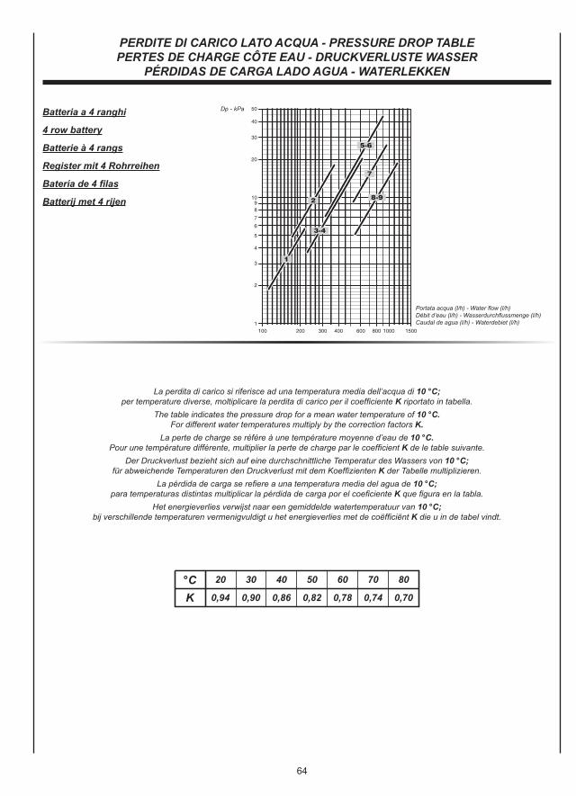
64
Batteria a 4 ranghi
4 row battery
Batterie à 4 rangs
Register mit 4 Rohrreihen
Batería de 4 filas
Batterij met 4 rijen
K 0,94 0,90 0,86 0,82 0,78 0,74 0,70
20 30 40 50 60 70 80°C
La perdita di carico si riferisce ad una temperatura media dell’acqua di 10 °C;per temperature diverse, moltiplicare la perdita di carico per il coefficiente K riportato in tabella.
The table indicates the pressure drop for a mean water temperature of 10 °C.For different water temperatures multiply by the correction factors K.
La perte de charge se référe à une température moyenne d’eau de 10 °C.Pour une température différente, multiplier la perte de charge par le coefficient K de le table suivante.
Der Druckverlust bezieht sich auf eine durchschnittliche Temperatur des Wassers von 10 °C;für abweichende Temperaturen den Druckverlust mit dem Koeffizienten K der Tabelle multiplizieren.
La pérdida de carga se refiere a una temperatura media del agua de 10 °C;para temperaturas distintas multiplicar la pérdida de carga por el coeficiente K que figura en la tabla.
Het energieverlies verwijst naar een gemiddelde watertemperatuur van 10 °C;bij verschillende temperaturen vermenigvuldigt u het energieverlies met de coëfficiënt K die u in de tabel vindt.
PERDITE DI CARICO LATO ACQUA - PRESSURE DROP TABLEPERTES DE CHARGE CÔTE EAU - DRUCKVERLUSTE WASSER
PÉRDIDAS DE CARGA LADO AGUA - WATERLEKKEN
Portata acqua (l/h) - Water flow (l/h)Débit d’eau (l/h) - Wasserdurchflussmenge (l/h)Caudal de agua (l/h) - Waterdebiet (l/h)
Dp - kPa
65
NOTES
NOTES
NOTES
WATERKOTTE GmbHGewerkenstraße 15, D-44628 Herne
Tel.: 0049/(0)2323/9376-0, Fax: 0049/(0)2323/9376-99
E-mail: [email protected]: http://www.waterkotte.de
Copyright © 2010 by WATERKOTTE GmbH, HerneSubject to change without notice.