Seminar 3rd Sem
21
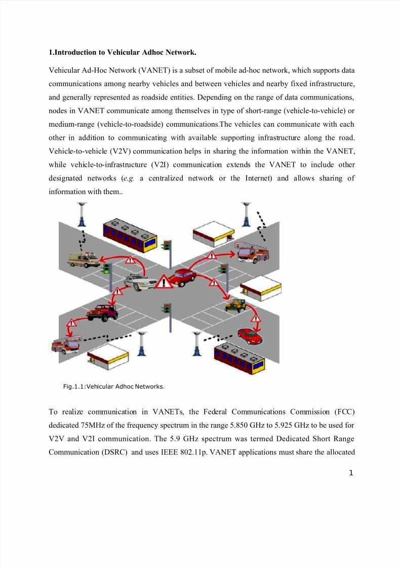
1.Introduction to Vehicular Adhoc Network. Vehicular Ad-Hoc Network (VANET) is a subset of mobile ad-hoc network, which supports data communications among nearby vehicles and between vehicles and nearby fixed infrastructure, and generally represented as roadside entities. Depending on the range of data communications, nodes in VANET communicate among themselves in type of short-range (vehicle-to-vehicle) or medium-range (vehicle-to-roadside) communications. The vehicles can communicate with each other in addit ion to commu nicati ng with availabl e suppor ting infrast ructu re along the road. Vehicl e-to-v ehicl e (V2V) communi cation helps in shari ng the infor mati on withi n the VANET, whi le vehi cle -to-in fra str uct ure (V2 I) communica tio n ext ends the VANET to inc lude other des ignated net works ( e.g. a centralized networ k or the Internet) and al lows shar ing of information with them.. Fig.1.1:Veh icular Adhoc Networks. To rea liz e communica tio n in VANETs, the Fed era l Communica ti ons Commis sio n (FCC) dedicated 75MHz of the frequency spectrum in the range 5.850 GHz to 5.925 GHz to be used for V2V and V2I communication. The 5.9 GHz spectrum was termed Dedicated Short Range Communication (DSRC) and uses IEEE 802.11p. VANET applications must share the allocated 1
-
Upload
ritu-parasher -
Category
Documents
-
view
226 -
download
0
Transcript of Seminar 3rd Sem
8/3/2019 Seminar 3rd Sem
http://slidepdf.com/reader/full/seminar-3rd-sem 1/21
1.Introduction to Vehicular Adhoc Network.
Vehicular Ad-Hoc Network (VANET) is a subset of mobile ad-hoc network, which supports data
communications among nearby vehicles and between vehicles and nearby fixed infrastructure,
and generally represented as roadside entities. Depending on the range of data communications,nodes in VANET communicate among themselves in type of short-range (vehicle-to-vehicle) or
medium-range (vehicle-to-roadside) communications.The vehicles can communicate with each
other in addition to communicating with available supporting infrastructure along the road.
Vehicle-to-vehicle (V2V) communication helps in sharing the information within the VANET,
while vehicle-to-infrastructure (V2I) communication extends the VANET to include other
designated networks (e.g. a centralized network or the Internet) and allows sharing of
information with them..
Fig.1.1:Vehicular Adhoc Networks.
To realize communication in VANETs, the Federal Communications Commission (FCC)
dedicated 75MHz of the frequency spectrum in the range 5.850 GHz to 5.925 GHz to be used for
V2V and V2I communication. The 5.9 GHz spectrum was termed Dedicated Short Range
Communication (DSRC) and uses IEEE 802.11p. VANET applications must share the allocated
1
8/3/2019 Seminar 3rd Sem
http://slidepdf.com/reader/full/seminar-3rd-sem 2/21
bandwidth, making it a scarce resource that should be managed very carefully. Inefficient data
dissemination wastes a large amount of bandwidth that if saved would allow more vehicular
applications to co-exist in addition to allowing the vehicular data to be disseminated further.
Many VANET applications require each vehicle to share its data (e.g. speed and location) with
its neighbors through broadcasting a message containing such data. Sending these messages to
farther distances will waste the bandwidth and may cause a broadcast storm problem based on
the traffic density. So, to share the data with vehicles at farther distances efficiently, many data
aggregation techniques have been proposed. Data aggregation has been proposed in VANETs to
solve the bandwidth utilization problem. The basic idea is to gather information about many
vehicles into a single frame. Data aggregation techniques can be classified as syntactic or
semantic . Syntactic aggregation uses a technique to compress or encode the data from multiple
vehicles in order to fit the data into a single frame. This results in lower overhead than sending
each message individually. In semantic aggregation, data from individual vehicles is
summarized. For instance, instead of reporting the exact position of five vehicles, only the fact
that five vehicles exist is reported. The trade-off is a much smaller message in exchange for a
loss of precise data.Efficient data dissemination in VANETs is an important problem that needs
to be handled carefully. The importance of this problem has attracted many researchers to study
it and, as a consequence, many data dissemination techniques have been proposed. The proposed
techniques can be categorized according to the communication method used V2I, V2V, and
hybrid of the two. In the infrastructure-based techniques, vehicles mainly communicate through
infrastructure units that can be road side units (RSUs) embedded sensor belts in the road
pavement , or cellular networks. V2I approaches depend upon a pervasive infrastructure that may
not become a reality due to its high cost. V2V techniques for data dissemination depend on data
routing or on broadcasting. In the majority of VANET applications (especially safety
applications), the exchanged messages have no specific destination but have all the surrounding
vehicles as the targeted destinations. This makes broadcast the most suitable method for
dissemination
1.1 Application areas of VANET
The applications of vehicular ad hoc networks (VANETs) can be classified into three main
categories:
2
8/3/2019 Seminar 3rd Sem
http://slidepdf.com/reader/full/seminar-3rd-sem 3/21
a) General data routing services: The general data routing provides one-to-one data
routing or one-to-all data broadcasting for services, such as entertainment, route planning,
and communications Informational applications include notification of upcoming traffic
conditions and roadway hazards, as well as gathering and disseminating weather
information.. The data transmission requirement of this type of service is reliability; that
is to say the packets should be successfully received by the receiver.
b) Safety applications: The safety applications provide one-to-all emergency message
broadcasting for receivers in a predefined region, such as, electronic brake lights, lane
changing assistance, and road condition reports.Safety applications, which are the main
focus of the US DoT’s efforts in vehicular networks, include collision warning and
merge assistance.
c) The third type of applications, entertainment, includes Internet access, multimedia
streaming , and P2P file sharing
These applications are usually life critical. Therefore, the data should not only be successfully
received by the receivers, but be received in a very short time to provide the driver with more
reaction time. For the most urgent situations,e.g. vehicle collisions, the limit of propagation time
of the emergency message is extremely low. Some research focuses on Cooperative Collision
Avoidance (CCA) to broadcast collision avoidance messages in a very short latency in order to
save as many victim vehicles as possible.
1.2 Security Issues in Vehicular Network.
The need for a robust VANET networks is strongly dependent on their security and privacy
features.A. ATTACKS AND THREATS
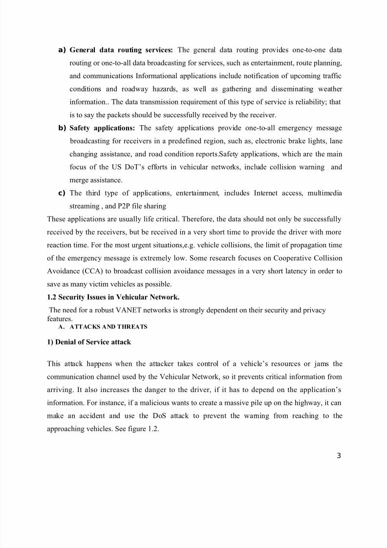
1) Denial of Service attack
This attack happens when the attacker takes control of a vehicle’s resources or jams the
communication channel used by the Vehicular Network, so it prevents critical information from
arriving. It also increases the danger to the driver, if it has to depend on the application’s
information. For instance, if a malicious wants to create a massive pile up on the highway, it can
make an accident and use the DoS attack to prevent the warning from reaching to the
approaching vehicles. See figure 1.2.
3
8/3/2019 Seminar 3rd Sem
http://slidepdf.com/reader/full/seminar-3rd-sem 4/21
Fig1.2:DOS Attack
2) Message Suppression Attack
An attacker selectively dropping packets from the network, these packets may hold critical
information for the receiver, the attacker suppress these packets and can use them again in other
time. The goal of such an attacker would be to prevent registration and insurance authorities
from learning about collisions involving his vehicle and/or to avoid delivering collision reports
to roadside access points. For instance, an attacker may suppress a congestion warning, and use it
in another time, so vehicles will not receive the warning and forced to wait in the traffic.
3) Fabrication Attack,
An attacker can make this attack by transmitting false information into the network, the
information could be false or the transmitter could claim that it is somebody else. This attack
includes fabricate messages, warnings, certificates, Identities.
4) Alteration Attack
This attack happens when attacker alters an existing data. It includes delaying the transmission of
the information, replaying earlier transmission, or altering the actual entry of the data transmitted
5) Replay Attack
This attack happens when an attacker replay the transmission of an earlier information to take
advantage of the situation of the message at time of sending. Basic 802.11 security has no
protection against replay. The goal of such an attack would be to confuse the authorities and
possibly prevent identification of vehicles in hit-and-run incidents.
B. Adversaries
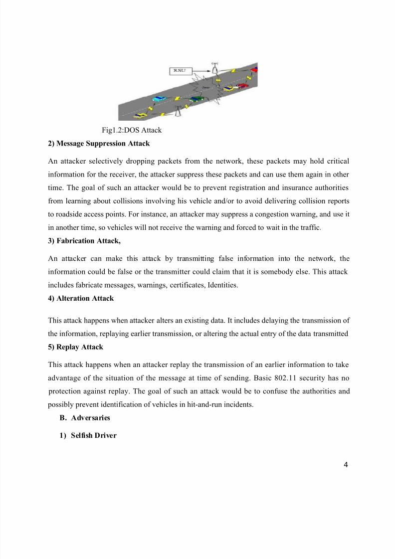
1) Selfish Driver
4
8/3/2019 Seminar 3rd Sem
http://slidepdf.com/reader/full/seminar-3rd-sem 5/21
The general idea for trust in Vehicular Network is that all vehicles must be trusted initially, these
vehicles are trusted to follow the protocols specified by the application, some drivers try to
maximize their profit from the network, regardless the cost for the system by taking advantage of
the network resources illegally. A Selfish Driver can tell other vehicles that there is congestion in
the road, so they must choose an alternate route, so the road will be clear for it. See figure1.3
Fig.1.3: Selfish Driver
2) Malicious Attacker
This kind of attacker tries to cause damage via the applications available on the vehicular
network. In many cases, these attackers will have specific targets, and they will have access to
the resources of the network.
1.3 Vehicular Networks Challenges
1) Mobility
The basic idea from Ad Hoc Networks is that each node in the network is mobile, and can move
from one place to another within the coverage area, but still the mobility is limited, in Vehicular
Ad Hoc Networks nodes moving in high mobility, vehicles make connection throw their way
with another vehicles that maybe never faced before, and this connection lasts for only few
seconds as each vehicle goes in its direction, and these two vehicles may never meet again. So
securing mobility challenge is hard problem.
2) Volatility
The connectivity among nodes can be highly ephemeral, and maybe will not happen again,
Vehicles traveling throw coverage area and making connection with other vehicles, these
connections will be lost as each car has a high mobility, and maybe will travel in opposite
5
8/3/2019 Seminar 3rd Sem
http://slidepdf.com/reader/full/seminar-3rd-sem 6/21
direction. Vehicular networks lacks the relatively long life context, so personal contact of users
device to a hot spot will require long life password, and this will be impractical for securing VC.
2) Network Scalability
The scale of this network in the world approximately exceeding the 750 million nodes, and this
number is growing, another problem arise when we must know that there is no a global authority
govern the standards for this network , for example: the standards for DSRC in North America is
deferent from the DSRC standards in Europe, the standards for the GM Vehicles is deferent from
the BMW one.
4 ) Bootstrap
At this moment only few number of cars will be have the equipment required for the DSRC
radios, so if we make a communication we have to assume that there is a limited number of cars
that will receive the communication, in the future we must concentrate on getting the number
higher, to get a financial benefit that will courage the commercial firms to invest in this
technology
1.4 Security Requirements
1. Authentication
In VC every message must be authenticated, to make sure for its origin and to control
authorization level of the vehicles, to do this vehicles will assign every message with their
Private Key along with its Certificate, at the receiver side, the vehicle will receive the message
and check for the key and certificate once this is done, the receiver verifies the message. Signing
each message with this, causes an overhead, to reduce this overhead we can use the approach
ECC (Elliptic Curve Cryptography), the efficient public key cryptosystem.
2. Availability
Vehicular Network must be available all the time, for many applications Vehicular Networks
will require realtime, these applications need faster response from Sensor Networks or even Ad
Hoc Network, a delay in seconds for some applications will make the message meaningless and
maybe the result will be devastating. Attempting to meet real-time demands makes the system
vulnerable to the DoS attack. In some messages, a delay in millisecond makes the message
meaningless; the problem is much bigger, where the application layer is unreliable, since the
6
8/3/2019 Seminar 3rd Sem
http://slidepdf.com/reader/full/seminar-3rd-sem 7/21
potential way to recover with unreliable transmission is to store partial messages in hopes to be
completed in next transmission.
3. Non-repudiation
Non-repudiation will facilitate the ability to identify the attackers even after the attack
happens.This prevents cheaters from denying their crimes. Any information related to the car
like: the trip rout, speed, time, any violation will be stored in the TPD, any official side holding
authorization can retrieve this data.
4. Privacy
Keeping the information of the drivers away from unauthorized observers, this information like
real identity, trip path, speed etc.The privacy could be achieved by using temporary (anonymous)keys, these keys will be changed frequently as each key could be used just for one time and
expires after usage ,all the keys will be stored in the TPD, and will be reloaded again in next time
that the vehicle makes an official checkup .For preserving the real identity of the driver, an ELP
(Electronic License Plate) is used, this license is installed in the factory for every new vehicle, it
will provide an identification number for the vehicle, to identify the vehicle in anywhere , with
the RFID technology to hold the ELP.
5. Confidentiality
The privacy of each driver must be protected; the messages should be encrypted to prevent
outsiders from gaining the drivers information.
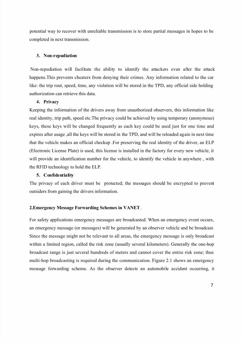
2.Emergency Message Forwarding Schemes in VANET.
For safety applications emergency messages are broadcasted. When an emergency event occurs,
an emergency message (or messages) will be generated by an observer vehicle and be broadcast.
Since the message might not be relevant to all areas, the emergency message is only broadcast
within a limited region, called the risk zone (usually several kilometers). Generally the one-hop
broadcast range is just several hundreds of meters and cannot cover the entire risk zone; thus
multi-hop broadcasting is required during the communication. Figure 2.1 shows an emergency
message forwarding scheme. As the observer detects an automobile accident occurring, it
7
8/3/2019 Seminar 3rd Sem
http://slidepdf.com/reader/full/seminar-3rd-sem 8/21
immediately broadcasts an emergency message to inform all its neighbors; meanwhile one of the
observer’s neighbors (the forwarder) will be selected to play the role of message relaying.
Fig2.1. Emergency message forwarding scheme for safety application in VANET
Similarly, the new chosen forwarder will broadcast the message and also select the next
forwarder for message relaying. The above tasks continue until the message reaches the edge of
the risk zone. Since the involved vehicles of message broadcasting are only the forwarders, the
broadcast storm problem can then be relieved. However, without appropriate forwarder node
selection, there will be many nodes rebroadcasting the message. A large number of receiving
nodes broadcasting the same message will create the problems of channel contention and serious
packet collisions. Rebroadcasting due to transmission failure. makes the problem even worse. In
order to ensure all the vehicles in the risk zone can receive the emergency message in time, we
consider two important ways to reduce the message propagation latency. The key point is to
reduce the hop counts needed to propagate the message to the entire risk zone. This can be done
by choosing the forwarders such that the hop distance is maximized. Moreover, the additional
waiting time before rebroadcasting the message should also be as small as possible to ensure low
latency.The scheme vehicle-density-based emergency broadcast scheme called the VDEB is
proposed to reduce the message propagation latency with little overhead.
FORWARDING SCHEMES
8
8/3/2019 Seminar 3rd Sem
http://slidepdf.com/reader/full/seminar-3rd-sem 9/21
Several research papers have proposed methods for emergency message forwarding.These
methods can be categorized into two types: sender-oriented schemes and receiver oriented
schemes
2.1 The sender-oriented schemes
Sender-oriented schemes use accurate neighbor positions to select the best forwarder node
(usually the farthest node from the sender) claiming minimum hop count and no additional
waiting time. This approach uses high frequency beacon messages or handshaking mechanisms
to choose a single node as the forwarder. Among the papers concerning the sender-oriented
scheme, are backbone-based methods. They try to create and maintain stable clusters (or virtual
backbones) to reduce the overhead of the backbone structure maintenance. The emergency
messages are rebroadcast by the farthest vehicle of each cluster head. The papers are MCDS-like
(minimum connected dominating set like) methods. They use periodic beacon messages to
acquire the vehicle ID of the farthest vehicle in the transmission range of a vehicle, and try to
maintain an MCDS structure as the backbone. The vehicle nodes located in the backbone will be
responsible for message broadcasting. Due to the requirement of frequent beacon message
exchanges, this type of method encounters the problem of high overhead.
B. The receiver-oriented schemes
The receiver-oriented schemes use contention to automatically elect the forwarder(s) in a
distributed fashion. Contrasting with the sender-oriented schemes, the sender does not assign the
forwarder in the broadcast message. All the one hop receivers concerning the emergency event
enter the contention phase after receiving the message in the receiver oriented schemes. They
calculate a waiting time, and wait this time period before rebroadcasting the message. The node
with the shortest waiting time may rebroadcast the message first. All the other nodes overhearing
this broadcast will cancel their broadcasting process. The parameters for waiting time calculation
can be the distance between the sender and receiver, vehicle velocity, vehicle’s moving direction,
number of nodes, and so on. Note that the vehicle with the larger waiting time will not
necessarily rebroadcast the message first. Statistically, the furthest node from the sender will
have the highest chance of rebroadcasting the emergency message first. However, in a sparse
network, the waiting time still has a high chance of being long. Moreover, several vehicles may
9
8/3/2019 Seminar 3rd Sem
http://slidepdf.com/reader/full/seminar-3rd-sem 10/21
have a similar contention window size. As the vehicle density increases, the situation of multiple
rebroadcasting also could occur. This might cause network congestion and collisions. Both types
of the existing message forwarding schemes have their drawbacks. The sender-oriented schemes
mainly rely on accurate position data to select the forwarder. To maintain accurate data, the
broadcasting period of the beacon messages should be very short, and the overhead will therefore
become large. In addition, inaccurate data may cause the sender to select a forwarder outside the
transmission range and thus the forwarding process will fail. On the other hand, the latency of
the receiver-oriented schemes usually gets much longer in a sparse network. The waiting time is
usually reversely proportional to the distance between the sender and the receiver. The
forwarders in a sparse network have a higher chance of being far from the border of the sender’s
transmission range because the inter-vehicle spaces are larger than in a dense network.
3. The Vehicle Density Based Emergency Broadcasting Scheme(VDEB)
The considered scenario of our method is in a highway environment.
• Assume all of the vehicles on the road are equipped with a positioning device such as
GPS to acquire their own positions.
• To detect an emergency event, the vehicles should also be equipped with several sensors
for vehicle velocity, etc.
• For the transmission of packets, each vehicle is equipped with the WAVE DSRC device.
TheVDEB is a receiver-oriented forwarding method; however, it synthesizes the main ideas of the sender-oriented scheme and tries to reduce the influence of the drawbacks of both methods.
The basic idea is that, in order to overcome the problem of a long waiting time in a sparse
network for the receiver-oriented scheme, the VDEB adopts a ring-based approach to shorten the
waiting time. The aim of the ring-based approach is to partition the transmission range of the
current forwarder into multiple concentric rings..
10
8/3/2019 Seminar 3rd Sem
http://slidepdf.com/reader/full/seminar-3rd-sem 11/21
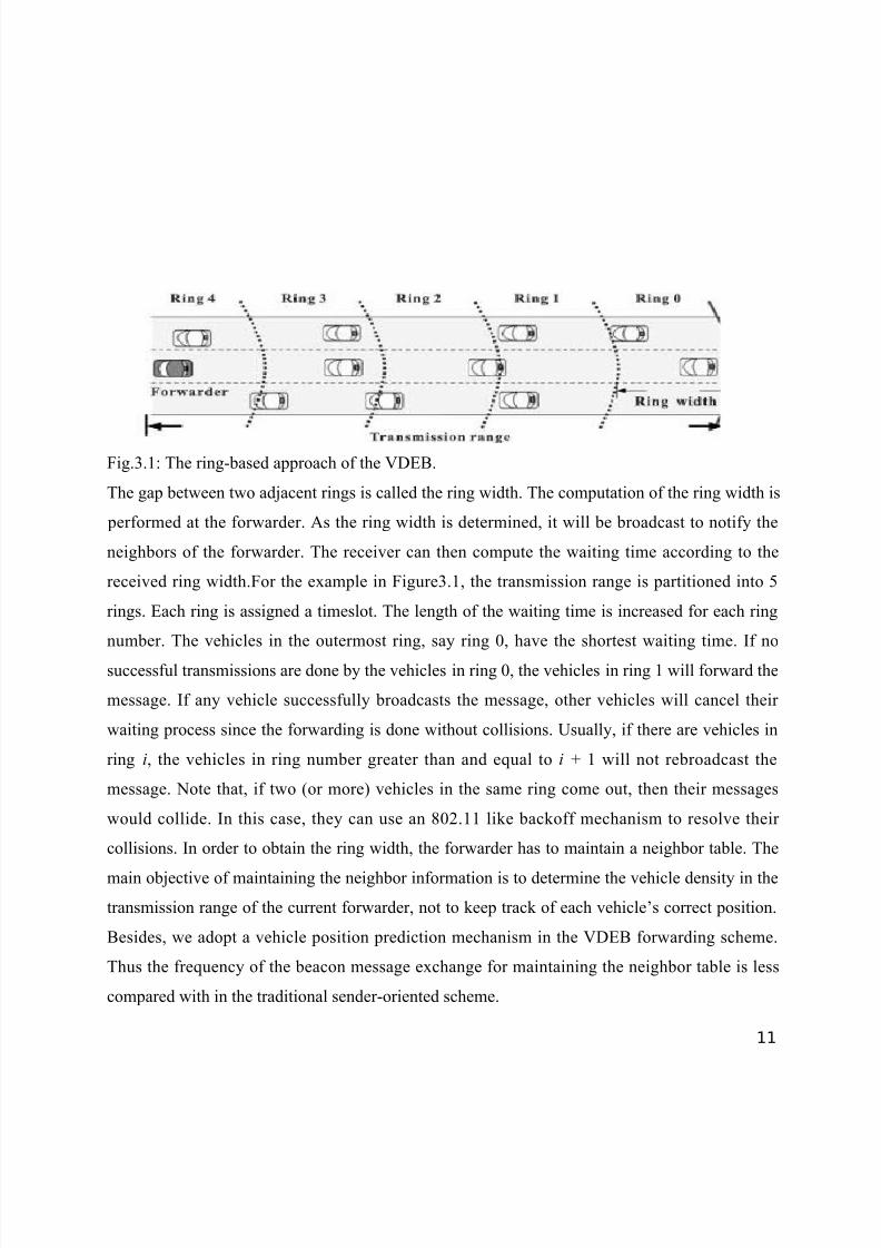
Fig.3.1: The ring-based approach of the VDEB.
The gap between two adjacent rings is called the ring width. The computation of the ring width is
performed at the forwarder. As the ring width is determined, it will be broadcast to notify the
neighbors of the forwarder. The receiver can then compute the waiting time according to the
received ring width.For the example in Figure3.1, the transmission range is partitioned into 5
rings. Each ring is assigned a timeslot. The length of the waiting time is increased for each ring
number. The vehicles in the outermost ring, say ring 0, have the shortest waiting time. If no
successful transmissions are done by the vehicles in ring 0, the vehicles in ring 1 will forward the
message. If any vehicle successfully broadcasts the message, other vehicles will cancel their
waiting process since the forwarding is done without collisions. Usually, if there are vehicles in
ring i, the vehicles in ring number greater than and equal to i + 1 will not rebroadcast the
message. Note that, if two (or more) vehicles in the same ring come out, then their messages
would collide. In this case, they can use an 802.11 like backoff mechanism to resolve their
collisions. In order to obtain the ring width, the forwarder has to maintain a neighbor table. The
main objective of maintaining the neighbor information is to determine the vehicle density in the
transmission range of the current forwarder, not to keep track of each vehicle’s correct position.
Besides, we adopt a vehicle position prediction mechanism in the VDEB forwarding scheme.
Thus the frequency of the beacon message exchange for maintaining the neighbor table is less
compared with in the traditional sender-oriented scheme.
11
8/3/2019 Seminar 3rd Sem
http://slidepdf.com/reader/full/seminar-3rd-sem 12/21
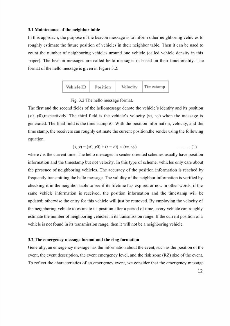
3.1 Maintenance of the neighbor table
In this approach, the purpose of the beacon message is to inform other neighboring vehicles to
roughly estimate the future position of vehicles in their neighbor table. Then it can be used to
count the number of neighboring vehicles around one vehicle (called vehicle density in this
paper). The beacon messages are called hello messages in based on their functionality. The
format of the hello message is given in Figure 3.2.
Fig. 3.2 The hello message format.
The first and the second fields of the hellomessage denote the vehicle’s identity and its position
( x0 , y0),respectively. The third field is the vehicle’s velocity (vx, vy) when the message is
generated. The final field is the time stamp t 0. With the position information, velocity, and the
time stamp, the receivers can roughly estimate the current position,the sender using the following
equation.
( x, y) = ( x0 , y0) + (t − t 0) × (vx, vy) ………(1)
where t is the current time. The hello messages in sender-oriented schemes usually have position
information and the timestamp but not velocity. In this type of scheme, vehicles only care about
the presence of neighboring vehicles. The accuracy of the position information is reached byfrequently transmitting the hello message. The validity of the neighbor information is verified by
checking it in the neighbor table to see if its lifetime has expired or not. In other words, if the
same vehicle information is received, the position information and the timestamp will be
updated; otherwise the entry for this vehicle will just be removed. By employing the velocity of
the neighboring vehicle to estimate its position after a period of time, every vehicle can roughly
estimate the number of neighboring vehicles in its transmission range. If the current position of a
vehicle is not found in its transmission range, then it will not be a neighboring vehicle.
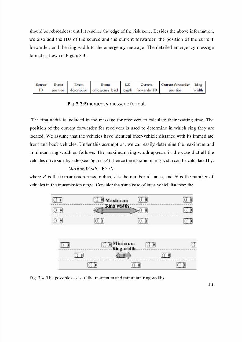
3.2 The emergency message format and the ring formation
Generally, an emergency message has the information about the event, such as the position of the
event, the event description, the event emergency level, and the risk zone (RZ) size of the event.
To reflect the characteristics of an emergency event, we consider that the emergency message
12
8/3/2019 Seminar 3rd Sem
http://slidepdf.com/reader/full/seminar-3rd-sem 13/21
should be rebroadcast until it reaches the edge of the risk zone. Besides the above information,
we also add the IDs of the source and the current forwarder, the position of the current
forwarder, and the ring width to the emergency message. The detailed emergency message
format is shown in Figure 3.3.
Fig.3.3:Emergency message format.
The ring width is included in the message for receivers to calculate their waiting time. The
position of the current forwarder for receivers is used to determine in which ring they are
located. We assume that the vehicles have identical inter-vehicle distance with its immediate
front and back vehicles. Under this assumption, we can easily determine the maximum and
minimum ring width as follows. The maximum ring width appears in the case that all the
vehicles drive side by side (see Figure 3.4). Hence the maximum ring width can be calculated by:
MaxRingWidth = R×l/N
where R is the transmission range radius, l is the number of lanes, and N is the number of
vehicles in the transmission range. Consider the same case of inter-vehicl distance; the
Fig. 3.4. The possible cases of the maximum and minimum ring widths.
13
8/3/2019 Seminar 3rd Sem
http://slidepdf.com/reader/full/seminar-3rd-sem 14/21
minimum ring width appears when the vehicle distribution is as shown in Figure 3.4. The
vehicles in the second and third lanes partition the inter-vehicle distance of the first lane into
three equal parts. The minimum ring width can be calculated by:
MinRingWidth=R/N
The ring width can be randomly set to be the value in [ MinRingWidth,MaxRingWidth] and then
the emergency message can be broadcast to the neighbors of the current forwarder.
3.3 The emergency message broadcasting scheme
The VDEB uses hello messages to periodically exchange the basic information between any two
vehicles. Based on the information in the received hello message, each vehicle can maintain its
own neighbor table. For the current forwarder, the vehicle density can be easily obtained from its
neighbor table and then the ring width can be determined. As the ring width is estimated, it will
be added to the emergency message and then be broadcast to the one-hop neighbors. Upon
receiving an emergency message from a vehicle, it firstly calculates its ring number by the ring
width and the position of the forwarder given in the message. The waiting time of ring 0 is 0
SIFS time. The waiting time of the other rings is proportional to their ring number as follows:
WaitingT ime = SlotTime × RingNumber ….(4)
When a vehicle waiting in the waiting process overhears any vehicle forwarding an emergency
message, the waiting process is canceled. As the next forwarder is elected, the message relaying
will be continued until the border of the risk zone is reached.
The purpose of simulations is to compare the performance of our proposed VDEB with the other
conventional emergency message forwarding schemes.
A) Procedure for forwarder-emergency-message-forwarding
Output: emergency message (EM);
{
if (the current vehicle is the observer) {
Add event-related information into the EM; }
Compute the vehicle density N ;
/* Determine the ring width value */
MaxRingWidth = R×l/N
14
8/3/2019 Seminar 3rd Sem
http://slidepdf.com/reader/full/seminar-3rd-sem 15/21
MinRingWidth = R
N , where R is the transmission range,
l is the number of lanes;
RingWidth= randomly depicts any value in
[MinRingWidth,MaxRingWidth];
Add RingWidth into the EM;
Broadcast(EM);
}
B) Procedure for receiver-emergency-message-forwarding;
Input: emergency message (EM);
{
Retrieve RingWidth value from the EM;
RingNumber=Ring-Number-Determination(RingWidth, current
forwarder’s position);
WaitingTime=SlotTime × RingNumber;
Perform the Waiting process;
if ((the waiting timer expired) and (does not overhear EM from
neighbor)) {
Set itself to be the forwarder;
call procedure forwarder-emergency-message-forwarding;
}
else cancel the waiting process;
4.Simulation Analysis
4.1. Simulation Environmental Setup:
The simulation scenario is an 8km, 3 lane, single direction section of highway. The risk zone of
an emergency event is 1km. We vary the hello interval from 0.2 s to 3.2 s for the MCDS scheme.
The VDEB is also simulated with the hello interval from 3 .2 s to 25.6 s . The mobility of vehicles
is evaluated by two speed scenarios: the low speed scenario has a speed of [20km/h, 70km/h],
while the high speed scenario has a speed of [70km/h, 120km/h]. The vehicle density varies from
a sparse to a dense road environment based on the safety distance with respect to the vehicles’
speed. Since the performance results for both scenarios (the low speed and the high speed) are
15
8/3/2019 Seminar 3rd Sem
http://slidepdf.com/reader/full/seminar-3rd-sem 16/21
quite similar, thus we only demonstrate the results of the high speed scenario. The complete
simulation setting is summarized in Table 1.
4.2 The numerical results
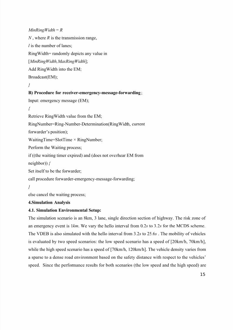
4.2.1 The simulations for hello interval setting: Figure 4.2.1 shows the average delay for
the MCDS scheme as the hello interval (HI) varies. Clearly, the shorter the hello interval we set,
the lower average delay we have. However, a shorter hello interval will disseminate many hello
messages in the network, which will cause the maintenance to be too costly. As shown in Figure
8, the performance of the MCDS when the hello interval is set to 0 .4 is a proper choice, since the
average delay is under 4ms for any vehicle density. Similarly, Figure 4.2 gives the average delay
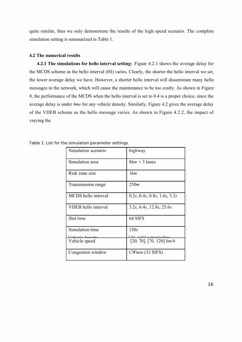
of the VDEB scheme as the hello message varies. As shown in Figure 4.2.2, the impact of
varying the
Table 1: List for the simulation parameter settings.
Simulation scenario highway
Simulation area 8km × 3 lanes
Risk zone size 1km
Transmission range 250m
MCDS hello interval 0.2 s, 0.4 s, 0.8 s, 1.6 s, 3.2 s
VDEB hello interval 3.2 s, 6.4 s, 12.8 s, 25.6 s
Slot time 64 SIFS
Simulation time
150 s
Vehicle speed [20 , 70] , [70 , 120] km/h
Congestion window CWmin (32 SIFS)
16
8/3/2019 Seminar 3rd Sem
http://slidepdf.com/reader/full/seminar-3rd-sem 17/21
Fig.4.2.1: The average delay comparisons of the different hello intervals of MCDS.
To achieve a similar delay performance to the MCDS scheme, we can use larger hello intervals
in our VDEB scheme,which will result in less network overhead consumption. The hello interval
of VDEB will therefore be set to 6.4 for the second part of the simulation.
Fig.4.2.2: The average delay comparisons of the different hello intervals of VDEB.
4.2.2 The simulation results for performance metrics comparison:
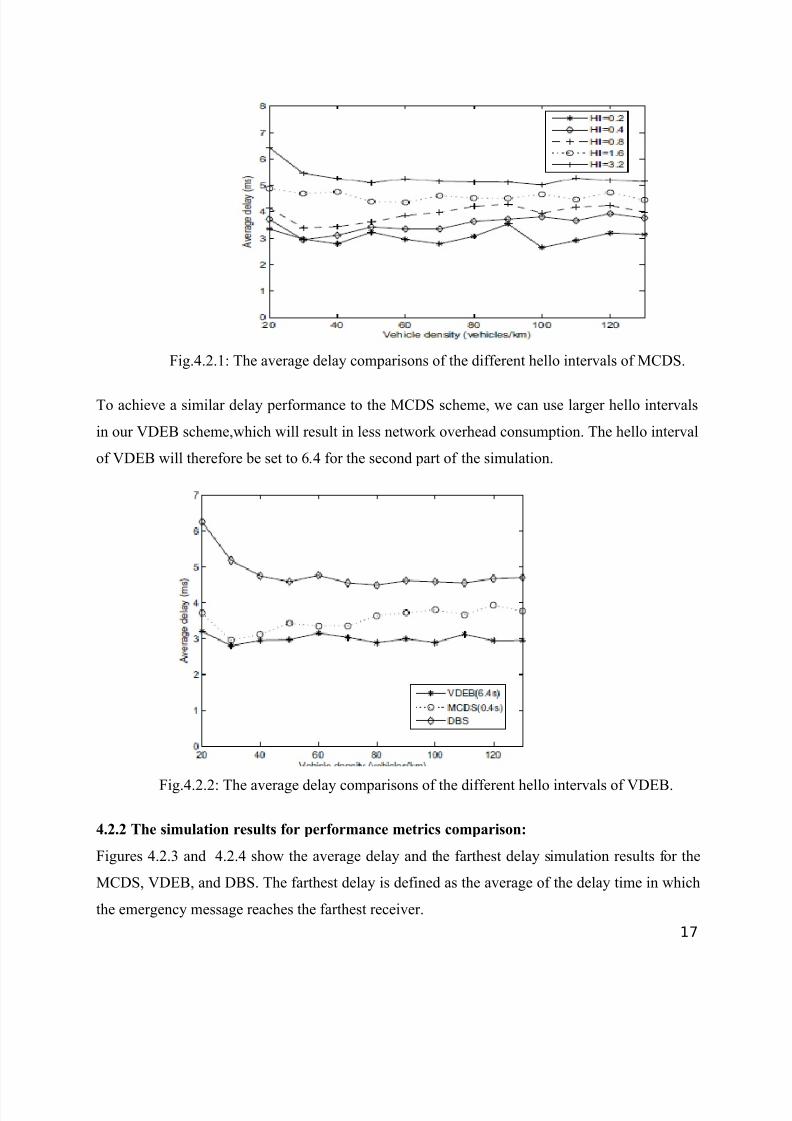
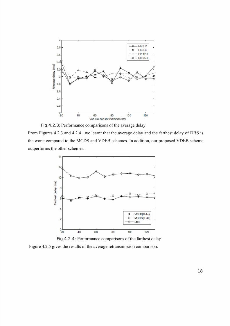
Figures 4.2.3 and 4.2.4 show the average delay and the farthest delay simulation results for the
MCDS, VDEB, and DBS. The farthest delay is defined as the average of the delay time in which
the emergency message reaches the farthest receiver.
17
8/3/2019 Seminar 3rd Sem
http://slidepdf.com/reader/full/seminar-3rd-sem 18/21
Fig.4.2.3: Performance comparisons of the average delay.
From Figures 4.2.3 and 4.2.4 , we learnt that the average delay and the farthest delay of DBS is
the worst compared to the MCDS and VDEB schemes. In addition, our proposed VDEB scheme
outperforms the other schemes.
Fig.4.2.4: Performance comparisons of the farthest delay
Figure 4.2.5 gives the results of the average retransmission comparison.
18
8/3/2019 Seminar 3rd Sem
http://slidepdf.com/reader/full/seminar-3rd-sem 19/21
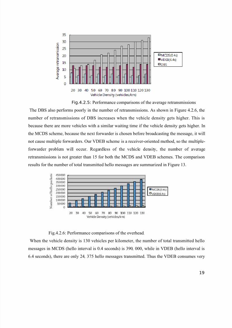
Fig.4.2.5: Performance comparisons of the average retransmissions
The DBS also performs poorly in the number of retransmissions. As shown in Figure 4.2.6, the
number of retransmissions of DBS increases when the vehicle density gets higher. This is
because there are more vehicles with a similar waiting time if the vehicle density gets higher. In
the MCDS scheme, because the next forwarder is chosen before broadcasting the message, it will
not cause multiple forwarders. Our VDEB scheme is a receiver-oriented method, so the multiple-
forwarder problem will occur. Regardless of the vehicle density, the number of average
retransmissions is not greater than 15 for both the MCDS and VDEB schemes. The comparison
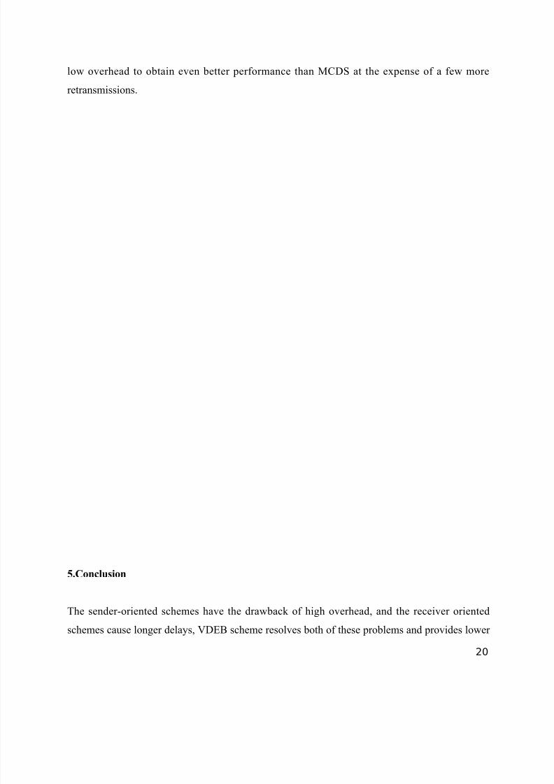
results for the number of total transmitted hello messages are summarized in Figure 13.
Fig.4.2.6: Performance comparisons of the overhead.
When the vehicle density is 130 vehicles per kilometer, the number of total transmitted hello
messages in MCDS (hello interval is 0.4 seconds) is 390 , 000, while in VDEB (hello interval is
6.4 seconds), there are only 24 , 375 hello messages transmitted. Thus the VDEB consumes very
19
8/3/2019 Seminar 3rd Sem
http://slidepdf.com/reader/full/seminar-3rd-sem 20/21
low overhead to obtain even better performance than MCDS at the expense of a few more
retransmissions.
5.Conclusion
The sender-oriented schemes have the drawback of high overhead, and the receiver oriented
schemes cause longer delays, VDEB scheme resolves both of these problems and provides lower
20
8/3/2019 Seminar 3rd Sem
http://slidepdf.com/reader/full/seminar-3rd-sem 21/21
delay and lower overhead for emergency message broadcasting. In this a receiver oriented
contention mechanism is adopted with the vehicle density measurement component. Vehicle
density help to reduce the number of retransmissions of messages, and avoid the situation that
the delay time increases if the forwarder is not far enough away. In addition, the number of
forwarders is limited by the ring width which is estimated by the vehicle density and neighbor. In
the VDEB scheme ,the number of retransmission is not proportional to the vehicle density
information
21