Schoenborn JM T 2012
162
A Case Study Approach to Identifying the Constraints and Barriers to Design Innovation for Modular Construction Joseph M. Schoenborn THESIS SUBMITTED TO THE FACULTY OF THE VIRGINIA POLYTECHNIC INSTITUTE AND STATE UNIVERSITY IN PARTIAL FULFILLMENT OF THE REQUIREMENTS FOR THE DEGREE OF MASTER OF SCIENCE IN ARCHITECTURE James R. Jones, Chair Robert P. Schubert Thomas E. Hardiman April 27, 2012: Blacksburg, VA keywords: prefabrication, industrialization, modularization Copyright 2012, Joseph Schoenborn
-
Upload
yoseph-birru -
Category
Documents
-
view
216 -
download
1
Transcript of Schoenborn JM T 2012
A Case Study Approach to Identifying the Constraints
and Barriers to Design Innovation for
Modular Construction
Joseph M. Schoenborn
THESIS SUBMITTED TO THE FACULTY OF THE
VIRGINIA POLYTECHNIC INSTITUTE AND STATE
UNIVERSITY IN PARTIAL FULFILLMENT OF THE
REQUIREMENTS FOR THE DEGREE OF
MASTER OF SCIENCE
IN
ARCHITECTURE
James R. Jones, Chair
Robert P. Schubert
Thomas E. Hardiman
April 27, 2012: Blacksburg, VA
keywords: prefabrication, industrialization, modularization
Copyright 2012, Joseph Schoenborn
A Case Study Approach to Identifying the Constraints and Barriers to
Design Innovation for Moudlar Construction
Joseph M. Schoenborn
It is important for an architect to understand
the limiting factors that will affect the design
of a modular building. The implementation of
modular construction as a means of improving
production effi ciency and worker safety in
the construction industry raises into question
the design quality of modular buildings, and
whether or not the merits of the building pro-
cess can also be captured from the perspective
of the architect. For this reason, the constraints
and barriers to design innovation in modular
construction are recorded through the lens of
an architect.
This study uses interviews with modular
ABSTRACT
manufacturers to extract information on the topic
of innovation in the industry. Featuring a case
study project as the platform for discussion, the
opinions of experienced building professionals
were sought to identify what is and what isn’t
possible. Among the primary constraints and
barriers to innovation, including manufacturing
costs, dimensional requirements based on
transportation method, and the infl exibility
of CAM software, the results of the study
identifi ed a need for architects to become
better educated about modular construction in
general. Therefore, the information presented
is meant to be a teaching tool geared towards
architects.

iii
Special thanks to the participants of this study listed as follows (in alphabetical order):
Ian Peter AtkinsJohn S. CatalinoDonald F. Engle, Jr.Dennis MichaudJohn R. MorrisonJay Van VlerahRodney Young
ACKNOWLEDGEMENTS
iv
ABSTRACT
ACKNOWLEDGEMENTS
TABLE OF CONTENTS
LIST OF FIGURES
LIST OF TABLES
CHAPTER 1: INTRODUCTION
CHAPTER 2: LITERATURE REVIEW
2.1 Definitions
2.1.1 Prefabrication
2.1.2 Preassembly
2.1.3 Modular Construction
2.1.4 Manufactured Homes
2.1.5 Onsite Construction
2.1.6 Offsite Construction
2.1.7 Modularization
2.1.8 Industrialization
2.1.9 Lean Construction
2.1.10 Modular
2.2 Perceived Benefits and
Challenges of Modular
Construction
2.3 Current Trends in Modular
Construction
2.4 Cross Industry Learning
2.5 Innovation in Computer Aided
Design
2.6 Architectural Precedents
2.6.1 Prototyping
2.6.2 Processed Materials
2.6.3 Prefabricated
Components
2.6.4 Panelized Structures
2.6.5 Modular Structures
2.6.6 Manufactured Homes
ii
iii
iv
v
vii
1
3
3
3
5
5
6
6
6
6
6
6
6
6
8
9
10
12
13
13
14
14
15
16
2.7 Reaction to Literature
CHAPTER 3: METHODOLOGY
3.1 Overview of Qualitiative Methods
3.1.1 The Case Study Design
3.1.2 Role of the Researcher
3.1.3 Ethical Considerations
3.1.4 Setting
3.1.5 Actors
3.1.6 Events
3.2 Data Collection Tactic
3.2.1 Development of the
Questionairre
3.2.2 Data Recording
Procedures
3.2.3 Data Analysis Procedures
3.2.4 Data Coding
3.2.5 Verification
3.2.6 Reforting and Findings
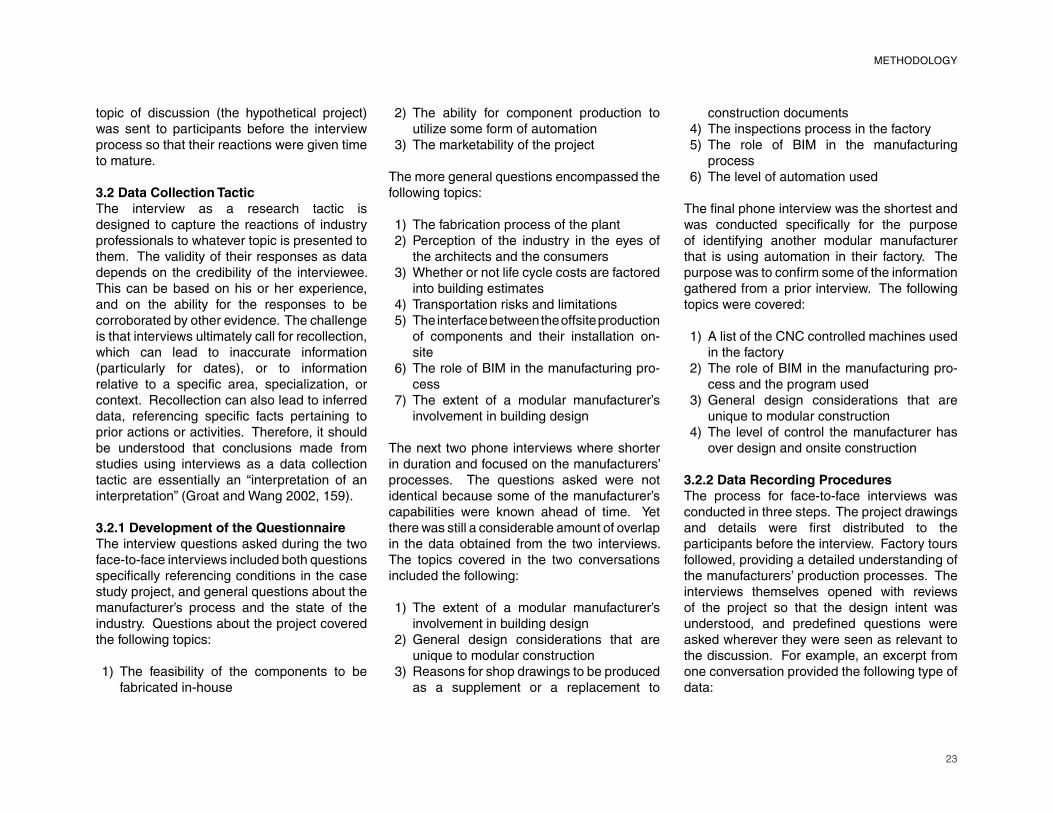
3.3 The Case Study Project
3.3.1 Program
3.3.2 Building Systems
3.3.3 Initial Cost Review
3.4 Description of Participants
3.4.1 Company A
3.4.2 Company B
3.4.3 Company C
3.4.4 Company D
3.4.5 Company E
CHAPTER 4: DATA COLLECTION
4.1 Company A Interview Summary
4.2 Company B Interview Summary
4.3 Company C Interview Summary
4.4 Company D Interview Summary
4.5 Company E Interview Summary
18
19
19
19
21
21
22
22
22
23
23
23
24
24
25
25
26
26
27
29
30
30
31
32
32
32
34
34
37
41
44
48
4.6 Identification of Themes
CHAPTER 5: DATA ANALYSIS
5.1 Market Perception
5.1.1 Marketing and Outreach
5.1.2 LEED
5.2 Education
5.2.1 Building Codes
5.2.2 Transportation
Limmitations
5.2.3 Tolerances
5.2.4 Means and Methods
5.3 Scope of Work
5.4 Drawing Duplication
5.4.1 Shop Drawings
5.4.2 BIM/3D�CAD
5.4.3 Paperless Production
5.5 Impediments to Mass
Customization
5.6 Offsite/Onsite Interface
5.7 Initial Building Cost
CHAPTER 6: CONCLUSIONS
6.1 Interpretation of Data
6.2 Opportunities for Future Study
6.3 Summary of Findings
REFERENCES
APPENDIX A: PROJECT DWGS
APPENDIX B.1: TRANSCRIPT A
APPENDIX B.2: TRANSCRIPT B
APPENDIX B.3: TRANSCRIPT C
APPENDIX B.4: TRANSCRIPT D
APPENDIX B.5: TRANSCRIPT E
APPENDIX C: IRB PROTOCOL
49
50
50
50
51
51
52
53
53
53
56
56
57
57
57
58
59
60
62
62
69
70
71
75
104
115
127
135
146
149
TABLE OF CONTENTS

v
LIST OF FIGURES
4
4
4
4
5
7
7
10
10
11
11
11
12
13
Figure 2.6.1.2 Garden Prototype
by Kierran Timberlake Architects (KieranTimberlake 2007)
Figure 2.6.4.1 Acorn House by Carl
Koch (Koch 1958, 91)Figure 2.6.4.2 Acorn House
foundation installation (Koch 1958, 93)
Figure 2.6.5.1 Container Kit home by
Lot-EK (Lot-EK)Figure 2.6.5.2 rendering of
O’Connell East Architect’s and
CTZWG’s Victoria Hall (OCA)Figure 2.6.5.3 rendering of SHoP
Architect’s B2 Brooklyn Building for
Atlantic Yards (SHoP Architects)Figure 3.3.1.1 single classroom
exploded axonometric
Figure 3.3.1.2 duplex option exterior
photomontage
Figure 3.3.1.3 one, two, and three
classroom options
Figure 3.3.2.1 SIP assembly, drawing by Brendan Johnston
Figure 3.3.2.2 SIP assembly, drawing by Brendan Johnston
Figure 3.3.2.2 SIP assembly,
drawing by Brendan JohnstonFigure 3.4.1.1 picture taken at
Company A’s factory
Figure 3.4.1.2 picture taken at
Company A’s factory
Figure 3.4.1.3 picture taken at
Company A’s factory
Figure 3.4.2.1 picture taken at
Company B’s factory
13
15
15
16
17
17
26
27
27
28
28
28
30
30
30
31
Figure 3.4.2.2 picture taken at
Company B’s factory
Figure 3.4.2.3 picture taken at
Company B’s factory
Figure 3.4.2.4 picture taken at
Company B’s factory
Figure 5.2.2.1 example of a module
on a double-drop trailer bed
Figure 5.2.2.2 comparison of
maximum module lengths base on
different shipping methods
Figure 5.2.4.1 common modular
structure (Reidelbach 1971, 126)Figure 5.2.4.2 steel connections
(Allen and Iano 2004, 392)Figure 5.2.4.3 steel connections
(Allen and Iano 2004, 394)Figure 5.2.4.4 module cross section
(Reidelbach 1971, 137)Figure 5.5.1 stool design by Patrick
Chia (Piller 2006, 6)Figure 5.7.1 the life cycle value of
materials (Blengini 2009, 322)Figure 6.1.1 Triad/Ruvo automated
machine for steel wall and fl oor
panel fabrication (Deluxe Building Systems 2009)
Figure 6.1.2 component assembly
line (Reidelbach 1971, 154)Figure A.1 two-classroom rendering
Figure A.2 building diagram
Figure A.3 SIP panel design with
embedded cam locks, drawing by Brendan Johnston
Figure A.4 cam lock mechanism, image provided by Vera Novak
31
31
31
54
54
55
55
55
55
58
60
66
67
76
77
78
78
Figure 2.1.1.1 Habitat ‘67 by Mosche
Safdie (Safdie 1970, 23)Figure 2.1.1.2 Furniture House by
Shigeru Ban (McQuaid 2003, 167)Figure 2.1.1.3 IBM Traveling Pavilion
by Renzo Piano (Dini 1984, 79)Figure 2.1.1.4 Eames House by
Charles and Ray Eames (Smith 2007, 23)
Figure 2.1.3.1 typical modular
construction schedule (Permanent
Modular Construction 2011: Annual
Report 2011, 3)Figure 2.2.1 perceived benefi ts of
modular construction (Haas et al 2000, 17)
Figure 2.2.2 perceived constraints to
modular construction (Haas et al 2000, 18)
Figure 2.4.1 Witchita House by
Buckminster Fuller (Arieff 2002, 17)
Figure 2.4.2 patent drawings for
Buckminster Fuller’s Dymaxion Car
(Fuller and Marks 1973, 49)Figure 2.5.1 MasterCAM x2 model
Figure 2.5.2 Rhino 3-dimensional
model
Figure 2.5.3 CNC-milled 4x4
Figure 2.6.1 a Sears Roebuck
House of the 1920’s (Small Houses
of the Twenties 1991, 21)Figure 2.6.1.1 Case Study House
#22, the Stahl House, by Peter
Koening (Smith 2007, 68)

vi
LIST OF FIGURES
78
78
79
80
80
80
81
81
81
82
82
82
83
83
Figure A.5 light, cold-formed steel
structure (Lite Steel Technologies America 2008)
Figure A.6 phenolic resin skin (DuraSip)
Figure A.7 pod variation design,
drawing set by Josh LillyFigure A.8 helical pile (Foundation
Supportworks 2012)Figure A.9 cork fl oor tiles (Home
Sevice Publications 2012)Figure A.10 grey water purifi cation
system (Aquaco Grey Water
Recycling System 2010)Figure A.11 solar thermal panel
(Solar Themal Heating)Figure A.12 photovoltaic array
(Applied Solar Technology 2012)Figure A.13 heat exchanger with
enthalpy wheel (BuildingGreen 2012)
Figure A.14 LED light tubes (Energy Solutions Center 2007)
Figure A.15 adjustable interior
shades (Eartheasy.com 2011)Figure A.16 soy-based foam
insulation SIP’s, image provided by Vera Novak
Figure A.17 phenolic resin sheets
customizable in color and surface
texture (Focus Technology Co. 2012)
Figure A.18 Magnum Board building
product used in place of gyp board (Magnum Building Products 2012)
83
84
85
86
87
88
89
90
90
90
91
91
92
92
93
93
94
94
95
95
95
96
96
Figure A.19 light shelf design (Lechner 2009, 323)
Figure A.20 interior rendering
Figure A.21 exploded axonometric
Figure A.22 pod component
assembly
Figure A.23 panel and clerestory
assembly
Figure A.24 fl oor component
assembly
Figure A.25 roof component
assembly
Figure A.26 location of cam lock
mechanisms
Figure A.27 detail section
Figure A.28 detail plan
Figure A.29 photomontage
Figure A.30 fi t-out plan
Figure A.31 detail plan at fl oor/wall
component connection
Figure A.32 typical section through
beams
Figure A.33 typical clerestory detail
Figure A.34 typical wall component
detail
Figure A.35 detail of pod connection
to clerestory component
Figure A.36 pod section
Figure A.37 detail of fl oor
component connection to pod
Figure A.38 pod section
Figure A.39 pod detail section
Figure A.40 detail plan of end pod
condition
Figure A.41 detail plan of connected
pods
Figure A.42 detail plan of connected
pods with door partition
Figure A.43 detail plan of corner
condition
Figure A.44 typical corner section
Figure A.45 detail section through
beams
Figure A.46 typical cross section
Figure A.47 detail section through
clerestory
Figure A.48 typical section through
pod
Figure A.49 photomontage
Figure A.50 plan option
Figure A.51 detail section of
classroom connecting to corridor
Figure A.52 detail plan of corner
component connecting to
classroom
Figure A.53 photomontage
Figure A.54 plan option
Figure A.55 detail section of stacked
pod confi guration
Figure A.56 section of stacked pods
Cover Image by Josh Lilly
96
97
97
98
98
99
99
100
100
101
101
102
102
103
103

4
20
32
37
40
44
47
48
52
Table 2.1.1.1 classifi cation of
prefabricated systems (Sylvester 2004)
Table 3.1.1.1 assumptions of
qualitative design (Creswell 2009, 179)
Table 3.4.1 comparative table
summarizing the size and
experience of Companies A, B, C,
D, and E, and the experience of the
stateholders
Table 4.1.1 themes and pertinent
information identifi ed from the
interview with Company A
Table 4.2.1 themes and pertinent
information identifi ed from the
interview with Company B
Table 4.3.1 themes and pertinent
information identifi ed from the
interview with Company C
Table 4.4.1 themes and pertinent
information identifi ed from the
interview with Company D
Table 4.5.1 themes and pertinent
information identifi ed from the
interview with Company E
Table 5.2.1.1 state departments
identifi ed as governing bodies in
charge of defi ning commercial
modular buidlng codes (both
relocatable buildings and PMC)
and certifying third-party inspection
agencies (Relocatable Buildings:
2011 Annual Report 2011, 20)
LIST OF TABLES
vii
Table 5.2.2.1 transportation
requirements by state (Oversized
Load, Permit and Pilot Car
Requirements 2011) 54
1
CHAPTER 1: INTRODUCTION
The benefi ts of modular construction can be
quantifi ed through a comparative analysis
of selected buildings. A 2011 study by
McGraw Hill Construction conducted among
architects, engineers, contractors, and
building owners supports the arguments
that speed to completion, quality, and safety
can be increased with modular construction,
while overall costs, material waste, and the
impact on the environment can be reduced
(Bernstein, Gudgel, and Laquidara-Carr 2011,
39-47). As a result, the number of buildings
incorporating prefabrication over the past 15
years has increased by 86% (Haas et al. 2000,
29). Unfortunately it seems that innovation in
the modular construction industry is slow to
adapt. The identifi cation of the constraints and
barriers to innovation in modular construction
however can be more subjective. The technical
limitations of different modular manufactures
and the varying degree to which prefabrication
and preassembly are used make a comparative
study diffi cult. A survey of architects, engineers,
and general contractors in 2007 indicated that
the perceived challenges to using prefabrication
includes transportation restrictions on design
and construction schedule rigidity (the inability
for changes to be made during construction) (Bertelsen 2004, 127). However, these
results were drawn without the perspective of
manufactures with experience in component
prefabrication and preassembly.
A perceived lack of innovation in modular
construction projects to date raises the question
of why, or what is holding the industry back. The
problem is that industry-wide design limitations
and restrictions prohibiting building construction
methods or materials are not clearly known to
architects. This study therefore was designed to
discover the challenges presented to architects
involved in the design of modular buildings.
Upon completion, the results can then be used
for future research aimed at nullifying these
constraints and barriers to design innovation
for modular construction.
The purpose, ultimately, was to list these con-

2
INTRODUCTION
straints and barriers using information gathered from the analysis of a case study project. The research is presented as an exploratory case study, with the aim of being able to provide an understanding of how design and fabrication processes infl uence one another – design pushing innovation in the building process and the use of technology, and the fabrication process defi ning the parameters
of design. For the purposes of this study, the
topic of innovation in modular construction is
demonstrated through mass customization
featured in the design of the case study project.
The impediments to design innovation were
therefore discovered through thoughts shared
by professionals through interview tactics.
What is the current level of involvement with
architects in the commercial modular building
industry? And how often are advantageous
changes in the manufacturing processes
pursued? Known technical limitations
are consistently being overcome because
technological innovation is a byproduct of
design ingenuity. This research focuses on
the interactions between professionals in
order to both defi ne the current barriers and
constraints, and to collectively hypothesize on
how they can be overcome.
Analysis of the case study project was com-
pleted through interviews with stakeholders
from the modular construction industry. The
study was confi ned to interviews with fi ve
different modular building manufacturers.
Companies predominantly work on non-
residential, permanent buildings. The questions
asked in the interviews focused on the topics
of initial building costs versus life cycle costs,
the fabrication and transportation of building
components, the required quality of and access
to construction documents, the ability for a
diverse library of building components to be
developed, and the differences in the market
perception of offsite construction versus onsite
construction.
3
CHAPTER 2: LITERATURE REVIEW
2.1 Defi nitionsCommercial modular manufacturers were con-sulted for this study, and so the information and nomenclature presented will remain consistent with the modular construction industry. But even though the terms used may refer specifi cally to the modular construction
industry, the concepts identifi ed are likely
applicable to multiple levels of prefabrication
or offsite construction. The defi nitions used
for the purposes of this research include the
following:
2.1.1 PrefabricationPrefabrication encompasses the construction
of all building components that are a part
of a larger fi nal assembly (Gibb 1999, 1). Prefabrication is an offsite manufacturing
process that takes place at a specialized
facility in which various materials and building
systems are joined to form a component or
part of a larger fi nal installation (Haas et al.
2000, 4). Work is done at a remote location for
increased construction speed and quality. The
type of prefabricated components vary based
on size and complexity (including the amount
of fi nish work done in the factory and the
number of building trades involved on a single
component), and based on the amount of labor
required for onsite assembly. Components can
be categorized into four types:
Processed materials are pre-cut structural
or cladding materials custom fabricated
through a manufacturing process.
Prefabricated components are simple
building blocks that usually involve a
single building trade. The vast majority of
buildings constructed today use some form
of prefabrication. Applications include
timber frame panels, precast panels, steel
frame panels, structurally insulated panels
(SIP’s), building envelope/façade systems,
composite panels, precast cladding, Light
Steel Frame Building Systems (LSF), pre-cast structural elements, insulating
concrete formwork (ICF), and tunnel form
construction (Hartley and Blagden 2007,
12).
1)
2)
4
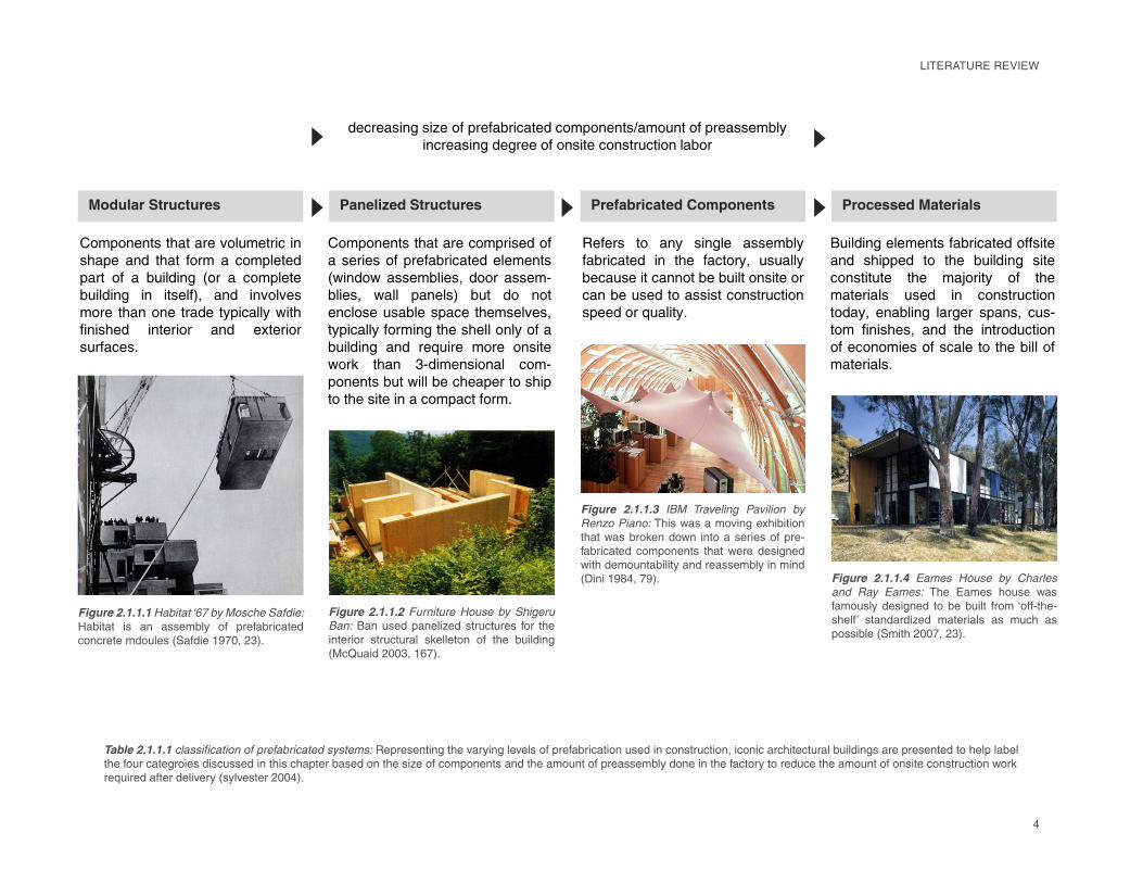
Table 2.1.1.1 classifi cation of prefabricated systems: Representing the varying levels of prefabrication used in construction, iconic architectural buildings are presented to help label the four categroies discussed in this chapter based on the size of components and the amount of preassembly done in the factory to reduce the amount of onsite construction work required after delivery (sylvester 2004).
���������� �� �� �� ������� ��
��� �� �� ���� ���� ����
��� �� ��� ���� ��� ���� ���
��� ���� �� ���� ��� �� ���� ���
���� �� ��� ���� ����� � ���
������� �������� �� ��������
��������
���������� �� �� ��������� ��
������ �� ����������� � ������
������� ����� ���� ���� �����
� ���� � ��� �� ��� �� ���
��� ��� ��� � ���� ����� ����
����� � ������� �� �� �� � ��
��� ���� �� ������� ���� ������
���� �� ����������� ����
������� ��� �� �� ����� �� ���
�� �� ���� �� ������ �����
����� �� �� ���� � ����� �
�������� �� �� ������� ��� �
������ �� ����� �� ��� � ������ ��
�� �� ���� �� ����� ������������
����� �� �� ����
!�� ���� � ������ �������� �������
�� ������ �� �� ��� ���� ����
���������� �� �"����� �� ��
����� � ���� �� ������������
����� ��� ��� ���� ����� ����
��� �������� �� �� ������������
�� ��������� �� �� � �� �� �� ��
����� ��
�������������� ���������������� ��������������������� ����� ����������
���������#��$�#��#�����������#����������%�����#��#�������� �
���������#������#��#������#������������# ���
Figure 2.1.1.1 Habitat ‘67 by Mosche Safdie:
Habitat is an assembly of prefabricated concrete mdoules (Safdie 1970, 23).
Figure 2.1.1.2 Furniture House by Shigeru
Ban: Ban used panelized structures for the interior structural skelleton of the building (McQuaid 2003, 167).
Figure 2.1.1.3 IBM Traveling Pavilion by
Renzo Piano: This was a moving exhibition that was broken down into a series of pre-fabricated components that were designed with demountability and reassembly in mind (Dini 1984, 79). Figure 2.1.1.4 Eames House by Charles
and Ray Eames: The Eames house was famously designed to be built from ‘off-the-shelf’ standardized materials as much as possible (Smith 2007, 23).
LITERATURE REVIEW
5
LITERATURE REVIEW
cess defi ned by the use of prefabrication
and preassembly at a remote location to
compose volumetric components (modular
structures) which are transported as largely
fi nished components to a building site. The
Modular Building Institute (MBI) categorizes
commercial modular buildings as being 60-
80% completed offsite before being shipped
to an end destination (Permanent Modular
Construction 2011: Annual Report, 2-4). The
divisions within the modular construction
industry include the following:
Permanent Modular Construction (PMC)
provides a service comparable to onsite
construction where components are
attached to a permanent foundation.
Components can be integrated into site built
projects or stand-alone buildings. While
costs are likely competitive to an onsite
construction process, the time savings
accrued from the simultaneous scheduling
of offsite and onsite work enables clients
to turn profi ts quicker and save the money
spent on employee displacement. PMC
buildings are the most likely to involve the
assistance of an architect, yet the industry
currently can stake claim to only 1% of
the overall commercial building market.
A typical job will be fi nanced by a private
owner with the work being coordinated
between an architectural and engineering
group, a modular manufacturer, and an
onsite general contractor (unless the
manufacturer is licensed and staffed to
work outside of the factory) (Permanent
Modular Construction 2011: Annual Report
2011, 2).
Panelized structures are an assembly
of prefabricated components that do
not enclose usable space. They form
a considerable percentage of the fi nal
building envelope prior to shipment in
compact form on a fl atback trailer.
Modular structures are volumetric offsite
fabrications that form an enclosed
usable space. Modules are structurally
independent and include more than one
building trade. This category can be
broken down further based on size. Larger
modules are shipped by themselves and
generally comprise more than one room
of the fi nal building. The term ‘pod’ refers
to one-room modules; the most common
applications today are bathroom pods for
site built high-rises. ‘Interstitial modules’ are non-inhabitable spaces including
fi nished roof components or fl oor and
ceiling plenums.
2.1.2 PreassemblyPreassembly involves the joining of
prefabricated components together away from
the fi nal building site to form either a complete
building or a building system. Preassembly
can be done either offsite (at a manufacturer’s
factory) or onsite, and promotes parallel
fabrication practices (Haas et al. 2000, 4). Work
typically requires multiple building trades and
the placement of preassembled components
that often requires the utilization of a crane.
2.1.3 Modular ConstructionModular construction is a manufacturing pro-
Site Built Construction Schedule
Design
Eng.
Permits &
Approvals
Site Development &
Foundations
Building
Construction
Site
Restoration
Modular Construction Schedule.
Design
Eng.
Permits &
Approvals
Site Development &
Foundations
Install & Site
RestorationTime Savings
Building Construction at Plant
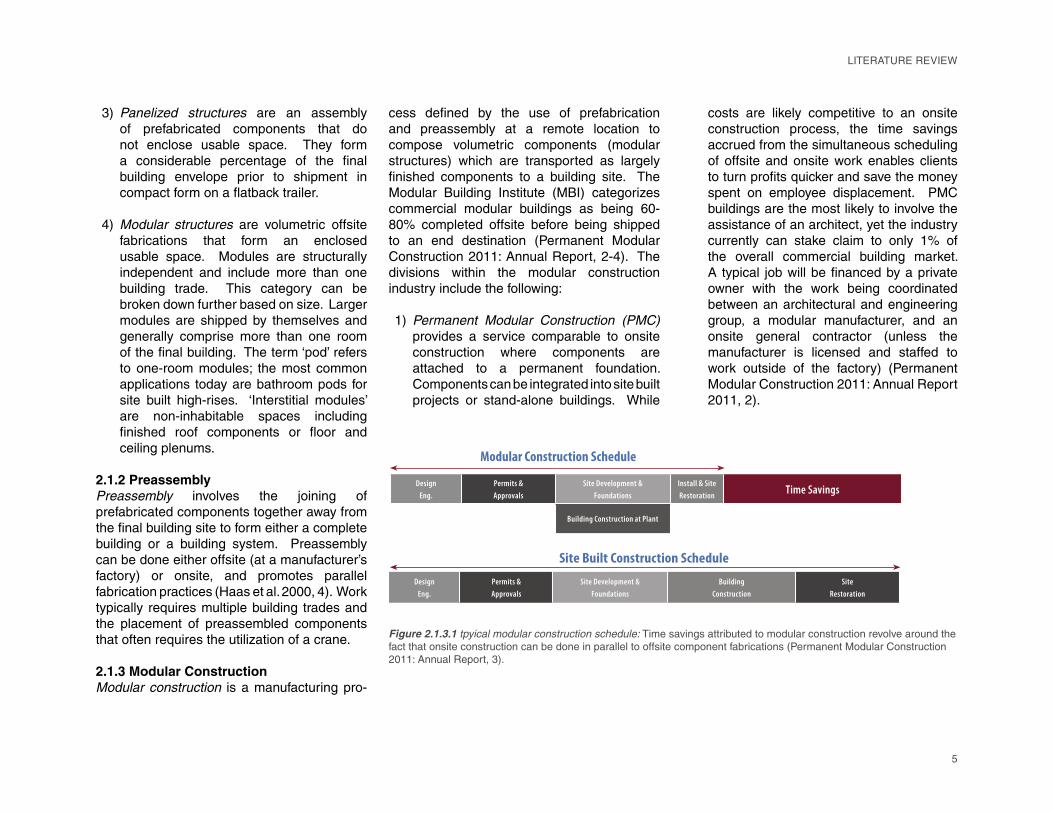
Figure 2.1.3.1 tpyical modular construction schedule: Time savings attributed to modular construction revolve around the
fact that onsite construction can be done in parallel to offsite component fabrications (Permanent Modular Construction
2011: Annual Report, 3).
1)
3)
4)
6
2.1.5 Onsite ConstructionStick built construction is used interchangeabe with onsite construction and in-situ construction. The term stick built historically refers to dimensioned lumber construction, but it will be used here for any construction done onsite.
2.1.6 Offsite ConstructionOffsite construction includes prefabrication and/or preassembly away from the fi nal
building site. The term is traditionally used in
the UK, where prefabricated components are
instead categorized as ‘non-volumetric offsite
fabrications,’ ‘volumetric offsite fabrications,’ and ‘modular buildings’ (Gibb 1999, 8). In this
study, offsite construction is used to describe
the use of prefabrication and preassembly in
generic terms.
2.1.7 ModularizationModularization generally referrs to a process
of breaking a complete building down into a
series of smaller modules constructed offsite
so that onsite construction is reduced to
foundation work and module assembly. While
the modular manufacturer has more control
over quality and the production schedule, the
major downside to modularization is the fact
that shipping large empty volumes is costly.
2.1.8 IndustrializationIndustrialization is used to describe the
automation of building construction utilizing
advanced equipment and technology to
minimize human involvement.
2.1.9 Lean ConstructionLean construction principles revolve around
reducing waste of materials and money for
industrial production. While prefabrication
and the integration of BIM into the process are
suggested, the strategies of lean construction
will not be discussed in this book.
2.1.10 ModularModular is a term that is identifi ed with
standardized units or dimensions. It will not be
used by itself in this book.
2.2 Perceived Benefi ts and Challenges of
Modular ConstructionA study conducted at the Graduate School of
the University of Clemson by Lu Na in 2000
revealed the perceived benefi ts and limitations
to using prefabricated components. The survey
received responses from a mixture of 138
practicing architects, engineers, and general
contractors in the U.S. The benefi ts associated
with prefabrication revealed in the study
included the following (Lu 2007, 126-127):
Reduced overall construction time and
effi cient scheduling due to parallel
production activities
Inreased building quality and
craftsmanship
Increased labor productivity
Increased labor safety
Reduced construction schedule
disruptions due to the use of a weather-
protected work environment
The minimal environmental impact of the
construction process on the site
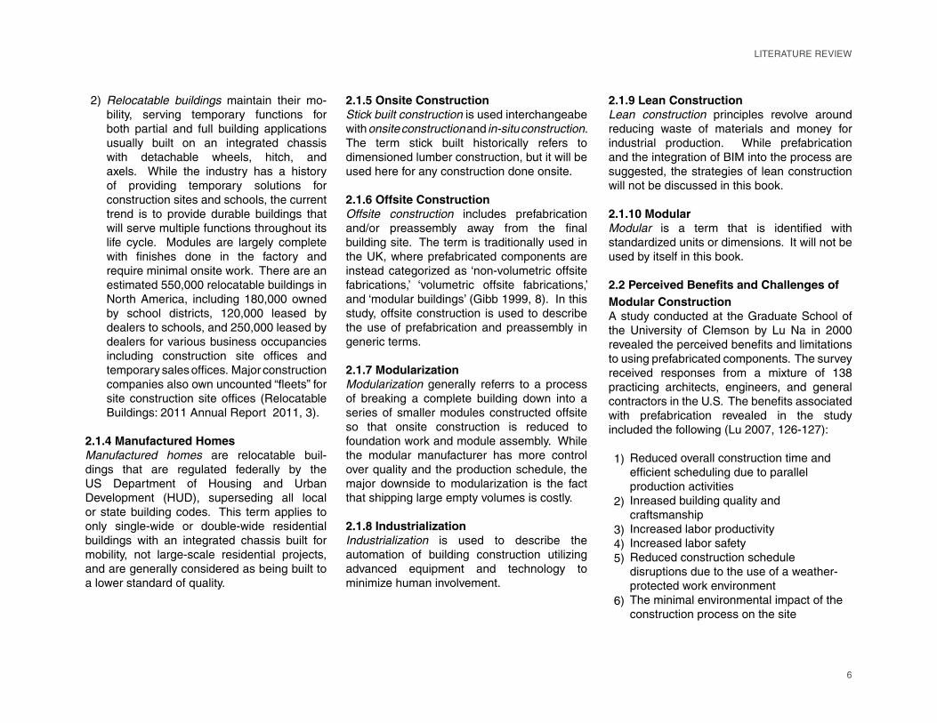
Relocatable buildings maintain their mo-
bility, serving temporary functions for
both partial and full building applications
usually built on an integrated chassis
with detachable wheels, hitch, and
axels. While the industry has a history
of providing temporary solutions for
construction sites and schools, the current
trend is to provide durable buildings that
will serve multiple functions throughout its
life cycle. Modules are largely complete
with fi nishes done in the factory and
require minimal onsite work. There are an
estimated 550,000 relocatable buildings in
North America, including 180,000 owned
by school districts, 120,000 leased by
dealers to schools, and 250,000 leased by
dealers for various business occupancies
including construction site offi ces and
temporary sales offi ces. Major construction
companies also own uncounted “fl eets” for
site construction site offi ces (Relocatable
Buildings: 2011 Annual Report 2011, 3).
2.1.4 Manufactured HomesManufactured homes are relocatable buil-
dings that are regulated federally by the
US Department of Housing and Urban
Development (HUD), superseding all local
or state building codes. This term applies to
only single-wide or double-wide residential
buildings with an integrated chassis built for
mobility, not large-scale residential projects,
and are generally considered as being built to
a lower standard of quality.
2)
1)
2)
3)4)5)
6)
LITERATURE REVIEW
7
LITERATURE REVIEW
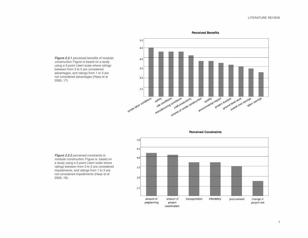
Perceived Benefits
Perceived Constraints
Figure 2.2.1 perceived benefi ts of modular
construction: Figure is based on a study using a 5-point Likert scale where ratings between from 3 to 5 are considered advantages, and ratings from 1 to 3 are not considered advantages (Haas et al 2000, 17).
Figure 2.2.2 perceived constraints to
modular construction: Figure is based on a study using a 5-point Likert scale where ratings between from 3 to 5 are considered impediments, and ratings from 1 to 3 are not considered impediments (Haas et al 2000, 18).
8
Financing
While the benefi ts are currently known to both
clients and general contractors, stick built
construction is still used in 75% of new houses
built in the US (Lu 2007, 56). Studies have
shown that there simply is not a competitive
marketing advantage to the use of modular
construction over stick built construction
(Chiang, Tang, and Wong 2008, 165).
A 2007 article in Building and Environment
indicated that the following strategies are
required in order for modular construction to
be considered cost effective (Tam et al. 2007,
3652):
Complete mechanizing of the production
process
Eliminating the amount of site work
required as much as possible
Maximizing the usage of recycled
materials for prefabricated building
components
There can be a stigma of poor building quality
associated with modular construction due to a
history of cheap manufactured buildings. This
public perception was overcome by German
manufactures through quality certifi cation
schemes, consistent promotional marketing
of the benefi ts of offsite construction, and the
standardization of components (increasing
effi ciency and productivity) (Lu 2007, 47).
Prefabricated components are still used today
in the majority of new building construction.
The building trades that are identifi ed as using
prefabricated components most effectively
were ranked as follows (Haas et al. 2000, 19):
Piping
Mechanical
Structural assemblies
Equipment
Ironworks
Instrumentation
Welding
Electrical
Concrete
Insulation
Carpeting
Finishes
Furnishings
Masonry
Roofi ng
Plastics
And although skill levels required for
prefabrication is no different than that in
traditional stick built construction, the cost of
labor was shown to be lower (Haas et al. 2000,
24).
A 2011 study by McGraw Hill Construction
– a part or the McGraw Hill Companies which
provides construction project and product
information, plans and specifi cations, industry
news, market research, industry trends and
forecasts – was conducted to document the
current state of the modular building industry.
The major factors infl uencing interest in
prefabrication and modularization include the
development of lean construction techniques,
Additional benefi ts commonly associated with
prefabrication include the reduction of onsite
labor congestion and onsite labor volume,
the overall cost reduction of construction as
a result of effi cient work scheduling, and the
accessibility to advanced computer technology
and equipment (Haas et al. 2000, 23).
The constraints to using prefabricated
components identifi ed included (Lu 2007,
127):
The effects of transportation restrictions
on design
The inability for changes to be made
during the construction process
Increased design costs and engineering work
required upfront are also typically referred to
as barriers to prefabrication (Haas et al. 2000,
24).
2.3 Current Trends in Modular ConstructionThe National Institute of Standards and
Technology (NIST) recommended an
increased use of prefabricated components
and preassembly as being one of the top
fi ve opportunities for breakthroughs in the
construction industry (Improving Construction
2010, 1). General contractors outsource
prefabricated work because they require the
following to be competitive (Chiang, Tang, and
Wong 2008, 168):
Market share
Know how
1)
2)
1)2)
3)
1)
2)
3)
1)2)3)4)5)6)7)8)9)10)11)12)13)14)15)16)
LITERATURE REVIEW
9
the emergence of BIM as the preferred tool of architects and clients to document construction, and the recognition of the importance of sustainable or green building (Bernstein, Gudgel, and Laquidara-Carr 2011, 7). Currently, the type sectors most using prefabrication and modularization for new construction are ranked as follows (Bernstein, Gudgel, and Laquidara-Carr 2011, 6-11):
Healthcare buildingsHigher education buildingsManufacturing buildingsLow-rise offi ces
Public buildings
Conversely, architects are most interested in
using prefabrication for the following types of
projects:
Multi-family residential
K-12 schools
Hotels and motels
The building elements that prefabrication is
primarily used for includes the following:
Building superstructure
Exterior walls
Roof construction
Meanwhile, the primary reasons for architectural
integration of prefabricated components into a
project include the following:
Owner demand
Improve quality
LITERATURE REVIEW
Save time
The recommendations of the study include
the education of clients on the productivity
and business benefi ts of prefabrication, the
development of BIM objects by the modular
manufacturers to make it easier for architects
to specify products in their design, and to
promote the green benefi ts of prefabrication to
make it stand out to both architects and clients
as a positive alternative to onsite construction
(Bernstein, Gudgel, and Laquidara-Carr 2011,
6-11).
2.4 Cross Industry LearningMass customization is defi ned in detail by
Kieran and Timberlake in Refabricating
Architecture. It is used effectively today
in industrial design. For example, Toyota
automobiles, Dell computers, and Nike shoes
divide the manufacturing process of their
products into two primary parts: a base model
with features included that are considered
necessary, and auxiliary features that are
available for inclusion based on the demand
of consumers (Jacobs 2007, 27). In the case
of buildings, the structural skeleton acts as the
canvas for architects to address issues of site,
function, and the demands of a client. The
Sekisui house model in Japan, for example, is
comprised of 30,000 components with more
than 2 million available so that a high degree
of customization is possible (Lu 2007, 45).
While onsite construction phasing is dictated
by gravity, requiring the sequential coordination
of building trades, modular manufacturers
decide the means, methods and sequence of
construction by expanding the supply chain into
specialized groupings (Kieren and Timberlake
2004, 31). Again using the model of the car
manufacturer, assemblies are organized
linearly enabling the simultaneous production
of components to reduce labor congestion
and increase overall quality and productivity.
Project management thereby utilizes a tiered
structure – depending on the degree to which
components are broken down and integrated in
a fi nal assembly (Kieren and Timberlake 2004,
55).
Comparisons between offsite building
construction and car manufacturing per-
sist because cross industry learning is
commonplace. In an article about the history
of Toyota car manufactures and the Sekisui
house model, David Gann identifi es the
techniques shared between the two companies
– Toyota’s introduction to the concept of mass
customization, and the Sekisui house model’s
development of component standardization
and cataloging, quality control techniques,
and technology integration (1996, 447). It
can be argued that buildings are even sold
like cars; they have features that raise market
value, and are comprised of parts that can be
removed, traded-in, and upgraded to further
extend building life expectancy. The marketing
strategy for Buckminster Fuller’s Wichita
House employed this strategy. Because
the house was fully demountable, the entire
building could be upgraded when new models
were created (Burns 2001, 52). Historically
in manufacturing processes, modifi cations to
1)2)3)4)5)
1)2)3)
1)2)3)
1)2)
3)
10
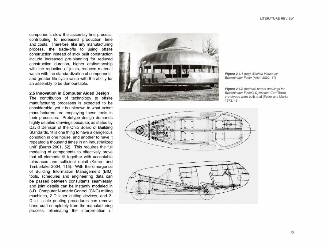
components slow the assembly line process, contributing to increased production time and costs. Therefore, like any manufacturing process, the trade-offs to using offsite construction instead of stick built construction include increased pre-planning for reduced construction duration, higher craftsmanship with the reduction of joints, reduced material waste with the standardization of components, and greater life cycle value with the ability for an assembly to be demountable.
2.5 Innovation in Computer Aided DesignThe contribution of technology to offsite manufacturing processes is expected to be considerable, yet it is unknown to what extent manufacturers are employing these tools in their processes. Prototype design demands highly detailed drawings because, as stated by David Denison of the Ohio Board of Building Standards, “it is one thing to have a dangerous condition in one house, and another to have it repeated a thousand times in an industrialized unit” (Burns 2001, 52). This requires the full modeling of components to effectively prove that all elements fi t together with acceptable
tolerances and suffi cient detail (Kieren and
Timberlake 2004, 115). With the emergence
of Building Information Management (BIM) tools, schedules and engineering data can
be passed between consultants seamlessly,
and joint details can be instantly modeled in
3-D. Computer Numeric Control (CNC) milling
machines, 2-D laser cutting devices, and 3-
D full scale printing procedures can remove
hand craft completely from the manufacturing
process, eliminating the interpretation of
Figure 2.4.2 (bottom) patent drawings for
Buckminster Fuller’s Dymaxion Car: Three
prototypes were built total (Fuller and Marks
1973, 49).
Figure 2.4.1 (top) Witchita House by
Buckminster Fuller (Arieff 2002, 17)
LITERATURE REVIEW
11
LITERATURE REVIEW
drawings by the different design and con-struction disciplines.
The advancements of technology most associated with building construction include the use of innovative building materials, internet based purchasing, 3D-CAD, computer aided manufacturing (CAM) tools, and computer aided engineering (CAE) simulation tools. 3D-CAD software enables modeling with built-in databases that store building information (product information, assembly groups, dimensions, etc.). 4D-CAD software additionally stores scheduling and construction sequencing information, while 5D-CAD incorporates cost data (CADeshack 2009). The depth of building information modeling allows compact data fi les
to be passed seamlessly between designers,
engineers, contractors, manufacturers, and
clients. CAM tools today can pass building
information directly between the designer and
the machine, eliminating the chance for human
error. For example, the aim of a system like
D-Shape, being developed by Monolite, is to
construct inhabitable space without involving
any human intervention (Monolite UK 2011). Similarly, Contour Crafting, a robotic arm
concrete pouring system being developed
at the University of Southern California, can
produce a 30 foot slab on grade, and, with the
foundation in place, the machine can erect
detailed concrete walls that include omissions
for door and window fabrications (“Robot Crafted
House” 2006, 20). CAE simulation tools like
Autodesk Ecotect Analysis, used for studying
the energy performance of buildings, and SAP
2000, used for structural analysis, interface
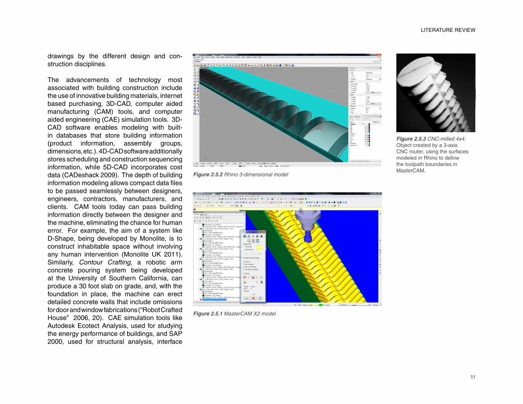
Figure 2.5.1 MasterCAM X2 model
Figure 2.5.2 Rhino 3-dimensional model
Figure 2.5.3 CNC-milled 4x4:
Object created by a 3-axis
CNC router, using the surfaces
modeled in Rhino to defi ne
the toolpath boundaries in
MasterCAM.
12
with 3D-CAD tools. Eventually, a heightened accountability among disciplines may be the biggest contribution computer modeling tools have to offer to building construction, because no longer are construction documents intended as diagrammatic representations with a complete disregard to how systems relate to one another in 3-D space.
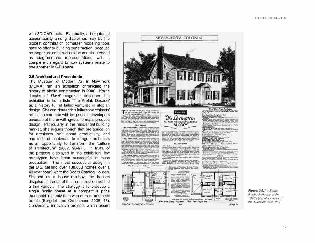
2.6 Architectural PrecedentsThe Museum of Modern Art in New York (MOMA) ran an exhibition chronicling the history of offsite construction in 2008. Karrie Jacobs of Dwell magazine described the exhibition in her article “The Prefab Decade” as a history full of failed ventures in utopian design. She contributed this failure to architects’ refusal to compete with large-scale developers because of the unwillingness to mass produce design. Particularly in the residential building market, she argues though that prefabrication for architects isn’t about productivity, and has instead continued to intrigue architects as an opportunity to transform the “culture of architecture” (2007, 96-97). In truth, of the projects displayed in the exhibition, few prototypes have been successful in mass production. The most successful design in the U.S. (selling over 100,000 homes over a 40 year span) were the Sears Catalog Houses. Shipped as a house-in-a-box, the houses disguise all traces of their construction behind a thin veneer. The strategy is to produce a single family house at a competitive price that could instantly fi t-in with current aesthetic
trends (Bergdoll and Christensen 2008, 48). Conversely, innovative projects which assert
Figure 2.6.1 a Sears
Roebuck House of the
1920’s (Small Houses of
the Twenties 1991, 21)
LITERATURE REVIEW
13
LITERATURE REVIEW
themselves as homes for the future, like Buckminster Fuller’s Dymaxion House, never left the prototype phase.
2.6.1 PrototypingThe Dymaxion House (completed as a one-off built house named the Wichita House) was designed as a transportable kit that could be suitable for any building site. The geodesic dome of the house covers the maximum amount of space with the smallest amount of material possible. The façade is clad in repetitive aluminum panels, and the interior space is divided radially around a central mast structure (Koch 1958, 78). It can be argued that the Case Study House Program (started in 1945 by Art and Architecture Magazine
edited by John Entenza) was an example of prototyping at the scale of a completed home. The intent of the program was to challenge the construction process by introducing a range of prefabrication components for custom buildings; the fi nal outcome could have been marketed
as a mass produced commodity (Bergdoll
and Christensen 2008, 95). Although it was
ultimately viewed as an educational exercise,
trying to push what is possible in single family
house design, the Make It Right program being
implemented today in New Orleans is being
realized at a large scale. The homes designed
for the program provides clients a range of pre-
designed houses to choose from.
2.6.2 Processed MaterialsFrank Lloyd Wright’s Usonian Houses are all
unique, simplifying design by using standard
details and economies of scale to reduce
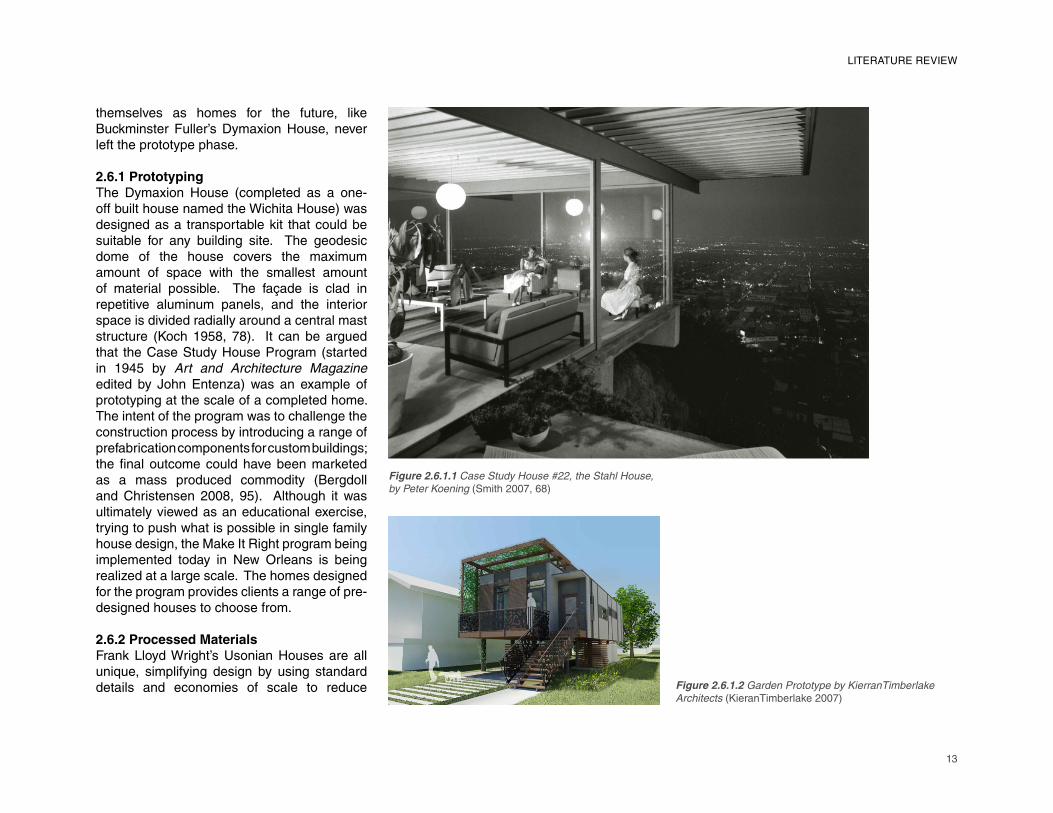
Figure 2.6.1.1 Case Study House #22, the Stahl House,
by Peter Koening (Smith 2007, 68)
Figure 2.6.1.2 Garden Prototype by KierranTimberlake
Architects (KieranTimberlake 2007)
14
pine forest, both visually display the conscious sensitivity the construction process had to its impact on the site.
Oskar and Johannes Kaufmann, partners in the fi rm KFN, have developed a heavy timber frame
that produces a 3-dimensional structural matrix
in which the envelope – a panel composition
selected from a library of opaque, transparent,
and partially transparent panels – can be
bolted directly to providing a higher level of
customizability. Renzo Piano’s IBM Traveling
Pavilion consisted of a demountable laminated
wood frame infi lled with a multitude of clear
polycarbonate pyramids that are also bolted
directly to the structure to create the envelope.
While acting as the thermal envelope of the
building, the polycarbonate pyramids play a role
in the cross bracing of the semicircular truss
elements. These prefabricated components
could be transported in compact form (stacked
in a nested fashion), and were light enough to
be handled and assembled by a manned crew
(Dini 1984, 79).
2.6.4 Panelized StructuresSIP (Structurally Insulated Panels) components
were designed to eliminate thermal bridging
concerns prevalent with lightweight timber
construction by using a continuous sheet of
extruded polystyrene adhered and sandwiched
between two sheets of 3/4” OSB plywood.
Structurally, they provide lateral stiffness
between parallel columns or beams. In the
Cantilever House by Anderson Anderson
Architects, a steel vierendeel truss is used as
the pallet for the SIPs that comprise the walls,
crate/palette foundation, the walls are made of
paper tubes (wrapped in a waterproof sponge
tape with an insulated backing), and the roof
of a tent material. The units are demountable
and the materials are easily recyclable (Matilda
2003, 36-38).
As discussed previously, the Sears Catalog
Houses (and similarly, IKEA’s Bo Klok homes) was comprised of prefabricated components,
but it was designed to hide, not celebrate their
construction. In Taylors Island, Maryland, the
Loblolly House designed by KieranTimberlake
Architects (KTA) similarly uses site-installed
siding to fi nish the building, but the design
deliberately celebrates its small impact on the
construction site. The building site is located in
a fairly dense forested area near the water, and
the building’s orientation and its attachment to
the site refl ect the building’s desire to fi t in to its
surroundings. The house is built on a wooden
pile foundation to both minimize excavation
and to elevate the house above the site’s
fl ood plain. The architects designed a series
of factory built components including “smart
cartridges” for the fl oors, ceiling and roof,
“dumb cartridges” for the skin, and modular
mechanical and bathroom “blocks.” 30 percent
of the overall construction work was required to
be done onsite, though the architects believed
that if the house was mass produced, that fi gure
could easily be reduced to 15 percent (Clifford
2007, 147). Of the few elements that were built
onsite, the pile foundation, which expresses
the light connection to the site visually, and the
vertical cedar plank siding, which aesthetically
camoufl ages the building in the dense loblolly
costs. Finish work is arguably the most
labor intensive part of construction, and an
effective use of prefabrication would ideally
limit the amount of precision work needed to
be done onsite. The board and batten system
was designed for shell construction using the
natural wood fi nish on the interior and on the
exterior, thus eliminating the need for labor-
intensive plaster fi nishing. Wright further
reached into componentized design with the
Usonian Automatic Building System (UABS) in which the plan grid aligned with the grid of
the shell’s textile block construction. The intent
was for houses to be self-built by the individual
client, as executed by the Adelman House in
Arizona (Morse-Fortier 1994, 277).
2.6.3 Prefabricated ComponentsThe 3-dimensional components in Shigeru
Ban’s Furniture House are not inhabitable
spaces. The OSB-clad fl oor-to-ceiling
shelving units are used to divide the spaces
within the house, but they also serve as the
primary structural elements of the house.
Five different projects were completed by
Ban, The ‘furniture’ components are used
both as shelving and closet spaces, and they
free the shell of the building from structural
burdens, instead allowing it to be responsive
to its surroundings (Bell 2001, 45). The idea
actually was conceived as a response to site
conditions; earthquake casualties in the home
are often a result of victims being trapped by
furniture falling over, so Ban instead uses built-
in furniture. His Paper Log Houses were also
made reactionary to extreme site conditions –
used for quick disaster relief shelters. Built on a
LITERATURE REVIEW
15
the fl oor, and the roof. Due to the material composition of the SIPs, the same panels are used for the roof as those used for the walls, giving the building envelope continuity in its aesthetic only broken by the introduction of glazing elements (Anderson 2006, 114).
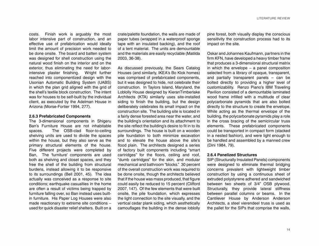
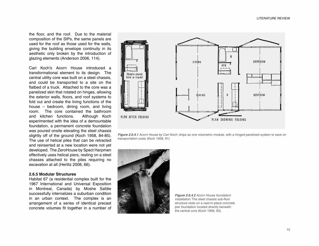
Carl Koch’s Acorn House introduced a transformational element to its design. The central utility core was built on a steel chassis, and could be transported to a site on the fl atbed of a truck. Attached to the core was a panelized skin that rotated on hinges, allowing the exterior walls, fl oors, and roof systems to fold out and create the living functions of the house – bedroom, dining room, and living room. The core contained the bathroom and kitchen functions. Although Koch experimented with the idea of a demountable foundation, a permanent concrete foundation was poured onsite elevating the steel chassis slightly off of the ground (Koch 1958, 84-85). The use of helical piles that can be retracted and reinserted at a new location were not yet developed. The ZeroHouse by Spect Harpmen effectively uses helical piers, resting on a steel chasses attached to the piles requiring no excavation at all (Herlitz 2008, 66).
2.6.5 Modular StructuresHabitat 67 (a residential complex built for the 1967 International and Universal Exposition in Montreal, Canada) by Moshe Safdie successfully internalizes a suburban condition in an urban context. The complex is an arrangement of a series of identical precast concrete volumes fi t together in a number of
LITERATURE REVIEW
Figure 2.6.4.1 Acorn House by Carl Koch: ships as one volumetric module, with a hinged panelized system to save on
transportation costs (Koch 1958, 91)
Figure 2.6.4.2 Acorn House foundation
installation: The steel chassis sub-fl oor
structure rests on a cast-in-place concrete
pier foundation located directly beneath
the central core (Koch 1958, 93).
16
different arrangements to create a monolithic landmark for the city. Using about fi ve different
shaped module structures, each living unit
(with a private garden) commands its individual
presence despite the compact nature of the
cluster of modules because of the interstitial
spaces created by staggering their layout.
Communal spaces including parks, shops, and
even movie theatres are dispersed through the
complex (Safdie 1970, 11-12).
Modular construction would seem to be
ideal for urban infi ll sites because onsite
construction can be completed in phases
allowing the surroundings buildings to be
relatively undisturbed. The challenge, however,
is that high-value “fl agship projects” like large
offi ce developments would be undermined by
the introduction of the limitations of modular
construction (Hartley and Blagden 2007,
67). But, though by no means prevalent,
the challenge is being undertaken today by
large architectural fi rms like SHoP Architects
(Atlantic Yards in New York), or O’Connell East
Architects (Victoria Hall in Wembley, UK). The
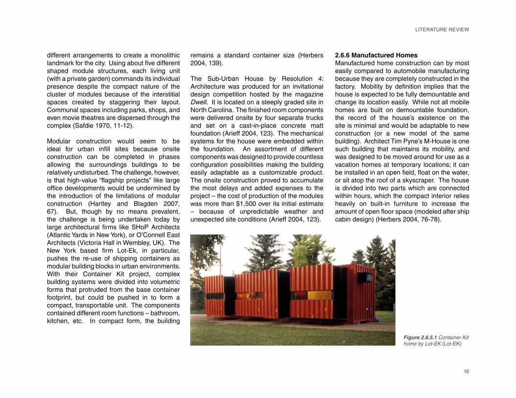
New York based fi rm Lot-Ek, in particular,
pushes the re-use of shipping containers as
modular building blocks in urban environments.
With their Container Kit project, complex
building systems were divided into volumetric
forms that protruded from the base container
footprint, but could be pushed in to form a
compact, transportable unit. The components
contained different room functions – bathroom,
kitchen, etc. In compact form, the building
remains a standard container size (Herbers
2004, 139).
The Sub-Urban House by Resolution 4: Architecture was produced for an invitational
design competition hosted by the magazine
Dwell. It is located on a steeply graded site in
North Carolina. The fi nished room components
were delivered onsite by four separate trucks
and set on a cast-in-place concrete matt
foundation (Arieff 2004, 123). The mechanical
systems for the house were embedded within
the foundation. An assortment of different
components was designed to provide countless
confi guration possibilities making the building
easily adaptable as a customizable product.
The onsite construction proved to accumulate
the most delays and added expenses to the
project – the cost of production of the modules
was more than $1,500 over its initial estimate
– because of unpredictable weather and
unexpected site conditions (Arieff 2004, 123).
2.6.6 Manufactured HomesManufactured home construction can by most
easily compared to automobile manufacturing
because they are completely constructed in the
factory. Mobility by defi nition implies that the
house is expected to be fully demountable and
change its location easily. While not all mobile
homes are built on demountable foundation,
the record of the house’s existence on the
site is minimal and would be adaptable to new
construction (or a new model of the same
building). Architect Tim Pyne’s M-House is one
such building that maintains its mobility, and
was designed to be moved around for use as a
vacation homes at temporary locations; it can
be installed in an open fi eld, fl oat on the water,
or sit atop the roof of a skyscraper. The house
is divided into two parts which are connected
within hours, which the compact interior relies
heavily on built-in furniture to increase the
amount of open fl oor space (modeled after ship
cabin design) (Herbers 2004, 76-78).
Figure 2.6.5.1 Container Kit
home by Lot-EK (Lot-EK)
LITERATURE REVIEW
17
LITERATURE REVIEW
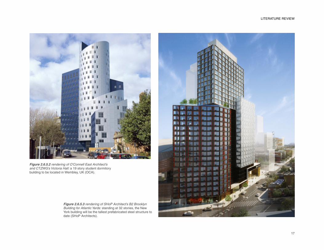
Figure 2.6.5.2 rendering of O’Connell East Architect’s
and CTZWG’s Victoria Hall: a 19 story student dormitory building to be located in Wembley, UK (OCA).
Figure 2.6.5.3 rendering of SHoP Architect’s B2 Brooklyn
Building for Atlantic Yards: standing at 32 stories, the New York building will be the tallest prefabricated steel structure to date (SHoP Architects).

18
2.7 Reaction to LiteratureMajor architects throughout the twentieth century have tried to develop prototypes for mass production with little success – Le Corbussier’s “La maison standardisée,” Buckminster Fuller’s Dymaxion House, Frank Lloyd Wright’s Usonian Automatic Building System, Walter Gropius’s Copper Houses, etc. (Kierran and Timberlake 2007, 104). Yet today there appears to be a renewed interest in the integration of prefabrication and preassembly to improve quality and to save time, par-ticularly in the commercial building sector. The emergence of BIM as the preferred design tool of architects has helped to highlight the potential benefi ts of a manufactured building
process. BIM strengthens the architect’s role
as the “master builder,” bringing construction
and scheduling confl icts to the forefront early
in the design process. Furthermore, from
a research perspective, the opportunities
for manufacturers to adopt some of the
automated construction techniques seen in
the automobile or airplane building industries
has drawn the interest of architects to the
modular building industry with the desires to
increase labor productivity and craftsmanship
while investigating the use of complex building
components and cutting-edge materials.
Several studies over the past 10 years (those
done by Lu Na, McGraw Hill Construction,
Carl T. Haas, etc.) have identifi ed the
amount of pre-planning, project coordination,
transportation restrictions, and procurement/scope of work concerns as the primary
limitations of modular construction. Collecting
the opinions of architects, engineers, onsite
general contractors, and building owners
through both interviews and surveys, these
studies predominantly considered the cost
effectiveness or business model alterations
that could improve the effi ciency of onsite
construction. This study instead focused
on the design and coordination issues that
arise specifi cally through the interactions of
the architect and modular manufacturer for a
project that would be predominantly built in a
factory, providing an understanding of what
different modular manufacturers identifi ed as
general concerns, and what might be specifi c
to their type of building process or strategy.
LITERATURE REVIEW
19
CHAPTER 3: METHODOLOGY
3.1 Overview of Qualitative Research MethodsThis study used qualitative research, and specifi cally a grounded theory methodology, to
uncover the primary issues considered to be
constraints or barriers to the industry’s ability to
build innovative design projects. Quantitative
methods use empirical data (data acquired
by means of experimentation) collected to
support a proposed research hypothesis.
Qualitative research emphasizes the infl uence
of the researcher on the data collected.
Instead of interpreting data objectively without
bias, the researcher’s background and point
of view play into the presentation of the data
and the structure of the investigation (the
questions asked, and the level of interaction
with the subjects) (Groat and Wang 2002,
88). Qualitative research seeks the answer
to “why” by obtaining unstructured data,
while quantitative research is occupied with
“how” using numerical and statistical data.
The purpose, therefore, is to shed light on a
subject’s attitude, behavior, values, concerns,
motivations, aspirations, or culture (Groat
and Wang 2002, 173-175). Grounded theory
methodology makes the development of theory
reactionary, uncovered after data analysis.
It operates in an opposite manner from the
scientifi c method where a hypothesis is posted,
tested, and then proven either to be correct or
incorrect. Instead, it involves the collection of
data, followed by the subsequent coding and
grouping of data into concepts that a theory
can be based upon (Allan 2003, 1-10).
3.1.1 The Case Study DesignThis study was designed using case study as
a tactic. Originating from the social sciences,
the case study methodology is defi ned as an
in-depth description and analysis of a single
entity or phenomenon (the case). It can be
either descriptive or explanatory, using any
manner of data collection procedures (Yin 1984,
10). The cases can be used to encompass a
program, an event, a process, an institution,
or a social group (Creswell 2009, 12). As a
qualitative research method, the emphasis is
20
������������� ������
������������
����������
�������� ����������
��������� ����������
�����������
����������
���������� �����������
��������������������� �������
������������������������
����������������������
������������������ ���������
�����������������������������
��������������������������
��������������������������������
���������������������������������
����������������������������������
����������������������
���������������������
���������������� ���
�������������������������
�������������������������� ���������
��������������������������������
����������������������� ���
���� ���������������������
����������� ������������
����������������������������������
��������������������
�������������������������
�������������������������
�� �����������������������
�������������������� ����
������������������������������
������������������������
����������������������� ������
��������������
�����������������������������
��������������
�� �������� ������
�����
�������������������
!�������������
"�����������# ��������$����
%�� ������������
& ����������
'����������( ����������������
�������� ��
&����)�����
*������+������������������������
�)���������� �����������
��� ���������������� ���������
������������
������ �� ���������� ��� ������ ��
���� �� ������������ �� � �����
���������� ��������� ���� ���� ����
����������
��������� ��� ������
�������
������ ���������
������ �����
�������� !��������� �����
��������� �������
����� ����������� ������ ��
�������
������ ����� " ���������
���������� ����� �������� �������
#������ �����
�������$ �������� �������� ���
������������
�������� ��� ������ ������
������������
��������� �������� ������� �������� �
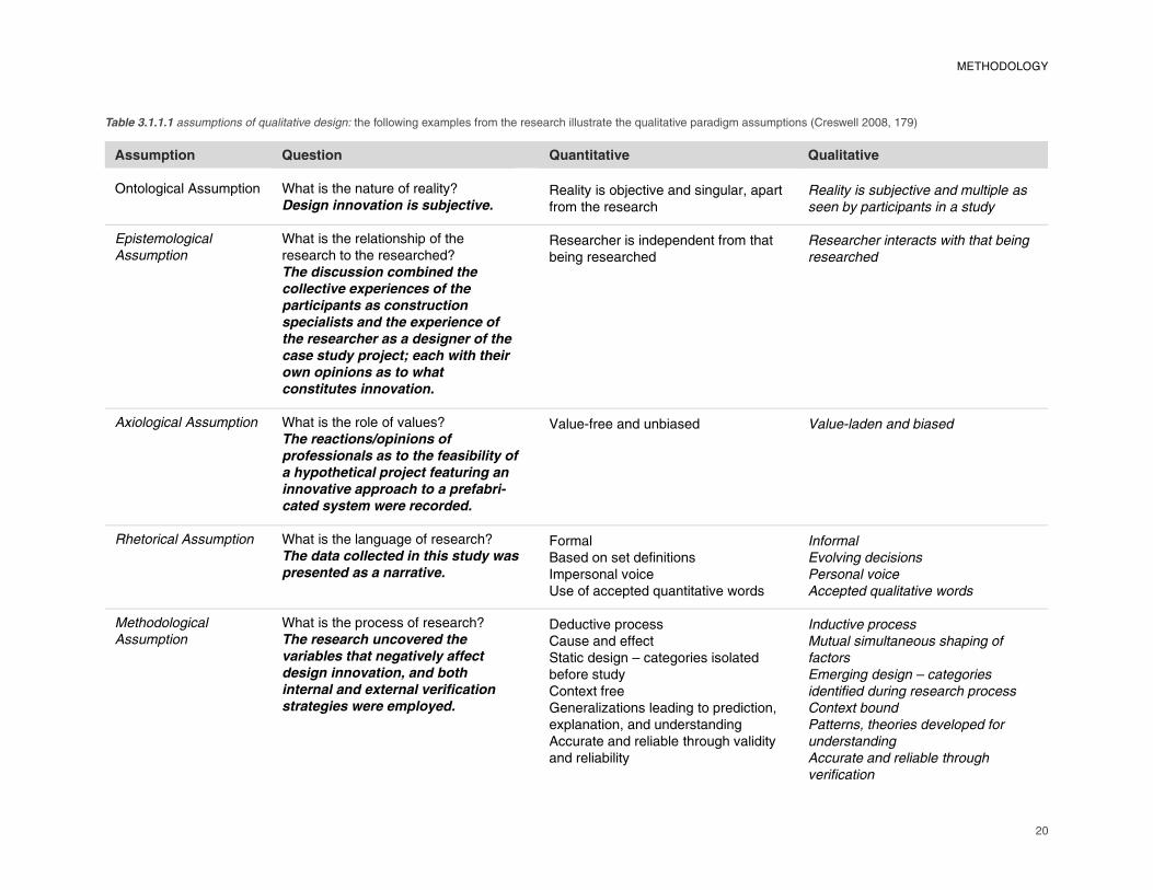
Table 3.1.1.1 assumptions of qualitative design: the following examples from the research illustrate the qualitative paradigm assumptions (Creswell 2008, 179)
METHODOLOGY
21
METHODOLOGY
on process and discovery, instead of results and accuracies (Creswell 2009, 5). The intent is to provide a comprehensive stat of the case (its feasibility).
Lois-ellin Datta divides case study research into six different types: illustrative, exploratory, critical instance, program implementation, program effects, and cumulative (Datta 1990, 37). An illustrative case study is a descriptive study that depicts what a situation is like, familiarizing the audience with a topic that there is too little information available about (Datta 1990, 37). An exploratory case study is a condensed process that researchers usually undertake as a part of a larger study; it helps identify questions and select measurement constraints in order to serve as the introduction to a larger investigation (Datta 1990, 42). A critical instance case study is a detailed examination of one instance, and is used to either examine a situation of unique interest to the researcher, or to test the validity of a universal assertion (Datta 1990, 47-48). A program implementation case study can help discern whether or not an instance is in compliance with its design intent; it is often used when concerns presently exist about a program (Datta 1990, 50-51). A program effects case study is used to determine the impact of a program and the reasons for its success or failure (Datta 1990, 56). Finally, a cumulative case study brings together the fi ndings of multiple case studies, using either a
retrospective or a prospective tone, as a means
to aggregate fi ndings and prevent repetitive
analyses (Datta 1990, 59).
The approach to this study primarily fi ts into the
explorative case study method. The ultimate
purpose was for this to be part of a larger study.
Suggestions for further investigation into the
topic of innovation in modular construction
are identifi ed in a later chapter. In the end,
however, the data collected was largely geared
towards providing a tool for the education
of architects which also makes this study
an illustrative case study type. There is an
underlying need for information to be provided
that identifi es the constraints and barriers to
design innovation. Only when the design chal-
lenges and technical limitations of modular
construction are understood, can solutions be
pursued.
3.1.2 Role of the ResearcherIn this study, I acted as the sole researcher who
contributed to the design of the hypothetical
project and was responsible for gathering
information from modular manufacturers.
The case being investigated is an example
of an innovative modular building project.
The program is the external classroom – an
education facility that would ideally incorporate
mass customization techniques to fabricate an
array of unique building components. The pro-
gram requirements were introduced through a
graduate level interdisciplinary studies course.
In the class, the designs for 20 sustainable,
temporary, re-usable, and affordable class-
rooms for an urban environment were proposed.
The challenge was extended to students from
different disciplines (architecture, landscape
architecture, and building construction). The
project pushes innovation by programmatically
accommodating the need for education facilities
to be adaptable and evolutionary (in their
support of teacher’s needs, in the increasing
expectations of students, and in the growth and
expansion of technology).
The following design strategies for modular
construction were encouraged through the
class to increase quality without increasing
initial building costs:
Standardization of components (ie: reproduction of component and joint
details)Reduce number of joints (light tool usage) to increase onsite craftsmanship
Reduce component shipping numbers and
shipping weight (less than 3000 lbs)Reduce electrical complexity with a plug
and play lighting system
Minimize duct sizes and length of runs
(distributed systems, not central AHU
unit)Minimize the amount and the complexity of
work done onsite (foundation pre-work and
onsite preassembly)
Following the completion of the course, a set
of drawings that adequately represent the
design goals and the construction details of
the project were produced for distribution to
the professionals from the modular building
industry participating in the research.
3.1.3 Ethical ConsiderationsThis explorative case study was designed
to contribute to generalized knowledge, and
•
•
•
•
•
•
22
because the research involved the interaction of individuals, the safeguard of sensitive information is an ethical requirement. To protect the rights of participants, the following procedures were followed:
The research objective and process were made clear to the participants.The data collected was used for the research objectives only.Only data collected from consented participants has been included.Data recording methods were made known to the participants.The written transcript of interviews, and the data analysis were all made available at the request of the participants.The anonymity of the participants was maintained.Institutional Review Board (IRB) approval was obtained before data collection and after data analysis.
3.1.4 SettingThe study was conducted both remotely for interviews conducted over the phone, and at the plants of manufacturers for interviews conducted face-to-face. Conducting the interviews at the plants provided the opportunity to observe production processes and the organizational structure of the companies, adding a visual and immersive component to the data. Alternatively, in the interviews conducted remotely, the production processes of the companies was not explicitly known, and all the data collected is based on the responses
1)
2)
3)
4)
5)
6)
7)
to the questionnaire and the discussions that follow.
3.1.5 ActorsFive building manufacturers were interviewed. Two interviews were conducted at the factories of the manufacturers, and three interviews were conducted remotely over the phone. One of each was required at the minimum for internal validation. Interviews were done in pairs, providing the opportunitiy for data to be reviewed for external validation. Duplicate participation levels were used in order to collect detailed data.
The representation from modular manu-facturers in the interviews included the following participants: construction managers, billing or fi nance specialists, and building code
research specialists. Group interviews were
intended to facilitate the discussion, and to
include professionals familiar with all phases of
the manufacturing process. The effectiveness
of this study is ultimately dependent on the
collaboration of participants who share an
interest in innovative construction practices
and whose goals coincide with the perceived
benefi ts of offsite construction – waste
reduction, parallel work, labor productivity and
safety, quality control, construction time and
cost savings, and the overall reduction of the
environmental impact of buildings. Modular
manufacturers sought for participation
employed varying fabrication techniques, and
affi liation with the Modular Building Institute
and Virginia Tech were used to aid in the
search for participants.
3.1.6 EventsThis study used interviews as a method of
recording the reaction of manufacturers to an
innovative design proposal which incorporates
offsite construction (the case study project). The questions asked were open-ended, and the
interviews were one-time group interchanges.
The advantage of group interviews, best
described by Norman K. Denzin and Yvona
S. Lincoln, is that they can either “aid
respondents’ recall of specifi c events or …
stimulate embellished descriptions of events or
experiences shared by the group” (2000, 651). This is benefi cial because the experience of
the individuals is expected to play a role in their
answers. However, there are disadvantages
to this approach, and Denzin and Lincoln
make a series of suggestions to keep the
interviews bounded: 1) prevent one person
form dominating the discussion, 2) encourage
reluctant individuals to parti-cipate, and 3) make sure each individual has the oppor-tunity
to speak on each topic (2000, 652). Therefore,
the conversations needed to be fl uid and
sometimes improvised.
The difference between structured and
unstructured interviews is that structured
interviews are completely scripted, whereas
unstructured interviews require little more
than an objective (Denzin and Lincoln 2000,
649). This study employed an identical set
of pre-determined questions asked to all
participants, but the participants were all given
the opportunity to ask questions, and the
conversations were encouraged to evolve. The
METHODOLOGY
23
topic of discussion (the hypothetical project) was sent to participants before the interview process so that their reactions were given time to mature.
3.2 Data Collection TacticThe interview as a research tactic is designed to capture the reactions of industry professionals to whatever topic is presented to them. The validity of their responses as data depends on the credibility of the interviewee. This can be based on his or her experience, and on the ability for the responses to be corroborated by other evidence. The challenge is that interviews ultimately call for recollection, which can lead to inaccurate information (particularly for dates), or to information relative to a specifi c area, specialization, or
context. Recollection can also lead to inferred
data, referencing specifi c facts pertaining to
prior actions or activities. Therefore, it should
be understood that conclusions made from
studies using interviews as a data collection
tactic are essentially an “interpretation of an
interpretation” (Groat and Wang 2002, 159).
3.2.1 Development of the QuestionnaireThe interview questions asked during the two
face-to-face interviews included both questions
specifi cally referencing conditions in the case
study project, and general questions about the
manufacturer’s process and the state of the
industry. Questions about the project covered
the following topics:
The feasibility of the components to be
fabricated in-house
The ability for component production to
utilize some form of automation
The marketability of the project
The more general questions encompassed the
following topics:
The fabrication process of the plant
Perception of the industry in the eyes of
the architects and the consumers
Whether or not life cycle costs are factored
into building estimates
Transportation risks and limitations
The interface between the offsite production
of components and their installation on-
site
The role of BIM in the manufacturing pro-
cess
The extent of a modular manufacturer’s
involvement in building design
The next two phone interviews where shorter
in duration and focused on the manufacturers’ processes. The questions asked were not
identical because some of the manufacturer’s
capabilities were known ahead of time. Yet
there was still a considerable amount of overlap
in the data obtained from the two interviews.
The topics covered in the two conversations
included the following:
The extent of a modular manufacturer’s
involvement in building design
General design considerations that are
unique to modular construction
Reasons for shop drawings to be produced
as a supplement or a replacement to
1)
2)
3)
1)2)
3)
4)5)
6)
7)
1)
2)
3)
construction documents
The inspections process in the factory
The role of BIM in the manufacturing
process
The level of automation used
The fi nal phone interview was the shortest and
was conducted specifi cally for the purpose
of identifying another modular manufacturer
that is using automation in their factory. The
purpose was to confi rm some of the information
gathered from a prior interview. The following
topics were covered:
A list of the CNC controlled machines used
in the factory
The role of BIM in the manufacturing pro-
cess and the program used
General design considerations that are
unique to modular construction
The level of control the manufacturer has
over design and onsite construction
3.2.2 Data Recording ProceduresThe process for face-to-face interviews was
conducted in three steps. The project drawings
and details were fi rst distributed to the
participants before the interview. Factory tours
followed, providing a detailed understanding of
the manufacturers’ production processes. The
interviews themselves opened with reviews
of the project so that the design intent was
understood, and predefi ned questions were
asked wherever they were seen as relevant to
the discussion. For example, an excerpt from
one conversation provided the following type of
data:
4)5)
6)
1)
2)
3)
4)
METHODOLOGY

24
Q: Design innovation in this particular
project is largely attributed to the ability
for the building to be customized based
on a standard set of parts. With smaller
panelized components shipped onsite,
a greater amount of onsite assembly is
required as compared to using larger
complete modules. From an economic
feasibility and overall craftsmanship point
of view, is there a recognizable difference
in the advantages and disadvantages to
component sizes being designed for use?
A: I don’t know that there is an advantage of one over the other; comparing whether more can be done in the factory as site work is taking place versus shipping pre-cut materials to the site and having them assembled there. In terms of time savings, the more you can do to a point in the factory you can get more time savings in the overall construction process.
While there were no directions on the structure of the discussion, all key questions were asked regardless of their order. The interviews were recorded and transcribed at a later date (full transcriptions are provided in Appendix B). During each interview, only generalized notes were made at the researcher’s discretion. The face-to-face interviews were conducted immediately after the participants agreed to be involved in the study.
The subsequent phone interviews were conducted at a more leisurely pace – spread out over several weeks. Consequently, the
questions asked were not identical, but reactionary to the information already obtained. Instead of a presentation of the design project, the interview sessions shifted to a direct Q&A format. Although the project drawings and details were distributed to the participants ahead of time once again, few of the questions asked addressed the specifi c feasibility of the
project. Instead, questions focused on the
capabilities of the manufacturers’ plants, and
their building processes. An excerpt from one
of phone interviews follows:
Q: What is the greatest barrier to the
concept of mass customization…?
A: … There is a huge disconnect between
the software that are designing the thing
(whatever it is, be it Revit or SolidWorks,
or Grasshopper which is the ultimate mass
customization tool), and the software that
are involved in programming the robots,
(which are usually quite disappointing). Now, I haven’t seen the full range, but
whenever you are buying this advanced
machinery you have to balance the
machinery with what the software is as
well. Like the Ring of Fire (the automated
steel cutting machine) was the worst
scenario. [It was] like an Excel chart
calculator really. So with the robots, even
if you wanted to move the steel by 1/8 of
an inch, or something like that which is
only a fraction, you had to write a whole
new program for software with checks to
verify the coding. So you had to write a
new program anytime there was something
”
“
different, and to the architectural world 1/8
of an inch is not really different …
3.2.3 Data Analysis ProceduresIn the end, a comprehensive list of the potential
challenges that present themselves during
the manufacturing process was compiled.
Because unstructured data were collected,
matching and opposing arguments were
discerned from patterns in the responses of
participants. The nature of the data collected
from open-ended questions resulted in a large
volume of information, therefore data analysis
and interpretation occurred during the interview
process. Data coding is common in qualitative
studies in order to divide the information into
themes or categories (Creswell 2009, 154). Therefore, data was organized and sorted by
the frequency in which themes are repeated.
Participants’ individual and company names
were also coded (numerically based on the
chronological order of the interviews) to
maintain confi dentiality and organization. The
fi nal form in which the data is presented was
determined by the nature of the results
3.2.4 Data CodingThe interview processes resulted in a large
amount of data, including the notes taken during
each interview and the written conversation
transcripts. The task of managing data
involved a coding process in which information
is reduced and organized into “chunks” (Groat
and Wang 2002, 193). The data can then
be sorted by theme for direct comparisons.
Traditionally, keywords like “innovation,” “design
constraints,” or “barriers” would be sought out
”“
METHODOLOGY
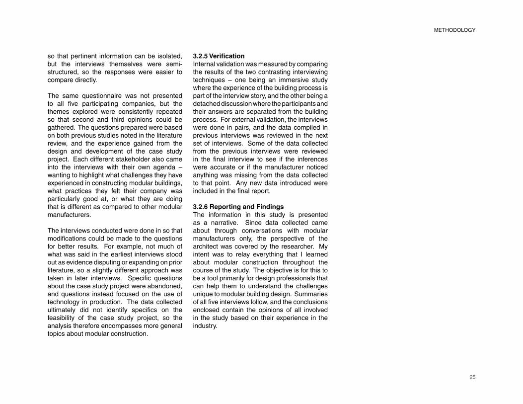
25
METHODOLOGY
so that pertinent information can be isolated, but the interviews themselves were semi-structured, so the responses were easier to compare directly.
The same questionnaire was not presented to all fi ve participating companies, but the
themes explored were consistently repeated
so that second and third opinions could be
gathered. The questions prepared were based
on both previous studies noted in the literature
review, and the experience gained from the
design and development of the case study
project. Each different stakeholder also came
into the interviews with their own agenda –
wanting to highlight what challenges they have
experienced in constructing modular buildings,
what practices they felt their company was
particularly good at, or what they are doing
that is different as compared to other modular
manufacturers.
The interviews conducted were done in so that
modifi cations could be made to the questions
for better results. For example, not much of
what was said in the earliest interviews stood
out as evidence disputing or expanding on prior
literature, so a slightly different approach was
taken in later interviews. Specifi c questions
about the case study project were abandoned,
and questions instead focused on the use of
technology in production. The data collected
ultimately did not identify specifi cs on the
feasibility of the case study project, so the
analysis therefore encompasses more general
topics about modular construction.
3.2.5 Verifi cationInternal validation was measured by comparing
the results of the two contrasting interviewing
techniques – one being an immersive study
where the experience of the building process is
part of the interview story, and the other being a
detached discussion where the participants and
their answers are separated from the building
process. For external validation, the interviews
were done in pairs, and the data compiled in
previous interviews was reviewed in the next
set of interviews. Some of the data collected
from the previous interviews were reviewed
in the fi nal interview to see if the inferences
were accurate or if the manufacturer noticed
anything was missing from the data collected
to that point. Any new data introduced were
included in the fi nal report.
3.2.6 Reporting and FindingsThe information in this study is presented
as a narrative. Since data collected came
about through conversations with modular
manufacturers only, the perspective of the
architect was covered by the researcher. My
intent was to relay everything that I learned
about modular construction throughout the
course of the study. The objective is for this to
be a tool primarily for design professionals that
can help them to understand the challenges
unique to modular building design. Summaries
of all fi ve interviews follow, and the conclusions
enclosed contain the opinions of all involved
in the study based on their experience in the
industry.
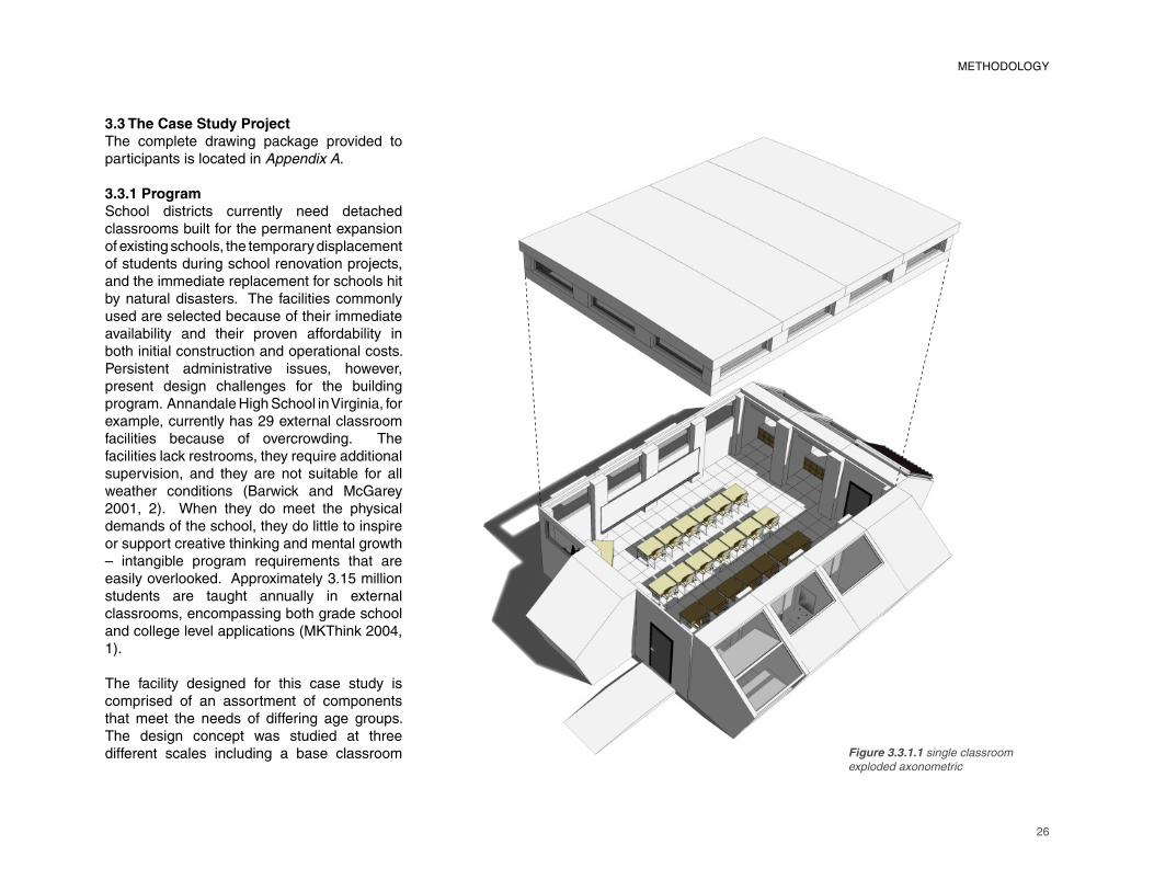
26
Figure 3.3.1.1 single classroom
exploded axonometric
3.3 The Case Study ProjectThe complete drawing package provided to participants is located in Appendix A.
3.3.1 ProgramSchool districts currently need detached classrooms built for the permanent expansion of existing schools, the temporary displacement of students during school renovation projects, and the immediate replacement for schools hit by natural disasters. The facilities commonly used are selected because of their immediate availability and their proven affordability in both initial construction and operational costs. Persistent administrative issues, however, present design challenges for the building program. Annandale High School in Virginia, for example, currently has 29 external classroom facilities because of overcrowding. The facilities lack restrooms, they require additional supervision, and they are not suitable for all weather conditions (Barwick and McGarey 2001, 2). When they do meet the physical demands of the school, they do little to inspire or support creative thinking and mental growth – intangible program requirements that are easily overlooked. Approximately 3.15 million students are taught annually in external classrooms, encompassing both grade school and college level applications (MKThink 2004, 1).
The facility designed for this case study is comprised of an assortment of components that meet the needs of differing age groups. The design concept was studied at three different scales including a base classroom
METHODOLOGY
27
METHODOLOGY
Figure 3.3.1.2 duplex option exterior photomontage
Figure 3.3.1.3 one, two, and three classroom options
accommodating 25 students, 3 connected classrooms, and 20 connected classrooms with support functions (ie: teachers offi ces,
janitor closets, etc.) included. The designs all
abide by ADA and International Building Code
regulations. The concept for a relocatable
building structure was primarily explored,
emphasizing both component demountability
(temporary foundation, simplifi cation of joint
details and detachment from local resources), and durability (use of re-usable building
materials and components).
3.3.2 Building SystemsEducational facilities require fl exibility in their
distribution of both space and resources.
Constraints on classroom fl oor area, ceiling
height, access to daylight, and views to the
outside vary depending on the application.
Similarly, building orientation and the
surrounding environment cannot be predicted.
A basic structural system, using highway
transportation size limits for the controlling
dimensions, act as the canvas for offsite
components to be plugged in wherever they
are deemed necessary. The prefabricated
components include both modular structures
(pods) that can be handled with a forklift, and
panelized structures that can be handled by a
manned crew. Ultimately, the overall fl exibility
of the system is dependent on the library of
components available, which over time can
be substantial. Envisioned auxiliary teaching
functions for the pods include locker and
storage units, light shelves or greenhouse
space, teacher storage, media and audio/visual equipment outlets, laboratory spaces,
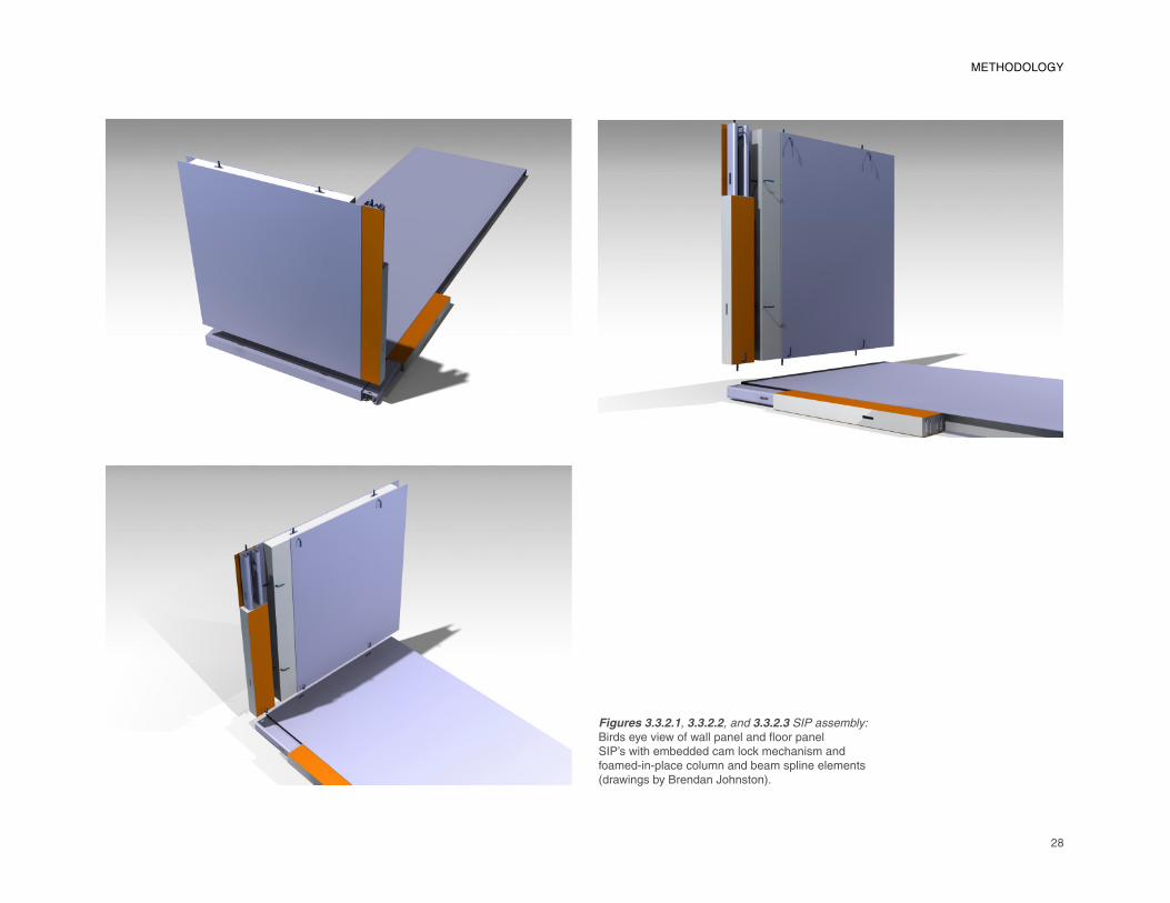
28
Figures 3.3.2.1, 3.3.2.2, and 3.3.2.3 SIP assembly: Birds eye view of wall panel and fl oor panel SIP’s with embedded cam lock mechanism and foamed-in-place column and beam spline elements (drawings by Brendan Johnston).
METHODOLOGY
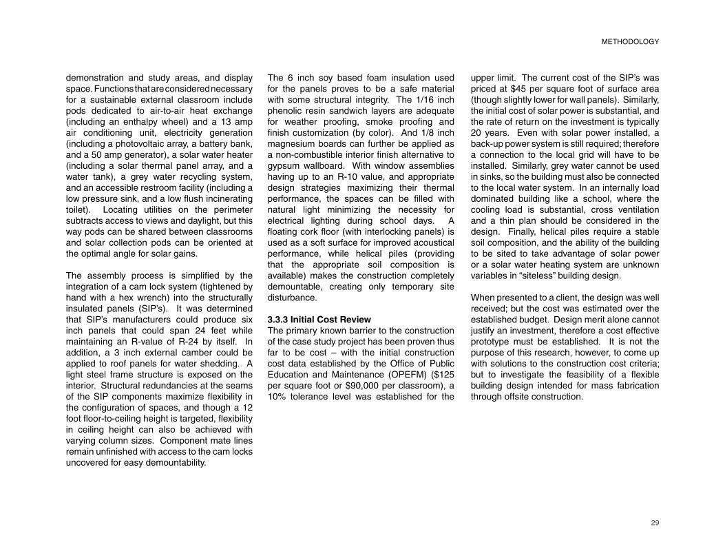
29
METHODOLOGY
demonstration and study areas, and display space. Functions that are considered necessary for a sustainable external classroom include pods dedicated to air-to-air heat exchange (including an enthalpy wheel) and a 13 amp air conditioning unit, electricity generation (including a photovoltaic array, a battery bank, and a 50 amp generator), a solar water heater (including a solar thermal panel array, and a water tank), a grey water recycling system, and an accessible restroom facility (including a low pressure sink, and a low fl ush incinerating toilet). Locating utilities on the perimeter subtracts access to views and daylight, but this way pods can be shared between classrooms and solar collection pods can be oriented at the optimal angle for solar gains.
The assembly process is simplifi ed by the
integration of a cam lock system (tightened by
hand with a hex wrench) into the structurally
insulated panels (SIP’s). It was determined
that SIP’s manufacturers could produce six
inch panels that could span 24 feet while
maintaining an R-value of R-24 by itself. In
addition, a 3 inch external camber could be
applied to roof panels for water shedding. A
light steel frame structure is exposed on the
interior. Structural redundancies at the seams
of the SIP components maximize fl exibility in
the confi guration of spaces, and though a 12
foot fl oor-to-ceiling height is targeted, fl exibility
in ceiling height can also be achieved with
varying column sizes. Component mate lines
remain unfi nished with access to the cam locks
uncovered for easy demountability.
The 6 inch soy based foam insulation used
for the panels proves to be a safe material
with some structural integrity. The 1/16 inch
phenolic resin sandwich layers are adequate
for weather proofi ng, smoke proofi ng and
fi nish customization (by color). And 1/8 inch
magnesium boards can further be applied as
a non-combustible interior fi nish alternative to
gypsum wallboard. With window assemblies
having up to an R-10 value, and appropriate
design strategies maximizing their thermal
performance, the spaces can be fi lled with
natural light minimizing the necessity for
electrical lighting during school days. A
fl oating cork fl oor (with interlocking panels) is
used as a soft surface for improved acoustical
performance, while helical piles (providing
that the appropriate soil composition is
available) makes the construction completely
demountable, creating only temporary site
disturbance.
3.3.3 Initial Cost ReviewThe primary known barrier to the construction
of the case study project has been proven thus
far to be cost – with the initial construction
cost data established by the Offi ce of Public
Education and Maintenance (OPEFM) ($125
per square foot or $90,000 per classroom), a
10% tolerance level was established for the
upper limit. The current cost of the SIP’s was
priced at $45 per square foot of surface area
(though slightly lower for wall panels). Similarly,
the initial cost of solar power is substantial, and
the rate of return on the investment is typically
20 years. Even with solar power installed, a
back-up power system is still required; therefore
a connection to the local grid will have to be
installed. Similarly, grey water cannot be used
in sinks, so the building must also be connected
to the local water system. In an internally load
dominated building like a school, where the
cooling load is substantial, cross ventilation
and a thin plan should be considered in the
design. Finally, helical piles require a stable
soil composition, and the ability of the building
to be sited to take advantage of solar power
or a solar water heating system are unknown
variables in “siteless” building design.
When presented to a client, the design was well
received; but the cost was estimated over the
established budget. Design merit alone cannot
justify an investment, therefore a cost effective
prototype must be established. It is not the
purpose of this research, however, to come up
with solutions to the construction cost criteria; but to investigate the feasibility of a fl exible
building design intended for mass fabrication
through offsite construction.
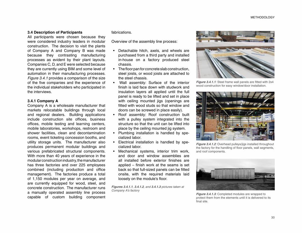
30
3.4 Description of ParticipantsAll participants were chosen because they were considered industry leaders in modular construction. The decision to visit the plants of Company A and Company B was made because they contrasting manufacturing processes as evident by their plant layouts. Companies C, D, and E were selected because they are currently using BIM and some level of automation in their manufacturing processes. Figure 3.4.1 provides a comparison of the size of the fi ve companies and the experience of
the individual stakeholders who participated in
the interviews.
3.4.1 Company ACompany A is a wholesale manufacturer that
markets relocatable buildings through local
and regional dealers. Building applications
include construction site offi ces, business
offi ces, mobile testing and learning centers,
mobile laboratories, workshops, restroom and
shower facilities, clean and decontamination
rooms, event ticketing concession booths, and
utility storage units. The manufacturer also
produces permanent modular buildings and
various prefabricated structural components.
With more than 40 years of experience in the
modular construction industry, the manufacturer
has three factories and over 225 employees
combined (including production and offi ce
management). The factories produce a total
of 1,150 modules per year on average, and
are currently equipped for wood, steel, and
concrete construction. The manufacturer runs
a manually operated assembly line process
capable of custom building component
fabrications.
Overview of the assembly line process:
Detachable hitch, axels, and wheels are
purchased from a third party and installed
in-house on a factory produced steel
chassis.
The fl oor pan for concrete slab construction,
steel joists, or wood joists are attached to
the steel chassis.
� Wall assembly: Surface of the interior
fi nish is laid face down with studwork and
insulation layers all applied until the full
panel is ready to be lifted and set in place
with ceiling mounted jigs (openings are
fi tted with wood studs so that window and
doors can be screwed in place easily).Roof assembly: Roof construction built
with a pulley system integrated into the
structure so that the unit can be lifted into
place by the ceiling mounted jig system.
Plumbing installation is handled by spe-
cialized labor.
Electrical installation is handled by spe-
cialized labor.
Mechanical systems, interior trim work,
and door and window assemblies are
all installed before exterior fi nishes are
applied – fi nish work at the seams is set
back so that full-sized panels can be fi tted
onsite, with the required materials laid
loosely on the module’s fl oor.
•
•
•
•
•
•
•
Figure 3.4.1.3: Completed modules are wrapped to
protect them from the elements until it is delivered to its
fi nal site.
Figure 3.4.1.2: Overhead pulleys/jigs installed throughout
the factory for the handling of fl oor panels, wall segments,
and roof components.
Figure 3.4.1.1: Steel frame wall panels are fi tted with 2x4
wood construction for easy window/door installation.
Figures 3.4.1.1, 3.4.1.2, and 3.4.1.3 pictures taken at
Company A’s factory
METHODOLOGY
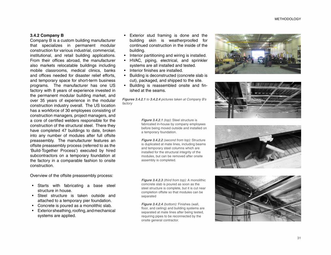
31
METHODOLOGY
3.4.2 Company BCompany B is a custom building manufacturer that specializes in permanent modular construction for various industrial, commercial, institutional, and retail building applications. From their offi ces abroad, the manufacturer
also markets relocatable buildings including
mobile classrooms, medical clinics, banks
and offi ces needed for disaster relief efforts,
and temporary space for short-term business
programs. The manufacturer has one US
factory with 8 years of experience invested in
the permanent modular building market, and
over 35 years of experience in the modular
construction industry overall. The US location
has a workforce of 30 employees consisting of
construction managers, project managers, and
a core of certifi ed welders responsible for the
construction of the structural steel. There they
have completed 47 buildings to date, broken
into any number of modules after full offsite
preassembly. The manufacturer features an
offsite preassembly process (referred to as the
‘Build-Together Process’) executed by hired
subcontractors on a temporary foundation at
the factory in a comparable fashion to onsite
construction.
Overview of the offsite preassembly process:
Starts with fabricating a base steel
structure in house.
Steel structure is taken outside and
attached to a temporary pier foundation.
Concrete is poured as a monolithic slab.
Exterior sheathing, roofi ng, and mechanical
systems are applied.
Exterior stud framing is done and the
building skin is weatherproofed for
continued construction in the inside of the
building.
Interior partitioning and wiring is installed.
HVAC, piping, electrical, and sprinkler
systems are all installed and tested.
Interior fi nishes are installed.
Building is deconstructed (concrete slab is
cut), packaged, and shipped to the site.
Building is reassembled onsite and fi n-
ished at the seams.
•
••
••
•
•
•
••
Figure 3.4.2.1 (top): Steel structure is
fabricated in-house by company employees
before being moved outside and installed on
a temporary foundation.
Figure 3.4.2.2 (second from top): Structure
is duplicated at mate lines, including beams
and temporary steel columns which are
installed for the structural integrity of the
modules, but can be removed after onsite
assembly is completed.
Figure 3.4.2.3 (third from top): A monolithic
comcrete slab is poured as soon as the
steel structure is complete, but it is cut near
completion offsite so that modules can be
separated
Figure 3.4.2.4 (bottom): Finishes (wall,
fl oor, and ceiling) and building systems are
separated at mate lines after being tested,
requiring pipes to be reconnected by the
onsite general contractor.
Figures 3.4.2.1 to 3.4.2.4 pictures taken at Company B’s
factory
32
3.4.3 Company CCompany C is a custom building manufacturer that produces both relocatable buildings and permanent modular buildings. Building applications include housing, dormitories, prisons, schools, banks, and equipment buildings for cellular communications towers. The manufacturer also markets restroom modules for multi-story buildings constructed onsite. With over 70 years of experience in the modular construction industry, the manufacturer has one plant employing approximately 200 people between offi ce and
production staff. They produce around 1,000
large modules (4 per day) and 300 bathroom
pods (for 1 or 2 big projects per year) annually.
The manufacturer and the architect work on a
design-build contract with close coordination
beginning at the start of design through the
shipment of components. Architects involved
in projects typically have experience with the
modular manufacturer’s process from previous
collaborations. The manufacturer uses
automated machining operations for custom
steel formations integrated into an otherwise
manually run assembly line.
3.4.4 Company DCompany D is a wholesale building manu-
facturer that produces both relocatable
buildings and permanent modular buildings
that are marketed through local and regional
dealers. Building applications include schools,
classrooms, bank buildings, dialysis clinics,
club houses, offi ce buildings, and dormitories.
Historically, the manufacturer has also
developed projects for several different military
contracts ranging from the development of
affordable housing alternatives to providing
communication equipment buildings for
shipment all over the world. The manufacturer
currently has three factories located throughout
the country (Midwest and West Coast), and
over 40 years of experience in the modular
construction industry. The manufacturer has
between 200 and 250 employees. As a custom
builder, their production rate per year varries
considerably based on the size of projects.
For example, one of thier three factories is
currently in the process of completing a project
comprised of over 500 mdoules.
3.4.5 Company ECompany E is a residential building manu-
facturer that takes responsibility for the design,
engineering, manufacturing, shipment, onsite
assembly and fi nish, and management of
foundation work. Over the past 5 years, the
manufacturer has developed a series of kit-
homes in which modular assembly variations
can be composed online with accurate cost
estimation and a virtual tour. The manufacturer
has one plant providing services throughout the
country focused on LEED certifi ed construction.
They employ between 130 and 150 workers,
and produce approximately 300 large modules
annually on a manually operated assembly line
process. Automated machining operations are
also currently used for custom steel forms.
Table 3.4.1 (next page): comparative table
summarizing the size and experience of
Companies A, B, C, D, and E, and the
experience of the stateholders
METHODOLOGY
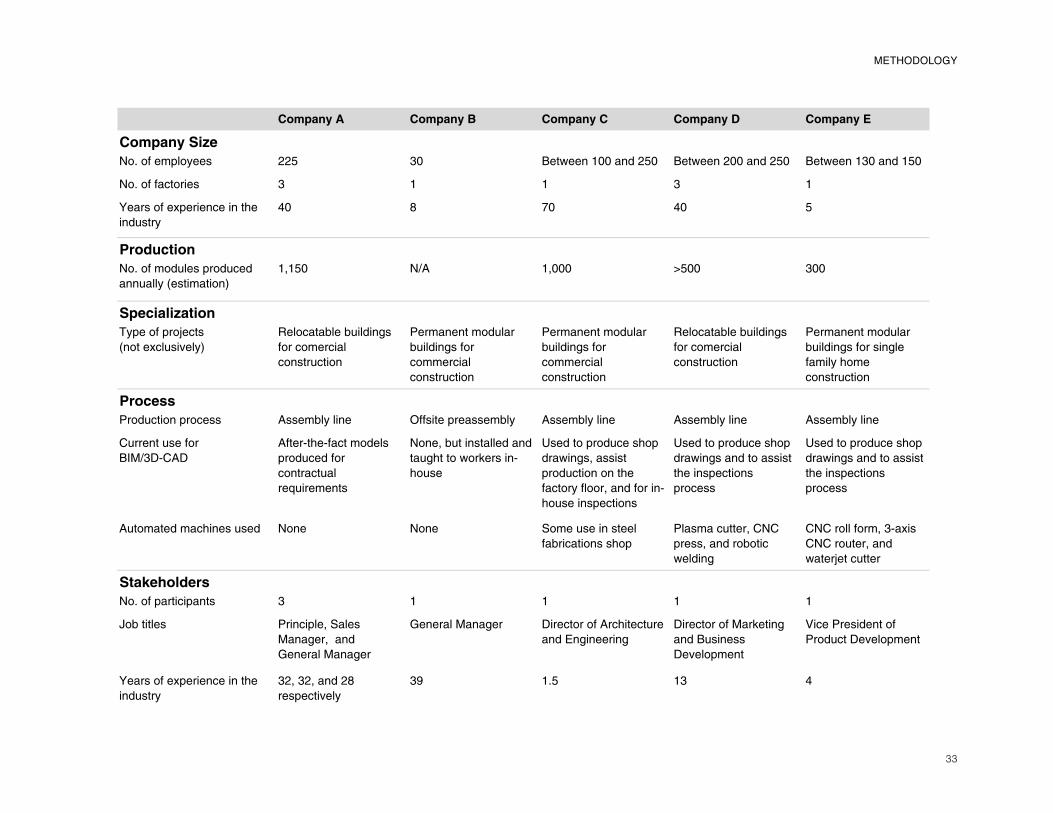
33
METHODOLOGY
�������� �������� ��������� ��������� ���������
�������� ���
�������������� �� �� ����������������� � ����������������� � ����������������� �
���������������� � � � � �
��������������������������
�������
�� � � ��
����������
�����������������������
������!����������"
�#� � �$% �#��� & �� ���
�������������
'���������(����
!����������)�"
*������+��+�����,�
������������
������������
-���������������
+�����,�����
���������
������������
-���������������
+�����,�����
���������
������������
*������+��+�����,�
������������
������������
-���������������
+�����,���������,�
���������
������������
�������
-����������������� %����+���� .���������������+ %����+���� %����+���� %����+����
/��������������
�01$�23/%2
%����3���3����������
������������
����������
��4���������
����#�+���������������
���,���������5������3
�����
6��������������������
������,�#��������
������������������
�����������#�����������3
�����������������
6��������������������
������,����������������
����������������
�������
6��������������������
������,����������������
����������������
�������
%���������������������� ���� ���� 7���������������
��+��������������
-�����������#�/�/
�����#�������+����
�����,
/�/��������#��3����
/�/�������#����
�����(���������
�����������
������������������� � � � � �
8�+������ -�������#�7���
1���,��#������
9������1���,��
9������1���,�� 2�����������%�����������
����:�,�������,
2�����������1��5����,
������������
2�)�������
;����-�����������
-�������2�)�������
��������������������������
�������
��#���#�������
��������)�
�< �� �� �
34
CHAPTER 4: DATA COLLECTION
Data collected for this study were obtained through fi ve interviews. Companies A and B
were interviewed face-to-face, and Companies
C, D, and E were interviewed over the phone.
Questions asked encompass the feasibility
of the case study project as it relates to each
manufacturer’s current process and factory
arrangement, and concerns faced by the
industry in general where design and production
innovation are concerned. The interviews have
been summarized in the following chapter and
full transcripts can be found in Appendix B.
Clear themes in both the lines of questioning
and in the responses can be identifi ed for
direct comparisons. Data presented by theme
in bullet-point form are appended to the end of
each summary.
4.1 Company A Interview SummaryQ: What is the driving force for interest in
modular construction – either interest coming
from architects or clients?
A: Although the market perception is better than
it was 20 years ago and the products coming
from the factory are gaining recognition, clients primarily come to manufacturers expecting lower construction costs and a faster built product. While speed is typically easy to
achieve – as foundation work is being done
onsite, manufacturers are building modules
at the same time, saving nearly 30-50% of
the time for construction – cost savings in construction duration are typically offset by module transport costs.
The industry is becoming better known for
quality and as an inherently greener building
process, but it is still likely that less than 5%
of architects design modular buildings. As
LEED certifi cation systems are gaining
recognition, more architects will try modular construction as an alternative to site-built construction because there is presumably less waste (materials are bought specifi cally
sized for the project), and because there is less site disturbance during construction.
Manufacturing techniques are getting more
35
sophisticated, and building codes more stringent, so the end built product produced in the factory is comparable to a site built equivalent. Permanent modular buildings are expected to be indistinguishable from onsite built buildings.
Q: What types of projects require an architect’s
involvement?
A: Schools tend to go to architects for help. While low end $45 per square foot trailers are still being produced in the industry, the industry has grown in the public’s eye as an alternative way to build because there are built precedents featuring high-end materials and durable construction.
Q: Can component re-use, building portability,
and the life cycle value of materials be used
as a strategy to compensate for higher initial
construction costs?
A: A big percentage of the industry’s business is in educational use buildings. School districts already understand that portable classrooms can both be moved as enrollment or demographics change, and leased out for different functions. Therefore, there is potentially a market for a $120 per square foot classroom that will last 25 years versus a $45 per square foot classroom that will last 5 to 10 years.
The price of SIP’s construction, however, is estimated to be 28% more expensive than standard stud frame details, though the
creative use of the material as an interior and exterior fi nish surface makes it a more viable
option because of the elimination of labor costs
for fi nish work. A $4 or $5 per square foot tile
fi nish (for the fl oating fl oor) is also not typical in
the modular building industry.
So, while the materials being specifi ed by
architects right now are taking into account
the life cycle value of materials (durable) and
components (re-usable). But from a marketing
perspective, the strategy is to focus on the fi nancial benefi ts of construction speed
in comparison to a fully onsite constructed
building: either by reducing the costs of displacing workers, or through the opportunity to turn profi ts sooner.
Q: When or how often are advantageous
changes to the manufacturing process
pursued?
A: As a custom builder, the factory is built to be able to switch from one process to another. Yet there is a start up cost associated
with changes to the fabrication process – the
assembly line has to be geared up to handle
new materials, and there will be a dip in labor
productivity initially. So, if only a small number of components are being fabricated at a time, it is hard to recover from the start up costs involved. The plants will evolve over
time incorporating additional processes and
materials, but it is market driven – a large volume of demand will initiate change, or a large-revenue project.
Q: Is the level of precision required for
component fi tting a major obstacle in the
fabrication process, and does volume factor
in the feasibility of the design from either an
economic or a production standpoint?
A: Effi ciency and quality increase with repetition
because workers can become familiar with the
process.
The SIP’s in the case study project would be purchased by a specialized manufacturer and assembled and packaged at the factory. The demand for a high volume of
components would be required to make a
factory within the company solely dedicated to
SIP’s manufacturing.
Q: Is it advantageous to do fi nish work offsite,
or do components run a risk of damage being
accumulated during transport?
A: Architects are not typically familiar with the different transportation codes that
building manufacturers have to follow. Height,
width, length, and weight of modules are all
restricted by the physical limitations of the truck
and the road. Modules shipped on a fl at-bed,
for example, are restricted to a 12’x56’ footprint,
while modules with a built-in axel and wheels
can have a footprint of 16’x80’. Similarly,
concrete modules have to be built smaller than
wood assemblies because of the difference in
the weight of materials.
So, the major challenge is in planning a module’s travel path and building it
DATA COLLECTION
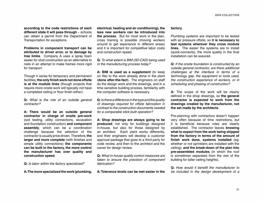
36
according to the code restrictions of each different state it will pass through – schools can obtain a permit from the Department of Transportation for exceptions.
Problems in component transport can be attributed to driver error, or to damage by tree limbs. Company A uses a spray foam sealer for stud construction as an alternative to nails in an attempt to make frames more rigid for transport.
Though it varies for temporary and permanent facilities, the only fi nish work not done offsite is at the module lines (though projects that require more onsite work will typically not have a completed ceiling or fl oor fi nish either).
Q: What is the role of an outside general
contractor?
A: There would be an outside general contractor in charge of onsite pre-work
(soil testing, utility connections, excavation
and foundation construction) and component assembly, which can be a coordination
challenge because the selection of the
contractor is usually price driven. Therefore, the larger and more complete (with fi nishes and
simple utility connections) the components can be built in the factory, the more control the manufacturer has over quality and construction speed.
Q: Is labor within the factory specialized?
A: The more specialized the work (plumbing,
electrical, heating and air conditioning), the less new workers can be introduced into the process. But for most work in the plan,
cross training is possible (moving workers
around to get experience in different areas) and it is important for competitive labor costs
and construction speed.
Q: To what extent is BIM (3D-CAD) being used
in the manufacturing process today?
A: BIM is used as a supplement (to keep
on fi le) to the work already done in the plant
(done after-the-fact). The engineers on staff
do the design work and the drawings, and in a
time sensitive building process, familiarity with
the computer software is necessary.
Q: Is there a difference in the type and the quality
of drawings required for offsite fabrication in
contrast to the construction documents needed
for a comparable stick-built operation?
A: Shop drawings are always going to be produced; not only for buildings designed
in-house, but also for those designed by
an architect. Each plant works differently,
and their engineers will develop a customer
approval package that goes to a third party for
code review, and then to the architect and the
owner for design review.
Q: What in-house quality control measures are
taken to ensure the precision of component
fabrication?
A: Tolerance levels can be met easier in the
factory.
Plumbing systems are important to be tested
with air pressure offsite, so it is necessary to test systems wherever they cross module lines. The easier the systems are to install
(quick-connects), the more quality in the fi nal
installation can be assured.
Q: If the onsite foundation is constructed by an
outside general contractor, are there additional
challenges at the interface in terms of a
technology gap, the equipment or tools used,
the construction experience of workers, or in
scheduling and phasing of construction?
A: The scope of the work will be clearly
defi ned in the shop drawings, so the general contractor is expected to work from the drawings created by the manufacturer, not the set made by the architects.
Pre-planning with contractors doesn’t happen
very often because of time restrictions, but
it is benefi cial because roles are clearly
established. The contractor leaves knowing what to expect from the work being shipped from the factory in terms of the amount of fi nish work done, systems installed (eg: whether or not sprinklers are installed with the
ceiling), and the break-down of the plan into pre-assembled modules (in which the roof
is sometimes separated from the rest of the
building for taller ceiling heights).
Q: How would it benefi t the manufacturer to
be included in the design development of a
DATA COLLECTION
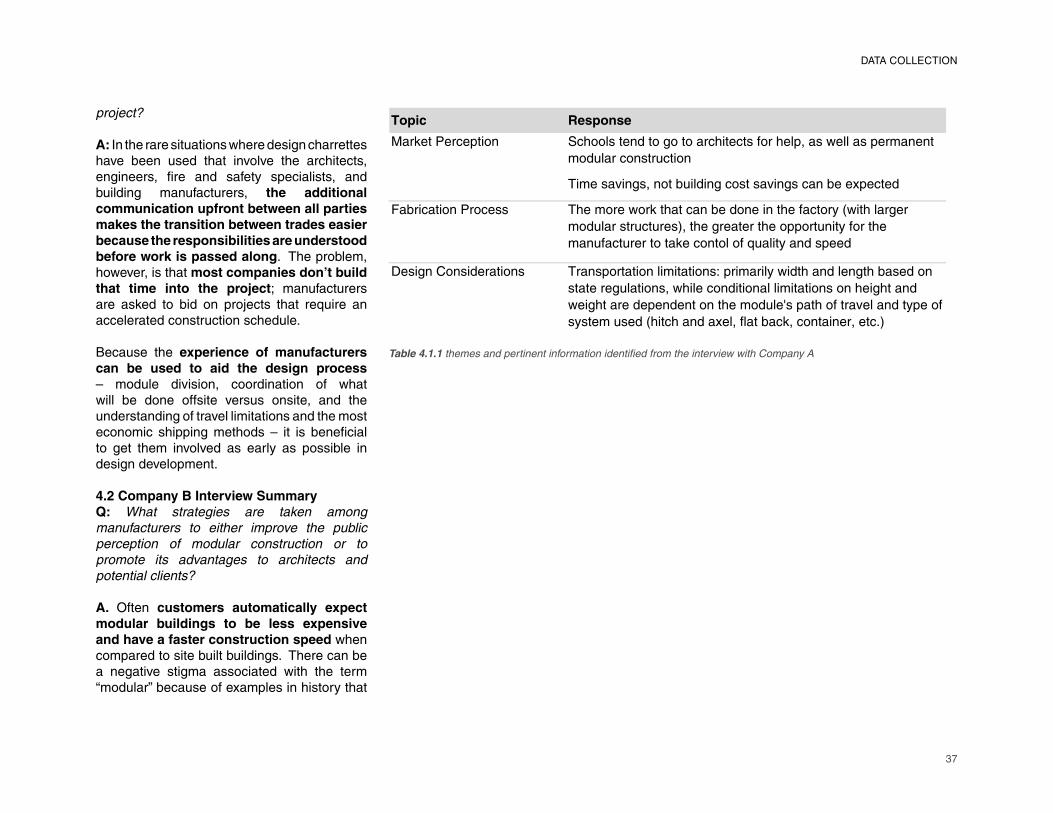
37
����� �������
�������������� ��������� �������������������������������������������� � ��
��������� �������
��������� ���� ��������� ���������� ���� ����������
��������� ������� �������������������� ������ ��� �������������������������
����������������� ����������������������� ������������
�� ������������������ �������!�������� ������
"���� �#� ��������� � ��� �������� ���������� �$����������������� ���� ����������� �
��������������� ���������� ����� ������������ ��� ��������� ��
�������������� �� ��� �����������%����������������� ���������
������������������� ������������������� ��� ������&
project?
A: In the rare situations where design charrettes have been used that involve the architects, engineers, fi re and safety specialists, and
building manufacturers, the additional communication upfront between all parties makes the transition between trades easier because the responsibilities are understood before work is passed along. The problem,
however, is that most companies don’t build that time into the project; manufacturers
are asked to bid on projects that require an
accelerated construction schedule.
Because the experience of manufacturers can be used to aid the design process
– module division, coordination of what
will be done offsite versus onsite, and the
understanding of travel limitations and the most
economic shipping methods – it is benefi cial
to get them involved as early as possible in
design development.
4.2 Company B Interview SummaryQ: What strategies are taken among
manufacturers to either improve the public
perception of modular construction or to
promote its advantages to architects and
potential clients?
A. Often customers automatically expect modular buildings to be less expensive and have a faster construction speed when
compared to site built buildings. There can be
a negative stigma associated with the term
“modular” because of examples in history that
Table 4.1.1 themes and pertinent information identifi ed from the interview with Company A
DATA COLLECTION
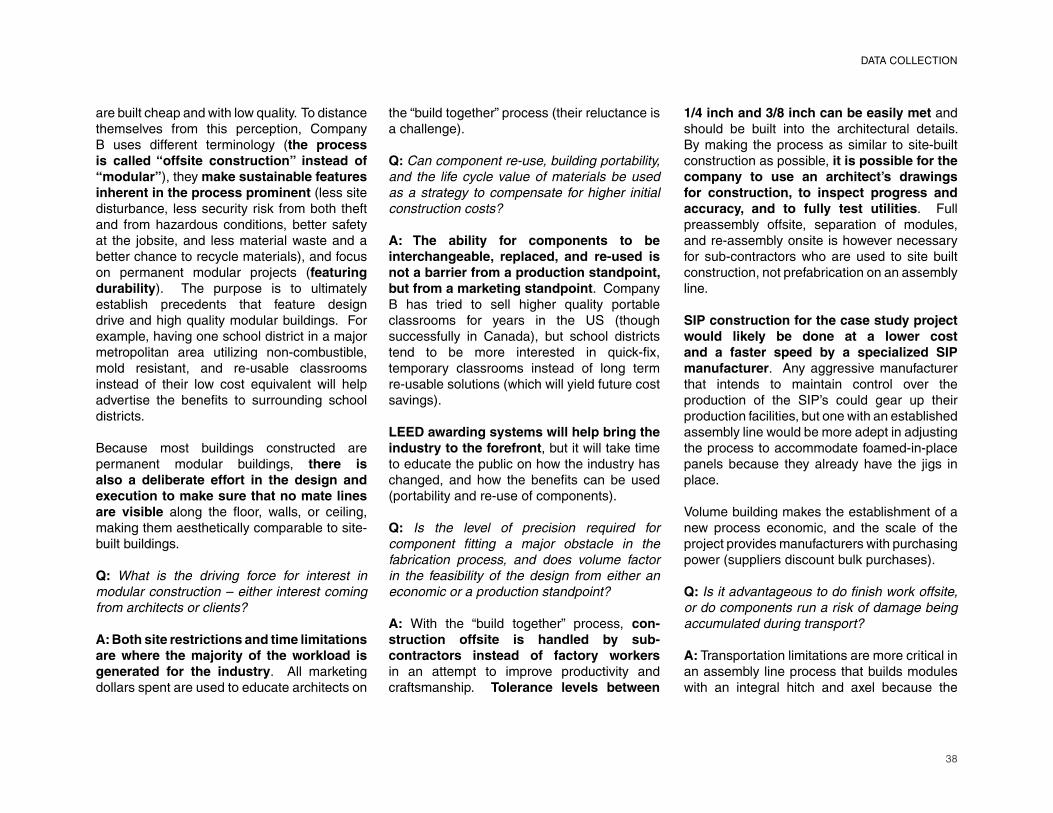
38
are built cheap and with low quality. To distance themselves from this perception, Company B uses different terminology (the process is called “offsite construction” instead of “modular”), they make sustainable features inherent in the process prominent (less site disturbance, less security risk from both theft and from hazardous conditions, better safety at the jobsite, and less material waste and a better chance to recycle materials), and focus on permanent modular projects (featuring durability). The purpose is to ultimately establish precedents that feature design drive and high quality modular buildings. For example, having one school district in a major metropolitan area utilizing non-combustible, mold resistant, and re-usable classrooms instead of their low cost equivalent will help advertise the benefi ts to surrounding school
districts.
Because most buildings constructed are
permanent modular buildings, there is also a deliberate effort in the design and execution to make sure that no mate lines are visible along the fl oor, walls, or ceiling,
making them aesthetically comparable to site-
built buildings.
Q: What is the driving force for interest in
modular construction – either interest coming
from architects or clients?
A: Both site restrictions and time limitations are where the majority of the workload is generated for the industry. All marketing
dollars spent are used to educate architects on
the “build together” process (their reluctance is
a challenge).
Q: Can component re-use, building portability,
and the life cycle value of materials be used
as a strategy to compensate for higher initial
construction costs?
A: The ability for components to be interchangeable, replaced, and re-used is not a barrier from a production standpoint, but from a marketing standpoint. Company
B has tried to sell higher quality portable
classrooms for years in the US (though
successfully in Canada), but school districts
tend to be more interested in quick-fi x,
temporary classrooms instead of long term
re-usable solutions (which will yield future cost
savings).
LEED awarding systems will help bring the industry to the forefront, but it will take time
to educate the public on how the industry has
changed, and how the benefi ts can be used
(portability and re-use of components).
Q: Is the level of precision required for
component fi tting a major obstacle in the
fabrication process, and does volume factor
in the feasibility of the design from either an
economic or a production standpoint?
A: With the “build together” process, con-struction offsite is handled by sub-contractors instead of factory workers
in an attempt to improve productivity and
craftsmanship. Tolerance levels between
1/4 inch and 3/8 inch can be easily met and
should be built into the architectural details.
By making the process as similar to site-built
construction as possible, it is possible for the company to use an architect’s drawings for construction, to inspect progress and accuracy, and to fully test utilities. Full
preassembly offsite, separation of modules,
and re-assembly onsite is however necessary
for sub-contractors who are used to site built
construction, not prefabrication on an assembly
line.
SIP construction for the case study project would likely be done at a lower cost and a faster speed by a specialized SIP manufacturer. Any aggressive manufacturer
that intends to maintain control over the
production of the SIP’s could gear up their
production facilities, but one with an established
assembly line would be more adept in adjusting
the process to accommodate foamed-in-place
panels because they already have the jigs in
place.
Volume building makes the establishment of a
new process economic, and the scale of the
project provides manufacturers with purchasing
power (suppliers discount bulk purchases).
Q: Is it advantageous to do fi nish work offsite,
or do components run a risk of damage being
accumulated during transport?
A: Transportation limitations are more critical in
an assembly line process that builds modules
with an integral hitch and axel because the
DATA COLLECTION

39
module becomes in essence a vehicle and falls under motor vehicle laws. Components shipped on a fl atbed trailer qualify as “freight” and can be shipped at larger sizes at a higher price and listed as a “super load.”
The potential for damage during transport is always present, but they are rarity. Tree-lined streets are the biggest problems, and roads can be inspected ahead of time (and branches cut). Narrow streets must be accounted for in the design of modules.
Floor fi nishes are typically not completed
offsite because of the amount of traffi c onsite
builders will put on the fl oor surfaces, but some clients will require a specifi c completion percentage in the building contract (limiting
the amount of onsite construction expected).
Q: Considering all components are pre-
fabricated offsite, what is the role of an outside
general contractor?
The purpose of the general contractor is to do
all of the site prep-work, running of the utilities,
foundation construction, and installation of
the fi nal assembly; ultimately the general contractor will bear the responsibility for the end result. It is important to get the
general contractor involved as soon as possible
so that they understand the manufacturer’s
building process and know exactly what will
be delivered onsite. While contractors are invited to the plant, a project manage in-house is assigned to a project for its
duration (both offsite and onsite).
There is often a disconnect between the
manufacturer and the general contractor.
Some manufacturers, however, will handle all
of the work. Company B is licensed to do onsite work only in-state.
Q: To what extent is BIM (3D-CAD) being used
in the manufacturing process today?
A: BIM has been installed and taught to the workers at Company B. However, no project has required its use from start to fi nish (initial requirements have been lifted in each instance). The integration of
BIM requires clients to invest time and money
into its upkeep (understanding that it provides
immediate access to the location of utilities
and their specifi cation), and architects must be
willing to share the drawing fi les for information
to be added. Architects, however, are not willing to share their drawings because of liability issues – they are afraid that if changes
are made to the drawings that create onsite
problems and added costs, then they would be
suspect to legal action from the client.
Factory workers and engineers build a structural
steel frame in-house, and it is moved outside
and set on a temporary foundation for the
work of sub-contractors to be done. In-house engineers would provide shop drawings (production drawings) for the steel only,
unless the architect cannot bring the drawings
to a construction drawing level of detail.
Q: Is there a difference in the type and the quality
of drawings required for offsite fabrication in
contrast to the construction documents needed
for a comparable stick-built operation?
A: With the “build together” process, modules
are built from an architect’s drawings, with steel
shop drawings created only as a supplement.
The architect therefore maintains ownership of the drawings and that commission. In
a process where shop drawings replace the
architectural documents, the value of the
architect’s drawings is reduced as well as their
overall contribution to the process.
Q: When are automation and the integration of
a machined process feasible in the fabrication
of components?
A: Automation requires volume, particularly
at start up because of upfront costs, and
although it is important to maintain that volume,
if the manufacturer has enough diversity in
their work, the CAM tools can be set aside and
easily reinstalled for later work.
Q: What in-house quality control measures are
taken to ensure the precision of component
fabrication?
A: Full preassembly is done offsite so architects and clients have the opportunity to inspect the building’s progress and quality, and so the utilities can be tested.
Finishes at the module lines, and utilities
crossing module lines are removed so that
modules can be separated for shipment.
DATA COLLECTION
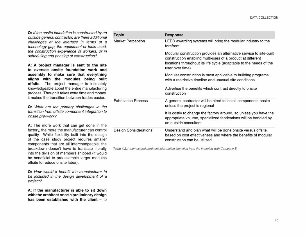
40
Q: If the onsite foundation is constructed by an
outside general contractor, are there additional
challenges at the interface in terms of a
technology gap, the equipment or tools used,
the construction experience of workers, or in
scheduling and phasing of construction?
A: A project manager is sent to the site
to oversee onsite foundation work and
assembly to make sure that everything
aligns with the modules being built
offsite. The project manager is intimately knowledgeable about the entire manufacturing process. Though it takes extra time and money, it makes the transition between trades easier.
Q: What are the primary challenges in the
transition from offsite component integration to
onsite pre-work?
A: The more work that can get done in the factory, the more the manufacturer can control quality. While fl exibility built into the design of the case study project requires smaller components that are all interchangeable, the breakdown doesn’t have to translate literally into the division of members shipped (it would be benefi cial to preassemble larger modules
offsite to reduce onsite labor).
Q: How would it benefi t the manufacturer to
be included in the design development of a
project?
A: If the manufacturer is able to sit down
with the architect once a preliminary design
has been established with the client – to
����� �������
�������������� ����������� ������������������ ��������������� ��������������
������� �
��������� ������� ���������� ������ ���������������������������
� ������� �� ���� ���������������������������������� ��
������ ������������������������������������������� ������������
���������������
��������� ������� �������������������������� ����������
������������������������ ��� ��� ������������ ����� �
��������������� ������������ ������������������ �����
� �������
!�������� ������� ��� ������ ������������������������� ��������� � ���� �����
� �����������"����������� ��
#���������������� ������������������ �$����� ������������������
���������������$�������%������������ ������������ ��������
� ���������� ����� �
����� �&� ��������� � ' ������ ��� ���� ���������������� ��� �������������������$�
������� ������������� ����� �������������� �����������������
� ������� �� ���������%��
Table 4.2.1 themes and pertinent information identifi ed from the interview with Company B
DATA COLLECTION
41
make sure that where the mate lines are laid out from module to module is accurate, and to defi ne where the structural steel needs to be
located – the better the chances are that the
blend between the architectural intent and
the production process fi ts together.
4.3 Company C Interview Summary
Q: At what stage of the design process should
the manufacturer meet with the architect?
A: The manufacturer needs to be on board from day one, not even giving the architect a
head start. The design-build process used
by Company C involves a packaged bid set in which the construction manager, manufacturer, and architect are chosen together as a team.
Q: After that initial coordination meeting,
how intense is the coordination between the
architect and the manufacturer throughout the
rest of the design process?
A: The level of coordination is intense because
the pace is consistent and the deliverables are evenly spread out. Beyond deliverables,
however, ongoing communication is necessary
because of the accelerated schedule. This
requires weekly meetings between the architect and the manufacturer, or
sometimes a dedicated staff working full-time
in the architect’s offi ce.
Q: What infl uence does the manufacturing
process have on the design of a modular
building?
A: Each modular manufacturer has a unique
system, and the system has a critical infl uence
on the design of the project. The plant fl oor isn’t going to be rearranged for any new project, and
the equipment available in the factory affects
the materials that are used.
Q: Where can the education of the architect
improve in regards to modular construction?
A: The education of the architect is centered
around what is and isn’t possible in the particular
factory, and ultimately that discussion is part of the sales courtship and outreach program of the modular manufacturer as
they present precedents and their research
into systems and details.
What is largely unique to each manufacturer
is the design of the structural system used
for modules. So it is important for the manufacturer to defi ne the variables and the absolutes of the system to the architect.
Q: Can you identify some general design
considerations that are unique to modular
construction?
A: Fire ratings are diffi cult to understand in the modular world. It requires intensive
detailing – typical details involve wrapping the
steel in layers of drywall or using intumescent
paint – and it requires inspections during
design and production that will impact the
project schedule.
Building tolerances into the drawings is
also not something architects typically have to deal with. Instead of absolute
dimensions, spaces need to have “give” in
them, because there are material thicknesses
and elements that are not given consideration
– glue thicknesses, grout thicknesses, screw
heads, etc. For this reason, it is important
to add a higher level of detail and increased
coordination into the design process, requiring
more design costs upfront.
Q: Are you always required to produce a set
of shop drawings as a supplement to the
architectural drawings for projects built in the
factory?
A: In terms of AIA procedure, construction
documents are is the product of the architect.
Verbally and legalistically, they are the
coordinated set of all the trades coming together.
Shop drawings act as the set of commands
handed to the builders, and therefore act as the architect’s check of the work that is expected to be done, and as a fi nancial check because material orders are based off
of the quantities indicated in the drawings.
The way around the need for shop drawings requires constant dialogue between the
manufacturer, the architect, and the engineers
(structural and MEP) early on. For that reason Company C would usually work on a design-build contract, and exclusively
would draw from a preferred vendor pool
(primarily working with architects that they
have worked with in the past) who understand
their manufacturing process and who don’t
DATA COLLECTION
42
need educating on modular manufacturing
processes.
The main challenge to working in a design build contract is the fact that it reduces the
competitive bidding process that clients try to take advantage of, and architects also fear that it takes away some of the control they have over the design.
Construction documents are inadequate
for making a modular building because a manufacturering process crosses into the realm of industrial production, requiring details and a level of organization specifi c to the
process unique to each different manufacturer.
For example, the drawings set is organized to
be one sheet per station on the assembly line
because the modules being developed are
isolated from the rest of the building.
Q: Can you explain the third-party approval
system that you have to go through for modular
buildings?
A: A state certifi ed third-party agency is hired to inspect and license modular buildings. They travel to the factory whenever
trade work has been completed, and progress
and payment are halted until that work can
pass. Periodic or continuous inspections can
be offered, though continuous inspections are
generally undesirable. For simple buildings/structures, the same inspection agency stamps
the shop drawings as well.
When the module leaves the factory, the
manufacturer is done with the job. Therefore,
it is not the responsibility of the manufacturer
to make changes after that point at all, as it is
the ownership of the client once it has been
delivered onsite.
Q: How are precision and quality ensured
without full preassembly being done offsite to
check fi tting and tolerances?
A: BIM is placing the responsibility on the
architect to be the master builder, much more
so than what we’ve seen in CAD. The BIM model brings the problems of construction forward, making it possible to catch confl icts before the drawings are sent to
the factory fl oor. With a detailed BIM model
assisting the construction process, Company
C could eliminate preassembly in order to
coordinate where pipes and mechanical ducts
end at module lines.
Q: What led to the integration of BIM in the
manufacturing process?
A: Company C abandoned 2-D CAD-based
working back in 2004 or 2005, and they
were able to transition easily because they
already have to work at a high level of digital
preparation because they use automation in
their fabrication process.
Q: To what extent is BIM being used in the
manufacturing process today?
A: If the BIM model is prepared before
fabrication, it can be used as a supplement
to the drawings, allowing the shop drawings
to be minimal and easier to handle (making it
easier to fi nd information) on the factory fl oor.
The centralized database of building information
in a 3-D model is typically primary benefi t for
the use of BIM. Revit modelers are encouraged
not to “over-model,” however, Company C the models were highly detailed and separated into a series of fi les organized by a workfl ow
diagram.
The level of detail and effort put into the model
early, though costly, ultimately reduced the
number of RFI’s requested from the department
and saved money in the long run.
The challenge of having so much detail in the
BIM model is that it makes fi les diffi cult to work
with (virtual memory), and while Revit “groups” are a recommended solution, they are not very
polished and are diffi cult to work with.
Q: Who ultimately is responsible for the quality
of the model?
A: Using a live BIM model in which each
company makes their own additions where
necessary is only possible in a large design-build
outfi t where everything is in-house. Otherwise,
the model is property of the architect and the engineers; so because the manufacturer
cannot be the ones literally making changes,
they can still do a lot of direct commanding as to what needs to be worked on.
The AIA E202-2008 BIM Protocol Exhibit
DATA COLLECTION
43
document has taken the initiative to defi ne the Level of Development (LOD) and the Model Element Author (MEA). The LOD defi nes the level of detail a contractor (or
contributor), would need to provide contractually.
The MEA’s are the parties responsible for
developing specifi c model content. It is not a
formal addendum required in project contracts,
but it is a step for the development of BIM
Management Plans.
Q: What has in the past made it possible for you
to experiment with the concept of a paperless
production process – using the BIM model for
construction instead of shop drawings?
A: The opportunity to engage in a paperless
production process using the 3-D BIM model as
the tool for communicating not only the design
intent but the instructions for the builders, is
possible primarily in design-build outfi ts where
constant coordination between the designers
(engineers) and the builders is aided by the
fact that the two disciplines are in the same
building.
The challenge is that it requires more time at the front of the project to develop a detailed 3-D model as opposed to the requirements for
an accurate 2-D set.
Q: What are the barriers to making this possible
and altogether eliminating the need for shop
drawings?
The legal approval process (including both
the approval of drawings by the third-party
code reviewer, architect, and client, as well
as the periodic or continuous inspections
of trade work by a third-party reviewer) can be a challenge because currently the shop
drawings are the only documents that will
stand up in court.
The dimensions on the shop drawings are
historically considered the demands for the
construction; there is no precedent for the BIM model being a legally accountable entity. Many fi rms currently do not have a
working BIM contract, meaning that they are
not building in the appropriate amount of
time to create an accurate 3-D model with
all building elements (mechanical, electrical,
plumbing, etc.).
Q: What level of automation is being used in
the manufacturing process today?
A: The CNC press was used for metal panel fabrication for bathroom pods, communication
buildings, and even metal studs (though the
challenge with the studs is in getting their UL
fi re rating). SolidWorks models were used for the press.
Similarly, the Peddinghaus Ring of Fire
(plasma cutter) was used for automated steel cutting. The machine did not interface
with Revit. The databases created by the Revit
model, however, could be used to transfer
information from the model to the machine’s
software, which was essentially an Excel
chart.
Robots were rarely used in factory, but they drastically reduced weld times (a 3-day job
could be reduced to 45 minutes). They were
mainly used for pure manufacturing in highly
repetitive jobs because, though the agility of the
machines was impressive, the software was a disappointment (working like a calculator). So minor changes to the activities conducted
required full program re-writes.
Another challenge for the robots was in getting
them certifi ed. The Steel Welding Institute required the robots themselves to be certifi ed (like a person), while the operators
of the machines did not have to get their own
certifi cation.
Q: What is the greatest barrier to mass
customization: the complexity of the software
associated with the tools, and/or their inability
to interface with preferred CAD programs, the
need for specialized training for the operation
and/or supervision of the hardware; or the
limited number of operations and materials that
the machines can be used for?
A: There is a disconnect between the advanced technology available in robotics and the software used to operate the machines. Honestly, architects are ahead
in the notion of mass customization, where
“custom tweaking” can be easily manipulated
in programs like Revit and Grasshopper.
The software associated with the machines
(which come packaged with the machines) is not nearly advanced. So really the only
DATA COLLECTION
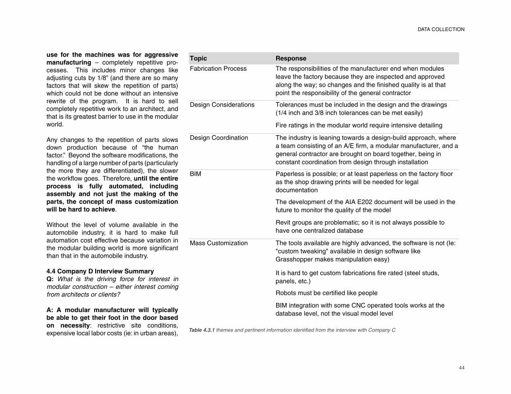
44
use for the machines was for aggressive
manufacturing – completely repetitive pro-cesses. This includes minor changes like adjusting cuts by 1/8” (and there are so many factors that will skew the repetition of parts) which could not be done without an intensive rewrite of the program. It is hard to sell completely repetitive work to an architect, and that is its greatest barrier to use in the modular world.
Any changes to the repetition of parts slows down production because of “the human factor.” Beyond the software modifi cations, the
handling of a large number of parts (particularly
the more they are differentiated), the slower
the workfl ow goes. Therefore, until the entire
process is fully automated, including
assembly and not just the making of the
parts, the concept of mass customization
will be hard to achieve.
Without the level of volume available in the
automobile industry, it is hard to make full
automation cost effective because variation in
the modular building world is more signifi cant
than that in the automobile industry.
4.4 Company D Interview Summary
Q: What is the driving force for interest in
modular construction – either interest coming
from architects or clients?
A: A modular manufacturer will typically
be able to get their foot in the door based
on necessity: restrictive site conditions,
expensive local labor costs (ie: in urban areas),
����� �������
��������������� ����� �� �������� ���������������������������
�������������������� ��������� ����������������
����������� ������ �������� ����������� ������
��������� �� ���������������������������
�� ���� �������� �������� �� ���������������� �������������
�� !�����" #����������� ��������� ���$
��������� �������������������������� �����������
�� ������������ ������ ���� ����������� ��� ��%�������������&�����
������� � ������' (����&�������������������&���
���������������������������������������&�����
�� ������������������� ���������� ��������
)*+ ������� � �� ������������ �������� ����������������
� ��� ������������� �������������������
�����������
������������������'*'(,-,�������������� ������
����������������������������������
.��������� ��������������� ���� ������� �� ������
�������������/�������� �
+� �� ����/���� ������� �������������������������&��� �������� ���*�0
1�� �������2��1������������ �� ���������2�
3�� ��������2� ������������ �$
*�� ����������� ������������� ���������� ���� ��� &
���� &���4$
.���� �� ��������������2�������
)*+������������� ����5������������� ���2 �����
������ ������&������� �������������
Table 4.3.1 themes and pertinent information identifi ed from the interview with Company C
DATA COLLECTION
45
or because of a reduced timeline (ie: education facilities).
Q: What strategies are taken among
manufacturers to either improve the public
perception of modular construction or to promote
the advantages of modular construction to
architects and potential clients?
A: Modular construction in the public’s eye is often equated with manufactured HUD code housing – inexpensive, economical, mass produced-type products. In a permanent modular building, the goal is to make the building indistinguishable from a site-built structure. In the education market, when a school is planning to lease a classroom, they usually spend money on the cheapest option because they expect it being a two-year necessity.
Customers typically have an expectation that the budget for a modular building will drop by 15%, so the challenge then for the manufacturer is to sell the fact that a construction timeline reduced by 25% would result in quicker revenue generation.
Q: Can awarding incentives (LEED Certi-
fi cation points), established precedents
illustrating long-term fi nancial benefi ts, or
quality certifi cations be used to increase the
integration of prefabricated components into
building design and execution?
A: The price of sustainable building materials have been decreasing dramatically over the
past three or four years, and that trend is expected to continue. Studies have shown that the manufacturing process is a much more sustainable process before even getting into specifi cations, building systems, and material
selections.
Q: How does the strategy to keep panelized
components compare to modular building
assemblies in terms of quality control and
the costs associated with packaging and
transport?
A: The pros to building 3-D modules offsite
versus 2-D panelized components is the fact
that the complexity and the extent of onsite
construction is reduced with larger 3-D
modules built offsite, so the manufacturer can
manage the effi ciencies and the quality of the
process in the factory. Labor rates are also
comparatively low in the factory, so it generally
is benefi cial to get as much work done in the
factory as possible.
However, for projects exported long distances
overseas (or potentially by train), the fl at-pack
shipping method of a panelized 2-D design
becomes more economical because no
longer are “empty volumes” being shipped,
and instead the maximum capacity of a
cargo container is being utilized.
Q: What type of projects are you best geared
for, and how diffi cult is it to modify your
fabrication process?
A: Traditionally, a project done at Company
D is at least 40% complete before it leaves
the factory.
Q: How would a business model for the case
study project be designed?
A: The business model that would likely be
used for the case study project would require
the architect to “shop around” for individual
manufacturers that can build the many different
sub-assemblies and hire a general contractor
to put it all together at the site. This would
be effective in a leasing situation, where a
distributer owns the subassemblies and rents
them out to school systems. The SIP’s panels,
for example, would have to be sourced carefully,
working with an existing panel maker that’s
already tooled up to build them.
Using a leasing business model for a kit-of-
parts system with interchangeable components
also requires the end product to comply with
the regulations of multiple states.
The project ultimately would not require the
services of a modular manufacturer because
the onsite general contractor would be
responsible for the bulk of the work, and the
architect could be responsible for sourcing out
all of the component work.
Q: At what stage in the design process should
the manufacturer meet with the architect?
A: One problem in working with architects on
modular projects is that often times a modular
manufacturer is brought in after the project has
DATA COLLECTION
46
been designed for conventional construction and requires some level of re-design. Coordination at the start of a project, however, can prevent overlaps in the scope
of work of the architect/engineers and the modular manufacturer, particularly in terms of shop drawings that duplicate construction documents and permit drawings.
A modular manufacturer has a knowledge of
local products (eg: steel truss manufacturers) that can aid in making a design cost effective. These include value engineering and
economy of scale. Similarly, the manufacturer can suggest the use of products that they can obtain at a discounted price and those which they are already volume purchasing to help
drive the cost of the design down.
Q: Who is responsible for LEED Certifi cation
calculations?
A: The calculations for LEED Certifi cation
will fall under the architect’s scope of work.
The modular manufacturer will write the
justifi cation for the Innovation Credit (for
modular construction), they will provide mill
certifi cates for the materials used (type of
steel/wood/aggregate), and they will provide
information on the factory’s recycling program.
Company D does a lot of work for the military,
and those projects are currently required to be
LEED Gold certifi ed.
Q: Can you identify some general design
considerations that are unique to modular
construction?
A: It usually helps if the architect comes into
the factory and sees the building systems
typically built by the manufacturer and gets and
understanding of the particular manufacturer’s
building process.
An architect should understand the cross
section of a modular building. Particularly
prevalent in multi-story modular buildings, the
relationship of the roof structure of the lower
module to the fl oor substructure of the top
module presents a unique design condition
that needs to be accounted for.
Material redundancies in modular buildings
are unavoidable because the structure of
each individual module must be stable, often
doubling columns and beams. The design
of a modular building must account for that
and consider the consequences and possible
solutions.
Dimensional restrictions due to transportation
laws vary from state to state. Not only does
the design of a modular building have to
conform to the regulations of its end location,
the path of travel must also be planned and
considered. Therefore, it is important for an
architect to be aware of the width, height,
length, and weight of modules as well as the
consequences of working outside of those
parameters (eg: 16’ x60’ module is possible,
but the transportation cost would be higher if
installation is intended for New York City).
The installation procedure after a module
arrives onsite is also important to be
considered in the early stages of design.
For example, it can be a challenge to order the
sequence in which models are placed and how
they are secured without either damaging the
modules or putting workers in danger.
Q: Are you always required to produce a set
of shop drawings as a supplement to the
architectural drawings for projects built in the
factory?
A: It is both possible to build from (and to get
state approval) an architect’s and engineers’ coordinated construction drawings set. If the
architect has a good enough understanding of
the process, and if there is enough detail present
in the drawings, shop drawings are not actually
required. It is not common, though Company
D has built off of construction documents
in the past, and that is a major reason why
the coordination between the architect and the
manufacturer early is important – to clearly
defi ne what drawings are expected of which
discipline.
The challenge then is the fact that the workers
at the factory are unaccustomed to the drawing
format produced by the architect/engineers.
This problem is only an issue for one or two
weeks depending on how long it takes workers
to get acclimated with the set. So that drawings
aren’t duplicated, the drawings the modular
manufacturer has to do for state approval
are typically identifi ed at the beginning of the
design.
Architects that repeatedly work with a modular
DATA COLLECTION
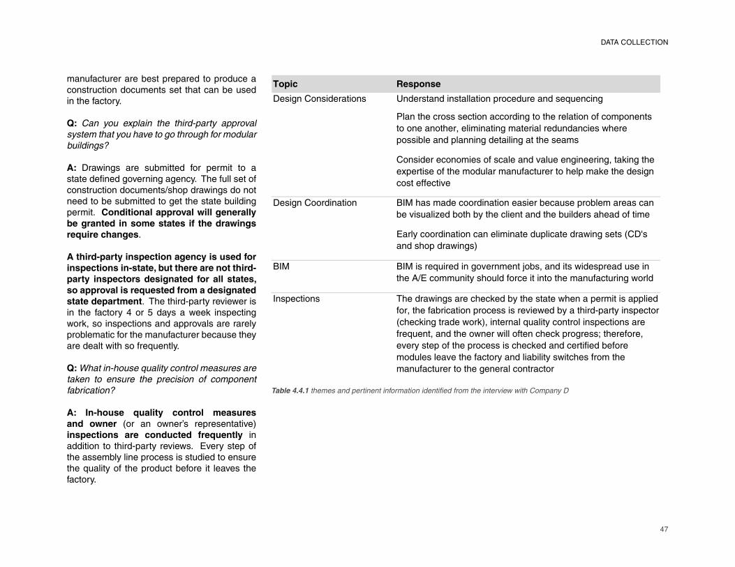
47
manufacturer are best prepared to produce a construction documents set that can be used in the factory.
Q: Can you explain the third-party approval
system that you have to go through for modular
buildings?
A: Drawings are submitted for permit to a state defi ned governing agency. The full set of
construction documents/shop drawings do not
need to be submitted to get the state building
permit. Conditional approval will generally
be granted in some states if the drawings
require changes.
A third-party inspection agency is used for
inspections in-state, but there are not third-
party inspectors designated for all states,
so approval is requested from a designated
state department. The third-party reviewer is
in the factory 4 or 5 days a week inspecting
work, so inspections and approvals are rarely
problematic for the manufacturer because they
are dealt with so frequently.
Q: What in-house quality control measures are
taken to ensure the precision of component
fabrication?
A: In-house quality control measures
and owner (or an owner’s representative) inspections are conducted frequently in
addition to third-party reviews. Every step of
the assembly line process is studied to ensure
the quality of the product before it leaves the
factory.
����� �������
�������������� ��� ����� ������ ���� ������������������������
����� ����������� ����������� � ������� ����������� ��
������ ������������ ������ �����������������������
��������������������� �������� � ��������
��������������������������������������������� ������ ���
����� ������ ���������������� ����� ����������� ���������
�� ������ ���
������������ �� �� �������������� �����������������������������������
����������!��� ���"� �������� ���� ������������������ ���
#���"������ �������������� �������� ����������� ��$��%��
��������������&
�� �� ����������������������� �'�������� ������������������
���()#������� "������������ ��� � ���������� ���������
������ ��� *�����������������������"� ���� � �������������� �����������
���� ���������� ����������������������"��� ���+��� "������� ��
$��������� �������&���� ����������� "��� ��������� ��������
������� ����� �������������� ����������������,� ���������
����"�� ����� �������������������������� �����������
������������ ������ �"����������� "���� ��������� ���
������� ����� � ������������� ��� �
Table 4.4.1 themes and pertinent information identifi ed from the interview with Company D
DATA COLLECTION
48
DATA COLLECTION
Q: To what extent is BIM being used in the
manufacturing process today?
A: All drawings are now done in Revit. It is
a requirement for all government projects, so to remain competitive in the market Company D ran a four-week training seminar for their employees. The only challenges of Revit pertain to the education of the draftsman within the company.
Coordination has improved due to the use
of BIM because it makes it easy to visualize the project during the design phase which is when issues can collectively (between manufacturer, architect, and the engineers) be identifi ed and
resolved. The 3-D model is also a great benefi t
to the client during design. 2-D printouts are
used on the factory fl oor.
Q: Is there a reluctance among architects
to share their drawings because of liability
concerns?
A: Sharing of the BIM could (potentially) be
an issue for architects/engineers that are
developing a proprietary system, yet there
haven’t been any problems for Company D as
of yet.
Q: Who ultimately is responsible for the quality
of the model?
A: It varies based on the type of project being
done. The model for bathroom pod modules,
for example, designed to be set in a site-built
building are created in Revit and inserted
into the BIM model, coordinated between the
architect and the engineers. The modular
manufacturer is solely responsible for the
quality of that portion of the model.
Q: What level of automation is being used in
the factory today?
A: While there is a limited level of automation
used in the steel fabrication shop (cold-rolled
steel formations), Company D is a custom
builder and automation tends to work best with
a commodity-type product where the mass
production of components is taking place with
a limited number of changes.
4.5 Company E Interview Summary
Q: To what extent are manufacturers involved
in the building’s design?
A: Company E is the architect, and tries to
maintain control from inception through
fi nishing. This includes fi nancing ventures, identifying land to build on, design and engineering, offsite manufacturing, packaging and shipping, onsite assembly, and construction management for the concrete foundation (done by a hired
contractor).
They are considered an “engineering-to-order” product company rather than a design-build
company, and use a building model program in which the building analysis and design are prepared ahead of time, and capable of being changed accordingly to the specifi c demands of a client or site.
Q: Can you identify some general design
considerations that are unique to modular
construction?
A: An increased level of specifi city in an architect’s design is important for modular
construction, requiring drawings to be more
detailed.
Shipping and craning concerns will obviously
limit design.
Picking the right manufacturer for the job
is also important because their specialization
can vary. It’s important to know what the
manufacturer is good at, how they do things,
what’s easy for them, what’s hard for them,
etc. For example, knowing the skill of the
manufacturer in terms of tile and grout work
may be important if the detailing of the building
calls for expensive and highly precise tile
fi nishes. Looking at the built work done by the
manufacturer can provide an understanding of
this level of craftsmanship.
Q: Are you always required to produce a set of
shop drawings as a supplement for architectural
drawings for projects built in the factory?
A: Prefab companies will need to redo or
signifi cantly modify the drawings produced
by an architect. Architect’s don’t produce shop drawings typically because onsite construction involves skilled industry professionals who can interpret a diagram-
matic set of drawings. In industrialized pro-
duction, where one person is not looking at
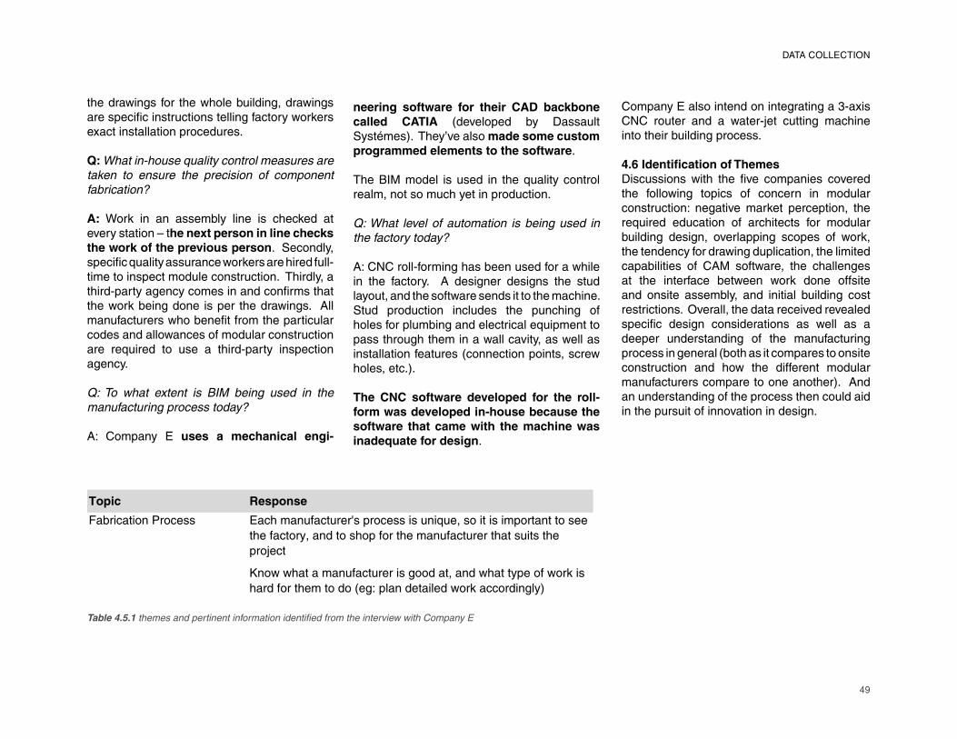
49
the drawings for the whole building, drawings are specifi c instructions telling factory workers
exact installation procedures.
Q: What in-house quality control measures are
taken to ensure the precision of component
fabrication?
A: Work in an assembly line is checked at
every station – the next person in line checks
the work of the previous person. Secondly,
specifi c quality assurance workers are hired full-
time to inspect module construction. Thirdly, a
third-party agency comes in and confi rms that
the work being done is per the drawings. All
manufacturers who benefi t from the particular
codes and allowances of modular construction
are required to use a third-party inspection
agency.
Q: To what extent is BIM being used in the
manufacturing process today?
A: Company E uses a mechanical engi-
����� �������
��������������� ���������������� ����� � ������ ���� ���������� ��
��������������� ������������������������ ��� ���
�������
�������������������� ������������������������
�������������������� ������ �������������� �!
Table 4.5.1 themes and pertinent information identifi ed from the interview with Company E
neering software for their CAD backbone
called CATIA (developed by Dassault
Systémes). They’ve also made some custom
programmed elements to the software.
The BIM model is used in the quality control
realm, not so much yet in production.
Q: What level of automation is being used in
the factory today?
A: CNC roll-forming has been used for a while
in the factory. A designer designs the stud
layout, and the software sends it to the machine.
Stud production includes the punching of
holes for plumbing and electrical equipment to
pass through them in a wall cavity, as well as
installation features (connection points, screw
holes, etc.).
The CNC software developed for the roll-
form was developed in-house because the
software that came with the machine was
inadequate for design.
Company E also intend on integrating a 3-axis
CNC router and a water-jet cutting machine
into their building process.
4.6 Identifi cation of ThemesDiscussions with the fi ve companies covered
the following topics of concern in modular
construction: negative market perception, the
required education of architects for modular
building design, overlapping scopes of work,
the tendency for drawing duplication, the limited
capabilities of CAM software, the challenges
at the interface between work done offsite
and onsite assembly, and initial building cost
restrictions. Overall, the data received revealed
specifi c design considerations as well as a
deeper understanding of the manufacturing
process in general (both as it compares to onsite
construction and how the different modular
manufacturers compare to one another). And
an understanding of the process then could aid
in the pursuit of innovation in design.
DATA COLLECTION
50
CHAPTER 5: DATA ANALYSIS
The nature of the data collection procedures – a series of one-time semi-structured interviews – called for data analysis to occur during the development of the questionnaire and in the interviews themselves. Themes revealed during the literature review and from prior discussions with manufacturers infl uenced the questions asked. The data coding procedures that followed provided direct comparisons of the modular manufacturers’ responses. The contents of this chapter therefore refl ect upon the experiences of the participating stakeholders and their reactions to the case study project.
5.1 Market Perception
The stigma of low quality and cheap construction associated with manufactured housing has limited the involvement of architects in the modular construction industry. The industry today is focused on providing a comparable building product to a site-built equivalent. Traditionally temporary solutions are complimented with permanent modular
buildings and demountable components for predominantly onsite built buildings. The introduction of modular construction to the consumer as a viable option, however, is generally based on necessity: restrictive sites, expensive labor costs, and time restrictions. They turn to the industry expecting a budget reduced by 15% and a timeline reduced by 30%, and manufacturers are forced to produce $45 per square foot trailers. So, while modular manufacturers continue to develop $85 per square foot alternatives that are non-combustible, mold resistant, and re-usable over the course of 20 to 25 years, the public’s perception of modular buildings ultimately affects the industry’s ability to move forward. A different type of building product altogether should be advertised – an inherently greener process with access to advanced construction technology for both permanent and temporary applications.
5.1.1 Marketing and Outreach
Design innovation ultimately calls for going
51
beyond what is possible and what has been done before. First and foremost, this requires both architects and manufacturers to be malleable; open to pushing the established boundaries of their own practices. And secondly, they must understand what those boundaries are.
Outreach programs and marketing dollars currently spent by modular manufacturers are geared towards educating architects. Promotional marketing recognizes built precedents that feature good design, high craftsmanship, and durable materials to es-tablish the possibilities and to garner interest in the industry. The education of the architect on specifi c factory procedures and fabrication
methods identifi es the variables and capabilities
of the manufacturer’s production process.
Whatever infl uence the modular manufacturer
has on an architect’s design often dictates
the allowable materials and structural system.
Finally, collaboration between manufacturers
and architects on research and development
infl uences industry-wide innovation. This
includes investing into new building materials,
advanced building systems, and mass
customization techniques. Through research
of any kind helps both parties to know what
questions are being asked and sets goals for
the future.
5.1.2 LEED
Knowledge of the industry can also be
circulated to the public by taking advantage of
systems that are already in place for building
construction. With LEED (Leadership in En-
ergy and Environmental Design) certifi cation
measures encouraging sustainable building
processes, modular construction stands out as
an alternative to onsite construction because
there is presumably less material waste and
less site disturbance attributed to the building
process. Considering the popularity of LEED
today, the establishment of a high rate of cert-
ifi cation that can be directly associated with the
integration of prefabricated components can
be used to quantify the “inherent greenness” of the process.
Sustainability, as it applies to construction,
encompasses both fabrication and erection.
Coupled with operational policies that do not
incur additional expenses (no smoking policy,
green cleaning, etc.), LEED certifi cation can
be prominently billed as a feature the modular
construction industry is equipped to support.
Robert Kobet breaks down the LEED points
system for new construction as it compares
to modular construction in his report Modular
Building and the USGBC’s LEED™ Version
3.0 2009 Building Rating System (2009). 13 different points can be achieved almost
automatically by using modular construction.
These include the following:
An Innovation and Design Process credit
is automatic.
Sustainable Sites credits reward limited
site disturbance in terms of both duration
and affected area, which in itself is one of
the primary benefi ts of building offsite (SS
6.1).Materials and Resources credits require
planning on the part of the modular
manufacturer to assure that a recycling
program is in place at the factory, and that
regional materials are being used (MR 2,
MR 3, MR 4, MR 5, and MR 7).Indoor Environmental Quality/Indoor Air
Quality credits are attributed to the fact
that the factory provides a safe and well-
ventilated environment for workers, and
that materials are off-gassed prior to being
delivered onsite (EQ 3.1, EQ 3.2, EQ 4.1,
EQ 4.2, EQ 4.3, and EQ 4.4).LEED for Homes has a Materials and
Resources credit specifi cally for modular
construction (MR 1.5).
The fi nal calculations for LEED certifi cation
will fall under the architect’s scope of work.
The modular manufacturer will be expected to
write the justifi cation for the innovation credit.
They will also need to provide mill certifi cates
for the materials used (type of steel/wood/aggregate), and information on the factory’s
recycling program. Major government projects
have currently adopted a minimum threshold of
LEED Gold, though temporary structures are
exempt from such considerations.
5.2 Education
Interested architects should have a general
understanding of modular construction. The
shortened construction schedule demands a
thorough design development phase including
the design and engineering of components,
planning of the assembly line, bill of materials
and processing of materials, shipping methods,
assembly procedure, and even the location
•
•
•
•
•
DATA ANALYSIS
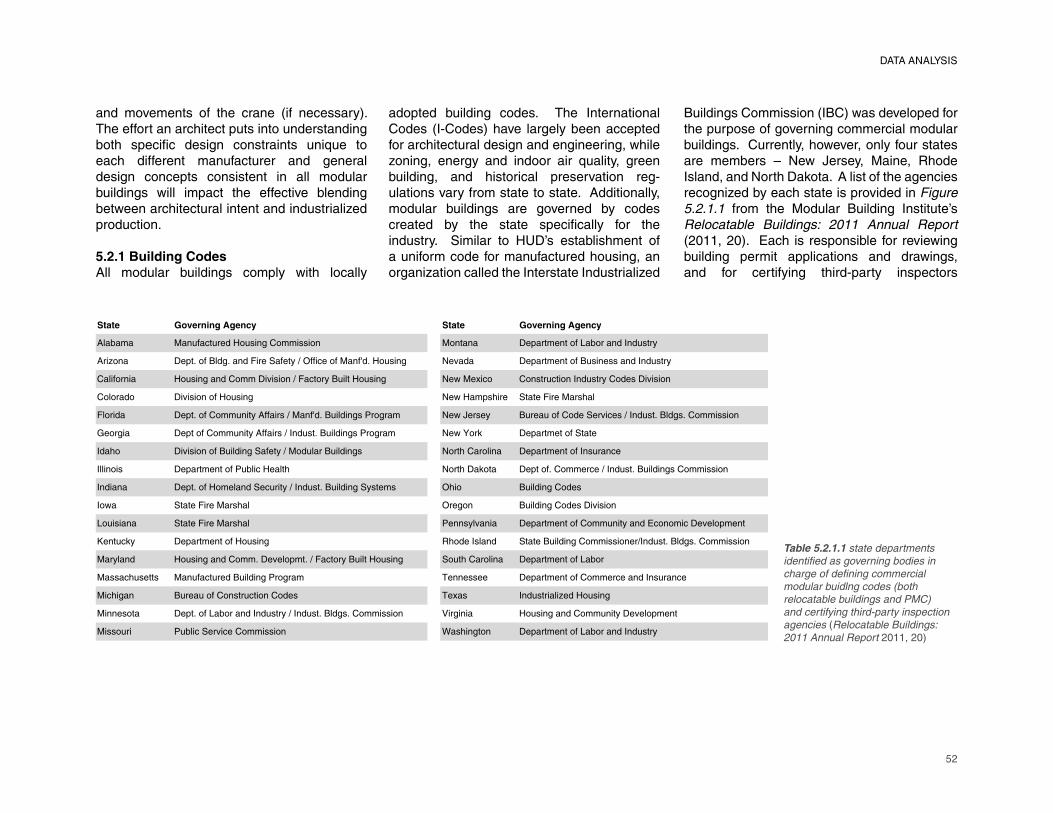
52
DATA ANALYSIS
and movements of the crane (if necessary). The effort an architect puts into understanding both specifi c design constraints unique to
each different manufacturer and general
design concepts consistent in all modular
buildings will impact the effective blending
between architectural intent and industrialized
production.
5.2.1 Building Codes
All modular buildings comply with locally
����� ������� ���� ����� ������� ����
������� �������� �������������������� ������� � ����� �����������������������
������� � ������������������� ��� ��� �!� ������"���������� # $��� � ����� ���������� ���������������
��������� �������������������$������ ��������������������� # %�� &�� ������������������������ ����$�����
�������� ��$��������������� # %������'�� ���� ���� �����'��
������� � ���������������������� ����"�������������(������ # %�) �� � ��� �������� �� �$� �� ��������������������������
* ����� � ��������������������� �������������������(������ # %�+��, � ����� ��������
���'� ��$������������������� ��� ������������������ #���'��������� � ����� ������������
�������� � ����� �����(������ ���' #���'���,��� � ���������� � � �����������������������������
������� � ��������� ������ ������ ���������������������� �� !'�� ������������ �
��%� ���� ���� �����'�� !� ��� ������������ ����$�����
��������� ���� ���� �����'�� ( �����$���� � ����� �������������������-������� $ ���� ��
. ���,� � ����� ������������ /'�� ������� ���� �������������������� � �������������������������
�������� ������������������� $ ������� ��������������������� ����'��������� � ����� ����������
�����'�� ��� �������� �����������(������ 0 �� �� � ����� ��������� � ������������
��'���� ��� �������������������� � 0 &�� ������������ ���������
���� ���� � ������������������������� �������������������������� 1������� ����������������������� $ ���� ��
�������� (������ �$� ����������� 2��'������ � ����� �����������������������
adopted building codes. The International
Codes (I-Codes) have largely been accepted
for architectural design and engineering, while
zoning, energy and indoor air quality, green
building, and historical preservation reg-
ulations vary from state to state. Additionally,
modular buildings are governed by codes
created by the state specifi cally for the
industry. Similar to HUD’s establishment of
a uniform code for manufactured housing, an
organization called the Interstate Industrialized
Buildings Commission (IBC) was developed for
the purpose of governing commercial modular
buildings. Currently, however, only four states
are members – New Jersey, Maine, Rhode
Island, and North Dakota. A list of the agencies
recognized by each state is provided in Figure
5.2.1.1 from the Modular Building Institute’s
Relocatable Buildings: 2011 Annual Report
(2011, 20). Each is responsible for reviewing
building permit applications and drawings,
and for certifying third-party inspectors
Table 5.2.1.1 state departments
identifi ed as governing bodies in
charge of defi ning commercial
modular buidlng codes (both
relocatable buildings and PMC)
and certifying third-party inspection
agencies (Relocatable Buildings:
2011 Annual Report 2011, 20)
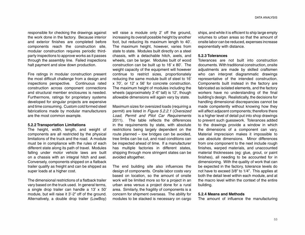
53
responsible for checking the drawings against the work done in the factory. Because interior and exterior fi nishes are completed before
components reach the construction site,
modular construction requires periodic third-
party inspections to approve works as it passes
through the assembly line. Failed inspections
halt payment and slow down production.
Fire ratings in modular construction present
the most diffi cult challenge from a design and
inspections perspective. Continuous rated
construction across component connections
and structural member enclosures is needed.
Furthermore, ratings for proprietary systems
developed for singular projects are expensive
and time consuming. Custom cold formed steel
fabrications made by modular manufacturers
are the most common example.
5.2.2 Transportation Limitations
The height, width, length, and weight of
components are all restricted by the physical
limitations of the truck and the road. A module
must be in compliance with the rules of each
different state along its path of travel. Modules
falling under motor vehicle laws are built
on a chassis with an integral hitch and axel.
Conversely, components shipped on a fl atback
trailer qualify as freight and can be shipped as
super loads at a higher cost.
The dimensional restrictions of a fl atback trailer
vary based on the truck used. In general terms,
a single drop trailer can handle a 13’ x 50’ module, but will raise it 3’-2” off of the ground.
Alternatively, a double drop trailer (LowBoy)
will raise a module only 2’ off the ground,
increasing its overall possible height by another
foot, but reducing its maximum length to 40’. The maximum height, however, varies from
state to state. Modules built directly on a steel
chassis, with a detachable hitch, axels, and
wheels, can be larger. Modules built of wood
construction can be built up to 16’ x 80’. The
weight capacity of the equipment will however
continue to restrict sizes, proportionately
reducing the same module built of steel to 16’ x 70’, or 12’ x 56’ for concrete construction.
The maximum height of modules including the
wheels (approximately 3’-6” tall) is 12’, though
allowable dimensions will again vary by state.
Maximum sizes for oversized loads (requiring a
permit) are listed in Figure 5.2.2.1 (Oversized
Load, Permit and Pilot Car Requirements
2011). The table refl ects the differences
in the requirements by state, with absolute
restrictions being largely dependent on the
route planned – low bridges can be avoided,
tree limbs can be cut, and road conditions can
be inspected ahead of time. If a manufacturer
has multiple factories in different states,
shipping through more stringent states can be
avoided altogether.
The end building site also infl uences the
design of components. Onsite labor costs vary
based on location, so the amount of onsite
work will be limited more so for a project in an
urban area versus a project done for a rural
area. Similarly, the fragility of components is a
concern for shipment overseas. The ability for
modules to be stacked is necessary on cargo
ships, and while it is effi cient to ship large empty
volumes to urban areas so that the amount of
onsite labor can be reduced, expenses increase
exponentially with distance.
5.2.3 Tolerances
Tolerances are not built into construction
documents. With traditional construction, onsite
adjustments are made by skilled craftsmen
who can interpret diagrammatic drawings
representative of the intended construction.
Components built instead in the factory are
fabricated as isolated elements, and the factory
workers have no understanding of the fi nal
building’s design. Realistically, the decisions for
handling dimensional discrepancies cannot be
made competently without knowing how they
will affect adjacent components; therefore there
is a higher level of detail put into shop drawings
to prevent such guesswork. Tolerances added
to the drawings provide a window in which
the dimensions of a component can vary.
Material imprecision makes it impossible to
use absolute dimensions. Minor differences
from one component to the next include rough
fi nishes, warped materials, and unaccounted
material thicknesses (eg: glue, grout, or paint
fi nishes), all needing to be accounted for in
dimensioning. With the quality of work that can
be expected in the factory, tolerance levels do
not have to exceed 3/8” to 1/4”. This applies at
both the detail level within each module, and at
the macro level within the context of the entire
building.
5.2.4 Means and Methods
The amount of infl uence the manufacturing
DATA ANALYSIS
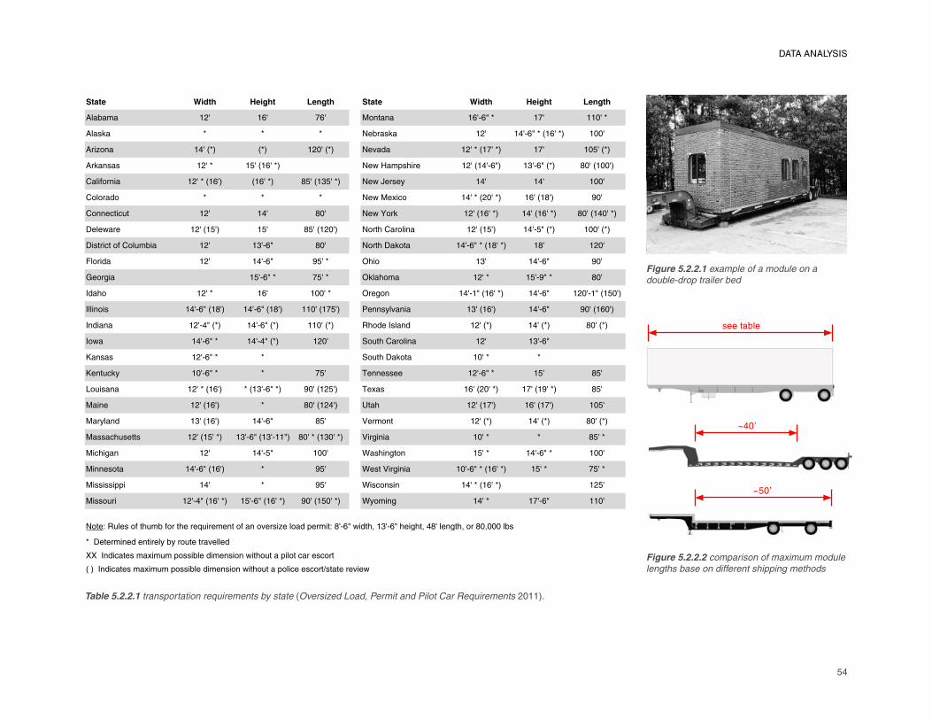
54
DATA ANALYSIS
Table 5.2.2.1 transportation requirements by state (Oversized Load, Permit and Pilot Car Requirements 2011).
~50’
~40’
see table
Figure 5.2.2.1 example of a module on a
double-drop trailer bed
Figure 5.2.2.2 comparison of maximum module
lengths base on different shipping methods
����� ����� ���� ����� ����� ����� ���� �����
������� ��� �� � �� �� � ������ �� ������
������ � � � �������� ��� �������������� ����
����� � ������� ��� �������� ������ ������������ �� �� �����
���� ��� ����� � �������� ��!�"��#�$��� ����������� �%������� &���������
'���(�� �� ���������� ������ & ����% ���� ��!�)����* ��� ��� ����
'������� � � � ��!���+�,� ������������� �����&�� -��
'� �,��,.� ��� ��� &�� ��!�/��� ���������� ���������� &�����������
0���!��� ������ �� � � & �������� ����$�'����� � ������ �� ���� ����� ��������
0�����,���(�'��.���� ��� �%��� &�� ����$�0����� ����������&���� �&� ����
1������ ��� ����� - ��� 2$�� �%� ����� -��
3���4�� � ����� ��� 2���$��� ����� � ��-��� &��
5��$� ����� �� ������ 2��4� ������������� ����� ���������� ���
5��� ��� ��������&�� ��������&�� ������� �� 6� �*��� �� �%������ ����� -��������
5 ��� � ���������� ��������� �������� 7$����5��� � ������� ������� &������
5�!� ������� ���������� ���� 8�.�$�'����� � ��� �%���
9� ��� ������� � 8�.�$�0����� ����� �
9� �.,�* ������� � � :� ����� ������� � � & �
;�.��� � ���������� ����%������ -������ �� :�+�� ���������� �����-���� & �
��� � �������� � &��������� <��$ �������� ������� �� �
���*�� � �%������ ����� & � =���� � ������� ������� &������
�����,$.����� ������ ���� �%������%������ &�������%����� =��4� �� ����� � & ���
��,$�4� ��� ���� � ���� >��$� 4�� � ��� ������� ����
�� ����� ���������� � - � >����=��4� �� �������������� � ��� ���
��������##� ��� � - � >��,� �� ������������ �� �
�����.�� ������������� � ���������� -����� ����� >*��� 4 ����� ���� ����
����?�7.�����(��$.���(����$����@.����� ���(�� ���������������#�����?�&����!���$A��%����$��4$�A��&���� 4�$A����&�A�������B
���0������ ���� �����*��*���.������������
CC��5 ��,�������+��.��#������������ ��� �!��$�.����#�����,�����,���
�����5 ��,�������+��.��#������������ ��� �!��$�.����#���,����,���D�����������!
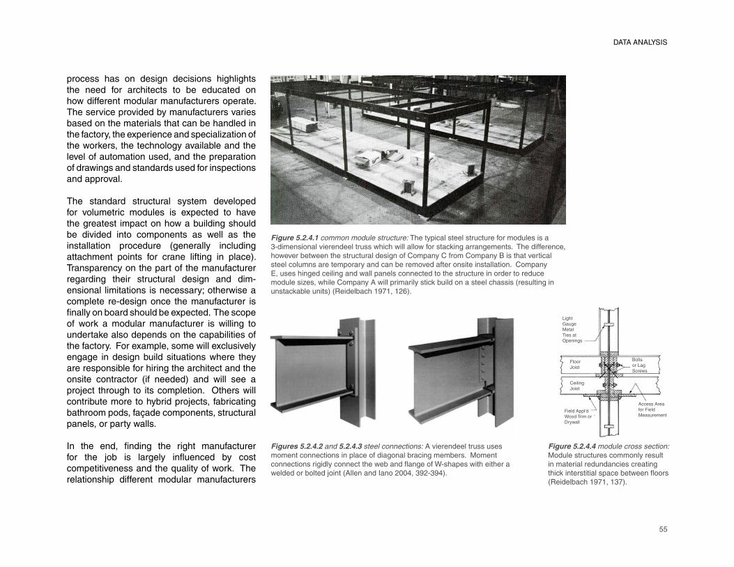
55
process has on design decisions highlights the need for architects to be educated on how different modular manufacturers operate. The service provided by manufacturers varies based on the materials that can be handled in the factory, the experience and specialization of the workers, the technology available and the level of automation used, and the preparation of drawings and standards used for inspections and approval.
The standard structural system developed for volumetric modules is expected to have the greatest impact on how a building should be divided into components as well as the installation procedure (generally including attachment points for crane lifting in place). Transparency on the part of the manufacturer regarding their structural design and dim-ensional limitations is necessary; otherwise a complete re-design once the manufacturer is fi nally on board should be expected. The scope
of work a modular manufacturer is willing to
undertake also depends on the capabilities of
the factory. For example, some will exclusively
engage in design build situations where they
are responsible for hiring the architect and the
onsite contractor (if needed) and will see a
project through to its completion. Others will
contribute more to hybrid projects, fabricating
bathroom pods, façade components, structural
panels, or party walls.
In the end, fi nding the right manufacturer
for the job is largely infl uenced by cost
competitiveness and the quality of work. The
relationship different modular manufacturers
Figure 5.2.4.1 common module structure: The typical steel structure for modules is a
3-dimensional vierendeel truss which will allow for stacking arrangements. The difference,
however between the structural design of Company C from Company B is that vertical
steel columns are temporary and can be removed after onsite installation. Company
E, uses hinged ceiling and wall panels connected to the structure in order to reduce
module sizes, while Company A will primarily stick build on a steel chassis (resulting in
unstackable units) (Reidelbach 1971, 126).
Figures 5.2.4.2 and 5.2.4.3 steel connections: A vierendeel truss uses
moment connections in place of diagonal bracing members. Moment
connections rigidly connect the web and fl ange of W-shapes with either a
welded or bolted joint (Allen and Iano 2004, 392-394).
Figure 5.2.4.4 module cross section:
Module structures commonly result
in material redundancies creating
thick interstitial space between fl oors
(Reidelbach 1971, 137).
Bolts
or Lag
Screws
Light
Gauge
Metal
Ties at
Openings
Floor
Joist
Ceiling
Joist
Access Area
for Field
MeasurementField Appl’d
Wood Trim or
Drywall
DATA ANALYSIS
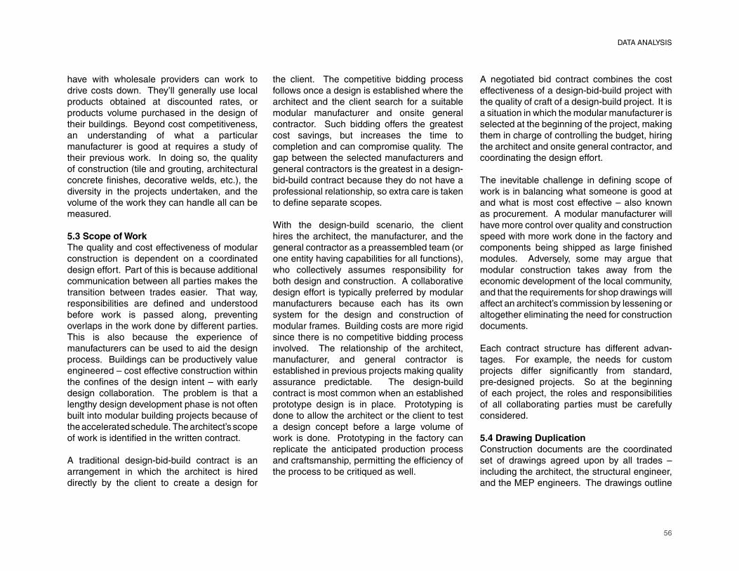
56
DATA ANALYSIS
have with wholesale providers can work to drive costs down. They’ll generally use local products obtained at discounted rates, or products volume purchased in the design of their buildings. Beyond cost competitiveness, an understanding of what a particular manufacturer is good at requires a study of their previous work. In doing so, the quality of construction (tile and grouting, architectural concrete fi nishes, decorative welds, etc.), the
diversity in the projects undertaken, and the
volume of the work they can handle all can be
measured.
5.3 Scope of Work
The quality and cost effectiveness of modular
construction is dependent on a coordinated
design effort. Part of this is because additional
communication between all parties makes the
transition between trades easier. That way,
responsibilities are defi ned and understood
before work is passed along, preventing
overlaps in the work done by different parties.
This is also because the experience of
manufacturers can be used to aid the design
process. Buildings can be productively value
engineered – cost effective construction within
the confi nes of the design intent – with early
design collaboration. The problem is that a
lengthy design development phase is not often
built into modular building projects because of
the accelerated schedule. The architect’s scope
of work is identifi ed in the written contract.
A traditional design-bid-build contract is an
arrangement in which the architect is hired
directly by the client to create a design for
the client. The competitive bidding process
follows once a design is established where the
architect and the client search for a suitable
modular manufacturer and onsite general
contractor. Such bidding offers the greatest
cost savings, but increases the time to
completion and can compromise quality. The
gap between the selected manufacturers and
general contractors is the greatest in a design-
bid-build contract because they do not have a
professional relationship, so extra care is taken
to defi ne separate scopes.
With the design-build scenario, the client
hires the architect, the manufacturer, and the
general contractor as a preassembled team (or
one entity having capabilities for all functions), who collectively assumes responsibility for
both design and construction. A collaborative
design effort is typically preferred by modular
manufacturers because each has its own
system for the design and construction of
modular frames. Building costs are more rigid
since there is no competitive bidding process
involved. The relationship of the architect,
manufacturer, and general contractor is
established in previous projects making quality
assurance predictable. The design-build
contract is most common when an established
prototype design is in place. Prototyping is
done to allow the architect or the client to test
a design concept before a large volume of
work is done. Prototyping in the factory can
replicate the anticipated production process
and craftsmanship, permitting the effi ciency of
the process to be critiqued as well.
A negotiated bid contract combines the cost
effectiveness of a design-bid-build project with
the quality of craft of a design-build project. It is
a situation in which the modular manufacturer is
selected at the beginning of the project, making
them in charge of controlling the budget, hiring
the architect and onsite general contractor, and
coordinating the design effort.
The inevitable challenge in defi ning scope of
work is in balancing what someone is good at
and what is most cost effective – also known
as procurement. A modular manufacturer will
have more control over quality and construction
speed with more work done in the factory and
components being shipped as large fi nished
modules. Adversely, some may argue that
modular construction takes away from the
economic development of the local community,
and that the requirements for shop drawings will
affect an architect’s commission by lessening or
altogether eliminating the need for construction
documents.
Each contract structure has different advan-
tages. For example, the needs for custom
projects differ signifi cantly from standard,
pre-designed projects. So at the beginning
of each project, the roles and responsibilities
of all collaborating parties must be carefully
considered.
5.4 Drawing Duplication
Construction documents are the coordinated
set of drawings agreed upon by all trades –
including the architect, the structural engineer,
and the MEP engineers. The drawings outline
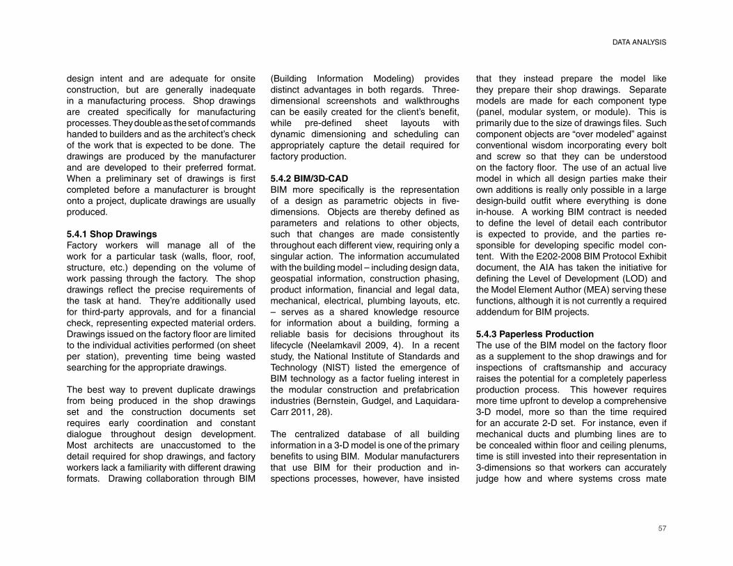
57
design intent and are adequate for onsite construction, but are generally inadequate in a manufacturing process. Shop drawings are created specifi cally for manufacturing
processes. They double as the set of commands
handed to builders and as the architect’s check
of the work that is expected to be done. The
drawings are produced by the manufacturer
and are developed to their preferred format.
When a preliminary set of drawings is fi rst
completed before a manufacturer is brought
onto a project, duplicate drawings are usually
produced.
5.4.1 Shop Drawings
Factory workers will manage all of the
work for a particular task (walls, fl oor, roof,
structure, etc.) depending on the volume of
work passing through the factory. The shop
drawings refl ect the precise requirements of
the task at hand. They’re additionally used
for third-party approvals, and for a fi nancial
check, representing expected material orders.
Drawings issued on the factory fl oor are limited
to the individual activities performed (on sheet
per station), preventing time being wasted
searching for the appropriate drawings.
The best way to prevent duplicate drawings
from being produced in the shop drawings
set and the construction documents set
requires early coordination and constant
dialogue throughout design development.
Most architects are unaccustomed to the
detail required for shop drawings, and factory
workers lack a familiarity with different drawing
formats. Drawing collaboration through BIM
(Building Information Modeling) provides
distinct advantages in both regards. Three-
dimensional screenshots and walkthroughs
can be easily created for the client’s benefi t,
while pre-defi ned sheet layouts with
dynamic dimensioning and scheduling can
appropriately capture the detail required for
factory production.
5.4.2 BIM/3D-CAD
BIM more specifi cally is the representation
of a design as parametric objects in fi ve-
dimensions. Objects are thereby defi ned as
parameters and relations to other objects,
such that changes are made consistently
throughout each different view, requiring only a
singular action. The information accumulated
with the building model – including design data,
geospatial information, construction phasing,
product information, fi nancial and legal data,
mechanical, electrical, plumbing layouts, etc.
– serves as a shared knowledge resource
for information about a building, forming a
reliable basis for decisions throughout its
lifecycle (Neelamkavil 2009, 4). In a recent
study, the National Institute of Standards and
Technology (NIST) listed the emergence of
BIM technology as a factor fueling interest in
the modular construction and prefabrication
industries (Bernstein, Gudgel, and Laquidara-
Carr 2011, 28).
The centralized database of all building
information in a 3-D model is one of the primary
benefi ts to using BIM. Modular manufacturers
that use BIM for their production and in-
spections processes, however, have insisted
that they instead prepare the model like
they prepare their shop drawings. Separate
models are made for each component type
(panel, modular system, or module). This is
primarily due to the size of drawings fi les. Such
component objects are “over modeled” against
conventional wisdom incorporating every bolt
and screw so that they can be understood
on the factory fl oor. The use of an actual live
model in which all design parties make their
own additions is really only possible in a large
design-build outfi t where everything is done
in-house. A working BIM contract is needed
to defi ne the level of detail each contributor
is expected to provide, and the parties re-
sponsible for developing specifi c model con-
tent. With the E202-2008 BIM Protocol Exhibit
document, the AIA has taken the initiative for
defi ning the Level of Development (LOD) and
the Model Element Author (MEA) serving these
functions, although it is not currently a required
addendum for BIM projects.
5.4.3 Paperless Production
The use of the BIM model on the factory fl oor
as a supplement to the shop drawings and for
inspections of craftsmanship and accuracy
raises the potential for a completely paperless
production process. This however requires
more time upfront to develop a comprehensive
3-D model, more so than the time required
for an accurate 2-D set. For instance, even if
mechanical ducts and plumbing lines are to
be concealed within fl oor and ceiling plenums,
time is still invested into their representation in
3-dimensions so that workers can accurately
judge how and where systems cross mate
DATA ANALYSIS
58
DATA ANALYSIS
lines. Another challenge is the legal approval process because the shop drawings are currently the only documents that will stand up in court as the argument for completed work. The dimensions on the shop drawings are historically considered the commands for construction; there is no precedent for the BIM model being a legally accountable entity.
5.5 Impediments to Mass Customization
The ability of CAM tools today to produce custom fabrications without human intervention makes the utilization of CNC (Computer Numeric Control) devices and advanced robotics desirable. CNC connects CAD and CAM visualization programs with machine tools. Such programs write the commands for interpretation by the machinery. Robots similarly run on CAM programs and operate in over 5-axes, featuring agility capable of com-plex actions. At the component level, simple task-oriented processes like CNC cutting, milling, and pressing, and robotic welding or drilling, all can be completed in fi xed locations
while posing minimal challenges in handling.
Full automation further requires more complex
sensor dependent robotics for movement to
perform such tasks as column positioning, fl oor
and fl oor cage laying, cladding attachment,
beam placing, partition placing, ceiling cage
placing, and fl oor grouting (Ibañes-Guzmán et
al. 1990, 88). Any level of automation requires
sustained volume, particularly at startup
because of upfront costs.
Mass production is about repetition; volume
building using identical processes to increase
Figure 5.5.1 stool design by Patrick Chia: An example of mass customization
in industrial design: variations in this stool design are not executed through
hand craft, but by mechanical means (Piller 2006, 6).
59
labor productivity and the cost effectiveness of construction. The notion of mass production can be promoted for fl eet buildings which are rented for temporary uses, but in most cases the site, program, architect, and client will each dictate unique requirements. Modular construction does, however, provide the opportunity for economies of scale to be introduced into design so that isolated ele-ments of a building can be produced in volume. Economies of scale maximize the use of both stock materials bought in bulk and processed materials prepared regularly in the factory.
Mass customization takes advantage of the cost benefi ts of an automated production
process without compromising variety. In
an assembly line, each station introduces
a different system or material, making it
possible to isolate like processes for mass
production (Kieren and Timberlake 2004,
63). When automation is introduced to the
process, component modifi cations will typically
contribute to increased production time and
costs. The concept of mass customization
revolves around the notion that CAM tools can
be designed to incorporate machine fabrication
technologies while still providing fl exibility for
individual customization.
Architects are ahead in the notion of mass
customization where “custom tweaking” can
be manipulated easily in design programs
through dynamic scripts (Grasshopper,
Revit, 3D Studio Max, etc.). The software
associated with machining processes is not
nearly as advanced. There is a difference in
the sophistication of the advanced technology
available and the software used to operate the
machines. Consequently, automation is used
currently for completely repetitive processes,
as even minor changes skew repetition and
involves intensive code modifi cations. CNC
and robotic tools purchased are packaged
each with their own CAM software, also lacking
the consistency available with CAD. Modular
manufactures are thereby forced to write their
own software unless adequate information can
be extracted from BIM model databases.
Any change to the repetition of parts slows
down production because of the “human
factor.” Beyond the software modifi cations,
the handling of a large number of parts
(particularly the more they are differentiated), the slower the workfl ow goes. Therefore, until
the entire process is fully automated, including
assembly and not just the making of the parts,
the concept of mass customization will be hard
to achieve. And without the level of volume
available in the automobile industry, it is hard
to make full automation cost effective because
the variation in modular construction is much
greater than in the automobile industry.
5.6 Offsite/Onsite Interface
The diffi culties at the transition from offsite
modular construction to onsite construction
(including foundation, site-built features, and
component assembly) extend beyond the
scope of work defi nitions. An onsite general
contractor, often hired separately as a local
contributor to the project, needs to understand
what will be delivered to the site from the mod-
ular manufacturer and how it should be hand-
led. This is accomplished in some instances
by the general contractor visiting the factory,
or the modular manufacturer sending their
own project manager to the site. Coordination
through notations on the drawings, with sections
of the full building clearly identifi ed as offsite
work or onsite work, is the only requirement
for state approval. Early planning on the part
of both the delivering party and the receiving
party is however critical in developing the order
in which modules are delivered and installed so
that damages to the modules or putting workers
in dangerous situations can be prevented.
The term mate line refers to where modules are
connected onsite. Finishing of components built
offsite is typically necessary to cover the seams,
with materials (including trim and drywall) shipped in the empty volume of the modules
by the manufacturer. The effects of unfi nished
seams on the interior or the increased labor
required for fi nish work required onsite present
an example of the decisions architects will have
to make regarding installation procedures.
Pulling back fi nishes at the end of modules so
that full wallboard segments can be used can
prevent irregularities in their rhythm across a
large span, while avoiding mate lines crossing
restrooms ensures consistency in the quality of
tile fi nishes.
An architect must consider the consequences
of integrating a modular manufacturer’s
structural system when developing the
drawings. There are going to be structural
redundancies an architect might not anticipate.
DATA ANALYSIS
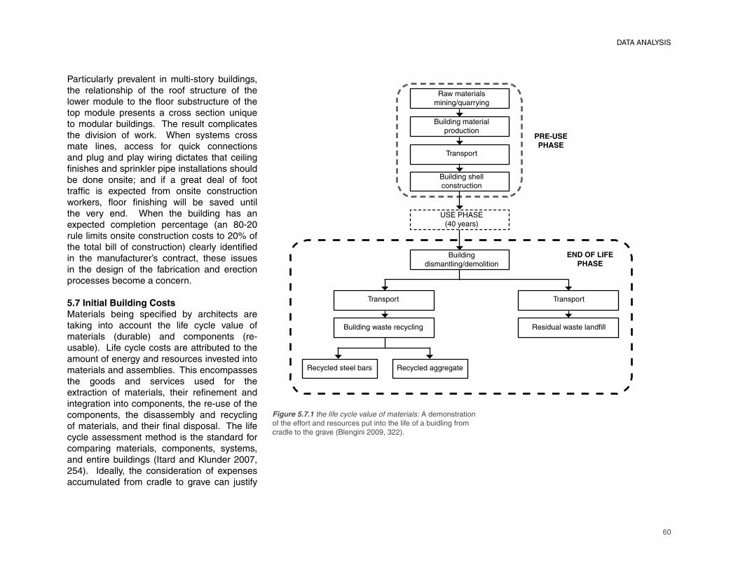
60
Particularly prevalent in multi-story buildings, the relationship of the roof structure of the lower module to the fl oor substructure of the top module presents a cross section unique to modular buildings. The result complicates the division of work. When systems cross mate lines, access for quick connections and plug and play wiring dictates that ceiling fi nishes and sprinkler pipe installations should
be done onsite; and if a great deal of foot
traffi c is expected from onsite construction
workers, fl oor fi nishing will be saved until
the very end. When the building has an
expected completion percentage (an 80-20
rule limits onsite construction costs to 20% of
the total bill of construction) clearly identifi ed
in the manufacturer’s contract, these issues
in the design of the fabrication and erection
processes become a concern.
5.7 Initial Building Costs
Materials being specifi ed by architects are
taking into account the life cycle value of
materials (durable) and components (re-
usable). Life cycle costs are attributed to the
amount of energy and resources invested into
materials and assemblies. This encompasses
the goods and services used for the
extraction of materials, their refi nement and
integration into components, the re-use of the
components, the disassembly and recycling
of materials, and their fi nal disposal. The life
cycle assessment method is the standard for
comparing materials, components, systems,
and entire buildings (Itard and Klunder 2007,
254). Ideally, the consideration of expenses
accumulated from cradle to grave can justify
Figure 5.7.1 the life cycle value of materials: A demonstration
of the effort and resources put into the life of a buidling from
cradle to the grave (Blengini 2009, 322).
DATA ANALYSIS
Recycled steel bars Recycled aggregate
Building waste recycling
Transport
Residual waste landfi ll
Transport
Building
dismantling/demolition
USE PHASE(40 years)
Building shell
construction
Transport
Building material
production
Raw materials
mining/quarrying
END OF LIFE
PHASE
PRE-USE
PHASE
61
durable construction for components that can be re-used.
Component re-use, building portability, and the life cycle value of materials do not currently compensate for higher initial construction costs. So while the ability for components to be interchangeable, replaced, and re-used is not a challenge from a production standpoint, feasibility is decided by cost. Customers expect cheaper buildings. The strategy manufacturers employ focuses on the fi nancial benefi ts of
construction speed in comparison to a fully
onsite constructed building: either by reducing
the costs of displacing workers, or through the
opportunity to turn profi ts sooner.
It is possible that costs saved in construction
through time savings are offset by
transportation costs. Savings are then
sought through material optimization, labor
effi ciency, and value engineering. Material
optimization is a byproduct of labor effi ciency
and value engineering, but factory production
is conducive to material savings attributed to
fewer incidents of component damage, error,
and theft. Labor effi ciency and accuracy
are aided by a system of jigs and fi xtures. A
fi xture is a device that positions materials or
formwork, and a jig controls the movement of
the tools so that duplicate actions are done
with precision. Value engineering identifi es
and removes unnecessary expenditures,
maximizing the value of the building with early
design collaboration.
The other option for investment into expensive
construction is through third parties. Modular
building distributers or dealers will volume
purchase a fl eet of relocatable buildings from
a wholesale manufacturer in a similar fashion
to the way that a car dealership operates. This
way a building (or components that comprise
a kit of parts) can be leased for multiple
temporary functions throughout its life. With
that in mind, it is within the realm of possibility
for an evolving building kit of parts to exist as
a demountable structure which can be taken
down and reattached easily.
DATA ANALYSIS
62
CHAPTER 6: CONCLUSIONS
The objective of this study was to clearly pre-sent the barriers and the design limitations placed upon architects by the building manufacturing process. Ideally, this would lead to future investigations that propose ways to overcome these obstacles.
6.1 Interpretation of Data
From a production standpoint, the feasibility of the case study project was not a concern of the participants. Their concern was for its cost. SIP’s fabrication in-house would require re-tooling or a dedicated factory responsible for their production. So the panels would instead be outsourced to a specialized manufacturer unless an adequate volume is demanded. Similarly, if the manufacturer isn’t already capable of forming their own cold-rolled steel shapes, those too would be outsourced. The responsibilities of the modular manufacturer would thereby reduced to the services of purchaser, inspector, and planner. Manufacturers are therefore hesitant to explore changes to their production lines because
it’s costly to do so (re-tooling, education of the workers, and increased coordination with architects).
This issue of the cost of production is an example of a barrier, or an obstacle to design innovation in the modular construction industry. A constraint is a restriction or limitation serving as a bottleneck that forces the designer’s hand throughout the decision making process. The following constraints that were uncovered in this study:
The lack of knowledge of manufacturing processes among architectsModule size and weight limitations based on shipment method and the designated path of travelThe effects of the manufacturer’s means and methods of production on the design of a modular buildingThe higher level of detail and the time commitment required upfront for the de-velopment of shop drawings
1)
2)
3)
4)
63
How the approach to the procurement of work affects the responsibilities of involved partiesThe knowledge of coding needed for the use of CAM-operated machines limiting the use of automation in the factory
The two barriers identifi ed from this study
include the following:
Negative market perception based on built
precedents
High initial costs compounded with a lack
of awareness among clients of the potential
long-term fi nancial advantages
The conclusions made in this chapter are
interpretations of the data made by the
researcher. The experiences gained through
participation in the design of the case study
project, through the literature review, and
through the conversations with industry
professions all have infl uenced the identifi cation
of the problems and the suggestions that
follow.
1) The lack of knowledge of manufacturing
processes among architects
The data collected in this study stressed the
desire of manufacturers to educate architects,
informing them of what is and what isn’t possible through modular construction. This
can vary from manufacturer to manufacturer
because their processes differ, but an architect
should have a general understanding of the
following:
5)
6)
7)
8)
The fabrication process: Work is typically
divided into stations combining similar
tasks, allowing the construction of different
parts to be done in tandem.
The third-party inspections and approval
process: Drawings clearly defi ning what
will be done in the factory versus what
will be done offsite are submitted for state
approval. Internal quality control measures
are conducted at each station, which can
include visits from the architect and/or
client. Finally, a third-party inspector is
hired to make sure that the work done is
per the drawings.
Transportation methods: Module sizes vary
based on shipping method and the path of
travel of components.
Onsite assembly procedures: The move-
ments and location of the crane, the
sequence of module installation, and the
necessary points of connection for handling
must all be planned ahead of time.
The cross section of a modular structure:
The structure of the modules will be
designed by the modular manufacturer,
and each has its own standard details.
So it is important to know how modules
will relate to one another in regards to
structural redundancies and the resulting
effects it will have on the overall size of the
fi nal building.
A lengthened design development stage is
common with architects not familiar with the
process of modular construction. Measures
that could be taken to educate architects
include the following:
•
•
•
•
•
Continuing education seminars sponsored
by LEED, the AIA, and NCARB offer
opportunities for manufacturers to interact
with architects before working on projects
together. Similarly, teaming with students
through design charrettes and sponsored
competitions provides the manufacturer
with insight into the interests of architects
while providing architects with experience
working on modular buildings.
Tutorials built directly into CAD software,
providing immediate access to information
regarding the general constraints and
design limitations of modular construction.
Dynamic scripts written for Revit designed
for immediate “confl ict detection” so that
drawings conform to the dimensional
restrictions and code-related regulations of
different states.
Shared design responsibilities between the
architect and the manufacturer, including
either a scenario in which the architect
relinquishes control after schematic design,
or a collaborative design effort from start to
fi nish. The latter requires a dedicated staff
of designers working directly alongside the
manufacturer and a shared server.
Incorporate integrated project design
and delivery methods (IPD). IPD is a
team-based approach to design and
construction. More so than in a design-
build scenario, collaboration is optimized
because the major disciplines (including
architect, manufacturer, general contractor,
and specialized subcontractors) form either
a single entity or a strategic partnership
(Integrated Project Delivery – A Working
•
•
•
•
•
CONCLUSIONS
64
Defi nition, 1). The architect is immersed
in the manufacturing process, paving the
way for future certifi ed modular architects.
2) Module size and weight limitations based
on shipment method and the designated
path of travel
Fabricating components offsite immediately
raises into question the mode of transportation
available for shipment. Savings accrued
from the fabrication process are often offset
by transportation costs, so it is important to
capitalize on the most cost-effective solution
when deciding the size and structure of
modules. The following are all factors affected
by transportation constraints:
Modular structures transported on a fl at-
back trailer will be limited in length, width,
and weight based on the physical capacity
of the truck.
Components fi t into shipping containers are
best suited for projects overseas because
the structural integrity of the containers
allows for unorganized stacking. However,
components will be limited by the interior
dimensions of the container in length,
width, and height.
A modular structure built on a steel
chassis with an integral hitch, axels, and
wheels will have to fall within the maximum
dimensions defi ned by state law.
Oversized loads or “superloads” can still be
shipped at higher costs, so it is important
to know what the consequences are to
exceeding the allowable state dimensions
CONCLUSIONS
•
•
•
•
(eg: larger escorts, special state approval). Superloads are also more susceptible to
unplanned roadblocks created by highway
construction, even if the path of travel is
inspected in advance.
3) The effects of the manufacturer’s means
and methods of production on the design
of a modular building
For the manufacturers interviewed there were
signifi cant differences between their fabrication
processes:
Company A builds isolated modules which
are not combined until fi nal assembly.
Company B builds a monolithic structure
offsite, which is broken down into modules
once completed.
Companies C, D, and E have introduced
BIM into their production lines, allowing
automated machines to be used by
extracting information directly from the
models.
The structural system and subsequent
detailing of modules will usually fall under the
manufacturer’s scope of work. This will have
the most signifi cant infl uence on the form of the
fi nal building. The differences in the structural
systems of the fi ve companies interviewed
include the following:
Company A primarily stick builds directly
on a steel chassis resulting in unstackable
units, and uses an adhesive spray foam
to reduce the number of screw and bolt
•
•
•
•
connections.
Company B builds a “steel cube” struc-
ture with temporary columns that can
be removed after onsite assembly is
completed.
Company C employs a 3-dimensional steel
vierendeel truss which allows for stacked
arrangements.
Company E uses hinged ceiling and wall
panels connected to its steel structure in
order to reduce module sizes.
Therefore, it is critical for an architect to
“shop” for the appropriate manufacturer. The
challenge to “shopping around” is that the
capabilities of each modular manufacturer are
not immediately known.
This lack of transparency regarding the means
and methods of construction can be considered
a constraint to design innovation. To improve
transparency, the following steps could be
taken by manufacturers:
Create an online virtual presence pro-
viding typical structural details, material
specifi cations, and 3-dimensional models
for immediate integration into BIM pro-
jects.
Adopt industry standards applicable to dif-
ferent materials used. Standardized con-
nections and detailing prevent confusion in
design development and onsite assembly.
Proprietary structural frames will vary
between manufacturers, but industry-wide
standards would assist in design decisions
related to fi re-rated assemblies and forklift
•
•
•
•
•
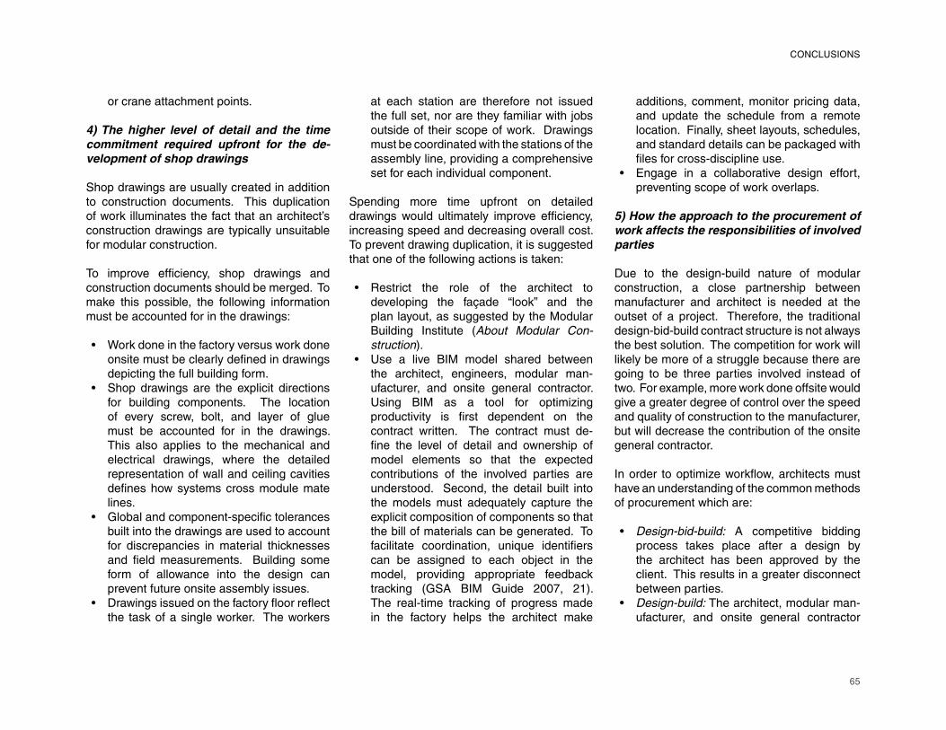
65
or crane attachment points.
4) The higher level of detail and the time
commitment required upfront for the de-
velopment of shop drawings
Shop drawings are usually created in addition to construction documents. This duplication of work illuminates the fact that an architect’s construction drawings are typically unsuitable for modular construction.
To improve effi ciency, shop drawings and
construction documents should be merged. To
make this possible, the following information
must be accounted for in the drawings:
Work done in the factory versus work done
onsite must be clearly defi ned in drawings
depicting the full building form.
Shop drawings are the explicit directions
for building components. The location
of every screw, bolt, and layer of glue
must be accounted for in the drawings.
This also applies to the mechanical and
electrical drawings, where the detailed
representation of wall and ceiling cavities
defi nes how systems cross module mate
lines.
Global and component-specifi c tolerances
built into the drawings are used to account
for discrepancies in material thicknesses
and fi eld measurements. Building some
form of allowance into the design can
prevent future onsite assembly issues.
Drawings issued on the factory fl oor refl ect
the task of a single worker. The workers
•
•
•
•
at each station are therefore not issued
the full set, nor are they familiar with jobs
outside of their scope of work. Drawings
must be coordinated with the stations of the
assembly line, providing a comprehensive
set for each individual component.
Spending more time upfront on detailed
drawings would ultimately improve effi ciency,
increasing speed and decreasing overall cost.
To prevent drawing duplication, it is suggested
that one of the following actions is taken:
Restrict the role of the architect to
developing the façade “look” and the
plan layout, as suggested by the Modular
Building Institute (About Modular Con-
struction).Use a live BIM model shared between
the architect, engineers, modular man-
ufacturer, and onsite general contractor.
Using BIM as a tool for optimizing
productivity is fi rst dependent on the
contract written. The contract must de-
fi ne the level of detail and ownership of
model elements so that the expected
contributions of the involved parties are
understood. Second, the detail built into
the models must adequately capture the
explicit composition of components so that
the bill of materials can be generated. To
facilitate coordination, unique identifi ers
can be assigned to each object in the
model, providing appropriate feedback
tracking (GSA BIM Guide 2007, 21). The real-time tracking of progress made
in the factory helps the architect make
•
•
additions, comment, monitor pricing data,
and update the schedule from a remote
location. Finally, sheet layouts, schedules,
and standard details can be packaged with
fi les for cross-discipline use.
Engage in a collaborative design effort,
preventing scope of work overlaps.
5) How the approach to the procurement of
work affects the responsibilities of involved
parties
Due to the design-build nature of modular
construction, a close partnership between
manufacturer and architect is needed at the
outset of a project. Therefore, the traditional
design-bid-build contract structure is not always
the best solution. The competition for work will
likely be more of a struggle because there are
going to be three parties involved instead of
two. For example, more work done offsite would
give a greater degree of control over the speed
and quality of construction to the manufacturer,
but will decrease the contribution of the onsite
general contractor.
In order to optimize workfl ow, architects must
have an understanding of the common methods
of procurement which are:
Design-bid-build: A competitive bidding
process takes place after a design by
the architect has been approved by the
client. This results in a greater disconnect
between parties.
Design-build: The architect, modular man-
ufacturer, and onsite general contractor
•
•
•
CONCLUSIONS
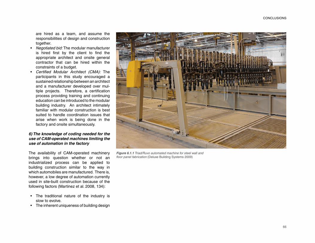
66
Figure 6.1.1 Triad/Ruvo automated machine for steel wall and
fl oor panel fabrication (Deluxe Building Systems 2009)
CONCLUSIONS
are hired as a team, and assume the responsibilities of design and construction together.Negotiated bid: The modular manufacturer is hired fi rst by the client to fi nd the
appropriate architect and onsite general
contractor that can be hired within the
constraints of a budget.
Certifi ed Modular Architect (CMA): The
participants in this study encouraged a
sustained relationship between an architect
and a manufacturer developed over mul-
tiple projects. Therefore, a certifi cation
process providing training and continuing
education can be introduced to the modular
building industry. An architect intimately
familiar with modular construction is best
suited to handle coordination issues that
arise when work is being done in the
factory and onsite simultaneously.
6) The knowledge of coding needed for the
use of CAM-operated machines limiting the
use of automation in the factory
The availability of CAM-operated machinery
brings into question whether or not an
industrialized process can be applied to
building construction similar to the way in
which automobiles are manufactured. There is,
however, a low degree of automation currently
used in site-built construction because of the
following factors (Martinez et al. 2008, 134):
The traditional nature of the industry is
slow to evolve.
The inherent uniqueness of building design
•
•
•
•
67
defi ned by the individual client and site,
and the lack of standardization of parts
makes mass production impractical.
The work environment is constantly
changing based on the type of project
undertaken.
Modular construction provides the most static
work environment, dividing construction into
a series of isolated tasks. A fully automated
manufacturing process is contingent on a
high volume of demand, a level of which is
not typically available in building construction.
Therefore, the application of dedicated
machines towards singular tasks is instead
pursued where possible.
The problem is that CAM software today is
generally inadequate for the manipulation of
work for custom projects. Such programs do
not have the capacity for customization that
CAD software has, so repetition is critical.
Architects are drawn to the concept of mass
customization in modular building design
being able to automate a custom kit of parts
with interchangeable components that can be
plugged into a constant structural system. For
this to be possible, the following must occur:
The design must strategically plan the
use of technology available in the factory,
maximizing the repetition of parts that can
be fabricated by mechanical means.
CAM software must be brought to a level
of customization similar to that available in
CAD programs. For example, Grasshopper
Figure 6.1.2 component assembly line (Reidelbach 1971, 154)
•
•
•
CONCLUSIONS
68
In order to overcome the stigma sometimes associated with modular construction, man-ufacturers attempt to offer a built product indistinguishable from one built onsite. There-fore, the industry advertises a direct alternative to onsite construction. In a comparative analysis of the two processes, time savings and worker safety stand out as the primary advantages of modular construction over onsite construction. The building manufacturing process itself, construction in a controlled environment with access to advanced technology, is an evolution of the art of building, which is traditionally slow to evolve. The modular building industry therefore should advertise a different building product altogether, featuring design innovation and ingenuity executed through advanced building techniques.
The following merits of modular construction should be prominently featured:
The industry’s claim of being a more sustainable construction process should be backed by a high rate of LEED-certifi ed
projects.
The reusability of demountable com-
ponents raises the re-sale value of building
parts, or even whole buildings, that can be
replaced, recycled, or moved based on
need.
Access to CAM-operated machines limiting
human intervention improves crafts-
manship and production speed, while
enabling complex forms and assemblies
to be produced.
Factories are likely open to experimenta-
tion and research, making manufacturers
quick to adopt new fabrication techniques
and building materials.
8) High initial costs compounded with a lack
of awareness among clients of the potential
long-term fi nancial advantages
The issue of production costs will always be a
barrier to innovation in modular construction
because both the client and the architect will
expect lower fabrication costs. It is actually
common for modular buildings to be more
expensive than site-built buildings, with cost
savings only noticeable in urban projects where
labor costs and the costs for parking equipment
are high. Therefore, because time savings
can be guaranteed in modular construction,
manufacturers stress the fact that “time is
money.” For example, with expedited con-
struction an owner of an income-generating
business can turn profi ts sooner. Similarly,
a school district will spend less money on
student displacement when less time is spent
on construction.
Even though modular construction operates
on an accelerated timeline and factory workers
command lower wages than onsite construction
workers, savings will generally be offset by high
transportation costs. Design costs will also be
higher because the process calls for length-
ened design and document development
phases. The expectation of con-sumers that
they will be getting a cheaper product thereby
limits the potential for design innovation.
•
•
•
•
(a plugin for Rhino) maximizes “tweaking” through the use of generative modeling,
making scripting more accessible to the
user by giving it a visual component.
Conversely, most CAM programs are
usable only at the database level requiring
an understanding of coding.
7) Negative market perception based on
built precedents
Although the nomenclature used throughout
the industry is not consistent, the type of
products produced by a manufacturer can be
categorized as either relocatable or Permanent
Modular Construction (PMC). Architects are
more likely to be involved in PMC projects, but
the percentage of new construction projects
utilizing modular components is currently
under one percent. The challenge then is to
increase the level of integration of modular
components in construction despite poor
market perception.
The negative connotation associated with
modular construction comes from the
association of poor and unsafe construction
with the industry. Historically, the industry was
geared to build temporary building solutions for
immediate needs. These buildings, which were
built for only three to fi ve years, were used for
permanent applications. Today, the industry
recognizes the need for durable construction
for even temporary uses, making it possible
to move and re-use full buildings. So, a lack
of knowledge among consumers as to what is
possible can prevent design innovation.
CONCLUSIONS
69
transportation costs and the diffi culty of
onsite labor is critical. Connection details
for components, ductwork, piping, and
electrical systems should be simplifi ed.
Simplify fi nishes that need to be applied
onsite. Instead of using labor-intensive fi nish
work designed to cover up all mate lines,
the design can celebrate the construction.
Architects should particularly eliminate
module seams crossing restrooms to
prevent tile work from having to be done
onsite, and minimize the number of duct
runs and pipes crossing modules.
By spending time upfront on a coordinated
BIM model that can be used to detect
problems ahead of time, the number of
RFI’s (Requests for Information) needed
during construction can be reduced.
6.2 Opportunities for Future Study
The list of constraints and barriers generated
in this study can be used as a tool to inform
architects of the potential limits and pitfalls
to modular construction. Future explorations
into this topic should focus on minimizing the
effects of these limitations and on overcoming
the pitfalls. Considering the infl uence of
technology in the design world, technological
integration into the production line is a medium
unexplored to its fullest potential.
The following research questions have been
proposed by this study:
1) Can CAM software be used as a design tool
capable of high levels of customization?
In terms of material processing, CAM software
would benefi t from being either more design
intuitive or built into CAD programs. Points or
surfaces along a model can be pinpointed for
operations like welding, drilling, or cutting.
2) With “problem detection” integrated into
Revit, can BIM be used as an education tool,
preventing code confl icts?
BIM can be used as an education tool for
architects. A 3-dimensional Revit model can
be analyzed and dynamically updated with a
plugin designed to identify code confl icts. With
a program capable of defi ning dimensional
and weight restrictions, module designs can
potentially be measured against the regulations
of each state and year as they apply.
3) Can the bill of materials assess the life
cycle value of components, quantifying
resale value?
The potential for BIM to be used from securing
and processing materials to inspections and
the scheduling of component delivery makes
it an ideal tool for the industry. Life cycle
assessment tools either built-in or linked to
material schedules would be used to justify
the value of durable construction, or to back
long-term leasing strategies with effective cost
analyses.
4) Can augmented reality integrated with
BIM be used to supplement shop drawings
and facilitate onsite assembly?
•
•
•
Every effort must be made to keep initial costs
down. Savings could potentially be accrued
through the following measures:
By quantifying the life cycle value and the
re-usability of components, a third-party
distributer would be more likely to invest in
a leasing business model spanning 20 to
30 years serving multiple users.
The amount of time needed in design
development can be reduced by eliminating
the need for duplicate drawing sets. To do
so, either the architect would need to bring
the construction documents to a level of
detail suitable for shop drawing production,
or the modular manufacturer would need
to handle design decisions.
Make standard details and specifi cations
available for use by the architect during
design development to avoid wasted time
spent in re-design when a manufacturer is
introduced to the project.
Value engineering services provided
by the modular manufacturer early in
design would keep expenses in check,
preventing prominent design features from
being cut due to budget constraints. This
strengthens the argument for a design-
build or negotiated bid approach where
the modular manufacturer is involved at
the beginning of the project.
While shipping small components in-
creases onsite labor, transportation costs
are cheaper. Conversely, shipping larger
preassembled components requires
less onsite labor but costs more to ship.
Creating a balance between cheaper
•
•
•
•
•
CONCLUSIONS
70
CONCLUSIONS
With augmented reality, a real-world en-vironment is viewed through a physical lens that can enhance one’s perception. For example, when paired with a 3-dimensional building model, the device would recognize the component under construction and im-mediately identify the elements missing from the fi nal composition (Webster et al, 2).
5) How could a plug-and-play program built
for rapid prototyping be applied to modular
construction?
“Fritzing” is a tool that simulates the effects
of combining different electronic components
(breadboards, sensors, cables, etc.). After
refi ning an electronic composition, a proto-
type of the hardware can be ordered for use
(Wettach, Knörig, and Cohen, 3). At the building
scale, an architect can develop a library of
modular and panelized components, modeled
with cost analysis, energy performance
data, appliances, and mechanical systems.
A program like Fritzing would provide the
consumer with the ability to manipulate the
building by adding the components of their
choosing, and test the building’s performance
in terms of energy consumption and op-
erational costs before ordering.
6.3 Summary of Findings
An architect requires a knowledge both of
the general process of modular construction
and of the manufacturer’s production process
to effectively design a modular building.
Increased interaction between the designer
and the modular construction industry can best
inform architects of what is and isn’t possible,
and provide manufacturers insight into the
interests of the architect.
Size and weight of the modules are restricted
by state transportation laws, mode of trans-
portation used, or by the designated path of
travel. Damage during transport is possible,
but is uncommon.
The structural design of modules, which is
engineered in-house by a manufacturer,
will affect the breakdown of modules and
detailing at mate lines. Without industry-wide
standardization, the manufacturer will need to
be involved in a collaborated design effort with
the architect.
Construction documents are typically in-
adequate for modular construction. The
shop drawings created by the manufacturer
are used for acquiring the building permit,
fabricating components, performing third-
party and internal inspections, and for as-
sembling modules onsite. The development
of construction documents and shop drawings
must be coordinated to prevent duplication of
work.
The effectiveness of a competitive bidding
process is dependent on the experience of
the architect, whether or not the architect is
familiar with modular construction. The level
of coordination required generally calls for a
design-build approach where the architect,
manufacturer, and general contractor have
collaborated on previous projects.
Mass customization requires a level of
manipulability that CAM-operated machines
cannot provide. The software accompanying
the machines must be more intuitive to make
this possible. Minor changes to the repetitive
actions of the machines currently require an
intensive re-coding process.
There is an existing stigma of cheap and
temporary construction, sometimes associated
with modular buildings, that is based on built
precedents. In reality, a modular building
product is indistinguishable from an onsite-built
equivalent.
Clients expect lower costs from modular
buildings. Time savings can be expected,
but fabrication costs will usually be offset by
shipping costs. The industry, therefore, focuses
on the construction speed, saving money on
employee displacement and allowing the owner
to turn profi ts sooner.

71
About Modular Construction. Modular Building Institute [cited 03 Febuary 2012. Available from http://www.modular.org/htmlPage.aspx?name=About_Modular_Construction.
Allan, George. 2003. “A Critique of Using Grounded Theory as a Research Method.” Electronic Journal of Business Research
Methods no. 2 (1):1-10.
Allen, Edward, and Joseph Iano. 2004. Fundamentals of Building Construction:
Materials and Methods. Hoboken, New Jersey: John Wiley & Sons, Inc.
Anderson, Mark. 2006. Prefab Prototypes: Site
Specifi c Design for Offsite Construction. New York: Princeton Architectural Press.
Applied Solar Technology, Inc. 2012. The
History of Photovoltaic Cells - Applied
Solar Technology. DIYthemes 2012 [cited April 1 2012]. Available from http://www.applied-solar.info/solar-energy/history-of-solar-cells/.
Arieff, Allison. 2004. “Prefab, Proven.” Dwell no. 5 (2):123.
Arieff, Allison, and Bryan Burkhart. 2002. Prefab. Layton, Utah: Gibbs Smith, Publisher.
REFERENCES
Barwick, Timi, and Jennifer McGarey. 2001. Annandale Regional Planning Study. In Report of the Middle School/High School
Committee. Annandale, VA.
Bell, Eugenia. 2001. Shigeru Ban. New York: Princeton Architectural Press.
Bergdoll, Barry, and Peter Christensen. 2008. Home Delivery: Fabricating the Modern
Dwelling. New York: The Museum of Modern Art.
Bernstein, Harvey M., John E. Gudgel, and Donna Laquidara-Carr. 2011. Prefabrication and Modularization: Increasing Productivity in the Construction Industry. In SmarkMarket Report, edited by McGraw-Hill Construction: National Institute of Standards and Technology.
Bertelsen, Sven. 2004. “Lean Construction: Where are We and How to Proceed.” Lean
Construction Journal no. 1 (1):46-62.
Blengini, Gian Andrea. 2009. “Life Cycle of Buildings, Demolition and Recycling Potential: A Case Study in Turin, Italy.” Building and Environment no. 44 (2):319-330.
BuildingGreen, Inc. 2012. GreenSpec Product:
EcoVeil PVC - Free Interior Shade Screening 2012 [cited April 1 2012]. Available from http: / /www.bui ld inggreen.com/auth/productDetail.cfm?ProductID=2742.
Burns, Carol. 2001. “A Manufactured Housing Studio: Home On the Highway.” Journal of
Architectural Education no. 55 (1):51-57.
CADeshack. 5DCAD: Space (3D), Time
(4D), and Resources (5D) 2009 [cited 2 September 2011. Available from http://www.5dcad.com/.
Chiang, Tat-Hung, Bo-Sin Tang, and Francis K. W. Wong. 2008. “Volume Building as a Competitive Strategy.” Construction
Management and Economics no. 26 (2):161-176.
Clifford, Pearson. 2007. “On a Wooded Site on Taylors Island, Maryland, KieranTimberlake Tested a New Way of Building with the Loblolly House.” Architectural Record no. 195 (4):146-248.
Creswell, John W. 2009. Research Design:
Qualitative, Quantitative and Mixed
Methods Approaches. Thousand Oaks, CA: Sage Publishers, Inc.

72
Datta, Lois-Ellen. 1990. Case Study Evaluations. Washington, DC: U.S. General Accounting Offi ce.
Deluxe Building Systems, Inc. 2012. Deluxe
Responds Fast in High-Volume Building
Systems Production 2009 [cited April
24 2012]. Available from http://www.
deluxebuildingsystems.com/NewsDetail.
aspx?nsId=15.
Denzin, Norman K., and Yvonna S. Lincoln.
2000. Handbook of Qualitative Research.
Second Edition ed. Thousand Oaks, CA: Sage Publications, Inc.
Dini, Massimo. 1984. Renzo Piano, Projects
and Buildings, 1964-1983. Translated
by Richard Sadleir. Milan, Italy: Rizzoli
International Publications, Inc.
DuraSip. 2012. DuraSip Phenolic Fiberglass
Laminante Sheets [cited April 8 2012]. Available from http://durasip.com/products.
html.
Eartheasy.com. 2011. Are LED Fluorescent
Tubes Ready for Prime Time. In Eartheasy
Blog.
Energy Solutions Center, FoodPro. 2012.
Air to Air Heat Exchanger 2007 [cited
April 1 2012]. Available from http://www.
foodtechinfo.com/FoodPro/Effi ciency/air_to_air_heat_exchanger.htm.
Focus Technology Co., Ltd. 2012. Phenolic
Resin Board - China Board, Resin,
Colophony in Other Decoration Materials
2012 [cited April 8 2012]. Available from
http://www.made-in-china.com/showroom/cmbsir/product-detailNbtEROjAEhkS/China-Phenolic-Resin-Board.html.
Foundation Supportworks, Inc. 2012. Corrosion
Considerations: Effects of Corrosion
on Helical Products 2012 [cited April 1
2012]. Available from http://commercial.
foundationsupportworks.com/resources/corrosion-considerations.html.
Fuller, R. Buckminster, and Robert W. Marks.
1973. The Dymaxion World of Buckminster
Fuller: Doubleday.
Gann, David M. 1996. “Construction as a
Manufacturing Process? Similarities
and Differences Between Industrialized
Housing and Car Production in Japan.” Construction Management and Economics
no. 14 (5):437-450.
Gibb, Alistair G. F. 1999. Offsite Fabrication:
Prefabrication, Pre-assembly and
Modularization. Scotland, UK: Whittles
Publishing.
Groat, Linda, and David Wang. 2002.
Architectural Research Methods. New
York: John Wiley and Sons, Inc.
GSA BIM Guide for Spatial Program Validation
Volume 0.96. 2007. In GSA Building
Information Modeling Guide Series.
Washington, DC: General Services
Administration.
Haas, Carl T., James T. O’Connor, Richard L.
Tucker, Jason A. Eickmann, and Walter
R. Fagerland. 2000. Prefabrication and
Preassembly Trends and Effects on the
Construction Workforce. Austin, Texas: Center for Construction Industry Studies.
Hartley, Andrew, and Alex Blagden. 2007.
Current Practices and Future Potential in
Modern Methods of Construction. Banbury,
UK: Wrap.
Herbers, Jill. 2004. Prefab Modern. New York: Harper Design International.
Herlitz, Jeff. 2008. “The Eco-Prefab Decade.” Urban Land no. 67 (5):64-68.
Home Offi ce Declares Aquaco Grey Water
Recycling System a Success! 2012. 2010
[cited April 1 2012]. Available from http://www.pollutionsolutions-online.com/news/water-wastewater /17/aquaco /home_office_declares_aquaco_grey_water_recycling_system_a_success/12549/.
REFERENCES

73
Home Service Publications, Inc. 2012. How
to Install Cork Tile Flooring: The Family
Handyman Magazine 2012 [cited April 1 2012]. Available from http://www.fami lyhandyman.com/DIY-Projects/Flooring/Floor-Installation/how-to-install-cork-tile-fl ooring.
Ibañes-Guzmán, Javier, Peter Atkinson, Brian L. Atkin, Colin E. Bridgewater, and John Bayes. 1990. Automation Systems and Robotic Tools for Modular Building Systems. In 1990 Proceedings of the 7th
ISARC. Bristol, United Kingdom: University of Reading.
Improving Construction Effi ciency and
Productivity with Modular Construction.
2010. Charlottesville, VA: The Modular
Building Institute.
Integrated Project Delivery -- A Working
Defi nition: Version 2. 2007. AIA California
Council.
Itard, Laure, and Gerda Klunder. 2007.
“Comparing Environmental Impacts of
Renovated Housing Stock with New
Construction.” Building Research and
Environment no. 35 (3):252-267.
Jacobs, Karrie. 2007. “The Prefab Decade.” Dwell no. 9 (3):96-97.
KieranTimberlake. 2012. KT [Make It Right]
2007 [cited April 1 2012]. Available from
http://www.kierantimberlake.com/pl_sustainability/make_it_right_1.html.
Kieren, Stephen, and James Timberlake.
2004. Refabricating Architecture: How
Manufacturing Methodologies are Poised
to Transform Building Construction. New
York: McGraw Hill.
Kobet, Robert J. 2009. Modular Building and
the USGBC’s LEED™ Version 3.0 2009
Building Rating System. The Modular
Building Institute.
Koch, Carl. 1958. At Home with Tommorrow.
Toronto, Canada: Clarke, Irwin and
Company, Ltd.
Lechner, Norbert. 2009. Heating, Cooling,
Lighting: Design Methods for Architects.
Hoboken, NJ: John Wiley & Sons.
LiteSteel Technologies America, LLC. 2012.
LiteSteelbeam 2008 [cited April 1 2012]. Available from http://www.litesteelbeam.
com/.
Lot-EK. 2012. MDU (Mobile Dwelling Unit) -
Lot-EK Architecture [cited April 1 2012]. Available from http://www.lot-ek.com/MDU-Mobile-Dwelling-Unit.
Lu, Na. 2007. Investigation of the Designers’ and
General Contractors’ Perceptions of Offsite
Construction Techniques in the United
States Construction Industry, Department
of Career and Technology Education,
Clemson University, Clemson, GA.
Magnum Building Products, Inc. 2012. Magnum
Building Products [cited April 8 2012]. Available from http://www.magnumbp.com/products/mb-gallery.html.
Martinez, Santiago, Alberto Jardon, Jose
Maria Navarro, and Patricia Gonzalex.
2008. “Building Industrialization: Robotized
Assembly of Modular Products.” Assembly
Automation no. 28 (2):134-142.
McQuaid, Matilda. 2003. Shigeru Ban. New
York: Phaidon Press, Inc.
MKThink. 2004. Modular Learning Environments: Beyond the ‘Classroom in a Can’.
Monolite UK, Ltd. D-Shape 2011 [cited 31
March 2011. Available from http://www.d-
shape.com/cose.htm.
Morse-Fortier, Leonard J. 1994. “From Frank
Lloyd Wright’s Usonian Automatic Building
System: Lessons and Limitations in a Lost
Paradigm.” Journal of Architecture and
Planning Research no. 11 (4):274-293.
REFERENCES

74
Neelamkavil, Joseph. 2009. Automation in the Prefab and Modular Construction Industry. In International Symposium on Automation
and Robotics in Construction ISARC 2009. Austin, TX: NRC Institute for Research in Construction.
OEA. 2012. OEA. DM Web Solutions Ltd. [cited April 1 2012]. Available from http://www.oea.org.uk/view_portfolio.php?view=57.
Oversized Load, Permit and Pilot Car
Requirements. ParkerPilot Pilot Cars 2011 [cited 24 February 2012. Available from http://parkerpilot.com/regmap.html.
Permanent Modular Construction 2011: Annual Report. 2011. The Modular Building Institute.
Piller, Frank T. 2006. Mass Customization and Open Innovation News. Frank Piller’s Web
Site on Mass Customization, Customer Co-Creation & Open Innovation 9 (2): 20.
Reidelbach, J. A. 1971. Modular Housing -
1971; Facts and Concepts. Boston: Cahner Books.
Relocatable Buildings: 2011 Annual Report. 2011. The Modular Building Institute.
“Robot-Crafted Housing for Post Disaster Areas.” 2006. Urban Land no. 65 (5):20.
Safdie, Mosche. 1970. Beyond Habitat. Edited by John Kettle. Montreal, Quebec: Tundra Books of Montreal.
Small Houses of the Twenties: The Sears,
Roebuck 1926 House Catalog, An
Unabridged Reprint. 1991. New York: Dover Publications, Inc.
Smith, Elizabeth A. T. 2007. Case Study Houses:
1945-1966: The California Impetus. Hong Kong: TASCHEN GmbH.
Solar Thermal Heating. 2012. [cited April 1 2012]. Available from http://www.so la r t he r ma lmagaz ine . com/SolarThermal/solar-thermal-heating/.
Sylvester, Michael. FabPrefab: Modernist
Prefab Dwellings. Sandor Pty, Lt. 2004 [cited 21 January 2011. Available from www.fabprefab.com.
Tam, Vivian W. Y., C. M. Tam, S. X. Zang, and William C. Y. Ng. 2007. “Towards Adoption of Prefabrication in Construction.” Building
and Environment no. 42 (10):3642-3654.
Webster, Anthony, Steven Feiner, Blair McacIntyre, William Massie, and Theodore Krueger. Augmented Reality in Architectural Construction, Inspection, and Renovation. Columbia University.
REFERENCES
Wettach, Reto, André Knörig, and Jonathan Cohen. Fritzing: Open-source Software for Documenting Prototypes, Learning Interactive Electronics, and PCB Production. In www.fritzing.org, edited by Postdam University of Applied Sciences. Brandenburg, Germany.
Yin, Robert K. 1984. Case Study Research:
Design and Methods. Beverly Hills, CA: SAGE Publications, Inc.
75
The design of the case study project is credited to students who, at the direction of Professor Yvan Beliveau, participated in a semester-long course in the Spring of 2011. The development of the project (a system of sustainable, temporary, re-usable, and affordable classrooms) was conducted in three phases. First, the program was introduced with a design charette conducted at Virginia Tech’s School of Building Construction. The charette teamed industry professionals with students in order to develop broad ideas on modularity, construction, portability, sustainable building systems integration, and classroom layouts. These topics were studied in depth throughout the semester while students collaborated on a single classroom prototype that could be adaptable to varying sites, programs, and scales. The fi nal design was presented to a
local school district to test its feasibility. Having
participating in both the charette and in the
course, I continued developing the drawings in
order to bring the project to an adequate level
of detail for its use in this case study.
The fi nal drawings set produced is enclosed
in this Appendix. The students and industry
partners who participated are listed below:
Virginia Tech Participants:
Faculty: Yvan Beliveau, George Richard
PHD Students: Joseph Tomi, Vera Novak,
Brendan Johnston, Ana Jaramillo
Masters Students: Kamille Ditcher, Adrian
Carter, Alex Amrine, Milton Salcedo, Josh Lilly,
Josh Echols, Mike Roberts
Bachelors Students: Josh Frady, Samantha
Hugo
Industry Partners:
Turner Construction: Susan Boggs, Pamela
Johnson, Joe Swanson, Tom Engers
Fanning Howey Associates, Inc.: Ed Schmidt,
Bruce Hobby, Eric McMillan, Julia Devine,
Rocio Sanchez Seijas
APPENDIX A: PROJECT DRAWINGS
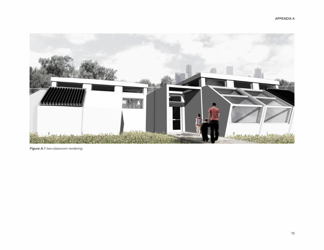
76
Figure A.1 two-classroom rendering
APPENDIX A
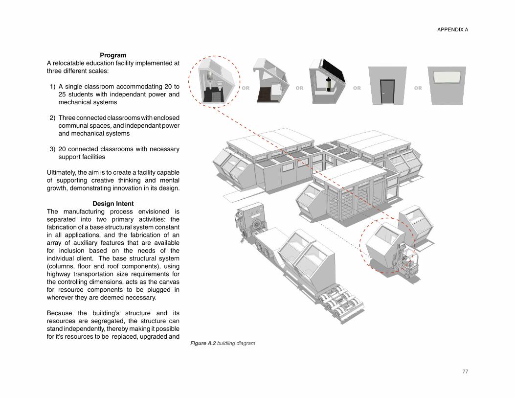
77
�� �� �� ��
APPENDIX A
Figure A.2 buidling diagram
Program
A relocatable education facility implemented at three different scales:
A single classroom accommodating 20 to 25 students with independant power and mechanical systems
Three connected classrooms with enclosed communal spaces, and independant power and mechanical systems
20 connected classrooms with necessary support facilities
Ultimately, the aim is to create a facility capable of supporting creative thinking and mental growth, demonstrating innovation in its design.
Design Intent
The manufacturing process envisioned is separated into two primary activities: the fabrication of a base structural system constant in all applications, and the fabrication of an array of auxiliary features that are available for inclusion based on the needs of the individual client. The base structural system (columns, fl oor and roof components), using highway transportation size requirements for the controlling dimensions, acts as the canvas for resource components to be plugged in wherever they are deemed necessary.
Because the building’s structure and its resources are segregated, the structure can stand independently, thereby making it possible for it’s resources to be replaced, upgraded and
1)
2)
3)
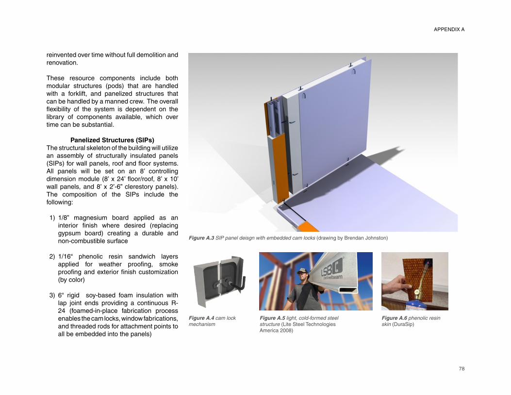
78
��������������� �� �������������� �������������������� ���� ��������������� �����������
Figure A.3 SIP panel deisgn with embedded cam locks (drawing by Brendan Johnston)
Figure A.4 cam lock
mechanism
Figure A.5 light, cold-formed steel
structure (Lite Steel Technologies America 2008)
Figure A.6 phenolic resin
skin (DuraSip)
reinvented over time without full demolition and renovation.
These resource components include both modular structures (pods) that are handled with a forklift, and panelized structures that can be handled by a manned crew. The overall fl exibility of the system is dependent on the library of components available, which over time can be substantial.
Panelized Structures (SIPs)
The structural skeleton of the building will utilize an assembly of structurally insulated panels (SIPs) for wall panels, roof and fl oor systems. All panels will be set on an 8’ controlling dimension module (8’ x 24’ fl oor/roof, 8’ x 10’ wall panels, and 8’ x 2’-6” clerestory panels). The composition of the SIPs include the following:
1/8” magnesium board applied as an interior fi nish where desired (replacing
gypsum board) creating a durable and
non-combustible surface
1/16“ phenolic resin sandwich layers
applied for weather proofi ng, smoke
proofi ng and exterior fi nish customization
(by color)
6“ rigid soy-based foam insulation with
lap joint ends providing a continuous R-
24 (foamed-in-place fabrication process
enables the cam locks, window fabrications,
and threaded rods for attachment points to
all be embedded into the panels)
1)
2)
3)
APPENDIX A
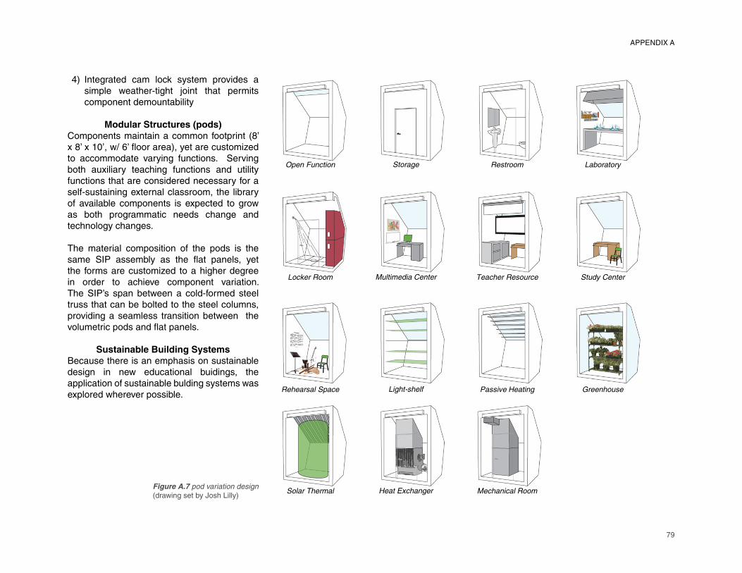
79
����������� �� ��� ��� ��� ���� �� �
����� ����� ������������ ������ ������ �� ���������
����� ��������� ��������� ���� ��!���� " ��������
���� ���� ��� !���#$������ ��������������
APPENDIX A
Figure A.7 pod variation design (drawing set by Josh Lilly)
Integrated cam lock system provides a simple weather-tight joint that permits component demountability
Modular Structures (pods)
Components maintain a common footprint (8’ x 8’ x 10’, w/ 6’ fl oor area), yet are customized to accommodate varying functions. Serving both auxiliary teaching functions and utility functions that are considered necessary for a self-sustaining external classroom, the library of available components is expected to grow as both programmatic needs change and technology changes.
The material composition of the pods is the same SIP assembly as the fl at panels, yet the forms are customized to a higher degree in order to achieve component variation. The SIP’s span between a cold-formed steel truss that can be bolted to the steel columns, providing a seamless transition between the volumetric pods and fl at panels.
Sustainable Building Systems
Because there is an emphasis on sustainable design in new educational buidings, the application of sustainable bulding systems was explored wherever possible.
4)
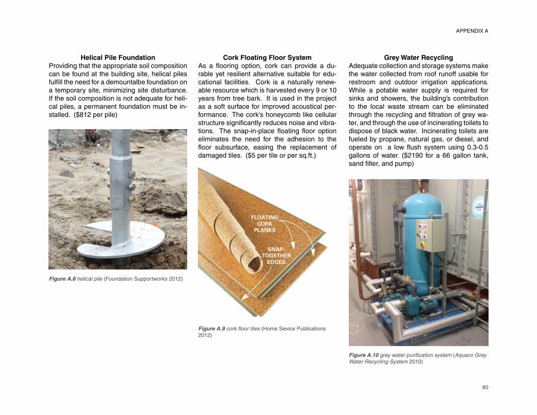
80
Helical Pile Foundation
Providing that the appropriate soil composition can be found at the building site, helical piles fulfi ll the need for a demountalbe foundation on
a temporary site, minimizing site disturbance.
If the soil composition is not adequate for heli-
cal piles, a permanent foundation must be in-
stalled. ($812 per pile)
Cork Floating Floor System
As a fl ooring option, cork can provide a du-
rable yet resilient alternative suitable for edu-
cational facilities. Cork is a naturally renew-
able resource which is harvested every 9 or 10
years from tree bark. It is used in the project
as a soft surface for improved acoustical per-
formance. The cork’s honeycomb like cellular
structure signifi cantly reduces noise and vibra-
tions. The snap-in-place fl oating fl oor option
eliminates the need for the adhesion to the
fl oor subsurface, easing the replacement of
damaged tiles. ($5 per tile or per sq.ft.)
Grey Water Recycling
Adequate collection and storage systems make
the water collected from roof runoff usable for
restroom and outdoor irrigation applications.
While a potable water supply is required for
sinks and showers, the building’s contribution
to the local waste stream can be eliminated
through the recycling and fi ltration of grey wa-
ter, and through the use of incinerating toilets to
dispose of black water. Incinerating toilets are
fueled by propane, natural gas, or diesel, and
operate on a low fl ush system using 0.3-0.5
gallons of water. ($2190 for a 66 gallon tank,
sand fi lter, and pump)
Figure A.8 helical pile (Foundation Supportworks 2012)
Figure A.9 cork fl oor tiles (Home Sevice Publications
2012)
Figure A.10 grey water purifi cation system (Aquaco Grey
Water Recycling System 2010)
APPENDIX A
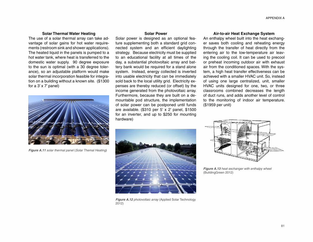
81
APPENDIX A
Solar Thermal Water Heating
The use of a solar thermal array can take ad-vantage of solar gains for hot water require-ments (restroom sink and shower applications). The heated liquid in the panels is pumped to a hot water tank, where heat is transferred to the domestic water supply. 90 degree exposure to the sun is optimal (with a 30 degree toler-ance), so an adjustable platform would make solar thermal incorporation feasible for integra-tion on a building without a known site. ($1300 for a 3’ x 7’ panel)
Solar Power
Solar power is designed as an optional fea-ture supplementing both a standard grid con-nected system and an effi cient daylighting
strategy. Because electricity must be supplied
to an educational facility at all times of the
day, a substantial photovoltaic array and bat-
tery bank would be required for a stand alone
system. Instead, energy collected is inverted
into usable electricity that can be immediately
sold back to the local utility grid. Electricity ex-
penses are thereby reduced (or offset) by the
income generated from the photovoltaic array.
Furthermore, because they are built on a de-
mountable pod structure, the implementation
of solar power can be postponed until funds
are available. ($310 per 5’ x 2’ panel, $1500
for an inverter, and up to $250 for mounting
hardware)
Air-to-air Heat Exchange System
An enthalpy wheel built into the heat exchang-
er saves both cooling and reheating energy
through the transfer of heat directly from the
entering air to the low-temperature air leav-
ing the cooling coil. It can be used to precool
or preheat incoming outdoor air with exhaust
air from the conditioned spaces. With the sys-
tem, a high heat transfer effectiveness can be
achieved with a smaller HVAC unit. So, instead
of using one large centralized, unit, smaller
HVAC units designed for one, two, or three
classrooms combined decreases the length
of duct runs, and adds another level of control
to the monitoring of indoor air temperature.
($1959 per unit)
Figure A.11 solar thermal panel (Solar Themal Heating)
Figure A.12 photovoltaic array (Applied Solar Technology
2012)
Figure A.13 heat exchanger with enthalpy wheel
(BuildingGreen 2012)
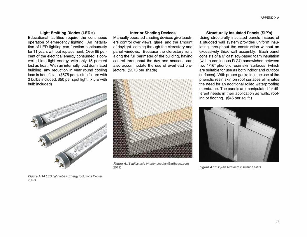
82
Light Emitting Diodes (LED’s)
Educational facilities require the continuous operation of emergency lighting. An installa-tion of LED lighting can function continuously for 11 years without replacement. Over 85 per-cent of the electrical energy consumed is con-verted into light energy, with only 15 percent lost as heat. With an internally load dominated building, any reduction in year round cooling load is benefi cial. ($575 per 4’ strip fi xture with
2 bulbs included; $50 per spot light fi xture with
bulb included)
Interior Shading Devices
Manually operated shading devices give teach-
ers control over views, glare, and the amount
of daylight coming through the clerestory and
panel windows. Because the clerestory runs
along the full perimeter of the building, having
control throughout the day and seasons can
also accommodate the use of overhead pro-
jectors. ($375 per shade)
Structurally Insulated Panels (SIP’s)
Using structurally insulated panels instead of
a studded wall system provides uniform insu-
lating throughout the construction without an
excessively thick wall assembly. Each panel
consists of a 6” cast soy-based foam insulation
(with a continuous R-24) sandwiched between
two 1/16” phenolic resin skin surfaces (which
are suitable for use as both indoor and outdoor
surfaces). With proper gasketing, the use of the
phenolic resin skin on roof surfaces eliminates
the need for an additional rolled waterproofi ng
membrane. The panels are manipulated for dif-
ferent needs in their application as walls, roof-
ing or fl ooring. ($45 per sq. ft.)
Figure A.14 LED light tubes (Energy Solutions Center
2007)
Figure A.15 adjustable interior shades (Eartheasy.com
2011) Figure A.16 soy-based foam insulation SIP’s
APPENDIX A
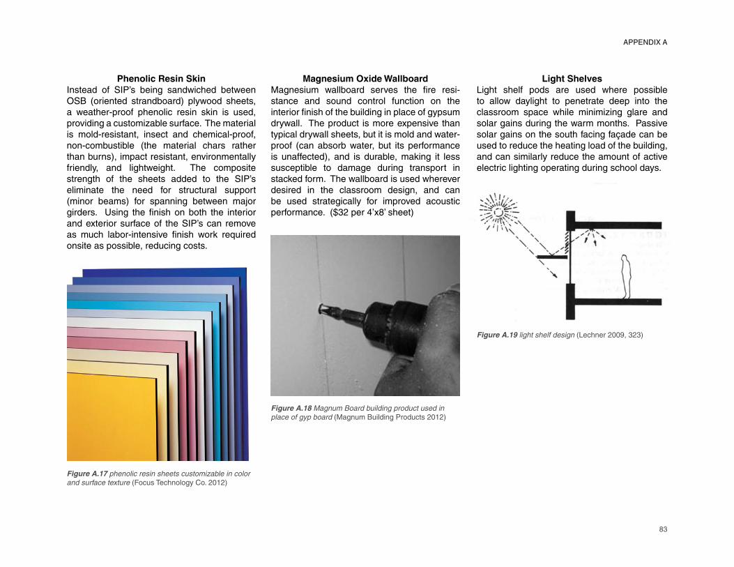
83
APPENDIX A
Phenolic Resin Skin
Instead of SIP’s being sandwiched between OSB (oriented strandboard) plywood sheets, a weather-proof phenolic resin skin is used, providing a customizable surface. The material is mold-resistant, insect and chemical-proof, non-combustible (the material chars rather than burns), impact resistant, environmentally friendly, and lightweight. The composite strength of the sheets added to the SIP’s eliminate the need for structural support (minor beams) for spanning between major girders. Using the fi nish on both the interior
and exterior surface of the SIP’s can remove
as much labor-intensive fi nish work required
onsite as possible, reducing costs.
Magnesium Oxide Wallboard
Magnesium wallboard serves the fi re resi-
stance and sound control function on the
interior fi nish of the building in place of gypsum
drywall. The product is more expensive than
typical drywall sheets, but it is mold and water-
proof (can absorb water, but its performance
is unaffected), and is durable, making it less
susceptible to damage during transport in
stacked form. The wallboard is used wherever
desired in the classroom design, and can
be used strategically for improved acoustic
performance. ($32 per 4’x8’ sheet)
Light Shelves
Light shelf pods are used where possible
to allow daylight to penetrate deep into the
classroom space while minimizing glare and
solar gains during the warm months. Passive
solar gains on the south facing façade can be
used to reduce the heating load of the building,
and can similarly reduce the amount of active
electric lighting operating during school days.
Figure A.17 phenolic resin sheets customizable in color
and surface texture (Focus Technology Co. 2012)
Figure A.18 Magnum Board building product used in
place of gyp board (Magnum Building Products 2012)
Figure A.19 light shelf design (Lechner 2009, 323)
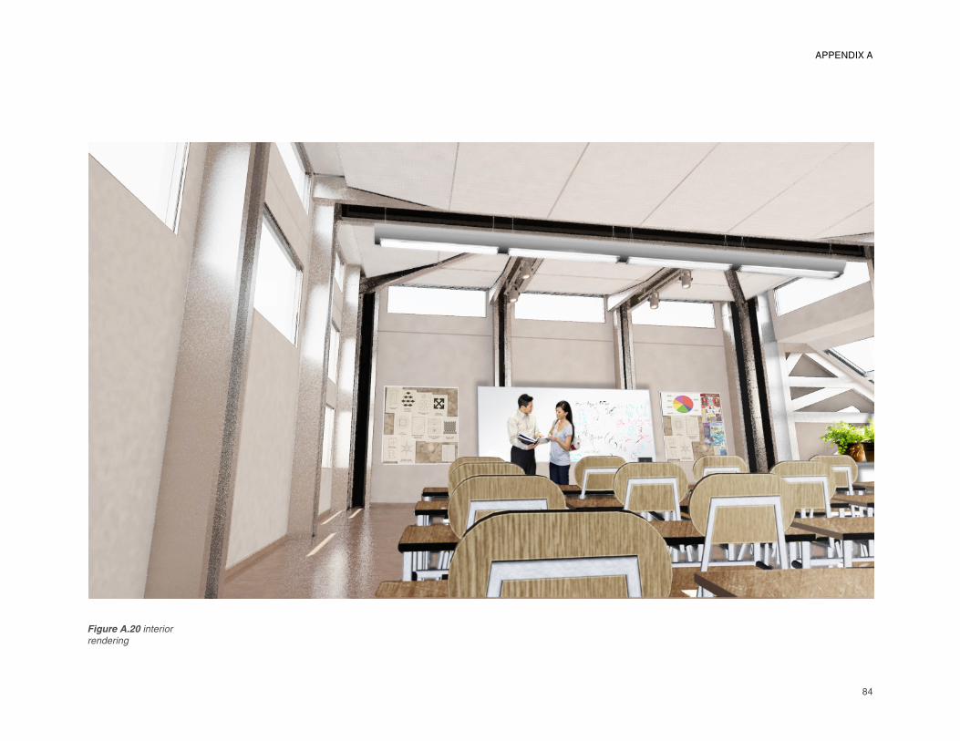
84
Figure A.20 interior
rendering
APPENDIX A
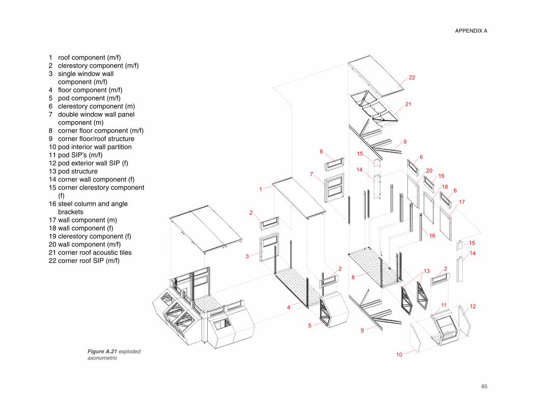
85
4
5
3
2
1
9
8
10
132
1211
14
15
6
19
6
17
18
20
6
14
15
7
9
21
22
16
2
1 roof component (m/f)2 clerestory component (m/f)3 single window wall component (m/f)4 fl oor component (m/f)5 pod component (m/f)6 clerestory component (m)7 double window wall panel component (m)8 corner fl oor component (m/f)9 corner fl oor/roof structure10 pod interior wall partition11 pod SIP’s (m/f)12 pod exterior wall SIP (f)13 pod structure14 corner wall component (f)15 corner clerestory component (f)16 steel column and angle brackets17 wall component (m)18 wall component (f)19 clerestory component (f)20 wall component (m/f)21 corner roof acoustic tiles22 corner roof SIP (m/f)
Figure A.21 exploded
axonometric
APPENDIX A
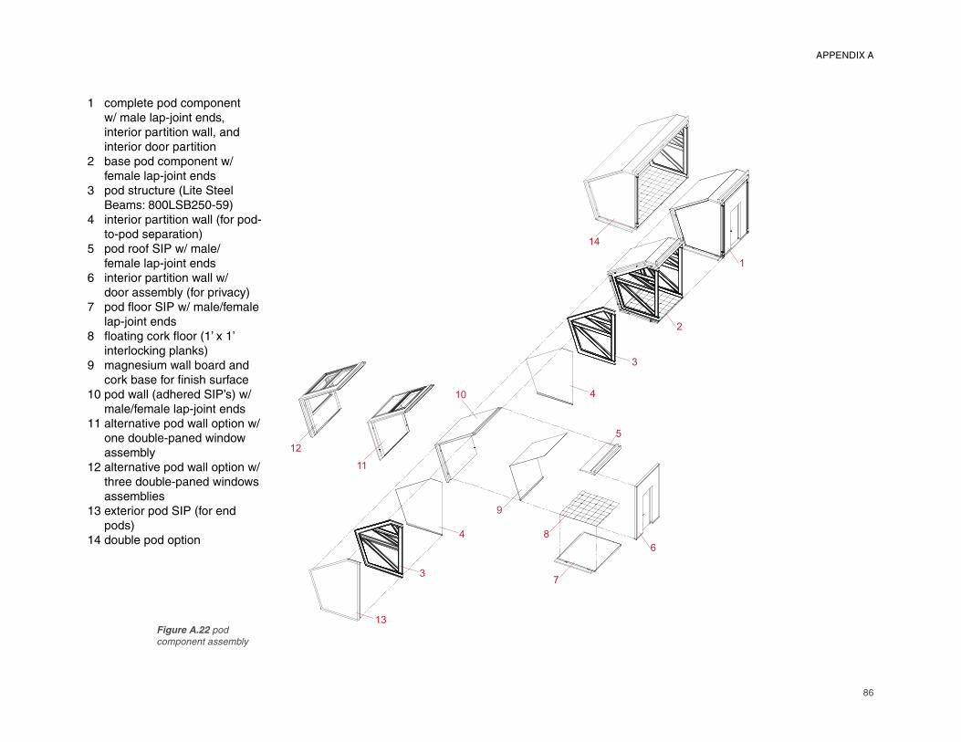
86
7
8
6
5
2
4
3
1
9
4
3
13
10
11
12
14
1 complete pod component w/ male lap-joint ends, interior partition wall, and interior door partition2 base pod component w/ female lap-joint ends3 pod structure (Lite Steel Beams: 800LSB250-59)4 interior partition wall (for pod- to-pod separation)5 pod roof SIP w/ male/ female lap-joint ends6 interior partition wall w/ door assembly (for privacy)7 pod fl oor SIP w/ male/female lap-joint ends8 fl oating cork fl oor (1’ x 1’ interlocking planks)9 magnesium wall board and cork base for fi nish surface
10 pod wall (adhered SIP’s) w/ male/female lap-joint ends
11 alternative pod wall option w/ one double-paned window
assembly
12 alternative pod wall option w/ three double-paned windows
assemblies
13 exterior pod SIP (for end
pods)14 double pod option
Figure A.22 pod
component assembly
APPENDIX A
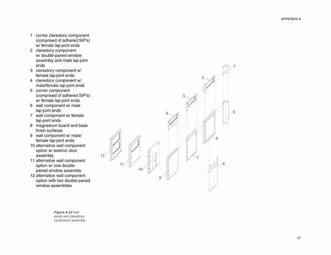
87
1 corner clerestory component (comprised of adhered SIP’s) w/ female lap-joint ends2 clerestory component w/ double-paned window assembly and male lap-joint ends3 clerestory component w/ female lap-joint ends4 clerestory component w/ male/female lap-joint ends5 corner component (comprised of adhered SIP’s) w/ female lap-joint ends6 wall component w/ male lap-joint ends7 wall component w/ female lap-joint ends8 magnesium board and base fi nish surfaces
9 wall component w/ male/ female lap-joint ends
10 alternative wall component
option w/ exterior door
assembly
11 alternative wall component
option w/ one double-
paned window assembly
12 alternative wall component
option with two double-paned
window assemblies
1
5
2
3
4
10
9
8
6
7
11
12
Figure A.23 wall
panel and clerestory
component assembly
APPENDIX A
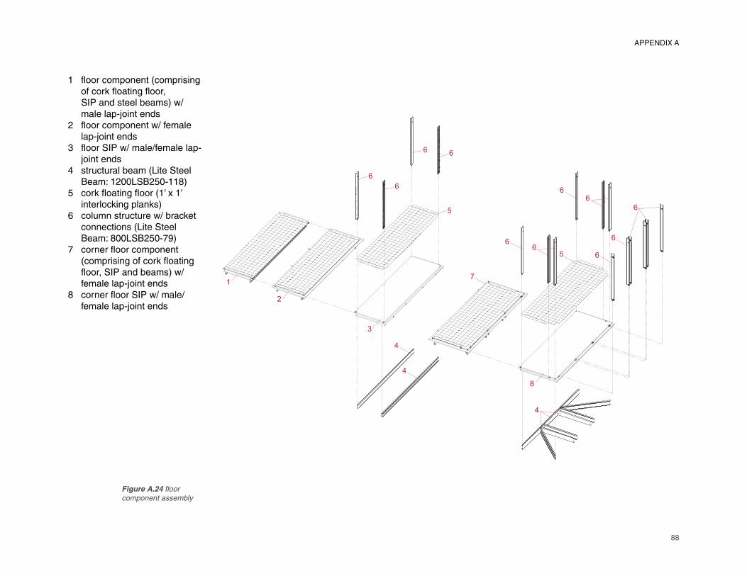
88
1 fl oor component (comprising of cork fl oating fl oor, SIP and steel beams) w/ male lap-joint ends2 fl oor component w/ female lap-joint ends3 fl oor SIP w/ male/female lap- joint ends4 structural beam (Lite Steel Beam: 1200LSB250-118)5 cork fl oating fl oor (1’ x 1’ interlocking planks)6 column structure w/ bracket connections (Lite Steel Beam: 800LSB250-79)7 corner fl oor component (comprising of cork fl oating fl oor, SIP and beams) w/ female lap-joint ends8 corner fl oor SIP w/ male/ female lap-joint ends
1
2
3
66
6
6
5
7
66
6
6
6
6
6
4
4
4
8
5
Figure A.24 fl oor
component assembly
APPENDIX A
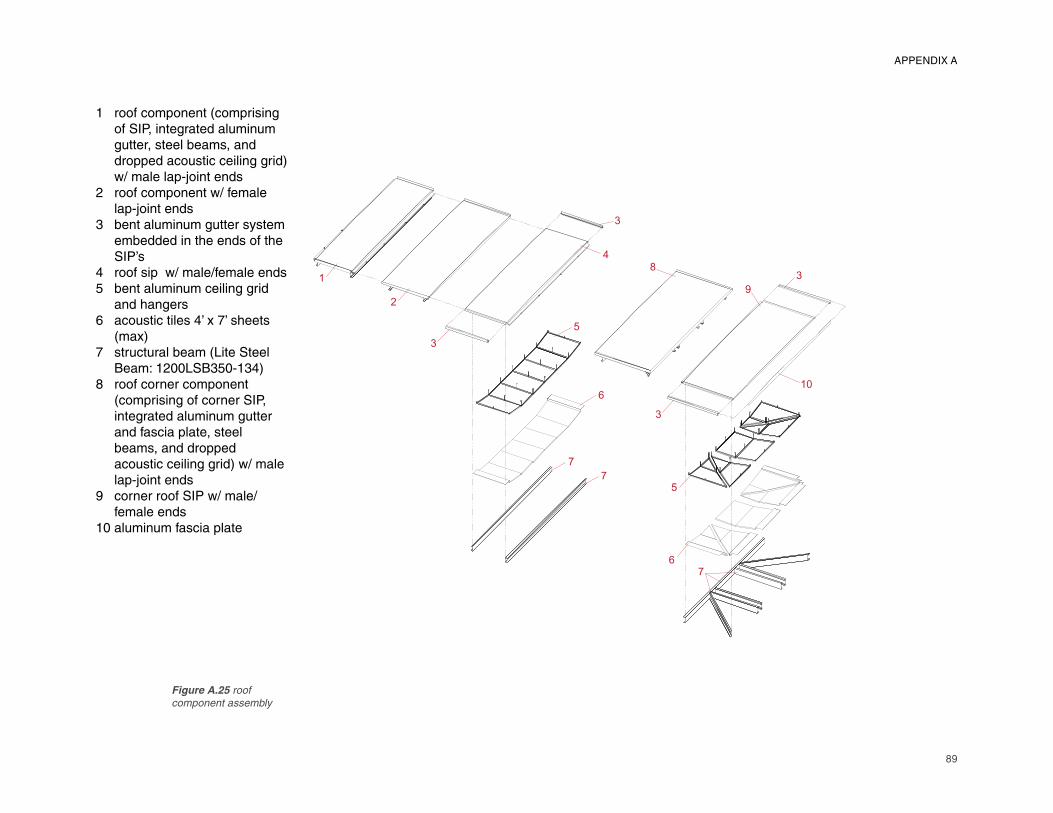
89
1 roof component (comprising of SIP, integrated aluminum gutter, steel beams, and dropped acoustic ceiling grid) w/ male lap-joint ends2 roof component w/ female lap-joint ends3 bent aluminum gutter system embedded in the ends of the SIP’s4 roof sip w/ male/female ends5 bent aluminum ceiling grid and hangers6 acoustic tiles 4’ x 7’ sheets (max)7 structural beam (Lite Steel Beam: 1200LSB350-134)8 roof corner component (comprising of corner SIP, integrated aluminum gutter and fascia plate, steel beams, and dropped acoustic ceiling grid) w/ male lap-joint ends9 corner roof SIP w/ male/ female ends10 aluminum fascia plate
1
2
3
4
3
8
9
7
6
7
7
6
5
5
10
3
3
Figure A.25 roof
component assembly
APPENDIX A
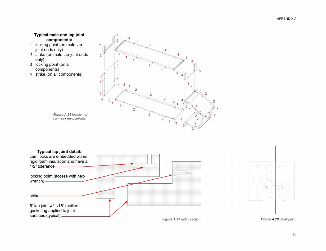
90
Typical male-end lap joint
components:
1 locking point (on male lap- joint ends only)2 strike (on male lap-joint ends only)3 locking point (on all components)4 strike (on all components)
2
2
2
2
1
13
32
2
2
22
1
4
4
2
3
43
1
1
1
1
3
4
3
4
2
2
4
1
2
2
221
3
1
1
1
13
4
3
3
3
44
2
2
4
2
2
24
22
4
2
2
3
Typical lap joint detail:
cam locks are embedded within rigid foam insulation and have a 1/2” tolerance
locking point (access with hex-wrench)
strike
6” lap joint w/ 1/16” resilient gasketing applied to joint surfaces (typical)
Figure A.27 detail section Figure A.28 detail plan
Figure A.26 location of
cam lock mechanisms
APPENDIX A
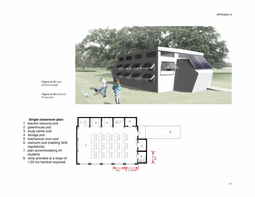
91
Single classroom plan:
1 teacher resource pod2 greenhouse pod3 study center pod4 storage pod5 mechanical room pod6 restroom pod (meeting ADA regulations)7 plan accommodating 24 students8 ramp provided at a slope of 1:20 (no handrail required)
1 2 2 34
5
6
7
8
8’�0 ” 9’� 3 13/16”
8’�0
”
Figure A.29 (top)
photomontage
Figure A.30 (bottom)
fi t-out plan
APPENDIX A
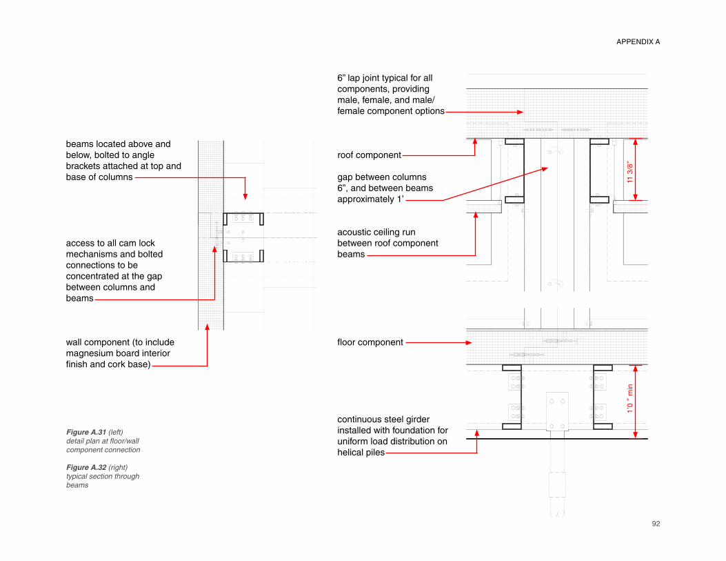
92
beams located above and below, bolted to angle brackets attached at top and base of columns
access to all cam lock mechanisms and bolted connections to be concentrated at the gap between columns and beams
wall component (to include magnesium board interior fi nish and cork base)
6” lap joint typical for all
components, providing
male, female, and male/female component options
roof component
gap between columns
6”, and between beams
approximately 1’
acoustic ceiling run
between roof component
beams
fl oor component
continuous steel girder
installed with foundation for
uniform load distribution on
helical piles
1’�0
” m
in11
3/8
”
Figure A.31 (left)
detail plan at fl oor/wall
component connection
Figure A.32 (right)
typical section through
beams
APPENDIX A
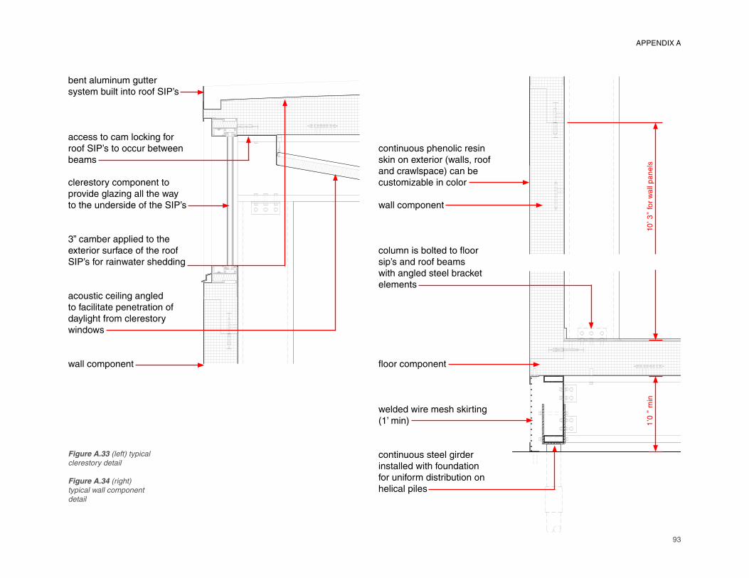
93
bent aluminum gutter system built into roof SIP’s
access to cam locking for roof SIP’s to occur between beams
clerestory component to provide glazing all the way to the underside of the SIP’s
3” camber applied to the exterior surface of the roof SIP’s for rainwater shedding
acoustic ceiling angled to facilitate penetration of daylight from clerestory windows
wall component
continuous phenolic resin skin on exterior (walls, roof and crawlspace) can be customizable in color
wall component
column is bolted to fl oor sip’s and roof beams with angled steel bracket elements
fl oor component
welded wire mesh skirting (1’ min)
continuous steel girder installed with foundation for uniform distribution on helical piles
1’�0
” m
in10
’�3”
for
wall
panels
Figure A.33 (left) typical
clerestory detail
Figure A.34 (right)
typical wall component
detail
APPENDIX A
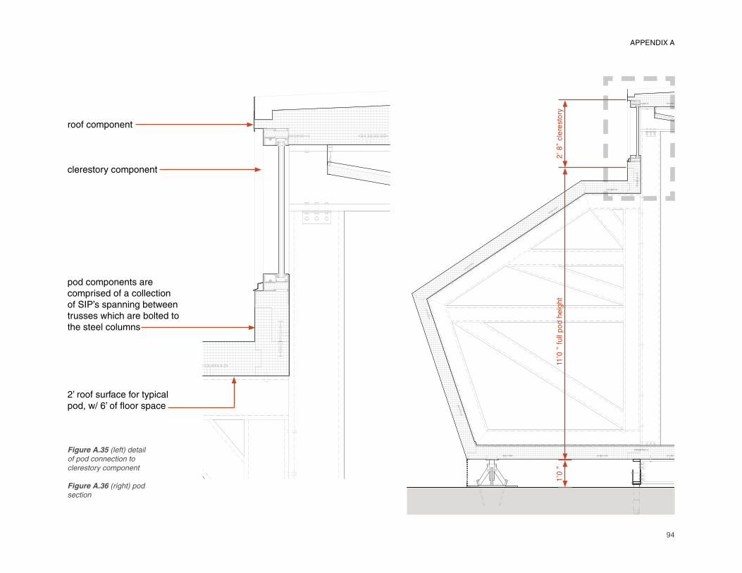
94
roof component
clerestory component
pod components are comprised of a collection of SIP’s spanning between trusses which are bolted to the steel columns
2’ roof surface for typical pod, w/ 6’ of fl oor space
1’�0
”11
’�0”
full
pod h
eig
ht
2’�8
” cle
resto
ry
Figure A.35 (left) detail
of pod connection to
clerestory component
Figure A.36 (right) pod
section
APPENDIX A
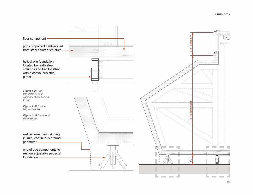
95
fl oor component
pod component cantilevered from steel column structure
helical pile foundation located beneath steel columns and tied together with a continuous steel girder
welded wire mesh skirting (1’ min) continuous around perimeter
end of pod components to rest on adjustable pedestal foundation
1’�0
”11
’�0”
full
pod h
eig
ht
2’�8
” cle
resto
ry
APPENDIX A
Figure A.37 (top
left) detail of fl oor
component connection
to pod
Figure A.38 (bottom
left) pod section
Figure A.39 (right) pod
detail section
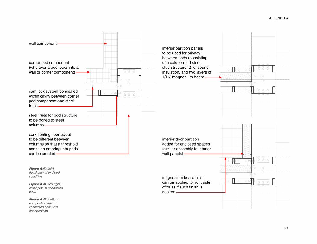
96
wall component
corner pod component (wherever a pod locks into a wall or corner component)
cam lock system concealed within cavity between corner pod component and steel truss
steel truss for pod structure to be bolted to steel columns
cork fl oating fl oor layout to be different between columns so that a threshold condition entering into pods can be created
interior partition panels to be used for privacy between pods (consisting of a cold formed steel stud structure, 2” of sound insulation, and two layers of 1/16” magnesium board
interior door partition added for enclosed spaces (similar assembly to interior wall panels)
magnesium board fi nish
can be applied to front side
of truss if such fi nish is
desired
Figure A.40 (left)
detail plan of end pod
condition
Figure A.41 (top right)
detail plan of connected
pods
Figure A.42 (bottom
right) detail plan of
connected pods with
door partition
APPENDIX A
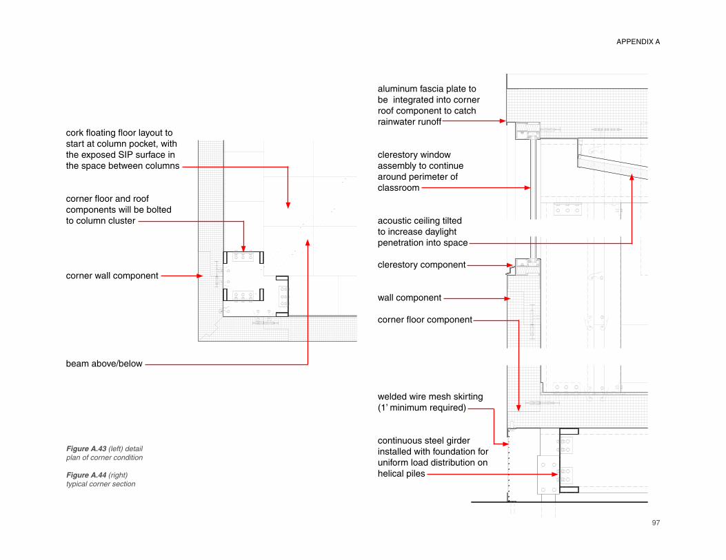
97
cork fl oating fl oor layout to start at column pocket, with the exposed SIP surface in the space between columns
corner fl oor and roof components will be bolted to column cluster
corner wall component
beam above/below
aluminum fascia plate to be integrated into corner roof component to catch rainwater runoff
clerestory window assembly to continue around perimeter of classroom
acoustic ceiling tilted to increase daylight penetration into space
clerestory component
wall component
corner fl oor component
welded wire mesh skirting (1’ minimum required)
continuous steel girder installed with foundation for uniform load distribution on helical piles
Figure A.43 (left) detail
plan of corner condition
Figure A.44 (right)
typical corner section
APPENDIX A
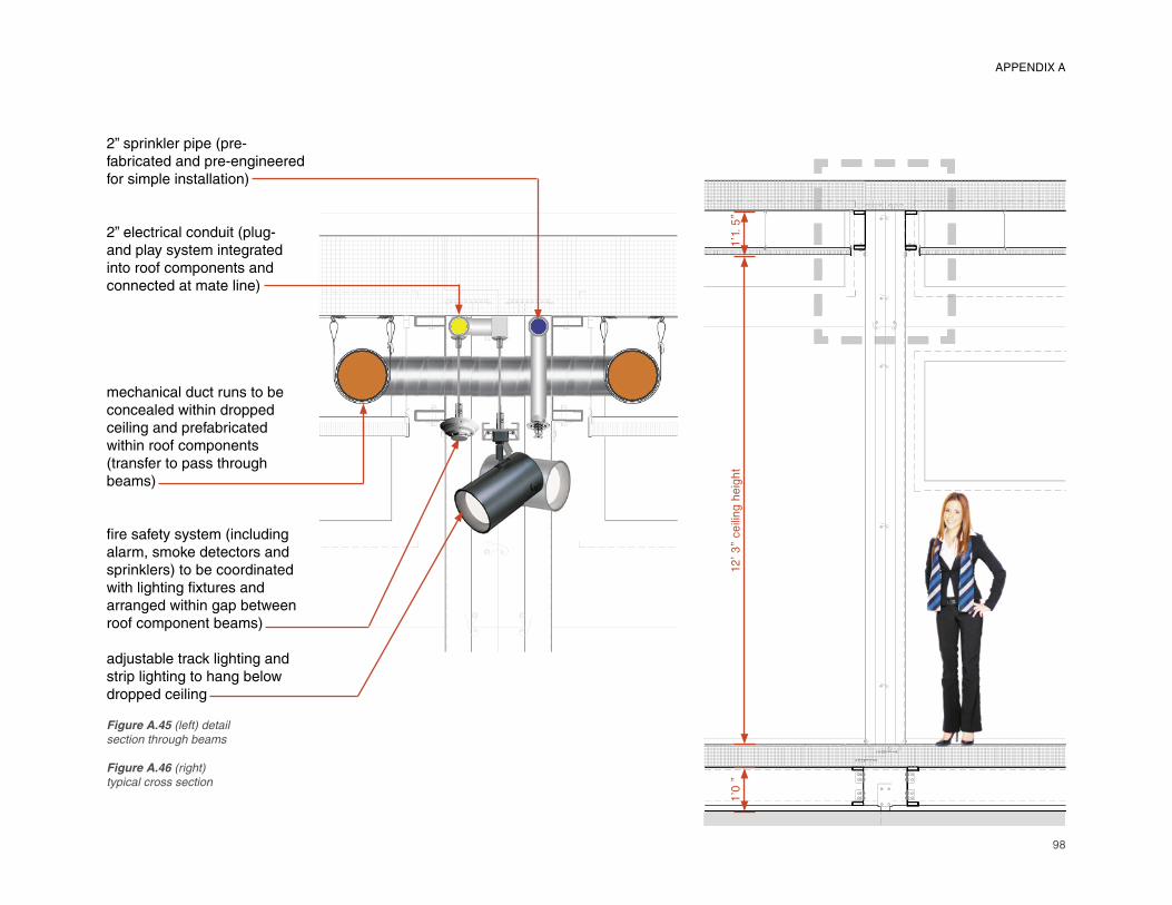
98
2” sprinkler pipe (pre-fabricated and pre-engineered for simple installation)
2” electrical conduit (plug-and play system integrated into roof components and connected at mate line)
mechanical duct runs to be concealed within dropped ceiling and prefabricated within roof components (transfer to pass through beams)
fi re safety system (including
alarm, smoke detectors and
sprinklers) to be coordinated
with lighting fi xtures and
arranged within gap between
roof component beams)
adjustable track lighting and
strip lighting to hang below
dropped ceiling
1’�0
”12
’�3”
ceili
ng h
eig
ht
1’�1
.5”
Figure A.45 (left) detail
section through beams
Figure A.46 (right)
typical cross section
APPENDIX A
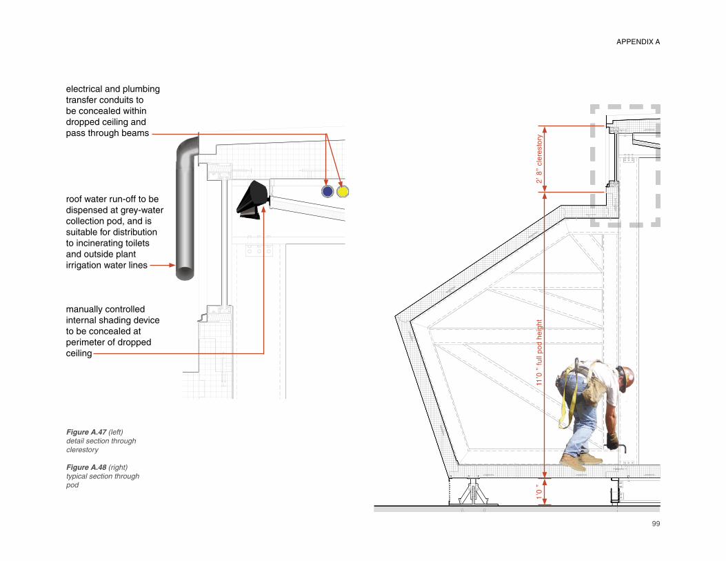
99
electrical and plumbing transfer conduits to be concealed within dropped ceiling and pass through beams
roof water run-off to be dispensed at grey-water collection pod, and is suitable for distribution to incinerating toilets and outside plant irrigation water lines
manually controlled internal shading device to be concealed at perimeter of dropped ceiling
1’�0
”11
’�0”
full
pod h
eig
ht
2’�8
” cle
resto
ry
Figure A.47 (left)
detail section through
clerestory
Figure A.48 (right)
typical section through
pod
APPENDIX A
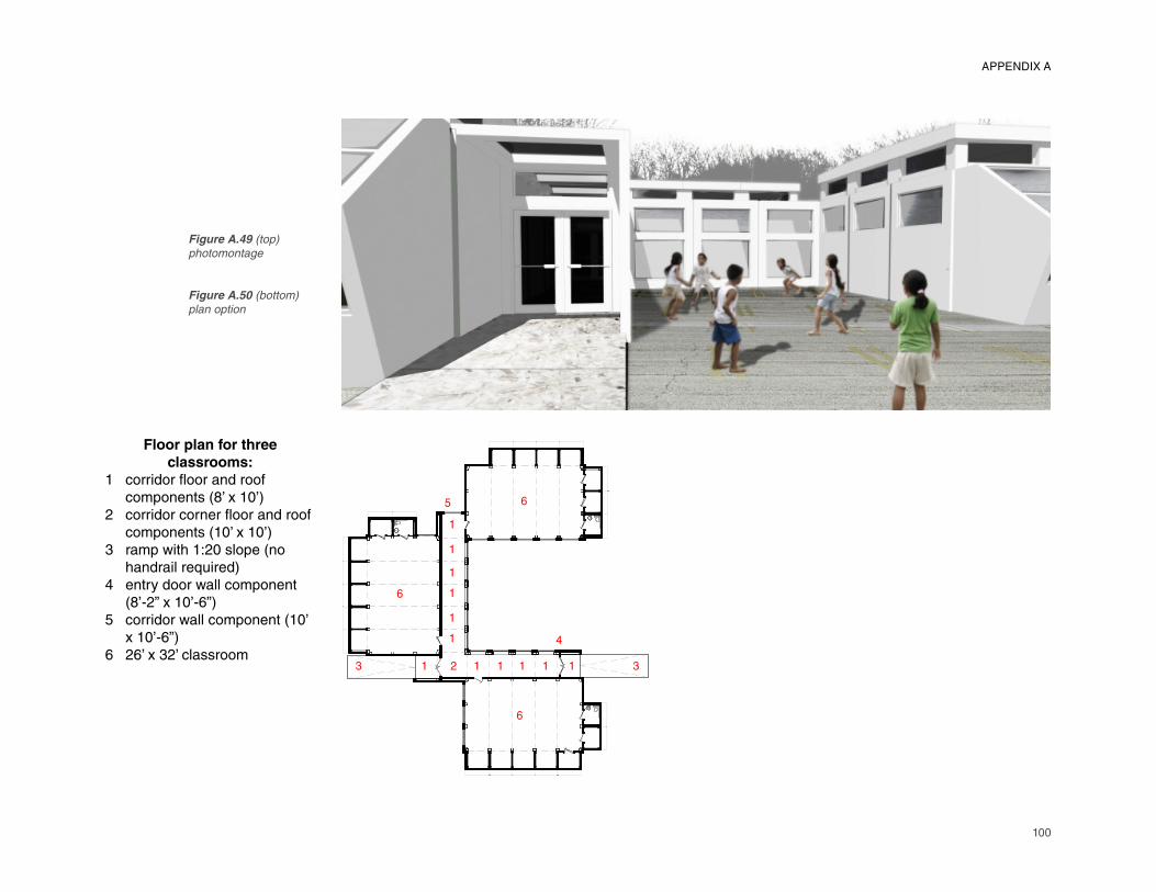
100
Floor plan for three
classrooms:
1 corridor fl oor and roof components (8’ x 10’)2 corridor corner fl oor and roof components (10’ x 10’)3 ramp with 1:20 slope (no handrail required)4 entry door wall component (8’-2” x 10’-6”)5 corridor wall component (10’ x 10’-6”)6 26’ x 32’ classroom
3 1 2 1 1 1 1 1
1
1
1
1
1
1
3
4
5
6
6
6
Figure A.49 (top)
photomontage
Figure A.50 (bottom)
plan option
APPENDIX A
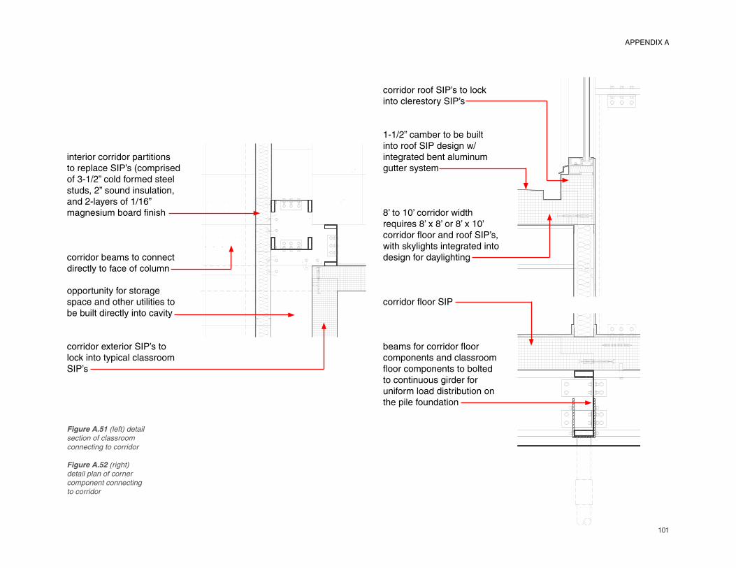
101
interior corridor partitions to replace SIP’s (comprised of 3-1/2” cold formed steel studs, 2” sound insulation, and 2-layers of 1/16” magnesium board fi nish
corridor beams to connect
directly to face of column
opportunity for storage
space and other utilities to
be built directly into cavity
corridor exterior SIP’s to
lock into typical classroom
SIP’s
corridor roof SIP’s to lock
into clerestory SIP’s
1-1/2” camber to be built
into roof SIP design w/ integrated bent aluminum
gutter system
8’ to 10’ corridor width
requires 8’ x 8’ or 8’ x 10’ corridor fl oor and roof SIP’s,
with skylights integrated into
design for daylighting
corridor fl oor SIP
beams for corridor fl oor
components and classroom
fl oor components to bolted
to continuous girder for
uniform load distribution on
the pile foundation
Figure A.51 (left) detail
section of classroom
connecting to corridor
Figure A.52 (right)
detail plan of corner
component connecting
to corridor
APPENDIX A
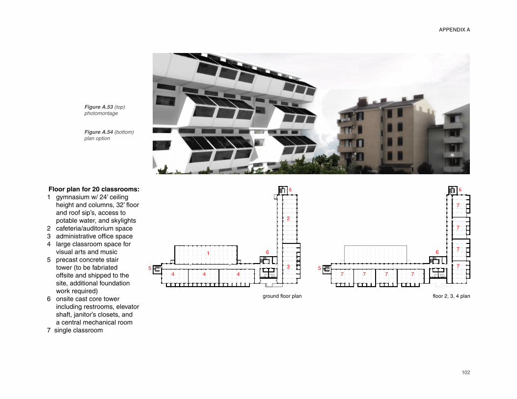
102
Floor plan for 20 classrooms:
1 gymnasium w/ 24’ ceiling height and columns, 32’ fl oor and roof sip’s, access to potable water, and skylights2 cafeteria/auditorium space3 administrative offi ce space
4 large classroom space for
visual arts and music
5 precast concrete stair
tower (to be fabriated
offsite and shipped to the
site, additional foundation
work required)6 onsite cast core tower
including restrooms, elevator
shaft, janitor’s closets, and
a central mechanical room
7 single classroom
ground floor plan floor 2, 3, 4 plan
4 4 4
1
3
2
6
6
57 7 7 7
7
7
6
6
5
7
7
Figure A.53 (top)
photomontage
Figure A.54 (bottom)
plan option
APPENDIX A
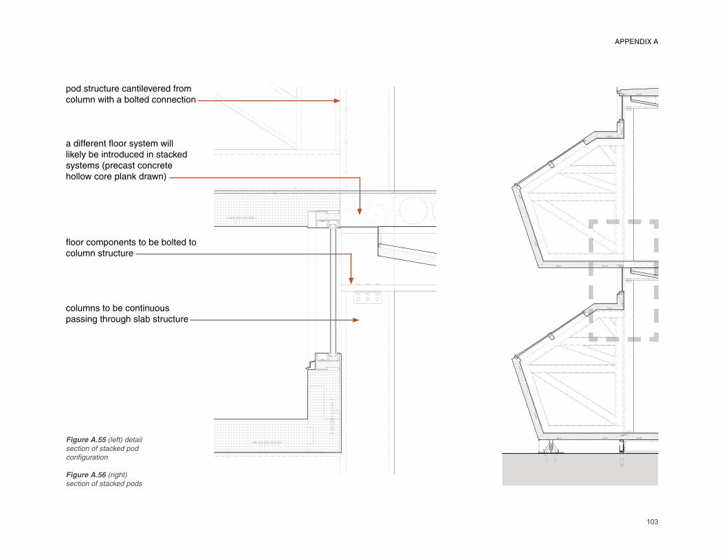
103
pod structure cantilevered from column with a bolted connection
a different fl oor system will likely be introduced in stacked systems (precast concrete hollow core plank drawn)
fl oor components to be bolted to column structure
columns to be continuous passing through slab structure
Figure A.55 (left) detail
section of stacked pod
confi guration
Figure A.56 (right)
section of stacked pods
APPENDIX A
104
Company A Meeting TranscriptNo. of Stakeholders: 3Type of Interview: Face-to-face
Q: While proposing an innovative design
solution for this building program, it may
be impossible to compete with the facilities
commonly used in terms of initial building costs,
yet are there other strategies and long term
cost savings that can be used to market the
proposal? For example, are users factoring in
life cycle value into their design to move ahead
with a more expensive facility?
A: [In terms of] initial building cost versus life cycle cost, like [what was] said when we were going through the production facility, when this industry started out it really was just [for building] fi eld offi ce trailers, and it was very time sensitive
and cost driven. In other words, the lowest
cost producer got the orders. There wasn’t a
lot of care or consideration. [At the start of the
industry there was very little involvement from
architects and engineers] until it really started
to evolve. So, it was just really just a bunch of
guys that had construction experience that saw
an opportunity. Instead of building these shacks
on construction sites, everyone saw need to be
able to produce a trailer that could be moved
from site to site with [some] consideration as
to how long it is going to last. When it started,
we didn’t even put trim around the windows.
We stained the 2x4’s a walnut stain, creating a
very rustic environment. Now, as the industry
has started to grow, we see more involvement
APPENDIX B.1: TRANSCRIPT A
[from architects], requiring us to hire some
professional engineers. Because now, all of a
sudden, we are designing buildings that need to
span 60’; and similarly the codes are evolving,
thus requiring us to meet certain roof loads,
wind loads, and seismic requirements. These
are requirements that everyone else that was
building onsite were already complying with.
So, through that evolution, we can build larger
buildings, and we are starting to be able to do
some things that you can do onsite. Schools
and education [facilities were] the biggest
natural evolution. But as the diffi culty of the
product has evolved, cost saving have become
less and less important (although it remains
very competitive, we lose custom projects,
for example we were $10,000 higher than the
competition on a recent project). Although
cost is still a big player, it is becoming more
and more important to the dealers or the
end users to evaluate the experience of the
manufacturer, the quality of the product, and
the service provided.
A: Also whether or not they can get it done in
the given time frame.
A: Yes, delivery times. And we are beginning
to see more and more involvement through
architects, which I think is great because it is
creating more opportunities for our industry.
We’re working with [an architect] on developing
a new concept for a classroom buildings. And
because of the life cycle value of the materials
that they are using, it is being designed up
front to last 25 years. This is in contrast to
the materials that we have historically used
(especially in the early days) where there was
no consideration as to how long it was going to
last. So the materials that are being specifi ed
by the architects are considering life cycle
cost up front versus costs down the road – eg: how long it is going to last, how am I going
to have to maintain it, green requirements,
recycled content of materials. With this idea
of mass customization, they are coming up
with a concept (similar to what you have here) [involving] a standard of modules and add-ons
[where] you can create a 10,000 square foot
school addition or a 1,000 square foot school
out of those [select] components. With the way
that the roof is designed, it won’t matter how
many you have side by side, end by end, and
so on. My opinion on market perception is that
although I think that the perception is better than
what it was 20 years ago, as well as knowledge
of the product, the end user still thinks that by
going modular it should cost less. This may
have been the case back in the days of building
mobile homes out of 2x2’s versus a home out
of 2x4’s onsite because it was a lower cost
alternative. But as the code requirements have
come on, as the abilities of the manufactures
has strengthened, and as [we] are getting to
the point that we are doing a lot of permanent
modular buildings where the only difference
between that building and that which would be
built onsite is that we build it in a factory and it is
shipped to the site (though some of the fi nishes
are done onsite). But now we are using the

105
same materials that the site contractor would use, therefore, our costs aren’t going to be any less than there’s necessarily because we have to compensate for freight costs (although we may have a gain on labor because we are not paying prevailing wages in the factory). We may [also] have some effi ciencies were we start
time wise. [The client can] see the savings on
the back-end from production effi ciency.
Q: So what is the driving force for interest in
modular construction? Are people interested
in going modular because of craftsmanship or
time savings primarily, or even sustainability
points?
A: My opinion is the time, how quickly they
get a completed building. It is also becoming
better known publically.
A: If you look at a construction schedule,
they have to do the site development, put
the foundation in, put the utilities in, and start
building a building on top. For us, as they are
doing the site foundation, we are building the
building at the same time. So the goal is that
when the foundation is traditionally ready to
start building the building on top of it, we have
buildings already built that are shipped and set
on that foundation. People will throw around
numbers of anywhere from a times savings of
30-50% depending on the project. If they can
get into a building and start turning dollars in
six months versus a year, that is huge for the
user.
Q: Design innovation in this particular project
is largely attributed to the ability for the building
to be customized based on a standard set of
parts. With smaller panelized components
shipped onsite, a greater amount of onsite
assembly is required as compared to using
larger complete modules. From an economic
feasibility and overall craftsmanship point of
view, is there a recognizable difference in the
advantages and disadvantages to component
sizes being designed for use?
A: I don’t know that there is an advantage of
one over the other; comparing whether more
can be done in the factory as site work is
taking place versus shipping pre-cut materials
to the site and having them assembled there.
In terms of time savings, the more you can do
to a point in the factory you can get more time
savings in the overall construction process.
Q: Is there a greater risk in the shipping of
larger components versus more compact
components?
A: With these panels, you could ship
components on a fl at back truck.
A: There are probably pros and cons both ways.
You’ll have more site labor with the building
being broken down like this, though you may
also have a little more control by shipping these
parts and putting them together onsite.
Q: Why would you have more control there?
A: You probably won’t have your [as much fi nish
work to do] where the units would go together.
On a single-wide, however, it wouldn’t matter.
A: As you’re putting it together it is being
fi nished (with the larger modules).
Q: These panels I expect would be fi nished
also before you ship them.
A: I guess my question was about this
construction taking place here, with the fl oor
and the walls and the roof, on whether or not
the plan was to do the fi nishing onsite or in the
factory? When I looked at it I assumed that
these pods would be completed in the factory
to be attached onsite to the SIP’s panel portion
of the building.
Q: I feel as if you have more control if you fi nish
all elements offsite and wrap and send them to
the site for assembly.
A: So you are really saying that the panels
would be produced in the factory so that you
have more control over the package of what is
going to the site. [Okay, that should work].
Q: Do you tend to run into problems with the
transportation of your modules?
A: Not very often.
A: We can have some issues where we have
tires blow out, or a driver hits a bridge or a
tree.
A: Yes, driver error. Or if you get into a very
rough construction zone for instance, and you
APPENDIX B.1
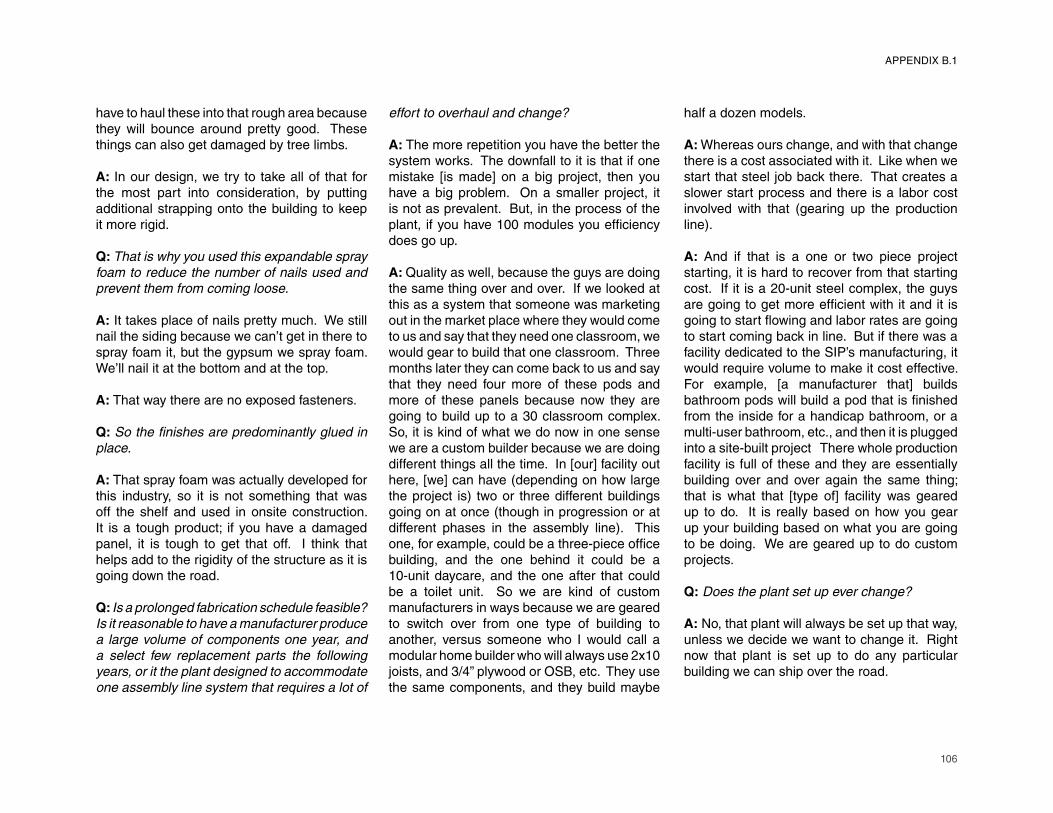
106
have to haul these into that rough area because they will bounce around pretty good. These things can also get damaged by tree limbs.
A: In our design, we try to take all of that for the most part into consideration, by putting additional strapping onto the building to keep it more rigid.
Q: That is why you used this expandable spray
foam to reduce the number of nails used and
prevent them from coming loose.
A: It takes place of nails pretty much. We still nail the siding because we can’t get in there to spray foam it, but the gypsum we spray foam. We’ll nail it at the bottom and at the top.
A: That way there are no exposed fasteners.
Q: So the fi nishes are predominantly glued in
place.
A: That spray foam was actually developed for this industry, so it is not something that was off the shelf and used in onsite construction. It is a tough product; if you have a damaged panel, it is tough to get that off. I think that helps add to the rigidity of the structure as it is going down the road.
Q: Is a prolonged fabrication schedule feasible?
Is it reasonable to have a manufacturer produce
a large volume of components one year, and
a select few replacement parts the following
years, or it the plant designed to accommodate
one assembly line system that requires a lot of
effort to overhaul and change?
A: The more repetition you have the better the system works. The downfall to it is that if one mistake [is made] on a big project, then you have a big problem. On a smaller project, it is not as prevalent. But, in the process of the plant, if you have 100 modules you effi ciency
does go up.
A: Quality as well, because the guys are doing
the same thing over and over. If we looked at
this as a system that someone was marketing
out in the market place where they would come
to us and say that they need one classroom, we
would gear to build that one classroom. Three
months later they can come back to us and say
that they need four more of these pods and
more of these panels because now they are
going to build up to a 30 classroom complex.
So, it is kind of what we do now in one sense
we are a custom builder because we are doing
different things all the time. In [our] facility out
here, [we] can have (depending on how large
the project is) two or three different buildings
going on at once (though in progression or at
different phases in the assembly line). This
one, for example, could be a three-piece offi ce
building, and the one behind it could be a
10-unit daycare, and the one after that could
be a toilet unit. So we are kind of custom
manufacturers in ways because we are geared
to switch over from one type of building to
another, versus someone who I would call a
modular home builder who will always use 2x10
joists, and 3/4” plywood or OSB, etc. They use
the same components, and they build maybe
half a dozen models.
A: Whereas ours change, and with that change
there is a cost associated with it. Like when we
start that steel job back there. That creates a
slower start process and there is a labor cost
involved with that (gearing up the production
line).
A: And if that is a one or two piece project
starting, it is hard to recover from that starting
cost. If it is a 20-unit steel complex, the guys
are going to get more effi cient with it and it is
going to start fl owing and labor rates are going
to start coming back in line. But if there was a
facility dedicated to the SIP’s manufacturing, it
would require volume to make it cost effective.
For example, [a manufacturer that] builds
bathroom pods will build a pod that is fi nished
from the inside for a handicap bathroom, or a
multi-user bathroom, etc., and then it is plugged
into a site-built project There whole production
facility is full of these and they are essentially
building over and over again the same thing; that is what that [type of] facility was geared
up to do. It is really based on how you gear
up your building based on what you are going
to be doing. We are geared up to do custom
projects.
Q: Does the plant set up ever change?
A: No, that plant will always be set up that way,
unless we decide we want to change it. Right
now that plant is set up to do any particular
building we can ship over the road.
APPENDIX B.1

107
A: And the plant will evolve over time as the market changes too. So, for example with foam seal, the process is a little bit different than when we used nails and screws. So we modify our system and our processes as the market demand changes. When people requested us to pour concrete fl oors in our factory, we tried it and it worked. Now that we can do it, we have to change our systems – we pour them outside. Our [newer plant] was built for today’s newer construction methods in mind. As the materials change (concrete fl oors, steel studs, the sidings, the roofi ngs), we’ve always
modifi ed our process while still trying to stay in
the seven stations that we’ve designed – walls,
roofs, electric, plumbing, etc.
Q: I didn’t see a concrete project out there,
how much does the process change?
A: The concrete truck comes in and pours the
fl oor and the walls, but the guys still have to put
that pan in; they still have to prepare the fl oor
for the pour. So if there are four guys back
there, we may only need two to do that, and
we’ll push them somewhere else in the plant. It
is more about juggling your people and putting
them where they’re best suited.
Q: Are workers specialized in a particular trade
(plumbing and electrical for example)?
A: Electric and plumbing are defi nitely
specialized. And people who have been
building walls are better than guys that are
cleaning windows. Over time they do become
specialized in the area that they work in. The
guy that builds roofs know exactly how to build
the roof, though someone can go back to
assist him. It is harder to get help with electric
because someone without electric knowledge
will not be helpful. Same with plumbing.
A: I think the more highly specialized the less
you can introduce people (plumbing, electoral,
heating, and air conditioning). But framing is
easier; a guy that can frame a wall knows how
to cut lumber and knows how to fasten it, can
help someone in fl oors.
A: It comes with cross training. That’s one of
the things that we do; we want a certain number
of individuals to work in multiple areas of the
plant. We purposely switch people around to
get them experience in various areas.
A: Which helps a start-up situation like steel
walls. If you throw a couple more guys back
there to get walls moving, or if you get behind in
one area and ahead in another area, the ability
to move labor around is really important.
Q: To what extent is BIM being used in your
process today?
A: [We] don’t use BIM at all. In our situation
with the projects that we do the design and
engineering on time is a factor, so familiarity
with the computer software used is necessary.
On a [recent] 26,000 square foot building for
example, we needed to be able to design and
engineer it within 2 or 3 weeks completely.
So, when I think about BIM and introducing
it into our engineering department, I believe
that the whole process would have to change
somewhere ahead of us. But the problem
with that is that at the stage they don’t know
our processes and how we do things and how
we design our frames, walls, roofs, standard
details, etc. I can defi nitely see the benefi ts,
[as our General Manager] has something going
down the line and he says, “I have a recess and
it’s going to be covered by chalkboard,” or “I’ve
got a window that is not going to fi t where you
have put it,” or “I’ve got ducts interfering with
lights.” However, how you introduce it into our
industry is going to be a challenge.
Q: Are you already considering when the
integration of BIM into your design process will
take place?
A: You have to see when something like that is
working its way into our industry. Some of the
government projects that we are doing require
this to be done. How we’ve gotten around
that, isn’t the way it was intended to be used,
is that is being done after we build. It’s only
being done because the government wants
that in their fi les just so that they know where
all the utilities are. So that is really the extent
to which we are using it – as an after the fact
application because of the time associated
with its integration. Engineering is a lot like a
production facility. They have an order come
in, they have to draw it, it goes out, they have
another order come in, etc. There is a process
that has to follow because they’ll send a set off to
the state of Ohio, get comments back, address
them, etc. There just isn’t a lot of extra time
to be working on altering the process because
APPENDIX B.1

108
each new project coming in is custom. An 8-unit wide can be drawn in a matter of hours now, and that is a 30,000 square foot project. If someone were designing a standardized product like this (the case study project), and everything was designed ahead of time coming into our process, and we were building to match the details and tolerances already set in front of us, I’d see it as an opportunity to introduce BIM into our fabrication process. So, in reality it depends on how big the project ultimately is for us to consider altering our process because again there is a high start-up cost associated with changes.
Q: How much of your work is designed by
outside architects as compared to buildings
designed and engineered in-house?
A: Schools tend to go to an architect for help.
A: A lot of the work that we do are designs for site building that we turn into a modular concept ourselves. This happens a lot. [We aren’t] getting upfront designs from architects [often], outside of the schools, it seems like it is happening more and more, though, as the LEED certifi cation system is developing
interest. I think architects are beginning to see
modular as an already inherently a greener
building process because it can be relocated,
and there is assumed to be less waste because
we are buying a lot of our materials sized for
the project. [One architect], for example, sees
a need for a modular component process for a
school system, and they’ve gone out and found
one of our dealers that is promoting that type of
project. They look at who they want to put on
the team to develop this whole concept, market
it, and build it. So we have [the architect], one
of our dealers, and us that we’re hoping to kick
this project off pretty quickly. In that process,
the architect already understands modular,
he’s been doing all of the drawings with that
modular concept in mind, so when we actually
sit down to start to engineer it, a lot of those
things should already be worked out, making
it a smoother process. But as far as the
percentage of architects that design modular, I
doubt it is even 5 percent.
A: A lot of times we are taking an architect’s
drawings and trying to right off the bat make
it more modular friendly with the fl oor plan in
order to send that out with our bid.
A: [Our] guys will do a fl oor plan with more
custom type projects that they’ve had to take in
and make it more modular just so a customer
sees what they are getting by going modular
versus a site built project.
A: And even some times when the architect is
thinking modular, the sizes maybe aren’t quite
right, so we’ll just take that concept and do a
new drawing with our size of modules ultimately
coming through with the same thing, but more
friendly to our process.
A: And the limitations as far as widths and
lengths and heights. We get a lot of requests
for 9’ and 10’ ceiling heights, but that is tough to
achieve when we have to get it on the shipping
height of 13’-6”.
A: We can ship 14’ in Pennsylvania. In North
Carolina I’m not sure if there is any height
requirement. But in Pennsylvania for example
you have to stick within the regulations of 14’-2” that the state highway system requires.
A: So that is a challenge too, understanding
where the module is going to be built and what
states it is going to have to pass through to get
to the site. For example, if [we] could get out of
the state of Pennsylvania and get into Maryland,
[we] can maybe ship 14’6” through Maryland,
but we can’t even get out of Pennsylvania, so
we have to build it in North Carolina so that we
can get it to Maryland with a taller building.
A: Connecticut again, for example, only allows
13’6”. And in Massachusetts, though there is
an exception for schools, the maximum height
is also low. You can get exceptions through the
people who issue the permits – the Department
of Transportation. They’ll issue a permit for the
school. But it will have to take a different route
to accommodate low bridge clearances.
Q: There are four basic component types, a rigid
skeleton that is constant including the columns,
fl oor and roof components, and the fl exible wall
and 3-dimensional pod components which are
interchangeable.
A: [For] the SIP’s panels themselves, [we] would
go out and fi nd someone that manufactures
those for us. For the different components,
we would outsource that work and have it
delivered to us ready for assembly. Likewise,
we may buy the SIP’s walls, fl oors, and roofs
APPENDIX B.1
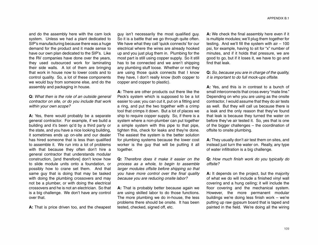
109
and do the assembly here with the cam lock system. Unless we had a plant dedicated to SIP’s manufacturing because there was a huge demand for the product and it made sense to have our own plan dedicated to the SIP’s. Like the RV companies have done over the years, they used outsourced work for laminating their side walls. A lot of them are bringing that work in house now to lower costs and to control quality. So, a lot of these components we would buy from someone else, and do the assembly and packaging in house.
Q: What then is the role of an outside general
contractor on site, or do you include that work
within your own scope?
A: Yes, there would probably be a separate general contractor. For example, if we build a building and it’s been qc’d by a third party or the state, and you have a nice looking building, it sometimes ends up on-site and our dealer has hired someone that is less than qualifi ed
to assemble it. We run into a lot of problems
with that because they often don’t hire a
general contractor that understands modular
construction, [and therefore] don’t know how
to slide module units onto a foundation, or
possibly how to crane set them. And that
same guy that is doing that may be tasked
with doing the plumbing crossovers and may
not be a plumber, or with doing the electrical
crossovers and he is not an electrician. So that
is a big challenge. We don’t have any control
over that.
A: That is price driven too, and the cheapest
guy isn’t necessarily the most qualifi ed guy.
So it is a battle that we go through quite often.
We have what they call ‘quick connects’ for our
electrical where the wires are already hooked
up and you just plug them in. Plumbing for the
most part is still using copper supply. So it still
has to be connected and we aren’t shipping
any plumbing stuff loose. Whether or not they
are using those quick connects that I know
they have, I don’t really know (both copper to
copper and copper to plastic).
A: There are other products out there like the
Peck’s system which is supposed to be a lot
easier to use; you can cut it, put on a fi tting and
a ring, and put the two together with a crimp
tool that crimps it down. But a lot of places we
ship to require copper supply. So, if there is a
system where a non-plumber can put together
a simple system with this pipe to that pipe,
tighten this, check for leaks and they’re done.
The easiest the system is the better solution
for plumbing systems because the lower cost
worker is the guy that will be putting it all
together.
Q: Therefore does it make it easier on the
process as a whole, to begin to assemble
larger modules offsite before shipping so that
you have more control over the fi nal quality
because you are reducing onsite labor?
A: That is probably better because again we
are using skilled labor to do those functions.
The more plumbing we do in-house, the less
problems there should be onsite. It has been
tested, checked, signed off, etc.
A: We check the fi nal assembly here even if it
is multiple modules; we’ll plug them together for
testing. And we’ll fi ll the system with air – 100
psi, for example, having to sit for “x” number of
minutes, and if it holds that pressure, we are
good to go, but if it loses it, we have to go and
fi nd that leak.
Q: So, because you are in charge of the quality,
it is important to do full mock-ups offsite.
A: Yes, and this is in contrast to a bunch of
small interconnects that cross every “mate line.” Depending on who you are using as the onsite
contractor, I would assume that they do air tests
as well. But they will call us because there is
a leak and the only reason that they’ve found
that leak is because they turned the water on
before they’ve air tested it. So, yes that is one
of the bigger challenges – the coordination of
offsite to onsite plumbing.
A: They usually don’t air test them on sites, and
instead just turn the water on. Really, any type
of water infi ltration is a big challenge.
Q: How much fi nish work do you typically do
offsite?
A: It depends on the project, but the majority
of what we do will include a fi nished vinyl wall
covering and a hung ceiling; it will include the
fl oor covering and the mechanical system.
However, the more permanent modular
buildings we’re doing less fi nish work – we’re
putting up raw gypsum board that is taped and
painted in the fi eld. We’re doing all the wiring
APPENDIX B.1

110
above the suspended ceiling and then attaching the lights to the sub-ceiling, so they will place the lights and the diffusers in the fi eld as well
as infi ll the ceiling panels. We probably do the
same amount of electrical and plumbing on
these big jobs depending on the requirements
of the heating and air conditioning system (how
complicated it is). Though, we may run all of
the duct work, but not install the HVAC system
especially if it is a roof-mounted type unit. It
really is what happens at each module line that
is unfi nished and what the detail is to fi nish that
in the fi eld (what you bring across that “mate
line” and how you trim it out, etc.). In the ceiling
grid, we may install the two longitudinal t-bars
and in the fi eld they’ll put the cross bars in and
drop the tiles in.
Q: What are the challenges at the interface
between offsite and onsite construction? Or
at the interface between architect and the
manufacturer?
A: It is important for the architect to realize
what they are getting in the factory. A lot of
times they don’t even have our prints at the
construction site. We furnish our prints, they
don’t have them onsite and they’ll just be doing
what they think is right.
A: [For example, one project we had] was a very
nice building [with] the exterior siding already
paneled with all different colored panels, and
whoever they hired to fi nish across “mate lines” (we held panels back at different distances at
these seams) were trying to do that without a
set of plans.
A: They had the architect’s original set, but
they didn’t have our set which shows what we
are doing in the factory and what they have to
do onsite. They didn’t have that.
Q: Is there always going to be that supplemental
set of drawings that you are producing for each
project?
A: Yes, shop drawings. This is a case where
the dealer has to get the drawings to the
guy who is setting the building up at its fi nal
construction site.
A: Using an example, [the architect] did design
[this one] building to be modular, but because
of our little differences in our manufacturing
processes and what we can and can’t do in the
factory, we have to take their set of drawings
and come up with our shop drawings. The
architect’s drawings were close, but we had to
alter them – he specifi es 11’-10” modules, but
when we look at it, we need to make it 11’-9”. Or maybe he specifi ed certain things to be
installed in the factory, and it really needed to
be installed on the site. So we’re taking that
and we need to turn it into shop drawings for a
customer approval package that does go back
to the architect and the owner [for] a review.
They’ll look at the drawings and determine if
these drawings follow the design intent. I don’t know that the architect will be able to take it to
a show drawings level package because our
engineering group has to show their drawings
just a little bit differently at each plant based
on how they build and the drawings that the
workers are used to handling.
A: We have an approved system package
that we have to adhere to because it is being
checked by a third party. That is not always
taken into account in the stuff that we get from
the architect.
A: In our opinion, we don’t feel that they do any
of the pre-planning that they need to do before
the modules arrive. And, on larger and more
complicated projects that we know it is going
to be very important to have communication,
we have invited the contractor to come to
our facility. We’ve [even] offered to meet with
them offsite somewhere in the middle just to
go through what we are going to be doing in
the factory and what they’ll be expected to do
in the fi eld. But it doesn’t happen very often.
We do that internally, where we’ll have our own
internal pre-production meetings, but getting
the two together doesn’t happen very often.
And it should happen on any project that is
custom in nature. [But] it is time consuming.
We are offsite, and if that contractor traveled
to our facility, then he is not onsite working on
projects. And likewise if we are traveling to
meet with them, we are not doing our work in
house pre-planning. So it can be a challenge.
Q: What are the typical problems with the
designs sent to you by architects?
A: Height limitations a lot of the time; also
the type of roof system that they want. If I
remember correctly, on [one particular school], each classroom was two modules, and they
wanted the roof sloped. Well, they wanted a
certain ceiling height and a certain slope to the
APPENDIX B.1

111
roof, making the building about 16’ tall. We couldn’t ship a building 16’ tall into the state of Massachusetts. If that was built on site, then obviously that is not a problem. So it is mainly heights; the ceiling height that they want versus the type of roof system that they want. And a lot of times now we have gone to roofs being put on the buildings afterwards onsite because they want it taller (eg: wanting a 4-12 roof slope).
A: The module widths that we can do include anything up to 16’. However, it might be more economical to divide up the modules differently than how they’ve laid it out.
A: Architects coming into the industry will need to educate themselves on shipping limitations, what makes sense to do in the factory, what doesn’t make sense to do in the factory, etc. And it seems like the more and more architects that I talk to, they are now getting that type of education in school, probably due to a peak in interest in the industry.
Q: Can you list examples?
A: We don’t do brick because it adds too much weight. Weight of materials is a problem in terms of shipping constraints.
A: Though with concrete, we’ll pour a 3 or 4” slab, but the limitations then are that the modules are smaller (up to a 12’ wide 56’ dimension instead of a 16’ wide by 70’ or 80’ dimension for a wood fl oor construction). So there are shipping limitations based on the
weight of the materials you are using. And what will hold up during shipment and what will not.
A: Now, if you are doing a big building made of many parts that requires a larger amount of onsite labor, do you want the building to be shipped with carpet on the fl oor where your subcontractors will tear up and muck up.
A: And we recommend doing a suspended ceiling in a room like this that doesn’t cross any module lines. But if you are going to put a suspended ceiling down an 8’ corridor that is 100’ long, for example, it is harder to expect that line up after fi nal construction.
A: Or if you are expecting a lot of work in that
ceiling to be done onsite, and you fi nish the
ceiling offsite, your subcontractor may need to
tear it apart to get access. We fi nd that all the
time.
A: A lot of times we’ll put the suspended ceiling
in with the assumption that we’re going to be
doing the sprinkler system in the factory; but if
they want the sprinkler system installed onsite,
it therefore doesn’t make any sense for us to
install the ceiling offsite. So we’ll tell them that
they’ll need to include the ceiling also in their
scope of work. It’s not tough stuff, but thinking
about the work you are going to be doing [is
important].
A: And I would think that the way you divide up
systems and fi nishes would change depending
on whether it is a temporary building or a
permanent building.
A: Our standard set of details take that into
consideration. With a temporary building, for
example, that we know will be put together and
taken apart, we will hold the drywall back (the
vinyl gyp with a rolled edge), and in the fi eld
they will install a 12” piece over the module
line, and they’ll put two batten’s over that seam.
Because that is a temporary situation. When
they pull it apart, they’ll pull the trim off, pull
the vinyl gyp out, and the insulation out, take
it to the site, and put it all back together. This
is in contrast to a permanent modular building
where we may have raw gyp in two full sheets
run all the way to the “mate line.” And so they
can run the gypsum all the way to the corner
seamlessly, and we’ll provide the materials
loose in the modules for them to use and cover
up the “mate lines” because they won’t be
needed for deconstruction.
A: Depending on what makes the fi nal product
look better, you’ll hold off on the fi nishes offsite
so that you can place a full piece in when
the fi nal assembly is put together making the
module lines less recognizable. We’ll design
the sizes of the set-backs based on what the
pattern of the material sizes we are using.
A: The purpose of the design of a permanent
modular building is to come up with a building
that you wouldn’t know is built offsite or onsite.
We’re doing some youth activity centers right
now with a full gymnasium, 18’ ceilings in the
commons area, 12’ ceilings in the entry area.
I walked into the building last month, and you
APPENDIX B.1
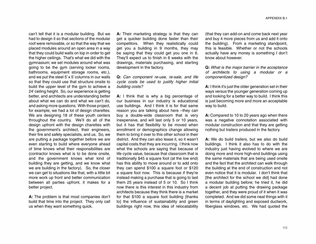
112
can’t tell that it is a modular building. But we had to design it so that sections of the modular roof were removable, or so that the way that we placed modules around an open area in a way that they could build walls on top in order to get the higher ceilings. That’s what we did with the gymnasium; we set modules around what was going to be the gym (serving locker rooms, bathrooms, equipment storage rooms, etc.), and we put the steel 5’ x 5’ columns in our walls so that they could use that structure onsite to build the upper level of the gym to achieve a 24’ ceiling height. So, our experience is getting better, and architects are understanding better about what we can do and what we can’t do, and asking more questions. With those project, for example, we had a lot of design charettes. We are designing 18 of these youth centers throughout the country. We’ll do all of the design upfront with the design charettes with the government’s architect, their engineers, their fi re and safety specialists, and us. So, we
are putting a package together before we are
even starting to build where everyone ahead
of time knows what their responsibilities are
(contractor knows what is to be done onsite,
and the government knows what kind of
building they are getting, and we know what
we are building in the factory). So, the closer
we can get to situations like that, with a little bit
more work up front and better communication
between all parties upfront, it makes for a
better project.
A: The problem is that most companies don’t build that time into the project. They only call
us when they want something quick.
A: Their marketing strategy is that they can
get a quicker building done faster than their
competitors. When they realistically could
get you a building in 9 months, they may
be saying that they could get you one in 6.
They’ll expect us to fi nish in 6 weeks with the
drawings, materials purchasing, and starting
development in the factory.
Q: Can component re-use, re-sale, and life
cycle costs be used to justify higher initial
building costs?
A: I think that is why a big percentage of
our business in our industry is educational
use buildings. And I think it is for that same
reason you are talking about here –they can
buy a double-wide classroom that is very
inexpensive, and will last only 5 or 10 years,
but it has that fl exibility to be moved when
enrollment or demographics change allowing
them to bring it over to this other school in their
district. And they can also lease it, so it wasn’t capital costs that they are incurring. I think now
what the schools are saying that because of
life cycle value, because that classroom that is
traditionally $45 a square foot (at the low end) has this ability to move around or to add onto
they can spend $100 a square foot or $120
a square foot now. This is because if they’re
instead making a purchase that is going to last
them 25 years instead of 5 or 10. So I think
now there is this interest in this industry from
architects because they think there is a market
for that $100 a square foot building [thanks
to] the infl uence of sustainability and green
buildings right now, this idea of relocatability
(that they can add-on and come back next year
and buy 4 more pieces from us and add it onto
the building). From a marketing standpoint,
this is feasible. Whether or not the schools
actually have any money is something I don’t know about however.
Q: What is the major barrier in the acceptance
of architects to using a modular or a
componentized design?
A: I think it’s just the older generation set in their
ways versus the younger generation coming up
and looking for a better way to build. I think this
is just becoming more and more an acceptable
way to build.
A: Compared to 10 to 20 years ago when there
was a negative connotation associated with
modular construction and that they are getting
nothing but trailers produced in the factory.
A: We do build trailers, but we also do build
buildings. I think it also has to do with the
industry just having evolved to where we are
doing more and more high-end buildings using
the same materials that are being used onsite
and the fact that the architect can walk through
the building at the end of construction and not
even notice that it is modular. I don’t think that
[the architect for the school we did] had done
a modular building before; he tried it, he did
a decent job at putting the drawing package
together, and they were proud of it when it was
completed. And we did some neat things with it
in terms of daylighting and exposed ductwork,
fi berglass windows, etc. We had quoted the
APPENDIX B.1

113
project as he had specifi ed it the fi rst time,
and he was shocked at how expensive it was.
Then we met together and brainstormed ways
to reduce the cost – removing the fi berglass
windows because they are twice the cost of
nice energy effi cient windows, eliminating
the lightshelves, etc. The school district was
[ultimately so] excited about the end product,
that they put another bid out for four more
classrooms. Again they didn’t have enough
money, so they resorted to the $45 per square
foot units instead.
A: For that project, the time frame was too
tight. They wanted the building by November,
and they put the bid out in July.
A: It is tough in the education market, because
they don’t always know what their enrollment
and needs are by location until school is out.
And when they start their planning for next
year, that doesn’t give us enough time to plan; they’ll determine they need them in July, but
want them before school starts in September.
A: And you have a restriction as to our
availability as well. If we’re backlogged in June,
the schools are out of luck in that upcoming
year.
A: If they don’t have orders in, and if the
buildings aren’t coming off by the fi rst of July,
then they will not make a September deadline.
Q: Next, if you had an opportunity to review the
drawing package that I sent to you last week,
can you please comment on any situations in
the design that you think will be challenging
from a production standpoint?
A: In the project we are working with [one
architect], we did talk about the cork fl oating
fl oor system. We did go away from it because
of the cost, but also the question of how we
would treat that across “mate lines.” We did
not want it to look like the typical double-wide
classroom building. Also, we just wanted to
do as much in the factory as possible. For
example, we may have bamboo fl ooring on
the perimeter and carpet tile in the middle just
because carpet tiles can be pulled up along
the “mate line” and be replaced. I haven’t worked with fl oating fl oors before, but when I
see $5 per square foot or per tile, those are
high numbers in our industry. However, we
are starting to see some of these products
today. For example, someone is specifying
marmolium for a project we’re working on
right now which is $3 a square foot or $4 a
square foot. They just aren’t numbers we are
traditionally used to seeing.
A: I really like the SIP’s panel idea you have
quoted. I like the idea where the exterior and
the interior are part of the SIP’s. The price of
SIP’s that we’ve looked into ended up being
about 28% more in terms of construction costs
than our standard building details. However,
if you can incorporate the exterior and interior
fi nishes with the SIP’s, I think it makes it more
competitive in its pricing because I’m not
adding fi nish work labor and materials into its
bid.
A: With SIP’s for me however, my major
concern is where you run utilities? How do you
get electrical and plumbing into the walls?
A: They have chases built into the panels where
you would run wiring, and we would send them
prints and when they manufacture them, the
window openings, door openings, and chases
would be in the panels when they send them
to us.
A: [We] worked for a company that built
equipment and communications enclosures that
utilized a cam lock system like those used for
refrigerators. What they would do is they would
preassemble them in the factory and made sure
that everything fi t, but then they dismantled it,
shipped it on pallets and reassembled it onsite.
Although they didn’t do a lot of work like that, it
worked well. In one building in Boston, the did
an enclosure where the panels were sent to the
roof through the elevator. They completed it in
about 72 hours.
A: We have a building in the works that will
be shipped on a fl atbed instead of a chassis
similar to what you are specifying here. It will
not have the axles on it.
A: They have what they call a double drop deck
for the trucks now that can get you a higher
ceiling height if it can sit on a bed instead of its
own chassis. But then you are limited to length,
even though you end up getting additional
height.
A: Generally with something like that your
APPENDIX B.1

114
modules can be 40’ or 50’ maximum.
A: I’m familiar with the helical foundation system, but is this adjustable pedestal foundation a product that is available? Is this a steel platform system that the SIP’s rest on?
Q: Yes.
A: I thought this was kind of neat with the electrical conduits, the ducts, and the sprinkler pipes are positioned at the seam instead of trying to hide everything. Again, if there was a way to fi gure out how to do more work in the
factory, regardless if it is 8’ x 24’ sections, and
coming up with some method of transporting
would be a time saver. Though I don’t know
how long it would take them to assemble fl at
packs onsite. I think that ultimately we would
be able to hold tolerances better in the factory
than they would be able to onsite.
APPENDIX B.1
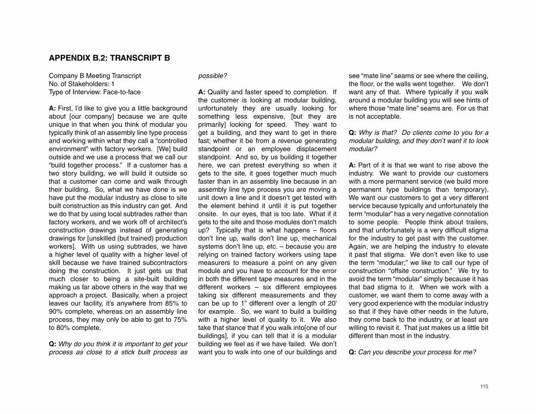
115
Company B Meeting TranscriptNo. of Stakeholders: 1Type of Interview: Face-to-face
A: First, I’d like to give you a little background about [our company] because we are quite unique in that when you think of modular you typically think of an assembly line type process and working within what they call a “controlled environment” with factory workers. [We] build outside and we use a process that we call our “build together process.” If a customer has a two story building, we will build it outside so that a customer can come and walk through their building. So, what we have done is we have put the modular industry as close to site built construction as this industry can get. And we do that by using local subtrades rather than factory workers, and we work off of architect’s construction drawings instead of generating drawings for [unskilled (but trained) production workers]. With us using subtrades, we have a higher level of quality with a higher level of skill because we have trained subcontractors doing the construction. It just gets us that much closer to being a site-built building making us far above others in the way that we approach a project. Basically, when a project leaves our facility, it’s anywhere from 85% to 90% complete, whereas on an assembly line process, they may only be able to get to 75% to 80% complete.
Q: Why do you think it is important to get your
process as close to a stick built process as
APPENDIX B.2: TRANSCRIPT B
possible?
A: Quality and faster speed to completion. If the customer is looking at modular building, unfortunately they are usually looking for something less expensive, [but they are primarily] looking for speed. They want to get a building, and they want to get in there fast; whether it be from a revenue generating standpoint or an employee displacement standpoint. And so, by us building it together here, we can pretest everything so when it gets to the site, it goes together much much faster than in an assembly line because in an assembly line type process you are moving a unit down a line and it doesn’t get tested with the element behind it until it is put together onsite. In our eyes, that is too late. What if it gets to the site and those modules don’t match up? Typically that is what happens – fl oors don’t line up, walls don’t line up, mechanical systems don’t line up, etc. – because you are relying on trained factory workers using tape measurers to measure a point on any given module and you have to account for the error in both the different tape measures and in the different workers – six different employees taking six different measurements and they can be up to 1” different over a length of 20’ for example. So, we want to build a building with a higher level of quality to it. We also take that stance that if you walk into[one of our buildings], if you can tell that it is a modular building we feel as if we have failed. We don’t want you to walk into one of our buildings and
see “mate line” seams or see where the ceiling, the fl oor, or the walls went together. We don’t want any of that. Where typically if you walk around a modular building you will see hints of where those “mate line” seams are. For us that is not acceptable.
Q: Why is that? Do clients come to you for a
modular building, and they don’t want it to look
modular?
A: Part of it is that we want to rise above the industry. We want to provide our customers with a more permanent service (we build more permanent type buildings than temporary). We want our customers to get a very different service because typically and unfortunately the term “modular” has a very negative connotation to some people. People think about trailers, and that unfortunately is a very diffi cult stigma
for the industry to get past with the customer.
Again, we are helping the industry to elevate
it past that stigma. We don’t even like to use
the term “modular;” we like to call our type of
construction “offsite construction.” We try to
avoid the term “modular” simply because it has
that bad stigma to it. When we work with a
customer, we want them to come away with a
very good experience with the modular industry
so that if they have other needs in the future,
they come back to the industry, or at least are
willing to revisit it. That just makes us a little bit
different than most in the industry.
Q: Can you describe your process for me?
116
A: We start with building a steel structure (what we call a steel cube) in the plant: including a steel chasis, decking, temporary steel columns, and a roof structure. Then we transport it outside across the street and set it on a temporary foundation getting everything blocked, leveled, and tied together. And then, when the steel structure is completely erected and set in place, we then come back and pour the concrete fl oor as a monolithic slab. Now that that structure is outside, the mechanical systems can be installed, the steel studding can start, etc. Basically, from that point onward we build just like site built construction, where we have subtrades coming into the building site to build the building. In one case for example, this was a two story structure going to Massachusetts in which we had to match the existing building at three different elevations for fl oor access or access into the new structure. That is why you see here spacer beams that are bringing the level up to the current level of the existing building’s fl oor elevation onsite (interstitial space). Following the standard construction methods and techniques that they would use in a site built construction process, we build the outside fi rst with interior mechanicals
being installed at the same time because there
is nothing that will hurt them weather-wise.
Then as we process through, you can see how
the “mate lines” handle an electrical junction
line with an electrical whip; the ducts are
similarly held back for a piece to be installed
at the “mate line” onsite. Then we try to get
the insulation in, the sheathing board on, and
the outside completely weathered in before we
start in earnest on the interior construction.
The reason in this project, for example, that
they went modular was because of the site was
complicated, and at the site they couldn’t get
materials and workers in because it was boxed
in. [It’s a] three story mechanical structure, a 6
story hospital, a 4 story psychiatric ward, and
a two story connector link between the two
facilities creating a courtyard as the only access
in which we could lift and drop the modules in
order to get them in and slip underneath of
the hospital because its third fl oor jutted out
18 inches. This was a very diffi cult site and
that was the reason they went modular for the
project. It was a very industrial looking building
simply because it was inside of a courtyard,
and with it being at Cambridge, MA, they put
these decorative panels with ivy planted at its
base for future growth. This was built with a
total of 14 modules – 7 on the fi rst fl oor, and 7
on the second fl oor – and on the interior as you
look down the corridor which passes through
all 7 modules, you cannot tell where the “mate
lines” are located. So, we are one of the
extremes, and there are a lot of factories that
build in a similar process and more at a middle
ground between an assembly line process and
our own built together process.
Q: From the perspective of the fabrication
process, while breaking a design up into a larger
quantity of smaller components will provide a
greater degree of fl exibility in the application of
a system of interchangeable parts, does this
pose problems for the manufacturers because
of the precision required for the increased
number of joints or of the coordination at the
point of assembly onsite.
A: When people are looking to this industry,
it is all about speed to completion, so the
less work you have to do onsite the better off
you are in meeting deadlines set. The green
features prominent in this process include less
site disruption, less security required onsite for
protection from material theft and hazardous
materials laying around (you don’t have a
fenced in area because you bring the modules
in, and you get it fi nished shortly thereafter so
the construction equipment is gone very soon), better safety at the jobsite, and presumably
less material waste and a better chance at
recycling materials. In your process you want
to address those attribute associated with the
modular industry. So by increasing the amount
of onsite construction, you take away some of
the opportunities for us to take advantage of
those benefi ts.
Q: In your process are you eliminating the need
for the added step of creating a set of shop
drawings?
A: What I’m saying is that in our process, the
architect is the one that takes the drawings to a
level of detail where we can build straight from
them. All that I am going to do is supplement
the architect’s drawings with my structural
steel cube drawings since I am building and
designing the structural element of the building; so I will have to give that to the architect.
Other than that, he maintains ownership of his
drawings and he maintains ownership of his
commission. That is one challenge that we
face when working with architects. When you
talk to architects about modular construction,
APPENDIX B.2
117
they feel that they lose some of their ability to earn a living. For an assembly line type of construction, for example, he doesn’t have to do a lot of drawings, and that is what he is mainly getting paid for. With our type of construction, we’re telling them to do the full set of drawings and go through your process with the customer, and we’ll build from your drawings. So he maintains his viability and his contribution to the process. So again, there are these extremes that exist in this industry from assembly line type of production to our type of production. Though on our type of construction, we do have architects that from time to time say they will put together the basic type of design but they want us to take the drawings into a construction detail level. That is really dependent on what the architect and his fi rm wants to contribute to the project in the
end. Though that does typically depend on
how important the project is to them.
Q: When we talk about the market’s perception
towards modular construction, are you primarily
using different terminology to disassociate
yourselves with lower quality buildings that are
historically seen in the industry?
A: You just have to be careful with the term
“modular.” Because there is a preconceived
notion of what modular is for some individuals.
It is diffi cult for the customer to get past that
sometimes. We’ve walked into school boards
looking for alternative methods to get a school
built, and once we had an architect present a
project to the schools where he did everything
he could to avoid the term “modular.” And he
succeeded without bringing the term up once,
until a member of the school board labeled it
a modular building to which he had no choice
but to agree with, and ultimately that killed
the project (although it was a very viable
alternative to their needs). Once everyone
on the board had this preconceived notion
that they were going to get trailers, the project
got shot down. That is where you have to be
cautious, and in part is why some of us in this
industry are trying to get away from that word
– we use “offsite construction” or some other
terminology instead. So in a presentation, it is
important that the end customer understands
what it is you are trying to offer to them. So it
is tough to get past that marketing point. For
your project, I’m looking at the word “pods,” which may have a different connotation in the
eyes of the end client as opposed to the word
“modular.” It may have a different meaning to
some people as well; for me a “pod” is more
of a packaged unit and the word “modular” doesn’t come to mind right away. You just have
to fi nd the right words. And there are not a
set of standard terms required or consistently
used throughout the industry, so you do have
to be creative in how you sell the project as an
alternative building process.
Q: Among the perceived barriers and constraints
to design innovation in modular construction,
transportation limitations rank among the
highest challenge for architects as well as the
infl exibility of the construction process and the
amount of pre-planning required. Would you
agree with these fi ndings?
A: Transportation limitations is more critical for
those that work with an assembly line process
because we’re transporting our modules on a
low-back tractor trailer whereas an assembly
line typically has an integral hitch and axels.
When it has a hitches and axels like that it is
in essence a vehicle and falls under the motor
vehicle laws. So they are a lot more restricted
than me because I sit on a fl at-bed tractor trailer
and therefore I’m considered “freight.” So, if
I get higher, or wider, or longer, I can simply
pay more money and have it transported as a
“super load.” In contrast, if they get higher, or
wider, or longer, they can’t ship their modules
(though they can get up to some pretty large
sizes before that will happen). So they are a
lot more restricted in their means and methods
of transportation than I am. With your design,
you would pretty much fall under this type of
scenario of being “freight,” so you are not going
to have the type of restrictions that will have with
a “mobile modular unit.” So you wouldn’t face
the same type of restrictions as an assembly
line type process. So that is a good attribute.
Q: The program of the building for this case
study is a relocatable educational facility, and
one of the reasons this program was selected
was because of the tight time frame typically
required for the competition of a unit.
A: I sat on a local school board building and
property committee where I live, and with the
schools’ planning process their scheduling don’t really occur until May or June. So they do not
know what their projected student population
is going to be until late in the year, while still
APPENDIX B.2
118
needing facilities in September. That is where the portable classrooms have played an important part in helping the schools adjust to the student population at the various schools. So it is a planning problem on the schools’ side, though that is why the modular industry comes in as a viable solution for that problem. As we talked about earlier, both site restrictions and time limitations are largely where we get the majority of our workload. When you get into an urban area like Baltimore, Richmond, or Alexandria, for example, streets are tight and congested and onsite construction in those areas is extremely diffi cult because you don’t have what is called the “lay-down area” where
a general contractor can come in and place
materials. He doesn’t have room for the workers
to show up onsite and park their vehicles, etc.
There are a lot of problems associated with
urban type areas that onsite construction has
diffi culty overcoming in their building process,
and we’d like to think that modular construction
becomes the best solution for those type of
areas.
Q: Whereby breaking this design into a larger
number of parts, the number of joints is
increased, and therefore the precision required
for fi tting and assembly is expected to be very
high in the end product coming from the factory.
Is this idea of a prolonged fabrication process
feasible from an economic and fabrication
standpoint where a considerably smaller
volume of components would be produced in
later years after a high volume of parts have
already been fabricated in the early life of a
project?
A: We have a sustainable classroom on our
property; our other offi ces have school districts
that will order 700 portable classrooms at a
time in any one given year. They use those so
much more to adjust their student population
than [we do here]. They see these facilities as
a more permanent type solution to a problem,
whereas down here it’s strictly regarded as a
temporary situation. With this type of design,
you are offering fl exibility. These really could
become whatever the school district would
need them for – classroom space, offi ce space,
study space, etc. These adaptable pods offer
more fl exibility to school districts than just
classroom space. We’ve tried to market our
sustainable, non-combustible classrooms for
years, and it just won’t fl y in the region that we
sell. It does come down to dollars and cents,
and I think that with the way the school system
is set up, there are too many different entities
involved so that they tend to overlook the
overall, big picture (they look at the temporary
classrooms as a quick fi x). They are not looking
to the possibility that you can take this portable
classroom and move it from one school to the
other. While there are some school districts
that do do that (Montgomery County in
Maryland, for example, is great at doing that). But, they often don’t look at that fact that these
could be used for something else, and I simply
don’t understand that myself.
Q: Can this be attributed to a poor explanation
of the product or of poor marketing? Or
is it simply attributed to initial building cost
restrictions?
A: It is a diffi cult question to answer. School
districts have historically had the same attitude,
but I’d like to think that they would look at the
overall big picture including adaptability and re-
use. As you have illustrated here, you could
have an entire school built out of this type of
system that as needs change, you could bring
in a different pod, make a different attachment,
or swap out something. It just makes perfect
sense to us as builders, but I don’t know how
you would get that across to the general public.
So it is not a barrier from a production stand
point, but it is a diffi cult process to market and to
educate the general public in. It is an educational
process, and I do think that things are slowly
changing. For instance, we just did a school
project in Alexandria, and they’ve embraced
the modular classroom concept. We built a
wing for one of their schools this past summer,
and it was built with the understanding that they
could potentially build a second story with the
intention that if they built a new school and they
were going to tear the old one down where this
wing was currently located, they can take it (the
modular portion) to a new building site and go
from there. Once you have one school district
trying something like that, you have other
school districts around it that acknowledge it as
a viable process. It just takes one to get the ball
rolling, and then potentially others will invest
in the idea. The modular building industry has
been around since about 1947, and we are just
now in 2011 getting people to understand that
there is a viable resource/alternative to site
built construction. It just takes time.
Q: Is there going to be an issue with
APPENDIX B.2
119
craftsmanship if the components are broken
down into smaller parts?
A: Yes, but again you are offering a great deal of alternatives so it may be necessary. The customer will know initially what is needed/wanted. So, you’re still going to be able to deliver a faster speed to completion project to the customer even though it may arrive in more pieces. As long as it is all engineered, and as long as it is all delivered at the same time, and there is a speed to completion process that will enable you to fi nish that building out quickly, it
is still a viable option as compared to site built
construction. You always want to compare this
to site built construction; you don’t necessarily
want to compare modular methodology
to modular methodology. This is because
you want to sell the advantages of modular
processes to site built construction because
that is who your real competition is. If they
were to do this exact same process onsite, it
may have taken them 2 or 3 times longer. So, if
you are able to cut that time table down 30% or
even 50%, you are still the advantage. That is
what the modular industry is all about – speed
to completion. So, although there are many
pieces, it is a viable alternative to site built
construction. Remember, they only have from
when school lets out in mid June to when they
start up again in the end of August or beginning
of September to complete their requirements/accomplish that student population shift, and
fi nd means and methods to get them housed.
As long as your completion can fi t in that two
month window, it is a viable solution.
Q: The SIP’s for this project utilize an integrated
cam lock system commonly used today in
industrial freezers.
A: When I was working for a company down in
Baltimore, 1973 to 1980, I built overseas camps
using the cam lock system. So this took me
back, and I thought that that system was dead.
That to me, though, is a very good solution. I
used that in a lot of overseas camps, and that
cam lock system was so quick and easy.
Q: Does it require too much precision to be
feasible?
A: Yes, it probably does require a high level of
precision, but manufacturing has come a long
ways since the days that I used it in the 70’s.
As you’ve probably already seen, everything
is set up in jigs, so while they don’t build like
us and maybe don’t get the precision that we
would get, the 1/2 inch tolerance that you have
allowed in the drawings is more than suffi cient.
I would think that you can easily manage to
build these parts within a 1/4 inch to 3/8 inch
tolerance. So, I don’t think the cam lock system
is a draw-back with regards to accuracy. In
today’s manufacturing process with jigs and
the way things are set up, accuracy is very
good today versus where it was 30 years ago.
So I don’t see it as a problem.
Q: Would you outsource the SIP’s fabrication
to specialized manufacturers?
A: Yes, but if you have a manufacturer that
would concentrate on this type of construction
– a blend between panelized and modular
– in an assembly line process, you could easily
integrate the different materials into that process
already set up with its jigs. You would simply
bring over that foaming machine that puts in the
soy-based material and injects it into the wall
panel system. So, in actuality, the adaptability
of the manufacturer would be fairly simple. Even
for me it would be simple; if I needed to, I could
set up jigs to build up panelized wall sections. I
don’t necessarily need to subcontract it out to a
SIP panel manufacturer. They might be better
at it, and they might be less expensive, but it
does depend on the manufacturer whether
or not you go outside to get the work done
and how aggressive they want to be; whether
or not they would want to keep it in house or
whether they would want to sub it out. There
are alternatives.
Q: So are you willing to adjust your process
accordingly for any new project coming in?
A: Yes, if we were to bring the SIP’s
manufacturing, for example, internal, that
will give us more control over the quality and
whatever adjustments that need to be made
to the elements or design itself. If I were to
subcontract these SIP panels out to someone
else, I will lose control. If I keep it in house,
I maintain control over quality, accuracy, etc.,
and it will ultimately add to the resume of my
plant’s capabilities. So, if someone else came
to me asking about construction with SIP’s, I
now have the means and the methods to do
that work. We are always looking here at new
alternative building methods and that is why we
APPENDIX B.2

120
are so open her to adjustments in our process. If construction techniques are out there that we can bring to our production process, I need to understand them so I can remain competitive within in my own industry. [Our company has been in business] for 35 years, though we have been here for about 8 and 1/2 years. We are very open minded.
Q: Does the volume of the work factor into
whether or not you are willing to alter your
process?
A: With a smaller order, the price would have the tendency to be a little bit higher than if it were a volume piece or order, but that is with any production facility. Volume is key, no matter what you are building. Again, it is not as important to us as it would be in an assembly line type manufacturer. I don’t think that with this project it would be diffi cult to revisit our
process for a smaller order. And since we
have the jig set up, the accuracy should still
be there.
Q: Are CAM technologies and an automated
process be incorporated into the production of
components?
A: For automation, the biggest problem would
be volume. Volume is required to automate
a plant because you are putting an outlay of
cash to develop systems, methods, jigs, and
whatever else it takes to build the end product.
So to start you would need volume, but you
would also need to maintain that volume over
the years because of the large outlay. But if you
have a manufacturing facility that has diversity,
you can tuck that away for a little while and
hope that the business comes back while you
concentrate on something else. That is why
we are so interested in different avenues or
adventures in modular construction because
if we can build something only once, we at
least have a project to look at and say that we
are good at that type of construction should it
come back in a future project. But for start up,
automation is volume driven.
Q: To what extent is BIM being used in your
manufacturing process?
A: The problem right now with BIM (having just
come from a seminar), is that it is over sold and
overhyped. Architects are not willing to share
the drawings. What is important with BIM is
the information system. If you have a customer
that doesn’t buy into that information part of
Revit, there is no sense in using Revit because
you can draw a line in 3D AutoCAD just as
well. But if you have a customer that is willing
to invest into what BIM can give in terms of that
information, then that is when it really needs
to be utilized. If the customer is going to take
the Revit drawings and use the information in
that drawing to give him immediate access to
what kind of air fi lter the mechanical systems
take, and he stocks that part, inventories it,
and places it somewhere, I think BIM is being
well utilized. I’ll give you a good example: Penn
State is all BIM now. With what used to take a
maintenance guy an hour and a half to replace
an air fi lter, he can instead go to this room
where all this information is stored locally and
pull up what building he is looking at: it tells him
what the air conditioning unit is, it tells him what
the fi lter is, it tells him where it is stocked, and
he goes and gets it and replaces it now half
the time it used to. There is a customer who
understands that they can cut costs because
they have a maintenance man whose work was
cut in half – they’re only paying him 45 minutes
to replace an air fi lter versus an hour and a half.
That is where BIM becomes important, but if
you don’t have that customer buying into those
benefi ts, there is no sense in using Revit. The
other problem though is sharing. Revit was
developed over the concept that an architect
would do the drawings and share that with
the trades. They are not doing that because
lawyers are telling them that it creates a liability,
so architects are not willing to share Revit. That
is one of the biggest problems we are having
here. We bought Revit and we are training in
Revit, but we can’t get anyone to share it with
us. The architects are not willing to share their
drawings with us because of liability issues –
they are afraid that if we make a change to the
drawings and it becomes a problem onsite and
adds costs, then they are automatically sued.
So, Revit is not a good solution to a problem
as of yet. Revit should be used as a tool and
it should be shared. Architects are not giving
up that tool to allow the trades to do their job.
Revit right now is a failure to us, and most of the
architects that we are talking to are abandoning
it and going back to AutoCAD. It is a shame
though because it is a fantastic tool, but it will
fall by the wayside if lawyers and litigation are
involved. It will however take intelligent end
consumers of a building to understand what
APPENDIX B.2
121
BIM can offer to them – in managing systems, in maintenance, future additions, renovations, etc. Until the customer becomes educated and can understand its future applications, it will not be forced enough to the point where it forces the architect to share that information with the trades in an attempt to bring all that information back to the customer for their use in the future. BIM’s use must be customer driven, not architect driven because the architect is worried about liability issues.
Q: Are there instances however where BIM is
required?
A: The last three projects we have worked on, we were told that Revit would be required, but it never happened. But this modular type system in your case study project is a perfect example as to what Revit is made for. You would have these models of these different parts and you could plug and play with the different options within that full building model. All the resources are already in place for BIM integration into our process and all the technology is available. But it just hasn’t taken off yet. We spent a lot of money on Revit, so we will keep pushing to use it and learn it better.
Q: What problems are more prevalent in large
scale complexes versus a single classroom?
A: The biggest difference is price. Volume gives you economy and scale gives you purchasing power – the more you buy the more you can get a discount, or you reach a level of discount with some suppliers. For mass production
volume is again the key because it is going to drive down your costs, you’ll get economies of scale out of your workers, and your labor starts to get faster with the 10th or 30th iteration because the process is fully understood (while the 2nd iteration might take as long as the 1st). So, volume will help your costs be lower as seen by any assembly line production facility (Ford’s Model T for example). Initial startup costs might be high, but you would spread that over the volume that you anticipate getting.
Q: What problems are prevalent in the interface
between architects and manufacturers?
A: Not too much really. The caveat is that we try to get involved in design process as early as possible so that when it comes time for production, you don’t have the problems. With our type of process, if we are able to sit down with the architect, after maybe he has already sat down with the customer and come up with a preliminary design for the building. [This way we can] make sure that where the split lines are laid out from module to module is accurate, and [make sure] that where the structural steel needs to go is well defi ned.
The earlier the manufacturer can be brought
into the process, the better. We can assure
that the blend between the architectural design
and the production process fi ts together well
with one another. If Revit can be utilized and
drawings can be shared, it will ultimately make
it that much better.
Q: What problems are prevalent at the interface
between offsite construction and onsite
construction?
A: [We] send a project manager to the site to
make sure that everything that is being done
onsite matches our requirements so that the
buildings land properly. With this project across
the street, the foundation is under construction
right now; it sits on steel plates so that when our
building sets on top, it is welded in places. The
steel plates were put in the wrong direction. So,
in our type of construction, we fi nd that there is
a lot of effort required to coordinate between
the building and the site. That is where a lot of
problems do come in in this industry which can
give the industry a bad name because most of
the manufacturers don’t have the capabilities
or the willpower to send people to the site. It
takes a lot of time, effort, and money to do that.
Because we want a successful project, we
make that effort, and most times we fi nd that
we are glad that we took that step. When you
have units arriving to the site just hours apart
and requiring to be set in place, it requires a lot
of coordination with site people. The chances
of a successful project is so much higher if you
have someone onsite than if you didn’t have
someone onsite. So it is important to us to
have a project coordinator that manages the
site effort in our building.
Q: What is the role of a general contractor
onsite?
A: The purpose of the general contractor is
to do all of the site prep, running of utilities,
foundation, and installation of the fi nal assembly.
He ultimately bears the responsibility for the
APPENDIX B.2
122
end result. But again, he may not be familiar with the process. So it is important to get him involved as soon as possible as well. We invite the general contractors to come here to see how our buildings are built. But even then, there is no guarantee that he has an intimacy with how we build. So that is why we send a project manager who is intimate with our process, who understands the project, who has an understanding of the fi ner details of the
modules, and who is looking beyond not just
the construction of the project here but what
is it going to take onsite to make the project
a success. While the general contractor is
ultimately responsible, he is not going to know
and understand everything. So a key element
for us is making sure that someone from our
facility goes to the site to verify that everything
is as it is supposed to be. We have our own
project managers in-house who manage the
project from our drafting stage, through the
purchasing of materials, the coordination of
the subtrades, etc. (basically the whole project
while it is at our plant and who we will eventually
send to the site).
Q: Are there problems that commonly arise
during the transport of modules?
A: No, though the potential for damage is
always present. I have seen modules lay on
their sides and on their roofs on the way to a
site. Because you cannot make much progress
[when that happens], there just really is no good
solution because you will need that module.
That possibility does always exist, but it is a
rarity that that would happen. And generally,
that type of situation is usually an Act of God
– gust of wind, etc. Tree-lined streets are the
biggest problem, because you are hauling a
load down the road on a truck, and inevitably
this little branch will put a big scrape down the
side of a unit or of a building. That is where
you are going to get most of your damage in
transport. Not much you can other than going
in and measuring a route and cut branches off
of trees or cut trees down – though sometimes
you face challenges in getting that done as
well if it is a private property or a city. You can
route around bridges (low hanging wire and
traffi c signals will not cause damage). Trees
are the biggest problem that this industry has
in getting a unit to the site – though it is still a
rarity – other than transportation restrictions.
Q: What type of fi nish are best saved for onsite
construction ,or do you like to have the majority
of your fi nish work done in the factory?
A: A lot of our buildings go in without fl oor
fi nishes because it sometimes doesn’t make
sense to put them in ahead of time because
of the amount of traffi c a construction trade
that is going to be in the building will put on
the fl oor surfaces. This building across the
street is a government building that has an
80-20 rule (requiring the building only being
capable of being disturbed by onsite work by
20%). So when that building arrives onsite, it
has to be 80% complete. So we cannot afford
to put the fl oor fi nishes onsite – it has to be
installed here. The fl oor tile is generally the
last thing we do before we exit the building
onsite. When you have a fi nished product, it
takes a knowledge and a skill on the part of
the people onsite to understand the type of
building or product that they are getting. We
had a building down in Virginia, for example,
that had a very expensive metal architectural
panel on the exterior. Whether our buildings
have an exterior fi nish or not, we always wrap
he building in plastic to give it an added layer
of protection and to keep it from getting during
transport, etc. So this building with the metal
architectural panels was wrapped in plastic,
and a worker ended up destroying a panel with
his utility knife while removing the plastic. Had
he known or had he been educated to know
what he was receiving, he probably wouldn’t have taken a knife to the plastic and at least
taken more care into the removal of the plastic.
Again, because he wasn’t understanding
what he was getting, he created a very costly
problem. So you have the separation between
what the general contractor and his people
know and what you know as the manufacturer
– there is a disconnect there at times. There
are some manufacturers however that will
handle all of the work. In-state, we will build,
deliver, and set the building and fi nally fi nish it
because we are licensed to do all of that work.
Outside of the state, I am not licensed to do all
of that work. But you have some manufacturers
that will follow a project form the beginning to
the end. They minimalize that risk. So again,
there are different manufacturers with different
capabilities.
Q: To what extent are you fi nding resistance
from architects taking a modular approach to
their designs?
APPENDIX B.2
123
A: Almost all of our marketing dollars are spent educating architects. We do what are called “lunch-and-learns” where we are given an hour to do a presentation with a free lunch in hopes that they understand what you do after you leave. The biggest thing that we fi nd is that
not a lot of architects know that [our system] system exists (this “build-together process”). The type of fi nishes and the level of completion
that we can get to with our process can
surprise them too. But once they understand
it, and can fi nd value in it, then it becomes a
no brainer. We have [a local architect] that has
embraced our technique so much that they are
out selling it to school districts. So at one end
of the spectrum we have architects that have
embraced the modular industry and know what
we are capable of doing in our process and is
out there promoting it. [At the other end of the
spectrum], architects that associate a negative
connotation still with modular construction fi nd
no value in it and associate it with cheap, low-
quality, and less-durable buildings. Once they
have that mindset, it is diffi cult to sell modular
construction to them. So, at times it can be
diffi cult to get architects past what they perceive
modular construction to be despite what we
have showed them. Once they can fi nd a value
in it, they then are willing to embrace it. With
schools, usually it isn’t architect that are afraid
to go modular, but their budget doesn’t permit
it. The infrastructure that schools have is
crumbling beneath them because they do not
have the budget to fi x or maintain their buildings.
We have a building out here that Canada has
embraced in the last 10 years that just hasn’t caught on in the US – it is mold resistant, non-
combustible, energy effi cient, etc. But we can’t sell it in the US because it is twice the cost of a
wood temporary classroom at $45 per square
foot. It has been discouraging that we haven’t been able to get this building sold. Right now
they just don’t have the budgets for this type of
building. Though Alexandria’s school system,
for example, does have the money and are
a growing school district and have ultimately
found the value in going modular with their
buildings. I think that having that one school
district in a major metropolitan school district
area like that will help surrounding districts
to see the advantages in having these higher
quality buildings. Because I think that these
buildings offer other long-term/big-picture
advantages that the $45 per square foot
buildings don’t. There are so many advantages
in a modular type system that you can’t get out
of a site built system. The school in Alexandria
can literally move an entire wing of their building
to another school site. You can’t do that with a
site-built building. So while these advantages
that we try to sell center around portability
and speed, ultimately cost savings can also
be achieved in a modular type building. If you
can take a whole section of a building from
a school that doesn’t need it anymore, and
move it to a school that does, the cost savings
to the taxpayer is tremendous because you
normally couldn’t do anything other than tear
down an old antiquated building. There really
are endless possibilities available for the
application of sections that can however be
moved and re-used and made adaptable. So
while it may be the building of the future, it takes
an educated consumer to understand that and
recognize the possibilities. Most people are
however driven by immediate costs, that they
lose track of the big picture in terms of future
costs for new additions. In Europe, modular
construction is so widely accepted now that
they cost more than site-built buildings because
of its adaptive re-use, its availability, and its
speed to completion. They recognize that there
is a price to be paid for the benefi ts of modular
construction themselves, while everyone in the
US still equates modular with cheap buildings
(no one recognizes the added value). In
Europe they are so much further ahead of us in
accepting modular buildings. I think that what
will help though is the green codes and LEED.
Those types of awarding systems I think will
help bring modular to the forefront. Though it
will still take some time. For example, back in
the 70’s when we had a gasoline and oil crisis,
solar panels were regarded as an alternative
to oil, but it never took off. It is acceptable
today though because it is considered the right
thing to do – green, sustainable and re-usable.
You were lucky if you could sell a solar panel in
the ‘70’s, because people thought they looked
ugly on top of houses. But today everywhere
you drive you will see solar panels on top of
houses.
Q: Do you do a lot of the design work for your
own projects?
A: We have the capabilities to do both, but
because of the way that we build, we are more
focused on allowing the architect to do more
design work.
APPENDIX B.2
124
Q: Are you ever faced with the task of having
to turn a building into a modular building,
designing the way the building would have to
be broken up in order to make it feasible in
modular construction?
A: [One school], for example, was a pie-shaped building with a portico in the front. When we worked with the architect, he came to [us] and proposed that we do only a little portion in the front of the building. But by the time we were fi nished with the architect, we were building
the majority of the building. The architect and
his customer came up with the design, and
what we did was divided it up into a series of
modules – breaking the sections of the building
into smaller prefabricated parts that would be
erected onsite. So we ended up building pie-
shaped modules for the project. But we let the
architect and his customer do all of the design
work. There are projects, however, where the
customer comes to us not knowing what he
wants, and wants us to handle the project’s
design entirely. So we do have the capabilities
to do both, but again because an assembly line
has a certain mold that the building has to fi t
in, most of their buildings are square and box-
like. They have so many more restrictions put
on them (they can’t build a two-story building
in their plant) than I do. The more custom
their buildings get, the slower their line gets –
volume is much more important for them than it
is for me. Each factory has its advantages and
its disadvantages. They may in fact be more
adept at building your design than we may be
because they have an assembly line already
set up that can be easily be set up. They have
jigs already set up to build the walls. They may
have the advantage over us then because I
would have to gear and tool up in order to take
on something new. That doesn’t mean that I
couldn’t do it, but it does mean more time and
more money for me to do that than it would be
for them.
Q: Do you have any additional comments on
the design of the case study project itself?
A: For instance, with your wall panels; for us, that
could be something that we could potentially
sub out. We fi nd another manufacturing plant
that is maybe used to doing SIP panels and
they will do those type of panels for us. The
bad side of that is that we will lose control, but
after we jig up and tool up and everything else
in house to gain control, it might cost us up
to three times as much to do that than if we
had subbed it out to a place that already does
that type of construction. You have to look at
what is for the good of the project. Typically the
good of the project is to build it competitively
so that you get the orders to continue this type
of design. Then, in that case, we would have to
sub this work out. The pod construction would
be perfect for an assembly line type process.
Our [other] facilities are looking into building
bathroom pods. In hospitals and motels where
you have repetitive style bathrooms, fi rms that
specialize in bathroom pods can slip in their
pods into these buildings because of their
repetitiveness. That is a European idea that
is now being embraced as a feasible business
model. Similarly, in cruise ships, all of the
cabins are modular. They aren’t built onsite,
they are built offsite and brought to the ships
themselves. So these pods do lend themselves
to an assembly line type process because it is
already being done. But when you get into the
main body of your design, while it is basically
made up of components, the basic structure is
perfect for our type of construction. So if I were
building this frame in our factory, and I had a
side assembly line for these pods, then I can
bring all of these pieces together and build it
here as a complete building before it even gets
to the site. So the possibility exists that I can
ship this unit here, for instance, with the pods
already attached which would decrease the
amount of labor onsite thereby increasing our
speed to completion. So, because this design
is being transported on a fl at-bed tractor trailer,
the whole bottom assembly can be shipped as
a super load or a wide load, minimizing site
work. So there are a lot of different methods
that can handle this project differently in the
factory. The project does bring together a lot of
diverse methods of modular construction into
one application. This could be completely built
in a single factory, but it does depend on how
much control or how much the manufacturer
wants to take on, and on whether or not
they subtrade the SIP panels out to a SIP
manufacturer which will depend on if you can
get it to a cost point to market it appropriately.
There is nothing in your design that I see as
a manufacturer that would create any type of
manufacturing problems. As with anything, you
just have to develop the system – the means
and the methods to develop and fabricate it.
What you can’t fabricate in house, you will need
to fi nd someone who does fabricate it.
APPENDIX B.2

125
Q: Can you talk about potential diffi culties with
the demountable foundation system and the
challenges at the coordination level between
offsite component construction and onsite pre-
work?
A: There are systems already that work like this. A lot of the mobile modular builders utilize it because those are temporary-type situations. A more permanent building would require a more permanent foundation. There are a lot of foundation systems that are geared towards this industry. So, again, your ideas here are doable, and there are probably already systems that exist that you will not have to go and reinvent the wheel for. So I feel like everything is out there already that can make this design happen. There is nothing in the design that really scares me from a manufacturing standpoint.
Q: But you have stated that you would
recommend that larger modules are formed
offsite (panels and pods combines) instead of
having them shipped apart on a fl at-back?
A: You would try to reduce the amount of onsite labor as much as possible, but again if your customer comes to you with an order for your system, he’s already going to know what he wants. So you’ll be able to incorporate that into the end product before you deliver it anyway. You’re always going to be able to reduce your onsite costs and your onsite requirements simply because a customer is not likely going come to you requesting a set of panels (one Panel A, one Panel B, one Roof C, and one
fl oor A). They are going to be ordering a complete building from you. So it is not going to be arriving onsite in pieces and parts that they have to put together.
Q: So, as an architect, you are not going to
want to give away control of the design of the
fl oor plan by just handing a kit of parts that the
customer can play with and create his own
building with an online model.
A: Well, this can get the client close to understanding the type of building that they want. So they could order what they want, but they’re not quite there without the architect. That’s why the architect and the manufacturer would come in and show them what they have conceived, and offer them what is really possible for the type of building that they want. Which again falls back to that assembly line type methodology where this lends itself to; allowing the consumer to pick and choose, versus a process where the architect is starting from scratch.
Q: With your process, you call for full scale
mock-ups and inspection of the architect
and the client offsite for everything including
the mechanical, electrical, and plumbing
systems?
A: Yes.
Q: I also don’t have a problem with a modular-
type aesthetic with the module and seams
completely visible.
A: We do have projects where that is acceptable. For example, we worked on a daycare with an architect that is pro-modular. He wants the building to look modular – exposed steel and ductwork inside, etc. But that requires us to be highly quality driven and a general pain, but it is going to be an award winning project when it is all done and it will be a nice project to have on our resume. So because he wants it to look modular, he will have taken his design to a very high level that most manufacturers cannot achieve. But it is that challenge of getting the modular industry beyond that perceived conception of a trailer. So it is good to have projects like that which can help to change that perception among architects and among customers. Eventually as time goes on and more and more of these type of projects are out there, people will associate the term modular with these type of buildings that are architecturally design driven, high-end quality, exposed infrastructure and superstructure, etc. That is one of the things that will bring the level of this industry up again.
Q: While the building is feasible from a design
standpoint at the scale of the single classroom,
start-up costs will essentially force the issue for
a larger application right?
A: Yeah, initially volume is key. But once you are past that, whether you build a single classroom or an entire school, the start-up doesn’t factor into the cost, but square footage does, [providing discounts from a supplier] because of volume. Though at the larger scale, coordination becomes the major concern from
APPENDIX B.2

126
the manufacturers standpoint. With the larger school that you have drawn, even the larger bathroom and stair core can be broken up in a modular fashion. The elevator, though they do have some that can be contained in a modular fashion, will likely be built onsite. These type of areas we do modular quite frequently, but where you run into the biggest problems is where you have a large expanse like a cafeteria, an auditorium, a gymnasium, or a large mechanical room. Those are typically site built. That is where you will end up having a blend between onsite construction and the rest of the building – the offi ces, the
classrooms, etc., which are is all done in
a modular fashion. Then it comes down to
coordination. In one project, for example, they
built the stair towers onsite and when we went
out to take measurements to verify, the fl oor
elevation was off by an inch and that had to
be torn down and rebuilt. [Our slogan] is “no
limits, only possibilities.”
APPENDIX B.2
127
Company C Meeting TranscriptNo. of Stakeholders: 1Type of Interview: Phone Interview
Q: What was your role at the company?
A: I was the Director of Architecture and Engineering, which meant that I had to defi ne
how all the architects and engineers had to
operate (including the structural, mechanical,
and electrical people [in the company]). So I
had to defi ne the way in which the company
interacted with the outside world (the
architects, the structural engineer, etc.), how
we licensed and legalized buildings, what we
documented, and what our role was in the
greater construction process. The reason why
I was in that position was because of my BIM
background, working on high end projects using
BIM coming from the architectural world. I’ve
done a lot of large, multi-disciplined, multi-story
projects which needed that level of coordination
available within the BIM world, while my project
managers [had primarily only] dealt with it in
the more traditional world of 2-D construction
documents. The CEO of the company (who
had a manufacturing background and he
basically wanted to manufacture buildings) wanted to push, very aggressively, into the
world of automation and the world of BIM,
bridging that gap between the architectural
and the manufacturing communities.
Q: So were you largely responsible for creating
the shop drawings?
APPENDIX B.3: TRANSCRIPT C
A: Exactly, and there was a lot of cross training
involved in the process. For example, even
though my architects weren’t mechanical
engineers, it was often that the same person
was doing electrical and architecture. There
were specialists within the department,
however; there was a guy who basically
knew the MEP stuff, and he would bleed into
the architectural role, and vice versa. I knew
SolidWorks and Dassault stuff in general,
having used it in other projects going into the
fi rm, which reinforced my bridging role. The
sheet metal engineers were doing their work
in SolidWorks,, and the architectural people
were in Revit, and the models were typically
put together in Navisworks for the fi nal, end of
the line product.
Q: You’ve mentioned the concept of a
paperless production process. What made
that possible?
A: Not just in the architecture and construction
industry, but in the automobile industry as
well, the piece of paper with the numbers
on it are currently the only documents that
legally stand when you go to court in front of
a judge. There is no real precedent for the
BIM model being a legally accountable entity.
The challenge to getting to that place, where
the BIM model is the legal thing, is the fact
that it is still quite far off. Even Ford, who are
among the most advanced car companies in
terms of engineering output and research
and development, still has to make 2-D shop
drawings for legal accountability. It’s partly
because those numbers that you put in the
dimensions are not just considered information,
they are historically considered demands to the
person building it. It is not just “I wonder how
much that measures.” It’s actually “this has
to be this dimension,” and “this has to be that
dimension.” And the work that can exist in the
BIM model is not graphically explicit, or it is not
explicit at all as to what dimension the thing that
you care about. You can put annotations, or you
can overlay dimensions within the model, but it
won’t be the thing that stands up in court. And,
as you are probably aware of, so many projects
do go through the courts at some point, and
there are various levels of anger throughout
the proceedings. So, the ability to get rid of
shop drawings and to communicate in a BIM
model, is not so much about communicating
to the instruction on how to build it. What is
more signifi cant is the legalistic approval
procedure of the modular manufacturer. The
manufacturer has to have the approval of
the architect on record, and they approve it
against those numbers in the 2-D world. The
examples that we have, I explained in my talk
about the mechanical scenario, where the
mechanical guy did not complete the drawings
post-coordination. So our department, with
experienced mechanical engineers on our team,
took up the slack because we were the ones
building it. And we kind of legalized it ourselves
so to speak. It was kind of vulnerable, but it
was nothing compared to the vulnerability of a
building with bad mechanicals not coordinated

128
properly. So total design-build outfi ts have that
ability to push paperless a bit more, because
they legalize in-house. But it is unusual. The
client usually has their own mechanical, their
own structural, etc., or they want it to go out
to bid with another mechanical fi rm. And that
cross company legally has to communicate
through that 2-D interface in the premise that
the we might go to court in front of a judge.
Q: Why is it necessary to have that shop drawing
set to be produced as a supplement to the
architectural set of construction documents?
A: It is a good question. In terms of AIA
procedure, the construction document is the
product of the architect, and verbally and
legalistically it is the coordinated set of all the
trades come together. It describes the design
intent of not just the project, but how all of
the trades operate together. What the shop
drawings are doing is something different. It
is the isolated subcontractor who does their
part – which can be as minor or as major as
whatever the project dictates. It is basically
saying ‘this is what I’m going to do, and I’m not
going to veer from it, and this is how it fi ts into
your construction documents set.’ So then the
architect has to approve their commands, and
then they can legally do it. It is also a fi nancial
check because the subcontractors will be
ordering the materials based on the quantities
and information indicated on the shop drawings
that they have submitted. So if the subcontractor
says “I need 30 tons of steel,” and they are only
building a beam across two columns, there is a
red fl ag and there is accountability in the paper
work documenting it. So the process can be
horrifi cally ineffi cient, and every architect that
you talk to will have a story either how work
froze or how inaccurate shop drawings were
compared to the architectural set released,
but in terms of the world of construction
management (in which everyone has to play
the game, really), there is a logic to it. But
it is not the most effi cient. There are ways
around it, but that is the prescribed way. The
way around it does involve a lot of dialogue,
and everyone being involved early on. [We] always had to do a design-build contract for
a number of reasons. One of them was that
the document set that we had to work with
had to comply with government requirements.
But then there is another release of what is
called “bridging documents,” which make the
construction documents conform to a modular
manufacturer’s system. So it is part of that
playing the game process, which will sacrifi ce
lots of trees.
Q: Can you go over some of the benefi ts of
the design-build contract? Is it primarily used
when architects aren’t designing a project
for modular construction, and it needs to be
redesigned to be able to work as a modular
project?
A: Yeah, it is a bit of that, but there are a few
factors and I’ll go over it. So we had a preferred
vender system; I guess you could call it a
favorite architect, that we liked working with.
And unfortunately that system didn’t always
hold up all that well, because the architects
had to get on board with the client, or we had
to get on board with the architect. And usually
the client will say “well we want this architect,” or
“we want it to go through a competitive bidding
process.” And it’s true that we really needed to
be on board from day one, not even giving the
architect a head start; they needed to be in the
room. Because their fi rst questions are “how
do we work with you,” “what’s your system,” and
“how many architects can we put on this project
if you need an architect designing with us in
parallel.” There are so many questions that no
one can take one step before the other. Often
our clients were very eager to do modular.
We were starting from nothing with the client
requiring us to educate them, and they were
eager to learn what was involved. When we
brought the numbers back [to the client], with
the calculations of how much everything is
going to cost, there was either a dialogue or
else they loved it and we all went ahead. The
design-build scenario is something that a lot
of architects are quite scared of because they
are concerned about the lack of control they
have over the project and how the building
will turn out. Some clients are nervous about
the competitive bidding process and how it
is reduced, but what happens in the modular
world when you go through the design-build
process is that you package your bid for a
government job comprised of three separate
bids: an architect, a construction manager,
and a modular manufacturer (which might
sometimes be the same, we were also the
construction manager on several projects). And you would go up against another team of
an architect, a construction manager, and a
modular manufacturer. This broad package of
APPENDIX B.3
129
a team is the direction in which the industry is headed in a broader context, where an architect doesn’t just have to submit their design, they have to submit a whole cost analysis package with the construction manager and the whole project is chosen together with the team intact. When clients want to come to us and say that “I have my architect and he is going to have his construction manager, so I don’t want to pay your architect to double up on construction documents,” we couldn’t do that. That was a client that did need educating on exactly why the architectural system fails at the modular level because what we do really crosses into the level of industrial production. Construction documents are inadequate for making a modular building, and the architect’s training doesn’t usually go anywhere near the modular industry. If you move on like this you really lose the advantage of modular construction which is a gain in time and money which is a direct result of the shorter amount of time needed to make a building (otherwise the cost comes out roughly equal to conventional construction). So that is why pretty much every modular manufacturer that you will speak to has to go through the design-build process because they have a pre-engineered system. They can’t just make a general construction document set that gets sent out to the wind and hopefully someone will bid it. When some projects came in in that fashion, where a construction documents set would land on my desk, I would just look at it and I couldn’t do it because it was another modular manufacturer’s system. And it wasn’t just that I didn’t want to bid it because they had obviously been speaking to another modular
manufacturer behind closed doors; it was just that their system was their system and it was engineered to have UL ratings associated with it, etc. You couldn’t just tweak it, you’re instead talking about the whole redesign of the factory layout and stuff.
Q: What are some of these questions that
arise in a design charette when the architect,
the engineer, and the building manufacturer
get together?
A: It depends on how educated the architect is and how familiar the modular manufacturer is with the architecture world. There are a few modular manufacturers that have an architecture department in-house [like us], and there are also a lot of manufacturers that rely on the architect solely for the skeleton stuff which is more engineering. As a summary I would say that it is basic stuff like “well, what do you do,” that architects ask manufacturers because architects also think that they know how to do it already. Now the education from the manufacturer to the architect is all about saying what they can and cannot do. They determine materials, and they can tell the architect where they can make the building thinner or narrower, and what you can’t do like touching the structural elements, etc. So it is kind of like defi ning the variables and the
absolutes of the structural system. And the
fi re ratings and tolerances are the main issues
that I can attribute to being the fi rst part of
those meetings. Fire ratings are tricky in the
modular world because [detailing] is complex
in the modular world. It involves the inspection
processes interlinked with the design and the
production which really impacts the project
schedules. Tolerance, because it is something
that never enters the architectural discussion
at all. Even before you get to the screws and
bolts level, the idea that you can’t have whole
dimensions all over the plan and not have
anywhere where you don’t have any give in it,
allowing for things that people don’t think about
(like glue thicknesses, or the screw head). The
architects don’t necessarily have to deal with it
directly, they just have to be aware that material
dimensions aren’t what they actually think that
they are. So, I gave the example in my talk about
[a module width of] just over 8’, and there is a
5’ hole and a 3’ hole together across that width.
Including the widths of all the walls that they
had specifi ed, the walls fall off of the edge of
the module because the glue laminate is 1/16”, and the grout is between 1/4” and 1/8” (and
you are lucky if you get grout thickness in the
architectural plan), and all those measurements
add up to a problem if you are not thinking in
a manufacturing mindset with that tolerance.
So at that point, after the initial architectural
meeting, that is the most general that I can get
because beyond that the discussion gets more
specifi c as any architect can produce any left-
fi eld comment that I wouldn’t be prepared for.
Like the other day, I was in a meeting, and the
architect said that “all modular buildings look
like an orthopedics’ shoes, how can I make sure
my design doesn’t look like that?” I wasn’t really
prepared for modular precedents with design
awards and how to design elegant systems
and stuff like that. So, because the discussion
went there, and you want the project, you try
APPENDIX B.3
130
to assure them that all you are providing is a system and a way of building. The outcome of the orthopedics’ shoe is up to them to decide.
Q: After that initial coordination meeting,
how intense is the coordination with the
manufacturer throughout the rest of the design
process?
A: It depends on the overall schedule. Sometimes they are very intensive, and our team will have to work full-time on it (maybe even in the architect’s offi ce, literally sitting in
the same room as the architect). For quite a
few projects, we developed what we called
the “war room,” where that project had its own
dedicated room and everyone who worked on
it was in that room no matter what company
you worked for. That is the expensive way of
doing it though, because it takes a dedicated
staff and partitioned servers for developing
that project. But usually you want kind of a
back-and-forth fairly consistent throughout
because it is not the traditional design-bid-
build construction process. The pace is more
consistent and the deliverables are a lot more
evenly spread out. I would say that a minimum
once-a-week meeting is necessary. It’s not
always about deliverables either, because
often it is ongoing communication. I would say
to the architects that we have to ease off of
the deliverables mindset, and imagine that if
I walked behind your desk at any time, don’t be afraid that there is something wrong with
the work and instead keep fi xing it on a live
basis, and nothing is too outrageous to ask.
There was an architect who we worked for
[that needed us] to work alongside them very
closely for a package and a bid, and they did
a fantastic job of studying and understanding
our system including the capabilities, the
dimensions, and all of the parts and the pieces.
By that point we really felt that they had a
full understanding up through the part of the
process that normally can be an assessable
point where we can give our opinions. And
they had gotten the perfect utopian dimensions
taking into account the shipping route, the
module sizes were not too wide, and [it was] slightly narrower than we had initially asked
because it passes through certain states with
more strict limitations. And we were amazed
that that level of coordination went so well.
But then the partner [of the architectural fi rm] wanted a material that was a very traditional,
heavyweight material – like a composite stone
– and suddenly it put the project into a totally
different arena where we couldn’t do it in the
factory because the modules were going to be
too heavy. So the choice then was to either do
it onsite for many times the price, or they had
to change the façade to a lightweight material
(which the partners at an architectural fi rm do
not want to be told), or if they wanted to keep
that material [and still build it in the factory], the added weight would cause the dimensions
of the modules to get much smaller. So, if you
can imagine changing the modules to a smaller
size because of the impact the weight had on
their transportable size, you ended up with a
new design completely. If the process [wasn’t live like that] (and fortunately we were able to
catch it a day or two after the request went out
and it didn’t end up scrapping the project), we
wouldn’t have caught the effect that the change
the architect wanted to make on the material
selection. So it is a condition where everyone
has to be in each other’s faces constantly no
matter how uncomfortable it is because it is a
different process than what most people are
used to dealing with in building construction.
Q: Where could the education for architects
improve in modular construction?
A: It’s a funny question actually. It really
depends on how much the architect (me, for
example, I’m an architect, and I worked for
[this manufacturer], though I’m back in the
architecture world now) wants to take it on.
Some architects really like to be integral with
the modular manufacturer, and be a part of
their marketing. We want the opportunity to
show the architects our capabilities and say
“this is what we can do and this is how the
architecture will integrate into that process.” So that architect will require very little
education on the next project they work with
us on because they already know it all. Some
modular manufacturers don’t even want to
work with new architects; they like their certain
set of architects. So, it is a choice that can be
determined by many of the parties involved: the
modular manufacturer and the architect (as to
how open they want to be and how they want to
structure their outreach, if it is a system where
any architect can come and work with them
and any design can be modifi ed). There are
prefab guides out there, but you couldn’t really
run a project off of them because each modular
manufacturer has a system, and they are very
APPENDIX B.3
131
precious about that system. Part of the issue with the modular manufacturing system is that the system is so critical, but it is also only talked about and discussed behind a closed door with partners of the fi rm together saying that
they would like to do the project. It is a tricky
hurdle for the industry because designs do get
stolen, and architectural comments shared.
There are systems and details that have a lot
of research and development into them, but
cannot be released to the broad publishing
world, saying that “I would like to educate the
world in a really broad sweep to eliminate a
lot of that preliminary work.” Unfortunately,
a lot of that preliminary work is done behind
closed doors, and confi dentiality agreements
are made on those topics. It is all part of their
sales courtship.
Q: Can you explain the third-party approval
system that you would have to go through for
buildings at [your company]?
A: This is one of the things that you have to
educate architects about. We use [a third-
party code researcher and inspector], and
they were a company that was allowed to
inspect and license modular building. They
do the inspections inside the factory. What
happens normally on the building site is that
when the plumbing is done, or any licensed
trade is done, their work is inspected and
approved. Only when inspections are passed,
can all the companies get paid and everyone
can move on. Then the last trade to come in
is the drywall, who seals up the wall. So, your
argument as to what work has been completed
with accuracy is basically enclosed within the
drywall fi nish, and you don’t want to pull all of
that work down to prove that the work has been
done. And furthermore, all of the trades are in
the factory, and you can’t just pull the trades
onto the site because they are working on bids
and managing new projects in the factory. So
what happens is that early on in the project
(during the design), you will be allowed to get
periodic inspections, or sometimes continuous
inspections if you are an experienced modular
manufacturer [with those capabilities] – though
you generally want to avoid at all costs the
creation of a design or a scenario that will
require continuous inspections. A guy will
basically come to the factory, look at the work
and put a stamp on the module when it goes
out the door, and that stamp has to be on a
pre-approved area of the module so that
they can fi nd it (it’s clearly recognized). And,
under state law, that will stand as the offi cial
approval for all of the trades that worked on the
module, at least for the modular part because
in the fi eld there are connections that have a
separate inspections process (though that
is the conventional part of the construction
process). The signifi cance of that inspection
process means that when the module leaves
the factory, you [as the manufacturer] are really
done with the job. It’s complete by then, and
if there is anything that the architect doesn’t like after that, it’s too late. They need to catch
anything in the factory. The architect cannot
tweak and poke the design when it has left the
factory. It can’t be changed then, its wrapped
and sealed, and once its unwrapped, the client
then owns it because you are entering an area
that has already been inspected and approved.
On some projects, like communication shells
or something standard, that inspector can also
be the approver of the shop drawings – the
person who stamps the drawings [in place of
an architect or engineer].
Q: In the project that you were able to go with a
paperless production process, why wasn’t the
mechanical engineer held accountable for the
quality of the BIM model?
A: It goes back to the fact that the drawings
are the contractual entity. So, in theory,
once you’ve made that 2-D drawing for the
construction set, you’ve complied in getting
that building legalized. However, you may
have heard of the E202 [Building Information
Modeling Protocol Exhibit] document from the
AIA, where they try to set the standards for the
level of development for the model itself. But
at the time the contracts were written [for this
project], the standards really weren’t that high
for the actual model. So, while the mechanical
guy had met the contractual obligations for
his part, he kind of was held accountable
(and that is why he even agreed to legalize
the building based on our 3-D shop model) because there was a part of his contract that
included coordination. So you could say that
his thing worked, but that was before everyone
[so to speak] had thrown all of their parts over
the fence including the rest of the construction
documents. What we ultimately agreed upon
was that he forfeited the hours that he was
going to get paid for hours for the coordination
part of the contract. I think I’m confi dent in
APPENDIX B.3
132
saying that the mechanical engineering sector of the industry is about the furthest behind in BIM development. When they are forced into BIM, with their arms twisted, they are usually the ones that raise the additional fee fl ag. And many clients, unfortunately, are not willing to pay for this. This is unfortunate because what BIM does is force additional coordination in the early part of the project, with the extra effort going to the front and you not being able to just pocket that coordination money. So the mechanical engineer in this instance did not get that extra fee for learning BIM in 3-D. While the project was constructed in Revit, when the model came in the information was put in the fl oor or in the ceiling, but it wasn’t drawn properly in 3-D space (for example, the pipes didn’t go underneath and over eachother, etc.). It was like a cheating 2-1/2-D. So they did comply with their contract. But a lot of people don’t have a good working BIM contract, which requires an understanding of the product that you can get from a BIM project, and would require you to build into it the hours that you will need for coordination. In most fi rms, the
difference is very little (a BIM project contract
versus a traditional 2-D CAD contract), and if
anything it is cheaper in the long run if you do a
thorough and succinct additional procedure for
[3-D BIM models]. And while it should come
out less, so many fi rms have a business model
based on the bare minimum of legalizing and
immediately fi nishing their work on the project.
You can’t really compare the BIM setup against
the bare minimum “winging it in the fi eld,” so to
speak, procedure (and a frightening amount
of construction is done through the “winging
it” and poor CAD drawings scenario) because
what ultimately makes BIM cheaper is its
removal of the “winging it” factor.
Q: What propelled [your company] in to
integrating BIM into the production process?
A: With any architectural fi rm or [modular
manufacturer] who has to go to BIM, the
main factor that I would consider in all of the
companies that I have been a manager, is the
confi dence and the assurance in the decision
making of the guy at the top saying “we are
going into BIM.” There will always be a healthy
amount of skepticism towards anything new that
disrupts workfl ows causing your staff to learn
new things. So, an educated CEO, or person
at the top, will really help move things along.
If the staff understands that the leadership is
leading them in that direction and they can’t get around that, then they will have to learn
it. That psychological aspect is actually one of
the challenges to the integration of BIM. [The
reason why we] implemented it so early on was
because it was a well-researched decision.
A lot of the people at [our company] were
from a very pure manufacturing background,
and were horrifi ed at the ineffi ciency of the
architectural process. That is actually also how
Revit got its start. The people who wrote Pro/Engineering (Pro/E), which is an engineering
and manufacturing software, started Revit out
of a disbelief in how architects work, and that
very simple manufacturing program grew into
Revit. [We] initially abandoned 2-D CAD-based
working back in 2004 or 2005. SolidWorks
was already being used for bent-metal panel
making, specifi cally the parts that required
machine communication and preparation. So,
it wasn’t unfamiliar territory to go into the high-
end BIM procedures. And I think that a lot of
the manufacturers who you talked to who were
cautious about it are not the manufacturers
who make the actual parts of the building
like the studs. Those that do already have to
work in a very high level of design and digital
preparation. So it wasn’t that hard for [us] I
would say because we were already making
so much of the building and were at the heart
of the manufacturing procedure, which was
more complex than most architectural digital
procedures (working in 2-D space). The
challenge for [us] was the integration of the
manufacturing demands with the architectural
process.
Q: And you were making metal studs with the
CNC press correct?
A: Yes, but not always. We did buy studs.
There is a modular manufacturer out there
that makes their studs. They don’t do metal
panels [like we do], but they do make their own
studs. The metal panels that we used the CNC
press was done more for complex projects,
specifi cally areas of the project that needed
intense mechanical systems integration (like
the bathroom pods, and the communication
shelter, etc., that have tons of mechanical
equipment going through holes). The clients
usually loved it because when you have that
complex interaction of mechanical parts, you
have to put loads of metal backers on the studs
when you screw through the drywall. So by
APPENDIX B.3
133
the time you’re done with putting all of those backers in, you’ve got a very shocking looking metal panel system anyway. So the speed and increased time of building them in the factory made it worth-while.
Q: Have you run into any resistance of architects
to using BIM because of liability concerns?
A: Yes, and it was usually in the beginning of the project, when the architect is reluctant to let us in under the hood when they don’t know us. It’s not a case of the architect being stingy. It is the architect’s insurance for their practice, which is based on their employees being the ones doing the model. So it is not just a case of being uptight, it is hard legalistically. So when we worked with the architect directly, we couldn’t really be the ones clicking because we weren’t the ones working for the company. But we could look in it and we could do a lot of direct commanding as to what needed to be done and what needed to be worked on. The architects really weren’t used to the Revit or BIM specialization being at a much higher level on the manufacturing side, so there was that initial surprise when they realized that they were the ones playing catch-up. Though it works in reverse also, as the architects don’t want the manufacturers to mess up their model. So it is hard to create that scenario of the digital utopia where everyone is working in the same fi le. I don’t think that that really
exists yet. When I was a BIM manager at large
architecture fi rms. I normally am using a live
model, and I don’t send it every 10 minutes
to some manufacturer, and they work on it
and thow it back after they have worked on
it, and someone somewhere coordinates all
of this back and forth. They may want that
ideologically, where that one live model is
the thing that everyone is working on, but the
only one that can do that is either a very large
design-build outfi t, and everything is in-house,
or they are exaggerating and it hasn’t worked
like that completely (with only limited success). That is far from the industry norm. To achieve
that, you have to be on the industry’s cutting
edge, and Autodesk hasn’t actually perfected
the system yet. So it is not normal.
Q: What is the greatest idea to the concept of
mass customization – an automated process
creating custom fabrications?
A: I gave an example in my talk about the
state of mass customization. The machinery
can be very advanced, like the robots that you
saw in the talk. And they are very capable of
complex movements. And the software being
designed for what is being built is also very
advanced, but there is a disconnect there. It is
like owning an apartment in Central Park South
(one of the richest areas in the US), and you
have a Ferrari in New Jersey, but you take a
scooter to get to it. There is a huge disconnect
between the software [we use to design] the
thing (whatever it is, be it Revit or SolidWorks,
or Grasshopper which is the ultimate mass
customization tool), and the software that are
involved in programming the robots, which
are usually quite disappointing. Now I haven’t seen the full range, and there might be some
out there, but whenever you are buying this
advanced machinery you have to balance the
machinery with what the software is as well.
Like the Ring of Fire – the automated steel
cutting machine – was the worst scenario,
which was like an Excel chart calculator really.
So with the robots, even if you wanted to move
the steel by 1/8 of an inch, or something like
that which is only a fraction, you had to write
a whole new program for software with checks
to verify the coding. So you had to write a new
program anytime there was something different,
and to the architectural world 1/8 of an inch is
not really different. There is a difference in
thinking, with something like a mirror command
which would seem simple to the architect. It
is a different X, Y, and Z coordinates set. Or,
for example, in the bathroom pod, having a hot
and a cold plumbing line, you can’t just fl ip it
and expect it to work; it needs to be a whole
new design. So there isn’t a place where there
is true mass customization within the software
of the machining, and that is the real challenge.
For example, a lot of how Grasshopper is
being applied is typically fancy lobby walls, and
you follow the commands down to the person
building it. You still would talk to the carpenter
and have that interaction with the human, telling
him that he is putting a thousand different
things into these walls. So, even if you design
it in a simplifi ed way, there are still a thousand
different things that you are putting into that
wall. And there is a very complex system of
command that you have to draw up. So, the
actual software is a big hurdle that we couldn’t even overcome. We just used the robots for
the aggressively repetitious work, and I mean
repetitious in the manufacturing sense, not the
APPENDIX B.3

134
architectural sense, where it is absolutely the same thing done without a change.
Q: Which was primarily small task work?
A: Yes, and it wasn’t the architect’s fault, it’s just a matter of fact that there are things that will skew the repetition of parts, even if you are trying very hard to keep the repetition. So, like that example of mirroring, the hot and cold must stay the same, you can’t just fl ip it. Architects are generally ahead in mass customization specifi cally in formulating custom tweaking.
But it is still a challenge, and ultimately in the
construction industry you have a lot of guys
on the site who need specifi ed commands.
And you still have the reality of tons and tons
of pieces whether they are the same of not.
The more those pieces are differentiated, the
slower the workfl ow goes. Unless you are at
the level, like the car industry, where you are
fully automating all the way (including assembly
and not just making the parts). The scenario
exists where the more repetition you have, the
better use you can make out of the machines
for the cost. This forcing of repetition does
lead to some unfortunate architecture, and that
is the reason why cheap, nasty buildings look
so repetitious.
APPENDIX B.3
135
Company D Meeting TranscriptNo. of Stakeholders: 1Type of Interview: Phone Interview
Q: What is your role at [the company]?
A: I am the Director of Marketing and Business Development. We are not a huge company, so in business development I tend to work with new clients outside of the modular industry. Like some of our military clients, and some of the bigger healthcare clients that we build products for. So I am typically in the initial meetings with the design team. One of the barriers is that often times a modular manufacturer is brought in after the project has been designed for conventional construction, and they are looking at modular construction because of timeline or budgetary concerns. If the building has been designed for conventional construction, some re-design is going to have to happen. With the biggest custom projects that our company does, it goes well when we have been working with the client, the general contractor, and the architecture and engineering fi rm from the
early planning stages.
Q: Why is it important for the manufacturer to
be involved in the early stages of design?
A: The usual challenge is that there is a
misperception by the owner of the building in
many cases because modular construction
often in the public’s eye is equated with
manufactured housing, or something like
APPENDIX B.4: TRANSCRIPT D
that, where you are looking at inexpensive,
economical, mass produced-type products
and people aren’t associating it with what we
can provide. In a permanent modular building,
the goal is that you don’t even know that was
prefabricated offsite. A lot of people just aren’t aware of what the possibilities are, so when they
are going to look at a modular manufacturing
company, they have an expectation that they
will see the budget drop 15%, for example. And
this just is not the case always with modular
construction. The timeline can be reduced by
25%, but the cost reduction isn’t going to be that
dramatic. So I think that there is sometimes a
[misconception] on the part of a client. When
we are working from the beginning, we can
value engineer technical issues. Like for
example, as a modular construction company,
when we build something for the state we
are going to get approval by submitting out
production prints. And even though we don’t have to submit the full set that we have in the
shop, we will create a package for whatever
that state’s industrialized building group is. If
we are working together from the start, we
will coordinate with architect and tell them to
do these particular drawings because we will
already have to do these particular drawings.
That way we are not duplicating scope of
work. So we can coordinate to make things
more effective, we can value engineer the
dimensions of units, and give them references
as to what can and can’t be done and what the
costs are, [all] because our company builds a
lot of buildings that have 60’ clear spans and
we know that we can purchase steel trusses of
fi xed lengths very economically. So if I were
to value engineer a structure, I’d recommend
using, for example, 12’ wide by 60’ long modules
wherever possible to get the best value. So
there are things like that that you can look at.
What I liked about your project is that it does
address the transportation restrictions. One of
the things that I’d see when architects would
send in a project that they’ve been working on
for a client that they want pricing on from our
company is that it turns out to be something
that we can do, but it would be expensive. A
client does not want to pay something like $135
per square foot for modular construction. So
we could do some value engineering by coming
into the project early and reduce the projected
costs. We can also avoid overlaps in the scope
of work. And really often on a large project it
is going to be a hybrid. For example, let’s say
we are doing a large permanent project, like
a school building. We will have modular units
comprising the classroom wings, often times
we will panelize the roof over the entry, we have
glass curtain walls that we’d install onsite, we
have elevators and stairwells going up onsite,
etc. So, there are a lot of things that we may be
able to do easier than the onsite guys.
Q: Can you defi ne or expand on this concept of
value engineering?
A: With a project like yours, I think there is the
opportunity to bring to the table some things
like economies of scale because you are
136
working with a limited number of components. I have a customer, for example, that is similar (though the product is nothing like this), and what they do is they modify once-used shipping containers for use in military operations and urban training facilities. What we’re working with is various confi gurations
of 8’ x 40’ or 20’ shipping containers that have
different door and window assemblies cut and
installed in the side. There is sheathing like
galvanized steel, there are 48” interior partition
assemblies, etc. So they are using a limited
kit-of-parts that they are using to comprise the
various buildings. Their business model is that
they are going to shop hard for pricing on each
of these assemblies, using the fact that there
are a limited number of components that they
are sourcing. They can volume purchase and
drive down the per unit costs down. So I think
that with the product that you have, because
you are working with a limited number of
components and the fact that the components
are fairly interchangeable, you could use
some of the economies of scale. The prices
of a lot of sustainable materials, I think, also
have been going down dramatically over the
past 3 or 4 years. So in actuality the price of
the project could go down in a couple of years
to $15 per square foot less than it is today in
terms of material costs. The most complicated
fabrication that you obviously have in there is
the SIP’s panels. You would have to source
that carefully, working with an existing panel
maker that would already be tooled up to do
something like this.
Q: For the project, the concept of the fl at panels
shipped in a more compact confi guration was
designed to counter one of the problems
of modular construction in wasted shipping
space. Yet, the suggestion is still to ship
larger modules to reduce onsite construction
complexity. Which do you think is a more
effective solution for shipment of this kit-of-
parts system?
A: Obviously there are pros and cons to each.
You aren’t going to spend much time onsite if
it is a very fi nished component. The company
that I work for is a little bit different. We do a lot
of custom products where it (the part that we
are making) is going to just be a component
of a much larger building. We recently did an
80,000 square foot secure information facility
out on the east coast for the military, and all we
shipped was structural shells – no exterior or
interior fi nishes, no electrical, just conduit runs,
etc. We just wanted to get [in that project] the
envelope of the building in place and out of the
weather [and they could] fi nish everything else
onsite. So our scope of work differs quite a bit.
We have a project out in Chicago, which is like
an 8-story building and we are prefabricating
about 300 restroom components (that is a
98% site-built building). So, our company has
less bias in terms of requiring you to build a 3-
dimensional module. The pros to shipping a 3-
dimensional module are obviously the fact that
you aren’t going to spend much time onsite,
and you can manage some of the effi ciencies
[of the modular process] in the factory. Our
factory, for example, is in a fairly rural area
and the labor rates are therefore fairly low
in our factory. We can ship into Detroit or
Chicago where comparatively our rates 1/3
less than what construction wages would be
there. So there could be some advantages
there. But then again when we had some work
in Chile (after the earthquake hit) for a huge
mining company that had money and needed
temporary shelters, the building cost $750,00
to build and it would have cost $750,000 to
transport it. So, instead, a system like yours with
a fl at pack is more economical to be exported
overseas. Everything that you have here can
be shipped in standard iso-shipping containers,
which would be stacked 9 courses high on an
ocean freight vessel. That is something that
I like about this system. You could use one
central manufacturer and even transport them
by rail or some other more inexpensive modes
of transport. But again, your idea is something
that is new to modular manufacturers, and the
guys that sit next to me (one having worked in
the industry for 30 years and another for 27) are very conservative and there is a sometimes
a lack of innovation.
Q: How many projects have you done
overseas?
A: The project in Chile didn’t happen because
of the transportation costs. We have done
projects in Iraq, Afghanistan, Guam, Germany,
and a new one in South Korea which is a skiff
building for secure information. We do a lot of
telecommunication shelters for the military that
will be computerized and are in custom-built
iso-containers. Last year we did about 130 of
them for Afghanistan. With those though, we
were just the manufacturer, and we weren’t
APPENDIX B.4
137
responsible for transportation once they left the factory.
Q: Do you typically have a standing relationship
with the general contractors doing the onsite
work, or is that a problem, in terms of the
quality of the work that they are doing?
A: We are a whole-sale manufacturer so we are going to sell through one of our distributers. Although in the last 8 or 9 years we’ve tried to diversify [our clientele]. So, the people that we would consider to be distributers are technically general contractors. There are some [modular manufacturers] who will do direct work including installation and the site work. They would be considered the general contractors. We’ve done that a couple of times when we do projects locally, but we don’t tend to do much work at all in-state though. From our plant [here], we are usually shipping to one of the urban areas in the Midwest (Chicago, Detroit, Cleveland, Cincinnati, Indianapolis) or to the Mid-Atlantic states (Boston, New York, Washington, DC). Or else we are doing military contracts. We don’t do a lot in the more rural areas just because construction costs are very low there. And unless you have a pressing time constraint, which I can make a case for the client that saving time is saving money, [the benefi ts aren’t marketable to rural
areas]. To give you an example, we fabricate
radio-therapy buildings for a company, and
they have a proprietary steel vault system that
we fabricate for them. It is relocatable and the
vault system is comprised of 4 prefabricated
units, and the whole structure is relocated every
30 days. Hospitals will rent this radio therapy
clinic for them when they are upgrading their
own equipment, because people cannot pause
their treatment while the hospital is down for
upgrades because they would lose all of those
patients since they would just go somewhere
else. So basically one month with the radio-
therapy equipment on a fully booked schedule,
and that $700,000 of revenue to the hospital,
[which is equivalent to] the typical cost of a
piece of radio equipment. So, if I can show
them that we will be open 3 months earlier
than a conventionally built building, it is easy to
equate time savings would equal $1.1 million
dollars of extra revenue to the hospital. So,
like in this case, it can sometime be really
easy to make the case that with the time
savings, the reduced disruption of the site, and
things like that can override the fact that the
costs are similar. Sometimes in the Midwest,
we would be even more expensive than
conventional construction. As I mentioned in
the email, with a 3-dimensional modular unit
you are going to inherently have redundant
material in there. For example, at the seam
line, you are going to have two trusses where
the two units are coming together. And it’s
probably unavoidable because each of the 3-
dimensional modules needs to be structurally
distinct, causing material redundancies. And
even though I work for a modular manufacturer,
I did go to architecture school at Ball State for
a couple of years, which make me more likely
to be open to some alternative approaches.
With your scheme, you’ve reduced that
material redundancy, you’ve addressed some
transportation issues (particularly some of
the export issues), etc. And it wouldn’t be
that tough of a system to build a business
model around I don’t think. Because working
with components like that you could even use
a leasing building model. There you would
address some of the issues like that which [a
client of ours is using]. For example, they are
doing business in many different states and
the buildings may or may not be compliant in
each of those different states. When we built
a leased fl eet product for them, we would need
to comply with 26 different states so that they
could use them interchangeably. So they’ll end
up with units that accommodate a 60 psi snow
load, and they have copper pipe plumbing to
comply with Massachusetts, etc. Whereas, on
the fl ipside, with this panelized system, I think
that you can make it comply with nearly any
state’s construction code, assuming that the
components are interchangeable, making the
system truly reconfi gurable. We sell modular
construction as being fl exible, and as being
adaptable. But I see with a panelized system
where you can interchange components to
comprise different units as the next step in
being able to make it adaptable because you
really could comprise an unlimited number
of structures out of that same library of
components.
Q: What about your ability to take a design for a
different modular manufacturer’s systems and
adapting that to work with your system? How
diffi cult is that?
A: To some extent that is a game that people
will play, to specify things that work best with
APPENDIX B.4
138
their system. There are some guys in Canada, Eastern Canada, and the Northeast that only do steel frame construction with poured concrete fl oors. And then there are a lot of manufacturers that don’t do any steel, or pour concrete. So certainly you can reduce your competition if you get the architect to specify everything in steel. So, there is some of that, and if you do a lot of steel buildings, you can purchase steel at lower costs than a manufacturer that does less. So, it’s one of those cases where maybe they could do something more effi ciently or cost effectively if
they specify things a different way. With this
system here, and the way that our company
is set up now, we’d end up subcontracting a
lot of the subassemblies. [That] is something
that we do a lot of because [we are in a fairly] reasonably sized city, and we have a lot of
defense contractors and healthcare contractors
that we could potentially subcontract these
items to. And whether that would be a cost
effective way to do it or not remains to be seen.
So we wouldn’t be set up quite properly with
the appropriate technology to do something
like this panel that you have designed. But we
have done some custom panels before that
we’ve subbed to people. Like a project that
we did a couple of years ago that was panels
that were removeable and reconfi gurable and
could slide into place. That was a case again
where the buildings cost was more than what
they thought that they could get in the market.
The majority of the work that we do in the
education sector is work for charter schools
because the public school districts don’t have
a lot of money. And I think that might tie into
poor public perception, where public projects
that you hear about go poorly because of
people who are not qualifi ed [are doing] the
work or bad work is done. It is a black eye to
the industry.
Q: What general design considerations need
to be understood early in the process?
A: What has always helped with us is when
someone comes into the factory and sees
the system and the way that we typically build
things. At our factory [here], the steel frame
is going to be integrated with the building.
So, if an architect could understand the basic
cross section of the building [things would go
smoothly] because in a multi-story building you
are going to have the case where you have
two units stacking one on top of another to
comprise the building, and roof system of the
fi rst fl oor module, and then the fl oor of second
fl oor module (steel fl oor subsystem) sitting
on top of each other. And that is not a way
in which an architect would typically design a
building. In this case, with a multi-story building
over underground parking, the extra height
of these systems stacked up on top of each
other was going to take us over the height in
which we got approval from the city to build.
So I think to understand the cross section for
the way that modular units work is important.
This includes having some idea of how they
are going to be installed onsite. [One solution
I’ve seen an architect make proposed that] when the craned units were set, one would be
able to slide over another. And hypothetically,
that would work on paper, but when you’re at
the construction site and you have a 60’ long
modular unit dangling by crane straps 100’ above the ground, it is easier said than done
to have that unit slide partially under the other
unit without damaging them in some fashion. I
also think it is important to understand some of
the dimensional restrictions which is something
that you did a good job in addressing with this
system. You can do a 16’ wide module unit,
but if you are shipping it to the East Coast, that
would be very expensive to do. So I think that
things like that are important: understanding
the dimensional restrictions, understanding the
cross section of the typical modular building,
and understanding the installation procedure.
And something else that is important, which is
when we look at a hybrid between work that
is going to be done at the site by the general
contractor and work that is going to be done at
the factory, there are some things that I think
we can do really cost effectively in the factory
versus doing it onsite – like ceramic tile in a
restroom, is something that we install really
frequently in the factory, and we can do that
cost effectively. In classroom buildings it may
make more sense to lay carpet tile when the
building is at the site (particularly where the
two units have been joined). That all goes back
to the importance of value engineering at the
beginning of the process. If we can understand
those things with the architect from the
beginning, then you’re not going to run into the
issues where we are going to run into confl icts
with the height restrictions, because it is easier
to address these type of things upfront rather
than when you have 60% of it done.
APPENDIX B.4
139
Q: How intense is the coordination with
the architect after that initial coordination
meeting?
A: It is still important, and I think it’s improved in the last several years due to some of the technology. Obviously we are working in BIM, the architect is working in BIM, and the client is now easily able to visualize things. This gives the client a good overview of the building because when working in modular construction you are compressing the timeline of the overall project. There isn’t as much time to be doing things like change-orders because we are producing the building much more quickly. You have two phases of construction running concurrently [in modular buildings]: while the general contractor is building foundations, we are building the building. When he fi nishes with
the foundation, we will start shipping modules
to the site. So changing things mid-stream is
more diffi cult. Some of those technologies like
BIM allow a clearer picture of how all of these
components are going to be working together.
You can easily visualize the structure, you can
see where the problems are going to be, and
it is just overall fairly easy to collaborate using
some of these technologies. So I think that
that has improved things defi nitely.
Q: Does BIM also aid in your inspections and
your approvals?
A: Yes it does, but rarely are the inspections
and the approvals a problem because they
are something that we deal with so frequently.
I mean, our company does business in 48
states, so we are fairly used to some of these
things. Customer approvals is something that
we are always waiting on, because we are
trying to run production every day. That is just
a challenge that you will have to deal with. You
try to give people a couple of weeks and get
them the stuff quickly.
Q: What is the challenge with fi re ratings in the
modular industry?
A: It depends, but non-combustible construction
is not an issue for us. We do a lot of steel
[construction], and we do a lot of poured
concrete, and it just isn’t real problematic.
There are some construction types that aren’t going to work. The real restrictive fi re [codes] in
the city can be problematic, but I don’t think it is
something that cannot be addressed because
in Europe and Asia you see some really large
prefabricated projects being done. So I don’t see it as an impossibility.
Q: What about the issues with tolerances in
the architectural drawings?
A: We have worked completely from architect’s
drawings in the past. But our company is
probably a bit unique to some extent. We did a
seven building school campus, and the architect
did all of the drawings for the project including
the drawings that we submitted to the state for
approval. If there is a good understanding of
[modular construction], we don’t even have to
do the production drawings. It’s not as if we
don’t want to keep that in our scope of work,
but if the drawings are good, there is no reason
for our manufacturer not to be able to work off
of them. The only issue might be that [the
workers] are used to seeing it one way. For
the customer that I mentioned to you earlier
where we are building training facilities for the
military, each of the fabricated components for
their system we have SolidWorks fi les. And
since we are assembling and installing these
components in the shipping containers, we’ll do the subcontracting for the items we won’t do ourselves (or purchases like the specialized
door handle they have specifi ed), and we will do
no drawings at all. I’d say that the fi rst two weeks
were challenging because their drawings are
different than those that our drafting department
would produce, but the problem only lasted a
week or two once the people got acclimated to
it. So that is not that concerning for me. But
again, our company does more custom work
rather than mass produced products where
you are going to be working for a long time on
very similar things. So that usually is not that
big of a concern to us.
Q: How often are you able to build off of a
construction documents set from an architect?
A: This project that we are doing right now is 534
shipping containers that are being modifi ed, a
seven building school kit, and a local dormitory
were all built from the architect’s drawings]. So
just a few projects I would say we’ve worked
from the drawings. In some of those cases
they were fi rms that we have worked with in the
past. We have [another] plant [that does a lot of
work with an architect on healithcare projects,
and they] have a really good understanding
APPENDIX B.4
140
of modular construction. So it is easier to work from their drawings because they have a strong grasp on what our process is like in the factory and what the installation process is like at the site. I think that the more that architects understand about why we want to do it a certain way the better. If you have so sort of an understanding about the process and the justifi cations as to why the modular
manufacturer likes to do things a certain way,
then I think that it simplifi es the process. For
instance, when we do slab-on-grade [work], we don’t like to do anything longer than 40’ because it’s diffi cult to fi nd a drop-deck that you
ship the building on. So if you have fl oorless
sections that are designed as 48’ long, even
though it is possible, it is going to be hard to
source shipping for the building. So there are
little technical issues, and I don’t think that
it’s actually that diffi cult to design a modular
building if you have some grasp of how the
system works. I think the main issue is the
differences in the way that manufacturers do
things.
Q: So are you saying that they need experience
with you specifi cally or with modular
construction in general?
A: I wouldn’t say that you would need specifi c
experience with one manufacturer or the other.
There are obviously going to be difference in
the ways that manufacturers would prefer to do
things, but I think if an architect has a good
grasp on how the system works and why things
would be sized the way they are.
Q: So the main element is transportation
dimensions that an architect needs to
understand?
A: Right, the cross section of the building also
as I mentioned earlier. I’ve also talked to a lot of
end customers and they feel that the architect
has run the price of the building up on them.
And really they are calling on us as a modular
manufacturer because they feel that they could
reduce the price. So that is another thing to
always keep in mind. I talked to someone on
Friday, and he needs four classrooms, and he
hired an architect and he has them designed as
Project Frog units which are a very sustainable
panelized system but really pricey for the North
Carolina market. So that is another thing to
keep an eye on – the fact that you can’t get out
of the client’s budget.
Q: So you would almost be selling modular
construction as a different product – comparable
to site-built construction – in that you can
provide a faster speed to completion and you
can accommodate diffi cult site conditions?
A: Yeah, and also the fl exibility. We’ve done
several classroom wings additions onto a
school, and they can grow when they need to
add more space by adding to modules. It can
happen over summer recess so it won’t disrupt
classes. You have (something people aren’t looking at right now) better life cycle costs as
opposed to the initial costs. When you site
build a building in masonry or concrete, you
really have a capped solution there. With a
modular or a panelized system like you have
in your packet, it can be scaled up over time
fairly easily with minimal disruption. We could
have a charter school building where they are
expecting 50 kids in that year, and then they
might be expecting 100 kids that next year,
and what do they do? Do they rent storefront
space for the fi rst 10 years until they have a
good grasp on their enrollment, or do they
try to build initially a building that is going to
have room for 500 kids (which is their eventual
goal)? A prefabricated system [provides kids
with a] sustainable, and healthy space from day
one, [and that] could easily scale that building
up or down based on actual demand. So to
me, the ultimate sustainable building process
adapts to the needs of the user over time.
Which is something that is much easier to do
with prefabricated construction and modular
construction, and I think that it is an important
thing that people overlook. For example, I’m at
my in-laws house where the industry climate
has really fallen off and the unemployment is
high. So you have a bunch of vacant school
buildings sitting here, whereas a couple hours
to the left of here [the schools] are overcrowded,
the student are crammed, and they [are using] portable classrooms. If you could shift that
empty space from here to there, you would be
able to solve a lot of problems and deliver much
better education to the students. That’s one
of those things that I don’t think people think
about and it is hard to put a dollar value on it,
so it is hard to sell that to people.
Q: How are you selling that to your clients?
A: Basically the way that I just sold it to you.
APPENDIX B.4
141
Some businesses will see value in that a lot. But you know that when a school is looking to lease a classroom, they are thinking that they will have this thing for two years, and they don’t care what it is and they just want the cheapest option since it is a temporary solution. Still a lot of schools here in the Midwest don’t even look at modular construction as a permanent solution. Most of the permanent buildings that we are doing are charter schools. And from what I’ve heard, they only pick modular construction because of some specifi c challenge. Like the
fi rst large project that I worked on when I started
here 6 or 7 years ago, was a school in Detroit
(a charter school, fairly new), they had money
and fi nancing, but they owned a piece of land
with an old building on it. So, we demo’d the
building the day that school got out, cleared the
site, installed foundations, and we had the new
building which was 58,000 square feet up in the
Fall. And that is something that you couldn’t have done with conventional construction. But
often times when we get customers in like that
because they are in a position where they
couldn’t do it any other way.
Q: Are you showing precedents to potential
clients show successful applications of modular
construction?
A: Right, and now we’ve built 4 permanent
buildings for that particular charted building
in Detroit, but we would have never gotten
in the door unless it was a project that they
couldn’t possible do any other way. And some
of that is based on awareness [as to what we
do]. An architecture fi rm will probably know
every general contractor in that area – at least
by reputation if they don’t know them and
haven’t worked with them before. The modular
manufacturer’s website is about all they would
see of us. Some of those are challenges for
us, and we may just not be on people’s radar.
So for architects they’ll think “maybe these
modular manufacturers have a cool system,” of they’ll think “OK, I’ve worked with this guy
on like 15 projects, so I know him and even
though I know there might be some value to the
system, I’m going to play it safe.” So I think that
that is one of the challenges. And we’ll run into
the problems with labor. The project in Chicago
that I was talking about where we are doing the
restrooms, the general contractor was having
problems (and it was a big, long controversy) with the construction union there because they
didn’t want these prefab components brought
in. The general contractor argued for them
because [the modules] were basically just like
a piece of equipment that they would pay us
to hook up, and so there were just logistical
challenges. I don’t think that the modular
system cannot be adaptable to any of the stuff
that we build now. I don’t think that there are
any insurmountable challenges to working
with architecture fi rms to do these kind of
things. It’s just public perception issues. It’s a
relatively new system that has been used much
more the last several years than it has been
in the past for more permanent things, but it
seems like awareness amongst architects is
increasing. So I’m relatively optimistic about
the future, and there is also the sustainability
aspect of the process itself. I think that studies
have shown that it is a much more sustainable
process before you even get into specifi cations,
systems, material selections, etc. The process
itself is more sustainable than the conventional
construction process, and obviously because
of resource scarcity it is going to become more
and more of a factor over the coming decades.
It is kind of hard to put a price on sustainability,
as usually we kind of talk about it as a tertiary
benefi t. It’s not LEED certifi cation where you’d
have some sort of tax incentives. Though we
have done a number of LEED Certifi ed buildings
people largely don’t want to spend the money
for that when it comes down to it.
Q: Do you use simulation programs to try to put
a dollar amount with the life cycle benefi ts of
the product?
A: Since we’re doing a lot of military projects, the
contract has in the past specifi ed that a project
had to be LEED Silver, and now it’s gone to
LEED Gold. So we have done a number of them,
but usually that is going to be in the architect’s
scope of work. As a manufacturer, I’m LEED
AP but I’m going to have very little to do with the
submission. I’m going to write the justifi cation
for which typically the USGBC will award you
the Innovation Credit for modular construction.
We will also provide mill certifi cates on the
steel we use showing its content, and we are
going to provide information on the factory’s
recycling program. But most of the calculation
side of things are going to be in the architect’s
scope of work. On LEED Certifi ed projects,
we are going to be looking to the A/E fi rm to
do HVAC design and the modeling on. But
we would do that on small projects that don’t
APPENDIX B.4
142
involve the architect or that don’t require LEED Certifi cation.
Q: Can you talk about your third party approval
process?
A: Yes, we use [a third-party inspection
agency]. The process is different [at our other
factory]. They don’t use a third-party system,
and instead get inspected by the Bureau of
Labor and Industry. [Here], we can sometimes
use the construction documents for the third-
party approval, but it depends. Every state
is different, and I would hate to have the job
of the lady in our offi ce that does approvals.
We don’t have to typically submit our full set
of construction documents that go to the state
building permits. We also don’t have to submit
our full set of production prints that we are
generating in the plant, but I cannot say how
much you need to submit for each state to get
that approval. Some states turn it around in a
week or two weeks and they will often times
give you conditional approval to start building.
And [they will] even send you back mark-ups.
Some states are really good at working with
the modular manufacturer, [and its important
because] we have [work] scheduled to go
online, and if the project doesn’t go through
we’d have people standing around waiting for
something to do. So that is a concern for us as
a manufacturer, but it is not so much a concern
for our customer. It may become a concern
for the architect if they are doing some portion
of the drawings because we would be on the
phone with them telling them what still needs
to get wrapped up. In some of the states, if
they have some mark-ups on your plumbing
design, they will give you conditional approval
to start building up until the point where you
have some red lines, and then you would have
to wait for corrections to come in. So some
states are better than others in terms of letting
people continue work.
Q: So do [third-party inspectors] check drawings
and trade work once it has been done?
A: Yeah, they do. They are there probably
in the factory maybe 4 days a week, if not
everyday. And then we obviously have in-
house quality control that is doing inspections.
And, depending on the project we may have
an owner’s representative inspecting the
project as well. That is common on some of
the restrictive military projects that you may
a government security offi cer serving as an
owner’s representative. So there are several
tiers. I am confi dent saying that a lot more eyes
have looked at every step of modular buildings
than of conventional buildings.
Q: Are you using BIM on all projects now?
A: We draw almost every project in Revit
nowadays. On some of the government
projects it is now just a requirement so that you
can work with everyone else on the project. I
think that that really makes collaboration and
the use of prefabricated components and
modular units a lot easier [because it makes
it possible for clients] to visualize in the design
phase (which is when you want to be identifying
the issues).
Q: Have you run into any conditions where the
architects are unwilling to share the BIM fi le
with the manufacturer?
A: We haven’t, but I guess I could understand
where there might be [a problem] with a
proprietary product. Like that radio vault system
that I was talking to you earlier about, that is
our client’s proprietary system and if we were
ever in a system where we needed to share
BIM models, I don’t know if they would allow
that or be happy about it at all. I see that it
could be a problem, and it’s not been a problem
for us as of yet.
Q: What contribution to the BIM model do you
typically need to make?
A: By the time that we are sharing models,
usually it isn’t a problem. In two weeks from
now I’ll be going to be working on the hospital [in
Chicago], and once we’ve worked out what the
architect (based on their client’s requirements) decides that restroom component will look like,
that’s when we will start to model it out. But, I
think that most of the time we try to get a clear
picture of what [everyone’s scope of work is]. So in that project we’ll be doing the model for
our portion, which is a tiny portion [compared to
the whole]. It is just the prefabricated restroom
that is going to go into the three hundred room
hospital. So, we’re going to model that, and
they are going to use that within their larger
building model. The main reason that they
want it is to make it easier for everything to
line up or to see how the [modules are] going
to connect together between the prefab units
APPENDIX B.4

143
and the actual building itself. So it is not an issue that I’ve run into yet. We’re not a huge company, and we don’t have a huge drafting department, so we try to get a good idea of what we’re drawing before we start investing people’s time into it.
Q: Do you use it on the factory fl oor as
a supplemental drawing set to assist
fabrication?
A: They do not, no. And with some of that, I’ve been after them for years to bring the technology up to date out there. But it’s not really a welcomed message with the way that the economy has been the last few years. They are usually looking at 2-D printouts out at the factory typically. In the steel fabrication shop they have some nicer equipment and they might be using some more advanced processes that they aren’t using out on the typical assembly line.
Q: Do you think a paperless production process
is possible?
A: Yes, at the company that I worked for prior to this one which was a residential modular manufacturer, our factory was brand new and it used technology that was much more advanced than that used in this factory. So there is room to automate the process even further.
Q: Where can BIM improve from your
standpoint?
A: I do not know [anything] specifi c. When
we moved to Revit, we paid for someone to
come over for about four weeks and we did
training classes. So, the main complaints that
I’ve heard have less to do with the software,
and more to do with it being something new
and people not understanding how to use it
as well as they knew how to use AutoCAD. In
the modular construction environment, you are
always moving quickly and you have to keep
production running, so you don’t have a lot of
time to sit and work out all of the functions of
the program. You have to be turning drawings
quickly. Our engineering department, since a
large majority of the projects that we do are
custom, they are going to end up doing a lot of
drawings. With these container modifi cations,
taken to the level of detail that they are, we
don’t need to do any drawings, but that is not
the norm really.
Q: Are you using any CAM/CNC/robotics-type
of automation in your plant currently?
A: In the steel fabrication shop, we do have
some of that kind of stuff. At the place that
I worked at before, we had jigs where you
would layout the joists for the fl oor system.
They would plug their laptop into the piece of
equipment, pull up the model that they were
going to build, and all of the guys would move
to the correct position for whatever partition
they were going to build. Then you could just
lay your 2x4’s into the guides and fasten them.
But personally I would like to see us do a lot
more with automation, and I would say that
most of our better equipment tends to be in
the steel fabrication shop. The owner of the
company is fairly conservative about making
large capital expenditures and things like that.
But as we’ve changed what we’ve traditionally
built, we have upgraded equipment. Ten years
ago the company must have built a lot of
portable classrooms and now we do much more
non-combustible construction. Things have
changed a lot even in the last 6 years since I’ve
worked there which is why I feel positive about
the adoption of more prefab construction stuff.
Q: Is there anything from the project that you
had a comment on in terms of feasibility?
A: The number one challenge to making a
system like that work would be to keep the
cost down just because of who your clientele.
If you are working in the educational market,
you’re going to be predominantly working
with limited funding and you are often going
to be in competitive bid situations. If your
system isn’t specifi ed in the bid specifi cations
section, you really don’t have a way to put your
foot in the door. What I do like is that with a
tradition modular system you have material
redundancies (which are kind of unavoidable). And while you’re usually paying to ship an
empty volume, I think that with the fl at pack
system there are pluses and minuses: you will
have to construct more onsite and depending
on where the site is, you may have expensive
labor rates there. But I think that because you
have a limited library of components that you
are comprising buildings out of, I think that
you can use some economies of scale to drive
some of those costs down. And that system is
broadly applicable, not just to education (though
APPENDIX B.4
144
education is what you are showing in the case study, but there is no reason a similar system can’t work for healthcare or retail). And really the broader the range of applications, the more you can drive costs down.
Q: So in the case of this project, if you can
bring value engineering to the table I wouldn’t
necessarily need to sit down with you from
day one because this is already taking into
consideration some of the design aspects
that you think are important for an architect to
understand in the beginning?
A: Yes. A lot of the stuff in the project probably doesn’t fi t with the particular company’s bus-
iness model because our response is typically
going to be that we are going to assemble a
building that is at least 40% complete when
it leaves our factory. This is a lot different of
a model than what we typically do. With the
skeleton of the building, you are using Lite
Steel’s product which will be purchased from
them and won’t be something for us to fabricate.
We would typically cold roll our own C-channel,
or something at the factory. We’ll typically do
the framing for interior partitions and stuff
like that ourselves because it is cheaper than
buying stuff already formed. And we are in a
unique situation because we are 5 minutes
away from the seventh biggest steel plant in
the United States, and we can typically get
good prices on steel products. We are not set
up to make the panels themselves now, which
is why if this is in a real world business model
I would say it would take on a similar model
as those military container modifi cations. They
aren’t doing work other than the logistics of it
– they are sourcing some of the components
and we are sourcing some of the components,
and they are taking care of some of the
logistical things. Some of the things that we
are doing now are going to go to Okinawa, so
they are taking care of how [the containers] are
going to get there and how they are going to
be installed. The roof hatches will be sourced
because they do projects all over the world and
so they can volume purchase them. We will
make tube-steel door frames ourselves in the
factory. The breachable door assemblies we will
subcontract, and in the end we will assemble
all of the components and install them in the
factory. So I see a business model for it would
work like something where we have your
[architecture company] in charge of sourcing
these components when a customer comes to
you, and you will source a general contractor
that can do assembly at the site. And I’m not
not sure that you need a commercial modular
manufacturer in that process. Project Frog,
for example, has a company that does custom
panels for them (it’s their proprietary panel), they have a proprietary steel skeleton that they
are using, and they don’t need a manufacturer
in there because they aren’t assembling these
components before they get to the site. The
kit-of-parts is going to come to the site and
get assembled by the general contractor. But
I think you could get something like this work
because you could model the business as a
lease situation where you can defer some of
the cost to the school district as there are some
benefi ts to them from a tax-end because of the
way that they can depreciate it. Your system
works from state-to-state without problems,
you don’t have to carry as much inventory. Your
inventory would be usable all over the country
and overseas, so when that stuff comes off lease
and you have another customer that wants to
do something completely different there isn’t a
problem. Whereas, with a typical modular unit,
if I have a 24’x60’ portable classroom for the
school district that has one restroom, when it
comes off lease it can be re-leased to someone
else only if they have room for a 24’x60’ building
and only if they need one restroom and two
classrooms and only if that building will comply
with their state’s building codes. With that
panelized system that you show here, you’ve
eliminated most of those problems because if
they have different space constraints that’s not
a problem. If they’re in a different state that’s
not a problem. If they need a larger classroom
that’s not a problem. So I defi nitely think that
there are some benefi ts there. So you could
make it work there as a business model, but
there is a thing where you need some volume
to get started with. If you are purchasing from
a company to do 65 of those SIP’s, the price
per unit is going to be extremely high. Whereas
if you are going to do 1000 of them, your cost
is going to come down a lot. So those are the
kind of things that you need to work out in the
real world. In the past we would push people
to do more work in the factory and try to keep
more things in our scope of work because that’s
how we make money. But we’ve had a little
bit of a change of heart in the past few years,
and we’ve seen that there is an opportunity
to get more business if you are willing to be
realistic about what the best scope of work is.
APPENDIX B.4

145
And in [one] case, we weren’t going to be cost competitive doing the full scope of work, but the customer had some timeline concerns. And by doing portions of it prefabricated, which we could do very effi ciently in the factory, we could
reduce the timeline and still keep the project in
budget. Sometimes that is helpful for the client
too because another objective that you’ll hear
sometimes with modular construction is that
because you are working in a factory. You are
taking away from the economic development of
the local community. So in that case we could
sell it to the client that you are still creating jobs
and economic development locally because
there is still quite a bit of work that is going to
be done at the site.
APPENDIX B.4
146
Company E Meeting TranscriptNo. of Stakeholders: 1Type of Interview: Phone Interview
Q: Are you using any CNC or automated
machinery for task-oriented operations to
assist your production process today?
A: Yes, we have for a while been using CNC roll-forming. Basically how that works is the designer designs the stud layout and the software sends it to the machine which forms the stud, punches the holes for plumbing and electrical, and does all of the assembly features for the assemblers. We’re also moving towards a CNC router, which is a basic 3-axis router automation. And we are also going to use a water jet.
Q: Have you faced any issues with the software
used with the CNC roll-form?
A: We’ve actually developed our own software in-house software to do it.
Q: Do you work with architects on your
projects?
A: We are the architects. [We do] the design, engineering, manufacturing, shipment, set, and fi nish. We’ll manage the site-work,
sometimes help fi nd land, and we’ll help with
the fi nancing. Overall, we as much as possible
try to do everything.
APPENDIX B.5: TRANSCRIPT E
Q: Are you using BIM?
A: We actually use a mechanical engineering
software for our CAD backbone which is called
CATIA. We’ve made some customizations to
that (adding some custom programed elements
to it), but the backbone of the geometric model
is CATIA.
Q: Can you talk about your design process?
A: We’re not really a design-build company, but
that is the closest analogy to the AEC industry.
But we’re much more of an “engineering-to-
order” product company. So we’ll have a set of
products which we will confi gure or customize
for an individual customer or site. We have
the thing modeled previously and all of the
analysis done, and it is a matter of modifying
that model and analysis to meet the needs of
the site and customer. So if you’re familiar with
the way that Revit or BIM deals with drawings
and models, it’s somewhat similar to our
process where when we change the model
and the shop drawings automatically change. I
guess the difference is the tool that we’re using
is much more geared towards manufacturing
and the detail required is far more extensive
than would typically output from a BIM system.
So a 1,000 square foot house might have
300 pages or so of shop drawings sent to the
factory for production.
Q: Why do the drawings have to be so much
more detailed for shop drawings?
A: If you speak with any prefab company,
probably what you’ll hear is that they’ll redo
all of the drawings or they’ll add signifi cantly
to the drawings from the architect. Architects
don’t produce shop drawings typically. They
produce construction drawings which can be
enough to site build, but that’s site building
where you have a person that is an industry
skilled professional (like let’s say a skilled
carpenter and a professional skilled foundation
person) who can look at an image which is a
symbolic representation of what the architect
wants, and knows exactly how to detail that
out. For example, you don’t need to tell a
carpenter where to put the nails between two
studs. However, if you change to industrialized
production where one person is not looking at
the drawings for the whole building, and each
different assembler doesn’t know what the
whole of the building is (they just know their one
part), they need to be told “OK, there are two
studs here, and they need to have two nails to
go into them this way.” So you have to be much
more specifi c because you’re not expecting
them to re-interpret the drawing in their mind or
through another set of drawings. You’re instead
expecting them to look at the drawings and
follow them. So you could hire someone from
any industry: you could hire someone from car
manufacturing and give them a job, and tell
them “you’re now a carpenter, look at these
drawings and they’ll tell you what to do.”
Q: How do you inspect the quality of the work
since the modules are isolated?

147
A: Well one thing is that the next person in line checks the work of the previous person. That’s one way. We also have in-house quality assurance people who look at the drawings and walk around checking work as a full-time job. As well as a third-party agency who comes in and confi rms that the work being done is per
the drawings.
Q: Do you use the 3-D model at all to
supplement the drawings on the factory fl oor?
A: We do use the model, though typically in
the quality control realm. No so much yet in
production.
Q: Can you list some general design
considerations that are unique to modular
construction?
A: I guess one thing, a topic that we’ve already
discussed, is specifi city. Typically there is
much less discussion of this concept of means
and methods in prefab than there are in onsite
construction. What means and methods is
is basically the way that things are done in a
specifi c area. So, a foundation is designed
this particular way in Massachusetts, and it’s
typically designed this way in Virginia. Those
may be different, but the architect doesn’t necessarily need to tell the GC “this is how I
want this particular little thing detailed.” The
same with how you want your base board
fastened to or detailed to the wall. What
happens when the base board comes in
contact with the door trim? Where exactly
do the outlets go? Not only how high about
the fl oor, but exactly where they go? This is
because the person that is doing the work
doesn’t have a fl oor plan in front of them. They
have a drawing that says “here’s a picture of
a wall, and an outlet goes here, here, and
here.” If there are no dimensions, they might
put an outlet behind a cabinet. So, specifi city
is incredibly important. Obviously there are
shipping and craning concerns, which goes
without saying. But because we’re not really
collaborating with architects very often, and its
mainly the architects that work at [our company] doing the design, we don’t deal often with the
pitfalls which other people might have been
able to mention. Though, it’s very important for
the designer/architect to know what the factory
is good at, to know what their level of fi nish is,
where they can expect quality and where they
can’t expect quality. Because it’s not effective
using the same people on every project. So if
the architect can go to the factory and look at
this house and see that the tile work has 1/8
inch grout, or 1/4 inch grout, and it’s not great
quality. If 1/16 inch grout with 1” x 1” glass tile
imported from somewhere special in a regular
pattern [is what] the architect is going to
specify perfectly and expect it to be executed
perfectly, it’s probably a good idea to pick
another factory if that is going to be important
to them. Because ultimately the same person
who did the tile on the building that you just
saw is going to be the person doing the tile on
your project. It doesn’t mean that they’re not
good, it just means that they’re not accustomed
to doing the type of work that you might want.
So, picking the right factory that you might want
and also knowing from that factory what they
are good at, how they do things, what’s easy,
what’s hard, etc. If something is hard for the
factory, they’re not going to go any slower for
your building, particularly when the economy
is good. For example, if the building is going
to take one day in the drywall phase, and you
have very complicated drywall details, they’re
still only going to spend one day on the drywall
phase. This means that probably those details
are not going to be executed the way that you
want them to. So I think it is very important
to understand what is easy for the factory,
what is hard for the factory, and not designing
something that it is going to be too diffi cult for
them to do a good job on when compared to
their standard building practice.
Q: You run an assembly line process correct?
A: Yes.
Q: How many fl oors do you produce per year?
A: Our factory is capable of producing 1,000
per year.
Q: How many people do you employ?
A: 130, or maybe 150 today.
Q: Do all modular manufacturers require a
third-party inspector?
A: I believe that the law requires that all
modular manufacturers use a third-party
inspection agency. I could be wrong and there
could be exceptions, but from what I know, all
APPENDIX B.5

148
factories that are considered modular (at least residential) in the US who benefi t from the
particular codes and allowances of modular do
require a third-party inspection.
Q: And you said that you do all of the work
onsite correct?
A: We do act as the builder onsite, but we don’t pour the foundation, though we will manage
the foundation work.
Q: And that is not just for in-state project, you
will do onsite work no matter the location?
A: Correct. We do that work pretty much
anywhere in North America right now.
APPENDIX B.5

149
APPENDIX C: IRB RESEARCH PROTOCOL
1
Institutional Review Board
Research Protocol
Once complete, upload this form as a Word document to the IRB Protocol Management System: https://secure.research.vt.edu/irb
Section 1: General Information
1.1 DO ANY OF THE INVESTIGATORS OF THIS PROJECT HAVE A REPORTABLE CONFLICT
OF INTEREST? (http://www.irb.vt.edu/pages/researchers.htm#conflict)
No
Yes, explain:
1.2 WILL THIS RESEARCH INVOLVE COLLABORATION WITH ANOTHER INSTITUTION?
No, go to question 1.3
Yes, answer questions within table
IF YES Provide the name of the institution [for institutions located overseas, please also provide name of country]:
Indicate the status of this research project with the other institution’s IRB:
Pending approval
Approved
Other institution does not have a human subject protections review board
Other, explain:
Will the collaborating institution(s) be engaged in the research?
(http://www.hhs.gov/ohrp/policy/engage08.html)
No
Yes
Will Virginia Tech’s IRB review all human subject research activities involved with this project?
No, provide the name of the primary institution:
Yes
Note: primary institution = primary recipient of the grant or main coordinating center
1.3 IS THIS RESEARCH FUNDED?
No, go to question 1.4
Yes, answer questions within table
IF YES
Provide the name of the sponsor [if NIH, specify department]:
Is this project receiving federal funds?
No
Yes
If yes, 2
Does the grant application, OSP proposal, or “statement of work” related to this project include
activities involving human subjects that are not covered within this IRB application?
No, all human subject activities are covered in this IRB application
Yes, however these activities will be covered in future VT IRB applications, these activities
include: Yes, however these activities have been covered in past VT IRB applications, the IRB
number(s) are as follows: Yes, however these activities have been or will be reviewed by another institution’s IRB, the
name of this institution is as follows: Other, explain:
Is Virginia Tech the primary awardee or the coordinating center of this grant?
No, provide the name of the primary institution: Yes
1.4 DOES THIS STUDY INVOLVE CONFIDENTIAL OR PROPRIETARY INFORMATION (OTHER
THAN HUMAN SUBJECT CONFIDENTIAL INFORMATION), OR INFORMATION RESTRICTED
FOR NATIONAL SECURITY OR OTHER REASONS BY A U.S. GOVERNMENT AGENCY? For example – government / industry proprietary or confidential trade secret information
No
Yes, describe:
1.5 DOES THIS STUDY INVOLVE SHIPPING ANY TANGIBLE ITEM, BIOLOGICAL OR SELECT
AGENT OUTSIDE THE U.S?
No
Yes
Section 2: Justification
2.1 DESCRIBE THE BACKGROUND, PURPOSE, AND ANTICIPATED FINDINGS OF THIS
STUDY:
The purpose of this study will be to identify the barriers and constraints to innovation in offsite construction using a case study project. The research will be presented as an exploratory case study, with the aim of being able to provide an understanding of how design and fabrication processes influence one another –design pushing innovation in the building process and technology, and fabrication defining the parameters of design.
The exploratory case study method will be used for this research in order to reveal the broad range ofquestions that persist in offsite construction. Only when the design challenges and technical limitations of offsite construction are understood, can solutions be pursued. In the end, a comprehensive list of the potential challenges that present themselves during the manufacturing process will be compiled, and solutions will be hypothesized.
2.2 EXPLAIN WHAT THE RESEARCH TEAM PLANS TO DO WITH THE STUDY RESULTS: For example - publish or use for dissertation
The study be used for dissertation and will be published to contribute to generalized knowledge.
Section 3: Recruitment

150
3
3.1 DESCRIBE THE SUBJECT POOL, INCLUDING INCLUSION AND EXCLUSION CRITERIA
AND NUMBER OF SUBJECTS: Examples of inclusion/exclusion criteria - gender, age, health status, ethnicity
4 building manufacturers (2 minimum) will be interviewed. 2 interviews will be conducted at the plants of the manufacturers, and 2 interviews will be conducted remotely over the phone. 1 of each will be required at the minimum. 2 final interviews (1 minimum) will be done retrospectively to review the results with other industries, getting a second opinion based on alternative building methods. These will be conducted at the plants of the manufacturers also. Duplicate participation levels will be used in order to collect detailed data.
Manufacturers will be represented in the interviews by the following participants: a construction manager, a billing or finance specialist, and a building code research specialist. Group interviews will be used to facilitate the discussion, and to include professionals familiar with all phases of the manufacturing process. Manufacturers who work predominantly on non-residential, permanent buildings will be pursued as collaborators (instead of residential); those selected for participation will have varying fabrication techniques.
3.2 WILL EXISTING RECORDS BE USED TO IDENTIFY AND CONTACT / RECRUIT SUBJECTS?Examples of existing records - directories, class roster, university records, educational records
No, go to question 3.3
Yes, answer questions within table
IF YES
Are these records private or public? Public
Private, describe the researcher’s privilege to the records:
Will student, faculty, and/or staff records or contact information be requested from the University?
No
Yes, visit the following link for further information: http://www.policies.vt.edu/index.php (policy no. 2010)
3.3 DESCRIBE RECRUITMENT METHODS, INCLUDING HOW THE STUDY WILL BE
ADVERTISED OR INTRODUCED TO SUBJECTS:
Participants will be asked to be involved in the interviews personally.
3.4 PROVIDE AN EXPLANATION FOR CHOOSING THIS POPULATION: Note: the IRB must ensure that the risks and benefits of participating in a study are distributed equitably among the general
population and that a specific population is not targeted because of ease of recruitment.
The effectiveness of this study is ultimately dependent on the collaboration of participants who share an interest in innovative construction practices and whose goals coincide with the perceived benefits of offsite construction – waste reduction, parallel work, labor productivity and safety, quality control, construction time and cost savings, and the overall reduction of the environmental impact of buildings. Affiliation with the Modular Building Institute and Virginia Tech will be used to aid in the search for participants.
Section 4: Consent Process
For more information about consent process and consent forms visit the following link: http://www.irb.vt.edu/pages/consent.htm
If feasible, researchers are advised and may be required to obtain signed consent from each participant unless obtaining
signatures leads to an increase of risk (e.g., the only record linking the subject and the research would be the consent document
4
and the principal risk would be potential harm resulting in a breach of confidentiality). Signed consent is typically not required
for low risk questionnaires (consent is implied) unless audio/video recording or an in-person interview is involved. If researchers
will not be obtaining signed consent, participants must, in most cases, be supplied with consent information in a different format
(e.g., in recruitment document, at the beginning of survey instrument, read to participant over the phone, information sheet
physically or verbally provided to participant).
4.1 CHECK ALL OF THE FOLLOWING THAT APPLY TO THIS STUDY’S CONSENT PROCESS:
Verbal consent will be obtained from participants
Written/signed consent will be obtained from participants
Consent will be implied from the return of completed questionnaire. Note: The IRB recommends providing consent information
in a recruitment document or at the beginning of the questionnaire (if the study only involves implied consent, skip to Section 5
below)
Other, describe:
4.2 PROVIDE A GENERAL DESCRIPTION OF THE PROCESS THE RESEARCH TEAM WILL USE
TO OBTAIN AND MAINTAIN INFORMED CONSENT:
I will contact select building manufacturers either by phone or via email and ask for their participation in the interview process. Respondants will then follow-up with a list of employees that will be present for the interviews. At the beginning of the interview process, I will present a consent form for participants to sign outlining the purpose of the research, the process, and inform them how they can obtain a record of all materials collected from the interviews.
4.3 WHO, FROM THE RESEARCH TEAM, WILL BE OVERSEEING THE PROCESS AND
OBTAINING CONSENT FROM SUBJECTS?
As the sole interviewer, I (the researcher) will get consent from participants.
4.4 WHERE WILL THE CONSENT PROCESS TAKE PLACE?
Verbal consent will initially be informally asked remotely via email or over the phone. A formal consent form will later be presented at the start of the interview process for face-to-face interviews, and via email a day in advance for over-the-phone interviews.
4.5 DURING WHAT POINT IN THE STUDY PROCESS WILL CONSENTING OCCUR? Note: unless waived by the IRB, participants must be consented before completing any study procedure, including screening
questionnaires.
Initial consent will occur at minimum a week in advance. Later a formal consent form will be presented to participants in face-to-face interviews at the start of the interview, and to participants in over-the-phone interviews a day in advance via email.
4.6 IF APPLICABLE, DESCRIBE HOW THE RESEARCHERS WILL GIVE SUBJECTS AMPLE
TIME TO REVIEW THE CONSENT DOCUMENT BEFORE SIGNING:Note: typically applicable for complex studies, studies involving more than one session, or studies involving more of a risk to
subjects.
Not applicable
Section 5: Procedures
5.1 PROVIDE A STEP-BY-STEP THOROUGH EXPLANATION OF ALL STUDY PROCEDURES
EXPECTED FROM STUDY PARTICIPANTS, INCLUDING TIME COMMITMENT &
LOCATION:
APPENDIX C

151
APPENDIX C
5
Both face-to-face interviews and over-the-phone interviews will be conducted in a 3-step process. First, the description and drawings of the case study project will be distributed to the participants ahead of time (at minimum 1 week). The participants will be given the time to review the project at their own leisure (will likely take an hour to review the content). Second, the project will be reviewed at the start of the interview process. Questions will be fielded about the project in order to make sure the design intent is understood. This project review will be recorded as part of the discussion as I am looking for anything in the reactions of the manufacturers that will give an indication as to what can be cone in their current fabrication process. Finally, an idential set of pre-determined questions will be asked to the participants. The questions will be semi-structured and open ended. Free discussion can ensue in response to any one question, yet I will be sure to prevent one person in the group from dominating the discussion, and I will be sure to get each person's response to each individual topic. Not all questions will be asked verbatum, but I will judge whether each topic is adequately covered. This will allow the discussion to be fluid and to evolve, and participants will be free to ask questions themselves. The interview in total will be a minimum of 1 hour in length.
I will be visiting the manufacturing plants for face-to-face interviews, and will ask ahead of time to tour the plant in order to observe the fabriation process and plant layout of the manufacturers. This will take a minimum of 30 minutes, depending on the time the participants have available to meet with me. Both over-the-phone and retrospective interviews will be done remotely without visiting the plants of the manufacturers. Retrospective interviews (also face-to-face) will be done last, after I am given time to review the responses and observations from the prior interviews. Additional questions or modified questions will likely be presented during retrospective interviews after I am given a chance to review the previous discussions.
5.2 DESCRIBE HOW DATA WILL BE COLLECTED AND RECORDED:
All interviews will be tape recorded and transcribed at a later date. During each interview, I will make generalized notes that will be organized according to the structure of the questionnaire. The transcriptions will be made available to participants at their request.
5.3 DOES THE PROJECT INVOLVE ONLINE RESEARCH ACTIVITES (INCLUDES
ENROLLMENT, RECRUITMENT, SURVEYS)? View the “Policy for Online Research Data Collection Activities Involving Human Subjects” at
http://www.irb.vt.edu/documents/onlinepolicy.pdf
No, go to question 6.1
Yes, answer questions within table
IF YES
Identify the service / program that will be used:
www.survey.vt.edu, go to question 6.1
Blackboard, go to question 6.1
Center for Survey Research, go to question 6.1
Other
IF OTHER:
Name of service / program: URL: This service is…
Included on the list found at: http://www.irb.vt.edu/pages/validated.htm
Approved by VT IT Security
An external service with proper SSL or similar encryption (https://) on the login (if
applicable) and all other data collection pages.
None of the above (note: only permissible if this is a collaborative project in which
VT individuals are only responsible for data analysis, consulting, or recruitment)
6
Section 6: Risks and Benefits
6.1 WHAT ARE THE POTENTIAL RISKS (E.G., EMOTIONAL, PHYSICAL, SOCIAL, LEGAL,
ECONOMIC, OR DIGNITY) TO STUDY PARTICIPANTS?
In the study, I will present a theoretical project design to participants and record their reactions/opinions about it, and to collectively hypothesize how it could be achieved through offsite construction processes. There is a remote possibility that participants risk embarrassment in their lack of knowledge about technology available within the industry or to their understanding/reading of the project drawings.
6.2 EXPLAIN THE STUDY’S EFFORTS TO REDUCE POTENTIAL RISKS TO SUBJECTS:
I will make every effort in the data analysis to omit anything from the discussions that could be embarrassing regarding a lack of knowledge from the participants.
6.3 WHAT ARE THE DIRECT OR INDIRECT ANTICIPATED BENEFITS TO STUDY
PARTICIPANTS AND/OR SOCIETY?
Ultimately, the benefits to the participants is that the information from the study should be helpful for architects in their understanding as to what is possible with offsite construction, and what is being currently being done by building manufacturers that provide new design and buidling opportunities that are currently unknown by architects. Or at least to raise the questions regarding the current and future direction of the industry and what needs to be overcome technologically before benefits from offsite construction processes can be realized.
Section 7: Full Board Assessment
7.1 DOES THE RESEARCH INVOLVE MICROWAVES/X-RAYS, OR GENERAL ANESTHESIA OR
SEDATION?
No
Yes
7.2 DO RESEARCH ACTIVITIES INVOLVE PRISONERS, PREGNANT WOMEN, FETUSES,
HUMAN IN VITRO FERTILIZATION, OR MENTALLY DISABLED PERSONS?
No, go to question 7.3
Yes, answer questions within table
IF YES
This research involves:
Prisoners
Pregnant women Fetuses Human in vitro fertilization
Mentally disabled persons
7.3 DOES THIS STUDY INVOLVE MORE THAN MINIMAL RISK TO STUDY PARTICIPANTS? Minimal risk means that the probability and magnitude of harm or discomfort anticipated in the research are not greater in and
of themselves than those ordinarily encountered in daily activities or during the performance of routine physical or psychological
examinations or tests. Examples of research involving greater than minimal risk include collecting data about abuse or illegal
activities. Note: if the project qualifies for Exempt review (http://www.irb.vt.edu/pages/categories.htm), it will not need to go to
the Full Board.
No
152
7
Yes
IF YOU ANSWERED “YES” TO ANY ONE OF THE ABOVE QUESTIONS, 7.1, 7.2, OR 7.3, THE BOARD MAY REVIEW THE
PROJECT’S APPLICATION MATERIALS AT ITS MONTHLY MEETING. VIEW THE FOLLOWING LINK FOR DEADLINES
AND ADDITIONAL INFORMATION: http://www.irb.vt.edu/pages/deadlines.htm
Section 8: Confidentiality / Anonymity
For more information about confidentiality and anonymity visit the following link: http://www.irb.vt.edu/pages/confidentiality.htm
8.1 WILL PERSONALLY IDENTIFYING STUDY RESULTS OR DATA BE RELEASED TO
ANYONE OUTSIDE OF THE RESEARCH TEAM? For example – to the funding agency or outside data analyst, or participants identified in publications with individual consent
No
Yes, to whom will identifying data be released?
8.2 WILL ANY STUDY FILES CONTAIN PARTICIPANT IDENTIFYING INFORMATION (E.G.,
NAME, CONTACT INFORMATION, VIDEO/AUDIO RECORDINGS)?Note: if collecting signatures on a consent form, select “Yes.”
No, go to question 8.3
Yes, answer questions within table
IF YES
Describe if/how the study will utilize study codes: Because confidentiality will be maintained, the names of participants (company name, employee name and contact information) will be coded based on a company identification number, and employee identification number (ie: 1,1).
If applicable, where will the key [i.e., linked code and identifying information document (for instance, John Doe
= study ID 001)] be stored and who will have access? I as the researcher (and lone interviewer) will have access to the key. The key will be stored only electronically with the recorded interviews, and will be separated from the data analysis.
Note: the key should be stored separately from subjects’ completed data documents and accessibility should be
limited.
The IRB strongly suggests and may require that all data documents (e.g., questionnaire responses, interview
responses, etc.) do not include or request identifying information (e.g., name, contact information, etc.) from
participants. If you need to link subjects’ identifying information to subjects’ data documents, use a study ID/code
on all data documents.
8.3 WHERE WILL DATA BE STORED? Examples of data - questionnaire, interview responses, downloaded online survey data, observation recordings, biological
samples
Data will be stored on an external hard drive in which I, as the researcher (and lone interviewer) will have access to. Paper notes taken during the interview process will be scanned, stored, and disposed of.
8.4 WHO WILL HAVE ACCESS TO STUDY DATA?
I be the only one to have access to the study data as the researcher, and lone interviewer. If written transcript from the interview is asked for by the participants, the transcripts will be electronically sent to the participants.
8
8.5 DESCRIBE THE PLANS FOR RETAINING OR DESTROYING THE STUDY DATA
Study data will be stored in an external hard drive in which I will have lone access to. Interview data will be deleted one year (at maximum) after final submittal of thesis document.
8.6 DOES THIS STUDY REQUEST INFORMATION FROM PARTICIPANTS REGARDING
ILLEGAL BEHAVIOR?
No, go to question 9.1
Yes, answer questions within table
IF YES
Does the study plan to obtain a Certificate of Confidentiality? No
Yes (Note: participants must be fully informed of the conditions of the Certificate of Confidentiality within
the consent process and form)
For more information about Certificates of Confidentiality, visit the following link:
http://www.irb.vt.edu/pages/coc.htm
Section 9: Compensation
For more information about compensating subjects, visit the following link: http://www.irb.vt.edu/pages/compensation.htm
9.1 WILL SUBJECTS BE COMPENSATED FOR THEIR PARTICIPATION?
No, go to question 10.1
Yes, answer questions within table
IF YES
What is the amount of compensation?
Will compensation be prorated?
Yes, please describe: No, explain why and clarify whether subjects will receive full compensation if they withdraw from the
study?
Unless justified by the researcher, compensation should be prorated based on duration of study participation.
Payment must not be contingent upon completion of study procedures. In other words, even if the subject decides
to withdraw from the study, he/she should be compensated, at least partially, based on what study procedures
he/she has completed.
Section 10: Audio / Video Recording
For more information about audio/video recording participants, visit the following link: http://www.irb.vt.edu/pages/recordings.htm
10.1 WILL YOUR STUDY INVOLVE VIDEO AND/OR AUDIO RECORDING?
APPENDIX C
153
APPENDIX C
9
No, go to question 11.1
Yes, answer questions within table
IF YES
This project involves:
Audio recordings only
Video recordings only
Both video and audio recordings
Provide compelling justification for the use of audio/video recording: The interviews will involve both an open discussion of the case study project and the responses to a series of open-ended questions. Because I will both be recording responses and participating in the discussions (to facilitate discussion and to answer questions asked by the participants), the use of an audio recording device will assist me in my recall of the conversations at a later date when i am trying to summarize and analyze what was said.
How will data within the recordings be retrieved / transcribed? Data within the recordings will be transcribed, though not word for word because of the anticipated length of the discussion, but summarized depending of the length of the responses. Segments of the recordings will also be omitted in the transcriptions based on their relevance.
How and where will recordings (e.g., tapes, digital data, data backups) be stored to ensure security?
Recordings will be stored on an external hard drive along with all private data collected from the study, and will be deleted at a later date as mentioned earlier.
Who will have access to the recordings? I will have access to the full audio recordings as the researcher and lone interviewer. Transcrips, as described earlier, will be available to participants at their request.
Who will transcribe the recordings? I will transcribe the recordings as the researcher and lone interviewer.
When will the recordings be erased / destroyed? The recordings will be erased from the external hard drive one year after the final submission of the thesis document.
Section 11: Research Involving Students
11.1 DOES THIS PROJECT INCLUDE STUDENTS AS PARTICIPANTS?
No, go to question 12.1
Yes, answer questions within table
IF YES
Does this study involve conducting research with students of the researcher?
No
Yes, describe safeguards the study will implement to protect against coercion or undue influence for
participation:
Note: if it is feasible to use students from a class of students not under the instruction of the researcher, the IRB
recommends and may require doing so.
Will the study need to access student records (e.g., SAT, GPA, or GRE scores)?
No
10
Yes
11.2 DOES THIS PROJECT INCLUDE ELEMENTARY, JUNIOR, OR HIGH SCHOOL STUDENTS?
No, go to question 11.3
Yes, answer questions within table
IF YES
Will study procedures be completed during school hours? No
Yes
If yes,
Students not included in the study may view other students’ involvement with the research
during school time as unfair. Address this issue and how the study will reduce this outcome:
Missing out on regular class time or seeing other students participate may influence a student’s
decision to participate. Address how the study will reduce this outcome:
Is the school’s approval letter(s) attached to this submission?
Yes
No, project involves Montgomery County Public Schools (MCPS)
No, explain why:
You will need to obtain school approval (if involving MCPS, click here: http://www.irb.vt.edu/pages/mcps.htm).
Approval is typically granted by the superintendent, principal, and classroom teacher (in that order). Approval by
an individual teacher is insufficient. School approval, in the form of a letter or a memorandum should accompany
the approval request to the IRB.
11.3 DOES THIS PROJECT INCLUDE COLLEGE STUDENTS?
No, go to question 12.1
Yes, answer questions within table
IF YES
Some college students might be minors. Indicate whether these minors will be included in the research or
actively excluded:
Included
Actively excluded, describe how the study will ensure that minors will not be included:
Will extra credit be offered to subjects? No
Yes
If yes,
What will be offered to subjects as an equal alternative to receiving extra credit without
participating in this study?
Include a description of the extra credit (e.g., amount) to be provided within question 9.1 (“IF
YES” table)
154
11
Section 12: Research Involving Minors
12.1 DOES THIS PROJECT INVOLVE MINORS (UNDER THE AGE OF 18 IN VIRGINIA)? Note: age constituting a minor may differ in other States.
No, go to question 13.1
Yes, answer questions within table
IF YES
Does the project reasonably pose a risk of reports of current threats of abuse and/or suicide?
No
Yes, thoroughly explain how the study will react to such reports:
Note: subjects and parents must be fully informed of the fact that researchers must report threats of suicide or
suspected/reported abuse to the appropriate authorities within the Confidentiality section of the Consent, Assent,
and/or Permission documents.
Are you requesting a waiver of parental permission (i.e., parent uninformed of child’s involvement)?
No, both parents/guardians will provide their permission, if possible.
No, only one parent/guardian will provide permission.
Yes, describe below how your research meets all of the following criteria (A-D):
Criteria A - The research involves no more than minimal risk to the subjects: Criteria B - The waiver will not adversely affect the rights and welfare of the subjects: Criteria C - The research could not practicably be carried out without the waiver: Criteria D - (Optional) Parents will be provided with additional pertinent information after
participation:
Is it possible that minor research participants will reach the legal age of consent (18 in Virginia) while
enrolled in this study?
No
Yes, will the investigators seek and obtain the legally effective informed consent (in place of the minors’
previously provided assent and parents’ permission) for the now-adult subjects for any ongoing interactions
with the subjects, or analysis of subjects’ data? If yes, explain how:
For more information about minors reaching legal age during enrollment, visit the following link:
http://www.irb.vt.edu/pages/assent.htm
The procedure for obtaining assent from minors and permission from the minor’s guardian(s) must be described
in Section 4 (Consent Process) of this form.
Section 13: Research Involving Deception
For more information about involving deception in research and for assistance with developing your debriefing form, visit our website
at http://www.irb.vt.edu/pages/deception.htm
13.1 DOES THIS PROJECT INVOLVE DECEPTION?
No, go to question 14.1
Yes, answer questions within table
12
IF YES
Describe the deception:
Why is the use of deception necessary for this project?
Describe the debriefing process:
Provide an explanation of how the study meets all the following criteria (A-D) for an alteration of consent:
Criteria A - The research involves no more than minimal risk to the subjects: Criteria B - The alteration will not adversely affect the rights and welfare of the subjects: Criteria C - The research could not practicably be carried out without the alteration: Criteria D - (Optional) Subjects will be provided with additional pertinent information after participation
(i.e., debriefing for studies involving deception):
By nature, studies involving deception cannot provide subjects with a complete description of the study during the
consent process; therefore, the IRB must allow (by granting an alteration of consent) a consent process which
does not include, or which alters, some or all of the elements of informed consent.
The IRB requests that the researcher use the title “Information Sheet” instead of “Consent Form” on the
document used to obtain subjects’ signatures to participate in the research. This will adequately reflect the fact
that the subject cannot fully consent to the research without the researcher fully disclosing the true intent of the
research.
Section 14: Research Involving Existing Data
14.1 WILL THIS PROJECT INVOLVE THE COLLECTION OR STUDY/ANALYSIS OF EXISTING
DATA DOCUMENTS, RECORDS, PATHOLOGICAL SPECIMENS, OR DIAGNOSTIC
SPECIMENS? Please note: it is not considered existing data if a researcher transfers to Virginia Tech from another institution and will be
conducting data analysis of an on-going study.
No, you are finished with the application
Yes, answer questions within table
IF YES
From where does the existing data originate?
Provide a detailed description of the existing data that will be collected or studied/analyzed:
Is the source of the data public?
No, continue with the next question
Yes, you are finished with this application
Will any individual associated with this project (internal or external) have access to or be provided with
existing data containing information which would enable the identification of subjects:
� Directly (e.g., by name, phone number, address, email address, social security number, student ID number),
or
� Indirectly through study codes even if the researcher or research team does not have access to the master
list linking study codes to identifiable information such as name, student ID number, etc
or
� Indirectly through the use of information that could reasonably be used in combination to identify an
individual (e.g., demographics)
No, collected/analyzed data will be completely de-identified
APPENDIX C

155
APPENDIX C
13
Yes,
If yes,
Research will not qualify for exempt review; therefore, if feasible, written consent must be obtained
from individuals whose data will be collected / analyzed, unless this requirement is waived by the
IRB.
Will written/signed or verbal consent be obtained from participants prior to the analysis of
collected data? -select one-
This research protocol represents a contract between all research personnel associated with the project, the
University, and federal government; therefore, must be followed accordingly and kept current.
Proposed modifications must be approved by the IRB prior to implementation except where necessary to
eliminate apparent immediate hazards to the human subjects.
Do not begin human subjects activities until you receive an IRB approval letter via email.
It is the Principal Investigator's responsibility to ensure all members of the research team who interact with
research subjects, or collect or handle human subjects data have completed human subjects protection
training prior to interacting with subjects, or handling or collecting the data.
----------END----------