Hoover Dam Τα Νέα Β · 2014-01-23 · Dams” 21 - J.M. Parsons, R.P. Bass, C.M. Kahler and...
64
Τα Νέα 44Β Hoover Dam της Ε Ε Ε Ε Γ Μ Αρ. 44Β – ΑΠΡΙΛΙΟΣ 2012 ΑΦΙΕΡΩΜΑ ΣΤΑ ΦΡΑΓΜΑΤΑ Με το συμπληρωματικό αυτό τεύχος του Απριλίου 2012 εγκαινιά- ζουμε μια νέα προσπάθεια ενημέρωσης των μελών μας, μέσω ΤΩΝ ΝΕΩΝ ΤΗΣ ΕΕΕΕΓΜ, σε εξειδικευμένα θέματα γεωμηχανικής, αρχίζοντας από τα φράγματα, με ιδιαίτερη έμφαση στα φράγ- ματα από κυλινδρούμενο σκυρόδεμα (RCC), τα οποία παρου- σιάζουν σημαντικό ενδιαφέρον για την χώρα μας. Τα επόμενα αφιερώματα θα αφορούν στην Σεισμική Γεωτεχνική Μηχανική, στις Σήραγγες και στα Οδοστρώματα. Όποιοι συνάδελφοι επιθυμούν να συμμετάσχουν με ανακοινώ- σεις τους στα αφιερώματα παρακαλούνται να ενημερώσουν τον εκδότη του περιοδικού στην ηλ.δι. [email protected] . Φράγμα Πλατανόβρυσης στον Ποταμό Νέστο
Transcript of Hoover Dam Τα Νέα Β · 2014-01-23 · Dams” 21 - J.M. Parsons, R.P. Bass, C.M. Kahler and...

Τα Νέα 44Β
Hoover Dam
της Ε Ε Ε Ε Γ Μ
Αρ. 44Β – ΑΠΡΙΛΙΟΣ 2012
ΑΦΙΕΡΩΜΑ ΣΤΑ ΦΡΑΓΜΑΤΑ Με το συμπληρωματικό αυτό τεύχος του Απριλίου 2012 εγκαινιά-ζουμε μια νέα προσπάθεια ενημέρωσης των μελών μας, μέσω ΤΩΝ ΝΕΩΝ ΤΗΣ ΕΕΕΕΓΜ, σε εξειδικευμένα θέματα γεωμηχανικής, αρχίζοντας από τα φράγματα, με ιδιαίτερη έμφαση στα φράγ-ματα από κυλινδρούμενο σκυρόδεμα (RCC), τα οποία παρου-σιάζουν σημαντικό ενδιαφέρον για την χώρα μας. Τα επόμενα αφιερώματα θα αφορούν στην Σεισμική Γεωτεχνική Μηχανική, στις Σήραγγες και στα Οδοστρώματα.
Όποιοι συνάδελφοι επιθυμούν να συμμετάσχουν με ανακοινώ-σεις τους στα αφιερώματα παρακαλούνται να ενημερώσουν τον εκδότη του περιοδικού στην ηλ.δι. [email protected].
Φράγμα Πλατανόβρυσης στον Ποταμό Νέστο

ΤΑ ΝΕΑ ΤΗΣ ΕΕΕΕΓΜ – Αρ. 44Β – ΑΠΡΙΛΙΟΣ 2012 Σελίδα 2
Π Ε Ρ Ι Ε Χ Ο Μ Ε Ν Α
Γεωτεχνικά Προβλήματα στην Μελέτη και Κατασκευή Φραγμάτων 3
- Imran Sayeed “Civil Construction: Project Develop- ment in the Himalayas: Solving Geotechnical Challenges” 3
Φράγματα από Κυλινδρούμενο Σκυρόδεμα – RCC (Roller Compacted Concrete Dams) 7
- F.Y. Abdo “Roller-Compacted-Concrete Dams: Design and Construction Trends” 7
- E.K. Schrader “Some Considerations in Designing an RCC Dam” 11
- E.K. Schrader “RCC Dam Design: Analyzing Stress and Stability” 15
- E.K. Schrader “Roller-Compacted-Concrete Dams: Designing Spillways and Outlet Works” 19
- E.K. Schrader “Dam Design: Designing Facings and Contraction Joints for Roller-Compacted-Concrete Dams” 21
- J.M. Parsons, R.P. Bass, C.M. Kahler and R.T. Ruiz-Gaekel “Hickory Log Creek: Building a Roller-Com-pacted-Concrete Dam” 25
- Y. Lyapichev and Y. Landau “Modern Structural and Technological Solutions for New Large Dams” 30
- K.D. Hansen “Design considerations for small RCC dams” 33
Αστοχίες και Αποκατάσταση Φραγμάτων 37
- Foundation Flaws Make Kentucky's Wolf Creek Dam a High-Risk Priority 37
- Vijay Pal Singh Chauhan “Reservoir Failure at Malana: Repair and Rehabilitation” 40
- More Dangerous Than Nuclear Power: The Floods Caused by Aging Dams [Video] 43
- A. Braimah and M. Rayhani “How Explosives Affect Embankment Dams” 44
Φράγματα Βαρύτητας 49
- Biswajit Das “Planning and Building the Subansiri Lower Dam and Hydro Project” 49
Καθαίρεση Φραγμάτων 52
- Spectacular Time-Lapse Video of Historic Dam Removal 52
Μεγάλα Φράγματα 53
Περιβαλλοντικά Θέματα 58
- Project aims to extract dam methane 58
Νέες (και Παλαιές) Εκδόσεις στις Γεωτεχνικές Επιστήμες για Φράγματα 60
Ηλεκτρονικά Περιοδικά για Φράγματα 63
ΤΑ ΝΕΑ ΤΗΣ ΕΕΕΕΓΜ – Αρ. 44Β – ΑΠΡΙΛΙΟΣ 2012 Σελίδα 3
ΓΕΩΤΕΧΝΙΚΑ ΠΡΟΒΛΗΜΑΤΑ ΣΤΗΝ ΜΕΛΕΤΗ ΚΑΙ ΚΑΤΑΣΚΕΥΗ ΦΡΑΓΜΑΤΩΝ
Civil Construction: Project Development in the Himalayas: Solving Geotechnical Challenges
Imran Sayeed
In India, the Himalaya mountain range has enormous un-tapped potential for hydro development. According to the Central Electricity Authority of India, about 80 percent of the 148,700 MW of hydro potential in the country comes from rivers that arise in the Himalayas. In fact, only 2 per-cent of the potential in north-eastern India and 24 percent of the potential in northern India has been developed.
One significant challenge in developing this potential is the structurally unsound rock and other issues related to the complexity of the region’s geology. Throughout 33 years of developing hydro projects in this area, NHPC Limited (for-merly known as National Hydroelectric Power Corporation Limited) has developed solutions to a number of geotechni-cal problems. For example, it is possible to successfully excavate underground powerhouses or make high cut slopes for spillways or surface power stations in the Hima-layas by carrying out detailed investigations and using ap-propriate rock support systems. Other challenges for which NHPC has developed solutions include dealing with difficult foundation conditions, locating construction materials, and tunneling in uncertain rock conditions.
Experience shows that it is feasible to build large dams in the Himalayas despite constraints the geology imposes. For example, the highest concrete gravity dam (Bhakra Dam), highest rockfill dam (Tehri Dam), longest headrace tunnel (associated with the 1,500-MW Nathpa Jhakri project), and largest underground powerhouse cavern (Tehri) in the country are all in the Himalayas. In addition, construction is under way on 800-MW Parbati 2 with its 31.5-kilometer-long headrace tunnel and 3,000-MW Dibang with a 288-meter-high dam, which will be the highest concrete gravity dam in the world.
Hydro development in the Himalayas
The Himalayas are the world’s highest mountain range, with more than 100 peaks attaining a height above 7,200 meters. In India, the Himalayas run, from west to east, through the states of Jammu and Kashmir, Himachal Pradesh, Uttrakhand, Sikkim, Arunachal Pradesh, and As-sam.
The Indus, Ganges, and Brahmaputra rivers arise in the Himalayas and flow toward the northern plains in India. These rivers are fed by the permanent snow line and gla-ciers in the summer and by heavy rainfall during the mon-soon season. This arrangement of a steep fall in the Hima-layan river beds, together with perennial discharge, forms an ideal setting for hydropower development.
Geotechnical challenges and solutions
In the Himalayas, the geological challenges occur in part from the fact that this mountain range evolved due to the collision of the Australasian and Eurasian plates. The rocks were thrown into several folds and fault zones, giving rise to a disturbed rock mass traversed by several discontinui-ties. Geotechnical challenges that must be solved include: assessing foundation conditions, ensuring stability of high cut rock slopes, securing rock slopes during construction of above-ground powerhouses, locating construction materi-als, and tunneling in uncertain rock conditions.
Assessing condition of the foundation
Rivers that arise in the Himalayas have a high-velocity flow of water because of the steep fall. The rivers often follow weak zones of rock, such as faults. In these areas, deep erosion in the river bed may be covered by loosely consoli-dated deposits. These rivers often flow through narrow gorges that may be the result of a major discontinuity. Be-cause of this situation, there is a general tendency of an irregular deep bedrock profile in many river sections. Choices of viable dam sites often are limited, so proper site selection in the deep gorges or even in relatively wider val-ley sections that may have buried channels is quite chal-lenging.
Choosing a site for a dam in the Himalayas primarily re-quires careful assessment of foundation conditions. For rivers with deep bedrock (30 meters or more deep), build-ing a rockfill or concrete-faced rockfill dam (CFRD) with a positive cutoff, such as a plastic concrete diaphragm wall, is an effective measure to avoid the need to excavate down to the bedrock. For example, NHPC built a CFRD at 280-MW Dhauliganga 1, where the bedrock was 65 to 70 meters deep. NHPC also used this solution at 520-MW Parbati 3, which features a conventional rockfill dam with a clay core and a cutoff wall to a depth of 40 meters. Rockfill was cho-sen over CFRD for this site because it is less expensive than excavating to bedrock and avoids the construction risk in-volved in this practice. In addition, transporting a large quantity of cement to the remote location would be chal-lenging.
If the bedrock is shallower than 30 meters, construction of a concrete dam may be a better option. Excavation of over-burden to this depth is feasible without much difficulty. Deeper excavation involves problems of seepage, slope stability, and time required to complete the work. However, if sufficient materials are available for construction of a rockfill dam and an adequate spillway can be provided, it could be less expensive to build a rockfill dam on a site with shallow bedrock.
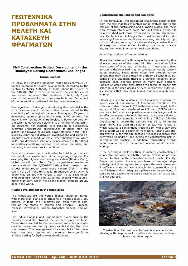
Construction of a positive cutoff wall is one solution for dealing with deep bedrock conditions in rivers in the Hima-
layan mountain region.
ΤΑ ΝΕΑ ΤΗΣ ΕΕΕΕΓΜ – Αρ. 44Β – ΑΠΡΙΛΙΟΣ 2012 Σελίδα 4
Other factors — such as availability of construction materi-als and capacity required for the spillway — also plan a ma-jor role in selecting the type of dam.
For concrete dams, proper investigation is required to de-termine the sub-surface bedrock profile, as well as the foundation conditions. In situations where there is a large deviation in foundation depth, problems may include in-creased excavation, water seepage, and large increases in concrete. This can cause problems with regard to a pro-ject’s construction schedule. In addition, provisions may be required for treatment of shear zones. For the concrete dams built to impound water for the 540-MW Chamera 1 and Parbati 2 projects, NHPC was able to use a carefully planned drilling program to predict the bedrock conditions quite accurately.
Ensuring stability of rock slopes
There are several projects in the Himalayas that may in-volve slope cuts more than 50 meters high. This includes excavating for building side channel spillways at rockfill dams or for removal of weathered or slumped rocks, which typically are present at many sites in the Himalayas. Re-moval of these rocks may be needed to provide a sound foundation for placement of the dam and a proper junction between the dam body and abutments, or for building side channel spillways at rockfill dams. Rock conditions play a pivotal role in the design of such slopes and the need for adequate rock reinforcement.
For 280-MW Dhauliganga 1, a high slope cut was to be exe-cuted on the right bank in strong biotite gneiss of Pre-Cambrian age. However, the joint patterns of this rock were such that prominent unstable wedges formed. When the excavation work began in 2000, blocks as large as 10,000 cubic meters in volume started to fall from the cut slope.
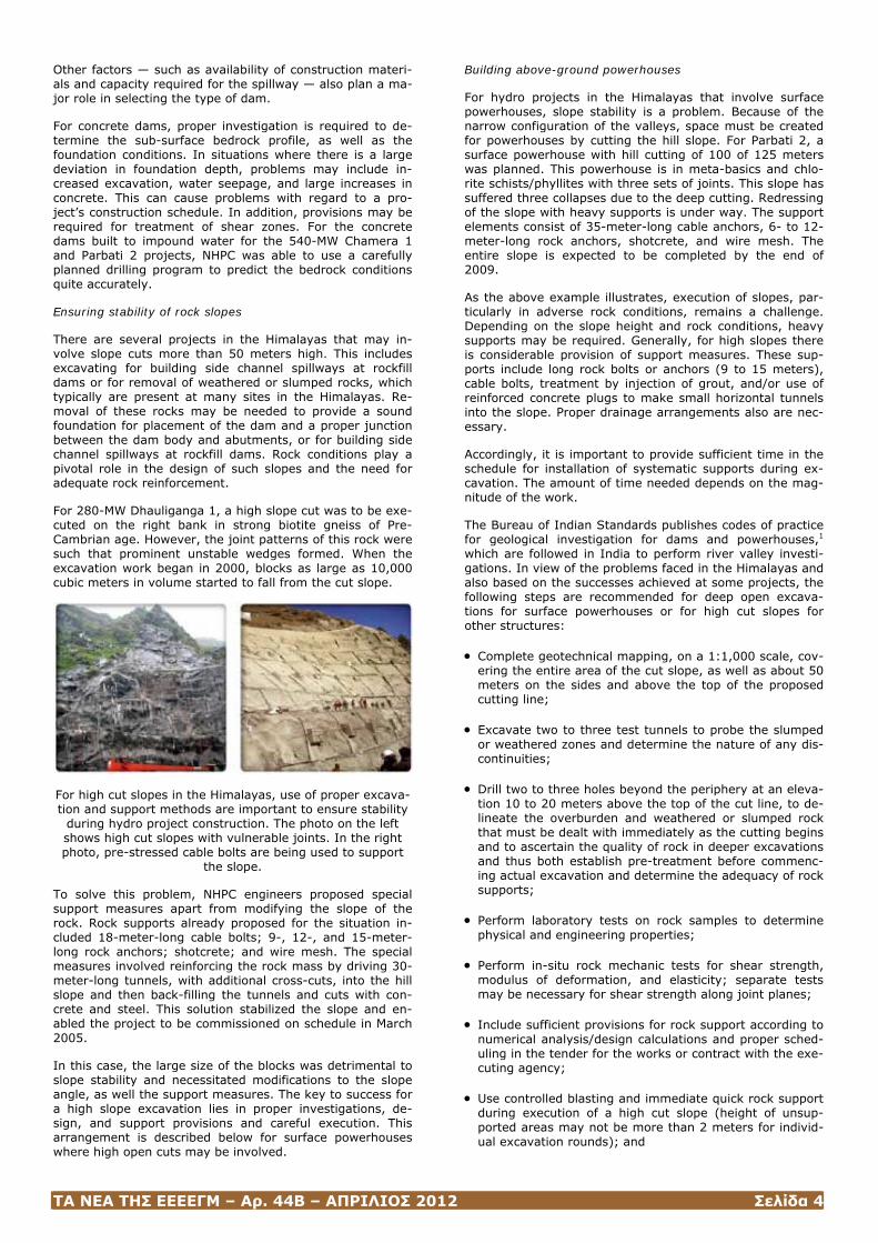
For high cut slopes in the Himalayas, use of proper excava-tion and support methods are important to ensure stability
during hydro project construction. The photo on the left shows high cut slopes with vulnerable joints. In the right photo, pre-stressed cable bolts are being used to support
the slope.
To solve this problem, NHPC engineers proposed special support measures apart from modifying the slope of the rock. Rock supports already proposed for the situation in-cluded 18-meter-long cable bolts; 9-, 12-, and 15-meter-long rock anchors; shotcrete; and wire mesh. The special measures involved reinforcing the rock mass by driving 30-meter-long tunnels, with additional cross-cuts, into the hill slope and then back-filling the tunnels and cuts with con-crete and steel. This solution stabilized the slope and en-abled the project to be commissioned on schedule in March 2005.
In this case, the large size of the blocks was detrimental to slope stability and necessitated modifications to the slope angle, as well the support measures. The key to success for a high slope excavation lies in proper investigations, de-sign, and support provisions and careful execution. This arrangement is described below for surface powerhouses where high open cuts may be involved.
Building above-ground powerhouses
For hydro projects in the Himalayas that involve surface powerhouses, slope stability is a problem. Because of the narrow configuration of the valleys, space must be created for powerhouses by cutting the hill slope. For Parbati 2, a surface powerhouse with hill cutting of 100 of 125 meters was planned. This powerhouse is in meta-basics and chlo-rite schists/phyllites with three sets of joints. This slope has suffered three collapses due to the deep cutting. Redressing of the slope with heavy supports is under way. The support elements consist of 35-meter-long cable anchors, 6- to 12-meter-long rock anchors, shotcrete, and wire mesh. The entire slope is expected to be completed by the end of 2009.
As the above example illustrates, execution of slopes, par-ticularly in adverse rock conditions, remains a challenge. Depending on the slope height and rock conditions, heavy supports may be required. Generally, for high slopes there is considerable provision of support measures. These sup-ports include long rock bolts or anchors (9 to 15 meters), cable bolts, treatment by injection of grout, and/or use of reinforced concrete plugs to make small horizontal tunnels into the slope. Proper drainage arrangements also are nec-essary.
Accordingly, it is important to provide sufficient time in the schedule for installation of systematic supports during ex-cavation. The amount of time needed depends on the mag-nitude of the work.
The Bureau of Indian Standards publishes codes of practice for geological investigation for dams and powerhouses,1 which are followed in India to perform river valley investi-gations. In view of the problems faced in the Himalayas and also based on the successes achieved at some projects, the following steps are recommended for deep open excava-tions for surface powerhouses or for high cut slopes for other structures:
• Complete geotechnical mapping, on a 1:1,000 scale, cov-ering the entire area of the cut slope, as well as about 50 meters on the sides and above the top of the proposed cutting line;
• Excavate two to three test tunnels to probe the slumped or weathered zones and determine the nature of any dis-continuities;
• Drill two to three holes beyond the periphery at an eleva-tion 10 to 20 meters above the top of the cut line, to de-lineate the overburden and weathered or slumped rock that must be dealt with immediately as the cutting begins and to ascertain the quality of rock in deeper excavations and thus both establish pre-treatment before commenc-ing actual excavation and determine the adequacy of rock supports;
• Perform laboratory tests on rock samples to determine physical and engineering properties;
• Perform in-situ rock mechanic tests for shear strength, modulus of deformation, and elasticity; separate tests may be necessary for shear strength along joint planes;
• Include sufficient provisions for rock support according to numerical analysis/design calculations and proper sched-uling in the tender for the works or contract with the exe-cuting agency;
• Use controlled blasting and immediate quick rock support during execution of a high cut slope (height of unsup-ported areas may not be more than 2 meters for individ-ual excavation rounds); and
ΤΑ ΝΕΑ ΤΗΣ ΕΕΕΕΓΜ – Αρ. 44Β – ΑΠΡΙΛΙΟΣ 2012 Σελίδα 5
• Use pre-strengthening measures like grouting in weak rocks or vulnerable areas.
Locating construction materials
The choice of a dam type greatly depends on the availabil-ity of construction materials. In the Himalayas, the rocks contain a considerable percentage of free mica, rendering them unsuitable for use as aggregate. In addition, because of the steep bed slopes in the rivers, the occurrence of suit-able river shoals or terrace deposits is rare. This results in greater dependence on rock quarries.
Detailed work is required to choose safe and environmen-tally benign locations for quarries. This work involves study-ing the available rock types (which could be used for ag-gregate) and performing surveys, testing, and confirmation regarding exploitable quantities. The optimal choice is to locate quarries in the area that will be submerged when the reservoir is impounded because this avoids affecting new areas. If suitable deposits are not found in the reservoir area, alternative locations for the quarry are identified, along with a plan for restoration of the quarry site after construction work is complete. Such restoration plans are now part of the environmental management plan included in the environmental impact assessment for all NHPC pro-jects.
Tunneling in uncertain rock conditions
Tunneling is an intrinsic part of hydro projects in the Hima-layas. Since 1975, NHPC has completed more than 200 kilometers of tunnels in the region. Although many projects with tunnels have been completed in the Himalayas by other companies as well, some have taken a decade or more, with the delays mainly attributed to tunnel comple-tion. Contractors cite poor rock conditions as the prime reason for cost and time overruns.
Keys to successful tunneling include:
• Investigation and rock mechanics testing, before con-struction begins, to develop a suitable tunneling method, select support elements for different types of rock, esti-mate the quantity of work to be performed, and identify geohazards that require treatment (such as fractured and crushed rock zones, fault crossings, water ingress under high pressure, and rock burst areas); and
• Provision of immediate primary support in the heading portions, consisting of shotcrete or fiber-reinforced shot-crete, together with rock bolts. When this support is not in place, there are likely to be collapses and subsequent disruptions to the work.
The tailrace tunnel for 480-MW Uri 1 provides an example of efficient support methods in poor and highly stressed rock conditions. Along the course of the 2-kilometer-long tunnel, the contractor encountered a folded thrust zone between the sedimentary formation and the meta-volcanics. According to the geomechanical classification developed by Z.T. Bieniawski, the rock encountered in the tunnel included 1 percent class II, 49 percent class III, 28 percent of class IV, and 22 percent class V. There are five rock classes in the geomechanical classification, from I (very good) to V (very poor).
Despite the poor rock quality at this site, no steel arches were needed for support, nor was there a single instance of cavities or heavy overbreak. (Overbreak is rock excavated in excess of that needed to install the tunnel. In this case, overbreak would result from weak rock or close fractures or shear zones that could not be controlled.) Support elements used at this site consisted of pre-grouting of the rock mass, division of the tunnel section into several parts for easier excavation in poor rock, application of 200- to 250-
millimeter-thick shotcrete with a double layer of wire mesh and water-expanding bolts, and grouted dowels. Successful completion of Uri 1 brought about changes in tunneling techniques in the Himalayas, particularly with respect to the use of flexible supports and pre-grouting as a stabilization measure. The tunneling method used at this site, designed by Sweco of Sweden, is based on the New Australian Tun-neling Method. The civil contractor was Uri Civil Contractor AB, a Swedish-British consortium led by Skanska.
The use of tunnel boring machines in the Himalayas has met with limited success. The Parbati 2 project is a good example. This project involves trans-basin water transfer between two rivers via a 31.5-kilometer-long headrace tun-nel. This is one of the longest water-conducting tunnels in the world. Total tunneling for the project, which includes feeder tunnels and access adits, is 57.2 kilometers. Con-struction of this project began in 2002 and is scheduled to be complete in 2010, according to the revised program.
One element of success at this project involved use of a double shield inclined tunnel boring machine to excavate two inclined pressure shafts. These shafts are 1,546 meters in length and 3.5 meters in diameter, at a difficult angle of 30 degrees, and run through meta-basics and chlorite schist bands. Progress in the second pressure shaft was so fast that the tunnel was completed in 136 days in 2006. The main reason for the success of this tunnel boring ma-chine is the moderate strength of the meta-basics, which is amenable to boring without difficulty.
Use of an open shield tunnel boring machine to complete the portion of the headrace tunnel that passes below a high ridge met with less success. Initially, the machine worked fairly well in granite gneiss, schistose gneiss, and schist bands. However, progress slowed as the tunnel entered quartzites, and heavy-duty cutters were required. Simulta-neously, as the rock cover on the tunnel increased to 800 to 1,000 meters, the jointed quartzite gave rise to wedge failures near the cutter head.
Because there were site limitations to using shotcrete, the contractor used wire mesh with channels in the crown por-tion, together with rock bolts, as support measures in class III conditions. In class IV and some area of class III, ring beams were used.
From 4,000 meters onwards, the tunnel encountered closely jointed zones and silt-filled discontinuities in the tunnel. At 4,056 meters, water and silt emerged from a probe hole under high pressure, with a discharge of 5,000 to 6,000 liters per minute. This caused inundation of the tunnel for nearly 2 kilometers, and the tunnel boring ma-chine was virtually buried under silt. The discharge slowly subsided to 2,000 liters per minute and continues more than two years after the leak began. As of February 2009, discharge had reduced to 1,350 liters per minute. An expert group consisting of experts in contracts, civil design, cost engineering, geology, and financing has recommended op-tions for treating the difficult zone so that the balance of the tunneling can be completed. These options include building a bypass tunnel and treating the weak zone by grouting.
Conclusions
Development of the nearly 119,000 MW of hydro potential from rivers in India that arise in the Himalayas relies on finding solutions to challenges posed by the region’s com-plex geology. Through 33 years of experience developing hydro projects in this area, NHPC Limited has developed solutions to a number of geotechnical problems. These so-lutions have allowed construction of some of the largest dams and hydraulic structures in the world.

ΤΑ ΝΕΑ ΤΗΣ ΕΕΕΕΓΜ – Αρ. 44Β – ΑΠΡΙΛΙΟΣ 2012 Σελίδα 6
Note
1Code of Practice for Sub-Surface Investigation for Power House Sites, IS 10060: 1981, Bureau of Indian Standards (BIS), New Delhi, India, 1981 and 2004. A number of other standards for geotechnical investigation and subsurface exploration are available under Division 14 Water Re-sources, Section WRD-5 of the BIS.
Imran Sayeed is chief (geology) for NHPC Limited, which develops and operates hydroelectric projects in India.
(Hydro Review, http://www.hydroworld.com/index/display/article-display/0810446792/articles/hydro-review-worldwide/volume-17/Issue_3/Articles/Civil_Construction__Project_Development_in_the_Himalayas__Solving_Geotechnical_Challenges.html)
ΤΑ ΝΕΑ ΤΗΣ ΕΕΕΕΓΜ – Αρ. 44Β – ΑΠΡΙΛΙΟΣ 2012 Σελίδα 7
ΦΡΑΓΜΑΤΑ ΑΠΟ ΚΥΛΙΝΔΡΟΥΜΕΝΟ ΣΚΥΡΟΔΕΜΑ - RCC (ROLLER-COMPACTED-CONCRETE DAMS)
Roller-Compacted-Concrete Dams: Design and Construction Trends
A review of the design and construction of five recently completed roller-compacted-concrete dams in the U.S. re-veals that many new design details and construction meth-ods have been adapted to enhance the final product.
Fares Y. Abdo
Roller-compacted concrete (RCC) continues to gain recogni-tion as a competitive material for building new and rehabili-tating existing dams. Over the past two decades, many design details and construction methods have been adapted to enhance the final product while maintaining the speed of construction that provides RCC its competitive edge.
More than 370 RCC gravity dams higher than 50 feet have been built worldwide using RCC, 43 of these in the U.S. Many more RCC gravity dams less than 50 feet high have been built worldwide.
The first two large RCC gravity dams in the U.S. – Willow Creek in Oregon and Upper Stillwater in Utah – were built in the 1980s. These dams experienced seepage through lift joints and at shrinkage cracks. Since that time, design en-gineers, owners, and contractors have been looking for innovative methods to improve durability and aesthetics of RCC and to limit seepage. Several facing systems are being used on dams built today, including air-entrained conven-tional concrete with crack inducers and water stops, precast concrete panels, and waterproofing membranes.
Five medium-sized RCC gravity dams were built in the U.S. between 2004 and 2008. A review of the main elements design engineers have to consider in regard to RCC pro-vides important information on the latest design details, mixes, and construction methods.
Using RCC for U.S. dams
In the late 1970s, promising research results led the U.S. Army Corps of Engineers to change the design of Willow Creek Dam in Oregon to RCC. Originally, the Corps planned to build a rockfill embankment dam. About a month later, the U.S. Department of the Interior’s Bureau of Reclama-tion adopted this new technology for its Upper Stillwater Dam in Utah.1
Thus, RCC emerged as a viable new type of dam. The first to be completed was Willow Creek Dam, in 1982. At this dam, 433,000 cubic yards of RCC were placed in less than five months, at an average cost of $19 per cubic yard. The dam had no transverse joints and used a lean (low cemen-titious content) dry RCC mixture with nominal maximum aggregate size of 2.5 inches. Precast concrete panels were used on the upstream face, and the downstream face was unformed. Although Willow Creek Dam was deemed struc-turally sound, excessive water seepage at lift joints oc-curred during first filling of the reservoir.
A few years later, Upper Stillwater Dam was built. Con-struction of the dam began in 1985 and was completed in 1987. At 294 feet high and with a crest length of 2,673 feet, the dam required 1,471,000 cubic yards of RCC. As of September 2008, the dam remains the largest volume RCC dam completed in the U.S. Reclamation’s approach to build-ing Upper Stillwater Dam was quite different from the Corps’ approach to Willow Creek Dam. Reclamation elected to use a richer RCC mixture (higher cementitious content) with a wetter consistency. The upstream vertical face and downstream stepped face of the central spillway section were slipformed using conventional concrete. The richer RCC mix produced a higher tensile strength and thus re-duced the cross-section of the dam. In addition, the richer mix and the upstream conventional concrete facing pro-vided better seals and prevented seepage at lift joints.
Upper Stillwater Dam did not include contraction joints. Vertical thermal cracks developed at an average spacing of about 190 feet. The cracks were not structurally significant; however, one crack produced excessive water leakage and required waterproofing repairs.2
Much was learned from the RCC dams built in the 1980s. Although these dams were never in structural jeopardy, future designs placed more emphasis on seepage and crack control for most projects. Designers of dams built during and after the 1990s incorporated different types of facing systems and control joints. They typically used richer RCC mixtures, a smaller maximum aggregate size, stricter con-struction requirements, special lift joint treatments, up-stream membranes, and special facing mixtures to improve watertightness and bonding at lift joints.
Five recent medium-sized RCC dam projects
For the purpose of this article, medium-sized RCC gravity dams are those higher than 50 feet with a concrete volume not exceeding 300,000 cubic yards. The five dams featured in this article were built between 2004 and 2008. The vol-ume of RCC used ranged from 13,800 cubic yards to 218,000 cubic yards, and their heights vary from 70 to 188 feet (see Table 1). The dams are in Colorado, Georgia, Vir-ginia, and West Virginia. In Georgia, deterioration from freeze-thaw cycles is of minimal concern. However, in the other three states, numerous freeze-thaw cycles take place annually. The main purpose of all five dams is to provide water supply for nearby communities.
New Big Cherry Dam in Wise County, Va., replaced a 70-year-old cyclopean concrete dam that suffered from struc-tural deficiencies and had a spillway capacity less than that needed to meet the state dam safety requirements. In ad-dition to increasing the spillway capacity, the new dam is 7 feet higher than the old dam, which increased the reservoir water storage from 359 to 633 million gallons.
Pine Brook and Genesee No. 2 dams in Colorado have simi-lar designs, with a conventional concrete upstream face and an unformed downstream face covered with soil and vege-tated. Both construction sites were congested, with minimal space for RCC plants, aggregate stockpiles, and RCC han-dling equipment. Pine Brook was the first design-build dam in Colorado, whereas Genesee No. 2 was built based on a negotiated contract with the lowest bidder. Most of the RCC aggregates for the two dams were mined and processed on site.
Hickory Log Creek Dam in Canton, Ga., about 30 miles north of Atlanta, began impounding water in January 2008. It is the tallest non-federally-regulated concrete dam in the state. Once filled, the reservoir will supply much-needed water especially after the region endured one of the most severe droughts on record, in 2007. The developer used crushed concrete aggregates hauled to the site from a nearby rock quarry.
ΤΑ ΝΕΑ ΤΗΣ ΕΕΕΕΓΜ – Αρ. 44Β – ΑΠΡΙΛΙΟΣ 2012 Σελίδα 8
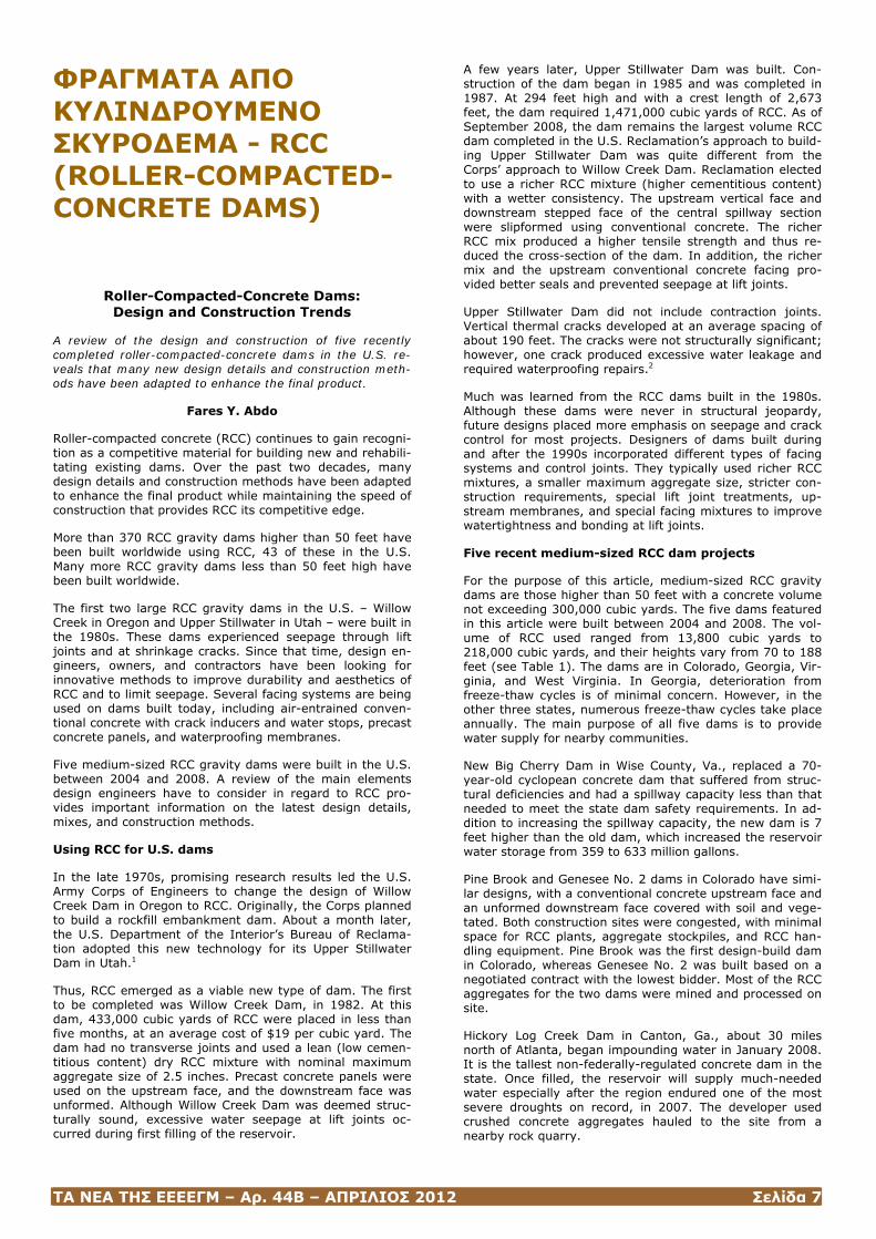
Table 1: Design Features of Five Medium-Sized RCC Dams
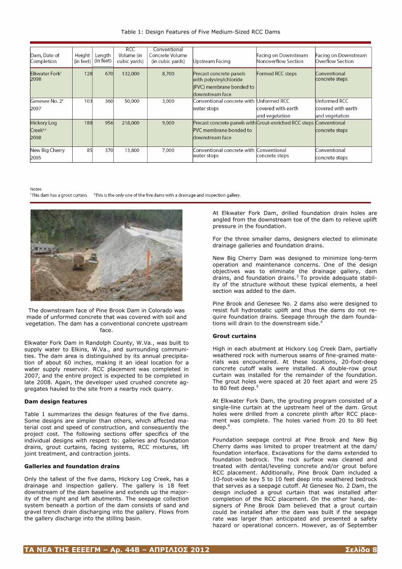
The downstream face of Pine Brook Dam in Colorado was made of unformed concrete that was covered with soil and vegetation. The dam has a conventional concrete upstream
face.
Elkwater Fork Dam in Randolph County, W.Va., was built to supply water to Elkins, W.Va., and surrounding communi-ties. The dam area is distinguished by its annual precipita-tion of about 60 inches, making it an ideal location for a water supply reservoir. RCC placement was completed in 2007, and the entire project is expected to be completed in late 2008. Again, the developer used crushed concrete ag-gregates hauled to the site from a nearby rock quarry.
Dam design features
Table 1 summarizes the design features of the five dams. Some designs are simpler than others, which affected ma-terial cost and speed of construction, and consequently the project cost. The following sections offer specifics of the individual designs with respect to: galleries and foundation drains, grout curtains, facing systems, RCC mixtures, lift joint treatment, and contraction joints.
Galleries and foundation drains
Only the tallest of the five dams, Hickory Log Creek, has a drainage and inspection gallery. The gallery is 18 feet downstream of the dam baseline and extends up the major-ity of the right and left abutments. The seepage collection system beneath a portion of the dam consists of sand and gravel trench drain discharging into the gallery. Flows from the gallery discharge into the stilling basin.
At Elkwater Fork Dam, drilled foundation drain holes are angled from the downstream toe of the dam to relieve uplift pressure in the foundation.
For the three smaller dams, designers elected to eliminate drainage galleries and foundation drains.
New Big Cherry Dam was designed to minimize long-term operation and maintenance concerns. One of the design objectives was to eliminate the drainage gallery, dam drains, and foundation drains.3 To provide adequate stabil-ity of the structure without these typical elements, a heel section was added to the dam.
Pine Brook and Genesee No. 2 dams also were designed to resist full hydrostatic uplift and thus the dams do not re-quire foundation drains. Seepage through the dam founda-tions will drain to the downstream side.4
Grout curtains
High in each abutment at Hickory Log Creek Dam, partially weathered rock with numerous seams of fine-grained mate-rials was encountered. At these locations, 20-foot-deep concrete cutoff walls were installed. A double-row grout curtain was installed for the remainder of the foundation. The grout holes were spaced at 20 feet apart and were 25 to 80 feet deep.5
At Elkwater Fork Dam, the grouting program consisted of a single-line curtain at the upstream heel of the dam. Grout holes were drilled from a concrete plinth after RCC place-ment was complete. The holes varied from 20 to 80 feet deep.6
Foundation seepage control at Pine Brook and New Big Cherry dams was limited to proper treatment at the dam/ foundation interface. Excavations for the dams extended to foundation bedrock. The rock surface was cleaned and treated with dental/leveling concrete and/or grout before RCC placement. Additionally, Pine Brook Dam included a 10-foot-wide key 5 to 10 feet deep into weathered bedrock that serves as a seepage cutoff. At Genesee No. 2 Dam, the design included a grout curtain that was installed after completion of the RCC placement. On the other hand, de-signers of Pine Brook Dam believed that a grout curtain could be installed after the dam was built if the seepage rate was larger than anticipated and presented a safety hazard or operational concern. However, as of September
ΤΑ ΝΕΑ ΤΗΣ ΕΕΕΕΓΜ – Αρ. 44Β – ΑΠΡΙΛΙΟΣ 2012 Σελίδα 9
2008, reports indicate that a grout curtain will not be needed.
Facing systems
As mentioned previously, some early RCC dams experi-enced significant seepage through lift joints and/or vertical cracks. As a result, many facing systems consisting of con-ventional concrete, precast concrete, geomembranes, and combinations thereof have been used and refined during the past two decades. Facing systems now are being used to reduce seepage and to improve durability and appear-ance. Detailed descriptions of the facing systems used worldwide can be found in a Portland Cement Association publication.7 A review of facing systems used on U.S. dams built after 2001 reveals that designers continue specifying facing systems that were successfully used during the 1990s.
As Table 1 shows, different types of facing systems were used on the upstream and/or downstream faces of these five dams. Conventional concrete with crack inducers and water stops at contraction joints were placed at the vertical upstream faces at New Big Cherry, Pine Brook, and Gene-see No. 2 dams. The slope of the downstream faces of these dams ranged from 0.88 horizontal : 1 vertical to 0.75 horizontal : 1 vertical.
The design of New Big Cherry Dam included an uncontrolled ogee spillway to function as a combined service and emer-gency spillway. The downstream face consisted of air-entrained conventional concrete for improved freeze-thaw resistance in a harsh environment. The spillway chute in-corporated steps that provided energy dissipation.
The designs and construction of Pine Brook and Genesee No. 2 dams were simplified by limiting facing systems to the upstream face and by eliminating the need for a con-crete stilling basin to reduce cost. The dams were built without forming the downstream face of the RCC. Backfill-ing with earth to cover the unformed RCC was required after initial reservoir filling was complete. Each of these similar structures includes a concrete drop inlet and outlet works designed to pass normal flows. Larger flows up to inflow design flood can pass over an emergency spillway in the middle section of the parapet wall. The middle of the parapet wall is lower than the abutment sections to prop-erly route the flood flow over the dam and down the vege-tated earthen cover. Design engineers believed that a still-ing basin was not needed based on anticipated flow charac-teristics and good-quality rock at the dam toe. To reduce initial cost, the owners accepted this design approach, knowing that if the emergency spillways operate, repair work likely will be needed to restore portions of the earthen covers.
The upstream face at both Hickory Log Creek and Elkwater Fork dams is formed with 6-foot-high by 16-foot-long pre-cast concrete panels with a geomembrane fully bonded to the downstream face of the panels. Each panel is anchored to the dam with six galvanized steel rods.
The downstream face of the chimney section at Hickory Log Creek Dam is built with decorative precast concrete panels without a membrane. The sloped downstream face is formed with 3-foot-high steps. The project team elected to use conventional concrete placed concurrently with the RCC within the spillway chute and grout-enriched RCC else-where. Grout-enriched RCC gave the exposed downstream steps of the dam an improved appearance compared with typical exposed RCC. A grout mix was prepared using a colloidal mixing plant at the proportions of one part port-land cement to one part water (by weight). After grading the RCC but before compaction, the grout was manually poured over the top of the freshly placed RCC adjacent to
the downstream wood forms. Workers then internally vi-brated the grout into the fresh RCC. The RCC in this area was compacted using flat bottom plate tampers, resulting in smooth, aesthetically pleasing exposed steps.
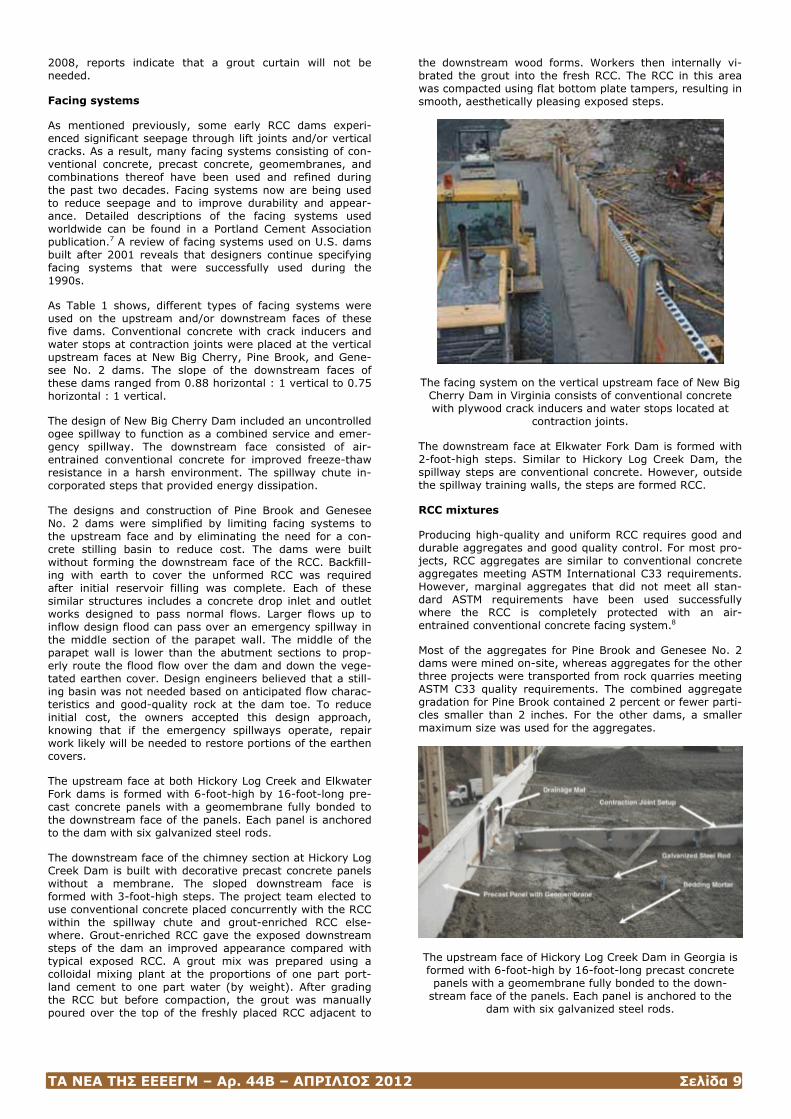
The facing system on the vertical upstream face of New Big Cherry Dam in Virginia consists of conventional concrete with plywood crack inducers and water stops located at
contraction joints.
The downstream face at Elkwater Fork Dam is formed with 2-foot-high steps. Similar to Hickory Log Creek Dam, the spillway steps are conventional concrete. However, outside the spillway training walls, the steps are formed RCC.
RCC mixtures
Producing high-quality and uniform RCC requires good and durable aggregates and good quality control. For most pro-jects, RCC aggregates are similar to conventional concrete aggregates meeting ASTM International C33 requirements. However, marginal aggregates that did not meet all stan-dard ASTM requirements have been used successfully where the RCC is completely protected with an air-entrained conventional concrete facing system.8
Most of the aggregates for Pine Brook and Genesee No. 2 dams were mined on-site, whereas aggregates for the other three projects were transported from rock quarries meeting ASTM C33 quality requirements. The combined aggregate gradation for Pine Brook contained 2 percent or fewer parti-cles smaller than 2 inches. For the other dams, a smaller maximum size was used for the aggregates.
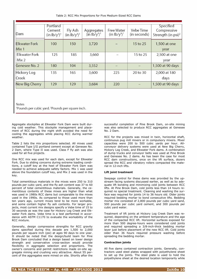
The upstream face of Hickory Log Creek Dam in Georgia is formed with 6-foot-high by 16-foot-long precast concrete panels with a geomembrane fully bonded to the down-
stream face of the panels. Each panel is anchored to the dam with six galvanized steel rods.
ΤΑ ΝΕΑ ΤΗΣ ΕΕΕΕΓΜ – Αρ. 44Β – ΑΠΡΙΛΙΟΣ 2012 Σελίδα 10
Table 2: RCC Mix Proportions for Five Medium-Sized RCC Dams
Aggregate stockpiles at Elkwater Fork Dam were built dur-ing cold weather. This stockpile management and place-ment of RCC during the night shift avoided the need for cooling the aggregates while placing RCC during warmer weather.
Table 2 lists the mix proportions selected. All mixes used contained Type I/II portland cement except at Genesee No. 2 Dam, where Type II was used. Class F fly ash was also used for all five projects.
One RCC mix was used for each dam, except for Elkwater Fork. Due to sliding concerns during extreme loading condi-tions, a cutoff key at the heel of Elkwater Fork Dam was needed to achieve adequate safety factors. Mix 1 was used above the foundation cutoff key, and Mix 2 was used in the key.
Total cementitious materials in the mixes were 250 to 310 pounds per cubic yard, and the fly ash content was 37 to 60 percent of total cementitious materials. Generally, the ce-mentitious contents of these mixes are higher than what was used in 1980s RCC dams but comparable to the mixes used in the 1990s. As compared to those used more than ten years ago, current mixes tend to be more workable, and some contain higher fly ash contents. For larger pro-jects, most current mix designs specify a Vebe time of 15 to 30 seconds as was the case for Hickory Log Creek and Elk-water Fork dams. Vebe time is a test performed in accor-dance with ASTM C1170 to evaluate the workability of the RCC mixture.
Generally, design compressive strengths for RCC gravity dams specified during this decade are 1,500 to 2,000 pounds per square inch (psi) at ages 90 days to one year. It should be noted that the design/build team for Pine Brook Dam concluded that a design based on lower design strength and conservative cross-section would provide flexibility in aggregate selection and proportions. The owner’s concerns and permit restrictions made on-site ag-gregate mining and crushing very attractive. About 55 per-cent of the aggregates were mined on site. Shortly after the
successful completion of Pine Brook Dam, on-site mining was also selected to produce RCC aggregates at Genesee No. 2 Dam.
RCC for the projects was mixed in twin, horizontal shaft, continuous pug mill mixers or in compulsory mixers. Mixer capacities were 200 to 500 cubic yards per hour. All-conveyor delivery systems were used at New Big Cherry, Hickory Log Creek, and Elkwater Fork dams. A combination of dump trucks and conveyor belts was used at Pine Brook and Genesee No. 2 dams. As has been the case for most RCC dam constructions, once on the lift surface, dozers spread the RCC and vibratory rollers compacted the mate-rial in 12-inch lifts.
Lift joint treatment
Seepage control for these dams was provided by the up-stream facing systems discussed earlier, as well as by ade-quate lift bonding and minimizing cold joints between RCC lifts. At Pine Brook Dam, cold joints less than 14 hours re-quired no special treatment. Cleaning and washing the sur-face was required for joints 14 to 36 hours old. Older joints required bedding mortar to bond consecutive lifts. Bedding mortar mix consisted of 2,800 pounds per cubic yard sand, 500 pounds per cubic yard cement, and 300 pounds per cubic yard water.
Treatment of lift joints at Hickory Log Creek Dam was re-quired, depending on the ambient temperature and the age of the compacted RCC lift. Horizontal surfaces exposed for more than 500 degree-hours were considered cold joints and required spreading a 3/8-inch-thick bedding mortar layer just before placement of the new RCC lift. Cold joints older than 36 hours required pressure washing before spreading the bedding mortar.
Contraction joints
All five dams contained contraction joints. Generally, con-tractors used steel plates wrapped with polyethylene sheet to set up the joints. The steel plate is used to hold the polyethylene sheet at the desired location temporarily while
ΤΑ ΝΕΑ ΤΗΣ ΕΕΕΕΓΜ – Αρ. 44Β – ΑΠΡΙΛΙΟΣ 2012 Σελίδα 11
the RCC is being spread. Immediately after spreading and before starting compaction of the RCC, the steel plate is removed, leaving behind the polyethylene sheet to serve as a bond breaker at the location of the contraction joint.
Conclusions
Economy and speed of construction continue to be the main reasons designers select RCC for new gravity dam construc-tion.
Conventional concrete with contraction joints and water stops and precast concrete panels with bonded waterproof-ing membranes appear to be the upstream facing systems of choice for recently built dams. Conventional concrete and grout-enriched concrete are becoming more common for downstream facing systems.
Engineers continue specifying RCC mixtures similar to those used in the 1990s, which have better workability and con-tain relatively higher cementitious contents compared to mixes used for RCC dams in the 1980s. High paste and very workable mixes containing fly ash in the range of 40 to 60 percent of total cementitious materials are commonly specified. Additionally, higher paste mixes with smaller ag-gregate (nominal maximum size of 1 or 1.5 inches) are selected to reduce segregation and achieve high density. Mixes with high fly ash content have been used on a few projects worldwide to build what is referred to as “all-RCC dams.”9 The concept is to design a 100 percent RCC dam, and no other concrete mixes or auxiliary items are included to meet strength or seepage requirements. This concept, which would significantly increase the speed of construc-tion, has yet to gain acceptance in the U.S.
Stockpiling aggregates during cold weather and placement of RCC at night can eliminate the need for costly methods that otherwise would be required to maintain the required mix temperature at time of placement. The stockpiling management approach used at Elkwater Fork Dam should be considered for RCC gravity dam construction.
Perhaps the most notable development in recent RCC grav-ity dams in the U.S. is the design approach implemented at Pine Brook and Genesee No. 2 dams. The following design features resulted in significant effects on the Pine Brook Dam speed of construction and total cost:
– Increasing the dam size to reduce the required RCC strength provided an opportunity to use on-site aggregates of marginal quality. Aggregates that fail to meet certain ASTM requirements still may be used if appropriate tests are performed and the results show that the aggregates can produce RCC meeting the project requirements;
– Building the dam without forming the RCC on the down-stream face and covering the unformed RCC with soil pro-vided protection against freeze-thaw action;
– Designing the dam to resist full hydrostatic uplift pressure eliminated the need for foundation drains and a drainage gallery; and
– Eliminating the construction of a stilling basin saved money and time.
Notes
1. Hansen, K.D., “Roller-Compacted Concrete: A Civil Engi-neering Innovation,” Concrete International, Volume 15, No. 3, March 1996.
2. Smoak, W.G., “Crack Repairs to Upper Stillwater Dam,” Concrete International, Volume 13, No. 2, February 1994, pages 24-32.
3. Cowan, G.L., K.A. Ferguson, and Fares Y. Abdo, “New RCC Dam Replaces 70-Year Old Concrete Dam,” Portland Cement Association Publication PL464, Skokie, Ill., 2006.
4. Shannon, D.A., J.C. Allen, and R.D. Hass, “Design/Build Approach Big Success for Pine Brook RCC Dam,” Portland Cement Association Publication PL466, Skokie, Ill., 2007.
5. Parsons, James M., Randall P. Bass, Charles M. Kahler, and Rodolfo T. Ruiz-Gaekel, “Hickory Log Creek: Building a Roller-Compacted-Concrete Dam,” Hydro Review, Vol-ume 27, No. 1, March 2008, pages 36-45.
6. Holderbaum, R.E., R.L. Judy, and P.G. Schweiger, “Elk-water Fork Dam,” Portland Cement Association Publica-tion PL468, Skokie, Ill., 2008.
7. Facing Systems for Roller Compacted Concrete Dams & Spillways, Portland Cement Association, Skokie, Ill., 2001.
8. Gaekel, L., and Ernest K. Schrader, “RCC Mixes and Properties Using Poor Quality Material - Concepcion Dam,” Roller-Compacted Concrete III, American Society of Civil Engineers, New York, 1992.
9. Ortega, F., “Alternative Designs,” International Water Power & Dam Construction, Volume 59, No. 7, July 2007, pages 14-18.
Fares Abdo, P.E., is program manager for water resources with the Portland Cement Association. He provides technical support and develops literature on roller-compacted con-crete and soil-cement for water resources applications. Mr. Abdo may be reached at Portland Cement Association, P.O. Box 26381, Birmingham, AL 35260; (1) 205-979-9435; E-mail: [email protected].
(Hydro Review, http://www.hydroworld.com/index/display/article-display/353450/articles/hydro-review/volume-27/issue-7/technical-articles/roller-compacted-concrete-dams-design-and-construction-trends.html)
Some Considerations in Designing an RCC Dam
Ernest K. Schrader
Builders of roller-compacted-concrete dams need to con-sider several design elements before beginning construc-tion. These elements include choosing the best location, determining the need for leveling concrete, deciding the overall configuration of the dam, and designing to minimize the effects of features embedded in the dam.
Roller-compacted concrete (RCC) offers a range of eco-nomical and safe design alternatives to conventional con-crete and embankment dams. And while the same basic dam design concepts apply, there are several unique con-siderations for RCC dams.
Some important considerations to address before proceed-ing with detailed final designs include but are not limited to: the basic purpose of the dam, the owner’s requirements for cost, construction schedule, appearance, watertightness, operation, and maintenance. A review of these considera-tions guides selection of several key components, including location, the use of leveling concrete, the basic configura-tion of the dam, and how to deal with conveyor supports. To fully capture the advantages of rapid construction using
ΤΑ ΝΕΑ ΤΗΣ ΕΕΕΕΓΜ – Αρ. 44Β – ΑΠΡΙΛΙΟΣ 2012 Σελίδα 12
RCC technology, the overall design should keep construc-tion as simple as possible.
Choosing the best location
Foundations that are suitable for massive internally vi-brated concrete dams also are suitable for RCC dams with similar properties. However, because of the low cost, con-struction techniques, and material properties of RCC, this type of dam can use a wider base and special design details to accommodate foundations that would otherwise be un-suitable. To build a well-constructed RCC dam on unique foundations, proper attention to certain details is crucial. These details include the width of the structure, isolation of monolith joints, foundation shaping (including use of steps), footings for the delivery system, and use of leveling con-crete. Foundation considerations for RCC dams are dis-cussed more fully in previous HRW articles.1,2
Considering leveling concrete
One particular foundation consideration worth noting is the use of “leveling” concrete. Builders of some RCC dams have used leveling concrete to cover the foundation and provide a smooth base for the RCC. For other RCC projects, builders have started with RCC directly on the foundation. Each ap-proach has merit, with each being more or less suitable to different conditions. There are considerations for and against the use of leveling concrete.1,2 These include:
• Leveling concrete simplifies the start of RCC placing and its initial production rate, but makes construction more time-consuming and costly;
• On a foundation with substantial undulations and slopes, the leveling concrete will be very thick in most locations, requiring forced cooling;
• Leveling concrete typically has long-term stiffness (modulus) values of 20 Giga-pascals (GPa) to 35 GPa (3 to 5 million pounds per square inch), with low creep. If placed on a foundation with lower tensile mass modulus, this concrete creates added restraint and higher thermal stresses;
• Any type of RCC mix can be placed directly onto founda-tion rock without leveling concrete. This is accomplished by first spreading a thin layer of high-slump bedding mix onto the rock, then spreading the RCC over the bedding and compacting it while the bedding is still fresh;
• If the foundation is relatively poor and would deteriorate from exposure before placing RCC, it is common to use shotcrete or a thin “mud mat” to seal and protect it; and
• Where shotcrete is placed against abutments and the foundation still tends to deteriorate, or where the abut-ment could not be cleaned to sound material before shot-creting, grout pipes have been used to ensure a seal be-tween the shotcrete and foundation.
More details on the use of leveling concrete for RCC dams are available in previous HRW articles.1,2
Determining the configuration of the RCC dam
RCC dams can be built with straight or curved axes, vertical or inclined upstream faces, and downstream faces varying from vertical to any slope. The design type chosen, pro-posed height, and foundation characteristics strongly influ-ence the basic dam cross section.3,4
The overall design of an RCC structure must balance the use of available materials, selection of structural features, volume and strength requirements for different-sized dam sections, and proposed construction methods. Each factor
must be considered in light of the others. For example, a particular dam section may require certain shear strength for stability. However, available materials may not be capa-ble of providing this strength or the construction method may not ensure sufficient lift-joint quality to provide the strength. In these situations, changes to the mix design, construction method, or section structure may be the solu-tion.
Low dams
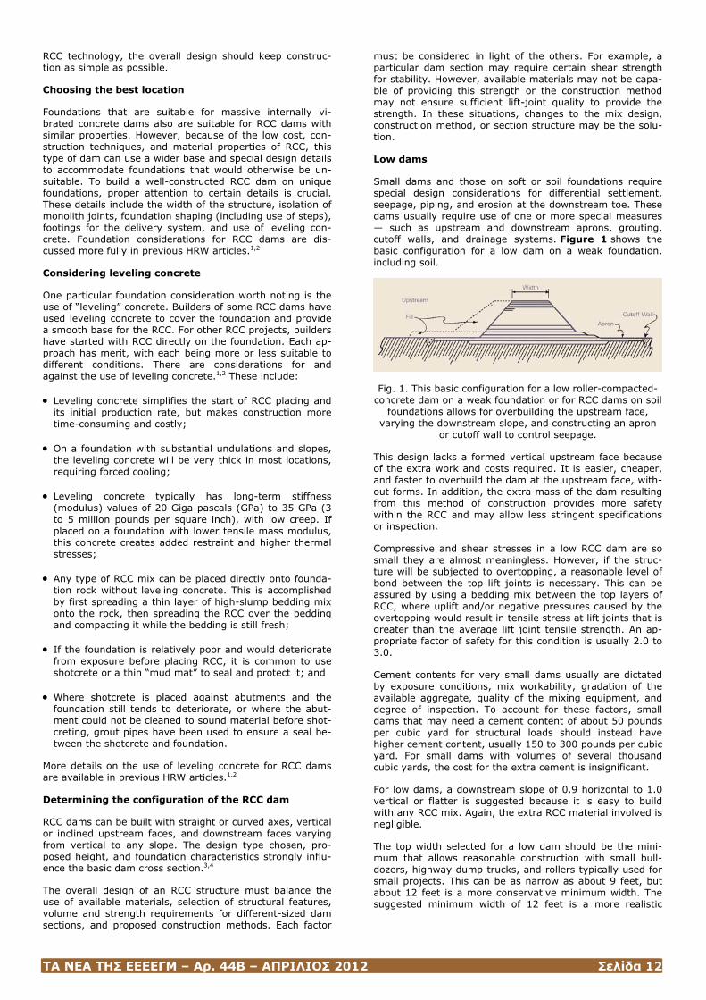
Small dams and those on soft or soil foundations require special design considerations for differential settlement, seepage, piping, and erosion at the downstream toe. These dams usually require use of one or more special measures — such as upstream and downstream aprons, grouting, cutoff walls, and drainage systems. Figure 1 shows the basic configuration for a low dam on a weak foundation, including soil.
Fig. 1. This basic configuration for a low roller-compacted-concrete dam on a weak foundation or for RCC dams on soil
foundations allows for overbuilding the upstream face, varying the downstream slope, and constructing an apron
or cutoff wall to control seepage.
This design lacks a formed vertical upstream face because of the extra work and costs required. It is easier, cheaper, and faster to overbuild the dam at the upstream face, with-out forms. In addition, the extra mass of the dam resulting from this method of construction provides more safety within the RCC and may allow less stringent specifications or inspection.
Compressive and shear stresses in a low RCC dam are so small they are almost meaningless. However, if the struc-ture will be subjected to overtopping, a reasonable level of bond between the top lift joints is necessary. This can be assured by using a bedding mix between the top layers of RCC, where uplift and/or negative pressures caused by the overtopping would result in tensile stress at lift joints that is greater than the average lift joint tensile strength. An ap-propriate factor of safety for this condition is usually 2.0 to 3.0.
Cement contents for very small dams usually are dictated by exposure conditions, mix workability, gradation of the available aggregate, quality of the mixing equipment, and degree of inspection. To account for these factors, small dams that may need a cement content of about 50 pounds per cubic yard for structural loads should instead have higher cement content, usually 150 to 300 pounds per cubic yard. For small dams with volumes of several thousand cubic yards, the cost for the extra cement is insignificant.
For low dams, a downstream slope of 0.9 horizontal to 1.0 vertical or flatter is suggested because it is easy to build with any RCC mix. Again, the extra RCC material involved is negligible.
The top width selected for a low dam should be the mini-mum that allows reasonable construction with small bull-dozers, highway dump trucks, and rollers typically used for small projects. This can be as narrow as about 9 feet, but about 12 feet is a more conservative minimum width. The suggested minimum width of 12 feet is a more realistic
ΤΑ ΝΕΑ ΤΗΣ ΕΕΕΕΓΜ – Αρ. 44Β – ΑΠΡΙΛΙΟΣ 2012 Σελίδα 13
width for permanent access (if required) after construction, and to comply with typical safety regulations.
As an alternative to overbuilding the dam using RCC, fill material can be used at the upstream face to steepen the slope, narrow the width of RCC, and save volume. Impervi-ous fill used at the upstream face can also improve water-tightness. When fill is used to steepen the RCC slopes of a dam on a non-rock foundation, consideration should be given to the increase in bearing pressure and sliding that this causes at the base of the dam because the RCC base is now spread over a smaller area. When placed at the down-stream face of the dam, the fill hides minor seepage and protects the RCC from exposure.
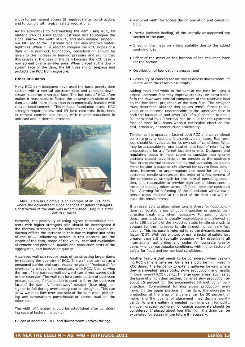
Other RCC dams
Many RCC dam designers have used the basic gravity dam section with a vertical upstream face and constant down-stream slope on a vertical face. The low cost of RCC often makes it reasonable to flatten the downstream slope of the dam and add more mass than is economically feasible with conventional concrete. This reduces foundation stress, RCC strength requirements, and lift-joint concerns. Reductions in cement content also result, with related reductions in unit cost and in thermal stresses.
Miel 1 Dam in Colombia is an example of an RCC dam where the downstream slope changes at different heights.
Construction of the dam was accomplished using five differ-ent RCC mixes.
However, the possibility of using higher cementitious con-tents with higher strengths also should be investigated if the thermal stresses can be tolerated and the volume re-duction offsets the increase in cost due to higher unit costs of the RCC. Influencing factors in this decision are the length of the dam, shape of the valley, cost and availability of cement and pozzolan, quality and production costs of the aggregates, and foundation quality.
A parapet wall can reduce costs of constructing larger dams by reducing the quantity of RCC. The wall also can act as a personnel barrier and curb. Added height or “freeboard” for overtopping waves is not necessary with RCC. Also, curving the top of the parapet wall outward can direct waves back to the reservoir. The wall can be a continuation of upstream precast panels, if that option is used to form the upstream face of the dam. A “breakaway” parapet (fuse plug) de-signed to fail during overtopping can be designed. This can allow water to flow over one side of the dam while protect-ing any downstream powerhouse or access road on the other side.
The width of the dam should be established after consider-ing several factors, including:
• Cost of additional RCC and downstream vertical facing;
• Required width for access during operation and construc-tion;
• Inertia (seismic loading) of the laterally unsupported top section of the dam;
• Effect of the mass on sliding stability due to the added confining load;
• Effect of the mass on the location of the resultant force for the section;
• Distribution of foundation stresses; and
• Possibility of causing tensile stress across downstream lift joints when the reservoir is empty.
Adding mass and width to the dam at the base by using a sloped upstream face may improve stability. An extra bene-fit is the downward vertical component of the reservoir load on the horizontal projection of the dam face. The designer must determine whether this causes tensile forces to de-velop or to become unacceptable at the upstream face in both the foundation and lower RCC lifts. Slopes up to about 0.1 horizontal to 1.0 vertical can be built for the upstream face of most RCC dams without noticeable effect on the cost, schedule, or construction practicality.
Tension at the upstream face of both RCC and conventional concrete gravity sections is a controversial issue. Each pro-ject should be evaluated for its own set of conditions. What may be acceptable for one location and type of mix may be unacceptable for a different location or mix. Designers and regulating codes in most countries consider that gravity sections should have little or no tension at the upstream face in the normal reservoir or normal operating condition. Minor tension is occasionally allowed for severe flood condi-tions. However, to accommodate the need for small but sustained tensile stresses on the order of a few percent of the compressive strength for the normal operating condi-tion, it is reasonable to provide high cementitious content mixes or bedding mixes across lift joints near the upstream face. Allowing for softening of the foundation with a lower tensile mass modulus at the heel of the dam also will re-duce this tensile stress.
It is reasonable to allow minor tensile stress for flood condi-tions at isolated areas of good inspection or special con-struction treatment, when necessary. For seismic condi-tions, tensile stress is usually unavoidable and allowed at up to 150 percent of the expected static tensile strength to account for the increased tensile strength under very fast loading. This increase is referred to as the dynamic increase factor (DIF). With this allowed stress, a factor of safety just greater than 1.0 is typically accepted — by essentially all international authorities and codes for concrete gravity dams — under earthquake conditions, with higher factors of safety for flood and normal load conditions.
Another feature that needs to be considered when design-ing RCC dams is galleries. Galleries should be minimized in RCC dams. The tendency to extend galleries beyond where they are needed raises costs, slows production, and results in lower overall RCC quality. In large open areas, such as at the base of a high dam section, galleries slow production by about 15 percent for the uncemented fill method of con-struction. Conventional forming slows production even more. In the upper portions of the dam, the decrease in production at the area of a gallery can be 50 percent or more, and the quality of placement may decline signifi-cantly. Where a gallery is needed high in a dam for uplift, an open graded rock drain of coarse aggregate should be considered. If placed about four lifts high, the drain can be excavated for access in the future if necessary.
ΤΑ ΝΕΑ ΤΗΣ ΕΕΕΕΓΜ – Αρ. 44Β – ΑΠΡΙΛΙΟΣ 2012 Σελίδα 14
The vertical distance between galleries is usually deter-mined by the accuracy that equipment can drill from the floor of the top gallery to intersect the roof of the gallery below. This typically is about 100 feet for a gallery 6 feet wide, using rotary percussion drilling equipment.
A gallery high in a dam can be a point of weakness in a seismic event. Designers of low- and medium-height dams should consider overbuilding the dam enough so that gal-leries and drains are not even necessary. The unit cost of the RCC decreases, while construction, operation, and maintenance are simplified.
Using a bedding mix between lifts or a high cementitious content RCC is suggested upstream of galleries and be-tween the first three layers in the area above and below the gallery floor and ceiling. This reduces seepage to provide watertightness, bond against uplift below the floor, and added sliding resistance against reservoir pressure at the upstream gallery wall.
A grout curtain can be installed prior to the RCC or can be installed afterward from a gallery. The gallery should be large enough to accommodate suitable production equip-ment, especially at interior corners and intersections.
Internal drains can be easily drilled using track-mounted rotary percussion equipment. Nominal 3-inch holes at spac-ings of 10 to 15 feet are adequate. These holes can be drilled with an accuracy of plus or minus 3 feet in about 120 feet. A very efficient way to drill these holes is immediately after placing the RCC lift that is the gallery floor. When a long gallery with holes starting at the same elevation is called for, it is effective to stop RCC placement for a day while several track drills drive onto the lift and drill the holes. The area is then cleaned and treated as a cold joint, and RCC placement resumes.
To increase sliding stability of the section and offset some uplift pressures, use of a “fillet” in the upper part of the dam at the downstream face provides needed additional weight. On a high dam, it moves the resultant force of the entire dam section slightly upstream. On a low dam, it shifts the force downstream. The distribution of stress un-der the dam, amount or existence of tensile stress, and maximum compressive stress are slightly affected. The fillet also reduces the height of the section at the top of the dam.
A downstream toe extension can provide additional stability for a high dam where sliding stresses increase significantly with a minor addition in height. It adds both weight and total cohesion, but only in the bottom portion of the dam, where it usually is needed. The fillet increases the mass across the full length of the dam, including the upper por-tions of the foundation where it usually is not needed.
The fillet also adds to foundation bearing and RCC com-pressive stresses, whereas the toe extension reduces the bearing and maximum RCC stresses. The extended toe re-quires extra excavation and foundation preparation, but only in the deepest section of the dam and not for much of its length. It is possible that an extended toe in a high dam will result in tension across downstream lift-joint areas at the maximum height for an empty reservoir condition. This can be overcome by an early partial reservoir filling.
A “key” is an effective way of providing additional sliding stability when it is needed in the foundation but not in the RCC. Although adding the key near the upstream face may seem like a good idea because of its potential to act as a cutoff, the downstream location typically is better. If ana-lyzed for local stresses, an upstream key of a high dam may have tensile forces that could negate sliding friction resistance because there will be little or no vertical stress at the key and a full reservoir. A downstream location has the
benefit of maximum vertical confining stresses and the re-sulting friction. To minimize the width of the key (up-stream-downstream) and assure the required load is trans-ferred to the foundation without slippage across a weak RCC lift surface, bedding mix should be placed between RCC layers in the key, or a high paste content mix should be considered.
The key provides added foundation stability by extending the foundation failure plane and by the related horizontal component of the downstream foundation-bearing capacity. A relatively simple consolidation grouting program in the area downstream of the key may significantly improve sta-bility. A key is usually needed only in the deeper portion of a high dam (if it is on medium- to poor-quality rock), at isolated locations where the foundation condition is bad, or for a medium-height dam on an unsuitable foundation.
When the bearing and sliding strengths of a foundation are poor, a conventional concrete dam usually is not economi-cal. RCC can be a viable option. Using a low-strength and low-cost RCC with a parabolically curved downstream face is one approach.
A preliminary design with this concept was prepared for a tailings dam in Mexico on a foundation of clay and weath-ered rock. The dam was composed of large monoliths that could undergo significant independent movements caused by time-dependent consolidation of the foundations. Each monolith sat on its own excavated foundation, with steps in the foundation matching the location of monolith joints. The abutments were tied in with embankments that would un-dergo deformation as required. The foundation was so poor that a massive key was needed to provide sliding resistance and lower the bearing pressure. Because foundation re-straint is minimal for this type of foundation and cement contents are low owing to the low strength requirements, thermal stresses are minimized.
However, the thickness of the key (distance from the down-stream surface to the foundation under the key) should be analyzed as a cantilevered beam to assure that it will not break from the rest of the dam. If bearing pressures under the key can accept the added weight, a fill can be placed over a portion of the toe to offset some of the cantilever forces. The fill also provides extra sliding stability if it is extended downstream beyond the RCC key.
Regardless of which option is used to widen a dam base, a reduction in bearing pressure and maximum stress occurs in the RCC. Reduced strength requirements allow less ce-ment, cost, and thermal stress. Stresses at the lower levels are closer to stresses higher in the dam, so fewer “zones” requiring different quality RCC at different heights are needed.
Although structural requirements for strength reduce to zero at the top of a dam, some minimum strength is needed for erosion and weathering protection, impermeabil-ity, and making the mix cohesive enough to be placed and compacted. The minimum RCC strength should be based on factors such as exposure conditions, function of the dam, risk level, and economics. There may be some disagree-ment, but minimum strengths at one-year values of about 1,000 pounds per square inch (psi) are usually considered acceptable for the mass.
Early RCC dams used higher-strength mixes for the up-stream and downstream regions and lower-strength RCC at the interior. This proved to be a more serious construction and inspection problem than anticipated. The practice is now generally avoided. In addition, other factors have in-fluenced this trend, including the good field performance of low-strength RCC exposed at the downstream face under severe weather. If needed, RCC can be protected at the upstream face by constant immersion in the reservoir, an
ΤΑ ΝΕΑ ΤΗΣ ΕΕΕΕΓΜ – Αρ. 44Β – ΑΠΡΙΛΙΟΣ 2012 Σελίδα 15
unbonded impervious membrane (with or without protective pre-cast facing panels), and conventional concrete placed using one of many possible techniques. The downstream surface can also be protected by using conventional con-crete or grout-enriched RCC at the exposed face.
It is usually best to use one mix throughout an entire sec-tion for dams up to about 120 feet in height. Because of thermal and economic considerations, higher dams are usually separated into horizontal zones, with higher-strength mixes used in the lower part of the structure. Generally, these zones are 30 to 60 feet thick, with in-creases in strength of 100 to 500 psi per zone. For very large dams, and large dams with high earthquake loading, it usually is best to use a combination of horizontal and vertical zoning. The interior mass — for example, 25 to 75 percent of the total volume — typically will have the lowest strength requirements and the leanest mix. Higher strength typically is necessary at the base and in high-stress areas of the upstream and downstream faces. Earthquake loading also can result in high stresses at the toe and heel of the dam, as well as localized regions at about the upper third of the dam near the downstream face.
In addition to the higher compressive strengths needed for higher principal stresses in the lower portion of high dams, stronger mixes in the lower zones also provide additional lift-joint tensile strength, added cohesion, and usually a slight increase in friction. When a mix in a lower zone has adequate strength for compression but not for sliding sta-bility, there are several options. These include increasing the mass or weight of the dam and widening the base. In-creasing the paste content of the mixes is another option if it is economical and does not cause thermal cracking due to added heat from hydration and/ or a higher elastic modulus. Another option uses bedding between RCC layers. This dramatically increases cohesion and moderately in-creases friction. This technique is especially useful when “cold joints” occur in low-paste mixes.
Dealing with conveyor supports
Conveyor supports are a common embedded structure for an RCC dam. Many RCC dams are constructed using a con-veyor system, with the conveyor being supported on posts within the dam. Before there is sufficient RCC to support the posts, they require a substantial footing. Without proper design considerations, these footings represent fixed rigid blocks protruding into the dam. For example, the vertical faces of these blocks could initiate cracking. One way to deal with the restraint from footings is to place them at the center of monoliths, or so that one face of the footing is flush with a monolith joint. Ideally, footings near the middle of a monolith should be circular, without corners. If the footings have corners, they should be rounded or cham-fered. If the footings are located at monolith joints, square footings can be used.
Previous HRW articles contain more details on conveyor supports.1,2
Notes
1. Schrader, Ernest K., “Building Roller-Compacted-Concrete Dams on Unique Foundations,” HRW, Volume 14, No. 1, March 2006, pages 28-33.
2. Schrader, Ernest K., “Roller-Compacted-Concrete Dams on Difficult Foundations: Practical Examples,” HRW, Vol-ume 14, No. 2, May 2006, pages 20-31.
3. Schrader, Ernest K., “Design and Facing Options for RCC on Various Foundations,” International Water Power and Dam Construction, Volume 45, No. 2, February 1993, pages 33-38.
4. Nawy, E.G., Concrete Construction Engineering Hand-book, Chapter 20, CRC Press, Boca Raton, N.Y., 2007.
Ernie Schrader, PhD, PE, is a consultant with more than 30 years of experience in roller-compacted concrete (RCC). He has been involved in more more than 30 RCC dams that are complete and operational, several under construction, and several undergoing design and feasibility studies. The pro-jects range from the world’s highest to smallest RCC dams. Dr. Schrader may be reached at Schrader Consulting, 1474 Blue Creek Road, Walla Walla, WA 99362 USA; (1) 509-529-1210; E-mail: [email protected].
(Hydro Review, http://www.hydroworld.com/index/display/article-display/354946/articles/hydro-review-worldwide/volume-15/issue-5/articles/cover-story/some-considerations-in-designing-an-rcc-dam.html)
RCC Dam Design: Analyzing Stress and Stability
Ernest K. Schrader
The author — who has been involved in the design and con-struction of more than 100 RCC dams in 35 countries — shares recommendations on how best to conduct stress and stability analyses when designing an RCC dam.
One important area of consideration in designing an RCC dam is stress and stability analysis. This involves including provisions for proper control for thermal stresses. Without proper thermal control, cracking can occur that leads to unacceptable leakage and potential for failure by sliding or overturning. Properly performing stress and stability analy-ses for a variety of situations and dam sections is critical to the design of any dam, including RCC. By using the proper methods and evaluating the relevant parameters, designers can ensure an RCC dam will provide adequate safety and stability under all foreseeable conditions.
Temperature studies and thermal control
Because thermal volume changes in concrete can lead to increased stresses or cracking, the design of any concrete dam (whether conventional concrete or RCC) should include provisions for dealing with the inherent temperature changes and resulting volume changes of any concrete mass. The principal concerns related to cracking in RCC and other concrete gravity dams are stability of the structure, appearance, durability, and leakage control. Although it is not usually a critical factor in structural stability, uncon-trolled leakage through transverse cracks in a concrete dam can result in an undesirable loss of water from the reser-voir, create operational and/or maintenance problems, and be visually undesirable. Leakage can be extremely difficult to control.
Typically, thermal stresses and associated volume changes result in transverse cracking of the concrete structure. However, RCC dams experiencing high thermal stresses also may exhibit unseen cracking parallel to the axis of the dam. This type of cracking has occurred in both conven-tional concrete and RCC dams and can have serious impli-cations with regard to structure and stability. A dam with this type of cracking probably will be safe and stable for normal load conditions if the crack is closed and does not contain water, although with reduced factors of safety. However, experience has shown that this type of cracking can jeopardize sliding and overturning stability if the crack
ΤΑ ΝΕΑ ΤΗΣ ΕΕΕΕΓΜ – Αρ. 44Β – ΑΠΡΙΛΙΟΣ 2012 Σελίδα 16
opens and fills with water. The source of water can be the foundation, seepage through lift joints, monolith joints with failed waterstops, or transverse cracks.
When attempting to predict the degree of cracking a struc-ture may experience, a number of factors should be evalu-ated. Simple analyses that combine very generalized condi-tions yield very general results. Complex analyses combine very specific determination of conditions to yield more ex-acting results. At a minimum, dam designers should con-sider daily and monthly ambient temperature fluctuations, the conditions during construction for aggregate production and RCC mixing that lead to the temperature range at which RCC will be placed, a realistic placing schedule, and realistic material properties. In many cases, the results of a thermal study are key to determining mixture proportions, construction schedule, and cooling and jointing require-ments.
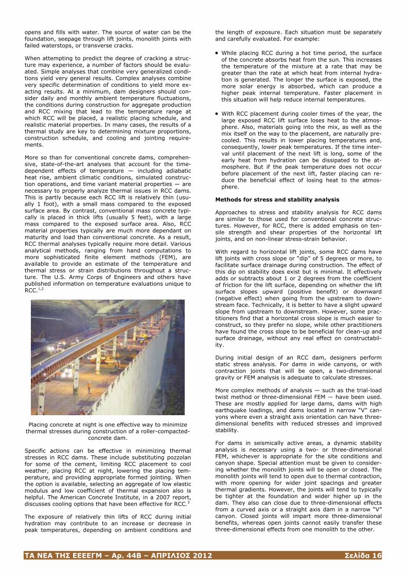
More so than for conventional concrete dams, comprehen-sive, state-of-the-art analyses that account for the time-dependent effects of temperature — including adiabatic heat rise, ambient climatic conditions, simulated construc-tion operations, and time variant material properties — are necessary to properly analyze thermal issues in RCC dams. This is partly because each RCC lift is relatively thin (usu-ally 1 foot), with a small mass compared to the exposed surface area. By contrast, conventional mass concrete typi-cally is placed in thick lifts (usually 5 feet), with a large mass compared to the exposed surface area. Also, RCC material properties typically are much more dependant on maturity and load than conventional concrete. As a result, RCC thermal analyses typically require more detail. Various analytical methods, ranging from hand computations to more sophisticated finite element methods (FEM), are available to provide an estimate of the temperature and thermal stress or strain distributions throughout a struc-ture. The U.S. Army Corps of Engineers and others have published information on temperature evaluations unique to RCC.1,2
Placing concrete at night is one effective way to minimize thermal stresses during construction of a roller-compacted-
concrete dam.
Specific actions can be effective in minimizing thermal stresses in RCC dams. These include substituting pozzolan for some of the cement, limiting RCC placement to cool weather, placing RCC at night, lowering the placing tem-perature, and providing appropriate formed jointing. When the option is available, selecting an aggregate of low elastic modulus and low coefficient of thermal expansion also is helpful. The American Concrete Institute, in a 2007 report, discusses cooling options that have been effective for RCC.3
The exposure of relatively thin lifts of RCC during initial hydration may contribute to an increase or decrease in peak temperatures, depending on ambient conditions and
the length of exposure. Each situation must be separately and carefully evaluated. For example:
• While placing RCC during a hot time period, the surface of the concrete absorbs heat from the sun. This increases the temperature of the mixture at a rate that may be greater than the rate at which heat from internal hydra-tion is generated. The longer the surface is exposed, the more solar energy is absorbed, which can produce a higher peak internal temperature. Faster placement in this situation will help reduce internal temperatures.
• With RCC placement during cooler times of the year, the large exposed RCC lift surface loses heat to the atmos-phere. Also, materials going into the mix, as well as the mix itself on the way to the placement, are naturally pre-cooled. This results in lower placing temperatures and, consequently, lower peak temperatures. If the time inter-val until placement of the next lift is long, some of the early heat from hydration can be dissipated to the at-mosphere. But if the peak temperature does not occur before placement of the next lift, faster placing can re-duce the beneficial effect of losing heat to the atmos-phere.
Methods for stress and stability analysis
Approaches to stress and stability analysis for RCC dams are similar to those used for conventional concrete struc-tures. However, for RCC, there is added emphasis on ten-sile strength and shear properties of the horizontal lift joints, and on non-linear stress-strain behavior.
With regard to horizontal lift joints, some RCC dams have lift joints with cross slope or “dip” of 5 degrees or more, to facilitate surface drainage during construction. The effect of this dip on stability does exist but is minimal. It effectively adds or subtracts about 1 or 2 degrees from the coefficient of friction for the lift surface, depending on whether the lift surface slopes upward (positive benefit) or downward (negative effect) when going from the upstream to down-stream face. Technically, it is better to have a slight upward slope from upstream to downstream. However, some prac-titioners find that a horizontal cross slope is much easier to construct, so they prefer no slope, while other practitioners have found the cross slope to be beneficial for clean-up and surface drainage, without any real effect on constructabil-ity.
During initial design of an RCC dam, designers perform static stress analysis. For dams in wide canyons, or with contraction joints that will be open, a two-dimensional gravity or FEM analysis is adequate to calculate stresses.
More complex methods of analysis — such as the trial-load twist method or three-dimensional FEM — have been used. These are mostly applied for large dams, dams with high earthquake loadings, and dams located in narrow “V” can-yons where even a straight axis orientation can have three-dimensional benefits with reduced stresses and improved stability.
For dams in seismically active areas, a dynamic stability analysis is necessary using a two- or three-dimensional FEM, whichever is appropriate for the site conditions and canyon shape. Special attention must be given to consider-ing whether the monolith joints will be open or closed. The monolith joints will tend to open due to thermal contraction, with more opening for wider joint spacings and greater thermal gradients. However, the joints will tend to typically be tighter at the foundation and wider higher up in the dam. They also can close due to three-dimensional effects from a curved axis or a straight axis dam in a narrow “V” canyon. Closed joints will impart more three-dimensional benefits, whereas open joints cannot easily transfer these three-dimensional effects from one monolith to the other.
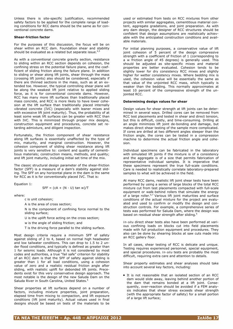
ΤΑ ΝΕΑ ΤΗΣ ΕΕΕΕΓΜ – Αρ. 44Β – ΑΠΡΙΛΙΟΣ 2012 Σελίδα 17
Unless there is site-specific justification, recommended safety factors to be applied for the complete range of load-ing conditions for RCC dams should be the same as for con-ventional concrete dams.
Shear-friction factor
For the purposes of this discussion, the focus will be on shear within an RCC dam. Foundation shear and stability should be evaluated as a related but separate issue.4,5
As with a conventional concrete gravity section, resistance to sliding within an RCC section depends on cohesion, the confining stress on the potential failure plane, and the coef-ficient of sliding friction along the failure plane. In addition to sliding or shear along lift joints, shear through the mass (crossing lift joints) also should be considered, especially if there are thinned sections in the mass, such as at an ex-tended toe. However, the typical controlling shear plane will be along the weakest lift joint relative to applied sliding force, as it is for conventional concrete dams. However, RCC has many more lift surfaces than traditionally placed mass concrete, and RCC is more likely to have lower cohe-sion at the lift surface than traditionally placed internally vibrated concrete (IVC) (especially with leaner mixes and with excessive lift joint maturity). Thus, the probability of at least some weak lift surfaces can be greater with RCC than with IVC. This is minimized through proper mix designs, construction equipment and procedures, concrete set re-tarding admixture, and diligent inspection.
Fortunately, the friction component of shear resistance along lift surfaces is essentially unaffected by the type of mix, maturity, and marginal construction. However, the cohesion component of sliding shear resistance along lift joints is very sensitive to: content and quality of cementi-tious materials; construction means, methods, and quality; and lift joint maturity, including initial set time of the mix.
The classic structural design parameter of the shear-friction factor (SFF) is a measure of a dam’s stability against slid-ing. The SFF on any horizontal plane in the dam is the same for RCC as it is for conventionally placed IVC. That is:
Equation 1: SFF = (cA + (N - U) tan w)/T
where:
c is unit cohesion;
A is the area of cross section;
N is the component of confining force normal to the sliding surface;
U is the uplift force acting on the cross section;
w is the angle of sliding friction; and
T is the driving force parallel to the sliding surface.
Most design criteria require a minimum SFF of safety against sliding of 2 to 4, based on normal high headwater and low tailwater conditions. This can drop to 1.5 to 2 un-der flood conditions, and typically is defined as greater than 1 for seismic loads. Although it is not considered by most codes and authorities, a true “fail safe” criterion for stability of an RCC dam is that the SFF of safety against sliding is greater than 1 for all load conditions, using a cohesion value of zero and a realistic residual friction angle after sliding, with realistic uplift for debonded lift joints. Prece-dents exist for this very conservative design approach. The most notable is the design of the new Saluda Dam on the Saluda River in South Carolina, United States.6
Shear properties at lift surfaces depend on a number of factors, including mixture properties, joint preparation, elapsed time from mixing to compaction, and lift exposure conditions (lift joint maturity). Actual values used in final designs should be based on tests of the materials to be
used or estimated from tests on RCC mixtures from other projects with similar aggregates, cementitious material con-tent, aggregate gradations, and joint preparation. As with any dam design, the designer of RCC structures should be confident that design assumptions are realistically achiev-able with the anticipated construction conditions and avail-able materials.
For initial planning purposes, a conservative value of lift joint cohesion of 5 percent of the design compressive strength with a coefficient of friction of 1 (corresponding to a w friction angle of 45 degrees) is generally used. This should be adjusted as site-specific mixes and material properties are better evaluated. Cohesion tends to be slightly lower for dry consistency RCC mixes and slightly higher for wetter consistency mixes. Where bedding mix is used, the cohesion value will be essentially the same as that value of the unjointed RCC mass, which typically is weaker than the bedding. This normally approximates at least 10 percent of the compressive strength of the un-jointed RCC.
Determining design values for shear
Design values for shear strength at lift joints can be deter-mined in several ways. Drilled cores can be removed from RCC test placements and tested in shear and direct tension, but this is difficult, costly, and time-consuming. Drilling at an angle minimizes lift joint de-bonding and damage, but makes direct shear testing of the sample more complicated. If cores are drilled at two different angles steeper than the friction angle, the cores can be tested in a compression machine to determine the actual friction angle and cohe-sion.
Individual specimens can be fabricated in the laboratory with simulated lift joints if the mixture is of a consistency and the aggregate is of a size that permits fabrication of representative individual samples. It is imperative that these specimens represent the true full-scale conditions. Care is needed to realistically correlate laboratory-prepared samples to what will be achieved in the field.
At many RCC dams, realistic lift joint shear tests have been performed by using a series of large blocks of the total RCC mixture cut from test placements compacted with full-scale equipment or walk-behind rollers that simulate the energy of a large roller.6,7 Various lift joint maturities and surface conditions of the actual mixture for the project are evalu-ated and used to confirm or modify the design and con-struction controls. For example, a comprehensive series of tests was performed for Saluda Dam, where the design was based on residual shear strength after sliding.6
In-situ direct shear tests also have been performed at vari-ous confining loads on blocks cut into field placements made with full production equipment and procedures. They also can be done by shearing blocks at saw cuts made into an RCC gallery floor.
In all cases, shear testing of RCC is delicate and unique. Testing requires experienced personnel, special equipment, and special procedures. In-situ tests are probably the most difficult, requiring extra care and attention to details.
Shear property estimates and shear analyses should take into account several key factors, including:
• It is not reasonable that an isolated section of an RCC dam would slide away, leaving behind another portion of the dam that remains bonded at a lift joint. Conse-quently, over-reaction should be avoided if a FEM analy-sis indicates that shear stress exceeds shear strength (with the appropriate factor of safety) for a small portion of a large lift surface;
ΤΑ ΝΕΑ ΤΗΣ ΕΕΕΕΓΜ – Αρ. 44Β – ΑΠΡΙΛΙΟΣ 2012 Σελίδα 18
• Estimated shear strengths should include appropriate consideration for the reasonable amount of debonded area to be expected on lift joints;
• When a “back-analysis” is done using results of cores or shear blocks extracted from a dam, the percent of debonded lift joints should be considered. A debonded lift joint typically will have the same friction as bonded joints, but it has no cohesion or tensile capacity. After excluding cores that were broken by mechanical forces of coring or handling, the remainder of debonded cores should be assigned a cohesion value of “zero” when the average cohesion is calculated; and
• One unacceptable lift joint is all that is required for fail-ure. It is inappropriate to average good values from adja-cent lifts with bad values from a clearly identifiable bad lift joint.
Non-linear stress-strain behavior
RCC mixtures, especially those with low cementitious con-tents, tend to have non-linear stress-strain behavior with strain softening (see Figure 1). That is, at increasing stress levels the material deforms or strains more than it does for the same unit increase in stress at a lower stress level. Strain softening occurs similarly in both tension and com-pression. This can have the beneficial effect of decreasing peak stresses that otherwise would occur in isolated areas such as the toe or heel of a high dam, and at other stress concentrations that usually are related to earthquakes. As deformation in the area of high stress increases with in-creasing load, very little added stress occurs. Instead, most of the stress that would have been added to this area if the concrete had linear elastic properties is re-distributed to adjacent areas of lower stress.
Roller-compacted concrete exhibits a specific type of stress-strain behavior. At higher levels of stress, the rate of in-crease becomes slower for every increment of increasing
strain (or deformation). This behavior results in less stress for increasing deformation, as well as in a redistribution of
stress to areas of lower stress within the mass.
Examples of this situation include reductions in peak stress for the non-linear properties of RCC at Mujib Dam on the Mujib River in Jordan.8 This dam was completed in 2003, primarily to impound water for irrigation.
Uplift and upstream watertightness
Proper estimates of uplift within the dam are essential, re-gardless of whether it is constructed with conventional con-crete or RCC. Recent practice and industry guidelines have established that the designer should evaluate impervious-ness at the upstream face based on precedent, trial sec-tions, and experience for the method being used to estab-lish the expected degree of watertightness and uplift control on each project.9 This is a change from the past practice of
assuming 100 percent uplift at the upstream face and 67 percent reduction of uplift at the drilled drains. If the pro-cedure to be used to estimate uplift (with the anticipated degree of quality control) demonstrates that uplift will be less than 100 percent near the upstream face, it may be appropriate to use this reduced uplift in the stress and sta-bility analysis.
As an example, consider a dam design with a proper imper-vious upstream watertight barrier with face drains. When this type of system is properly designed and installed, it allows total control of uplift pressures at the upstream face. A conservative approach initially was taken in the design of earlier RCC dams using this system, by applying 50 percent uplift reduction at the upstream face, with 67 percent addi-tional reduction at drilled internal drains within the mass of the RCC. This results in significant improvements in stability and reduction of heel stresses.8
However, experience and performance of this type of sys-tem (an impervious upstream membrane or facing used in conjunction with a drain between the facing and RCC to relieve any pressure that may migrate past the facing) has shown reliable 100 percent reduction of uplift at the up-stream membrane when properly designed and con-structed. Thus, the 50 percent reduction of uplift at the face is overly conservative.
Many RCC dams are constructed with stair-stepped spill-ways, using formed RCC, grout-enriched RCC, or conven-tional IVC for the steps. The horizontal lift joint surface be-tween steps is typically not watertight. Any lift joint seep-age that migrates to the downstream face normally can escape along the lift joint. In some cases, drains have been installed through the steps to assure that uplift pressure can escape. If the pressure cannot escape — for example, if a continuous slab of concrete is used to create a smooth conventional spillway over the RCC — uplift is trapped on the RCC lift joint behind the slab. The design should ad-dress the implications of this potential increased uplift both within the mass and against the spillway slab, or drainage should be provided under the slab.
Tensile strengths
Low-cementitious-content RCC with drier consistency typi-cally has low, but adequate, lift joint tensile strength in most of the dam with no special joint treatment. Although it varies from dam to dam, with lift joint maturity, and with the degree of inspection, the overall long-term average lift joint strength for these types of mixes tends to be about 30 to 80 percent of the unjointed RCC tensile strength. Lower percentages are applicable to leaner mixes, older lift joint maturities, shorter set times, and more damage or con-tamination at the lift surface. Higher percentages are appli-cable to higher cementitious content mixes, younger lift joint maturities, longer set times, and better-quality lift surfaces. When bedding mix (mortar or concrete) is used between lift joints, the lift joint typically will achieve 100 percent of the tensile strength of the unjointed RCC.
Lift joint bonding is of interest from the perspectives of ten-sile strength (usually under earthquake load), cohesion for sliding resistance, and watertightness. Static strengths are discussed below. Tests of various concrete mixes have shown that the dynamic or fast-loading strength applicable to earthquakes is higher, with the dynamic increase factor (DIF) being greater for faster loads and for lower strength concrete and lower for slower loads and higher strength concrete. Without site-specific test data, RCC typically is assumed to have a DIF of 150 percent of the static tensile strength. Interestingly, tests of lower-strength concretes show the DIF to be higher than for higher-strength con-cretes. Tests also have shown that the DIF increases dra-matically at very rapid rates of loading.
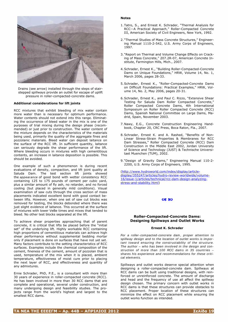
ΤΑ ΝΕΑ ΤΗΣ ΕΕΕΕΓΜ – Αρ. 44Β – ΑΠΡΙΛΙΟΣ 2012 Σελίδα 19
Drains (see arrow) installed through the steps of stair-stepped spillways provide an outlet for escape of uplift
pressure in roller-compacted-concrete dams.
Additional considerations for lift joints
RCC mixtures that exhibit bleeding of mix water contain more water than is necessary for optimum performance. Water contents should not extend into this range. Eliminat-ing the occurrence of bleed water in the mix is one of the purposes of trial mixing during the design phase (recom-mended) or just prior to construction. The water content of the mixture depends on the characteristics of the materials being used, primarily the quality of the aggregate fines and pozzolanic materials. Bleed water can deposit laitance on the surface of the RCC lift. In sufficient quantity, laitance can seriously degrade the shear performance of the lift. Where bleeding occurs in mixtures with high cementitious contents, an increase in laitance deposition is possible. This should be avoided.
One example of such a phenomenon is during recent evaluations of density, compaction, and lift joint quality at Saluda Dam. The test section lift joints showed the appearance of good bond with wetter consistency RCC containing 125 to 175 pounds of cement per cubic yard, plus a similar amount of fly ash, no retarder, and no forced cooling (but placed in generally mild conditions). Visual examination of saw cuts through the cross section of mass placements indicated excellent bond with good contact be-tween lifts. However, when one set of saw cut blocks was removed for testing, the blocks debonded where there was just slight evidence of laitance. This occurred at the surface of mixtures with lower VeBe times and mixes that tended to bleed. No other test blocks separated at the lift.
To achieve shear properties approaching that of parent concrete, it is critical that lifts be placed before the “initial set” of the underlying lift. Highly workable RCC containing high proportions of cementitious materials can achieve high shear performance without supplemental bedding mortar only if placement is done on surfaces that have not yet set. Many factors contribute to the setting characteristics of RCC surfaces. Examples include the chemical composition of the cement, fineness of the cement, amount of pozzolan that is used, temperature of the mix when it is placed, ambient temperature, effectiveness of moist cure prior to placing the next layer of RCC, and effectiveness and quantity of any admixtures.
Ernie Schrader, PhD, P.E., is a consultant with more than 30 years of experience in roller-compacted concrete (RCC). He has been involved in more than 30 RCC dams that are complete and operational, several under construction, and many undergoing design and feasibility studies. The pro-jects range from the world’s highest and largest to the smallest RCC dams.
Notes
1. Tatro, S., and Ernest K. Schrader, “Thermal Analysis for RCC—A Practical Approach,” Roller-Compacted Concrete III, American Society of Civil Engineers, New York, 1992.
2. “Thermal Studies of Mass Concrete Structures,” Engineer-ing Manual 1110-2-542, U.S. Army Corps of Engineers, 1997.
3. “Report on Thermal and Volume Change Effects on Crack-ing of Mass Concrete,” 207.2R-07, American Concrete In-stitute, Farmington Hills, Mich., 2007.
4. Schrader, Ernest K., “Building Roller-Compacted-Concrete Dams on Unique Foundations,” HRW, Volume 14, No. 1, March 2006, pages 28-33.
5. Schrader, Ernest K., “Roller-Compacted-Concrete Dams on Difficult Foundations: Practical Examples,” HRW, Vol-ume 14, No. 2, May 2006, pages 20-31.
6. Schrader, Ernest K., and Paul C. Rizzo, “Extensive Shear Testing for Saluda Dam Roller Compacted Concrete,” Roller Compacted Concrete Dams, 4th International Symposium on Roller Roller Compacted Concrete (RCC) Dams, Spanish National Committee on Large Dams, Ma-drid, Spain, November 2003.
7. Nawy, E.G., Concrete Construction Engineering Hand-book, Chapter 20, CRC Press, Boca Raton, Fla., 2007.
8. Schrader, Ernest K. and A. Rashed, “Benefits of Non-Linear Stress-Strain Properties & Membranes for RCC Dam Stresses,” Roller Compacted Concrete (RCC) Dam Construction in the Middle East 2002, Jordan University of Science and Technology (JUST) & Technische Universi-taet Muenchen (TUM), 2002.
9. “Design of Gravity Dams,” Engineering Manual 110-2-2200, U.S. Army Corps of Engineers, 1995.
(http://www.hydroworld.com/index/display/article-display/355247/articles/hydro-review-worldwide/volume-16/issue-1/articles/technical/rcc-dam-design-analyzing-stress-and-stability.html)
Roller-Compacted-Concrete Dams: Designing Spillways and Outlet Works
Ernest K. Schrader
For a roller-compacted-concrete dam, proper attention to spillway design and to the location of outlet works is impor-tant toward ensuring the constructability of the structure. The author – who has been involved in the design and con-struction of more than 100 RCC dams in 35 countries – shares his experience and recommendations for these criti-cal elements.
Spillways and outlet works deserve special attention when designing a roller-compacted-concrete dam. Spillways at RCC dams can be built using traditional designs, with rein-forced or unreinforced concrete. The amount of discharge and head and the frequency of use all affect the spillway design chosen. The primary concern with outlet works in RCC dams is that these structures can provide obstacles to RCC placement. Proper location of these structures can minimize the effect on RCC placement while ensuring the outlet works function as intended.
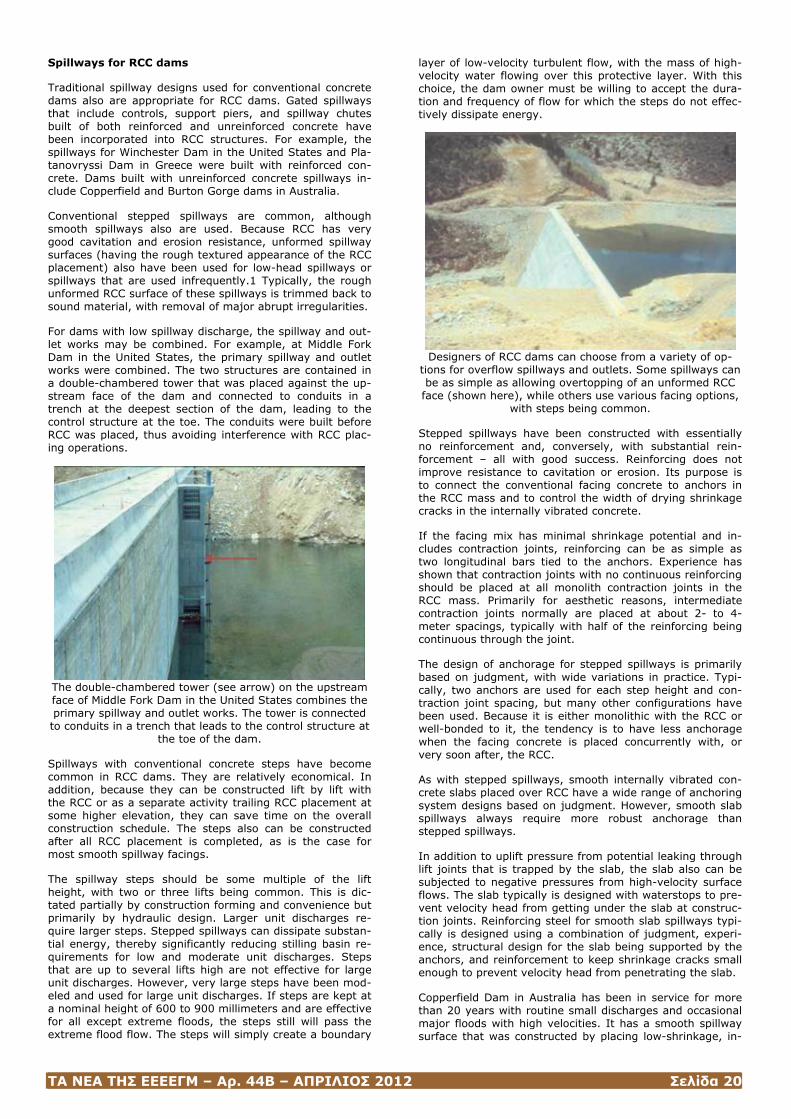
ΤΑ ΝΕΑ ΤΗΣ ΕΕΕΕΓΜ – Αρ. 44Β – ΑΠΡΙΛΙΟΣ 2012 Σελίδα 20
Spillways for RCC dams
Traditional spillway designs used for conventional concrete dams also are appropriate for RCC dams. Gated spillways that include controls, support piers, and spillway chutes built of both reinforced and unreinforced concrete have been incorporated into RCC structures. For example, the spillways for Winchester Dam in the United States and Pla-tanovryssi Dam in Greece were built with reinforced con-crete. Dams built with unreinforced concrete spillways in-clude Copperfield and Burton Gorge dams in Australia.
Conventional stepped spillways are common, although smooth spillways also are used. Because RCC has very good cavitation and erosion resistance, unformed spillway surfaces (having the rough textured appearance of the RCC placement) also have been used for low-head spillways or spillways that are used infrequently.1 Typically, the rough unformed RCC surface of these spillways is trimmed back to sound material, with removal of major abrupt irregularities.
For dams with low spillway discharge, the spillway and out-let works may be combined. For example, at Middle Fork Dam in the United States, the primary spillway and outlet works were combined. The two structures are contained in a double-chambered tower that was placed against the up-stream face of the dam and connected to conduits in a trench at the deepest section of the dam, leading to the control structure at the toe. The conduits were built before RCC was placed, thus avoiding interference with RCC plac-ing operations.
The double-chambered tower (see arrow) on the upstream face of Middle Fork Dam in the United States combines the primary spillway and outlet works. The tower is connected to conduits in a trench that leads to the control structure at
the toe of the dam.
Spillways with conventional concrete steps have become common in RCC dams. They are relatively economical. In addition, because they can be constructed lift by lift with the RCC or as a separate activity trailing RCC placement at some higher elevation, they can save time on the overall construction schedule. The steps also can be constructed after all RCC placement is completed, as is the case for most smooth spillway facings.
The spillway steps should be some multiple of the lift height, with two or three lifts being common. This is dic-tated partially by construction forming and convenience but primarily by hydraulic design. Larger unit discharges re-quire larger steps. Stepped spillways can dissipate substan-tial energy, thereby significantly reducing stilling basin re-quirements for low and moderate unit discharges. Steps that are up to several lifts high are not effective for large unit discharges. However, very large steps have been mod-eled and used for large unit discharges. If steps are kept at a nominal height of 600 to 900 millimeters and are effective for all except extreme floods, the steps still will pass the extreme flood flow. The steps will simply create a boundary
layer of low-velocity turbulent flow, with the mass of high-velocity water flowing over this protective layer. With this choice, the dam owner must be willing to accept the dura-tion and frequency of flow for which the steps do not effec-tively dissipate energy.
Designers of RCC dams can choose from a variety of op-
tions for overflow spillways and outlets. Some spillways can be as simple as allowing overtopping of an unformed RCC
face (shown here), while others use various facing options, with steps being common.
Stepped spillways have been constructed with essentially no reinforcement and, conversely, with substantial rein-forcement – all with good success. Reinforcing does not improve resistance to cavitation or erosion. Its purpose is to connect the conventional facing concrete to anchors in the RCC mass and to control the width of drying shrinkage cracks in the internally vibrated concrete.
If the facing mix has minimal shrinkage potential and in-cludes contraction joints, reinforcing can be as simple as two longitudinal bars tied to the anchors. Experience has shown that contraction joints with no continuous reinforcing should be placed at all monolith contraction joints in the RCC mass. Primarily for aesthetic reasons, intermediate contraction joints normally are placed at about 2- to 4-meter spacings, typically with half of the reinforcing being continuous through the joint.
The design of anchorage for stepped spillways is primarily based on judgment, with wide variations in practice. Typi-cally, two anchors are used for each step height and con-traction joint spacing, but many other configurations have been used. Because it is either monolithic with the RCC or well-bonded to it, the tendency is to have less anchorage when the facing concrete is placed concurrently with, or very soon after, the RCC.
As with stepped spillways, smooth internally vibrated con-crete slabs placed over RCC have a wide range of anchoring system designs based on judgment. However, smooth slab spillways always require more robust anchorage than stepped spillways.
In addition to uplift pressure from potential leaking through lift joints that is trapped by the slab, the slab also can be subjected to negative pressures from high-velocity surface flows. The slab typically is designed with waterstops to pre-vent velocity head from getting under the slab at construc-tion joints. Reinforcing steel for smooth slab spillways typi-cally is designed using a combination of judgment, experi-ence, structural design for the slab being supported by the anchors, and reinforcement to keep shrinkage cracks small enough to prevent velocity head from penetrating the slab.
Copperfield Dam in Australia has been in service for more than 20 years with routine small discharges and occasional major floods with high velocities. It has a smooth spillway surface that was constructed by placing low-shrinkage, in-
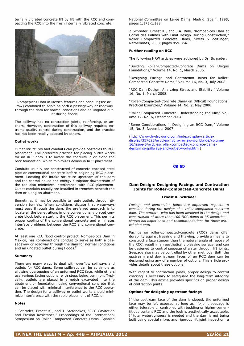
ΤΑ ΝΕΑ ΤΗΣ ΕΕΕΕΓΜ – Αρ. 44Β – ΑΠΡΙΛΙΟΣ 2012 Σελίδα 21
ternally vibrated concrete lift by lift with the RCC and com-pacting the RCC into the fresh internally vibrated concrete.
Rompepicos Dam in Mexico features one conduit (see ar-row) combined to serve as both a passageway or roadway
through the dam for normal conditions and an ungated out-let during floods.
The spillway has no contraction joints, reinforcing, or an-chors. However, construction of this spillway required ex-treme quality control during construction, and the practice has not been readily adopted by others.
Outlet works
Outlet structures and conduits can provide obstacles to RCC placement. The preferred practice for placing outlet works for an RCC dam is to locate the conduits in or along the rock foundation, which minimizes delays in RCC placement.
Conduits usually are constructed of concrete-encased steel pipe or conventional concrete before beginning RCC place-ment. Locating the intake structure upstream of the dam and the control house and energy dissipator downstream of the toe also minimizes interference with RCC placement. Outlet conduits usually are installed in trenches beneath the dam or along an abutment.
Sometimes it may be possible to route outlets through di-version tunnels. When conditions dictate that waterways must pass through the dam, the preferred approach is to locate all the penetrations in one conventionally placed con-crete block before starting the RCC placement. This permits proper cooling of the conventional concrete and eliminates interface problems between the RCC and conventional con-crete.
At least one RCC flood control project, Rompepicos Dam in Mexico, has combined one conduit to serve as both a pas-sageway or roadway through the dam for normal conditions and an ungated outlet during floods.2
Summary
There are many ways to deal with overflow spillways and outlets for RCC dams. Some spillways can be as simple as allowing overtopping of an unformed RCC face, while others use various facing options, with steps being common. Typi-cally, outlets are placed in a notch excavated into the abutment or foundation, using conventional concrete that can be placed with minimal interference to the RCC opera-tion. The design for a spillway or outlet works should mini-mize interference with the rapid placement of RCC. s
Notes
1 Schrader, Ernest K., and J. Stefanakos, “RCC Cavitation and Erosion Resistance,” Proceedings of the International Symposium on Roller Compacted Concrete Dams, Spanish
National Committee on Large Dams, Madrid, Spain, 1995, pages 1,175-1,188.
2 Schrader, Ernest K., and J.A. Balli, “Rompepicos Dam at Corral des Palmas with Final Design During Construction,” Roller Compacted Concrete Dams, Swets & Zeitlinger, Netherlands, 2003, pages 859-864.
Further reading on RCC
The following HRW articles were authored by Dr. Schrader:
“Building Roller-Compacted-Concrete Dams on Unique Foundations,” Volume 14, No. 1, March 2006.
“Designing Facings and Contraction Joints for Roller-Compacted-Concrete Dams,” Volume 16, No. 3, July 2008.
“RCC Dam Design: Analyzing Stress and Stability,” Volume 16, No. 1, March 2008.
“Roller-Compacted-Concrete Dams on Difficult Foundations: Practical Examples,” Volume 14, No. 2, May 2006.
“Roller-Compacted Concrete: Understanding the Mix,” Vol-ume 12, No. 6, December 2004.
“Some Considerations in Designing an RCC Dam,” Volume 15, No. 5, November 2007.
(http://www.hydroworld.com/index/display/article-display/357628/articles/hydro-review-worldwide/volume-16/issue-5/articles/roller-compacted-concrete-dams-designing-spillways-and-outlet-works.html)
Dam Design: Designing Facings and Contraction Joints for Roller-Compacted-Concrete Dams
Ernest K. Schrader
Facings and contraction joints are important aspects to consider during the design of a roller-compacted-concrete dam. The author – who has been involved in the design and construction of more than 100 RCC dams in 35 countries – shares his experience and recommendations for these criti-cal elements.
Facings on roller-compacted-concrete (RCC) dams offer durability against freezing and thawing, provide a means to construct a face steeper than the natural angle of repose of the RCC, result in an aesthetically pleasing surface, and can be designed to control seepage of water through lift joints. Seepage also may be controlled by other methods. Both the upstream and downstream faces of an RCC dam can be designed using any of a number of options. This article pro-vides details about these options.
With regard to contraction joints, proper design to control cracking is necessary to safeguard the long-term integrity of the dam. This article provides specifics on proper design of contraction joints.
Options for designing upstream facings
If the upstream face of the dam is sloped, the unformed face may be left exposed as long as lift-joint seepage is either tolerable or controlled with bedding or higher cemen-titious content RCC and the look is aesthetically acceptable. If total watertightness is needed and the dam is not being built using special mixes and rigorous lift joint inspection, a
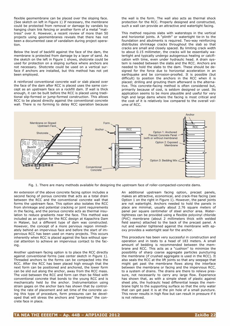
ΤΑ ΝΕΑ ΤΗΣ ΕΕΕΕΓΜ – Αρ. 44Β – ΑΠΡΙΛΙΟΣ 2012 Σελίδα 22
flexible geomembrane can be placed over the sloping face. (See sketch on left in Figure 1) If necessary, the membrane could be protected from removal or damage by vandals by hanging chain link fencing or another form of a metal “mat-tress” over it. However, a recent review of more than 50 projects using geomembranes reveals that there has not been a documented case of vandalism during project opera-tion.
Below the level of backfill against the face of the dam, the membrane is protected from damage by a layer of sand. As the sketch on the left in Figure 1 shows, shotcrete could be used for protection on a sloping surface where anchors are not necessary. Shotcrete could be used on a vertical sur-face if anchors are installed, but this method has not yet been employed.
A reinforced conventional concrete wall or slab placed over the face of the dam after RCC is placed uses the same con-cept as an upstream face on a rockfill dam. If wall is thick enough, it can be built before the RCC is placed using tradi-tional slip-formed or jump-formed construction. This allows RCC to be placed directly against the conventional concrete wall. There is no forming to delay RCC operation because
the wall is the form. The wall also acts as thermal shock protection for the RCC. Properly designed and constructed, such a wall can provide an attractive and watertight facing.
This method requires slabs with waterstops in the vertical and horizontal joints. A “plinth” or watertight tie-in to the foundation and abutments is required. Two-way reinforcing distributes shrinkage cracks throughout the slab so that cracks are small and closely spaced. By limiting crack width to about 0.15 millimeter, the cracks will be essentially wa-tertight and typically undergo autogenous healing or calcifi-cation with time, even under hydraulic head. A drain sys-tem is needed between the slabs and the RCC. Anchors are needed to hold the slabs to the dam. These should be de-signed for the force due to horizontal acceleration in an earthquake and be corrosion-proofed. It is possible (but difficult) to position the anchors in the RCC when it is placed; drilling and grouting them afterward is the alterna-tive. This concrete-facing method is often considered but, primarily because of cost, is seldom designed or used. Its application seems to be more plausible and useful for very high and large dams where the facing is most critical and the cost of it is relatively low compared to the overall vol-ume of RCC.
Fig. 1. There are many methods available for designing the upstream face of roller-compacted-concrete dams.
An extension of the above concrete facing option includes a second facing of porous concrete that acts as a total drain between the RCC and the conventional concrete wall that forms the upstream face. This option also isolates the RCC from shrinkage and potential cracking or joint requirements in the facing, and the porous concrete acts as thermal insu-lation to reduce gradients near the face. This method was included as an option for the RCC design at Kapachira Dam in Malawi, but a different type of dam was constructed. However, the concept of a more pervious region immedi-ately behind an impervious face and before the start of im-pervious RCC has been used on many projects. This occurs inherently when RCC is placed against the face without spe-cial attention to achieve an impervious contact to the fac-ing.
Another upstream facing option is to place the RCC directly against conventional forms (see center sketch in Figure 1). Threaded anchors to the forms can be compacted into the RCC. After the RCC has been placed high enough that the next form can be positioned and anchored, the lower form can be slid out along the anchor, away from the RCC mass. The void between the RCC and form can then be filled with conventional concrete that bonds to the young RCC and is mechanically held by the anchor. Instrumentation using strain gages on the anchor bars has shown that by control-ling the rate of placement and set time of the concrete us-ing this type of procedure, form pressures can be devel-oped that will stress the anchors and “prestress” the con-crete face in place.
An additional upstream facing option, precast panels, makes an attractive, economical, and crack-free facing (see Option 1 on the right in Figure 1). However, the panel joints are not watertight. Anchors needed to hold the panels in place are minimal, usually about 2.76 square meters of panel per square centimeter of steel anchor area. Water-tightness can be provided using a flexible polyvinyl chloride (PVC) membrane (about 2 millimeters thick with welded field seams) attached to the back of the precast panel. A nut and washer tightened against the membrane with ep-oxy provides a watertight seal for the anchor.
This procedure has been very successful in construction and operation and in tests to a head of 183 meters. A small amount of bedding is recommended between the mem-brane and RCC. This acts as a “cushion” to minimize the possibility of sharp coarse aggregate particles puncturing the membrane (if crushed aggregate is used in the RCC). It also seals the RCC at the lift joints so that any seepage that might get past the membrane flows along the interface between the membrane or facing and the impervious RCC, to a system of drains. The drains are there to relieve pres-sure, not necessarily to carry any large flow. Experience has shown that, as with a simple sheet of plastic against sheet pile, the hydraulic head differential keeps the mem-brane tight to the supporting surface so that the only water that can get past it is at the pin hole of a small puncture. This never results in high flow but can result in pressure if it is not relieved.
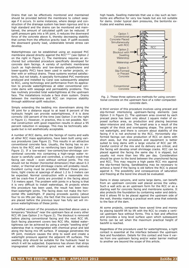
ΤΑ ΝΕΑ ΤΗΣ ΕΕΕΕΓΜ – Αρ. 44Β – ΑΠΡΙΛΙΟΣ 2012 Σελίδα 23
Drains that can be effectively monitored and maintained should be provided behind the membrane to collect seep-age if it occurs. In some instances, where design and con-struction of the drainage system has been rigorous and to a high standard and the drains can be monitored and main-tained, the amount of calculated uplift can be reduced. If uplift pressure gets into a lift joint, it reduces the downward force of the concrete above it, thereby decreasing stability that comes from the effective gravity load. If uplift exceeds the downward gravity load, undesirable tensile stress can develop.
Watertightness can be established using an exposed PVC membrane placed directly against the RCC1,2,3 (see Option 2 on the right in Figure 1). The membrane requires an an-chored but unbonded procedure specifically developed for concrete dam facings. A variety of synthetic membranes (such as high-density and low-density polyethylene and lower-quality PVC) have been used in earlier projects, ei-ther with or without drains. These systems worked satisfac-torily, but not totally. A specially formulated PVC membrane produced and installed by Carpi was subsequently adapted to RCC, using technology and performance from its applica-tion to provide watertightness at older conventional con-crete dams with seepage and permeability problems. This has routinely provided total watertightness at the upstream face. The installations include a face drain system. Drains between the membrane and RCC can improve stability through additional uplift reduction.
Simply extending the bedding mix downstream along the lift joint for a distance equal to at least 8 percent of the hydraulic height can provide watertightness, if it is done correctly 100 percent of the time (see Option 3 on the right in Figure 1). However, in practice, this is not possible. Nor-mal construction with good inspection results in about a 95 percent reduction in seepage. This may be technically ade-quate but is not aesthetically acceptable.
A number of RCC dams, and the facings of rooms and walls at other RCC mass applications, have been built using vari-ous procedures (see Figure 2). This results in an attractive conventional concrete face. Usually, the facing has no an-chors to the RCC and no reinforcing bars (see Option 1 in Figure 2). If a low-water/ low-cement/low-shrinkage con-ventional concrete mix containing a high-range water re-ducer is carefully used and controlled, a virtually crack-free facing can result – even without vertical joints. The mix should not be thicker (horizontal dimension) than about 0.3 meter, or thermal and shrinkage cracks will probably result. Excellent curing must be provided. Without these precau-tions, tight cracks at spacings of about 1.2 to 3 meters can be expected. Normal construction with a reasonable mix will be crack-free if joints are provided in the facing about 7.6 meters apart. The problem with joints in a facing is that it is very difficult to install waterstops. At projects where this procedure has been used, the result has been less-than-watertight joints. The facing does not make the hori-zontal lifts watertight. If placing proceeds quickly (about four to six lifts per day), the fact that the successive layers are placed before the previous layer has fully set will im-prove watertightness of these joints.
A modified version of the procedure described above uses a temporary “blockout” near the upstream face at every other RCC lift (see Option 2 in Figure 2). The blockout is removed before placing conventional facing and the next RCC lift. Each facing placement covers two RCC lifts. Added water-tightness can be achieved by using a simple “swelling strip” waterstop that is impregnated with chemical grout and laid along the facing mix lift surface. If seepage penetrates the lift joint, moisture causes the strip to swell and create a watertight pressure against the adjacent lift surfaces. The swelling strip should be suitable for the hydraulic head to which it will be subjected. Experience has shown that strips impregnated with chemical grout work well at relatively
high heads. Swelling materials that use a clay such as ben-tonite are effective for very low heads but are not suitable for dams. Under typical dam pressures, the bentonite ex-trudes and washes away.
Fig. 2. These three options are methods for using conven-tional concrete on the upstream face of a roller-compacted-
concrete dam.
A third version of this procedure involves using precast and slip-formed interlocking upstream-facing elements (see Option 3 in Figure 2). The upstream area covered by each precast piece has been only about 1 square meter of ex-posed surface area, so production and placing becomes labor-intensive and slow. The small area is a result of the weight of the thick and overlapping shape. The joints are not watertight, and there is concern about stability of the facing if it is not anchored to the RCC. Horizontally slip-formed facings can slow production of RCC on dams with short axes, but the procedure and equipment is better suited to long dams with a large volume of RCC per lift. Careful control of the mix and its delivery are critical, and the facing will develop small shrinkage cracks. RCC can be placed against the facing the same day it is slipped, but usually not more than two lifts per day. Consideration should be given to the bond between the unanchored facing and RCC. This may require a high paste RCC mix against the slip-formed facing. Sandblasting may be necessary to achieve a bond if the facing is old before the RCC is placed against it. The possibility and consequences of saturation and freezing at the bond line should be evaluated.
Dams in steep canyons, and some large dams, can benefit from an upstream concrete wall placed across the valley. Such a wall acts as an upstream form for the RCC or as a starting wall for concrete facing and membrane systems. It also protects the foundation by containing water and debris. And it allows fill to be placed against the upstream side of the wall, thereby making a practical work area that extends to the face of the dam.
At some projects, companies have saved time and money by placing backfill lift by lift with the RCC to create a verti-cal upstream face without forms. This is fast and effective and provides a long level surface upon which subsequent forms can be set when the maximum practical height of backfill is reached.
Regardless of the procedure used for watertightness, a tight contact is essential at the interface between the upstream face and foundation. Details for this contact and how it var-ies from one upstream facing and/or water barrier method to another are beyond the scope of this article.
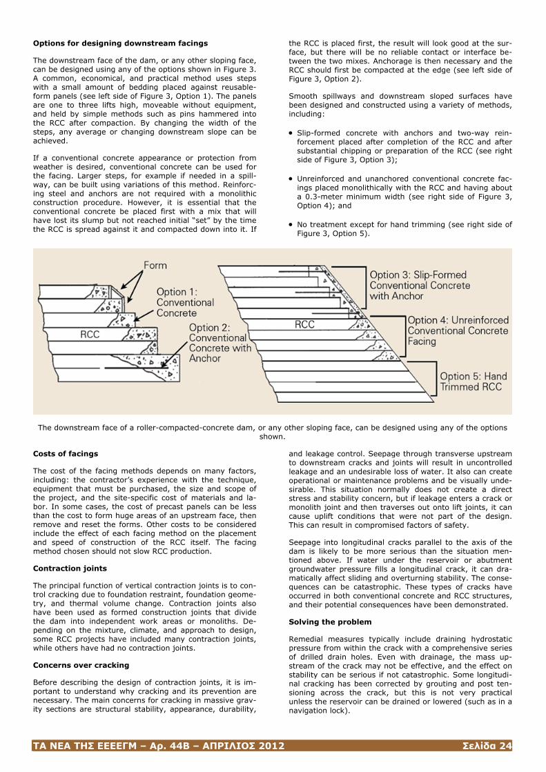
ΤΑ ΝΕΑ ΤΗΣ ΕΕΕΕΓΜ – Αρ. 44Β – ΑΠΡΙΛΙΟΣ 2012 Σελίδα 24
Options for designing downstream facings
The downstream face of the dam, or any other sloping face, can be designed using any of the options shown in Figure 3. A common, economical, and practical method uses steps with a small amount of bedding placed against reusable-form panels (see left side of Figure 3, Option 1). The panels are one to three lifts high, moveable without equipment, and held by simple methods such as pins hammered into the RCC after compaction. By changing the width of the steps, any average or changing downstream slope can be achieved.
If a conventional concrete appearance or protection from weather is desired, conventional concrete can be used for the facing. Larger steps, for example if needed in a spill-way, can be built using variations of this method. Reinforc-ing steel and anchors are not required with a monolithic construction procedure. However, it is essential that the conventional concrete be placed first with a mix that will have lost its slump but not reached initial “set” by the time the RCC is spread against it and compacted down into it. If
the RCC is placed first, the result will look good at the sur-face, but there will be no reliable contact or interface be-tween the two mixes. Anchorage is then necessary and the RCC should first be compacted at the edge (see left side of Figure 3, Option 2).
Smooth spillways and downstream sloped surfaces have been designed and constructed using a variety of methods, including:
• Slip-formed concrete with anchors and two-way rein-forcement placed after completion of the RCC and after substantial chipping or preparation of the RCC (see right side of Figure 3, Option 3);
• Unreinforced and unanchored conventional concrete fac-ings placed monolithically with the RCC and having about a 0.3-meter minimum width (see right side of Figure 3, Option 4); and
• No treatment except for hand trimming (see right side of Figure 3, Option 5).
The downstream face of a roller-compacted-concrete dam, or any other sloping face, can be designed using any of the options shown.
Costs of facings
The cost of the facing methods depends on many factors, including: the contractor’s experience with the technique, equipment that must be purchased, the size and scope of the project, and the site-specific cost of materials and la-bor. In some cases, the cost of precast panels can be less than the cost to form huge areas of an upstream face, then remove and reset the forms. Other costs to be considered include the effect of each facing method on the placement and speed of construction of the RCC itself. The facing method chosen should not slow RCC production.
Contraction joints
The principal function of vertical contraction joints is to con-trol cracking due to foundation restraint, foundation geome-try, and thermal volume change. Contraction joints also have been used as formed construction joints that divide the dam into independent work areas or monoliths. De-pending on the mixture, climate, and approach to design, some RCC projects have included many contraction joints, while others have had no contraction joints.
Concerns over cracking
Before describing the design of contraction joints, it is im-portant to understand why cracking and its prevention are necessary. The main concerns for cracking in massive grav-ity sections are structural stability, appearance, durability,
and leakage control. Seepage through transverse upstream to downstream cracks and joints will result in uncontrolled leakage and an undesirable loss of water. It also can create operational or maintenance problems and be visually unde-sirable. This situation normally does not create a direct stress and stability concern, but if leakage enters a crack or monolith joint and then traverses out onto lift joints, it can cause uplift conditions that were not part of the design. This can result in compromised factors of safety.
Seepage into longitudinal cracks parallel to the axis of the dam is likely to be more serious than the situation men-tioned above. If water under the reservoir or abutment groundwater pressure fills a longitudinal crack, it can dra-matically affect sliding and overturning stability. The conse-quences can be catastrophic. These types of cracks have occurred in both conventional concrete and RCC structures, and their potential consequences have been demonstrated.
Solving the problem
Remedial measures typically include draining hydrostatic pressure from within the crack with a comprehensive series of drilled drain holes. Even with drainage, the mass up-stream of the crack may not be effective, and the effect on stability can be serious if not catastrophic. Some longitudi-nal cracking has been corrected by grouting and post ten-sioning across the crack, but this is not very practical unless the reservoir can be drained or lowered (such as in a navigation lock).
ΤΑ ΝΕΑ ΤΗΣ ΕΕΕΕΓΜ – Αρ. 44Β – ΑΠΡΙΛΙΟΣ 2012 Σελίδα 25
When thermal or other analysis indicates that an unaccept-able longitudinal crack is possible, a groutable joint can be constructed at that location. The joint should be grouted after thermal contraction has caused it to open significantly, but grouting may be needed earlier due to the schedule for filling the reservoir. In this case, a re-groutable joint should be designed if possible, or the joint and grout should be designed so that the grout will continually expand over time as the joint tends to open more.
The location and spacing of joints depends on: foundation restraint, temperature change and the time period over which it occurs, the tensile strain capacity of the concrete at the time in question, creep relaxation, the coefficient of thermal expansion of the concrete, and applied loads. For many projects, joints are carefully formed to go through the entire dam. Other designs use partial joints to provide a weakened plane along which cracks will propagate. Wa-terstops and drains are usually an integral part of a com-plete joint design.
Seepage control methods of transverse contraction joints vary widely. Seepage control methods for RCC dams include:
• A surface control joint with waterstops;
• A membrane placed over the upstream surface (either a membrane with precast concrete panels or an exposed membrane); and
• Conventional concrete face of jointed slabs placed after the RCC.
Transverse contraction joints with surface control and wa-terstops have been used in numerous RCC dams. Typical details consist of a formed crack inducer in the upstream face with a waterstop in the facing concrete, followed by crack inducement in the RCC lift by one of the methods described above.
Arch dams and gravity arch dams require contact across transverse contraction joints in order for the structure to function in the three-dimensional manner in which it has been designed. This normally requires grouting with effec-tive “grout stops” at both the upstream and downstream faces of the dam, similar to conventional concrete arch dams. Unlike conventional concrete, RCC typically is not post-cooled to assure full contraction before grouting, so the concerns discussed above for longitudinal joints also apply to these joints. However, if the RCC has a high Pois-son ratio and low modulus of elasticity during the time the dam is constructed, and if thermal contraction is kept to a minimum, joints in the lower portion of the dam may re-main in close contact even without grouting. The same ap-plies to straight axis dams in tight “V” shaped canyons, which also can benefit from three-dimensional effects simi-lar to arch dams.
Notes
1. Nawy, E.G., Concrete Construction Engineering Hand-book, Chapter 20, CRC Press, Boca Raton, Fla., 2007.
2. Schrader, Ernest K. and A. Rashed, “Benefits of Non-Linear Stress-Strain Properties & Membranes for RCC Dam Stresses,” Roller Compacted Concrete (RCC) Dam Construction in the Middle East 2002, Jordan University of Science and Technology (JUST) & Technische Universi-taet Muenchen (TUM), 2002.
3. Scuero, A, and G. Vaschetti, “Synthetic Geomembranes in RCC Dams: Since 1984, A Reliable Cost Effective Way to Stop Leakage,” Roller Compacted Concrete Dams, In-ternational RCC Dam Symposium, Swets & Zeitlinger,
Lisse, Netherlands, Lisse, November 2003, pages 519-530.
(Hydro Review, http://www.hydroworld.com/index/display/article-display/356887/articles/hydro-review-worldwide/volume-16/issue-3/articles/dam-design-designing-facings-and-contraction-joints-for-roller-compacted-concrete-dams.html)
Hickory Log Creek: Building a Roller-Compacted-Concrete Dam
James M. Parsons, Randall P. Bass, Charles M. Kahler, and Rodolfo T. Ruiz-Gaekel
To overcome site constraints and to meet a tight timeline for completing its new Hickory Log Creek Dam, the Cobb County-Marietta Water Authority and the city of Canton, Ga., chose to build a roller-compacted-concrete structure. Construction of the dam, completed in November 2007, taught several valuable lessons about the use of RCC.
Construction of Hickory Log Creek Dam on Hickory Log Creek, a tributary of the Etowah River in Georgia, was completed in November 2007. Hickory Log Creek Dam is the highest roller-compacted-concrete (RCC) dam in Geor-gia and the fourth highest in North America. The dam is 180 feet high and 956 feet long. The need for this dam was initially identified in a 1996 study, to increase water avail-able for the growing area northeast of Atlanta.
Before the dam could be built, Cobb County-Marietta Water Authority and the city of Canton, Ga., needed to determine whether to build an earthfill or RCC dam. Site restrictions, costs, and schedule led to the selection of an RCC dam. This option would save about $4 million and one construc-tion season compared with building an earthfill dam.
Impoundment of the reservoir behind Hickory Log Creek Dam began in November 2007. When this process is com-pleted in one to two years, the reservoir will provide 44 million gallons of water a day for the city of Canton and the wholesale customers of the water authority. Lessons learned from the construction of this dam could help others who are designing and building RCC dams.
Why the dam was needed
Significant population growth in the northeast area of At-lanta resulted in growing demand for water in the region. To meet this demand, the Cobb County-Marietta Water Au-thority and the city of Canton started the planning process for a new water supply reservoir.
The site chosen for the proposed Hickory Log Creek Dam is near an 8.5-acre lake on Hickory Log Creek that was part of the Canton Mills Lake manufacturing plant along the Etowah River. The Canton Mills heirs donated 300 acres in the area where the Hickory Log Creek Reservoir would be located.
The reservoir needed to yield 44 million gallons of water per day. Using this yield, the dam developers established the final dam site and the normal pool elevation. Inflows into the resulting 411-acre Hickory Log Creek Reservoir are supplemented by a pumping station located about 7,000 feet below the dam on the Etowah River. This station pumps water from the Etowah River when inflow from Hick-ory Log Creek is insufficient to fill the reservoir. Once the
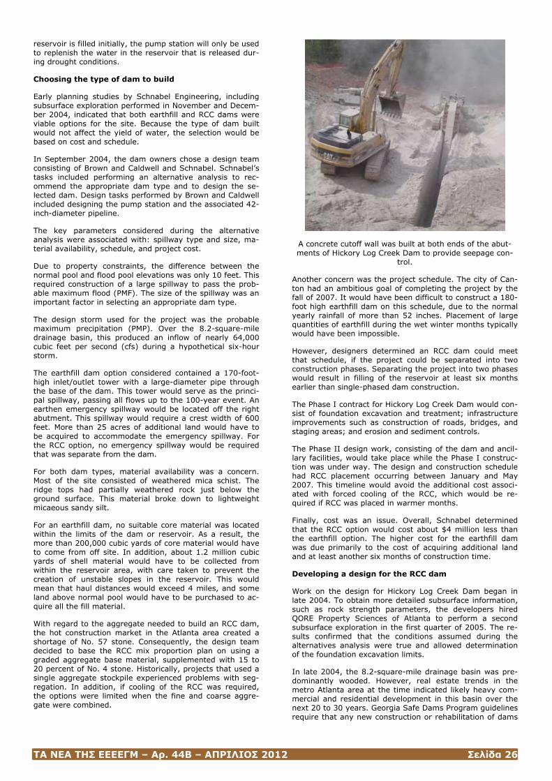
ΤΑ ΝΕΑ ΤΗΣ ΕΕΕΕΓΜ – Αρ. 44Β – ΑΠΡΙΛΙΟΣ 2012 Σελίδα 26
reservoir is filled initially, the pump station will only be used to replenish the water in the reservoir that is released dur-ing drought conditions.
Choosing the type of dam to build
Early planning studies by Schnabel Engineering, including subsurface exploration performed in November and Decem-ber 2004, indicated that both earthfill and RCC dams were viable options for the site. Because the type of dam built would not affect the yield of water, the selection would be based on cost and schedule.
In September 2004, the dam owners chose a design team consisting of Brown and Caldwell and Schnabel. Schnabel’s tasks included performing an alternative analysis to rec-ommend the appropriate dam type and to design the se-lected dam. Design tasks performed by Brown and Caldwell included designing the pump station and the associated 42-inch-diameter pipeline.
The key parameters considered during the alternative analysis were associated with: spillway type and size, ma-terial availability, schedule, and project cost.
Due to property constraints, the difference between the normal pool and flood pool elevations was only 10 feet. This required construction of a large spillway to pass the prob-able maximum flood (PMF). The size of the spillway was an important factor in selecting an appropriate dam type.
The design storm used for the project was the probable maximum precipitation (PMP). Over the 8.2-square-mile drainage basin, this produced an inflow of nearly 64,000 cubic feet per second (cfs) during a hypothetical six-hour storm.
The earthfill dam option considered contained a 170-foot-high inlet/outlet tower with a large-diameter pipe through the base of the dam. This tower would serve as the princi-pal spillway, passing all flows up to the 100-year event. An earthen emergency spillway would be located off the right abutment. This spillway would require a crest width of 600 feet. More than 25 acres of additional land would have to be acquired to accommodate the emergency spillway. For the RCC option, no emergency spillway would be required that was separate from the dam.
For both dam types, material availability was a concern. Most of the site consisted of weathered mica schist. The ridge tops had partially weathered rock just below the ground surface. This material broke down to lightweight micaeous sandy silt.
For an earthfill dam, no suitable core material was located within the limits of the dam or reservoir. As a result, the more than 200,000 cubic yards of core material would have to come from off site. In addition, about 1.2 million cubic yards of shell material would have to be collected from within the reservoir area, with care taken to prevent the creation of unstable slopes in the reservoir. This would mean that haul distances would exceed 4 miles, and some land above normal pool would have to be purchased to ac-quire all the fill material.
With regard to the aggregate needed to build an RCC dam, the hot construction market in the Atlanta area created a shortage of No. 57 stone. Consequently, the design team decided to base the RCC mix proportion plan on using a graded aggregate base material, supplemented with 15 to 20 percent of No. 4 stone. Historically, projects that used a single aggregate stockpile experienced problems with seg-regation. In addition, if cooling of the RCC was required, the options were limited when the fine and coarse aggre-gate were combined.
A concrete cutoff wall was built at both ends of the abut-ments of Hickory Log Creek Dam to provide seepage con-
trol.
Another concern was the project schedule. The city of Can-ton had an ambitious goal of completing the project by the fall of 2007. It would have been difficult to construct a 180-foot high earthfill dam on this schedule, due to the normal yearly rainfall of more than 52 inches. Placement of large quantities of earthfill during the wet winter months typically would have been impossible.
However, designers determined an RCC dam could meet that schedule, if the project could be separated into two construction phases. Separating the project into two phases would result in filling of the reservoir at least six months earlier than single-phased dam construction.
The Phase I contract for Hickory Log Creek Dam would con-sist of foundation excavation and treatment; infrastructure improvements such as construction of roads, bridges, and staging areas; and erosion and sediment controls.
The Phase II design work, consisting of the dam and ancil-lary facilities, would take place while the Phase I construc-tion was under way. The design and construction schedule had RCC placement occurring between January and May 2007. This timeline would avoid the additional cost associ-ated with forced cooling of the RCC, which would be re-quired if RCC was placed in warmer months.
Finally, cost was an issue. Overall, Schnabel determined that the RCC option would cost about $4 million less than the earthfill option. The higher cost for the earthfill dam was due primarily to the cost of acquiring additional land and at least another six months of construction time.
Developing a design for the RCC dam
Work on the design for Hickory Log Creek Dam began in late 2004. To obtain more detailed subsurface information, such as rock strength parameters, the developers hired QORE Property Sciences of Atlanta to perform a second subsurface exploration in the first quarter of 2005. The re-sults confirmed that the conditions assumed during the alternatives analysis were true and allowed determination of the foundation excavation limits.
In late 2004, the 8.2-square-mile drainage basin was pre-dominantly wooded. However, real estate trends in the metro Atlanta area at the time indicated likely heavy com-mercial and residential development in this basin over the next 20 to 30 years. Georgia Safe Dams Program guidelines require that any new construction or rehabilitation of dams
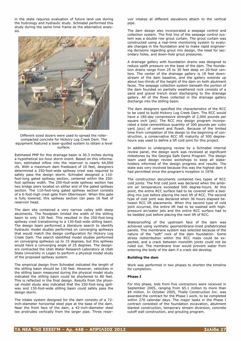
ΤΑ ΝΕΑ ΤΗΣ ΕΕΕΕΓΜ – Αρ. 44Β – ΑΠΡΙΛΙΟΣ 2012 Σελίδα 27
in the state requires evaluation of future land use during the hydrology and hydraulic study. Schnabel performed this study during the same time frame as the alternative analy-sis.
Different sized dozers were used to spread the roller-compacted concrete for Hickory Log Creek Dam. The
equipment featured a laser-guided system to obtain a level surface.
Estimated PMP for this drainage basin is 30.3 inches during a hypothetical six-hour storm event. Based on this informa-tion, estimated inflow into the reservoir is nearly 64,000 cfs. With a maximum dam freeboard of 10 feet, designers determined a 250-foot-wide spillway crest was required to safely pass the design storm. Schnabel designed a 110-foot-long gated spillway section, centered within the 250-foot spillway width. The 250-foot-wide spillway section has two bridge piers located on either end of the gated spillway section. The 110-foot-long gated spillway section consists of a 6-foot-high crest gate from Obermeyer. When this gate is fully lowered, this spillway section can pass 16 feet of reservoir head.
The dam site contained a very narrow valley with steep abutments. The floodplain limited the width of the stilling basin to only 130 feet. This resulted in the 250-foot-long spillway crest transitioning to a 130-foot-wide stilling basin. The design team performed a literature search to identify hydraulic model studies performed on converging spillways that would match the design configuration for Hickory Log Creek Dam. The search identified model studies performed on converging spillways up to 15 degrees, but this spillway would have a converging angle of 25 degrees. The design-ers contracted the Utah Water Research Laboratory at Utah State University in Logan to perform a physical model study of the proposed spillway system.
The empirical design from Schnabel indicated the length of the stilling basin should be 130 feet. However, velocities in the stilling basin measured during the physical model study indicated the stilling basin could be shortened to 80 feet. This is reflected in the final design. Results from the physi-cal model study also indicated that the 250-foot-long spill-way and 130-foot-wide stilling basin could safely pass the design storm.
The intake system designed for the dam consists of a 72-inch-diameter horizontal steel pipe at the base of the dam. Near the front face of the dam, a 42-inch-diameter steel tee protrudes vertically from the larger pipe. Three reser-
voir intakes at different elevations attach to the vertical pipe.
The dam design also incorporated a seepage control and collection system. The first line of the seepage control sys-tem was a double row grout curtain. The grout curtain was constructed using a real-time monitoring system to evalu-ate changes in the foundation and to make rapid engineer-ing decisions regarding grout mix design, the need for sec-ondary holes, and down-hole grout pressures.
A drainage gallery with foundation drains was designed to reduce uplift pressure on the base of the dam. The founda-tion drains range from 25 to 30 feet deep on 20-foot cen-ters. The center of the drainage gallery is 18 feet down-stream of the dam baseline, and the gallery extends up about two-thirds of the height of the dam on both abutment faces. The seepage collection system beneath the portion of the dam founded on partially weathered rock consists of a sand and gravel trench drain discharging to the drainage gallery. All of the flows collected in the drainage gallery discharge into the stilling basin.
The dam designers specified the characteristics of the RCC to be used to build Hickory Log Creek Dam. The RCC would have a 180-day compressive strength of 2,000 pounds per square inch (psi). The RCC mix design program incorpo-rated a total cementitious quantity of 300 pounds per cubic yard (pcy) of cement and flyash. Because of the limited time from completion of the design to the beginning of con-struction, a conservative RCC lift maturity of 500 degree-hours was used to define a lift cold joint for this project.
In addition to undergoing review by a Schnabel internal review panel, the design work was reviewed at significant milestones by the Georgia Safe Dams Program. The design team used design review workshops to keep all stake-holders informed of the design progress and results. The state was very involved because this was the highest dam it had permitted since the program’s inception in 1978.
The construction documents contained two types of RCC cold joints. The first cold joint was declared when the ambi-ent air temperature exceeded 500 degree-hours. At this point, the entire RCC surface had to be covered with a bed-ding mix just before placing the next lift of RCC. The second type of cold joint was declared when 36 hours elapsed be-tween RCC lift placements. When this second type of cold joint occurred, the entire lift had to be washed with high-pressure air/water jets and the entire RCC surface had to be bedded just before placing the next lift of RCC.
Waterproofing of the upstream face of the dam was achieved using synthetic geomembrane-lined prefabricated panels. This membrane system was selected because of the nature of the “soft” rock of the dam foundation. Some stress redistribution within the RCC mass could be ex-pected, and a crack between monolith joints could not be ruled out. The membrane liner would prevent water from entering the body of the dam if a crack did develop.
Building the dam
Work was performed in two phases to shorten the timeline for completion.
Phase I
For this phase, bids from five contractors were received in September 2005, ranging from $5.1 million to more than $9 million. In October 2005, Thalle Construction Inc. was awarded the contract for the Phase I work, to be completed within 270 calendar days. The major tasks in the Phase I contract consisted of the foundation excavation, abutment blanket construction, temporary stream diversion, concrete cutoff wall construction, and grouting program.
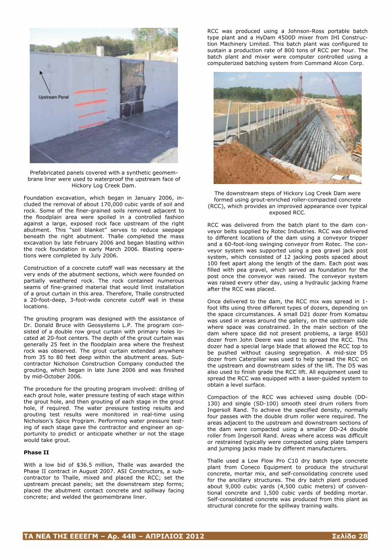
ΤΑ ΝΕΑ ΤΗΣ ΕΕΕΕΓΜ – Αρ. 44Β – ΑΠΡΙΛΙΟΣ 2012 Σελίδα 28
Prefabricated panels covered with a synthetic geomem-brane liner were used to waterproof the upstream face of
Hickory Log Creek Dam.
Foundation excavation, which began in January 2006, in-cluded the removal of about 170,000 cubic yards of soil and rock. Some of the finer-grained soils removed adjacent to the floodplain area were spoiled in a controlled fashion against a large, exposed rock face upstream of the right abutment. This “soil blanket” serves to reduce seepage beneath the right abutment. Thalle completed the mass excavation by late February 2006 and began blasting within the rock foundation in early March 2006. Blasting opera-tions were completed by July 2006.
Construction of a concrete cutoff wall was necessary at the very ends of the abutment sections, which were founded on partially weathered rock. The rock contained numerous seams of fine-grained material that would limit installation of a grout curtain in this area. Therefore, Thalle constructed a 20-foot-deep, 3-foot-wide concrete cutoff wall in these locations.
The grouting program was designed with the assistance of Dr. Donald Bruce with Geosystems L.P. The program con-sisted of a double row grout curtain with primary holes lo-cated at 20-foot centers. The depth of the grout curtain was generally 25 feet in the floodplain area where the freshest rock was observed. The grout curtain extended anywhere from 35 to 80 feet deep within the abutment areas. Sub-contractor Nicholson Construction Company conducted the grouting, which began in late June 2006 and was finished by mid-October 2006.
The procedure for the grouting program involved: drilling of each grout hole, water pressure testing of each stage within the grout hole, and then grouting of each stage in the grout hole, if required. The water pressure testing results and grouting test results were monitored in real-time using Nicholson’s Spice Program. Performing water pressure test-ing of each stage gave the contractor and engineer an op-portunity to predict or anticipate whether or not the stage would take grout.
Phase II
With a low bid of $36.5 million, Thalle was awarded the Phase II contract in August 2007. ASI Constructors, a sub-contractor to Thalle, mixed and placed the RCC; set the upstream precast panels; set the downstream step forms; placed the abutment contact concrete and spillway facing concrete; and welded the geomembrane liner.
RCC was produced using a Johnson-Ross portable batch type plant and a HyDam 4500D mixer from IHI Construc-tion Machinery Limited. This batch plant was configured to sustain a production rate of 800 tons of RCC per hour. The batch plant and mixer were computer controlled using a computerized batching system from Command Alcon Corp.
The downstream steps of Hickory Log Creek Dam were formed using grout-enriched roller-compacted concrete
(RCC), which provides an improved appearance over typical exposed RCC.
RCC was delivered from the batch plant to the dam con-veyor belts supplied by Rotec Industries. RCC was delivered to different locations of the dam using a conveyor tripper and a 60-foot-long swinging conveyor from Rotec. The con-veyor system was supported using a pea gravel jack post system, which consisted of 12 jacking posts spaced about 100 feet apart along the length of the dam. Each post was filled with pea gravel, which served as foundation for the post once the conveyor was raised. The conveyor system was raised every other day, using a hydraulic jacking frame after the RCC was placed.
Once delivered to the dam, the RCC mix was spread in 1-foot lifts using three different types of dozers, depending on the space circumstances. A small D21 dozer from Komatsu was used in areas around the gallery, on the upstream side where space was constrained. In the main section of the dam where space did not present problems, a large 850J dozer from John Deere was used to spread the RCC. This dozer had a special large blade that allowed the RCC top to be pushed without causing segregation. A mid-size D5 dozer from Caterpillar was used to help spread the RCC on the upstream and downstream sides of the lift. The D5 was also used to finish grade the RCC lift. All equipment used to spread the RCC was equipped with a laser-guided system to obtain a level surface.
Compaction of the RCC was achieved using double (DD-130) and single (SD-100) smooth steel drum rollers from Ingersoll Rand. To achieve the specified density, normally four passes with the double drum roller were required. The areas adjacent to the upstream and downstream sections of the dam were compacted using a smaller DD-24 double roller from Ingersoll Rand. Areas where access was difficult or restrained typically were compacted using plate tampers and jumping jacks made by different manufacturers.
Thalle used a Low Flow Pro C10 dry batch type concrete plant from Coneco Equipment to produce the structural concrete, mortar mix, and self-consolidating concrete used for the ancillary structures. The dry batch plant produced about 9,000 cubic yards (4,500 cubic meters) of conven-tional concrete and 1,500 cubic yards of bedding mortar. Self-consolidated concrete was produced from this plant as structural concrete for the spillway training walls.
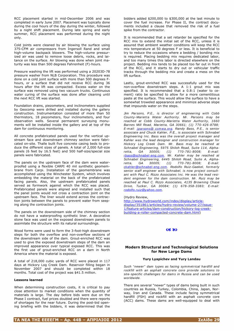
ΤΑ ΝΕΑ ΤΗΣ ΕΕΕΕΓΜ – Αρ. 44Β – ΑΠΡΙΛΙΟΣ 2012 Σελίδα 29
RCC placement started in mid-December 2006 and was completed in early June 2007. Placement was typically done during the cool hours of the day during the winter, followed by a night shift placement. During late spring and early summer, RCC placement was performed during the night only.
Cold joints were cleaned by air blowing the surface using 375-CFM air compressors from Ingersoll Rand and small high-volume backpack blowers. The high-volume pressur-ized air was used to remove loose debris, rocks, and lai-tance on the surface. Air blowing was done when joint ma-turity was less than 500 degrees Fahrenheit (F)-hours.
Pressure washing the lift was performed using a 20203D-78 pressure washer from NLB Corporation. This procedure was done on a cold joint surface with more than 500 degrees F-hours, or a surface that did not receive RCC during 36 hours after the lift was compacted. Excess water on the surface was removed using two vacuum trucks. Continuous water curing of the surface was done after cleaning until the next RCC lift was started.
Foundation drains, piezometers, and inclinometers supplied by Geocomp were drilled and installed during the gallery construction. Instrumentation consisted of more than 50 thermistors, 18 piezometers, four inclinometers, and four observation wells. Several permanent surveying monu-ments will be installed inside the gallery and at top of the dam for continuous monitoring.
All concrete prefabricated panels used for the vertical up-stream face and downstream chimney section were fabri-cated on-site. Thalle built five concrete casing beds to pro-duce the different sizes of panels. A total of 2,000 full-size panels (6 feet by 16.5 feet) and 500 half-size/special size panels were fabricated.
The panels on the upstream face of the dam were water-proofed using a flexible CARPI 40 mil synthetic geomem-brane from Carpi. Installation of the geomembrane was accomplished using the Winchester System, which involves embedding the material on the back of the prefabricated facing panels. Also, the upstream prefabricated panels served as formwork against which the RCC was placed. Prefabricated panels were aligned and installed such that the panel joints would not cross a contraction joint on the upstream face. The liner would extend across the contrac-tion joints between the panels to prevent water from seep-ing along the contraction joints.
The panels on the downstream side of the chimney section do not have a waterproofing synthetic liner. A decorative stone face was used on the exposed downstream panels to assimilate the structure with its natural surroundings.
Wood forms were used to form the 3-foot-high downstream steps for both the overflow and non-overflow sections of the downstream side of the dam. Grout-enriched RCC was used to give the exposed downstream steps of the dam an improved appearance over typical exposed RCC. This was the first use of grout-enriched RCC on a dam in North America where the material is exposed.
A total of 218,000 cubic yards of RCC were placed in 117 days at Hickory Log Creek Dam. Reservoir filling began in November 2007 and should be completed within 18 months. Total cost of the project was $41.5 million.
Lessons learned
When determining construction costs, it is critical to pay close attention to market conditions when the quantity of materials is large. The day before bids were due on the Phase I contract, fuel prices doubled and there were reports of shortages for the near future. During the post-bid open-ing briefing with the bidders, it was determined that the
bidders added $200,000 to $300,000 at the last minute to cover the fuel increase. For Phase II, the contract docu-ments included a clause that removed the risk of a fuel spike from the contractor.
It is recommended that a set retarder be specified for the RCC mix to extend the initial set of the RCC, unless it is assured that ambient weather conditions will keep the RCC mix temperature at 50 degrees F or less. It is beneficial to try to reduce the occasions where a bedding / bonding mix is required. Placing bedding mix requires dedicated labor, and too many times this labor is directed elsewhere on the project. Bedding mix tends to be placed too far out in front of the RCC, and it starts to dry out or vehicular traffic tracks through the bedding mix and create a mess on the lift surface.
Lastly, grout-enriched RCC was successfully used for the non-overflow downstream steps. A 1:1 grout mix was specified. It is recommended that a 0.8:1 (water to ce-ment) ratio be specified to allow for a more cementitious paste at the surface. This would allow the surface to have a somewhat troweled appearance and minimize adverse slope that impounds water on the steps.
Jim Parsons, P.E., is director of engineering with Cobb County-Marietta Water Authority. Mr. Parsons may be reached at Cobb County-Marietta Water Authority, 1660 Barnes Mill Road, Marietta, GA 30661; (1) 770-426-8788; E-mail: jparsons@ ccmwa.org. Randy Bass, P.E., is senior associate and Chuck Kahler, P.E., is associate with Schnabel Engineering Inc. Bass was the overall project manager and Kahler was the lead designer and construction manager for Hickory Log Creek Dam. Mr. Bass may be reached at Schnabel Engineering, 5975 Shiloh Road, Suite 114, Alpha-retta, GA 30005; (1) 770-781-8008; E-mail: [email protected]. Mr. Kahler may be reached at Schnabel Engineering, 6445 Shiloh Road, Suite A, Alpha-retta, GA 30005; (1) 770-781-8008; E-mail: [email protected]. Rodolfo Ruiz-Gaekel, formerly senior staff engineer with Schnabel, is now project consult-ant with Paul C. Rizzo Associates Inc. He was the lead resi-dent engineer for the dam construction. Mr. Ruiz may be reached at Paul C. Rizzo Associates, 4135 Browning Chase Drive, Tucker, GA 30084; (1) 678-358-3383; E-mail: [email protected].
(Hydro Review, http://www.hydroworld.com/index/display/article-display/351861/articles/hydro-review/volume-27/issue-1/feature-articles/dam-construction/hickory-log-creek-building-a-roller-compacted-concrete-dam.html)
Modern Structural and Technological Solutions for New Large Dams
Yury Lyapichev and Yury Landau
Such “newer” dam types as facing symmetrical hardfill and rockfill with an asphalt concrete core provide solutions to site-specific challenges for dams in Russia and can be used worldwide.
There are several “newer” types of dams being built in such countries as Russia, Turkey, Colombia, China, Japan, Nor-way, Iran and Canada. These include facing symmetrical hardfill (FSH) and rockfill with an asphalt concrete core (ACC) dams. These dams are well-equipped to deal with
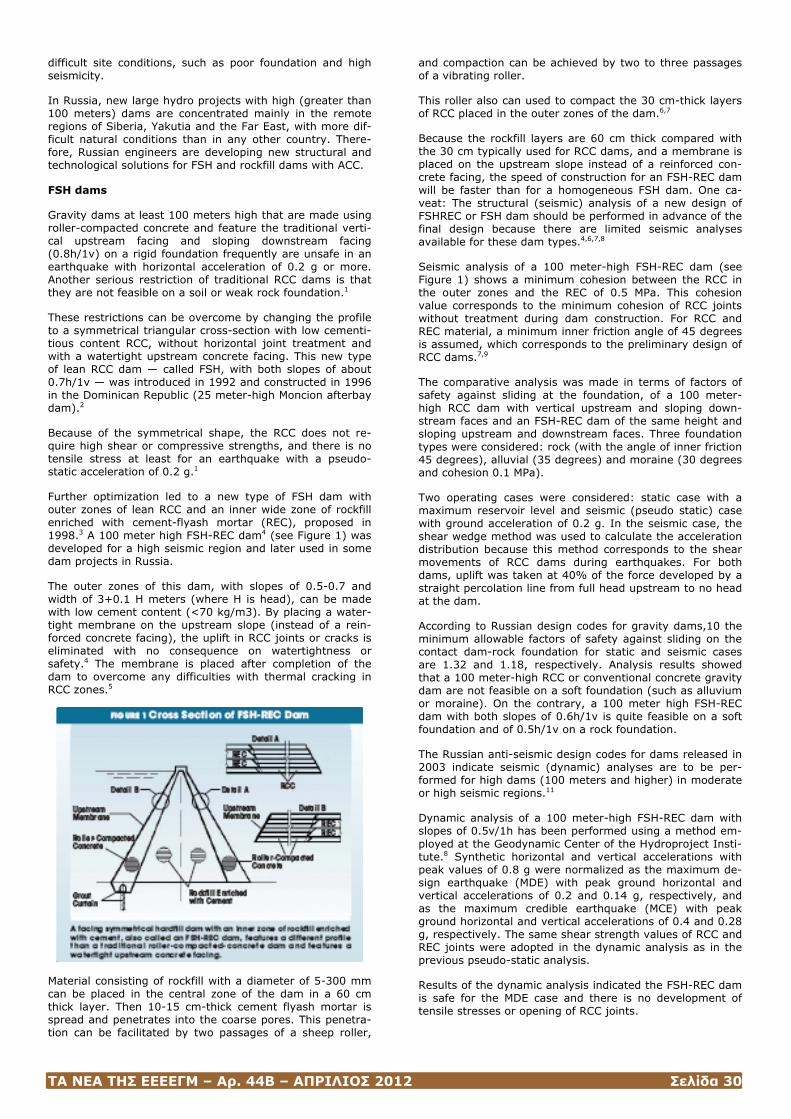
ΤΑ ΝΕΑ ΤΗΣ ΕΕΕΕΓΜ – Αρ. 44Β – ΑΠΡΙΛΙΟΣ 2012 Σελίδα 30
difficult site conditions, such as poor foundation and high seismicity.
In Russia, new large hydro projects with high (greater than 100 meters) dams are concentrated mainly in the remote regions of Siberia, Yakutia and the Far East, with more dif-ficult natural conditions than in any other country. There-fore, Russian engineers are developing new structural and technological solutions for FSH and rockfill dams with ACC.
FSH dams
Gravity dams at least 100 meters high that are made using roller-compacted concrete and feature the traditional verti-cal upstream facing and sloping downstream facing (0.8h/1v) on a rigid foundation frequently are unsafe in an earthquake with horizontal acceleration of 0.2 g or more. Another serious restriction of traditional RCC dams is that they are not feasible on a soil or weak rock foundation.1
These restrictions can be overcome by changing the profile to a symmetrical triangular cross-section with low cementi-tious content RCC, without horizontal joint treatment and with a watertight upstream concrete facing. This new type of lean RCC dam — called FSH, with both slopes of about 0.7h/1v — was introduced in 1992 and constructed in 1996 in the Dominican Republic (25 meter-high Moncion afterbay dam).2
Because of the symmetrical shape, the RCC does not re-quire high shear or compressive strengths, and there is no tensile stress at least for an earthquake with a pseudo-static acceleration of 0.2 g.1
Further optimization led to a new type of FSH dam with outer zones of lean RCC and an inner wide zone of rockfill enriched with cement-flyash mortar (REC), proposed in 1998.3 A 100 meter high FSH-REC dam4 (see Figure 1) was developed for a high seismic region and later used in some dam projects in Russia.
The outer zones of this dam, with slopes of 0.5-0.7 and width of 3+0.1 H meters (where H is head), can be made with low cement content (<70 kg/m3). By placing a water-tight membrane on the upstream slope (instead of a rein-forced concrete facing), the uplift in RCC joints or cracks is eliminated with no consequence on watertightness or safety.4 The membrane is placed after completion of the dam to overcome any difficulties with thermal cracking in RCC zones.5
Material consisting of rockfill with a diameter of 5-300 mm can be placed in the central zone of the dam in a 60 cm thick layer. Then 10-15 cm-thick cement flyash mortar is spread and penetrates into the coarse pores. This penetra-tion can be facilitated by two passages of a sheep roller,
and compaction can be achieved by two to three passages of a vibrating roller.
This roller also can used to compact the 30 cm-thick layers of RCC placed in the outer zones of the dam.6,7
Because the rockfill layers are 60 cm thick compared with the 30 cm typically used for RCC dams, and a membrane is placed on the upstream slope instead of a reinforced con-crete facing, the speed of construction for an FSH-REC dam will be faster than for a homogeneous FSH dam. One ca-veat: The structural (seismic) analysis of a new design of FSHREC or FSH dam should be performed in advance of the final design because there are limited seismic analyses available for these dam types.4,6,7,8
Seismic analysis of a 100 meter-high FSH-REC dam (see Figure 1) shows a minimum cohesion between the RCC in the outer zones and the REC of 0.5 MPa. This cohesion value corresponds to the minimum cohesion of RCC joints without treatment during dam construction. For RCC and REC material, a minimum inner friction angle of 45 degrees is assumed, which corresponds to the preliminary design of RCC dams.7,9
The comparative analysis was made in terms of factors of safety against sliding at the foundation, of a 100 meter-high RCC dam with vertical upstream and sloping down-stream faces and an FSH-REC dam of the same height and sloping upstream and downstream faces. Three foundation types were considered: rock (with the angle of inner friction 45 degrees), alluvial (35 degrees) and moraine (30 degrees and cohesion 0.1 MPa).
Two operating cases were considered: static case with a maximum reservoir level and seismic (pseudo static) case with ground acceleration of 0.2 g. In the seismic case, the shear wedge method was used to calculate the acceleration distribution because this method corresponds to the shear movements of RCC dams during earthquakes. For both dams, uplift was taken at 40% of the force developed by a straight percolation line from full head upstream to no head at the dam.
According to Russian design codes for gravity dams,10 the minimum allowable factors of safety against sliding on the contact dam-rock foundation for static and seismic cases are 1.32 and 1.18, respectively. Analysis results showed that a 100 meter-high RCC or conventional concrete gravity dam are not feasible on a soft foundation (such as alluvium or moraine). On the contrary, a 100 meter high FSH-REC dam with both slopes of 0.6h/1v is quite feasible on a soft foundation and of 0.5h/1v on a rock foundation.
The Russian anti-seismic design codes for dams released in 2003 indicate seismic (dynamic) analyses are to be per-formed for high dams (100 meters and higher) in moderate or high seismic regions.11
Dynamic analysis of a 100 meter-high FSH-REC dam with slopes of 0.5v/1h has been performed using a method em-ployed at the Geodynamic Center of the Hydroproject Insti-tute.8 Synthetic horizontal and vertical accelerations with peak values of 0.8 g were normalized as the maximum de-sign earthquake (MDE) with peak ground horizontal and vertical accelerations of 0.2 and 0.14 g, respectively, and as the maximum credible earthquake (MCE) with peak ground horizontal and vertical accelerations of 0.4 and 0.28 g, respectively. The same shear strength values of RCC and REC joints were adopted in the dynamic analysis as in the previous pseudo-static analysis.
Results of the dynamic analysis indicated the FSH-REC dam is safe for the MDE case and there is no development of tensile stresses or opening of RCC joints.
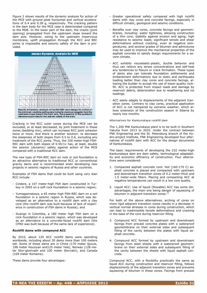
ΤΑ ΝΕΑ ΤΗΣ ΕΕΕΕΓΜ – Αρ. 44Β – ΑΠΡΙΛΙΟΣ 2012 Σελίδα 31
Figure 2 shows results of the dynamic analysis for action of the MCE with ground peak horizontal and vertical accelera-tions of 0.4 and 0.28 g, respectively. The cracking pattern in the dam body for the MCE case is deteriorated compared to the MDE. In the lower part of the dam, the cracks (joint opening) propagated from the upstream slope toward the dam axis. However, owing to the upstream impervious membrane, uplift propagation through the RCC and REC joints is impossible and seismic safety of the dam is pro-vided.
Cracking in the RCC outer zones during the MCE can be excluded, or at least decreased, by joint treatment in these zones (bedding mix), which can increase RCC joint cohesion twice or more. And there is another solution: to decrease the steepness of both slopes from 0.5 to 0.6, excluding any treatment of the RCC joints. Thus, the 100 meter-high FSH-REC dam with both slopes of 0.5h/1v has, at least, double the seismic (dynamic) safety against action of the MCE compared with a traditional RCC dam.
The new type of FSH-REC dam on rock or soil foundation is an attractive alternative to traditional RCC or conventional gravity dams and is recommended when developing new projects in seismic regions of Russia and other countries.
Examples of FSH dams that could be built using very lean RCC include:
- Cindere, a 107 meter-high FSH dam constructed in Tur-key in 2005 on a soft rock foundation in a seismic region;
- Yumagazinskaya, a 65 meter high FSH-REC dam on a soil foundation in a seismic region in Russia, which was de-veloped as an alternative to a rockfill dam with a clay core (the rockfill dam was built because of lack of experi-ence in construction of FSH dams in Russia); and
- Ituango in Colombia, a 180 meter high FSH dam on a rock foundation in a seismic region, which was developed as an alternative to a concrete-faced rockfill dam (the CFRD was built because of the same lack of experience).
Rockfill dams with compound ACC
By 2010, about 120 ACC rockfill dams were operating worldwide, including about 30 dams more than 100 meters tall. Some of these dams are in China (170 meter Quxue, 198 meter Houziyan and125 meter Yele), Norway (128 me-ter Stor-glomvatn and 100 meter Storvatn), and Canada (109 meter Romaine).
These dams provide four advantages:
- Greater operational safety compared with high rockfill dams with clay cores and concrete facings, especially in difficult climatic, geological and seismic conditions.
- Benefits over clay cores, concrete facings and geomem-branes, including: water tightness, allowing construction of a thin core; stability against erosion and aging; high resistance to seismic loads; significant tensile and shear deformations without cracking, even at negative tem-peratures; and several grades of bitumen and admixtures may be used to improve the mechanical properties of the asphalt concrete to satisfy design requirements for a se-vere climate.
- ACC exhibits viscoelastic-plastic, ductile behavior and thus can relieve any stress concentrations and self-heal any tendencies to fissure or crack formation. These types of dams also can tolerate foundation settlements and embankment deformations due to static and earthquake loading better than clay cores and concrete facings, al-lowing the builder to accept the use of lower-quality rock-fill. ACC is protected from impact loads and damage by reservoir debris, deterioration due to weathering and ice loadings.
- ACC easily adapts to displacements of the adjacent tran-sition zones. Contrary to clay cores, practical application of ACC is not hampered by extreme weather, which al-lows extension of the construction season in Siberia by nearly two months.
Alternatives for Kankunskaya rockfill dam
The 1,200 MW Kankunskaya plant is to be built in Southern Yakutia from 2013 to 2025. Under the contract between FNK Engineering and the St. Petersburg branch of the Hy-dro-project Institute, FNK Engineering developed four alter-natives of rockfill dam with ACC for the design documents of Kankunskaya.
The basic requirements of developing the 232 meter-high Kankunskaya dam are dam safety, technological adaptabil-ity and economic efficiency of construction. Four alterna-tives were considered:
1. Compacted asphalt concrete core: Hot (160-170 C) as-phalt concrete is placed and compacted with upstream and downstream transition zones of 0.2 meter-thick and 1.5 meter-wide filters. Placing and compacting ACC at negative temperatures can result in a low core quality.
2. Liquid ACC: Use of liquid (flowable) ACC has some dis-advantages, the main one being danger of squeezing of bitumen in adjacent transition zones.12
For both of the above alternatives, arching of cores on more rigid adjacent transition zones results in a decrease in vertical normal stresses in cores during construction, which can lead to inadmissible tensile deformations and cracking in the base of the core during reservoir filling.
3. Compound ACC formed by upstream and downstream facings from precast concrete plates with a waterproof geomembrane on their external sides and subsequent filling of the cavity between the plates with liquid as-phalt concrete.
4. Compound ACC formed by upstream and downstream facings from steel sheets with a waterproof geomem-brane on their external sides and subsequent filling of the cavity between the sheets with liquid asphalt con-crete.
Compound ACC, with a flexibility practically the same as liquid ACC during construction and reservoir filling, follows displacements of the adjacent transition zones and prevents squeezing of bitumen in these zones. Facings from precast
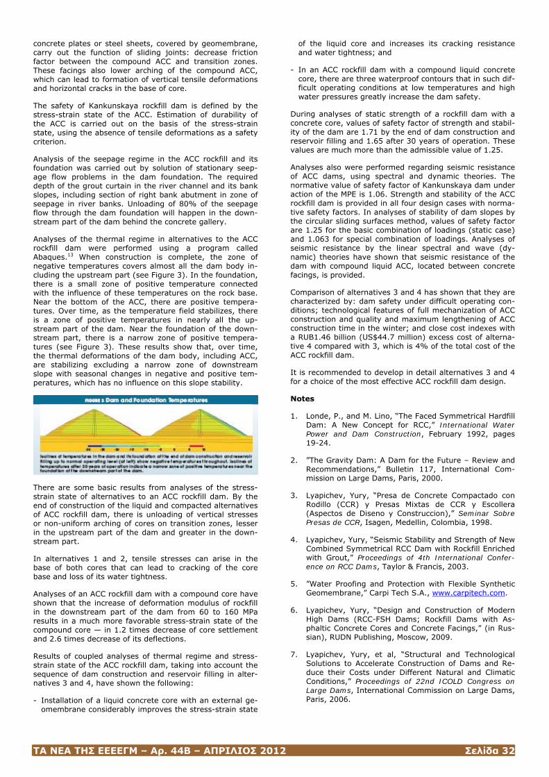
ΤΑ ΝΕΑ ΤΗΣ ΕΕΕΕΓΜ – Αρ. 44Β – ΑΠΡΙΛΙΟΣ 2012 Σελίδα 32
concrete plates or steel sheets, covered by geomembrane, carry out the function of sliding joints: decrease friction factor between the compound ACC and transition zones. These facings also lower arching of the compound ACC, which can lead to formation of vertical tensile deformations and horizontal cracks in the base of core.
The safety of Kankunskaya rockfill dam is defined by the stress-strain state of the ACC. Estimation of durability of the ACC is carried out on the basis of the stress-strain state, using the absence of tensile deformations as a safety criterion.
Analysis of the seepage regime in the ACC rockfill and its foundation was carried out by solution of stationary seep-age flow problems in the dam foundation. The required depth of the grout curtain in the river channel and its bank slopes, including section of right bank abutment in zone of seepage in river banks. Unloading of 80% of the seepage flow through the dam foundation will happen in the down-stream part of the dam behind the concrete gallery.
Analyses of the thermal regime in alternatives to the ACC rockfill dam were performed using a program called Abaques.13 When construction is complete, the zone of negative temperatures covers almost all the dam body in-cluding the upstream part (see Figure 3). In the foundation, there is a small zone of positive temperature connected with the influence of these temperatures on the rock base. Near the bottom of the ACC, there are positive tempera-tures. Over time, as the temperature field stabilizes, there is a zone of positive temperatures in nearly all the up-stream part of the dam. Near the foundation of the down-stream part, there is a narrow zone of positive tempera-tures (see Figure 3). These results show that, over time, the thermal deformations of the dam body, including ACC, are stabilizing excluding a narrow zone of downstream slope with seasonal changes in negative and positive tem-peratures, which has no influence on this slope stability.
There are some basic results from analyses of the stress-strain state of alternatives to an ACC rockfill dam. By the end of construction of the liquid and compacted alternatives of ACC rockfill dam, there is unloading of vertical stresses or non-uniform arching of cores on transition zones, lesser in the upstream part of the dam and greater in the down-stream part.
In alternatives 1 and 2, tensile stresses can arise in the base of both cores that can lead to cracking of the core base and loss of its water tightness.
Analyses of an ACC rockfill dam with a compound core have shown that the increase of deformation modulus of rockfill in the downstream part of the dam from 60 to 160 MPa results in a much more favorable stress-strain state of the compound core — in 1.2 times decrease of core settlement and 2.6 times decrease of its deflections.
Results of coupled analyses of thermal regime and stress-strain state of the ACC rockfill dam, taking into account the sequence of dam construction and reservoir filling in alter-natives 3 and 4, have shown the following:
- Installation of a liquid concrete core with an external ge-omembrane considerably improves the stress-strain state
of the liquid core and increases its cracking resistance and water tightness; and
- In an ACC rockfill dam with a compound liquid concrete core, there are three waterproof contours that in such dif-ficult operating conditions at low temperatures and high water pressures greatly increase the dam safety.
During analyses of static strength of a rockfill dam with a concrete core, values of safety factor of strength and stabil-ity of the dam are 1.71 by the end of dam construction and reservoir filling and 1.65 after 30 years of operation. These values are much more than the admissible value of 1.25.
Analyses also were performed regarding seismic resistance of ACC dams, using spectral and dynamic theories. The normative value of safety factor of Kankunskaya dam under action of the MPE is 1.06. Strength and stability of the ACC rockfill dam is provided in all four design cases with norma-tive safety factors. In analyses of stability of dam slopes by the circular sliding surfaces method, values of safety factor are 1.25 for the basic combination of loadings (static case) and 1.063 for special combination of loadings. Analyses of seismic resistance by the linear spectral and wave (dy-namic) theories have shown that seismic resistance of the dam with compound liquid ACC, located between concrete facings, is provided.
Comparison of alternatives 3 and 4 has shown that they are characterized by: dam safety under difficult operating con-ditions; technological features of full mechanization of ACC construction and quality and maximum lengthening of ACC construction time in the winter; and close cost indexes with a RUB1.46 billion (US$44.7 million) excess cost of alterna-tive 4 compared with 3, which is 4% of the total cost of the ACC rockfill dam.
It is recommended to develop in detail alternatives 3 and 4 for a choice of the most effective ACC rockfill dam design.
Notes
1. Londe, P., and M. Lino, “The Faced Symmetrical Hardfill Dam: A New Concept for RCC,” International Water Power and Dam Construction, February 1992, pages 19-24.
2. ”The Gravity Dam: A Dam for the Future – Review and Recommendations,” Bulletin 117, International Com-mission on Large Dams, Paris, 2000.
3. Lyapichev, Yury, “Presa de Concrete Compactado con Rodillo (CCR) y Presas Mixtas de CCR y Escollera (Aspectos de Diseno y Construccion),” Seminar Sobre Presas de CCR, Isagen, Medellin, Colombia, 1998.
4. Lyapichev, Yury, “Seismic Stability and Strength of New Combined Symmetrical RCC Dam with Rockfill Enriched with Grout,” Proceedings of 4th International Confer-ence on RCC Dams, Taylor & Francis, 2003.
5. ”Water Proofing and Protection with Flexible Synthetic Geomembrane,” Carpi Tech S.A., www.carpitech.com.
6. Lyapichev, Yury, “Design and Construction of Modern High Dams (RCC-FSH Dams; Rockfill Dams with As-phaltic Concrete Cores and Concrete Facings,” (in Rus-sian), RUDN Publishing, Moscow, 2009.
7. Lyapichev, Yury, et al, “Structural and Technological Solutions to Accelerate Construction of Dams and Re-duce their Costs under Different Natural and Climatic Conditions,” Proceedings of 22nd ICOLD Congress on Large Dams, International Commission on Large Dams, Paris, 2006.
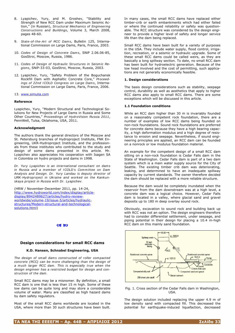
ΤΑ ΝΕΑ ΤΗΣ ΕΕΕΕΓΜ – Αρ. 44Β – ΑΠΡΙΛΙΟΣ 2012 Σελίδα 33
8. Lyapichev, Yury, and M. Groshev, “Stability and Strength of New RCC Dam under Maximum Seismic Ac-tion,” (in Russian), Structural Mechanics of Engineering Constructions and Buildings, Volume 3, March 2008, pages 48-60.
9. State-of-the-Art of RCC Dams, Bulletin 125, Interna-tional Commission on Large Dams, Paris, France, 2003.
10. Codes of Design of Concrete Dams, SNiP 2.06.06-85, GosStroi, Moscow, Russia, 1986.
11. Codes of Design of Hydraulic Structures in Seismic Re-gions, SNiP-33-03, GosStroi, Moscow, Russia, 2003.
12. Lyapichev, Yury, “Safety Problem of the Boguchansk Rockfill Dam with Asphaltic Concrete Core,” Proceed-ings of 22nd ICOLD Congress on Large Dams, Interna-tional Commission on Large Dams, Paris, France, 2006.
13. www.simulia.com
Reference
Lyapichev, Yury, “Modern Structural and Technological So-lutions for New Projects of Large Dams in Russia and Some Other Countries,” Proceedings of HydroVision Russia 2011, PennWell, Tulsa, Oklahoma, USA, 2011.
Acknowledgment
The authors thank the general directors of the Moscow and St. Petersburg branches of Hydroproject Institute, FNK En-gineering, UKR-Hydroproject Institute, and the profession-als from these institutes who contributed to the study and design of some dams presented in this article. Mr. Lyapichev also appreciates his cooperation with Isagen SA in Colombia on hydro projects and dams in 1998.
Dr. Yury Lyapichev is an international consultant on dams in Russia and a member of ICOLD’s Committee on Dam Analysis and Design. Dr. Yury Landau is deputy director of URK-Hydroproject in Ukraine and worked on the Kankun-skaya project in Russia with Dr. Lyapichev.
(HRW / November-December 2011, pp. 14-24, http://www.hydroworld.com/index/display/article-display/8942489627/articles/hydro-review-worldwide/volume-19/issue-5/articles/hydraulic-structures/Modern-structural-and-technological-solutions.html)
Design considerations for small RCC dams
K.D. Hansen, Schnabel Engineering, USA
The design of small dams constructed of roller compacted concrete (RCC) can be more challenging than the design of a much larger RCC dam. This is especially true when the design engineer has a restricted budget for design and con-struction of the dam.
Small RCC dams may be a misnomer. By definition, a small RCC dam is one that is less than 15 m high. Some of these low dams can be quite long and may store a considerable volume of water. Many are classified as high hazard dams by dam safety regulators.
Most of the small RCC dams worldwide are located in the USA, where more than 30 such structures have been built.
In many cases, the small RCC dams have replaced either timber-crib or earth embankments which had either failed or where the continued reliability or safety was question-able. The RCC structure was considered by the design engi-neer to provide a higher level of safety and longer service life than the dam being replaced.
Small RCC dams have been built for a variety of purposes in the USA. They include water supply, flood control, irriga-tion, recreation, or a seismic or hydraulic upgrade. Some of these small RCC dams could be called weirs, as they are basically a long spillway section. To date, no small RCC dam has been built for hydroelectric generation. Because of the low head involved and the cost of permitting, such applica-tions are not generally economically feasible.
1. Design considerations
The basis design considerations such as stability, seepage control, durability as well as aesthetics that apply to higher RCC dams also apply to small RCC dams. There are some exceptions which will be discussed in this article.
1.1 Foundation conditions
While an RCC dam higher than 30 m is invariably founded on a reasonably competent rock foundation, there are a number of examples of low RCC dams being founded on non-rock foundations. Sound rock foundations are preferred for concrete dams because they have a high bearing capac-ity, a high deformation modulus and a high degree of resis-tance to erosion and seepage. Nevertheless, if sound engi-neering principles are applied, an RCC dam can be founded on a nonrock or low modulus foundation material.
An example for the competent design of a small RCC dam sitting on a non-rock foundation is Cedar Falls dam in the State of Washington. Cedar Falls dam is part of a two dam system which is a main water supply source for the City of Seattle. The existing timber crib dam was deteriorating, leaking, and determined to have an inadequate spillway capacity by current standards. The owner therefore decided the dam should be replaced with a more reliable structure.
Because the dam would be completely inundated when the reservoir from the dam downstream was at a high level, a concrete dam was a logical choice. However, Cedar Falls dam is located in a valley, where glacial sand and gravel deposits up to 180 m deep overlay sound rock.
Obviously, excavation to sound rock and building back up with RCC was not an option. The design engineers therefore had to consider differential settlement, under seepage, and piping potential in their design for placing a 10.4 m-high RCC dam on this mainly sand foundation.
Fig. 1. Cross section of the Cedar Falls dam in Washington, USA.
The design solution included replacing the upper 4.9 m of low density sand with compacted fill. This decreased the potential for earthquake-induced liquefaction, decreased
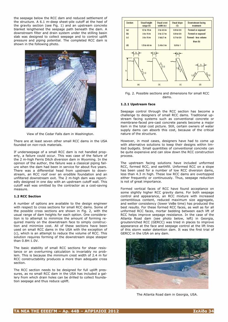
ΤΑ ΝΕΑ ΤΗΣ ΕΕΕΕΓΜ – Αρ. 44Β – ΑΠΡΙΛΙΟΣ 2012 Σελίδα 34
the seepage below the RCC dam and reduced settlement of the structure. A 6.1 m-deep sheet-pile cutoff at the heel of the gravity section (see Fig. 1) and an upstream concrete blanket lengthened the seepage path beneath the dam. A downstream filter and drain system under the stilling basin slab was designed to collect seepage and to control uplift pressure and piping potential. The completed RCC dam is shown in the following photo.
View of the Cedar Falls dam in Washington.
There are at least seven other small RCC dams in the USA founded on non-rock materials.
If underseepage of a small RCC dam is not handled prop-erly, a failure could occur. This was case of the failure of the 2 m-high Ferris Ditch diversion dam in Wyoming. In the opinion of the author, the failure was a classical piping fail-ure when the dam had been in service for about five years. There was a differential head from upstream to down-stream, an RCC roof over an erodible foundation and an unfiltered downstream exit. The 2 m-high dam was report-edly designed in one day with an upstream cutoff wall. This cutoff wall was omitted by the contractor as a cost-saving measure.
1.2 RCC Section
A number of options are available to the design engineer with respect to cross sections for small RCC dams. Some of the possible cross sections are shown in Fig. 2, with the usual range of dam heights for each option. One considera-tion is to attempt to minimize the amount of forming re-quired mainly on the downstream face to simply construc-tion and minimize cost. All of these sections have been used on small RCC dams in the USA with the exception of (c), which is an attempt to reduce the volume of RCC. This solution requires forming of the downstream slope steeper than 0.8H:1.0V.
The basic stability of small RCC sections for shear resis-tance or an overturning calculation is invariably no prob-lem. This is because the minimum crest width of 2.4 m for RCC constructability produces a more than adequate cross section.
The RCC section needs to be designed for full uplift pres-sures, as no small RCC dam in the USA has included a gal-lery from which drain holes can be drilled to collect founda-tion seepage and thus reduce uplift.
Fig. 2. Possible sections and dimensions for small RCC dams.
1.2.1 Upstream face
Seepage control through the RCC section has become a challenge to designers of small RCC dams. Traditional up-stream facing systems such as conventional concrete or membrane-faced pre-cast concrete panels become a major item in the total cost picture. Still, certain owners of water supply dams can absorb this cost, because of the critical nature of the structure.
However, in most cases, designers have had to come up with alternative solutions to keep their designs within lim-ited budgets. Small quantities of conventional concrete can be quite expensive and can slow down the RCC construction process.
The upstream facing solutions have included unformed RCC, formed RCC, and earthfill. Unformed RCC on a slope has been used for a number of low RCC diversion dams, less than 4.3 m high. These low RCC dams are overtopped either frequently or continuously. Thus, seepage reduction is not of great importance.
Formed vertical faces of RCC have found acceptance on some slightly higher RCC gravity dams. For both seepage control and appearance, an RCC mixture with increased cementitious content, reduced maximum size aggregate, and wetter consistency (lower VeBe time) has produced the best results. For these formed RCC faces, as well as for all unformed RCC faces, mortar bedding between each lift of RCC helps improve seepage resistance. In the case of the Atlanta Road dam (see photo below, left) in Georgia, groutenriched RCC (GERCC) was tried in places to improve appearance at the face and seepage control at the lift lines of this storm water detention dam. It was the first trial of GERCC in the USA on any dam.
The Atlanta Road dam in Georgia, USA.
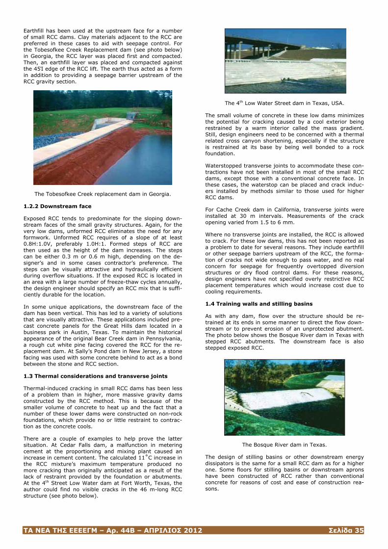
ΤΑ ΝΕΑ ΤΗΣ ΕΕΕΕΓΜ – Αρ. 44Β – ΑΠΡΙΛΙΟΣ 2012 Σελίδα 35
Earthfill has been used at the upstream face for a number of small RCC dams. Clay materials adjacent to the RCC are preferred in these cases to aid with seepage control. For the Tobesofkee Creek Replacement dam (see photo below) in Georgia, the RCC layer was placed first and compacted. Then, an earthfill layer was placed and compacted against the 45Ί edge of the RCC lift. The earth thus acted as a form in addition to providing a seepage barrier upstream of the RCC gravity section.
The Tobesofkee Creek replacement dam in Georgia.
1.2.2 Downstream face
Exposed RCC tends to predominate for the sloping down-stream faces of the small gravity structures. Again, for the very low dams, unformed RCC eliminates the need for any formwork. Unformed RCC requires of a slope of at least 0.8H:1.0V, preferably 1.0H:1. Formed steps of RCC are then used as the height of the dam increases. The steps can be either 0.3 m or 0.6 m high, depending on the de-signer’s and in some cases contractor’s preference. The steps can be visually attractive and hydraulically efficient during overflow situations. If the exposed RCC is located in an area with a large number of freeze-thaw cycles annually, the design engineer should specify an RCC mix that is suffi-ciently durable for the location.
In some unique applications, the downstream face of the dam has been vertical. This has led to a variety of solutions that are visually attractive. These applications included pre-cast concrete panels for the Great Hills dam located in a business park in Austin, Texas. To maintain the historical appearance of the original Bear Creek dam in Pennsylvania, a rough cut white pine facing covered the RCC for the re-placement dam. At Sally’s Pond dam in New Jersey, a stone facing was used with some concrete behind to act as a bond between the stone and RCC section.
1.3 Thermal considerations and transverse joints
Thermal-induced cracking in small RCC dams has been less of a problem than in higher, more massive gravity dams constructed by the RCC method. This is because of the smaller volume of concrete to heat up and the fact that a number of these lower dams were constructed on non-rock foundations, which provide no or little restraint to contrac-tion as the concrete cools.
There are a couple of examples to help prove the latter situation. At Cedar Falls dam, a malfunction in metering cement at the proportioning and mixing plant caused an increase in cement content. The calculated 11˚C increase in the RCC mixture’s maximum temperature produced no more cracking than originally anticipated as a result of the lack of restraint provided by the foundation or abutments. At the 4th Street Low Water dam at Fort Worth, Texas, the author could find no visible cracks in the 46 m-long RCC structure (see photo below).
The 4th Low Water Street dam in Texas, USA.
The small volume of concrete in these low dams minimizes the potential for cracking caused by a cool exterior being restrained by a warm interior called the mass gradient. Still, design engineers need to be concerned with a thermal related cross canyon shortening, especially if the structure is restrained at its base by being well bonded to a rock foundation.
Waterstopped transverse joints to accommodate these con-tractions have not been installed in most of the small RCC dams, except those with a conventional concrete face. In these cases, the waterstop can be placed and crack induc-ers installed by methods similar to those used for higher RCC dams.
For Cache Creek dam in California, transverse joints were installed at 30 m intervals. Measurements of the crack opening varied from 1.5 to 6 mm.
Where no transverse joints are installed, the RCC is allowed to crack. For these low dams, this has not been reported as a problem to date for several reasons. They include earthfill or other seepage barriers upstream of the RCC, the forma-tion of cracks not wide enough to pass water, and no real concern for seepage for frequently overtopped diversion structures or dry flood control dams. For these reasons, design engineers have not specified overly restrictive RCC placement temperatures which would increase cost due to cooling requirements.
1.4 Training walls and stilling basins
As with any dam, flow over the structure should be re-trained at its ends in some manner to direct the flow down-stream or to prevent erosion of an unprotected abutment. The photo below shows the Bosque River dam in Texas with stepped RCC abutments. The downstream face is also stepped exposed RCC.
The Bosque River dam in Texas.
The design of stilling basins or other downstream energy dissipators is the same for a small RCC dam as for a higher one. Some floors for stilling basins or downstream aprons have been constructed of RCC rather than conventional concrete for reasons of cost and ease of construction rea-sons.

ΤΑ ΝΕΑ ΤΗΣ ΕΕΕΕΓΜ – Αρ. 44Β – ΑΠΡΙΛΙΟΣ 2012 Σελίδα 36
Bibliography
Hansen, K.D., and Reinhart, W.G., “Roller-Compacted Concrete Dams”, McGraw-Hill, Inc, New York, USA; 1991.
Portland Cement Association, “Design Manual for Small RCC Dams”, Publication EB 225.01, prepared by Schnabel Engineering Associates Inc., Skokie, Illinois, USA; 2003.
Ken Hansen is a Senior Consultant with Schnabel Engineer-ing. Before joining the company more than 11 years ago, he worked for the Portland Cement Association (PCA) for nearly 37 years. He is an international recognized author, lecturer, and consultant on the use of roller compacted con-crete (RCC) for new dams and the rehabilitation of existing dams. He is the primary author of the book ‘Roller Com-pacted Concrete Dams’ published by McGraw-Hill, and he edited or co-edited all three ASCE books on RCC. Mr. Han-sen has given more than 400 presentations on RCC dams in the USA and by invitation in 11 other countries, including being the keynote speaker or invited special lecturer at six international conferences on RCC. His consulting assign-ments now number 70 in 11 countries.
(Hydropower & Dams Issue Three, 2008, www.hydropower-dams.com)
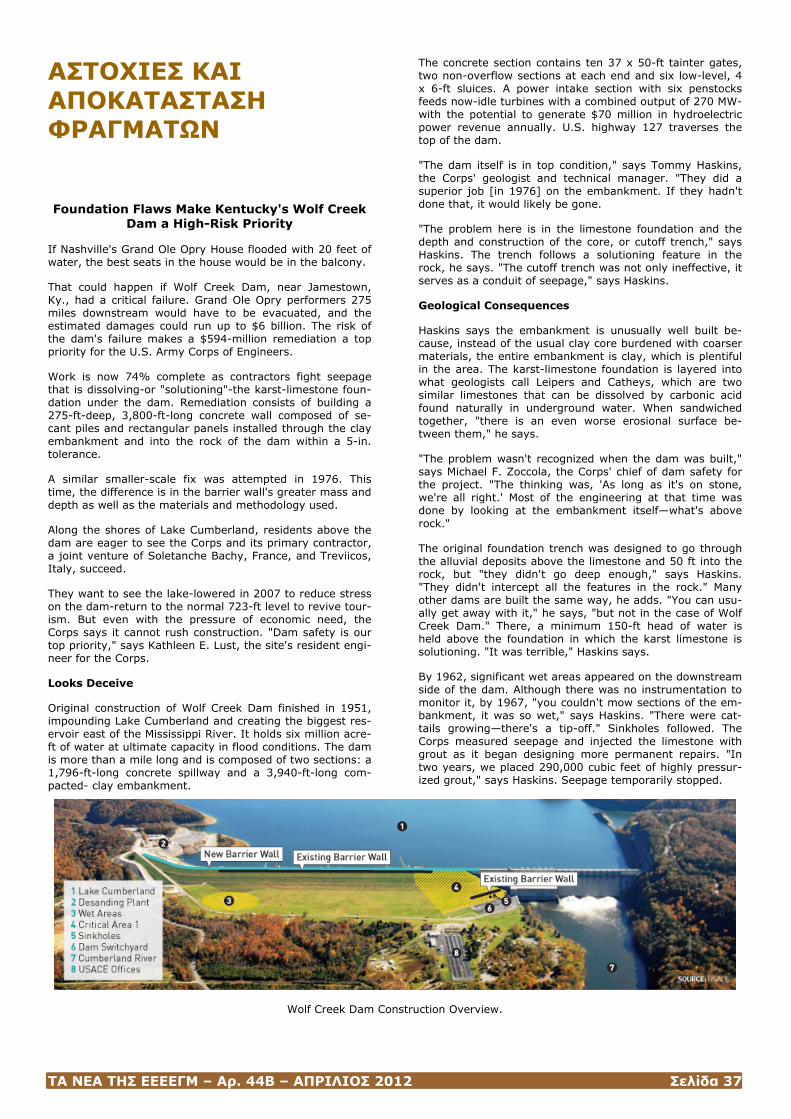
ΤΑ ΝΕΑ ΤΗΣ ΕΕΕΕΓΜ – Αρ. 44Β – ΑΠΡΙΛΙΟΣ 2012 Σελίδα 37
ΑΣΤΟΧΙΕΣ ΚΑΙ ΑΠΟΚΑΤΑΣΤΑΣΗ ΦΡΑΓΜΑΤΩΝ Foundation Flaws Make Kentucky's Wolf Creek
Dam a High-Risk Priority
If Nashville's Grand Ole Opry House flooded with 20 feet of water, the best seats in the house would be in the balcony.
That could happen if Wolf Creek Dam, near Jamestown, Ky., had a critical failure. Grand Ole Opry performers 275 miles downstream would have to be evacuated, and the estimated damages could run up to $6 billion. The risk of the dam's failure makes a $594-million remediation a top priority for the U.S. Army Corps of Engineers.
Work is now 74% complete as contractors fight seepage that is dissolving-or "solutioning"-the karst-limestone foun-dation under the dam. Remediation consists of building a 275-ft-deep, 3,800-ft-long concrete wall composed of se-cant piles and rectangular panels installed through the clay embankment and into the rock of the dam within a 5-in. tolerance.
A similar smaller-scale fix was attempted in 1976. This time, the difference is in the barrier wall's greater mass and depth as well as the materials and methodology used.
Along the shores of Lake Cumberland, residents above the dam are eager to see the Corps and its primary contractor, a joint venture of Soletanche Bachy, France, and Treviicos, Italy, succeed.
They want to see the lake-lowered in 2007 to reduce stress on the dam-return to the normal 723-ft level to revive tour-ism. But even with the pressure of economic need, the Corps says it cannot rush construction. "Dam safety is our top priority," says Kathleen E. Lust, the site's resident engi-neer for the Corps.
Looks Deceive
Original construction of Wolf Creek Dam finished in 1951, impounding Lake Cumberland and creating the biggest res-ervoir east of the Mississippi River. It holds six million acre-ft of water at ultimate capacity in flood conditions. The dam is more than a mile long and is composed of two sections: a 1,796-ft-long concrete spillway and a 3,940-ft-long com-pacted- clay embankment.
The concrete section contains ten 37 x 50-ft tainter gates, two non-overflow sections at each end and six low-level, 4 x 6-ft sluices. A power intake section with six penstocks feeds now-idle turbines with a combined output of 270 MW-with the potential to generate $70 million in hydroelectric power revenue annually. U.S. highway 127 traverses the top of the dam.
"The dam itself is in top condition," says Tommy Haskins, the Corps' geologist and technical manager. "They did a superior job [in 1976] on the embankment. If they hadn't done that, it would likely be gone.
"The problem here is in the limestone foundation and the depth and construction of the core, or cutoff trench," says Haskins. The trench follows a solutioning feature in the rock, he says. "The cutoff trench was not only ineffective, it serves as a conduit of seepage," says Haskins.
Geological Consequences
Haskins says the embankment is unusually well built be-cause, instead of the usual clay core burdened with coarser materials, the entire embankment is clay, which is plentiful in the area. The karst-limestone foundation is layered into what geologists call Leipers and Catheys, which are two similar limestones that can be dissolved by carbonic acid found naturally in underground water. When sandwiched together, "there is an even worse erosional surface be-tween them," he says.
"The problem wasn't recognized when the dam was built," says Michael F. Zoccola, the Corps' chief of dam safety for the project. "The thinking was, 'As long as it's on stone, we're all right.' Most of the engineering at that time was done by looking at the embankment itself—what's above rock."
The original foundation trench was designed to go through the alluvial deposits above the limestone and 50 ft into the rock, but "they didn't go deep enough," says Haskins. "They didn't intercept all the features in the rock." Many other dams are built the same way, he adds. "You can usu-ally get away with it," he says, "but not in the case of Wolf Creek Dam." There, a minimum 150-ft head of water is held above the foundation in which the karst limestone is solutioning. "It was terrible," Haskins says.
By 1962, significant wet areas appeared on the downstream side of the dam. Although there was no instrumentation to monitor it, by 1967, "you couldn't mow sections of the em-bankment, it was so wet," says Haskins. "There were cat-tails growing—there's a tip-off." Sinkholes followed. The Corps measured seepage and injected the limestone with grout as it began designing more permanent repairs. "In two years, we placed 290,000 cubic feet of highly pressur-ized grout," says Haskins. Seepage temporarily stopped.
Wolf Creek Dam Construction Overview.

ΤΑ ΝΕΑ ΤΗΣ ΕΕΕΕΓΜ – Αρ. 44Β – ΑΠΡΙΛΙΟΣ 2012 Σελίδα 38
An independent board of consultants was brought in by the Corps to evaluate the foundation and recommend action, says Arturo Ressi, who was executive vice president of ICOS Corp. of America, the contractor on the $100-million job in 1976. The board recommended a concrete cutoff wall. But dissenting members of the board—led by the late civil engineer Ralph Peck—urged the Corps to extend the wall to the length of the embankment and well bellow the Leipers and Catheys limestone contact section, says Ressi. But Peck's admonitions were not heeded, and the wall was extended from the concrete portion of the dam only two-thirds of the way from the right abutment wall, says Ressi.
A deeper and stronger wall will halt seepage.
David Hendrix, manager on the current project, says the Corps' 1976 decision was not cost-driven. It was a technical decision, he says. "The rock was more competent out near the right abutment," Hendrix says. The current excavation has proven that to be true. Nevertheless, less than 20 years after the wall was finished, seepage appeared on the downstream side of the dam again.
The Challenge
"The old wall has 26-in.-dia, steel-encased primary piles," says Lust. But the steel primary piles and the concrete se-cant piles were not placed with sufficient vertical precision to seal out seepage. "The steel-to-concrete joints were a big problem," adds Lust. This time around, the Corps is using a more precise method to attain a better seal.
The new barrier wall lies upstream and parallel to the old wall but does not touch it. It maintains at least a 24-in.-thick barrier in all locations and extends 1,500 feet longer—3,800 ft in total—and deeper into the limestone than the old wall, down to a level "where there is less solutioning," says Zoccola. "Most of the wall is about 275 ft deep."
Two wall designs are used. The first is a series of 50-in. overlapping secant piles. The second is a combination wall comprising rectangular panels tied together by secant piles. "The combination wall was originally intended for 70% of the job," says Haskins. "It's now being used for 12% of the wall."
The joint venture discovered that the hydromill—a machine used to cut the panel swaths through the earth for the combination-wall construction—wasn't as effective in rock as expected. The contractor opted to use more overlapping
Progress on the wall.
secant piles. Fabio Santillan, the JV's project manager, says hydromills are now mostly used to excavate for a concrete embankment wall that is installed prior to the barrier wall itself.
Hendrix says the depths required and rock hardness make this foundation project unlike any other. "This is the most complicated foundation job being done in the world today," claims Santillan.
Construction of the barrier wall requires several steps of site preparation. In the $70-million first phase, grout was used to stabilize the embankment and create curtains on either side of the barrier-wall site. The curtains are formed by pressure-grouting in holes augered 12 ft on either side of the wall footprint at various intervals, depending on soil conditions. The curtains extend 50 ft below the barrier's foundation.
The hydromill, with a 6 x 9-ft-long cutter head, excavates the clay embankment, extending a minimum of two feet
into bedrock, to build a protective concrete embankment wall (PCEW).
The work area is prepared for the hydromill by excavators with clamshells that produce a hole large enough to accept the machine's head. The hole is filled with a water-and-polymer slurry. The slurry keeps the cutter head cool, maintains hydrostatic pressure to hold the trench open and provides a medium for removing cuttings from the excava-tion, says Hendrix. The cuttings-laden slurry is cycled through pipelines to a treatment area where screens, shak-ers and a centrifuge remove debris before cycling the cleaned mixture back into the excavation. When the hole reaches final depth, pipes are lowered in and tremie con-crete is gravity-fed through the 10-in. pipes. The concrete displaces the slurry, which is recovered for re-use.
"We don't intend to jeopardize the already-strong clay em-bankment," says Lust. The PCEW stabilizes the clay em-bankment and gives a solid grip to the directional drill, which bores 8-in. pilot holes through the cured concrete as
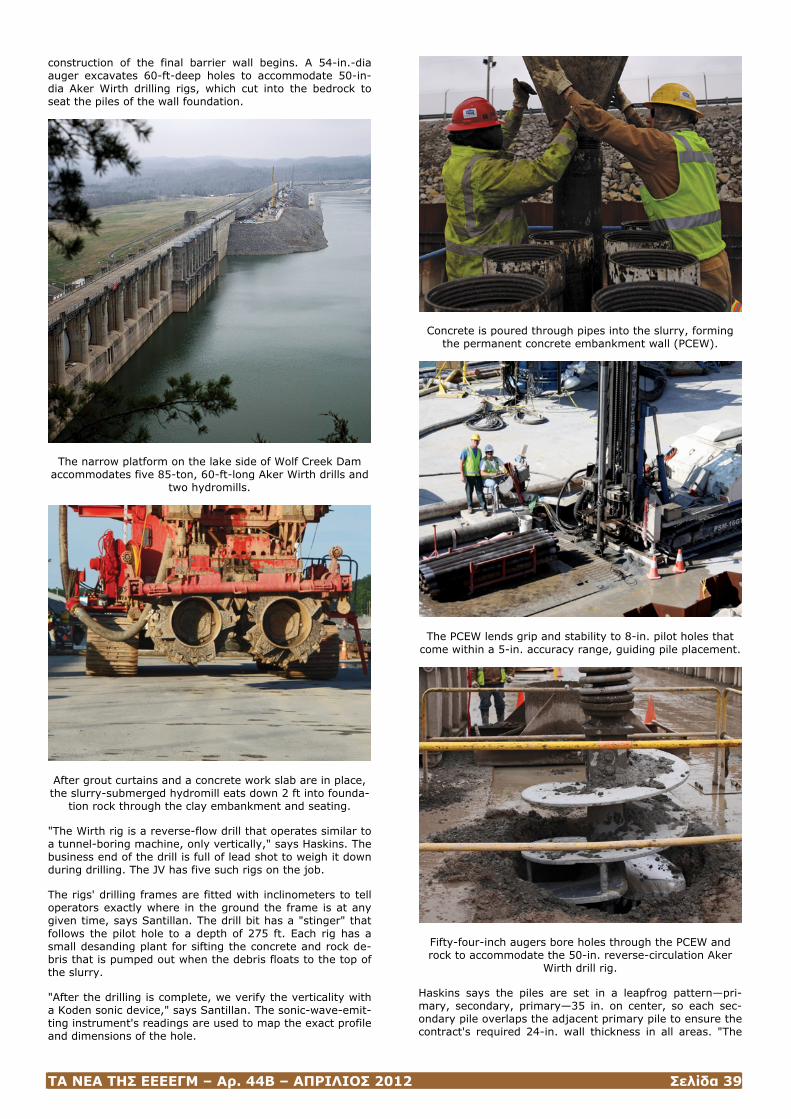
ΤΑ ΝΕΑ ΤΗΣ ΕΕΕΕΓΜ – Αρ. 44Β – ΑΠΡΙΛΙΟΣ 2012 Σελίδα 39
construction of the final barrier wall begins. A 54-in.-dia auger excavates 60-ft-deep holes to accommodate 50-in-dia Aker Wirth drilling rigs, which cut into the bedrock to seat the piles of the wall foundation.
The narrow platform on the lake side of Wolf Creek Dam accommodates five 85-ton, 60-ft-long Aker Wirth drills and
two hydromills.
After grout curtains and a concrete work slab are in place, the slurry-submerged hydromill eats down 2 ft into founda-
tion rock through the clay embankment and seating.
"The Wirth rig is a reverse-flow drill that operates similar to a tunnel-boring machine, only vertically," says Haskins. The business end of the drill is full of lead shot to weigh it down during drilling. The JV has five such rigs on the job.
The rigs' drilling frames are fitted with inclinometers to tell operators exactly where in the ground the frame is at any given time, says Santillan. The drill bit has a "stinger" that follows the pilot hole to a depth of 275 ft. Each rig has a small desanding plant for sifting the concrete and rock de-bris that is pumped out when the debris floats to the top of the slurry.
"After the drilling is complete, we verify the verticality with a Koden sonic device," says Santillan. The sonic-wave-emit-ting instrument's readings are used to map the exact profile and dimensions of the hole.
Concrete is poured through pipes into the slurry, forming the permanent concrete embankment wall (PCEW).
The PCEW lends grip and stability to 8-in. pilot holes that come within a 5-in. accuracy range, guiding pile placement.
Fifty-four-inch augers bore holes through the PCEW and rock to accommodate the 50-in. reverse-circulation Aker
Wirth drill rig.
Haskins says the piles are set in a leapfrog pattern—pri-mary, secondary, primary—35 in. on center, so each sec-ondary pile overlaps the adjacent primary pile to ensure the contract's required 24-in. wall thickness in all areas. "The
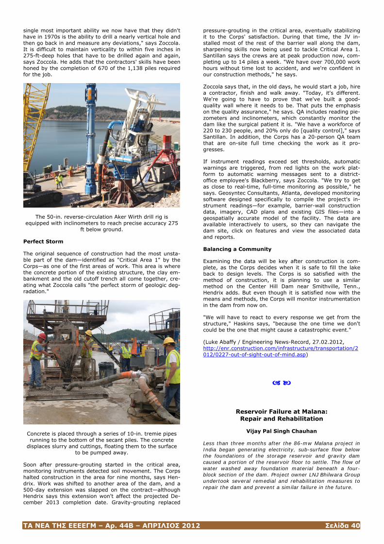
ΤΑ ΝΕΑ ΤΗΣ ΕΕΕΕΓΜ – Αρ. 44Β – ΑΠΡΙΛΙΟΣ 2012 Σελίδα 40
single most important ability we now have that they didn't have in 1970s is the ability to drill a nearly vertical hole and then go back in and measure any deviations," says Zoccola. It is difficult to maintain verticality to within five inches in 275-ft-deep holes that have to be drilled again and again, says Zoccola. He adds that the contractors' skills have been honed by the completion of 670 of the 1,138 piles required for the job.
The 50-in. reverse-circulation Aker Wirth drill rig is equipped with inclinometers to reach precise accuracy 275
ft below ground.
Perfect Storm
The original sequence of construction had the most unsta-ble part of the dam—identified as "Critical Area 1" by the Corps—as one of the first areas of work. This area is where the concrete portion of the existing structure, the clay em-bankment and the old cutoff trench all come together, cre-ating what Zoccola calls "the perfect storm of geologic deg-radation."
Concrete is placed through a series of 10-in. tremie pipes running to the bottom of the secant piles. The concrete
displaces slurry and cuttings, floating them to the surface to be pumped away.
Soon after pressure-grouting started in the critical area, monitoring instruments detected soil movement. The Corps halted construction in the area for nine months, says Hen-drix. Work was shifted to another area of the dam, and a 500-day extension was slapped on the contract—although Hendrix says this extension won't affect the projected De-cember 2013 completion date. Gravity-grouting replaced
pressure-grouting in the critical area, eventually stabilizing it to the Corps' satisfaction. During that time, the JV in-stalled most of the rest of the barrier wall along the dam, sharpening skills now being used to tackle Critical Area 1. Santillan says the crews are at peak production now, com-pleting up to 14 piles a week. "We have over 700,000 work hours without time lost to accident, and we're confident in our construction methods," he says.
Zoccola says that, in the old days, he would start a job, hire a contractor, finish and walk away. "Today, it's different. We're going to have to prove that we've built a good-quality wall where it needs to be. That puts the emphasis on the quality assurance," he says. QA includes reading pie-zometers and inclinometers, which constantly monitor the dam like the surgical patient it is. "We have a workforce of 220 to 230 people, and 20% only do [quality control]," says Santillan. In addition, the Corps has a 20-person QA team that are on-site full time checking the work as it pro-gresses.
If instrument readings exceed set thresholds, automatic warnings are triggered, from red lights on the work plat-form to automatic warning messages sent to a district-office employee's Blackberry, says Zoccola. "We try to get as close to real-time, full-time monitoring as possible," he says. Geosyntec Consultants, Atlanta, developed monitoring software designed specifically to compile the project's in-strument readings—for example, barrier-wall construction data, imagery, CAD plans and existing GIS files—into a geospatially accurate model of the facility. The data are available interactively to users, so they can navigate the dam site, click on features and view the associated data and reports.
Balancing a Community
Examining the data will be key after construction is com-plete, as the Corps decides when it is safe to fill the lake back to design levels. The Corps is so satisfied with the method of construction, it is planning to use a similar method on the Center Hill Dam near Smithville, Tenn., Hendrix adds. But even though it is satisfied now with the means and methods, the Corps will monitor instrumentation in the dam from now on.
"We will have to react to every response we get from the structure," Haskins says, "because the one time we don't could be the one that might cause a catastrophic event."
(Luke Abaffy / Engineering News-Record, 27.02.2012, http://enr.construction.com/infrastructure/transportation/2012/0227-out-of-sight-out-of-mind.asp)
Reservoir Failure at Malana: Repair and Rehabilitation
Vijay Pal Singh Chauhan
Less than three months after the 86-mw Malana project in India began generating electricity, sub-surface flow below the foundations of the storage reservoir and gravity dam caused a portion of the reservoir floor to settle. The flow of water washed away foundation material beneath a four-block section of the dam. Project owner LNJ Bhilwara Group undertook several remedial and rehabilitation measures to repair the dam and prevent a similar failure in the future.
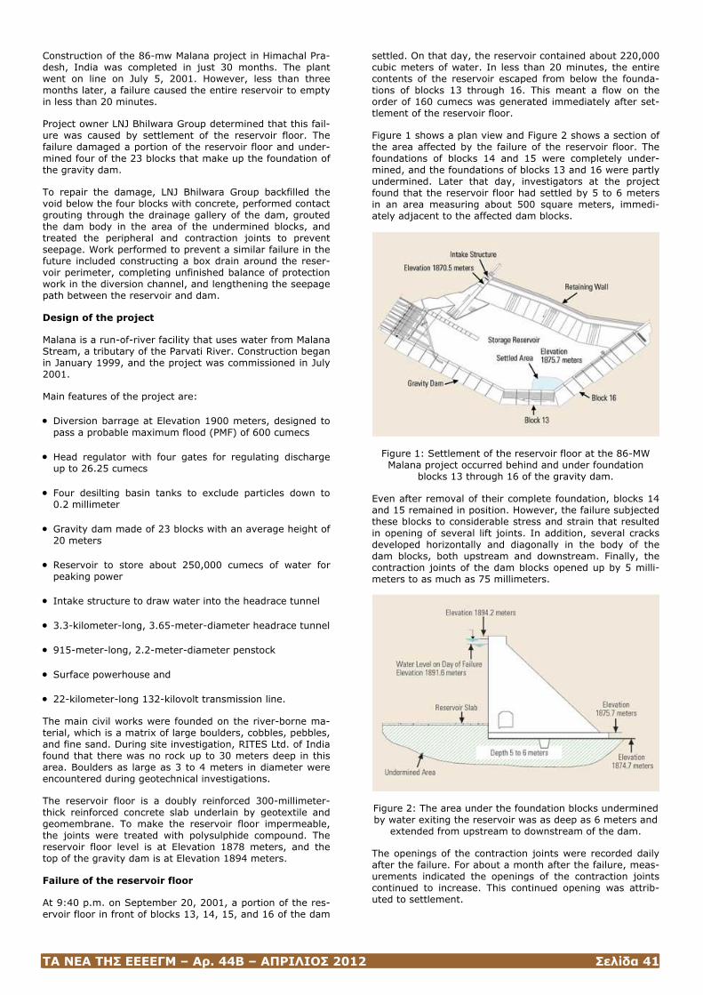
ΤΑ ΝΕΑ ΤΗΣ ΕΕΕΕΓΜ – Αρ. 44Β – ΑΠΡΙΛΙΟΣ 2012 Σελίδα 41
Construction of the 86-mw Malana project in Himachal Pra-desh, India was completed in just 30 months. The plant went on line on July 5, 2001. However, less than three months later, a failure caused the entire reservoir to empty in less than 20 minutes.
Project owner LNJ Bhilwara Group determined that this fail-ure was caused by settlement of the reservoir floor. The failure damaged a portion of the reservoir floor and under-mined four of the 23 blocks that make up the foundation of the gravity dam.
To repair the damage, LNJ Bhilwara Group backfilled the void below the four blocks with concrete, performed contact grouting through the drainage gallery of the dam, grouted the dam body in the area of the undermined blocks, and treated the peripheral and contraction joints to prevent seepage. Work performed to prevent a similar failure in the future included constructing a box drain around the reser-voir perimeter, completing unfinished balance of protection work in the diversion channel, and lengthening the seepage path between the reservoir and dam.
Design of the project
Malana is a run-of-river facility that uses water from Malana Stream, a tributary of the Parvati River. Construction began in January 1999, and the project was commissioned in July 2001.
Main features of the project are:
• Diversion barrage at Elevation 1900 meters, designed to pass a probable maximum flood (PMF) of 600 cumecs
• Head regulator with four gates for regulating discharge up to 26.25 cumecs
• Four desilting basin tanks to exclude particles down to 0.2 millimeter
• Gravity dam made of 23 blocks with an average height of 20 meters
• Reservoir to store about 250,000 cumecs of water for peaking power
• Intake structure to draw water into the headrace tunnel
• 3.3-kilometer-long, 3.65-meter-diameter headrace tunnel
• 915-meter-long, 2.2-meter-diameter penstock
• Surface powerhouse and
• 22-kilometer-long 132-kilovolt transmission line.
The main civil works were founded on the river-borne ma-terial, which is a matrix of large boulders, cobbles, pebbles, and fine sand. During site investigation, RITES Ltd. of India found that there was no rock up to 30 meters deep in this area. Boulders as large as 3 to 4 meters in diameter were encountered during geotechnical investigations.
The reservoir floor is a doubly reinforced 300-millimeter-thick reinforced concrete slab underlain by geotextile and geomembrane. To make the reservoir floor impermeable, the joints were treated with polysulphide compound. The reservoir floor level is at Elevation 1878 meters, and the top of the gravity dam is at Elevation 1894 meters.
Failure of the reservoir floor
At 9:40 p.m. on September 20, 2001, a portion of the res-ervoir floor in front of blocks 13, 14, 15, and 16 of the dam
settled. On that day, the reservoir contained about 220,000 cubic meters of water. In less than 20 minutes, the entire contents of the reservoir escaped from below the founda-tions of blocks 13 through 16. This meant a flow on the order of 160 cumecs was generated immediately after set-tlement of the reservoir floor.
Figure 1 shows a plan view and Figure 2 shows a section of the area affected by the failure of the reservoir floor. The foundations of blocks 14 and 15 were completely under-mined, and the foundations of blocks 13 and 16 were partly undermined. Later that day, investigators at the project found that the reservoir floor had settled by 5 to 6 meters in an area measuring about 500 square meters, immedi-ately adjacent to the affected dam blocks.
Figure 1: Settlement of the reservoir floor at the 86-MW Malana project occurred behind and under foundation
blocks 13 through 16 of the gravity dam.
Even after removal of their complete foundation, blocks 14 and 15 remained in position. However, the failure subjected these blocks to considerable stress and strain that resulted in opening of several lift joints. In addition, several cracks developed horizontally and diagonally in the body of the dam blocks, both upstream and downstream. Finally, the contraction joints of the dam blocks opened up by 5 milli-meters to as much as 75 millimeters.
Figure 2: The area under the foundation blocks undermined by water exiting the reservoir was as deep as 6 meters and
extended from upstream to downstream of the dam.
The openings of the contraction joints were recorded daily after the failure. For about a month after the failure, meas-urements indicated the openings of the contraction joints continued to increase. This continued opening was attrib-uted to settlement.
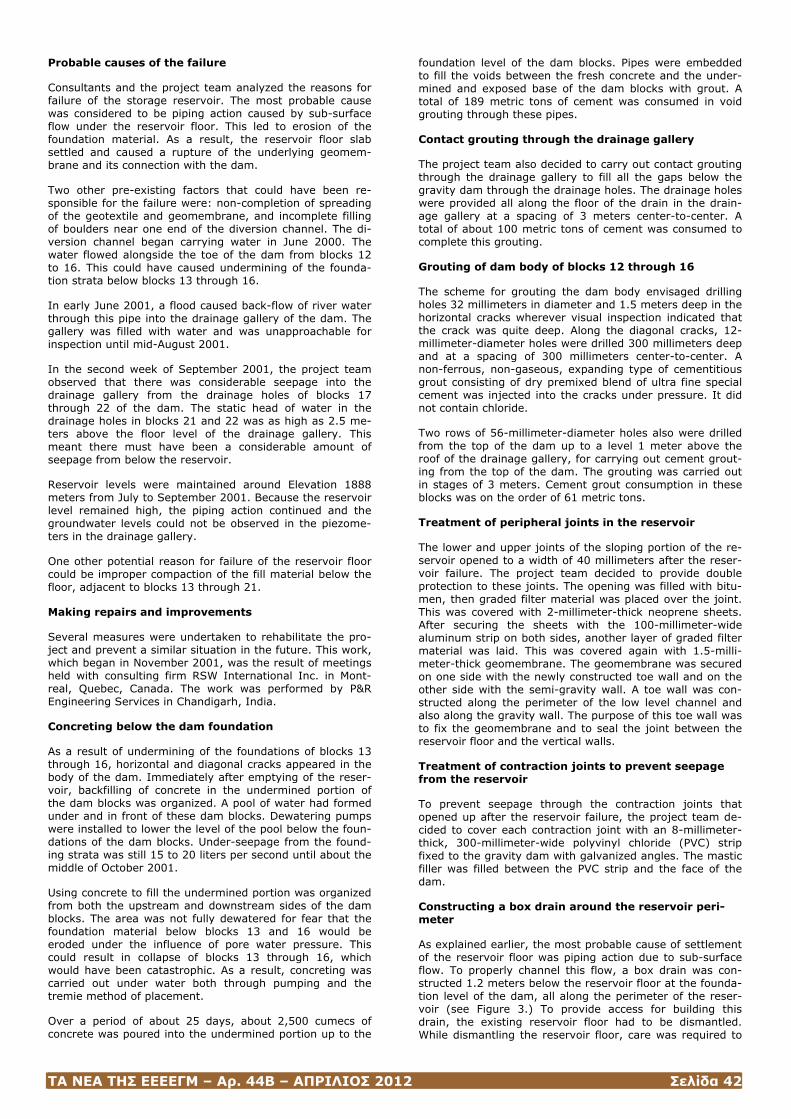
ΤΑ ΝΕΑ ΤΗΣ ΕΕΕΕΓΜ – Αρ. 44Β – ΑΠΡΙΛΙΟΣ 2012 Σελίδα 42
Probable causes of the failure
Consultants and the project team analyzed the reasons for failure of the storage reservoir. The most probable cause was considered to be piping action caused by sub-surface flow under the reservoir floor. This led to erosion of the foundation material. As a result, the reservoir floor slab settled and caused a rupture of the underlying geomem-brane and its connection with the dam.
Two other pre-existing factors that could have been re-sponsible for the failure were: non-completion of spreading of the geotextile and geomembrane, and incomplete filling of boulders near one end of the diversion channel. The di-version channel began carrying water in June 2000. The water flowed alongside the toe of the dam from blocks 12 to 16. This could have caused undermining of the founda-tion strata below blocks 13 through 16.
In early June 2001, a flood caused back-flow of river water through this pipe into the drainage gallery of the dam. The gallery was filled with water and was unapproachable for inspection until mid-August 2001.
In the second week of September 2001, the project team observed that there was considerable seepage into the drainage gallery from the drainage holes of blocks 17 through 22 of the dam. The static head of water in the drainage holes in blocks 21 and 22 was as high as 2.5 me-ters above the floor level of the drainage gallery. This meant there must have been a considerable amount of seepage from below the reservoir.
Reservoir levels were maintained around Elevation 1888 meters from July to September 2001. Because the reservoir level remained high, the piping action continued and the groundwater levels could not be observed in the piezome-ters in the drainage gallery.
One other potential reason for failure of the reservoir floor could be improper compaction of the fill material below the floor, adjacent to blocks 13 through 21.
Making repairs and improvements
Several measures were undertaken to rehabilitate the pro-ject and prevent a similar situation in the future. This work, which began in November 2001, was the result of meetings held with consulting firm RSW International Inc. in Mont-real, Quebec, Canada. The work was performed by P&R Engineering Services in Chandigarh, India.
Concreting below the dam foundation
As a result of undermining of the foundations of blocks 13 through 16, horizontal and diagonal cracks appeared in the body of the dam. Immediately after emptying of the reser-voir, backfilling of concrete in the undermined portion of the dam blocks was organized. A pool of water had formed under and in front of these dam blocks. Dewatering pumps were installed to lower the level of the pool below the foun-dations of the dam blocks. Under-seepage from the found-ing strata was still 15 to 20 liters per second until about the middle of October 2001.
Using concrete to fill the undermined portion was organized from both the upstream and downstream sides of the dam blocks. The area was not fully dewatered for fear that the foundation material below blocks 13 and 16 would be eroded under the influence of pore water pressure. This could result in collapse of blocks 13 through 16, which would have been catastrophic. As a result, concreting was carried out under water both through pumping and the tremie method of placement.
Over a period of about 25 days, about 2,500 cumecs of concrete was poured into the undermined portion up to the
foundation level of the dam blocks. Pipes were embedded to fill the voids between the fresh concrete and the under-mined and exposed base of the dam blocks with grout. A total of 189 metric tons of cement was consumed in void grouting through these pipes.
Contact grouting through the drainage gallery
The project team also decided to carry out contact grouting through the drainage gallery to fill all the gaps below the gravity dam through the drainage holes. The drainage holes were provided all along the floor of the drain in the drain-age gallery at a spacing of 3 meters center-to-center. A total of about 100 metric tons of cement was consumed to complete this grouting.
Grouting of dam body of blocks 12 through 16
The scheme for grouting the dam body envisaged drilling holes 32 millimeters in diameter and 1.5 meters deep in the horizontal cracks wherever visual inspection indicated that the crack was quite deep. Along the diagonal cracks, 12-millimeter-diameter holes were drilled 300 millimeters deep and at a spacing of 300 millimeters center-to-center. A non-ferrous, non-gaseous, expanding type of cementitious grout consisting of dry premixed blend of ultra fine special cement was injected into the cracks under pressure. It did not contain chloride.
Two rows of 56-millimeter-diameter holes also were drilled from the top of the dam up to a level 1 meter above the roof of the drainage gallery, for carrying out cement grout-ing from the top of the dam. The grouting was carried out in stages of 3 meters. Cement grout consumption in these blocks was on the order of 61 metric tons.
Treatment of peripheral joints in the reservoir
The lower and upper joints of the sloping portion of the re-servoir opened to a width of 40 millimeters after the reser-voir failure. The project team decided to provide double protection to these joints. The opening was filled with bitu-men, then graded filter material was placed over the joint. This was covered with 2-millimeter-thick neoprene sheets. After securing the sheets with the 100-millimeter-wide aluminum strip on both sides, another layer of graded filter material was laid. This was covered again with 1.5-milli-meter-thick geomembrane. The geomembrane was secured on one side with the newly constructed toe wall and on the other side with the semi-gravity wall. A toe wall was con-structed along the perimeter of the low level channel and also along the gravity wall. The purpose of this toe wall was to fix the geomembrane and to seal the joint between the reservoir floor and the vertical walls.
Treatment of contraction joints to prevent seepage from the reservoir
To prevent seepage through the contraction joints that opened up after the reservoir failure, the project team de-cided to cover each contraction joint with an 8-millimeter-thick, 300-millimeter-wide polyvinyl chloride (PVC) strip fixed to the gravity dam with galvanized angles. The mastic filler was filled between the PVC strip and the face of the dam.
Constructing a box drain around the reservoir peri-meter
As explained earlier, the most probable cause of settlement of the reservoir floor was piping action due to sub-surface flow. To properly channel this flow, a box drain was con-structed 1.2 meters below the reservoir floor at the founda-tion level of the dam, all along the perimeter of the reser-voir (see Figure 3.) To provide access for building this drain, the existing reservoir floor had to be dismantled. While dismantling the reservoir floor, care was required to
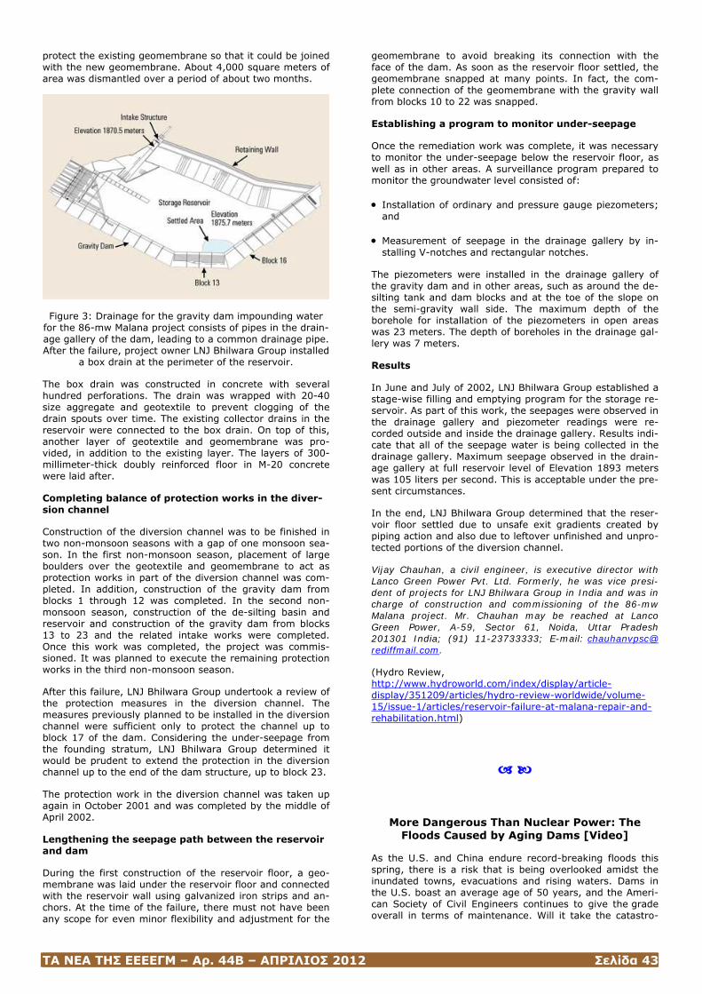
ΤΑ ΝΕΑ ΤΗΣ ΕΕΕΕΓΜ – Αρ. 44Β – ΑΠΡΙΛΙΟΣ 2012 Σελίδα 43
protect the existing geomembrane so that it could be joined with the new geomembrane. About 4,000 square meters of area was dismantled over a period of about two months.
Figure 3: Drainage for the gravity dam impounding water for the 86-mw Malana project consists of pipes in the drain-age gallery of the dam, leading to a common drainage pipe. After the failure, project owner LNJ Bhilwara Group installed
a box drain at the perimeter of the reservoir.
The box drain was constructed in concrete with several hundred perforations. The drain was wrapped with 20-40 size aggregate and geotextile to prevent clogging of the drain spouts over time. The existing collector drains in the reservoir were connected to the box drain. On top of this, another layer of geotextile and geomembrane was pro-vided, in addition to the existing layer. The layers of 300-millimeter-thick doubly reinforced floor in M-20 concrete were laid after.
Completing balance of protection works in the diver-sion channel
Construction of the diversion channel was to be finished in two non-monsoon seasons with a gap of one monsoon sea-son. In the first non-monsoon season, placement of large boulders over the geotextile and geomembrane to act as protection works in part of the diversion channel was com-pleted. In addition, construction of the gravity dam from blocks 1 through 12 was completed. In the second non-monsoon season, construction of the de-silting basin and reservoir and construction of the gravity dam from blocks 13 to 23 and the related intake works were completed. Once this work was completed, the project was commis-sioned. It was planned to execute the remaining protection works in the third non-monsoon season.
After this failure, LNJ Bhilwara Group undertook a review of the protection measures in the diversion channel. The measures previously planned to be installed in the diversion channel were sufficient only to protect the channel up to block 17 of the dam. Considering the under-seepage from the founding stratum, LNJ Bhilwara Group determined it would be prudent to extend the protection in the diversion channel up to the end of the dam structure, up to block 23.
The protection work in the diversion channel was taken up again in October 2001 and was completed by the middle of April 2002.
Lengthening the seepage path between the reservoir and dam
During the first construction of the reservoir floor, a geo-membrane was laid under the reservoir floor and connected with the reservoir wall using galvanized iron strips and an-chors. At the time of the failure, there must not have been any scope for even minor flexibility and adjustment for the
geomembrane to avoid breaking its connection with the face of the dam. As soon as the reservoir floor settled, the geomembrane snapped at many points. In fact, the com-plete connection of the geomembrane with the gravity wall from blocks 10 to 22 was snapped.
Establishing a program to monitor under-seepage
Once the remediation work was complete, it was necessary to monitor the under-seepage below the reservoir floor, as well as in other areas. A surveillance program prepared to monitor the groundwater level consisted of:
• Installation of ordinary and pressure gauge piezometers; and
• Measurement of seepage in the drainage gallery by in-stalling V-notches and rectangular notches.
The piezometers were installed in the drainage gallery of the gravity dam and in other areas, such as around the de-silting tank and dam blocks and at the toe of the slope on the semi-gravity wall side. The maximum depth of the borehole for installation of the piezometers in open areas was 23 meters. The depth of boreholes in the drainage gal-lery was 7 meters.
Results
In June and July of 2002, LNJ Bhilwara Group established a stage-wise filling and emptying program for the storage re-servoir. As part of this work, the seepages were observed in the drainage gallery and piezometer readings were re-corded outside and inside the drainage gallery. Results indi-cate that all of the seepage water is being collected in the drainage gallery. Maximum seepage observed in the drain-age gallery at full reservoir level of Elevation 1893 meters was 105 liters per second. This is acceptable under the pre-sent circumstances.
In the end, LNJ Bhilwara Group determined that the reser-voir floor settled due to unsafe exit gradients created by piping action and also due to leftover unfinished and unpro-tected portions of the diversion channel.
Vijay Chauhan, a civil engineer, is executive director with Lanco Green Power Pvt. Ltd. Formerly, he was vice presi-dent of projects for LNJ Bhilwara Group in India and was in charge of construction and commissioning of the 86-mw Malana project. Mr. Chauhan may be reached at Lanco Green Power, A-59, Sector 61, Noida, Uttar Pradesh 201301 India; (91) 11-23733333; E-mail: chauhanvpsc@ rediffmail.com.
(Hydro Review, http://www.hydroworld.com/index/display/article-display/351209/articles/hydro-review-worldwide/volume-15/issue-1/articles/reservoir-failure-at-malana-repair-and-rehabilitation.html)
More Dangerous Than Nuclear Power: The Floods Caused by Aging Dams [Video]
As the U.S. and China endure record-breaking floods this spring, there is a risk that is being overlooked amidst the inundated towns, evacuations and rising waters. Dams in the U.S. boast an average age of 50 years, and the Ameri-can Society of Civil Engineers continues to give the grade overall in terms of maintenance. Will it take the catastro-
ΤΑ ΝΕΑ ΤΗΣ ΕΕΕΕΓΜ – Αρ. 44Β – ΑΠΡΙΛΙΟΣ 2012 Σελίδα 44
phic collapse of a dam—like the five in the 1970s in the U.S. that killed hundreds—before the infrastructure is re-paired?
The nation’s more than 80,000 dams have served us well—restraining less-than-epic floods and generating billions of kilowatt-hours of electricity for regional grids. In fact, mas-sive dams across the western U.S., like Grand Coulee in Washington State, still provide the vast majority of "renew-able" electricity in the U.S., some 7 percent. At the same time, hydropower can help balance more intermittent re-newable resources, such as wind power. For example, wa-ter can be held back water to cope with "wind droughts," prolonged periods of little or no wind such as an 11 day wind drought in the Pacific Northwest earlier this year.
But these dams of legend—that helped win World War II as the poster illustrating this post implies—are old. And old dams are in danger of failure—more than 4,000 in the U.S. alone are at high risk of imminent failure, according to the Association of State Dam Safety Officials.
http://blogs.scientificamerican.com/observations/2011/06/20/more-dangerous-than-nuclear-power-the-floods-caused-by-aging-dams-video/
On a per kilowatt-hour basis, dams are the most dangerous source of electricity generation, followed by burning coal with its attendant mining accidents and deaths via heavily polluted air. A tsunami flood crippled Fukushima Daiichi in Japan—prompting the meltdown of three nuclear reac-tors that have, so far, killed no one. A series of dam failures in China in the 1970s killed more than 200,000 people. Similarly, more than 500,000 have been evacuated in cen-tral and southern China this month due to flooding and mudslides, whereas about 80,000 have been relocated due to the nuclear plant disaster in Japan.
In fact, the filling the reservoirs behind new big dams in China may have helped trigger the deadly 2008 earthquake in Sichuan Province. As a result, the Chinese government has admitted that its most massive dam—Three Gorges—has "urgent problems," ranging from "geological disaster prevention" to the ongoing relocation of millions of people.
Nevertheless, the world is embarking on a new renaissance of big dam building; just this month Brazil gave final ap-proval to move forward with the massive Belo Monte dam in the Amazon region of Para state on the Xingu River, which will be able to produce more than 11 gigawatts of power. Meanwhile, the world’s older dams are in dire need of refurbishment, lest the floods burst their bounds.
(David Biello / SCIENTIFIC AMERICAN, June 20, 2011)
How Explosives Affect Embankment Dams
Abass Braimah and Mohammad Rayhani
Failure of embankment dams as a result of explosive attack can have serious ramifications for the people and environ-ment downstream of the structure. Understanding how ex-plosives affect these dams can help owners and operators develop mitigation strategies.
Dams are considered critical infrastructure under Interna-tional Humanitarian Law because of the massive effect a breach or failure could have on the population and envi-ronment. For example, the failure of South Fork Dam in 1889 caused more than 2,200 deaths in Johnstown, Pa., USA.1 A similar failure could cause greater casualties and economic losses because of the many cities in the flood plains of dams. Were Aswan Dam in Egypt to fail, it would cause fatality to a large percentage of Egypt's population while sweeping many structures into the Mediterranean Sea.
The most common causes of dam failure are design errors, geological instability, extreme inflow, sub-standard materi-als/techniques and poor maintenance. However, an in-crease in global terrorism has imposed another potential cause of failure. The destruction of dams has the potential to cause catastrophic floods and put strain on electrical power supplies, which in turn could have adverse effects on many national critical infrastructure sectors. Thus, terrorists and other groups seeking to cause mass casualties or eco-nomic disruption or attract media attention could target dams.
The effects of explosives on dams are not well-understood, and most dam owners/engineers lack the expertise to esti-mate the vulnerability of dam infrastructure to such at-tacks. Knowledge of these effects will undoubtedly lead to implementation of mitigation strategies aimed at limiting damage to dam infrastructure and its consequential effects on downstream communities and the electrical power sys-tem. Although little test data is available to aid the dam owner/designer in identifying vulnerabilities and establish-ing the amount of explosives that can compromise the many critical dam infrastructure systems, data from attacks on dams during conflicts or wars are available. Investiga-tions into these attacks provide insight into the robustness of dams to attacks with various amounts of explosives at a number of locations on the dam structure.
Attacks on dams
A literature review reveals only a few attempts by terrorists or violent protestors to attack dam infrastructure. One dam targeted by terrorists is Chingaza in Colombia, which sup-plies water to the city of Bogota. The dam is gravel fill with a concrete face and impounds a reservoir with a capacity of 223 million cubic meters. The Revolutionary Armed Forces of Colombia (FARC) have attacked several dams and aque-ducts. In January 2002, FARC detonated an explosive de-vice in a gate valve inside a tunnel in Chingaza Dam in an attempt to breach the structure and disrupt water supply to Bogota and flood the city of Villavicencio downstream of the dam. However, the attack was not successful and the dam was not breached.
In July 2011, the Indian Army intercepted a terrorist threat to Bhakra Nangal Dam in Himachal Pradesh, India, a con-crete gravity structure that holds the distinction of being the world's highest straight gravity dam. The dam, on the Satluj River, impounds water for a 1,325 MW hydroelectric project. Reports indicated two terrorist groups were plan-ning strikes during the monsoon, when the water level be-hind the dam is at its highest, to cause maximum damage to downstream structures and people. Luckily, no such at-tack was carried out.
With regard to embankment dams, the below case studies present information on two attacks and the accompanying damage.
Sorpe Dam
Sorpe Dam in North Rhine-Westphalia, Germany, was con-structed from 1922 to 1935. It is an earthfill embankment with a watertight concrete core wall. The dam crest is 700
ΤΑ ΝΕΑ ΤΗΣ ΕΕΕΕΓΜ – Αρ. 44Β – ΑΠΡΙΛΙΟΣ 2012 Σελίδα 45
m long, and the height above the valley floor is 60 m, with a maximum water depth of 57 m. The dam is 10 m wide at the crest and 307 m wide at the base, with 1:2.25 and 1:2.50 slopes of the upstream and downstream faces, re-spectively.2
This dry model embankment dam was built to help further understanding of the effects of explosives on embankment
dams.
Sorpe Dam was attacked during Operation Chastise (Dam-busters Raid) of WWII. The air attack was carried out on May 17, 1943, by a squadron of the Royal Air Force using the Upkeep (bouncing) Bomb developed for that purpose. This bomb was 1.5 m long and 1.3 m in diameter and was filled with 3,600 kg of RDX explosive.3 Sorpe Dam suffered two hits on its crest that resulted in craters about 12 m deep. The dam structure, however, did not fail. Shortly after the Dambusters Raid, the water level in Sorpe Reser-voir was lowered as a precautionary measure.
The attacks on Sorpe Dam were repeated several times in 1944 by the Allied Forces. On October 16, 1944, an attack on Sorpe Dam resulted in 11 direct hits. Although 12 m-deep and 25 to 30 m-diameter craters were formed, the embankment dam was not breached. The second wave of attacks used 5,500 kg "Tallboy" bombs, which also did not breach the dam. After the war, the dam was repaired and the craters filled. However, in the 1950s serious leakage problems were discovered and more remedial work was authorized. In 1958, when the dam was partially drained for repairs, an unexploded Tallboy was found buried in the embankment dam and removed. Sorpe Dam was repaired and put back into service and remains in operation today.
Peruca Dam
Peruca Dam is on the Cetina River in the Republic of Croa-tia. It is a 425 m-long and 60 m-high rockfill dam with a convex upstream axis.4 Peruca Dam was constructed be-tween 1955 and 1960.5
During the Balkan wars, the area around the dam was oc-cupied by the Yugoslav Army and later by Serbian Forces, who planted 20 to 30 tons of TNT in five locations in the walls of the spillway structure and inspection gallery. On several occasions, Serbian Forces threatened to destroy the dam using these explosives and closed the spillway gate, power tunnels and outlets and maintained the water level as high as possible so that maximum damage would re-sult.4,5
In 1992, a United Nations Protection Force took control of the dam and lowered the water level to the design eleva-tion. On January 28, 1993, Serbian Forces retook the dam and detonated the explosives in an attempt to destroy Pe-
ruca Dam and flood the villages and hydroelectric power station downstream.4
But the effects of the detonations were not sufficient to breach the dam or lead to overtopping and subsequent ero-sion and failure of the structure. The explosions did leave two large craters at the abutments. The elevation of the rim of the crater was only 300 mm from the water level in the reservoir. The inspection gallery was also heavily damaged at the abutments and completely destroyed at the deepest section in the middle of the dam. A total settlement of about 1.55 m of the crest was recorded about ten months after the explosion.
The explosives did not breach the dam because the three entrances of the inspection gallery were left open, thus venting the confined gas pressure from the explosion. Also, the reservoir was about 5 m lower than the level at which Serbian Forces intended to detonate the explosives. But for the actions of the protection force, the dam would have been breached, causing about 12,000 deaths and about 60,000 displaced people. The population would have been without electricity, and all farming lands in the low-lying valley would have been flooded.5
Rehabilitation of Peruca Dam began immediately after the attack. The craters at the abutments were filled and the bottom outlet was opened to begin lowering the head pond. This relieved the damaged dam from the hydrostatic pres-sure and seepage. The rehabilitation continued for about three years. By April 1996, the head pond was filled to the design level and the hydroelectric station was put back into regular operation.
Explosive impacts
The damage sustained by a dam and related infrastructure during an attack with an explosive device depends on the type of dam, the type of explosive device and amount of charge used, and its placement on or relative to the infra-structure. When an explosive device is detonated, a short-lived fireball is formed, followed by a blast wave that trav-els omnidirectionally from the center of detonation. De-pending on the center of detonation relative to the ground surface, a crater is formed, accompanied by ground shock/ vibrations. If the explosive device is in a container, a por-tion of the energy is expended in fragmenting the container and projecting the fragments at high velocities. The blast wave also has a propensity to break up frangible structures in its path and throw them at high velocities.
The fireball from an explosion can ignite proximate flam-mable materials, while the ground shock/vibrations are of consequence for buried infrastructure systems. The blast wave exerts high-peak and short-duration pressures on structures in its path that can lead to failure, whereas the high-velocity fragments impart high-impulse impact loads to structures in their paths. The dimensions of explosive craters depend on the depth of burial or height of burst of the explosive relative to the ground surface. Crater size decreases with an increase in height of the burst and in-creases with an increase in the depth of burial.
When the explosive charge is buried or close to the ground surface, the blast/shock waves from the explosion travel through the earth mass and increase pore water pressure. This can lead to instability of embankment dams through decrease in effective pressure, piping and liquefaction of the dam material. Buried explosives are confined by the soil mass, and the detonation energy is immediately imparted into the soil, causing fracture of the rock and displacement of soil.
For underwater explosions, the over-pressure can be up to two orders of magnitude higher than that in air for the same scaled distance.6 Therefore, underwater contact
ΤΑ ΝΕΑ ΤΗΣ ΕΕΕΕΓΜ – Αρ. 44Β – ΑΠΡΙΛΙΟΣ 2012 Σελίδα 46
charges can impart greater loads to a target surface. On the other hand, due to the confining effect of the water, particle motion will be reduced so that underwater crater formation is less effective than that by contact charges at ground/air interfaces.7
Mode of failure
The primary explosion-induced mode of failure of embank-ment dams is cratering and accompanying overtopping and erosion. The crater dimensions depend on the amount of explosive, location of the explosive charge relative to the body of the embankment (buried in the embankment, placed on the surface, or elevated above the surface), soil type, and moisture content of the soil. Crater formation on the crest of an embankment dam can lead to instantaneous overtopping depending on available freeboard, and the ac-companying erosion and scour can cause serious damage to the structure. Crater and cavity formation on the down-stream face of an embankment dam due to surface-placed or buried explosive charges can lead to piping and eventual failure. In conflict situations where military-type weapons can be used, standoff artillery with the capability of burrow-ing into the body of the embankment and detonating can cause much more severe cratering and damage to the dam.
The size of explosive crater has been the subject of re-search studies,8 and the U.S. Army developed a software program — Conventional Weapons Effect Program (Con-Wep) — for determining crater properties given charge mass and depth of burial. However, ConWep deals with cratering on flat ground surfaces and is not applicable to embankments, where the slopes will have a marked effect on crater size.
A preliminary research effort to investigate the effect of an embankment on crater size was carried out on a dry em-bankment shaped from native soil.9 The model dam was constructed by digging the sandy native soil of the test site away from ground level, leaving the native undisturbed topsoil to form the crest of the dam, while the slopes were shaped by excavation. The model dam, which represents a one-fifth scale of a 10 m-high embankment dam with 3:1 upstream slope and 2.5:1 downstream slope, was 33 m long and 2 m wide at the crest and 13 m wide at the base (see Figure 1). ANFO (Ammonium Nitrate and Fuel Oil) was used as the surface explosive charge (the charge placed on the crest of the dam). Also, the same amount of ANFO was detonated on the ground surface without embankments (infinite flat ground) and the crater sizes measured.
The average crater diameter on the dam crest was typically larger than that of the craters formed with equal masses of explosive on the infinite flat ground. The presence of the dam slope reduced the confining effects, thus a larger amount of ejecta was discharged toward the upstream and downstream faces of the dam. The craters on the crest were elliptical in shape, with the long axis across the dam crest and the short axis along the centerline. The depth of crater, however, was similar for both the crater on infinite flat ground and crater on the embankment dam. Compari-son of the typical crater profiles resulting from the experi-ment with those predicted by ConWep showed that ConWep overestimates both crater diameter and depth (see Figure 2).9
Due to the fact that the dam material used in this study was uncompacted, native sandy soil that did not represent a typical embankment construction, further tests on a properly constructed dam with, possibly, a head of water is required to investigate the impact of explosives on behavior of embankment dams. Sieve analysis of the native sandy soil of the test site of the model embankment dam per-formed in accordance with ASTM D42210 indicates that the soil particles are mainly sand and gravel. The fine portion of the soil was less than 5% fine (passing the 0.075 mm sieve). The soil can mainly be classified as poorly graded sand in USCS classification system.11
Another physical model test was performed on an earthfill dam with a height of 3 m and a 2 m-wide crest to investi-gate the crater size.12 The fill material was nonbinding sands with grain size ranging from 0.02 to 2 mm. Blasts of one or more 200 gram charges (mostly TNT) were set off on the model dam, which was erected in the open. A crater with the natural slope of 36 degrees was found for all mod-els tested. The laws of similitude were used to scale the explosive effect for charges up to 1,000 kg. All model tests showed that any leakage, no matter how insignificant, represents primary danger because it leads, without fail, to a dam break. The exception to this observation is if the leakage is stopped and the primary damage repaired im-mediately.
Effect of explosive shock on pore water pressure
Explosion-induced ground motion can cause increase in pore pressure that may take hours or days (depending on the soil properties) to dissipate. The increased pore pres-sure leads to a reduction in the effective stress of the soil and reduced shear strength.12,13 This reduced strength can adversely affect the stability and safety of embankment dams and slopes. A number of embankment dam failures have been reported due to adjacent blasting activities, in-cluding slope failure of Calaveras Dam in California.13 This and other examples indicate that blasting in or near em-bankment dams can significantly increase residual (excess) pore-water pressure and reduce stability.
Ground motions caused by explosives produce localized peak accelerations that can be several orders of magnitude greater than earthquake accelerations. When a buried charge is detonated, the rapid release of energy generates a compression wave that radiates away from the explosion and produces tensile hoop strains accompanied by intense radial compressive strains in the surrounding soil. The detonation pressure of commercial explosives ranges from 105 to 108 kPa, depending on the distance from the center of detonation. A shock wave propagating from the center of detonation typically has one sharp peak of acceleration with duration of a few milliseconds for rock and tens of millisec-onds for soil.14 The ground motion frequency from blasting in most soils ranges from 6 to 9 Hz, but in loose saturated sands, silts and soft clays it can be as low as 2 Hz.13
ΤΑ ΝΕΑ ΤΗΣ ΕΕΕΕΓΜ – Αρ. 44Β – ΑΠΡΙΛΙΟΣ 2012 Σελίδα 47
For a deeply buried charge, most of the blast energy in the surrounding material is in the form of a compressional stress wave. When this wave reaches an interface such as the water table or ground surface, it is reflected into a ten-sion wave. Even though the blast wave is a few milliseconds in duration, it can produce oscillatory ground motions last-ing several seconds at locations several hundred meters away from the center of detonation. Blast-induced ground motion is affected by many factors, including soil type, charge weight and depth of burial. An increase in the amount of explosive charge leads to higher ground shock amplitude and lower frequencies. A buried explosion creates significantly greater ground vibration, and therefore higher excess pore water pressure, than surface or near-surface explosions. Explosions in saturated soils generally produce higher peak particle velocity and hence higher excess pore water pressure than those in partially saturated soils.
The blast-induced pore water pressure response in satu-rated soils can be explained through transient, residual and dissipation stages. The transient response is associated with the passage of blast-induced stress waves through the soil. After passage of the stress waves, a residual increase in pore-water pressure occurs in which the fluid phase re-sponds elastically, while the response of soil particles is in plastic range. This residual increase in pore water pressure is important for dam safety. Dissipation of the pore-water pressure may take hours to days after the blast, depending on the soil hydraulic conductivity and thickness.
Extensive data are available on blasting and on the per-formance of certain structures subjected to blast vibrations. However, only limited information is available on the per-formance of embankment dams and other hydraulic struc-tures subjected to blast loading. Most of the work on the effects of blast-induced pore water pressure increases on embankment dams has been from proximate explosions. Few have looked at the effects of explosion on either the crest of the dam or the upstream or downstream slopes of the embankment.
Researchers have studied blast-induced liquefaction where a complete loss of shear strength occurs as a consequence of reduced effective stress from increased residual pore-water pressure. Experimental laboratory and field studies of shock waves revealed that liquefaction did not occur in sa-turated sands with dry densities greater than 1.60 g/cm3.15 In addition, liquefaction did not occur in any satu-rated soil subjected to peak particle velocities less than 7 cm/s.16 Blast-induced residual pore water pressures oc-curred where the peak particle velocity exceeded 5 cm/s.17
A shear or compression strain of less than 0.01% is gener-ally considered small enough to preclude generation of re-sidual pore water pressures because the strains are in the elastic range.18 A shear strain of 0.01% corresponds to a peak transverse particle velocity of about 1 to 3 cm/s for cohesionless soils having shear wave velocities of 100 to 300 m/s, typical of saturated soils. For blasting with a sin-gle charge of 100 kg, the residual pore water pressures could occur out to about 50 to 100 m.12
Notes
1. Johnson, W.F., "History of the Johnstown Flood," 1889, www.jaha.org/FloodMuseum/history.html.
2. Matich, F., "The Dams Raid: Breaking the Great Dams of Western Germany," Talk to the Royal Canadian Military Institute, 2005.
3. "Operation Chastise: The Dams Raid," Commonwealth War Graves Commission, Berkshire, UK, 2005, www.cwgc.org/admin/files/The%20Dams%20Raid.pdf.
4. Nonveiller, E., J. Rupcic, and Z. Sever, "War Damages and Recon-struction of Peruca Dam," Journal of Geotechni-
cal and Geoenvironmental Engineering, Volume 125, No. 4, April 1999, pages 280-288.
5. Vajic, N., "Protection of Dams in Armed Conflicts: The Peruca Case," Journal of Chemists and Chemical Engineers, Volume 43, No. 3, 1994, pages 108-114.
6. Braimah, A., and E. Contestabile, "Historical Review: Bombings of Dams," Canadian Dam Association Bulletin, Volume 20, No. 1. 2009, pages 12-21.
7. Long, W. and Y. Ho, "Blasting Engineering," Metallurgical Industry Publishing House, 1996.
8. Ambrosini, R. D. et al., "Size of Craters Produced by Ex-plosive Charges on or Above the Ground Surface," Shock Waves, Volume 12, 2002. pages 69-78.
9. Li, Y., E. Contestabile, A. Braimah, and D. Wilson, "Pre-liminary Vulnerability of an Embankment Dam due to Ex-plosions," CERL Report 2007-01 (CF), 2007.
10. "Standard Test Method for Particle Size Analysis of Soils," ASTM D 422, ASTM International, West Consho-hocken, Pa., USA, 2008.
11. "Standard Practice for Classification of Soils for Engi-neering Purposes (Unified Soil Classification System)," ASTM D 2487, ASTM International, West Conshohocken, Pa., USA, 2008.
12. Charlie, W. A. et al., "Pore Water Pressure Increases in Soil and Rock from Underground Chemical and Nuclear Ex-plosions," Engineering Geology, Volume 43, No. 4, 1996, pages 225-236.
13. Bretz, T. E., "Soil Liquefaction Resulting from Blast In-duced Spherical Stress Waves," WL-TR-89-100, Weapons Laboratory, US Air Force Systems Command, 1990.
14. Stagg, K.G., and O.C. Zienkiewicz, "Rock Mechanics in Engineering Practice," John Wiley and Sons, London, 1968.
15. Lyakhov, G.M. "Shock Waves in the Ground and the Dilatency of Water Saturated Sand," Zhurnal Prikladnoy Mekhaniki i Tekhnicheskoy Fiziki, Volume 1, 1961, pages 38-46.
16. Puchkov, S.V., "Correlation between the Velocity of Seismic Oscillations of Particles and the Liquefaction Phe-nomenon of Water-saturated Sand," in Issue No. 6, Prob-lems of Engineering Seismology, translated by Consultants Bureau, New York, N.Y., USA, 1962.
17. Long, J.H., E.R. Ries, and A.P. Michalopoulos, "Potential for Liquefaction due to Construction Blasting," Proceedings of the International Conferemce on Recent Advances in Geotechnical Engineering and Soil Dynamics, St. Louis, Mo., USA, 1981.
18. Dobry, R. et al., "Prediction of Pore Water Pressure Buildup and Liquefaction of Sands during Earthquakes by Cycle Strain Method," Building Science Series 138, National Bureau of Standards, 1982.
Abass Braimah, PhD, P.Eng., is a professor of infrastructure protection and international security and Mohammad Ray-hani, PhD, P.Eng., is a professor of geotechnical engineer-ing in the Department of Civil and Environmental Engineer-ing at Carleton University in Ontario, Canada.
(http://www.hydroworld.com/index/display/article-display/5015752669/articles/hydro-review-worldwide/volume-20/issue-2/articles/dam-safety/How-Explosives-Affect.html)
ΤΑ ΝΕΑ ΤΗΣ ΕΕΕΕΓΜ – Αρ. 44Β – ΑΠΡΙΛΙΟΣ 2012 Σελίδα 48
ΦΡΑΓΜΑΤΑ ΒΑΡΥΤΗΤΑΣ Planning and Building the Subansiri Lower Dam
and Hydro Project
Biswajit Das
Many challenges have been encountered during construc-tion of Subansiri Lower Dam, which will impound water for a 2,000 MW hydro project. Finding ways to overcome these challenges — including delays in completing infrastructure — have provided valuable lessons learned with regard to dam design and construction.
Design and construction of Subansiri Lower Dam, on the Subansiri River in Arunachal Pradesh, India, involves many challenges. These include land not being available when construction was scheduled to commence, a limited period available for construction because of monsoons (from mid-April to mid-October), the need to handle high flood flows and poor rock conditions.
To meet these challenges, the design of the dam has un-dergone drastic and repeated revisions that also affected the schedule and planning for the construction work. As of November 2011, the dam had attained a level of elevation 138 meters, just below the spillway at elevation 145 me-ters. It is estimated that concreting work to reach the final elevation of 210 meters will be completed by February 2014.
Building Subansiri Dam
The 2,000 MW Subansiri Lower project, owned by NHPC, consists of a 133 meter-high concrete gravity dam with nine spillways equipped with radial gates. Energy dissipa-tion is provided via a ski jump and preformed plunge pool that can handle a design flood of 37,000 m3/s. Figure 1 shows a layout plan of the project.
Upstream and downstream cofferdams are used to dewater the construction site. The upstream cofferdam is 31 meters high and 143 meters from the dam axis; the downstream cofferdam is 21 meters high and 312 meters from the dam axis. Five tunnels — each 9.5 meters in diameter and with an average length of 100 meters — were built to divert the river during construction. Each tunnel has inlet and outlet structures and diverts 4,550 m3/sec during the non-monsoon period, which lasts about seven months. The cof-ferdams were designed to wash out each year during the monsoon period in April and be rebuilt after the monsoon in October, depending on rain and flood variation.
The contract for building the dam and appurtenant works was awarded in December 2003 to a consortium of Bogu-chandgesstroy, Soyuzgidrosptsstry and Soma Enterprise Ltd. The contractors were asked to mobilize immediately and to finish the work in 72 months. However, the land on which the dam was to be constructed was not available because clearance was needed from the Forest and Envi-ronment Authority. After 13 months, the land covering only the dam and tunnels area was handed over. But land needed for the supporting infrastructure was not handed over until 41 months after the contract was awarded be-cause the authority raised many objections, which had to be mitigated through prolonged discussions and examina-tions by all departments.
Further hindrances were encountered during construction of the diversion tunnels, due to geological variation in the rock characteristics in and around the diversion tunnels and inlet and outlet structures. This situation resulted in a series of landslides and lower production by the rock cutting ma-chines than anticipated. Despite this and other hindrances, the contractors continued the work quickly, and NHPC di-rected them to deploy more personnel and equipment to mitigate the time loss.
The river was diverted in December 2007, and by April 2008 the foundation excavation was completed. The ex-posed rock was repeatedly scraped using rock cutting ma-chines and cleaned using an air-water jet. In addition, NHPC performed geological exploration to establish the suitability of this rock for the foundation of the dam. One problem: The foundation rock was encountered 10 meters above the anticipated level, requiring revision of the con-struction drawings. Contractors were asked not to exca-vate, lower the foundation level or perform block concreting during that season. NHPC decided instead that concrete would be laid 500 mm thick over the foundation rock to protect it during the monsoon season.
Revised construction drawings were completed in October 2008, and the contractor immediately began reconstructing the cofferdams. Once the foundation was exposed, it was cleaned and prepared for concrete. However, the plant and machinery for producing the concrete was not ready be-cause the land was not made available until April 2008, immediately before the rainy season started. Thus, installa-tion of the concreting plants started in October 2008.
Normally, such plants require at least 18 months to install and three months for testing and commissioning. However, with an accelerated effort, two plants with a capacity of 240 m3/hr each were commissioned in March 2009. This en-abled contractors to install 60,000 m3 of concrete on the dam foundation before work was suspended in May 2009 because of the onset of the monsoon season.
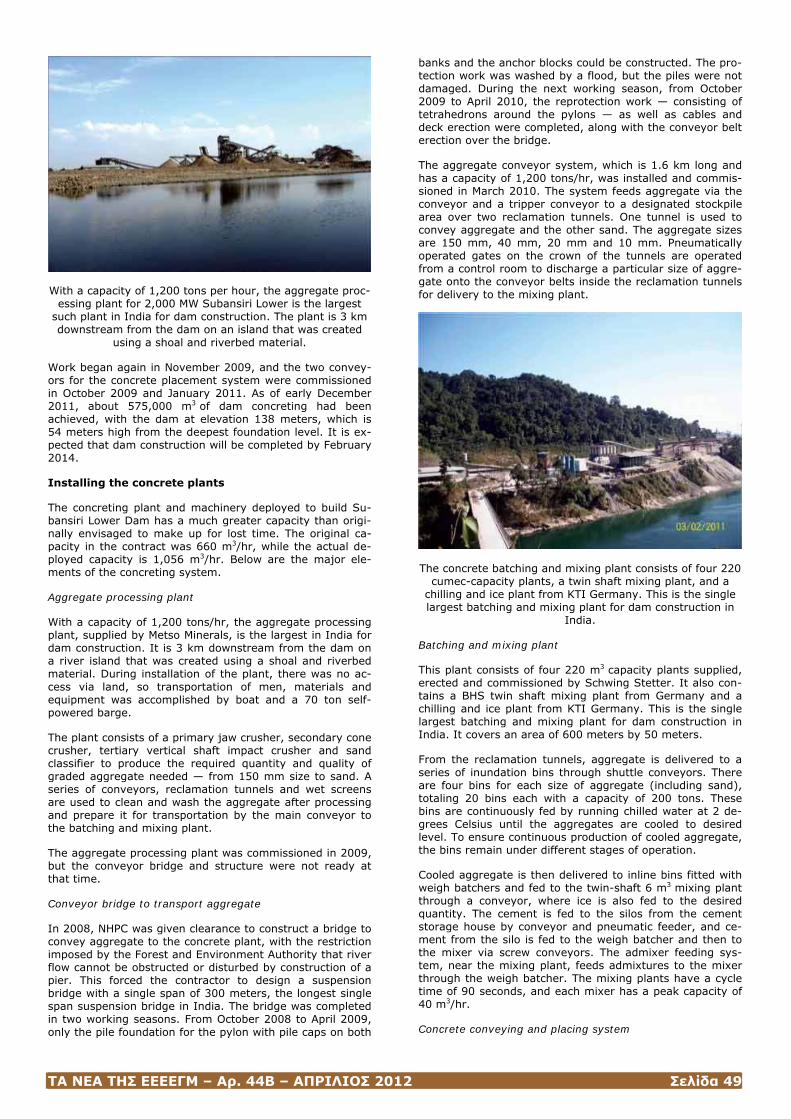
ΤΑ ΝΕΑ ΤΗΣ ΕΕΕΕΓΜ – Αρ. 44Β – ΑΠΡΙΛΙΟΣ 2012 Σελίδα 49
With a capacity of 1,200 tons per hour, the aggregate proc-essing plant for 2,000 MW Subansiri Lower is the largest
such plant in India for dam construction. The plant is 3 km downstream from the dam on an island that was created
using a shoal and riverbed material.
Work began again in November 2009, and the two convey-ors for the concrete placement system were commissioned in October 2009 and January 2011. As of early December 2011, about 575,000 m3 of dam concreting had been achieved, with the dam at elevation 138 meters, which is 54 meters high from the deepest foundation level. It is ex-pected that dam construction will be completed by February 2014.
Installing the concrete plants
The concreting plant and machinery deployed to build Su-bansiri Lower Dam has a much greater capacity than origi-nally envisaged to make up for lost time. The original ca-pacity in the contract was 660 m3/hr, while the actual de-ployed capacity is 1,056 m3/hr. Below are the major ele-ments of the concreting system.
Aggregate processing plant
With a capacity of 1,200 tons/hr, the aggregate processing plant, supplied by Metso Minerals, is the largest in India for dam construction. It is 3 km downstream from the dam on a river island that was created using a shoal and riverbed material. During installation of the plant, there was no ac-cess via land, so transportation of men, materials and equipment was accomplished by boat and a 70 ton self-powered barge.
The plant consists of a primary jaw crusher, secondary cone crusher, tertiary vertical shaft impact crusher and sand classifier to produce the required quantity and quality of graded aggregate needed — from 150 mm size to sand. A series of conveyors, reclamation tunnels and wet screens are used to clean and wash the aggregate after processing and prepare it for transportation by the main conveyor to the batching and mixing plant.
The aggregate processing plant was commissioned in 2009, but the conveyor bridge and structure were not ready at that time.
Conveyor bridge to transport aggregate
In 2008, NHPC was given clearance to construct a bridge to convey aggregate to the concrete plant, with the restriction imposed by the Forest and Environment Authority that river flow cannot be obstructed or disturbed by construction of a pier. This forced the contractor to design a suspension bridge with a single span of 300 meters, the longest single span suspension bridge in India. The bridge was completed in two working seasons. From October 2008 to April 2009, only the pile foundation for the pylon with pile caps on both
banks and the anchor blocks could be constructed. The pro-tection work was washed by a flood, but the piles were not damaged. During the next working season, from October 2009 to April 2010, the reprotection work — consisting of tetrahedrons around the pylons — as well as cables and deck erection were completed, along with the conveyor belt erection over the bridge.
The aggregate conveyor system, which is 1.6 km long and has a capacity of 1,200 tons/hr, was installed and commis-sioned in March 2010. The system feeds aggregate via the conveyor and a tripper conveyor to a designated stockpile area over two reclamation tunnels. One tunnel is used to convey aggregate and the other sand. The aggregate sizes are 150 mm, 40 mm, 20 mm and 10 mm. Pneumatically operated gates on the crown of the tunnels are operated from a control room to discharge a particular size of aggre-gate onto the conveyor belts inside the reclamation tunnels for delivery to the mixing plant.
The concrete batching and mixing plant consists of four 220 cumec-capacity plants, a twin shaft mixing plant, and a
chilling and ice plant from KTI Germany. This is the single largest batching and mixing plant for dam construction in
India.
Batching and mixing plant
This plant consists of four 220 m3 capacity plants supplied, erected and commissioned by Schwing Stetter. It also con-tains a BHS twin shaft mixing plant from Germany and a chilling and ice plant from KTI Germany. This is the single largest batching and mixing plant for dam construction in India. It covers an area of 600 meters by 50 meters.
From the reclamation tunnels, aggregate is delivered to a series of inundation bins through shuttle conveyors. There are four bins for each size of aggregate (including sand), totaling 20 bins each with a capacity of 200 tons. These bins are continuously fed by running chilled water at 2 de-grees Celsius until the aggregates are cooled to desired level. To ensure continuous production of cooled aggregate, the bins remain under different stages of operation.
Cooled aggregate is then delivered to inline bins fitted with weigh batchers and fed to the twin-shaft 6 m3 mixing plant through a conveyor, where ice is also fed to the desired quantity. The cement is fed to the silos from the cement storage house by conveyor and pneumatic feeder, and ce-ment from the silo is fed to the weigh batcher and then to the mixer via screw conveyors. The admixer feeding sys-tem, near the mixing plant, feeds admixtures to the mixer through the weigh batcher. The mixing plants have a cycle time of 90 seconds, and each mixer has a peak capacity of 40 m3/hr.
Concrete conveying and placing system
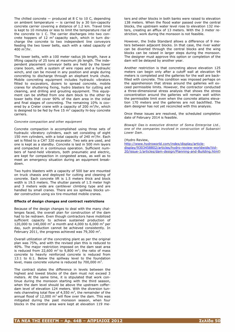
ΤΑ ΝΕΑ ΤΗΣ ΕΕΕΕΓΜ – Αρ. 44Β – ΑΠΡΙΛΙΟΣ 2012 Σελίδα 50
The chilled concrete — produced at 8 C to 10 C, depending on ambient temperature — is carried by a 30 ton-capacity concrete carrier covering a distance of 1.2 km. Travel time is kept to 10 minutes or less to limit the temperature rise of the concrete to 1 C. The carrier discharges into two con-crete hoppers of 12 m3 capacity each, which in turn dis-charge the concrete to two independent line conveyors feeding the two tower belts, each with a rated capacity of 400 m3/hr.
The tower belts, with a 100 meter radius jib length, have a lifting capacity of 25 tons at maximum jib length. The inde-pendent placement conveyor belts are held by the tower crane boom, with a system of wire ropes and a hydraulic winch, and can be moved in any position and angle during concreting to discharge through an elephant trunk chute. Mobile concreting equipment includes hydraulic vibrators fitted to excavators, dozers to spread concrete, mobile cranes for shuttering fixing, hydro blasters for cutting and cleaning, and drilling and grouting equipment. This equip-ment can be shifted from one dam block to the other by tower belts that cover 90% of the dam area in the initial and final stages of concreting. The remaining 10% is cov-ered by a Creter crane with a capacity of 200 m3/hr, which is designed to be fed by five 15 m3 capacity hi-boy concrete carriers.
Concrete compaction and other equipment
Concrete compaction is accomplished using three sets of hydraulic vibratory cylinders, each set consisting of eight 150 mm cylinders, with a total capacity of 240 m3/hr. Each set is fitted to a CAT 320 excavator. Two sets are used, and one is kept as a standby. Concrete is laid in 500 mm layers and compacted in a continuous operation. Sufficient num-bers of hand-held vibrators, both pneumatic and electric, are kept for compaction in congested areas, as well as to meet an emergency situation during an equipment break-down.
Two hydro blasters with a capacity of 500 bar are mounted on truck chassis and deployed for cutting and cleaning of concrete. Each concrete lift is 1.5 meters thick and block width is 19.5 meters. The shutter panels of 1.5 meter high and 3 meters wide are cantilever climbing type and are handled by small cranes. There are six spillway blocks un-der construction using six tire-mounted mobile cranes.
Effects of design changes and contract restrictions
Because of the design changes to deal with the many chal-lenges faced, the overall plan for construction of the dam had to be redrawn. Even though contractors have mobilized sufficient capacity to achieve sustained production of 120,000 to 140,000 m3 a month and 4,000 to 6,000 m3 per day, such production cannot be achieved consistently. In February 2011, the progress achieved was 79,300 m3.
Overall utilization of the concreting plant as per the original plan was 75%, and with the revised plan this is reduced to 40%. The major restriction imposed on the dam seat area is reduced from 22,600 m2 to 9,800 m2; the ratio of mass concrete to heavily reinforced concrete is reduced from 13:1 to 6:1. Below the spillway level to the foundation level, mass concrete volume is reduced by 700,000 m3.
The contract states the difference in levels between the highest and lowest blocks of the dam must not exceed 3 meters. At the same time, it is stipulated that work con-tinue during the monsoon starting with the third season, when the dam level should be above the upstream coffer-dam level of elevation 124 meters. With the diversion tun-nels channeling total flow of 4,550 m3, the remainder of the annual flood of 12,000 m3 will flow over the dam. This was mitigated during the past monsoon season, when four blocks in the central area were kept at elevation 119 me-
ters and other blocks in both banks were raised to elevation 138 meters. When the flood water passed over the central blocks, the upstream water level rose to elevation 132 me-ters, creating an afflux of 13 meters. With the 3 meter re-striction, work during the monsoon is not feasible.
However, the India Standard allows a difference of 9 me-ters between adjacent blocks. In that case, the river water can be diverted through the central blocks and the wing blocks can be raised in larger steps during the monsoon. The designer must approve this option or completion of the dam will be delayed by another year.
Another restriction is that concreting above elevation 125 meters can begin only after a cutoff wall at elevation 94 meters is completed and the galleries for the wall are back-filled with concrete. This condition was imposed perhaps on the apprehension that stress around the galleries will ex-ceed permissible limits. However, the contractor conducted a three-dimensional stress analysis that shows the stress concentration around the galleries will remain well within the permissible limit even when the concrete attains eleva-tion 170 meters and the galleries are not backfilled. The dam designer has not yet reconciled with this analysis.
Once these issues are resolved, the scheduled completion date of February 2014 is feasible.
Biswajit Das is executive director of Soma Enterprise Ltd., one of the companies involved in construction of Subansiri Lower Dam.
(Hydro Review, http://www.hydroworld.com/index/display/article-display/9303458802/articles/hydro-review-worldwide/Vol-20/issue-1/articles/dam-design/Planning-and-Building.html)
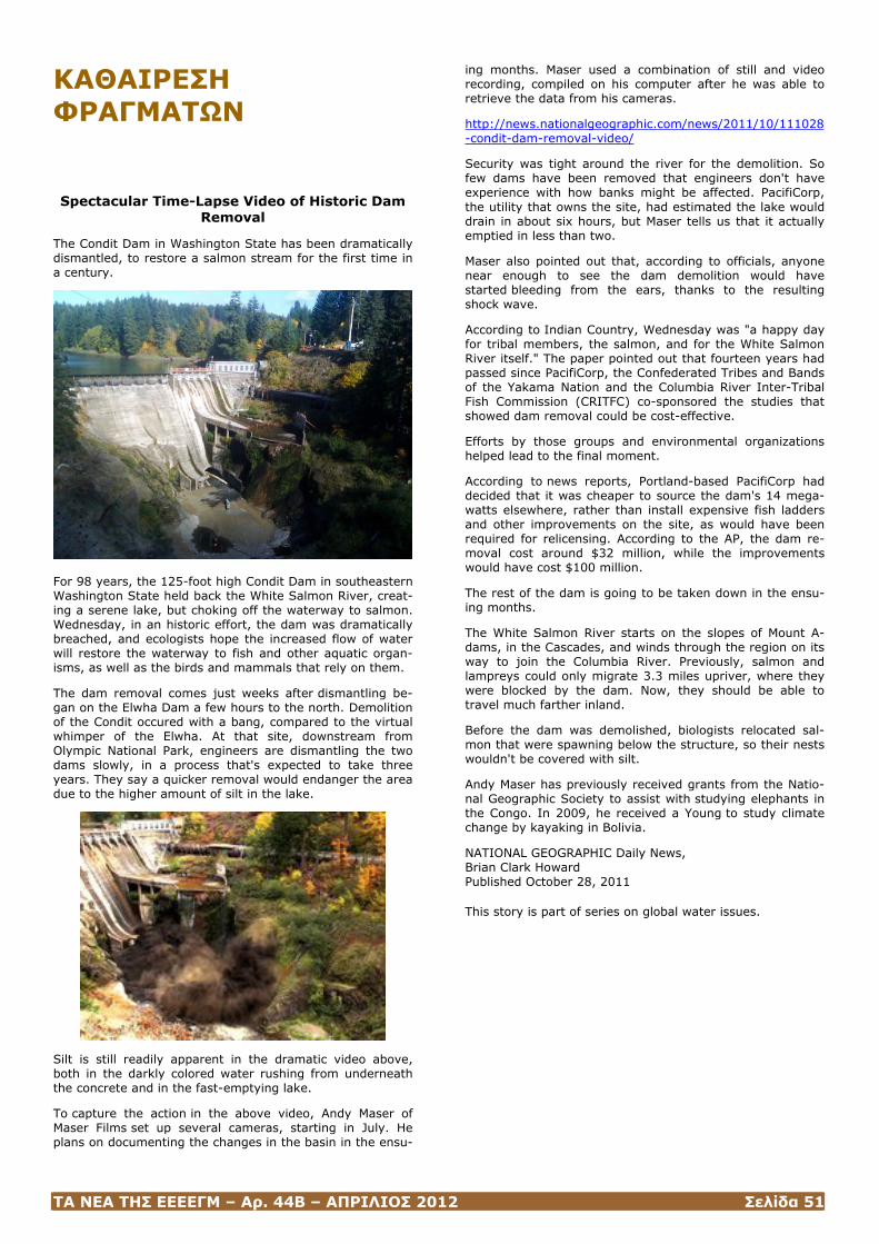
ΤΑ ΝΕΑ ΤΗΣ ΕΕΕΕΓΜ – Αρ. 44Β – ΑΠΡΙΛΙΟΣ 2012 Σελίδα 51
ΚΑΘΑΙΡΕΣΗ ΦΡΑΓΜΑΤΩΝ Spectacular Time-Lapse Video of Historic Dam
Removal
The Condit Dam in Washington State has been dramatically dismantled, to restore a salmon stream for the first time in a century.
For 98 years, the 125-foot high Condit Dam in southeastern Washington State held back the White Salmon River, creat-ing a serene lake, but choking off the waterway to salmon. Wednesday, in an historic effort, the dam was dramatically breached, and ecologists hope the increased flow of water will restore the waterway to fish and other aquatic organ-isms, as well as the birds and mammals that rely on them.
The dam removal comes just weeks after dismantling be-gan on the Elwha Dam a few hours to the north. Demolition of the Condit occured with a bang, compared to the virtual whimper of the Elwha. At that site, downstream from Olympic National Park, engineers are dismantling the two dams slowly, in a process that's expected to take three years. They say a quicker removal would endanger the area due to the higher amount of silt in the lake.
Silt is still readily apparent in the dramatic video above, both in the darkly colored water rushing from underneath the concrete and in the fast-emptying lake.
To capture the action in the above video, Andy Maser of Maser Films set up several cameras, starting in July. He plans on documenting the changes in the basin in the ensu-
ing months. Maser used a combination of still and video recording, compiled on his computer after he was able to retrieve the data from his cameras.
http://news.nationalgeographic.com/news/2011/10/111028-condit-dam-removal-video/
Security was tight around the river for the demolition. So few dams have been removed that engineers don't have experience with how banks might be affected. PacifiCorp, the utility that owns the site, had estimated the lake would drain in about six hours, but Maser tells us that it actually emptied in less than two.
Maser also pointed out that, according to officials, anyone near enough to see the dam demolition would have started bleeding from the ears, thanks to the resulting shock wave.
According to Indian Country, Wednesday was "a happy day for tribal members, the salmon, and for the White Salmon River itself." The paper pointed out that fourteen years had passed since PacifiCorp, the Confederated Tribes and Bands of the Yakama Nation and the Columbia River Inter-Tribal Fish Commission (CRITFC) co-sponsored the studies that showed dam removal could be cost-effective.
Efforts by those groups and environmental organizations helped lead to the final moment.
According to news reports, Portland-based PacifiCorp had decided that it was cheaper to source the dam's 14 mega-watts elsewhere, rather than install expensive fish ladders and other improvements on the site, as would have been required for relicensing. According to the AP, the dam re-moval cost around $32 million, while the improvements would have cost $100 million.
The rest of the dam is going to be taken down in the ensu-ing months.
The White Salmon River starts on the slopes of Mount A-dams, in the Cascades, and winds through the region on its way to join the Columbia River. Previously, salmon and lampreys could only migrate 3.3 miles upriver, where they were blocked by the dam. Now, they should be able to travel much farther inland.
Before the dam was demolished, biologists relocated sal-mon that were spawning below the structure, so their nests wouldn't be covered with silt.
Andy Maser has previously received grants from the Natio-nal Geographic Society to assist with studying elephants in the Congo. In 2009, he received a Young to study climate change by kayaking in Bolivia.
NATIONAL GEOGRAPHIC Daily News, Brian Clark Howard Published October 28, 2011
This story is part of series on global water issues.

ΤΑ ΝΕΑ ΤΗΣ ΕΕΕΕΓΜ – Αρ. 44Β – ΑΠΡΙΛΙΟΣ 2012 Σελίδα 52
ΜΕΓΑΛΑ ΦΡΑΓΜΑΤΑ
BIG DAMS
A look at ongoing development of nine of the world’s tallest dams provides examples of design, excavation, and con-struction work occurring in Asia, Africa, Latin America, and the Middle East.
To highlight dam design and construction work occur-ring, HRW shares information about development of nine of the largest dams in the world. These dams - all over 150 meters in height - are prominent components of major hy-droelectric projects being built in Asia, Africa, Latin Amer-ica, and the Middle East. Table 1 provides details about the nine projects.
These nine dams involve record-setting achievements. For example, Diamer Basha Dam in Pakistan, to be completed in 2019, will be the tallest roller-compacted-concrete (RCC) dam in the world at 270 meters. And, at 305 meters tall, the massive Jinping 1 Dam in China will be the tallest dou-ble-curvature thin arch dam in the world when it is com-plete in 2014. The 288-meter-high Dibang Dam in India will be the tallest concrete gravity dam in the world when com-pleted in 2017.
Of the nine dams being featured, three are arch concrete, three are concrete-faced rockfill, two are roller-compacted concrete, and one is concrete gravity. They range in height from 166 meters to 305 meters. Common design and con-struction challenges include working at sites with complex geology, solving problems with seepage, and managing sediment-laden waters.
The hydroelectric facilities associated with these dams range in capacity from 160 MW to 4,500 MW. Together, they will provide 17,500 MW of new capacity and are ex-pected to produce more than 58,100 gigawatt-hours (GWh) of electricity each year.
Development of these nine projects - to be completed be-tween 2009 and 2019 - will cost an estimated US$27.4 bil-lion.
Bakun
Country: Malaysia Owner: Sarawak Hidro Sdn Bhd River: Batang Balui Type: Concrete-Faced Rockfill (CFRD) Height: 205 meters Volume: 16.8 million cubic meters
Power Generation Component: 2,400 MW, surface pow-erhouse 250 meters long by 56 meters wide by 20.5 meters high with eight units: vertical Francis turbines and synchro-nous 360 megavolt-ampere generators
Anticipated Date of Completion: 2012 Estimated Cost: $4.6 billion
Companies Involved:
Ahmad Zaki Resources Bhd, Alstom, Atlas Copco (Malaysia) Sdn Bhd, Caterpillar, China National Water Resources and Hydropower Engineering Corporation, Dong Ah Construction of Korea, Edward and Son Sdn Bhd, Ekran Corporation Bhd, Fong Mook Seong Sdn Bhd (FMS), Geonor SA, Global Upline Sdn Bhd, Intraxis Engineering, JacobsGIBB Ltd., Meritec Limited, M K Ting, MTD Capital Bhd, Overseas Tunneling
and Construction, PB Power, Sime Engineering Sdn Bhd, Snowy Mountains Engineering Corp., Syarikat Ismail Ibra-him Sdn Bhd, Volvo Malaysia Construction Equipment, WCT Engineering Bhd, YTL Ranhill Theiss Consortium
Design Notes:
The design and build contract for the dam and ancillary facilities was awarded in October 2002 to Malaysia-China Hydro Joint Venture, which includes China National Water Resources and Hydropower Engineering Corporation, Sime Engineering, WCT Engingineering, MTD Capital, Ahmad Zaki Resources, Syarikat Ismail Ibrahim, and Edward and Son. Considerable effort was made in the design of the dam - including extensive laboratory and trial embankment tests on materials - to optimize the use of excavated materials and reduce waste. Some material for construction of the dam was obtained from site excavation, and the remainder was obtained from quarries. The 205-meter-high dam has a crest length of 750 meters.
Excavation Notes:
Fong Mook Seong (FMS) carried out the drilling and blasting for the lower spillway and powerhouse, as well as general rock clearance along the banks of the river downstream of the dam. Most of the work was completed using two ROC D7 drill rigs from Atlas Copco. These machines were used to drill 76- and 89-millimeter-diameter holes to various depths. During an eight-hour shift, each machine can be used to drill more than 300 meters. M K Ting did blasting work to prepare the dam foundations.
The drilling and blasting work was challenging because of the complex geology at the site. The site is predominantly conglomerate sandstone greywacke with inter-bedded shale and mudstone, mostly folded and with a dip of more than 45 degrees. Work in this type of rock requires recognition of changes in rock condition in order to change drilling techniques as needed.
Construction Notes:
To protect against seepage through the dam foundation, a grout curtain with a maximum depth of about 130 meters was installed at the upstream side of the dam beneath the plinth of the concrete-faced rockfill dam. The main civil work at the project has been completed, and work is pro-ceeding on installation of the electrical and mechanical equipment.
Information Obtained From:
Sarawak Hidro Sdn Bhd website; Kai Leong Gooi, Atlas Copco (Malaysia) Sdn Bhd
Diamer Basha (formerly called Basha)
Country: Pakistan Owner: Water and Power Development Authority (WAPDA) River: Indus Type: Roller-Compacted Concrete (RCC) Height: 272 meters Volume: 17 million cubic meters of concrete
Power Generation Component: 4,500 MW, 18,100 giga-watt-hours, two underground powerhouses that each con-tain six units: vertical Francis turbines and 416 megavolt-ampere generators

ΤΑ ΝΕΑ ΤΗΣ ΕΕΕΕΓΜ – Αρ. 44Β – ΑΠΡΙΛΙΟΣ 2012 Σελίδα 53
Anticipated Date of Completion: 2019 Estimated Cost: US$11.3 billion
Companies Involved:
AMEC, Associated Consulting Engineers (Pvt) Ltd. (ACE), BARQAB Consulting Services, Binnie Black & Veatch, Lah-meyer International, MWH, National Engineering Services Pakistan (Pvt) Ltd. (NESPAK), National Development Con-sultants (NDC), Pakistan Engineering Services
Design Notes:
The project consists of the dam and related structures, in-cluding two diversion tunnels and a permanent access bridge. There will be two underground powerhouses, one on the left bank and one on the right bank. Each powerhouse will contain six 375-MW turbine-generator units. The reser-voir will have a gross storage of 10 billion cubic meters of water and a live storage of 7.9 billion cubic meters. The design discharge of the spillway is 18,126 cubic meters per second. To pass sediment in the river, the dam will feature five low-level sediment flushing outlets in the dam body under the spillway. To keep the power intake clear of sedi-ment, the dam will contain an outlet under the right bank intake (built by converting one of the diversion tunnels) and a tunnel under the left bank.
Excavation Notes:
The location of the underground powerhouse and trans-former caverns was chosen to avoid fault areas. The tun-nels, shafts, and caverns will be excavated by drilling and controlled blasting. Where fault zones will be intersected, increased support through use of shotcrete or rock bolts will be provided. Large rock excavation for construction of a 90-meter-wide diversion canal, together with the right and left bank excavation for the dam foundation, will supply more than 60 percent of the aggregate needed for construction of the dam. The project also features two 15.4-meter-diameter diversion tunnels — one 887 meters long and one 1,016 meters long. These tunnels will penetrate through the right rock ridge that forms an abutment of the dam.
Construction Notes:
The upstream and downstream cofferdams required to iso-late the site for construction will be rockfill embankments with a core of alluvial material. The foundation of the dam and the embankments will be sealed by a plastic concrete diaphragm wall constructed to a maximum depth of 50 to 70 meters. The main construction activities for the project will take place in five contract lots, with work to begin in 2009. The RCC dam will be built in 32 blocks and will pro-ceed in zones, starting from the bedrock. RCC will be placed by the sloped layer method, in 3-meter lifts in 0.3-meter layers. Reservoir impounding will begin in 2017 and be complete in 2019.
Information Obtained From: Izhar ul Haq, Water and Power Development Authority
Dibang
Country: India Owner: NHPC Limited (formerly National Hydroelectric Power Corporation) River: Dibang Type: Concrete Gravity
Height: 288 meters Volume: 16.5 million cubic meters
Power Generation Component: 3,000 MW, 11,330 giga-watt-hours, underground powerhouse 24.5 meters wide by 54.8 meters high by 382.8 meters long with 12 units: Fran-cis turbines
Anticipated Date of Completion: 2017 Estimated Cost: US$3.34 billion
Companies Involved:
AF Colenco, National Institute of Rock Mechanics
Design Notes:
The concrete gravity dam will be 288 meters high from the deepest foundation level. When completed, this will be the tallest dam of its kind in the world. The length of the top of the dam is 816 meters, including 154 meters of overflow section. The spillway is designed for a probable flood of 22,809 cubic meters per second. To investigate the site, NHPC performed detailed engineering geological mapping and laboratory testing of rock samples. NHPC also investi-gated three axes for placement of the dam at this site.
Excavation Notes:
The dam will be located at the junction of two rock forma-tions. The thrusted contact of the two formations passes through the tailrace tunnel outlet area and intersects the main access tunnel and diversion tunnel near the outlet end. Subsurface explorations at the dam site indicated the rock on the left bank of the dam is comparatively weaker than the rock on the right bank. The overall height of the open excavation for the dam will be 300 to 350 meters. The total quantity of rock excavation in the dam abutments and river bed is estimated at 5.58 million cubic meters.
Construction Notes:
Construction of the structures will require 19.3 million cubic meters of coarse aggregate, 9.65 million cubic meters of fine aggregate, 74,000 cubic meters of shell material, and 26,000 cubic meters of impervious soil. Civil work on the project is scheduled to begin in 2009.
Ermenek
Country: Turkey Owner: DSI (Devlet Su Isleri) General Directorate of State Hydraulic Works River: Ermenek Type: Thin Arch Concrete Height: 218 meters Volume: 299,000 cubic meters of concrete
Power Generation Component: 300 MW, 1,014 giga-watt-hours, two units in a surface powerhouse: vertical Francis turbines and synchronous generators
Anticipated Date of Completion: 2011 Estimated Cost: US$797 million
Companies Involved:
Alpine Mayreder Bau GmbH, Alstom Power Austria, BM Mühendsilik ve Insaat A.S., Pöyry Energy Ltd., VA Tech Hydro GmbH & Co., Voith Siemens Hydro Power Generation
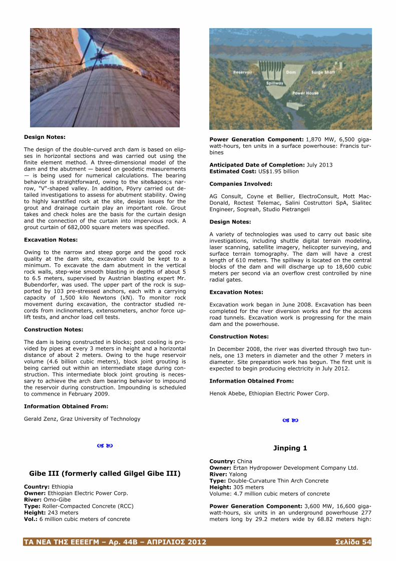
ΤΑ ΝΕΑ ΤΗΣ ΕΕΕΕΓΜ – Αρ. 44Β – ΑΠΡΙΛΙΟΣ 2012 Σελίδα 54
Design Notes:
The design of the double-curved arch dam is based on elip-ses in horizontal sections and was carried out using the finite element method. A three-dimensional model of the dam and the abutment — based on geodetic measurements — is being used for numerical calculations. The bearing behavior is straightforward, owing to the site's nar-row, "V"-shaped valley. In addition, Pöyry carried out de-tailed investigations to assess for abutment stability. Owing to highly karstified rock at the site, design issues for the grout and drainage curtain play an important role. Grout takes and check holes are the basis for the curtain design and the connection of the curtain into impervious rock. A grout curtain of 682,000 square meters was specified.
Excavation Notes:
Owing to the narrow and steep gorge and the good rock quality at the dam site, excavation could be kept to a minimum. To excavate the dam abutment in the vertical rock walls, step-wise smooth blasting in depths of about 5 to 6.5 meters, supervised by Austrian blasting expert Mr. Bubendorfer, was used. The upper part of the rock is sup-ported by 103 pre-stressed anchors, each with a carrying capacity of 1,500 kilo Newtons (kN). To monitor rock movement during excavation, the contractor studied re-cords from inclinometers, extensometers, anchor force up-lift tests, and anchor load cell tests.
Construction Notes:
The dam is being constructed in blocks; post cooling is pro-vided by pipes at every 3 meters in height and a horizontal distance of about 2 meters. Owing to the huge reservoir volume (4.6 billion cubic meters), block joint grouting is being carried out within an intermediate stage during con-struction. This intermediate block joint grouting is neces-sary to achieve the arch dam bearing behavior to impound the reservoir during construction. Impounding is scheduled to commence in February 2009.
Information Obtained From:
Gerald Zenz, Graz University of Technology
Gibe III (formerly called Gilgel Gibe III)
Country: Ethiopia Owner: Ethiopian Electric Power Corp. River: Omo-Gibe Type: Roller-Compacted Concrete (RCC) Height: 243 meters Vol.: 6 million cubic meters of concrete
Power Generation Component: 1,870 MW, 6,500 giga-watt-hours, ten units in a surface powerhouse: Francis tur-bines
Anticipated Date of Completion: July 2013 Estimated Cost: US$1.95 billion
Companies Involved:
AG Consult, Coyne et Bellier, ElectroConsult, Mott Mac-Donald, Roctest Telemac, Salini Costruttori SpA, Sialitec Engineer, Sogreah, Studio Pietrangeli
Design Notes:
A variety of technologies was used to carry out basic site investigations, including shuttle digital terrain modeling, laser scanning, satellite imagery, helicopter surveying, and surface terrain tomography. The dam will have a crest length of 610 meters. The spillway is located on the central blocks of the dam and will discharge up to 18,600 cubic meters per second via an overflow crest controlled by nine radial gates.
Excavation Notes:
Excavation work began in June 2008. Excavation has been completed for the river diversion works and for the access road tunnels. Excavation work is progressing for the main dam and the powerhouse.
Construction Notes:
In December 2008, the river was diverted through two tun-nels, one 13 meters in diameter and the other 7 meters in diameter. Site preparation work has begun. The first unit is expected to begin producing electricity in July 2012.
Information Obtained From:
Henok Abebe, Ethiopian Electric Power Corp.
Jinping 1
Country: China Owner: Ertan Hydropower Development Company Ltd. River: Yalong Type: Double-Curvature Thin Arch Concrete Height: 305 meters Volume: 4.7 million cubic meters of concrete
Power Generation Component: 3,600 MW, 16,600 giga-watt-hours, six units in an underground powerhouse 277 meters long by 29.2 meters wide by 68.82 meters high:
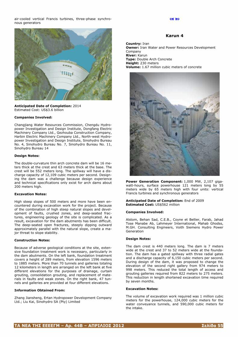
ΤΑ ΝΕΑ ΤΗΣ ΕΕΕΕΓΜ – Αρ. 44Β – ΑΠΡΙΛΙΟΣ 2012 Σελίδα 55
air-cooled vertical Francis turbines, three-phase synchro-nous generators
Anticipated Date of Completion: 2014 Estimated Cost: US$3.6 billion
Companies Involved:
Changjiang Water Resources Commission, Chengdu Hydro-power Investigation and Design Institute, Dongfang Electric Machinery Company Ltd., Gezhouba Construction Company, Harbin Electric Machinery Company Ltd., North-west Hydro-power Investigation and Design Institute, Sinohydro Bureau No. 4, Sinohydro Bureau No. 7, Sinohydro Bureau No. 11, Sinohydro Bureau 14
Design Notes:
The double-curvature thin arch concrete dam will be 16 me-ters thick at the crest and 63 meters thick at the base. The crest will be 552 meters long. The spillway will have a dis-charge capacity of 12,109 cubic meters per second. Design-ing the dam was a challenge because design experience and technical specifications only exist for arch dams about 200 meters high.
Excavation Notes:
High steep slopes of 500 meters and more have been en-countered during excavation work for the project. Because of the combination of high steep natural slopes and devel-opment of faults, crushed zones, and deep-seated frac-tures, engineering geology of the site is complicated. As a result, excavation for the dam abutments has been difficult. The deep-seated open fractures, steeply dipping outward approximately parallel with the natural slope, create a ma-jor threat to slope stability.
Construction Notes:
Because of adverse geological conditions at the site, exten-sive foundation treatment work is necessary, particularly in the dam abutments. On the left bank, foundation treatment covers a height of 289 meters, from elevation 1596 meters to 1885 meters. More than 70 tunnels and galleries totaling 12 kilometers in length are arranged on the left bank at five different elevations for the purposes of drainage, curtain grouting, consolidation grouting, and replacement of mate-rials in faults and weak zones. On the right bank, 47 tun-nels and galleries are provided at four different elevations.
Information Obtained From:
Zhang Jiansheng, Ertan Hydropower Development Company Ltd.; Liu Kai, Sinohydro SA (Pty) Limited
Karun 4
Country: Iran Owner: Iran Water and Power Resources Development Company River: Karun Type: Double Arch Concrete Height: 230 meters Volume: 1.67 million cubic meters of concrete
Power Generation Component: 1,000 MW, 2,107 giga-watt-hours, surface powerhouse 121 meters long by 55 meters wide by 65 meters high with four units: vertical Francis turbines and synchronous generators
Anticipated Date of Completion: End of 2009 Estimated Cost: US$562 million
Companies Involved:
Alstom, Behan Sad, C.E.B., Coyne et Bellier, Farab, Jahad Tose Manabe Ab, Lahmeyer International, Mahab Ghodss, M.GH. Consulting Engineers, Voith Siemens Hydro Power Generation
Design Notes:
The dam crest is 440 meters long. The dam is 7 meters wide at the crest and 37 to 52 meters wide at the founda-tion. The dam has a gated spillway with three radial gates and a discharge capacity of 6,150 cubic meters per second. During design of the dam, it was proposed to change the elevation of the second right gallery from 974 meters to 998 meters. This reduced the total length of access and grouting galleries required from 822 meters to 275 meters. This reduction in length shortened excavation time required by seven months.
Excavation Notes:
The volume of excavation work required was 1 million cubic meters for the powerhouse, 124,000 cubic meters for the water conveyance tunnels, and 590,000 cubic meters for the intake.
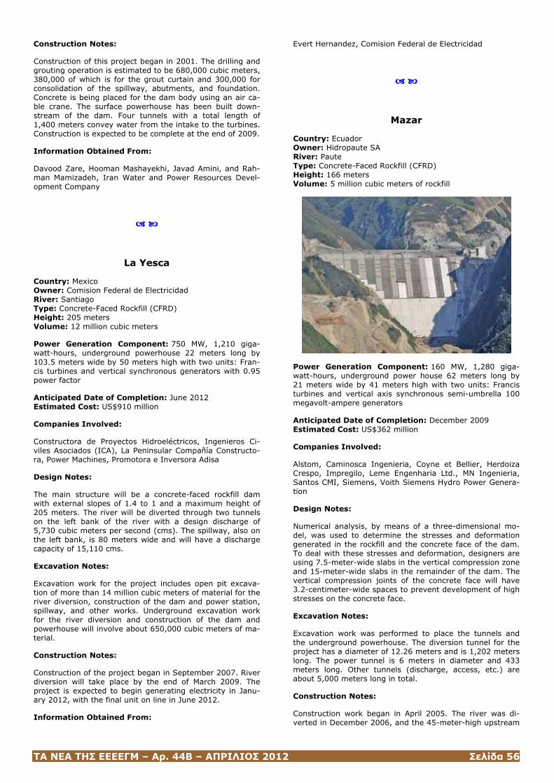
ΤΑ ΝΕΑ ΤΗΣ ΕΕΕΕΓΜ – Αρ. 44Β – ΑΠΡΙΛΙΟΣ 2012 Σελίδα 56
Construction Notes:
Construction of this project began in 2001. The drilling and grouting operation is estimated to be 680,000 cubic meters, 380,000 of which is for the grout curtain and 300,000 for consolidation of the spillway, abutments, and foundation. Concrete is being placed for the dam body using an air ca-ble crane. The surface powerhouse has been built down-stream of the dam. Four tunnels with a total length of 1,400 meters convey water from the intake to the turbines. Construction is expected to be complete at the end of 2009.
Information Obtained From:
Davood Zare, Hooman Mashayekhi, Javad Amini, and Rah-man Mamizadeh, Iran Water and Power Resources Devel-opment Company
La Yesca
Country: Mexico Owner: Comision Federal de Electricidad River: Santiago Type: Concrete-Faced Rockfill (CFRD) Height: 205 meters Volume: 12 million cubic meters
Power Generation Component: 750 MW, 1,210 giga-watt-hours, underground powerhouse 22 meters long by 103.5 meters wide by 50 meters high with two units: Fran-cis turbines and vertical synchronous generators with 0.95 power factor
Anticipated Date of Completion: June 2012 Estimated Cost: US$910 million
Companies Involved:
Constructora de Proyectos Hidroeléctricos, Ingenieros Ci-viles Asociados (ICA), La Peninsular Compañía Constructo-ra, Power Machines, Promotora e Inversora Adisa
Design Notes:
The main structure will be a concrete-faced rockfill dam with external slopes of 1.4 to 1 and a maximum height of 205 meters. The river will be diverted through two tunnels on the left bank of the river with a design discharge of 5,730 cubic meters per second (cms). The spillway, also on the left bank, is 80 meters wide and will have a discharge capacity of 15,110 cms.
Excavation Notes:
Excavation work for the project includes open pit excava-tion of more than 14 million cubic meters of material for the river diversion, construction of the dam and power station, spillway, and other works. Underground excavation work for the river diversion and construction of the dam and powerhouse will involve about 650,000 cubic meters of ma-terial.
Construction Notes:
Construction of the project began in September 2007. River diversion will take place by the end of March 2009. The project is expected to begin generating electricity in Janu-ary 2012, with the final unit on line in June 2012.
Information Obtained From:
Evert Hernandez, Comision Federal de Electricidad
Mazar
Country: Ecuador Owner: Hidropaute SA River: Paute Type: Concrete-Faced Rockfill (CFRD) Height: 166 meters Volume: 5 million cubic meters of rockfill
Power Generation Component: 160 MW, 1,280 giga-watt-hours, underground power house 62 meters long by 21 meters wide by 41 meters high with two units: Francis turbines and vertical axis synchronous semi-umbrella 100 megavolt-ampere generators
Anticipated Date of Completion: December 2009 Estimated Cost: US$362 million
Companies Involved:
Alstom, Caminosca Ingenieria, Coyne et Bellier, Herdoiza Crespo, Impregilo, Leme Engenharia Ltd., MN Ingenieria, Santos CMI, Siemens, Voith Siemens Hydro Power Genera-tion
Design Notes:
Numerical analysis, by means of a three-dimensional mo-del, was used to determine the stresses and deformation generated in the rockfill and the concrete face of the dam. To deal with these stresses and deformation, designers are using 7.5-meter-wide slabs in the vertical compression zone and 15-meter-wide slabs in the remainder of the dam. The vertical compression joints of the concrete face will have 3.2-centimeter-wide spaces to prevent development of high stresses on the concrete face.
Excavation Notes:
Excavation work was performed to place the tunnels and the underground powerhouse. The diversion tunnel for the project has a diameter of 12.26 meters and is 1,202 meters long. The power tunnel is 6 meters in diameter and 433 meters long. Other tunnels (discharge, access, etc.) are about 5,000 meters long in total.
Construction Notes:
Construction work began in April 2005. The river was di-verted in December 2006, and the 45-meter-high upstream

ΤΑ ΝΕΑ ΤΗΣ ΕΕΕΕΓΜ – Αρ. 44Β – ΑΠΡΙΛΙΟΣ 2012 Σελίδα 57
cofferdam was completed in January 2007. Work on the rockfill portion of the dam was completed in September 2008. Placement of the concrete slabs was to be completed at the beginning of 2009. To achieve high quality and per-formance for the rockfill in the dam, Hidropaute adopted several advanced techniques, including numerical analysis of a three-dimensional model and curtain reinforcement of the concrete face slab in areas of stress.
Information Obtained From:
Segundo Vanegas, Hidropaute SA
(Hydro Review, http://www.hydroworld.com/index/display/article-display/354756/articles/hydro-review-worldwide/volume-17/issue-1/articles/cover-story/big-dams.html)

ΤΑ ΝΕΑ ΤΗΣ ΕΕΕΕΓΜ – Αρ. 44Β – ΑΠΡΙΛΙΟΣ 2012 Σελίδα 58
ΠΕΡΙΒΑΛΛΟΝΤΙΚΑ ΘΕΜΑΤΑ
Project aims to extract dam methane
Scientists in Brazil have claimed that a major source of greenhouse gas emissions could be curbed by capturing and burning methane given off by large hydro-electric dams.
The team at the country's National Space Research Insti-tute (INPE) is developing prototype equipment designed to stop the greenhouse gas from entering the atmosphere.
The technology will extract the methane from the water to supplement the energy produced by the dam turbines.
The scientists estimate that worldwide the technique could prevent emissions equivalent to more than the total annual burning of fossil fuels in the UK - and reduce the pressure to build new dams in sensitive areas such as the Amazon.
The project follows a long-running controversy over how clean hydro-electric power really is.
Critics of the industry have claimed that in tropical areas of Brazil - which supplies more than 90% of its electricity from large dams - some reservoirs emit so much methane that their contribution to climate change is greater than an equivalent power station burning fossil fuels like coal or gas.
'Soda' factor
Methane is produced mainly by bacteria that break down organic matter where there is little or no oxygen, for exam-ple at the bottom of lakes and reservoirs.
Since intake pipes for hydroelectric turbines tend to be placed quite deep, methane-rich water is suddenly trans-ferred from conditions of high-pressure to the open air.
The lead scientist of the INPE project, Fernando Ramos, told the BBC's Science In Action programme: "It's like opening a bottle of soda. A large part of the methane is dissolved in the water bubbles, and it's released to the at-mosphere.
"That's the reason big hydro-electric dams built in tropical areas are harmful to the environment."
There is still great uncertainty about the precise amount of methane added to the atmosphere in this way, as each dam behaves in very different ways depending on the amount of vegetation in the water, the temperature, the shape of the reservoir and many other factors.
However, a statistical analysis carried out by the INPE sci-entists has estimated that large dams could be responsible for worldwide annual emissions equivalent to some 800 million tonnes of carbon dioxide.
To put that in perspective, last year's total greenhouse gas emissions from the UK were around 660 million tonnes.
Partial waters
The impact of methane emissions is disproportionate to their actual quantity, since, tonne for tonne, the gas is es-timated to be more than 20 times as powerful than CO2 in
creating the human-induced greenhouse effect linked to climate change.
The INPE scientists are proposing that with relatively simple technology, this unwanted by-product of hydro-electric power generation could be turned into an extra source of clean, renewable electricity.
They have estimated that some dams with an especially heavy methane load in the Amazon could increase their output by up to 50%.
The first stage of the plan is to prevent deep, methane-rich water from going directly into the turbines, reducing the "soda bottle" effect.
A submerged membrane or steel barrier close to the dam would channel surface water to the intake pipes - there is little or no methane at the higher level of a reservoir where oxygen is plentiful.
To tap the methane, a floating device would pump deep water to an enclosed rotor on the surface. This would cre-ate small droplets that would liberate the dissolved gas, which could then be piped to a plant that would burn it to produce electricity.
How the technology will work
1. Reservoir waters are drawn by gravity towards the dam wall and the turbine intakes positioned near its base
2. A membrane preferentially steers higher, methane-poor waters into the turbines to produce electricity
3. A deep pump takes the methane-rich waters to the sur-face for separation and gas capture in a sealed vessel
4. The methane is stored for burning, to drive a steam tur-bine and make more electricity. Depleted waters return to the reservoir
Technology demonstrator
Burning methane does produce carbon dioxide, but since this carbon would have originally been taken out of the air by plants through photosynthesis before being locked into the sediments on the floor of the reservoir, the scientists argue there would be no net addition of greenhouse gases to the atmosphere.
It would also prevent the much stronger global warming impacts of direct methane emissions, they say.
But the process of extracting the methane would require considerable amounts of energy.
However, the team suggest this could be supplied by hy-dro-power at night when demand is much lower; and in any case, they say, it would be far outweighed by the power generated by the thermal plant.

ΤΑ ΝΕΑ ΤΗΣ ΕΕΕΕΓΜ – Αρ. 44Β – ΑΠΡΙΛΙΟΣ 2012 Σελίδα 59
INPE hopes to develop prototype equipment to demonstrate the process later this year.
It is sure to be very controversial in Brazil where power companies have been strongly disputing claims that their dams are significant sources of greenhouse gases.
Dr Ramos told the BBC: "We cannot hide from this prob-lem; you have to address it. In fact, it's better to recognise there is a problem today, and to use this methane that is there as a commodity, harvest it to produce energy.
"And most important, it will reduce the pressure for building new dams in sensitive areas like the Amazon region."
(Tim Hirsch / BBC Sao Paulo, Brazil, http://news.bbc.co.uk/2/hi/science/nature/6638705.stm#graphic)
ΤΑ ΝΕΑ ΤΗΣ ΕΕΕΕΓΜ – Αρ. 44Β – ΑΠΡΙΛΙΟΣ 2012 Σελίδα 60
ΝΕΕΣ (ΚΑΙ ΠΑΛΑΙΕΣ) ΕΚΔΟΣΕΙΣ ΣΤΙΣ ΓΕΩΤΕΧΝΙΚΕΣ ΕΠΙΣΤΗΜΕΣ ΓΙΑ ΦΡΑΓΜΑΤΑ
Εκδόσεις της United States Society on Dams
Materials for Embankment Dams
Prepared by the USSD Commit-tee on Materials for Embank-ment Dams
The USSD Committee on Materials for Embankment Dams has pre-
pared this WhitePaper on Materials for Embankment Dams. The paper provides an outline of important points that need to be recognized and understood when selecting material for use in embankment dams. It covers soil materials; rock-fill materials; granular filters and drains; asphalt concrete as a water barrier; concrete facing rockfill dams; geosyn-thetics; reinforced fill; upstream slope protection; material for watertight cutoffs; and construction issues. For each of these topics, design and construction considerations are presented.
This white paper provides a brief summary of the use of materials in embankment dams. It is not intended to serve as an exhaustive treatise on the characteristics of the vari-ous materials that comprise these types of dams. It is, rather, an outline of important points that need to be rec-ognized and understood when selecting materials for use in the embankment dam.
(United States Society on Dams, January 2011)
Οι ενδιαφερόμενοι μπορούν να «κατεβάσουν» το βιβλίο από την ιστοσελίδα http://www.ussdams.com/materials.PDF
The Aging of Embankment Dams
Prepared by the USSD Commit-tee on Materials for Embank-ment Dams
The USSD Committee on Materials for Embankment Dams has pre-
pared this White Paper on The Aging of Embankment Dams. The White Paper is of interest to owners of dams and those responsible for the safety of existing dams. It points out that there are aging processes, and a project may be de-veloping aging characteristics which need to be examined, studied and remedied to preclude a safety issue. For de-signers of new dams, it provides a checklist of conditions
which could lead to early aging becoming a safety issue and for which designs could be developed to preclude or to mitigate the effects of aging. The White Paper is a summary of the chapter on embankment dams from ICOLD Bulletin No. 93, Ageing of Dams and Appurtenant Works, with addi-tional commentary by USSD.
(United States Society on Dams, Μay 2010)
Οι ενδιαφερόμενοι μπορούν να «κατεβάσουν» το βιβλίο από την ιστοσελίδα http://www.ussdams.org/aging.PDF
Planning Processes for the De-velopment of Dams and Reser-voirs
Public Involvement and Alterna-tives Analysis:
A Framework for Successful De-cision-Making
Responsible planning for dams and reservoirs requires deci-sion-making and planning processes that are founded on the values of equity, efficiency, accountability, sustainability and participatory decision-making.
Alternatives development and screening processes need to be based on a well-defined statement of project need and purpose. The public needs to be directly involved in the development and workings of both of these processes. The purpose of the planning phase decision-making process is to effectively identify project alternatives that successfully meet the identified societal need and project purpose with an efficient investment of public resources. Accountability and public participation in this process lead to a decision that can be implemented and sustained. The process sup-ports our professional responsibilities for stewardship and the sustainability of public resources in the development of dams and reservoirs for promoting and sustaining a healthy and prosperous society.
(United States Society on Dams, June 2003)
Οι ενδιαφερόμενοι μπορούν να «κατεβάσουν» το βιβλίο από την ιστοσελίδα http://www.ussdams.org/alternatives.pdf
Strength of Materials for Em-bankment Dams
Prepared by the USSD Commit-tee on Materials for Embank-ment Dams
This white paper presents the re-sults of a survey initiated by the Committee on Materials for Embankment Dams to determine the “state of the practice” for selecting fill strength parameters used in static and pseudostatic analyses of earthfill embankment dams.
This white paper is not intended to be a “how to” manual in selecting material strengths and the reader is directed to the references for more comprehensive discussion of the
ΤΑ ΝΕΑ ΤΗΣ ΕΕΕΕΓΜ – Αρ. 44Β – ΑΠΡΙΛΙΟΣ 2012 Σελίδα 61
subject. An experienced geotechnical engineer should be involved in the determination of fill strengths and the per-formance of stability analyses.
(United States Society on Dams, February 2007)
Οι ενδιαφερόμενοι μπορούν να «κατεβάσουν» το βιβλίο από την ιστοσελίδα http://www.ussdams.org/07materials.PDF
Why Include Instrumentation in Dam Monitoring Programs?
Prepared by the USSD Commit-tee on Monitoring of Dams and Their Foundations
Primary Authors: Barry Myers and Jay Stateler
The importance of monitoring programs for dam safety is widely accepted. There are many historical cases of dam failures where early warning signs of failure might have been detected if a good dam safety-monitoring program had been in place. The monitoring program provides the information that is needed to develop a better understand-ing of the on-going performance of the dam. Knowing that the dam is performing as expected is reassuring to dam owners, and the ability to detect a change in this perform-ance is critical because the dam owner is directly responsi-ble for the consequences of a dam failure. Therefore, a good dam safety monitoring program should be a key part of every dam owner’s risk management program.
The use of instrumentation as part of dam safety programs is growing as the technology of instrumentation and ease of use improves. Instrumentation can be used to implement a monitoring program that provides more comprehensive and timelier information regarding the on-going performance of the dam. With this information dam owners can improve their ability to responsibly operate and maintain the dams in a safe manner.
(United States Society on Dams, November 2008 Version 1.00)
Οι ενδιαφερόμενοι μπορούν να «κατεβάσουν» το βιβλίο από την ιστοσελίδα http://www.ussdams.org/instrumentation.PDF
The Role of Dams in the 21st Century
26th Annual USSD Conference San Antonio, Texas, May 1-6, 2006
http://ussdams.com/proceedings/USSDProceedings2006.pdf
Modernization and Optimization of Existing Dams and Reservoirs
27th Annual USSD Conference Philadelphia, Pennsylvania,
March 5-9, 2007
http://ussdams.com/proceedings/USSDProceedings2007.pdf
The Sustainability of Experience - Investing in the Human Factor
28th Annual USSD Conference Portland, Oregon, April 28 - May 2, 2008
http://ussdams.com/proceedings/USSDProceedings2008.pdf
Managing Our Water Retention Systems
29th Annual USSD Conference Nashville, Tennessee, April 20-24, 2009
http://ussdams.com/proceedings/USSDProceedings2009.pdf
Collaborative Management of Integrated Watersheds
30th Annual USSD Conference Sacramento, California, April 12-16, 2010
http://ussdams.com/proceedings/USSDproceedings2010.pdf
ΤΑ ΝΕΑ ΤΗΣ ΕΕΕΕΓΜ – Αρ. 44Β – ΑΠΡΙΛΙΟΣ 2012 Σελίδα 62
21st Century Dam Design-Advances and Adaptations
31st Annual USSD Conference-San Diego, California, April 11-15, 2011
http://ussdams.com/proceedings/USSDproceedings2011.pdf
White Paper on Dam Safety Risk Assessment This White Paper represents the consensus position of a diverse group of U.S. Society on Dams (USSD) Members and other dam safety professionals listed in Appendix A. It was prepared for the dam engineering profession in the U.S. by a Working Group established by the USSD Commit-tee on Dam Safety (CODS) in response to a request from the USSD Board. The request grew out of the growth of interest in and applications of dam safety risk assessment. The White Paper's overall purpose is To assess the state-of-the-practice in dam safety risk assessment, and to provide commentary on appropriate types of applications and ways to facilitate and strengthen its use.
The White Paper is neither a "how to" guide nor a standard of practice. The Working Group did not endorse any specific approaches. References made to applications are illustrative of what some owners and regulators have found to be use-ful. They should be understood in the context in which they were conducted and in which their outcomes were used. They should not be considered templates to be copied.
The Working Group held several half-day working sessions in addition to three-day workshop in March 2000 with spon-sorship from FEMA through the Association of State Dam Safety Officials (ASDSO). The ASDSO/FEMA Specialty Workshop on Risk Assessment for Dams provided the prin-cipal opportunity to develop the consensus position pre-sented in the White Paper. The Working Group was assisted at the Workshop by some additional participants, including some from the States and some from Australia and Canada, who are listed in Appendix A.
The organization of the White Paper flows from the three questions posed in its title, Dam Safety Risk Assessment: What Is It? Who's Using It and Why? Where Should We Be Going With It? as follows:
• What is it? Section 2.0 summarizes some principles and fundamental concepts of dam safety risk assessment. Section 3.0 provides an assessment of the current state-of-the-practice for the four risk assessment application categories, which are listed below.
• Who's using it and why? Section 4.0 provides summa-ries and evaluations of applications in each of the four application categories by the owners or regulators who sponsored them.
• Where should we be going with it? Section 5.0 pro-vides commentary on appropriate current practice of risk assessment, including cautions and limitations, which were identified by the Working Group. Section 6.0 sum-marizes technology transfer and training (T3) needed to make the state-of-the-practice more broadly available to the profession. Section 7.0 summarizes research and de-
velopment (R&D) needed to improve the breadth, depth and quality of applications.
(United States Society on Dams, 2003, http://ussdams.org/03risk.html)
Geotechnical Engineering of Dams
R. Fell, P. MacGregor, D. Staple-don and G. Bell
Dams engineering is the under-standing and control from the huge forces and potential power of drink-
ing water and mixture of technical experience from many disciplines, from foundation and seismic assessments to geotechnical, hydrological, hydraulic and structural design. It indicates dams engineering demands specialist abilities along with a commonsense approach.
Geotechnical Engineering of Dams book by Robin Fell includes complete details on theories and practical issues of Dams engineering including all elements of planning, site investigation, design and construction of embankment dams. This book is highly recommended for engineering students and practitioners who need complete technical input, design management and development guidance for new dams towards the planning of complex structural analyses of current dams.
Geotechnical Engineering of Dams book delivers a compre-hensive text around the geotechnical and geological aspects on the investigations for and the design and construction of new dams. Additionally, significantly awareness is paid to the assessment and assessment of existing dams. This book focuses on elements related to geology, could be used for concrete gravity and arch dams. All phases of investiga-tion, design and development of a dam are covered.
This Geotechnical Engineering of Dams book incorporates the collective expertise from the authors, therefore design approaches are presented in combination with their theo-retical foundation, to allow the reader to create a appropri-ate understanding of the opportunities and limitations of a approach.
For its sensible, well-founded approach, this Geotechnical Engineering of Dams book can serve as a useful guide for expert dam engineers and engineering geologists and being a textbook for college students.
(Balkema, 2005 - οι ενδιαφερόμενοι μπορούν να «κατεβά-σουν» το βιβλίο από την ιστοσελίδα http://civilebook.com/geotechnical-engineering-dams-fell/)

ΤΑ ΝΕΑ ΤΗΣ ΕΕΕΕΓΜ – Αρ. 44Β – ΑΠΡΙΛΙΟΣ 2012 Σελίδα 63
ΗΛΕΚΤΡΟΝΙΚΕΣ ΔΙΕΥΘΥΝΣΕΙΣ ΚΑΙ ΠΕΡΙΟΔΙΚΑ ΓΙΑ ΦΡΑΓΜΑΤΑ
International Commission on Large Dams http://www.icold-cigb.org/
United States Society on Dams
http://ussdams.org/
Ελληνική Επιτροπή Μεγάλων Φραγμάτων
http://www.eemf.gr/
www.hydroworld.com www.hydroworld.com/index/HRW_Current_Issue.ht
ml

ΤΑ ΝΕΑ ΤΗΣ ΕΕΕΕΓΜ – Αρ. 44Β – ΑΠΡΙΛΙΟΣ 2012 Σελίδα 64
ΕΕΕΕΓΜ Τομέας Γεωτεχνικής Τηλ. 210.7723434 ΣΧΟΛΗ ΠΟΛΙΤΙΚΩΝ ΜΗΧΑΝΙΚΩΝ Τοτ. 210.7723428 ΕΘΝΙΚΟΥ ΜΕΤΣΟΒΙΟΥ ΠΟΛΥΤΕΧΝΕΙΟΥ Ηλ-Δι. [email protected] ,
Πολυτεχνειούπολη Ζωγράφου [email protected] 15780 ΖΩΓΡΑΦΟΥ Ιστοσελίδα www.hssmge.org (υπό κατασκευή)
«ΤΑ ΝΕΑ ΤΗΣ ΕΕΕΕΓΜ» Εκδότης: Χρήστος Τσατσανίφος, τηλ. 210.6929484, τοτ. 210.6928137, ηλ-δι. [email protected], [email protected], [email protected]
«ΤΑ ΝΕΑ ΤΗΣ ΕΕΕΕΓΜ» «αναρτώνται» και στην ιστοσελίδα www.hssmge.gr