GMS 120 Professional - Tooled-Up.com GMS 120.pdf · Robert Bosch GmbH Power Tools Division 70745...
9
Robert Bosch GmbH Power Tools Division 70745 Leinfelden-Echterdingen Germany www.bosch-pt.com 2 609 140 939 (2012.03) T / 157 XXX GMS 120 Professional N S GMS 120 Professional de Originalbetriebsanleitung en Original instructions fr Notice originale es Manual original pt Manual original it Istruzioni originali nl Oorspronkelijke gebruiksaanwijzing da Original brugsanvisning sv Bruksanvisning i original no Original driftsinstruks fi Alkuperäiset ohjeet el Ðñùôüôõðï ïäçãéþí ÷ñÞóçò tr Orijinal işletme talimat pl Instrukcja oryginalna cs Původní návod k používání sk Pôvodný návod na použitie hu Eredeti használati utasítás ru Îðèãèíàëüíîå ðóêîâîäñòâî ïî ýêñïëóàòàöèè uk Îðèã³íàëüíà ³íñòðóêö³ÿ ç åêñïëóàòàö³¿ ro Instrucţiuni originale bg Îðèãèíàëíà èíñòðóêöèÿ sr Originalno uputstvo za rad sl Izvirna navodila hr Originalne upute za rad et Algupärane kasutusjuhend lv Instrukcijas oriģinālvalodā lt Originali instrukcija ja オリジナル取扱説明書 cn 正本使用说明书 tw 正本使用說明書 ko 사용 설명서 원본 th หนังสือคูมือการใชงานฉบับตนแบบ id Petunjuk-Petunjuk untuk Penggunaan Orisinal vi BΩng hõëng dÿn nguy›n bΩn ar fa OBJ_BUCH-1222-005.book Page 1 Thursday, March 8, 2012 10:55 AM
-
Upload
truongkhuong -
Category
Documents
-
view
222 -
download
0
Transcript of GMS 120 Professional - Tooled-Up.com GMS 120.pdf · Robert Bosch GmbH Power Tools Division 70745...
Robert Bosch GmbHPower Tools Division70745 Leinfelden-EchterdingenGermany
www.bosch-pt.com
2 609 140 939 (2012.03) T / 157 XXX
GMS 120Professional
NS
GMS 120 Professional
de Originalbetriebsanleitungen Original instructionsfr Notice originalees Manual originalpt Manual originalit Istruzioni originalinl Oorspronkelijke gebruiksaanwijzingda Original brugsanvisningsv Bruksanvisning i originalno Original driftsinstruksfi Alkuperäiset ohjeetel Ðñùôüôõðï ïäçãéþí ÷ñÞóçòtr Orijinal işletme talimatpl Instrukcja oryginalna
cs Původní návod k používánísk Pôvodný návod na použitiehu Eredeti használati utasításru Îðèãèíàëüíîå ðóêîâîäñòâî ïî
ýêñïëóàòàöèèuk Îðèã³íàëüíà ³íñòðóêö³ÿ ç åêñïëóàòàö³¿ro Instrucţiuni originalebg Îðèãèíàëíà èíñòðóêöèÿsr Originalno uputstvo za radsl Izvirna navodilahr Originalne upute za radet Algupärane kasutusjuhendlv Instrukcijas oriģinālvalodālt Originali instrukcija
ja オリジナル取扱説明書
cn 正本使用说明书
tw 正本使用說明書
ko 사용 설명서 원본th หนงสอคมอการใชงานฉบบตนแบบid Petunjuk-Petunjuk untuk
Penggunaan Orisinalvi BΩng hõëng dÿn nguy›n bΩnarfa
OBJ_BUCH-1222-005.book Page 1 Thursday, March 8, 2012 10:55 AM
3 |
2 609 140 939 | (8.3.12) Bosch Power Tools
GMS 120Professional
NS
GMS 120
1
2
3
4
10
9
85
6
7
OBJ_BUCH-1222-005.book Page 3 Thursday, March 8, 2012 10:58 AM
2 609 140 939 | (8.3.12) Bosch Power Tools
4 |
GMS
Professional
17
18
11
11
11
12
14
15
18
16
2
13
OBJ_BUCH-1222-005.book Page 4 Thursday, March 8, 2012 10:58 AM
5 |
2 609 140 939 | (8.3.12) Bosch Power Tools
SensorSensor
NS
GMS 120Professional
NS
NS
GMS 120Professional
3x
NS
NS
12 2
BB
B
B
A
11
11
11
a b c d
e
f g h
i
j
k
B
A
OBJ_BUCH-1222-005.book Page 5 Thursday, March 8, 2012 10:58 AM
10 | English
2 609 140 939 | (8.3.12) Bosch Power Tools
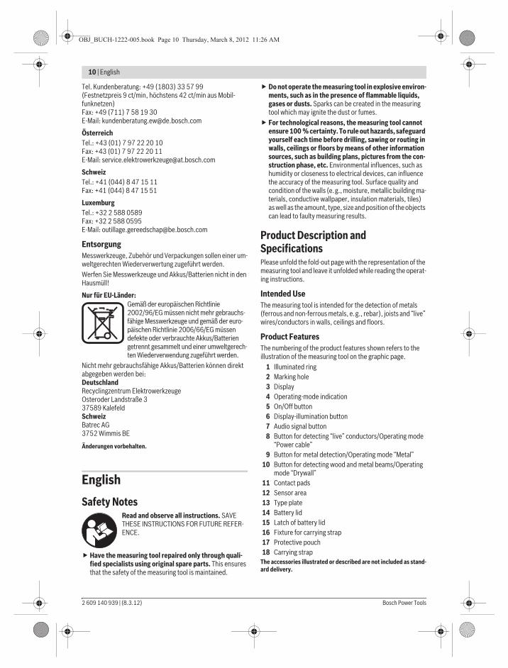
Tel. Kundenberatung: +49 (1803) 33 57 99(Festnetzpreis 9 ct/min, höchstens 42 ct/min aus Mobil-funknetzen)Fax: +49 (711) 7 58 19 30E-Mail: [email protected]
ÖsterreichTel.: +43 (01) 7 97 22 20 10Fax: +43 (01) 7 97 22 20 11E-Mail: [email protected]
SchweizTel.: +41 (044) 8 47 15 11Fax: +41 (044) 8 47 15 51
LuxemburgTel.: +32 2 588 0589Fax: +32 2 588 0595E-Mail: [email protected]
EntsorgungMesswerkzeuge, Zubehör und Verpackungen sollen einer um-weltgerechten Wiederverwertung zugeführt werden.Werfen Sie Messwerkzeuge und Akkus/Batterien nicht in den Hausmüll!
Nur für EU-Länder:Gemäß der europäischen Richtlinie 2002/96/EG müssen nicht mehr gebrauchs-fähige Messwerkzeuge und gemäß der euro-päischen Richtlinie 2006/66/EG müssen defekte oder verbrauchte Akkus/Batterien getrennt gesammelt und einer umweltgerech-ten Wiederverwendung zugeführt werden.
Nicht mehr gebrauchsfähige Akkus/Batterien können direkt abgegeben werden bei:DeutschlandRecyclingzentrum ElektrowerkzeugeOsteroder Landstraße 337589 KalefeldSchweizBatrec AG3752 Wimmis BE
Änderungen vorbehalten.
English
Safety NotesRead and observe all instructions. SAVE THESE INSTRUCTIONS FOR FUTURE REFER-ENCE.
Have the measuring tool repaired only through quali-fied specialists using original spare parts. This ensures that the safety of the measuring tool is maintained.
Do not operate the measuring tool in explosive environ-ments, such as in the presence of flammable liquids, gases or dusts. Sparks can be created in the measuring tool which may ignite the dust or fumes.For technological reasons, the measuring tool cannot ensure 100 % certainty. To rule out hazards, safeguard yourself each time before drilling, sawing or routing in walls, ceilings or floors by means of other information sources, such as building plans, pictures from the con-struction phase, etc. Environmental influences, such as humidity or closeness to electrical devices, can influence the accuracy of the measuring tool. Surface quality and condition of the walls (e.g., moisture, metallic building ma-terials, conductive wallpaper, insulation materials, tiles) as well as the amount, type, size and position of the objects can lead to faulty measuring results.
Product Description and SpecificationsPlease unfold the fold-out page with the representation of the measuring tool and leave it unfolded while reading the operat-ing instructions.
Intended UseThe measuring tool is intended for the detection of metals (ferrous and non-ferrous metals, e.g., rebar), joists and “live” wires/conductors in walls, ceilings and floors.
Product FeaturesThe numbering of the product features shown refers to the illustration of the measuring tool on the graphic page.
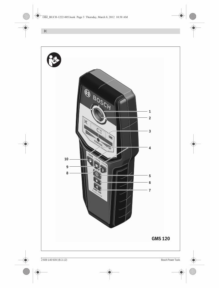
1 Illuminated ring2 Marking hole3 Display4 Operating-mode indication5 On/Off button6 Display-illumination button7 Audio signal button8 Button for detecting “live” conductors/Operating mode
“Power cable”9 Button for metal detection/Operating mode “Metal”
10 Button for detecting wood and metal beams/Operating mode “Drywall”
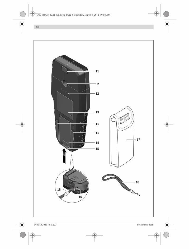
11 Contact pads12 Sensor area13 Type plate14 Battery lid15 Latch of battery lid16 Fixture for carrying strap17 Protective pouch18 Carrying strap
The accessories illustrated or described are not included as stand-ard delivery.
OBJ_BUCH-1222-005.book Page 10 Thursday, March 8, 2012 11:26 AM
English | 11
Bosch Power Tools 2 609 140 939 | (8.3.12)
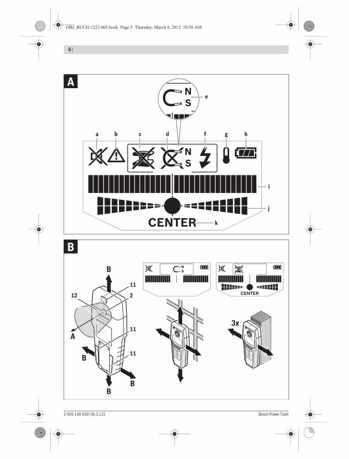
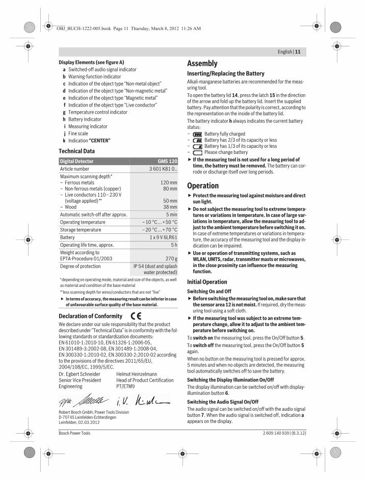
Display Elements (see figure A)a Switched-off audio signal indicatorb Warning-function indicatorc Indication of the object type “Non-metal object”d Indication of the object type “Non-magnetic metal”e Indication of the object type “Magnetic metal”f Indication of the object type “Live conductor”g Temperature control indicatorh Battery indicatori Measuring indicatorj Fine scale
k Indication “CENTER”
Technical Data
Declaration of ConformityWe declare under our sole responsibility that the product described under “Technical Data” is in conformity with the fol-lowing standards or standardization documents: EN 61010-1:2010-10, EN 61326-1:2006-05, EN 301489-3:2002-08, EN 301489-1:2008-04, EN 300330-1:2010-02, EN 300330-2:2010-02 according to the provisions of the directives 2011/65/EU, 2004/108/EC, 1999/5/EC.
Robert Bosch GmbH, Power Tools Division D-70745 Leinfelden-Echterdingen Leinfelden, 02.03.2012
AssemblyInserting/Replacing the BatteryAlkali-manganese batteries are recommended for the meas-uring tool.To open the battery lid 14, press the latch 15 in the direction of the arrow and fold up the battery lid. Insert the supplied battery. Pay attention that the polarity is correct, according to the representation on the inside of the battery lid.The battery indicator h always indicates the current battery status:– Battery fully charged– Battery has 2/3 of its capacity or less– Battery has 1/3 of its capacity or less– Please change battery
If the measuring tool is not used for a long period of time, the battery must be removed. The battery can cor-rode or discharge itself over long periods.
OperationProtect the measuring tool against moisture and direct sun light.Do not subject the measuring tool to extreme tempera-tures or variations in temperature. In case of large var-iations in temperature, allow the measuring tool to ad-just to the ambient temperature before switching it on. In case of extreme temperatures or variations in tempera-ture, the accuracy of the measuring tool and the display in-dication can be impaired.Use or operation of transmitting systems, such as WLAN, UMTS, radar, transmitter masts or microwaves, in the close proximity can influence the measuring function.
Initial OperationSwitching On and Off
Before switching the measuring tool on, make sure that the sensor area 12 is not moist. If required, dry the meas-uring tool using a soft cloth.If the measuring tool was subject to an extreme tem-perature change, allow it to adjust to the ambient tem-perature before switching on.
To switch on the measuring tool, press the On/Off button 5.To switch off the measuring tool, press the On/Off button 5 again.When no button on the measuring tool is pressed for approx. 5 minutes and when no objects are detected, the measuring tool automatically switches off to save the battery.
Switching the Display Illumination On/OffThe display illumination can be switched on/off with display-illumination button 6.
Switching the Audio Signal On/OffThe audio signal can be switched on/off with the audio signal button 7. When the audio signal is switched off, indication a appears on the display.
Digital Detector GMS 120Article number 3 601 K81 0..Maximum scanning depth*– Ferrous metals– Non-ferrous metals (copper)– Live conductors 110–230 V
(voltage applied)**– Wood
120 mm80 mm
50 mm38 mm
Automatic switch-off after approx. 5 minOperating temperature –10 °C...+50 °CStorage temperature –20 °C...+70 °CBattery 1 x 9 V 6LR61Operating life time, approx. 5 hWeight according to EPTA-Procedure 01/2003 270 gDegree of protection IP 54 (dust and splash
water protected)*depending on operating mode, material and size of the objects, as well as material and condition of the base material
** less scanning depth for wires/conductors that are not “live”
In terms of accuracy, the measuring result can be inferior in case of unfavourable surface quality of the base material.
Dr. Egbert SchneiderSenior Vice PresidentEngineering
Helmut HeinzelmannHead of Product CertificationPT/ETM9
OBJ_BUCH-1222-005.book Page 11 Thursday, March 8, 2012 11:26 AM
12 | English
2 609 140 939 | (8.3.12) Bosch Power Tools
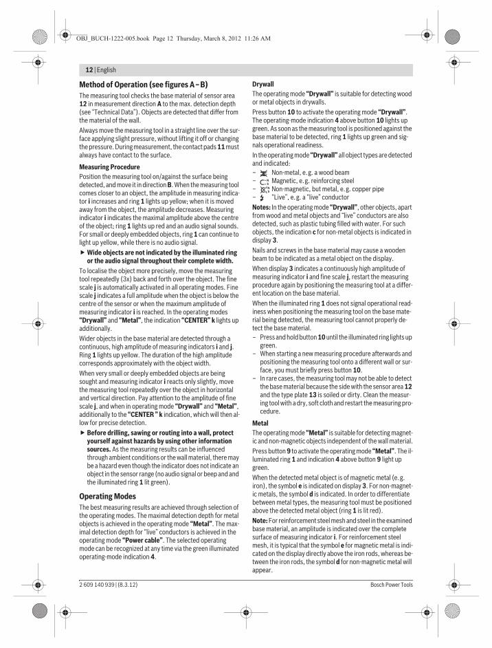
Method of Operation (see figures A–B)The measuring tool checks the base material of sensor area 12 in measurement direction A to the max. detection depth (see “Technical Data”). Objects are detected that differ from the material of the wall.Always move the measuring tool in a straight line over the sur-face applying slight pressure, without lifting it off or changing the pressure. During measurement, the contact pads 11 must always have contact to the surface.
Measuring ProcedurePosition the measuring tool on/against the surface being detected, and move it in direction B. When the measuring tool comes closer to an object, the amplitude in measuring indica-tor i increases and ring 1 lights up yellow; when it is moved away from the object, the amplitude decreases. Measuring indicator i indicates the maximal amplitude above the centre of the object; ring 1 lights up red and an audio signal sounds. For small or deeply embedded objects, ring 1 can continue to light up yellow, while there is no audio signal.
Wide objects are not indicated by the illuminated ring or the audio signal throughout their complete width.
To localise the object more precisely, move the measuring tool repeatedly (3x) back and forth over the object. The fine scale j is automatically activated in all operating modes. Fine scale j indicates a full amplitude when the object is below the centre of the sensor or when the maximum amplitude of measuring indicator i is reached. In the operating modes “Drywall” and “Metal”, the indication “CENTER” k lights up additionally.Wider objects in the base material are detected through a continuous, high amplitude of measuring indicators i and j. Ring 1 lights up yellow. The duration of the high amplitude corresponds approximately with the object width.When very small or deeply embedded objects are being sought and measuring indicator i reacts only slightly, move the measuring tool repeatedly over the object in horizontal and vertical direction. Pay attention to the amplitude of fine scale j, and when in operating mode “Drywall” and “Metal”, additionally to the “CENTER ” k indication, which will then al-low for precise detection.
Before drilling, sawing or routing into a wall, protect yourself against hazards by using other information sources. As the measuring results can be influenced through ambient conditions or the wall material, there may be a hazard even though the indicator does not indicate an object in the sensor range (no audio signal or beep and and the illuminated ring 1 lit green).
Operating ModesThe best measuring results are achieved through selection of the operating modes. The maximal detection depth for metal objects is achieved in the operating mode “Metal”. The max-imal detection depth for “live” conductors is achieved in the operating mode “Power cable”. The selected operating mode can be recognized at any time via the green illuminated operating-mode indication 4.
DrywallThe operating mode “Drywall” is suitable for detecting wood or metal objects in drywalls.Press button 10 to activate the operating mode “Drywall”. The operating-mode indication 4 above button 10 lights up green. As soon as the measuring tool is positioned against the base material to be detected, ring 1 lights up green and sig-nals operational readiness.In the operating mode “Drywall” all object types are detected and indicated:– Non-metal, e.g. a wood beam– Magnetic, e.g. reinforcing steel– Non-magnetic, but metal, e.g. copper pipe– “Live”, e.g. a “live” conductorNotes: In the operating mode “Drywall”, other objects, apart from wood and metal objects and “live” conductors are also detected, such as plastic tubing filled with water. For such objects, the indication c for non-metal objects is indicated in display 3.Nails and screws in the base material may cause a wooden beam to be indicated as a metal object on the display.When display 3 indicates a continuously high amplitude of measuring indicator i and fine scale j, restart the measuring procedure again by positioning the measuring tool at a differ-ent location on the base material.When the illuminated ring 1 does not signal operational read-iness when positioning the measuring tool on the base mate-rial being detected, the measuring tool cannot properly de-tect the base material.– Press and hold button 10 until the illuminated ring lights up
green.– When starting a new measuring procedure afterwards and
positioning the measuring tool onto a different wall or sur-face, you must briefly press button 10.
– In rare cases, the measuring tool may not be able to detect the base material because the side with the sensor area 12 and the type plate 13 is soiled or dirty. Clean the measur-ing tool with a dry, soft cloth and restart the measuring pro-cedure.
MetalThe operating mode “Metal” is suitable for detecting magnet-ic and non-magnetic objects independent of the wall material.Press button 9 to activate the operating mode “Metal”. The il-luminated ring 1 and indication 4 above button 9 light up green.When the detected metal object is of magnetic metal (e.g. iron), the symbol e is indicated on display 3. For non-magnet-ic metals, the symbol d is indicated. In order to differentiate between metal types, the measuring tool must be positioned above the detected metal object (ring 1 is lit red).Note: For reinforcement steel mesh and steel in the examined base material, an amplitude is indicated over the complete surface of measuring indicator i. For reinforcement steel mesh, it is typical that the symbol e for magnetic metal is indi-cated on the display directly above the iron rods, whereas be-tween the iron rods, the symbol d for non-magnetic metal will appear.
OBJ_BUCH-1222-005.book Page 12 Thursday, March 8, 2012 11:26 AM
English | 13
Bosch Power Tools 2 609 140 939 | (8.3.12)
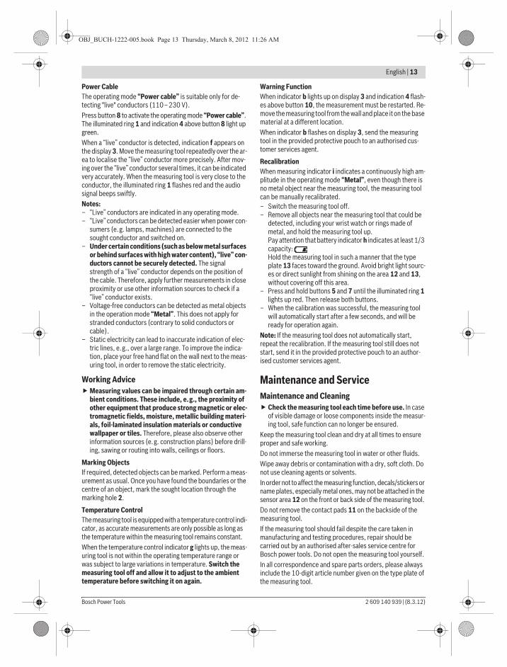
Power CableThe operating mode “Power cable” is suitable only for de-tecting "live" conductors (110–230 V). Press button 8 to activate the operating mode “Power cable”. The illuminated ring 1 and indication 4 above button 8 light up green.When a “live” conductor is detected, indication f appears on the display 3. Move the measuring tool repeatedly over the ar-ea to localise the “live” conductor more precisely. After mov-ing over the “live” conductor several times, it can be indicated very accurately. When the measuring tool is very close to the conductor, the illuminated ring 1 flashes red and the audio signal beeps swiftly.Notes: – “Live” conductors are indicated in any operating mode.– “Live” conductors can be detected easier when power con-
sumers (e.g. lamps, machines) are connected to the sought conductor and switched on.
– Under certain conditions (such as below metal surfaces or behind surfaces with high water content), “live” con-ductors cannot be securely detected. The signal strength of a “live” conductor depends on the position of the cable. Therefore, apply further measurements in close proximity or use other information sources to check if a “live” conductor exists.
– Voltage-free conductors can be detected as metal objects in the operation mode “Metal”. This does not apply for stranded conductors (contrary to solid conductors or cable).
– Static electricity can lead to inaccurate indication of elec-tric lines, e.g., over a large range. To improve the indica-tion, place your free hand flat on the wall next to the meas-uring tool, in order to remove the static electricity.
Working AdviceMeasuring values can be impaired through certain am-bient conditions. These include, e.g., the proximity of other equipment that produce strong magnetic or elec-tromagnetic fields, moisture, metallic building materi-als, foil-laminated insulation materials or conductive wallpaper or tiles. Therefore, please also observe other information sources (e.g. construction plans) before drill-ing, sawing or routing into walls, ceilings or floors.
Marking ObjectsIf required, detected objects can be marked. Perform a meas-urement as usual. Once you have found the boundaries or the centre of an object, mark the sought location through the marking hole 2.
Temperature ControlThe measuring tool is equipped with a temperature control indi-cator, as accurate measurements are only possible as long as the temperature within the measuring tool remains constant. When the temperature control indicator g lights up, the meas-uring tool is not within the operating temperature range or was subject to large variations in temperature. Switch the measuring tool off and allow it to adjust to the ambient temperature before switching it on again.
Warning FunctionWhen indicator b lights up on display 3 and indication 4 flash-es above button 10, the measurement must be restarted. Re-move the measuring tool from the wall and place it on the base material at a different location.When indicator b flashes on display 3, send the measuring tool in the provided protective pouch to an authorised cus-tomer services agent.
RecalibrationWhen measuring indicator i indicates a continuously high am-plitude in the operating mode “Metal”, even though there is no metal object near the measuring tool, the measuring tool can be manually recalibrated.– Switch the measuring tool off.– Remove all objects near the measuring tool that could be
detected, including your wrist watch or rings made of metal, and hold the measuring tool up.Pay attention that battery indicator h indicates at least 1/3 capacity: Hold the measuring tool in such a manner that the type plate 13 faces toward the ground. Avoid bright light sourc-es or direct sunlight from shining on the area 12 and 13, without covering off this area.
– Press and hold buttons 5 and 7 until the illuminated ring 1 lights up red. Then release both buttons.
– When the calibration was successful, the measuring tool will automatically start after a few seconds, and will be ready for operation again.
Note: If the measuring tool does not automatically start, repeat the recalibration. If the measuring tool still does not start, send it in the provided protective pouch to an author-ised customer services agent.
Maintenance and ServiceMaintenance and Cleaning
Check the measuring tool each time before use. In case of visible damage or loose components inside the measur-ing tool, safe function can no longer be ensured.
Keep the measuring tool clean and dry at all times to ensure proper and safe working.Do not immerse the measuring tool in water or other fluids.Wipe away debris or contamination with a dry, soft cloth. Do not use cleaning agents or solvents.In order not to affect the measuring function, decals/stickers or name plates, especially metal ones, may not be attached in the sensor area 12 on the front or back side of the measuring tool.Do not remove the contact pads 11 on the backside of the measuring tool.If the measuring tool should fail despite the care taken in manufacturing and testing procedures, repair should be carried out by an authorised after-sales service centre for Bosch power tools. Do not open the measuring tool yourself.In all correspondence and spare parts orders, please always include the 10-digit article number given on the type plate of the measuring tool.
OBJ_BUCH-1222-005.book Page 13 Thursday, March 8, 2012 11:26 AM
14 | English
2 609 140 939 | (8.3.12) Bosch Power Tools
Store and transport the measuring tool only in the supplied protective pouch.In case of repairs, send in the measuring tool packed in its protective pouch 17.
After-sales Service and Customer AssistanceOur after-sales service responds to your questions concern-ing maintenance and repair of your product as well as spare parts. Exploded views and information on spare parts can also be found under:www.bosch-pt.comOur customer service representatives can answer your ques-tions concerning possible applications and adjustment of products and accessories.
Great BritainRobert Bosch Ltd. (B.S.C.)P.O. Box 98Broadwater ParkNorth Orbital RoadDenhamUxbridgeUB 9 5HJTel. Service: +44 (0844) 736 0109Fax: +44 (0844) 736 0146E-Mail: [email protected]
IrelandOrigo Ltd.Unit 23 Magna DriveMagna Business ParkCity WestDublin 24Tel. Service: +353 (01) 4 66 67 00Fax: +353 (01) 4 66 68 88
Australia, New Zealand and Pacific IslandsRobert Bosch Australia Pty. Ltd.Power ToolsLocked Bag 66Clayton South VIC 3169Customer Contact CenterInside Australia:Phone: +61 (01300) 307 044Fax: +61 (01300) 307 045Inside New Zealand:Phone: +64 (0800) 543 353Fax: +64 (0800) 428 570Outside AU and NZ:Phone: +61 (03) 9541 5555www.bosch.com.au
Republic of South AfricaCustomer serviceHotline: +27 (011) 6 51 96 00
Gauteng – BSC Service Centre35 Roper Street, New CentreJohannesburgTel.: +27 (011) 4 93 93 75Fax: +27 (011) 4 93 01 26E-Mail: [email protected]
KZN – BSC Service CentreUnit E, Almar Centre143 Crompton StreetPinetownTel.: +27 (031) 7 01 21 20Fax: +27 (031) 7 01 24 46E-Mail: [email protected]
Western Cape – BSC Service CentreDemocracy Way, Prosperity ParkMilnertonTel.: +27 (021) 5 51 25 77Fax: +27 (021) 5 51 32 23E-Mail: [email protected]
Bosch HeadquartersMidrand, GautengTel.: +27 (011) 6 51 96 00Fax: +27 (011) 6 51 98 80E-Mail: [email protected]
People’s Republic of ChinaChina MainlandBosch Power Tools (China) Co., Ltd.567, Bin Kang RoadBin Jiang District 310052Hangzhou, P.R.ChinaService Hotline: 400 826 8484Fax: +86 571 8777 4502E-Mail: [email protected]
HK and Macau Special Administrative RegionsRobert Bosch Hong Kong Co. Ltd.21st Floor, 625 King’s RoadNorth Point, Hong KongCustomer Service Hotline: +852 2101 0235Fax: +852 2590 9762E-Mail: [email protected]
IndonesiaPT. Multi MayakaKawasan Industri PulogadungJalan Rawa Gelam III No. 2Jakarta 13930IndonesiaTel.: +62 (21) 46 83 25 22Fax: +62 (21) 46 82 86 45/68 23E-Mail: [email protected]
PhilippinesRobert Bosch, Inc.28th Floor Fort Legend Towers,3rd Avenue corner 31st Street,Fort Bonifacio Global City,1634 Taguig City, PhilippinesTel.: +63 (2) 870 3871Fax: +63 (2) 870 [email protected]
OBJ_BUCH-1222-005.book Page 14 Thursday, March 8, 2012 11:26 AM