

Carlos Frederico Meschini Almeida [email protected] 11 ...
58
Transcript of Carlos Frederico Meschini Almeida [email protected] 11 ...
OPENDSS-G TUTORIAL 1Referência:
https://www.youtube.com/watch?v=UzOFdvpjcZk&list=PLhdRxvt3nJ8zRpfalsBt8vMWwBDcsFJ_N
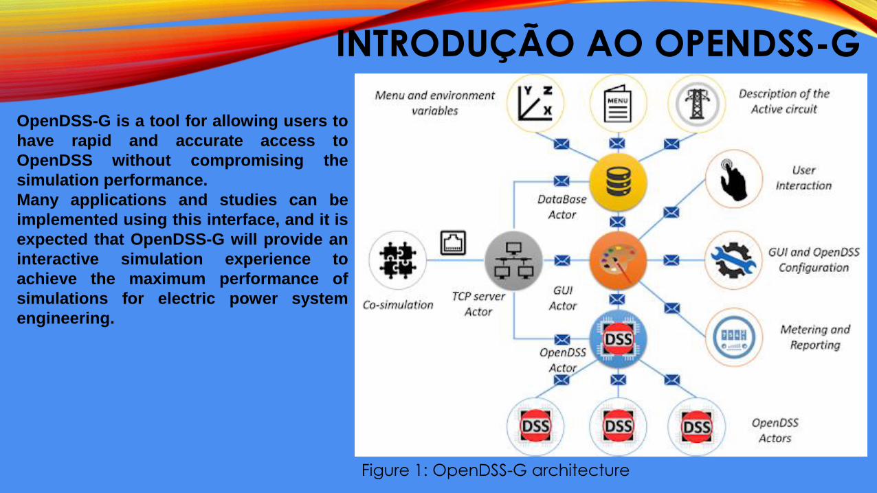
INTRODUÇÃO AO OPENDSS-G
OpenDSS-G is a tool for allowing users to
have rapid and accurate access to
OpenDSS without compromising the
simulation performance.
Many applications and studies can be
implemented using this interface, and it is
expected that OpenDSS-G will provide an
interactive simulation experience to
achieve the maximum performance of
simulations for electric power system
engineering.
Figure 1: OpenDSS-G architecture
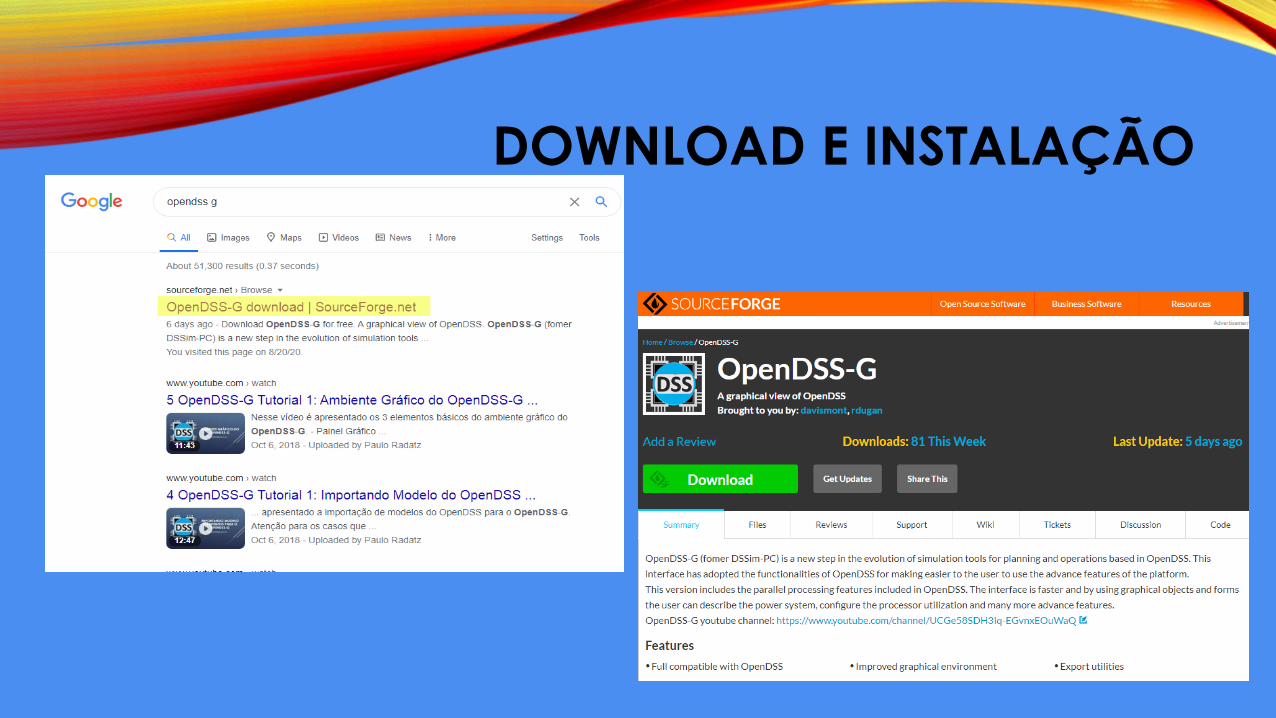
DOWNLOAD E INSTALAÇÃO
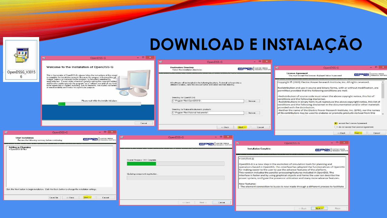
DOWNLOAD E INSTALAÇÃO
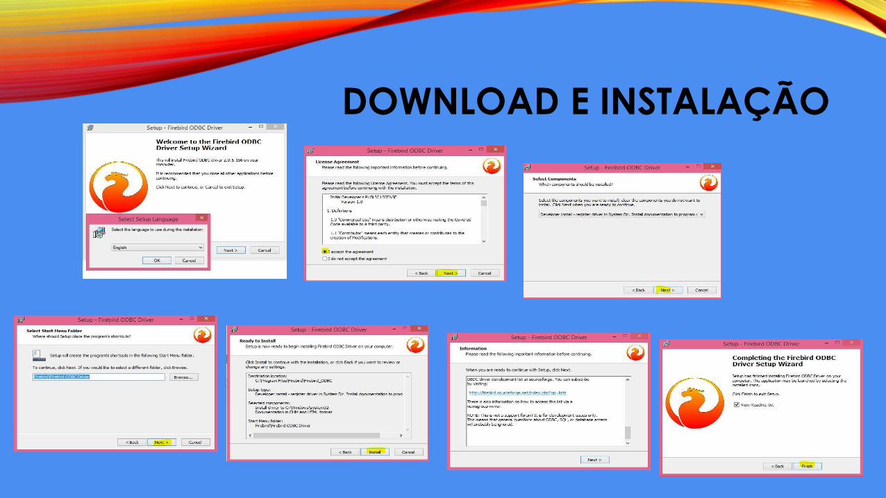
DOWNLOAD E INSTALAÇÃO
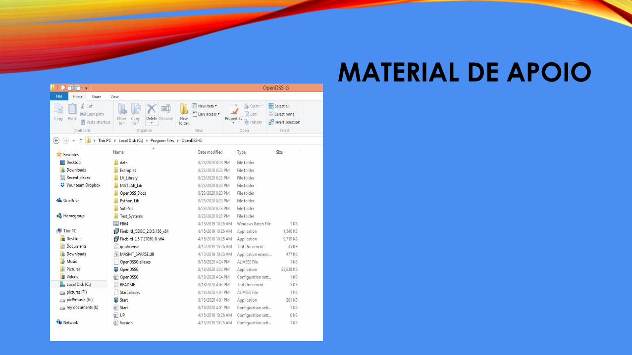
MATERIAL DE APOIO
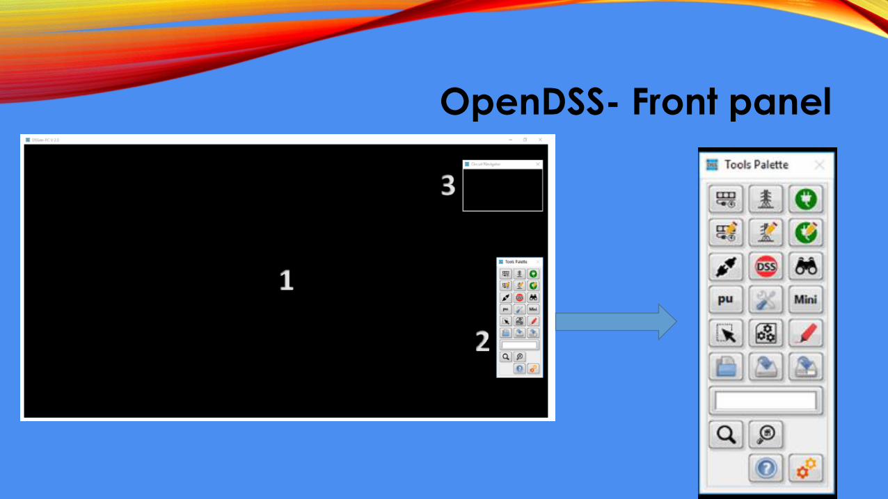
OpenDSS- Front panel
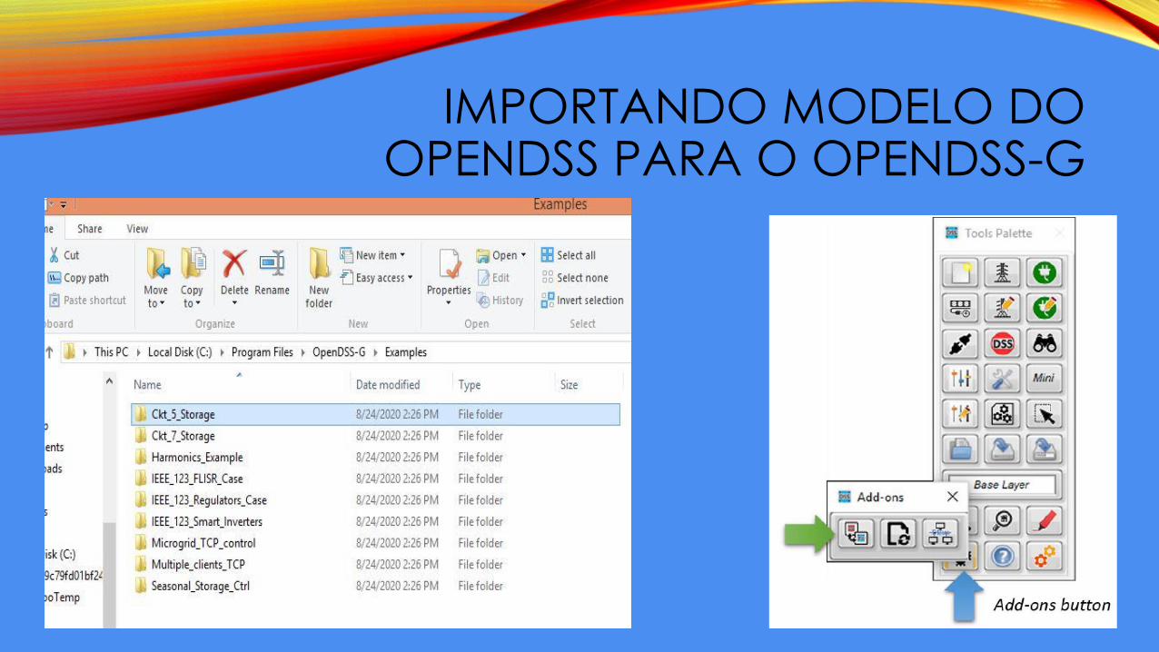
IMPORTANDO MODELO DO OPENDSS PARA O OPENDSS-G
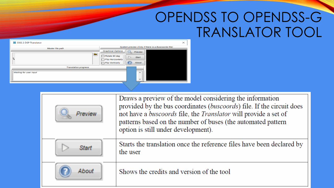
OPENDSS TO OPENDSS-G TRANSLATOR TOOL
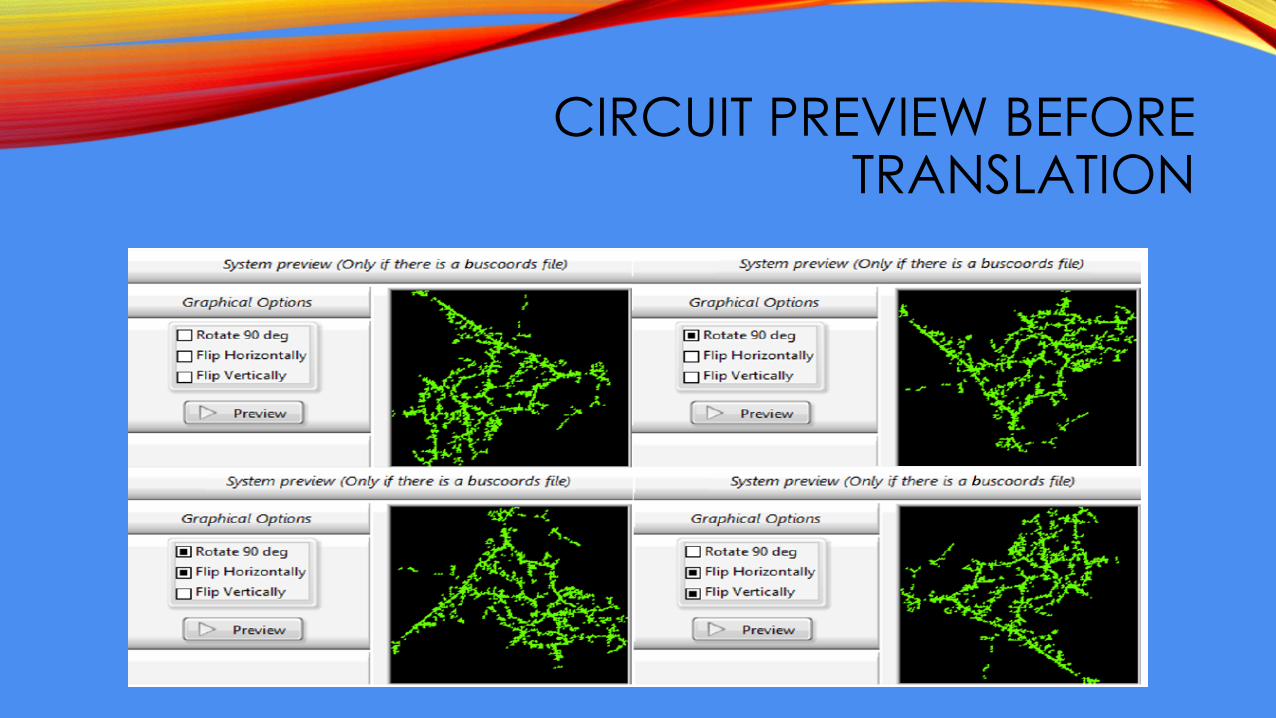
CIRCUIT PREVIEW BEFORE TRANSLATION
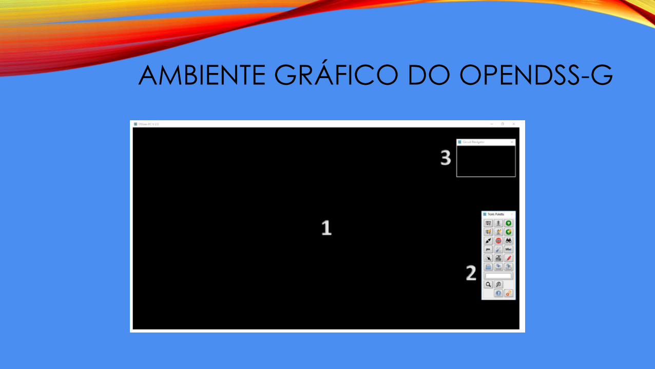
AMBIENTE GRÁFICO DO OPENDSS-G
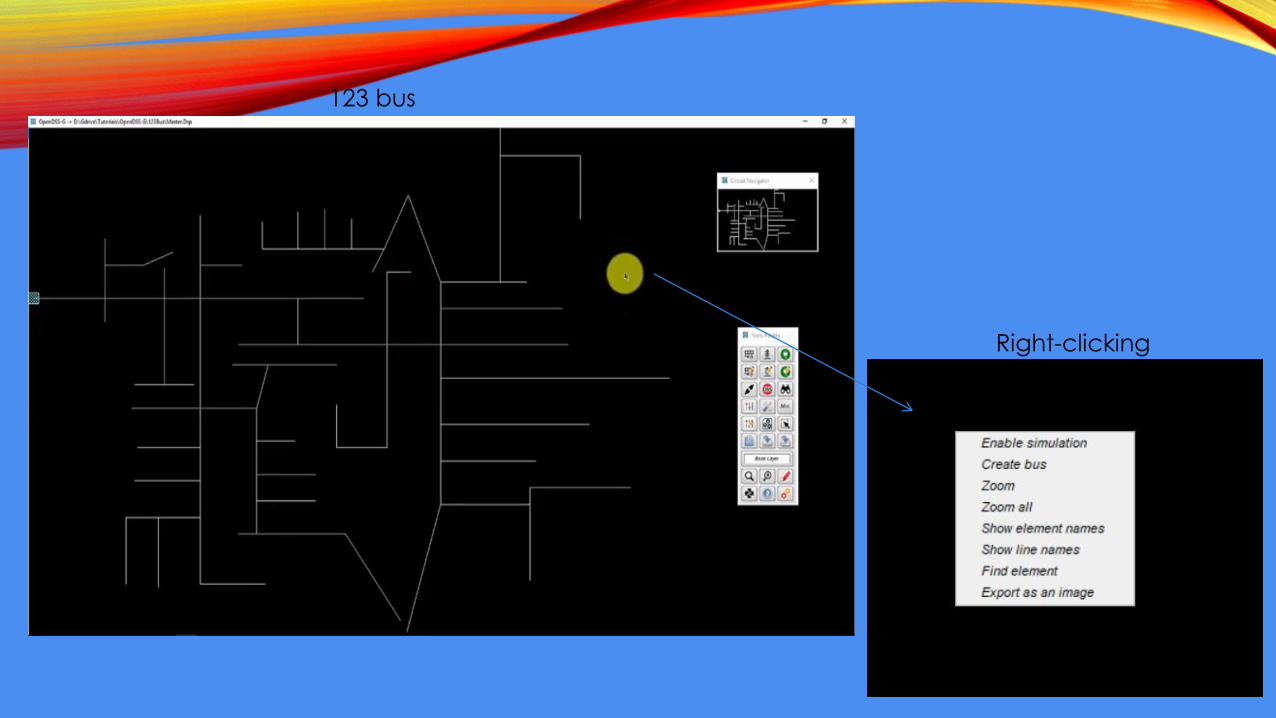
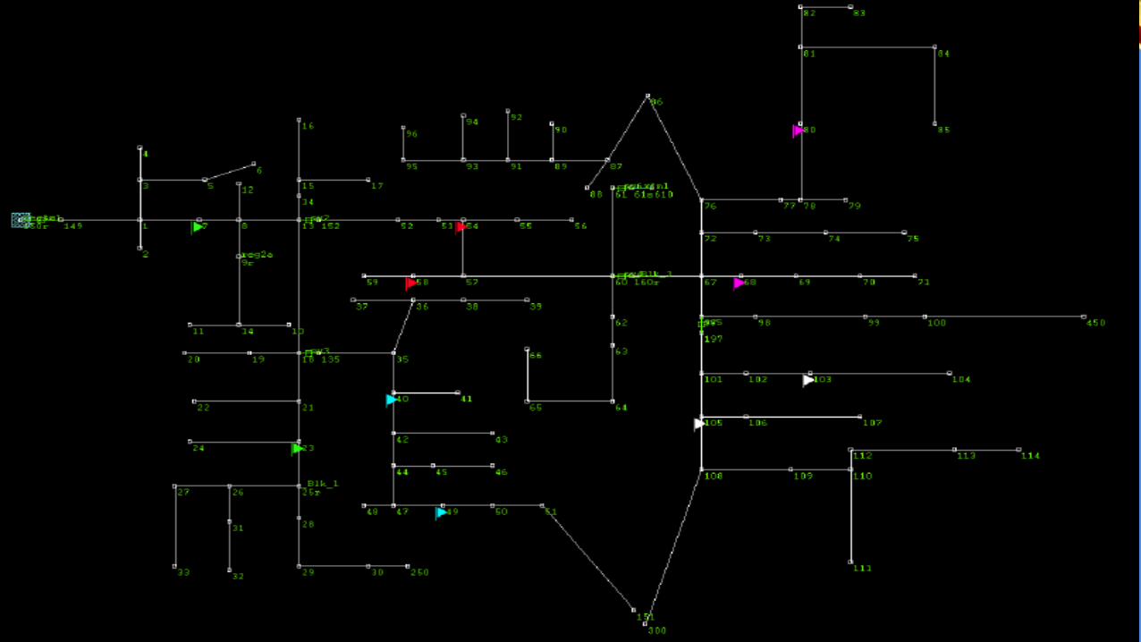
123 bus
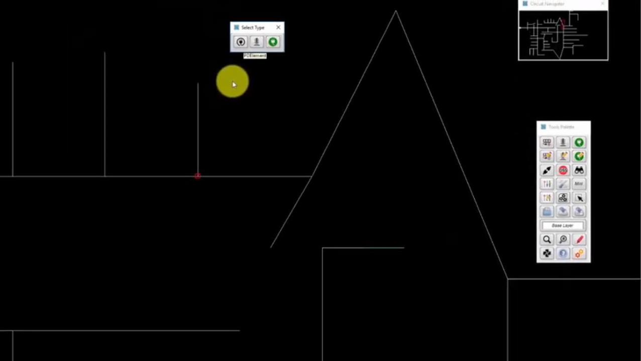
Right-clicking
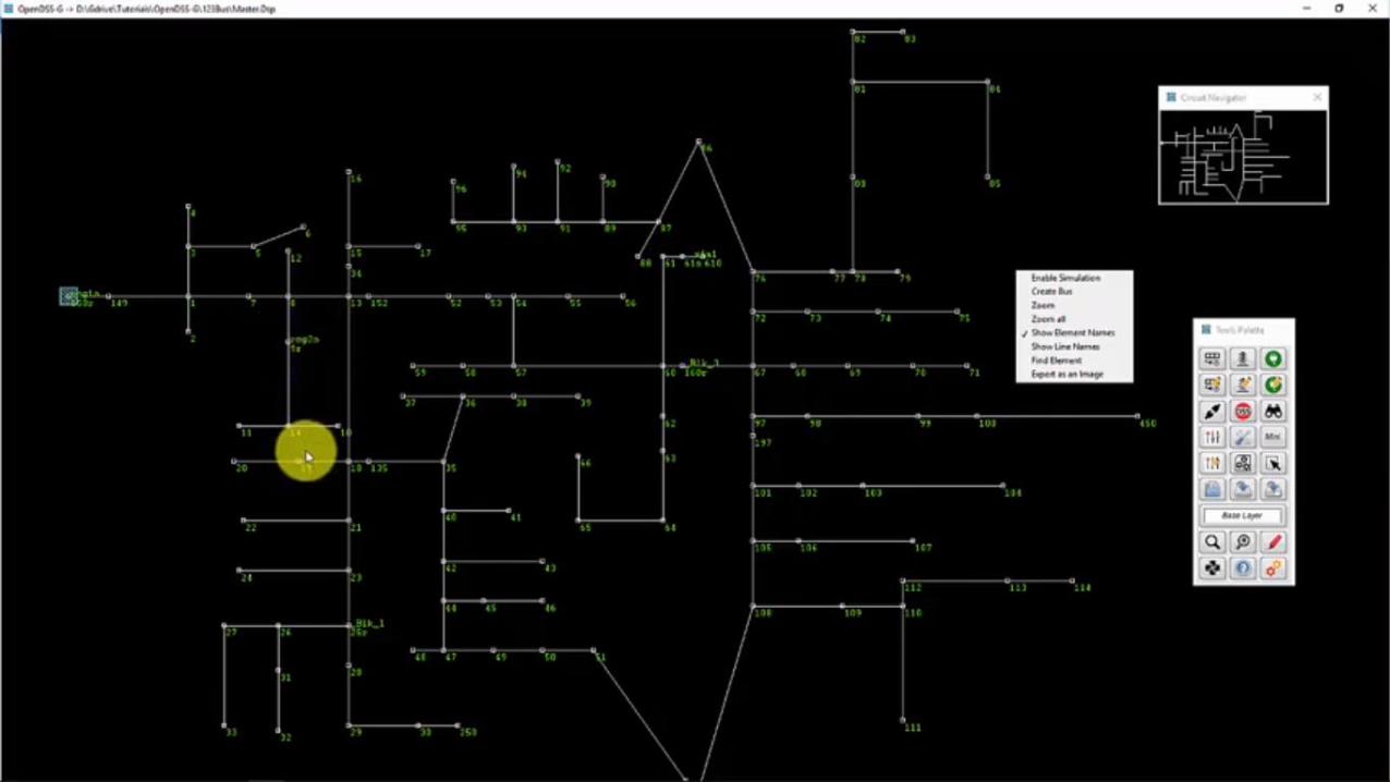
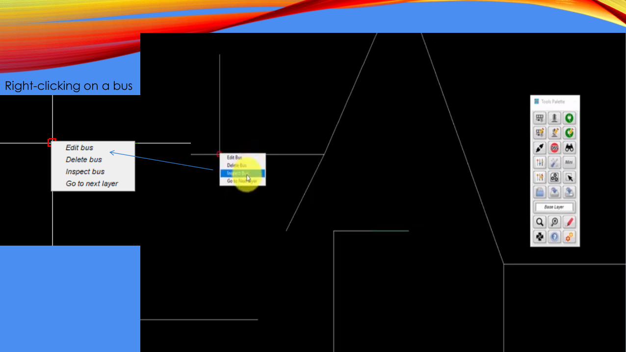
Right-clicking on a bus
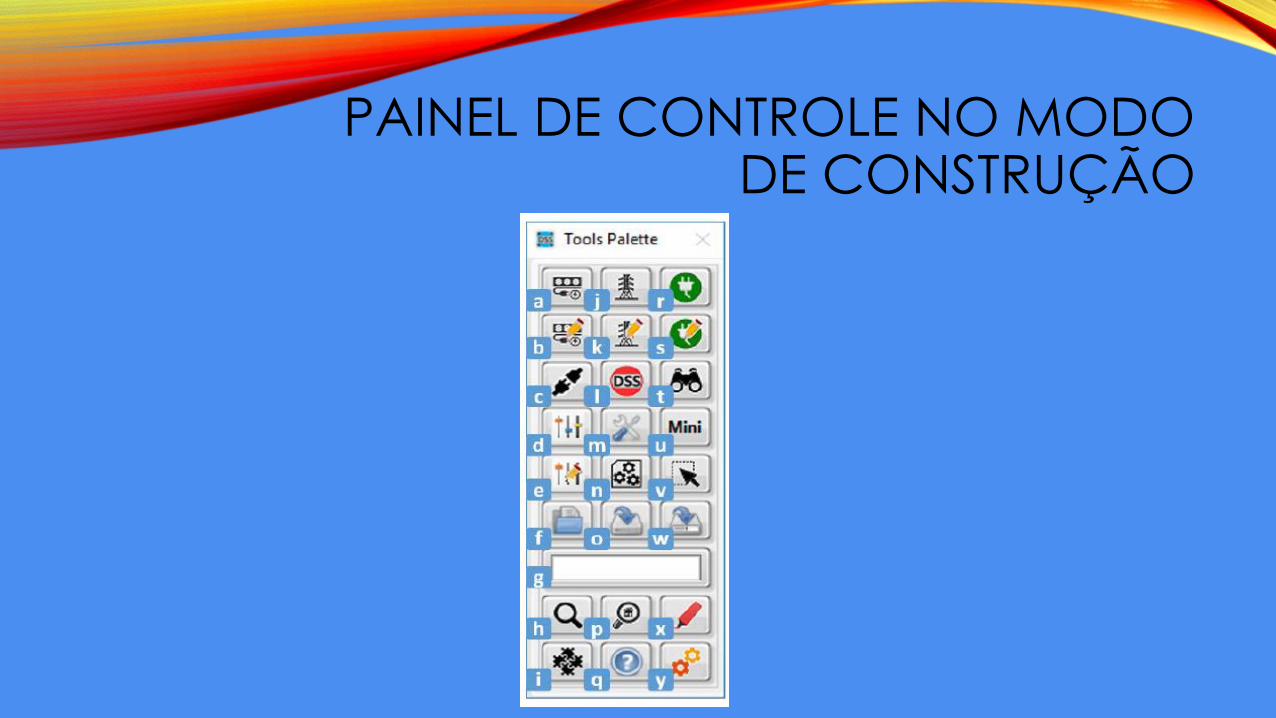
PAINEL DE CONTROLE NO MODO DE CONSTRUÇÃO
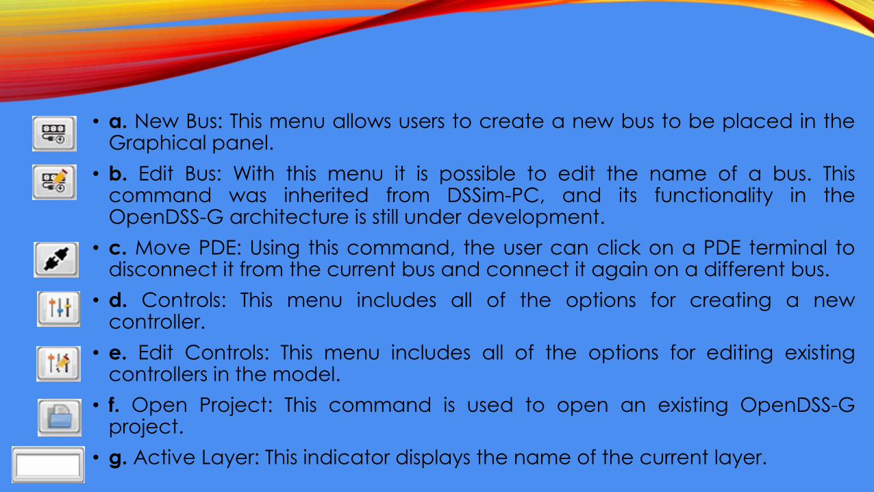
• a. New Bus: This menu allows users to create a new bus to be placed in theGraphical panel.
• b. Edit Bus: With this menu it is possible to edit the name of a bus. Thiscommand was inherited from DSSim-PC, and its functionality in theOpenDSS-G architecture is still under development.
• c. Move PDE: Using this command, the user can click on a PDE terminal todisconnect it from the current bus and connect it again on a different bus.
• d. Controls: This menu includes all of the options for creating a newcontroller.
• e. Edit Controls: This menu includes all of the options for editing existingcontrollers in the model.
• f. Open Project: This command is used to open an existing OpenDSS-Gproject.
• g. Active Layer: This indicator displays the name of the current layer.
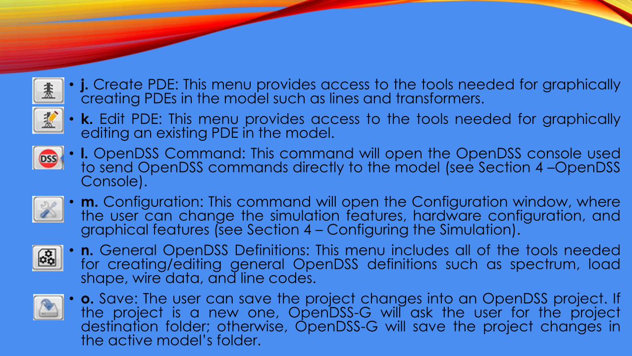
• j. Create PDE: This menu provides access to the tools needed for graphicallycreating PDEs in the model such as lines and transformers.
• k. Edit PDE: This menu provides access to the tools needed for graphicallyediting an existing PDE in the model.
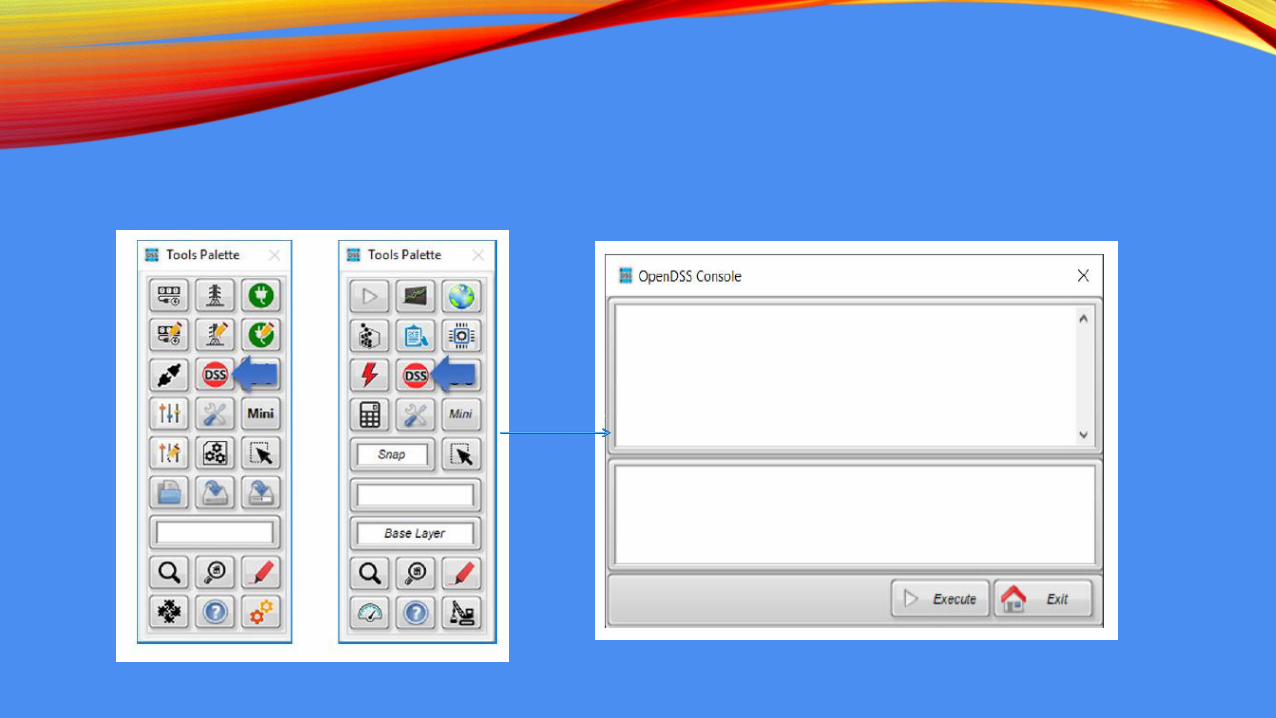
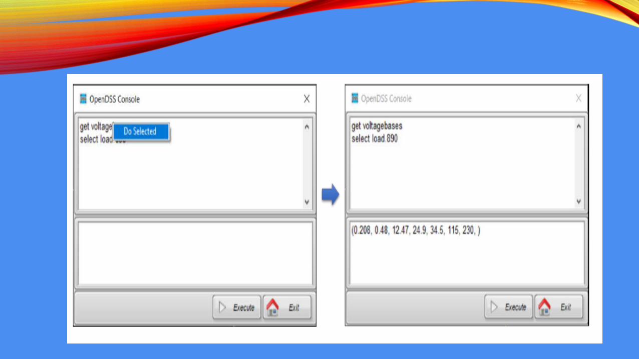
• l. OpenDSS Command: This command will open the OpenDSS console usedto send OpenDSS commands directly to the model (see Section 4 –OpenDSSConsole).
• m. Configuration: This command will open the Configuration window, wherethe user can change the simulation features, hardware configuration, andgraphical features (see Section 4 – Configuring the Simulation).
• n. General OpenDSS Definitions: This menu includes all of the tools neededfor creating/editing general OpenDSS definitions such as spectrum, loadshape, wire data, and line codes.
• o. Save: The user can save the project changes into an OpenDSS project. Ifthe project is a new one, OpenDSS-G will ask the user for the projectdestination folder; otherwise, OpenDSS-G will save the project changes inthe active model’s folder.
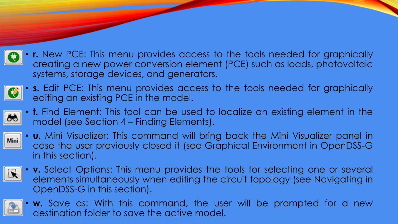
• r. New PCE: This menu provides access to the tools needed for graphicallycreating a new power conversion element (PCE) such as loads, photovoltaicsystems, storage devices, and generators.
• s. Edit PCE: This menu provides access to the tools needed for graphicallyediting an existing PCE in the model.
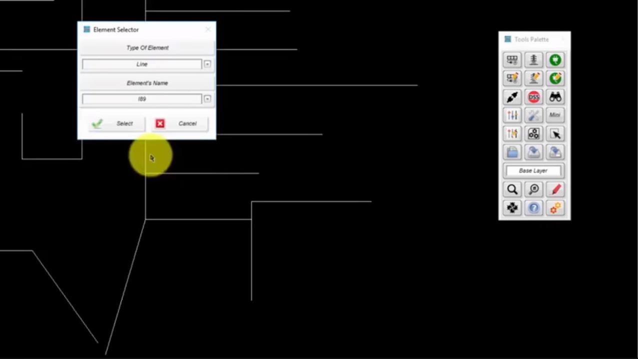
• t. Find Element: This tool can be used to localize an existing element in themodel (see Section 4 – Finding Elements).
• u. Mini Visualizer: This command will bring back the Mini Visualizer panel incase the user previously closed it (see Graphical Environment in OpenDSS-Gin this section).
• v. Select Options: This menu provides the tools for selecting one or severalelements simultaneously when editing the circuit topology (see Navigating inOpenDSS-G in this section).
• w. Save as: With this command, the user will be prompted for a newdestination folder to save the active model.

• Exemplo para a aula
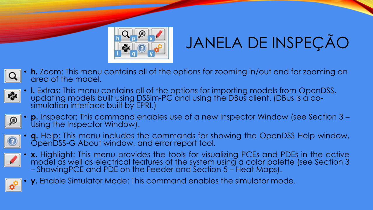
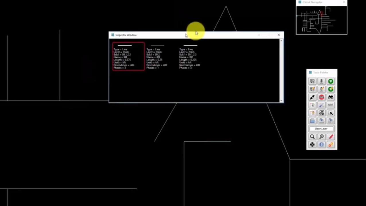
JANELA DE INSPEÇÃO
• h. Zoom: This menu contains all of the options for zooming in/out and for zooming an area of the model.
• i. Extras: This menu contains all of the options for importing models from OpenDSS, updating models built using DSSim-PC and using the DBus client. (DBus is a co-simulation interface built by EPRI.)
• p. Inspector: This command enables use of a new Inspector Window (see Section 3 –Using the Inspector Window).
• q. Help: This menu includes the commands for showing the OpenDSS Help window,OpenDSS-G About window, and error report tool.
• x. Highlight: This menu provides the tools for visualizing PCEs and PDEs in the activemodel as well as electrical features of the system using a color palette (see Section 3– ShowingPCE and PDE on the Feeder and Section 5 – Heat Maps).
• y. Enable Simulator Mode: This command enables the simulator mode.
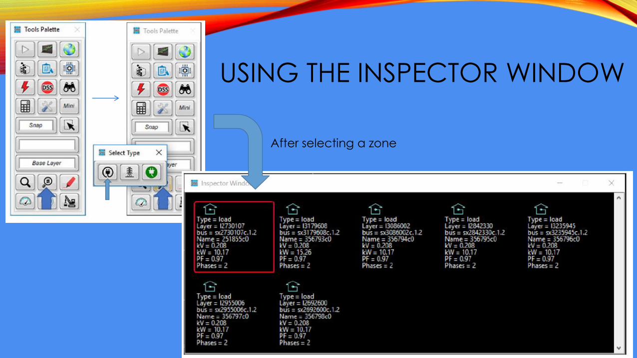
USING THE INSPECTOR WINDOW
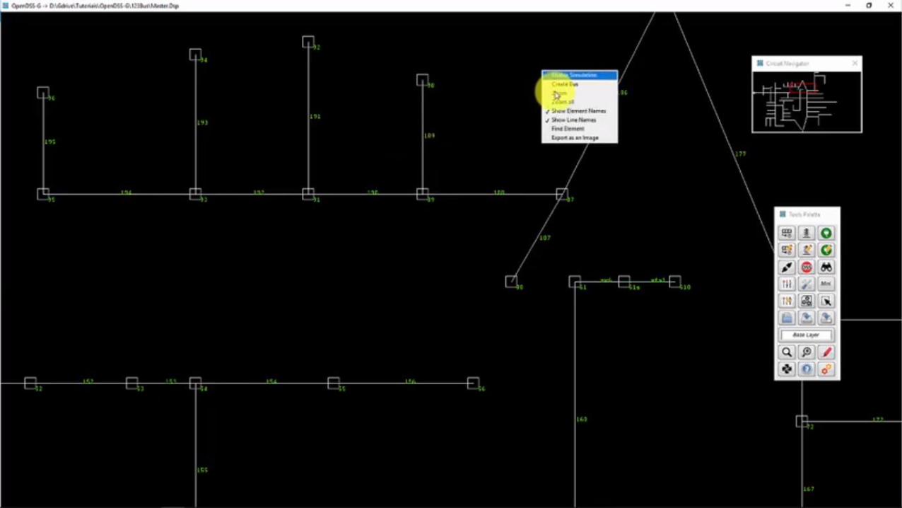
After selecting a zone
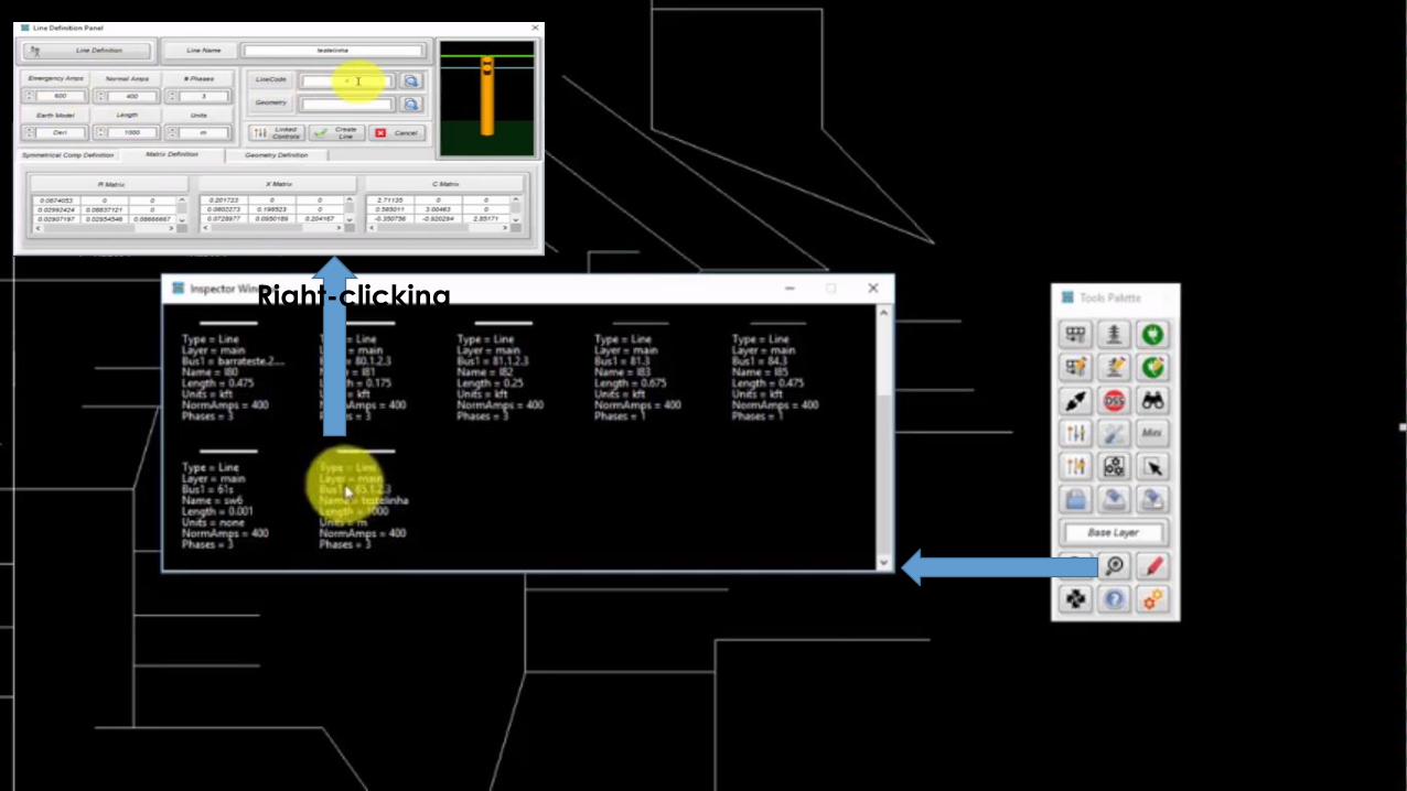
Right-clicking
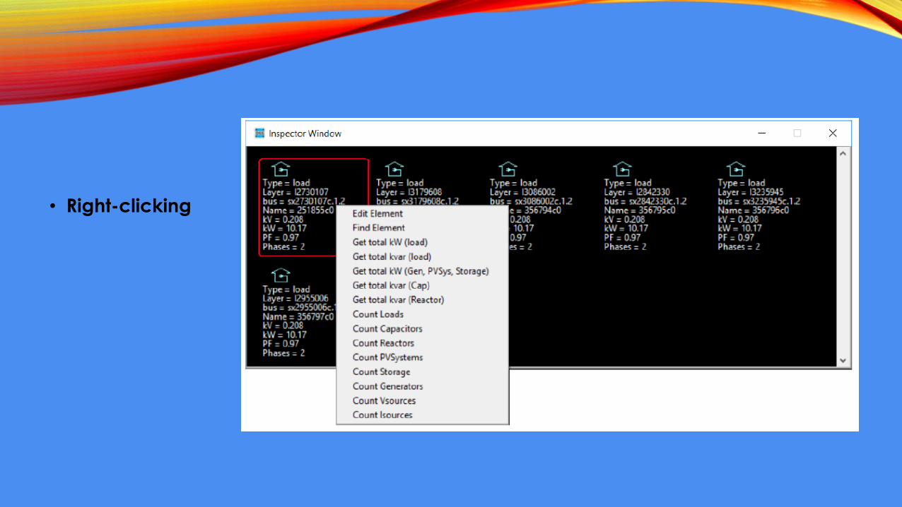
• Right-clicking
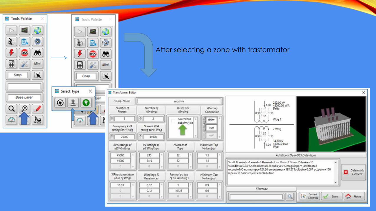
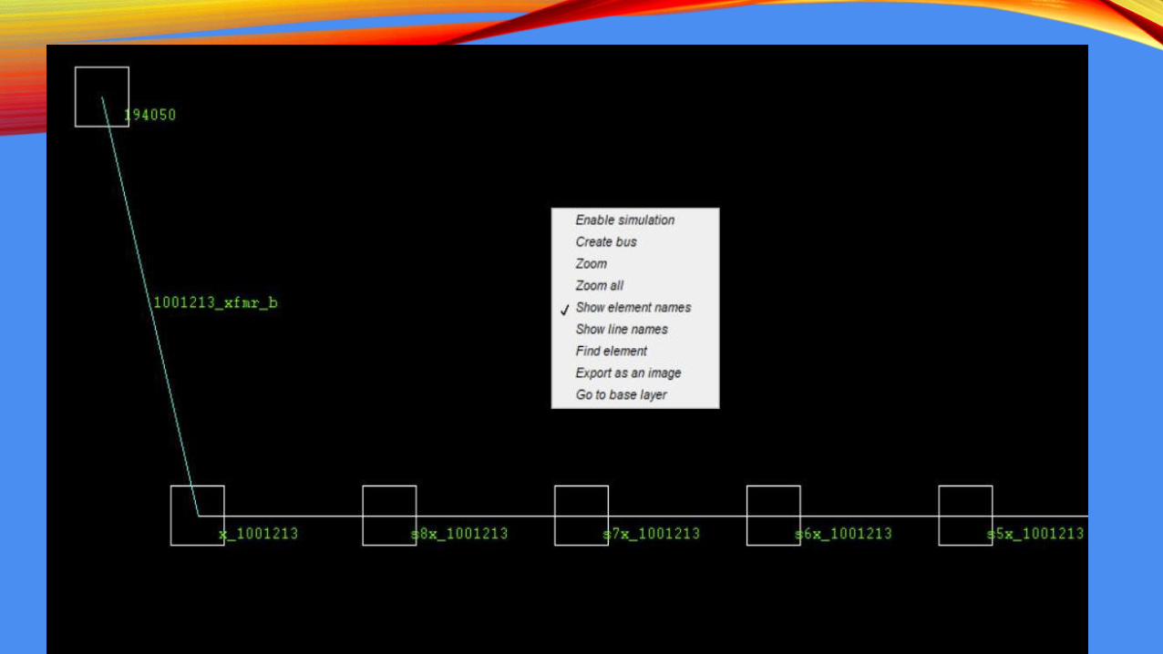
After selecting a zone with trasformator
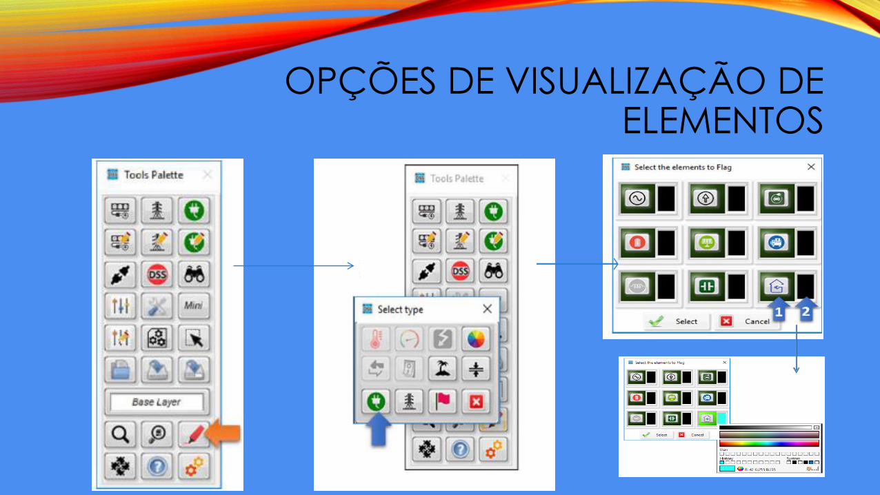
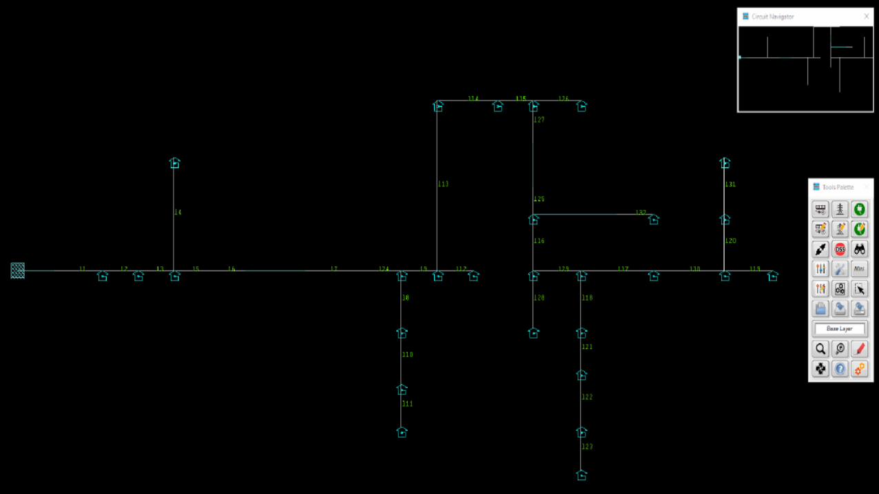
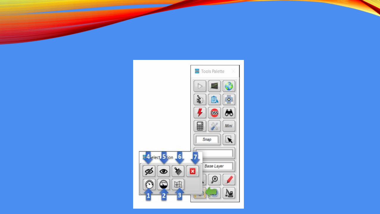
OPÇÕES DE VISUALIZAÇÃO DE ELEMENTOS
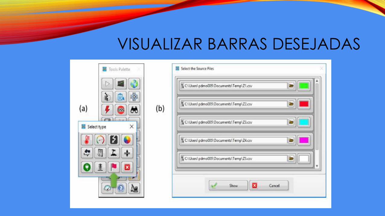
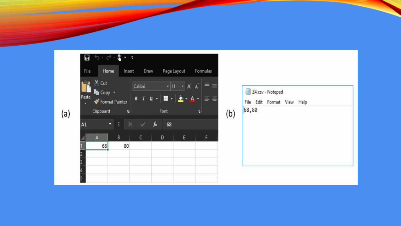
VISUALIZAR BARRAS DESEJADAS
OPÇÕES DE SIMULAÇÃO
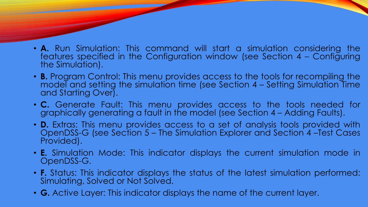
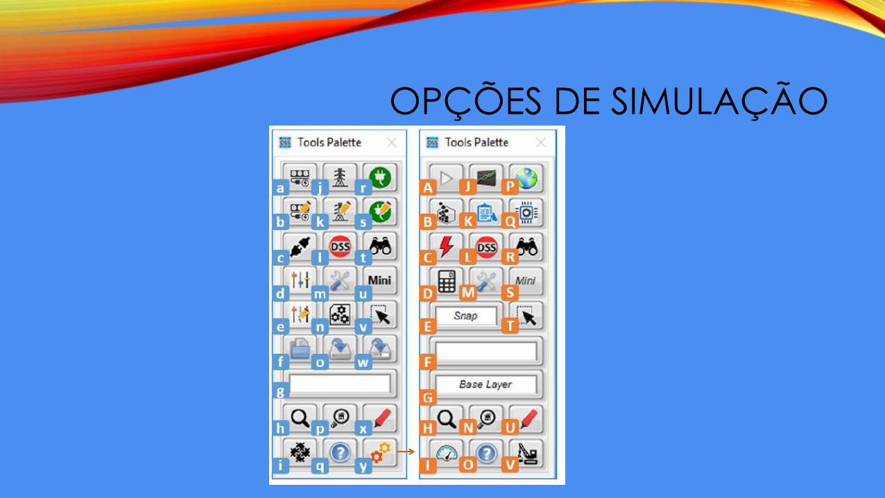
• A. Run Simulation: This command will start a simulation considering thefeatures specified in the Configuration window (see Section 4 – Configuringthe Simulation).
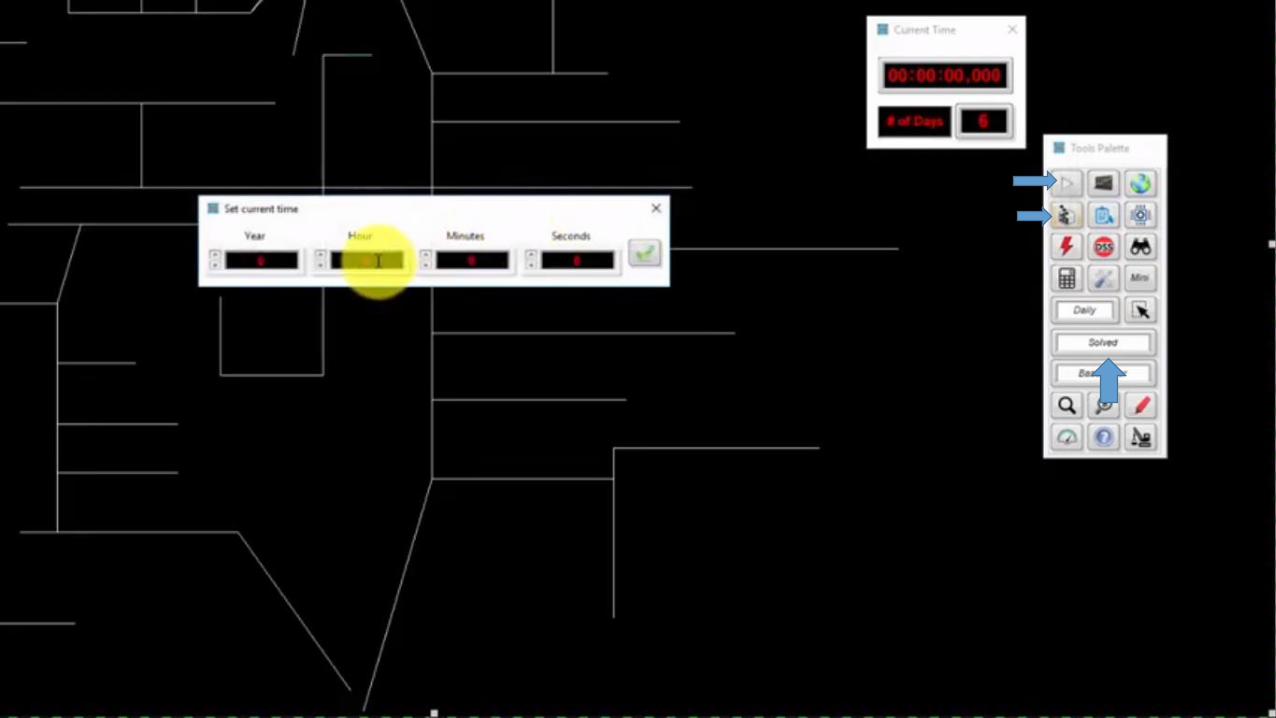
• B. Program Control: This menu provides access to the tools for recompiling themodel and setting the simulation time (see Section 4 – Setting Simulation Timeand Starting Over).
• C. Generate Fault: This menu provides access to the tools needed forgraphically generating a fault in the model (see Section 4 – Adding Faults).
• D. Extras: This menu provides access to a set of analysis tools provided withOpenDSS-G (see Section 5 – The Simulation Explorer and Section 4 –Test CasesProvided).
• E. Simulation Mode: This indicator displays the current simulation mode inOpenDSS-G.
• F. Status: This indicator displays the status of the latest simulation performed:Simulating, Solved or Not Solved.
• G. Active Layer: This indicator displays the name of the current layer.
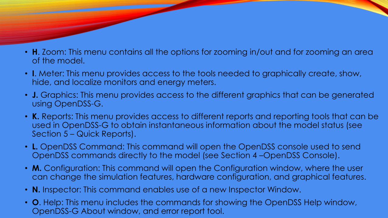
• H. Zoom: This menu contains all the options for zooming in/out and for zooming an area of the model.
• I. Meter: This menu provides access to the tools needed to graphically create, show, hide, and localize monitors and energy meters.
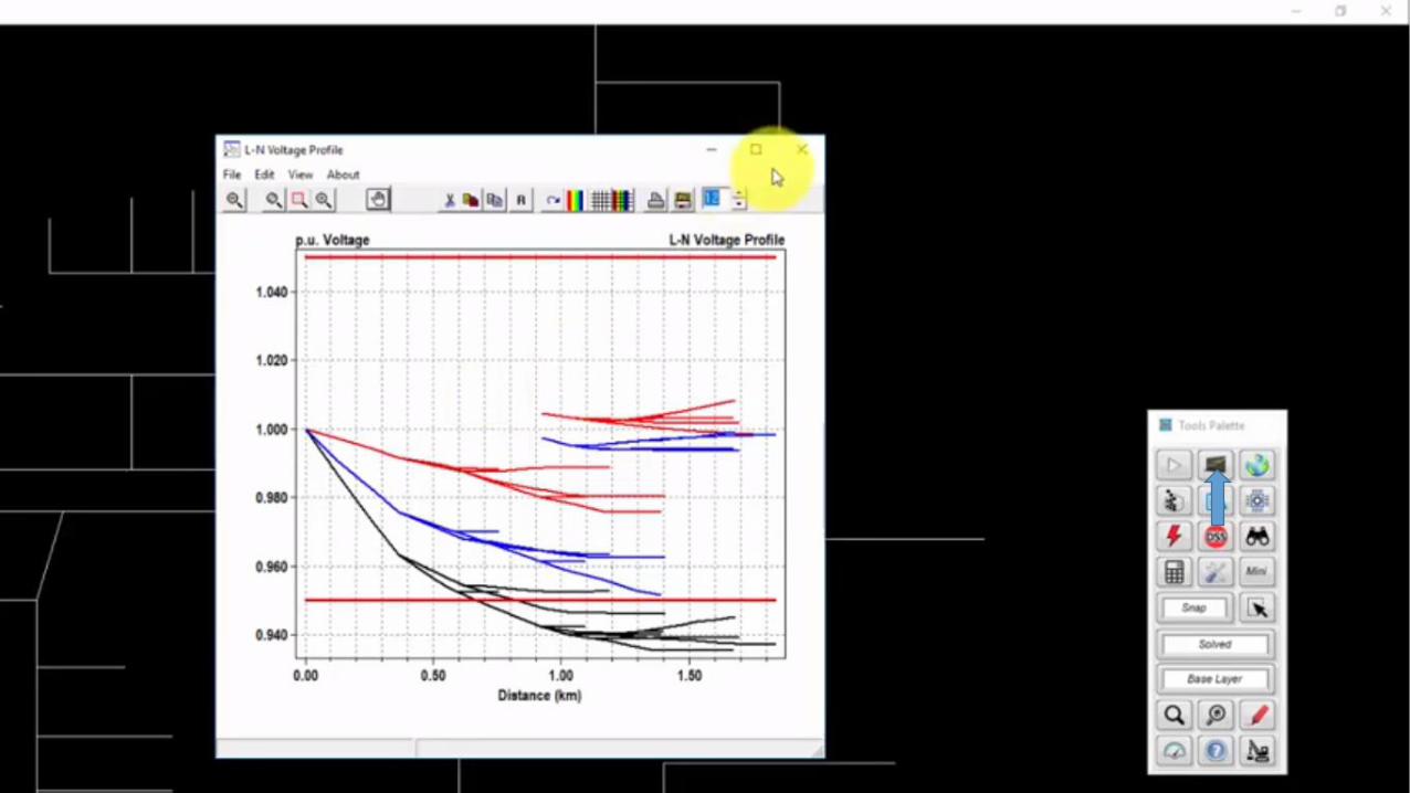
• J. Graphics: This menu provides access to the different graphics that can be generated using OpenDSS-G.
• K. Reports: This menu provides access to different reports and reporting tools that can be used in OpenDSS-G to obtain instantaneous information about the model status (see Section 5 – Quick Reports).
• L. OpenDSS Command: This command will open the OpenDSS console used to send OpenDSS commands directly to the model (see Section 4 –OpenDSS Console).
• M. Configuration: This command will open the Configuration window, where the user can change the simulation features, hardware configuration, and graphical features.
• N. Inspector: This command enables use of a new Inspector Window.
• O. Help: This menu includes the commands for showing the OpenDSS Help window, OpenDSS-G About window, and error report tool.
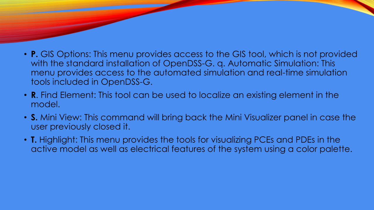
• P. GIS Options: This menu provides access to the GIS tool, which is not provided with the standard installation of OpenDSS-G. q. Automatic Simulation: This menu provides access to the automated simulation and real-time simulation tools included in OpenDSS-G.
• R. Find Element: This tool can be used to localize an existing element in the model.
• S. Mini View: This command will bring back the Mini Visualizer panel in case the user previously closed it.
• T. Highlight: This menu provides the tools for visualizing PCEs and PDEs in the active model as well as electrical features of the system using a color palette.
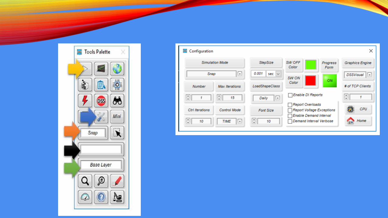
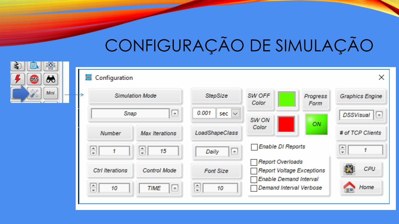
CONFIGURAÇÃO DE SIMULAÇÃO
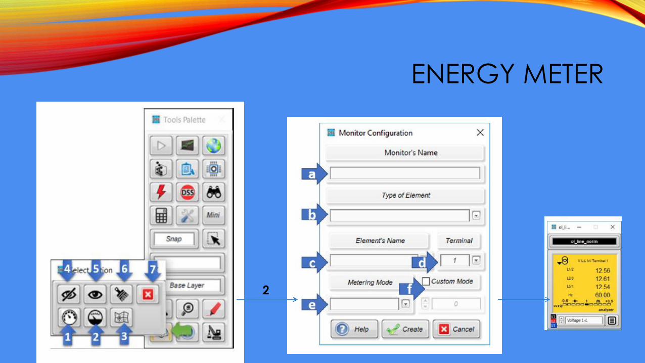
ENERGY METER
2
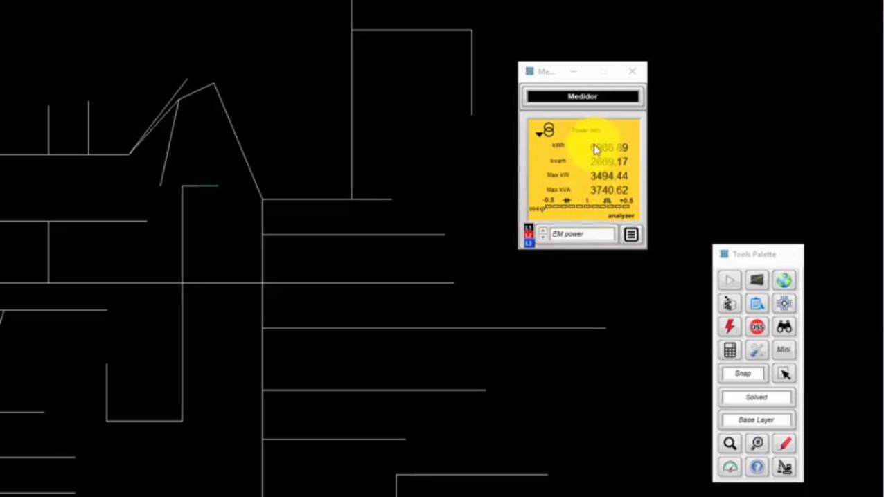
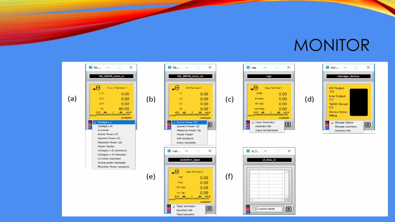
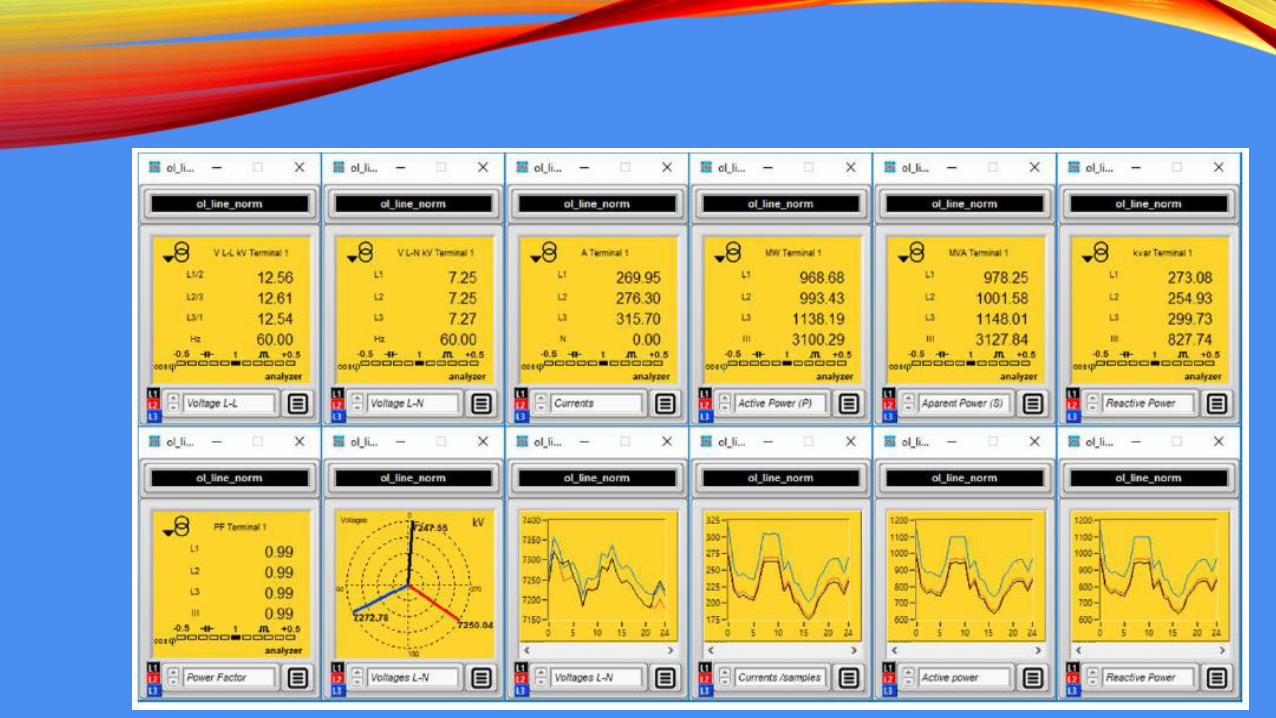
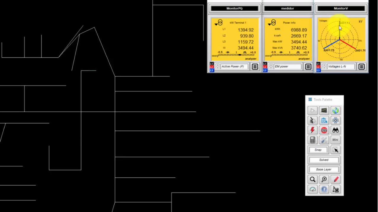
MONITOR
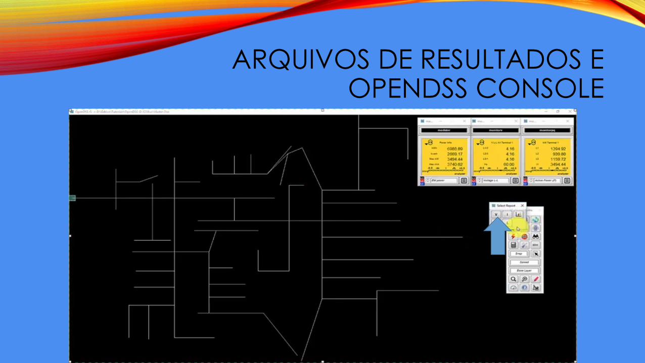
ARQUIVOS DE RESULTADOS E OPENDSS CONSOLE
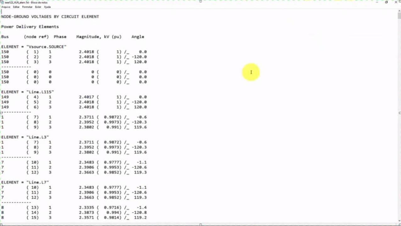
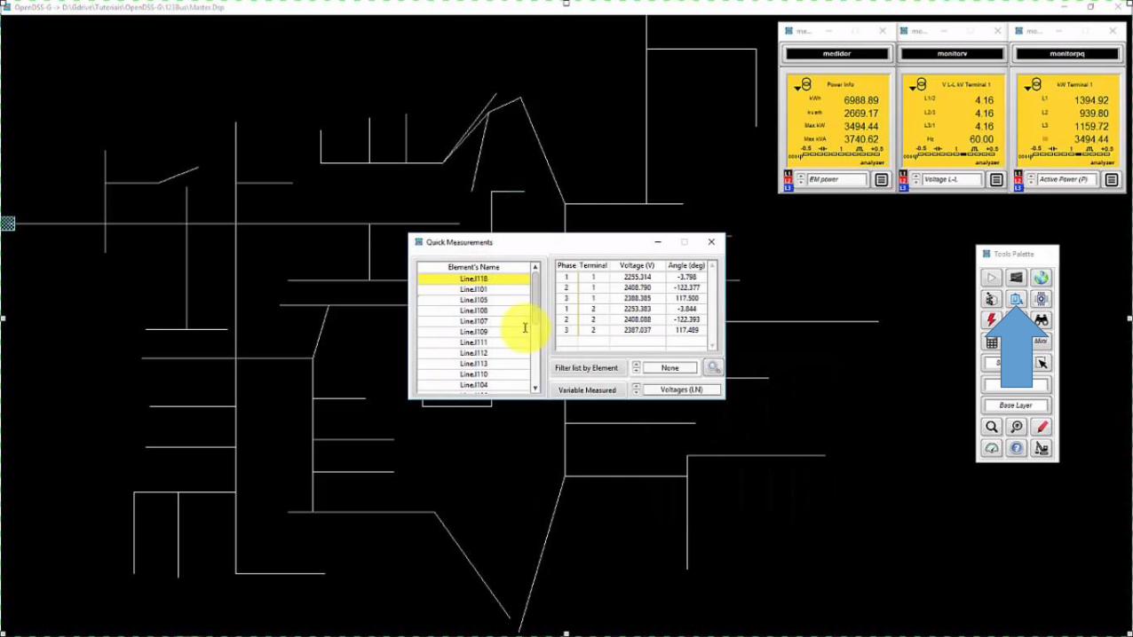
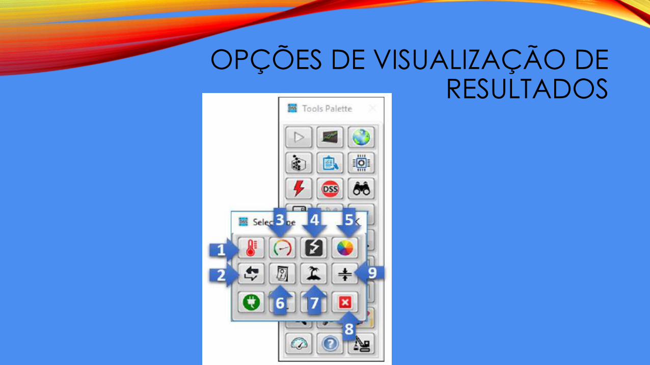
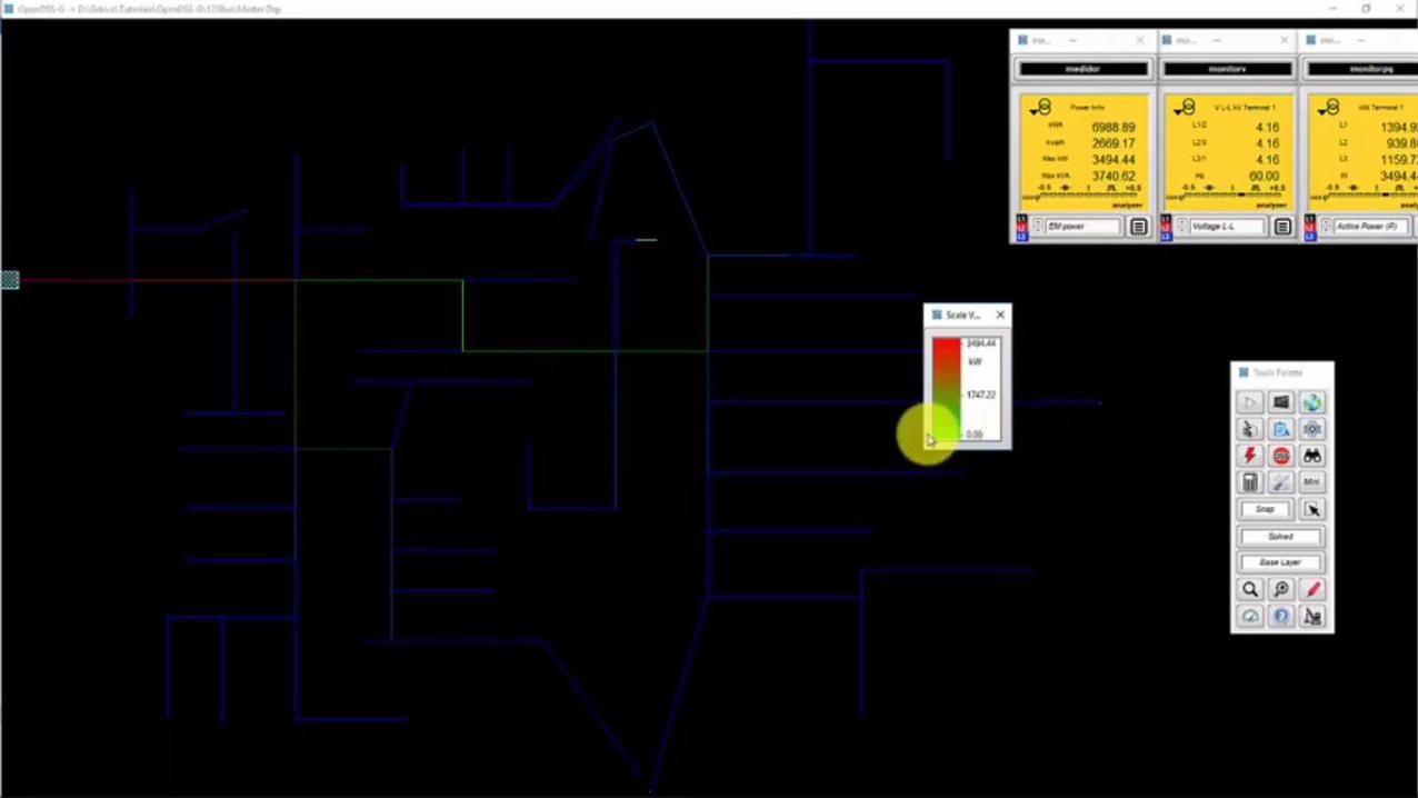
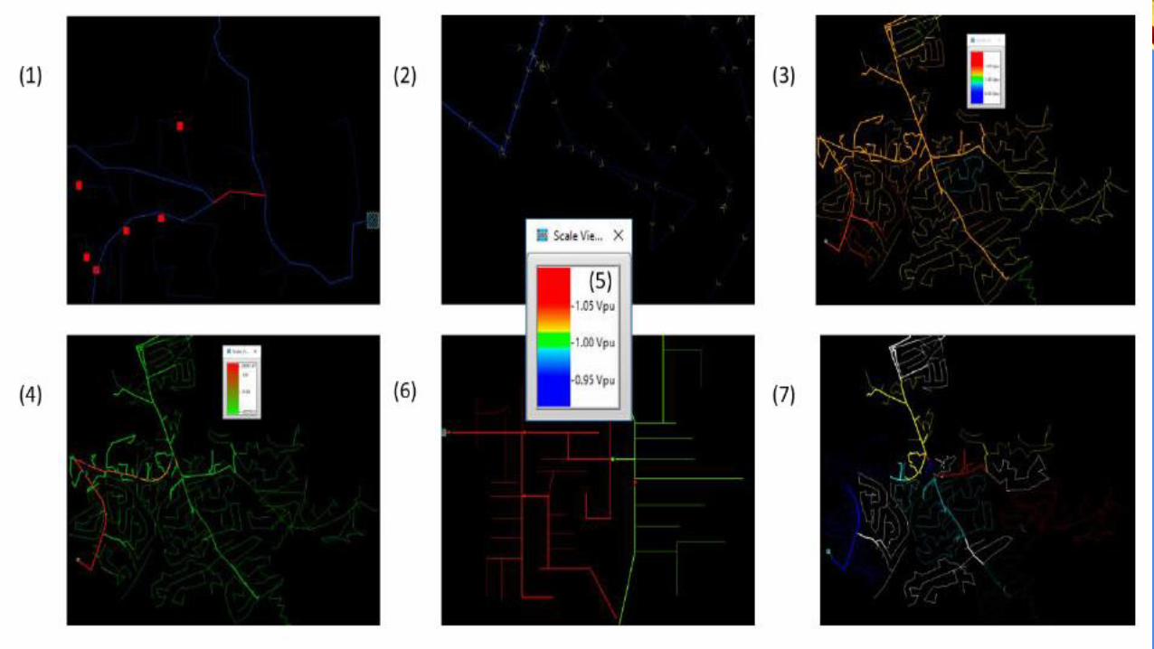
OPÇÕES DE VISUALIZAÇÃO DE RESULTADOS

• Exemplo para relatório