Voorblad - Telenet.beusers.telenet.be/abder/rommel/ait bouzid/Gip Finala5.doc · Web...
65
GEINTEGREERDE PROEF Voornaam en naam Maciej D’Andrea & Kevin Vanhove Onderwijsvorm TSO Studierichtin g Industriële ICT technieken Leerjaar zesde Schooljaar 2005-2006 Mentor Mr. Loos Microcontrollerbord via USB
Transcript of Voorblad - Telenet.beusers.telenet.be/abder/rommel/ait bouzid/Gip Finala5.doc · Web...
GEINTEGREERDE PROEF
Technisch Instituut Heilig Hart Hasselt
Voornaam en naam Maciej D’Andrea & Kevin VanhoveOnderwijsvorm TSOStudierichting Industriële ICT techniekenLeerjaar zesdeSchooljaar 2005-2006Mentor Mr. Loos
Voorwoord
Om op het zesde jaar secundair onderwijs te kunnen slagen moeten de studenten zich bewijzen aan de hand van een eindwerk. Dit eindwerk noemt men de geïntegreerde proef (GIP).
In de GIP zijn verschillende vakken geïntegreerd. Het doel van de GIP is het toepassen van de leerstof van de voorafgaande jaren in een groot project. Onze GIP opdracht bestaat uit het maken van een microcontrollerbordje met ATtiny2313.
Hierbij moeten we gebruik maken van een FTDI chip, meer bepaald de FT232BM.Onze printplaat hebben we ontworpen met het programma Eagle.
Maciej D’Andrea & Kevin Vanhove GIP 2005-2006 2
Microcontrollerbord via USB
Technisch Instituut Heilig Hart Hasselt
Inhoudsopgave
Voorwoord Inleiding Microcontrollerbord via usb
Rs232 Inleiding Rs232 Rs232 Pintoewijzing Rs232 fysieke eigenschappen Kabellengtes bij Rs232
USB Inleiding Eigenschappen Verschillende soorten USB Technische Eigenschappen
FT232BM Eigenschappen Inwendig Schema Technische Eigenschappen
ATtiny 2313 Eigenschappen Inwendig Schema Technische Eigenschappen ISP
Maciej D’Andrea & Kevin Vanhove GIP 2005-2006 3
2456678899910101111121316161718212223
2728282930303235404849
Technisch Instituut Heilig Hart Hasselt
Microcontrollerbord Schema
Board
Nederlands Brieven aanvraag informatie
Maciej D’Andrea Kevin Vanhove
Solicitatiebrieven & CV Maciej D’Andrea Kevin Vanhove
Frans Engels Dankwoord Bibliografie
Inleiding
De opdracht voor ons eindwerk met het microcontrollerbord was het omzetten van een usb naar rs232 signaal.Het verloop van de opdracht diende als volgt te gebeuren:
- Het bestuderen van de FTDI-chip (FT232BM).- Het bestuderen van de te gebruiken microcontroller (ATtiny2313)
- Het ontwerpen en tekenen van een schakeling met EAGLE om de microcontroller via usb en de FTDI-chip te programmeren.
- Het bouwen en testen van de schakeling. - Kennis verwerven van BASCOM om de microcontroller te programmeren. - Installeren van een serial device programmer (vb.Ponyprog)
- Een toepassing maken met de microcontroller.
Bij Nederlands is er aandacht besteed aan de communicatie tussen student en bedrijf. Er zijn zowel zakelijke als sollicitatiebrieven geschreven.
Bij Frans en Engels was er vooral aandacht voor het opzoeken van informatie in verschillende talen, deze te begrijpen en vragen hierover op te lossen.
Maciej D’Andrea & Kevin Vanhove GIP 2005-2006 4
Technisch Instituut Heilig Hart Hasselt
Microcontrollerbord via USB
Mentor: Mr. Loos
Maciej D’Andrea & Kevin Vanhove GIP 2005-2006 5
Technisch Instituut Heilig Hart Hasselt
1 Rs232
1.1 Inleiding Rs232
De RS232 standaard is één van de oudste communicatie standaarden in computer wereld. De standaard definieert een low-cost seriële communicatie op een robuuste wijze waar bits sequentieel over een koper leiding worden verstuurd. Origineel is de standaard ontworpen voor het aansluiten van apparatuur als computers, printers, terminals en dergelijke op modems. Dergelijke apparaten worden aangesloten via hun seriële poort. Op dit moment is de koppeling van twee computers onderling met een zogenaamde nulmodem kabel een veel gebruikte configuratie.
Maciej D’Andrea & Kevin Vanhove GIP 2005-2006 6
Technisch Instituut Heilig Hart Hasselt
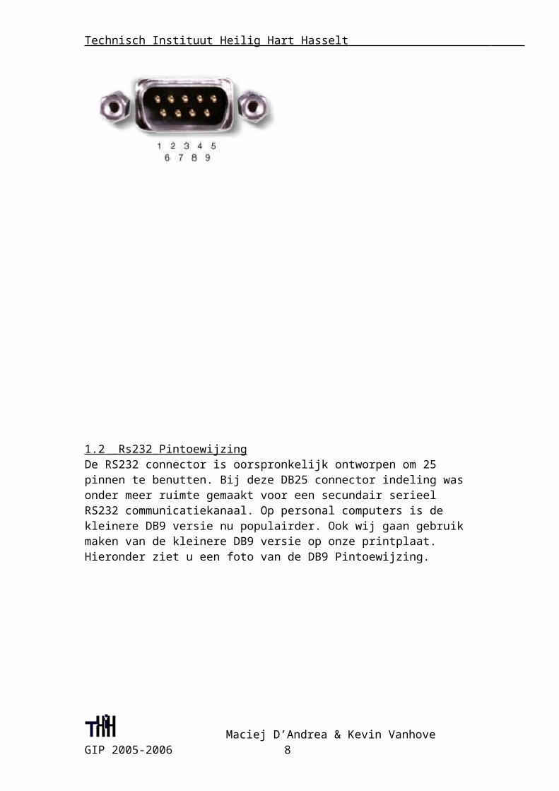
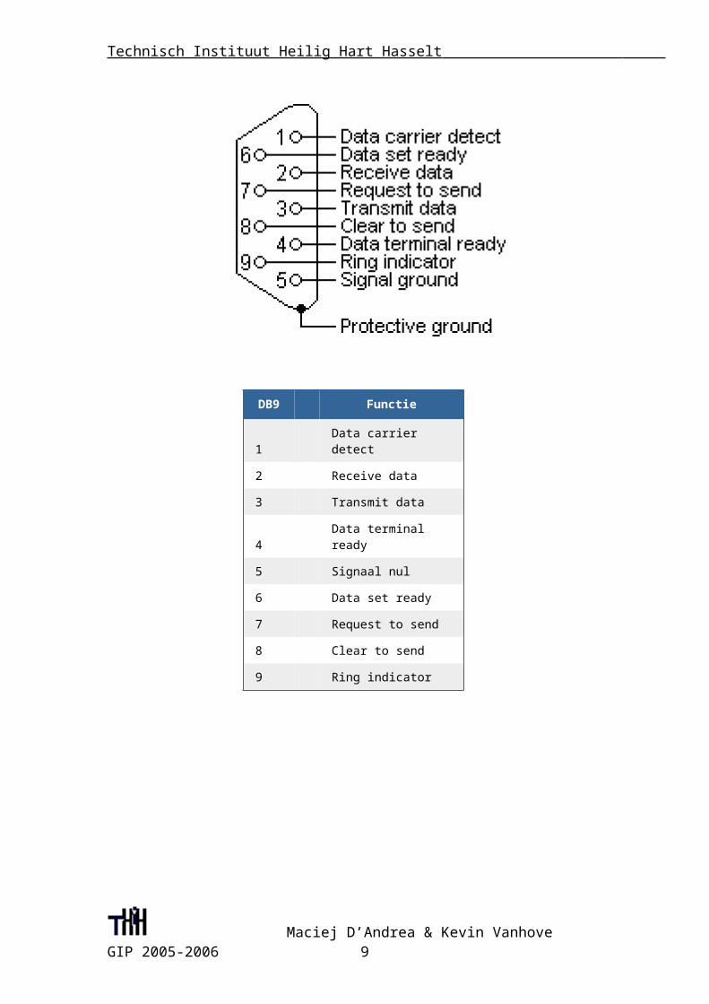
1.2 Rs232 Pintoewijzing De RS232 connector is oorspronkelijk ontworpen om 25 pinnen te benutten. Bij deze DB25 connector indeling was onder meer ruimte gemaakt voor een secundair serieel RS232 communicatiekanaal. Op personal computers is de kleinere DB9 versie nu populairder. Ook wij gaan gebruik maken van de kleinere DB9 versie op onze printplaat.Hieronder ziet u een foto van de DB9 Pintoewijzing.
Maciej D’Andrea & Kevin Vanhove GIP 2005-2006 7
Technisch Instituut Heilig Hart Hasselt
DB9 Functie
1 Data carrier detect2 Receive data3 Transmit data
4Data terminal ready
5 Signaal nul6 Data set ready7 Request to send8 Clear to send9 Ring indicator
1.3 Rs232 fysieke eigenschappen De RS232 standaard beschrijft een communicatiemethode waarmee het mogelijk is om te communiceren onder verschillende omstandigheden. Dit heeft invloed op de maximaal toelaatbare spanningen en dergelijke op de pinnen. In de originele definitie zijn de technische mogelijkheden van die tijd meegenomen. De maximale baudrate die gedefinieerd is bijvoorbeeld 20 kbps. Met tegenwoordige elektronica als de 16550A UART zijn maximale snelheden van 1,5 Mbps mogelijk
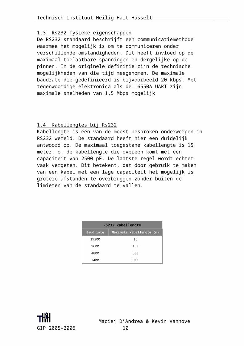
1.4 Kabellengtes bij Rs232 Kabellengte is één van de meest besproken onderwerpen in RS232 wereld. De standaard heeft hier een duidelijk antwoord op. De maximaal toegestane kabellengte is 15 meter, of de kabellengte die overeen komt met een capaciteit van 2500 pF. De laatste regel wordt echter vaak vergeten. Dit betekent, dat door gebruik te maken van een kabel met een lage capaciteit het mogelijk is grotere afstanden te overbruggen zonder buiten de limieten van de standaard te vallen.
Maciej D’Andrea & Kevin Vanhove GIP 2005-2006 8
Technisch Instituut Heilig Hart Hasselt
RS232 kabellengte
Baud rate Maximale kabellengte (m)
19200 15
9600 150
4800 300
2400 900
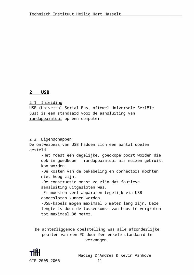
2 USB
2.1 Inleiding USB (Universal Serial Bus, oftewel Universele Seriële Bus) is een standaard voor de aansluiting van randapparatuur op een computer.
2.2 Eigenschappen De ontwerpers van USB hadden zich een aantal doelen gesteld:
-Het moest een degelijke, goedkope poort worden die ook in goedkope randapparatuur als muizen gebruikt kon worden.-De kosten van de bekabeling en connectors mochten niet hoog zijn.-De constructie moest zo zijn dat foutieve aansluiting uitgesloten was.-Er moesten veel apparaten tegelijk via USB aangesloten kunnen worden.-USB-kabels mogen maximaal 5 meter lang zijn. Deze lengte is door de tussenkomst van hubs te vergroten tot maximaal 30 meter.
De achterliggende doelstelling was alle afzonderlijke poorten van een PC door één enkele standaard te vervangen.
Maciej D’Andrea & Kevin Vanhove GIP 2005-2006 9
Technisch Instituut Heilig Hart Hasselt
2.3 Verschillende soorten USB -USB 1.0: 1,5 Mbit/s (low speed)-USB 1.1: 12 Mbit/s (full speed)-USB 2.0: 480 Mbit/s plug & play (high speed)
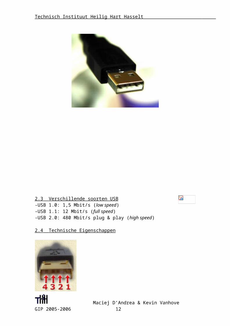
2.4 Technische Eigenschappen
De aansluitingen zijn:
Maciej D’Andrea & Kevin Vanhove GIP 2005-2006 10
Technisch Instituut Heilig Hart Hasselt
1. Vusb. Dit is een voedingsspanning. Apparaten die niet te veel stroom
gebruiken kunnen direct uit de bus gevoed worden.
2. D-. Dit is één van de twee signaal draden.
3. D+. Dit is de andere signaal draad.
4. GND.
Data wordt in één richting tegelijkertijd over de signaal draden gestuurd. Het signaal
is differentieel, een ‘1’ betekent dat D+ hoog is, en D- laag, terwijl een ‘0’ betekent
dat D+ laag is, en D- hoog. De data signalen zijn compatible met low-voltage (3.3V)
TTL.
Een speciaal geval is wanneer D+ en D- beide laag zijn. Dit wordt gebruikt om het
einde van een boodschap aan te geven, en om een reset signaal via de bus door te
geven.
Als de bus niet in gebruik is (idle) wordt D+ hoog gehouden, en D- wordt laag
gehouden. Als de bus langer dan 3ms achtereen idle is, moeten randapparaten in een
energie zuinige toestand gaan (suspend.) In de suspend toestand mag een apparaat niet
meer dan 500µA (gemiddeld) uit Vusb gebruiken.
3 FT232BM
3.1 Eigenschappen
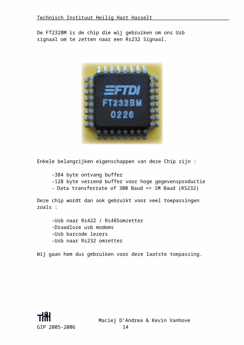
De FT232BM is de chip die wij gebruiken om ons Usb signaal om te zetten naar een Rs232 Signaal.
Maciej D’Andrea & Kevin Vanhove GIP 2005-2006 11
Technisch Instituut Heilig Hart Hasselt
Enkele belangrijken eigenschappen van deze Chip zijn :
-384 byte ontvang buffer-128 byte verzend buffer voor hoge gegevensproductie- Data transferrate of 300 Baud => 1M Baud (RS232)
Deze chip wordt dan ook gebruikt voor veel toepassingen zoals :
-Usb naar Rs422 / Rs485omzetter-Draadloze usb modems-Usb barcode lezers-Usb naar Rs232 omzetter
Wij gaan hem dus gebruiken voor deze laatste toepassing.
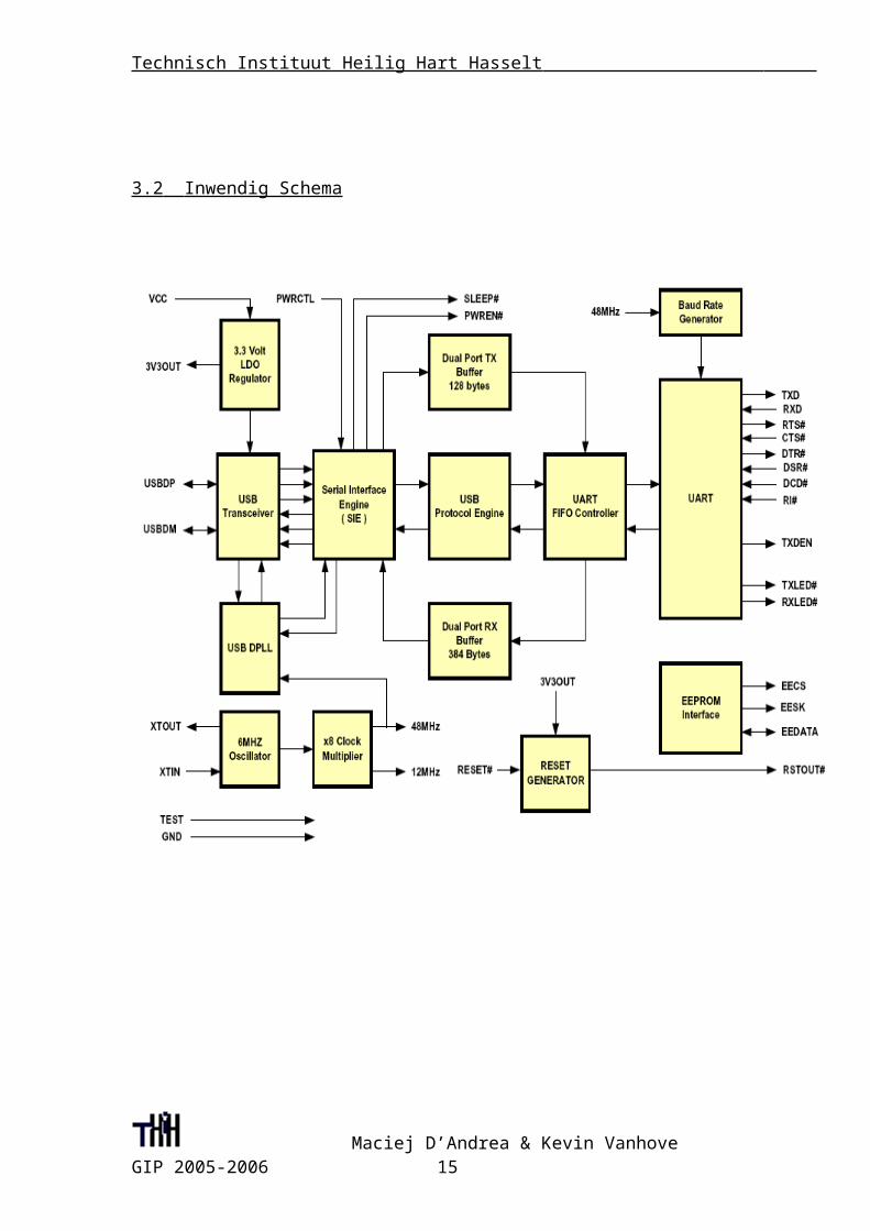
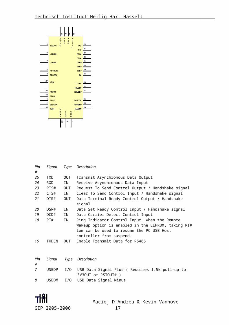
3.2 Inwendig Schema
Maciej D’Andrea & Kevin Vanhove GIP 2005-2006 12
Technisch Instituut Heilig Hart Hasselt
Maciej D’Andrea & Kevin Vanhove GIP 2005-2006 13
Technisch Instituut Heilig Hart Hasselt
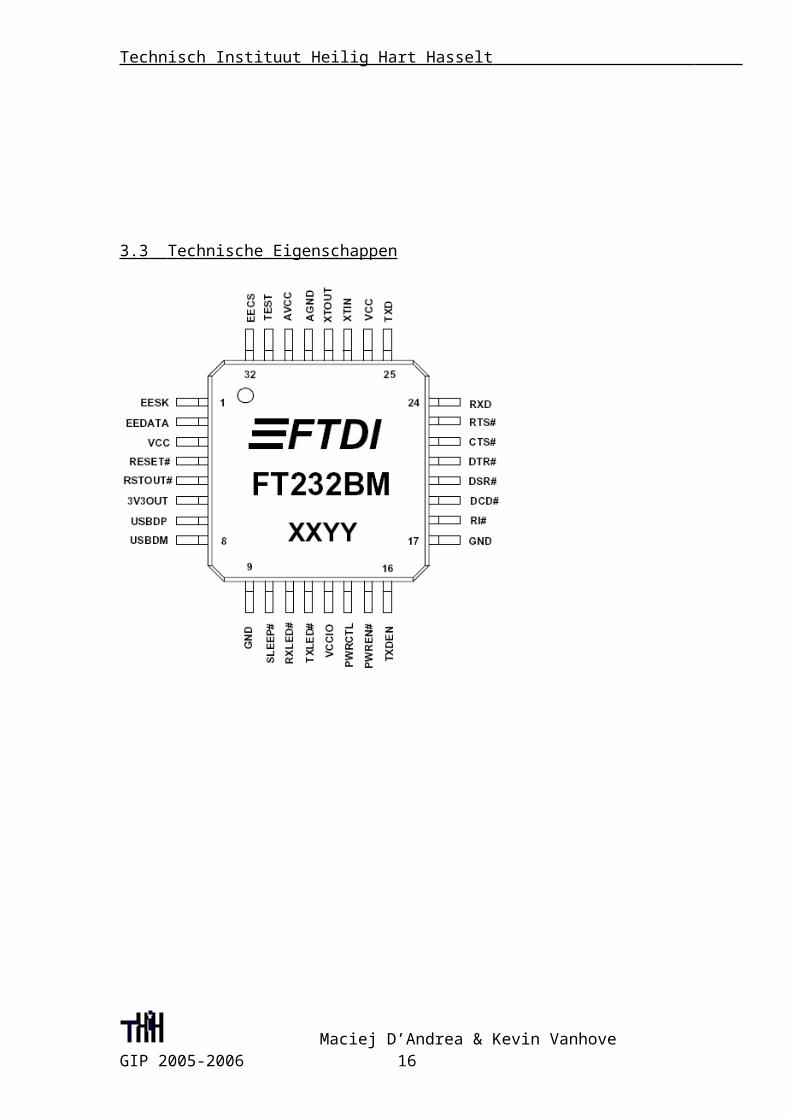
3.3 Technische Eigenschappen
Maciej D’Andrea & Kevin Vanhove GIP 2005-2006 14
Technisch Instituut Heilig Hart Hasselt
Pin# Signal Type Description25 TXD OUT Transmit Asynchronous Data Output24 RXD IN Receive Asynchronous Data Input23 RTS# OUT Request To Send Control Output / Handshake signal22 CTS# IN Clear To Send Control Input / Handshake signal21 DTR# OUT Data Terminal Ready Control Output / Handshake signal20 DSR# IN Data Set Ready Control Input / Handshake signal19 DCD# IN Data Carrier Detect Control Input18 RI# IN Ring Indicator Control Input. When the Remote Wakeup option is
enabled in the EEPROM, taking RI# low can be used to resume the PC USB Host controller from suspend.
16 TXDEN OUT Enable Transmit Data for RS485
Pin# Signal Type Description7 USBDP I/O USB Data Signal Plus ( Requires 1.5k pull-up to 3V3OUT or
RSTOUT# )8 USBDM I/O USB Data Signal Minus
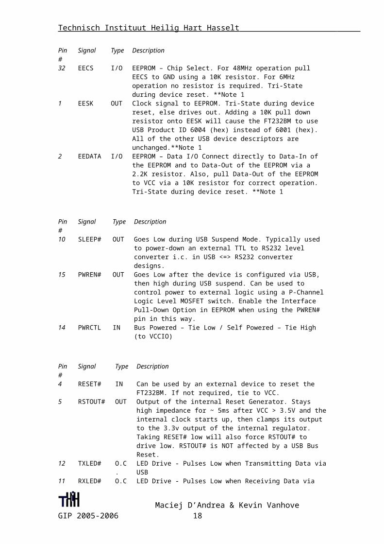
Pin# Signal Type Description32 EECS I/O EEPROM – Chip Select. For 48MHz operation pull EECS to GND
using a 10K resistor. For 6MHz operation no resistor is required. Tri-State during device reset. **Note 1
1 EESK OUT Clock signal to EEPROM. Tri-State during device reset, else drives out. Adding a 10K pull down resistor onto EESK will cause the FT232BM to use USB Product ID 6004 (hex) instead of 6001 (hex). All of the other USB device descriptors are unchanged.**Note 1
2 EEDATA I/O EEPROM – Data I/O Connect directly to Data-In of the EEPROM and to Data-Out of the EEPROM via a 2.2K resistor. Also, pull Data-Out of the EEPROM to VCC via a 10K resistor for correct operation. Tri-State during device reset. **Note 1
Pin# Signal Type Description10 SLEEP# OUT Goes Low during USB Suspend Mode. Typically used to power-
down an external TTL to RS232 level converter i.c. in USB <=> RS232 converter designs.
15 PWREN# OUT Goes Low after the device is configured via USB, then high during USB suspend. Can be used to control power to external logic using a P-Channel Logic Level MOSFET switch. Enable the Interface Pull-Down Option in EEPROM when using the PWREN# pin in this way.
14 PWRCTL IN Bus Powered – Tie Low / Self Powered – Tie High (to VCCIO)
Pin# Signal Type Description4 RESET# IN Can be used by an external device to reset the FT232BM. If not
required, tie to VCC.5 RSTOUT# OUT Output of the internal Reset Generator. Stays high impedance for
~ 5ms after VCC > 3.5V and the internal clock starts up, then clamps its output to the 3.3v output of the internal regulator. Taking RESET# low will also force RSTOUT# to drive low. RSTOUT# is NOT affected by a USB Bus Reset.
Maciej D’Andrea & Kevin Vanhove GIP 2005-2006 15
Technisch Instituut Heilig Hart Hasselt
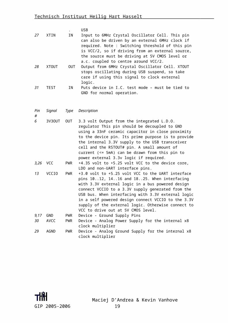
12 TXLED# O.C. LED Drive - Pulses Low when Transmitting Data via USB11 RXLED# O.C. LED Drive - Pulses Low when Receiving Data via USB27 XTIN IN Input to 6MHz Crystal Oscillator Cell. This pin can also be driven
by an external 6MHz clock if required. Note : Switching threshold of this pin is VCC/2, so if driving from an external source, the source must be driving at 5V CMOS level or a.c. coupled to centre around VCC/2.
28 XTOUT OUT Output from 6MHz Crystal Oscillator Cell. XTOUT stops oscillating during USB suspend, so take care if using this signal to clock external logic.
31 TEST IN Puts device in I.C. test mode – must be tied to GND for normal operation.
Pin# Signal Type Description6 3V3OUT OUT 3.3 volt Output from the integrated L.D.O. regulator This pin should
be decoupled to GND using a 33nF ceramic capacitor in close proximity to the device pin. Its prime purpose is to provide the internal 3.3V supply to the USB transceiver cell and the RSTOUT# pin. A small amount of current (<= 5mA) can be drawn from this pin to power external 3.3v logic if required.
3,26 VCC PWR +4.35 volt to +5.25 volt VCC to the device core, LDO and non-UART interface pins.
13 VCCIO PWR +3.0 volt to +5.25 volt VCC to the UART interface pins 10..12, 14..16 and 18..25. When interfacing with 3.3V external logic in a bus powered design connect VCCIO to a 3.3V supply generated from the USB bus. When interfacing with 3.3V external logic in a self powered design connect VCCIO to the 3.3V supply of the external logic. Otherwise connect to VCC to drive out at 5V CMOS level.
9,17 GND PWR Device - Ground Supply Pins30 AVCC PWR Device - Analog Power Supply for the internal x8 clock multiplier29 AGND PWR Device - Analog Ground Supply for the internal x8 clock multiplier
4 ATtiny 2313
4.1 Eigenschappen
Maciej D’Andrea & Kevin Vanhove GIP 2005-2006 16
Technisch Instituut Heilig Hart Hasselt
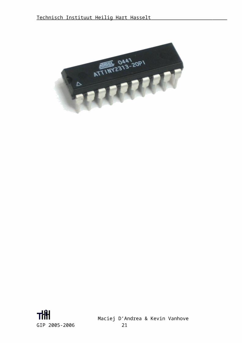
Wij gaan de ATtiny 2313 gebruiken als microcontroller voor ons project.De ATtiny 2313 is een low-power 8-bit microcontroller gebaseerd op de AVR RISC architectuur.Door krachtige instructies in één enkele klokpuls uit te voeren, bereikt de ATtiny 2313 producties rond 1 MIPS per Mhz en dat staat de systeemontwerper toe om power-consumption tegenover verwerkingssnelheid te optimaliseren.
Enkele Belangrijke eigenschappen:-High performance, Low power 8-bit microcontroller-Geavenceerde RISC architectuur
Maciej D’Andrea & Kevin Vanhove GIP 2005-2006 17
Technisch Instituut Heilig Hart Hasselt
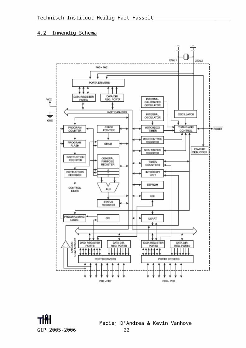
4.2 Inwendig Schema
Maciej D’Andrea & Kevin Vanhove GIP 2005-2006 18
Technisch Instituut Heilig Hart Hasselt
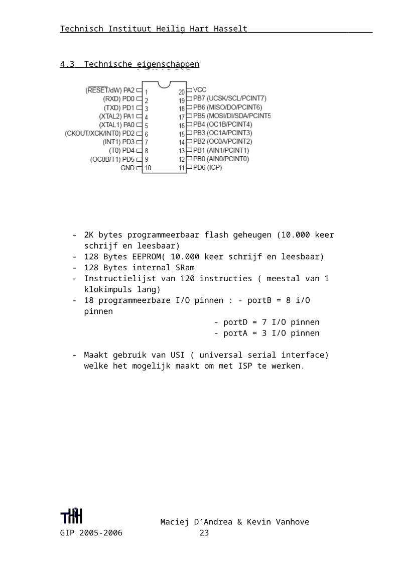
4.3 Technische eigenschappen
- 2K bytes programmeerbaar flash geheugen (10.000 keer schrijf en leesbaar)- 128 Bytes EEPROM( 10.000 keer schrijf en leesbaar)- 128 Bytes internal SRam- Instructielijst van 120 instructies ( meestal van 1 klokimpuls lang)- 18 programmeerbare I/O pinnen : - portB = 8 i/O pinnen
- portD = 7 I/O pinnen - portA = 3 I/O pinnen
- Maakt gebruik van USI ( universal serial interface) welke het mogelijk maakt om met ISP te werken.
Maciej D’Andrea & Kevin Vanhove GIP 2005-2006 19
Technisch Instituut Heilig Hart Hasselt
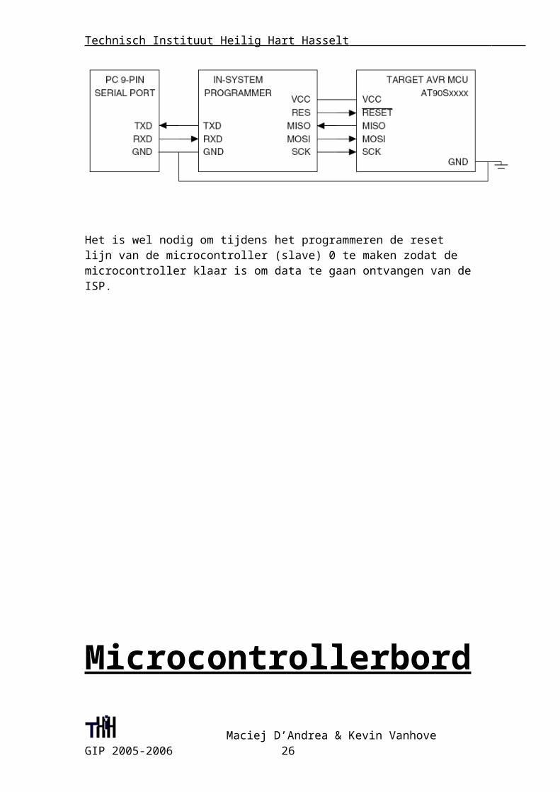
4.4 ISP
Isp is een systeem dat ervoor zorgt dat een Microcontroller geprogrammeerd kan worden terwijl hij nog in de toepassing aanwezig is . Voor ons zou dit dus betekenen dat hij nog steeds op de klok gemonteerd zou staan . In bedrijfstoepassingen kan hierdoor dus veel tijd (en dus ook geld) worden bespaard want de microcontroller moet niet steeds uit zijn toepassing gehaald worden om opnieuw geprogrammeerd te worden zodat hij een ander doel kan dienen.
Om de microcontroller te herprogrammeren zijn er enkel 3 draden nodig. Deze 3 draden gaan van de 9 pin seriële poort naar de ISP (In System Programmer). Omdat er maar zo weinig draden voor nodig zijn spreekt het vanzelf dat de datatransmissie serieel zal gebeuren.
De SPI interface bestaat uit 3 draden : De seriële klok (SCK), de master in – slave out (MISO) en de master out – slave in (MOSI). Als we de microcontroller willen gaan programmeren dan zal de In-system programmer altijd fungeren als Master en de microcontroller als Slave. De ISP zorgt voor de klok die de communicatie mogelijk maakt (op de SCK lijn). Bij elke puls op de SCK (klok) lijn zal er 1 bit worden overgedragen van de master naar de slave (op de MOSI lijn) en gelijktijdig een bit teruggestuurd van de slave naar de master (over de MISO lijn).
Het is wel nodig om tijdens het programmeren de reset lijn van de microcontroller (slave) 0 te maken zodat de microcontroller klaar is om data te gaan ontvangen van de ISP.
Maciej D’Andrea & Kevin Vanhove GIP 2005-2006 21
Technisch Instituut Heilig Hart Hasselt
Microcontrollerbord
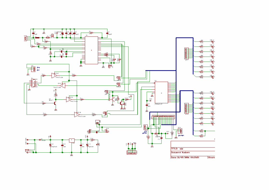
5.1 Schema
Maciej D’Andrea & Kevin Vanhove GIP 2005-2006 22

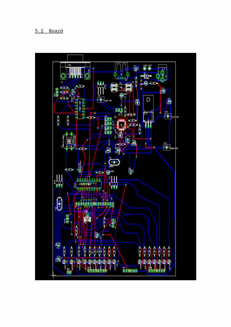
5.2 Board
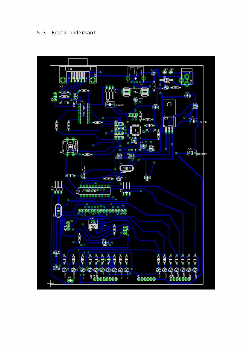
5.3 Board onderkant
Technisch Instituut Heilig Hart Hasselt
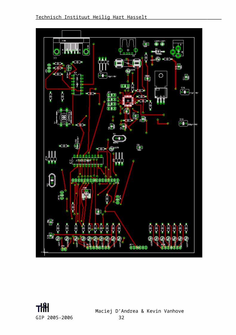
5.4 Board bovenkant
Maciej D’Andrea & Kevin Vanhove GIP 2005-2006 26
Technisch Instituut Heilig Hart Hasselt
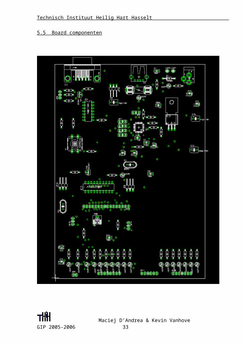
5.5 Board componenten
Maciej D’Andrea & Kevin Vanhove GIP 2005-2006 27
Technisch Instituut Heilig Hart Hasselt
Nederlands
Leerkracht: Mr. Janssens
Maciej D’Andrea & Kevin Vanhove GIP 2005-2006 28
Technisch Instituut Heilig Hart Hasselt
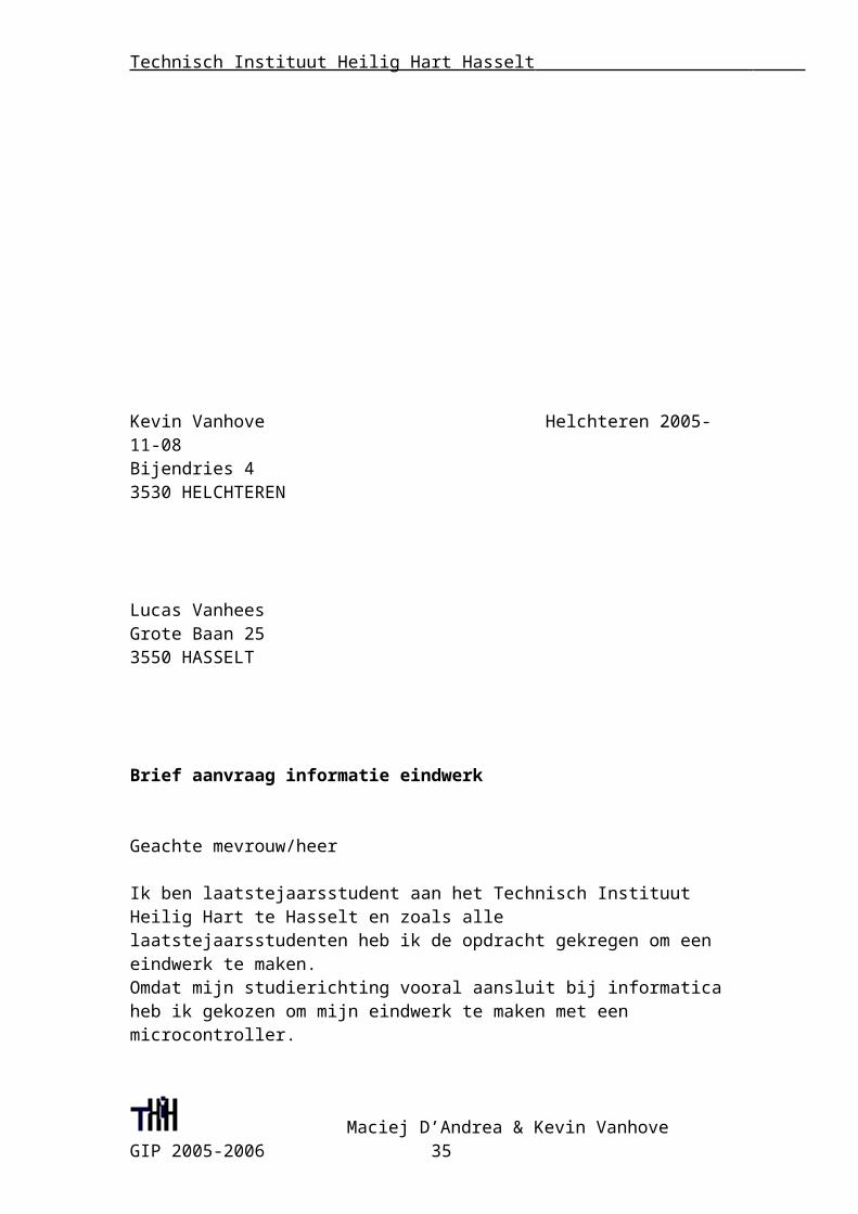
Kevin Vanhove Helchteren 2005-11-08Bijendries 43530 HELCHTEREN
Lucas VanheesGrote Baan 253550 HASSELT
Brief aanvraag informatie eindwerk
Geachte mevrouw/heer
Ik ben laatstejaarsstudent aan het Technisch Instituut Heilig Hart te Hasselt en zoals alle laatstejaarsstudenten heb ik de opdracht gekregen om een eindwerk te maken.Omdat mijn studierichting vooral aansluit bij informatica heb ik gekozen om mijn eindwerk te maken met een microcontroller.
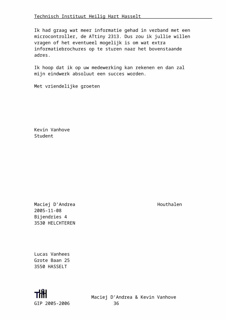
Ik had graag wat meer informatie gehad in verband met een microcontroller, de ATtiny 2313. Dus zou ik jullie willen vragen of het eventueel mogelijk is om wat extra informatiebrochures op te sturen naar het bovenstaande adres.
Ik hoop dat ik op uw medewerking kan rekenen en dan zal mijn eindwerk absoluut een succes worden. Met vriendelijke groeten
Kevin VanhoveStudent
Maciej D’Andrea & Kevin Vanhove GIP 2005-2006 29
Technisch Instituut Heilig Hart Hasselt
Maciej D’Andrea Houthalen 2005-11-08Bijendries 43530 HELCHTEREN
Lucas VanheesGrote Baan 253550 HASSELT
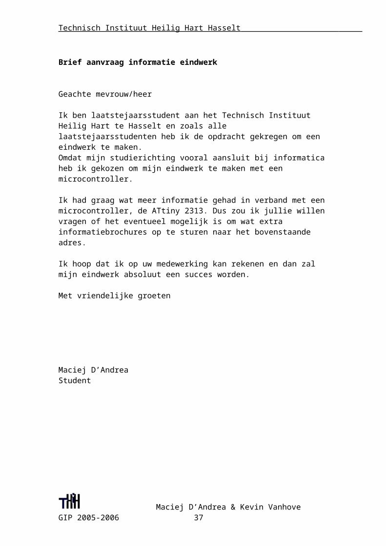
Brief aanvraag informatie eindwerk
Geachte mevrouw/heer
Ik ben laatstejaarsstudent aan het Technisch Instituut Heilig Hart te Hasselt en zoals alle laatstejaarsstudenten heb ik de opdracht gekregen om een eindwerk te maken.Omdat mijn studierichting vooral aansluit bij informatica heb ik gekozen om mijn eindwerk te maken met een microcontroller.
Ik had graag wat meer informatie gehad in verband met een microcontroller, de ATtiny 2313. Dus zou ik jullie willen vragen of het eventueel mogelijk is om wat extra informatiebrochures op te sturen naar het bovenstaande adres.
Ik hoop dat ik op uw medewerking kan rekenen en dan zal mijn eindwerk absoluut een succes worden. Met vriendelijke groeten
Maciej D’AndreaStudent
Maciej D’Andrea & Kevin Vanhove GIP 2005-2006 30
Technisch Instituut Heilig Hart Hasselt
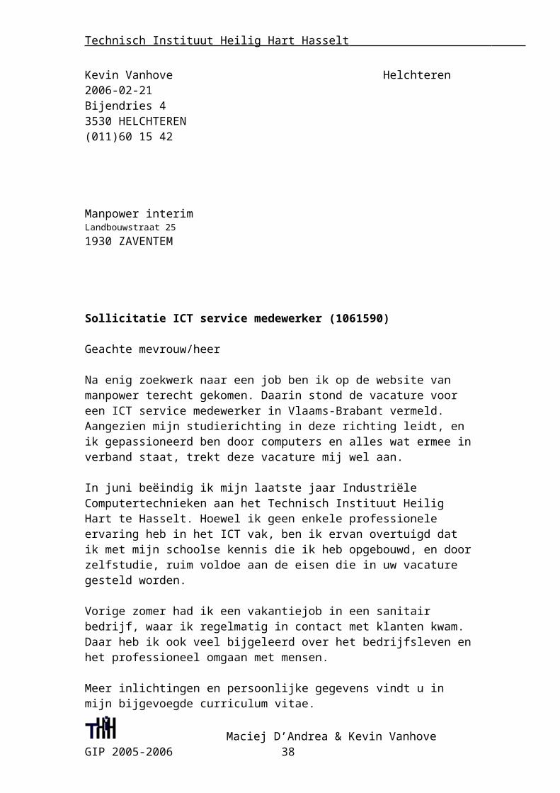
Kevin Vanhove Helchteren 2006-02-21Bijendries 43530 HELCHTEREN(011)60 15 42
Manpower interimLandbouwstraat 251930 ZAVENTEM
Sollicitatie ICT service medewerker (1061590)
Geachte mevrouw/heer
Na enig zoekwerk naar een job ben ik op de website van manpower terecht gekomen. Daarin stond de vacature voor een ICT service medewerker in Vlaams-Brabant vermeld. Aangezien mijn studierichting in deze richting leidt, en ik gepassioneerd ben door computers en alles wat ermee in verband staat, trekt deze vacature mij wel aan.
In juni beëindig ik mijn laatste jaar Industriële Computertechnieken aan het Technisch Instituut Heilig Hart te Hasselt. Hoewel ik geen enkele professionele ervaring heb in het ICT vak, ben ik ervan overtuigd dat ik met mijn schoolse kennis die ik heb opgebouwd, en door zelfstudie, ruim voldoe aan de eisen die in uw vacature gesteld worden.
Vorige zomer had ik een vakantiejob in een sanitair bedrijf, waar ik regelmatig in contact met klanten kwam. Daar heb ik ook veel bijgeleerd over het bedrijfsleven en het professioneel omgaan met mensen.
Meer inlichtingen en persoonlijke gegevens vindt u in mijn bijgevoegde curriculum vitae.
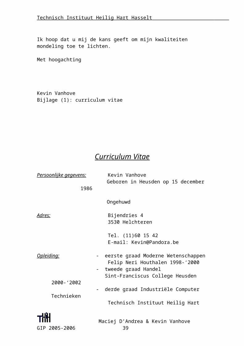
Ik hoop dat u mij de kans geeft om mijn kwaliteiten mondeling toe te lichten.
Met hoogachting
Maciej D’Andrea & Kevin Vanhove GIP 2005-2006 31
Technisch Instituut Heilig Hart Hasselt
Kevin VanhoveBijlage (1): curriculum vitae
Curriculum Vitae
Persoonlijke gegevens: Kevin Vanhove Geboren in Heusden op 15 december 1986
Ongehuwd
Adres: Bijendries 4 3530 Helchteren
Tel. (11)60 15 42 E-mail: [email protected]
Opleiding: - eerste graad Moderne Wetenschappen Felip Neri Houthalen 1998-‘2000
- tweede graad Handel Sint-Franciscus College Heusden 2000-‘2002
- derde graad Industriële Computer Technieken Technisch Instituut Heilig Hart Hasselt 2002-‘2006
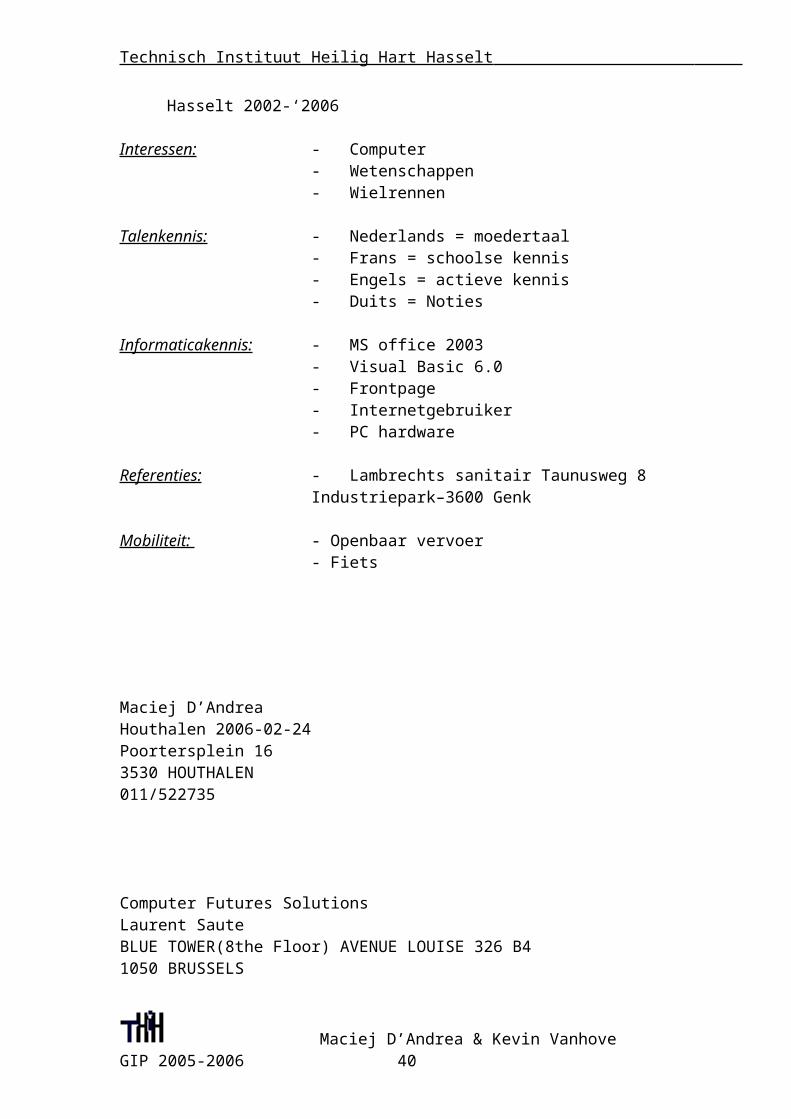
Interessen: - Computer- Wetenschappen- Wielrennen
Talenkennis: - Nederlands = moedertaal- Frans = schoolse kennis- Engels = actieve kennis- Duits = Noties
Informaticakennis: - MS office 2003- Visual Basic 6.0- Frontpage- Internetgebruiker- PC hardware
Referenties: - Lambrechts sanitair Taunusweg 8 Industriepark–3600 Genk
Mobiliteit: - Openbaar vervoer
Maciej D’Andrea & Kevin Vanhove GIP 2005-2006 32
Technisch Instituut Heilig Hart Hasselt
- Fiets
Maciej D’Andrea Houthalen 2006-02-24 Poortersplein 16 3530 HOUTHALEN 011/522735
Computer Futures Solutions Laurent Saute BLUE TOWER(8the Floor) AVENUE LOUISE 326 B4 1050 BRUSSELS
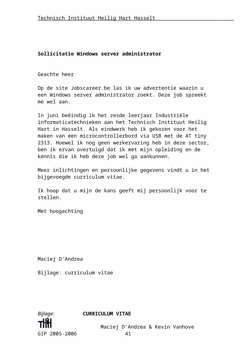
Sollicitatie Windows server administrator
Geachte heer
Op de site Jobscareer.be las ik uw advertentie waarin u een Windows server administrator zoekt. Deze job spreekt me wel aan.
In juni beëindig ik het zesde leerjaar Industriële informaticatechnieken aan het Technisch Instituut Heilig Hart in Hasselt. Als eindwerk heb ik gekozen voor het maken van een microcontrollerbord via USB met de AT tiny 2313. Hoewel ik nog geen werkervaring heb in deze sector, ben ik ervan overtuigd dat ik met mijn opleiding en de kennis die ik heb deze job wel ga aankunnen.
Meer inlichtingen en persoonlijke gegevens vindt u in het bijgevoegde curriculum vitae.
Ik hoop dat u mijn de kans geeft mij persoonlijk voor te stellen.
Met hoogachting
Maciej D’Andrea
Maciej D’Andrea & Kevin Vanhove GIP 2005-2006 33

Technisch Instituut Heilig Hart Hasselt
Bijlage: curriculum vitae
Bijlage: CURRICULUM VITAE
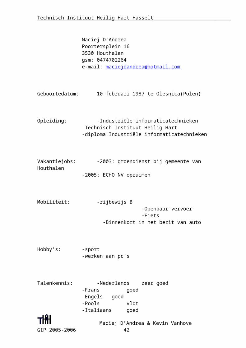
Maciej D’Andrea Poortersplein 16 3530 Houthalen gsm: 0474702264 e-mail: [email protected]
Geboortedatum: 10 februari 1987 te Olesnica(Polen)
Opleiding: -Industriële informaticatechnieken Technisch Instituut Heilig Hart -diploma Industriële informaticatechnieken
Vakantiejobs: -2003: groendienst bij gemeente van Houthalen -2005: ECHO NV opruimen
Mobiliteit: -rijbewijs B -Openbaar vervoer -Fiets
-Binnenkort in het bezit van auto
Hobby’s: -sport -werken aan pc’s
Talenkennis: -Nederlands zeer goed -Frans goed -Engels goed -Pools vlot -Italiaans goed
Maciej D’Andrea & Kevin Vanhove GIP 2005-2006 34
Technisch Instituut Heilig Hart Hasselt
Informaticakennis: -MS Word goede beheersing -Excel goede beheersing -Visual Basic goede beheersing -Windows zeer goede beheersing
Frans
Leerkracht: Mevr. Monteyne
Maciej D’Andrea & Kevin Vanhove GIP 2005-2006 35
Technisch Instituut Heilig Hart Hasselt
Naam: D’Andrea Maciej & Vanhove Kevin Klas: 6T-IT Vak: Frans
Gip Frans
1) Texte
Universal Serial Bus & RS 232L'Universal Serial Bus (USB) est un bus informatique plug-and-play servant à brancher des périphériques informatiques à un ordinateur pour communiquer en série.
Usage
L'USB a été conçu au milieu des années 1990 afin de remplacer les nombreux ports externes d'ordinateur lents et incompatibles, notamment les ports série et parallèle. L'USB est aujourd'hui présent sur tous les ordinateurs et est généralement utilisé pour brancher les imprimantes, les scanners, les modems et de nombreux appareils stockant des données, dont les clés USB.
Spécifications techniques
L'Universal Serial Bus est un bus informatique qui permet de connecter des périphériques externes à un ordinateur (hôte dans la littérature USB). Il supporte le branchement simultané de 127 périphériques, en série. Le bus supporte les branchements et débranchements à chaud (sans avoir besoin de redémarrer l'ordinateur) et fournit l'alimentation électrique des périphériques, dans la limite des 500mA.
La version 1.1 du bus peut communiquer dans deux modes : lent (1,5 Mbit/s) ou rapide (12 Mbit/s).
Le mode lent permet de connecter des périphériques qui ont besoin de transférer peu de données, comme les claviers et souris.
Le mode rapide est utilisé pour connecter des imprimantes, scanners, disques durs, graveurs de CD et autres périphériques ayant besoin de plus de rapidité. Néanmoins il est insuffisant pour beaucoup de périphériques de stockage de
Maciej D’Andrea & Kevin Vanhove GIP 2005-2006 36
Technisch Instituut Heilig Hart Hasselt
masse (par exemple, il ne permet que la vitesse 4x sur les lecteurs/graveurs de CD).
La nouvelle version de ce bus, USB 2.0, comporte un troisième mode permettant de communiquer à 480 Mbit/s. Il est utilisé par les périphériques rapides : disques durs, graveurs, etc. On appelle maintenant (depuis fin 2002) « USB 2.0 » tout dispositif USB, même à la norme 1.1 :
USB 2.0 Full Speed pour un dispositif transmettant au maximum à 12 Mbit/s (ex USB 1.1).
USB 2.0 High Speed pour un dispositif transmettant jusqu'à 480 Mbit/s (ex USB 2.0).
Les logos apposés sur le dispositif diffèrent. Voir les détails sur le site http://www.usb.org
Utilisation concrète
Le bus USB supporte un protocole plug-and-play (« branchez et utilisez »). Dès la connexion, l'hôte lit certaines informations sur le périphérique. Celles-ci lui permettent d'identifier le périphérique (type, constructeur, nom, version) et donc facilitent le travail du système pour déterminer le driver le plus approprié.
L'hôte communique successivement avec chaque périphérique, le débit total est donc partagé entre l'ensemble des périphériques. Il est possible d'attribuer à certains périphériques un débit constant pour une période de temps. Le reste du débit est toujours attribué de façon équitable entre les autres périphériques.
Une autre caractéristique du protocole USB est la possibilité de structurer la communication entre un hôte et un périphérique en plusieurs canaux logiques pour simplifier la commande du périphérique. Par exemple sur un disque dur USB, il est commode de disposer d'un canal pour passer les commandes (lire/écrire secteur n, formater secteur n) et d'un autre séparé pour passer les données (contenu du secteur).
Le bus USB reste un bus externe lent et ne peut pas entrer en concurrence avec des bus internes comme les bus PCI ou bus AGP.
Voici la fonction des pins décrites ci-dessous :
1) Alimentation +5V (VBUS) 100mA maximum 2) Données (D-) 3) Données (D+) 4) Masse (GND)
Rs232 : RS 232 est dû bien connu à la popularité des PCS d'aujourd'hui, à la différence du RS422 et du RS 485. Ceux-ci sont employés dans l'industrie pour des transferts desystèmes et de données de commande (petits volumes, AUCUNES centaines de mbs). Ainsi, quelle est la différence principale entre RS 232 et RS 422 et 485 ? Les signaux de RS 232 sont représentés par des niveaux de tension en ce qui concerne la terre. Il y a un fil pour chaque signal, en même temps que le signal au sol (référence pour des niveaux de tension). Cette interface est utile pour que le point dirige la
Maciej D’Andrea & Kevin Vanhove GIP 2005-2006 37
Technisch Instituut Heilig Hart Hasselt
communication aux vitesses réduites. Par exemple, le port COM1 dans un PC peut être employé pour une souris, port COM2 pour un modem, etc... C'est un exemple du point pour diriger la communication : un port, un dispositif. En raison de la manière les signaux sont reliés, une terre commune est exigée. Ceci implique la longueur de câble limitée - environ 30 à 60 mètres de maximum. (les problèmes principaux sont interférence et résistance du câble.) sous peu, RS 232 a été conçu pour la communication des dispositifs locaux, et appuis un émetteur et un récepteur. Utilisations de RS 422 et 485 un principe différent : Chaque signal emploie une ligne du twistedpair (TP) - deux fils tordus autour d'eux-mêmes. Nous parlons 'la transmission de données équilibrée ', ou 'transmission différentielle de tension '. implément, marquons un des fils 'A 'et l'autre un 'B 'de TP. Puis, le signal est inactif quand la tension à A est négative et la tension à B est positive. Autrement, le signal est en activité, A est positif et B est négatif. Naturellement, la différence entre les fils A et B importe. Pour RS 422 et 485 le câble peut être de jusqu'à 1200 mètres (4000 pieds) de long, et les circuits généralement disponibles fonctionnent au mb 2.5taux de transfert de s. Quelle est la différence entre RS 422 et RS 485 ? Le principe électrique est identique : employez les émetteurs différentiels avec les tensions alternatives 0 et 5V. Cependant, RS 422 est prévu pour que le point dirige des communications, comme RS 232. Utilisations de RS 422 deux fils séparés de TP, des données peuvent être transférées dans les deux directions simultanément. RS 422 est souvent employé pour prolonger une ligne de RS 232, ou dans les environnements industriels. RS 485 est employé pour des communications multipoint : plus de dispositifs peuvent être reliés à un câble simple designal - semblable à e.g. Réseaux ETHERNET, ce qui emploient le câble coaxial. La plupart de maître d'utilisation de systèmes de RS 485Architecture slave, là où chaque unité slave a son adresse unique et répond seulement aux paquets adressés à cette unité. Ces paquets sont produits par Master (e.g. PC), le quel vote périodiquement toutes les unités slaves reliées. Cet article couvrira principalement le maître Architecture slave parce qu'il est suffisant pour 95% d'applications. Dans des cas spéciaux (systèmes de sécurité, ...), une version améliorée de communication de multiprocesseur est employée. Ce système emploie seulement une ligne simple pour la communication bidirectionnelle ; cependant, il n'y a aucun maître. Toutes les unités annoncent une transmission de paquet d'une longueur indiquée, et écoutez en même temps si les données ont été avec succès transmises. Si ce n'est pas le cas, ils cessent de communiquer et détectent à l'oreille ce qui s'est produit. Actuellement, des paquets pressants peuvent être transmis au-dessus de la ligne. Ce système est idéal pour des dispositifs, ce besoin de transférer immédiatement quelques données très importantes et à jour, sans maître d'attente pour leur donner une chance de faire ainsi. De l'autre côté, le transfert de données utile est moins efficace (environ 30% moinsefficace que le premier système). Dans Le Maître Architecture slave, slave ne commence jamais la communication. Il est critique pour que le maître envoie des adresses correctes. RS 485 existe dans deux versions : 1 TwistedPair ou 2 TwistedPairs. TwistedPair Simple RS 485 Dans cette version, tous les dispositifs sont reliés à un TwistedPair simple. Ainsi, tous doivent avoir des conducteurs avec les sorties de trois états (maître y compris). La communication va au-dessus de la ligne simple dans les deux directions. Il est important d'empêcher plus de dispositifs de transmettre immédiatement (problème logiciel). Double TwistedPair RS 485 Ici, Le maître ne doit pas avoir le rendement de trois états, puisque les dispositifs Slaves transmettent l'excédent le deuxième twistedpair, ce qui est prévu pour envoyer des données de
Maciej D’Andrea & Kevin Vanhove GIP 2005-2006 38
Technisch Instituut Heilig Hart Hasselt
Slave au maître. Cette solution laisse souvent mettre en application la communication multipoint dans les systèmes, ce qui ont été à l'origine conçus (HW aussi bien que le commutateur) pour RS232. Naturellement, Le logiciel principal doit être modifié, de sorte que le maître envoie périodiquement des paquets de question à tous les dispositifs Slaves. Le flux de données accru est évident en grands volumes. Parfois vous pouvez voir un système de RS 485 dans un point pourdiriger le système. Il est pratiquement identique à RS 422 ; l'état élevé d'impédance du conducteur produit de RS 485 n'est pas employé. La seule différence dans le matériel des circuits de RS 485 et de RS422 est la capacité de placer le rendement à l'état élevé d'impédance.
2) Expliquez brièvement pourquoi vous avez choisi ce texte-là.J'ai choisi ce texte parce que ma tâche intégrée est au sujet du USB et Rs232.Ma tâche est de trasformer un signal USB vers un signal Rs322. Je pense que vous pouvez imaginer après avoir lis ce texte ce qui est la signification de mon charge et comment elle doit être faite.
3) Notez 15 mots difficile de votre texte.
Verbe :
1)brancher : aansluiten2)répond(repondre) : antwoorden3)relier : verbinden
Substantifs :
4)l'alimentation : de voeding5)des canaux : de kanalen6)la comparaison : de vergelijking7)le protocole : het protocol8)les imprimantes : de printers9)l'hôte : de gastheer10)un dispositif : een hulpmiddel
Adjectif :
11)suffisamment : voldoende12)efficace : effectief13)périodiquement : periodiek14)disponibles : beschikbaar
Maciej D’Andrea & Kevin Vanhove GIP 2005-2006 39
Technisch Instituut Heilig Hart Hasselt
15)facultatif : facultatief
4) Traduisez 10 phrases en néerlandais.
1)En raison de la manière les signaux sont reliés, une terre commune est exigée.- Door de manier waarop de signalen verbonden zijn, is een gemeenschappelijke grond noodzakelijk
2) Le mode rapide est utilisé pour connecter des imprimantes, scanners, disques durs, graveurs de CD et autres périphériques ayant besoin de plus de rapidité.
- De snelle manier wordt gebruikt om printers, scanners, harde schijven, graveurs van CD en andere randapparatuur aan te sluiten die meer snelheid nodig hebben.
3) Il est critique pour que le maître envoie des adresses correctes.- Het is noodzakelijk voor de “master” het correcte adres te versturen.
4) Le bus USB supporte le protocole plug-and-play (branchez et utilisez )- De USB bus ondersteunt het protocol plug-and-play (aansluiten en
gebruiken).5) Le principe électrique est identique : employez les émetteurs différentiels avec les tensions alternatives 0 et 5V.
- Het elektrische principe is hetzelfde: beide gebruiken differentiële verzenders met wisselende spanningen van 0 en 5V.
6) RS 232 est dû bien connu à la popularité des PCS d'aujourd'hui.- RS 232 is goed gekend dankzij de populariteit van de hedendaagse
computers.7) RS 422 est souvent employé pour prolonger une ligne de RS 232.
-RS 422 wordt vaak gebruikt om een Rs232 kabel te verlengen.8) Néanmoins il est insuffisant pour beaucoup de périphériques.
- Niettemin is hij onbruikbaar voor veel randapparatuur.
9) Ainsi, quelle est la différence principale entre RS 232 et RS 422- Dus, wat is het grote verschil tussen RS 232 en RS 422?
10) Il est utilisé par les périphériques rapides : disques durs, graveurs, etc.- Hij wordt gebruikt door de snelle randapparatuur: harde schijven, schrijvers,
enz.
5) Posez 3 questions en français sur votre texte.
1) Quand usb a-t-il été inventé ?- L'USB a été conçu au milieu des années 1990.
2) Dans combien de versions RS 485 existe-t-il?- RS 485 existe dans deux versions : 1 TwistedPair ou 2 TwistedPairs
3) Quelle protocole usb soutenu?-Le protocole « plug & play »
Maciej D’Andrea & Kevin Vanhove GIP 2005-2006 40
Technisch Instituut Heilig Hart Hasselt
Engels
Leerkracht : Mr.Janssens
Maciej D’Andrea & Kevin Vanhove GIP 2005-2006 41
Technisch Instituut Heilig Hart Hasselt
Naam: D’Andrea Maciej & Vanhove Kevin Klas: 6T-IT Vak: Engels
GIP Engels
Universal Serial Bus Universal Serial Bus (USB) provides a serial bus standard for connecting devices, usually to computers such as PCs and the Apple Macintosh, but is also becoming commonplace on video game consoles such as Microsoft's Xbox 360, Nintendo's Revolution, Sony's PlayStation 2, and PDAs, and even devices like televisions and home stereo equipment.OverviewA USB system has an asymmetric design, consisting of a host controller and multiple daisy-chained devices. Additional USB hubs may be included in the chain, allowing branching into a tree structure, subject to a limit of 5 levels of branching per controller. Not more than 127 devices, including the bus devices, may be connected to a single host controller. Modern computers often have several host controllers, allowing a very large number of USB devices to be connected. USB cables do not need to be terminated. USB 2 uses bursts, unlike FireWire.Despite the capability of daisy-chaining several USB devices and that early USB announcements foresaw that each future USB device could replicate the USB port on itself and allow for a long chain of devices, this was never widespread for economical and technical reasons, and typically only USB hubs actually replicate and multiply USB ports, thus making most USB devices effectively "consuming" an USB port, disallowing daisychaining or shared use.USB was designed to allow peripherals to be connected without the need to plug expansion cards into the computer's ISA, EISA, or PCI bus, and to improve plug-and-play capabilities by allowing devices to be hot-swapped (connected or disconnected without powering down or rebooting the computer). When a device is first connected, the host enumerates and recognises it, and loads the device driver it needs.USB can connect peripherals such as mice, keyboards, gamepads and joysticks, scanners, digital cameras, printers, external storage, networking components, etc. For many devices such as scanners and digital cameras, USB has become the standard connection method. USB is also used extensively to connect non-networked printers, replacing the parallel ports which were widely used; USB simplifies connecting several printers to one computer. As of 2004 there were about 1 billion USB devices in the world. As of 2005, the only large classes of peripherals that cannot use USB, because they need a higher data rate than USB can provide, are displays and monitors, and high-quality digital video components.
Maciej D’Andrea & Kevin Vanhove GIP 2005-2006 42
Technisch Instituut Heilig Hart Hasselt
StandardizationThe design of USB is standardized by the USB Implementers Forum (USB-IF), an industry standards body incorporating leading companies from the computer and electronics industries. Notable members have included Apple Computer, Hewlett-Packard, NEC, Microsoft, Intel, and Agere.The USB specification is at version 2.0 (with revisions) as of March 2006. Hewlett-Packard, Intel, Lucent, Microsoft, NEC, and Philips jointly led the initiative to develop a higher data transfer rate than the 1.1 specification. The USB 2.0 specification was released in April 2000 and was standardized by the USB-IF at the end of 2001. Previous notable releases of the specification were 0.9, 1.0, and 1.1. Equipment conforming with any version of the standard will also work with devices designed to any of the previous specifications (backwards compatibility).Smaller USB plugs and receptacles, called Mini-A and Mini-B, are also available, as specified by the On-The-Go Supplement to the USB 2.0 Specification. The specification is at revision 1.0a (Jan 2006).Technical detailsUSB connects several devices to a host controller through a chain of hubs. In USB terminology devices are referred to as functions, because in theory what we know as a device may actually host several functions, such as a router that is a Secure Digital Card reader at the same time. The hubs are special purpose devices that are not officially considered functions. There always exists one hub known as the root hub, which is attached directly to the host controller.USB endpoints actually reside on the connected device: the channels to the host is referred to as a pipeThese devices/functions (and hubs) have associated pipes (logical channels) which are connections from the host controller to a logical entity on the device named an endpoint. The pipes are synonymous to byte streams such as in the pipelines of Unix, however the term endpoint is also (sloppily) used to mean the entire pipe, even in the standard USB documentation.These endpoints (and their respective pipes) are numbered 0-15 in each direction, so a device/function can have up to 32 active pipes, 16 inward and 16 outward. (The OUT direction shall be interpreted out of the host controller and the IN direction is into the host controller.)Each endpoint can transfer data in one direction only, either into or out of the device/function, so each pipe is uni-directional. Endpoint 0 is however reserved for the bus management in both directions and thus takes up two of the 32 endpoints — all USB devices are required to implement endpoint 0, so there is always an inward and an outward pipe numbered 0 on any given device.In these pipes, data is transferred in packets of varying length. Each pipe has a maximum packet length, typically 2n bytes, so a USB packet will often contain something on the order of 8, 16, 32, 64, 128, 256, 512 or 1024 bytes.The pipes are also divided into four different categories by way of their transfer type:control transfers - typically used for short, simple commands to the device, and a status response, used e.g. by the bus control pipe number 0 isochronous transfers - at some guaranteed speed (often but not necessarily as fast as possible) but with possible data loss, e.g. realtime audio or video interrupt transfers - devices that need guaranteed quick responses (bounded latency), e.g. pointing devices and keyboards bulk transfers - large sporadic transfers using all remaining available bandwidth (but with no guarantees on bandwidth or latency), e.g. file transfers When a device (function) or hub is attached to the host controller through any hub on the bus, it is given a unique 7 bit address on the bus by the host controller.The host
Maciej D’Andrea & Kevin Vanhove GIP 2005-2006 43
Technisch Instituut Heilig Hart Hasselt
controller then polls the bus for traffic, usually in a round-robin fashion, so no device can transfer any data on the bus without explicit request from the host controller. The interrupt transfers on corresponding endpoints does not actually interrupt any traffic on the bus, they are just scheduled to be queried more often and in between any other large transfers, thus "interrupt traffic" on a USB bus is really only high-priority traffic.USB device descriptors are hierarchical and quite complex. This UML diagram tries to give an entity relation between the different descriptors: the lower left device descriptor is highest in the hierarchy, this has configuration descriptors, which have interface descriptors, which have interface settings which in turn hold the actual endpoints.To access an endpoint, a hierarchical configuration must be obtained. The device connected to the bus has one (and only one) device descriptor which in turn has one or more configuration descriptors. These configurations often correspond to states, e.g. active vs. low power mode. Each configuration descriptor in turn has one or more interface descriptors, which describe certain aspects of the device, so that it may be used for different purposes: for example, a camera may have both audio and video interfaces. These interface descriptors in turn have one default interface setting and possibly more alternate interface settings which in turn have endpoint descriptors, as outlined above. An endpoint may however be reused among several interfaces and alternate interface settings.The hardware that contains the host controller and the root hub has an interface toward the programmer which is called Host Controller Device (HCD) and is defined by the hardware implementer. In practice, these are hardware registers (ports) in the computer.At version 1.0 and 1.1 there were two competing HCD implementations. Compaq's Open Host Controller Interface (OHCI) was adopted as the standard by the USB-IF. However, Intel subsequently created a specification they called the Universal Host Controller Interface (UHCI) and insisted other implementers pay to license and implement UHCI. VIA Technologies licensed the UHCI standard from Intel; all other chipset implementers use OHCI. The main difference between OHCI and UHCI is the fact that UHCI is more software-driven than OHCI is, making UHCI slightly more processor-intensive but cheaper to implement (excluding the license fees). The dueling implementations forced operating system vendors and hardware vendors to develop and test on both implementations which increased cost. During the design phase of USB 2.0 the USB-IF insisted on only one implementation. The USB 2.0 HCD implementation is called the Extended Host Controller Interface (EHCI). Only EHCI can support high-speed transfers. Each EHCI controller contains four virtual HCD implementations to support Full Speed and Low Speed devices. The virtual HCD on Intel and Via EHCI controllers are UHCI. All other vendors use virtual OHCI controllers.On Microsoft Windows platforms, one can tell whether a USB port is version 2.0 by opening the Device Manager and checking for the word "Enhanced" in its description; only USB 2.0 drivers will contain the word "Enhanced." On Linux systems, the lspci -v command will list all PCI devices, and a controllers will be named OHCI, UHCI or EHCI respectively, which is also the case in the Mac OS X system profiler. On BSD systems, dmesg will show the detailed information hierarchy. USB signalingStandard USB signalingUSB signals are transmitted on a twisted pair of data cables, labelled D+ and D−. These collectively use half-duplex differential signaling to combat the effects of
Maciej D’Andrea & Kevin Vanhove GIP 2005-2006 44
Technisch Instituut Heilig Hart Hasselt
electromagnetic noise on longer lines. D+ and D− operate together; they are not separate simplex connections. Transmitted signal levels are 0.0–0.3 V for low and 2.8–3.6 V for high.Transfer speedUSB supports three data rates.-A Low Speed rate of 1.5 Mbit/s (183 KiB/s) that is mostly used for Human Interface Devices (HID) such as keyboards, mice and joysticks. -A Full Speed rate of 12 Mbit/s (1.4 MiB/s). Full Speed was the fastest rate before the USB 2.0 specification and many devices fall back to Full Speed. Full Speed devices divide the USB bandwidth between them in a first-come first-served basis and it is not uncommon to run out of bandwidth with several isochronous devices. All USB Hubs support Full Speed. -A Hi-Speed rate of 480 Mbit/s (57 MiB/s). Though Hi-Speed devices are commonly referred to as "USB 2.0", not all USB 2.0 devices are Hi-Speed. A USB device should specify the speed it will use by correct labeling on the box it came in or sometimes on the device itself. The USB-IF certifies devices and provides licenses to use special marketing logos for either "Basic-Speed" (low and full) or High-Speed after passing a compliancy test and paying a licensing fee. All devices are tested according to the latest spec, so recently-compliant Low Speed devices are also 2.0.Hi-Speed devices should fall back to the slower data rate of Full Speed when plugged into a Full Speed hub. Hi-Speed hubs have a special function called the Transaction Translator that segregates Full Speed and Low Speed bus traffic from Hi-Speed traffic. The Transaction Translator in a Hi-Speed hub (or possibly each port depending on the electrical design) will function as a completely separate Full Speed bus to Full Speed and Low Speed devices attached to it. This segregation is for bandwidth only; bus rules about power and hub depth still apply.Data EncodingThe USB standard uses the NRZI system to encode data, and uses bit stuffing for logic 1 transmission more than six bits long. NRZI (non-return to zero, inverted) encoding method does not change the signal for transmission of a logic 1, but the signal level is inverted for each change to a logic 0.Mini USB signalingMost of the pins of a mini USB connector are the same as a standard USB connector, except pin 4. Pin 4 is called ID and is connected to pin 5 for a mini-A. This indicates if a device supporting usb on the go (with a mini AB socket) should initially act as host, in the mini B this is open circuit. The Mini A also has an additional piece of plastic inside to prevent insertion into slave only device.USB connectorsThe connectors which the USB committee specified were designed to support a number of USB's underlying goals, and to reflect lessons learned from the varied menagerie of connectors then in service. In particular:-The connectors are designed to be robust. Many previous connector designs were fragile, with pins or other delicate components prone to bending or breaking, even with the application of only very modest force. The electrical contacts in a USB connector are protected by an adjacent plastic tongue, and the entire connecting assembly is further protected by an enclosing metal sheath. As a result USB connectors can safely be handled, inserted, and removed, even by a small child. The encasing sheath and the tough moulded plug body mean that a connector can be
Maciej D’Andrea & Kevin Vanhove GIP 2005-2006 45

Technisch Instituut Heilig Hart Hasselt
dropped, stepped upon, even crushed or struck, all without damage; a considerable degree of force is needed to significantly damage a USB connector. -It is difficult to incorrectly attach a USB connector. Connectors cannot be plugged-in upside down, and it is clear from the appearance and kinesthetic sensation of making a connection when the plug and socket are correctly mated. However, it is not obvious at a glance to the inexperienced user which way round a connector goes, so it is often necessary to try both ways. -The connectors are particularly cheap to manufacture. -The connectors enforce the directed topology of a USB network. USB does not support cyclical networks, so the connectors from incompatible USB devices are themselves incompatible. Unlike other communications systems (e.g. RJ-45 cabling) gender-changers are never used, making it difficult to create a cyclic USB network. -A moderate insertion/removal force is specified. USB cables and small USB devices are held in place by the gripping force from the receptacle (without the need for the screws, clips, or thumbturns other connectors require). The force needed to make or break a connection is modest, allowing connections to be made in awkward circumstances or by those with motor disabilities. -The connector construction always ensures that the external sheath on the plug contacts with its counterpart in the receptacle before the four connectors within are connected. This sheath is typically connected to the system ground, allowing otherwise damaging static charges to be safely discharged by this route (rather than via delicate electronic components). This means of enclosure also means that there is a (moderate) degree of protection from electromagnetic interference afforded to the USB signal while it travels through the mated connector pair (this is the only location when the otherwise twisted data pair must travel a distance in parallel). In addition, the power and common connections are made after the system ground but before the data connections. This type of staged make-break timing allows for safe hot-swapping and has long been common practice in the design of connectors in the aerospace industry. -The USB standard specifies relatively low tolerances for compliant USB connectors, intending to minimize incompatibilities in connectors produced by different vendors (a goal that has been very successfully achieved). Unlike most other connector standards, the USB spec also defines limits to the size of a connecting device in the area around its plug. This was done to avoid circumstances where a device complied with the connector specification but its large size blocked adjacent ports. Compliant devices must either fit within the size restrictions or support a compliant extension cable which does. -The USB 1.0, 1.1 and 2.0 specifications define two types of connectors for the attachment of devices to the bus: A, and B. The USB 2.0 specification also introduces the mini-B connector, for smaller devices such as PDAs, mobile phones or digital cameras. All connectors are mechanically incompatible, with an A connector always used on the upstream (host) end, and a B connector always used on the downstream (device) end. Hosts and devices include connectors (female) while cables contain plugs (male). Thus all compliant USB cables have an A plug on one end, and either a B or Mini-B on the other end. The A-plug is approximately 4x12 mm, the B-plug is approximately 7x8 mm, and the B-mini plug is approximately 3x7 mm.However, the mechanical layer has changed in some examples. For example, the IBM UltraPort is a proprietary USB connector located on the top of IBM's laptop LCDs. It uses a different mechanical connector while preserving the USB signaling and protocol. Other manufacturers of small items also developed their own small form
Maciej D’Andrea & Kevin Vanhove GIP 2005-2006 46
Technisch Instituut Heilig Hart Hasselt
factor connector, and a wide variety of these have appeared. For specification purposes, these devices were treated as having a captive cable.An extension to USB called USB On-The-Go allows a single port to act as either a host or a device - chosen by which end of the cable plugs into the socket on the unit. Even after the cable is hooked up and the units are talking, the two units may "swap" ends under program control. This facility targets units such as PDAs where the USB link might connect to a PC's host port as a device in one instance, yet connect as a host itself to a keyboard and mouse device in another instance. USB On-The-Go has therefore defined two small form factor connectors, the mini-A and mini-B, and a hermaphroditic socket (mini-AB), which should stop the proliferation of proprietary designs.Wireless USB is a standard being developed to extend the USB standard while maintaining backwards compatibility with USB 1.1 and USB 2.0 on the protocol level.The maximum length of a USB cable is 5 meters; greater lengths require hub
Why I have chosen this text?
I have chosen this text because my integrated assignment is about Usb.We have to make a board that converts a Rs232 signal into a Usb signal.
Obtain 15 words from the text and translate to Dutch.
1) Delicate: Delicaat / Gevoelig2) Awkward: Raar-Onhandig3) Peripherals: Randapperatuur4) Replicate: Herhaling5) Multiply: Vermenigvuldigt6) Capabilities: Mogelijkheden7) Specification: Specificatie8) Mechanical: Mechanica9) Education: opleiding10) Skills: vaardigheden11) Compatibility : Verenigbaar met12) Facility: Faciliteit13) Comprehensive: veelomvattend, uitgebreid14) Specified: Gespecificeerd15) Necessary: Noodzakelijk
Translate 10 sentences from English to Dutch.
1) The pipes are also divided into four different categories by way of their transfer type.
De pijpen zijn ook verdeeld in vier verschillende categorieën als hun overdrachttype
2) Control transfers - typically used for short, simple commands to the device, and a status response, used e.g. by the bus control pipe number 0.
Maciej D’Andrea & Kevin Vanhove GIP 2005-2006 47
Technisch Instituut Heilig Hart Hasselt
De controle brengt - typisch gebruikt voor korte, eenvoudige bevelen naar het apparaat, en een statusreactie, over die b.v. door de pijp nummer 0 wordt gebruikt van de buscontrole
3) Isochronous transfers - at some guaranteed speed (often but not necessarily as fast as possible) but with possible data loss, e.g. realtime audio or video.Isochrone overdrachten - bij wat gewaarborgde snelheid (vaak maar niet noodzakelijk zo snel zoals mogelijk) maar met mogelijk gegevensverlies, b.v. audio of video in real time.
4) Interrupt transfers - devices that need guaranteed quick responses (bounded latency), e.g. pointing devices and keyboards Onderbreek overdrachten - apparaten die gewaarborgde snelle reacties (begrensde latentie) vergen, b.v. richtend apparaten en toetsenborden.
5) Bulk transfers - large sporadic transfers using all remaining available bandwidth (but with no guarantees on bandwidth or latency), e.g. file transfers. Onderbreek overdrachten - apparaten die gewaarborgde snelle reacties (begrensde latentie) vergen, b.v. richtend apparaten en toetsenborden.
6) The connectors are particularly cheap to manufacture. De schakelaars zijn bijzonder goedkoop om te fabriceren.
7) Though Hi-Speed devices are commonly referred to as "USB 2.0", not all USB 2.0 devices are Hi-Speed. Hoewel de apparaten van de Hoge-Snelheid algemeen als "USB 2.0" worden bedoeld, zijn niet alle apparaten USB 2.0 Hoge-Snelheid.
8) Most of the pins of a mini USB connector are the same as a standard USB
connector, except pin 4. De meeste pinnen van een minischakelaar USB zijn het zelfde als een standaardschakelaar USB, behalve pin 4.
9) The maximum length of a USB cable is 5 meters. De maximumlengte van een USB kabel is 5 meter.
10) It is difficult to incorrectly attach a USB connector. Het is moeilijk om een USB connector verkeerd aan te sluiten.
3 questions concerning the text.
1)What Kind of peripherals Can Connect Usb?
-keyboards, gamepads and joysticks, scanners, digital cameras, printers, external storage, networking components, etc.
2)How many data rates does Usb support? And wich ones?
-USB supports three data rates.
Maciej D’Andrea & Kevin Vanhove GIP 2005-2006 48
Technisch Instituut Heilig Hart Hasselt
- A low speed- A full speed- A Hi-speed
3)How many versions of Usb do you have?And wich ones?
-You have 3 Versions of Usb-Usb 1.0-Usb 1.1-Usb 2.0
Dankwoord
Een geïntegreerde proef tot een goed einde brengen zonder hulp van personen in de school en thuis is een onmogelijke opdracht. Daarom willen we de mensen die ons geholpen hebben bedanken voor alle moeite die ze voor ons gedaan hebben.
Op de eerste plaats willen we onze leerkrachten bedanken voor al het werk dat ze gedaan hebben om onze opdrachten uit te leggen en te verbeteren. In het speciaal willen we ook onze mentor Mr. Loos bedanken voor al de goede raad en hulp die hij ons gegeven heeft. Ook willen we alle andere leerkrachten bedanken waarbij we de kans hebben gehad om aan onze GIP te werken tijdens de lesuren.
Dan willen we ook onze ouders bedanken voor alle steun die we doorheen het schooljaar van hen hebben gekregen.
Nogmaals allemaal bedankt want zonder jullie hadden we deze zware opdracht niet tot een goed einde kunnen brengen.
Maciej D’Andrea & Kevin Vanhove GIP 2005-2006 49
Technisch Instituut Heilig Hart Hasselt
Bibliografie
http://www.weethet.nl/dutch/hardware_usb.phphttp://www.lammertbies.nl/comm/info/nl_RS-232.htmlwww.wikipedia.orgwww.parallax.comwww.ftdichip.comwww.cadsoft.dewww.antratek.nl/Bascom.html
Maciej D’Andrea & Kevin Vanhove GIP 2005-2006 50