VLT micro drive FC51
23
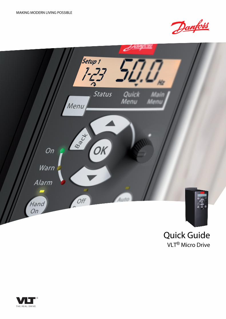
MAKING MODERN LIVING POSSIBLE Quick Guide VLT ® Micro Drive
-
Upload
cong-ty-co-phan-oks-ban-cua-co-dien-va-mua-hang -
Category
Automotive
-
view
170 -
download
0
Transcript of VLT micro drive FC51
MAKING MODERN LIVING POSSIBLE
Quick GuideVLT® Micro Drive
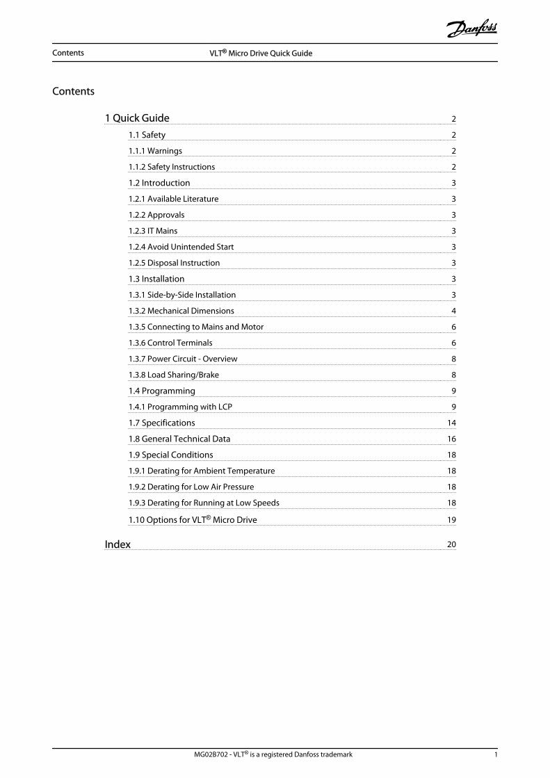
Contents
1 Quick Guide 2
1.1 Safety 2
1.1.1 Warnings 2
1.1.2 Safety Instructions 2
1.2 Introduction 3
1.2.1 Available Literature 3
1.2.2 Approvals 3
1.2.3 IT Mains 3
1.2.4 Avoid Unintended Start 3
1.2.5 Disposal Instruction 3
1.3 Installation 3
1.3.1 Side-by-Side Installation 3
1.3.2 Mechanical Dimensions 4
1.3.5 Connecting to Mains and Motor 6
1.3.6 Control Terminals 6
1.3.7 Power Circuit - Overview 8
1.3.8 Load Sharing/Brake 8
1.4 Programming 9
1.4.1 Programming with LCP 9
1.7 Specifications 14
1.8 General Technical Data 16
1.9 Special Conditions 18
1.9.1 Derating for Ambient Temperature 18
1.9.2 Derating for Low Air Pressure 18
1.9.3 Derating for Running at Low Speeds 18
1.10 Options for VLT® Micro Drive 19
Index 20
Contents VLT® Micro Drive Quick Guide
MG02B702 - VLT® is a registered Danfoss trademark 1
1 Quick Guide
1.1 Safety
1.1.1 Warnings
WARNINGHIGH VOLTAGE!Frequency converters contain high voltage whenconnected to AC mains input power. Installation, start up,and maintenance should be performed by qualifiedpersonnel only. Failure to perform installation, start up, andmaintenance by qualified personnel could result in deathor serious injury.
High VoltageFrequency converts are connected to hazardous mainsvoltages. Extreme care should be taken to protect againstshock. Only trained personnel familiar with electronicequipment should install, start, or maintain this equipment.
Touching the electrical parts may be fatal - even after theequipment has been disconnected from mains. Also makesure that other voltage inputs have been disconnected(linkage of DC intermediate circuit). Be aware that theremay be high voltage on the DC link even when the LEDsare turned off. Before touching any potentially live parts ofthe frequency converter, wait at least 4 min for all M1, M2and M3 sizes. Wait at least 15 min for all M4 and M5 sizes.
WARNINGUNINTENDED START!When the frequency converter is connected to AC mains,the motor may start at any time. The frequency converter,motor, and any driven equipment must be in operationalreadiness. Failure to be in operational readiness when thefrequency converter is connected to AC mains could resultin death, serious injury, equipment, or property damage.
Unintended StartWhen the frequency converter is connected to the ACmains, the motor may be started by means of an externalswitch, a serial bus command, an input reference signal, ora cleared fault condition. Use appropriate cautions toguard against an unintended start.
Leakage Current (>3.5 mA)Follow national and local codes regarding protectiveearthing of equipment with a leakage current > 3,5 mA.frequency converter technology implies high frequencyswitching at high power. This will generate a leakagecurrent in the earth connection. A fault current in thefrequency converter at the output power terminals mightcontain a DC component which can charge the filtercapacitors and cause a transient earth current. The earth
leakage current depends on various system configurationsincluding RFI filtering, screened motor cables, andfrequency converter power.
EN/IEC61800-5-1 (Power Drive System Product Standard)requires special care if the leakage current exceeds 3,5 mA.Earth grounding must be reinforced in one of thefollowing ways:
• Earth ground wire of at least 10 mm2.
• Two separate earth ground wires both complyingwith the dimensioning rules.
See EN 60364-5-54 § 543.7 for further information.
Using RCDsWhere residual current devices (RCDs), also known as earthleakage circuit breakers (ELCBs), are used, comply with thefollowing:
Use RCDs of type B only which are capable ofdetecting AC and DC currents.
Use RCDs with an inrush delay to prevent faultsdue to transient earth currents.
Dimension RCDs according to the system configu-ration and environmental considerations.
Motor Thermal ProtectionMotor overload protection is possible by setting Parameter1-90 Motor thermal protection to the value ETR trip. Forthe North American market: Implemented ETR functionprovide class 20 motor overload protection, in accordancewith NEC.
Installation at High AltitudesFor altitudes above 2 km, contact Danfoss regarding PELV.
1.1.2 Safety Instructions
• Make sure the frequency converter is properlyconnected to earth.
• Do not remove mains connections, motorconnections or other power connections whilethe frequency converter is connected to power.
• Protect users against supply voltage.
• Protect the motor against overloading accordingto national and local regulations.
• The earth leakage current exceeds 3.5 mA.
• The [Off/Reset] key is not a safety switch. It doesnot disconnect the frequency converter frommains.
Quick Guide VLT® Micro Drive Quick Guide
2 MG02B702 - VLT® is a registered Danfoss trademark
11
1.2 Introduction
1.2.1 Available Literature
NOTEThis design guide contains the basic information necessaryfor installing and running the frequency converter.
If more information is needed, the literature below can bedownloaded from:http: //www.danfoss.com/BusinessAreas/DrivesSolutions/Documentations
Title Literatureno.
VLT Micro Drive FC 51 Design Guide MG02K
VLT Micro Drive FC 51 Quick Guide MG02B
VLT Micro Drive FC 51 Programming Guide MG02C
FC 51 LCP Mounting Instruction MI02A
FC 51 De-coupling Plate Mounting Instruction MI02B
FC 51 Remote Mounting Kit Mounting Instruction MI02C
FC 51 DIN Rail Kit Mounting Instruction MI02D
FC 51 IP21 Kit Mounting Instruction MI02E
FC 51 Nema1 Kit Mounting Instruction MI02F
Line Filter MCC 107 Installation Instruction MI02U
Table 1.1
1.2.2 Approvals
Table 1.2
1.2.3 IT Mains
NOTEIT MainsInstallation on isolated mains source, i.e. IT mains.Max. supply voltage allowed when connected to mains:440 V.
As an option, Danfoss offers recommended line filters forimproved harmonics performance.
1.2.4 Avoid Unintended Start
While the frequency converter is connected to mains, themotor can be started/stopped using digital commands, buscommands, references or via the LCP.
• Disconnect the frequency converter from mainswhenever personal safety considerations make itnecessary to avoid unintended start of anymotors.
• To avoid unintended start, always press [Off/Reset] before changing parameters.
1.2.5 Disposal Instruction
Equipment containing electrical componentsmust not be disposed of together with domesticwaste.It must be separately collected with electricaland electronic waste according to local andcurrently valid legislation.
Table 1.3
1.3 Installation
1. Disconnect FC 51 from mains (and external DCsupply, if present.)
2. Wait for 4 min (M1, M2 and M3) and 15 min (M4and M5) for discharge of the DC-link.
3. Disconnect DC bus terminals and brake terminals(if present).
4. Remove motor cable.
1.3.1 Side-by-Side Installation
The frequency converter can be mounted side-by-side forIP20 rating units and requires 100 mm clearance aboveand below for cooling. Refer to the specifications near theend of this document for details on environmental ratingsof the frequency converter.
Quick Guide VLT® Micro Drive Quick Guide
MG02B702 - VLT® is a registered Danfoss trademark 3
1 1
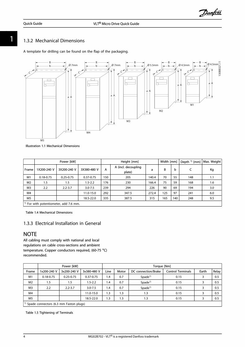
1.3.2 Mechanical Dimensions
A template for drilling can be found on the flap of the packaging.
B
a A a A
a A
a Aa A
C C C C C
bBb
Bb
Bb
BbØ 7mm
M5
M4
M3
M2
M1
Ø 7mm Ø 5.5mm Ø 4.5mm
130B
B321
.11
Ø 4.5mm
Illustration 1.1 Mechanical Dimensions
Power [kW] Height [mm] Width [mm] Depth 1) [mm] Max. Weight
Frame 1X200-240 V 3X200-240 V 3X380-480 V AA (incl. decoupling
plate)a B b C Kg
M1 0.18-0.75 0.25-0.75 0.37-0.75 150 205 140.4 70 55 148 1.1
M2 1.5 1.5 1.5-2.2 176 230 166.4 75 59 168 1.6
M3 2.2 2.2-3.7 3.0-7.5 239 294 226 90 69 194 3.0
M4 11.0-15.0 292 347.5 272.4 125 97 241 6.0
M5 18.5-22.0 335 387.5 315 165 140 248 9.51) For with potentiometer, add 7.6 mm.
Table 1.4 Mechanical Dimensions
1.3.3 Electrical Installation in General
NOTEAll cabling must comply with national and localregulations on cable cross-sections and ambienttemperature. Copper conductors required, (60-75 °C)recommended.
Power [kW] Torque [Nm]
Frame 1x200-240 V 3x200-240 V 3x380-480 V Line Motor DC connection/Brake Control Terminals Earth Relay
M1 0.18-0.75 0.25-0.75 0.37-0.75 1.4 0.7 Spade1) 0.15 3 0.5
M2 1.5 1.5 1.5-2.2 1.4 0.7 Spade1) 0.15 3 0.5
M3 2.2 2.2-3.7 3.0-7.5 1.4 0.7 Spade1) 0.15 3 0.5
M4 11.0-15.0 1.3 1.3 1.3 0.15 3 0.5
M5 18.5-22.0 1.3 1.3 1.3 0.15 3 0.51) Spade connectors (6.3 mm Faston plugs)
Table 1.5 Tightening of Terminals
Quick Guide VLT® Micro Drive Quick Guide
4 MG02B702 - VLT® is a registered Danfoss trademark
11
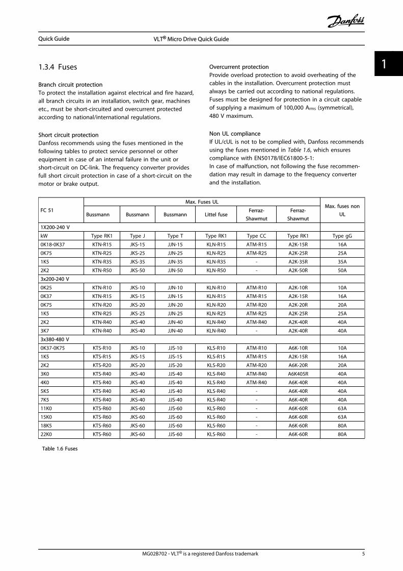
1.3.4 Fuses
Branch circuit protectionTo protect the installation against electrical and fire hazard,all branch circuits in an installation, switch gear, machinesetc., must be short-circuited and overcurrent protectedaccording to national/international regulations.
Short circuit protectionDanfoss recommends using the fuses mentioned in thefollowing tables to protect service personnel or otherequipment in case of an internal failure in the unit orshort-circuit on DC-link. The frequency converter providesfull short circuit protection in case of a short-circuit on themotor or brake output.
Overcurrent protectionProvide overload protection to avoid overheating of thecables in the installation. Overcurrent protection mustalways be carried out according to national regulations.Fuses must be designed for protection in a circuit capableof supplying a maximum of 100,000 Arms (symmetrical),480 V maximum.
Non UL complianceIf UL/cUL is not to be complied with, Danfoss recommendsusing the fuses mentioned in Table 1.6, which ensurescompliance with EN50178/IEC61800-5-1:In case of malfunction, not following the fuse recommen-dation may result in damage to the frequency converterand the installation.
FC 51
Max. Fuses ULMax. fuses non
ULBussmann Bussmann Bussmann Littel fuseFerraz-
ShawmutFerraz-
Shawmut
1X200-240 V
kW Type RK1 Type J Type T Type RK1 Type CC Type RK1 Type gG
0K18-0K37 KTN-R15 JKS-15 JJN-15 KLN-R15 ATM-R15 A2K-15R 16A
0K75 KTN-R25 JKS-25 JJN-25 KLN-R25 ATM-R25 A2K-25R 25A
1K5 KTN-R35 JKS-35 JJN-35 KLN-R35 - A2K-35R 35A
2K2 KTN-R50 JKS-50 JJN-50 KLN-R50 - A2K-50R 50A
3x200-240 V
0K25 KTN-R10 JKS-10 JJN-10 KLN-R10 ATM-R10 A2K-10R 10A
0K37 KTN-R15 JKS-15 JJN-15 KLN-R15 ATM-R15 A2K-15R 16A
0K75 KTN-R20 JKS-20 JJN-20 KLN-R20 ATM-R20 A2K-20R 20A
1K5 KTN-R25 JKS-25 JJN-25 KLN-R25 ATM-R25 A2K-25R 25A
2K2 KTN-R40 JKS-40 JJN-40 KLN-R40 ATM-R40 A2K-40R 40A
3K7 KTN-R40 JKS-40 JJN-40 KLN-R40 - A2K-40R 40A
3x380-480 V
0K37-0K75 KTS-R10 JKS-10 JJS-10 KLS-R10 ATM-R10 A6K-10R 10A
1K5 KTS-R15 JKS-15 JJS-15 KLS-R15 ATM-R15 A2K-15R 16A
2K2 KTS-R20 JKS-20 JJS-20 KLS-R20 ATM-R20 A6K-20R 20A
3K0 KTS-R40 JKS-40 JJS-40 KLS-R40 ATM-R40 A6K405R 40A
4K0 KTS-R40 JKS-40 JJS-40 KLS-R40 ATM-R40 A6K-40R 40A
5K5 KTS-R40 JKS-40 JJS-40 KLS-R40 - A6K-40R 40A
7K5 KTS-R40 JKS-40 JJS-40 KLS-R40 - A6K-40R 40A
11K0 KTS-R60 JKS-60 JJS-60 KLS-R60 - A6K-60R 63A
15K0 KTS-R60 JKS-60 JJS-60 KLS-R60 - A6K-60R 63A
18K5 KTS-R60 JKS-60 JJS-60 KLS-R60 - A6K-60R 80A
22K0 KTS-R60 JKS-60 JJS-60 KLS-R60 - A6K-60R 80A
Table 1.6 Fuses
Quick Guide VLT® Micro Drive Quick Guide
MG02B702 - VLT® is a registered Danfoss trademark 5
1 1
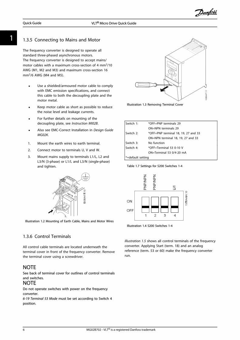
1.3.5 Connecting to Mains and Motor
The frequency converter is designed to operate allstandard three-phased asynchronous motors.The frequency converter is designed to accept mains/motor cables with a maximum cross-section of 4 mm2/10AWG (M1, M2 and M3) and maximum cross-section 16mm2/6 AWG (M4 and M5).
• Use a shielded/armoured motor cable to complywith EMC emission specifications, and connectthis cable to both the decoupling plate and themotor metal.
• Keep motor cable as short as possible to reducethe noise level and leakage currents.
• For further details on mounting of thedecoupling plate, see Instruction MI02B.
• Also see EMC-Correct Installation in Design GuideMG02K.
1. Mount the earth wires to earth terminal.
2. Connect motor to terminals U, V and W.
3. Mount mains supply to terminals L1/L, L2 andL3/N (3-phase) or L1/L and L3/N (single-phase)and tighten.
Illustration 1.2 Mounting of Earth Cable, Mains and Motor Wires
1.3.6 Control Terminals
All control cable terminals are located underneath theterminal cover in front of the frequency converter. Removethe terminal cover using a screwdriver.
NOTESee back of terminal cover for outlines of control terminalsand switches.
NOTEDo not operate switches with power on the frequencyconverter.6-19 Terminal 53 Mode must be set according to Switch 4position.
Illustration 1.3 Removing Terminal Cover
Switch 1: *OFF=PNP terminals 29ON=NPN terminals 29
Switch 2: *OFF=PNP terminal 18, 19, 27 and 33ON=NPN terminal 18, 19, 27 and 33
Switch 3: No functionSwitch 4: *OFF=Terminal 53 0-10 V
ON=Terminal 53 0/4-20 mA*=default setting
Table 1.7 Settings for S200 Switches 1-4
Illustration 1.4 S200 Switches 1-4
Illustration 1.5 shows all control terminals of the frequencyconverter. Applying Start (term. 18) and an analogreference (term. 53 or 60) make the frequency converterrun.
Quick Guide VLT® Micro Drive Quick Guide
6 MG02B702 - VLT® is a registered Danfoss trademark
11
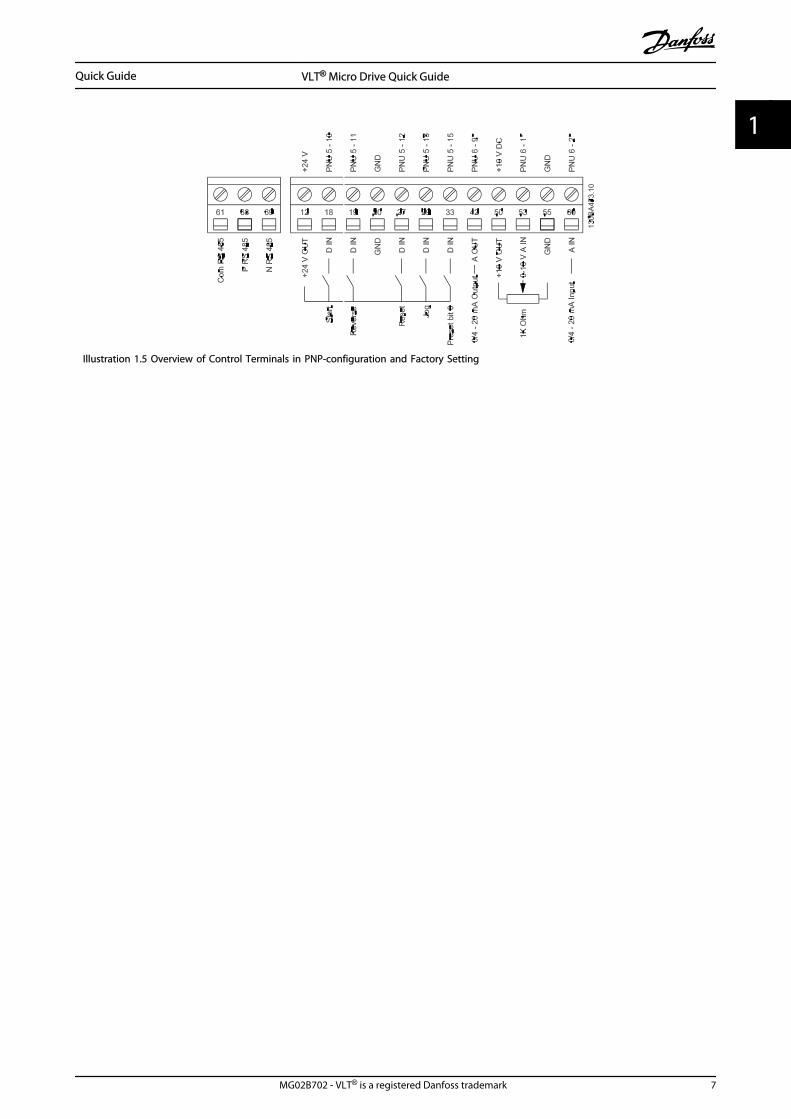
Illustration 1.5 Overview of Control Terminals in PNP-configuration and Factory Setting
Quick Guide VLT® Micro Drive Quick Guide
MG02B702 - VLT® is a registered Danfoss trademark 7
1 1
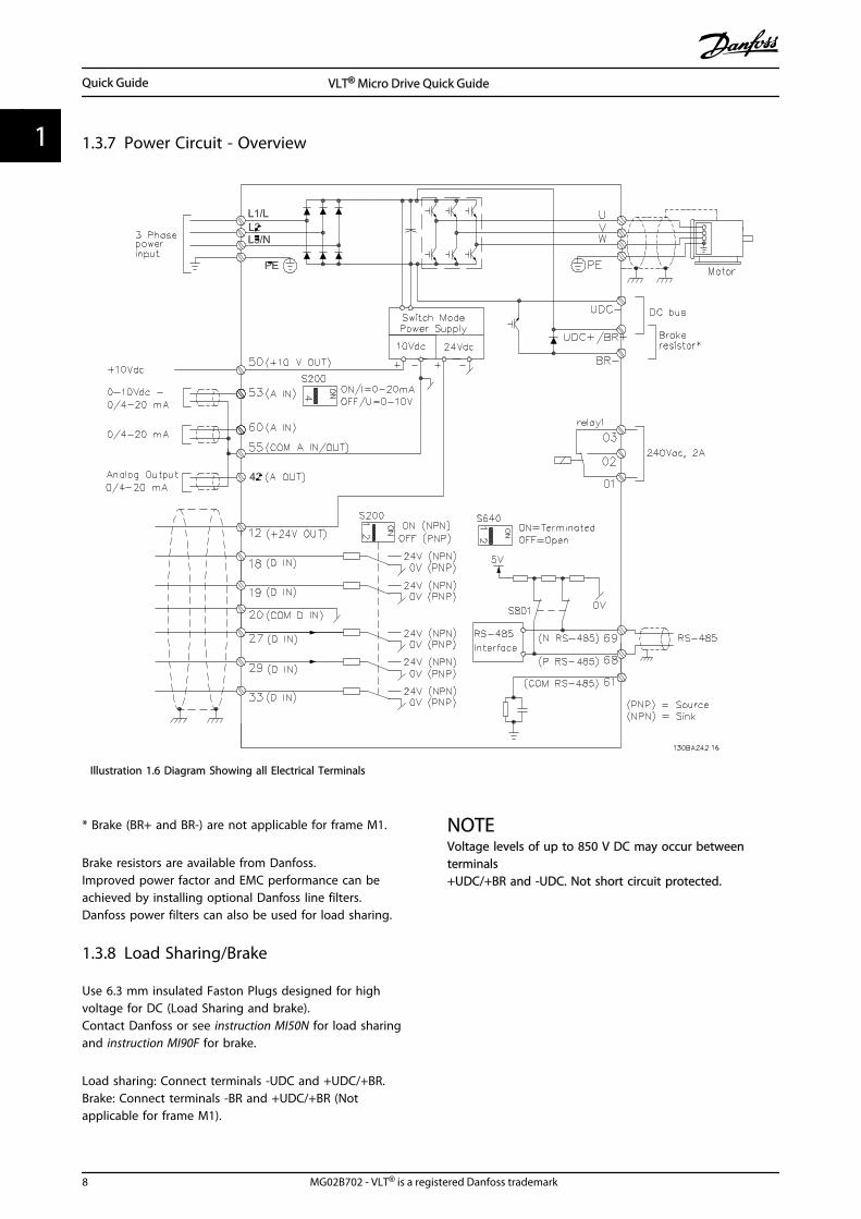
1.3.7 Power Circuit - Overview
Illustration 1.6 Diagram Showing all Electrical Terminals
* Brake (BR+ and BR-) are not applicable for frame M1.
Brake resistors are available from Danfoss.Improved power factor and EMC performance can beachieved by installing optional Danfoss line filters.Danfoss power filters can also be used for load sharing.
1.3.8 Load Sharing/Brake
Use 6.3 mm insulated Faston Plugs designed for highvoltage for DC (Load Sharing and brake).Contact Danfoss or see instruction MI50N for load sharingand instruction MI90F for brake.
Load sharing: Connect terminals -UDC and +UDC/+BR.Brake: Connect terminals -BR and +UDC/+BR (Notapplicable for frame M1).
NOTEVoltage levels of up to 850 V DC may occur betweenterminals+UDC/+BR and -UDC. Not short circuit protected.
Quick Guide VLT® Micro Drive Quick Guide
8 MG02B702 - VLT® is a registered Danfoss trademark
11
1.4 Programming
1.4.1 Programming with LCP
For detailed information on programming, seeProgramming Guide, MG02C.
NOTEThe frequency converter can also be programmed from aPC via RS-485 com-port by installing the MCT 10 Set-upSoftware.This software can either be ordered using code number130B1000 or downloaded from the Danfoss Web site:www.danfoss.com/BusinessAreas/DrivesSolutions/software-download
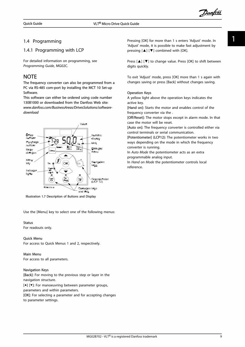
Illustration 1.7 Description of Buttons and Display
Use the [Menu] key to select one of the following menus:
StatusFor readouts only.
Quick MenuFor access to Quick Menus 1 and 2, respectively.
Main MenuFor access to all parameters.
Navigation Keys[Back]: For moving to the previous step or layer in thenavigation structure.[] []: For manoeuvring between parameter groups,parameters and within parameters.[OK]: For selecting a parameter and for accepting changesto parameter settings.
Pressing [OK] for more than 1 s enters 'Adjust' mode. In'Adjust' mode, it is possible to make fast adjustment bypressing [] [] combined with [OK].
Press [] [] to change value. Press [OK] to shift betweendigits quickly.
To exit 'Adjust' mode, press [OK] more than 1 s again withchanges saving or press [Back] without changes saving.
Operation KeysA yellow light above the operation keys indicates theactive key.[Hand on]: Starts the motor and enables control of thefrequency converter via the .[Off/Reset]: The motor stops except in alarm mode. In thatcase the motor will be reset.[Auto on]: The frequency converter is controlled either viacontrol terminals or serial communication.[Potentiometer] (LCP12): The potentiometer works in twoways depending on the mode in which the frequencyconverter is running.In Auto Mode the potentiometer acts as an extraprogrammable analog input.In Hand on Mode the potentiometer controls localreference.
Quick Guide VLT® Micro Drive Quick Guide
MG02B702 - VLT® is a registered Danfoss trademark 9
1 1
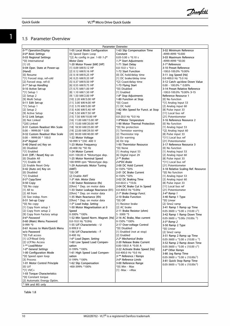
1.5 Parameter Overview
Parameter Overwiev0-** Operation/Display0-0* Basic Settings0-03 Regional Settings*[0] International[1] US0-04 Oper. State at Power-up(Hand)[0] Resume*[1] Forced stop, ref=old[2] Forced stop, ref=00-1* Set-up Handling0-10 Active Set-up*[1] Setup 1[2] Setup 2[9] Multi Setup0-11 Edit Set-up*[1] Setup 1[2] Setup 2[9] Active Setup0-12 Link Setups[0] Not Linked*[20] Linked0-31 Custom Readout Min Scale0.00 – 9999.00 * 0.000-32 Custom Readout Max Scale0.00 – 9999.00 * 100.00-4* Keypad0-40 [Hand on] Key on [0] Disabled*[1] Enabled0-41 [Off / Reset] Key on [0] Disable All*[1] Enable All[2] Enable Reset Only0-42 [Auto on] Key on [0] Disabled*[1] Enabled0-5* Copy/Save0-50 Copy*[0] No copy[1] All to [2] All from [3] Size indep. from 0-51 Set-up Copy*[0] No copy[1] Copy from setup 1[2] Copy from setup 2[9] Copy from Factory setup0-6* Password0-60 (Main) Menu Password0-999 *00-61 Access to Main/Quick Menuw/o Password*[0] Full access[1] LCP:Read Only[2] LCP:No Access1-** Load/Motor1-0* General Settings1-00 Configuration Mode*[0] Speed open loop[3] Process1-01 Motor Control Principle[0] U/f*[1] VVC+1-03 Torque Characteristics*[0] Constant torque[2] Automatic Energy Optim.
1-05 Local Mode Configuration[0] Speed Open Loop*[2] As config in par. 1-00 1-2*Motor Data1-20 Motor Power [kW] [HP][1] 0.09 kW/0.12 HP[2] 0.12 kW/0.16 HP[3] 0.18 kW/0.25 HP[4] 0.25 kW/0.33 HP[5] 0.37 kW/0.50 HP[6] 0.55 kW/0.75 HP[7] 0.75 kW/1.00 HP[8] 1.10 kW/1.50 HP[9] 1.50 kW/2.00 HP[10] 2.20 kW/3.00 HP[11] 3.00 kW/4.00 HP[12] 3.70 kW/5.00 HP[13] 4.00 kW/5.40 HP[14] 5.50 kW/7.50 HP[15] 7.50 kW/10.00 HP[16] 11.00 kW/15.00 HP[17] 15.00 kW/20.00 HP[18] 18.50 kW/25.00 HP[19] 22.00 kW/29.50 HP[20] 30.00 kW/40.00 HP1-22 Motor Voltage50-999 V *230 -400 V1-23 Motor Frequency20-400 Hz *50 Hz1-24 Motor Current0.01-100.00 A *Motortype dep.1-25 Motor Nominal Speed100-9999 rpm *Motortype dep.1-29 Automatic Motor Tuning(AMT)*[0] Off[2] Enable AMT1-3* Adv. Motor Data1-30 Stator Resistance (Rs)[Ohm] * Dep. on motor data1-33 Stator Leakage Reactance (X1)[Ohm] * Dep. on motor data1-35 Main Reactance (Xh)[Ohm] * Dep. on motor data1-5* Load Indep. Setting1-50 Motor Magnetisation at 0Speed0-300% *100%1-52 Min Speed Norm. Magnet. [Hz]0.0-10.0 Hz *0.0Hz1-55 U/f Characteristic - U0-999.9 V1-56 U/f Characteristic - F0-400 Hz1-6* Load Depen. Setting1-60 Low Speed Load Compen-sation0-199% *100%1-61 High Speed Load Compen-sation0-199% *100%1-62 Slip Compensation-400-399% *100%
1-63 Slip Compensation TimeConstant0.05-5.00 s *0.10 s1-7* Start Adjustments1-71 Start Delay0.0-10.0 s *0.0 s1-72 Start Function[0] DC hold/delay time[1] DC brake/delay time*[2] Coast/delay time1-73 Flying Start*[0] Disabled[1] Enabled1-8* Stop Adjustments1-80 Function at Stop*[0] Coast[1] DC hold1-82 Min Speed for Funct. at Stop[Hz]0.0-20.0 Hz *0.0 Hz1-9*Motor Temperature1-90 Motor Thermal Protection*[0] No protection[1] Termistor warning[2] Thermistor trip[3] Etr warning[4] Etr trip1-93 Thermistor Resource*[0] None[1] Analog input 53[6] Digital input 292-** Brakes2-0*DC-Brake2-00 DC Hold Current0-150% *50%2-01 DC Brake Current0-150% *50%2-02 DC Braking Time0.0-60.0 s *10.0s2-04 DC Brake Cut In Speed0.0-400.0 Hz *0.0Hz2-1* Brake Energy Funct.2-10 Brake Function*[0] Off[1] Resistor brake[2] AC brake2-11 Brake Resistor (ohm)5 -5000 *52-16 AC Brake, Max current0-150% *100%2-17 Over-voltage Control*[0] Disabled[1] Enabled (not at stop)[2] Enabled2-2* Mechanical Brake2-20 Release Brake Current0.00-100.0 A *0.00 A2-22 Activate Brake Speed [Hz]0.0-400.0 Hz *0.0 Hz3-** Reference / Ramps3-0* Reference Limits3-00 Reference Range*[0] Min - Max[1] -Max - +Max
3-02 Minimum Reference-4999-4999 *0.0003-03 Maximum Reference-4999-4999 *50.003-1* References3-10 Preset Reference-100.0-100.0% *0.00%3-11 Jog Speed [Hz]0.0-400.0 Hz *5.0 Hz3-12 Catch up/slow Down Value0.00 - 100.0% * 0.00%3-14 Preset Relative Reference-100.0-100.0% *0.00% 3-15Reference Resource 1[0] No function*[1] Analog Input 53[2] Analog input 60[8] Pulse input 33[11] Local bus ref[21] Potentiometer3-16 Reference Resource 2[0] No function[1] Analog Input 53*[2] Analog input 60[8] Pulse input 33*[11] Local bus ref[21] Potentiometer3-17 Reference Resource 3[0] No function[1] Analog Input 53[2] Analog input 60[8] Pulse input 33*[11] Local bus ref[21] Potentiometer3-18 Relative Scaling Ref. Resource*[0] No function[1] Analog Input 53[2] Analog input 60[8] Pulse input 33[11] Local bus ref[21] Potentiometer3-4* Ramp 13-40 Ramp 1 Type*[0] Linear[2] Sine2 ramp3-41 Ramp 1 Ramp up Time0.05-3600 s *3.00 s (10.00 s1))3-42 Ramp 1 Ramp Down Time0.05-3600 s *3.00s (10.00s 1))3-5* Ramp 23-50 Ramp 2 Type*[0] Linear[2] Sine2 ramp3-51 Ramp 2 Ramp up Time0.05-3600 s *3.00 s (10.00 s 1))3-52 Ramp 2 Ramp down Time0.05-3600 s *3.00 s (10.00 s1))3-8* Other Ramps3-80 Jog Ramp Time0.05-3600 s *3.00 s (10.00s1))3-81 Quick Stop Ramp Time0.05-3600 s *3.00 s (10.00s1))
1) M4 and M5 only
Table 1.8
Quick Guide VLT® Micro Drive Quick Guide
10 MG02B702 - VLT® is a registered Danfoss trademark
11
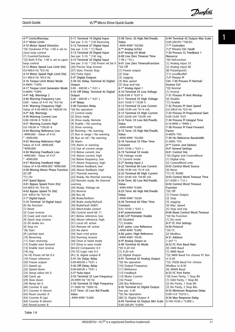
4-** Limits/Warnings4-1* Motor Limits4-10 Motor Speed Direction*[0] Clockwise If Par. 1-00 is set toclose loop control[1] CounterClockwise*[2] Both if Par. 1-00 is set to openloop control4-12 Motor Speed Low Limit [Hz]0.0-400.0 Hz *0.0 Hz4-14 Motor Speed High Limit [Hz]0.1-400.0 Hz *65.0 Hz4-16 Torque Limit Motor Mode0-400% *150%4-17 Torque Limit Generator Mode0-400% *100%4-4* Adj. Warnings 24-40 Warning Frequency Low0.00 - Value of 4-41 Hz *0.0 Hz4-41 Warning Frequency HighValue of 4-40-400.0 Hz *400.00 Hz4-5* Adj. Warnings4-50 Warning Current Low0.00-100.00 A *0.00 A4-51 Warning Current High0.0-100.00 A *100.00 A4-54 Warning Reference Low-4999.000 - Value of 4-55* -4999.0004-55 Warning Reference HighValue of 4-54 -4999.000*4999.0004-56 Warning Feedback Low-4999.000 - Value of 4-57* -4999.0004-57 Warning Feedback HighValue of 4-56-4999.000 *4999.0004-58 Missing Motor Phase Function[0] Off*[1] On4-6* Speed Bypass4-61 Bypass Speed From [Hz]0.0-400.0 Hz *0.0 Hz4-63 Bypass Speed To [Hz]0.0 -400.0 Hz *0.0 Hz5-1* Digital Inputs5-10 Terminal 18 Digital Input[0] No function[1] Reset[2] Coast inverse[3] Coast and reset inv.[4] Quick stop inverse[5] DC-brake inv.[6] Stop inv*[8] Start[9] Latched start[10] Reversing[11] Start reversing[12] Enable start forward[13] Enable start reverse[14] Jog[16-18] Preset ref bit 0-2[19] Freeze reference[20] Freeze output[21] Speed up[22] Speed down[23] Setup select bit 0[28] Catch up[29] Slow down[34] Ramp bit 0[60] Counter A (up)[61] Counter A (down)[62] Reset counter A[63] Counter B (up)[64] Counter B (down)[65] ResetCounter B
5-11 Terminal 19 Digital InputSee par. 5-10. * [10] Reversing5-12 Terminal 27 Digital InputSee par. 5-10. * [1] Reset5-13 Terminal 29 Digital InputSee par. 5-10. * [14] Jog5-15 Terminal 33 Digital InputSee par. 5-10. * [16] Preset ref bit 0[26] Precise Stop Inverse[27] Start, Precise Stop[32] Pulse Input5-3* Digital Outputs5-34 On Delay, Terminal 42 DigitalOutput0.00 - 600.00 s * 0.01 s5-35 Off Delay, Terminal 42 DigitalOutput0.00 - 600.00 s * 0.01 s5-4* Relays5-40 Function Relay*[0] No operation[1] Control ready[2] Drive ready[3] Drive ready, Remote[4] Enable / No warning[5] Drive running[6] Running / No warning[7] Run in range / No warning[8] Run on ref / No warning[9] Alarm[10] Alarm or warning[12] Out of current range[13] Below current, low[14] Above current, high[16] Below frequency, low[17] Above frequency, high[19] Below feedback, low[20] Above feedback, high[21] Thermal warning[22] Ready, No thermal warning[23] Remote ready, No thermalwarning[24] Ready, Voltage ok[25] Reverse[26] Bus ok[28] Brake,NoWarn[29] Brake ready/NoFault[30] BrakeFault (IGBT)[32] Mech.brake control[36] Control word bit 11[41] Below reference, low[42] Above reference, high[51] Local ref. active[52] Remote ref. active[53] No alarm[54] Start cmd active[55] Running reverse[56] Drive in hand mode[57] Drive in auto mode[60-63] Comparator 0-3[70-73] Logic rule 0-3[81] SL digital output B5-41 On Delay, Relay0.00-600.00 s *0.01 s5-42 Off Delay, Relay0.00-600.00 s *0.01 s5-5* Pulse Input5-55 Terminal 33 Low Frequency20-4999 Hz *20 Hz5-56 Terminal 33 High Frequency21-5000 Hz *5000 Hz5-57 Term. 33 Low Ref./Feedb.Value-4999-4999 *0.000
5-58 Term. 33 High Ref./Feedb.Value-4999-4999 *50.0006-** Analog In/Out6-0* Analog I/O Mode6-00 Live Zero Timeout Time1-99 s *10 s6-01 Live Zero TimeoutFunction*[0] Off[1] Freeze output[2] Stop[3] Jogging[4] Max speed[5] Stop and trip6-1* Analog Input 16-10 Terminal 53 Low Voltage0.00-9.99 V *0.07 V6-11 Terminal 53 High Voltage0.01-10.00 V *10.00 V6-12 Terminal 53 Low Current0.00-19.99 mA *0.14 mA6-13 Terminal 53 High Current0.01-20.00 mA *20.00 mA6-14 Term. 53 Low Ref./Feedb.Value-4999-4999 *0.0006-15 Term. 53 High Ref./Feedb.Value-4999-4999 *50.0006-16 Terminal 53 Filter TimeConstant0.01-10.00 s *0.01 s6-19 Terminal 53 mode*[0] Voltage mode[1] Current mode6-2* Analog Input 26-22 Terminal 60 Low Current0.00-19.99 mA *0.14 mA6-23 Terminal 60 High Current0.01-20.00 mA *20.00 mA6-24 Term. 60 Low Ref./Feedb.Value-4999-4999 *0.0006-25 Term. 60 High Ref./Feedb.Value-4999-4999 *50.006-26 Terminal 60 Filter TimeConstant0.01-10.00 s *0.01 s6-8* potentiometer6-80 LCP Potmeter Enable[0] Disabled*[1] Enable6-81 potm. Low Reference-4999-4999 *0.0006-82 potm. High Reference-4999-4999 *50.006-9* Analog Output xx6-90 Terminal 42 Mode*[0] 0-20 mA[1] 4-20 mA[2] Digital Output6-91 Terminal 42 Analog Output*[0] No operation[10] Output Frequency[11] Reference[12] Feedback[13] Motor Current[16] Power[20] Bus Reference6-92 Terminal 42 Digital OutputSee par. 5-40*[0] No Operation[80] SL Digital Output A6-93 Terminal 42 Output Min Scale0.00-200.0% *0.00%
6-94 Terminal 42 Output Max Scale0.00-200.0% *100.0%7-** Controllers7-2* Process Ctrl. Feedb7-20 Process CL Feedback 1Resource*[0] NoFunction[1] Analog Input 53[2] Analog input 60[8] PulseInput33[11] LocalBusRef7-3* Process PICtrl. 7-30 Process PI Normal/Inverse Ctrl*[0] Normal[1] Inverse7-31 Process PI Anti Windup[0] Disable*[1] Enable7-32 Process PI Start Speed0.0-200.0 Hz *0.0 Hz7-33 Process PI Proportional Gain0.00-10.00 *0.017-34 Process PI Integral Time0.10-9999 s *9999 s7-38 Process PI Feed ForwardFactor0-400% *0%7-39 On Reference Bandwidth0-200% *5%8-** Comm. and Options8-0* General Settings8-01 Control Site*[0] Digital and ControlWord[1] Digital only[2] ControlWord only8-02 Control Word Source[0] None*[1] FC RS4858-03 Control Word Timeout Time0.1-6500 s *1.0 s8-04 Control Word TimeoutFunction*[0] Off[1] Freeze Output[2] Stop[3] Jogging[4] Max. Speed[5] Stop and trip8-06 Reset Control Word Timeout*[0] No Function[1] Do reset8-3* FC Port Settings8-30 Protocol*[0] FC[2] Modbus8-31 Address1-247 *18-32 FC Port Baud Rate[0] 2400 Baud[1] 4800 Baud*[2] 9600 Baud For choose FC Busin 8-30*[3] 19200 Baud For chooseModbus in 8-30[4] 38400 Baud8-33 FC Port Parity*[0] Even Parity, 1 Stop Bit[1] Odd Parity, 1 Stop Bit[2] No Parity, 1 Stop Bit[3] No Parity, 2 Stop Bits8-35 Minimum Response Delay0.001-0.5 *0.010 s8-36 Max Response Delay0.100-10.00 s *5.000 s
Table 1.9
Quick Guide VLT® Micro Drive Quick Guide
MG02B702 - VLT® is a registered Danfoss trademark 11
1 1
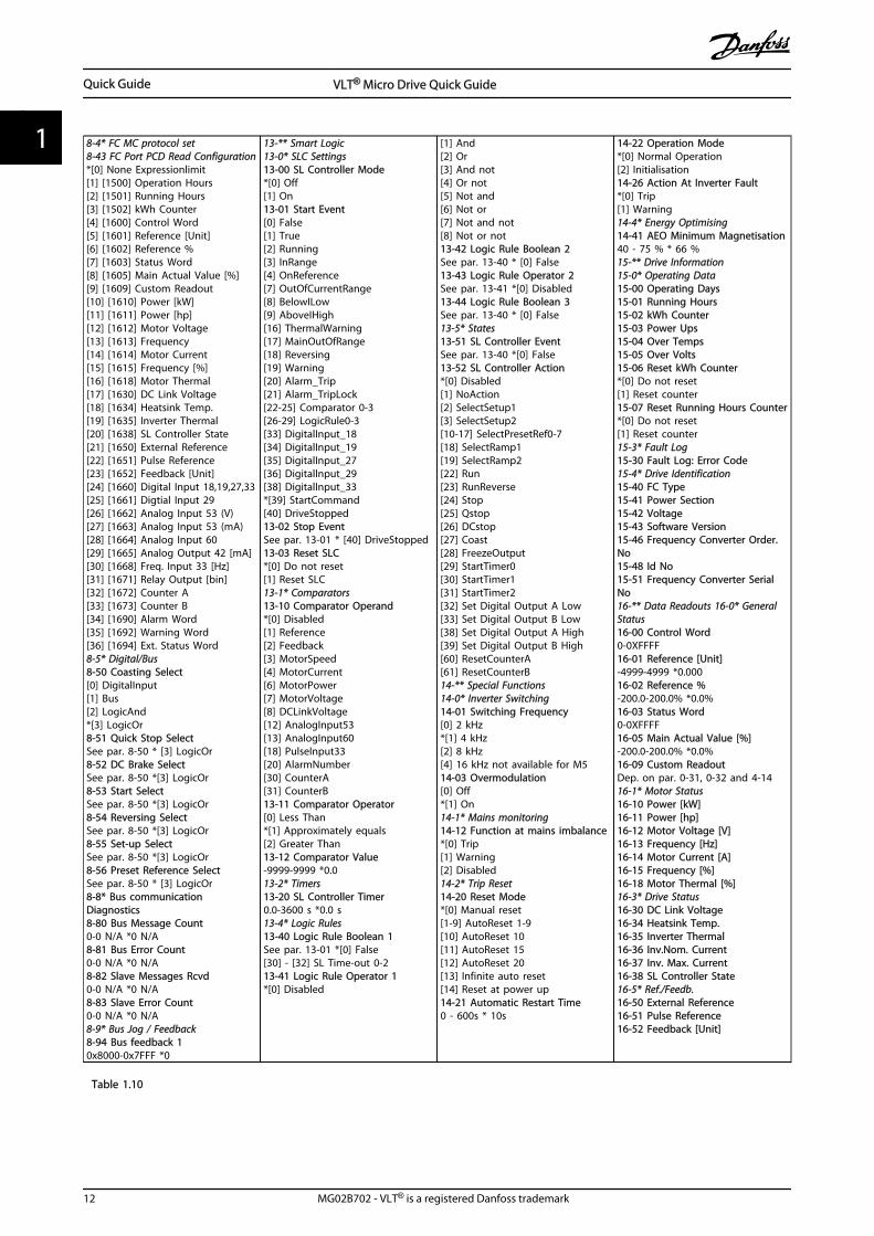
8-4* FC MC protocol set8-43 FC Port PCD Read Configuration*[0] None Expressionlimit[1] [1500] Operation Hours[2] [1501] Running Hours[3] [1502] kWh Counter[4] [1600] Control Word[5] [1601] Reference [Unit][6] [1602] Reference %[7] [1603] Status Word[8] [1605] Main Actual Value [%][9] [1609] Custom Readout[10] [1610] Power [kW][11] [1611] Power [hp][12] [1612] Motor Voltage[13] [1613] Frequency[14] [1614] Motor Current[15] [1615] Frequency [%][16] [1618] Motor Thermal[17] [1630] DC Link Voltage[18] [1634] Heatsink Temp.[19] [1635] Inverter Thermal[20] [1638] SL Controller State[21] [1650] External Reference[22] [1651] Pulse Reference[23] [1652] Feedback [Unit][24] [1660] Digital Input 18,19,27,33[25] [1661] Digtial Input 29[26] [1662] Analog Input 53 (V)[27] [1663] Analog Input 53 (mA)[28] [1664] Analog Input 60[29] [1665] Analog Output 42 [mA][30] [1668] Freq. Input 33 [Hz][31] [1671] Relay Output [bin][32] [1672] Counter A[33] [1673] Counter B[34] [1690] Alarm Word[35] [1692] Warning Word[36] [1694] Ext. Status Word8-5* Digital/Bus8-50 Coasting Select[0] DigitalInput[1] Bus[2] LogicAnd*[3] LogicOr8-51 Quick Stop SelectSee par. 8-50 * [3] LogicOr8-52 DC Brake SelectSee par. 8-50 *[3] LogicOr8-53 Start SelectSee par. 8-50 *[3] LogicOr8-54 Reversing SelectSee par. 8-50 *[3] LogicOr8-55 Set-up SelectSee par. 8-50 *[3] LogicOr8-56 Preset Reference SelectSee par. 8-50 * [3] LogicOr8-8* Bus communicationDiagnostics8-80 Bus Message Count0-0 N/A *0 N/A8-81 Bus Error Count0-0 N/A *0 N/A8-82 Slave Messages Rcvd0-0 N/A *0 N/A8-83 Slave Error Count0-0 N/A *0 N/A8-9* Bus Jog / Feedback8-94 Bus feedback 10x8000-0x7FFF *0
13-** Smart Logic13-0* SLC Settings13-00 SL Controller Mode*[0] Off[1] On13-01 Start Event[0] False[1] True[2] Running[3] InRange[4] OnReference[7] OutOfCurrentRange[8] BelowILow[9] AboveIHigh[16] ThermalWarning[17] MainOutOfRange[18] Reversing[19] Warning[20] Alarm_Trip[21] Alarm_TripLock[22-25] Comparator 0-3[26-29] LogicRule0-3[33] DigitalInput_18[34] DigitalInput_19[35] DigitalInput_27[36] DigitalInput_29[38] DigitalInput_33*[39] StartCommand[40] DriveStopped13-02 Stop EventSee par. 13-01 * [40] DriveStopped13-03 Reset SLC*[0] Do not reset[1] Reset SLC13-1* Comparators13-10 Comparator Operand*[0] Disabled[1] Reference[2] Feedback[3] MotorSpeed[4] MotorCurrent[6] MotorPower[7] MotorVoltage[8] DCLinkVoltage[12] AnalogInput53[13] AnalogInput60[18] PulseInput33[20] AlarmNumber[30] CounterA[31] CounterB13-11 Comparator Operator[0] Less Than*[1] Approximately equals[2] Greater Than13-12 Comparator Value-9999-9999 *0.013-2* Timers13-20 SL Controller Timer0.0-3600 s *0.0 s13-4* Logic Rules13-40 Logic Rule Boolean 1See par. 13-01 *[0] False[30] - [32] SL Time-out 0-213-41 Logic Rule Operator 1*[0] Disabled
[1] And[2] Or[3] And not[4] Or not[5] Not and[6] Not or[7] Not and not[8] Not or not13-42 Logic Rule Boolean 2See par. 13-40 * [0] False13-43 Logic Rule Operator 2See par. 13-41 *[0] Disabled13-44 Logic Rule Boolean 3See par. 13-40 * [0] False13-5* States13-51 SL Controller EventSee par. 13-40 *[0] False13-52 SL Controller Action*[0] Disabled[1] NoAction[2] SelectSetup1[3] SelectSetup2[10-17] SelectPresetRef0-7[18] SelectRamp1[19] SelectRamp2[22] Run[23] RunReverse[24] Stop[25] Qstop[26] DCstop[27] Coast[28] FreezeOutput[29] StartTimer0[30] StartTimer1[31] StartTimer2[32] Set Digital Output A Low[33] Set Digital Output B Low[38] Set Digital Output A High[39] Set Digital Output B High[60] ResetCounterA[61] ResetCounterB14-** Special Functions14-0* Inverter Switching14-01 Switching Frequency[0] 2 kHz*[1] 4 kHz[2] 8 kHz[4] 16 kHz not available for M514-03 Overmodulation[0] Off*[1] On14-1* Mains monitoring14-12 Function at mains imbalance*[0] Trip[1] Warning[2] Disabled14-2* Trip Reset14-20 Reset Mode*[0] Manual reset[1-9] AutoReset 1-9[10] AutoReset 10[11] AutoReset 15[12] AutoReset 20[13] Infinite auto reset[14] Reset at power up14-21 Automatic Restart Time0 - 600s * 10s
14-22 Operation Mode*[0] Normal Operation[2] Initialisation14-26 Action At Inverter Fault*[0] Trip[1] Warning14-4* Energy Optimising14-41 AEO Minimum Magnetisation40 - 75 % * 66 %15-** Drive Information15-0* Operating Data15-00 Operating Days15-01 Running Hours15-02 kWh Counter15-03 Power Ups15-04 Over Temps15-05 Over Volts15-06 Reset kWh Counter*[0] Do not reset[1] Reset counter15-07 Reset Running Hours Counter*[0] Do not reset[1] Reset counter15-3* Fault Log15-30 Fault Log: Error Code15-4* Drive Identification15-40 FC Type15-41 Power Section15-42 Voltage15-43 Software Version15-46 Frequency Converter Order.No15-48 Id No15-51 Frequency Converter SerialNo16-** Data Readouts 16-0* GeneralStatus16-00 Control Word0-0XFFFF16-01 Reference [Unit]-4999-4999 *0.00016-02 Reference %-200.0-200.0% *0.0%16-03 Status Word0-0XFFFF16-05 Main Actual Value [%]-200.0-200.0% *0.0%16-09 Custom ReadoutDep. on par. 0-31, 0-32 and 4-1416-1* Motor Status16-10 Power [kW]16-11 Power [hp]16-12 Motor Voltage [V]16-13 Frequency [Hz]16-14 Motor Current [A]16-15 Frequency [%]16-18 Motor Thermal [%]16-3* Drive Status16-30 DC Link Voltage16-34 Heatsink Temp.16-35 Inverter Thermal16-36 Inv.Nom. Current16-37 Inv. Max. Current16-38 SL Controller State16-5* Ref./Feedb.16-50 External Reference16-51 Pulse Reference16-52 Feedback [Unit]
Table 1.10
Quick Guide VLT® Micro Drive Quick Guide
12 MG02B702 - VLT® is a registered Danfoss trademark
11
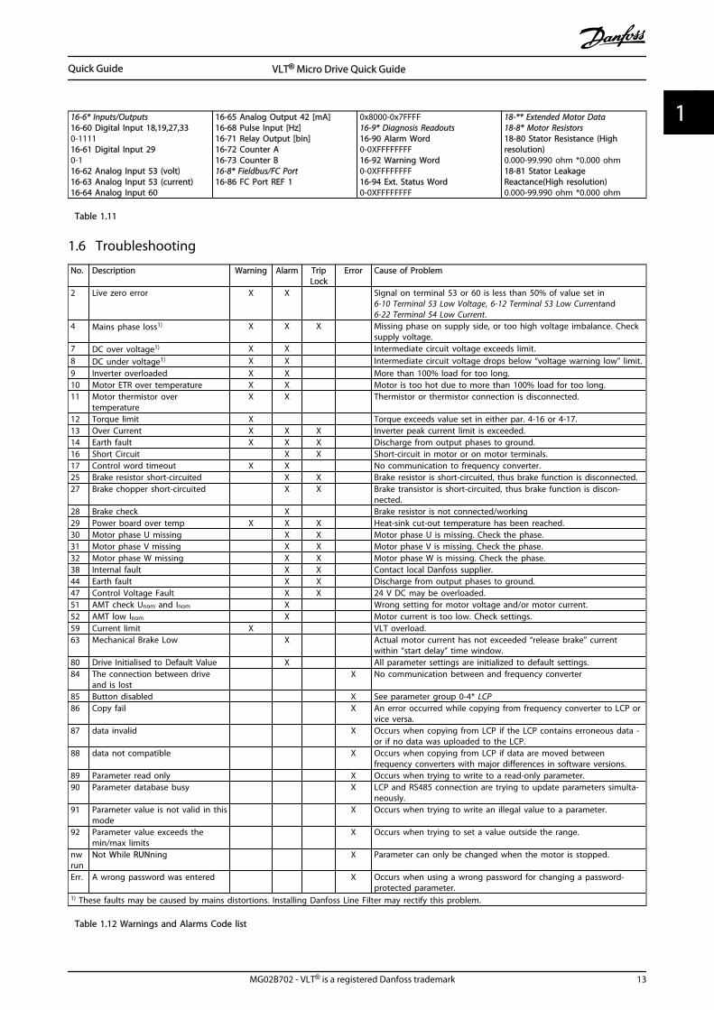
16-6* Inputs/Outputs16-60 Digital Input 18,19,27,330-111116-61 Digital Input 290-116-62 Analog Input 53 (volt)16-63 Analog Input 53 (current)16-64 Analog Input 60
16-65 Analog Output 42 [mA]16-68 Pulse Input [Hz]16-71 Relay Output [bin]16-72 Counter A16-73 Counter B16-8* Fieldbus/FC Port16-86 FC Port REF 1
0x8000-0x7FFFF16-9* Diagnosis Readouts16-90 Alarm Word0-0XFFFFFFFF16-92 Warning Word0-0XFFFFFFFF16-94 Ext. Status Word0-0XFFFFFFFF
18-** Extended Motor Data18-8* Motor Resistors18-80 Stator Resistance (Highresolution)0.000-99.990 ohm *0.000 ohm18-81 Stator LeakageReactance(High resolution)0.000-99.990 ohm *0.000 ohm
Table 1.11
1.6 Troubleshooting
No. Description Warning Alarm TripLock
Error Cause of Problem
2 Live zero error X X Signal on terminal 53 or 60 is less than 50% of value set in6-10 Terminal 53 Low Voltage, 6-12 Terminal 53 Low Currentand6-22 Terminal 54 Low Current.
4 Mains phase loss1) X X X Missing phase on supply side, or too high voltage imbalance. Checksupply voltage.
7 DC over voltage1) X X Intermediate circuit voltage exceeds limit.8 DC under voltage1) X X Intermediate circuit voltage drops below “voltage warning low” limit.9 Inverter overloaded X X More than 100% load for too long.10 Motor ETR over temperature X X Motor is too hot due to more than 100% load for too long.11 Motor thermistor over
temperatureX X Thermistor or thermistor connection is disconnected.
12 Torque limit X Torque exceeds value set in either par. 4-16 or 4-17.13 Over Current X X X Inverter peak current limit is exceeded.14 Earth fault X X X Discharge from output phases to ground.16 Short Circuit X X Short-circuit in motor or on motor terminals.17 Control word timeout X X No communication to frequency converter.25 Brake resistor short-circuited X X Brake resistor is short-circuited, thus brake function is disconnected.27 Brake chopper short-circuited X X Brake transistor is short-circuited, thus brake function is discon-
nected.28 Brake check X Brake resistor is not connected/working29 Power board over temp X X X Heat-sink cut-out temperature has been reached.30 Motor phase U missing X X Motor phase U is missing. Check the phase.31 Motor phase V missing X X Motor phase V is missing. Check the phase.32 Motor phase W missing X X Motor phase W is missing. Check the phase.38 Internal fault X X Contact local Danfoss supplier.44 Earth fault X X Discharge from output phases to ground.47 Control Voltage Fault X X 24 V DC may be overloaded.51 AMT check Unom and Inom X Wrong setting for motor voltage and/or motor current.52 AMT low Inom X Motor current is too low. Check settings.59 Current limit X VLT overload.63 Mechanical Brake Low X Actual motor current has not exceeded “release brake” current
within “start delay” time window.80 Drive Initialised to Default Value X All parameter settings are initialized to default settings.84 The connection between drive
and is lost X No communication between and frequency converter
85 Button disabled X See parameter group 0-4* LCP86 Copy fail X An error occurred while copying from frequency converter to LCP or
vice versa.87 data invalid X Occurs when copying from LCP if the LCP contains erroneous data -
or if no data was uploaded to the LCP.88 data not compatible X Occurs when copying from LCP if data are moved between
frequency converters with major differences in software versions.89 Parameter read only X Occurs when trying to write to a read-only parameter.90 Parameter database busy X LCP and RS485 connection are trying to update parameters simulta-
neously.91 Parameter value is not valid in this
mode X Occurs when trying to write an illegal value to a parameter.
92 Parameter value exceeds themin/max limits
X Occurs when trying to set a value outside the range.
nwrun
Not While RUNning X Parameter can only be changed when the motor is stopped.
Err. A wrong password was entered X Occurs when using a wrong password for changing a password-protected parameter.
1) These faults may be caused by mains distortions. Installing Danfoss Line Filter may rectify this problem.
Table 1.12 Warnings and Alarms Code list
Quick Guide VLT® Micro Drive Quick Guide
MG02B702 - VLT® is a registered Danfoss trademark 13
1 1
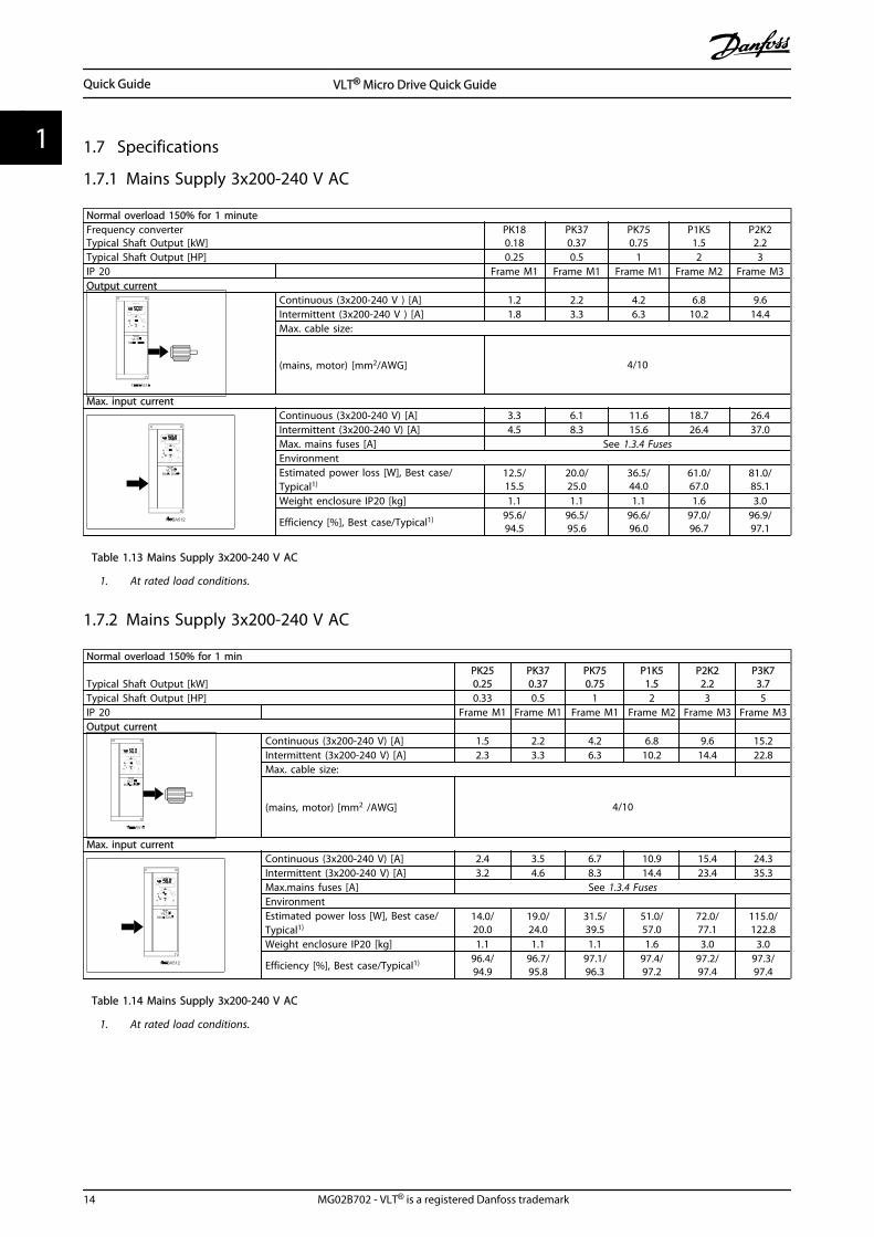
1.7 Specifications
1.7.1 Mains Supply 3x200-240 V AC
Normal overload 150% for 1 minuteFrequency converterTypical Shaft Output [kW]
PK180.18
PK370.37
PK750.75
P1K51.5
P2K22.2
Typical Shaft Output [HP] 0.25 0.5 1 2 3IP 20 Frame M1 Frame M1 Frame M1 Frame M2 Frame M3Output current
Continuous (3x200-240 V ) [A] 1.2 2.2 4.2 6.8 9.6Intermittent (3x200-240 V ) [A] 1.8 3.3 6.3 10.2 14.4Max. cable size:
(mains, motor) [mm2/AWG] 4/10
Max. input currentContinuous (3x200-240 V) [A] 3.3 6.1 11.6 18.7 26.4Intermittent (3x200-240 V) [A] 4.5 8.3 15.6 26.4 37.0Max. mains fuses [A] See 1.3.4 FusesEnvironmentEstimated power loss [W], Best case/Typical1)
12.5/15.5
20.0/25.0
36.5/44.0
61.0/67.0
81.0/85.1
Weight enclosure IP20 [kg] 1.1 1.1 1.1 1.6 3.0
Efficiency [%], Best case/Typical1) 95.6/94.5
96.5/95.6
96.6/96.0
97.0/96.7
96.9/97.1
Table 1.13 Mains Supply 3x200-240 V AC
1. At rated load conditions.
1.7.2 Mains Supply 3x200-240 V AC
Normal overload 150% for 1 min
Typical Shaft Output [kW]PK250.25
PK370.37
PK750.75
P1K51.5
P2K22.2
P3K73.7
Typical Shaft Output [HP] 0.33 0.5 1 2 3 5IP 20 Frame M1 Frame M1 Frame M1 Frame M2 Frame M3 Frame M3Output current
Continuous (3x200-240 V) [A] 1.5 2.2 4.2 6.8 9.6 15.2Intermittent (3x200-240 V) [A] 2.3 3.3 6.3 10.2 14.4 22.8Max. cable size:
(mains, motor) [mm2 /AWG] 4/10
Max. input currentContinuous (3x200-240 V) [A] 2.4 3.5 6.7 10.9 15.4 24.3Intermittent (3x200-240 V) [A] 3.2 4.6 8.3 14.4 23.4 35.3Max.mains fuses [A] See 1.3.4 FusesEnvironment Estimated power loss [W], Best case/Typical1)
14.0/20.0
19.0/24.0
31.5/39.5
51.0/57.0
72.0/77.1
115.0/122.8
Weight enclosure IP20 [kg] 1.1 1.1 1.1 1.6 3.0 3.0
Efficiency [%], Best case/Typical1) 96.4/94.9
96.7/95.8
97.1/96.3
97.4/97.2
97.2/97.4
97.3/97.4
Table 1.14 Mains Supply 3x200-240 V AC
1. At rated load conditions.
Quick Guide VLT® Micro Drive Quick Guide
14 MG02B702 - VLT® is a registered Danfoss trademark
11
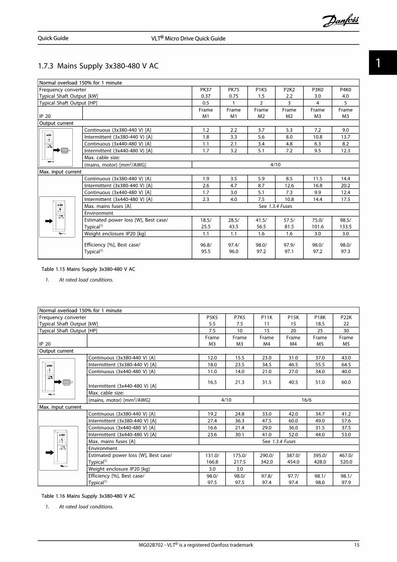
1.7.3 Mains Supply 3x380-480 V AC
Normal overload 150% for 1 minuteFrequency converterTypical Shaft Output [kW]
PK370.37
PK750.75
P1K51.5
P2K22.2
P3K03.0
P4K04.0
Typical Shaft Output [HP] 0.5 1 2 3 4 5
IP 20 Frame
M1Frame
M1Frame
M2Frame
M2Frame
M3Frame
M3Output current
Continuous (3x380-440 V) [A] 1.2 2.2 3.7 5.3 7.2 9.0Intermittent (3x380-440 V) [A] 1.8 3.3 5.6 8.0 10.8 13.7Continuous (3x440-480 V) [A] 1.1 2.1 3.4 4.8 6.3 8.2Intermittent (3x440-480 V) [A] 1.7 3.2 5.1 7.2 9.5 12.3Max. cable size:(mains, motor) [mm2/AWG] 4/10
Max. input currentContinuous (3x380-440 V) [A] 1.9 3.5 5.9 8.5 11.5 14.4Intermittent (3x380-440 V) [A] 2.6 4.7 8.7 12.6 16.8 20.2Continuous (3x440-480 V) [A] 1.7 3.0 5.1 7.3 9.9 12.4Intermittent (3x440-480 V) [A] 2.3 4.0 7.5 10.8 14.4 17.5Max. mains fuses [A] See 1.3.4 FusesEnvironmentEstimated power loss [W], Best case/Typical1)
18.5/25.5
28.5/43.5
41.5/56.5
57.5/81.5
75.0/101.6
98.5/133.5
Weight enclosure IP20 [kg] 1.1 1.1 1.6 1.6 3.0 3.0
Efficiency [%], Best case/Typical1)
96.8/95.5
97.4/96.0
98.0/97.2
97.9/97.1
98.0/97.2
98.0/97.3
Table 1.15 Mains Supply 3x380-480 V AC
1. At rated load conditions.
Normal overload 150% for 1 minuteFrequency converterTypical Shaft Output [kW]
P5K55.5
P7K57.5
P11K11
P15K15
P18K18.5
P22K22
Typical Shaft Output [HP] 7.5 10 15 20 25 30
IP 20 Frame
M3Frame
M3Frame
M4Frame
M4Frame
M5Frame
M5Output current
Continuous (3x380-440 V) [A] 12.0 15.5 23.0 31.0 37.0 43.0Intermittent (3x380-440 V) [A] 18.0 23.5 34.5 46.5 55.5 64.5Continuous (3x440-480 V) [A] 11.0 14.0 21.0 27.0 34.0 40.0
Intermittent (3x440-480 V) [A]16.5 21.3 31.5 40.5 51.0 60.0
Max. cable size:(mains, motor) [mm2/AWG] 4/10 16/6
Max. input currentContinuous (3x380-440 V) [A] 19.2 24.8 33.0 42.0 34.7 41.2Intermittent (3x380-440 V) [A] 27.4 36.3 47.5 60.0 49.0 57.6Continuous (3x440-480 V) [A] 16.6 21.4 29.0 36.0 31.5 37.5Intermittent (3x440-480 V) [A] 23.6 30.1 41.0 52.0 44.0 53.0Max. mains fuses [A] See 1.3.4 FusesEnvironmentEstimated power loss [W], Best case/Typical1)
131.0/166.8
175.0/217.5
290.0/342.0
387.0/454.0
395.0/428.0
467.0/520.0
Weight enclosure IP20 [kg] 3.0 3.0 Efficiency [%], Best case/Typical1)
98.0/97.5
98.0/97.5
97.8/97.4
97.7/97.4
98.1/98.0
98.1/97.9
Table 1.16 Mains Supply 3x380-480 V AC
1. At rated load conditions.
Quick Guide VLT® Micro Drive Quick Guide
MG02B702 - VLT® is a registered Danfoss trademark 15
1 1
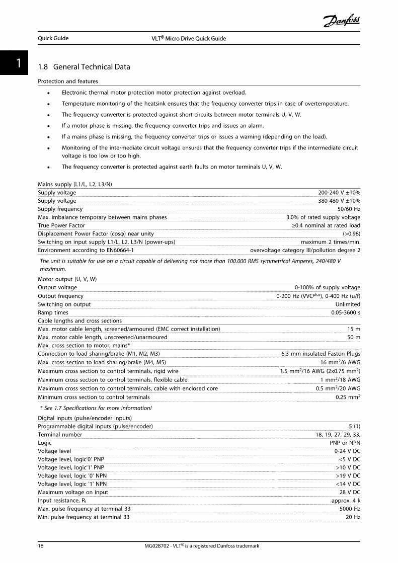
1.8 General Technical Data
Protection and features
• Electronic thermal motor protection motor protection against overload.
• Temperature monitoring of the heatsink ensures that the frequency converter trips in case of overtemperature.
• The frequency converter is protected against short-circuits between motor terminals U, V, W.
• If a motor phase is missing, the frequency converter trips and issues an alarm.
• If a mains phase is missing, the frequency converter trips or issues a warning (depending on the load).
• Monitoring of the intermediate circuit voltage ensures that the frequency converter trips if the intermediate circuitvoltage is too low or too high.
• The frequency converter is protected against earth faults on motor terminals U, V, W.
Mains supply (L1/L, L2, L3/N)Supply voltage 200-240 V ±10%Supply voltage 380-480 V ±10%Supply frequency 50/60 HzMax. imbalance temporary between mains phases 3.0% of rated supply voltageTrue Power Factor ≥0.4 nominal at rated loadDisplacement Power Factor (cosφ) near unity (>0.98)Switching on input supply L1/L, L2, L3/N (power-ups) maximum 2 times/min.Environment according to EN60664-1 overvoltage category III/pollution degree 2
The unit is suitable for use on a circuit capable of delivering not more than 100.000 RMS symmetrical Amperes, 240/480 Vmaximum.
Motor output (U, V, W)Output voltage 0-100% of supply voltageOutput frequency 0-200 Hz (VVCplus), 0-400 Hz (u/f)Switching on output UnlimitedRamp times 0.05-3600 sCable lengths and cross sectionsMax. motor cable length, screened/armoured (EMC correct installation) 15 mMax. motor cable length, unscreened/unarmoured 50 mMax. cross section to motor, mains*Connection to load sharing/brake (M1, M2, M3) 6.3 mm insulated Faston PlugsMax. cross section to load sharing/brake (M4, M5) 16 mm2/6 AWGMaximum cross section to control terminals, rigid wire 1.5 mm2/16 AWG (2x0.75 mm2)Maximum cross section to control terminals, flexible cable 1 mm2/18 AWGMaximum cross section to control terminals, cable with enclosed core 0.5 mm2/20 AWGMinimum cross section to control terminals 0.25 mm2
* See 1.7 Specifications for more information!
Digital inputs (pulse/encoder inputs)Programmable digital inputs (pulse/encoder) 5 (1)Terminal number 18, 19, 27, 29, 33,Logic PNP or NPNVoltage level 0-24 V DCVoltage level, logic'0' PNP <5 V DCVoltage level, logic'1' PNP >10 V DCVoltage level, logic '0' NPN >19 V DCVoltage level, logic '1' NPN <14 V DCMaximum voltage on input 28 V DCInput resistance, Ri approx. 4 kMax. pulse frequency at terminal 33 5000 HzMin. pulse frequency at terminal 33 20 Hz
Quick Guide VLT® Micro Drive Quick Guide
16 MG02B702 - VLT® is a registered Danfoss trademark
11
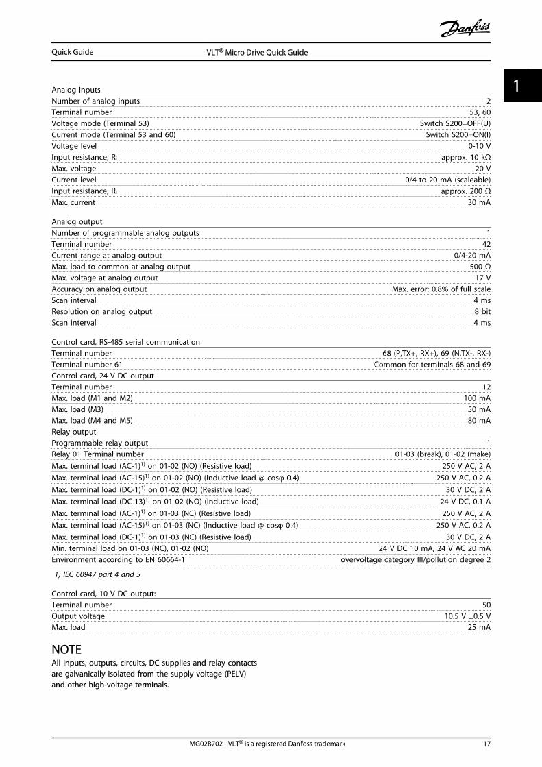
Analog InputsNumber of analog inputs 2Terminal number 53, 60Voltage mode (Terminal 53) Switch S200=OFF(U)Current mode (Terminal 53 and 60) Switch S200=ON(I)Voltage level 0-10 VInput resistance, Ri approx. 10 kΩMax. voltage 20 VCurrent level 0/4 to 20 mA (scaleable)Input resistance, Ri approx. 200 ΩMax. current 30 mA
Analog outputNumber of programmable analog outputs 1Terminal number 42Current range at analog output 0/4-20 mAMax. load to common at analog output 500 ΩMax. voltage at analog output 17 VAccuracy on analog output Max. error: 0.8% of full scaleScan interval 4 msResolution on analog output 8 bitScan interval 4 ms
Control card, RS-485 serial communicationTerminal number 68 (P,TX+, RX+), 69 (N,TX-, RX-)Terminal number 61 Common for terminals 68 and 69Control card, 24 V DC outputTerminal number 12Max. load (M1 and M2) 100 mAMax. load (M3) 50 mAMax. load (M4 and M5) 80 mARelay outputProgrammable relay output 1Relay 01 Terminal number 01-03 (break), 01-02 (make)Max. terminal load (AC-1)1) on 01-02 (NO) (Resistive load) 250 V AC, 2 AMax. terminal load (AC-15)1) on 01-02 (NO) (Inductive load @ cosφ 0.4) 250 V AC, 0.2 AMax. terminal load (DC-1)1) on 01-02 (NO) (Resistive load) 30 V DC, 2 AMax. terminal load (DC-13)1) on 01-02 (NO) (Inductive load) 24 V DC, 0.1 AMax. terminal load (AC-1)1) on 01-03 (NC) (Resistive load) 250 V AC, 2 AMax. terminal load (AC-15)1) on 01-03 (NC) (Inductive load @ cosφ 0.4) 250 V AC, 0.2 AMax. terminal load (DC-1)1) on 01-03 (NC) (Resistive load) 30 V DC, 2 AMin. terminal load on 01-03 (NC), 01-02 (NO) 24 V DC 10 mA, 24 V AC 20 mAEnvironment according to EN 60664-1 overvoltage category III/pollution degree 2
1) IEC 60947 part 4 and 5
Control card, 10 V DC output:Terminal number 50Output voltage 10.5 V ±0.5 VMax. load 25 mA
NOTEAll inputs, outputs, circuits, DC supplies and relay contactsare galvanically isolated from the supply voltage (PELV)and other high-voltage terminals.
Quick Guide VLT® Micro Drive Quick Guide
MG02B702 - VLT® is a registered Danfoss trademark 17
1 1
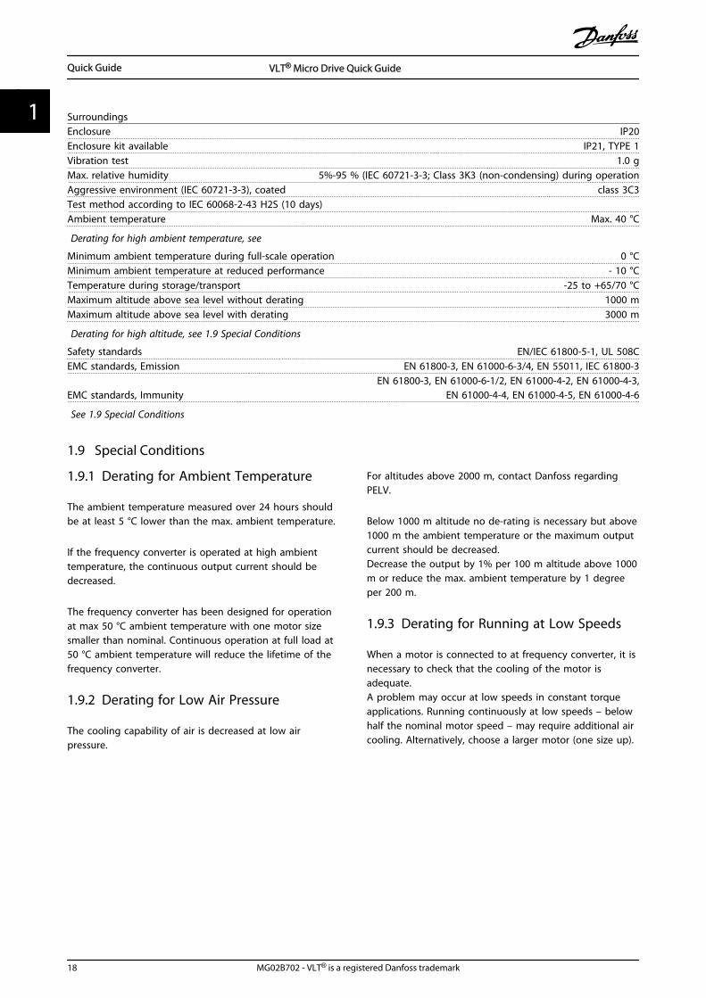
SurroundingsEnclosure IP20Enclosure kit available IP21, TYPE 1Vibration test 1.0 gMax. relative humidity 5%-95 % (IEC 60721-3-3; Class 3K3 (non-condensing) during operationAggressive environment (IEC 60721-3-3), coated class 3C3Test method according to IEC 60068-2-43 H2S (10 days)Ambient temperature Max. 40 °C
Derating for high ambient temperature, see
Minimum ambient temperature during full-scale operation 0 °CMinimum ambient temperature at reduced performance - 10 °CTemperature during storage/transport -25 to +65/70 °CMaximum altitude above sea level without derating 1000 mMaximum altitude above sea level with derating 3000 m
Derating for high altitude, see 1.9 Special Conditions
Safety standards EN/IEC 61800-5-1, UL 508CEMC standards, Emission EN 61800-3, EN 61000-6-3/4, EN 55011, IEC 61800-3
EMC standards, ImmunityEN 61800-3, EN 61000-6-1/2, EN 61000-4-2, EN 61000-4-3,
EN 61000-4-4, EN 61000-4-5, EN 61000-4-6
See 1.9 Special Conditions
1.9 Special Conditions
1.9.1 Derating for Ambient Temperature
The ambient temperature measured over 24 hours shouldbe at least 5 °C lower than the max. ambient temperature.
If the frequency converter is operated at high ambienttemperature, the continuous output current should bedecreased.
The frequency converter has been designed for operationat max 50 °C ambient temperature with one motor sizesmaller than nominal. Continuous operation at full load at50 °C ambient temperature will reduce the lifetime of thefrequency converter.
1.9.2 Derating for Low Air Pressure
The cooling capability of air is decreased at low airpressure.
For altitudes above 2000 m, contact Danfoss regardingPELV.
Below 1000 m altitude no de-rating is necessary but above1000 m the ambient temperature or the maximum outputcurrent should be decreased.Decrease the output by 1% per 100 m altitude above 1000m or reduce the max. ambient temperature by 1 degreeper 200 m.
1.9.3 Derating for Running at Low Speeds
When a motor is connected to at frequency converter, it isnecessary to check that the cooling of the motor isadequate.A problem may occur at low speeds in constant torqueapplications. Running continuously at low speeds – belowhalf the nominal motor speed – may require additional aircooling. Alternatively, choose a larger motor (one size up).
Quick Guide VLT® Micro Drive Quick Guide
18 MG02B702 - VLT® is a registered Danfoss trademark
11
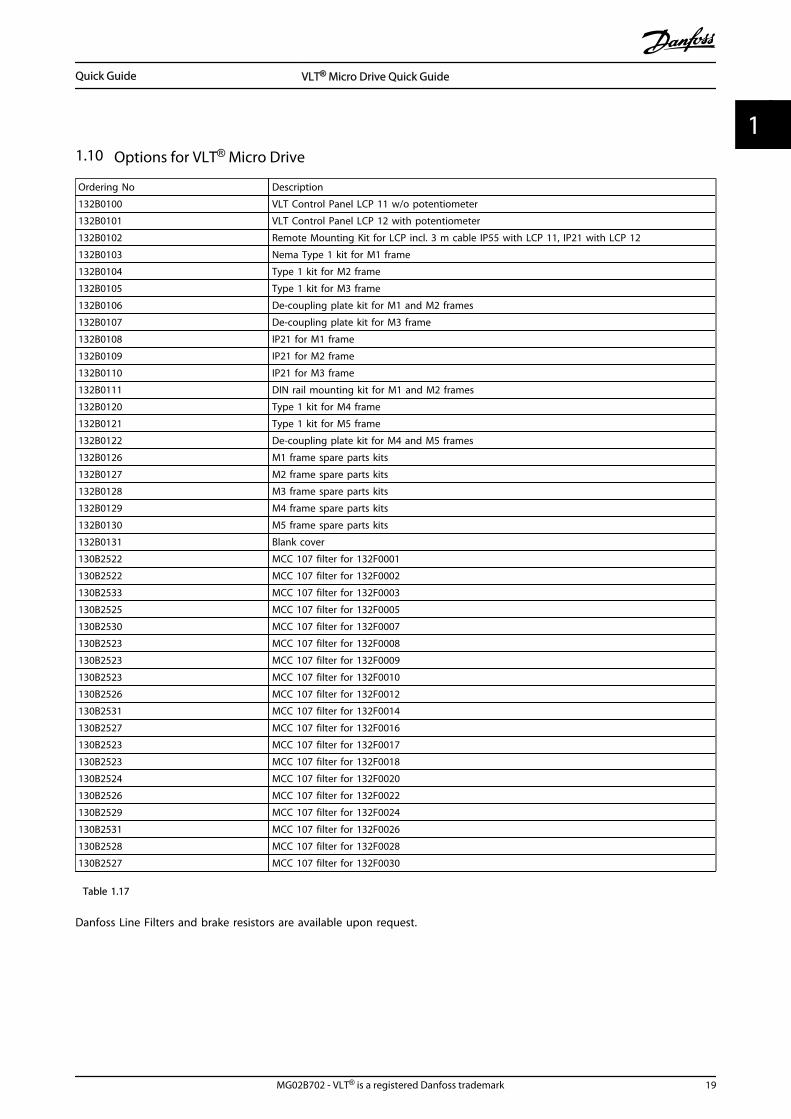
1.10 Options for VLT® Micro Drive
Ordering No Description
132B0100 VLT Control Panel LCP 11 w/o potentiometer
132B0101 VLT Control Panel LCP 12 with potentiometer
132B0102 Remote Mounting Kit for LCP incl. 3 m cable IP55 with LCP 11, IP21 with LCP 12
132B0103 Nema Type 1 kit for M1 frame
132B0104 Type 1 kit for M2 frame
132B0105 Type 1 kit for M3 frame
132B0106 De-coupling plate kit for M1 and M2 frames
132B0107 De-coupling plate kit for M3 frame
132B0108 IP21 for M1 frame
132B0109 IP21 for M2 frame
132B0110 IP21 for M3 frame
132B0111 DIN rail mounting kit for M1 and M2 frames
132B0120 Type 1 kit for M4 frame
132B0121 Type 1 kit for M5 frame
132B0122 De-coupling plate kit for M4 and M5 frames
132B0126 M1 frame spare parts kits
132B0127 M2 frame spare parts kits
132B0128 M3 frame spare parts kits
132B0129 M4 frame spare parts kits
132B0130 M5 frame spare parts kits
132B0131 Blank cover
130B2522 MCC 107 filter for 132F0001
130B2522 MCC 107 filter for 132F0002
130B2533 MCC 107 filter for 132F0003
130B2525 MCC 107 filter for 132F0005
130B2530 MCC 107 filter for 132F0007
130B2523 MCC 107 filter for 132F0008
130B2523 MCC 107 filter for 132F0009
130B2523 MCC 107 filter for 132F0010
130B2526 MCC 107 filter for 132F0012
130B2531 MCC 107 filter for 132F0014
130B2527 MCC 107 filter for 132F0016
130B2523 MCC 107 filter for 132F0017
130B2523 MCC 107 filter for 132F0018
130B2524 MCC 107 filter for 132F0020
130B2526 MCC 107 filter for 132F0022
130B2529 MCC 107 filter for 132F0024
130B2531 MCC 107 filter for 132F0026
130B2528 MCC 107 filter for 132F0028
130B2527 MCC 107 filter for 132F0030
Table 1.17
Danfoss Line Filters and brake resistors are available upon request.
Quick Guide VLT® Micro Drive Quick Guide
MG02B702 - VLT® is a registered Danfoss trademark 19
1 1
Index
AActive Set-up.......................................................................................... 10
Ambient Temperature........................................................................ 18
Analog Inputs......................................................................................... 17
BBrake
Resistor (ohm)................................................................................... 10Resistor Short-circuited................................................................. 13
CCable Lengths And Cross Sections................................................. 16
Clearance................................................................................................... 3
Control Card, 24 V DC Output.......................................................... 17
DDC-brake.................................................................................................. 11
DC-Brake.................................................................................................. 10
De-coupling Plate Kit.......................................................................... 19
DeratingFor Ambient Temperature............................................................ 18For Low Air Pressure....................................................................... 18For Running At Low Speeds......................................................... 18
DigitalInputs................................................................................................... 16Inputs (pulse/encoder Inputs)..................................................... 16
DIN Rail Mounting Kit.......................................................................... 19
EEarth Leakage Current........................................................................... 2
Edit Set-up............................................................................................... 10
Electronic Waste...................................................................................... 3
GGround Wire.............................................................................................. 2
Grounding................................................................................................. 2
HHand Mode............................................................................................. 11
IIP21............................................................................................................ 19
Isolated Mains Source........................................................................... 3
IT Mains....................................................................................................... 3
LLoad
Compensation................................................................................... 10Sharing/Brake...................................................................................... 8
MMain Menu................................................................................................. 9
MainsSupply.................................................................................................. 14Supply (L1/L, L2, L3/N)................................................................... 16Supply 3x200-240 V AC.................................................................. 14Supply 3x380-480 V AC.................................................................. 15
MotorOutput (U, V, W)................................................................................ 16Overload Protection.......................................................................... 2Phase.................................................................................................... 11Protection........................................................................................... 16Temperature...................................................................................... 10
NNavigation Keys....................................................................................... 9
Nema Type 1 Kit.................................................................................... 19
OOperation Keys......................................................................................... 9
Output Performance (U, V, W).......................................................... 16
Overcurrent Protection......................................................................... 5
Over-voltage Control.......................................................................... 10
PPower Circuit - Overview...................................................................... 8
ProtectionProtection.............................................................................................. 5And Features...................................................................................... 16
QQuick Menu............................................................................................... 9
RRCD............................................................................................................... 2
Reference................................................................................................... 2
Relay Output.......................................................................................... 17
Remote Mounting Kit.......................................................................... 19
SSlip Compensation............................................................................... 10
Status........................................................................................................... 9
Surroundings......................................................................................... 18
Index VLT® Micro Drive Quick Guide
20 MG02B702 - VLT® is a registered Danfoss trademark
TThermistor............................................................................................... 10
UUL Compliance......................................................................................... 5
VVLT
Control Panel LCP 11...................................................................... 19Control Panel LCP 12...................................................................... 19
Voltage Level.......................................................................................... 16
WWarnings And Alarms......................................................................... 13
Index VLT® Micro Drive Quick Guide
MG02B702 - VLT® is a registered Danfoss trademark 21
www.danfoss.com/drives
*MG02B702*132R0029 MG02B702 Rev. 2012-03-17