
User Manual - gongkong
244
User Manual Logix5550 Controller (Cat. No. 1756-L1, -L1Mx) Allen-Bradley
Transcript of User Manual - gongkong
User ManualLogix5550 Controller
(Cat. No. 1756-L1, -L1Mx)
Allen-Bradley
1756-6.5.12 March 1999
Important User Information 6ROLG�VWDWH�HTXLSPHQW�KDV�RSHUDWLRQDO�FKDUDFWHULVWLFV�GLIIHULQJ�IURP�WKRVH�RI�HOHFWURPHFKDQLFDO�HTXLSPHQW���6DIHW\�*XLGHOLQHV�IRU�WKH�$SSOLFDWLRQ��,QVWDOODWLRQ��DQG�0DLQWHQDQFH�RI�6ROLG�6WDWH�&RQWUROV��SXEOLFDWLRQ�6*,�����GHVFULEHV�VRPH�LPSRUWDQW�GLIIHUHQFHV�EHWZHHQ�VROLG�VWDWH�HTXLSPHQW�DQG�KDUG�ZLUHG�HOHFWURPHFKDQLFDO�GHYLFHV���%HFDXVH�RI�WKLV�GLIIHUHQFH��DQG�DOVR�EHFDXVH�RI�WKH�ZLGH�YDULHW\�RI�XVHV�IRU�VROLG�VWDWH�HTXLSPHQW��DOO�SHUVRQV�UHVSRQVLEOH�IRU�DSSO\LQJ�WKLV�HTXLSPHQW�PXVW�VDWLVI\�WKHPVHOYHV�WKDW�HDFK�LQWHQGHG�DSSOLFDWLRQ�RI�WKLV�HTXLSPHQW�LV�DFFHSWDEOH�
,Q�QR�HYHQW�ZLOO�WKH�$OOHQ�%UDGOH\�&RPSDQ\�EH�UHVSRQVLEOH�RU�OLDEOH�IRU�LQGLUHFW�RU�FRQVHTXHQWLDO�GDPDJHV�UHVXOWLQJ�IURP�WKH�XVH�RU�DSSOLFDWLRQ�RI�WKLV�HTXLSPHQW�
7KH�H[DPSOHV�DQG�GLDJUDPV�LQ�WKLV�PDQXDO�DUH�LQFOXGHG�VROHO\�IRU�LOOXVWUDWLYH�SXUSRVHV���%HFDXVH�RI�WKH�PDQ\�YDULDEOHV�DQG�UHTXLUHPHQWV�DVVRFLDWHG�ZLWK�DQ\�SDUWLFXODU�LQVWDOODWLRQ��WKH�$OOHQ�%UDGOH\�&RPSDQ\�FDQQRW�DVVXPH�UHVSRQVLELOLW\�RU�OLDELOLW\�IRU�DFWXDO�XVH�EDVHG�RQ�WKH�H[DPSOHV�DQG�GLDJUDPV�
1R�SDWHQW�OLDELOLW\�LV�DVVXPHG�E\�$OOHQ�%UDGOH\�&RPSDQ\�ZLWK�UHVSHFW�WR�XVH�RI�LQIRUPDWLRQ��FLUFXLWV��HTXLSPHQW��RU�VRIWZDUH�GHVFULEHG�LQ�WKLV PDQXDO�
5HSURGXFWLRQ�RI�WKH�FRQWHQWV�RI�WKLV�PDQXDO��LQ�ZKROH�RU�LQ�SDUW��ZLWKRXW�ZULWWHQ�SHUPLVVLRQ�RI�WKH�$OOHQ�%UDGOH\�&RPSDQ\�LV�SURKLELWHG�
7KURXJKRXW�WKLV�PDQXDO�ZH�XVH�QRWHV�WR�PDNH�\RX�DZDUH�RI�VDIHW\�FRQVLGHUDWLRQV�
$WWHQWLRQV�KHOS�\RX�� LGHQWLI\�D�KD]DUG� DYRLG�WKH�KD]DUG� UHFRJQL]H�WKH�FRQVHTXHQFHV
,PSRUWDQW��,GHQWLILHV�LQIRUPDWLRQ�WKDW�LV�HVSHFLDOO\�LPSRUWDQW�IRU�VXFFHVVIXO�DSSOLFDWLRQ�DQG�XQGHUVWDQGLQJ�RI�WKH�SURGXFW�
�$77(17,21� ,GHQWLILHV�LQIRUPDWLRQ�DERXW�SUDFWLFHV�RU�FLUFXPVWDQFHV�WKDW�FDQ�OHDG�WR�SHUVRQDO�LQMXU\�RU�GHDWK��SURSHUW\�GDPDJH��RU�HFRQRPLF�ORVV�
6XPPDU\�RI�&KDQJHV
Introduction 7KLV�UHOHDVH�RI�WKLV�GRFXPHQW�FRQWDLQV�QHZ�DQG�XSGDWHG�LQIRUPDWLRQ���7R�KHOS�\RX�ILQG�WKH�QHZ�DQG�XSGDWHG�LQIRUPDWLRQ��ORRN�IRU�FKDQJH�EDUV��DV�VKRZQ�QH[W�WR�WKLV�SDUDJUDSK�
Updated Information 7KLV�GRFXPHQW�KDV�EHHQ�XSGDWHG�WKURXJKRXW���7KH�PRVW�VLJQLILFDQW�FKDQJHV�DUH�
For this new/updated information: See chapter:
Upload/download changes 2
Forcing 11
1756-6.5.12 March 1999

ii
1RWHV�
1756-6.5.12 March 1999
3UHIDFH
Using This Manual
Introduction 7KLV�PDQXDO�LV�RQH�RI�VHYHUDO�&RQWURO/RJL[�GRFXPHQWV�
Who Should Use This Manual 7KLV�GRFXPHQW�SURYLGHV�D�SURJUDPPHU�ZLWK�LQIRUPDWLRQ�DERXW�KRZ�WKH�/RJL[�����FRQWUROOHU�
� VWRUHV�DQG�SURFHVVHV�GDWD� RSHUDWHV� FRPPXQLFDWHV�ZLWK�RWKHU�PRGXOHV� SURFHVVHV�DQG�KDQGOHV�IDXOW�LQIRUPDWLRQ
Task/Goal: Documents:
Installing the controller and its components Logix5550 Controller Quick Start, publication 1756-10.1
Logix5550 Memory Board Installation Instructions, publication 1756-5.33
Using the controllerLogix5550 Controller User Manual, publication 1756-6.5.12
Programming the controller Logix5550 Controller Instruction Set Reference Manual, publication 1756-6.4.1
Configuring and communicating with digital I/O modules
Digital Modules User Manual, publication 1756-6.5.8
Configuring and communicating with analog I/O modules
Analog Modules User Manual, publication 1756-6.5.9
Selecting and installing a chassis ControlLogix Chassis Installation Instructions, publication 1756-5.69
Selecting and installing a power supply ControlLogix Power Supply Installation Instructions, publication 1756-5.1
You are here
1756-6.5.12 March 1999

ii Using This Manual
Purpose of This Manual 7KLV�PDQXDO�LV�LQWHQGHG�WR�KHOS�\RX�GHVLJQ�DQG�RSHUDWH�D�V\VWHP�XVLQJ�D�/RJL[�����FRQWUROOHU���7KH�ILUVW�FKDSWHU�LQ�WKLV�PDQXDO�SURYLGHV�WKH�VWHSV�DQG�LQIRUPDWLRQ�\RX�QHHG�WR�JHW�VWDUWHG�
8VH�WKH�UHPDLQGHU�RI�WKLV�PDQXDO�WR�KHOS�\RX�
� ZRUN�ZLWK�FRQWUROOHU�SURMHFWV� FRQILJXUH�,�2�PRGXOHV� RUJDQL]H�GDWD� GHYHORS�SURJUDPV� FRQILJXUH�SURGXFHG�DQG�FRQVXPHG�GDWD� DFFRXQW�IRU�FRPPXQLFDWLRQ�FRQQHFWLRQV� FRPPXQLFDWLRQ�RYHU�D�VHULDO�QHWZRUN� FRPPXQLFDWH�RYHU�RWKHU�QHWZRUNV� LGHQWLI\�DQG�SURFHVV�FRQWUROOHU�IDXOWV
Conventions and Related Terms 7KLV�PDQXDO�LQFOXGHV�D�JORVVDU\�WR�GHILQH�FRPPRQ�WHUPV�
1756-6.5.12 March 1999
Table of Contents
Getting Started Chapter 1
Using This Chapter . . . . . . . . . . . . . . . . . . . . . . . . . . . . . 1-1Installing the Controller . . . . . . . . . . . . . . . . . . . . . . . . . . 1-2
Prepare the controller . . . . . . . . . . . . . . . . . . . . . . . . . 1-3Install the controller . . . . . . . . . . . . . . . . . . . . . . . . . . 1-3
Creating and Downloading a Project . . . . . . . . . . . . . . . . 1-4Create a project . . . . . . . . . . . . . . . . . . . . . . . . . . . . . 1-5Changing project properties . . . . . . . . . . . . . . . . . . . . 1-6Adding a local input module . . . . . . . . . . . . . . . . . . . . 1-7Adding a local output module . . . . . . . . . . . . . . . . . . . 1-9Changing module properties . . . . . . . . . . . . . . . . . . . 1-11Viewing I/O tags . . . . . . . . . . . . . . . . . . . . . . . . . . . . 1-12Creating other tags . . . . . . . . . . . . . . . . . . . . . . . . . . 1-13Documenting I/O with alias tags . . . . . . . . . . . . . . . . 1-14Enter logic. . . . . . . . . . . . . . . . . . . . . . . . . . . . . . . . . 1-16Download a project . . . . . . . . . . . . . . . . . . . . . . . . . . 1-18Viewing program scan time. . . . . . . . . . . . . . . . . . . . 1-21Viewing controller memory usage . . . . . . . . . . . . . . . 1-22
What To Do Next . . . . . . . . . . . . . . . . . . . . . . . . . . . . . . 1-22
Working with Projects Chapter 2
Using This Chapter . . . . . . . . . . . . . . . . . . . . . . . . . . . . . 2-1Creating a Project . . . . . . . . . . . . . . . . . . . . . . . . . . . . . . 2-1
Naming controllers . . . . . . . . . . . . . . . . . . . . . . . . . . . 2-2Changing Project Properties . . . . . . . . . . . . . . . . . . . . . . 2-2Working with the Controller Organizer . . . . . . . . . . . . . . . 2-3Saving Your Project. . . . . . . . . . . . . . . . . . . . . . . . . . . . . 2-4Uploading From the Controller. . . . . . . . . . . . . . . . . . . . . 2-4Using Coordinated System Time . . . . . . . . . . . . . . . . . . . 2-5
Configuring I/O Modules Chapter 3
Using This Chapter . . . . . . . . . . . . . . . . . . . . . . . . . . . . . 3-1Introduction . . . . . . . . . . . . . . . . . . . . . . . . . . . . . . . . . . 3-1Logic Scanning . . . . . . . . . . . . . . . . . . . . . . . . . . . . . . . . 3-2Defining I/O Updates . . . . . . . . . . . . . . . . . . . . . . . . . . . . 3-2
How an I/O module uses COS . . . . . . . . . . . . . . . . . . . 3-2How an I/O module uses RPI . . . . . . . . . . . . . . . . . . . . 3-3When an analog module uses RTS. . . . . . . . . . . . . . . . 3-3
How I/O Modules Operate . . . . . . . . . . . . . . . . . . . . . . . . 3-3
1756-6.5.12 March1999
toc–ii Table of Contents
Configuring Local I/O. . . . . . . . . . . . . . . . . . . . . . . . . . . . 3-4Naming modules . . . . . . . . . . . . . . . . . . . . . . . . . . . . . 3-5Electronic keying . . . . . . . . . . . . . . . . . . . . . . . . . . . . . 3-6Configuring communication format . . . . . . . . . . . . . . . 3-7Selecting controller ownership . . . . . . . . . . . . . . . . . . 3-8Inhibiting module operation . . . . . . . . . . . . . . . . . . . . . 3-9
Configuring I/O in a Remote Chassis . . . . . . . . . . . . . . . 3-11Changing Configuration Information . . . . . . . . . . . . . . . 3-15Accessing I/O . . . . . . . . . . . . . . . . . . . . . . . . . . . . . . . . 3-16
Example of local addressing . . . . . . . . . . . . . . . . . . . 3-17Example of remote addressing . . . . . . . . . . . . . . . . . 3-18Defining aliases. . . . . . . . . . . . . . . . . . . . . . . . . . . . . 3-19
Viewing Module Fault Information . . . . . . . . . . . . . . . . . 3-19Using the programming software to view I/O faults . . 3-21Using logic to monitor I/O faults. . . . . . . . . . . . . . . . . 3-22
Organizing Data Chapter 4Using This Chapter . . . . . . . . . . . . . . . . . . . . . . . . . . . . . 4-1How the Controller Stores Data . . . . . . . . . . . . . . . . . . . . 4-1Creating Tags . . . . . . . . . . . . . . . . . . . . . . . . . . . . . . . . . 4-2
Data types. . . . . . . . . . . . . . . . . . . . . . . . . . . . . . . . . . 4-3Naming tags . . . . . . . . . . . . . . . . . . . . . . . . . . . . . . . . 4-4Entering tags. . . . . . . . . . . . . . . . . . . . . . . . . . . . . . . . 4-4
Using Base Tags . . . . . . . . . . . . . . . . . . . . . . . . . . . . . . . 4-6Memory allocation for base tags . . . . . . . . . . . . . . . . . 4-6Data type conversions . . . . . . . . . . . . . . . . . . . . . . . . . 4-8Specifying bits. . . . . . . . . . . . . . . . . . . . . . . . . . . . . . . 4-8
Using Structures . . . . . . . . . . . . . . . . . . . . . . . . . . . . . . . 4-9Predefined structures . . . . . . . . . . . . . . . . . . . . . . . . 4-10Module-defined structure . . . . . . . . . . . . . . . . . . . . . 4-10User-defined structure. . . . . . . . . . . . . . . . . . . . . . . . 4-10Memory allocation for user-defined structures. . . . . . 4-11Referencing members within a structure . . . . . . . . . . 4-12
Viewing an Array as a Collection of Elements . . . . . . . . 4-13Indexing through arrays. . . . . . . . . . . . . . . . . . . . . . . 4-14Specifying Bits Within Arrays . . . . . . . . . . . . . . . . . . . 4-15
Viewing an Array as a Block of Memory. . . . . . . . . . . . . 4-15How the controller stores array data . . . . . . . . . . . . . 4-16Varying a dimension . . . . . . . . . . . . . . . . . . . . . . . . . 4-17
Memory Allocation for Arrays . . . . . . . . . . . . . . . . . . . . 4-17Aliasing Tags. . . . . . . . . . . . . . . . . . . . . . . . . . . . . . . . . 4-19Scoping Tags . . . . . . . . . . . . . . . . . . . . . . . . . . . . . . . . 4-20
Scoping tags local to a program . . . . . . . . . . . . . . . . 4-21Scoping tags global to a controller. . . . . . . . . . . . . . . 4-21
1756-6.5.12 March1999
Table of Contents toc–iii
Developing Programs Chapter 5Using This Chapter . . . . . . . . . . . . . . . . . . . . . . . . . . . . . 5-1Organizing Projects . . . . . . . . . . . . . . . . . . . . . . . . . . . . . 5-1Defining Tasks . . . . . . . . . . . . . . . . . . . . . . . . . . . . . . . . 5-2
Using a continuous task . . . . . . . . . . . . . . . . . . . . . . . 5-3Using a periodic task . . . . . . . . . . . . . . . . . . . . . . . . . . 5-3Creating tasks . . . . . . . . . . . . . . . . . . . . . . . . . . . . . . . 5-5Naming tasks . . . . . . . . . . . . . . . . . . . . . . . . . . . . . . . 5-6Configuring tasks . . . . . . . . . . . . . . . . . . . . . . . . . . . . 5-6Setting the task watchdog . . . . . . . . . . . . . . . . . . . . . . 5-8Avoiding periodic task overlap . . . . . . . . . . . . . . . . . . . 5-8
Defining Programs . . . . . . . . . . . . . . . . . . . . . . . . . . . . . 5-8Creating programs. . . . . . . . . . . . . . . . . . . . . . . . . . . . 5-9Naming programs . . . . . . . . . . . . . . . . . . . . . . . . . . . . 5-9Configuring programs . . . . . . . . . . . . . . . . . . . . . . . . 5-10
Defining Routines . . . . . . . . . . . . . . . . . . . . . . . . . . . . . 5-11Creating routines. . . . . . . . . . . . . . . . . . . . . . . . . . . . 5-11Naming routines . . . . . . . . . . . . . . . . . . . . . . . . . . . . 5-12Configuring routines . . . . . . . . . . . . . . . . . . . . . . . . . 5-12
Entering Ladder Logic . . . . . . . . . . . . . . . . . . . . . . . . . . 5-13Entering branches . . . . . . . . . . . . . . . . . . . . . . . . . . . 5-14
Scheduling System Overhead . . . . . . . . . . . . . . . . . . . . 5-15Downloading a Project . . . . . . . . . . . . . . . . . . . . . . . . . 5-16
Communicating with Other Controllers
Chapter 6
Using This Chapter . . . . . . . . . . . . . . . . . . . . . . . . . . . . . 6-1Using MSG Instructions . . . . . . . . . . . . . . . . . . . . . . . . . . 6-1
Communicating with another Logix5550 controller . . . 6-1Communicating with other processors. . . . . . . . . . . . . 6-2Mapping addresses . . . . . . . . . . . . . . . . . . . . . . . . . . . 6-4
Using Produced and Consumed Tags . . . . . . . . . . . . . . . 6-6Processing produced and consumed tags . . . . . . . . . . 6-7Maximum number of produced and consumed tags . . 6-8
Planning to Support Produced and Consumed Tags. . . . . 6-9Identifying another local controller. . . . . . . . . . . . . . . 6-10Identifying a remote controller . . . . . . . . . . . . . . . . . . 6-10
Producing a Tag . . . . . . . . . . . . . . . . . . . . . . . . . . . . . . 6-12Consuming a Tag . . . . . . . . . . . . . . . . . . . . . . . . . . . . . 6-14Sending Large Arrays of Data . . . . . . . . . . . . . . . . . . . . 6-17
1756-6.5.12 March1999
toc–iv Table of Contents
Allocating Communication Connections
Chapter 7
Using This Chapter . . . . . . . . . . . . . . . . . . . . . . . . . . . . . 7-1How the ControlLogix System Uses Connections . . . . . . . 7-1Determining Connections for I/O Modules . . . . . . . . . . . . 7-2
Direct connections for I/O modules . . . . . . . . . . . . . . . 7-2Rack optimized connections for I/O modules . . . . . . . . 7-4Combining direct and rack optimized connections . . . . 7-5
Determining Connections for Produced/Consumed Tags . 7-6Connections for produced tags . . . . . . . . . . . . . . . . . . 7-6Optimizing produced tags . . . . . . . . . . . . . . . . . . . . . . 7-7Connections for consumed tags. . . . . . . . . . . . . . . . . . 7-7
Determining Connections for Messaging . . . . . . . . . . . . . 7-7Determining Total Connection Requirements . . . . . . . . . . 7-8
Communicating with Devices on a Serial Link
Chapter 8
Using This Chapter . . . . . . . . . . . . . . . . . . . . . . . . . . . . . 8-1Using RS-232 . . . . . . . . . . . . . . . . . . . . . . . . . . . . . . . . . 8-1Connecting to the Serial Port . . . . . . . . . . . . . . . . . . . . . . 8-2
Configuring the controller to use the serial port . . . . . . 8-3Using the DF1 Serial Protocol . . . . . . . . . . . . . . . . . . . . . 8-4
Master/slave communication methods . . . . . . . . . . . . 8-5Configuring Serial Communications. . . . . . . . . . . . . . . . . 8-5
Configuring a DF1 point-to-point station . . . . . . . . . . . 8-6Configuring a DF1 slave station . . . . . . . . . . . . . . . . . . 8-7Configuring a DF1 master station . . . . . . . . . . . . . . . . 8-8If you choose one of the standard polling modes . . . . . 8-9
Communicating with a Workstation
Chapter 9
Using This Chapter . . . . . . . . . . . . . . . . . . . . . . . . . . . . . 9-1Configuring Communications to the Controller. . . . . . . . . 9-1Defining Connection Paths . . . . . . . . . . . . . . . . . . . . . . . 9-2
Connection path examples . . . . . . . . . . . . . . . . . . . . . 9-4
1756-6.5.12 March1999
Table of Contents toc–v
Integrating Motion Chapter 10
Using This Chapter . . . . . . . . . . . . . . . . . . . . . . . . . . . . 10-1Introduction. . . . . . . . . . . . . . . . . . . . . . . . . . . . . . . . . . 10-1Developing a Motion Control Application Program . . . . . 10-2
Selecting the master controller . . . . . . . . . . . . . . . . . 10-2Adding a 1756-M02AE module . . . . . . . . . . . . . . . . . 10-3Naming an axis . . . . . . . . . . . . . . . . . . . . . . . . . . . . . 10-4Configuring a servo axis . . . . . . . . . . . . . . . . . . . . . . 10-5Running hookup diagnostics and auto tuning. . . . . . 10-11
Writing a Motion Application Program . . . . . . . . . . . . . 10-12Understanding the MOTION_INSTRUCTION tag . . . . 10-13Using motion status and configuration parameters . 10-13Modifying motion configuration parameters. . . . . . . 10-14Handling motion faults. . . . . . . . . . . . . . . . . . . . . . . 10-14Understanding errors. . . . . . . . . . . . . . . . . . . . . . . . 10-14Understanding minor/major faults . . . . . . . . . . . . . . 10-14Understanding a programming example . . . . . . . . . 10-15
Forcing Chapter 11
Using This Chapter . . . . . . . . . . . . . . . . . . . . . . . . . . . . 11-1Forcing . . . . . . . . . . . . . . . . . . . . . . . . . . . . . . . . . . . . . 11-1Entering Forces . . . . . . . . . . . . . . . . . . . . . . . . . . . . . . . 11-2
Entering forces from the data monitor . . . . . . . . . . . . 11-2Entering forces from the ladder editor . . . . . . . . . . . . 11-3
Enabling Forces. . . . . . . . . . . . . . . . . . . . . . . . . . . . . . . 11-4Disabling Forces . . . . . . . . . . . . . . . . . . . . . . . . . . . . . . 11-5Removing Forces . . . . . . . . . . . . . . . . . . . . . . . . . . . . . 11-5Monitoring Forces . . . . . . . . . . . . . . . . . . . . . . . . . . . . . 11-6
Handling Controller Faults Chapter 12
Using This Chapter . . . . . . . . . . . . . . . . . . . . . . . . . . . . 12-1Understanding Controller Faults. . . . . . . . . . . . . . . . . . . 12-1Viewing Controller Faults. . . . . . . . . . . . . . . . . . . . . . . . 12-2Monitoring I/O Faults . . . . . . . . . . . . . . . . . . . . . . . . . . . 12-2Handling Hardware Faults . . . . . . . . . . . . . . . . . . . . . . . 12-3Processing Minor Faults . . . . . . . . . . . . . . . . . . . . . . . . 12-3
Processing instruction-execution minor faults . . . . . . 12-4Writing logic for instruction-execution minor faults . . 12-5Processing other minor faults . . . . . . . . . . . . . . . . . . 12-6Writing logic for other minor faults. . . . . . . . . . . . . . . 12-7
Minor Fault Types and Codes . . . . . . . . . . . . . . . . . . . . 12-8Processing Major Faults . . . . . . . . . . . . . . . . . . . . . . . . 12-9
Writing logic for a major fault . . . . . . . . . . . . . . . . . 12-12Major Fault Types and Codes . . . . . . . . . . . . . . . . . . . 12-14Creating a Program Fault Routine . . . . . . . . . . . . . . . . 12-16Creating the Controller Fault Handler . . . . . . . . . . . . . . 12-16
1756-6.5.12 March1999
toc–vi Table of Contents
Creating a program for the controller fault handler. . 12-17Naming programs . . . . . . . . . . . . . . . . . . . . . . . . . . 12-17Selecting an unscheduled program . . . . . . . . . . . . . 12-17Configuring programs . . . . . . . . . . . . . . . . . . . . . . . 12-18Creating routines. . . . . . . . . . . . . . . . . . . . . . . . . . . 12-19Naming routines . . . . . . . . . . . . . . . . . . . . . . . . . . . 12-19
Accessing the FAULTLOG . . . . . . . . . . . . . . . . . . . . . . 12-20MajorFaultBits structure . . . . . . . . . . . . . . . . . . . . . 12-20MinorFaultBits structure . . . . . . . . . . . . . . . . . . . . . 12-20
Preparing a Power-Up Program Chapter 13
Using This Chapter . . . . . . . . . . . . . . . . . . . . . . . . . . . . 13-1How the Controller Powers Up in Run Mode. . . . . . . . . . 13-1
Processing the power-up handler . . . . . . . . . . . . . . . 13-2Creating the Power-Up Handler . . . . . . . . . . . . . . . . . . . 13-3
Creating a program for the power-up handler . . . . . . 13-3Naming programs . . . . . . . . . . . . . . . . . . . . . . . . . . . 13-3Selecting an unscheduled program . . . . . . . . . . . . . . 13-4Configuring programs . . . . . . . . . . . . . . . . . . . . . . . . 13-4Creating routines. . . . . . . . . . . . . . . . . . . . . . . . . . . . 13-5Naming routines . . . . . . . . . . . . . . . . . . . . . . . . . . . . 13-6
Clearing the Major Fault . . . . . . . . . . . . . . . . . . . . . . . . 13-6
Troubleshooting Appendix A
Using This Appendix . . . . . . . . . . . . . . . . . . . . . . . . . . . . A-1Identifying Controller Components. . . . . . . . . . . . . . . . . . A-1Monitoring Controller Status LEDs . . . . . . . . . . . . . . . . . . A-2
Determining which modules are not responding . . . . . A-3Monitoring Controller Status . . . . . . . . . . . . . . . . . . . . . . A-5
Viewing status through the programming software . . . A-5Monitoring status flags . . . . . . . . . . . . . . . . . . . . . . . . A-6Using GSV/SSV instructions . . . . . . . . . . . . . . . . . . . . . A-6
Changing Controller Mode . . . . . . . . . . . . . . . . . . . . . . . . A-8Examining Controller Prescan Operations . . . . . . . . . . . . A-9
Instructions with unique prescan operations . . . . . . . . A-9Recovering from prescan errors. . . . . . . . . . . . . . . . . A-10
1756-6.5.12 March1999
Table of Contents toc–vii
IEC1131-3 Compliance Appendix B
Using This Appendix . . . . . . . . . . . . . . . . . . . . . . . . . . . . B-1Introduction. . . . . . . . . . . . . . . . . . . . . . . . . . . . . . . . . . . B-1Operating System . . . . . . . . . . . . . . . . . . . . . . . . . . . . . . B-2Data Definitions. . . . . . . . . . . . . . . . . . . . . . . . . . . . . . . . B-2Programming Languages . . . . . . . . . . . . . . . . . . . . . . . . B-3Instruction Set. . . . . . . . . . . . . . . . . . . . . . . . . . . . . . . . . B-3IEC1131-3 Program Portability . . . . . . . . . . . . . . . . . . . . B-4IEC Compliance Tables . . . . . . . . . . . . . . . . . . . . . . . . . . B-4
Specifications Appendix C
Logix5550 Controller . . . . . . . . . . . . . . . . . . . . . . . . . . . . C-1Logix5550 Memory Board . . . . . . . . . . . . . . . . . . . . . . . . C-21756-CP3 Serial Cable Pinouts . . . . . . . . . . . . . . . . . . . . C-31756-BA1 Battery . . . . . . . . . . . . . . . . . . . . . . . . . . . . . . C-31756-M0A2E Motion Module. . . . . . . . . . . . . . . . . . . . . . C-4
Glossary
1756-6.5.12 March1999

toc–viii Table of Contents
1RWHV�
1756-6.5.12 March1999
Chapter 1
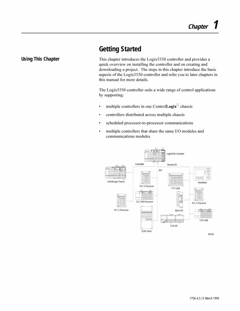
Getting StartedUsing This Chapter 7KLV�FKDSWHU�LQWURGXFHV�WKH�/RJL[�����FRQWUROOHU�DQG�SURYLGHV�D�
TXLFN�RYHUYLHZ�RQ�LQVWDOOLQJ�WKH�FRQWUROOHU�DQG�RQ�FUHDWLQJ�DQG�GRZQORDGLQJ�D�SURMHFW���7KH�VWHSV�LQ�WKLV�FKDSWHU�LQWURGXFH�WKH�EDVLF�DVSHFWV�RI�WKH�/RJL[�����FRQWUROOHU�DQG�UHIHU�\RX�WR�ODWHU�FKDSWHUV�LQ�WKLV�PDQXDO�IRU�PRUH�GHWDLOV�
7KH�/RJL[�����FRQWUROOHU�VXLWV�D�ZLGH�UDQJH�RI�FRQWURO�DSSOLFDWLRQV�E\�VXSSRUWLQJ�
� PXOWLSOH�FRQWUROOHUV�LQ�RQH�&RQWURO/RJL[�FKDVVLV
� FRQWUROOHUV�GLVWULEXWHG�DFURVV�PXOWLSOH�FKDVVLV
� VFKHGXOHG�SURFHVVRU�WR�SURFHVVRU�FRPPXQLFDWLRQV
� PXOWLSOH�FRQWUROOHUV�WKDW�VKDUH�WKH�VDPH�,�2�PRGXOHV�DQG�FRPPXQLFDWLRQV�PRGXOHV
DH+
ControlNet Remote I/O
1771-ASB
PanelView
Block I/O
PLC-5 Processor
1747-ASB
FLEX I/O
ControlLogix Chassis
SLC 5/04 Processor
1336T Drive
PLC-5 Processor
PLC-5 Processor
Logix5550 Controller
30169
1756-6.5.12 March 1999

1-2 Getting Started
Installing the Controller 7KH�IROORZLQJ�GLUHFWLRQV�VXPPDUL]H�WKH�SURFHGXUH�IRU�LQVWDOOLQJ�D�/RJL[�����FRQWUROOHU���)RU�GHWDLOV��VHH�WKH�/RJL[�����&RQWUROOHU�4XLFN�6WDUW��SXEOLFDWLRQ������������ZKLFK�VKLSV�ZLWK�WKH�FRQWUROOHU�
7DNH�WKHVH�SUHFDXWLRQV�WR�JXDUG�DJDLQVW�(6'�GDPDJH�
<RX�FDQ�LQVWDOO�RU�UHPRYH�&RQWURO/RJL[�V\VWHP�FRPSRQHQWV�ZKLOH�FKDVVLV�SRZHU�LV�DSSOLHG�DQG�WKH�V\VWHP�LV�RSHUDWLQJ���,I�\RX�UHPRYH�WKH�FRQWUROOHU��DOO�WKH�GHYLFHV�RZQHG�E\�WKH�FRQWUROOHU�JR�WR�WKHLU�FRQILJXUHG�IDXOWHG�VWDWH�
�$77(17,21� (OHFWURVWDWLF�GLVFKDUJH�FDQ�GDPDJH�WKH�FRPSRQHQWV���)ROORZ�WKHVH�JXLGHOLQHV�
� WRXFK�D�JURXQGHG�REMHFW�WR�GLVFKDUJH�SRWHQWLDO�VWDWLF� ZHDU�DQ�DSSURYHG�JURXQGLQJ�ZULVWVWUDS� GR�QRW�WRXFK�FRQQHFWRUV�RU�FRQQHFWRU�RQ�FRPSRQHQW�
ERDUGV� GR�QRW�WRXFK�FLUFXLW�FRPSRQHQWV�LQVLGH�WKH�
FRQWUROOHU� LI�DYDLODEOH��XVH�D�VWDWLF�VDIH�ZRUN�VWDWLRQ� ZKHQ�QRW�LQ�XVH��VWRUH�HDFK�FRPSRQHQW�LQ�WKH�
DQWL�VWDWLF�SDFNDJLQJ�LQ�ZKLFK�LW�ZDV�VKLSSHG
�$77(17,21� :KHQ�\RX�LQVHUW�RU�UHPRYH�D�PRGXOH�ZKLOH�EDFNSODQH�SRZHU�LV�RQ��DQ�HOHFWULFDO�DUF�PD\�RFFXU���$Q�HOHFWULFDO�DUF�FDQ�FDXVH�SHUVRQDO�LQMXU\�RU�SURSHUW\�GDPDJH E\�
� VHQGLQJ�DQ�HUURQHRXV�VLJQDO�WR�\RXU�V\VWHP¶V�DFWXDWRUV�FDXVLQJ�XQLQWHQGHG�PDFKLQH�PRWLRQ�RU�ORVV�RI�SURFHVV FRQWURO
� FDXVLQJ�DQ�H[SORVLRQ�LQ�D�KD]DUGRXV�HQYLURQPHQW
5HSHDWHG�HOHFWULFDO�DUFLQJ�FDXVHV�H[FHVVLYH�ZHDU�WR�FRQWDFWV�RQ�ERWK�WKH�PRGXOH�DQG�LWV�PDWLQJ�FRQQHFWRU���:RUQ�FRQWDFWV�PD\�FUHDWH�HOHFWULFDO�UHVLVWDQFH�WKDW�FDQ�DIIHFW�PRGXOH RSHUDWLRQ�
1756-6.5.12 March 1999
Getting Started 1-3
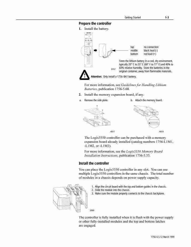
Prepare the controller�� ,QVWDOO�WKH�EDWWHU\�
)RU�PRUH�LQIRUPDWLRQ��VHH�*XLGHOLQHV�IRU�+DQGOLQJ�/LWKLXP�%DWWHULHV��SXEOLFDWLRQ�����������
�� ,QVWDOO�WKH�PHPRU\�H[SDQVLRQ�ERDUG��LI�DQ\�
7KH�/RJL[�����FRQWUROOHU�FDQ�EH�SXUFKDVHG�ZLWK�D�PHPRU\�H[SDQVLRQ�ERDUG�DOUHDG\�LQVWDOOHG��FDWDORJ�QXPEHUV������/�0����/�0���RU��/�0���
)RU�PRUH�LQIRUPDWLRQ��VHH�WKH�/RJL[�����0HPRU\�%RDUG�,QVWDOODWLRQ�,QVWUXFWLRQV��SXEOLFDWLRQ�����������
Install the controller
<RX�FDQ�SODFH�WKH�/RJL[�����FRQWUROOHU�LQ�DQ\�VORW���<RX�FDQ�XVH�PXOWLSOH�/RJL[�����FRQWUROOHUV�LQ�WKH�VDPH FKDVVLV���7KH�WRWDO�QXPEHU�RI�PRGXOHV�LQ�D�FKDVVLV�GHSHQGV�RQ�SRZHU�VXSSO\�FDSDFLW\�
7KH�FRQWUROOHU�LV�IXOO\�LQVWDOOHG�ZKHQ�LW�LV�IOXVK�ZLWK�WKH�SRZHU�VXSSO\�RU�RWKHU�IXOO\�LQVWDOOHG�PRGXOHV�DQG�WKH�WRS�DQG�ERWWRP�ODWFKHV�DUH HQJDJHG�
top no connectionmiddle black lead (-)bottom red lead (+)
Attention: Only install a 1756-BA1 battery.
30167
�
Store the lithium battery in a cool, dry environment, typically 20° C to 25° C (68° F to 77° F) and 40% to 60% relative humidity. Store the batteries in the original container, away from flammable materials.
40017
a. Remove the side plate. b. Attach the memory board.
40018
1. Align the circuit board with the top and bottom guides in the chassis.2. Slide the module into the chassis.3. Make sure the module properly connects to the chassis backplane.
20880
1756-6.5.12 March 1999
1-4 Getting Started
Creating and Downloading a Project
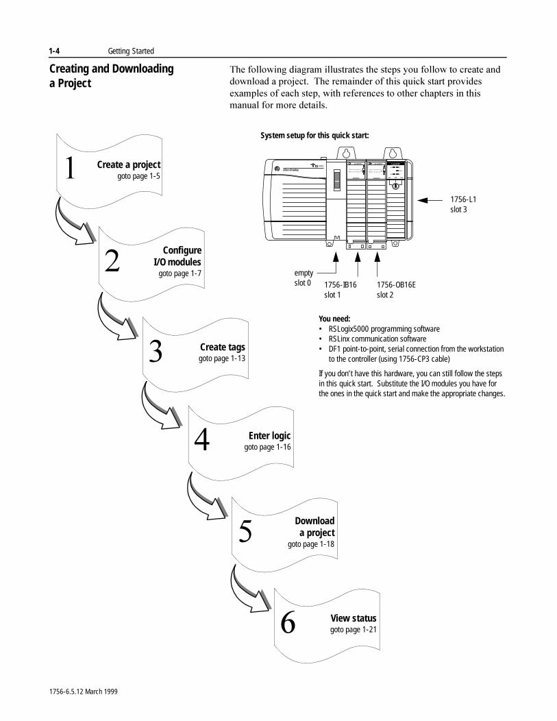
7KH�IROORZLQJ�GLDJUDP�LOOXVWUDWHV�WKH�VWHSV�\RX�IROORZ�WR�FUHDWH�DQG�GRZQORDG�D�SURMHFW���7KH�UHPDLQGHU�RI�WKLV�TXLFN�VWDUW�SURYLGHV�H[DPSOHV�RI�HDFK�VWHS��ZLWK�UHIHUHQFHV�WR�RWKHU�FKDSWHUV�LQ�WKLV�PDQXDO�IRU�PRUH�GHWDLOV�
Create a projectgoto page 1-5�
ConfigureI/O modules
goto page 1-7�
Create tagsgoto page 1-13�
Enter logicgoto page 1-16�
View statusgoto page 1-21�
Downloada project
goto page 1-18�
You need:• RSLogix5000 programming software• RSLinx communication software• DF1 point-to-point, serial connection from the workstation
to the controller (using 1756-CP3 cable)
If you don’t have this hardware, you can still follow the steps in this quick start. Substitute the I/O modules you have for the ones in the quick start and make the appropriate changes.
System setup for this quick start:
1756-IB16slot 1
1756-OB16Eslot 2
1756-L1slot 3
emptyslot 0
1756-6.5.12 March 1999
Getting Started 1-5
Create a project
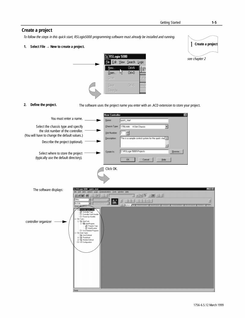
Create a project�1. Select File → New to create a project.
2. Define the project.
You must enter a name.
Select the chassis type and specifythe slot number of the controller.
(You will have to change the default values.)
Describe the project (optional).
Select where to store the project(typically use the default directory).
The software displays:
Click OK.
see chapter 2
The software uses the project name you enter with an .ACD extension to store your project.
To follow the steps in this quick start, RSLogix5000 programming software must already be installed and running.
controller organizer
1756-6.5.12 March 1999
1-6 Getting Started
Changing project properties
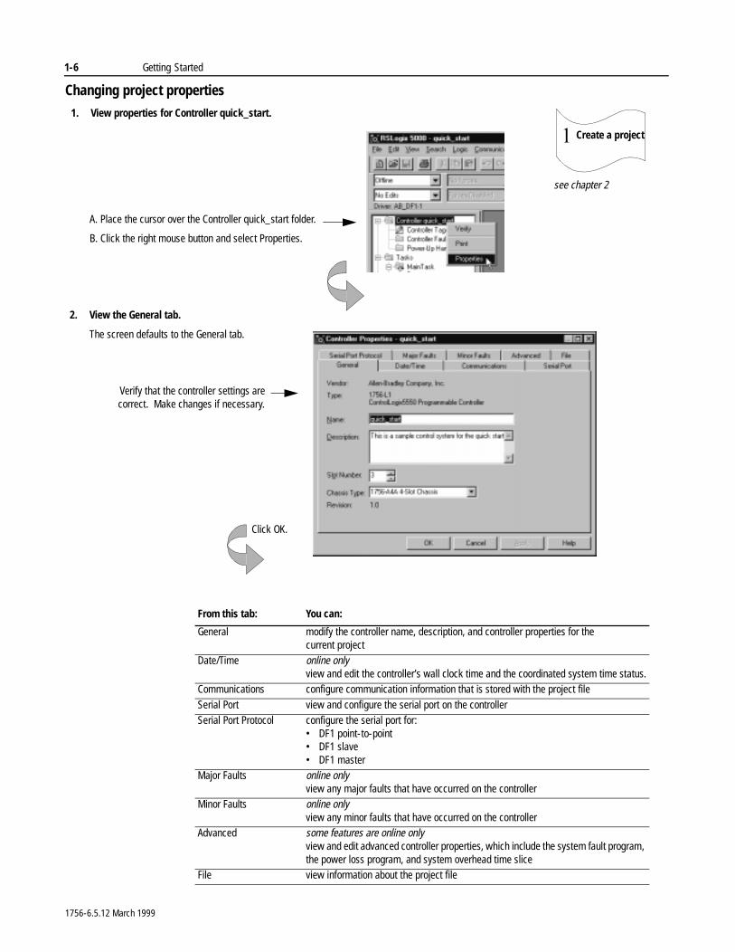
1. View properties for Controller quick_start.
2. View the General tab.
The screen defaults to the General tab.
Verify that the controller settings arecorrect. Make changes if necessary.
Create a project�
see chapter 2
A. Place the cursor over the Controller quick_start folder.
B. Click the right mouse button and select Properties.
Click OK.
From this tab: You can:
General modify the controller name, description, and controller properties for the current project
Date/Time online onlyview and edit the controller’s wall clock time and the coordinated system time status.
Communications configure communication information that is stored with the project file
Serial Port view and configure the serial port on the controllerSerial Port Protocol configure the serial port for:
• DF1 point-to-point• DF1 slave• DF1 master
Major Faults online onlyview any major faults that have occurred on the controller
Minor Faults online onlyview any minor faults that have occurred on the controller
Advanced some features are online onlyview and edit advanced controller properties, which include the system fault program, the power loss program, and system overhead time slice
File view information about the project file
1756-6.5.12 March 1999
Getting Started 1-7
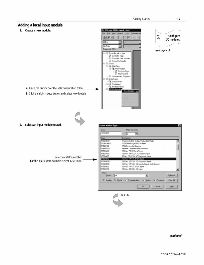
Adding a local input module
ConfigureI/O modules�
1. Create a new module.
2. Select an input module to add.
Select a catalog number.For this quick start example, select 1756-IB16.
Click OK.
continued
see chapter 3
A. Place the cursor over the I/O Configuration folder.
B. Click the right mouse button and select New Module
1756-6.5.12 March 1999
1-8 Getting Started
Adding a local input module (continued)
ConfigureI/O modules�
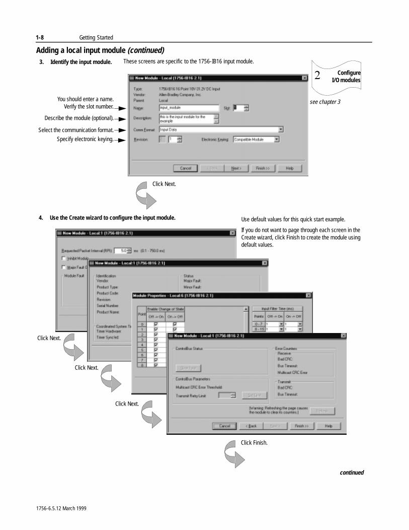
3. Identify the input module.
continued
You should enter a name.Verify the slot number.
Describe the module (optional).
Specify electronic keying.
Select the communication format.
Click Next.
These screens are specific to the 1756-IB16 input module.
4. Use the Create wizard to configure the input module. Use default values for this quick start example.
If you do not want to page through each screen in the Create wizard, click Finish to create the module using default values.
Click Finish.
see chapter 3
Click Next.
Click Next.
Click Next.
1756-6.5.12 March 1999
Getting Started 1-9
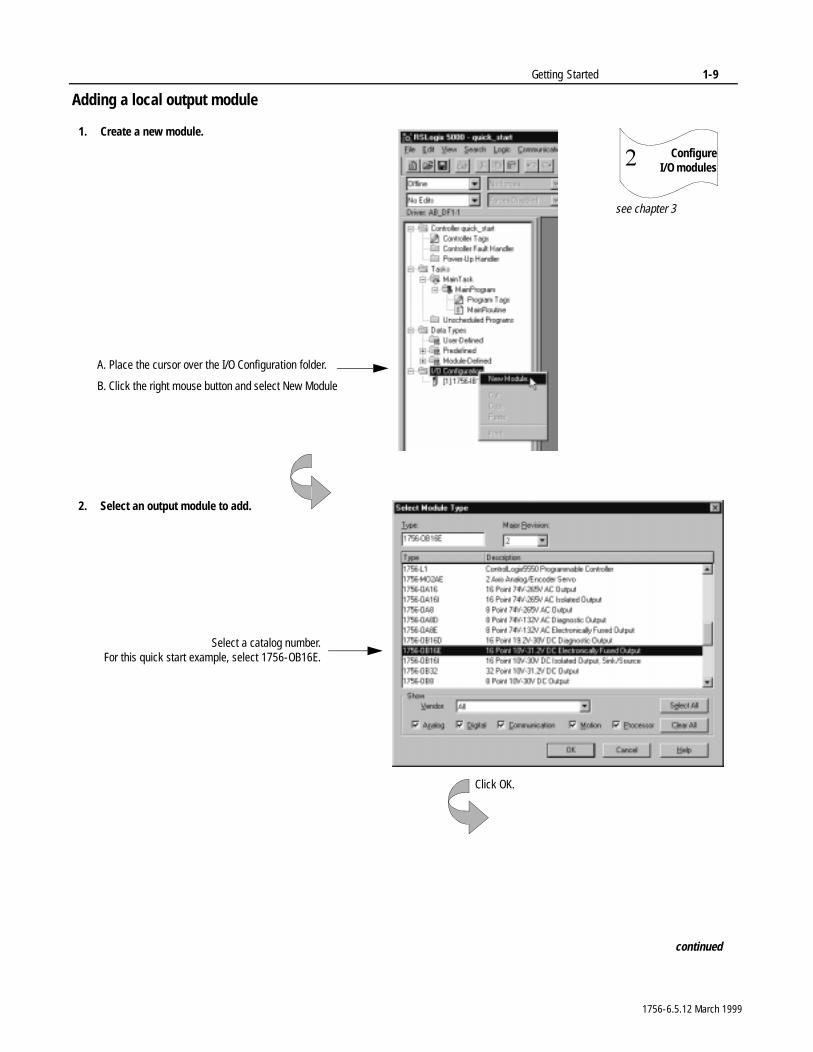
Adding a local output module
ConfigureI/O modules�
1. Create a new module.
2. Select an output module to add.
Select a catalog number.For this quick start example, select 1756-OB16E.
Click OK.
continued
see chapter 3
A. Place the cursor over the I/O Configuration folder.
B. Click the right mouse button and select New Module
1756-6.5.12 March 1999
1-10 Getting Started
Adding a local output module (continued)
ConfigureI/O modules�
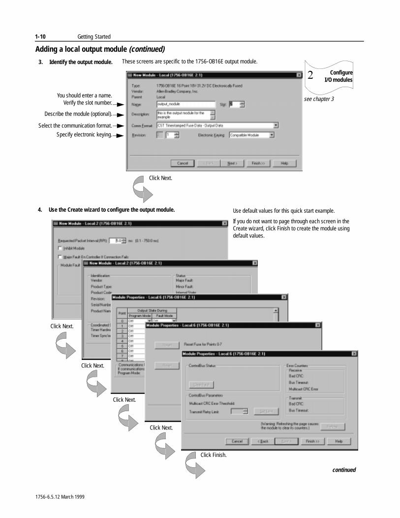
3. Identify the output module.
continued
Click Next.
These screens are specific to the 1756-OB16E output module.
4. Use the Create wizard to configure the output module.
Click Finish.
see chapter 3
Click Next.
You should enter a name.Verify the slot number.
Describe the module (optional).
Specify electronic keying.
Select the communication format.
Click Next.
Click Next.
Click Next.
Use default values for this quick start example.
If you do not want to page through each screen in the Create wizard, click Finish to create the module using default values.
1756-6.5.12 March 1999
Getting Started 1-11
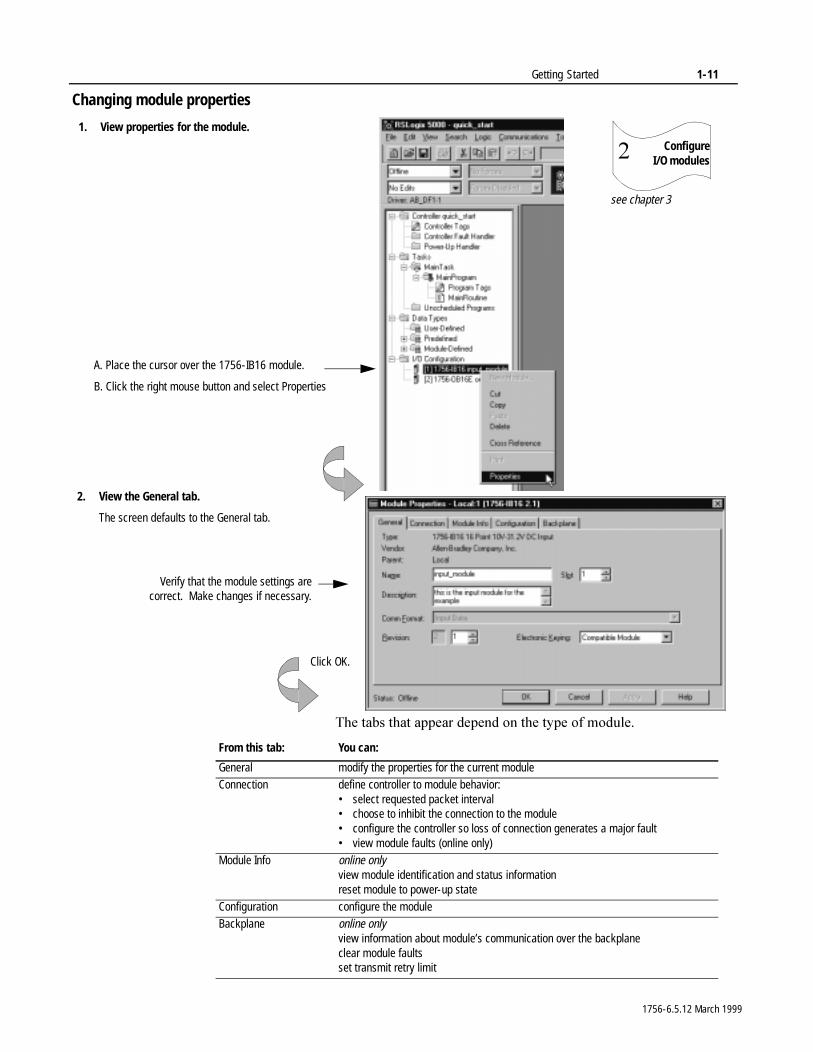
Changing module properties
7KH�WDEV�WKDW�DSSHDU�GHSHQG�RQ�WKH�W\SH�RI�PRGXOH�
1. View properties for the module.
2. View the General tab.
The screen defaults to the General tab.
Verify that the module settings arecorrect. Make changes if necessary.
A. Place the cursor over the 1756-IB16 module.
B. Click the right mouse button and select Properties
ConfigureI/O modules�
see chapter 3
Click OK.
From this tab: You can:
General modify the properties for the current moduleConnection define controller to module behavior:
• select requested packet interval• choose to inhibit the connection to the module• configure the controller so loss of connection generates a major fault• view module faults (online only)
Module Info online onlyview module identification and status informationreset module to power-up state
Configuration configure the moduleBackplane online only
view information about module’s communication over the backplaneclear module faultsset transmit retry limit
1756-6.5.12 March 1999
1-12 Getting Started
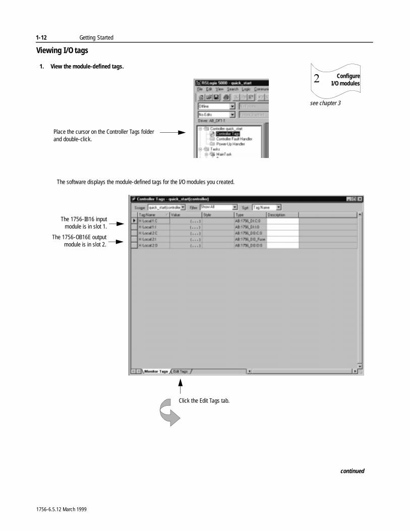
Viewing I/O tags
1. View the module-defined tags.
The software displays the module-defined tags for the I/O modules you created.
The 1756-IB16 inputmodule is in slot 1.
The 1756-OB16E outputmodule is in slot 2.
Click the Edit Tags tab.
continued
Place the cursor on the Controller Tags folder and double-click.
ConfigureI/O modules�
see chapter 3
1756-6.5.12 March 1999
Getting Started 1-13
Creating other tags
Create tags�
see chapter 4
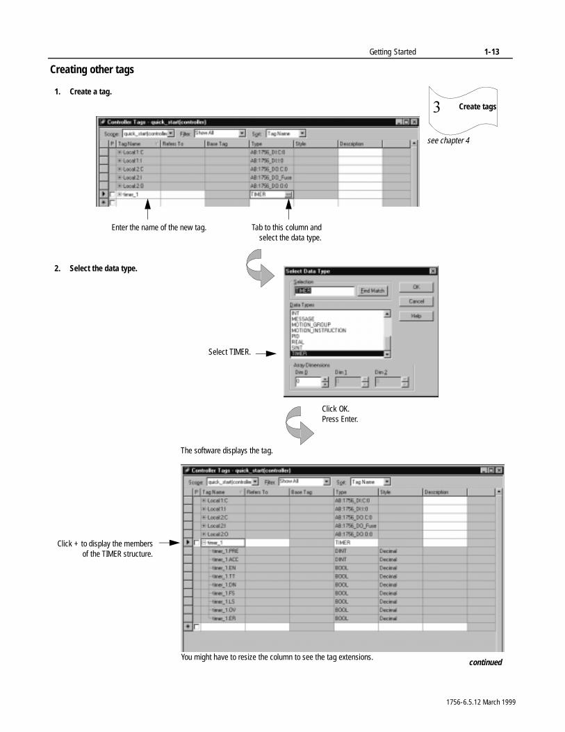
1. Create a tag.
Enter the name of the new tag. Tab to this column andselect the data type.
2. Select the data type.
Select TIMER.
Click OK.Press Enter.
The software displays the tag.
Click + to display the membersof the TIMER structure.
continuedYou might have to resize the column to see the tag extensions.
1756-6.5.12 March 1999
1-14 Getting Started
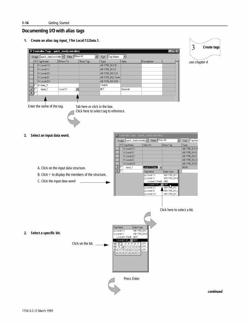
Documenting I/O with alias tags
A. Click on the input data structure.
B. Click + to display the members of the structure.
C. Click the input data word
Create tags�
see chapter 4
1. Create an alias tag input_1 for Local:1:I.Data.1.
Enter the name of the tag. Tab here or click in the box. Click here to select tag to reference.
2. Select an input data word.
Press Enter.
Click here to select a bit.
continued
2. Select a specific bit.
Click on the bit.
1756-6.5.12 March 1999
Getting Started 1-15
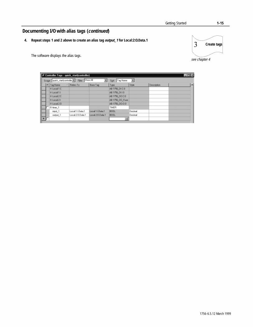
Documenting I/O with alias tags (continued)
Create tags�
see chapter 4The software displays the alias tags.
4. Repeat steps 1 and 2 above to create an alias tag output_1 for Local:2:O.Data.1
1756-6.5.12 March 1999
1-16 Getting Started
Enter logic
Enter logic�
see chapter 5
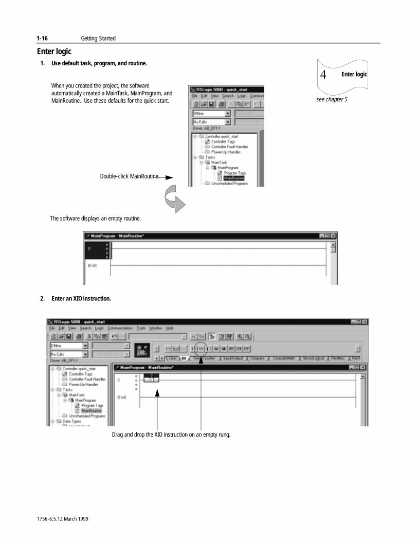
1. Use default task, program, and routine.
Double-click MainRoutine.
When you created the project, the software automatically created a MainTask, MainProgram, and MainRoutine. Use these defaults for the quick start.
2. Enter an XIO instruction.
The software displays an empty routine.
Drag and drop the XIO instruction on an empty rung.
1756-6.5.12 March 1999
Getting Started 1-17
Entering logic (continued)
Enter logic�
see chapter 5
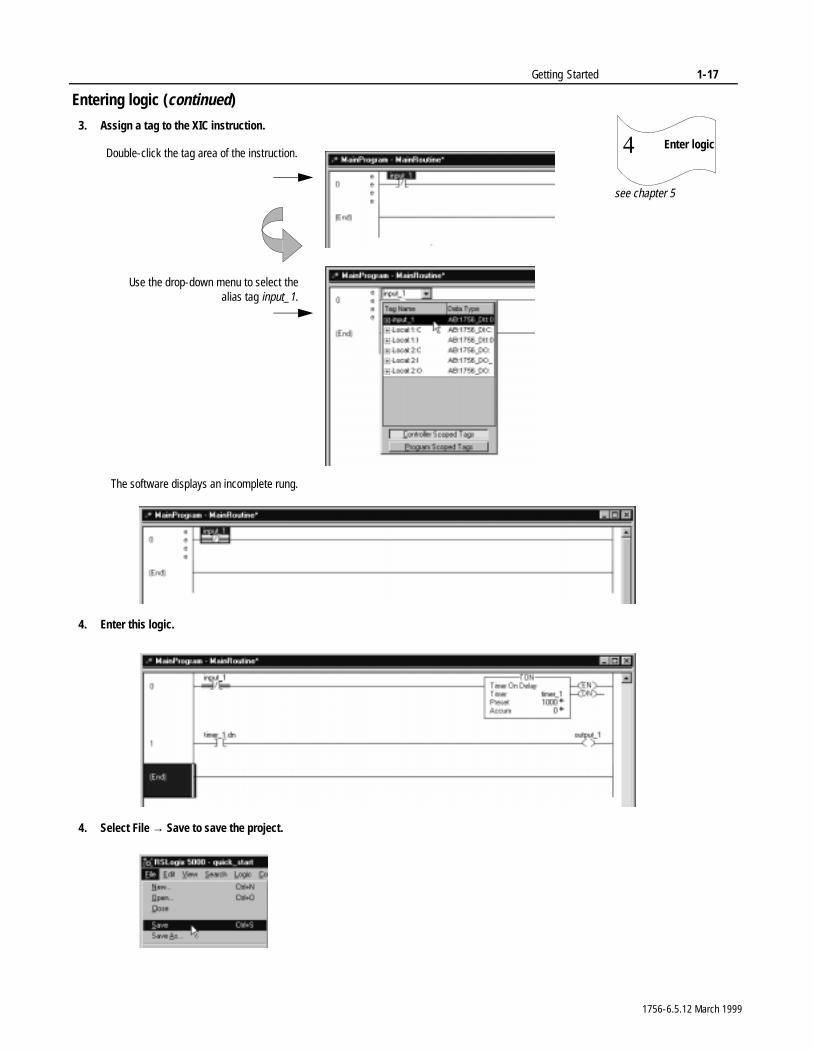
3. Assign a tag to the XIC instruction.
Double-click the tag area of the instruction.
4. Enter this logic.
Use the drop-down menu to select thealias tag input_1.
The software displays an incomplete rung.
4. Select File → Save to save the project.
1756-6.5.12 March 1999
1-18 Getting Started
Download a project
Downloada project�
see chapter 5 and chapter 8
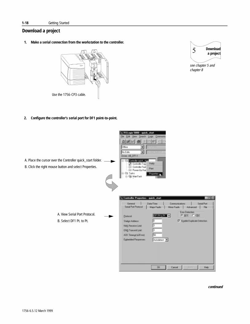
1. Make a serial connection from the workstation to the controller.
Use the 1756-CP3 cable.
2. Configure the controller’s serial port for DF1 point-to-point.
continued
A. Place the cursor over the Controller quick_start folder.
B. Click the right mouse button and select Properties.
A. View Serial Port Protocol.
B. Select DF1 Pt. to Pt.
1756-6.5.12 March 1999
Getting Started 1-19
Download a project (continued)
Download a project�
see chapter 5 and chapter 8
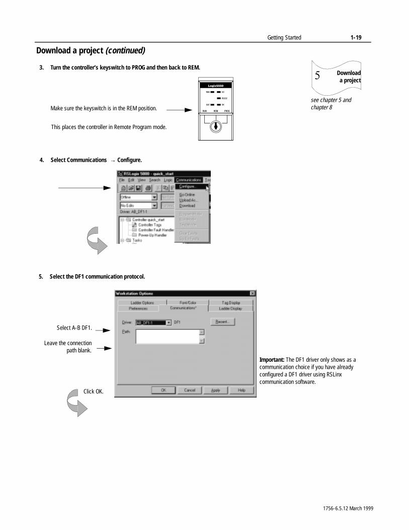
5. Select the DF1 communication protocol.
Select A-B DF1.
Leave the connectionpath blank.
Important: The DF1 driver only shows as a communication choice if you have already configured a DF1 driver using RSLinx communication software.
Click OK.
3. Turn the controller’s keyswitch to PROG and then back to REM.
Make sure the keyswitch is in the REM position.
This places the controller in Remote Program mode.
4. Select Communications → Configure.
1756-6.5.12 March 1999
1-20 Getting Started
Download a project (continued)
Download a project�
see chapter 5 and chapter 8
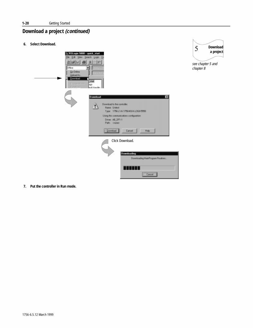
6. Select Download.
Click Download.
7. Put the controller in Run mode.
1756-6.5.12 March 1999
Getting Started 1-21
Viewing program scan time
Viewstatus�
see chapter 5
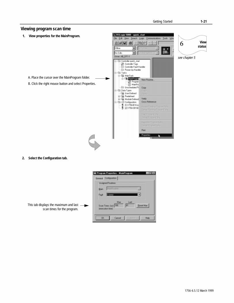
1. View properties for the MainProgram.
2. Select the Configuration tab.
This tab displays the maximum and lastscan times for the program.
A. Place the cursor over the MainProgram folder.
B. Click the right mouse button and select Properties.
1756-6.5.12 March 1999
1-22 Getting Started
Viewing controller memory usage
What To Do Next 2QFH�\RXU�FRQWUROOHU�LV�LQVWDOOHG�DQG�RSHUDWLQJ��\RX�FDQ�EHJLQ�GHYHORSLQJ�DQG�WHVWLQJ�\RXU�FRQWURO�DSSOLFDWLRQ���8VH�56/RJL[�����SURJUDPPLQJ�VRIWZDUH�
8VH�WKH�UHPDLQLQJ�FKDSWHUV�LQ�WKLV�PDQXDO�DV�UHIHUHQFH�PDWHULDO�IRU�GHYHORSLQJ�DQG�WHVWLQJ�\RXU�FRQWURO�DSSOLFDWLRQ���7KH�UHPDLQLQJ�FKDSWHUV�SURYLGH�GHWDLOHG�LQIRUPDWLRQ�DERXW�KRZ�WKH�FRQWUROOHU RSHUDWHV�
Viewstatus�
see chapter 5
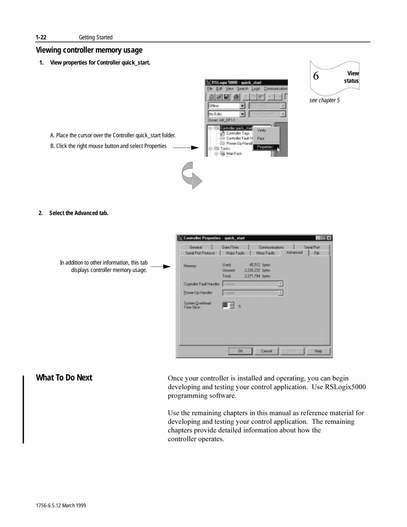
2. Select the Advanced tab.
In addition to other information, this tabdisplays controller memory usage.
1. View properties for Controller quick_start.
A. Place the cursor over the Controller quick_start folder.
B. Click the right mouse button and select Properties
1756-6.5.12 March 1999
Chapter 2
Working with ProjectsUsing This Chapter
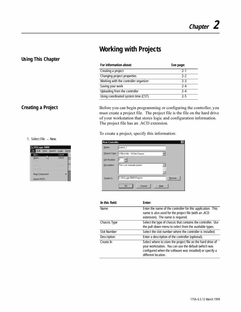
Creating a Project %HIRUH�\RX�FDQ�EHJLQ�SURJUDPPLQJ�RU�FRQILJXULQJ�WKH�FRQWUROOHU��\RX�PXVW�FUHDWH�D�SURMHFW�ILOH���7KH�SURMHFW�ILOH�LV�WKH�ILOH�RQ�WKH�KDUG�GULYH�RI�\RXU�ZRUNVWDWLRQ�WKDW�VWRUHV�ORJLF�DQG�FRQILJXUDWLRQ�LQIRUPDWLRQ���7KH�SURMHFW�ILOH�KDV�DQ��$&'�H[WHQVLRQ�
7R�FUHDWH�D�SURMHFW��VSHFLI\�WKLV�LQIRUPDWLRQ�
For information about: See page:
Creating a project 2-1
Changing project properties 2-2Working with the controller organizer 2-3
Saving your work 2-4Uploading from the controller 2-4Using coordinated system time (CST) 2-5
1. Select File → New.
In this field: Enter:
Name Enter the name of the controller for this application. This name is also used for the project file (with an .ACD extension). The name is required.
Chassis Type Select the type of chassis that contains the controller. Use the pull-down menu to select from the available types.
Slot Number Select the slot number where the controller is installed.
Description Enter a description of the controller (optional). Create In Select where to store the project file on the hard drive of
your workstation. You can use the default (which was configured when the software was installed) or specify a different location.
1756-6.5.12 March 1999
2-2 Working with Projects
Naming controllers
&RQWUROOHU�QDPHV�IROORZ�,(&��������LGHQWLILHU�UXOHV�DQG�� PXVW�EHJLQ�ZLWK�DQ�DOSKDEHWLF�FKDUDFWHU�RU�DQ�XQGHUVFRUH �B�� FDQ�FRQWDLQ�RQO\�DOSKDEHWLF�FKDUDFWHUV��QXPHULF�FKDUDFWHUV��
DQG XQGHUVFRUHV� FDQ�KDYH�DV�PDQ\�DV����FKDUDFWHUV� PXVW�QRW�KDYH�FRQVHFXWLYH�RU�WUDLOLQJ�XQGHUVFRUH�FKDUDFWHUV��B�
<RX�FDQ�DOVR�DGG�D�GHVFULSWLRQ���'HVFULSWLRQV�FDQ�KDYH�DV�PDQ\�DV�����FKDUDFWHUV���<RX�FDQ�XVH�DQ\�SULQWDEOH�FKDUDFWHU�
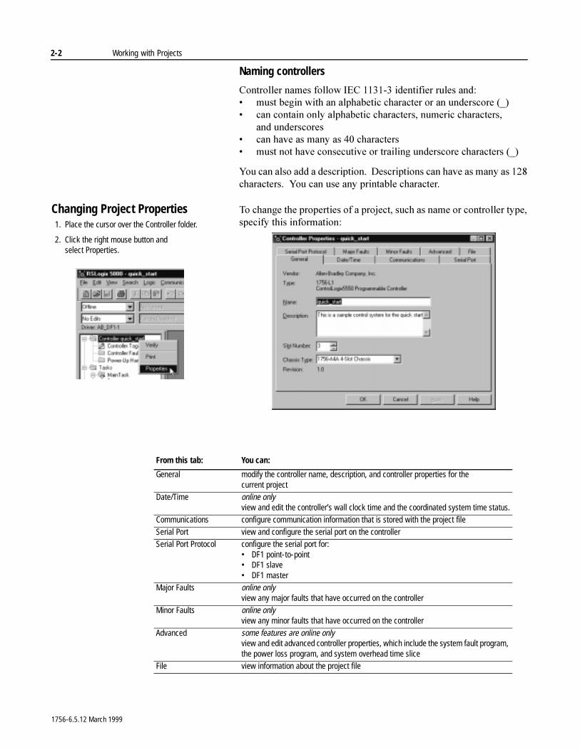
Changing Project Properties 7R�FKDQJH�WKH�SURSHUWLHV�RI�D�SURMHFW��VXFK�DV�QDPH�RU�FRQWUROOHU�W\SH��VSHFLI\�WKLV�LQIRUPDWLRQ�1. Place the cursor over the Controller folder.
2. Click the right mouse button andselect Properties.
From this tab: You can:
General modify the controller name, description, and controller properties for the current project
Date/Time online onlyview and edit the controller’s wall clock time and the coordinated system time status.
Communications configure communication information that is stored with the project file
Serial Port view and configure the serial port on the controllerSerial Port Protocol configure the serial port for:
• DF1 point-to-point• DF1 slave• DF1 master
Major Faults online onlyview any major faults that have occurred on the controller
Minor Faults online onlyview any minor faults that have occurred on the controller
Advanced some features are online onlyview and edit advanced controller properties, which include the system fault program, the power loss program, and system overhead time slice
File view information about the project file
1756-6.5.12 March 1999
Working with Projects 2-3
Working with the Controller Organizer
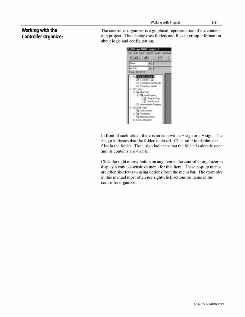
7KH�FRQWUROOHU�RUJDQL]HU�LV�D�JUDSKLFDO�UHSUHVHQWDWLRQ�RI�WKH�FRQWHQWV�RI�D�SURMHFW���7KH�GLVSOD\�XVHV�IROGHUV�DQG�ILOHV�WR�JURXS�LQIRUPDWLRQ�DERXW�ORJLF�DQG�FRQILJXUDWLRQ�
,Q�IURQW�RI�HDFK�IROGHU��WKHUH�LV�DQ�LFRQ�ZLWK�D���VLJQ�RU�D�−�VLJQ���7KH���VLJQ�LQGLFDWHV�WKDW�WKH�IROGHU�LV�FORVHG���&OLFN�RQ�LW�WR�GLVSOD\�WKH�ILOHV�LQ�WKH�IROGHU���7KH�−�VLJQ�LQGLFDWHV�WKDW�WKH�IROGHU�LV�DOUHDG\�RSHQ�DQG�LWV�FRQWHQWV�DUH�YLVLEOH�
&OLFN�WKH�ULJKW�PRXVH�EXWWRQ�RQ�DQ\�LWHP�LQ�WKH�FRQWUROOHU�RUJDQL]HU�WR�GLVSOD\�D�FRQWH[W�VHQVLWLYH�PHQX�IRU�WKDW�LWHP���7KHVH�SRS�XS�PHQXV�DUH�RIWHQ�VKRUWFXWV�WR�XVLQJ�RSWLRQV�IURP�WKH�PHQX�EDU���7KH�H[DPSOHV�LQ�WKLV�PDQXDO�PRVW�RIWHQ�XVH�ULJKW�FOLFN�DFWLRQV�RQ�LWHPV�LQ�WKH�FRQWUROOHU�RUJDQL]HU�
1756-6.5.12 March 1999
2-4 Working with Projects
Saving Your Project $V�\RX�FUHDWH�ORJLF�DQG�PDNH�FRQILJXUDWLRQ�FKDQJHV��VDYH�\RXU�ZRUN�WR�WKH�SURMHFW�ILOH�
,I�\RX�DUH�SURJUDPPLQJ�RQOLQH�ZKHQ�\RX�VDYH�\RXU�SURMHFW��GDWD�YDOXHV�DUH�XSORDGHG�IURP�WKH�FRQWUROOHU�DQG�VDYHG�DV�ZHOO�
,PSRUWDQW��,I�\RX�GR�QRW�ZDQW�WKH�GDWD�YDOXHV�XSORDGHG�IURP�WKH�FRQWUROOHU��JR�RIIOLQH�EHIRUH�VDYLQJ�WKH�SURMHFW�
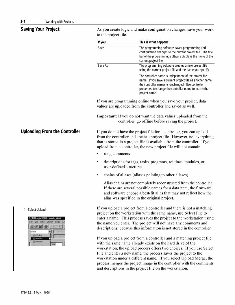
Uploading From the Controller ,I�\RX�GR�QRW�KDYH�WKH�SURMHFW�ILOH�IRU�D�FRQWUROOHU��\RX�FDQ�XSORDG�IURP�WKH�FRQWUROOHU�DQG�FUHDWH�D�SURMHFW�ILOH���+RZHYHU��QRW�HYHU\WKLQJ�WKDW�LV�VWRUHG�LQ�D�SURMHFW�ILOH�LV�DYDLODEOH�IURP�WKH�FRQWUROOHU���,I�\RX�XSORDG�IURP�D�FRQWUROOHU��WKH�QHZ�SURMHFW�ILOH�ZLOO�QRW�FRQWDLQ�
� UXQJ�FRPPHQWV
� GHVFULSWLRQV�IRU�WDJV��WDVNV��SURJUDPV��URXWLQHV��PRGXOHV��RU�XVHU�GHILQHG�VWUXFWXUHV
� FKDLQV�RI�DOLDVHV��DOLDVHV�SRLQWLQJ�WR�RWKHU�DOLDVHV�
$OLDV�FKDLQV�DUH�QRW�FRPSOHWHO\�UHFRQVWUXFWHG�IURP�WKH�FRQWUROOHU���,I�WKHUH�DUH�VHYHUDO�SRVVLEOH�QDPHV�IRU�D�GDWD�LWHP��WKH�ILUPZDUH�DQG�VRIWZDUH�FKRRVH�D�EHVW�ILW�DOLDV�WKDW�PD\�QRW�UHIOHFW�KRZ�WKH�DOLDV�ZDV�VSHFLILHG�LQ�WKH�RULJLQDO�SURMHFW�
,I�\RX�XSORDG�D�SURMHFW�IURP�D�FRQWUROOHU�DQG�WKHUH�LV�QRW�D�PDWFKLQJ�SURMHFW�RQ�WKH�ZRUNVWDWLRQ�ZLWK�WKH�VDPH�QDPH��XVH�6HOHFW�)LOH�WR�HQWHU�D�QDPH���7KLV�SURFHVV�VDYHV�WKH�SURMHFW�WR�WKH�ZRUNVWDWLRQ�XVLQJ�WKH�QDPH�\RX�HQWHU���7KH�SURMHFW�ZLOO�QRW�KDYH�DQ\�FRPPHQWV�DQG�GHVFULSWLRQV��EHFDXVH�WKLV�LQIRUPDWLRQ�LV�QRW�VWRUHG�LQ�WKH�FRQWUROOHU��
,I�\RX�XSORDG�D�SURMHFW�IURP�D�FRQWUROOHU�DQG�D�PDWFKLQJ�SURMHFW�ILOH�ZLWK�WKH�VDPH�QDPH�DOUHDG\�H[LVWV�RQ�WKH�KDUG�GULYH�RI�WKH�ZRUNVWDWLRQ��WKH�XSORDG�SURFHVV�RIIHUV�WZR�FKRLFHV���,I�\RX�XVH�6HOHFW�)LOH�DQG�HQWHU�D�QHZ�QDPH��WKH�SURFHVV�VDYHV�WKH�SURMHFW�WR�WKH�ZRUNVWDWLRQ�XQGHU�D�GLIIHUHQW�QDPH���,I�\RX�VHOHFW�8SORDG�0HUJH��WKH�SURFHVV�PHUJHV�WKH�SURMHFW�LPDJH�LQ�WKH�FRQWUROOHU�ZLWK�WKH�FRPPHQWV�DQG�GHVFULSWLRQV�LQ�WKH�SURMHFW�ILOH�RQ�WKH�ZRUNVWDWLRQ�
If you: This is what happens:
Save The programming software saves programming and configuration changes to the current project file. The title bar of the programming software displays the name of the current project file.
Save As The programming software creates a new project file using the current project file and the name you specify.
The controller name is independent of the project file name. If you save a current project file as another name, the controller names is unchanged. Use controller properties to change the controller name to match the project name.
1. Select Upload.
1756-6.5.12 March 1999
Working with Projects 2-5
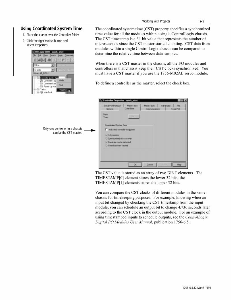
Using Coordinated System Time 7KH�FRRUGLQDWHG�V\VWHP�WLPH��&67��SURSHUW\�VSHFLILHV�D�V\QFKURQL]HG�WLPH�YDOXH�IRU�DOO�WKH�PRGXOHV�ZLWKLQ�D�VLQJOH�&RQWURO/RJL[�FKDVVLV���7KH�&67�WLPHVWDPS�LV�D����ELW�YDOXH�WKDW�UHSUHVHQWV�WKH�QXPEHU�RI�PLFURVHFRQGV�VLQFH�WKH�&67�PDVWHU�VWDUWHG�FRXQWLQJ���&67�GDWD�IURP�PRGXOHV�ZLWKLQ�D�VLQJOH�&RQWURO/RJL[�FKDVVLV�FDQ�EH�FRPSDUHG�WR�GHWHUPLQH�WKH�UHODWLYH�WLPH�EHWZHHQ�GDWD�VDPSOHV�
:KHQ�WKHUH�LV�D�&67�PDVWHU�LQ�WKH�FKDVVLV��DOO�WKH�,�2�PRGXOHV�DQG�FRQWUROOHUV�LQ�WKDW�FKDVVLV�NHHS�WKHLU�&67�FORFNV�V\QFKURQL]HG���<RX�PXVW�KDYH�D�&67�PDVWHU�LI�\RX�XVH�WKH������0��$(�VHUYR�PRGXOH�
7R�GHILQH�D�FRQWUROOHU�DV�WKH�PDVWHU��VHOHFW�WKH�FKHFN�ER[�
7KH�&67�YDOXH�LV�VWRUHG�DV�DQ�DUUD\�RI�WZR�',17�HOHPHQWV���7KH�7,0(67$03>�@�HOHPHQW�VWRUHV�WKH�ORZHU����ELWV��WKH�7,0(67$03>�@�HOHPHQWV�VWRUHV�WKH�XSSHU����ELWV�
<RX�FDQ�FRPSDUH�WKH�&67�FORFNV�RI�GLIIHUHQW�PRGXOHV�LQ�WKH�VDPH�FKDVVLV�IRU�WLPHNHHSLQJ�SXUSRVHV���)RU�H[DPSOH��NQRZLQJ�ZKHQ�DQ�LQSXW�ELW�FKDQJHG�E\�FKHFNLQJ�WKH�&67�WLPHVWDPS�IURP�WKH�LQSXW�PRGXOH��\RX�FDQ�VFKHGXOH�DQ�RXWSXW�ELW�WR�FKDQJH�������VHFRQGV�ODWHU�DFFRUGLQJ�WR�WKH�&67�FORFN�LQ�WKH�RXWSXW�PRGXOH���)RU�DQ�H[DPSOH�RI�XVLQJ�WLPHVWDPSHG�LQSXWV�WR�VFKHGXOH�RXWSXWV��VHH�WKH�&RQWURO/RJL[�'LJLWDO�,�2�0RGXOHV�8VHU�0DQXDO��SXEOLFDWLRQ����������
1. Place the cursor over the Controller folder.
2. Click the right mouse button andselect Properties.
Only one controller in a chassiscan be the CST master.
1756-6.5.12 March 1999
2-6 Working with Projects
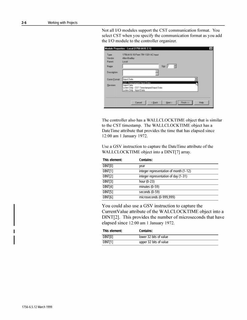
1RW�DOO�,�2�PRGXOHV�VXSSRUW�WKH�&67�FRPPXQLFDWLRQ�IRUPDW���<RX�VHOHFW�&67�ZKHQ�\RX�VSHFLI\�WKH�FRPPXQLFDWLRQ�IRUPDW�DV�\RX�DGG�WKH�,�2�PRGXOH�WR�WKH�FRQWUROOHU�RUJDQL]HU�
7KH�FRQWUROOHU�DOVR�KDV�D�:$//&/2&.7,0(�REMHFW�WKDW�LV�VLPLODU�WR�WKH�&67�WLPHVWDPS���7KH�:$//&/2&.7,0(�REMHFW�KDV�D�'DWH7LPH�DWWULEXWH�WKDW�SURYLGHV�WKH�WLPH�WKDW�KDV�HODSVHG�VLQFH������ DP���-DQXDU\������
8VH�D�*69�LQVWUXFWLRQ�WR�FDSWXUH�WKH�'DWH7LPH�DWWULEXWH�RI�WKH�:$//&/2&.7,0(�REMHFW�LQWR�D�',17>�@�DUUD\�
<RX�FRXOG�DOVR�XVH�D�*69�LQVWUXFWLRQ�WR�FDSWXUH�WKH�&XUUHQW9DOXH�DWWULEXWH�RI�WKH�:$/&/2&.7,0(�REMHFW�LQWR�D�',17>�@���7KLV�SURYLGHV�WKH�QXPEHU�RI�PLFURVHFRQGV�WKDW�KDYH�HODSVHG�VLQFH������ DP���-DQXDU\������
This element: Contains:
DINT[0] yearDINT[1] integer representation of month (1-12)DINT[2] integer representation of day (1-31)
DINT[3] hour (0-23)DINT[4] minutes (0-59)
DINT[5] seconds (0-59)DINT[6] microseconds (0-999,999)
This element: Contains:
DINT[0] lower 32 bits of valueDINT[1] upper 32 bits of value
1756-6.5.12 March 1999
Chapter 3
Configuring I/O ModulesUsing This Chapter
7KH�FRQILJXUDWLRQ�LQIRUPDWLRQ�IRU�WKH�PRGXOH�GHSHQGV�RQ�WKH�PRGXOH�\RX�VHOHFWHG���)RU�PRUH�LQIRUPDWLRQ��VHH�WKH�XVHU�GRFXPHQWDWLRQ�IRU�WKH�VSHFLILF�PRGXOH�
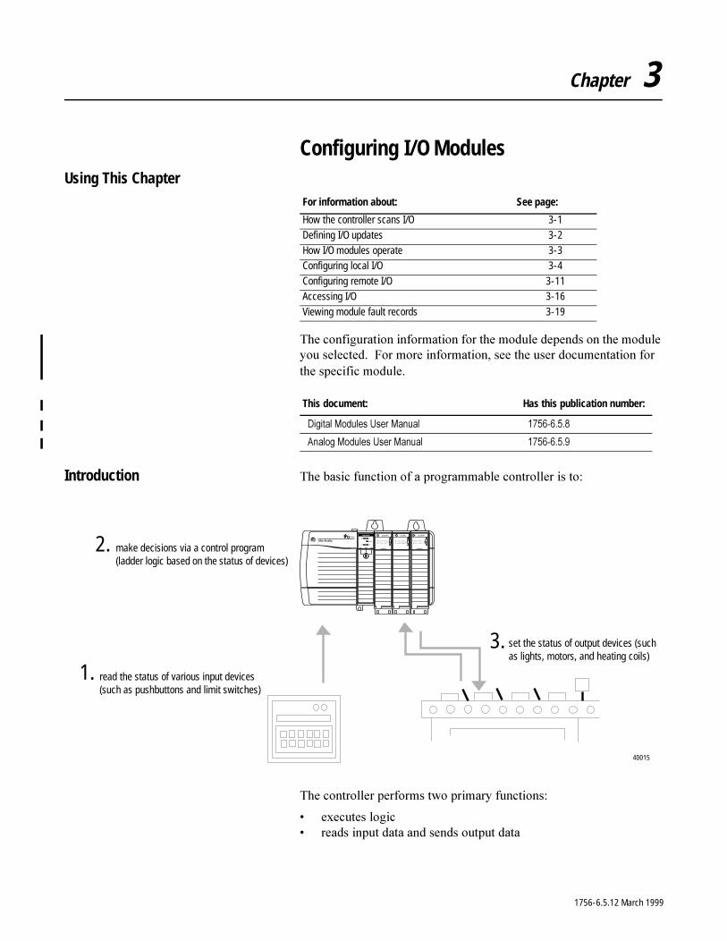
Introduction 7KH�EDVLF�IXQFWLRQ�RI�D�SURJUDPPDEOH�FRQWUROOHU�LV�WR�
7KH�FRQWUROOHU�SHUIRUPV�WZR�SULPDU\�IXQFWLRQV�
� H[HFXWHV�ORJLF� UHDGV�LQSXW�GDWD�DQG�VHQGV�RXWSXW�GDWD
For information about: See page:
How the controller scans I/O 3-1
Defining I/O updates 3-2How I/O modules operate 3-3Configuring local I/O 3-4
Configuring remote I/O 3-11Accessing I/O 3-16
Viewing module fault records 3-19
This document: Has this publication number:
'LJLWDO�0RGXOHV�8VHU�0DQXDO ����������
$QDORJ�0RGXOHV�8VHU�0DQXDO ����������
read the status of various input devices (such as pushbuttons and limit switches)
make decisions via a control program(ladder logic based on the status of devices)
set the status of output devices (such as lights, motors, and heating coils)
40015
1.
2.
3.
1756-6.5.12 March 1999
3-2 Configuring I/O Modules
Logic Scanning 7KH�FRQWUROOHU�FRQWLQXDOO\�VFDQV�WKH�FRQWURO�ORJLF���2QH�VFDQ�LV�WKH�WLPH�LW�WDNHV�WKH�FRQWUROOHU�WR�H[HFXWH�WKH�ORJLF�RQFH���,QSXW�GDWD�WUDQVIHUV�WR�WKH�FRQWUROOHU�DV\QFKURQRXV�WR�WKH�ORJLF�VFDQ���7KH�FRQWUROOHU�WUDQVIHUV�RXWSXW�GDWD�DW�WKH�HQG�RI�HDFK�DQG�HYHU\�SURJUDP VFDQ�
,I�\RX�ZDQW�LQSXW�GDWD�WR�UHPDLQ�FRQVWDQW�WKURXJKRXW�RQH�VFDQ��PDNH�D�FRS\�RI�WKH�LQSXW�GDWD�DW�WKH�EHJLQQLQJ�RI�WKH�VFDQ�DQG�XVH�WKH�FRS\�WKURXJKRXW�WKH�VFDQ�
Defining I/O Updates 7KH�&RQWURO/RJL[�V\VWHP�IROORZV�D�SURGXFHU�FRQVXPHU�PRGHO���,QSXW�PRGXOHV�SURGXFH�GDWD�IRU�WKH�V\VWHP���2XWSXW�PRGXOHV��FRQWUROOHUV��DQG�LQWHOOLJHQW�PRGXOHV�SURGXFH�DQG�FRQVXPH�GDWD�
7KH�SURGXFHU�FRQVXPHU�PRGHO�PXOWLFDVWV�PHVVDJHV���7KLV�PHDQV�WKDW�PXOWLSOH�QRGHV�FDQ�FRQVXPH�WKH�VDPH�GDWD�DW�WKH�VDPH�WLPH�IURP�D�VLQJOH�GHYLFH���:KHUH�\RX�SODFH�,�2�PRGXOHV�LQ�WKH�FRQWURO�V\VWHP�GHWHUPLQHV�KRZ�WKH�PRGXOHV�H[FKDQJH�GDWD�
How an I/O module uses change-of-state (COS)
'LJLWDO�LQSXW�PRGXOHV�LQ�WKH�ORFDO�FKDVVLV�XVH�WKH�FKDQJH�RI�VWDWH�PHWKRG�WR�WUDQVIHU�GDWD���7KLV�PHWKRG�WUDQVIHUV�GDWD�ZKHQHYHU�DQ�LQSXW�SRLQW�FKDQJHV�IURP�21�WR�2))�RU�2))�WR�21�
8VH�FKDQJH�RI�VWDWH�GDWD�H[FKDQJH�LQ�SURMHFWV�ZKHUH�
� GDWD�FKDQJHV�UDSLGO\��VXFK�DV�FRXQWLQJ��WLPLQJ��DQG�SRVLWLRQ�UHIHUHQFLQJ�DSSOLFDWLRQV
� GDWD�LV�GLJLWDOO\�LQWHQVLYH��VXFK�DV�SDFNDJLQJ�DQG�PDWHULDO�KDQGOLQJ�DSSOLFDWLRQV
If the I/O module is: And you place the module here: The data exchange method is based on:
digital local chassis change of state
and
requested packet intervalremote chassis requested packet interval
analog local chassis real time sample
and
requested packet intervalremote chassis real time sample
and
requested packet interval
1756-6.5.12 March 1999
Configuring I/O Modules 3-3
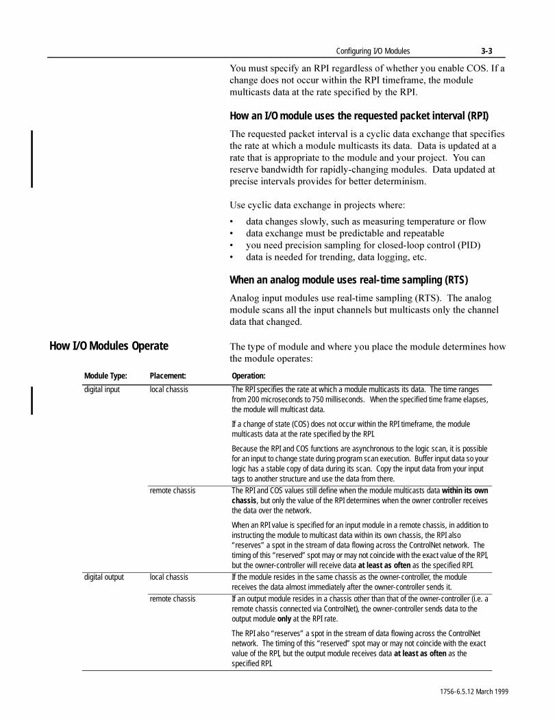
<RX�PXVW�VSHFLI\�DQ�53,�UHJDUGOHVV�RI�ZKHWKHU�\RX�HQDEOH�&26��,I�D�FKDQJH�GRHV�QRW�RFFXU�ZLWKLQ�WKH�53,�WLPHIUDPH��WKH�PRGXOH�PXOWLFDVWV�GDWD�DW�WKH�UDWH�VSHFLILHG�E\�WKH�53,�
How an I/O module uses the requested packet interval (RPI)
7KH�UHTXHVWHG�SDFNHW�LQWHUYDO�LV�D�F\FOLF�GDWD�H[FKDQJH�WKDW�VSHFLILHV�WKH�UDWH�DW�ZKLFK�D�PRGXOH�PXOWLFDVWV�LWV�GDWD���'DWD�LV�XSGDWHG�DW�D�UDWH�WKDW�LV�DSSURSULDWH�WR�WKH�PRGXOH�DQG�\RXU SURMHFW���<RX�FDQ�UHVHUYH�EDQGZLGWK�IRU�UDSLGO\�FKDQJLQJ�PRGXOHV���'DWD�XSGDWHG�DW�SUHFLVH�LQWHUYDOV�SURYLGHV�IRU�EHWWHU GHWHUPLQLVP�
8VH�F\FOLF�GDWD�H[FKDQJH�LQ�SURMHFWV�ZKHUH�
� GDWD�FKDQJHV�VORZO\��VXFK�DV�PHDVXULQJ�WHPSHUDWXUH�RU�IORZ� GDWD�H[FKDQJH�PXVW�EH�SUHGLFWDEOH�DQG�UHSHDWDEOH� \RX�QHHG�SUHFLVLRQ�VDPSOLQJ�IRU�FORVHG�ORRS�FRQWURO��3,'�� GDWD�LV�QHHGHG�IRU�WUHQGLQJ��GDWD�ORJJLQJ��HWF�
When an analog module uses real-time sampling (RTS)
$QDORJ�LQSXW�PRGXOHV�XVH�UHDO�WLPH�VDPSOLQJ��576����7KH�DQDORJ�PRGXOH�VFDQV�DOO�WKH�LQSXW�FKDQQHOV�EXW�PXOWLFDVWV�RQO\�WKH�FKDQQHO�GDWD�WKDW�FKDQJHG�
How I/O Modules Operate 7KH�W\SH�RI�PRGXOH�DQG�ZKHUH�\RX�SODFH�WKH�PRGXOH�GHWHUPLQHV�KRZ�WKH�PRGXOH�RSHUDWHV�
Module Type: Placement: Operation:
digital input local chassis The RPI specifies the rate at which a module multicasts its data. The time ranges from 200 microseconds to 750 milliseconds. When the specified time frame elapses, the module will multicast data.
If a change of state (COS) does not occur within the RPI timeframe, the module multicasts data at the rate specified by the RPI.
Because the RPI and COS functions are asynchronous to the logic scan, it is possible for an input to change state during program scan execution. Buffer input data so your logic has a stable copy of data during its scan. Copy the input data from your input tags to another structure and use the data from there.
remote chassis The RPI and COS values still define when the module multicasts data within its own chassis, but only the value of the RPI determines when the owner controller receives the data over the network.
When an RPI value is specified for an input module in a remote chassis, in addition to instructing the module to multicast data within its own chassis, the RPI also “reserves” a spot in the stream of data flowing across the ControlNet network. The timing of this “reserved” spot may or may not coincide with the exact value of the RPI, but the owner-controller will receive data at least as often as the specified RPI.
digital output local chassis If the module resides in the same chassis as the owner-controller, the module receives the data almost immediately after the owner-controller sends it.
remote chassis If an output module resides in a chassis other than that of the owner-controller (i.e. a remote chassis connected via ControlNet), the owner-controller sends data to the output module only at the RPI rate.
The RPI also “reserves” a spot in the stream of data flowing across the ControlNet network. The timing of this “reserved” spot may or may not coincide with the exact value of the RPI, but the output module receives data at least as often as the specified RPI.
1756-6.5.12 March 1999
3-4 Configuring I/O Modules
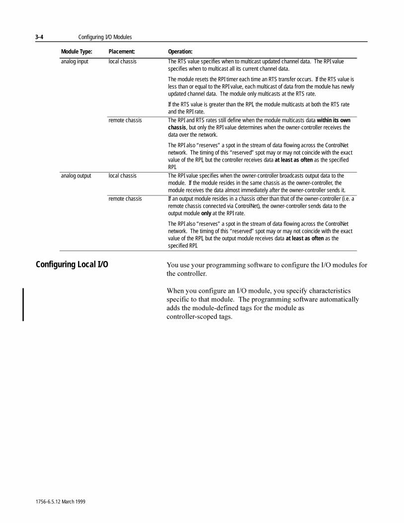
Configuring Local I/O <RX�XVH�\RXU�SURJUDPPLQJ�VRIWZDUH�WR�FRQILJXUH�WKH�,�2�PRGXOHV�IRU�WKH�FRQWUROOHU�
:KHQ�\RX�FRQILJXUH�DQ�,�2�PRGXOH��\RX�VSHFLI\�FKDUDFWHULVWLFV�VSHFLILF�WR�WKDW�PRGXOH���7KH�SURJUDPPLQJ�VRIWZDUH�DXWRPDWLFDOO\�DGGV�WKH�PRGXOH�GHILQHG�WDJV�IRU�WKH�PRGXOH�DV�FRQWUROOHU�VFRSHG WDJV�
analog input local chassis The RTS value specifies when to multicast updated channel data. The RPI value specifies when to multicast all its current channel data.
The module resets the RPI timer each time an RTS transfer occurs. If the RTS value is less than or equal to the RPI value, each multicast of data from the module has newly updated channel data. The module only multicasts at the RTS rate.
If the RTS value is greater than the RPI, the module multicasts at both the RTS rate and the RPI rate.
remote chassis The RPI and RTS rates still define when the module multicasts data within its own chassis, but only the RPI value determines when the owner-controller receives the data over the network.
The RPI also “reserves” a spot in the stream of data flowing across the ControlNet network. The timing of this “reserved” spot may or may not coincide with the exact value of the RPI, but the controller receives data at least as often as the specified RPI.
analog output local chassis The RPI value specifies when the owner-controller broadcasts output data to the module. If the module resides in the same chassis as the owner-controller, the module receives the data almost immediately after the owner-controller sends it.
remote chassis If an output module resides in a chassis other than that of the owner-controller (i.e. a remote chassis connected via ControlNet), the owner-controller sends data to the output module only at the RPI rate.
The RPI also “reserves” a spot in the stream of data flowing across the ControlNet network. The timing of this “reserved” spot may or may not coincide with the exact value of the RPI, but the output module receives data at least as often as the specified RPI.
Module Type: Placement: Operation:
1756-6.5.12 March 1999
Configuring I/O Modules 3-5
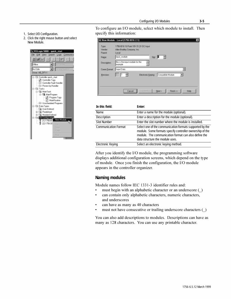
7R�FRQILJXUH�DQ�,�2�PRGXOH��VHOHFW�ZKLFK�PRGXOH�WR�LQVWDOO���7KHQ�VSHFLI\�WKLV�LQIRUPDWLRQ�
$IWHU�\RX�LGHQWLI\�WKH�,�2�PRGXOH��WKH�SURJUDPPLQJ�VRIWZDUH�GLVSOD\V�DGGLWLRQDO�FRQILJXUDWLRQ�VFUHHQV��ZKLFK�GHSHQG�RQ�WKH�W\SH�RI�PRGXOH���2QFH�\RX�ILQLVK�WKH�FRQILJXUDWLRQ��WKH�,�2�PRGXOH�DSSHDUV�LQ�WKH�FRQWUROOHU�RUJDQL]HU�
Naming modules
0RGXOH�QDPHV�IROORZ�,(&��������LGHQWLILHU�UXOHV�DQG�� PXVW�EHJLQ�ZLWK�DQ�DOSKDEHWLF�FKDUDFWHU�RU�DQ�XQGHUVFRUH �B�� FDQ�FRQWDLQ�RQO\�DOSKDEHWLF�FKDUDFWHUV��QXPHULF�FKDUDFWHUV��
DQG XQGHUVFRUHV� FDQ�KDYH�DV�PDQ\�DV����FKDUDFWHUV� PXVW�QRW�KDYH�FRQVHFXWLYH�RU�WUDLOLQJ�XQGHUVFRUH�FKDUDFWHUV��B�
<RX�FDQ�DOVR�DGG�GHVFULSWLRQV�WR�PRGXOHV���'HVFULSWLRQV�FDQ�KDYH�DV�PDQ\�DV�����FKDUDFWHUV���<RX�FDQ�XVH�DQ\�SULQWDEOH�FKDUDFWHU�
In this field: Enter:
Name Enter a name for the module (optional).Description Enter a description for the module (optional).
Slot Number Enter the slot number where the module is installed.Communication Format Select one of the communication formats supported by the
module. Some formats specify controller ownership of the module. The communication format can also define the data structure the module uses.
Electronic Keying Select an electronic keying method.
1. Select I/O Configuration.2. Click the right mouse button and select
New Module.
1756-6.5.12 March 1999
3-6 Configuring I/O Modules
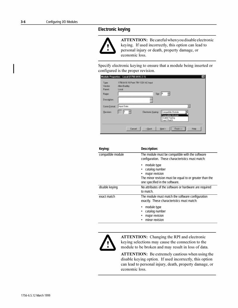
Electronic keying
6SHFLI\�HOHFWURQLF�NH\LQJ�WR�HQVXUH�WKDW�D�PRGXOH�EHLQJ�LQVHUWHG�RU�FRQILJXUHG�LV�WKH�SURSHU�UHYLVLRQ�
�$77(17,21� %H�FDUHIXO�ZKHQ�\RX�GLVDEOH�HOHFWURQLF�NH\LQJ���,I�XVHG�LQFRUUHFWO\��WKLV�RSWLRQ�FDQ�OHDG�WR�SHUVRQDO�LQMXU\�RU�GHDWK��SURSHUW\�GDPDJH��RU�HFRQRPLF ORVV�
Keying: Description:
compatible module The module must be compatible with the software configuration. These characteristics must match:
• module type• catalog number• major revisionThe minor revision must be equal to or greater than the one specified in the software.
disable keying No attributes of the software or hardware are required to match.
exact match The module must match the software configuration exactly. These characteristics must match:
• module type• catalog number• major revision• minor revision
�$77(17,21� &KDQJLQJ�WKH�53,�DQG�HOHFWURQLF�NH\LQJ�VHOHFWLRQV�PD\�FDXVH�WKH�FRQQHFWLRQ�WR�WKH�PRGXOH�WR�EH�EURNHQ�DQG�PD\�UHVXOW�LQ�ORVV�RI�GDWD�
$77(17,21� %H�H[WUHPHO\�FDXWLRXV�ZKHQ�XVLQJ�WKH�GLVDEOH�NH\LQJ�RSWLRQ���,I�XVHG�LQFRUUHFWO\��WKLV�RSWLRQ�FDQ�OHDG�WR�SHUVRQDO�LQMXU\��GHDWK��SURSHUW\�GDPDJH��RU�HFRQRPLF�ORVV�
1756-6.5.12 March 1999
Configuring I/O Modules 3-7
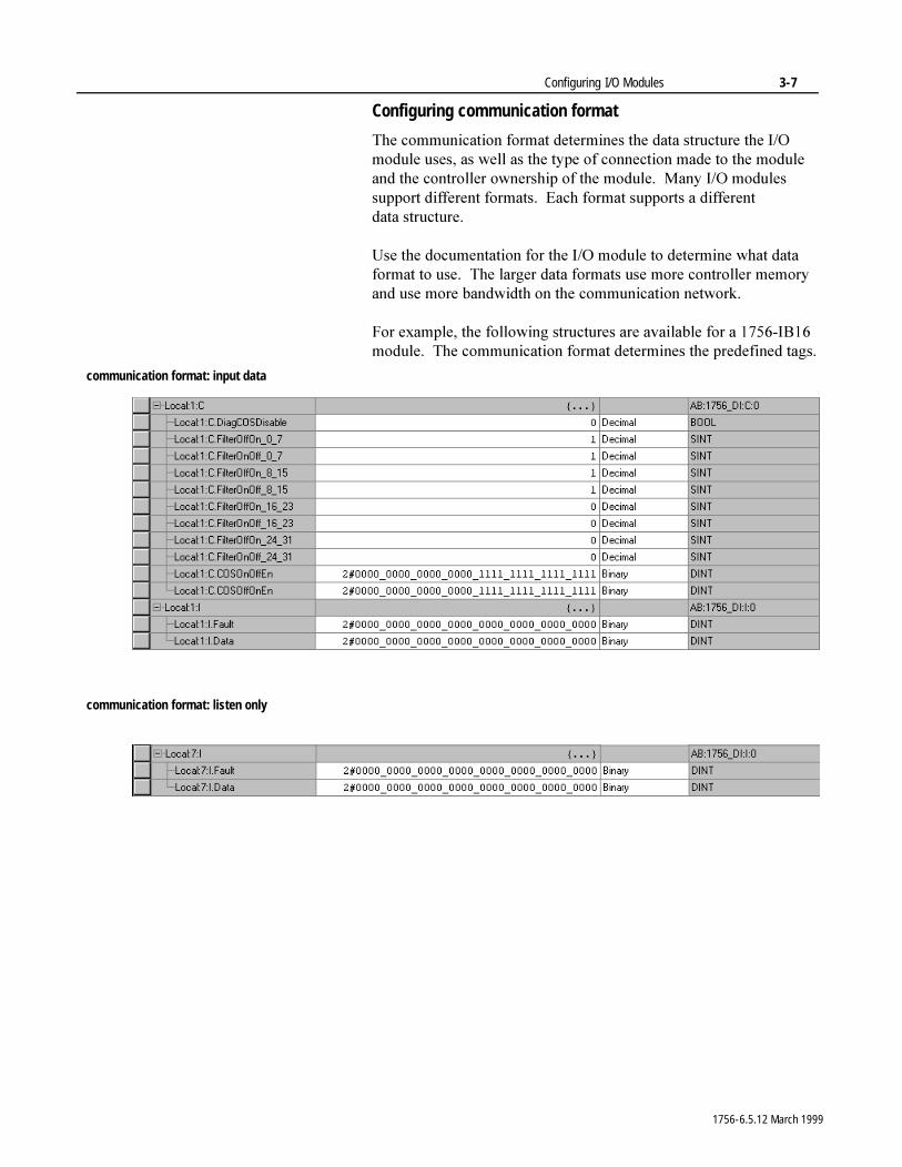
Configuring communication format
7KH�FRPPXQLFDWLRQ�IRUPDW�GHWHUPLQHV�WKH�GDWD�VWUXFWXUH�WKH�,�2�PRGXOH�XVHV��DV�ZHOO�DV�WKH�W\SH�RI�FRQQHFWLRQ�PDGH�WR�WKH�PRGXOH�DQG�WKH�FRQWUROOHU�RZQHUVKLS�RI�WKH�PRGXOH���0DQ\�,�2�PRGXOHV�VXSSRUW�GLIIHUHQW�IRUPDWV���(DFK�IRUPDW�VXSSRUWV�D�GLIIHUHQW�GDWD VWUXFWXUH�
8VH�WKH�GRFXPHQWDWLRQ�IRU�WKH�,�2�PRGXOH�WR�GHWHUPLQH�ZKDW�GDWD�IRUPDW�WR�XVH���7KH�ODUJHU�GDWD�IRUPDWV�XVH�PRUH�FRQWUROOHU�PHPRU\�DQG�XVH�PRUH�EDQGZLGWK�RQ�WKH�FRPPXQLFDWLRQ�QHWZRUN�
)RU�H[DPSOH��WKH�IROORZLQJ�VWUXFWXUHV�DUH�DYDLODEOH�IRU�D������,%���PRGXOH���7KH�FRPPXQLFDWLRQ�IRUPDW�GHWHUPLQHV�WKH�SUHGHILQHG�WDJV�
communication format: input data
communication format: listen only
1756-6.5.12 March 1999
3-8 Configuring I/O Modules
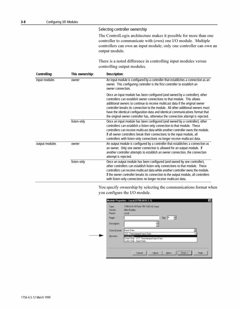
Selecting controller ownership
7KH�&RQWURO/RJL[�DUFKLWHFWXUH�PDNHV�LW�SRVVLEOH�IRU�PRUH�WKDQ�RQH�FRQWUROOHU�WR�FRPPXQLFDWH�ZLWK��RZQ��RQH�,�2�PRGXOH���0XOWLSOH�FRQWUROOHUV�FDQ�RZQ�DQ�LQSXW�PRGXOH��RQO\�RQH�FRQWUROOHU�FDQ�RZQ�DQ�RXWSXW PRGXOH�
7KHUH�LV�D�QRWHG�GLIIHUHQFH�LQ�FRQWUROOLQJ�LQSXW�PRGXOHV�YHUVXV�FRQWUROOLQJ�RXWSXW�PRGXOHV�
<RX�VSHFLI\�RZQHUVKLS�E\�VHOHFWLQJ�WKH�FRPPXQLFDWLRQV�IRUPDW�ZKHQ�\RX�FRQILJXUH�WKH�,�2�PRGXOH�
Controlling: This ownership: Description:
input modules owner An input module is configured by a controller that establishes a connection as an owner. This configuring controller is the first controller to establish an owner connection.
Once an input module has been configured (and owned by a controller), other controllers can establish owner connections to that module. This allows additional owners to continue to receive multicast data if the original owner controller breaks its connection to the module. All other additional owners must have the identical configuration data and identical communications format that the original owner controller has, otherwise the connection attempt is rejected.
listen-only Once an input module has been configured (and owned by a controller), other controllers can establish a listen-only connection to that module. These controllers can receive multicast data while another controller owns the module. If all owner controllers break their connections to the input module, all controllers with listen-only connections no longer receive multicast data.
output modules owner An output module is configured by a controller that establishes a connection as an owner. Only one owner connection is allowed for an output module. If another controller attempts to establish an owner connection, the connection attempt is rejected.
listen-only Once an output module has been configured (and owned by one controller), other controllers can establish listen-only connections to that module. These controllers can receive multicast data while another controller owns the module. If the owner controller breaks its connection to the output module, all controllers with listen-only connections no longer receive multicast data.
1756-6.5.12 March 1999
Configuring I/O Modules 3-9
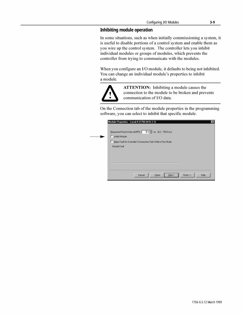
Inhibiting module operation
,Q�VRPH�VLWXDWLRQV��VXFK�DV�ZKHQ�LQLWLDOO\�FRPPLVVLRQLQJ�D�V\VWHP��LW�LV�XVHIXO�WR�GLVDEOH�SRUWLRQV�RI�D�FRQWURO�V\VWHP�DQG�HQDEOH�WKHP�DV�\RX�ZLUH�XS�WKH�FRQWURO�V\VWHP���7KH�FRQWUROOHU�OHWV�\RX�LQKLELW�LQGLYLGXDO�PRGXOHV�RU�JURXSV�RI�PRGXOHV��ZKLFK�SUHYHQWV�WKH�FRQWUROOHU�IURP�WU\LQJ�WR�FRPPXQLFDWH�ZLWK�WKH�PRGXOHV�
:KHQ�\RX�FRQILJXUH�DQ�,�2�PRGXOH��LW�GHIDXOWV�WR�EHLQJ�QRW�LQKLELWHG���<RX�FDQ�FKDQJH�DQ�LQGLYLGXDO�PRGXOH¶V�SURSHUWLHV�WR�LQKLELW�D PRGXOH�
2Q�WKH�&RQQHFWLRQ�WDE�RI�WKH�PRGXOH�SURSHUWLHV�LQ�WKH�SURJUDPPLQJ�VRIWZDUH��\RX�FDQ�VHOHFW�WR�LQKLELW�WKDW�VSHFLILF�PRGXOH�
�$77(17,21� ,QKLELWLQJ�D�PRGXOH�FDXVHV�WKH�FRQQHFWLRQ�WR�WKH�PRGXOH�WR�EH�EURNHQ�DQG�SUHYHQWV�FRPPXQLFDWLRQ�RI�,�2�GDWD�
1756-6.5.12 March 1999
3-10 Configuring I/O Modules
:KHQ�\RX�LQKLELW�D�FRPPXQLFDWLRQ�EULGJH�PRGXOH��VXFK�DV�D������&1%�RU������'+5,2�PRGXOH��WKH�FRQWUROOHU�VKXWV�GRZQ�WKH�FRQQHFWLRQV�WR�WKH�EULGJH�PRGXOH�DQG�WR�DOO�WKH�PRGXOHV�WKDW�GHSHQG�RQ�WKDW�EULGJH�PRGXOH���,QKLELWLQJ�D�FRPPXQLFDWLRQ�EULGJH�PRGXOH�OHWV�\RX�GLVDEOH�DQ�HQWLUH�EUDQFK�RI�WKH�,�2�QHWZRUN�
:KHQ�\RX�VHOHFW�WR�LQKLELW�WKH�PRGXOH��WKH�FRQWUROOHU�RUJDQL]HU�GLVSOD\V�D�\HOORZ�DWWHQWLRQ�V\PERO��/!\��RYHU�WKH�PRGXOH��
If you are: Inhibit a module to:
offline put a place holder for a module you are configuring
The inhibit status is stored in the project. When you download the project, the module is still inhibited.
online stop communication to a module
If you inhibit a module while you are connected to the module, the connection to the module is closed. The modules’ outputs go to the last configured program mode.
If you inhibit a module but a connection to the module was not established (perhaps due to an error condition or fault), the module is inhibited. The module status information changes to indicate that the module is inhibited and not faulted.
If you uninhibit a module (clear the checkbox), and no fault condition occurs, a connection is made to the module and the module is dynamically reconfigured (if the controller is the owner controller) with the configuration you created for that module. If the controller is configured for listen-only, it cannot reconfigure the module.
If you uninhibit the module and a fault condition occurs, a connection is not made to the module. The module status information changes to indicate the fault condition.
1756-6.5.12 March 1999
Configuring I/O Modules 3-11
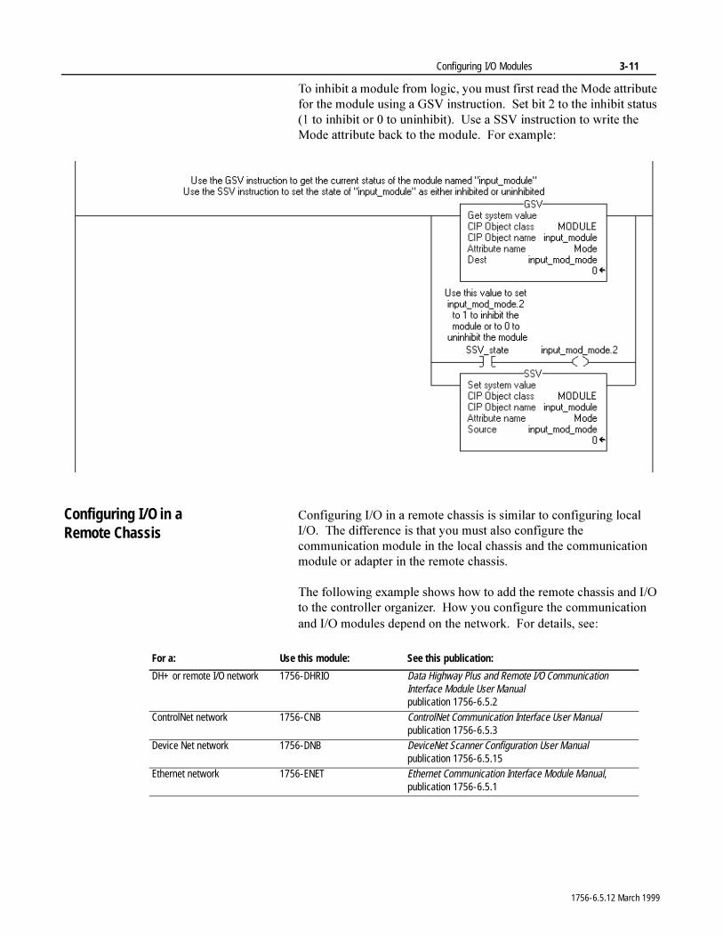
7R�LQKLELW�D�PRGXOH�IURP�ORJLF��\RX�PXVW�ILUVW�UHDG�WKH�0RGH�DWWULEXWH�IRU�WKH�PRGXOH�XVLQJ�D�*69�LQVWUXFWLRQ���6HW�ELW���WR�WKH�LQKLELW�VWDWXV����WR�LQKLELW�RU���WR�XQLQKLELW����8VH�D�669�LQVWUXFWLRQ�WR�ZULWH�WKH�0RGH�DWWULEXWH�EDFN�WR�WKH�PRGXOH���)RU�H[DPSOH�
Configuring I/O in a Remote Chassis
&RQILJXULQJ�,�2�LQ�D�UHPRWH�FKDVVLV�LV�VLPLODU�WR�FRQILJXULQJ�ORFDO�,�2���7KH�GLIIHUHQFH�LV�WKDW�\RX�PXVW�DOVR�FRQILJXUH�WKH�FRPPXQLFDWLRQ�PRGXOH�LQ�WKH�ORFDO�FKDVVLV�DQG�WKH�FRPPXQLFDWLRQ�PRGXOH�RU�DGDSWHU�LQ�WKH�UHPRWH�FKDVVLV�
7KH�IROORZLQJ�H[DPSOH�VKRZV�KRZ�WR�DGG�WKH�UHPRWH�FKDVVLV�DQG�,�2�WR�WKH�FRQWUROOHU�RUJDQL]HU���+RZ�\RX�FRQILJXUH�WKH�FRPPXQLFDWLRQ�DQG�,�2�PRGXOHV�GHSHQG�RQ�WKH�QHWZRUN���)RU�GHWDLOV��VHH�
For a: Use this module: See this publication:
DH+ or remote I/O network 1756-DHRIO Data Highway Plus and Remote I/O Communication Interface Module User Manualpublication 1756-6.5.2
ControlNet network 1756-CNB ControlNet Communication Interface User Manualpublication 1756-6.5.3
Device Net network 1756-DNB DeviceNet Scanner Configuration User Manualpublication 1756-6.5.15
Ethernet network 1756-ENET Ethernet Communication Interface Module Manual, publication 1756-6.5.1
1756-6.5.12 March 1999
3-12 Configuring I/O Modules
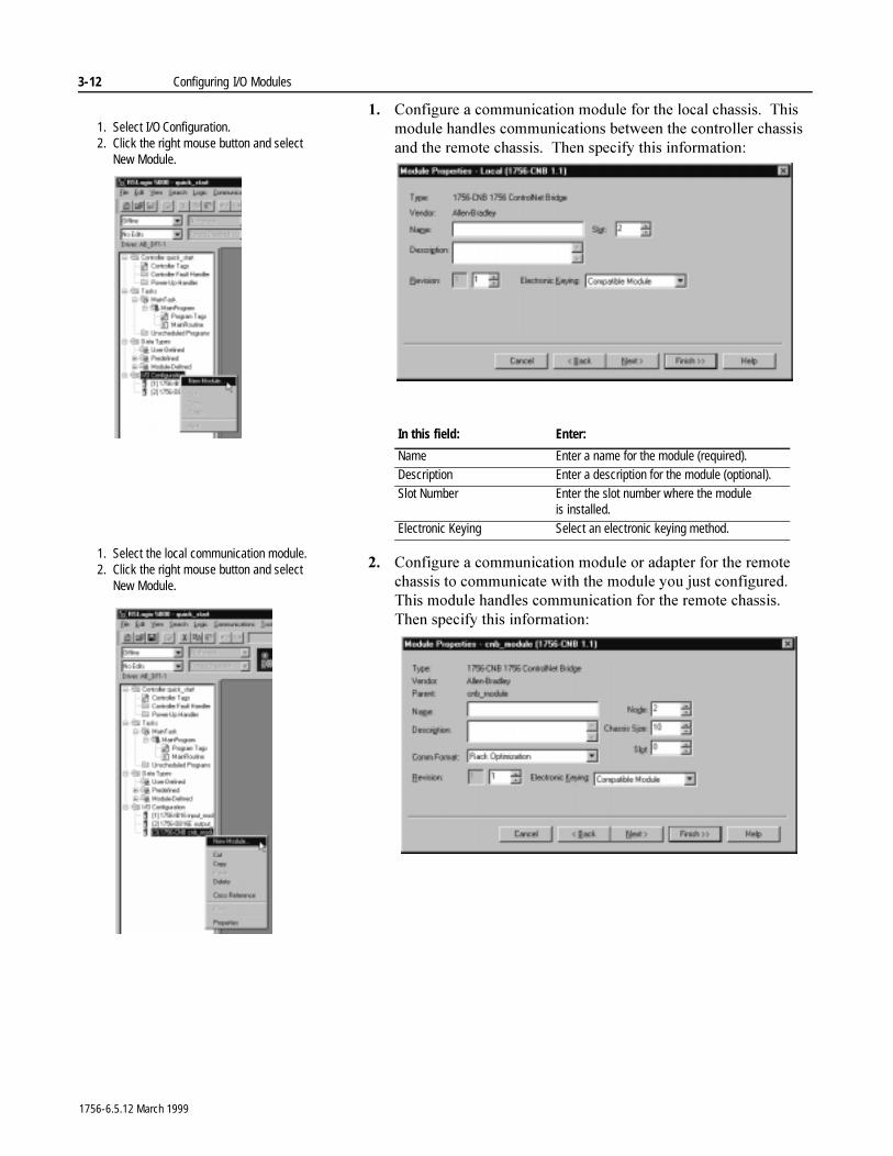
�� &RQILJXUH�D�FRPPXQLFDWLRQ�PRGXOH�IRU�WKH�ORFDO�FKDVVLV���7KLV�PRGXOH�KDQGOHV�FRPPXQLFDWLRQV�EHWZHHQ�WKH�FRQWUROOHU�FKDVVLV�DQG�WKH�UHPRWH�FKDVVLV���7KHQ�VSHFLI\�WKLV�LQIRUPDWLRQ�
�� &RQILJXUH�D�FRPPXQLFDWLRQ�PRGXOH�RU�DGDSWHU�IRU�WKH�UHPRWH�FKDVVLV�WR�FRPPXQLFDWH�ZLWK�WKH�PRGXOH�\RX�MXVW�FRQILJXUHG���7KLV�PRGXOH�KDQGOHV�FRPPXQLFDWLRQ�IRU�WKH�UHPRWH�FKDVVLV���7KHQ�VSHFLI\�WKLV LQIRUPDWLRQ�
In this field: Enter:
Name Enter a name for the module (required).Description Enter a description for the module (optional).
Slot Number Enter the slot number where the module is installed.
Electronic Keying Select an electronic keying method.
1. Select I/O Configuration.2. Click the right mouse button and select
New Module.
1. Select the local communication module.2. Click the right mouse button and select
New Module.
1756-6.5.12 March 1999
Configuring I/O Modules 3-13
:KHQ�\RX�FOLFN�RQ�D�ORFDO�FRPPXQLFDWLRQ�PRGXOH�DQG�DGG�D�UHPRWH�FRPPXQLFDWLRQ�PRGXOH��WKH�ORFDO�PRGXOH�EHFRPHV�WKH�³SDUHQW�PRGXOH´�WR�WKH�UHPRWH�PRGXOH���7KH�FRQWUROOHU�RUJDQL]HU�VKRZV�WKLV�SDUHQW�FKLOG�UHODWLRQVKLS�EHWZHHQ�ORFDO�DQG�UHPRWH�PRGXOHV�
,I�\RX�DUH�FRQILJXULQJ�D������&1%�PRGXOH�IRU�WKH�UHPRWH�FKDVVLV�
$� $GG�,�2�WR�WKH�FKDVVLV�
%� 5XQ�561HWZRU[�VRIWZDUH�WR�FRQILJXUH�WKH�FRQQHFWLRQV�
&� 'RZQORDG�WKH�SURMHFW�WR�WKH�/RJL[�����FRQWUROOHU�
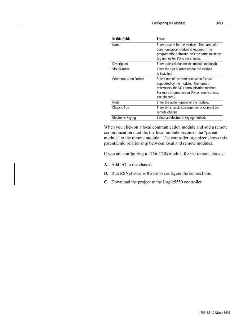
In this field: Enter:
Name Enter a name for the module. The name of a communication module is required. The programming software uses the name to create tag names for I/O in the chassis.
Description Enter a description for the module (optional).Slot Number Enter the slot number where the module
is installed.Communication Format Select one of the communication formats
supported by the module. The format determines the I/O communication method. For more information on I/O communications, see chapter 7.
Node Enter the node number of the module.
Chassis Size Enter the chassis size (number of slots) of the remote chassis.
Electronic Keying Select an electronic keying method.
1756-6.5.12 March 1999
3-14 Configuring I/O Modules
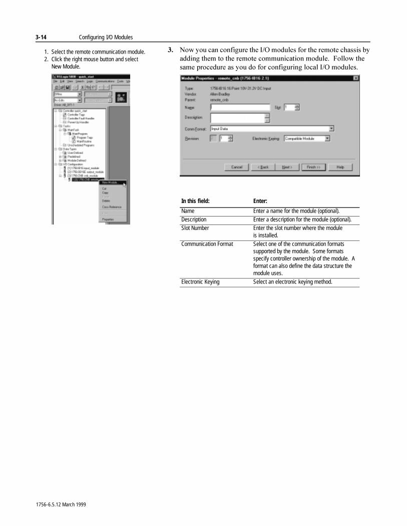
�� 1RZ�\RX�FDQ�FRQILJXUH�WKH�,�2�PRGXOHV�IRU�WKH�UHPRWH�FKDVVLV�E\�DGGLQJ�WKHP�WR�WKH�UHPRWH�FRPPXQLFDWLRQ�PRGXOH���)ROORZ�WKH�VDPH�SURFHGXUH�DV�\RX�GR�IRU�FRQILJXULQJ�ORFDO�,�2�PRGXOHV�
In this field: Enter:
Name Enter a name for the module (optional).Description Enter a description for the module (optional).Slot Number Enter the slot number where the module
is installed.
Communication Format Select one of the communication formats supported by the module. Some formats specify controller ownership of the module. A format can also define the data structure the module uses.
Electronic Keying Select an electronic keying method.
1. Select the remote communication module.2. Click the right mouse button and select
New Module.
1756-6.5.12 March 1999
Configuring I/O Modules 3-15
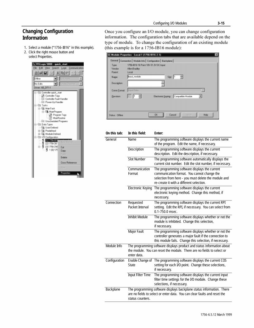
Changing Configuration Information
2QFH�\RX�FRQILJXUH�DQ�,�2�PRGXOH��\RX�FDQ�FKDQJH�FRQILJXUDWLRQ�LQIRUPDWLRQ���7KH�FRQILJXUDWLRQ�WDEV�WKDW�DUH�DYDLODEOH�GHSHQG�RQ�WKH�W\SH�RI�PRGXOH���7R�FKDQJH�WKH�FRQILJXUDWLRQ�RI�DQ�H[LVWLQJ�PRGXOH��WKLV�H[DPSOH�LV�IRU�D������,%���PRGXOH��
On this tab: In this field: Enter:
General Name The programming software displays the current name of the program. Edit the name, if necessary.
Description The programming software displays the current description. Edit the description, if necessary.
Slot Number The programming software automatically displays the current slot number. Edit the slot number, if necessary.
Communication Format
The programming software displays the current communication format. You cannot change the selection from here - you must delete the module and re-create it with a different selection.
Electronic Keying The programming software displays the current electronic keying method. Change this method, if necessary.
Connection Requested Packet Interval
The programming software displays the current RPI setting. Edit the RPI, if necessary. You can select from 0.1-750.0 msec.
Inhibit Module The programming software displays whether or not the module is inhibited. Change this selection, if necessary.
Major Fault The programming software displays whether or not the controller generates a major fault if the connection to this module fails. Change this selection, if necessary.
Module Info The programming software displays product and status information about the module. You can reset the module. There are no fields to select or enter data.
Configuration Enable Change of State
The programming software displays the current COS setting for each I/O point. Change these selections, if necessary.
Input Filter Time The programming software displays the current input filter time settings for the I/O module. Change these selections, if necessary.
Backplane The programming software displays backplane status information. There are no fields to select or enter data. You can clear faults and reset the status counters.
1. Select a module (“1756-IB16” in this example).2. Click the right mouse button and
select Properties.
1756-6.5.12 March 1999
3-16 Configuring I/O Modules
Accessing I/O ,�2�LQIRUPDWLRQ�LV�SUHVHQWHG�DV�D�VWUXFWXUH�RI�PXOWLSOH�ILHOGV��ZKLFK�GHSHQG�RQ�WKH�VSHFLILF�IHDWXUHV�RI�WKH�,�2�PRGXOH���7KH�QDPH�RI�WKH�VWUXFWXUH�LQIRUPDWLRQ�LV�EDVHG�RQ�WKH�ORFDWLRQ�RI�WKH�,�2�PRGXOH�LQ�WKH�V\VWHP���(DFK�,�2�WDJ�LV�DXWRPDWLFDOO\�FUHDWHG�ZKHQ�\RX�FRQILJXUH�WKH�,�2�PRGXOH�WKURXJK�WKH�SURJUDPPLQJ�VRIWZDUH���(DFK�WDJ�QDPH�IROORZV�WKLV IRUPDW�
/RFDWLRQ�6ORW1XPEHU�7\SH�0HPEHU1DPH�6XE0HPEHU1DPH�%LW
ZKHUH�
)RU�PRUH�LQIRUPDWLRQ�RQ�WDJV��VHH�FKDSWHU���
This address variable: Is:
Location Identifies network location
LOCAL = local chassis
ADAPTER_NAME = identifies remote chassis communication adapter or bridge module
SlotNumber Slot number of I/O module in its chassisType Type of data
I = input
O = output
C = configuration
S = status
MemberName Specific data from the I/O module; depends on what type of data the module can store
For example, Data and Fault are possible fields of data for an I/O module. Data is the common name for values the are sent to or received from I/O points.
SubMemberName Specific data related to a MemberName.Bit (optional) Specific point on the I/O module; depends on the size of
the I/O module (0-31 for a 32-point module)
1756-6.5.12 March 1999
Configuring I/O Modules 3-17
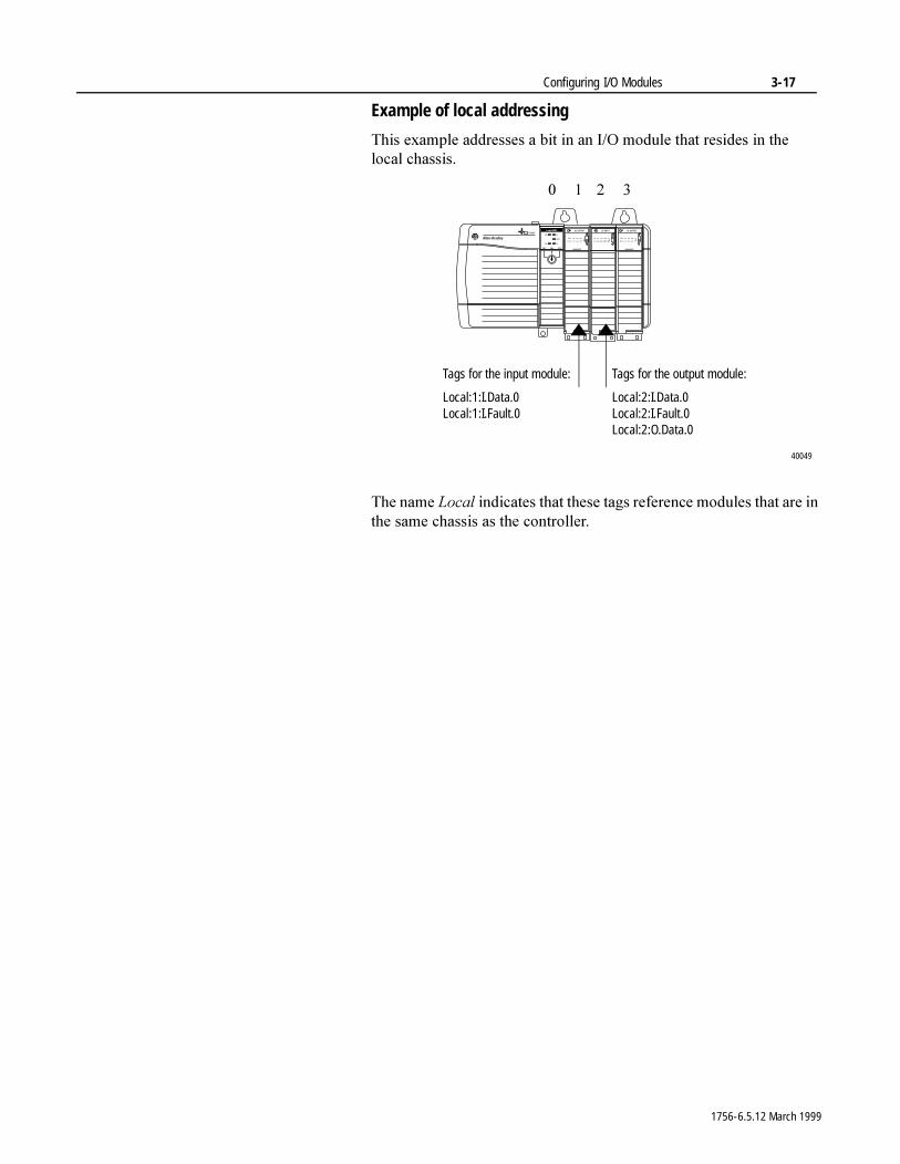
Example of local addressing
7KLV�H[DPSOH�DGGUHVVHV�D�ELW�LQ�DQ�,�2�PRGXOH�WKDW�UHVLGHV�LQ�WKH�ORFDO FKDVVLV�
7KH�QDPH�/RFDO�LQGLFDWHV�WKDW�WKHVH�WDJV�UHIHUHQFH�PRGXOHV�WKDW�DUH�LQ�WKH�VDPH�FKDVVLV�DV�WKH FRQWUROOHU�
� � � �
Tags for the output module:
Local:2:I.Data.0Local:2:I.Fault.0Local:2:O.Data.0
Tags for the input module:
Local:1:I.Data.0Local:1:I.Fault.0
40049
1756-6.5.12 March 1999
3-18 Configuring I/O Modules
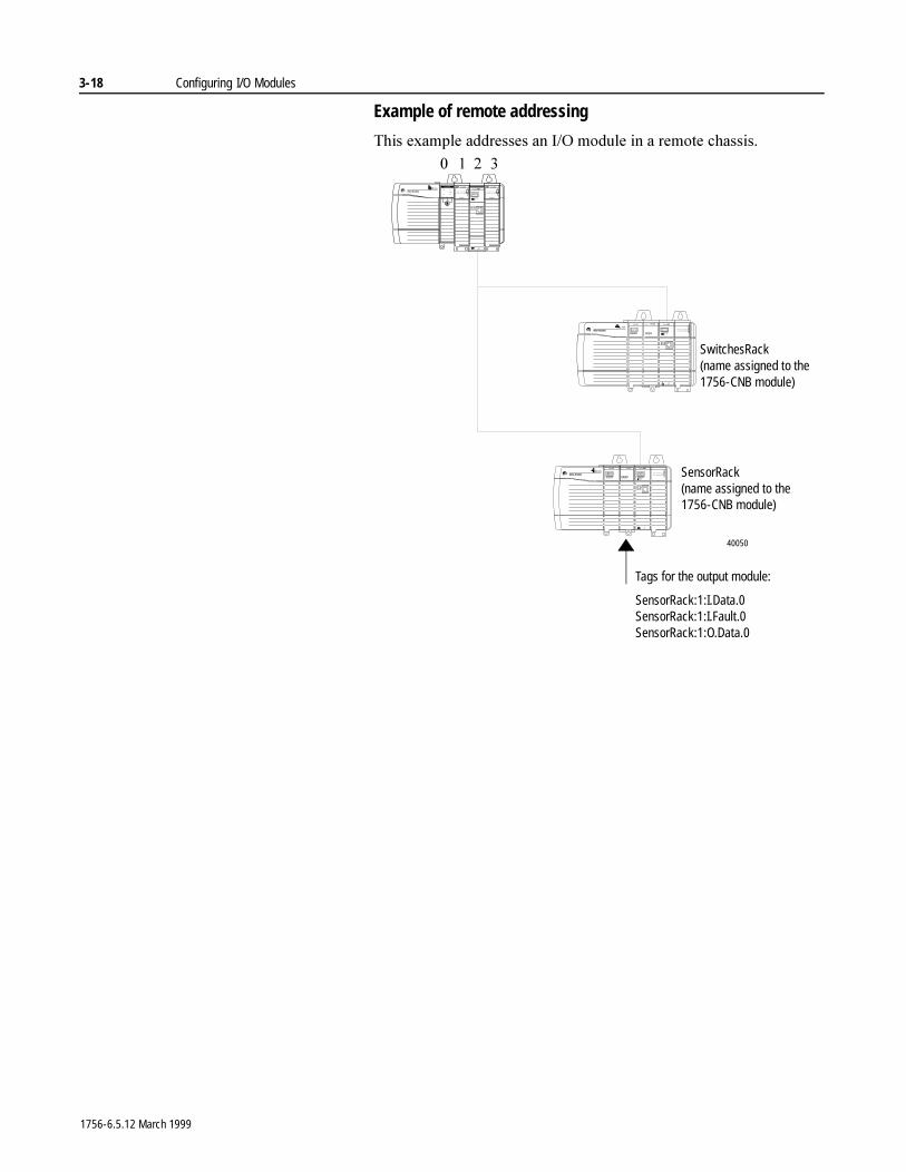
Example of remote addressing
7KLV�H[DPSOH�DGGUHVVHV�DQ�,�2�PRGXOH�LQ�D�UHPRWH�FKDVVLV�� � � �
SwitchesRack(name assigned to the 1756-CNB module)
SensorRack(name assigned to the 1756-CNB module)
Tags for the output module:
SensorRack:1:I.Data.0SensorRack:1:I.Fault.0SensorRack:1:O.Data.0
40050
1756-6.5.12 March 1999
Configuring I/O Modules 3-19
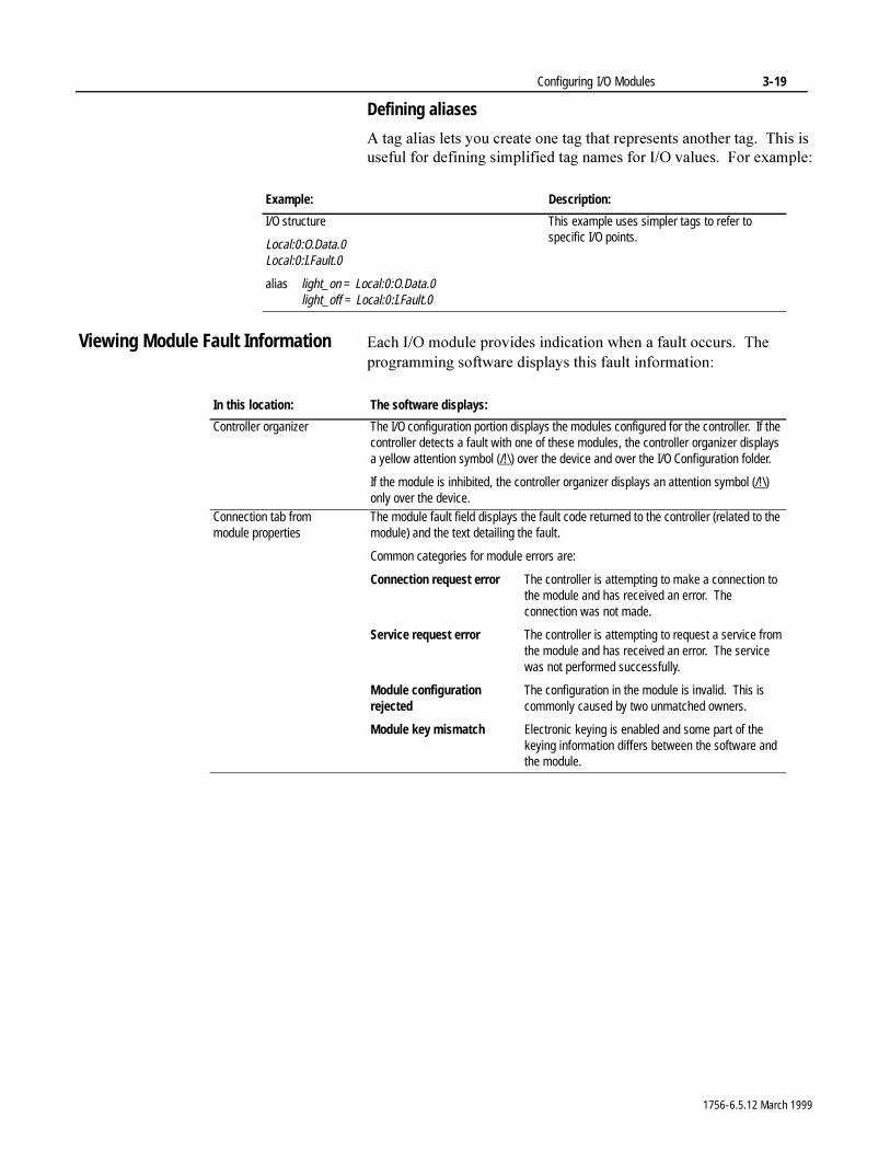
Defining aliases
$�WDJ�DOLDV�OHWV�\RX�FUHDWH�RQH�WDJ�WKDW�UHSUHVHQWV�DQRWKHU�WDJ���7KLV�LV�XVHIXO�IRU�GHILQLQJ�VLPSOLILHG�WDJ�QDPHV�IRU�,�2�YDOXHV���)RU H[DPSOH�
Viewing Module Fault Information (DFK�,�2�PRGXOH�SURYLGHV�LQGLFDWLRQ�ZKHQ�D�IDXOW�RFFXUV���7KH�SURJUDPPLQJ�VRIWZDUH�GLVSOD\V�WKLV�IDXOW�LQIRUPDWLRQ�
Example: Description:
I/O structure
Local:0:O.Data.0Local:0:I.Fault.0
alias light_on = Local:0:O.Data.0light_off = Local:0:I.Fault.0
This example uses simpler tags to refer to specific I/O points.
In this location: The software displays:
Controller organizer The I/O configuration portion displays the modules configured for the controller. If the controller detects a fault with one of these modules, the controller organizer displays a yellow attention symbol (/!\) over the device and over the I/O Configuration folder.
If the module is inhibited, the controller organizer displays an attention symbol (/!\) only over the device.
Connection tab from module properties
The module fault field displays the fault code returned to the controller (related to the module) and the text detailing the fault.
Common categories for module errors are:
Connection request error The controller is attempting to make a connection tothe module and has received an error. Theconnection was not made.
Service request error The controller is attempting to request a service fromthe module and has received an error. The servicewas not performed successfully.
Module configuration The configuration in the module is invalid. This isrejected commonly caused by two unmatched owners.
Module key mismatch Electronic keying is enabled and some part of thekeying information differs between the software and the module.
1756-6.5.12 March 1999
3-20 Configuring I/O Modules
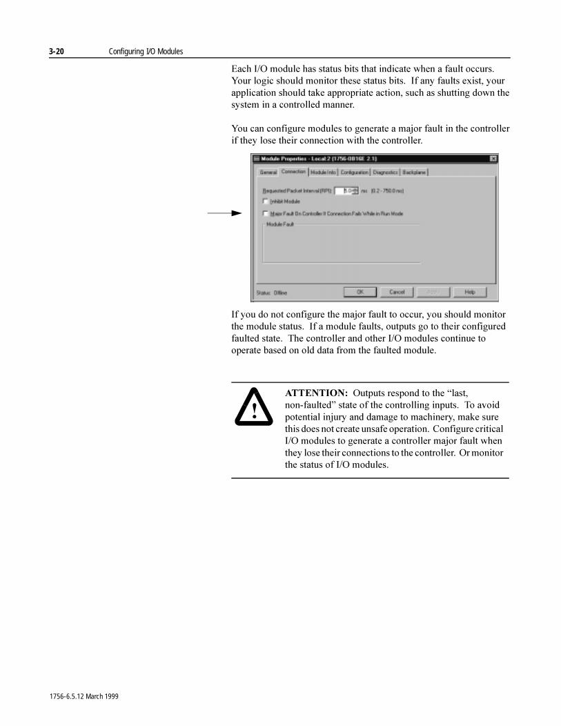
(DFK�,�2�PRGXOH�KDV�VWDWXV�ELWV�WKDW�LQGLFDWH�ZKHQ�D�IDXOW�RFFXUV���<RXU�ORJLF�VKRXOG�PRQLWRU�WKHVH�VWDWXV�ELWV���,I�DQ\�IDXOWV�H[LVW��\RXU�DSSOLFDWLRQ�VKRXOG�WDNH�DSSURSULDWH�DFWLRQ��VXFK�DV�VKXWWLQJ�GRZQ�WKH�V\VWHP�LQ�D�FRQWUROOHG�PDQQHU�
<RX�FDQ�FRQILJXUH�PRGXOHV�WR�JHQHUDWH�D�PDMRU�IDXOW�LQ�WKH�FRQWUROOHU�LI�WKH\�ORVH�WKHLU�FRQQHFWLRQ�ZLWK�WKH�FRQWUROOHU�
,I�\RX�GR�QRW�FRQILJXUH�WKH�PDMRU�IDXOW�WR�RFFXU��\RX�VKRXOG�PRQLWRU�WKH�PRGXOH�VWDWXV���,I�D�PRGXOH�IDXOWV��RXWSXWV�JR�WR�WKHLU�FRQILJXUHG�IDXOWHG�VWDWH���7KH�FRQWUROOHU�DQG�RWKHU�,�2�PRGXOHV�FRQWLQXH�WR�RSHUDWH�EDVHG�RQ�ROG�GDWD�IURP�WKH�IDXOWHG�PRGXOH�
�$77(17,21� 2XWSXWV�UHVSRQG�WR�WKH�³ODVW��QRQ�IDXOWHG´�VWDWH�RI�WKH�FRQWUROOLQJ�LQSXWV���7R�DYRLG�SRWHQWLDO�LQMXU\�DQG�GDPDJH�WR�PDFKLQHU\��PDNH�VXUH�WKLV�GRHV�QRW�FUHDWH�XQVDIH�RSHUDWLRQ���&RQILJXUH�FULWLFDO�,�2�PRGXOHV�WR�JHQHUDWH�D�FRQWUROOHU�PDMRU�IDXOW�ZKHQ�WKH\�ORVH�WKHLU�FRQQHFWLRQV�WR�WKH�FRQWUROOHU���2U�PRQLWRU�WKH�VWDWXV�RI�,�2�PRGXOHV�
1756-6.5.12 March 1999

Configuring I/O Modules 3-21
Using the programming software to view I/O faults
)URP�WKH�SURJUDPPLQJ�VRIWZDUH��\RX�FDQ�PRQLWRU�WKH�VWDWXV�RI�DQ�,�2�PRGXOH���7KH�SURJUDPPLQJ�VRIWZDUH�KDV�D�PRGXOH�LQIRUPDWLRQ�WDE�WKDW�GLVSOD\V�PRGXOH�IDXOW�VWDWXV�DQG�RWKHU�LQIRUPDWLRQ���<RX�PXVW�EH�RQOLQH�WR�JHW�DFWXDO�GDWD���7KLV�LQIRUPDWLRQ�LV�UHDG�IURP�WKH�DFWXDO�PRGXOH��VR�LW¶V�RQO\�DYDLODEOH�LI�WKH�FRQQHFWLRQ�WR�WKH�PRGXOH�LV�RSHQ��<RX�FDQ�DOVR�UHVHW�WKH�PRGXOH�IURP�WKLV�WDE�
<RX�FDQ�DOVR�YLHZ�,�2�LQIRUPDWLRQ�IURP�WKH�FRQQHFWLRQ�WDE���7KLV�LQIRUPDWLRQ�LV�UHDG�IURP�WKH�FRQWUROOHU���8VH�WKLV�WDE�LI�WKH�FRQQHFWLRQ�WR�WKH�PRGXOH�LV�VKXW�GRZQ�
1. Select a module (“1756-IB16” in this example).2. Click the right mouse button and select Properties.
1756-6.5.12 March 1999
3-22 Configuring I/O Modules
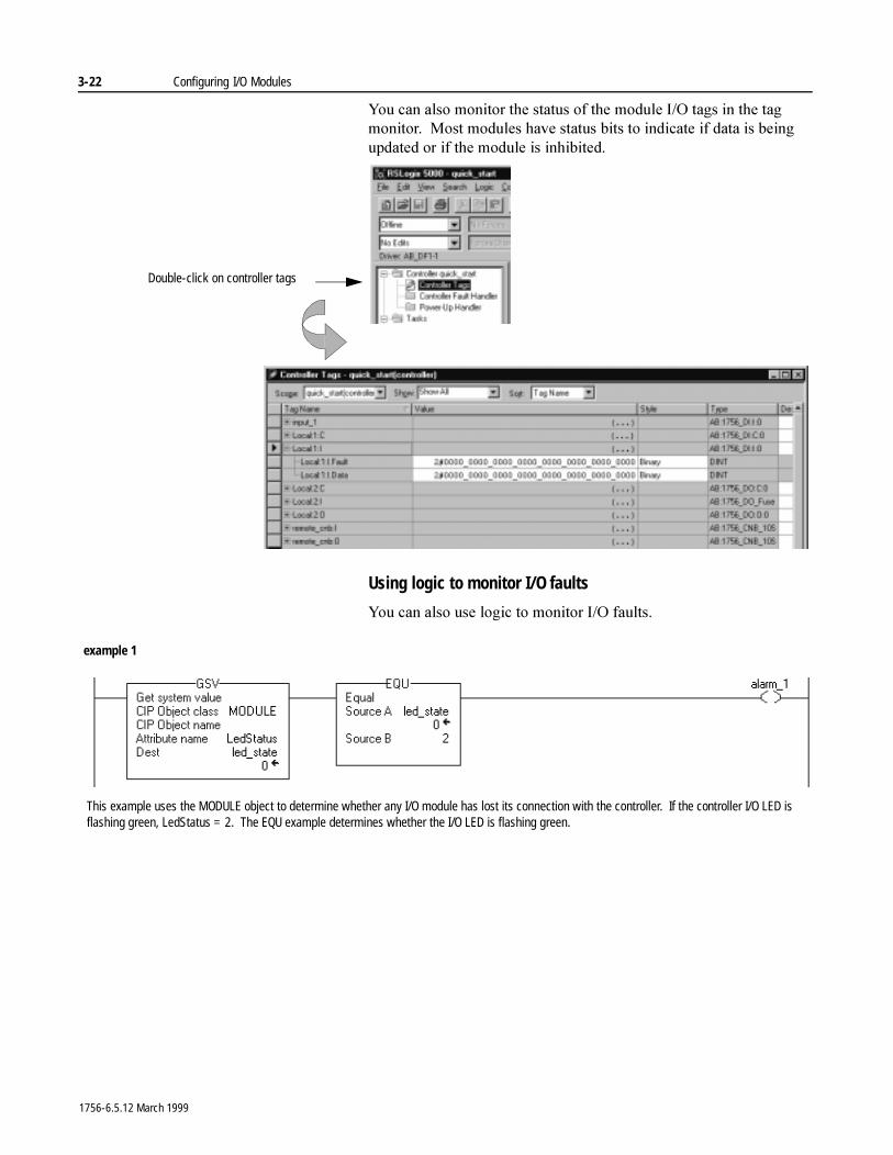
<RX�FDQ�DOVR�PRQLWRU�WKH�VWDWXV�RI�WKH�PRGXOH�,�2�WDJV�LQ�WKH�WDJ�PRQLWRU���0RVW�PRGXOHV�KDYH�VWDWXV�ELWV�WR�LQGLFDWH�LI�GDWD�LV�EHLQJ�XSGDWHG�RU�LI�WKH�PRGXOH�LV�LQKLELWHG�
Using logic to monitor I/O faults
<RX�FDQ�DOVR�XVH�ORJLF�WR�PRQLWRU�,�2�IDXOWV�
Double-click on controller tags
example 1
This example uses the MODULE object to determine whether any I/O module has lost its connection with the controller. If the controller I/O LED is flashing green, LedStatus = 2. The EQU example determines whether the I/O LED is flashing green.
1756-6.5.12 March 1999
Configuring I/O Modules 3-23
)RU�PRUH�LQIRUPDWLRQ�RQH�KDQGOLQJ�IDXOWV��VHH�FKDSWHU����
)RU�PRUH�LQIRUPDWLRQ�RQ�XVLQJ�WKH�*69�LQVWUXFWLRQ��VHH�WKH�/RJL[�����,QVWUXFWLRQ�6HW�5HIHUHQFH�0DQXDO��SXEOLFDWLRQ������������
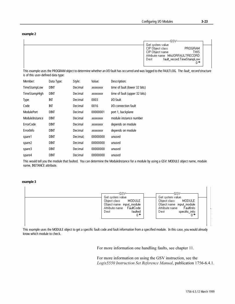
example 2
This example uses the PROGRAM object to determine whether an I/O fault has occurred and was logged to the FAULTLOG. The fault_record structure is of this user-defined data type:
Member: Data Type: Style: Value: Description:
TimeStampLow DINT Decimal xxxxxxxx time of fault (lower 32 bits)
TimeStampHigh DINT Decimal xxxxxxxx time of fault (upper 32 bits)
Type INT Decimal 0003 I/O fault
Code INT Decimal 0016 I/O connection fault
ModulePort DINT Decimal 00000001 port 1, backplane
ModuleInstance DINT Decimal xxxxxxxx module instance number
ErrorCode DINT Decimal xxxxxxxx depends on module
ErrorInfo DINT Decimal xxxxxxxx depends on module
spare1 DINT Decimal; 00000000 unused
spare2 DINT Decimal 00000000 unused
spare3 DINT Decimal 00000000 unused
spare4 DINT Decimal 00000000 unused
This would tell you the module that faulted. You can determine the ModuleInstance for a module by using a GSV: MODULE object name, module name, INSTANCE attribute.
example 3
This example uses the MODULE object to get a specific fault code and fault information from a specified module. In this case, you would already know which module to check.
1756-6.5.12 March 1999

3-24 Configuring I/O Modules
1RWHV�
1756-6.5.12 March 1999
Chapter 4
Organizing DataUsing This Chapter
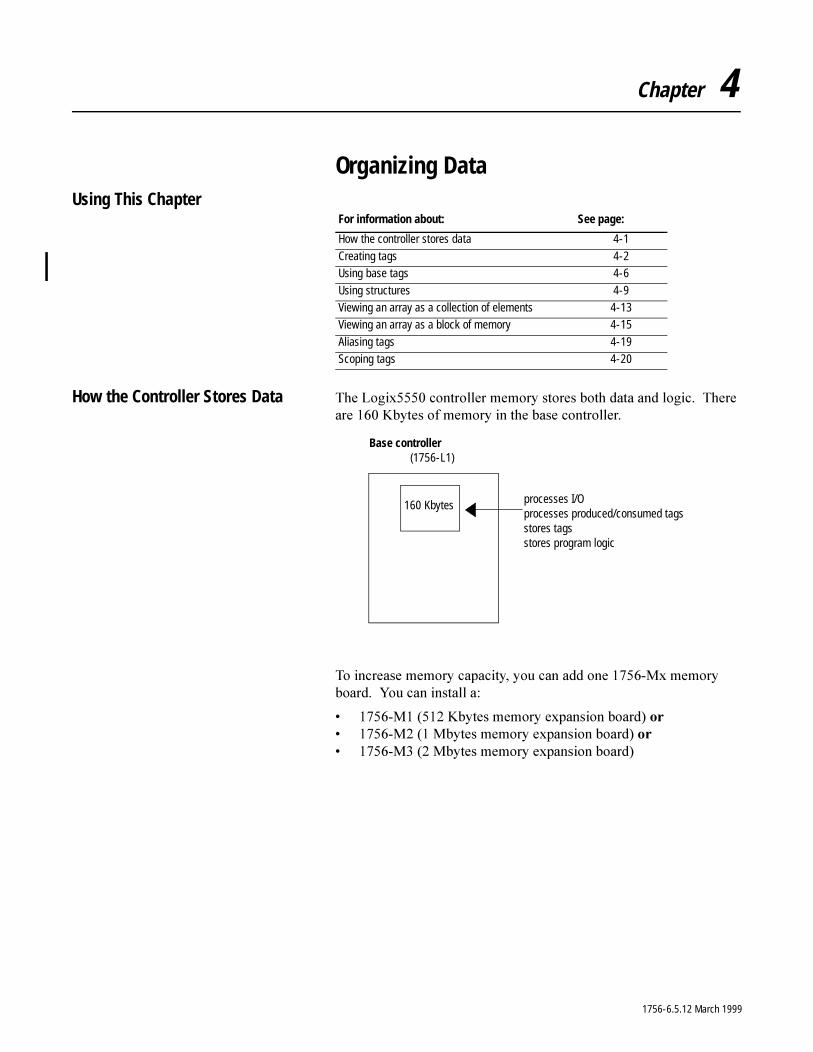
How the Controller Stores Data 7KH�/RJL[�����FRQWUROOHU�PHPRU\�VWRUHV�ERWK�GDWD�DQG�ORJLF���7KHUH�DUH�����.E\WHV�RI�PHPRU\�LQ�WKH�EDVH�FRQWUROOHU�
7R�LQFUHDVH�PHPRU\�FDSDFLW\��\RX�FDQ�DGG�RQH������0[�PHPRU\�ERDUG���<RX�FDQ�LQVWDOO�D�
� �����0�������.E\WHV�PHPRU\�H[SDQVLRQ�ERDUG��RU� �����0�����0E\WHV�PHPRU\�H[SDQVLRQ�ERDUG��RU� �����0�����0E\WHV�PHPRU\�H[SDQVLRQ�ERDUG�
For information about: See page:
How the controller stores data 4-1
Creating tags 4-2Using base tags 4-6
Using structures 4-9Viewing an array as a collection of elements 4-13Viewing an array as a block of memory 4-15
Aliasing tags 4-19Scoping tags 4-20
160 Kbytes
Base controller(1756-L1)
processes I/Oprocesses produced/consumed tagsstores tagsstores program logic
1756-6.5.12 March 1999
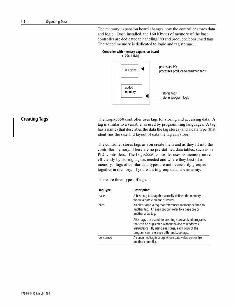
4-2 Organizing Data
7KH�PHPRU\�H[SDQVLRQ�ERDUG�FKDQJHV�KRZ�WKH�FRQWUROOHU�VWRUHV�GDWD�DQG�ORJLF���2QFH�LQVWDOOHG��WKH�����.E\WHV�RI�PHPRU\�RI�WKH�EDVH�FRQWUROOHU�DUH�GHGLFDWHG�WR�KDQGOLQJ�,�2�DQG�SURGXFHG�FRQVXPHG�WDJV���7KH�DGGHG�PHPRU\�LV�GHGLFDWHG�WR�ORJLF�DQG�WDJ�VWRUDJH�
Creating Tags 7KH�/RJL[�����FRQWUROOHU�XVHV�WDJV�IRU�VWRULQJ�DQG�DFFHVVLQJ�GDWD���$�WDJ�LV�VLPLODU�WR�D�YDULDEOH��DV�XVHG�E\�SURJUDPPLQJ�ODQJXDJHV���$�WDJ�KDV�D�QDPH��WKDW�GHVFULEHV�WKH�GDWD�WKH�WDJ�VWRUHV��DQG�D�GDWD�W\SH��WKDW�LGHQWLILHV�WKH�VL]H�DQG�OD\RXW�RI�GDWD�WKH�WDJ�FDQ�VWRUH��
7KH�FRQWUROOHU�VWRUHV�WDJV�DV�\RX�FUHDWH�WKHP�DQG�DV�WKH\�ILW�LQWR�WKH�FRQWUROOHU�PHPRU\���7KHUH�DUH�QR�SUH�GHILQHG�GDWD�WDEOHV��VXFK�DV�LQ�3/&�FRQWUROOHUV���7KH�/RJL[�����FRQWUROOHU�XVHV�LWV�PHPRU\�PRUH�HIILFLHQWO\�E\�VWRULQJ�WDJV�DV�QHHGHG�DQG�ZKHUH�WKH\�EHVW�ILW�LQ�PHPRU\���7DJV�RI�VLPLODU�GDWD�W\SHV�DUH�QRW�QHFHVVDULO\�JURXSHG�WRJHWKHU�LQ�PHPRU\���,I�\RX�ZDQW�WR�JURXS�GDWD��XVH�DQ�DUUD\�
7KHUH�DUH�WKUHH�W\SHV�RI�WDJV�
added memory
Controller with memory expansion board(1756-L1Mx)
processes I/Oprocesses produced/consumed tags
stores tagsstores program logic
160 Kbytes
Tag Type: Description:
base A base tag is a tag that actually defines the memory where a data element is stored.
alias An alias tag is a tag that references memory defined by another tag. An alias tag can refer to a base tag or another alias tag.
Alias tags are useful for creating standardized programs that can be duplicated without having to readdress instructions. By using alias tags, each copy of the program can reference different base tags.
consumed A consumed tag is a tag whose data value comes from another controller.
1756-6.5.12 March 1999
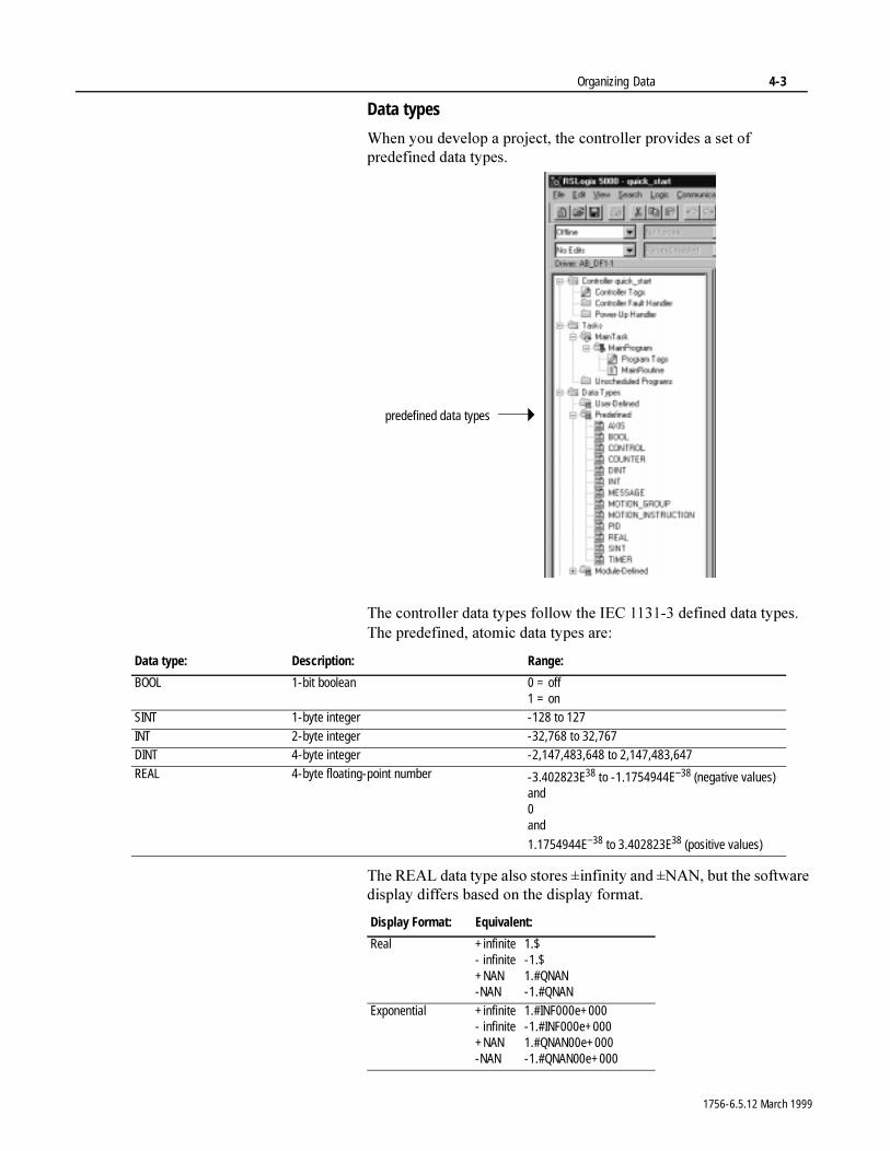
Organizing Data 4-3
Data types
:KHQ�\RX�GHYHORS�D�SURMHFW��WKH�FRQWUROOHU�SURYLGHV�D�VHW�RI�SUHGHILQHG�GDWD�W\SHV�
7KH�FRQWUROOHU�GDWD�W\SHV�IROORZ�WKH�,(&��������GHILQHG�GDWD�W\SHV���7KH�SUHGHILQHG��DWRPLF�GDWD�W\SHV�DUH�
7KH�5($/�GDWD�W\SH�DOVR�VWRUHV��LQILQLW\�DQG��1$1��EXW�WKH�VRIWZDUH�GLVSOD\�GLIIHUV�EDVHG�RQ�WKH�GLVSOD\�IRUPDW�
predefined data types
Data type: Description: Range:
BOOL 1-bit boolean 0 = off1 = on
SINT 1-byte integer -128 to 127
INT 2-byte integer -32,768 to 32,767DINT 4-byte integer -2,147,483,648 to 2,147,483,647
REAL 4-byte floating-point number -3.402823E38 to -1.1754944E−38 (negative values)and0and
1.1754944E−38 to 3.402823E38 (positive values)
Display Format: Equivalent:
Real +infinite 1.$- infinite -1.$+NAN 1.#QNAN-NAN -1.#QNAN
Exponential +infinite 1.#INF000e+000- infinite -1.#INF000e+000+NAN 1.#QNAN00e+000-NAN -1.#QNAN00e+000
1756-6.5.12 March 1999
4-4 Organizing Data
7KH�SUHGHILQHG�VWUXFWXUHV�DUH�
Naming tags
7DJ�QDPHV�IROORZ�,(&��������LGHQWLILHU�UXOHV�DQG�� PXVW�EHJLQ�ZLWK�DQ�DOSKDEHWLF�FKDUDFWHU��$�=�RU�D�]��RU�DQ�
XQGHUVFRUH �B�� FDQ�FRQWDLQ�RQO\�DOSKDEHWLF�FKDUDFWHUV��QXPHULF�FKDUDFWHUV��
DQG XQGHUVFRUHV� FDQ�KDYH�DV�PDQ\�DV����FKDUDFWHUV� PXVW�QRW�KDYH�FRQVHFXWLYH�RU�WUDLOLQJ�XQGHUVFRUH�FKDUDFWHUV��B�
7DJ�QDPHV�DUH�QRW�FDVH�VHQVLWLYH
<RX�FDQ�DOVR�DGG�GHVFULSWLRQV�WR�WDJV���'HVFULSWLRQV�FDQ�KDYH�DV�PDQ\�DV�����FKDUDFWHUV���<RX�FDQ�XVH�DQ\�SULQWDEOH�FKDUDFWHU�
Entering tags
<RX�XVH�WKH�SURJUDPPLQJ�VRIWZDUH�WR�FUHDWH�WDJV���<RX�FDQ�HLWKHU�FUHDWH�D�WDJ�LQGLYLGXDOO\��RU�WKURXJK�WKH�(GLW�7DJV�WDE�RI�WKH�GDWD PRQLWRU�
Data type: Description:
AXIS1
1. These structures do not support arrays, cannot be nested in user-defined structures, and cannot be passed to other routines via a JSR instruction. These are controller-only tags.
control structure for an axis
CONTROL control structure for array (file) instructionsCOUNTER control structure for counter instructions
MESSAGE1 control structure for the MSG instruction
MOTION_GROUP1 control structure for a motion group
MOTION_INSTRUCTION control structure for motion instructionsPID control structure for the PID instructionTIMER control structure for timer instructions
1756-6.5.12 March 1999
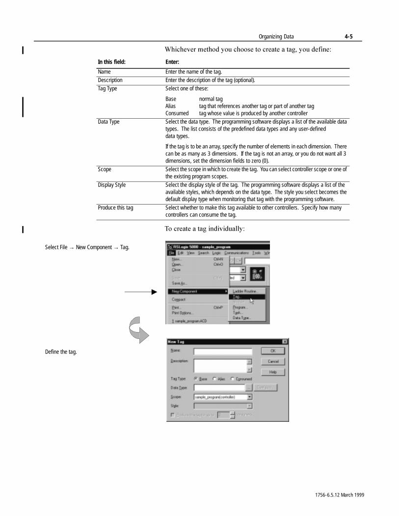
Organizing Data 4-5
:KLFKHYHU�PHWKRG�\RX�FKRRVH�WR�FUHDWH�D�WDJ��\RX�GHILQH�
7R�FUHDWH�D�WDJ�LQGLYLGXDOO\�
In this field: Enter:
Name Enter the name of the tag.Description Enter the description of the tag (optional).Tag Type Select one of these:
Base normal tagAlias tag that references another tag or part of another tagConsumed tag whose value is produced by another controller
Data Type Select the data type. The programming software displays a list of the available data types. The list consists of the predefined data types and any user-defined data types.
If the tag is to be an array, specify the number of elements in each dimension. There can be as many as 3 dimensions. If the tag is not an array, or you do not want all 3 dimensions, set the dimension fields to zero (0).
Scope Select the scope in which to create the tag. You can select controller scope or one of the existing program scopes.
Display Style Select the display style of the tag. The programming software displays a list of the available styles, which depends on the data type. The style you select becomes the default display type when monitoring that tag with the programming software.
Produce this tag Select whether to make this tag available to other controllers. Specify how many controllers can consume the tag.
Select File → New Component → Tag.
Define the tag.
1756-6.5.12 March 1999
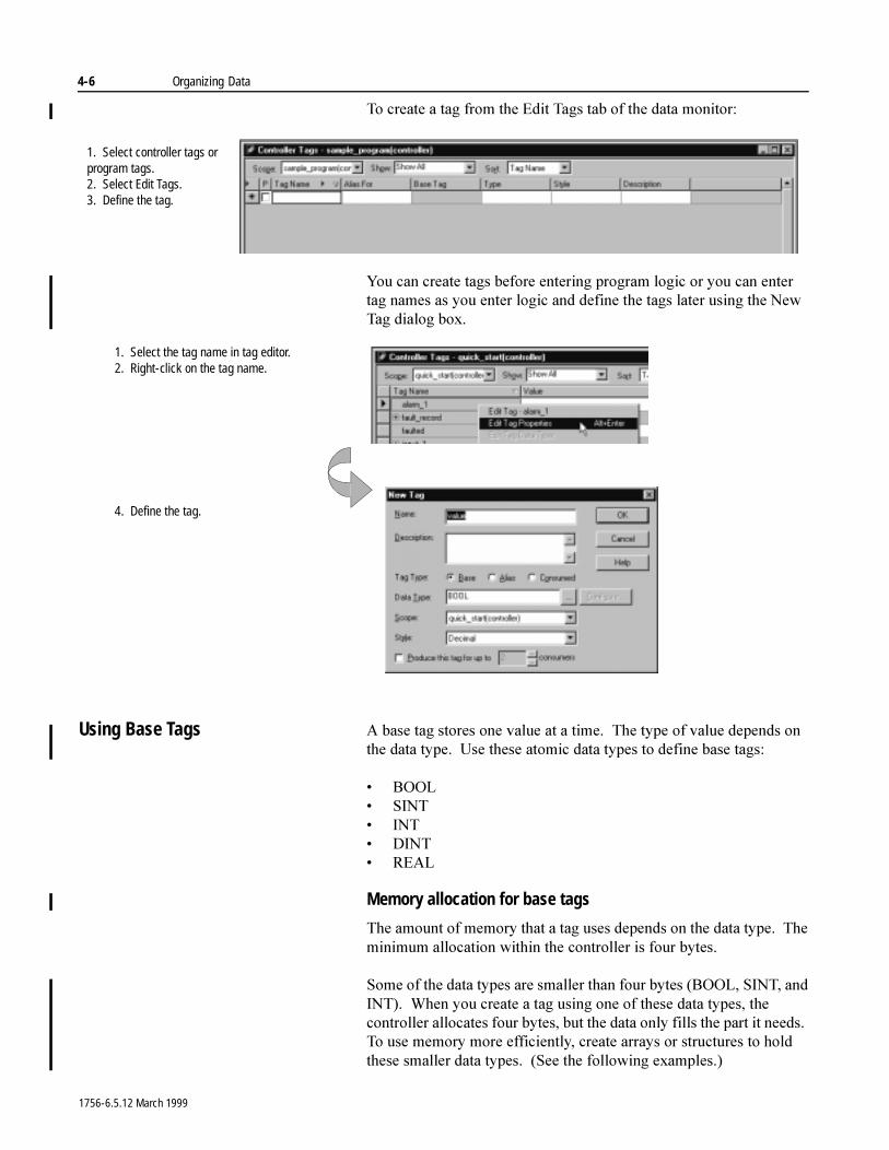
4-6 Organizing Data
7R�FUHDWH�D�WDJ�IURP�WKH�(GLW�7DJV�WDE�RI�WKH�GDWD�PRQLWRU�
<RX�FDQ�FUHDWH�WDJV�EHIRUH�HQWHULQJ�SURJUDP�ORJLF�RU�\RX�FDQ�HQWHU�WDJ�QDPHV�DV�\RX�HQWHU�ORJLF�DQG�GHILQH�WKH�WDJV�ODWHU�XVLQJ�WKH�1HZ�7DJ�GLDORJ�ER[�
Using Base Tags $�EDVH�WDJ�VWRUHV�RQH�YDOXH�DW�D�WLPH���7KH�W\SH�RI�YDOXH�GHSHQGV�RQ�WKH�GDWD�W\SH���8VH�WKHVH�DWRPLF�GDWD�W\SHV�WR�GHILQH�EDVH WDJV�
� %22/� 6,17� ,17� ',17� 5($/
Memory allocation for base tags
7KH�DPRXQW�RI�PHPRU\�WKDW�D�WDJ�XVHV�GHSHQGV�RQ�WKH�GDWD�W\SH���7KH�PLQLPXP�DOORFDWLRQ�ZLWKLQ�WKH�FRQWUROOHU�LV�IRXU�E\WHV��
6RPH�RI�WKH�GDWD�W\SHV�DUH�VPDOOHU�WKDQ�IRXU�E\WHV��%22/��6,17��DQG�,17����:KHQ�\RX�FUHDWH�D�WDJ�XVLQJ�RQH�RI�WKHVH�GDWD�W\SHV��WKH�FRQWUROOHU�DOORFDWHV�IRXU�E\WHV��EXW�WKH�GDWD�RQO\�ILOOV�WKH�SDUW�LW�QHHGV���7R�XVH�PHPRU\�PRUH�HIILFLHQWO\��FUHDWH�DUUD\V�RU�VWUXFWXUHV�WR�KROG�WKHVH�VPDOOHU�GDWD�W\SHV����6HH�WKH�IROORZLQJ�H[DPSOHV��
1. Select controller tags or program tags.2. Select Edit Tags.3. Define the tag.
1. Select the tag name in tag editor.2. Right-click on the tag name.
4. Define the tag.
1756-6.5.12 March 1999
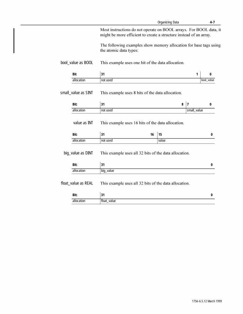
Organizing Data 4-7
0RVW�LQVWUXFWLRQV�GR�QRW�RSHUDWH�RQ�%22/�DUUD\V���)RU�%22/�GDWD��LW�PLJKW�EH�PRUH�HIILFLHQW�WR�FUHDWH�D�VWUXFWXUH�LQVWHDG�RI�DQ�DUUD\�
7KH�IROORZLQJ�H[DPSOHV�VKRZ�PHPRU\�DOORFDWLRQ�IRU�EDVH�WDJV�XVLQJ�WKH�DWRPLF�GDWD�W\SHV�
bool_value as BOOL 7KLV�H[DPSOH�XVHV�RQH�ELW�RI�WKH�GDWD�DOORFDWLRQ�
small_value as SINT 7KLV�H[DPSOH�XVHV���ELWV�RI�WKH�GDWD�DOORFDWLRQ�
value as INT 7KLV�H[DPSOH�XVHV����ELWV�RI�WKH�GDWD�DOORFDWLRQ�
big_value as DINT 7KLV�H[DPSOH�XVHV�DOO����ELWV�RI�WKH�GDWD�DOORFDWLRQ�
float_value as REAL 7KLV�H[DPSOH�XVHV�DOO����ELWV�RI�WKH�GDWD�DOORFDWLRQ�
Bit 31 1 0
allocation not used bool_value
Bit: 31 8 7 0
allocation not used small_value
Bit: 31 16 15 0
allocation not used value
Bit: 31 0
allocation big_value
Bit: 31 0
allocation float_value
1756-6.5.12 March 1999
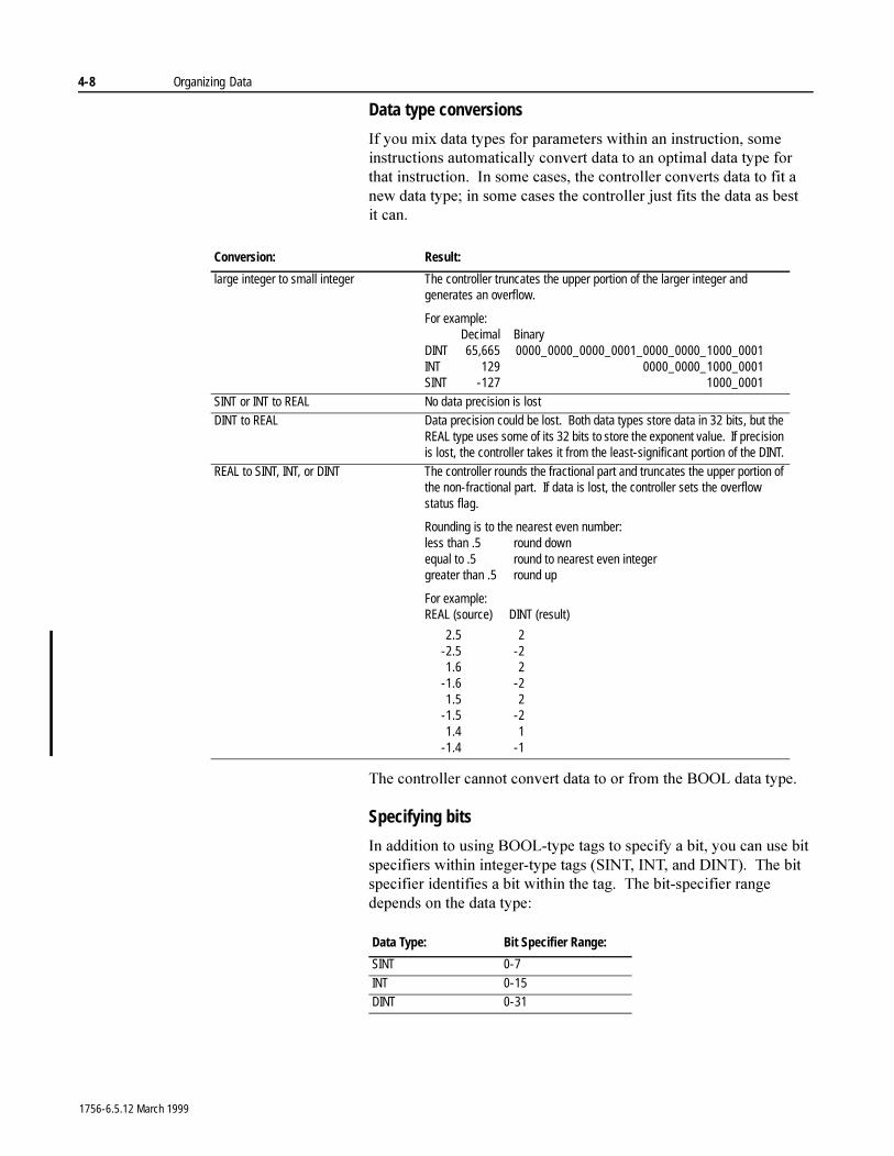
4-8 Organizing Data
Data type conversions
,I�\RX�PL[�GDWD�W\SHV�IRU�SDUDPHWHUV�ZLWKLQ�DQ�LQVWUXFWLRQ��VRPH�LQVWUXFWLRQV�DXWRPDWLFDOO\�FRQYHUW�GDWD�WR�DQ�RSWLPDO�GDWD�W\SH�IRU�WKDW�LQVWUXFWLRQ���,Q�VRPH�FDVHV��WKH�FRQWUROOHU�FRQYHUWV�GDWD�WR�ILW�D�QHZ�GDWD�W\SH��LQ�VRPH�FDVHV�WKH�FRQWUROOHU�MXVW�ILWV�WKH�GDWD�DV�EHVW�LW FDQ�
7KH�FRQWUROOHU�FDQQRW�FRQYHUW�GDWD�WR�RU�IURP�WKH�%22/�GDWD�W\SH�
Specifying bits
,Q�DGGLWLRQ�WR�XVLQJ�%22/�W\SH�WDJV�WR�VSHFLI\�D�ELW��\RX�FDQ�XVH�ELW�VSHFLILHUV�ZLWKLQ�LQWHJHU�W\SH�WDJV��6,17��,17��DQG�',17����7KH�ELW�VSHFLILHU�LGHQWLILHV�D�ELW�ZLWKLQ�WKH�WDJ���7KH�ELW�VSHFLILHU�UDQJH�GHSHQGV�RQ�WKH�GDWD�W\SH�
Conversion: Result:
large integer to small integer The controller truncates the upper portion of the larger integer and generates an overflow.
For example:Decimal Binary
DINT 65,665 0000_0000_0000_0001_0000_0000_1000_0001INT 129 0000_0000_1000_0001SINT -127 1000_0001
SINT or INT to REAL No data precision is lostDINT to REAL Data precision could be lost. Both data types store data in 32 bits, but the
REAL type uses some of its 32 bits to store the exponent value. If precision is lost, the controller takes it from the least-significant portion of the DINT.
REAL to SINT, INT, or DINT The controller rounds the fractional part and truncates the upper portion of the non-fractional part. If data is lost, the controller sets the overflow status flag.
Rounding is to the nearest even number:less than .5 round downequal to .5 round to nearest even integergreater than .5 round up
For example:REAL (source) DINT (result)
2.5 2-2.5 -21.6 2
-1.6 -21.5 2
-1.5 -21.4 1
-1.4 -1
Data Type: Bit Specifier Range:
SINT 0-7
INT 0-15DINT 0-31
1756-6.5.12 March 1999
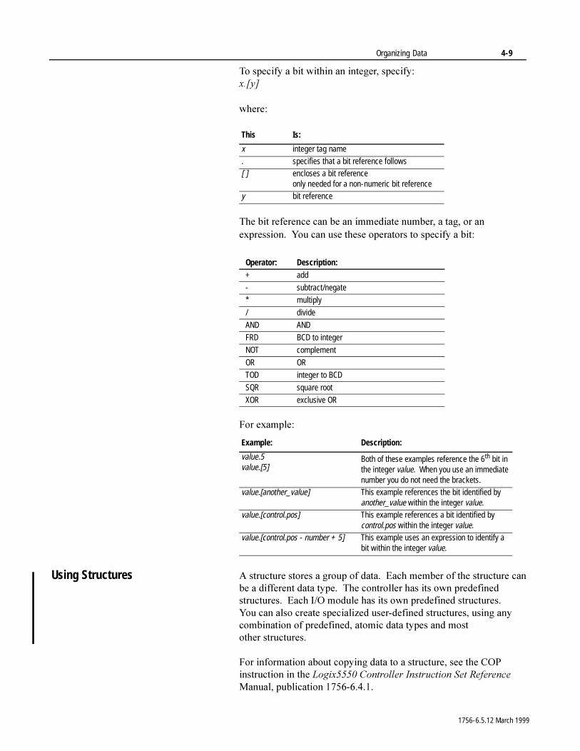
Organizing Data 4-9
7R�VSHFLI\�D�ELW�ZLWKLQ�DQ�LQWHJHU��VSHFLI\�[�>\@
ZKHUH�
7KH�ELW�UHIHUHQFH�FDQ�EH�DQ�LPPHGLDWH�QXPEHU��D�WDJ��RU�DQ�H[SUHVVLRQ���<RX�FDQ�XVH�WKHVH�RSHUDWRUV�WR�VSHFLI\�D�ELW�
)RU�H[DPSOH�
Using Structures $�VWUXFWXUH�VWRUHV�D�JURXS�RI�GDWD���(DFK�PHPEHU�RI�WKH�VWUXFWXUH�FDQ�EH�D�GLIIHUHQW�GDWD�W\SH���7KH�FRQWUROOHU�KDV�LWV�RZQ�SUHGHILQHG�VWUXFWXUHV���(DFK�,�2�PRGXOH�KDV�LWV�RZQ�SUHGHILQHG�VWUXFWXUHV���<RX FDQ�DOVR�FUHDWH�VSHFLDOL]HG�XVHU�GHILQHG�VWUXFWXUHV��XVLQJ�DQ\�FRPELQDWLRQ�RI�SUHGHILQHG��DWRPLF�GDWD�W\SHV�DQG�PRVW�RWKHU VWUXFWXUHV�
)RU�LQIRUPDWLRQ�DERXW�FRS\LQJ�GDWD�WR�D�VWUXFWXUH��VHH�WKH�&23�LQVWUXFWLRQ�LQ�WKH�/RJL[�����&RQWUROOHU�,QVWUXFWLRQ�6HW�5HIHUHQFH�0DQXDO��SXEOLFDWLRQ������������
This Is:
x integer tag name
. specifies that a bit reference follows[ ] encloses a bit reference
only needed for a non-numeric bit referencey bit reference
Operator: Description:+ add
- subtract/negate
* multiply
/ divide
AND AND
FRD BCD to integer
NOT complement
OR OR
TOD integer to BCD
SQR square root
XOR exclusive OR
Example: Description:
value.5value.[5]
Both of these examples reference the 6th bit in the integer value. When you use an immediate number you do not need the brackets.
value.[another_value] This example references the bit identified by another_value within the integer value.
value.[control.pos] This example references a bit identified by control.pos within the integer value.
value.[control.pos - number + 5] This example uses an expression to identify a bit within the integer value.
1756-6.5.12 March 1999
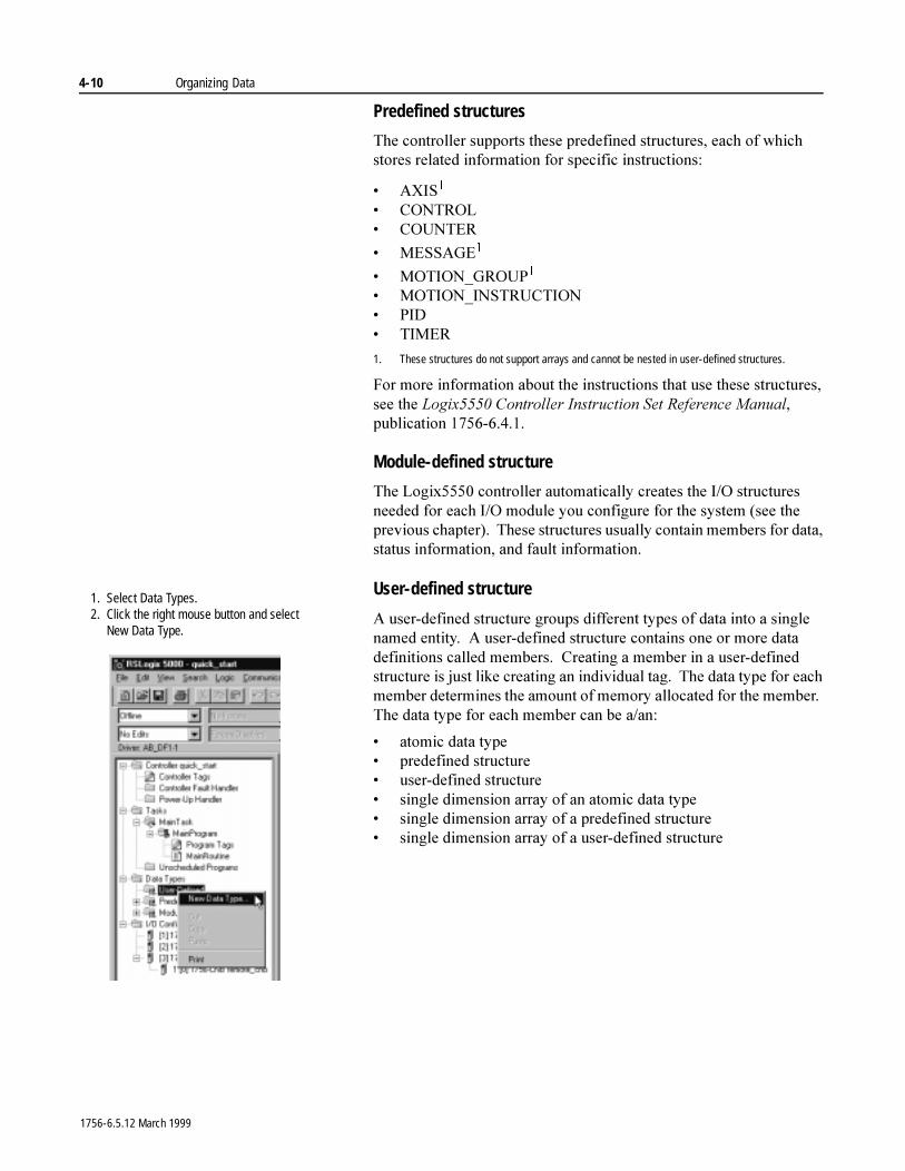
4-10 Organizing Data
Predefined structures
7KH�FRQWUROOHU�VXSSRUWV�WKHVH�SUHGHILQHG�VWUXFWXUHV��HDFK�RI�ZKLFK�VWRUHV�UHODWHG�LQIRUPDWLRQ�IRU�VSHFLILF�LQVWUXFWLRQV�
� $;,6�
� &21752/� &2817(5
� 0(66$*(�
� 027,21B*5283�
� 027,21B,16758&7,21� 3,'� 7,0(5
1. These structures do not support arrays and cannot be nested in user-defined structures.
)RU�PRUH�LQIRUPDWLRQ�DERXW�WKH�LQVWUXFWLRQV�WKDW�XVH�WKHVH�VWUXFWXUHV��VHH�WKH�/RJL[�����&RQWUROOHU�,QVWUXFWLRQ�6HW�5HIHUHQFH�0DQXDO��SXEOLFDWLRQ������������
Module-defined structure
7KH�/RJL[�����FRQWUROOHU�DXWRPDWLFDOO\�FUHDWHV�WKH�,�2�VWUXFWXUHV�QHHGHG�IRU�HDFK�,�2�PRGXOH�\RX�FRQILJXUH�IRU�WKH�V\VWHP��VHH�WKH�SUHYLRXV�FKDSWHU����7KHVH�VWUXFWXUHV�XVXDOO\�FRQWDLQ�PHPEHUV�IRU�GDWD��VWDWXV�LQIRUPDWLRQ��DQG�IDXOW�LQIRUPDWLRQ�
User-defined structure
$�XVHU�GHILQHG�VWUXFWXUH�JURXSV�GLIIHUHQW�W\SHV�RI�GDWD�LQWR�D�VLQJOH�QDPHG�HQWLW\���$�XVHU�GHILQHG�VWUXFWXUH�FRQWDLQV�RQH�RU�PRUH�GDWD�GHILQLWLRQV�FDOOHG�PHPEHUV���&UHDWLQJ�D�PHPEHU�LQ�D�XVHU�GHILQHG�VWUXFWXUH�LV�MXVW�OLNH�FUHDWLQJ�DQ�LQGLYLGXDO�WDJ���7KH�GDWD�W\SH�IRU�HDFK�PHPEHU�GHWHUPLQHV�WKH�DPRXQW�RI�PHPRU\�DOORFDWHG�IRU�WKH�PHPEHU���7KH�GDWD�W\SH�IRU�HDFK�PHPEHU�FDQ�EH�D�DQ�
� DWRPLF�GDWD�W\SH� SUHGHILQHG�VWUXFWXUH� XVHU�GHILQHG�VWUXFWXUH� VLQJOH�GLPHQVLRQ�DUUD\�RI�DQ�DWRPLF�GDWD�W\SH� VLQJOH�GLPHQVLRQ�DUUD\�RI�D�SUHGHILQHG�VWUXFWXUH� VLQJOH�GLPHQVLRQ�DUUD\�RI�D�XVHU�GHILQHG�VWUXFWXUH
1. Select Data Types.2. Click the right mouse button and select
New Data Type.
1756-6.5.12 March 1999
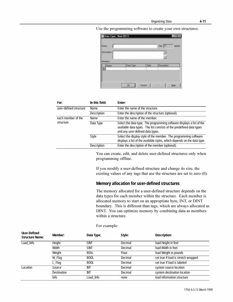
Organizing Data 4-11
8VH�WKH�SURJUDPPLQJ�VRIWZDUH�WR�FUHDWH�\RXU�RZQ�VWUXFWXUHV�
<RX�FDQ�FUHDWH��HGLW��DQG�GHOHWH�XVHU�GHILQHG�VWUXFWXUHV�RQO\�ZKHQ�SURJUDPPLQJ�RIIOLQH�
,I�\RX�PRGLI\�D�XVHU�GHILQHG�VWUXFWXUH�DQG�FKDQJH�LWV�VL]H��WKH�H[LVWLQJ�YDOXHV�RI�DQ\�WDJV�WKDW�XVH�WKH�VWUXFWXUH�DUH�VHW�WR�]HUR�����
Memory allocation for user-defined structures
7KH�PHPRU\�DOORFDWHG�IRU�D�XVHU�GHILQHG�VWUXFWXUH�GHSHQGV�RQ�WKH�GDWD�W\SHV�IRU�HDFK�PHPEHU�ZLWKLQ�WKH�VWUXFWXUH���(DFK�PHPEHU�LV�DOORFDWHG�PHPRU\�WR�VWDUW�RQ�DQ�DSSURSULDWH�E\WH��,17��RU�',17�ERXQGDU\���7KLV�LV�GLIIHUHQW�WKDQ�WDJV��ZKLFK�DUH�DOZD\V�DOORFDWHG�DV�',17���<RX�FDQ�RSWLPL]H�PHPRU\�E\�FRPELQLQJ�GDWD�DV�PHPEHUV�ZLWKLQ�D VWUXFWXUH�
)RU�H[DPSOH�
For: In this field: Enter:
user-defined structure Name Enter the name of the structure.Description Enter the description of the structure (optional).
each member of the structure
Name Enter the name of the member.Data Type Select the data type. The programming software displays a list of the
available data types. The list consists of the predefined data types and any user-defined data types.
Style Select the display style of the member. The programming software displays a list of the available styles, which depends on the data type.
Description Enter the description of the member (optional).
User-Defined Structure Name:
Member: Data Type: Style: Description:
Load_Info Height SINT Decimal load Height in feet
Width SINT Decimal load Width in feetWeight REAL Float load Weight in pounds
W_Flag BOOL Decimal set true if load is stretch wrappedL_Flag BOOL Decimal set true if load is labeled
Location Source INT Decimal system source location
Destination INT Decimal system destination locationInfo Load_Info none load information structure
1756-6.5.12 March 1999
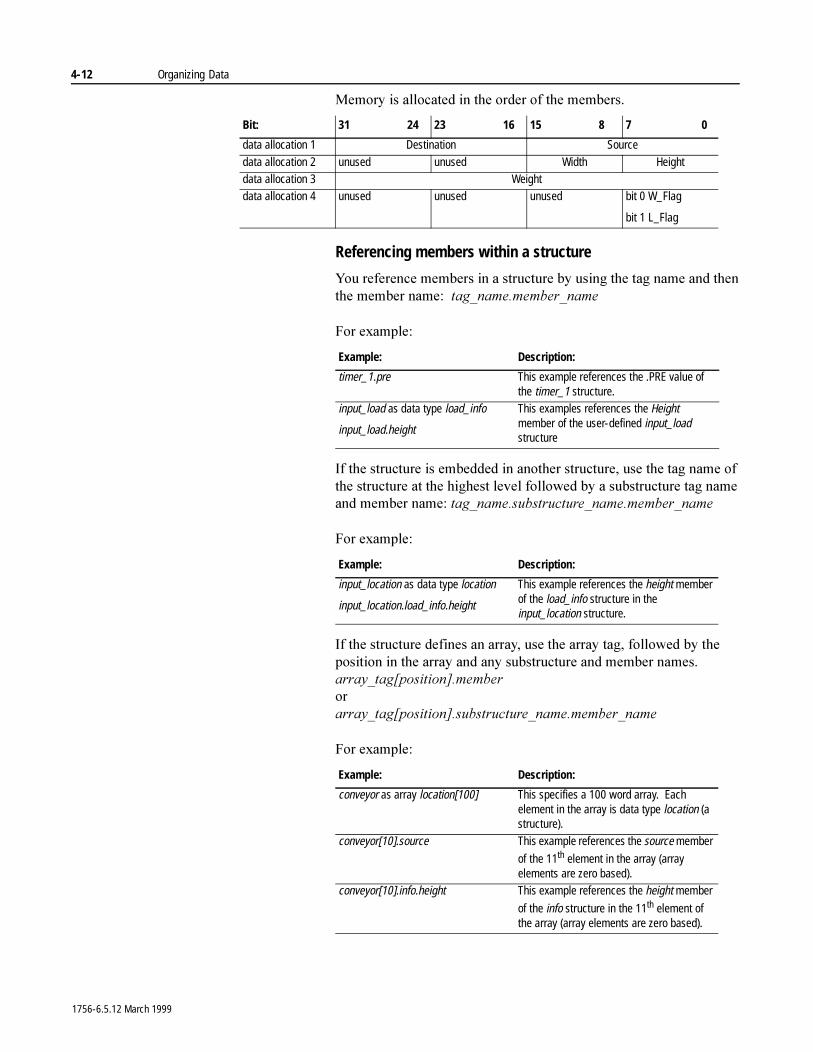
4-12 Organizing Data
0HPRU\�LV�DOORFDWHG�LQ�WKH�RUGHU�RI�WKH�PHPEHUV�
Referencing members within a structure
<RX�UHIHUHQFH�PHPEHUV�LQ�D�VWUXFWXUH�E\�XVLQJ�WKH�WDJ�QDPH�DQG�WKHQ�WKH�PHPEHU�QDPH���WDJBQDPH�PHPEHUBQDPH
)RU�H[DPSOH�
,I�WKH�VWUXFWXUH�LV�HPEHGGHG�LQ�DQRWKHU�VWUXFWXUH��XVH�WKH�WDJ�QDPH�RI�WKH�VWUXFWXUH�DW�WKH�KLJKHVW�OHYHO�IROORZHG�E\�D�VXEVWUXFWXUH�WDJ�QDPH�DQG�PHPEHU�QDPH��WDJBQDPH�VXEVWUXFWXUHBQDPH�PHPEHUBQDPH
)RU�H[DPSOH�
,I�WKH�VWUXFWXUH�GHILQHV�DQ�DUUD\��XVH�WKH�DUUD\�WDJ��IROORZHG�E\�WKH�SRVLWLRQ�LQ�WKH�DUUD\�DQG�DQ\�VXEVWUXFWXUH�DQG�PHPEHU�QDPHV��DUUD\BWDJ>SRVLWLRQ@�PHPEHURUDUUD\BWDJ>SRVLWLRQ@�VXEVWUXFWXUHBQDPH�PHPEHUBQDPH
)RU�H[DPSOH�
Bit: 31 24 23 16 15 8 7 0
data allocation 1 Destination Source
data allocation 2 unused unused Width Heightdata allocation 3 Weightdata allocation 4 unused unused unused bit 0 W_Flag
bit 1 L_Flag
Example: Description:
timer_1.pre This example references the .PRE value of the timer_1 structure.
input_load as data type load_info
input_load.height
This examples references the Height member of the user-defined input_load structure
Example: Description:
input_location as data type location
input_location.load_info.height
This example references the height member of the load_info structure in the input_location structure.
Example: Description:
conveyor as array location[100] This specifies a 100 word array. Each element in the array is data type location (a structure).
conveyor[10].source This example references the source member
of the 11th element in the array (array elements are zero based).
conveyor[10].info.height This example references the height member
of the info structure in the 11th element of the array (array elements are zero based).
1756-6.5.12 March 1999
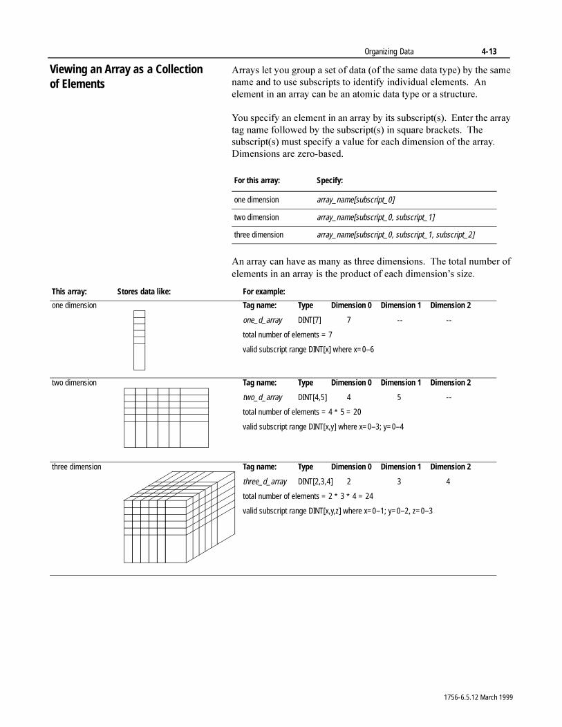
Organizing Data 4-13
Viewing an Array as a Collection of Elements
$UUD\V�OHW�\RX�JURXS�D�VHW�RI�GDWD��RI�WKH�VDPH�GDWD�W\SH��E\�WKH�VDPH�QDPH�DQG�WR�XVH�VXEVFULSWV�WR�LGHQWLI\�LQGLYLGXDO HOHPHQWV���$Q�HOHPHQW�LQ�DQ�DUUD\�FDQ�EH�DQ�DWRPLF�GDWD�W\SH�RU�D�VWUXFWXUH�
<RX�VSHFLI\�DQ�HOHPHQW�LQ�DQ�DUUD\�E\�LWV�VXEVFULSW�V����(QWHU�WKH�DUUD\�WDJ�QDPH�IROORZHG�E\�WKH�VXEVFULSW�V��LQ�VTXDUH�EUDFNHWV���7KH�VXEVFULSW�V��PXVW�VSHFLI\�D�YDOXH�IRU�HDFK�GLPHQVLRQ�RI�WKH�DUUD\���'LPHQVLRQV�DUH�]HUR�EDVHG�
$Q�DUUD\�FDQ�KDYH�DV�PDQ\�DV�WKUHH�GLPHQVLRQV���7KH�WRWDO�QXPEHU�RI�HOHPHQWV�LQ�DQ�DUUD\�LV�WKH�SURGXFW�RI�HDFK�GLPHQVLRQ¶V�VL]H�
For this array: Specify:
one dimension array_name[subscript_0]
two dimension array_name[subscript_0, subscript_1]
three dimension array_name[subscript_0, subscript_1, subscript_2]
This array: Stores data like: For example:
one dimension Tag name: Type Dimension 0 Dimension 1 Dimension 2
one_d_array DINT[7] 7 -- --
total number of elements = 7
valid subscript range DINT[x] where x=0–6
two dimension Tag name: Type Dimension 0 Dimension 1 Dimension 2
two_d_array DINT[4,5] 4 5 --
total number of elements = 4 ∗ 5 = 20
valid subscript range DINT[x,y] where x=0–3; y=0–4
three dimension Tag name: Type Dimension 0 Dimension 1 Dimension 2
three_d_array DINT[2,3,4] 2 3 4
total number of elements = 2 ∗ 3 ∗ 4 = 24
valid subscript range DINT[x,y,z] where x=0–1; y=0–2, z=0–3
1756-6.5.12 March 1999
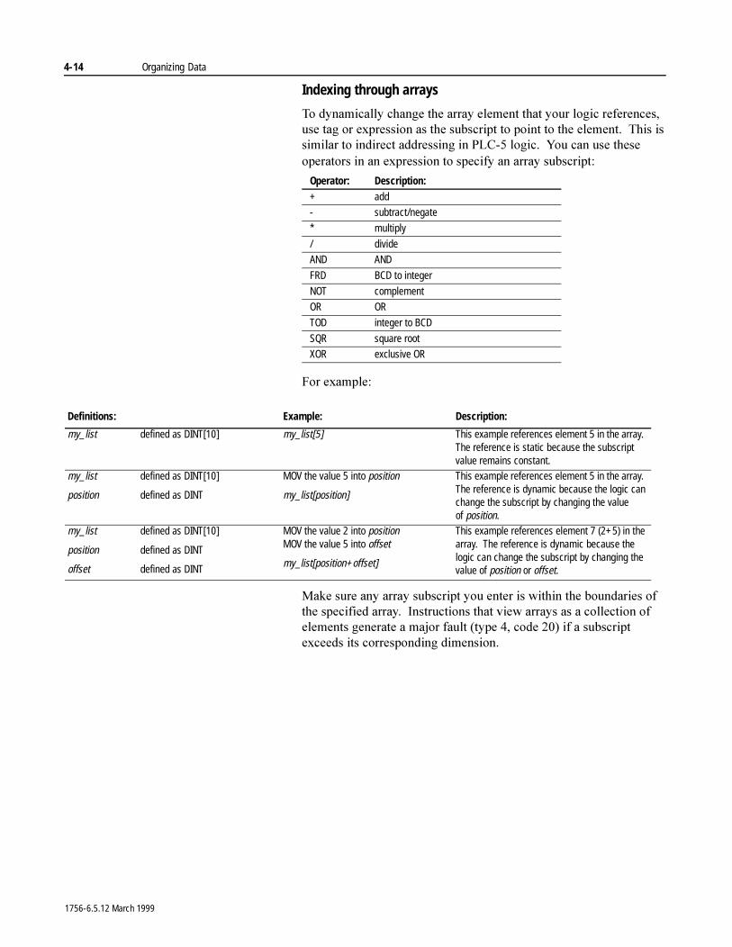
4-14 Organizing Data
Indexing through arrays
7R�G\QDPLFDOO\�FKDQJH�WKH�DUUD\�HOHPHQW�WKDW�\RXU�ORJLF�UHIHUHQFHV��XVH�WDJ�RU�H[SUHVVLRQ�DV�WKH�VXEVFULSW�WR�SRLQW�WR�WKH�HOHPHQW���7KLV�LV�VLPLODU�WR�LQGLUHFW�DGGUHVVLQJ�LQ�3/&���ORJLF���<RX�FDQ�XVH�WKHVH�RSHUDWRUV�LQ�DQ�H[SUHVVLRQ�WR�VSHFLI\�DQ�DUUD\�VXEVFULSW�
)RU�H[DPSOH�
0DNH�VXUH�DQ\�DUUD\�VXEVFULSW�\RX�HQWHU�LV�ZLWKLQ�WKH�ERXQGDULHV�RI�WKH�VSHFLILHG�DUUD\���,QVWUXFWLRQV�WKDW�YLHZ�DUUD\V�DV�D�FROOHFWLRQ�RI�HOHPHQWV�JHQHUDWH�D�PDMRU�IDXOW��W\SH����FRGH�����LI�D�VXEVFULSW�H[FHHGV�LWV�FRUUHVSRQGLQJ�GLPHQVLRQ�
Operator: Description:+ add
- subtract/negate
* multiply
/ divide
AND AND
FRD BCD to integer
NOT complement
OR OR
TOD integer to BCD
SQR square root
XOR exclusive OR
Definitions: Example: Description:
my_list defined as DINT[10] my_list[5] This example references element 5 in the array. The reference is static because the subscript value remains constant.
my_list defined as DINT[10]
position defined as DINT
MOV the value 5 into position
my_list[position]
This example references element 5 in the array. The reference is dynamic because the logic can change the subscript by changing the value of position.
my_list defined as DINT[10]
position defined as DINT
offset defined as DINT
MOV the value 2 into positionMOV the value 5 into offset
my_list[position+offset]
This example references element 7 (2+5) in the array. The reference is dynamic because the logic can change the subscript by changing the value of position or offset.
1756-6.5.12 March 1999
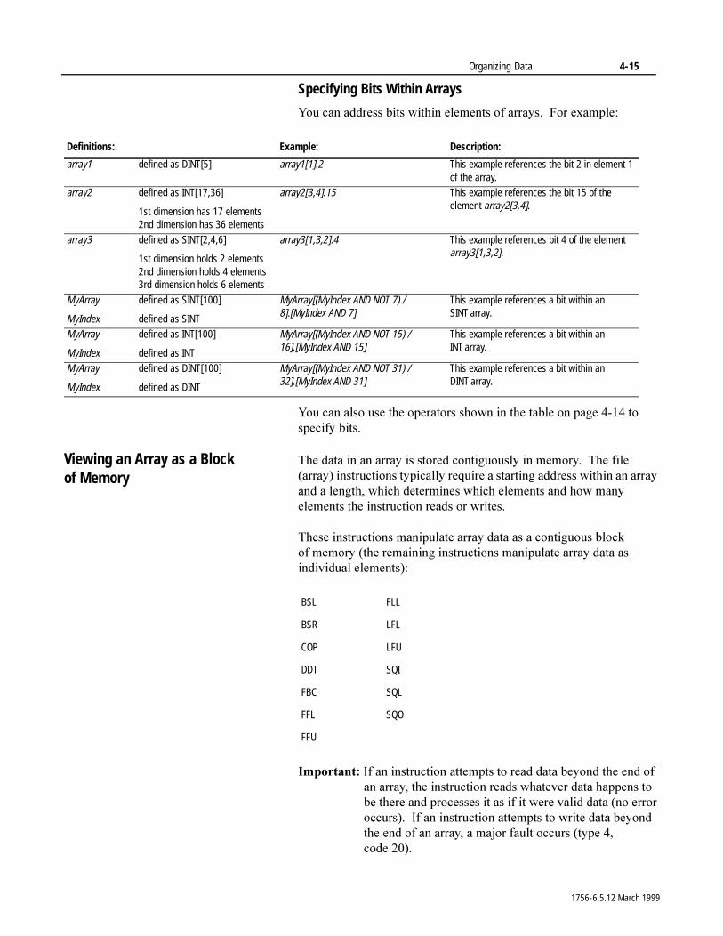
Organizing Data 4-15
Specifying Bits Within Arrays
<RX�FDQ�DGGUHVV�ELWV�ZLWKLQ�HOHPHQWV�RI�DUUD\V���)RU�H[DPSOH�
<RX�FDQ�DOVR�XVH�WKH�RSHUDWRUV�VKRZQ�LQ�WKH�WDEOH�RQ�SDJH������WR�VSHFLI\�ELWV�
Viewing an Array as a Block of Memory
7KH�GDWD�LQ�DQ�DUUD\�LV�VWRUHG�FRQWLJXRXVO\�LQ�PHPRU\���7KH�ILOH��DUUD\��LQVWUXFWLRQV�W\SLFDOO\�UHTXLUH�D�VWDUWLQJ�DGGUHVV�ZLWKLQ�DQ�DUUD\�DQG�D�OHQJWK��ZKLFK�GHWHUPLQHV�ZKLFK�HOHPHQWV�DQG�KRZ�PDQ\�HOHPHQWV�WKH�LQVWUXFWLRQ�UHDGV�RU�ZULWHV�
7KHVH�LQVWUXFWLRQV�PDQLSXODWH�DUUD\�GDWD�DV�D�FRQWLJXRXV�EORFN�RI PHPRU\��WKH�UHPDLQLQJ�LQVWUXFWLRQV�PDQLSXODWH�DUUD\�GDWD�DV�LQGLYLGXDO�HOHPHQWV��
,PSRUWDQW��,I�DQ�LQVWUXFWLRQ�DWWHPSWV�WR�UHDG�GDWD�EH\RQG�WKH�HQG�RI�DQ�DUUD\��WKH�LQVWUXFWLRQ�UHDGV�ZKDWHYHU�GDWD�KDSSHQV�WR�EH�WKHUH�DQG�SURFHVVHV�LW�DV�LI�LW�ZHUH�YDOLG�GDWD��QR�HUURU�RFFXUV����,I�DQ�LQVWUXFWLRQ�DWWHPSWV�WR�ZULWH�GDWD�EH\RQG�WKH�HQG�RI�DQ�DUUD\��D�PDMRU�IDXOW�RFFXUV��W\SH����FRGH ����
Definitions: Example: Description:
array1 defined as DINT[5] array1[1].2 This example references the bit 2 in element 1 of the array.
array2 defined as INT[17,36]
1st dimension has 17 elements2nd dimension has 36 elements
array2[3,4].15 This example references the bit 15 of the element array2[3,4].
array3 defined as SINT[2,4,6]
1st dimension holds 2 elements2nd dimension holds 4 elements3rd dimension holds 6 elements
array3[1,3,2].4 This example references bit 4 of the element array3[1,3,2].
MyArray defined as SINT[100]
MyIndex defined as SINT
MyArray[(MyIndex AND NOT 7) / 8].[MyIndex AND 7]
This example references a bit within an SINT array.
MyArray defined as INT[100]
MyIndex defined as INT
MyArray[(MyIndex AND NOT 15) / 16].[MyIndex AND 15]
This example references a bit within an INT array.
MyArray defined as DINT[100]
MyIndex defined as DINT
MyArray[(MyIndex AND NOT 31) / 32].[MyIndex AND 31]
This example references a bit within an DINT array.
BSL FLL
BSR LFL
COP LFU
DDT SQI
FBC SQL
FFL SQO
FFU
1756-6.5.12 March 1999
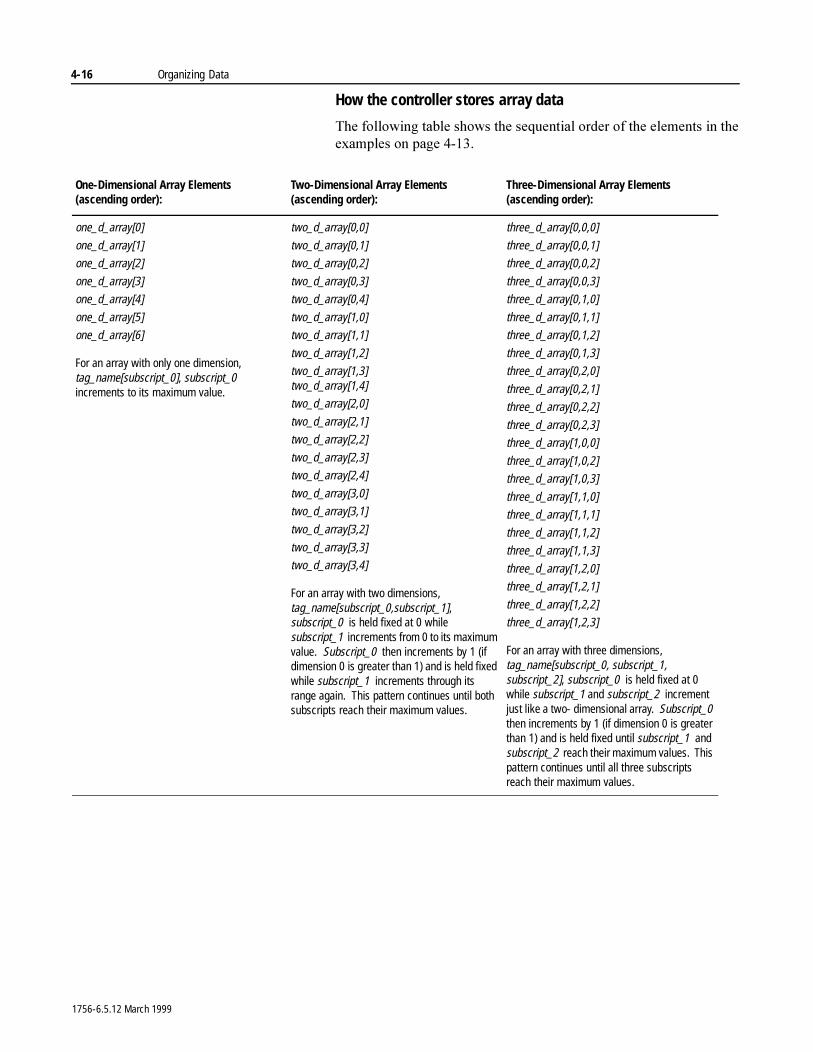
4-16 Organizing Data
How the controller stores array data
7KH�IROORZLQJ�WDEOH�VKRZV�WKH�VHTXHQWLDO�RUGHU�RI�WKH�HOHPHQWV�LQ�WKH�H[DPSOHV�RQ�SDJH������
One-Dimensional Array Elements (ascending order):
Two-Dimensional Array Elements (ascending order):
Three-Dimensional Array Elements (ascending order):
one_d_array[0]
one_d_array[1]
one_d_array[2]
one_d_array[3]
one_d_array[4]
one_d_array[5]
one_d_array[6]
For an array with only one dimension, tag_name[subscript_0], subscript_0 increments to its maximum value.
two_d_array[0,0]
two_d_array[0,1]
two_d_array[0,2]
two_d_array[0,3]
two_d_array[0,4]
two_d_array[1,0]
two_d_array[1,1]
two_d_array[1,2]
two_d_array[1,3]two_d_array[1,4]
two_d_array[2,0]
two_d_array[2,1]
two_d_array[2,2]
two_d_array[2,3]
two_d_array[2,4]
two_d_array[3,0]
two_d_array[3,1]
two_d_array[3,2]
two_d_array[3,3]
two_d_array[3,4]
For an array with two dimensions, tag_name[subscript_0,subscript_1], subscript_0 is held fixed at 0 while subscript_1 increments from 0 to its maximum value. Subscript_0 then increments by 1 (if dimension 0 is greater than 1) and is held fixed while subscript_1 increments through its range again. This pattern continues until both subscripts reach their maximum values.
three_d_array[0,0,0]
three_d_array[0,0,1]
three_d_array[0,0,2]
three_d_array[0,0,3]
three_d_array[0,1,0]
three_d_array[0,1,1]
three_d_array[0,1,2]
three_d_array[0,1,3]
three_d_array[0,2,0]
three_d_array[0,2,1]
three_d_array[0,2,2]
three_d_array[0,2,3]
three_d_array[1,0,0]
three_d_array[1,0,2]
three_d_array[1,0,3]
three_d_array[1,1,0]
three_d_array[1,1,1]
three_d_array[1,1,2]
three_d_array[1,1,3]
three_d_array[1,2,0]
three_d_array[1,2,1]
three_d_array[1,2,2]
three_d_array[1,2,3]
For an array with three dimensions, tag_name[subscript_0, subscript_1, subscript_2], subscript_0 is held fixed at 0 while subscript_1 and subscript_2 increment just like a two- dimensional array. Subscript_0 then increments by 1 (if dimension 0 is greater than 1) and is held fixed until subscript_1 and subscript_2 reach their maximum values. This pattern continues until all three subscripts reach their maximum values.
1756-6.5.12 March 1999
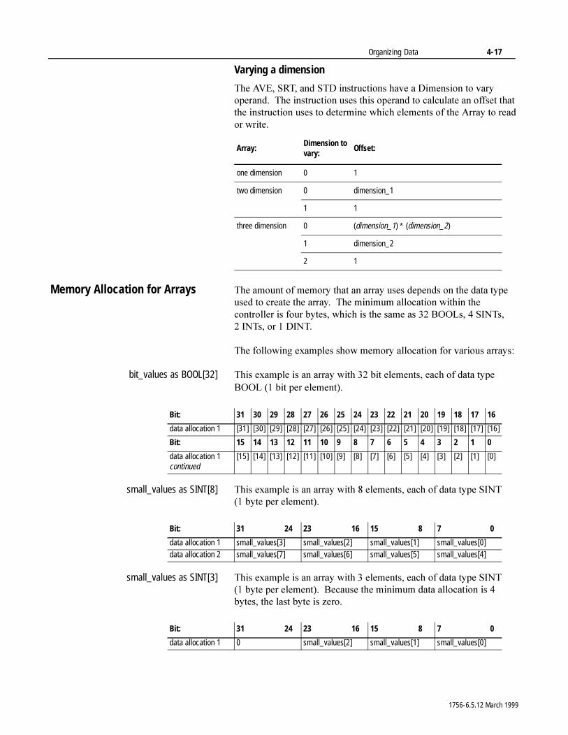
Organizing Data 4-17
Varying a dimension
7KH�$9(��657��DQG�67'�LQVWUXFWLRQV�KDYH�D�'LPHQVLRQ�WR�YDU\�RSHUDQG���7KH�LQVWUXFWLRQ�XVHV�WKLV�RSHUDQG�WR�FDOFXODWH�DQ�RIIVHW�WKDW�WKH�LQVWUXFWLRQ�XVHV�WR�GHWHUPLQH�ZKLFK�HOHPHQWV�RI�WKH�$UUD\�WR�UHDG�RU�ZULWH�
Memory Allocation for Arrays 7KH�DPRXQW�RI�PHPRU\�WKDW�DQ�DUUD\�XVHV�GHSHQGV�RQ�WKH�GDWD�W\SH�XVHG�WR�FUHDWH�WKH�DUUD\���7KH�PLQLPXP�DOORFDWLRQ�ZLWKLQ�WKH�FRQWUROOHU�LV�IRXU�E\WHV��ZKLFK�LV�WKH�VDPH�DV����%22/V����6,17V��� ,17V��RU�� ',17�
7KH�IROORZLQJ�H[DPSOHV�VKRZ�PHPRU\�DOORFDWLRQ�IRU�YDULRXV�DUUD\V�
bit_values as BOOL[32] 7KLV�H[DPSOH�LV�DQ�DUUD\�ZLWK����ELW�HOHPHQWV��HDFK�RI�GDWD�W\SH�%22/��� ELW�SHU�HOHPHQW��
small_values as SINT[8] 7KLV�H[DPSOH�LV�DQ�DUUD\�ZLWK���HOHPHQWV��HDFK�RI�GDWD�W\SH�6,17��� E\WH�SHU�HOHPHQW��
small_values as SINT[3] 7KLV�H[DPSOH�LV�DQ�DUUD\�ZLWK���HOHPHQWV��HDFK�RI�GDWD�W\SH�6,17��� E\WH�SHU�HOHPHQW����%HFDXVH�WKH�PLQLPXP�GDWD�DOORFDWLRQ�LV���E\WHV��WKH�ODVW�E\WH�LV�]HUR�
Array:Dimension to vary:
Offset:
one dimension 0 1
two dimension 0 dimension_1
1 1
three dimension 0 (dimension_1) ∗ (dimension_2)
1 dimension_2
2 1
Bit: 31 30 29 28 27 26 25 24 23 22 21 20 19 18 17 16
data allocation 1 [31] [30] [29] [28] [27] [26] [25] [24] [23] [22] [21] [20] [19] [18] [17] [16]
Bit: 15 14 13 12 11 10 9 8 7 6 5 4 3 2 1 0
data allocation 1 continued
[15] [14] [13] [12] [11] [10] [9] [8] [7] [6] [5] [4] [3] [2] [1] [0]
Bit: 31 24 23 16 15 8 7 0
data allocation 1 small_values[3] small_values[2] small_values[1] small_values[0]data allocation 2 small_values[7] small_values[6] small_values[5] small_values[4]
Bit: 31 24 23 16 15 8 7 0
data allocation 1 0 small_values[2] small_values[1] small_values[0]
1756-6.5.12 March 1999
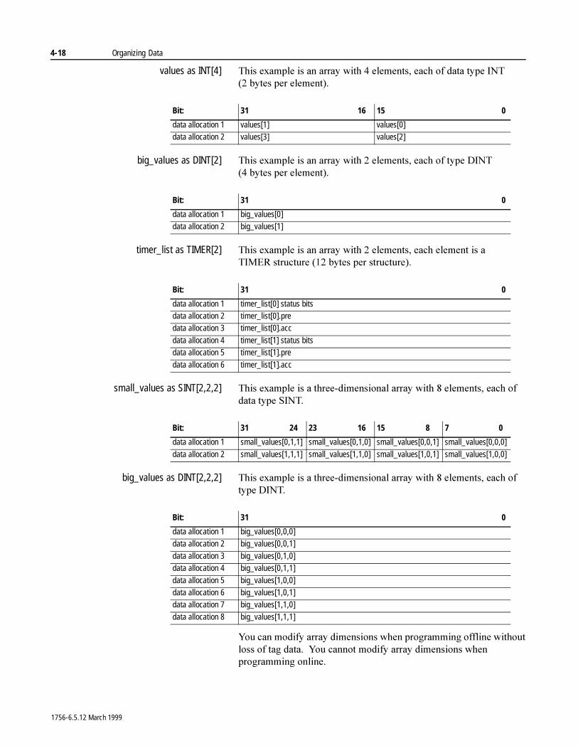
4-18 Organizing Data
values as INT[4] 7KLV�H[DPSOH�LV�DQ�DUUD\�ZLWK���HOHPHQWV��HDFK�RI�GDWD�W\SH�,17��� E\WHV�SHU�HOHPHQW��
big_values as DINT[2] 7KLV�H[DPSOH�LV�DQ�DUUD\�ZLWK���HOHPHQWV��HDFK�RI�W\SH�',17��� E\WHV SHU�HOHPHQW��
timer_list as TIMER[2] 7KLV�H[DPSOH�LV�DQ�DUUD\�ZLWK���HOHPHQWV��HDFK�HOHPHQW�LV�D�7,0(5 VWUXFWXUH�����E\WHV�SHU�VWUXFWXUH��
small_values as SINT[2,2,2] 7KLV�H[DPSOH�LV�D�WKUHH�GLPHQVLRQDO�DUUD\�ZLWK���HOHPHQWV��HDFK�RI�GDWD�W\SH�6,17�
big_values as DINT[2,2,2] 7KLV�H[DPSOH�LV�D�WKUHH�GLPHQVLRQDO�DUUD\�ZLWK���HOHPHQWV��HDFK�RI�W\SH�',17�
<RX�FDQ�PRGLI\�DUUD\�GLPHQVLRQV�ZKHQ�SURJUDPPLQJ�RIIOLQH�ZLWKRXW�ORVV�RI�WDJ�GDWD���<RX�FDQQRW�PRGLI\�DUUD\�GLPHQVLRQV�ZKHQ�SURJUDPPLQJ�RQOLQH�
Bit: 31 16 15 0
data allocation 1 values[1] values[0]data allocation 2 values[3] values[2]
Bit: 31 0
data allocation 1 big_values[0]data allocation 2 big_values[1]
Bit: 31 0
data allocation 1 timer_list[0] status bitsdata allocation 2 timer_list[0].predata allocation 3 timer_list[0].acc
data allocation 4 timer_list[1] status bitsdata allocation 5 timer_list[1].pre
data allocation 6 timer_list[1].acc
Bit: 31 24 23 16 15 8 7 0
data allocation 1 small_values[0,1,1] small_values[0,1,0] small_values[0,0,1] small_values[0,0,0]
data allocation 2 small_values[1,1,1] small_values[1,1,0] small_values[1,0,1] small_values[1,0,0]
Bit: 31 0
data allocation 1 big_values[0,0,0]data allocation 2 big_values[0,0,1]
data allocation 3 big_values[0,1,0]data allocation 4 big_values[0,1,1]
data allocation 5 big_values[1,0,0]data allocation 6 big_values[1,0,1]data allocation 7 big_values[1,1,0]
data allocation 8 big_values[1,1,1]
1756-6.5.12 March 1999
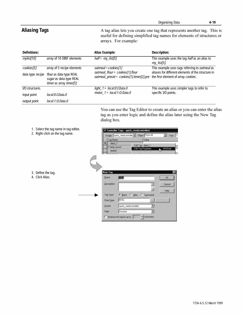
Organizing Data 4-19
Aliasing Tags $�WDJ�DOLDV�OHWV�\RX�FUHDWH�RQH�WDJ�WKDW�UHSUHVHQWV�DQRWKHU�WDJ���7KLV�LV�XVHIXO�IRU�GHILQLQJ�VLPSOLILHG�WDJ�QDPHV�IRU�HOHPHQWV�RI�VWUXFWXUHV�RU�DUUD\V���)RU�H[DPSOH�
<RX�FDQ�XVH�WKH�7DJ�(GLWRU�WR�FUHDWH�DQ�DOLDV�RU�\RX�FDQ�HQWHU�WKH�DOLDV�WDJ�DV�\RX�HQWHU�ORJLF�DQG�GHILQH�WKH�DOLDV�ODWHU�XVLQJ�WKH�1HZ�7DJ�GLDORJ�ER[�
Definitions: Alias Example: Description:
mylist[10] array of 10 DINT elements half = my_list[5] This example uses the tag half as an alias to my_list[5].
cookies[5] array of 5 recipe elements
data type recipe flour as data type REALsugar as data type REALtimer as array timer[5]
oatmeal =cookies[1]oatmeal_flour = cookies[1].flouroatmeal_preset = cookies[1].timer[2].pre
This example uses tags referring to oatmeal as aliases for different elements of the structure in the first element of array cookies.
I/O structures
input point local:0:I.Data.0
output point local:1:O.Data.0
light_1 = local:0:I.Data.0motor_1 = local:1:O.Data.0
This example uses simpler tags to refer to specific I/O points.
1. Select the tag name in tag editor.2. Right-click on the tag name.
3. Define the tag.4. Click Alias.
1756-6.5.12 March 1999
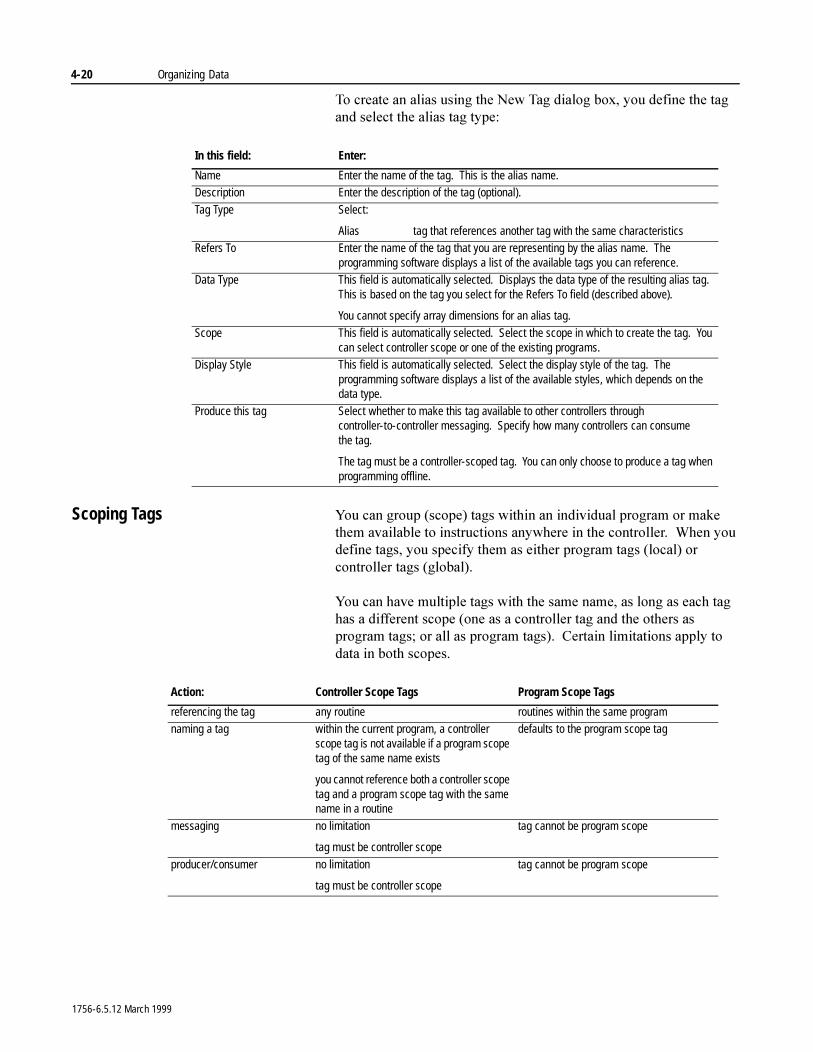
4-20 Organizing Data
7R�FUHDWH�DQ�DOLDV�XVLQJ�WKH�1HZ�7DJ�GLDORJ�ER[��\RX�GHILQH�WKH�WDJ�DQG�VHOHFW�WKH�DOLDV�WDJ�W\SH�
Scoping Tags <RX�FDQ�JURXS��VFRSH��WDJV�ZLWKLQ�DQ�LQGLYLGXDO�SURJUDP�RU�PDNH�WKHP�DYDLODEOH�WR�LQVWUXFWLRQV�DQ\ZKHUH�LQ�WKH�FRQWUROOHU���:KHQ�\RX�GHILQH�WDJV��\RX�VSHFLI\�WKHP�DV�HLWKHU�SURJUDP�WDJV��ORFDO��RU�FRQWUROOHU�WDJV��JOREDO��
<RX�FDQ�KDYH�PXOWLSOH�WDJV�ZLWK�WKH�VDPH�QDPH��DV�ORQJ�DV�HDFK�WDJ�KDV�D�GLIIHUHQW�VFRSH��RQH�DV�D�FRQWUROOHU�WDJ�DQG�WKH�RWKHUV�DV�SURJUDP�WDJV��RU�DOO�DV�SURJUDP�WDJV����&HUWDLQ�OLPLWDWLRQV�DSSO\�WR�GDWD�LQ�ERWK�VFRSHV�
In this field: Enter:
Name Enter the name of the tag. This is the alias name.Description Enter the description of the tag (optional).
Tag Type Select:
Alias tag that references another tag with the same characteristicsRefers To Enter the name of the tag that you are representing by the alias name. The
programming software displays a list of the available tags you can reference.Data Type This field is automatically selected. Displays the data type of the resulting alias tag.
This is based on the tag you select for the Refers To field (described above).
You cannot specify array dimensions for an alias tag.
Scope This field is automatically selected. Select the scope in which to create the tag. You can select controller scope or one of the existing programs.
Display Style This field is automatically selected. Select the display style of the tag. The programming software displays a list of the available styles, which depends on the data type.
Produce this tag Select whether to make this tag available to other controllers through controller-to-controller messaging. Specify how many controllers can consume the tag.
The tag must be a controller-scoped tag. You can only choose to produce a tag when programming offline.
Action: Controller Scope Tags Program Scope Tags
referencing the tag any routine routines within the same programnaming a tag within the current program, a controller
scope tag is not available if a program scope tag of the same name exists
you cannot reference both a controller scope tag and a program scope tag with the same name in a routine
defaults to the program scope tag
messaging no limitation
tag must be controller scope
tag cannot be program scope
producer/consumer no limitation
tag must be controller scope
tag cannot be program scope
1756-6.5.12 March 1999
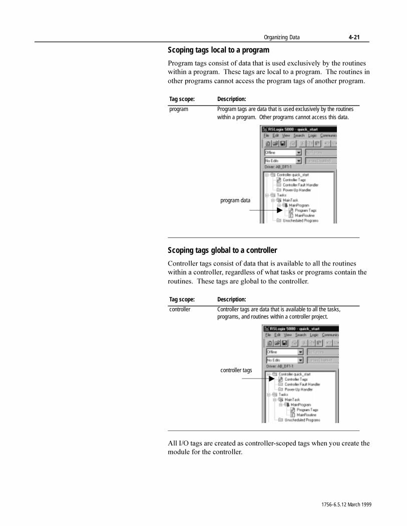
Organizing Data 4-21
Scoping tags local to a program
3URJUDP�WDJV�FRQVLVW�RI�GDWD�WKDW�LV�XVHG�H[FOXVLYHO\�E\�WKH�URXWLQHV�ZLWKLQ�D�SURJUDP���7KHVH�WDJV�DUH�ORFDO�WR�D�SURJUDP���7KH�URXWLQHV�LQ�RWKHU�SURJUDPV�FDQQRW�DFFHVV�WKH�SURJUDP�WDJV�RI�DQRWKHU�SURJUDP�
Scoping tags global to a controller
&RQWUROOHU�WDJV�FRQVLVW�RI�GDWD�WKDW�LV�DYDLODEOH�WR�DOO�WKH�URXWLQHV�ZLWKLQ�D�FRQWUROOHU��UHJDUGOHVV�RI�ZKDW�WDVNV�RU�SURJUDPV�FRQWDLQ�WKH�URXWLQHV���7KHVH�WDJV�DUH�JOREDO�WR�WKH�FRQWUROOHU�
$OO�,�2�WDJV�DUH�FUHDWHG�DV�FRQWUROOHU�VFRSHG�WDJV�ZKHQ�\RX�FUHDWH�WKH�PRGXOH�IRU�WKH�FRQWUROOHU�
Tag scope: Description:
program Program tags are data that is used exclusively by the routines within a program. Other programs cannot access this data.
Tag scope: Description:
controller Controller tags are data that is available to all the tasks, programs, and routines within a controller project.
program data
controller tags
1756-6.5.12 March 1999

4-22 Organizing Data
1RWHV�
1756-6.5.12 March 1999
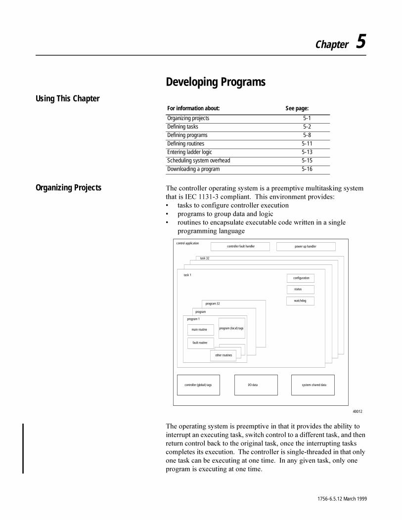
Chapter 5
Developing ProgramsUsing This Chapter
Organizing Projects 7KH�FRQWUROOHU�RSHUDWLQJ�V\VWHP�LV�D�SUHHPSWLYH�PXOWLWDVNLQJ�V\VWHP�WKDW�LV�,(&��������FRPSOLDQW���7KLV�HQYLURQPHQW�SURYLGHV�� WDVNV�WR�FRQILJXUH�FRQWUROOHU�H[HFXWLRQ� SURJUDPV�WR�JURXS�GDWD�DQG�ORJLF� URXWLQHV�WR�HQFDSVXODWH�H[HFXWDEOH�FRGH�ZULWWHQ�LQ�D�VLQJOH�
SURJUDPPLQJ�ODQJXDJH
7KH�RSHUDWLQJ�V\VWHP�LV�SUHHPSWLYH�LQ�WKDW�LW�SURYLGHV�WKH�DELOLW\�WR�LQWHUUXSW�DQ�H[HFXWLQJ�WDVN��VZLWFK�FRQWURO�WR�D�GLIIHUHQW�WDVN��DQG�WKHQ�UHWXUQ�FRQWURO�EDFN�WR�WKH�RULJLQDO�WDVN��RQFH�WKH�LQWHUUXSWLQJ�WDVNV�FRPSOHWHV�LWV�H[HFXWLRQ���7KH�FRQWUROOHU�LV�VLQJOH�WKUHDGHG�LQ�WKDW�RQO\�RQH�WDVN�FDQ�EH�H[HFXWLQJ�DW�RQH�WLPH���,Q�DQ\�JLYHQ�WDVN��RQO\�RQH�SURJUDP�LV�H[HFXWLQJ�DW�RQH�WLPH�
For information about: See page:
Organizing projects 5-1
Defining tasks 5-2Defining programs 5-8
Defining routines 5-11Entering ladder logic 5-13Scheduling system overhead 5-15
Downloading a program 5-16
configuration
status
task 1
program 1
program 32
program
main routine
fault routine
other routines
program (local) tags
task 32
control applicationcontroller fault handler power up handler
watchdog
controller (global) tags I/O data system-shared data
40012
1756-6.5.12 March 1999
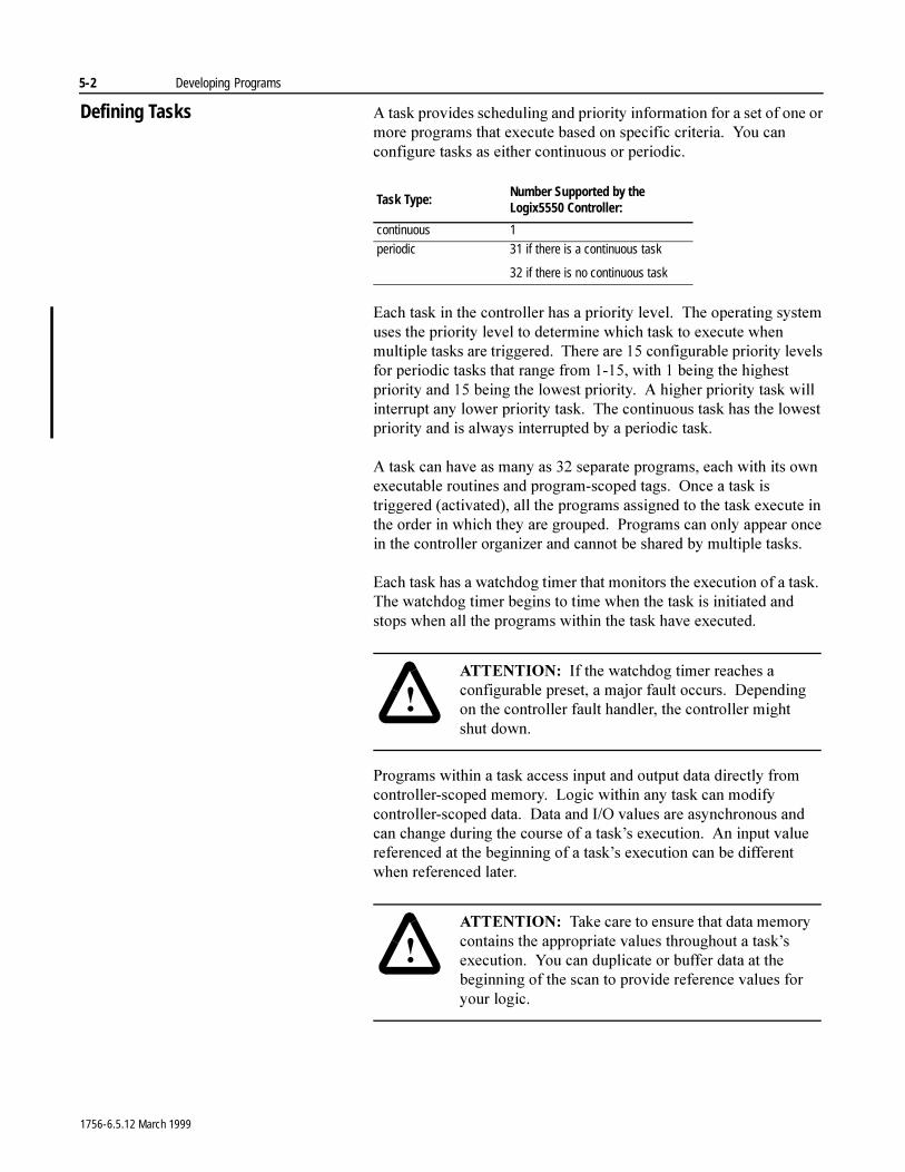
5-2 Developing Programs
Defining Tasks $�WDVN�SURYLGHV�VFKHGXOLQJ�DQG�SULRULW\�LQIRUPDWLRQ�IRU�D�VHW�RI�RQH�RU�PRUH�SURJUDPV�WKDW�H[HFXWH�EDVHG�RQ�VSHFLILF�FULWHULD���<RX�FDQ�FRQILJXUH�WDVNV�DV�HLWKHU�FRQWLQXRXV�RU�SHULRGLF�
(DFK�WDVN�LQ�WKH�FRQWUROOHU�KDV�D�SULRULW\�OHYHO���7KH�RSHUDWLQJ�V\VWHP�XVHV�WKH�SULRULW\�OHYHO�WR�GHWHUPLQH�ZKLFK�WDVN�WR�H[HFXWH�ZKHQ�PXOWLSOH�WDVNV�DUH�WULJJHUHG���7KHUH�DUH����FRQILJXUDEOH�SULRULW\�OHYHOV�IRU�SHULRGLF�WDVNV�WKDW�UDQJH�IURP�������ZLWK���EHLQJ�WKH�KLJKHVW�SULRULW\�DQG����EHLQJ�WKH�ORZHVW�SULRULW\���$�KLJKHU�SULRULW\�WDVN�ZLOO�LQWHUUXSW�DQ\�ORZHU�SULRULW\�WDVN���7KH�FRQWLQXRXV�WDVN�KDV�WKH�ORZHVW�SULRULW\�DQG�LV�DOZD\V�LQWHUUXSWHG�E\�D�SHULRGLF�WDVN�
$�WDVN�FDQ�KDYH�DV�PDQ\�DV����VHSDUDWH�SURJUDPV��HDFK�ZLWK�LWV�RZQ�H[HFXWDEOH�URXWLQHV�DQG�SURJUDP�VFRSHG�WDJV���2QFH�D�WDVN�LV�WULJJHUHG��DFWLYDWHG���DOO�WKH�SURJUDPV�DVVLJQHG�WR�WKH�WDVN�H[HFXWH�LQ�WKH�RUGHU�LQ�ZKLFK�WKH\�DUH�JURXSHG���3URJUDPV�FDQ�RQO\�DSSHDU�RQFH�LQ�WKH�FRQWUROOHU�RUJDQL]HU�DQG�FDQQRW�EH�VKDUHG�E\�PXOWLSOH�WDVNV�
(DFK�WDVN�KDV�D�ZDWFKGRJ�WLPHU�WKDW�PRQLWRUV�WKH�H[HFXWLRQ�RI�D�WDVN���7KH�ZDWFKGRJ�WLPHU�EHJLQV�WR�WLPH�ZKHQ�WKH�WDVN�LV�LQLWLDWHG�DQG�VWRSV�ZKHQ�DOO�WKH�SURJUDPV�ZLWKLQ�WKH�WDVN�KDYH�H[HFXWHG�
3URJUDPV�ZLWKLQ�D�WDVN�DFFHVV�LQSXW�DQG�RXWSXW�GDWD�GLUHFWO\�IURP�FRQWUROOHU�VFRSHG�PHPRU\���/RJLF�ZLWKLQ�DQ\�WDVN�FDQ�PRGLI\�FRQWUROOHU�VFRSHG�GDWD���'DWD�DQG�,�2�YDOXHV�DUH�DV\QFKURQRXV�DQG�FDQ�FKDQJH�GXULQJ�WKH�FRXUVH�RI�D�WDVN¶V�H[HFXWLRQ���$Q�LQSXW�YDOXH�UHIHUHQFHG�DW�WKH�EHJLQQLQJ�RI�D�WDVN¶V�H[HFXWLRQ�FDQ�EH�GLIIHUHQW�ZKHQ�UHIHUHQFHG�ODWHU�
Task Type:Number Supported by the Logix5550 Controller:
continuous 1
periodic 31 if there is a continuous task
32 if there is no continuous task
�$77(17,21� ,I�WKH�ZDWFKGRJ�WLPHU�UHDFKHV�D�FRQILJXUDEOH�SUHVHW��D�PDMRU�IDXOW�RFFXUV���'HSHQGLQJ�RQ�WKH�FRQWUROOHU�IDXOW�KDQGOHU��WKH�FRQWUROOHU�PLJKW�VKXW GRZQ�
�$77(17,21� 7DNH�FDUH�WR�HQVXUH�WKDW�GDWD�PHPRU\�FRQWDLQV�WKH�DSSURSULDWH�YDOXHV�WKURXJKRXW�D�WDVN¶V�H[HFXWLRQ���<RX�FDQ�GXSOLFDWH�RU�EXIIHU�GDWD�DW�WKH�EHJLQQLQJ�RI�WKH�VFDQ�WR�SURYLGH�UHIHUHQFH�YDOXHV�IRU�\RXU�ORJLF�
1756-6.5.12 March 1999
Developing Programs 5-3
Using a continuous task
$�FRQWLQXRXV�WDVN�RSHUDWHV�LQ�D�VHOI�WULJJHUHG�PRGH���,W�UHVWDUWV�LWVHOI�DIWHU�HDFK�FRPSOHWLRQ���<RX�FDQ�FUHDWH�RQH�FRQWLQXRXV�WDVN�IRU�WKH�FRQWUROOHU���7KH�FRQWLQXRXV�WDVN�RSHUDWHV�DV�WKH�ORZHVW�SULRULW\�WDVN�LQ�WKH�FRQWUROOHU��RQH�SULRULW\�OHYHO�ORZHU�WKDQ�WKH�ORZHVW�SHULRGLF�WDVN����7KLV�PHDQV�WKDW�DOO�SHULRGLF�WDVNV�ZLOO�LQWHUUXSW�WKH�FRQWLQXRXV�WDVN�
7KH�FRQWLQXRXV�WDVN�LV�D�EDFNJURXQG�WDVN�EHFDXVH�DQ\�&38�WLPH�QRW�DOORFDWHG�WR�RWKHU�RSHUDWLRQV��VXFK�DV�PRWLRQ��FRPPXQLFDWLRQV��DQG�SHULRGLF�WDVNV��LV�XVHG�WR�H[HFXWH�WKH�SURJUDPV�ZLWKLQ�WKH�FRQWLQXRXV WDVN�
:KHQ�\RX�FUHDWH�D�SURMHFW��WKH�GHIDXOW�0DLQ7DVN�LV�D�FRQWLQXRXV�WDVN���<RX�FDQ�OHDYH�WKLV�WDVN�DV�LW�LV��RU�\RX�FDQ�FKDQJH�LWV�FKDUDFWHULVWLFV
Using a periodic task
$�SHULRGLF�WDVN��DOVR�NQRZQ�DV�D�VHOHFWDEOH�WLPHG�LQWHUUXSW��67,���LV�WULJJHUHG�E\�WKH�RSHUDWLQJ�V\VWHP�DW�D�UHSHWLWLYH�SHULRG�RI�WLPH���7KLV�W\SH�RI�WDVN�LV�XVHIXO�IRU�SURMHFWV�WKDW�UHTXLUH�DFFXUDWH�RU�GHWHUPLQLVWLF�H[HFXWLRQ���3HULRGLF�WDVNV�DOZD\V�LQWHUUXSW�WKH�FRQWLQXRXV�WDVN���'HSHQGLQJ�RQ�WKH�SULRULW\�OHYHO��D�SHULRGLF�WDVN�PD\�LQWHUUXSW�RWKHU�SHULRGLF�WDVNV�LQ�WKH�FRQWUROOHU�
8VH�WKH�SURJUDPPLQJ�VRIWZDUH�WR�FRQILJXUH�WKH�WLPH�SHULRG�IURP�� PVHF�WR������VHFRQGV���7KH�GHIDXOW�LV����PVHFV�
:KHQ�ZRUNLQJ�ZLWK�PXOWLSOH�SHULRGLF�WDVNV��PDNH�VXUH�WKDW�VXIILFLHQW�&38�WLPH�LV�PDGH�DYDLODEOH�WR�KDQGOH�WDVN�LQWHUUXSWLRQ�
3HULRGLF�WDVNV�DW�WKH�VDPH�SULRULW\�H[HFXWH�RQ�D�WLPH�VOLFH�EDVLV�DW��PV LQWHUYDOV�
�$77(17,21� ��(QVXUH�WKDW�WKH�WLPH�SHULRG�LV�ORQJHU�WKDQ�WKH�VXP�RI�WKH�H[HFXWLRQ�WLPHV�RI�DOO�WKH�SURJUDPV�DVVLJQHG�WR�WKH�WDVN���,I�WKH�FRQWUROOHU�GHWHFWV�WKDW�D�SHULRGLF�WDVN�WULJJHU�RFFXUV�IRU�D�WDVN�WKDW�LV�DOUHDG\�RSHUDWLQJ��D�PDMRU�IDXOW�RFFXUV��
1756-6.5.12 March 1999
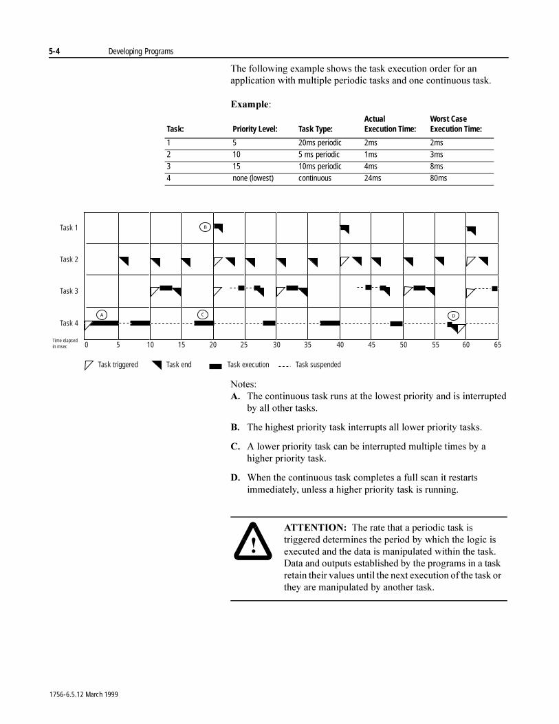
5-4 Developing Programs
7KH�IROORZLQJ�H[DPSOH�VKRZV�WKH�WDVN�H[HFXWLRQ�RUGHU�IRU�DQ�DSSOLFDWLRQ�ZLWK�PXOWLSOH�SHULRGLF�WDVNV�DQG�RQH�FRQWLQXRXV�WDVN�
([DPSOH�
1RWHV�$� 7KH�FRQWLQXRXV�WDVN�UXQV�DW�WKH�ORZHVW�SULRULW\�DQG�LV�LQWHUUXSWHG�
E\�DOO�RWKHU�WDVNV�
%� 7KH�KLJKHVW�SULRULW\�WDVN�LQWHUUXSWV�DOO�ORZHU�SULRULW\�WDVNV�
&� $�ORZHU�SULRULW\�WDVN�FDQ�EH�LQWHUUXSWHG�PXOWLSOH�WLPHV�E\�D�KLJKHU�SULRULW\�WDVN�
'� :KHQ�WKH�FRQWLQXRXV�WDVN�FRPSOHWHV�D�IXOO�VFDQ�LW�UHVWDUWV�LPPHGLDWHO\��XQOHVV�D�KLJKHU�SULRULW\�WDVN�LV�UXQQLQJ�
Task: Priority Level: Task Type:ActualExecution Time:
Worst CaseExecution Time:
1 5 20ms periodic 2ms 2ms2 10 5 ms periodic 1ms 3ms
3 15 10ms periodic 4ms 8ms4 none (lowest) continuous 24ms 80ms
0 5 10 15 20 25 45403530 65605550
Task 4
Task 1
Task 2
Task 3
B
CA D
Task triggered Task end Task execution Task suspended
Time elapsedin msec
�$77(17,21� 7KH�UDWH�WKDW�D�SHULRGLF�WDVN�LV�WULJJHUHG�GHWHUPLQHV�WKH�SHULRG�E\�ZKLFK�WKH�ORJLF�LV�H[HFXWHG�DQG�WKH�GDWD�LV�PDQLSXODWHG�ZLWKLQ�WKH�WDVN���'DWD�DQG�RXWSXWV�HVWDEOLVKHG�E\�WKH�SURJUDPV�LQ�D�WDVN�UHWDLQ�WKHLU�YDOXHV�XQWLO�WKH�QH[W�H[HFXWLRQ�RI�WKH�WDVN�RU�WKH\�DUH�PDQLSXODWHG�E\�DQRWKHU�WDVN�
1756-6.5.12 March 1999
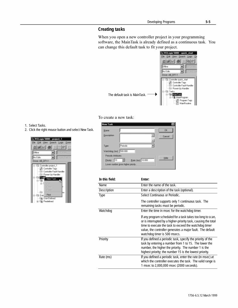
Developing Programs 5-5
Creating tasks
:KHQ�\RX�RSHQ�D�QHZ�FRQWUROOHU�SURMHFW�LQ�\RXU�SURJUDPPLQJ�VRIWZDUH��WKH�0DLQ7DVN�LV�DOUHDG\�GHILQHG�DV�D�FRQWLQXRXV�WDVN���<RX�FDQ�FKDQJH�WKLV�GHIDXOW�WDVN�WR�ILW�\RXU�SURMHFW�
7R�FUHDWH�D�QHZ�WDVN�
In this field: Enter:
Name Enter the name of the task.
Description Enter a description of the task (optional).Type Select Continuous or Periodic.
The controller supports only 1 continuous task. The remaining tasks must be periodic.
Watchdog Enter the time in msec for the watchdog timer.
If any program scheduled for a task takes too long to scan, or is interrupted by a higher-priority task, causing the total time to execute the task to exceed the watchdog timer value, the controller generates a major fault. The default watchdog timer is 500 msecs.
Priority If you defined a periodic task, specify the priority of the task by entering a number from 1 to 15. The lower the number, the higher the priority. The number 1 is the highest priority; the number 15 is the lowest priority.
Rate (ms) If you defined a periodic task, enter the rate (in msec) at which the controller executes the task. The valid range is 1 msec to 2,000,000 msec (2000 seconds).
The default task is MainTask.
1. Select Tasks.2. Click the right mouse button and select New Task.
1756-6.5.12 March 1999
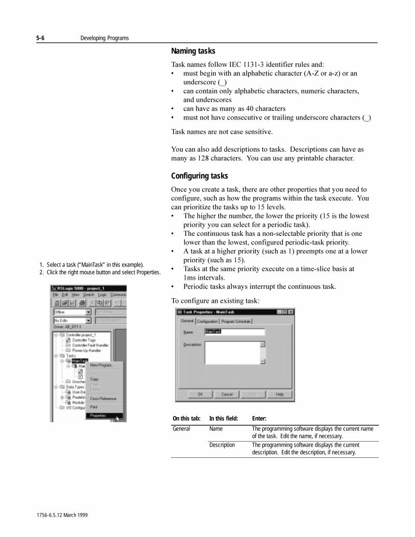
5-6 Developing Programs
Naming tasks
7DVN�QDPHV�IROORZ�,(&��������LGHQWLILHU�UXOHV DQG�� PXVW�EHJLQ�ZLWK�DQ�DOSKDEHWLF�FKDUDFWHU��$�=�RU�D�]��RU�DQ�
XQGHUVFRUH �B�� FDQ�FRQWDLQ�RQO\�DOSKDEHWLF�FKDUDFWHUV��QXPHULF�FKDUDFWHUV��
DQG XQGHUVFRUHV� FDQ�KDYH�DV�PDQ\�DV����FKDUDFWHUV� PXVW�QRW�KDYH�FRQVHFXWLYH�RU�WUDLOLQJ�XQGHUVFRUH�FKDUDFWHUV��B�
7DVN�QDPHV�DUH�QRW�FDVH�VHQVLWLYH�
<RX�FDQ�DOVR�DGG�GHVFULSWLRQV�WR�WDVNV���'HVFULSWLRQV�FDQ�KDYH�DV�PDQ\�DV�����FKDUDFWHUV���<RX�FDQ�XVH�DQ\�SULQWDEOH�FKDUDFWHU�
Configuring tasks
2QFH�\RX�FUHDWH�D�WDVN��WKHUH�DUH�RWKHU�SURSHUWLHV�WKDW�\RX�QHHG�WR�FRQILJXUH��VXFK�DV�KRZ�WKH�SURJUDPV�ZLWKLQ�WKH�WDVN�H[HFXWH���<RX�FDQ�SULRULWL]H�WKH�WDVNV�XS�WR����OHYHOV�� 7KH�KLJKHU�WKH�QXPEHU��WKH�ORZHU�WKH�SULRULW\�����LV�WKH�ORZHVW�
SULRULW\�\RX�FDQ�VHOHFW�IRU�D�SHULRGLF�WDVN��� 7KH�FRQWLQXRXV�WDVN�KDV�D�QRQ�VHOHFWDEOH�SULRULW\�WKDW�LV�RQH�
ORZHU�WKDQ�WKH�ORZHVW��FRQILJXUHG�SHULRGLF�WDVN�SULRULW\�� $�WDVN�DW�D�KLJKHU�SULRULW\��VXFK�DV����SUHHPSWV�RQH�DW�D�ORZHU�
SULRULW\��VXFK�DV������ 7DVNV�DW�WKH�VDPH�SULRULW\�H[HFXWH�RQ�D�WLPH�VOLFH�EDVLV�DW�
�PV LQWHUYDOV�� 3HULRGLF�WDVNV�DOZD\V�LQWHUUXSW�WKH�FRQWLQXRXV�WDVN�
7R�FRQILJXUH�DQ�H[LVWLQJ�WDVN�
On this tab: In this field: Enter:
General Name The programming software displays the current name of the task. Edit the name, if necessary.
Description The programming software displays the current description. Edit the description, if necessary.
1. Select a task (“MainTask” in this example).2. Click the right mouse button and select Properties.
1756-6.5.12 March 1999
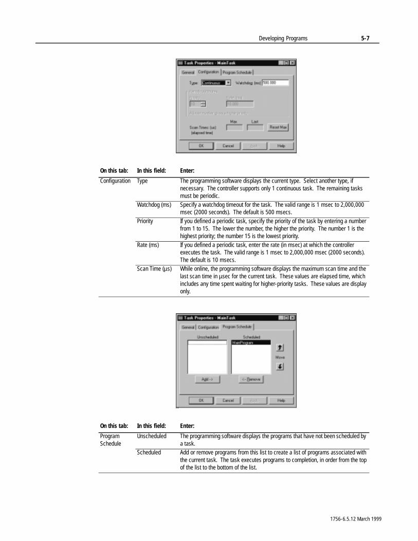
Developing Programs 5-7
On this tab: In this field: Enter:
Configuration Type The programming software displays the current type. Select another type, if necessary. The controller supports only 1 continuous task. The remaining tasks must be periodic.
Watchdog (ms) Specify a watchdog timeout for the task. The valid range is 1 msec to 2,000,000 msec (2000 seconds). The default is 500 msecs.
Priority If you defined a periodic task, specify the priority of the task by entering a number from 1 to 15. The lower the number, the higher the priority. The number 1 is the highest priority; the number 15 is the lowest priority.
Rate (ms) If you defined a periodic task, enter the rate (in msec) at which the controller executes the task. The valid range is 1 msec to 2,000,000 msec (2000 seconds). The default is 10 msecs.
Scan Time (µs) While online, the programming software displays the maximum scan time and the last scan time in µsec for the current task. These values are elapsed time, which includes any time spent waiting for higher-priority tasks. These values are display only.
On this tab: In this field: Enter:
Program Schedule
Unscheduled The programming software displays the programs that have not been scheduled by a task.
Scheduled Add or remove programs from this list to create a list of programs associated with the current task. The task executes programs to completion, in order from the top of the list to the bottom of the list.
1756-6.5.12 March 1999
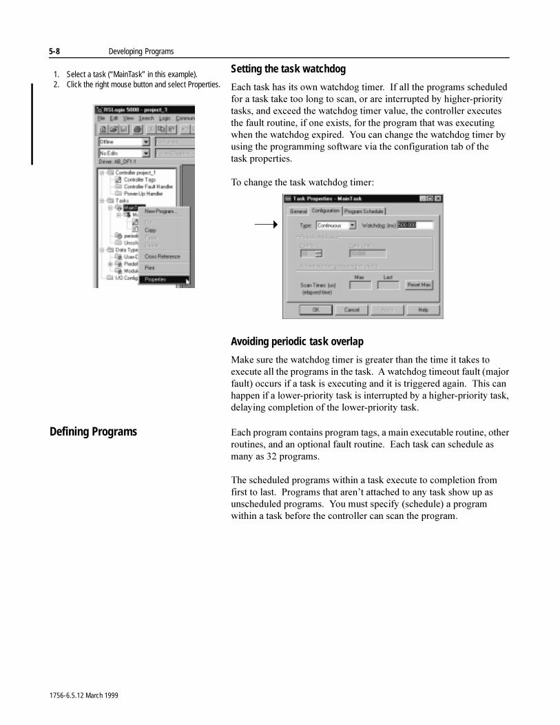
5-8 Developing Programs
Setting the task watchdog
(DFK�WDVN�KDV�LWV�RZQ�ZDWFKGRJ�WLPHU���,I�DOO�WKH�SURJUDPV�VFKHGXOHG�IRU�D�WDVN�WDNH�WRR�ORQJ�WR�VFDQ��RU�DUH�LQWHUUXSWHG�E\�KLJKHU�SULRULW\�WDVNV��DQG�H[FHHG�WKH�ZDWFKGRJ�WLPHU�YDOXH��WKH�FRQWUROOHU�H[HFXWHV�WKH�IDXOW URXWLQH��LI�RQH�H[LVWV��IRU�WKH�SURJUDP�WKDW�ZDV�H[HFXWLQJ�ZKHQ�WKH�ZDWFKGRJ�H[SLUHG���<RX�FDQ�FKDQJH�WKH�ZDWFKGRJ�WLPHU�E\�XVLQJ�WKH�SURJUDPPLQJ�VRIWZDUH�YLD�WKH�FRQILJXUDWLRQ�WDE�RI�WKH�WDVN SURSHUWLHV�
7R�FKDQJH�WKH�WDVN�ZDWFKGRJ�WLPHU�
Avoiding periodic task overlap
0DNH�VXUH�WKH�ZDWFKGRJ�WLPHU�LV�JUHDWHU�WKDQ�WKH�WLPH�LW�WDNHV�WR�H[HFXWH�DOO�WKH�SURJUDPV�LQ�WKH�WDVN���$�ZDWFKGRJ�WLPHRXW�IDXOW��PDMRU�IDXOW��RFFXUV�LI�D�WDVN�LV�H[HFXWLQJ�DQG�LW�LV�WULJJHUHG�DJDLQ���7KLV�FDQ�KDSSHQ�LI�D�ORZHU�SULRULW\�WDVN�LV�LQWHUUXSWHG�E\�D�KLJKHU�SULRULW\�WDVN��GHOD\LQJ�FRPSOHWLRQ�RI�WKH�ORZHU�SULRULW\�WDVN�
Defining Programs (DFK�SURJUDP�FRQWDLQV�SURJUDP�WDJV��D�PDLQ�H[HFXWDEOH�URXWLQH��RWKHU�URXWLQHV��DQG�DQ�RSWLRQDO�IDXOW�URXWLQH���(DFK�WDVN�FDQ�VFKHGXOH�DV�PDQ\�DV����SURJUDPV�
7KH�VFKHGXOHG�SURJUDPV�ZLWKLQ�D�WDVN�H[HFXWH�WR�FRPSOHWLRQ�IURP�ILUVW�WR�ODVW���3URJUDPV�WKDW�DUHQ¶W�DWWDFKHG�WR�DQ\�WDVN�VKRZ�XS�DV�XQVFKHGXOHG�SURJUDPV���<RX�PXVW�VSHFLI\��VFKHGXOH��D�SURJUDP�ZLWKLQ�D�WDVN�EHIRUH�WKH�FRQWUROOHU�FDQ�VFDQ�WKH�SURJUDP�
1. Select a task (“MainTask” in this example).2. Click the right mouse button and select Properties.
1756-6.5.12 March 1999
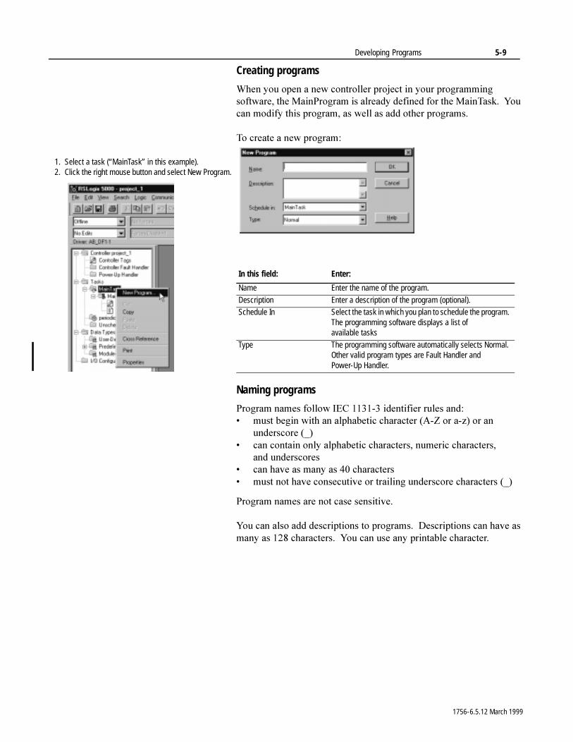
Developing Programs 5-9
Creating programs
:KHQ�\RX�RSHQ�D�QHZ�FRQWUROOHU�SURMHFW�LQ�\RXU�SURJUDPPLQJ�VRIWZDUH��WKH�0DLQ3URJUDP�LV�DOUHDG\�GHILQHG�IRU�WKH�0DLQ7DVN���<RX�FDQ�PRGLI\�WKLV�SURJUDP��DV�ZHOO�DV�DGG�RWKHU�SURJUDPV�
7R�FUHDWH�D�QHZ�SURJUDP�
Naming programs
3URJUDP�QDPHV�IROORZ�,(&��������LGHQWLILHU�UXOHV DQG�� PXVW�EHJLQ�ZLWK�DQ�DOSKDEHWLF�FKDUDFWHU��$�=�RU�D�]��RU�DQ�
XQGHUVFRUH �B�� FDQ�FRQWDLQ�RQO\�DOSKDEHWLF�FKDUDFWHUV��QXPHULF�FKDUDFWHUV��
DQG XQGHUVFRUHV� FDQ�KDYH�DV�PDQ\�DV����FKDUDFWHUV� PXVW�QRW�KDYH�FRQVHFXWLYH�RU�WUDLOLQJ�XQGHUVFRUH�FKDUDFWHUV��B�
3URJUDP�QDPHV�DUH�QRW�FDVH�VHQVLWLYH�
<RX�FDQ�DOVR�DGG�GHVFULSWLRQV�WR�SURJUDPV���'HVFULSWLRQV�FDQ�KDYH�DV�PDQ\�DV�����FKDUDFWHUV���<RX�FDQ�XVH�DQ\�SULQWDEOH�FKDUDFWHU�
In this field: Enter:
Name Enter the name of the program.
Description Enter a description of the program (optional).Schedule In Select the task in which you plan to schedule the program.
The programming software displays a list of available tasks
Type The programming software automatically selects Normal. Other valid program types are Fault Handler and Power-Up Handler.
1. Select a task (“MainTask” in this example).2. Click the right mouse button and select New Program.
1756-6.5.12 March 1999
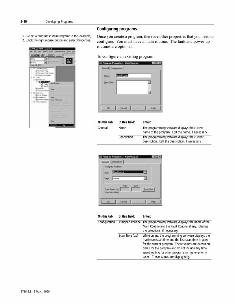
5-10 Developing Programs
Configuring programs
2QFH�\RX�FUHDWH�D�SURJUDP��WKHUH�DUH�RWKHU�SURSHUWLHV�WKDW�\RX�QHHG�WR�FRQILJXUH���<RX�PXVW�KDYH�D�PDLQ�URXWLQH���7KH�IDXOW�DQG�SRZHU�XS�URXWLQHV�DUH�RSWLRQDO�
7R�FRQILJXUH�DQ�H[LVWLQJ�SURJUDP�
On this tab: In this field: Enter:
General Name The programming software displays the current name of the program. Edit the name, if necessary.
Description The programming software displays the current description. Edit the description, if necessary.
On this tab: In this field: Enter:
Configuration Assigned Routine The programming software displays the name of the Main Routine and the Fault Routine, if any. Change the selections, if necessary.
Scan Time (µs) While online, the programming software displays the maximum scan time and the last scan time in µsec for the current program. These values are execution times for the program and do not include any time spent waiting for other programs or higher-priority tasks. These values are display only.
1. Select a program (“MainProgram” in this example).2. Click the right mouse button and select Properties.
1756-6.5.12 March 1999
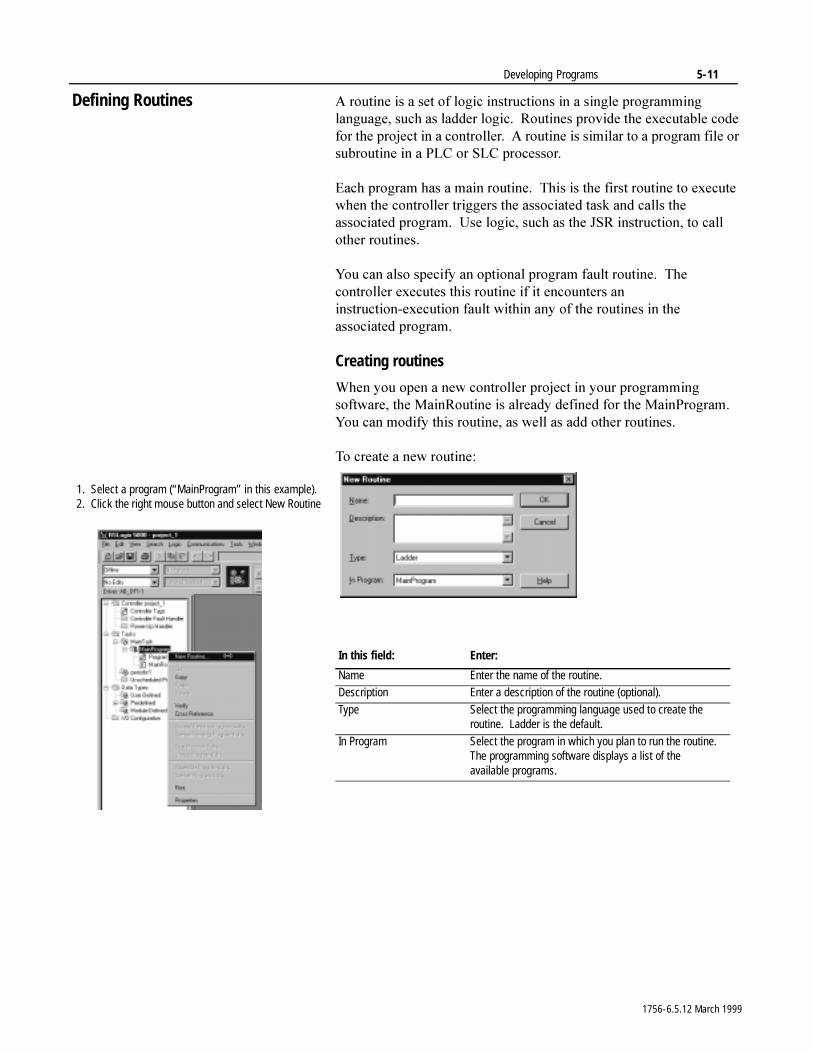
Developing Programs 5-11
Defining Routines $�URXWLQH�LV�D�VHW�RI�ORJLF�LQVWUXFWLRQV�LQ�D�VLQJOH�SURJUDPPLQJ�ODQJXDJH��VXFK�DV�ODGGHU�ORJLF���5RXWLQHV�SURYLGH�WKH�H[HFXWDEOH�FRGH�IRU�WKH�SURMHFW�LQ�D�FRQWUROOHU���$�URXWLQH�LV�VLPLODU�WR�D�SURJUDP�ILOH�RU�VXEURXWLQH�LQ�D�3/&�RU�6/& SURFHVVRU�
(DFK�SURJUDP�KDV�D�PDLQ�URXWLQH���7KLV�LV�WKH�ILUVW�URXWLQH�WR�H[HFXWH�ZKHQ�WKH�FRQWUROOHU�WULJJHUV�WKH�DVVRFLDWHG�WDVN�DQG�FDOOV�WKH�DVVRFLDWHG�SURJUDP���8VH�ORJLF��VXFK�DV�WKH�-65�LQVWUXFWLRQ��WR�FDOO�RWKHU�URXWLQHV�
<RX�FDQ�DOVR�VSHFLI\�DQ�RSWLRQDO�SURJUDP�IDXOW�URXWLQH���7KH�FRQWUROOHU�H[HFXWHV�WKLV�URXWLQH�LI�LW�HQFRXQWHUV�DQ�LQVWUXFWLRQ�H[HFXWLRQ�IDXOW�ZLWKLQ�DQ\�RI�WKH�URXWLQHV�LQ�WKH�DVVRFLDWHG SURJUDP�
Creating routines
:KHQ�\RX�RSHQ�D�QHZ�FRQWUROOHU�SURMHFW�LQ�\RXU�SURJUDPPLQJ�VRIWZDUH��WKH�0DLQ5RXWLQH�LV�DOUHDG\�GHILQHG�IRU�WKH�0DLQ3URJUDP���<RX�FDQ�PRGLI\�WKLV�URXWLQH��DV�ZHOO�DV�DGG�RWKHU�URXWLQHV�
7R�FUHDWH�D�QHZ�URXWLQH�
In this field: Enter:
Name Enter the name of the routine.Description Enter a description of the routine (optional).
Type Select the programming language used to create the routine. Ladder is the default.
In Program Select the program in which you plan to run the routine. The programming software displays a list of the available programs.
1. Select a program (“MainProgram” in this example).2. Click the right mouse button and select New Routine
1756-6.5.12 March 1999
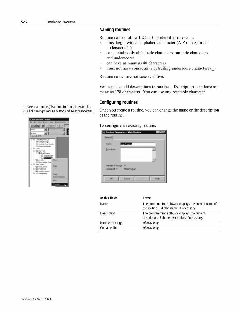
5-12 Developing Programs
Naming routines
5RXWLQH�QDPHV�IROORZ�,(&��������LGHQWLILHU�UXOHV DQG�� PXVW�EHJLQ�ZLWK�DQ�DOSKDEHWLF�FKDUDFWHU��$�=�RU�D�]��RU�DQ�
XQGHUVFRUH �B�� FDQ�FRQWDLQ�RQO\�DOSKDEHWLF�FKDUDFWHUV��QXPHULF�FKDUDFWHUV��
DQG XQGHUVFRUHV� FDQ�KDYH�DV�PDQ\�DV����FKDUDFWHUV� PXVW�QRW�KDYH�FRQVHFXWLYH�RU�WUDLOLQJ�XQGHUVFRUH�FKDUDFWHUV��B�
5RXWLQH�QDPHV�DUH�QRW�FDVH�VHQVLWLYH�
<RX�FDQ�DOVR�DGG�GHVFULSWLRQV�WR�URXWLQHV���'HVFULSWLRQV�FDQ�KDYH�DV�PDQ\�DV�����FKDUDFWHUV���<RX�FDQ�XVH�DQ\�SULQWDEOH�FKDUDFWHU�
Configuring routines
2QFH�\RX�FUHDWH�D�URXWLQH��\RX�FDQ�FKDQJH�WKH�QDPH�RU�WKH�GHVFULSWLRQ�RI�WKH�URXWLQH�
7R�FRQILJXUH�DQ�H[LVWLQJ�URXWLQH�
In this field: Enter:
Name The programming software displays the current name of the routine. Edit the name, if necessary.
Description The programming software displays the current description. Edit the description, if necessary.
Number of rungs display onlyContained in display only
1. Select a routine (“MainRoutine” in this example).2. Click the right mouse button and select Properties.
1756-6.5.12 March 1999
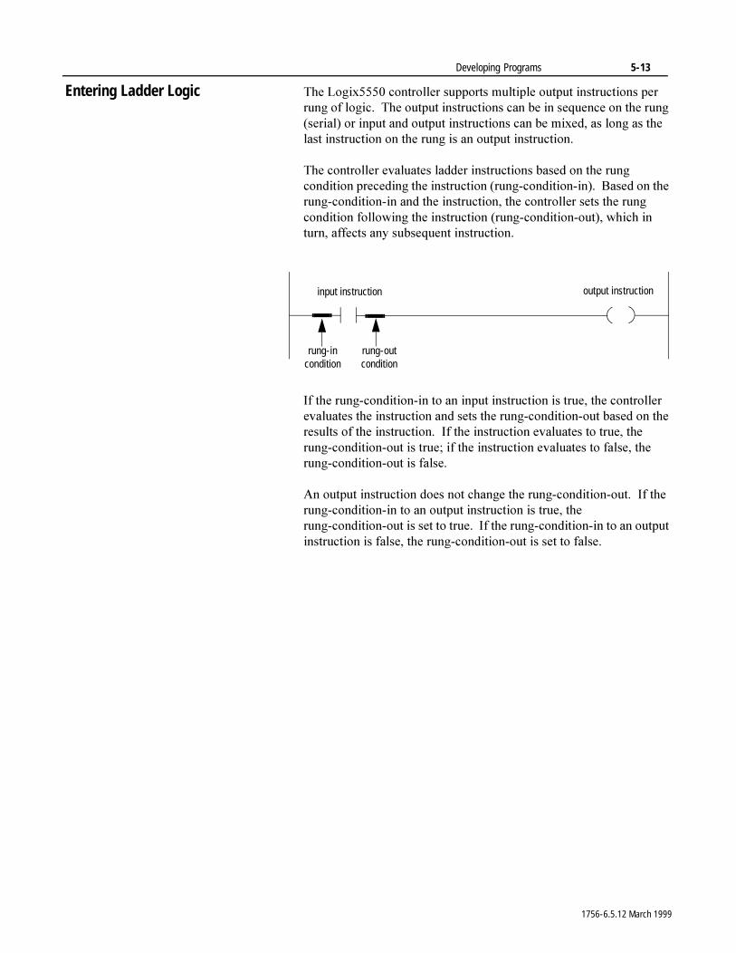
Developing Programs 5-13
Entering Ladder Logic 7KH�/RJL[�����FRQWUROOHU�VXSSRUWV�PXOWLSOH�RXWSXW�LQVWUXFWLRQV�SHU�UXQJ�RI�ORJLF���7KH�RXWSXW�LQVWUXFWLRQV�FDQ�EH�LQ�VHTXHQFH�RQ�WKH�UXQJ��VHULDO��RU�LQSXW�DQG�RXWSXW�LQVWUXFWLRQV�FDQ�EH�PL[HG��DV�ORQJ�DV�WKH�ODVW�LQVWUXFWLRQ�RQ�WKH�UXQJ�LV�DQ�RXWSXW�LQVWUXFWLRQ�
7KH�FRQWUROOHU�HYDOXDWHV�ODGGHU�LQVWUXFWLRQV�EDVHG�RQ�WKH�UXQJ�FRQGLWLRQ�SUHFHGLQJ�WKH�LQVWUXFWLRQ��UXQJ�FRQGLWLRQ�LQ����%DVHG�RQ�WKH�UXQJ�FRQGLWLRQ�LQ�DQG�WKH�LQVWUXFWLRQ��WKH�FRQWUROOHU�VHWV�WKH�UXQJ�FRQGLWLRQ�IROORZLQJ�WKH�LQVWUXFWLRQ��UXQJ�FRQGLWLRQ�RXW���ZKLFK�LQ�WXUQ��DIIHFWV�DQ\�VXEVHTXHQW�LQVWUXFWLRQ�
,I�WKH�UXQJ�FRQGLWLRQ�LQ�WR�DQ�LQSXW�LQVWUXFWLRQ�LV�WUXH��WKH�FRQWUROOHU�HYDOXDWHV�WKH�LQVWUXFWLRQ�DQG�VHWV�WKH�UXQJ�FRQGLWLRQ�RXW�EDVHG�RQ�WKH�UHVXOWV�RI�WKH�LQVWUXFWLRQ���,I�WKH�LQVWUXFWLRQ�HYDOXDWHV�WR�WUXH��WKH�UXQJ�FRQGLWLRQ�RXW�LV�WUXH��LI�WKH�LQVWUXFWLRQ�HYDOXDWHV�WR�IDOVH��WKH�UXQJ�FRQGLWLRQ�RXW�LV�IDOVH�
$Q�RXWSXW�LQVWUXFWLRQ�GRHV�QRW�FKDQJH�WKH�UXQJ�FRQGLWLRQ�RXW���,I�WKH�UXQJ�FRQGLWLRQ�LQ�WR�DQ�RXWSXW�LQVWUXFWLRQ�LV�WUXH��WKH�UXQJ�FRQGLWLRQ�RXW�LV�VHW�WR�WUXH���,I�WKH�UXQJ�FRQGLWLRQ�LQ�WR�DQ�RXWSXW�LQVWUXFWLRQ�LV�IDOVH��WKH�UXQJ�FRQGLWLRQ�RXW�LV�VHW�WR�IDOVH�
input instruction
rung-in condition
output instruction
rung-out condition
1756-6.5.12 March 1999
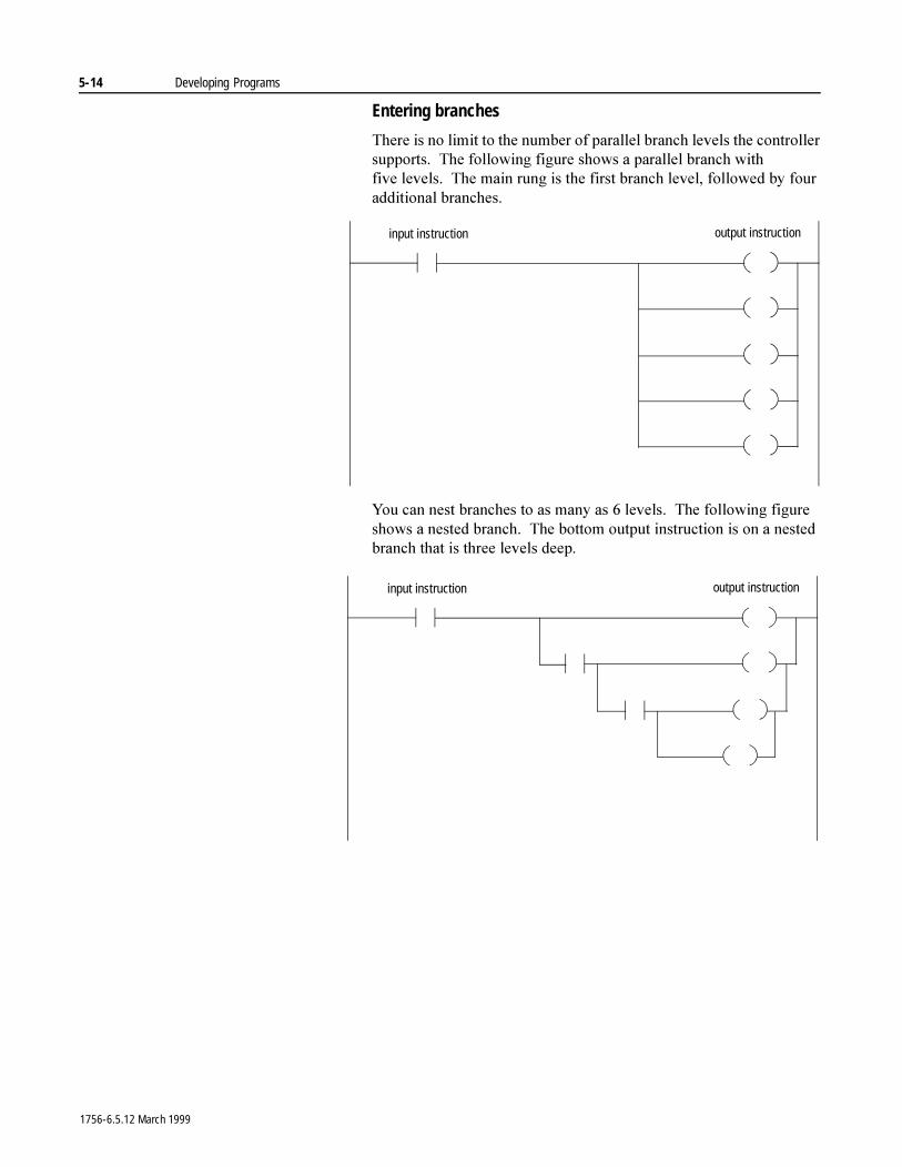
5-14 Developing Programs
Entering branches
7KHUH�LV�QR�OLPLW�WR�WKH�QXPEHU�RI�SDUDOOHO�EUDQFK�OHYHOV�WKH�FRQWUROOHU�VXSSRUWV���7KH�IROORZLQJ�ILJXUH�VKRZV�D�SDUDOOHO�EUDQFK�ZLWK�ILYH OHYHOV���7KH�PDLQ�UXQJ�LV�WKH�ILUVW�EUDQFK�OHYHO��IROORZHG�E\�IRXU�DGGLWLRQDO�EUDQFKHV�
<RX�FDQ�QHVW�EUDQFKHV�WR�DV�PDQ\�DV���OHYHOV���7KH�IROORZLQJ�ILJXUH�VKRZV�D�QHVWHG�EUDQFK���7KH�ERWWRP�RXWSXW�LQVWUXFWLRQ�LV�RQ�D�QHVWHG�EUDQFK�WKDW�LV�WKUHH�OHYHOV�GHHS�
input instruction output instruction
input instruction output instruction
1756-6.5.12 March 1999
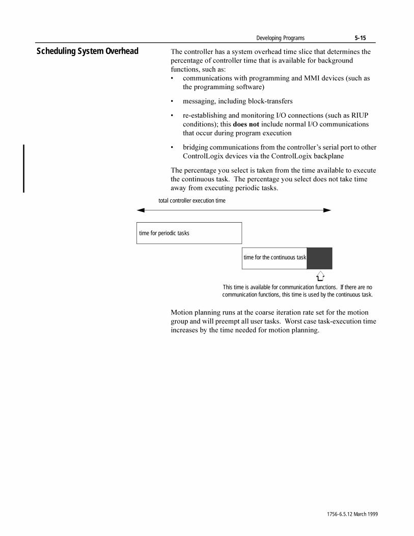
Developing Programs 5-15
Scheduling System Overhead 7KH�FRQWUROOHU�KDV�D�V\VWHP�RYHUKHDG�WLPH�VOLFH�WKDW�GHWHUPLQHV�WKH�SHUFHQWDJH�RI�FRQWUROOHU�WLPH�WKDW�LV�DYDLODEOH�IRU�EDFNJURXQG�IXQFWLRQV��VXFK�DV�� FRPPXQLFDWLRQV�ZLWK�SURJUDPPLQJ�DQG�00,�GHYLFHV��VXFK�DV�
WKH�SURJUDPPLQJ�VRIWZDUH�
� PHVVDJLQJ��LQFOXGLQJ�EORFN�WUDQVIHUV
� UH�HVWDEOLVKLQJ�DQG�PRQLWRULQJ�,�2�FRQQHFWLRQV��VXFK�DV�5,83�FRQGLWLRQV���WKLV�GRHV�QRW�LQFOXGH�QRUPDO�,�2�FRPPXQLFDWLRQV�WKDW�RFFXU�GXULQJ�SURJUDP�H[HFXWLRQ
� EULGJLQJ�FRPPXQLFDWLRQV�IURP�WKH�FRQWUROOHU¶V�VHULDO�SRUW�WR�RWKHU�&RQWURO/RJL[�GHYLFHV�YLD�WKH�&RQWURO/RJL[�EDFNSODQH
7KH�SHUFHQWDJH�\RX�VHOHFW�LV�WDNHQ�IURP�WKH�WLPH�DYDLODEOH�WR�H[HFXWH�WKH�FRQWLQXRXV�WDVN���7KH�SHUFHQWDJH�\RX�VHOHFW�GRHV�QRW�WDNH�WLPH�DZD\�IURP�H[HFXWLQJ�SHULRGLF�WDVNV�
0RWLRQ�SODQQLQJ�UXQV�DW�WKH�FRDUVH�LWHUDWLRQ�UDWH�VHW�IRU�WKH�PRWLRQ�JURXS�DQG�ZLOO�SUHHPSW�DOO�XVHU�WDVNV���:RUVW�FDVH�WDVN�H[HFXWLRQ�WLPH�LQFUHDVHV�E\�WKH�WLPH�QHHGHG�IRU�PRWLRQ�SODQQLQJ�
total controller execution time
time for periodic tasks
time for the continuous task
This time is available for communication functions. If there are no communication functions, this time is used by the continuous task.
1756-6.5.12 March 1999
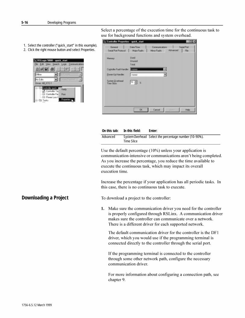
5-16 Developing Programs
6HOHFW�D�SHUFHQWDJH�RI�WKH�H[HFXWLRQ�WLPH�IRU�WKH�FRQWLQXRXV�WDVN�WR�XVH�IRU�EDFNJURXQG�IXQFWLRQV�DQG�V\VWHP�RYHUKHDG�
8VH�WKH�GHIDXOW�SHUFHQWDJH�������XQOHVV�\RXU�DSSOLFDWLRQ�LV�FRPPXQLFDWLRQ�LQWHQVLYH�RU�FRPPXQLFDWLRQV�DUHQ¶W�EHLQJ�FRPSOHWHG���$V�\RX�LQFUHDVH�WKH�SHUFHQWDJH��\RX�UHGXFH�WKH�WLPH�DYDLODEOH�WR�H[HFXWH�WKH�FRQWLQXRXV�WDVN��ZKLFK�PD\�LPSDFW�LWV�RYHUDOO�H[HFXWLRQ WLPH�
,QFUHDVH�WKH�SHUFHQWDJH�LI�\RXU�DSSOLFDWLRQ�KDV�DOO�SHULRGLF�WDVNV���,Q�WKLV�FDVH��WKHUH�LV�QR�FRQWLQXRXV�WDVN�WR�H[HFXWH�
Downloading a Project 7R�GRZQORDG�D�SURMHFW�WR�WKH�FRQWUROOHU�
�� 0DNH�VXUH�WKH�FRPPXQLFDWLRQ�GULYHU�\RX�QHHG�IRU�WKH�FRQWUROOHU�LV�SURSHUO\�FRQILJXUHG�WKURXJK�56/LQ[���$�FRPPXQLFDWLRQ�GULYHU�PDNHV�VXUH�WKH�FRQWUROOHU�FDQ�FRPPXQLFDWH�RYHU�D�QHWZRUN���7KHUH�LV�D�GLIIHUHQW�GULYHU�IRU�HDFK�VXSSRUWHG�QHWZRUN�
7KH�GHIDXOW�FRPPXQLFDWLRQ�GULYHU�IRU�WKH�FRQWUROOHU�LV�WKH�')��GULYHU��ZKLFK�\RX�ZRXOG�XVH�LI�WKH�SURJUDPPLQJ�WHUPLQDO�LV�FRQQHFWHG�GLUHFWO\�WR�WKH�FRQWUROOHU�WKURXJK�WKH�VHULDO�SRUW�
,I�WKH�SURJUDPPLQJ�WHUPLQDO�LV�FRQQHFWHG�WR�WKH�FRQWUROOHU�WKURXJK�VRPH�RWKHU�QHWZRUN�SDWK��FRQILJXUH�WKH�QHFHVVDU\�FRPPXQLFDWLRQ�GULYHU�
)RU�PRUH�LQIRUPDWLRQ�DERXW�FRQILJXULQJ�D�FRQQHFWLRQ�SDWK��VHH�FKDSWHU���
On this tab: In this field: Enter:
Advanced System Overhead Time Slice
Select the percentage number (10-90%).
1. Select the controller (“quick_start” in this example).2. Click the right mouse button and select Properties.
1756-6.5.12 March 1999
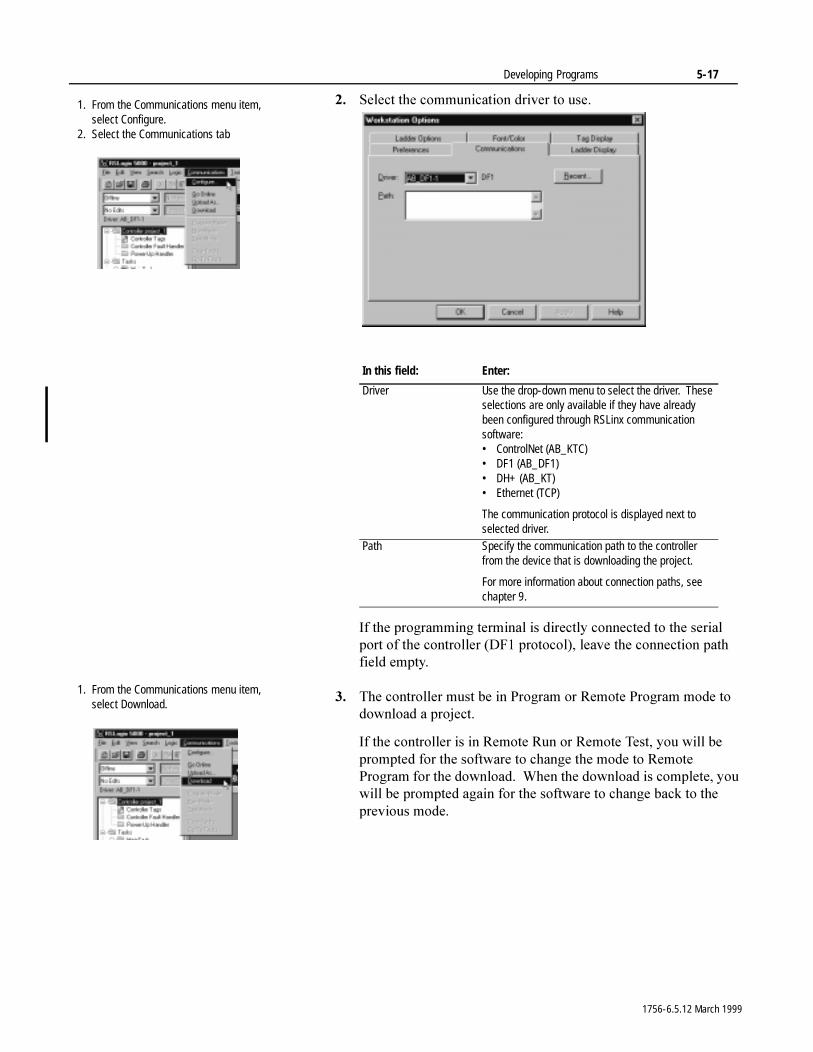
Developing Programs 5-17
�� 6HOHFW�WKH�FRPPXQLFDWLRQ�GULYHU�WR�XVH�
,I�WKH�SURJUDPPLQJ�WHUPLQDO�LV�GLUHFWO\�FRQQHFWHG�WR�WKH�VHULDO�SRUW�RI�WKH�FRQWUROOHU��')��SURWRFRO���OHDYH�WKH�FRQQHFWLRQ�SDWK�ILHOG�HPSW\�
�� 7KH�FRQWUROOHU�PXVW�EH�LQ�3URJUDP�RU�5HPRWH�3URJUDP�PRGH�WR�GRZQORDG�D�SURMHFW�
,I�WKH�FRQWUROOHU�LV�LQ�5HPRWH�5XQ�RU�5HPRWH�7HVW��\RX�ZLOO�EH�SURPSWHG�IRU�WKH�VRIWZDUH�WR�FKDQJH�WKH�PRGH�WR�5HPRWH�3URJUDP�IRU�WKH�GRZQORDG���:KHQ�WKH�GRZQORDG�LV�FRPSOHWH��\RX�ZLOO�EH�SURPSWHG�DJDLQ�IRU�WKH�VRIWZDUH�WR�FKDQJH�EDFN�WR�WKH�SUHYLRXV�PRGH�
In this field: Enter:
Driver Use the drop-down menu to select the driver. These selections are only available if they have already been configured through RSLinx communication software:• ControlNet (AB_KTC)• DF1 (AB_DF1)• DH+ (AB_KT)• Ethernet (TCP)
The communication protocol is displayed next to selected driver.
Path Specify the communication path to the controller from the device that is downloading the project.
For more information about connection paths, see chapter 9.
1. From the Communications menu item, select Configure.
2. Select the Communications tab
1. From the Communications menu item, select Download.
1756-6.5.12 March 1999

5-18 Developing Programs
1RWHV�
1756-6.5.12 March 1999
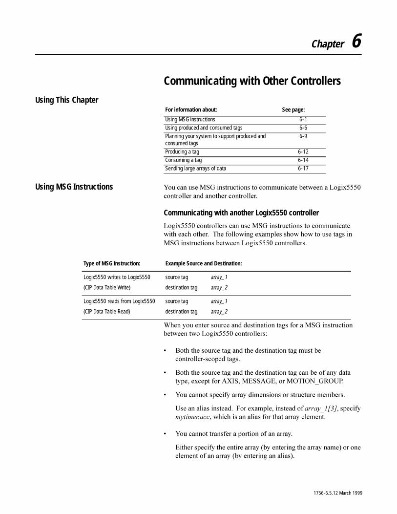
Chapter 6
Communicating with Other Controllers
Using This Chapter
Using MSG Instructions <RX�FDQ�XVH�06*�LQVWUXFWLRQV�WR�FRPPXQLFDWH�EHWZHHQ�D�/RJL[�����FRQWUROOHU�DQG�DQRWKHU�FRQWUROOHU�
Communicating with another Logix5550 controller
/RJL[�����FRQWUROOHUV�FDQ�XVH�06*�LQVWUXFWLRQV�WR�FRPPXQLFDWH�ZLWK�HDFK�RWKHU���7KH�IROORZLQJ�H[DPSOHV�VKRZ�KRZ�WR�XVH�WDJV�LQ�06*�LQVWUXFWLRQV�EHWZHHQ�/RJL[�����FRQWUROOHUV�
:KHQ�\RX�HQWHU�VRXUFH�DQG�GHVWLQDWLRQ�WDJV�IRU�D�06*�LQVWUXFWLRQ�EHWZHHQ�WZR�/RJL[�����FRQWUROOHUV�
� %RWK�WKH�VRXUFH�WDJ�DQG�WKH�GHVWLQDWLRQ�WDJ�PXVW�EH�FRQWUROOHU�VFRSHG�WDJV�
� %RWK�WKH�VRXUFH�WDJ�DQG�WKH�GHVWLQDWLRQ�WDJ�FDQ�EH�RI�DQ\�GDWD�W\SH��H[FHSW�IRU�$;,6��0(66$*(��RU�027,21B*5283�
� <RX�FDQQRW�VSHFLI\�DUUD\�GLPHQVLRQV�RU�VWUXFWXUH�PHPEHUV�
8VH�DQ�DOLDV�LQVWHDG���)RU�H[DPSOH��LQVWHDG�RI�DUUD\B�>�@��VSHFLI\�P\WLPHU�DFF��ZKLFK�LV�DQ�DOLDV�IRU�WKDW�DUUD\�HOHPHQW�
� <RX�FDQQRW�WUDQVIHU�D�SRUWLRQ�RI�DQ�DUUD\�
(LWKHU�VSHFLI\�WKH�HQWLUH�DUUD\��E\�HQWHULQJ�WKH�DUUD\�QDPH��RU�RQH�HOHPHQW�RI�DQ�DUUD\��E\�HQWHULQJ�DQ�DOLDV��
For information about: See page:
Using MSG instructions 6-1Using produced and consumed tags 6-6
Planning your system to support produced and consumed tags
6-9
Producing a tag 6-12Consuming a tag 6-14Sending large arrays of data 6-17
Type of MSG Instruction: Example Source and Destination:
Logix5550 writes to Logix5550
(CIP Data Table Write)
source tag array_1
destination tag array_2
Logix5550 reads from Logix5550
(CIP Data Table Read)
source tag array_1
destination tag array_2
1756-6.5.12 March 1999
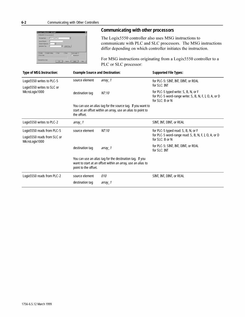
6-2 Communicating with Other Controllers
Communicating with other processors
7KH�/RJL[�����FRQWUROOHU�DOVR�XVHV�06*�LQVWUXFWLRQV�WR�FRPPXQLFDWH�ZLWK�3/&�DQG�6/&�SURFHVVRUV���7KH�06*�LQVWUXFWLRQV�GLIIHU�GHSHQGLQJ�RQ�ZKLFK�FRQWUROOHU�LQLWLDWHV�WKH�LQVWUXFWLRQ�
)RU�06*�LQVWUXFWLRQV�RULJLQDWLQJ�IURP�D�/RJL[���� FRQWUROOHU�WR�D�3/&�RU�6/&�SURFHVVRU�
Type of MSG Instruction: Example Source and Destination: Supported File Types:
Logix5550 writes to PLC-5
Logix5550 writes to SLC or MicroLogix1000
source element array_1
destination tag N7:10
You can use an alias tag for the source tag. If you want to start at an offset within an array, use an alias to point to the offset.
for PLC-5: SINT, INT, DINT, or REALfor SLC: INT
for PLC-5 typed write: S, B, N, or Ffor PLC-5 word-range write: S, B, N, F, I, O, A, or Dfor SLC: B or N
Logix5550 writes to PLC-2 array_1 SINT, INT, DINT, or REAL
Logix5550 reads from PLC-5
Logix5550 reads from SLC or MicroLogix1000
source element N7:10
destination tag array_1
You can use an alias tag for the destination tag. If you want to start at an offset within an array, use an alias to point to the offset.
for PLC-5 typed read: S, B, N, or Ffor PLC-5 word-range read: S, B, N, F, I, O, A, or Dfor SLC: B or N
for PLC-5: SINT, INT, DINT, or REALfor SLC: INT
Logix5550 reads from PLC-2 source element 010
destination tag array_1
SINT, INT, DINT, or REAL
1756-6.5.12 March 1999
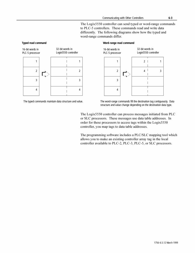
Communicating with Other Controllers 6-3
7KH�/RJL[�����FRQWUROOHU�FDQ�VHQG�W\SHG�RU�ZRUG�UDQJH�FRPPDQGV�WR�3/&���FRQWUROOHUV���7KHVH�FRPPDQGV�UHDG�DQG�ZULWH�GDWD�GLIIHUHQWO\���7KH�IROORZLQJ�GLDJUDPV�VKRZ�KRZ�WKH�W\SHG�DQG�ZRUG�UDQJH�FRPPDQGV�GLIIHU�
7KH�/RJL[�����FRQWUROOHU�FDQ�SURFHVV�PHVVDJHV�LQLWLDWHG�IURP�3/&�RU�6/&�SURFHVVRUV���7KHVH�PHVVDJHV�XVH�GDWD�WDEOH�DGGUHVVHV���,Q�RUGHU�IRU�WKHVH�SURFHVVRUV�WR�DFFHVV�WDJV�ZLWKLQ�WKH�/RJL[�����FRQWUROOHU��\RX�PDS�WDJV�WR�GDWD�WDEOH�DGGUHVVHV�
7KH�SURJUDPPLQJ�VRIWZDUH�LQFOXGHV�D�3/&�6/&�PDSSLQJ�WRRO�ZKLFK�DOORZV�\RX�WR�PDNH�DQ�H[LVWLQJ�FRQWUROOHU�DUUD\�WDJ�LQ�WKH�ORFDO�FRQWUROOHU�DYDLODEOH�WR�3/&����3/&����3/&����RU�6/&�SURFHVVRUV�
16-bit words in PLC-5 processor
32-bit words in Logix5550 controller
The typed commands maintain data structure and value.
1
2
3
4
Typed read command
1
2
3
4
16-bit words in PLC-5 processor
32-bit words in Logix5550 controller
The word-range commands fill the destination tag contiguously. Data structure and value change depending on the destination data type.
1
2
3
4
Word-range read command
1
3
2
4
1756-6.5.12 March 1999
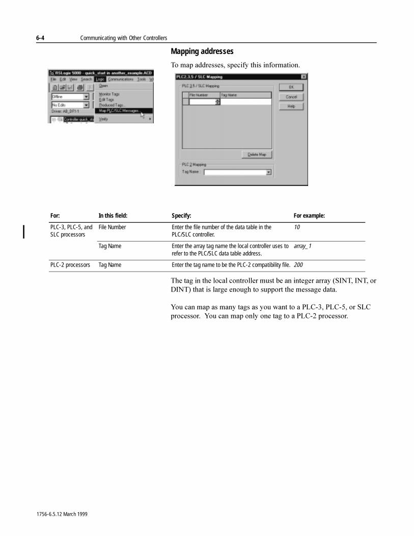
6-4 Communicating with Other Controllers
Mapping addresses
7R�PDS�DGGUHVVHV��VSHFLI\�WKLV�LQIRUPDWLRQ�
7KH�WDJ�LQ�WKH�ORFDO�FRQWUROOHU�PXVW�EH�DQ�LQWHJHU�DUUD\��6,17��,17��RU�',17��WKDW�LV�ODUJH�HQRXJK�WR�VXSSRUW�WKH�PHVVDJH�GDWD�
<RX�FDQ�PDS�DV�PDQ\�WDJV�DV�\RX�ZDQW�WR�D�3/&����3/&����RU�6/&�SURFHVVRU���<RX�FDQ�PDS�RQO\�RQH�WDJ�WR�D�3/&���SURFHVVRU�
For: In this field: Specify: For example:
PLC-3, PLC-5, and SLC processors
File Number Enter the file number of the data table in the PLC/SLC controller.
10
Tag Name Enter the array tag name the local controller uses to refer to the PLC/SLC data table address.
array_1
PLC-2 processors Tag Name Enter the tag name to be the PLC-2 compatibility file. 200
1756-6.5.12 March 1999
Communicating with Other Controllers 6-5
7KH�IROORZLQJ�H[DPSOHV�VKRZ�H[DPSOH�VRXUFH�DQG�GHVWLQDWLRQ�WDJV�DQG�HOHPHQWV�IRU�GLIIHUHQW�FRQWUROOHU�FRPELQDWLRQV�
:KHQ�WKH�/RJL[�����FRQWUROOHU�LQLWLDWHV�PHVVDJHV�WR�3/&�RU�6/&�FRQWUROOHUV��\RX�GR�QRW�KDYH�WR�PDS�FRPSDWLELOLW\�ILOHV���<RX�HQWHU�WKH�GDWD�WDEOH�DGGUHVV�RI�WKH�WDUJHW�GHYLFH�MXVW�DV�\RX�ZRXOG�D�WDJ�QDPH�
6/&������SURFHVVRUV��6/&������SURFHVVRUV��26����DQG�DERYH���DQG�6/&������SURFHVVRUV��26����DQG�DERYH��VXSSRUW�ORJLFDO�$6&,,�DGGUHVVLQJ�DQG�VXSSRUW�3/&�6/&�PDSSLQJ��VHH�WKH�H[DPSOHV�DERYH����)RU�DOO�RWKHU�6/&�RU�0LFUR/RJL[�����SURFHVVRUV��\RX�PXVW�PDS�D�3/&���FRPSDWLELOLW\�ILOH��VHH�WKH�3/&���H[DPSOHV�DERYH��
Type of MSG Instruction: Example Source and Destination:
PLC-5 writes to Logix5550
SLC writes to Logix5550SLC 5/05SLC 5/04 OS402 and aboveSLC 5/03 OS303 and above
source element N7:10
destination tag “array_1”
The PLC-5, PLC-3, and SLC processors support logical ASCII addressing so you do not have to map a compatibility file for MSG instructions initiated by a PLC-5, PLC-3, or SLC processor. Place the Logix5550 tag name in double quotes (“).
You could optionally map a compatibility file. For example, if you enter 10 for the compatibility file, you enter N10:0 for the destination tag.
PLC-2 writes to Logix5550 source element 010
destination tag 200
The destination tag is the three-digit PLC-2 address you specified for PLC-2 mapping.
PLC-5 reads from Logix5550
SLC reads from Logix5550SLC 5/05SLC 5/04 OS402 and aboveSLC 5/03 OS303 and above
source tag “array_1”
destination element N7:10
The PLC-5, PLC-3, and SLC processors support logical ASCII addressing so you do not have to map a compatibility file for MSG instructions initiated by a PLC-5, PLC-3, or SLC processor. Place the Logix5550 tag name in double quotes (“).
You could optionally map a compatibility file. For example, if you enter 10 for the compatibility file, you enter N10:0 for the source tag.
PLC-2 reads from Logix5550 source tag 200
destination element 010
The source tag is the three-digit PLC-2 address you specified for PLC-2 mapping.
1756-6.5.12 March 1999
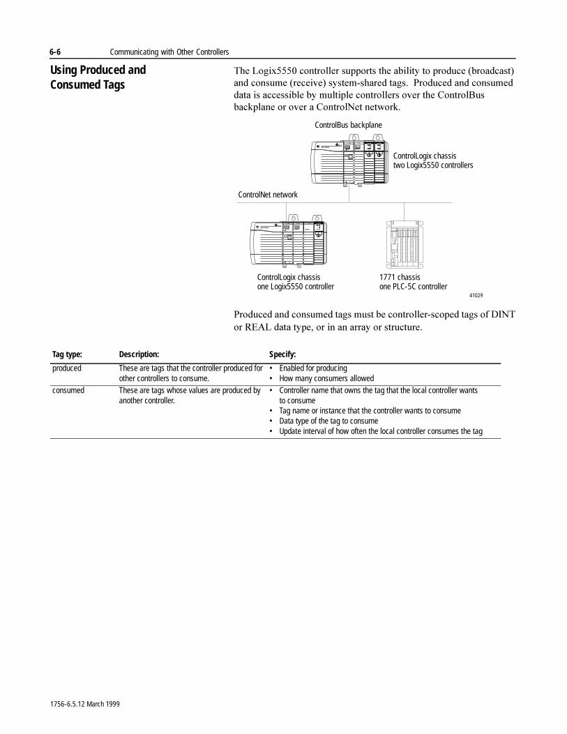
6-6 Communicating with Other Controllers
Using Produced and Consumed Tags
7KH�/RJL[�����FRQWUROOHU�VXSSRUWV�WKH�DELOLW\�WR�SURGXFH��EURDGFDVW��DQG�FRQVXPH��UHFHLYH��V\VWHP�VKDUHG�WDJV���3URGXFHG�DQG�FRQVXPHG�GDWD�LV�DFFHVVLEOH�E\�PXOWLSOH�FRQWUROOHUV�RYHU�WKH�&RQWURO%XV�EDFNSODQH�RU�RYHU�D�&RQWURO1HW�QHWZRUN�
3URGXFHG�DQG�FRQVXPHG�WDJV�PXVW�EH�FRQWUROOHU�VFRSHG�WDJV�RI�',17�RU�5($/�GDWD�W\SH��RU�LQ�DQ�DUUD\�RU�VWUXFWXUH�
ControlNet network
ControlLogix chassistwo Logix5550 controllers
ControlLogix chassisone Logix5550 controller
1771 chassisone PLC-5C controller
ControlBus backplane
41029
Tag type: Description: Specify:
produced These are tags that the controller produced for other controllers to consume.
• Enabled for producing• How many consumers allowed
consumed These are tags whose values are produced by another controller.
• Controller name that owns the tag that the local controller wants to consume
• Tag name or instance that the controller wants to consume• Data type of the tag to consume• Update interval of how often the local controller consumes the tag
1756-6.5.12 March 1999
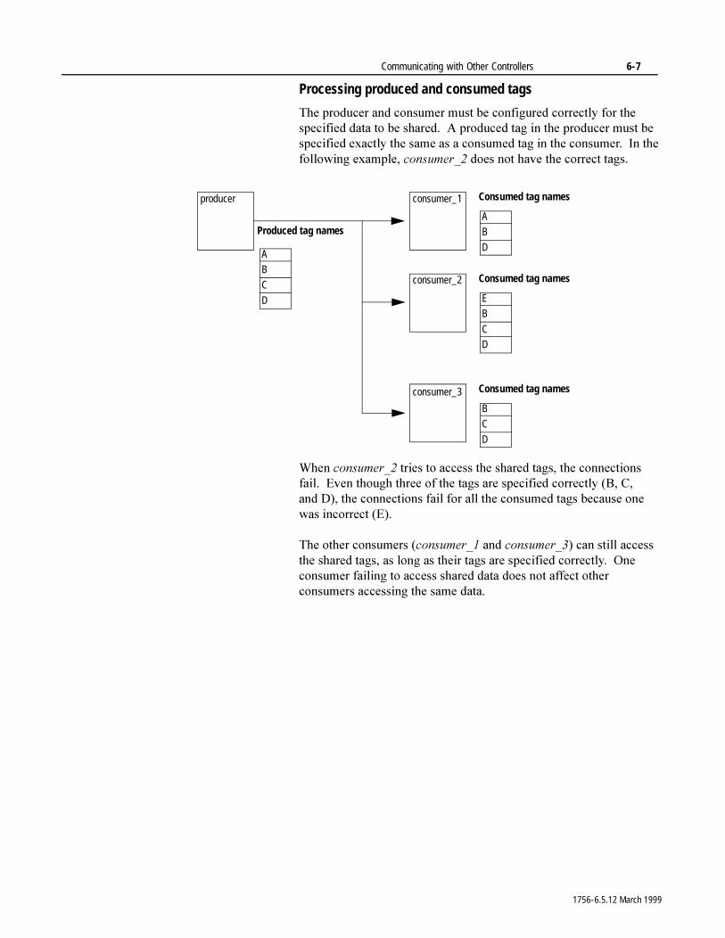
Communicating with Other Controllers 6-7
Processing produced and consumed tags
7KH�SURGXFHU�DQG�FRQVXPHU�PXVW�EH�FRQILJXUHG�FRUUHFWO\�IRU�WKH�VSHFLILHG�GDWD�WR�EH�VKDUHG���$�SURGXFHG�WDJ�LQ�WKH�SURGXFHU�PXVW�EH�VSHFLILHG�H[DFWO\�WKH�VDPH�DV�D�FRQVXPHG�WDJ�LQ�WKH�FRQVXPHU���,Q�WKH�IROORZLQJ�H[DPSOH��FRQVXPHUB��GRHV�QRW�KDYH�WKH�FRUUHFW�WDJV�
:KHQ�FRQVXPHUB��WULHV�WR�DFFHVV�WKH�VKDUHG�WDJV��WKH�FRQQHFWLRQV�IDLO���(YHQ�WKRXJK�WKUHH�RI�WKH�WDJV�DUH�VSHFLILHG�FRUUHFWO\��%��&��DQG '���WKH�FRQQHFWLRQV�IDLO�IRU�DOO�WKH�FRQVXPHG�WDJV�EHFDXVH�RQH�ZDV�LQFRUUHFW��(��
7KH�RWKHU�FRQVXPHUV��FRQVXPHUB��DQG�FRQVXPHUB���FDQ�VWLOO�DFFHVV�WKH�VKDUHG�WDJV��DV�ORQJ�DV�WKHLU�WDJV�DUH�VSHFLILHG�FRUUHFWO\���2QH�FRQVXPHU�IDLOLQJ�WR�DFFHVV�VKDUHG�GDWD�GRHV�QRW�DIIHFW�RWKHU�FRQVXPHUV�DFFHVVLQJ�WKH�VDPH�GDWD�
A
B
C
D
Produced tag names
producer consumer_1
consumer_2
consumer_3
E
B
C
D
Consumed tag names
B
C
D
Consumed tag names
A
B
D
Consumed tag names
1756-6.5.12 March 1999
6-8 Communicating with Other Controllers
Maximum number of produced and consumed tags
7KH�IROORZLQJ�WDEOH�VKRZV�WKH�WRWDO�QXPEHU�RI�SURGXFHG�DQG�FRQVXPHG�WDJV�D�FRQWUROOHU�VXSSRUWV�
(DFK�SURGXFHG�WDJ�XVHV�RQH�XQLGLUHFWLRQDO�FRQQHFWLRQ�IRU�WKH�WDJ�DQG�RQH�XQLGLUHFWLRQDO�FRQQHFWLRQ�IRU�HDFK�FRQWUROOHU�WKDW�FRQVXPHV�WKH�WDJ���:LWK�WKHVH�PD[LPXP�QXPEHUV�LQ�PLQG��WKH�WRWDO�FRPELQHG�FRQVXPHG�DQG�SURGXFHG�WDJV�WKDW�D�FRQWUROOHU�VXSSRUWV�LV��WKLV�LV�DOVR�WKH�PD[LPXP�QXPEHU�RI�XQLGLUHFWLRQDO�FRQQHFWLRQV��VHH�FKDSWHU����
�QXPEHU�RI�SURGXFHG�WDJV�����QXPEHU�RI�FRQVXPHG�WDJV��≤����
$V�WKH�QXPEHU�RI�FRQVXPHG�WDJV�LQFUHDVHV��WKH�QXPEHU�RI�DYDLODEOH�SURGXFHG�WDJV�GHFUHDVHV���<RX�LQFUHDVH�WKH�QXPEHU�RI�FRQVXPHG�WDJV�HLWKHU�E\�FUHDWLQJ�FRQVXPHG�WDJV�RU�E\�DGGLQJ�DGGLWLRQDO�FRQVXPHUV�WR�D�SURGXFHG�WDJ�
As a: The controller supports:
consumer (number of consumed tags) ≤ 250
If your controller consumes 250 tags, these tags must come from more than one controller. A controller can only produce as many as 127 tags. See the producer numbers in this table.
producer (number of produced tags) ≤ 127
1756-6.5.12 March 1999
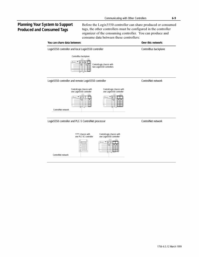
Communicating with Other Controllers 6-9
Planning Your System to Support Produced and Consumed Tags
%HIRUH�WKH�/RJL[�����FRQWUROOHU�FDQ�VKDUH�SURGXFHG�RU�FRQVXPHG�WDJV��WKH�RWKHU�FRQWUROOHUV�PXVW�EH�FRQILJXUHG�LQ�WKH�FRQWUROOHU�RUJDQL]HU�RI�WKH�FRQVXPLQJ�FRQWUROOHU���<RX�FDQ�SURGXFH�DQG�FRQVXPH�GDWD�EHWZHHQ�WKHVH�FRQWUROOHUV�
You can share data between: Over this network:
Logix5550 controller and local Logix5550 controller ControlBus backplane
Logix5550 controller and remote Logix5550 controller ControlNet network
Logix5550 controller and PLC-5 ControlNet processor ControlNet network
ControlLogix chassis withtwo Logix5550 controllers
ControlBus backplane
ControlNet network
ControlLogix chassis withone Logix5550 controller
ControlLogix chassis withone Logix5550 controller
ControlNet network
ControlLogix chassis withone Logix5550 controller
1771 chassis withone PLC-5C controller
1756-6.5.12 March 1999
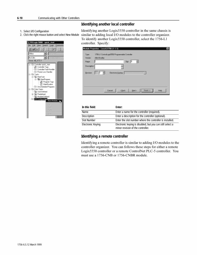
6-10 Communicating with Other Controllers
Identifying another local controller
,GHQWLI\LQJ�DQRWKHU�/RJL[�����FRQWUROOHU�LQ�WKH�VDPH�FKDVVLV�LV�VLPLODU�WR�DGGLQJ�ORFDO�,�2�PRGXOHV�WR�WKH�FRQWUROOHU�RUJDQL]HU�7R�LGHQWLI\�DQRWKHU�/RJL[�����FRQWUROOHU��VHOHFW�WKH������/��FRQWUROOHU���6SHFLI\�
Identifying a remote controller
,GHQWLI\LQJ�D�UHPRWH�FRQWUROOHU�LV�VLPLODU�WR�DGGLQJ�,�2�PRGXOHV�WR�WKH�FRQWUROOHU�RUJDQL]HU���<RX�FDQ�IROORZV�WKHVH�VWHSV�IRU�HLWKHU�D�UHPRWH�/RJL[�����FRQWUROOHU�RU�D�UHPRWH�&RQWURO1HW�3/&���FRQWUROOHU���<RX�PXVW�XVH�D������&1%�RU������&1%5�PRGXOH�
In this field: Enter:
Name Enter a name for the controller (required).Description Enter a description for the controller (optional).Slot Number Enter the slot number where the controller is installed.
Electronic Keying Electronic keying is disabled, but you can still select a minor revision of the controller.
1. Select I/O Configuration2. Click the right mouse button and select New Module
1756-6.5.12 March 1999
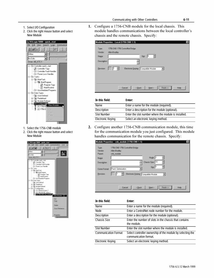
Communicating with Other Controllers 6-11
�� &RQILJXUH�D������&1%�PRGXOH�IRU�WKH�ORFDO�FKDVVLV���7KLV�PRGXOH�KDQGOHV�FRPPXQLFDWLRQV�EHWZHHQ�WKH�ORFDO�FRQWUROOHU¶V�FKDVVLV�DQG�WKH�UHPRWH�FKDVVLV���6SHFLI\�
�� &RQILJXUH�DQRWKHU������&1%�FRPPXQLFDWLRQ�PRGXOH��WKLV�WLPH�IRU�WKH�FRPPXQLFDWLRQ�PRGXOH�\RX�MXVW�FRQILJXUHG���7KLV�PRGXOH�KDQGOHV�FRPPXQLFDWLRQ�IRU�WKH�UHPRWH�FKDVVLV���6SHFLI\�
In this field: Enter:
Name Enter a name for the module (required).Description Enter a description for the module (optional).
Slot Number Enter the slot number where the module is installed.Electronic Keying Select an electronic keying method.
In this field: Enter:
Name Enter a name for the module (required).Node Enter a ControlNet node number for the module.
Description Enter a description for the module (optional).Chassis Size Enter the number of slots in the chassis that contains
the module.Slot Number Enter the slot number where the module is installed.
Communication Format Select controller ownership of the module by selecting the communication format.
Electronic Keying Select an electronic keying method.
1. Select I/O Configuration2. Click the right mouse button and select
New Module
1. Select the 1756-CNB module2. Click the right mouse button and select
New Module
1756-6.5.12 March 1999
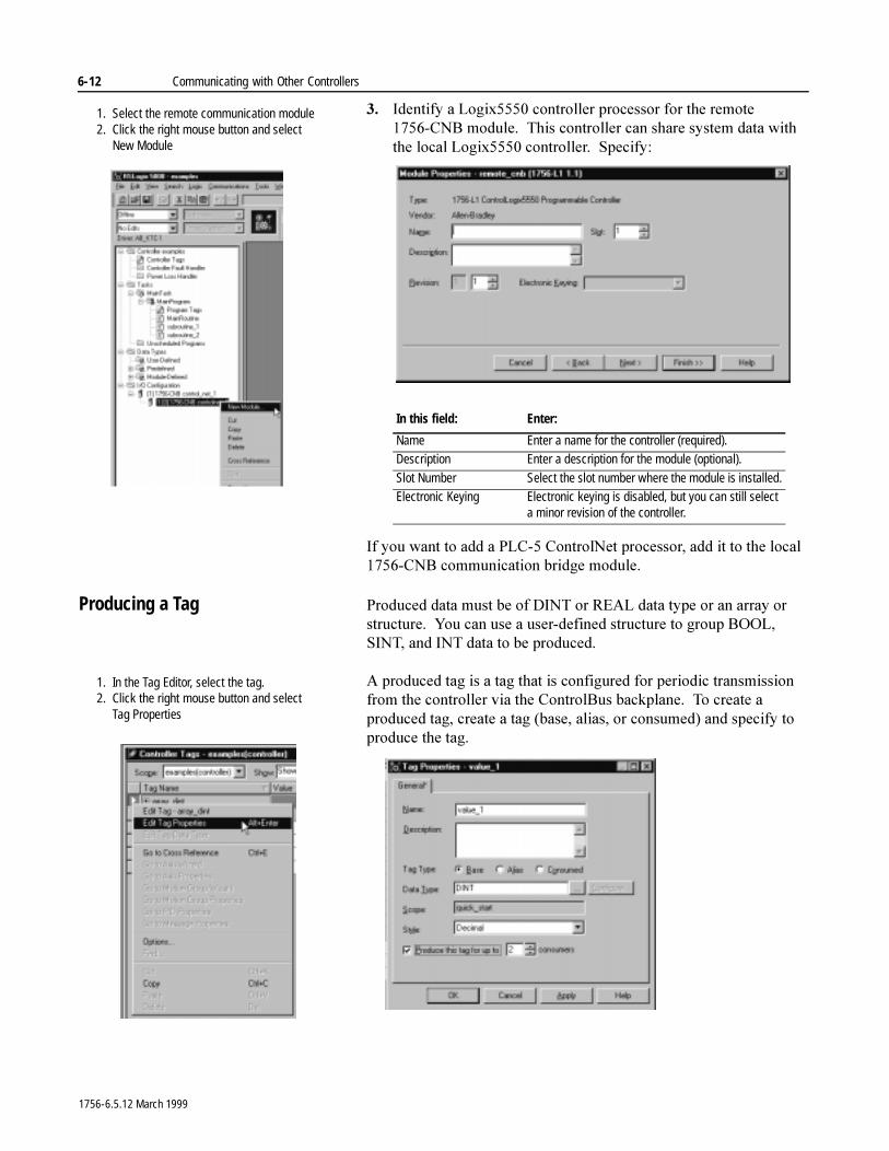
6-12 Communicating with Other Controllers
�� ,GHQWLI\�D�/RJL[�����FRQWUROOHU�SURFHVVRU�IRU�WKH�UHPRWH������&1%�PRGXOH���7KLV�FRQWUROOHU�FDQ�VKDUH�V\VWHP�GDWD�ZLWK�WKH�ORFDO�/RJL[�����FRQWUROOHU���6SHFLI\�
,I�\RX�ZDQW�WR�DGG�D�3/&���&RQWURO1HW�SURFHVVRU��DGG�LW�WR�WKH�ORFDO������&1%�FRPPXQLFDWLRQ�EULGJH�PRGXOH�
Producing a Tag 3URGXFHG�GDWD�PXVW�EH�RI�',17�RU�5($/�GDWD�W\SH�RU�DQ�DUUD\�RU�VWUXFWXUH���<RX�FDQ�XVH�D�XVHU�GHILQHG�VWUXFWXUH�WR�JURXS�%22/��6,17��DQG�,17�GDWD�WR�EH�SURGXFHG�
$�SURGXFHG�WDJ�LV�D�WDJ�WKDW�LV�FRQILJXUHG�IRU�SHULRGLF�WUDQVPLVVLRQ�IURP�WKH�FRQWUROOHU�YLD�WKH�&RQWURO%XV�EDFNSODQH���7R�FUHDWH�D�SURGXFHG�WDJ��FUHDWH�D�WDJ��EDVH��DOLDV��RU�FRQVXPHG��DQG�VSHFLI\�WR�SURGXFH�WKH�WDJ�
In this field: Enter:
Name Enter a name for the controller (required).Description Enter a description for the module (optional).
Slot Number Select the slot number where the module is installed.Electronic Keying Electronic keying is disabled, but you can still select
a minor revision of the controller.
1. Select the remote communication module2. Click the right mouse button and select
New Module
1. In the Tag Editor, select the tag.2. Click the right mouse button and select
Tag Properties
1756-6.5.12 March 1999
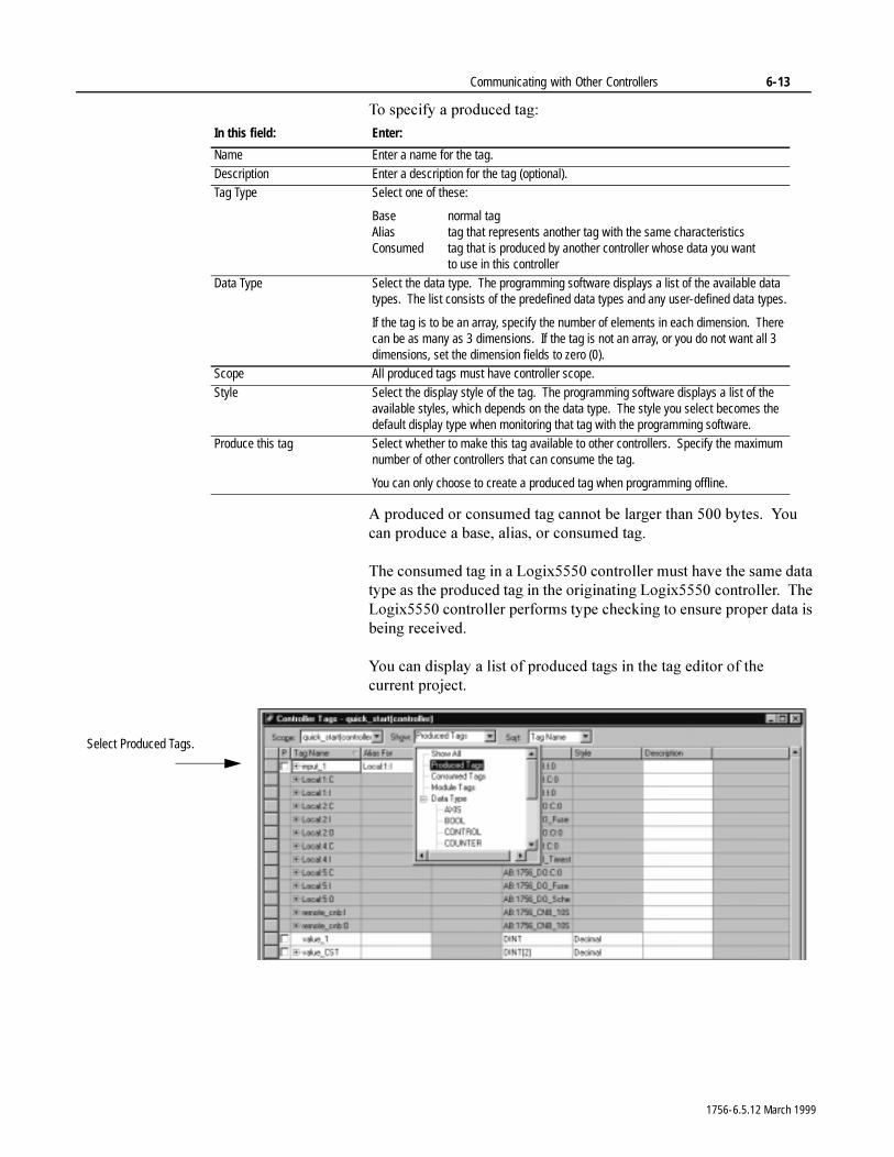
Communicating with Other Controllers 6-13
7R�VSHFLI\�D�SURGXFHG�WDJ�
$�SURGXFHG�RU�FRQVXPHG�WDJ�FDQQRW�EH�ODUJHU�WKDQ�����E\WHV���<RX�FDQ�SURGXFH�D�EDVH��DOLDV��RU�FRQVXPHG�WDJ�
7KH�FRQVXPHG�WDJ�LQ�D�/RJL[�����FRQWUROOHU�PXVW�KDYH�WKH�VDPH�GDWD�W\SH�DV�WKH�SURGXFHG�WDJ�LQ�WKH�RULJLQDWLQJ�/RJL[���� FRQWUROOHU���7KH�/RJL[�����FRQWUROOHU�SHUIRUPV�W\SH�FKHFNLQJ�WR�HQVXUH�SURSHU�GDWD�LV�EHLQJ�UHFHLYHG�
<RX�FDQ�GLVSOD\�D�OLVW�RI�SURGXFHG�WDJV�LQ�WKH�WDJ�HGLWRU�RI�WKH�FXUUHQW SURMHFW�
In this field: Enter:
Name Enter a name for the tag.
Description Enter a description for the tag (optional).Tag Type Select one of these:
Base normal tagAlias tag that represents another tag with the same characteristicsConsumed tag that is produced by another controller whose data you want
to use in this controller
Data Type Select the data type. The programming software displays a list of the available data types. The list consists of the predefined data types and any user-defined data types.
If the tag is to be an array, specify the number of elements in each dimension. There can be as many as 3 dimensions. If the tag is not an array, or you do not want all 3 dimensions, set the dimension fields to zero (0).
Scope All produced tags must have controller scope.
Style Select the display style of the tag. The programming software displays a list of the available styles, which depends on the data type. The style you select becomes the default display type when monitoring that tag with the programming software.
Produce this tag Select whether to make this tag available to other controllers. Specify the maximum number of other controllers that can consume the tag.
You can only choose to create a produced tag when programming offline.
Select Produced Tags.
1756-6.5.12 March 1999
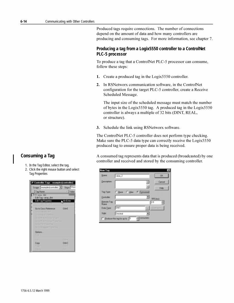
6-14 Communicating with Other Controllers
3URGXFHG�WDJV�UHTXLUH�FRQQHFWLRQV���7KH�QXPEHU�RI�FRQQHFWLRQV�GHSHQG�RQ�WKH�DPRXQW�RI�GDWD�DQG�KRZ�PDQ\�FRQWUROOHUV�DUH�SURGXFLQJ�DQG�FRQVXPLQJ�WDJV���)RU�PRUH�LQIRUPDWLRQ��VHH�FKDSWHU���
Producing a tag from a Logix5550 controller to a ControlNet PLC-5 processor
7R�SURGXFH�D�WDJ�WKDW�D�&RQWURO1HW�3/&���SURFHVVRU�FDQ�FRQVXPH��IROORZ�WKHVH�VWHSV�
�� &UHDWH�D�SURGXFHG�WDJ�LQ�WKH�/RJL[�����FRQWUROOHU�
�� ,Q�561HWZRU[�FRPPXQLFDWLRQ�VRIWZDUH��LQ�WKH�&RQWURO1HW�FRQILJXUDWLRQ�IRU�WKH�WDUJHW�3/&���FRQWUROOHU��FUHDWH�D�5HFHLYH�6FKHGXOHG�0HVVDJH�
7KH�LQSXW�VL]H�RI�WKH�VFKHGXOHG�PHVVDJH�PXVW�PDWFK�WKH�QXPEHU�RI�E\WHV�LQ�WKH�/RJL[�����WDJ���$�SURGXFHG�WDJ�LQ�WKH�/RJL[�����FRQWUROOHU�LV�DOZD\V�D�PXOWLSOH�RI����ELWV��',17��5($/��RU VWUXFWXUH��
�� 6FKHGXOH�WKH�OLQN�XVLQJ�561HWZRU[�VRIWZDUH�
7KH�&RQWURO1HW�3/&���FRQWUROOHU�GRHV�QRW�SHUIRUP�W\SH�FKHFNLQJ���0DNH�VXUH�WKH�3/&���GDWD�W\SH�FDQ�FRUUHFWO\�UHFHLYH�WKH�/RJL[�����SURGXFHG�WDJ�WR�HQVXUH�SURSHU�GDWD�LV�EHLQJ�UHFHLYHG�
Consuming a Tag $�FRQVXPHG�WDJ�UHSUHVHQWV�GDWD�WKDW�LV�SURGXFHG��EURDGFDVWHG��E\�RQH�FRQWUROOHU�DQG�UHFHLYHG�DQG�VWRUHG�E\�WKH�FRQVXPLQJ�FRQWUROOHU�
1. In the Tag Editor, select the tag.2. Click the right mouse button and select
Tag Properties
1756-6.5.12 March 1999
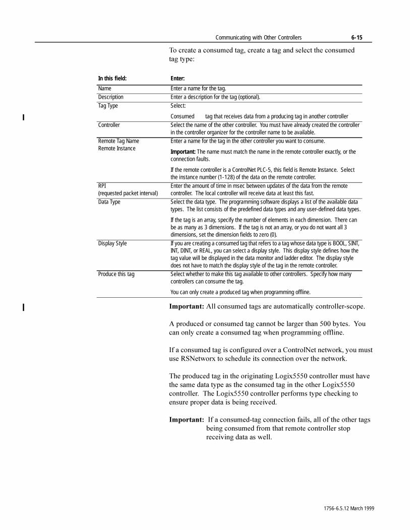
Communicating with Other Controllers 6-15
7R�FUHDWH�D�FRQVXPHG�WDJ��FUHDWH�D�WDJ�DQG�VHOHFW�WKH�FRQVXPHG�WDJ W\SH�
,PSRUWDQW��$OO�FRQVXPHG�WDJV�DUH�DXWRPDWLFDOO\�FRQWUROOHU�VFRSH�
$�SURGXFHG�RU�FRQVXPHG�WDJ�FDQQRW�EH�ODUJHU�WKDQ�����E\WHV���<RX�FDQ�RQO\�FUHDWH�D�FRQVXPHG�WDJ�ZKHQ�SURJUDPPLQJ�RIIOLQH�
,I�D�FRQVXPHG�WDJ�LV�FRQILJXUHG�RYHU�D�&RQWURO1HW�QHWZRUN��\RX�PXVW�XVH�561HWZRU[�WR�VFKHGXOH�LWV�FRQQHFWLRQ�RYHU�WKH�QHWZRUN�
7KH�SURGXFHG�WDJ�LQ�WKH�RULJLQDWLQJ�/RJL[�����FRQWUROOHU�PXVW�KDYH�WKH�VDPH�GDWD�W\SH�DV�WKH�FRQVXPHG�WDJ�LQ�WKH�RWKHU�/RJL[�����FRQWUROOHU���7KH�/RJL[�����FRQWUROOHU�SHUIRUPV�W\SH�FKHFNLQJ�WR�HQVXUH�SURSHU�GDWD�LV�EHLQJ�UHFHLYHG�
,PSRUWDQW���,I�D�FRQVXPHG�WDJ�FRQQHFWLRQ�IDLOV��DOO�RI�WKH�RWKHU�WDJV�EHLQJ�FRQVXPHG�IURP�WKDW�UHPRWH�FRQWUROOHU�VWRS�UHFHLYLQJ�GDWD�DV�ZHOO�
In this field: Enter:
Name Enter a name for the tag.Description Enter a description for the tag (optional).
Tag Type Select:
Consumed tag that receives data from a producing tag in another controllerController Select the name of the other controller. You must have already created the controller
in the controller organizer for the controller name to be available.Remote Tag NameRemote Instance
Enter a name for the tag in the other controller you want to consume.
Important: The name must match the name in the remote controller exactly, or the connection faults.
If the remote controller is a ControlNet PLC-5, this field is Remote Instance. Select the instance number (1-128) of the data on the remote controller.
RPI(requested packet interval)
Enter the amount of time in msec between updates of the data from the remote controller. The local controller will receive data at least this fast.
Data Type Select the data type. The programming software displays a list of the available data types. The list consists of the predefined data types and any user-defined data types.
If the tag is an array, specify the number of elements in each dimension. There can be as many as 3 dimensions. If the tag is not an array, or you do not want all 3 dimensions, set the dimension fields to zero (0).
Display Style If you are creating a consumed tag that refers to a tag whose data type is BOOL, SINT, INT, DINT, or REAL, you can select a display style. This display style defines how the tag value will be displayed in the data monitor and ladder editor. The display style does not have to match the display style of the tag in the remote controller.
Produce this tag Select whether to make this tag available to other controllers. Specify how many controllers can consume the tag.
You can only create a produced tag when programming offline.
1756-6.5.12 March 1999
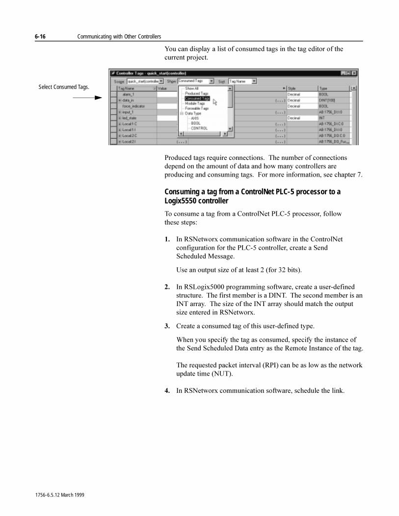
6-16 Communicating with Other Controllers
<RX�FDQ�GLVSOD\�D�OLVW�RI�FRQVXPHG�WDJV�LQ�WKH�WDJ�HGLWRU�RI�WKH�FXUUHQW SURMHFW�
3URGXFHG�WDJV�UHTXLUH�FRQQHFWLRQV���7KH�QXPEHU�RI�FRQQHFWLRQV�GHSHQG�RQ�WKH�DPRXQW�RI�GDWD�DQG�KRZ�PDQ\�FRQWUROOHUV�DUH�SURGXFLQJ�DQG�FRQVXPLQJ�WDJV���)RU�PRUH�LQIRUPDWLRQ��VHH�FKDSWHU���
Consuming a tag from a ControlNet PLC-5 processor to a Logix5550 controller
7R�FRQVXPH�D�WDJ�IURP�D�&RQWURO1HW�3/&���SURFHVVRU��IROORZ�WKHVH VWHSV�
�� ,Q�561HWZRU[�FRPPXQLFDWLRQ�VRIWZDUH�LQ�WKH�&RQWURO1HW�FRQILJXUDWLRQ�IRU�WKH�3/&���FRQWUROOHU��FUHDWH�D�6HQG�6FKHGXOHG 0HVVDJH�
8VH�DQ�RXWSXW�VL]H�RI�DW�OHDVW����IRU����ELWV��
�� ,Q�56/RJL[�����SURJUDPPLQJ�VRIWZDUH��FUHDWH�D�XVHU�GHILQHG�VWUXFWXUH���7KH�ILUVW�PHPEHU�LV�D�',17���7KH�VHFRQG�PHPEHU�LV�DQ�,17�DUUD\���7KH�VL]H�RI�WKH�,17�DUUD\�VKRXOG�PDWFK�WKH�RXWSXW�VL]H�HQWHUHG�LQ�561HWZRU[�
�� &UHDWH�D�FRQVXPHG�WDJ�RI�WKLV�XVHU�GHILQHG�W\SH�
:KHQ�\RX�VSHFLI\�WKH�WDJ�DV�FRQVXPHG��VSHFLI\�WKH�LQVWDQFH�RI�WKH�6HQG�6FKHGXOHG�'DWD�HQWU\�DV�WKH�5HPRWH�,QVWDQFH�RI�WKH�WDJ�
7KH�UHTXHVWHG�SDFNHW�LQWHUYDO��53,��FDQ�EH�DV�ORZ�DV�WKH�QHWZRUN�XSGDWH�WLPH��187��
�� ,Q�561HWZRU[�FRPPXQLFDWLRQ�VRIWZDUH��VFKHGXOH�WKH�OLQN�
Select Consumed Tags.
1756-6.5.12 March 1999
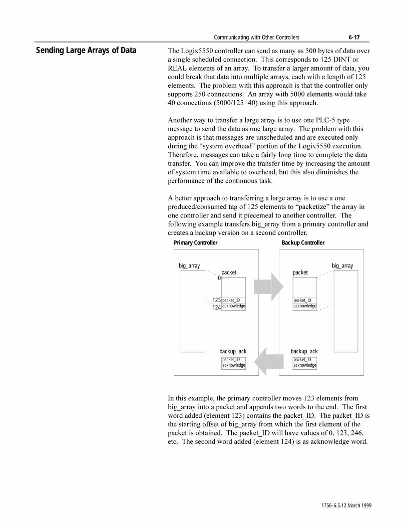
Communicating with Other Controllers 6-17
Sending Large Arrays of Data 7KH�/RJL[�����FRQWUROOHU�FDQ�VHQG�DV�PDQ\�DV�����E\WHV�RI�GDWD�RYHU�D�VLQJOH�VFKHGXOHG�FRQQHFWLRQ���7KLV�FRUUHVSRQGV�WR�����',17�RU�5($/�HOHPHQWV�RI�DQ�DUUD\���7R�WUDQVIHU�D�ODUJHU�DPRXQW�RI�GDWD��\RX�FRXOG�EUHDN�WKDW�GDWD�LQWR�PXOWLSOH�DUUD\V��HDFK�ZLWK�D�OHQJWK�RI�����HOHPHQWV���7KH�SUREOHP�ZLWK�WKLV�DSSURDFK�LV�WKDW�WKH�FRQWUROOHU�RQO\�VXSSRUWV�����FRQQHFWLRQV���$Q�DUUD\�ZLWK������HOHPHQWV�ZRXOG�WDNH����FRQQHFWLRQV���������� ����XVLQJ�WKLV�DSSURDFK�
$QRWKHU�ZD\�WR�WUDQVIHU�D�ODUJH�DUUD\�LV�WR�XVH�RQH�3/&���W\SH�PHVVDJH�WR�VHQG�WKH�GDWD�DV�RQH�ODUJH�DUUD\���7KH�SUREOHP�ZLWK�WKLV�DSSURDFK�LV�WKDW�PHVVDJHV�DUH�XQVFKHGXOHG�DQG�DUH�H[HFXWHG�RQO\�GXULQJ�WKH�³V\VWHP�RYHUKHDG´�SRUWLRQ�RI�WKH�/RJL[�����H[HFXWLRQ���7KHUHIRUH��PHVVDJHV�FDQ�WDNH�D�IDLUO\�ORQJ�WLPH�WR�FRPSOHWH�WKH�GDWD�WUDQVIHU���<RX�FDQ�LPSURYH�WKH�WUDQVIHU�WLPH�E\�LQFUHDVLQJ�WKH�DPRXQW�RI�V\VWHP�WLPH�DYDLODEOH�WR�RYHUKHDG��EXW�WKLV�DOVR�GLPLQLVKHV�WKH�SHUIRUPDQFH�RI�WKH�FRQWLQXRXV�WDVN�
$�EHWWHU�DSSURDFK�WR�WUDQVIHUULQJ�D�ODUJH�DUUD\�LV�WR�XVH�D�RQH�SURGXFHG�FRQVXPHG�WDJ�RI�����HOHPHQWV�WR�³SDFNHWL]H´�WKH�DUUD\�LQ�RQH�FRQWUROOHU�DQG�VHQG�LW�SLHFHPHDO�WR�DQRWKHU�FRQWUROOHU���7KH�IROORZLQJ�H[DPSOH�WUDQVIHUV�ELJBDUUD\�IURP�D�SULPDU\�FRQWUROOHU�DQG�FUHDWHV�D�EDFNXS�YHUVLRQ�RQ�D�VHFRQG�FRQWUROOHU�
,Q�WKLV�H[DPSOH��WKH�SULPDU\�FRQWUROOHU�PRYHV�����HOHPHQWV�IURP�ELJBDUUD\�LQWR�D�SDFNHW�DQG�DSSHQGV�WZR�ZRUGV�WR�WKH�HQG���7KH�ILUVW�ZRUG�DGGHG��HOHPHQW������FRQWDLQV�WKH�SDFNHWB,'���7KH�SDFNHWB,'�LV�WKH�VWDUWLQJ�RIIVHW�RI�ELJBDUUD\�IURP�ZKLFK�WKH�ILUVW�HOHPHQW�RI�WKH�SDFNHW�LV�REWDLQHG���7KH�SDFNHWB,'�ZLOO�KDYH�YDOXHV�RI��������������HWF���7KH�VHFRQG�ZRUG�DGGHG��HOHPHQW������LV�DV�DFNQRZOHGJH�ZRUG�
big_array
0
123124
packet
packet_IDacknowledge
big_arraypacket
packet_IDacknowledge
Primary Controller Backup Controller
backup_ackpacket_IDacknowledge
backup_ackpacket_IDacknowledge
1756-6.5.12 March 1999
6-18 Communicating with Other Controllers
7KH�SULPDU\�FRQWUROOHU�FUHDWHV�D�SDFNHW�E\�GHWHUPLQLQJ�ZKDW�VHFWLRQ�RI�ELJBDUUD\�WR�FRS\�LQWR�WKH�SDFNHW�DQG�VHWWLQJ�WKH�SDFNHWB,'�HTXDO�WR�WKH�ILUVW�HOHPHQW�ORFDWLRQ�RI�WKDW�GDWD�VHFWLRQ�LQ�WKH�ELJBDUUD\���7KH�SULPDU\�FRQWUROOHU�WKHQ�ZDLWV�IRU�WKH�DFNQRZOHGJH�ZRUG�RI�WKH�EDFNXSBDFN�DUUD\�WR�EH�VHW�HTXDO�WR�±����E\�WKH�EDFNXS�FRQWUROOHU��ZKLFK�LQGLFDWHV�WKDW�WKH�EDFNXS�FRQWUROOHU�KDV�UHFHLYHG�D�QHZ�SDFNHW�
7KH�EDFNXS�FRQWUROOHU�ZDLWV�XQWLO�LW�VHHV�D�YDOXH�RI�WKH�SDFNHWB,'�HOHPHQW�RI�WKH�SDFNHW�WKDW�LV�QRW�HTXDO�WR�WKH�SUHYLRXV�YDOXH�RI�WKH�SDFNHWB,'���7KLV�VLJQDOV�WKH�EDFNXS�FRQWUROOHU�WKDW�D�QHZ�SDFNHW�KDV�VWDUWHG�WR�EH�UHFHLYHG���7KH�EDFNXS�FRQWUROOHU�WKHQ�VHWV�WKH�DFNQRZOHGJH�ZRUG�RI�EDFNXSBDFN�DUUD\�HTXDO�WR�±����DQG�ZDLWV�WR�VHH�WKLV�±����YDOXH�UHWXUQHG�E\�WKH�SULPDU\�FRQWUROOHU�LQ�WKH�DFNQRZOHGJH�ZRUG�RI�WKH�SDFNHW�
:KHQ�WKH�SULPDU\�FRQWUROOHU�VHHV�WKDW�WKH�EDFNXS�FRQWUROOHU�KDV�VHW�WKH�DFNQRZOHGJH�ZRUG�RI�EDFNXSBDFN�WR�±�����WKH�SULPDU\�FRQWUROOHU�PRYHV�WKH�YDOXH�RI�±����LQWR�WKH�DFNQRZOHGJH�ZRUG�RI�WKH�SDFNHW�
2QFH�WKH�EDFNXS�FRQWUROOHU�VHHV�WKDW�WKH�SULPDU\�FRQWUROOHU�KDV�VHW�WKH�DFNQRZOHGJH�ZRUG�RI�WKH�SDFNHW�WR�±�����WKH�EDFNXS�FRQWUROOHU�NQRZV�WKDW�LW�KDV�UHFHLYHG�D�FRPSOHWH�FRS\�RI�WKH�SDFNHW�DQG�FDQ�FRS\�WKDW�GDWD�LQWR�WKH�DSSURSULDWH�ORFDWLRQ�LQ�LW¶V�RZQ�ELJBDUUD\���$IWHU�WKH�EDFNXS�FRQWUROOHU�ILQLVKHV�FRS\LQJ�WKH�SDFNHW��WKH�EDFNXS�FRQWUROOHU�VHWV�WKH�DFNQRZOHGJH�ZRUG�RI�EDFNXSBDFN�DUUD\�HTXDO�WR�]HUR�DQG�VHWV�WKH�SDFNHWB,'�HOHPHQW�RI�EDFNXSBDFN�DUUD\�HTXDO�WR�WKH�SDFNHWB,'�RI�WKH�SDFNHW���7KLV�VLJQDOV�WKH�SULPDU\�FRQWUROOHU�WKDW�WKH�EDFNXS�FRQWUROOHU�KDV�ILQLVKHG�FRS\LQJ�WKH�SDFNHW�
:KHQ�WKH�SULPDU\�FRQWUROOHU�VHHV�WKDW�WKH�SDFNHWB,'�RI�EDFNXSBDFN�LV�HTXDO�WR�WKH�FXUUHQW�YDOXH�RI�WKH�SDFNHWB,'��WKH�SULPDU\�FRQWUROOHU�WKHQ�UHVHWV�WKH�DFNQRZOHGJH�ZRUG�RI�WKH�SDFNHW�HTXDO�WR�]HUR���7KH�SULPDU\�FRQWUROOHU�FDQ�QRZ�EXLOG�WKH�QH[W�SDFNHW�
7KLV�F\FOH�RI�EXLOGLQJ�DQG�SURGXFLQJ�SDFNHWV�FRQWLQXHV�XQWLO�WKH�SDFNHWB,'�YDOXH�UHWXUQHG�LQ�EDFNXSBDFN�DGGHG�WR�����LV�JUHDWHU�WKDQ�RU�HTXDO�WR�WKH�VL]H�RI�ELJBDUUD\���:KHQ�WKLV�LV�WUXH��WKH�SDFNHWB,'�LQ�WKH�SDFNHW�LV�VHW�HTXDO�WR�]HUR�WR�VWDUW�UHEXLOGLQJ�SDFNHWV�VWDUWLQJ�DW�WKH�EHJLQQLQJ�RI�ELJBDUUD\���%HFDXVH�WKH�ILQDO�SDFNHW�PLJKW�EH�ULJKW�DW�WKH�HQG�RI�ELJBDUUD\��EH�VXUH�WKDW�\RX�FUHDWH�ELJBDUUD\�WR�EH�DW�OHDVW�����HOHPHQWV�ODUJHU�WKDQ�WKH�ODUJHVW�DPRXQW�RI�GDWD�\RX�ZLOO�HYHU�ZDQW�WR�WUDQVIHU���7KLV�HQVXUHV�WKDW�\RX�ZLOO�QHYHU�HQG�XS�WU\LQJ�WR�FRS\�PRUH�HOHPHQWV�IURP�RU�LQWR�ELJBDUUD\�WKDQ�UHDOO\�H[LVW�
3URGXFHG�GDWD�RYHU�WKH�&RQWURO%XV�EDFNSODQH�JHWV�VHQW�LQ����E\WH�VHJPHQWV���7KLV�LV�DV\QFKURQRXV�WR�WKH�SURJUDP�VFDQ�LQ�WKH�FRQWUROOHU���<RX�QHHG�WKH�DFNQRZOHGJH�ZRUGV�WR�PDNH�VXUH�WKDW�HDFK�FRQWUROOHU�LV�FRPSOHWH�ZLWK�LW¶V�FRS\LQJ�EHIRUH�HLWKHU�FRQWUROOHU�DWWHPSWV�LWV�QH[W�FRS\���2WKHUZLVH��WKH�SULPDU\�FRQWUROOHU�FRXOG�EH�EXLOGLQJ�D�QHZ�SDFNHW�ZKLOH�WKH�EDFNXS�FRQWUROOHU�LV�VWLOO�FRS\LQJ�WKH�SUHYLRXV�SDFNHW��UHVXOWLQJ�LQ�LQDFFXUDWH�GDWD�
1756-6.5.12 March 1999
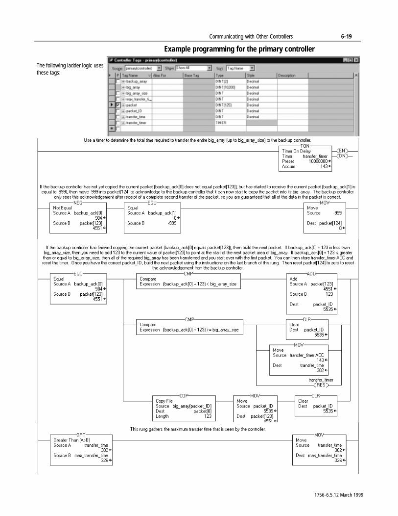
Communicating with Other Controllers 6-19
Example programming for the primary controller
The following ladder logic uses these tags:
1756-6.5.12 March 1999
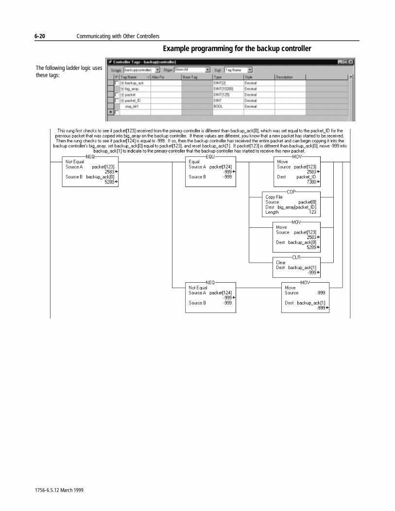
6-20 Communicating with Other Controllers
Example programming for the backup controller
The following ladder logic uses these tags:
1756-6.5.12 March 1999
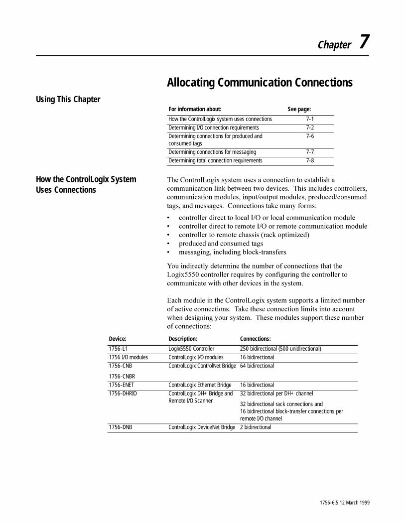
Chapter 7
Allocating Communication ConnectionsUsing This Chapter
How the ControlLogix System Uses Connections
7KH�&RQWURO/RJL[�V\VWHP�XVHV�D�FRQQHFWLRQ�WR�HVWDEOLVK�D�FRPPXQLFDWLRQ�OLQN�EHWZHHQ�WZR�GHYLFHV���7KLV�LQFOXGHV�FRQWUROOHUV��FRPPXQLFDWLRQ�PRGXOHV��LQSXW�RXWSXW�PRGXOHV��SURGXFHG�FRQVXPHG�WDJV��DQG�PHVVDJHV���&RQQHFWLRQV�WDNH�PDQ\�IRUPV�
� FRQWUROOHU�GLUHFW�WR�ORFDO�,�2�RU�ORFDO�FRPPXQLFDWLRQ�PRGXOH� FRQWUROOHU�GLUHFW�WR�UHPRWH�,�2�RU�UHPRWH�FRPPXQLFDWLRQ�PRGXOH� FRQWUROOHU�WR�UHPRWH�FKDVVLV��UDFN�RSWLPL]HG�� SURGXFHG�DQG�FRQVXPHG�WDJV� PHVVDJLQJ��LQFOXGLQJ�EORFN�WUDQVIHUV
<RX�LQGLUHFWO\�GHWHUPLQH�WKH�QXPEHU�RI�FRQQHFWLRQV�WKDW�WKH�/RJL[�����FRQWUROOHU�UHTXLUHV�E\�FRQILJXULQJ�WKH�FRQWUROOHU�WR�FRPPXQLFDWH�ZLWK�RWKHU�GHYLFHV�LQ�WKH�V\VWHP�
(DFK�PRGXOH�LQ�WKH�&RQWURO/RJL[�V\VWHP�VXSSRUWV�D�OLPLWHG�QXPEHU�RI�DFWLYH�FRQQHFWLRQV���7DNH�WKHVH�FRQQHFWLRQ�OLPLWV�LQWR�DFFRXQW�ZKHQ�GHVLJQLQJ�\RXU�V\VWHP���7KHVH�PRGXOHV�VXSSRUW�WKHVH�QXPEHU�RI FRQQHFWLRQV�
For information about: See page:
How the ControlLogix system uses connections 7-1
Determining I/O connection requirements 7-2Determining connections for produced and consumed tags
7-6
Determining connections for messaging 7-7
Determining total connection requirements 7-8
Device: Description: Connections:
1756-L1 Logix5550 Controller 250 bidirectional (500 unidirectional)
1756 I/O modules ControlLogix I/O modules 16 bidirectional1756-CNB
1756-CNBR
ControlLogix ControlNet Bridge 64 bidirectional
1756-ENET ControlLogix Ethernet Bridge 16 bidirectional1756-DHRIO ControlLogix DH+ Bridge and
Remote I/O Scanner32 bidirectional per DH+ channel
32 bidirectional rack connections and 16 bidirectional block-transfer connections per remote I/O channel
1756-DNB ControlLogix DeviceNet Bridge 2 bidirectional
1756-6.5.12 March 1999
7-2 Allocating Communication Connections
Determining Connections for I/O Modules
$OO�,�2�PRGXOHV�FDQ�KDYH�D�GLUHFW��ELGLUHFWLRQDO�FRQQHFWLRQ�WR�WKH�FRQWUROOHU���$������&1%�&RQWURO1HW�EULGJH�PRGXOH�VXSSRUWV�WKH�DELOLW\�WR�RUJDQL]H�D�FKDVVLV�RI�GLJLWDO�,�2�PRGXOHV�LQWR�RQH�ELGLUHFWLRQDO�FRQQHFWLRQ��UDFN�FRQQHFWLRQ���UDWKHU�WKDQ�UHTXLULQJ�D�GLUHFW�ELGLUHFWLRQDO�FRQQHFWLRQ�IRU�HDFK�LQGLYLGXDO�,�2�PRGXOH�
<RX�FDQ�FRQILJXUH�WKHVH�W\SHV�RI�FRQQHFWLRQV�WR�WKHVH�PRGXOHV�
Direct connections for I/O modules
$�GLUHFW�FRQQHFWLRQ�LV�D�UHDO�WLPH��GDWD�WUDQVIHU�OLQN�EHWZHHQ�WKH�FRQWUROOHU�DQG�DQ�,�2�PRGXOH���7KH�FRQWUROOHU�PDLQWDLQV�DQG�PRQLWRUV�WKH�FRQQHFWLRQ�EHWZHHQ�WKH�FRQWUROOHU�DQG�WKH�,�2�PRGXOH���$Q\�EUHDN�LQ�WKH�FRQQHFWLRQ��VXFK�DV�D�PRGXOH�IDXOW�RU�WKH�UHPRYDO�RI�D�PRGXOH�IURP�WKH�FKDVVLV�ZKLOH�XQGHU�SRZHU��FDXVHV�WKH�FRQWUROOHU�WR�VHW�IDXOW�VWDWXV�ELWV�LQ�WKH�GDWD�DUHD�DVVRFLDWHG�ZLWK�WKH�PRGXOH�
,I�D�FRQWUROOHU�KDV�D�PRGXOH�FRQILJXUDWLRQ�WKDW�UHIHUHQFHV�D�VORW�LQ�WKH�FRQWURO�V\VWHP��WKH�FRQWUROOHU�SHULRGLFDOO\�FKHFNV�IRU�WKH�SUHVHQFH�RI�D�GHYLFH�LQ�WKDW�VORW���:KHQ�D�GHYLFH¶V�SUHVHQFH�LV�GHWHFWHG�WKHUH��WKH�FRQWUROOHU�DXWRPDWLFDOO\�VHQGV�WKH�PRGXOH�FRQILJXUDWLRQ�
,I�WKH�PRGXOH�FRQILJXUDWLRQ�LV�DSSURSULDWH�IRU�WKH�,�2�PRGXOH�IRXQG�LQ�WKH�VORW��D�FRQQHFWLRQ�LV�PDGH�DQG�RSHUDWLRQ�EHJLQV���,I�WKH�PRGXOH�FRQILJXUDWLRQ�LV�QRW�DSSURSULDWH��WKH�FRQQHFWLRQ�LV�UHMHFWHG���<RX�FDQ�YLHZ�WKH�IDXOW�PHVVDJH�RQ�WKH�&RQQHFWLRQ�WDE�RI�WKH�PRGXOH¶V�SURSHUWLHV���0RGXOH�FRQILJXUDWLRQ�FDQ�EH�LQDSSURSULDWH�IRU�DQ\�RI�D�QXPEHU�RI�UHDVRQV���)RU�H[DPSOH��D�PLVPDWFK�LQ�HOHFWURQLF�NH\LQJ�WKDW�SUHYHQWV�QRUPDO�RSHUDWLRQ�
A Logix5550 connection to: Can use this connection type:
local I/O direct connection only
remote I/O direct connection
or
rack optimized connection
1756-6.5.12 March 1999
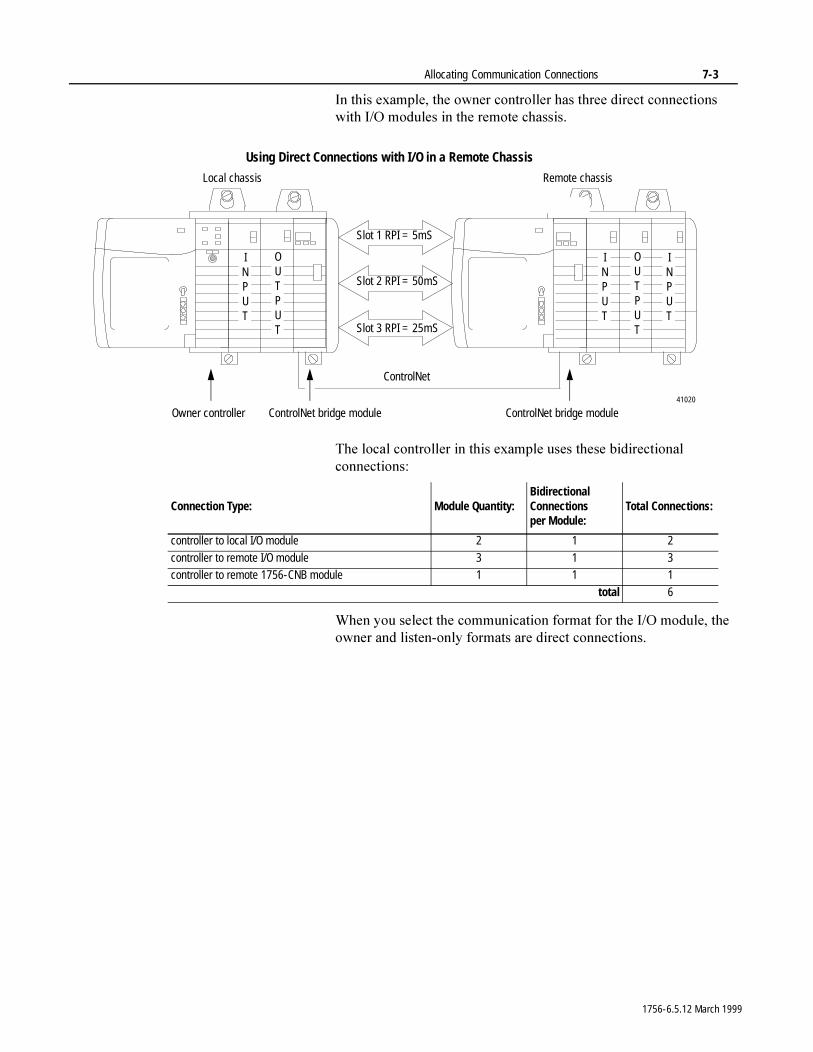
Allocating Communication Connections 7-3
,Q�WKLV�H[DPSOH��WKH�RZQHU�FRQWUROOHU�KDV�WKUHH�GLUHFW�FRQQHFWLRQV�ZLWK�,�2�PRGXOHV�LQ�WKH�UHPRWH�FKDVVLV�����
7KH�ORFDO�FRQWUROOHU�LQ�WKLV�H[DPSOH�XVHV�WKHVH�ELGLUHFWLRQDO�FRQQHFWLRQV�
:KHQ�\RX�VHOHFW�WKH�FRPPXQLFDWLRQ�IRUPDW�IRU�WKH�,�2�PRGXOH��WKH�RZQHU�DQG�OLVWHQ�RQO\�IRUPDWV�DUH�GLUHFW�FRQQHFWLRQV�
Using Direct Connections with I/O in a Remote Chassis
Owner controller ControlNet bridge module
Slot 1 RPI = 5mS
Slot 2 RPI = 50mS
Slot 3 RPI = 25mS
ControlNet bridge module
Local chassis Remote chassis
INPUT
INPUT
OUTPUT
ControlNet
41020
INPUT
OUTPUT
Connection Type: Module Quantity:Bidirectional Connections per Module:
Total Connections:
controller to local I/O module 2 1 2
controller to remote I/O module 3 1 3controller to remote 1756-CNB module 1 1 1
total 6
1756-6.5.12 March 1999
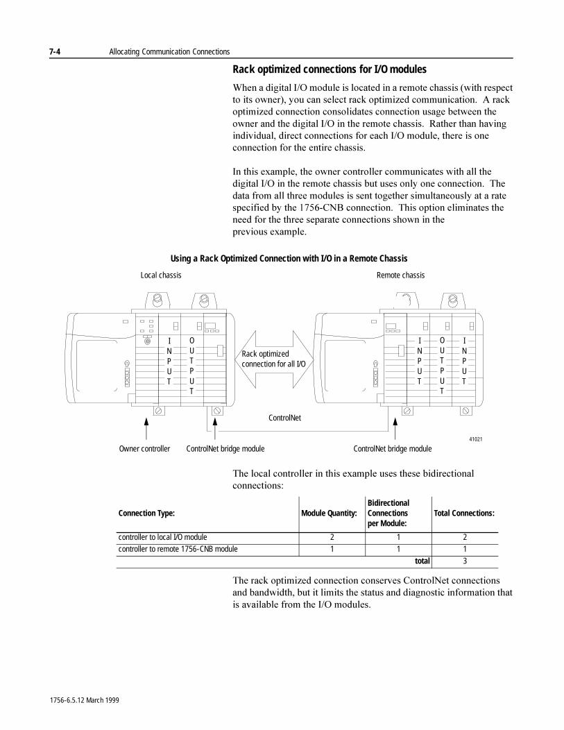
7-4 Allocating Communication Connections
Rack optimized connections for I/O modules
:KHQ�D�GLJLWDO�,�2�PRGXOH�LV�ORFDWHG�LQ�D�UHPRWH�FKDVVLV��ZLWK�UHVSHFW�WR�LWV�RZQHU���\RX�FDQ�VHOHFW�UDFN�RSWLPL]HG�FRPPXQLFDWLRQ���$�UDFN�RSWLPL]HG�FRQQHFWLRQ�FRQVROLGDWHV�FRQQHFWLRQ�XVDJH�EHWZHHQ�WKH�RZQHU�DQG�WKH�GLJLWDO�,�2�LQ�WKH�UHPRWH�FKDVVLV���5DWKHU�WKDQ�KDYLQJ�LQGLYLGXDO��GLUHFW�FRQQHFWLRQV�IRU�HDFK�,�2�PRGXOH��WKHUH�LV�RQH�FRQQHFWLRQ�IRU�WKH�HQWLUH�FKDVVLV�
,Q�WKLV�H[DPSOH��WKH�RZQHU�FRQWUROOHU�FRPPXQLFDWHV�ZLWK�DOO�WKH�GLJLWDO�,�2�LQ�WKH�UHPRWH�FKDVVLV�EXW�XVHV�RQO\�RQH�FRQQHFWLRQ���7KH�GDWD�IURP�DOO�WKUHH�PRGXOHV�LV�VHQW�WRJHWKHU�VLPXOWDQHRXVO\�DW�D�UDWH�VSHFLILHG�E\�WKH������&1%�FRQQHFWLRQ���7KLV�RSWLRQ�HOLPLQDWHV�WKH�QHHG�IRU�WKH�WKUHH�VHSDUDWH�FRQQHFWLRQV�VKRZQ�LQ�WKH�SUHYLRXV H[DPSOH��
7KH�ORFDO�FRQWUROOHU�LQ�WKLV�H[DPSOH�XVHV�WKHVH�ELGLUHFWLRQDO�FRQQHFWLRQV�
7KH�UDFN�RSWLPL]HG�FRQQHFWLRQ�FRQVHUYHV�&RQWURO1HW�FRQQHFWLRQV�DQG�EDQGZLGWK��EXW�LW�OLPLWV�WKH�VWDWXV�DQG�GLDJQRVWLF�LQIRUPDWLRQ�WKDW�LV�DYDLODEOH�IURP�WKH�,�2�PRGXOHV�
Using a Rack Optimized Connection with I/O in a Remote Chassis
Owner controller ControlNet bridge module ControlNet bridge module
Local chassis Remote chassis
INPUT
INPUT
OUTPUT
Rack optimized connection for all I/O
ControlNet
41021
INPUT
OUTPUT
Connection Type: Module Quantity:Bidirectional Connections per Module:
Total Connections:
controller to local I/O module 2 1 2controller to remote 1756-CNB module 1 1 1
total 3
1756-6.5.12 March 1999
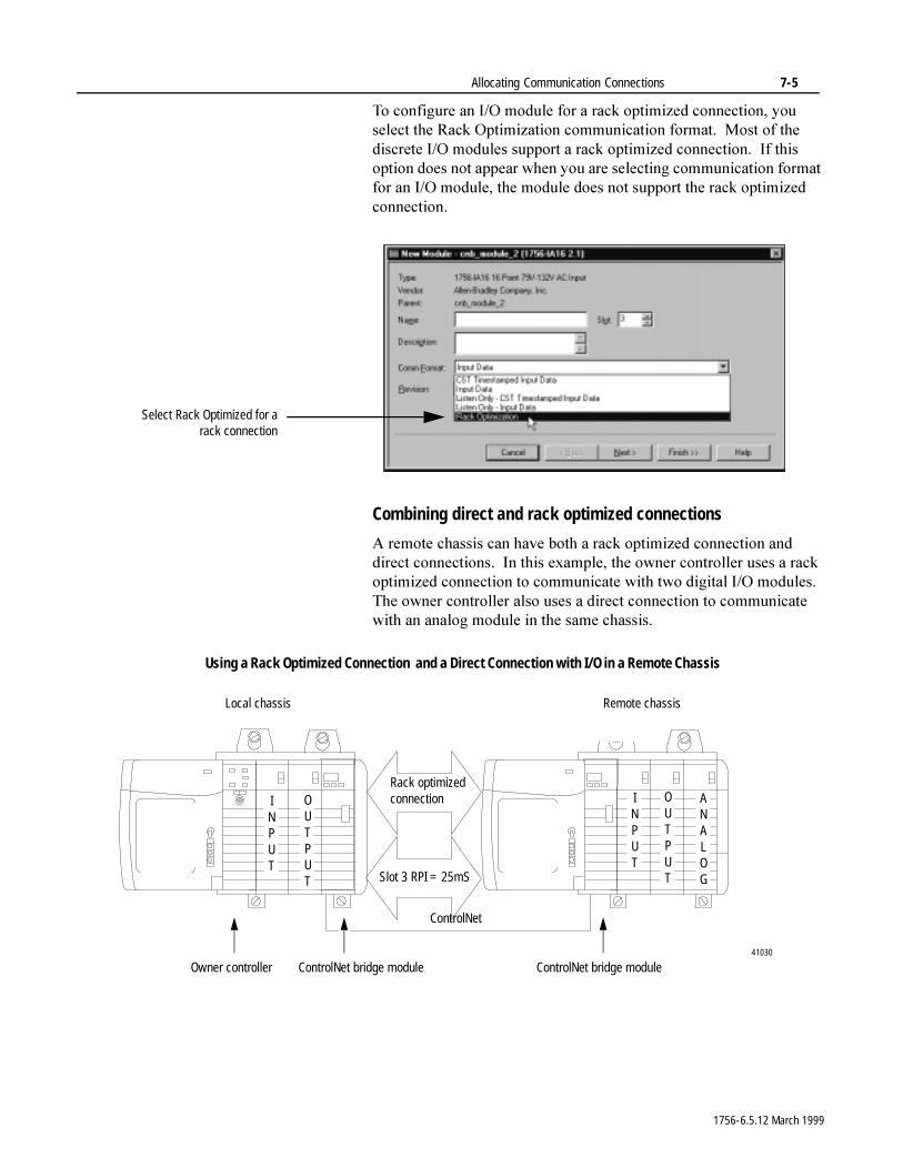
Allocating Communication Connections 7-5
7R�FRQILJXUH�DQ�,�2�PRGXOH�IRU�D�UDFN�RSWLPL]HG�FRQQHFWLRQ��\RX�VHOHFW�WKH�5DFN�2SWLPL]DWLRQ�FRPPXQLFDWLRQ�IRUPDW���0RVW�RI�WKH�GLVFUHWH�,�2�PRGXOHV�VXSSRUW�D�UDFN�RSWLPL]HG�FRQQHFWLRQ���,I�WKLV�RSWLRQ�GRHV�QRW�DSSHDU�ZKHQ�\RX�DUH�VHOHFWLQJ�FRPPXQLFDWLRQ�IRUPDW�IRU�DQ�,�2�PRGXOH��WKH�PRGXOH�GRHV�QRW�VXSSRUW�WKH�UDFN�RSWLPL]HG�FRQQHFWLRQ�
Combining direct and rack optimized connections
$�UHPRWH�FKDVVLV�FDQ�KDYH�ERWK�D�UDFN�RSWLPL]HG�FRQQHFWLRQ�DQG�GLUHFW�FRQQHFWLRQV���,Q�WKLV�H[DPSOH��WKH�RZQHU�FRQWUROOHU�XVHV�D�UDFN�RSWLPL]HG�FRQQHFWLRQ�WR�FRPPXQLFDWH�ZLWK�WZR�GLJLWDO�,�2�PRGXOHV���7KH�RZQHU�FRQWUROOHU�DOVR�XVHV�D�GLUHFW�FRQQHFWLRQ�WR�FRPPXQLFDWH�ZLWK�DQ�DQDORJ�PRGXOH�LQ�WKH�VDPH FKDVVLV�
Select Rack Optimized for arack connection
Using a Rack Optimized Connection and a Direct Connection with I/O in a Remote Chassis
Owner controller ControlNet bridge module ControlNet bridge module
Local chassis Remote chassis
INPUT
ANALOG
OUTPUT
ControlNet
41030
Rack optimized connection
Slot 3 RPI = 25mS
INPUT
OUTPUT
1756-6.5.12 March 1999
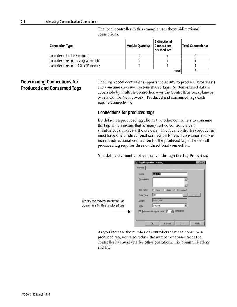
7-6 Allocating Communication Connections
7KH�ORFDO�FRQWUROOHU�LQ�WKLV�H[DPSOH�XVHV�WKHVH�ELGLUHFWLRQDO�FRQQHFWLRQV�
Determining Connections for Produced and Consumed Tags
7KH�/RJL[�����FRQWUROOHU�VXSSRUWV�WKH�DELOLW\�WR�SURGXFH��EURDGFDVW��DQG�FRQVXPH��UHFHLYH��V\VWHP�VKDUHG�WDJV���6\VWHP�VKDUHG�GDWD�LV�DFFHVVLEOH�E\�PXOWLSOH�FRQWUROOHUV�RYHU�WKH�&RQWURO%XV�EDFNSODQH�RU�RYHU�D�&RQWURO1HW�QHWZRUN���3URGXFHG�DQG�FRQVXPHG�WDJV�HDFK�UHTXLUH�FRQQHFWLRQV�
Connections for produced tags
%\�GHIDXOW��D�SURGXFHG�WDJ�DOORZV�WZR�RWKHU�FRQWUROOHUV�WR�FRQVXPH�WKH�WDJ��ZKLFK�PHDQV�WKDW�DV�PDQ\�DV�WZR�FRQWUROOHUV�FDQ�VLPXOWDQHRXVO\�UHFHLYH�WKH�WDJ�GDWD���7KH�ORFDO�FRQWUROOHU��SURGXFLQJ��PXVW�KDYH�RQH�XQLGLUHFWLRQDO�FRQQHFWLRQ�IRU�HDFK�FRQVXPHU�DQG�RQH�PRUH�XQLGLUHFWLRQDO�FRQQHFWLRQ�IRU�WKH�SURGXFHG�WDJ���7KH�GHIDXOW�SURGXFHG�WDJ�UHTXLUHV�WKUHH�XQLGLUHFWLRQDO�FRQQHFWLRQV�
<RX�GHILQH�WKH�QXPEHU�RI�FRQVXPHUV�WKURXJK�WKH�7DJ�3URSHUWLHV�
$V�\RX�LQFUHDVH�WKH�QXPEHU�RI�FRQWUROOHUV�WKDW�FDQ�FRQVXPH�D�SURGXFHG�WDJ��\RX�DOVR�UHGXFH�WKH�QXPEHU�RI�FRQQHFWLRQV�WKH�FRQWUROOHU�KDV�DYDLODEOH�IRU�RWKHU�RSHUDWLRQV��OLNH�FRPPXQLFDWLRQV�DQG ,�2�
Connection Type: Module Quantity:Bidirectional Connections per Module:
Total Connections:
controller to local I/O module 2 1 2controller to remote analog I/O module 1 1 1
controller to remote 1756-CNB module 1 1 1total 5
specify the maximum number of consumers for this produced tag
1756-6.5.12 March 1999
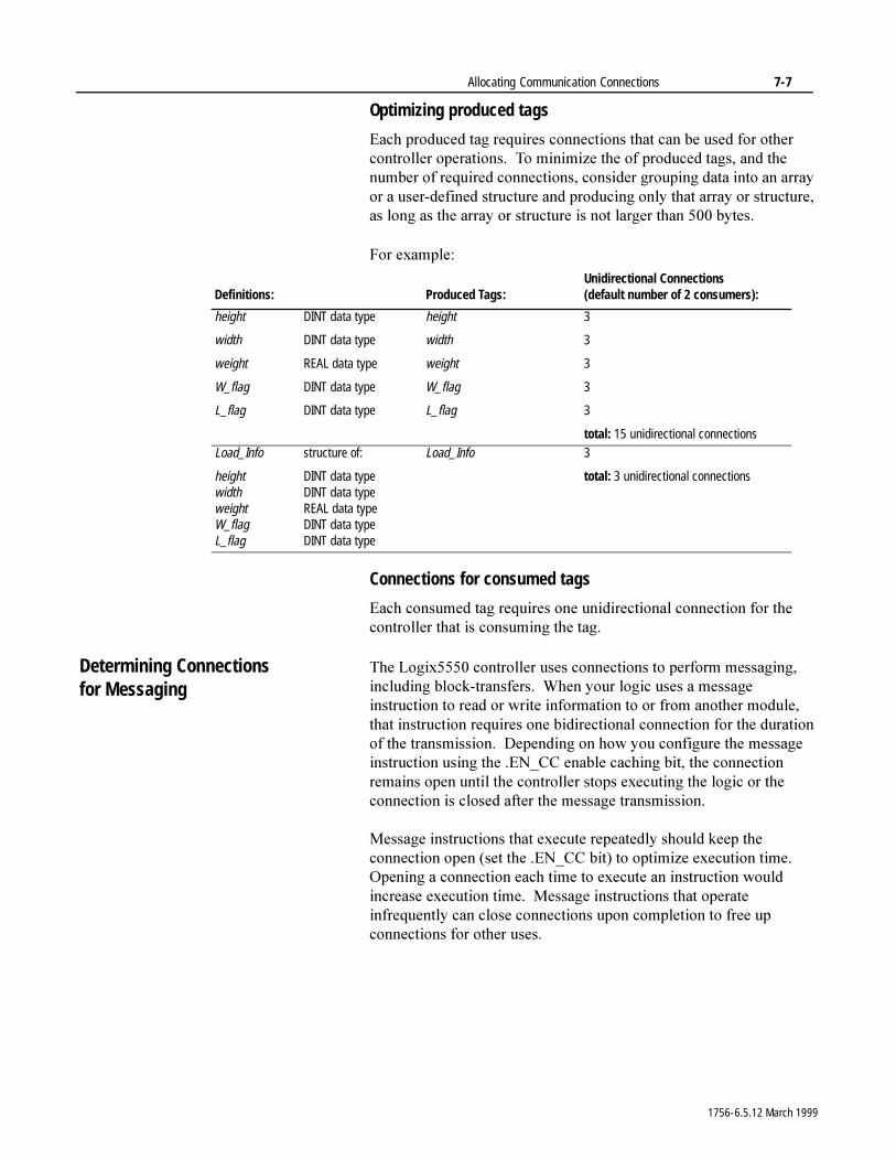
Allocating Communication Connections 7-7
Optimizing produced tags
(DFK�SURGXFHG�WDJ�UHTXLUHV�FRQQHFWLRQV�WKDW�FDQ�EH�XVHG�IRU�RWKHU�FRQWUROOHU�RSHUDWLRQV���7R�PLQLPL]H�WKH�RI�SURGXFHG�WDJV��DQG�WKH�QXPEHU�RI�UHTXLUHG�FRQQHFWLRQV��FRQVLGHU�JURXSLQJ�GDWD�LQWR�DQ�DUUD\�RU�D�XVHU�GHILQHG�VWUXFWXUH�DQG�SURGXFLQJ�RQO\�WKDW�DUUD\�RU�VWUXFWXUH��DV�ORQJ�DV�WKH�DUUD\�RU�VWUXFWXUH�LV�QRW�ODUJHU�WKDQ���� E\WHV�
)RU�H[DPSOH�
Connections for consumed tags
(DFK�FRQVXPHG�WDJ�UHTXLUHV�RQH�XQLGLUHFWLRQDO�FRQQHFWLRQ�IRU�WKH�FRQWUROOHU�WKDW�LV�FRQVXPLQJ�WKH�WDJ�
Determining Connections for Messaging
7KH�/RJL[�����FRQWUROOHU�XVHV�FRQQHFWLRQV�WR�SHUIRUP�PHVVDJLQJ��LQFOXGLQJ�EORFN�WUDQVIHUV���:KHQ�\RXU�ORJLF�XVHV�D�PHVVDJH�LQVWUXFWLRQ�WR�UHDG�RU�ZULWH�LQIRUPDWLRQ�WR�RU�IURP�DQRWKHU�PRGXOH��WKDW�LQVWUXFWLRQ�UHTXLUHV�RQH�ELGLUHFWLRQDO�FRQQHFWLRQ�IRU�WKH�GXUDWLRQ�RI�WKH�WUDQVPLVVLRQ���'HSHQGLQJ�RQ�KRZ�\RX�FRQILJXUH�WKH�PHVVDJH�LQVWUXFWLRQ�XVLQJ�WKH��(1B&&�HQDEOH�FDFKLQJ�ELW��WKH�FRQQHFWLRQ�UHPDLQV�RSHQ�XQWLO�WKH�FRQWUROOHU�VWRSV�H[HFXWLQJ�WKH�ORJLF�RU�WKH�FRQQHFWLRQ�LV�FORVHG�DIWHU�WKH�PHVVDJH�WUDQVPLVVLRQ�
0HVVDJH�LQVWUXFWLRQV�WKDW�H[HFXWH�UHSHDWHGO\�VKRXOG�NHHS�WKH�FRQQHFWLRQ�RSHQ��VHW�WKH��(1B&&�ELW��WR�RSWLPL]H�H[HFXWLRQ�WLPH���2SHQLQJ�D�FRQQHFWLRQ�HDFK�WLPH�WR�H[HFXWH�DQ�LQVWUXFWLRQ�ZRXOG�LQFUHDVH�H[HFXWLRQ�WLPH���0HVVDJH�LQVWUXFWLRQV�WKDW�RSHUDWH�LQIUHTXHQWO\�FDQ�FORVH�FRQQHFWLRQV�XSRQ�FRPSOHWLRQ�WR�IUHH�XS�FRQQHFWLRQV�IRU�RWKHU�XVHV�
Definitions: Produced Tags:Unidirectional Connections(default number of 2 consumers):
height DINT data type
width DINT data type
weight REAL data type
W_flag DINT data type
L_flag DINT data type
height
width
weight
W_flag
L_flag
3
3
3
3
3
total: 15 unidirectional connectionsLoad_Info structure of:
height DINT data typewidth DINT data typeweight REAL data typeW_flag DINT data typeL_flag DINT data type
Load_Info 3
total: 3 unidirectional connections
1756-6.5.12 March 1999
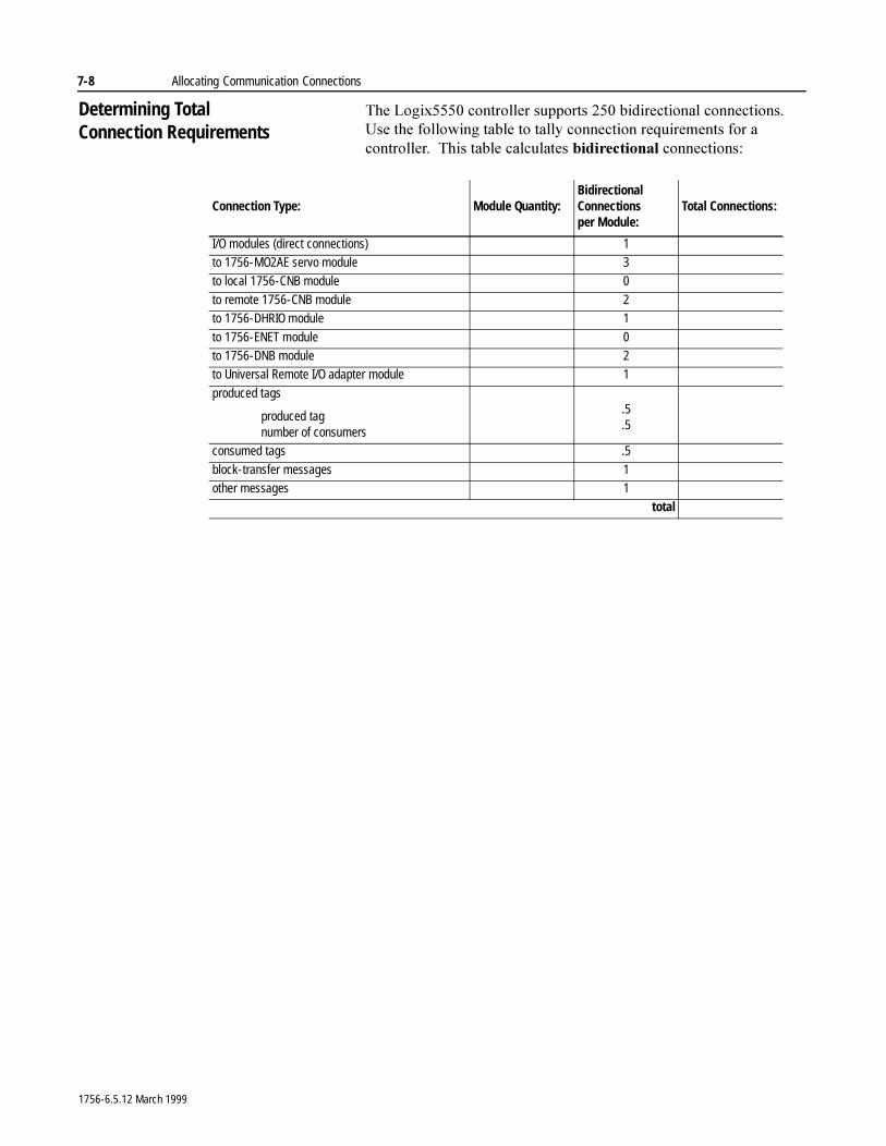
7-8 Allocating Communication Connections
Determining Total Connection Requirements
7KH�/RJL[�����FRQWUROOHU�VXSSRUWV�����ELGLUHFWLRQDO�FRQQHFWLRQV���8VH�WKH�IROORZLQJ�WDEOH�WR�WDOO\�FRQQHFWLRQ�UHTXLUHPHQWV�IRU�D�FRQWUROOHU���7KLV�WDEOH�FDOFXODWHV�ELGLUHFWLRQDO�FRQQHFWLRQV�
Connection Type: Module Quantity:Bidirectional Connections per Module:
Total Connections:
I/O modules (direct connections) 1to 1756-MO2AE servo module 3to local 1756-CNB module 0
to remote 1756-CNB module 2to 1756-DHRIO module 1
to 1756-ENET module 0to 1756-DNB module 2to Universal Remote I/O adapter module 1
produced tags
produced tagnumber of consumers
.5
.5
consumed tags .5
block-transfer messages 1other messages 1
total
1756-6.5.12 March 1999
Chapter 8
Communicating with Devices on a Serial Link
Using This Chapter
Using RS-232 7KH�FRQWUROOHU�VXSSRUWV�56�����RQ�WKH�VHULDO�SRUW���8VH�56�����ZKHQ�\RX�KDYH�
� D�GDWD�WUDQVPLVVLRQ�UDQJH�RI�XS�WR����IW�������P��� DQ�DSSOLFDWLRQ�WKDW�UHTXLUHV�PRGHPV�RU�OLQH�GULYHUV�
7KH�PD[LPXP�FDEOH�OHQJWK�IRU�56�����FRPPXQLFDWLRQV�LV����P���� IW���
For information about: See page:
Using RS-232 8-1
Connecting to the serial port 8-2Using the DF1 serial protocol 8-3
Configuring serial communications 8-5
1756-6.5.12 March 1999
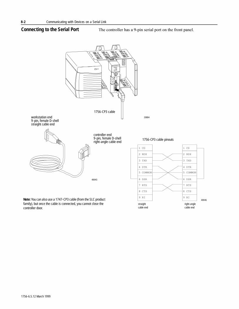
8-2 Communicating with Devices on a Serial Link
Connecting to the Serial Port 7KH�FRQWUROOHU�KDV�D���SLQ�VHULDO�SRUW�RQ�WKH�IURQW�SDQHO�
right-angle cable end
straight
2 RDX
cable end
3 TXD
4 DTR
5 COMMON
6 DSR
7 RTS
8 CTS
9 RI
1 CD
2 RDX
3 TXD
4 DTR
5 COMMON
6 DSR
7 RTS
8 CTS
9 RI
1 CD
workstation end 9-pin, female D-shell straight cable end
controller end 9-pin, female D-shell right-angle cable end
1756-CP3 cable
20884
40043
40046Note: You can also use a 1747-CP3 cable (from the SLC product family), but once the cable is connected, you cannot close the controller door.
1756-CP3 cable pinouts
1756-6.5.12 March 1999
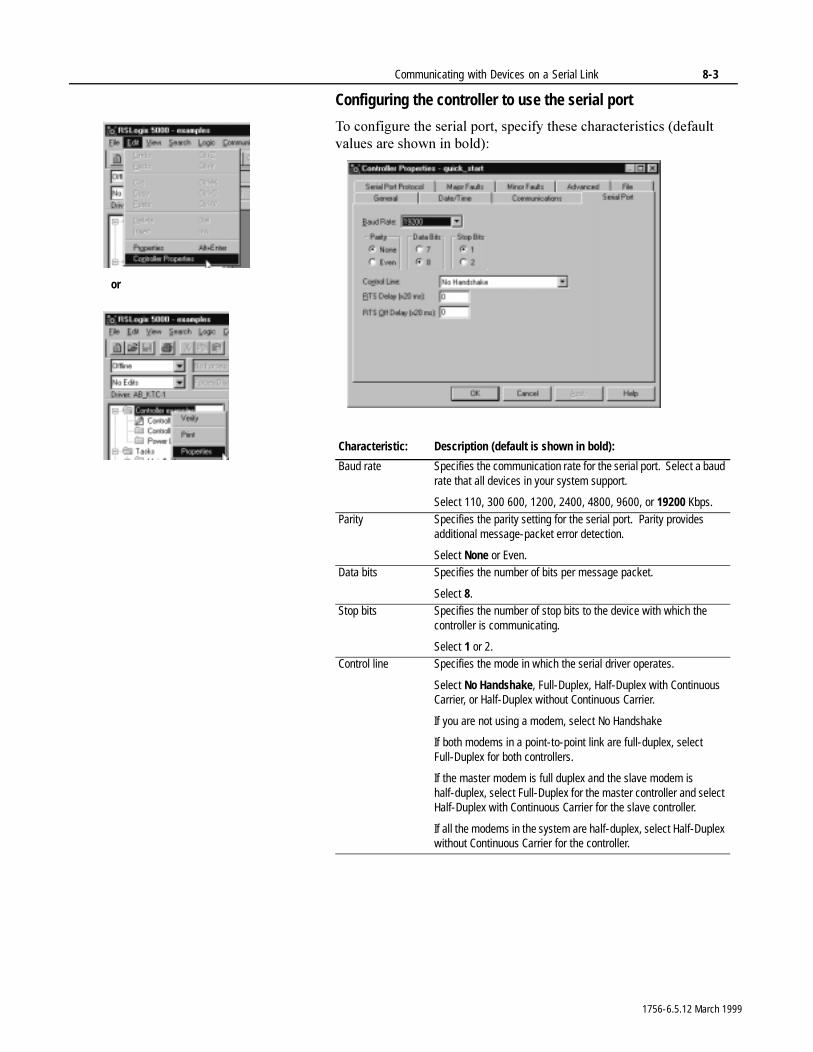
Communicating with Devices on a Serial Link 8-3
Configuring the controller to use the serial port
7R�FRQILJXUH�WKH�VHULDO�SRUW��VSHFLI\�WKHVH�FKDUDFWHULVWLFV��GHIDXOW�YDOXHV�DUH�VKRZQ�LQ�EROG��
Characteristic: Description (default is shown in bold):
Baud rate Specifies the communication rate for the serial port. Select a baud rate that all devices in your system support.
Select 110, 300 600, 1200, 2400, 4800, 9600, or 19200 Kbps.
Parity Specifies the parity setting for the serial port. Parity provides additional message-packet error detection.
Select None or Even.Data bits Specifies the number of bits per message packet.
Select 8.Stop bits Specifies the number of stop bits to the device with which the
controller is communicating.
Select 1 or 2.Control line Specifies the mode in which the serial driver operates.
Select No Handshake, Full-Duplex, Half-Duplex with Continuous Carrier, or Half-Duplex without Continuous Carrier.
If you are not using a modem, select No Handshake
If both modems in a point-to-point link are full-duplex, select Full-Duplex for both controllers.
If the master modem is full duplex and the slave modem is half-duplex, select Full-Duplex for the master controller and select Half-Duplex with Continuous Carrier for the slave controller.
If all the modems in the system are half-duplex, select Half-Duplex without Continuous Carrier for the controller.
or
1756-6.5.12 March 1999
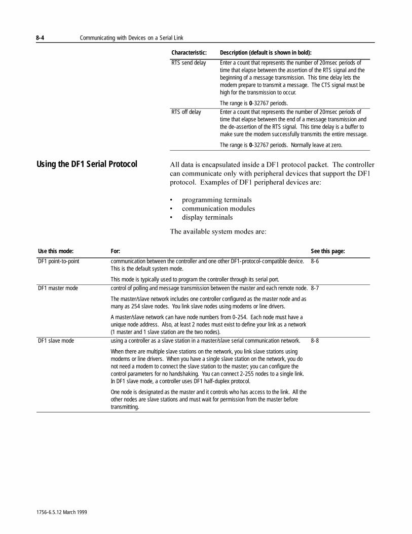
8-4 Communicating with Devices on a Serial Link
Using the DF1 Serial Protocol $OO�GDWD�LV�HQFDSVXODWHG�LQVLGH�D�')��SURWRFRO�SDFNHW���7KH�FRQWUROOHU�FDQ�FRPPXQLFDWH�RQO\�ZLWK�SHULSKHUDO�GHYLFHV�WKDW�VXSSRUW�WKH�')��SURWRFRO���([DPSOHV�RI�')��SHULSKHUDO�GHYLFHV DUH�
� SURJUDPPLQJ�WHUPLQDOV� FRPPXQLFDWLRQ�PRGXOHV� GLVSOD\�WHUPLQDOV
7KH�DYDLODEOH�V\VWHP�PRGHV�DUH�
RTS send delay Enter a count that represents the number of 20msec periods of time that elapse between the assertion of the RTS signal and the beginning of a message transmission. This time delay lets the modem prepare to transmit a message. The CTS signal must be high for the transmission to occur.
The range is 0-32767 periods.RTS off delay Enter a count that represents the number of 20msec periods of
time that elapse between the end of a message transmission and the de-assertion of the RTS signal. This time delay is a buffer to make sure the modem successfully transmits the entire message.
The range is 0-32767 periods. Normally leave at zero.
Characteristic: Description (default is shown in bold):
Use this mode: For: See this page:
DF1 point-to-point communication between the controller and one other DF1-protocol-compatible device. This is the default system mode.
This mode is typically used to program the controller through its serial port.
8-6
DF1 master mode control of polling and message transmission between the master and each remote node.
The master/slave network includes one controller configured as the master node and as many as 254 slave nodes. You link slave nodes using modems or line drivers.
A master/slave network can have node numbers from 0-254. Each node must have a unique node address. Also, at least 2 nodes must exist to define your link as a network (1 master and 1 slave station are the two nodes).
8-7
DF1 slave mode using a controller as a slave station in a master/slave serial communication network.
When there are multiple slave stations on the network, you link slave stations using modems or line drivers. When you have a single slave station on the network, you do not need a modem to connect the slave station to the master; you can configure the control parameters for no handshaking. You can connect 2-255 nodes to a single link. In DF1 slave mode, a controller uses DF1 half-duplex protocol.
One node is designated as the master and it controls who has access to the link. All the other nodes are slave stations and must wait for permission from the master before transmitting.
8-8
1756-6.5.12 March 1999
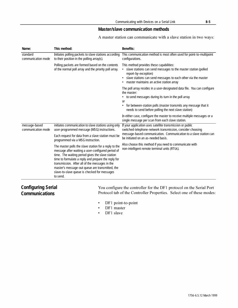
Communicating with Devices on a Serial Link 8-5
Master/slave communication methods
$�PDVWHU�VWDWLRQ�FDQ�FRPPXQLFDWH�ZLWK�D�VODYH�VWDWLRQ�LQ�WZR�ZD\V�
Configuring Serial Communications
<RX�FRQILJXUH�WKH�FRQWUROOHU�IRU�WKH�')��SURWRFRO�RQ�WKH�6HULDO�3RUW�3URWRFRO�WDE�RI�WKH�&RQWUROOHU�3URSHUWLHV���6HOHFW�RQH�RI�WKHVH PRGHV�
� ')��SRLQW�WR�SRLQW� ')��PDVWHU� ')��VODYH
Name: This method: Benefits:
standard communication mode
Initiates polling packets to slave stations according to their position in the polling array(s).
Polling packets are formed based on the contents of the normal poll array and the priority poll array.
This communication method is most often used for point-to-multipoint configurations.
This method provides these capabilities:• slave stations can send messages to the master station (polled
report-by-exception)• slave stations can send messages to each other via the master• master maintains an active station array
The poll array resides in a user-designated data file. You can configure the master:• to send messages during its turn in the poll arrayor• for between-station polls (master transmits any message that it
needs to send before polling the next slave station)
In either case, configure the master to receive multiple messages or a single message per scan from each slave station.
message-based communication mode
initiates communication to slave stations using only user-programmed message (MSG) instructions.
Each request for data from a slave station must be programmed via a MSG instruction.
The master polls the slave station for a reply to the message after waiting a user-configured period of time. The waiting period gives the slave station time to formulate a reply and prepare the reply for transmission. After all of the messages in the master’s message-out queue are transmitted, the slave-to-slave queue is checked for messages to send.
If your application uses satellite transmission or public switched-telephone-network transmission, consider choosing message-based communication. Communication to a slave station can be initiated on an as-needed basis.
Also choose this method if you need to communicate with non-intelligent remote terminal units (RTUs).
1756-6.5.12 March 1999
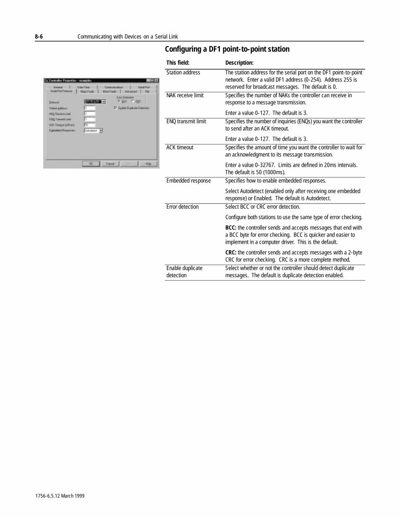
8-6 Communicating with Devices on a Serial Link
Configuring a DF1 point-to-point station
This field: Description:
Station address The station address for the serial port on the DF1 point-to-point network. Enter a valid DF1 address (0-254). Address 255 is reserved for broadcast messages. The default is 0.
NAK receive limit Specifies the number of NAKs the controller can receive in response to a message transmission.
Enter a value 0-127. The default is 3.ENQ transmit limit Specifies the number of inquiries (ENQs) you want the controller
to send after an ACK timeout.
Enter a value 0-127. The default is 3.ACK timeout Specifies the amount of time you want the controller to wait for
an acknowledgment to its message transmission.
Enter a value 0-32767. Limits are defined in 20ms intervals. The default is 50 (1000ms).
Embedded response Specifies how to enable embedded responses.
Select Autodetect (enabled only after receiving one embedded response) or Enabled. The default is Autodetect.
Error detection Select BCC or CRC error detection.
Configure both stations to use the same type of error checking.
BCC: the controller sends and accepts messages that end with a BCC byte for error checking. BCC is quicker and easier to implement in a computer driver. This is the default.
CRC: the controller sends and accepts messages with a 2-byte CRC for error checking. CRC is a more complete method.
Enable duplicate detection
Select whether or not the controller should detect duplicate messages. The default is duplicate detection enabled.
1756-6.5.12 March 1999
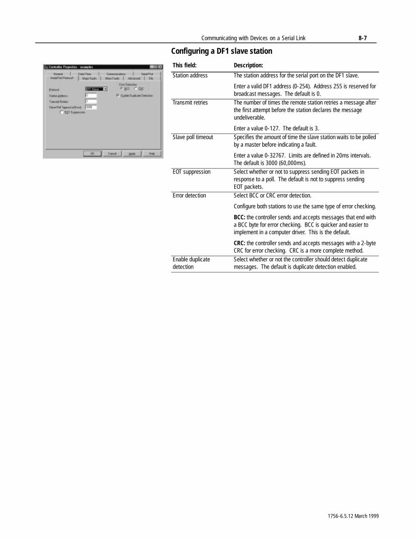
Communicating with Devices on a Serial Link 8-7
Configuring a DF1 slave station
This field: Description:
Station address The station address for the serial port on the DF1 slave.
Enter a valid DF1 address (0-254). Address 255 is reserved for broadcast messages. The default is 0.
Transmit retries The number of times the remote station retries a message after the first attempt before the station declares the message undeliverable.
Enter a value 0-127. The default is 3.Slave poll timeout Specifies the amount of time the slave station waits to be polled
by a master before indicating a fault.
Enter a value 0-32767. Limits are defined in 20ms intervals. The default is 3000 (60,000ms).
EOT suppression Select whether or not to suppress sending EOT packets in response to a poll. The default is not to suppress sending EOT packets.
Error detection Select BCC or CRC error detection.
Configure both stations to use the same type of error checking.
BCC: the controller sends and accepts messages that end with a BCC byte for error checking. BCC is quicker and easier to implement in a computer driver. This is the default.
CRC: the controller sends and accepts messages with a 2-byte CRC for error checking. CRC is a more complete method.
Enable duplicate detection
Select whether or not the controller should detect duplicate messages. The default is duplicate detection enabled.
1756-6.5.12 March 1999
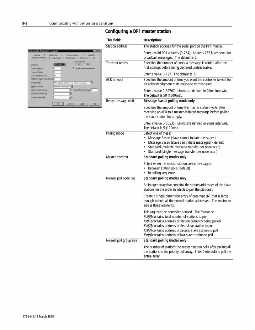
8-8 Communicating with Devices on a Serial Link
Configuring a DF1 master station
This field: Description:
Station address The station address for the serial port on the DF1 master.
Enter a valid DF1 address (0-254). Address 255 is reserved for broadcast messages. The default is 0.
Transmit retries Specifies the number of times a message is retried after the first attempt before being declared undeliverable.
Enter a value 0-127. The default is 3.
ACK timeout Specifies the amount of time you want the controller to wait for an acknowledgment to its message transmission.
Enter a value 0-32767. Limits are defined in 20ms intervals. The default is 50 (1000ms).
Reply message wait Message-based polling mode only
Specifies the amount of time the master station waits after receiving an ACK to a master-initiated message before polling the slave station for a reply.
Enter a value 0-65535. Limits are defined in 20ms intervals. The default is 5 (100ms).
Polling mode Select one of these:• Message Based (slave cannot initiate messages)• Message Based (slave can initiate messages) - default• Standard (multiple message transfer per node scan)• Standard (single message transfer per node scan)
Master transmit Standard polling modes only
Select when the master station sends messages:• between station polls (default)• in polling sequence
Normal poll node tag Standard polling modes only
An integer array that contains the station addresses of the slave stations (in the order in which to poll the stations).
Create a single-dimension array of data type INT that is large enough to hold all the normal station addresses. The minimum size is three elements.
This tag must be controller-scoped. The format is:list[0] contains total number of stations to polllist[1] contains address of station currently being polledlist[2] contains address of first slave station to polllist[3] contains address of second slave station to polllist[n] contains address of last slave station to poll
Normal poll group size Standard polling modes only
The number of stations the master station polls after polling all the stations in the priority poll array. Enter 0 (default) to poll the entire array.
1756-6.5.12 March 1999
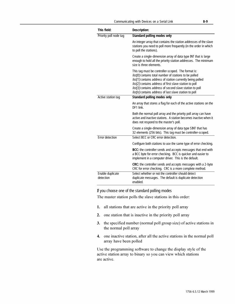
Communicating with Devices on a Serial Link 8-9
If you choose one of the standard polling modes
7KH�PDVWHU�VWDWLRQ�SROOV�WKH�VODYH�VWDWLRQV�LQ�WKLV�RUGHU�
�� DOO�VWDWLRQV�WKDW�DUH�DFWLYH�LQ�WKH�SULRULW\�SROO�DUUD\
�� RQH�VWDWLRQ�WKDW�LV�LQDFWLYH�LQ�WKH�SULRULW\�SROO�DUUD\
�� WKH�VSHFLILHG�QXPEHU��QRUPDO�SROO�JURXS�VL]H��RI�DFWLYH�VWDWLRQV�LQ�WKH�QRUPDO�SROO�DUUD\
�� RQH�LQDFWLYH�VWDWLRQ��DIWHU�DOO�WKH�DFWLYH�VWDWLRQV�LQ�WKH�QRUPDO�SROO�DUUD\�KDYH�EHHQ�SROOHG
8VH�WKH�SURJUDPPLQJ�VRIWZDUH�WR�FKDQJH�WKH�GLVSOD\�VW\OH�RI�WKH�DFWLYH�VWDWLRQ�DUUD\�WR�ELQDU\�VR�\RX�FDQ�YLHZ�ZKLFK�VWDWLRQV�DUH DFWLYH�
Priority poll node tag Standard polling modes only
An integer array that contains the station addresses of the slave stations you need to poll more frequently (in the order in which to poll the stations).
Create a single-dimension array of data type INT that is large enough to hold all the priority station addresses. The minimum size is three elements.
This tag must be controller-scoped. The format is:list[0] contains total number of stations to be polledlist[1] contains address of station currently being polledlist[2] contains address of first slave station to polllist[3] contains address of second slave station to polllist[n] contains address of last slave station to poll
Active station tag Standard polling modes only
An array that stores a flag for each of the active stations on the DF1 link.
Both the normal poll array and the priority poll array can have active and inactive stations. A station becomes inactive when it does not respond to the master’s poll.
Create a single-dimension array of data type SINT that has 32 elements (256 bits). This tag must be controller-scoped.
Error detection Select BCC or CRC error detection.
Configure both stations to use the same type of error checking.
BCC: the controller sends and accepts messages that end with a BCC byte for error checking. BCC is quicker and easier to implement in a computer driver. This is the default.
CRC: the controller sends and accepts messages with a 2-byte CRC for error checking. CRC is a more complete method.
Enable duplicate detection
Select whether or not the controller should detect duplicate messages. The default is duplicate detection enabled.
This field: Description:
1756-6.5.12 March 1999

8-10 Communicating with Devices on a Serial Link
1RWHV�
1756-6.5.12 March 1999
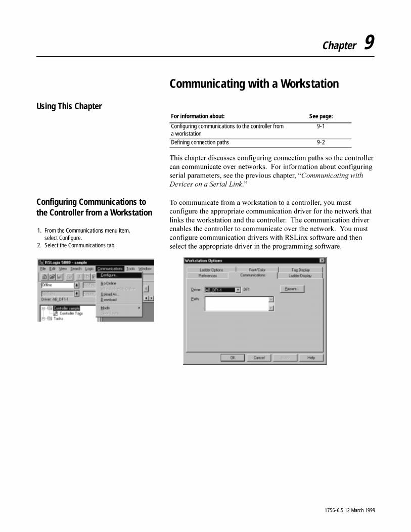
Chapter 9
Communicating with a Workstation
Using This Chapter
7KLV�FKDSWHU�GLVFXVVHV�FRQILJXULQJ�FRQQHFWLRQ�SDWKV�VR�WKH�FRQWUROOHU�FDQ�FRPPXQLFDWH�RYHU�QHWZRUNV���)RU�LQIRUPDWLRQ�DERXW�FRQILJXULQJ�VHULDO�SDUDPHWHUV��VHH�WKH�SUHYLRXV�FKDSWHU��³&RPPXQLFDWLQJ�ZLWK�'HYLFHV�RQ�D�6HULDO�/LQN�´
Configuring Communications to the Controller from a Workstation
7R�FRPPXQLFDWH�IURP�D�ZRUNVWDWLRQ�WR�D�FRQWUROOHU��\RX�PXVW�FRQILJXUH�WKH�DSSURSULDWH�FRPPXQLFDWLRQ�GULYHU�IRU�WKH�QHWZRUN�WKDW�OLQNV�WKH�ZRUNVWDWLRQ�DQG�WKH�FRQWUROOHU���7KH�FRPPXQLFDWLRQ�GULYHU�HQDEOHV�WKH�FRQWUROOHU�WR�FRPPXQLFDWH�RYHU�WKH�QHWZRUN���<RX�PXVW�FRQILJXUH�FRPPXQLFDWLRQ�GULYHUV�ZLWK�56/LQ[�VRIWZDUH�DQG�WKHQ�VHOHFW�WKH�DSSURSULDWH�GULYHU�LQ�WKH�SURJUDPPLQJ VRIWZDUH�
For information about: See page:
Configuring communications to the controller from a workstation
9-1
Defining connection paths 9-2
1. From the Communications menu item, select Configure.
2. Select the Communications tab.
1756-6.5.12 March 1999
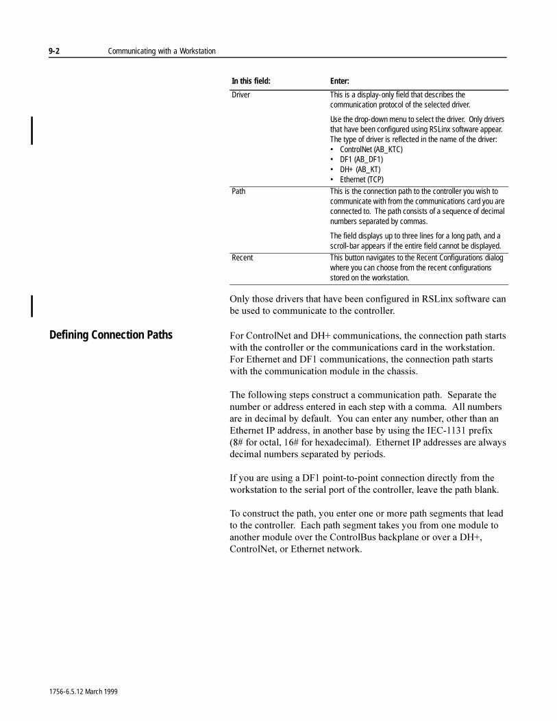
9-2 Communicating with a Workstation
2QO\�WKRVH�GULYHUV�WKDW�KDYH�EHHQ�FRQILJXUHG�LQ�56/LQ[�VRIWZDUH�FDQ�EH�XVHG�WR�FRPPXQLFDWH�WR�WKH�FRQWUROOHU�
Defining Connection Paths )RU�&RQWURO1HW�DQG�'+��FRPPXQLFDWLRQV��WKH�FRQQHFWLRQ�SDWK�VWDUWV�ZLWK�WKH�FRQWUROOHU�RU�WKH�FRPPXQLFDWLRQV�FDUG�LQ�WKH�ZRUNVWDWLRQ���)RU�(WKHUQHW�DQG�')��FRPPXQLFDWLRQV��WKH�FRQQHFWLRQ�SDWK�VWDUWV�ZLWK�WKH�FRPPXQLFDWLRQ�PRGXOH�LQ�WKH�FKDVVLV�
7KH�IROORZLQJ�VWHSV�FRQVWUXFW�D�FRPPXQLFDWLRQ�SDWK���6HSDUDWH�WKH�QXPEHU�RU�DGGUHVV�HQWHUHG�LQ�HDFK�VWHS�ZLWK�D�FRPPD���$OO�QXPEHUV�DUH�LQ�GHFLPDO�E\�GHIDXOW���<RX�FDQ�HQWHU�DQ\�QXPEHU��RWKHU�WKDQ�DQ�(WKHUQHW�,3�DGGUHVV��LQ�DQRWKHU�EDVH�E\�XVLQJ�WKH�,(&������SUHIL[���� IRU�RFWDO������IRU�KH[DGHFLPDO����(WKHUQHW�,3�DGGUHVVHV�DUH�DOZD\V�GHFLPDO�QXPEHUV�VHSDUDWHG�E\�SHULRGV�
,I�\RX�DUH�XVLQJ�D�')��SRLQW�WR�SRLQW�FRQQHFWLRQ�GLUHFWO\�IURP�WKH�ZRUNVWDWLRQ�WR�WKH�VHULDO�SRUW�RI�WKH�FRQWUROOHU��OHDYH�WKH�SDWK�EODQN�
7R�FRQVWUXFW�WKH�SDWK��\RX�HQWHU�RQH�RU�PRUH�SDWK�VHJPHQWV�WKDW�OHDG�WR�WKH�FRQWUROOHU���(DFK�SDWK�VHJPHQW�WDNHV�\RX�IURP�RQH�PRGXOH�WR�DQRWKHU�PRGXOH�RYHU�WKH�&RQWURO%XV�EDFNSODQH�RU�RYHU�D�'+���&RQWURO1HW��RU�(WKHUQHW�QHWZRUN�
In this field: Enter:
Driver This is a display-only field that describes the communication protocol of the selected driver.
Use the drop-down menu to select the driver. Only drivers that have been configured using RSLinx software appear. The type of driver is reflected in the name of the driver:• ControlNet (AB_KTC)• DF1 (AB_DF1)• DH+ (AB_KT)• Ethernet (TCP)
Path This is the connection path to the controller you wish to communicate with from the communications card you are connected to. The path consists of a sequence of decimal numbers separated by commas.
The field displays up to three lines for a long path, and a scroll-bar appears if the entire field cannot be displayed.
Recent This button navigates to the Recent Configurations dialog where you can choose from the recent configurations stored on the workstation.
1756-6.5.12 March 1999
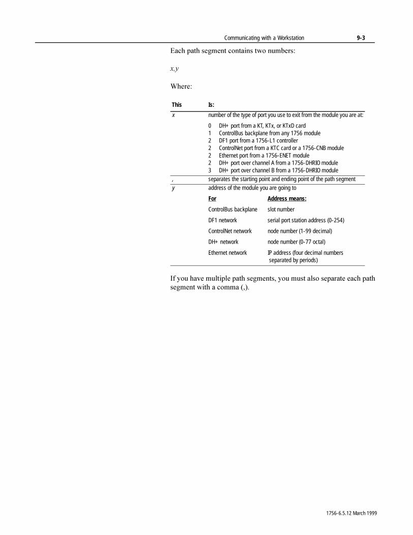
Communicating with a Workstation 9-3
(DFK�SDWK�VHJPHQW�FRQWDLQV�WZR�QXPEHUV�
[�\
:KHUH�
,I�\RX�KDYH�PXOWLSOH�SDWK�VHJPHQWV��\RX�PXVW�DOVR�VHSDUDWH�HDFK�SDWK�VHJPHQW�ZLWK�D�FRPPD�����
This Is:
x number of the type of port you use to exit from the module you are at:
0 DH+ port from a KT, KTx, or KTxD card1 ControlBus backplane from any 1756 module2 DF1 port from a 1756-L1 controller2 ControlNet port from a KTC card or a 1756-CNB module2 Ethernet port from a 1756-ENET module2 DH+ port over channel A from a 1756-DHRIO module3 DH+ port over channel B from a 1756-DHRIO module
, separates the starting point and ending point of the path segment
y address of the module you are going to
For Address means:
ControlBus backplane slot number
DF1 network serial port station address (0-254)
ControlNet network node number (1-99 decimal)
DH+ network node number (0-77 octal)
Ethernet network IP address (four decimal numbers separated by periods)
1756-6.5.12 March 1999
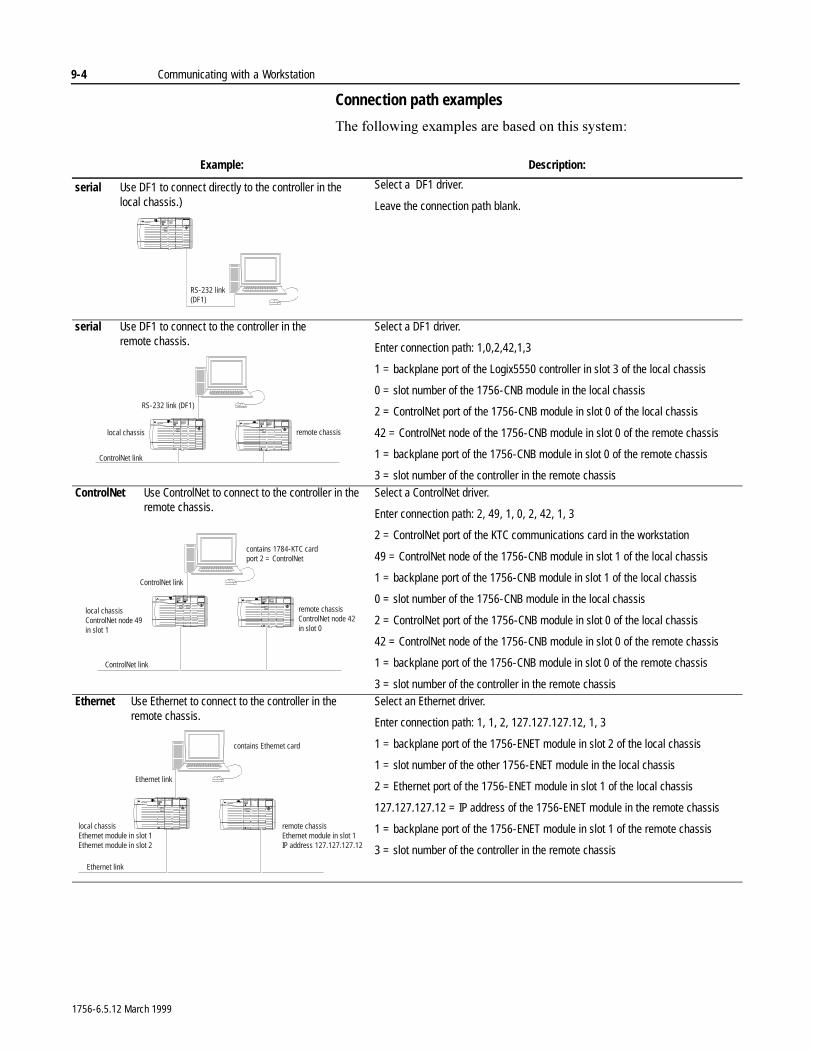
9-4 Communicating with a Workstation
Connection path examples
7KH�IROORZLQJ�H[DPSOHV�DUH�EDVHG�RQ�WKLV�V\VWHP�
Example: Description:
serial Use DF1 to connect directly to the controller in thelocal chassis.)
Select a DF1 driver.
Leave the connection path blank.
serial Use DF1 to connect to the controller in theremote chassis.
Select a DF1 driver.
Enter connection path: 1,0,2,42,1,3
1 = backplane port of the Logix5550 controller in slot 3 of the local chassis
0 = slot number of the 1756-CNB module in the local chassis
2 = ControlNet port of the 1756-CNB module in slot 0 of the local chassis
42 = ControlNet node of the 1756-CNB module in slot 0 of the remote chassis
1 = backplane port of the 1756-CNB module in slot 0 of the remote chassis
3 = slot number of the controller in the remote chassis
ControlNet Use ControlNet to connect to the controller in theremote chassis.
Select a ControlNet driver.
Enter connection path: 2, 49, 1, 0, 2, 42, 1, 3
2 = ControlNet port of the KTC communications card in the workstation
49 = ControlNet node of the 1756-CNB module in slot 1 of the local chassis
1 = backplane port of the 1756-CNB module in slot 1 of the local chassis
0 = slot number of the 1756-CNB module in the local chassis
2 = ControlNet port of the 1756-CNB module in slot 0 of the local chassis
42 = ControlNet node of the 1756-CNB module in slot 0 of the remote chassis
1 = backplane port of the 1756-CNB module in slot 0 of the remote chassis
3 = slot number of the controller in the remote chassisEthernet Use Ethernet to connect to the controller in the
remote chassis.Select an Ethernet driver.
Enter connection path: 1, 1, 2, 127.127.127.12, 1, 3
1 = backplane port of the 1756-ENET module in slot 2 of the local chassis
1 = slot number of the other 1756-ENET module in the local chassis
2 = Ethernet port of the 1756-ENET module in slot 1 of the local chassis
127.127.127.12 = IP address of the 1756-ENET module in the remote chassis
1 = backplane port of the 1756-ENET module in slot 1 of the remote chassis
3 = slot number of the controller in the remote chassis
RS-232 link(DF1)
local chassis remote chassis
ControlNet link
RS-232 link (DF1)
local chassisControlNet node 49in slot 1
remote chassisControlNet node 42in slot 0
contains 1784-KTC cardport 2 = ControlNet
ControlNet link
ControlNet link
local chassisEthernet module in slot 1Ethernet module in slot 2
remote chassisEthernet module in slot 1IP address 127.127.127.12
contains Ethernet card
Ethernet link
Ethernet link
1756-6.5.12 March 1999
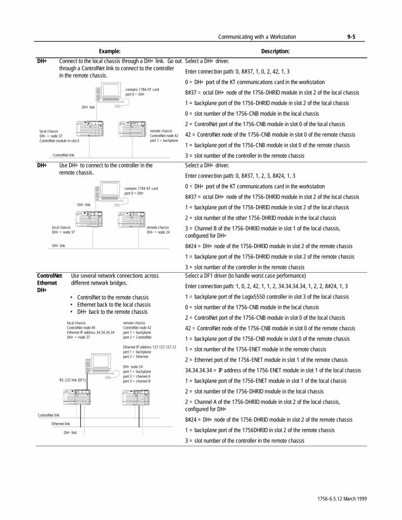
Communicating with a Workstation 9-5
DH+ Connect to the local chassis through a DH+ link. Go outthrough a ControlNet link to connect to the controllerin the remote chassis.
Select a DH+ driver.
Enter connection path: 0, 8#37, 1, 0, 2, 42, 1, 3
0 = DH+ port of the KT communications card in the workstation
8#37 = octal DH+ node of the 1756-DHRIO module in slot 2 of the local chassis
1 = backplane port of the 1756-DHRIO module in slot 2 of the local chassis
0 = slot number of the 1756-CNB module in the local chassis
2 = ControlNet port of the 1756-CNB module in slot 0 of the local chassis
42 = ControlNet node of the 1756-CNB module in slot 0 of the remote chassis
1 = backplane port of the 1756-CNB module in slot 0 of the remote chassis
3 = slot number of the controller in the remote chassis
DH+ Use DH+ to connect to the controller in theremote chassis.
Select a DH+ driver.
Enter connection path: 0, 8#37, 1, 2, 3, 8#24, 1, 3
0 = DH+ port of the KT communications card in the workstation
8#37 = octal DH+ node of the 1756-DHRIO module in slot 2 of the local chassis
1 = backplane port of the 1756-DHRIO module in slot 2 of the local chassis
2 = slot number of the other 1756-DHRIO module in the local chassis
3 = Channel B of the 1756-DHRIO module in slot 1 of the local chassis, configured for DH+
8#24 = DH+ node of the 1756-DHRIO module in slot 2 of the remote chassis
1 = backplane port of the 1756-DHRIO module in slot 2 of the remote chassis
3 = slot number of the controller in the remote chassisControlNet Use several network connections acrossEthernet different network bridges.DH+
• ControlNet to the remote chassis• Ethernet back to the local chassis• DH+ back to the remote chassis
Select a DF1 driver (to handle worst case performance)
Enter connection path: 1, 0, 2, 42, 1, 1, 2, 34.34.34.34, 1, 2, 2, 8#24, 1, 3
1 = backplane port of the Logix5550 controller in slot 3 of the local chassis
0 = slot number of the 1756-CNB module in the local chassis
2 = ControlNet port of the 1756-CNB module in slot 0 of the local chassis
42 = ControlNet node of the 1756-CNB module in slot 0 of the remote chassis
1 = backplane port of the 1756-CNB module in slot 0 of the remote chassis
1 = slot number of the 1756-ENET module in the remote chassis
2 = Ethernet port of the 1756-ENET module in slot 1 of the remote chassis
34.34.34.34 = IP address of the 1756-ENET module in slot 1 of the local chassis
1 = backplane port of the 1756-ENET module in slot 1 of the local chassis
2 = slot number of the 1756-DHRIO module in the local chassis
2 = Channel A of the 1756-DHRIO module in slot 2 of the local chassis, configured for DH+
8#24 = DH+ node of the 1756-DHRIO module in slot 2 of the remote chassis
1 = backplane port of the 1756DHRIO in slot 2 of the remote chassis
3 = slot number of the controller in the remote chassis
Example: Description:
local chassisDH+ = node 37ControlNet module in slot 0
remote chassisControlNet node 42port 1 = backplane
contains 1784-KT cardport 0 = DH+
ControlNet link
DH+ link
local chassisDH+ = node 37
remote chassisDH+ = node 24
contains 1784-KT cardport 0 = DH+
DH+ link
DH+ link
local chassisControlNet node 49Ethernet IP address 34.34.34.34DH+ = node 37
remote chassisControlNet node 42port 1 = backplaneport 2 = ControlNet
Ethernet link
ControlNet link
DH+ link
Ethernet IP address 127.127.127.12port 1 = backplaneport 2 = Ethernet
DH+ node 24port 1 = backplaneport 2 = channel Aport 3 = channel BRS-232 link (DF1)
1756-6.5.12 March 1999

9-6 Communicating with a Workstation
1RWHV�
1756-6.5.12 March 1999
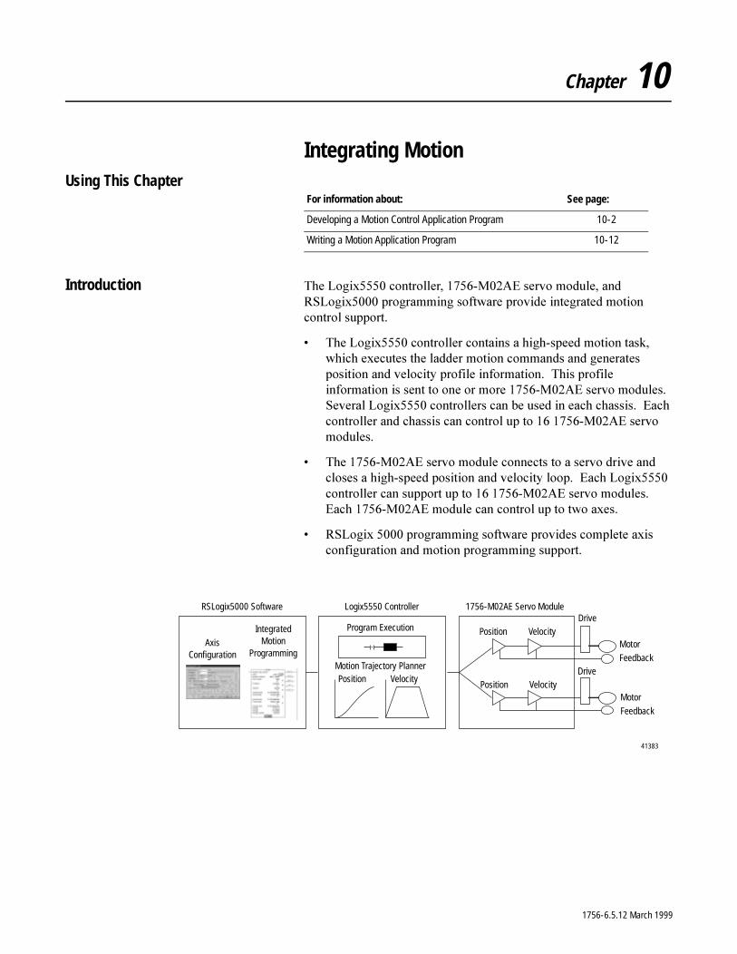
Chapter 10
Integrating MotionUsing This Chapter
Introduction 7KH�/RJL[�����FRQWUROOHU�������0��$(�VHUYR�PRGXOH��DQG�56/RJL[�����SURJUDPPLQJ�VRIWZDUH�SURYLGH�LQWHJUDWHG�PRWLRQ�FRQWURO�VXSSRUW�
� 7KH�/RJL[�����FRQWUROOHU�FRQWDLQV�D�KLJK�VSHHG�PRWLRQ�WDVN��ZKLFK�H[HFXWHV�WKH�ODGGHU�PRWLRQ�FRPPDQGV�DQG�JHQHUDWHV�SRVLWLRQ�DQG�YHORFLW\�SURILOH�LQIRUPDWLRQ���7KLV�SURILOH�LQIRUPDWLRQ�LV�VHQW�WR�RQH�RU�PRUH������0��$(�VHUYR�PRGXOHV���6HYHUDO�/RJL[�����FRQWUROOHUV�FDQ�EH�XVHG�LQ�HDFK�FKDVVLV���(DFK�FRQWUROOHU�DQG�FKDVVLV�FDQ�FRQWURO�XS�WR���������0��$(�VHUYR�PRGXOHV�
� 7KH������0��$(�VHUYR�PRGXOH�FRQQHFWV�WR�D�VHUYR�GULYH�DQG�FORVHV�D�KLJK�VSHHG�SRVLWLRQ�DQG�YHORFLW\�ORRS���(DFK�/RJL[�����FRQWUROOHU�FDQ�VXSSRUW�XS�WR���������0��$(�VHUYR�PRGXOHV���(DFK������0��$(�PRGXOH�FDQ�FRQWURO�XS�WR�WZR�D[HV�
� 56/RJL[ �����SURJUDPPLQJ�VRIWZDUH�SURYLGHV�FRPSOHWH�D[LV�FRQILJXUDWLRQ�DQG�PRWLRQ�SURJUDPPLQJ�VXSSRUW�
For information about: See page:
Developing a Motion Control Application Program 10-2
Writing a Motion Application Program 10-12
41383
RSLogix5000 Software Logix5550 Controller 1756-M02AE Servo Module
Axis Configuration
Integrated Motion
Programming
Program Execution
Motion Trajectory PlannerPosition Velocity
Drive
Motor
Feedback
Position Velocity
Position VelocityMotor
Feedback
Drive
1756-6.5.12 March 1999
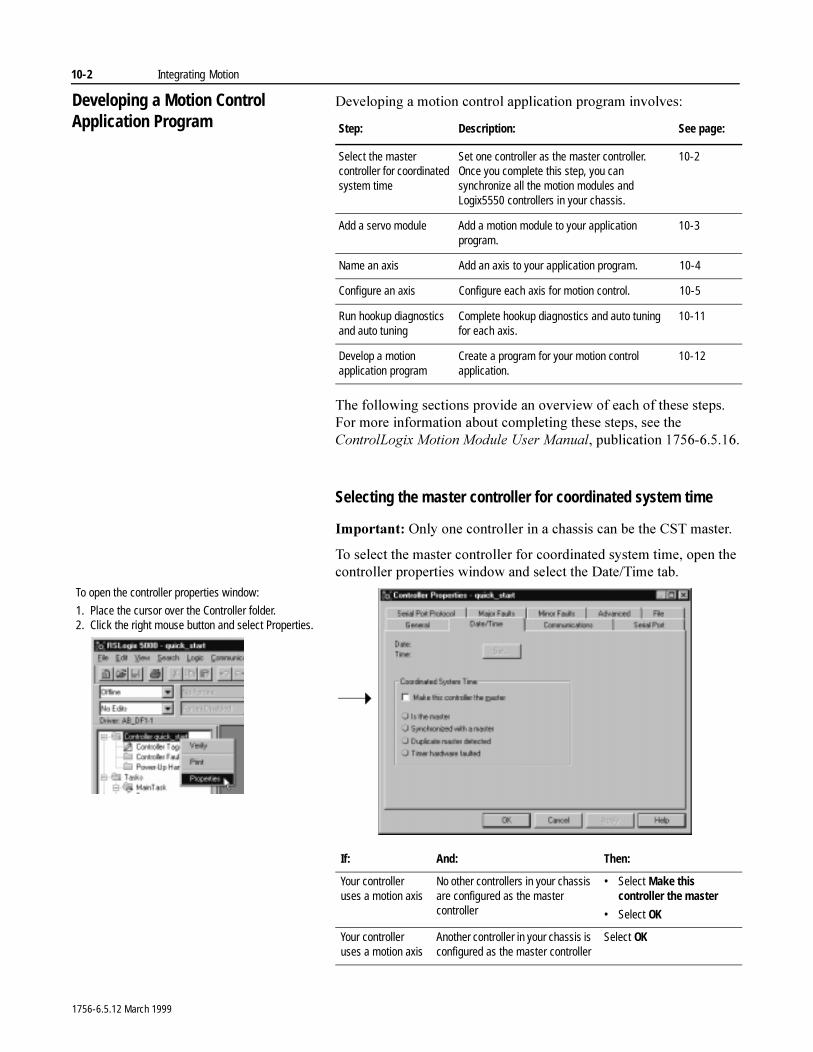
10-2 Integrating Motion
Developing a Motion Control Application Program
'HYHORSLQJ�D�PRWLRQ�FRQWURO�DSSOLFDWLRQ�SURJUDP�LQYROYHV�
7KH�IROORZLQJ�VHFWLRQV�SURYLGH�DQ�RYHUYLHZ�RI�HDFK�RI�WKHVH�VWHSV���)RU�PRUH�LQIRUPDWLRQ�DERXW�FRPSOHWLQJ�WKHVH�VWHSV��VHH�WKH�&RQWURO/RJL[�0RWLRQ�0RGXOH�8VHU�0DQXDO��SXEOLFDWLRQ�������������
Selecting the master controller for coordinated system time
,PSRUWDQW��2QO\�RQH�FRQWUROOHU�LQ�D�FKDVVLV�FDQ�EH�WKH�&67�PDVWHU�
7R�VHOHFW�WKH�PDVWHU�FRQWUROOHU�IRU�FRRUGLQDWHG�V\VWHP�WLPH��RSHQ�WKH�FRQWUROOHU�SURSHUWLHV�ZLQGRZ�DQG�VHOHFW�WKH�'DWH�7LPH�WDE�
Step: Description: See page:
Select the master controller for coordinated system time
Set one controller as the master controller. Once you complete this step, you can synchronize all the motion modules and Logix5550 controllers in your chassis.
10-2
Add a servo module Add a motion module to your application program.
10-3
Name an axis Add an axis to your application program. 10-4
Configure an axis Configure each axis for motion control. 10-5
Run hookup diagnostics and auto tuning
Complete hookup diagnostics and auto tuning for each axis.
10-11
Develop a motion application program
Create a program for your motion control application.
10-12
To open the controller properties window:
1. Place the cursor over the Controller folder.2. Click the right mouse button and select Properties.
If: And: Then:
Your controller uses a motion axis
No other controllers in your chassis are configured as the master controller
• Select Make this controller the master
• Select OK
Your controller uses a motion axis
Another controller in your chassis is configured as the master controller
Select OK
1756-6.5.12 March 1999
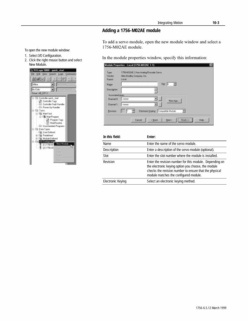
Integrating Motion 10-3
Adding a 1756-M02AE module
7R�DGG�D�VHUYR�PRGXOH��RSHQ�WKH�QHZ�PRGXOH�ZLQGRZ�DQG�VHOHFW�D������0��$(�PRGXOH�
,Q�WKH�PRGXOH�SURSHUWLHV�ZLQGRZ��VSHFLI\�WKLV�LQIRUPDWLRQ�
To open the new module window:
1. Select I/O Configuration.2. Click the right mouse button and select
New Module.
In this field: Enter:
Name Enter the name of the servo module.
Description Enter a description of the servo module (optional).
Slot Enter the slot number where the module is installed.
Revision Enter the revision number for this module. Depending on the electronic keying option you choose, the module checks the revision number to ensure that the physical module matches the configured module.
Electronic Keying Select an electronic keying method.
1756-6.5.12 March 1999

10-4 Integrating Motion
Naming an axis
7R�QDPH�DQ�D[LV��FOLFN�1HZ�$[LV�LQ�WKH�PRGXOH�SURSHUWLHV�ZLQGRZ�
6SHFLI\�WKLV�LQIRUPDWLRQ�
Make sure you have entered a servo module name.
In this field: Enter:
Name Enter the name of the axis.
Description Enter a description of the axis (optional).
1756-6.5.12 March 1999
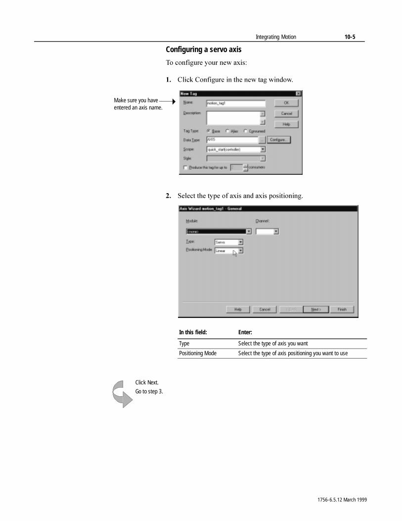
Integrating Motion 10-5
Configuring a servo axis
7R�FRQILJXUH�\RXU�QHZ�D[LV�
�� &OLFN�&RQILJXUH�LQ�WKH�QHZ�WDJ�ZLQGRZ�
�� 6HOHFW�WKH�W\SH�RI�D[LV�DQG�D[LV�SRVLWLRQLQJ�
Make sure you have entered an axis name.
In this field: Enter:
Type Select the type of axis you want
Positioning Mode Select the type of axis positioning you want to use
Click Next.
Go to step 3.
1756-6.5.12 March 1999
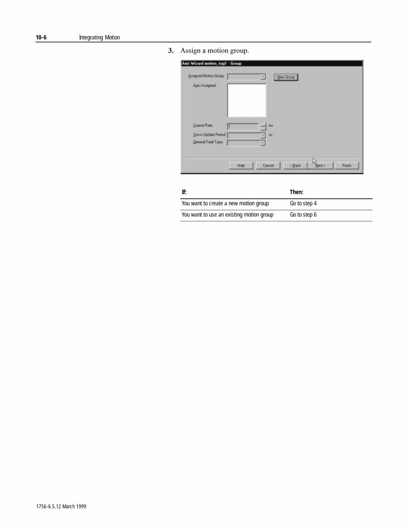
10-6 Integrating Motion
�� $VVLJQ�D�PRWLRQ�JURXS�
If: Then:
You want to create a new motion group Go to step 4
You want to use an existing motion group Go to step 6
1756-6.5.12 March 1999
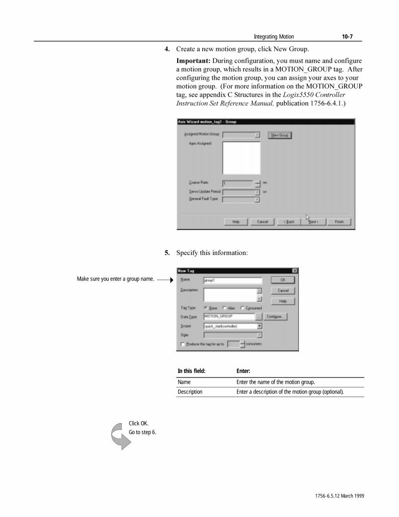
Integrating Motion 10-7
�� &UHDWH�D�QHZ�PRWLRQ�JURXS��FOLFN�1HZ�*URXS�
,PSRUWDQW��'XULQJ�FRQILJXUDWLRQ��\RX�PXVW�QDPH�DQG�FRQILJXUH�D�PRWLRQ�JURXS��ZKLFK�UHVXOWV�LQ�D�027,21B*5283�WDJ���$IWHU�FRQILJXULQJ�WKH�PRWLRQ�JURXS��\RX�FDQ�DVVLJQ�\RXU�D[HV�WR�\RXU�PRWLRQ�JURXS����)RU�PRUH�LQIRUPDWLRQ�RQ�WKH�027,21B*5283�WDJ��VHH�DSSHQGL[�&�6WUXFWXUHV�LQ�WKH�/RJL[�����&RQWUROOHU�,QVWUXFWLRQ�6HW�5HIHUHQFH�0DQXDO��SXEOLFDWLRQ�������������
�� 6SHFLI\�WKLV�LQIRUPDWLRQ�
Make sure you enter a group name.
In this field: Enter:
Name Enter the name of the motion group.
Description Enter a description of the motion group (optional).
Click OK.
Go to step 6.
1756-6.5.12 March 1999
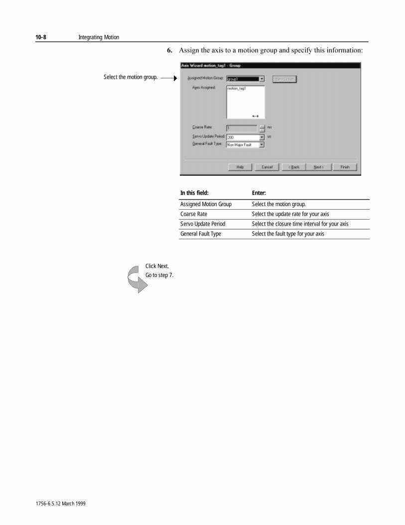
10-8 Integrating Motion
�� $VVLJQ�WKH�D[LV�WR�D�PRWLRQ�JURXS�DQG�VSHFLI\�WKLV�LQIRUPDWLRQ�
Select the motion group.
In this field: Enter:
Assigned Motion Group Select the motion group.
Coarse Rate Select the update rate for your axis
Servo Update Period Select the closure time interval for your axis
General Fault Type Select the fault type for your axis
Click Next.
Go to step 7.
1756-6.5.12 March 1999
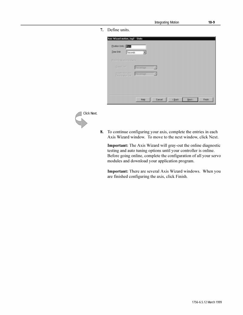
Integrating Motion 10-9
�� 'HILQH�XQLWV�
�� 7R�FRQWLQXH�FRQILJXULQJ�\RXU�D[LV��FRPSOHWH�WKH�HQWULHV�LQ�HDFK�$[LV�:L]DUG�ZLQGRZ���7R�PRYH�WR�WKH�QH[W�ZLQGRZ��FOLFN�1H[W�
,PSRUWDQW��7KH�$[LV�:L]DUG�ZLOO�JUD\�RXW�WKH�RQOLQH�GLDJQRVWLF�WHVWLQJ�DQG�DXWR�WXQLQJ�RSWLRQV�XQWLO�\RXU�FRQWUROOHU�LV�RQOLQH���%HIRUH�JRLQJ�RQOLQH��FRPSOHWH�WKH�FRQILJXUDWLRQ�RI�DOO�\RXU�VHUYR�PRGXOHV�DQG�GRZQORDG�\RXU�DSSOLFDWLRQ�SURJUDP�
,PSRUWDQW��7KHUH�DUH�VHYHUDO�$[LV�:L]DUG�ZLQGRZV���:KHQ�\RX�DUH�ILQLVKHG�FRQILJXULQJ�WKH�D[LV��FOLFN�)LQLVK�
Click Next.
1756-6.5.12 March 1999
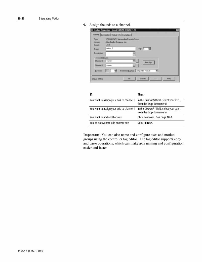
10-10 Integrating Motion
�� $VVLJQ�WKH�D[LV�WR�D�FKDQQHO�
,PSRUWDQW��<RX�FDQ�DOVR�QDPH�DQG�FRQILJXUH�D[HV�DQG�PRWLRQ�JURXSV�XVLQJ�WKH�FRQWUROOHU�WDJ�HGLWRU���7KH�WDJ�HGLWRU�VXSSRUWV�FRS\�DQG�SDVWH�RSHUDWLRQV��ZKLFK�FDQ�PDNH�D[LV�QDPLQJ�DQG�FRQILJXUDWLRQ�HDVLHU�DQG�IDVWHU�
If: Then:
You want to assign your axis to channel 0 In the Channel 0 field, select your axis from the drop-down menu
You want to assign your axis to channel 1 In the Channel 1 field, select your axis from the drop-down menu
You want to add another axis Click New Axis. See page 10-4.
You do not want to add another axis Select Finish.
1756-6.5.12 March 1999
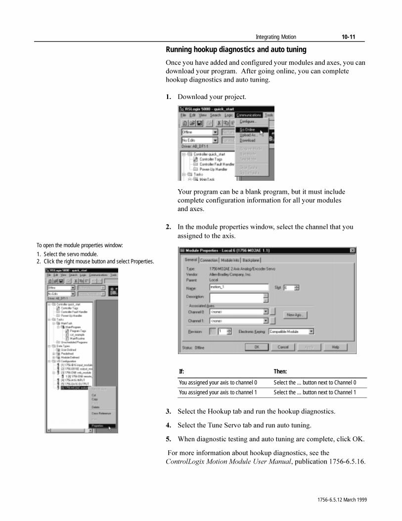
Integrating Motion 10-11
Running hookup diagnostics and auto tuning
2QFH�\RX�KDYH�DGGHG�DQG�FRQILJXUHG�\RXU�PRGXOHV�DQG�D[HV��\RX�FDQ�GRZQORDG�\RXU�SURJUDP���$IWHU�JRLQJ�RQOLQH��\RX�FDQ�FRPSOHWH�KRRNXS�GLDJQRVWLFV�DQG�DXWR�WXQLQJ�
�� 'RZQORDG�\RXU�SURMHFW�
<RXU�SURJUDP�FDQ�EH�D�EODQN�SURJUDP��EXW�LW�PXVW�LQFOXGH�FRPSOHWH�FRQILJXUDWLRQ�LQIRUPDWLRQ�IRU�DOO�\RXU�PRGXOHV�DQG D[HV�
�� ,Q�WKH�PRGXOH�SURSHUWLHV�ZLQGRZ��VHOHFW�WKH�FKDQQHO�WKDW�\RX�DVVLJQHG�WR�WKH�D[LV�
�� 6HOHFW�WKH�+RRNXS�WDE�DQG�UXQ�WKH�KRRNXS�GLDJQRVWLFV�
�� 6HOHFW�WKH�7XQH�6HUYR�WDE�DQG�UXQ�DXWR�WXQLQJ�
�� :KHQ�GLDJQRVWLF�WHVWLQJ�DQG�DXWR�WXQLQJ�DUH�FRPSOHWH��FOLFN 2.�
�)RU�PRUH�LQIRUPDWLRQ�DERXW�KRRNXS�GLDJQRVWLFV��VHH�WKH�&RQWURO/RJL[�0RWLRQ�0RGXOH�8VHU�0DQXDO��SXEOLFDWLRQ�������������
To open the module properties window:
1. Select the servo module.2. Click the right mouse button and select Properties.
If: Then:
You assigned your axis to channel 0 Select the ... button next to Channel 0
You assigned your axis to channel 1 Select the ... button next to Channel 1
1756-6.5.12 March 1999
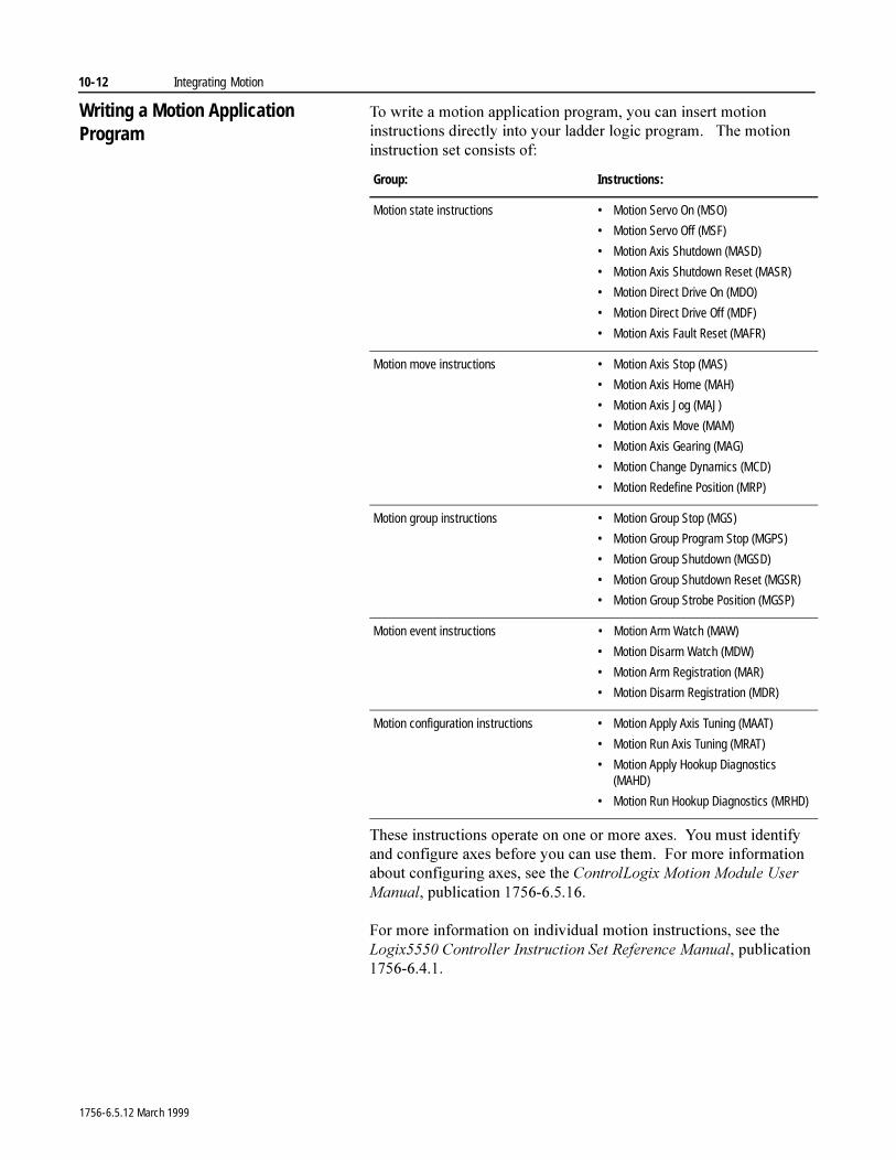
10-12 Integrating Motion
Writing a Motion Application Program
7R�ZULWH�D�PRWLRQ�DSSOLFDWLRQ�SURJUDP��\RX�FDQ�LQVHUW�PRWLRQ�LQVWUXFWLRQV�GLUHFWO\�LQWR�\RXU�ODGGHU�ORJLF�SURJUDP����7KH�PRWLRQ�LQVWUXFWLRQ�VHW�FRQVLVWV�RI�
7KHVH�LQVWUXFWLRQV�RSHUDWH�RQ�RQH�RU�PRUH�D[HV���<RX�PXVW�LGHQWLI\�DQG�FRQILJXUH�D[HV�EHIRUH�\RX�FDQ�XVH�WKHP���)RU�PRUH�LQIRUPDWLRQ�DERXW�FRQILJXULQJ�D[HV��VHH�WKH�&RQWURO/RJL[�0RWLRQ�0RGXOH�8VHU�0DQXDO��SXEOLFDWLRQ�������������
)RU�PRUH�LQIRUPDWLRQ�RQ�LQGLYLGXDO�PRWLRQ�LQVWUXFWLRQV��VHH�WKH�/RJL[�����&RQWUROOHU�,QVWUXFWLRQ�6HW�5HIHUHQFH�0DQXDO��SXEOLFDWLRQ������������
Group: Instructions:
Motion state instructions • Motion Servo On (MSO)
• Motion Servo Off (MSF)
• Motion Axis Shutdown (MASD)
• Motion Axis Shutdown Reset (MASR)
• Motion Direct Drive On (MDO)
• Motion Direct Drive Off (MDF)
• Motion Axis Fault Reset (MAFR)
Motion move instructions • Motion Axis Stop (MAS)
• Motion Axis Home (MAH)
• Motion Axis Jog (MAJ)
• Motion Axis Move (MAM)
• Motion Axis Gearing (MAG)
• Motion Change Dynamics (MCD)
• Motion Redefine Position (MRP)
Motion group instructions • Motion Group Stop (MGS)
• Motion Group Program Stop (MGPS)
• Motion Group Shutdown (MGSD)
• Motion Group Shutdown Reset (MGSR)
• Motion Group Strobe Position (MGSP)
Motion event instructions • Motion Arm Watch (MAW)
• Motion Disarm Watch (MDW)
• Motion Arm Registration (MAR)
• Motion Disarm Registration (MDR)
Motion configuration instructions • Motion Apply Axis Tuning (MAAT)
• Motion Run Axis Tuning (MRAT)
• Motion Apply Hookup Diagnostics (MAHD)
• Motion Run Hookup Diagnostics (MRHD)
1756-6.5.12 March 1999
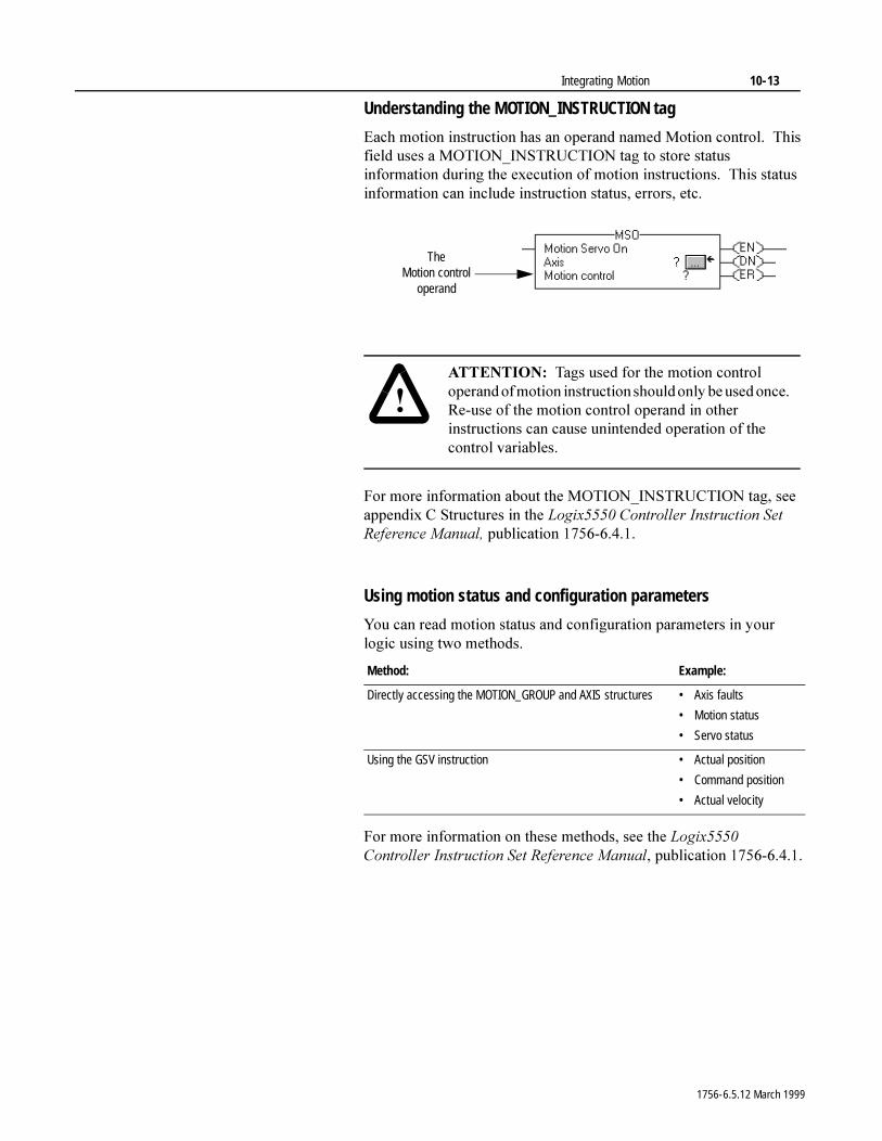
Integrating Motion 10-13
Understanding the MOTION_INSTRUCTION tag
(DFK�PRWLRQ�LQVWUXFWLRQ�KDV�DQ�RSHUDQG�QDPHG�0RWLRQ�FRQWURO���7KLV�ILHOG�XVHV�D�027,21B,16758&7,21�WDJ�WR�VWRUH�VWDWXV�LQIRUPDWLRQ�GXULQJ�WKH�H[HFXWLRQ�RI�PRWLRQ�LQVWUXFWLRQV���7KLV�VWDWXV�LQIRUPDWLRQ�FDQ�LQFOXGH�LQVWUXFWLRQ�VWDWXV��HUURUV��HWF�
)RU�PRUH�LQIRUPDWLRQ�DERXW�WKH�027,21B,16758&7,21�WDJ��VHH�DSSHQGL[�&�6WUXFWXUHV�LQ�WKH�/RJL[�����&RQWUROOHU�,QVWUXFWLRQ�6HW�5HIHUHQFH�0DQXDO��SXEOLFDWLRQ������������
Using motion status and configuration parameters
<RX�FDQ�UHDG�PRWLRQ�VWDWXV�DQG�FRQILJXUDWLRQ�SDUDPHWHUV�LQ�\RXU�ORJLF�XVLQJ�WZR�PHWKRGV�
)RU�PRUH�LQIRUPDWLRQ�RQ�WKHVH�PHWKRGV��VHH�WKH�/RJL[�����&RQWUROOHU�,QVWUXFWLRQ�6HW�5HIHUHQFH�0DQXDO��SXEOLFDWLRQ������������
The Motion control
operand
�$77(17,21� 7DJV�XVHG�IRU�WKH�PRWLRQ�FRQWURO�RSHUDQG�RI�PRWLRQ�LQVWUXFWLRQ�VKRXOG�RQO\�EH�XVHG�RQFH���5H�XVH�RI�WKH�PRWLRQ�FRQWURO�RSHUDQG�LQ�RWKHU�LQVWUXFWLRQV�FDQ�FDXVH�XQLQWHQGHG�RSHUDWLRQ�RI�WKH�FRQWURO�YDULDEOHV�
Method: Example:
Directly accessing the MOTION_GROUP and AXIS structures • Axis faults
• Motion status
• Servo status
Using the GSV instruction • Actual position
• Command position
• Actual velocity
1756-6.5.12 March 1999
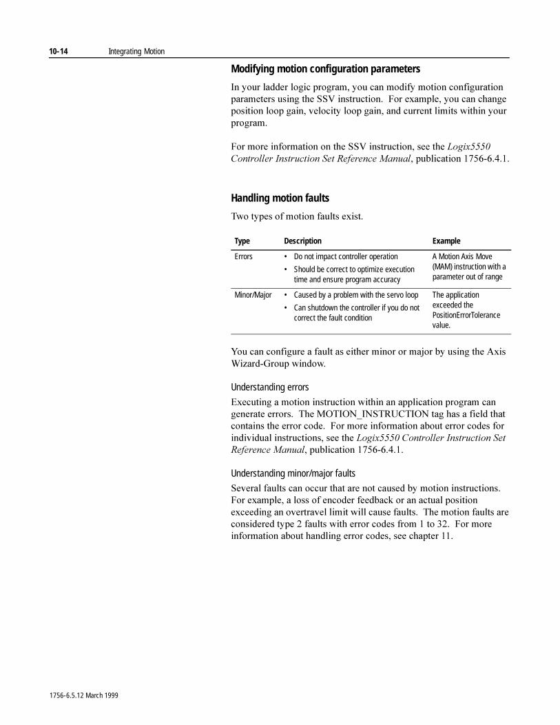
10-14 Integrating Motion
Modifying motion configuration parameters
,Q�\RXU�ODGGHU�ORJLF�SURJUDP��\RX�FDQ�PRGLI\�PRWLRQ�FRQILJXUDWLRQ�SDUDPHWHUV�XVLQJ�WKH�669�LQVWUXFWLRQ���)RU�H[DPSOH��\RX�FDQ�FKDQJH�SRVLWLRQ�ORRS�JDLQ��YHORFLW\�ORRS�JDLQ��DQG�FXUUHQW�OLPLWV�ZLWKLQ�\RXU�SURJUDP�
)RU�PRUH�LQIRUPDWLRQ�RQ�WKH�669�LQVWUXFWLRQ��VHH�WKH�/RJL[�����&RQWUROOHU�,QVWUXFWLRQ�6HW�5HIHUHQFH�0DQXDO��SXEOLFDWLRQ������������
Handling motion faults
7ZR�W\SHV�RI�PRWLRQ�IDXOWV�H[LVW�
<RX�FDQ�FRQILJXUH�D�IDXOW�DV�HLWKHU�PLQRU�RU�PDMRU�E\�XVLQJ�WKH�$[LV�:L]DUG�*URXS�ZLQGRZ�
Understanding errors
([HFXWLQJ�D�PRWLRQ�LQVWUXFWLRQ�ZLWKLQ�DQ�DSSOLFDWLRQ�SURJUDP�FDQ�JHQHUDWH�HUURUV���7KH�027,21B,16758&7,21�WDJ�KDV�D�ILHOG�WKDW�FRQWDLQV�WKH�HUURU�FRGH���)RU�PRUH�LQIRUPDWLRQ�DERXW�HUURU�FRGHV�IRU�LQGLYLGXDO�LQVWUXFWLRQV��VHH�WKH�/RJL[�����&RQWUROOHU�,QVWUXFWLRQ�6HW�5HIHUHQFH�0DQXDO��SXEOLFDWLRQ������������
Understanding minor/major faults
6HYHUDO�IDXOWV�FDQ�RFFXU�WKDW�DUH�QRW�FDXVHG�E\�PRWLRQ�LQVWUXFWLRQV���)RU�H[DPSOH��D�ORVV�RI�HQFRGHU�IHHGEDFN�RU�DQ�DFWXDO�SRVLWLRQ�H[FHHGLQJ�DQ�RYHUWUDYHO�OLPLW�ZLOO�FDXVH�IDXOWV���7KH�PRWLRQ�IDXOWV�DUH�FRQVLGHUHG�W\SH���IDXOWV�ZLWK�HUURU�FRGHV�IURP���WR������)RU�PRUH�LQIRUPDWLRQ�DERXW�KDQGOLQJ�HUURU�FRGHV��VHH�FKDSWHU ���
Type Description Example
Errors • Do not impact controller operation
• Should be correct to optimize execution time and ensure program accuracy
A Motion Axis Move (MAM) instruction with a parameter out of range
Minor/Major • Caused by a problem with the servo loop
• Can shutdown the controller if you do not correct the fault condition
The application exceeded the PositionErrorTolerance value.
1756-6.5.12 March 1999
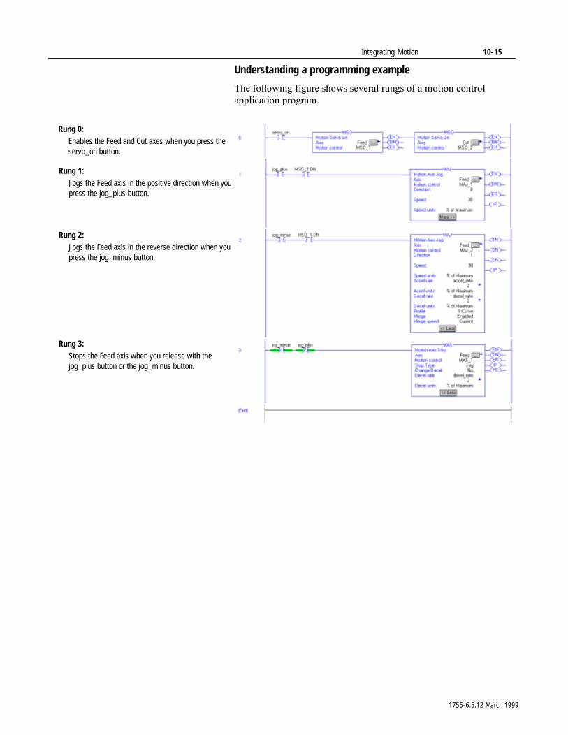
Integrating Motion 10-15
Understanding a programming example
7KH�IROORZLQJ�ILJXUH�VKRZV�VHYHUDO�UXQJV�RI�D�PRWLRQ�FRQWURO�DSSOLFDWLRQ�SURJUDP�
Rung 0:Enables the Feed and Cut axes when you press the servo_on button.
Rung 1:Jogs the Feed axis in the positive direction when you press the jog_plus button.
Rung 2:Jogs the Feed axis in the reverse direction when you press the jog_minus button.
Rung 3:Stops the Feed axis when you release with the jog_plus button or the jog_minus button.
1756-6.5.12 March 1999

10-16 Integrating Motion
1RWHV�
1756-6.5.12 March 1999
Chapter 11
Forcing I/OUsing This Chapter
Forcing )RUFLQJ�OHWV�\RX�RYHUULGH�DQ�,�2�PRGXOH¶V�YDOXHV�LQ�WKH�FRQWUROOHU���<RX�FDQ�IRUFH�
� D�VWUXFWXUH�PHPEHU�RI�DQ�,�2�WDJ
6LQFH�DQ�,�2�WDJ�LV�D�VWUXFWXUHG�WDJ��WKH�IRUFH�LV�DSSOLHG�WR�LWV�VWUXFWXUH�PHPEHUV��RI�W\SH�%22/��6,17��,17��',17��RU�5($/����<RX�FDQ�IRUFH�DOO�,�2�GDWD��H[FHSW�IRU�FRQILJXUDWLRQ�GDWD�
� DQ�DOLDV�WR�DQ�,�2�VWUXFWXUH�PHPEHU��RI�W\SH�%22/��6,17��,17��',17��RU�5($/�
)RUFLQJ�DQ�LQSXW�YDOXH�RYHUULGHV�WKH�DFWXDO�LQSXW�YDOXH�EHLQJ�UHFHLYHG�IURP�WKH�FRQWUROOHU��EXW�ZLOO�QRW�DIIHFW�WKH�YDOXH�UHFHLYHG�E\�RWKHU�FRQWUROOHUV�PRQLWRULQJ�WKDW�SK\VLFDO�LQSXW�PRGXOH���)RUFLQJ�DQ�LQSXW�YDOXH�RYHUULGHV�WKH�YDOXH�UHJDUGOHVV�RI�WKH�VWDWH�RI�WKH�SK\VLFDO�LQSXW PRGXOH�
)RUFLQJ�DQ�RXWSXW�YDOXH�RYHUULGHV�WKH�ORJLF�IRU�WKH�SK\VLFDO�RXWSXW�PRGXOH���2WKHU�FRQWUROOHUV�PRQLWRULQJ�WKDW�RXWSXW�PRGXOH�LQ�D�OLVWHQ�RQO\�FDSDFLW\�ZLOO�DOVR�VHH�WKH�IRUFHG�YDOXH�
)RUFHV�DUH�DSSOLHG�WR�WKH�DFWXDO�PRGXOHV�DW�WKH�HQG�RI�HYHU\�SURJUDP�VFDQ�ZKHQ�GDWD�DUULYHV�DW�WKH�PRGXOH�
,PSRUWDQW��)RUFLQJ�LQFUHDVHV�ORJLF�H[HFXWLRQ�WLPH���7KH�PRUH�YDOXHV�\RX�IRUFH��WKH�ORQJHU�LW�WDNHV�WR�H[HFXWH�WKH�ORJLF�
,PSRUWDQW��)RUFHV�DUH�KHOG�E\�WKH�FRQWUROOHU�DQG�QRW�E\�WKH�SURJUDPPLQJ�ZRUNVWDWLRQ���)RUFHV�UHPDLQ�HYHQ�LI�WKH�SURJUDPPLQJ�ZRUNVWDWLRQ�LV�GLVFRQQHFWHG�
For information about: See page:
Forcing 11-1
Entering forces 11-2Enabling forces 11-4
Disabling forcesRemoving forces 11-5Monitoring forces 11-6
�$77(17,21� ,I�IRUFHV�DUH�HQDEOHG�DQG�DQ\WKLQJ�LV�IRUFHG��NHHS�SHUVRQQHO�DZD\�IURP�WKH�PDFKLQH�DUHD���)RUFLQJ�FDQ�FDXVH�XQH[SHFWHG�PDFKLQH�PRWLRQ�WKDW�FRXOG�LQMXUH SHUVRQQHO�
1756-6.5.12 March 1999
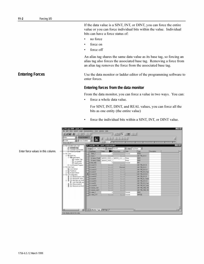
11-2 Forcing I/O
,I�WKH�GDWD�YDOXH�LV�D�6,17��,17��RU�',17��\RX�FDQ�IRUFH�WKH�HQWLUH�YDOXH�RU�\RX�FDQ�IRUFH�LQGLYLGXDO�ELWV�ZLWKLQ�WKH�YDOXH���,QGLYLGXDO�ELWV�FDQ�KDYH�D�IRUFH�VWDWXV�RI�
� QR�IRUFH
� IRUFH�RQ
� IRUFH�RII
$Q�DOLDV�WDJ�VKDUHV�WKH�VDPH�GDWD�YDOXH�DV�LWV�EDVH�WDJ��VR�IRUFLQJ�DQ�DOLDV�WDJ�DOVR�IRUFHV�WKH�DVVRFLDWHG�EDVH�WDJ���5HPRYLQJ�D�IRUFH�IURP�DQ�DOLDV�WDJ�UHPRYHV�WKH�IRUFH�IURP�WKH�DVVRFLDWHG�EDVH�WDJ�
Entering Forces 8VH�WKH�GDWD�PRQLWRU�RU�ODGGHU�HGLWRU�RI�WKH�SURJUDPPLQJ�VRIWZDUH�WR�HQWHU�IRUFHV�
Entering forces from the data monitor
)URP�WKH�GDWD�PRQLWRU��\RX�FDQ�IRUFH�D�YDOXH�LQ�WZR�ZD\V���<RX FDQ�
� IRUFH�D�ZKROH�GDWD�YDOXH�
)RU�6,17��,17��',17��DQG�5($/�YDOXHV��\RX�FDQ�IRUFH�DOO�WKH�ELWV�DV�RQH�HQWLW\��WKH�HQWLUH�YDOXH�
� IRUFH�WKH�LQGLYLGXDO�ELWV�ZLWKLQ�D�6,17��,17��RU�',17�YDOXH�
Enter force values in this column.
1756-6.5.12 March 1999
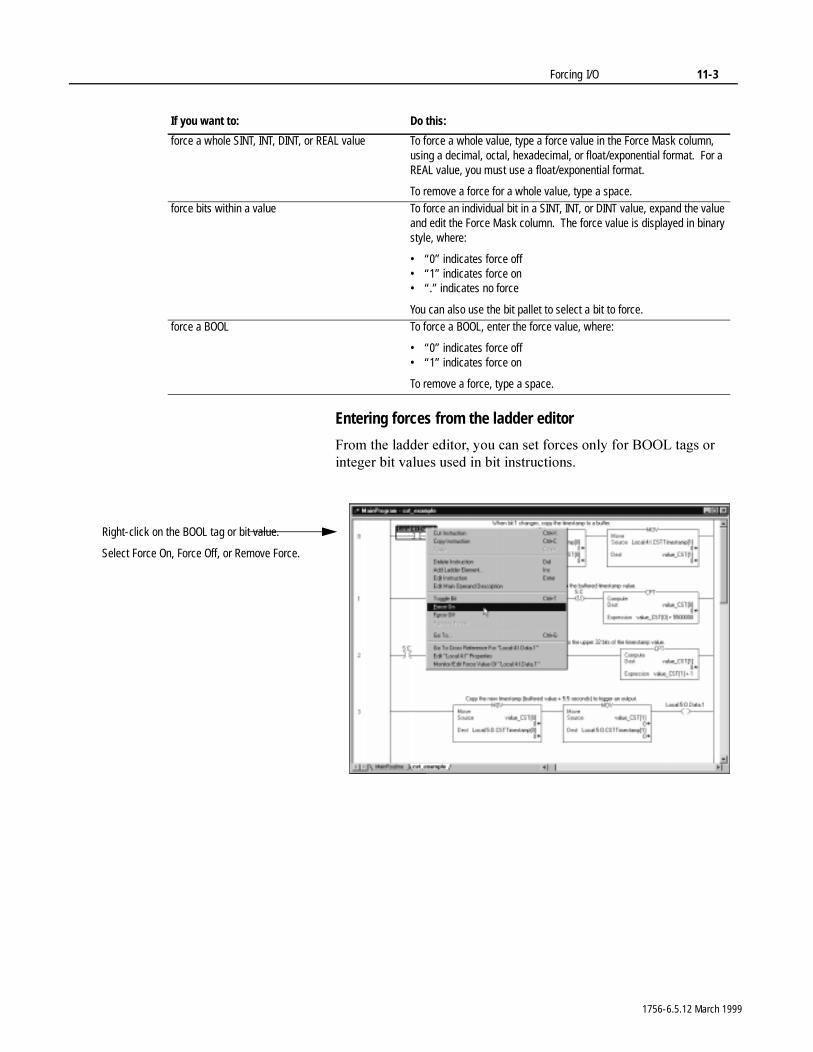
Forcing I/O 11-3
Entering forces from the ladder editor
)URP�WKH�ODGGHU�HGLWRU��\RX�FDQ�VHW�IRUFHV�RQO\�IRU�%22/�WDJV�RU�LQWHJHU�ELW�YDOXHV�XVHG�LQ�ELW�LQVWUXFWLRQV�
If you want to: Do this:
force a whole SINT, INT, DINT, or REAL value To force a whole value, type a force value in the Force Mask column, using a decimal, octal, hexadecimal, or float/exponential format. For a REAL value, you must use a float/exponential format.
To remove a force for a whole value, type a space.force bits within a value To force an individual bit in a SINT, INT, or DINT value, expand the value
and edit the Force Mask column. The force value is displayed in binary style, where:
• “0” indicates force off• “1” indicates force on• “.” indicates no force
You can also use the bit pallet to select a bit to force.force a BOOL To force a BOOL, enter the force value, where:
• “0” indicates force off• “1” indicates force on
To remove a force, type a space.
Right-click on the BOOL tag or bit value.
Select Force On, Force Off, or Remove Force.
1756-6.5.12 March 1999
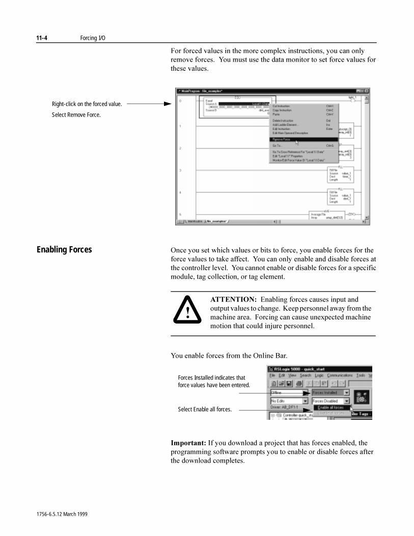
11-4 Forcing I/O
)RU�IRUFHG�YDOXHV�LQ�WKH�PRUH�FRPSOH[�LQVWUXFWLRQV��\RX�FDQ�RQO\�UHPRYH�IRUFHV���<RX�PXVW�XVH�WKH�GDWD�PRQLWRU�WR�VHW�IRUFH�YDOXHV�IRU�WKHVH�YDOXHV�
Enabling Forces 2QFH�\RX�VHW�ZKLFK�YDOXHV�RU�ELWV�WR�IRUFH��\RX�HQDEOH�IRUFHV�IRU�WKH�IRUFH�YDOXHV�WR�WDNH�DIIHFW���<RX�FDQ�RQO\�HQDEOH�DQG�GLVDEOH�IRUFHV�DW�WKH�FRQWUROOHU�OHYHO���<RX�FDQQRW�HQDEOH�RU�GLVDEOH�IRUFHV�IRU�D�VSHFLILF�PRGXOH��WDJ�FROOHFWLRQ��RU�WDJ�HOHPHQW�
<RX�HQDEOH�IRUFHV�IURP�WKH�2QOLQH�%DU��
,PSRUWDQW��,I�\RX�GRZQORDG�D�SURMHFW�WKDW�KDV�IRUFHV�HQDEOHG��WKH�SURJUDPPLQJ�VRIWZDUH�SURPSWV�\RX�WR�HQDEOH�RU�GLVDEOH�IRUFHV�DIWHU�WKH�GRZQORDG�FRPSOHWHV�
Right-click on the forced value.
Select Remove Force.
�$77(17,21� (QDEOLQJ�IRUFHV�FDXVHV�LQSXW�DQG�RXWSXW�YDOXHV�WR�FKDQJH���.HHS�SHUVRQQHO�DZD\�IURP�WKH�PDFKLQH�DUHD���)RUFLQJ�FDQ�FDXVH�XQH[SHFWHG�PDFKLQH�PRWLRQ�WKDW�FRXOG�LQMXUH SHUVRQQHO�
Select Enable all forces.
Forces Installed indicates that force values have been entered.
1756-6.5.12 March 1999
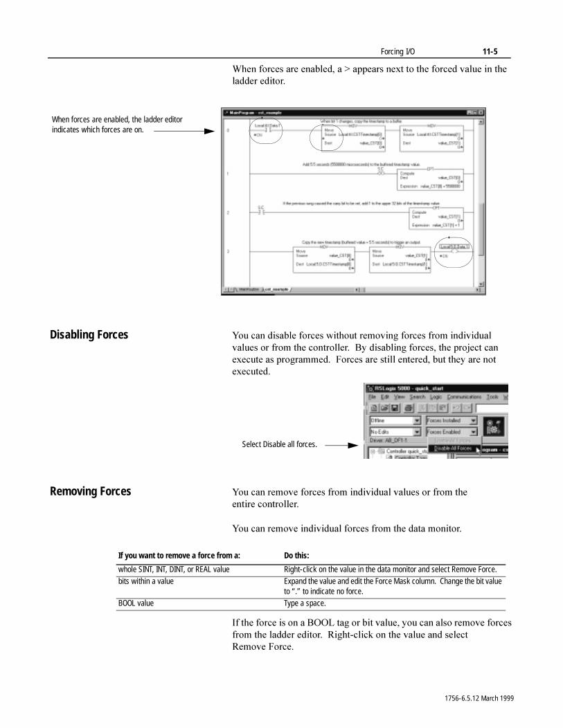
Forcing I/O 11-5
:KHQ�IRUFHV�DUH�HQDEOHG��D�!�DSSHDUV�QH[W�WR�WKH�IRUFHG�YDOXH�LQ�WKH�ODGGHU�HGLWRU�
Disabling Forces <RX�FDQ�GLVDEOH�IRUFHV�ZLWKRXW�UHPRYLQJ�IRUFHV�IURP�LQGLYLGXDO�YDOXHV�RU�IURP�WKH�FRQWUROOHU���%\�GLVDEOLQJ�IRUFHV��WKH�SURMHFW�FDQ�H[HFXWH�DV�SURJUDPPHG���)RUFHV�DUH�VWLOO�HQWHUHG��EXW�WKH\�DUH�QRW�H[HFXWHG�
Removing Forces <RX�FDQ�UHPRYH�IRUFHV�IURP�LQGLYLGXDO�YDOXHV�RU�IURP�WKH�HQWLUH FRQWUROOHU�
<RX�FDQ�UHPRYH�LQGLYLGXDO�IRUFHV�IURP�WKH�GDWD�PRQLWRU�
,I�WKH�IRUFH�LV�RQ�D�%22/�WDJ�RU�ELW�YDOXH��\RX�FDQ�DOVR�UHPRYH�IRUFHV�IURP�WKH�ODGGHU�HGLWRU���5LJKW�FOLFN�RQ�WKH�YDOXH�DQG�VHOHFW�5HPRYH )RUFH�
When forces are enabled, the ladder editor indicates which forces are on.
Select Disable all forces.
If you want to remove a force from a: Do this:
whole SINT, INT, DINT, or REAL value Right-click on the value in the data monitor and select Remove Force.bits within a value Expand the value and edit the Force Mask column. Change the bit value
to “.” to indicate no force.BOOL value Type a space.
1756-6.5.12 March 1999
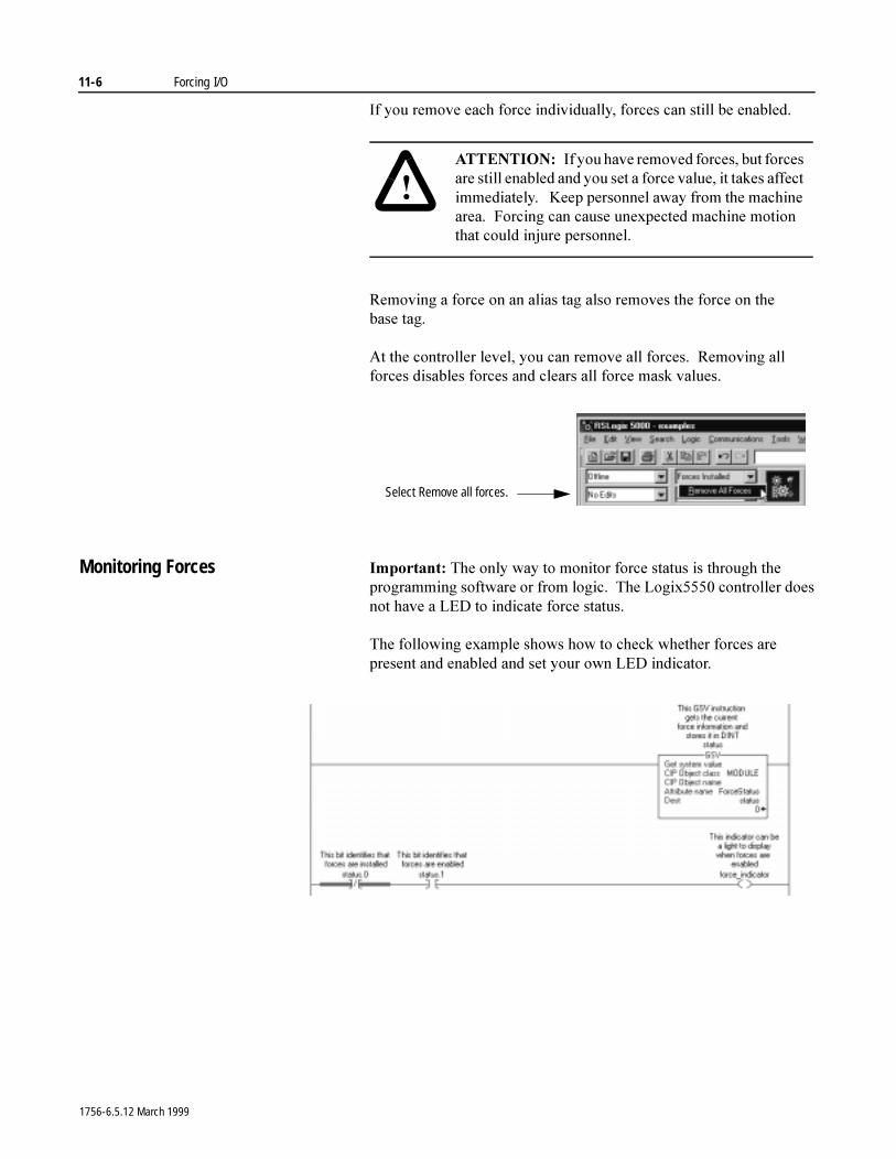
11-6 Forcing I/O
,I�\RX�UHPRYH�HDFK�IRUFH�LQGLYLGXDOO\��IRUFHV�FDQ�VWLOO�EH�HQDEOHG�
5HPRYLQJ�D�IRUFH�RQ�DQ�DOLDV�WDJ�DOVR�UHPRYHV�WKH�IRUFH�RQ�WKH�EDVH WDJ�
$W�WKH�FRQWUROOHU�OHYHO��\RX�FDQ�UHPRYH�DOO�IRUFHV���5HPRYLQJ�DOO�IRUFHV�GLVDEOHV�IRUFHV�DQG�FOHDUV�DOO�IRUFH�PDVN�YDOXHV�
Monitoring Forces ,PSRUWDQW��7KH�RQO\�ZD\�WR�PRQLWRU�IRUFH�VWDWXV�LV�WKURXJK�WKH�SURJUDPPLQJ�VRIWZDUH�RU�IURP�ORJLF���7KH�/RJL[�����FRQWUROOHU�GRHV�QRW�KDYH�D�/('�WR�LQGLFDWH�IRUFH�VWDWXV�
7KH�IROORZLQJ�H[DPSOH�VKRZV�KRZ�WR�FKHFN�ZKHWKHU�IRUFHV�DUH�SUHVHQW�DQG�HQDEOHG�DQG�VHW�\RXU�RZQ�/('�LQGLFDWRU�
�$77(17,21� ,I�\RX�KDYH�UHPRYHG�IRUFHV��EXW�IRUFHV�DUH�VWLOO�HQDEOHG�DQG�\RX�VHW�D�IRUFH�YDOXH��LW�WDNHV�DIIHFW�LPPHGLDWHO\����.HHS�SHUVRQQHO�DZD\�IURP�WKH�PDFKLQH�DUHD���)RUFLQJ�FDQ�FDXVH�XQH[SHFWHG�PDFKLQH�PRWLRQ�WKDW�FRXOG�LQMXUH SHUVRQQHO�
Select Remove all forces.
1756-6.5.12 March 1999
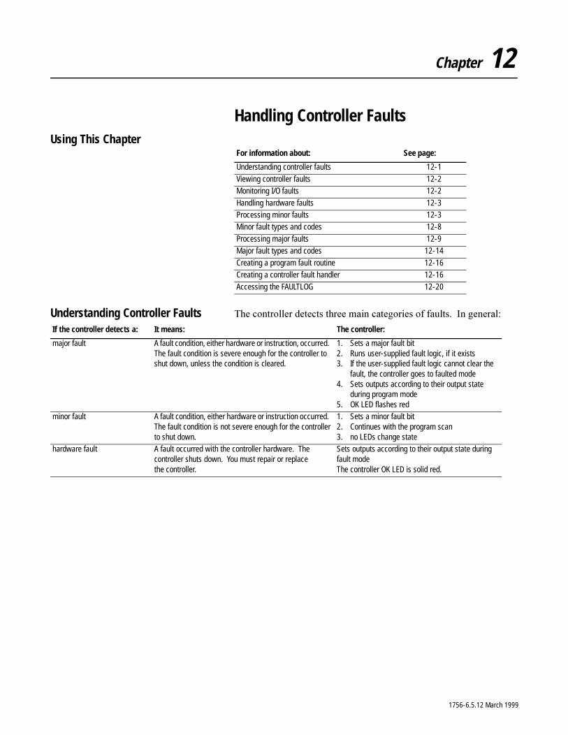
Chapter 12
Handling Controller FaultsUsing This Chapter
Understanding Controller Faults 7KH�FRQWUROOHU�GHWHFWV�WKUHH�PDLQ�FDWHJRULHV�RI�IDXOWV���,Q�JHQHUDO�
For information about: See page:
Understanding controller faults 12-1
Viewing controller faults 12-2Monitoring I/O faults 12-2
Handling hardware faults 12-3Processing minor faults 12-3Minor fault types and codes 12-8
Processing major faults 12-9Major fault types and codes 12-14
Creating a program fault routine 12-16Creating a controller fault handler 12-16
Accessing the FAULTLOG 12-20
If the controller detects a: It means: The controller:
major fault A fault condition, either hardware or instruction, occurred. The fault condition is severe enough for the controller to shut down, unless the condition is cleared.
1. Sets a major fault bit2. Runs user-supplied fault logic, if it exists3. If the user-supplied fault logic cannot clear the
fault, the controller goes to faulted mode4. Sets outputs according to their output state
during program mode5. OK LED flashes red
minor fault A fault condition, either hardware or instruction occurred. The fault condition is not severe enough for the controller to shut down.
1. Sets a minor fault bit2. Continues with the program scan3. no LEDs change state
hardware fault A fault occurred with the controller hardware. The controller shuts down. You must repair or replace the controller.
Sets outputs according to their output state during fault modeThe controller OK LED is solid red.
1756-6.5.12 March 1999
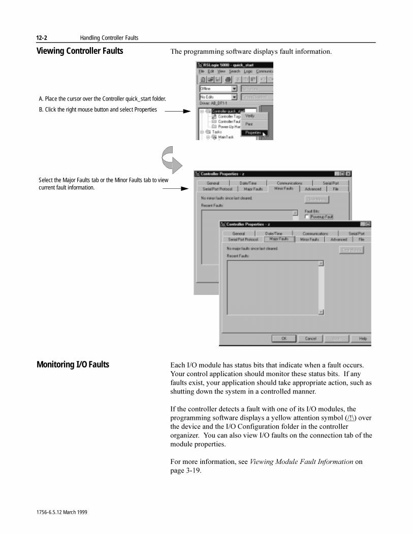
12-2 Handling Controller Faults
Viewing Controller Faults 7KH�SURJUDPPLQJ�VRIWZDUH�GLVSOD\V�IDXOW�LQIRUPDWLRQ�
Monitoring I/O Faults (DFK�,�2�PRGXOH�KDV�VWDWXV�ELWV�WKDW�LQGLFDWH�ZKHQ�D�IDXOW�RFFXUV���<RXU�FRQWURO�DSSOLFDWLRQ�VKRXOG�PRQLWRU�WKHVH�VWDWXV�ELWV���,I�DQ\�IDXOWV�H[LVW��\RXU�DSSOLFDWLRQ�VKRXOG�WDNH�DSSURSULDWH�DFWLRQ��VXFK�DV�VKXWWLQJ�GRZQ�WKH�V\VWHP�LQ�D�FRQWUROOHG�PDQQHU�
,I�WKH�FRQWUROOHU�GHWHFWV�D�IDXOW�ZLWK�RQH�RI�LWV�,�2�PRGXOHV��WKH�SURJUDPPLQJ�VRIWZDUH�GLVSOD\V�D�\HOORZ�DWWHQWLRQ�V\PERO����?��RYHU�WKH�GHYLFH�DQG�WKH�,�2�&RQILJXUDWLRQ�IROGHU�LQ�WKH�FRQWUROOHU�RUJDQL]HU���<RX�FDQ�DOVR�YLHZ�,�2�IDXOWV�RQ�WKH�FRQQHFWLRQ�WDE�RI�WKH�PRGXOH�SURSHUWLHV�
)RU�PRUH�LQIRUPDWLRQ��VHH�9LHZLQJ�0RGXOH�)DXOW�,QIRUPDWLRQ�RQ�SDJH �����
A. Place the cursor over the Controller quick_start folder.
B. Click the right mouse button and select Properties
Select the Major Faults tab or the Minor Faults tab to view current fault information.
1756-6.5.12 March 1999
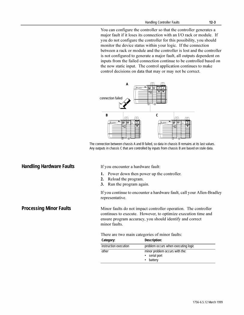
Handling Controller Faults 12-3
<RX�FDQ�FRQILJXUH�WKH�FRQWUROOHU�VR�WKDW�WKH�FRQWUROOHU�JHQHUDWHV�D�PDMRU�IDXOW�LI�LW�ORVHV�LWV�FRQQHFWLRQ�ZLWK�DQ�,�2�UDFN�RU�PRGXOH���,I�\RX�GR�QRW�FRQILJXUH�WKH�FRQWUROOHU�IRU�WKLV�SRVVLELOLW\��\RX�VKRXOG�PRQLWRU�WKH�GHYLFH VWDWXV�ZLWKLQ�\RXU�ORJLF���,I�WKH�FRQQHFWLRQ�EHWZHHQ�D�UDFN�RU�PRGXOH�DQG�WKH�FRQWUROOHU�LV�ORVW�DQG�WKH�FRQWUROOHU�LV�QRW�FRQILJXUHG�WR�JHQHUDWH�D�PDMRU�IDXOW��DOO�RXWSXWV�GHSHQGHQW�RQ�LQSXWV�IURP�WKH�IDLOHG�FRQQHFWLRQ�FRQWLQXH�WR�EH�FRQWUROOHG�EDVHG�RQ�WKH�QRZ�VWDWLF�LQSXW���7KH�FRQWURO�DSSOLFDWLRQ�FRQWLQXHV�WR�PDNH�FRQWURO�GHFLVLRQV�RQ�GDWD�WKDW�PD\�RU�PD\�QRW�EH FRUUHFW�
Handling Hardware Faults ,I�\RX�HQFRXQWHU�D�KDUGZDUH�IDXOW�
�� 3RZHU�GRZQ�WKHQ�SRZHU�XS�WKH�FRQWUROOHU��� 5HORDG�WKH�SURJUDP��� 5XQ�WKH�SURJUDP�DJDLQ�
,I�\RX�FRQWLQXH�WR�HQFRXQWHU�D�KDUGZDUH�IDXOW��FDOO�\RXU�$OOHQ�%UDGOH\�UHSUHVHQWDWLYH�
Processing Minor Faults 0LQRU�IDXOWV�GR�QRW�LPSDFW�FRQWUROOHU�RSHUDWLRQ���7KH�FRQWUROOHU�FRQWLQXHV�WR�H[HFXWH���+RZHYHU��WR�RSWLPL]H�H[HFXWLRQ�WLPH�DQG�HQVXUH�SURJUDP�DFFXUDF\��\RX�VKRXOG�LGHQWLI\�DQG�FRUUHFW�PLQRU IDXOWV�
7KHUH�DUH�WZR�PDLQ�FDWHJRULHV�RI�PLQRU�IDXOWV�
The connection between chassis A and B failed, so data in chassis B remains at its last values. Any outputs in chassis C that are controlled by inputs from chassis B are based on stale data.
A
B C
connection failed
Category: Description:
instruction execution problem occurs when executing logic
other minor problem occurs with the:• serial port• battery
1756-6.5.12 March 1999
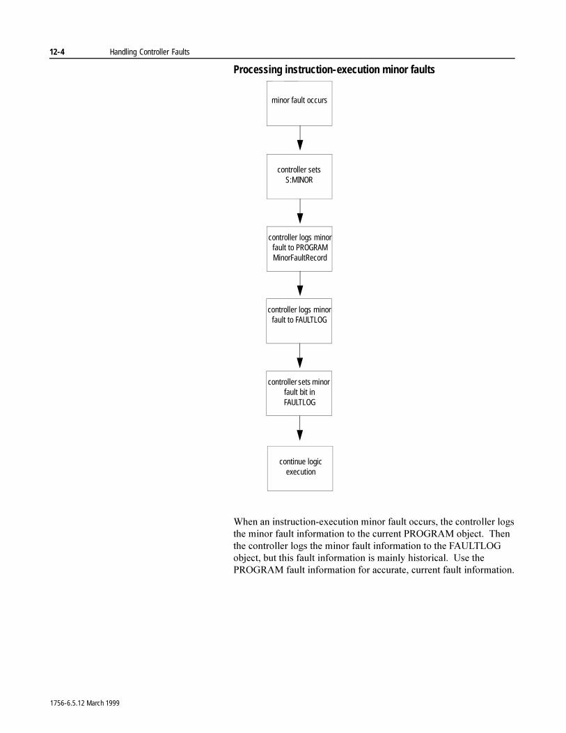
12-4 Handling Controller Faults
Processing instruction-execution minor faults
:KHQ�DQ�LQVWUXFWLRQ�H[HFXWLRQ�PLQRU�IDXOW�RFFXUV��WKH�FRQWUROOHU�ORJV�WKH�PLQRU�IDXOW�LQIRUPDWLRQ�WR�WKH�FXUUHQW�352*5$0�REMHFW���7KHQ�WKH�FRQWUROOHU�ORJV�WKH�PLQRU�IDXOW�LQIRUPDWLRQ�WR�WKH�)$8/7/2*�REMHFW��EXW�WKLV�IDXOW�LQIRUPDWLRQ�LV�PDLQO\�KLVWRULFDO���8VH�WKH�352*5$0�IDXOW�LQIRUPDWLRQ�IRU�DFFXUDWH��FXUUHQW�IDXOW�LQIRUPDWLRQ�
minor fault occurs
continue logic execution
controller logs minor fault to PROGRAM MinorFaultRecord
controller sets S:MINOR
controller logs minor fault to FAULTLOG
controller sets minor fault bit in FAULTLOG
1756-6.5.12 March 1999
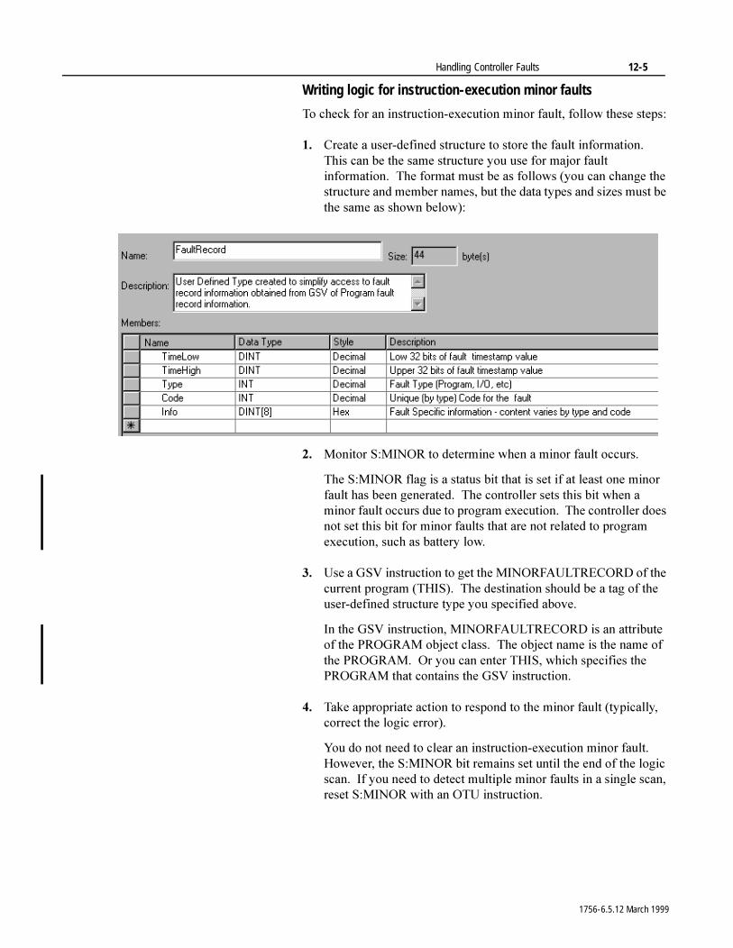
Handling Controller Faults 12-5
Writing logic for instruction-execution minor faults
7R�FKHFN�IRU�DQ�LQVWUXFWLRQ�H[HFXWLRQ�PLQRU�IDXOW��IROORZ�WKHVH VWHSV�
�� &UHDWH�D�XVHU�GHILQHG�VWUXFWXUH�WR�VWRUH�WKH�IDXOW�LQIRUPDWLRQ���7KLV�FDQ�EH�WKH�VDPH�VWUXFWXUH�\RX�XVH�IRU�PDMRU�IDXOW�LQIRUPDWLRQ���7KH�IRUPDW�PXVW�EH�DV�IROORZV��\RX�FDQ�FKDQJH�WKH�VWUXFWXUH�DQG�PHPEHU�QDPHV��EXW�WKH�GDWD�W\SHV�DQG�VL]HV�PXVW�EH�WKH�VDPH�DV�VKRZQ�EHORZ��
�� 0RQLWRU�6�0,125�WR�GHWHUPLQH�ZKHQ�D�PLQRU�IDXOW�RFFXUV�
7KH�6�0,125�IODJ�LV�D�VWDWXV�ELW�WKDW�LV�VHW�LI�DW�OHDVW�RQH�PLQRU�IDXOW�KDV�EHHQ�JHQHUDWHG���7KH�FRQWUROOHU�VHWV�WKLV�ELW�ZKHQ�D�PLQRU�IDXOW�RFFXUV�GXH�WR�SURJUDP�H[HFXWLRQ���7KH�FRQWUROOHU�GRHV�QRW�VHW�WKLV�ELW�IRU�PLQRU�IDXOWV�WKDW�DUH�QRW�UHODWHG�WR�SURJUDP�H[HFXWLRQ��VXFK�DV�EDWWHU\�ORZ�
�� 8VH�D�*69�LQVWUXFWLRQ�WR�JHW�WKH�0,125)$8/75(&25'�RI�WKH�FXUUHQW�SURJUDP��7+,6����7KH�GHVWLQDWLRQ�VKRXOG�EH�D�WDJ�RI�WKH�XVHU�GHILQHG�VWUXFWXUH�W\SH�\RX�VSHFLILHG�DERYH�
,Q�WKH�*69�LQVWUXFWLRQ��0,125)$8/75(&25'�LV�DQ�DWWULEXWH�RI�WKH�352*5$0�REMHFW�FODVV���7KH�REMHFW�QDPH�LV�WKH�QDPH�RI�WKH�352*5$0���2U�\RX�FDQ�HQWHU�7+,6��ZKLFK�VSHFLILHV�WKH�352*5$0�WKDW�FRQWDLQV�WKH�*69�LQVWUXFWLRQ�
�� 7DNH�DSSURSULDWH�DFWLRQ�WR�UHVSRQG�WR�WKH�PLQRU�IDXOW��W\SLFDOO\��FRUUHFW�WKH�ORJLF�HUURU��
<RX�GR�QRW�QHHG�WR�FOHDU�DQ�LQVWUXFWLRQ�H[HFXWLRQ�PLQRU�IDXOW���+RZHYHU��WKH�6�0,125�ELW�UHPDLQV�VHW�XQWLO�WKH�HQG�RI�WKH�ORJLF�VFDQ���,I�\RX�QHHG�WR�GHWHFW�PXOWLSOH�PLQRU�IDXOWV�LQ�D�VLQJOH�VFDQ��UHVHW�6�0,125�ZLWK�DQ�278�LQVWUXFWLRQ�
1756-6.5.12 March 1999
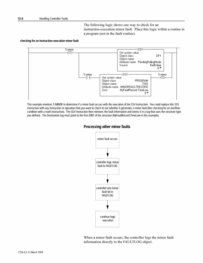
12-6 Handling Controller Faults
7KH�IROORZLQJ�ORJLF�VKRZV�RQH�ZD\�WR�FKHFN�IRU�DQ�LQVWUXFWLRQ�H[HFXWLRQ�PLQRU�IDXOW���3ODFH�WKLV�ORJLF�ZLWKLQ�D�URXWLQH�LQ�D�SURJUDP��QRW�LQ�WKH�IDXOW�URXWLQH��
Processing other minor faults
:KHQ�D�PLQRU�IDXOW�RFFXUV��WKH�FRQWUROOHU�ORJV�WKH�PLQRU�IDXOW�LQIRUPDWLRQ�GLUHFWO\�WR�WKH�)$8/7/2*�REMHFW�
checking for an instruction-execution minor fault
This example monitors S:MINOR to determine if a minor fault occurs with the execution of the SSV instruction. You could replace this SSV instruction with any instruction or operation that you want to check to see whether it generates a minor fault (like checking for an overflow condition with a math instruction). The GSV instruction then retrieves the fault information and stores it in a tag that uses the structure type you defined. The Destination tag must point to the first DINT of the structure (MyFaultRecord.TimeLow in this example).
minor fault occurs
continue logic execution
controller logs minor fault to FAULTLOG
controller sets minor fault bit in FAULTLOG
1756-6.5.12 March 1999
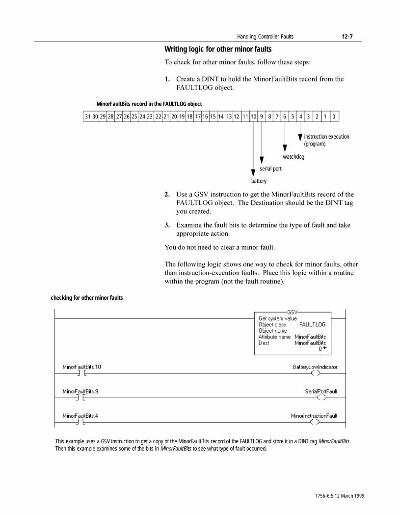
Handling Controller Faults 12-7
Writing logic for other minor faults
7R�FKHFN�IRU�RWKHU�PLQRU�IDXOWV��IROORZ�WKHVH�VWHSV�
�� &UHDWH�D�',17�WR�KROG�WKH�0LQRU)DXOW%LWV�UHFRUG�IURP�WKH�)$8/7/2*�REMHFW�
�� 8VH�D�*69�LQVWUXFWLRQ�WR�JHW�WKH�0LQRU)DXOW%LWV�UHFRUG�RI�WKH�)$8/7/2*�REMHFW���7KH�'HVWLQDWLRQ�VKRXOG�EH�WKH�',17�WDJ�\RX FUHDWHG�
�� ([DPLQH�WKH�IDXOW�ELWV�WR�GHWHUPLQH�WKH�W\SH�RI�IDXOW�DQG�WDNH�DSSURSULDWH�DFWLRQ�
<RX�GR�QRW�QHHG�WR�FOHDU�D�PLQRU�IDXOW�
7KH�IROORZLQJ�ORJLF�VKRZV�RQH�ZD\�WR�FKHFN�IRU�PLQRU�IDXOWV��RWKHU�WKDQ�LQVWUXFWLRQ�H[HFXWLRQ�IDXOWV���3ODFH�WKLV�ORJLF�ZLWKLQ�D�URXWLQH�ZLWKLQ�WKH�SURJUDP��QRW�WKH�IDXOW URXWLQH��
31 30 29 28 27 26 25 24 23 22 21 20 19 18 17 16 15 14 13 12 11 10 9 8 7 6 5 4 3 2 1 0
instruction execution (program)
watchdog
serial port
battery
MinorFaultBits record in the FAULTLOG object
checking for other minor faults
This example uses a GSV instruction to get a copy of the MinorFaultBits record of the FAULTLOG and store it in a DINT tag MinorFaultBits. Then this example examines some of the bits in MinorFaultBits to see what type of fault occurred.
1756-6.5.12 March 1999
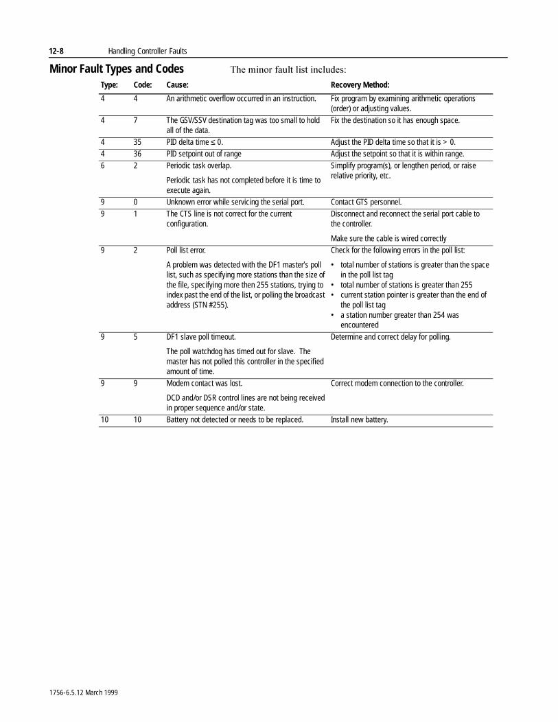
12-8 Handling Controller Faults
Minor Fault Types and Codes 7KH�PLQRU�IDXOW�OLVW�LQFOXGHV�
Type: Code: Cause: Recovery Method:
4 4 An arithmetic overflow occurred in an instruction. Fix program by examining arithmetic operations (order) or adjusting values.
4 7 The GSV/SSV destination tag was too small to hold all of the data.
Fix the destination so it has enough space.
4 35 PID delta time ≤ 0. Adjust the PID delta time so that it is > 0.4 36 PID setpoint out of range Adjust the setpoint so that it is within range.
6 2 Periodic task overlap.
Periodic task has not completed before it is time to execute again.
Simplify program(s), or lengthen period, or raise relative priority, etc.
9 0 Unknown error while servicing the serial port. Contact GTS personnel.
9 1 The CTS line is not correct for the current configuration.
Disconnect and reconnect the serial port cable to the controller.
Make sure the cable is wired correctly9 2 Poll list error.
A problem was detected with the DF1 master’s poll list, such as specifying more stations than the size of the file, specifying more then 255 stations, trying to index past the end of the list, or polling the broadcast address (STN #255).
Check for the following errors in the poll list:
• total number of stations is greater than the space in the poll list tag
• total number of stations is greater than 255• current station pointer is greater than the end of
the poll list tag• a station number greater than 254 was
encountered
9 5 DF1 slave poll timeout.
The poll watchdog has timed out for slave. The master has not polled this controller in the specified amount of time.
Determine and correct delay for polling.
9 9 Modem contact was lost.
DCD and/or DSR control lines are not being received in proper sequence and/or state.
Correct modem connection to the controller.
10 10 Battery not detected or needs to be replaced. Install new battery.
1756-6.5.12 March 1999

Handling Controller Faults 12-9
Processing Major Faults 7KH�FRQWUROOHU�VXSSRUWV�WZR�OHYHOV�IRU�KDQGOLQJ�PDMRU�IDXOWV�� SURJUDP�IDXOW�URXWLQH� FRQWUROOHU�IDXOW�KDQGOHU
(DFK�SURJUDP�FDQ�KDYH�LWV�RZQ�IDXOW�URXWLQH���7KH�FRQWUROOHU�H[HFXWHV�WKH�SURJUDP¶V�IDXOW�URXWLQH�ZKHQ�DQ�LQVWUXFWLRQ�IDXOW�RFFXUV���,I�WKH�SURJUDPV¶�IDXOW�URXWLQH�GRHV�QRW�FOHDU�WKH�IDXOW��RU�D�SURJUDP�IDXOW�URXWLQH�GRHV�QRW�H[LVW��WKH�FRQWUROOHU�SURFHHGV�WR�H[HFXWH�WKH�FRQWUROOHU�IDXOW�KDQGOHU��LI�GHILQHG����,I�WKH�FRQWUROOHU�IDXOW�KDQGOHU�GRHV�QRW�H[LVW�RU�FDQQRW�FOHDU�WKH�PDMRU�IDXOW��WKH�FRQWUROOHU�HQWHUV�IDXOWHG�PRGH�DQG�VKXWV�GRZQ���$W�WKLV�SRLQW��WKH�)$8/7/2*�LV�XSGDWHG����6HH�WKH�QH[W�SDJH��
$OO�QRQ�LQVWUXFWLRQ�IDXOWV��,�2��WDVN�ZDWFKGRJ��HWF���H[HFXWH�WKH�FRQWUROOHU�IDXOW KDQGOHU�GLUHFWO\��QR�SURJUDP�IDXOW�URXWLQH�LV�FDOOHG��
configuration
status
task 1
program 1
program 32
program
main routine
fault routine
other routines
program (local) tags
task 32
control applicationcontroller fault handler power up handler
watchdog
controller (global) tags I/O data system-shared data
40012
1756-6.5.12 March 1999
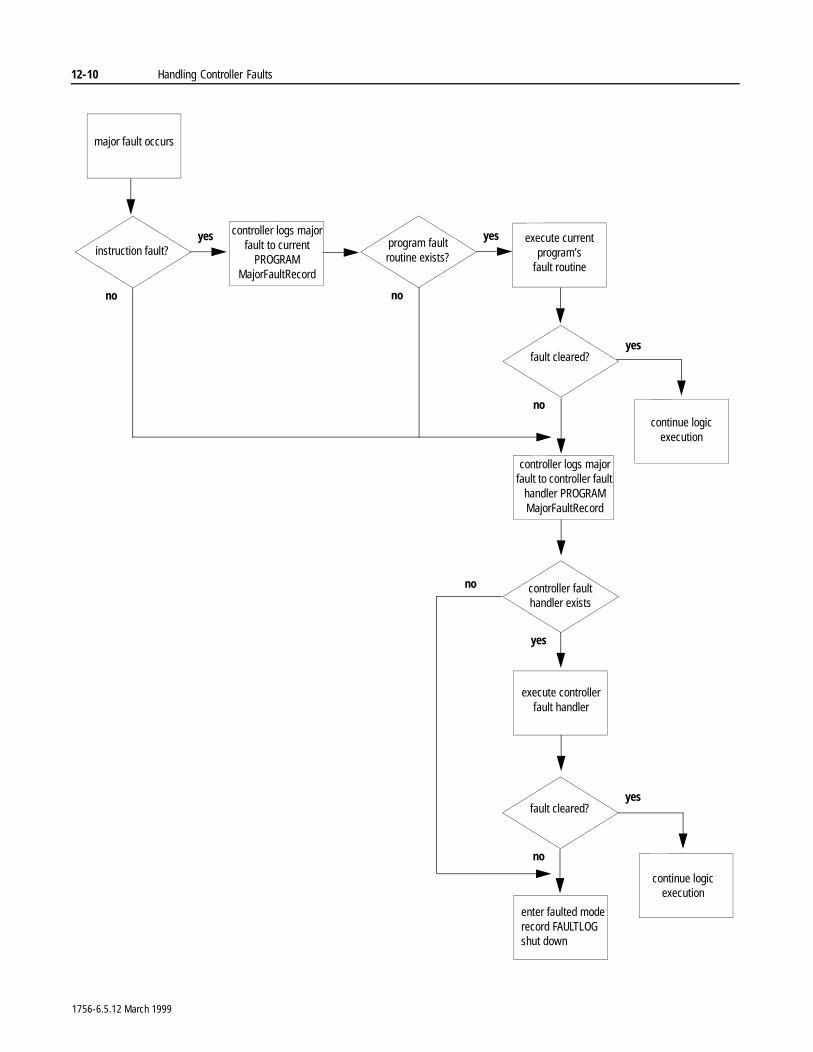
12-10 Handling Controller Faults
execute current program’s
fault routine
fault cleared?
execute controllerfault handler
continue logic execution
yes
no
fault cleared?yes
no
enter faulted moderecord FAULTLOGshut down
program fault routine exists?
yes
no
major fault occurs
instruction fault?yes
no
continue logic execution
controller logs major fault to current
PROGRAM MajorFaultRecord
controller logs major fault to controller fault
handler PROGRAM MajorFaultRecord
controller fault handler exists
yes
no
1756-6.5.12 March 1999
Handling Controller Faults 12-11
7KHUH�DUH�WZR�PDLQ�FDWHJRULHV�RI�PDMRU�IDXOWV�
7KH�PXOWLWDVNLQJ�FDSDELOLW\�RI�WKH�FRQWUROOHU�PDNHV�LW�SRVVLEOH�IRU�PXOWLSOH�PDMRU�IDXOWV�WR�EH�UHSRUWHG���)RU�H[DPSOH��PXOWLSOH�WDVN�ZDWFKGRJ�WLPHRXWV�FDQ�RFFXU�DW�WKH�VDPH�WLPH�RU�,�2�IDXOWV�FDQ�EH�UHSRUWHG�DW�WKH�VDPH�WLPH�DV�DQ�LQVWUXFWLRQ�H[HFXWLRQ�IDXOW�RFFXUV���,Q�WKHVH�FDVHV��PDMRU�IDXOWV�DUH�SURFHVVHG�LQ�WKH�RUGHU�WKDW�WKH\�RFFXUUHG�
<RX�FDQ�XVH�WKH�FRQWUROOHU�IDXOW�KDQGOHU�WR�FOHDU�D�ZDWFKGRJ�IDXOW���,I�WKH�VDPH�ZDWFKGRJ�IDXOW�RFFXUV�D�VHFRQG�WLPH�GXULQJ�WKH�VDPH�ORJLF�VFDQ��WKH�FRQWUROOHU�HQWHUV�IDXOWHG�PRGH��UHJDUGOHVV�RI�ZKHWKHU�WKH�FRQWUROOHU�IDXOW�KDQGOHU�FOHDUV�WKH�ZDWFKGRJ�IDXOW�
,I�DQ\�RI�WKH�PXOWLSOH�UHSRUWHG�PDMRU�IDXOWV�DUH�QRW�FOHDUHG�E\�WKH�FRQWUROOHU�IDXOW�KDQGOHU��WKH�FRQWUROOHU�JRHV�WR�IDXOWHG�PRGH���7KH�IDXOW�WKDW�ZDV�QRW�FOHDUHG��DQG�XS�WR�WZR�DGGLWLRQDO�IDXOWV�WKDW�KDYH�QRW�EHHQ�FOHDUHG��DUH�ORJJHG�LQ�WKH�FRQWUROOHU�IDXOW�ORJ���<RX�FDQ�YLHZ�WKLV�IDXOW�LQIRUPDWLRQ�YLD�WKH�SURJUDPPLQJ�VRIWZDUH�E\�XVLQJ�WKH�PDMRU�IDXOW�WDE�LQ�WKH�FRQWUROOHU�SURSHUWLHV�
7KH�FRQWUROOHU�FDQ�KDQGOH�DV�PDQ\�DV����VLPXOWDQHRXV�PDMRU�IDXOWV���,I�PRUH�WKDQ����PDMRU�IDXOWV�RFFXU�DW�WKH�VDPH�WLPH��WKH�FRQWUROOHU�JRHV�WR�IDXOWHG�PRGH�DQG�WKH�ILUVW�WKUHH�PDMRU�IDXOWV�DUH�ORJJHG�WR�WKH�FRQWUROOHU�IDXOW�ORJ
Category: Description:
instruction execution problem occurs when executing logicother major problem occurs with the:
• power loss• I/O• task watchdog• mode change• motion axis
1756-6.5.12 March 1999
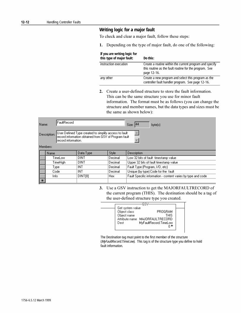
12-12 Handling Controller Faults
Writing logic for a major fault7R�FKHFN�DQG�FOHDU�D�PDMRU�IDXOW��IROORZ�WKHVH VWHSV�
�� 'HSHQGLQJ�RQ�WKH�W\SH�RI�PDMRU�IDXOW��GR�RQH�RI�WKH�IROORZLQJ�
�� &UHDWH�D�XVHU�GHILQHG�VWUXFWXUH�WR�VWRUH�WKH�IDXOW�LQIRUPDWLRQ���7KLV�FDQ�EH�WKH�VDPH�VWUXFWXUH�\RX�XVH�IRU�PLQRU�IDXOW�LQIRUPDWLRQ���7KH�IRUPDW�PXVW�EH�DV�IROORZV��\RX�FDQ�FKDQJH�WKH�VWUXFWXUH�DQG�PHPEHU�QDPHV��EXW�WKH�GDWD�W\SHV�DQG�VL]HV�PXVW�EH�WKH�VDPH�DV�VKRZQ�EHORZ��
�� 8VH�D�*69�LQVWUXFWLRQ�WR�JHW�WKH�0$-25)$8/75(&25'�RI�WKH�FXUUHQW�SURJUDP��7+,6����7KH�GHVWLQDWLRQ�VKRXOG�EH�D�WDJ�RI�WKH�XVHU�GHILQHG�VWUXFWXUH�W\SH�\RX�FUHDWHG�
If you are writing logic for this type of major fault: Do this:
instruction execution Create a routine within the current program and specify this routine as the fault routine for the program. See page 12-16.
any other Create a new program and select this program as the controller fault handler program. See page 12-16.
The Destination tag must point to the first member of the structure (MyFaultRecord.TimeLow). This tag is of the structure type you define to hold fault information.
1756-6.5.12 March 1999
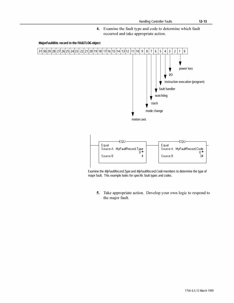
Handling Controller Faults 12-13
�� ([DPLQH�WKH�IDXOW�W\SH�DQG�FRGH�WR�GHWHUPLQH�ZKLFK�IDXOW�RFFXUUHG�DQG�WDNH�DSSURSULDWH�DFWLRQ�
�� 7DNH�DSSURSULDWH�DFWLRQ���'HYHORS�\RXU�RZQ�ORJLF�WR�UHVSRQG�WR�WKH�PDMRU�IDXOW�
31 30 29 28 27 26 25 24 23 22 21 20 19 18 17 16 15 14 13 12 11 10 9 8 7 6 5 4 3 2 1 0
power loss
I/O
instruction execution (program)
watchdog
mode change
motion axis
MajorFaultBits record in the FAULTLOG object
stack
fault handler
Examine the MyFaultRecord.Type and MyFaultRecord.Code members to determine the type of major fault. This example looks for specific fault types and codes.
1756-6.5.12 March 1999
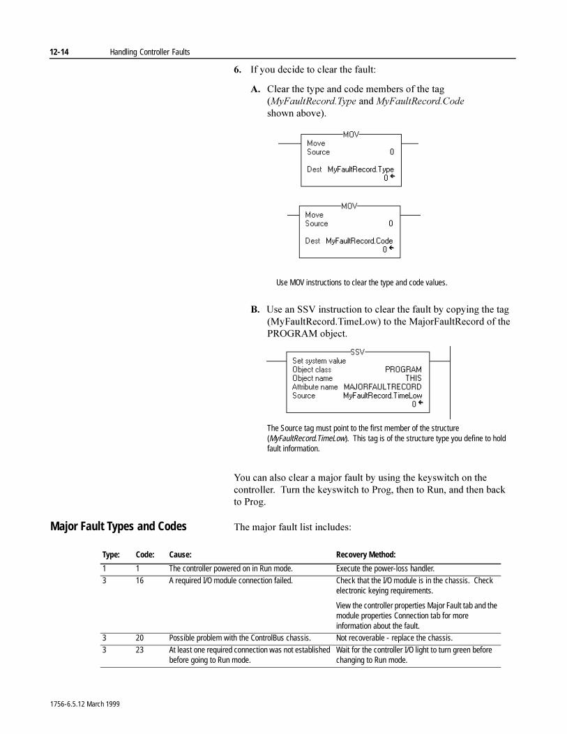
12-14 Handling Controller Faults
�� ,I�\RX�GHFLGH�WR�FOHDU�WKH�IDXOW�
$� &OHDU�WKH�W\SH�DQG�FRGH�PHPEHUV�RI�WKH�WDJ�0\)DXOW5HFRUG�7\SH�DQG�0\)DXOW5HFRUG�&RGH�VKRZQ DERYH��
%� 8VH�DQ�669�LQVWUXFWLRQ�WR�FOHDU�WKH�IDXOW�E\�FRS\LQJ�WKH�WDJ��0\)DXOW5HFRUG�7LPH/RZ��WR�WKH�0DMRU)DXOW5HFRUG�RI�WKH�352*5$0�REMHFW�
<RX�FDQ�DOVR�FOHDU�D�PDMRU�IDXOW�E\�XVLQJ�WKH�NH\VZLWFK�RQ�WKH�FRQWUROOHU���7XUQ�WKH�NH\VZLWFK�WR�3URJ��WKHQ�WR�5XQ��DQG�WKHQ�EDFN�WR 3URJ�
Major Fault Types and Codes 7KH�PDMRU�IDXOW�OLVW�LQFOXGHV�
Use MOV instructions to clear the type and code values.
The Source tag must point to the first member of the structure (MyFaultRecord.TimeLow). This tag is of the structure type you define to hold fault information.
Type: Code: Cause: Recovery Method:
1 1 The controller powered on in Run mode. Execute the power-loss handler.
3 16 A required I/O module connection failed. Check that the I/O module is in the chassis. Check electronic keying requirements.
View the controller properties Major Fault tab and the module properties Connection tab for more information about the fault.
3 20 Possible problem with the ControlBus chassis. Not recoverable - replace the chassis.
3 23 At least one required connection was not established before going to Run mode.
Wait for the controller I/O light to turn green before changing to Run mode.
1756-6.5.12 March 1999
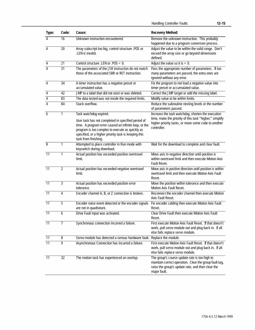
Handling Controller Faults 12-15
4 16 Unknown instruction encountered. Remove the unknown instruction. This probably happened due to a program conversion process.
4 20 Array subscript too big, control structure .POS or .LEN is invalid.
Adjust the value to be within the valid range. Don’t exceed the array size or go beyond dimensions defined.
4 21 Control structure .LEN or .POS < 0. Adjust the value so it is > 0.4 31 The parameters of the JSR instruction do not match
those of the associated SBR or RET instruction.Pass the appropriate number of parameters. If too many parameters are passed, the extra ones are ignored without any error.
4 34 A timer instruction has a negative preset or accumulated value.
Fix the program to not load a negative value into timer preset or accumulated value.
4 42 JMP to a label that did not exist or was deleted. Correct the JMP target or add the missing label.4 83 The data tested was not inside the required limits. Modify value to be within limits.
4 84 Stack overflow. Reduce the subroutine nesting levels or the number of parameters passed.
6 1 Task watchdog expired.
User task has not completed in specified period of time. A program error caused an infinite loop, or the program is too complex to execute as quickly as specified, or a higher priority task is keeping this task from finishing.
Increase the task watchdog, shorten the execution time, make the priority of this task “higher,” simplify higher priority tasks, or move some code to another controller.
8 1 Attempted to place controller in Run mode with keyswitch during download.
Wait for the download to complete and clear fault.
11 1 Actual position has exceeded positive overtravel limit.
Move axis in negative direction until position is within overtravel limit and then execute Motion Axis Fault Reset.
11 2 Actual position has exceeded negative overtravel limit.
Move axis in positive direction until position is within overtravel limit and then execute Motion Axis Fault Reset.
11 3 Actual position has exceeded position error tolerance.
Move the position within tolerance and then execute Motion Axis Fault Reset.
11 4 Encoder channel A, B, or Z connection is broken. Reconnect the encoder channel then execute Motion Axis Fault Reset.
11 5 Encoder noise event detected or the encoder signals are not in quadrature.
Fix encoder cabling then execute Motion Axis Fault Reset.
11 6 Drive Fault input was activated. Clear Drive Fault then execute Motion Axis Fault Reset.
11 7 Synchronous connection incurred a failure. First execute Motion Axis Fault Reset. If that doesn’t work, pull servo module out and plug back in. If all else fails replace servo module.
11 8 Servo module has detected a serious hardware fault. Replace the module.11 9 Asynchronous Connection has incurred a failure. First execute Motion Axis Fault Reset. If that doesn’t
work, pull servo module out and plug back in. If all else fails replace servo module.
11 32 The motion task has experienced an overlap. The group’s course update rate is too high to maintain correct operation. Clear the group fault tag, raise the group’s update rate, and then clear the major fault.
Type: Code: Cause: Recovery Method:
1756-6.5.12 March 1999
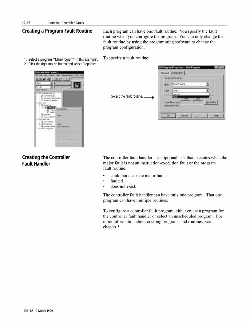
12-16 Handling Controller Faults
Creating a Program Fault Routine (DFK�SURJUDP�FDQ�KDYH�RQH�IDXOW�URXWLQH���<RX�VSHFLI\�WKH�IDXOW�URXWLQH�ZKHQ�\RX�FRQILJXUH�WKH�SURJUDP���<RX�FDQ�RQO\�FKDQJH�WKH�IDXOW�URXWLQH�E\�XVLQJ�WKH�SURJUDPPLQJ�VRIWZDUH�WR�FKDQJH�WKH�SURJUDP FRQILJXUDWLRQ�
7R�VSHFLI\�D�IDXOW�URXWLQH�
Creating the Controller Fault Handler
7KH�FRQWUROOHU�IDXOW�KDQGOHU�LV�DQ�RSWLRQDO�WDVN�WKDW�H[HFXWHV�ZKHQ�WKH�PDMRU�IDXOW�LV�QRW�DQ�LQVWUXFWLRQ�H[HFXWLRQ�IDXOW�RU�WKH�SURJUDP�IDXOW URXWLQH�
� FRXOG�QRW�FOHDU�WKH�PDMRU�IDXOW�� IDXOWHG�� GRHV�QRW�H[LVW�
7KH�FRQWUROOHU�IDXOW�KDQGOHU�FDQ�KDYH�RQO\�RQH�SURJUDP���7KDW�RQH�SURJUDP�FDQ�KDYH�PXOWLSOH�URXWLQHV�
7R�FRQILJXUH�D�FRQWUROOHU�IDXOW�SURJUDP��HLWKHU�FUHDWH�D�SURJUDP�IRU�WKH�FRQWUROOHU�IDXOW�KDQGOHU�RU�VHOHFW�DQ�XQVFKHGXOHG�SURJUDP���)RU�PRUH�LQIRUPDWLRQ�DERXW�FUHDWLQJ�SURJUDPV�DQG�URXWLQHV��VHH�FKDSWHU ��
1. Select a program (“MainProgram” in this example).2. Click the right mouse button and select Properties.
Select the fault routine.
1756-6.5.12 March 1999
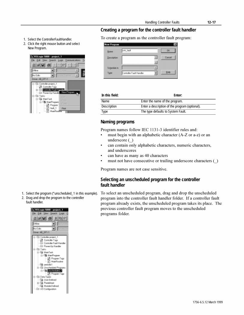
Handling Controller Faults 12-17
Creating a program for the controller fault handler
7R�FUHDWH�D�SURJUDP�DV�WKH�FRQWUROOHU�IDXOW�SURJUDP�
Naming programs
3URJUDP�QDPHV�IROORZ�,(&��������LGHQWLILHU�UXOHV DQG�� PXVW�EHJLQ�ZLWK�DQ�DOSKDEHWLF�FKDUDFWHU��$�=�RU�D�]��RU�DQ�
XQGHUVFRUH �B�� FDQ�FRQWDLQ�RQO\�DOSKDEHWLF�FKDUDFWHUV��QXPHULF�FKDUDFWHUV��
DQG XQGHUVFRUHV� FDQ�KDYH�DV�PDQ\�DV����FKDUDFWHUV� PXVW�QRW�KDYH�FRQVHFXWLYH�RU�WUDLOLQJ�XQGHUVFRUH�FKDUDFWHUV��B�
3URJUDP�QDPHV�DUH�QRW�FDVH�VHQVLWLYH�
Selecting an unscheduled program for the controller fault handler
7R�VHOHFW�DQ�XQVFKHGXOHG�SURJUDP��GUDJ�DQG�GURS�WKH�XQVFKHGXOHG�SURJUDP�LQWR�WKH�FRQWUROOHU�IDXOW�KDQGOHU�IROGHU���,I�D�FRQWUROOHU�IDXOW�SURJUDP�DOUHDG\�H[LVWV��WKH�XQVFKHGXOHG�SURJUDP�WDNHV�LWV�SODFH���7KH�SUHYLRXV�FRQWUROOHU�IDXOW�SURJUDP�PRYHV�WR�WKH�XQVFKHGXOHG�SURJUDPV IROGHU�
In this field: Enter:
Name Enter the name of the program.
Description Enter a description of the program (optional).Type The type defaults to System Fault.
1. Select the ControllerFaultHandler.2. Click the right mouse button and select
New Program.
1. Select the program (“unscheduled_1 in this example).2. Drag and drop the program to the controller
fault handler.
1756-6.5.12 March 1999
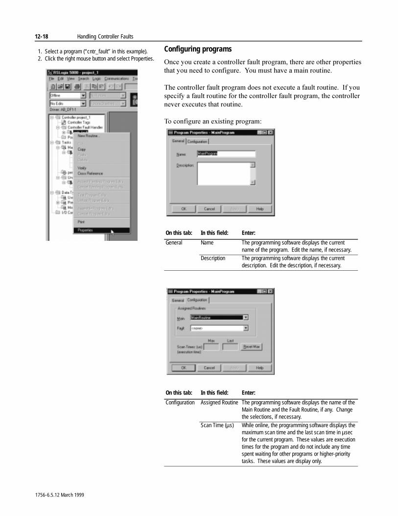
12-18 Handling Controller Faults
Configuring programs
2QFH�\RX�FUHDWH�D�FRQWUROOHU�IDXOW�SURJUDP��WKHUH�DUH�RWKHU�SURSHUWLHV�WKDW�\RX�QHHG�WR�FRQILJXUH���<RX�PXVW�KDYH�D�PDLQ�URXWLQH�
7KH�FRQWUROOHU�IDXOW�SURJUDP�GRHV�QRW�H[HFXWH�D�IDXOW�URXWLQH���,I�\RX�VSHFLI\�D�IDXOW�URXWLQH�IRU�WKH�FRQWUROOHU�IDXOW�SURJUDP��WKH�FRQWUROOHU�QHYHU�H[HFXWHV�WKDW�URXWLQH�
7R�FRQILJXUH�DQ�H[LVWLQJ�SURJUDP�
On this tab: In this field: Enter:
General Name The programming software displays the current name of the program. Edit the name, if necessary.
Description The programming software displays the current description. Edit the description, if necessary.
On this tab: In this field: Enter:
Configuration Assigned Routine The programming software displays the name of the Main Routine and the Fault Routine, if any. Change the selections, if necessary.
Scan Time (µs) While online, the programming software displays the maximum scan time and the last scan time in µsec for the current program. These values are execution times for the program and do not include any time spent waiting for other programs or higher-priority tasks. These values are display only.
1. Select a program (“cntr_fault” in this example).2. Click the right mouse button and select Properties.
1756-6.5.12 March 1999
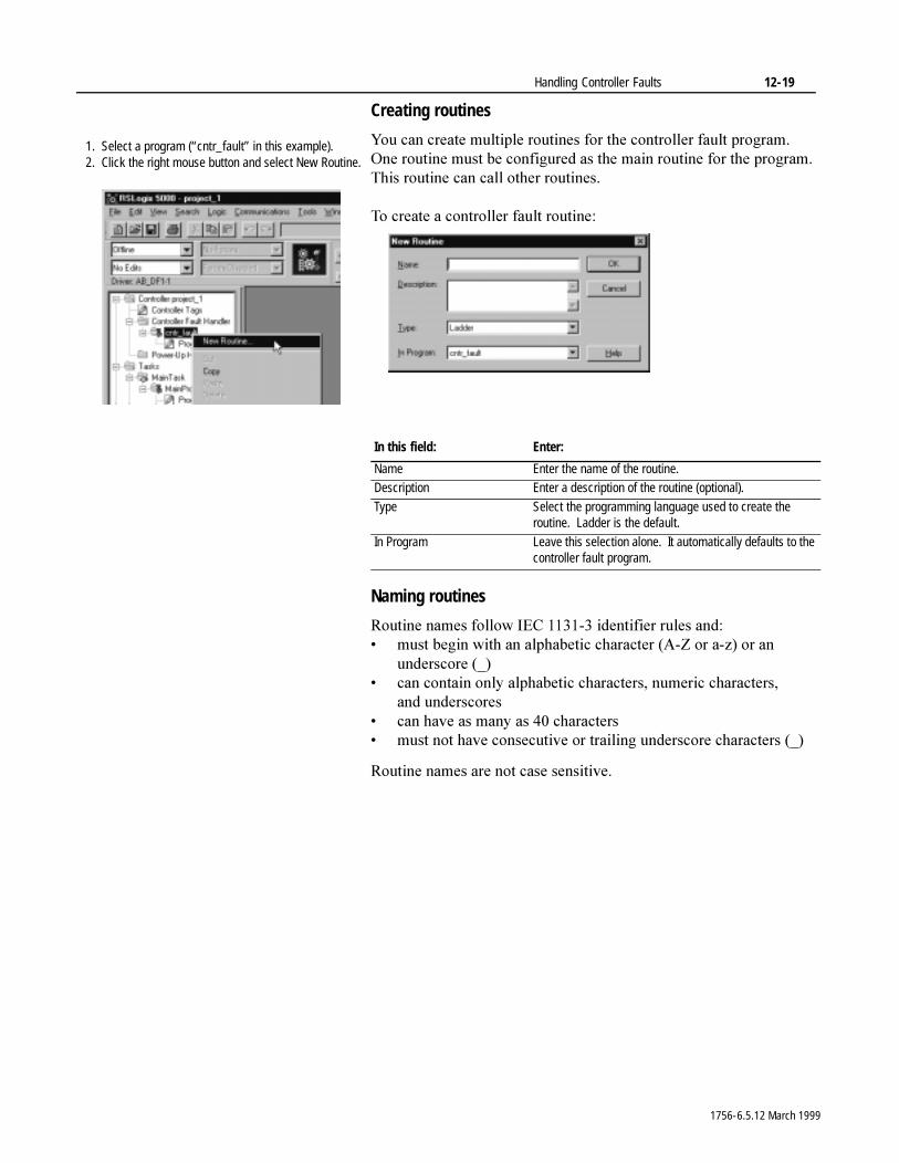
Handling Controller Faults 12-19
Creating routines
<RX�FDQ�FUHDWH�PXOWLSOH�URXWLQHV�IRU�WKH�FRQWUROOHU�IDXOW�SURJUDP���2QH�URXWLQH�PXVW�EH�FRQILJXUHG�DV�WKH�PDLQ�URXWLQH�IRU�WKH�SURJUDP���7KLV�URXWLQH�FDQ�FDOO�RWKHU�URXWLQHV�
7R�FUHDWH�D�FRQWUROOHU�IDXOW�URXWLQH�
Naming routines
5RXWLQH�QDPHV�IROORZ�,(&��������LGHQWLILHU�UXOHV DQG�� PXVW�EHJLQ�ZLWK�DQ�DOSKDEHWLF�FKDUDFWHU��$�=�RU�D�]��RU�DQ�
XQGHUVFRUH �B�� FDQ�FRQWDLQ�RQO\�DOSKDEHWLF�FKDUDFWHUV��QXPHULF�FKDUDFWHUV��
DQG XQGHUVFRUHV� FDQ�KDYH�DV�PDQ\�DV����FKDUDFWHUV� PXVW�QRW�KDYH�FRQVHFXWLYH�RU�WUDLOLQJ�XQGHUVFRUH�FKDUDFWHUV��B�
5RXWLQH�QDPHV�DUH�QRW�FDVH�VHQVLWLYH�
In this field: Enter:
Name Enter the name of the routine.Description Enter a description of the routine (optional).
Type Select the programming language used to create the routine. Ladder is the default.
In Program Leave this selection alone. It automatically defaults to the controller fault program.
1. Select a program (“cntr_fault” in this example).2. Click the right mouse button and select New Routine.
1756-6.5.12 March 1999
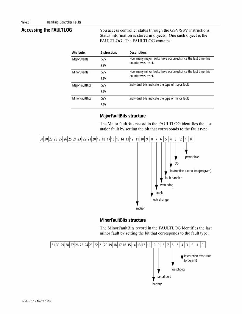
12-20 Handling Controller Faults
Accessing the FAULTLOG <RX�DFFHVV�FRQWUROOHU�VWDWXV�WKURXJK�WKH�*69�669�LQVWUXFWLRQV���6WDWXV�LQIRUPDWLRQ�LV�VWRUHG�LQ�REMHFWV���2QH�VXFK�REMHFW�LV�WKH�)$8/7/2*���7KH�)$8/7/2*�FRQWDLQV�
MajorFaultBits structure
7KH�0DMRU)DXOW%LWV�UHFRUG�LQ�WKH�)$8/7/2*�LGHQWLILHV�WKH�ODVW�PDMRU�IDXOW�E\�VHWWLQJ�WKH�ELW�WKDW�FRUUHVSRQGV�WR�WKH�IDXOW�W\SH�
MinorFaultBits structure
7KH�0LQRU)DXOW%LWV�UHFRUG�LQ�WKH�)$8/7/2*�LGHQWLILHV�WKH�ODVW�PLQRU�IDXOW�E\�VHWWLQJ�WKH�ELW�WKDW�FRUUHVSRQGV�WR�WKH�IDXOW�W\SH�
Attribute: Instruction: Description:
MajorEvents GSV
SSV
How many major faults have occurred since the last time this counter was reset.
MinorEvents GSV
SSV
How many minor faults have occurred since the last time this counter was reset.
MajorFaultBits GSV
SSV
Individual bits indicate the type of major fault.
MinorFaultBits GSV
SSV
Individual bits indicate the type of minor fault.
31 30 29 28 27 26 25 24 23 22 21 20 19 18 17 16 15 14 13 12 11 10 9 8 7 6 5 4 3 2 1 0
power loss
I/O
instruction execution (program)
watchdog
mode change
motion
fault handler
stack
31 30 29 28 27 26 25 24 23 22 21 20 19 18 17 16 15 14 13 12 11 10 9 8 7 6 5 4 3 2 1 0
watchdog
serial port
battery
instruction execution (program)
1756-6.5.12 March 1999
Chapter 13
Preparing a Power-Up ProgramUsing This Chapter
How the Controller Powers Up in Run Mode
<RX�FDQ�XVH�WKH�SRZHU�XS�KDQGOHU�WR�GHWHUPLQH�KRZ�WKH�FRQWUROOHU�SRZHUV�XS�LQ�5XQ�PRGH�
,I�\RX�XVH�WKH�SRZHU�XS�KDQGOHU��D�SURJUDP�LV�GHILQHG���DQG�WKH�FRQWUROOHU�SRZHUV�XS�LQ�5XQ�PRGH��WKH�FRQWUROOHU�VHWV�PDMRU�IDXOW�W\SH ���FRGH�����7KH�SRZHU�XS�KDQGOHU�PXVW�FOHDU�WKH�PDMRU�IDXOW�IRU�WKH�FRQWUROOHU�WR�RSHUDWH�QRUPDOO\���2WKHUZLVH��WKH�FRQWUROOHU�HQWHUV�LWV�IDXOWHG�PRGH��VKXWV�GRZQ��
,I�\RX�GR�QRW�XVH�WKH�SRZHU�XS�KDQGOHU��QR�SURJUDP�LV�GHILQHG���WKH�FRQWUROOHU�VWD\V�LQ�5XQ�PRGH�LI�LW�SRZHUV�XS�LQ�5XQ�PRGH���7KH�FRQWUROOHU�EHJLQV�H[HFXWLQJ�ORJLF�
For information about: See page:
How the controller powers up in Run mode 13-1
Creating the power-up handler 13-3Clearing the major fault 13-6
1756-6.5.12 March 1999
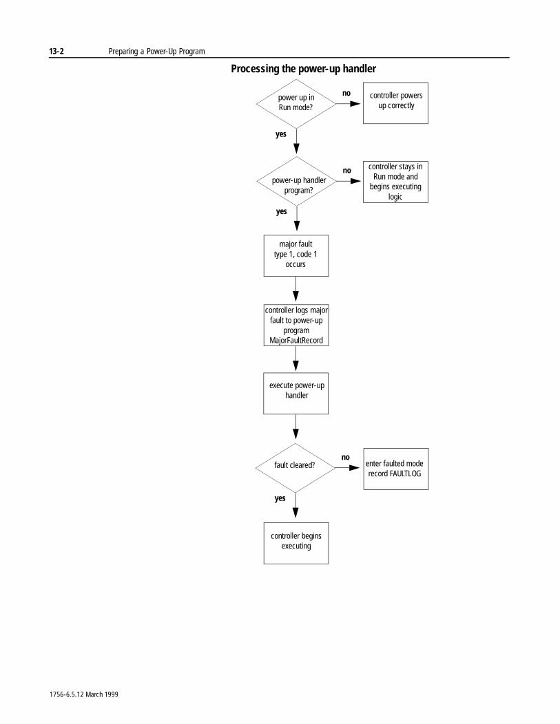
13-2 Preparing a Power-Up Program
Processing the power-up handler
power up in Run mode?
execute power-up handler
controller powers up correctly
no
yes
fault cleared? enter faulted moderecord FAULTLOG
no
yes
controller begins executing
major fault type 1, code 1
occurs
power-up handler program?
no
yes
controller stays in Run mode and
begins executing logic
controller logs major fault to power-up
program MajorFaultRecord
1756-6.5.12 March 1999
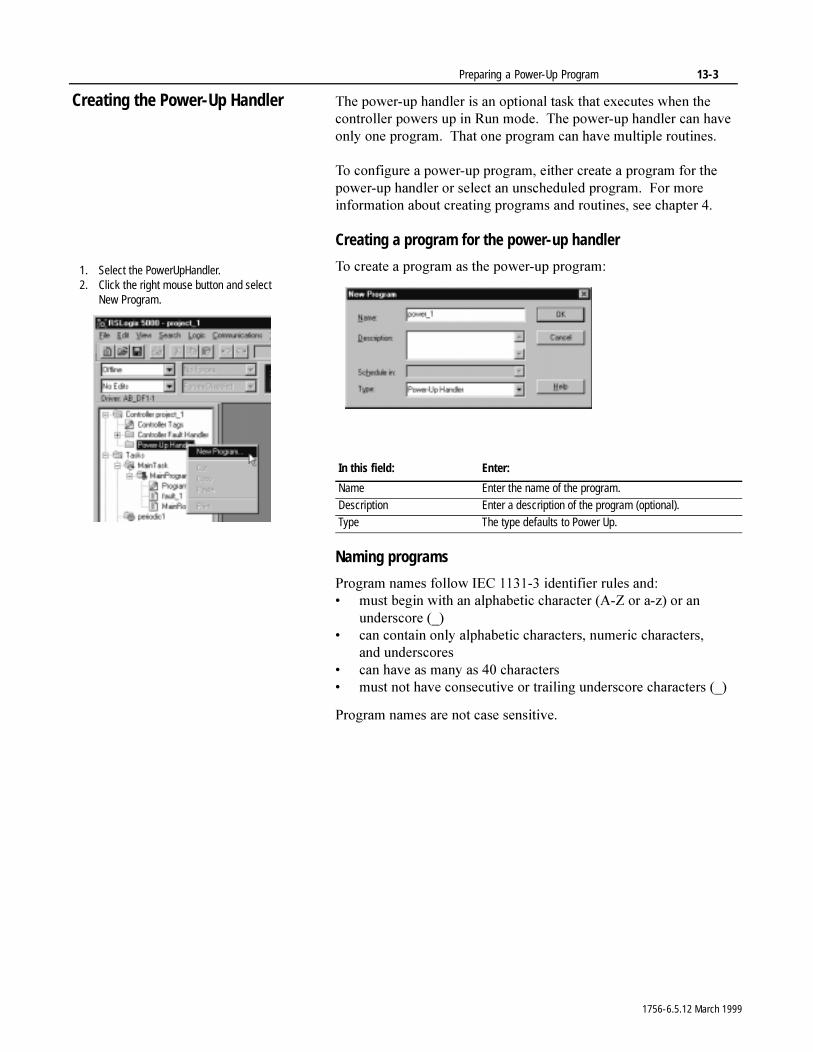
Preparing a Power-Up Program 13-3
Creating the Power-Up Handler 7KH�SRZHU�XS�KDQGOHU�LV�DQ�RSWLRQDO�WDVN�WKDW�H[HFXWHV�ZKHQ�WKH�FRQWUROOHU�SRZHUV�XS�LQ�5XQ�PRGH���7KH�SRZHU�XS�KDQGOHU�FDQ�KDYH�RQO\�RQH�SURJUDP���7KDW�RQH�SURJUDP�FDQ�KDYH�PXOWLSOH�URXWLQHV�
7R�FRQILJXUH�D�SRZHU�XS�SURJUDP��HLWKHU�FUHDWH�D�SURJUDP�IRU�WKH�SRZHU�XS�KDQGOHU�RU�VHOHFW�DQ�XQVFKHGXOHG�SURJUDP���)RU�PRUH�LQIRUPDWLRQ�DERXW�FUHDWLQJ�SURJUDPV�DQG�URXWLQHV��VHH�FKDSWHU���
Creating a program for the power-up handler
7R�FUHDWH�D�SURJUDP�DV�WKH�SRZHU�XS�SURJUDP�
Naming programs
3URJUDP�QDPHV�IROORZ�,(&��������LGHQWLILHU�UXOHV DQG�� PXVW�EHJLQ�ZLWK�DQ�DOSKDEHWLF�FKDUDFWHU��$�=�RU�D�]��RU�DQ�
XQGHUVFRUH �B�� FDQ�FRQWDLQ�RQO\�DOSKDEHWLF�FKDUDFWHUV��QXPHULF�FKDUDFWHUV��
DQG XQGHUVFRUHV� FDQ�KDYH�DV�PDQ\�DV����FKDUDFWHUV� PXVW�QRW�KDYH�FRQVHFXWLYH�RU�WUDLOLQJ�XQGHUVFRUH�FKDUDFWHUV��B�
3URJUDP�QDPHV�DUH�QRW�FDVH�VHQVLWLYH�
In this field: Enter:
Name Enter the name of the program.Description Enter a description of the program (optional).Type The type defaults to Power Up.
1. Select the PowerUpHandler.2. Click the right mouse button and select
New Program.
1756-6.5.12 March 1999
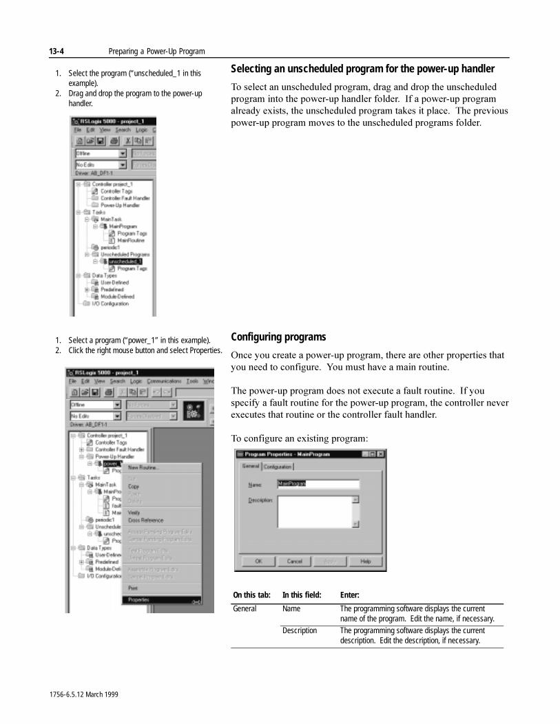
13-4 Preparing a Power-Up Program
Selecting an unscheduled program for the power-up handler
7R�VHOHFW�DQ�XQVFKHGXOHG�SURJUDP��GUDJ�DQG�GURS�WKH�XQVFKHGXOHG�SURJUDP�LQWR�WKH�SRZHU�XS�KDQGOHU�IROGHU���,I�D�SRZHU�XS�SURJUDP�DOUHDG\�H[LVWV��WKH�XQVFKHGXOHG�SURJUDP�WDNHV�LW�SODFH���7KH�SUHYLRXV�SRZHU�XS�SURJUDP�PRYHV�WR�WKH�XQVFKHGXOHG�SURJUDPV�IROGHU�
Configuring programs
2QFH�\RX�FUHDWH�D�SRZHU�XS�SURJUDP��WKHUH�DUH�RWKHU�SURSHUWLHV�WKDW�\RX�QHHG�WR�FRQILJXUH���<RX�PXVW�KDYH�D�PDLQ�URXWLQH�
7KH�SRZHU�XS�SURJUDP�GRHV�QRW�H[HFXWH�D�IDXOW�URXWLQH���,I�\RX�VSHFLI\�D�IDXOW�URXWLQH�IRU�WKH�SRZHU�XS�SURJUDP��WKH�FRQWUROOHU�QHYHU�H[HFXWHV�WKDW�URXWLQH�RU�WKH�FRQWUROOHU�IDXOW�KDQGOHU�
7R�FRQILJXUH�DQ�H[LVWLQJ�SURJUDP�
On this tab: In this field: Enter:
General Name The programming software displays the current name of the program. Edit the name, if necessary.
Description The programming software displays the current description. Edit the description, if necessary.
1. Select the program (“unscheduled_1 in thisexample).
2. Drag and drop the program to the power-uphandler.
1. Select a program (“power_1” in this example).2. Click the right mouse button and select Properties.
1756-6.5.12 March 1999
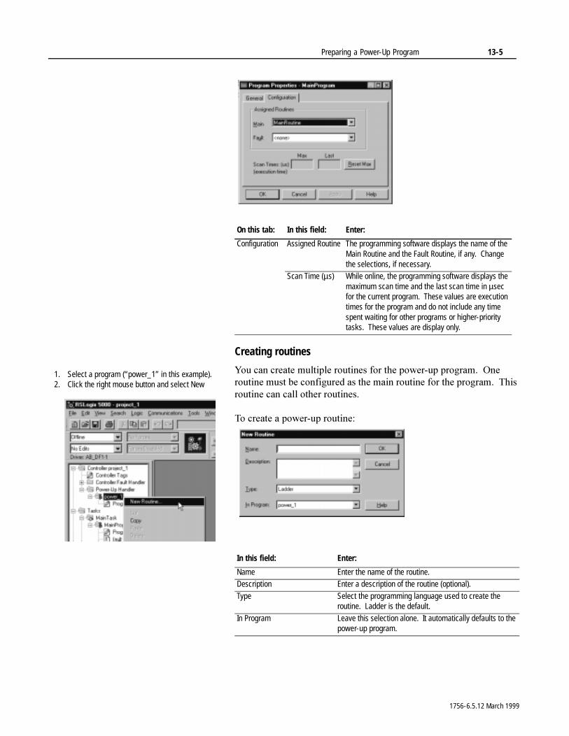
Preparing a Power-Up Program 13-5
Creating routines
<RX�FDQ�FUHDWH�PXOWLSOH�URXWLQHV�IRU�WKH�SRZHU�XS�SURJUDP���2QH�URXWLQH�PXVW�EH�FRQILJXUHG�DV�WKH�PDLQ�URXWLQH�IRU�WKH�SURJUDP���7KLV�URXWLQH�FDQ�FDOO�RWKHU�URXWLQHV�
7R�FUHDWH�D�SRZHU�XS�URXWLQH�
On this tab: In this field: Enter:
Configuration Assigned Routine The programming software displays the name of the Main Routine and the Fault Routine, if any. Change the selections, if necessary.
Scan Time (µs) While online, the programming software displays the maximum scan time and the last scan time in µsec for the current program. These values are execution times for the program and do not include any time spent waiting for other programs or higher-priority tasks. These values are display only.
In this field: Enter:
Name Enter the name of the routine.Description Enter a description of the routine (optional).
Type Select the programming language used to create the routine. Ladder is the default.
In Program Leave this selection alone. It automatically defaults to the power-up program.
1. Select a program (“power_1” in this example).2. Click the right mouse button and select New
1756-6.5.12 March 1999
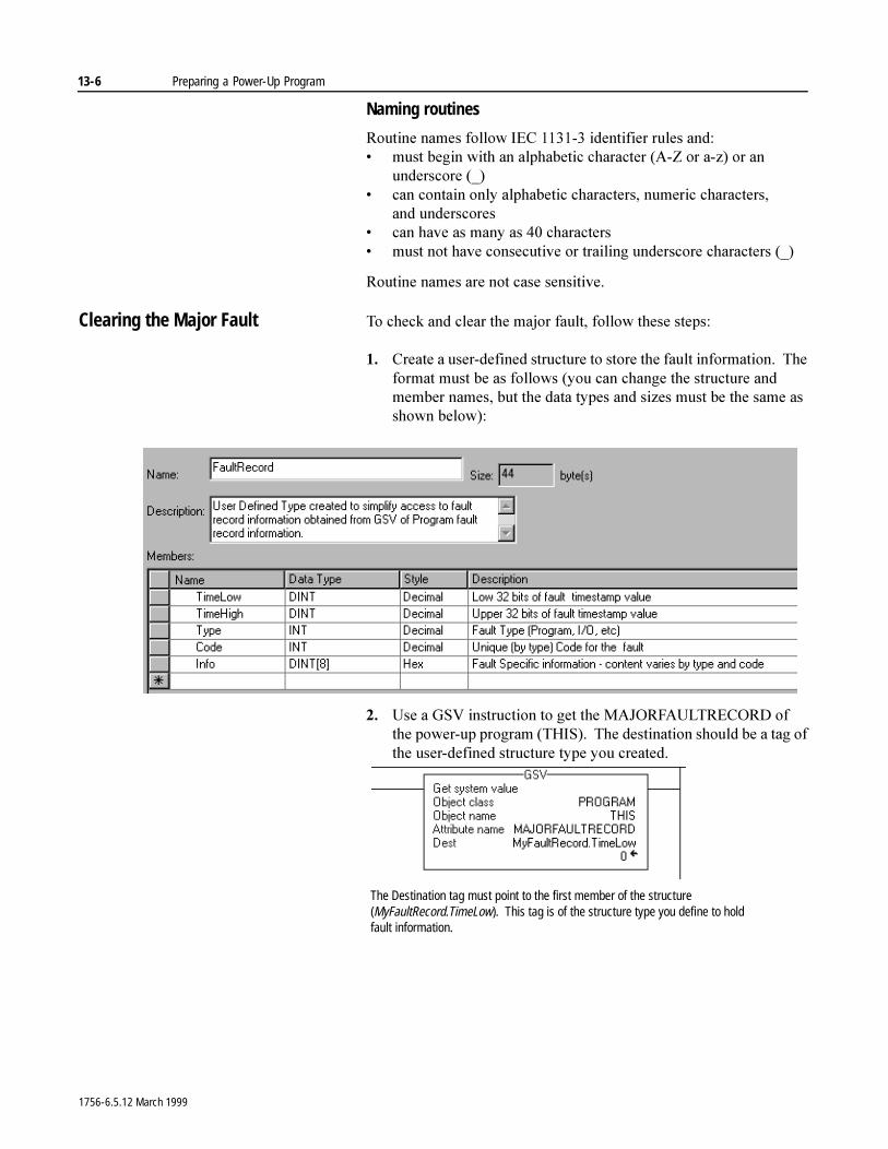
13-6 Preparing a Power-Up Program
Naming routines
5RXWLQH�QDPHV�IROORZ�,(&��������LGHQWLILHU�UXOHV DQG�� PXVW�EHJLQ�ZLWK�DQ�DOSKDEHWLF�FKDUDFWHU��$�=�RU�D�]��RU�DQ�
XQGHUVFRUH �B�� FDQ�FRQWDLQ�RQO\�DOSKDEHWLF�FKDUDFWHUV��QXPHULF�FKDUDFWHUV��
DQG XQGHUVFRUHV� FDQ�KDYH�DV�PDQ\�DV����FKDUDFWHUV� PXVW�QRW�KDYH�FRQVHFXWLYH�RU�WUDLOLQJ�XQGHUVFRUH�FKDUDFWHUV��B�
5RXWLQH�QDPHV�DUH�QRW�FDVH�VHQVLWLYH�
Clearing the Major Fault 7R�FKHFN�DQG�FOHDU�WKH�PDMRU�IDXOW��IROORZ�WKHVH VWHSV�
�� &UHDWH�D�XVHU�GHILQHG�VWUXFWXUH�WR�VWRUH�WKH�IDXOW�LQIRUPDWLRQ���7KH�IRUPDW�PXVW�EH�DV�IROORZV��\RX�FDQ�FKDQJH�WKH�VWUXFWXUH�DQG�PHPEHU�QDPHV��EXW�WKH�GDWD�W\SHV�DQG�VL]HV�PXVW�EH�WKH�VDPH�DV�VKRZQ�EHORZ��
�� 8VH�D�*69�LQVWUXFWLRQ�WR�JHW�WKH�0$-25)$8/75(&25'�RI�WKH�SRZHU�XS�SURJUDP��7+,6����7KH�GHVWLQDWLRQ�VKRXOG�EH�D�WDJ�RI�WKH�XVHU�GHILQHG�VWUXFWXUH�W\SH�\RX�FUHDWHG�
The Destination tag must point to the first member of the structure (MyFaultRecord.TimeLow). This tag is of the structure type you define to hold fault information.
1756-6.5.12 March 1999
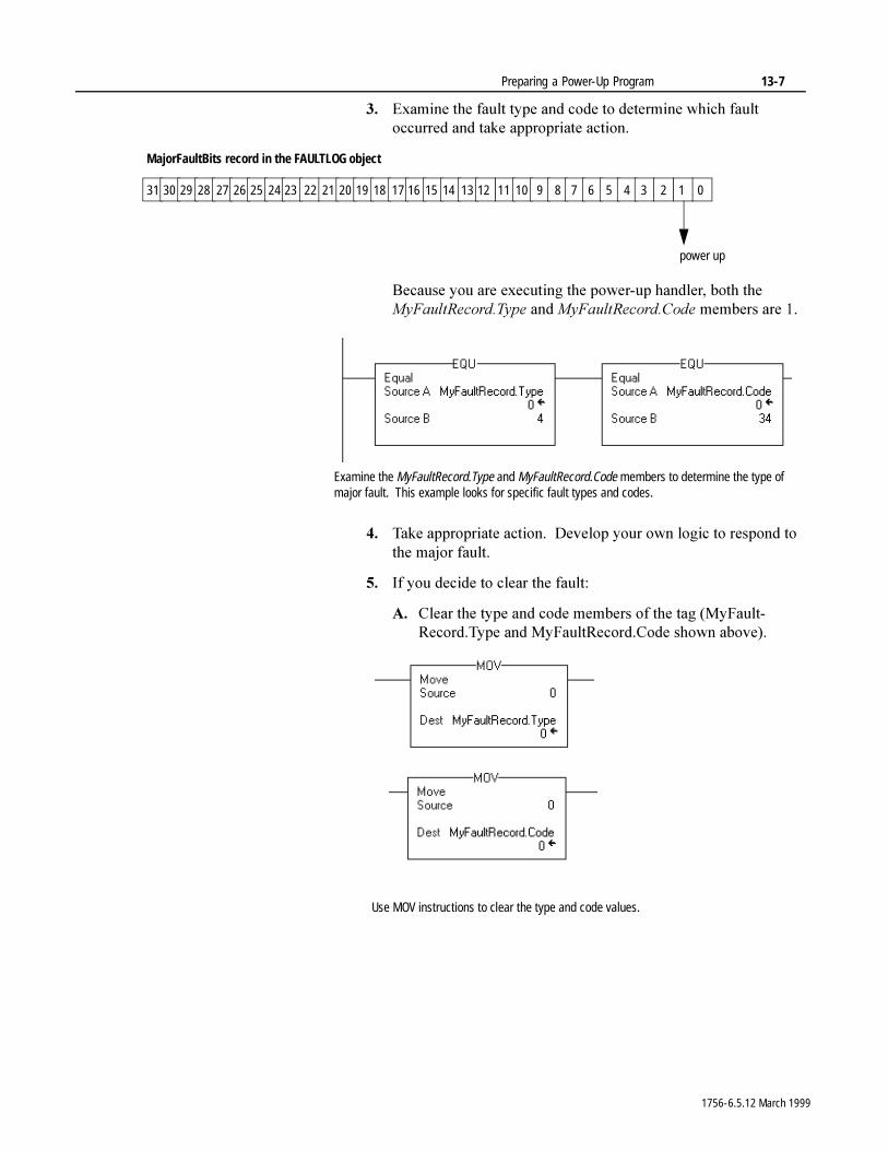
Preparing a Power-Up Program 13-7
�� ([DPLQH�WKH�IDXOW�W\SH�DQG�FRGH�WR�GHWHUPLQH�ZKLFK�IDXOW�RFFXUUHG�DQG�WDNH�DSSURSULDWH�DFWLRQ�
%HFDXVH�\RX�DUH�H[HFXWLQJ�WKH�SRZHU�XS�KDQGOHU��ERWK�WKH�0\)DXOW5HFRUG�7\SH�DQG�0\)DXOW5HFRUG�&RGH�PHPEHUV�DUH���
�� 7DNH�DSSURSULDWH�DFWLRQ���'HYHORS�\RXU�RZQ�ORJLF�WR�UHVSRQG�WR�WKH�PDMRU�IDXOW�
�� ,I�\RX�GHFLGH�WR�FOHDU�WKH�IDXOW�
$� &OHDU�WKH�W\SH�DQG�FRGH�PHPEHUV�RI�WKH�WDJ��0\)DXOW�5HFRUG�7\SH�DQG�0\)DXOW5HFRUG�&RGH�VKRZQ�DERYH��
31 30 29 28 27 26 25 24 23 22 21 20 19 18 17 16 15 14 13 12 11 10 9 8 7 6 5 4 3 2 1 0
power up
MajorFaultBits record in the FAULTLOG object
Examine the MyFaultRecord.Type and MyFaultRecord.Code members to determine the type of major fault. This example looks for specific fault types and codes.
Use MOV instructions to clear the type and code values.
1756-6.5.12 March 1999
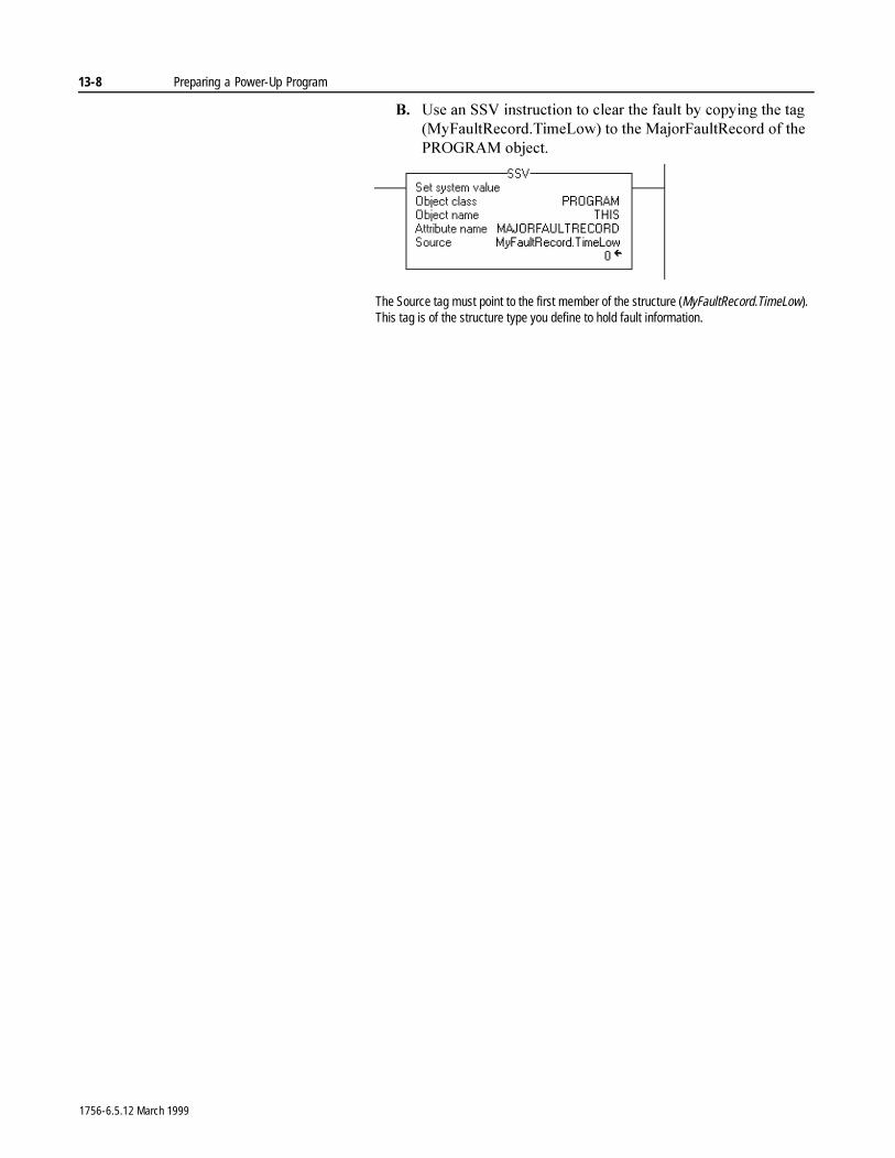
13-8 Preparing a Power-Up Program
%� 8VH�DQ�669�LQVWUXFWLRQ�WR�FOHDU�WKH�IDXOW�E\�FRS\LQJ�WKH�WDJ��0\)DXOW5HFRUG�7LPH/RZ��WR�WKH�0DMRU)DXOW5HFRUG�RI�WKH�352*5$0�REMHFW�
The Source tag must point to the first member of the structure (MyFaultRecord.TimeLow). This tag is of the structure type you define to hold fault information.
1756-6.5.12 March 1999
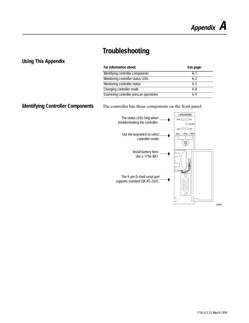
Appendix A
TroubleshootingUsing This Appendix
Identifying Controller Components 7KH�FRQWUROOHU�KDV�WKHVH�FRPSRQHQWV�RQ�WKH�IURQW�SDQHO�
For information about: See page:
Identifying controller components A-1
Monitoring controller status LEDs A-2Monitoring controller status A-5
Changing controller mode A-8Examining controller prescan operations A-9
RS232
RUN
OK
I/O
BAT
RUN REM
LOGIX5550
PROG
The status LEDs help whentroubleshooting the controller.
Use the keyswitch to selectcontroller mode.
Install battery here.Use a 1756-BA1.
The 9-pin D-shell serial portsupports standard EIA RS-232C.
40001
1756-6.5.12 March 1999
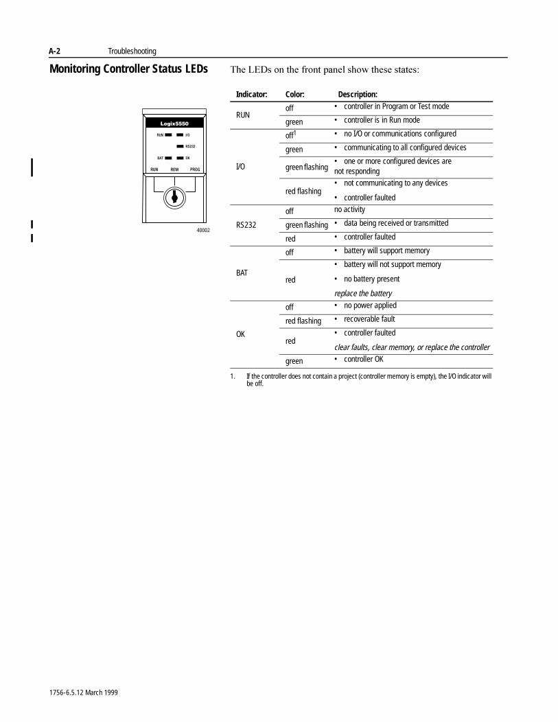
A-2 Troubleshooting
Monitoring Controller Status LEDs 7KH�/('V�RQ�WKH�IURQW�SDQHO�VKRZ�WKHVH�VWDWHV�
Indicator: Color: Description:
RUNoff • controller in Program or Test mode
green • controller is in Run mode
I/O
off1
1. If the controller does not contain a project (controller memory is empty), the I/O indicator will be off.
• no I/O or communications configured
green • communicating to all configured devices
green flashing• one or more configured devices are not responding
red flashing• not communicating to any devices
• controller faulted
RS232
off no activity
green flashing • data being received or transmitted
red • controller faulted
BAT
off • battery will support memory
red
• battery will not support memory
• no battery present
replace the battery
OK
off • no power applied
red flashing • recoverable fault
red• controller faulted
clear faults, clear memory, or replace the controller
green • controller OK
40002
1756-6.5.12 March 1999
Troubleshooting A-3
Determining which modules are not responding
,I�WKH�,�2�VWDWXV�LQGLFDWRU�LV�IODVKLQJ�JUHHQ�RU�IODVKLQJ�UHG��\RX�FDQ�XVH�WKH�SURJUDPPLQJ�VRIWZDUH�WR�GHWHUPLQH�ZKLFK�,�2�GHYLFHV�DUH�QRW�UHVSRQGLQJ�
(DFK�,�2�PRGXOH�SURYLGHV�DQ�LQGLFDWLRQ�ZKHQ�D�IDXOW�RFFXUV���7KH�SURJUDPPLQJ�VRIWZDUH�GLVSOD\V�WKLV�IDXOW�LQIRUPDWLRQ�
In this location: The software displays:
Controller organizer The I/O configuration portion displays the modules configured for the controller. If the controller detects an error condition or fault with one of these modules, the controller organizer displays a yellow attention symbol (/!\) over the device.
Connection tab from module properties
The module fault field displays the fault code returned to the controller (related to the module) and the text detailing the fault.
Common categories for module errors are:
Connection request error The controller is attempting to make a connection tothe module and has received an error. Theconnection was not made.
Service request error The controller is attempting to request a service fromthe module and has received an error. The servicewas not performed successfully.
Module configuration The configuration in the module is invalid. This rejected commonly happens when a second controller tries
to share ownership of an input module, but themodule configuration does not match theconfiguration already in the input module.
Module key mismatch Electronic keying is enabled and some part of thekeying information differs between the software and the module.
Module Info tab from module properties
This tab displays module and status information about the module. You can also reset a module to its power-up state. You must be online to use this tab.
Backplane tab from module properties
This tab displays diagnostic information about the module’s communications over the backplane and the chassis in which it is located. You can also clear module faults and reset the transmit retry limit.
1756-6.5.12 March 1999
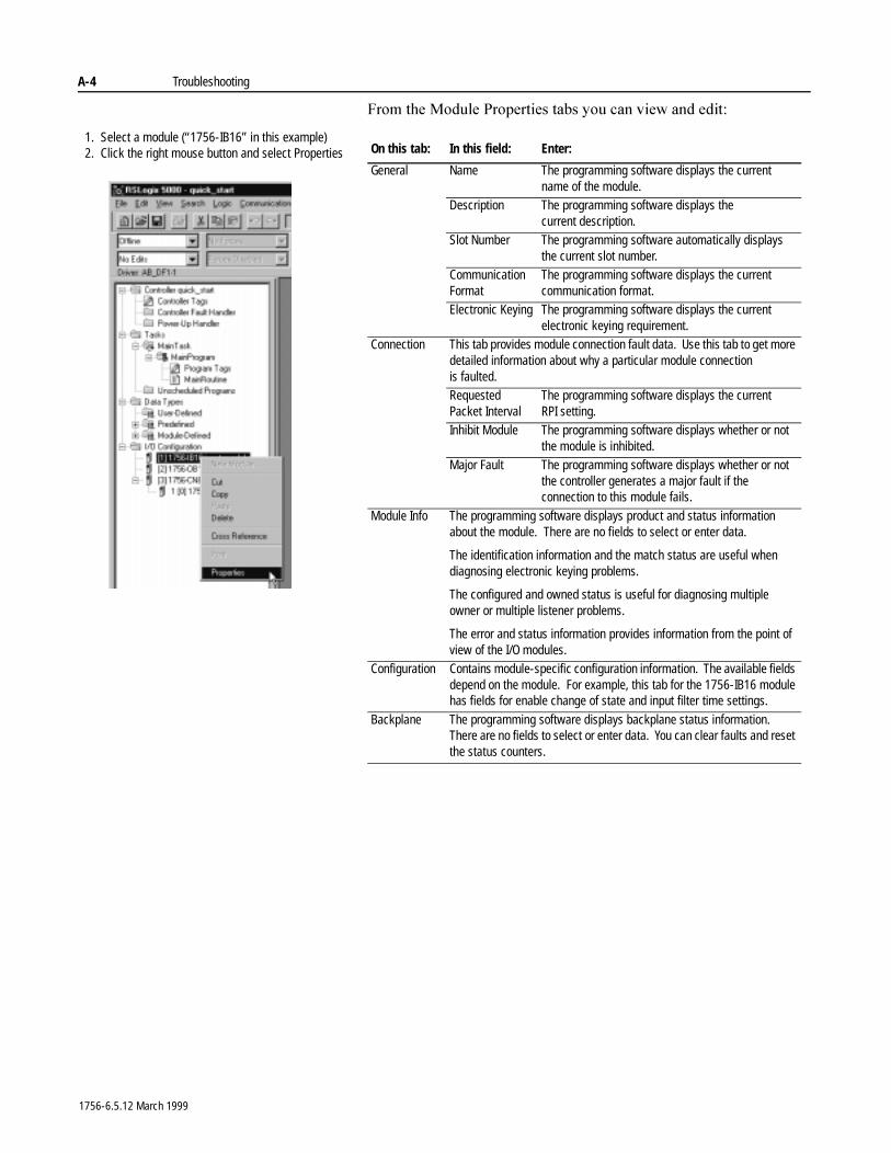
A-4 Troubleshooting
)URP�WKH�0RGXOH�3URSHUWLHV�WDEV�\RX�FDQ�YLHZ�DQG�HGLW�
On this tab: In this field: Enter:
General Name The programming software displays the current name of the module.
Description The programming software displays the current description.
Slot Number The programming software automatically displays the current slot number.
Communication Format
The programming software displays the current communication format.
Electronic Keying The programming software displays the current electronic keying requirement.
Connection This tab provides module connection fault data. Use this tab to get more detailed information about why a particular module connection is faulted.Requested Packet Interval
The programming software displays the current RPI setting.
Inhibit Module The programming software displays whether or not the module is inhibited.
Major Fault The programming software displays whether or not the controller generates a major fault if the connection to this module fails.
Module Info The programming software displays product and status information about the module. There are no fields to select or enter data.
The identification information and the match status are useful when diagnosing electronic keying problems.
The configured and owned status is useful for diagnosing multiple owner or multiple listener problems.
The error and status information provides information from the point of view of the I/O modules.
Configuration Contains module-specific configuration information. The available fields depend on the module. For example, this tab for the 1756-IB16 module has fields for enable change of state and input filter time settings.
Backplane The programming software displays backplane status information. There are no fields to select or enter data. You can clear faults and reset the status counters.
1. Select a module (“1756-IB16” in this example)2. Click the right mouse button and select Properties
1756-6.5.12 March 1999
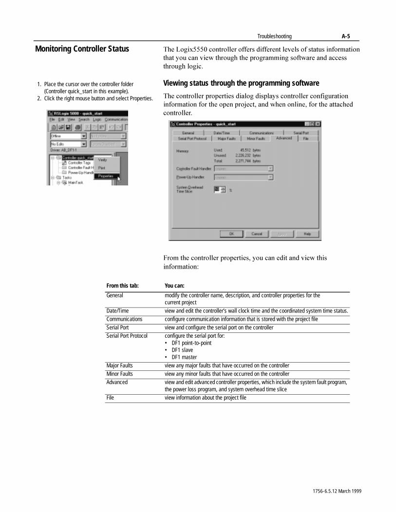
Troubleshooting A-5
Monitoring Controller Status 7KH�/RJL[�����FRQWUROOHU�RIIHUV�GLIIHUHQW�OHYHOV�RI�VWDWXV�LQIRUPDWLRQ�WKDW�\RX�FDQ�YLHZ�WKURXJK�WKH�SURJUDPPLQJ�VRIWZDUH�DQG�DFFHVV�WKURXJK�ORJLF�
Viewing status through the programming software
7KH�FRQWUROOHU�SURSHUWLHV�GLDORJ�GLVSOD\V�FRQWUROOHU�FRQILJXUDWLRQ�LQIRUPDWLRQ�IRU�WKH�RSHQ�SURMHFW��DQG�ZKHQ�RQOLQH��IRU�WKH�DWWDFKHG�FRQWUROOHU�
)URP�WKH�FRQWUROOHU�SURSHUWLHV��\RX�FDQ�HGLW�DQG�YLHZ�WKLV�LQIRUPDWLRQ�
1. Place the cursor over the controller folder(Controller quick_start in this example).
2. Click the right mouse button and select Properties.
From this tab: You can:
General modify the controller name, description, and controller properties for the current project
Date/Time view and edit the controller’s wall clock time and the coordinated system time status.Communications configure communication information that is stored with the project file
Serial Port view and configure the serial port on the controllerSerial Port Protocol configure the serial port for:
• DF1 point-to-point• DF1 slave• DF1 master
Major Faults view any major faults that have occurred on the controller
Minor Faults view any minor faults that have occurred on the controllerAdvanced view and edit advanced controller properties, which include the system fault program,
the power loss program, and system overhead time sliceFile view information about the project file
1756-6.5.12 March 1999
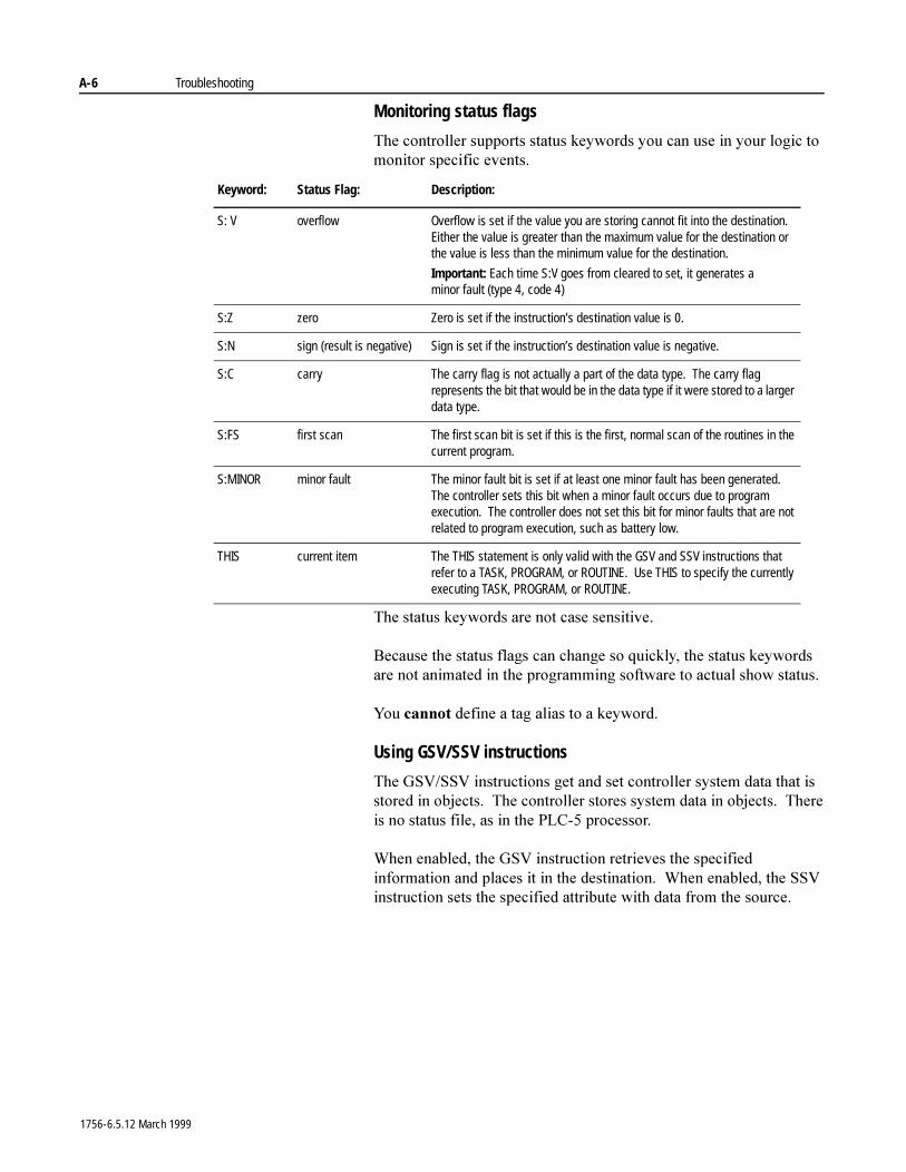
A-6 Troubleshooting
Monitoring status flags
7KH�FRQWUROOHU�VXSSRUWV�VWDWXV�NH\ZRUGV�\RX�FDQ�XVH�LQ�\RXU�ORJLF�WR�PRQLWRU�VSHFLILF�HYHQWV�
7KH�VWDWXV�NH\ZRUGV�DUH�QRW�FDVH�VHQVLWLYH�
%HFDXVH�WKH�VWDWXV�IODJV�FDQ�FKDQJH�VR�TXLFNO\��WKH�VWDWXV�NH\ZRUGV�DUH�QRW�DQLPDWHG�LQ�WKH�SURJUDPPLQJ�VRIWZDUH�WR�DFWXDO�VKRZ�VWDWXV�
<RX�FDQQRW�GHILQH�D�WDJ�DOLDV�WR�D�NH\ZRUG�
Using GSV/SSV instructions
7KH�*69�669�LQVWUXFWLRQV�JHW�DQG�VHW�FRQWUROOHU�V\VWHP�GDWD�WKDW�LV�VWRUHG�LQ�REMHFWV���7KH�FRQWUROOHU�VWRUHV�V\VWHP�GDWD�LQ�REMHFWV���7KHUH�LV�QR�VWDWXV�ILOH��DV�LQ�WKH�3/&���SURFHVVRU�
:KHQ�HQDEOHG��WKH�*69�LQVWUXFWLRQ�UHWULHYHV�WKH�VSHFLILHG�LQIRUPDWLRQ�DQG�SODFHV�LW�LQ�WKH�GHVWLQDWLRQ���:KHQ�HQDEOHG��WKH�669�LQVWUXFWLRQ�VHWV�WKH�VSHFLILHG�DWWULEXWH�ZLWK�GDWD�IURP�WKH�VRXUFH�
Keyword: Status Flag: Description:
S: V overflow Overflow is set if the value you are storing cannot fit into the destination. Either the value is greater than the maximum value for the destination or the value is less than the minimum value for the destination.
Important: Each time S:V goes from cleared to set, it generates a minor fault (type 4, code 4)
S:Z zero Zero is set if the instruction’s destination value is 0.
S:N sign (result is negative) Sign is set if the instruction’s destination value is negative.
S:C carry The carry flag is not actually a part of the data type. The carry flag represents the bit that would be in the data type if it were stored to a larger data type.
S:FS first scan The first scan bit is set if this is the first, normal scan of the routines in the current program.
S:MINOR minor fault The minor fault bit is set if at least one minor fault has been generated. The controller sets this bit when a minor fault occurs due to program execution. The controller does not set this bit for minor faults that are not related to program execution, such as battery low.
THIS current item The THIS statement is only valid with the GSV and SSV instructions that refer to a TASK, PROGRAM, or ROUTINE. Use THIS to specify the currently executing TASK, PROGRAM, or ROUTINE.
1756-6.5.12 March 1999
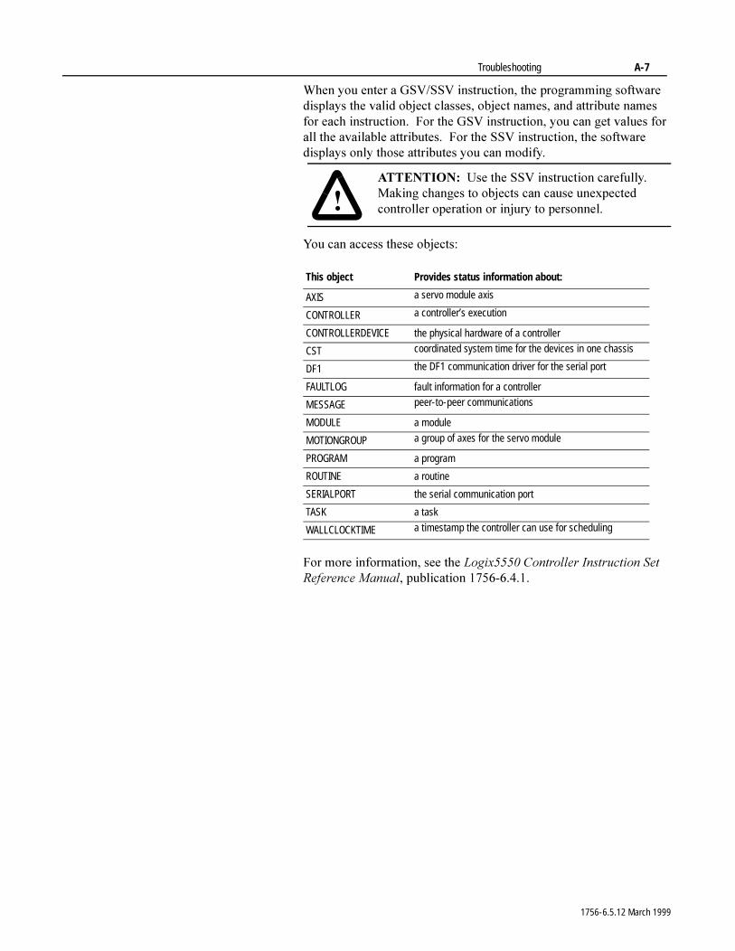
Troubleshooting A-7
:KHQ�\RX�HQWHU�D�*69�669�LQVWUXFWLRQ��WKH�SURJUDPPLQJ�VRIWZDUH�GLVSOD\V�WKH�YDOLG�REMHFW�FODVVHV��REMHFW�QDPHV��DQG�DWWULEXWH�QDPHV�IRU�HDFK�LQVWUXFWLRQ���)RU�WKH�*69�LQVWUXFWLRQ��\RX�FDQ�JHW�YDOXHV�IRU�DOO�WKH�DYDLODEOH�DWWULEXWHV���)RU�WKH�669�LQVWUXFWLRQ��WKH�VRIWZDUH�GLVSOD\V�RQO\�WKRVH�DWWULEXWHV�\RX�FDQ�PRGLI\�
<RX�FDQ�DFFHVV�WKHVH�REMHFWV�
)RU�PRUH�LQIRUPDWLRQ��VHH�WKH�/RJL[�����&RQWUROOHU�,QVWUXFWLRQ�6HW�5HIHUHQFH�0DQXDO��SXEOLFDWLRQ������������
�$77(17,21� 8VH�WKH�669�LQVWUXFWLRQ�FDUHIXOO\���0DNLQJ�FKDQJHV�WR�REMHFWV�FDQ�FDXVH�XQH[SHFWHG�FRQWUROOHU�RSHUDWLRQ�RU�LQMXU\�WR�SHUVRQQHO�
This object Provides status information about:
AXIS a servo module axis
CONTROLLER a controller’s execution
CONTROLLERDEVICE the physical hardware of a controller
CST coordinated system time for the devices in one chassis
DF1 the DF1 communication driver for the serial port
FAULTLOG fault information for a controller
MESSAGE peer-to-peer communications
MODULE a module
MOTIONGROUP a group of axes for the servo module
PROGRAM a program
ROUTINE a routine
SERIALPORT the serial communication port
TASK a task
WALLCLOCKTIME a timestamp the controller can use for scheduling
1756-6.5.12 March 1999
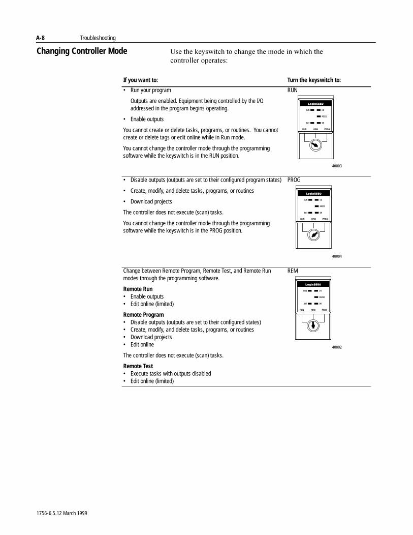
A-8 Troubleshooting
Changing Controller Mode 8VH�WKH�NH\VZLWFK�WR�FKDQJH�WKH�PRGH�LQ�ZKLFK�WKH�FRQWUROOHU RSHUDWHV�
If you want to: Turn the keyswitch to:
• Run your program
Outputs are enabled. Equipment being controlled by the I/O addressed in the program begins operating.
• Enable outputs
You cannot create or delete tasks, programs, or routines. You cannot create or delete tags or edit online while in Run mode.
You cannot change the controller mode through the programming software while the keyswitch is in the RUN position.
RUN
• Disable outputs (outputs are set to their configured program states)
• Create, modify, and delete tasks, programs, or routines
• Download projects
The controller does not execute (scan) tasks.
You cannot change the controller mode through the programming software while the keyswitch is in the PROG position.
PROG
Change between Remote Program, Remote Test, and Remote Run modes through the programming software.
Remote Run• Enable outputs• Edit online (limited)
Remote Program• Disable outputs (outputs are set to their configured states)• Create, modify, and delete tasks, programs, or routines• Download projects• Edit online
The controller does not execute (scan) tasks.
Remote Test• Execute tasks with outputs disabled• Edit online (limited)
REM
40003
40004
40002
1756-6.5.12 March 1999
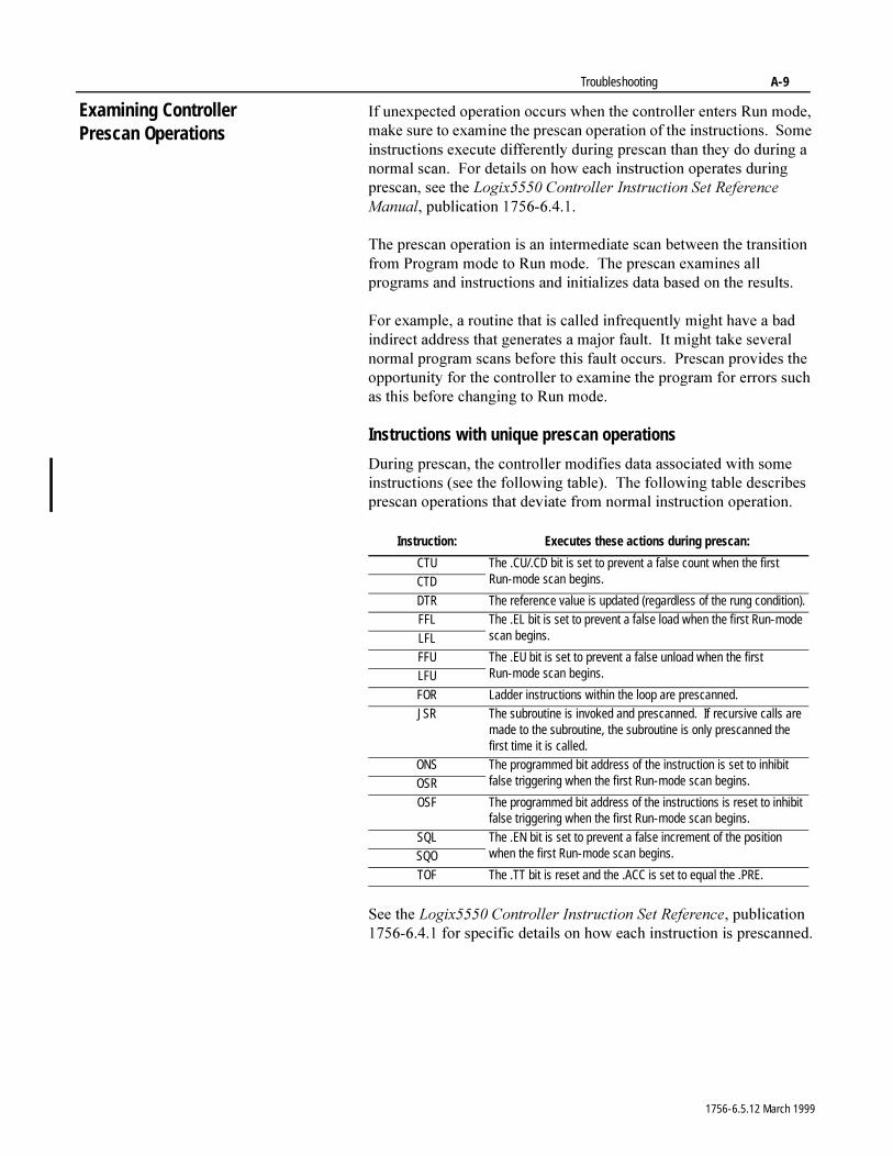
Troubleshooting A-9
Examining Controller Prescan Operations
,I�XQH[SHFWHG�RSHUDWLRQ�RFFXUV�ZKHQ�WKH�FRQWUROOHU�HQWHUV�5XQ�PRGH��PDNH�VXUH�WR�H[DPLQH�WKH�SUHVFDQ�RSHUDWLRQ�RI�WKH�LQVWUXFWLRQV���6RPH�LQVWUXFWLRQV�H[HFXWH�GLIIHUHQWO\�GXULQJ�SUHVFDQ�WKDQ�WKH\�GR�GXULQJ�D�QRUPDO�VFDQ���)RU�GHWDLOV�RQ�KRZ�HDFK�LQVWUXFWLRQ�RSHUDWHV�GXULQJ�SUHVFDQ��VHH�WKH�/RJL[�����&RQWUROOHU�,QVWUXFWLRQ�6HW�5HIHUHQFH�0DQXDO��SXEOLFDWLRQ������������
7KH�SUHVFDQ�RSHUDWLRQ�LV�DQ�LQWHUPHGLDWH�VFDQ�EHWZHHQ�WKH�WUDQVLWLRQ�IURP�3URJUDP�PRGH�WR�5XQ�PRGH���7KH�SUHVFDQ�H[DPLQHV�DOO�SURJUDPV�DQG�LQVWUXFWLRQV�DQG�LQLWLDOL]HV�GDWD�EDVHG�RQ�WKH�UHVXOWV�
)RU�H[DPSOH��D�URXWLQH�WKDW�LV�FDOOHG�LQIUHTXHQWO\�PLJKW�KDYH�D�EDG�LQGLUHFW�DGGUHVV�WKDW�JHQHUDWHV�D�PDMRU�IDXOW���,W�PLJKW�WDNH�VHYHUDO�QRUPDO�SURJUDP�VFDQV�EHIRUH�WKLV�IDXOW�RFFXUV���3UHVFDQ�SURYLGHV�WKH�RSSRUWXQLW\�IRU�WKH�FRQWUROOHU�WR�H[DPLQH�WKH�SURJUDP�IRU�HUURUV�VXFK�DV�WKLV�EHIRUH�FKDQJLQJ�WR�5XQ�PRGH�
Instructions with unique prescan operations
'XULQJ�SUHVFDQ��WKH�FRQWUROOHU�PRGLILHV�GDWD�DVVRFLDWHG�ZLWK�VRPH�LQVWUXFWLRQV��VHH�WKH�IROORZLQJ�WDEOH����7KH�IROORZLQJ�WDEOH�GHVFULEHV�SUHVFDQ�RSHUDWLRQV�WKDW�GHYLDWH�IURP�QRUPDO�LQVWUXFWLRQ�RSHUDWLRQ�
6HH�WKH�/RJL[�����&RQWUROOHU�,QVWUXFWLRQ�6HW�5HIHUHQFH��SXEOLFDWLRQ������������IRU�VSHFLILF�GHWDLOV�RQ�KRZ�HDFK�LQVWUXFWLRQ�LV�SUHVFDQQHG�
Instruction: Executes these actions during prescan:
CTU The .CU/.CD bit is set to prevent a false count when the first Run-mode scan begins.CTD
DTR The reference value is updated (regardless of the rung condition).FFL The .EL bit is set to prevent a false load when the first Run-mode
scan begins.LFLFFU The .EU bit is set to prevent a false unload when the first
Run-mode scan begins.LFU
FOR Ladder instructions within the loop are prescanned.JSR The subroutine is invoked and prescanned. If recursive calls are
made to the subroutine, the subroutine is only prescanned the first time it is called.
ONS The programmed bit address of the instruction is set to inhibit false triggering when the first Run-mode scan begins.OSR
OSF The programmed bit address of the instructions is reset to inhibit false triggering when the first Run-mode scan begins.
SQL The .EN bit is set to prevent a false increment of the position when the first Run-mode scan begins.SQO
TOF The .TT bit is reset and the .ACC is set to equal the .PRE.
1756-6.5.12 March 1999
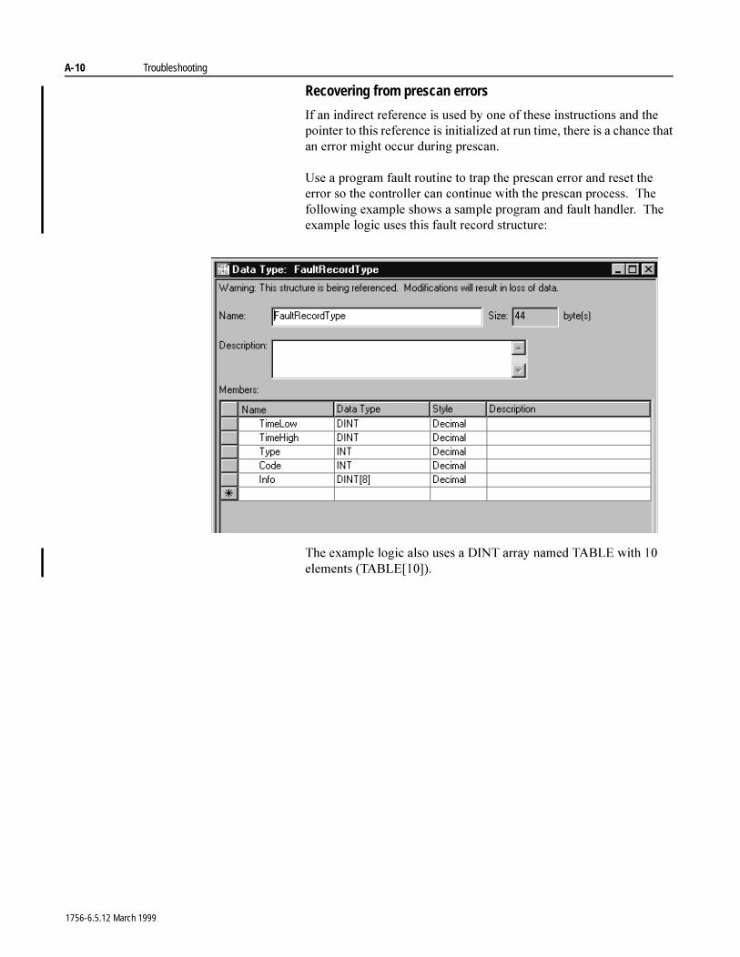
A-10 Troubleshooting
Recovering from prescan errors
,I�DQ�LQGLUHFW�UHIHUHQFH�LV�XVHG�E\�RQH�RI�WKHVH�LQVWUXFWLRQV�DQG�WKH�SRLQWHU�WR�WKLV�UHIHUHQFH�LV�LQLWLDOL]HG�DW�UXQ�WLPH��WKHUH�LV�D�FKDQFH�WKDW�DQ�HUURU�PLJKW�RFFXU�GXULQJ�SUHVFDQ�
8VH�D�SURJUDP�IDXOW�URXWLQH�WR�WUDS�WKH�SUHVFDQ�HUURU�DQG�UHVHW�WKH�HUURU�VR�WKH�FRQWUROOHU�FDQ�FRQWLQXH�ZLWK�WKH�SUHVFDQ�SURFHVV���7KH�IROORZLQJ�H[DPSOH�VKRZV�D�VDPSOH�SURJUDP�DQG�IDXOW�KDQGOHU���7KH�H[DPSOH�ORJLF�XVHV�WKLV�IDXOW�UHFRUG�VWUXFWXUH�
7KH�H[DPSOH�ORJLF�DOVR�XVHV�D�',17�DUUD\�QDPHG�7$%/(�ZLWK����HOHPHQWV��7$%/(>��@��
1756-6.5.12 March 1999
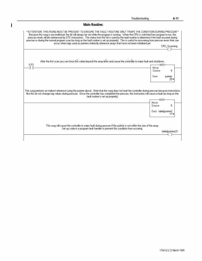
Troubleshooting A-11
Main Routine:
1756-6.5.12 March 1999
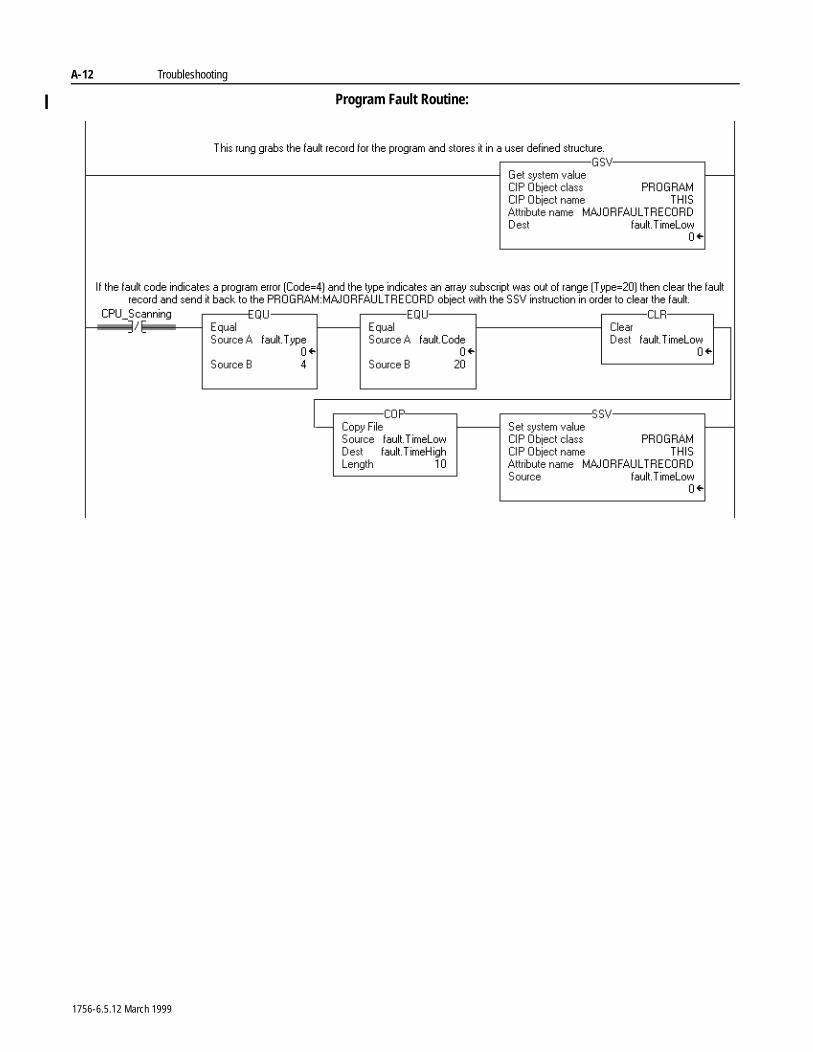
A-12 Troubleshooting
Program Fault Routine:
1756-6.5.12 March 1999
Appendix B
IEC1131-3 ComplianceUsing This Appendix
Introduction 7KH�,QWHUQDWLRQDO�(OHFWURWHFKQLFDO�&RPPLVVLRQ��,(&��KDV�GHYHORSHG�D�VHULHV�RI�VSHFLILFDWLRQV�IRU�SURJUDPPDEOH�FRQWUROOHUV���7KHVH�VSHFLILFDWLRQV�DUH�LQWHQGHG�WR�SURPRWH�LQWHUQDWLRQDO�XQLILFDWLRQ�RI�HTXLSPHQW�DQG�SURJUDPPLQJ�ODQJXDJHV�IRU�XVH�LQ�WKH�FRQWUROV�LQGXVWU\���7KHVH�VWDQGDUGV�SURYLGH�WKH�IRXQGDWLRQ�IRU�WKH�/RJL[�����FRQWUROOHU�DQG�56/RJL[������SURJUDPPLQJ�VRIWZDUH�
7KH�,(&�SURJUDPPDEOH�FRQWUROOHU�VSHFLILFDWLRQ�LV�EURNHQ�GRZQ�LQWR�ILYH�VHSDUDWH�SDUWV�HDFK�IRFXVLQJ�RQ�D�GLIIHUHQW�DVSHFW�RI�WKH�FRQWURO V\VWHP�� 3DUW����*HQHUDO�,QIRUPDWLRQ� 3DUW����(TXLSPHQW�DQG�5HTXLUHPHQWV�7HVW� 3DUW����3URJUDPPLQJ�/DQJXDJHV� 3DUW����8VHU�*XLGHOLQHV� 3DUW����0HVVDJLQJ�6HUYLFH�6SHFLILFDWLRQ
7KH�FRQWUROV�LQGXVWU\�DV�D�ZKROH�KDV�IRFXVHG�RQ�SDUW����,(&���������3URJUDPPLQJ�/DQJXDJHV��EHFDXVH�LW�SURYLGHV�WKH�FRUQHUVWRQH�IRU�LPSOHPHQWLQJ�WKH�RWKHU�VWDQGDUGV�DQG�SURYLGHV�WKH�PRVW�VLJQLILFDQW�HQG�XVHU�EHQHILW�E\�UHGXFLQJ�WUDLQLQJ�FRVW���%HFDXVH�RI�WKLV��RQO\�,(&�������LV�DGGUHVVHG�KHUH�
7KH�,(&�������SURJUDPPLQJ�ODQJXDJH�VSHFLILFDWLRQ�DGGUHVVHV�QXPHURXV�DVSHFWV�RI�SURJUDPPDEOH�FRQWUROOHU�LQFOXGLQJ�WKH�RSHUDWLQJ�V\VWHP�H[HFXWLRQ��GDWD�GHILQLWLRQV��SURJUDPPLQJ�ODQJXDJHV��DQG�LQVWUXFWLRQ�VHW���&RPSRQHQWV�RI�WKH�,(&������VSHFLILFDWLRQ�DUH�FDWHJRUL]HG�DV�UHTXLUHG�E\�WKH�VSHFLILFDWLRQ��RSWLRQDO�RU�H[WHQVLRQV���%\�VR�GRLQJ��WKH�,(&������VSHFLILFDWLRQ�SURYLGHV�D�PLQLPXP�VHW�RI�IXQFWLRQDOLW\�WKDW�FDQ�EH�H[WHQGHG�WR�PHHW�HQG�XVHU�DSSOLFDWLRQ�QHHGV���7KH�GRZQVLGH�RI�WKLV�DSSURDFK�LV�WKDW�HDFK�SURJUDPPDEOH�FRQWURO�V\VWHP�YHQGRU�PD\�LPSOHPHQW�GLIIHUHQW�FRPSRQHQWV�RI�WKH�VSHFLILFDWLRQ�RU�SURYLGH�GLIIHUHQW�H[WHQVLRQV�
For information about: See page:
Introduction B-1
Operating system B-2Data definitions B-2
Programming languages B-3Instruction set B-3IEC1131-3 program portability B-4
IEC compliance tables B-4
1756-6.5.12 March 1999
B-2 IEC1131-3 Compliance
Operating System 7KH�FRQWUROOHUV�SUHHPSWLYH�PXOWLWDVNLQJ�RSHUDWLQJ�V\VWHP��26��LV�FRPSOLDQW�ZLWK�WKH�,(&������GHILQLWLRQ��,Q�,(&��������WKH�SURJUDPPDEOH�FRQWUROOHUV�26�FDQ�FRQWDLQ�]HUR�RU�PRUH�WDVNV��WKDW�FDQ�H[HFXWH�RQH�RU�PRUH�SURJUDPV�HDFK�FRQWDLQLQJ�RQH�RU�PRUH�IXQFWLRQV�RU�URXWLQHV���$FFRUGLQJ�WR�,(&��������WKH�QXPEHU�RI�HDFK�RI�WKHVH�FRPSRQHQWV�LV�LPSOHPHQWDWLRQ�GHSHQGHQW���7KH�/RJL[�����SURYLGHV����WDVN�HDFK�FRQWDLQLQJ����SURJUDPV�DQG�DQ�XQOLPLWHG�QXPEHU�RI�IXQFWLRQV�RU�URXWLQHV��
,(&�������SURYLGHV�DQ�RSWLRQ�IRU�FUHDWLQJ�GLIIHUHQW�WDVN�H[HFXWLRQ�FODVVLILFDWLRQV���7DVN�PD\�EH�FRQILJXUHG�DV�FRQWLQXRXV��SHULRGLF�DQ�HYHQW�EDVHG���$�FRQWLQXRXV�WDVN�GRHV�QRW�QHHG�WR�EH�VFKHGXOHG�LQ�WKDW�LW�ZLOO�XWLOL]H�DQ\�OHIW�RYHU�SURFHVVLQJ�WLPH�ZKHQ�RWKHU�WDVNV�DUH�GRUPDQW���3HULRGLF�WDVNV�DUH�VFKHGXOHG�WR�RSHUDWH�EDVHG�RQ�D�UHRFFXUULQJ�WLPH�SHULRG���7KH�,(&�������VSHFLILFDWLRQ�GRHV�QRW�VSHFLI\�D�WLPH�EDVH�IRU�SHULRGLF�WDVN�FRQILJXUDWLRQ���$Q�,(&�������HYHQW�EDVHG�WDVN�LV�WULJJHUHG�XSRQ�GHWHFWLRQ�RI�WKH�ULVLQJ�HGJH�RI�D�FRQILJXUHG�LQSXW���7KH�/RJL[�����SURYLGHV�VXSSRUWV�IRU�ERWK�FRQWLQXRXV�DQG�SHULRGLF�WDVN�RSWLRQV���$GGLWLRQDOO\��WKH�SHULRG�IRU�D�SHULRGLF�WDVN��LV�FRQILJXUDEOH�VWDUWLQJ�DV�ORZ�DV���PLOOLVHFRQG��PV��
Data Definitions 7KH�,(&�������VSHFLILFDWLRQ�SURYLGHV�DFFHVV�WR�PHPRU\�WKURXJK�WKH�FUHDWLRQ�RI�QDPHG�YDULDEOHV���,(&�������QDPHV�IRU�YDULDEOHV�FRQVLVW�RI�D�PLQLPXP�RI�VL[�FKDUDFWHUV��56/RJL[�����SURJUDPPLQJ�VRIWZDUH�VXSSRUWV�D�PLQLPXP�RI���FKDUDFWHU��VWDUWLQJ�ZLWK�DQ�XQGHUVFRUH��B��RU�DQ�DOSKD�FKDUDFWHU��$�=���IROORZHG�E\�RQH�RU�PRUH�FKDUDFWHUV�FRQVLVWLQJ�RI�DQ�XQGHUVFRUH��B���DOSKD�FKDUDFWHU��$�=��RU�D�QXPEHU���������2SWLRQDOO\��ORZHU�FDVH�DOSKD�FKDUDFWHUV��D�]��FDQ�EH�VXSSRUWHG�DV�ORQJ�DV�WKH\�DUH�FDVH�LQVHQVLWLYH��$� �D��%� �E��&� �F�«����7KH�FRQWUROOHU�SURYLGHV�IXOO�FRPSOLDQFH�ZLWK�WKLV�GHILQLWLRQ��VXSSRUWV�WKH�ORZHU�FDVH�RSWLRQ�DQG�H[WHQGV�WKH�QDPH�WR�VXSSRUW�XS�WR����FKDUDFWHU QDPHV�
'DWD�YDULDEOHV�LQ�,(&������PD\�EH�GHILQHG�VXFK�WKDW�WKH\�DUH�DFFHVVLEOH�WR�DOO�SURJUDPV�ZLWKLQ�D�UHVRXUFH�RU�FRQWUROOHU��RU�OLPLWHG�DFFHVV�LV�SURYLGHG�RQO\�WR�WKH�IXQFWLRQV�RU�URXWLQHV�ZLWKLQ�D�VLQJOH�SURJUDP���7R�SDVV�GDWD�EHWZHHQ�PXOWLSOH�UHVRXUFHV�RU�FRQWUROOHUV��DFFHVV�SDWKV�PD\�EH�FRQILJXUHG�WR�GHILQH�WKH�ORFDWLRQ�RI�WKH�GDWD�ZLWKLQ�D�V\VWHP���7KH�/RJL[�����SURYLGHV�FRPSOLDQFH�E\�SURYLGLQJ�SURJUDP�VFRSHG��FRQWUROOHU�VFRSHG�GDWD�DQG�SHUPLWV�WKH�FRQILJXUDWLRQ�RI�DFFHVV�SDWKV�XVLQJ�SURGXFHG�FRQVXPHG�GDWD�
7KH�PHPRU\�LQWHUSUHWDWLRQ�RI�D�YDULDEOH�ZLWKLQ�,(&�������LV�GHILQHG�WKURXJK�WKH�XVH�RI�HLWKHU�DQ�HOHPHQWDU\�GDWD�W\SH�RU�DQ�RSWLRQDO�GHULYHG�GDWD�W\SH�WKDW�LV�FUHDWHG�IURP�D�JURXS�RI�PXOWLSOH�GDWD�W\SHV���7KH�/RJL[�����VXSSRUWV�WKH�XVH�RI�WKH�%22/����ELW���6,17����ELW�LQWHJHU���,17�����ELW�LQWHJHU���',17�����ELW�LQWHJHU��DQG�5($/��,(((�IORDWLQJ�SRLQW�QXPEHU��HOHPHQWDU\�GDWD�W\SHV���$GGLWLRQDOO\��WKH�RSWLRQDO�GHULYHG�GDWD�W\SHV�DUH�VXSSRUWHG�WKURXJK�WKH�FUHDWLRQ�RI�XVHU�GHILQHG�VWUXFWXUHV�DQG�DUUD\V�
1756-6.5.12 March 1999
IEC1131-3 Compliance B-3
Programming Languages 7KH�,(&������VSHFLILFDWLRQ�GHILQHV�ILYH�����GLIIHUHQW�SURJUDPPLQJ�ODQJXDJHV�DQG�D�VHW�RI�FRPPRQ�HOHPHQWV���$OO�ODQJXDJHV�DUH�GHILQHG�DV�RSWLRQDO�EXW�DW�OHDVW�RQH�PXVW�EH�VXSSRUWHG�LQ�RUGHU�WR�FODLP�FRPSOLDQFH�ZLWK�WKH�VSHFLILFDWLRQ���7KH�,(&�������SURJUDPPLQJ�ODQJXDJH�FRPSRQHQWV�DUH�GHILQHG�DV�IROORZV�� &RPPRQ�/DQJXDJH�(OHPHQWV� &RPPRQ�*UDSKLFDO�(OHPHQWV� ,QVWUXFWLRQ�/LVW��,/��/DQJXDJH�(OHPHQWV� 6WUXFWXUHG�7H[W�/DQJXDJH��67��(OHPHQWV� /DGGHU�'LDJUDP��/'��/DQJXDJH�(OHPHQWV� 6HTXHQWLDO�)XQFWLRQ�&KDUW��6)&��/DQJXDJH�(OHPHQWV� )XQFWLRQ�%ORFN�'LDJUDP��)%'��/DQJXDJH�(OHPHQWV
7KH�FRQWUROOHU�DQG�56/RJL[�����SURYLGH�VXSSRUW�IRU�WKH�FRPPRQ�ODQJXDJH�HOHPHQWV�DQG�WKH�/DGGHU�'LDJUDP�ODQJXDJH�RSWLRQV���$GGLWLRQDOO\��WKH�HQYLURQPHQW�XWLOL]HV�DQ�$6&,,�LPSRUW�H[SRUW�IRUPDW�EDVHG�RQ�WKH�6WUXFWXUHG�7H[W�ODQJXDJH���7KH�LQVWUXFWLRQ�VHW�DQG�SURJUDP�ILOH�H[FKDQJH�IHDWXUHV�DUH�GLVFXVVHG�LQ�GHWDLO�LQ�WKH�VHFWLRQV�WKDW�IROORZ�
Instruction Set 7KH�LQVWUXFWLRQ�VHW�VSHFLILHG�E\�,(&�������LV�HQWLUHO\�RSWLRQDO���7KH�VSHFLILFDWLRQ�OLVWV�D�OLPLWHG�VHW�RI�LQVWUXFWLRQV�WKDW�LI�LPSOHPHQWHG�PXVW�FRQIRUP�WR�WKH�VWDWHG�H[HFXWLRQ�DQG�YLVXDO�UHSUHVHQWDWLRQ��,(&�������KRZHYHU��GRHV�QRW�OLPLW�WKH�LQVWUXFWLRQV�VHW�WR�WKRVH�OLVWHG�ZLWKLQ�WKH�VSHFLILFDWLRQ���(DFK�3/&�YHQGRU�LV�IUHH�WR�LPSOHPHQW�DGGLWLRQDO�IXQFWLRQDOLW\�LQ�WKH�IRUP�RI�LQVWUXFWLRQV�RYHU�DQG�DERYH�WKRVH�OLVWHG�E\�WKH�VSHFLILFDWLRQ���([DPSOHV�RI�VXFK�H[WHQGHG�LQVWUXFWLRQV�DUH�WKRVH�QHHGHG�WR�SHUIRUP�GLDJQRVWLFV��3,'�ORRS�FRQWURO��PRWLRQ�FRQWURO�DQG�GDWD�ILOH�PDQLSXODWLRQ���%HFDXVH�H[WHQGHG�LQVWUXFWLRQV�DUH�QRW�GHILQHG�E\�WKH�,(&�������VSHFLILFDWLRQ��WKHUH�LV�QR�JXDUDQWHH�WKDW�WKH�LPSOHPHQWDWLRQ�EHWZHHQ�GLIIHUHQW�3/&�YHQGRUV�ZLOO�EH�FRPSDWLEOH���7KXV�XWLOL]DWLRQ�RI�WKHVH�LQVWUXFWLRQV�PD\�SUHFOXGH�WKH�PRYHPHQW�RI�ORJLF�EHWZHHQ�YHQGRUV�
7KH�FRQWUROOHU�DQG�56/RJL[�����SURYLGH�D�VXLWH�RI�LQVWUXFWLRQV�WKDW�H[HFXWH�DV�GHILQHG�E\�WKH�,(&�������VSHFLILFDWLRQ���7KH�SK\VLFDO�UHSUHVHQWDWLRQ�RI�WKHVH�LQVWUXFWLRQV�PDLQWDLQ�WKHLU�ORRN�DQG�IHHO�ZLWK�H[LVWLQJ�V\VWHPV�VR�DV�WR�UHGXFH�WKH�WUDLQLQJ�FRVW�DVVRFLDWHG�ZLWK�ZRUNLQJ�ZLWK�WKH�HQYLURQPHQW���,Q�DGGLWLRQ�WR�WKH�,(&�������FRPSOLDQW�LQVWUXFWLRQV��D�IXOO�UDQJH�RI�LQVWUXFWLRQV�IURP�H[LVWLQJ�SURGXFWV�KDYH�EHHQ�EURXJKW�IRUZDUG�LQWR�WKH�HQYLURQPHQW�VR�WKDW�QR�IXQFWLRQDOLW\�LV�ORVW�
1756-6.5.12 March 1999
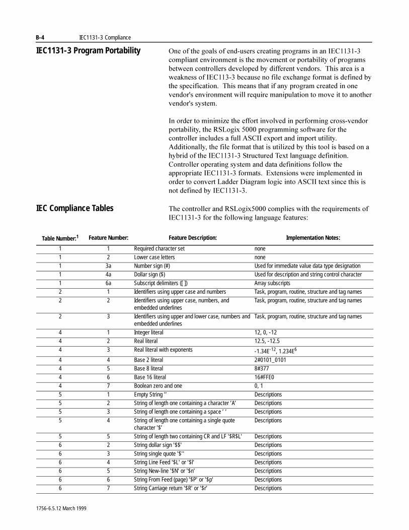
B-4 IEC1131-3 Compliance
IEC1131-3 Program Portability 2QH�RI�WKH�JRDOV�RI�HQG�XVHUV�FUHDWLQJ�SURJUDPV�LQ�DQ�,(&�������FRPSOLDQW�HQYLURQPHQW�LV�WKH�PRYHPHQW�RU�SRUWDELOLW\�RI�SURJUDPV�EHWZHHQ�FRQWUROOHUV�GHYHORSHG�E\�GLIIHUHQW�YHQGRUV���7KLV�DUHD�LV�D�ZHDNQHVV�RI�,(&������EHFDXVH�QR�ILOH�H[FKDQJH�IRUPDW�LV�GHILQHG�E\�WKH�VSHFLILFDWLRQ���7KLV�PHDQV�WKDW�LI�DQ\�SURJUDP�FUHDWHG�LQ�RQH�YHQGRUV�HQYLURQPHQW�ZLOO�UHTXLUH�PDQLSXODWLRQ�WR�PRYH�LW�WR�DQRWKHU�YHQGRUV�V\VWHP�
,Q�RUGHU�WR�PLQLPL]H�WKH�HIIRUW�LQYROYHG�LQ�SHUIRUPLQJ�FURVV�YHQGRU�SRUWDELOLW\��WKH�56/RJL[������SURJUDPPLQJ�VRIWZDUH�IRU�WKH�FRQWUROOHU�LQFOXGHV�D�IXOO�$6&,,�H[SRUW�DQG�LPSRUW�XWLOLW\���$GGLWLRQDOO\��WKH�ILOH�IRUPDW�WKDW�LV�XWLOL]HG�E\�WKLV�WRRO�LV�EDVHG�RQ�D�K\EULG�RI�WKH�,(&�������6WUXFWXUHG�7H[W�ODQJXDJH�GHILQLWLRQ���&RQWUROOHU�RSHUDWLQJ�V\VWHP�DQG�GDWD�GHILQLWLRQV�IROORZ�WKH�DSSURSULDWH�,(&�������IRUPDWV���([WHQVLRQV�ZHUH�LPSOHPHQWHG�LQ�RUGHU�WR�FRQYHUW�/DGGHU�'LDJUDP�ORJLF�LQWR�$6&,,�WH[W�VLQFH�WKLV�LV�QRW�GHILQHG�E\�,(&�������
IEC Compliance Tables 7KH�FRQWUROOHU�DQG�56/RJL[�����FRPSOLHV�ZLWK�WKH�UHTXLUHPHQWV�RI�,(&�������IRU�WKH�IROORZLQJ�ODQJXDJH�IHDWXUHV�
Table Number:1 Feature Number: Feature Description: Implementation Notes:
1 1 Required character set none
1 2 Lower case letters none1 3a Number sign (#) Used for immediate value data type designation1 4a Dollar sign ($) Used for description and string control character
1 6a Subscript delimiters ([ ]) Array subscripts2 1 Identifiers using upper case and numbers Task, program, routine, structure and tag names
2 2 Identifiers using upper case, numbers, and embedded underlines
Task, program, routine, structure and tag names
2 3 Identifiers using upper and lower case, numbers and embedded underlines
Task, program, routine, structure and tag names
4 1 Integer literal 12, 0, -124 2 Real literal 12.5, -12.5
4 3 Real literal with exponents -1.34E-12, 1.234E6
4 4 Base 2 literal 2#0101_01014 5 Base 8 literal 8#377
4 6 Base 16 literal 16#FFE04 7 Boolean zero and one 0, 1
5 1 Empty String ’’ Descriptions5 2 String of length one containing a character ’A’ Descriptions5 3 String of length one containing a space ’ ’ Descriptions
5 4 String of length one containing a single quote character '$’
Descriptions
5 5 String of length two containing CR and LF '$R$L' Descriptions6 2 String dollar sign '$$' Descriptions
6 3 String single quote '$'' Descriptions6 4 String Line Feed '$L' or '$l' Descriptions6 5 String New-line '$N' or '$n' Descriptions
6 6 String From Feed (page) '$P' or '$p' Descriptions6 7 String Carriage return '$R' or '$r' Descriptions
1756-6.5.12 March 1999
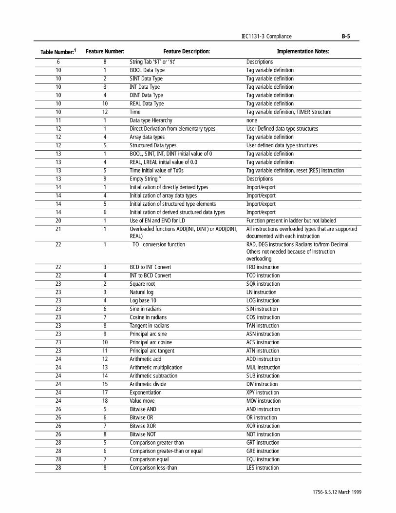
IEC1131-3 Compliance B-5
6 8 String Tab ’$T’ or ’$t’ Descriptions10 1 BOOL Data Type Tag variable definition
10 2 SINT Data Type Tag variable definition10 3 INT Data Type Tag variable definition10 4 DINT Data Type Tag variable definition
10 10 REAL Data Type Tag variable definition10 12 Time Tag variable definition, TIMER Structure
11 1 Data type Hierarchy none12 1 Direct Derivation from elementary types User Defined data type structures12 4 Array data types Tag variable definition
12 5 Structured Data types User defined data type structures13 1 BOOL, SINT, INT, DINT initial value of 0 Tag variable definition
13 4 REAL, LREAL initial value of 0.0 Tag variable definition13 5 Time initial value of T#0s Tag variable definition, reset (RES) instruction13 9 Empty String ’’ Descriptions
14 1 Initialization of directly derived types Import/export14 4 Initialization of array data types Import/export
14 5 Initialization of structured type elements Import/export14 6 Initialization of derived structured data types Import/export
20 1 Use of EN and ENO for LD Function present in ladder but not labeled21 1 Overloaded functions ADD(INT, DINT) or ADD(DINT,
REAL)All instructions overloaded types that are supported documented with each instruction
22 1 _TO_ conversion function RAD, DEG instructions Radians to/from Decimal. Others not needed because of instruction overloading
22 3 BCD to INT Convert FRD instruction22 4 INT to BCD Convert TOD instruction
23 2 Square root SQR instruction23 3 Natural log LN instruction23 4 Log base 10 LOG instruction
23 6 Sine in radians SIN instruction23 7 Cosine in radians COS instruction
23 8 Tangent in radians TAN instruction23 9 Principal arc sine ASN instruction23 10 Principal arc cosine ACS instruction
23 11 Principal arc tangent ATN instruction24 12 Arithmetic add ADD instruction
24 13 Arithmetic multiplication MUL instruction24 14 Arithmetic subtraction SUB instruction24 15 Arithmetic divide DIV instruction
24 17 Exponentiation XPY instruction24 18 Value move MOV instruction
26 5 Bitwise AND AND instruction26 6 Bitwise OR OR instruction26 7 Bitwise XOR XOR instruction
26 8 Bitwise NOT NOT instruction28 5 Comparison greater-than GRT instruction
28 6 Comparison greater-than or equal GRE instruction28 7 Comparison equal EQU instruction28 8 Comparison less-than LES instruction
Table Number:1 Feature Number: Feature Description: Implementation Notes:
1756-6.5.12 March 1999
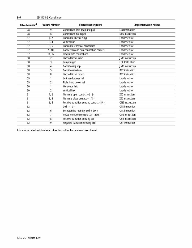
B-6 IEC1131-3 Compliance
28 9 Comparison less-than or equal LEQ instruction28 10 Comparison not equal NEQ instruction
57 1, 2 Horizontal line for rung Ladder editor57 3, 4 Vertical line Ladder editor57 5, 6 Horizontal / Vertical connection Ladder editor
57 9, 10 Connection and non-connection corners Ladder editor57 11, 12 Blocks with connections Ladder editor
58 2 Unconditional jump JMP instruction58 3 Jump target LBL Instruction58 4 Conditional jump JMP instruction
58 5 Conditional return RET instruction58 8 Unconditional return RET instruction
59 1 Left hand power rail Ladder editor59 2 Right hand power rail Ladder editor60 1 Horizontal link Ladder editor
60 2 Vertical link Ladder editor61 1, 2 Normally open contact --| |-- XIC instruction
61 3, 4 Normally close contact --| / |-- XIO instruction61 5, 6 Positive transition sensing contact -| P |- ONS instruction
62 1 Coil --( )-- OTE instruction62 6 Set retentive memory coil -( SM )- OTL instruction62 7 Reset retentive memory coil -( RM )- OTU instruction
62 8 Positive transition sensing coil OSR instruction62 9 Negative transition sensing coil OSF instruction
��7DEOH�DVVRFLDWHG�ZLWK�ODQJXDJHV�RWKHU�WKDQ�ODGGHU�GLDJUDP�KDYH�EHHQ�VNLSSHG�
Table Number:1 Feature Number: Feature Description: Implementation Notes:
1756-6.5.12 March 1999
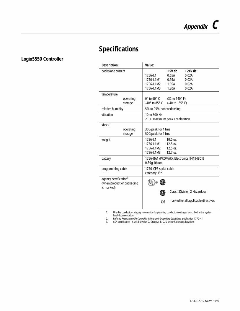
Appendix C
SpecificationsLogix5550 Controller
Description: Value:
backplane current +5V dc +24V dc1756-L1 0.65A 0.02A1756-L1M1 0.95A 0.02A1756-L1M2 1.05A 0.02A1756-L1M3 1.20A 0.02A
temperatureoperatingstorage
0° to 60° C (32 to 140° F)-40° to 85° C (-40 to 185° F)
relative humidity 5% to 95% noncondensing
vibration 10 to 500 Hz2.0 G maximum peak acceleration
shockoperatingstorage
30G peak for 11ms50G peak for 11ms
weight 1756-L1 10.0 oz.1756-L1M1 12.5 oz.1756-L1M2 12.5 oz.1756-L1M3 12.7 oz.
battery 1756-BA1 (PROMARK Electronics 94194801)0.59g lithium
programming cable 1756-CP3 serial cablecategory 31,2
1. Use this conductor category information for planning conductor routing as described in the systemlevel documentation.
2. Refer to Programmable Controller Wiring and Grounding Guidelines, publication 1770-4.1
agency certification3
(when product or packaging is marked)
3. CSA certification - Class I Division 2, Group A, B, C, D or nonhazardous locations
Class I Division 2 Hazardous
marked for all applicable directives
1756-6.5.12 March 1999
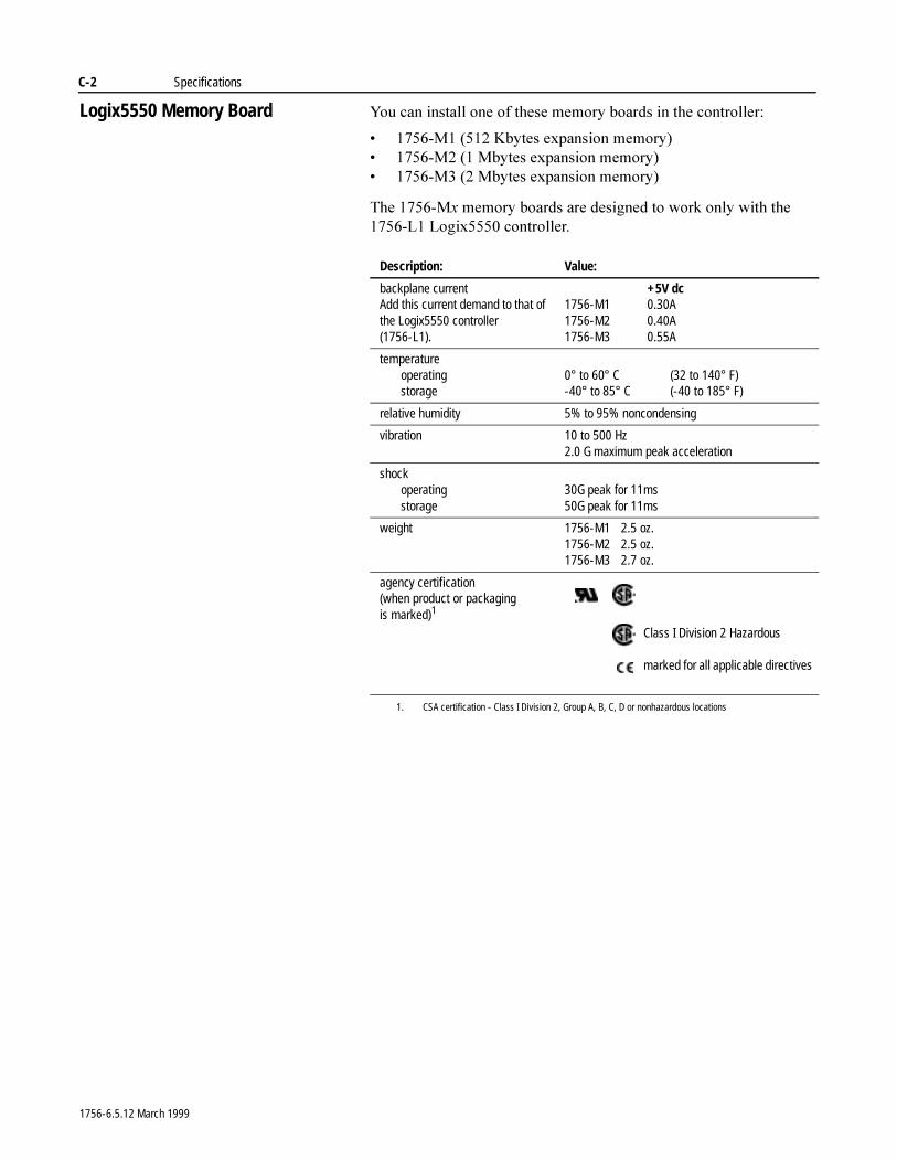
C-2 Specifications
Logix5550 Memory Board <RX�FDQ�LQVWDOO�RQH�RI�WKHVH�PHPRU\�ERDUGV�LQ�WKH�FRQWUROOHU�
� �����0�������.E\WHV�H[SDQVLRQ�PHPRU\�� �����0�����0E\WHV�H[SDQVLRQ�PHPRU\�� �����0�����0E\WHV�H[SDQVLRQ�PHPRU\�
7KH������0[�PHPRU\�ERDUGV�DUH�GHVLJQHG�WR�ZRUN�RQO\�ZLWK�WKH������/��/RJL[�����FRQWUROOHU�
Description: Value:
backplane currentAdd this current demand to that of the Logix5550 controller (1756-L1).
+5V dc1756-M1 0.30A1756-M2 0.40A1756-M3 0.55A
temperatureoperatingstorage
0° to 60° C (32 to 140° F)-40° to 85° C (-40 to 185° F)
relative humidity 5% to 95% noncondensing
vibration 10 to 500 Hz2.0 G maximum peak acceleration
shockoperatingstorage
30G peak for 11ms50G peak for 11ms
weight 1756-M1 2.5 oz.1756-M2 2.5 oz.1756-M3 2.7 oz.
agency certification(when product or packaging is marked)1
1. CSA certification - Class I Division 2, Group A, B, C, D or nonhazardous locations
Class I Division 2 Hazardous
marked for all applicable directives
1756-6.5.12 March 1999
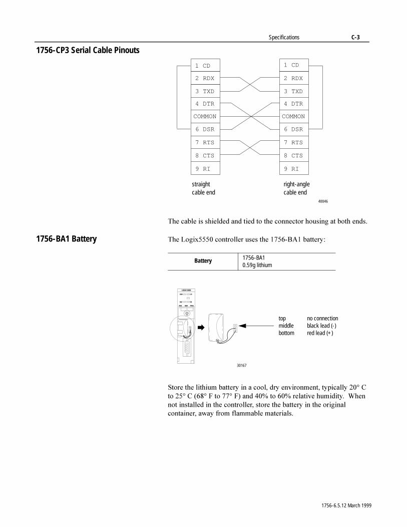
Specifications C-3
1756-CP3 Serial Cable Pinouts
7KH�FDEOH�LV�VKLHOGHG�DQG�WLHG�WR�WKH�FRQQHFWRU�KRXVLQJ�DW�ERWK HQGV�
1756-BA1 Battery 7KH�/RJL[�����FRQWUROOHU�XVHV�WKH������%$��EDWWHU\�
6WRUH�WKH�OLWKLXP�EDWWHU\�LQ�D�FRRO��GU\�HQYLURQPHQW��W\SLFDOO\�����&�WR�����&������)�WR�����)��DQG�����WR�����UHODWLYH�KXPLGLW\���:KHQ�QRW�LQVWDOOHG�LQ�WKH�FRQWUROOHU��VWRUH�WKH�EDWWHU\�LQ�WKH�RULJLQDO�FRQWDLQHU��DZD\�IURP�IODPPDEOH�PDWHULDOV�
right-angle cable end
straightcable end
2 RDX
3 TXD
4 DTR
COMMON
6 DSR
7 RTS
8 CTS
9 RI
1 CD
2 RDX
3 TXD
4 DTR
COMMON
6 DSR
7 RTS
8 CTS
9 RI
1 CD
40046
Battery 1756-BA10.59g lithium
top no connectionmiddle black lead (-)bottom red lead (+)
30167
1756-6.5.12 March 1999
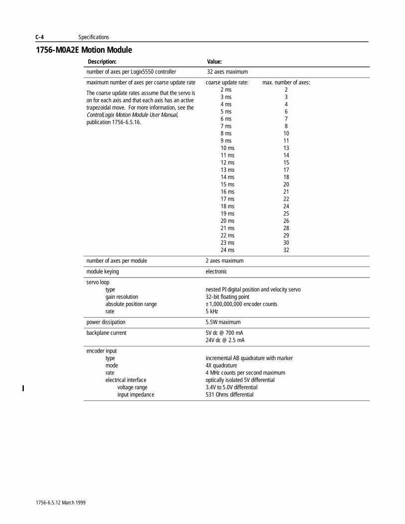
C-4 Specifications
1756-M0A2E Motion ModuleDescription: Value:
number of axes per Logix5550 controller 32 axes maximum
maximum number of axes per coarse update rate
The coarse update rates assume that the servo is on for each axis and that each axis has an active trapezoidal move. For more information, see the ControlLogix Motion Module User Manual, publication 1756-6.5.16.
coarse update rate: max. number of axes:2 ms 23 ms 34 ms 45 ms 66 ms 77 ms 88 ms 109 ms 1110 ms 1311 ms 1412 ms 1513 ms 1714 ms 1815 ms 2016 ms 2117 ms 2218 ms 2419 ms 2520 ms 2621 ms 2822 ms 2923 ms 3024 ms 32
number of axes per module 2 axes maximum
module keying electronic
servo looptypegain resolutionabsolute position rangerate
nested PI digital position and velocity servo32-bit floating point±1,000,000,000 encoder counts5 kHz
power dissipation 5.5W maximum
backplane current 5V dc @ 700 mA24V dc @ 2.5 mA
encoder inputtypemoderateelectrical interface
voltage rangeinput impedance
incremental AB quadrature with marker4X quadrature4 MHz counts per second maximumoptically isolated 5V differential3.4V to 5.0V differential531 Ohms differential
1756-6.5.12 March 1999
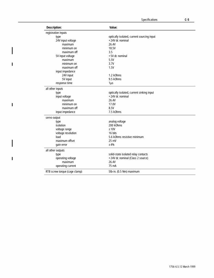
Specifications C-5
registration inputstype24V input voltage
maximumminimum onmaximum off
5V input voltagemaximumminimum onmaximum off
input impedance24V input5V input
response time
optically isolated, current sourcing input+24V dc nominal26.4V18.5V3.5+5V dc nominal5.5V3.7V1.5V
1.2 kOhms9.5 kOhms1µs
all other inputstypeinput voltage
maximumminimum onmaximum off
input impedance
optically isolated, current sinking input+24V dc nominal26.4V17.0V8.5V7.5 kOhms
servo outputtypeisolationvoltage rangevoltage resolutionloadmaximum offsetgain error
analog voltage200 kOhms±10V16 bits5.6 kOhms resistive minimum25 mV±4%
all other outputstypeoperating voltage
maximumoperating current
solid-state isolated relay contacts+24V dc nominal (Class 2 source)26.4V75 mA
RTB screw torque (cage clamp) 5lb-in. (0.5 Nm) maximum
Description: Value:
1756-6.5.12 March 1999
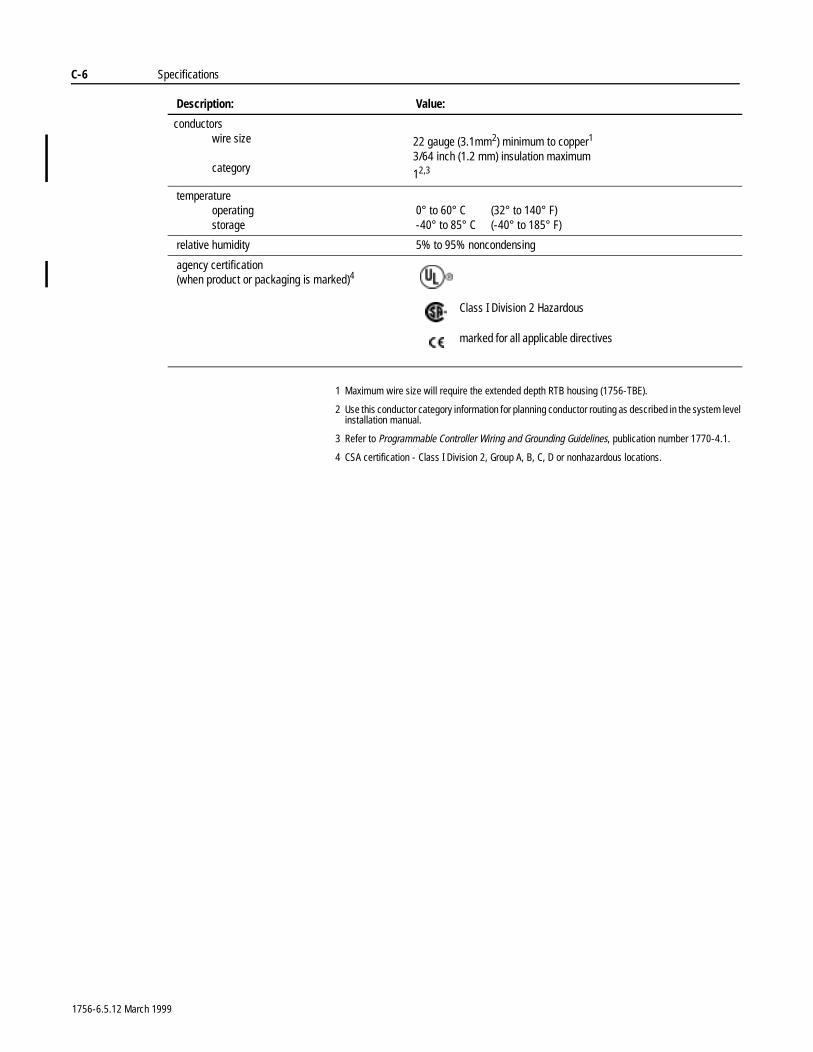
C-6 Specifications
1 Maximum wire size will require the extended depth RTB housing (1756-TBE).
2 Use this conductor category information for planning conductor routing as described in the system level installation manual.
3 Refer to Programmable Controller Wiring and Grounding Guidelines, publication number 1770-4.1.
4 CSA certification - Class I Division 2, Group A, B, C, D or nonhazardous locations.
conductorswire size
category
22 gauge (3.1mm2) minimum to copper1
3/64 inch (1.2 mm) insulation maximum
12,3
temperatureoperatingstorage
0° to 60° C (32° to 140° F)-40° to 85° C (-40° to 185° F)
relative humidity 5% to 95% noncondensing
agency certification(when product or packaging is marked)4
Description: Value:
Class I Division 2 Hazardous
marked for all applicable directives
1756-6.5.12 March 1999
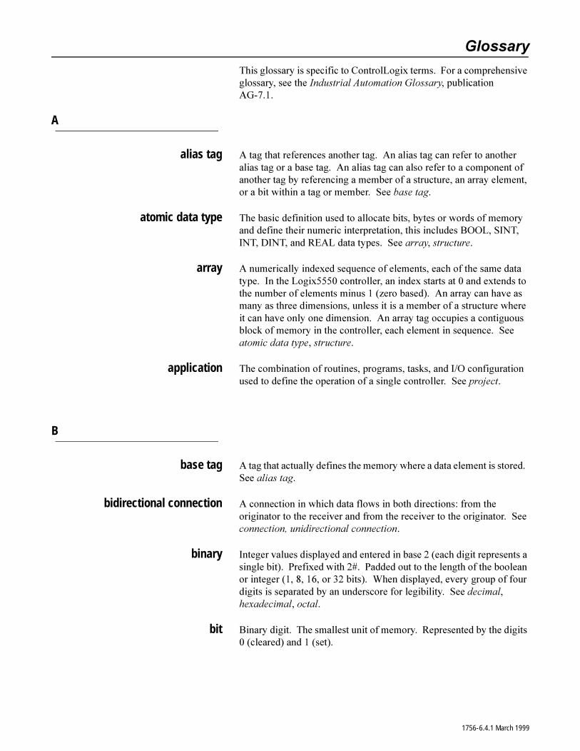
*ORVVDU\
7KLV�JORVVDU\�LV�VSHFLILF�WR�&RQWURO/RJL[�WHUPV���)RU�D�FRPSUHKHQVLYH�JORVVDU\��VHH�WKH�,QGXVWULDO�$XWRPDWLRQ�*ORVVDU\��SXEOLFDWLRQ�$*�����
A
alias tag $�WDJ�WKDW�UHIHUHQFHV�DQRWKHU�WDJ���$Q�DOLDV�WDJ�FDQ�UHIHU�WR�DQRWKHU�DOLDV�WDJ�RU�D�EDVH�WDJ���$Q�DOLDV�WDJ�FDQ�DOVR�UHIHU�WR�D�FRPSRQHQW�RI�DQRWKHU�WDJ�E\�UHIHUHQFLQJ�D�PHPEHU�RI�D�VWUXFWXUH��DQ�DUUD\�HOHPHQW��RU�D�ELW�ZLWKLQ�D�WDJ�RU�PHPEHU���6HH�EDVH�WDJ�
atomic data type 7KH�EDVLF�GHILQLWLRQ�XVHG�WR�DOORFDWH�ELWV��E\WHV�RU�ZRUGV�RI�PHPRU\�DQG�GHILQH�WKHLU�QXPHULF�LQWHUSUHWDWLRQ��WKLV�LQFOXGHV�%22/��6,17��,17��',17��DQG�5($/�GDWD�W\SHV���6HH�DUUD\��VWUXFWXUH�
array $�QXPHULFDOO\�LQGH[HG�VHTXHQFH�RI�HOHPHQWV��HDFK�RI�WKH�VDPH�GDWD�W\SH���,Q�WKH�/RJL[�����FRQWUROOHU��DQ�LQGH[�VWDUWV�DW���DQG�H[WHQGV�WR�WKH�QXPEHU�RI�HOHPHQWV�PLQXV����]HUR�EDVHG����$Q�DUUD\�FDQ�KDYH�DV�PDQ\�DV�WKUHH�GLPHQVLRQV��XQOHVV�LW�LV�D�PHPEHU�RI�D�VWUXFWXUH�ZKHUH�LW�FDQ�KDYH�RQO\�RQH�GLPHQVLRQ���$Q�DUUD\�WDJ�RFFXSLHV�D�FRQWLJXRXV�EORFN�RI�PHPRU\�LQ�WKH�FRQWUROOHU��HDFK�HOHPHQW�LQ�VHTXHQFH���6HH�DWRPLF�GDWD�W\SH��VWUXFWXUH�
application 7KH�FRPELQDWLRQ�RI�URXWLQHV��SURJUDPV��WDVNV��DQG�,�2�FRQILJXUDWLRQ�XVHG�WR�GHILQH�WKH�RSHUDWLRQ�RI�D�VLQJOH�FRQWUROOHU���6HH�SURMHFW�
B
base tag $�WDJ�WKDW�DFWXDOO\�GHILQHV�WKH�PHPRU\�ZKHUH�D�GDWD�HOHPHQW�LV�VWRUHG���6HH�DOLDV�WDJ�
bidirectional connection $�FRQQHFWLRQ�LQ�ZKLFK�GDWD�IORZV�LQ�ERWK�GLUHFWLRQV��IURP�WKH�RULJLQDWRU�WR�WKH�UHFHLYHU�DQG�IURP�WKH�UHFHLYHU�WR�WKH�RULJLQDWRU���6HH�FRQQHFWLRQ��XQLGLUHFWLRQDO�FRQQHFWLRQ�
binary ,QWHJHU�YDOXHV�GLVSOD\HG�DQG�HQWHUHG�LQ�EDVH����HDFK�GLJLW�UHSUHVHQWV�D�VLQJOH�ELW����3UHIL[HG�ZLWK������3DGGHG�RXW�WR�WKH�OHQJWK�RI�WKH�ERROHDQ�RU�LQWHJHU������������RU����ELWV����:KHQ�GLVSOD\HG��HYHU\�JURXS�RI�IRXU�GLJLWV�LV�VHSDUDWHG�E\�DQ�XQGHUVFRUH�IRU�OHJLELOLW\���6HH�GHFLPDO��KH[DGHFLPDO��RFWDO�
bit %LQDU\�GLJLW���7KH�VPDOOHVW�XQLW�RI�PHPRU\���5HSUHVHQWHG�E\�WKH�GLJLWV����FOHDUHG��DQG����VHW��
1756-6.4.1 March 1999
2
BOOL $Q�DWRPLF�GDWD�W\SH�WKDW�VWRUHV�WKH�VWDWH�RI�D�VLQJOH�ELW����RU����
byte $�XQLW�RI�PHPRU\�FRQVLVWLQJ�RI���ELWV�
C
cached connection :LWK�WKH�06*�LQVWUXFWLRQ��D�FDFKHG�FRQQHFWLRQ�LQVWUXFWV�WKH�FRQWUROOHU�WR�PDLQWDLQ�WKH�FRQQHFWLRQ�HYHQ�DIWHU�WKH�06*�LQVWUXFWLRQ�FRPSOHWHV���7KLV�LV�XVHIXO�LI�\RX�UHSHDWHGO\�H[HFXWH�WKH�06*�LQVWUXFWLRQ�EHFDXVH�LQLWLDWLQJ�WKH�FRQQHFWLRQ�HDFK�WLPH�LQFUHDVHV�VFDQ�WLPH���6HH�FRQQHFWLRQ��XQFDFKHG�FRQQHFWLRQ�
change of state (COS) $Q\�FKDQJH�LQ�WKH�VWDWXV�RI�D�SRLQW�RU�JURXS�RI�SRLQWV�RQ�DQ�,�2 PRGXOH�
CIP 6HH�&RQWURO�DQG�,QIRUPDWLRQ�3URWRFRO�
communication format 'HILQHV�KRZ�DQ�,�2�PRGXOH�FRPPXQLFDWHV�ZLWK�WKH�FRQWUROOHU���&KRRVLQJ�D�FRPPXQLFDWLRQ�IRUPDW�GHILQHV�
� ZKDW�FRQILJXUDWLRQ�WDEV�DUH�DYDLODEOH�WKURXJK�WKH�SURJUDPPLQJ VRIWZDUH
� WKH�WDJ�VWUXFWXUH�DQG�FRQILJXUDWLRQ�PHWKRG
compatible module $Q�HOHFWURQLF�NH\LQJ�SURWHFWLRQ�PRGH�WKDW�UHTXLUHV�WKDW�WKH�YHQGRU��FDWDORJ�QXPEHU��DQG�PDMRU�UHYLVLRQ�DWWULEXWHV�RI�WKH�SK\VLFDO�PRGXOH�DQG�WKH�PRGXOH�FRQILJXUHG�LQ�WKH�VRIWZDUH�PDWFK�LQ�RUGHU�WR�HVWDEOLVK�D�FRQQHFWLRQ�WR�WKH�PRGXOH���6HH�GLVDEOH�NH\LQJ��H[DFW PDWFK�
connection 7KH�FRPPXQLFDWLRQ�PHFKDQLVP�IURP�WKH�FRQWUROOHU�WR�DQRWKHU�PRGXOH�LQ�WKH�FRQWURO�V\VWHP���7KH�QXPEHU�RI�FRQQHFWLRQV�WKDW�D�VLQJOH�FRQWUROOHU�FDQ�KDYH�LV�OLPLWHG���&RPPXQLFDWLRQV�ZLWK�,�2�PRGXOHV��FRQVXPHG�WDJV��SURGXFHG�WDJV��DQG�06*�LQVWUXFWLRQV�XVH�FRQQHFWLRQV�WR�WUDQVIHU�GDWD�
consumed tag $�WDJ�WKDW�UHFHLYHV�LWV�GDWD�IURP�DQRWKHU�FRQWUROOHU���&RQVXPHG�WDJV�DUH�DOZD\V�DW�FRQWUROOHU�VFRSH���6HH�SURGXFHG�WDJ�
continuous task $�WDVN�WKDW�UXQV�FRQWLQXRXVO\��UHVWDUWLQJ�WKH�H[HFXWLRQ�RI�LWV�SURJUDPV�ZKHQ�WKH�ODVW�RQH�ILQLVKHV���7KHUH�FDQ�EH�RQO\�RQH�FRQWLQXRXV�WDVN��DOWKRXJK�WKHUH�GRHV�QRW�KDYH�WR�EH�DQ\���6HH�SHULRGLF�WDVN�
Control and Information Protocol 0HVVDJLQJ�SURWRFRO�XVHG�E\�$OOHQ�%UDGOH\¶V�VHULHV�&RQWURO/RJL[�OLQH�RI�FRQWURO�HTXLSPHQW���1DWLYH�FRPPXQLFDWLRQV�SURWRFRO�XVHG�RQ�WKH�&RQWURO1HW�QHWZRUN�
ControlBus 7KH�EDFNSODQH�XVHG�E\�WKH������FKDVVLV���$FWV�DV�D�QHWZRUN�
1756-6.4.1 March 1999
3
controller scope 'DWD�DFFHVVLEOH�DQ\ZKHUH�LQ�WKH�FRQWUROOHU���7KH�FRQWUROOHU�FRQWDLQV�D�FROOHFWLRQ�RI�WDJV�WKDW�FDQ�EH�UHIHUHQFHG�E\�WKH�URXWLQHV�DQG�DOLDV�WDJV�LQ�DQ\�SURJUDP��DV�ZHOO�DV�RWKHU�DOLDVHV�LQ�WKH�FRQWUROOHU�VFRSH���6HH�SURJUDP�VFRSH�
Coordinated System Time (CST) $�V\QFKURQL]HG�WLPH�YDOXH�IRU�DOO�WKH�PRGXOHV�ZLWKLQ�D�VLQJOH�&RQWURO%XV�FKDVVLV���'DWD�WLPHVWDPSHG�ZLWK�&67�GDWD�IURP�PRGXOHV�ZLWKLQ�D�VLQJOH�&RQWURO%XV�FKDVVLV�FDQ�VDIHO\�EH�FRPSDUHG�WR�GHWHUPLQH�WKH�UHODWLYH�WLPH�EHWZHHQ�GDWD�VDPSOHV�
COUNTER 6WUXFWXUH�GDWD�W\SH�WKDW�FRQWDLQV�VWDWXV�DQG�FRQWURO�LQIRUPDWLRQ�IRU�FRXQWHU�LQVWUXFWLRQV
D
data type $�GHILQLWLRQ�RI�WKH�PHPRU\�VL]H�DQG�WKH�OD\RXW�RI�PHPRU\�WKDW�ZLOO�EH�DOORFDWHG�ZKHQ�D�WDJ�RI�WKH�GDWD�W\SH�LV�FUHDWHG���'DWD�W\SHV�FDQ�EH�DWRPLF��VWUXFWXUHV��RU�DUUD\V�
decimal ,QWHJHU�YDOXHV�GLVSOD\HG�DQG�HQWHUHG�LQ�EDVH������1R�SUHIL[���1RW�SDGGHG�WR�WKH�OHQJWK�RI�WKH�LQWHJHU���6HH�ELQDU\��KH[DGHFLPDO��RFWDO�
description 'HVFULSWLRQV�IRU�WDJV�DUH�DV�PDQ\�DV�����FKDUDFWHUV�ORQJ��GHVFULSWLRQV�IRU�RWKHU�REMHFWV�DUH�DV�PDQ\�DV�����FKDUDFWHUV�ORQJ���$Q\�SULQWDEOH�FKDUDFWHU�FDQ�EH�XVHG��LQFOXGLQJ�FDUULDJH�UHWXUQ��WDE��DQG�VSDFH�
dimension 6SHFLILFDWLRQ�RI�WKH�VL]H�RI�DQ�DUUD\���$UUD\V�FDQ�KDYH�DV�PDQ\�DV�WKUHH�GLPHQVLRQV�
DINT $Q�DWRPLF�GDWD�W\SH�WKDW�VWRUHV�D����ELW�VLJQHG�LQWHJHU�YDOXH�����������������WR�����������������
direct $Q�,�2�FRQQHFWLRQ�ZKHUH�WKH�FRQWUROOHU�HVWDEOLVKHV�DQ�LQGLYLGXDO�FRQQHFWLRQV�ZLWK�DQ�,�2�PRGXOH���6HH�UDFN�RSWLPL]HG�
disable keying $Q�HOHFWURQLF�NH\LQJ�SURWHFWLRQ�PRGH�WKDW�UHTXLUHV�QR�DWWULEXWHV�RI�WKH�SK\VLFDO�PRGXOH�DQG�WKH�PRGXOH�FRQILJXUHG�LQ�WKH�VRIWZDUH�WR�PDWFK�DQG�VWLOO�HVWDEOLVKHV�D�FRQQHFWLRQ�WR�WKH�PRGXOH���6HH�FRPSDWLEOH�PRGXOH��H[DFW�PDWFK�
download 7KH�SURFHVV�RI�WUDQVIHUULQJ�WKH�FRQWHQWV�RI�D�SURMHFW�RQ�WKH�ZRUNVWDWLRQ�LQWR�WKH�FRQWUROOHU���6HH�XSORDG�
1756-6.4.1 March 1999
4
E
elapsed time 7KH�WRWDO�WLPH�UHTXLUHG�IRU�WKH�H[HFXWLRQ�RI�DOO�RSHUDWLRQV�FRQILJXUHG�ZLWKLQ�D�VLQJOH�WDVN���,I�WKH�FRQWUROOHU�LV�FRQILJXUHG�WR�UXQ�PXOWLSOH�WDVNV��HODSVHG�WLPH�LQFOXGHV�DQ\�WLPH�XVHG�VKDUHG�E\�RWKHU�WDVNV�SHUIRUPLQJ�RWKHU�RSHUDWLRQV���6HH�H[HFXWLRQ�WLPH�
electronic keying $�IHDWXUH�RI�WKH������,�2�OLQH�ZKHUH�PRGXOHV�FDQ�EH�UHTXHVWHG�WR�SHUIRUP�DQ�HOHFWURQLF�FKHFN�WR�LQVXUH�WKDW�WKH�SK\VLFDO�PRGXOH�LV�FRQVLVWHQW�ZLWK�ZKDW�ZDV�FRQILJXUHG�E\�WKH�VRIWZDUH���(QDEOHV�WKH�XVHU�YLD�WKH�VRIWZDUH�WR�SUHYHQW�LQFRUUHFW�PRGXOHV�RU�LQFRUUHFW�UHYLVLRQV�RI�PRGXOHV�IURP�EHLQJ�LQDGYHUWHQWO\�XVHG���6HH�FRPSDWLEOH�PRGXOH��GLVDEOH�NH\LQJ��H[DFW�PDWFK�
element $Q�DGGUHVVDEOH�XQLW�RI�GDWD�WKDW�LV�D�VXE�XQLW�RI�D�ODUJHU�XQLW�RI�GDWD���$�VLQJOH�XQLW�RI�DQ�DUUD\���6HH�DUUD\�
exact match $Q�HOHFWURQLF�NH\LQJ�SURWHFWLRQ�PRGH�WKDW�UHTXLUHV�WKDW�DOO�DWWULEXWHV��YHQGRU��FDWDORJ�QXPEHU��PDMRU�UHYLVLRQ��DQG�PLQRU�UHYLVLRQ��RI�WKH�SK\VLFDO�PRGXOH�DQG�WKH�PRGXOH�FRQILJXUHG�LQ�WKH�VRIWZDUH�PDWFK�LQ�RUGHU�WR�HVWDEOLVK�D�FRQQHFWLRQ�WR�WKH�PRGXOH�
execution time 7KH�WRWDO�WLPH�UHTXLUHG�IRU�WKH�H[HFXWLRQ�RI�D�VLQJOH�SURJUDP���([HFXWLRQ�WLPH�LQFOXGHV�RQO\�WKH�WLPH�XVHG�E\�WKDW�VLQJOH�SURJUDP��DQG�H[FOXGHV�DQ\�WLPH�VKDUHG�XVHG�E\�SURJUDPV�LQ�RWKHU�WDVNV�SHUIRUPLQJ�RWKHU�RSHUDWLRQV���6HH�HODSVHG�WLPH�
exponential 5HDO�YDOXHV�GLVSOD\HG�DQG�HQWHUHG�LQ�VFLHQWLILF�RU�H[SRQHQWLDO�IRUPDW���7KH�QXPEHU�LV�DOZD\V�GLVSOD\HG�ZLWK�RQH�GLJLW�WR�WKH�OHIW�RI�WKH�GHFLPDO�SRLQW��IROORZHG�E\�WKH�GHFLPDO�SRUWLRQ��DQG�WKHQ�E\�DQ�H[SRQHQW���6HH�VW\OH�
F
faulted mode 7KH�FRQWUROOHU�JHQHUDWHG�D�PDMRU�IDXOW��FRXOG�QRW�FOHDU�WKH�IDXOW��DQG�KDV�VKXW�GRZQ�
float 5HDO�YDOXHV�GLVSOD\HG�DQG�HQWHUHG�LQ�IORDWLQJ�SRLQW�IRUPDW���7KH�QXPEHU�RI�GLJLWV�WR�WKH�OHIW�RI�WKH�GHFLPDO�SRLQW�YDULHV�DFFRUGLQJ�WR�WKH�PDJQLWXGH�RI�WKH�QXPEHU���6HH�VW\OH�
1756-6.4.1 March 1999
5
H
hexadecimal ,QWHJHU�YDOXHV�GLVSOD\HG�DQG�HQWHUHG�LQ�EDVH�����HDFK�GLJLW�UHSUHVHQWV�IRXU�ELWV����3UHIL[HG�ZLWK�������3DGGHG�RXW�WR�OHQJWK�RI�WKH�ERROHDQ�RU�LQWHJHU������������RU����ELWV����:KHQ�GLVSOD\HG��HYHU\�JURXS�RI�IRXU�GLJLWV�LV�VHSDUDWHG�E\�DQ�XQGHUVFRUH�IRU�OHJLELOLW\���6HH�ELQDU\��GHFLPDO��RFWDO�
I
immediate value $Q�DFWXDO����ELW�VLJQHG�UHDO�RU�LQWHJHU�YDOXH���1RW�D�WDJ�WKDW�VWRUHV�D YDOXH�
index $�UHIHUHQFH�XVHG�WR�VSHFLI\�DQ�HOHPHQW�ZLWKLQ�DQ�DUUD\�
INT $Q�DWRPLF�GDWD�W\SH�WKDW�VWRUHV�D����ELW�LQWHJHU�YDOXH��������� WR ���������
interface module (IFM) $�SUHZLUHG�,�2�ILHOG�ZLULQJ�DUP�
L
listen-only connection $Q�,�2�FRQQHFWLRQ�ZKHUH�DQRWKHU�FRQWUROOHU�RZQV�SURYLGHV�WKH�FRQILJXUDWLRQ�GDWD�IRU�WKH�,�2�PRGXOH���$�FRQWUROOHU�XVLQJ�D�OLVWHQ�RQO\�FRQQHFWLRQ�GRHV�QRW�ZULWH�FRQILJXUDWLRQ�GDWD�DQG�FDQ�RQO\�PDLQWDLQ�D�FRQQHFWLRQ�WR�WKH�,�2�PRGXOH�ZKHQ�WKH�RZQHU�FRQWUROOHU�LV�DFWLYHO\�FRQWUROOLQJ�WKH�,�2�PRGXOH���6HH�RZQHU�FRQWUROOHU�
M
major fault $�PDOIXQFWLRQ��HLWKHU�KDUGZDUH�RU�LQVWUXFWLRQ��WKDW�VHWV�D�PDMRU�IDXOW�ELW�DQG�SURFHVVHV�IDXOW�ORJLF�WR�WU\�WR�FOHDU�WKH�IDXOW�FRQGLWLRQ���,I�WKH�IDXOW�ORJLF�FDQQRW�FOHDU�WKH�IDXOW��ORJLF�H[HFXWLRQ�VWRSV��WKH�FRQWUROOHU�VKXWV�GRZQ��DQG�RXWSXWV�JR�WR�WKHLU�FRQILJXUHG�VWDWH���6HH�IDXOWHG�VWDWH��PLQRU�IDXOW�
major revision 7KH������OLQH�RI�PRGXOHV�KDYH�PDMRU�DQG�PLQRU�UHYLVLRQ�LQGLFDWRUV���7KH�PDMRU�UHYLVLRQ�LV�XSGDWHG�DQ\�WLPH�WKHUH�LV�D�IXQFWLRQDO�FKDQJH�WR�WKH�PRGXOH���6HH�HOHFWURQLF�NH\LQJ��PLQRU�UHYLVLRQ�
1756-6.4.1 March 1999
6
master (CST) :LWKLQ�D�VLQJOH�FKDVVLV��RQH�DQG�RQO\�RQH��FRQWUROOHU�PXVW�EH�GHVLJQDWHG�DV�WKH�&RRUGLQDWHG�6\VWHP�7LPH��&67��PDVWHU���$OO�RWKHU�PRGXOHV�LQ�WKH�FKDVVLV�V\QFKURQL]H�WKHLU�&67�YDOXHV�WR�WKH�&67 PDVWHU�
member $Q�HOHPHQW�RI�D�VWUXFWXUH�WKDW�KDV�LWV�RZQ�GDWD�W\SH�DQG�QDPH���0HPEHUV�FDQ�EH�VWUXFWXUHV�DV�ZHOO��FUHDWLQJ�QHVWHG�VWUXFWXUH�GDWD�W\SHV���(DFK�PHPEHU�ZLWKLQ�D�VWUXFWXUH�FDQ�EH�D�GLIIHUHQW�GDWD�W\SH���6HH�VWUXFWXUH�
memory (OHFWURQLF�VWRUDJH�PHGLD�EXLOW�LQWR�D�FRQWUROOHU��XVHG�WR�KROG�SURJUDPV�DQG�GDWD�
minor fault $�PDOIXQFWLRQ��HLWKHU�KDUGZDUH�RU�LQVWUXFWLRQ��WKDW�VHWV�D�PLQRU�IDXOW�ELW��EXW�DOORZV�WKH�ORJLF�VFDQ�WR�FRQWLQXH���6HH�PDMRU�IDXOW�
minor revision 7KH������OLQH�RI�PRGXOHV�KDYH�PDMRU�DQG�PLQRU�UHYLVLRQ�LQGLFDWRUV���7KH�PLQRU�UHYLVLRQ�LV�XSGDWHG�DQ\�WLPH�WKHUH�LV�D�FKDQJH�WR�D�PRGXOH�WKDW�GRHV�QRW�DIIHFW�LWV�IXQFWLRQ�RU�LQWHUIDFH����6HH�HOHFWURQLF�NH\LQJ��PDMRU�UHYLVLRQ�
multicast $�PHFKDQLVP�ZKHUH�D�PRGXOH�FDQ�VHQG�GDWD�RQ�D�QHWZRUN�WKDW�LV�VLPXOWDQHRXVO\�UHFHLYHG�E\�PRUH�WKDW�RQH�OLVWHQHU���'HVFULEHV�WKH�IHDWXUH�RI�WKH�&RQWURO/RJL[�,�2�OLQH�ZKLFK�VXSSRUWV�PXOWLSOH�FRQWUROOHUV�UHFHLYLQJ�LQSXW�GDWD�IURP�WKH�VDPH�,�2�PRGXOH�DW�WKH�VDPH WLPH�
multiple owners $�FRQILJXUDWLRQ�VHWXS�ZKHUH�PRUH�WKDQ�RQH�FRQWUROOHU�KDV�H[DFWO\�WKH�VDPH�FRQILJXUDWLRQ�LQIRUPDWLRQ�WR�VLPXOWDQHRXVO\�RZQ�WKH�VDPH�LQSXW PRGXOH�
N
name 1DPHV�LGHQWLI\�WDJV�DQG�PRGXOHV���7KH�QDPLQJ�FRQYHQWLRQV�DUH�,(&��������FRPSOLDQW���$�QDPH�
� PXVW�EHJLQ�ZLWK�DQ�DOSKDEHWLF�FKDUDFWHU��$�=�RU�D�]��RU�DQ�XQGHUVFRUH �B�
� FDQ�FRQWDLQ�RQO\�DOSKDEHWLF�FKDUDFWHUV��QXPHULF�FKDUDFWHUV��DQG XQGHUVFRUHV
� FDQ�KDYH�DV�PDQ\�DV����FKDUDFWHUV� PXVW�QRW�KDYH�FRQVHFXWLYH�RU�WUDLOLQJ�XQGHUVFRUH�FKDUDFWHUV��B�
network update time (NUT) 7KH�UHSHWLWLYH�WLPH�LQWHUYDO�LQ�ZKLFK�GDWD�FDQ�EH�VHQW�RQ�D�&RQWURO1HW QHWZRUN���7KH�QHWZRUN�XSGDWH�WLPH�UDQJHV�IURP��PV����PV�
1756-6.4.1 March 1999
7
O
object $�VWUXFWXUH�RI�GDWD�WKDW�VWRUHV�VWDWXV�LQIRUPDWLRQ���:KHQ�\RX�HQWHU�D�*69�669�LQVWUXFWLRQ��\RX�VSHFLI\�WKH�REMHFW�DQG�LWV�DWWULEXWH�WKDW�\RX�ZDQW�WR�DFFHVV���,Q�VRPH�FDVHV��WKHUH�DUH�PRUH�WKDQ�RQH�LQVWDQFH�RI�WKH�VDPH�W\SH�RI�REMHFW��VR�\RX�PLJKW�DOVR�KDYH�WR�VSHFLI\�WKH�REMHFW�QDPH���)RU�H[DPSOH��WKHUH�FDQ�EH�VHYHUDO�WDVNV�LQ�\RXU�DSSOLFDWLRQ���(DFK�WDVN�KDV�LWV�RZQ�7$6.�REMHFW�WKDW�\RX�DFFHVV�E\�WKH�WDVN�QDPH�
octal ,QWHJHU�YDOXHV�GLVSOD\HG�DQG�HQWHUHG�LQ�EDVH����HDFK�GLJLW�UHSUHVHQWV�WKUHH�ELWV����3UHIL[HG�ZLWK������3DGGHG�RXW�WR�WKH�OHQJWK�RI�WKH�ERROHDQ�RU�LQWHJHU������������RU����ELWV����:KHQ�GLVSOD\HG��HYHU\�JURXS�RI�WKUHH�GLJLWV�LV�VHSDUDWHG�E\�DQ�XQGHUVFRUH�IRU�OHJLELOLW\���6HH�ELQDU\��GHFLPDO��KH[DGHFLPDO�
owner controller 7KH�FRQWUROOHU�WKDW�FUHDWHV�WKH�SULPDU\�FRQILJXUDWLRQ�DQG�FRPPXQLFDWLRQ�FRQQHFWLRQ�WR�D�PRGXOH���7KH�RZQHU�FRQWUROOHU�ZULWHV�FRQILJXUDWLRQ�GDWD�DQG�FDQ�HVWDEOLVK�D�FRQQHFWLRQ�WR�WKH�PRGXOH���6HH�OLVWHQ�RQO\�FRQQHFWLRQ�
P
path $�GHVFULSWLRQ�RI�WKH�GHYLFHV�DQG�QHWZRUNV�EHWZHHQ�RQH�GHYLFH�DQG�DQRWKHU���$�FRQQHFWLRQ�IURP�RQH�GHYLFH�WR�DQRWKHU�IROORZV�WKH�VSHFLILHG�SDWK���6HH�FRQQHFWLRQ�
periodic task $�WDVN�WKDW�LV�WULJJHUHG�DW�D�VSHFLILF�WLPH�LQWHUYDO���:KHQHYHU�WKH�WLPH�LQWHUYDO�H[SLUHV��WKH�WDVN�LV�WULJJHUHG�DQG�LWV�SURJUDPV�DUH�H[HFXWHG���7KHUH�FDQ�EH�DV�PDQ\�DV����SHULRGLF�WDVNV�LQ�WKH�FRQWUROOHU���6HH�FRQWLQXRXV�WDVN�
periodic task overlap $�FRQGLWLRQ�WKDW�RFFXUV�ZKHQ�DQ�LQVWDQFH�RI�RQH�WDVN�LV�H[HFXWLQJ�DQG�WKH�VDPH�WDVN�LV�WULJJHUHG�DJDLQ���7KH�H[HFXWLRQ�WLPH�RI�WKH�WDVN�LV�JUHDWHU�WKDQ�WKH�SHULRGLF�UDWH�FRQILJXUHG�IRU�WKH�WDVN���6HH�SHULRGLF WDVN�
predefined structure $�VWUXFWXUH�GDWD�W\SH�WKDW�VWRUHV�UHODWHG�LQIRUPDWLRQ�IRU�D�VSHFLILF�LQVWUXFWLRQ��VXFK�DV�WKH�7,0(5�VWUXFWXUH�IRU�WLPHU�LQVWUXFWLRQV���3UHGHILQHG�VWUXFWXUHV�DUH�DOZD\V�DYDLODEOH��UHJDUGOHVV�RI�WKH�V\VWHP�KDUGZDUH�FRQILJXUDWLRQ���6HH�SURGXFW�GHILQHG�VWUXFWXUH�
prescan $�IXQFWLRQ�RI�WKH�FRQWUROOHU�ZKHUH�WKH�ORJLF�LV�H[DPLQHG�SULRU�WR�H[HFXWLRQ�LQ�RUGHU�LQLWLDOL]H�LQVWUXFWLRQV�DQG�GDWD�
7KH�FRQWUROOHU�SHUIRUPV�SUHVFDQ�ZKHQ�\RX�FKDQJH�WKH�FRQWUROOHU�IURP�3URJUDP�PRGH�WR�5XQ�PRGH�
1756-6.4.1 March 1999
8
priority 6SHFLILHG�SUHFHGHQFH�RI�WDVN�H[HFXWLRQ���,I�WZR�WDVNV�DUH�WULJJHUHG�DW�WKH�VDPH�WLPH��WKH�WDVN�ZLWK�WKH�KLJKHU�SULRULW\�H[HFXWHV�ILUVW���3ULRULWLHV�UDQJH�IURP�������ZLWK���EHLQJ�WKH�KLJKHVW�SULRULW\���,I�WZR�WDVNV�ZLWK�WKH�VDPH�SULRULW\�DUH�WULJJHUHG�DW�WKH�VDPH�WLPH��WKH�FRQWUROOHU�VZLWFKHV�EHWZHHQ�WKH�WDVNV�HYHU\�PLOOLVHFRQG���$�FRQWLQXRXV�WDVN�UXQV�DW�D�IL[HG�SULRULW\�OHYHO�WKDW�LV�ORZHU�WKDQ�DOO�WKH�RWKHU�WDVNV�LQ�WKH FRQWUROOHU�
postscan $�IXQFWLRQ�RI�WKH�FRQWUROOHU�ZKHUH�WKH�ORJLF�ZLWKLQ�D�SURJUDP�LV�H[DPLQHG�EHIRUH�GLVDEOLQJ�WKH�SURJUDP�LQ�RUGHU�UHVHW�LQVWUXFWLRQV�DQG GDWD�
produced tag $�WDJ�WKDW�D�FRQWUROOHU�LV�PDNLQJ�DYDLODEOH�IRU�XVH�E\�RWKHU�FRQWUROOHUV���3URGXFHG�WDJV�DUH�DOZD\V�DW�FRQWUROOHU�VFRSH���6HH�FRQVXPHG�WDJ�
product defined structure $�VWUXFWXUH�GDWD�W\SH�WKDW�LV�DXWRPDWLFDOO\�GHILQHG�E\�WKH�VRIWZDUH�DQG�FRQWUROOHU���%\�FRQILJXULQJ�DQ�,�2�PRGXOH�\RX�DGG�WKH�SURGXFW�GHILQHG�VWUXFWXUH�IRU�WKDW�PRGXOH�
program $�SURJUDP�FRQWDLQV�D�VHW�RI�UHODWHG�URXWLQHV�DQG�D�FROOHFWLRQ�RI�WDJV���:KHQ�D�SURJUDP�LV�H[HFXWHG�E\�D�WDVN��H[HFXWLRQ�RI�ORJLF�VWDUWV�DW�WKH�FRQILJXUHG�PDLQ�URXWLQH���7KDW�URXWLQH�FDQ��LQ�WXUQ��H[HFXWH�VXEURXWLQHV�XVLQJ�WKH�-65�LQVWUXFWLRQ���,I�D�SURJUDP�IDXOW�RFFXUV��H[HFXWLRQ�MXPSV�WR�D�FRQILJXUHG�IDXOW�URXWLQH�IRU�WKH�SURJUDP���$Q\�RI�WKHVH�URXWLQHV�FDQ�DFFHVV�WKH�SURJUDP�WDJV��EXW�URXWLQHV�LQ�RWKHU�SURJUDPV�FDQQRW�DFFHVV�WKHVH�SURJUDP�WDJV���6HH�URXWLQH��WDVN�
program scope 'DWD�DFFHVVLEOH�RQO\�ZLWKLQ�WKH�FXUUHQW�SURJUDP���(DFK�SURJUDP�FRQWDLQV�D�FROOHFWLRQ�RI�WDJV�WKDW�FDQ�RQO\�EH�UHIHUHQFHG�E\�WKH�URXWLQHV�DQG�DOLDV�WDJV�LQ�WKDW�SURJUDP���6HH�FRQWUROOHU�VFRSH�
project 7KH�ILOH�WKDW�WKH�SURJUDPPLQJ�VRIWZDUH�XVHV�WR�VWRUH�D�FRQWUROOHU¶V�ORJLF�DQG�FRQILJXUDWLRQ���6HH�DSSOLFDWLRQ�
R
rack optimized $Q�,�2�FRQQHFWLRQ�ZKHUH�WKH������&1%�PRGXOH�FROOHFWV�GLJLWDO�,�2�ZRUGV�LQWR�D�UDFN�LPDJH��VLPLODU�WR������$6%����$�UDFN�RSWLPL]HG�FRQQHFWLRQ�FRQVHUYHV�&RQWURO1HW�FRQQHFWLRQV�DQG�EDQGZLGWK��KRZHYHU��OLPLWHG�VWDWXV�DQG�GLDJQRVWLF�LQIRUPDWLRQ�LV�DYDLODEOH�ZKHQ�XVLQJ�WKLV�FRQQHFWLRQ�W\SH���6HH�GLUHFW�
REAL $Q�DWRPLF�GDWD�W\SH�WKDW�VWRUHV�D����ELW�,(((�IORDWLQJ�SRLQW�YDOXH�
removal and insertion under power(RIUP)
$�&RQWURO/RJL[�IHDWXUH�WKDW�DOORZV�D�XVHU�WR�LQVWDOO�RU�UHPRYH�D�PRGXOH�ZKLOH�FKDVVLV�SRZHU�LV�DSSOLHG�
1756-6.4.1 March 1999

9
requested packet interval (RPI) :KHQ�FRPPXQLFDWLQJ�RYHU�D�WKH�QHWZRUN��WKLV�LV�WKH�PD[LPXP�DPRXQW�RI�WLPH�EHWZHHQ�VXEVHTXHQW�SURGXFWLRQ�RI�LQSXW�GDWD���7\SLFDOO\��WKLV�LQWHUYDO�LV�FRQILJXUHG�LQ�PLFURVHFRQGV���7KH�DFWXDO�SURGXFWLRQ�RI�GDWD�LV�FRQVWUDLQHG�WR�WKH�ODUJHVW�PXOWLSOH�RI�WKH�QHWZRUN�XSGDWH�WLPH�WKDW�LV�VPDOOHU�WKDQ�WKH�VHOHFWHG�53,���7KH�VHOHFWHG�53,�PXVW�EH�JUHDWHU�WKDQ�RU�HTXDO�WR�WKH�QHWZRUN�XSGDWH�WLPH�
routine $�URXWLQH�LV�D�VHW�RI�ORJLF�LQVWUXFWLRQV�LQ�D�VLQJOH�SURJUDPPLQJ�ODQJXDJH��VXFK�DV�D�ODGGHU�GLDJUDP���5RXWLQHV�SURYLGH�WKH�H[HFXWDEOH�FRGH�IRU�WKH�SURMHFW�LQ�D�FRQWUROOHU���$�URXWLQH�LV�VLPLODU�WR�D�SURJUDP�ILOH�LQ�D�3/&�RU�6/& SURFHVVRU���6HH�SURJUDP��WDVN�
S
scan time 6HH�HODSVHG�WLPH��H[HFXWLRQ�WLPH�
scope 'HILQHV�ZKHUH�\RX�FDQ�DFFHVV�D�SDUWLFXODU�VHW�RI�WDJV���6HH�FRQWUROOHU�VFRSH��SURJUDP�VFRSH�
SINT $Q�DWRPLF�GDWD�W\SH�WKDW�VWRUHV�DQ���ELW�VLJQHG�LQWHJHU�YDOXH������ WR ������
structure $�VWUXFWXUH�VWRUHV�D�JURXS�RI�GDWD��HDFK�RI�ZKLFK�FDQ�EH�D�GLIIHUHQW�GDWD�W\SH���7KH�FRQWUROOHU�KDV�LWV�RZQ�SUHGHILQHG�VWUXFWXUHV���(DFK�,�2�PRGXOH�\RX�FDQ�FRQILJXUH�IRU�WKH�FRQWUROOHU�KDV�LWV�RZQ�SUHGHILQHG�VWUXFWXUHV���$QG�\RX�FDQ�FUHDWH�VSHFLDOL]HG�XVHU�GHILQHG�VWUXFWXUHV��XVLQJ�DQ\�FRPELQDWLRQ�RI�LQGLYLGXDO�WDJV�DQG�PRVW�RWKHU�VWUXFWXUHV���6HH�PHPEHU��XVHU�GHILQHG�VWUXFWXUH�
style 7KH�IRUPDW�WKDW�QXPHULF�YDOXHV�DUH�GLVSOD\HG�LQ���6HH�ELQDU\��GHFLPDO��KH[DGHFLPDO��RFWDO��IORDW��H[SRQHQWLDO�
system overhead timeslice 7KH�SHUFHQWDJH�RI�WLPH�WKH�FRQWUROOHU�DOORFDWHV�WR�SHUIRUP�FRPPXQLFDWLRQ�DQG�EDFNJURXQG�IXQFWLRQV�
T
tag $�QDPHG�DUHD�RI�WKH�FRQWUROOHU¶V�PHPRU\�ZKHUH�GDWD�LV�VWRUHG���7DJV�DUH�WKH�EDVLF�PHFKDQLVP�IRU�DOORFDWLQJ�PHPRU\��UHIHUHQFLQJ�GDWD�IURP�ORJLF��DQG�PRQLWRULQJ�GDWD���6HH�DOLDV�WDJ��EDVH�WDJ��FRQVXPHG�WDJ�
1756-6.4.1 March 1999
10
task $�VFKHGXOLQJ�PHFKDQLVP�IRU�H[HFXWLQJ�D�SURJUDP���$V�PDQ\�DV����SURJUDPV�FDQ�EH�VFKHGXOH�WR�H[HFXWH�ZKHQ�D�WDVN�LV�WULJJHUHG���$�WDVN�FDQ�EH�FRQILJXUHG�WR�UXQ�DV�D�FRQWLQXRXV�WDVN�RU�D�SHULRGLF�WDVN���$V�PDQ\�DV����WDVNV�FDQ�EH�FUHDWHG�WR�VFKHGXOH�SURJUDPV���6HH�FRQWLQXRXV�WDVN��SHULRGLF�WDVN�
timestamp $�&RQWURO/RJL[�SURFHVV�WKDW�UHFRUGV�D�FKDQJH�LQ�LQSXW�GDWD�ZLWK�D�UHODWLYH�WLPH�UHIHUHQFH�RI�ZKHQ�WKDW�FKDQJH�RFFXUUHG�
U
uncached connection :LWK�WKH�06*�LQVWUXFWLRQ��DQ�XQFDFKHG�FRQQHFWLRQ�LQVWUXFWV�WKH�FRQWUROOHU�WR�FORVH�WKH�FRQQHFWLRQ�XSRQ�FRPSOHWLRQ�RI�WKH�P6*�LQVWUXFWLRQ���&OHDULQJ�WKH�FRQQHFWLRQ�OHDYHV�LW�DYDLODEOH�IRU�RWKHU�FRQWUROOHU�XVHV���6HH�FRQQHFWLRQ��FDFKHG FRQQHFWLRQ�
unidirectional connection $�FRQQHFWLRQ�LQ�ZKLFK�GDWD�IORZV�LQ�RQO\�RQH�GLUHFWLRQ��IURP�WKH�RULJLQDWRU�WR�WKH�UHFHLYHU���6HH�FRQQHFWLRQ��ELGLUHFWLRQDO�FRQQHFWLRQ�
upload 7KH�SURFHVV�RI�WUDQVIHUULQJ�WKH�FRQWHQWV�RI�WKH�FRQWUROOHU�LQWR�D�SURMHFW�ILOH�RQ�WKH�ZRUNVWDWLRQ���6HH�GRZQORDG�
user defined structure $�XVHU�GHILQHG�VWUXFWXUH�JURXSV�GLIIHUHQW�W\SHV�RI�GDWD�LQWR�D�VLQJOH�QDPHG�HQWLW\���$�XVHU�GHILQHG�VWUXFWXUH�FRQWDLQV�RQH�RU�PRUH�GDWD�GHILQLWLRQV�FDOOHG�PHPEHUV���&UHDWLQJ�D�PHPEHU�LQ�D�XVHU�GHILQHG�VWUXFWXUH�LV�MXVW�OLNH�FUHDWLQJ�DQ�LQGLYLGXDO�WDJ���7KH�GDWD�W\SH�IRU�HDFK�PHPEHU�GHWHUPLQHV�WKH�DPRXQW�RI�PHPRU\�DOORFDWHG�IRU�WKH�PHPEHU���7KH�GDWD�W\SH�IRU�HDFK�PHPEHU�FDQ�EH�D�DQ�
� DWRPLF�GDWD�W\SH� SURGXFW�GHILQHG�VWUXFWXUH� XVHU�GHILQHG�VWUXFWXUH� VLQJOH�GLPHQVLRQ�DUUD\�RI�DQ�DWRPLF�GDWD�W\SH� VLQJOH�GLPHQVLRQ�DUUD\�RI�D�SURGXFW�GHILQHG�VWUXFWXUH� VLQJOH�GLPHQVLRQ�DUUD\�RI�D�XVHU�GHILQHG�VWUXFWXUH
W
watchdog 6SHFLILHV�KRZ�ORQJ�D�WDVN�FDQ�UXQ�EHIRUH�WULJJHULQJ�D�PDMRU�FRQWUROOHU IDXOW�
1756-6.4.1 March 1999
Index
Numerics
1756-BA1 C-3
1756-CP3 cable C-3
1756-M02AE servo module 10-1
A
accessingdata 4-2FAULTLOG 12-20I/O 3-16
ACD file extension 2-1
aliasdefining for I/O data 3-19getting started 1-14, 1-15tag type 4-2
arrayintroduction 4-13memory allocation 4-17
array conceptsindexing 4-14specifying bits 4-15
atomic data type 4-3, 4-6
axis 10-4
B
background function 5-15
base tag 4-2
battery 1-3, C-3
bits within arrays 4-15
branch 5-14
C
change-of-state data exchange 3-2, 3-3
changingcontroller mode A-8I/O configuration 3-15module properties 1-11project properties 2-2
clearing a major fault 13-6
communicatingdefining connection path 9-2mapping addresses 6-4other controllers 6-1serial 8-1using MSG instructions 6-1with another Logix5550 controller 6-1with PLC and SLC controllers 6-2with workstation 9-1
communication connection 7-1
compliance tables B-4
components A-1
configuringcommunication with workstation 9-1controller fault handler program 12-18controller fault handler routine 12-19DF1 master 8-8DF1 point-to-point 8-6DF1 protocol 8-5DF1 slave 8-7
1756-6.5.12 March 1999
I–2 Index
I/O modulesalias 3-19changing configuration 3-15controller ownership 3-7COS 3-3electronic keying 3-6inhibit operation 3-9local 3-4logic scan 3-2naming 3-5operation 3-3remote 3-11RPI 3-3update 3-2
power-up handler 13-4power-up handler program 13-4power-up handler routine 13-5program 5-10routine 5-12serial port 8-3task 5-6watchdog 5-8
connecting to controller serial port 8-2
connectionallocating 7-1consumed tag 7-7direct connection 7-2for I/O module 7-2messaging 7-7produced tag 7-6rack-optimized 7-4requirements 7-8
connection path 9-2
consumerconnection 7-7maximum number of produced and
consumed tags 6-8processing 6-7system-shared tag 6-6
continuous task 5-2, 5-3
controllerfault handler 12-16faults 12-1
controller fault handler 12-9
controller memory 4-1
controller mode A-8
controller organizer 2-3, 3-19
controller ownership 3-7
controller scope 4-20
converting data types 4-8
coordinated system time 2-5, 10-2
COS 3-3
creatingcontroller fault handler 12-16controller fault handler program 12-17power-up handler program 13-3program 5-9program fault routine 12-16project 1-4, 2-1routine 5-11sample I/O module 1-7, 1-9sample project 1-5tags 1-13, 4-2task 5-5
CST. See coordinated system time
D
dataaccessing 4-2array 4-13atomic type 4-3, 4-6definitions B-2forcing 11-2how stored 4-1organizing 4-1predefined structures 4-4specifying bits 4-8
1756-6.5.12 March 1999
Index I–3
structureI/O 3-16introduction 4-9member 4-12module-defined 4-10predefined 4-10user-defined 4-10
type conversion 4-8types 4-3
data exchangechange of state 3-2
devices not responding A-3
DF1 protocolconfiguring 8-5introduction 8-4master 8-4, 8-8master/slave methods 8-5point-to-point 8-4, 8-6slave 8-4, 8-7
direct connection 7-2
documenting I/O 1-14, 1-15
downloadingproject 1-4, 5-16sample project 1-18
E
electronic keying 3-6
enteringbranch 5-14logic 5-13sample logic 1-16
exampleconnection path 9-4coordinated system time 2-6getting started 1-16major fault 12-12minor fault 12-5motion 10-2power-up 13-6viewing I/O module faults 3-22
F
faultcontroller 12-1controller fault handler 12-9, 12-16I/O module 3-19logic for major 12-12logic for minor 12-5, 12-7major types and codes 12-14minor types and codes 12-8monitoring I/O 12-2processing major 12-9processing minor 12-3program fault routine 12-9, 12-16types 12-1
forcingdescription 11-1disabling 11-5enabling 11-4entering 11-2I/O tags 11-1monitoring 11-6removing 11-5
front plate A-1
G
getting startedadding an input module 1-7adding an output module 1-9changing module properties 1-11changing project properties 1-6creating a project 1-5creating other tags 1-13documenting I/O with alias tags 1-14, 1-15downloading a project 1-18enter logic 1-16installing 1-2introduction 1-1project 1-4viewing controller memory usage 1-22viewing I/O tags 1-12viewing program scan time 1-21
1756-6.5.12 March 1999
I–4 Index
H
hardware fault 12-1
I
I/O modulealias 3-19change-of-state data exchange 3-2, 3-3changing configuration 3-15configuring local 3-4configuring remote 3-11connection 7-2controller ownership 3-7creating sample 1-7, 1-9data structure 4-10determining if not responding A-3direct connection 7-2electronic keying 3-6inhibit operation 3-9monitoring fault 12-2naming 3-5operation 3-3properties 1-11rack-optimized connection 7-4RPI 3-3updates 3-2viewing fault information 3-19
I/O tagsforcing 11-1
IEC 1131-3 compliancedata definitions B-2instruction set B-3introduction B-1operating system B-2program portability B-4programming language B-3tables B-4
indexing 4-14
individual tag 4-6
inhibit I/O operation 3-9
installingcontroller module 1-3ESD precautions 1-2preparing the controller 1-3
instruction set B-3
integrating motion 10-1
introduction 1-1
K
keying, electronic 3-6
keyswitch A-8
L
LED states A-2
listen-only 3-7
localexample I/O addressing 3-17I/O module 3-4
logicbranch 5-14entering 1-16, 5-13major fault 12-12minor fault 12-5, 12-7scan 3-2
M
major faultclearing 13-6controller
fault handler 12-9controller fault handler 12-16description 12-1logic 12-12power-up handler 13-1processing 12-9program fault routine 12-9, 12-16types and codes 12-14
mapping an address 6-4
master/slave communication 8-5
member 4-12
1756-6.5.12 March 1999
Index I–5
memorycontroller 4-1usage 1-22
memory allocationarray 4-17base tag 4-6structure 4-11
memory expansion board 1-3, 4-1, C-2
messaging connection 7-7
minor faultdescription 12-1logic 12-5, 12-7processing 12-3types and codes 12-8
mode A-8
module-defined structure 4-10
motionadding a module 10-3autotuning 10-11configuring an axis 10-5hookup diagnostics 10-11integrating 10-1naming an axis 10-4selecting CST master 10-2
motion example 10-2
MSG instruction 6-1
multiple controllers 1-3, 3-7
N
namingcontroller 2-2I/O module 3-5program 5-9, 12-17, 13-3routine 5-12, 12-19, 13-6tag 4-4task 5-6
O
operating system B-2
organizing data 4-1
organizing project 5-1
owner controller 3-7
ownership 3-7
P
periodic task 5-2, 5-3
pinouts C-3
power up in Run mode 13-1
power-up handler 13-1
predefined structure 4-4, 4-10
prescan operations A-9
producerconnection 7-6maximum number of produced and
consumed tags 6-8processing 6-7system-shared tag 6-6
program 13-4configuring 5-10configuring controller fault handler 12-18controller fault handler 12-17creating 5-9defining 5-8developing 5-1naming 5-9, 12-17, 13-3portability B-4power-up handler 13-1, 13-3scan time 1-21scope 4-20unscheduled 12-17, 13-4
1756-6.5.12 March 1999
I–6 Index
programming examplecoordinated system time 2-6getting started 1-16major fault 12-12minor fault 12-5monitoring forces 11-6motion 10-2power-up 13-6viewing I/O module faults 3-22
programming language B-3
projectchanging properties 2-2controller organizer 2-3creating 2-1developing 5-1downloading 1-18, 5-16file extension 2-1getting started 1-5organizing 5-1properties 1-6saving 2-4uploading 2-4
R
rack-optimized connection 7-4
referencing members 4-12
remoteexample I/O addressing 3-18I/O module 3-11
removal and insertion under power 1-2
requested packet interval 3-3
RIUP 1-2
routineconfiguring 5-12configuring controller fault handler 12-19configuring power-up handler 13-5creating 5-11defining 5-11naming 5-12, 12-19, 13-6program fault 12-9, 12-16
RPI 3-3
S
savingproject 2-4save vs. save as 2-4
scan timeprogram 1-21
scope 4-20
serial1756-CP3 cable C-3cable pinouts C-3communicating 8-1configuring DF1 protocol 8-5configuring port 8-3connecting to controller serial port 8-2DF1 protocol 8-4master 8-8point-to-point 8-6RS-232 8-1slave 8-7
slave/master communication 8-5
specifications1756-BA1 C-31756-CP3 cable C-3battery C-3controller C-1memory expansion board C-2serial cable pinouts C-3
specifying bits 4-8
storing data 4-1
structureintroduction 4-9memory allocation 4-11module-defined 4-10predefined 4-10referencing members 4-12user-defined 4-10
system overhead 5-15
1756-6.5.12 March 1999
Index I–7
system-shared tagconnection for consumed tag 7-7connection for produced tag 7-6introduction 6-6maximum number of produced and
consumed tags 6-8processing 6-7
T
tagconnection for consumed 7-7connection for produced 7-6consumed 6-6individual 4-6naming 4-4predefined I/O structure 3-16produced 6-6sample alias 1-14, 1-15scope 4-20system shared 6-6types 4-2viewing I/O 1-12
tagscreating 4-2
taskconfiguring 5-6continuous 5-3controller fault handler 12-9, 12-16creating 5-5defining 5-2naming 5-6periodic 5-3system overhead 5-15watchdog 5-8
time 2-6
troubleshootingcontroller components A-1LED states A-2prescan operations A-9
U
unscheduled program 12-17, 13-4
update 3-2
uploading 2-4
user-defined structure 4-10
using MSG instructions 6-1
V
viewingcontroller memory usage 1-22I/O module fault information 3-19I/O tags 1-12program scan time 1-21
W
WALLCLOCKTIME 2-6
watchdog 5-8
1756-6.5.12 March 1999

I–8 Index
1RWHV�
1756-6.5.12 March 1999

&RQWURO/RJL[��/RJL[������3/&����3/&����3/&����6/&��'+���$OOHQ�%UDGOH\��56/LQ[��561HWZRU[��DQG�5RFNZHOO�6RIWZDUH�DUH�WUDGHPDUNV�RI�5RFNZHOO�$XWRPDWLRQ�
&RQWURO1HW�LV�D�WUDGHPDUN�RI�&RQWURO1HW�,QWHUQDWLRQDO��/WG�
'HYLFH1HW�LV�D�WUDGHPDUN�RI�WKH�2SHQ�'HYLFH1HW�9HQGRU�$VVRFLDWLRQ�
(WKHUQHW�LV�D�WUDGHPDUN�RI�'LJLWDO�(TXLSPHQW�&RUSRUDWLRQ��,QWHO��DQG�;HUR[ &RUSRUDWLRQ�
1756-6.5.12 March 1999

Publication 1756-6.5.12 March 1999 PN 955135-85Supersedes Publication 1756-6.5.12 October 1998 © (1999) Rockwell International Corporation. Printed in the U.S.A.