Tijdschrift van het NERG - kivi.nl · onderzoek op het gebied van de elektronica, ... [email protected]...
40
Correspondentie-adres: postbus 39, 2260 AA Leidschendam. Internet: www.nerg.nl, [email protected] Gironummer 94746 t.n.v. Penning- meester NERG, Leidschendam. DE VERENIGING NERG Het NERG is een wetenschappelijke vereniging die zich ten doel stelt de kennis en het wetenschappelijk onderzoek op het gebied van de elektronica, signaalbewerking, com- municatie- en informatietechnologie te bevorderen en de verbreiding en toepassing van die kennis te stimu- leren. BESTUUR prof.dr.ir. W.C. van Etten, voorzitter prof.dr.ir. P. Regtien, vice-voorzitter ir. E. Bottelier, secretaris P.F. Maartense, penningmeester dr.ir. A.B. Smolders, tijdschrift-manager dr.ir. Tj.J. Tjalkens, programma-manager ir. R.J. Kopmeiners, web-beheer vacature, onderwijs-commissaris vacature, ledenwervings-manager LIDMAATSCHAP Voor het lidmaatschap wende men zich via het correspondentie-adres tot de secretaris of via de NERG website: http://www.nerg.nl. Het lidmaatschap van het NERG staat open voor hen, die aan een universi- teit of hogeschool zijn afgestudeerd en die door hun kennis en ervaring bij kunnen dragen aan het NERG. De contributie wordt geheven per kalenderjaar en is inclusief abonne- ment op het Tijdschrift van het NERG en deelname aan vergade- ringen, lezingen en excursies. De jaarlijkse contributie bedraagt voor gewone leden € 43,- en voor studentleden € 21,50. Bij automati- sche incasso wordt € 2,- korting ver- leend. Gevorderde studenten aan een universiteit of hogeschool komen in aan- merking voor het studentlidmaatschap. In bepaalde gevallen kunnen ook andere leden, na overleg met de pen- ningmeester voor een gereduceerde contributie in aanmerking komen. HET TIJDSCHRIFT Het tijdschrift verschijnt vijf maal per jaar. Opgenomen worden arti- kelen op het gebied van de elektro- nica, signaalbewerking, communi- catie- en informatietechnologie. Auteurs, die publicatie van hun onderzoek in het tijdschrift over- wegen, wordt verzocht vroegtijdig contact op te nemen met de hoofdre- dacteur of een lid van de Tijdschrift- commissie. Toestemming tot overnemen van artikelen of delen daarvan kan uit- sluitend worden gegeven door de tijdschriftcommissie. Alle rechten worden voorbehouden. TIJDSCHRIFTCOMMISSIE dr. ir. A.B. Smolders, voorzitter. Philips Semiconductors, BL RF-modules, Nijmegen, E-mail: [email protected] ir. H.J. Visser, hoofdredacteur. TNO-IND, Postbus 6235, 5600 HE Eindhoven, E-mail: [email protected] ir. G.W. Kant, redactielid. ASTRON, Dwingeloo, E-mail: [email protected] dr. ir. C.J.M. Verhoeven, redactielid ITS, TU Delft, Mekelweg 4, 2628 CD Delft, E-mail: [email protected] Tijdschrift van het NERG deel 67-nr.4-2002 127 Tijdschrift van het NERG INHOUD Deze uitgave van het NERG wordt geheel verzorgd door: Henk Visscher, Zutphen Advertenties: Henk Visscher tel: (0575) 542380 E-mail: : [email protected] Van de redactie . . . . . . . 128 Huib Visser Millimeter-wave front-end instrumentation for the ESTEC compact antenna test range. . . . . . . . . . . . . 129 M.H.A. Paquay, D.R. Vizard, D. Korneev, P. Ivanov, V.J. Vokurka Fasoren, een reactie op een reactie . . . . . . . . . . . . 134 P. van der Wurf Large Space-Borne Antennas as a Tool For Studying the Universe at an Ultimate Angular Resolution . . . . 135 Kees van ‘t Klooster, Leonid Gurvits Synthesis of Conformal and Miniature Antennas . . . . 145 Hubregt J. Visser, Jan Jonker- gouw, Jos C.J.M. Warnier A matrix-based polarimetric model for a CMB polarimeter telescope. . . . . . . . . . . 152 J.P. Hamaker Semi-active Ka-band reflectarray antenna . . . . 158 John A.J. de Groot, Jos T.C. Duivenvoorden In Memoriam Oscar Rikkert de Koe . . . . . . . . . . . . 163 Ledenmutaties NERG . . . 164 Aankondigingen & Oproepen . . . . . . . . . . 165 ISSN 03743853
Transcript of Tijdschrift van het NERG - kivi.nl · onderzoek op het gebied van de elektronica, ... [email protected]...
Correspondentie-adres: postbus 39,
2260 AA Leidschendam. Internet:
www.nerg.nl, [email protected]
Gironummer 94746 t.n.v. Penning-
meester NERG, Leidschendam.
DE VERENIGING NERG
Het NERG is een wetenschappelijke
vereniging die zich ten doel stelt de
kennis en het wetenschappelijk
onderzoek op het gebied van de
elektronica, signaalbewerking, com-
municatie- en informatietechnologie
te bevorderen en de verbreiding en
toepassing van die kennis te stimu-
leren.
BESTUUR
prof.dr.ir. W.C. van Etten, voorzitter
prof.dr.ir. P. Regtien,
vice-voorzitter
ir. E. Bottelier, secretaris
P.F. Maartense, penningmeester
dr.ir. A.B. Smolders,
tijdschrift-manager
dr.ir. Tj.J. Tjalkens,
programma-manager
ir. R.J. Kopmeiners, web-beheer
vacature, onderwijs-commissaris
vacature, ledenwervings-manager
LIDMAATSCHAP
Voor het lidmaatschap wende men
zich via het correspondentie-adres
tot de secretaris of via de NERG
website: http://www.nerg.nl. Het
lidmaatschap van het NERG staat
open voor hen, die aan een universi-
teit of hogeschool zijn afgestudeerd
en die door hun kennis en ervaring
bij kunnen dragen aan het NERG. De
contributie wordt geheven per
kalenderjaar en is inclusief abonne-
ment op het Tijdschrift van het
NERG en deelname aan vergade-
ringen, lezingen en excursies.
De jaarlijkse contributie bedraagt
voor gewone leden € 43,- en voor
studentleden € 21,50. Bij automati-
sche incasso wordt € 2,- korting ver-
leend. Gevorderde studenten aan een
universiteit of hogeschool komen in aan-
merking voor het studentlidmaatschap.
In bepaalde gevallen kunnen ook
andere leden, na overleg met de pen-
ningmeester voor een gereduceerde
contributie in aanmerking komen.
HET TIJDSCHRIFT
Het tijdschrift verschijnt vijf maal
per jaar. Opgenomen worden arti-
kelen op het gebied van de elektro-
nica, signaalbewerking, communi-
catie- en informatietechnologie.
Auteurs, die publicatie van hun
onderzoek in het tijdschrift over-
wegen, wordt verzocht vroegtijdig
contact op te nemen met de hoofdre-
dacteur of een lid van de Tijdschrift-
commissie.
Toestemming tot overnemen van
artikelen of delen daarvan kan uit-
sluitend worden gegeven door de
tijdschriftcommissie. Alle rechten
worden voorbehouden.
TIJDSCHRIFTCOMMISSIE
dr. ir. A.B. Smolders, voorzitter.
Philips Semiconductors,
BL RF-modules, Nijmegen,
E-mail: [email protected]
ir. H.J. Visser, hoofdredacteur.
TNO-IND, Postbus 6235,
5600 HE Eindhoven,
E-mail: [email protected]
ir. G.W. Kant, redactielid.
ASTRON, Dwingeloo,
E-mail: [email protected]
dr. ir. C.J.M. Verhoeven, redactielid
ITS, TU Delft, Mekelweg 4,
2628 CD Delft, E-mail:
Tijdschrift van het NERG deel 67-nr.4-2002 127
Tijdschrift van het NERG
INHOUD
Deze uitgave van het NERG
wordt geheel verzorgd door:
Henk Visscher, Zutphen
Advertenties: Henk Visscher
tel: (0575) 542380
E-mail: : [email protected]
Van de redactie . . . . . . . 128
Huib Visser
Millimeter-wave front-end
instrumentation for the
ESTEC compact antenna test
range. . . . . . . . . . . . . 129
M.H.A. Paquay, D.R. Vizard,
D. Korneev, P. Ivanov,
V.J. Vokurka
Fasoren, een reactie op een
reactie . . . . . . . . . . . . 134
P. van der Wurf
Large Space-Borne Antennas
as a Tool For Studying the
Universe at an Ultimate
Angular Resolution . . . . 135
Kees van ‘t Klooster,
Leonid Gurvits
Synthesis of Conformal and
Miniature Antennas . . . . 145
Hubregt J. Visser, Jan Jonker-
gouw, Jos C.J.M. Warnier
A matrix-based polarimetric
model for a CMB polarimeter
telescope. . . . . . . . . . . 152
J.P. Hamaker
Semi-active Ka-band
reflectarray antenna . . . . 158
John A.J. de Groot,
Jos T.C. Duivenvoorden
In Memoriam Oscar Rikkert
de Koe . . . . . . . . . . . . 163
Ledenmutaties NERG . . . 164
Aankondigingen &
Oproepen . . . . . . . . . . 165
ISSN 03743853
Het vierde nummer van jaargang
67 moet helaas weer beginnen
met een droevig bericht. Voor de
tweede keer in korte tijd heeft het
NERG afscheid moeten nemen
van een gewaardeerd actief lid.
Op 21 november 2002 is, veel te
vroeg, Oscar Rikkert de Koe
overleden. Oscar is zonder meer
een markant en bijzonder actief
lid van het NERG geweest.
Hoewel hij geen bestuursfunctie
meer vervulde het afgelopen
jaar, zal zijn kennis, ervaring en
behulpzaamheid bijzonder
gemist worden. Op de laatste
pagina's van dit nummer van het
Tijdschrift staan Wim van Etten,
Bob van Loon en Gerard Haver-
mans uitgebreider hierbij stil. Op
deze plaats willen we, namens
de redactie, Oscar's familie
sterkte wensen met het geleden
verlies.
Dit nummer van het Tijdschrift
alsmede een deel van het
komende nummer zal in het
teken staan van de "25th ESA
Antenna Workshop on Satellite
Antenna Technology", welke 18
tot en met 20 september 2002
plaatsvond bij ESTEC te Noor-
dwijk. Deze workshop werd
georganiseerd in samenwerking
met - mede - het NERG. In dit en
het komende nummer van het
Tijdschrift zullen we daarom de
Nederlandse bijdragen, zoals
deze in de proceedings van de
Workshop te vinden zijn, de
revue laten passeren. Kees van 't
Klooster, voorzitter van deze
workshop, alsmede Maurice
Paquay en Margreet van der
Plas, allen werkzaam bij ESTEC,
worden bedankt voor hun hulp
bij het aanleveren van de bij-
dragen.
In het kader van "Satellite
Antenna Technology" treft u -
wellicht tegen de verwachting in
- een grote diversiteit aan
antenne-gerelateerde artikelen
aan. Achtereenvolgens komen
aan bod: " Het meten van milli-
metergolf-antennes, grote an-
tennes in de ruimte, miniatuur-
antennes, een model voor een
Cosmic Microwave Background
polarimetrische telescoop en een
semi-actieve Ka-band reflec-
tarray. In het volgende nummer
van het Tijdschrift zullen de ove-
rige Nederlandse bijdragen aan
deze, mede door het NERG
mogelijk gemaakte, workshop
aan bod komen.
Rest mij nog om - zij het met
enige terughoudendheid - u,
namens de redactie, een prettige
kerst en een voorspoedig 2003
toe te wensen. Met enige terug-
houdendheid, want ik realiseer
mij dat, hoewel het midden
december 2002 is dat ik dit
schrijf, u dit waarschijnlijk leest
halverwege januari 2003. Het zal
u niet ontgaan zijn dat het ver-
schijnen van het Tijdschrift onre-
gelmatig geworden is. Dit is het
gevolg van het feit dat het uit-
brengen van het Tijdschrift door
een kleine groep mensen
gedragen wordt. Ziekte van één
van deze mensen heeft dan
direct een vertraging tot gevolg.
Als redactie proberen we dit zo
goed mogelijk op te vangen,
maar het is niet te voorkomen dat
u als lezer hier iets van merkt. Ik
denk dat er niets anders op zit
dan dit te accepteren in deze tijd
van afnemende interesse voor
actief bijdragen aan het vereni-
gingsleven.
128
Van de redactie
Huib Visser
Hoofdredacteur
AbstractIn preparation of antenna testing for future space
exploration missions, ESA ESTEC decided to
upgrade its Compact Antenna Test Range into the
mm-wave region. As a goal, the same functionality
as at lower frequencies should be realized. That
means: full (octave) frequency band coverage,
sweep or step frequency capability, high dynamic
range in the order of 70-80 dB, computer control-
lable and compatibility with the existing HP8530
receiver equipment. The 110 - 170 GHz band was
chosen as a first step to test the concept. With a
transmitter, based on a PLL-locked Backward
Wave Oscillator, and a receiver based on sub-har-
monic mixing in combination with multiplexing of
the LO, a system was created with unsurpassed
performance in terms of band coverage and
dynamic range.
IntroductionMankind, or at a least part of the scientific commu-
nity, always wanted to know what happened at the
beginning of time, how galaxies were formed in the
early universe, how stars were and are formed, in
order to get a clue how the earth became what it is
now. Traces can be found as emissions from stars
or small perturbations of the cosmos. Other scien-
tists study the processes taking place in the
atmosphere of the earth as it is today. Study of the
spectral absorption lines of chemicals like H2O,
CO2 , O2 , O3 etc can tell us a lot about processes like
the greenhouse effect or ozone depletion.
Many of these effects take place in the millimetre
and sub-millimetre wave region of the spectrum.
Several Earth observation instruments and astro-
nomical missions, like Planck, Herschel, Master
and Achechem [1], equipped with instruments
operating on these frequencies, are being planned
and developed by ESA. The design and manufactu-
ring of these instruments is a challenge of its own.
However, at the end the performance has to be
verified by measurements so test techniques and
instrumentation have to keep up with these deve-
lopments.
Most of the instruments operate in a few narrow
bands, for example the spectral absorption lines of
certain chemicals. On the other hand, remote sen-
sing instruments are designed for the “windows”
were there is minimal absorption. All of these
instruments can be based on narrow band compo-
nents, like e.g. Gunn oscillators, however a test
engineer, faced with the combined requirements of
all the instruments will prefer a wideband cove-
rage and easy tunability.
ESA-ESTEC decided to upgrade its Compact
Antenna Test Range instrumentation into the
mm-wave region. As a goal, the same functionality
as at lower frequencies should be realized. That
means: full (octave) band coverage, sweep or step
frequency capability, coherent measurement of
amplitude and phase, high dynamic range in the
order of 70 to 80 dB, computer controllable and pre-
ferable compatible with existing receiver equip-
ment (HP8530). The 110-170 GHz band (sometimes
denoted as D-band) was chosen as a first step to test
the concept. Further upgrades, up to 350 GHz, are
foreseen if the quality of the Quiet Zone, mainly
determined by the (unknown) surface profile of the
Compact Antenna Test Range reflectors, remains
acceptable.
System design considerationsWhen passing the 100 GHz border, the RF engineer
will notice that he has entered a new zone were a
term like “standard catalogue item” fades away.
Nevertheless, a good starting point for the design is
still the power budget.
Starting at the receiver end, it is clear that there is
no equipment that can do coherent measurements
at mm-wave frequencies. The signal has to be
down-converted to a (standard) measurable fre-
quency. These receivers, e.g. an HP8511, have a
Tijdschrift van het NERG deel 67-nr.4-2002 129
Millimeter-wave front-end instrumentationfor the ESTEC compact antenna test range.
M.H.A. Paquay, D.R. Vizard, D. Korneev, P. Ivanov, V.J. Vokurka
minimum detectable power of about –110 dBm.
Taking into account the cables losses between
mixer and receiver (> 5 dB), the conversion loss of
the harmonic mixer (15-20 dB for sub-harmonic
mixing, 30-50 dB for high harmonic numbers) and
the free space loss in a Compact Antenna Test
Range (including the gains of range feed and AUT:
10-15 dB), the conclusion is that the minimum avai-
lable output power of the transmitter should be 0
dBm. So besides the requirements, mentioned in
the introduction, the dynamic range requirement
translates to:
• Transmit power: minimum 0 dBm
• Low receiver conversion loss
The system can be divided in three major compo-
nents: the transmitter, the receiver front-end and
the range feed antenna.
The transmitter.
There are a number of sources available for genera-
ting output power at mm-wave frequencies. A
good overview is given by Zimmermann [2]. Syn-
thesizers are not in his list for obvious reasons.
Commercial available synthesizers stop at about 50
GHz. HP/Agilent offers frequency extensions up
to 110 GHz by means of multipliers (HP83557-8).
Above that, Oleson Microwave Labs (OML) offers
HP-compatible multiplier sources [3], however the
multiplication number to be used reduces the effi-
ciency and the output power does not match the
required 0 dBm.
Other popular sources are the GUNN-oscillators.
They are frequently used in instruments with
narrow banded operation. Their main limitation is
their tunability. Mechanical tuning is not the pre-
ferred solution for a measurement range and elec-
trical tuning is limited to about 5%. Every AUT
would require the purchase of a dedicated GUNN-
oscillator front-end.
Solid-state sources are emerging, however, their
output power is still very limited.
The Backward Wave Oscillator (BWO, also known
as carcinotron) combines both the requirements of
output power and tunability. The main drawbacks
are that it is a tube with a limited lifetime (typical
2000 hrs) requiring high voltage supply. Another
drawback is the phase noise and stability of this
source. Since the oscillator frequency is voltage
controlled, any ripple (e.g. 50 Hz) will cause a fre-
quency modulation. Recently, there have been
some developments: ELVA-1 [4], supported by
FARRAN Technology Ltd. [5], has developed a
BWO-based Millimetre Wave Generator with inte-
grated power supply and control unit.
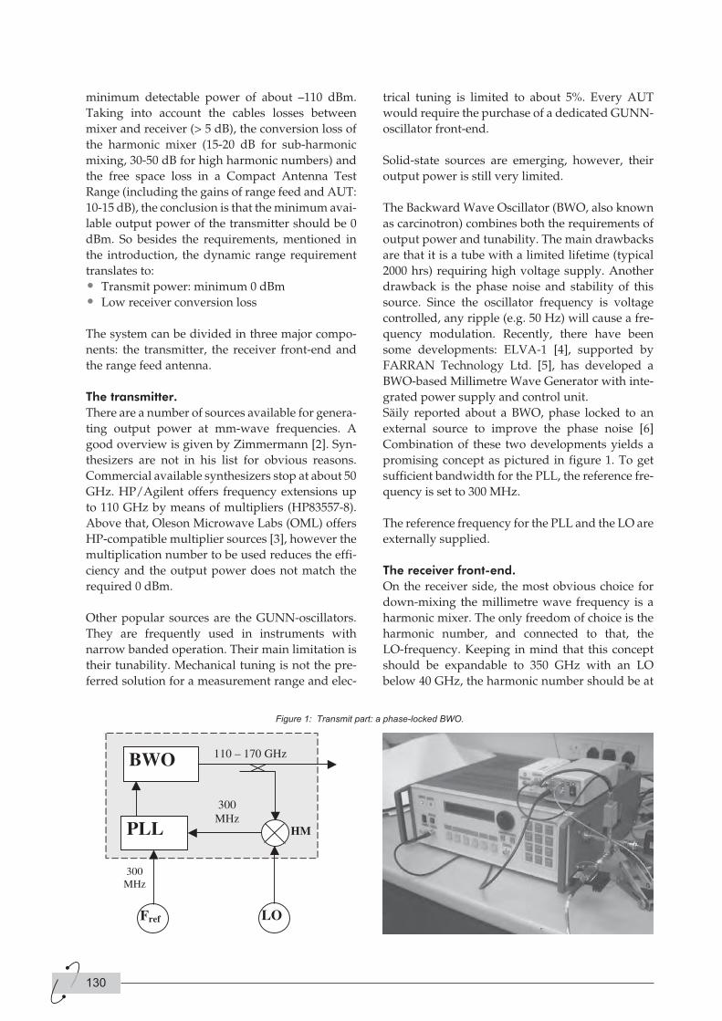
Säily reported about a BWO, phase locked to an
external source to improve the phase noise [6]
Combination of these two developments yields a
promising concept as pictured in figure 1. To get
sufficient bandwidth for the PLL, the reference fre-
quency is set to 300 MHz.
The reference frequency for the PLL and the LO are
externally supplied.
The receiver front-end.
On the receiver side, the most obvious choice for
down-mixing the millimetre wave frequency is a
harmonic mixer. The only freedom of choice is the
harmonic number, and connected to that, the
LO-frequency. Keeping in mind that this concept
should be expandable to 350 GHz with an LO
below 40 GHz, the harmonic number should be at
130
Figure 1: Transmit part: a phase-locked BWO.
least 9. With these high harmonic numbers, the
conversion loss is in the order of 30 dB. Compared
to the 15 dB as assumed in the power budget of the
introduction, this would reduce the dynamic range
by 15 dB.
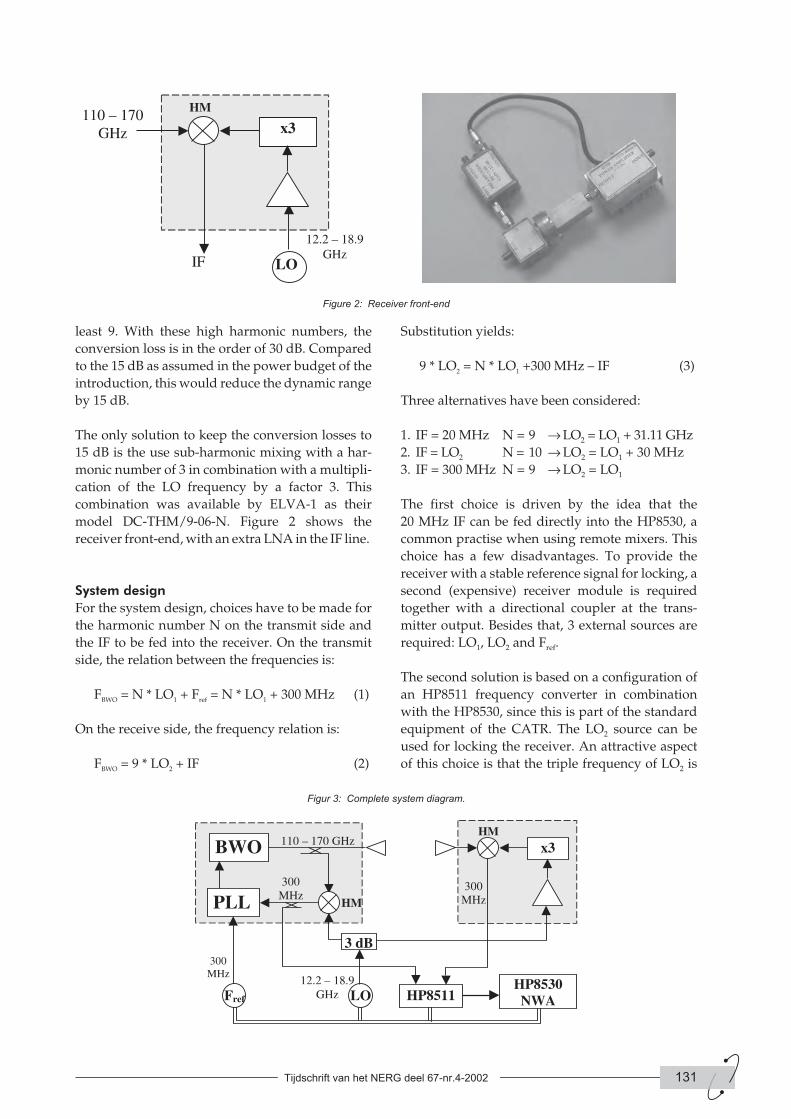
The only solution to keep the conversion losses to
15 dB is the use sub-harmonic mixing with a har-
monic number of 3 in combination with a multipli-
cation of the LO frequency by a factor 3. This
combination was available by ELVA-1 as their
model DC-THM/9-06-N. Figure 2 shows the
receiver front-end, with an extra LNA in the IF line.
System design
For the system design, choices have to be made for
the harmonic number N on the transmit side and
the IF to be fed into the receiver. On the transmit
side, the relation between the frequencies is:
FBWO = N * LO1 + Fref = N * LO1 + 300 MHz (1)
On the receive side, the frequency relation is:
FBWO = 9 * LO2 + IF (2)
Substitution yields:
9 * LO2 = N * LO1 +300 MHz – IF (3)
Three alternatives have been considered:
1. IF = 20 MHz N = 9 → LO2 = LO1 + 31.11 GHz
2. IF = LO2 N = 10 → LO2 = LO1 + 30 MHz
3. IF = 300 MHz N = 9 → LO2 = LO1
The first choice is driven by the idea that the
20 MHz IF can be fed directly into the HP8530, a
common practise when using remote mixers. This
choice has a few disadvantages. To provide the
receiver with a stable reference signal for locking, a
second (expensive) receiver module is required
together with a directional coupler at the trans-
mitter output. Besides that, 3 external sources are
required: LO1, LO2 and Fref.
The second solution is based on a configuration of
an HP8511 frequency converter in combination
with the HP8530, since this is part of the standard
equipment of the CATR. The LO2 source can be
used for locking the receiver. An attractive aspect
of this choice is that the triple frequency of LO2 is
Tijdschrift van het NERG deel 67-nr.4-2002 131
Figure 2: Receiver front-end
Figur 3: Complete system diagram.
again a standard RF band, even for extensions up to
360 GHz (170 – 250 GHz, 250 – 360 GHz), which
increases the availability of components. However,
for the mixer operation it is not an optimal choice
since the third harmonic of the IF is equal to the
mixer-LO (= 3 * LO2). This can give al kind of
unwanted mixer products. And also in this case, 3
external sources are required.
In the last option, the IF is equal to the PLL refe-
rence frequency (300 MHz). Since LO2 is equal to
LO1, only two external sources are needed and
these can be controlled conveniently by the mul-
tiple source capability of the HP8530. A reference
signal for locking the receiver and monitoring the
TX-output can be obtained by a directional coupler
in the line between harmonic mixer and PLL. This
is the most attractive solution and has been imple-
mented. The complete system is shown if figure 3.
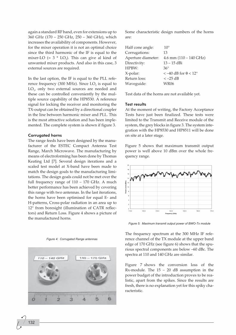
Corrugated horns
The range feeds have been designed by the manu-
facturer of the ESTEC Compact Antenna Test
Range, March Microwave. The manufacturing by
means of electroforming has been done by Thomas
Keating Ltd [7]. Several design iterations and a
scaled test model at X-band have been made to
match the design goals to the manufacturing limi-
tations. The design goals could not be met over the
full frequency range of 110 – 170 GHz. A much
better performance has been achieved by covering
this range with two antennas. In the last iterations,
the horns have been optimised for equal E- and
H-patterns, Cross-polar radiation in an area up to
12° from boresight (illumination of CATR reflec-
tors) and Return Loss. Figure 4 shows a picture of
the manufactured horns.
Some characteristic design numbers of the horns
are:
Half cone angle: 10°
Corrugations: 13
Aperture diameter: 4.6 mm (110 – 140 GHz)
Directivity: 13 – 15 dBi
HPBW: 36°
X-polar: < –40 dB for q < 12°
Return loss: < –25 dB
Waveguide: WR06
Test data of the horns are not available yet.
Test results
At the moment of writing, the Factory Acceptance
Tests have just been finalized. These tests were
limited to the Transmit and Receive module of the
system, the grey blocks in figure 3. The system inte-
gration with the HP8530 and HP8511 will be done
on site at a later stage.
Figure 5 shows that maximum transmit output
power is well above 10 dBm over the whole fre-
quency range.
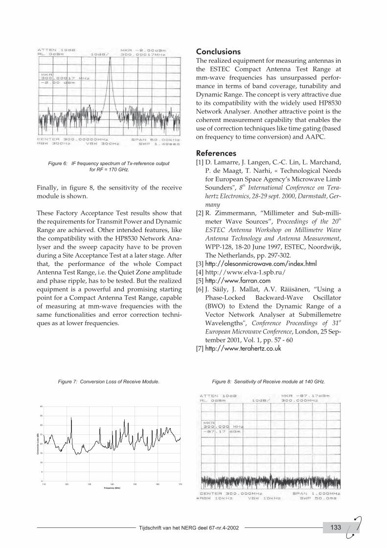
The frequency spectrum at the 300 MHz IF refe-
rence channel of the TX module at the upper band
edge of 170 GHz (see figure 6) shows that the spu-
rious spectral components are below –60 dBc. The
spectra at 110 and 140 GHz are similar.
Figure 7 shows the conversion loss of the
Rx-module. The 15 – 20 dB assumption in the
power budget of the introduction proves to be rea-
listic, apart from the spikes. Since the results are
fresh, there is no explanation yet for this spiky cha-
racteristic.
132
Figure 4: Corrugated Range antennas
Figure 5: Maximum transmit output power of BWO-Tx module
Finally, in figure 8, the sensitivity of the receive
module is shown.
These Factory Acceptance Test results show that
the requirements for Transmit Power and Dynamic
Range are achieved. Other intended features, like
the compatibility with the HP8530 Network Ana-
lyser and the sweep capacity have to be proven
during a Site Acceptance Test at a later stage. After
that, the performance of the whole Compact
Antenna Test Range, i.e. the Quiet Zone amplitude
and phase ripple, has to be tested. But the realized
equipment is a powerful and promising starting
point for a Compact Antenna Test Range, capable
of measuring at mm-wave frequencies with the
same functionalities and error correction techni-
ques as at lower frequencies.
ConclusionsThe realized equipment for measuring antennas in
the ESTEC Compact Antenna Test Range at
mm-wave frequencies has unsurpassed perfor-
mance in terms of band coverage, tunability and
Dynamic Range. The concept is very attractive due
to its compatibility with the widely used HP8530
Network Analyser. Another attractive point is the
coherent measurement capability that enables the
use of correction techniques like time gating (based
on frequency to time conversion) and AAPC.
References[1] D. Lamarre, J. Langen, C.-C. Lin, L. Marchand,
P. de Maagt, T. Narhi, « Technological Needs
for European Space Agency’s Microwave Limb
Sounders", 8th International Conference on Tera-
hertz Electronics, 28-29 sept. 2000, Darmstadt, Ger-
many
[2] R. Zimmermann, “Millimeter and Sub-milli-
meter Wave Sources”, Proceedings of the 20th
ESTEC Antenna Workshop on Millimetre Wave
Antenna Technology and Antenna Measurement,
WPP-128, 18-20 June 1997, ESTEC, Noordwijk,
The Netherlands, pp. 297-302.
[3] http://olesonmicrowave.com/index.html[4] http://www.elva-1.spb.ru/
[5] http://www.farran.com[6] J. Säily, J. Mallat, A.V. Räiisänen, “Using a
Phase-Locked Backward-Wave Oscillator
(BWO) to Extend the Dynamic Range of a
Vector Network Analyser at Submillemetre
Wavelengths", Conference Proceedings of 31st
European Microwave Conference, London, 25 Sep-
tember 2001, Vol. 1, pp. 57 - 60
[7] http://www.terahertz.co.uk
Tijdschrift van het NERG deel 67-nr.4-2002 133
Figure 6: IF frequency spectrum of Tx-reference output
for RF = 170 GHz.
Figure 7: Conversion Loss of Receive Module. Figure 8: Sensitivity of Receive module at 140 GHz.
AuthorsM.H.A. Paquay
ESA-ESTEC
P.O. Box 299
NL-2200 AG Noordwijk
The Netherlands
Email: [email protected]
D.R. Vizard
Farran Technology Ltd
Ballincollig, Cork, Ireland.
Email: [email protected]
D. Korneev
ELVA-1 Millimeter Wave Division
DOK Ltd, Nevsky 74, 23N
St. Petersburg, Russia
Email: [email protected]
P. Ivanov
ELVA-1 Millimeter Wave Division
DOK Ltd, Nevsky 74, 23N
St. Petersburg, Russia
Email: [email protected]
V.J. Vokurka
March Microwave Systems B.V.
De Huufkes 20
NL 5674 TM Nuenen
The Netherlands
134
Uit de reactie van de heer Gestman Gerardts in nr. 1
(2002) van het NERG-tijdschrift blijkt dat sommige
van mijn ideeën niet helemaal goed zijn overge-
komen. Ik heb beslist niet - zoals Gerstman Ger-
ardts stelt - stroom als een complexe e-macht willen
weergeven. Mijn complexe e-macht is geen stroom,
maar de fasor van een stroom, die gegevens her-
bergt over de amplitude en de fase. Anderen
noemen dat de "complexe amplitude". Met de fasor
kun je rekenen, zoals je ook met de amplitude of
met de fase van de stroom kunt rekenen.
De fasor is zeker niet "een stroom of spanning
waaruit de frequentie verdreven is", om de
woorden van Gestman Gerardts te gebruiken.
Omdat de modulus en de fasehoek van de fasor
beïnvloed kunnen worden door frequentie-afhan-
kelijke netwerkelementen en omdat de mate van
beïnvloeding mede bepaald wordt door de (vaste)
frequentie van de stroom, is de fasor fre-
quentie-afhankelijk. Deze frequentie-afhankelijk-
heid wordt teruggevonden in de uitdrukking voor
de impedantie, die ontstaat uit het quotiënt van
twee fasoren. (Zie de uitdrukkingen voor de
stroomfasor bij spoel en condensator bij de for-
mules (7) en (8) van mijn artikel.)
Omdat impedanties frequentie-afhankelijk zijn,
vind ik het logisch om van impedantie-functies te
spreken.
Fasoren, een reactie op een reactie
P. van der Wurf
Vervolg op pagina 144
IntroductionThere are ongoing efforts to create new
ground-based radio telescopes with a square kilo-
meter receiving area in the not so far future [1]. It is
a given physical fact, that the finite size of the Earth
limits resolution capability in radio astronomical
observations.
The first step on the way forward to exceed the
resolution as imposed by the Earth limit in the
radio domain is the use of space-based radio tele-
scopes and to observe in an interferometric mode
(Very Long Baseline Interferometry = VLBI) in con-
junction with the ground-based radio telescopes.
The possibility of increased resolution capability in
radio astronomy interferometric observations has
been clearly shown recently with an inclusion of
the space-based element in the VLBI-network.
Several missions were proposed in Europe, the
USA and the USSR in the 70’s and 80’s [3]. A Japa-
nese satellite HALCA demonstrated this fact. It
was launched in February 1997 and led to the
VSOP program [2]. The launch of HALCA marked
the brightest event in the history of Space-VLBI
(SVLBI). Together with the terrestrial network it
created the VSOP mission.
The technical feasibility of SVLBI was demon-
strated by observations conducted with the com-
munication satellite TDRSE in 1986 [11].
From the late-1970s through the early 1990s, at least
four different dedicated space VLBI missions have
been considered seriously. QUASAT [5] and the
International VLBI Satellite [6,7] were proposed
missions that did not receive final approval.
HALCA (earlier VSOP [8,9]) is mentioned above
and presented in this workshop [2] and is led by the
Institute of Space and Astronautical Science in
Japan. RadioAstron is a mission, led by the Astro
Space Center of the P.N.Lebedev Physical Institute
in Russia [4,10,36,37].
VSOP and RadioAstron are similar in character
and in system sensitivity, with frequency coverage
up to 22 GHz, 10-mclass radio telescopes with
system temperatures near 100 K and data-acquisi-
tion rates of 128 Megabit/s. As described in [2], the
22 GHz channel in the VSOP mission experienced
some problems after launch. The most important
difference between the two missions is that Radi-
oAstron is planned to have an apogee height of
80000km, providing baseline lengths of up to seven
Earth diameters, while VSOP has an apogee height
of 22000km, providing baseline lengths up to about
2.5 Earth diameters. These missions are sometimes
referred to as first generation SVLBI missions.
The next generation SVLBI missionMajor characteristics for a next SVLBI mission,
which will distinguish them from their predeces-
sors , are:
1. A decreased system temperatures of the tele-
scopes;
2. An increased data rate of the signal recorded;
3. An increased collecting area of each VLBI tele-
scope,
Of these three main characteristics for a next
SVLBI-mission, the latter seems to be of paramount
importance and is of course of interest for the
audience in this workshop.
• The first item is being actively investigated,
with the goal of reaching a system temperature
Tsys of about 10 to 20K for most operational
frequencies in the ARISE mission, under
consideration in USA [12,14,15].
This development is matched by similar target
Tijdschrift van het NERG deel 67-nr.4-2002 135
Large Space-Borne Antennas as aTool For Studying the Universe atan Ultimate Angular Resolution
Kees van ‘t Klooster, Leonid Gurvits
values for ground-based radio telescopes.
However, further improvement of VLBI
sensitivity due to decrease of Tsys is becoming
asymptotically difficult as the values of system
temperature reach single digits in Kelvin. Also
other application scenarios are found, where
such improvement in Tsys is of interest, like in
other radio-astronomy (radiometric) type of
missions (Planck for instance) and so such
efforts are ongoing.
• The second item is also being actively pursued.
It is foreseen that a data rate of 1 Gbit/s will
become available in a few years [16,17].
Apart from the fact, that ITU regulates
available bandwidths, there is also a practical
limit on the width of the signal: the bandwidth
must not exceed a reasonable fraction of the
sky frequency of the observations. In addition,
a major drawback of this venue for sensitivity
improvement is its irrelevance to spectral line
VLBI.
• The remaining third item, the increase of the
collecting area of each element of the VLBI
array, remains the only option that is
practically unlimited and equally efficient for
both continuum and spectral line VLBI
observations.
As discussed in [2], possibilities for a follow-up
mission (VSOP-2) are investigated. There is the
ARISE initiative [12,14,15], relying on an inflatable
antenna with a size of the 25-m diameter. An infla-
table antenna was considered for QUASAT
[5,23,30] and studied for land-mobile applications
with demonstration models [24].
If steps to the higher frequency bands are imple-
mented, it implies, that the reflector antenna must
have an rms accuracy of circa 0.2 mm, in order to be
operational at wavelengths as short as 3 mm (86
GHz), a target requirement for the ARISE mission.
Error correction techniques, using self-focussing
approaches were proposed, but then the calibra-
tion aspects might be displaced to the calibration of
the feed-arrays to be used. NRAO elaborated such
a technique [25], but obviously much more work is
needed.
There is clearly the interest to explore the larger
space-borne antenna as SVLBI element
Use of the international space station(ISS) for construction of a largeantenna
Traditionally, SVLBI is considered as a single
launch mission with no in-orbit assembly opera-
tions. Three possible technologies have been inves-
tigated for forming the reflecting surface in the
antenna, namely: inflatable, mesh or solid material
structure. All three options require in-orbit deploy-
ment of the antenna and associated with the laun-
cher capability (fairing size), which is a limitation
for each type of technology in terms of stowage
volume and resulting antenna diameter.
Roughly the largest diameter possible for the sto-
wage volume fixed is achieved with an inflatable
technology, followed by the mesh technology with
straight or foldable ribs. The solid panel approach
is less economic in terms of stowing within a given
volume.
But in particular the requirements for the larger
diameter and at the same moment the requirement
of a better surface accuracy as needed for the higher
frequency band are contradictory and for this intu-
itively the preferred technology is the one with
solid panels. The RadioAstron mission relies on a
solid panel type of antenna, however the stowage
during launch and subsequent deployment sce-
nario are factors, which have serious impact on the
achievable surface accuracy [4,10,36,37]. Once
deployed in orbit with the desired shape, the
antenna construction has a very long lifetime.
Here we consider an approach, which may be bene-
ficial for the demand of high surface accuracy as
well as for a realization of a larger diameter. The
concept for a next SVLBI mission is discussed with
a 25-30 meter class radio telescope, which is to be
assembled in space, with – in outline format - dedi-
cated attention to antenna problems .
The International Space Station (ISS), a permanent
multi-purpose orbital manned facility, is consi-
dered as a base for the telescope assembly. There
are plans to use the ISS as a place with infra-struc-
ture assembling and/or servicing freeflying scien-
tific missions (X-ray Evolving Universe
Spectroscopy or XEUS [19,20,21]). The X-ray lens as
considered for XEUS has also sub-millimeter focu-
sing capability and as such a function in the
sub-mm or IR-domain (with reduced efficiency,
but better resolution than Herschel) could be of
interest.
136
It seems logical to consider ISS as a building place
for a large space-based radio telescope, which can
then be sent into a dedicated orbit, away from the
ISS. Servicing would be also possible eventually,
after docking of the spacecraft with this radio tele-
scope.
A mission using a multiple launch and in orbit
assembly is an alternative to a single launch con-
cept with limited cargo capability. Such an
approach makes it possible to accommodate an
antenna of considerably larger mass, and therefore
larger diameter and better surface accuracy. The
multiple launch concept could be combined with
all three antenna designs above (inflatable, mesh
and solid panel technology). However, obvious
advantages of a multiple launch scheme are clearly
for a solid petal antenna especially as such configu-
ration is of interest to go to higher frequency. Since
the assembly is likely to require manned opera-
tions, it is logical to consider the International
Space Station (ISS) as the base for such a next SVLBI
mission. In general, it is imperative for the ISS to
become an assembling facility for future large
orbital or interplanetary missions, as assumed
already for XEUS [19,20,21].
The spacecraft module with the large
SVLBI-antenna assembled should have the ability
to function in a free-flying regime as well as docked
to the ISS. It can reach the ISS in autonomous flight
or be delivered to the ISS by a Space Shuttle or
other transport spacecraft. In the former case, the
module must be equipped with a full set of systems
for autonomous flight, rendezvous, proximity
operations and docking. Most of these could be uti-
lized for autonomous flight after assembling the
radio telescope. The set of antenna reflector ele-
ments (panels) could be delivered to the ISS by a
Space Shuttle or by another transport vehicle
involved in the ISS logistics.
The main requirements for the module spacecraft
of for a next SVLBI mission and the overall mission
operational issues are quite similar to those of
several other applications, like astrophysical and
Earth science missions, that do not need to be per-
manently located at the station. A very high level of
commonality in major mission requirements could
be pursued and reached between the SVLBI-con-
cept described here and the XEUS mission
[19,20,21].
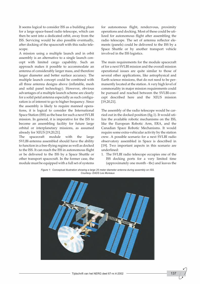
The assembly of the radio telescope would be car-
ried out in the docked position (fig.1). It would uti-
lize the available robotic mechanisms on the ISS,
like the European Robotic Arm, ERA, and the
Canadian Space Robotic Mechanisms. It would
require some extra-vehicular activity by the station
crew. A possible scenario for a next SVLBI radio
observatory assembled in Space is described in
[19]. Two important aspects in this scenario are
underlined:
1. The SVLBI radio telescope occupies one of the
ISS docking ports for a very limited time
(approximately one month - tbc) and leaves the
Tijdschrift van het NERG deel 67-nr.4-2002 137
Figure 1: Conceptual illustration showing a large 25 meter diameter antenna during assembly on ISS.
Courtesy- EADS Les Mureaux
ISS low orbit after completion of assembly and
test operations;
2. The in-orbit checkout of the telescope starts
while the SVLBI spacecraft is docked at the ISS.
The latter provides the opportunity to fix most
possible problems – if any - with the SVLBI-2
spacecraft before it goes into autonomous flight.
Multiple launch and in-orbit assembly of a next
SVLBI-mission could bring technical, budgetary
and logistical advantages over traditional single-
launch in-orbit deployment schemes. The in-orbit
assembly concept should therefore be explored at
the earliest stages of the next SVLBI-mission design
studies. Such a scheme could also bring additional
benefits (in the form of decrease in per-mission
cost) by sharing substantial parts of its overall cost
with other ISS applications.
This idea to use International Space Station has
been preliminary investigated in the sense of infra-
structure and mechanical by EADS, with exploita-
tion of transfer logistics (ATV) and robotics
available on ISS for the construction of a large radio
telescope. However, background information and
further suggestions for a large space based radio
telescope need to be investigated in more detail.
Certain antenna configurations are more suitable
in ergonomic sense (for the robotics available) for
assembly at ISS. This paper attempts to indicate
this by some further background information and
some suggestions, which could be discussed fur-
ther.
Two indicative directions to realise a large radio
telescope, based on available technologies, are put
forward for further exploration. Obviously the sce-
nario invites for alternatives. A study of a realisa-
tion of a large radio telescope in space, considering
International Space Station as a shipyard to con-
struct the large radio telescope, would require
combined efforts of all disciplines (radio-physical,
mechanical, robotics, ergonomics, transportation).
Different technologies could then be revisited, also
imposing constraints and inputs on antenna design
capabilities. The antenna reflector assembly would
require a backing structure with a main reflector
assembly, a sub-reflector supported somehow by
some structure to support the latter. No decision is
made at all for a particular scenario and an off-set
(like the Green Bank radio telescope [26]) or a sym-
metrical parabolic or shaped or even deviating
shape can be considered. Once more the required
trade-offs in close cooperation with all disciplines
involved are emphasised.
Today it is common practice in the realisation of
ground-based radio telescopes to have the main
reflector built up out of separate reflector panels
[22], even at sub-millimeter wavelength. A suitable
backing structure and an optimisation of the
number of panels would permit for our SVLBI-mis-
sion to realise a main reflector assembly. Also the
offset scenario as used for [26] would permit to
have identical panels along partial rings with the
focus of the describing parabola for the offset geo-
metry as center.
Two potential scenarios for the backing structure
could be imagined:
1. Use of a truss, which still may have some
limited foldability if needed for easier transfer
in a cargo ship or which can be consisting out of
sub-segment trusses.
2. Use of a radial rib structure as considered
already some decades ago for large deployable
antennas [27,28].
There have been studies in the past for deployable
truss-type of antenna support structures . The 6
meter Travers antenna and the KRT-10 antenna
belong to this category [33,34]. Also a truss-type
structure was tested in space in early 80, with
extra-vehicular activity performed by the French
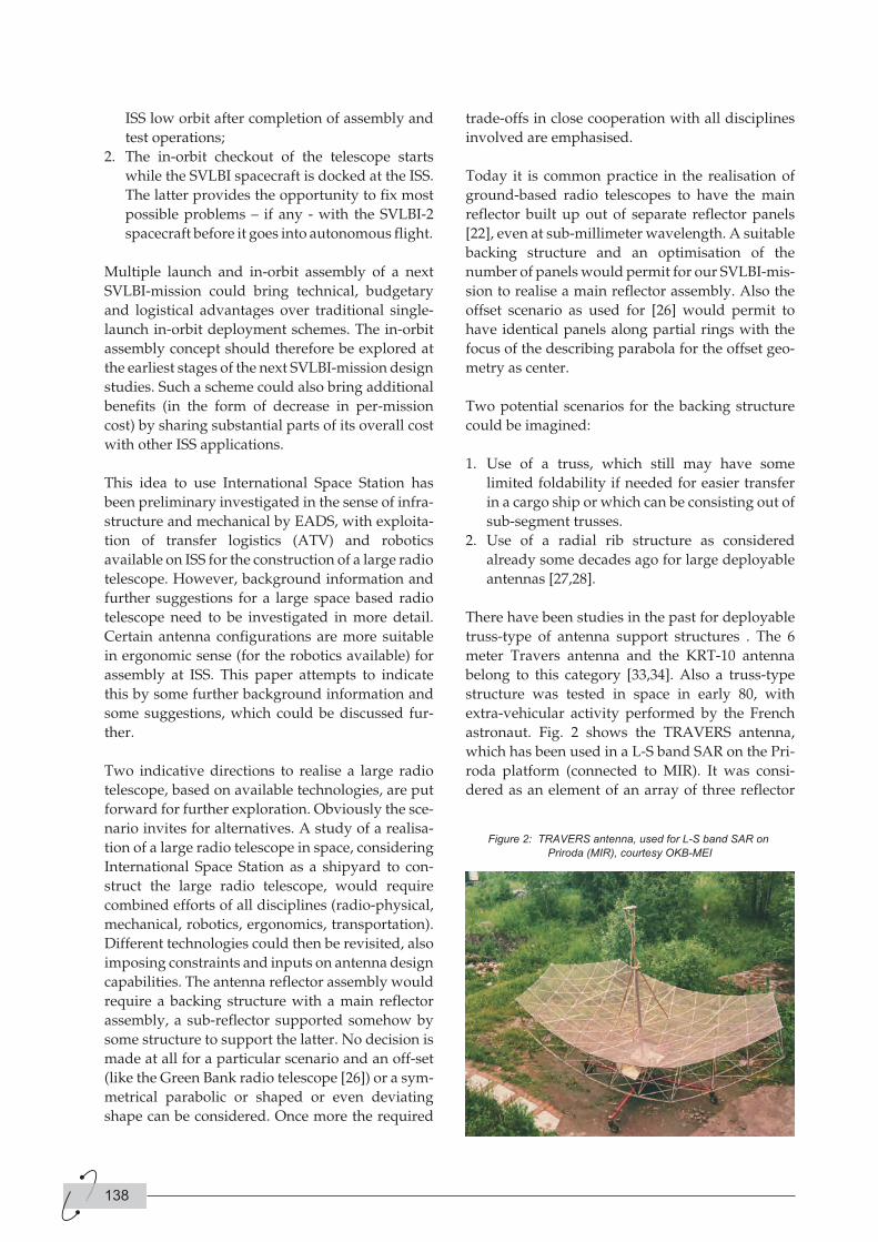
astronaut. Fig. 2 shows the TRAVERS antenna,
which has been used in a L-S band SAR on the Pri-
roda platform (connected to MIR). It was consi-
dered as an element of an array of three reflector
138
Figure 2: TRAVERS antenna, used for L-S band SAR on
Priroda (MIR), courtesy OKB-MEI
antennas for a SAR on-board the ALMAZ II space-
craft.
Already in 1979 a 10-meter radio telescope has been
flown on the space-station at that time (note some
synergy with the proposed concept here), the Sal-
joet 6. Two concepts have been investigated in that
interesting time, based on a space ‘truss’, suppor-
ting a mesh reflector antenna. One concept relied
on the space truss constructed out of rods only
(with where needed mechanisms to fold and
stretch) [34], where as the other concept relied on
replacing part of the rods by wires and in this way
the 10-meter KRT -10 antenna was realised [33].
This KRT-10 antenna had thus a space truss, where
the upper and lower surface was provided by a
wire configuration. The mass was at that time
about 300 kilogram, with 60 kilogram for the
reflector.
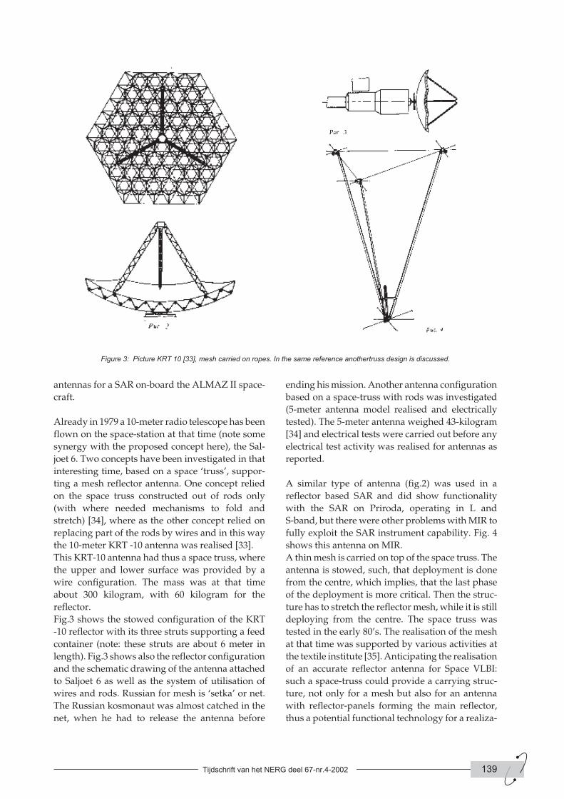
Fig.3 shows the stowed configuration of the KRT
-10 reflector with its three struts supporting a feed
container (note: these struts are about 6 meter in
length). Fig.3 shows also the reflector configuration
and the schematic drawing of the antenna attached
to Saljoet 6 as well as the system of utilisation of
wires and rods. Russian for mesh is ‘setka’ or net.
The Russian kosmonaut was almost catched in the
net, when he had to release the antenna before
ending his mission. Another antenna configuration
based on a space-truss with rods was investigated
(5-meter antenna model realised and electrically
tested). The 5-meter antenna weighed 43-kilogram
[34] and electrical tests were carried out before any
electrical test activity was realised for antennas as
reported.
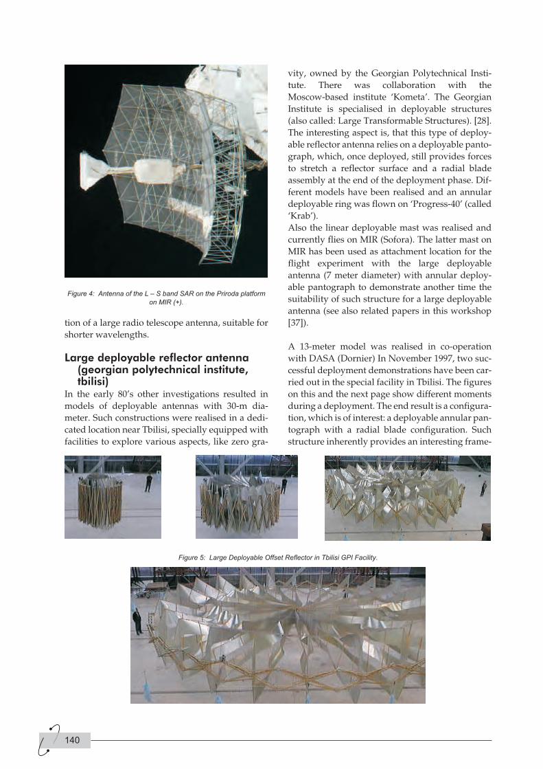
A similar type of antenna (fig.2) was used in a
reflector based SAR and did show functionality
with the SAR on Priroda, operating in L and
S-band, but there were other problems with MIR to
fully exploit the SAR instrument capability. Fig. 4
shows this antenna on MIR.
A thin mesh is carried on top of the space truss. The
antenna is stowed, such, that deployment is done
from the centre, which implies, that the last phase
of the deployment is more critical. Then the struc-
ture has to stretch the reflector mesh, while it is still
deploying from the centre. The space truss was
tested in the early 80’s. The realisation of the mesh
at that time was supported by various activities at
the textile institute [35]. Anticipating the realisation
of an accurate reflector antenna for Space VLBI:
such a space-truss could provide a carrying struc-
ture, not only for a mesh but also for an antenna
with reflector-panels forming the main reflector,
thus a potential functional technology for a realiza-
Tijdschrift van het NERG deel 67-nr.4-2002 139
Figure 3: Picture KRT 10 [33], mesh carried on ropes. In the same reference anothertruss design is discussed.
tion of a large radio telescope antenna, suitable for
shorter wavelengths.
Large deployable reflector antenna(georgian polytechnical institute,tbilisi)
In the early 80’s other investigations resulted in
models of deployable antennas with 30-m dia-
meter. Such constructions were realised in a dedi-
cated location near Tbilisi, specially equipped with
facilities to explore various aspects, like zero gra-
vity, owned by the Georgian Polytechnical Insti-
tute. There was collaboration with the
Moscow-based institute ‘Kometa’. The Georgian
Institute is specialised in deployable structures
(also called: Large Transformable Structures). [28].
The interesting aspect is, that this type of deploy-
able reflector antenna relies on a deployable panto-
graph, which, once deployed, still provides forces
to stretch a reflector surface and a radial blade
assembly at the end of the deployment phase. Dif-
ferent models have been realised and an annular
deployable ring was flown on ‘Progress-40’ (called
‘Krab’).
Also the linear deployable mast was realised and
currently flies on MIR (Sofora). The latter mast on
MIR has been used as attachment location for the
flight experiment with the large deployable
antenna (7 meter diameter) with annular deploy-
able pantograph to demonstrate another time the
suitability of such structure for a large deployable
antenna (see also related papers in this workshop
[37]).
A 13-meter model was realised in co-operation
with DASA (Dornier) In November 1997, two suc-
cessful deployment demonstrations have been car-
ried out in the special facility in Tbilisi. The figures
on this and the next page show different moments
during a deployment. The end result is a configura-
tion, which is of interest: a deployable annular pan-
tograph with a radial blade configuration. Such
structure inherently provides an interesting frame-
140
Figure 4: Antenna of the L – S band SAR on the Priroda platform
on MIR (+).
Figure 5: Large Deployable Offset Reflector in Tbilisi GPI Facility.
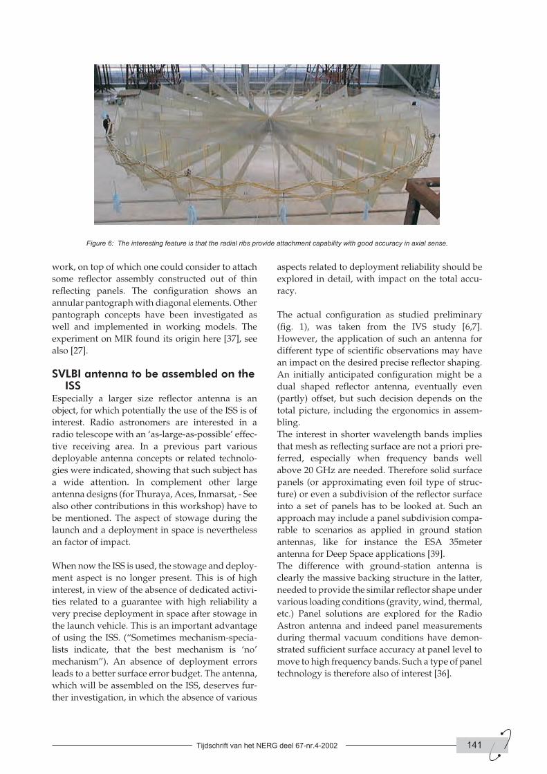
work, on top of which one could consider to attach
some reflector assembly constructed out of thin
reflecting panels. The configuration shows an
annular pantograph with diagonal elements. Other
pantograph concepts have been investigated as
well and implemented in working models. The
experiment on MIR found its origin here [37], see
also [27].
SVLBI antenna to be assembled on theISS
Especially a larger size reflector antenna is an
object, for which potentially the use of the ISS is of
interest. Radio astronomers are interested in a
radio telescope with an ‘as-large-as-possible’ effec-
tive receiving area. In a previous part various
deployable antenna concepts or related technolo-
gies were indicated, showing that such subject has
a wide attention. In complement other large
antenna designs (for Thuraya, Aces, Inmarsat, - See
also other contributions in this workshop) have to
be mentioned. The aspect of stowage during the
launch and a deployment in space is nevertheless
an factor of impact.
When now the ISS is used, the stowage and deploy-
ment aspect is no longer present. This is of high
interest, in view of the absence of dedicated activi-
ties related to a guarantee with high reliability a
very precise deployment in space after stowage in
the launch vehicle. This is an important advantage
of using the ISS. (“Sometimes mechanism-specia-
lists indicate, that the best mechanism is ‘no’
mechanism”). An absence of deployment errors
leads to a better surface error budget. The antenna,
which will be assembled on the ISS, deserves fur-
ther investigation, in which the absence of various
aspects related to deployment reliability should be
explored in detail, with impact on the total accu-
racy.
The actual configuration as studied preliminary
(fig. 1), was taken from the IVS study [6,7].
However, the application of such an antenna for
different type of scientific observations may have
an impact on the desired precise reflector shaping.
An initially anticipated configuration might be a
dual shaped reflector antenna, eventually even
(partly) offset, but such decision depends on the
total picture, including the ergonomics in assem-
bling.
The interest in shorter wavelength bands implies
that mesh as reflecting surface are not a priori pre-
ferred, especially when frequency bands well
above 20 GHz are needed. Therefore solid surface
panels (or approximating even foil type of struc-
ture) or even a subdivision of the reflector surface
into a set of panels has to be looked at. Such an
approach may include a panel subdivision compa-
rable to scenarios as applied in ground station
antennas, like for instance the ESA 35meter
antenna for Deep Space applications [39].
The difference with ground-station antenna is
clearly the massive backing structure in the latter,
needed to provide the similar reflector shape under
various loading conditions (gravity, wind, thermal,
etc.) Panel solutions are explored for the Radio
Astron antenna and indeed panel measurements
during thermal vacuum conditions have demon-
strated sufficient surface accuracy at panel level to
move to high frequency bands. Such a type of panel
technology is therefore also of interest [36].
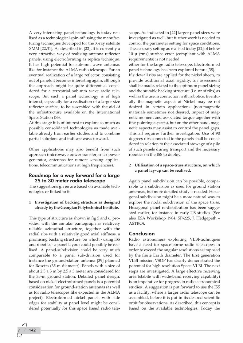
Tijdschrift van het NERG deel 67-nr.4-2002 141
Figure 6: The interesting feature is that the radial ribs provide attachment capability with good accuracy in axial sense.
A very interesting panel technology is today rea-
lised as a technological spin-off using the manufac-
turing techniques developed for the X-ray satellite
XMM [22,31]. As described in [22], it is currently a
very attractive way of realizing antenna reflector
panels, using electroforming as replica technique.
It has high potential for sub-mm wave antennas
like for instance the ALMA radio telescope. For an
eventual realization of a large reflector, consisting
out of panels it becomes interesting again, although
the approach might be quite different as consi-
dered for a terrestrial sub-mm wave radio tele-
scope. But such a panel technology is of high
interest, especially for a realisation of a larger size
reflector surface, to be assembled with the aid of
the infrastructure available on the International
Space Station ISS.
At this stage it is of interest to explore as much as
possible consolidated technologies as made avai-
lable already from earlier studies and to combine
partial solutions and indicate ways forward.
Other applications may also benefit from such
approach (microwave power transfer, solar power
generator, antennas for remote sensing applica-
tions, telecommunications at high frequencies).
Roadmap for a way forward for a large25 to 30 meter radio telescope
The suggestions given are based on available tech-
nologies or linked to it.
1 Investigation of backing structure as designed
already by the Georgian Polytechnical Institute.
This type of structure as shown in fig 5 and 6, pro-
vides, with the annular pantograph as relatively
reliable azimuthal structure, together with the
radial ribs with a relatively good axial stiffness, a
promising backing structure, on which - using ISS
and robotics - a panel layout could possibly be rea-
lised. A panel-subdivision could be very much
comparable to a panel sub-division used for
instance the ground-station antenna [39] planned
for Rosetta (35-m diameter). Panels with a size of
about 2.5 a 3 m by 2.5 a 3 meter are considered for
the 35-m ground station. Detailed panel design,
based on nickel-electroformed panels is a potential
consideration for ground-station antennas (as well
as for radio telescopes like expected in the ALMA
project). Electroformed nickel panels with side
edges for stability at panel level might be consi-
dered potentially for this space based radio tele-
scope. As indicated in [22] larger panel sizes were
investigated as well, but further work is needed to
control the parameter setting for space conditions.
The accuracy setting as realised today [22] of below
10 µ (rms) surface error (compliant with ALMA
requirements) is not needed
either for the large radio telescope. Electroformed
panel-technology has been explored before [38].
If sidewall ribs are applied for the nickel sheets, to
provide additional axial rigidity, an assessment
shall be made, related to the optimum panel sizing
and the suitable backing structure (i.e. nr of ribs) as
well as the use in connection with robotics. Eventu-
ally the magnetic aspect of Nickel may be not
desired in certain applications (non-magnetic
materials sometimes not desired, impact of mag-
netic moment and associated torque together with
fine-pointing aspects), but on the other hand, mag-
netic aspects may assist to control the panel gaps.
This all requires further investigation. Use of 90
degrees ribs connected to the panels shall be consi-
dered in relation to the associated stowage of a pile
of such panels during transport and the necessary
robotics on the ISS to deploy.
2 Utilisation of a space-truss structure, on which
a panel lay-up can be realised.
Again panel subdivision can be possible, compa-
rable to a subdivision as used for ground station
antennas, but more detailed study is needed. Hexa-
gonal subdivision might be a more natural way to
explore the nodal subdivision of the space truss.
Hexagonal panel re-distribution has been sugge-
sted earlier, for instance in early US studies. (See
also ESA Workshop 1984, SP-225, J. Hedgepeth –
ASTRO).
ConclusionRadio astronomers exploiting VLBI-techniques
have a need for space-borne radio telescopes in
order to exceed the angular resolutions as imposed
by the finite Earth diameter. The first generation
VLBI mission VSOP has clearly demonstrated the
potential for high resolution Space-VLBI. The next
steps are investigated. A large effective receiving
area (stabile with wide-band receiving capability)
is an imperative for progress in radio astronomical
studies . A suggestion is put forward to use the ISS
as a facility, where a larger radio telescope can be
assembled, before it is put in its desired scientific
orbit for observations. As described, this concept is
based on the available technologies. Today the
142

state of these technologies is even further
advanced, and in part well known to the audience,
but no exhaustive referencing has been done here.
We note a considerable level of synergy between
this concept and the technologies exploited
on-board the ISS (e.g. robotic arms, in -orbit
assembly operations). Further study can detail
these aspects.
References[1] http://www.astron.nl/, follow indication SKA
[2] Hirabayashi, H. “Experiences with the
HALCA Space VLBI Satellite and Plans for the
Future”, 25th ESA Antenna Workshop, Noor-
dwijk September 2002.
[3] Ulvestad J.S., Gurvits L.I., Linfield R.P., 1997,
in High Sensitivity Radio Astronomy, eds.
N.Jackson and R.J.Davis, Cambridge Univ.
Press, 252
[4] Kardashev N.S. & Slysh V.I. 1988, in The
Impact of VLBI on Astrophysics and Geophy-
sics, IAU Symposium No. 129, Eds. M. J. Reid
and J. M. Moran, Dordrecht: Kluwer Academic
Publishers, p. 433
[5] Schilizzi R.T. 1988, in ‘The Impact of VLBI on
Astrophysics and Geophysics’, Proc.of the
IAU Symp. No. 129, eds. M. J. Reid and J. M.
Moran, Kluwer, 441
[6] Pilbratt G. 1991, in ‘Radio Interferometry:
Theory, Techniques, and Applications, eds. T.
J. Cornwell and R. A. Perley, Astron. Soc.
Pacific Conf. Series, 19, 102
[7] van ‘t Klooster, C.G.M. ‘Space VLBI, A Pro-
posed Antenna Configuration for the Radio
Astronomy Satellite IVS’, Proc. 2nd Int. Conf.
Electromagnetics in Aerospace Applications’,
ICEAA, Sept 1991, Torino.
[8] Hirosawa H. & Hirabayashi H. 1995a, IEEE
AES Systems Magazine, June 1995, p. 17.
[9] Hirosawa H.& Hirabayashi H. 1995b, 46th
International Astronautical Congress, Paper
IAF-95-Q.2.01.
[10] http://www.asc.rssi.ru/radioastron/Descrip-tion/intro_eng.htm
[11] Levy G.S. , Linfield, R.P. Ulvestad, J.S. et al.
1986, Science, 234, 187
[12] Ulvestad, J.S. and Linfield, R.P. 1998, IAU Col-
loquium 164, ASP Conf. Series 144, 397
[13] http://www.astron.nl/documents/conf/science_index.htm
[14] http://arise.jpl.nasa.gov/[15] http://us-space-vlbi.jpl.nasa.gov/
[16] Whitney, A.R. 1999, New Astronomy Review,
43, 527
[17] Cannon, W.H. 2000, Advances in Space Rese-
arch, 26, No. 4, 747
[18] Gurvits, L.I. 2000, Advances in Space Rese-
arch, 26, No. 4, 739
[19] Bavdaz, M., Peacock, A., Parmar, A. et al. 1999,
in ‘ Utilisation of the ISS, ed. A.Wilson, ESA
SP433, 621.
[20] ESA Bulletin May 2002 (ESA Estec Noordwijk)
http://esapub.esrin.esa.it/bulletin/bullet110/parmar.pdf
[21] ESA Bulletin May 2002 (ESA Estec Noordwijk)
http://esapub.esrin.esa.it/bulletin/bullet110/bavdaz.pdf
[22] G. Valsecchi, J.Eder, G.Grisoni, C.G.M. van ’t
Klooster, L. Fanchi, ‘High Precision Nickel
Electroformed Panel Technology for Sub Milli-
metre Radio Telescope Antennas’, this 25th
ESA Antenna Workshop.
[23] QUASAT, A Phase A Study, ESA contract
CR(P)2914 and SCI(88)4, 1988, ESA (SCI(88)4
available still).
[24] Electrical Performance of a 10 Meter Inflatable
Reflector for Land Mobile Communications,
P.M. Besso, K. van ‘t Klooster, W. Rits, D.
Savini, P. Tatalias, IEE, Int. Conference on
Antennas and Propagation, York April, 1991.
[25] Self Calibration of Antenna Errors Using Focal
Plane Arrays, P.J. Napier, T.J.Cornwell, ‘Multi-
feed Systems for Radio Telescopes’, ASP Conf
Series Vol 75, 1995, Tucson, Arizona.
[26] http://www.gb.nrao.edu/GBT/
[27] G.G. Kinteraya, E.V. Medzmariashvili, L. Sh.
Datashvili ‘5 - 30 Meter Deployable High Pre-
cision Light Weight Space Antenna Reflectors
and the Ground-based Stand-test Complex for
Assembling and Testing Large Deployable
Space Structures’, Keynote Paper Int. Conf. on
Space Struct , Braunschweig, Nov.1998 (ESA
sponsored).
[28] E.Medsmariashvili, ‘Transformable Construc-
tions for Space And Earth based Application
(Russian)’, Monograph, published by GPI,
Tbilisi, 1995 ( [email protected])
[29] Space VLBI: Radio Astron and its Large
Deployable Antenna. V. Babyshkin, In “Large
Antennas in Radio 110, Noordwijk.
[30] K. van ‘t Klooster, W.Rits, E.Pagana, P.G.Man-
tica, M.C.Bernasconi, ‘An Inflatable Parabolic
Reflector Antenna: Its realisation and Elec-
trical Predictions’, ESA Journal 1990,Vol.14
(also Int. Conf Antennas, Riga, 1990).
Tijdschrift van het NERG deel 67-nr.4-2002 143
[31] G.Valsecchi, C.Francini, R.Garcia Prieto, K.van
‘t Klooster, ‘Nickel Sandwich Technology for
High Precision Reflector Antennas’, IEEE APS,
Orlando 1999.
[32] H.Kellermeier, W.Schaefer, H.Vorbrugg,
‘Offset Unfurlable Antenna Concepts’ MBB
(Now Astrium), ESA/Estec Workshop on
Mechanical Technology for Antennas, June
1984, SP225.
[33] A.G.Sokolov, A.S.Gvamichava,, ‘Decisions for
the Engineering Construction of Space Based
Radio Telescopes’, (in Russian), ‘Antennas’,
Volume 29, 1981,
[34] A.F.Bogomolov, N.V.Bykarev,
G.N.Vachensjev, Yu.A.Kisanov, N.M.Fey-
sulla, I.F.Sokolov. ‘Deployable Antenna for
Space Applications’, (Russian), ‘Antennas’,
Volume 29, 1981,
[35] Yu.A Kisanov, N.M. Feysulla, L.A.Kydrjavin,
V.A.Savaryev, ‘Materials for Reflecting Sur-
face for Deployable Antennas for Space’, (in
Russian), ‘Antennas’, Volume 29, 1981,
[36] A.S.Gv amichava, A.N.Kotik, V.Babyshkin,
V.Perminov, M.Bolotov, G.Mersch, H.van Oel,
C.G.M. van ‘t Klooster, ‘Accurate Surface
Shape Measurements of 3.75 meter CFRP
Antenna Panels for the Radio Astron Antenna
Estec Workshop Antenna Technology, 21-23
Nov. Noordwijk, 1995.
[37] http://egs.cosmos.ru/freport.htm[38] V.S.Poljak, E.Ya. Bervalds, ‘Precision Con-
structions for Mirros for Radiotelescopes’
Acad. Sci Latvia, ISBN 57966-0164-4 Published
in Riga, 1990, page 166.
[39] R.Martin, D.Atkins, ‘First ESA Deep Space
Antenna in New Norcia West Australia’, this
workshop proceedings.
AuthorsKees van ‘t Klooster,
ESA Estec
Keplerlaan 1, P.O.Box 299, 2200 AG Noordwijk,
The Netherlands
Email: [email protected]
Leonid Gurvits
Joint Institute for VLBI in Europe (JIVE)
P.O.Box 2, 7990 AA, Dwingeloo, The Netherlands
Email: [email protected]
144
Omdat impedanties frequentie-afhankelijk zijn,
vind ik het logisch om van impedantie-functies te
spreken. We hebben het in de systeemtheorie
immers ook over overdrachtsfuncties. De notatie
Z(w) doet studenten eraan herinneren dat impe-
danties functies van de frequentie zijn en dat helpt
misschien voorkomen dat ze schrijven:
u(t) = Z. i(t) en dergelijke onzin.
Ik wou overigens dat ik als docent had beschikt
over de twee didactische handigheden, die
Gestman Gerardts noemt in zijn reactie en die op
een eenvoudige manier aannemelijk maken dat een
factor j een fasedraaiing van 90 graden geeft en dat
de formule van Euler niet zo vreemd is als het lijkt.
Conclusie? Docenten en oud-docenten moeten veel
meer publiceren over hun ervaringen met de
didactiek van de theoretische elektrotechniek. Een
nieuwe functie voor het NERG-tijdschrift?
P. van der Wurf
Vervolg van pagina 134
IntroductionThe continuing miniaturisation of handheld tele-
communication equipment has led to the situation
where the antenna has become the volume-defi-
ning component of today’s portable and wearable
products. A further miniaturisation requires first of
all the antenna to be miniaturised even beyond
today’s standards. As a consequence of this minia-
turisation, the antenna can no longer be regarded
as a stand-alone component. This means that
antennas need to be designed, incorporating effects
of finite ground planes and substrates, dielectric
covering and metallic and dielectric objects in the
immediate neighbourhood of the antenna.
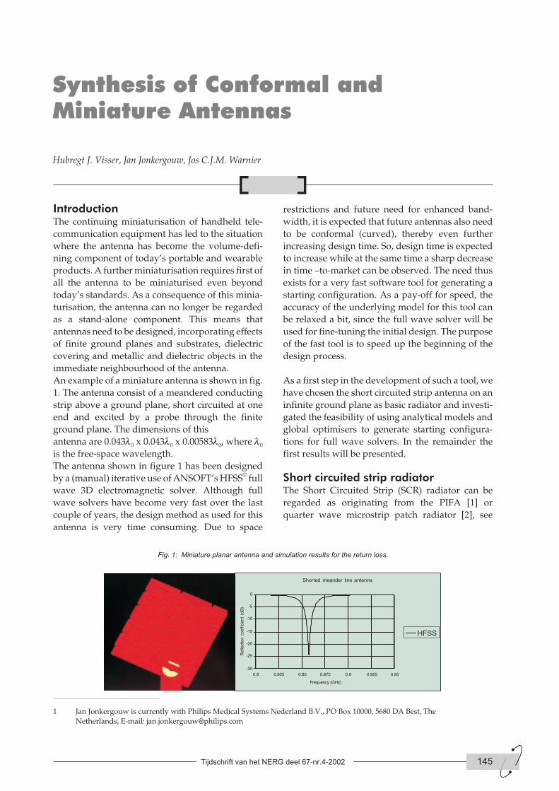
An example of a miniature antenna is shown in fig.
1. The antenna consist of a meandered conducting
strip above a ground plane, short circuited at one
end and excited by a probe through the finite
ground plane. The dimensions of this
antenna are 0.043l0 x 0.043l0 x 0.00583l0, where l0
is the free-space wavelength.
The antenna shown in figure 1 has been designed
by a (manual) iterative use of ANSOFT’s HFSS© full
wave 3D electromagnetic solver. Although full
wave solvers have become very fast over the last
couple of years, the design method as used for this
antenna is very time consuming. Due to space
restrictions and future need for enhanced band-
width, it is expected that future antennas also need
to be conformal (curved), thereby even further
increasing design time. So, design time is expected
to increase while at the same time a sharp decrease
in time –to-market can be observed. The need thus
exists for a very fast software tool for generating a
starting configuration. As a pay-off for speed, the
accuracy of the underlying model for this tool can
be relaxed a bit, since the full wave solver will be
used for fine-tuning the initial design. The purpose
of the fast tool is to speed up the beginning of the
design process.
As a first step in the development of such a tool, we
have chosen the short circuited strip antenna on an
infinite ground plane as basic radiator and investi-
gated the feasibility of using analytical models and
global optimisers to generate starting configura-
tions for full wave solvers. In the remainder the
first results will be presented.
Short circuited strip radiatorThe Short Circuited Strip (SCR) radiator can be
regarded as originating from the PIFA [1] or
quarter wave microstrip patch radiator [2], see
Tijdschrift van het NERG deel 67-nr.4-2002 145
Synthesis of Conformal andMiniature Antennas
Hubregt J. Visser, Jan Jonkergouw, Jos C.J.M. Warnier
Fig. 1: Miniature planar antenna and simulation results for the return loss.
1 Jan Jonkergouw is currently with Philips Medical Systems Nederland B.V., PO Box 10000, 5680 DA Best, The
Netherlands, E-mail: [email protected]
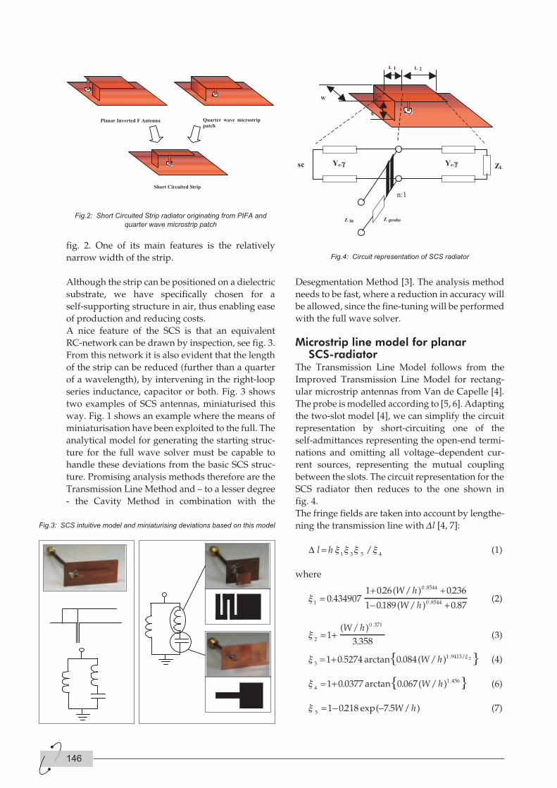
fig. 2. One of its main features is the relatively
narrow width of the strip.
Although the strip can be positioned on a dielectric
substrate, we have specifically chosen for a
self-supporting structure in air, thus enabling ease
of production and reducing costs.
A nice feature of the SCS is that an equivalent
RC-network can be drawn by inspection, see fig. 3.
From this network it is also evident that the length
of the strip can be reduced (further than a quarter
of a wavelength), by intervening in the right-loop
series inductance, capacitor or both. Fig. 3 shows
two examples of SCS antennas, miniaturised this
way. Fig. 1 shows an example where the means of
miniaturisation have been exploited to the full. The
analytical model for generating the starting struc-
ture for the full wave solver must be capable to
handle these deviations from the basic SCS struc-
ture. Promising analysis methods therefore are the
Transmission Line Method and – to a lesser degree
- the Cavity Method in combination with the
Desegmentation Method [3]. The analysis method
needs to be fast, where a reduction in accuracy will
be allowed, since the fine-tuning will be performed
with the full wave solver.
Microstrip line model for planarSCS-radiator
The Transmission Line Model follows from the
Improved Transmission Line Model for rectang-
ular microstrip antennas from Van de Capelle [4].
The probe is modelled according to [5, 6]. Adapting
the two-slot model [4], we can simplify the circuit
representation by short-circuiting one of the
self-admittances representing the open-end termi-
nations and omitting all voltage–dependent cur-
rent sources, representing the mutual coupling
between the slots. The circuit representation for the
SCS radiator then reduces to the one shown in
fig. 4.
The fringe fields are taken into account by lengthe-
ning the transmission line with Dl [4, 7]:
∆ l h= x x x x1 3 5 4
/ (1)
where
x1
0 8544
0 850 4349071 026 0236
1 0189=
+ +
−.
. ( / ) .
. ( / )
.
.
W h
W h 44 0 87+ .(2)
x2
0 371
13 358
= +( / )
.
.W h(3)
x3
x= +1 0 5274 0 084 1 9413 2. arctan . ( / ) . /W h (4)
x4
= +1 0 0377 0 067 1 456. arctan . ( / ) .W h (6)
x5
1 0218 7 5= − −. exp( . / )W h (7)
146
Fig.2: Short Circuited Strip radiator originating from PIFA and
quarter wave microstrip patch
Fig.3: SCS intuitive model and miniaturising deviations based on this model
Fig.4: Circuit representation of SCS radiator
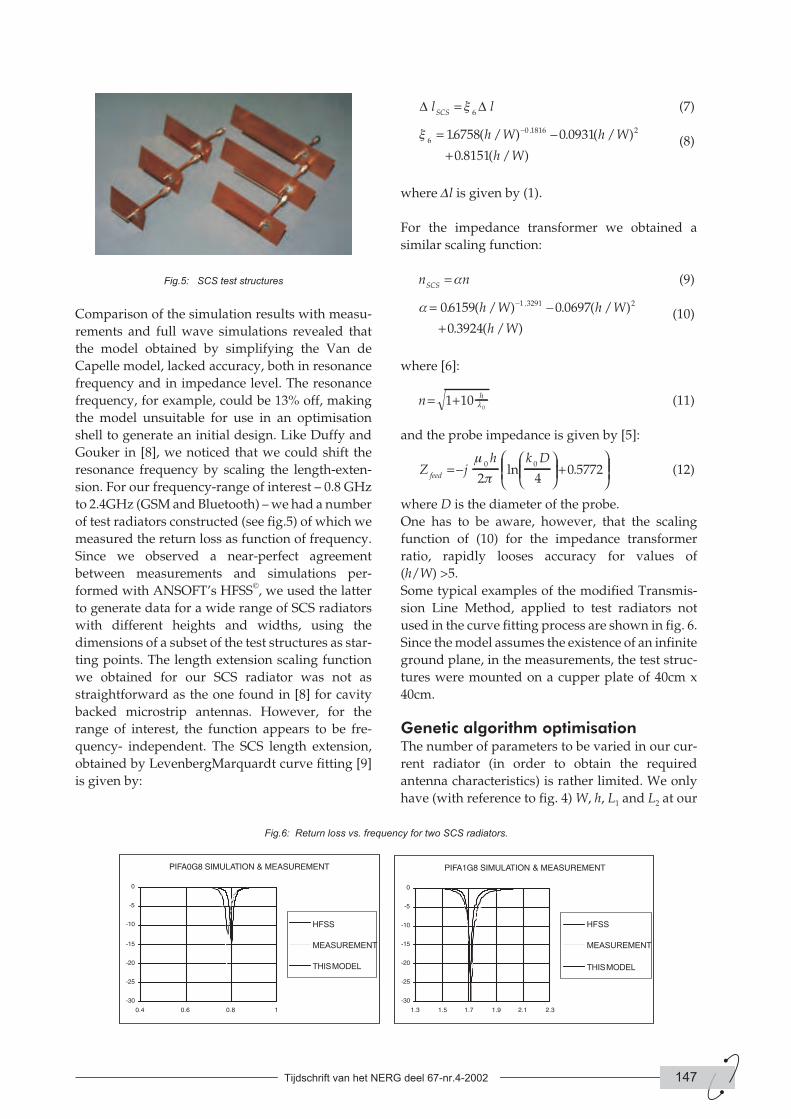
Comparison of the simulation results with measu-
rements and full wave simulations revealed that
the model obtained by simplifying the Van de
Capelle model, lacked accuracy, both in resonance
frequency and in impedance level. The resonance
frequency, for example, could be 13% off, making
the model unsuitable for use in an optimisation
shell to generate an initial design. Like Duffy and
Gouker in [8], we noticed that we could shift the
resonance frequency by scaling the length-exten-
sion. For our frequency-range of interest – 0.8 GHz
to 2.4GHz (GSM and Bluetooth) – we had a number
of test radiators constructed (see fig.5) of which we
measured the return loss as function of frequency.
Since we observed a near-perfect agreement
between measurements and simulations per-
formed with ANSOFT’s HFSS©, we used the latter
to generate data for a wide range of SCS radiators
with different heights and widths, using the
dimensions of a subset of the test structures as star-
ting points. The length extension scaling function
we obtained for our SCS radiator was not as
straightforward as the one found in [8] for cavity
backed microstrip antennas. However, for the
range of interest, the function appears to be fre-
quency- independent. The SCS length extension,
obtained by LevenbergMarquardt curve fitting [9]
is given by:
∆ ∆l lSCS
= x6
(7)
x6
0 1816 216758 0 0931
0 8151
= −
+
−. ( / ) . ( / )
. ( / )
.h W h W
h W(8)
where Dl is given by (1).
For the impedance transformer we obtained a
similar scaling function:
n nSCS
= a (9)
a = −
+
−06159 0 0697
0 3924
1 3291 2. ( / ) . ( / )
. ( / )
.h W h W
h W(10)
where [6]:
n h= +1 100l (11)
and the probe impedance is given by [5]:
Z jh k D
feed= −
+
m
p0 0
2 40 5772ln . (12)
where D is the diameter of the probe.
One has to be aware, however, that the scaling
function of (10) for the impedance transformer
ratio, rapidly looses accuracy for values of
(h/W) >5.
Some typical examples of the modified Transmis-
sion Line Method, applied to test radiators not
used in the curve fitting process are shown in fig. 6.
Since the model assumes the existence of an infinite
ground plane, in the measurements, the test struc-
tures were mounted on a cupper plate of 40cm x
40cm.
Genetic algorithm optimisationThe number of parameters to be varied in our cur-
rent radiator (in order to obtain the required
antenna characteristics) is rather limited. We only
have (with reference to fig. 4) W, h, L1 and L2 at our
Tijdschrift van het NERG deel 67-nr.4-2002 147
Fig.5: SCS test structures
Fig.6: Return loss vs. frequency for two SCS radiators.
disposal. It is anticipated though, that with the size
reduction measures as shown in fig.1 and fig.3, the
number of parameters will grow significantly. The-
refore the need exists for a multi-parameter, con-
strainted optimisation method, preferably
independent of any starting values supplied; i.e. a
global optimisation method. Given these require-
ments, a Genetic Algorithm (GA) solution is parti-
cularly useful [10, 11], also since the software
implementation of a general purpose GA -engine is
very straightforward.
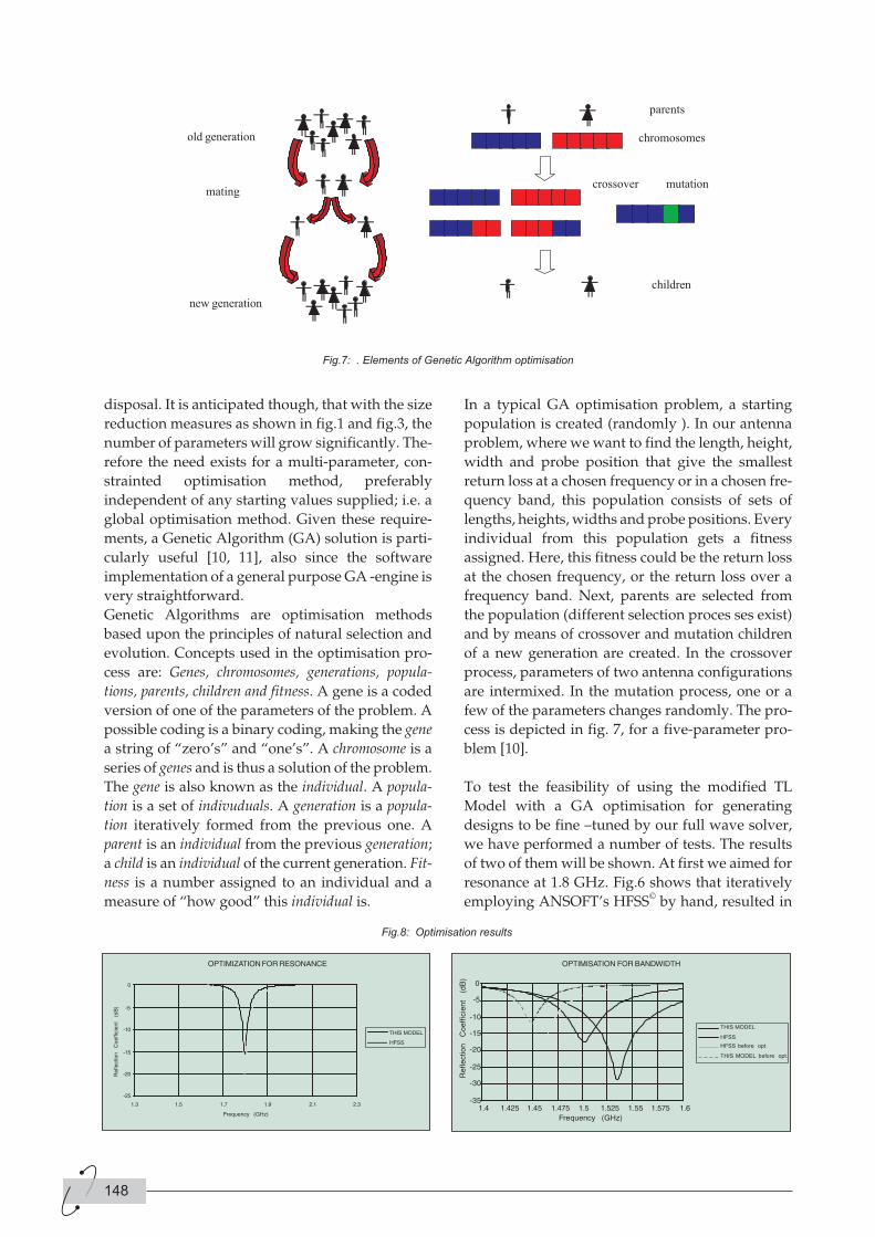
Genetic Algorithms are optimisation methods
based upon the principles of natural selection and
evolution. Concepts used in the optimisation pro-
cess are: Genes, chromosomes, generations, popula-
tions, parents, children and fitness. A gene is a coded
version of one of the parameters of the problem. A
possible coding is a binary coding, making the gene
a string of “zero’s” and “one’s”. A chromosome is a
series of genes and is thus a solution of the problem.
The gene is also known as the individual. A popula-
tion is a set of indivuduals. A generation is a popula-
tion iteratively formed from the previous one. A
parent is an individual from the previous generation;
a child is an individual of the current generation. Fit-
ness is a number assigned to an individual and a
measure of “how good” this individual is.
In a typical GA optimisation problem, a starting
population is created (randomly ). In our antenna
problem, where we want to find the length, height,
width and probe position that give the smallest
return loss at a chosen frequency or in a chosen fre-
quency band, this population consists of sets of
lengths, heights, widths and probe positions. Every
individual from this population gets a fitness
assigned. Here, this fitness could be the return loss
at the chosen frequency, or the return loss over a
frequency band. Next, parents are selected from
the population (different selection proces ses exist)
and by means of crossover and mutation children
of a new generation are created. In the crossover
process, parameters of two antenna configurations
are intermixed. In the mutation process, one or a
few of the parameters changes randomly. The pro-
cess is depicted in fig. 7, for a five-parameter pro-
blem [10].
To test the feasibility of using the modified TL
Model with a GA optimisation for generating
designs to be fine –tuned by our full wave solver,
we have performed a number of tests. The results
of two of them will be shown. At first we aimed for
resonance at 1.8 GHz. Fig.6 shows that iteratively
employing ANSOFT’s HFSS© by hand, resulted in
148
Fig.7: . Elements of Genetic Algorithm optimisation
Fig.8: Optimisation results
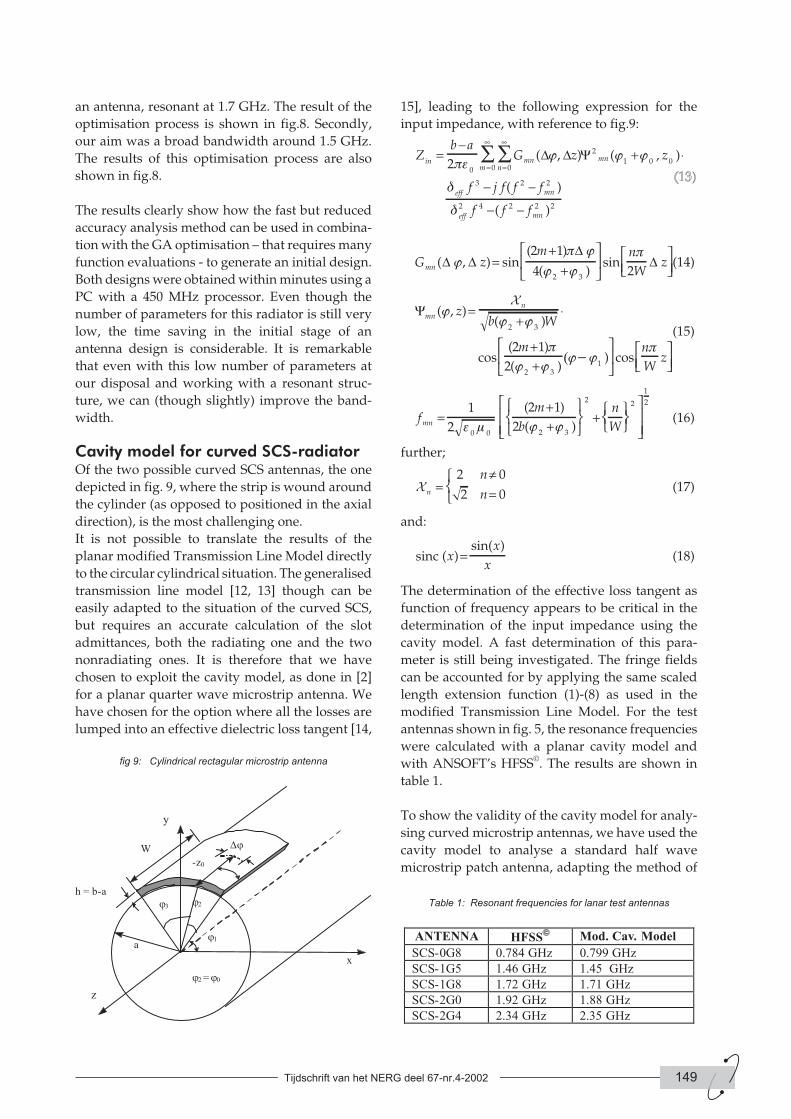
an antenna, resonant at 1.7 GHz. The result of the
optimisation process is shown in fig.8. Secondly,
our aim was a broad bandwidth around 1.5 GHz.
The results of this optimisation process are also
shown in fig.8.
The results clearly show how the fast but reduced
accuracy analysis method can be used in combina-
tion with the GA optimisation – that requires many
function evaluations - to generate an initial design.
Both designs were obtained within minutes using a
PC with a 450 MHz processor. Even though the
number of parameters for this radiator is still very
low, the time saving in the initial stage of an
antenna design is considerable. It is remarkable
that even with this low number of parameters at
our disposal and working with a resonant struc-
ture, we can (though slightly) improve the band-
width.
Cavity model for curved SCS-radiatorOf the two possible curved SCS antennas, the one
depicted in fig. 9, where the strip is wound around
the cylinder (as opposed to positioned in the axial
direction), is the most challenging one.
It is not possible to translate the results of the
planar modified Transmission Line Model directly
to the circular cylindrical situation. The generalised
transmission line model [12, 13] though can be
easily adapted to the situation of the curved SCS,
but requires an accurate calculation of the slot
admittances, both the radiating one and the two
nonradiating ones. It is therefore that we have
chosen to exploit the cavity model, as done in [2]
for a planar quarter wave microstrip antenna. We
have chosen for the option where all the losses are
lumped into an effective dielectric loss tangent [14,
15], leading to the following expression for the
input impedance, with reference to fig.9:
Zb a
G z zin mn
nmn
m
eff
=−
+ ⋅=
∞
=
∞
∑∑2
0 0
2
1 0 00pe
j j j
d
( , ) ( , )∆ ∆ Ψ
f j f f f
f f f
mn
eff mn
3 2 2
2 4 2 2 2
− −
− −
( )
( )d
G zm n
Wzmn ( , ) sin
( )
( )sin∆ ∆
∆∆j
p j
j j
p=
++
2 1
4 22 3
(14)
Ψmn
nz
b W
m
( , )( )
cos( )
( ))
jj j
p
j j(j- j
=+
⋅
++
X
2 3
2 31
2 1
2
cosn
Wz
p(15)
fm
b
n
Wmn =++
+
1
2
2 1
20 0 2 3
2 2
e m j j
( )
( )
1
2
(16)
further;
X n
n
n=
≠=
2 0
2 0(17)
and:
sinc ( )sin( )
xx
x= (18)
The determination of the effective loss tangent as
function of frequency appears to be critical in the
determination of the input impedance using the
cavity model. A fast determination of this para-
meter is still being investigated. The fringe fields
can be accounted for by applying the same scaled
length extension function (1)-(8) as used in the
modified Transmission Line Model. For the test
antennas shown in fig. 5, the resonance frequencies
were calculated with a planar cavity model and
with ANSOFT’s HFSS©. The results are shown in
table 1.
To show the validity of the cavity model for analy-
sing curved microstrip antennas, we have used the
cavity model to analyse a standard half wave
microstrip patch antenna, adapting the method of
Tijdschrift van het NERG deel 67-nr.4-2002 149
fig 9: Cylindrical rectagular microstrip antenna
Table 1: Resonant frequencies for lanar test antennas
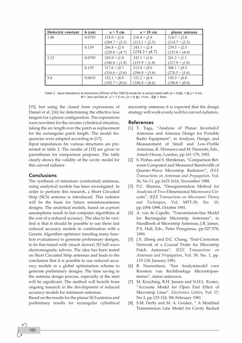
[15], but using the closed form expressions of
Daniel et al. [16] for determining the effective loss
tangent for a planar configuration. The expressions
were rewritten for the circular cylindrical situation,
taking the arc length over the patch as replacement
for the rectangular patch length. The modal fre-
quencies were adapted according to [17].
Input impedances for various structures are pre-
sented in table 2. The results of [15] are given in
parentheses for comparison purposes. The table
clearly shows the validity of the cavity model for
this curved radiator.
ConclusionsThe synthesis of miniature (conformal) antennas,
using analytical models has been investigated. In
order to perform this research, a Short Circuited
Strip (SCS) antenna is introduced. This radiator
will be the basis for future miniatureantenna
designs. The analytical models, based on a-priori
assumptions result in fast computer algorithms at
the cost of a reduced accuracy. The idea to be veri-
fied is that it should be possible to use these fast
reduced accuracy models in combination with a
Genetic Algorithm optimiser (needing many func-
tion evaluations) to generate preliminary designs,
to be fine-tuned with (much slower) 3D full wave
electromagnetic solvers. The idea has been tested
on Short Circuited Strip antennas and leads to the
conclusion that it is possible to use reduced accu-
racy models in a global optimisation scheme to
generate preliminary designs. The time saving in
the antenna design process, especially at the start
will be significant. The method will benefit from
ongoing research in the development of reduced
accuracy models for miniature antennas.
Based on the results for the planar SCS antenna and
preliminary results for rectangular cylindrical
microstrip antennas it is expected that the design
strategy will work evenly well for curved radiators.
References[1] T. Taga, “Analysis of Planar Inverted-F
Antennas and Antenna Design for Portable
Radio Equipment”, in Analysis, Design, and
Measurement of Small and Low-Profile
Antennas, K. Hirasawa and M. Haneishi, Eds.,
Artech House, London, pp.161-179, 1992.
[2] S. Pinhas and S. Shtrikman, “Comparison Bet-
ween Computed and Measured Bandwidth of
Quarter-Wave Microstrip Radiators”, IEEE
Transactions on Antennas and Propagation, Vol.
36, No.11, pp.1615-1616, November 1988.
[3] P.C. Sharma, “Desegmentation Method for
Analysis of Two-Dimensional Microwave Cir-
cuits”, IEEE Transactions on Microwave Theory
and Techniques, Vol. MTT-29, No. 10,
pp.1094-1098, October 1981.
[4] A. van de Capelle, “Transmission-line Model
for Rectangular Microstrip Antennas”, in
Handbook of Microstrip Antennas, J.R. James,
P.S. Hall, Eds., Peter Peregrinus, pp.527-578,
1990.
[5] J.X. Zheng and D.C. Chang, “End-Correction
Network of a Coaxial Probe for Microstrip
Patch Antennas”, IEEE Transactions on
Antennas and Propagation, Vol. 39, No. 1, pp.
115-118, January 1981.
[6] B. Nauwelaers, “Een Analysemodel voor
Roosters van Rechthoekige Microstripan-
tennes”, status unknown.
[7] M. Kirsching, R.H. Jansen and N.H.L. Koster,
“Accurate Model for Open End Effect of
Microstrip Lines”, Electronics Letters, Vol. 17,
No.3, pp.123-124, 5th February 1981.
[8] S.M. Duffy and M. A. Gouker, “ A Modified
Transmission Line Model for Cavity Backed
150
Table 2: Input impedance at resonance (Ohms) of the TM(10)-mode for a curved patch with (a + h)(j2 + j3) = 4 cm,
W = 3cm and fed at –z’ = 1.5 cm, (a + h) j2 =1cm , Dj = 5mm.

Microstrip Antennas”, Antennas and Propaga-
tion Society International Symposium, 1997, IEE.,
Digest, Volume 4, pp.2139-2142, 1997.
[9] W.H. Press, B.P. Flannery, S.A. Teukolsky and
W.T. Vetterling, “Numerical Recipes, The Art of
Scientific Computing”, Cambridge University
Press, pp.523-528, 1988.
[10] J.M. Johnson and Y. Rahmatt-Samii, “Genetic
Algorithms in Engineering Electromagnetics”,
IEEE Antennas and Propagation Magazine,
Vol.39, No.4., pp.7-21, August 1997.
[11] J.M. Johnson and Y. Rahmatt-Samii, “ An
Introduction to Genetic Algorithms”, in Elec-
tromagnetic Optimization by Genetic Algo-
rithms, Y, Rahmatt-Samii and E. Michielsen,
Eds., John Wiley & Sons, Inc., New York,
pp.1-27, 1999.
[12] A.K. Bhattacharyya and R. Garg, “Generalised
Transmission Line Model for Microstrip Pat-
ches”, IEE Proceedings, Vol. 132, Pt. H, No.2,
pp.93-98, April 1985.
[13] K.L. Wong, Y.H. Liu and C.Y. Huang, “Gene-
ralized Transmission-Line Model for Cylin-
drical-Rectangular Microstrip Antennas",
Microwave and Optical Technology Letters, Vol.7,
No.16, pp.729-732, Nov. 1994.
[14] K.R. Carver and J.W. Mink, “ Microstrip
Antenna Technology”, IEEE Transactions on
Antennas and Propagation, Vol. AP-29, No.1,
pp.3-25, January 1981.
[15] K.M. Luk, K.F. Lee and J.S. Dahele, “Analysis
of the Cylindrical-Rectangular Patch
Antenna”, IEEE Transactions on Antennas and
Propagation, Vol. 37, No.2, pp.143-147,
February 1989.
[16] J.P. Daniel, G. Dubost, C. Terret, J. Citerne and
M. Drissi, “Research on Planar Antennas and
Array: “Structures Rayonnantes”", IEEE
Antennas and Propagation Magazine, Vol. 35,
No.1, pp.14-38, Feb. 1993.
[17] J.R.James, P.S. Hall and Wood, “Microstrip
Antennas, Theory and Design”, Peter Pere-
grinus, London, p.100, 1981.
AuthorsHubregt J. Visser
TNO Industrial Technology
PO Box 6235, 5600 HE Eindhoven, The Netherlands
also:
Eindhoven University of Technology, Faculty of
Electrical Engineering
PO Box 513, 5600 MB Eindhoven, The Netherlands
Jan Jonkergouw
TNO Industrial Technology
PO Box 6235, 5600 HE Eindhoven, The Netherlands
Jos C.J.M. Warnier
Eindhoven University of Technology, Faculty of
Electrical Engineering
PO Box 513, 5600 MB Eindhoven, The Netherlands
Tijdschrift van het NERG deel 67-nr.4-2002 151
IntroductionRadio astronomy developed from observations of
unpolarized flux and brightness using antennas
with single feeds. For this purpose, a scalar repre-
sentation of the radiation and the antenna
/receuver system is fully adequate. Polarimetry
evolved several decades later, as an afterthought
one might say, and is accounted for in an approxi-
mate way as a first-order perturbation on the scalar
equations. The extended equations have formed a
basic tool of radio polarimetry ever since. Apart
from being a mere approximation, this approach is
inadequate in that it fragments the problem and
deals with the parts in isolation: There is no grand
picture – lengthy explanations appear in its place
and important aspects got completely lost.
It may be possible nonetheless to get away with this
approach even in the most daring and ambitious
quest of measuring CMB polarization – but a rigou-
rous approach is obvious to be preferred, if only to
reassure oneself that nothing important has been
overlooked. To this end, this contribution applies
the matrix-based description of polarimetry
(Hamaker 2000; see also Hamaker et al. 1996) in
modeling a CMBP instrument (for which PLANCK
served as an example).
This description is complete, clean, coherent and
modular, showing the things that matter without
the encumbrance of distracting detail that is so cha-
racteristic of scalar-based treatments. A clear con-
ceptual distinction emerges between the signal as
such and the way in which it may be represented;
or, more or less equivalently, between the characte-
ristics of the signal and those of the measuring
equipment. Consequently, the analysis need not be
narrowed down to a particular instrumental confi-
guration (linearly/circularly polarized feeds, cor-
relating or differencing receiver) until the point
where the errors in a specific design must be
considered.
Although the emphasis in this paper is on astrono-
mical measurement of an extremely weakly pola-
rized background signal, the matrix formalism is
universally valid and may be brought to bear on
many other situations in which a proper descrip-
tion and understanding of polarization pheno-
mena are important.
The matrix formalismI give here a very brief summary of the matrix for-
malism. See Hamaker Bregman and Sault (1996)
and the first sections of Hamaker (2000) for the full
story.
Signal Vector, Jones and Coherency Matrices
The amplitude of the electric radiation field propa-
gating in the z direction is a vector
e =
e
ep
q
(1)
where p and q are two-dimensional cartesian coor-
dinate axes. Commonly used systems are geome-
tric xy and circular rl coordinates. We will use the
former exclusively.
Along its path, this signal encounters linear trans-
formations; we represent each by a matrix multipli-
cation
′ =e J e , (2)
where the 2 x 2 matrix J is known as a Jones matrix.
For a chain of transformation stages labeled 1, 2, ... ,
N, the overall Jones matrix is the product of the
stage matrices in reverse order:
J J J J J= = ∏N k k
K
2 1(3)
152
A matrix-based polarimetric modelfor a CMB polarimeter telescope
J.P. Hamaker
ASTRON, P.O. Box 2, 7900 AA Dwingeloo,
Netherlands1
1 This contribution is based upon work carried out under contract for the European Space Agency ESA
In this note it is understood that the factors in a pro-
duct ∏k k
J always appear in descending order of k.
Polarization of the radiation is characterised by the
auto- (powers) and cross-covariances of the field
components, which are the elements of the cohe-
rency matrix
C =< >≡<
>≡e e
e e e e
e e e e
e e
eP q† P p
*
P q*
q p*
q q*
pp pq
qp e qq
, (4)
where the dagger superscript indicates hermitian
transposition and the angle brackets <> represent
time averaging. Note the use of single indices for
field components, double indices for matrix ele-
ments. The diagonal elements represent the
powers in the epp and eqq fields and each contain one
half of the unpolarized part of the radiation.
Also note that the electric field is measured in a
single point rather than in two interferometer ele-
ments as in the references; consequently, the cohe-
rency matrix is hermitian and contains only 4
independent parameters. This is also true for the
output of any signal transformation; this require-
ment may serve as a simple check on the correct-
ness of the analytical expressions and
approximations to be developed below.
From (2) and (4) it immediately follows that the
effect of a Jones matrix J on the coherency matrix is
given by (Hamaker 2000)
′ =C JCJ † . (5)
Stokes Parameters: Intensity and Polvector
The Stokes vector (I, Q, U, V) is an alternative repre-
sentation of the coherency matrix; in xy coordi-
nates:
I
Q
U
V
e e
e e
e e
i e e
≡
+−+
− −
1
2
xx yy
xx yy
xy yx
xy( yx )
(6)
Conversely
C =+ −+ −
I Q U iV
U iV I Q(7)
In the present context the Stokes parameters are
intrinsically real. For an unpolarized source, C is a
multiple of the indentity matrix I. The polarized
part of the radiation is represented by the other
three parameters which form the polvector
p ≡ (Q, U, V) (8)
that resides in an abstract polvector space of its
own. (The term ‘polvector’ was introduced by
Hamaker (2000); a closely related concept is that of
the Poincaré é sphere, which is the locus of the nor-
malized polvector p/I for a fully polarized signal.)
The values of I and p as functions of celestial pos-
tion is what CMBP experiments are supposed to
measure. V is assumed to be zero: p = (Q, U, 0).
Scalar and Vector Parts of 2 x 2 Matrices
The Stokes representation is not restricted to cohe-
rency matrices. Equation (7) applies to any matrix
and we may thus generally define the scalar and
vector parts of a matrix, corresponding respectively
to I and p above. This gives rise to an interesting
and valuable geometrical interpretation of the
matrices and their products and transformations
(Hamaker 2000) – which is, however, outside the
scope of this paper.
In physical terms, the scalar part of a Jones matrix
simply scales the coherency without altering its
relative polarization p/I. The vector part is respon-
sible for rotations of the polvector and for mutual
conversion between the unpolarized and polarized
parts of the coherency (Hamaker 2000).
Coordinate Systems
The (Q, U, V) coordinate axes in polvector space
may represent any Cartesian frame. The conventi-
onal choice is to let positive Q represent a signal
whose preferred direction of vibration is along the
x axis of our physical coordinates, and positive U
along position angle +p/4 (Hamaker and Bregman
1996).
It is natural (although not necessary) to align one’s
coordinates with an axis of symmetry of the instru-
ment. E.g. for the PLANCK LFI, an obvious choice
is the symmetry plane of the dual-reflector system.
Such choices are a matter of convenience and we
may even use different frames for different parts of
our systems, interspersing transformations where
necessary. For example, if the OMT were to have a
symmetry plane that is different from that of the
optics, one might use two different coordinate sys-
tems joined by a geometric rotation.
The Norm of a Matrix
A a measure to compare the relative magnitudes of
matrices we use the Euclidian or Frobenius norm
A AA= =∑ ajk
jk
2
Tr † . (9)
Tijdschrift van het NERG deel 67-nr.4-2002 153
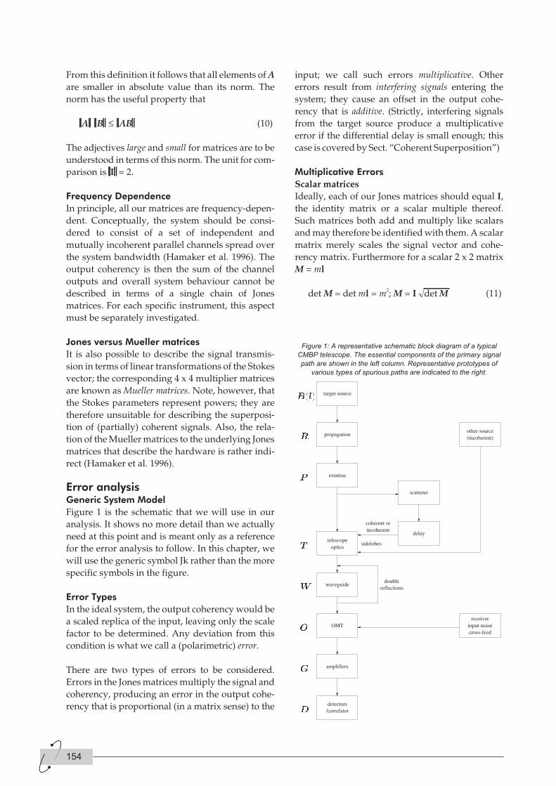
From this definition it follows that all elements of A
are smaller in absolute value than its norm. The
norm has the useful property that
A B AB≤ (10)
The adjectives large and small for matrices are to be
understood in terms of this norm. The unit for com-
parison is I = 2.
Frequency Dependence
In principle, all our matrices are frequency-depen-
dent. Conceptually, the system should be consi-
dered to consist of a set of independent and
mutually incoherent parallel channels spread over
the system bandwidth (Hamaker et al. 1996). The
output coherency is then the sum of the channel
outputs and overall system behaviour cannot be
described in terms of a single chain of Jones
matrices. For each specific instrument, this aspect
must be separately investigated.
Jones versus Mueller matrices
It is also possible to describe the signal transmis-
sion in terms of linear transformations of the Stokes
vector; the corresponding 4 x 4 multiplier matrices
are known as Mueller matrices. Note, however, that
the Stokes parameters represent powers; they are
therefore unsuitable for describing the superposi-
tion of (partially) coherent signals. Also, the rela-
tion of the Mueller matrices to the underlying Jones
matrices that describe the hardware is rather indi-
rect (Hamaker et al. 1996).
Error analysisGeneric System Model
Figure 1 is the schematic that we will use in our
analysis. It shows no more detail than we actually
need at this point and is meant only as a reference
for the error analysis to follow. In this chapter, we
will use the generic symbol Jk rather than the more
specific symbols in the figure.
Error Types
In the ideal system, the output coherency would be
a scaled replica of the input, leaving only the scale
factor to be determined. Any deviation from this
condition is what we call a (polarimetric) error.
There are two types of errors to be considered.
Errors in the Jones matrices multiply the signal and
coherency, producing an error in the output cohe-
rency that is proportional (in a matrix sense) to the
input; we call such errors multiplicative. Other
errors result from interfering signals entering the
system; they cause an offset in the output cohe-
rency that is additive. (Strictly, interfering signals
from the target source produce a multiplicative
error if the differential delay is small enough; this
case is covered by Sect. “Coherent Superposition”)
Multiplicative Errors
Scalar matrices
Ideally, each of our Jones matrices should equal I,
the identity matrix or a scalar multiple thereof.
Such matrices both add and multiply like scalars
and may therefore be identified with them. A scalar
matrix merely scales the signal vector and cohe-
rency matrix. Furthermore for a scalar 2 x 2 matrix
M = ml
det M = det ml = m2; M = I det M (11)
154
Figure 1: A representative schematic block diagram of a typical
CMBP telescope. The essential components of the primary signal
path are shown in the left column. Representative prototypes of
various types of spurious paths are indicated to the right.

True Jones Matrices
The Jones matrices in our system are designed to
deviate little from the ideal of a scalar matrix; we
may represent them as
J J Jk k k
= +det ( )I d (12)
where dJk is small. We may also say that Jk is nearly
scalar. The rationale for this decomposition is that
products with scalar matrices are commutative; by
swapping factors in such a product we obtain
expressions that are more transparent and inter-
pretable.
More precisely, dJk is composed of a small, strictly
constant errer dJk
and an even smaller variable error
making
J J Jk k k
= + +det ( I d ). (13)
In the same way we write the sky coherency as
C C l C l= +det ( ) ( ( ))I d . (14)
I are the pointing coordinates; we will not carry
them explicitly in the sequel.
In analysing polarimetric system performance, we
may ignore the scalar multipliers and concentrate
on the error terms in the parentheses. The constant
errors are of order 10-2; the variable errors are at
least another two orders smaller (10-6 – 10-4), but
they may be well above the target accuracy which
is of order 10-7 – 10-6 of the brightness level of 2.7K.
If they are, the variations will have somehow to be
calibrated.
Multiplicative-Error Model
The system Jones matrix J (without a subscript) is
J J J J= = + +∏ ∏k k k k kdet ( I d ). (15)
Considering the magnitudes of the previous sec-
tion, we may simplify the equation. In the product
Jk∏
• All products involving only fixed errors dJk
add up to a new fixed error dJ. It is dominated
by the linear term dJk∑ whose order of
magnitude is that of the individual dJk
.
• All products involving more than one variable
term may be neglected.
• All products involving a mixture of fixed and
variable error terms are much smaller than the
variable terms themselves and may be
neglected.
The remaining terms are
J J J≈ + +∑det ( I dk
). (16)
We may use the shorthand for the third term to
write J in the standard form of (13) when this is con-
venient.
Output Coherency
From (5), (14) and (16), the output coherency
becomes
C’ = JCJ† ≈|det J|(I + dJ + ) detC (I + dC)⋅
( I + dJ + ) † (17)
We may again neglect products involving two or
more error terms and/or dC, leaving
C’ ≈ |det J| detC ( I + dC + 2He dJ + 2He )
(18)
where the symbol He stands for the hermitian part
of.
Possible Refinements
The model may be refined by including certain
second-order products or even more. At present I
see no justification for doing this.
Additive errors may originate from the target
source itself through stray paths; such paths are
formed by
• beam sidelobes picking up radiation scattered
off the satellite structure;
• fractions of the signal being reflected backward
and then forward again in the telescope optics
and/or the waveguide system.
Depending on the differential delay, the error
signal may be coherently or incoherently related to
the target signal.
Other sources may also contribute an error signal:
Both the sky and radiation from the satellite itself
are picked up by beam sidelobes. These signals are
always incoherent with the target source.
Coherent Superposition
In the coherent case, the target and error signals
add. The error signal is coherently derived from the
Tijdschrift van het NERG deel 67-nr.4-2002 155
target and therefore representable by the latter
multiplied with an error Jones matrix J’, so we get
′′ = + ′ = ′e Je e J J e( + ) (19)
The net effect is that of adding one or more (relati-
vely small) error terms to the system Jones matrix J;
they may contain both fixed and variable parts.
One particular possible source of variation are
moving parts of the satellite.
Incoherent Superposition
For incoherent superposition, it is the coherency
matrices that add. We consider the point where the
superposition happens. The target source’s cohe-
rency is JCJt and the interfering coherency J’C’J’t.
Then the output C“ becomes
′′ = + ′ ′ ′C JCJ J C J† † (20)
To estimate the relative magnitude of the error, we
may approximate J and C’ by their scalar parts to
get
′′ ≈ + ′ ′ ′−
C J C J J C Jdet ( det1 † (21)
There are too many variables to allow a general
conclusion. One must consider each possible inter-
ference source separately, taking into account its
strength C’ and the path J’ through which its enters.
Summary of Results
It may be useful at this point to summarise what we
have learnt.
• The system Jones matrix is given by (16). It con-
tains a fixed and a variable error term, both of
which are represented with appropriate accu-
racy by the sums of the corresponding errors in
the component Jones matrices.
•• The output coherency is given by (18). It con-
tains a scaled replica of the input coherency C,
contaminated by the input intensity cI mul-
tiplied by twice the hermitian part of the error
terms in the system Jones matrix.
• Spurious signals from the target source entering
with a small differential delay contribute extra
multiplicative error terms to (16).
• Spurious signals from the target source entering
with a big delay as well as signals from other
sources contribute addytive error terms per (20)
and (21) to the coherency.
• The latter two types of error may also contain
fixed and variable parts; they must be analysed
for each individual source of interference.
This is as far as the generic analysis will carry us. At
this point, the details a specific instrument configu-
ration and its constituent parts come into play.
Antenna modelBy the antenna I understand the optics that con-
verts the incident plane waves from the entire sky
into a single guided wave. This is the input opera-
tion common to all instruments. The antenna con-
sists of a feed horn and a(n optional) (set of)
reflector(s). The properties of these components are
so intertwined that the only reasonable way to
model them is through a single Jones matrix T that
is a function of spatial coordinates l. The antenna
integrates the incident coherency B(l) over the sky
with T as Jones matrix:
′ = ∫C T l B l T ld ( ( (Ω ) ) )† (22)
In decomposing this integral it is convenient to
split T in its scalar and vector parts:
T T l T l= + =t tI d , ( ) ( )12 Tr . (23)
Then
′ = + +∫C T B Td t tΩ ( ) ( )I Id d † (24)
[= + +∫ d t tΩ 22B B T T B THe † †( )d d d (25)
The first term in the integrand is the weighted
matrix brightness; this is what an ideal scalar or
polarizationfree antenna ( T = tI ; dT = 0) would
yield.
The argument of the second term is the weighted
cross-covariance of the brightness and the beam’s
vector part, with t (i.e. the scalar part of the voltage
beam) acting as the weight factor.
The third term, being quadratic in dT, is second-
order small over the entire beam. However, unlike
the similar second-order terms in Sect. “Multiplica-
tive-Error Model” it is not constant since it depends
on the position of the sky relative to the telescope.
Although smaller than the middle term, it must be
retained and analysed; in a complete analysis, the
split (23) is not necessarily very useful.
156
One may also interpret (25) as an expansion of C’ in
powers of the relative instrumental polarization
dT(l)/t(l):
[ ]′ = + +∫C B B T T B Td t t t tΩ 22He † †( / ) / ( / )d d d
(26)
By design, the beam should be weakly polarized in
the main lobe – i.e. dT /t = 1 where |t| is large.
In the sidelobe region dT is an oscillating function
of l of the same order of magnitude and, since |t| is
small, sidelobes may be strongly polarized.
The telescope output is the convolution over the
entire sphere of the beam with the sky coherency. It
is dominated by the main beam, but the sidelobe
contributions are nonnegligible at the accuracy
levels required; some kind of deconvolution will be
necessary. In my opinion, this matter needs to be
studied with greater care than may have been done
so far; for this, the equations of this section provide
a better starting point than representations in terms
of scalar formulae (e.g. Carretti et al. 2001).
Rotation and conversion transforma-tions
Any matrix J can be represented (Hamaker 2000) as
the product of a scale factor with unimodular uni-
tary and positive-hermitian matrix factors:
J = cHY. (27)
(A unimodular matrix has a unity determinant;
unitary matrices are the matrix equivalent of scalar
phase factors, positive-hermitian matrices the equi-
valent of positive numbers; )
Applying this to the Jones matrix J in the interfer-
ometer equation (5) we get
C’ = JCJ† = c H (YCY
†) H†. (28)
The inner transformation X = YCY† leaves the
Stokes intensity I invariant, since for a unitary
matrix YY† = I. Furthermore it can be shown to
rotate the polvector in its abstract polvector space.
The rotation axis and angle are functions of the four
elements of Y; a detailed discussion is given in
Hamaker (2000).
The outer transformation C’ = HXH† effects a
mutual conversion of power between intensity I
and polvector p without changing the latter’s orien-
tation – the transformation is said to be rotation-free.
Again, the precise form of the conversion depends
on the elements of the transformation matrix
(Hamaker 2000).
Since J is nearly scalar (cf. Sect. 3.3.2), so are Y and
H; in other words, Y represents a rotation over a
small angle and H converts a small fraction of I.
Since p/I = 1 the inverse conversion is negligible.
ReferencesE. Carretti, R. Tascone, S. Cortiglioni, J. Monari, J.
and M. Orsini 2001: “Limits due to instrumental
polarisation in CMB experiments at microwave
wavelengths.” New Astronomy 6, 173-187, 2001.
J.P. Hamaker, J.D. Bregman and R.J. Sault 1996:
“Understanding Radio Polarimetry, I: Mathema-
tical Foundations”. Astron. and Astrophys. Suppl.
117, 137-1467, 1996.
J.P. Hamaker and J.D. Bregman 1996: “Understan-
ding Radio Polarimetry, III: Interpreting the
IAU/IEEE definitions of the Stokes parameters”.
emphAstron. and Astrophys. Suppl. 117, 161-165,
1996.
J.P. Hamaker 2000: “Understanding Radio Polari-
metry, IV: ”The full-coherency analogue of scalar
self-calibration: Self-alignment, dynamic range
and polarimetric fidelity". Astron. and Astrophys.
Suppl., 143, 515-534, May I, 2000.
Tijdschrift van het NERG deel 67-nr.4-2002 157
IntroductionAntenna front-ends for modern active phased
array radars and communication systems are cha-
racterised by a large operational bandwidth and
the ability to scan over a large angular area. Cost
drivers for such antennas are active components
including GaAs MMICS. If some reduced perfor-
mance is acceptable, much less expensive alterna-
tives for active phase array antennas are
reflectarray antennas. The work presented here
describes design, production and testing of a
semi-active Ka -band reflectarray, developed by
Thales Nederland B.V. The antenna consists of a
feedhorn in front of a thin flat reflectarray multi-
layer printed circuit board. The toplayers consist of
integrated RF radiator and phase shifter elements.
PIN diode switches control reflection phase. The
backlayers are for digital control, data distribution
and dc power distribution.
Design of the reflectarray antenna concentrated on
antenna efficiency, particularly for the phase
shifter design. At Kaband frequencies many mate-
rials have relatively high loss tangent. Applicable
PIN-diode switches introduce reduced switching
due to series resistance and capacitive RF currents.
The principle of operation is chosen to minimise
loss mechanisms. A finite element software tool is
used to optimise the dimensions of the reflectarray
elements. Results are validated by measurements
on small samples in a waveguide simulator. After
several design iterations a prototype reflectarray
antenna is put into production and tested after-
wards. The study is presented with photos of the
antenna hardware within and after production, as
well as the nearfield and farfield measurement
results.
Problem descriptionThree types of reflectarrays can be distinguished:
passive (fixed beam and passive reflection),
semi-active (electronic beamsteering and passive
reflection) and active (electronic beamsteering and
amplified reflection). This paper concerns the
development of a semi-active Ka-band reflectarray
demonstrator. The demonstrator must prove the
semi-active reflectarray antenna concept. This
paper gives a brief overview of the presentation
contents.
Principle of operationPhase shifter elements are the fundamental parts of
a reflectarray antenna. One of the key features is
how the individual elements are adjusted to scatter
the desired phase. Proper characteristics are: fast
switching time, phase states with uniform distribu-
tion, low loss, wide band operation, good scan per-
formance, low production cost and compatible
with a building block design philosophy. This
paragraph describes phase shifter loss issues: loss
in general, material losses, quantisation loss and
loss in switches.
Phase shifters inhibit sensitive phase influence ope-
rating at and around resonance frequencies. There-
fore it seems attractive to design when large phase
changes are required. However at resonance, cur-
rent and electric field excitations are very intense.
Therefore the loss is relatively high and the opera-
ting bandwidth small. The remedy is simple:
design phase shifters in non-resonance zones. Out
of resonance there are regions where phase states
can be controlled properly. Some types of Fre-
quency Selective Surfaces [6, 7] also have such
regions: semi -reflective-inductive, non-reflective-
transparent and semi-reflective-capacitive.
158
Semi-active Ka-band reflectarrayantenna
John A.J. de Groot (1), Jos T.C. Duivenvoorden (2)
Thales Netherland B.V., P.O. Box 42, 7550 GD Hengelo (Ov.),
The Netherlands
(1) Email: [email protected]
(2) Email: [email protected]
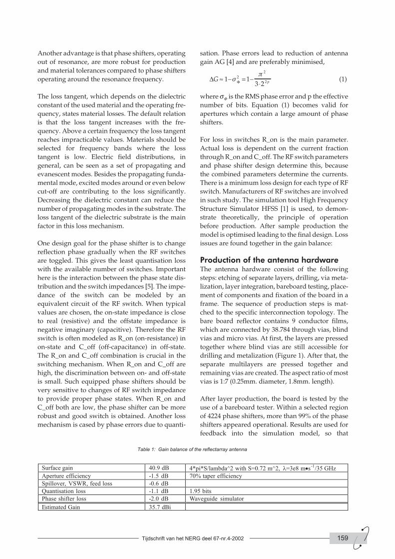
Another advantage is that phase shifters, operating
out of resonance, are more robust for production
and material tolerances compared to phase shifters
operating around the resonance frequency.
The loss tangent, which depends on the dielectric
constant of the used material and the operating fre-
quency, states material losses. The default relation
is that the loss tangent increases with the fre-
quency. Above a certain frequency the loss tangent
reaches impracticable values. Materials should be
selected for frequency bands where the loss
tangent is low. Electric field distributions, in
general, can be seen as a set of propagating and
evanescent modes. Besides the propagating funda-
mental mode, excited modes around or even below
cut-off are contributing to the loss significantly.
Decreasing the dielectric constant can reduce the
number of propagating modes in the substrate. The
loss tangent of the dielectric substrate is the main
factor in this loss mechanism.
One design goal for the phase shifter is to change
reflection phase gradually when the RF switches
are toggled. This gives the least quantisation loss
with the available number of switches. Important
here is the interaction between the phase state dis-
tribution and the switch impedances [5]. The impe-
dance of the switch can be modeled by an
equivalent circuit of the RF switch. When typical
values are chosen, the on-state impedance is close
to real (resistive) and the offstate impedance is
negative imaginary (capacitive). Therefore the RF
switch is often modeled as R_on (on-resistance) in
on-state and C_off (off-capacitance) in off-state.
The R_on and C_off combination is crucial in the
switching mechanism. When R_on and C_off are
high, the discrimination between on- and off-state
is small. Such equipped phase shifters should be
very sensitive to changes of RF switch impedance
to provide proper phase states. When R_on and
C_off both are low, the phase shifter can be more
robust and good switch is obtained. Another loss
mechanism is cased by phase errors due to quanti-
sation. Phase errors lead to reduction of antenna
gain AG [4] and are preferably minimised,
∆ ΦG p≈ − = −⋅
1 13 2
2
2
2sp
(1)
where sF is the RMS phase error and p the effective
number of bits. Equation (1) becomes valid for
apertures which contain a large amount of phase
shifters.
For loss in switches R_on is the main parameter.
Actual loss is dependent on the current fraction
through R_on and C_off. The RF switch parameters
and phase shifter design determine this, because
the combined parameters determine the currents.
There is a minimum loss design for each type of RF
switch. Manufacturers of RF switches are involved
in such study. The simulation tool High Frequency
Structure Simulator HFSS [1] is used, to demon-
strate theoretically, the principle of operation
before production. After sample production the
model is optimised leading to the final design. Loss
issues are found together in the gain balance:
Production of the antenna hardwareThe antenna hardware consist of the following
steps: etching of separate layers, drilling, via meta-
lization, layer integration, bareboard testing, place-
ment of components and fixation of the board in a
frame. The sequence of production steps is mat-
ched to the specific interconnection topology. The
bare board reflector contains 9 conductor films,
which are connected by 38.784 through vias, blind
vias and micro vias. At first, the layers are pressed
together where blind vias are still accessible for
drilling and metalization (Figure 1). After that, the
separate multilayers are pressed together and
remaining vias are created. The aspect ratio of most
vias is 1:7 (0.25mm. diameter, 1.8mm. length).
After layer production, the board is tested by the
use of a bareboard tester. Within a selected region
of 4224 phase shifters, more than 99% of the phase
shifters appeared operational. Results are used for
feedback into the simulation model, so that
Tijdschrift van het NERG deel 67-nr.4-2002 159
Table 1: Gain balance of the reflectarray antenna
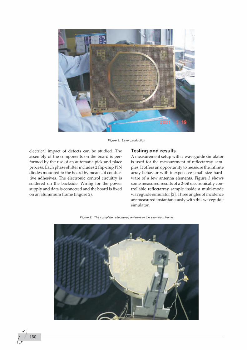
electrical impact of defects can be studied. The
assembly of the components on the board is per-
formed by the use of an automatic pick-and-place
process. Each phase shifter includes 2 flip-chip PIN
diodes mounted to the board by means of conduc-
tive adhesives. The electronic control circuitry is
soldered on the backside. Wiring for the power
supply and data is connected and the board is fixed
on an aluminium frame (Figure 2).
Testing and resultsA measurement setup with a waveguide simulator
is used for the measurement of reflectarray sam-
ples. It offers an opportunity to measure the infinite
array behavior with inexpensive small size hard-
ware of a few antenna elements. Figure 3 shows
some measured results of a 2-bit electronically con-
trollable reflectarray sample inside a multi-mode
waveguide simulator [2]. Three angles of incidence
are measured instantaneously with this waveguide
simulator.
160
Figure 1: Layer production
Figure 2: The complete reflectarray antenna in the aluminum frame
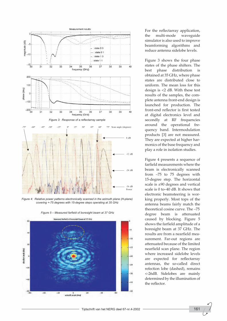
For the reflectarray application,
the multi-mode waveguide
simulator is also used to improve
beamforming algorithms and
reduce antenna sidelobe levels.
Figure 3 shows the four phase
states of the phase shifters. The
best phase distribution is
obtained at 35 GHz, where phase
states are distributed close to
uniform. The mean loss for this
design is <2 dB. With these test
results of the samples, the com-
plete antenna front-end design is
launched for production. The
front-end reflector is first tested
at digital electronics level and
secondly at RF frequencies
around the operational fre-
quency band. Intermodulation
products [3] are not measured.
They are expected at higher har-
monics of the base frequency and
play a role in isolation studies.
Figure 4 presents a sequence of
farfield measurements where the
beam is electronically scanned
from –75 to 75 degrees with
15-degree step. The horizontal
scale is ±90 degrees and vertical
scale is 0 to–40 dB. It shows that
electronic beamsteering is wor-
king properly. Most tops of the
antenna beams fairly match the
theoretical cosine curve. The –75
degree beam is attenuated
caused by blocking. Figure 5
shows the farfield amplitude of a
boresight beam at 37 GHz. The
results are from a nearfield mea-
surement. Far-out regions are
attenuated because of the limited
nearfield scan plane. The region
where increased sidelobe levels
are expected for reflectarray
antennas, the so-called direct
refection lobe (dashed), remains
<-26dB. Sidelobes are mainly
determined by the illumination of
the reflector.
Tijdschrift van het NERG deel 67-nr.4-2002 161
Figure 3: Response of a reflectarray sample
Figure 4: Relative power patterns electronically scanned in the azimuth plane (H-plane)
covering +-75 degrees with 15-degree steps operating at 35 GHz
Figure 5 – Measured farfield of boresight beam at 37 GHz
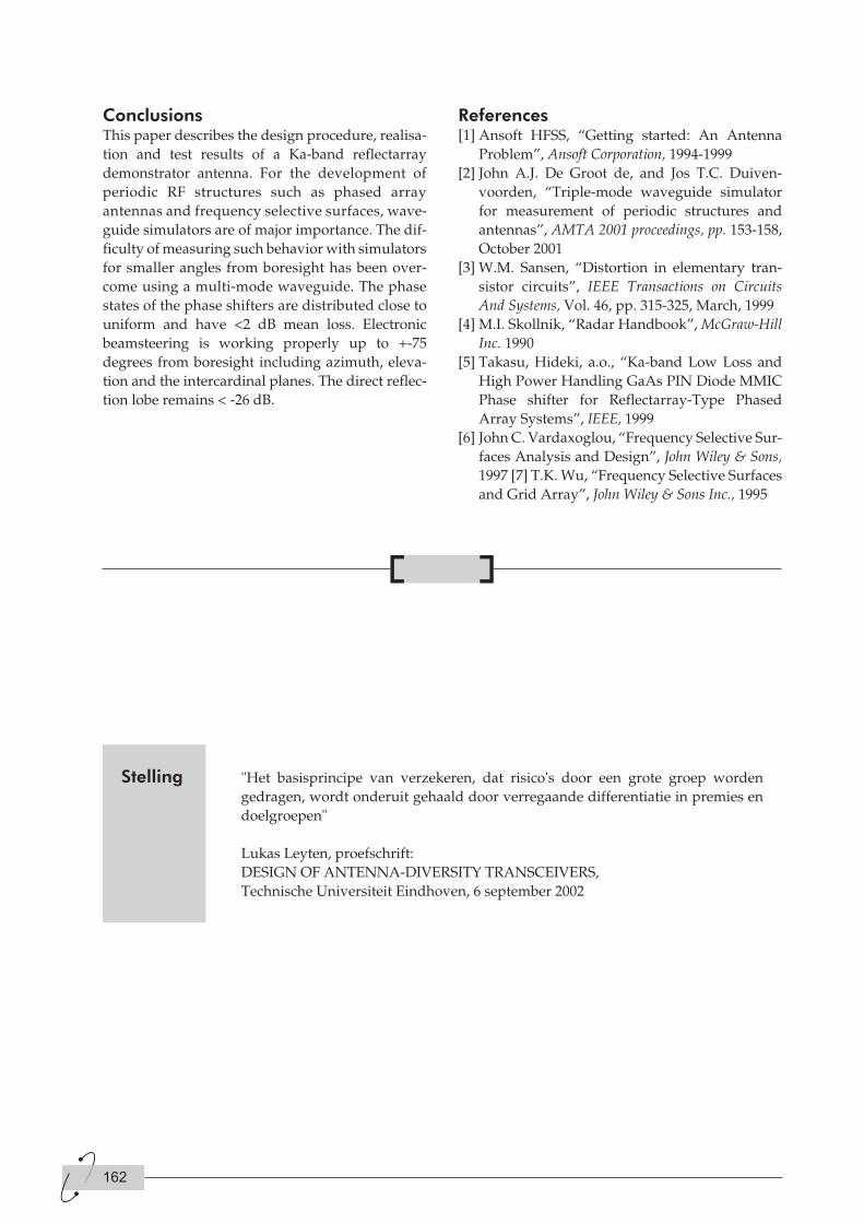
ConclusionsThis paper describes the design procedure, realisa-
tion and test results of a Ka-band reflectarray
demonstrator antenna. For the development of
periodic RF structures such as phased array
antennas and frequency selective surfaces, wave-
guide simulators are of major importance. The dif-
ficulty of measuring such behavior with simulators
for smaller angles from boresight has been over-
come using a multi-mode waveguide. The phase
states of the phase shifters are distributed close to
uniform and have <2 dB mean loss. Electronic
beamsteering is working properly up to +-75
degrees from boresight including azimuth, eleva-
tion and the intercardinal planes. The direct reflec-
tion lobe remains < -26 dB.
References[1] Ansoft HFSS, “Getting started: An Antenna
Problem”, Ansoft Corporation, 1994-1999
[2] John A.J. De Groot de, and Jos T.C. Duiven-
voorden, “Triple-mode waveguide simulator
for measurement of periodic structures and
antennas”, AMTA 2001 proceedings, pp. 153-158,
October 2001
[3] W.M. Sansen, “Distortion in elementary tran-
sistor circuits”, IEEE Transactions on Circuits
And Systems, Vol. 46, pp. 315-325, March, 1999
[4] M.I. Skollnik, “Radar Handbook”, McGraw-Hill
Inc. 1990
[5] Takasu, Hideki, a.o., “Ka-band Low Loss and
High Power Handling GaAs PIN Diode MMIC
Phase shifter for Reflectarray-Type Phased
Array Systems”, IEEE, 1999
[6] John C. Vardaxoglou, “Frequency Selective Sur-
faces Analysis and Design”, John Wiley & Sons,
1997 [7] T.K. Wu, “Frequency Selective Surfaces
and Grid Array”, John Wiley & Sons Inc., 1995
162
"Het basisprincipe van verzekeren, dat risico's door een grote groep worden
gedragen, wordt onderuit gehaald door verregaande differentiatie in premies en
doelgroepen"
Lukas Leyten, proefschrift:
DESIGN OF ANTENNA-DIVERSITY TRANSCEIVERS,
Technische Universiteit Eindhoven, 6 september 2002
Stelling
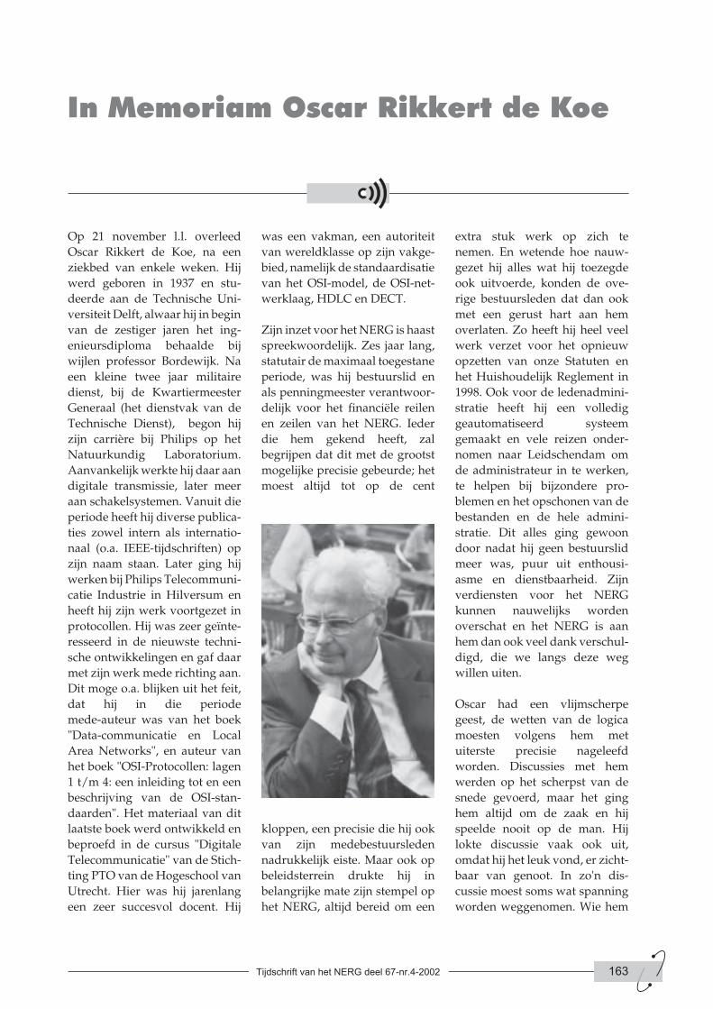
Op 21 november l.l. overleed
Oscar Rikkert de Koe, na een
ziekbed van enkele weken. Hij
werd geboren in 1937 en stu-
deerde aan de Technische Uni-
versiteit Delft, alwaar hij in begin
van de zestiger jaren het ing-
enieursdiploma behaalde bij
wijlen professor Bordewijk. Na
een kleine twee jaar militaire
dienst, bij de Kwartiermeester
Generaal (het dienstvak van de
Technische Dienst), begon hij
zijn carrière bij Philips op het
Natuurkundig Laboratorium.
Aanvankelijk werkte hij daar aan
digitale transmissie, later meer
aan schakelsystemen. Vanuit die
periode heeft hij diverse publica-
ties zowel intern als internatio-
naal (o.a. IEEE-tijdschriften) op
zijn naam staan. Later ging hij
werken bij Philips Telecommuni-
catie Industrie in Hilversum en
heeft hij zijn werk voortgezet in
protocollen. Hij was zeer geïnte-
resseerd in de nieuwste techni-
sche ontwikkelingen en gaf daar
met zijn werk mede richting aan.
Dit moge o.a. blijken uit het feit,
dat hij in die periode
mede-auteur was van het boek
"Data-communicatie en Local
Area Networks", en auteur van
het boek "OSI-Protocollen: lagen
1 t/m 4: een inleiding tot en een
beschrijving van de OSI-stan-
daarden". Het materiaal van dit
laatste boek werd ontwikkeld en
beproefd in de cursus "Digitale
Telecommunicatie" van de Stich-
ting PTO van de Hogeschool van
Utrecht. Hier was hij jarenlang
een zeer succesvol docent. Hij
was een vakman, een autoriteit
van wereldklasse op zijn vakge-
bied, namelijk de standaardisatie
van het OSI-model, de OSI-net-
werklaag, HDLC en DECT.
Zijn inzet voor het NERG is haast
spreekwoordelijk. Zes jaar lang,
statutair de maximaal toegestane
periode, was hij bestuurslid en
als penningmeester verantwoor-
delijk voor het financiële reilen
en zeilen van het NERG. Ieder
die hem gekend heeft, zal
begrijpen dat dit met de grootst
mogelijke precisie gebeurde; het
moest altijd tot op de cent
kloppen, een precisie die hij ook
van zijn medebestuursleden
nadrukkelijk eiste. Maar ook op
beleidsterrein drukte hij in
belangrijke mate zijn stempel op
het NERG, altijd bereid om een
extra stuk werk op zich te
nemen. En wetende hoe nauw-
gezet hij alles wat hij toezegde
ook uitvoerde, konden de ove-
rige bestuursleden dat dan ook
met een gerust hart aan hem
overlaten. Zo heeft hij heel veel
werk verzet voor het opnieuw
opzetten van onze Statuten en
het Huishoudelijk Reglement in
1998. Ook voor de ledenadmini-
stratie heeft hij een volledig
geautomatiseerd systeem
gemaakt en vele reizen onder-
nomen naar Leidschendam om
de administrateur in te werken,
te helpen bij bijzondere pro-
blemen en het opschonen van de
bestanden en de hele admini-
stratie. Dit alles ging gewoon
door nadat hij geen bestuurslid
meer was, puur uit enthousi-
asme en dienstbaarheid. Zijn
verdiensten voor het NERG
kunnen nauwelijks worden
overschat en het NERG is aan
hem dan ook veel dank verschul-
digd, die we langs deze weg
willen uiten.
Oscar had een vlijmscherpe
geest, de wetten van de logica
moesten volgens hem met
uiterste precisie nageleefd
worden. Discussies met hem
werden op het scherpst van de
snede gevoerd, maar het ging
hem altijd om de zaak en hij
speelde nooit op de man. Hij
lokte discussie vaak ook uit,
omdat hij het leuk vond, er zicht-
baar van genoot. In zo'n dis-
cussie moest soms wat spanning
worden weggenomen. Wie hem
Tijdschrift van het NERG deel 67-nr.4-2002 163
In Memoriam Oscar Rikkert de Koe
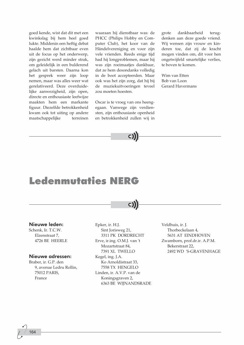
goed kende, wist dat dit met een
kwinkslag bij hem heel goed
lukte. Middenin een heftig debat
haalde hem dat zichtbaar even
uit de focus op het onderwerp,
zijn gezicht werd minder strak,
om geleidelijk in een bulderend
gelach uit barsten. Daarna kon
het gesprek weer zijn loop
nemen, maar was alles weer wat
gerelativeerd. Deze overduide-
lijke aanwezigheid, zijn open,
directe en enthousiaste leefwijze
maakten hem een markante
figuur. Diezelfde betrokkenheid
kwam ook tot uiting op andere
maatschappelijke terreinen
waaraan hij dienstbaar was: de
PHCC (Philips Hobby en Com-
puter Club), het koor van de
Händelvereniging en voor zijn
vele vrienden. Reeds enige tijd
had hij longproblemen, maar hij
was zijn roeimaatjes dankbaar,
dat ze hem desondanks volledig
in de boot accepteerden. Maar
ook was het zijn zorg, dat hij bij
de muziekuitvoeringen teveel
zou moeten hoesten.
Oscar is te vroeg van ons heeng-
egaan. Vanwege zijn verdien-
sten, zijn enthousiaste openheid
en betrokkenheid zullen wij in
grote dankbaarheid terug-
denken aan deze goede vriend.
Wij wensen zijn vrouw en kin-
deren toe, dat zij de kracht
mogen vinden om, dit voor hen
ongetwijfeld smartelijke verlies,
te boven te komen.
Wim van Etten
Bob van Loon
Gerard Havermans
164
Ledenmutaties NERG
Nieuwe leden:Schenk, Ir. T.C.W.
Elzenstraat 7,
4726 BE HEERLE
Nieuwe adressen:Braber, ir. G.P. den
9, avenue Ledru Rollin,
75012 PARIS,
France
Epker, ir. H.J.
Sint Jorisweg 21,
3311 PK DORDRECHT
Erve, ir.ing. O.M.J. van 't
Mozartstraat 84,
7391 XL TWELLO
Kegel, ing. J.A.
Ko Arnoldistraat 33,
7558 TX HENGELO
Linden, ir. A.V.P. van de
Koningsgraven 2,
6363 BE WIJNANDSRADE
Veldhuis, ir. J.
Thorbeckelaan 4,
5631 AT EINDHOVEN
Zwamborn, prof.dr.ir. A.P.M.
Bekerstraat 22,
2492 WD 'S-GRAVENHAGE
3rd European Workshop on
CONFORMAL ANTENNAS
Bonn, Germany October 22-23, 2003
The FGAN Research Institute for
High Frequency Physics and
Radar Techniques (FHR) close to
Bonn, Germany, is pleased to
host the 3rd European Workshop
on Conformal Antennas. The
Workshop is scheduled for
October 22-23, 2003. The number
of attendees will be limited to
approximately 150. The official
language of the Workshop will
be English and the following
topics will be addressed:
• Applications of conformal
antennas
• Mathematical models and
simulations
• Microstrip and waveguide
antennas
• Measurement techniques
• Conformal phased and
switched arrays
• Microwave and photonic
feeding techniques
• Pattern synthesis
• Direction finding and
adaptive conformal arrays
• Other topics concerning
conformal antennas
A guided tour of the facilities of
FGAN-FHR (http://www.fgan.de)
is scheduled for October 24, 2003.
Additional information will
become available at our website
or can be obtained via the confe-
rence secretary.
Information for AuthorsProspective authors are invited
to submit a 400 words abstract
with the name of the author, affi-
liation, address, phone number
and e-mail address to the Confe-
rence Secretary. Abstracts are
due June 2, 2003. August 4, 2003
acceptance notifications will be
mailed. Authors of accepted con-
tributions will be requested to
provide a full paper (4 pages) by
September 8, 2003 and give a pre-
sentation at the workshop. Early
registration is required for at
least one author. Electronic sub-
mission is strongly encouraged.
Important DatesJune 2, 2003:
400 word abstracts due
August 4, 2003:
Notifications mailed, Open-
ing of preregistration
September 8, 2003:
Full papers due
October 22-23, 2003:
Workshop
October 24, 2003:
Tour of FGAN-FHR
Workshop FeeThe workshop fee will be
approximately 120 Euro and will
include proceedings, lunch and
refreshments.
Bookmarkhttp://www.ewca-home.org
Tijdschrift van het NERG deel 67-nr.4-2002 165
Aankondigingen & Oproepen
Announcement and First Call For Papers

Conference Secretary:Harald Schneider
FGAN-FHR
Neuenahrer Str. 20
D-53343 Wachtberg-Werthhoven,
Germany
Telephone: +49-228-9435-214
Telefax: +49-228-9435-521
E-mail: [email protected]
Conference Chairman:Thomas Bertuch
FGAN-FHR
Neuenahrer Str. 20
D-53343 Wachtberg-Werthhoven,
Germany
Telephone: +49-228-9435-223
Telefax: +49-228-9435-521
E-mail: [email protected]
Conference Co-Chairman:Dr. Patrik Persson
Royal Institute of Technology Divi-
sion of Electromagnetic Theory
Teknikringen 31
SE-100 44 Stockholm, Sweden
Telephone: +46-8-790-83-69
Telefax: +46-8-24-54-31
E-mail: [email protected]
166