SIMOTICS reluctance motor and SINAMICS converter · 2020-02-19 · Synchronous reluctance motor...
34
siemens.com/simotics Internal© Siemens AG 2017 SIMOTICS reluctance motor and SINAMICS converter Status: 2018-04-05 – Botlek Studiegroep
Transcript of SIMOTICS reluctance motor and SINAMICS converter · 2020-02-19 · Synchronous reluctance motor...

Restricted © Siemens AG 2017
siemens.com/simoticsInternal© Siemens AG 2017
SIMOTICS reluctancemotor and SINAMICSconverterStatus: 2018-04-05 – Botlek Studiegroep
Restricted © Siemens AG 2017
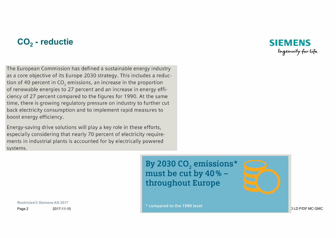
CO2 - reductie
2017-11-10 PD LD P/DF MC GMCPage 2
Restricted © Siemens AG 2017
Doorgaans wordt ca. 30 % van het totale energieverbruik vanNederland verbruikt door de Industrie, waarvan dan ca. 70% weer valttoe te schrijven aan de vermogensopname van elektromotoren.
Dat is dus een behoorlijke noemer om energie te besparen.
The challenge: Standards & legislationDrive systems use 70% of industrial power.Currently, there are standards and regulations that define the efficiency classes of DOL motors
Solution:Future definition of efficiency classes for converters and systems in the various standards and laterin the appropriate regulations
The challenge: Suppliers of electrically driven production machinesAccording to regulation EC 622/2012 (1W-2.5kW) circulating pumps must specify an energy efficiency index (EEI).The EEI is defined in the appropriate standards for additional pump types and power ratings.
Solution:Analysis of the energy usage transitions from just the pure product approach to electrically driven machines
Restricted © Siemens AG 2017
PROFIenergy
MinutePROFINET_ What is PROFIenergy_ (1).mp4
5282_Highlight_Profienergy_K2_EN_360p_450KBit.mp4
Restricted © Siemens AG 20172017-11-10 PD LD P/DF MC GMCPage 5
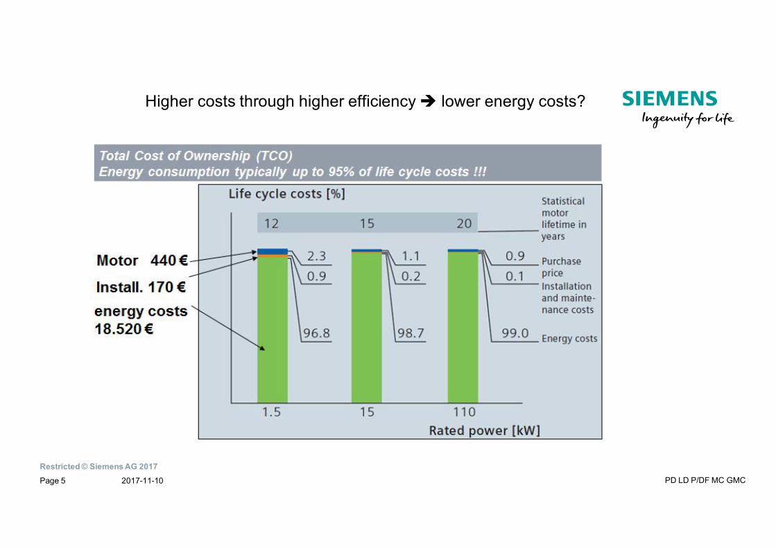
Higher costs through higher efficiency lower energy costs?
Restricted © Siemens AG 2017
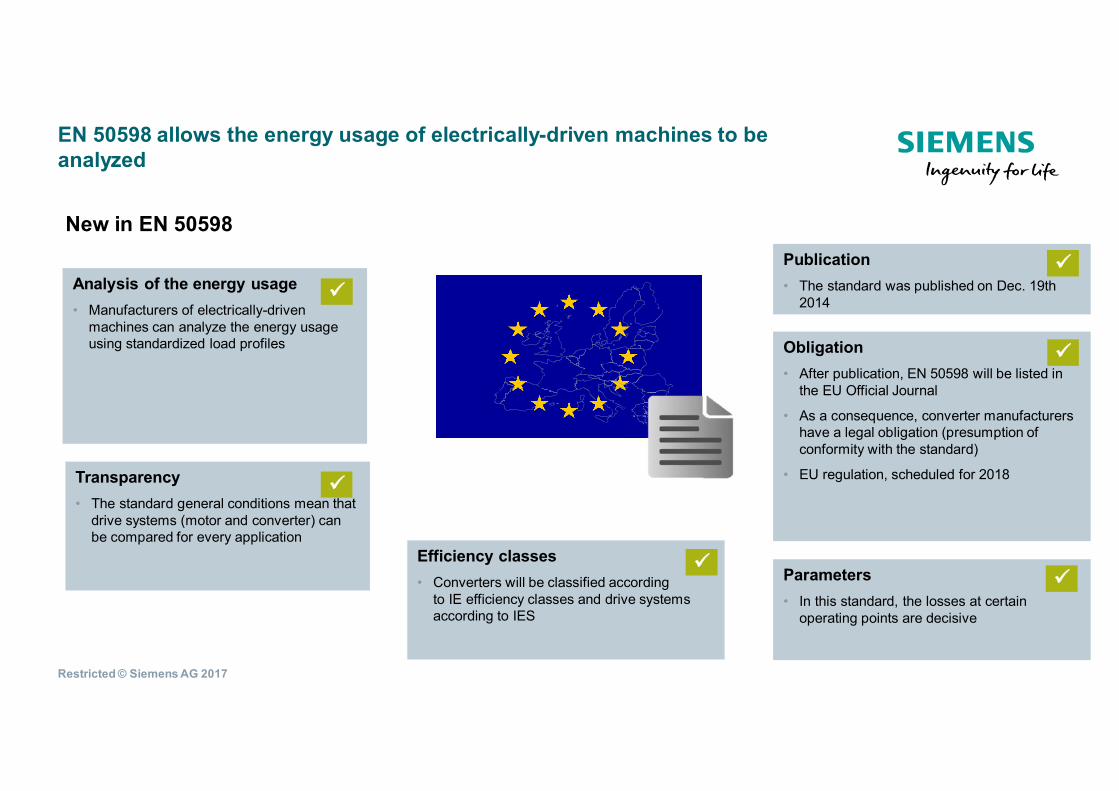
Obligation• After publication, EN 50598 will be listed in
the EU Official Journal
• As a consequence, converter manufacturershave a legal obligation (presumption ofconformity with the standard)
• EU regulation, scheduled for 2018Transparency• The standard general conditions mean that
drive systems (motor and converter) canbe compared for every application
EN 50598 allows the energy usage of electrically-driven machines to beanalyzed
New in EN 50598
Analysis of the energy usage• Manufacturers of electrically-driven
machines can analyze the energy usageusing standardized load profiles
Publication• The standard was published on Dec. 19th
2014
Efficiency classes• Converters will be classified according
to IE efficiency classes and drive systemsaccording to IES
Parameters• In this standard, the losses at certain
operating points are decisive
Restricted © Siemens AG 2017
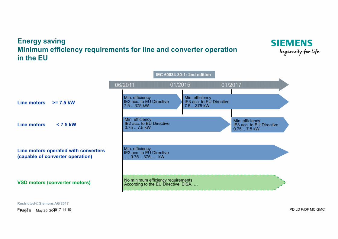
Min. efficiencyIE2 acc. to EU Directive…, 0.75 .. 375, … kW
Min. efficiencyIE2 acc. to EU Directive7.5 .. 375 kW
Min. efficiencyIE2 acc. to EU Directive0.75 .. 7.5 kW
No minimum efficiency requirementsAccording to the EU Directive, EISA, …
Energy savingMinimum efficiency requirements for line and converter operationin the EU
Min. efficiencyIE3 acc. to EU Directive7.5 .. 375 kW
06/2011 01/2015 01/2017
Min. efficiencyIE3 acc. to EU Directive0.75 .. 7.5 kW
Line motors >= 7.5 kW
Line motors operated with converters(capable of converter operation)
VSD motors (converter motors)
Line motors < 7.5 kW
IEC 60034-30-1: 2nd edition
Page 5 May 25, 2017Page 7 2017-11-10 PD LD P/DF MC GMC
Restricted © Siemens AG 2017
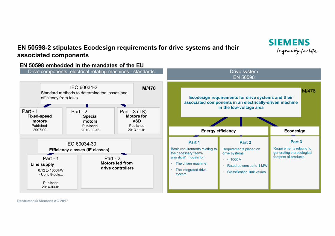
EN 50598-2 stipulates Ecodesign requirements for drive systems and theirassociated componentsEN 50598 embedded in the mandates of the EU
Drive components, electrical rotating machines - standards
M/476
Part - 3 (TS)Motors for
VSDPublished
2013-11-01
IEC 60034-2Standard methods to determine the losses andefficiency from tests
IEC 60034-30
Part - 1 Part - 2Line supply Motors fed from
drive controllers0.12 to 1000 kW- Up to 8-pole...
Published2014-03-01
M/470
Part - 1 Part - 2Fixed-speed
motorsPublished2007-09
SpecialmotorsPublished2010-03-16
Efficiency classes (IE classes)
Part 3Requirements relating togenerating the ecologicalfootprint of products.
Part 1Basic requirements relating tothe necessary "semi-analytical" models for
• The driven machine
• The integrated drivesystem
Ecodesign requirements for drive systems and theirassociated components in an electrically-driven machine
in the low-voltage area
Part 2Requirements placed ondrive systems:
• < 1000 V
• Rated powers up to 1 MW
• Classification limit values
Energy efficiency Ecodesign
Drive systemEN 50598
Restricted © Siemens AG 2017
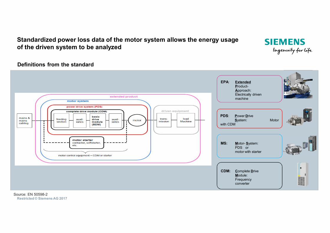
Definitions from the standard
Source: EN 50598-2
Standardized power loss data of the motor system allows the energy usageof the driven system to be analyzed
EPA: ExtendedProduct-Approach:Electrically drivenmachine
PDS: Power DriveSystem: Motor
with CDM
MS: Motor- System:PDS ormotor with starter
CDM: Complete DriveModule:Frequencyconverter
Restricted © Siemens AG 2017
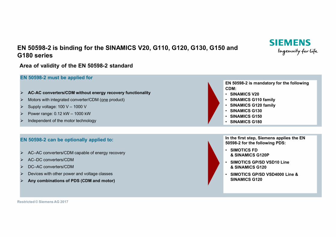
EN 50598-2 is binding for the SINAMICS V20, G110, G120, G130, G150 andG180 series
EN 50598-2 must be applied for
⋅ AC-AC converters/CDM without energy recovery functionality⋅ Motors with integrated converter/CDM (one product)⋅ Supply voltage: 100 V – 1000 V⋅ Power range: 0.12 kW – 1000 kW⋅ Independent of the motor technology
EN 50598-2 can be optionally applied to:
⋅ AC–AC converters/CDM capable of energy recovery⋅ AC–DC converters/CDM⋅ DC–AC converters/CDM⋅ Devices with other power and voltage classes⋅ Any combinations of PDS (CDM and motor)
Area of validity of the EN 50598-2 standard
EN 50598-2 is mandatory for the followingCDM:• SINAMICS V20• SINAMICS G110 family• SINAMICS G120 family• SINAMICS G130• SINAMICS G150• SINAMICS G180
In the first step, Siemens applies the EN50598-2 for the following PDS:• SIMOTICS FD
& SINAMICS G120P• SIMOTICS GP/SD VSD10 Line
& SINAMICS G120• SIMOTICS GP/SD VSD4000 Line &
SINAMICS G120
Restricted © Siemens AG 2017
Ecodesign
2017-11-10 PD LD P/DF MC GMCPage 11
De Europese normenserie EN 50598 definieert de Ecodesign voorwaarden vooraandrijfsystemen in een elektrisch aangedreven machine, inclusief energie-efficiëntie en levenscyclusanalyse. De basis voor het vaststellen enoptimaliseren van de efficiëntie van elektrisch aangedreven machines werdengemaakt met het gezamenlijke concept opgesteld door drivefabrikanten enmachinebouwers.
Restricted © Siemens AG 2017
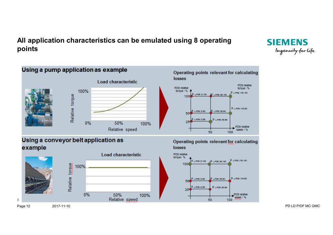
All application characteristics can be emulated using 8 operatingpoints
2017-11-10 PD LD P/DF MC GMCPage 12
Restricted © Siemens AG 2017
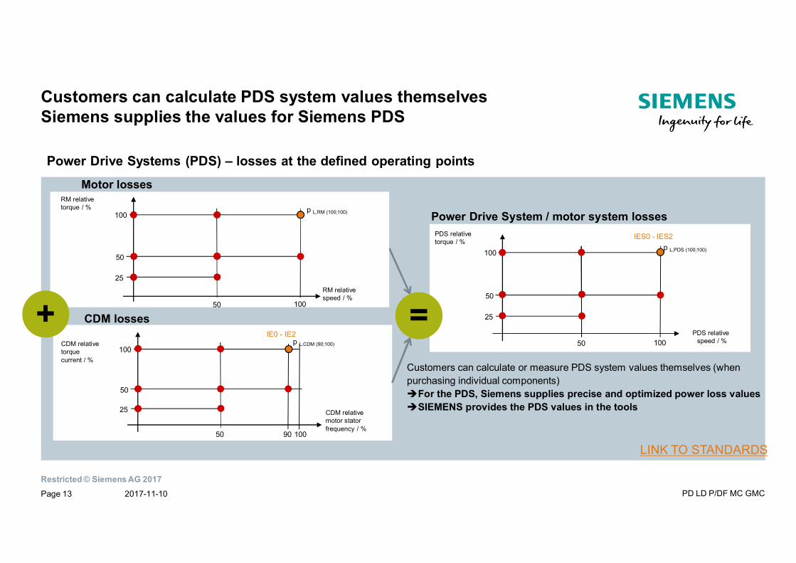
Customers can calculate PDS system values themselvesSiemens supplies the values for Siemens PDS
CDM lossesIE0 - IE2
CDM relativetorquecurrent / %
CDM relativemotor statorfrequency / %
100
25
50
50 100
p L,CDM (90;100)
90
Motor lossesRM relativetorque / %
RM relativespeed / %
100
25
50
50 100
p L,RM (100;100)
IES0 - IES2
Power Drive System / motor system lossesPDS relativetorque / %
PDS relativespeed / %
100
25
50
50 100
p L,PDS (100;100)
+ =Customers can calculate or measure PDS system values themselves (whenpurchasing individual components)For the PDS, Siemens supplies precise and optimized power loss valuesSIEMENS provides the PDS values in the tools
Power Drive Systems (PDS) – losses at the defined operating points
LINK TO STANDARDS
2017-11-10 PD LD P/DF MC GMCPage 13
Restricted © Siemens AG 2017
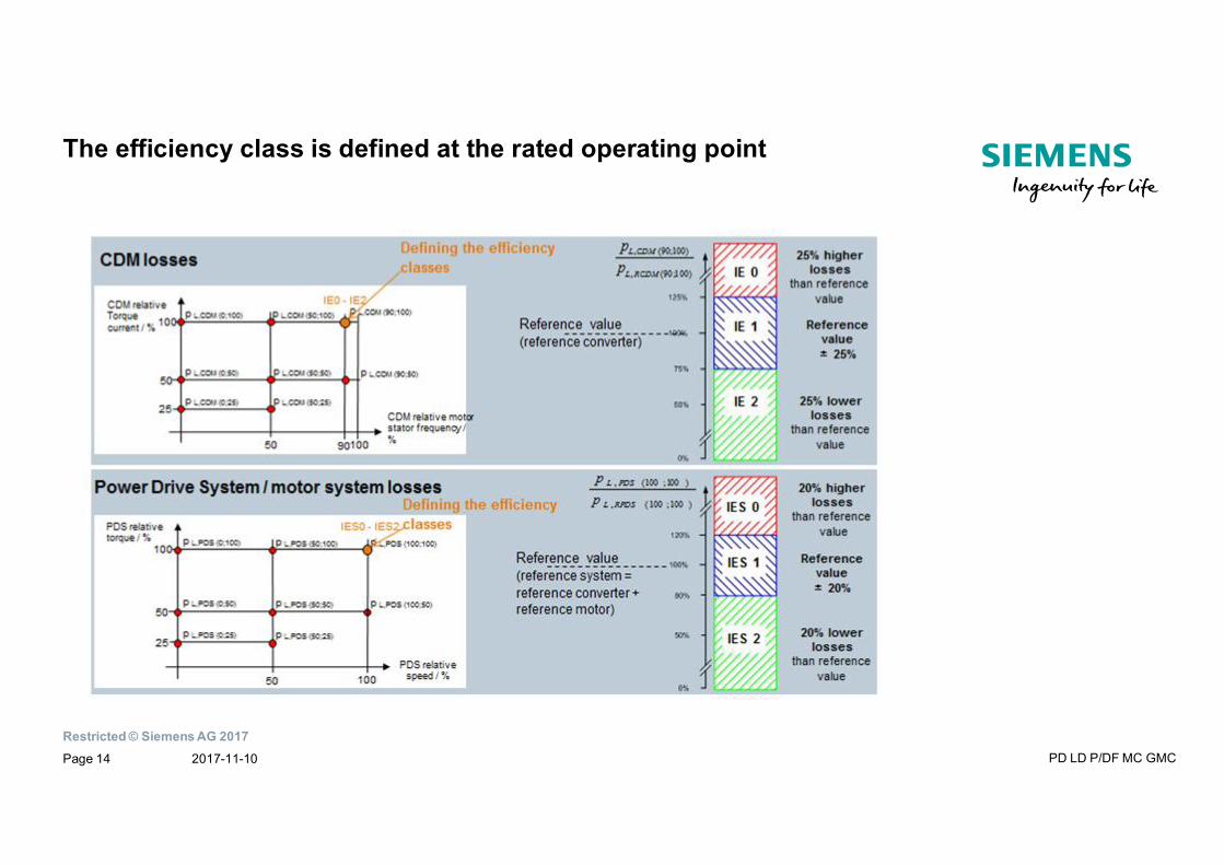
The efficiency class is defined at the rated operating point
2017-11-10 PD LD P/DF MC GMCPage 14
Restricted © Siemens AG 2017
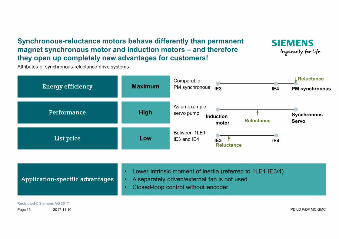
Synchronous-reluctance motors behave differently than permanentmagnet synchronous motor and induction motors – and thereforethey open up completely new advantages for customers!
Energy efficiency
Performance
List price
Application-specific advantages
Attributes of synchronous-reluctance drive systems
Maximum
High
Low
• Lower intrinsic moment of inertia (referred to 1LE1 IE3/4)• A separately driven/external fan is not used• Closed-loop control without encoder
As an exampleservo pump Induction
motorSynchronousServoReluctance
IE3 IE4Reluctance
IE3 IE4
Reluctance
PM synchronousComparablePM synchronous
Between 1LE1IE3 and IE4
2017-11-10 PD LD P/DF MC GMCPage 15
Restricted © Siemens AG 2017
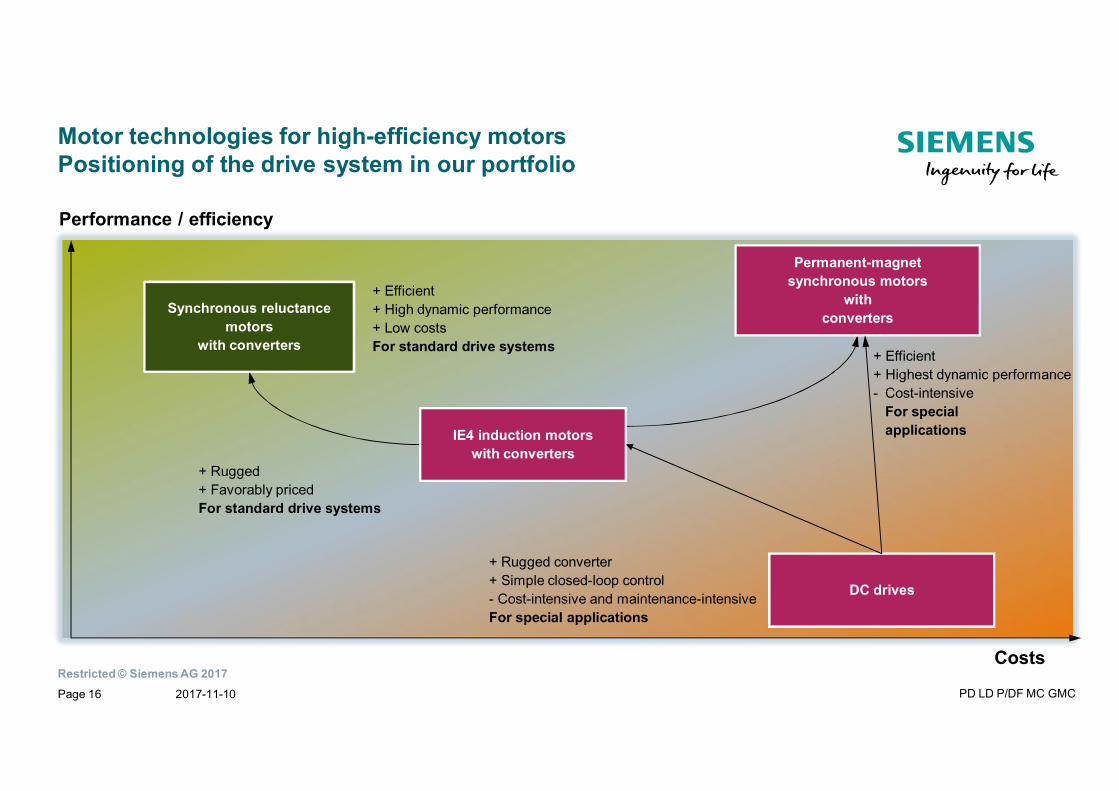
Motor technologies for high-efficiency motorsPositioning of the drive system in our portfolio
Costs
Performance / efficiency
DC drives
IE4 induction motorswith converters
Permanent-magnetsynchronous motors
withconverters
Synchronous reluctancemotors
with converters+ Efficient+ Highest dynamic performance- Cost-intensive
For specialapplications
+ Efficient+ High dynamic performance+ Low costsFor standard drive systems
+ Rugged+ Favorably pricedFor standard drive systems
+ Rugged converter+ Simple closed-loop control- Cost-intensive and maintenance-intensiveFor special applications
2017-11-10 PD LD P/DF MC GMCPage 16
Restricted © Siemens AG 2017
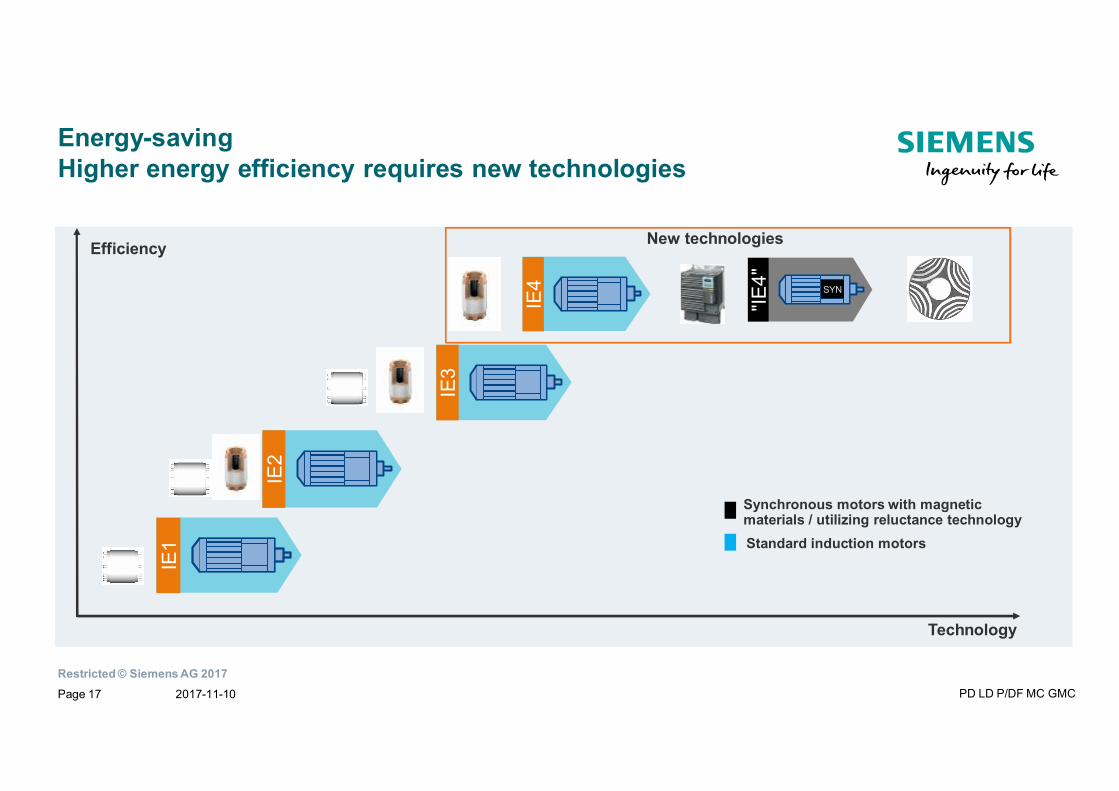
Energy-savingHigher energy efficiency requires new technologies
IE2
IE3
IE1
Efficiency
Technology
Standard induction motors
Synchronous motors with magneticmaterials / utilizing reluctance technology
"IE4"
SYN
IE4
New technologies
2017-11-10 PD LD P/DF MC GMCPage 17
Restricted © Siemens AG 2017
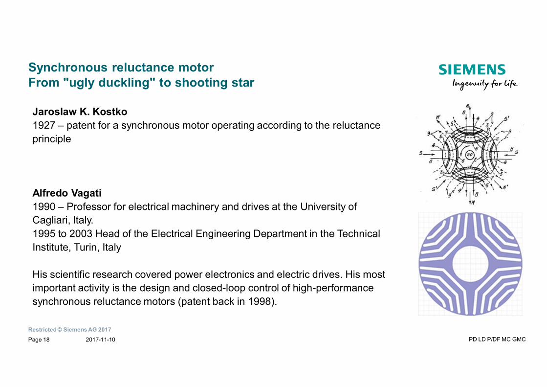
Synchronous reluctance motorFrom "ugly duckling" to shooting star
Jaroslaw K. Kostko1927 – patent for a synchronous motor operating according to the reluctanceprinciple
Alfredo Vagati1990 – Professor for electrical machinery and drives at the University ofCagliari, Italy.1995 to 2003 Head of the Electrical Engineering Department in the TechnicalInstitute, Turin, Italy
His scientific research covered power electronics and electric drives. His mostimportant activity is the design and closed-loop control of high-performancesynchronous reluctance motors (patent back in 1998).
2017-11-10 PD LD P/DF MC GMCPage 18
Restricted © Siemens AG 2017
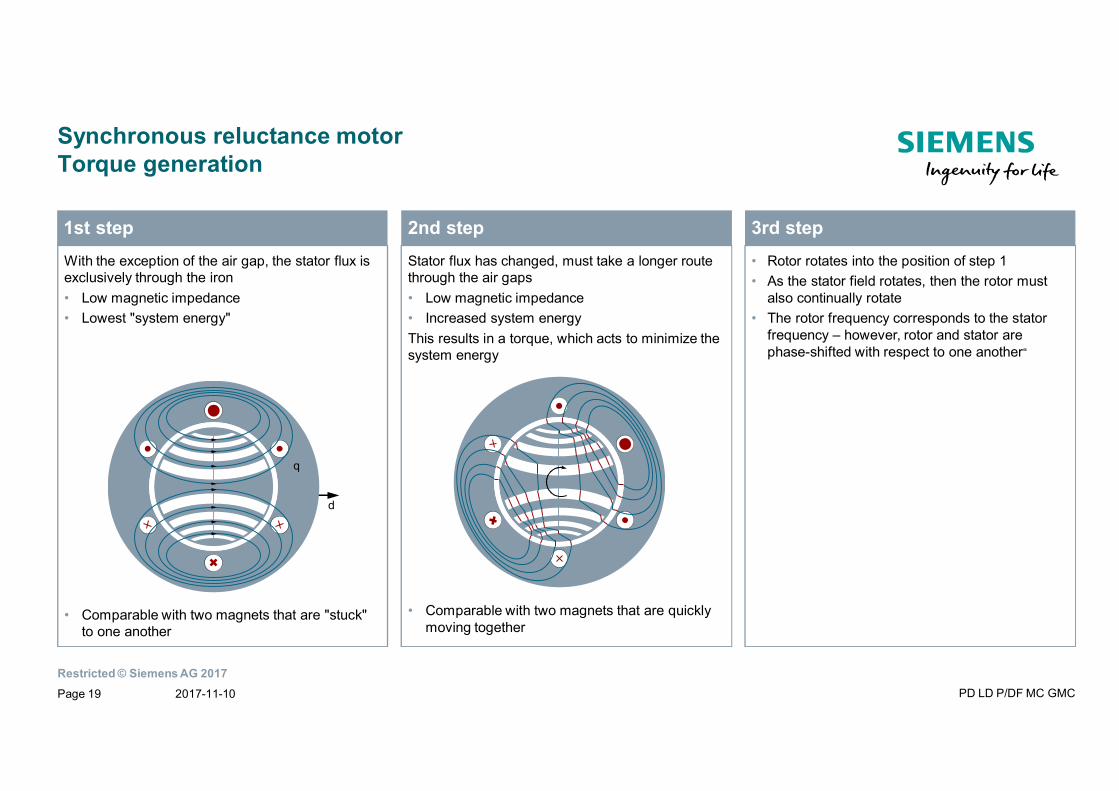
Synchronous reluctance motorTorque generation
With the exception of the air gap, the stator flux isexclusively through the iron• Low magnetic impedance• Lowest "system energy"
• Comparable with two magnets that are "stuck"to one another
1st stepStator flux has changed, must take a longer routethrough the air gaps• Low magnetic impedance• Increased system energyThis results in a torque, which acts to minimize thesystem energy
• Comparable with two magnets that are quicklymoving together
2nd step• Rotor rotates into the position of step 1• As the stator field rotates, then the rotor must
also continually rotate• The rotor frequency corresponds to the stator
frequency – however, rotor and stator arephase-shifted with respect to one another“
3rd step
d
q
2017-11-10 PD LD P/DF MC GMCPage 19
Restricted © Siemens AG 2017
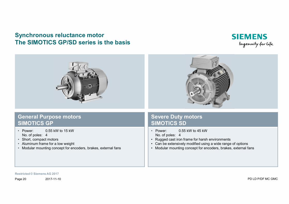
Synchronous reluctance motorThe SIMOTICS GP/SD series is the basis
General Purpose motorsSIMOTICS GP• Power: 0.55 kW to 15 kW
No. of poles: 4• Short, compact motors• Aluminum frame for a low weight• Modular mounting concept for encoders, brakes, external fans
Severe Duty motorsSIMOTICS SD• Power: 0.55 kW to 45 kW
No. of poles: 4• Rugged cast iron frame for harsh environments• Can be extensively modified using a wide range of options• Modular mounting concept for encoders, brakes, external fans
2017-11-10 PD LD P/DF MC GMCPage 20
Restricted © Siemens AG 2017
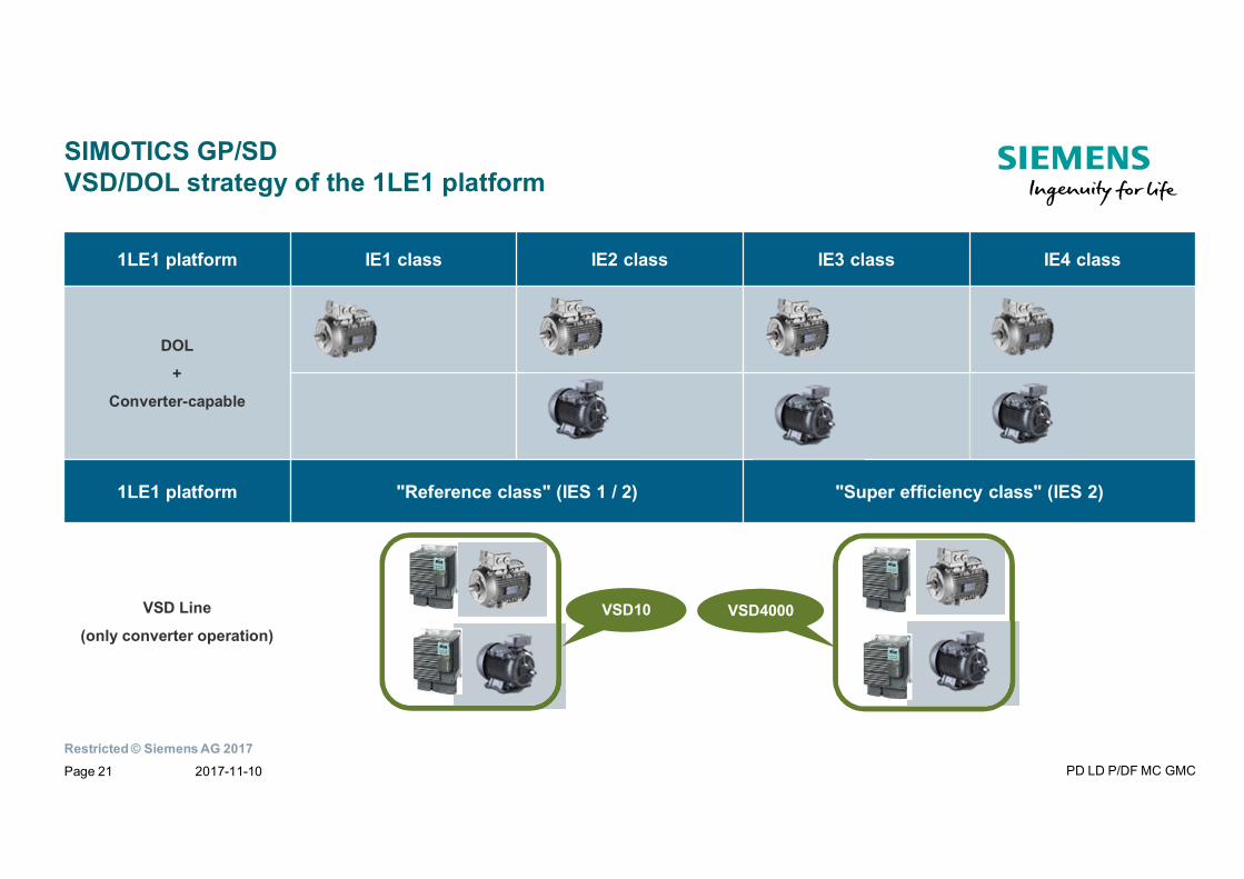
SIMOTICS GP/SDVSD/DOL strategy of the 1LE1 platform
1LE1 platform IE1 class IE2 class IE3 class IE4 class
DOL
+
Converter-capable
1LE1 platform "Reference class" (IES 1 / 2) "Super efficiency class" (IES 2)
VSD Line
(only converter operation)VSD10 VSD4000
2017-11-10 PD LD P/DF MC GMCPage 21
Restricted © Siemens AG 2017
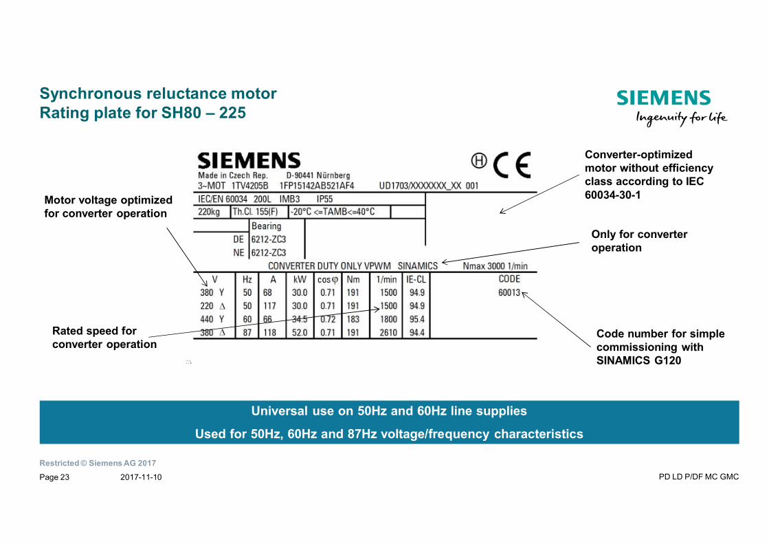
Synchronous reluctance motorRating plate for SH80 – 225
Rated speed forconverter operation
Motor voltage optimizedfor converter operation
Code number for simplecommissioning withSINAMICS G120
Only for converteroperation
Converter-optimizedmotor without efficiencyclass according to IEC60034-30-1
Universal use on 50Hz and 60Hz line supplies
Used for 50Hz, 60Hz and 87Hz voltage/frequency characteristics
2017-11-10 PD LD P/DF MC GMCPage 23
Restricted © Siemens AG 2017
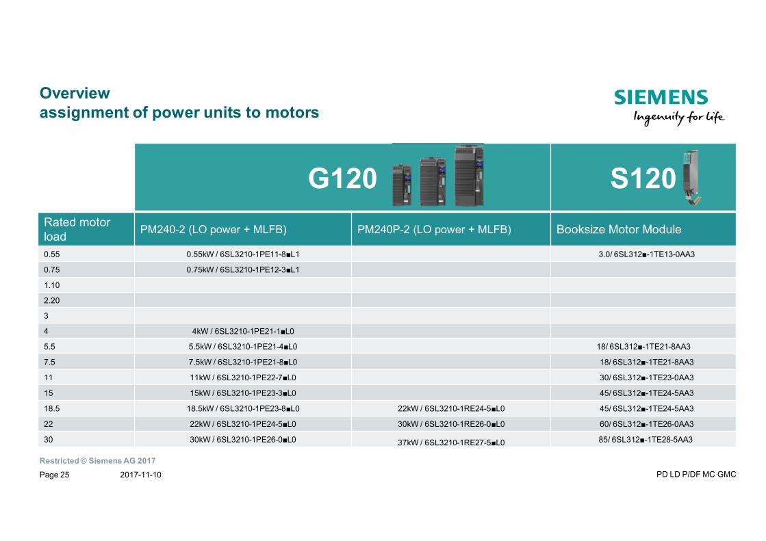
Overviewassignment of power units to motors
G120 S120Rated motorload PM240-2 (LO power + MLFB) PM240P-2 (LO power + MLFB) Booksize Motor Module
0.55 0.55kW / 6SL3210-1PE11-8■L1 3.0/ 6SL312■-1TE13-0AA3
0.75 0.75kW / 6SL3210-1PE12-3■L1
1.10
2.20
3
4 4kW / 6SL3210-1PE21-1■L0
5.5 5.5kW / 6SL3210-1PE21-4■L0 18/ 6SL312■-1TE21-8AA3
7.5 7.5kW / 6SL3210-1PE21-8■L0 18/ 6SL312■-1TE21-8AA3
11 11kW / 6SL3210-1PE22-7■L0 30/ 6SL312■-1TE23-0AA3
15 15kW / 6SL3210-1PE23-3■L0 45/ 6SL312■-1TE24-5AA3
18.5 18.5kW / 6SL3210-1PE23-8■L0 22kW / 6SL3210-1RE24-5■L0 45/ 6SL312■-1TE24-5AA3
22 22kW / 6SL3210-1PE24-5■L0 30kW / 6SL3210-1RE26-0■L0 60/ 6SL312■-1TE26-0AA3
30 30kW / 6SL3210-1PE26-0■L0 37kW / 6SL3210-1RE27-5■L0 85/ 6SL312■-1TE28-5AA3
2017-11-10 PD LD P/DF MC GMCPage 25
Restricted © Siemens AG 2017
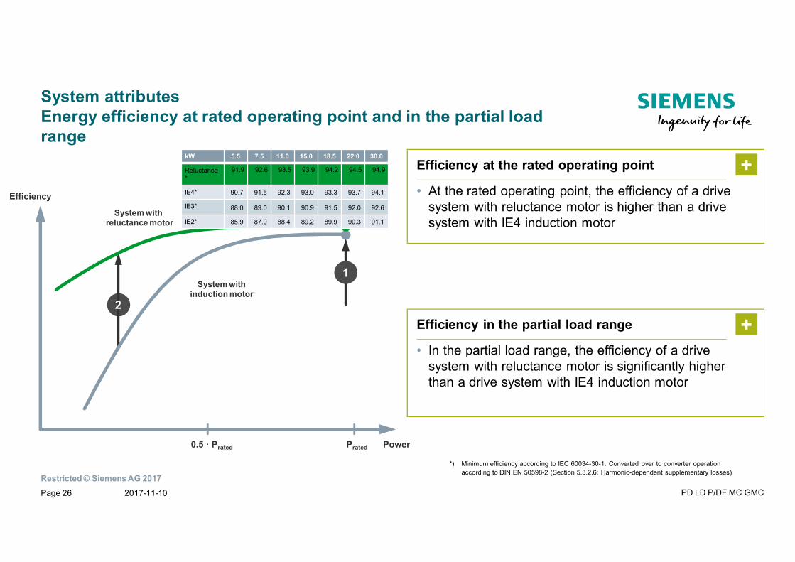
System attributesEnergy efficiency at rated operating point and in the partial loadrange
Efficiency in the partial load range
• In the partial load range, the efficiency of a drivesystem with reluctance motor is significantly higherthan a drive system with IE4 induction motor
+
1
2
System withinduction motor
System withreluctance motor
Efficiency
Prated Power0.5 · Prated
*) Minimum efficiency according to IEC 60034-30-1. Converted over to converter operationaccording to DIN EN 50598-2 (Section 5.3.2.6: Harmonic-dependent supplementary losses)
Efficiency at the rated operating point
• At the rated operating point, the efficiency of a drivesystem with reluctance motor is higher than a drivesystem with IE4 induction motor
+kW 5.5 7.5 11.0 15.0 18.5 22.0 30.0
Reluctance*
91.9 92.6 93.5 93.9 94.2 94.5 94.9
IE4* 90.7 91.5 92.3 93.0 93.3 93.7 94.1
IE3* 88.0 89.0 90.1 90.9 91.5 92.0 92.6
IE2* 85.9 87.0 88.4 89.2 89.9 90.3 91.1
2017-11-10 PD LD P/DF MC GMCPage 26
Restricted © Siemens AG 2017
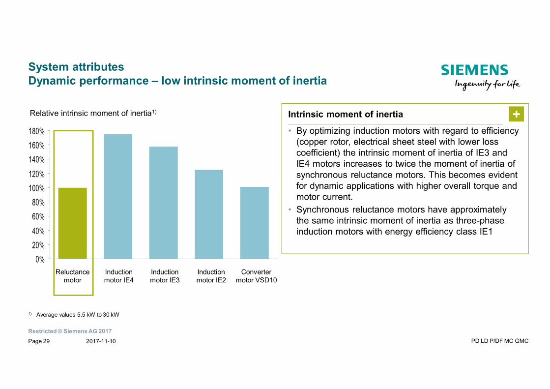
System attributesDynamic performance – low intrinsic moment of inertia
0%20%40%60%80%
100%120%140%160%180%
Inductionmotor IE4
Inductionmotor IE3
Reluctancemotor
Convertermotor VSD10
Inductionmotor IE2
Relative intrinsic moment of inertia1) Intrinsic moment of inertia
• By optimizing induction motors with regard to efficiency(copper rotor, electrical sheet steel with lower losscoefficient) the intrinsic moment of inertia of IE3 andIE4 motors increases to twice the moment of inertia ofsynchronous reluctance motors. This becomes evidentfor dynamic applications with higher overall torque andmotor current.
• Synchronous reluctance motors have approximatelythe same intrinsic moment of inertia as three-phaseinduction motors with energy efficiency class IE1
+
1) Average values 5.5 kW to 30 kW
2017-11-10 PD LD P/DF MC GMCPage 29
Restricted © Siemens AG 2017
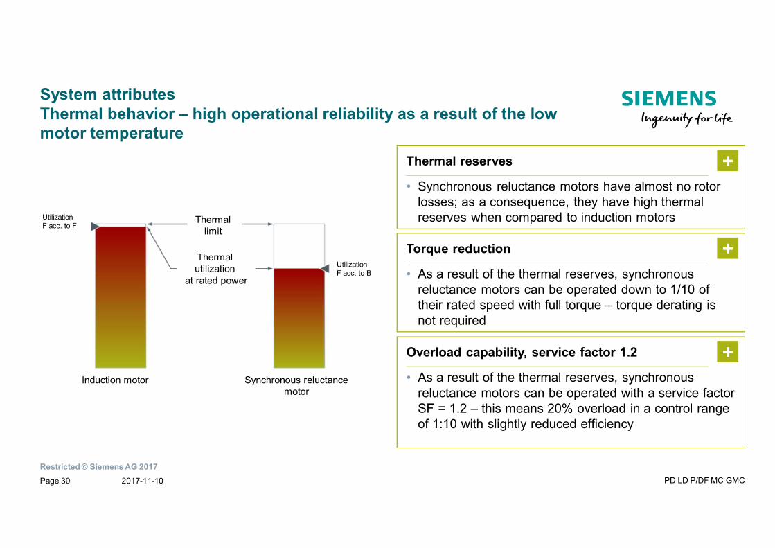
System attributesThermal behavior – high operational reliability as a result of the lowmotor temperature
Thermal reserves
• Synchronous reluctance motors have almost no rotorlosses; as a consequence, they have high thermalreserves when compared to induction motors
+
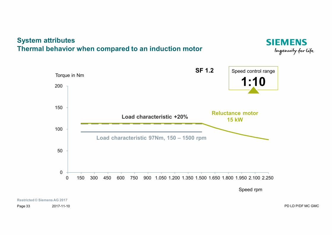
Torque reduction
• As a result of the thermal reserves, synchronousreluctance motors can be operated down to 1/10 oftheir rated speed with full torque – torque derating isnot required
+
Overload capability, service factor 1.2
• As a result of the thermal reserves, synchronousreluctance motors can be operated with a service factorSF = 1.2 – this means 20% overload in a control rangeof 1:10 with slightly reduced efficiency
+
UtilizationF acc. to F
Thermallimit
Thermalutilization
at rated power
UtilizationF acc. to B
Induction motor Synchronous reluctancemotor
2017-11-10 PD LD P/DF MC GMCPage 30
Restricted © Siemens AG 2017
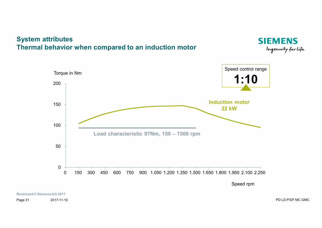
System attributesThermal behavior when compared to an induction motor
Torque in Nm
Induction motor22 kW
Speed control range
1:10
0
50
100
150
200
0 150 300 450 600 750 900 1.050 1.200 1.350 1.500 1.650 1.800 1.950 2.100 2.250
Load characteristic 97Nm, 150 – 1500 rpm
Speed rpm
2017-11-10 PD LD P/DF MC GMCPage 31
Restricted © Siemens AG 2017
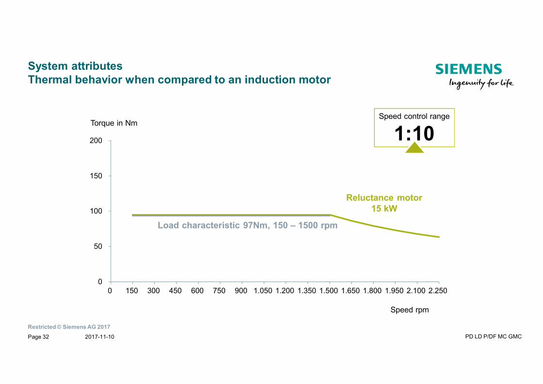
System attributesThermal behavior when compared to an induction motor
Torque in Nm
Reluctance motor15 kW
Speed control range
1:10
0
50
100
150
200
0 150 300 450 600 750 900 1.050 1.200 1.350 1.500 1.650 1.800 1.950 2.100 2.250
Load characteristic 97Nm, 150 – 1500 rpm
Speed rpm
2017-11-10 PD LD P/DF MC GMCPage 32
Restricted © Siemens AG 2017
System attributesThermal behavior when compared to an induction motor
Torque in Nm
Reluctance motor15 kW
Speed control range
1:10
Speed rpm
Load characteristic +20%
0
50
100
150
200
0 150 300 450 600 750 900 1.050 1.200 1.350 1.500 1.650 1.800 1.950 2.100 2.250
Load characteristic 97Nm, 150 – 1500 rpm
SF 1.2
2017-11-10 PD LD P/DF MC GMCPage 33
Restricted © Siemens AG 2017
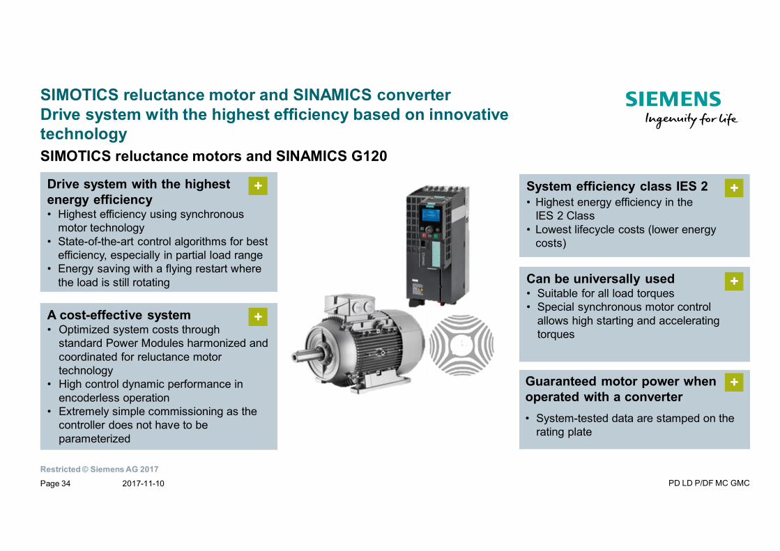
SIMOTICS reluctance motor and SINAMICS converterDrive system with the highest efficiency based on innovativetechnology
A cost-effective system• Optimized system costs through
standard Power Modules harmonized andcoordinated for reluctance motortechnology
• High control dynamic performance inencoderless operation
• Extremely simple commissioning as thecontroller does not have to beparameterized
+
Can be universally used• Suitable for all load torques• Special synchronous motor control
allows high starting and acceleratingtorques
+
Drive system with the highestenergy efficiency• Highest efficiency using synchronous
motor technology• State-of-the-art control algorithms for best
efficiency, especially in partial load range• Energy saving with a flying restart where
the load is still rotating
+ System efficiency class IES 2• Highest energy efficiency in the
IES 2 Class• Lowest lifecycle costs (lower energy
costs)
+
+Guaranteed motor power whenoperated with a converter• System-tested data are stamped on the
rating plate
SIMOTICS reluctance motors and SINAMICS G120
2017-11-10 PD LD P/DF MC GMCPage 34
Restricted © Siemens AG 2017
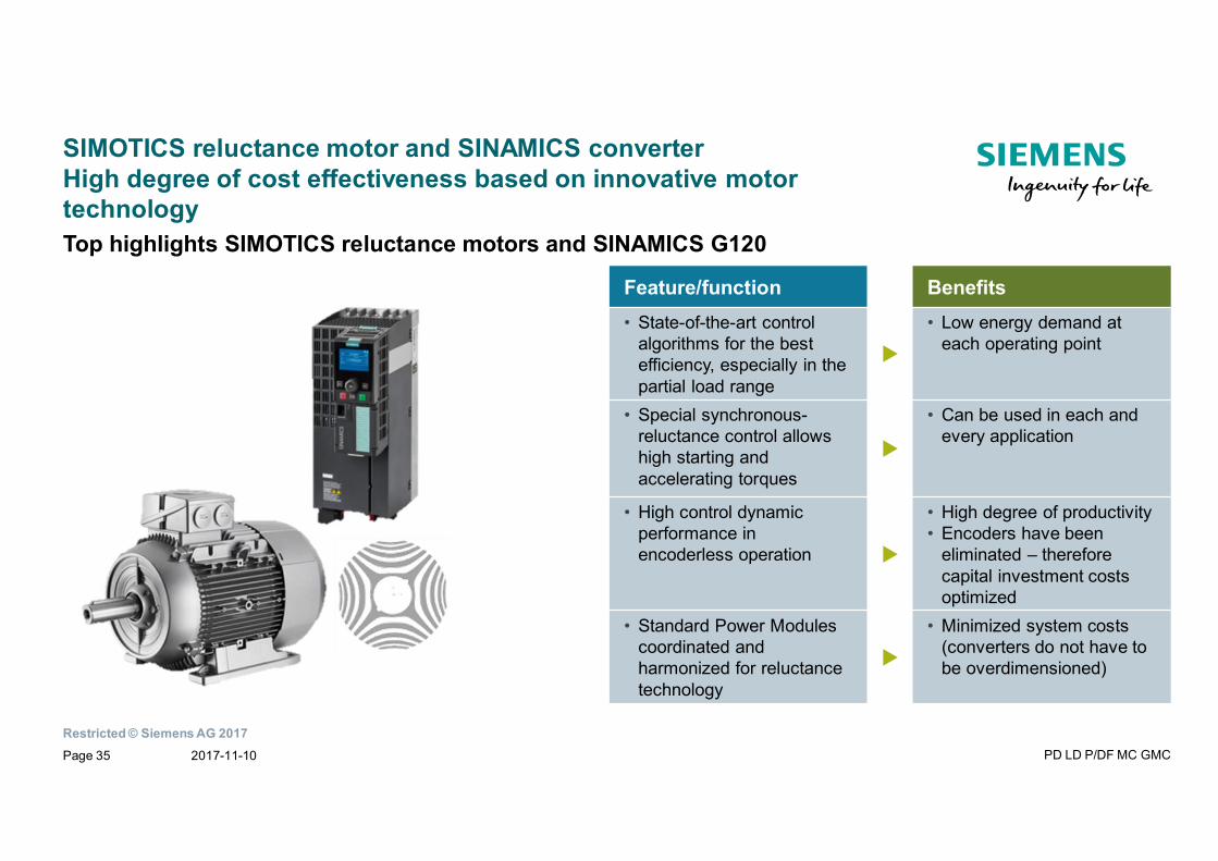
SIMOTICS reluctance motor and SINAMICS converterHigh degree of cost effectiveness based on innovative motortechnology
Feature/function Benefits• State-of-the-art control
algorithms for the bestefficiency, especially in thepartial load range
τ
• Low energy demand ateach operating point
• Special synchronous-reluctance control allowshigh starting andaccelerating torques
τ
• Can be used in each andevery application
• High control dynamicperformance inencoderless operation τ
• High degree of productivity• Encoders have been
eliminated – thereforecapital investment costsoptimized
• Standard Power Modulescoordinated andharmonized for reluctancetechnology
τ
• Minimized system costs(converters do not have tobe overdimensioned)
Top highlights SIMOTICS reluctance motors and SINAMICS G120
2017-11-10 PD LD P/DF MC GMCPage 35
Restricted © Siemens AG 2017
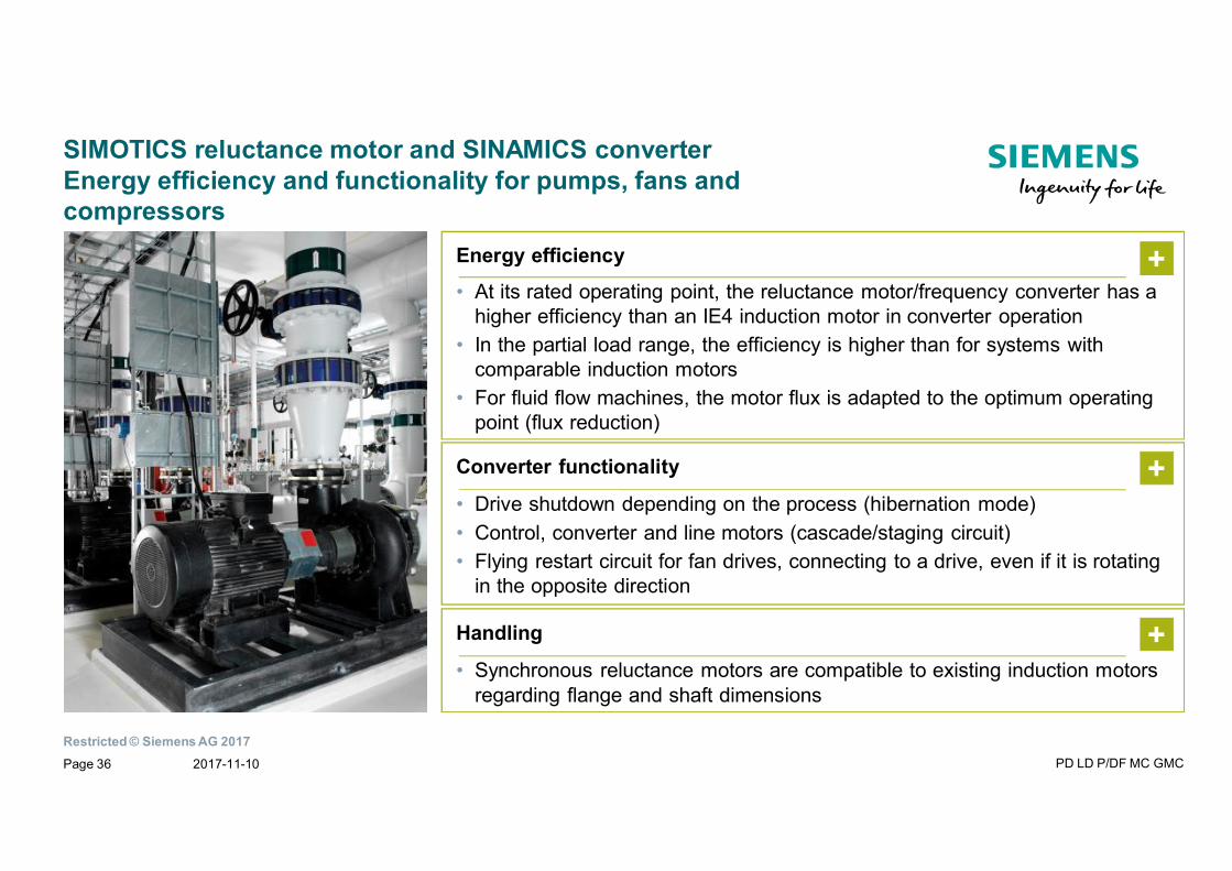
SIMOTICS reluctance motor and SINAMICS converterEnergy efficiency and functionality for pumps, fans andcompressors
Energy efficiency
• At its rated operating point, the reluctance motor/frequency converter has ahigher efficiency than an IE4 induction motor in converter operation
• In the partial load range, the efficiency is higher than for systems withcomparable induction motors
• For fluid flow machines, the motor flux is adapted to the optimum operatingpoint (flux reduction)
+
Converter functionality
• Drive shutdown depending on the process (hibernation mode)• Control, converter and line motors (cascade/staging circuit)• Flying restart circuit for fan drives, connecting to a drive, even if it is rotating
in the opposite direction
+
Handling
• Synchronous reluctance motors are compatible to existing induction motorsregarding flange and shaft dimensions
+
2017-11-10 PD LD P/DF MC GMCPage 36
Restricted © Siemens AG 2017
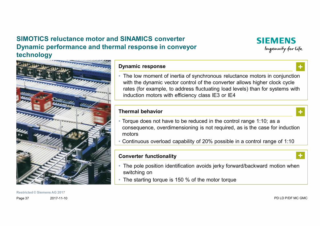
SIMOTICS reluctance motor and SINAMICS converterDynamic performance and thermal response in conveyortechnology
Converter functionality
• The pole position identification avoids jerky forward/backward motion whenswitching on
• The starting torque is 150 % of the motor torque
+
Dynamic response
• The low moment of inertia of synchronous reluctance motors in conjunctionwith the dynamic vector control of the converter allows higher clock cyclerates (for example, to address fluctuating load levels) than for systems withinduction motors with efficiency class IE3 or IE4
+
Thermal behavior
• Torque does not have to be reduced in the control range 1:10; as aconsequence, overdimensioning is not required, as is the case for inductionmotors
• Continuous overload capability of 20% possible in a control range of 1:10
+
2017-11-10 PD LD P/DF MC GMCPage 37
Restricted © Siemens AG 2017
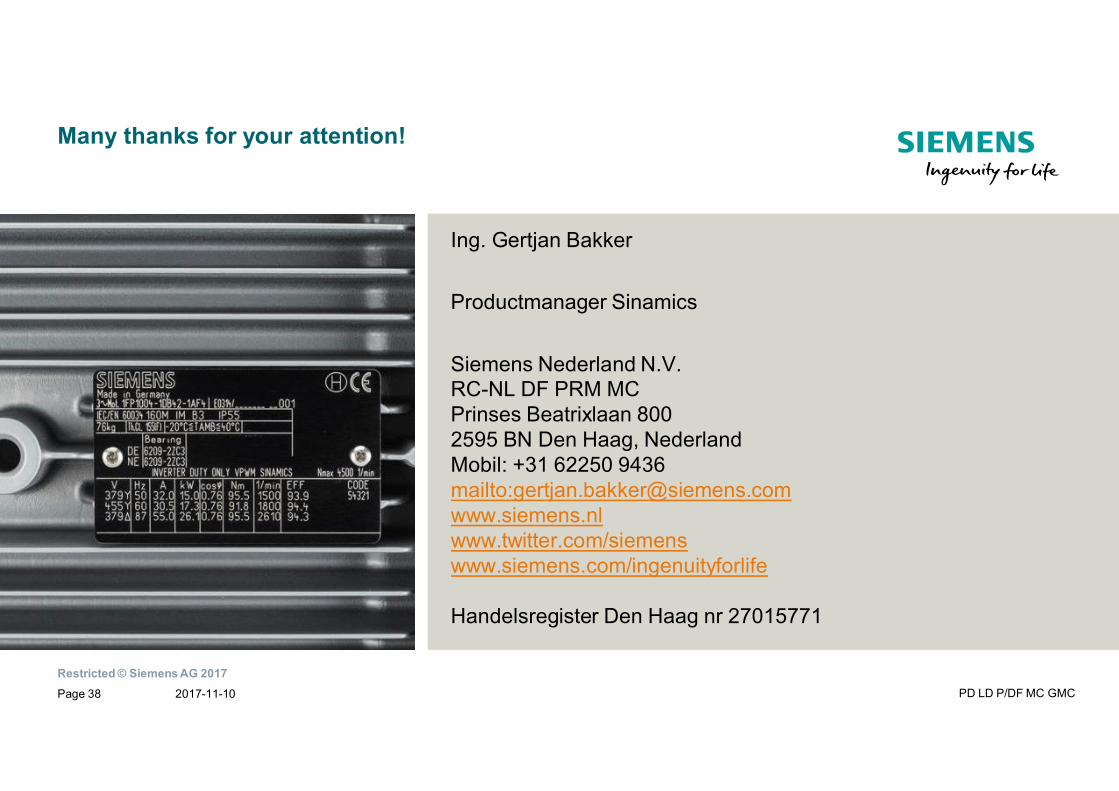
Ing. Gertjan Bakker
Productmanager Sinamics
Siemens Nederland N.V.RC-NL DF PRM MCPrinses Beatrixlaan 8002595 BN Den Haag, NederlandMobil: +31 62250 9436mailto:[email protected]/siemenswww.siemens.com/ingenuityforlife
Handelsregister Den Haag nr 27015771
Many thanks for your attention!
2017-11-10 PD LD P/DF MC GMCPage 38