REAL-TIME VIDEO MIXER
89
REAL-TIME VIDEO MIXER A Degree's Thesis Submitted to the Faculty of the Escola Tècnica Superior d'Enginyeria de Telecomunicació de Barcelona Universitat Politècnica de Catalunya by Marc Palau Erena In partial fulfilment of the requirements for the degree in AUDIOVISUAL SYSTEMS ENGINEERING Advisors: David Cassany (i2CAT) Josep Ramon Casas (UPC) Barcelona, February 2014
Transcript of REAL-TIME VIDEO MIXER
REAL-TIME VIDEO MIXER
A Degree's Thesis
Submitted to the Faculty of the
Escola Tècnica Superior d'Enginyeria de
Telecomunicació de Barcelona
Universitat Politècnica de Catalunya
by
Marc Palau Erena
In partial fulfilment
of the requirements for the degree in
AUDIOVISUAL SYSTEMS ENGINEERING
Advisors:
David Cassany (i2CAT)
Josep Ramon Casas (UPC)
Barcelona, February 2014

2
Abstract
The aim of this project is to develop a software real-time video production tool capable of mixing and switching video signals received via RTP, compressed with standard H264. Traditional production systems are based on non scalable hardware with high costs that can become unaffordable and require dedicated inflexible infrastructure. The solution presented is intended as a software version of traditional production elements, such as switching matrices and video mixers, increasing flexibility, decreasing costs and offering scalability. The developed product is able to manage different compressed input video streams (decompressing, resizing and locating them in a certain position) and to compress and send via RTP the resulting video. Real-time feature demands focusing on performance and minimizing delays, specially for video-conferencing, so the process needs to be optimized in terms of stream compression, decompression and scaling, the main bottlenecks. Moreover, real-time management is mandatory, so it has been necessary to develop an event handler system and a RESTful API in order to achieve this. Performance tests have been done in order to measure some important parameters, such as introduced delay by the system and average frame rate achieved. For example, receiving four 720p streams at 24 fps and composing them as a 2x2 grid on a FULL HD layout, video mixer can achieve an average delay of 108 ms and 24 fps.
3
Resum
L'objectiu d'aquest projecte és desenvolupar una eina software de realització de video en temps real, capaç de realitzar mixing de diferents senyals de video rebuts via RTP i comprimits en format H264 estàndard. Els sistemes de realització tradicionals estan basats en hardware no escalable, amb costos molt alts, i necessiten una infrastructura dedicada i poc flexible. La solució presentada pretén ser una versió software dels elements de realització tradicionals, com els matrius de commutació i els mescladors de video, augmentant la flexibilitat, disminuint els costos i oferint escalabilitat. El producte desenvolupat és capaç de gestionar diferents fluxos de video d'entrada (descomprimint-los, escalant-los i colocant-los en una posició determinada) i de comprimir i enviar via
reix dedicar especial atenció en el rendiment del sistema, així com en minimitzar els diferents retards introduits pel mateix. És per això que és necessari optimitzar els processos de compressió, descompressió i escalat, els principals colls d'ampolla. A més a més, la gestió del mixer en temps real és imprescindible, cosa que ha fet necessari desenvolupar un gestor d'events i una API RESTful per aconseguir-ho. S'han realitzat també tests de rendiment per mesurar alguns paràmetres importants, com per exemple el retard introduït pel sistema i el framerate mitjà aconseguit. Per exemple, rebent quatre streams 720p a 24 fps i composant-los en una quadrícula de 2x2 en un video FULL HD, el mixer pot aconseguir un retard mitjà de 108 ms i un framerate mitjà de 24 fps.
4
Resumen
El objectivo de este proyecto es desarrollar una herramienta software de realización de video en tiempo real, capaz de realitzar mixing de diferentes senyales de video recibidos via RTP y comprimidos en format H264 estandard. Los sistemes de realización tradicionales estan basados en hardware no escalable, con costes muy altos, y necesitan una infrastractura dedicada y poco flexible. La solución presentada pretende ser una versión software de les elementos de realización tradicional, como las matrices de commutación i los mezcladores de video, aumentado la flexibilidad, disminuyendo los costes y ofreciendo escalabilidad. El producto desarrollado és capaz de gestionar diferentes flujos de video de entrada (descomprimiendolos, escalandolos i colocandolos en una posición determinada) y de comprimir y enviar via RTP el video resultante. El hecho de realizar todo este proceso en tiempo real requiere dedicar especial atención en el rendimiento del sistema, así com en minimizar los diferentes retardos introducidos por el mismo. Es por eso que es necesario optimizar los procesos de compresión, descompresión i escalado, los principals cuellos de botella. Además, la gestión del mixer en tiempo real es imprescindible, cosa que ha hecho necesario desarrollar un gestor de eventos y una API RESTful para conseguirlo. Se han realizado también tests de rendimiento para mesurar algunos parámetros importantes, como por ejemplo el retardo introducido por el sistema i el framerate medio conseguido. Por ejemplo, recibiendo cuatro streams 720p a 24 fps y componiendolos en una cuadrícula de 2x2 en un video FULL HD, el mixer puede conseguir un retardo medio de 108 ms y un framerate medio de 24 fps.

5
Acknowledgements
I would like to thank all the people that made this work possible. The whole i2CAT
Audiovisual Unit, for giving me the opportunity to do this project, specially to David
Cassany, for giving me advice every time I needed, for helping me organizing all the work
and for orienting me through all the concepts. I would like to thank Josep Ramon Casas
for being the advisor for my project.
6
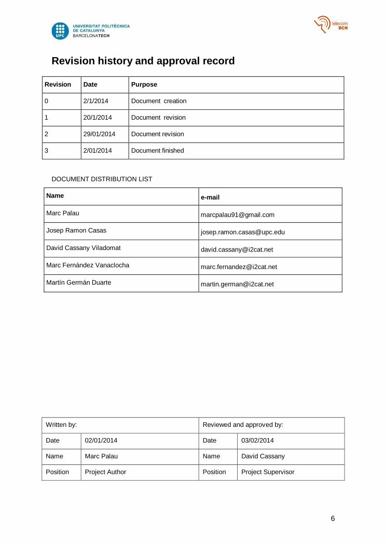
Revision history and approval record
Revision Date Purpose
0 2/1/2014 Document creation
1 20/1/2014 Document revision
2 29/01/2014 Document revision
3 2/01/2014 Document finished
DOCUMENT DISTRIBUTION LIST
Name e-mail
Marc Palau [email protected]
Josep Ramon Casas [email protected]
David Cassany Viladomat [email protected]
Marc Fernández Vanaclocha [email protected]
Martín Germán Duarte [email protected]
Written by: Reviewed and approved by:
Date 02/01/2014 Date 03/02/2014
Name Marc Palau Name David Cassany
Position Project Author Position Project Supervisor
7
Table of contents
Abstract ............................................................................................................................ 2
Resum .............................................................................................................................. 3
Resumen .......................................................................................................................... 4
Acknowledgements........................................................................................................... 5
Revision history and approval record ................................................................................ 6
List of Tables .................................................................................................................. 12
1. INTRODUCTION ..................................................................................................... 13
2. STATE OF THE ART ............................................................................................... 15
2.1. Digital video coding overview ............................................................................... 15
2.2. H264 .................................................................................................................... 17
2.2.1. H.264 NAL ................................................................................................. 18
2.2.2. H.264 NAL Header .................................................................................... 21
2.2.3. H.264 NAL Types ...................................................................................... 22
2.3. RTP Protocol ........................................................................................................ 23
2.3.1. What is RTP .............................................................................................. 23
2.3.2. Some RTP tips .......................................................................................... 23
2.3.3. RTP packets and fields architecture .......................................................... 24
2.4. H.264 over RTP ................................................................................................... 25
2.4.1. Overview ................................................................................................... 25
2.4.2. Session Description Protocol ..................................................................... 26
2.4.3. NALU management ................................................................................... 26
3. PROJECT DEVELOPMENT .................................................................................... 28
3.1. System overview .................................................................................................. 28
3.2. System structure .................................................................................................. 30
3.2.1. IO Manager ............................................................................................... 30
3.2.2. Frame Mixing Library ................................................................................. 34
3.2.3. Mixer ......................................................................................................... 36
3.3. RTP Reception ..................................................................................................... 39
3.3.1. RTP packets management ........................................................................ 39
3.3.2. NAL parsing............................................................................................... 41
3.3.3. Decoding ................................................................................................... 41
3.4. Mixing .................................................................................................................. 43
3.4.1. Mixer main routine ..................................................................................... 43
8
3.4.2. Maximum frame rate control ...................................................................... 43
3.5. RTP Transmission ................................................................................................ 45
3.5.1. Encoding ................................................................................................... 45
3.5.2. RTP packetizing and transmitting .............................................................. 46
3.6. System external management .............................................................................. 47
3.6.1. Mixer Public API ........................................................................................ 47
3.6.2. Events ....................................................................................................... 48
3.6.3. Controller workflow .................................................................................... 48
3.6.4. Mixer event handling ................................................................................. 50
3.7. Statistics Manager ................................................................................................ 51
3.7.1. Overview ................................................................................................... 51
3.7.2. Stream statistics ........................................................................................ 51
3.7.3. Mixer statistics ........................................................................................... 52
3.7.4. General statistics ....................................................................................... 52
3.8. Ruby Module and Web GUI.................................................................................. 53
4. RESULTS ................................................................................................................ 54
4.1. Frame discarding analysis .................................................................................... 54
4.1.1. Frame discarding between receiver and decoder ...................................... 54
4.1.2. Frame discarding between decoder and mixer .......................................... 54
4.1.3. Frame discarding between mixer and encoder .......................................... 55
4.1.4. Frame discarding between encoder and transmitter .................................. 55
4.2. Load tests ............................................................................................................ 59
4.2.1. Tests overview .......................................................................................... 59
4.2.2. Mixing tests ............................................................................................... 59
4.2.3. Results analysis ........................................................................................ 66
5. BUDGET ................................................................................................................. 67
6. CONCLUSIONS AND FUTURE DEVELOPMENT ................................................... 69
6.1. Overall evaluation ................................................................................................ 69
6.2. Goal accomplishment ........................................................................................... 69
6.3. Future development ............................................................................................. 70
6.3.1. Audio ......................................................................................................... 70
6.3.2. Performance .............................................................................................. 70
6.3.3. New features ............................................................................................. 71
6.4. Use cases ............................................................................................................ 71

9
6.4.1. Video conferencing .................................................................................... 71
6.4.2. Video Wall ................................................................................................. 72
6.4.3. Real-time video production ........................................................................ 72
6.4.4. Security camera system ............................................................................ 72
6.4.5. Culture and art ........................................................................................... 72
BIBLIOGRAPHY AND REFERENCES ........................................................................... 73
GLOSSARY .................................................................................................................... 74
ANNEX I ......................................................................................................................... 75
ANNEX II ........................................................................................................................ 85
10
List of Figures
Figure 1 - Chroma subsampling ...................................................................................... 15
Figure 2 - Group of pictures example .............................................................................. 16
Figure 3 - H.264 layer structure ...................................................................................... 17
Figure 4 NAL Unit structure ......................................................................................... 19
Figure 5 - Start code inside a byte stream ...................................................................... 19
Figure 6 - H.264 bytestream ........................................................................................... 21
Figure 7 - NAL Unit header ............................................................................................. 21
Figure 8 RTP Packet ................................................................................................... 24
Figure 9 - H264 over RTP bytestream ............................................................................ 25
Figure 10 - RTP payload for a FU-A NALU ..................................................................... 27
Figure 11 - FU-A header ................................................................................................. 27
Figure 12 - FU reconstruction ......................................................................................... 27
Figure 13 - System application example ......................................................................... 29
Figure 14 - Example of a process workflow using a memory copy strategy .................... 31
Figure 15 - Example of a process workflow using circular queues .................................. 31
Figure 16 - IO Manager class diagram. Circle objects represent data processors, which
have an associated thread. Rectangle objects represent data containers. ...................... 33
Figure 17 - Frame mixing library class diagram. Circle objects represent data processors,
which have an associated thread. Rectangle objects represent data containers. ............ 35
Figure 18 - Mixing and Splitting process example ........................................................... 35
Figure 19 - System class diagram. Circle objects represent data processors, which have
an associated thread. Rectangle objects represent data containers. .............................. 37
Figure 20 - System workflow diagram representing the situation of Figure 18. Colours
indicate elements library membership (see Figure 19). Circle objects represent data
processors, which have an associated thread. Rectangle objects represent data
containers. Rhombus objects represent processes associated with data processors by its
colours. ........................................................................................................................... 38
Figure 21 - Reception flow diagram ................................................................................ 40
Figure 22 - Decoding flow diagram ................................................................................. 42
Figure 23 - Mixer flow diagram ....................................................................................... 44
Figure 24 - Encoding flow diagram ................................................................................. 45
Figure 25 - Transmission flow diagram ........................................................................... 46
Figure 26 - Controller flow diagram ................................................................................. 49
Figure 27 - Event handling flow diagram ......................................................................... 50
Figure 28 - Web front-end ............................................................................................... 53

11
Figure 29 - Decoded frames discarding effects ............................................................... 54
Figure 30 - Frame discarding between receiver and decoder example ........................... 56
Figure 31 - Frame discarding between decoder and mixer example ............................... 57
Figure 32 - Frame discarding between mixer and encoder example ............................... 58
Figure 33 - Tests scenario diagram ................................................................................ 59
Figure 34 - Grid set used ................................................................................................ 60
Figure 35 - Input 720p Output 720p losses and frame rate chart. Blue column are input
coded frame losses, red column are input decoded frame losses and orange column is
output decoded frame losses. The line represent output frame rate ................................ 62
Figure 36 - Input 720p Output 720p introduced delay chart ............................................ 62
Figure 37 - Input 720p Output 1080p losses and frame rate chart. Blue column are input
coded frame losses, red column are input decoded frame losses and orange column is
output decoded frame losses. The line represent output frame rate ................................ 63
Figure 38 - Input 720p Output 1080p introduced delay chart .......................................... 63
Figure 39 - Input 1080p Output 720p losses and frame rate chart. Blue column are input
coded frame losses, red column are input decoded frame losses and orange column is
output decoded frame losses. The line represent output frame rate ................................ 64
Figure 40 - Input 1080p Output 720p introduced delay chart .......................................... 64
Figure 41 - Input 1080p Output 1080p losses and frame rate chart. Blue column are input
coded frame losses, red column are input decoded frame losses and orange column is
output decoded frame losses. The line represent output frame rate ................................ 65
Figure 42 - Input 1080p Output 720p introduced delay chart .......................................... 65

12
List of Tables
Table 1- NAL Unit types .................................................................................................. 22
Table 2 - H.264 over RTP NAL Unit types ...................................................................... 26
Table 3 - Project total costs ............................................................................................ 67
Table 4 - Project direct costs .......................................................................................... 68
13
1. INTRODUCTION
Video production has been traditionally related to professional areas, such as TV and
cinema. However, nowadays this scenario has changed. Apart from professional
cameras, video recording can be done with smartphones, webcams and non-professional
cameras. This means that everyone with these devices, which can be found at lower
prices and in a lot of stores, can record its own videos. These videos will not be only
stored in hard disks or memory cards, but also shared via social networks or streamed.
Apart of the changes found on video recording, storage and distribution, what about video
editing?
Regarding video editing, we can find some nonprofessional software which allows doing
some kind of mixing, switching between different videos and also adding effects.
However, most of them only accept as an input recorded videos, storing the resulting
video as a file. Of course, this kind of software cannot be used in professional situations,
such as a TV studio control room.
Given this situation, it is logical to think that changes on the other steps of a video
production need to be applied also to video editing. Features such as real-time capturing
from multiple sources, real-time video editing and real-time video distribution are
mandatory. Furthermore, scalability, low-cost, hardware independence and a user-
friendly interface are important points to be taken into account in order to create a
suitable software solution. The solution proposed in this project fulfils these requirements,
acting as a complete real-time video production tool.
A tool like this is extremely useful in different situations such as videoconferencing,
audiovisual art, TV production or security camera control rooms.
The success of the developed software will be measured in two terms: functionality and
performance. Regarding functionality, its required features are:
Stream adding and removing
Stream display enabling and disabling
Destination adding and removing
Mixed video size modification
Stream size and position modification
Predefined layout grid application
Real-time management
Concerning performance, two scenarios should be considered:
One-way or broadcasting context:
Receive, decode and mix 4 H264 streams encoding and transmitting a
720p layout at 25 fps to N destinations
Introduce a maximum delay of 300 ms
Maximum response time changing stream size and position of 150 ms
Bidirectional context
Receive, decode and mix 4 H264 stream encoding and transmitting a
720p layout to N destinations
Achieve adaptative frame rate in order to have a maximum delay between
audio and video of 150 ms one-way (with a minimum frame rate of 5 fps)
Maximum response time changing stream size and position of 150 ms

14
The generic skills that are meant to be learned during this project by the student are oral
and written communication, teamwork and autonomous learning.
This project has been realized in i2CAT Foundation and is part of the European project
SPECIFI.
Development has been done in C, C++ and Ruby programming languages. Open source
projects involved in the development are Ultragrid [1], OpenCV [2], FFMPEG [3], libx264
[4] JZON [5] and h264bitstream [6].
Self-developed source code is open under GPL license and available at Audiovisual Unit
i2CAT GitHub repository [7].
Tests have been done in a x64 Ubuntu Server with 8 cores (2.40 GHz) and 2GB RAM.
The work plan with its tasks, milestones and a Gantt diagram can be found on annex II
along with the descriptions of the deviations from the initial plan.
15
2. STATE OF THE ART
In order to understand some parts of the project, it is necessary to talk about some
fundamentals about video coding and RTP protocol. In this chapter, there is a brief review
about video coding techniques (mainly H264) and also about RTP protocol (mainly H264
headers).
2.1. Digital video coding overview
All video codecs have a common goal: reduce the size of the files keeping as good as
possible its quality. Raw video files are too big to be stored or transmitted without
problems, so its size must be reduced taking into account the trade-off between
compression and quality: video quality is reduced when the number of bits in the file is
also reduced.
Image compression
Since video can be seen as a sequence of images, the first step in compression is
studying how to reduce the number of bits needed to represent a still image. For example,
a raw colour frame from and HD video weights, at least, 6.2 MB (1920 width pixels x 1080
height pixels x 8 bits/pixel x 3 colour planes) while the same image coded in JPEG format
can weigh less than 200 KB. How is this possible?
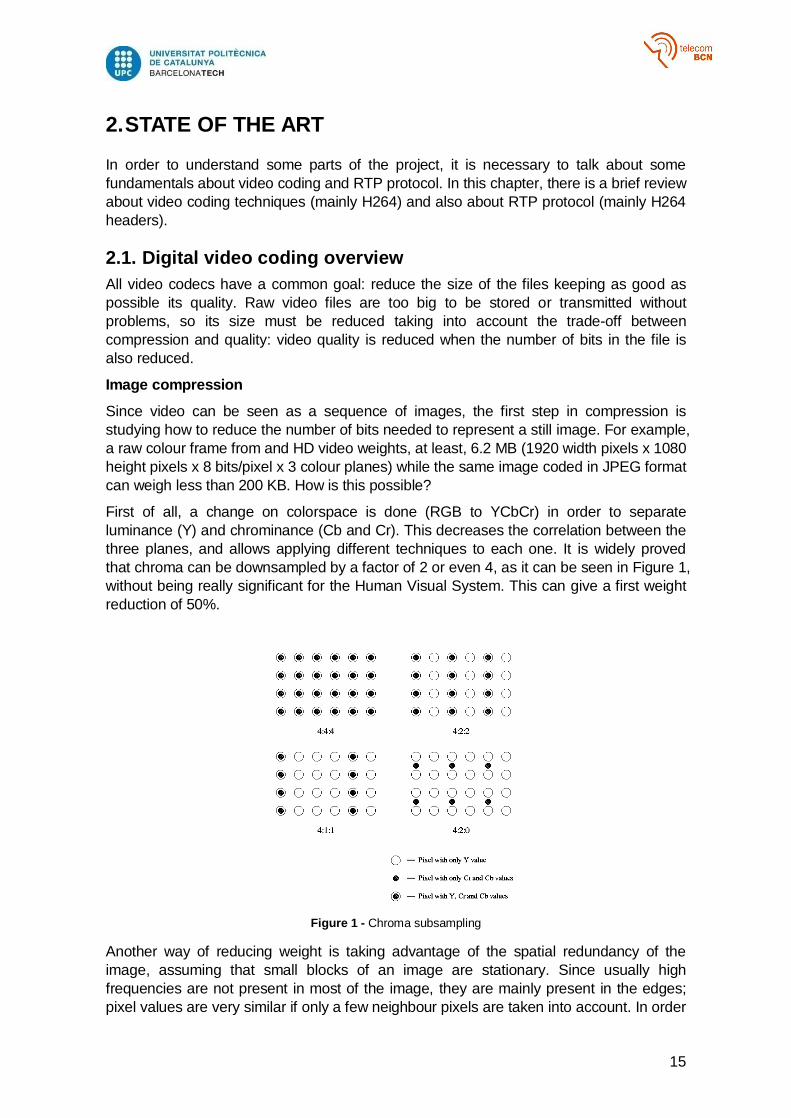
First of all, a change on colorspace is done (RGB to YCbCr) in order to separate
luminance (Y) and chrominance (Cb and Cr). This decreases the correlation between the
three planes, and allows applying different techniques to each one. It is widely proved
that chroma can be downsampled by a factor of 2 or even 4, as it can be seen in Figure 1,
without being really significant for the Human Visual System. This can give a first weight
reduction of 50%.
Figure 1 - Chroma subsampling
Another way of reducing weight is taking advantage of the spatial redundancy of the
image, assuming that small blocks of an image are stationary. Since usually high
frequencies are not present in most of the image, they are mainly present in the edges;
pixel values are very similar if only a few neighbour pixels are taken into account. In order
16
to exploit this redundancy some transformation can be performed to the image, both in
space and frequency domains. One of the most popular methods is to split the image in
small blocks and apply to each one the Discrete Cosine Transform (DCT), which
produces, from a NxM pixels block, NxM new coefficients representing the previous block
by NxM different combinations of different frequency sinusoids. The original image can be
obtained back without losing any information if all the coefficients are kept.
One of the main advantages of using DCT is that only a few coefficients at each block will
have significant information (the ones that represent lower frequencies). Therefore, if
these coefficients are kept and those which represent high frequencies are set to zero
(even if they have a small positive value) we can achieve a high compression ratio
without losing too much information. In order to do this, a quantification matrix is applied
to the coefficients.
Finally, the way in which coefficients are stored can be useful to increase the
compression ratio. The coefficients are scanned in a particular path, producing a new
array where zero coefficients are placed at the end. Using an entropy coder to code this
array, like Run-Length, we can reduce the number of needed bits, because of the large
amount of zeros.
Image prediction and motion compensation
After reviewing how images are compressed, it is time to analyze how to compress
videos, which can be seen as several consecutive images. Apart from space redundancy,
talking about videos involves thinking about time redundancy, because of the consecutive
frames similarity.
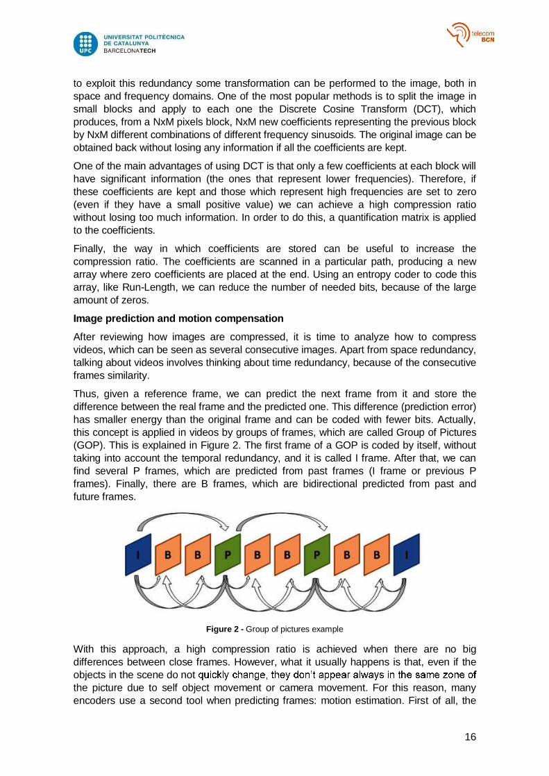
Thus, given a reference frame, we can predict the next frame from it and store the
difference between the real frame and the predicted one. This difference (prediction error)
has smaller energy than the original frame and can be coded with fewer bits. Actually,
this concept is applied in videos by groups of frames, which are called Group of Pictures
(GOP). This is explained in Figure 2. The first frame of a GOP is coded by itself, without
taking into account the temporal redundancy, and it is called I frame. After that, we can
find several P frames, which are predicted from past frames (I frame or previous P
frames). Finally, there are B frames, which are bidirectional predicted from past and
future frames.
Figure 2 - Group of pictures example
With this approach, a high compression ratio is achieved when there are no big
differences between close frames. However, what it usually happens is that, even if the
objects in the scene do not
the picture due to self object movement or camera movement. For this reason, many
encoders use a second tool when predicting frames: motion estimation. First of all, the

17
frame is split in Macro Blocks (MB). Each MB is compared to all zones in the reference
frame and when the most similar zone is found, the difference between the MB and this
zone is calculated as the prediction error. Although the Motion vector has to be encoded
for every MB the prediction error has been reduced (less bits to code it are needed). It is
also necessary to say that not all the MB in a frame must be coded the same way. For
example, in a B frame, there can be MB predicted either from a previous one, a future
one or even not predicted if there is not any similar MB in the reference frame. Encoders
which use these techniques are called hybrid encoders.
Finally, the resulting coefficients from a frame (predicted or not) need to be encoded
using DCT, quantization and entropy coding, providing a high compression ratio when
using all described tools.
2.2. H264
In this project only H264 standard is contemplated. This means that reception and
decoding of input video streams and coding and transmission of output video streams are
related to this video coding standard.
H264 is a video compression standard that was completed in 2003. Actually H264 does
not suppose a great revolution in already known coding techniques used in previous
standards as H262 (used in DTT) or H263 (designed for low bit rate environments) and
described in 2.1 chapter of this project. However, it improves these techniques,
increasing video compression ratio and providing more flexibility in compression,
transmission and storage at expense of a higher computational encoding cost.
This standard is designed for technical solutions including at least the following
application areas:
Broadcast over cable, satellite, cable modem, DSL, terrestrial, etc.
Interactive or serial storage in optical and magnetic devices, DVD, etc.
Conversational services over ISDN, Ethernet, LAN, DSL, wireless and mobile
networks, modems, etc.
Video-on-demand or multimedia streaming services over ISDN, cable modem,
DSL, LAN, wireless networks, etc.
Multimedia messaging services (MMS) over ISDN, DSL, Ethernet, LAN, wireless
and mobile networks
To address this need of flexibility and customizability, the H.264 design covers a VCL
(Video Coding Layer), designed to represent efficiently the video content, and a NAL
(Network Abstraction Layer), which formats the VCL representation of the video and
provides header information in a manner appropriate for conveyance by a variety of
transport layers or storage media (see Figure 3).
Figure 3 - H.264 layer structure

18
Some highlighted features of H.264 in terms of picture prediction are variable block-size
motion compensation with small block sizes, quarter-sample-accurate motion
compensation and multiple reference picture motion compensation. Regarding coding
efficiency some improvements are small block-size transform, arithmetic entropy coding
and context-adaptive entropy coding. The scope of this project is far from analyzing
H.264 improvements on coding techniques, so it will not be commented deeper. For more
information you can check this document [8].
On the other hand, robustness to data errors/losses and flexibility for operation over a
variety of network environments is enabled by a number of design aspects new to the
H.264 standard, including the following highlighted features, which are relevant regarding
this project:
Parameter set structure: The parameter set design provides for robust and
efficient conveyance header information. As the loss of a few key bits of
information (such as sequence header or picture header information) could have a
sever negative impact on the decoding process when using prior standards, this
key information was separated for handling in a more flexible and specialized
manner in the standard.
NAL unit syntax structure: Each syntax structure in H.264 is placed into a
logical data packet called NAL unit. Rather than forcing a specific bitstream
interface to the system as in prior video coding standards, the NAL unit syntax
structure allows greater customization of the method of carrying the video content
in a manner appropriate for each specific network
2.2.1. H.264 NAL
customization of the use of the VCL for a broad variety of systems.
NAL facilitates the ability to map H.264 VCL data to transport layers such as:
RTP/IP for any kind of real-time wire-line and wireless Internet services
(conversational and streaming).
File formats, e.g., ISO MP4 for storage and MMS
Some key concepts of NAL are NAL Units, byte stream, and packet format uses of NAL
units, parameter sets and access units. A short description of these concepts is given
below whereas a more detailed description including error resilience aspects is provided
in [8].
NAL Units
The coded video data is organized into NAL units, each of which is effectively a packet
that contains and integer number of bytes. The first byte of each NAL unit is a header
byte that contains an indication of the type of the data in the NAL unit, and the remaining
bytes contain the payload data of the type indicated by the header (Raw Byte Sequence
Payload).

19
Figure 4 NAL Unit structure
NAL Units in Byte-Stream Format Use
Some systems require delivery of the entire or partial NAL unit stream as an ordered
stream of bytes or bits in which the locations of NAL unit boundaries need to be
identifiable from patterns within the coded data itself.
To use that in such systems, the H.264 specification defines a byte stream format. In the
byte stream format, each NAL unit is prefixed by a specific pattern of three bytes called
start code prefix. The boundaries of the NAL unit can then be identified by searching the
coded data for the unique start code prefix pattern.
Figure 5 - Start code inside a byte stream
NAL Units in Packet-Transport System Use
In other systems, such as RTP systems, the coded data is carried in packets that are
framed by the system transport protocol, and identification of the boundaries of NAL units
within the packets can be established without use of start code prefix patterns. In such
systems, the inclusion of start code prefixes in the data would be a waste of data carrying
capacity, so instead the NAL units can be carried in data packets without start code
prefixes.
VCL and Non-VCL NAL Units
NAL units are classified into VCL and non-VCL NAL units. The VCL NAL units contain the
data that represents the values of the samples in the video pictures, and the non-VCL
NAL units contain any associated additional information.
Parameter Sets
A parameter set is supposed to contain information that is expected to rarely change and
offers the decoding of a large number of VCL NAL units. There are two types of
parameter sets:
Sequence Parameter Sets (SPS), which apply to a series of consecutive coded
video pictures called a coded video sequence and contains relevant information
such as picture width and height.
Picture Parameter Sets (PPS), which apply to the decoding of one or more
individual pictures within a coded video sequence

20
The sequence and picture parameter-set mechanism decouples the transmission of
infrequently changing information from the transmission of coded representations of the
values of the samples in the video pictures. Each VCL NAL unit contains an identifier that
refers to the content of the relevant PPS and each PPS contains and identifier that refers
to the content of the relevant SPS.
Access Units
A set of NAL units in a specified form is referred to as an Access Unit. The decoding of
each access unit results in one decoded picture.
The primary coded picture consists of a set of VCL NAL units consisting of slices or slice
data partitions that represent the samples of the video picture.
Finally, if the coded picture is the last picture of a coded video sequence (a sequence of
pictures that is independently decidable and uses only one SPS) an end of sequence
NAL unit may be present to indicate the end of the sequence; and if the coded picture is
the last coded picture in the entire NAL unit stream, an end of stream NAL unit may be
present to indicate that the stream is ending.
Coded Video Sequences
A coded video sequence consists of a series of access units that are sequential in the
NAL unit stream and use only one SPS. Given the necessary parameter set information,
each coded video sequence can be decoded independently of any other coded video
sequence.
At the beginning of a coded video sequence there is an Instantaneous Decoding Refresh
(IDR) access unit. An IDR access unit contains and intra picture, which can be decoded
without decoding any previous pictures in the NAL unit stream and indicates that no
subsequent picture in the stream will require reference to pictures prior to the intra picture
it contains in order to be decoded. It represents the idea of GOP commented in 2.1.
Random Access Points
Random Access Points represent positions of the stream where it can start being
decoded without any information about past stream parts. In previous standards, such as
MPEG2, RAPs were associated to GOPs because its first frame (an Intra frame) could be
decoded itself (without using any information about past or future frames). I frames need
more bits than P and B frames to be encoded, so there is a trade off between
compression rate and the number of RAPs in the stream.
In H.264, RAPs are associated to IDR frames, which contain I slices, so the concept is
similar to the one described before. However, H.264 offers the possibility of having RAP
without sending IDR frames. This is possible due to periodic intra refresh. Periodic Intra
Refresh can replace key frames by using a column of intra blocks that move across the
video from one side to the other, refreshing the image. Instead of a big keyframe, the
keyframe is spread over many frames. The video is still seekable: Supplemental
Enhancement Information (SEI) NALUs tell the decoder to start, decode X frames, and
then start displaying the video. This hides the refresh effect from the user while the frame
loads. Motion vectors are restricted so that blocks on one side of the refresh column do
not reference blocks on the other side [4].
21
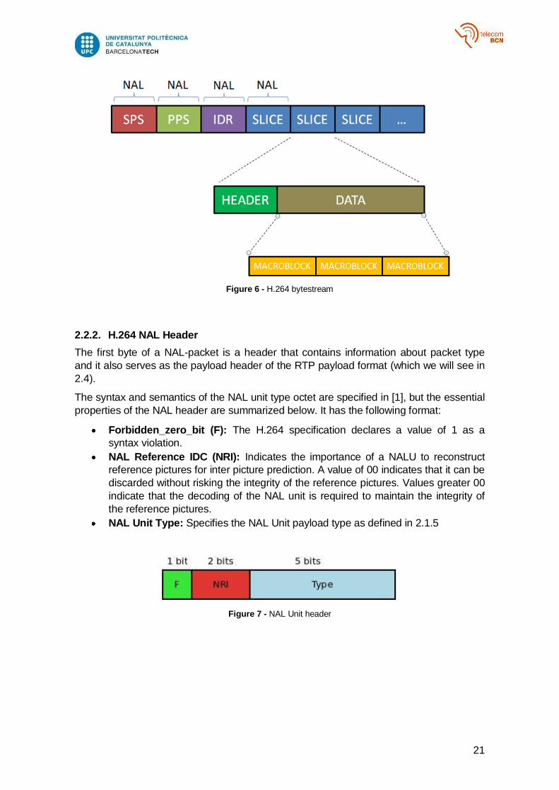
Figure 6 - H.264 bytestream
2.2.2. H.264 NAL Header
The first byte of a NAL-packet is a header that contains information about packet type
and it also serves as the payload header of the RTP payload format (which we will see in
2.4).
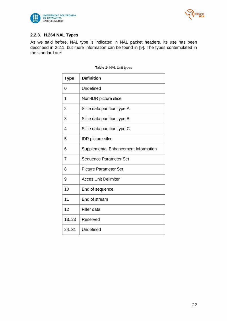
The syntax and semantics of the NAL unit type octet are specified in [1], but the essential
properties of the NAL header are summarized below. It has the following format:
Forbidden_zero_bit (F): The H.264 specification declares a value of 1 as a
syntax violation.
NAL Reference IDC (NRI): Indicates the importance of a NALU to reconstruct
reference pictures for inter picture prediction. A value of 00 indicates that it can be
discarded without risking the integrity of the reference pictures. Values greater 00
indicate that the decoding of the NAL unit is required to maintain the integrity of
the reference pictures.
NAL Unit Type: Specifies the NAL Unit payload type as defined in 2.1.5
Figure 7 - NAL Unit header
22
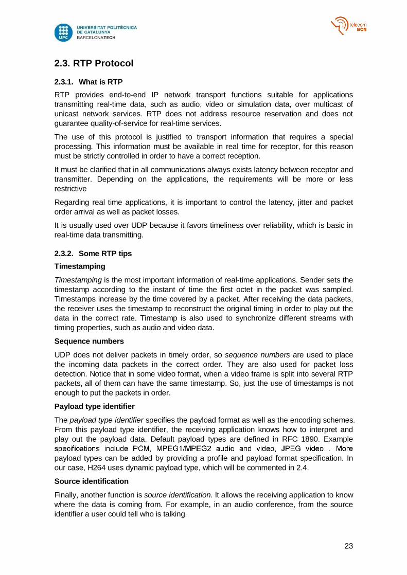
2.2.3. H.264 NAL Types
As we said before, NAL type is indicated in NAL packet headers. Its use has been
described in 2.2.1, but more information can be found in [9]. The types contemplated in
the standard are:
Table 1- NAL Unit types
Type Definition
0 Undefined
1 Non-IDR picture slice
2 Slice data partition type A
3 Slice data partition type B
4 Slice data partition type C
5 IDR picture silce
6 Supplemental Enhancement Information
7 Sequence Parameter Set
8 Picture Parameter Set
9 Acces Unit Delimiter
10 End of sequence
11 End of stream
12 Filler data
13..23 Reserved
24..31 Undefined
23
2.3. RTP Protocol
2.3.1. What is RTP
RTP provides end-to-end IP network transport functions suitable for applications
transmitting real-time data, such as audio, video or simulation data, over multicast of
unicast network services. RTP does not address resource reservation and does not
guarantee quality-of-service for real-time services.
The use of this protocol is justified to transport information that requires a special
processing. This information must be available in real time for receptor, for this reason
must be strictly controlled in order to have a correct reception.
It must be clarified that in all communications always exists latency between receptor and
transmitter. Depending on the applications, the requirements will be more or less
restrictive
Regarding real time applications, it is important to control the latency, jitter and packet
order arrival as well as packet losses.
It is usually used over UDP because it favors timeliness over reliability, which is basic in
real-time data transmitting.
2.3.2. Some RTP tips
Timestamping
Timestamping is the most important information of real-time applications. Sender sets the
timestamp according to the instant of time the first octet in the packet was sampled.
Timestamps increase by the time covered by a packet. After receiving the data packets,
the receiver uses the timestamp to reconstruct the original timing in order to play out the
data in the correct rate. Timestamp is also used to synchronize different streams with
timing properties, such as audio and video data.
Sequence numbers
UDP does not deliver packets in timely order, so sequence numbers are used to place
the incoming data packets in the correct order. They are also used for packet loss
detection. Notice that in some video format, when a video frame is split into several RTP
packets, all of them can have the same timestamp. So, just the use of timestamps is not
enough to put the packets in order.
Payload type identifier
The payload type identifier specifies the payload format as well as the encoding schemes.
From this payload type identifier, the receiving application knows how to interpret and
play out the payload data. Default payload types are defined in RFC 1890. Example
payload types can be added by providing a profile and payload format specification. In
our case, H264 uses dynamic payload type, which will be commented in 2.4.
Source identification
Finally, another function is source identification. It allows the receiving application to know
where the data is coming from. For example, in an audio conference, from the source
identifier a user could tell who is talking.

24
2.3.3. RTP packets and fields architecture
Below these lines, the RTP header is described. The minimum RTP header size is 12
bytes. In Figure 8 a RTP packet can be seen (notice that Extension Header is not
mandatory).
Figure 8 RTP Packet
The description of compulsory fields in the header is the following:
Version Number (V) (2 bits)
It indicates protocol version. The current version is 2.
Padding (P) (1 bit)
It is used to indicate if there are extra padding bytes at the end of the RTP packet
Extension (X) (1 bit)
It indicates presence of an Extension header between standard header and payload data
CSRC Count (CC) (4 bits)
Contains the number of Contributing Source identifiers that follow the fixed header
Marker (M) (1 bit)
It indicates the end of a video frame (progressive video) or the end of a field (interlaced
video). It is set to 1 for t he last packet of the video frame/field and it must be set to 0 for
the other packets
Payload type (PT) (7 bits)
It indicates the payload type
Sequence Number (16 bits)
A sequence number in order to identify packet order and packet loss
Time Stamp (32 bits)
For progressive scan video, the timestamp denotes the sampling instant of the frame to
which the RTP packet belongs. Packets must not include data from multiple frames, and
all packets belonging to the same frame must have the same timestamp.
For H264 video a 90 kHz clock must be used.
25
SSRC (32 bits)
Synchronization source identifier uniquely identifies the source of a stream. It must be
taken into account that video and audio sent from the same source, for example a
camera, will have different SSRC.
2.4. H.264 over RTP
2.4.1. Overview
H.264 was thought to be a standard capable of adapting to any transport network. One of
these networks are IP networks and it is widely common to use RTP as transport layer
protocol. For deeper information, RFC 6184 [10] can be checked, which describes
entirely the RTP Payload format for H.264 video
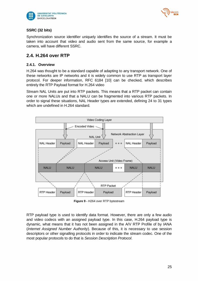
Stream NAL Units are put into RTP packets. This means that a RTP packet can contain
one or more NALUs and that a NALU can be fragmented into various RTP packets. In
order to signal these situations, NAL Header types are extended, defining 24 to 31 types
which are undefined in H.264 standard.
Figure 9 - H264 over RTP bytestream
RTP payload type is used to identify data format. However, there are only a few audio
and video codecs with an assigned payload type. In this case, H.264 payload type is
dynamic, what means that it has not been assigned in the A/V RTP Profile of by IANA
(Internet Assigned Number Authority). Because of this, it is necessary to use session
descriptors or other signalling protocols in order to indicate the stream codec. One of the
most popular protocols to do that is Session Description Protocol.
26
2.4.2. Session Description Protocol
The Session Description Protocol (SDP) is a format for describing streaming media
initialization parameters. SDP is intended for describing multimedia communication
sessions. It does not deliver media itself but is used for negotiation between end points of
media type, format, and all associated properties. The set of properties and parameters
are often called a session profile. SDP is designed to be extensible to support new media
types and formats.
SDP started off as a component of the Session Announcement Protocol (SAP), but found
other uses in conjunction with Real-time Transport Protocol (RTP), Real-time Streaming
Protocol (RTSP), Session Initiation Protocol (SIP) and even as a standalone format for
describing multicast sessions.
The scope of the project is far from analyzing this protocol. For more information RFC
4566 [11] can be checked.
Media description SDP fields for H.264 are specified in [10]. The key fields are specified
below:
m=video <port> RTP/AVP 96
a=rtpmap:96 H264/90000
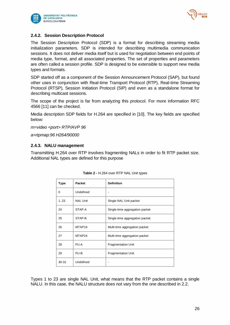
2.4.3. NALU management
Transmitting H.264 over RTP involves fragmenting NALs in order to fit RTP packet size.
Additional NAL types are defined for this purpose
Table 2 - H.264 over RTP NAL Unit types
Type Packet Definition
0 Undefined -
1..23 NAL Unit Single NAL Unit packet
24 STAP-A Single-time aggregation packet
25 STAP-B Single-time aggregation packet
26 MTAP16 Multi-time aggregation packet
27 MTAP24 Multi-time aggregation packet
28 FU-A Fragmentation Unit
29 FU-B Fragmentation Unit
30-31 Undefined -
Types 1 to 23 are single NAL Unit, what means that the RTP packet contains a single NALU. In this case, the NALU structure does not vary from the one described in 2.2.

27
Types 24 to 27 are associated to RTP packets which contain multiple NALUs. This is not a usual situation because it is easier to match only one NAL, fragmented or not, to an RTP packet. For more information [10] can be checked.
Finally, 28 and 29 correspond to fragmented NALUs and are the most usual types using H.264 over RTP. The RTP payload for a FU-A is represented in Figure 10. FU-A is used for progressive video streams and FU-B for interleaved video streams. For more information section 5.8. of [10] can be checked.
Figure 10 - RTP payload for a FU-A NALU
FU indicator is the standard NAL header, described in 2.2.3. NALU type is 28 and NRI is the same as the fragmented NALU. The FU header contains information in order to reconstruct the fragmented NALU:
S (1 bit): when set to one, the Start bit indicates the start of a fragmented NAL unit. It must be set to 0 in other cases.
E (1 bit): when set to one, the End bit indicates the end of a fragmented NAL unit. It must be set to 0 in other cases.
R (1 bit): the Reserved bit must be equal to 0 and must be ignored by the receiver.
Type (5 bits): the original NAL unit payload type, as defined in 2.2.3.
Figure 11 - FU-A header
In the receiving step, the different FU must be buffered until the original NAL could be reconstructed (see Figure 12). Moreover, it is necessary to add the start code prefix for every NALU, which was not necessary while the NAL was inside the RTP packet.
Figure 12 - FU reconstruction
28
3. PROJECT DEVELOPMENT
3.1. System overview
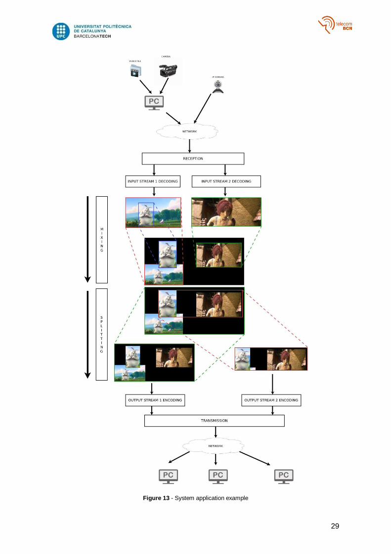
The aim of the project is developing a software real-time production tool. The proposed
solution is mainly divided in 3 blocks, which will be analyzed deeper in next chapters.
These are, input streams reception, stream manipulation, output stream transmission
First of all, it is necessary to talk about the whole system structure, which is done in 3.2.
In order to manipulate streams, the first step is receiving and decoding them, in order to
have raw frames. The first challenge in this part is achieving a good management of RTP
packets: packet order, packet loss control, complete frames identification and
identification of sources are some of the problems that need to be faced. The second
challenge is decoding step; once a complete decoded frame is obtained, it has to be
decompressed as fast as possible. Reception step is described in 3.3.
Once different raw frames from multiple streams have been obtained, they can be
manipulated in order to create a mixing effect. As it will be seen later, the mixing process
is done at decompressed frame level in order to simplify frame manipulation (as they can
be treated as independent pictures). In order to compose a layout (the final mixed frame)
some operations have to be done to frames such as cropping and resizing. Finally each
one has to be d on the background, using a layer system to manage overlapping.
This step is analyzed in 3.4.
After that, the composed frame has to be encoded and transmitted. Main challenges in
this step seem obvious: encoding speed and RTP packetizing. Furthermore, the
proposed system allows to crop parts of the composed layout and to treat them as
independent output streams, which can be useful in many applications. Discussion about
this step is done in 3.5.
Moreover, an essential feature of a system like this is real-time management. The
external system management is analyzed in 3.6.
In order to evaluate the system performance, it is necessary to extract some statistics of
the system. This process is explained in 3.7.
In 3.8, the RESTful API implementation is described.
Finally, other aspects must be taken into account. All these steps are parallelized so data
exchange between different modules has to be managed correctly. This means that
speed differences between these modules have to be managed in order to maintain
system robustness. These effects are discussed in 4.1.
29
Figure 13 - System application example
30
3.2. System structure
First of all, it is necessary to talk about system structure. It is basically divided in three
blocks:
IO Manager, which is responsible for managing stream reception, decoding,
encoding and transmission
Frame Mixing Library, which does the mixing at frame level.
Mixer, which is the main block and uses the previous ones as libraries.
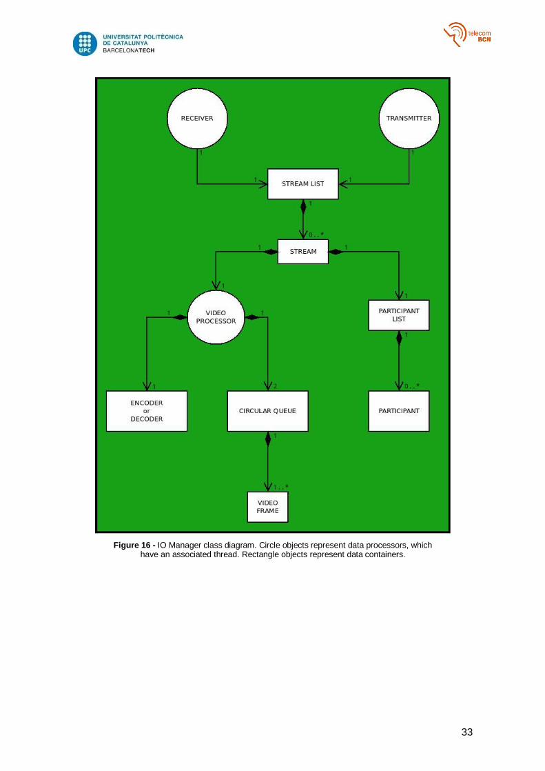
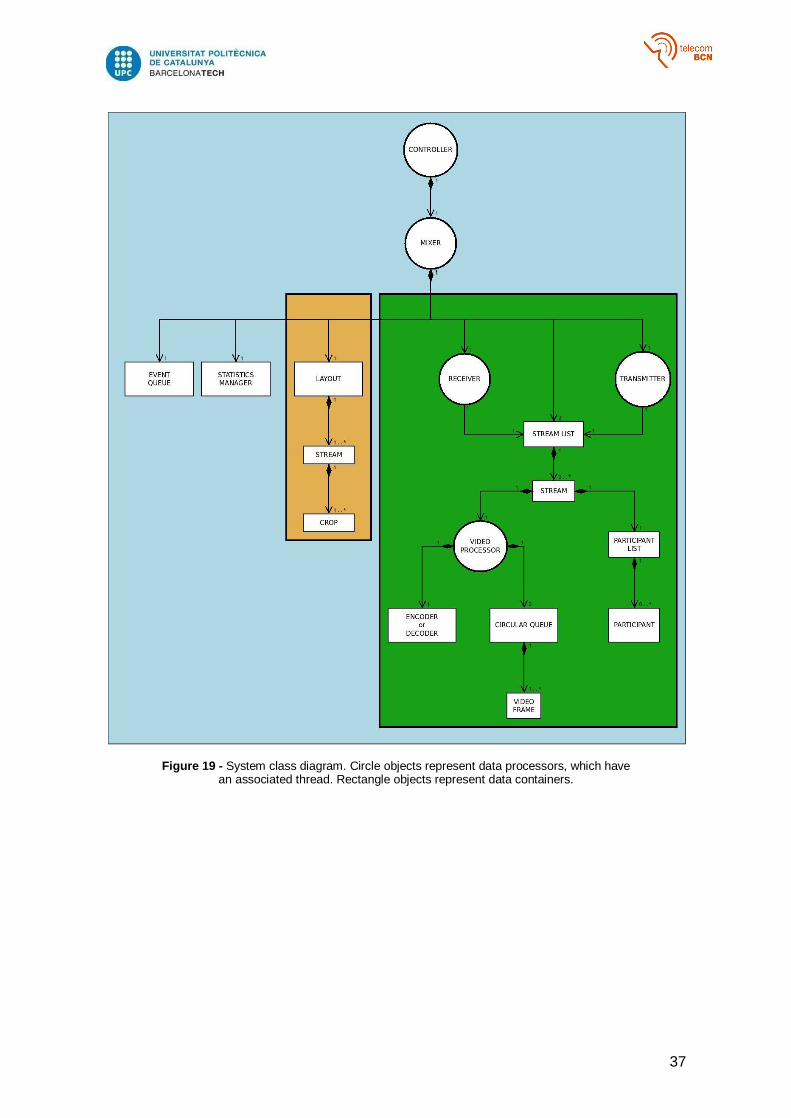
Every block is complemented with a class diagram. Round components represent
processors that have a thread associated which manipulates data. Rectangle objects
represent data containers.
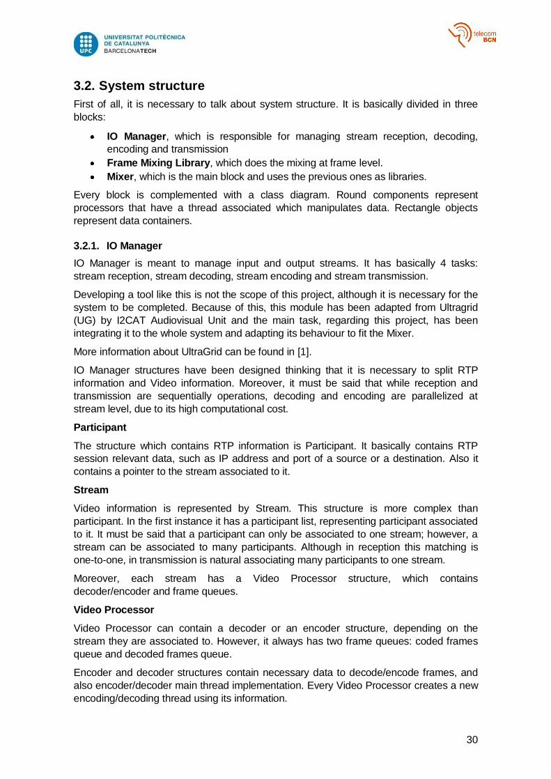
3.2.1. IO Manager
IO Manager is meant to manage input and output streams. It has basically 4 tasks:
stream reception, stream decoding, stream encoding and stream transmission.
Developing a tool like this is not the scope of this project, although it is necessary for the
system to be completed. Because of this, this module has been adapted from Ultragrid
(UG) by I2CAT Audiovisual Unit and the main task, regarding this project, has been
integrating it to the whole system and adapting its behaviour to fit the Mixer.
More information about UltraGrid can be found in [1].
IO Manager structures have been designed thinking that it is necessary to split RTP
information and Video information. Moreover, it must be said that while reception and
transmission are sequentially operations, decoding and encoding are parallelized at
stream level, due to its high computational cost.
Participant
The structure which contains RTP information is Participant. It basically contains RTP
session relevant data, such as IP address and port of a source or a destination. Also it
contains a pointer to the stream associated to it.
Stream
Video information is represented by Stream. This structure is more complex than
participant. In the first instance it has a participant list, representing participant associated
to it. It must be said that a participant can only be associated to one stream; however, a
stream can be associated to many participants. Although in reception this matching is
one-to-one, in transmission is natural associating many participants to one stream.
Moreover, each stream has a Video Processor structure, which contains
decoder/encoder and frame queues.
Video Processor
Video Processor can contain a decoder or an encoder structure, depending on the
stream they are associated to. However, it always has two frame queues: coded frames
queue and decoded frames queue.
Encoder and decoder structures contain necessary data to decode/encode frames, and
also encoder/decoder main thread implementation. Every Video Processor creates a new
encoding/decoding thread using its information.
31
Circular queue
Each queue is a mutex-free circular queue implemented by I2CAT, extremely useful
when performance is a key factor. Thread safe can be assumed if there is only one
producer (who fills the queue pushing objects to the back) and one consumer (who
consumes objects from the front). The queue has a configurable number of slots and the
objects, in this case video frames, are pre-allocated, reusing its buffer for every new
frame.
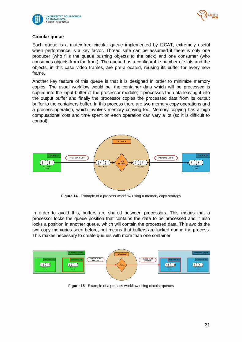
Another key feature of this queue is that it is designed in order to minimize memory
copies. The usual workflow would be: the container data which will be processed is
copied into the input buffer of the processor module; it processes the data leaving it into
the output buffer and finally the processor copies the processed data from its output
buffer to the containers buffer. In this process there are two memory copy operations and
a process operation, which involves memory copying too. Memory copying has a high
computational cost and time spent on each operation can vary a lot (so it is difficult to
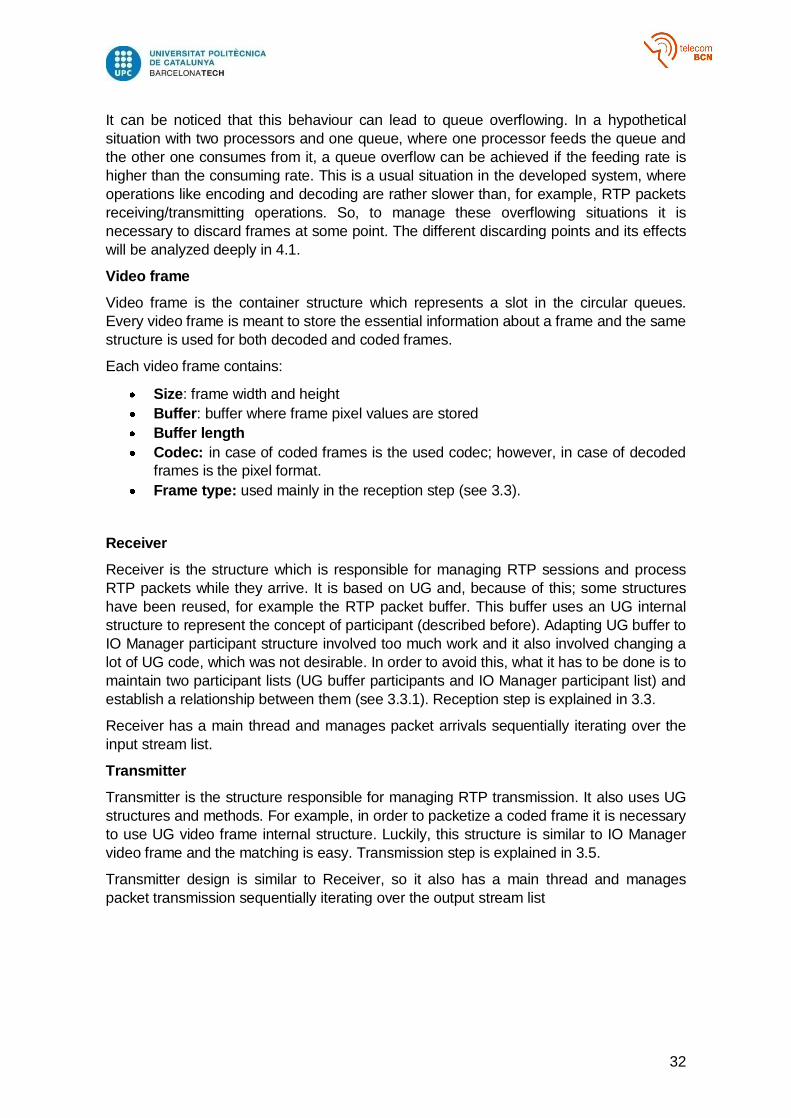
control).
Figure 14 - Example of a process workflow using a memory copy strategy
In order to avoid this, buffers are shared between processors. This means that a
processor locks the queue position that contains the data to be processed and it also
locks a position in another queue, which will contain the processed data. This avoids the
two copy memories seen before, but means that buffers are locked during the process.
This makes necessary to create queues with more than one container.
Figure 15 - Example of a process workflow using circular queues
32
It can be noticed that this behaviour can lead to queue overflowing. In a hypothetical
situation with two processors and one queue, where one processor feeds the queue and
the other one consumes from it, a queue overflow can be achieved if the feeding rate is
higher than the consuming rate. This is a usual situation in the developed system, where
operations like encoding and decoding are rather slower than, for example, RTP packets
receiving/transmitting operations. So, to manage these overflowing situations it is
necessary to discard frames at some point. The different discarding points and its effects
will be analyzed deeply in 4.1.
Video frame
Video frame is the container structure which represents a slot in the circular queues.
Every video frame is meant to store the essential information about a frame and the same
structure is used for both decoded and coded frames.
Each video frame contains:
Size: frame width and height
Buffer: buffer where frame pixel values are stored
Buffer length
Codec: in case of coded frames is the used codec; however, in case of decoded
frames is the pixel format.
Frame type: used mainly in the reception step (see 3.3).
Receiver
Receiver is the structure which is responsible for managing RTP sessions and process
RTP packets while they arrive. It is based on UG and, because of this; some structures
have been reused, for example the RTP packet buffer. This buffer uses an UG internal
structure to represent the concept of participant (described before). Adapting UG buffer to
IO Manager participant structure involved too much work and it also involved changing a
lot of UG code, which was not desirable. In order to avoid this, what it has to be done is to
maintain two participant lists (UG buffer participants and IO Manager participant list) and
establish a relationship between them (see 3.3.1). Reception step is explained in 3.3.
Receiver has a main thread and manages packet arrivals sequentially iterating over the
input stream list.
Transmitter
Transmitter is the structure responsible for managing RTP transmission. It also uses UG
structures and methods. For example, in order to packetize a coded frame it is necessary
to use UG video frame internal structure. Luckily, this structure is similar to IO Manager
video frame and the matching is easy. Transmission step is explained in 3.5.
Transmitter design is similar to Receiver, so it also has a main thread and manages
packet transmission sequentially iterating over the output stream list
33
Figure 16 - IO Manager class diagram. Circle objects represent data processors, which have an associated thread. Rectangle objects represent data containers.

34
3.2.2. Frame Mixing Library
Working at frame level means that every frame can be treated as an independent picture.
Because of this, the mixing step is based on a self-developed picture mixing library which
uses OpenCV as a third-party library. [2]
It is basically composed of three classes: layout, stream and crop.
Crop
A crop represents a part of a whole image, in this case defined by a rectangle. It is
identified by a unique ID.
This structure contains information about:
Width, height and upper left corner position of the rectangle which delimits the
original image region associated to the crop.
Width, height and upper left corner position of the rectangle which delimits the
region it will occupy in the composed image.
Enable/Disable flag, determining if the crop has to be used in the composition or
not.
Associated layer, used in order to manage overlapping. Lower values are at
bottom, while higher values are at top.
Opacity, which determines the blending alpha between the crop and the underlaid
composed image.
Moreover it also contains the last original frame crop once scaled. This means that pixel
values of the resized crop are stored in this structure for future manipulation (in this case,
layout composing).
Stream
Stream structure represents a whole stream. It contains original stream size, the list of
crop structures and the last original frame. It is identified by a unique ID.
The stream concept in a picture mixing library seems to be not natural. However, this
library was developed thinking in video mixing so it was necessary to create a structure to
store frames common data, such as width and height.
Layout
It is the main class. It mainly contains a list of input streams and the output stream (which
represents the mixed stream and it can contain its own crops).
Moreover, it also has the API to modify stream and crop characteristics or add new ones,
between other actions, which will be analyzed later.
Apart from this public API, it also has a method which composes the mixed frame. This
process consists on pasting every resized crop on its position, layer by layer. It has to be
done sequentially in order to manage overlapping and create the layer effect. On the
other hand, it must be said that the scaling operation is parallelized at crop level for
efficiency purposes (its computational cost is high).
35
Figure 17 - Frame mixing library class diagram. Circle objects represent data processors, which have an associated thread. Rectangle objects represent data containers.
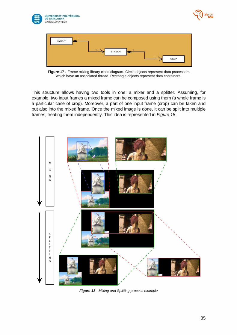
This structure allows having two tools in one: a mixer and a splitter. Assuming, for
example, two input frames a mixed frame can be composed using them (a whole frame is
a particular case of crop). Moreover, a part of one input frame (crop) can be taken and
put also into the mixed frame. Once the mixed image is done, it can be split into multiple
frames, treating them independently. This idea is represented in Figure 18.
Figure 18 - Mixing and Splitting process example
36
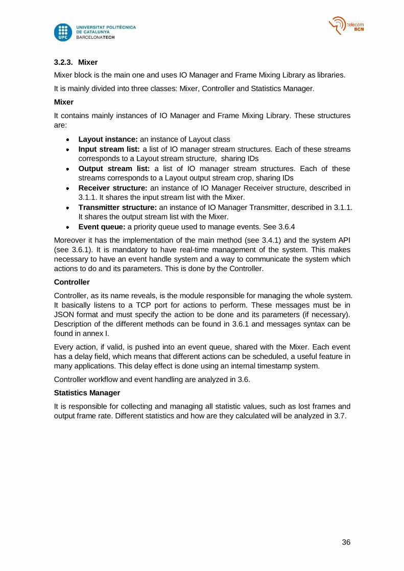
3.2.3. Mixer
Mixer block is the main one and uses IO Manager and Frame Mixing Library as libraries.
It is mainly divided into three classes: Mixer, Controller and Statistics Manager.
Mixer
It contains mainly instances of IO Manager and Frame Mixing Library. These structures
are:
Layout instance: an instance of Layout class
Input stream list: a list of IO manager stream structures. Each of these streams
corresponds to a Layout stream structure, sharing IDs
Output stream list: a list of IO manager stream structures. Each of these
streams corresponds to a Layout output stream crop, sharing IDs
Receiver structure: an instance of IO Manager Receiver structure, described in
3.1.1. It shares the input stream list with the Mixer.
Transmitter structure: an instance of IO Manager Transmitter, described in 3.1.1.
It shares the output stream list with the Mixer.
Event queue: a priority queue used to manage events. See 3.6.4
Moreover it has the implementation of the main method (see 3.4.1) and the system API
(see 3.6.1). It is mandatory to have real-time management of the system. This makes
necessary to have an event handle system and a way to communicate the system which
actions to do and its parameters. This is done by the Controller.
Controller
Controller, as its name reveals, is the module responsible for managing the whole system.
It basically listens to a TCP port for actions to perform. These messages must be in
JSON format and must specify the action to be done and its parameters (if necessary).
Description of the different methods can be found in 3.6.1 and messages syntax can be
found in annex I.
Every action, if valid, is pushed into an event queue, shared with the Mixer. Each event
has a delay field, which means that different actions can be scheduled, a useful feature in
many applications. This delay effect is done using an internal timestamp system.
Controller workflow and event handling are analyzed in 3.6.
Statistics Manager
It is responsible for collecting and managing all statistic values, such as lost frames and
output frame rate. Different statistics and how are they calculated will be analyzed in 3.7.
37
Figure 19 - System class diagram. Circle objects represent data processors, which have an associated thread. Rectangle objects represent data containers.
38
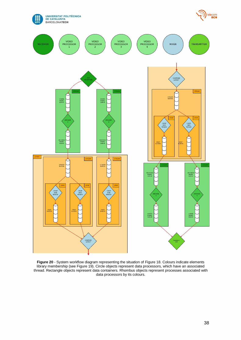
Figure 20 - System workflow diagram representing the situation of Figure 18. Colours indicate elements library membership (see Figure 19). Circle objects represent data processors, which have an associated
thread. Rectangle objects represent data containers. Rhombus objects represent processes associated with data processors by its colours.
39
3.3. RTP Reception
As it has been seen in chapter 2, H.264 VCL information is encapsulated in NAL packets,
which in turn are encapsulated in RTP packets.
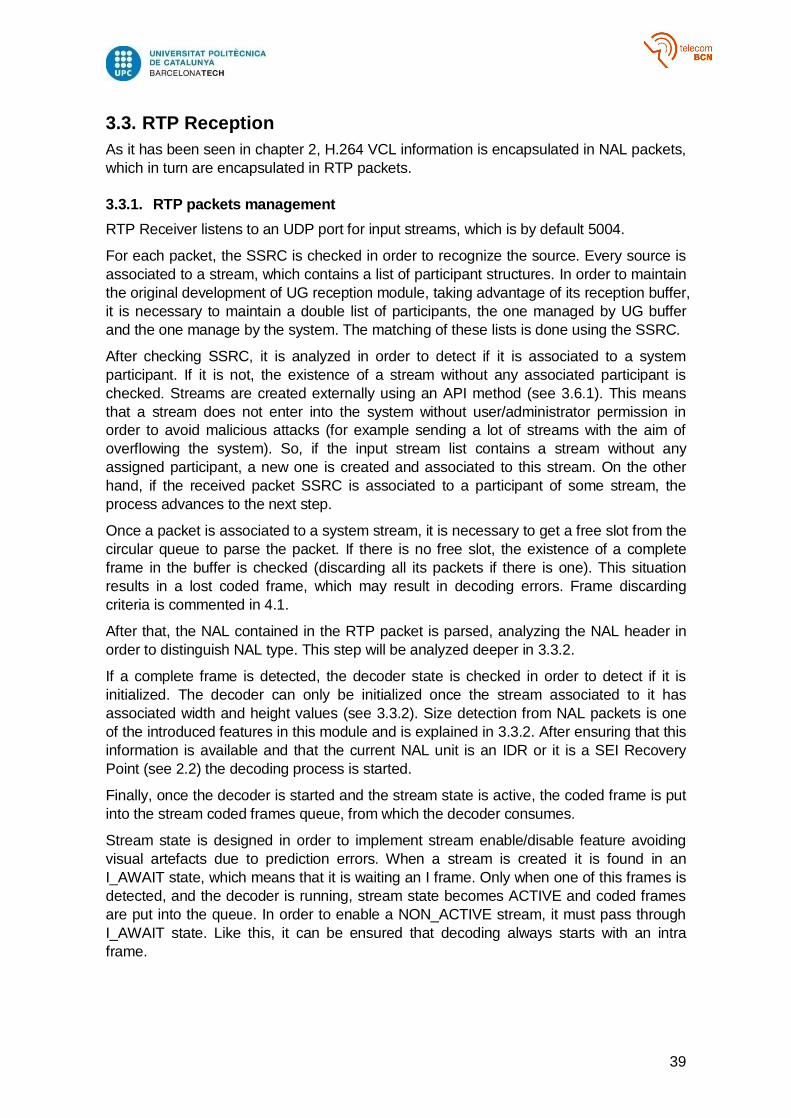
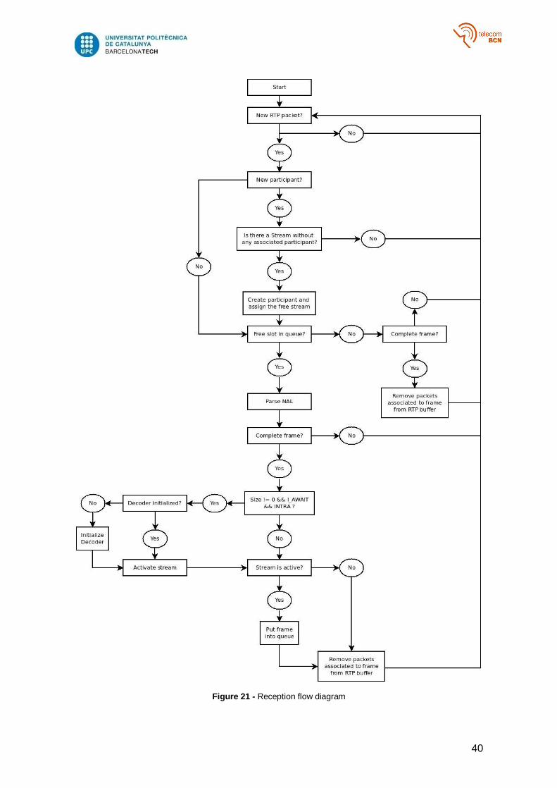
3.3.1. RTP packets management
RTP Receiver listens to an UDP port for input streams, which is by default 5004.
For each packet, the SSRC is checked in order to recognize the source. Every source is
associated to a stream, which contains a list of participant structures. In order to maintain
the original development of UG reception module, taking advantage of its reception buffer,
it is necessary to maintain a double list of participants, the one managed by UG buffer
and the one manage by the system. The matching of these lists is done using the SSRC.
After checking SSRC, it is analyzed in order to detect if it is associated to a system
participant. If it is not, the existence of a stream without any associated participant is
checked. Streams are created externally using an API method (see 3.6.1). This means
that a stream does not enter into the system without user/administrator permission in
order to avoid malicious attacks (for example sending a lot of streams with the aim of
overflowing the system). So, if the input stream list contains a stream without any
assigned participant, a new one is created and associated to this stream. On the other
hand, if the received packet SSRC is associated to a participant of some stream, the
process advances to the next step.
Once a packet is associated to a system stream, it is necessary to get a free slot from the
circular queue to parse the packet. If there is no free slot, the existence of a complete
frame in the buffer is checked (discarding all its packets if there is one). This situation
results in a lost coded frame, which may result in decoding errors. Frame discarding
criteria is commented in 4.1.
After that, the NAL contained in the RTP packet is parsed, analyzing the NAL header in
order to distinguish NAL type. This step will be analyzed deeper in 3.3.2.
If a complete frame is detected, the decoder state is checked in order to detect if it is
initialized. The decoder can only be initialized once the stream associated to it has
associated width and height values (see 3.3.2). Size detection from NAL packets is one
of the introduced features in this module and is explained in 3.3.2. After ensuring that this
information is available and that the current NAL unit is an IDR or it is a SEI Recovery
Point (see 2.2) the decoding process is started.
Finally, once the decoder is started and the stream state is active, the coded frame is put
into the stream coded frames queue, from which the decoder consumes.
Stream state is designed in order to implement stream enable/disable feature avoiding
visual artefacts due to prediction errors. When a stream is created it is found in an
I_AWAIT state, which means that it is waiting an I frame. Only when one of this frames is
detected, and the decoder is running, stream state becomes ACTIVE and coded frames
are put into the queue. In order to enable a NON_ACTIVE stream, it must pass through
I_AWAIT state. Like this, it can be ensured that decoding always starts with an intra
frame.
40
Figure 21 - Reception flow diagram
41
3.3.2. NAL parsing
One of the operations performed by the receiver is NAL units parsing.
First of all, it must be said that only some type of NAL units are contemplated: 1-23, 24
and 28. Using NRI and NAL type, a type is associated to every frame. Contemplated
types are INTRA, which is associated to frames composed by NAL type 5 units or frames
following a SEI Recovery Point; BFRAME, which indicates B-type slices (not supported
by our system); and finally OTHER, which involves other types.
Moreover, when some types of NAL are detected, apart from parsing and buffering the
contained VCL info, a key action has been added: stream width and height automatic
detection.
This is possible because of SPS NALs (see 2.2.1). Using some of the fields contained in
this NAL width and height can be known (supposing a MB size of 16x16):
pic_width_in_mbs_minus1
pic_height_in_map_units_minus1
frame_mbs_only_flag, which indicates if the video is progressive or interlaced.
frame_cropping_flag, which indicates offset in case width and height are not
multiple of MB size (frame_crop_left_offset, frame_crop_right_offset,
frame_crop_top_offset, frame_crop_bottom_offset)
If frame_cropping_flag is 1, width and height must be modified this way:
Every time an SPS NAL is detected, width and height values, which are contained in
every frame, are revised and modified, if necessary (in this case the decoder is
reconfigured).
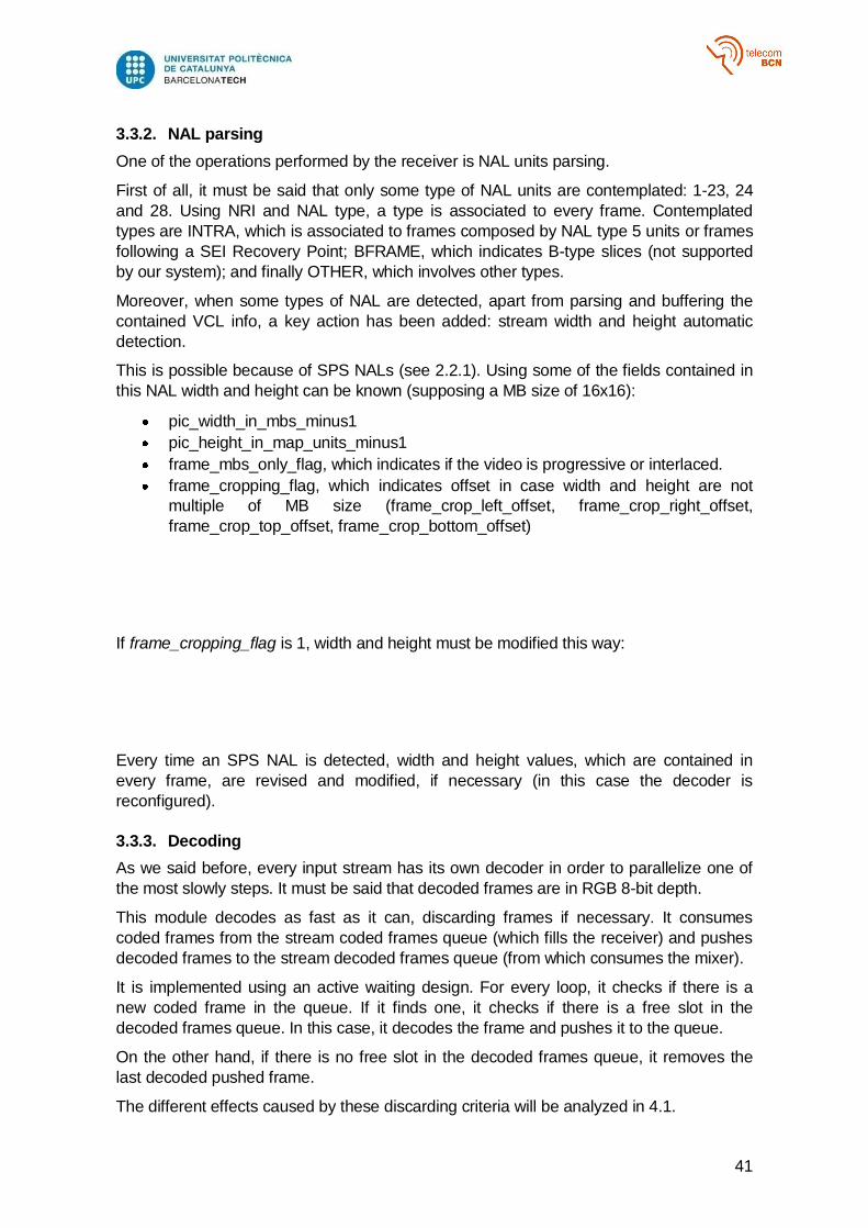
3.3.3. Decoding
As we said before, every input stream has its own decoder in order to parallelize one of
the most slowly steps. It must be said that decoded frames are in RGB 8-bit depth.
This module decodes as fast as it can, discarding frames if necessary. It consumes
coded frames from the stream coded frames queue (which fills the receiver) and pushes
decoded frames to the stream decoded frames queue (from which consumes the mixer).
It is implemented using an active waiting design. For every loop, it checks if there is a
new coded frame in the queue. If it finds one, it checks if there is a free slot in the
decoded frames queue. In this case, it decodes the frame and pushes it to the queue.
On the other hand, if there is no free slot in the decoded frames queue, it removes the
last decoded pushed frame.
The different effects caused by these discarding criteria will be analyzed in 4.1.
42
Figure 22 - Decoding flow diagram
43
3.4. Mixing
Mixing step is done by Mixer (see 3.2.3). In this chapter its main routine and some other
features are described
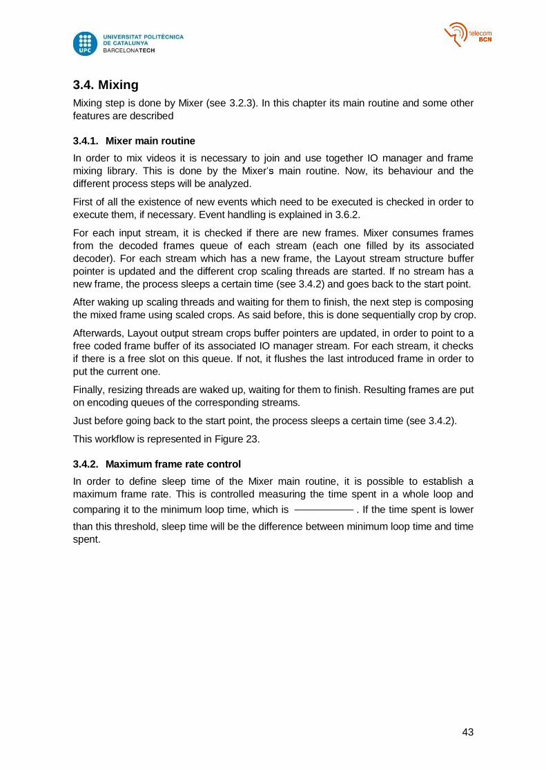
3.4.1. Mixer main routine
In order to mix videos it is necessary to join and use together IO manager and frame
mixing library. This is done by the Mixer main routine. Now, its behaviour and the
different process steps will be analyzed.
First of all the existence of new events which need to be executed is checked in order to
execute them, if necessary. Event handling is explained in 3.6.2.
For each input stream, it is checked if there are new frames. Mixer consumes frames
from the decoded frames queue of each stream (each one filled by its associated
decoder). For each stream which has a new frame, the Layout stream structure buffer
pointer is updated and the different crop scaling threads are started. If no stream has a
new frame, the process sleeps a certain time (see 3.4.2) and goes back to the start point.
After waking up scaling threads and waiting for them to finish, the next step is composing
the mixed frame using scaled crops. As said before, this is done sequentially crop by crop.
Afterwards, Layout output stream crops buffer pointers are updated, in order to point to a
free coded frame buffer of its associated IO manager stream. For each stream, it checks
if there is a free slot on this queue. If not, it flushes the last introduced frame in order to
put the current one.
Finally, resizing threads are waked up, waiting for them to finish. Resulting frames are put
on encoding queues of the corresponding streams.
Just before going back to the start point, the process sleeps a certain time (see 3.4.2).
This workflow is represented in Figure 23.
3.4.2. Maximum frame rate control
In order to define sleep time of the Mixer main routine, it is possible to establish a
maximum frame rate. This is controlled measuring the time spent in a whole loop and
comparing it to the minimum loop time, which is . If the time spent is lower
than this threshold, sleep time will be the difference between minimum loop time and time
spent.

44
Figure 23 - Mixer flow diagram
45
3.5. RTP Transmission
The final step of the system flow is encoding mixed frames (and/or its crops) and sending
them to the associated participants, defined by an IP address and a port.
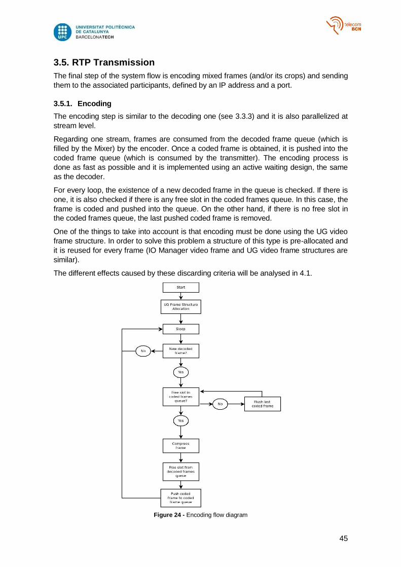
3.5.1. Encoding
The encoding step is similar to the decoding one (see 3.3.3) and it is also parallelized at
stream level.
Regarding one stream, frames are consumed from the decoded frame queue (which is
filled by the Mixer) by the encoder. Once a coded frame is obtained, it is pushed into the
coded frame queue (which is consumed by the transmitter). The encoding process is
done as fast as possible and it is implemented using an active waiting design, the same
as the decoder.
For every loop, the existence of a new decoded frame in the queue is checked. If there is
one, it is also checked if there is any free slot in the coded frames queue. In this case, the
frame is coded and pushed into the queue. On the other hand, if there is no free slot in
the coded frames queue, the last pushed coded frame is removed.
One of the things to take into account is that encoding must be done using the UG video
frame structure. In order to solve this problem a structure of this type is pre-allocated and
it is reused for every frame (IO Manager video frame and UG video frame structures are
similar).
The different effects caused by these discarding criteria will be analysed in 4.1.
Figure 24 - Encoding flow diagram
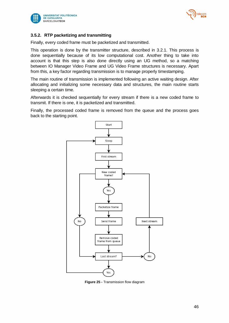
46
3.5.2. RTP packetizing and transmitting
Finally, every coded frame must be packetized and transmitted.
This operation is done by the transmitter structure, described in 3.2.1. This process is
done sequentially because of its low computational cost. Another thing to take into
account is that this step is also done directly using an UG method, so a matching
between IO Manager Video Frame and UG Video Frame structures is necessary. Apart
from this, a key factor regarding transmission is to manage properly timestamping.
The main routine of transmission is implemented following an active waiting design. After
allocating and initializing some necessary data and structures, the main routine starts
sleeping a certain time.
Afterwards it is checked sequentially for every stream if there is a new coded frame to
transmit. If there is one, it is packetized and transmitted.
Finally, the processed coded frame is removed from the queue and the process goes
back to the starting point.
Figure 25 - Transmission flow diagram

47
3.6. System external management
Real-time management is essential in a production tool. This feature is meant to be done
by Controller class (see 3.2.3) and Event class. In this chapter the public API is described
along with Controller workflow and event management.
3.6.1. Mixer Public API
A human readable API has been designed in order to perform the actions of a traditional
production tool and mainly manage the whole system. This is only a description of the
actions; a more formal version (with parameter types, JSON format and syntax) can be
found in annex I.
The first ones are executed directly by the Controller and involve Mixer object instance
management:
Start: it is the first step in order to use the system. It involves instantiating a Mixer
object (initialising Mixer structures) and start Mixer main routine. Its parameters
are layout (mixed video) width and height.
Stop: it destroys the Mixer object. It involves stopping all the processes and clean
memory allocated by structures.
Exit: it exits the Controller, destroying a Mixer object if it is running.
The second ones are directly methods regarding Mixer actions:
Add source: registers a new input stream. It has no parameters (remember that
width and height are auto detected). It returns the ID assigned to the stream.
Remove source: removes an input stream (both Layout and IO Manager stream
structures) and all its crops. The only parameter needed is the ID of the stream to
be removed.
Add crop to source: adds a new crop to the desired stream. Needed parameters
are stream ID, size and position of the original stream cropping area (in pixels),
size and position of the region it will occupy in the layout (in pixels) and layer.
Opacity is by default set to 1.
Modify crop from source: modifies an input stream cropping area. Its
parameters are stream ID, crop ID and new size and position of the area.
Modify crop resizing from source: modifies crop layout region parameters from
an input stream. Parameters are stream ID, crop ID, new size and position of the
region it will occupy in the layout, new layer and new opacity value.
Remove crop from source: removes an input stream crop. Its parameters are
only stream ID which it forms part of and the ID of the crop to be removed.
Enable crop from source: it enables the displaying of an input stream crop. Its
parameters are the stream ID and the crop ID.
Disable crop from source: it disables the displaying of an input stream crop. Its
parameters are the stream ID and the crop ID.
Add crop to layout: add a new crop to the layout which will be associated to an
IO Manager output stream. Needed parameters are cropping are size and position
and output size. Although it also has output position parameter (because it is a
crop object, the same as input crops) this parameter is ignored (because it make
no sense in this context).
Modify crop from layout: modifies the cropping area of a layout crop. Its
parameters are the crop ID and the size and the position of the new area.
48
Modify crop resizing from layout: modifies layout crop output size. Parameters
needed are the crop ID and the new output size.
Remove crop from layout: removes a layout crop and the IO Manager stream
structure associated. The needed parameter is the ID of the crop to be removed.
Add destination: adds a destination to an output stream. Its parameters are IP
address and port.
Remove destination: removes a destination from an output stream. The only
parameter needed is the participant ID.
Finally, the third block concerns consultation methods. Response JSON format of all
methods is specified in annex I.
Get streams: returns information about input streams and its crops.
Get layout: returns information about the layout, its crops and the associated
output streams.
Get stats: returns information about system statistics
Get layout size: returns layout width and height.
Get stream: returns information about one input stream. Its unique parameter is
the ID of the stream.
Get crop from stream: returns information about an input stream crop. Its
parameters are the stream ID and the crop ID.
3.6.2. Events
Each of these methods are encapsulated into an Event structure and pushed into an
event queue, which is shared by Controller and Mixer.
An Event structure has mainly these parameters:
Delay: associated delay to the event.
Socket: socket structure in order to send the method response and close the TCP
connection established by the Controller.
Timestamp: associated timestamp, which indicates to the Mixer when to execute
the event.
Input JSON: JSON which contains the parameters of the associated method
Function: reference to a Mixer method
The event queue is an implementation of a priority queue, which means that events are
automatically ordered by a certain value. In this case its timestamp value.
3.6.3. Controller workflow
Controller is responsible for managing the external communication of the system and
creating the events. Moreover, it is the class which is executed to deploy the whole
system. Listening port is an execution argument.
Controller workflow is simple. First of all it opens a socket in order to receive TCP
connection requests. When a request is received, it establishes the connection and
buffers the received data. As we said before, this data must be in JSON format. In order
to deal with it, an external library is used [5].
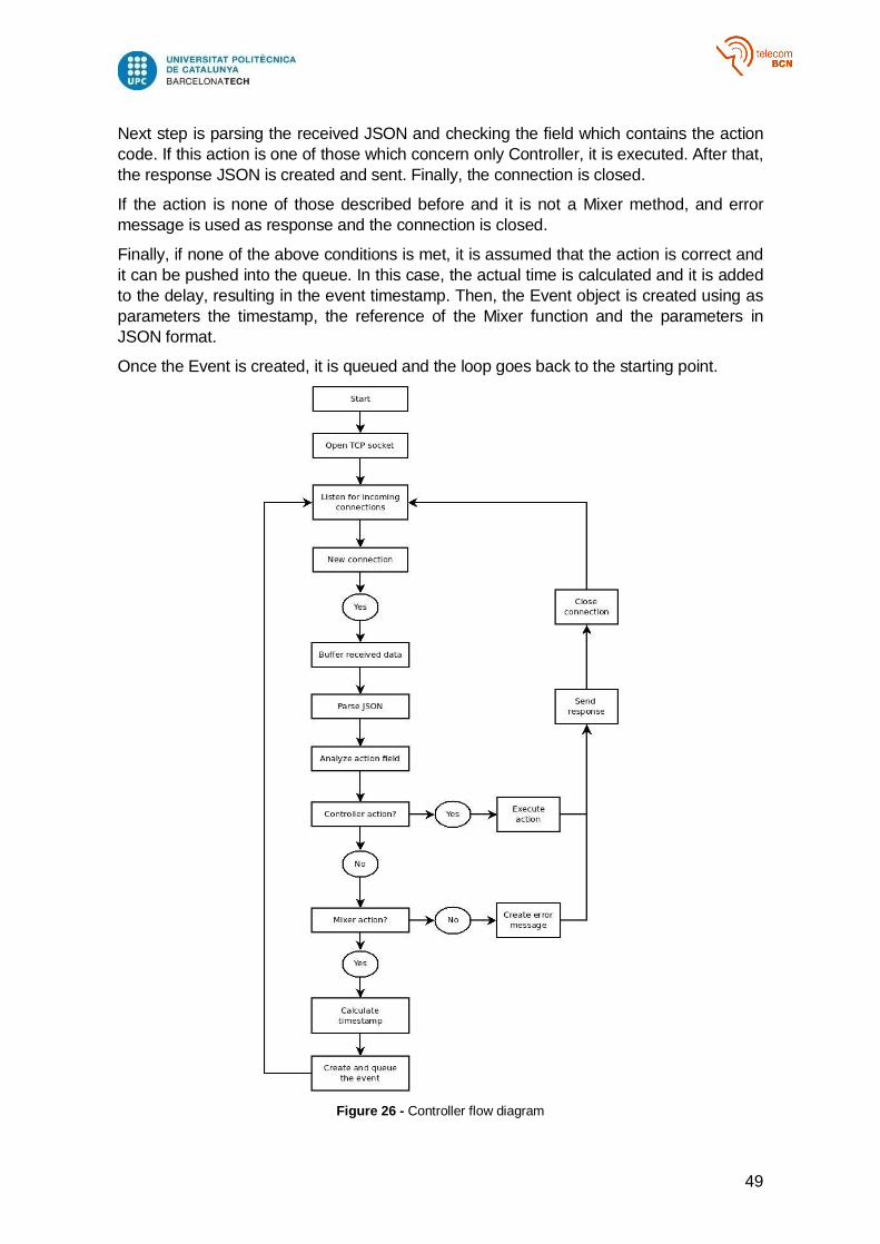
49
Next step is parsing the received JSON and checking the field which contains the action
code. If this action is one of those which concern only Controller, it is executed. After that,
the response JSON is created and sent. Finally, the connection is closed.
If the action is none of those described before and it is not a Mixer method, and error
message is used as response and the connection is closed.
Finally, if none of the above conditions is met, it is assumed that the action is correct and
it can be pushed into the queue. In this case, the actual time is calculated and it is added
to the delay, resulting in the event timestamp. Then, the Event object is created using as
parameters the timestamp, the reference of the Mixer function and the parameters in
JSON format.
Once the Event is created, it is queued and the loop goes back to the starting point.
Figure 26 - Controller flow diagram
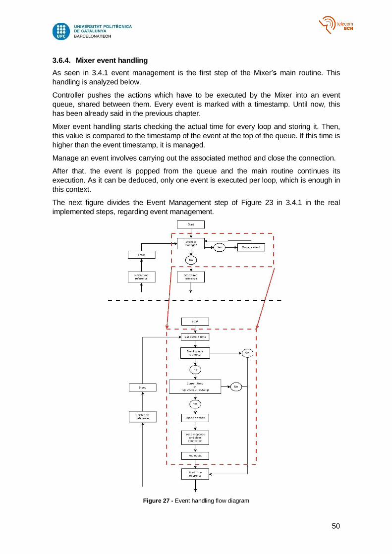
50
3.6.4. Mixer event handling
As seen in 3.4.1 event management is the first step of the Mixer main routine. This
handling is analyzed below.
Controller pushes the actions which have to be executed by the Mixer into an event
queue, shared between them. Every event is marked with a timestamp. Until now, this
has been already said in the previous chapter.
Mixer event handling starts checking the actual time for every loop and storing it. Then,
this value is compared to the timestamp of the event at the top of the queue. If this time is
higher than the event timestamp, it is managed.
Manage an event involves carrying out the associated method and close the connection.
After that, the event is popped from the queue and the main routine continues its
execution. As it can be deduced, only one event is executed per loop, which is enough in
this context.
The next figure divides the Event Management step of Figure 23 in 3.4.1 in the real
implemented steps, regarding event management.
Figure 27 - Event handling flow diagram
51
3.7. Statistics Manager
Although it is easy to evaluate the performance of a video system visually, it is necessary
to do it using objective measures too. This is the scope of the Statistics Manager. In this
section, measured parameters are described. Its analysis is carried out in chapter 4.
Statistics management involves a computational cost overrun that can affect the whole
performance of the system. Because of this, the decision of managing statistics or not is
taken at compilation time.
3.7.1. Overview
Statistics system is based on the existence of a Manager class responsible for collecting
all the statistics and presenting it to the user.
Every IO Manager Stream structure has its own parameters and Mixer has its ones also.
Using all this information a sort of general statistics estimation is done. These parameters
are updated every certain time associated to Mixer main process loops. So, the method
that loads new statistics data is executed at the end of every Mixer main routine loop.
3.7.2. Stream statistics
Each stream has its own statistics
Delay
It is the average delay introduced by process steps.
Regarding an input stream frame, it is the time between it is introduced by the receiver in
the coded frames queue and it is removed from the decoded frames queue (decoding
and resizing time). As we can see, depacketizing time is ignored.
Regarding an output stream frame, it is the time between it is put into the decoded frames
queue by the Mixer and it is removed from the coded frames queue by the transmitter
(scaling, encoding and packetizing time).
It is computed frame by frame and averaged every certain quantity of put and remove
operation executions.
Frame rate
Output stream frame rate is calculated as the time between two consecutive put
operations to the decoded frame queue (done by the Mixer).
It is also computed frame by frame and averaged every time a certain amount of put and
remove operations has been reached.
Lost coded frames
Regarding input streams, lost coded frame number is increased every time the receiver
fails to put a coded frame into the coded frame queue of an input stream. As described in
3.3, it removes the last introduced frame in order to put the current one. As it will be seen
in chapter 4, this can lead to decoding errors
Regarding output streams, lost coded frame number is increased every time the encoder
tries to push a coded frame into the coded frame queue of an output stream and it is full.
In this case, it removes the last introduced coded frame in order to put the current one.
Lost decoded frames

52
Regarding input streams, lost decoded frame number is computed using sequence
numbers. Every frame is marked by a sequence number, which starts at 0 and increases
by one for each frame. Every time the Mixer takes a decoded frame from a queue, it
checks it sequence number. If it is not consecutive with the last it took, it increases the
lost decoded frame number the difference between the two sequence numbers minus 1.
Sequence number is also used to count the number of total frames.
On the other hand, it is not necessary to use sequence numbers to compute output
streams lost decoded frames. Every time Mixer tries to push a frame into the decoded
frames queue and it is full, it removes the last introduced frame so this number is
increased. However, sequence number is used in this case to compute total frames.
3.7.3. Mixer statistics
The only measure exclusively managed by the Mixer and common for every stream is the
time spent composing the layout, splitting it and resizing these output crops.
It is measured for every mixed frame and averaged every certain number of loops.
3.7.4. General statistics
Finally, statistics used to evaluate the system are computed using the ones described
above. These measures are updated every time the update statistics method is executed
by the Mixer.
Total delay
It is the sum of the maximum input stream delay, the maximum output stream delay and
the average mixing delay. So, we can consider it the maximum introduced delay by the
system.
Lost input frames
It is the percentage of frames (both coded and decoded) lost by all the input streams.
Lost output frames
It is the percentage of frames (both coded and decoded) lost by all the output streams
Output frame rate
It is the lowest output stream frame rate.
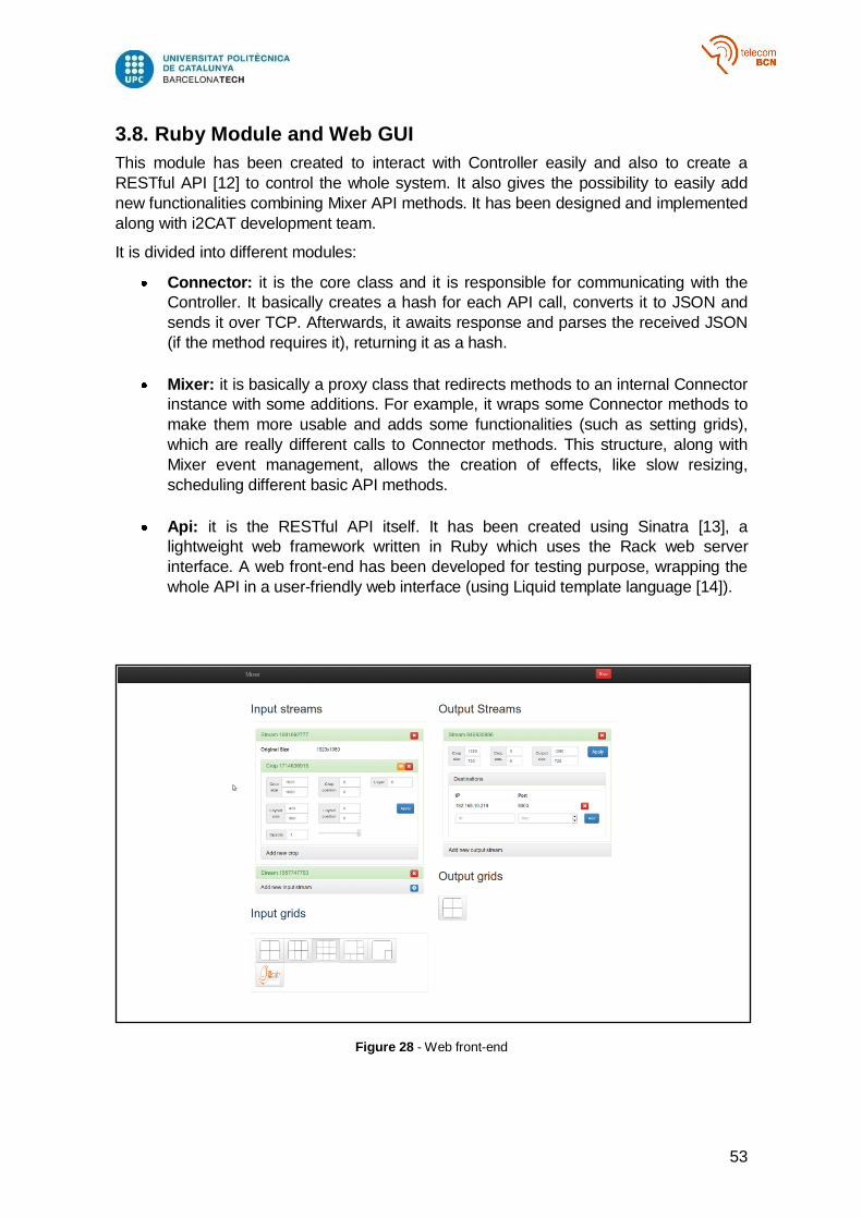
53
3.8. Ruby Module and Web GUI
This module has been created to interact with Controller easily and also to create a
RESTful API [12] to control the whole system. It also gives the possibility to easily add
new functionalities combining Mixer API methods. It has been designed and implemented
along with i2CAT development team.
It is divided into different modules:
Connector: it is the core class and it is responsible for communicating with the
Controller. It basically creates a hash for each API call, converts it to JSON and
sends it over TCP. Afterwards, it awaits response and parses the received JSON
(if the method requires it), returning it as a hash.
Mixer: it is basically a proxy class that redirects methods to an internal Connector
instance with some additions. For example, it wraps some Connector methods to
make them more usable and adds some functionalities (such as setting grids),
which are really different calls to Connector methods. This structure, along with
Mixer event management, allows the creation of effects, like slow resizing,
scheduling different basic API methods.
Api: it is the RESTful API itself. It has been created using Sinatra [13], a
lightweight web framework written in Ruby which uses the Rack web server
interface. A web front-end has been developed for testing purpose, wrapping the
whole API in a user-friendly web interface (using Liquid template language [14]).
Figure 28 - Web front-end

54
4. RESULTS
4.1. Frame discarding analysis
The system has been designed and developed thinking always in real-time applications.
This means that maintaining the frame rate as high as possible is more important than
data consistence.
Regarding one module, if the process time for a frame is lower than the frame input rate
on that module, there is no problem. However, this is not the case. Operations involved in
every module of the system have a high computational cost and the assumption made
before is not true. Although stream frame queues act as buffers and can manage peaks,
queues overflowing has to be managed as well (basically discarding frames).
4.1.1. Frame discarding between receiver and decoder
Regarding one stream, this occurs when the time spent decoding a frame is higher than
the received frame rate. As explained in 3.3 and as is represented in Figure 30 it
supposes discarding coded frames, involving decoding errors.
Increasing frame queue slots can be a possible solution in order to manage peaks, but if
the decoding process is too slow the buffer will be overflowed anyway.
Loosing coded frames is an important problem that affects the integrity of the decoded
frames and, of course, the quality of the video. If the discarded frame is an Intra frame, all
the frames which are predicted from it will have errors and the video will not be decoded
properly until the next intra frame arrives. On the other hand, if a P frame is lost, the next
one will be reconstructed wrongly. This error will be spread until the end of the next Intra
frame.
Figure 30 represents this situation.
4.1.2. Frame discarding between decoder and mixer
The next step to analyze is the frame discarding between decoder and mixer. As seen in
3.4, in this case, frame losses regard decoded frames. Discarding decoded frames
decrease
A simplified version of this situation can be done simulating a system which receives a
stream at a certain frame rate. This discards a percentage of frames and sends the non-
discarded frames to a sink, which consumes the stream.
Figure 29 - Decoded frames discarding effects
55
For example, if a supposed Discarding Module receives a stream at 25 frames per
second and discards a 20% of frames, the sink receiving frame rate will be only of 20
frames per second. Regarding our system, for an input stream the Sink is the Mixer, the
Discarding module is the stream Decoder and the source is the Receiver. The Discarding
rate can be associated to the Input Decoded Frame Losses percentage associated to that
stream.
Figure 31 represents a decoded frame lost situation
4.1.3. Frame discarding between mixer and encoder
This step is similar to the one described in 4.2.2 (Frame discarding between decoder and
mixer) because the discarded frames are decoded frames. This means that this situation
can be represented with the same schema (Figure 29) for an output stream (which is
associated to a composed frame crop). In this case both the Source and the Discarding
Module will be the Mixer and the Sink will be the stream Encoder.
Every time there is a new input frame of any of the Mixer input streams, the Mixer
composes a new layout, what means that there is a new decoded frame (which is a crop
of the composed frame) to push into the output stream queue. Because of this, the output
frame rate can be higher than the maximum input frame rate. However, the system sets a
maximum frame rate.
Figure 32 represents this situation
4.1.4. Frame discarding between encoder and transmitter
The final step when frame discarding is possible is in output streams coded frame queues.
Losing coded frames involves, as seen in 4.1.1, decoding errors (in this case in the
receivers of the destinations associated to the stream).
However, this case will not be explained as deeply as the other ones because it is difficult
to achieve this situation. Transmitter step consists on parsing frames in different NALs if
necessary and adding the RTP header. This process is about ten times faster than
encoding process. Although it is not parallelized by streams, unlike encoding, there must
be a lot of streams and destinations associated to them in order to discard frames in this
step.
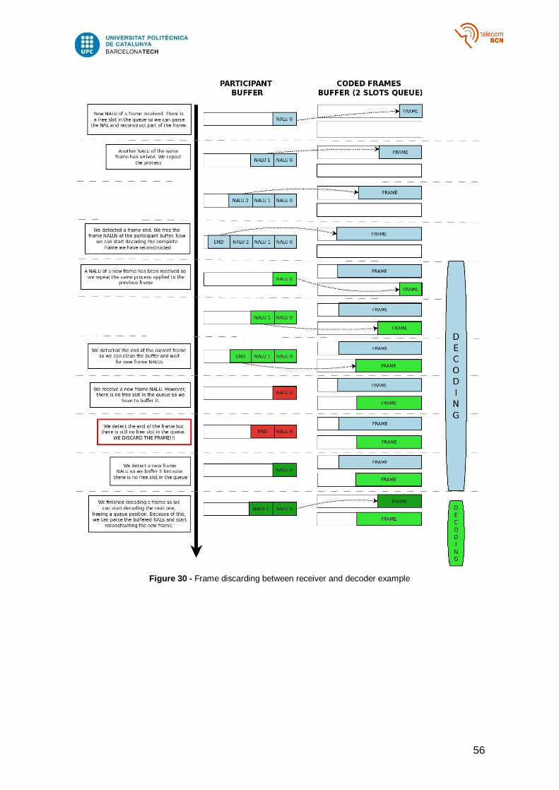
56
Figure 30 - Frame discarding between receiver and decoder example
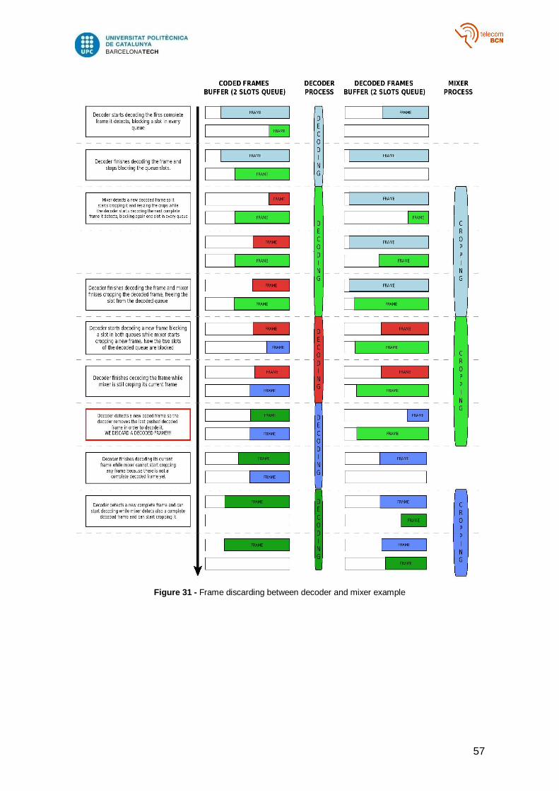
57
Figure 31 - Frame discarding between decoder and mixer example
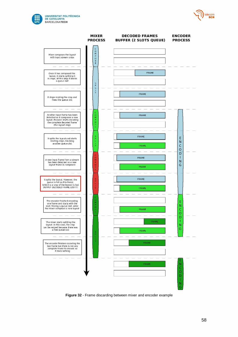
58
Figure 32 - Frame discarding between mixer and encoder example
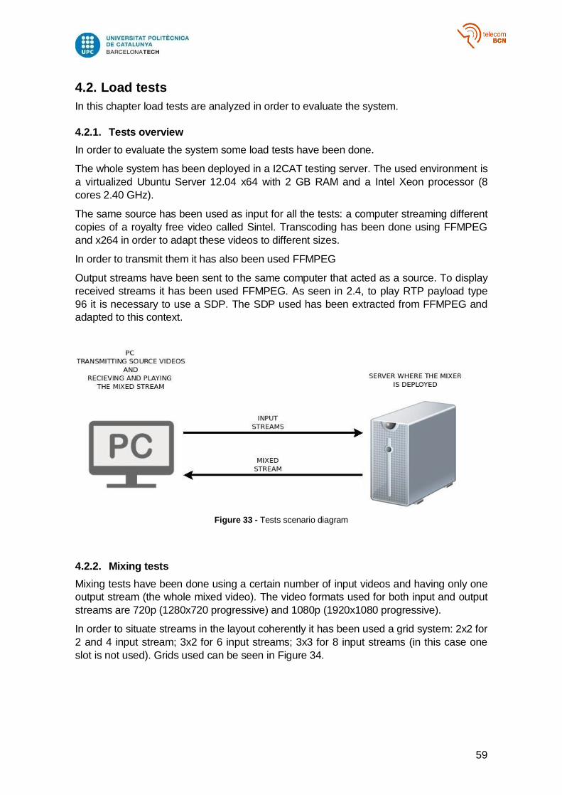
59
4.2. Load tests
In this chapter load tests are analyzed in order to evaluate the system.
4.2.1. Tests overview
In order to evaluate the system some load tests have been done.
The whole system has been deployed in a I2CAT testing server. The used environment is
a virtualized Ubuntu Server 12.04 x64 with 2 GB RAM and a Intel Xeon processor (8
cores 2.40 GHz).
The same source has been used as input for all the tests: a computer streaming different
copies of a royalty free video called Sintel. Transcoding has been done using FFMPEG
and x264 in order to adapt these videos to different sizes.
In order to transmit them it has also been used FFMPEG
Output streams have been sent to the same computer that acted as a source. To display
received streams it has been used FFMPEG. As seen in 2.4, to play RTP payload type
96 it is necessary to use a SDP. The SDP used has been extracted from FFMPEG and
adapted to this context.
Figure 33 - Tests scenario diagram
4.2.2. Mixing tests
Mixing tests have been done using a certain number of input videos and having only one
output stream (the whole mixed video). The video formats used for both input and output
streams are 720p (1280x720 progressive) and 1080p (1920x1080 progressive).
In order to situate streams in the layout coherently it has been used a grid system: 2x2 for
2 and 4 input stream; 3x2 for 6 input streams; 3x3 for 8 input streams (in this case one
slot is not used). Grids used can be seen in Figure 34.
60
Figure 34 - Grid set used
The 4 different scenarios contemplated are analyzed using two charts. The first one
reflects frame losses and output frame rate whereas the second one reflects the delay
introduced by the system for each step. The different scenarios analyses are put together,
followed by all the charts.
Input: 720p Output: 720p
The system working with 720p input streams and having as output a 720p stream works
properly managing 2 and 4 input streams. Output frame rate is higher than the original
input frame rate of the streams (24 fps) and there are no frame losses.
When the system manages 6 input streams there are some input coded frame losses,
which affect directly to the visual perception quality (there are decoding errors, as it is
explained in 4.2). However the percentage is low (1%) and it can be considered negligible.
As there are no losses of input decoded frames it also can be considered that the original
input frame rate for every stream is the maintained.
Finally, for 8 input streams, input coded frame losses increase a bit and there are
decoded frame losses (about 11%), which mean that the original input frame rate of each
stream decreases and that some decoding errors appear.
Regarding the introduced delay, in the worst case its value is below 100 ms, which is a
good result according to the project specifications (300 ms maximum delay). It also can
be noticed that input delay, which involves decoding and resizing, is the step which
introduces more delay. Mixing delay is almost negligible while output delay is not as high
as input delay.
Associated charts are Figure 35 and Figure 36.
Input: 720p Output: 1080p
The performance managing 720p input streams and a 1080p output stream is
represented in Figure 37. Analyzing the chart, it can be considered that the system works
properly only with 2 input streams. The output frame rate is over 24 and there are no
input frames losses.
However, when managing 4 and 6 input streams some input and output decoded frames
losses appear and consequently decrease the frame rate.
Finally, having 8 input streams, there are input coded frames losses. Moreover, the
number of decoded frame losses increase so the frame rate decays a lot (about 17 fps).
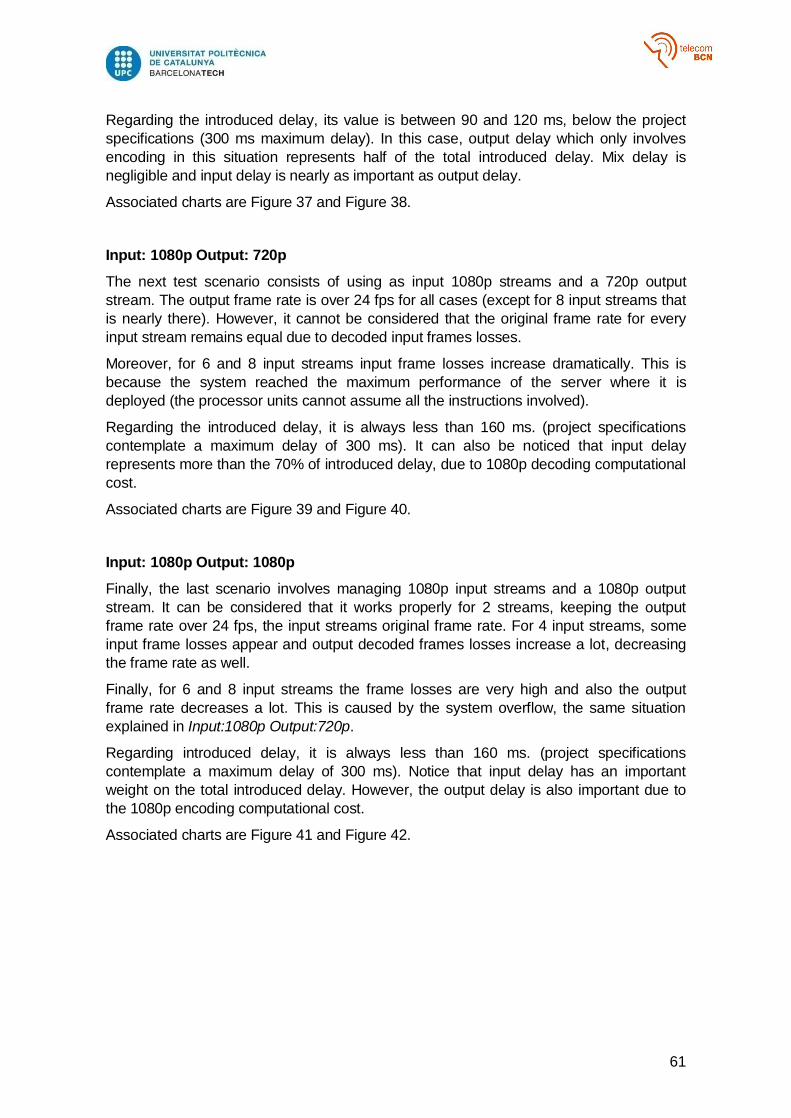
61
Regarding the introduced delay, its value is between 90 and 120 ms, below the project
specifications (300 ms maximum delay). In this case, output delay which only involves
encoding in this situation represents half of the total introduced delay. Mix delay is
negligible and input delay is nearly as important as output delay.
Associated charts are Figure 37 and Figure 38.
Input: 1080p Output: 720p
The next test scenario consists of using as input 1080p streams and a 720p output
stream. The output frame rate is over 24 fps for all cases (except for 8 input streams that
is nearly there). However, it cannot be considered that the original frame rate for every
input stream remains equal due to decoded input frames losses.
Moreover, for 6 and 8 input streams input frame losses increase dramatically. This is
because the system reached the maximum performance of the server where it is
deployed (the processor units cannot assume all the instructions involved).
Regarding the introduced delay, it is always less than 160 ms. (project specifications
contemplate a maximum delay of 300 ms). It can also be noticed that input delay
represents more than the 70% of introduced delay, due to 1080p decoding computational
cost.
Associated charts are Figure 39 and Figure 40.
Input: 1080p Output: 1080p
Finally, the last scenario involves managing 1080p input streams and a 1080p output
stream. It can be considered that it works properly for 2 streams, keeping the output
frame rate over 24 fps, the input streams original frame rate. For 4 input streams, some
input frame losses appear and output decoded frames losses increase a lot, decreasing
the frame rate as well.
Finally, for 6 and 8 input streams the frame losses are very high and also the output
frame rate decreases a lot. This is caused by the system overflow, the same situation
explained in Input:1080p Output:720p.
Regarding introduced delay, it is always less than 160 ms. (project specifications
contemplate a maximum delay of 300 ms). Notice that input delay has an important
weight on the total introduced delay. However, the output delay is also important due to
the 1080p encoding computational cost.
Associated charts are Figure 41 and Figure 42.
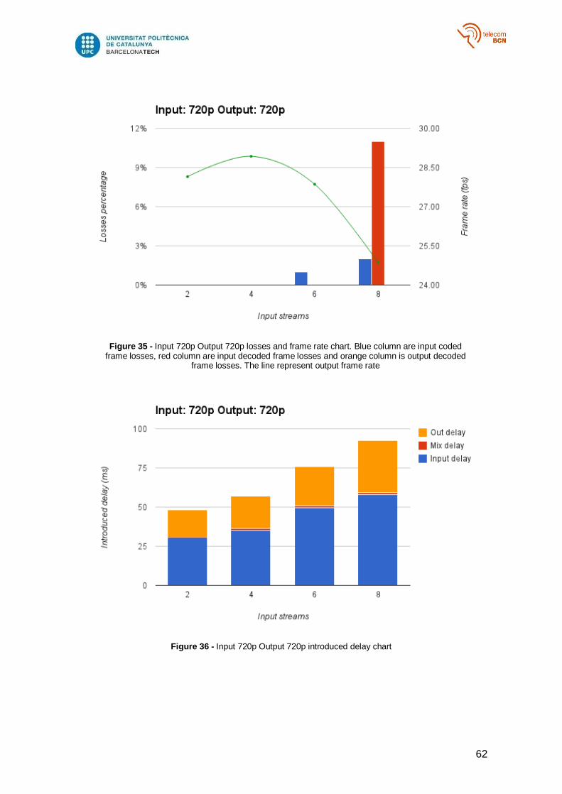
62
Figure 35 - Input 720p Output 720p losses and frame rate chart. Blue column are input coded frame losses, red column are input decoded frame losses and orange column is output decoded
frame losses. The line represent output frame rate
Figure 36 - Input 720p Output 720p introduced delay chart
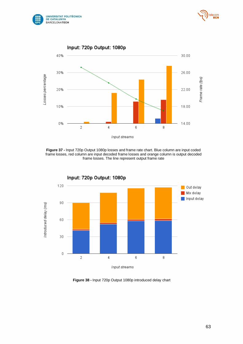
63
Figure 37 - Input 720p Output 1080p losses and frame rate chart. Blue column are input coded frame losses, red column are input decoded frame losses and orange column is output decoded
frame losses. The line represent output frame rate
Figure 38 - Input 720p Output 1080p introduced delay chart

64
Figure 39 - Input 1080p Output 720p losses and frame rate chart. Blue column are input coded frame losses, red column are input decoded frame losses and orange column is output decoded
frame losses. The line represent output frame rate
Figure 40 - Input 1080p Output 720p introduced delay chart
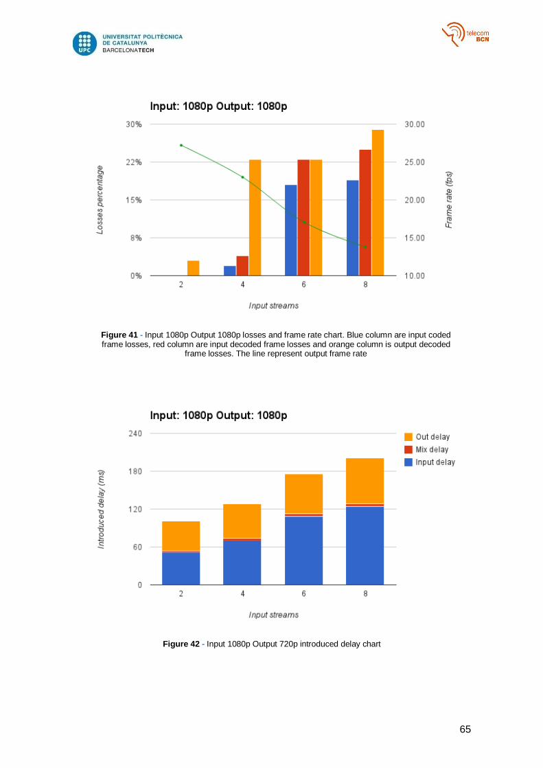
65
Figure 41 - Input 1080p Output 1080p losses and frame rate chart. Blue column are input coded frame losses, red column are input decoded frame losses and orange column is output decoded
frame losses. The line represent output frame rate
Figure 42 - Input 1080p Output 720p introduced delay chart
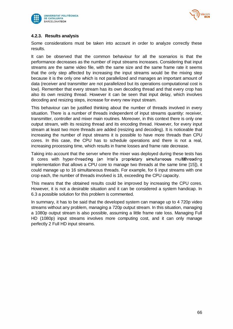
66
4.2.3. Results analysis
Some considerations must be taken into account in order to analyze correctly these
results.
It can be observed that the common behaviour for all the scenarios is that the
performance decreases as the number of input streams increases. Considering that input
streams are the same video file, with the same size and the same frame rate it seems
that the only step affected by increasing the input streams would be the mixing step
because it is the only one which is not parallelized and manages an important amount of
data (receiver and transmitter are not parallelized but its operations computational cost is
low). Remember that every stream has its own decoding thread and that every crop has
also its own resizing thread. However it can be seen that input delay, which involves
decoding and resizing steps, increase for every new input stream.
This behaviour can be justified thinking about the number of threads involved in every
situation. There is a number of threads independent of input streams quantity: receiver,
transmitter, controller and mixer main routines. Moreover, in this context there is only one
output stream, with its resizing thread and its encoding thread. However, for every input
stream at least two more threads are added (resizing and decoding). It is noticeable that
increasing the number of input streams it is possible to have more threads than CPU
cores. In this case, the CPU has to schedule operations and there is not a real,
increasing processing time, which results in frame losses and frame rate decrease.
Taking into account that the server where the mixer was deployed during these tests has
8 cores with hyper-
implementation that allows a CPU core to manage two threads at the same time [15]), it
could manage up to 16 simultaneous threads. For example, for 6 input streams with one
crop each, the number of threads involved is 18, exceeding the CPU capacity.
This means that the obtained results could be improved by increasing the CPU cores.
However, it is not a desirable situation and it can be considered a system handicap. In
6.3 a possible solution for this problem is commented.
In summary, it has to be said that the developed system can manage up to 4 720p video
streams without any problem, managing a 720p output stream. In this situation, managing
a 1080p output stream is also possible, assuming a little frame rate loss. Managing Full
HD (1080p) input streams involves more computing cost, and it can only manage
perfectly 2 Full HD input streams.

67
5. BUDGET
This budget represents the development of a similar project to the one described in this
document. It has been done regarding software development hours and software
documentation and including additional development made by i2CAT Audiovisual Unit.
Hours spent during meetings are also included.
The first table summarizes the amount of hours for each development:
MIXER: which regards this final degree project
IO MANAGER: developed by i2CAT team
RUBY MODULE AND WEB FRONT END: developed by i2CAT team
The implementation of IO Manager, Ruby Module and Web Front End is not part of this
project. However, the time spent designing and developing them must be taken into
account.
Development costs has been counted using as reference a junior developer salary (about
. Moreover, indirect costs incurred by i2CAT are also estimated. These costs
basically regard office rental and maintenance and technical equipment amortization and
maintenance. It is usual to estimate indirect costs as a percentage of direct costs of the
project (usually 20% - 60%).
Table 3 - Project total costs
COSTS Hours
DIRECT COSTS 946 8 7568
MIXER DEVELOPMENT 356 8 2848
IO MANAGER DEVELOPMENT 430 8 3440
RUBY MODULE AND WEB FRONT END DEVELOPMENT 160 8 1280
INDIRECT COSTS - - 2270
30% - -
TOTAL COSTS - - 9838
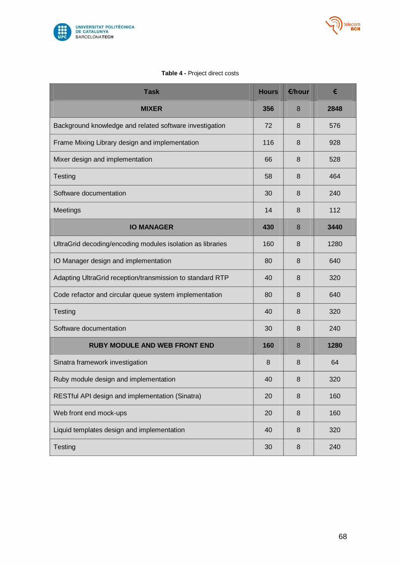
68
Table 4 - Project direct costs
Task Hours
MIXER 356 8 2848
Background knowledge and related software investigation 72 8 576
Frame Mixing Library design and implementation 116 8 928
Mixer design and implementation 66 8 528
Testing 58 8 464
Software documentation 30 8 240
Meetings 14 8 112
IO MANAGER 430 8 3440
UltraGrid decoding/encoding modules isolation as libraries 160 8 1280
IO Manager design and implementation 80 8 640
Adapting UltraGrid reception/transmission to standard RTP 40 8 320
Code refactor and circular queue system implementation 80 8 640
Testing 40 8 320
Software documentation 30 8 240
RUBY MODULE AND WEB FRONT END 160 8 1280
Sinatra framework investigation 8 8 64
Ruby module design and implementation 40 8 320
RESTful API design and implementation (Sinatra) 20 8 160
Web front end mock-ups 20 8 160
Liquid templates design and implementation 40 8 320
Testing 30 8 240
69
6. CONCLUSIONS AND FUTURE DEVELOPMENT
This chapter includes an overall evaluation of the project; talking about achievements and
proposing future research lines related to it. Moreover, possible use cases for the
developed system are exposed.
6.1. Overall evaluation
The aim of this project was developing a real-time production software tool capable of
mixing IP streams. We can say that this objective has been widely accomplished.
Using the developed system 4 H.264 720p video streams at 24 fps can be received and
mixed in a 1280x720 layout, encoding the resultant video stream in H.264 and
transmitting it again to multiple destinations; keeping each stream original frame rate and
introducing only 57 ms of delay.
Nearly every parameter of the system is configurable: number of input streams, layout
size, crops position and size into the layout, layout crops output size, number of
destinations associated to each output stream... These features make the system
scalable and adaptable to many contexts. Additional functionalities such as cropping and
blending were not mandatory, but add value to the overall quality of the system.
Furthermore, real-time management has also been implemented, using a simple TCP
connection and a human readable JSON API. The development of the ruby module made
possible to create several effects easily concatenating different basic operations and to
implement an API REST and a Web Front End.
6.2. Goal accomplishment
As said at the beginning of this project, its success has to be measured in two terms:
functionality and performance.
Regarding functionality, mandatory features have been implemented successfully:
Stream adding and removing
Stream display enabling and disabling
Destination adding and removing
Mixed video size modification
Stream size and position modification
Predefined layout grid application
Moreover, additional implemented features are:
Input stream cropping option
Crop management as independent entities, what means that adding, removing,
enabling/disabling and size and position modification actions can be applied to
each crop.
Layout cropping option, treating every crop as an independent output stream.
Event handling, which offers the possibility to schedule actions.
Blending option for every crop
Concerning performance we considered two scenarios. On a one-way or broadcasting
context, the aim was receiving 4 H264 streams and mix them in a 1280x720 layout,
70
encoding and transmitting it to N destinations, introducing a maximum delay of 300 ms.
This objective has been achieved widely; in this situation the delay introduced by the
system is about 57 ms only, without introducing losses and maintaining the original frame
rate of each stream.
In a bidirectional context, the objective was achieving adaptative frame rate in order to
have a maximum delay between audio and video of 150 ms. This objective has not been
reached because audio is not part of the project. However, the implementation has been
done regarding the possibility of changing the best effort criteria for a frame rate based
criteria for the different processor modules, which will allow implementing adaptative
frame rate.
Regarding generic skills learning, teamwork has been necessary in order to take
decisions along with the i2CAT development team, organize the different tasks assigned
to each member and design the integration between the different developed modules.
The learning and use of tools such as Git (a repository manager) and JIRA (a task
manager) have also been important to learn this skill. Autonomous learning has been
learned while developing the project. It was necessary to make research about video
management open source software, to learn how each one could be useful in the project
context and to investigate how to integrate them into the project. This has been done
searching in the Internet, asking in specialized forums and checking projects
documentation. Moreover it was necessary to decide the different tasks associated to the
project development and carry out each one based on the relevance and importance,
deciding how to carry it out and the time needed, and selecting most appropriate
information sources. The writing of this document and its oral defense ensure the learning
of effective oral and written communication skill.
6.3. Future development
The developed system meets expectations. However, it can be improved in some key
aspects in order to have a complete product, which are analyzed below
6.3.1. Audio
In order to have a complete solution it is mandatory to include audio in the system.
Managing multiple input audio streams, creating mixes and associating them to video
output streams are mandatory features for a professional AV mixing tool. Although it was
not the scope of this project including audio in the system, it has to be said that adding
audio to the system is in i2Cat roadmap and, because of this, IO Manager library was
developed regarding this fact.
All IO Manager structures described in the project have their parallel implementations for
audio. Furthermore, the audio mixer workflow should be similar to the video mixer
developed in this project.
6.3.2. Performance
As it has been said, the main bottlenecks in the whole process are decoding and
encoding processes, as well as scaling. These operations have a high computing cost
and
frame losses and frame rate downfall.
71
In order to solve this, an easy solution is increasing CPU cores of the server where the
mixer is deployed. However, this solution is not optimal because we are engaging the
which is limited. Moreover, the current system structure involves thread creation for every
new stream, compromising the scalability of the system.
Another possible solution is changing the system structure in order to have a workers
pool, where the number of workers would be related to the available hardware. Having
more threads than hardware resources to manage them involves that the CPU has to
schedule operations and the whole performance is affected. Using this structure, the
available resources could be distributed manually depending on context needs (assigning
each worker a specific task, for example audio or video, or even specific hardware) and
ensuring like this that low computational cost operations (audio processing) are not
affected by high computational cost operations (video processing).
Another future development line concerns hardware acceleration in order to speed up the
processing time beyond what the CPU alone can offer. This can be done offloading most
of the resource-intensive operations (decoding, coding and scaling) to the GPU (Graphics
Processing Unit). In contrast to CPUs, GPUs provide a parallel architecture that consists
of a large number of cores. Of course, this solution depends on the hardware, and
depending on this, different parallel computing platforms could be used such as, OpenCL
for most GPUs and CUDA for NVIDIA GPUs.
6.3.3. New features
Project required features implementation has been achieved and even some new
features have been included also. However, in order to have a complete solution it is
necessary to add some important features such as:
New codecs support
Static picture overlay
Text overlay
Chroma key
More sources capturing possibilities (files and hardware)
RTSP support
6.4. Use cases
The developed software can be used in multiple real applications, some of them
commented below.
6.4.1. Video conferencing
If the Mixer is used along with a SIP [16] management unit it can be used as a Video
Conferencing manager, where each input stream is associated to a videoconference
participant. A unique layout is composed depending on the number of participants and is
broadcasted to all the participants.
Obviously this use case requires audio management.
72
6.4.2. Video Wall
A video wall consists of multiple display devices (computer monitors, video projectors, or
television sets) tiled together contiguously or overlapped in order to form one large
screen. There are multiple solutions to deploy and manage video walls; however, most of
them involve high costs and a lot of infrastructure.
Using , it is possible to crop the mixed layout, streaming it to
independent devices (e.g low-cost single-board computer as Raspberry Pi) that are
connected to screens forming a video wall. In this case, synchronism between each crop
would be the main problem to face in order to achieve a good quality.
Using this scheme is possible to offer a low-cost video wall solution.
6.4.3. Real-time video production
Another possible use case for the Mixer is using it to emulate a SRC (Studio Control
Room). Managing different cameras, creating different compositions, switching between
cameras, introducing effects, and overlaying images and text are usual functions carried
out in TV SCRs. As it can be seen, all this functions can be done by the developed Mixer
without using the huge amount of infrastructure of a traditional SCR. Moreover, it can be
managed remotely using any device with a web browser (laptops, tables, smartphones,
PCs).
6.4.4. Security camera system
Security camera systems usually involve the deployment of a complete CCTV system,
which is hardly scalable once deployed and requires specific hardware and wiring.
Using the developed Mixer, it is possible to emulate this system using IP cameras
(available at low prices in many computer stores) and a server with a deployed Mixer.
The Mixer can put together the cameras which are capturing in a unique video using the
grid system and stream it in order to control, at the same time, multiple cameras.
The only infrastructure needed is a LAN (Local Area Network), which can be wireless in
order to minimize wiring, where the cameras and the server are connected.
So, a scalable low-cost security system can be offered using the Mixer.
6.4.5. Culture and art
Mixer can be used as a culture and art exchange platform.
,
creating an artistic piece and viewing the result at the same time. The only needs for
each artist would be an IP camera and a PC to receive and play the mixed video.
Moreover, the Mixer structure allows adding effects easily, which is an added value in this
context.
73
BIBLIOGRAPHY AND REFERENCES
[1] Ultragrid Home. [Online]. http://www.ultragrid.cz/en
[2] OpenCV Home. [Online]. http://opencv.org/
[3] FFMPEG Home. [Online]. http://www.ffmpeg.org/
[4] X264. [Online]. http://www.techex.co.uk/codecs/x264
[5] JZON Github repositoy. [Online]. https://github.com/Zguy/Jzon
[6] h264bitstream Home. [Online]. http://h264bitstream.sourceforge.net/
[7] AU i2CAT GitHub repository. [Online]. https://github.com/ua-i2cat
[8] Gary J. Sullivan, Senior Member, IEEE, Gisle Bjontegaard, and Ajay Luthra, Senior
Member, IEEE Thomas Wiegand, IEEE TRANSACTIONS ON CIRCUITS AND
SYSTEMS FOR VIDEO TECHNOLOGY., 2003, vol. 13.
[9] ITU-T Recommendation H.264, "Advanced video coding for generic audiovisual
services", March 2010.
[10] Y., Even, R., Kristensen, T., and R. Jesup Wang, "RTP Payload Format for H.264
Video", RFC 6184, May 2011.
[11] Marc Handley and Colin Perkins van Jacobson, "SDP: Session Description Protocol",
RFC 4566, July 2006.
[12] Leonard Richardson and Sam Ruby, RESTful Web Services.: O'Reilly, May 2007.
[13] Sinatra Home Page. [Online]. http://www.sinatrarb.com/
[14] Liquid Templating Home. [Online]. http://liquidmarkup.org/
[15] Intel Hyper-Threading. [Online].
http://www.intel.com/content/www/us/en/architecture-and-technology/hyper-
threading/hyper-threading-technology.html
[16] RFC 3261, "SIP: Session Initiation Protocol", June 2002.
[17] Ruby Home. [Online]. https://www.ruby-lang.org/en/
74
GLOSSARY
RTP Real-time Transport Protocol
API Application Programming Interface
REST Representation State Transfer
NAL Network Abstraction Layer
FU Fragmented Unit
NALU Network Abstraction Layer Unit
DCT Discrete Cosine Transform
GOP Group Of Pictures
MB MacroBlock
ISDN Integrated Services Digital Network
LAN Local Area Network
DSL Digital Subscriber Line
IP Internet Protocol
SPS Sequence Parameter Set
PPS Picture Parameter Set
IDR Instantaneous Decoding Refresh
MMS Multimedia Messaging Services
RBSP Raw Byte Sequence Payload
VCL Video Coding Layer
SEI Supplemental Enhancement Information
SSRC Synchronization Source identifier
SDP Session Description Protocol
SAP Session Announcement Protocol
SIP Session Initiation Protocol
JSON JavaScript Object Notation
CPU Central Processing Unit
GPU Graphic Processing Unit
CCTV Close-circuit Television

75
ANNEX I
MIXER JSON API
START
Input JSON { "action":"start", "params": { "width":<value>, "height":<value>, "input_port":<value> }, "delay":<value in ms> }
Output JSON {"error": nil} or {"error": message error as string}
STOP
Input JSON { "action":"stop", "params": { }, "delay":<value in ms> }
Output JSON {"error": nil} or {"error": message error as string}
EXIT
Input JSON { "action":"exit", "params": { }, "delay":<value in ms> }
Output JSON {"error": nil} or {"error": message error as string}
ADD SOURCE
Input JSON { "action":"add_source", "params": { }, "delay":<value in ms> }
Output JSON {"id": <value>}
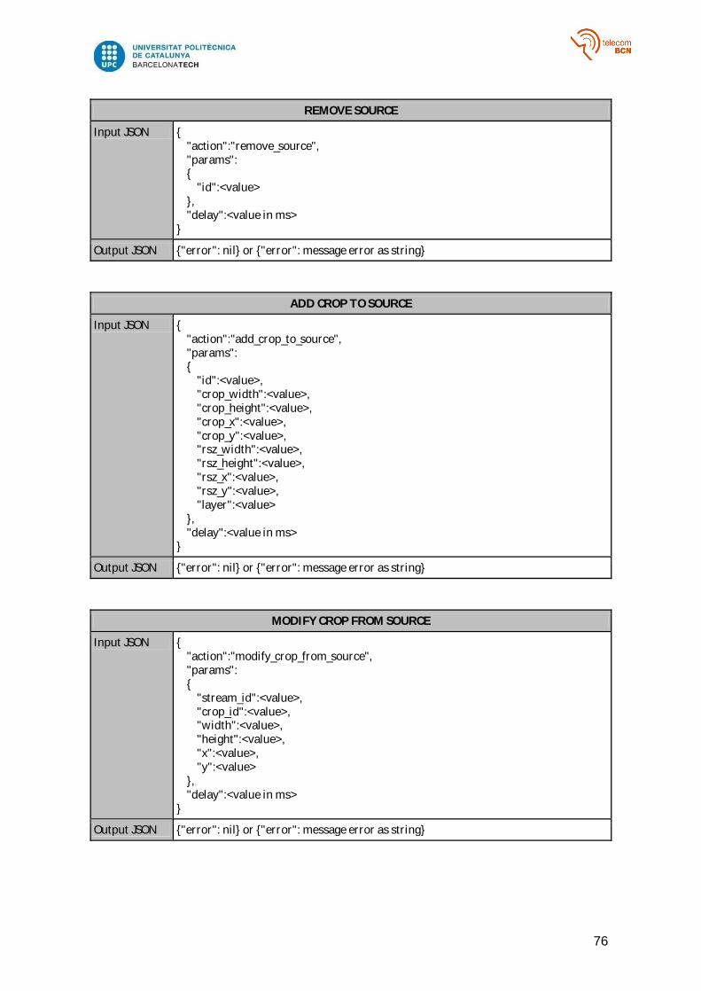
76
REMOVE SOURCE
Input JSON { "action":"remove_source", "params": { "id":<value> }, "delay":<value in ms> }
Output JSON {"error": nil} or {"error": message error as string}
ADD CROP TO SOURCE
Input JSON { "action":"add_crop_to_source", "params": { "id":<value>, "crop_width":<value>, "crop_height":<value>, "crop_x":<value>, "crop_y":<value>, "rsz_width":<value>, "rsz_height":<value>, "rsz_x":<value>, "rsz_y":<value>, "layer":<value> }, "delay":<value in ms> }
Output JSON {"error": nil} or {"error": message error as string}
MODIFY CROP FROM SOURCE
Input JSON { "action":"modify_crop_from_source", "params": { "stream_id":<value>, "crop_id":<value>, "width":<value>, "height":<value>, "x":<value>, "y":<value> }, "delay":<value in ms> }
Output JSON {"error": nil} or {"error": message error as string}
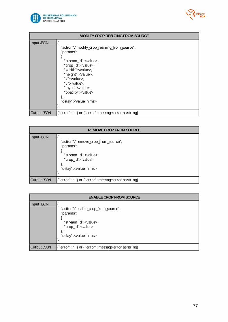
77
MODIFY CROP RESIZING FROM SOURCE
Input JSON { "action":"modify_crop_resizing_from_source", "params": { "stream_id":<value>, "crop_id":<value>, "width":<value>, "height":<value>, "x":<value>, "y":<value>, "layer":<value>, "opacity":<value> }, "delay":<value in ms> }
Output JSON {"error": nil} or {"error": message error as string}
REMOVE CROP FROM SOURCE
Input JSON { "action":"remove_crop_from_source", "params": { "stream_id":<value>, "crop_id":<value>, }, "delay":<value in ms> }
Output JSON {"error": nil} or {"error": message error as string}
ENABLE CROP FROM SOURCE
Input JSON { "action":"enable_crop_from_source", "params": { "stream_id":<value>, "crop_id":<value>, }, "delay":<value in ms> }
Output JSON {"error": nil} or {"error": message error as string}
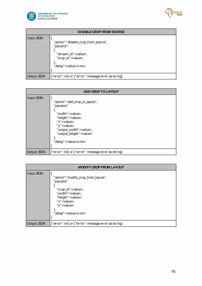
78
DISABLE CROP FROM SOURCE
Input JSON { "action":"disable_crop_from_source", "params": { "stream_id":<value>, "crop_id":<value>, }, "delay":<value in ms> }
Output JSON {"error": nil} or {"error": message error as string}
ADD CROP TO LAYOUT
Input JSON { "action":"add_crop_to_layout", "params": { "width":<value>, "height":<value>, "x":<value>, "y":<value>, "output_width":<value>, "output_height":<value> }, "delay":<value in ms> }
Output JSON {"error": nil} or {"error": message error as string}
MODIFY CROP FROM LAYOUT
Input JSON { "action":"modify_crop_from_layout", "params": { "crop_id":<value>, "width":<value>, "height":<value>, "x":<value>, "y":<value> }, "delay":<value in ms> }
Output JSON {"error": nil} or {"error": message error as string}

79
MODIFY CROP RESIZING FROM LAYOUT
Input JSON { "action":"modify_crop_resizing_from_layout", "params": { "crop_id":<value>, "width":<value>, "height":<value> }, "delay":<value in ms> }
Output JSON {"error": nil} or {"error": message error as string}
REMOVE CROP FROM LAYOUT
Input JSON { "action":"remove_crop_from_layout", "params": { "crop_id":<value> }, "delay":<value in ms> }
Output JSON {"error": nil} or {"error": message error as string}
ADD DESTINATION
Input JSON { "action":"add_destination", "params": { "stream_id":<value>, "ip":<value as string>, "port":<value> }, "delay":<value in ms> }
Output JSON {"id": <value>}
REMOVE DESTINATION
Input JSON { "action":"remove_destination", "params": { "id":<value> }, "delay":<value in ms> }
Output JSON {"error": nil} or {"error": message error as string}
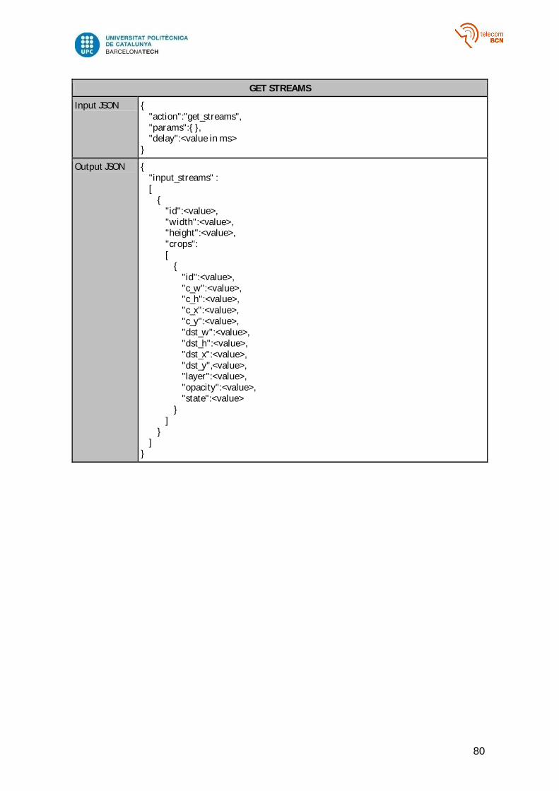
80
GET STREAMS
Input JSON { "action":"get_streams", "params":{ }, "delay":<value in ms> }
Output JSON { "input_streams" : [ { "id":<value>, "width":<value>, "height":<value>, "crops": [ { "id":<value>, "c_w":<value>, "c_h":<value>, "c_x":<value>, "c_y":<value>, "dst_w":<value>, "dst_h":<value>, "dst_x":<value>, "dst_y",<value>, "layer":<value>, "opacity":<value>, "state":<value> } ] } ] }
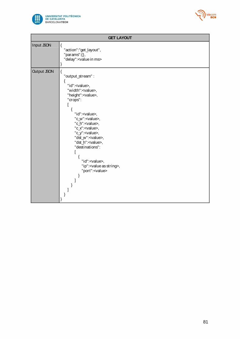
81
GET LAYOUT
Input JSON { "action":"get_layout", "params":{}, "delay":<value in ms> }
Output JSON { "output_stream" : { "id":<value>, "width":<value>, "height":<value>, "crops": [ { "id":<value>, "c_w":<value>, "c_h":<value>, "c_x":<value>, "c_y":<value>, "dst_w":<value>, "dst_h":<value>, "destinations": [ { "id":<value>, "ip":<value as string>, "port":<value> } ] } ] } }

82
GET STATS
Input JSON { "action":"get_stats", "params":{ }, "delay":<value in ms> }
Output JSON { "input_streams": [ { "id":<value>, "delay":<value>, "fps":<value>, "bitrate":<value>, "lost_coded_frames":<value>, "lost_frames":<value>, "total_frames":<value>, "lost_frames_percent":<value> } ], "output_streams": [ { "id":<value>, "delay":<value>, "fps":<value>, "bitrate":<value>, "lost_coded_frames":<value>, "lost_frames":<value>, "total_frames":<value>, "lost_frames_percent":<value> } ] }
GET LAYOUT SIZE
Input JSON { "action":"get_layout_size", "params":{ }, "delay":<value in ms> }
Output JSON { "width":<value>, "height":<value> }
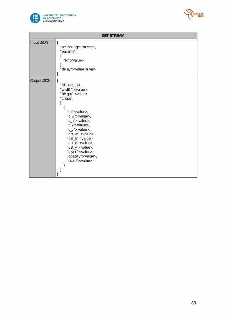
83
GET STREAM
Input JSON { "action":"get_stream", "params": { "id":<value> }, "delay":<value in ms> }
Output JSON { "id":<value>, "width":<value>, "height":<value>, "crops": [ { "id":<value>, "c_w":<value>, "c_h":<value>, "c_x":<value>, "c_y":<value>, "dst_w":<value>, "dst_h":<value>, "dst_x":<value>, "dst_y",<value>, "layer":<value>, "opacity":<value>, "state":<value> } ] }
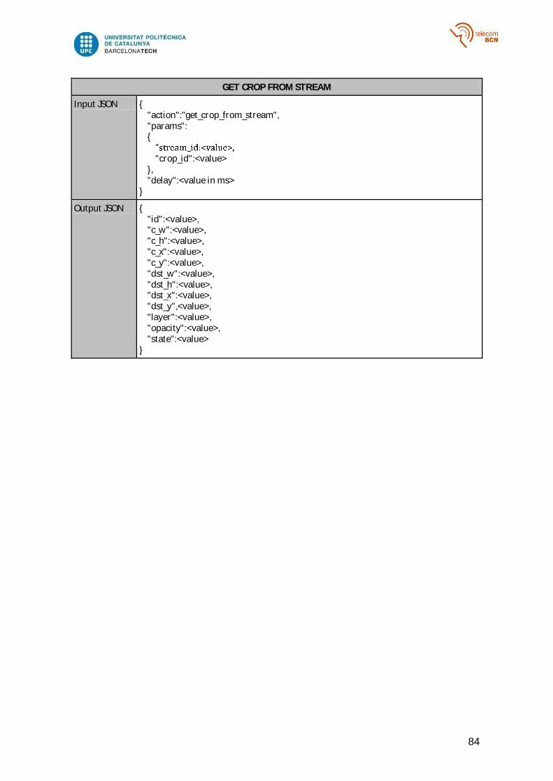
84
GET CROP FROM STREAM
Input JSON { "action":"get_crop_from_stream", "params": { "crop_id":<value> }, "delay":<value in ms> }
Output JSON { "id":<value>, "c_w":<value>, "c_h":<value>, "c_x":<value>, "c_y":<value>, "dst_w":<value>, "dst_h":<value>, "dst_x":<value>, "dst_y",<value>, "layer":<value>, "opacity":<value>, "state":<value> }
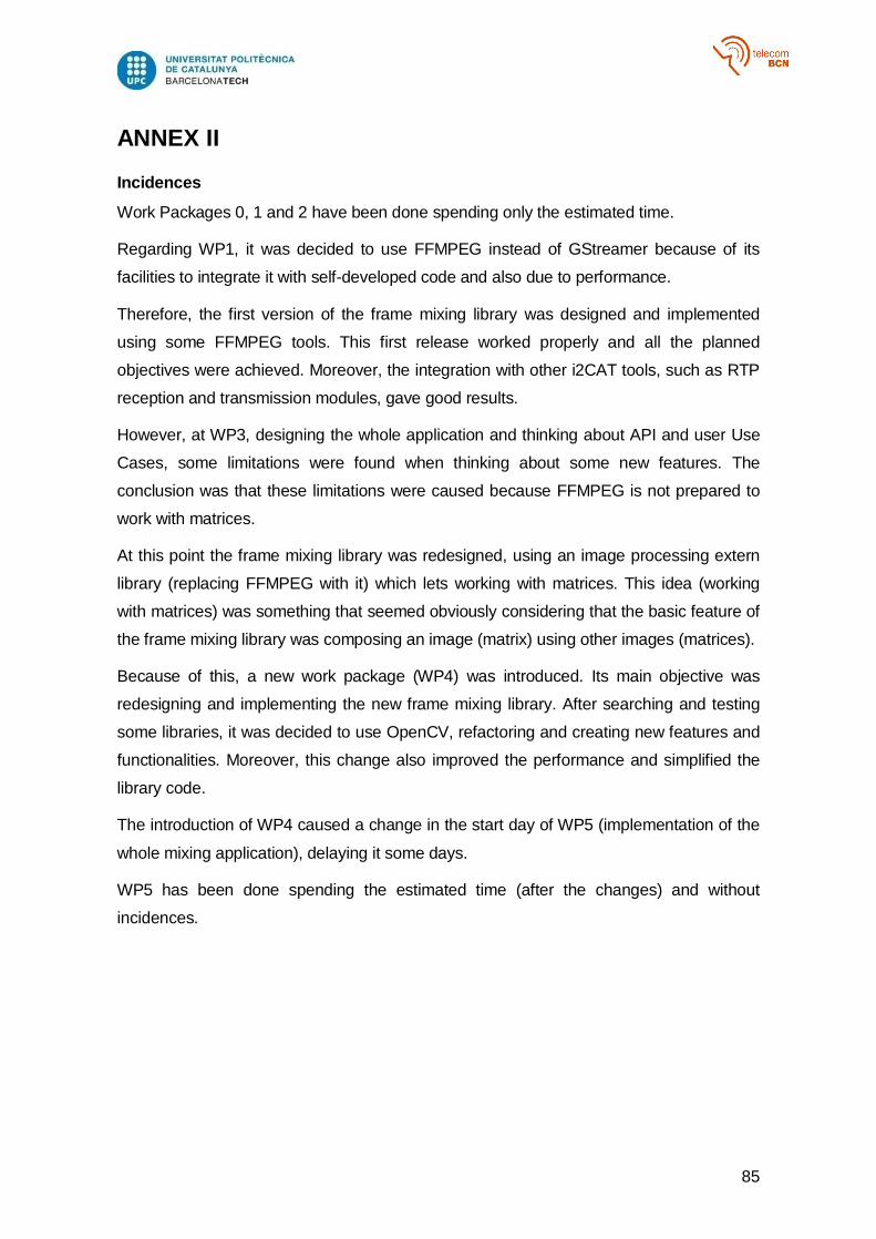
85
ANNEX II
Incidences
Work Packages 0, 1 and 2 have been done spending only the estimated time.
Regarding WP1, it was decided to use FFMPEG instead of GStreamer because of its
facilities to integrate it with self-developed code and also due to performance.
Therefore, the first version of the frame mixing library was designed and implemented
using some FFMPEG tools. This first release worked properly and all the planned
objectives were achieved. Moreover, the integration with other i2CAT tools, such as RTP
reception and transmission modules, gave good results.
However, at WP3, designing the whole application and thinking about API and user Use
Cases, some limitations were found when thinking about some new features. The
conclusion was that these limitations were caused because FFMPEG is not prepared to
work with matrices.
At this point the frame mixing library was redesigned, using an image processing extern
library (replacing FFMPEG with it) which lets working with matrices. This idea (working
with matrices) was something that seemed obviously considering that the basic feature of
the frame mixing library was composing an image (matrix) using other images (matrices).
Because of this, a new work package (WP4) was introduced. Its main objective was
redesigning and implementing the new frame mixing library. After searching and testing
some libraries, it was decided to use OpenCV, refactoring and creating new features and
functionalities. Moreover, this change also improved the performance and simplified the
library code.
The introduction of WP4 caused a change in the start day of WP5 (implementation of the
whole mixing application), delaying it some days.
WP5 has been done spending the estimated time (after the changes) and without
incidences.
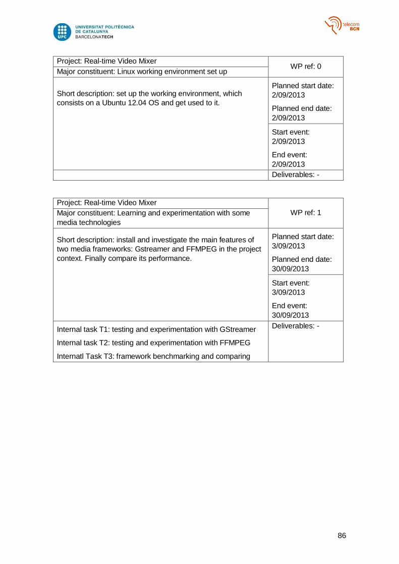
86
Project: Real-time Video Mixer WP ref: 0
Major constituent: Linux working environment set up
Short description: set up the working environment, which
consists on a Ubuntu 12.04 OS and get used to it.
Planned start date:
2/09/2013
Planned end date:
2/09/2013
Start event:
2/09/2013
End event:
2/09/2013
Deliverables: -
Project: Real-time Video Mixer
WP ref: 1 Major constituent: Learning and experimentation with some
media technologies
Short description: install and investigate the main features of
two media frameworks: Gstreamer and FFMPEG in the project
context. Finally compare its performance.
Planned start date:
3/09/2013
Planned end date:
30/09/2013
Start event:
3/09/2013
End event:
30/09/2013
Internal task T1: testing and experimentation with GStreamer
Internal task T2: testing and experimentation with FFMPEG
Internatl Task T3: framework benchmarking and comparing
Deliverables: -
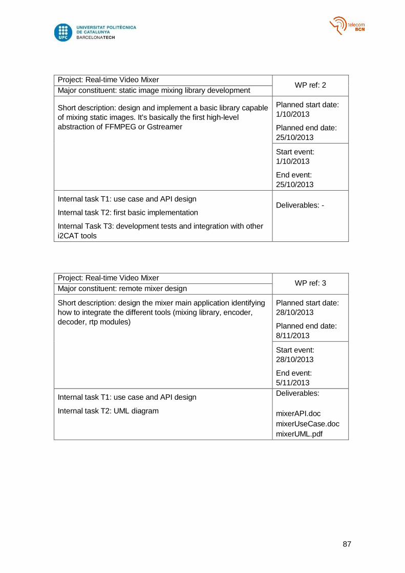
87
Project: Real-time Video Mixer WP ref: 2
Major constituent: static image mixing library development
Short description: design and implement a basic library capable
of mixing static images. It's basically the first high-level
abstraction of FFMPEG or Gstreamer
Planned start date:
1/10/2013
Planned end date:
25/10/2013
Start event:
1/10/2013
End event:
25/10/2013
Internal task T1: use case and API design
Internal task T2: first basic implementation
Internal Task T3: development tests and integration with other
i2CAT tools
Deliverables: -
Project: Real-time Video Mixer WP ref: 3
Major constituent: remote mixer design
Short description: design the mixer main application identifying
how to integrate the different tools (mixing library, encoder,
decoder, rtp modules)
Planned start date:
28/10/2013
Planned end date:
8/11/2013
Start event:
28/10/2013
End event:
5/11/2013
Internal task T1: use case and API design
Internal task T2: UML diagram
Deliverables:
mixerAPI.doc
mixerUseCase.doc
mixerUML.pdf
88
Project: Real-time Video Mixer WP ref: 4
Major constituent: static image mixing library refactor
Short description: redesign static image mixing library in order
to achieve new features
Planned start date:
6/11/2013
Planned end date:
19/11/2013
Start event:
6/11/2013
End event:
19/11/2013
Internal task T1: API and Use Case redesign
Internal task T2: image processing library search
Internal task T3: library implementation
Internal task T4: library testing
Deliverables: -
Project: Real-time Video Mixer
WP ref: 5 Major constituent: First release development and
documentation
Short description: development and testing of the main
application. Documentation and benchmarking.
Planned start date:
20/11/2013
Planned end date:
31/01/2014
Start event:
20/11/2013
End event:
31/1/2014
Internal task T1: mixer implementation
Internal task T2: mixer testing
Internal task T3: documentation
Internal task T4: TFG memory writing
Deliverables:
benchmarking.xls
mixer.doc
memory.doc
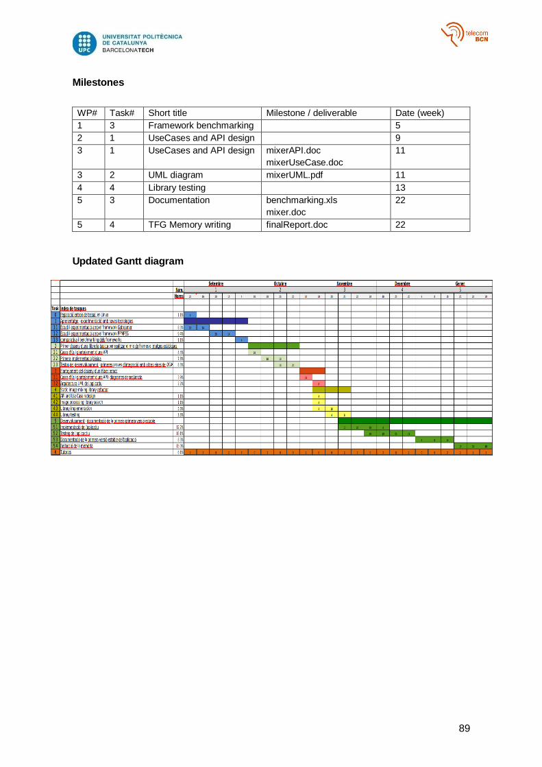
89
Milestones
WP# Task# Short title Milestone / deliverable Date (week)
1 3 Framework benchmarking 5
2 1 UseCases and API design 9
3 1 UseCases and API design mixerAPI.doc
mixerUseCase.doc
11
3 2 UML diagram mixerUML.pdf 11
4 4 Library testing 13
5 3 Documentation benchmarking.xls
mixer.doc
22
5 4 TFG Memory writing finalReport.doc 22
Updated Gantt diagram


![QL EditorQL Editor - Yamaha · Mixer Setup (configuración del mezclador) Para abrir el cuadro de diálogo Mixer Setup, elija [Mixer Setup] en el menú [File]. 1Mix Bus Setup (configuración](https://static.fdocuments.nl/doc/165x107/603bd1cd42f2ba7e6b79a8cd/ql-editorql-editor-yamaha-mixer-setup-configuracin-del-mezclador-para-abrir.jpg)