Kansei: A Testbed for Sensing at Scale
8
Kansei: A Testbed for Sensing at Scale Emre Ertin, Anish Arora, Rajiv Ramnath, Mikhail Nesterenko, Vinayak Naik, Sandip Bapat, Vinod Kulathumani, Mukundan Sridharan, Hongwei Zhang, Hui Cao Abstract— The Kansei testbed at The Ohio State University is de- signed to facilitate research on networked sensing applications at scale. Kansei embodies a unique combination of characteristics as a result of its design focus on sensing and scaling: (i) Heterogeneous hardware infrastructure with dedicated node resources for local computation, storage, data exfiltration and back-channel communication, to support complex experimentation. (ii) Time accurate hybrid simulation engine for simulating substantially larger arrays using testbed hardware resources. (iii) High fidelity sensor data generation and real-time data and event injection. (iv) Software components and associated job control language to support complex multi-tier experiments utilizing real hardware resources and data generation and simulation engines. In this paper, we present the elements of Kansei testbed architecture, including its hardware and software platforms as well as its hybrid simulation and sensor data generation engines. I. I NTRODUCTION Research on embedded wireless sensor networks has gravitated towards experimentation with current hardware and software plat- forms, with testbeds becoming the preferred basis for experimen- tation. Experience from early field experiments has reinforced the message of tight interdependence between the sensing application and the network/middleware layers; this is primarily due to resource limitations, hardware variability, and sensitivity to environment char- acteristics. As a result there is growing recognition that end-to-end debugging, validation, and integration of WSN applications requires joint consideration of sensing/environmental domain characteristics and networking/hardware/software platform properties. A notable challenge in developing testbeds has been fidelity with respect to scale. There have been several instances of small application prototypes that failed when tested at full field deployment scale. Several factors explain such failures: the uncertainty of the field environment, the variability/unreliability of the hardware, the growth in application complexity as well as management complexity, and complex interactions between the sensing application and the networking layers. The Kansei testbed at The Ohio State University is designed to facilitate research of networked sensing applications at scale. The basic idea is to couple one or more generic platform arrays that support a broad set of users, with multiple domain-specific sensing platform arrays. One implication of this idea is Kansei needs to be extensible to readily add new platforms—especially domain-specific ones. Towards addressing the scaling challenge, the basic idea is to use arrays that are large enough so as to mirror deployment scale and, if they are not large enough, to capture sensing/radio phenomena at a resolution that enables their scaling via software in a high fidelity manner. We have been developing the Kansei facility since Spring 2004, partly through equipment support obtained from DARPA for the ExScal project [1] as well as Intel Corporation and The Ohio State University. While a basic purpose for developing Kansei was to shorten the long cycle time of ExScal field-testing in multiple outdoor settings, we soon found Kansei to be supporting a significant number of diverse use cases and users. Since Kansei has been made openly available, it is being increas- ingly used for research projects at Ohio State and elsewhere. Datasets resulting from experiments on the testbed are being used at several academic institutions. We have used the testbed in project-based graduate and undergraduate courses, including our undergraduate capstone courses, as well as in short classes for training XSM and Stargate users. Kansei has also assisted in transitioning software to industry partners, in part by getting them to execute validation tests on components being transitioned. The number of external users who have brought to bear their own portable arrays is growing. The basic design considerations and the description of Kansei use cases including its role in the Exscal project is presented in an accompanying, invited summary paper [2]. In this paper, we present a detailed description of the Kansei design and its software/hardware components. In summary, Kansei embodies a unique combination of characteris- tics as a result of its design focus on sensing and scaling: (i) Heteroge- neous hardware infrastructure with dedicated node resources for local computation, storage, data exfiltration and back-channel communica- tion to support complex experimentation. (ii) Time accurate hybrid simulation engine for simulating substantially larger arrays using testbed hardware resources. (iii) High fidelity sensor data generation and real-time data and event injection. (iv) Software components and associated job control language to support complex multi-tier experiments utilizing real hardware resources and data generation and simulation engines. In the rest of the paper, we first review relevant work on testing of wireless sensor network applications. Next, we present the elements of Kansei testbed architecture, including its hardware and software platforms as well as its hybrid simulation and sensor data generation engines. We conclude with the overview of a recent demonstration based on Kansei and with future work. II. RELATED WORK Domain Testbeds. Domain-specific sensing testbeds include the NIMS [3] deployments at James Reserve, Merced Basin, and Wind River. NIMS testbeds are being used to observe natural environments using a hierarchy of nodes: a few untethered, some tethered but static, and notably others that move in constrained manners along a network of suspended ropes and, in the case of imaging sensors, via pan, tilt and zoom. Sensing fidelity, via autonomous self-awareness of sensing uncertainty, coordinated mobility, and adaptive sampling, are research priorities in this effort. By way of contrast, the testbeds deployed in Huntington Botanical Gardens, Avra Valley [4], Sonoma Redwood Forest [5] and Great Duck Island [6] use only static nodes for studying microclimates and fauna behavior; they have yielded experience in supporting long lived installations. The WISDEN testbed [7] deployed in an earthquake-affected building has enabled seismic structural health monitoring. Platform Testbeds. Numerous 10-50 sensor node testbeds exist for supporting network and middleware research efforts; these include testbeds that supplement static nodes with mobile ones. A few of these support generic testability goals for a broad set of users: MoteLab [8] is an early example, consisting of 30 MicaZ nodes embedded in a office building, that supports development and test- ing of sensor network programming environments, communication protocols, system design, and applications. MistLab at MIT has
Transcript of Kansei: A Testbed for Sensing at Scale
Kansei: A Testbed for Sensing at Scale
Emre Ertin, Anish Arora, Rajiv Ramnath, Mikhail Nesterenko,Vinayak Naik, Sandip Bapat, Vinod Kulathumani, Mukundan Sridharan, Hongwei Zhang, Hui Cao
Abstract— The Kansei testbed at The Ohio State University is de-signed to facilitate research on networked sensing applications at scale.Kansei embodies a unique combination of characteristics as a result ofits design focus on sensing and scaling: (i) Heterogeneous hardwareinfrastructure with dedicated node resources for local computation,storage, data exfiltration and back-channel communication, to supportcomplex experimentation. (ii) Time accurate hybrid simulation engine forsimulating substantially larger arrays using testbed hardware resources.(iii) High fidelity sensor data generation and real-time data and eventinjection. (iv) Software components and associated job control language tosupport complex multi-tier experiments utilizing real hardware resourcesand data generation and simulation engines. In this paper, we presentthe elements ofKansei testbed architecture, including its hardware andsoftware platforms as well as its hybrid simulation and sensor datageneration engines.
I. I NTRODUCTION
Research on embedded wireless sensor networks has gravitatedtowards experimentation with current hardware and software plat-forms, with testbeds becoming the preferred basis for experimen-tation. Experience from early field experiments has reinforced themessage of tight interdependence between the sensing applicationand the network/middleware layers; this is primarily due to resourcelimitations, hardware variability, and sensitivity to environment char-acteristics. As a result there is growing recognition that end-to-enddebugging, validation, and integration of WSN applications requiresjoint consideration of sensing/environmental domain characteristicsand networking/hardware/software platform properties.
A notable challenge in developing testbeds has been fidelitywith respect to scale. There have been several instances of smallapplication prototypes that failed when tested at full field deploymentscale. Several factors explain such failures: the uncertainty of thefield environment, the variability/unreliability of the hardware, thegrowth in application complexity as well as management complexity,and complex interactions between the sensing application and thenetworking layers.
The Kansei testbed at The Ohio State University is designed tofacilitate research of networked sensing applications at scale. Thebasic idea is to couple one or more generic platform arrays thatsupport a broad set of users, with multiple domain-specific sensingplatform arrays. One implication of this idea isKanseineeds to beextensible to readily add new platforms—especially domain-specificones. Towards addressing the scaling challenge, the basic idea is touse arrays that are large enough so as to mirror deployment scale and,if they are not large enough, to capture sensing/radio phenomena ata resolution that enables their scaling via software in a high fidelitymanner. We have been developing theKansei facility since Spring2004, partly through equipment support obtained from DARPA forthe ExScalproject [1] as well as Intel Corporation and The OhioState University. While a basic purpose for developingKanseiwas toshorten the long cycle time ofExScalfield-testing in multiple outdoorsettings, we soon foundKanseito be supporting a significant numberof diverse use cases and users.
SinceKanseihas been made openly available, it is being increas-ingly used for research projects at Ohio State and elsewhere. Datasetsresulting from experiments on the testbed are being used at several
academic institutions. We have used the testbed in project-basedgraduate and undergraduate courses, including our undergraduatecapstone courses, as well as in short classes for training XSM andStargate users.Kanseihas also assisted in transitioning software toindustry partners, in part by getting them to execute validation testson components being transitioned. The number of external userswho have brought to bear their own portable arrays is growing.The basic design considerations and the description ofKansei usecases including its role in theExscal project is presented in anaccompanying, invited summary paper [2]. In this paper, we presenta detailed description of theKanseidesign and its software/hardwarecomponents.
In summary,Kanseiembodies a unique combination of characteris-tics as a result of its design focus on sensing and scaling: (i) Heteroge-neous hardware infrastructure with dedicated node resources for localcomputation, storage, data exfiltration and back-channel communica-tion to support complex experimentation. (ii) Time accurate hybridsimulation engine for simulating substantially larger arrays usingtestbed hardware resources. (iii) High fidelity sensor data generationand real-time data and event injection. (iv) Software componentsand associated job control language to support complex multi-tierexperiments utilizing real hardware resources and data generation andsimulation engines. In the rest of the paper, we first review relevantwork on testing of wireless sensor network applications. Next, wepresent the elements ofKansei testbed architecture, including itshardware and software platforms as well as its hybrid simulationand sensor data generation engines. We conclude with the overviewof a recent demonstration based onKanseiand with future work.
II. RELATED WORK
Domain Testbeds. Domain-specific sensing testbeds include theNIMS [3] deployments at James Reserve, Merced Basin, and WindRiver. NIMS testbeds are being used to observe natural environmentsusing a hierarchy of nodes: a few untethered, some tethered but static,and notably others that move in constrained manners along a networkof suspended ropes and, in the case of imaging sensors, via pan,tilt and zoom. Sensing fidelity, via autonomous self-awareness ofsensing uncertainty, coordinated mobility, and adaptive sampling, areresearch priorities in this effort. By way of contrast, the testbedsdeployed in Huntington Botanical Gardens, Avra Valley [4], SonomaRedwood Forest [5] and Great Duck Island [6] use only static nodesfor studying microclimates and fauna behavior; they have yieldedexperience in supporting long lived installations. The WISDENtestbed [7] deployed in an earthquake-affected building has enabledseismic structural health monitoring.Platform Testbeds. Numerous 10-50 sensor node testbeds exist forsupporting network and middleware research efforts; these includetestbeds that supplement static nodes with mobile ones. A few ofthese support generic testability goals for a broad set of users:MoteLab [8] is an early example, consisting of 30 MicaZ nodesembedded in a office building, that supports development and test-ing of sensor network programming environments, communicationprotocols, system design, and applications. MistLab at MIT has
about similarly embedded 60 Mica2/Cricket nodes, each with anprogramming board, which also provides power and an Ethernetconnection. ENL [9] is a multi-hop mote-based sensor networkplatform testbed used for the real time analysis and evaluation ofsensor network applications. GNOMES [10], a low-cost hardware andsoftware testbed, explores the properties of heterogeneous wirelesssensor networks, to test theory in sensor networks architecture, and bedeployed in practical application environments. SensoNet [11] projectaims at developing protocols for very low power sensor networks atvarious levels in the communication stack.
By way of comparison with theKansei testbed, these testbedstypically have a stationary/mobile array that is relatively smallerthan ours and they do not integrate with portable arrays. Couplingand logical/physical configuration of the arrays is key to allowingexperimenters to access the environmental condition of their actualdeployment space, as opposed to that of their stationary/mobiletestbed space. Another distinguishing feature of our testbed is thatit can be used in conjunction with model composition and hybridsimulation tools to perform large-scale sensing experiments with highfidelity.
In terms of experimentation on motes, theKansei testbed soft-ware architecture is similar to Motelab in the underlying Open-Source Linux-Apache-MySQL-PHP/PERL (LAMP) implementationtechnology, and in certain aspects of the software architecture (web-based scheduling interface, scheduling daemon) of the stationaryarray. Kansei differs in the design of its various software components(user management, database schema, daemon thread-management,interface to the hardware, reservation and data retrieval mechanismsand so on), and it also currently supports experimental setup acrossall three levels of the Kansei hardware (PC clusters, Stargate meshnetwork and motes).Kansei implements a uniforminterface to ex-perimentation functions that is independent of the specific hardware,for both portable arrays and the stationary array.
Related to these testbeds are those that the mesh networking[12] and mobile ad hoc networking communities has recently beendeveloping. ORBIT [13] is a laboratory-based wireless networkemulator that uses two-dimensional grid of 400 802.11x radio nodeswhich can be dynamically interconnected into specified topologieswith reproducible wireless channel models. WHYNET [14] is ahybrid testbed that networks geographically distributed heterogeneouswireless physical testbeds with multiple protocol stacks, physicaltechnologies and a parallel & distributed multi-tool simulation frame-work. Roofnet [15] is a 20-node 802.11b/g mesh network testbedfor conducting 802.11 measurement experiments and studies of linkcharacteristics and protocols.Kansei’s static and mobile Stargatenodes will continue to support experimentation that would be relevantto these communities, as a by product of its capabilities.Simulators and hybrid simulation. The limitations of simulatorshave been widely studied in the sensor and wireless networkingcommunities [16], [17], [18]. That said, researchers find useful theconvenience and scalability of high-level simulators such as ns-2 [19],GloMoSim [20], and Prowler [21] during initial application develop-ment, even though their representation of reality is circumscribed.None of these simulators allow the designers to run the code of thetarget platform.
There are a number of simulators that compile and run TinyOSprogram. TOSSIM [22] and TOSSF [23] and SENS [24] allow thedesigner to compile the TinyOS program for Intel architecture andrun the program on a PC. ATEMU [25] and Avrora [26] emulate theinstruction set of the mote’s processor on a PC which provides aninteresting Debugging option. All four tools are capable of simulating
thousands of motes on a single PC. However, the mote hardware issimulated, hence simulation fidelity is an issue.
Few simulators allow running of the code on physical sensor nodes.SensorSim [27] is a modification of ns-2 which allows simulatedsensor nodes to communicate with real sensor nodes through gatewaymachines. This capability extends the usefulness of a high-levelsimulator as a debugging tool. Yet the limitations of high-levelsimulators outlined above apply to SensorSim as well. EmStar [28],[29] has a range of tools that can be used for simulation anddeployment in sensor networks. EmStar simulates sensor nodes asseparate processes running on a host PC. EmStar provides com-munication between simulated sensor nodes through Unix devicefiles. This communication can be purely simulated or hybrid. Inthe latter case physical nodes are used to transmit the messages.The processes that simulate the sensor nodes are controlled by thescheduler of the operating system of the host machine. To maintaincoordinated execution of multiple simulated sensor nodes, EmStarrelies on periodic resynchronization and the estimates of processexecution speed. This task becomes rather difficult in the hybridmode as coordination with physical nodes have to be factored in.Thus, there are inherent scalability and fidelity limitations in thesimulation approach used in EmStar.Kanseihybrid simulation engineis designed to simulate large-scale experiments with emphasis on highfidelity on timing, application, radio and sensing environments andcomplements the prior work on simulation.Sensor data generation and Injection. Modeling of theenvironmental processes that gives rise to sensor readings is thecore problem in physical sciences. Using model generated sensorreadings to drive embedded software-hardware systems is a wellestablished test method in automotive industry and in general controlsystem design, known as hardware-in-the-loop testing [30]. Bruceetal. [31] developed a middleware for the implementation of hardware-in-the-loop testing in wireless sensor network applications. Theydemonstrated the middleware using pre-generated sensor streamsusing empirically derived models of acoustic, infrared and magneticsensors and white normal distributed noise. The traces are firstbroadcast to each mote and stored in their memory, then the motesexecute the application using the stored sensor traces .
Kanseisensor data generation facility combines accurate physicsbased parametric models of the foreground signal with probabilisticmodels of background processes to capture spatial and temporalcorrelations in the background signal. The two modeling techniquesare augmented by sample based models using a database of sensortraces collected through the various portable arrays to provide a richerset of high fidelity sensor signals.
In addition, for many sensor-actuator network applications thecontrol actions directly influence the sensor streams experienced bythe sensor nodes. For example, the position of a robot in the sensornetwork will determine the particular sensors that will detect itsmotion. For these applications pre-generated sensor streams are notappropriate. The sensor data generation and injection is accomplishedon the fly in theKansei, which enables dynamic experiments withmobile nodes where the user or the network actions can change theinput processes in real time.
III. E LEMENTS OFKansei
Kanseiconsists of a set of hardware platforms, access to which ismanaged by a remotely-accessible Director framework. The environ-ment supports several tools, for high-fidelity sensor data generationand “hybrid” simulation.
A. Hardware Infrastructure
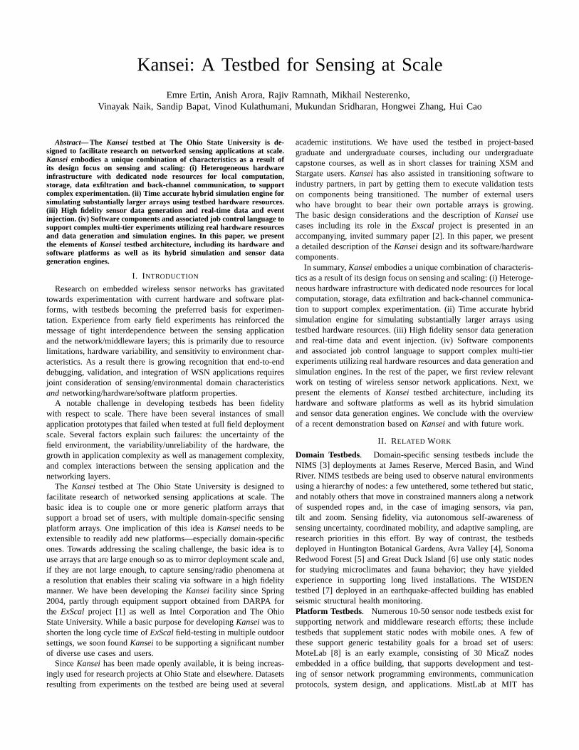
Kansei’s hardware infrastructure consists of three components:Stationary Array, Portable Array, and Mobile Array.Stationary Array . The stationary array consists of 210 sensor nodesplaced on a 15×14 rectangular grid benchwork with 3ft spacing.Each node in the stationary array consists of two hardware platforms:Extreme Scale Motes (XSMs) and Stargates (Figures 1 and 2).
XSM is a derivative of Berkeley prototype sensor nodes, that wasdeveloped by Crossbow and the Ohio State University DARPA NESTteam for use in theExScal Project. Each XSM is equipped witha 4 MHz 8 Bit CPU, 128 KB instruction memory and 4KBRAM.For communication, the mote uses a 916MHz low-power radio.The radio’s reliable communication range is between 15 and 30meters when placed on ground level. Each mote accommodatesa variety of sensors. Sensors include a photocell, a passive infrared (PIR), a temperature, and a magnetometer sensor, as well asa microphone. The motes run TinyOS [32], which is a lightweightevent-based operating system that implements the networking stackand communication with the sensors, and provides the programmingenvironment for this platform.
Fig. 1. Stationary Array
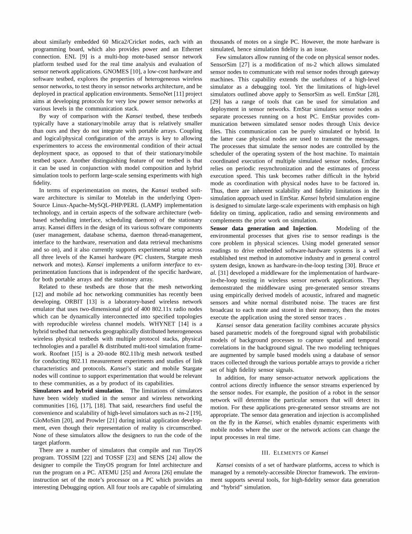
Fig. 2. Stationary Array Node
Stargate is an expandable single-board computer with Intel’s400MHz PXA255 CPU running Linux operating system. It also has adaughter-card which contains an interface to a mote and a number ofother interfaces including RS-232 serial, 10/100 Ethernet, and USB.Its in-band communication is via an 802.11(b) wireless NIC card.We have measured the radio characteristics of outdoor environmentsfor this specific 802.11(b) radios in extensive measurements in May2004 at OSU Don Scott Airport and at theKanseiwarehouse. Themeasured link characteristics were roughly consistent with log normal
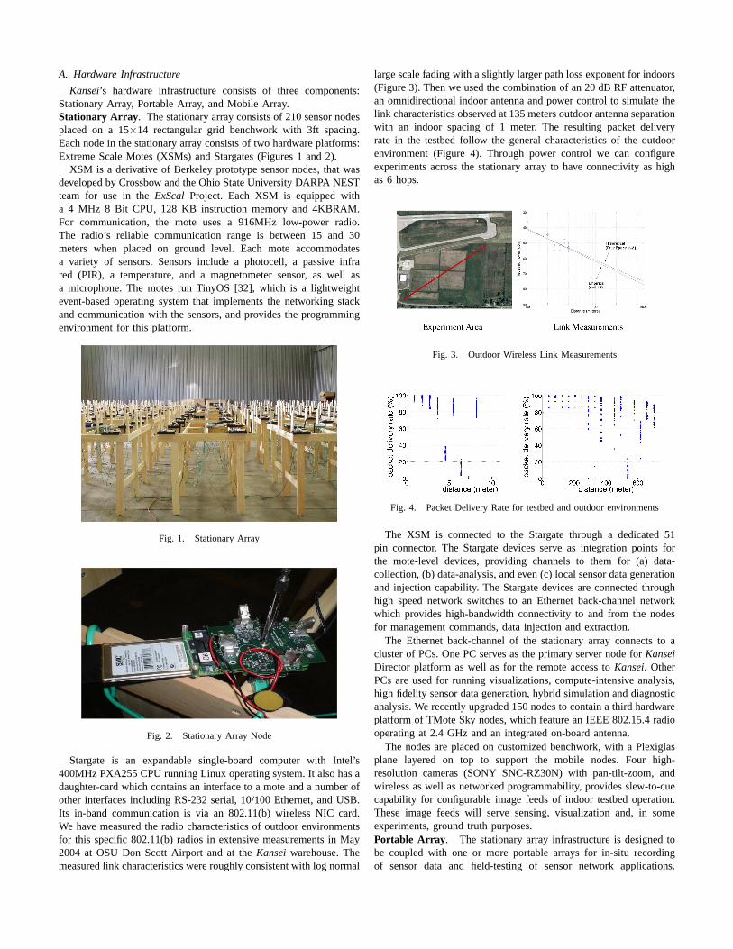
large scale fading with a slightly larger path loss exponent for indoors(Figure 3). Then we used the combination of an 20 dB RF attenuator,an omnidirectional indoor antenna and power control to simulate thelink characteristics observed at 135 meters outdoor antenna separationwith an indoor spacing of 1 meter. The resulting packet deliveryrate in the testbed follow the general characteristics of the outdoorenvironment (Figure 4). Through power control we can configureexperiments across the stationary array to have connectivity as highas 6 hops.
Fig. 3. Outdoor Wireless Link Measurements
Fig. 4. Packet Delivery Rate for testbed and outdoor environments
The XSM is connected to the Stargate through a dedicated 51pin connector. The Stargate devices serve as integration points forthe mote-level devices, providing channels to them for (a) data-collection, (b) data-analysis, and even (c) local sensor data generationand injection capability. The Stargate devices are connected throughhigh speed network switches to an Ethernet back-channel networkwhich provides high-bandwidth connectivity to and from the nodesfor management commands, data injection and extraction.
The Ethernet back-channel of the stationary array connects to acluster of PCs. One PC serves as the primary server node forKanseiDirector platform as well as for the remote access toKansei. OtherPCs are used for running visualizations, compute-intensive analysis,high fidelity sensor data generation, hybrid simulation and diagnosticanalysis. We recently upgraded 150 nodes to contain a third hardwareplatform of TMote Sky nodes, which feature an IEEE 802.15.4 radiooperating at 2.4 GHz and an integrated on-board antenna.
The nodes are placed on customized benchwork, with a Plexiglasplane layered on top to support the mobile nodes. Four high-resolution cameras (SONY SNC-RZ30N) with pan-tilt-zoom, andwireless as well as networked programmability, provides slew-to-cuecapability for configurable image feeds of indoor testbed operation.These image feeds will serve sensing, visualization and, in someexperiments, ground truth purposes.Portable Array . The stationary array infrastructure is designed tobe coupled with one or more portable arrays for in-situ recordingof sensor data and field-testing of sensor network applications.
Each portable array consists of domain specific sensors and genericsoftware services for data storage, compression, exfiltration, time-synchronization and management.
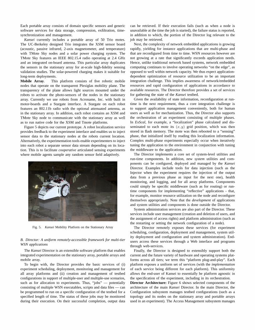
Kansei currently includes a portable array of 50 Trio motes.The UC-Berkeley designed Trio integrates the XSM sensor board(acoustic, passive infrared, 2-axis magnetometer, and temperature)with TMote Sky nodes and a solar power charging system. TheTMote Sky features an IEEE 802.15.4 radio operating at 2.4 GHzand an integrated on-board antenna. This particular array duplicatesthe sensors in the stationary array for at-scale high-fidelity sensingvalidation studies. The solar-powered charging makes it suitable forlong-term deployments.Mobile Array . This platform consists of five robotic mobilenodes that operate on the transparent Plexiglas mobility plane. Thetransparency of the plane allows light sources mounted under therobots to activate the photo-sensors of the nodes in the stationaryarray. Currently we use robots from Acroname, Inc. with built inmotor-boards and a Stargate interface. A Stargate on each robotfeatures an 802.11b radio with the optional attenuated antenna, asin the stationary array. In addition, each robot contains an XSM andTMote Sky node to communicate with the stationary array as wellas to run native code for the XSM and Tmote platforms.
Figure 5 depicts our current prototype. A robot localization serviceprovides feedback to the experiment interface and enables us to injectsensor data to the stationary nodes at the robots current location.Alternatively, the experimentation tools enable experimenters to injectinto each robot a separate sensor data stream depending on its loca-tion. This is to facilitatecooperativearticulated sensing experimentswhere mobile agents sample any random sensor field adaptively.
Fig. 5. KanseiMobility Platform on the Stationary Array
B. Director: A uniform remotely-accessible framework for multi-tierWSN applications
TheKanseiDirector is an extensible software platform that enablesintegrated experimentation on the stationary array, portable arrays andmobile array.
To begin with, the Director provides the basic services of (i)experiment scheduling, deployment, monitoring and management forall array platforms and (ii) creation and management of testbedconfigurations in support of multiple-user and multiple-use scenarios,such as for allocation to experiments. Thus, “jobs” — potentiallyconsisting of multiple WSN executables, scripts and data files — canbe programmed to run on a specific configuration of the testbed for aspecified length of time. The status of these jobs may be monitoredduring their execution. On their successful completion, output data
can be retrieved. If their execution fails (such as when a node isunavailable at the time the job is started), the failure status is reported,in addition to which, the portion of the Director log relevant to thejob may be retrieved.
Next, the complexity of network embedded applications is growingrapidly, yielding for instance applications that are multi-phase andthat are reconfigured from time to time. WSN resources however arenot growing at a rate that significantly exceeds application needs.Hence, unlike traditional network based systems, network embeddedcomputing continues to involve operating networks “on the edge”, asopposed to well within network capacity. We thus expect application-dependent optimization of resource utilization to be an importantintegration challenge. This implies awareness of network/embeddedresources and rapid configuration of applications in accordance toavailable resources. The Director therefore provides a set of servicesfor gathering the state of theKanseitestbed.
Given the availability of state information, reconfiguration at run-time is the next requirement, thus a core integration challenge isto support application management conveniently, both for humanusers as well as for mechanization. Thus, the Director also supportsthe orchestration of an experiment consisting of multiple phases.In ExScal, for example, a “localization” phase calculated and dis-seminated to each mote its(x, y) grid position, which was thenstored in flash memory. The mote was then rebooted to a “sensing”phase, that initialized itself by reading this localization information.Complex multi-phase experiments especially occur when iterativelytuning the application to the environment in conjunction with tuningthe middleware to the application.
The Director implements a core set of system-level utilities andrun-time components. In addition, newsystemutilities and com-ponents can be configured, deployed and managed by theKanseiDirector. Examples include tools for data injection (such as theInjector when the experiment requires the injection of the outputdata from a previous phase as input for the next one), healthmonitoring, and logging, and for all array platforms. Componentscould simply be specific middleware (such as for routing) or run-time components for implementing “reflective” applications - that,for example, monitor resource utilization on the node and reconfigurethemselves appropriately. Note that thedevelopmentof applicationsand system utilities and components is done outside the Director.
System administration services are also part of the Director. Theseservices include user management (creation and deletion of users, andthe assignment of access rights) and platform administration (such asthe restarting or setting the network configuration of a node).
The Director remotely exposes these services (for experimentscheduling, configuration, deployment and management, system util-ity deployment and configuration and system administration). End-users access these services through a Web interface and programsthrough web-services.
Finally, the Director is designed to extensibly support both thecurrent and the future variety of hardware and operating systems plat-forms across all tiers; we term this “platform plug-and-play”. Eachplatform exposes a uniform set of services (with theimplementationof each service being different for each platform). This uniformityallows the end-user of Kansei to essentially be platform agnostic inthe specification of the experiment, including in its orchestration.Director Architecture: Figure 6 shows selected components of thearchitecture of the mainKanseiDirector. In the main Director, theConfiguration subsystem manages testbed configurations (such as atopology and its nodes on the stationary array and portable arraysused in an experiment). The Access Management subsystem manages
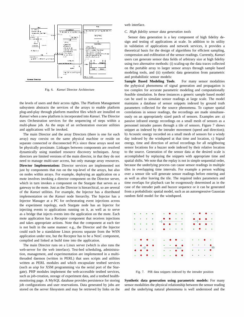
Fig. 6. KanseiDirector Architecture
the levels of users and their access rights. The Platform Managementsubsystem abstracts the services of the arrays to enable platformplug-and-play through platform manifest files which are installed onKanseiwhen a new platform is incorporated intoKansei. The Directoruses Orchestration services for the sequencing of steps within amulti-phase job. As the steps of an orchestration execute utilitiesand applications will be invoked.
The main Director and the array Directors (there is one for eacharray) may coexist on the same physical machine or reside onseparate connected or disconnected PCs since these arrays need notbe physically proximate. Linkages between components are resolveddynamically using standard resource discovery techniques. Arraydirectors are limited versions of the main director, in that they do notneed to manage multi-user access, but only manage array resources.Director Implementation: Director services are implemented notjust by components that run on the top-level of the arrays, but alsoon nodes within arrays. For example, deploying an application on amote involves invoking a director component on the Director server,which in turn invokes a component on the Stargate that serves as agateway to the mote. Just as the Director is hierarchical, so are severalof the Kansei utilities. For example, the Injector has a distributedimplementation on theKansei node hierarchy. The Injector has aInjector Manager at a PC for orchestrating event injections acrossthe experiment topology, each Stargate node has an Injector forinjecting events to applications running on it, as well as to serveas a bridge that injects events into the application on the mote. Eachmote application has a Receptor component that receives injectionsand takes appropriate actions. Note that the component at each tieris not built in the same manner: e.g., the Director and the Injectorcould each be a standalone Linux process separate from the WSNapplication under test, but the Receptor has to be a NesC component,compiled and linked at build time into the application.
The main Director runs on a Linux server (which is also runs theweb-server for the web interface). Test-bed scheduling, administra-tion, management, and experimentation are implemented in a multi-threaded daemon (written in PERL) that uses scripts and utilitieswritten as PERL modules and which encapsulate testbed services(such asuisp for XSM programming via the serial port of the Star-gate). PHP modules implement the web-accessible testbed services,such as job-creation, storage of experiment data, and a testbed health-monitoring page. A MySQL database provides persistence for storingjob configurations and user reservations. Data generated by jobs arestored on the server filesystem and may be retrieved by links on the
web interface.
C. High fidelity sensor data generation tools
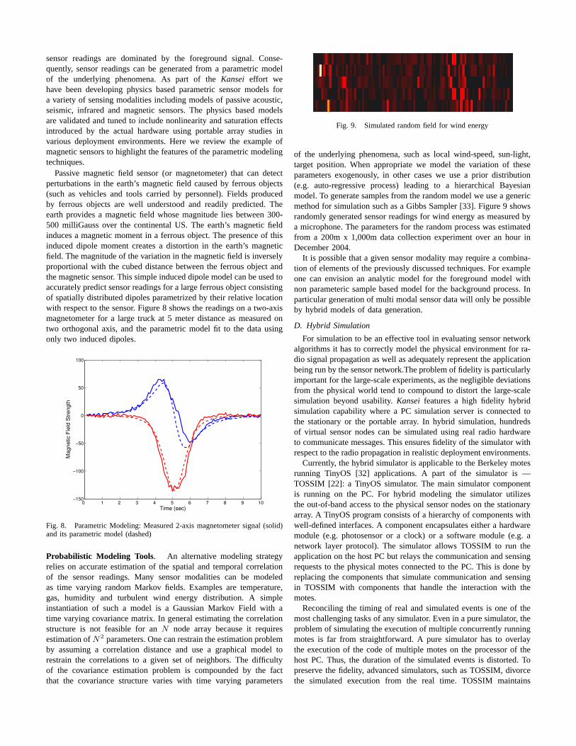
Sensor data generation is a key component of high fidelity de-sign and testing of applications at scale. In addition to its utilityin validation of applications and network services, it provides atheoretical basis for the design of algorithms for efficient sampling,compression and exfiltration of the sensor readings. Currently,Kanseiusers can generate sensor data fields of arbitrary size at high fidelityusing two alternative methods: (i) scaling-up the data traces collectedon the portable array to larger sensor arrays through sample basedmodeling tools, and (ii) synthetic data generation from parametricand probabilistic sensor models:Sample Based Modeling Tools. For many sensor modalitiesthe pyhysical phenomena of signal generation and propagation istoo complex for accurate parametric modeling and computationallyfeasible simulation. In these instances a generic sample based modelcan be used to simulate sensor readings at large scale. The modelmaintains a database of sensor snippets indexed by ground truthparameters collected for the source phenomena. To capture spatialcorrelations in sensor readings, the recordings are made simultane-ously on an appropriately sized patch of sensors. Examples are: a)passive infrared energy recordings on a small mesh of sensors as apersonnel intruder passes through a tile of sensors. Figure 7 showssnippet as indexed by the intruder movement (speed and direction);b) Acoustic energy recorded on a small mesh of sensors for a windyday indexed by the windspeed at that time and location, c) Signalenergy, time and direction of arrival recordings for all neighboringsensor locations for a buzzer node indexed by their relative locationto the source. Generation of the sensor data at the desired scale isaccomplished by replaying the snippets with appropriate time andspatial shifts. We note that the replay is not in simple sequential order,because the underlying process can cause sensor readings in multipletiles in overlapping time intervals. For example a person walkingover a sensor tile will generate sensor readings before entering andas well as after leaving the tile. The required index parameters andtime overlaps for playback can be exogenously determined as in thecase of the intruder path and buzzer sequence or it can be generatedfrom a probabilistic spatial model, such as an autoregressive Gaussianrandom field model for the windspeed.
Fig. 7. PIR data snippets indexed by the intruder position
Synthetic data generation using parametric models:For manysensor modalities the physical relationship between the sensor readingand the underlying natural phenomena is well understood and the
sensor readings are dominated by the foreground signal. Conse-quently, sensor readings can be generated from a parametric modelof the underlying phenomena. As part of theKansei effort wehave been developing physics based parametric sensor models fora variety of sensing modalities including models of passive acoustic,seismic, infrared and magnetic sensors. The physics based modelsare validated and tuned to include nonlinearity and saturation effectsintroduced by the actual hardware using portable array studies invarious deployment environments. Here we review the example ofmagnetic sensors to highlight the features of the parametric modelingtechniques.
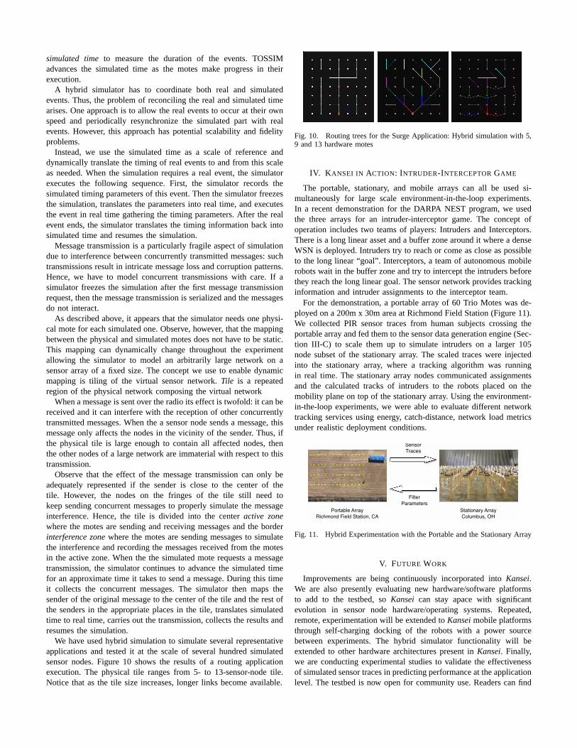
Passive magnetic field sensor (or magnetometer) that can detectperturbations in the earth’s magnetic field caused by ferrous objects(such as vehicles and tools carried by personnel). Fields producedby ferrous objects are well understood and readily predicted. Theearth provides a magnetic field whose magnitude lies between 300-500 milliGauss over the continental US. The earth’s magnetic fieldinduces a magnetic moment in a ferrous object. The presence of thisinduced dipole moment creates a distortion in the earth’s magneticfield. The magnitude of the variation in the magnetic field is inverselyproportional with the cubed distance between the ferrous object andthe magnetic sensor. This simple induced dipole model can be used toaccurately predict sensor readings for a large ferrous object consistingof spatially distributed dipoles parametrized by their relative locationwith respect to the sensor. Figure 8 shows the readings on a two-axismagnetometer for a large truck at 5 meter distance as measured ontwo orthogonal axis, and the parametric model fit to the data usingonly two induced dipoles.
0 1 2 3 4 5 6 7 8 9 10−150
−100
−50
0
50
100
Time (sec)
Mag
netic
Fie
ld S
treng
th
Fig. 8. Parametric Modeling: Measured 2-axis magnetometer signal (solid)and its parametric model (dashed)
Probabilistic Modeling Tools. An alternative modeling strategyrelies on accurate estimation of the spatial and temporal correlationof the sensor readings. Many sensor modalities can be modeledas time varying random Markov fields. Examples are temperature,gas, humidity and turbulent wind energy distribution. A simpleinstantiation of such a model is a Gaussian Markov Field with atime varying covariance matrix. In general estimating the correlationstructure is not feasible for anN node array because it requiresestimation ofN2 parameters. One can restrain the estimation problemby assuming a correlation distance and use a graphical model torestrain the correlations to a given set of neighbors. The difficultyof the covariance estimation problem is compounded by the factthat the covariance structure varies with time varying parameters
Fig. 9. Simulated random field for wind energy
of the underlying phenomena, such as local wind-speed, sun-light,target position. When appropriate we model the variation of theseparameters exogenously, in other cases we use a prior distribution(e.g. auto-regressive process) leading to a hierarchical Bayesianmodel. To generate samples from the random model we use a genericmethod for simulation such as a Gibbs Sampler [33]. Figure 9 showsrandomly generated sensor readings for wind energy as measured bya microphone. The parameters for the random process was estimatedfrom a 200m x 1,000m data collection experiment over an hour inDecember 2004.
It is possible that a given sensor modality may require a combina-tion of elements of the previously discussed techniques. For exampleone can envision an analytic model for the foreground model withnon parameteric sample based model for the background process. Inparticular generation of multi modal sensor data will only be possibleby hybrid models of data generation.
D. Hybrid Simulation
For simulation to be an effective tool in evaluating sensor networkalgorithms it has to correctly model the physical environment for ra-dio signal propagation as well as adequately represent the applicationbeing run by the sensor network.The problem of fidelity is particularlyimportant for the large-scale experiments, as the negligible deviationsfrom the physical world tend to compound to distort the large-scalesimulation beyond usability.Kansei features a high fidelity hybridsimulation capability where a PC simulation server is connected tothe stationary or the portable array. In hybrid simulation, hundredsof virtual sensor nodes can be simulated using real radio hardwareto communicate messages. This ensures fidelity of the simulator withrespect to the radio propagation in realistic deployment environments.
Currently, the hybrid simulator is applicable to the Berkeley motesrunning TinyOS [32] applications. A part of the simulator is —TOSSIM [22]: a TinyOS simulator. The main simulator componentis running on the PC. For hybrid modeling the simulator utilizesthe out-of-band access to the physical sensor nodes on the stationaryarray. A TinyOS program consists of a hierarchy of components withwell-defined interfaces. A component encapsulates either a hardwaremodule (e.g. photosensor or a clock) or a software module (e.g. anetwork layer protocol). The simulator allows TOSSIM to run theapplication on the host PC but relays the communication and sensingrequests to the physical motes connected to the PC. This is done byreplacing the components that simulate communication and sensingin TOSSIM with components that handle the interaction with themotes.
Reconciling the timing of real and simulated events is one of themost challenging tasks of any simulator. Even in a pure simulator, theproblem of simulating the execution of multiple concurrently runningmotes is far from straightforward. A pure simulator has to overlaythe execution of the code of multiple motes on the processor of thehost PC. Thus, the duration of the simulated events is distorted. Topreserve the fidelity, advanced simulators, such as TOSSIM, divorcethe simulated execution from the real time. TOSSIM maintains
simulated timeto measure the duration of the events. TOSSIMadvances the simulated time as the motes make progress in theirexecution.
A hybrid simulator has to coordinate both real and simulatedevents. Thus, the problem of reconciling the real and simulated timearises. One approach is to allow the real events to occur at their ownspeed and periodically resynchronize the simulated part with realevents. However, this approach has potential scalability and fidelityproblems.
Instead, we use the simulated time as a scale of reference anddynamically translate the timing of real events to and from this scaleas needed. When the simulation requires a real event, the simulatorexecutes the following sequence. First, the simulator records thesimulated timing parameters of this event. Then the simulator freezesthe simulation, translates the parameters into real time, and executesthe event in real time gathering the timing parameters. After the realevent ends, the simulator translates the timing information back intosimulated time and resumes the simulation.
Message transmission is a particularly fragile aspect of simulationdue to interference between concurrently transmitted messages: suchtransmissions result in intricate message loss and corruption patterns.Hence, we have to model concurrent transmissions with care. If asimulator freezes the simulation after the first message transmissionrequest, then the message transmission is serialized and the messagesdo not interact.
As described above, it appears that the simulator needs one physi-cal mote for each simulated one. Observe, however, that the mappingbetween the physical and simulated motes does not have to be static.This mapping can dynamically change throughout the experimentallowing the simulator to model an arbitrarily large network on asensor array of a fixed size. The concept we use to enable dynamicmapping is tiling of the virtual sensor network.Tile is a repeatedregion of the physical network composing the virtual network
When a message is sent over the radio its effect is twofold: it can bereceived and it can interfere with the reception of other concurrentlytransmitted messages. When the a sensor node sends a message, thismessage only affects the nodes in the vicinity of the sender. Thus, ifthe physical tile is large enough to contain all affected nodes, thenthe other nodes of a large network are immaterial with respect to thistransmission.
Observe that the effect of the message transmission can only beadequately represented if the sender is close to the center of thetile. However, the nodes on the fringes of the tile still need tokeep sending concurrent messages to properly simulate the messageinterference. Hence, the tile is divided into the centeractive zonewhere the motes are sending and receiving messages and the borderinterference zonewhere the motes are sending messages to simulatethe interference and recording the messages received from the motesin the active zone. When the the simulated mote requests a messagetransmission, the simulator continues to advance the simulated timefor an approximate time it takes to send a message. During this timeit collects the concurrent messages. The simulator then maps thesender of the original message to the center of the tile and the rest ofthe senders in the appropriate places in the tile, translates simulatedtime to real time, carries out the transmission, collects the results andresumes the simulation.
We have used hybrid simulation to simulate several representativeapplications and tested it at the scale of several hundred simulatedsensor nodes. Figure 10 shows the results of a routing applicationexecution. The physical tile ranges from 5- to 13-sensor-node tile.Notice that as the tile size increases, longer links become available.
Fig. 10. Routing trees for the Surge Application: Hybrid simulation with 5,9 and 13 hardware motes
IV. K ANSEI IN ACTION: INTRUDER-INTERCEPTORGAME
The portable, stationary, and mobile arrays can all be used si-multaneously for large scale environment-in-the-loop experiments.In a recent demonstration for the DARPA NEST program, we usedthe three arrays for an intruder-interceptor game. The concept ofoperation includes two teams of players: Intruders and Interceptors.There is a long linear asset and a buffer zone around it where a denseWSN is deployed. Intruders try to reach or come as close as possibleto the long linear “goal”. Interceptors, a team of autonomous mobilerobots wait in the buffer zone and try to intercept the intruders beforethey reach the long linear goal. The sensor network provides trackinginformation and intruder assignments to the interceptor team.
For the demonstration, a portable array of 60 Trio Motes was de-ployed on a 200m x 30m area at Richmond Field Station (Figure 11).We collected PIR sensor traces from human subjects crossing theportable array and fed them to the sensor data generation engine (Sec-tion III-C) to scale them up to simulate intruders on a larger 105node subset of the stationary array. The scaled traces were injectedinto the stationary array, where a tracking algorithm was runningin real time. The stationary array nodes communicated assignmentsand the calculated tracks of intruders to the robots placed on themobility plane on top of the stationary array. Using the environment-in-the-loop experiments, we were able to evaluate different networktracking services using energy, catch-distance, network load metricsunder realistic deployment conditions.
SensorTraces
FilterParameters
Portable ArrayRichmond Field Station, CA
Stationary ArrayColumbus, OH
Fig. 11. Hybrid Experimentation with the Portable and the Stationary Array
V. FUTURE WORK
Improvements are being continuously incorporated intoKansei.We are also presently evaluating new hardware/software platformsto add to the testbed, soKansei can stay apace with significantevolution in sensor node hardware/operating systems. Repeated,remote, experimentation will be extended toKanseimobile platformsthrough self-charging docking of the robots with a power sourcebetween experiments. The hybrid simulator functionality will beextended to other hardware architectures present inKansei. Finally,we are conducting experimental studies to validate the effectivenessof simulated sensor traces in predicting performance at the applicationlevel. The testbed is now open for community use. Readers can find
more information aboutKanseion the web at http://www.cse.ohio-state.edu/kansei.
ACKNOWLEDGEMENTWe would like to acknowledge the contributions of Bill Leal,
Taewoo Kwon, Brian Dupaix, Prabal Dutta, Chris Anderson, NathanStohs, John Wiesemann and Gavin Fox to the development of theKanseitestbed.
REFERENCES
[1] A. Arora, R. Ramnath, E. Ertin, P. Sinha, S. Bapat, V. Naik, V. Ku-lathumani, H. Zhang, H. Cao, M. Sridhara, S. Kumar, N. Seddon,C. Anderson, T. Herman, N. Trivedi, C. Zhang, M. Gouda, Y. R. Choi,M. Nesterenko, R. Shah, S. Kulkarni, M. Aramugam, L. Wang, D. Culler,P. Dutta, C. Sharp, G. Tolle, M. Grimmer, B. Ferriera, and K. Parker,“Exscal: Elements of an extreme scale wireless sensor network,” inProceedings of the 11th IEEE International Conference on Embeddedand Real-Time Computing Systems and Applications (RTCSA 2005),Hong Kong, Aug 2005.
[2] A. Arora, E. Ertin, R. Ramnath, M. Nesterenko, and W. Leal, “Kansei:A high fidelity sensing testbed,” invited paper submitted to InternetComputing.
[3] W. J. Kaiser, G. J. Pottie, M. Srivastava, G. S. Sukhatme, J. Villasenor,and D. Estrin, “Networked infomechanical systems (NIMS) for ambientintelligence,” Book, Editor(s): J. Rabaey Collection: Ambient Intelli-gence, 2004.
[4] K. A. Delin, S. P. Jackson, D. W. Johnson, S. C. Burleigh, R. R.Woodrow, J. M. McAuley, J. M. Dohm, F. Ip, T. P. Ferr, D. F. Rucker,and V. R. Baker, “Environmental studies with the sensor web: Principlesand practice,”Sensors, vol. 5, no. 1-2, pp. 103–117, 2005.
[5] D. E. Culler, “Toward the sensor network macroscope,” inACM Mobi-Hoc (Keynote Speech), 2005.
[6] A. Mainwaring, J. Polastre, R. Szewczyk, D. Culler, and J. Anderson,“Wireless sensor networks for habitat monitoring,” inWSNA, 2002.
[7] J. Paek, K. Chintalapudi, J. Cafferey, R. Govindan, and S. Masri, “Awireless sensor network for structural health monitoring: Performanceand experience,” inProceedings of the Second IEEE Workshop onEmbedded Networked Sensors (EmNetS-II), May 2005.
[8] G. Werner-Allen, P. Swieskowski, and M. Welsh, “Motelab: A wirelesssensor network testbed,” inProceedings of the Fourth InternationalConference on Information Processing in Sensor Networks (IPSN’05),Special Track on Platform Tools and Design Methods for NetworkEmbedded Sensors (SPOTS), April 2005.
[9] “ENL Sensor Network Testbed,” http://enl.usc.edu/projects/testbed/.[10] E. Welsh, W. Fish, and P. Frantz, “GNOMES: A Testbed for Low-
Power Heterogeneous Wireless Sensor Networks,” inIEEE InternationalSymposium on Circuits and Systems (ISCAS), Bangkok, Thailand, May2003.
[11] “SensoNet,” http://users.ece.gatech.edu/weilian/Sensor/index.html.[12] I. Akyildiz and X. Wang, “A survey on wireless mesh networks,”IEEE
Communications Magazine, vol. 43, no. 9, Sep 2005.[13] D. Raychaudhuri, I. Seskar, M. Ott, S. Ganu, K. Ramachandran,
H. Kremo, R. Siracusa, H. Liu, and M. Singh, “Overview of the orbitradio grid testbed for evaluation of next-generation wireless networkprotocols,” inWCNC, 2005.
[14] “WHYNET,” http://pcl.cs.ucla.edu/projects/whynet/.[15] B. A. Chambers, “The grid roofnet: A rooftop ad hoc wireless network,”
MIT Master’s Thesis, Tech. Rep., June 2002.[16] J. Heidemann, N. Bulusu, and J. Elson, “Effects of detail in wireless
network simulation,” inSCS Multiconference on Distributed Simulation,2001.
[17] M. Takai, J. Martin, and R. Bagrodia, “Effects of wireless physical layermodeling in mobile ad hoc networks,” inACM MobiHoc, 2001.
[18] K. Pawlikowski, H.-D. J. Jeong, and J.-S. R. Lee, “On credibility of sim-ulation studies of telecommunication networks,”IEEE CommunicationsMagazine, vol. 40, no. 1, Jan 2002.
[19] J. Broch, D. A. Maltz, D. B. Johnson, Y.-C. Hu, and J. Jetcheva, “Aperformance comparison of multi-hop wireless ad hoc network routingprotocols,” in Mobile Computing and Networking, 1998, pp. 85–97.[Online]. Available: citeseer.ist.psu.edu/broch98performance.html
[20] X. Zeng, R. Bagrodia, and M. Gerla, “GloMoSim: A library for parallelsimulation of large-scale wireless networks,” inWorkshop on Paralleland Distributed Simulation, 1998, pp. 154–161. [Online]. Available:citeseer.ist.psu.edu/zeng98glomosim.html
[21] G. Simon, P. Volgyesi, M. Maroti, and A. Ledeczi, “Simulation-basedoptimization of communication protocols for large-scale wireless sensornetworks,” in IEEE Aerospace Conference, 2003.
[22] P. Levis, N. Lee, M. Welsh, and D. Culler, “TOSSIM: accurate andscalable simulation of entire tinyos applications,” inProceedings of thefirst international conference on Embedded networked sensor systems.ACM Press, 2003, pp. 126–137.
[23] L. F. Perrone and D. M. Nicol, “A scalable simulator for TinyOSapplications,” inWSC, 2002.
[24] S. Sundresh, W. Kim, and G. Agha, “SENS: A sensor, environment, net-work simulator,” inThe 37th Annual Simulation Symposium (ANSS37),April 2004.
[25] “ATEMU - sensor network emulator/simulator/debugger,”http://www.isr.umd.edu/CSHCN/research/atemu .
[26] B. Titzer, D. Lee, and J. Palsberg, “Avrora: Scalable sensor network sim-ulation with precise timing,” inProceedings of the Furth InternationalConference on Information Processing in Sensor Networks (IPSN’05),to appear, Los Angeles, CA, April 2005.
[27] S. Park, A. Savvides, and M. B. Srivastava, “SensorSim: A simulationframework for sensor networks,” inProceedings of MSWiM, August2000.
[28] L. Girod, J. Elson, A. Cerpa, T. Stathopoulos, N. Ramanathan, and D. Es-trin, “EmStar: a software environment for developing and deployingwireless sensor networks,” inProceedings of USENIX 04, 2004.
[29] L. Girod, T. Stathopoulos, N. Ramanathan, J. Elson, D. Estrin, E. Oster-weil, and T. Schoellhammer, “A system for simulation, emulation, anddeployment of heterogeneous sensor networks,” inIn Proceedings ofthe second ACM Conference on Embedded Networked Sensor Systems(SenSys), November 2004.
[30] H. Hanselmann, “Hardware in the loop simulation as a standard approachfor development, customization, production test,” SAE paper 930207,1993.
[31] D. Jia, B. H. Krogh, and C. Wong, “TOSHILT: middlewarefor hardware-in-the-loop testing of wireless sensor networks,”http://www.ece.cmu.edu/webk/sensornetworks/toshilt/.
[32] J. Hill, R. Szewczyk, A. Woo, D. Culler, S. Hollar, and K. Pister, “Systemarchitecture directions for networked sensors,”ACM SIGPLAN Notices,vol. 35, no. 11, pp. 93–104, Nov. 2000.
[33] J. S. Liu, Monte Carlo Strategies in Scientific Computing. Springer,2001.