
K SERIES (watertight) - PEI-Genesis · 2019. 5. 13. · FKG Elbow (90°) plug for remote handling,...
34
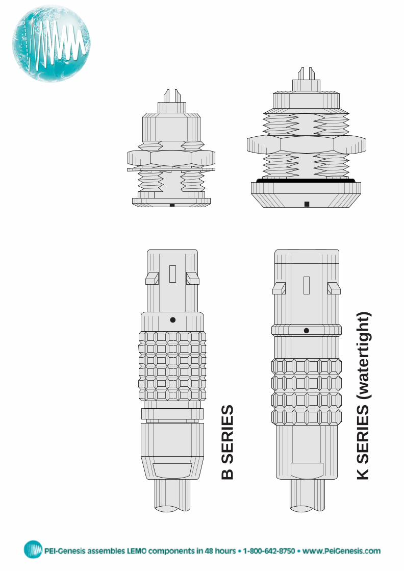
K SERIES (watertight) B SERIES
Transcript of K SERIES (watertight) - PEI-Genesis · 2019. 5. 13. · FKG Elbow (90°) plug for remote handling,...
K S
ER
IES
(w
ater
tight
)
B S
ER
IES
peg
Stamp
FHG
FIG
FKG
FGG
FFG
FGG
FEG
FNG
JGG
FDG
EJG
R••
EPG
EZG
CFF, CRG
PHG
PHG
PNG
FGGFGG
FGYFGY
FTG
FMG
ENG
ENY
FAG
FWG EGG
EHG
EKG
ENG
ESG
EEG
ECG
EFG
ECG
ECG
EYG
XPF
XBG, EXG
PEG
PKG
PFG
S••YHG
HCG
HGG HHG
HNG HMG
HEG FVG
FVB
ESG
XRB
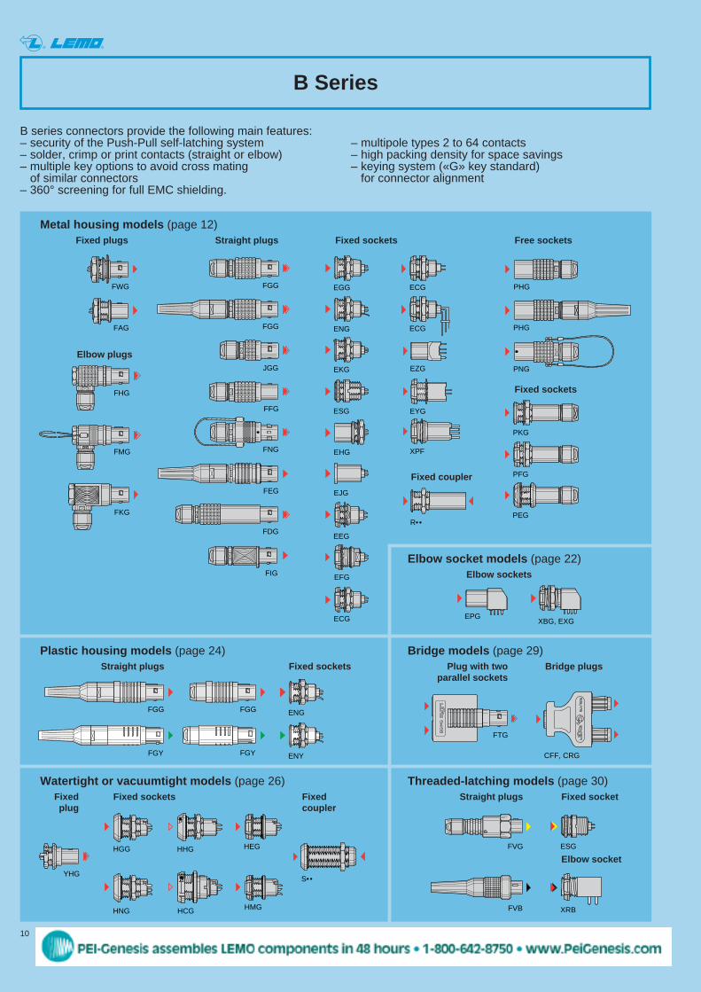
B Series
B series connectors provide the following main features:– security of the Push-Pull self-latching system – multipole types 2 to 64 contacts– solder, crimp or print contacts (straight or elbow) – high packing density for space savings– multiple key options to avoid cross mating – keying system («G» key standard)
of similar connectors for connector alignment – 360° screening for full EMC shielding.
Fixed plugs Straight plugs Fixed sockets Free sockets
Elbow plugs
Fixed sockets
Fixed coupler
Fixed socketsStraight plugs
Elbow sockets
Bridge plugsPlug with twoparallel sockets
Plastic housing models (page 24)
Metal housing models (page 12)
Bridge models (page 29)
Elbow socket models (page 22)
Fixedplug
Fixed sockets Fixedcoupler
Watertight or vacuumtight models (page 26)Straight plugs Fixed socket
Elbow socket
Threaded-latching models (page 30)
10 www.lemo.com
® ®
peg
Stamp
Z
11www.lemo.com
® ®
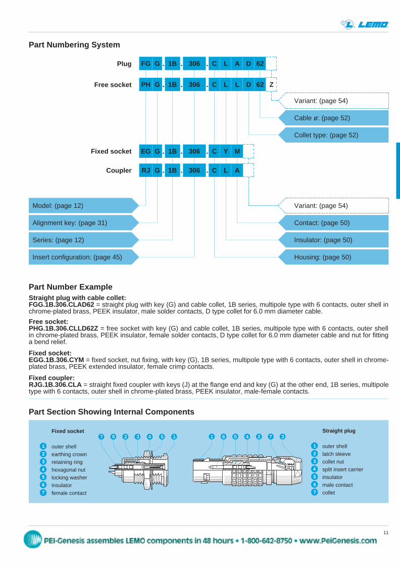
Straight plug with cable collet:FGG.1B.306.CLAD62 = straight plug with key (G) and cable collet, 1B series, multipole type with 6 contacts, outer shell in chrome-plated brass, PEEK insulator, male solder contacts, D type collet for 6.0 mm diameter cable.
FG G 1B
Insert configuration: (page 45)
Cable ø: (page 52)
Collet type: (page 52)
Variant: (page 54)
306
Series: (page 12)
Model: (page 12)
Alignment key: (page 31)
C L A D 62
Fixed socket EG G 1B 306 C Y M
Housing: (page 50)
Insulator: (page 50)
Contact: (page 50)
Fixed socket:EGG.1B.306.CYM = fixed socket, nut fixing, with key (G), 1B series, multipole type with 6 contacts, outer shell in chrome-plated brass, PEEK extended insulator, female crimp contacts.
Variant: (page 54)
Coupler RJ G 1B 306 C L A
Part Numbering System
Plug
PH G 1B 306 C L L D 62Free socket
Part Section Showing Internal Components
13 4 5267
4
3
6
7
5
1
2
4
3
6
5
7
1
2
1 6 5 4 2 7 3Fixed socket
outer shellearthing crownretaining ringhexagonal nutlocking washerinsulatorfemale contact
Straight plug
outer shelllatch sleevecollet nutsplit insert carrierinsulatormale contactcollet
Fixed coupler:RJG.1B.306.CLA = straight fixed coupler with keys (J) at the flange end and key (G) at the other end, 1B series, multipoletype with 6 contacts, outer shell in chrome-plated brass, PEEK insulator, male-female contacts.
Part Number Example
Free socket:PHG.1B.306.CLLD62Z = free socket with key (G) and cable collet, 1B series, multipole type with 6 contacts, outer shell in chrome-plated brass, PEEK insulator, female solder contacts, D type collet for 6.0 mm diameter cable and nut for fitting a bend relief.
. . .
. . .
. . .
. . .
peg
Stamp
12 www.lemo.com
® ®
~M
~L
ø A
S 1S 2
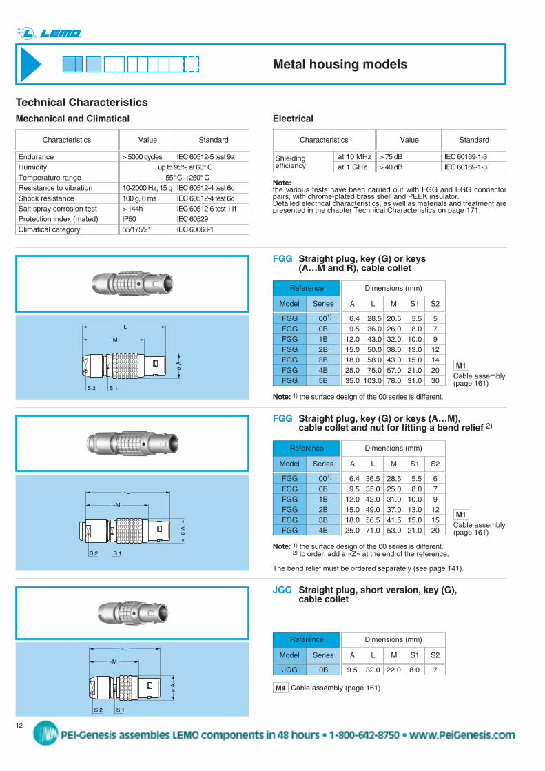
JGG Straight plug, short version, key (G), cable collet
9.5 32.0 22.0 8.0 7
Reference
Model Series
Dimensions (mm)
A L M S1 S2
JGG 0B
~M
~L
ø A
S 1S 2
FGG Straight plug, key (G) or keys (A…M and R), cable collet
Reference
Model Series
S 2
~M
~L
S 1
ø A
FGG 001)
FGG 0BFGG 1BFGG 2BFGG 3BFGG 4BFGG 5B
6.4 28.5 20.5 5.5 59.5 36.0 26.0 8.0 7
12.0 43.0 32.0 10.0 915.0 50.0 38.0 13.0 1218.0 58.0 43.0 15.0 1425.0 75.0 57.0 21.0 2035.0 103.0 78.0 31.0 30
Dimensions (mm)
A L M S1 S2
FGG Straight plug, key (G) or keys (A…M), cable collet and nut for fitting a bend relief 2)
Reference
Model Series
FGG 001)
FGG 0BFGG 1BFGG 2BFGG 3BFGG 4B
6.4 36.5 28.5 5.5 69.5 35.0 25.0 8.0 7
12.0 42.0 31.0 10.0 915.0 49.0 37.0 13.0 1218.0 56.5 41.5 15.0 1525.0 71.0 53.0 21.0 20
Dimensions (mm)
A L M S1 S2
Note: 1) the surface design of the 00 series is different.2) to order, add a «Z» at the end of the reference.
The bend relief must be ordered separately (see page 141).
Note: 1) the surface design of the 00 series is different.
M4 Cable assembly (page 161)
M1Cable assembly(page 161)
M1Cable assembly(page 161)
Technical CharacteristicsElectrical
at 10 MHzat 1 GHz
Characteristics
> 75 dB IEC 60169-1-3> 40 dB IEC 60169-1-3
Value Standard
Shielding efficiency
Note:the various tests have been carried out with FGG and EGG connectorpairs, with chrome-plated brass shell and PEEK insulator.Detailed electrical characteristics, as well as materials and treatment arepresented in the chapter Technical Characteristics on page 171.
> 5000 cycles IEC 60512-5 test 9aup to 95% at 60° C- 55° C, +250° C
10-2000 Hz, 15 g IEC 60512-4 test 6d100 g, 6 ms IEC 60512-4 test 6c> 144h IEC 60512-6 test 11fIP50 IEC 6052955/175/21 IEC 60068-1
EnduranceHumidityTemperature rangeResistance to vibrationShock resistanceSalt spray corrosion testProtection index (mated)Climatical category
Characteristics Value Standard
Mechanical and Climatical
Metal housing models
peg
Stamp
13www.lemo.com
® ®
~M
~L
ø A
S 1S 2
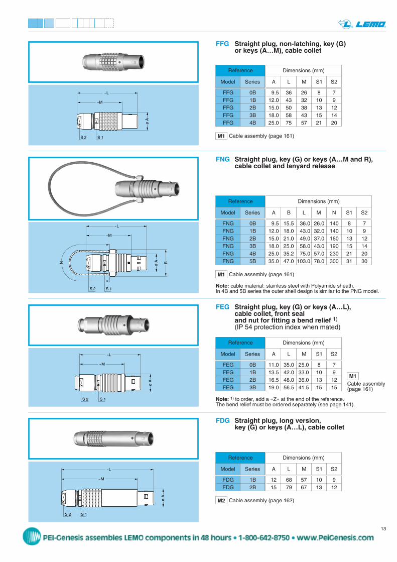
FFG Straight plug, non-latching, key (G) or keys (A…M), cable collet
9.5 36 26 8 712.0 43 32 10 915.0 50 38 13 1218.0 58 43 15 1425.0 75 57 21 20
Reference
Model Series
Dimensions (mm)
A L M S1 S2
FFG 0BFFG 1BFFG 2BFFG 3BFFG 4B
~M
~L
ø A B
S 2 S 1
N
S 2
~M
~L
S 1
ø A
FEG Straight plug, key (G) or keys (A…L), cable collet, front seal and nut for fitting a bend relief 1)
(IP 54 protection index when mated)
FNG Straight plug, key (G) or keys (A…M and R),cable collet and lanyard release
9.5 15.5 36.0 26.0 140 8 712.0 18.0 43.0 32.0 140 10 915.0 21.0 49.0 37.0 160 13 1218.0 25.0 58.0 43.0 190 15 1425.0 35.2 75.0 57.0 230 21 2035.0 47.0 103.0 78.0 300 31 30
Reference
Model Series
Dimensions (mm)
A B L M N S1 S2
FNG 0BFNG 1BFNG 2BFNG 3BFNG 4BFNG 5B
11.0 35.0 25.0 8 713.5 42.0 33.0 10 916.5 48.0 36.0 13 1219.0 56.5 41.5 15 15
Reference
Model Series
Dimensions (mm)
A L M S1 S2
FEG 0BFEG 1BFEG 2BFEG 3B
~M
~L
ø A
S 1S 2
FDG Straight plug, long version, key (G) or keys (A…L), cable collet
12 68 57 10 915 79 67 13 12
Reference
Model Series
Dimensions (mm)
A L M S1 S2
FDG 1BFDG 2B
Note: cable material: stainless steel with Polyamide sheath.In 4B and 5B series the outer shell design is similar to the PNG model.
Note: 1) to order, add a «Z» at the end of the reference.The bend relief must be ordered separately (see page 141).
M1 Cable assembly (page 161)
M1Cable assembly(page 161)
M1 Cable assembly (page 161)
M2 Cable assembly (page 162)
peg
Stamp
14 www.lemo.com
® ®
ø Aeø B
S 3
S 1
N
M
E maxi
L maxi
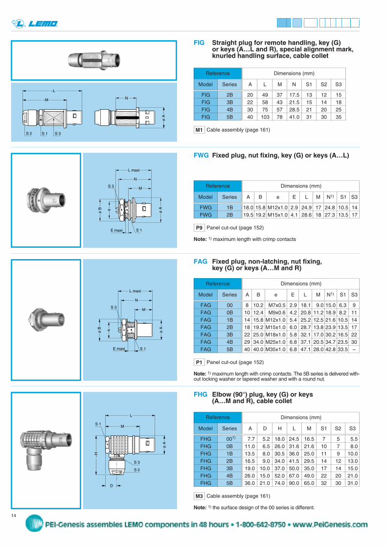
FAG Fixed plug, non-latching, nut fixing, key (G) or keys (A…M and R)
FHG Elbow (90°) plug, key (G) or keys (A…M and R), cable collet
Reference
Model Series
FAG 00FAG 0BFAG 1BFAG 2BFAG 3BFAG 4BFAG 5B
Note: 1) maximum length with crimp contacts. The 5B series is delivered with-out locking washer or tapered washer and with a round nut.
Reference
Model Series
FHG 001)
FHG 0BFHG 1BFHG 2BFHG 3BFHG 4BFHG 5B
P1 Panel cut-out (page 152)
M
ø A
~H
S 2
L
D
S 1
S 3
Dimensions (mm)
A D H L M S1 S2 S3
S 1E maxi
S 3
e
ø B ø A
M
N
L maxi
FWG Fixed plug, nut fixing, key (G) or keys (A…L)
P9 Panel cut-out (page 152)
18.0 15.8 M12x1.0 2.9 24.9 17 24.8 10.5 1419.5 19.2 M15x1.0 4.1 28.6 18 27.3 13.5 17
Reference
Model Series
Dimensions (mm)
A B e E L M N1) S1 S3
FWG 1BFWG 2B
Note: 1) maximum length with crimp contacts
8 10.2 M7x0.5 2.9 18.1 9.0 15.0 6.3 910 12.4 M9x0.6 4.2 20.8 11.2 18.9 8.2 1114 15.8 M12x1.0 5.4 25.2 12.5 21.6 10.5 1418 19.2 M15x1.0 6.0 28.7 13.8 23.9 13.5 1722 25.0 M18x1.0 5.8 32.1 17.0 30.2 16.5 2229 34.0 M25x1.0 6.8 37.1 20.5 34.7 23.5 3040 40.0 M35x1.0 6.8 47.1 28.0 42.8 33.5 –
Dimensions (mm)
A B e E L M N1) S1 S3
Note: 1) the surface design of the 00 series is different.
7.7 5.2 18.0 24.5 16.5 7 5 5.511.0 6.5 26.0 31.6 21.6 10 7 8.013.5 8.0 30.5 36.0 25.0 11 9 10.016.5 9.0 34.0 41.5 29.5 14 12 13.019.0 10.0 37.0 50.0 35.0 17 14 15.026.0 15.0 52.0 67.0 49.0 22 20 21.036.0 21.0 74.0 90.0 65.0 32 30 31.0
M3 Cable assembly (page 161)
FIG Straight plug for remote handling, key (G) or keys (A…L and R), special alignment mark,knurled handling surface, cable collet
ø A
S 2
~M
~L
S 1 S 3
N20 49 37 17.5 13 12 1522 58 43 21.5 15 14 1830 75 57 28.5 21 20 2540 103 78 41.0 31 30 35
Reference
Model Series
Dimensions (mm)
A L M N S1 S2 S3
FIG 2BFIG 3BFIG 4BFIG 5B
M1 Cable assembly (page 161)
peg
Stamp

15www.lemo.com
® ®
FMG Elbow (90°) plug, key (G) or keys (A…M), cable collet and lanyard release, long key
Reference
Model Series
FMG 0B
Note: cable material: stainless steel with Polyamide sheath
M
ø A
~H
S 2
L
S 1
S 3
BN11 17 26 31.6 21.6 140 10 7 8
Dimensions (mm)
A B H L M N S1 S2 S3
S 4
M S 1
L
~H
N
ø A
S 2
S 3
FKG Elbow (90°) plug for remote handling, key (G) or keys (A…L), special alignment mark, knurled handling surface, cable collet
Reference
Model Series
FKG 3BFKG 4B
25 37 50 35 21.0 17 14 15 2132 52 67 49 28.5 22 20 21 26
Dimensions (mm)
A H L M N S1 S2 S3 S4
Note: dimension D is the same as for the FHG model.
eø B
S 1E maxi
S 3
N
M
L maxi
ø A
EGG Fixed socket, nut fixing, key (G) or keys (A…M and R)
8 10.2 M7x0.5 6.0 15.5 1.0 13.7 6.3 910 12.4 M9x0.6 7.0 20.7 1.2 19.1 8.2 1114 15.8 M12x1.0 7.5 23.0 1.5 21.1 10.5 1418 19.2 M15x1.0 8.5 26.7 1.8 24.6 13.5 1722 25.0 M18x1.0 11.5 30.7 2.0 28.1 16.5 2228 34.0 M25x1.0 12.0 35.7 2.5 34.1 23.5 3040 40.0 M35x1.0 11.0 43.5 3.0 39.6 33.5 –
Reference
Model Series
EGG 00EGG 0BEGG 1BEGG 2BEGG 3BEGG 4BEGG 5B
Dimensions (mm)
A B e E L M N1) S1 S3
Note: 1) maximum length with crimp contacts. The 5B series is delivered with a tapered washer and a round nut.
ø Aeø B
S 1E maxi
S 3 M
L maxi
N
ENG Fixed socket with earthing tag, nut fixing, key (G) or keys (A…M)
10 12.4 M9x0.6 7.0 20.7 1.2 19.1 8.2 1114 15.8 M12x1.0 7.5 23.0 1.5 21.1 10.5 1418 19.2 M15x1.0 8.5 26.7 1.8 24.6 13.5 1722 25.0 M18x1.0 11.5 30.7 2.0 28.1 16.5 2228 34.0 M25x1.0 12.0 35.7 2.5 34.1 23.5 30
Reference
Model Series
ENG 0BENG 1B2)
ENG 2BENG 3BENG 4B
Dimensions (mm)
A B e E L M N1) S1 S3
Note: 1) maximum length with crimp contacts.2) for the 1B series the earthing tag is on the upper side.
P1 Panel cut-out (page 152)
P1 Panel cut-out (page 152)
M3 Cable assembly (page 161)
M3 Cable assembly (page 161)
peg
Stamp
16 www.lemo.com
® ®
N
L maxi
M
ø B
ø A
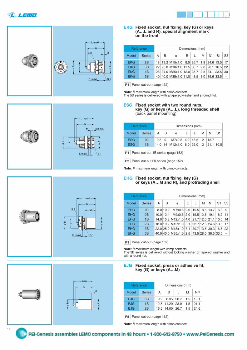
EJG Fixed socket, press or adhesive fit, key (G) or keys (A…M)
Note: 1) maximum length with crimp contacts.
ø Aeø B
S 3
S 1E maxi
N
M
L maxi
EHG Fixed socket, nut fixing, key (G) or keys (A…M and R), and protruding shell
8.0 10.2 M7x0.5 2.0 15.5 8.5 13.7 6.3 910.0 12.4 M9x0.6 2.0 19.5 12.5 19.1 8.2 1114.0 15.8 M12x1.0 4.0 21.7 12.0 21.1 10.5 1418.0 19.2 M15x1.0 5.1 22.7 12.5 24.6 13.5 1722.0 25.0 M18x1.0 7.1 30.7 13.5 30.3 16.5 2240.0 40.0 M35x1.0 2.5 43.5 28.0 38.5 33.5 –
Reference
Model Series
EHG 00EHG 0BEHG 1BEHG 2BEHG 3BEHG 5B
Dimensions (mm)
A B e E L M N1) S1 S3
Note: 1) maximum length with crimp contacts. The 5B series is delivered without locking washer or tapered washer andwith a round nut.
9.2 8.35 20.7 1.5 19.112.5 11.20 23.0 1.5 21.116.5 14.00 26.7 1.5 24.6
Reference
Model Series
Dimensions (mm)
A B L M N1)
EJG 0BEJG 1BEJG 2B
P1 Panel cut-out (page 152)
P5 Panel cut-out (page 152)
N
L maxi
ø Aeø B
E maxi S 1
M 3.2 mini
ESG Fixed socket with two round nuts, key (G) or keys (A…L), long threaded shell(back panel mounting)
9.5 9 M7x0.5 4.2 15.5 2 13.7 –14.0 14 M12x1.0 8.0 23.0 2 21.1 10.5
Reference
Model Series
ESG 00ESG 1B
Dimensions (mm)
A B e E L M N1) S1
Note: 1) maximum length with crimp contacts.
P1 Panel cut-out 1B series (page 152)
P2 Panel cut-out 00 series (page 152)
e
ø B
S 1E maxi
S 3
N
M
L maxi
ø A
EKG Fixed socket, nut fixing, key (G) or keys (A…L and R), special alignment mark on the front
18 19.2 M15x1.0 8.5 26.7 1.8 24.6 13.5 1722 25.0 M18x1.0 11.5 30.7 2.0 28.1 16.5 2228 34.0 M25x1.0 12.0 35.7 2.5 34.1 23.5 3040 40.0 M35x1.0 11.0 43.5 3.0 39.6 33.5 –
Reference
Model Series
EKG 2BEKG 3BEKG 4BEKG 5B
Dimensions (mm)
A B e E L M N1) S1 S3
Note: 1) maximum length with crimp contacts. The 5B series is delivered with a tapered washer and a round nut.
P1 Panel cut-out (page 152)
peg
Stamp
17www.lemo.com
® ®
ø Aeø B
S 1
N
P
M
L maxi
E maxiS 2
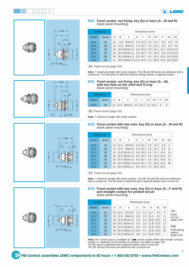
EEG Fixed socket, nut fixing, key (G) or keys (A…M and R)(back panel mounting)
Reference
Model Series
EEG 00EEG 0BEEG 1BEEG 2BEEG 3BEEG 5B
10 9.5 M7x0.5 2.3 15.5 2.5 13.7 6.0 6.3 7.512 12.5 M9x0.6 2.4 20.7 2.5 19.1 6.3 8.2 9.016 16.0 M12x1.0 6.5 23.0 3.5 21.1 11.0 10.5 13.020 20.0 M15x1.0 3.0 26.7 3.5 24.6 9.0 13.5 15.024 25.0 M18x1.0 5.0 30.7 4.5 28.1 12.0 16.5 20.041 40.0 M35x1.0 13.5 43.5 5.0 39.6 19.5 33.5 38.0
Dimensions (mm)
A B e E L M N1) P S1 S2
Note: 1) maximum length with crimp contacts. The 3B and 5B series are delivered with aconical nut. The 5B series is delivered without locking washer or tapered washer.
P1 Panel cut-out (page 152)
Reference
Model Series
ECG 00ECG 0BECG 1BECG 2BECG 3BECG 4BECG 5B
ø Aeø B
S 3
N
M
L maxi
E maxiS 1
ECG Fixed socket with two nuts, key (G) or keys (A…M and R)(back panel mounting)
10 10.2 M7x0.5 4.3 13.7 2.5 13.7 6.3 912 12.4 M9x0.6 5.5 20.7 2.5 19.1 8.2 1116 15.8 M12x1.0 6.0 23.0 3.5 21.1 10.5 1420 19.2 M15x1.0 6.5 26.7 3.5 24.6 13.5 1724 25.0 M18x1.0 9.0 30.7 4.5 28.1 16.5 2230 34.0 M25x1.0 10.0 35.7 4.5 32.6 23.5 3041 40.0 M35x1.0 9.0 43.5 5.0 39.6 33.5 –
Dimensions (mm)
A B e E L M N1) S1 S3
P15PCB drilling pattern(page 154)
Reference
Model Series
ECG 00ECG 0BECG 1BECG 2BECG 3BECG 4BECG 5B
ø Aeø B
S 3
NL
M
E maxiS 1
ECG Fixed socket with two nuts, key (G) or keys (A…F and R)and straight contact for printed circuit (back panel mounting)
10 10.2 M7x0.5 4.3 2.5 13.7 6.3 912 12.4 M9x0.6 5.5 2.5 16.4 8.2 1116 15.8 M12x1.0 6.0 3.5 19.8 10.5 1420 19.2 M15x1.0 6.5 3.5 21.8 13.5 1724 25.0 M18x1.0 9.0 4.5 25.8 16.5 2230 34.0 M25x1.0 10.0 4.5 29.8 23.5 3041 40.0 M35x1.0 9.0 5.0 36.8 33.5 –
Dimensions (mm)
A B e E M N S1 S3
Note: this contact type is available for E socket models fitted with female contacts.Length «L» depends on the number of contacts, see table on page 156. The 5B series is delivered with a tapered washer and a round nut. The 3B, 4B and 5B series are delivered with a conical nut.
Note: 1) maximum length with crimp contacts. The 3B, 4B and 5B series are deliveredwith a conical nut. The 5B series is delivered with a tapered washer and a round nut.
ø Aeø B
N
P
M
L maxi
E maxiS 2
EFG Fixed socket, nut fixing, key (G) or keys (A…M), with two flats on the shell and O-ring (back panel mounting)
12 12.5 M9x0.6 5.5 20.7 2.5 19.1 9 8
Reference
Model Series
EFG 0B
Dimensions (mm)
A B e E L M N1) P S2
P2 Panel cut-out (page 152)
P1Panel cut-out(page 152)
Note: 1) maximum length with crimp contacts.
P1 Panel cut-out (page 152)
peg
Stamp
L N
ø A
K
M 1
.6 H
B
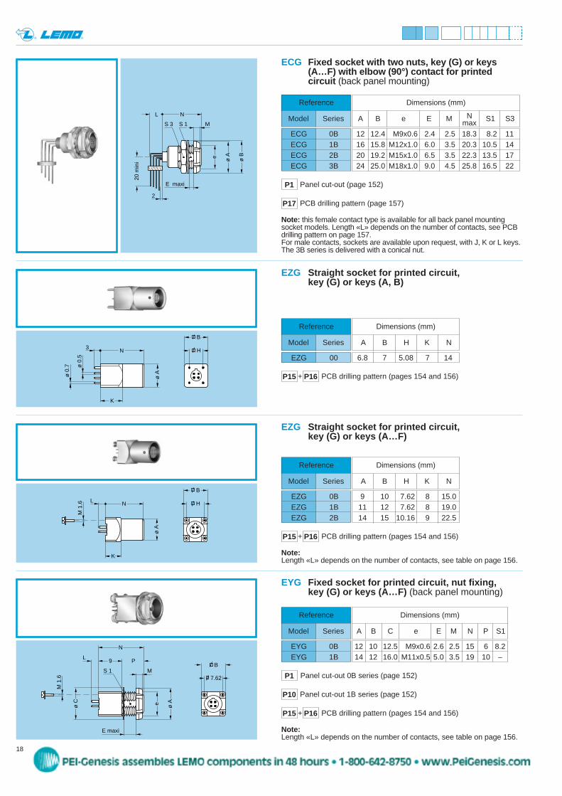
EZG Straight socket for printed circuit, key (G) or keys (A…F)
9 10 7.62 8 15.011 12 7.62 8 19.014 15 10.16 9 22.5
Reference
Model Series
Dimensions (mm)
A B H K N
EZG 0BEZG 1BEZG 2B
Note:Length «L» depends on the number of contacts, see table on page 156.
PCB drilling pattern (pages 154 and 156)P15 P16+
18 www.lemo.com
® ®
EYG Fixed socket for printed circuit, nut fixing,key (G) or keys (A…F) (back panel mounting)
12 10 12.5 M9x0.6 2.6 2.5 15 6 8.214 12 16.0 M11x0.5 5.0 3.5 19 10 –
Reference
Model Series
EYG 0BEYG 1B
Dimensions (mm)
A B C e E M N P S1
L
ø Ae
P9
M
E maxi
N
S 1
ø C
M 1
.6 7.62
B
PCB drilling pattern (pages 154 and 156)P15 P16+
Note:Length «L» depends on the number of contacts, see table on page 156.
P1 Panel cut-out 0B series (page 152)
P10 Panel cut-out 1B series (page 152)
ø Aø 0
.7
N3 H
B
K
ø 0
.5
EZG Straight socket for printed circuit, key (G) or keys (A, B)
6.8 7 5.08 7 14
Reference
Model Series
Dimensions (mm)
A B H K N
EZG 00
PCB drilling pattern (pages 154 and 156)P15 P16+
Dimensions (mm)
A B e E M S1 S3Nmax
Reference
Model Series
ECG 0BECG 1BECG 2BECG 3B
ECG Fixed socket with two nuts, key (G) or keys(A…F) with elbow (90°) contact for printed circuit (back panel mounting)
12 12.4 M9x0.6 2.4 2.5 18.3 8.2 1116 15.8 M12x1.0 6.0 3.5 20.3 10.5 1420 19.2 M15x1.0 6.5 3.5 22.3 13.5 1724 25.0 M18x1.0 9.0 4.5 25.8 16.5 22
Note: this female contact type is available for all back panel mounting socket models. Length «L» depends on the number of contacts, see PCBdrilling pattern on page 157. For male contacts, sockets are available upon request, with J, K or L keys. The 3B series is delivered with a conical nut.
P17 PCB drilling pattern (page 157)
P1 Panel cut-out (page 152)
ø Ae ø B
S 3
N
MS 1
E maxi
2
20 m
ini
L
peg
Stamp
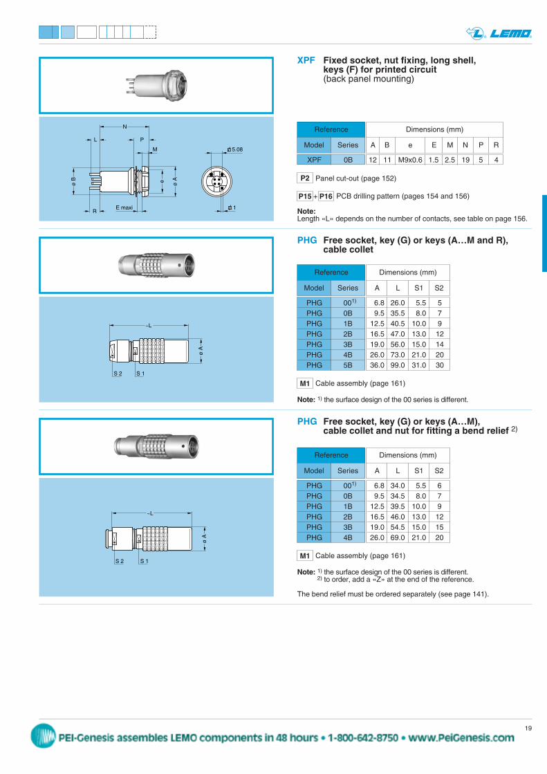
6.8 26.0 5.5 59.5 35.5 8.0 7
12.5 40.5 10.0 916.5 47.0 13.0 1219.0 56.0 15.0 1426.0 73.0 21.0 2036.0 99.0 31.0 30
S 2
~L
S 1
ø A
PHG Free socket, key (G) or keys (A…M and R),cable collet
Reference
Model Series
Dimensions (mm)
A L S1 S2
PHG 001)
PHG 0BPHG 1BPHG 2BPHG 3BPHG 4BPHG 5B
~L
S 2 S 1
ø A
PHG Free socket, key (G) or keys (A…M), cable collet and nut for fitting a bend relief 2)
6.8 34.0 5.5 69.5 34.5 8.0 7
12.5 39.5 10.0 916.5 46.0 13.0 1219.0 54.5 15.0 1526.0 69.0 21.0 20
Reference
Model Series
Dimensions (mm)
A L S1 S2
PHG 001)
PHG 0BPHG 1BPHG 2BPHG 3BPHG 4B
Note: 1) the surface design of the 00 series is different.
Note: 1) the surface design of the 00 series is different.2) to order, add a «Z» at the end of the reference.
The bend relief must be ordered separately (see page 141).
19www.lemo.com
® ®
XPF Fixed socket, nut fixing, long shell, keys (F) for printed circuit(back panel mounting)
Reference
Model Series
XPF 0B
ø Aeø B
PL
M
E maxiR
N
5.08
1 Note:Length «L» depends on the number of contacts, see table on page 156.
P2
12 11 M9x0.6 1.5 2.5 19 5 4
Dimensions (mm)
A B e E M N P R
Panel cut-out (page 152)
PCB drilling pattern (pages 154 and 156)P15 P16+
M1 Cable assembly (page 161)
M1 Cable assembly (page 161)
peg
Stamp
20 www.lemo.com
® ®
ø Ae
ø B
S 3 M
E maxiS 1S 2
~L
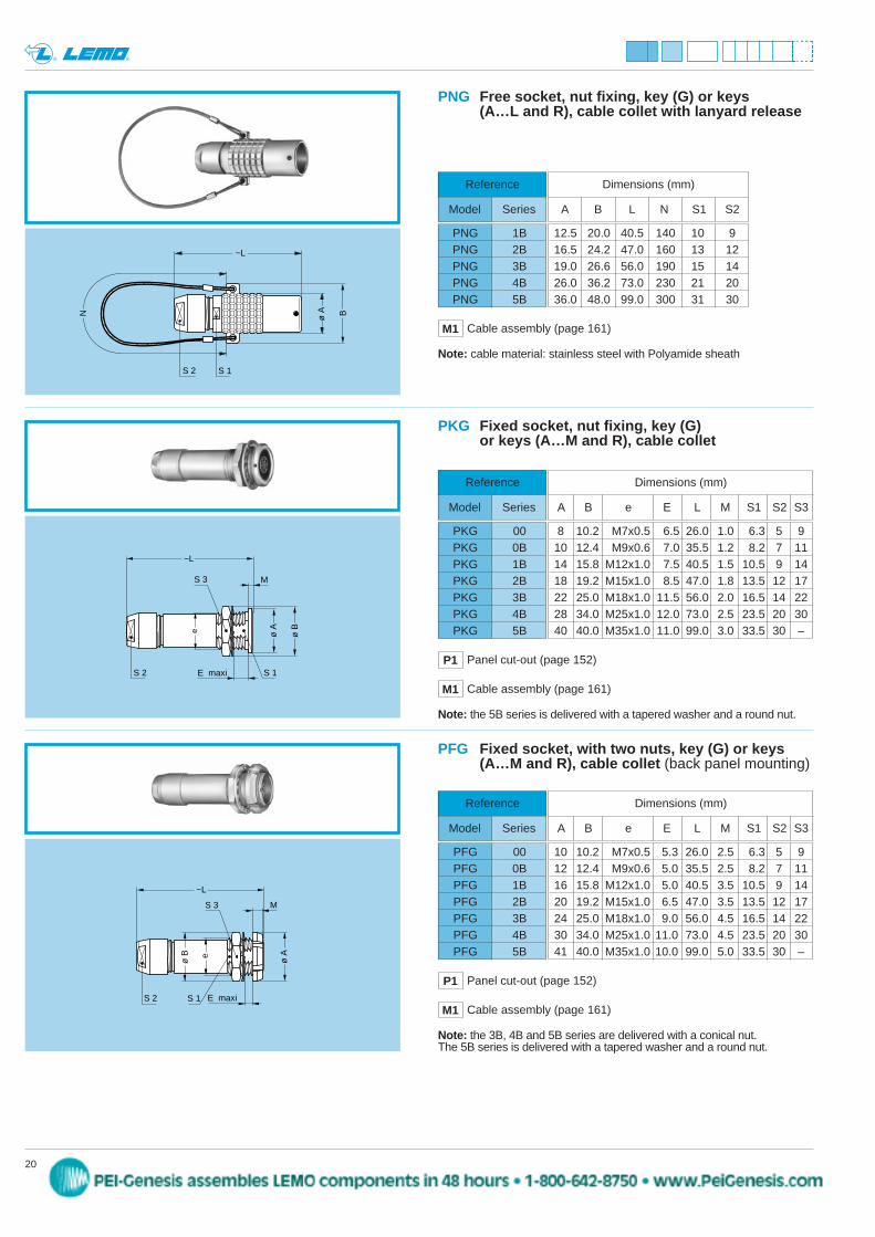
PFG Fixed socket, with two nuts, key (G) or keys (A…M and R), cable collet (back panel mounting)
Reference
Model Series
PFG 00PFG 0BPFG 1BPFG 2BPFG 3BPFG 4BPFG 5B
10 10.2 M7x0.5 5.3 26.0 2.5 6.3 5 912 12.4 M9x0.6 5.0 35.5 2.5 8.2 7 1116 15.8 M12x1.0 5.0 40.5 3.5 10.5 9 1420 19.2 M15x1.0 6.5 47.0 3.5 13.5 12 1724 25.0 M18x1.0 9.0 56.0 4.5 16.5 14 2230 34.0 M25x1.0 11.0 73.0 4.5 23.5 20 3041 40.0 M35x1.0 10.0 99.0 5.0 33.5 30 –
~L
ø Ae
S 3
S 1
M
E maxi
ø B
S 2
PKG Fixed socket, nut fixing, key (G) or keys (A…M and R), cable collet
Reference
Model Series
PKG 00PKG 0BPKG 1BPKG 2BPKG 3BPKG 4BPKG 5B
8 10.2 M7x0.5 6.5 26.0 1.0 6.3 5 910 12.4 M9x0.6 7.0 35.5 1.2 8.2 7 1114 15.8 M12x1.0 7.5 40.5 1.5 10.5 9 1418 19.2 M15x1.0 8.5 47.0 1.8 13.5 12 1722 25.0 M18x1.0 11.5 56.0 2.0 16.5 14 2228 34.0 M25x1.0 12.0 73.0 2.5 23.5 20 3040 40.0 M35x1.0 11.0 99.0 3.0 33.5 30 –
Dimensions (mm)
A B e E L M S1 S2 S3
P1 Panel cut-out (page 152)
Note: the 3B, 4B and 5B series are delivered with a conical nut. The 5B series is delivered with a tapered washer and a round nut.
Note: the 5B series is delivered with a tapered washer and a round nut.
P1 Panel cut-out (page 152)
M1 Cable assembly (page 161)
M1 Cable assembly (page 161)
~L
ø A B
S 2 S 1
N
PNG Free socket, nut fixing, key (G) or keys (A…L and R), cable collet with lanyard release
12.5 20.0 40.5 140 10 916.5 24.2 47.0 160 13 1219.0 26.6 56.0 190 15 1426.0 36.2 73.0 230 21 2036.0 48.0 99.0 300 31 30
Reference
Model Series
Dimensions (mm)
A B L N S1 S2
PNG 1BPNG 2BPNG 3BPNG 4BPNG 5B
Note: cable material: stainless steel with Polyamide sheath
M1 Cable assembly (page 161)
Dimensions (mm)
A B e E L M S1 S2 S3
peg
Stamp
21www.lemo.com
® ®
L
S 3 M
ø A
ø Be
S 1E maxi
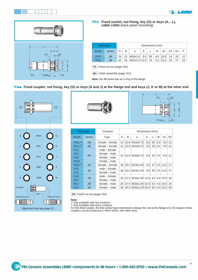
R Fixed coupler, nut fixing, key (G) or keys (A and J) at the flange end and keys (J, K or M) at the other end
Reference
Model Series
RGG 1) 0BRGG 2) 0BRJGRGJ
0BRAKRGMRGG 2) 1BRJG
1BRGJRJG
2BRGJRGJ 3BRGJ 4B
female – female 12 13.8 M10x0.75 8.0 34 2.0 9.0 12female – female 12 13.8 M10x0.75 8.0 43 2.0 9.0 12male – femalefemale – male
12 13.8 M10x0.75 8.0 34 2.0 9.0 12female – malefemale – male
female – female 16 19.2 M14x1.00 8.5 47 2.5 12.5 17male – female
16 19.2 M14x1.00 8.5 39 2.5 12.5 17female – malemale – female
20 21.5 M16x1.00 12.0 44 4.0 15.0 19female – malefemale – male 25 27.0 M20x1.00 32.0 53 4.0 18.5 24female – male 34 34.0 M25x1.00 50.0 65 4.0 23.5 30
Contacts Dimensions (mm)
Type A B e E L M S1 S3
Note:1) only available with two contacts.2) only available with three contacts.For this fixed coupler, the first contact type mentioned is always the one at the flange end. On request, thesecouplers can be produced in other series, with other keys.
RGGG G
G J
J GRJG
RGJ
A KRAK
G MRGM
PEG Fixed socket, nut fixing, key (G) or keys (A…L), cable collet (back panel mounting)
Reference
Model Series
PEG 3BPEG 4B
24 22 M18x1.0 5.0 56 4.5 16.5 14 20 1232 34 M25x1.0 12.5 73 5.0 23.5 20 27 20
Dimensions (mm)
A B e E L M S1 S2 S4 P
P1 Panel cut-out (page 152)
S 2
~L
S 1 M
P
e ø A
ø B
S 4E maxi
Note: the 4B series has an o-ring on the flange.
P4 Panel cut-out (page 152)
M1 Cable assembly (page 161)
Alignment key see page 31.
Example
Plug with key GRGJ
Plug with key J
peg
Stamp
22 www.lemo.com
® ®
EPG-XBG 00EPG-EXG 0BEPG-EXG 0BEPG-EXG 0BEPG-EXG 0BEPG-EXG 0BEPG-EXG 0BEPG-EXG 0BEPG-EXG 1BEPG-EXG 1BEPG-EXG 1BEPG-EXG 1BEPG-EXG 1BEPG-EXG 1BEPG-EXG 1BEPG-EXG 1B
EPG 1B
1 2 3
6 5 4
1 2 3
5 4
302
303
304
306
3051
2
3 4
5
1
2 3
1
2 3
4
1
2
3 4
56
1 2 3
7
6 5 4
2
1
3 4
8
7 6 5
307
00
00
1 2
3
0B, 1B
00
1 2
4 3
0B, 1B
0B, 1B
0B, 1B
0B, 1B
3081B
1
2
3 4
56
7
12
34 5
687
3090B
1
2
1
2
0B, 1B
3101B1 8
4 567
32 9
10
1
9
2 3
6
4
10
8 7 5
1 8
4 567
32
9
1
9
2 3
6
4
8 7 5
4 3
1 2
1 2
3
1 2
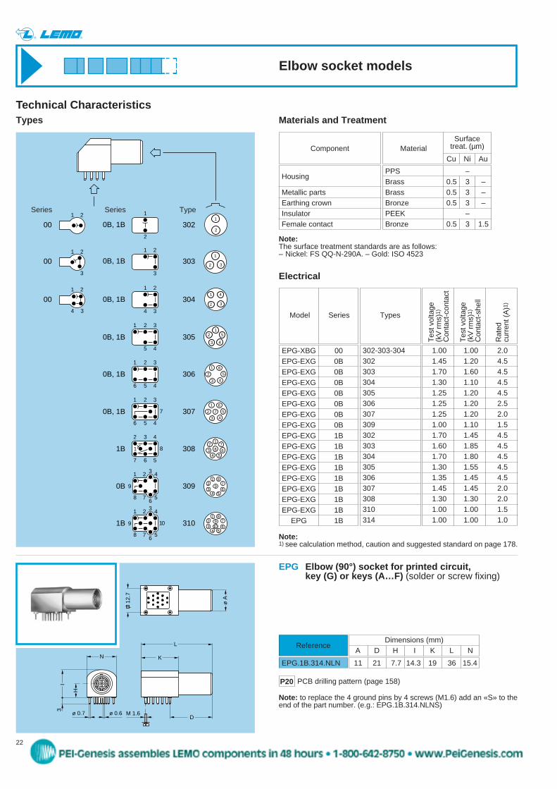
Housing
Metallic partsEarthing crownInsulatorFemale contact
Component MaterialSurface
treat. (µm)
Cu Ni Au
PPS –Brass 0.5 3 –Brass 0.5 3 –Bronze 0.5 3 –PEEK –Bronze 0.5 3 1.5
Materials and Treatment
Note:The surface treatment standards are as follows:– Nickel: FS QQ-N-290A. – Gold: ISO 4523
Types
Technical Characteristics
Types
Tes
t vol
tage
(kV
rm
s)1)
Con
tact
-con
tact
Tes
t vol
tage
(kV
rm
s)1)
Con
tact
-she
ll
Rat
ed
curr
ent (
A)1
)
Electrical
Model Series
1.00 1.00 2.01.45 1.20 4.51.70 1.60 4.51.30 1.10 4.51.25 1.20 4.51.25 1.20 2.51.25 1.20 2.01.00 1.10 1.51.70 1.45 4.51.60 1.85 4.51.70 1.80 4.51.30 1.55 4.51.35 1.45 4.51.45 1.45 2.01.30 1.30 2.01.00 1.00 1.51.00 1.00 1.0
302-303-304302303304305306307309302303304305306307308310314
Note:1) see calculation method, caution and suggested standard on page 178.
Series Series Type
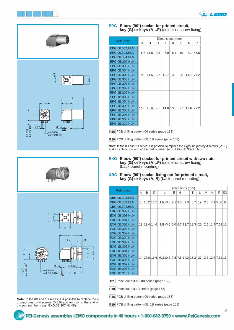
EPG Elbow (90°) socket for printed circuit, key (G) or keys (A…F) (solder or screw fixing)
Reference
EPG.1B.314.NLN
Note: to replace the 4 ground pins by 4 screws (M1.6) add an «S» to theend of the part number. (e.g.: EPG.1B.314.NLNS)
L
ø A
H
3 I
KN
M 1.6D
ø 0.7 ø 0.6
12.7
11 21 7.7 14.3 19 36 15.4
Dimensions (mm)A D H I K L N
P20 PCB drilling pattern (page 158)
Elbow socket models
peg
Stamp
23www.lemo.com
® ®
6.8 11.5 3.5 7.0 8.7 19 7.1 5.08
9.0 14.6 6.7 12.7 13.3 25 11.7 7.62
11.0 16.6 7.5 14.0 13.3 27 12.6 7.62
L
ø A
H
3.0
(00)
3.
2 (0
B-1
B)
I
KN
M 1.6D
ø 0.7
R
ø 0.5 (00)ø 0.7 (0B-1B)
EPG Elbow (90°) socket for printed circuit, key (G) or keys (A…F) (solder or screw fixing)
ReferenceDimensions (mm)
A D H I K L N R
Note: In the 0B and 1B series, it is possible to replace the 4 ground pins by 4 screws (M1.6)add an «S» to the end of the part number. (e.g.: EPG.0B.307.HLNS)
P18 PCB drilling pattern 00 series (page 158)
EPG.00.302.HLNEPG.00.303.HLNEPG.00.304.HLNEPG.0B.302.HLNEPG.0B.303.HLNEPG.0B.304.HLNEPG.0B.305.HLNEPG.0B.306.HLNEPG.0B.307.HLNEPG.0B.309.HLNEPG.1B.302.HLNEPG.1B.303.HLNEPG.1B.304.HLNEPG.1B.305.HLNEPG.1B.306.HLNEPG.1B.307.HLNEPG.1B.308.HLNEPG.1B.310.HLN
P19 PCB drilling pattern 0B, 1B series (page 158)
10 10.2 11.5 M7x0.5 2.1 3.5 7.0 8.7 19 2.5 7.1 5.08 9
12 12.4 14.6 M9x0.6 6.0 6.7 12.7 13.3 25 2.5 11.7 7.62 11
14 15.0 16.6 M11x0.5 7.5 7.5 14.0 13.3 27 3.5 12.6 7.62 13
Dimensions (mm)A B D e E H I K L M N R S3
Reference
EXG Elbow (90°) socket for printed circuit with two nuts, key (G) or keys (A…F) (solder or screw fixing)(back panel mounting)
L
K
H
MS 3
ø Ae
E maxi
D
I
ø B
M 1.6
RN
3.0
(00)
3.
2 (0
B-1
B)
ø 0.5 (00)ø 0.7 (0B-1B)
Note: In the 0B and 1B series, it is possible to replace the 4ground pins by 4 screws (M1.6) add an «S» to the end ofthe part number. (e.g.: EXG.0B.307.HLNS).
XBG.00.302.HLNXBG.00.303.HLNXBG.00.304.HLNEXG.0B.302.HLNEXG.0B.303.HLNEXG.0B.304.HLNEXG.0B.305.HLNEXG.0B.306.HLNEXG.0B.307.HLNEXG.0B.309.HLNEXG.1B.302.HLNEXG.1B.303.HLNEXG.1B.304.HLNEXG.1B.305.HLNEXG.1B.306.HLNEXG.1B.307.HLNEXG.1B.308.HLNEXG.1B.310.HLN
XBG Elbow (90°) socket fixing nut for printed circuit, key (G) or keys (A, B) (back panel mounting)
P18 PCB drilling pattern 00 series (page 158)
P19 PCB drilling pattern 0B, 1B series (page 158)
P2 Panel cut-out 00, 0B series (page 152)
P10 Panel cut-out 1B series (page 152)
peg
Stamp
24 www.lemo.com
® ®
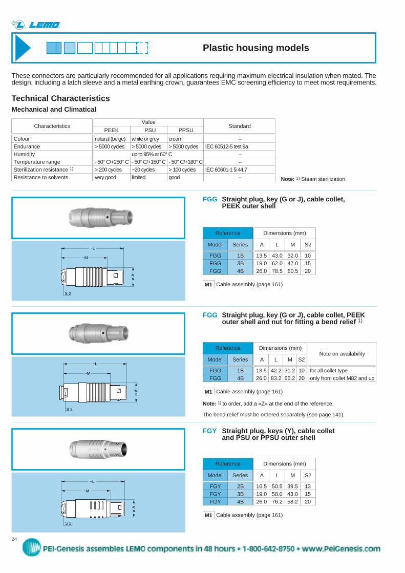
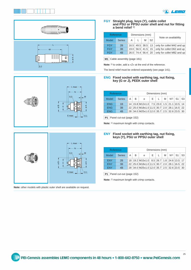
FGY 2BFGY 3BFGY 4B
13.5 43.0 32.0 1019.0 62.0 47.0 1526.0 78.5 60.5 20
ø A
~M
~L
S 2
FGG Straight plug, key (G or J), cable collet, PEEK outer shell
~M
~L
ø A
S 2
FGY Straight plug, keys (Y), cable collet and PSU or PPSU outer shell
Reference
Model Series
Dimensions (mm)
A L M S2
FGG 1BFGG 3BFGG 4B
16.5 50.5 39.5 1319.0 58.0 43.0 1526.0 76.2 58.2 20
Reference
Model Series
Dimensions (mm)
A L M S2
Standard
These connectors are particularly recommended for all applications requiring maximum electrical insulation when mated. Thedesign, including a latch sleeve and a metal earthing crown, guarantees EMC screening efficiency to meet most requirements.
natural (beige) white or grey cream –> 5000 cycles > 5000 cycles > 5000 cycles IEC 60512-5 test 9a
up to 95% at 60° C –- 50° C/+250° C - 50° C/+150° C - 50° C/+180° C –> 200 cycles ~20 cycles > 100 cycles IEC 60601-1 § 44.7very good limited good –
ColourEnduranceHumidityTemperature rangeSterilization resistance 1)
Resistance to solvents
Characteristics
Mechanical and Climatical
Technical Characteristics
Value
PEEK PSU PPSU
Note: 1) Steam sterilization
M1 Cable assembly (page 161)
M1 Cable assembly (page 161)
Plastic housing models
ø A
~M
~L
S 2
FGG Straight plug, key (G or J), cable collet, PEEKouter shell and nut for fitting a bend relief 1)
Reference
Model Series
FGG 1BFGG 4B
Note: 1) to order, add a «Z» at the end of the reference.
The bend relief must be ordered separately (see page 141).
M1 Cable assembly (page 161)
13.5 42.2 31.2 1026.0 83.2 65.2 20
Dimensions (mm)
A L M S2
for all collet typeonly from collet M82 and up
Note on availability
peg
Stamp
25www.lemo.com
® ®
ENY 2BENY 3BENY 4B
ø Aeø B
S 1E maxi
S 3 M
L maxi
N
ENG Fixed socket with earthing tag, nut fixing, key (G or J), PEEK outer shell
14 15.8 M12x1.0 7.5 23.0 1.5 21.1 10.5 1422 25.0 M18x1.0 11.5 30.7 2.0 28.1 16.5 2228 34.0 M25x1.0 12.0 35.7 2.5 32.6 23.5 30
Reference
Model Series
ENG 1BENG 3BENG 4B
Dimensions (mm)
A B e E L M N1) S1 S3
Note: 1) maximum length with crimp contacts.
ø Aeø B
S 1E maxi
S 3 M
L maxi
N
ENY Fixed socket with earthing tag, nut fixing, keys (Y), PSU or PPSU outer shell
18 19.2 M15x1.0 8.5 26.7 1.8 24.6 13.5 1722 25.0 M18x1.0 11.5 30.7 2.0 28.1 16.5 2228 34.0 M25x1.0 12.0 35.7 2.5 32.6 23.5 30
Reference
Model Series
Dimensions (mm)
A B e E L M N1) S1 S3
Note: 1) maximum length with crimp contacts.
P1 Panel cut-out (page 152)
P1 Panel cut-out (page 152)
Note: other models with plastic outer shell are available on request.
~M
~L
ø A
S 2
FGY Straight plug, keys (Y), cable collet and PSU or PPSU outer shell and nut for fittinga bend relief 1)
16.5 49.5 38.5 1319.0 56.5 41.5 1526.0 74.4 56.4 20
Reference
Model Series
Dimensions (mm)
A L M S2
only for collet M42 and uponly for collet D62 and uponly for collet M82 and up
Note on availability
FGY 2BFGY 3BFGY 4B
Note: 1) to order, add a «Z» at the end of the reference.
The bend relief must be ordered separately (see page 141).
M1 Cable assembly (page 161)
peg
Stamp
26 www.lemo.com
® ®
S 3M
L maxi
eø B
ø A
S 1E maxi
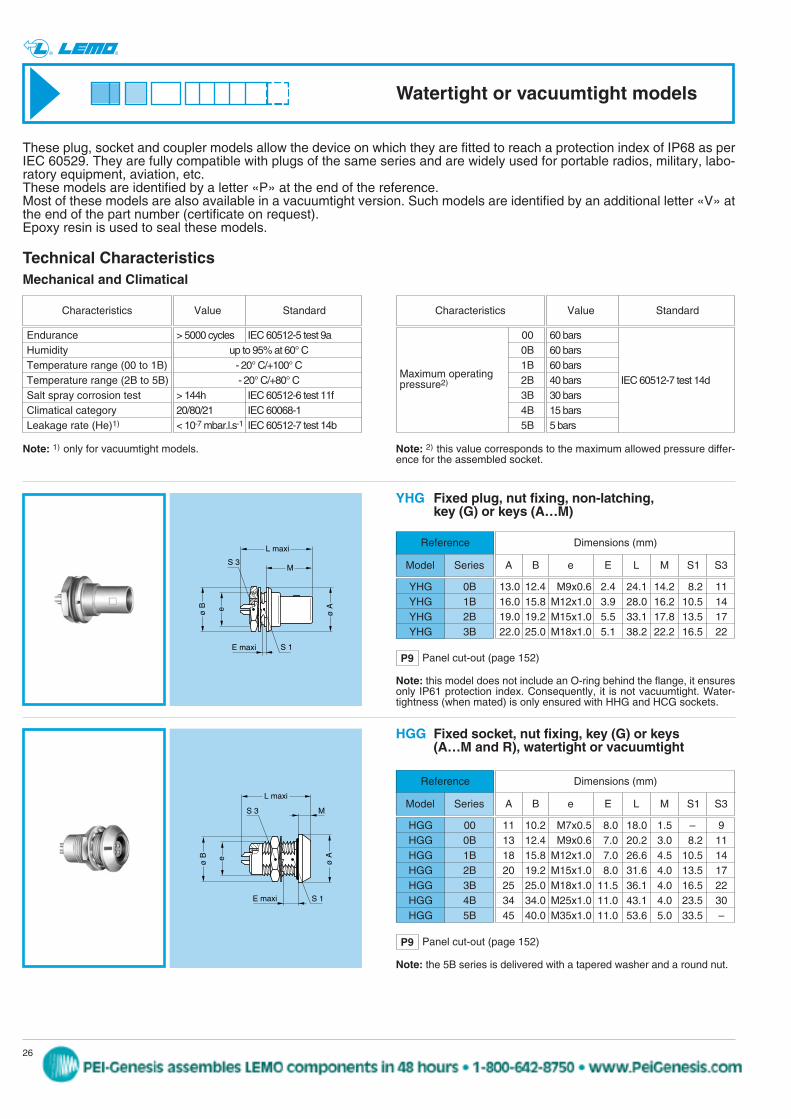
YHG Fixed plug, nut fixing, non-latching, key (G) or keys (A…M)
Reference
Model Series
YHG 0BYHG 1BYHG 2BYHG 3B
13.0 12.4 M9x0.6 2.4 24.1 14.2 8.2 1116.0 15.8 M12x1.0 3.9 28.0 16.2 10.5 1419.0 19.2 M15x1.0 5.5 33.1 17.8 13.5 1722.0 25.0 M18x1.0 5.1 38.2 22.2 16.5 22
Dimensions (mm)
A B e E L M S1 S3
S 3
L maxi
M
ø Aeø B
S 1E maxi
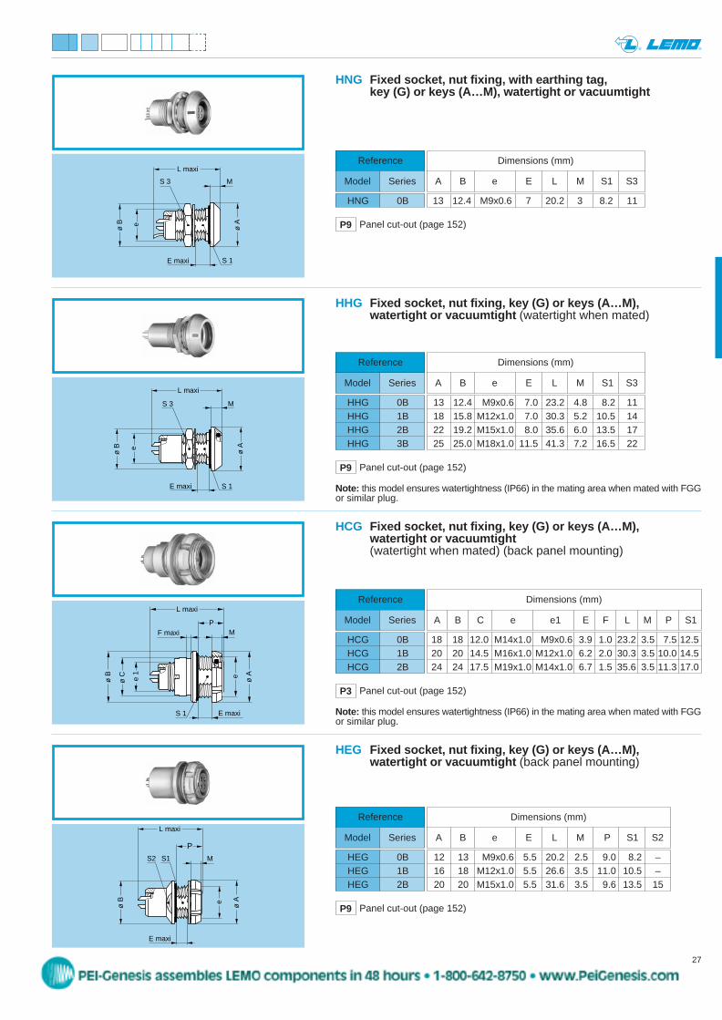
Note: this model does not include an O-ring behind the flange, it ensuresonly IP61 protection index. Consequently, it is not vacuumtight. Water-tightness (when mated) is only ensured with HHG and HCG sockets.
HGG Fixed socket, nut fixing, key (G) or keys (A…M and R), watertight or vacuumtight
Reference
Model Series
HGG 00HGG 0BHGG 1BHGG 2BHGG 3BHGG 4BHGG 5B
11 10.2 M7x0.5 8.0 18.0 1.5 – 913 12.4 M9x0.6 7.0 20.2 3.0 8.2 1118 15.8 M12x1.0 7.0 26.6 4.5 10.5 1420 19.2 M15x1.0 8.0 31.6 4.0 13.5 1725 25.0 M18x1.0 11.5 36.1 4.0 16.5 2234 34.0 M25x1.0 11.0 43.1 4.0 23.5 3045 40.0 M35x1.0 11.0 53.6 5.0 33.5 –
Dimensions (mm)
A B e E L M S1 S3
> 5000 cycles IEC 60512-5 test 9aup to 95% at 60° C
- 20° C/+100° C- 20° C/+80° C
> 144h IEC 60512-6 test 11f20/80/21 IEC 60068-1< 10-7 mbar.l.s-1 IEC 60512-7 test 14b
EnduranceHumidityTemperature range (00 to 1B)Temperature range (2B to 5B)Salt spray corrosion testClimatical categoryLeakage rate (He)1)
Characteristics Value Standard
Mechanical and Climatical
Note: 1) only for vacuumtight models. Note: 2) this value corresponds to the maximum allowed pressure differ-ence for the assembled socket.
Technical Characteristics
Note: the 5B series is delivered with a tapered washer and a round nut.
P9 Panel cut-out (page 152)
P9 Panel cut-out (page 152)
60 bars60 bars60 bars40 bars IEC 60512-7 test 14d30 bars15 bars5 bars
000B1B2B3B4B5B
Characteristics Value Standard
Maximum operating pressure2)
Watertight or vacuumtight models
These plug, socket and coupler models allow the device on which they are fitted to reach a protection index of IP68 as perIEC 60529. They are fully compatible with plugs of the same series and are widely used for portable radios, military, labo-ratory equipment, aviation, etc.These models are identified by a letter «P» at the end of the reference. Most of these models are also available in a vacuumtight version. Such models are identified by an additional letter «V» atthe end of the part number (certificate on request).Epoxy resin is used to seal these models.
peg
Stamp
27www.lemo.com
® ®
ø Ae
ø B
S 3
S 1
L maxi
M
E maxi
HNG Fixed socket, nut fixing, with earthing tag, key (G) or keys (A…M), watertight or vacuumtight
Reference
Model Series
HNG 0B 13 12.4 M9x0.6 7 20.2 3 8.2 11
Dimensions (mm)
A B e E L M S1 S3
P9 Panel cut-out (page 152)
ø Ae
ø B
S 3
S 1
L maxi
M
E maxi
HHG Fixed socket, nut fixing, key (G) or keys (A…M), watertight or vacuumtight (watertight when mated)
Reference
Model Series
HHG 0BHHG 1BHHG 2BHHG 3B
13 12.4 M9x0.6 7.0 23.2 4.8 8.2 1118 15.8 M12x1.0 7.0 30.3 5.2 10.5 1422 19.2 M15x1.0 8.0 35.6 6.0 13.5 1725 25.0 M18x1.0 11.5 41.3 7.2 16.5 22
Dimensions (mm)
A B e E L M S1 S3
ø Ae 1
ø B
L maxi
MP
F maxi
S 1 E maxi
e
ø C
HCG Fixed socket, nut fixing, key (G) or keys (A…M), watertight or vacuumtight(watertight when mated) (back panel mounting)
Reference
Model Series
HCG 0BHCG 1BHCG 2B
18 18 12.0 M14x1.0 M9x0.6 3.9 1.0 23.2 3.5 7.5 12.520 20 14.5 M16x1.0 M12x1.0 6.2 2.0 30.3 3.5 10.0 14.524 24 17.5 M19x1.0 M14x1.0 6.7 1.5 35.6 3.5 11.3 17.0
Dimensions (mm)
A B C e e1 E F L M P S1
P9 Panel cut-out (page 152)
P3 Panel cut-out (page 152)
ø Ae
ø B
S1S2
L maxi
M
E maxi
P
HEG Fixed socket, nut fixing, key (G) or keys (A…M), watertight or vacuumtight (back panel mounting)
Reference
Model Series
HEG 0BHEG 1BHEG 2B
P9 Panel cut-out (page 152)
12 13 M9x0.6 5.5 20.2 2.5 9.0 8.2 –16 18 M12x1.0 5.5 26.6 3.5 11.0 10.5 –20 20 M15x1.0 5.5 31.6 3.5 9.6 13.5 15
Dimensions (mm)
A B e E L M P S1 S2
Note: this model ensures watertightness (IP66) in the mating area when mated with FGGor similar plug.
Note: this model ensures watertightness (IP66) in the mating area when mated with FGGor similar plug.
peg
Stamp
28 www.lemo.com
® ®
E maxi
S 3
ø A
S 1 M
ø B e
L
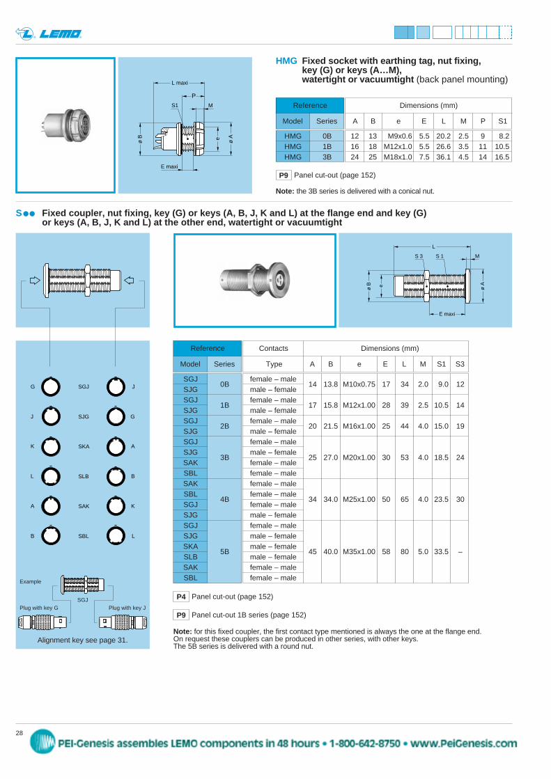
S Fixed coupler, nut fixing, key (G) or keys (A, B, J, K and L) at the flange end and key (G) or keys (A, B, J, K and L) at the other end, watertight or vacuumtight
Reference
Model Series
SGJ0B
SJGSGJ
1BSJGSGJ
2BSJGSGJSJG
3BSAKSBLSAKSBL
4BSGJSJGSGJSJGSKA
5BSLBSAKSBL
female – male14 13.8 M10x0.75 17 34 2.0 9.0 12
male – femalefemale – male
17 15.8 M12x1.00 28 39 2.5 10.5 14male – femalefemale – male
20 21.5 M16x1.00 25 44 4.0 15.0 19male – femalefemale – malemale – female
25 27.0 M20x1.00 30 53 4.0 18.5 24female – malefemale – malefemale – malefemale – male
34 34.0 M25x1.00 50 65 4.0 23.5 30female – malemale – femalefemale – malemale – femalemale – female
45 40.0 M35x1.00 58 80 5.0 33.5 –male – femalefemale – malefemale – male
Contacts Dimensions (mm)
Type A B e E L M S1 S3
Note: for this fixed coupler, the first contact type mentioned is always the one at the flange end. On request these couplers can be produced in other series, with other keys.The 5B series is delivered with a round nut.
SGJG J
J GSJG
K ASKA
L BSLB
A KSAK
B LSBL
P4 Panel cut-out (page 152)
P9 Panel cut-out 1B series (page 152)
HMG Fixed socket with earthing tag, nut fixing, key (G) or keys (A…M), watertight or vacuumtight (back panel mounting)
Reference
Model Series
HMG 0BHMG 1BHMG 3B
12 13 M9x0.6 5.5 20.2 2.5 9 8.216 18 M12x1.0 5.5 26.6 3.5 11 10.524 25 M18x1.0 7.5 36.1 4.5 14 16.5
Dimensions (mm)
A B e E L M P S1
P9 Panel cut-out (page 152)
ø Ae
ø B
S1
L maxi
M
E maxi
P
Note: the 3B series is delivered with a conical nut.
Alignment key see page 31.
Example
Plug with key GSGJ
Plug with key J
peg
Stamp
29www.lemo.com
® ®
A
BH N
M maxi
L maxi
CFF
CRG
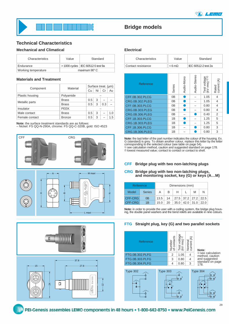
Bridge plug with two non-latching plugs
Bridge plug with two non-latching plugs, and monitoring socket, key (G) or keys (A…M)
CFF-CRG 0BCFF-CRG 1B
13.5 14 27.5 37.2 27.2 22.515.0 20 35.0 42.0 31.0 22.0
Dimensions (mm)
A B H L M N
Technical Characteristics
Note: the last letter of the part number indicates the colour of the housing. Ex.G (standard) is grey. To obtain another colour, replace this letter by the lettercorresponding to the selected colour (see table on page 54). 1) see calculation method, caution and suggested standard on page 178.2) lowest measured value; contact to contact or contact to shell.
> 1000 cycles IEC 60512-5 test 9amaximum 90° C
EnduranceWorking temperature
Characteristics Value Standard
Mechanical and Climatical
Note: in order to provide the user with a coding system, the bridge plug hous-ing, the double panel washers and the bend reliefs are available in nine colours.
Electrical
Polyamide –Brass 0.5 3 – –Brass 0.5 3 0.3 –PEEK –Brass 0.5 3 – 1.0Bronze 0.5 3 – 1.5
Plastic housing
Metallic parts
InsulatorMale contactFemale contact
ComponentSurface treat. (µm)Cu Ni Cr Au
Materials and Treatment
Material
Note: the surface treatment standards are as follows:– Nickel: FS QQ-N-290A, chrome: FS QQ-C-320B, gold: ISO 4523
Reference
Ser
ies
Aud
io-M
ono
Aud
io-S
tere
o
Tes
t vol
tage
(k
V r
ms)
1) 2
)
Rat
ed
curr
ent (
A)
Reference
Model Series
< 6 mΩ IEC 60512-2 test 2aContact resistance
Characteristics Value Standard
0B – 1.05 40B – 1.05 40B – 0.80 40B – 0.80 40B – 0.40 21B – 1.25 51B – 1.25 51B – 0.80 31B – 0.80 3
CFF.0B.302.PLCGCRG.0B.302.PLEGCFF.0B.303.PLCGCRG.0B.303.PLEGCRG.0B.306.PLEGCFF.1B.303.PLCGCRG.1B.303.PLEGCFF.1B.306.PLCGCRG.1B.306.PLEG
CFF CRG
12
15
24
37.8
27.8
1
2
1
2
1
2
1
3 2
1
2 3
1
2 3
3 2
2 3
1 4
2 3
1 4
4 1
FTG Straight plug, key (G) and two parallel sockets
Reference
Num
ber
of c
onta
cts
Tes
t vol
tage
(kV
rm
s)1)
Nom
inal
cu
rren
t (A
)
2 1.05 43 0.80 44 0.80 3
FTG.0B.302.PLFGFTG.0B.303.PLFGFTG.0B.304.PLFG
Note:1) see calculationmethod, cautionand suggestedstandard on page178.
Type 302 Type 303 Type 304
Bridge models
peg
Stamp
30 www.lemo.com
® ®
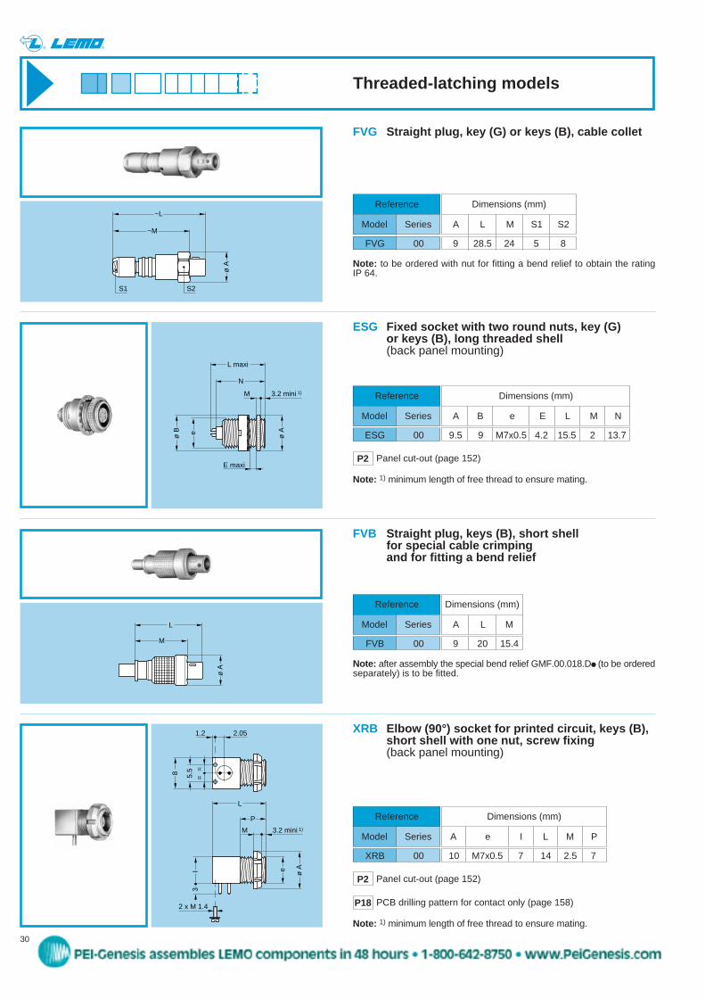
FVG Straight plug, key (G) or keys (B), cable collet
Reference
Model Series
FVG 00 9 28.5 24 5 8
Dimensions (mm)
A L M S1 S2ø
A
M
L
FVB Straight plug, keys (B), short shell for special cable crimping and for fitting a bend relief
XRB Elbow (90°) socket for printed circuit, keys (B),short shell with one nut, screw fixing (back panel mounting)
Reference
Model Series
XRB 00
N
M 3.2 mini 1)
L maxi
ø Aeø B
E maxi
ESG Fixed socket with two round nuts, key (G) or keys (B), long threaded shell(back panel mounting)
Reference
Model Series
ESG 00 9.5 9 M7x0.5 4.2 15.5 2 13.7
Dimensions (mm)
A B e E L M N
Reference
Model Series
FVB 00 9 20 15.4
Dimensions (mm)
A L M
Note: after assembly the special bend relief GMF.00.018.D (to be orderedseparately) is to be fitted.
Note: 1) minimum length of free thread to ensure mating.
Note: 1) minimum length of free thread to ensure mating.
L
ø Ae
M
P
3.2 mini 1)
I3
2 x M 1.4
2.051.2
5.5
==8
10 M7x0.5 7 14 2.5 7
Dimensions (mm)
A e I L M P
Note: to be ordered with nut for fitting a bend relief to obtain the rating IP 64.
S1 S2
~L
~Mø
A
P2 Panel cut-out (page 152)
P2 Panel cut-out (page 152)
P18 PCB drilling pattern for contact only (page 158)
Threaded-latching models
peg
Stamp
R 5
Ref
eren
ce Series
00 0B 1BAng
les
31www.lemo.com
® ®
Alignment Key (B series)
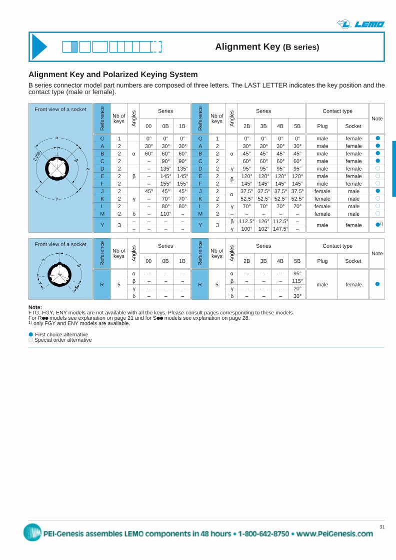
Alignment Key and Polarized Keying System
α
β
δ
γ
β(5
B)
Contact type
Plug SocketNote
male femalemale femalemale femalemale femalemale femalemale femalemale female
female malefemale malefemale malefemale male
male female
1)
Note:FTG, FGY, ENY models are not available with all the keys. Please consult pages corresponding to these models.For R models see explanation on page 21 and for S models see explanation on page 28.1) only FGY and ENY models are available.
First choice alternative Special order alternative
B series connector model part numbers are composed of three letters. The LAST LETTER indicates the key position and thecontact type (male or female).
Front view of a socket
G 1 0° 0° 0°A 2 30° 30° 30°B 2 α 60° 60° 60°C 2 – 90° 90°D 2 – 135° 135°E 2 β – 145° 145°F 2 – 155° 155°J 2 45° 45° 45°K 2 γ – 70° 70°L 2 – 80° 80°M 2 δ – 110° –
– – – –Y 3
– – – –
Nb ofkeys
Ref
eren
ce Series
2B 3B 4B 5BAng
les
G 1 0° 0° 0° 0°A 2 30° 30° 30° 30°B 2 α 45° 45° 45° 45°C 2 60° 60° 60° 60°D 2 γ 95° 95° 95° 95°E 2 120° 120° 120° 120°F 2 145° 145° 145° 145°J 2 37.5° 37.5° 37.5° 37.5°K 2 52.5° 52.5° 52.5° 52.5°L 2 γ 70° 70° 70° 70°M 2 – – – – –
β 112.5° 126° 112.5° –Y 3
γ 100° 102° 147.5° –
Nb ofkeys
δ
α
γ
β
Front view of a socket
β
α
Ref
eren
ce Series
00 0B 1BAng
les Contact type
Plug SocketNote
male female
α – – –β – – –γ – – –δ – – –
Nb ofkeys
R 5
α – – – 95°β – – – 115°γ – – – 20°δ – – – 30°
Ref
eren
ce Series
2B 3B 4B 5BAng
les
Nb ofkeys
peg
Stamp
45www.lemo.com
® ®
First choice alternative Special order alternative
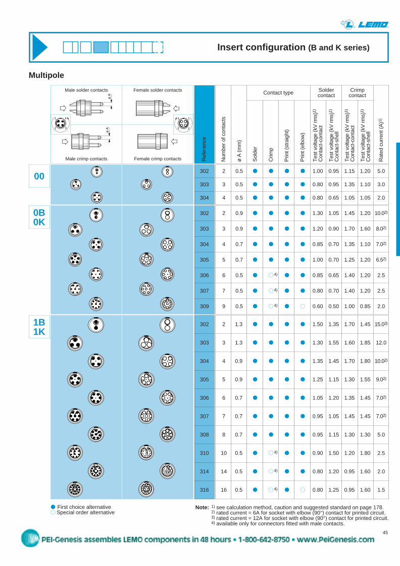
Multipole
Num
ber o
f con
tact
s
ø A
(mm
)
Sol
der
Crim
p
Prin
t (st
raig
ht)
Prin
t (el
bow
)
Tes
t vol
tage
(kV
rms)
1)
Con
tact
-con
tact
Tes
t vol
tage
(kV
rms)
1)
Con
tact
-she
ll
Tes
t vol
tage
(kV
rms)
1)
Con
tact
-con
tact
Tes
t vol
tage
(kV
rms)
1)
Con
tact
-she
ll
Rat
ed c
urre
nt (A
)1)
Ref
eren
ce
Solder CrimpContact type contact contact
Note: 1) see calculation method, caution and suggested standard on page 178.2) rated current = 6A for socket with elbow (90°) contact for printed circuit.3) rated current = 12A for socket with elbow (90°) contact for printed circuit.4) available only for connectors fitted with male contacts.
ø A
Male solder contacts Female solder contacts
ø A
Male crimp contacts Female crimp contacts
302
303
304
305
306
307
309
0B0K
302
303
304
00
302
303
304
305
306
307
308
310
314
316
1B1K
2 0.5 1.00 0.95 1.15 1.20 5.0
3 0.5 0.80 0.95 1.35 1.10 3.0
4 0.5 0.80 0.65 1.05 1.05 2.0
2 0.9 1.30 1.05 1.45 1.20 10.02)
3 0.9 1.20 0.90 1.70 1.60 8.02)
4 0.7 0.85 0.70 1.35 1.10 7.02)
5 0.7 1.00 0.70 1.25 1.20 6.52)
6 0.5 4) 0.85 0.65 1.40 1.20 2.5
7 0.5 4) 0.80 0.70 1.40 1.20 2.5
9 0.5 4) 0.60 0.50 1.00 0.85 2.0
2 1.3 1.50 1.35 1.70 1.45 15.03)
3 1.3 1.30 1.55 1.60 1.85 12.0
4 0.9 1.35 1.45 1.70 1.80 10.02)
5 0.9 1.25 1.15 1.30 1.55 9.02)
6 0.7 1.05 1.20 1.35 1.45 7.02)
7 0.7 0.95 1.05 1.45 1.45 7.02)
8 0.7 0.95 1.15 1.30 1.30 5.0
10 0.5 4) 0.90 1.50 1.20 1.80 2.5
14 0.5 4) 0.80 1.20 0.95 1.60 2.0
16 0.5 4) 0.80 1.25 0.95 1.60 1.5
14
23
1 4
2 3
Insert configuration (B and K series)
peg
Stamp
46 www.lemo.com
® ®
First choice alternative Special order alternative
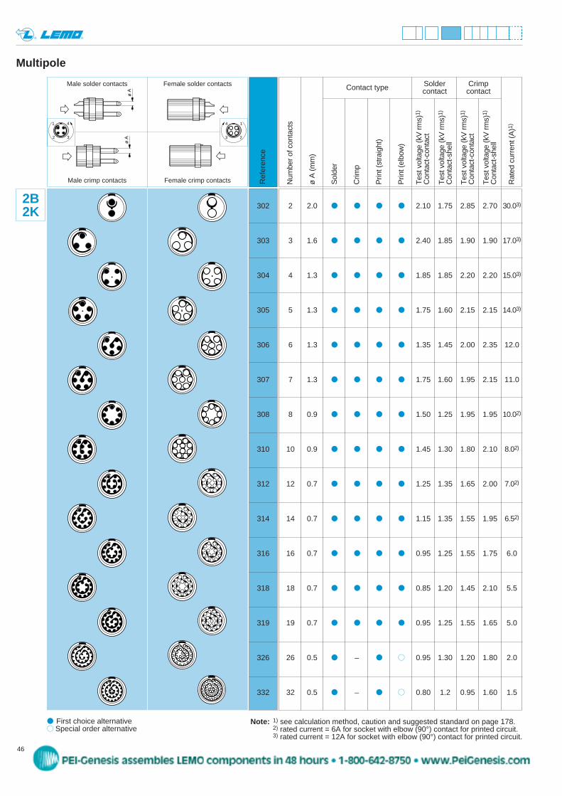
Multipole
Note: 1) see calculation method, caution and suggested standard on page 178.2) rated current = 6A for socket with elbow (90°) contact for printed circuit.3) rated current = 12A for socket with elbow (90°) contact for printed circuit.
Num
ber o
f con
tact
s
ø A
(mm
)
Sol
der
Crim
p
Prin
t (st
raig
ht)
Prin
t (el
bow
)
Tes
t vol
tage
(kV
rms)
1)
Con
tact
-con
tact
Tes
t vol
tage
(kV
rms)
1)
Con
tact
-she
ll
Tes
t vol
tage
(kV
rms)
1)
Con
tact
-con
tact
Tes
t vol
tage
(kV
rms)
1)
Con
tact
-she
ll
Rat
ed c
urre
nt (A
)1)
Ref
eren
ce
Solder CrimpContact type contact contact
302
303
304
305
306
307
308
310
312
314
316
318
319
326
332
2B2K 2 2.0 2.10 1.75 2.85 2.70 30.03)
3 1.6 2.40 1.85 1.90 1.90 17.03)
4 1.3 1.85 1.85 2.20 2.20 15.03)
5 1.3 1.75 1.60 2.15 2.15 14.03)
6 1.3 1.35 1.45 2.00 2.35 12.0
7 1.3 1.75 1.60 1.95 2.15 11.0
8 0.9 1.50 1.25 1.95 1.95 10.02)
10 0.9 1.45 1.30 1.80 2.10 8.02)
12 0.7 1.25 1.35 1.65 2.00 7.02)
14 0.7 1.15 1.35 1.55 1.95 6.52)
16 0.7 0.95 1.25 1.55 1.75 6.0
18 0.7 0.85 1.20 1.45 2.10 5.5
19 0.7 0.95 1.25 1.55 1.65 5.0
26 0.5 – 0.95 1.30 1.20 1.80 2.0
32 0.5 – 0.80 1.2 0.95 1.60 1.5
ø A
Male solder contacts Female solder contacts
ø A
Male crimp contacts Female crimp contacts
14
23
1 4
2 3
peg
Stamp
47www.lemo.com
® ®
First choice alternative Special order alternative
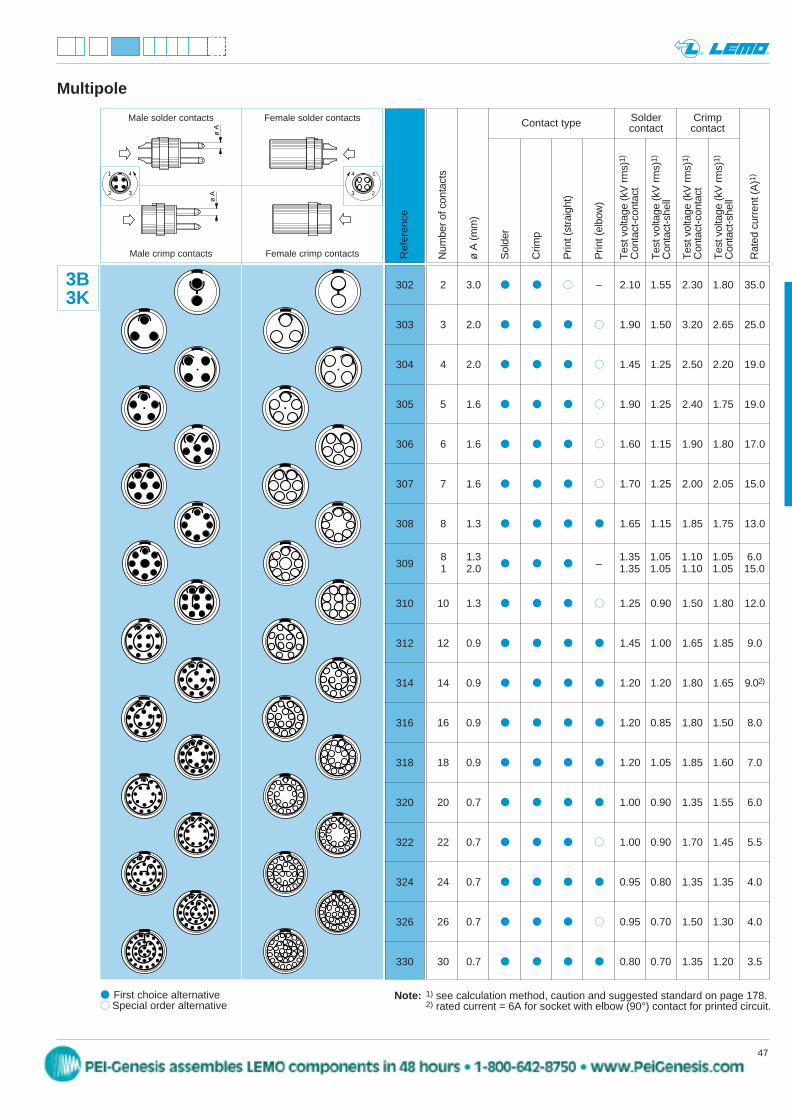
Multipole
Note: 1) see calculation method, caution and suggested standard on page 178.2) rated current = 6A for socket with elbow (90°) contact for printed circuit.
Num
ber o
f con
tact
s
ø A
(mm
)
Sol
der
Crim
p
Prin
t (st
raig
ht)
Prin
t (el
bow
)
Tes
t vol
tage
(kV
rms)
1)
Con
tact
-con
tact
Tes
t vol
tage
(kV
rms)
1)
Con
tact
-she
ll
Tes
t vol
tage
(kV
rms)
1)
Con
tact
-con
tact
Tes
t vol
tage
(kV
rms)
1)
Con
tact
-she
ll
Rat
ed c
urre
nt (A
)1)
Ref
eren
ce
Solder CrimpContact type contact contact
302
303
304
305
306
307
308
309
310
312
314
316
318
320
322
324
326
330
3B3K
2 3.0 – 2.10 1.55 2.30 1.80 35.0
3 2.0 1.90 1.50 3.20 2.65 25.0
4 2.0 1.45 1.25 2.50 2.20 19.0
5 1.6 1.90 1.25 2.40 1.75 19.0
6 1.6 1.60 1.15 1.90 1.80 17.0
7 1.6 1.70 1.25 2.00 2.05 15.0
8 1.3 1.65 1.15 1.85 1.75 13.0
–
10 1.3 1.25 0.90 1.50 1.80 12.0
12 0.9 1.45 1.00 1.65 1.85 9.0
14 0.9 1.20 1.20 1.80 1.65 9.02)
16 0.9 1.20 0.85 1.80 1.50 8.0
18 0.9 1.20 1.05 1.85 1.60 7.0
20 0.7 1.00 0.90 1.35 1.55 6.0
22 0.7 1.00 0.90 1.70 1.45 5.5
24 0.7 0.95 0.80 1.35 1.35 4.0
26 0.7 0.95 0.70 1.50 1.30 4.0
30 0.7 0.80 0.70 1.35 1.20 3.5
8 1.3 1.35 1.05 1.10 1.05 6.01 2.0 1.35 1.05 1.10 1.05 15.0
ø A
Male solder contacts Female solder contacts
ø A
Male crimp contacts Female crimp contacts
14
23
1 4
2 3
peg
Stamp
48 www.lemo.com
® ®
First choice alternative Special order alternative
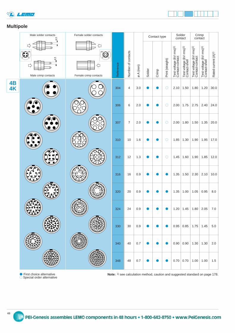
Multipole
Num
ber o
f con
tact
s
ø A
(mm
)
Sol
der
Crim
p
Prin
t (st
raig
ht)
Tes
t vol
tage
(kV
rms)
1)
Con
tact
-con
tact
Tes
t vol
tage
(kV
rms)
1)
Con
tact
-she
ll
Tes
t vol
tage
(kV
rms)
1)
Con
tact
-con
tact
Tes
t vol
tage
(kV
rms)
1)
Con
tact
-she
ll
Rat
ed c
urre
nt (A
)1)
Ref
eren
ce
Solder CrimpContact type contact contact
304
306
307
310
312
316
320
324
330
340
348
4B4K
Note: 1) see calculation method, caution and suggested standard on page 178.
4 3.0 2.10 1.50 1.80 1.20 30.0
6 2.0 2.00 1.75 2.75 2.40 24.0
7 2.0 2.00 1.80 1.50 1.35 20.0
10 1.6 1.85 1.30 1.90 1.95 17.0
12 1.3 1.45 1.60 1.90 1.85 12.0
16 0.9 1.35 1.50 2.30 2.10 10.0
20 0.9 1.35 1.00 1.05 0.95 8.0
24 0.9 1.20 1.45 1.80 2.05 7.0
30 0.9 0.95 0.85 1.75 1.45 5.0
40 0.7 0.90 0.90 1.30 1.30 2.0
48 0.7 0.70 0.70 1.00 1.00 1.5
ø A
Male solder contacts Female solder contacts
ø A
Male crimp contacts Female crimp contacts
14
23
1 4
2 3
peg
Stamp
49www.lemo.com
® ®
First choice alternative Special order alternative
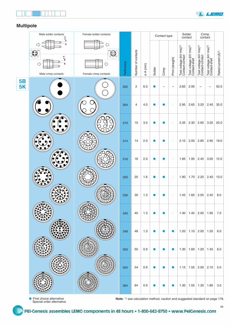
Multipole
Num
ber o
f con
tact
s
ø A
(mm
)
Sol
der
Crim
p
Prin
t (st
raig
ht)
Tes
t vol
tage
(kV
rms)
1)
Con
tact
-con
tact
Tes
t vol
tage
(kV
rms)
1)
Con
tact
-she
ll
Tes
t vol
tage
(kV
rms)
1)
Con
tact
-con
tact
Tes
t vol
tage
(kV
rms)
1)
Con
tact
-she
ll
Rat
ed c
urre
nt (A
)1)
Ref
eren
ce
Solder CrimpContact type contact contact
302
304
310
314
316
320
330
340
348
350
354
364
5B5K
Note: 1) see calculation method, caution and suggested standard on page 178.
2 6.0 – – 3.60 2.95 – – 50.0
4 4.0 2.95 2.65 3.20 2.40 35.0
10 3.0 2.35 2.30 2.65 3.20 20.0
14 2.0 2.10 2.00 2.85 2.95 18.0
16 2.0 1.85 1.95 2.45 3.05 12.0
20 1.6 1.90 1.70 2.20 2.40 10.0
30 1.3 1.45 1.60 2.05 2.45 8.0
40 1.3 1.30 1.45 2.00 1.95 7.0
48 1.3 1.20 1.10 2.00 1.55 6.0
50 0.9 1.30 1.60 1.20 1.45 6.0
54 0.9 1.15 1.55 2.00 2.10 5.0
64 0.9 1.30 1.55 1.35 1.85 3.0
ø A
Male solder contacts Female solder contacts
ø A
Male crimp contacts Female crimp contacts
14
23
1 4
2 3
peg
Stamp
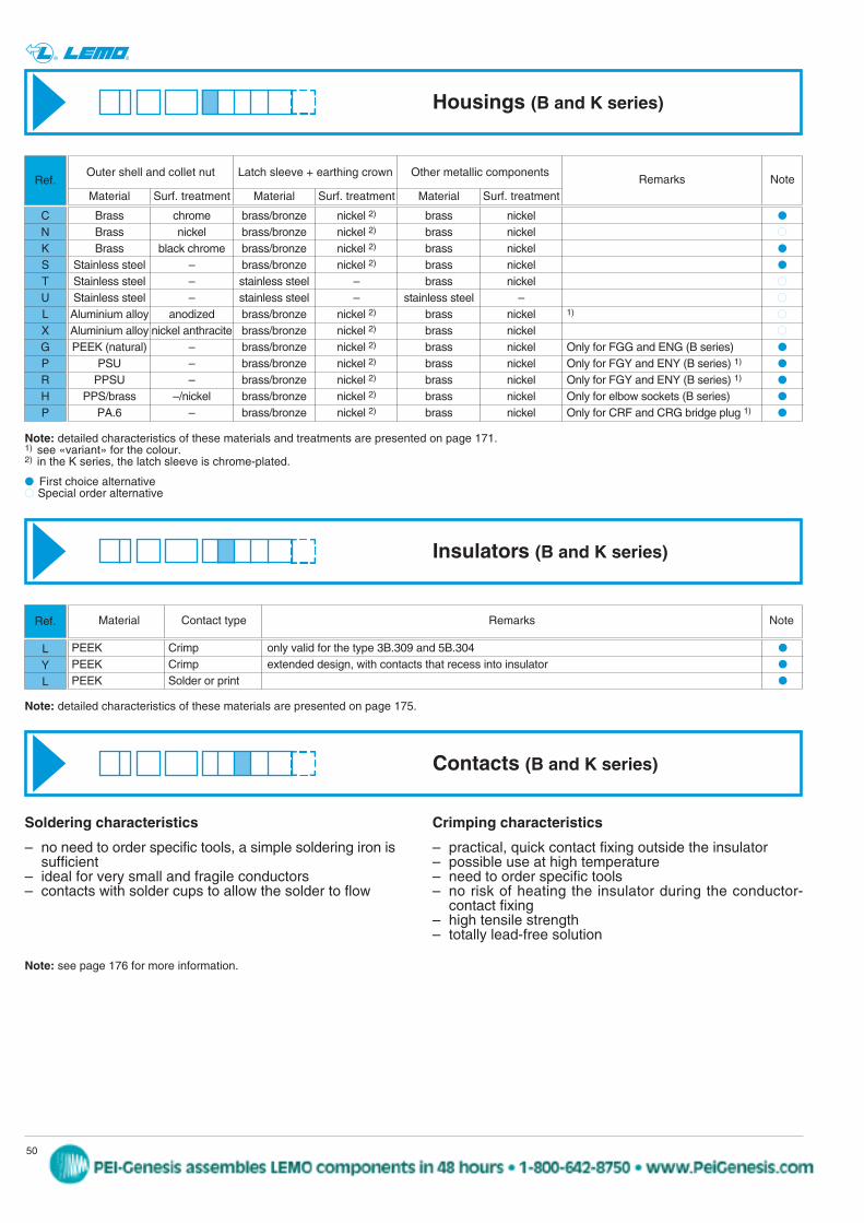
Material Contact type Remarks Note
Outer shell and collet nut Latch sleeve + earthing crown Other metallic components
Material Surf. treatment Material Surf. treatment Material Surf. treatment
50 www.lemo.com
® ®
Brass chrome brass/bronze nickel 2) brass nickel
Brass nickel brass/bronze nickel 2) brass nickel
Brass black chrome brass/bronze nickel 2) brass nickel
Stainless steel – brass/bronze nickel 2) brass nickel
Stainless steel – stainless steel – brass nickel
Stainless steel – stainless steel – stainless steel –
Aluminium alloy anodized brass/bronze nickel 2) brass nickel 1)
Aluminium alloy nickel anthracite brass/bronze nickel 2) brass nickel
PEEK (natural) – brass/bronze nickel 2) brass nickel Only for FGG and ENG (B series)
PSU – brass/bronze nickel 2) brass nickel Only for FGY and ENY (B series) 1)
PPSU – brass/bronze nickel 2) brass nickel Only for FGY and ENY (B series) 1)
PPS/brass –/nickel brass/bronze nickel 2) brass nickel Only for elbow sockets (B series)
PA.6 – brass/bronze nickel 2) brass nickel Only for CRF and CRG bridge plug 1)
Remarks Note
CNKSTULXGPRHP
First choice alternative Special order alternative
Ref.
Note: detailed characteristics of these materials and treatments are presented on page 171.1) see «variant» for the colour.2) in the K series, the latch sleeve is chrome-plated.
Note: detailed characteristics of these materials are presented on page 175.
Housings (B and K series)
Insulators (B and K series)
PEEK Crimp only valid for the type 3B.309 and 5B.304
PEEK Crimp extended design, with contacts that recess into insulator
PEEK Solder or print
LYL
Ref.
Contacts (B and K series)
Crimping characteristics
– practical, quick contact fixing outside the insulator– possible use at high temperature– need to order specific tools– no risk of heating the insulator during the conductor-
contact fixing– high tensile strength– totally lead-free solution
Soldering characteristics
– no need to order specific tools, a simple soldering iron is sufficient
– ideal for very small and fragile conductors– contacts with solder cups to allow the solder to flow
Note: see page 176 for more information.
peg
Stamp
ConductorSolid Stranded
AWG Section (mm2)
min. max. min. max.
Fr1)
(N)AWGmax.
Sectionmax.
(mm2)
51www.lemo.com
® ®
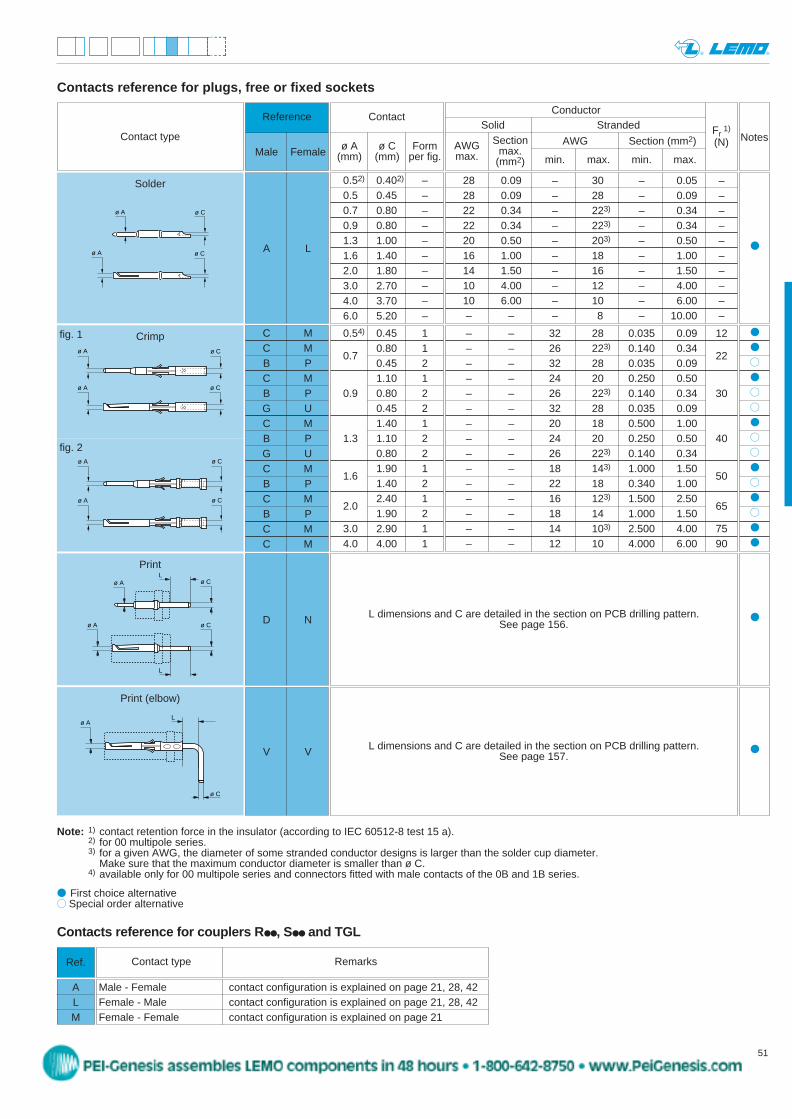
Contacts reference for plugs, free or fixed sockets
Reference
Male Female
Contact
ø A ø C Form(mm) (mm) per fig.
0.54) 0.45 10.80 1
0.70.45 21.10 1
0.9 0.80 20.45 21.40 1
1.3 1.10 20.80 21.90 1
1.61.40 22.40 1
2.01.90 2
3.0 2.90 14.0 4.00 1
C MC MB PC MB PG UC MB PG UC MB PC MB PC MC M
Notes
ø A
ø Cø A
ø C
Contact type
– – 32 28 0.035 0.09 12– – 26 223) 0.140 0.34
22– – 32 28 0.035 0.09– – 24 20 0.250 0.50– – 26 223) 0.140 0.34 30– – 32 28 0.035 0.09– – 20 18 0.500 1.00– – 24 20 0.250 0.50 40– – 26 223) 0.140 0.34– – 18 143) 1.000 1.50
50– – 22 18 0.340 1.00– – 16 123) 1.500 2.50
65– – 18 14 1.000 1.50– – 14 103) 2.500 4.00 75– – 12 10 4.000 6.00 90
L dimensions and C are detailed in the section on PCB drilling pattern.See page 156.D N
L dimensions and C are detailed in the section on PCB drilling pattern.See page 157.V V
ø A
ø A
ø C
ø C
ø A ø C
ø A ø C
ø A ø C
ø Cø A
L
L
ø C
Lø A
Note: 1) contact retention force in the insulator (according to IEC 60512-8 test 15 a).2) for 00 multipole series.3) for a given AWG, the diameter of some stranded conductor designs is larger than the solder cup diameter.
Make sure that the maximum conductor diameter is smaller than ø C.4) available only for 00 multipole series and connectors fitted with male contacts of the 0B and 1B series.
fig. 1
fig. 2
First choice alternative Special order alternative
A L
Solder 28 0.09 – 30 – 0.05 –28 0.09 – 28 – 0.09 –22 0.34 – 223) – 0.34 –22 0.34 – 223) – 0.34 –20 0.50 – 203) – 0.50 –16 1.00 – 18 – 1.00 –14 1.50 – 16 – 1.50 –10 4.00 – 12 – 4.00 –10 6.00 – 10 – 6.00 –– – – 8 – 10.00 –
0.52) 0.402) –0.5 0.45 –0.7 0.80 –0.9 0.80 –1.3 1.00 –1.6 1.40 –2.0 1.80 –3.0 2.70 –4.0 3.70 –6.0 5.20 –
Crimp
Print (elbow)
Contacts reference for couplers R , S and TGL
Ref.
ALM
Contact type Remarks
Male - Female contact configuration is explained on page 21, 28, 42Female - Male contact configuration is explained on page 21, 28, 42Female - Female contact configuration is explained on page 21
peg
Stamp
52 www.lemo.com
® ®
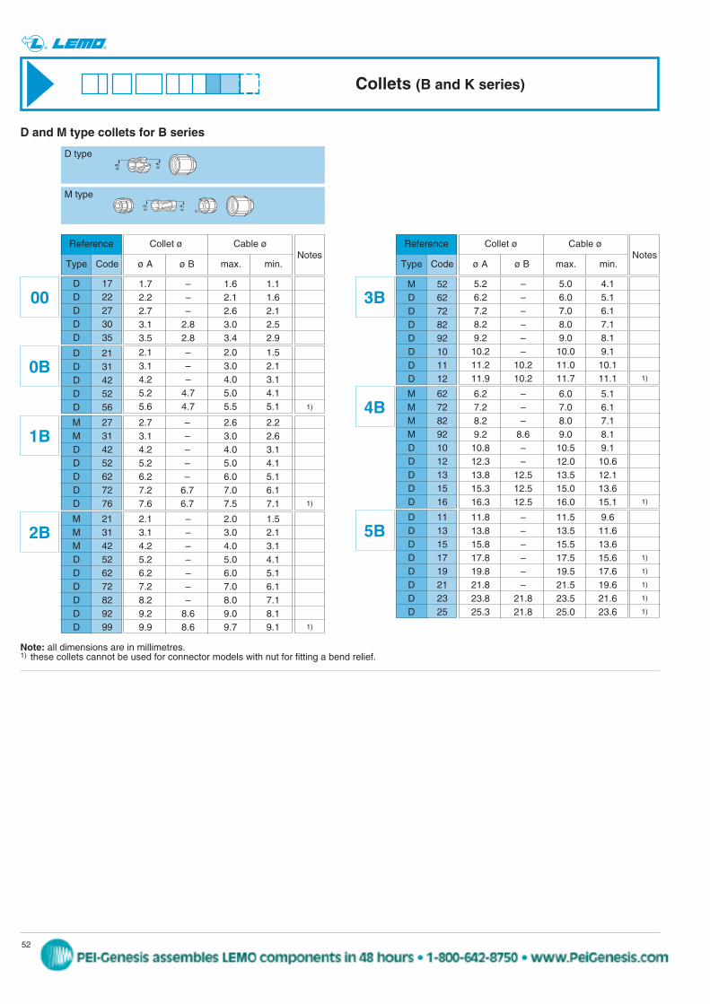
D 11D 13D 15D 17D 19D 21D 23D 25
11.8 – 11.5 9.613.8 – 13.5 11.615.8 – 15.5 13.617.8 – 17.5 15.619.8 – 19.5 17.621.8 – 21.5 19.623.8 21.8 23.5 21.625.3 21.8 25.0 23.6
5B
M 62M 72M 82M 92D 10D 12D 13D 15D 16
6.2 – 6.0 5.17.2 – 7.0 6.18.2 – 8.0 7.19.2 8.6 9.0 8.110.8 – 10.5 9.112.3 – 12.0 10.613.8 12.5 13.5 12.115.3 12.5 15.0 13.616.3 12.5 16.0 15.1
4B
Reference
Type Code
D and M type collets for B series
D 17D 22D 27D 30D 35
1.7 – 1.6 1.12.2 – 2.1 1.62.7 – 2.6 2.13.1 2.8 3.0 2.53.5 2.8 3.4 2.9
00
D 21D 31D 42D 52D 56
2.1 – 2.0 1.53.1 – 3.0 2.14.2 – 4.0 3.15.2 4.7 5.0 4.15.6 4.7 5.5 5.1
0B
M 27M 31D 42D 52D 62D 72D 76
2.7 – 2.6 2.23.1 – 3.0 2.64.2 – 4.0 3.15.2 – 5.0 4.16.2 – 6.0 5.17.2 6.7 7.0 6.17.6 6.7 7.5 7.1
1B
M 21M 31M 42D 52D 62D 72D 82D 92D 99
2.1 – 2.0 1.53.1 – 3.0 2.14.2 – 4.0 3.15.2 – 5.0 4.16.2 – 6.0 5.17.2 – 7.0 6.18.2 – 8.0 7.19.2 8.6 9.0 8.19.9 8.6 9.7 9.1
2B
M 52D 62D 72D 82D 92D 10D 11D 12
5.2 – 5.0 4.16.2 – 6.0 5.17.2 – 7.0 6.18.2 – 8.0 7.19.2 – 9.0 8.110.2 – 10.0 9.111.2 10.2 11.0 10.111.9 10.2 11.7 11.1
3B
Reference
Type Code
ø B ø A
D type
M type
Collets (B and K series)
Note: all dimensions are in millimetres.1) these collets cannot be used for connector models with nut for fitting a bend relief.
Collet ø Cable ø
ø A ø B max. min.Notes
Collet ø Cable ø
ø A ø B max. min.Notes
1)
1)
1)
1)
1)
1)
1)
1)
1)
1)
peg
Stamp
53www.lemo.com
® ®
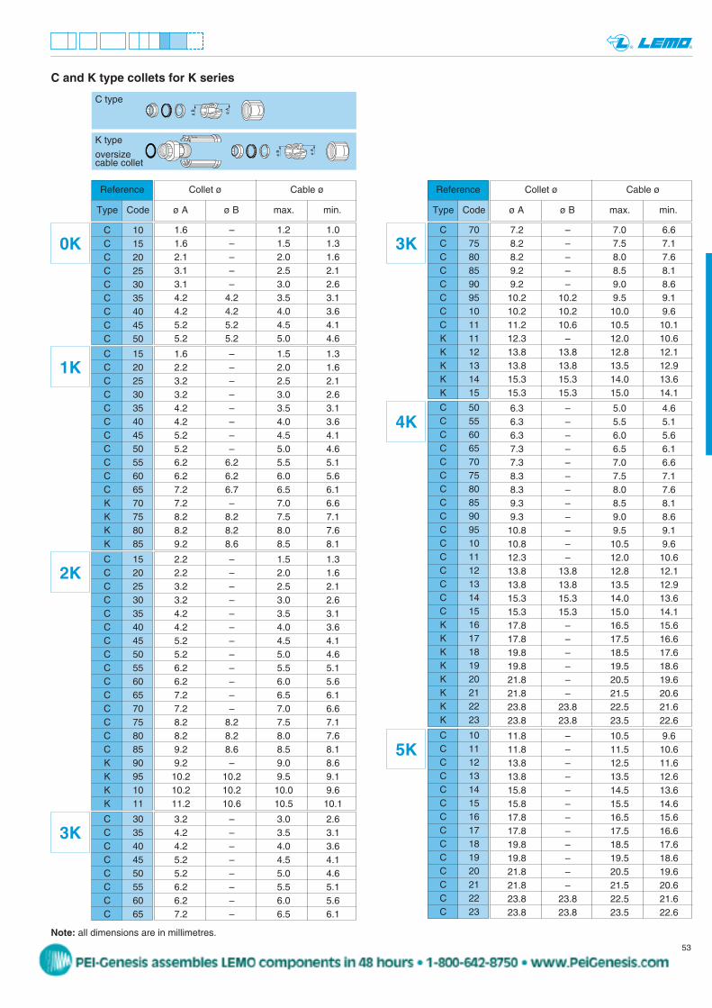
C 10C 15C 20C 25C 30C 35C 40C 45C 50
1.6 – 1.2 1.01.6 – 1.5 1.32.1 – 2.0 1.63.1 – 2.5 2.13.1 – 3.0 2.64.2 4.2 3.5 3.14.2 4.2 4.0 3.65.2 5.2 4.5 4.15.2 5.2 5.0 4.6
0K
Reference
Type Code
Reference
Type Code
C 15C 20C 25C 30C 35C 40C 45C 50C 55C 60C 65K 70K 75K 80K 85
1.6 – 1.5 1.32.2 – 2.0 1.63.2 – 2.5 2.13.2 – 3.0 2.64.2 – 3.5 3.14.2 – 4.0 3.65.2 – 4.5 4.15.2 – 5.0 4.66.2 6.2 5.5 5.16.2 6.2 6.0 5.67.2 6.7 6.5 6.17.2 – 7.0 6.68.2 8.2 7.5 7.18.2 8.2 8.0 7.69.2 8.6 8.5 8.1
1K
C and K type collets for K series
Note: all dimensions are in millimetres.
C type
K type
oversizecable collet
ø B ø A
ø B ø A
C 15C 20C 25C 30C 35C 40C 45C 50C 55C 60C 65C 70C 75C 80C 85K 90K 95K 10K 11
2.2 – 1.5 1.32.2 – 2.0 1.63.2 – 2.5 2.13.2 – 3.0 2.64.2 – 3.5 3.14.2 – 4.0 3.65.2 – 4.5 4.15.2 – 5.0 4.66.2 – 5.5 5.16.2 – 6.0 5.67.2 – 6.5 6.17.2 – 7.0 6.68.2 8.2 7.5 7.18.2 8.2 8.0 7.69.2 8.6 8.5 8.19.2 – 9.0 8.610.2 10.2 9.5 9.110.2 10.2 10.0 9.611.2 10.6 10.5 10.1
2K
C 70C 75C 80C 85C 90C 95C 10C 11K 11K 12K 13K 14K 15
7.2 – 7.0 6.68.2 – 7.5 7.18.2 – 8.0 7.69.2 – 8.5 8.19.2 – 9.0 8.610.2 10.2 9.5 9.110.2 10.2 10.0 9.611.2 10.6 10.5 10.112.3 – 12.0 10.613.8 13.8 12.8 12.113.8 13.8 13.5 12.915.3 15.3 14.0 13.615.3 15.3 15.0 14.1
3K
C 50C 55C 60C 65C 70C 75C 80C 85C 90C 95C 10C 11C 12C 13C 14C 15K 16K 17K 18K 19K 20K 21K 22K 23
6.3 – 5.0 4.66.3 – 5.5 5.16.3 – 6.0 5.67.3 – 6.5 6.17.3 – 7.0 6.68.3 – 7.5 7.18.3 – 8.0 7.69.3 – 8.5 8.19.3 – 9.0 8.610.8 – 9.5 9.110.8 – 10.5 9.612.3 – 12.0 10.613.8 13.8 12.8 12.113.8 13.8 13.5 12.915.3 15.3 14.0 13.615.3 15.3 15.0 14.117.8 – 16.5 15.617.8 – 17.5 16.619.8 – 18.5 17.619.8 – 19.5 18.621.8 – 20.5 19.621.8 – 21.5 20.623.8 23.8 22.5 21.623.8 23.8 23.5 22.6
4K
C 10C 11C 12C 13C 14C 15C 16C 17C 18C 19C 20C 21C 22C 23
11.8 – 10.5 9.611.8 – 11.5 10.613.8 – 12.5 11.613.8 – 13.5 12.615.8 – 14.5 13.615.8 – 15.5 14.617.8 – 16.5 15.617.8 – 17.5 16.619.8 – 18.5 17.619.8 – 19.5 18.621.8 – 20.5 19.621.8 – 21.5 20.623.8 23.8 22.5 21.623.8 23.8 23.5 22.6
5K
Collet ø Cable ø
ø A ø B max. min.
Collet ø Cable ø
ø A ø B max. min.
C 30C 35C 40C 45C 50C 55C 60C 65
3.2 – 3.0 2.64.2 – 3.5 3.14.2 – 4.0 3.65.2 – 4.5 4.15.2 – 5.0 4.66.2 – 5.5 5.16.2 – 6.0 5.67.2 – 6.5 6.1
3K
peg
Stamp
Bridge plug and plastic shell Aluminium alloys
PSU PPSU PA.6 Anodized colour Anodized colourfor bend relief collet nut
GMA.00..
GMB.00..
GMA.0B..
GMA.0B..
GMA.2B..
GMA.2B..
GMA.1B..
GMA.3B..
GMA.2B..
GMA.4B..
GMA.4B..
GMA.4B..
GMA.1B..
GMA.1B..
YH, HG,HN, HH,HC, HE,HM, S
54 www.lemo.com
® ®
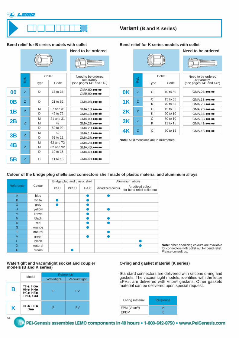
C 10 to 50
C 15 to 65K 70 to 85
C 15 to 85K 90 to 10
C 30 to 10K 11 to 15
C 50 to 15
0K
1K
2K
3K
4K
D 17 to 35
D 21 to 52
M 27 and 31D 42 to 72
M 21 and 31M 42D 52 to 92
M 52D 62 to 11
M 62 and 72M 82 and 92D 10 to 15
D 11 to 15
00
0B
1B
2B
3B
4B
5B
Collet
Type Code
Bend relief for B series models with collet
Need to be orderedseparately
(see pages 141 and 142)Ref
. Collet
Type Code
Need to be orderedseparately
(see pages 141 and 142)Ref
.
Z Z
Z
Z
Z
Z
Z
Z
Z
Z
Z
Z
Note: All dimensions are in millimetres.
P PVB
ReferenceWatertight Vacuumtight
Watertight and vacumtight socket and coupler models (B and K series)
Model
HG, HE,S
P PVK
Reference
ABGJMNRSTVLXF
Colour of the bridge plug shells and connectors shell made of plastic material and aluminium alloys
Colour
bluewhitegrey
yellowbrownblackred
orangenaturalgreenblack
naturalcream
Note: other anodizing colours are availablefor connectors with collet nut for bend relief.Please consult us.
Need to be ordered
Bend relief for K series models with collet
Variant (B and K series)
GMA.0B..
GMA.1B..
GMA.2B..
GMA.2B..
GMA.3B..
GMA.3B..
GMA.4B..
GMA.4B..
Need to be ordered
O-ring and gasket material (K series)
Standard connectors are delivered with silicone o-ring andgaskets. The vacuumtight models, identified with the letter«PV», are delivered with Viton® gaskets. Other gasketsmaterial can be delivered upon special request.
O-ring material Reference
FPM (Viton®)EPDM
HE
peg
Stamp