ETAG 001 METAL ANCHORS FOR USE IN CONCRETE Amended November 2006
53
ETAG 001 Edition 1997 GUIDELINE FOR EUROPEAN TECHNICAL APPROVAL OF METAL ANCHORS FOR USE IN CONCRETE Amended November 2006 Part one: ANCHORS IN GENERAL EOTA © Avenue des Arts 40 Kunstlaan B - 1040 Brussels TABLE OF CONTENTS European Organisation for Technical Approvals Europäische Organisation für Technische Zulassungen Organisation Européenne pour l’Agrément Technique
Transcript of ETAG 001 METAL ANCHORS FOR USE IN CONCRETE Amended November 2006
ETAG 001 Edition 1997
GUIDELINE FOR EUROPEAN TECHNICAL APPROVAL OF
METAL ANCHORS FOR USE IN CONCRETE Amended November 2006
Part one: ANCHORS IN GENERAL
EOTA © Avenue des Arts 40 Kunstlaan
B - 1040 Brussels
TABLE OF CONTENTS
European Organisation for Technical Approvals
Europäische Organisation für Technische Zulassungen
Organisation Européenne pour l’Agrément Technique
ETAG 001-1 2
PART ONE: ANCHORS IN GENERAL
_________________________________________________
INTRODUCTORY NOTES
REFERENCES
Section one:
INTRODUCTION
1 PRELIMINARIES
1.1 Legal basis
1.2 Status of ETA-Guidelines
2 SCOPE
2.0 General
2.1 Anchors
2.1.1 Types and operating principles
2.1.2 Materials
2.1.3 Dimensions
2.2 Concrete
2.2.1 Materials
2.2.2 Concrete members
2.3 Actions
2.4 Categories
2.5 Design and installation quality
3 TERMINOLOGY
3.1 Common terminology and abbreviations
3.1.1 Works and products
3.1.2 Performances
3.1.3 ETAG-format
3.1.4 Working life
3.1.5 Conformity
3.1.6 Abbreviations
3.2 Particular terminology and abbreviations
3.2.1 General
3.2.2 Anchors
3.2.3 Concrete and steel
3.2.4 Concrete members
3.2.5 Loads/forces
3.2.6 Tests
ETAG 001-1 3
Section two:
GUIDANCE FOR THE ASSESSMENT OF THE FITNESS FOR USE 4 REQUIREMENTS FOR WORKS
4.0 General
4.1 Mechanical resistance and stability (ER 1)
4.1.1 General
4.1.1.1 Overall behaviour
4.1.1.2 Temperature
4.1.1.3 Predictability
4.1.2 Suitability
4.1.2.1 Correct installation
4.1.2.2 Concrete strengths
4.1.2.3 Crack movements
4.1.2.4 Repeated/variable loading
4.1.2.5 Sustained loading
4.1.2.6 Types of installation
4.1.2.7 Minor impact loads
4.1.3 Admissible service conditions
4.1.3.1 Level of loading
4.1.3.2 Displacement
4.1.3.3 Edge distance and anchor spacing
4.1.3.4 Intensity of anchorage
4.1.4 Durability
4.2 Safety in case of fire (ER 2)
4.3 Hygiene, health and the environment (ER 3)
4.4 Safety in use (ER 4)
4.5 Protection against noise (ER 5)
4.6 Energy economy and heat retention (ER 6)
5 METHODS OF VERIFICATION
5.0 General
5.1 Methods related to 4.1 (mechanical resistance and stability)
5.1.1 General
5.1.2 Tests for suitability
5.1.3 Tests for admissible service conditions
5.1.4 Tests for checking durability
5.2 Safety in case of Fire (ER2)
5.3 Hygiene, Health and the environment (ER3)
ETAG 001-1 4
6 ASSESSING AND JUDGING THE FITNESS OF ANCHORS FOR AN INTENDED USE
6.0 General
(a) 5 %-fractile of the ultimate loads
(b) Conversion of ultimate loads to take account of concrete and steel strength
6.1 Assessing and judging related to 4.1 (mechanical resistance and stability)
6.1.1 Suitability
6.1.1.1 Criteria valid for all tests
6.1.1.2 Criteria valid for specific tests
6.1.2 Admissible service conditions
6.1.2.1 Criteria
6.1.2.2 Assessment of admissible service conditions
6.1.2.2.1 Characteristic resistance of single anchor
6.1.2.2.2 Partial safety factor γ2
6.1.2.2.3 Spacing scr,N and edge distance ccr,N for tension loading (concrete cone failure)
6.1.2.2.4 Edge distance ccr,sp and spacing scr,sp for tension loading (splitting failure)
6.1.2.2.5 Characteristic shear resistance in case of pryout failure
6.1.2.2.6 Characteristic shear resistance, spacing scr,V and edge distance ccr,V for shear
loading at the edge (concrete edge failure)
6.1.2.2.7 Minimum spacing smin and minimum edge distance cmin
6.1.2.2.8 Displacement behaviour
6.1.3 Assessment of durability
6.2 Safety in case of fire (ER2) 6.3 Hygiene, health and the environment (ER3) 6.7 Identification of anchor
7 ASSUMPTIONS UNDER WHICH THE FITNESS FOR USE IS TO BE ASSESSED
7.0 General
7.1 Design methods for anchorages
7.2 Recommendations for packaging, transport and storage
7.3 Installation of anchors
ETAG 001-1 5
Section three:
ATTESTATION OF CONFORMITY
8 ATTESTATION OF CONFORMITY (AC)
8.1 EC decisions
8.2 Action in relation to tasks
8.2.1 Initial type-testing
8.2.2 Testing of samples taken at the factory
8.2.3 Factory production control (FPC)
8.2.4 Initial inspection and continuous surveillance, assessment of the factory production
control system
8.3 Documentation
8.4 EC-conformity marking and information
Section four:
ETA CONTENTS
9 THE ETA CONTENTS
9.1 Definition of the anchor and its intended use
9.1.1 Definition
9.1.2 Use
9.1.3 Categories
9.2 Characteristics of the anchor with regard to mechanical resistance and stability and methods of
verification
9.3 Attestation of conformity and CE-marking
9.4 Assumptions under which the fitness of the anchor for the intended use was favourably assessed
9.4.1 Design methods for anchorages
9.4.2 Transport and storage
9.4.3 Installation of anchors
9.5 Legal basis and general conditions
ETAG 001-1 6
INTRODUCTORY NOTES The Guideline for European Technical Approval (ETA) of „METAL ANCHORS FOR USE IN CONCRETE“ sets out the basis for assessing anchors to be used in cracked and non-cracked concrete or in non-cracked concrete only and consists of: Part 1 Anchors in general Part 2 Torque-controlled expansion anchors Part 3 Undercut anchors Part 4 Deformation-controlled expansion anchors Part 5 Bonded anchors Part 6 Anchors for multiple use for non-structural applications The following Annexes are full parts of the Guideline: Annex A - Details of tests Annex B - Tests for admissible service conditions - Detailed information Annex C - Design methods for anchorages In this Guideline, the auxiliary verbs are used as follows in accordance with the „Rules for the drafting and presentation of European Standards (PNE-Rules)“ [7]:
English German French
shall should may can
muß sollte darf kann
doit il convient de
peut peut
This Guideline sets out the requirements for anchors, the acceptance criteria they shall meet and guidance in understanding these two central features, also the assessment and test methods used in carrying out assessments. In addition, more general aspects of relevance, including the information required by all parties concerned and quality control, are included. The general assessment approach adopted in this Guideline is based on combining relevant existing knowledge and experience of anchor behaviour with testing. Using this approach, testing is needed to assess the suitability of anchors. Anchors and their behaviour in use are of interest to a number of bodies, including manufacturers, planning and design engineers, building contractors and specialist installers. Behaviour in use depends on many factors including the design of the anchor, the embedment concrete, the quality of installation, the type of loading, etc. The individual and collective influence of the different factors referred to above are not sufficiently known at present to allow determination, by purely theoretical means, of the behaviour of anchorages under the various types of loading. It is necessary therefore to carry out tests to enable a safe assessment to be made of the influence of the different factors on the loadbearing and long-term stability of anchorages. Tests for suitability are crucial in assessing anchors. They are required for the following reasons: a) Anchors should not be too sensitive to deviations from the manufacturer’s installation
specifications which can commonly occur during construction. These deviations include, e.g.:
− Cleaning of the drilled hole
− Moisture content of the concrete and wetness of the hole surface at installation
− Undercutting of the drill hole in case of undercut anchors
− Torque moment
− Expansion of deformation-controlled expansion and undercut anchors
− Mixing of the mortar in case of bonded anchors
− Striking of reinforcement during anchor installation The procedure for testing the installation safety of a particular anchor type should take into account variations from the installation procedure required by the manufacturer which can occur on site. Variations which will not affect the anchor behaviour significantly may be omitted in the test programme.
ETAG 001-1 7
However, gross errors are not covered by this Guideline and should be avoided by proper training of the installers and supervision on site. Such gross errors include e.g.:
− Use of a drill bit with a wrong diameter (e.g. + 1 mm) or with tolerances of the cutting edge outside the range specified in this Guideline
− Use of a wrong drilling system, e.g. in case of undercut anchors
− Use of wrong setting tools
− No attempt made to clean the hole, if cleaning is required by the manufacturer
− Installation of the anchor such that the fixture cannot be installed without significant manipulations (e.g. anchor is not flush with the concrete surface in cases where required)
− Hammering in an anchor that should be installed by rotation (e.g. anchor rod of bonded anchors)
b) Anchors should not be too sensitive to variations in the properties of the base material - As the actual concrete strength in a structure can be higher than the design value, anchors
shall function properly in all concrete strength classes covered by this Guideline, even if the characteristic resistance given in the European Technical Approval is limited to the lowest strength class.
- Anchors assessed for use in cracked concrete are tested in concrete members with a crack
width of 0.3 mm and 0.5 mm. According to Eurocode N° 2 [1] acceptable crack width in reinforced concrete structures is limited to wk = 0.3 mm (wk = 95 %-fractile of all cracks occurring in a structure) under quasi-permanent load. However, when loading the structure to the allowable service load which is higher than the quasi-permanent load, the crack width can exceed w = 0.3 mm. In general, these wide cracks are opened a short time only, therefore they do not negatively influence the durability of the structure, but they may influence the load/displacement behaviour of anchors. This is taken into account by testing in cracks with a width of 0.5 mm.
Anchors can be located in cracks running in one direction (unidirectional) or at the junction of intersecting cracks. According to investigations carried out, the crack width of intersecting cracks is about 50 % of that of unidirectional cracks. For the anchors covered by this Guideline, a comparison of their behaviour in unidirectional cracks and intersecting cracks has been made: the results allow testing to be carried out, for the sake of simplicity, in unidirectional cracks only. If a newly developed anchor (not represented in Figure 2.2) is likely to behave less favourably when anchored in intersecting cracks than when anchored in unidirectional cracks, the necessity for and the nature and extent of any tests in intersecting cracks will be considered by the approval body responsible for the assessment.
- In reinforced concrete structures the crack width can vary due to variations in the actions applied to the structure. These crack openings can have a significant effect on the anchor behaviour. Therefore, anchors are tested with a tension load in opening and closing cracks according to Annex A, 5.5.
c) Due to tolerances in manufacture and wear, the actual diameter of the drill bit can vary in the range
specified in this Guideline. Therefore tests are performed with drill bits at the extremes of the specified tolerance range.
d) Anchors may be subjected to sustained loads or to loads with varying magnitude(neither fatigue nor dynamic loads). As anchors shall function properly under these conditions, corresponding tests are performed with a loading of the anchor which is higher than the admissible service load, in order to reduce the duration of the testing time.
e) In general, anchors are installed for pre-positioned or through installation anchorages with direct bearing on the concrete surface. This is reflected by the required tests. If anchors are to be used without bearing on the support (see Figure 4.1), additional tests are needed to check the suitability for this type of installation.
In the suitability tests, some of the influencing factors are combined and the anchor behaviour is tested to a combination of unfavourable conditions. These combinations are such that unfavourable results can be expected: e.g. suitability in high strength concrete, drilling the hole with drill bits of a diameter at the limit of
the specified range and crack width ∆w = 0.5 mm. The combination of unfavourable conditions allows to reduce the test programme.
ETAG 001-1 8
In suitability tests it is accepted that there may be a well defined but limited reduction in the anchor capacity in comparison to results of tests for admissible service conditions. This reduction is justified by the fact that the occurrence of the above described adverse conditions a) to c) can be lower compared to normal conditions. Therefore, in spite of the lower anchor failure load, in general the probability of failure will almost be constant. As the anchor behaviour can be sensitive to variations in the installation procedure, the installation safety factor of an anchor is derived depending on the results in the installation safety tests. Tests for admissible service conditions of the product are included to derive design data relating to the performance characteristics of the anchor. They are intended to reflect conditions which are expected under normal site practice, i.e. anchors designed according to the methods in Annex C and installed in accordance with the manufacturer’s published installation instructions. Testing for admissible service conditions is limited to that necessary to confirm whether the behaviour of the anchor under assessment falls within current experience (see 3.2.1). Otherwise the complete testing programme given in Annex B for the appropriate Option is necessary. One of the three design methods (see Annex C) is used to complement the test results to provide comprehensive information on the design of anchorages. The following parameters are taken into account in the evaluation process: a) The characteristic resistance of anchors should be based on the average concrete strength fcm
of the specified concrete strength class. However, the actual concrete strength in a structure can be lower than the value measured on control cubes or cylinders. This is reflected in Eurocode N° 2 [1] in the calculation of the design resistance of concrete. Therefore, the characteristic anchor resistance is evaluated for the concrete characteristic compression strength fck.
b) The characteristic resistance of anchors in cracked concrete is evaluated for a crack width
∆w = 0.3 mm.This width may be considered as the 95 %-fractile of all cracks occurring in a structure under quasi-permanent loads. In practice, anchors can be positioned in cracks of smaller widths or away from cracks. The influence of the scatter of the actual crack width on the failure load has been taken into account in the material safety factor.
In carrying out assessments, the responsible approval body may take account of other relevant data, for example test results, provided by the product manufacturer and this can result in a reduction in testing required by the approval body (see 5.1.3).
ETAG 001-1 9
REFERENCES [1] CEN: Eurocode N° 2. Design of concrete structures. Part 1: General rules and rules for buildings;Ref. N° ENV 1992-1-1: 1991 E [2] Directive relating to construction products (CPD) Council Directive of 21 December 1988 on the approximation of laws, regulations and
administrative provisions of the Member States relating to construction products (89/106/EEC) taking account of the modified provisions (93/68/EEC).
[3] ISO 898. Mechanical properties of fasteners. Part 1; 1988: Bolts, screws and studs Part 2; 1992: Nuts with specified proof load values, coarse thread. [4] ISO 3506; 1979. Corrosion-resistant stainless steel fasteners; specifications. [5] ISO 5922; 1981. Malleable cast iron. [6] Council Directive 89/106/EEC, Construction Products Interpretative Documents, Brussels, 16-7-1993 [7] Internal Regulations CEN/CENELEC Part 3: Rules for the drafting and presentation of European Standards (PNE-Rules) Edition 1991 - 09 [8] ENV 206: 1990-03. Concrete - Performance, Production, Placing and Compliance Criteria [9] ISO 6783; 1982. Coarse aggregates for concrete - determination of particle density and water absorption - hydrostatic balance method. [10] ENV 197-1: 1992. Cement composition, specifications and conformity criteria. [11] DIN 8035: 1976-11. Hammer drills. [12] NF E 66-079. Rotary and rotary impact masonry drill bits with hardened tips. Dimensions. July 1993. [13] ISO 273: 1979-06: Fasteners; clearance holes for bolts and screws. [14] CEN: Eurocode N° 3. Design of steel structures, Part 1-1: General rules and rules for buildings, Ref. N° ENV 1993-1-1: 1992 E.
ETAG 001-1 10
Section one: INTRODUCTION
1 PRELIMINARIES
1.1 Legal basis
This Guideline for European Technical Approvals has been established in full compliance with the provisions of the Council Directive 89/106/EEC (CPD) and has been established taking into account the following steps:
• issuing of the final mandate by the EC: 18 April 1996
• issuing of the final mandate by EFTA: not relevant
• adoption of the Guideline by EOTA (Executive Commission ) 5 September 1997
• endorsement of the document by the EC SCC opinion of 7/8 October 1997
EC letter of 29 October 1997
• endorsement of the document by EFTA not relevant.
• Endorsement of the amended version by the EC 05 March 2007
This document is published by the Member States in their official language or languages according to Art. 11/3 of the CPD. 1.2 Status of ETA-Guidelines
1.2.1 An ETA is one of the two types of technical specifications
in the sense of the CPD [2] , that means that Member States shall presume that approved products fit for their intended use, e.g. that they enable works in which they are employed to satisfy the essential requirements during an economically reasonable working life (see Part 1, 4.0) provided that:
− the works are properly designed and built;
− the conformity of the products with the ETA has been properly attested. 1.2.2 An ETA-Guideline is a basis for ETAs, that is a basis for technical assessment of the fitness of a product for an intended use*). ETA-Guidelines express the common understanding of the approval bodies of the provisions of the CPD and of the Interpretative Documents [6], with regard to the products and uses concerned, established within the framework of a mandate given by the Commission after consulting the EC-Standing Committee for Construction. 1.2.3 ETA-Guidelines are binding for the issuing of ETAs of the products concerned for an intended use, when accepted by the EC-Commission after consultation with the Standing Committee for Construction and published by the Member States in their official language or languages. The applicability and the satisfaction of the ETAG for a product and its intended use have to be assessed in a case by case evaluation by an authorized approval body. Satisfaction of the provisions of an ETAG (examinations, tests and evaluation methods) leads to a presumption of fitness for use only through this case by case evaluation. Products which are outside the scope of an ETA-Guideline may be considered where appropriate through the approval procedure without Guidelines according to Art. 9.2 of the CPD. The requirements in ETA-Guidelines are set out in terms of objectives and of relevant actions to be taken into account. ETAGs specify values and characteristics, the conformity with which gives the presumption that the requirements set out are satisfied, whenever the state of art permits to do so. The Guidelines may indicate alternate possibilities for the demonstration of the satisfaction of the requirements. _______________________ *) An ETA-Guideline is not on itself a technical specification in the sense of the CPD.
ETAG 001-1 11
2 SCOPE
2.0 General
The Guideline for European Technical Approval (ETA) of „METAL ANCHORS FOR USE IN CONCRETE“ sets out the basis for assessing anchors to be used in cracked and non-cracked concrete or in non-cracked concrete only and consists of:
Part 1 Anchors in general Part 2 Torque-controlled expansion anchors Part 3 Undercut anchors Part 4 Deformation-controlled expansion anchors Part 5 Bonded anchors Part 6 Anchors multiple use for non-structural applications
The requirements and assessment procedures applicable to all anchors are set out in this Part of Guideline. The subsequent Parts contain appropriate additional and/or deviating requirements and assessment procedures as well as details of the number of tests to be carried out for each anchor type and are only applicable in connection with Part 1.
The following Annexes are full parts of the Guideline:
Annex A - Details of tests Annex B - Tests for admissible service conditions - Detailed information Annex C - Design methods for anchorages
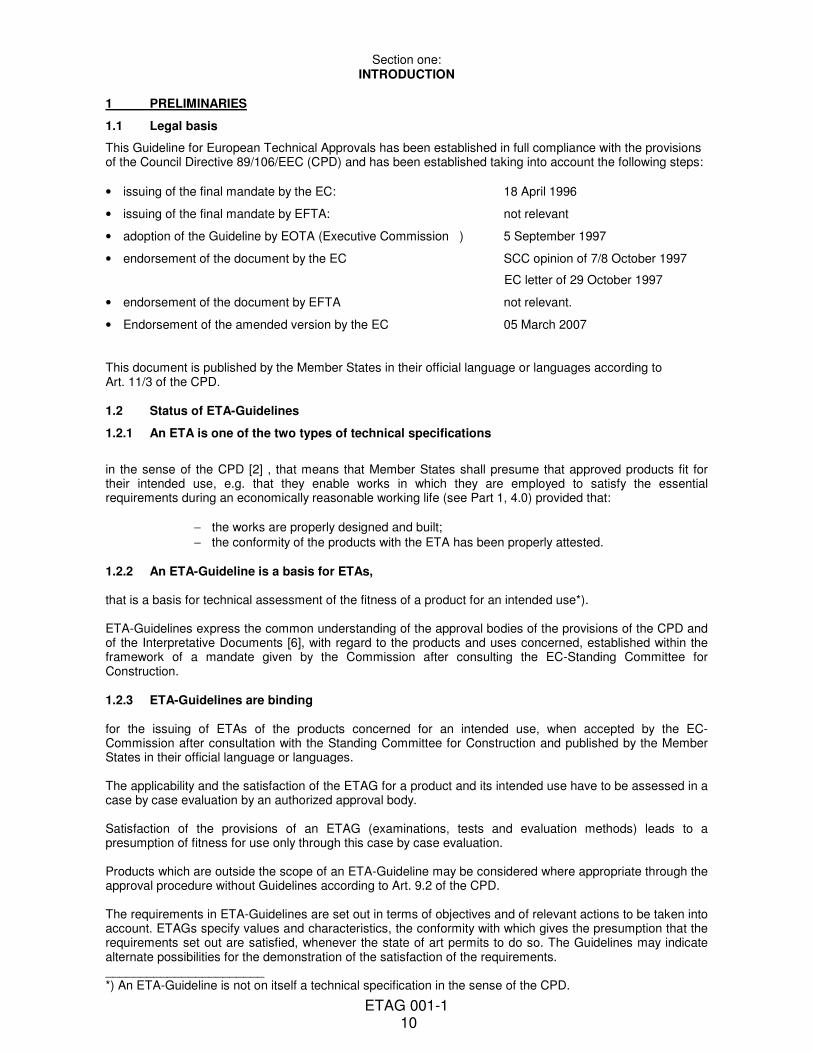
This Guideline covers the assessment of post-installed metal anchors in normal weight concrete when their use shall fulfil the Essential Requirements 1 and 4 of the CPD (see 4.1.1.1 and 4.4) and when failure of anchorages made with these products would compromise the stability of the works, cause risk to human life and/or lead to considerable economic consequences. The fixture can be supported either statically determinate (one or two supports) or statically indeterminate (more than two supports) (see Figure 2.1). Part 6 Anchors for lightweight systems covers also other concretes.
Figure 2.1 Examples of anchored components
2.1 Anchors
2.1.1 Types and operating principles
This Guideline applies to metal anchors placed into drilled holes in concrete and anchored by expansion, undercutting or bonding, as described below and shown in Figure 2.2.
Expansion anchors are anchored in drilled holes by forced expansion. A tensile force applied to the anchor is transferred to the concrete by friction and some keying between an expanded sleeve and the concrete.
ETAG 001-1 12
Two types of expansion anchors are covered:
(1) torque-controlled (Figure 2.2a), and (2) deformation-controlled (Figures 2.2c1 and 2.2c2).
With torque-controlled anchors, the expansion is achieved by a torque acting on the screw or bolt; the intensity of the anchorage is controlled by this torque.
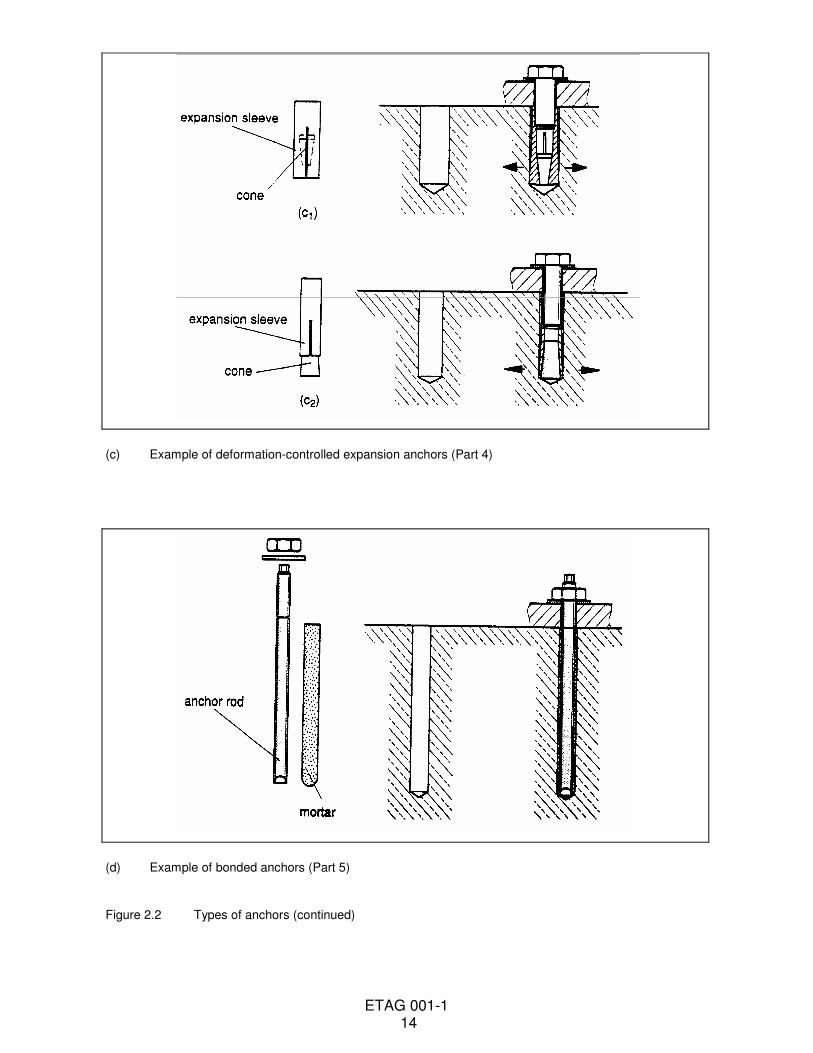
With deformation-controlled anchors, the expansion is generally achieved by impacts acting on a sleeve or cone. In Figure 2.2c1 the sleeve is expanded by driving in a cone; the anchorage being controlled by the length of travel of the cone. In Figures 2.2c2 a sleeve is driven over an expansion element, the anchorage being controlled by the travel of the sleeve over the expansion element.
Undercut anchors are anchored mainly by mechanical interlock provided by an undercut in the concrete. The undercutting can be achieved by hammering or rotating the anchor sleeve into a drilled undercut hole (Figures 2.2b1) or driving the anchor sleeve onto the tapered bolt in a cylindrical hole. In the latter, the concrete is mostly cut away rather than compressed (Figures 2.2b2).
Bonded anchors (Figure 2.2d) are anchored in drilled holes by bonding the metal parts to the sides of the drilled hole with a mortar (e.g. resin mortar). Tensile loads are transmitted to the concrete via bond stresses between the metal parts and the mortar and the mortar and the concrete face of the drilled hole.
For anchor types, sizes and conditions of use not specifically referred to in the following Sections and Parts, the Guideline will provide useful information, particularly with reference to important functional requirements, but which shall be applied only after careful consideration of their validity and the relevance of the procedures set out.
2.1.2 Materials
This Guideline applies to anchors in which all the metal parts directly anchored in the concrete and designed to transmit the applied loads are made of either carbon steel, stainless steel or malleable cast iron. The anchors may include non-loadbearing material, e.g. plastic parts, for rotation prevention. In the case of bonded anchors, the embedded metal part(s) may be either of carbon steel or stainless steel and the mortar may be made primarily of resin, cement or a combination of both as a binding material. 2.1.3 Dimensions
This Guideline applies to anchors with a minimum thread size of 6 mm (M6). For anchors for multiple use for non-structural applications, see Part 6. In general, the minimum anchorage depth min hef shall be 40 mm. In special cases, e.g. in anchoring structural components which are statically indeterminate (such as light-weight suspended ceilings) and subject to internal exposure conditions only, min hef may be reduced to 30 mm and these required restrictions have to be clearly stated in the ETA. For anchors for multiple use for non-structural applications, see Part 6. Anchors with internal thread are covered only if they have a thread length of at least d + 5 mm after taking account of possible tolerances. 2.2 Concrete
2.2.1 Materials This Guideline applies to the use of anchors in normal weight concrete between strength classes C20/25 and C50/60, inclusively, according to ENV 206, exception see Part 6. This Guideline does not cover anchorages made in screeds or toppings, which can be uncharacteristic of the concrete and/or excessively weak. 2.2.2 Concrete members
This Guideline applies to applications where the minimum thickness of members in which anchors are installed is h > 2 hef and at least h > 100 mm. For bonded anchors see Part 5. For anchors for multiple use for non-structural applications see Part 6. If the thickness of the concrete member is smaller than required above, then the resistance can be reduced because of a premature splitting failure or a reduction of the shear resistance for anchorages at the edge. Furthermore, the minimum values for edge distance and spacing might not be sufficient because a splitting
ETAG 001-1 13
failure can occur during installation. Therefore, a smaller thickness of the concrete member is allowed only if the above-mentioned effects are taken into account in the design and installation of the anchorage.
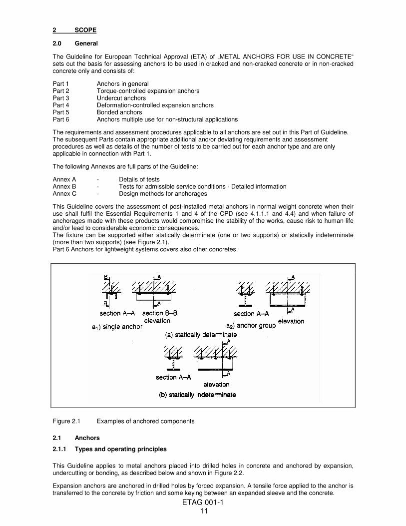
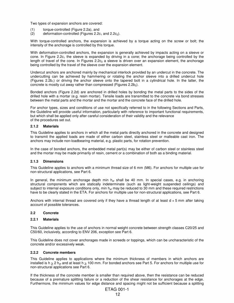
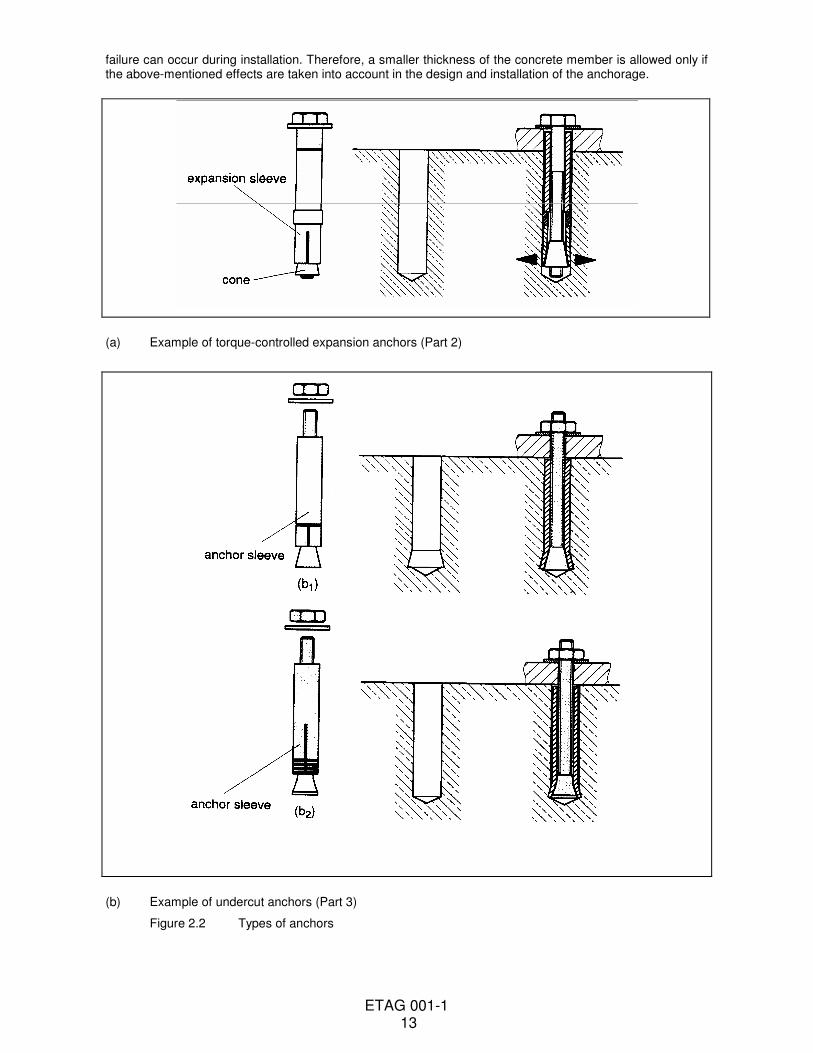
(a) Example of torque-controlled expansion anchors (Part 2)
(b) Example of undercut anchors (Part 3)
Figure 2.2 Types of anchors
ETAG 001-1 14
(c) Example of deformation-controlled expansion anchors (Part 4)
(d) Example of bonded anchors (Part 5)
Figure 2.2 Types of anchors (continued)
ETAG 001-1 15
2.3 Actions
This Guideline covers applications only where the concrete members in which the anchors are embedded are subject to static or quasi-static actions. This Guideline applies only to anchors subject to static or quasi-static actions in tension, shear or combined tension and shear or bending. 2.4 Categories
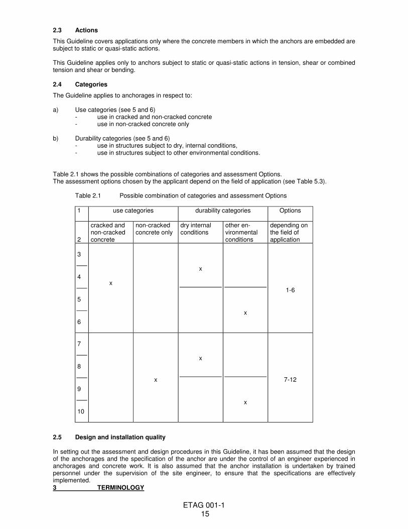
The Guideline applies to anchorages in respect to: a) Use categories (see 5 and 6) - use in cracked and non-cracked concrete - use in non-cracked concrete only b) Durability categories (see 5 and 6) - use in structures subject to dry, internal conditions, - use in structures subject to other environmental conditions. Table 2.1 shows the possible combinations of categories and assessment Options. The assessment options chosen by the applicant depend on the field of application (see Table 5.3). Table 2.1 Possible combination of categories and assessment Options
1 use categories
durability categories Options
2
cracked and non-cracked concrete
non-cracked concrete only
dry internal conditions
other en-vironmental conditions
depending on the field of application
3
4
5
6
x
x
x
1-6
7
8
9
10
x
x
x
7-12
2.5 Design and installation quality In setting out the assessment and design procedures in this Guideline, it has been assumed that the design of the anchorages and the specification of the anchor are under the control of an engineer experienced in anchorages and concrete work. It is also assumed that the anchor installation is undertaken by trained personnel under the supervision of the site engineer, to ensure that the specifications are effectively implemented. 3 TERMINOLOGY
ETAG 001-1 16
3.1 Common terminology and abbreviations
3.1.1 Works and products
3.1.1.1 Construction works (and parts of works) (often simply referred to as „works“) (ID 1.3.1) Everything that is constructed or results from construction operations and is fixed to the ground. (This covers both building and civil engineering works, and both structural and non structural elements). 3.1.1.2 Construction products (often simply referred to as „products“) (ID 1.3.2) Products which are produced for incorporation in a permanent manner in the works and placed as such on the market. (The term includes materials, elements, components and prefabricated systems or installations.) 3.1.1.3 Incorporation (of products in works) (ID 1.3.2) Incorporation of a product in a permanent manner in the works means that:
− its removal reduces the performance capabilities of the works, and
− that the dismantling or the replacement of the product are operations which involve construction activities. 3.1.1.4 Intended use (ID 1.3.4) Role(s) that the product is intended to play in the fulfilment of the essential requirements. (N.B. This definition covers only the intended use as far as relevant for the CPD.) 3.1.1.5 Execution (ETAG-format) Used in this document to cover all types of incorporation techniques such as installation, assembling, incorporation, etc. 3.1.1.6 System (EOTA/TB guidance) Part of the works realized by
− particular combination of a set of defined products, and
− particular design methods for the system, and/or
− particular execution procedures. 3.1.2 Performances
3.1.2.1 Fitness for intended use (of products) (CPD 2.1)
Means that the products have such characteristics that the works in which they are intended to be incorporated, assembled, applied or installed, can, if properly designed and built, satisfy the essential requirements. (N.B. This definition covers only the intended fitness for intended use as far as relevant for the CPD.) 3.1.2.2 Serviceability (of works) Ability of the works to fulfil their intended use and in particular the essential requirements relevant for this use. The products shall be suitable for construction works which (as a whole and in their separate parts) are fit for their intended use, subject to normal maintenance, be satisfied for an economically reasonable working life. The requirements generally concern actions which are foreseeable (CPD, Annex I, Preamble). 3.1.2.3 Essential Requirements (for works):
requirements applicable to works, which can influence the technical characteristics of a product, and are set out in objectives in the CPD, Annex I (CPD, Art. 3.1). 3.1.2.4 Performance (of works, parts of works or products) (ID 1.3.7)
ETAG 001-1 17
The quantitative expression (value, grade, class or level) of the behaviour of the works, parts of works or of the products, for an action to which it is subject or which it generates under the intended service conditions (works or parts of works) or intended use conditions (products).
As far as practicable the characteristics of products, or groups of products, should be described in measurable performance terms in the technical specifications and Guidelines for ETA. Methods of calculation, measurement, testing (where possible), evaluation of site experience and verification, together with compliance criteria shall be given either in the relevant technical specifications or in references called up in such specifications.
3.1.2.5 Actions (on works or parts of the works) (ID 1.3.6)
Service conditions of the works which can affect the compliance of the works with the essential requirements of the Directive and which are brought about by agents (mechanical, chemical, biological, thermal or electro-mechanical) acting on the works or parts of the works. Interactions between various products within a work are considered as „actions“. 3.1.2.6 Classes or levels (for essential requirements and for related product performances) (ID 1.2.1)
A classification of product performance(s) expressed as a range of requirement levels of the works, determined in the IDs or according to the procedure provided for in Art. 20.2a of the CPD. 3.1.3 ETAG-format
3.1.3.1 Requirements (for works) (ETAG-format 4.)
Expression and application, in more detail and in terms applicable to the scope of the Guideline, of the relevant requirements of the CPD (given concrete form in the IDs and further specified in the mandate) for works or parts of the works, taking into account the durability and serviceability of the works.
3.1.3.2 Methods of verification (for products) (ETAG-format 5.)
Verification methods used to determine the performance of the products in relation to the requirements for the works (calculations, tests, engineering knowledge, evaluation of site experience, etc.).
These verification methods are related only to the assessment of, and for judging the fitness for use. Verification methods for particular designs of works are called here „project testing“, for identification of products are called „identification testing“, for surveillance of execution or executed works are called „surveillance testing“, and for attestation of conformity are called „AC-testing“.
3.1.3.3 Specifications (for products) (ETAG-format 6.)
Transposition of the requirements into precise and measurable (as far as possible and proportional to the importance of the risk) or qualitative terms, related to the products and their intended use. The satisfaction of the specifications is deemed to satisfy the fitness for use of the products concerned.
Specifications may also be formulated with regard to the verification of particular designs, for identification of products, for surveillance of execution or executed works and for attestation of conformity, when relevant.
3.1.4 Working life
3.1.4.1 Working life (of works or parts of the works) (ID 1.3.5(1))
The period of time during which the performance will be maintained at a level compatible with the fulfilment of the essential requirements.
3.1.4.2 Working life (of products)
Period of time during which the performances of the product are maintained - under the corresponding service conditions - at a level compatible with the intended use conditions.
ETAG 001-1 18
3.1.4.3 Economically reasonable working life (ID 1.3.5(2))
Working life which takes into account all relevant aspects, such as costs of design, construction and use, costs arising from hindrance of use, risks and consequences of failure of the works during its working life and cost of insurance covering these risks, planned partial renewal, costs of inspections, maintenance, care and repair, costs of operation and administration, of disposal and environmental aspects.
3.1.4.4 Maintenance (of works) (ID 1.3.3(1))
A set of preventive and other measures which are applied to the works in order to enable the works to fulfil all their functions during their working life. These measures include cleaning, servicing, repainting, repairing, replacing parts of the works where needed, etc.
3.1.4.5 Normal maintenance (of works) (ID 1.3.3(2))
Maintenance, normally including inspections, which occurs at a time when the cost of the intervention which has to be made is not disproportionate to the value of the part of the work concerned, consequential costs (e.g. exploitation) being taken into account.
3.1.4.6 Durability (of products)
Ability of the product to contribute to the working life of the work by maintaining its performances, under the corresponding service conditions, at a level compatible with the fulfilment of the essential requirements by the works. 3.1.5 Conformity
3.1.5.1 Attestation of conformity (of products) Provisions and procedures as laid down in the CPD and fixed according to the Directive, aiming to ensure that, with acceptable probability, the specified performance of the product is achieved by the ongoing production. 3.1.5.2 Identification (of a product) Product characteristics and methods for their verification, allowing to compare a given product with the one that is described in the technical specification. 3.1.6 Abbreviations
AC: Attestation of conformity CEC: Commission of the European Communities CEN: Comité européen de normalisation CPD: Construction products directive EC: European Communities EFTA: European free trade association EN: European standards FPC: Factory production control ID: Interpretative documents of the CPD ISO: International standardisation organisation SCC: Standing Committee on Construction of the CPD EOTA: European Organisation for Technical Approvals ETA: European Technical Approval ETAG: European Technical Approval Guideline TB: EOTA-Technical Board UEAtc: Union Européenne pour l’Agrément technique dans la construction TC: Technical Committee WG: Working Group
3.2 Particular terminology and abbreviations
3.2.1 General
Anchor = a manufactured, assembled component for achieving anchorage between the base material (concrete) and the fixture. For a bonded anchor the bonding material is included.
ETAG 001-1 19
Anchor according = anchor with a performance which is consistent with the Equations in to current experience Annex B Anchor group = several anchors (working together)
Fixture = component to be fixed to the concrete
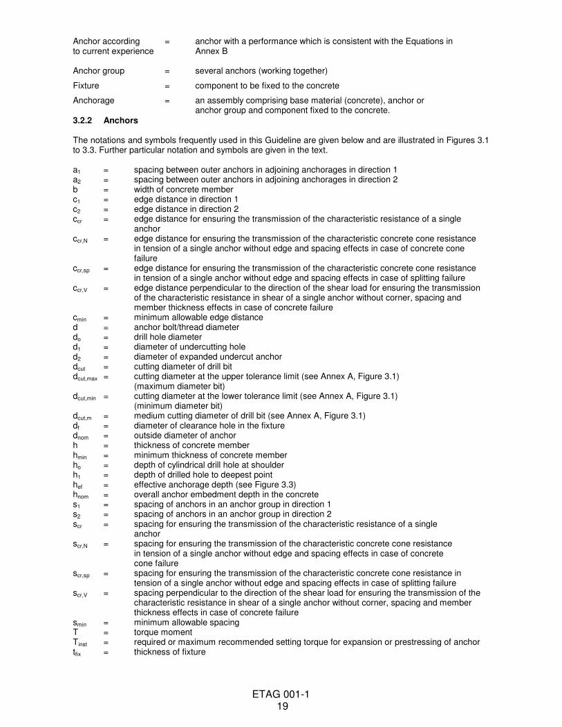
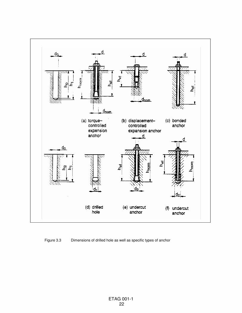
Anchorage = an assembly comprising base material (concrete), anchor or anchor group and component fixed to the concrete. 3.2.2 Anchors The notations and symbols frequently used in this Guideline are given below and are illustrated in Figures 3.1 to 3.3. Further particular notation and symbols are given in the text. a1 = spacing between outer anchors in adjoining anchorages in direction 1 a2 = spacing between outer anchors in adjoining anchorages in direction 2 b = width of concrete member c1 = edge distance in direction 1 c2 = edge distance in direction 2 ccr = edge distance for ensuring the transmission of the characteristic resistance of a single anchor ccr,N = edge distance for ensuring the transmission of the characteristic concrete cone resistance in tension of a single anchor without edge and spacing effects in case of concrete cone failure ccr,sp = edge distance for ensuring the transmission of the characteristic concrete cone resistance in tension of a single anchor without edge and spacing effects in case of splitting failure ccr,V = edge distance perpendicular to the direction of the shear load for ensuring the transmission of the characteristic resistance in shear of a single anchor without corner, spacing and member thickness effects in case of concrete failure cmin = minimum allowable edge distance d = anchor bolt/thread diameter do = drill hole diameter d1 = diameter of undercutting hole d2 = diameter of expanded undercut anchor dcut = cutting diameter of drill bit dcut,max = cutting diameter at the upper tolerance limit (see Annex A, Figure 3.1) (maximum diameter bit) dcut,min = cutting diameter at the lower tolerance limit (see Annex A, Figure 3.1) (minimum diameter bit) dcut,m = medium cutting diameter of drill bit (see Annex A, Figure 3.1) df = diameter of clearance hole in the fixture dnom = outside diameter of anchor h = thickness of concrete member hmin = minimum thickness of concrete member ho = depth of cylindrical drill hole at shoulder h1 = depth of drilled hole to deepest point hef = effective anchorage depth (see Figure 3.3) hnom = overall anchor embedment depth in the concrete s1 = spacing of anchors in an anchor group in direction 1 s2 = spacing of anchors in an anchor group in direction 2 scr = spacing for ensuring the transmission of the characteristic resistance of a single anchor scr,N = spacing for ensuring the transmission of the characteristic concrete cone resistance in tension of a single anchor without edge and spacing effects in case of concrete cone failure scr,sp = spacing for ensuring the transmission of the characteristic concrete cone resistance in tension of a single anchor without edge and spacing effects in case of splitting failure scr,V = spacing perpendicular to the direction of the shear load for ensuring the transmission of the characteristic resistance in shear of a single anchor without corner, spacing and member thickness effects in case of concrete failure smin = minimum allowable spacing T = torque moment Tinst = required or maximum recommended setting torque for expansion or prestressing of anchor tfix = thickness of fixture
ETAG 001-1 20
3.2.3 Concrete and steel
fc = concrete compression strength measured on cylinders fc,cube = concrete compression strength measured on cubes fc,test = compression strength of concrete at the time of testing fcm = average concrete compression strength fck = nominal characteristic concrete compression strength (based on cylinder) fck,cube = nominal characteristic concrete compression strength (based on cubes) fy,test = steel tensile yield strength in the test fyk = nominal characteristic steel yield strength fu,test = steel ultimate tensile strength in the test fuk = nominal characteristic steel ultimate strength
3.2.4 Concrete members Cracked or non-cracked concrete is defined in Annex C.
3.2.5 Loads/forces
F = force in general N = normal force (+N = tension force) V = shear force NRk,VRk = characteristic anchor resistance (5 %-fractile of results) under tension or shear force respectively 3.2.6 Tests test member = concrete member in which the anchor is tested unidirectional crack = crack running in one direction with an almost constant width over the member depth
FRut
= ultimate load in a test
FRu,mt
= mean ultimate load in a test series
FRkt
= 5 %-fractile of the ultimate load in a test series
n = number of tests of a test series v = coefficient of variation
∆w = increase in crack width during loading of the anchor and crack width at the time of installing the anchor
δ(δN, δV) = displacement (movement) of the anchor at the concrete surface relative to the concrete surface in direction of the load (tension, shear) outside the failure area
The displacement includes the steel and concrete deformations and a possible anchor slip.
ETAG 001-1 21
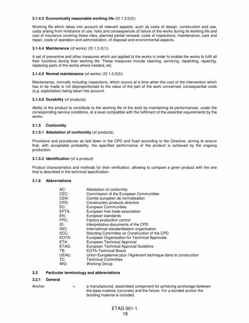
Figure 3.1 Installed anchor
Figure 3.2 Concrete member, anchor spacing and edge distance
ETAG 001-1 22
Figure 3.3 Dimensions of drilled hole as well as specific types of anchor
ETAG 001-1 23
Section two: GUIDANCE FOR THE ASSESSMENT OF THE FITNESS FOR USE
4 REQUIREMENTS FOR WORKS
4.0 General
This chapter identifies the aspects of performance to be examined in order to satisfy the relevant Essential Requirements, by:
− expressing in more detail, and in terms applicable to the scope of the guideline, the relevant essential requirements of the CPD (given concrete form in the Interpretative Documents and further specified in the mandate), for works or parts of the works, taking into account the durability and serviceability of the works.
− applying them to the scope of the ETAG (product/system and intended use), and indicate the resulting relevant product characteristics and eventually other aspects.
The linkage of the Essential Requirements (ER) of the CPD [2] with the relevant paragraphs of the Interpretative Documents [6], the related anchor characteristics and test methods for verification of characteristics can be taken from Table 4.1. The working life of an anchor shall be at least compatible with the working life of the fixture.
The Guideline is written on the assumption that the estimated working life of the anchor for the intended use is at least 50 years. All anchor specifications and assessment methods shall take account of this assumed working life.
The indication given on the working life of an anchor cannot be interpreted as a guarantee given by the producer (or the approval body) but is regarded only as a means for choosing the right anchors in relation to the expected economically reasonable working life of the works (ID 5.2.2). 4.1 Mechanical resistance and stability (ER 1)
4.1.1 General
4.1.1.1 Overall behaviour
Anchorages shall be designed and built in such a way that the loadings to which they are subjected during use will not lead to any of the following:
(a) collapse of the whole or part of the work; (b) major deformations to an inadmissible degree; (c) damage to other parts of the works or to fittings or installed equipment as a result of major deformation of
the load-bearing construction; (d) damage by an event to an extent disproportionate to the original cause.
Installed anchors shall sustain the design loads in tension, shear and combined tension and shear to which they are subjected for the assumed working life while providing:
(1) an adequate resistance to failure (ultimate limit state), (2) adequate resistance to displacements (serviceability limit state).
4.1.1.2 Temperature
The functioning of an anchor, including its ability to sustain its design load with an appropriate safety factor and to limit displacements, shall not be adversely affected by transient temperatures at the surface of the concrete within the range - 40°C to + 80°C (exception see Part 5).
4.1.1.3 Predictability
The behaviour of anchors, both in normal service conditions and in anticipated adverse conditions (see 4.1.2 Suitability) shall in all important respects be predictable.
ETAG 001-1 24
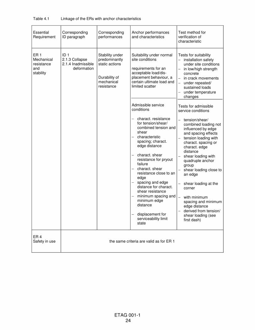
Table 4.1 Linkage of the ERs with anchor characteristics
Essential Requirement
Corresponding ID paragraph
Corresponding performances
Anchor performances and characteristics
Test method for verification of characteristic
ER 1 Mechanical resistance and stability
ID 1 2.1.3 Collapse 2.1.4 Inadmissible deformation
Stability under predominantly static actions Durability of mechanical resistance
Suitability under normal site conditions requirements for an acceptable load/dis-placement behaviour, a certain ultimate load and limited scatter
Admissible service conditions
− charact. resistance for tension/shear/ combined tension and shear
− characteristic spacing; charact. edge distance
− charact. shear resistance for pryout failure
− charact. shear resistance close to an edge
− spacing and edge distance for charact. shear resistance
− minimum spacing and minimum edge distance
− displacement for serviceability limit state
Tests for suitability
− installation safety under site conditions
− in low/high strength concrete
− in crack movements
− under repeated/ sustained loads
− under temperature changes
Tests for admissible service conditions
− tension/shear/ combined loading not influenced by edge and spacing effects
− tension loading with charact. spacing or charact. edge distance
− shear loading with quadruple anchor group
− shear loading close to an edge
− shear loading at the corner
− with minimum spacing and minimum edge distance
− derived from tension/ shear loading (see first dash)
ER 4 Safety in use
the same criteria are valid as for ER 1
ETAG 001-1 25
4.1.2 Suitability
4.1.2.1 Correct installation
Correct installation of anchors shall be easily achieved under normal site conditions with the equipment specified by the manufacturer, without damage resulting that can adversely affect their behaviour in service. Installation shall be practicable at normal ambient temperatures (within the range - 5°C to + 40°C). It shall be possible to control and verify the correct installation of the anchor.
Except in cases where special tools are provided by the manufacturer, installation should be reasonably easily achieved using the tools normally available on site.
4.1.2.2 Concrete strengths
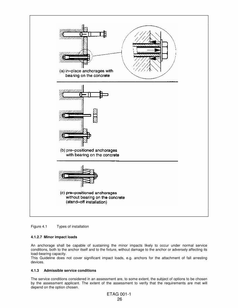
Anchors shall be capable of functioning correctly in concretes in the range of strengths covered by this Guideline. 4.1.2.3 Crack movements Anchors intended for use in cracked concrete, in the long term, shall continue to function effectively when the width of the crack is subject to changes in the range covered by this Guideline. 4.1.2.4 Repeated/variable loading Anchors, in the long term, shall continue to function effectively when their service load is subject to variation. 4.1.2.5 Sustained loading Anchors shall be capable of sustaining their design loads for the assumed working life of the fixture without significant increase in displacement which could render the anchorage ineffective. 4.1.2.6 Types of installation Anchors shall function correctly for the types of installation for which they are intended by the manufacturer. Installations according to Figures 4.1 (a) and 4.1 (b) are covered by this Guideline. After installation including torquing, the fixture shall be clamped against the surface of the base material. This can be ensured e.g. by a gap between sleeve and fixture (pre-positioned fastening, Figure 4.1b) or the washer (in-place fastening, Figure 4.1a) or by compressible components along the length of the sleeve (see Part 2). If the manufacturer wishes other types of installation to be assessed, e.g. Figure 4.1 (c), additional tests can be necessary.
ETAG 001-1 26
Figure 4.1 Types of installation
4.1.2.7 Minor impact loads An anchorage shall be capable of sustaining the minor impacts likely to occur under normal service conditions, both to the anchor itself and to the fixture, without damage to the anchor or adversely affecting its load-bearing capacity. This Guideline does not cover significant impact loads, e.g. anchors for the attachment of fall arresting devices. 4.1.3 Admissible service conditions The service conditions considered in an assessment are, to some extent, the subject of options to be chosen by the assessment applicant. The extent of the assessment to verify that the requirements are met will depend on the option chosen.
ETAG 001-1 27
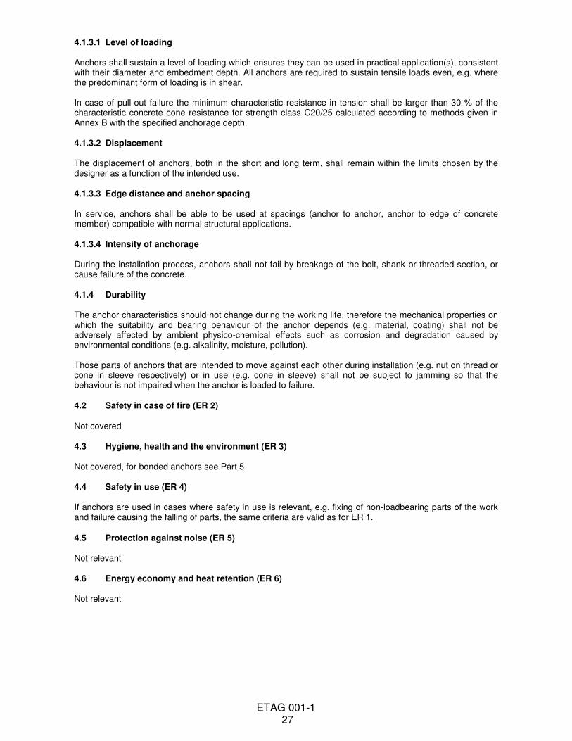
4.1.3.1 Level of loading Anchors shall sustain a level of loading which ensures they can be used in practical application(s), consistent with their diameter and embedment depth. All anchors are required to sustain tensile loads even, e.g. where the predominant form of loading is in shear. In case of pull-out failure the minimum characteristic resistance in tension shall be larger than 30 % of the characteristic concrete cone resistance for strength class C20/25 calculated according to methods given in Annex B with the specified anchorage depth. 4.1.3.2 Displacement The displacement of anchors, both in the short and long term, shall remain within the limits chosen by the designer as a function of the intended use. 4.1.3.3 Edge distance and anchor spacing In service, anchors shall be able to be used at spacings (anchor to anchor, anchor to edge of concrete member) compatible with normal structural applications. 4.1.3.4 Intensity of anchorage During the installation process, anchors shall not fail by breakage of the bolt, shank or threaded section, or cause failure of the concrete. 4.1.4 Durability The anchor characteristics should not change during the working life, therefore the mechanical properties on which the suitability and bearing behaviour of the anchor depends (e.g. material, coating) shall not be adversely affected by ambient physico-chemical effects such as corrosion and degradation caused by environmental conditions (e.g. alkalinity, moisture, pollution). Those parts of anchors that are intended to move against each other during installation (e.g. nut on thread or cone in sleeve respectively) or in use (e.g. cone in sleeve) shall not be subject to jamming so that the behaviour is not impaired when the anchor is loaded to failure. 4.2 Safety in case of fire (ER 2) Not covered 4.3 Hygiene, health and the environment (ER 3) Not covered, for bonded anchors see Part 5 4.4 Safety in use (ER 4) If anchors are used in cases where safety in use is relevant, e.g. fixing of non-loadbearing parts of the work and failure causing the falling of parts, the same criteria are valid as for ER 1. 4.5 Protection against noise (ER 5) Not relevant 4.6 Energy economy and heat retention (ER 6) Not relevant
ETAG 001-1 28
5 METHODS OF VERIFICATION
5.0 General
This chapter refers to the verification methods used to determine the various aspects of performance of the products in relation to the requirements for the works (calculations, tests, engineering knowledge, site experience, etc.). 5.1 Methods related to 4.1 (Mechanical resistance and stability)
5.1.1 General
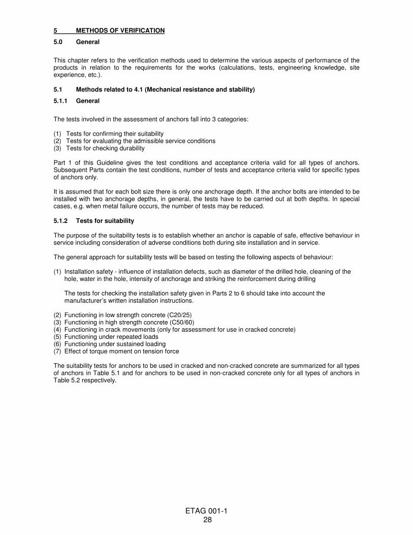
The tests involved in the assessment of anchors fall into 3 categories: (1) Tests for confirming their suitability (2) Tests for evaluating the admissible service conditions (3) Tests for checking durability Part 1 of this Guideline gives the test conditions and acceptance criteria valid for all types of anchors. Subsequent Parts contain the test conditions, number of tests and acceptance criteria valid for specific types of anchors only. It is assumed that for each bolt size there is only one anchorage depth. If the anchor bolts are intended to be installed with two anchorage depths, in general, the tests have to be carried out at both depths. In special cases, e.g. when metal failure occurs, the number of tests may be reduced. 5.1.2 Tests for suitability The purpose of the suitability tests is to establish whether an anchor is capable of safe, effective behaviour in service including consideration of adverse conditions both during site installation and in service. The general approach for suitability tests will be based on testing the following aspects of behaviour: (1) Installation safety - influence of installation defects, such as diameter of the drilled hole, cleaning of the
hole, water in the hole, intensity of anchorage and striking the reinforcement during drilling The tests for checking the installation safety given in Parts 2 to 6 should take into account the manufacturer’s written installation instructions.
(2) Functioning in low strength concrete (C20/25) (3) Functioning in high strength concrete (C50/60) (4) Functioning in crack movements (only for assessment for use in cracked concrete) (5) Functioning under repeated loads (6) Functioning under sustained loading (7) Effect of torque moment on tension force The suitability tests for anchors to be used in cracked and non-cracked concrete are summarized for all types of anchors in Table 5.1 and for anchors to be used in non-cracked concrete only for all types of anchors in Table 5.2 respectively.
ETAG 001-1 29
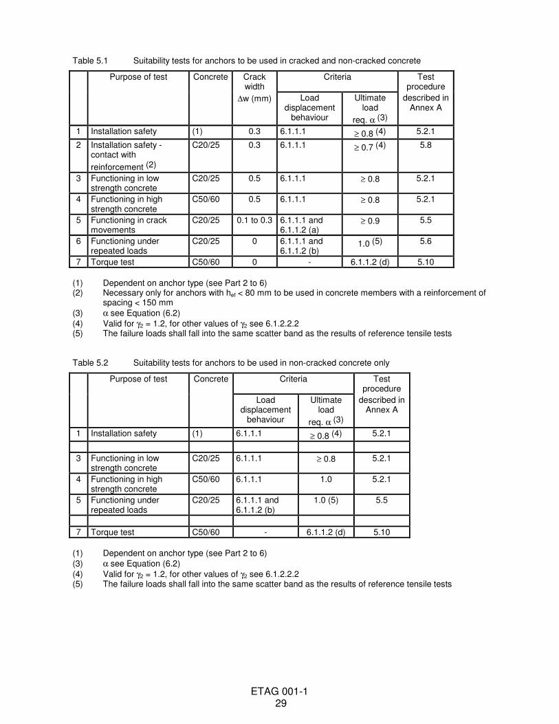
Table 5.1 Suitability tests for anchors to be used in cracked and non-cracked concrete
Purpose of test Concrete Crack width
Criteria Test procedure
∆w (mm) Load displacement
behaviour
Ultimate load
req. α (3)
described in Annex A
1 Installation safety (1) 0.3 6.1.1.1 ≥ 0.8 (4) 5.2.1
2 Installation safety - contact with
reinforcement (2)
C20/25 0.3 6.1.1.1 ≥ 0.7 (4) 5.8
3 Functioning in low strength concrete
C20/25 0.5 6.1.1.1 ≥ 0.8 5.2.1
4 Functioning in high strength concrete
C50/60 0.5 6.1.1.1 ≥ 0.8 5.2.1
5 Functioning in crack movements
C20/25 0.1 to 0.3 6.1.1.1 and 6.1.1.2 (a)
≥ 0.9 5.5
6 Functioning under repeated loads
C20/25 0 6.1.1.1 and 6.1.1.2 (b)
1.0 (5) 5.6
7 Torque test C50/60 0 - 6.1.1.2 (d) 5.10
(1) Dependent on anchor type (see Part 2 to 6) (2) Necessary only for anchors with hef < 80 mm to be used in concrete members with a reinforcement of
spacing < 150 mm
(3) α see Equation (6.2)
(4) Valid for γ2 = 1.2, for other values of γ2 see 6.1.2.2.2 (5) The failure loads shall fall into the same scatter band as the results of reference tensile tests Table 5.2 Suitability tests for anchors to be used in non-cracked concrete only
Purpose of test Concrete Criteria Test procedure
Load displacement
behaviour
Ultimate load
req. α (3)
described in Annex A
1 Installation safety (1) 6.1.1.1 ≥ 0.8 (4) 5.2.1
3 Functioning in low strength concrete
C20/25 6.1.1.1 ≥ 0.8 5.2.1
4 Functioning in high strength concrete
C50/60 6.1.1.1 1.0 5.2.1
5 Functioning under repeated loads
C20/25 6.1.1.1 and 6.1.1.2 (b)
1.0 (5) 5.5
7 Torque test C50/60 - 6.1.1.2 (d) 5.10
(1) Dependent on anchor type (see Part 2 to 6)
(3) α see Equation (6.2)
(4) Valid for γ2 = 1.2, for other values of γ2 see 6.1.2.2.2 (5) The failure loads shall fall into the same scatter band as the results of reference tensile tests

ETAG 001-1 30
5.1.3 Tests for admissible service conditions The admissible service conditions for anchors in concrete are influenced by a variety of factors, including:
− type of anchor (expansion, undercut, bonded, etc.)
− design and material specification of the anchor (embedment depth, diameter of drill hole, cross-section of steel parts, strength of anchor material, etc.)
− direction of loading of the anchor (tension, oblique tension, shear)
− condition of concrete member (cracked, non-cracked)
− concrete strength class
− arrangement of anchor(s) within concrete member (distance between anchors, edge distance, etc.). The modes of failure are important for the admissible service conditions, since, as given in Annex C, different partial safety factors will apply according to the mode of failure. The extent of the test programme will depend on the applicant’s request with respect to the range of conditions of use to be assessed for each anchor type. In general, the applicant will choose one of the available Options set out in Table 5.3 based on the following conditions of use:
− The anchor is for use in both cracked and non-cracked concrete (Options 1 to 6), or
− The anchor is for use in non-cracked concrete only (Options 7 to 12).
− The characteristic resistance is given as a function of the concrete strength (Options 1, 3, 5 for cracked concrete and Options 7, 9, 11 for non-cracked concrete). Tests are performed in concrete of strengths C20/25 and C50/60, or
− The influence of concrete strength on the characteristic resistance is neglected. In this case all tests are performed with concrete at strength C20/25 and tests with concrete at strength C50/60 are not required. Hence a single characteristic resistance is valid for all classes of strength > C20/25 (Options 2, 4, 6 for cracked concrete and Options 8, 10, 12 for non-cracked concrete).
− The characteristic resistance is given as a function of the load direction (Options 1 and 2 for cracked concrete and Options 7 and 8 for non-cracked concrete), or
− Only one characteristic resistance is given for all load directions (Options 3 to 6 for cracked concrete and Options 9 to 12 for non-cracked concrete).
− Both values for the distance between anchors scr and smin, and for the edge distance ccr and cmin are determined (Options 1 to 4 for cracked concrete and Options 7 to 10 for non-cracked concrete). For design purposes this procedure allows interpolation of the characteristic resistance in relation to spacing and edge distance according to the design methods, or
− The distance between anchors scr and distance from an edge ccr are determined by the applicant. These values cannot be reduced (Options 5 and 6 for cracked concrete and Options 11 and 12 for non-cracked concrete).
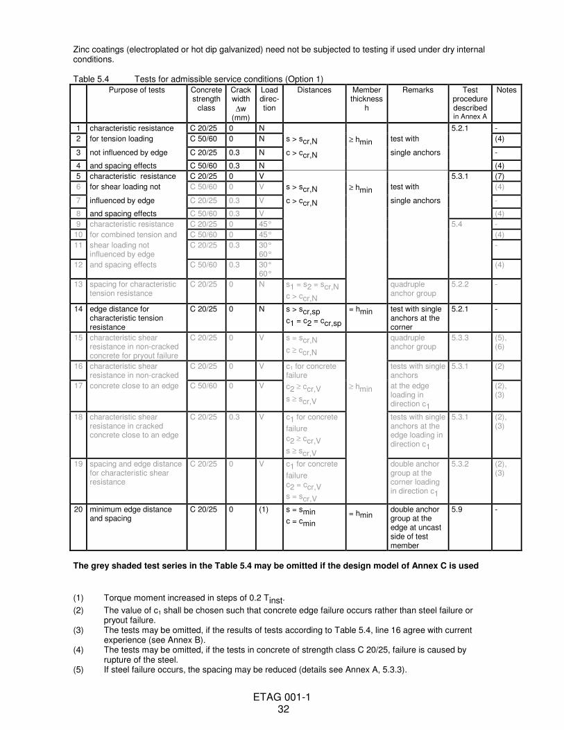
As an example, the tests required for Option 1 are summarized in Table 5.4. This Option requires the widest range of tests. For other Options some of these tests are not required. For convenience, details of the test conditions and the number of tests for different Options are given in Annex B.
The test procedures are described in Annex A.
The number of tests may be reduced if the anchor’s behaviour conforms to the current experience.
If existing information is available from the manufacturer and the corresponding test report contains all relevant data, then the Approval Body may reduce the number of tests given in Annex B, making use of this existing information. However, it will be considered in the assessment only if the results are consistent with the Institute’s test results or experience.
The required tests for assessing the admissible conditions of use are based on the design methods given in Annex C. Therefore the choice of the design method is a condition for assessing and judging of anchors. The relation between the different assessment options and the design method is given in Table 5.3. Use of a
ETAG 001-1 31
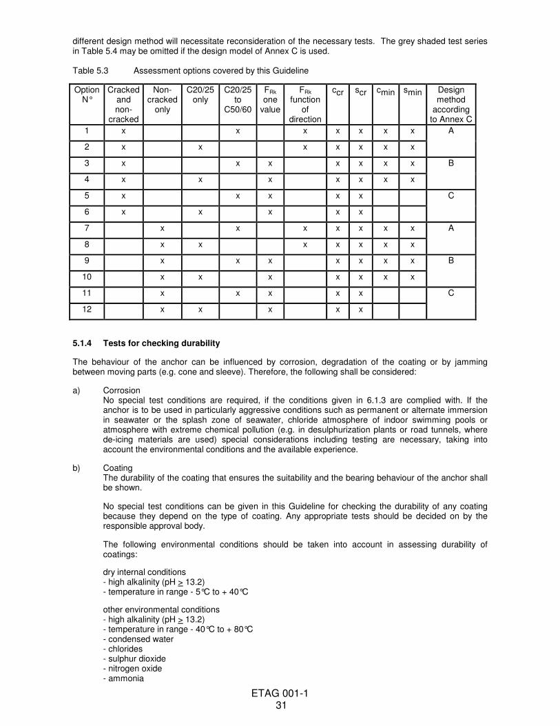
different design method will necessitate reconsideration of the necessary tests. The grey shaded test series in Table 5.4 may be omitted if the design model of Annex C is used. Table 5.3 Assessment options covered by this Guideline
Option N°
Cracked and non-
cracked
Non-cracked
only
C20/25 only
C20/25 to
C50/60
FRk one
value
FRk function
of direction
ccr scr cmin smin Design method
according to Annex C
1 x x x x x x x A
2 x x x x x x x
3 x x x x x x x B
4 x x x x x x x
5 x x x x x C
6 x x x x x
7 x x x x x x x A
8 x x x x x x x
9 x x x x x x x B
10 x x x x x x x
11 x x x x x C
12 x x x x x
5.1.4 Tests for checking durability
The behaviour of the anchor can be influenced by corrosion, degradation of the coating or by jamming between moving parts (e.g. cone and sleeve). Therefore, the following shall be considered:
a) Corrosion No special test conditions are required, if the conditions given in 6.1.3 are complied with. If the anchor is to be used in particularly aggressive conditions such as permanent or alternate immersion in seawater or the splash zone of seawater, chloride atmosphere of indoor swimming pools or atmosphere with extreme chemical pollution (e.g. in desulphurization plants or road tunnels, where de-icing materials are used) special considerations including testing are necessary, taking into account the environmental conditions and the available experience.
b) Coating The durability of the coating that ensures the suitability and the bearing behaviour of the anchor shall be shown.
No special test conditions can be given in this Guideline for checking the durability of any coating because they depend on the type of coating. Any appropriate tests should be decided on by the responsible approval body.
The following environmental conditions should be taken into account in assessing durability of coatings:
dry internal conditions - high alkalinity (pH > 13.2) - temperature in range - 5°C to + 40°C
other environmental conditions - high alkalinity (pH > 13.2) - temperature in range - 40°C to + 80°C - condensed water - chlorides - sulphur dioxide - nitrogen oxide - ammonia
ETAG 001-1 32
Zinc coatings (electroplated or hot dip galvanized) need not be subjected to testing if used under dry internal conditions. Table 5.4 Tests for admissible service conditions (Option 1)
Purpose of tests Concrete strength
class
Crack width
∆w (mm)
Load direc-tion
Distances Member thickness
h
Remarks Test procedure described in Annex A
Notes
1 characteristic resistance C 20/25 0 N 5.2.1 -
2 for tension loading C 50/60 0 N s > scr,N ≥ hmin test with (4)
3 not influenced by edge C 20/25 0.3 N c > ccr,N single anchors -
4 and spacing effects C 50/60 0.3 N (4)
5 characteristic resistance C 20/25 0 V 5.3.1 (7)
6 for shear loading not C 50/60 0 V s > scr,N ≥ hmin test with (4)
7 influenced by edge C 20/25 0.3 V c > ccr,N single anchors -
8 and spacing effects C 50/60 0.3 V (4)
9 characteristic resistance C 20/25 0 45° 5.4 -
10 for combined tension and C 50/60 0 45° (4)
11 shear loading not influenced by edge
C 20/25 0.3 30° 60°
-
12 and spacing effects C 50/60 0.3 30° 60°
(4)
13 spacing for characteristic tension resistance
C 20/25 0 N s1 = s2 = scr,N c > ccr,N
quadruple anchor group
5.2.2 -
14 edge distance for characteristic tension resistance
C 20/25 0 N s > scr,sp
c1 = c2 = ccr,sp
= hmin test with single anchors at the corner
5.2.1 -
15 characteristic shear resistance in non-cracked concrete for pryout failure
C 20/25 0 V s = scr,N
c ≥ ccr,N
quadruple anchor group
5.3.3 (5), (6)
16 characteristic shear resistance in non-cracked
C 20/25 0 V c1 for concrete failure
tests with single anchors
5.3.1 (2)
17 concrete close to an edge C 50/60 0 V c2 ≥ ccr,V
s ≥ scr,V
≥ hmin at the edge loading in direction c1
(2), (3)
18 characteristic shear resistance in cracked concrete close to an edge
C 20/25 0.3 V c1 for concrete
failure
c2 ≥ ccr,V
s ≥ scr,V
tests with single anchors at the edge loading in direction c1
5.3.1 (2), (3)
19 spacing and edge distance for characteristic shear resistance
C 20/25 0 V c1 for concrete
failure c2 = ccr,V
s = scr,V
double anchor group at the corner loading in direction c1
5.3.2 (2), (3)
20 minimum edge distance and spacing
C 20/25 0 (1) s = smin
c = cmin = hmin
double anchor group at the edge at uncast side of test member
5.9 -
The grey shaded test series in the Table 5.4 may be omitted if the design model of Annex C is used
(1) Torque moment increased in steps of 0.2 Tinst.
(2) The value of c1 shall be chosen such that concrete edge failure occurs rather than steel failure or pryout failure. (3) The tests may be omitted, if the results of tests according to Table 5.4, line 16 agree with current
experience (see Annex B). (4) The tests may be omitted, if the tests in concrete of strength class C 20/25, failure is caused by
rupture of the steel. (5) If steel failure occurs, the spacing may be reduced (details see Annex A, 5.3.3).
ETAG 001-1 33
(6) If different types of anchors of one anchor size are available, the stiffest anchor with the highest steel capacity shall be chosen.
(7) Tests according to line 5 are required only, if the anchor has a significantly reduced section along the length of the bolt or the sleeve of a sleeve type anchor should be considered or for internal threaded parts.
ETAG 001-1 34
c) Jamming No special test conditions are given to show compliance with the requirement given in 4.1.4, because they depend on the specific measures taken to prevent jamming and shall be decided by the responsible approval body.
5.2 Safety in case of Fire (ER2)
Not covered, anchorages concerning resistance to fire may be determined according to Technical Report 020 "Evaluation of Anchorages in Concrete concerning Resistance to Fire"
5.3 Hygiene, Health and the environment (ER3)
Not covered, for bonded anchors see Part 5 6 ASSESSING AND JUDGING THE FITNESS OF ANCHORS FOR AN INTENDED USE
6.0 General This chapter details the performance requirements to be met (chapter 4) into precise and measurable (as far as possible and proportional to the importance of the risk) or qualitative terms, related to the products and their intended use, using the verification methods (chapter 5). The following criteria shall be assessed: (a) 5 %-fractile of the ultimate loads The 5 %-fractile of the ultimate loads measured in a test series is to be calculated according to statistical procedures for a confidence level of 90 %. If a precise verification does not take place, in general, a normal distribution and an unknown standard deviation of the population shall be assumed.
F5% = F (1 - ks . v) (6.0)
e.g.: n = 5 tests: ks = 3.40 n = 10 tests: ks = 2.57 (b) Conversion of ultimate loads to take account of concrete and steel strength In some cases it can be necessary to convert the results of a test series to correlate with a concrete strength different from that of the test member (e.g. when comparing the results of repeated load tests with results of static tension tests performed on a different test member). When doing so, the type of failure shall be taken into account. In the case of concrete failure, this conversion should be carried out according to Equation (6.0a)
FRu (fc) = FRut .
(fc/fc,test)0.5
(6.0a)
where: FRu (fc) = failure load at concrete compression strength fc In the case of pull-out failure the influence of the concrete strength on the failure load should be established. In the absence of better information, Equation (6.0a) may be used as an approximation. In the case of steel failure the failure load shall be converted to the nominal steel strength by Equation (6.0b)
FRu (fuk) = FRut .
f
f
uk
u,test
(6.0b)
where: FRu (fuk) = failure load at nominal steel ultimate strength
ETAG 001-1 35
6.1 Assessing and judging related to 4.1 (mechanical resistance and stability)
6.1.1 Suitability
Approval for an anchor can only be obtained if the criteria for the suitability tests are met by all test results. To fulfil the requirements, in certain cases it can be necessary to reduce the characteristic resistance to be given in the ETA [see 6.1.2.2.1(b)].
6.1.1.1 Criteria valid for all tests
In all tests according to lines 1 to 6 of Tables 5.1 or 5.2, respectively, the following criteria shall be met:
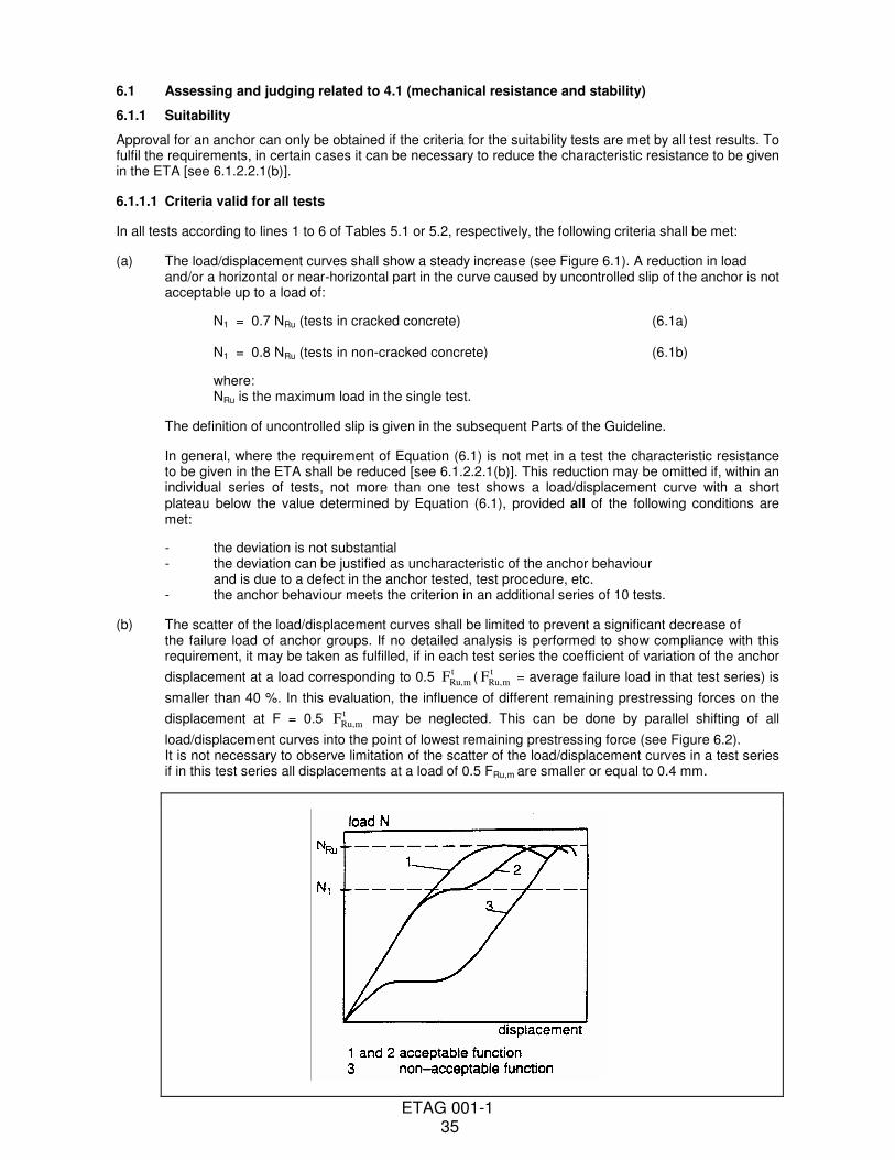
(a) The load/displacement curves shall show a steady increase (see Figure 6.1). A reduction in load and/or a horizontal or near-horizontal part in the curve caused by uncontrolled slip of the anchor is not acceptable up to a load of:
N1 = 0.7 NRu (tests in cracked concrete) (6.1a) N1 = 0.8 NRu (tests in non-cracked concrete) (6.1b)
where: NRu is the maximum load in the single test.
The definition of uncontrolled slip is given in the subsequent Parts of the Guideline.
In general, where the requirement of Equation (6.1) is not met in a test the characteristic resistance to be given in the ETA shall be reduced [see 6.1.2.2.1(b)]. This reduction may be omitted if, within an individual series of tests, not more than one test shows a load/displacement curve with a short plateau below the value determined by Equation (6.1), provided all of the following conditions are met:
- the deviation is not substantial - the deviation can be justified as uncharacteristic of the anchor behaviour and is due to a defect in the anchor tested, test procedure, etc. - the anchor behaviour meets the criterion in an additional series of 10 tests.
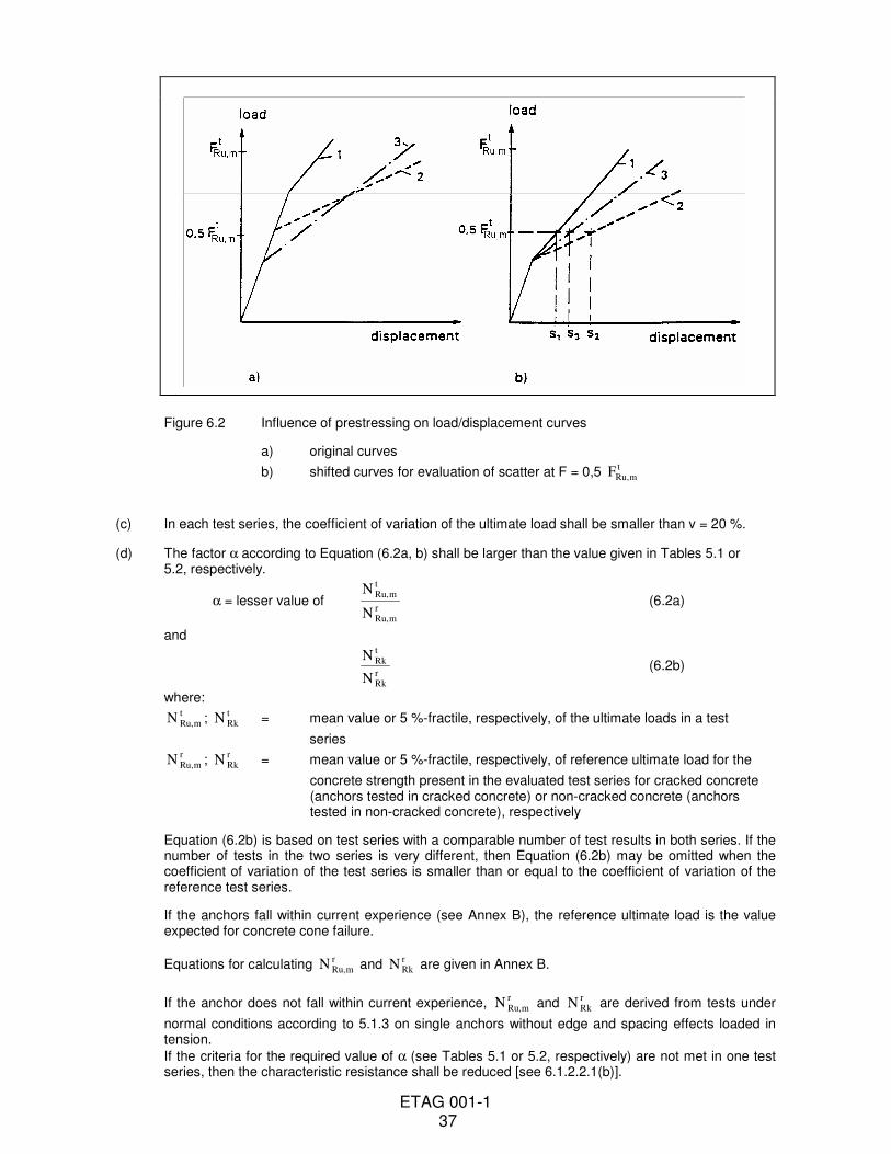
(b) The scatter of the load/displacement curves shall be limited to prevent a significant decrease of the failure load of anchor groups. If no detailed analysis is performed to show compliance with this requirement, it may be taken as fulfilled, if in each test series the coefficient of variation of the anchor
displacement at a load corresponding to 0.5 FRu,mt
( FRu,mt
= average failure load in that test series) is
smaller than 40 %. In this evaluation, the influence of different remaining prestressing forces on the
displacement at F = 0.5 FRu,mt
may be neglected. This can be done by parallel shifting of all
load/displacement curves into the point of lowest remaining prestressing force (see Figure 6.2). It is not necessary to observe limitation of the scatter of the load/displacement curves in a test series if in this test series all displacements at a load of 0.5 FRu,m are smaller or equal to 0.4 mm.
ETAG 001-1 36
Figure 6.1 Requirements for the load/displacement curve
ETAG 001-1 37
Figure 6.2 Influence of prestressing on load/displacement curves
a) original curves
b) shifted curves for evaluation of scatter at F = 0,5 FRu,mt
(c) In each test series, the coefficient of variation of the ultimate load shall be smaller than v = 20 %.
(d) The factor α according to Equation (6.2a, b) shall be larger than the value given in Tables 5.1 or 5.2, respectively.
α = lesser value of N
N
Ru,mt
Ru,mr
(6.2a)
and
N
N
Rkt
Rkr
(6.2b)
where:
N Ru,mt
; N Rkt
= mean value or 5 %-fractile, respectively, of the ultimate loads in a test
series
N Ru,mr
; N Rkr
= mean value or 5 %-fractile, respectively, of reference ultimate load for the
concrete strength present in the evaluated test series for cracked concrete (anchors tested in cracked concrete) or non-cracked concrete (anchors tested in non-cracked concrete), respectively
Equation (6.2b) is based on test series with a comparable number of test results in both series. If the number of tests in the two series is very different, then Equation (6.2b) may be omitted when the coefficient of variation of the test series is smaller than or equal to the coefficient of variation of the reference test series.
If the anchors fall within current experience (see Annex B), the reference ultimate load is the value expected for concrete cone failure.
Equations for calculating N Ru,mr
and N Rkr
are given in Annex B.
If the anchor does not fall within current experience, N Ru,mr
and N Rkr
are derived from tests under
normal conditions according to 5.1.3 on single anchors without edge and spacing effects loaded in tension.
If the criteria for the required value of α (see Tables 5.1 or 5.2, respectively) are not met in one test series, then the characteristic resistance shall be reduced [see 6.1.2.2.1(b)].
ETAG 001-1 38
6.1.1.2 Criteria valid for specific tests The following criteria shall be assessed: (a) Crack movement tests
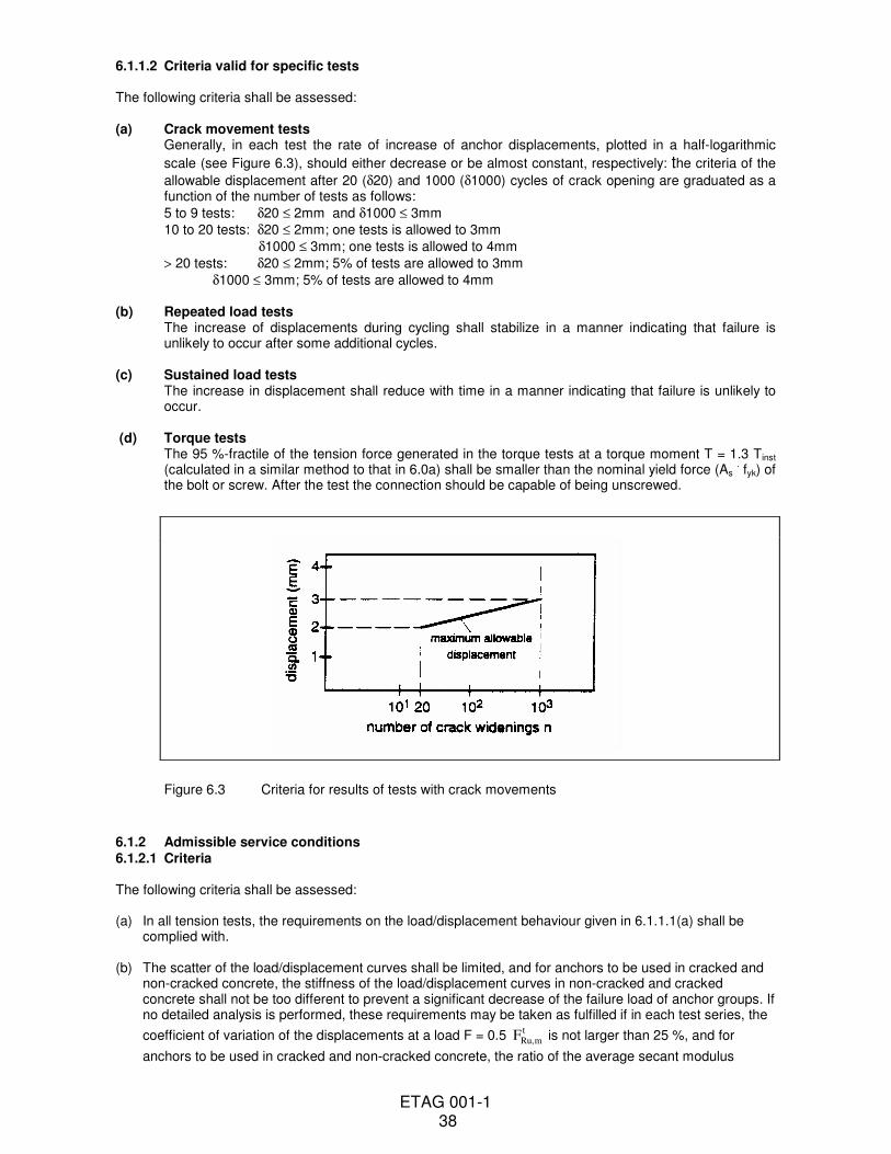
Generally, in each test the rate of increase of anchor displacements, plotted in a half-logarithmic
scale (see Figure 6.3), should either decrease or be almost constant, respectively: the criteria of the
allowable displacement after 20 (δ20) and 1000 (δ1000) cycles of crack opening are graduated as a function of the number of tests as follows:
5 to 9 tests: δ20 ≤ 2mm and δ1000 ≤ 3mm
10 to 20 tests: δ20 ≤ 2mm; one tests is allowed to 3mm
δ1000 ≤ 3mm; one tests is allowed to 4mm
> 20 tests: δ20 ≤ 2mm; 5% of tests are allowed to 3mm
δ1000 ≤ 3mm; 5% of tests are allowed to 4mm
(b) Repeated load tests The increase of displacements during cycling shall stabilize in a manner indicating that failure is unlikely to occur after some additional cycles.
(c) Sustained load tests The increase in displacement shall reduce with time in a manner indicating that failure is unlikely to occur.
(d) Torque tests The 95 %-fractile of the tension force generated in the torque tests at a torque moment T = 1.3 Tinst (calculated in a similar method to that in 6.0a) shall be smaller than the nominal yield force (As
. fyk) of
the bolt or screw. After the test the connection should be capable of being unscrewed.
Figure 6.3 Criteria for results of tests with crack movements
6.1.2 Admissible service conditions 6.1.2.1 Criteria The following criteria shall be assessed: (a) In all tension tests, the requirements on the load/displacement behaviour given in 6.1.1.1(a) shall be
complied with.
(b) The scatter of the load/displacement curves shall be limited, and for anchors to be used in cracked and non-cracked concrete, the stiffness of the load/displacement curves in non-cracked and cracked concrete shall not be too different to prevent a significant decrease of the failure load of anchor groups. If no detailed analysis is performed, these requirements may be taken as fulfilled if in each test series, the
coefficient of variation of the displacements at a load F = 0.5 FRu,mt
is not larger than 25 %, and for
anchors to be used in cracked and non-cracked concrete, the ratio of the average secant modulus
ETAG 001-1 39
between maximum load and the origin in cracked and non-cracked concrete is not larger than about 3.
(c) The average value of the coefficients of variation of the ultimate loads of all test series with anchors under tensile loads, where failure is caused by concrete break-out, concrete splitting or pull-out, shall be smaller than v = 15 %.
6.1.2.2 Assessment of admissible service conditions
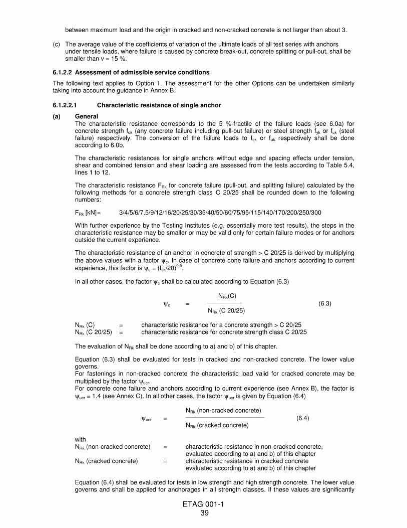
The following text applies to Option 1. The assessment for the other Options can be undertaken similarly taking into account the guidance in Annex B. 6.1.2.2.1 Characteristic resistance of single anchor
(a) General The characteristic resistance corresponds to the 5 %-fractile of the failure loads (see 6.0a) for concrete strength fck (any concrete failure including pull-out failure) or steel strength fyk or fuk (steel failure) respectively. The conversion of the failure loads to fck or fuk respectively shall be done according to 6.0b.
The characteristic resistances for single anchors without edge and spacing effects under tension, shear and combined tension and shear loading are assessed from the tests according to Table 5.4, lines 1 to 12.
The characteristic resistance FRk for concrete failure (pull-out, and splitting failure) calculated by the following methods for a concrete strength class C 20/25 shall be rounded down to the following numbers:
FRk [kN] = 3/4/5/6/7.5/9/12/16/20/25/30/35/40/50/60/75/95/115/140/170/200/250/300
With further experience by the Testing Institutes (e.g. essentially more test results), the steps in the characteristic resistance may be smaller or may be valid only for certain failure modes or for anchors outside the current experience.
The characteristic resistance of an anchor in concrete of strength > C 20/25 is derived by multiplying
the above values with a factor ψc. In case of concrete cone failure and anchors according to current
experience, this factor is ψc = (fck/20)0.5
.
In all other cases, the factor ψc shall be calculated according to Equation (6.3) NRk(C)
ψc = _______________
(6.3) NRk (C 20/25) NRk (C) = characteristic resistance for a concrete strength > C 20/25 NRk (C 20/25) = characteristic resistance for concrete strength class C 20/25 The evaluation of NRk shall be done according to a) and b) of this chapter.
Equation (6.3) shall be evaluated for tests in cracked and non-cracked concrete. The lower value governs. For fastenings in non-cracked concrete the characteristic load valid for cracked concrete may be
multiplied by the factor ψucr. For concrete cone failure and anchors according to current experience (see Annex B), the factor is
ψucr = 1.4 (see Annex C). In all other cases, the factor ψucr is given by Equation (6.4) NRk (non-cracked concrete)
ψucr = ___________________________________
(6.4) NRk (cracked concrete) with NRk (non-cracked concrete) = characteristic resistance in non-cracked concrete, evaluated according to a) and b) of this chapter NRk (cracked concrete) = characteristic resistance in cracked concrete evaluated according to a) and b) of this chapter Equation (6.4) shall be evaluated for tests in low strength and high strength concrete. The lower value governs and shall be applied for anchorages in all strength classes. If these values are significantly
ETAG 001-1 40
different and the difference can be explained by the anchor behaviour, then different values for the different concrete strengths may be given in the ETA. The following cases should be distinguished in the assessment: (1) Where single anchors conform to the current experience in one or more loading directions the corresponding characteristic resistance shall be calculated according to Annex B. (2) Where single anchors do not conform to current experience the following applies:
The characteristic resistance shall be calculated from the results of the corresponding tests according to 5.1.3 as described below:
− Concrete cone failure If concrete cone failure occurs in low and high strength concrete, then all results may be evaluated together and the characteristic resistance for the different strength classes shall be calculated using Equation (6.0a).
− Steel failure If steel failure occurs in low and high strength concrete, then the measured failure loads shall be converted to fuk according to Equation (6.0b). All results may be evaluated together.
− Other failure modes In all other cases the characteristic resistances for the different concrete strength classes shall be linear interpolated between NRk for low and high strength concrete.
In general, the interaction equations given in Annex B apply. If the failure loads measured in the interaction tests are lower than the values calculated according to the equations, then a modified interaction equation having the same general form shall be evaluated such that the 5 %-fractile of the results of the combined tension and shear tests are predicted.
(b) Reduction of the characteristic tension resistance
The characteristic tension resistance shall be reduced if certain requirements are not met as described in the following:
(1) Load/displacement behaviour, tension loading If the requirements on the load/displacement behaviour according to 6.1.1.1(a) are not fulfilled by the tension tests according to 5.1.2 and/or 5.1.3, then the characteristic resistance given in the ETA shall be reduced as follows:
α1 NRk = NRk.0
. _________
(6.5)
req. α1
where:
NRk = characteristic resistance stated in the ETA NRk,0 = characteristic resistance according to 6.1.2.2.1 (a)
α1 = lowest ratio N1/Nu of all tests N1 = load at which uncontrolled slip of the anchor occurs (see Figure 6.1)
N Rut
= failure load in that test
req.α1 = 0.7 tests in cracked concrete 0.8 tests in non-cracked concrete
(2) Crack movement, repeated and sustained load tests If, in the crack movement, repeated and sustained load tests, the requirements on the displacement behaviour are not fulfilled (see 6.1.1.2) then the characteristic resistance shall be reduced and the tests repeated until the requirements are fulfilled.
(3) Ultimate load in suitability tests If the requirements on the ultimate load in the suitability tests [see 6.1.1.1(b)] according to Table 5.1, lines 3 to 6 or Table 5.2, lines 3 to 6, respectively, are not fulfilled in one or more test series, then the characteristic resistance shall be reduced as follows:
α NRk = NRk,0
. _______
(6.6)
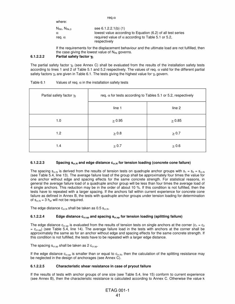
ETAG 001-1 41
req.α where:
NRK, NRk,0 see 6.1.2.2.1(b) (1)
α lowest value according to Equation (6.2) of all test series
req. α required value of α according to Table 5.1 or 5.2, respectively
If the requirements for the displacement behaviour and the ultimate load are not fulfilled, then the case giving the lowest value of NRk governs.
6.1.2.2.2 Partial safety factor γγγγ2
The partial safety factor γ2 (see Annex C) shall be evaluated from the results of the installation safety tests
according to lines 1 and 2 of Table 5.1 and 5.2 respectively. The values of req. α valid for the different partial
safety factors γ2 are given in Table 6.1. The tests giving the highest value for γ2 govern.
Table 6.1 Values of req. α in the installation safety tests
Partial safety factor γ2
req. α for tests according to Tables 5.1 or 5.2, respectively
line 1
line 2
1.0
> 0.95
> 0.85
1.2
> 0.8
> 0.7
1.4
> 0.7
> 0.6
6.1.2.2.3 Spacing scr,N and edge distance ccr,N for tension loading (concrete cone failure) The spacing scr,N is derived from the results of tension tests on quadruple anchor groups with s1 = s2 = scr,N (see Table 5.4, line 13). The average failure load of the group shall be approximately four times the value for one anchor without edge and spacing effects for the same concrete strength. For statistical reasons, in general the average failure load of a quadruple anchor group will be less than four times the average load of 4 single anchors. This reduction may be in the order of about 10 %. If this condition is not fulfilled, then the tests have to repeated with a larger spacing. If the anchors fall within current experience for concrete cone failure as defined in Annex B, the tests with quadruple anchor groups under tension loading for determination of scr,N = 3 hef will not be required. The edge distance ccr,N shall be taken as 0.5 scr,N. 6.1.2.2.4 Edge distance ccr,sp and spacing scr,sp for tension loading (splitting failure) The edge distance ccr,sp is evaluated from the results of tension tests on single anchors at the corner (c1 = c2 = ccr,sp) (see Table 5.4, line 14). The average failure load in the tests with anchors at the corner shall be approximately the same as for an anchor without edge and spacing effects for the same concrete strength. If this condition is not fulfilled, the tests have to be repeated with a larger edge distance. The spacing scr,sp shall be taken as 2 ccr,sp. If the edge distance ccr,sp is smaller than or equal to ccr,N, then the calculation of the splitting resistance may be neglected in the design of anchorages (see Annex C). 6.1.2.2.5 Characteristic shear resistance in case of pryout failure If the results of tests with anchor groups of one size (see Table 5.4, line 15) conform to current experience (see Annex B), then the characteristic resistance is calculated according to Annex C. Otherwise the value k
ETAG 001-1 42
(see Annex C) shall be evaluated from the results of tests described in Annex A, 5.3.3 according to Equation (6.7)
k = V
N
Rkt
Rk
(6.7)
with
NRk = calculated tension capacity of the anchor group.
If current experience is accepted, NRk is given by Equation (6.7a)
NRk = 10 hef1,5
. fc,test
0,5 (s 3h )
9h
ef2
ef
2
+ (6.7a)
If the value of k is not significantly influenced by the anchor size, then one value of k shall be assigned to all anchor sizes which corresponds to the lower bound of the test results. This is also valid for certain anchor size ranges. If the value of k increases significantly with the anchor size, then different k values may be used for each test anchor size. If in the tests with the smallest allowable spacing steel failure occurs and k according to Equation (6.7a) is smaller than 1.0 for hef < 60 mm or 2.0 for hef > 60 mm, then the characteristic pryout resistance may be calculated according to Annex C. 6.1.2.2.6 Characteristic shear resistance, spacing scr,V and edge distance ccr,V for shear loading at the edge (concrete edge failure) If the results of tests of single anchors at the edge (c2 > 1.5 c1, h > 1.5 c1) loaded in shear towards the edge (see Table 5.4, lines 16 and 17) conform to current experience (see Annex B) then the characteristic resistance is calculated according to Annex C with ccr,V = 1.5 c1 and scr,V = 3 c1 (c1 = edge distance in loading direction). If the above-mentioned test results do not conform to current experience then the characteristic shear resistance for the different concrete strength classes shall be assessed from the results of tests according to Table 5.4, lines 16 and 17 (non-cracked concrete) and line 18 (cracked concrete) respectively using Equation (6.0a). For non-cracked concrete, the results of tests in low and high strength concrete shall be evaluated together. The spacing scr,V = 2 ccr,V shall be derived from the results of tests with double anchor groups at the corner (c2 = ccr,V, s = 2 ccr,V, h > 1.5 c1) (see Table 5.4, line 19) loaded in shear towards the edge. The average failure load of the group shall be approximately twice the value valid for one anchor for otherwise equal conditions but without edge and spacing effects (see results of tests according to Table 5.4, lines 16 and 17). If this condition is not fulfilled, the tests shall be repeated with a larger spacing and edge distance. 6.1.2.2.7 Minimum spacing smin and minimum edge distance cmin The minimum spacing smin and minimum edge distance cmin shall be evaluated from the results of installation tests with double anchor groups (c = cmin, s = smin) (see Table 5.4, line 20). The 5 %-fractile of the torque moments, T5%, calculated according to (6.0a) at which a hairline crack has been observed at one anchor of the double anchor group, shall fulfil Equation (6.8).
T5% > γinst . req.Tinst (fc,test/fck)
0.5 (6.8)
The following values for γinst shall be taken: (a) Scatter of the friction coefficients which determine the magnitude of the splitting
forces at the required or recommended torque moment respectively is controlled during production to the values present with the anchors used in the approval tests
γinst = 1.3 anchorages in cracked concrete = 1.7 anchorages in non-cracked concrete
(b) Scatter of the friction coefficients which determine the magnitude of the splitting
ETAG 001-1 43
forces at the required or recommended torque moment respectively is not controlled during production to the values present with the anchors used in the approval tests
γinst = 1.5 anchorages in cracked concrete = 2.1 anchorages in non-cracked concrete
The splitting forces at the required or recommended torque moment respectively depend on the prestressing force generated during torquing and the ratio splitting force to prestressing force. Prestressing force and splitting force may be measured in appropriate tests (see Annex A).
6.1.2.2.8 Displacement behaviour As a minimum, the displacements under short and long term tension and shear loading shall be given in the ETA for a load F which corresponds approximately to the value according to Equation (6.9)
F = FRk
F Mγ γ• (6.9)
FRk = characteristic resistance according to 6.1.2.2.1
γF = 1.4
γM = material partial safety factor according to Annex C for the corresponding failure mode
The displacements under short term tension and shear loading (δNO and δVO) are evaluated from the tests on single anchors without edge or spacing effects according to Table 5.4, lines 1 to 8). The value derived shall correspond approximately to the 95 %-fractile for a confidence level of 90 %.
The short term tension and shear displacements δNO and δVO depend on the concrete strength class and state of the concrete (non-cracked, cracked). However, in general it is sufficient to give one value each for the tension and shear displacement which represents the most unfavourable condition and which is valid for all concrete strength classes and cracked and non-cracked concrete. Under shear loading, the displacements might increase due to a gap between fixture and anchor. The influence of this gap is taken into account in design (see Annex C).
In the absence of other information δN∞ may be calculated as follows: For anchors to be used in non-cracked and cracked concrete or in non-cracked concrete only the long term
displacements under tension loading, δN∞, shall be calculated from the results of crack movement tests (see Table 5.1, line 5) according to Equation (6.10)
δm1
δN∞ = ____
(6.10) 1.5 with
δN∞ = long term tension displacement
δm1 = average anchor displacement after 103 crack movements
For anchors to be used in non-cracked concrete only, the long term displacements under tension loading,
δN∞, shall be calculated from the results of repeated load and sustained load tests (see Table 5.2, lines 5 and 6) according to Equation (6.11)
δm2
δN∞ = ____
(6.11) 2.0 with
δm2 = average displacement in the repeated load tests after 105 load cycles
or the sustained load tests after terminating the tests (see Annex A) respectively. The larger value is decisive.
The long term shear displacements δV∞ may be assumed to be approximately equal to 1.5-times the value
δVO.
ETAG 001-1 44
The load at which first slip occurs cannot, except in special cases, be ensured in the long term because of the influence of shrinkage and creep of the concrete, crack formation, etc. 6.1.3 Assessment of durability a) Corrosion The assessment/testing required with respect to corrosion resistance will be dependent upon the specification of the anchor in relation to its use. Supporting evidence that corrosion will not occur is not required if the anchors are protected against corrosion of steel parts, as set out below: Anchors for use in structures subject to external atmospheric exposure or exposure in permanently damp internal conditions:
The metal parts of the anchors shall be made of an appropriate grade of stainless steel. The grade of stainless steel suitable for the various service environments (marine, industrial, etc.) shall be in accordance with existing rules. Grade A4 of ISO 3506 [4] or equivalent may be used under internal or other environmental conditions if no particularly aggressive conditions exist.
However, in particularly aggressive conditions such as permanent, alternating immersion in seawater or the splash zone of seawater, chloride atmosphere of indoor swimming pools or atmosphere with extreme chemical pollution (e.g. in desulphurization plants or road tunnels, where de-icing materials are used) special considerations shall be given to corrosion resistance. According to current experience, in general the types of stainless steel given above will not have sufficient corrosion resistance in those aggressive conditions.
Anchors intended for use in structures subject to dry, internal conditions:
In general, no special corrosion protection is necessary for steel parts as coatings provided for preventing corrosion during storage prior to use, to ensure proper functioning (e.g. a zinc coating with a minimum thickness of 5 microns) is considered sufficient. Malleable cast iron parts in general, e.g. type B32-12 and W40 05 to ISO 5922:1981 [5] do not require any protection.
Where a form of protection (material or coating) other than those mentioned above is specified, it will be necessary to provide evidence in support of its effectiveness in the defined service conditions; with due regard to the aggressiveness of the conditions concerned.
If an anchor involves the use of different metals, these shall be electrolytically compatible with each other. In dry internal conditions, carbon steel is compatible with malleable cast iron.
b) Coating Assessment of the durability of the coating is based on the type of coating and the intended conditions of use (i.e. dry internal or external conditions).
c) Jamming Assessment of the risk of jamming with stainless steel anchors is based on the consideration of the grade(s) and surface finish of steel used in relation to existing experience of jamming in appropriate cases.
6.2 Safety in case of fire (ER2) Not covered, anchorages concerning resistance to fire may be assessed according to Technical Report 020 "Evaluation of Anchorages in Concrete concerning Resistance to Fire" 6.3 Hygiene, health and the environment (ER3) Not covered; for bonded anchors see Part 5 6.7 Identification of anchors
In order to ensure that the anchor samples used for the initial assessment (see 5) conform to the specification referred to in the ETA it is necessary to identify their relevant specifications and characteristics which can influence their functioning, performance or durability. Identification tests are for verifying the characteristics of the anchors, including dimensions, constituent materials, anti-corrosion protection and the marking of the anchors and various components.
In addition, the identification tests contribute to the provision of a basis for quality control of the production.

ETAG 001-1 45
During tests on the constituent materials of the components, the following properties shall be determined: tensile strength, elastic limit, elongation at rupture, hardness. The measured values shall be compared with minimum values or strength classes indicated in ISO or European standards. The manner in which the components are fabricated shall also be checked (e.g. cold-forming, quenching, hardening). For the testing of carbon steel screws, bolts, nuts and threaded cones, reference can be made to ISO 898, Part 1 and 2 [3]. For the testing of stainless steel screws reference can be made to ISO 3506 [4]. For quenched components, the surface hardness and case depth are to be determined. Hardness testing shall be by either the Brinell or Vickers methods. Wherever possible, the material declaration, according to the relevant material standard, should be provided. If appropriate, surface condition, e.g. surface roughness and the type and thickness of any protective coating, shall be measured. Characteristics as specified in the manufacturer’s specification for production control and as required above are to be checked using ISO, European or recognized standard test methods as nominated by the manufacturer and accepted by the approval body. Wherever possible, checks should be carried out on finished components. Where dimensions or other factors prevent testing to a recognized standard, e.g. tensile properties where the required ratio of length to diameter does not exist in the finished component, then the tests should still be carried out on the finished component if practicable, in order to produce results for comparison purposes. Where this is not possible, tests should be carried out on the raw material; however, it shall be noted that where the production process changes the characteristics of the material, then a change to the production process can render the results of these tests invalid. Deviations of samples from the specification on the manufacturer’s drawings shall be identified and appropriate action taken to ensure compliance before testing anchors. A minimum number of each component (e.g. nuts, screws, washers, sleeves, plastic components of minor importance with regard to load-bearing behaviour and special drill bits and setting tools if appropriate) depending on factors such as the production process and the bag size is to be taken and dimensions measured and checked against the drawings provided by the manufacturer. The tolerances specified for all components shall be complied with and the dimensions of these elements shall conform to the appropriate ISO or European standards where relevant. The results obtained shall be assessed to ensure that they are within the manufacturer’s specification. 7 ASSUMPTIONS UNDER WHICH THE FITNESS FOR USE IS TO BE ASSESSED 7.0 General This chapter sets out the pre-conditions for design, execution, maintenance and repair which are a presumption for the assessment of the fitness for use according to the guideline (only when necessary and in so far as they have a bearing on the assessment or on the products). 7.1 Design methods for anchorages The assessment of the anchor shall be made assuming that one of the design methods given in Annex C is used. However, if an alternative design method should be proposed the approval body shall judge this design method and the relevance of the assessment, in particular the relevance of the tests to be undertaken. The overall assumption shall be made that the design and dimensioning of anchorages is based on technical considerations and in particular the following:
• the preparation of verifiable calculation notes and drawings for determining the state of the concrete (cracked or non-cracked) in the region of the anchorage, the loads to be transmitted and their transmission to the supports of the structure.
• verification of direct transmission of the load into the concrete according to Annex C using one of the design methods and the partial safety factors given.
• consideration not only of direct loads but also the important additional loads caused by restraint of intrinsic (e.g. shrinkage) or extrinsic deformation (e.g. by temperature variations) in the anchor, in the fixture or in the concrete together with verification of the distribution of loads in these structures and assemblies.
ETAG 001-1 46
Given that the installation position of anchors in the concrete can be of great importance for their behaviour (e.g. position of the anchor relative to reinforcement or to supports, in cracked or non-cracked concrete, etc.) it is further assumed that the position of anchors is to be indicated accurately on the design drawings. 7.2 Recommendations for packaging, transport and storage Only in special cases, e.g. for bonded anchors, will it be necessary to consider special recommendations for transport and storage. In such cases the approval body should, in the ETA, draw attention to any necessary precautions. 7.3 Installation of anchors The loading capacity and reliability of anchorages are greatly affected by the manner in which the anchors are installed. The manufacturer’s installation instructions therefore form a fundamental part of the assessment of the fitness for use of an anchor. This Guideline takes account of a reasonable degree of imperfection in relation to installation and thus control methods on site after installation will in general not be necessary. This assumes, however, that gross errors on site will be avoided by use of instructions and correct training of the installers and supervision on site. Installation instructions should typically include the following:
• Before placing an anchor checks to be made to ensure the strength class of the concrete is not lower than that to which the characteristic loads apply.
• The concrete to be well compacted e.g. without significant voids.
• Holes to be drilled perpendicular to the surface unless specifically required otherwise by the manufacturer’s instructions.
• Normally hard metal hammer-drill bits in accordance with ISO or National Standards should be used. Many drill bits exhibit marks indicating that these requirements have been met. If the drill bits do not bear a conformity mark, evidence of suitability should be provided.
• All special drill bits (e.g. stopdrills or diamond core drill bits) required in accordance with manufacturer’s installation instructions to be in compliance with the manufacturer’s specifications. This to be confirmed by the factory production control for the drill bits.
• Holes to be cleared of drilling dust.
• Anchors to be installed ensuring not less than the specified embedment depth. The edge distance and spacing to be kept to the specified values, no minus tolerances to be allowed.
• When drilling holes, care to be taken not to damage reinforcement in close proximity to the hole position. In the absence of national regulations it is recommended that the distance between the side of drilling hole and the outside of prestressed reinforcement is at least 50mm; for determining the position of the prestressed reinforcement in the structure, suitable device (reinforcement detector e.g.) should be used.
• Action to be taken in the event that drilling is aborted, e.g. due to encountering reinforcement. For example it may be recommended to either install the anchors immediately beside the aborted drill hole, provided that anchoring depth is increased by the depth of the aborted drill hole, or make a new drilling at a minimum distance away of twice the depth of the aborted hole. Alternatively, a smaller distance may be chosen, provided the aborted drill hole is filled with high strength mortar. However, unless the aborted drill hole is filled with mortar, it is not permissible under shear or oblique tension load for it to be closer than 1.0 hef or 5.0 do to the aborted hole in the direction of load application.
• For anchors to be subjected to temperatures below 0°C, measures to be taken to avoid the ingress of water into the hole and subsequent risk of local cracking of the concrete due to ice pressure.
ETAG 001-1 47
Finally it is assumed that the necessary information and appropriate specifications for correct installation are available on site and that the person responsible transmits all the necessary information to the installer. It is to be further assumed that installation is carried out by trained personnel under the supervision of the person responsible for technical matters on site.
ETAG 001-1 48
Section three: ATTESTATION OF CONFORMITY
8 ATTESTATION OF CONFORMITY
8.0 Evaluation of conformity
8.1 EC decision
The system of attestation of conformity specified by the European Commission as detailed in mandate Construct
95/139 Annex 3 is system 1 (for anchors for lightweight systems see Part 6) described in Council Directive
(89/106/EEC) Annex III 2.(i) as follows:
(a) tasks for the manufacturer
(1) factory production control; (see 8.2.3)
(2) further testing of samples taken at the factory by the manufacturer in accordance
with a prescribed test plan. (see 8.2.2)
(b) tasks for the approved body
(3) initial type-testing of the product; (see 8.2.1)
(4) initial inspection of factory and of factory production control; (see 8.2.4)
(5) continuous surveillance, assessment and approval of factory production control. (see
8.2.4)
8.2 Action in relation to tasks
8.2.1 Initial type-testing
Initial type-testing will be available as part of the work required for the assessment of products for ETA.
The tests will have been conducted by the approval body or under its responsibility (which may include a
proportion conducted by an approved laboratory or by the manufacturer) in accordance with chapter 5 of this
ETAG. The approval body will have assessed the results of these tests in accordance with chapter 6 of this
ETAG, as part of the ETA issuing procedure.
Where appropriate this assessment shall be used by the approved body for Certificate of Conformity purposes.
8.2.2 Testing of samples taken at the factory
Both large and small companies produce these products, there is a large variation in the volume of products
within the range of sizes produced and different production processes introduce further variations. Therefore a
precise scheme can only be set up on a case by case basis.
In general it is not normally necessary to conduct tests on anchors installed in concrete. Indirect methods will
normally be sufficient eg control of the raw materials, manufacturing process and properties of components.
8.2.3 Factory production control (FPC)
The manufacturer shall exercise permanent internal control of production. All the elements, requirements and
provisions adopted by the manufacturer shall be documented in a systematic manner in the form of written
policies and procedures. This production control system shall ensure that the product is in conformity with the
ETA.
ETAG 001-1 49
8.2.4 Initial inspection and continuous surveillance, assessment of the factory production
control system
Assessment of the factory production control system is the responsibility of the approved body.
An assessment shall be carried out on each production unit to demonstrate that the FPC is in conformity with the
ETA and any additional information. This assessment shall be based on an initial inspection of the factory.
Subsequently continuous surveillance of FPC is necessary to ensure continuing conformity with the ETA.
It is recommended that surveillance inspections be conducted at least twice per year. However, for factories
which are the subject of a certified quality assurance system, surveillance visits may be carried out at less
frequent intervals.
8.3 Documentation
In order to help the approved body make an evaluation of conformity the approval body issuing the ETA shall
supply the information detailed below. This information together with the requirements given in EC Guidance
Paper No 7 Construct 95/135 Rev 1, will generally form the basis on which the FPC is assessed by the approved
body.
(1) the ETA
(2) basic manufacturing processes
(3) product and materials specifications
(4) test plan
(5) other relevant information
This information shall initially be prepared or collected by the approval body and where appropriate shall be
agreed with the manufacturer. The following gives guidance on the type of information required:
(1) The ETA
See chapter 4 of this ETAG.
The nature of any additional (possibly confidential) information shall be declared in the ETA.
(2) Basic manufacturing processes
The basic manufacturing process shall be described in sufficient detail to support the proposed FPC
methods.
Anchors are normally manufactured using conventional metal working techniques. Any critical process
or treatment of the parts which affects performance should be highlighted.
(3) Product and materials specification
Product and materials specifications will be required for the various components and any bought-in
components eg nuts, washers.
These specifications can take the form of:
detailed drawings (including manufacturing tolerances)
raw materials specifications
references to national, European and/or international standards and grades
manufacturers data sheets eg for raw materials not covered by a recognised standard eg friction control
coating.

ETAG 001-1 50
(4) Test plan
The manufacturer and the approval body issuing the ETA shall agree on a test plan (CPD Annex III 1b).
This test plan is necessary to ensure that the product specification remains unchanged.
The validity of the type and frequency of checks/tests conducted during production and on the final
product shall be considered as a function of the production process. This will include the checks
conducted during manufacture on properties that cannot be inspected at a later stage and for checks on
the final product. These will normally include:
− material properties e.g. tensile strength, hardness, surface finish
− determination of the dimensions of component parts
− coating thickness
− check correct assembly.
Where bought-in components/materials are supplied without certificates of relevant properties they shall
be subject to checks/tests by the manufacturer before acceptance.
Table 8.1 sets out how the test plan meets the requirements of the mandate with regard to evaluation of
conformity.
8.4 EC-Conformity marking and information Every anchor shall be clearly identifiable before installation and shall be marked by: - the name or identifying mark of the producer - the anchors identity (commercial name) - the category (use categories, durability categories, e.g. an additional mark for stainless steel
anchors to distinguish them from non-stainless steel anchors). The category may be included in the anchor identity.
- for anchors projecting above the surface of concrete, the minimum anchorage depth or the maximum admissible thickness of the fixture. - if an anchor is designed for use at more than one anchorage depths while maintaining the same
thread diameter, the anchorage depths available and used shall be discernible after installation of the anchor.
In addition, the symbol „CE“ can be put on the anchor. The packaging or the delivery tickets associated with the product shall contain the CE conformity marking which shall consist of the symbol CE and be accompanied by: 1. The name or identifying mark of the producer and plant.
− If the mark is used under the responsibility of an agent within the EU, the agent, as well as the producer, have to be identified.
− If the anchor is produced in a stepped procedure, in different plants, it is the last one responsible for the mark, which has to be identified.
2. Indications to identify the characterisation of the anchor.
− This shall include: the anchor’s identity (commercial name), the Member State number, the approval body and the ETA-number. the categories (use categories and Option, durability categories) for anchors projecting above the surface of concrete, the minimum anchorage depth or the maximum admissible thickness of fixture.
The indication “for static or quasi-static actions only”; see ETA clause II.1.
3. The last two digits of the year in which the marking was affixed. 4. The identification symbol of the approved body involved:
ETAG 001-1 51
− the Member State number and the number or symbol allocated to the approved body. 5. The EC Certificate of Conformity:
− the number of the EC Certificate of Conformity shall be given.
All installation data shall be shown clearly on the package and/or on an enclosed instruction sheet, preferably using illustration(s). The minimum data required are:
− drill bit diameter (dcut)
− thread diameter (d)
− maximum thickness of the fixture (max tfix)
− minimum effective anchorage depth (hef)
− minimum hole depth (ho)
− necessary tightening (e.g. required or maximum recommended torque moment) (Tinst)
− information on the installation procedure, including cleaning of the hole, preferably by means of an illustration
− reference to any special installation equipment needed
− identification of the manufacturing batch All data shall be presented in a clear and explicit form.
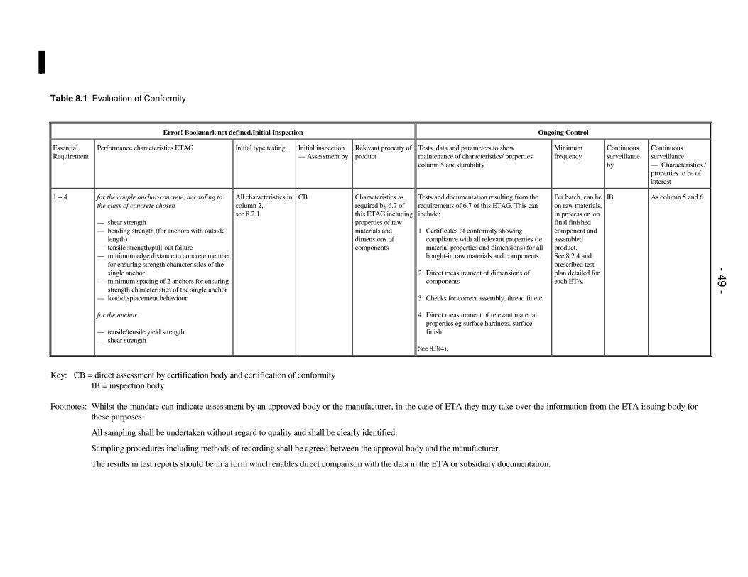
Table 8.1 Evaluation of Conformity
Error! Bookmark not defined.Initial Inspection Ongoing Control
Essential
Requirement
Performance characteristics ETAG Initial type testing
Initial inspection
— Assessment by
Relevant property of
product
Tests, data and parameters to show
maintenance of characteristics/ properties
column 5 and durability
Minimum
frequency
Continuous
surveillance
by
Continuous
surveillance
— Characteristics /
properties to be of
interest
1 + 4 for the couple anchor-concrete, according to
the class of concrete chosen
— shear strength
— bending strength (for anchors with outside
length)
— tensile strength/pull-out failure
— minimum edge distance to concrete member
for ensuring strength characteristics of the
single anchor
— minimum spacing of 2 anchors for ensuring
strength characteristics of the single anchor
— load/displacement behaviour
for the anchor
— tensile/tensile yield strength
— shear strength
All characteristics in
column 2,
see 8.2.1.
CB Characteristics as
required by 6.7 of
this ETAG including
properties of raw
materials and
dimensions of
components
Tests and documentation resulting from the
requirements of 6.7 of this ETAG. This can
include:
1 Certificates of conformity showing
compliance with all relevant properties (ie
material properties and dimensions) for all
bought-in raw materials and components.
2 Direct measurement of dimensions of
components
3 Checks for correct assembly, thread fit etc
4 Direct measurement of relevant material
properties eg surface hardness, surface
finish
See 8.3(4).
Per batch, can be
on raw materials,
in process or on
final finished
component and
assembled
product.
See 8.2.4 and
prescribed test
plan detailed for
each ETA.
IB As column 5 and 6
Key: CB = direct assessment by certification body and certification of conformity
IB = inspection body
Footnotes: Whilst the mandate can indicate assessment by an approved body or the manufacturer, in the case of ETA they may take over the information from the ETA issuing body for
these purposes.
All sampling shall be undertaken without regard to quality and shall be clearly identified.
Sampling procedures including methods of recording shall be agreed between the approval body and the manufacturer.
The results in test reports should be in a form which enables direct comparison with the data in the ETA or subsidiary documentation.
- 49 -
- 53 -
Section four: ETA CONTENTS
9 THE ETA CONTENTS 9.1 Definition of the anchor and its intended use 9.1.1 Definition 9.1.2 Use 9.1.3 Categories a) Use categories - use in cracked and non-cracked concrete - use in non-cracked concrete only b) Durability categories - use in structures subject to dry, internal conditions - use in structures subject to other environmental conditions 9.2 Characteristics of the anchor with regard to mechanical resistance and stability and methods of verification
− characteristic values to be used for the calculation of the ultimate limit state
− characteristic values of displacement for serviceability limit state
9.3 Attestation of conformity and CE-marking 9.4 Assumptions under which the fitness of the anchor for the intended use was favourably assessed 9.4.1 Design methods for anchorages The design procedures are given in Annex C. Method A, B or C shall be applied. 9.4.2 Transport and storage 9.4.3 Installation of anchors (take account of ETAG Part 1 to 6, 7.3) 9.5 Legal basis and general conditions