
ENERGY FOR THE WORLD ENERCOJ EPKII ( Á
184
Wind Farm Name Mairos Project-Number S-0261 9-VOl 41 ENERCOJ ENERGY FOR THE WORLD EPKII ( Á
Transcript of ENERGY FOR THE WORLD ENERCOJ EPKII ( Á
Wind Farm Name Mairos Project-Number S-0261 9-VOl
41
ENERCOJENERGY FOR THE WORLD
EPKII (Á
Revision 005.4 (International) ENERCON PARTNER KONZEPT II (“EPK II”) 1 Contract Agreement(Edition 052016) Contract No. S-02619-V01
Wind Farm Mairos, Portugal
Contract Agreementto
EPK II Contract No. S-02619-VO1
Mairos, Portugal
EHATB — Empreendimentos Hidroelétricos do Alto Tâmega e Barroso, EIM, S.A. , Rua D. NunoAlvares Pereira, 4870-1 60 Ribeira de Pena, Portugal, VAT No. PT502227842
(hereinafter called “Employer”)
and
ENERCON GmbH, of Dreekamp 5, 26605 Aurich, Germany, and for the purposes of this agreementregistered under its branch with local business address at ENERCON GmbH Sucursal em Portugal,with address in Parque Empresarial da Praia Norte — Av — Cabo Verde n° 36 — 4900-568 Viana doCastelo, registeres at the Viana do Castelo Commercial Registry and VAT No PT 980 369 355
(hereinafter calledContractor)
- both parties are hereinafter referred to as ‘Party”, orjointly, the “Parties” -
RECITALS
A. lhe Employer operates, or plans to operate, a wind farm project with one (1) wind energyconverter, type ENERCON E-48 and another one (1) wind energ’ converter, type ENERCON E-70 E4 (hereinafter ‘WEC”) at a site in Mairos, Portugal. On 13 January 2010, the Contractorconcluded a so-called ENERCON Partner Konzept Agreement with Eólica da Serra de Mairos,Lda. On 05th December 2013, the Parties concluded a Novation Agreement with Eólica da Serrade Mairos, Lda, to transfer the ENERCON Partner Konzept to the current Employer. Now theParties desire to conclude a new Contract to continue Service of the above mentioned WECs.
B. The Contractor has offered to carry out services and maintenance activities according to theENERCON PARTNER KONZEPT II on the WECs installed, or to be installed, on the abovementioned site. The ENERCON PARTNER KONZEPT II includes, among others, the provision ofrepair and maintenance services, the procurement of spare parts and major spare parts, and afull-term availability warranty for the WECs, alI as defined in the specifications of the Contract. Inaddition, the Employer may engage the Contractor for the execution of transports of major spareparts and of crane and lifting services.
C. The Employer accepts the Contractor’s offer, and agrees that in consideration of the execution ofthe services by the Contractor, the Employer shall pay the Contractor in accordance with theContract. The Contract becomes effective upon signature by the authorised representatives ofeach Party.
NOW, THEREFORE, in consideration of the recitaIs stated above, which the Parties agree are accurateand complete, the agreements, promises and warranties set forth below and other good and valuableconsideration, receipt of which is hereby acknowledged, the Parties agree as follows:
BASIS OF CONTRACT
The Contract between Employer and Contractor is evidenced by this document and the documentsenumerated below. Should there be any discrepancy or inconsistency between the documents whichconstitute the Contract the following order of priority shall apply:
between
Filename: 1 1-10-2018_S-02619_EPKII_GC_Mairos_l.docx Page 1 of 2

Revision 005.4 (International)(Edition 052016)
ENERCON PARTNER KONZEPT II (“EPK II”) 1 Contract AgreementContract No. S-02619-V01
Wind Farm Mairos, Portugal
1. this document entitled “Contract Agreement”;
2. the Particular Conditions;
3. the General Conditions; and
4. the following Annexes:
Annex 1 — Major Spare Parts List
Annex 2 — Definition of Availability
Annex 3 — Master Maintenance Instructions
Annex 4 — Road and Crane Requirements
Annex 5 — SCADA Description
Annex 6 — Contractor’s insurances
Annex 7 — Bank guarantee
Capitalised terms defined in the attached Particular Conditions and General Conditions are used in thisContract Agreement with their corresponding defined meaning.
* * *
Executed by the Employer acting by itsAuthorised Representative:
Date of Signature
E1TJ4iT BEJM ,
Rt 2. t. l. Pe.’• 3RD- 1/’7 aElRA DE PENANlC 202 227 3.32 Eincii0
hini. 2 ,‘‘ 42% 7>259 490 429
-
(Print) Name ofAuthorised Representative
Executed by the Contractor acting by itsManaging Director:
t1...ÔhZ.Q4Date of Signature
Micha Strauss anaging Director of ENERCON GmbH —
Sucursal e ortugal
L......ZJorge Ffrreir Head of Customer Relations ManagementPortug1 //
Filename: 11-10-201 8_S-0261 9_EPKII_GC_Mairos_I.docx Page 2 oí2

oo


4
oo
*
)
International Revision 005.4 ENERCON PARTNER KONZEPT II (“EPK II”) 1 Particular Conditions(Edition 052016) Contract No. S-02619-V01
Wind Farm Mairos, Portugal
PARTICULAR CONDITIONSEPK II Contract No. S-02619-VO1
Mairos, Portugal
Sub- Data and ModificationsClause
1.1.26 Operation Period
Replace the definition of “Operation PenoU” as follows:
The Operation Period shall be a period starting on the Q6th October 2018 and ending with the5th October 2026.
Even though once a turbine reach the 2Oth annivetsary of the operation lifetime, according tothe type of certificate and market direction shall be performed an assessment of the WECconditions. The aforementioned assessment shall consider the baUs to which has beenexposed the WEC throughout the past 20 years in order to calculate and determine thepossibility of an extended safe operation of the WEC beyond the 2Oth anniversary. Suchassessment is a guarantee safe working conditions for any operator beyond the initial designlifetime of the WEC type model specified in the type of certificate, and it shall be performed(and if necessary repeated or updated at the end of any extension of operation penoU) by anaccredited third party, stating the duration of the operation’s extension. lf this assessmentreveals a positive result, can be prolonged the Operation Period” until 5th October 2026.
1.1.36 Service Items
SCADA-PC
1.1.45 Details of (underlying) Turbine Supply Agreement (“TSA”)
Contract No.: W-02619
Employer: EHATB-Empreendimentos Hidroeléctnicos do Alto Tâmega e Barroso, EIM, S.A.Contractor: ENERCON GmbH or Branch
1.1. Definitions
Add the folbowing new Sub-Cbauses:
1.1 .51. Additional Service Fee” shall be the remuneration defined in Sub-Clause 4.2.3.”1.1 .52. “Service Base Fee” shabl be the remuneration as defined in Sub-Cbause 4.2.2.”
3.1.1 Availability Warranty
lf the Wind Farm consists of bess than 3 (three) WECs, the Contractor warrants an averageavailabibity of max. 95% per Wind Farm and Operational Year according to Annex 1[Definition of Availability].
3.2.2 Compensation (for breach of Availability Warranty)
0.05 EUR per kWh
4.2.2 “Service Base Fee for each Operational Year
The Service Base Fee shabb be
Filename: 1 1-10-2018_5-02619_EPKII_PC_Mairos_I
International Revision 005.4 ENERCON PARTNER KONZEPT II (“EPK II) 1 Particular Conditions(Edition 052016) Contract No. S-02619-V01
Wind Farm Mairos, Portugal
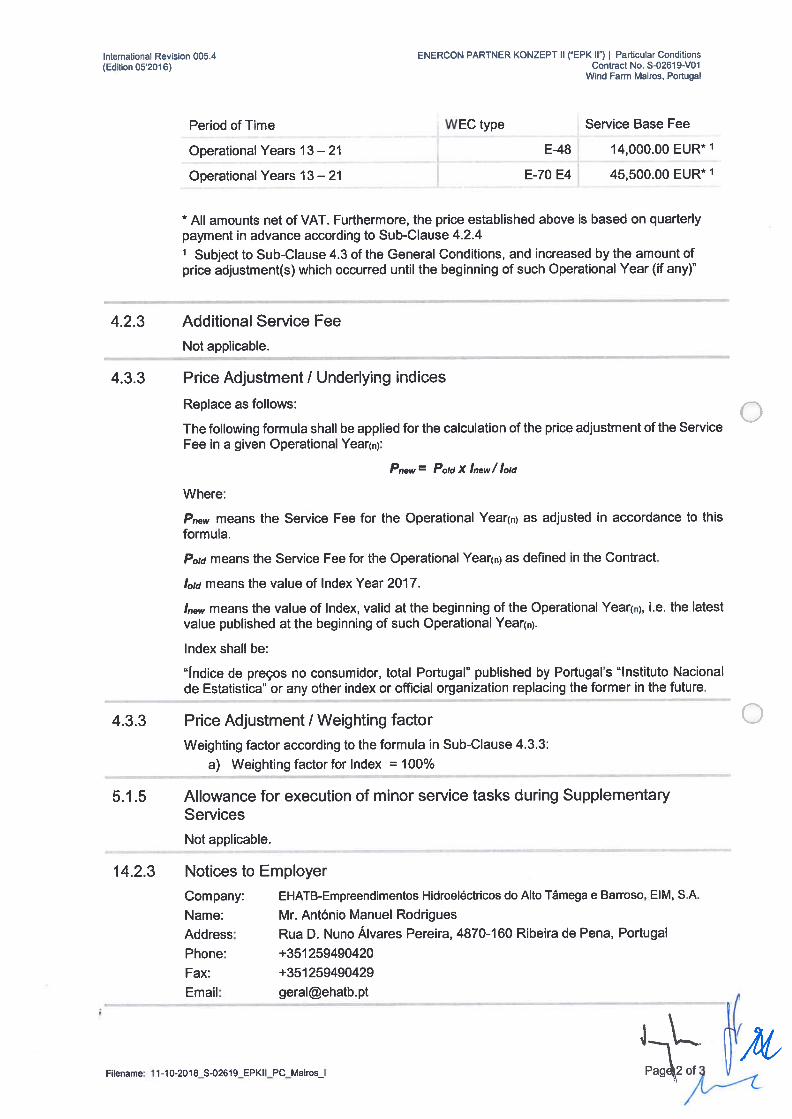
Period of Time WEC type Service Base Fee
Operational Years 13 — 21 E-48 14,000.00 EUR* 1
Operational Yeats 13 — 21 E-70 E4 45,500.00 EUR* 1
* Ali amounts net of VAT. Furthermore, the price established above is based on quarterlypayment in advance according to Sub-Clause 4.2.41 Subject to Sub-Clause 4.3 of the General Conditions, and increased by the amount ofprice adjustment(s) which occurred until the beginning of such Operational Year (if any)”
4.2.3 Additional Service Fee
Not applicable.
4.3.3 Príce Adjustment / Underlying índices
Replace as follows:
The following formula shall be applied for the calculation of the price adjustment of the ServiceFee in a given Operational Year(fl):
Pnew = PoId X Inew / IoId
Where:
Pnew means the Service Fee for the Operationai Year() as adjusted in accordance to thisformula.
PoId means the Service Fee for the Operational Year(fl) as defined in the Contract.
IoId means the value of Index Year 2017.
I,, means the vaiue of Index, valid at the beginning of the Operational Year(fl), i.e. the latestvalue published at the beginning of such Operational Year().
Index shall be:
índice de preços no consumidor, total Portugal” published by Portugal’s “Instituto Nacionalde Estatistica” or any other index or official organization replacing the former in the future.
4.3.3 Price Adjustment / Weighting factor
Weighting factor according to the formula in Sub-Clause 4.3.3:
a) Weighting factor for Index 100%
5.1.5 Allowance for execution of minor service tasks duríng SupplementaryServices
Not applicable.
14.2.3 Notices to Employer
Company: EHATB-Empreendimentos Hidroeléctricos do Alto Tâmega e Barroso, EIM, S.A.
Name: Mr. António Manuel Rodrigues
Address: Rua D. Nuno Álvares Pereira, 4870-1 60 Ribeira de Pena, Portugal
Phone: +351259490420
Fax: +351259490429
Email: [email protected]
HLFilename: 1 1-10-2018_S-02619_EPKII_PC_Mairos_I
International Revision 005.4 ENERCON PARTNER KONZEPT II (“EPK II”) 1 Particular Conditions(Edition 052016) Contract No. S-02619-V01
Wind Farm Mairos, Portugal
14.2.3 Notices to Contractor
Company: ENERCON GmbH
Name: Mr. Hermann Bohlen — Director of Customer Support Center
Address: Dreekamp 5, 26605 Aurich
Phone: +49 4941 976 385
Fax: +49 4941 976319
Email: [email protected]
Filename: 11-1 0-2018_S-0261 9_EPKII_PC_Mairos_l Page

oo

-.
•
/
•
• •••••
£

•1
o*
o

Revision 005.4 (Base Fee 1 International) ENERCON PARTNER KONZEPT II (EPK II”) General Conditions(Edition 052016)
General Conditionsto the EPK II Contract
Content
General Provisions 31.1 Definítions 3
1.2 Interpretation and Measures 6
2 The Services 62.1 Scope of Services 62.2 Scheduled Maintenance 7
2.3 Remote Monitoring 82.4 Software Updates for WEC Control System 82.5 Corrective Maintenance 8
2.6 Procurement of Spare Parts / Supply Management 92.7 DefectsWarranty 92.8 Transport 102.9 Waste Disposal & Cleaning of Site 102.10 Service Information Portal (SIP) 10
2.11 Reporting and Documentation 112.12 Telephone Service and Support 11
2.13 Contractors Personnel 11
2.14 Contractor’s Equipment 12
2.15 Contractor’s Insurances 12
3 AvailabilityWarranty 12
3.1 Availability 12
3.2 Availability Calculation and Compensation 13
4 Service Fee 15
4.1 Service Fee during Interim Period 154.2 Service Fee during Operation Period 15
4.3 Price Adjustment 15
4.4 Additional Cost 17
4.5 Taxes 174.6 lnvoicing and Payment 18
5 Supplementary Services 18
5.1 Contractor to Execute Supplementary Services 18
5.2 Documentation and lnvoicing of Supplementary Services 19
6 The Employer 19
6.1 Operation of the Project 19
6.2 Access to Site and Service ltems 19
6.3 Employer’s Further Obligations 19
Page 1 of 29
Revision 005.4 (Base Fee 1 International) ENERCON PARTNER KONZEPT II (EPK 11”) General Conditions(Edüion 052016)
7 Health & Safety 20
7.1 Contractor’s Obligations on Health & Safety 20
7.2 Employers Obligations on Health & Safety 20
8 Protection ofthe Environment 20
8.1 Contractor’s Obligationsto Protectthe Environment 20
8.2 Employer’s Obligation to Inform 21
9 Subcontracting, Co-operation & Compliance 21
9.1 Subcontracting 21
9.2 Co-operation 21
9.3 Com pliance and Code of Conduct 21
10 EffectivenessandTerm 21
10.1 Term 21
10.2 Optional Termination 22
10.3 Renewal of Contract 22
10.4 Parties’ Claims and Set-Qff 22
10.5 Termínation ofTSA 22
11 Default 22
11.1 Default by Contractor 22
11.2 Default by Employer 23
11.3 Interestforlatepayments 23
12 Force Majeure 23
12.1 Force Majeure Events 23
12.2 Partíes to Inform 24
12.3 Termination in Case of Continuing Force Majeure 24
13 Liability 25
13.1 Limitation of Liability 25
13.2 Parties to Mitigate Losses 25
14 Closing Provisions 25
14.1 Assignment and Transfer of Contract 25
14.2 Notices, Communication and Language 26
14.3 Confidentiality 26
14.4 Independent Contractor 27
14.5 No Waiver 28
14.6 Severability and Surviving Provisions 28
14.7 Entire Agreement 28
15 Resolution of Disputes and Applicable Law 28
15.1 Amicable Settlement 28
15.2 Arbitration 28
15.3 Governing Law 29
4 \__•_.%, Page2of29

International Revision 005.4 ENERCON PARTNER KONZEPT II (EPK II”) 1 General Conditions(Edition 052016)
1.1Definitions
General In the Contract as defined beiow, the following words, terms and expressions
Provisions shall have the meanings stated:
“Additionai Service Fee” shall be the remuneration defined in SubClause 4.2.3.
‘Affiuiate” means any company that directiy or indírectiy, through one or moteintermediaries, controis, is controiied by, ot is under common control byanothet company. A company is under common control with another companyif both companies ate directly or indirectiy controiied by the sarne cornpany.For the putpose of this definition, the term “control” shall mean the power todirect the policies and the management of the respective Party, whetherthrough voting rights or partnership or other ownership interests.
‘Annex” means the annex, or annexes, as specified in the ContractAgreement.
“Availability” means “EPK Availabílity” as defined in Annex 2 [Definition ofAvailabiity].
“Availability Watranty’ means the wattanty of Availability given by theConttactot as a part of the Services on the basis of Clause 3 and Annex 2[Definition ofAvallabilfty].
“Clause” means a Clause ofthese General Conditions (being the Clauses 1 to15) in the form as modified or amended in the Particular Conditions (wherevetapplicable).
uConsumablesn means ali lubricants, parts and items that ate worn out by useor used up and need continuous replenishment in accordance with theMaintenance Manuais.
“Contract” means the Contract Agreement, the Particular Conditions, theseGeneral Conditions and the Annexes specified in the Contract Agreement.
‘Contract Agreement” means the document entitied “Contract Agreernent”which, among others, contains the recitais and the Parties’ signatures.
“Contractor” means the person, persons, firrn, company or other body namedas “Contractor” in the Contract Agreement and inciudes the Contractor’spersonnel, representatives, successors and permitted assigns.
“Contractor’s Equiprnent” has the meaning as defined in Sub-Clause 2.14.1.
“Corrective Maintenance” means ali activities and repair actions to be carriedout by the Contractor putsuant to Sub-Ciause 2.5.
Country” means the country in which the Project is iocated.
Country Office” means the permanent estabiishment or office of theContractor in the Country (if any).
day” means a calendar day.
uEffective Date” means the date on which the Conttact becomes effective inits entirety, being the date on which both Parties have signed the Contract.
“Employer” means the petson, petsons, fitm, company or other body namedas “Employer” in the Contract Agreement and inciudes the Empioyer’spersonnei, representatives, successors and permitted assigns.
‘Financing Party” rneans one or more parties investing into or providíngfinancing to the Empioyer for ot in connection with a part or ali of the Project.
Page 3 of 29 /

ENERCON PARTNER KONZEPT II (EPK II”) 1 General Conditionslnternahonal Revision 005.4(Edition 052016)
“Force Majeure’ means an event or circumstance any other event orcircumstance which
a) is beyond a Party’s control,
b) such Party could not reasonably have provided against before enteringinto the Contract,
c) having arisen, such Party could not reasonably have avoided or overcome, and
d) which is not substantially attributable to the other Party.
“General Conditions” means these conditions of contract.
“Good Engineering and lndustry Practices” means the standards, practices,technical methods and procedures conforming to iaw and the degree of skill,diligence, prudence and foresight which would normally be expected from askilled and experienced service provider in the area of providing repair andmaintenance services on wind turbines, including the InternationalElectrotechnical Commission’s fIEC) recommendations for electrical works.
“Interim Period” means, in respect of each (single) WEC, the period of timestarting on the date on which such WEC has been taken over under the termsof the TSA, and ending on the first day of the Operation Period.
“Maintenance Manuais” means the Contractor’s electrical and mechanicalservice & maintenance documents attached to the Contract as Annex 3[Electrical Maintenance Plan] and Annex 4 [Mechanical Maintenance Plan], asmay be amended from time to time in accordance with new technicaladvances and Good Engineering and Industry Practices.
Major Spare Part’ means any of the items listed in Annex 1 [Major SpareParts List].
“Materiais” means Spare Paris, Major Spare Paris and items of ali kindswhich are supplied by the Contractor under the Contract and which areintended to form part of the Service ltems, inciuding any Consumables.
“Official Entity” means any public government authority or municipality orother authority, including but not limited to the grid operator providing theaccess to the electricity grid, which is required to give its consent orpermission to the instaliation, operation, repair or maintenance of the WECsat the Site or which are a part of such procedure to give such consent orpermission.
“Operation Period” means the period of time which starts on the date on whichthe last WEC of the Project has been taken over under the terms of the ISAand which ends on the last day of the period of time stipulated in theParticular Conditions.
“Operational Year” means a period of twelve consecutive months first startingon the first day of the Operation Period and thereafter on each anniversary ofsuch day.
Particular Conditions” means the document entitled “Particular Conditions”which is attached to the Contract Agreement.
‘Party” means either the Employer or the Contractor, and “Parties” meansboth of them.
“Project” means the sum of ali Service ltems, civil works, electrical works andali other installations, buildings, facilities, plant or devices of any kind (whethersupplied by the Contractor, TSA Contractor or Employer) which temporarily orpermanently form, and are relevant for the successful operation of, the windfarm project as defined in the preamble of the Contract Agreement.
Page 4 of 29

International Revision 005.4 ENERCON PARTNER KONZEPT II (“EPK II”) 1 General Conditions(Edition 052016)
Remote Monitoring” means ali activities to be carried out by the Contractorpursuant to Sub-Ciause 2.3.
“Road and Crane Requirements” means the Contractor’s specifications inrespect of the access roads and Site Roads as set out in Annex 5 [Road andCrane Requirements].
“SCADA System” means the Supervisory Control and Data Acquisitionsystem, a computer system for gathering and anaiysing real time data asdescribed in Annex 6 [SCADA Description].
Scheduied Maintenance” means ali activities to be carried out by theContractor pursuant to Sub-Clause 2.2.
“Service Base Fee” shall be the remuneration as defined in Sub-Clause 4.2.2.
“Service Fee” means the remuneration for the Services as defined in SubClauses 4.1 and 4.2.
“Service Item” means a facility, instailation or object which shall be subject tothe Services, and any Materiais suppiied and instaiied by the Contractor intoany Service Item on the occasion of executing Services or SupplementaryServices. Included as Service items are each WEC, the SCADA System, anyvoltage or wind farm controi system and aviation iights (if deiivered by theTSA Contractor under the TSA), and ali further items (if any) eniisted in theParticular Conditions.
“Services” means the services, suppiies, works, activities and warrantiesdefined in Sub-Ciause 2.1.1.
“SIP’ means the “ENERCON Service Info Portai” as defined in SubCiause[ 2.10.
“Site” means the real property where the Project is situated, and any otherpiaces specified in the Contract as forming part of the Site.
“Site Roads” means ali roads, paths, crane hardstands, lay-by areas andother working areas on the Site to be used by the Contractor for theperformance of the Services and Suppiementary Services.
Spare Parts” means any tem (however, excluding any Major Spare Part)intended to repiace a corresponding item in order to restore the originalrequired function of the item.
“Sub-Ciause” means a sub-Clause of this Contract, being either a subClause of these General Conditions in the form as modiffed or amended in theParticular Conditions (wherever appiicable), or any new subClause introduced in the Particular Conditions.
“Suppiementary Services’ means such services, suppiies, works and activitiesin addition to the Services which the Contractor executes according toCIause5.
“TSA” or Turbine Supply Agreement” means the agreement on theinstaliation and commissioning of the WECs and other Service Items asidentified in the Particular Conditions.
TSA Contractor” means the entity being a party to, and defined asContractor, in the TSA, and which supplied the Service Items to the Empioyer.
TSA Employer” means the person or entity being a party to, and defined asEmpioyer, in the TSA.
Page 5 of 29
International Revision 005.4 ENERCON PARTNER KONZEPT II (“EPK 1l) General Conditions(Edition 052016)
“WEC” means the Wind Energy Converter, or Wind Energy Converters,supplied under the TSA. A WEC shall consist of ali mechanicai and interioreiectricai equipment (which shaii also inciude the WEC transformer andswitchgear up to and inciuding the HV bus bar inside the switchgear, if theseitems are suppIied by the TSA Contractor under the TSA). For the purpose ofthis Contract, the WEC foundation shaii not form part of the WEC.
‘WECs” means two or more Wind Energy Converters, as the case may be.
Wind Farm” means, for the purpose of caicuiating and appiying theAvaiiabiiity Warranty, the sum of ali WEC.
1 .2 Interpretation and Measures
1.2.1 Words importing persons or parties shall include firms andorganisations. Words importing singular or one gender shaii inciude plural orthe other gender where the context requires. The headings in the documentsforming the Contract are for convenience oniy and shaii not in any way affectthe meaning or interpretation of the Contract.
1.2.2 Any weights and measures will be based on the International Systemof Units (SI).
2The Services 2.1 Scope of Services
2.1.1 Under the Contract the Contractor shaii provide to the Empioyer thefoiiowing services:
a) Scheduied Maintenance as specified in Sub-Ciause 2.2,
b) Remote Monitoring ofthe WECs as specified in Sub-Ciause 2.3,
c) updates for the WEC control software as specified in Sub-Ciause 2.4,
d) Corrective Maintenance as specified in Sub-Ciause 2.5,
e) procurement of Consumabies, Spare Parts and Major Spare Parts asspecified in Sub-Ciause 2.6,
f) transport of Consumabies and Spare Parts to the Site as specified inSub-Ciause 2.8,
g) instaliation and repiacement of Consumabies, Spare Parts and MajorSpare Parts on Site,
h) disposai of replaced Consumabies, Spare Parts and Major Spare Partsand waste as specified in Sub-Ciause 2.9,
i) access to the Service Info Portai” as specified in Sub-Ciause 2.10,
j) reporting and documentation as specified in Sub-Ciause 2.11,
k) teiephone hotiine and support according to SubCiause 2.12,
1) labour, inciuding travei and accommodation for personnei according toSub-Ciause 2.13,
m) toois, facilities and equipment according to Sub-Ciause 2.14,
n) insurance according to Sub-Ciause 2.15, and
‘YA
o) compliance with the Avaiiabiiity Warranty as specified in Ciause 3,
hereinafter aitogether referred to as the “Services”.
2.1.2 The Services under this Contract do not inciude
Page6of29
ENERCON PARTNER KONZEPT II (EPK II”) General ConditionsInternational Revision 005.4(Edition 052016)
a) the transport of Major Spare Parts and any crane operations necessaryfor the transport, repair, instailation and!or disposai of Major SpareParts, and
b) the provision of cranes, iifting piafforms and hydraulic hoists for on-Siteactivities.
Upon request of the Empioyer, such services and supplies shaii be offeredand executed by the Contractor as Suppiementary Services according toClause 5.
2.1.3 lhe Contractor shaii carry out the Services to keep the Service Itemsin good, safe and proper condition, in accordance with the Contract,manufacturers’ operation and maintenance instructions, appiicabie iaws andGood Engineering and Industry Practices.
2.1.4 For the purpose of improving the Services under this Contract, theContractor shaii be entitied to update Service Items, software, documentation(inciuding any maintenance instructions) and the desígn of Materiais andService items. Any update undertaken by the Contractor under this SubCiause shaii:
a) be in accordance with Good Engineering and industry Practices, thetype certificate and the appiicabie iaws, permits and technicai regulations,
b) have no detrimental effect on the durability, functionaiity, safety or performance of Materiais or Service Items,
c) be carried out at no additionai cost to the Empioyer, and
d) be duiy documented by the Contractor and displayed in SIP.
2.1.5 The Contractor shali obtain, when necessary and in a timely manner:
a) any licence, permit and/or approvai required by appiicable iaws for theContractor to do business and to perform the Services and Suppiementary Services in the Country,
b) the officiaiiy required transport licences for any transport undertaken byor on behaif of the Contractor, and
c) any other licences, permits or approvals defined in the Particular Conditions.
2.2 Scheduled Maintenance
2.2.1 The Contractor shall perform Scheduied Maintenance on the ServiceItems with the objective to detect, verify and prevent any damage, deficienciesor malfunctions, and, if necessary, to plan repair actions.
2.2.2 Scheduled Maintenance shall, in particular, comprise the foiiowingtasks:
a) examination of the condition and proper functioning of ali componentsof the WEC,
b) verification of functioning and tripping of internai protection devices,
c) controiling of toierance vaiues defined in the manufacturers’ specifications, and verification of anomalies (if any), and
d) substitution of ali Consumables in conformityspecifications.
the manufacturer’s
Page 7 of 29
International Revision 005.4 ENERCON PARTNER KONZEPT II (“EPK II”) 1 General Conditions(Edition 052016)
2.2.3 The Contractor shali prepare and provide the Empioyer via SIP withan annuai maintenance plan showing the estimated date(s) of ScheduledMaintenance activities.
2.2.4 The Contractor shall repair any deficiencies and malfunctionsidentified during Scheduled Maintenance in accordance with Sub-Clause 2.5[Corrective Maintenance] or Clause 5 [Supplementanj Se,vicesJ (whicheverapplies).
2.3 Remote Monitoring
2.3.1 The Contractor shall carry out the Remote Monitoring services on aliWECs as defined in this Sub-Clause 2.3 in accordance with GoodEngineering and lndustry Practices.
2.3.2 The Contractor shall receive ali status messages generated by eachWEC, 24 hours per day / 7 Uays per week. For such purposes, the Contractorshall use the SCADA System as described in Annex 5 [SCADA Description].
2.3.3 The Contractor shall analyse ali monitored errors and shall determinewhether an affected WEC can be returned into operation by remote reset viathe SCADA System. Where remote resetting is not possible, the Contractorshall arrange for an on-Site intervention.
2.3.4 The Contractor shall be authorised to stop and reset the WECs (bothremotely and at the Site) for the purpose of performing Services orSupplementary Services.
2.3.5 Upon the Employer’s request, the Contractor shall furthermoreprovide automatic fault status messages to one e-mau address as specifiedby the Employer.
2.3.6 After commencement of the first Services activities under theContract, the Employer may regularly download and update, via the SIPSystem, the latest status iist for warning and fault messages as described inAnnex 5 ESCADA Description].
2.4 Software Updates for WEC Control System
2.4.1 The Contractor shall instali updates of the WEC internal controlsoftware and the SCADA software in each WEC whenever an update for suchsoftware version and WEC type is available.
2.4.2 Updates wiIl be either arranged by the Contractor via the SCADASystem or via manual implementation during the next Scheduled Maintenancemission on Site.
2.5 Corrective Maintenance
2.5.1 Corrective Maintenance shall comprise ali activities executed by theContractor on the Service ltems to remedy a failure, deterioration, deficiencyor malfunction which is attributable to:
a) design defects, manufacturing defects, Uefects in material, instaliationdefects or, in general, such defects and malfunctions which are attributable to the Contractor,
b) wear and tear occurring to Service ltems or parts thereof, provided thatL such Service Item or part has at ali times been operated within its de
jV sign parameters and in accordance with the manufacturers operatinginstructions,
Page 8 of 29
International Revision 005.4 ENERCON PARTNER KONZEPT II (“EPK II”) 1 General Conditions(Edition 052016)
c) improper operation of a Service Item which is attributabie to the Contractor (e.g. incotrect operating instructions), or
d) faiiure by the Contractor to comply with any other obligation under theContract.
2.5.2 The Contractor shaii perform Corrective Maintenance to keep theService ltems in such condition that they can be operated safely and reiiabiyduring the term of the Contract.
2.5.3 Corrective Maintenance shaii include:
a) fauit iocaiisation and diagnosis on the Service Items,
b) procurement, repairs and repiacement of Spare Parts and Major SpareParts, and
c) supervision of on-Site activities and project management.
2.5.4 Corrective Maintenance on the Service Items shall be included in theService Fee (with the exception of such transport and crane services definedin Sub-Clause 2.1 .2).
2.5.5 Titie to any part which is repiaced by the Contractor whiie executingCorrective Maintenance shall pass from the Employer to the Contractor at nofurther cost as soon as such part has been demounted and repiaced by acorresponding Spare Part or Major Spare Part.
2.6 Procurement of Spare Paris / Supply Management
2.6.1 The Contractor shaii procure ali Consumables and Spare Partsnecessary for the Contractor to perform the Services on the Service items.
2.6.2 As integral part of the Services, the Contractor operates a worldwideSpare Parts management system which includes the maintaining of apermanent stock of Spare Parts to cover the majority of possibie damage ofthe WECs.
2.6.3 in order to safeguard a quick suppiy of Spare Parts and to complywith the Contractor’s environment protection objectives, the Contractorexpressiy reserves the right to use second hand Spare Parts which have beenreconditioned refurbished and tested and meet the Contractor’s requirementson new Spare Parts.
2.6.4 The Contractor represents and warrants that at the time of anytransfer of Spare Parts from the Contractor to the Employer, titie of said SpareParts shaii be free of any encumbrances, liens or other third party rights.
2.7 Defects Warranty
2.7.1 Without iimiting any concurrent obligation of the Contractor underSub-Clause 2.5.1, the Contractor provides the following defects warranty forany Spare Part or Major Spare Part suppiied and/or instailed by theContractor.
2.7.2 The warranty term (Defects Notification Period”) for any workmanshipexecuted and for any new or refurbished Spare Part or Major Spare Partsupplied under this Contract shaii be a period of twelve months commencing
a) in respect of any workmanship executed by the Contractor, on the datewhen the Contractor has completed such works, and
Page9of29
International Revision 005.4 ENERCON PARTNER KONZEPT II (EPK II”) 1 General Conditions(Edition 052016)
b) in respect of any new or refurbished Spare Part or Major Spare Part, onthe date when the Contractor has supplied such item.
2.7.3 During the Defects Notification Period for any workmanship and/orSpare Part / Major Spare Part the Contractor warrants that such workmanshipand Spare Part / Major Spare Part shaii be free from any defect which isaffributabie to
a) design defects, manufacturing defects, defects in material, installationdefects, defects in workmanship or any other defect andíor malfunctionwhich is attributabie to the Contractor,
b) improper operation of a Service Item which is attributable to the Contractor (e.g. incorrect operating instructions), or
c) failure by the Contractor to comply with any other obligation under theContract.
2.7.4 Any defect as stipulated above shall be rectified by the Contractorprovided that the Employer notified the Contractor about such defect withinthe relevant Defects Notification Period. In such case, the Contractor shallexecute the rectification of the defect at the Contractor’s cost (however, withthe exclusion of cost for the hiring or provision of cranes, lifting plafforms orhydraulic hoists and with the exclusion of air fares).
2.8 Transport
2.8.1 The Contractor shall arrange and execute the transport (including anytransport by ship or truck) to and from the Site of ali Spare Parts, Contractor’sEquipment (other than cranes, iifting piafforms or hydraulic hoists) andpersonnel required to carry out Scheduied Maintenance and/or CorrectiveMaintenance.
2.8.2 For visits to the Site during Scheduled or Corrective Maintenanceactivíties, the Contractor shaii use suitable service vehicles (Mercedes BenzSprinter® or comparabie two-wheel-drive transporters) which allow access tothe Site according to the Road and Crane Requirements.
2.9 Waste Disposal & Cleaning of Site
2.9.1 After executing Services on the Site, the Contractor shali remove fromthe Site any parts, wreckage, rubbish, residual material and any other items orparts which have been dismantled or otherwise removed from the Serviceltems on the occasion of performing Services.
2.9.2 When recycling and/or disposing of any item, the Contractor shallensure that the disposal is undertaken in com pliance with applicable laws andregulations.
2.10 Service Information Portal (SIP)
2.10.1 During the term of the Contract, the Contractor shall make availablethe Service Information Portal (SIP”). SIP is a password protected databasein which current and historical data in respect of the WECs is stored. lheinformation is available for remote access via a standard internet connection(https://sip.enercon.de). Access to SIP shall be subject to the Employer’sapplication for a personal authentication code.
a) the annuai maintenance plan [Sub-Clause 2.2.3],‘
‘L—
2.10.2 Information accessible in SIP includes the foliowing:
PagelOof29

International Revision 005.4 ENERCON PARTNER KONZEPT II (EPK 11”) General Conditions(Edition 052016)
b) the status of each WEC (as transmitted by the SCADA system),
c) the progress of any Corrective Maintenance activity,
d) the maintenance and service reports [Sub-Clause 2.11.1], and
e) updates on documentation and the WEC specific status list.
2.11 Reporting and Documentation
2.11.1 In order to keep the Empioyer informed about ali relevant ScheduledMaintenance and Corrective Maintenance activities, the Contractor shallprepare a complete report of any such intervention.
2.11.2 Within one week of the com pietion of each activity, the relevant reportshaii be made availabie in S1P. if S1P shouid be temporariiy unavailabie, theContractor shaii provide the Employer, upon the iatter’s request, with a copyof any reievant report by electronic mau.
2.12 Telephone SeMce and Support
2.12.1 lhe Contractor shaii provide, and maintain, a teiephone service withmessaging capabilities for emergency cases. The teiephone service shaii beavailabie 24 hours per day / 7 days per week.
2.12.2 if a Service item has been damaged due to an event for which theEmpioyer has taken out an insurance cover, the Contractor shaii duiy cooperate with the Empioyer and the Empioyer’s insurance agents to ciarify thematter. Upon request of the Empioyer, the Contractor shaii furthermoreparticipate in on-Site inspections carried out by the insurance company andprovide further technicai support and guidance.
2.12.3 During any inspection of the SeMce items required under theappiicabie iaws and reguiations or required for the renewai of any licence orpermit reiating to the Project, the Contractor shaii, upon request and at thecost of the Empioyer, provide assistance and information to the Employerand/or any Officiai Entity. if so instructed by the Empioyer, any repair actionidentified during any inspection under Sub-Ciause 2.12.3 shaii be carried outby the Contractor either under Sub-Clause 2.5 [Corrective Maintenance] orunder Clause 5 [Supplementary Seivices] (whichever appiies).
2.13 Contractor’s Personnel
2.13.1 The Contractor shaii provide ali personnei necessary to carry out theServices. Each person períorming Services under the Contract shaii beappropriately quaiified, skilied and experienced in the same type of servicesand tasks to be carried out under the Contract.
2.13.2 The Contractor shaii pay ali fees, insurance premiums, social securitycontributions and other expenses reiated to the empioyment of its personnei.
2.13.3 The Contractor shaii furthermore pay the cost for travei (inciuding feesfor work permits and visas), iodging and accommodation of any of itspersonnei carrying out Services under the Contract.
2.13.4 As part of the Services, the Contractor shaii maintain adequate backoffice staff and faciiities necessary to execute the Services.
Pagellof29
International Revision 005.4 ENERCON PARTNER KONZEPT II (“EPK II”) 1 General Conditions(Edition 052016)
2.14 Contractor’s Equipment
2.14.1 The Contractor shali provide ali necessary toois, apparatus,rnachinery, vehicies, safety equipment and other items required for theexecution of the Services which shaii also include any tem porary facilities andtemporary works required on Site during the execution of major instailationworks (Contractor’s Equiprnent”). With the exception of the services definedin Sub-Ciause 2.1.2, the provision and use of Contractor’s Equiprnent shaii beinciuded in the Service Fee.
2.14.2 The Contractor shail be responsibie for the sufficiency and for thesafety of the Contractor’s Equipment.
2.15 Contractor’s Insurances
2.15.1 The Contractor shaii, priorto performing any of the Services undertheContract and at its own expense, effect and thereafter maintain theinsurances set out in Annex 7 [Contractor’s insurancesJ. Upon the Employer’swritten request, the Contractor shali provide further detalis of the insurances.
2.15.2 Ali payrnents received from insurets reiating to ioss or darnage to theService Items shail be exciusiveiy used for the repair of the ioss or damage tothe Service ltems or as compensation for ioss or darnage that is not to berepaired.
2.15.3 if the Contractor falis to maintain any of its insurances, the Empioyermay, without prejudice to any other right or remedy, effect insurance for thecover reievant to such default and pay the premiums due and recover thesarne as a deduction from any other rnonies due to the Contractor.
3Availabilíty 3.1 Availability
Warranty 3.1.1 The Contractor shaii pian and conduct the Services in order to ensurethat during the Operation Period the Wind Farm rneets the Avaiiabiiity figuredefined in Sub-Ciause 3.1.1 ofthe Particular Conditions.
3.1.2 if one or more of the WECs are unavaiiabie, or continue to beunavaiiabie, due to:
a) an event of Force Majeure,
b) unavaiiabiiity or iirnited feed-in capacity of the grid,
c) the outage of voitage controi systerns or wind farm controi systerns,wind farrn cabiing or substations,
d) the Contractor diiigenuy carrying out Suppiementary Services in accordance with the Contract,
e) any stoppage, shutdown or outage caused by acts or ornissions of anyparty for which the Contractor is not responsibie (inciuding but not umited to inspections ordered by any Officiai Entity or any rnodification to aWEC or a Service Item which has not been approved in writing by theContractor),
/vf) any outage caused by any suspension or stoppage of the Services or
Suppiernentary Services ordered by or attributabie to the Ernpioyerprovided that the Contractor is not responsibie for the suspension orstoppage,
Pagel2of29

International Revision 005.4 ENERCON PARTNER KONZEPT II (“EPK ll) 1 General Conditions(Edition 052016)
g) any delay in performing the Services to the extent that such delay iscaused by adverse weather which, according to the applicable healthand safety regulations, does not allow the Contractor to commence orproceed with the execution of Services or Supplementary Services, or
h) any delay in performing the Services to the extent that such delay iscaused by unsuitable road conditions which would not allow the Contractor to access the Site and the Service Items,
then, for the purpose of calculating the Availability of the Wind Farm as wellas of the WEC(s) pursuant to the procedure established in Annex 2 [Definitionof Avallabiity], the affected WEC(s) shall be deemed to have been fullyavailable for the period during which such WEC(s) was/were unavailable.
3.1.3 In case of stoppage of a WEC caused by the failure of a Major SparePart or the shutdown of a WEC for the purpose of carrying out replacement orrepair on a Major Spare Part requiring cranes, lifting plafforms or hydraulichoists, the following specific provisions shall apply:
a) The Contractor, acting reasonably, shall examine and verify the necessity of any repair or replacement action and shall give notice thereof tothe Employer. The Employer may refuse the execution of the repair orreplacement action; however, should the Major Spare Part or anotherpart of the WEC fail as a consequence of the unperformed repair or replacement action, the WEC shall be deemed available during anydowntimes caused by such failure.
b) For the purpose of calculating the Availability during this period of time,the following shall apply:lhe WEC shall be deemed “available” except for:
i. the period of time starting on the date of stoppage of theWEC and ending on the date when the Major Spare Part hasbeen procured and prepared for transport at the Contractor’sfacility, and
ii. the period of time which the Contractor needs for mountingthe Major Spare Part to the WEC (provided that a suitablecrane, lifting plafform or hydraulic hoist is available at theWEC and can be operated under the given weather conditions).
3.2 Availability Calculation and Compensation
3.2.1 Within 30 days of the end of each Operational Year, the Contractorshall submit to the Employer calculations of the Availability of the Wind Farmaccording to the formulas established in Annex 2 [Definition of Avallabiity].The calculations shall also contam the availability figure of each single WEC.
3.2.2 lf the Availability of the Wind Farm in the underlying Operational Yearneither met nor exceeded the warranted Availability, compensation shall bedue to the Employer for the loss of energy resulting from such shortfall(hereinafter “Compensation”). Unless otherwise defined in the ParticularConditions, Compensation shall be paid at the average total revenues perMWh received from the energy off-taker (including green certificates and othersubventions) but shall in no case exceed the amount of forty (40) EUR perMWh.
3.2.3 The Availability Warranty under this Clause 3 is given by theContractor under the strict condition that the payment of Compensation asdefined in the Contract shall be the only compensation, including any
Pagel3of2g
International Revision 005.4 ENERCON PARTNER KONZEPT II (EPK II”) 1 General Conditions(Edition 052016)
indemnífication or damages whatsoever, payable by the Contractor to theEmployer in case of a breach by the Contractor of the Availability Warranty.
3.2.4 The Contractor shall credit the Employer the amount of Compensationat the Iatest 90 days after the end of the relevant Operational Year.
Pagel4of29
International Revision 005.4 ENERCON PARTNER KONZEPT II (“EPK Ir) General Conditions(Edition 052016)
4 4.1 Service Fee during Interim Period
Servíce Fee 4.1.1 For the Services as defined in Sub-Ciause2.1.la)-2.1.ln) and asexecuted during the Interim Period, the Contractor shaii receive the ServiceFee estabiished tn Sub-Ciause 4.1.1 of the Particular Conditions.
4.1.2 lhe Contractor shali be entitled to invoice such Service Fee on orafter the last day of the Interim Period. Each invoice shall contam the relevantdetails for the calculation of the Service Fee.
4.2 Service Fee during Operation Period
4.2.1 For the Services to be executed during each Operational Year onevery WEC according to Sub-Clause 2.1.la)-2.1.lo), the Contractor shallreceive the Service Fee for each WEC as set out in this Sub-Clause 4.2.
4.2.2 For each Operational Year, the Service Base Fee shall be as definedin Sub-Clause 4.2.2 of the Particular Conditions.
4.2.3 Further to the Service Base Fee in accordance with Sub-Clause 4.2.2the Contractor shall receive the Additional Service Fee calculated inaccordance with the energy output of each WEC:
The Additional Service Fee(fl) shall be calcuiated according to the followingformula:
Additionat Service Fee = Annuat Energy Yíe1d x Base Rate
Where:
AddtionatServiceFee means the Additional Service Fee for anOperational Year(fl) in Euro per WEC
Annuat Energy Yíetd means the amount of electricity (in MWh)generated by a single WEC as recorded by the SCADA System of theWEC during the Year(fl).
Base Rate means the amount (in Euro per MWh, excluding VAT) asdefined in Sub-Clause 4.2.3 of the Particular Conditions.
4.2.4 Payment of the Service Base Fee shali be made each OperationalYear in advance. For such purpose Contractor shall invoice the Servíce BaseFee at the beginning of the Operational Year.
4.2.5 Payment of the Additional Service Fee shail be made after eachOperational year. For such purpose the Contractor shall invoice the AdditionalService Fee after each Operational Year. Each invoice shail contam therelevant detaiis for the calculation of the Additional Service Fee.
4.3 Price Adjustment
4.3.1 In order to account for increases in the prices of raw materiais, prefabricated and primary products which are necessary to manufactureMateriais, as weIl as increases in labour cost from the Effective Date until theend of the term of the Contract, the Contractor shaii be entitled to areasonabie adjustment of both the Service Base Fee and the Base Rate on ayearly basis, in accordance with and subject to the conditions established inthis Sub-Clause.
Pagel5of2g

International Revision 005.4 ENERCON PARTNER KONZEPT II (“EPK ll) 1 General Conditions(Edition 052016)
4.3.2 The Contractor may adjust the Service Base Fee and the Base Rateat the beginning of the Instailation Period (if any) and, subsequently, witheffect from the beginning of every Operational Year. For the avoidance ofdoubt, any period of delay which is attributable to the Contractor, to theSupplier or to any of their Affihiates (e.g. a Iate completion of the Service Itemsunder the TSA) shall not be considered in the calculation of príce adjustments.
4.3.3 The following formula shall be applied for the calculation of the priceadjustment of the Service Base Fee and the Base Rate per kWh in a givenOperational Year(fl):
new = a otd‘a flew
+ b otd‘b new
‘aotd ‘botd
Where:
‘new means either the Service Base Fee or the Base Rate for theOperational Year(fl) as adjusted in accordance with this formula
‘otd means either the Service Base Fee or the Base Rate for theOperational Year(n) as defined in the Contract
aWeighting percentage of Indexa as defined in Sub-Clause 4.3.3 of theParticular Conditions
‘aotd means the value of Indexa as defined in Sub-Clause 4.3.3 ofthe Particular Conditions, valid at the Effective Date
‘anew means the value of Index3, valid at the beginning of theOperational Year(fl), i.e. the latest value published at the beginning ofsuch Operational Year(fl).
b Weíghting percentage of lndexb
1bold means the value of lndexb as defined in Sub-Clause 4.3.3 ofthe Particular Conditions, valid at the Effective Date
‘bnew means the value of the lndexb, valid at the beginning of theOperational Year(fl), e. the latest value published at the beginning ofsuch Operational Year(fl).
4.3.4 lf any of the índices (Ia!ib) established in Sub-Clause 4.3.3 of theParticular Conditions cease to exist or are not updated any longer by thecom petent authority, the Parties shall agree on a suitable substitute index.
4.3.5 Any price adjustment shall be communicated to the Employer inwriting. Together with the communication, the Contractor shall provide thecalculation of the price adjustment and alI relevant information reasonablyrequested by the Employer.
4.3.6 For the avoidance of doubt, the price adjustment defined above shallalso be applicable if the Parties have agreed on a successive or stepwiseincrease of the Service Base Fee and/or the Base Rate during the term of theContract.
4.3.7 If, despite the Contractor’s reasonable efforts, the Contractor’s costfor the performance of the Services increase due to
a) any change in the laws or the technical standards applicable to theexecution of the Services, or any change in the official interpretation ofsuch laws or technical standards,
b) changes in the quantity, type or design of the Service Items after theEffective Date (other than design changes attributable to the Contractorunder Sub-Clause 2.1.4 or attributable to the Supplier under the TSA),
Pagel6of2O

International Revision 005.4 ENERCON PARTNER KONZEPT II (“EPK It) General Conditions(EdWon 052016)
c) modifications to the Service ltems by or on behaif of the Ernployer,which occur after the Effective Date, the Contractor shall inform theEmployer of such event and the additional cost. The Parties shall thenagree whether the Contractor shall add such cost to the reievant Ser-vice Fee or reasonably reduce the scope of Services in order to keepthe Service Fee at the sarne levei.
4.3.6 The Parties acknowiedge and agree that the cornrnercial conditionsand warranties of the Contract are based on the number of Service ltems asincluded in the Contract on the Effective Date. lf the Employer wishes toreduce the nurnber of Service Items under the Conttact after the EffectiveDate (e.g. by selling one or rnore of the WECs), the Ernployer shall give noticein writing to the Contractor. in such case, the Parties shall re-negotiate ingood faith the conditions of this Contract for the remaining nurnber of Servicelterns; until such agreernent has been achieved, the Contract shaii continue toappiy to the Service ltems initially inciuded.
4.4 Additional Cost
4.4.1 lf the Contractor incurs additionai cost due to
a) obstructed access to the Site [Sub-Ciause 6.2],
b) unavailabiiity or reduced usabiiity of the grid [Sub-Clause 6.3d)], or
c) Ernpioyer’s defauit [Sub-Clause 11.2],
such cost shaii be borne by the Employer.
4.4.2 When ciairning additional cost under the Contract, the Contractor shaiisubrnit to the Ernployer a written staternent with supporting particuiars inrespect of the value and substantiation of such clairn. On receipt by theEmpioyer of the Contractor’s application, the Ernployer shaii duiy consider theclairn and respond to the Contractor’s notification without undue deiay.
4.4.3 If the Empioyer approves the Contractor’s ciaim, the Employer shaiiarrange for the payrnent of the ciaim within the time set out in SubClause 4.6.2. If the Ernpioyer disputes a part of the Contractor’s clairn or theamount of the ciairn, Sub-Ciause 4.6.3 shaii apply, accordingiy.
4.5 Taxes
4.5.1 Unless expressly stated otherwise, the Service Fee or any otherrernuneration or any cost due under the Contract shall be subject to theaddition of statutory VAT (Value Added Tax).
4.5.2 The Empioyer shall bear ali duties, taxes, levies, fees, or othercharges such as, but without lirnitation to, irnport and starnp duties, importpurchases tax, and others which rnay be ievied in connection with the deiiveryand irnport of Materiais, WEC and Contractor’s Equiprnent and the executionof Services or Suppiernentary Services. The Contractor shaii usecomrnerciaily reasonabie endeavours to mitigate those duties, taxes orcharges. lf the Contractor is required by iaw to pay such duties, taxes, ievies,fees, or other charges, the Ernpioyer shail reimburse the arnount thereof inaccordance with Sub-Ciause 4.6.2.
4.5.3 For the avoidance of doubt, the Contractor shaii bear ali taxes,charges and ievies in respect of the Contractor’s income, profit or benefitdrawn from the execution of the Contract, such as but not limited to, incornetax and/or corporation taxes.
Pagel7of29

International Revision 005.4 ENERCON PARTNER KONZEPT II (EPK II”) General Conditions(Edition 052016)
4.6 Invoicing and Payment
4.6.1 Invoices may be issued by the Contractor, and shall accordingly bepaid by the Employer, as per (single) WEC.
4.6.2 Any of the Contractor’s invoices subrnitted under the Contract shaI besettled by the Employer within 30 days of the date of each invoice.
4.6.3 If any amount payable under the Contract is disputed by the Partybeing obliged to pay, then such Party shall pay to the other Party anyundisputed amounts in a timely manner. The disputed amount which isultimately deterrnined to be payable to the Party asking for payment, shall bepaid with interest at the rate specified in the Contract. If the Party entitled toreceive the payment has decided to continue performance of its obligationsunder the Contract during the payment dispute period, such action shall notdeemed to be a waiver of its rights to the requested payment(s). If the Partiescannot agree on the grounds for or the amount of a claim for payment, eachParty shall be entitled to refer this matter to dispute resolution as foreseen inthe Contract.
4.6.4 Any payrnent to the Contractor under the Contract shall be effected tothe bank account stated in the respective invoice. Any charge, fee or royaltyarising from or incurred in connection with the payment procedure shall beborne by the Employer with the exception of any fees charged by theContractor’s own bank.
4.6.5 Any payment under the Contract shall be effected in Euro (€).
5Supplementary 5.1 Contractor to Execute Supplementary Services
Services 5.1.1 The Contractor shall, upon request and at the cost of the Employer,carry out further works, supplies, services and activities which are not coveredunder the Services defined in Sub-Clause 2.1.1.
5.1.2 If during the performance of the Services the Contractor becornesaware of any deficiency or malfunction which would require the execution ofSupplementary Services, the Contractor shall notify the Employer thereof byemail or facsimile.
5.1.3 The Employer shall inform the Contractor if the Employer wishes thecontractor to perform Supplementary Services. The sarne shall apply if theEm ployer wished the Contractor to arrange for transportation of Major SpareParts and or crane/lifting services as defined in Sub-Clause 2.1.2.
5.1.4 Upon having received a request by the Ernployer, the contractor shallsubmit to the Employer a quotation which shall include a plan of actionoutlining the estimated scope of works and services and an estirnate of theexpected cost. In case of substantial services the Contractor shall be entitledto request a reasonable advance payment.
5.1.5 In order to avoid adrninistrative efforts and to the extent agreed by theParties, the contractor shall be entitled to carry out Supplernentary Serviceswithout prior notice or quotation up to the cost lirnit stipulated in the Particularconditions.
_______
Pagel8of2g
ENERCON PARTNER KONZEPT II (EPK ll) 1 General ConditionsInternational Revision 005.4(Edition 052016)
52 Documentation and Invoicing of Supplementary SeMces
5.2.1 The Contractor shali dufy document any Supplementary Services andprovide a final report to the Employer within the deadlines established in SubClause 2.11 [Reporting and Documentation].
5.2.2 Whenever claiming payment for the execution of SupplementaryServices, the Contractor shall submit a separate invoice to the Employer.
6The Employer 6.1 Operation ofthe Project
Without limiting the Contractor’s obligation to perform the Services and anySupplementary Services in accordance with the Contract, the Employer shailbe solely responsible for the operation of the Project according to theapplicable statutory and legal requirements.
6.2 Access to Site and Service Items
6.2.1 From the beginning of the Interim Period until the end of theOperation Period, the Employer shall safeguard at its own cost, risk andexpense that:
a) ali Site Roads have an adequate carrying-capacity and breadth andcomply with the Road and Crane Requirements, and
b) that the Employer has ali requisite legal rights necessary to entitie theContractor to carry out the Services and Supplementary Services onthe Site,
ali in order to ensure that the Contractor has free, safe and unimpeded accessto the Site and to every Service item for the purpose of carrying out Servicesand Supplementary Services.
6.2.2 Subject to the Contractor complying with the applicable laws andlabour regulations, the Contractor and any of its subcontractors shall beentitled to carry out Services and Supplementary Services at the Site outsidenormal working hours, on weekends and on public holidays.
6.2.3 For the avoidance of doubt, the Contractor shall furthermore beentitled to keep and use duplicates of ali necessary keys to access theService Items and to use ali lifts, winches and any other instaliations at theService ltems for the purpose of performing Services and SupplementaryServices under the Contract.
6.3 Employer’s Further Obligations
During the term of the Contract, the Employer shall, among others:
a) operate the WECs and Service ltems in compliance with the manufacturers’ operating instructions and within the design limits of each WEC,
b) provide and maintain, at its own expense, general liability insuranceappropriateiy covering the operation of the Project,
c) provide and maintain, at its own expense, the data connection as defined in the TSA to allow for the Remote Monitoring of the Wind Farm,and the Employer shall not remove, modify or interfere with the SCADASystem,
Page 19 of 29
International Revision 005.4 ENERCON PARTNER KONZEPT II (“EPK II”) General Conditions(Edition 052016)
d) provide for unrestricted grid connection and ailow the Contractor, at noadditional cost to the Contractor, to use the avaiiabie power suppiy facilities at the Service Items for the purpose of performing Services andSupplementary Services,
e) provide an email address to the Contractor for the purposes of notifyingSupplementary Services according to Sub-Clause 5.1.2,
f) co-operate with the Contractor to the extent reasonably required for theperformance of any obligation under the Contract, and
g) not obstruct, delay, or unreasonably interfere with, the Contractor’sperformance of Services or Supplementary Services.
7Health & Safety 7.1 Contractor’s ObIigatons on Health & Safety
7.1.1 The Contractor shall ensure at ali times that any of its personnei orany subcontractor or other third party engaged by the Contractor complieswith the applicable iaws and regulations on health & safety. Furthermore, theContractor shall take ali reasonable precautions to ensure the safety andhealth of any of its personnel or any other persons or subcontractors whichare involved in the execution of Services or Supplementary Services on behalfof the Contractor. For such purposes, the Contractor shall appoint an accidentprevention officer for ali on-Site activities, responsibie for maintaining safetyand protection agaínst accidents. This person shaii be quaiified for thisresponsibility, and shail have the authority to issue instructions and takeprotective measures to prevent accidents.
7.1.2 Whenever the Contractor carnes out electrical works on the ServiceItems at the Site, the Contractor shali have allocated a “nominated person incontrol of an electrical instailation” pursuant to the norm EN 50110.
7.2 Employer’s Obligations on Health & Safety
7.2.1 The Empioyer shall inform and keep the Contractor updated ofparticular Site specific heaith & safety requirements or implications, if any,which exceed or vary from the general statutory requirements and which mayhave an impact on the execution of the Services or Supplementary Servicesunder the Contract.
7.2.2 Without limiting the Contractor’s responsibiiity to compiy with alihealth and safety obligations during the Contractor’s own on-Site activities,the Employer shall
a) com piy, and cause any of its subcontractors to comply, with appiicabiestandards on health & safety and to coordinate with the Contractor’spersonnel whenever performing activities at the Site, and
b) have fuil regard and responsibiiity for the health and safety of ali persons accessing the Site (whether lawfully or not) and shall keep theSite in a safe state
8Protection 8.1 Contractor’s Obligations to Protect the Environment
ofthe 8.1.1 lhe Contractor shall ensure at ali times that ali personnel,
Environment subcontractors and other third parties engaged by the Contractor, compiy withthe appiicable laws and regulations on protection of the environment.
Page200f2g
International Revision 005.4 ENERCON PARTNER KONZEPT II (“EPK II”) General Conditions(Edition 052016)
8.1.2 When executing the Services or Supplementary Services theContractor shall take ali reasonable steps to protect the environment (both onand off Site) and to limit damage and nuisance to people and propertyresulting from pollution, noise and other emissions resuiting from theContractors activities.
8.2 Employer’s Obligation to Inform
During the term of the Contract, the Employer shall inform and keep theContractor updated of further particular Site specific environmentalrequirements or implications, if any, which exceed or vary from the generalstatutory requirements and which may have an impact on the execution of theContractors services under the Contract.
9Subcontracting 9.1 Subcontracting
Co-operation & The Contractor shall be entitled to subcontract the Services in whole or in partCompliance to one or more of its Affihiates. lhe Contractor shall furthermore be entitled to
engage suitable subcontractors for the execution of certain parts of theServices. Any such subcontracting shall not exclude or limit the Contractor’soverall liability or responsibility under the Contract.
9.2 Co-operation
Each Party shall maintain, and shall ensure its personnel and subcontractorsmaintain, appropriate order and discipline at the Site. Furthermore, each Partyshall have fulI supervision and control over its personnel at the Site. In generaleach Party shall ensure that any of its personnel or any subcontractor or anyother third party engaged by such Party:
a) duly co-operates with the other Party and the other Party’s personnel,subcontractors and any other third party lawfully present at the Site,
b) is insured or, in case of subcontractors, provides adequate insurance,in accordance with the applicable laws and regulations, and
c) com plies with applicable laws, particularly those related to employment,social security, health and safety, protection of the environment, immigration and emigration and any other labour affairs.
9.3 Compliance and Code of Conduct
As in respect to anti-corruption, transparency, integrity and good businesspractice, the Parties undertake to respect and comply with, and they shallensure that any subcontractor respects and complies with, the Principies ofthe United Nations Global Compact (http://www.unglobalcompact.org!).
loEffectíveness 10.1 Term
and Term lhe Contract shall become effective on the Effective Date and shall end onthe last day of the Operation Period; however, the Contractor shali notcommence with the execution of any Services prior to the beginning of theInterim Period.
Page2lof2g

International Revision 005.4 ENERCON PARTNER KONZEPT II (“EPK II”) General Conditions(Edition 052016)
10.2 Optional Termination
lhe Employer may terminate the Contract upon providing the Contractor notless than six months’ notice prior to the end of each Operational Year;however, the Employer shall not be entitled to exercise such right prior to theend of the fifth Operational Year (unless the Operation Period as agreed onthe Effective Date is shorter than five years).
10.3 Renewal of Contract
Upon request of the Employer which shall be communicated to the Contractorno later than twelve months prior to the end of the Operation Period, theContractor shall submit to the Employer a proposal for a possible renewal ofthe Contract including any new technical, legal and/or commercial conditions.lhe proposal shall be submitted by the Contractor at the latest six monthsprior to the end of the Operation Period.
10.4 Parties’ Claíms and Set-Off
10.4.1 Any claims arising from this Contract must be notified by either Partyin writing to the other Party at the latest within 365 days following the expiry ortermination of the Contract. Any claim received after such date shali beconsidered invalid, and in respect of such claim this provision may be pleadedas an absolute bar to any action, suit or demand brought by a Party againstthe other Party.
10.4.2 Either Party shall be entitled to set 0ff a claim for payment against anamount due under this Contract provided that such payment claim a) hasarisen under this Contract or under the ISA, and b) has either beenunanimously confirmed by the other Party or has been finally awarded to theother Party in a dispute resolution procedure under the ISA or under thisContract.
10.5 Termination ofTSA
If a party to the Turbine Supply Agreement has validly terminated said TurbineSupply Agreement, either Party to this Contract shall be entitled to terminatethis Contract upon giving 30 days’ notice in writing to the other Party.
11Default 11 .1 Default by Contractor
11.1.1 Ifthe Contractor is in breach ofthe Contract, the Employer may give aformal notice referring to this Sub-Clause, stating the default and setting areasonable period of time for remedying the default.
11.1.2 lfthe Contractor:
a) abandons the Services, or Supplementary Services, or otherwise pIamly demonstrates the intention not to continue performance of its obligations under the Contract,
b) assigns the Contract or subcontracts ali of the Services other than
f accordance with Sub-Clause 9.1 and Sub-Clause 14.1,
c) has not remedied the breach of contract as required in the Employer’snotice under Sub-Clause 11.1.1, or
Page 22 of 29
ENERCON PARTNER KONZEPT II (“EPK II”) General ConditionsInternational Revision 005.4(Edition 052016)
d) becomes insolvent, goes into liquidation, has a receiving or administra-tive order made against it, carnes on business under an administratoror if any act is done which under the applicable Iaws would have a similar effect to these acts or events, to the extent that such terminationwould be allowable according to the applicable laws,
the Employer may, upon giving 30 days’ notice in writing to the Contractor,terminate the Contract.
11.1.3 In case of a termination of contract by the Employer, the Contractorshall demobilise from the Site leaving behind only such Materiais which theEmployer instructs in the second notice are to be used for the completion ofsuch part of the Services not finished by the Contractor.
II .2 Default by Employer
11.2.1 If the Employer is in breach ofthe Contract, the Contractor shall notifythe Employer and ask for rectification. The Contractor shall furthermore beentitled to suspend and re-schedule the execution of such part of the Serviceswhich cannot be reasonably performed due to the Employer’s default. lf theEmployer fails to pay in accordance with the Contract, the Contractor mayfurthermore suspend the execution of ali Services or Supplementary Services.
11.2.2 lf the Employer’s default is not remedied within 30 days after theEmployer’s receipt of the Contractor’s notice under Sub-Clause 11.2.1, theContractor may, upon giving 30 days’ notice in writing to the Employer,terminate the Contract.
11.2.3 The Contractor shall be entitled to suspend, or not to commence,performance of its obligations under this Contract if the TSA Contractor hasnot received fuli payment by the TSA Employer under the TSA, provided thatsuch claims for payment have become due according to the TSA.
11 .3 Interest for Iate payments
Each Party shall, without any notice or wnitten reminder for delay of paymentbeing required, be entitled to interest for late payment for each day the otherParty fails to pay any amount which is due under the Contract. The interestrate per annum shall be the statutory interest for late payment according toArticles 2-6 and 2-7 (a) (i) of European Directive on combating late payment incommercial transactions (2011/7/EU, of l6th February, 2011). lnterest shallpayable from the date that an amount is due hereunder to the date of
____________________
payment by the other Party, both before and after judgment.
12Force Majeure 12.1 Force Majeure Events
12.1.1 If either the Employer or the Contractor is prevented from performingany or ali of its obligations under the Contract due to the occurrence of anevent of Force Majeure, said Party shall be excused from performing theobligations affected by the event of Force Majeure (except for any paymentobligations).
12.1.2 Force Majeure shall compnise the following events and/or,fr’circumstances:
a) war (whether war is declared or not), rebellion, terronism, revolution,insurrection, military or usurped power, or civil war, and any exceptionalpolitical or social commotion such as revolution, insurrection, riots, public disorder or military coup,
Page 23 of 29
ENERCON PARTNER KONZEPT II (“EPK ll) General ConditionsInternational Revision 005.4(Edítion 052016)
b) riot, commotion, disorder, vandaiism or theft by persons other than theContractor’s personnel and other empioyees of the Contractor andContractor’s subcontractors or Empioyer’s personnel or personnel ofany of the Employer’s subcontractors,
c) munitions of war, explosive materiais, industrial or other accident suchas explosion, implosion, ionising radiation, contamination (biological,chemical or radioactive), conflagration or other environmental disaster,
ci) any exceptional labour or economic disturbance such as disorder,strikes, iockouts or concerted acts of workmen (uniess these arecaused by the Contractor’s personnel or by personnel of any of theContractor’s subcontractors or the Employer’s personnel or personneiof any of the Employer’s subcontractors), depreciation of currency ormonetary reform,
e) any exceptionai act of the government, legislation or any other publicauthority such as expropriation, nationalization, confiscation, sanction,blockage, embargo or any other prohibitive order, regulation or directive,
f) any other operation of the forces of nature which is unforeseeable oragainst which an experienced contractor couid not reasonably havebeen expected to have taken adequate preventative precautions, including but not limited to fire, earthquake, landslide, fiood, drought, epidemic piague, volcanic activity, typhoons, hurricanes, cyclones, tornado, biizzard, avalanche or other physical or natural disasters, inciudinglightning strikes which cause a breakdown of the lightning protectionsystem of a WEC, or
g) any delay or obstruction of the transport or the access to the Sitecaused by a third party (e.g. customs authorities, road authorities, landowners or transportation service providers) which is not attributable toeither Party.
12.2 Partiesto Inform
12.2.1 The Party affected by an event of Force Majeure shall, without unduedelay, give the other Party notice of the event of Force Majeure. Such noticeshall include information on the characteristics of the Force Majeure eventand the consequences for the normal progress on the Services.
12.2.2 The suspension of performance shall be of no greater scope and ofno longer duration than is reasonabiy required by the event of Force Majeure.The affected Party shail use ali reasonable endeavours to continue to performits obligations hereunder to the extent that performance is not excused.
12.2.3 The Party being affected by an event of Force Majeure shail givenotice to the other Party when it ceases to be affected by such event, andshaii promptiy resume performance of its obligations.
12.3 Termination ín Case ofContinuing Force Majeure
lf a Force Majeure event continues for a penou of 180 consecutive days andsubstantially affects the execution of ali of the Services, either Party may thengive notice of termination which shali take effect 28 days after the giving of thenotice.
Page 24 of 29
ENERCON PARTNER KONZEPT II (“EPK lI) General ConditionsInternational Revision 005.4(Edition 052016)
13 13.1 Limitation of Liability
Liability 13.1.1 Subject to and within the following iimits, each Party shali bear therisks and consequences arising out of its acts or omissions, the acts oromissions of its subcontractors, personnei, agents, representatives and theacts or omissions of other persons or entities for which such Party isresponsible.
13.1.2 Unless otherwise expressly provided for in the Contract, theContractor shall not be liable to the Employer, nor the Employer liable to theContractor, whether by way of indemnity or by reason of any breach of theContract or any termination thereof in whatever manner or by reason of anybreach of statutory duty or by reason of tort (including but not limited tonegligence) or otherwise, for any loss of profit, loss of use, loss of production,Ioss of contracts or for any financial or economic loss or for any indirect orconsequential damage whatsoever.
13.1.3 Notwithstanding the Contractor’s obligation to perform the Servicesunder the Contract, the Contractor’s liability for any damage to or loss of anyreal or personal property (other than the Service ltems) which has beencaused by a negligent act or omission by the Contractor or by any of theContractor’s subcontractors, personnel, agents or representatives or otherpersons or entities for which the Contractor is responsible, shall in any casebe limited to an amount of EUR 10,000,000. Sub-Clause 13.1.2 shall remamunaffected.
13.1.4 The limitations of liability stipulated in Sub-Clauses 13.1.2 and 13.1.3above shall not apply:
a) in case of gross negligence, fraud, deliberate default or reckless misconduct by the defaulting Party,
b) in case of negligent or deliberate acts or omissions by the defaultingParty causing bodily injury, sickness, disease or death of any person,
c) to any Compensation which may become due under the AvailabilityWarranty, and
d) to any payment due to the Contractor under Clauses 4 or 5.
13.2 Parties to Mitigate Losses
Each Party shall at ali times during the execution of the Contract undertakereasonable endeavours to mitigate any damage which such Party, or theother Party, might suifer under the Contract.
14.1 Assignment and Transfer of Contract
14.1.1 Neither Party shall be entitled to transfer, novate or assign their rights,benefits, obligations and/or liabilities provided for herein to any third personwithout the other Party’s prior written consent. For the purpose of thisContract, the words “assign” or “assignment” shall mean the transfer to a thirdparty of any rights, interests and/or benefits, only, and the words “transfer”“novate” or “novation” shall mean the transfer to a third party of ali rights,interests, benefits and obligations.
14.1.2 The prior wriffen consent of the other Party as defined in SubClause 14.1.1 shall not be required:
/
Page 25 of 29
14ClosingP rovis ion s
International Revision 005.4 ENERCON PARTNER KONZEPT II (“EPK II”) 1 General Conditions(Edition 052016)
a) in case of an assignment or transfer (inciuding transfer by way of novation) by the Contractor of part or ali of the Contract to any of its Affihiatesor Country Offices, províded that after such transfer the Contractor shaliremam jointly and severally liable for the execution of the Services andthe other obligations under the Contract, and
b) in case of an assignment by the Employer, of any benefit or interest inor under the Contract to a Financing Party for the purpose of obtainingand securing the financing ofthe Project, provided that (i) the Empioyerduiy informs the Contractor in writing about such Financing Party’srights and security interests and (ii) despite such assignment the Employer remains fully liable for the performance of its obligations underthe Contract.
14.2 Notices, Communication and Language
14.2.1 The Contract shali be executed in the English language and anytransiation shail be for convenience only.
14.2.2 Wherever provision is made for the giving or issue of any notice,instruction or other communication by any Party or person, suchcommunication shall be written in the Engiish language and shali not beunreasonably withheld or deiayed.
14.2.3 Any communication, required or permitted to be given by either Partyto the other Party, including the giving or issuing of approvai, certificates,consents, reports notices and requests shaii be in writíng and shail beaddressed to the persons identified in the Particular Conditions. Alicommunication shali be deiivered either in person, via confirmed prepaid firstciass mau or courier with a return receipt requested in a secureiy seaiedenvelope, or eiectronicaiiy transmitted by e-mau (not for approvais, certificatesand consents) or via facsimile.
14.2.4 Communications shall be effective when actuaily received or seven(7) days after being properly mailed as provided above, whichever is earlier,at the address specified above. Service by e-mau or facsimiie after 5:00 pmlocal time of the recipient shall be deemed received the foiiowing businessday. The Parties, by iike communication in writing, may designate, from timeto time, another address or office to which communications may be givenpursuant to this Contract.
14.3 Confidentiality
14.3.1 The contents of this Contract and ali negotiations and disputeresoiution procedures conducted pursuant to Clause 15, and ali informationand documents (whether in tangibie, electronic or digital form) exchanged bythe Parties in connection therewith, are confidential. Such information and
/ documents shall not be disclosed to any third party other than:
/ a) the Parties, their legal counsel and any Financing Party, representatives, consultants and advisors who need to know such information forthe purpose of executing the Contract,
b) subcontractors who need to receive certain information to prepareand/or execute their works and services under or in connection with theContract, or
c) any arbitrator or dispute resolution panei appointed under SubClause 15.2,
Paga 26 of 29
International Revision 005.4 ENERCON PARTNER KONZEPT II f”EPK ll) General Conditions(Edition 052016)
except as may be required by applicable law. Any Party disclosing confidentialinformation to a third party shall ensure that such third party agrees to keepsuch information confidential.
14.3.2 Neither Party shall at any time, prior, during or after the term of theContract,
a) publish, or allow any other person or entity to publish, any contents ofthe Contract on any media (including but not limited to any publishingon the internet or in the press), or
b) stote any contents of the Contract on any media or other device whichis legally accessible by internet search engine software or by personsor entities other than those entitled to receive such information according to the Contract.
14.3.3 lf a Party is required by any law or any requirement of any court,tribunal, authority, regulatory body or stock exchange to disclose anyinformation the receiving Party can disclose such information only to theextent so required and, unless such disclosure is required as a matter ofurgency, only after consultation with the providing Party and after theproviding Party has been given a reasonable opportunity to review andcomment on the proposed disclosure.
14.3.4 Each Party shall notify the other Party immediately if said Party learnsof any loss of, inability to account for, misappropriation or misuse ofconfidential information it has received and shall cooperate with the otherParty to minimise the effects of such event and damage resulting from suchevent.
14.3.5 Each Party acknowledges that the other believes that its confidentialinformation is unique property of extreme value to the other Party, and theunauthorised use or disclosure thereof would cause the other Partyirreparable harm that could not be compensated by monetary damages.Accordingly, each Party agrees that the other may seek, from any court ofcompetent jurisdiction, injunctive and preliminary relief to remedy any actualor threatened unauthorised use or disclosure of the other Party’s confidentialinformation.
14.4 Independent Contractor
lhe Contractor shall perform its duties hereunder as an independent serviceprovider, and neither the Contractor nor its employees, subcontractors oragents shall be deemed to be employees of the Employer (and vice versa).Nothing in this Contract shall create a partnership between the Parties. NoParty shall, by virtue of this Contract, have the power or authority to bind theother Party as to any matter or thing to be done in relation to the Project or tothe provision of Services or Supplementary Services save as may beexpressly authorised in this Contract or agreed in writing between the Partiesfrom time to time. Neither Party is authorised to act as the other Partys agentin performing any of each Party’s respective obligations hereunde..
Page 27 of 29

International Revision 005.4 ENERCON PARTNER KONZEPT II (EPK ll) General Conditions(Edition 052016)
14.5 NoWaïver
Neither Party, by any act, delay, omission ar otherwise shall be deemed tohave expressly ar impliedly waived any of its rights, powers or remedies, orany one ar mare of them, unless such waiver is in writing and signed by anauthorised signatory of such Party. Any such waiver shail be enfarceable onlyto the extent specificaiiy set forth in the waiver. A waiver by a Party of anyright, pawer ar remedy, ar any ane ar mare af them, an any one accasianshall nat be canstrued as a bar ta or waiver af any right, pawer ar remedy, arany one ar more of them, which such Party wouid atherwise have on anyfuture accasían, whether similar in kind ar otherwise.
14.6 Severabïlity and Surviving Provisions
14.6.1 If any provision of the Contract is heid to be invalid, iliegal arunenfarceable by a court of campetent jurisdictian, such invalidity shali natimpair the vaiidity, iegaiity ar enfarceability af the remaining provisians. Uponsuch determination that any term ar other pravisian is invalid, iliegal arincapable af being enforced, the Parties shali negatiate in goad faith to modifythis Contract so as ta effect the original intent of the Parties as closely aspossibie in a mutually acceptabie manner in arder that the terms of thisContract remam as ariginaliy cantempiated to the fuiiest extent passibie.
14.6.2 The pravisions af the Cantract that by their nature are intended tosurvive the termination, canceilation, compietian ar expiry af the Contract(inciuding but not iimited to Clause O, Sub-Clause 14.3 and Clause 15) shaiicontinue as vaiid and enfarceable provisians notwithstanding any suchtermination, canceilation, compietion and expiry.
14.7 Entire Agreement
This Cantract represents the entire agreement between the Parties heretareiating to the subject matter hereaf and may aniy be amended in writingsigned by duiy authorised representatives af bath Parties. The Partiesexpressiy waive aU provisians cantained in any past agreement arcorrespondence which negate, limit, extend ar confiict with provisians herein.For the avoidance of doubt, the pravisíons of the TSA shaii remam unaffected.
15Resolution of 15.1 Amicable Settlement
Disputes and Ali disputes arising aut af ar in cannectian with the Contract shall be settied
Applicable Law amicabiy by the Parties by means af negotiations. These negatiatians shaiilast a maximum penoU af 28 days from the mament one Party notifies theother Party af the existence of a dispute. Qniy if no agreement can bereached, shail the dispute be submiffed ta arbitration for settlement.
15.2 Arbitration
fr’ 15.2.1 Subject ta Sub-Ciause 15.1 [Amicable $ettlement] ali disputes arising
out of ar in cannectian with the Cantract shaii be referred to and finaiiy settiedby arbitration.
15.2.2 The arbitration proceedings shaii be canducted according to the Ruiesof Arbitratian of the International Chamber af Commerce (ICC).
L 15.2.3 The arbitration proceedings shali be conducted by three arbitratorsappointed in accordance with saiU Rules.
Page 28 of 29
International Revision 005.4 ENERCON PARTNER KONZEPT II (“EPK 1l) General Conditions(Edition 052016)
15.2.4 lhe arbitrator(s) shali decide the issues and determine the rights andobligations of the Parties according to the laws applicable to the Contract[Sub-Clause 15.3].
15.2.5 lhe language ofthe arbitration proceedings shall be English, and thearbitration proceedings shall take place in Hamburg, Germany.
15.2.6 The arbitration award shall be in writing and shall specify the factualand legal basis for the award. In case of proceedings with more than onearbitrator, a dissenting opinion shall not be permitted. The Parties agree thatthe arbitration award shall be final and binding without any right of appeal on apoint of fact or law, and that judgment upon the arbitration award may beentered in any court having jurisdiction of the matter.
15.2.7 In the course of arbitration, the Contract shall be executedcontinuously by the Parties except for those issues which are subject to thearbitration proceedings.
15.3 Governing Law
15.3.1 The Contract shall be governed and interpreted in accordance withthe laws of Germany.
15.3.2 The United Nations Convention on Contracts forthe International Saieof Goods shali not apply.
Page 29 of 29

oo

7,
.4
:
5j4\
‘4
‘•
1. ‘‘‘,‘ .‘
,,.,‘
,
— 4
____
:.‘,
,:‘ ‘
‘
—
-
.
.—,
.‘,.“•‘
.,.. ,.,
.
74
‘4 44
‘
/
a4
4 4
.44 \ 4:
4 4.4 4 t
7
‘4
e.4
(‘,
.,
,
., 4..44‘
“ ,
-
.4
.44 1.4
“4
4
t_ , 4
4Jk :4

1 —

CatalogueEPK II Major spare parts E-48 (CS48a; 800 kW)
ENERCONENERGY FOR THE WORLO
ENERCONFOR THE WORLD Legal information and document details
Publisher ENERCON GmbH Dreekamp 5 ‘ 26605 Auch • GermanyPhone: +49 4941 927-O Fax: +49 4941 927-1 09E-mau: [email protected]. Internei: hftp://www.enercon.deManaging Directors: Hans-Dieter Keftwig, Simon-Hermann WobbenLocal court: Aurich Company registration number: HRB 411
VAT ID no.: DE 181 977 360
Copyright notice The entire content of this document is protected by copyright and — withregard to other intellectual praperty rights — international laws and tteaties.ENERCON GmbH holds the rights in the content of this document unlessanother tights halder is expressly identified ar obviously recognisable.
ENERCON GmbH grants the user the right ta make copies and duplicates ofthis document for informational purposes for its own intra-corporate use;making this document available does not grant the user any further right ofuse. Any other duplication, modificatian, dissemination, publication, circulation, surrender to third parties and/or utilisatian af the contents of this doeument — alsa in part — shall require the express par wriffen consent aí ENERCON GmbH unless any aí the abave is permiffed by mandatory legislation.
A The user is prohibited from registering any industrial property rights in theknow-how reproduced in this document, ar for paris thereaf.
Hlf and to the extent that ENERCON GmbH does not hold the rights in the
/ content aí this dacument, the user shall adhere ta the relevant rights holder’s
/ termsofuse.
Registered trademarks Any trademarks mentioned in this document are intellectual property aftherespective registered trademark holders; the stipulations aí the applicabletrademark law are valid without restrictian.
Reservation of right of modifica- ENERCON GmbH reserves the right to change, imprave and expand thistion document and the subject matter described herein at any time without prior
notice, unless contractual agreements ar legal requirements provide otherwise.
ESC_EPK IL.Major_sparejarts_E-48 fCS48a 800kW)_Rev000_en-en
ENERCONFOR THE wORLD Legal information and document details
a)
a)0a)
O
tT)
±E0zoo
Area of application
This document applies to: ENERCON group
Document details
Document ID ESC_EPK II_Major_spare_parts_E-48 (CS48a 800kW)_Rev000_en-en.docx
Confidentiality ENERCON PARTNER
Date Language DCC PlanUdepartment
201 6-09-17 en CA ENERCON Service Deutschland GmbH / CustomerService
Revisíon table
Revision Date Section Change
000 2016-09-17 - Document created
ESC_EPK II_Major_spareparts_E-48 (CS48a 800kW)_Rev000_en-en iii
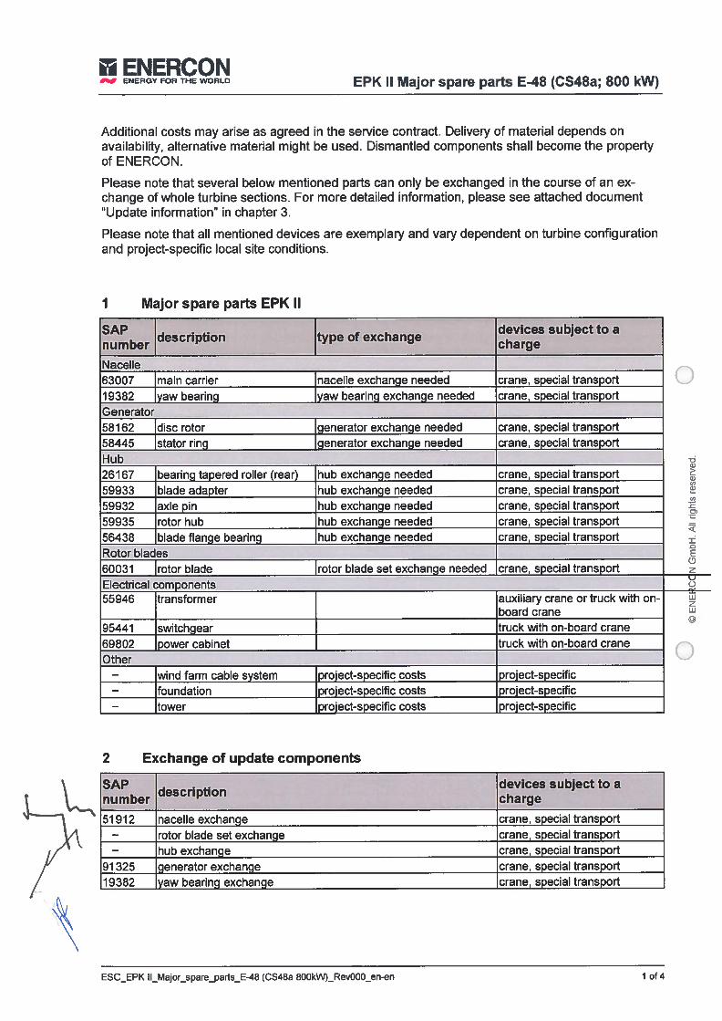
I ENERCONENERGY FOR THE WORLD EPK II Major spare parts E48 (CS48a; 800 kW)
Additional costs may arise as agreed in the service contract. Delivery of material depends onavailability, alternative material might be used. Dismantled components shall become the propertyof ENERCON.
Please note that several below mentioned parts can only be exchanged in the course of an exchange of whole turbine sections. For more detailed information, please see attached document‘Update information” in chapter 3.
Please note that ali mentioned devices are exemplary and vary dependent on turbine configurationand project-specific local site conditions.
1 Major spare parts EPK li
SAP . . devices subject to a
numberdescription type of exchange
charge
Naceile63007 main carrier nacelle exchange needed crane, special transport19382 yaw bearing yaw bearing exchange needed crane, special transportGenerator58162 disc rotor generator exchange needed crane, special transport58445 stator ring generator exchange needed crane, special transportHub26167 bearing tapered roller frear) hub exchange needed crane, special transport59933 blade adapter hub exchange needed crane, special transport59932 axle pín hub exchange needed crane, speciai transport59935 rotor hub hub exchange needed crane, special transport56438 blade flange bearing hub exchange needed crane, special transportRotor blades
Electrical com ponents
95441 switchgear truck with on-board crane69802 power cabinet truck with on-board craneOther
— wind farm cable system project-specific costs project-specific— foundation project-specific costs roject-specific— tower project-specific costs project-specific
2 Exchange of update com ponents
SAP . devices subject to a
numberdescription
charge
51912 nacelle exchange crane, specialtransport— rotor blade set exchange crane, special transport— hub exchange crane, special transport
91 325 generator exchange crane, special transport19382 yaw bearing exchange crane, special transport
60031 rotor blade
55946 transformer
rotor biade set exchanqe needed crane, special transport
auxiliary crane or truck with onboard crane
wzw©
ESC_EPK II_Major_spareparts_E-48 (CS48a 800kW)_Rev000_en-en 1 of4
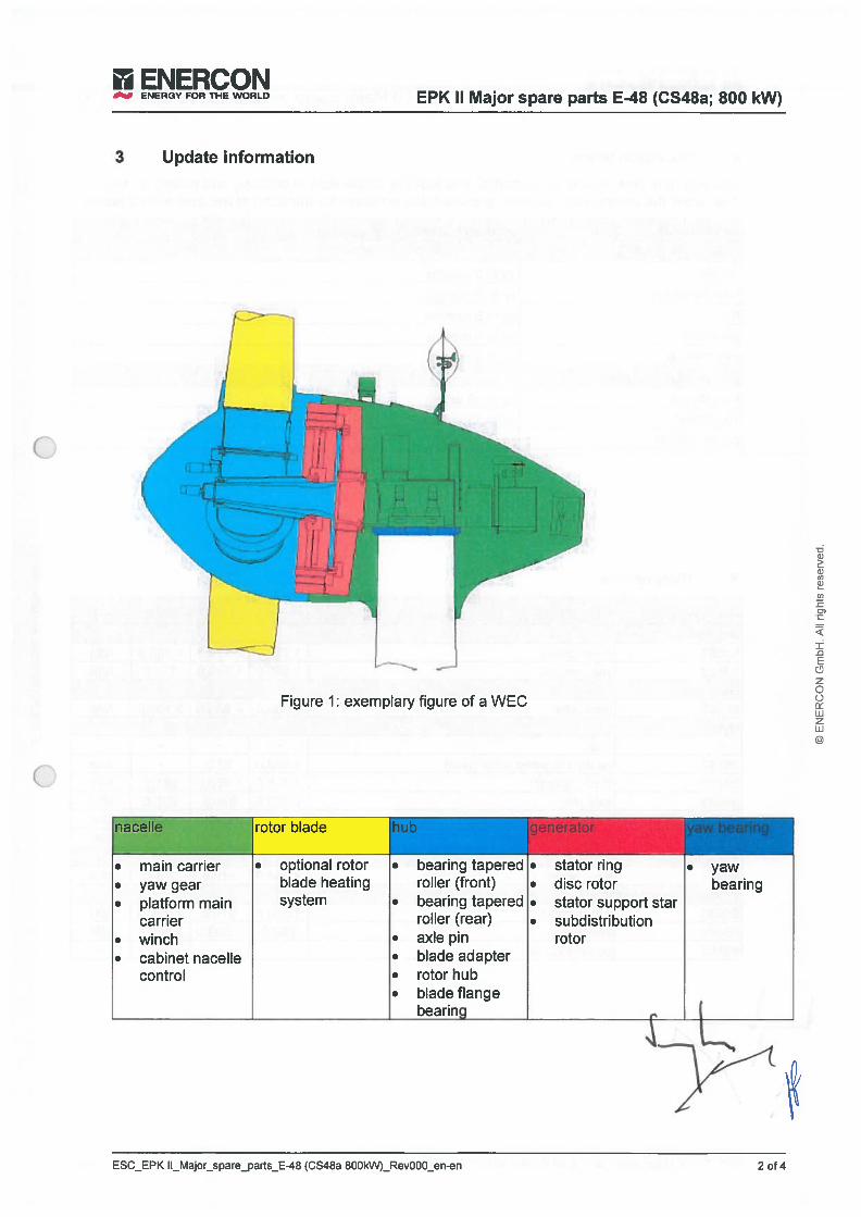
ENERCON
___
ENERGY FOR THE WORLD
3 Update information
EPK II Major spare parts E48 (CS48a; 800 kW)
• main carrier• yaw gear• platíorm main
carrier• winch• cabinet naceile
control
bearing taperedrolier (front)
• bearing taperedrolier (rear)
• axie pin• biade adapter• rotor hub• biade flange
bearinq
/‘:
L itFigure 1: exemplary figure of a WEC
a)a)0
O
c,)
±
E
zoowzw©
rotor biade
• optional rotorbiade heatingsystem
• •
•
•
stator ringdisc rotorstator support starsubdistributionrotor
• yawbearing
0, f
ESC_EPK II_Major_spareparts_E48 fCS48a 800kW)_Rev000_en-en 2 of 4
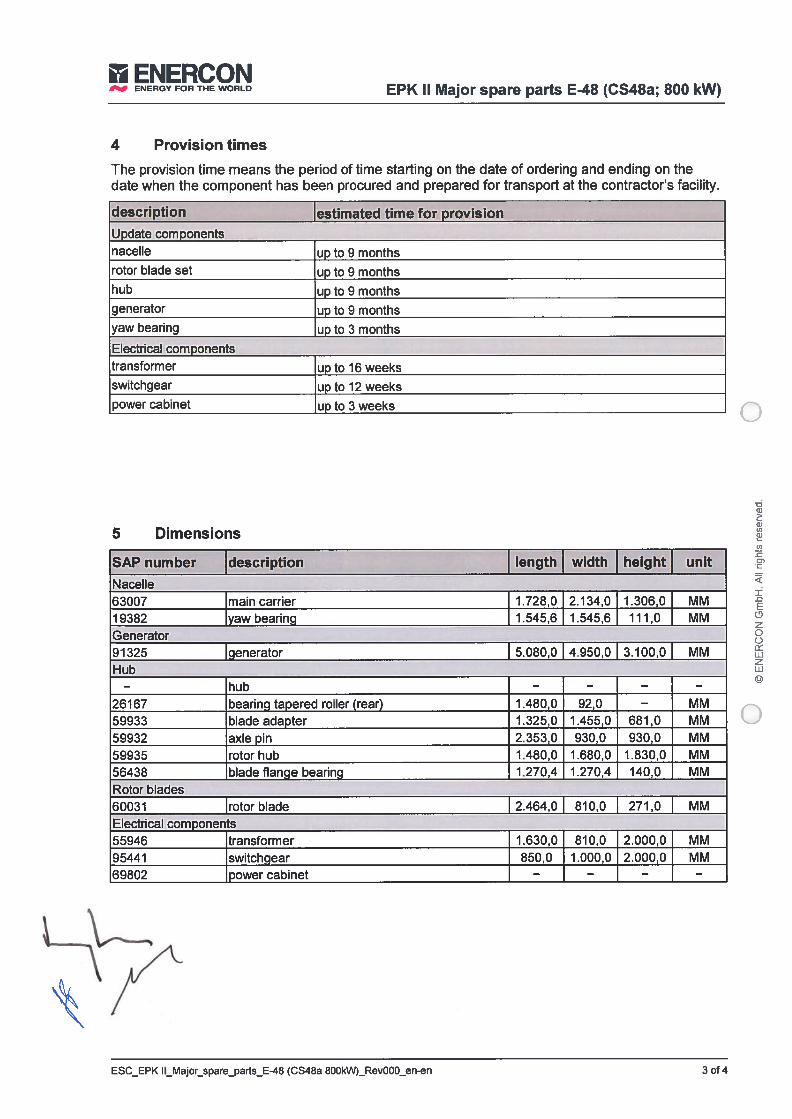
ENERCONENERGY FOR THE WORLD
EPK II Major spare parts E-48 (CS48a; 800 kW)
4 Provision times
lhe provision time means the period of time starting on the date of orderíng and ending on thedate when the component has been procured and prepared for transport at the contractor’s facility.
descriptionIestimated time for provision
Update componentsnaceUe up to 9 monthsrotor biade set up to 9 monthshub up to 9 monthsgenerator up to 9 monthsyaw bearing up to 3 months
Electrical com ponentstransformer up to 16 weeksswitchgear up to 12 weekspower cabinet up to 3 weeks
5 Dimensions
SAP number description Iength width height unit
Nacelie63007 main carrier 1.728,0 2.134,0 1.306,0 MM19362 yawbearing 1.545,6 1.545,6 111,0 MMGenerator91325 Igenerator 1 5.080,0 1 4.950,0 1 3.100,0 1 MMHub
— hub — — — —
26167 bearing tapered rolier (rear) 1.480,0 92,0 — MM59933 biade adapter 1.325,0 1.455,0 681,0 MM59932 axie pin 2.353,0 930,0 930,0 MM59935 rotor hub 1.480,0 1.680,0 1.830,0 MM56438 biade flange bearing 1.270,4 1.270,4 140,0 MMRotor biades60031 rotorbiade 2.464,0 810,0 271,0 MMElectrical com ponents55946 transformer 1.630,0 810,0 2.000,0 MM95441 switchgear 650,0 1.000,0 2.000,0 MM69802 power cabinet — — — —
a)2:a)u)a)
±E0
o0uJzw©
ESC_EPK II_Major_spare...parts_E-48 (CS48a 800kW)_Rev000_en-en 3 of 4
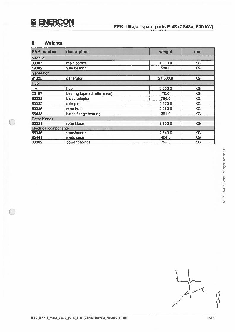
ENERCONEPK II Major spare parts E48 (CS48a; 800 kW)
6 Weights
SAP number description weight unitNaceile63007 main carriet 1.960,0 KG19382 yaw bearing 508,0 KGGenerator91325 Igenerator 1 24.300,0 KGHub
— hub 3.800,0 KG26167 bearing tapered rolier (rear) 70,0 KG59933 biade adapter 750,0 KG59932 axie pin 1.470,0 KG59935 rotor hub 2.050,0 KG56438 biade flange bearing 391,0 KGRotor biades6003 1 Irotor biade 2.200,0 KGElectrical components L.55946 transformer 2.640,0 KG95441 switchgear 404,0 KG69802 powercabinet 755,0 KG
w
a)
cl)
±£1E
zooLiizLii
ESC_EPK II_Major_spareparts_E-48 (CS48a 8OOkN)_RevOOO_en-en 4 of 4

9,
CatalogueEPK II Major spare parts E-70 E4 (CSZOb; 2000 kW)
ENERCONENERGY FOR THE WORLD
ENERCON
___
ENERGY FOR THE WORLD Legal information and document details
ENERCON GmbH • Dreekamp 5 • 26605 Aurich GermanyPhone: +49 4941 927-O• Fax: +49 4941 927-1 09E-mau: [email protected] - lnternet: http://www.enercon.deManaging Directors: Hans-Dieter Keftwig, Simon-Hermann WobbenLocal court: Aurich • Company registration number: HRB 411VAT ID no,: DE 181 977 360
The entire content of this document is protected by copyright and — withregard to other intellectual property rights — international laws and treaties.ENERCON GmbH holds the rights in the content of this document unlessanother rights holder is expressly identified or obviously recognisable.ENERCON GmbH grants the user the right to make copies and duplicates ofthis document for informational purposes for its own intra-corporate use;making this document available does not grant the user any further right ofuse. Any other duplication, modification, dissemination, publication, circulation, surrender to third parties and/or utilisation of the contents of this document — also in part — shall require the express prior wriften consent of ENERCON GmbH unless any of the above is permiffed by mandatory legislation.The user is prohibited from registering any industrial property rights in theknow-how reproduced in this document, or for parts thereof.lf and to the extent that ENERCON GmbH does not hold the rights in thecontent of this document, the user shall adhere to the relevant rights holder’sterms of use.
Any trademarks mentioned in this document are intellectual property of therespective registered trademark holders; the stipulations of the applicabletrademark law are valid without restriction.
ENERCON GmbH reserves the right to change, improve and expand thisdocument and the subject mailer described herein at any time without priornotice, unless contractual agreements or legal requirements provide otherwise.
Publisher
Copyright notice
-d0
a)a)co
cc
±DE0zoowzw©
iistered trademarks
Reservation of right of modification
Annex lb_EPK II_Major_spare_parts_E-70 E4 (CS82a 2000kW)_Rev000_en-en.docx II
ENERCONFOR THE WORLD Legal information and document details
-óG)
ci,ri,ci)
ri,
±-ci,E
z
Area of application
This document applies to: ENERCON group
Document details
Document ID ESC_EPK II_Major_spare_parts_E-70 E4 (CS7Ob 2000kW)_Rev000_en-en .docx
Confidentiality ENERCON PARTNER
Date Language DCC Plantldepartment
2016-09-17 en CA ENERCON Service Deutschland GmbH / CustomerService
Annex lb_EPK II_Major_spareparts_E-70 E4 fCS82a 2000kW)_Rev000_en-endocx iii

ENERCON
___
ENEPGY FOR THE WORLD EPK II Major spare parts E-70 E4 (CS7Ob; 2000 kW)
Additional costs may arise as agreed in the service contract. Deiivery of material depends onavailability, alternative material might be used. Dismantled components shall become the propertyof ENERCON.
Please note that several below mentioned paris can only be exchanged in the course of an exchange of whole turbine sections. For more detailed information, please see aüached document‘Update information” in chapter 3.
Please note that ali mentioned devices are exemplary and vary dependent on turbine configurationand project-specific local site conditions.
1 Major spare parts EPK II
SAP . . devices subject to adescription type of exchange
number charge
Naceile102020 main carrier nacelie exchange needed crane, special transport26877 yaw bearing yaw bearing exchange needed crane, special transportGenerator95211 disc rotor generator exchange needed crane, speciai transport93965 stator ring generatot exchange needed crane, speciai transport63023 stator support star generator exchange needed crane, speciai transportHub16473 bearing tapered roller (rear) hub exchange needed crane, speciai transport86024 biade adapter hub exchange needed crane, speciai transport81868 axie pin hub exchange needed crane, speciai transport86025 rotor hub hub exchange needed crane, speciai transport82919 biade fiange bearing hub exchange needed crane, speciai transportRotor biades60005 rotor biade rotor biade set exchange needed crane, speciai transport
— trailing edge segment project-specific costs project-specificElectricai com ponents100556 transformer auxiiiary crane or truck with
on-board ctane95434 switchgear truck with on-board crane65836 power cabinet truck with on-boatd craneOther
— wind farm cabie system project-specific costs project-specific— foundation project-specÍfic costs project-specific— tower project-specific costs project-specific
SAP . devices subject to adescription
number charge
51552 nacelie exchange ctane, speciai transport— rotor biade set exchange crane, speciai transport
122610 hub exchange crane, speciai transport122606 generator exchange crane, speciai transport
-da)
a)a)a)
O)
±-DEozoowzw©
Exchange of update components
Annex 1 b_EPK I_Major_spare_parts_E-70 E4 (CS82a 2000kW)_Rev000_en-en.docx 1 of 4
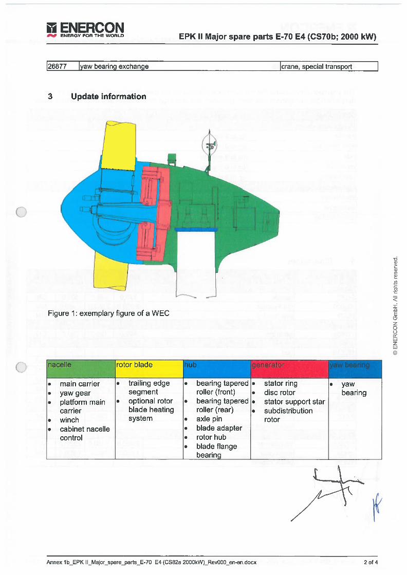
ENERCON
___
ENERGY FOR THE WORLD EPK II Major spare parts E-70 E4 (CS7Ob; 2000 kW)
126877 Iyaw bearing exchange Icrane, special transport
3 Update information
rL I
Figure 1: exemplary figure of a WEC
)r biade
. main carrier • trailing edge • bearing tapered • stator ring • yaw• yaw gear segment roiler (front) • disc rotor bearing• plafform main • optional rotor • bearing tapered • stator support star
carrier biade heating rolier (rear) • subdistribution• winch system • axie pin rotor• cabinet nacelie • biade adapter
control • rotorhub• biade flange
bearing
-dG)
cj
4:
±Eozoowzw©
Annex 1 b_EPK 1 l_Major_sparejarts_E-7O E4 (CS82a 2000kW)_Rev000_en-en.docx 2 of 4
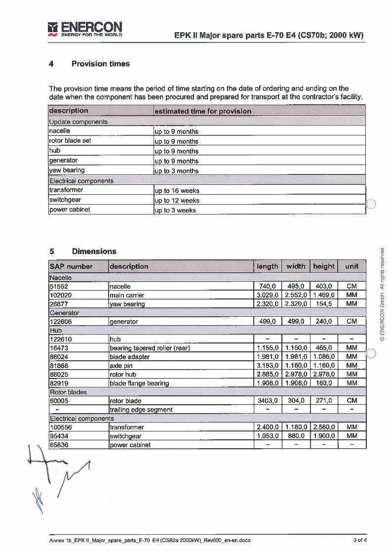
ENERCONENERGY FOR THE WORLD
EPK II Major spare parts E-70 E4 (CS7Ob; 2000 kW)
4 Provision times
The provision time means the period of time starting on the date of ordering and ending on thedate when the component has been procured and prepared for transport at the contractor’s facility.
description Iestimated time for provisionUpdate componentsnacelie up to 9 monthsrotor biade set up to 9 monthshub up to 9 monthsgenerator up to 9 monthsyaw bearing up to 3 months
Electrical com ponentstransformer up to 16 weeksswitchgear up to 12 weekspower cabinet up to 3 weeks
5 Dimensions
SAP number description Iength width height unit
Naceile51552 nacelie 740,0 495,0 403,0 CM102020 main carrier 3.029,0 2.552,0 1.469,0 MM26677 yaw bearing 2.320,0 2.320,0 154,5 MMGenerator122606 [generator [ 499,0 499,0 240,0 CM
Hub122610 hub — — — —
16473 bearingtapered rollerfrear) 1.155,0 1.150,0 465,0 MM
86024 biade adapter 1.981,0 1.981,0 1.086,0 MM
81868 axie pin 3.183,0 1.160,0 1.160,0 MM
86025 rotor hub 2.885,0 2.978,0 2.978,0 MM82919 biade flange bearing 1.908,0 1.908,0 160,0 MMRotor biades60005 rotor biade 3403,0 304,0 271,0 CM
— trailing edge segment — — — —
Electrical components100556 transformer 2.400,0 1.180,012.580,0 MM95434 switchgear 1.053,0 860,0 j 1.900,0 MM65836 power cabinet — —__J — —
-ócl)
cl)
cl)
co
±E
zoewzw©
Annex 1 b_EPK II Major spare_parts_E-70 E4 (CS82a 2000kW)_Rev000_en-en.docx 3 of 4

i)
0ti,
O
±-DEQzoci
zw©
II ENERCONENERGY FOR THE WORLD EPK II Major spare parts E-70 E4 (CS7Ob; 2000 kW)
6 Weights
SAP number description weight unit
Nacelie51552 nacelie 17.200,0 KG102020 main carrier 6.600,0 KG26877 yaw bearing 1 .650,0 KGGenerator122606 generator 49.000,0 KGHub122610 hub 25.850,0 KG16473 bearing tapered rolier (tear) 244,0 KG86024 biade adapter 2.100,0 KG81868 axie pin 4.350,0 KG86025 rotor hub 7.600,0 KG82919 biade flange bearing 1 .000,0 KGRotot biades60005 rotor biade 6.380,0 KG
— trailing edge segment — KGElectncal com ponents100556 transformer 7.150,0 KG95434 switchgear 580,0 KG65836 powercabinet 719,0 KG
Annex lb_EPK II_Major_spare_parts_E-70 E4 (CS82a 2000kW)_Rev000_en-en.docx 4 of 4

oo


oo

ENERCON Definition ofAvaílability Page
lof7ENERGY FOR THE WORLD- Annex to EPK Contract -
Definition of Availability
for
ENERCON
Wind Energy Converters
Imprint
Editor:
Teiephone:Fax:
Copyright:
Updates:
Revisïon
Revision:
Department:
Document information:
Document name:
ENERCON GmbH Dreekamp 5 • 26605 Autich - Germany
04941-927-004941-927-109
Uniess otherwise specified in this document, the contents of this document are protected bycopyright of ENERCON GmbH. Ali rights reserved. No use, including any copying or publishing, ofthis information is permifted without the prior written consent of ENERCON GmbH.
ENERCON GmbH reserves the right to continuousiy upd ate and modify this document and the itemsdescribed therein at any time without por notice.
28 Febmary 2013
ENERCON GmbH / Customer Service
Revision as of 07 December, 2012
Definiton of Availability 130228 eng© ENERCON GmbH

E’ ENERCON Definition ofAvailability2of7ENERGY FOR THE WORLD
- Annex to EPK Contract -
Introduction
1.1 Concept of Technical Availability
1.1.1 The concept of technical availability describes within a given interval the ratio of the totalpenoU of time during which a WEC is ready for operation to the total length of the giveninterval.
Operational period of time during interval under considerationTechnical availability f%) =
Interval under consideration
1.2 WEC ready for Operation
1.2.1 The WEC is considered to be ready for operation under the following main statuses1:
MAIN DE5cRIPTIONSTATUS
O Turbine in the WEC is in operationoperation
1 Tutbine stopped lhe WEC is operational but stopped without activation ofthe maintenance switch, e.g. by a voltage control system
2 Lack ofwind The WEC is operational but the wind speed is notsufficient for production
3 Storm lhe WEC is operational but the wind speed exceeds theupper limit.
4 Shadow stop lhe WEC is operational but stopped by the shadow shutoff system.
5 Biade defroster lhe WEC is operational but the biade de-icing system is
________
activated.
7 Unauthorized lhe WEC is operational but stopped by persons otheraccess than ENERCON personnel.
9 Generator lhe WEC is operational but the generator heating systemheating is activated (other than after a mains breakdown)
14 Ice detection lhe WEC is operational but the ice detection systemrecords ice.
A lit”of the exact assignment of the status messages to time categories can be downloadedfrom/https:I/sip. enercon. de.
Document information: Revision as of 07 December, 2012
Document name: Definiton ofAvailability 130228 eng© ENERCON GmbH

II ENERCON Definition ofAvailability Page
ENERGY rOR THE WORLD- Annex to EPK Contract - of 7
MAIN DESCRIPTIONSTATUS
15 Turbine moist The WEC is operational but moisture in electricalsystems is recorded (other than after a mainsbreakdown)
17 Test security The WEC is operational and a security test is performedsystem at the WEC.
21 Cable twisted The WEC is operational but the cable untwisting featureis active
1.3 WEC not considered for Calculation
1.3.1 The WEC is not considered for the calculation of availability under the following mainstatuses
a) the WEC stops due to gtid failures:
MAIN STATUS DESCRIPTION
60 Mains failure The WEC is operationai and but a mains failure occurred.
b) the SCADA system is unavailable
c) the WEC is unavailable at the instigation of the Employer.
14 WEC not ready for Operation
1.4.1 The WEC is considered to be not ready for operation if:
a) the WEC shows a fault,
b) the WEC is not in operation and the maintenance switch has been activated.
Document information: Revision as of 07 December, 2012
Document name: Definiton of Availability 130228 eng© ENERCON GmbH
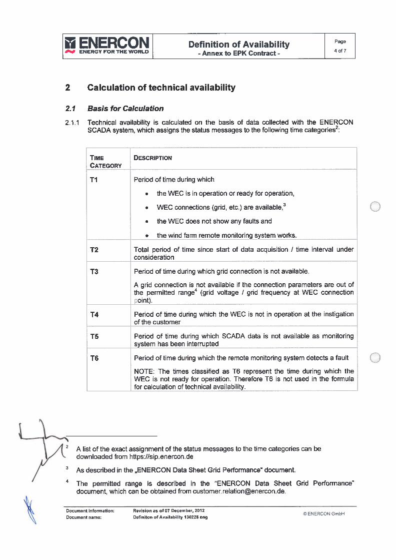
II ENERCON Definition of Availability Page
4of7ENERGY FOR THE WORLD- Annex to EPK Contract -
2 Calculation oftechnical availabïlity
2.1 Basis for Calculation
2.1.1 Technical availability is calculated on the basis of data collected with the ENERCONSCADA system, which assigns the status messages to the following time categories2:
TIME DESCRIPTIONCATEGORY
TI Period of time during which
• the WEC is in operation or ready for operation,
• WEC connections (grid, etc.) are available,3
• the WEC does not show any faults and
• the wind farm remote monitoring system works.
T2 Total period of time since start of data acquisition / time interval underconsideration
T3 Period of time during which grid connection is not available.
A grid connection is not available if the connection parameters are out ofthe permiffed range4 (grid voltage / grid frequency at WEC connectionpoint).
14 Period of time during which the WEC is not in operation at the instigationof the customer
T5 Period of time during which SCADA data is not available as monitoringsystem has been interrupted
T6 Period of time during which the remote monitoring system detects a fault
NOTE: The times classified as T6 represent the time during which theWEC is not ready for operation. Therefore 16 is not used in the formulafor calculation of technical availability.
\ ,4 2 A list of the exact assignment of the status messages to the time categories can be5/ ‘ downloaded from https://sip.enerconde
As described in the ,,ENERCON Data Sheet Grid Performance” document.
The permitted range is described in the “ENERCON Data Sheet Grid Performance”document, which can be obtained from [email protected].
Document information: Revision as of 07 December, 2012© ENERCON GmbH
\\ Document name: Definiton ofAvailability 130228 eng
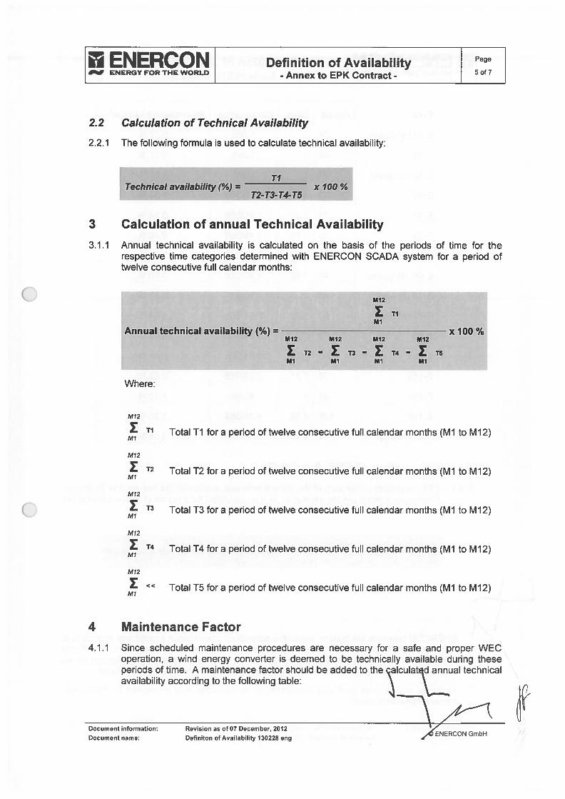
ENERCON Definition ofAvailabilítyENERGY FOR THE WORLD
- Annex to EPK Contract - Of 7
2.2 Calculation of Technical AvaiIabiIity
2.2.1 The following formula is used to calculate technical availability:
TITechnical avallability (%) = x 100 %
T2-T3-T4-T5
3 Calculation of annual Technical Availability
3.1.1 Annual technical availability is calculated on the basis of the periods of time for therespective time categories determined with ENERCON SCADA system for a penoU oftwelve consecutive fulI calendar months:
M12
TIMl
Annual technical availability (%) = x 100 %M12 M12 M12 M12
T2 — T3 — T4 — T5Ml Ml Ml Ml
Where:
M12
TI Total Ti for a penoU of twelve consecutive fulI calendar months (Mi to M12)
Ml 2
T2 Total T2 for a period of twelve consecutive fuli calendar months (Ml to M12)
M12
T3 TotalT3 fora penoU oftwelve consecutivefull calendar months (Ml to Mi2)
M12
T4 Total T4 for a penoU of twelve consecutive fulI calendar months (Ml to Mi2)
M12
« Total T5 for a period of twelve consecutive fulI calendar months (Ml to M12)
4 Maintenance Factor
4.1.1 Since scheduled maintenance procedures are necessary for a safe and proper WECoperation, a wind energy converter is deemed to be technically available during theseperiods of time. A maintenance factor should be added to the çalculat d annual technicalavailability according to the following table:
Documentinformation: Revision as of 07 December, 2012 ZAENERCONGmbHDocument name: Definiton of AvaiIabiIity 130228 eng

HOURS DAYS CALCULATION+MAINTENANCE FACTOR5
24 1 1/365
______
0.27%
24 1 1/365 0.27%
24 1 11365 0.27%
30 1.25 1.25/365 0.34 %
30 1.25 1.25/365 0.34%
35 1.46 1.46/365 0.40 %
40 1.66 1.66/365 0.46 %
44 1.83 1.83/365 0.50%
48 2 2/365 0.55 %
53 2.21 2.21/365 0.61 %
53 2.21 2.21/365 0.61 %
53 2.21 2.21/365 0.61 %
53 2.21 2.21/365 0.61 %
96 4 4/365 1.10%
105 4,38 4,38/365 1,20%
4 0.16 0.16/365 0.05%
5 Calculation of EPK Availabilíty
5.1.1 EPK avaiiabiiity is the sum of the annuai technicai avaiiabiiity (as per section 3) and themaintenance factor (as per section 4), and is caicuiated for a period of tweive consecutivefuil calendar months:
EPK availability (%) = Annual Technical Availabílity + Maintenance Factor
ENERCON Definition6of7ENERGY FOR THE WORLD
- Annex to EPK Contract -
TYPE
E-30 (ali types)
E-33
E-40 (ali types)
E-44
E-48
E-53
E-58
E-66 (ali types)
E-70 (ali types)
E-82 (ali types)
E-92
E-101
E-lis
E-112
E-i26
Transmission6
LENERCON reserves the right to adjust the scheduied maintenance procedures according totechnicai experience and new insights, provided that any such adjustment is in accordance
/ with internationaliy accepted engineering practice. Such an adjustment might affect the petiod
/ of time required for scheduied maintenance and consequentiy the maintenance factor.
6 Additionai maintenance work and thus additionai maintenance time is required for WECs withtransmission configuration.
1 Document information:
Document name:
Revision as of 07 December, 2012
Definiton of Availability 130228 eng© ENERCON GmbH
I ENERCON Definition ofAvaïlability Page
ENERGY OR THE WORLD- Annex to EPK Contract - of 7
6 Calculation of Compensation
6.1.1 lf the agreed EPK availability terms are not fulfihled, the resulting compensation for yieldloss (CL055) is calculated according to the following formula:
Where
CLOSS = (Ag - AEPK) X AEP X PPP
Ag Warranted Availability (%) in accordance with Sub-Clause 3.1.1 ofthe Contract
AEPK Calculated Availability for operational year under consideration (%)AEP Energy yield for operational year immediately before operational year under
consideration + compensation for lack of availability for operational yearimmediately before operational year under consideration, if any (kWh)
PPP Compensation rate in accordance with Sub-Clause 3.2.2 of the Contract
Document information:
Document name:
Revision as of 07 December, 2012
Definiton of Availability 130228 eng© ENERCON GmbH

oo


oo
Technical Description4-year MaintenanceWind Energy Converter E-48 (CS48a)
ENERCONENERGY FOR THE WORLD
! Legal information and document details
Publisher ENERCON GmbH Dreekamp 5 • 26605 Aurich• GermanyPhone: +49 4941 927-O Fax: +49 4941 927-1 09E-mau: [email protected]. lnternet: http://www.enercon.deManaging Directors: Hans-Dieter Kettwig, Simon-Hermann WobbenLocal court: Aurich Company registration number: HRB 411VAT ID no.: DE 181 977 360
Copyright notice lhe entire content of this document is protected by copyright and — with regard toother intellectual property rights — international laws and treaties. ENERCON GmbHholds the rights in the content of this document unless another rights holder is expressly identified or obviously recognisable.
ENERCON GmbH grants the userthe rightto make copies and duplicates ofthisdocument for ínformational purposes for its own intra-corporate use; making this document available does not grant the user any further right of use. Any other duplication, modification, dissemination, publication, circulation, surrender to third partiesand/or utilisation of the contents of this document — also in part — shall require the express prior written consent of ENERCON GmbH unless any of the above is permittedby mandatory legislation.
lhe user is prohibited from registering any industrial property rights in the know-howreproduced in this document, or for parts thereof.
lf and to the extent that ENERCON GmbH does not hold the rights in the content ofthis document, the user shall adhere to the relevant rights holder’s terms of use.
CI)
Registered trademarks Any trademarks mentioned in this document are intellectual property of the respective registered trademark holders; the stipulations of the applicable trademark law arevalid without restriction. ±
E0
Reservation of right ENERCON GmbH reserves the right to change, improve and expand this documentof modification and the subject matter described herein at any time without prior notice, unless con
tractual agreements or legal requirements provide otherwise.
Document details
Document ID ESC_4-Year Maintenance E-48 (CS48a)_RevOO7de-en
Confidentiality PUBLIC
Date Language DCC PlantlDepartment
2017-12-12 en DA Service Deutschland GmbH / System engineering of mechanical & EE /WEC electrotechnology
ESC_4-Year Maintenance E-48 (CS48a)_RevOO7_de-en ii

Iechnícal DescriptionMaster Maintenance
ENERCONENERGY FOR THE WORLD
Wind Energy Converter E-48 (CS48a) w
! EGE!3ÇQ!%i Legal information and document details
Publisher ENERCON GmbH • Dreekamp 5 • 26605 Aurich - GermanyPhone: +494941 927-O• Fax: +49 4941 927-1 09E-mau: [email protected] • lnternet: http://www.enercon deManaging Directors: Hans-Dieter Kettwig, Simon-Hermann WobbenLocal court: Aurich - Company registration number: HRB 411VAT ID no.: DE 181 977 360
Copyright notice The entire content of this document is ptotected by copyright and — with regard toother intellectual property rights — international laws and treaties. ENERCON GmbHholds the rights in the content of this document unless anothet rights holder is expressly identified or obviously recognisable.
ENERCON GmbH grants the user the right to make copies and duplicates of thisdocument for informational purposes for its own intra-corporate use; making this document available does not grant the user any further right of use. Any other duplication, modification, dissemination, publication, circulation, surrender to third partiesand/or utilisation of the contents of this document — also in part — shall require the express prior written consent of ENERCON GmbH unless any of the above is permittedby mandatory legislation.
The user is prohibited from registering any industrial property rights in the know-howreproduced in this document, or for parts thereof.
lf and to the extent that ENERCON GmbH does not hold the rights in the content ofthis document, the user shall adhere to the relevant rights holder’s terms of use.
0
Registered trademarks Any trademarks mentioned in this document are inteliectual property of the respective registered trademark holders; the stipulations of the applicable trademark law arevalid without restriction.
.0E0
Reservation of right ENERCON GmbH reserves the right to change, improve and expand this documentof modification and the subject matter described herein at any time without prior notice, unless con
tractual agreements ar legal requirements provide otherwise.
Document details
Document ID ESC_Master Maintenance E-48 fCS483)_RevOO7_de-en
Confidentiality PUBLIC
Date Language DCC PlantlDepartment
2017-12-12 en DA Service Deutschland GmbH / System engineering of mechanical & EE /WEC electrotechnology
5k/A
ESC_Master Maintenance E-48 (CS48a)_RevOO7_de-en
• ••
Iechnical DescriptionGrease MaintenanceE-44 E-48, E-53 wind energy converter
ENERCONENERQY FOR THE WORLD
ENERCONENERGY FOR THE WORLD Legal information and document detaiis
ENERCON GmbH - Dreekamp 5 - 26605 Aurich - GermanyPhone: +49 4941 927-O• Fax: +49 4941 927-1 09E-mali: [email protected] • internet: http://www.enercon.deManaging Ditectors: Hans-Dieter Kettwig, Simon-Hermann WobbenLocal court: Aunch- Company registration number: HRB 411VAT ID no.: DE 181 977 360
Copyright notice
Registered trademarks
Reservation of rightof modification
The entire content of this document is protected by copyright and — with regard toother intellectual property rights — international iaws and treaties. ENERCON GmbHhoids the rights in the content of this document uniess another rights hoider is expressly identified or obviousiy recognisabie.
ENERCON GmbH gtants the user the right to make copies and duplicates of thisdocument for informationai purposes for its own intra-corporate use; making this document avaiiable does not grant the user any further right of use. Any other duplication, modification, dissemination, pubiication, circulation, surrender to third partiesand/or utilisation of the contents of this document — also in part — shaii require the express prior written consent of ENERCON GmbH uniess any of the above is permittedby mandatory iegisiation.
The user is prohibited from registering any industrial property rights in the know-howreproduced in this document, or for parts thereof.
if and to the extent that ENERCON GmbH does not hoid the rights in the content ofthis document, the user shaii adhere to the relevant rights hoider’s terms of use.
Any trademarks mentioned in this document are inteiiectual property of the respective registered trademark hoiders; the stipuiations of the appiicabie trademark law arevalid without restriction.
ENERCON GmbH reserves the right to change, improve and expand this documentand the subject matter described herein at any time without prior notice, uniess contractuai agreements or legal requirements provide otherwise.
Area of application
tia)
u)a)
±E
zoowzw
Fis document appiies to: International
Document details
Document ID
Confidentiality
Publisher
PUBLIC
ESC_Grease Maintenance E-44, E-48, E-53_RevOO4_de-en
Date Language DCC PlantlDepartment
2017-01-17 en DA Service Deutschiand GmbH / Mechanical Engineering
ESC_Grease Maintenance E-44, E-48, E-53_RevOO4_de-en II
Technícal Descriptíon4-year MaintenanceWind Energy Converter E-70 E4 (CS82a)
F ENERCONENFRGY FOR THE WORLD
1
! Legal information and document details
Publisher ENERCON GmbH Dreekamp 5 26605 Aurich - GermanyPhone: +49 4941 927-O- Fax: +49 4941 927-1 09E-mau: [email protected]. Internet: http://www.enercon.deManaging Directors: Hans-Dieter Kettwig, Simon-Hermann WobbenLocal court: Aurich Company registration number: HRB 411VAI ID no.: DE 181 977 360
Copyright notice The entire content of this document is protected by copyright and — with regard toother inteilectual property rights — intemational laws and treaties. ENERCON GmbHholds the rights in the content of this document unless another rights holder is expressly identified or obviously recognisable.
ENERCON GmbH grants the user the right to make copies and duplícates of thisdocument for informational purposes for its own intra-corporate use; making this document available does not grant the user any further right of use. Any other duplication, modification, dissemination, publication, circulation, surrender to third partiesand/or utilisation of the contents of this document — also in part — shall require the express prior written consent of ENERCON GmbH unless any of the above is permittedby mandatory legislation.
The user is prohibited from registering any industrial property rights in the know-howreproduced in this document, or for parts thereof.
lf and to the extent that ENERCON GmbH does not hold the rights in the content ofthis document, the user shall adhere to the relevant rights holder’s terms of use.
Registered trademarks Any trademarks mentioned in this document are inteilectual property of the respective registered trademark holders; the stipulations ot the applicable trademark law arevalid without restríction. i
-QE0
Reservation of right ENERCON GmbH reserves the right to change, improve and expand this documentof modification and the subject matter described herein at any time without prior notice, unless con
tractual agreements or legal requirements provide otherwise.
Document details
Document ID ESC_4-Year Maintenance E-70 E4 (CS82a)_RevOO7_de-en
Confidentiality PUBLIC
Date Language Dcc PlanUDepartment
2017-12-12 en DA Service Deutschland GmbH / System engineering of mechanical & EE /WEC electrotechnology
ESC_4-Year Maintenance E-70 E4 (CS82a)_RevOO7_de-en ii

•411
Technícal DescriptionMaster MaintenanceWínd Energy Converter E-70 E4 (CS82a)
ENERCONENEROY FOR THE WORLD
! Legal information and document details
Publisher ENERCON GmbH Dreekamp 5 26605 Aurich • GermanyPhone: +49 4941 927-O• Fax: +49 4941 927-1 09E-mau: [email protected] lnternet: hllp://www.enercon.deManaging Directors: Hans-Dieter Kettwig, Simon-Hermann WobbenLocal court: Aunch• Company registration number: HRB 411VAT ID no.: DE 181 977 360
Copyright notice The entire content of this document is protected by copyright and — with regard toother inteliectual property rights — international laws and treaties. ENERCON GmbHholds the rights in the content of this document unless another rights holder is expressly identified or obviously recognisable.
ENERCON GmbH grants the user the right to make copies and duplicates ofthisdocument for informational purposes for its own intra-corporate use; making this document available does not grant the user any further right of use. Any other duplication, modification, dissemination, publication, circulation, surrender to third partiesand/or utilisation of the contents of this document — also in part — shall require the express prior written consent of ENERCON GmbH unless any of the above is permittedby mandatory legislation.
The user is prohibited from registering any industrial property rights in the know-howreproduced in this document, or for parts thereof.
lf and to the extent that ENERCON GmbH does not hold the rights in the content ofthis document, the user shall adhere to the relevant rights holder’s terms of use.
I)
Registered trademarks Any trademarks mentioned in this document are intellectual property of the respect- •
ive registered trademark holders; the stipulations of the applicable trademark law arevalid without restriction. ±
E0
Reservation of right ENERCON GmbH reserves the right to change, improve and expand this documentof modification and the subject matter described herein at any time without prior notice, unless con
tractual agreements or legal requirements provide otherwise.w©
Document details
Document ID ESC_Master Maintenance E-70 E4 (CS82a)_RevOO7_de-en
Confidentiality PUBLIC
Date Language DCC PlantlDepartment
2017-12-12 en DA Service Deutschland GmbH / System engineering of mechanical & EE /WEC electrotechnology
ESC_Master Maintenance E-70 E4 (CS82a)_RevOO7_de-en ii

1.S g
t
Iechnícal DescriptionGrease MaintenanceE-70 E4, E-fO E4-2, E-7O E4-3 wind energy converters
ENERCONFNERGY FOR THE WORLD
Ia -
I ENERCONENERGY FOR THE WORLD Legal information and document details
ENERCON GmbH Dreekamp 5 26605 Aurich GermanyPhone: +49 4941 927-Ou Fax: +49 4941 927-1 09E-mali: [email protected] • internet: http://www.enercon.deManaging Directors: Hans-Dieter Kettwig, Simon-Hermann WobbenLocal court: Aurich Company registration number: HRB 411VAT ID no.: DE 181 977 360
Copyright notice
Registered trademarks
Reservation of rightof modification
lhe entire content of this document is protected by copyright and — with regard toother inteilectual property rights — international iaws and treaties. ENERCON GmbHholds the rights in the content of this document uniess another rights hoider is expressly identified or obviousiy recognisabie.
ENERCON GmbH grants the user the right to make copies and duplicates ot thisdocument for informational purposes for its own intra-corporate use; making this document availabie does not grant the user any further right of use. Any other duplication, modification, dissemination, publication, circulation, surrender to third partiesand/or utilisation of the contents of this document — also in part — shall require the express prior written consent of ENERCON GmbH unless any of the above is permittedby mandatory legisiation.
lhe user is prohibited from registering any industrial property rights in the know-howreproduced in this document, or for parts thereof.
if and to the extent that ENERCON GmbH does not hoid the rights in the content ofthis document, the user shaii adhere to the reievant rights hoider’s terms of use.
Any trademarks mentioned in this document are inteiiectual property of the respective registered trademark holders; the stipuiations of the applicabie trademark iaw arevaiid without restriction.
ENERCON GmbH reserves the right to change, improve and expand this documentand the subject maifer described herein at any time without prior notice, uniess contractuai agreements or legal requirements provide otherwise,
Area of application
G)
0(1)O
.0
±.0E
CDzoowzLii
©
This document appiies to: international
Document details
II
Publísher
Document ID
Confidentiality PUBLIC
ESC_Grease Maintenance E-70 E4, E-70 E4-2, E-70 E4-3_RevOO5_de-en
Date Language DCC PlantiDepartment
2017-01-17 en DA Service Deutschland GmbH / Mechanicai Engineering
ESC_Grease Maintenance E-70 E4, E-70 E4-2, E-70 E4-3_RevOO5_de-en
—
Technical DescriptionWind-dependent maintenanceWind energy converters
ENERCONENEROY FOR THE WORIC

! Legal information and document details
ENERCON GmbH Dreekamp 5 • 26605 Aurich • GermanyPhone: +49 4941 927-O• Fax: +49 4941 927-1 09E-mau: [email protected] lnternet: http://www.enercon.deManaging Directors: Hans-Dieter Kettwig, Simon-Hermann WobbenLocal court: Aurich Company registration number: HRB 411VAT ID no.: DE 181 977 360
lhe entire content of thís document is protected by copyright and — with regard toother inteliectual property rights — international laws and treaties. ENERCON GmbHholds the rights in the content of this document unless another rights holder is expressly identified or obviously recognisable.
ENERCON GmbH grants the user the right to make copies and duplicates of thisdocument for informational purposes for its own intra-corporate use; making this document available does not grant the user any further right of use. Any other duplication, modification, dissemination, publication, circulation, surrender to third partiesand/or utilisation of the contents of this document — also in part — shall require the express prior wrillen consent of ENERCON GmbH unless any of the above is permittedby mandatory legislation.
The user is prohibited from registering any industrial property rights in the know-howreproduced in this document, or for parts thereof.
lf and to the extent that ENERCON GmbH does not hold the rights in the content ofthis document, the user shall adhere to the relevant rights holder’s terms of use.
Any trademarks mentioned in this document are intellectual property of the respective registered trademark holders; the stipulations of the applicable trademark law arevalid without restriction. ±
E(D
Reservation of right ENERCON GmbH reserves the right to change, improve and expand this documentof modification and the subject matter described herein at any time without prior notice, unless con
tractual agreements or legal requfrements provide otherwise.
Document details
Document ID ESC_Wind-based Maintenance_RevOO2_de-en
Confidentiality PUBLIC
Date Language DCC PlanUDepartment
2017-01-17 en DA Service Deutschland GmbH 1 Electrical Engineering
Publisher
Copyright notice
Registered trademarks
0Ci)O
ESC_Wi nd-based Maintenance_RevOO2_de-en II

ir
N7 47
-q

oo
Specification
ENERCON
___
ENERGY FOR THE WORLD
Access Roads and Crane PlafformsE-48 49m & 59m Steel Tower
ENERCON GmbH
Project Management
Specification
Access Roads and CranePlatforms
E-48
49m & 59m Steel Tower
ENERCON GmbH Dreekamp 5 26605 Aurich Germany
Phone: +49 4941 927-O • Fax: +49 4941 927-1 09
Copyright: © ENERCON GmbH. Any reproduction, distribution and utilisation of this document asweii as the communication of its contents to third parties without express authorisation isprohibited. Vioiators wilI be held liable for monetary damages. Ali rights reserved in theevent of the grant of a patent, utility model or design.
Legal notice
Publisher:
Content ENERCON GmbH reserves the right to change, improve and expand this document andsubject to the subject matter described herein at any time without prior notice.change:
File name: PM-PE.SP703.Zuwegung.Kranstellflaeche-E48_49.59-Rev000ger-eng
© Copyight ENERCON GmbH. Ali rights reserved Page 1 of 15

Specification
ENE Access Roads and Crane Plafformsm m ee ower ProjectManagement
CONTENTS
1. Assembly of tower and wind energy converter 3
2. Cranetechnology 32.1. Crane technology details 3
2.2. Assembly of telescopic crane 3
3. Access roads 43.1. Minimum requirements on access roads 43.2. Access road bearing capacity 53.3. Example of access road construction 63.4. Transport Ioading gauge 7
4. Curve radii 84.1. Minimum requirements on intersections and curves 84.2. Radii of curves < 90 degrees and > 90 degrees 9
5. Transport and Iogistics 105.1. Basic transport requirements 105.2. Overview of transport vehicles 11
6. Craneplatform 126.1. Minimum requirements on crane platforms 126.2. Standard crane platform 146.3. Crane platform in forested areas 15
File name: PM-PE-SP703-Zuwegung-Kranstellflaeche-E45_49-59.Rev000ger-eng
© Copyright ENERCON GmbH. Ali dghts reserved. Page 2 of 15
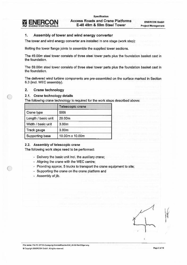
ENERCONENERGYFORTHEWORLO
Specification
Access Roads and Crane PlafformsE48 49m & 59m Steel Tower
ENERCON GmbH
Project Management
1. Assembly of tower and wind energy converter
lhe tower and wind energy converter are installed in one stage (work step):
Bolting the tower flange joints to assembie the supplied tower sections.
lhe 49.00m steel tower consists of three steel tower parts plus the foundation basket cast inthe foundation.
The 59.00m steel tower consists of three steel tower parts plus the foundation basket cast inthe foundation.
The delivered wind turbine components are pre-assembled on the surface marked in Section6.3 (ind. WEC assembly).
2. Crane technology
2.1. Crane technology detailslhe following crane technology is required for the work steps described above:
Telescopic crane
Cranetype 500t
Length / basic unit 20.00m
Width / basic unit 3.00m
lrack gauge 3.00m
Supporting base 1O.00m x JO.00m
2.2. Assembly of telescopic cranelhe following work steps need to be performed:
- Delivery the basic unit ind. the auxiliary crane;- Aligning the crane with the WEC centre;- Providing approx. 5 trucks to transport the crane equipment to site;- Supporting the crane on the crane platform and- Assembly ofjib.
File name: PM-PE-SP703-Zuwegung-Kranstellflaeche-E48_49-59-Rev000ger-eng
© Copyright ENERCON GmbH. Ali righis reserved. Page 3 or 15
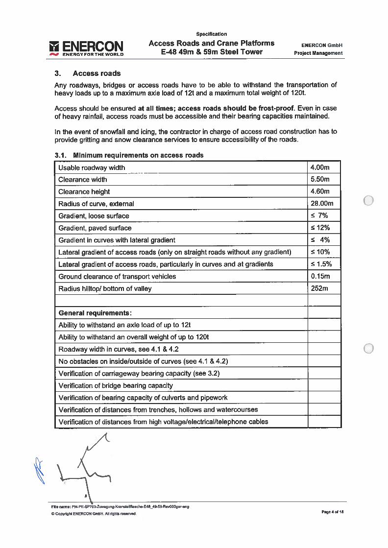
ENERCON
___
ENERGY FOR THE WORLD
Specification
Access Roads and Crane PlafformsE-48 49m & 59m Steel Tower
ENERCON GmbH
Project Management
3. Access roads
Any roadways, bridges or access roads have to be able to withstand the transportation ofheavy baUs up to a maximum axie Ioad of 12t and a maximum total weight of 120t.
Access shouid be ensured at ali times; access roads should be frost-proof. Even in caseof heavy rainfali, access roads must be accessible and their bearing capacities maintained.
In the event of snowfall and icing, the contractor in charge of access road construction has toprovide gritting and snow clearance seMces to ensure accessibiiity of the roads.
3.1. Mínimum requïrements on access roads
Usable roadway width 4.00m
Clearance width 5.50m
Clearance height 4.60m
Radius of curve, external 28.00m
Gradient, loose surface 7%
Gradient, paved surface 12%
Gradient in curves with lateral gradient 4%
Lateral gradient of access roads (only on straight roads without any gradient) 10%
Lateral gradient of access roads, particularly in curves and at gradients 1.5%
Ground clearance of transport vehicles 0.15m
Radius hilltop/ boilom of valley 252m
General requirements:
Ability to withstand an axle load of up to 12t
Abiiity to withstand an overali weight of up to 120t
Roadway width in curves, see 4.1 & 4.2
No obstacles on inside/outside of curves (see 4.1 & 4.2)
Verification of carriageway bearing capacity (see 3.2)
Verification of bridge bearing capacity
Verification of bearing capacity of culverts and pipework
Verification of distances from trenches, hollows and watercourses
Verification of d istances from high voltage/electrical/telephone cables
File name: PM-PE-SPO3-Zuwegung-Kransteliflaeche-E48_49-59-RevOOOger-eng
© Copyright ENERCON GmbH. Ali rights reserved. Page4of 15
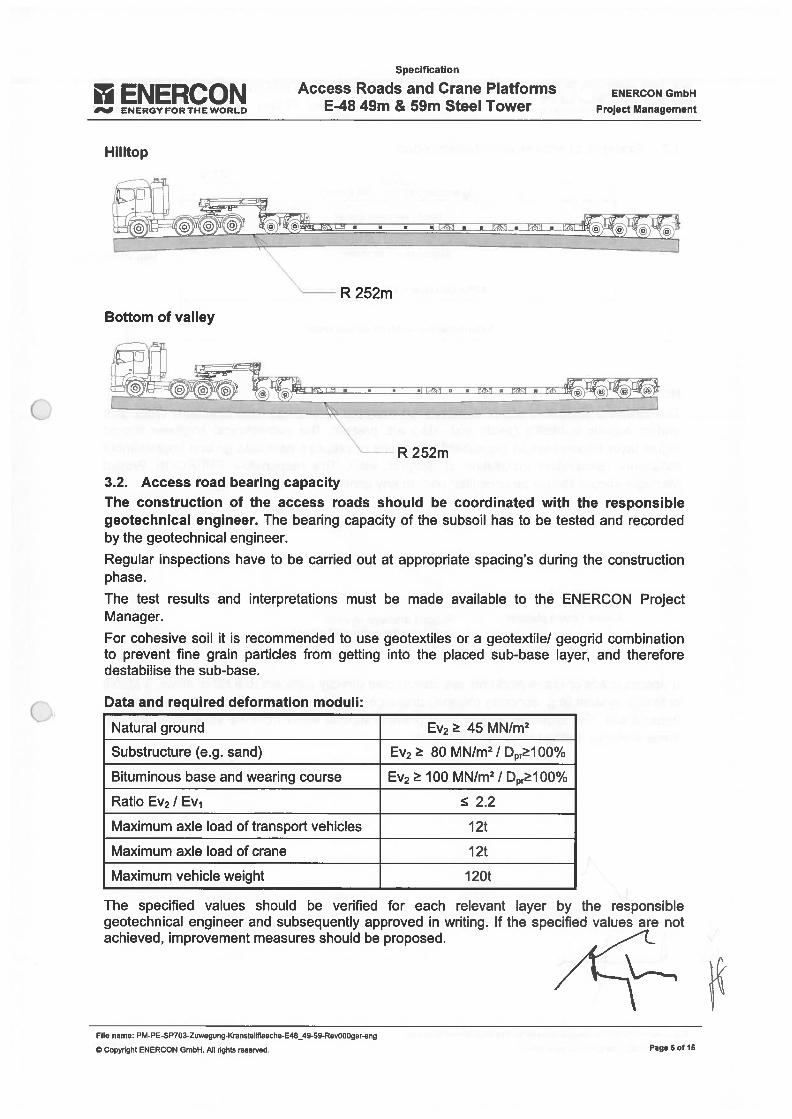
ENERCON
___
ENERGYFORTHEWORLO
Hilltop
Specification
Access Roads and Crane PlafformsE48 49m & 59m Steel Tower
ENERCON GmbH
Project Management
Bottom of valley
3.2. Access road bearing capacityThe construction of the access roads should be coordinated with the responsiblegeotechnical engineer. The bearing capacity of the subsoil has to be tested and recordedby the geotechnical engineer.
Regular inspections have to be carried out at appropriate spacing’s during the constructionphase.
The test results and interpretations must be made available to the ENERCON ProjectManager.
For cohesive soil it is recommended to use geotextiles or a geotextile/ geogrid combinationto prevent fine grain particles from getting into the placed sub-base layer, and thereforedestabilise the sub-base.
Data and required deformation moduli:
Natural ground Ev2 45 MN/m2
Substructure (e.g. sand) Ev2 80 MN/m2 / Dpr1 00%
Bituminous base and wearing course Ev2 100 MN/m2/ Dpr100%
Ratio Ev2 / Ev1 2.2
Maximum axie load of transport vehicles 12t
Maximum axle Ioad of crane 12t
Maximum vehicle weight 120t
The specified values should be verified for each relevant layer by the responsiblegeotechnical engineer and subsequently approved in writing. lf the specified values are notachieved, improvement measures should be proposed.
File name: PM-PE-SP703-Zuwegueg-Kranstellflaeche-E4849-59-Rev000ger-eng
© CopyTight ENERCON GmbH. Ali rights reserved
R252m
R 252m
Page 6 0115
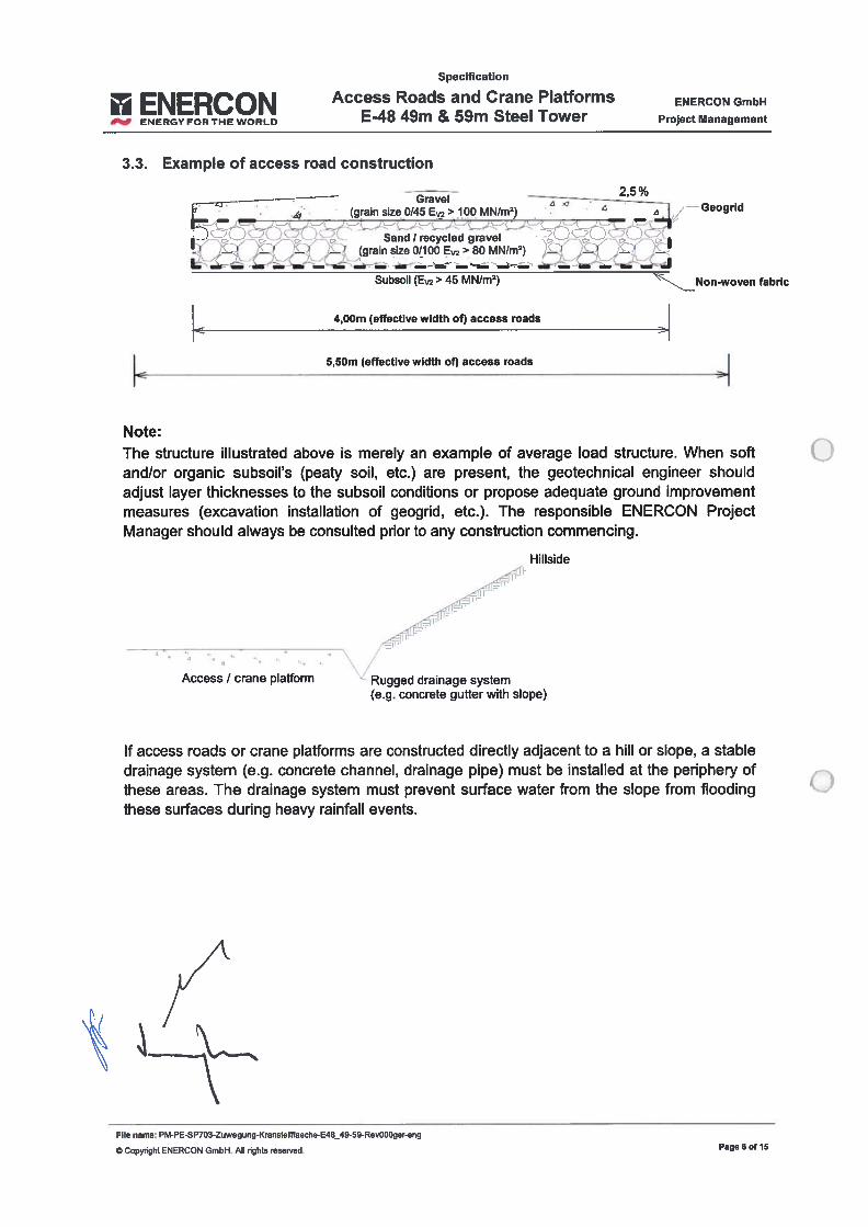
ENERCON
___
ENERGYr0RTHEW0RLD
Specification
Access Roads and Crane PlatformsE-48 49m & 59m Steel Tower
ENERCON GmbH
Project Management
3.3. Example of access road construction
Note:
5,50m feifective width of) access roads
Geogrid
Non-woven fabric
The structure illustrated above is merely an example of average Ioad structure. When softand/or organic subsoil’s (peaty sou, etc.) are present, the geotechnical engineer shouldadjust Iayer thicknesses to the subsoil conditions or propose adequate ground improvementmeasures (excavation instaliation of geogrid, etc.). The responsible ENERCON ProjectManager should always be consulted prior to any construction commencing.
Hiliside
Access / crane plafform Rugged drainage system(e.g. concrete gutter with siope)
If access roads or crane plafforms are constructed directly adjacent to a hili or siope, a stabledrainage system (e.g. concrete channel, drainage pipe) must be installed at the periphery ofthese areas. The drainage system must prevent surface water from the siope from floodingthese surfaces during heavy rainfail events.
-———-- 2,5%——-
Gravei —--————__
(grain size 0/45 E> 100 MN/m9
• Sand!recycied gravei‘ — L (grain size 0/100 Ev2 >80 MN/m2) —! —, —
L - . -_ — — -- — — — - —
Subsoil (Ev2 > 45 MN/m2)
4,OOm (effective width of) access roads
File name: PM-PE-SP703-Zuwegung-Kranstellflaeche-E46_49-59-Rev000ger-eng
© Copynght ENERCON GmbH. Ali rights reserved, Page 60115
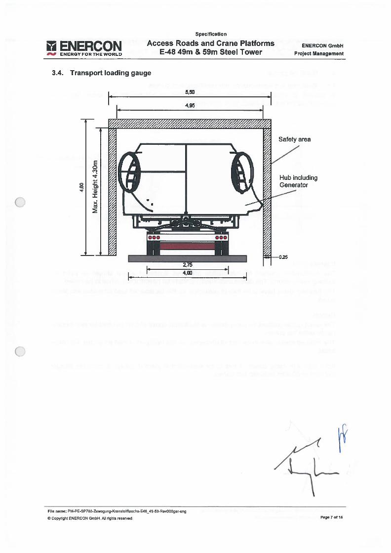
ENERCONENERGYFORTHEWORLD
Specification
Access Roads and Crane PlafformsE-48 49m & 59m Steel Tower
ENERCON GmbH
Project Management
3.4. Transport Ioading gauge
File
5O
4.95 •1
Eo
a)
x
Safety area
Í
__
1
_
T_2.75
4,GO
Copydght ENERCON GmbH. Ali rights reserved.
_49-59-Rev000ger-eng
Page 7 0115
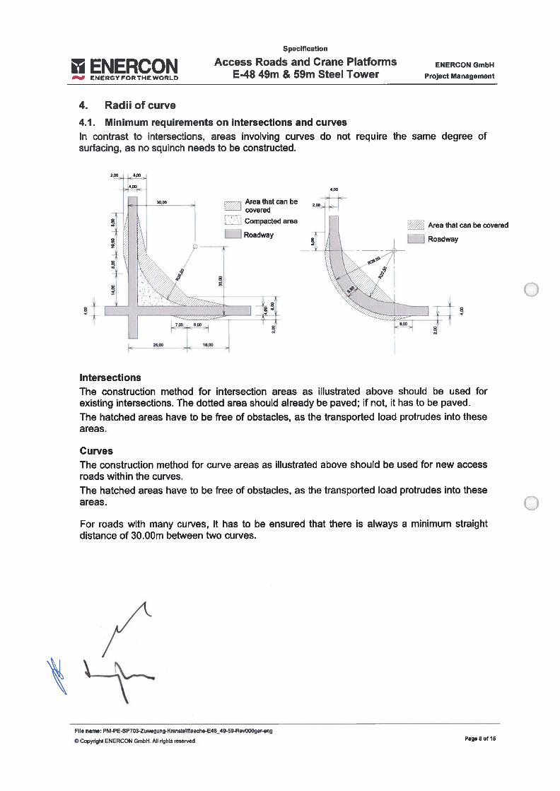
ENERCON
___
ENERGYr0RTHEW0RL0
Specification
Access Roads and Crane PlafformsE-48 49m & 59m Steel Tower
ENERCON GmbH
Project Management
4. Radii of curve
4.1. Minimum requirements on intersections and curvesIn contrast to intersections, areas involving curves do not require the sarne degree ofsurfacing, as no squinch needs to be constructed.
Curves
Area that can be covered
Roadway
The construction method for curve areas as illustrated above should be used for new accessroads within the curves.
The hatched areas have to be ftee of obstacles, as the transported Ioad protrudes into theseareas.
For roads with many curves, it has to be ensured that there is always a minimum straightdistance of 30.00m between two curves.
Area that can becovered
EZI Compacted
Roadway
t 1
Intersectionslhe construction method for intersection areas as illustrated above should be used forexisting intersections. The dotted area should already be paved; if not, it has to be paved.
The hatched areas have to be free of obstacles, as the transported Ioad protrudes into theseareas.
tFile name: PM-PE-SP703-Zuwegung-Kranstellflaeche-E48_49-59-Rev000ger-eng
© Copynght ENERCON GmbH. Ali rights reserved. Page 8 o! 15

ENERCON
___
ENERGYFORTHEWORLD
4.00
Specification
Access Roads and Crane PlafformsE-48 49m & 59m Steel Tower
ENERCON GmbH
Project Management
Area that can be covered
Roadway
4.2. Radii of curves < 90 degrees and > 90 degreesIf the angle of the curve under construction is < 90 degrees, the curved part to beconstructed moves outwards and the area associated with the 5.50m roadway width has tobe extended accordingly (see hatched area). Again the Ioad protrudes into the inside andoutside areas of the curve (see 4.1).
4,00
115 Degrees 65 Degrees ‘4O Degrees
File name: PM-PE-SP703-Zuwegung-Kranstellflaeche-E48_49-59-Rev000ger-eng
© Copyoight ENERCON GmbH. Ali ri9hts reserved Page 9 of 15
Specification
ENERCON Access Roads and Crane Plafforms
___
ENERGYFORTHEWORLO - m m ee ower ProjectManagement
5. Transport and Iogistics
5.1. Basic transport requirementsBasically, the transport vehicles must not exceed the maximum axle Ioad of 12t (usually lOt).Thus, a transport vehicle with an actual overall weight of JOOt has at least nine axies (plustowing vehicle).
About 8 transport cycles are required to deliver the entire wind energy converter (ind. tower)to the construction site. For the transport cycles of the crane, please see 2.2.
The following vehicles are used on ENERCON construction sites:
- Low-loader trailers;- Flatbed trailers;- Articulated trailers;- Semi-trailers and- Adapter vehicles.
The vehicles are telescopic to some extent in terms of length and width, and can beshortened to regular Iength once they have been unloaded.
Maximum vehicle length is 35.00m (steel tower section).
File name: PM-PE-SP703-Zuwegung-Kransleilflaeche-E48_49-59-Rev000ger-eng
© Copyright ENERCON GmbH. Ali rights reserved. Page 10 of 15
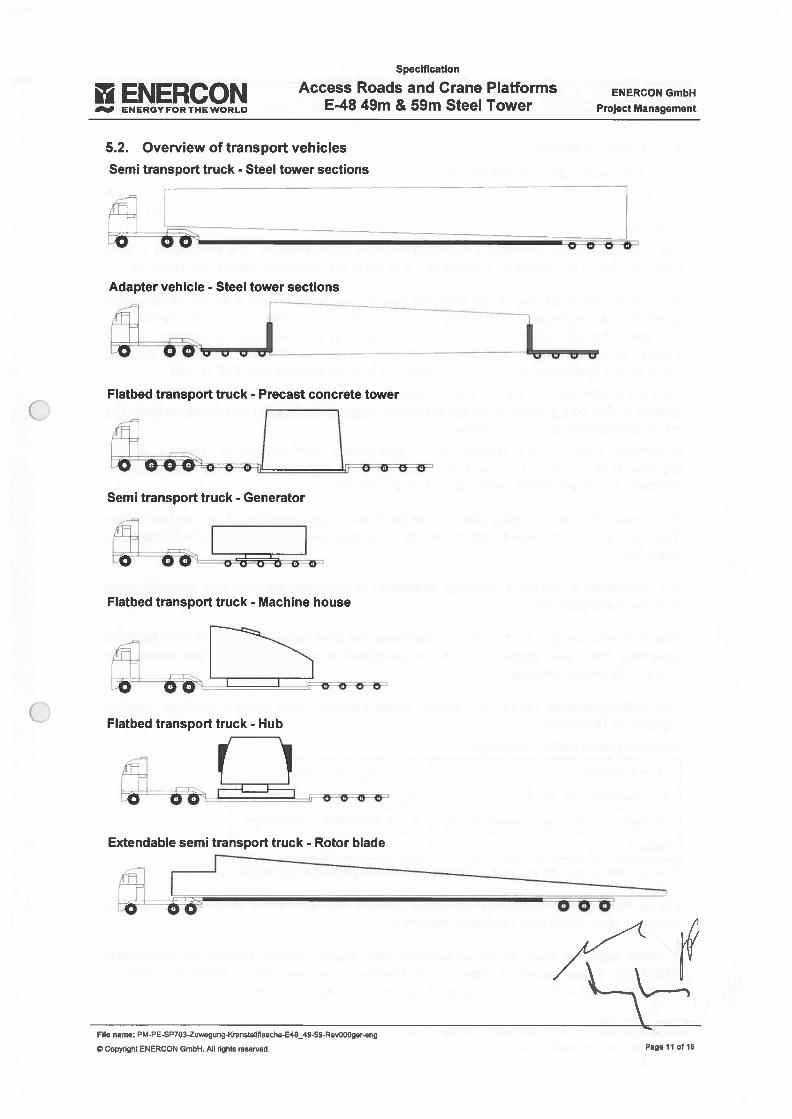
ENERCONENERGYFORTHEWORLD
Specification
Access Roads and Crane PlafformsE48 49m & 59m Steel Tower
ENERCON GmbH
Project Management
5.2. Overview of transport vehiclesSemi transport truck - Steel tower sections
Adapter vehicle - Steel tower sections
0000
Flatbed transport truck - Precast concrete tower
Flatbed transport truck - Machine house
Flatbed transport truck - Hub
ri-
Extendable semi transport truck - Rotor biade
Semi transport truck - Generator
O O O- o c
File name: PM-PE-SP703-Zuwegung-Kransteilflaeche-E4549-59-Rov000ger-eng
© Copyright ENERCON GmbH. Ali rights reserved Page 11 of 15
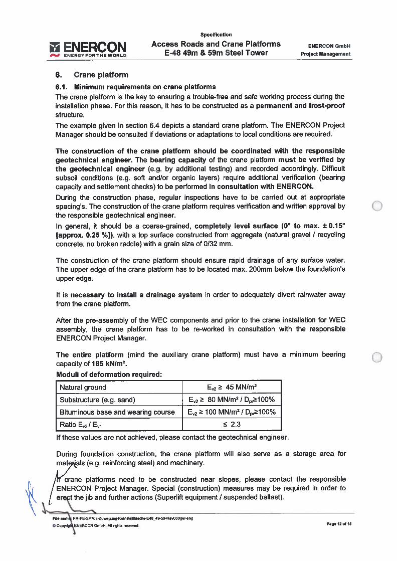
Specification
ENER N Access Roads and Crane PlafformsENERGYFORTHEWORLD - m m ee wer ProjectManagement
6. Crane plafform
6.1. Minimum requirements on crane plafformslhe crane plafform is the key to ensuring a trouble-free and safe working process during theinstaliation phase. For this reason, it has to be constructed as a permanent and frost-proofstwcture.
lhe example given in section 6.4 depicts a standard crane platform. lhe ENERCON ProjectManager should be consulted if deviations or adaptations to local conditions are required.
The construction of the crane plafform should be coordinated with the responsiblegeotechnical engineer. lhe bearing capacity of the crane plafform must be verified bythe geotechnical engineer (e.g. by additional testing) and recorded accordingly. Difficultsubsoil conditions (e.g. soft and/or organic Iayers) require additional verification (bearingcapacity and seftlement checks) to be performed in consultation with ENERCON.
During the construction phase, regular inspections have to be carried out at appropriatespacing’s. lhe construction of the crane plafform requires verification and written approval bythe responsible geotechnical engineer.
In general, it should be a coarse-grained, completely levei surface (0° to max. ± 0.15°[approx. 0.25 %]), with a top surface constructed from aggregate (natural gravei / recyclingconcrete, no broken raddle) with a grain size of 0/32 mm.
lhe construction of the crane plafform should ensure rapid drainage of any surface water.The upper edge of the crane plafform has to be located max. 200mm below the foundation’supper edge.
It is necessary to instail a drainage system in order to adequately divert rainwater awayfrom the crane plafform.
After the pre-assembly of the WEC components and prior to the crane instaliation for WECassembly, the crane plafform has to be re-worked in consultation with the responsibleENERCON Project Manager.
lhe entire plafform (mmd the auxiliary crane plafform) must have a minimum bearingcapacity of 185 kNIm2.
Moduli of deformation required:
Natural ground E2 45 MN/m2
Substructure (e.g. sand) E2 80 MN/m2 / Dpr100%
Bituminous base and wearing course E2 100 MN/m2 / Dpr100%
Ratio E2/ E1 2.3
lf these values are not achieved, please contact the geotechnicaI engineer.
During foundation construction, the crane plafform wiII also serve as a storage area formaIls (e.g. reinforcing steel) and machinery.
14(rane piatforms need to be constructed near siopes, please contact the responsible\kj / ENERCON Project Manager. Special (construction) measures may be required in order to
er. t the jib and further actions (Superlift equipment / suspended ballast).
File nam PM-PE-SP703-Zuwegung-Kranstellflaeche-E48_49-59-Rev000ger-eng
© Copyng ENERCON GmbH. Ali dghts reserved. Page 12 of 15
Specification
ENER ON Access Roads and Crane Plafforms
___
ENERGYFORTHEWORLD m ee ProjectManagement
Any excess sou excavated during the construction phase that is not needed for foundationbackfihling must not be stored laterally from the foundation. Storage is allowed only at theback of the foundation, otherwise excess excavated sou has to be removed completely(see 6.3).
lhe assembly area is a temporary area with a good bearing capacity that is used for storageand instailation of WEC components.lhe assembly area has to meet the following requirements:
- coarse-grained, levelled surface- maximum gradient of 1% over the entire surface- lhe entire area has to have a surface pressure/bearing capacity oí 4OkN/m2.- lhe additional storage area has to be levei and without any roots. At a later time,
ENERCON will place excavator mats on this surface to store further components.
File name: PM-PE-SP703-Zuwegung-Kranstellflaeche-E48_49-59-Rev000ger-eng
© Copydght ENERCON GmbH. Ali rights reserved, Page 13 of 15
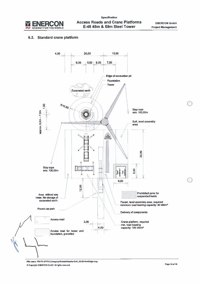
Specification
ENERCON— ENERGYr0RTHEW0RLD
Access Roads and Crane PlatformsE-48 49m & 59m Steel Tower
ENERCON GmbH
Project Management
6.2. Standard crane platform
20,00
9,00 5,00 6,00 7,50
4,00 rj — 15,00
Edge of excavation pit
- Excavated eatth )
Foundation
Tower
Stay topemm. 100,OOm
Soft, levei assembiyarea -
[=1/
EIr)
Eoco
xoooCD
Atea without anytrees. No storage of
excavated earth.
Stay topemm. lOODOm
oo
c)
ooo)
1.ooCN
9,00
Paved car park
Prohibited zone forsuspended ioads
Access road
Paved, levei assembiy area, requitedminimum Ioad bearing capacity: 40 kNIm2
Deiivery of components
__________
3,00
-. -
-
Crane piafform required
$ Access road for tow4,00
mm. Ioad beag
foundation, gravelleder and
- capaci: 185 kN/m2
File name: PM-PE-SP703-Zuwegung-Kransteiiflaeche-E48_49-59-Rev000gereng
© Copyright ENERCON GmbH. Ali rights reserved. Page 14 of 15
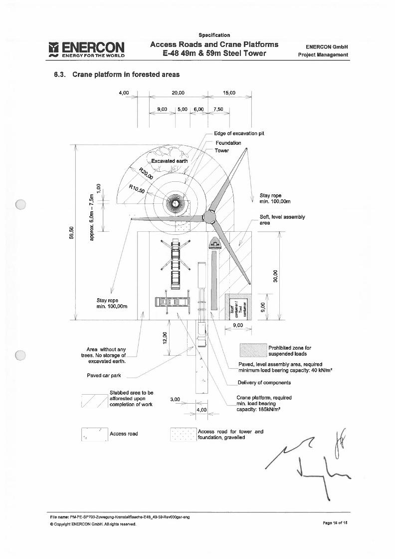
Specification
ENERCON
___
ENERGYFORTHEWORLD
Access Roads and Crane PlatformsE48 49m & 59m Steel Tower
ENERCON GmbH
Project Management
6.3. Crane plafform in forested areas
4,00
________
suspendedioads
Paved, levei assembiy area, requiredminimum load bearing capacity: 40 kN/m2
Crane platform, requiredmm. load beanngcapacity: 1 85kN/m2
File name: PM-PE-SP703-Zuwegung-KransteIlflaeche-E48_49-59-Rev000ger-eng
© Copynght ENERCON GmbH. AH rights reserved.
oo
EIX)
Eoco
xoo
pit
Stay topemm. 100,OOm
Soft, levei assembiyarea
ou,o)co
Stay topemm. 100,0Dm
oooc)
JA\
ooo)
Area without anyttees. No storage of
excavated earth.
Paved car park
_________
Stubbed area to be// /1 afforested upon
/ / compietion ofwork
Delivery of components
3,00 -
4,00
Access road•
- -: - Access road for tower and
__________
foundation, gravelled
Page 15 of 15

oo

Specification
ENERCON Access Roads and Crane Plafforms E70
___
ENERGYFORTHEWORLD m, m, m an m ee owers ProjectManagement
Specification
Access Roads and CranePlatforms
E-70 E4
56m, 63m, 73m and 84mSteel Towers
Legal notice
Publisher: ENERCON GmbH Dreekamp 5 • 26605 Aurich Germany
Phone: +49 4941 927-O• Fax: +49 4941 927-1 09
Copyright: © ENERCON GmbH. Any reproduction, distribution and utilisation of this document aswell as the communication of its contents to third parties without express authorisation isprohibited. Violators will be held liable for monetary damages. Ali rights reserved in theevent of the grant of a patent, utiiity model or design.
Content ENERCON GmbH reserves the right to change, improve and expand this document andsubject to the subject matter described herein at any time without prior notice.change:
File name: PM-PE-SP707-Zuwegung-Kransteliflaeche-E70-E4_56-84S-Rev000ger-eng
© Copynght ENERCON GmbH. Ali rights reserved. Page 1 of 15
Specification
ENERCON Access Roads and Crane Plafforms E7O
__
ENERGYFORTHEWORLD m, m, m an m ee owers ProjectManagement
TABLE OF CONTENTS
Assembling the tower and wind energy converter 3
Crane technology 3Crane technology details 3
Installing the lailice boom crane 3
Access road 4
Minimum requirements on access roads 4
Access road bearing capacity 5
Example of access / jib road constwction 6
Transport Ioading gauge 7
Radiiof Curves 8
Minimum requirements on intersections and curves 8
Radii of curves < 90 degrees and > 90 degrees 9
Road performance of vehicles in curves 9
Iransport and Iogistics 10
Basic transport requitements 10
Overview of transport vehicles 11
Craneplafform 12
Minimum requirements on crane plafforms 12
Access roads for jib assembly 13
Standard crane Standard crane plafform 14
Crane plafforms in forested areas 15
2.2.1.2.2.
3.3.1.3.2.3.3.3.4.
4.
4.1.4.2.4.3.
5.5.1.5.2.
6.6.1.6.2.6.3.6.4.
File name: PM-PE-3P707-Zuwegung-Kranstellflaeche-E70-E4_56-84S-Rev000ger-eng
© Copyright ENERCON GmbH. Ali hghts reserved. Page 2 of 15

Specification
ENERCON Access Roads and Crane Plafforms E70— ENERGYFORTHEWORLD m, m an m ee owers ProjectManagement
1. Assembling the tower and wind energy converter
The tower and wind energy converter are installed in one stage (work step):
Bolting the tower flange joints to assembie the supplied tower sections.
The 56.00 m steel tower consists of three steel tower parts plus the foundation basket cast inthe foundation.
The 63.00 m steel tower consists of three steel tower parts plus the foundation section orfoundation basket cast in the foundation.
The 73.00 m steel tower consists of five steel towet parts plus the foundation basket cast inthe foundation.
The 84.00 m steel tower consists of four steel tower parts plus the foundation section cast inthe foundation.
lhe delivered wind turbine components are pre-assembled on the surface marked in Section6.3 (ind. WEC assembly).
2. Crane technology
2.1. Crane technology detailsThe following crane technology is required for the work steps described above:
Crawler crane Mobile crane
Cranetype 500t 500t
Length / basic unit 1 1 .00 m 21.00
Width / basic unit 9.00 m 3.00 m
Track gauge 9.00 m 3.00 m
Supporting base / 10.00 m x 10.00 m
2.2. lnstalling the laifice boom craneThe following work steps need to be performed:
- Delevery the basic unit ind. the auxiliary crane.- Aligning the crane with the WEC centre.- Providing approx. 35 trucks to transport the crane equipment to the crane.- Supporting the crane on the crane platform and- Assembling the jib.
File name: PM-PE-SP707-Zuwegung-Kransteilflaeche-E70-E4_56-84S-Rev000ger-eng
© Copyright ENERCON GmbH. Ali rights reserved. Page 3 0115

Specification
ENERCON Access Roads and Crane Plafforms E70ENERGYFORTHEWORLO m, an m ee O ProjectManagement
3. Access road
Any roadways, bridges or access roads have to be able to withstand the transportation ofheavy loads up to a maximum axie Ioad of 12t and a maximum total weight of 130t.
Access should be ensured at ali times; access toads should be frost-proof. Even in caseof heavy rainfail, access roads must be accessible and keep their bearing capacities.
ln the event of snowfall and icing, the contractor in charge of access road construction has toprovide a grifting and snow clearance service to ensure accessibility of the roads.
3.1. Minimum requirements on access roads
Useable roadway width 4.00m
Useable access road width forjib assembly 6.00m
Clearance width 5.50m
Clearance height 4.60m
Radius of curve, external 28.00m
Incline with loose surface 7%
Incline with paved surface 12%
Incline in curves with lateral incline 4%
Lateral incline of access roads (only on straight roads without any incline) 10 %
Lateral incline of access roads, particularly in curves and at inclines 1.5 %
Ground clearance of transport vehicles 0.15m
General requirements:
Ability to withstand an axle load of up to 12 t
Ability to withstand an overali weight of up to 730 t
Roadway width in curves, see 4.1 & 4.2
No obstacles on inside/outside of curves (see 4.1 & 4.2)
Verification of carriageway_bearing_capacity_(see_3.2)
Verification of bridge bearing capacity
Verification of bearing capacity of culverts and pipework
Verification of distances from trenches, hollows and watercourses
Verification of d istances from high voltage/electrical/telephone cables
File name: PM-PE-SP707-Zuwegung-Kranstellflaeche-E70-E4_56-84S-Rev000ger-eng
© Copynght ENERCON GmbH. Ali rights reserved. Paga 4 of 15
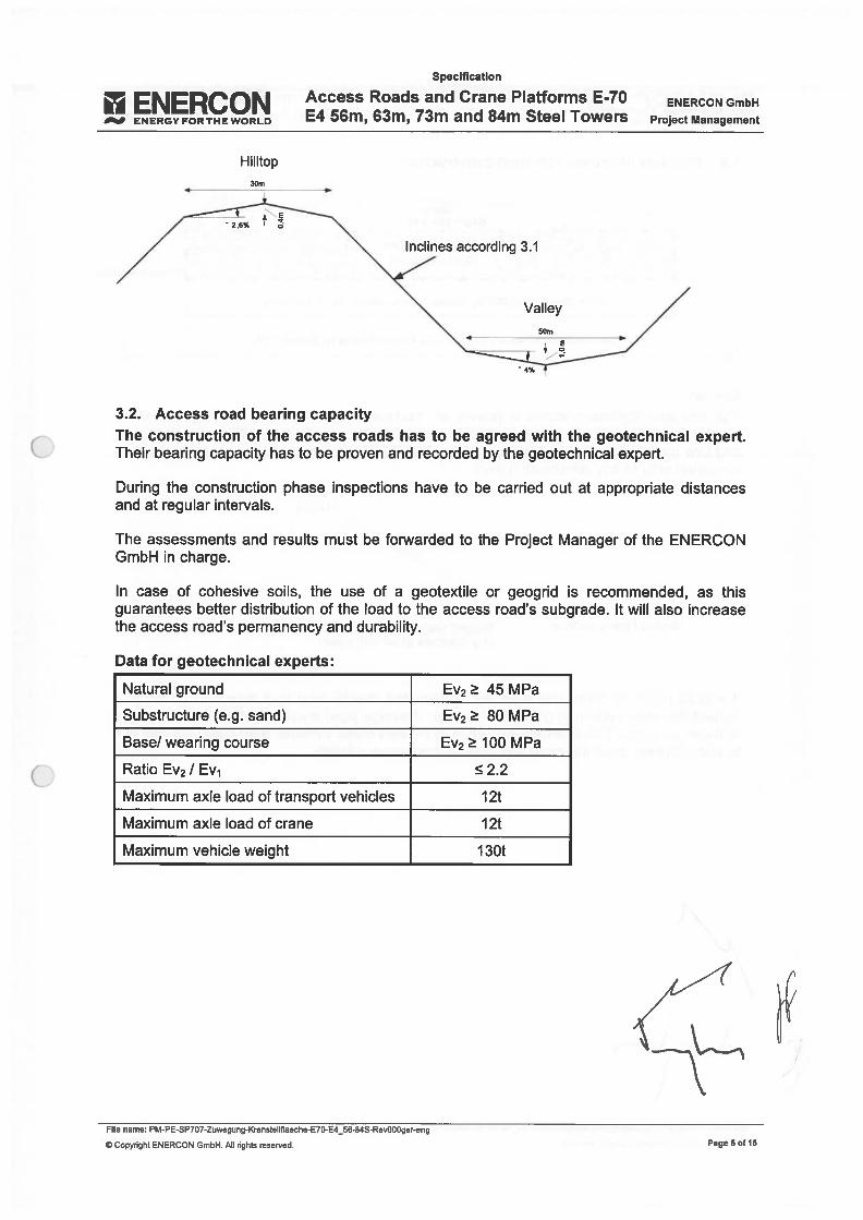
Specification
ENERCON
___
ENERGY FOR THE WORLD
Hilltop30m
Access Roads and Crane Plafforms E-70E4 56m, 63m, 73m and 84m Steel Towers
ENERCON GmbH
Project Management
The construction of the access roads has to be agreed with the geotechnical expert.Their bearing capacity has to be proven and recorded by the geotechnical expert.
During the construction phase inspections have to be carried out at appropriate distancesand at regular intervals.
lhe assessments and results must be forwarded to the Project Manager of the ENERCONGmbH in charge.
In case of cohesive soils, the use of a geotextile or geogrid is recommended, as thisguarantees beiler distribution of the load to the access road’s subgrade. It will also increasethe access road’s permanency and durability.
Data for geotechnical experts:
Natural ground Ev2 45 MPa
Substructure (e.g. sand) Ev2 80 MPa
Base! wearing course Ev2 100 MPa
Ratio Ev2 / Ev1 2.2
Maximum axle load of transport vehicles 12t
Maximum axle load ofcrane 12t
Maximum vehicle weight 1 30t
File name: PM-PE-SP707-Zuwegung-Kranstellflaeche-E70-E4_56-84S-Rev000ger-eng
© Copyright ENERCON GmbH. Ali nghts resetved.
*- 2,6%
Inclines according 3.1
Valley
3.2. Access road bearing capacity
Page 6 of 16
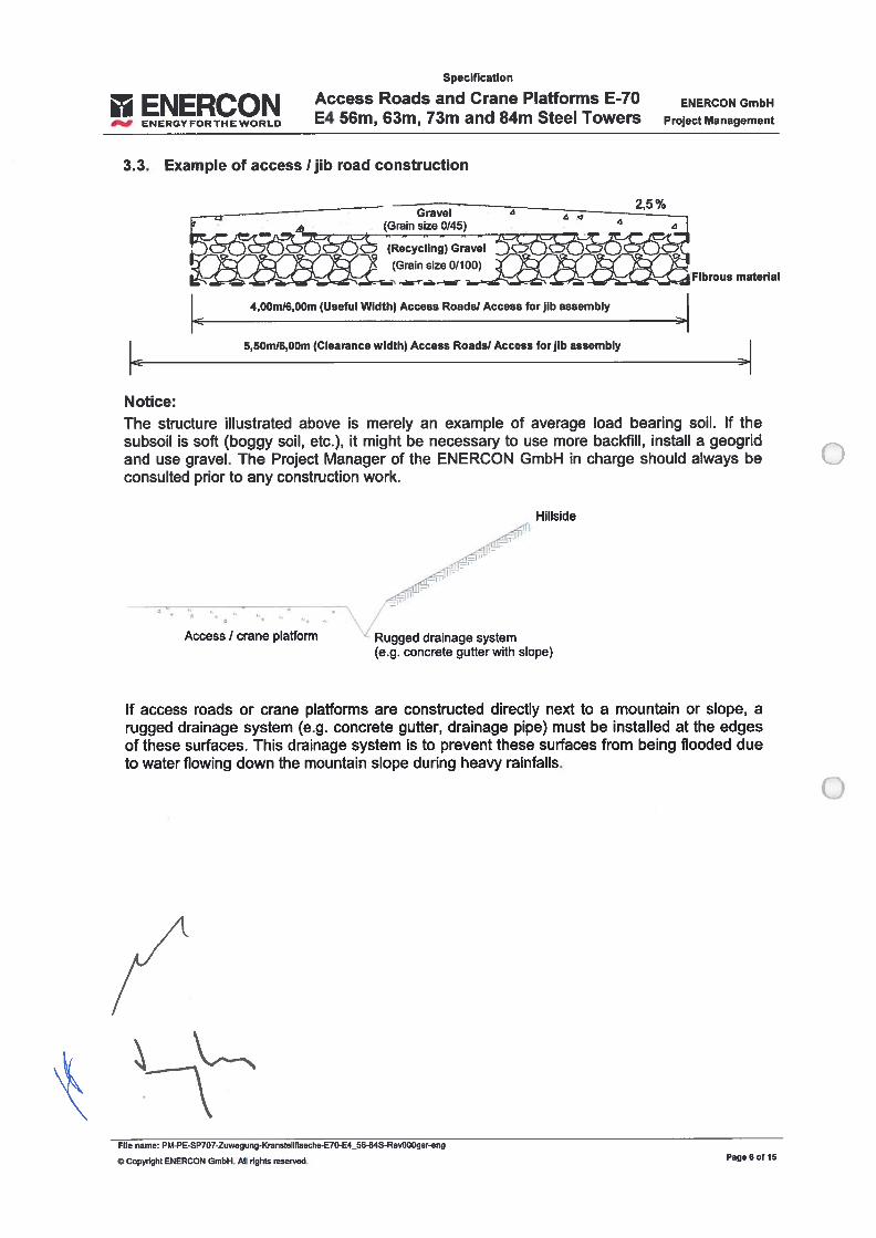
ENERCONENERGY FOR THE WORLD
Specification
Access Roads and Crane Plafforms E-70E4 56m, 63m, 73m and 84m Steel Towers
ENERCON GmbH
Project Management
3.3. Example of access 1 jib road construction
Notice:
2.5%—-
— Gravei
Fibrous material
4,00m16,OOm (Useful Width) Access Roadsi Access for jib assembly
5,50m16,OOm (Clearance width) Access Roadsl Access for jib assembly
The structure illustrated above is merely an example of average load beating sou. lf thesubsoil is soft (boggy sou, etc.), it might be necessary to use more backflhl, instail a geogridand use gravei. The Project Manager of the ENERCON GmbH in charge should always beconsulted prior to any construction work.
HillsiUe
Access / crane plafform Rugged drainage system(e.g. concrete gutter with siope)
lf access roads or crane piafforms are constructed directly next to a mountain or siope, arugged drainage system fe.g. concrete guiler, drainage pipe) must be instalied at the edgesof these surfaces. This drainage system is to prevent these suríaces from being flooded dueto water flowing down the mountain siope during heavy rainfalis.
File name: PM-PE-SP707-Zuwegung-Kransteilflaeche-E70-E4_56-84S-Re%000ger-eng
5 Copyïight ENERCON GmbH. Ali rights reerved. Page 60115
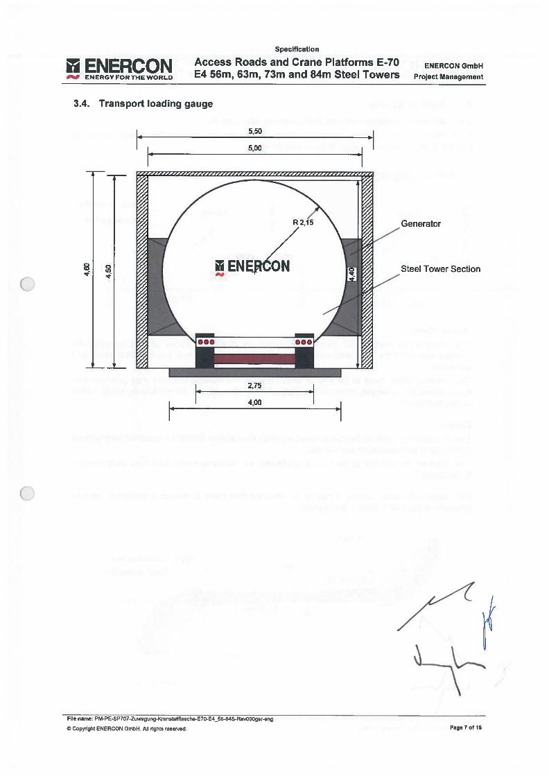
Specification
ENERCONENERGY FORTHEWORLO
Access Roads and Crane Plafforms E-70E4 56m, 63m, 73m and 84m Steel Towers
ENERCON GmbH
Project Management
File name: PM-PE-SP707-Zuwegung-Kranstellflaeche-E70-E4_56-84S-Rev000ger-eng
© Copyright ENERCON GmbH. Ali nghts reserved
1•”
5,50
5D0
3.4. Transport Ioading gauge
8
Generator
Steel Tower Section
2,75
4,00
Page 7 or 15
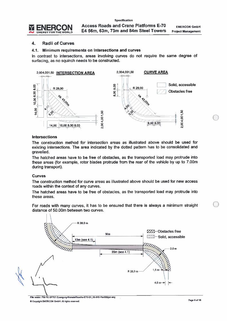
I ENERCON
___
ENERGY FOR THE WORLO
Specification
Access Roads and Crane Plafforms E-70E4 56m, 63m, 73m and 84m Steel Towers
ENERCON GmbH
Project Management
4
4. Radiiof Curves
4.1. Minimum requirements on intersections and curvesIn contrast to intersections, areas involving curves do not require the sarne degree ofsurfacing, as no squinch needs to be constructed.
2,004,001,50 INTERSECTION AREA
R28,00o
oo
ooo
o
IntersectionsThe construction method for intersection areas as illustrated above should be used forexisting intersections. The area indicated by the dofted paftern has to be consolidated andgravelled.
The hatched areas have to be free of obstacles, as the transported Ioad may protrude intothese areas (for example, rotor biades protrude from the tear of the vehicle by up to 7.00rnduring transport).
Curves
The construction method for curve areas as illustrated above should be used for new accessroads within the context of any curves.
The hatched areas have to be free of obstacles, as the transported Ioad may protrude intothese areas.
-2,0 m
CURVE AREA2,004,001,50
1.i28,00
oo
/
00ï
o
oc
oc’J
Solid, accessíble
Obstacles free
o
For roads with rnany curves, it has to be ensured that there is always a minimum straightdistance of 50.00m between two curves.
5Dm—ObstacIes free
accessible
R 28,0 m
4,0
File name: PM-PE-SP707-Zuwegung-Kransteilflaeche-E70-E4_56-84S-Rev000ger-eng
© Copyright ENERCON GmbH. Ali rghts reserved. Page 8 o! 15
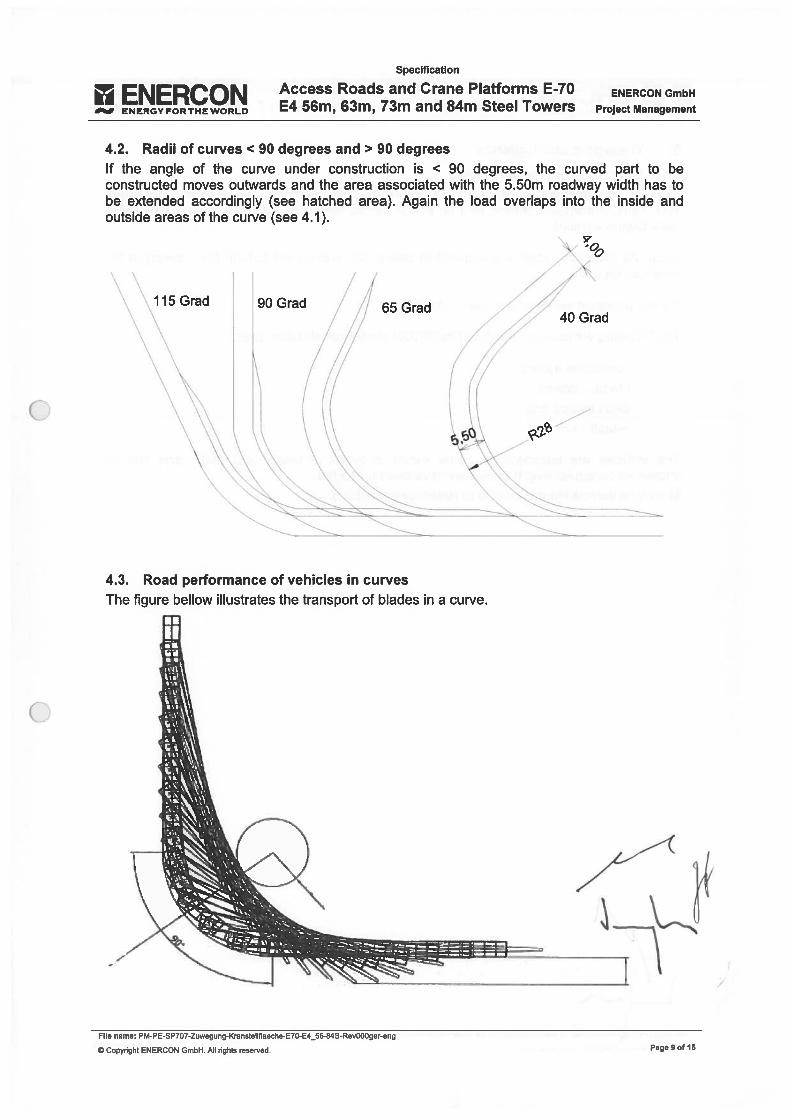
Specification
I’ ENERCON
___
ENERGY FOR THE WORLD
Access Roads and Crane Plafforms E-7OE4 56m, 63m, 73m and 84m Steel Towers
ENERCON GmbH
Project Management
4.2. Radii of curves < 90 degrees and > 90 degreesIf the angle of the curve under construction is < 90 degrees, the curved part to beconstructed moves outwards and the area associated with the 5.50m toadway width has tobe extended accordingly (see hatched area). Again the Ioad overlaps into the inside andoutside areas of the curve fsee 4.1).
/
90 Grad 65 Grad40 Grad
4.3. Road performance of vehicles in curvesThe figure bellow iliustrates the transport of biades in a curve.
File name: PM-PE-SP707-Zuwegung-Kranstellflaeche-E70-E4_56-84S-Rev000ger-eng
© Copyright ENERCON GmbH. Ali rights reserved. Page 90! 15
Specification
ENERCON Access Roads and Crane Plafforms E7O
___
ENERGYFORTHEWORLD m, m an ee owers ProjectManagement
5. Transport and Iogistics
5.1. Basic transport requirementsBasically, the transport vehicles should not exceed the maximum axie load of 12t fusuallylOt). Thus, a transport vehicle with an actual overall weight of lOOt has at least nine axies(plus towing vehicle).
About 20 transport cycles are required to deliver the entire wind turbine (ind. tower) to theconstruction site.
For the transport cycles of the crane, please see 2.2.
The following vehicles are used on ENERCON GmbH construction sites:
- Lowloader trailers- Flatbed trailers- Semi trailers and- Adapter vehicles
The vehicles are telescopic to some extent in terms of length and width, and can beshortened to regular length once they have been unloaded.Maximum vehicle length is 41.00 m (steel tower section).
File name: PM-P SP707-Zuwegung-Kransteliflaeche-E70-E4_56-84S-Rev000ger-eng
© Copyright ENERCON GmbH. Ali dghts reserved. Page 100115
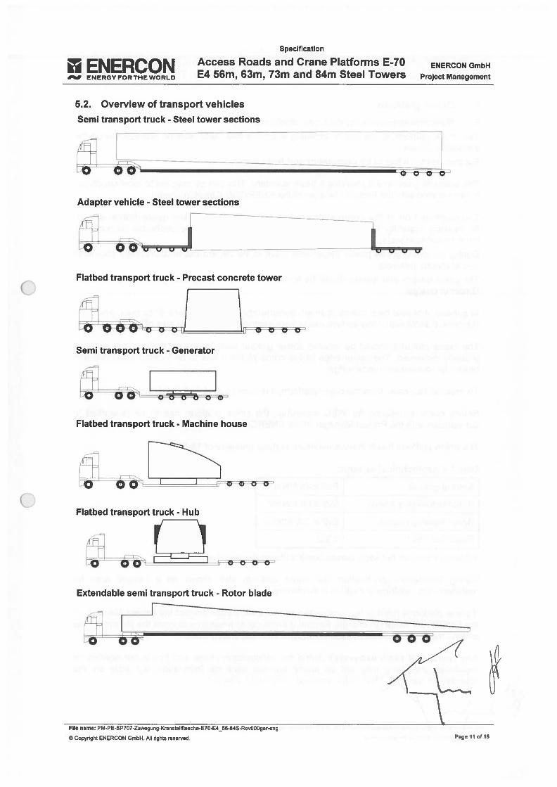
ENERCONENERGY FOR THE WORLD
Specihcation
Access Roads and Crane Plafforms E-70E4 56m, 63m, 73m and 84m Steel Towers
ENERCON GmbH
Project Management
5.2. Overview of transport vehiclesSemi transport truck - Steel tower sections
00 pego
Adapter vehicle - Steel tower sections
LÓJZ ZzFlatbed transport truck - Precast concrete tower
iJJ ,
Flatbed transport truck - Hub
Extendable semi transport truck - Rotor biade
o-- o o
File name: PM-PE-SP707-Zuwegung-Kranstellflaeche-E70-E4_56-84S-Rev000ger-eng
© Copyright ENERCON GmbH. Ali rights reserved,
Uvu
Semi transport truck - Generator
o o OOrO
Flatbed transport truck - Machine house
Pageil otl5
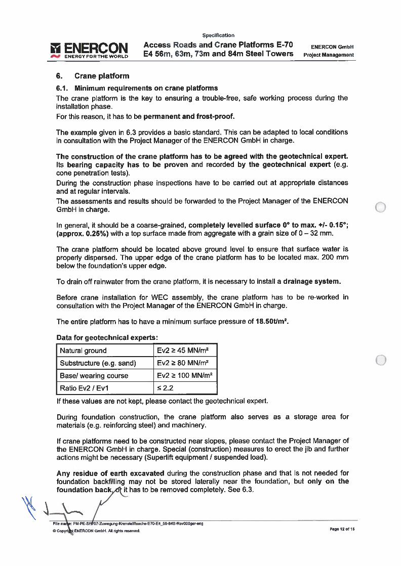
Speciflcation
ENERCON Access Roads and Crane Platforms ElOENERGYFORTHEWORLD m, m, m an m ee owers ProjectManagement
6. Crane platform
6.1. Minimum requirements on crane plafformsThe crane plafform is the key to ensuring a trouble-free, safe working process during theinstaliation phase.For this reason, it has to be permanent and frost-proof.
The example given in 6.3 provides a basic standard. This can be adapted to local conditionsin consultation with the Project Manager of the ENERCON GmbH in charge.
lhe construction of the crane plafform has to be agreed with the geotechnical expert.lts bearing capacity has to be proven and recorded by the geotechnical expert (e.g.cone penetration tests).During the construction phase inspections have to be carried out at appropriate distancesand at regular intervals.The assessments and results should be forwarded to the Project Manager of the ENERCONGmbH in charge.
In general, it should be a coarse-grained, completely levelled surface 00 to max. +1- 0.150;
(approx. 0.25%) with a top surface made from aggregate with a grain size of 0—32 mm.
lhe crane plafform should be located above ground levei to ensure that surface water isproperly dispersed. The upper edge of the crane plafform has to be located max. 200 mmbelow the foundation’s upper edge.
To drain off rainwater from the crane plafform, it is necessary to instail a drainage system.
Before crane instaliation for WEC assembly, the crane plafform has to be re-worked inconsultation with the Project Manager of the ENERCON GmbH in charge.
The entire plafform has to have a minimum surface pressure of 1$.50Um2.
Data for geotechnical experts:
Natural ground Ev2 45 MN/m2
Substructure (e.g. sand) Ev2 80 MN/m2
Base! wearing course Ev2 100 MN/m2
Ratio Ev2 / Evi 2.2
lf these values are not kept, please contact the geotechnical expert.
During foundation construction, the crane platform also serves as a storage area formateriais (e.g. reinforcing steel) and machinery.
lf crane platforms need to be constructed near slopes, please contact the Project Manager ofthe ENERCON GmbH in charge. Special (construction) measures to erect the jíb and furtheractions might be necessary fSuperlift equipment / suspended load).
Any residue of earth excavated during the construction phase and that is not needed forfoundation backfilling may not be stored laterally near the foundation, but only on thefoundation back,.d1 it has to be removed completely. See 6.3.
File nae: PM-PE-S 07-Zuwegung-KransteIIflaeche-E70-E4_56-84S-Rev000ger-eng
© Copyn ENERCON GmbH. Ali rights reserved. Page 12 0115
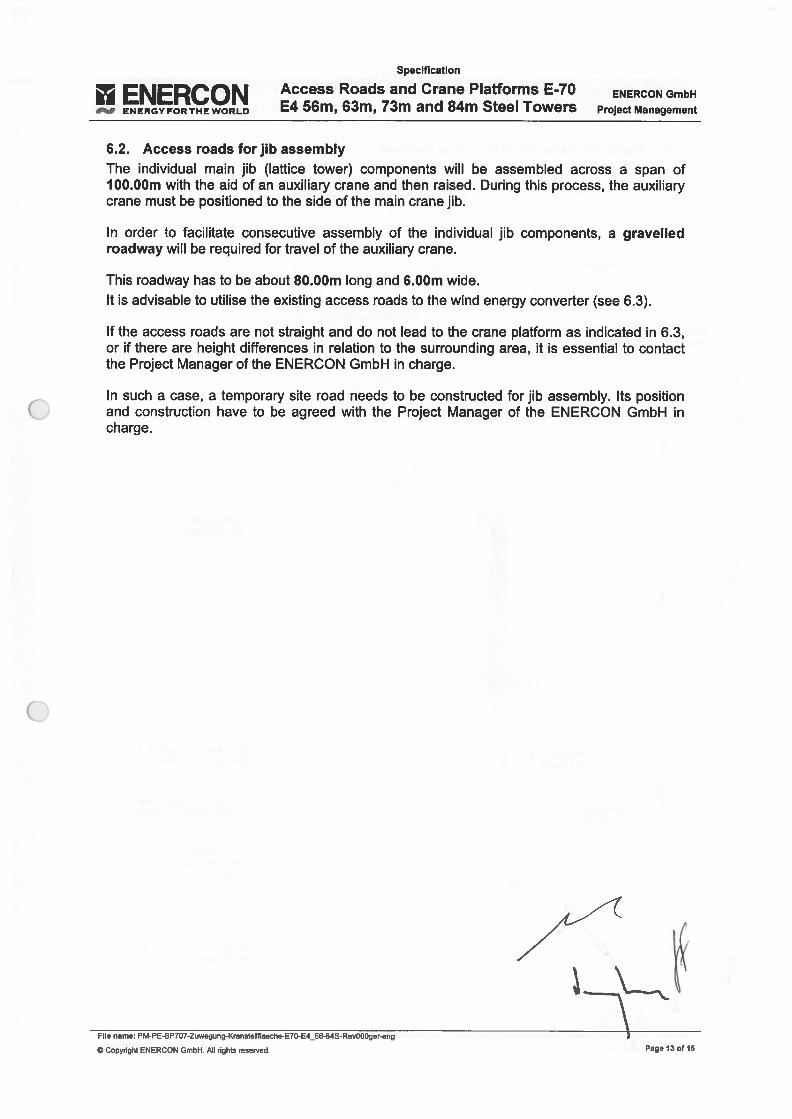
Specification
ENERCON Access Roads and Crane Piafforms E40— ENERGYFORTHEWORLD m, m, m an m ee owers ProjectManagement
6.2. Access roads for jib assemblyThe individual main jib fiattice tower) components wiii be assembied across a span of100.00m with the aid of an auxiliary crane and then raised. During this process, the auxiliarycrane must be positioned to the side of the main crane jib.
in order to facilitate consecutive assembiy of the individual jib components, a graveiledroadway will be required for travei of the auxiiiary crane.
This roadway has to be about $O.00m long and 6.00m wide.It is advisable to utilise the existing access roads to the wind energy converter (see 6.3).
if the access roads are not straight and do not lead to the crane piafform as indicated in 6.3,or if there are height differences in relation to the surrounding area, it is essential to contactthe Project Manager of the ENERCON GmbH in charge.
In such a case, a temporary site road needs to be constructed for jib assembly. its positionand construction have to be agreed with the Project Manager of the ENERCON GmbH incharge.
File name: PM-PE-SP707-Zuwegung-Kranstellflaevhe-E70-E4_56-84S-Rev000ger-eng
© Copynght ENERCON GmbH. Ali rights reserved. Page 13 of 15
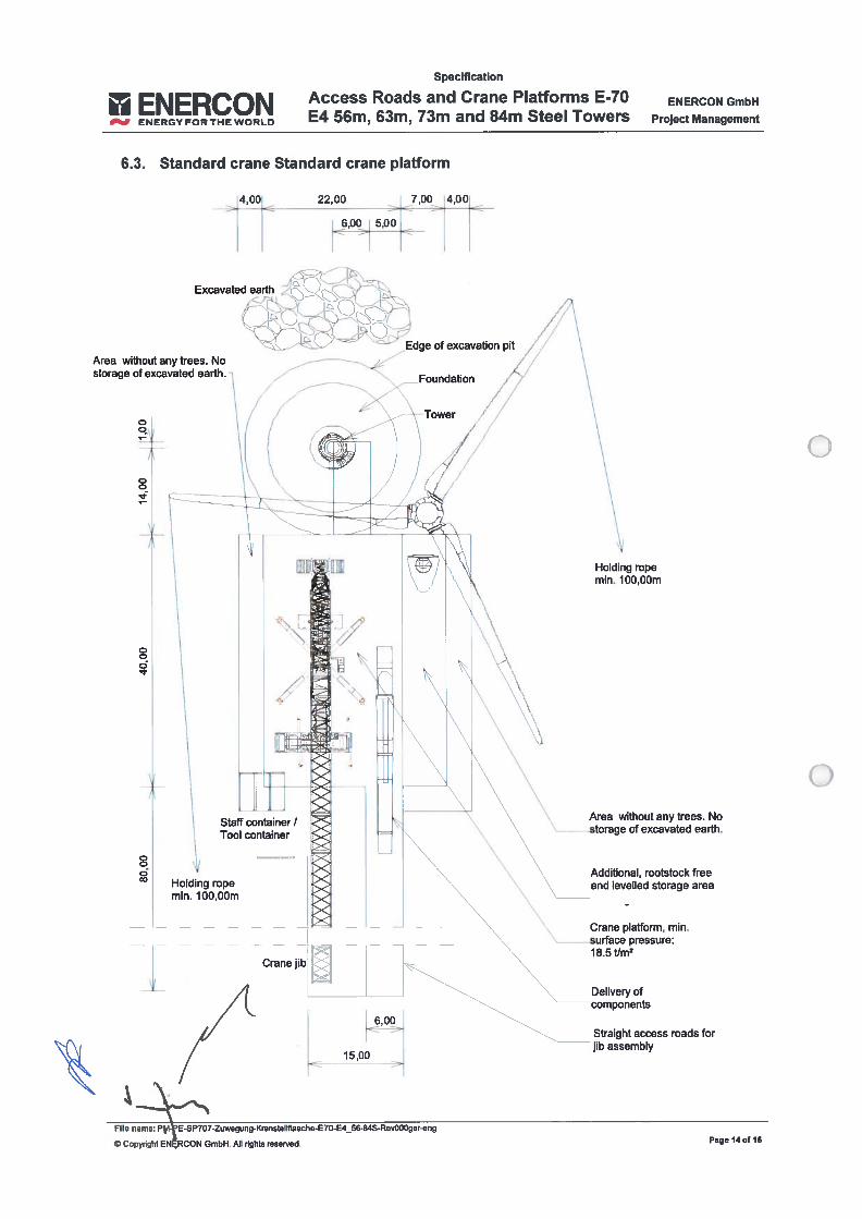
Specification
ENERCON Access Roads and Crane Plafforms E-70E4 56m, 63m, 73m and 84m Steel Towers
6.3. Standard crane Standard crane plafform
Area without any trees. Nostorage of excavated earth.
Additional, rootstock fteeand Ievelled storage area
15,OO
File name: Pi-ESP7O7-Zuwegung-KransteIIflaeche-E7O-E4_56-84S-RevOOOger-eng
© Copyright ENRCON GmbH. AH rights reserved.
Delivery ofcomponents
Straight access roads forjib assembly
ENERCON GmbH
Project Management
i4,001 22,00 7,00 4,00-
Edge of excavation pit
Foundation
Excavated earth
Area without any trees. Nostorage of excavated earth. -
ooo
oeo
Holding topemm. 100,OOm
Staff container /Tool container
Holding topemm. 100,OOm
Cranejib
tCrane platform, mm.
—
- surface pressure:18.5 I/mz
Page 14 0H15

Specification
ENERCON Access Roads and Crane Plafforms E-70E4 56m, 63m, 73m and 84m Steel Towers
6.4. Crane platforms ín forested areas
oo
22,00 7,00 4,00
ENERCON GmbH
Project Management
File name: PM-PE-SP707-Zuwegung-Kranstellflaeche-E70-E4_56-84S-Rev000ger-eng
Straight access roads forjib assembly
,- Previously cleared and aftercompletion of the works..afforested area
\ae 15 of 15
4,00!
0O
Area without any trees. Nostorage of excavated earth.
Holding ropemm. 100,OOm
Area without any trees.No storage of excavated earth.
Additional, rootstockfree and Ievelledstorage area
Cranejib —
Crane platform, mm.surface pressure:18.5 Um2
Area without any trees.No storage of excavated - jearth.
15,00
Delivery ofcomponents
© Copyright ENERCON GmbH. AlI nghts reserved.

oo

o

o
o
1
e
44
—
(
Iechnical Descriptíon
ENERCON SCADA System
ENERCONENERGY FOR THE WORLD
Technical DescriptionENERCON SCADA System I ENERCON
ENERGY FOR THE WORLD
ENERCON GmbH • Dreekamp 5 26605 Aurich GermanyPhone: +49 4941 927-O• Fax: +49 4941 927-109E-mali: [email protected] • internet: hftp://www.enercon.deManaging Directors: Hans-Dieter Kettwig, Simon-Hermann WobbenLocal court: Aurich Company registration number: HRB 411VAI iD no.: DE 181 977 360
Copyright notice
Registered trademarks
Reservation of rightof modification
Document details
The entire content of this document is protected by copyright and — with regard toother intellectuai property rights — international laws and tteaties. ENERCON GmbHhoids the rights in the content of this document uniess another rights hoider is expressiy identified or obviousiy recognisabie.
ENERCON GmbH grants the user the ght to make copies and duplicates of thisdocument for informational purposes for its own intra-corporate use; making this document avaitable does not grant the user any further right of use. Any othet duplication, modification, dissemination, publicatian, circuiation, surrender to third partiesand/ar utilisation of the contents of this document — aiso in part — shall require the express prior written consent of ENERCON GmbH unless any of the above is permittedby mandatory legisiation.
lhe user is prohibited from registering any industrial property rights in the know-howreproduced in this document, or for parts thereof.
if and to the extent that ENERCON GmbH does not hold the rights in the content aíthis document, the user shali adhere to the relevant rights holder’s terms oí use.
Any trademarks mentioned in this document are inteliectual property of the respective registered trademark hoiders; the stipuiations of the applicabie trademark iaw arevalid without restriction.
ENERCON GmbH reserves the right to change, improve and expand this documentand the subject matter described herein at any time without prior notice, uniess contractual agreements or legal requirements provide otherwise.
Document ID D0231306-9
Note Original document. Source document of this transiation: DOl 90917-9/2018-04-17
Date Language DCC Plantldepartment
2018-05-03 en DA WRD Management Support GmbH / Documentation Department
Publisher
2 of 48 D023 1306-9 / DA
Technical DescriptionENEY FOR THE ENERCON SCADA System
Applicable documents
lhe tities of the documents Iisted are the tities of the original language versions, with transiations of these tities in f)where applicable. Document IDs always refer to the original language versions. If the document ID does not contam arevision, the most recent revision of the document applies.
Document ID Titie
D0441 885 Technische Beschreibung ENERCON Windenergieanlagen Blattheizung (Technicaldescription of ENERCON Wind Energy Converters blade heating system)
D0353070 Technische Beschreibung ENERCON Windenergieanlagen Eiswarnleuchte (Technical Description, ENERCON Wind Energy Converters ice waming light)
IEC 60870-5-1 04 Fernwirkeinrichtungen und -systeme Teil 5-104: Übertragungsprotokolle - ZugrifffürIEC 60870-5-101 auf Netze mit genormten Transportprofilen (Remote controlequipment and systems, part 5-104: Transmission control protocols - access forIEC 60870-5-101 to grids with standardised transport profiles)
D0231306-9 / DA 3 of 48
Technical DescnptionENERCON SCADA System ENEY FOR THE
Table of contents
Introduction 7
2 Requirements 8
3 Scope of supply and services 9
4 Standard components and features 10
4.1 ENERCONSCADAServer 10
4.1.1 Function 10
4.1.2 Datatypes 10
4.1.3 Data transmission to Technical Service Dispatch at the ENERCON Service 11
4.2 ENERCON data bus 11
4.3 ENERCONSCADARemote 12
4.3.1 Function 12
4.3.2 Data exchange 13
4.4 Status and information messages 14
4.5 Data storage during a communication failure 15
4.6 Data quality and evaluation 15
5 Additional components and features 17
5.1 Data interfaces with external systems 17
5.1.1 Overview 17
5.1.2 ENERCON SCADAPDJ-OPC 18
5.1.2.1 Functionality 18
5.1.2.2 Data exchange 19
5.1.2.3 External analyses 19
5.1.3 ENERCON SCADA PDI-61400 20
5.1.3.1 Functionality 20
5.1.3.2 Data exchange 21
5.1.3.3 External analyses 21
5.1.4 ENERCON SCADA RTU (RTU-I and RTU-C) 22
5.1.5 Fault security and defaultvalues 22
5.2 Components for measured data acquisition 24
5.2.1 Overview 24
5.2.2 ENERCON SCADA RTU-C 24
5.2.3 ENERCON SCADA METEO 26
5.3 Open-Ioop and closed-Ioop control with ENERCON SCADA System 27
5.3.1 Overview 27
5.3.2 Open-Ioop control with the ENERCON SCADA system 27
4 of 48 D0231306-9 IDA
Technical DescriptionENE’RY FOR THE ENERCON SCADA System
5.3.3 Closed-Ioop control with the ENERCON SCADA system 28
5.3.4 ENERCON SCADA RTU-C 29
5.3.4.1 Productoverview 29
5.3.4.2 Types of open-Ioop and closed-Ioop control systems 30
5.3.4.3 Fault security and default values 31
5.3.5 ENERCON SCADA FCU 34
5.3.5.1 Product overview 34
5.3.5.2 Closed-Ioop control 35
5.3.5.3 Fault security and default values 37
5.4 Automatic fault message transmission 39
5.5 ENERCON SCADA Event Trigger Control System 41
5.6 Control of individual systems in an ENERCON wind energy converter 42
5.6.1 Rotor blade heating system open-loop control 42
5.6.2 Ice warning Iight open-Ioop control 42
5.7 ENERCON SCADA Power Consumption Management 43
5.8 ENERCON SCADA Bat Ptotection 44
5.9 Country-specific special solutions and applications 44
6 Maintenance 45
6.1 Required maintenance 45
6.2 ENERCON SCADA system within the ENERCON PartnerKonzept 45
Table of figures 46
Glossary of terms 47
D0231306-9 IDA 5 of 48
Technical DescriptionENERCON SCADA S1QtmJ ENERGY FOR THE WORLD
List of abbrevíations
DSL Digital subscriber une
FCU Farm Control Unit
GSM Global System for Mobile Communications
ISDN lntegrated Services Digital Network (telecommunication standard)
OPC Open Platform Communications
PDI Process Data Interface
RTU Remote Terminal Unit
SCADA Supervisory Control and Data Acquisition
SMS Short message service
UMTS Universal Mobile Telecommunications System
WEC Wind energy converter
6 of 48 D0231306-9 / DA
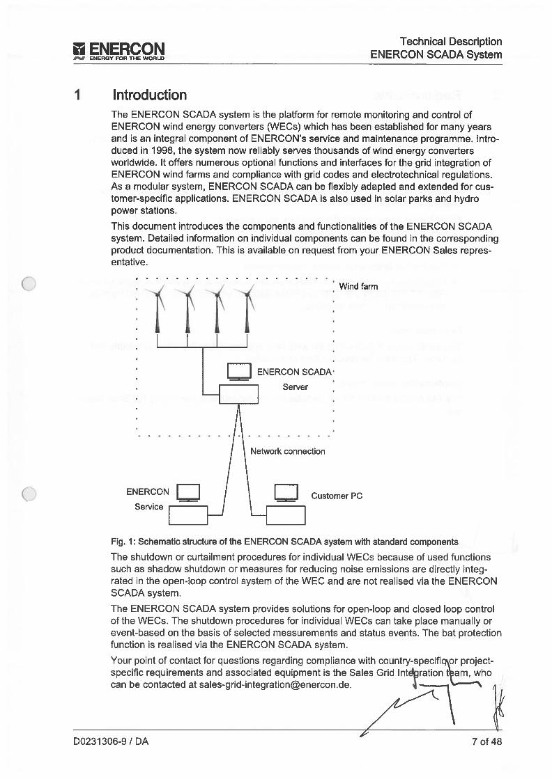
ENERCON
___
ENERGY FOR THE WORLD
Technical DescriptionENERCON SCADA System
IntroductionThe ENERCON SCADA system is the plafform for remate monitoring and control ofENERCON wind energy converters (WECs) which has been established for many yearsand is an integral component of ENERCON’s service and maintenance programme. Introduced in 1998, the system now reliably serves thousands of wind energy convertersworldwide. It offers numerous optional functions and interfaces for the grid integration ofENERCON wind farms and compliance with grid codes and electrotechnical regulations.As a modular system, ENERCON SCADA can be fiexibly adapted and extended for customer-specific applications. ENERCON SCADA is also used in solar parks and hydropower stations.
This document introduces the components and functionaiities of the ENERCON SCADAsystem. Detailed information on individual components can be found in the correspondingproduct documentation. This is available on request from your ENERCON Saies representative.
Fig. 1: Schematic structure of the ENERCON SCADA system with standard components
The shutdown ar curtailment procedures for individual WECs because of used functionssuch as shadow shutdown ar measures for reducing noise emissians are directly integrated in the open-loop contrai system of the WEC and are not realised via the ENERCONSCADA system.
The ENERCON SCADA system provides solutions for open-loop and closed ioop contraiof the WECs. The shutdown procedures for individual WECs can take place manually arevent-based an the basis of selected measurements and status events. lhe bat pratectianfunction is realised via the ENERCON SCADA system.
Your point of contact for questions regarding compliance with country-specifi ar projectspecific requirements and associated equipment is the Saies Grid lntration t am, whocan be contacted at [email protected]. 4—
Wind farmç
ENERCON SCADA
Server
II Customer
Network connection
ENERCON
Service
D0231306-9 / DA 7 of 48
Technical DescnptionENERCON SCADA S,ctm.7 ENERGY FOR THE WORLD
2 Requirements
ENERCON SCADA Server
An ENERC.ON SCADA Server must be installed in order to run the ENERCON SCADAsystem in the wind farm.
Data communication
An Internet connection is required to ensure external communication to and from theENERCON SCADA Server.
lhe following telecommunications options are supported:
• DSL (preferred telecommunications option)
• Public network connection (alternative connection option)
• Satellite Iink (alternative communication option)
• Mobile internet connection via UMTS or 3G as well as analogue communication standards (POTS), ISDN and GSM are only suitable to be used as an additional back-upconnection due to their technology
Fibre-optic cable
lhe transmission of data within the wind farm requires a data link which is reliable andtap-proof. This data link requires fibre-optic cables.
Unintermptible power supply
The ENERCON SCADA Server includes an uninterruptible power supply (UPS) as standard.
8 of 48 D0231306-9 / DA

Ek‘ERCO’Technical Description
“ “ ENERCONSCADASENERGY FOR THE WORLD
3 Scope of supply and servicesENERCON SCADA system refers collectively to ali SCADA components and the interaction between these components. lhe combination of these components is project-specific.
Unless otherwise contractuaiiy agreed, the standard scope of deiivery of a new wind farmto be erected by ENERCON contains the foilowing components:
• ENERCON SCADA Server
• ENERCON SCADA (software running on the ENERCON SCADA Server)
• ENERCON SCADA Remote (software for customer PC)
• One licence for both software products
• Hardware protection (dongle)
D0231 306-9 / DA 9 of 48
Technical DescriptionMIRCOM SCADA Sicm1 ENERGYFORTHEWORLD
4 Standard components and features
4.1 ENERCON SCADA Server
4.1.1 Function
The ENERCON SCADA Server is the key component of the ENERCON SCADA system.The ENERCON SCADA Server performs various wind farm communication, open-ioopcontrol and closed-loop control functions. lt is also the central repository for the currentand archived operating data ofthe WECs and the SCADA components. In addition, certain open-loop control algorithms can be impiemented using the ENERCON SCADAServer.
lhe ENERCON SCADA Server can fuifil a range of functions including:
• Acquisition and storage of the wind farm’s operating data
• Communication between the wind farm and the ENERCON Service
• Communication between the wind farm and the customer and/or grid operator
• Wind farm control (open-Ioop)
4.1.2 Data types
The ENERCON SCADA Server provides the foliowing types of data:
Online data
Online data are instantaneous values that the ENERCON SCADA Server refreshes as often as permitted by the wind farm’s SCADA System. The data refresh rate depends on thenumber of wind energy converters installed in the wind farm, the structure of the wind farmdata bus, and — primariiy — the communication hardware selected.
Online data also include fixed data such as the serial number of a wind energy converter(WEC).
Report data
Measurement data for each wind energy converter, spanning its entire operating time, arecoiiected. While in operation, the WEC is permanentiy monitored by measuring equipment; a data logger records ali measured values. This inciudes WEC status data as weIIas average values for specific time periods. lhe average values consist of data collectedby the ENERCON SCADA software on the ENERCON SCADA Server.
Typically, the averages are computed for periods of one minute, ten minutes, one day,one week, one month, and one year. Ali of these are based on one-minute averages. AlI10-minute values (plus longer intervals) are stored on the ENERCON SCADA Server.
Archiving operating data
As a rule, the capacity of the ENERCON SCADA Server hard drive aiiows for backup ofthe entire data within the operating period. If data acquisition by the ENERCON SCADAServer also inciudes transmission substations, meteorological masts or similar, the datavolume may increase considerably, meaning that the capacity Iimit wiii be reached sooner.When the hard drive is 90 % fuli, the ENERCON SCADA Server wiIl send a warning message to ENERCON Service.
\410 of 48 D0231306-9 / DA
N Technical Description
__
ENERGY FOR THE ENERCON SCADA System
4.1 3 Data transmission to Technical Service Dïspatch at the ENERCON Service
The data of ali WECs connected to an ENERCON SCADA system worldwide is transmitteU to the lechnical Service Dispatch every night and stored there (assuming that it isreachable). An updated record of the status messages from the past 24 hours is retrieved,along with the operating data for the past day and month. lf more than 24 hours havepassed since the last successful communication, the time periods for data retrieval are extended accordingly.
24 hours after the last communication, the ENERCON SCADA system sends at least atest message to Technical Service Dispatch. This ensures that a prolonged communication fault with the wind farm does not go unnoticed.
4.2 ENERCON data busThe ENERCON SCADA Server is connected to the ENERCON generation units (e.g.WEC) and the ENERCON SCADA devices (e.g. RTU) via the park-internal fibre optic databus system.
To ensure a high degree of communication reliability, a maximum of 10 systems/devicesare combined into one physical data bus. lf more systems!devices are installed in the windfarm, multipie physical data bus cables are set up using a star topology. lhe logical databus system always includes ali systems/devices in the wind farm.
Connection of the ENERCON SCADA Server to the ENERCON data bus system takesplace via an interface PCB. This acts as a converter between electrical and optical signais.
The SCADA interface PCB can optionally be equipped with backup batteries. lf a wind energy converter on a physical data bus is de-energised, e.g. due to maintenance work onthe medium-voltage transformer, the backup batteries allow communication to be maintained with the other systems and devices upstream of the affected WEC from the perspective of the ENERCON SCADA Server.
D0231306-9 / DA 11 of 48
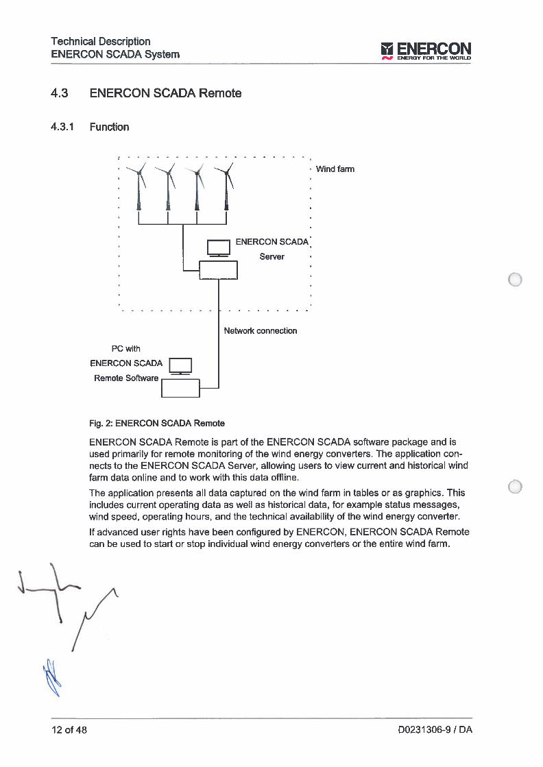
Technical DescriptionENERCON SCADA System ENERCON
ENERGY FOR THE WORLD
Fig. 2: ENERCON SCADA Remote
ENERCON SOADA Remote ís part ot the ENERCON SOADA software package and isused primarily for remote monitoring of the wind energy converters. lhe application connects to the ENERCON SCADA Server, ailowing users to view current and historical windfarm data online and to work with this data offline.
The application presents ali data captured on the wind farm in tables or as graphics. Thisincludes current operating data as welI as historical data, for example status messages,wind speed, operating hours, and the technical availability of the wind energy converter.
If advanced user rights have been configured by ENERCON, ENERCON SOADA Remotecan be used to start or stop individual wind energy converters or the entire wind farm.
4.3 ENERCON SCADA Remote
4.3.1 Function
ç
4 1Wind farm
ENERCON SCADA
Server
Network connection
PC with
ENERCONSCADA 1 1Remote Software
412 of 48 D0231 306-9 / DA
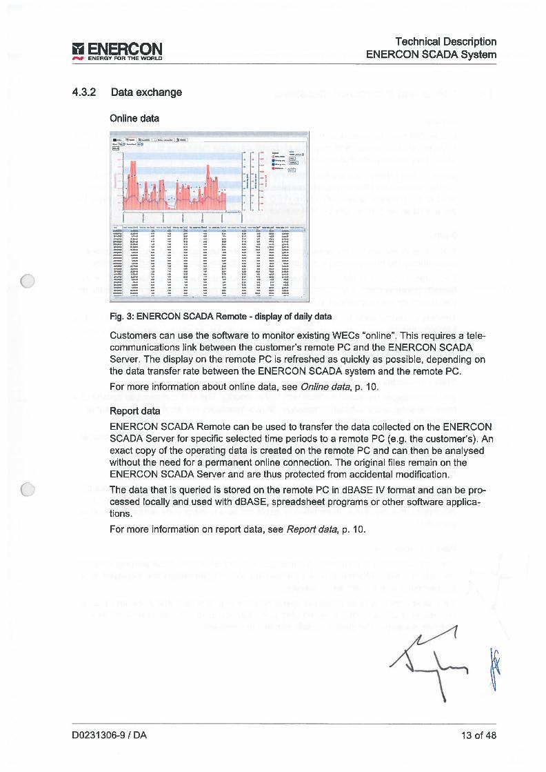
II Technical Description
__
ENER’Y FOR THE ENERCON SCADA System
4.3.2 Data exchange
Online data1
, •t&:,’
.“..
Fig. 3: ENERCON SCADA Remote - display of daily data
Customers can use the software to monitor existing WECs “online”. This requires a telecommunications link between the customer’s remote PC and the ENERCON SCADAServer. lhe display on the remote PC is refreshed as quickly as possible, depending onthe data transfer rate between the ENERCON SCADA system and the remote PC.
For more information about online data, see Online data, p. 10.
Report data
ENERCON SCADA Remote can be used to transfer the data collected on the ENERCONSCADA Server for specific selected time periods to a remote PC (e.g. the customer’s). Anexact copy of the operating data is created on the remote PC and can then be analysedwithout the need for a permanent online connection. The original files remam on theENERCON SCADA Server and are thus protected from accidental modification.
The data that is queried is stored on the remote PC in dBASE IV format and can be processed locally and used with dBASE, spreadsheet programs or other software applications.
For more information on report data, see Report data, p. 10.
D0231306-9 IDA 13 of 48
Technical DescriptíonENERCON SCADA System ENV FOR THE WO
4.4 Status and information messages
General
ENERCON wind turbines (e.g. WECs), ENERCON SCADA devices and other ENERCONsystems (such as infeed and charging systems) generate messages during operation withwhich they provide information about their current status.
Some of these messages are automatically transmitted to ENERCON Service so that itcan be ensured that the equipment remains available. Messages that are not directly reateU to the technical availability ofthe WEC are not transmitted to ENERCON Service butare available via ENERCON SCADA Remote.
Status
The status describes the current operating state of the respective system. lhe statusescontinuously Iog the operating state and the reason for the current status if necessary.
Each status consists of the main status and the substatus. The main status describes theoverali operating state, e.g. TURBINE STOPPED. lhe substatus provides more details andthe reason for the main status, e.g. Farm control
There is a number code for every main status and substatus. Statuses are specified in thefollowingformat:Main status number code : Main status text substatus
number code : Substatus text.
Examplestatusmessage: 1:6 Turbine stopped : Farm contrai
Status messages
Status messages represent a status with higher priority. lhe status messages consist of amain message and a substatus message. Status messages are displayed as a numbercode with a text explanation.
lf an abnormal operating state (such as a malfunction) occurs in a system that causes animmediate shutdown of the system, the system transmits a status message.
1 nformation
Information messages in the ENERCON SCADA system reptesent information about therespective system and its components, and are structured into main information and subinformation like the status. Information is displayed as a number code with a short text explanaUon.
Warning messages
Warning messages are information messages with higher priority. Each warning messageconsists of a main information and a subwarning. Warning messages are displayed as anumber code with a short text explanation.
If the wind turbine is in an abnormal operating state (e.g. a defect) that does not cause animmed iate shutdown of the system but requires Service action, the system transmits awarning message. The system initially remains in operation.
14 of 48 D0231306-9 / DA
E’ERCO’Technical Description
ENERCONSCADAS”t
__
ENERGVORTHEWORLD 3
4.5 Data storage during a communication failure
Status messages
During a communication failure between the control system of an ENERCON wind energyconverter and the ENERCON SCADA Server, up to 400 status messages can be storedby the control system (CS48, CS82, CSIO1, CS126 and EP4-CSO1).
When communication has been re-established, at Ieast 50 backdated status messagescan be transmitted to the ENERCON SCADA Server. If required, the number of backdatedstatus messages can be increased.
Information and warning messages
Information and warning messages are not deleted from the control system memory untilthey have been transmitted to the ENERCON SCADA Server.
Because no messages can be transmitted during a communication failure, these aresaved and can be transmitted to the ENERCON SCADA Server when communication hasbeen re-established.
• Messages during maintenance
The messages generated during the maintenance of an ENERCON wind energyconverter are not transmitted to the ENERCON SCADA Server. lhe wind energyconverter does not store these messages, either.
Instantaneous values
Instantaneous values such as e.g. wind speed, rotational speed, power, etc. are notsaved.
10-minute average values
The ENERCON SCADA Server cyclically retrieves the average values provided by thecontrol system and uses them to form a 10-minute mean.While communication is interrupted or down, the ENERCON SCADA Server cannot retrieve any average values and is therefore unable to form any 10-minute mean values.
Operating hours and power fed into grid
The operating hours and the power fed into the grid are recorded and saved by the WECcontrol system.
When communication has been re-established, the data is transmitted to the ENERCONSOADA Server.
SCADA Devices
SOADA devices such as RTU, FCU, METEO, etc. do not store any data in the event of acommunication failure.
4.6 Data qualíty and evaluation
When the SOADA data is used to evaluate performance or for other puposes, aftentionmust be paid to the following:
D0231306-9 IDA 15 of 48
Technical DescnptíonENERCON SCADA System ENY FOR THE
The ENERCON SCADA system records the measurement data and operating data of theconnected systems. The data is averaged and recorded. The reliability and accuracy ofthe data depends on the data source.
The sensor systems which are used in and on ENERCON wind turbines (e.g. WECs)have uncertainty in measurement for technical reasons. Because of the possible uncertainty in measurement and the averaging of the data, the data can only conditionally beused to check exact situations fe.g. for determining the power performance of the WEC).
16 of 48 D0231306-9 IDA
Technicai Description
__
ENEY FOR THE ENERCON SCADA System
5 Additional components and featuresThe additional components and features of the ENERCON SCADA system require separate contractual agreement. Please contact your Saies representative for more detaiis.
5.1 Data interfaces with external systems
5.1.1 Overview
ENERCON offers the foliowing data interfaces with external systems:
• ENERCON SCADA PDI-OPC
• ENERCON SCADA PDI-61400
ENERCON SCADA RTU-I
• ENERCON SCADA RTU-C (for more features, see ch. 5.2.2, p. 24 and ch. 5.3.4.1,p. 29)
• ENERCON SCADA FCU (for more features, see ch. 5.3.5.1, p. 34)
The data interfaces are used when setpoint specification and data retrieval must be fastand flexible. This requires a permanent data Tink. ENERCON SCADA PD1-OPC andENERCON SCADA PDI-61400 can be used to retrieve data from individual wind energyconverters. Compared to the ENERCON SCADA Remote monitoring software, data exchange via interface primariiy offers the option of specifying new setpoints. lhe associated time delay depends on the data link transfer rate.
D0231306-9 IDA 17 of 48

Technical DescriptionENERCON SCADA System i ENERCON
ENERGV FOR THE WORLD
5.1.2 ENERCON SCADA PDI-OPC
5.1.2.1 Functionality
1Wind fami
ENERCON SCADA PDI-OPC is an OPC XML DA server in accordance with the Vi .01specifications of the OPC Foundation. It can be used to retrieve measured values and foropen-loop control of the entire wind farm or individual wind energy converters.
AlI data available through the ENERCON SCADA Remote software can also be retrievedby means of ENERCON SCADA PDI-OPC. In addition, setpoints can be transmifted viaENERCON SCADA PDI-OPC (for instance, to adjust reactive power generation by thewind farm).
lhe features of ENERCON SCADA PDI-OPC as welI as its available technical interfacesand signals are described in its respective documentation. lhe method for setpoint modification must be selected on a project-specific basis.
Server,
and
OPCXML-DAServer
Network connection
OPC CIient1 1
Fig. 4: ENERCON SCADA PDI-OPC within the ENERCON SCADA system
18 of 48 D0231306-9 / DA
II Technícal Description
__
ENERQY FOR THE ENERCON SCADA System
5.1.2.2 Data exchange
The OPC XML DA server can provide and receive the following types of data:
Online data
The OPC XML DA server refreshes online data as often as permitted by the wind farm’sENERCON SCADA system. The structure of the specific project is included in the datatransfer and can be viewed on the client. The shortest possible refresh interval within OPCis one second.
For more information on online data, see Online data, p. 10.
Report data
The OPC server stores historical report data, i.e. it provides not only current values butalso values from past time intervais and thus helps ensure data consistency between thecustomer’s computer and the wind farm computer.
For more information on report data, see Report data, p. 10.
Setpoints
The client can use control data to modify wind farm or WEC parameters. These includestarUstop commands for individual WECs and the modification of setpoints for wind farmcontrol.
5.1.2.3 External analyses
Customers have the option of exporting the data from the wind farm OPC XML DA serverfor further processing.
For this purpose, the customer must obtain a software application that supports data exchange via the OPC XML DA protocol. A wide range of commercial software applicationsis available. Customers can decide individually which data to select, view and store ontheir systems.
The OPC XML DA server in the wind farm is designed so that customers can save to theirlocal systems the exact sarne data that exists in the wind farrn, even if online communication is poor. This is achieved by providing the entire history in addition to current onlineand average values. In this way, if data transmission is interrupted, customers can filI inany gaps in the data at a later stage. However, this process rnust be initiated by the OPCclient since the server cannot determine which gaps may have occurred in the customer’sdata.
D0231306-91 DA 19 of 48
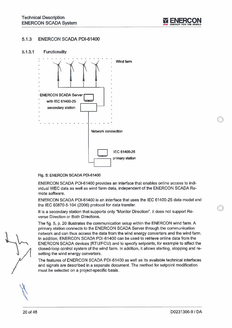
Technical DescriptíonENERCON SCADA System ENERCON
ENERGY FOR THE WORLD
/
Fig. 5: ENERCON SCADA PDI-61400
1 1
-H 1primary
ENERCON SCADA PDI-6 1400 provides an interface that enables online access to individual WEC data as well as wind farm data, independent of the ENERCON SCADA Remote software.
ENERCON SCADA PDI-61400 is an interface that uses the IEC 61400-25 data model andthe IEC 60870-5-104 (2006) protocol for data transfer.
It is a secondary station that supports only “Monitor Direction”. It does not support Reverse Direction or Both Directions.
lhe fig. 5, p. 20 illustrates the communication setup within the ENERCON wind farm. Aprimary station connects to the ENERCON SCADA Server through the communicationnetwork and can thus access the data from the wind energy converters and the wind farm.In addition, ENERCON SCADA PDI-61400 can be used to retrieve online data from theENERCON SCADA devices (RTU/FCU) and to specify setpoints, for example to affect theclosed-loop control system of the wind farm. In addition, it allows starting, stopping and tesetting the wind energy converters.
lhe features of ENERCON SCADA PDI-61400 as well as its available technical interfacesand signals are described in a separate document. lhe method for setpoint modificationmust be selected on a project-specific basis.
5.1.3 ENERCON SCADA PDI-61400
5.1.3.1 Functionality
‘ENERCON SCADA Server
with IEC 61400-25
Windfarm
secondary station
Network connection
20 ot 48 D0231306-9 IDA
II E‘ERCO’Technical Description
1 ENERCONSCADAS
___
ENERGY FOR THE WORLD
5.1.3.2 Data exchange
The ENERCON SCADA PDI-6 1400 can provide and receive the following types of data:
Online data
The ENERON SCADA PDI-61400 refreshes the online data as often as permitted by theENERCON SCADA system in the wind farm. The structure is determined by the hierarchydefined in IEC 61400-25. The shortest refresh interval within the PDI-61400 is onesecond.
For more information on online data, see ch. 4.1.2, p. 10.
Report data
The ENERCON SCADA PDI-61400 does not provide any report data.
Setpoint specification
Control data can be used to start and stop the wind farm and individual wind energy converters. They can also be used to reset the wind energy converters. In addition, they canbe used to transmit setpoints for closed-loop wind farm control to the ENERCON SCADAdevices (RTU/FCU).
5.1.3.3 External analyses
To analyse the data provided by the ENERCON SCADA PDI-61400, the customer IT system must include a software designed to support data exchange via the IEC 60870-5-104protocol. A wide range of commercial software applications is available. Customers candecide individually which data to view and store on their systems.
D0231306-9 IDA 21 of48
Technical DescriptionENERCON SCADA System ENE!RY FOR
5.1.4 ENERCON SCADA RIU (RTU-l and RTU-C)
lhe ENERCON SCADA Remote Terminal Unit (RIU) functions as an external data inter-face ofthe ENERCON SCADA system.
lhe RTU supports the following interfaces:
• IEC 60870-5-104lhe RIU can be operated as IEC 60870-5-104 Controlled Station (Siave).
• DNP3The RTU can be connected as a DNP3 outstation (siave) to control rooms/dispatchcentres (master) (protocol implementation: DNP3-L2 Outstation).
• Modbus TCP and RTU
As an option, the RIU can be equipped with digital and/or analogue 1/O modules to exchange signals with the utility company or the wind farm operator/owner. In addition, depending on its configuration, the RIU can be used for open-loop or closed-loop control ofgrid parameters.
lhe following target values can be specified for the RTU, among others:
• Active power P in %, relative to the contractually agreed wind farm power injection
• Reactive power Q in %, relative to the nominal reactive power of the wind farm
• Power factor cos Phi
• Voltage offset U in %, relative to the nominal voltage at the network connection point
• lhe interfaces can only be used to write setpoints and read wind farm data. Datafrom individual wind energy converters cannot be read however.
5.1.5 Fault secunty and default values
lf setpoints are specified via the ENERCON SCADA PDI-OPC or ENERCON SCADAPDI-61400 interface of the ENERCON SCADA server and if this interface is faulty, no newsetpoints can be received by the ENERCON SCADA server vía the interface. lhe setpointmay be incorrect due to the following events for example:
• lnterfacefault
• Server is offline
Interface malfunction
lf communication with the interface or the interface itself is faulty and the server is online,the controller used (ENERCON SCADA FCU or RTU) will continue closed-loop control using the last setpoints received.
Server offline - behaviour of FCU
lf control is via the ENERCON SCADA FCU and the ENERCON SCADA Server is shutdown due to a fault for instance (server offline), the FCU will continue operation using thelast setpoints received.
\
22 of 48 D0231306-9 / DA
E’ERCO’Technical Description
_
1 ENERCONSCADAS,ctENERGYFORTHEWORCD .7
Server offline - behaviour of RTU
If control is via the ENERCON SCADA RIU and the ENERCON SCADA Server is shutdown due to a fault for example (server offline), control via the RIU wiII not be possible asIong as the server is down.
If parameter 1308 SCADA farm control(wind energy converter parameter) is activated,the ENERCON SCADA Server wiII save the Iast valid control value to the following windenergy converter parameters:
a 1209 Dynamic reactive power (Q/P) (closed-Ioop wind farm control fau/t)
a 1210 Static reactive power (closed-Ioop wind farm control fault)
• 1400 Maximum power (closed-Ioop wind farm control fault)
To ensure any slight changes to RIU control values do not result in permanent changesto the Iast valid control values stored in the wind energy converters, the control values arenot written until a specified deadband has been exceeded/fatlen short of. lhe followingvalues apply here:
• P: ±10.01 %
a Q: ±10.01 %
• Q/P: ±0.170 (9.65)
Ifwind energy converter parameter 1308 is deactivated, the wind energy converters usethe control values stored in parameters 1209, 1210 and 1400. The control values are notstoted by the ENERCON SCADA Server if parameter 1308 is deactivated. lhe controlvalues stored wiII then be the default values configured.
Checking the setpoint
An evaluation of whether a setpoint has been received correctly and correctly processedby the FCU or RTU can be made via the feedback data points for the FCU/RIU interfacesfor the relevant setpoint.
• Checking the correct receipt and transfer of a setpoint is the job of the entitywhich specified the setpoint (e.g. the operator/owner).
D0231306-9 / DA 23 of 48

Technical DescnptionENERCON SCADA System ENERCON
ENERGY FOR THE WORLD
5.2 Components for measured data acquisitïon
5.2.1 Overview
lhe components for measured data acquisition collect the data from the specific measuring devices and sensors, process the data, and pass it on to the ENERCON SCADA system using the ENERCON-specific protocol.
ENERCON offers the following SCADA components for measured data acquisition:
• ENERCON SCADA RTU-C
• ENERCON SCADA METEO
5.2.2 ENERCON SCADA RTU-C
Fig. 6: RTU-C overview
ENERCON SCADA
[ Server Customer
_____
«-««-‘Ii
GriU connection
The RTU-C fuiflis the following functions:
Data interface
Customer PC
ENERCON SCADA PDI-OPC- -
ENERCON SCADA PDI-61 400— - — -
— Interfaces (Modbus, DNP3, ...)SCADA Bus
Measurement of electrical variables at the network connection point
4Data interface
measurement
(RTU-C)
¶4 1
--* {
24 of 48 D0231 306-9 / DA

Technical Description
__
ENERY FOR THE ENERCON SCADA System
Using a grid data analyser connected to external measuring transformers, the RTU measuresthree-phase currents (li, 12, 13) and voltages (Ul, U2, U3, N) atthe reference point,typically the network connection point. The grid data analyser measures the electríc current and voltage values in three phases and uses these to extract ali important grid parameters such as active and reactive power.
in combination with the setpoints, which may be specified e.g. by grid operators, the RIUC provides the wind farm with control values that are transmitted to the WECs by theENERCON SCADA Server. In this way a closed-loop control system can be implemented.
The foliowing values are recorded as 10-minute mean values and stored on theENERCON SCADA Server:
• Active power P, P1, P2, P3
• Reactive power Q, Qi, Q2, Q3
• Phase-to-phase voltages U12, U23, U31
• Currents Ii, 12, 13
• Grid frequency
• Power factor cos phi
D0231 306-9 / DA 25 of 48
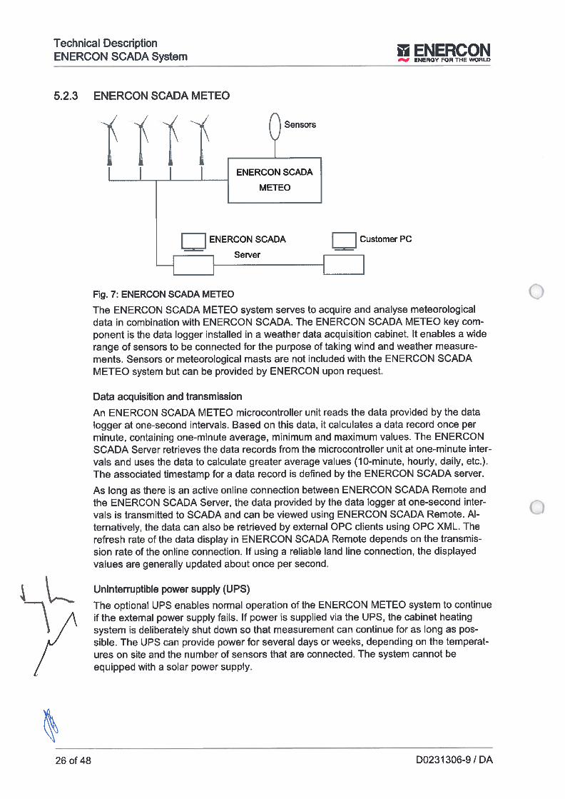
Technical DescriptionENERCON SCADA System ENEY FOR
5.2.3 ENERCON SCADA METEO
1’ 1 1’ 1’ F___2EE.
______
ENERCONSCADA
1 IENERCONSCADA 1 IcustometPc
-HServer
Fig. 7: ENERCON SCADA METEO
lhe ENERCON SCADA METEO system serves to acquire and analyse meteorologicaidata in combination with ENERCON SOADA. The ENERCON SOADA MEIEO key component is the data Iogger instailed in a weather data acquisition cabinet. It enabies a widerange of sensors to be connected for the purpose of taking wind and weather measurements. Sensors or meteorologicai masts are not inciuded with the ENEROON SOADAMETEO system but can be provided by ENEROON upon request.
Data acquisition and transmission
An ENERCON SOADA METEO microcontrolier unit reads the data provided by the dataiogger at one-second intervais. Based on this data, it caicuiates a data record once perminute, containing one-minute average, minimum and maximum values. lhe ENERCONSOADA Server retrieves the data records from the microcontroiler unit at one-minute inter-vais and uses the data to caicuiate greater average vaiues (10-minute, houriy, daiiy, etc.).lhe associated timestamp for a data record is defined by the ENERCON SCADA server.
As Iong as there is an active online connection between ENERCON SCADA Remote andthe ENERCON SOADA Server, the data provided by the data iogger at one-second inter-vais is transmitted to SOADA and can be viewed using ENERCON SCADA Remote. Aiternativeiy, the data can also be retrieved by external OPO ciients using OPO XML. lherefresh rate of the data display in ENEROON SOADA Remote depends on the transmission rate of the oniine connection. If using a reiiabie iand une connection, the dispiayedvaiues are generaiiy updated about once per second.
Uninterwptible power supply (UPS)
lhe optionai UPS enabies normai operation of the ENERCON METEO system to continue
\ A if the externai power supply faiis. if power is suppiied via the UPS, the cabinet heating1 / system is deiiberateiy shut down so that measurement can continue for as iong as pos
sibie. lhe UPS can provide power for severai days or weeks, depending on the temperat
/ ures on site and the number oí sensors that are connected. lhe system cannot be
/ equipped with a soiar power suppiy.
26 of 48 D0231 306-9 / DA
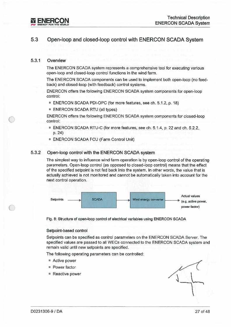
II EkIERCOI Technical DescriptionIV IV ENERCONSCADASictENERGYFORTHEWORLD J
5.3 Open-Ioop and closed-Ioop control with ENERCON SCADA System
5.3.1 OverviewThe ENERCON SCADA system represents a comprehensive tool for executing variousopen-Ioop and closed-loop control functions in the wind farm.
The ENERCON SCADA components can be used to implement both open-Ioop (no feedback) and closed-Ioop (with feedback) control systems.
ENERCON offers the foilowing ENERCON SCADA system components for open-loopcontrol:
• ENERCON SCADA PDI-OPC (for more features, see ch. 5.1.2, p. 18)
‘ ENERCON SCADA RTU fali types)
ENERCON offers the foilowing ENERCON SCADA system components for ciosed-ioopcontrol:
• ENERCON SCADA RTU-C (for more features, see ch. 5.1.4, p. 22 and ch. 5.2.2,p. 24)
• ENERCON SCADA FCU fFarm Control Unit)
5.3.2 Open-Ioop control with the ENERCON SCADA system
The simpiest way to influence wind farm operation is by open-ioop control of the operatingparameters. Open-ioop control (as opposed to ciosed-ioop control) means that the effectof the specifled setpoint is not fed back into the system. in other words, the value that isactuaiiy achieved is not monitored and cannot be automaticaliy taken into account for thenext control operation.
1 1 Actual valuesSetpoints SCADA _j Wind energy converter --
fe.g. active power,
____________________
t - powerfactor)
Fig. 8: Structure of open-loop control of electrical vanables using ENERCON SCADA
Setpoint-based control
Setpoints can be specified as control parameters on the ENERCON SCADA Server. lhespecified values ate passed to ali WECs connected to the ENERCON SCADA system andremam vaiid until new setpoints are specified.
The foiiowing operating parameters can be controiied:
• Active power
Power factor
• Reactive power
D0231306-9 / DA 27 of 48

Technical DescriptionENERCON SCADA System ENERY FOR THE
Table-based control
Tabie-based controi can be used to specify setpoints for the nominal power of the windfarm and the power factor for up to 40 time intervais per week. lhe wind farm’s controlsystem accesses and impiements these time-specific setpoints. ENERCON enters thetable values once through ENERCON SCADA Remote or on the ENERCON SCADAServer itself. Parameter entry and modification is password-protected and can only beperformed by ENERCON.
Control values via interfaces
ENERCON offers interfaces which can also be used to transmit open-loop control signaise.g. from the grid operator to the wind farm’s ENERCON SCADA system. These inciudeENERCON SCADA RTU (ali configurations) and ENERCON SCADA PDI-OPC.
5.3.3 Closed-loop control with the ENERCON SCADA system
lhe ENERCON SCADA RTU-C orENERCON SCADA FCU can be used in combinationwith the ENERCON SCADA system and the wind energy converters to set up a closedloop control system. The reference point for closed-loop controi of electricai variables isthe point where measuring values are acquired, typicaiiy, the point of common coupiingwith the grid operator.
in order to set up a ciosed-loop control system, the RTU-C or the FCU must be deployed.Externai setpoints can be received through the interfaces described. The accuracy anddynamics of the closed-ioop control system depend on the configuration of the wind farm,the number of wind energy converters connected, the current and voitage transformerciass, and other factors.
RTU-CSet points
FCU
SCADA
t
_________________
Actual values
(e.g. active power, Wind energy converter
power factor)
Fig. 9: Structure of closed-loop control with characteristic output signal feedback
28 of 48 D0231306-9 IDA
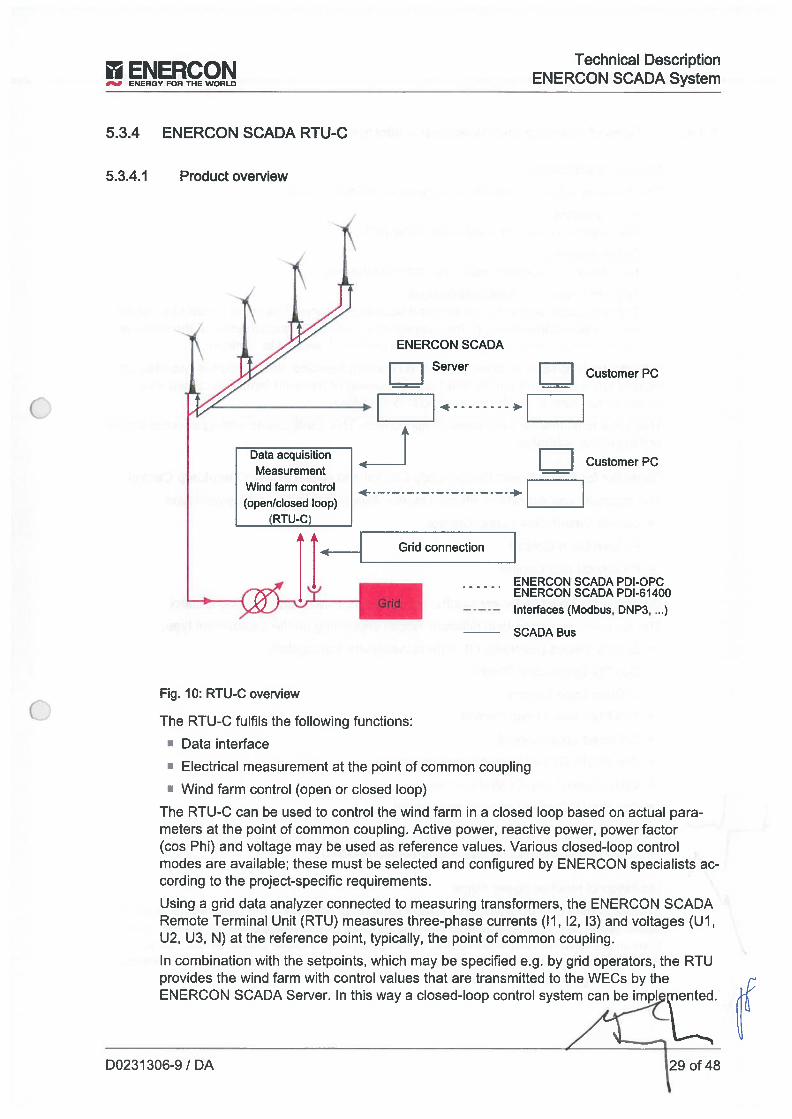
ENE CIM Technical DescriptionENERGY FOR THE RLD ENERCON SCADA System
5.3.4 ENERCON SCADA RTU-C
5.3.4.1 Product overview
ENERCON SCADA
Server
_____
1 1 Customer
1___1 Customer
Grid connectíon
ENERCON SCADA PDI-0PCENERCON SCADA PDI-61400
— -— -— Interfaces (Modbus, DNP3, ...)SCADA Bus
Fig. 10: RTU-C overview
The RTU-C fulfils the foilowing functions:
Data interíace
• Electrical measurement at the point of common coupiing
• Wind farm control (open or ciosed Ioop)
The RTU-C can be used to contrai the wind farm in a closed loop based on actual parameters at the point of com mon coupiing. Active power, reactive power, power factor(cos Phi) and voltage may be used as reference vaiues. Various closed-loop contraimodes are availabie; these must be selected and configured by ENERCON speciaiists according to the project-specific requirements.
Using a grid data anaiyzer connected to measuring transformers, the ENERCON SCADARemate Terminal Unit(RTU) measures three-phase currents (ii, 12, 13) and voitages (Ul,U2, U3, N) at the reference point, typicaily, the point of common coupiing.
In combination with the setpoints, which may be specified e.g. by grid operators, the RTUprovides the wind farm with contrai values that are transmitted to the WECs by theENERCON SCADA Server. in this way a ciosed-ioop contrai system can be impi
D0231 306-9 / DA 29 of 48
4
1h
Data acquisition
________
MeasurementWind farm control(open/closed Ioop)
(RTu-c)
t 1GriU -
Technical Description‘NERCON SCADA S10+m3 ENERGV FOR THE WORLD
5.3.4.2 lypes of open-Ioop and closed-Ioop control systems
Setpoint specification
The following different methods of setpoint specification exist:
• Fixed setpointlhe setpoint is set to a fixed value in the RIU.
• Online setpointThe setpoint is specified using the defined interface.
• Setpoint based on characteristic curvelhe applicable setpoint is determined based on a curve. The curve parameter can bethe average active power or the average grid voltage. The calculation of the averagevalue is based on a configurable time range from 1 second to 1 minute.
With closed-Ioop reactive power control (Q control) selected, the setpoint is specified as arelative value based on the installed reactive power of the wind farm. For closed-Iooppower factor control, an absolute setpoint is specified.
There is a time Iimit for each setpoint application. This configurable setting ensures propersettling of the controlier.
Controlier for Active Power Closed-Loop Control and Active Power Open-Loop Control
lhe controlier can operate in different modes depending on the deployment type:
Default Values Open Loop Control
• P Open Loop Control
• P Closed Loop Control
Controlier for Reactive Power Control and Reactive Power Closed-Loop Control
lhe controiler can operate in different modes depending on the deployment type:
• Default Values (controlier off, default values are transmitted)
• Cos Phi Open Loop Control
• Q Open Loop Control
• Cos Phi Closed Loop Control
• Q Closed Loop Control
• Cos Phi(P) Closed Loop Control (curve)
• Q(U) Closed Loop Control (curve)
Cos Phi(U) Closed Loop Control (curve)
• Q(P) CloseU Loop Control (curve)
• Cos Phi + Q Open Loop (open-Ioop control system)
Limitation of reactive power range
In order to minimise potential yield losses caused by exceeding the required minimum reactive power, the RTU-C is able to Iimit the reactive power range used for control operations at the network connection point. For this purpose, a curve characteristic can bedefined that Iimits the reactive power range that is actually used based on two characteristic curves (export side / import side).
30 of 48 D0231306-9 / DA
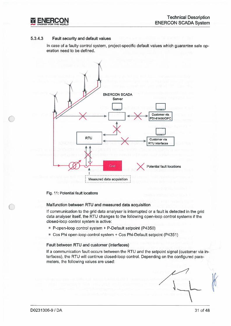
ENERCON
___
ENERGY FOR THE WORLD
Technical DescriptionENERCON SCADA System
5.3.4.3 Fault security and default values
In case of a faulty control system, project-specific default values which guarantee safe operation need to be defined.
Fig. II: Potential fault locations
1 14 Customer via
7 \ PDI-61400/OPC
1 1Customer via
RTU interfaces
Malfunction between RTU and measured data acquisition
If communication to the grid data analyser is interrupted or a fault is Uetected in the griddata analyser itself, the RTU changes to the following open-Ioop control systems if theclosed-Ioop control system is active:
• P-open-Ioop control system + P-Default setpoint (P4350)
• Cos Phi open-Ioop control system + Cos Phi-Default setpoint (P4351)
Fault between RTU and customer (interfaces)
If a communication fault occurs between the RTU and the setpoint signal (customer via interfaces), the RTU wiII continue closed-Ioop control. Depending on the configured parameters, the following values are used:
ENERCON SCADAServer
1 1
)t((4
RIU \/
ÁGrid
Measured dataacquionj
>c( Potential fault locations
D0231306-9 / DA 31 of48

Technical Description tiENERCON SCADA System EJY FOR THE WOILD
Iab. 1: Default RTU behaviour parameter
Parameters Setting Values
P4050 Use Iast set point Last valid setpoint
Use default set point RTU default values:P4350 to P4357
If default values are used, the gradients of the ramps for fault occurrence or fault clearance (%is or lis) can be defined for each specific project. By default, ramps are initialisedwith value “0”. In this way, the default value is applied directly.
For reliable fault clearance, the switch to the current setpoint occurs 30 seconds after thefault has been cleared.
Fault between ENERCON SCADA Server and RIU
If a communication fault occurs between the ENERCON SCADA Server and the RTU, theserver uses the following control values:
Default control values
• Last valid control values
Fault between ENERCON SCADA Server and customer fPDI-6140010PC)
If interface ENERCON SCADA PDI-6 1400 or ENERCON SCADA PDI-OPC fails or if thereis a communication fauft, the RTU continues closed-Ioop control using the Iast receivedsetpoi nts.
Fault between ENERCON SCADA Server and wind energy converter
If a communication fault occurs between the ENERCON SCADA Server and the wind energy converter, the wind enetgy converter uses the following control values:
Default control values
• Last valid control values
If parameter 1308 SCADA farm control(wind energy converter parameter) is activated,the ENERCON SCADA Server wiII save the Iast valid control value to the following windenergy converter parameters:
• 1209 Dynamic reactive power (Q/P) (closed-Ioop wind farm control fault)
• 1210 Static reactive power (closed-Ioop wind farm control fauit)
• 1400 Maximum power (ciosed-Íoop wind farm control fault)
To ensure any slight changes to RTU control values do not result in permanent changes
\ to the Iast valid control values stored in the wind energy converters, the control values arenot written until a specified deadband has been exceededifailen short of. The followingvalues apply here:
f \. • P:±10.01
] Q:±10.01
•QIP: ±0.170 (9.65°)
If wind energy converter parameter 1308 is deactivated, the wind energy converters use
the control values stored in parameters 1209, 1210 and 1400. If parameter 1308 is deactivated, these control values are not stored on the ENERCON SCADA Server; in thiscase, the stored control values are the configurable default values.
32 of 48 D0231306-9 iDA

EIERCOkI Technícal Description1 ENERCONSCADAS”tENERGYFORTHEWORLD
The RTU continues closed-ioop control of those wind energy converters not affected bythe fauit. Where possible, the loss of control capacity wiii be compensated.
Checking setpoint signals
An evaluation of whether a setpoint has been received correctiy and processed correctiyby the RTU can be made via the feedback data points of the RTU interfaces for the reievant setpoint.
• Checking the correct receipt and transfer of a setpoint is the job of the entitywhich specified the setpoint (e.g. the operator/owner).
• Ali fauits described above wiii automaticaiiy trigger a corresponding status mes‘ sage that wiN be forwarded first to the ENERCON SCADA Server and from thereto ENERCON Service. An automatic messaging system can be set up for thecustomer upon request.
D0231306-9 IDA 33 of 48

Technical DescnptionENERCON SCADA System ENERCON
ENERGY FOR THE WORLD
Fig. 12: FCU overview
lhe ENERCON SCADA Farm Control Unit (FCU) can be used to implement fast and constant centraiised closed-Ioop control in the wind farm. There is a defined, project-specificreference point for this closed-loop control system. lt is typically the sarne as the windfarm’s network connection point with the high or rnedium-voltage grid.
Depending on the grid operator’s requirements, both the active power fed into the grid andthe reactive power and its associated parameters (power factor and voltage) can be controlled.
Apart from the central hardware and software components at the reference point (FCUcontrai cabinet), the ENERCON SCADA FCU comprises additional hardware in the individual WECs as well as a dedicated fibre-optic data transmission system.
5.3.5 ENERCON SCADA FCU
5.3.5.1 Product overvíew
____ENERCON
SCADA
1 1
FCU bus
1 1 Customer
Customer PC1 1
-
______
Grid
i_ _1e2tn_
34 of 48 D0231306-9 / DA
Technical Description
__
ENY FOR THE ENERCON SCADA System
5.3.5.2 Closed-ioop control
Closed-ioop control setpoints can be configured as íixed parameters or specified externaiiy via defined interfaces.
The controlier and its parameters are designed and configured by ENERCON accordingto project-specific detaiis. lo ensure reliabie closed-ioop control at the network connectionpoint, dose coliaboration between the customer, ENERCON and the grid operator is essential. lt is the project deveioper’s responsibility to work with the grid operator eariy on todetermine the requirements at the network connection point, so that the appropriate timeand costs can be included in the pianning.
The FCU registers the voltage and the power injected at a reference point and uses thesevalues to compute the actual values of the controlied variabies, e.g. active or reactivepower. The controllers impiemented in the FCU use the difference from the specified setpoints (deviation) to generate the corresponding actuating variabies and transmit these tothe wind energy converters. lhe FCU sends the sarne control signai to ali wind energyconverters in the control ioop.
Active power limitation
This controlier limits the active power injected at the reference point to a setpoint specifiede.g. by the grid operator. lhe active power injected at the reference point is registeredand, provided that there is sufficient wind speed, adjusted to the specified setpoint. Setpoint changes can be specified in steps or using an adjustable gradient.
Power factor control
This controlier adjusts the power factor cos Phi at the reference point to a setpoint specified e.g. by the grid operator.
lhe FCU uses the specified power factor and the active power injected and measured atthe reference point to compute the required reactive power setpoint. The actual value ofthe reactive power infeed is adjusted to the reactive power setpoint.
Reactive power control
This controlier adjusts the reactive power fed in at the reference point to a setpoint specified e.g. by the grid operator.
Voitage control
Since points of common coupiing are primarily inductive, the voitage at the reference pointcan be controiled by outputting or absorbing reactive power.
The voltage controiler implernented in the FCU converts the difference between thevoitage setpoint and the actual voltage value into a reactive power actuating signal, whichit sends to ali WECs in the wind farm for which the control has been activated.
Voitage-dependent reactive power control (voltage droop control)
lhis controiler structure can be used to achieve a linear Q-U infeed characteristic (static)specified by the grid operator. This type of curve describes the reactive power to be fed inatthe reference point, depending on the measured differen oitageathe reference
D0231306-9 / DA 35 of 48
Technical DescriptionENERCON SCADA System ENE’RY FOR THE
For this purpose, the difference between the setpoint and the actual value of the voltagemeasured at the reference point is initially established. The reactive power fed in at thereference point is then adjusted to the reactive power setpoint that results from the Q-AUcharacteristic.
Límitation of reactive power range
In order to minimise potential yield losses caused by exceeding the required minimum reactive power, the FCU is able to Iimit the reactive power range used for control operationsat the network connection point. For thís purpose, a curve characteristic can be definedthat limits the reactive power range that is actually used based on two characteristiccurves (export side / import side).
36 of 48 D0231306-9 / DA
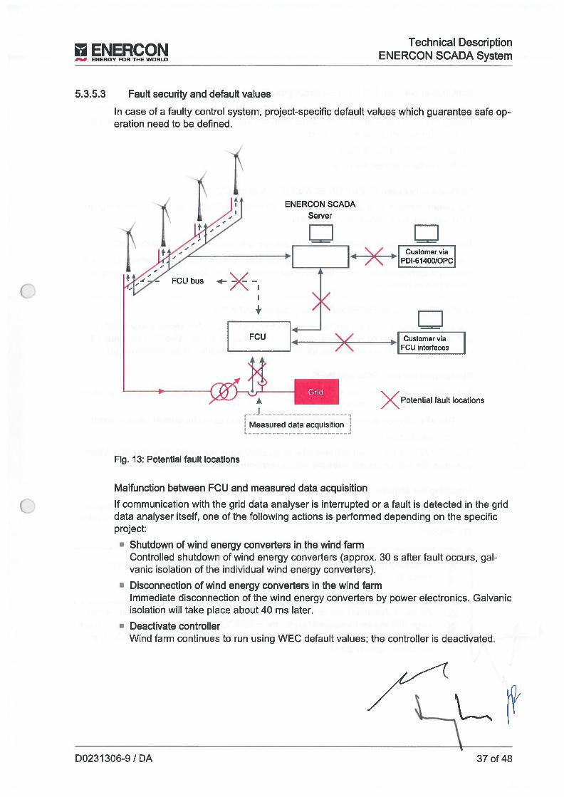
ENERCON
___
ENERGY FOR THE WORLD
Iechnical DescriptionENERCON SCADA System
5.3.5.3 Fault security and default values
In case of a faulty control system, project-specific default values which guarantee safe operation need to be defined.
Fig. 13: Potential fault locations
Malfunction between FCU and measured data acquisition
lf communication with the grid data analyser is interrupted or a fault is detected in the griddata analyser itself, one of the following actions is performed depending on the specificproject:
• Shutdown of wind energy converters in the wind farmControlled shutdown of wind energy converters (approx. 30 s after fault occurs, galvanic isolation of the individual wind energy converters).
• Disconnection of wind energy converters in the wind farmImmediate disconnection of the wind energy converters by power electronics. Galvanicisolation wiIl take place about 40 ms later.
• Deactivate controlierWind farm continues to run using WEC default values; the controiler is deactivated.
ENERCON SCADAServer
Li
FCU bus
Grid
>( Potential fault
Measured data acquisition
D0231 306-9 / DA 37 of 48
Technical DescriptionENERCON SCADA S,Qtm.7 ENERGY FOR THE WORLD
Maifunction between FCU and customer (interfaces)
if a communication fauit occurs between the FCU and the setpoint (customer via interfaces), the FCU wiii continue with ciosed-Ioop control. Depending on the configured parameters, the foiiowing values are used:
• Last setpoint remains vaiid
• FCU defauit values are used
Maifunction between ENERCON SCADA Server and FCU
if a communication fault occurs between the ENERCON SCADA server and the FCU, theFCU wiii continues with ciosed-Ioop control.
Malfunction between ENERCON SCADA Server and customer (PDI-61400/-OPC)
lf the ENERCON SCADA PD1-61400 or ENERCON SCADA PD1-OPC intertace falis or ifthere is a communication fauit, the FCU wiii continues with ciosed-ioop control using theiast setpoints received.
Maifunction between ENERCON SCADA Server and WEC
if a communication fault occurs between the ENERCON SCADA server and a WEC, theaffected wind energy converter wiii use the defauit vaiues stored. lhe FCU continues itsnormal operation. Where possibie, the ioss of control capacity wili be compensated.
Maifunctíon between FCU and WEC
if a communication fault occurs between the FCU and a WEC, one of the foiiowing actionsis performed depending on the project:
• The wind energy converter continues to operate and uses the defauit vaiues stored
• WEC is stopped
The FCU continues to control the wind energy converters foi affected by the fauit. Wherepossibie, the ioss of control capacity wiii be compensated.
Checking the setpoint
An evaiuation of whether a setpoint has been received correctiy and correctiy processedby the FCU can be made via the feedback data points for the FCU interfaces for the reievant setpoint.
• Checking the correct receipt and transfer of a setpoint is the job of the entitywhich specified the setpoint (e.g. the operator/owner).
• Ali fauits described above wiii automaticaliy trigger a corresponding status mes
\ \ sage that wíii be forwarded first to the ENERCON SCADA Server and from there‘— to ENERCON Service. An automatic messaging system can be set up for the
customer upon request.
38 of 48 D0231 306-9 / DA
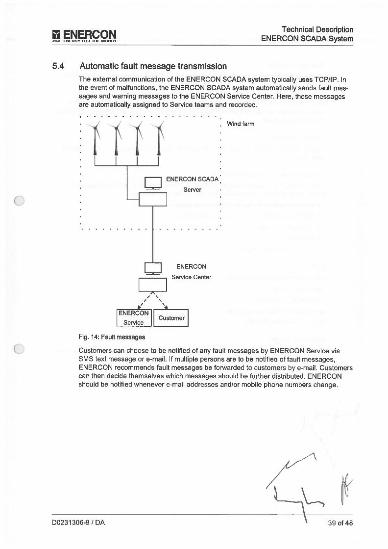
II ENERCONENERGY FOR THE WORLD
Technical DescriptionENERCON SCADA System
5.4 Automatic fault message transmission
The external communication of the ENERCON SCADA system typically uses TCP/IP. Inthe event of malfunctions, the ENERCON SCADA system automatically sends fault messages and warning messages to the ENERCON Service Center. Here, these messagesare automatically assigned to Service teams and recorded.
4
‘4ENERCON
CustomerService
Fig. 14: Fault messages
Windfarm
Customers can choose to be notified of any fault messages by ENERCON Service viaSMS text message or e-mau. If multiple persons are to be notified of fault messages,ENERCON recommends fault messages be forwarded to customers by e-maH. Customerscan then decide themselves which messages should be íurther distributed. ENERCONshould be notified whenever e-mau addresses and/or mobile phone numbers change.
ENERCON’
Server
ENERCON
Service Center
//
D0231306-9 / DA 39of48
Technical DescriptionIMrON SCM ,o+cm
ENERGY FOR THE WORLD
Message structure
Messages that are sent to customers by e-mau or SMS text message have the followingformat:
[Number of wind farmJ_[Number of wind energy converterJ_[Serial numberJ_[EC DENo.]_[Customer name]_[Site nameJ_[rime fault occurredJ_[(Type of message)]_[WECstatusJ_tNumber of fault or warning messageJ_[Description of statusJ_[Descríption of faultor warning message]
Sample message
325201 70217 1 Test Ltd. Testfarm 2013-07-01 15:59:57 (Warning) 0:0 190:2 HazardIight: Fault
Request for fault message forwarding
lf the forwardíng of fault messages is requíred, please provide ENERCON Service (Customer Support Centre department) with the following information:
Forwarding type: E-mau or SMS text message
Serial number(s) of wind energy converter(s)
‘ Wind farm number
• Site name
Recipient contact details
Address
ENERCON Service Deutschland GmbH
Dornumer StraBe 20
26607 Aurich, Germany
Email: [email protected]
Phone: +49 4941 976 388
Additional charges
Depending on the wind farm site, the message forwarding type and the maintenance contract type, additional charges for transmission may apply.
40 of 48 D0231306-9 / DA
Technical Description
__
ENERGY FOR THE ENERCON SCADA System
5.5 ENERCON SCADA Event Trigger Control SystemThe ENERCON SCADA Event Trigger Control System is a program installed and executed on the ENERCON SCADA Server. Depending on the date and time and takingmeasurement data into account, it can be used to respond to wind energy converterstatus changes.
By entering conditional command lines in the ptocess configuration file, an action can beprogrammed to a certain extent, e.g. ‘StarUstop WEC” or “Send messages”. However, theENERCON SCADA Event Trigger Control System cannot be used to reduce active power.Any events that occur are documented separately.
• Safety-related open-loop control systems cannot be realised with theSCADA Event Trigger Control System
Three event types are available for selection:
• Date/time
• WEC status
• Measurement condition for a data Iogger via ENERCON SCADA METEO or for WECdata such as wind direction and wind speed
In each command me, these events can be concatenated by means of AND to trigger anaction.
Example use cases for the ENERCON SCADA Event Trigger Control System:
• Noise protection
• Distance from buildings
D0231306-9IDA 41 of48
Technical DesctiptionENERCON SCADA System ENETHEWOt
5.6 Control of individual systems in an ENERCON wind energy converter
• Customers may oniy control individual systems in an ENERCON wind energy‘ converter after having been given appropriate access by ENERCON. For moreinformation, please contact your ENERCON saies representative or ENERCONService.
5.6.1 Rotor biade heating system open-loop control
The optional ENERCON SCADA PDi-OPC interface of the ENERCON SCADA Serverand ENERCON SCADA Remote 3 make it possibie to activeiy controi the biade heatingsystem built into the ENERCON wind energy converters.
lhe foiiowing controi operations can be performed whiie the WEC is running1 or at standstii 1:
lhe automatic mode of the blade heating system fsuppress/abort heating operation)can be suppressed
N Heating operation can be switched on manually (if automatic mode is suppressed)
Heating operation can be started for pre-defined duration (WEC parameter 1317)
• Retrieve current control status1lhe biade heating system can only be controlied in a running wind energy converter if
the WEC parameters have been set accordingiy; see ‘lechnische BeschreibungENERCON Windenergieanlagen Biattheizung’ fTechnical description of EN ERCON WindEnergy Converter biade heating system) documentfDO44l885).
5.6.2 Ice warning light open-loop control
lhe optional ENERCON SCADA PDI-OPC interface of the ENERCON SCADA Serverand ENERCON SCADA Remote 3 make it possibie to activeiy controi the optional icewarning light buiit into an ENERCON wind farm.
lhe foiiowing controi operations can be performed:
• Switch ice warning iight on
• Switch ice warníng iight off1
• Retrieve current status of ice detection system1
After being switched on, regardiess of the controliing system, the ice warning iight remains on for at ieast 20 minutes, lhe ice warning iight can only be switched off if no otherwind energy converter system (e.g. ice detection system) is generating a signal for switching on the ice warning iight.
The wind energy converter does not provide the status of the ice warning light. Oniy the
A ice detection system status is sent to ENERCON SCADA.
/ “ For more detaiied information on the optionai ice warning Iight, see the “Technische BesJIJ chreibung ENERCON Windenergieanlagen Eiswarnieuchte” (Technicai description of
ENERCON wind energy converter ice warning iight) document (D0353070).
42 of 48 D0231306-9 IDA
TechnicaI Description
__
EJY FOR THE ENERCON SCADA System
5.7 ENERCON SCADA Power Consumption ManagementENERCON SCADA Power Consumption Management fPCM) allows the power consumption of ENERCON wind energy converters to be restricted to a configurable limit at thenetwork connection point.
This is especially useful for systems such as the biade heating and generator drying systems as these have a high energy demand and are often only used when the WEC is at astandstili, most often for the entire wind farm, and consume considerabie leveis of powerat the network connection point.
The PCM calculates the power available for consumption by the WECs in cycles. Thispower equals the difference between the specified maximum power consumption (customer/grid operator setpoint) and the current power consumption at the network connection point. The current power consumption can be determined either by a virtual networkconnectíon point or by means of optionai measured data acquisition (FCU or RTU-C).
Power is provided to the WECs in successive cycles. lf any of the WECs requires consumable power and if enough power is available, the WEC reserves and consumespower. lhe consumable power available for the remaining WECs is reduced by the reserved amount.
The power demand of a WEC can be made up of the power required by several systemsincluded in the WEC. lhe WEC reserves power according to systems, i.e. if the poweravailable to the WEC is only sufficient for one out of two systems, the WEC only reservespower for this system.
This behaviour and cyclic processing reduce the power consumption at the network connection point.
lhe PCM is run as a process on the ENERCON SCADA Server and as part of the controlsystem software of the ENERCON wind energy converters.
No additional hardware is required.
1 nterfaces
Data can be specified and retrieved via the following interfacesíprograms:
• ENERCON SCADA Remote 3
• ENERCON SCADA PDI-OPC
D0231306-9/DA 43of48
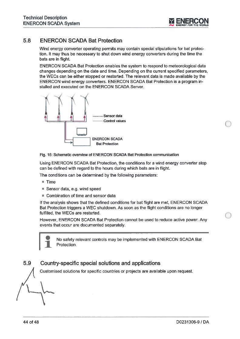
Technícal DescriptionENERCON SCADA S1ctm.7 ENERGYFORTHEWORLO
5.8 ENERCON SCADA Bat ProtectionWind energy converter operating permits may contam special stipulations for bat protection. It may thus be necessary to shut down wind energy converters during the time thebats are in flight.
ENERCON SCADA Bat Protection enables the system to respond to meteorological datachanges depending on the date and time. Depending on the current specified parameters,the WECs can be either stopped or restarted. lhe relevant data is made available by theENERCON wind energy converters. ENERCON SCADA Bat Protection is a program installed and executed on the ENERCON SCADA Server.
4 4 4 4 Sensor data1 1 1 Control values
ENERCON SCADABat Protection
Fig. 15: Schematic overview of ENERCON SCADA Bat Protection communication
Using ENERCON SCADA Bat Protection, the conditions for a wind energy converter stopcan be defined with regard to the hours during which bats are in flight.
lhe conditions can be determined by the following parameters:
• Time
• Sensor data, e.g. wind speed
• Combination of time and sensor data
If the analysis shows that the defined conditions for bat flight are met, ENERCON SCADABat Protection triggers a WEC shutdown. As soon as the flight conditions are no longerfulfilled, the WECs are restarted.
However, ENERCON SCADA Bat Protection cannot be used to reduce active power. Anyevents that occur are documented separately.
• No safety relevant controis may be implemented with ENERCON SCADAProtection.
5.9 Country-specific special sol utions and applicationsCustomised solutions for specific countries or projects are available upon request.
44 of 48 D0231306-9 / DA
Technical Description
__
ENE’RY FOR THE ENERCON SCADA System
6 Maintenance
6.1 Required maintenanceMaintenance required for the various hardware and software components of theENERCON SCADA system is described in the correspondíng product documentation.
6.2 ENERCON SCADA system within the ENERCON PartnerKonzeptInclusion of the ENERCON SCADA system into the ENERCON PartnerKonzept (EPK)must be agreed on a project-specific basis.
D0231306-9 / DA 45 of 48
Technical Description‘NERCON SCADA 5io+m
J ENERGY FOR THE WORLO
Table of figuresFig. 1 Schematic structure of the ENERCON SCADA system with standard components 7
Fig.2 ENERCONSCADARemote 12
Fig. 3 ENERCON SCADA Remote - display of daily data 13
Fig. 4 ENERCON SCADA PDI-OPC within the ENERCON SCADA system 18
Fig. 5 ENERCON SCADA PDI-61400 20
Fig. 6 RTU-C overview 24
Fig. 7 ENERCON SCADA METEO 26
Fig. 8 Structure of open-Ioop control of electrical variables using ENERCON SCADA 27
Fig. 9 Structure of closed-Ioop control with characteristic output signal feedback 28
Fig. 10 RTU-C overview 29
Fig. 11 Potential fault locations 31
Fig. 12 FCU overview 34
Fig. 13 Potential fault locations 37
Fig. 14 Fault messages 39
Fig. 15 Schematic overview of ENERCON SCADA Bat Protection communication 44
746 of 48 D0231 306-9 / DA
Technical Description! THEWJL ENERCON SCADA System
Glossary of termsClient Computer program on a terminal device or a terminal device that
connects to a server in order to make use of services running onthe server. Various services can be accessed, depending on thetype of client.
Data bus System for bi-directional data transmission between the centralunit, the hardware components, registers, storage, caches andperipheral devices within a computer or between several computers. lhere are data buses with data bus widths of 4, 8, 16, 32and 64 bits. The bigger the data bus width, the faster the datatransmission.
dBASE File-based database management system for personal computers.
Dongle Connector which, in combination with a user name and a password, is used to uniquely identify a user, define the user leveI andprovide protection from unauthorised use of software.
ENERCON SCADA FCU System for closed-loop control of the power factor and the activepower, reactive power and voltage fed in at the reference point ofa wind farm.
ENERCON SCADA PDI Hardware-based interface for transmitting process data betweendifferent communication devices such as the ENERCON SCADAsystem and the grid operator. lhe grid operator can call up datafor wind turbines and systems via ENERCON SCADA PDI.ENERCON provides different Process Data Interfaces.
ENERCON SCADA RTU Data interface of the ENERCON SCADA system between windturbines, the ENERCON SCADA Server and customers. Depending on the equipment, the ENERCON SCADA RIU can act as aprocess data interface (RIU-I) only or also take over open-loopand closed-Ioop control functions for influencing the grid parameters (RTU-C).
EPK Service product that provides an optional complete maintenancecontract between the wind turbine operator/owner and ENERCONin which ENERCON takes care of repair and maintenance of theWEC and guarantees a defined technical availability.
Information Message which provides information about the condition of adevice or wind turbine and the individual components of thedevice or wind turbine. Information consists of main informationand sub-information.
Main status Part of a status in the ENERCON SCADA system which describesthe general operating state of a device or a wind turbine. Themain status is generated as a number code with an additional explanation.
OPC XML-DA Interface standard of the OPC Foundation which is used for XMLbased exchange of data between computer systems, particu rlyvia the lnternet, among other things.
D0231306-9/DA 4 of 48
Technical DescnptionENERCON SCADA System II ENERCON
ENERGY FOR THE WORLD
Status Message that describes the current operating state of a device ora generating plant. A status consists of a main status and a sub-status.
Status message
Substatus
Uninterruptible powersupply
Warning message
Wind energy converter
Message in the ENERCON SCADA system which is transmittedto ENERCON Service or the operator/owner if a status generatedin a device ar a wind turbine points out an unusual operating statewhich requires a service measure and Ieads to an immediate stopof the device or the wind turbine. A status message consists of amain status message and a sub-status message.
Part of a status in the ENERCON SCADA system which providesdetailed information about the current operating state of a deviceor a wind turbine and the reason for the status as an addition tothe main status. The substatus is generated as a number codewith an explanation.
A system which, in the event of a power grid failure, takes overthe power supply to consumer units virtually without delay.
Message in the ENERCON SCADA system which is transmittedto ENERCON Service or the operator/owner if information generated in a device or a wind turbine points out an unusual operatingstate which requires a service measure but does not Iead to animmediate stop of the device or the wind turbine. The device arwind turbine initially remains in operation. A warning messageconsists of a main warning message and a sub-warning message.
System that converts the kinetic energy in the wind into electricalenergy (in accordance with DIN EN 61400-21).
48 of 48 D0231306-9 / DA

o

oo

Enercon GmbH, Dreekamp 5, D-26605 Aurich
otboerGenerei le
Versicherungsbestãtigung zurMontage - Versicherung
VersichererGothaer Aflgemeine Versicherung AG,
KatharinenstraRe 23-25, 0-20457 Hamburg, Deutschiand
VersicherterEnercon GmbH,
Dreekamp 5, D-26605 Aunch
VersicherungsnummerVS 80.410.664230
Laufzelt des VertragesVom 01. lanuar 2018 bis 01. lanuar 2019
DeckungsumfangVersichert sind alie Ueferungen und Leistungen, dia anissiich der Nau- De- und Remontagen, Service-, Wartungsund Roparaturmontagen der versicherten Windenergieaniage erbracht werden.
Versichert ist auch das interesse des Auftraggebers / Besteflers an elgenen Lieferungen und Leistungen.
GeltungsberelchLãnder der Europãischen Union
HaftungszeltraumDie Haftung beginnt mit der Aulnahme der ersten Aktivitãten am Versicherungsort, dia im Zusammenhang mit derProjektausführung stehen.
Die Haftung endet «ir das gesamte zur Verslcherungangemeldete Montageobjekt, wenn der Probebetrieb abgeschiossen und die Abnahme durch den Besteiler erfolgt istoder der Versicherungsnehmer das versicherte interessedem Versicherer gegenaber schrifthch ais erloschen erkiãrthat.
Haftu ngsllmltDie Grenze der Entschàdigung lst die auf das Montageobjekt entfaiiende Versichewngssumme, gegebenenfalis zuzügiich versicherter Mohrkosten. Die maximale Entschãdigungsleistung ist je Versicherungsfaii auf 25,0 Mio. EURbegrenzt.
SelbstbehaltEUR 50.000-- je Schadenfall
RechtsverbindlichkeltRechtsverbindiich ist ausschiieBiich dor deutsche Originaltext des Versichewngsvertrages.
GeneralCertificate of
Erection Ali Rísk insurance
insurerGothaer Atigemeine Verslcherung AG,
Katharinenstraie 23-25, 0-20457 Hamburg, Gerrnany
lnsuredEnercon GmbH,
Dreekamp 5, D-26605 Aurich
Insurance contract numberVS 80.410.664230
Contract perlodFrom lst January 2018 untiii isi January 2019
Scope of coverAli supplies and seces effected occasionaiiy on theerection, de- and re-assembly or mounting related toworks of seMce, maintenance o, repair on the insuredwind turbina wiii be insured.
The interests o! the principal! operator reiating to his ownsuppiies and performed services are aiso inciuded.
Territorial scopeCountries of European Union (EU)
Perlod of Insurancelhe penoU 01 insurance starts with the beginning of thefirst action undertaken at lhe Insurance location In reiationto the construction o! the insured obJect.
The petiod o! insurance ends for the compieted Insuredobject alter the trial operation ended and the given acceptance of the purchaser or, i! the insurance hoidersends weitten declaration 01 expiration 01 the insured Interest to the insurer.
Umit of coveragelhe coverage is iimited to the sum Insured of the declaredobject, plus, ii insured, additionai costs. The maximumsum to be paid per Ioss occurrence is iimited to25,0 Mio. EUR.
DeductibleEUR 50.000,-- per Ioss occurrence
Legally blndinglhe original German wording o! the insurance contract issolely iegaliy binding.
Gothaer Aligemeine Versicherung AGHamburg, den 24.10.2017
Dr, Chsopher Lohmann

oo

otboerGothaer Versicherungen 50598 Kln
FirmaENERCON GmbHDreekamp 5
26605 Aurich
lhr Zeichen Ibre Nacliricht vom Unser ZeichenIZustndig41304Frau Grapp
Kompetenzcenter UnternehmerkundenHamburgWandsbeker Allee 7722041 HamburgTelefon: (0 40) 37 04-42298Telefax: (040) 37 04-495298
Durchwahl-Nr Hamburg42298 07.11.2017 gr
Open Marine Cargo Policy No. 80.41 0.9001 58
Ladies and gentiemen,
we herewith confirm that the above mentioned Open Marine Cargo Poiicy insures goods ot ali kinds, inparticuiar wind energy piants in respect of shipments withín the following geographical limits:
woridwide
during the course of transit by transport o! ali kinds fiand, sea and air transport) and any storage connectedtherewith, provided that ENERCON is obliged to place insurance in this respect according to the principaisof commerce.
Contract-period: 01.01.2018 - 01.01.2019
The limit is EUR 10.000.000,00 per conveyance /storage area separated according to fite tegulations.
For transportation and storage, which are not to be notified individuaily, deemed to be the sum insured /insurabie vaiue (replacement vaiue) for deiiverieslimports of the purchase price plus customs, freight andau expenses untii receipt bearing the poiicyholder plus 10%.
The Open Cover is based on the foNowing:
1. German General Rules of Marine insurance (ADS) Special Conditions for Cargo(AOS Cargo 1973 - Edition 1984 — Fuil Cover) (PoLaR) and Dirty-Bomb-Ciause
2. Special Conditions for Open Policies3. DW-War, Strikes, Riots and Clvii Commotions Ciauses 19844. Written Conditions
GothaerAllgemelne Verslcherung AGGothaerAflee 1,50969 KOIn (Hausanschnft)Pro’. Or. Werner GÕrg (Vorsltzender)Dr. Chnstopher Lohmann (Vorsltzender), Oliver BitiS,Or. Mathlas Bohring-Uhle, Dr. Katsten Elchmann,HaralU Ingo Epple,
AkbengesellschaflAmtsgericht KOln HRB 21433DEi 22766654810N0081 0004206
GesellschaftSiLzAutsichtsratVorsiand
Postan,chrllt 50596 KõIn
RechtstormRegistergenchtUSt-IdNr.VersSt-Nt.
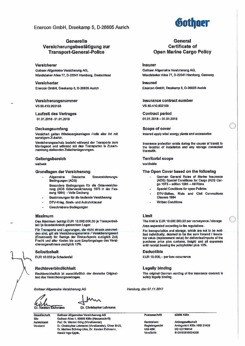
Enercon GmbH, Dreekamp 5, D-26605 Aurich
Generel leVersicherungsbestütigung zur
Transport-General-Police
VersichererGothaer Aligemeine Versicherung AG,
Wandsbeker Alice 77, D-22041 Hamburg, Deutschland
VersicherterEnercon GmbH, Dreekamp 5, 0-26605 Aurich
VersicherungsnummerVS 80.410.900158
Laufzeit des Vertrages01 .01.2018 -01.01.2019
DeckungsumfangVersichert gelten Windenergieanlagen I-telle alier Art mitsonstigem Zubebõr.
Versicherungsschutz besteht w#hrend der Transporte zumMontageort und wãhrend mit den Transporten in Zusammenhang stehenden Zwischenlagerungen.
GeItungsbereichweltwoit
Grundiagen der Versicherung- Aligemeine Deutsche Seeversicherungs
Bedingungen (ADS)
Besondere Bedingungen fOr die GOterversicherung (AOS Güterversicherung 1973 in der Fassung 1984) - Volie Deckung
- Bestimmungen fOr die laufende Versicherung
- DW-Krieg, Slreik- und Aufruhrklausel
- Geschnebene Bedingungen
MaximumDas Maximum betràgt EUR 10.000.000,00 je Transportmittel !je feuertechnisch getrenntem Lager
FOr Transporte und Lagerungen, die nlcht elnzeln anzumelden sind, gilt ais Versicherungssumme / VersicherungswertfErsatzwert) fOr Bezüge der Einkaufspreis zuzüglich Zoli,Fracht und alier Kosten bis zum Empfangs?ager des Verslcherungsnehmers zuzüglich 10%.
SelbstbehaltEUR 10.000je Schadenfail
RechtsverbindllchkeitRechtsverbindlich ist ausschlietiich der deulsche Originaltext des Versicherungsvedrages.
GothaerAllgemeine Versicherung AG
Lmann Di. Chrhtopher Lohmenn
iotbnerGeneral
Certificate ofOpen Marine Cargo Policy
InsurerGothaer Aligemeine Versicherung AG,
Wandsbeker Alice 77, 0-22041 Hamburg, Germany
InsuredEnercon GmbH, Dreekamp 5, 0-26605 Aurich
Insurance contract numberVS 80.410.900158
Contract period01.01.2018—01 .01 .2019
Scope of coverlnsured apply wind energy plants and accessories
Insurance protection exists during the course of transit loLhe location of instaliation and any storage connectedLherewlth.
Territorial scopeworldwide
The Open Cover based on the followlng- German General Rules of Matine Insurance
(AOS) Special Conditions for Cargo (AOS Cargo 1973— edition 1984 — Ali Risks
- Special Conditions for open Policies
- DW-Strikes, Riots and Civil CommotlonsClauses 1984
- Written Conditions
LimitThe limit is EUR 10.000.000,00 per conveyance storage
Arca separated according to tire regulations.
For transportation and storage, whlch are not to be notlfied individually, deemed to be the sum insured 1 insurabie value (rep?acement value) for deliveries/imports 01 thepurchase price plus customs, freight and ali expensesuntil receipt bearing the policyholder plus 10%.
DeductibieEUR 10.000,-- per Ioss occurrence
Legaliy blndingThe original Germen wording of lhe insurance contract issolely legally binding.
Haniburg, den 07.11.2017
Golhaer Allgemelne Verslcherung AGGolhaerAllee 1,50969 Keln (Hausanschnfl)Prol. Or. Werner GÕrg (Vorsltzender)Dr. Christopher Lohmann (Vorsltzender), Oliver BrOa,Dr. Malhias OOhring.Uhle, Dr. Karsten Eichmann,Harald Ingo Epple,
GeselischaftSitzAutsichtsratVorstand
Postanschrlft 80598 KôIn
RechtsfotmReglstergerichtUSt-ldNr.VersSt-Nr.
AktiengesellschartAmtsgericht KcIn HRB 214330E122786654810N90810004206
tlotboerLiability Insurance
Certificate of Insurance
Deckungsumfang
Betriebs- und ProdukthaftpflichtVersicherung
Scope of coverage
Comprehensive General LiabilityInsurance including Products andCompleted Operations
‘a
Versichert sind Schadenersatzansprüche Dritter aufgrund gesetzlicher Haftpflichtbestimmungenprivatrechtlichen lnhalts wegenPersonen-, Sach- und ProduktvermÕgensschden, die durch vomVersicherungsnehmer hergestellteoder gelieferte Produkte verursachtwurden und whrend der Wirksamkeit des Vertrages eintreten.
Seite/Page 1 von/of 2
Insurance coverage is provided forthird-party-claims on the basis oflegal liability provisions under private law with respect to any bodilyinjury and property damagecaused by products manufacturedor supplied by the insured occurring during the validity of the saidinsurance.
HaftpflichtversicherungVersicherunasbestâtiguna
Versicherungsnehmer PolicyholderFirma
ENERCON GmbHDreekamp 5
26605 Aurich
Versicherer InsurerGothaer Aligemeine Versicherung AG
Gothaer Allee 1D-50969 KÕln / Cologne
Verslcherungsscheinnummer Policynumber80.410.547929
VehSlcherungsperiode Policy Periodvonlfrom01.01.2018
mittags 12 Uhr MEZ 1 at 12 p.m. CET
bis Ito01.01.2019
mittags 12 Uhr MEZ / at 12 p.m. CET
Die Versicherung verIngert sich The insurance is automaticallystillschweigend um em weiteres extended for a further year unlessJahr, wenn sie nicht 3 Monate vor it is cancelled 3 months prior to theAblauf gekündigt wird. expiry date of the current period.
GeielI.haft
6112
AulsIchLsrat
Vof5tind
Gotha.r Aligemein. V.rIcherung AG
GalhanrAgen 1. 5011811 KOln (Nausaoschrlft)
Prol. Dt. Wemer G11rg (Vorsltzender)
Dt.Chdolopher Lohm800 (msMzendeiJ
O11ver 11r06, Dr. Malhias BQh4ng-UNe, Dr. Kwstelr Ekhma,m,
Krald Ingo EpØe
Poitanschrlft
Rechisfomi
Reglstnrgedcht
USt-IdNR.
VersSt..Nr.
Akfleogeseflschaft
Amlsgericht K0’Í1RB 21433
DE122786854
91161810/00420

othoerGeltungsbereich Territorial Scope
weltweit worldwide
Deckungssummen Limits of lndemnity
pauschal fOr Personen-, Sach- und combined single limit for bodilyProduktvermÕgensschden injury, property damage and finan
cial losses caused by productsmanufactured or supplied by theinsured
je Schadenereignis EUR 50.000.000 each occurcence
je Versicherungsjahr EUR 100.000.000 annual aggtegate
Diese Versicherungsbestâtigung This Certíficate of Insurance isdient ausschlieBlich Informati- issued for information purposesonszwecken. Rahmen und Um- only and does not amend, alterfang sowie Versicherungsneh- or extend the above mentionedmer des oben genannten Versi- insurance contract in respect tocherungsvertrages werden hier- either its limitations or scope ordurch nicht erweitert oder geün- the Insured. OnIy the Germandert. Rechtsverbindlich sind wording is Iegally binding.ausschlielUich die deutschenVersicherungsbedingungen.
Gothaer ANgemeine Versicherung AGKÕIn/Cologne, 13.10.2017
_/ ÇLM
.0
Seite/Page 2 von!of 2
0.
.0

-
4
-7.
)‘t44t
4.,
%•;2,?:?.—...-?-
4444
44
4..,?
—,2:‘44
-
4,—-•
?
-
‘
4
--4,
,
-,,.
4?
‘4‘-4
‘1,•
•••?,
4.
.
-
4
4‘.4‘4
-74•,
7.)4
44()
4-4
44?,
;,,;74?,•
•
•-•,;4
4O
rA.
7,.,’
.47.
7*

oo
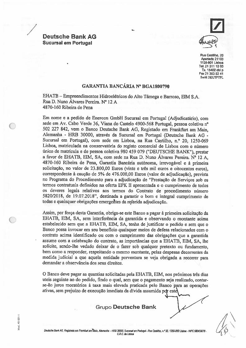
/ 0DeutscheBankAGSucursal em Portugal
Rua Castilho, 20Apartado 211031128-801 Lisboa
Tel. 21 311 1200Tx. 15402 dbip
Fax2l 3535241Swift DEUTPTPL
GARANTIA BANCÁRIA N° BGA 1800790
EHATB — Empreendimentos Hidroelétrícos do Alto Tâmega e Barroso, EIM S.A.Rua D. Nuno Alvares Pereira. N° 12 A4870-160 Ribeira de Pena
Em nome e a pedido de Enercon GmbH Sucursal em Portugal (Adjudicatário), comsede em Av. Cabo Verde 36, Viana do Castelo 4900-568 Portugal, pessoa coletiva n°502 227 842, vem o Banco Deutsche Bank AG, Registado em Franlcftirt am Main,Alemanha - HRB 30000, através da Sucursal em Portugal (Deutsche Bank AG -
Sucursal em Portugal), com sede em Lisboa, na Rua Castilho, n.° 20, 1250-069Lisboa, matriculada na conservatória do registo comercial de Lisboa com o númeroúnico de matrícula e de pessoa coletiva 980 459 079 (“DEUTSCHE BANK”), prestara favor de EHATB, EIM, SA, com sede na Rua D. Nuno Álvares Pereira. N° 12 A,4870-160 Ribeira de Pena, Garantia Bancária autónoma, irrevogável e à primeirasolicitação, no valor de 23.800,00 Furos (vinte e três mil euros e oitocentos euros),correspondente à caução de 5% de 476.000,00 Euros (valor de adjudicação), previstano Programa do Procedimento para a adjudicação de “Prestação de Serviços sob ostermos contratuais definidos na oferta EPK II apresentada e o cumprimento de todosos deveres legaís relativos aos termos do Contrato de procedimento número5820/2018, de 19.07.2018”, destinada a garantir o bom e integral cumprimento detodas e quaisquer obrigações emergeI1tes da re,ferida adjudicação.
Assim, por força desta Garantia, obriga-se este Banco a pagar à primeira solicitação daEHATB, EIM, SA, sem interferência da garantida e observando o montante acimaestabelecido sem que a EHATB, FIM, SA, tenha de justificar o pedido e sem que oBanco possa invocar em seu beneficio quaisquer meios de defesa relacionados com ocontrato acima identificado ou com o cumprimento das obrigações que a garantidaassume com a celebração do contrato, as importâncias que a EHATB, EIM, SA, lhesolicite, sendo-lhe vedado deixar de o fazer sob qualquer pretexto ou fundamento,bem como a responder, respeitando o mesmo montante, pelas despesas decorrentes damedida judicial a que aquela entidade porventura se veja obrigada a recorrer parademandar a observância dos seus direitos.
O Banco deve pagar as quantias solicitadas pela EHATB, FIM, nos próximos três diasuteis seguinte ao do pedido, findo o qual, sem que o pagamento seja realizado, contarse-ão juros moratórios à taxa mais elevada praticada pelo Banco para as operaçõesativas, sem prejuízo de execução imediata da dívida assumida
Grupo Deutsche Bank
(“/7 \De,fsche Bank AG, Registada em Franktwl am4ain. Alemanha -IIRO 30600. Suctnalem Portugal-Rue CasliMio, n.b 2L 1250-069 Lisboa - NIPC 980459079.
C.R,C. do Lisboa
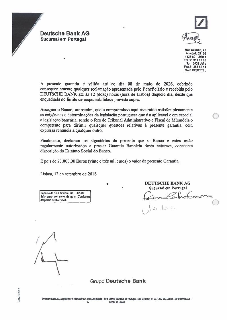
0Rua Castilho, 20Apartado 21103
1128-801 LisboaTeI.21 311 1200
Tx. 15402 Ubi pFax2l 3535241Swift DEUTPTPL
A presente garantia é válida até ao dia 08 de maio de 2026, cobrindoconsequentemente qualquer reclamação apresentada pelo Beneficiário e recebida peloDEUTSCHE BANK até às 12 (doze) horas (hora de Lisboa) daquele dia, desde queenquadrada no limite de responsabilidade prevista supra.
Assegura o Banco, outrossim, que o compromisso aqui assumido satisfaz plenamenteas exigências e determinações da legislação portuguesa que é a aplicável e em especiala legislação bancária, sendo o foro do Tribunal Administrativo e Fiscal de Mirandela ocompetente para dirimir quaisquer questões relativas à presente garantia, comexpressa renúncia a qualquer outro.
Finalmente, declaram os signatários da presente que o Banco e estes estãoregularmente autorizados a prestar Garantia Bancária desta natureza, consoantedisposição do Estatuto Social do Banco.
É pois de 23.800,00 Euros (vinte e três mil euros) o valor da presente Garantia.
Lisboa, 13 de setembro de 2018
o9
o
Imposto dc Selo devido Eur.: 142,80Selo pago por meio de guia. Conformedespacho de 87/10/28.
Grupo Deutsche Bank
DEUTSCHE BANK AGSucursal em Portugal
(_c:) -i
Deutsche Bank AGSucursal em Portugal
Deutsche BankAG, Registado em Frankfwl em Main, Alemanha - HRB 30000, Sucwalem Portugal- Rua Casli#io, n.’ 20, 1250-069 Lisboa - NIPC 980459079.C.R.C do Lisboa

NNotá.ri.aFtk ‘NJ)l
Reconheço as assinaturas de Fátima Cristina da Costa Coelho Fonseca e de
Ana Raquel Martins da Costa, em folha anexa, conforme verifiquei pela exibição
dos cartões de cidadão 11543669, válido até 06.12.2021, e 12308252, válido até
21.08.2020, emitidos pela República Portuguesa, na qualidade de procuradoras
substabelecidas, em representação da sociedade com a firma DEUTSCHE BANK
AKTIENGESELLSCHAFT, com SUCURSAL EM PORTUGAL, com poderes para o
ato, conforme verifiquei por uma procuração e um substabelecimento, documentos
que já se encontram arquivados neste Cartório, a procuração no maço dos
instrumentos avulsos e de documentos do ano de dois mil e treze, sob o número
vinte e cinco e o substabelecimento no maço dos instrumentos avulsos e de
documentos do ano de dois mil e dezoito, sob o número oito.
Lisboa, 14 de Setembro de 2018.
Cartório Notarial de Patrícia Rizzo Fernandes.
Conta registada sob os números --- 44
A Notária Estagiária,
Ana Catarina Farias mato Barata(colaboradora devidamente autorizada para a prática deste ato
pela Notária Patricia Rluo Femandes, conforme registo e
autorização número 255/9 publicada no site da Ordem dos
Notários em 23 de Junho de 2017, nOS termas do artigo 8,°
conjugado com o artigo 28° do Decreto-lei 26/2004 do 04 de
Fevereiro)
inexatidão ouO presente reconhecimento de assinaturas não ressalva qualquer
deficiência do conteúdo do documento apresentado.
,
Ru Carriilo, 14. ‘/r A 1 0 069 1.isl,on 0 1 13 5/6 .2 1 — O 213 576 123 - patricia.fernntdsl?Dnort cs.pI

oo


![Á Á Á X Á À Ì l ] v P X í ] v ( } Á À Ì l ] v P X...Title Microsoft PowerPoint - 191027 Aangepaste Power Point-- Concept voor lezing en informatieavond-- kopie.pptx Author](https://static.fdocuments.nl/doc/165x107/5e3d5c2600d7d9514e0df0f6/-x-oe-l-v-p-x-v-oe-l-v-p-x-title-microsoft.jpg)