Doctoraatsthesis - Kris Gellynck - Silk and spider silk in– · En mijn maatjes voor het zorgen...
220
Coconzijde en spinrag in weefselengineering Silk and Spider Silk in Tissue Engineering Kris Gellynck Promotoren: prof. dr. P. Kiekens, prof. dr. J. Mertens Proefschrift ingediend tot het behalen van de graad van Doctor in de Ingenieurswetenschappen: Materiaalkunde Vakgroep Textielkunde Voorzitter: prof. dr. P. Kiekens Faculteit Ingenieurswetenschappen Academiejaar 2005 - 2006
Transcript of Doctoraatsthesis - Kris Gellynck - Silk and spider silk in– · En mijn maatjes voor het zorgen...
Coconzijde en spinrag in weefselengineering
Silk and Spider Silk in Tissue Engineering
Kris Gellynck
Promotoren: prof. dr. P. Kiekens, prof. dr. J. MertensProefschrift ingediend tot het behalen van de graad van Doctor in de Ingenieurswetenschappen: Materiaalkunde
Vakgroep TextielkundeVoorzitter: prof. dr. P. KiekensFaculteit IngenieurswetenschappenAcademiejaar 2005 - 2006

ISBN 90-8578-054-3NUR 910Wettelijk depot: D/2006/10.500/12
Onderzoeksinstellingen: Universiteit Gent Vakgoep Textielkunde Technologiepark 907 B-9052 Zwijnaarde-Gent Vakgroep Biologie, afdeling Terrestrische Ecologie KL Ledeganckstraat 35 B-9000 Gent Vakgroepen Orthopedie en Fysiotherapie en vakgroep inwendige ziekten, dienst Reumatologie De Pintelaan 185 B-9000 Gent Vakgroep Biochemie, Fysiologie en Microbiologie KL Ledeganckstraat 35 B-9000 Gent
Research institutes: Ghent University Department of Textiles Technologiepark 907 B-9052 Zwijnaarde-Ghent Department of Biology, Unit of Terrestrial Ecology KL Ledeganckstraat 35 B-9000 Ghent Departments of Orthopaedics and Physiotherapy and department of Internal Disease, Rheumatology De Pintelaan 185 B-9000 Ghent Department of Biochemistry, Physiology en Microbiology KL Ledeganckstraat 35 B-9000 Ghent
Copyright Kris Gellynck ©2006 Alle rechten voorbehouden. Dit werk of delen ervan mogen onder geen enkele voorwaarde worden uitgeleend, gekopieerd of op één of andere manier vermenigvuldigd, zonder voorafgaande schriftelijke toestemming van de auteur. All rights reserved. This printed work, or parts of it, may not be lended, copied or reproduced through any means, without prior written permission of the author.
2
Preface .................................................................................................5 Acknowledgement ..............................................................................7 Samenvatting: .....................................................................................9 Coconzijde en spinrag in weefselengineering ...............................9 Summary: ..........................................................................................13 Silk and spider silk in tissue engineering......................................13 Abbreviations ....................................................................................17 Translations and definitions of silk.................................................19 Chapter 1 Silkworm and spider silk..............................................21
1.1 Silk ......................................................................................23 1.2 Silk producing insects ......................................................23 1.3 Silk fibres ...........................................................................33
1.3.1 Obtaining dragline and egg sac silk ......................33 1.3.2 Morphology of the different silk fibres ...................36 1.3.3 Organic composition and primary structure .........46 1.3.4 Secondary, tertiary and quaternary structure ......56 1.3.5 Spider and artificial spinning...................................60 1.3.6 Mechanical properties of spider silk ......................65 1.3.7 Supercontraction ......................................................68 1.3.8 Mechanical properties of the different egg sac layers 70
1.4 Limitations of spider silk ..................................................72 1.5 References ........................................................................73
Chapter 2 Cartilage.........................................................................79 2.1 Cartilage.............................................................................81
2.1.1 Structure of cartilage................................................81 2.1.2 Function of cartilage.................................................84 2.1.3 Mechanical properties of cartilage .........................84
2.2 Cartilage injury ..................................................................85 2.3 Cartilage repair and tissue engineering ........................87 2.4 Meniscus, tendons and ligaments .................................90 2.5 References: .......................................................................90
Chapter 3 Biomaterials and tissue engineering .........................93 3.1 Biomaterials.......................................................................95
3.1.1 General requirements ..............................................95 3.1.2 Classification .............................................................96
3.2 Tissue engineering ...........................................................98 3.2.1 Scaffold-free tissue engineering ............................99 3.2.2 Scaffolds in tissue engineering ..............................99
3
3.3 References ......................................................................105 Chapter 4 Silkworm silk and spider silk in biomedical applications .....................................................................................107
4.1 Silk in suture material ....................................................109 4.2 Silk non-wovens .............................................................110 4.3 Non-fibrous Silk materials .............................................110
4.3.1 Films .........................................................................111 4.3.2 Foams & scaffolds..................................................111 4.3.3 Enzyme immobilisation..........................................112 4.3.4 Electrospun mats....................................................112 4.3.5 Hydrogels.................................................................113 4.3.6 Fibroin coatings ......................................................115 4.3.7 Grafts on silk/ blends with silk ..............................115
4.4 Degradation of silkworm silk fibroin.............................116 4.5 Silkworm Silk biocompatibility ......................................117 4.6 References ......................................................................118
Chapter 5 Antibacterial prperties and sterilization of spider silk 123
5.1 Introduction......................................................................125 5.2 Antibacterial properties of spider silk ..........................126
5.2.1 Phosphate in spider cocoon silk ..........................126 5.2.2 Anti-bacterial activity of spider silk.......................130
5.3 Effect of radiation and autoclave sterilization methods 132 5.4 Conclusion .......................................................................138 5.5 References ......................................................................139
Chapter 6 Biocompatibility and cytotoxity of spider silk ..........141 6.1 Biocompatibility ...............................................................143
6.1.1 Biocompatibility testing ..........................................144 6.1.2 Cytotoxity of spider silk..........................................147
6.2 Implantation of spider silk: comparison with Vicryl®. 150 6.3 References ......................................................................162
Chapter 7 Biodegradation of silk and spider silk......................165 7.1 Introduction......................................................................167 7.2 In vivo biodegradation of spider egg sac silk .............167 7.3 In vitro biodegradation of spider egg sac silk, silkworm silk and Vicryl® ............................................................................169 7.4 Degradation of spider egg sac silk by enzymes ........173 7.5 Modeling of rate of biodegradation of a scaffold .......178
7.5.1 Different variables ..................................................179
4
7.5.2 Modeling scaffold biodegradation and tissue regeneration ............................................................................179 7.5.3 Conclusion ...............................................................184
7.6 References ......................................................................185 Chapter 8 Silkworm and spider silk scaffolds...........................187
8.1 Scaffolds in tissue engineering ....................................189 8.2 Scaffolds in cartilage regeneration ..............................189 8.3 Scaffolds made of silkworm and spider silk ...............190
8.3.1 Preparation of different silk scaffolds ..................190 8.3.2 Physical characterization of the scaffolds ..........192 8.3.3 Scaffold seeding with chondrocytes ....................199
8.4 Mathematical model revision after biological tests ...205 8.5 Reinforcement of scaffolds ...........................................207 8.6 References ......................................................................209
Chapter 9 Conclusion ...................................................................211 9.1 Silkworm and spider silk................................................213 9.2 Cartilage, Biomaterials and tissue engineering .........214 9.3 Silkworm silk and spider silk in biomedical applications 214 9.4 Natural sterility and sterilization of spider silk ............215 9.5 Biocompatibility and cytotoxicity of spider silk ...........215 9.6 Biodegradation of silk and spider silk..........................216 9.7 Silkworm and spider silk scaffolds...............................217
“There are only two ways to live your life. One is as though nothing is a miracle. The other is as though everything is a miracle.” A. Einstein “Kids, you tried your best and you failed miserably. The lesson is 'never try'.” H. Simpson
5
Preface Spiders were already grown in the laboratory of Terrestrial Ecology of the department of Biology for many years to investigate their behaviour and ecology. Although never studied intensively in this lab, the though threads made by these tiny animals already grabbed the attention of the biologists for a long time. When surgeons and biomedical engineers expressed the need for strong, biocompatible and biodegradable materials due to biomedical advances, material scientists were rapidly convinced to link a potential new biomaterial with an existing need. Not only the University Ghent, but also other biologists and material scientists rediscovered silk and spider silk as a potential candidate for fulfilling this need. In 2001 a project proposal - involving the study of the feasibility of the use of spider silk for biomedical purposes - was written in cooperation with the departments of biology, textiles, orthopaedics, internal disease and biochemistry. This project was approved by the BOF (Bijzonder Onderzoeksfonds - Special research fund) and started in 2002. As large research groups and multi-million dollar companies had set their goal to produce spider silk artificially for many years, our group never intended to catch up in this race. It was decided to use the experience of the Terrestrial Ecology Unit in animal behaviour and to use real, natural spider silk and silkworm silk as a closely related fibre. Due to the multidisciplinary character of this research the investigations were performed in the different laboratories from the participating departments, but also in laboratories of organic chemistry, microbiology and others.

6
7
Acknowledgement I want to express my gratitude to my professors, Prof Kiekens, Prof Van Langenhove and Prof Mertens, who gave me a chance when I applied for a research project at their departments. Besides taking me on the project, I’m appreciating their follow up of my progressions and their support to submit this thesis. The members of the exam-commission deserve my gratitude for reading and correcting my thesis. I also want to acknowledge the BOF (Bijzonder Onderzoeksfonds, Universiteit Gent) for the financial support of this project. Many thanks to my closest colleagues; Els, Tom, Domir and Peter for sharing the fun and the troubles of working on the subject. Els: for sharing the office for four pleasant years and helping me out with statistical and all kinds of other troubles. Tom and Domir: for being the real spidermen and the amusing spider huntings we had, the experimental trials in the orange lab and the joyful years. Dr. Peter Verdonk; for teaching me the cell culturing, helping me out with the animal tests, the article-writing and motivating me into the tissue engineering science with his enthusiasm. To Tom, Els and Peter, good luck with your PhD too! Even if they weren’t involved in the project directly, I want to render thanks to all my colleagues of the department of Textiles. For explaining me the instruments in the different labs, for keeping an eye closed when I wanted to use these machines for things they weren’t meant for, for helping me creating new machines and devices, for helping me out with ordering stuff, for fixing my pc, for having lunch with me, for having fun at or outside work, for listening to my nonsense, for going out with me, for sharing music with me, for inviting me over and for giving me love, warmth and affection. Some words are more applicable for some of them than for others, but I’ll thank them all anyway; Tamara (-x-), Els, Prof. Schoukens, Johanna, Jan, Kurt, Arlette, Judith, Ka Chi, Anja, Jo, Simona, Stijn, Phillipe, Stefaan, Lieve,
8
Katrien, Carla, Katrien, Katleen, Didier, Karen, Marjan, Fanny, Simon, Jeanine, Martine, Eric, Jean, Emmanuel, Sabine, Dieter, Nancy en Koen. Also in the other departments I want to thank the professors for their scientific advice and the use of the infrastructure in their laboratories. In the Biology-lab, I want to thank Prof Mertens for his persistence in the support of the project. Thanks to Lynda, Domir, Tom and others for the help and company. In the University Hospital: Prof Verbruggen for the use of his MRB-laboratory and his revision of my articles. Prof Almqvist: for his interest in the subject, for revising my articles, for the delivery of knee cartilage and for the support in my research. Also thanks to Peter, Tineke, Sara and Virgie: for explaining some techniques and their company in the lab. In the Department of Biochemistry, I want to thank Prof Van Beeumen, Prof Devreese, Dr. Vandendriessche and Elke for their support and help. In the Department of animalogy, I want to thank Prof De Smet for letting me use their operation room and her staff to take care of our animals. Last but not least, wil ik ook nog mijn ouders en mijn broerke bedanken, om me te steunen tijdens mijn studies. En mijn maatjes voor het zorgen van de ontspanning. Merci! Kris
9
Samenvatting: Coconzijde en spinrag in weefselengineering De laatste decennia is er een herontdekking van zijde, en naast de zijdeworm coconzijde ook spinrag, door materiaalwetenschappers. In tegenstelling tot zijdeworm coconzijde, dat al duizenden jaren in textiel en bijna een eeuw als hechtdraad gebruikt wordt, kon spinnenrag nooit in grote hoeveelheden geproduceerd worden. Ondanks moeilijkheden met het kweken van spinnen, het afoogsten van de spinrag en het nemen van spinneneizakrag uit de eizak, maken de mechanische eigenschappen van deze natuurlijke eiwitvezel alleen al een veelbelovend materiaal. Door de vooruitgang in de cel- en weefselbiologie ontstond er een nieuw biomedisch onderzoeksgebied, nl. de weefselengineering. Hier is het geïmplanteerde biomateriaal een composiet van levend cel- en weefselmateriaal en een ondersteunend biomateriaal. Het biomateriaal vervangt hierbij tijdelijk de weefselfunctie en biodegradeert terwijl het de cellen ondersteunt die het beschadigde weefsel regenereren. Dit biomateriaal moet biocompatibel zijn, geschikte mechanische eigenschappen hebben en biodegraderen met een snelheid passend bij de biomedische toepassing. Als celdrager in weefselengineering moet het materiaal ook kunnen verwerkt worden tot een macro-poreuze matrix. Dit onderzoek had als doel de mogelijkheid van het gebruik van spinrag in biomedische toepassingen te onderzoeken en cel/weefselondersteunende matrices te creëren uit zijdeworm coconzijde, spinrag en spinneneizakrag. Verscheidene spinnensoorten werden gevangen en in het laboratorium gekweekt. Methodes om het afoogsten van spinrag en spinneneizakrag werden geoptimaliseerd om over voldoende vezels te beschikken voor het onderzoek. Morfologie, diameter, sterkte, verlenging, lineaire densiteit, primaire en secundaire eiwitstructuur van deze vezels
10
werden geanalyseerd en vergeleken tussen verschillende spinnensoorten, verschillende vezeltypes en tussen de vezels uit verschillende lagen van één eizak. Er werd besloten om voornamelijk spinrag en spinneneizakrag van Araneus diadematus te gebruiken. Doordat een biomateriaal steeds gesteriliseerd moet worden voordat het in de chirurgie kan gebruikt worden, werd het effect van stoomsterilisatie en UV-bestraling geëvalueerd door middel van de rek-sterkte eigenschappen van spinneneizakrag. De UV-bestraling verminderde de rekbaarheid significant en maakte het spinneneizakrag brozer, wat verklaard kan worden door de rubberachtige structuur van de draad. De sterilisatie in de autoclaaf beschadigde de vezel veel minder, wat de keuze voor deze sterilisatiemethode in alle verdere in vitro en in vivo experimenten verantwoordt. Onafhankelijk van de biomedische toepassing zou een biomateriaal steeds biocompatibel moeten zijn en mag het geen erge immuunreactie opwekken omdat die leidt tot een totale afstoting door het lichaamsweefsel. Daarom werden gesteriliseerde spinneneizakrag (5mg) subcutaan geïmplanteerd in de rug van witte Wistar ratten. Een Vicryl®-implantaat, een gekend biodegradeerbaar materiaal, werd gebruikt om de opgewekte immuunreactie bij spinnenzijde te kunnen vergelijken. Er was een significante acute reactie, gekenmerkt door een groot aantal granulocyten en fibrotische inkapseling van het implantaat. De reactie verminderde na enkele weken en reuscellen, die typisch zijn voor immuunreacties tegenover inerte materialen, verschenen rond de vezels. Deze acute reactie leidde echter niet tot een totale afstoting door het lichaam, wat de hypothese verklaart dat de reactie opgewekt zou zijn door contaminerend materiaal op de vezel, maar niet door de vezel zelf. Een enzymatische reiniging met proteïnase K en/of trypsine verminderde de granulocyteproductie significant. Reuscellen en fibrotisch herstel tussen de draden in, kwamen veelvuldiger en in een vroeger stadium voor. Rek-sterkte testen toonden aan dat, in tegenstelling tot trypsine, proteïnase K de draden significant beschadigde. Omdat proteïnase K in staat is te knippen in de amorfe gedeeltes van de zijdestructuur die vooral uit helices bestaat waardoor de rekbaarheid vermindert en bijgevolg ook de taaiheid van de vezel. Trypsine is een minder sterk enzyme en kan gebruikt worden om de biocompatibiliteit van
11
spinneneizakrag te verbeteren zodat deze vergelijkbaar wordt met deze van Vicryl®. De biocompatibiliteit alleen al, suggereert dat spinneneizakrag niet cytotoxisch is. Dit alleen is echter niet voldoende bij het gebruik als celdrager in weefselengineering. De cellen moeten zich ook kunnen hechten, groeien en een extracellulaire matrix produceren op de draden. Om dit te testen werden chondrocyten geïsoleerd uit menselijk articulair kraakbeen en gezaaid op spinrag en spinneneizakrag. Na 24 uur werden de vezels ingebed in alginaat. Op deze manier werden enkel cellen vastgehecht op de vezels meegenomen in alginaat. De cellen groeiden verschillende weken lang vastgehecht op de draden, wat hun vermogen aantoont om cellen te dragen. De degradatie van de mechanische eigenschappen van de vezels (in vitro bij 37°C in PBS) werd gemeten na verschillende tijdstippen over een periode van drie maanden. Spinneneizakrag en zijdeworm coconzijde degradeerden weinig, in tegenstelling tot Vicryl® wiens sterkte gestaag afnam en oploste na twee maanden. Dit verschil was reeds merkbaar tijdens de in vivo experimenten, waar het spinneneizakrag na drie maanden bijna niet beschadigd was. Zijdeworm coconzijde en spinneneizakrag werden beide gebruikt om poreuze matrices te creëren. Kleine stukjes vliesstof werden gemaakt, waarbij de draden niet aangetast werden. Na een behandeling met een oplossing van Marseillezeep, kon spinneneizakrag en zijdeworm coconzijde opgelost worden in lithiumbromide. Een dialyse tegen gedestilleerd water gaf een waterige zijde-eiwitoplossing, die verwerkt kon worden tot een film, hydrogel of schuim. Na vriesdrogen kunnen matrices met een gecontroleerde porositeit en poriegrootte gecreëerd worden door middel van zout-uitloging of gas-schuiming. Hun morfologie en porieverbondenheid werden beiden geëvalueerd met rasterelectronenmicroscopie en een inkt-migratietest. De mechanische eigenschappen van deze matrices en hun relatie tot de porositeit en porie-grootte werden gecontroleerd door de kracht nodig om een matrix samen te drukken tot 50% van zijn volume te meten. De matrix keerde terug naar zijn oorspronkelijk volume na compressie. Menselijke articulaire chondrocyten werden geïsoleerd en gezaaid in de verschillende vliesstoffen en zout-uitgeloogde matrices. De cellen
12
konden migreren door en zich vasthechten in de poriën. Immuno-histochemische kleuringsmethodes werden gebruikt om de celoverleving en hun expressie van collageen I, II en aggrecaan te evalueren. Collageen II en aggrecaan (typisch voor kraakbeen) werden gedetecteerd rond de cellen, maar ook collageen I wat wijst op dedifferentiatie van een gedeelte van de cellen. Ondanks de detectie van collageen I, hadden de meeste cellen na drie weken in de poriën een ronde chondrocyteachtige celmorfologie. Dit onderzoek toont aan dat spinrag, net als zijdeworm coconzijde, kan gebruikt worden in biomedische toepassingen en dat beiden kunnen verwerkt worden tot macro-poreuze celdragers, bruikbaar in toepassingen in de weefsel-engineering zoals kraakbeenregeneratie.
13
Summary: Silk and spider silk in tissue engineering The last decades there is a rediscovery of silk, and especially spider silk, by material scientists. In contrast to silkworm silk, which has been used for thousands of years in textiles and for almost a century as suture material, spider silk could never be produced in bulk amounts. Despite the difficulty of breeding spiders, reeling off the dragline silk and obtaining the egg sac silk form the egg sac, the mechanical properties of this natural protein fibre makes it a promising material. Because of advances in cell and tissue biology, a new field in biomedical research, called tissue engineering, originated. Here, the implanted biomaterial is a composite of living cells and tissue and a non-living supporting biomaterial. The biomaterial temporarily repairs the tissue function and biodegrades while it is supporting the healing of the injured tissue by the cells it is carrying. It should have the appropriate mechanical properties, biocompatibility and rate of biodegradation according to the biomedical application. Used as a cell carrier in tissue engineering, the material should be processed into a macro-porous scaffold. This research intended to investigate the feasibility for using spider silk in biomedical application and for creating cell supportive scaffolds made from silkworm and spider silk. Several spider species were captured and grown in the lab. Methods for inducing egg sac production and improving dragline reeling were developed to increase the amount of fibre material. The morphology, diameter, strength, strain, linear density, primary and secondary protein structure of these fibres were analysed and compared between different species, different fibre types and between different layers within the same egg sac. Dragline and egg sac silk of Araneus diadematus was used in this study. Because a biomaterial is always sterilized before use in surgery,
14
the effect of steam-sterilisation and UV-radiation on the fibres was evaluated by their tensile properties. UV-radiation decreased the strain significant and made the spider egg sac fibres brittle, which can be explained by their rubber-like structure. Sterilisation by autoclavation harmed the fibres properties less, which justified the choice for this sterilisation method in further in vitro and in vivo experiments. Besides the biomedical application, a biomaterial should be biocompatible and cannot invoke a severe immune reaction that leads to a total rejection by body tissue. Sterilised spider egg sac fibres (5mg) were implanted subcutaneous in the back of white Wistar rats, by which a Vicryl® implant was used as control. There was an acute reaction, expressed by many granulocytes and a fibrotic encapsulation of the implant. The reaction cooled down after several weeks by which giant cells, typical for an immune reaction to inert materials, appeared around the fibres. The acute reaction did not lead to a total chronic reject, which confirms the hypothesis that a coating or contamination on the fibre caused this reaction and not the fibre itself. An enzymatic cleaning with Proteinase K and/or trypsin diminished the granulocyte-production significantly. Also the appearance of giant cells and fibrotic healing in between the fibres started earlier and more abundant than with the untreated fibres. Tensile tests revealed that Proteinase K damaged the fibres too hard, in contrast with trypsin. Proteinase K can cut in the helical amorphous parts of the silk structure and cuts back the strain, so the toughness of the fibre. Trypsin does not damage the fibre properties significant and can be used for ameliorating the biocompatibility of spider egg sac silk to a level comparable to Vicryl®. This biocompatibility already suggests that spider silk fibres are not cytotoxic. But as a cell carrier in tissue engineering lacking cytotoxicity is not enough. The cells also have to attach, grow and express their extra-cellular matrix on the fibres. Therefore chondrocytes were isolated from human knee articular cartilage and seeded on spider egg sac and dragline fibres. After 24 hours, the fibres were taken and embedded in alginate. In this way, only cells attached to fibres were taken into the alginate. Cells were growing along the fibres for several weeks, which proved their ability to carry cells. The tensile degradation was measured in vitro (in PBS, 37 °C) at regular times over three months. Spider and silkworm silk degraded
15
slightly, in contrast with Vicryl®, whose force gradually decreased and dissolved after two months. This difference was already noticeable during the in vivo experiments, where spider egg sac fibres were still undamaged after three months. Silkworm and spider egg sac silk were used for creating porous scaffolds. First small silk non-wovens were created, without harming the fibres. Subsequently, after cleaning with a solution of Marseille soap, spider and silkworm fibres could be dissolved in Lithium Bromide. A dialysis against pure water gives a silk solution, which can be processed into films, hydrogels or foams. After freeze-drying, scaffolds with a controlled porosity and pore size can be created by salt-leaching or gas-foaming. Their morphology and pore-interconnectivity was respectively evaluated by scanning electron microscopy and an ink-migration test. The mechanical properties of these scaffolds and the relation to their porosity and pore size were tested by measuring the force to compress the scaffold to 50% of its volume. The scaffold turned back to their original shape after compression. Human articular chondrocytes were isolated and seeded in the different non-wovens and salt-leached scaffolds. The cells were able to migrate through and attach in the pores. Immuno-histochemical staining methods were used to evaluate cell viability and their expression of collagen I, II and aggrecan. Collagen II and aggrecan (typical for cartilage) were detected around the cells, but also collagen I, which shows that a part of the cells dedifferentiated. Despite the collagen I detection, most cells in the pores had round chondrocyte-like cell morphology after three weeks of culturing in the silk scaffolds. This research demonstrates that spider silk, just like silkworm silk, can be used in biomedical applications and they both can be processed into macro-porous cell carriers which can be used in tissue engineering applications like cartilage regeneration.

16
17
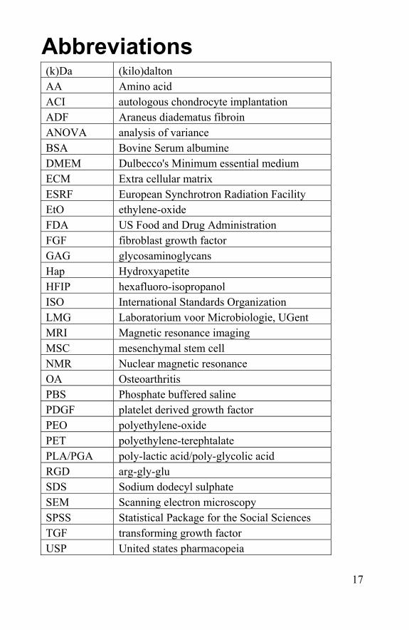
Abbreviations (k)Da (kilo)dalton AA Amino acid ACI autologous chondrocyte implantation ADF Araneus diadematus fibroin ANOVA analysis of variance BSA Bovine Serum albumine DMEM Dulbecco's Minimum essential medium ECM Extra cellular matrix ESRF European Synchrotron Radiation Facility EtO ethylene-oxide FDA US Food and Drug Administration FGF fibroblast growth factor GAG glycosaminoglycans Hap Hydroxyapetite HFIP hexafluoro-isopropanol ISO International Standards Organization LMG Laboratorium voor Microbiologie, UGent MRI Magnetic resonance imaging MSC mesenchymal stem cell NMR Nuclear magnetic resonance OA Osteoarthritis PBS Phosphate buffered saline PDGF platelet derived growth factor PEO polyethylene-oxide PET polyethylene-terephtalate PLA/PGA poly-lactic acid/poly-glycolic acid RGD arg-gly-glu SDS Sodium dodecyl sulphate SEM Scanning electron microscopy SPSS Statistical Package for the Social Sciences TGF transforming growth factor USP United states pharmacopeia

18
19
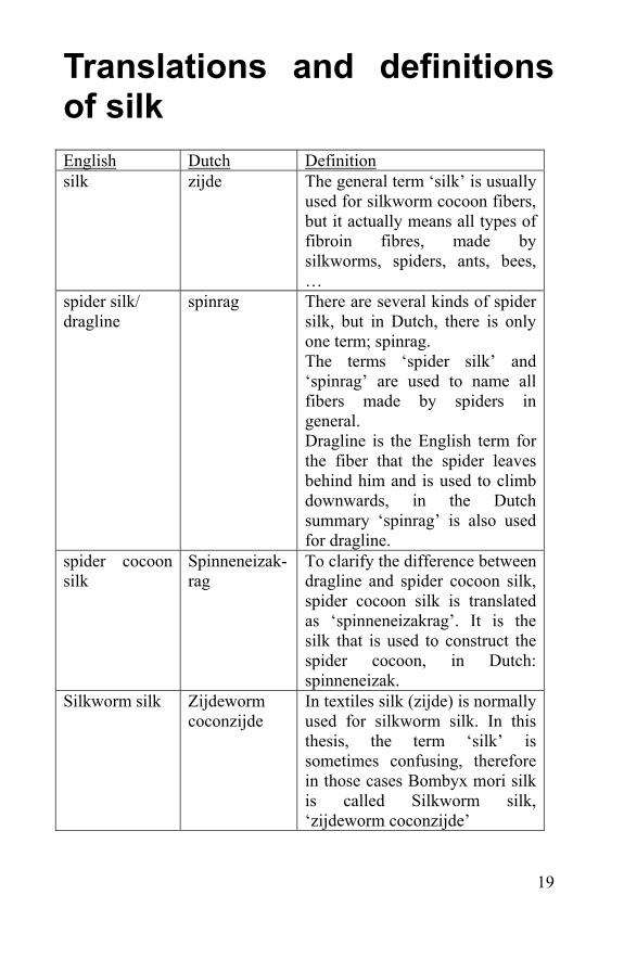
Translations and definitions of silk English Dutch Definition silk zijde The general term ‘silk’ is usually
used for silkworm cocoon fibers, but it actually means all types of fibroin fibres, made by silkworms, spiders, ants, bees, …
spider silk/ dragline
spinrag There are several kinds of spider silk, but in Dutch, there is only one term; spinrag. The terms ‘spider silk’ and ‘spinrag’ are used to name all fibers made by spiders in general. Dragline is the English term for the fiber that the spider leaves behind him and is used to climb downwards, in the Dutch summary ‘spinrag’ is also used for dragline.
spider cocoon silk
Spinneneizak-rag
To clarify the difference between dragline and spider cocoon silk, spider cocoon silk is translated as ‘spinneneizakrag’. It is the silk that is used to construct the spider cocoon, in Dutch: spinneneizak.
Silkworm silk Zijdeworm coconzijde
In textiles silk (zijde) is normally used for silkworm silk. In this thesis, the term ‘silk’ is sometimes confusing, therefore in those cases Bombyx mori silk is called Silkworm silk, ‘zijdeworm coconzijde’

20
21
Chapter 1 Silkworm and spider silk

22
23
1.1 Silk Silk is generally regarded as the protein filament secreted from glands present in some, but not all, invertebrates of the Arthropod genera. Silk production is a characteristic of all spiders and is also known among various mites, mantids, moths, butterflies, mayflies, caddisflies, beetles, ants, bees, wasps and other taxa. Some `silks', such as the gluey resin secreted by spider aggregate glands is included in this definition, although in the strict sense these are not composed of solidified filaments. Other filamentous proteins have a silk-like structure, but are not included in the definition of silk. Such a related protein filament is the widely studied byssus of molluscs.
1.2 Silk producing insects Engineers are always looking for and trying to develop new materials that are stronger, or lighter, or tougher than materials currently in use. One such material has been found, not in the laboratory, but in nature. It’s called silk, a name covering a large variety of natural protein fibres. The best known is the silk of the domesticated silkworm, Bombyx mori, but silk fibres are produced by many other insects as well. From moths to spiders, all have their own specialized silk fibres. There are over 34 000 known spider species, and each one of them makes its own silk, some of them even up to seven different kinds of silk. Spiders have been making silk for 400 million years [Vollrath et al., 2001], giving evolution plenty of time to refine the silk and the silk-making process. Orb weaving spiders have been around for about 120 million years [Kunzig et al., 2001] and have developed silk for the specific purpose of stopping aerial missiles – the flying insects that are the spider’s food source. An orb web is familiar to most people by its shape, if not its name. It is a circular shaped web, with the radial threads of the web supporting the threads spun in a spiral shape so that the finished web looks like a circular net. Dragline silk is used for the spokes of the web and as the spider’s safety line to break a fall if, say, the spider jumps out of a tree to avoid a predator. Spiders use silk also for creating a shelter, for housing their eggs, as a dragline for finding their way and for encasing their prey (zoo.org).
24
There are two kinds of spiders: the web-making spiders and the wandering spiders. The latter ones search very actively for food in contrast with the others creating webs to catch their preys. There is a wide variety in web-forms, like orb-, funnel-, sheet- and cob webs. Some spiders can even make a web under water. These fishing spiders (Dolomedes) can stay underwater for 45 minutes and more, using air bubbles stored on their abdomens. This allows them to swim underwater and attack insects and small fish for prey. The silk production of the water spider, Argyroneta aquatica, was investigated in preliminary research [De Bakker et al., 2006]. The Argyroneta can live under water permanently by building an underwater clock with silk fibres. The main focus in this thesis was on the silk of the silkworm, Bombyx mori and the garden spider, Araneus diadematus. But also other spiders have been captured from which the silk was roughly investigated. After a first examination it was decided not to use their silk for further investigations towards biomedical applications; either because their species was not abundant enough, too hard to breed in the laboratory or the fibers are too small and not applicable for further tests.
- Bombyx mori The silkworm is a member of the Bombycidae (Lepidoptera). After centuries of domestication, Bombyx mori is no longer found anywhere in a natural state. The legs of the caterpillar have degenerated, and the adults do not fly. The animals are cultivated in large amounts, by feeding mulberry leaves. Silkworm has four stages in its life cycle; egg, caterpillar, pupa and moth. The cocoons are taken and the moth is gassed to death before the silk is reeled off during degumming in a boiling soap bath. Subsequently to the degumming, the silk fibres are spun immediately into a yarn with 30-50 other silk fibres. Silk cocoons were kindly sent to our laboratory by Michael Rayne (Zhejiang Cathaya International Co Ltd, China). Silk samples were also bought in the silk museum (Zijdemuseum, Meliskerke, The Netherlands). Silk has been a popular fibre in textiles and fashion for thousands of years. It does not only have good mechanical properties (tensile
25
strength and elasticity), but it is easy to dye and comfortable to wear. It has a good thermal stability, hygroscopicity and microbial resistance [Zhang et al., 1998]. With its pearl-like gloss and a light velvety touch it has always been a luxurious product. There are four major types of silkworms of commercial importance; Mulberry, Tasar, Muga and Eri. India is the biggest producer of these silks.
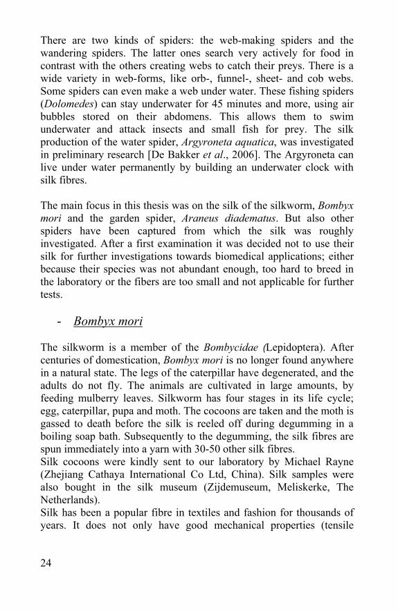
- Antheraea pernyi
This is a saturnid moth (Saturniidae). This one is closely related to Bombyx mori. The silk is called tussah silk or often wild silk, the term tussah is also used for silks from all non-domesticated silkworms [Li et al., 2003]. The moth is a nocturnal species which frequents deciduous and evergreen forests dominated by oaks. Both sexes of this species fly out in May and August (2 generations) and are readily attracted to light. By day, they can be found 'resting' on posts and walls below these.
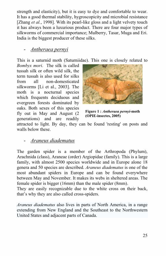
- Araneus diadematus The garden spider is a member of the Arthropoda (Phylum), Arachnida (class), Araneae (order) Argiopidae (family). This is a large family, with almost 2500 species worldwide and in Europe alone 18 genera and 50 species are described. Araneus diadematus is one of the most abundant spiders in Europe and can be found everywhere between May and November. It makes its webs in sheltered areas. The female spider is bigger (16mm) than the male spider (8mm). They are easily recognizable due to the white cross on their back, that’s why they are also called cross-spiders.
Araneus diadematus also lives in parts of North America, in a range extending from New England and the Southeast to the Northwestern United States and adjacent parts of Canada.
Figure 1 : Antheraea pernyi-moth (OPIE-insectes, 2005)
26
Individual spiders' colouring can range from extremely light yellow to very dark gray, but all european garden spiders have mottled markings across the back with five or more large white dots forming a cross.
It is hard to provoke a garden spider to bite - if it does, the bite is slightly unpleasant and utterly harmless.
Figure 2 : Araneus diadematus spiders leaving behind their dragline.
27
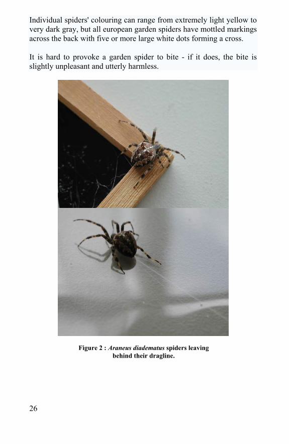
- Araneus quadratus
Araneus quadratus is a member of the same family as the previous described garden spider. Although found frequently it is not as abundant as A. diadematus. Its coloured abdomen varies considerably, from dark reddish-brown to pale yellow or green.
This spider sits either in the center of its orb-web or in a retreat lined with papery silk. Despite the variation in coloring this spider is unmistakable as it always has four white spots on its abdomen and banded legs. The white spots are more obvious on the darker specimens. This spider is often slightly bigger than A. diadematus, especially when full of eggs. It can be found on low vegetation in grassland and shrubbery. Although the silk of this animal is analogous to the one of A. diadematus, the lower abundance of the animal restricted the use of this fibre for thorough investigations.
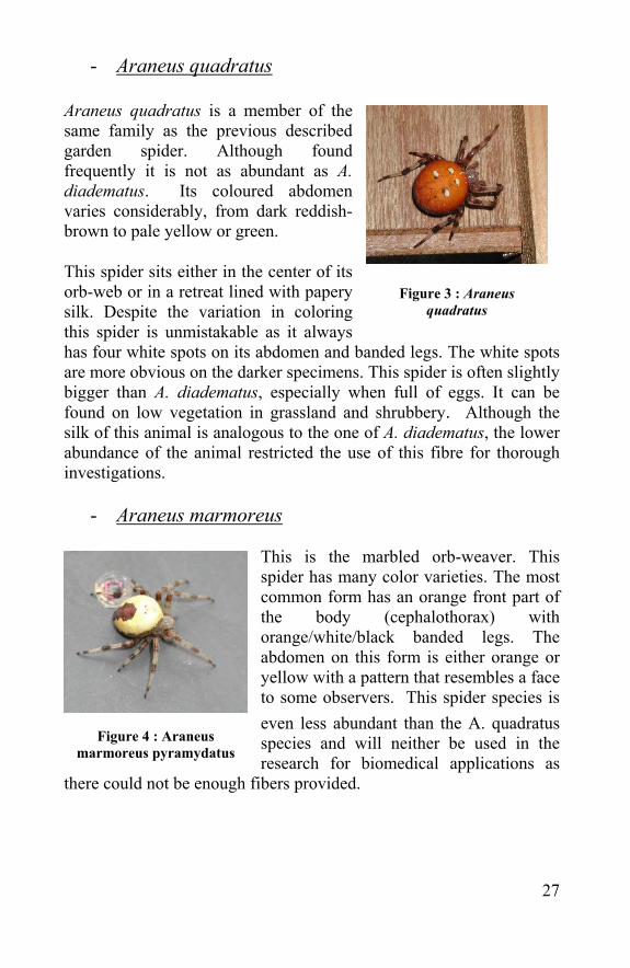
- Araneus marmoreus
This is the marbled orb-weaver. This spider has many color varieties. The most common form has an orange front part of the body (cephalothorax) with orange/white/black banded legs. The abdomen on this form is either orange or yellow with a pattern that resembles a face to some observers. This spider species is even less abundant than the A. quadratus species and will neither be used in the research for biomedical applications as
there could not be enough fibers provided.
Figure 4 : Araneus marmoreus pyramydatus
Figure 3 : Araneus quadratus
28
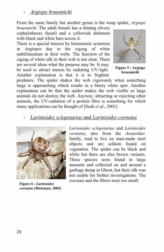
- Argiope bruennichi From the same family but another genus is the wasp spider, Argiope bruennichi. The adult female has a shining silvery cephalothorax (head) and a yellowish abdomen with black and white bars across it. There is a special interest by biomimetic scientists in Argiopes due to the zigzag of white stabilimentum in their webs. The function of the zigzag of white silk in their web is not clear. There are several ideas what the purpose may be. It may be used to attract insects by radiating UV-light. Another explanation is that it is to frighten predators. The spider shakes the web vigorously when something large is approaching which results in a blurry white spot. Another explanation can be that the spider makes the web visible so large animals do not destroy the web. Anyway, attracting or rejecting other animals, the UV-radiation of a protein fibre is something for which many applications can be thought of [Seah et al., 2001]
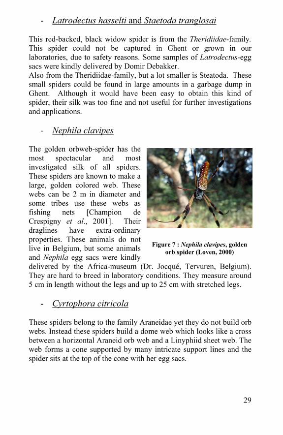
- Larinioides sclopetarius and Larinioides cornutus
Larinioides sclopetarius and Larinioides cornutus, also from the Araneidae-family, tend to live on man-made steel objects and are seldom found on vegetation. The spider can be black and white but there are also brown variants. These species were found in large amounts and collected on and around a garbage dump in Ghent, but their silk was not usable for further investigations. The cocoons and the fibres were too small.
Figure 6 : Larinioides cornutus (Hickman, 2003)
Figure 5 : Argiope bruennichi
29
- Latrodectus hasselti and Staetoda tranglosai This red-backed, black widow spider is from the Theridiidae-family. This spider could not be captured in Ghent or grown in our laboratories, due to safety reasons. Some samples of Latrodectus-egg sacs were kindly delivered by Domir Debakker. Also from the Theridiidae-family, but a lot smaller is Steatoda. These small spiders could be found in large amounts in a garbage dump in Ghent. Although it would have been easy to obtain this kind of spider, their silk was too fine and not useful for further investigations and applications.
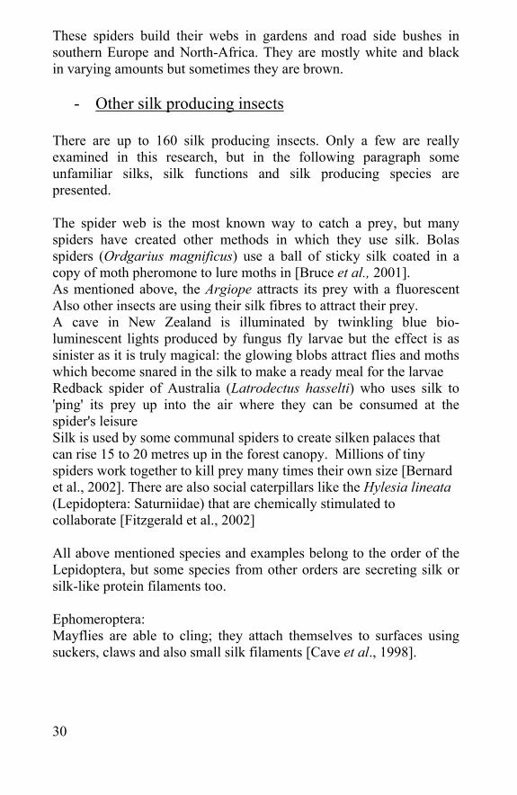
- Nephila clavipes The golden orbweb-spider has the most spectacular and most investigated silk of all spiders. These spiders are known to make a large, golden colored web. These webs can be 2 m in diameter and some tribes use these webs as fishing nets [Champion de Crespigny et al., 2001]. Their draglines have extra-ordinary properties. These animals do not live in Belgium, but some animals and Nephila egg sacs were kindly delivered by the Africa-museum (Dr. Jocqué, Tervuren, Belgium). They are hard to breed in laboratory conditions. They measure around 5 cm in length without the legs and up to 25 cm with stretched legs.
- Cyrtophora citricola
These spiders belong to the family Araneidae yet they do not build orb webs. Instead these spiders build a dome web which looks like a cross between a horizontal Araneid orb web and a Linyphiid sheet web. The web forms a cone supported by many intricate support lines and the spider sits at the top of the cone with her egg sacs.
Figure 7 : Nephila clavipes, golden orb spider (Loven, 2000)
30
These spiders build their webs in gardens and road side bushes in southern Europe and North-Africa. They are mostly white and black in varying amounts but sometimes they are brown.
- Other silk producing insects There are up to 160 silk producing insects. Only a few are really examined in this research, but in the following paragraph some unfamiliar silks, silk functions and silk producing species are presented. The spider web is the most known way to catch a prey, but many spiders have created other methods in which they use silk. Bolas spiders (Ordgarius magnificus) use a ball of sticky silk coated in a copy of moth pheromone to lure moths in [Bruce et al., 2001]. As mentioned above, the Argiope attracts its prey with a fluorescent Also other insects are using their silk fibres to attract their prey. A cave in New Zealand is illuminated by twinkling blue bio-luminescent lights produced by fungus fly larvae but the effect is as sinister as it is truly magical: the glowing blobs attract flies and moths which become snared in the silk to make a ready meal for the larvae Redback spider of Australia (Latrodectus hasselti) who uses silk to 'ping' its prey up into the air where they can be consumed at the spider's leisure Silk is used by some communal spiders to create silken palaces that can rise 15 to 20 metres up in the forest canopy. Millions of tiny spiders work together to kill prey many times their own size [Bernard et al., 2002]. There are also social caterpillars like the Hylesia lineata (Lepidoptera: Saturniidae) that are chemically stimulated to collaborate [Fitzgerald et al., 2002] All above mentioned species and examples belong to the order of the Lepidoptera, but some species from other orders are secreting silk or silk-like protein filaments too. Ephomeroptera: Mayflies are able to cling; they attach themselves to surfaces using suckers, claws and also small silk filaments [Cave et al., 1998].
31
Trichoptera: Three families of Trichoptera have larvae that are able to spin nets: Philopotamidae, Polycentropidae and Hydropsychidae. Caddisflies use silk (like butterflies) to build cases from gravel, twigs, needles, or sand. The aquatic caddisfly larvae secrete silk through their mouths from modified salivary glands. The silk is similar to that spun by the caterpillars or butterflies and moths. Certain caddisfly larvae construct silken nets to capture food from the water [Dunleavy, 2005]. They live in houses, called cases, they make themselves. They houses are so specialized that one can almost identify a caddisfly larva to genus when the case is seen. Embioptera These insects are small to medium sized insects, (usually under 12mm but can be up to 20) which live under an intricate web of silken tunnels which are woven on tree trunks, in leaf litter or in the soil. The insects live in colonies under their protective silk and feed on lichens and other plant material. Hymenoptera: The Oriental hornet (Vespa orientalis) develops a silk coat around its growing larva. Prior to its metamorphosis into a pupa, the larva secretes a silk weave, which enwraps it completely. This silk coat is not uniform throughout, but rather varies along the extent of the larval body. Apart from the pupating larvae, the adult hornets also secrete a type of silk, which acts as a glue holding together the components of the larval cell wall [Joseph et al., 2004]. There are also social-living Hymenoptera larvae [Gomes et al., 2004]. The Formicinae include several genera in which nest-weaving behaviour has been observed (Oecophylla, Polyrhachis, Camponotus, and Dendromyrmex). The ants’ own larvae use the silk in nest construction [Johnson et al., 2003].
- Silk-like protein filaments Some fibrous protein filaments are not considered as silk fibres, but do have partial silk-like microstructures. Such a protein filament is the widely studied Mollusc byssal filaments.
32
Molluscs (Mytilus) have a byssal beard used to attach on solid surfaces. These byssal threads Up to 70% of the total absorbed energy can be dissipated in the byssus [Rzepecki et al., 1995]. These are not counted as silks but their structure can be silk-like, collagenous, elastic or a combination of these. Protein gradients in byssal threads are constructed using natural macromolecular chimeras having a central collagenous domain, variable flanking modules and histidine-rich amino and carboxy termini. Stiff silk-like flanking modules prevail distally, while at the animal end, rubbery modules resembling elastin predominate [Waite et al., 2002]. The rest of the filament has a rather collagen-like structure, which makes it a potential product in tissue engineering for example in tendon regeneration. [Qin et al., 1997] Another silk or silk-like filament is the biopolymer composed of the at least ten proteins secreted by the salivary glands of the bloodworm Chironomus [Case et al., 1992]. These accumulate in the central lumen of the gland, forming dissociable complexes that appear as a network of smooth fibrils and multistranded beaded fibres. When secretory protein complexes are extruded through the secretory duct, the fibres become oriented in parallel arrays; when these parallel arrays of fibres emerge from the mouth of larvae they are an insoluble, silk-like thread. Larval silk is used to construct tubes for protective housing and assist with feeding; prepupal silk is used to construct tubes for larval/pupal ecdysis (pupation).
33
1.3 Silk fibres
1.3.1 Obtaining dragline and egg sac silk
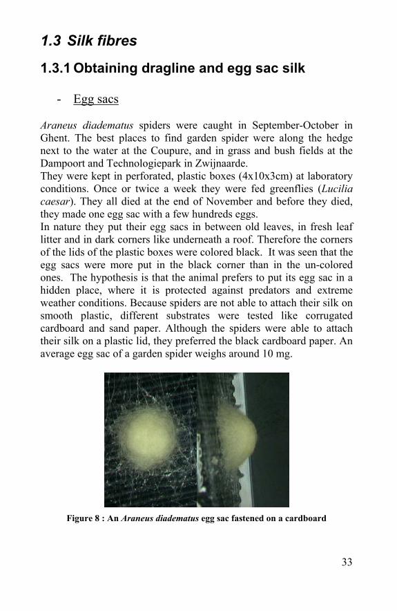
- Egg sacs Araneus diadematus spiders were caught in September-October in Ghent. The best places to find garden spider were along the hedge next to the water at the Coupure, and in grass and bush fields at the Dampoort and Technologiepark in Zwijnaarde. They were kept in perforated, plastic boxes (4x10x3cm) at laboratory conditions. Once or twice a week they were fed greenflies (Lucilia caesar). They all died at the end of November and before they died, they made one egg sac with a few hundreds eggs. In nature they put their egg sacs in between old leaves, in fresh leaf litter and in dark corners like underneath a roof. Therefore the corners of the lids of the plastic boxes were colored black. It was seen that the egg sacs were more put in the black corner than in the un-colored ones. The hypothesis is that the animal prefers to put its egg sac in a hidden place, where it is protected against predators and extreme weather conditions. Because spiders are not able to attach their silk on smooth plastic, different substrates were tested like corrugated cardboard and sand paper. Although the spiders were able to attach their silk on a plastic lid, they preferred the black cardboard paper. An average egg sac of a garden spider weighs around 10 mg.
Figure 8 : An Araneus diadematus egg sac fastened on a cardboard
34
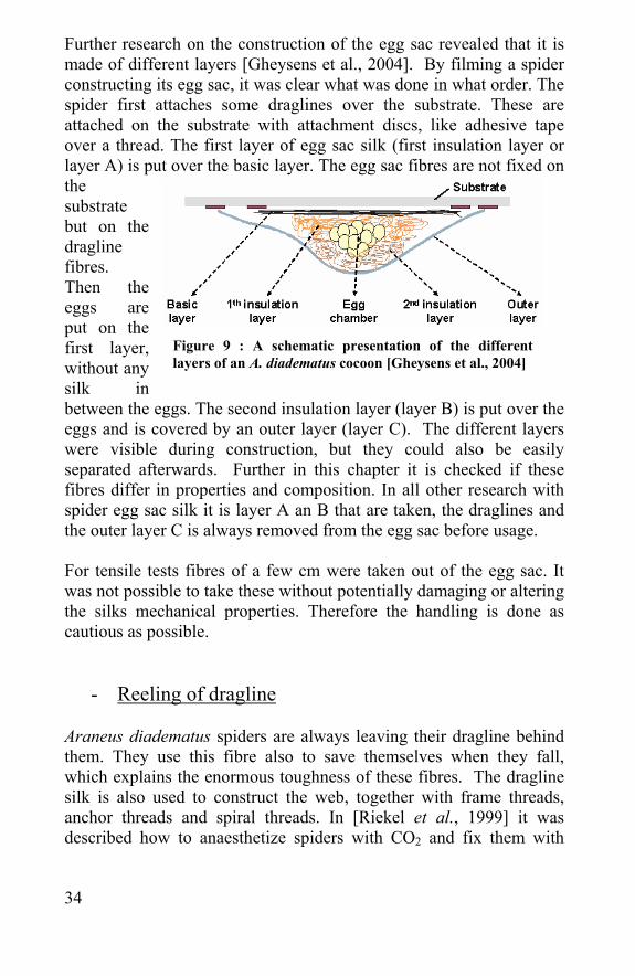
Further research on the construction of the egg sac revealed that it is made of different layers [Gheysens et al., 2004]. By filming a spider constructing its egg sac, it was clear what was done in what order. The spider first attaches some draglines over the substrate. These are attached on the substrate with attachment discs, like adhesive tape over a thread. The first layer of egg sac silk (first insulation layer or layer A) is put over the basic layer. The egg sac fibres are not fixed on the substrate but on the dragline fibres. Then the eggs are put on the first layer, without any silk in between the eggs. The second insulation layer (layer B) is put over the eggs and is covered by an outer layer (layer C). The different layers were visible during construction, but they could also be easily separated afterwards. Further in this chapter it is checked if these fibres differ in properties and composition. In all other research with spider egg sac silk it is layer A an B that are taken, the draglines and the outer layer C is always removed from the egg sac before usage. For tensile tests fibres of a few cm were taken out of the egg sac. It was not possible to take these without potentially damaging or altering the silks mechanical properties. Therefore the handling is done as cautious as possible.
- Reeling of dragline Araneus diadematus spiders are always leaving their dragline behind them. They use this fibre also to save themselves when they fall, which explains the enormous toughness of these fibres. The dragline silk is also used to construct the web, together with frame threads, anchor threads and spiral threads. In [Riekel et al., 1999] it was described how to anaesthetize spiders with CO2 and fix them with
Figure 9 : A schematic presentation of the different layers of an A. diadematus cocoon [Gheysens et al., 2004]
35
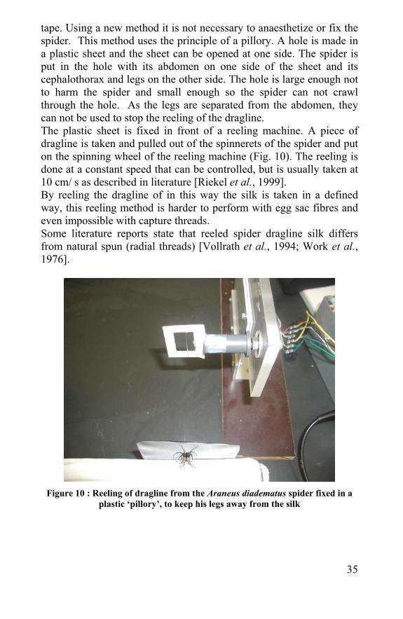
tape. Using a new method it is not necessary to anaesthetize or fix the spider. This method uses the principle of a pillory. A hole is made in a plastic sheet and the sheet can be opened at one side. The spider is put in the hole with its abdomen on one side of the sheet and its cephalothorax and legs on the other side. The hole is large enough not to harm the spider and small enough so the spider can not crawl through the hole. As the legs are separated from the abdomen, they can not be used to stop the reeling of the dragline. The plastic sheet is fixed in front of a reeling machine. A piece of dragline is taken and pulled out of the spinnerets of the spider and put on the spinning wheel of the reeling machine (Fig. 10). The reeling is done at a constant speed that can be controlled, but is usually taken at 10 cm/ s as described in literature [Riekel et al., 1999]. By reeling the dragline of in this way the silk is taken in a defined way, this reeling method is harder to perform with egg sac fibres and even impossible with capture threads. Some literature reports state that reeled spider dragline silk differs from natural spun (radial threads) [Vollrath et al., 1994; Work et al., 1976].
Figure 10 : Reeling of dragline from the Araneus diadematus spider fixed in a
plastic ‘pillory’, to keep his legs away from the silk
36
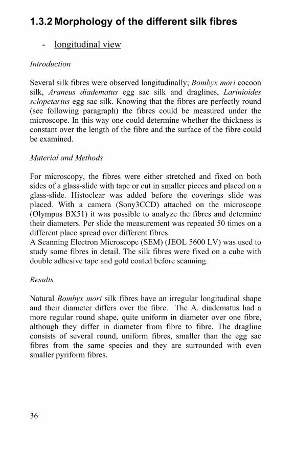
1.3.2 Morphology of the different silk fibres
- longitudinal view Introduction Several silk fibres were observed longitudinally; Bombyx mori cocoon silk, Araneus diadematus egg sac silk and draglines, Larinioides sclopetarius egg sac silk. Knowing that the fibres are perfectly round (see following paragraph) the fibres could be measured under the microscope. In this way one could determine whether the thickness is constant over the length of the fibre and the surface of the fibre could be examined. Material and Methods For microscopy, the fibres were either stretched and fixed on both sides of a glass-slide with tape or cut in smaller pieces and placed on a glass-slide. Histoclear was added before the coverings slide was placed. With a camera (Sony3CCD) attached on the microscope (Olympus BX51) it was possible to analyze the fibres and determine their diameters. Per slide the measurement was repeated 50 times on a different place spread over different fibres. A Scanning Electron Microscope (SEM) (JEOL 5600 LV) was used to study some fibres in detail. The silk fibres were fixed on a cube with double adhesive tape and gold coated before scanning. Results Natural Bombyx mori silk fibres have an irregular longitudinal shape and their diameter differs over the fibre. The A. diadematus had a more regular round shape, quite uniform in diameter over one fibre, although they differ in diameter from fibre to fibre. The dragline consists of several round, uniform fibres, smaller than the egg sac fibres from the same species and they are surrounded with even smaller pyriform fibres.
37
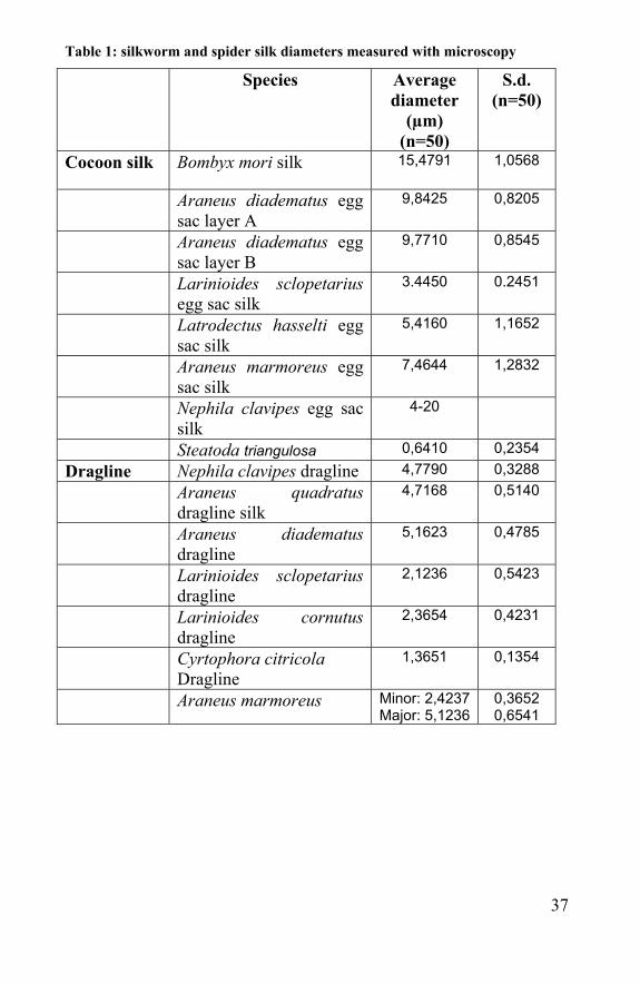
Table 1: silkworm and spider silk diameters measured with microscopy
Species Average diameter
(µm) (n=50)
S.d. (n=50)
Cocoon silk Bombyx mori silk 15,4791
1,0568
Araneus diadematus egg sac layer A
9,8425 0,8205
Araneus diadematus egg sac layer B
9,7710 0,8545
Larinioides sclopetarius egg sac silk
3.4450 0.2451
Latrodectus hasselti egg sac silk
5,4160
1,1652
Araneus marmoreus egg sac silk
7,4644 1,2832
Nephila clavipes egg sac silk
4-20
Steatoda triangulosa 0,6410 0,2354 Dragline Nephila clavipes dragline 4,7790 0,3288 Araneus quadratus
dragline silk 4,7168 0,5140
Araneus diadematus dragline
5,1623 0,4785
Larinioides sclopetarius dragline
2,1236 0,5423
Larinioides cornutus dragline
2,3654 0,4231
Cyrtophora citricola Dragline
1,3651 0,1354
Araneus marmoreus Minor: 2,4237Major: 5,1236
0,3652 0,6541
38
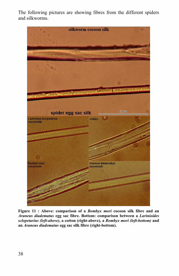
The following pictures are showing fibres from the different spiders and silkworms.
Figure 11 : Above: comparison of a Bombyx mori cocoon silk fibre and an Araneus diadematus egg sac fibre. Bottom: comparison between a Larinioides sclopetarius (left-above), a cotton (right-above), a Bombyx mori (left-bottom) and an Araneus diadematus egg sac silk fibre (right-bottom).
39
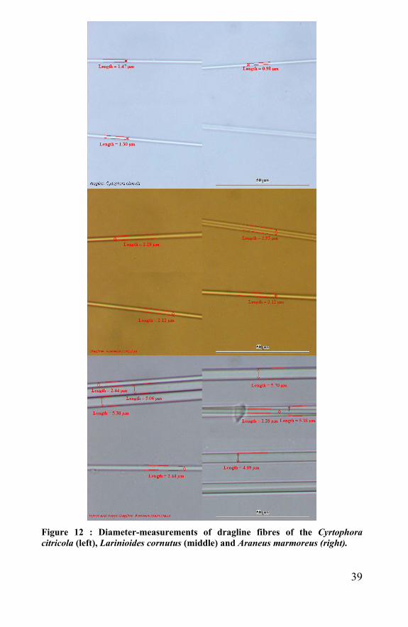
Figure 12 : Diameter-measurements of dragline fibres of the Cyrtophora citricola (left), Larinioides cornutus (middle) and Araneus marmoreus (right).
40
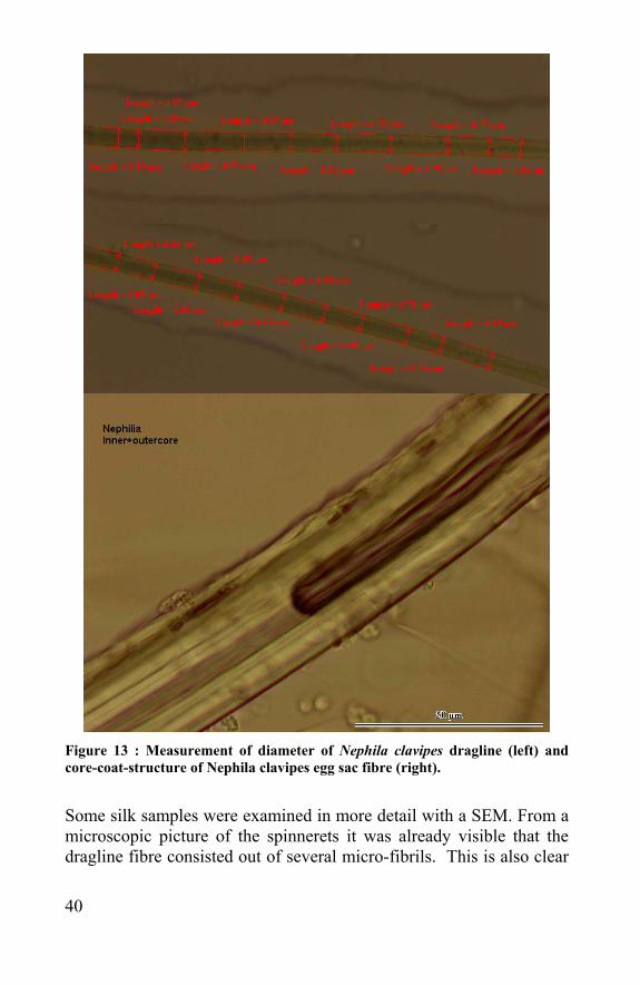
Figure 13 : Measurement of diameter of Nephila clavipes dragline (left) and core-coat-structure of Nephila clavipes egg sac fibre (right).
Some silk samples were examined in more detail with a SEM. From a microscopic picture of the spinnerets it was already visible that the dragline fibre consisted out of several micro-fibrils. This is also clear
41
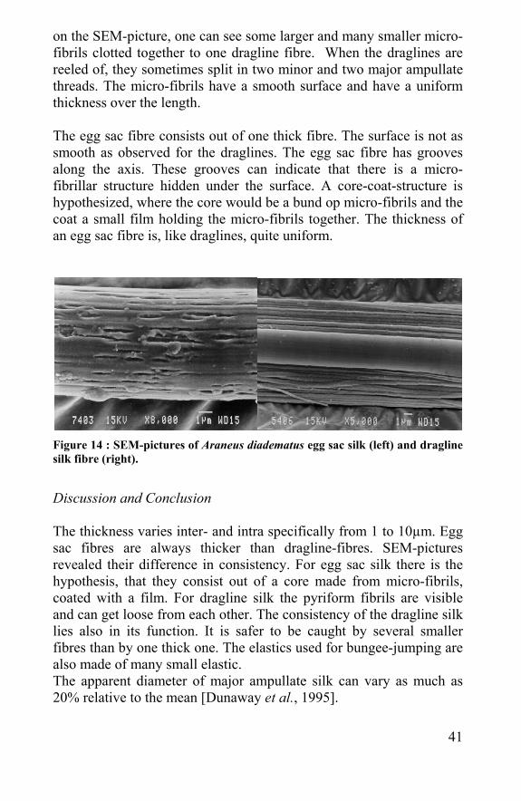
on the SEM-picture, one can see some larger and many smaller micro-fibrils clotted together to one dragline fibre. When the draglines are reeled of, they sometimes split in two minor and two major ampullate threads. The micro-fibrils have a smooth surface and have a uniform thickness over the length. The egg sac fibre consists out of one thick fibre. The surface is not as smooth as observed for the draglines. The egg sac fibre has grooves along the axis. These grooves can indicate that there is a micro-fibrillar structure hidden under the surface. A core-coat-structure is hypothesized, where the core would be a bund op micro-fibrils and the coat a small film holding the micro-fibrils together. The thickness of an egg sac fibre is, like draglines, quite uniform.
Figure 14 : SEM-pictures of Araneus diadematus egg sac silk (left) and dragline silk fibre (right).
Discussion and Conclusion The thickness varies inter- and intra specifically from 1 to 10µm. Egg sac fibres are always thicker than dragline-fibres. SEM-pictures revealed their difference in consistency. For egg sac silk there is the hypothesis, that they consist out of a core made from micro-fibrils, coated with a film. For dragline silk the pyriform fibrils are visible and can get loose from each other. The consistency of the dragline silk lies also in its function. It is safer to be caught by several smaller fibres than by one thick one. The elastics used for bungee-jumping are also made of many small elastic. The apparent diameter of major ampullate silk can vary as much as 20% relative to the mean [Dunaway et al., 1995].
42
On the SEM-pictures of the dragline fibres several small and larger microfibrils were found, although on fig 14 it is not clear how many microfibrils are present, in Viney, 2000 it is mentioned that a dragline thread consists of 2 minor and 2 major ampullate silk fibres.
- Cross-sectional view Introduction Synthetic fibres can be spun in different diameters and in the weirdest shapes. Natural fibres do have their characteristic morphology. Flax and wool are rather round (wool having a scale-like surface). The cross-sections of cotton and silkworm silk fibres are not that uniform. Cotton fibres can be round, oval or kidney-shaped, but have always a curved surface. Silk cocoon fibres have also irregular shapes but are more sharp-angled. With only a length-wise view it is impossible to report about the shape of the fibre, therefore cross-sections were made of silkworm silk and spider egg sac silk fibres. Silkworm silk consists out of 2 fibers embedded in a sericin coating, in this paragraph only the silk fiber is investigated. Material and methods Several egg sac and dragline fibres were embedded and cross-sections were made to investigate the shape and diameter of the tested fibres. Different embedding methods were used: 1) In hard paraffin: The silk threads were soaked in Bouin (picrinic acid, formaldehyde and formic acid (24-48h), ethanol (70%), (10 min)), ethanol (2 times, 95%, and 10 min), butyl-alcohol (10 min), paraffin (first bath, 1 hour) and paraffin (second bath, 1 hour). The threads were brought in a mould in paraffin and put in a fridge (1 hour). After cutting the paraffin in a trapezoidal shape and fixing it on a carrier, it was put in K2Cr2O7 to harden the paraffin. Cross-sections (5-10 µm) were made using a microtome and put on glass slides coated with albuminous water and dried on a heating plate (30°C). 2) In polyester-resin: The silk threads were pulled through a small tube (d: 1 mm). The polyester-resin (2,5g) was mixed with 1 drop of MEPK-hardener (60 mg, VossChemie GMBH, Uetersen) before it was injected in the tube. After one day, the resin was hardened and
43
the tube was brought in a hand-microtome (adamel-lhomargy). In this way, slices of the tube and polyester-embedded threads could be cut off with a razor at 5 µm and brought on glass slides 3) In technovit 9100: The technovit T9100 pre-infiltration I -, II- and infiltration-solution, stock A and B solution and polarisation mixture were made according to the T9100-kit. The silk threads were fixated in formaldehyde and dehydrated in alcohol (30%, 50%, 75%, and 96%) and xylol. After pre-infiltration and infiltration the threads were hung vertically in a mould by attaching a lead bead on the underside of the threads. The stock A and B mixture was brought in the mould to perform the final embedment. The technovit 9100 block was cut in cross-sections (5µm) with a microtome using a tungsten-carbide-knife; these cross-sections were stretched with alcohol on glass-slides coated with wood-glue. An analogue procedure was performed with the 7022 18500 Leica Historesin embedding kit (basic resin ((2-hydroxyethyl)-methacrylate), activator (dibenzylperoxide) and hardener (dimethylsulfoxide)), but the advantage of T9100 to the Leica and other resin is that the T9100 resin can be washed away afterwards for a better coloring. Deplasticizing the T9100 cross-section was done with xylol (2x, 20 min), 2-methoxyethylacetaat (20 min) and acetone (2x 5 min). Coloring was not really necessary to detect the fibres and no specific coloring is known to colour silk fibres, but several coloring agents were tested: 1) Methylene-blue 2) Toludine-blue 3) Trichrome-coloring with haematoxyline, acidified fuchsine – ponceau de xylidine – orange G, fosfo-tungsten-acid and aniline-blue – orange G – pure acetic acid. All were viewed and processed with the Olympus BX51 microscope and Lucia image-analysing system.
44
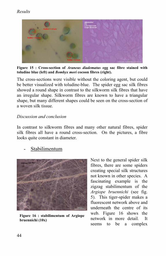
Results
Figure 15 : Cross-section of Araneus diadematus egg sac fibre stained with toludine blue (left) and Bombyx mori cocoon fibres (right).
The cross-sections were visible without the coloring agent, but could be better visualized with toludine-blue. The spider egg sac silk fibres showed a round shape in contrast to the silkworm silk fibres that have an irregular shape. Silkworm fibres are known to have a triangular shape, but many different shapes could be seen on the cross-section of a woven silk tissue. Discussion and conclusion In contrast to silkworm fibres and many other natural fibres, spider silk fibres all have a round cross-section. On the pictures, a fibre looks quite constant in diameter.
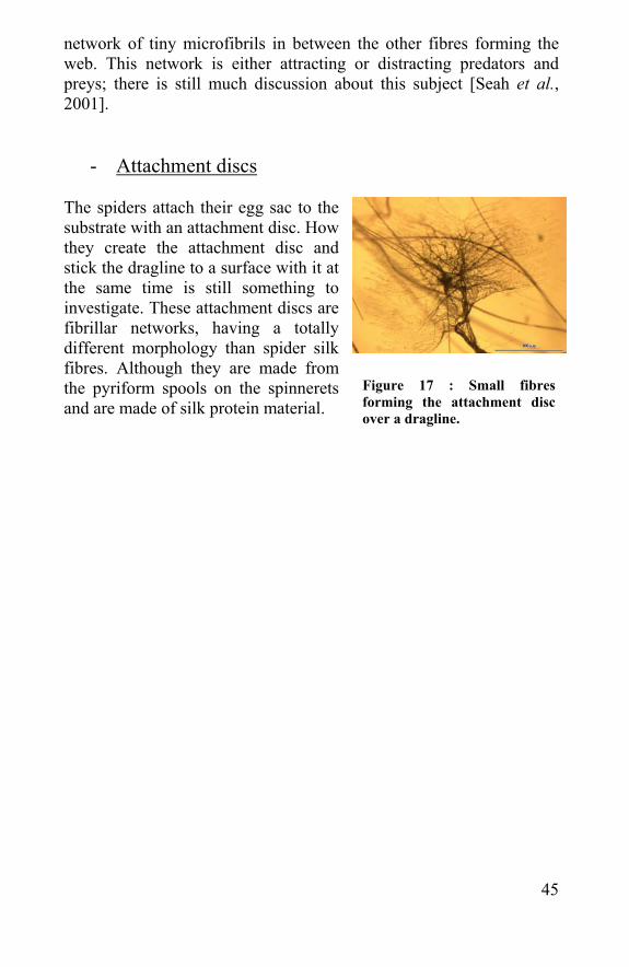
- Stabilimentum
Next to the general spider silk fibres, there are some spiders creating special silk structures not known in other species. A fascinating example is the zigzag stabilimentum of the Argiope bruennichi (see fig. 5). This tiger-spider makes a fluorescent network above and underneath the centre of its web. Figure 16 shows the network in more detail. It seems to be a complex
Figure 16 : stabilimentum of Argiope bruennichi (10x)
45
network of tiny microfibrils in between the other fibres forming the web. This network is either attracting or distracting predators and preys; there is still much discussion about this subject [Seah et al., 2001].
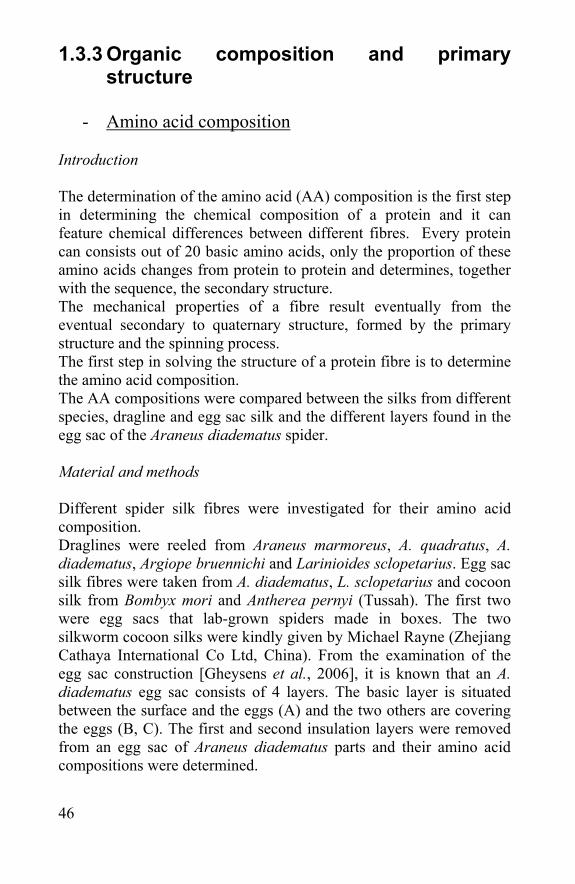
- Attachment discs The spiders attach their egg sac to the substrate with an attachment disc. How they create the attachment disc and stick the dragline to a surface with it at the same time is still something to investigate. These attachment discs are fibrillar networks, having a totally different morphology than spider silk fibres. Although they are made from the pyriform spools on the spinnerets and are made of silk protein material.
Figure 17 : Small fibres forming the attachment disc over a dragline.
46
1.3.3 Organic composition and primary structure
- Amino acid composition
Introduction The determination of the amino acid (AA) composition is the first step in determining the chemical composition of a protein and it can feature chemical differences between different fibres. Every protein can consists out of 20 basic amino acids, only the proportion of these amino acids changes from protein to protein and determines, together with the sequence, the secondary structure. The mechanical properties of a fibre result eventually from the eventual secondary to quaternary structure, formed by the primary structure and the spinning process. The first step in solving the structure of a protein fibre is to determine the amino acid composition. The AA compositions were compared between the silks from different species, dragline and egg sac silk and the different layers found in the egg sac of the Araneus diadematus spider. Material and methods Different spider silk fibres were investigated for their amino acid composition. Draglines were reeled from Araneus marmoreus, A. quadratus, A. diadematus, Argiope bruennichi and Larinioides sclopetarius. Egg sac silk fibres were taken from A. diadematus, L. sclopetarius and cocoon silk from Bombyx mori and Antherea pernyi (Tussah). The first two were egg sacs that lab-grown spiders made in boxes. The two silkworm cocoon silks were kindly given by Michael Rayne (Zhejiang Cathaya International Co Ltd, China). From the examination of the egg sac construction [Gheysens et al., 2006], it is known that an A. diadematus egg sac consists of 4 layers. The basic layer is situated between the surface and the eggs (A) and the two others are covering the eggs (B, C). The first and second insulation layers were removed from an egg sac of Araneus diadematus parts and their amino acid compositions were determined.
47
To determine a spider silk fiber’s AA composition, the secondary structure have to be broken and primary peptide-bonds have to be hydrolyzed by acid hydrolysis. For one experiment, a fibre sample of approximately 10 cm is taken. The linear density of an A. diadematus fibre is ± 1 dtex = ± 0, 1 g/km, this means a fibre with a length of ± 10 cm weighs ±10 µg. The sample is washed in formic acid, rinsed with distillated water, to remove adhering and interfering proteins and dried in a vacuum dryer. Several glass vials are filled with a sample and brought in a jar with HCl (6N, 200 µl). The jar was flushed with argon or N2 before closure and heated (>24h, 106-110°C). After cooling down and drying the hydrolyzed amino acids were re-dissolved in 250 µl water and sonicated. 10 µl of the solution was brought in the pico-analyzer next to a reference sample. Peak heights can be recalculated to amino acid percentages. It has to be remarked that Methionine (met) and Cysteine (cys) are destroyed during amino acid hydrolysis. These two amino acids are not abundant in silk anyway. Asparagine (Asn) and glutamine (Gln) are respectively converted to aspartic acid (Asp) and glutamic acid (Glu). This means the measured Asp and Glu are actually a sum of Asn + Asp and Gln + Glu. These sums are sometimes shown as Asx and Glx. The tests were done 2 or 3 times per fibre to confirm the results.
48
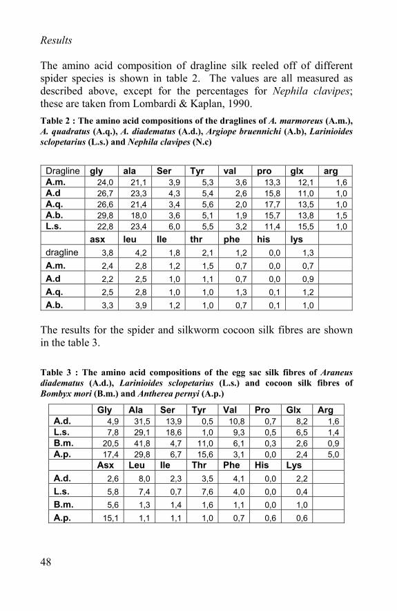
Results The amino acid composition of dragline silk reeled off of different spider species is shown in table 2. The values are all measured as described above, except for the percentages for Nephila clavipes; these are taken from Lombardi & Kaplan, 1990. Table 2 : The amino acid compositions of the draglines of A. marmoreus (A.m.), A. quadratus (A.q.), A. diadematus (A.d.), Argiope bruennichi (A.b), Larinioides sclopetarius (L.s.) and Nephila clavipes (N.c)
Dragline gly ala Ser Tyr val pro glx arg A.m. 24,0 21,1 3,9 5,3 3,6 13,3 12,1 1,6 A.d 26,7 23,3 4,3 5,4 2,6 15,8 11,0 1,0 A.q. 26,6 21,4 3,4 5,6 2,0 17,7 13,5 1,0 A.b. 29,8 18,0 3,6 5,1 1,9 15,7 13,8 1,5 L.s. 22,8 23,4 6,0 5,5 3,2 11,4 15,5 1,0 asx leu Ile thr phe his lys dragline 3,8 4,2 1,8 2,1 1,2 0,0 1,3 A.m. 2,4 2,8 1,2 1,5 0,7 0,0 0,7 A.d 2,2 2,5 1,0 1,1 0,7 0,0 0,9 A.q. 2,5 2,8 1,0 1,0 1,3 0,1 1,2 A.b. 3,3 3,9 1,2 1,0 0,7 0,1 1,0
The results for the spider and silkworm cocoon silk fibres are shown in the table 3. Table 3 : The amino acid compositions of the egg sac silk fibres of Araneus diadematus (A.d.), Larinioides sclopetarius (L.s.) and cocoon silk fibres of Bombyx mori (B.m.) and Antherea pernyi (A.p.)
Gly Ala Ser Tyr Val Pro Glx Arg A.d. 4,9 31,5 13,9 0,5 10,8 0,7 8,2 1,6 L.s. 7,8 29,1 18,6 1,0 9,3 0,5 6,5 1,4 B.m. 20,5 41,8 4,7 11,0 6,1 0,3 2,6 0,9 A.p. 17,4 29,8 6,7 15,6 3,1 0,0 2,4 5,0 Asx Leu Ile Thr Phe His Lys A.d. 2,6 8,0 2,3 3,5 4,1 0,0 2,2 L.s. 5,8 7,4 0,7 7,6 4,0 0,0 0,4 B.m. 5,6 1,3 1,4 1,6 1,1 0,0 1,0 A.p. 15,1 1,1 1,1 1,0 0,7 0,6 0,6
49
Table 4 : comparison between 3 most important amino acids between dragline fibers and cocoon fibers
dragline cocoon A.m. A.d A.q. A.b. L.s. A.d. L.s. B.m. A.p. Gly 24 26,7 26,6 29,8 22,8 4,9 7,8 20,5 17,4 Ala 21,1 23,3 21,4 18 23,4 31,5 29,1 41,8 29,8 Ser 3,9 4,3 3,4 3,6 6 13,9 18,6 4,7 6,7
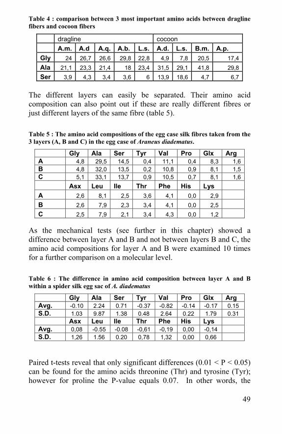
The different layers can easily be separated. Their amino acid composition can also point out if these are really different fibres or just different layers of the same fibre (table 5). Table 5 : The amino acid compositions of the egg case silk fibres taken from the 3 layers (A, B and C) in the egg case of Araneus diadematus.
Gly Ala Ser Tyr Val Pro Glx Arg A 4,8 29,5 14,5 0,4 11,1 0,4 8,3 1,6 B 4,8 32,0 13,5 0,2 10,8 0,9 8,1 1,5 C 5,1 33,1 13,7 0,9 10,5 0,7 8,1 1,6 Asx Leu Ile Thr Phe His Lys A 2,6 8,1 2,5 3,6 4,1 0,0 2,9 B 2,6 7,9 2,3 3,4 4,1 0,0 2,5 C 2,5 7,9 2,1 3,4 4,3 0,0 1,2
As the mechanical tests (see further in this chapter) showed a difference between layer A and B and not between layers B and C, the amino acid compositions for layer A and B were examined 10 times for a further comparison on a molecular level. Table 6 : The difference in amino acid composition between layer A and B within a spider silk egg sac of A. diadematus
Gly Ala Ser Tyr Val Pro Glx Arg Avg. -0.10 2.24 0.71 -0.37 -0.82 -0.14 -0.17 0.15 S.D. 1.03 9.87 1.38 0.48 2.64 0.22 1.79 0.31 Asx Leu Ile Thr Phe His Lys Avg. 0,08 -0.55 -0.08 -0,61 -0,19 0,00 -0,14 S.D. 1,26 1.56 0.20 0,78 1,32 0,00 0,66
Paired t-tests reveal that only significant differences (0.01 < P < 0.05) can be found for the amino acids threonine (Thr) and tyrosine (Tyr); however for proline the P-value equals 0.07. In other words, the
50
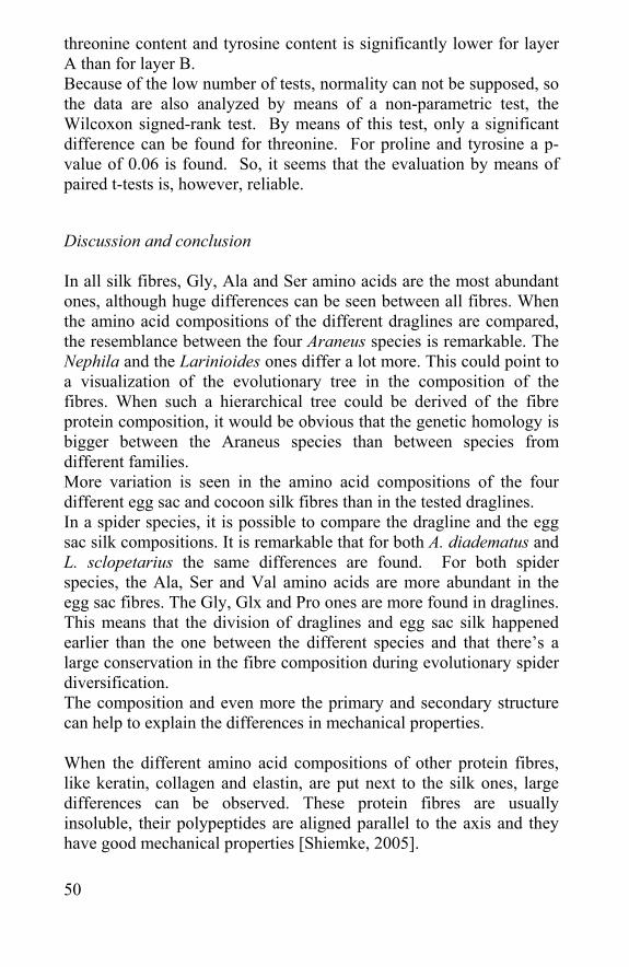
threonine content and tyrosine content is significantly lower for layer A than for layer B. Because of the low number of tests, normality can not be supposed, so the data are also analyzed by means of a non-parametric test, the Wilcoxon signed-rank test. By means of this test, only a significant difference can be found for threonine. For proline and tyrosine a p-value of 0.06 is found. So, it seems that the evaluation by means of paired t-tests is, however, reliable. Discussion and conclusion In all silk fibres, Gly, Ala and Ser amino acids are the most abundant ones, although huge differences can be seen between all fibres. When the amino acid compositions of the different draglines are compared, the resemblance between the four Araneus species is remarkable. The Nephila and the Larinioides ones differ a lot more. This could point to a visualization of the evolutionary tree in the composition of the fibres. When such a hierarchical tree could be derived of the fibre protein composition, it would be obvious that the genetic homology is bigger between the Araneus species than between species from different families. More variation is seen in the amino acid compositions of the four different egg sac and cocoon silk fibres than in the tested draglines. In a spider species, it is possible to compare the dragline and the egg sac silk compositions. It is remarkable that for both A. diadematus and L. sclopetarius the same differences are found. For both spider species, the Ala, Ser and Val amino acids are more abundant in the egg sac fibres. The Gly, Glx and Pro ones are more found in draglines. This means that the division of draglines and egg sac silk happened earlier than the one between the different species and that there’s a large conservation in the fibre composition during evolutionary spider diversification. The composition and even more the primary and secondary structure can help to explain the differences in mechanical properties. When the different amino acid compositions of other protein fibres, like keratin, collagen and elastin, are put next to the silk ones, large differences can be observed. These protein fibres are usually insoluble, their polypeptides are aligned parallel to the axis and they have good mechanical properties [Shiemke, 2005].
51
Table 7 : Amino acid compositions of keratin, collagen and elastin [Schiemke, 2005]
Gly Ala Ser Tyr Val Pro Glx Arg Silk 20,5 41,8 4,7 11,0 6,1 0,3 2,6 0,9 keratin 8.1 5 10.2 4.2 5.1 7.5 12.1 7.2 collagen 32.7 12 3.4 0.4 1.8 22.1 7.7 5 elastin 32.3 23 1.3 1.7 12.1 10.7 2.1 0.6
Asx Leu Ile Thr Phe His Lys Cys
silk 5,6 1,3 1,4 1,6 1,1 0,0 1,0 0 keratin 6 6.9 2.8 6.5 2.5 0.7 2.3 11.2 collagen 4.5 2.1 0.9 1.6 1.2 0.3 3.7 0 elastin 0.9 5.1 1.9 1.6 3.2 0 3.6 0
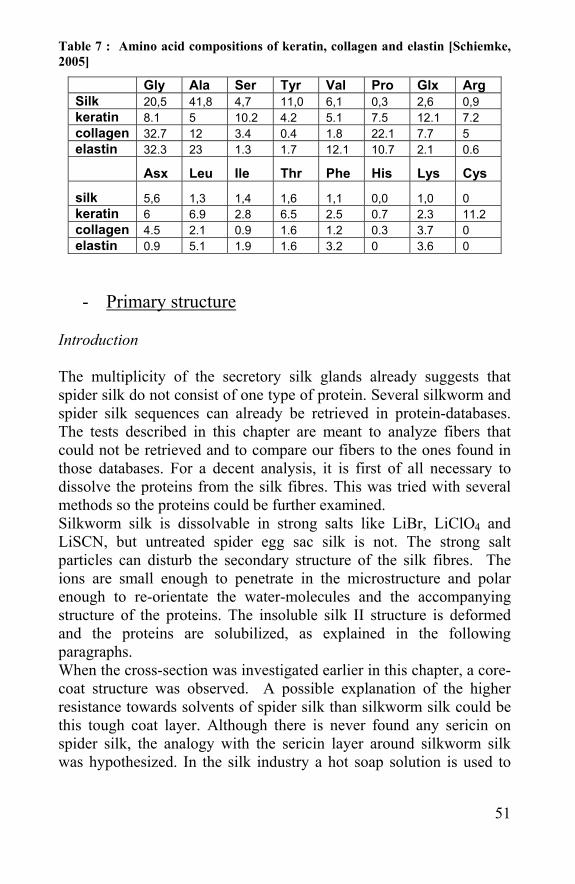
- Primary structure Introduction The multiplicity of the secretory silk glands already suggests that spider silk do not consist of one type of protein. Several silkworm and spider silk sequences can already be retrieved in protein-databases. The tests described in this chapter are meant to analyze fibers that could not be retrieved and to compare our fibers to the ones found in those databases. For a decent analysis, it is first of all necessary to dissolve the proteins from the silk fibres. This was tried with several methods so the proteins could be further examined. Silkworm silk is dissolvable in strong salts like LiBr, LiClO4 and LiSCN, but untreated spider egg sac silk is not. The strong salt particles can disturb the secondary structure of the silk fibres. The ions are small enough to penetrate in the microstructure and polar enough to re-orientate the water-molecules and the accompanying structure of the proteins. The insoluble silk II structure is deformed and the proteins are solubilized, as explained in the following paragraphs. When the cross-section was investigated earlier in this chapter, a core-coat structure was observed. A possible explanation of the higher resistance towards solvents of spider silk than silkworm silk could be this tough coat layer. Although there is never found any sericin on spider silk, the analogy with the sericin layer around silkworm silk was hypothesized. In the silk industry a hot soap solution is used to
52
remove the sericin around the silk fibroin. The same soap solution was tried out to remove a coating around the spider egg sac silk fibres, in the hope that this procedure would also take away the resistance towards strong salt dissolution. The dissolving process and the dissolved proteins could be evaluated with electrophoresis. Electrophoresis is the migration of charged molecules in solution in response to an electric field. Their rate of migration depends on the strength of the field; on the net charge, size and shape of the molecules and also on the ionic strength, viscosity and temperature of the medium in which the molecules are moving. As an analytical and separation tool, electrophoresis is simple, rapid and highly sensitive. Material and methods Silkworm silk (B. mori) and spider egg sac silk (A. diadematus) were both used in these experiments. Different solvents were examined, but only strong salts were capable of dissolving the silk fibers without destroying the peptides. An enzymatic cleavage method was also tried with trypsin (1 mg/ml, 37 °C, and 4 hours). As strong salts (LiBr, LiClO4 and LiSCN (± 9 M)) are known to dissolve Bombyx mori silk, these were also tried with and without washing the spider egg sac silk in a soap solution. The soap solution (1% Marseille soap – 0, 5% NaCO3) was heated up to 99 °C. The silk was washed twice for half an hour and subsequently rinsed in water. After dissolving, the salt has to be removed by dialysis against pure water or against SDS. A dialysis tube (12-14000 kDa, serva) was used to let the salt particles out and leave an aqueous silk proteins solution in.
In those cases where the fibres were dissolved, the solutions were run over an SDS-gel (12.5%). The stacking gel (0.4 ml 30% acrylamide (0.8%BIS), 1.25 ml Tris-HCl pH 6.8 (0.5 M), 3.15 ml BIDI, 50 µl 10% SDS, 60 µl 10% (NH4)2S2O3, 10 µl TEMED) and separating gel (2.4 ml 30%) acrylamide (2.6% BIS), 2.0 ml 1.5M Tris-HCL pH 8.8, 2.5 ml BIDI, 80 µl 10% SDS, 26.6 µl 10% (NH4)2S2O3, 4 µl TEMED) were made first and polymerized between two glass plates. The whole was brought into a running buffer (1l, pH 8.3: 14.4 g glycine, 6.0 g Tris-HCl, 1.0 g SDS). 5 µl of the dissolved silk solution was mixed with 5 µl of the coloring agent (125 mM Tris-HCl pH 6.8 / 10% 2-mercaptoethanol / 10% SDS / 10% glycerol) and brought in the lanes
53
made in the stacking gel. A marker was brought next to the lanes with the silk solution. After running the gel for 2-3 hours at ± 100 V, the separating gel was put in a fixative (3/4-1 hour) and a staining bath (Coomassie Brilliant Blue (0.2% CBB in 45:45:10 % methanol:water:acetic acid, shaking overnight). A spot can be cut out of the SDS-gel and brought back into solution.
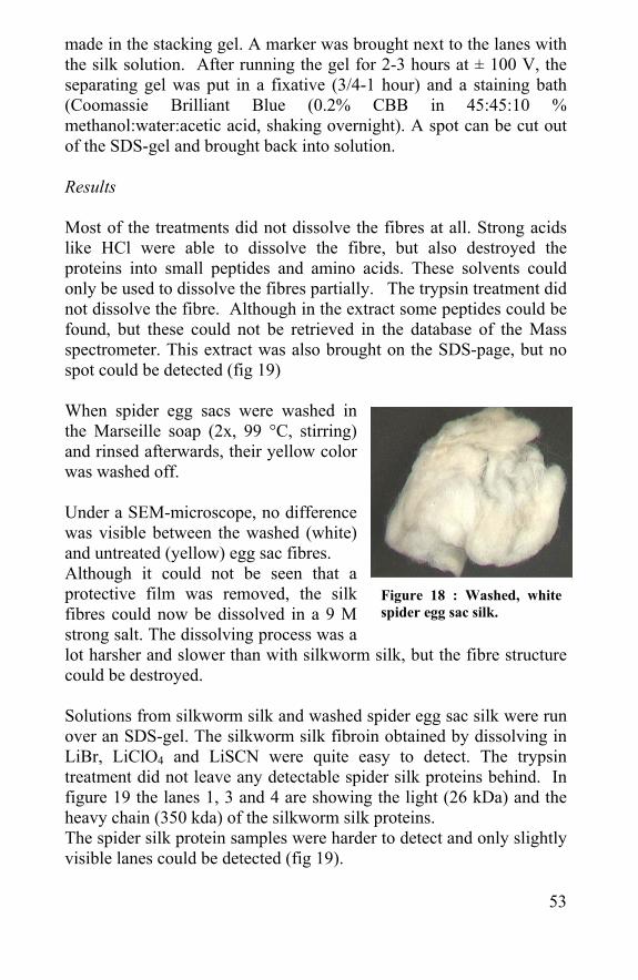
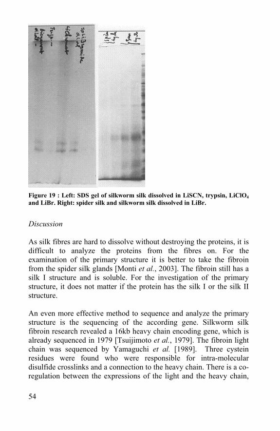
Results Most of the treatments did not dissolve the fibres at all. Strong acids like HCl were able to dissolve the fibre, but also destroyed the proteins into small peptides and amino acids. These solvents could only be used to dissolve the fibres partially. The trypsin treatment did not dissolve the fibre. Although in the extract some peptides could be found, but these could not be retrieved in the database of the Mass spectrometer. This extract was also brought on the SDS-page, but no spot could be detected (fig 19) When spider egg sacs were washed in the Marseille soap (2x, 99 °C, stirring) and rinsed afterwards, their yellow color was washed off. Under a SEM-microscope, no difference was visible between the washed (white) and untreated (yellow) egg sac fibres. Although it could not be seen that a protective film was removed, the silk fibres could now be dissolved in a 9 M strong salt. The dissolving process was a lot harsher and slower than with silkworm silk, but the fibre structure could be destroyed. Solutions from silkworm silk and washed spider egg sac silk were run over an SDS-gel. The silkworm silk fibroin obtained by dissolving in LiBr, LiClO4 and LiSCN were quite easy to detect. The trypsin treatment did not leave any detectable spider silk proteins behind. In figure 19 the lanes 1, 3 and 4 are showing the light (26 kDa) and the heavy chain (350 kda) of the silkworm silk proteins. The spider silk protein samples were harder to detect and only slightly visible lanes could be detected (fig 19).
Figure 18 : Washed, white spider egg sac silk.
54
Figure 19 : Left: SDS gel of silkworm silk dissolved in LiSCN, trypsin, LiClO4 and LiBr. Right: spider silk and silkworm silk dissolved in LiBr.
Discussion As silk fibres are hard to dissolve without destroying the proteins, it is difficult to analyze the proteins from the fibres on. For the examination of the primary structure it is better to take the fibroin from the spider silk glands [Monti et al., 2003]. The fibroin still has a silk I structure and is soluble. For the investigation of the primary structure, it does not matter if the protein has the silk I or the silk II structure. An even more effective method to sequence and analyze the primary structure is the sequencing of the according gene. Silkworm silk fibroin research revealed a 16kb heavy chain encoding gene, which is already sequenced in 1979 [Tsuijimoto et al., 1979]. The fibroin light chain was sequenced by Yamaguchi et al. [1989]. Three cystein residues were found who were responsible for intra-molecular disulfide crosslinks and a connection to the heavy chain. There is a co-regulation between the expressions of the light and the heavy chain,
55
although their genes are located on different chromosomes. There is also a small P25 molecule that helps the assembly of the heavy and light chains into a high molecular mass elementary unit. The molar ratio in such a unit between the H-chain, L-chain and P25 is 6:6:1 [Inoue et al., 2000]. To distinguish the proteins forming spider silk, the gland specific expression of the different gene families was investigated [Gosline et al., 1999; Guerette et al., 1996] and the genes can be sequenced. In gene and protein databanks like swiss-prot [expasy.org] or the ncbi-protein database [ncbi.nlm.nih.gov], one can retrieve already sequenced and published gene and protein sequences. When searching for Araneus diadematus silk proteins, the four fibroins discovered by Guerette et al., [1996] are found. These four protein-sequences were determined by conceptual translation of the 4 ADF-genes (Araneus diadematus fibroin gene). When the four fibroin sequences are looked in more detail, the abundant poly-alanine peptides are notable. Fibroin 3 has also many GQQGP-repeats and fibroin 1 many GAG-repeats. These repeating units are helping the beta-sheet formation explained in the following paragraph. Also other silk sequences could be found. Nephila clavipes dragline fibres are told to consist out of 2 proteins and are sequenced by Hinmen et al., [1992]. Bombyx mori were already known to have a light, a heavy chain and a small P25-protein, these are sequenced by [Zhou et al., 2000]. Biochemical techniques on protein level are harder due to the high molecular weight of silk diminishing the solvability of the proteins.
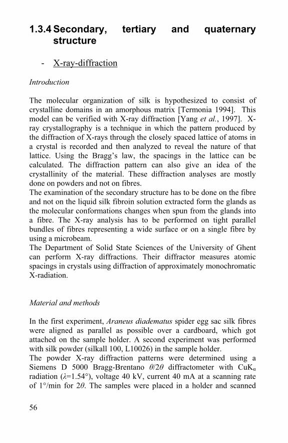
56
1.3.4 Secondary, tertiary and quaternary structure
- X-ray-diffraction
Introduction The molecular organization of silk is hypothesized to consist of crystalline domains in an amorphous matrix [Termonia 1994]. This model can be verified with X-ray diffraction [Yang et al., 1997]. X-ray crystallography is a technique in which the pattern produced by the diffraction of X-rays through the closely spaced lattice of atoms in a crystal is recorded and then analyzed to reveal the nature of that lattice. Using the Bragg’s law, the spacings in the lattice can be calculated. The diffraction pattern can also give an idea of the crystallinity of the material. These diffraction analyses are mostly done on powders and not on fibres. The examination of the secondary structure has to be done on the fibre and not on the liquid silk fibroin solution extracted form the glands as the molecular conformations changes when spun from the glands into a fibre. The X-ray analysis has to be performed on tight parallel bundles of fibres representing a wide surface or on a single fibre by using a microbeam. The Department of Solid State Sciences of the University of Ghent can perform X-ray diffractions. Their diffractor measures atomic spacings in crystals using diffraction of approximately monochromatic X-radiation. Material and methods In the first experiment, Araneus diadematus spider egg sac silk fibres were aligned as parallel as possible over a cardboard, which got attached on the sample holder. A second experiment was performed with silk powder (silkall 100, L10026) in the sample holder. The powder X-ray diffraction patterns were determined using a Siemens D 5000 Bragg-Brentano θ/2θ diffractometer with CuKα radiation (λ=1.54°), voltage 40 kV, current 40 mA at a scanning rate of 1°/min for 2θ. The samples were placed in a holder and scanned
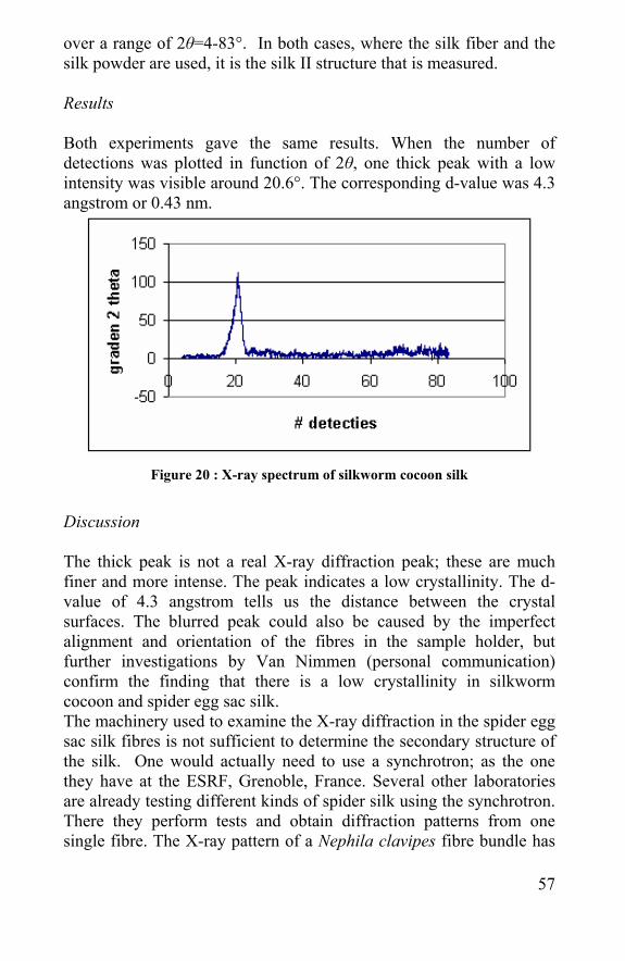
57
over a range of 2θ=4-83°. In both cases, where the silk fiber and the silk powder are used, it is the silk II structure that is measured. Results Both experiments gave the same results. When the number of detections was plotted in function of 2θ, one thick peak with a low intensity was visible around 20.6°. The corresponding d-value was 4.3 angstrom or 0.43 nm.
Figure 20 : X-ray spectrum of silkworm cocoon silk
Discussion The thick peak is not a real X-ray diffraction peak; these are much finer and more intense. The peak indicates a low crystallinity. The d-value of 4.3 angstrom tells us the distance between the crystal surfaces. The blurred peak could also be caused by the imperfect alignment and orientation of the fibres in the sample holder, but further investigations by Van Nimmen (personal communication) confirm the finding that there is a low crystallinity in silkworm cocoon and spider egg sac silk. The machinery used to examine the X-ray diffraction in the spider egg sac silk fibres is not sufficient to determine the secondary structure of the silk. One would actually need to use a synchrotron; as the one they have at the ESRF, Grenoble, France. Several other laboratories are already testing different kinds of spider silk using the synchrotron. There they perform tests and obtain diffraction patterns from one single fibre. The X-ray pattern of a Nephila clavipes fibre bundle has
58
been shown to be composed of Bragg-reflections, an oriented amorphous halo and a general diffuse background [Yang et al., 1997]. Riekel et al. (1997) also found a d-value of 0.425 nm for the (210) reflection. The (020) and (022) reflections were not stable enough to repeat the measurement. The most advanced method was performed by Riekel in cooperation with Vollrath [Riekel et al., 1999]. They fixed the spider and reeled off the dragline silk from the spider. The dragline silk was immediately radiated with an X-ray-microbeam to evaluate the correlation between the reeling speed and the diffraction patterns. Again the semi-crystalline morphology, characterized by Bragg reflections, an oriented halo and a diffuse halo, was detected. As the mechanical properties are changing with the reeling speed, it was expected to find a micro-structural change too [Van Nimmen et al., 2005]. Indeed the stretching and aligning of the anisotropic crystalline blocks changed the width of the (210) reflection. In terms of a 2-phase nanostructure, the silkworm silk microstructure can be explained as beta-sheet crystals interconnected with an amorphous matrix [Gosline et al., 1986]. Observations made by NMR, X-ray-diffraction and electron microscopy/diffraction suggest that major ampullate silk has a composite microstructure of three interconnected phases. The first one is amorphous, the second one are the highly crystalline blocks and the third one are semi-crystalline parts embedded in the amorphous regions (fig 21). Conclusion and Literature Investigations in the solid state sciences department and information from literature agree both with the model of small crystalline blocs in a matrix containing both oriented and un-oriented amorphous material [Gosline et al., 1986]. The crystallinity of spider egg sac silk is expected to be lower than that for dragline silk of the same species, but further investigations to prove the exact microstructure, the relation to the spinning process and the mechanical properties are necessary. In literature, six crystalline and three aqueous phases of silk are described [Viney et al., 2002]. They differ in self-assembly according to the mechanical and chemical environment. The mechanism to
59
transform the silk structure from one phase to the other is an important part of silk research. Silk I and II are already discovered for half a century [Kratky et al., 1950]. Silk III [Zhang et al., 1993] and other crystalline forms have been discovered more recently. The transformation of Silk I to Silk II is totally related with the spinning process, explained in the next paragraph. The structure of silk fibres is more complex than just anti-parallel beta-sheets [Pauling et al., 1951]. There are different motifs responsible for different folding patterns resulting into the final secondary structures. Regions of crystalline beta-sheet polymer have been identified in dragline silk, by NMR and X-ray diffraction to correspond with the Poly-Ala/poly-Gly-Ala motifs. These motifs are present in the ampullate silk of Nephila clavipes and are presumed to be responsible for the high tensile strength observed in ampullate silk [Hayashi et al., 1999]. Each individual motif forms highly aligned interlocking intra-molecular chains. The Parallel beta-sheet silk structure with cartoon ribbons indicates aligned planes of Gly-Ala-peptides. Experimental evidence has shown that the poly-Gly-Ala motifs do indeed have low water concentrations [Matsuno et al., 1999]. Four different conformations have been suggested for the GGX motif: 310-Helix / Type I beta-turn / alpha-helix / beta-sheet [Hayashi et al., 1999; Kummerlen et al., 1996; Xu et al., 1990] Another motif (GPGXX/ GPGQQ), where X represents an alternating amino acid, is reported to exist in silk originating from the major ampullate and flagelliform glands. The computationally optimized structure takes account of the fact that the silks are highly elastic. The structure is stabilized by hydrogen bonding between turns and subsequently resembles a spring. The polymer Elastin is also close related to this structure. Most fascinating is that flagelliform silk has at least 43 continuous motifs in the spiral, whilst ampullate silk
Figure 21 : Schematic figure explaining the 3 phases in spider silk: the crystalline phase embedded in a amorphous matrix with semi-crystalline particles units (Ball, 1997)
60
consists of only 9 uninterrupted motifs. This implies a correlation between extensibility and the number of sequential motifs. The existence of `spacer' regions in flagelliform and ampullate silks are believed to occupy a transitional zone and may help to align surrounding fibres or perhaps play a role in the secretion of the liquid polymer from the spider. The structure of these spacer regions is unknown apart from being complex and more research is needed. The structural transformations, changes in solubility and mechanical properties are also used in further chapters to produce scaffolds for tissue engineering applications. Using methanol, the insoluble silk II conformation can be induced in aqueous silk solutions. Studying the assembly of silk fibroin and silk-like proteins can help to learn the principles which govern secretory protein assembly at the molecular level. Which secretory proteins interact and what are the sites used for intraprotein and protein-protein interactions during the assembly of this biopolymer? The evolutionary conservation of motifs within repeats and among different secretory proteins suggests that the sequences and three-dimensional structures of the motifs may be important for assembly of secretory proteins into complexes, oriented fibres, and silk threads. Further study of secretory protein assembly will bring us closer to understanding how this silk assembles in vivo. By learning principles that nature employs to construct such a novel composite biopolymer, it may become feasible to design and produce new classes of fibres or biomolecular materials with distinctive properties that are currently unavailable. In this way it will be possible to isolate these motifs and create synthetic proteins that assemble into a desired fibre with tailored properties. These silk-like proteins are already tried to be synthesized [Yang et al., 2005].
1.3.5 Spider and artificial spinning
- Spider silk glands and spinnerets
Ampullate and pyriform gland
The ampullate glands are present in two pairs (minor and major ampullate glands) and each pair is linked to adjacent spinnerets in the abdomen of the spider [Witt et al., 1968]. It was observed by radiolabelling studies that the silk production begins in the upper part of the gland where proteins are secreted through the cell wall. The
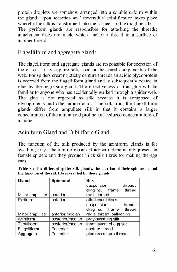
61
protein droplets are somehow arranged into a soluble α-form within the gland. Upon secretion an `irreversible' solidification takes place whereby the silk is transformed into the β-sheets of the dragline silk. The pyriform glands are responsible for attaching the threads; attachment discs are made which anchor a thread to a surface or another thread. Flagelliform and aggregate glands
The flagelliform and aggregate glands are responsible for secretion of the elastic sticky capture silk, used in the spiral components of the web. For spiders creating sticky capture threads an acidic glycoprotein is secreted from the flagelliform gland and is subsequently coated in glue by the aggregate gland. The effectiveness of this glue will be familiar to anyone who has accidentally walked through a spider web. The glue is not regarded as silk because it is composed of glycoproteins and other amino acids. The silk from the flagelliform glands differ from ampullate silk in that it contains a larger concentration of the amino acid proline and reduced concentrations of alanine. Aciniform Gland and Tubiliform Gland
The function of the silk produced by the aciniform glands is for swathing prey. The tubiliform (or cylindrical) gland is only present in female spiders and they produce thick silk fibres for making the egg sacs. Table 8 : The different spider silk glands, the location of their spinnerets and the function of the silk fibres created by these glands
Gland Spinneret Silk
Major ampullate anterior
suspension threads, dragline, frame thread, radial thread
Pyriform anterior attachment discs
Minor ampullate anterior/median
suspension threads, dragline, frame thread, radial thread, ballooning
Aciniform posterior/median prey-swathing silk Tubuliform posterior/median inner layers of egg sac Flagelliform Posterior capture thread Aggregate Posterior glue on capture thread
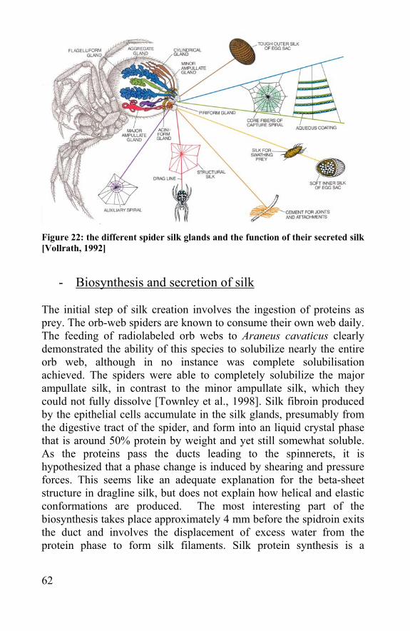
62
Figure 22: the different spider silk glands and the function of their secreted silk [Vollrath, 1992]
- Biosynthesis and secretion of silk
The initial step of silk creation involves the ingestion of proteins as prey. The orb-web spiders are known to consume their own web daily. The feeding of radiolabeled orb webs to Araneus cavaticus clearly demonstrated the ability of this species to solubilize nearly the entire orb web, although in no instance was complete solubilisation achieved. The spiders were able to completely solubilize the major ampullate silk, in contrast to the minor ampullate silk, which they could not fully dissolve [Townley et al., 1998]. Silk fibroin produced by the epithelial cells accumulate in the silk glands, presumably from the digestive tract of the spider, and form into an liquid crystal phase that is around 50% protein by weight and yet still somewhat soluble. As the proteins pass the ducts leading to the spinnerets, it is hypothesized that a phase change is induced by shearing and pressure forces. This seems like an adequate explanation for the beta-sheet structure in dragline silk, but does not explain how helical and elastic conformations are produced. The most interesting part of the biosynthesis takes place approximately 4 mm before the spidroin exits the duct and involves the displacement of excess water from the protein phase to form silk filaments. Silk protein synthesis is a
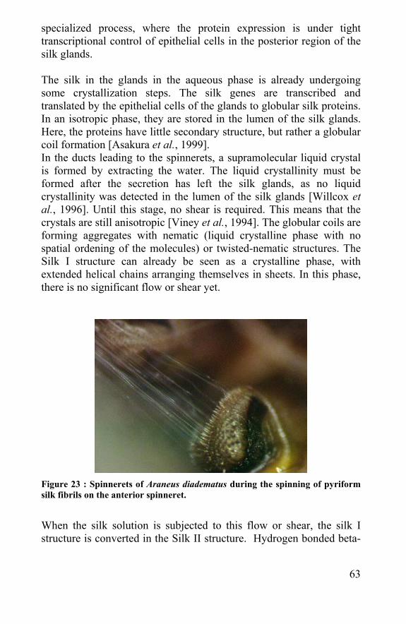
63
specialized process, where the protein expression is under tight transcriptional control of epithelial cells in the posterior region of the silk glands. The silk in the glands in the aqueous phase is already undergoing some crystallization steps. The silk genes are transcribed and translated by the epithelial cells of the glands to globular silk proteins. In an isotropic phase, they are stored in the lumen of the silk glands. Here, the proteins have little secondary structure, but rather a globular coil formation [Asakura et al., 1999]. In the ducts leading to the spinnerets, a supramolecular liquid crystal is formed by extracting the water. The liquid crystallinity must be formed after the secretion has left the silk glands, as no liquid crystallinity was detected in the lumen of the silk glands [Willcox et al., 1996]. Until this stage, no shear is required. This means that the crystals are still anisotropic [Viney et al., 1994]. The globular coils are forming aggregates with nematic (liquid crystalline phase with no spatial ordening of the molecules) or twisted-nematic structures. The Silk I structure can already be seen as a crystalline phase, with extended helical chains arranging themselves in sheets. In this phase, there is no significant flow or shear yet.
Figure 23 : Spinnerets of Araneus diadematus during the spinning of pyriform silk fibrils on the anterior spinneret.
When the silk solution is subjected to this flow or shear, the silk I structure is converted in the Silk II structure. Hydrogen bonded beta-
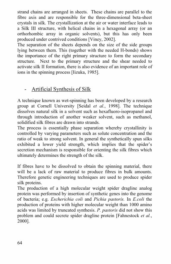
64
strand chains are arranged in sheets. These chains are parallel to the fibre axis and are responsible for the three-dimensional beta-sheet crystals in silk. The crystallization at the air or water interface leads to a Silk III structure, with helical chains in a hexagonal array (or an orthorhombic array in organic solvents), but this has only been produced under contrived conditions [Viney, 2002]. The separation of the sheets depends on the size of the side groups lying between them. This (together with the needed H-bonds) shows the importance of the right primary structure to form the secondary structure. Next to the primary structure and the shear needed to activate silk II formation, there is also evidence of an important role of ions in the spinning process [Iizuka, 1985].
- Artificial Synthesis of Silk A technique known as wet-spinning has been developed by a research group at Cornell University [Seidal et al., 1998]. The technique dissolves natural silk in a solvent such as hexafluoro-isopropanol and through introduction of another weaker solvent, such as methanol, solidified silk fibres are drawn into strands. The process is essentially phase separation whereby crystallinity is controlled by varying parameters such as solute concentration and the ratio of weak to strong solvent. In general the synthetically spun silks exhibited a lower yield strength, which implies that the spider’s secretion mechanism is responsible for orienting the silk fibres which ultimately determines the strength of the silk. If fibres have to be dissolved to obtain the spinning material, there will be a lack of raw material to produce fibres in bulk amounts. Therefore genetic engineering techniques are used to produce spider silk proteins. The production of a high molecular weight spider dragline analog protein was performed by insertion of synthetic genes into the genome of bacteria; e.g. Escherichia coli and Pichia pastoris. In E.coli the production of proteins with higher molecular weight than 1000 amino acids was limited by truncated synthesis. P. pastoris did not show this problem and could secrete spider dragline protein [Fahnestock et al., 2000].
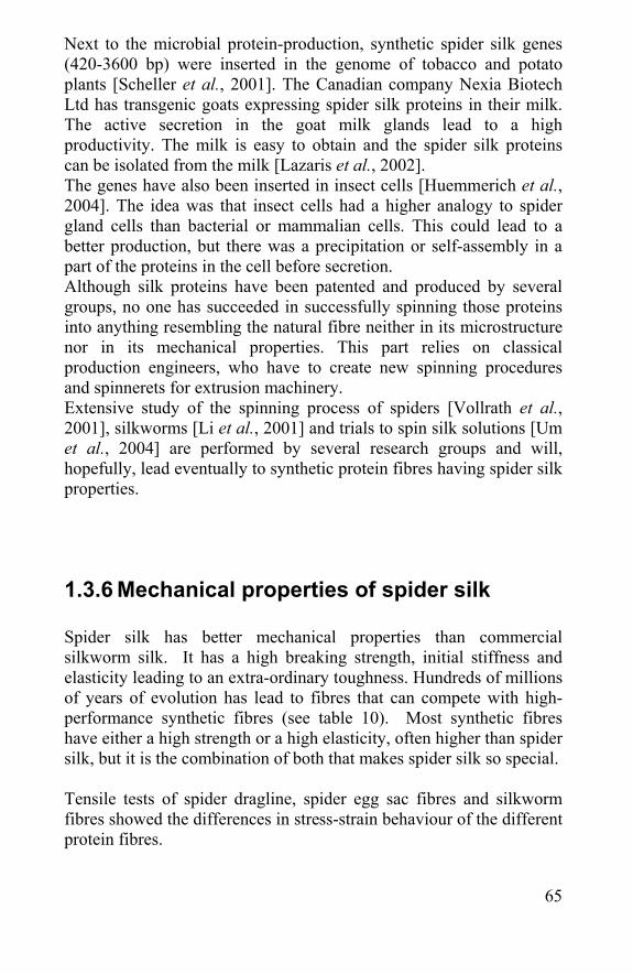
65
Next to the microbial protein-production, synthetic spider silk genes (420-3600 bp) were inserted in the genome of tobacco and potato plants [Scheller et al., 2001]. The Canadian company Nexia Biotech Ltd has transgenic goats expressing spider silk proteins in their milk. The active secretion in the goat milk glands lead to a high productivity. The milk is easy to obtain and the spider silk proteins can be isolated from the milk [Lazaris et al., 2002]. The genes have also been inserted in insect cells [Huemmerich et al., 2004]. The idea was that insect cells had a higher analogy to spider gland cells than bacterial or mammalian cells. This could lead to a better production, but there was a precipitation or self-assembly in a part of the proteins in the cell before secretion. Although silk proteins have been patented and produced by several groups, no one has succeeded in successfully spinning those proteins into anything resembling the natural fibre neither in its microstructure nor in its mechanical properties. This part relies on classical production engineers, who have to create new spinning procedures and spinnerets for extrusion machinery. Extensive study of the spinning process of spiders [Vollrath et al., 2001], silkworms [Li et al., 2001] and trials to spin silk solutions [Um et al., 2004] are performed by several research groups and will, hopefully, lead eventually to synthetic protein fibres having spider silk properties.
1.3.6 Mechanical properties of spider silk Spider silk has better mechanical properties than commercial silkworm silk. It has a high breaking strength, initial stiffness and elasticity leading to an extra-ordinary toughness. Hundreds of millions of years of evolution has lead to fibres that can compete with high-performance synthetic fibres (see table 10). Most synthetic fibres have either a high strength or a high elasticity, often higher than spider silk, but it is the combination of both that makes spider silk so special. Tensile tests of spider dragline, spider egg sac fibres and silkworm fibres showed the differences in stress-strain behaviour of the different protein fibres.
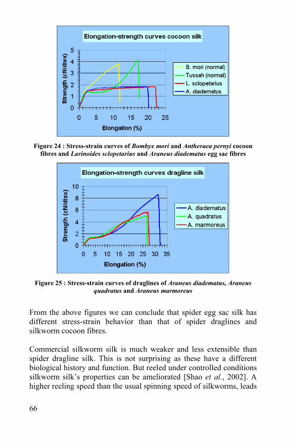
66
Figure 24 : Stress-strain curves of Bombyx mori and Antheraea pernyi cocoon
fibres and Larinoides sclopetarius and Araneus diadematus egg sac fibres
Figure 25 : Stress-strain curves of draglines of Araneus diadematus, Araneus
quadratus and Araneus marmoreus
From the above figures we can conclude that spider egg sac silk has different stress-strain behavior than that of spider draglines and silkworm cocoon fibres. Commercial silkworm silk is much weaker and less extensible than spider dragline silk. This is not surprising as these have a different biological history and function. But reeled under controlled conditions silkworm silk’s properties can be ameliorated [Shao et al., 2002]. A higher reeling speed than the usual spinning speed of silkworms, leads
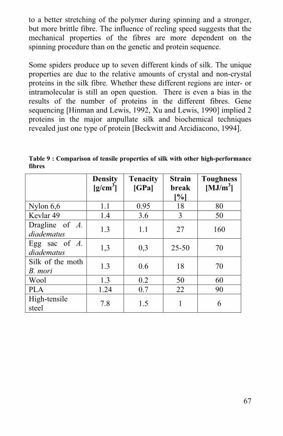
67
to a better stretching of the polymer during spinning and a stronger, but more brittle fibre. The influence of reeling speed suggests that the mechanical properties of the fibres are more dependent on the spinning procedure than on the genetic and protein sequence. Some spiders produce up to seven different kinds of silk. The unique properties are due to the relative amounts of crystal and non-crystal proteins in the silk fibre. Whether these different regions are inter- or intramolecular is still an open question. There is even a bias in the results of the number of proteins in the different fibres. Gene sequencing [Hinman and Lewis, 1992, Xu and Lewis, 1990] implied 2 proteins in the major ampullate silk and biochemical techniques revealed just one type of protein [Beckwitt and Arcidiacono, 1994]. Table 9 : Comparison of tensile properties of silk with other high-performance fibres
Density [g/cm3]
Tenacity [GPa]
Strain break [%]
Toughness [MJ/m3]
Nylon 6,6 1.1 0.95 18 80 Kevlar 49 1.4 3.6 3 50 Dragline of A. diadematus 1.3 1.1 27 160
Egg sac of A. diadematus 1,3 0,3 25-50 70
Silk of the moth B. mori 1.3 0.6 18 70
Wool 1.3 0.2 50 60 PLA 1.24 0.7 22 90 High-tensile steel 7.8 1.5 1 6
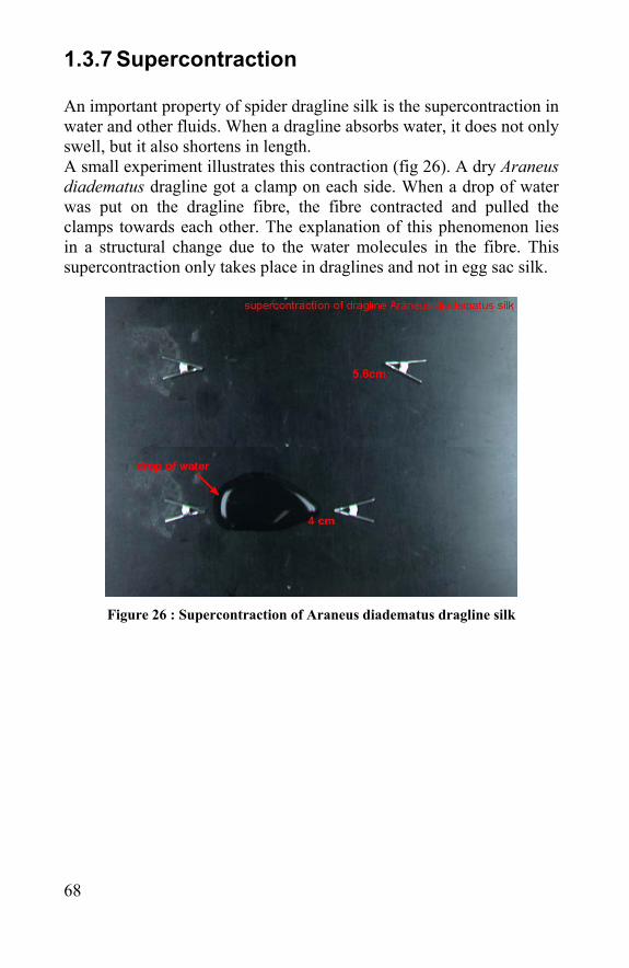
68
1.3.7 Supercontraction An important property of spider dragline silk is the supercontraction in water and other fluids. When a dragline absorbs water, it does not only swell, but it also shortens in length. A small experiment illustrates this contraction (fig 26). A dry Araneus diadematus dragline got a clamp on each side. When a drop of water was put on the dragline fibre, the fibre contracted and pulled the clamps towards each other. The explanation of this phenomenon lies in a structural change due to the water molecules in the fibre. This supercontraction only takes place in draglines and not in egg sac silk.
Figure 26 : Supercontraction of Araneus diadematus dragline silk
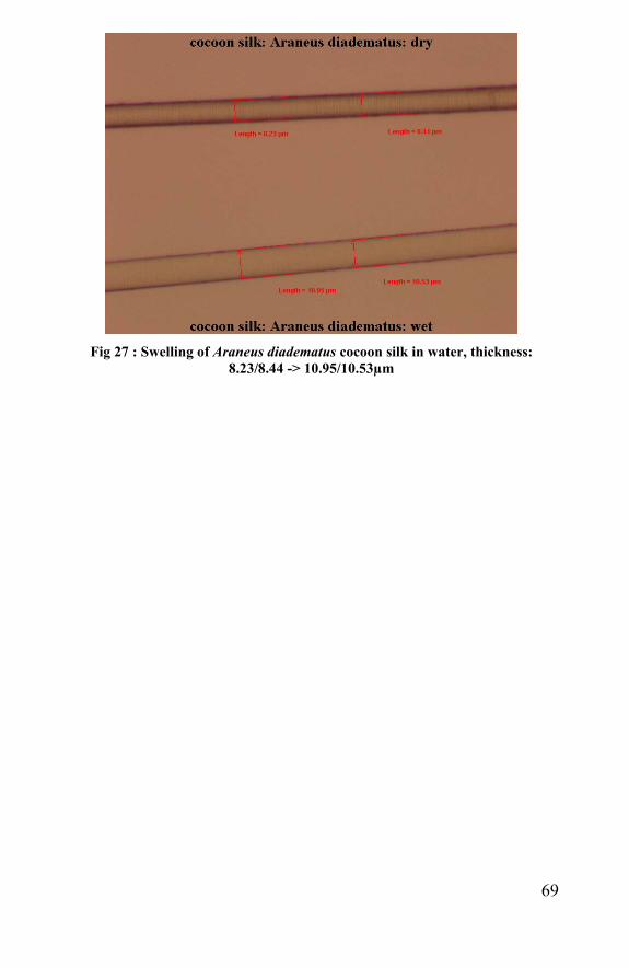
69
Fig 27 : Swelling of Araneus diadematus cocoon silk in water, thickness:
8.23/8.44 -> 10.95/10.53µm
70
1.3.8 Mechanical properties of the different egg sac layers
Introduction When the egg sac of A. diadematus was examined, it was observed that it consisted of three layers, one between the substrate and the eggs (A) and two covering the eggs (B and C) (fig 9). Microscopically it was impossible to determine whether these fibres were identical or not. Besides the amino acid determination, tensile tests can help to determine whether these three kinds of fibres are really different fibres. Material and methods One egg sac from A. diadematus made in the lab was taken and divided in the three parts using a stereomicroscope. From each part 50 fibres were taken carefully and brought into the Favimat. The tensile properties were tested using a gauge length of 20 mm, a test speed of 20 mm/m and a pre-load of 0.5 cN The results were evaluated with one-way ANOVA-statistics using SPSS, applying the LSD and Tukey tests. The averages were determined as significantly different when the p-value was smaller than 0.05. Results When the tensile properties of the fibres of the different layers are compared to each other, it is clear that A differs more from B and C than B and C from each other.
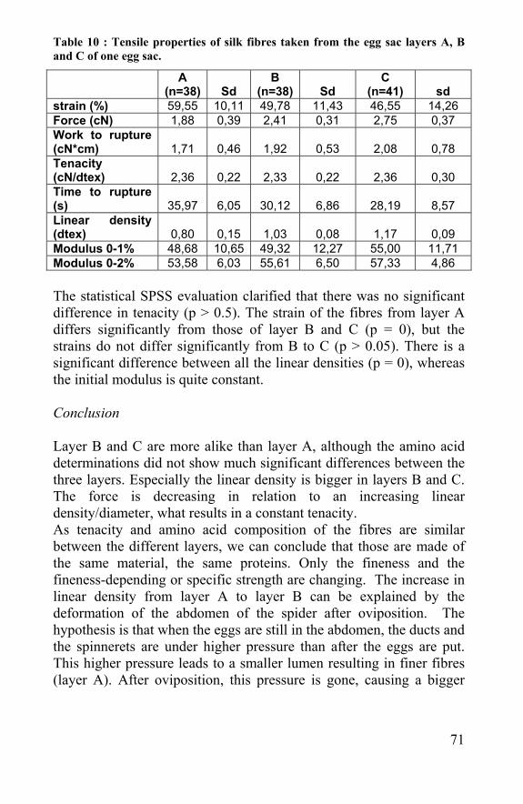
71
Table 10 : Tensile properties of silk fibres taken from the egg sac layers A, B and C of one egg sac.
A
(n=38) Sd B
(n=38) Sd C
(n=41) sd strain (%) 59,55 10,11 49,78 11,43 46,55 14,26 Force (cN) 1,88 0,39 2,41 0,31 2,75 0,37 Work to rupture (cN*cm) 1,71 0,46 1,92 0,53 2,08 0,78 Tenacity (cN/dtex) 2,36 0,22 2,33 0,22 2,36 0,30 Time to rupture (s) 35,97 6,05 30,12 6,86 28,19 8,57 Linear density (dtex) 0,80 0,15 1,03 0,08 1,17 0,09 Modulus 0-1% 48,68 10,65 49,32 12,27 55,00 11,71 Modulus 0-2% 53,58 6,03 55,61 6,50 57,33 4,86 The statistical SPSS evaluation clarified that there was no significant difference in tenacity (p > 0.5). The strain of the fibres from layer A differs significantly from those of layer B and C (p = 0), but the strains do not differ significantly from B to C (p > 0.05). There is a significant difference between all the linear densities (p = 0), whereas the initial modulus is quite constant. Conclusion Layer B and C are more alike than layer A, although the amino acid determinations did not show much significant differences between the three layers. Especially the linear density is bigger in layers B and C. The force is decreasing in relation to an increasing linear density/diameter, what results in a constant tenacity. As tenacity and amino acid composition of the fibres are similar between the different layers, we can conclude that those are made of the same material, the same proteins. Only the fineness and the fineness-depending or specific strength are changing. The increase in linear density from layer A to layer B can be explained by the deformation of the abdomen of the spider after oviposition. The hypothesis is that when the eggs are still in the abdomen, the ducts and the spinnerets are under higher pressure than after the eggs are put. This higher pressure leads to a smaller lumen resulting in finer fibres (layer A). After oviposition, this pressure is gone, causing a bigger
72
lumen resulting in thicker fibres (layers B and C) [Gheysens et al., 2004].
1.4 Limitations of spider silk First of all, the spiders are hard to breed and there is no economic production on large scale possible. The spiders are cannibalistic and can not be breed in bulk amounts like silkworms. When grown in the lab, they have to be put in separate boxes and even then they are hard to be bred in laboratory conditions. In order to have egg sac silk and spiders to reel off all year, the laboratory conditions have to mimic the different seasons to invoke the different phases of spider growth and egg sac production. By putting the egg sacs with eggs in a fridge, the winter period is mimicked as long as wanted and spiderlings are only coming out when the temperature is rising, after a determined period. The following problem is the feeding of the spiderlings and growing of spiders. Dependent on their size, they eat different insects, from green flies to bees. Having a good breed, the production of silk is still limited. For dragline fibres, the amount of reeling is not sufficient to obtain kilograms of silk. It is a lot of work to fix the spider and to keep the reeling going. Spiders also put just one egg sac with only 10 to 20 mg of egg sac silk in it, what means that thousands of spiders must be bred to be able to perform textile techniques, like: spinning, weaving, knitting and non-woven needle-punching on the material. This explains the search for synthetic production of spider silk. Dragline threads are not one solid fibre; they consist of 4 intertwined filaments: 2 major and 2 minor ampullate fibres. This makes the fibre irregular and harder to handle. Silk fibres are quite stable but they degrade above 160 °C [Guess and Viney, 1998]. This can lead to some production problems or the impossibility to use these fibres for some applications. In literature and in the tensile tests performed in this research, a high standard deviation in tensile properties of the silk fibres was found [Garrido et al., 2002]. There is a huge variability amongst spider silk fibres, not only between fibres from different species and different type of fibres, but also between fibres of the same type from spiders from the same species [Madsen et al., 1999].
73
The tensile properties are also changing when the silk is aging. In our experiments it was found that old spider egg sac silk fibres are much more brittle than fresh ones. Therefore in the next chapter when the effect of sterilisation, biodegradation or enzymes will be tested, it is important that a comparison is made between untreated and treated fibres from the same egg sac or between egg sacs harvested at the same time. Moisture has also effect on the tensile properties. This sensitivity is related to the microstructure of the fibre [Viney, 2000]. The effect of moisture is marked for spider dragline and capture thread, but less dramatic for spider egg sac silk. This could be a definite disadvantage for biomedical applications and could lead to a preference for spider egg sac silk towards dragline silk. An advantage in some applications and a disadvantage in other ones is that organisms can depolymerize silks with proteolytic enzymes. It is positive that the fibre is biodegradable, but there is also the drawback of non-permanence. This can be discouraged by adding a protective coating or using the silk in a dry, abiotic environment.
1.5 References - Asakura T, Iwadate M, Demura M, Williamson MP. Structural analysis of silk with 13C NMR chemical shift contour plots. Int J Biol Macromol. 1999 Mar-Apr; 24(2-3):167-71. - Beckwitt R, Arcidiacono S. Sequence conservation in the C-terminal region of spider silk proteins (Spidroin) from Nephila clavipes (Tetragnathidae) and Araneus bicentenarius (Araneidae). J Biol Chem. 1994 Mar 4;269(9):6661-3 - Bernard, A, Krafft, B Silk attraction: base of group cohesion and collective behaviours in social spiders CR BIOL 325 (11): 1153-1157 NOV 2002 - Bruce, MJ, Herberstein, ME, Elgar, MA. Signalling conflict between prey and predator attraction. J EVOLUTION BIOL 14 (5): 786-794 SEP 2001
74
- Case ST, Wieslander L. Secretory proteins of Chironomus salivary glands: structural motifs and assembly characteristics of a novel biopolymer. Results Probl Cell Differ. 1992;19:187-226. Review - Cave C. School of Fisheries, University of Washington 1998 Chamisa.freeshell.org - Champion de Crespigny FE, Herberstein ME, Elgar MA. Food caching in orb-web spiders (Araneae: Araneoidea). Naturwissenschaften. 2001 Jan;88(1):42-5. - Dunaway DL, Thiel BL, Srinivasan SG, Viney C. Characterizing the cross-sectional geometry of thin non-cylindrical twisted fibres. J Mater Sci 1995;30:4161–70 - Dunleavy S. Live in the undergrowth. BBC programme synopses 2005 - Fahnestock SR, Yao Z, Bedzyk LA. Microbial production of spider silk proteins. J Biotechnol. 2000 Aug;74(2):105-19 - Fitzgerald, TD, Pescador-Rubio, A The role of tactile and chemical stimuli in the formation and maintenance of the processions of the social caterpillar Hylesia lineata (Lepidoptera : Saturniidae) J INSECT BEHAV 15 (5): 659-674 SEP 2002 - Garrido, M.A.; Elices, M.; Viney, C; Perez-rigueiro J. The variability and interdependence of spider drag line tensile properties. Polymer 2002, 43: 4495-4502 - Garrido, M.A.; Elices, M.; Viney, C.; “Active control of spider silk strength: comparison of drag line spun on vertical and horizontal surfaces” Polymer 2002, 43, pp. 1537-1540 - Gheysens T., Beladjal L., Gellynck K., Van Nimmen E., Van Langenhove L., Mertens J. 2005. Egg sac structure of Zygiella x-notata (Arachnida, Araneidae). The Journal of Arachnology 33: 549-557 - Gomes G, Silva-Zacarin EC, Zara FJ, Silva de Moraes RL, Caetano FH. Macromolecular array patterns of silk gland secretion in social Hymenoptera larvae. Genet Mol Res. 2004 Sep 30;3(3):309-22. - Gosline JM, Guerette PA, Ortlepp CS, Savage KN. The mechanical design of spider silks: from fibroin sequence to mechanical function. J Exp Biol. 1999 Dec;202(Pt 23):3295-303. Review - Guerette PA, Ginzinger DG, Weber BH, Gosline JM. Silk properties determined by gland-specific expression of a spider fibroin gene family. Science. 1996 Apr 5;272(5258):112-5 - Hayashi C. Y., N. H. Shipley, and R. V. Lewis. Hypotheses that correlate the sequence, structure and mechanical properties of spider
75
silk proteins. International Journal of Biological Macromolecules, 24:271.274, 1999 - Hinman MB, Lewis RV. Isolation of a clone encoding a second dragline silk fibroin. Nephila clavipes dragline silk is a two-protein fibre. J Biol Chem. 1992 Sep 25;267(27):19320-4 - Huemmerich D, Scheibel T, Vollrath F, Cohen S, Gat U, Ittah S. Novel assembly properties of recombinant spider dragline silk proteins. Curr Biol. 2004 Nov 23;14(22):2070-4. - Iizuka, E. (1985). "Silk thread: mechanism of spinning and its mechanical properties." J. Appl. Polym. Sci.: Appl Polym. Symp. 41: 173-185 - Inoue S, Tanaka K, Arisaka F, Kimura S, Ohtomo K, Mizuno S. Silk fibroin of Bombyx mori is secreted, assembling a high molecular mass elementary unit consisting of H-chain, L-chain, and P25, with a 6:6:1 molar ratio.J Biol Chem. 2000 Dec 22;275(51):40517-28 - Johnson RN, Agapow PM, Crozier RH. A tree island approach to inferring phylogeny in the ant subfamily Formicinae, with especial reference to the evolution of weaving. Mol Phylogenet Evol. 2003 Nov;29(2):317-30. - Joseph Z, Ishay JS. Silk structure in the hornet cocoon. J Electron Microsc (Tokyo). 2004;53(3):293-304. - Kratky O., Schauenstein E., and Sekora A., 1950. Unstable Lattice in silk fibroin. Nature. 165, 319-320 - Kummerlen, J. D. van Beek, F. Vollrath, and B. H. Meier. Local structure in spider dragline silk investigated by by two-dimensional spin-diffusion nuclear magnetic resonance. Macromolecules, 29:2920.2928, 1996 - Kunzig, R. The Biology of… Spider Silk, Arachnomania. Discover. Vol. 22 No. 9 (2001) - Lazaris A, Arcidiacono S, Huang Y, Zhou JF, Duguay F, Chretien N, Welsh EA, Soares JW, Karatzas CN. Spider silk fibres spun from soluble recombinant silk produced in mammalian cells. Science. 2002 Jan 18;295(5554):472-6. - Li G, Zhou P, Shao Z, Xie X, Chen X, Wang H, Chunyu L, Yu T. The natural silk spinning process. A nucleation-dependent aggregation mechanism? Eur J Biochem. 2001 Dec;268(24):6600-6. - Li M, Tao W, Lu S, Kuga S. Compliant film of regenerated Antheraea pernyi silk fibroin by chemical crosslinking. Int J Biol Macromol. 2003 Sep;32(3-5):159-63
76
- Lucas F. and Rudall K.M. (1968) Extracellular fibrous proteins: The silks. In “Comprehensive Biochemistry” (M. Florkin and E.H. Stota, eds.) vol. 26B, pp. 475-558. Elsevier, Amsterdam. - Madsen B, Vollrath F. Mechanics and morphology of silk drawn from anesthetized spiders. Naturwissenschaften. 2000 Mar;87(3):148-53. Erratum in: Naturwissenschaften 2000 Jun;87(6):288 - Madsen B, Shao ZZ, Vollrath F. Variability in the mechanical properties of spider silks on three levels: interspecific, intraspecific and intraindividual. Int J Biol Macromol. 1999 Mar-Apr;24(2-3):301-6. - Matsuno K and R. V. Lewis. Hypotheses that correlate the sequence, structure and mechanical properties of spider silk proteins. 1999 - Monti P, Taddei P, Freddi G, Ohgo K, Asakura T. Vibrational 13C-cross-polarization/magic angle spinning NMR spectroscopic and thermal characterization of poly(alanine-glycine) as model for silk I Bombyx mori fibroin. Biopolymers. 2003;72(5):329-38.] - Pauling L. and R. B. Corey. The Stucture and Action of Proteins, 1951, Volume 37 ;page 729 - Qin XX, Coyne KJ, Waite JH. Tough tendons. Mussel byssus has collagen with silk-like domains. J Biol Chem. 1997 Dec 19;272(51):32623-7. - Riekel C, Branden C, Craig C, Ferrero C, Heidelbach F, Muller M. Aspects of X-ray diffraction on single spider fibres. Int J Biol Macromol. 1999 Mar-Apr;24(2-3):179-86. - Riekel C, Madsen B, Knight D, Vollrath F.X-ray diffraction on spider silk during controlled extrusion under a synchrotron radiation X-ray beam. Biomacromolecules. 2000 Winter;1(4):622-6. - Riekel C, Muller M. In situ X-ray diffraction during forced silking of spider silk. Macromolecules 1999. 32: 4464-4466 - Rzepecki LM, Waite JH. Wresting the muscle from mussel beards: research and applications. Mol Mar Biol Biotechnol. 1995 Dec;4(4):313-22. Review. - Scheller J, Guhrs KH, Grosse F, Conrad U. Production of spider silk proteins in tobacco and potato. Nat Biotechnol. 2001 Jun;19(6):573-7 - Seidal, O. Liivak, and L. Jelinski. Arti_cial spinning of spider silk. Macromolecules, 31:6733,1998 - Shao Z, Vollrath F. Surprising strength of silkworm silk. Nature. 2002 Aug 15;418(6899):741 - Seah WK, Li D. Stabilimenta attract unwelcome predators to orb-webs. Proc Biol Sci. 2001 Aug 7;268(1476):1553-8. - Shiemke: http://www.hsc.wvu.edu/som/bmp/files/shiemke/
77
- Termonia Y. Macromolecules. 1994;27:7378–81. - Townley, MA and Tillinghas EK. Orb web recycling in Araneus cavaticus (Araneae, Araneidae) with an emphasis on the adhesive spiral componenet, GABamide. J. Arachnology, 16: 303-319 - Um IC, Kweon H, Lee KG, Ihm DW, Lee JH, Park YH.Wet spinning of silk polymer. I. Effect of coagulation conditions on the morphological feature of filament. Int J Biol Macromol. 2004 Apr;34(1-2):89-105. - Um IC, Kweon H, Lee KG, Ihm DW, Lee JH, Park YH. Wet spinning of silk polymer. II. Effect of drawing on the structural characteristics and properties of filament. Int J Biol Macromol. 2004 Apr;34(1-2):107-19. - Viney C. The nature and role of liquid crystalline order in silk secretions. Results Probl Cell Differ. 1992;19:255-78. Review - Viney, C. 2000a, From natural silks to new polymer fibres: Journal of the Textile Institute. 91 (3):2–23 - Viney. From Natural silks to new polymer fibres. J. tex. Inst. 2000 Part 3 - Vollrath, F., 1992. Spider Webs and Silks. Scientific American. 266(3):52-58. - Vollrath, F., Knight, D.P. Liquid crystalline spinning of spider silk. Nature Vol. 410 pg. 541-8 (2001) - Vollrath F. General properties of some spider silks. In: Kaplan D, Adams WW, Farmer B, Viney C, editors. Silk Polymers, Material Science and Biotechnology. Washington, DC: American Chemical Society, 1994:17–28 - Vollrath and D. P. Knight. Structure and function of the silk production pathway in the spider nephilia edulis. International Journal of Biological Macromolecules, 24:243.249, 1999 - Vollrath F. Strength and structure of spiders' silks. J Biotechnol. 2000 Aug;74(2):67-83. Review. - Willcox P.J., S.P. Gido, W. Muller, D.L. Kaplan Evidence of a Cholesteric liquid crystalline phase in natural silk spinning processes.. Macromolecules 1996 29:5106-10 - Waite JH, Vaccaro E, Sun C, Lucas JM. Elastomeric gradients: a hedge against stress concentration in marine holdfasts? Philos Trans R Soc Lond B Biol Sci. 2002 Feb 28;357(1418):143-53. Review - Witt, C. F. Reed, and D. B. Peakall. A Spider's Web - Problems in Regulatory Biology. Springer-Verlag, Berlin, 1968
78
- Work R. W. 1976. The force-elongation behaviour of web fibres and silks forcibly obtained from orb-web-spinning spiders Text. Res. J., 46: 485-92. - Xu and R. V. Lewis. Structure of a protein superfibre: Spider dragline silk. Proceedings of the National Academy of Science USA, 87:7120.7124, 1990 - Yang, Z., Grubb, D. T. & Jelinski, L. W. Small-angle X-ray scattering of spider dragline silk. Macromolecules 30, 8254-61 (1997). - Yang J, Barr LA, Fahnestock SR, Liu ZB. High yield recombinant silk-like protein production in transgenic plants through protein targeting. Transgenic Res. 2005 Jun;14(3):313-24 - Yamaguchi K, Kikuchi Y, Takagi T, Kikuchi A, Oyama F, Shimura K, Mizuno S. Primary structure of the silk fibroin light chain determined by cDNA sequencing and peptide analysis. J Mol Biol. 1989 Nov 5;210(1):127-39 - Zhang W., Gido SP., Muller WS., Fossey SA., And Kaplan DL. 1993. A pseudo threefold helical structure found in silk langmuir-blodgett films by electron diffraction. In 51st annual meeting of the microscopy society of America. San Francisco press, CA, p 1216-17 - Zhang Y. Natural silk fibroin as a support for enzyme immobilization. Biotechnology Advances. 1998 16(5/6): 961-71) - Zhou CZ, Confalonieri F, Medina N, Zivanovic Y, Esnault C, Yang T, Jacquet M, Janin J, Duguet M, Perasso R, Li ZG. Fine organization of Bombyx mori fibroin heavy chain gene. Nucleic Acids Res. 2000 Jun 15;28(12):2413-9. - Zschokke S. Early stages of orb web construction in Araneus diadematus Clerck -- -- Revue Suisse de Zoologie hors série 2: 709-720 Proceedings of the XIIIth International Congress of Arachnology, Geneva, 3-8 September 1995 - Zijdemuseum - Dorpsstraat 3 - 4365 AL Meliskerke, http://www.zijdemuseum.nl - http://www.zoo.org/educate/fact_sheets/spiders/silk.html - http://www.fao.org/docrep/x2099e/x2099e00.htm#con - http://us.expasy.org/sprot - http://www.ncbi.nlm.nih.gov/entrez/
79
Chapter 2 Cartilage

80
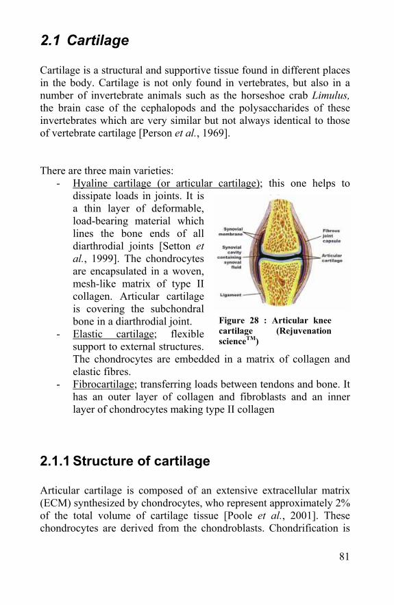
81
2.1 Cartilage Cartilage is a structural and supportive tissue found in different places in the body. Cartilage is not only found in vertebrates, but also in a number of invertebrate animals such as the horseshoe crab Limulus, the brain case of the cephalopods and the polysaccharides of these invertebrates which are very similar but not always identical to those of vertebrate cartilage [Person et al., 1969]. There are three main varieties:
- Hyaline cartilage (or articular cartilage); this one helps to dissipate loads in joints. It is a thin layer of deformable, load-bearing material which lines the bone ends of all diarthrodial joints [Setton et al., 1999]. The chondrocytes are encapsulated in a woven, mesh-like matrix of type II collagen. Articular cartilage is covering the subchondral bone in a diarthrodial joint.
- Elastic cartilage; flexible support to external structures. The chondrocytes are embedded in a matrix of collagen and elastic fibres.
- Fibrocartilage; transferring loads between tendons and bone. It has an outer layer of collagen and fibroblasts and an inner layer of chondrocytes making type II collagen
2.1.1 Structure of cartilage Articular cartilage is composed of an extensive extracellular matrix (ECM) synthesized by chondrocytes, who represent approximately 2% of the total volume of cartilage tissue [Poole et al., 2001]. These chondrocytes are derived from the chondroblasts. Chondrification is
Figure 28 : Articular knee cartilage (Rejuvenation scienceTM)
82
the process in which cartilage is formed from condensed mesenchyme tissue. The chondroprogenitor cells differentiate into chondrocytes. These cells express the ECM products that surround them and form the typical morphology and mechanical properties of cartilage. Cartilage contains a collagen fibre system, a proteoglycan matrix phase and in some cases elastin fibres as well [Wainwright et al., 1982]. Cartilage is very rich in proteoglycans, with chondroitin-4-sulphate and chondroitin-6-sulphate making up the major fraction of the polysaccharide present. Although it is possible to break cartilage down into its constituent small molecules, this kind of approach gives very little information about the macromolecular organisation of the tissue. It has been found that extraction with neutral salt solutions will yield as much as 50% of the dry weight in the form of soluble macromolecular components if the tissue is thoroughly homogenized. This type of extraction yields a mixture of proteoglycans that fall into two general classes; one with small molecules (15% protein, the rest is acid polysaccharide) and a class with heavy protein polysaccharides. The latter one contains aggregates of light protein polysaccharides and a substantial amount of collagen. [Schubert, 1966]. The heavy protein polysaccharide consists of a central protein core with short polysaccharide chains branched on it. This is in contrast with the proteoglycans in the synovial fluid, where the hyaluronic acid molecules are single linear molecules of extremely high weight [Mathews, 1965]. The protein core is seen as having an extended length of about 400 nm with from 60 to 100 chondroitin sulphate chains branching off from the backbone. Each of the chondroitin sulphate chains has a molecular weight of around 50.000 kDalton (kDa) and an extended length of around 100 nm. The high negative charge density of the chondroitin sulphate molecules causes these chains to stick out radially from the central core. This makes that the whole molecule encompasses a huge domain. The associations between the proteoglycan and the collagen molecules are based on electrostatic interactions between the acid polysaccharides of the proteoglycan and the basic groups of the collagen. The proteoglycans can link molecule to molecule to form long aggregates. The meshwork of proteoglycans and collagens form the basis of the structure of cartilage.
83
Articular cartilage is the type of cartilage used further to evaluate the processed scaffold as articular cartilage regeneration is one of the most promising applications in tissue engineering. Articular cartilage distinguishes itself from other cartilage tissues by its principal component collagen II and its lack of collagen type I. E.g. meniscus consists out of more than one collagen type, with a majority of collagen I. Next to collagen II, aggrecan is the most important aggregating proteoglycan in articular cartilage. An aggrecan monomer consists of a protein backbone of 210-250 kDa to which is attached both chondroitin sulphate and keratan sulphate chains. The chains are attached to the central portion of the core protein, chondroitin sulphate chains (100 - 150 per monomer), being located in the C terminal 90%, while the keratan sulphate (30 - 60 per monomer) is preferentially located towards the N terminus. Individual aggrecan monomers, up to 100, interact with hyaluronic acid to form an aggregate of very high molecular weight. The articular cartilage tissue is divided in different zones in respect to the depth in the cartilage and in regions around the chondrocytes. At its surface, boarding to the synovial fluid, the chondrocytes are flattened and aligned parallel to the surface. This superficial zone is dominated by a collagen fibrillar network and has less aggrecan. Below the superficial zone lies the midzone with a lower cell density. This midzone has the more typical round chondrocytes and higher aggrecan content. Under this midzone, the deepzone has fewer cells but more proteoglycans. Between this deepzone and the subchondral bone there is a calcified layer with intermediate mechanical properties. The chondrocytes in this layer are in a stage of differentiation towards endochondral bone formation necessary in fraction repair [Poole et al., 2001]. All chondrocytes are surrounded by a narrow (± 2µm) pericellular region with few collagen fibrils. Articular cartilage cells can be detected by staining the ECM they are producing using antibodies. The antibodies to be used are the ones binding specifically to collagen II and aggrecan. Next to collagen II and aggrecan, articular cartilage consists of many other molecules with functions like cell-matrix binding, formation of macrofibrils, structural and mechanical support.
84
2.1.2 Function of cartilage Cartilage is the material that maintains the shape of structures like ears, the nose, intervertebral discs, etc …. As such cartilage must to some extent be able to resist compression and bending forces. However the actual modulus and the extensibility of cartilage falls within the range associated with pliant materials [Wainwright et al., 1982]. The molecular organisation of cartilage which accounts for the mechanical properties depends to a large extent on the osmotic properties of acidic proteoglycans. Cartilage can be thought of as a hydrostatic system in which the fluid element is provided by the hydration water of the proteoglycan gel and the container provided by a collagen fibre meshwork which immobilizes the molecules of this gel. The water phase of cartilage constitutes of 65-85% of the total tissue weight [Setton et al., 1998]. Thus the rigidity or turgor of this hydrostatic system arises from the osmotic swelling of the proteoglycan gel against the constraint imposed by the collagen fibre system. This fibre-matrix interaction is quite unique. In articular cartilage in the knee joint, the main function is to bear the load and to reduce the friction of the body while standing and moving. The cartilage is preventing bone-to-bone contact and distributes the load over a larger surface.
2.1.3 Mechanical properties of cartilage Articular cartilage covers the moving surfaces inside the knee. Articular cartilage is very smooth and has very low friction. The most important property in relation to its function in the knee-joint is its ability to withstand compression. This property reflects the hydrostatic organisation of the tissue. Costal cartilage is more resistant to indentation than articular cartilage, but they both have the same shape of creep curve [Miller et al., 1969]. When indented there is an initial rapid deformation, evolving into a slower gradual deformation until an equilibrium is reached. This evolvement proves that the hydrostatic system can change in response to the existing load. During the load bearing there is water pushed away from the proteoglycan-collagen network into the synovium. This
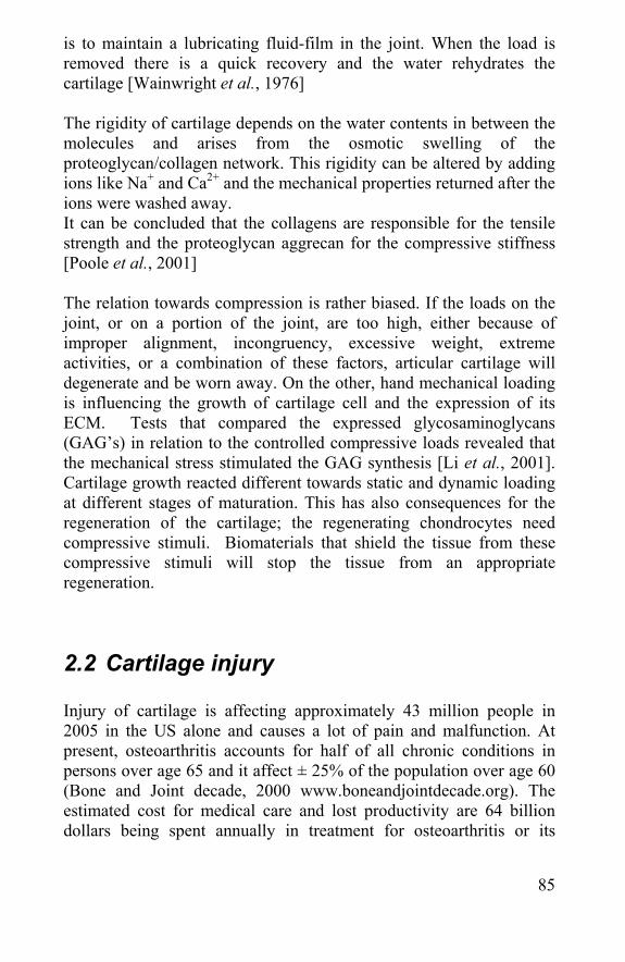
85
is to maintain a lubricating fluid-film in the joint. When the load is removed there is a quick recovery and the water rehydrates the cartilage [Wainwright et al., 1976] The rigidity of cartilage depends on the water contents in between the molecules and arises from the osmotic swelling of the proteoglycan/collagen network. This rigidity can be altered by adding ions like Na+ and Ca2+ and the mechanical properties returned after the ions were washed away. It can be concluded that the collagens are responsible for the tensile strength and the proteoglycan aggrecan for the compressive stiffness [Poole et al., 2001] The relation towards compression is rather biased. If the loads on the joint, or on a portion of the joint, are too high, either because of improper alignment, incongruency, excessive weight, extreme activities, or a combination of these factors, articular cartilage will degenerate and be worn away. On the other, hand mechanical loading is influencing the growth of cartilage cell and the expression of its ECM. Tests that compared the expressed glycosaminoglycans (GAG’s) in relation to the controlled compressive loads revealed that the mechanical stress stimulated the GAG synthesis [Li et al., 2001]. Cartilage growth reacted different towards static and dynamic loading at different stages of maturation. This has also consequences for the regeneration of the cartilage; the regenerating chondrocytes need compressive stimuli. Biomaterials that shield the tissue from these compressive stimuli will stop the tissue from an appropriate regeneration.
2.2 Cartilage injury Injury of cartilage is affecting approximately 43 million people in 2005 in the US alone and causes a lot of pain and malfunction. At present, osteoarthritis accounts for half of all chronic conditions in persons over age 65 and it affect ± 25% of the population over age 60 (Bone and Joint decade, 2000 www.boneandjointdecade.org). The estimated cost for medical care and lost productivity are 64 billion dollars being spent annually in treatment for osteoarthritis or its
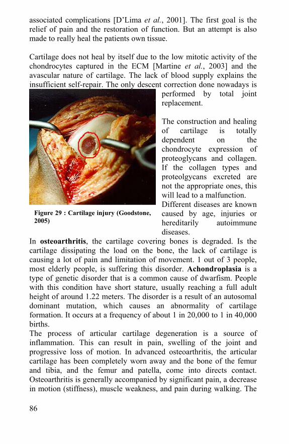
86
associated complications [D’Lima et al., 2001]. The first goal is the relief of pain and the restoration of function. But an attempt is also made to really heal the patients own tissue. Cartilage does not heal by itself due to the low mitotic activity of the chondrocytes captured in the ECM [Martine et al., 2003] and the avascular nature of cartilage. The lack of blood supply explains the insufficient self-repair. The only descent correction done nowadays is
performed by total joint replacement. The construction and healing of cartilage is totally dependent on the chondrocyte expression of proteoglycans and collagen. If the collagen types and proteolgycans excreted are not the appropriate ones, this will lead to a malfunction. Different diseases are known caused by age, injuries or hereditarily autoimmune diseases.
In osteoarthritis, the cartilage covering bones is degraded. Is the cartilage dissipating the load on the bone, the lack of cartilage is causing a lot of pain and limitation of movement. 1 out of 3 people, most elderly people, is suffering this disorder. Achondroplasia is a type of genetic disorder that is a common cause of dwarfism. People with this condition have short stature, usually reaching a full adult height of around 1.22 meters. The disorder is a result of an autosomal dominant mutation, which causes an abnormality of cartilage formation. It occurs at a frequency of about 1 in 20,000 to 1 in 40,000 births. The process of articular cartilage degeneration is a source of inflammation. This can result in pain, swelling of the joint and progressive loss of motion. In advanced osteoarthritis, the articular cartilage has been completely worn away and the bone of the femur and tibia, and the femur and patella, come into directs contact. Osteoarthritis is generally accompanied by significant pain, a decrease in motion (stiffness), muscle weakness, and pain during walking. The
Figure 29 : Cartilage injury (Goodstone, 2005)
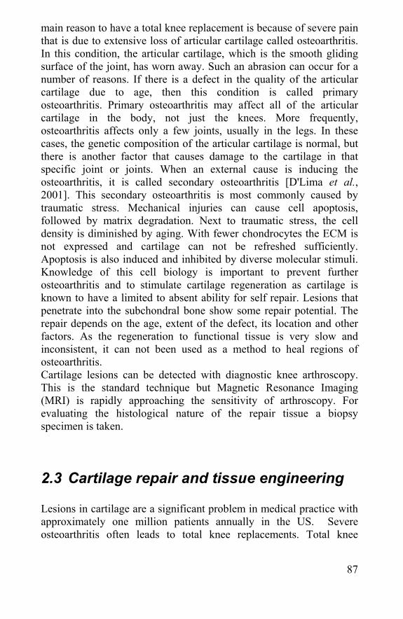
87
main reason to have a total knee replacement is because of severe pain that is due to extensive loss of articular cartilage called osteoarthritis. In this condition, the articular cartilage, which is the smooth gliding surface of the joint, has worn away. Such an abrasion can occur for a number of reasons. If there is a defect in the quality of the articular cartilage due to age, then this condition is called primary osteoarthritis. Primary osteoarthritis may affect all of the articular cartilage in the body, not just the knees. More frequently, osteoarthritis affects only a few joints, usually in the legs. In these cases, the genetic composition of the articular cartilage is normal, but there is another factor that causes damage to the cartilage in that specific joint or joints. When an external cause is inducing the osteoarthritis, it is called secondary osteoarthritis [D'Lima et al., 2001]. This secondary osteoarthritis is most commonly caused by traumatic stress. Mechanical injuries can cause cell apoptosis, followed by matrix degradation. Next to traumatic stress, the cell density is diminished by aging. With fewer chondrocytes the ECM is not expressed and cartilage can not be refreshed sufficiently. Apoptosis is also induced and inhibited by diverse molecular stimuli. Knowledge of this cell biology is important to prevent further osteoarthritis and to stimulate cartilage regeneration as cartilage is known to have a limited to absent ability for self repair. Lesions that penetrate into the subchondral bone show some repair potential. The repair depends on the age, extent of the defect, its location and other factors. As the regeneration to functional tissue is very slow and inconsistent, it can not been used as a method to heal regions of osteoarthritis. Cartilage lesions can be detected with diagnostic knee arthroscopy. This is the standard technique but Magnetic Resonance Imaging (MRI) is rapidly approaching the sensitivity of arthroscopy. For evaluating the histological nature of the repair tissue a biopsy specimen is taken.
2.3 Cartilage repair and tissue engineering Lesions in cartilage are a significant problem in medical practice with approximately one million patients annually in the US. Severe osteoarthritis often leads to total knee replacements. Total knee
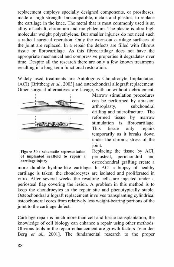
88
replacement employs specially designed components, or prostheses, made of high strength, biocompatible, metals and plastics, to replace the cartilage in the knee. The metal that is most commonly used is an alloy of cobalt, chromium and molybdenum. The plastic is ultra-high molecular weight polyethylene. But smaller injuries do not need such a radical surgical operation. Only the worn-out cartilage surfaces of the joint are replaced. In a repair the defects are filled with fibrous tissue or fibrocartilage. As this fibrocartilage does not have the appropriate mechanical and compressive properties it degradates over time. Despite all the research there are only a few known treatments resulting in a long-term functional restoration. Widely used treatments are Autologous Chondrocyte Implantation (ACI) [Brittberg et al., 2003] and osteochondral allograft replacement. Other surgical alternatives are lavage, with or without debridement.
Marrow stimulation procedures can be performed by abrasion arthroplasty, subchondral drilling and microfracture. The reformed tissue by marrow stimulation is fibrocartilage. This tissue only repairs temporarily as it breaks down under the chronic stress of the joint. Replacing the tissue by ACI, periosteal, perichondral and osteochondral grafting create a
more durable hyaline-like cartilage. In ACI a biopsy of healthy cartilage is taken, the chondrocytes are isolated and proliferated in vitro. After several weeks the resulting cells are injected under a periosteal flap covering the lesion. A problem in this method is to keep the chondrocytes in the repair site and phenotypically stable. Osteochondral allograft replacement involves transplanting cylindrical osteochondral cores from relatively less weight-bearing portions of the joint to the cartilage defect. Cartilage repair is much more than cell and tissue transplantation, the knowledge of cell biology can enhance a repair using other methods. Obvious tools in the repair enhancement are growth factors [Van den Berg et al., 2001]. The fundamental research to the proper
Figure 30 : schematic representation of implanted scaffold to repair a cartilage injury
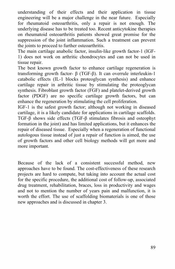
89
understanding of their effects and their application in tissue engineering will be a major challenge in the near future. Especially for rheumatoid osteoarthritis, only a repair is not enough. The underlying disease has to be treated too. Recent anticytokine therapies on rheumatoid osteoarthritis patients showed great promise for the suppression of the joint inflammation. Such a treatment can prevent the joints to proceed to further osteoarthritis. The main cartilage anabolic factor, insulin-like growth factor-1 (IGF-1) does not work on arthritic chondrocytes and can not be used in tissue repair. The best known growth factor to enhance cartilage regeneration is transforming growth factor- β (TGF-β). It can overrule interleukin-1 catabolic effects (IL-1 blocks proteoglycan synthesis) and enhance cartilage repair in arthritic tissue by stimulating the proteoglycan synthesis. Fibroblast growth factor (FGF) and platelet-derived growth factor (PDGF) are no specific cartilage growth factors, but can enhance the regeneration by stimulating the cell proliferation. IGF-1 is the safest growth factor; although not working in diseased cartilage, it is a likely candidate for applications in cartilage scaffolds. TGF-β shows side effects (TGF-β stimulates fibrosis and osteophyt formation in the joint) and has limited applications, but it enhances the repair of diseased tissue. Especially when a regeneration of functional autologous tissue instead of just a repair of function is aimed, the use of growth factors and other cell biology methods will get more and more important. Because of the lack of a consistent successful method, new approaches have to be found. The cost-effectiveness of these research projects are hard to compute, but taking into account the actual cost for the specific procedure, the additional cost of follow-up, associated drug treatment, rehabilitation, braces, loss in productivity and wages and not to mention the number of years pain and malfunction, it is worth the effort. The use of scaffolding biomaterials is one of those new approaches and is discussed in chapter 3.
90
2.4 Meniscus, tendons and ligaments Although the morphology and structure of the meniscus is different to the one of cartilage, repair methods and scaffolds used for cartilage repair could also be tested on meniscus repair. A first difference is that the meniscus contains 3 different types of cells in contrast to one type in cartilage. An elongated fibroblast-like cell type, a polygonal cell type and a small round chondrocyte-like cell type were cultivated from a human meniscus cell [Nakato et al., 2001]. The meniscus ECM contains aggrecan and collagen types I, II and III. The fact that a meniscus is built up with several cell-types makes it harder to engineer a meniscus from MSC’s. The cells isolated from a human meniscus could be isolated, grown and seeded in a collagen sponge; this makes meniscus engineering promising and the research of appropriate meniscus scaffolds worthwhile. Next to cartilage, bone and meniscus, lots of research is performed on the engineering of tendons and ligaments [Allen et al., 1999]. Fibrous biomaterials can be used to replace the tendons while the tendons are regenerated on the biomaterial [Cao et al., 1994]
2.5 References: - Allen CR, Livesay GA, Wong EK, Woo SL. Injury and reconstruction of the anterior cruciate ligament and knee osteoarthritis. Osteoarthritis Cartilage. 1999 Jan;7(1):110-21 - Brittberg M, Peterson L, Sjogren-Jansson E, Tallheden T, Lindahl A.Articular cartilage engineering with autologous chondrocyte transplantation. A review of recent developments. J Bone Joint Surg Am. 2003;85-A Suppl 3:109-15. Review
Figure 31 : scaffold for meniscus regeneration: collagen meniscus implant (sportorthopädie Bern)
91
- Cao Y, Vacanti JP, Ma X, Paige KT, Upton J, Chowanski Z, Schloo B, Langer R, Vacanti CA. Generation of neo-tendon using synthetic polymers seeded with tenocytes. Transplant Proc. 1994 Dec;26(6):3390-2. - D'Lima DD, Colwell CW Jr. Clinical objectives for cartilage repair. Clin Orthop. 2001 Oct;(391 Suppl):S402-5 - D'Lima DD, Hashimoto S, Chen PC, Colwell CW Jr, Lotz MK. Impact of mechanical trauma on matrix and cells.Clin Orthop. 2001 Oct;(391 Suppl):S90-9 - Li KW, Williamson AK, Wang AS, Sah RL. Growth responses of cartilage to static and dynamic compression. Clin Orthop. 2001 Oct;(391 Suppl):S34-48 - Martin JA, Buckwalter JA. The role of chondrocyte senescence in the pathogenesis of osteoarthritis and in limiting cartilage repair. J Bone Joint Surg Am. 2003;85-A Suppl 2:106-10 - Mathews MB. The interaction of collagen and acid mucopolysaccharides. A model for connective tissue. Biochem J. 1965 Sep;96(3):710-6.) - Miller EJ, Vanderkorst JK, Sokoloff L: Collagen of human articular and costal cartilage. Arthritis Rheum 1969; 12: 21 - Nakata K, Shino K, Hamada M, Mae T, Miyama T, Shinjo H, Horibe S, Tada K, Ochi T, Yoshikawa H. Human meniscus cell: characterization of the primary culture and use for tissue engineering. Clin Orthop. 2001 Oct;(391 Suppl):S208-18 - Person P., Philpott D. The biology of cartilage. I. Invertebrate cartilages: Limulus gill cartilage Journal of Morphology 1969 Volume 128, Issue 1 , Pages 67 – 93 - Poole AR, Kojima T, Yasuda T, Mwale F, Kobayashi M, Laverty S. Composition and structure of articular cartilage: a template for tissue repair. Clin Orthop. 2001 Oct;(391 Suppl):S26-33. Review - Schubert M. Structure of connective tissues, a chemical point of view. Fed Proc. 1966 May-Jun;25(3):1047-52 - Setton LA, Elliott DM, Mow VC. Altered mechanics of cartilage with osteoarthritis: human osteoarthritis and an experimental model of joint degeneration. Osteoarthritis Cartilage. 1999 Jan;7(1):2-14 - Setton LA, Tpohyama H, Mow VC. Swelling and curling behaviours of articular cartilage. J. biomech Eng. 1998; 10 (3): 519-25 - van den Berg WB, van der Kraan PM, Scharstuhl A, van Beuningen HM. Growth factors and cartilage repair. Clin Orthop. 2001 Oct;(391 Suppl):S244-50. Review
92
- Wainwright S. A, W. D. Biggs, J. D. Currey, and J. M. Gosline Mechanical Design in Organisms, Princeton University Press, 1982.
93
Chapter 3 Biomaterials and tissue engineering

94
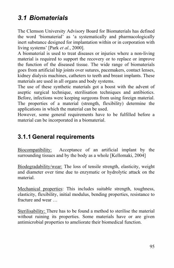
95
3.1 Biomaterials The Clemson University Advisory Board for Biomaterials has defined the word ‘biomaterial’ as ‘a systematically and pharmacologically inert substance designed for implantation within or in corporation with living systems’ [Park et al., 2000]. A biomaterial is used to treat diseases or injuries where a non-living material is required to support the recovery or to replace or improve the function of the diseased tissue. The wide range of biomaterials goes from artificial hip joints over sutures, pacemakers, contact lenses, kidney dialysis machines, catheters to teeth and breast implants. These materials are used in all organs and body systems. The use of these synthetic materials got a boost with the advent of aseptic surgical technique, sterilisation techniques and antibiotics. Before, infections were keeping surgeons from using foreign material. The properties of a material (strength, flexibility) determine the applications in which the material can be used. However, some general requirements have to be fulfilled before a material can be incorporated in a biomaterial.
3.1.1 General requirements Biocompatibility: Acceptance of an artificial implant by the surrounding tissues and by the body as a whole [Kellomaki, 2004] Biodegradability/wear: The loss of tensile strength, elasticity, weight and diameter over time due to enzymatic or hydrolytic attack on the material. Mechanical properties: This includes suitable strength, toughness, elasticity, flexibility, initial modulus, bending properties, resistance to fracture and wear … Sterilisability: There has to be found a method to sterilise the material without ruining its properties. Some materials have or are given antimicrobial properties to ameliorate their biomedical function.
96
Cell and tissue adhesion: When materials are to be used in contact with living tissue, the surface must be as such that the cells and tissue can adhere to the surface. Modifications to improve or hold these bindings can be made.
3.1.2 Classification The properties of a material are determined by its structure and chemical composition. This justifies the division of biomaterials in groups by the nature of their material.
- By material The material can be composed out of metals, ceramics, polymers, composites or biological materials, each having their specific advantages and disadvantages. Metals: The structure of metals is formed by grains, in a single grain there is a uniform crystal structure. The grain size is determining the metals properties. Stainless steel is often used in orthopaedics. The advantages of metals are that they are very strong and stable, but subjected to wear and corrosion. They are used in medicine for a long time especially in orthopaedics. Ceramics: Ceramics are mostly metal-oxides, like aluminium-oxide and zirconium-oxide, but also carbon and the widely used hydroxy-apetite (Hap) and bioactive glass are bioceramics. These are nearly inert, strong, but very brittle. They are often used in combination with metals for bone repair. Especially hydroxyapetite has osteoinductive properties. Their good durability, high compressive strength and esthetics make them usable for dental applications. Polymers: Polymers are macromolecules composed of repeating units called monomers. The monomers and the length of these chains are determining the material properties. There is a wide variety of polymers; natural-synthetic, stable-bioresorbable, strong-gel-like … Plastics used as biomaterials are always medical grade, this means they had higher quality expectations than bulk grade materials. Some examples are polyethylene, polytetrafluoroethylene, polypropylene, polymethylmetacrylate (bone cement), polyvinylchloride, polyamides,
97
silicones …. Some of these or their biodegradation products are not biocompatible enough to be used in vivo, but their processability makes them well-liked for hospital applications. There is also a huge difference between stable polymers and bioresorbable ones like polylactic acid and polyglycolic acid. These are known to be biocompatible and can be used in vivo especially in tissue engineering. Composites: Composites are materials/structures composed of separate parts/materials, having one or more phases with different structures and/or properties, when the material is studied at a macro-, micro- or sub-microscopic level. The goal is to have a material/structure with better properties than the properties of any of its components, when used alone. Metals are often coated with ceramics or polymer; this combines the high strength of a metal with the better cell-material interaction of a ceramic like a bioactive glass. Biological materials: These natural materials are renewable polymers like proteins, polysaccharides, lipids … They have different characteristics, but they are more biocompatible than other materials. The disadvantage is that they are harder to process than synthetic polymers.
- By tissue-material-interference
Biostable: Remains unchanged in the body for a life-long period Biodegradable/Bioabsorbable/bioresorbable: The material gets degraded in the body and is removed or re-used by the surrounding tissue. Bioactivity: The material contains factors that promote a defined biological response; e.g. growth factors stimulating cell growth or hydroxyapatite that is osteoinductive.
98
3.2 Tissue engineering
“ Tissue engineering combines the principles and methods of the life sciences with those of engineering to elucidate fundamental understanding of structure-function relationships in normal and diseased tissues, and to create entire tissue replacements” (Hubbel, 1995)
Tissue engineering is a special subdivision in biomaterials. The implant in tissue engineering can be defined as a composite of a biodegradable material (polymer/ biological material) and autologous cell or tissue material. This combination of synthetic and biological material makes the implant more than just a biomaterial. The field of tissue engineering is not just the territory of material scientists; it’s a crossroad where material scientists meet cell biologists and medical researchers [Hardingham et al., 2002]. The interaction between the body tissue and the implant is even more important in tissue engineering than in the use of other biomaterials. The objective of the implant is that the synthetic materials in the implant replace the function of the diseased tissue which is recovering (at least) at the same rate the synthetic part of the material is biodegrading and resolving in the body. As wear can cause a biocompatibility problem for solid implants, the biodegradation products have to be biocompatible and even bioresorbable for these biodegrading implants. Chapter 7 will elaborate more on the rate of the biodegradation. Transplantation of organs has proven to be successful for many serious diseases. Some disadvantages are obliging scientists to keep on looking for alternatives. There is a definite lack of donors. In the USA there are currently about 75,000 patients waiting for organ transplantation [UNOS, United network for organ sharing]. The immunologic response towards the donors and the risk to transmit infections like hepatitis and HIV are, together with the lack of donors, the arguments for not using biological material from an allogenic source. Previous reasons are forcing transplant researchers more and more to use allograft material or stem cells. The disadvantage of allograft material is the limited supply of material. This last problem can be solved by isolating healthy cells from the tissue that is to be
99
transplanted and to culture the cells in vitro to multiply their amount to a sufficient extent and implant the cells or regenerated tissue after several weeks of in vitro culturing. This re-implantation can be scaffold-free or with the help of a scaffold [Doser et al., 2000].
3.2.1 Scaffold-free tissue engineering
Scaffold-free tissue engineering is actually no real tissue engineering in the strict sense of the word, because there is no synthetic material in the implant. The cultured cells or new stem cells are placed in the injury and are helping to recover the tissue. The major advantage of not using a scaffold is that there is no synthetic material that can cause biocompatibility or biodegradation problems. Stem cells brought into a specific environment, e.g. liver tissue, will transform into the correct cell type, liver cells, due to environmental induction. The surrounding cells are releasing growth factors that induce the correct differentiation. In some applications mechanical forces are inducing the correct differentiation, the compression on articular cartilage tissue and the stretching of tendon tissue. An example of scaffold-free tissue engineering in cartilage repair is Autologous Chondrocyte Implantation (ACI). In this technique, the cartilage defect is covered with a periosteum membrane and a culture medium with lots of chondrocytes is injected under the periosteum in the defect. The objective is that the cartilage cells will grow in the defect and form their extracellular matrix (ECM) and the cartilage will be fully recovered in some time. The huge disadvantage of this method is that there is no cell support, the cells are not guided in the defect and that the function of the tissue is not replaced until the cartilage is fully recovered.
3.2.2 Scaffolds in tissue engineering
Scaffolds or matrices are porous biomaterials that can contain cells or regenerating tissue in their pores and are to be placed in an injury to replace the function and guide the recovery. When one is not satisfied with a repair, but a full regeneration is wanted, the scaffold should biodegrade when the tissue is healed.
100
Biodegrading scaffolds can be implanted without previous seeding with cells. This is called cell-free scaffold implantation. The recovery is fully based on the ingrowth of surrounding tissue in the pores of the scaffold. These cells are migrating through the scaffold that is bridging the sides of the wound. The major challenge however, especially for cartilage, meniscus and bone repair, is in the scaffold-based in vitro growth of cartilage in vitro, where the scaffold and regenerating tissue is implanted later to continue to repair the initial defect. In this way autologous cells can be cultured to big amounts, seeded in the scaffold in vitro and brought in the defect for a correct repair. This limits the need of donor material and makes autologous constructs feasible. Even stem cells can be used for the in vitro growth and differentiation in the scaffold can be guided by growth factors, e.g. TGF-β; Cartilage derived growth factor (CDGF), and others. An ideal scaffold for hyaline cartilage repair requires:
- good adhesion of the cells on the material, but not without loosing the possibility to migrate through the scaffold
- No dedifferentiation of autologous cells. Seeded chondrocytes form fibrous tissue when they are taken out of their cartilaginous environment. This is a problem for most scaffolds. An ideal scaffold should regulate the cell expression of the seeded cells. Immobilized growth factors can help to transform Mesenchymal Stem Cells (MSC) in the right direction or keep chondrocytes from dedifferentiation.
- Appropriate mechanical properties; e.g. scaffolds have to be compressible, but strong enough to carry the weight of the body. The scaffold may not be too strong or the cells will not feel the necessity to regenerate the correct strong tissue. This is called stress-shielding.
- Appropriate porosity; the pores should be big enough so cells and tissue can migrate and new ECM can be formed, but not too big or the cells will not be able to fill the gap.
- The pores should be interconnected. Fluids and nutrients should be able to diffuse through the scaffold and cells and tissue should be able to spread in all pores to obtain a full recovery.
- Appropriate and controllable speed of biodegradability and absence of cytotoxicity of the scaffold and the biodegradation products.
101
- Suitable for surgical manipulation and attachable in the injury, with a good fixation of the scaffold in the repair site.
- No inflammatory response against the scaffold, neither against biodegradation products, residual toxic chemicals such as monomers, stabilizers, inititators, crosslinking agents, emulsifiers and organic solvents. [Coutts et al., 2001; Hutmacher et al., 2001]
Many materials have been investigated on these characteristics and lots of methods have been presented to create a good matrix. First collagen I was used to deliver mesenchymal stem cells (MSC’s), which were unsatisfactory as cell carriers [Solchaga et al., 2001]. The rapid biodegradation of collagen has been recognized as a limitation in vivo and in vitro [Meinel et al., 2005]. Much research is performed on polylactic and polyglycolic acid (PLA/PGA) scaffolds. PLA and PGA are polymers respectively formed out of the monomers lactic acid and glycolic acid. These acids are used in the Krebs cycle and broken down into H2O and CO2, forming HCO3. As a consequence, biomaterials made out of PLA or PGA are fully bioresorbable. These polymers are already widely used in surgical sutures; which do not have to be removed afterwards. By composing different PLA/PGA copolymers, polymer scientists can create materials with a controlled rate of biodegradation. However the rate of biodegradation is quite fast as shown in chapter 7. Other biological materials are also used to create biomaterials for their biocompatible and bioresorbable nature, like hyaluronic acid, chitosan, hydroxyapetite, carbon, alginate or fibrin-based materials. These materials are preferred to synthetic polymers, as the biodegradation products of synthetic polymers are mostly cytotoxic and there is no possibility of bioresorbtion like for example with lactic acid in the Krebs cycle. Also de-cellularised cartilage from animal sources like bovine [Toolan et al., 1998] and lamb [Peretti et al., 1998] cartilage was investigated for their scaffolding feasibility. These were extracted, lyophilized and reseeded with chondrocytes. The implants in rabbits showed good repair results after 12 weeks. Materials tested for cartilage repair are: bioactive glass, carbon fibre, chitosan, collagen, demineralised bone, devitalized cartilage, fibrin, hyaluronan, hydroxyapetite, PLA/PGA
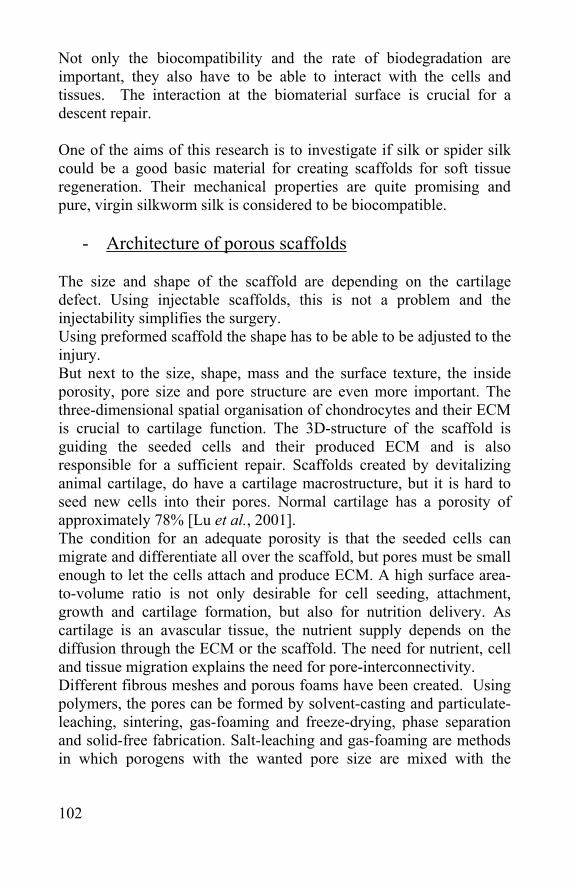
102
Not only the biocompatibility and the rate of biodegradation are important, they also have to be able to interact with the cells and tissues. The interaction at the biomaterial surface is crucial for a descent repair. One of the aims of this research is to investigate if silk or spider silk could be a good basic material for creating scaffolds for soft tissue regeneration. Their mechanical properties are quite promising and pure, virgin silkworm silk is considered to be biocompatible.
- Architecture of porous scaffolds The size and shape of the scaffold are depending on the cartilage defect. Using injectable scaffolds, this is not a problem and the injectability simplifies the surgery. Using preformed scaffold the shape has to be able to be adjusted to the injury. But next to the size, shape, mass and the surface texture, the inside porosity, pore size and pore structure are even more important. The three-dimensional spatial organisation of chondrocytes and their ECM is crucial to cartilage function. The 3D-structure of the scaffold is guiding the seeded cells and their produced ECM and is also responsible for a sufficient repair. Scaffolds created by devitalizing animal cartilage, do have a cartilage macrostructure, but it is hard to seed new cells into their pores. Normal cartilage has a porosity of approximately 78% [Lu et al., 2001]. The condition for an adequate porosity is that the seeded cells can migrate and differentiate all over the scaffold, but pores must be small enough to let the cells attach and produce ECM. A high surface area-to-volume ratio is not only desirable for cell seeding, attachment, growth and cartilage formation, but also for nutrition delivery. As cartilage is an avascular tissue, the nutrient supply depends on the diffusion through the ECM or the scaffold. The need for nutrient, cell and tissue migration explains the need for pore-interconnectivity. Different fibrous meshes and porous foams have been created. Using polymers, the pores can be formed by solvent-casting and particulate-leaching, sintering, gas-foaming and freeze-drying, phase separation and solid-free fabrication. Salt-leaching and gas-foaming are methods in which porogens with the wanted pore size are mixed with the
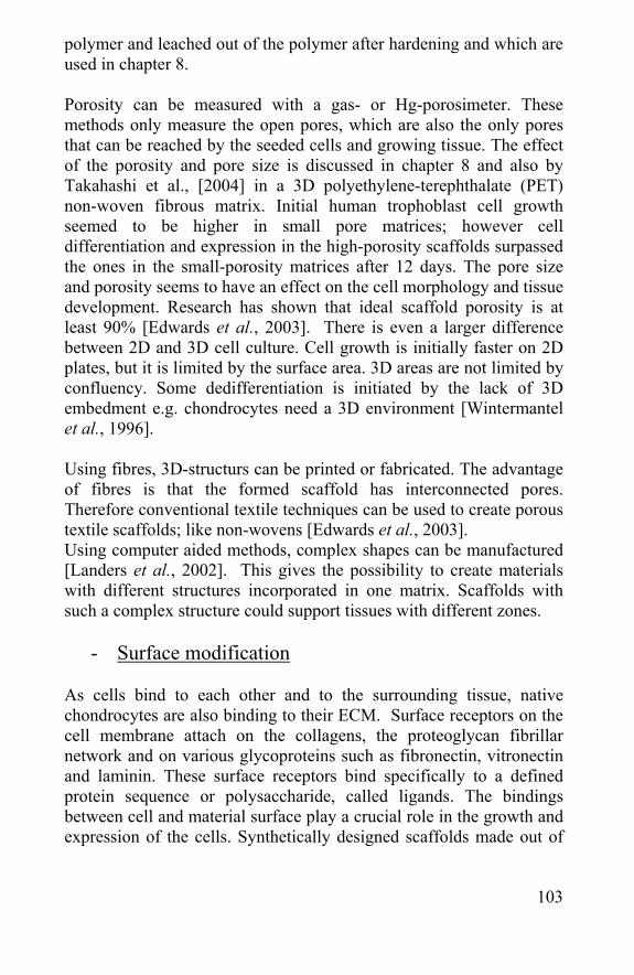
103
polymer and leached out of the polymer after hardening and which are used in chapter 8. Porosity can be measured with a gas- or Hg-porosimeter. These methods only measure the open pores, which are also the only pores that can be reached by the seeded cells and growing tissue. The effect of the porosity and pore size is discussed in chapter 8 and also by Takahashi et al., [2004] in a 3D polyethylene-terephthalate (PET) non-woven fibrous matrix. Initial human trophoblast cell growth seemed to be higher in small pore matrices; however cell differentiation and expression in the high-porosity scaffolds surpassed the ones in the small-porosity matrices after 12 days. The pore size and porosity seems to have an effect on the cell morphology and tissue development. Research has shown that ideal scaffold porosity is at least 90% [Edwards et al., 2003]. There is even a larger difference between 2D and 3D cell culture. Cell growth is initially faster on 2D plates, but it is limited by the surface area. 3D areas are not limited by confluency. Some dedifferentiation is initiated by the lack of 3D embedment e.g. chondrocytes need a 3D environment [Wintermantel et al., 1996]. Using fibres, 3D-structurs can be printed or fabricated. The advantage of fibres is that the formed scaffold has interconnected pores. Therefore conventional textile techniques can be used to create porous textile scaffolds; like non-wovens [Edwards et al., 2003]. Using computer aided methods, complex shapes can be manufactured [Landers et al., 2002]. This gives the possibility to create materials with different structures incorporated in one matrix. Scaffolds with such a complex structure could support tissues with different zones.
- Surface modification As cells bind to each other and to the surrounding tissue, native chondrocytes are also binding to their ECM. Surface receptors on the cell membrane attach on the collagens, the proteoglycan fibrillar network and on various glycoproteins such as fibronectin, vitronectin and laminin. These surface receptors bind specifically to a defined protein sequence or polysaccharide, called ligands. The bindings between cell and material surface play a crucial role in the growth and expression of the cells. Synthetically designed scaffolds made out of
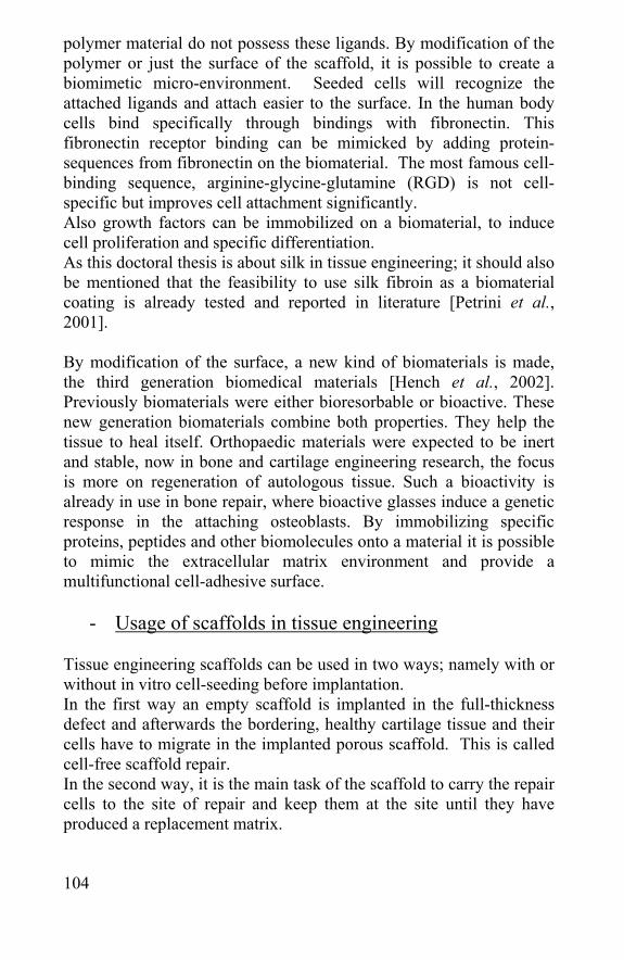
104
polymer material do not possess these ligands. By modification of the polymer or just the surface of the scaffold, it is possible to create a biomimetic micro-environment. Seeded cells will recognize the attached ligands and attach easier to the surface. In the human body cells bind specifically through bindings with fibronectin. This fibronectin receptor binding can be mimicked by adding protein-sequences from fibronectin on the biomaterial. The most famous cell-binding sequence, arginine-glycine-glutamine (RGD) is not cell-specific but improves cell attachment significantly. Also growth factors can be immobilized on a biomaterial, to induce cell proliferation and specific differentiation. As this doctoral thesis is about silk in tissue engineering; it should also be mentioned that the feasibility to use silk fibroin as a biomaterial coating is already tested and reported in literature [Petrini et al., 2001]. By modification of the surface, a new kind of biomaterials is made, the third generation biomedical materials [Hench et al., 2002]. Previously biomaterials were either bioresorbable or bioactive. These new generation biomaterials combine both properties. They help the tissue to heal itself. Orthopaedic materials were expected to be inert and stable, now in bone and cartilage engineering research, the focus is more on regeneration of autologous tissue. Such a bioactivity is already in use in bone repair, where bioactive glasses induce a genetic response in the attaching osteoblasts. By immobilizing specific proteins, peptides and other biomolecules onto a material it is possible to mimic the extracellular matrix environment and provide a multifunctional cell-adhesive surface.
- Usage of scaffolds in tissue engineering Tissue engineering scaffolds can be used in two ways; namely with or without in vitro cell-seeding before implantation. In the first way an empty scaffold is implanted in the full-thickness defect and afterwards the bordering, healthy cartilage tissue and their cells have to migrate in the implanted porous scaffold. This is called cell-free scaffold repair. In the second way, it is the main task of the scaffold to carry the repair cells to the site of repair and keep them at the site until they have produced a replacement matrix.
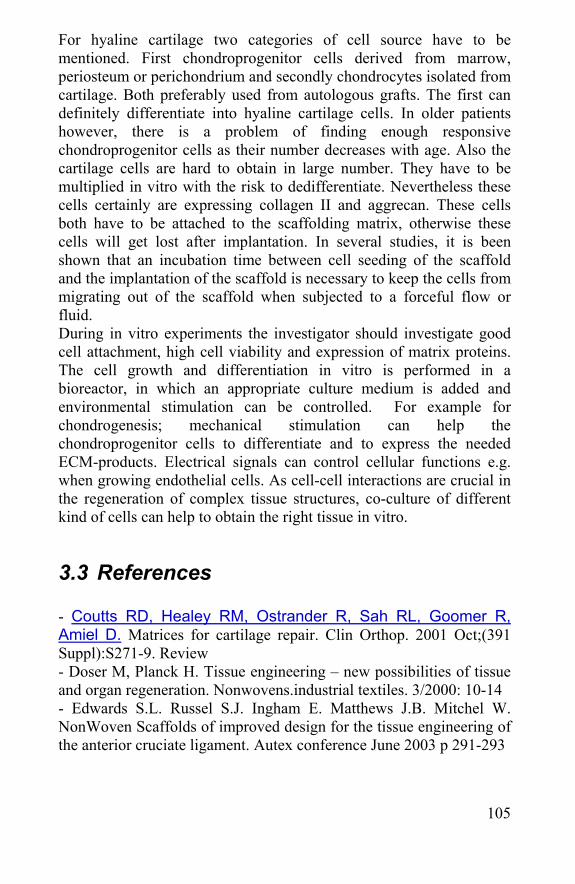
105
For hyaline cartilage two categories of cell source have to be mentioned. First chondroprogenitor cells derived from marrow, periosteum or perichondrium and secondly chondrocytes isolated from cartilage. Both preferably used from autologous grafts. The first can definitely differentiate into hyaline cartilage cells. In older patients however, there is a problem of finding enough responsive chondroprogenitor cells as their number decreases with age. Also the cartilage cells are hard to obtain in large number. They have to be multiplied in vitro with the risk to dedifferentiate. Nevertheless these cells certainly are expressing collagen II and aggrecan. These cells both have to be attached to the scaffolding matrix, otherwise these cells will get lost after implantation. In several studies, it is been shown that an incubation time between cell seeding of the scaffold and the implantation of the scaffold is necessary to keep the cells from migrating out of the scaffold when subjected to a forceful flow or fluid. During in vitro experiments the investigator should investigate good cell attachment, high cell viability and expression of matrix proteins. The cell growth and differentiation in vitro is performed in a bioreactor, in which an appropriate culture medium is added and environmental stimulation can be controlled. For example for chondrogenesis; mechanical stimulation can help the chondroprogenitor cells to differentiate and to express the needed ECM-products. Electrical signals can control cellular functions e.g. when growing endothelial cells. As cell-cell interactions are crucial in the regeneration of complex tissue structures, co-culture of different kind of cells can help to obtain the right tissue in vitro.
3.3 References - Coutts RD, Healey RM, Ostrander R, Sah RL, Goomer R, Amiel D. Matrices for cartilage repair. Clin Orthop. 2001 Oct;(391 Suppl):S271-9. Review - Doser M, Planck H. Tissue engineering – new possibilities of tissue and organ regeneration. Nonwovens.industrial textiles. 3/2000: 10-14 - Edwards S.L. Russel S.J. Ingham E. Matthews J.B. Mitchel W. NonWoven Scaffolds of improved design for the tissue engineering of the anterior cruciate ligament. Autex conference June 2003 p 291-293
106
- Hardingham T, Tew S, Murdoch A. Tissue engineering: chondrocytes and cartilage. Arthritis Res. 2002;4 Suppl 3:S63-8. Epub 2002 May 09. Review.) - Hench LL, Polak JM. Third-generation biomedical materials. Science. 2002 Feb 8;295(5557):1014-7 - Hubbell JA. Biomaterials in tissue engineering. Biotechnology (N Y). 1995 Jun;13(6):565-76. Review - Hutmacher DW. Scaffold design and fabrication technologies for engineering tissues--state of the art and future perspectives. J Biomater Sci Polym Ed. 2001;12(1):107-24. Review - Prof. Kellomaki, Biomaterials course, 2004 - Landers R, Pfister A. Fabrication of soft tissue engineering scaffolds by means of rapid prototyping techniques. J. of Materials science 2002. 37: 3107-3116 - Lu L, Zhu X, Valenzuela RG, Currier BL, Yaszemski MJ. Biodegradable polymer scaffolds for cartilage tissue engineering. Clin Orthop. 2001 Oct;(391 Suppl):S251-70. Review - Meinel L, Hofmann S, Karageorgiou V, Kirker-Head C, McCool J, Gronowicz G, Zichner L, Langer R, Vunjak-Novakovic G, Kaplan DL. The inflammatory responses to silk films in vitro and in vivo.Biomaterials. 2005 Jan;26(2):147-55. - Park J.B., R.S. Lakes Biomaterials, An Introduction. - Peretti GM, Randolph MA, Caruso EM, Rossetti F, Zaleske DJ. Bonding of cartilage matrices with cultured chondrocytes: an experimental model. J Orthop Res. 1998 Jan;16(1):89-95. - Petrini P, Parolari C, Tanzi MC. Silk fibroin-polyurethane scaffolds for tissue engineering. J Mater Sci Mater Med. 2001 Oct-Dec;12(10-12):849-53.) - Takahashi Y, Tabata Y. Effect of the fibre diameter and porosity of non-woven PET fabrics on the osteogenic differentiation of mesenchymal stem cells. J Biomater Sci Polym Ed. 2004;15(1):41-57 - Toolan BC, Frenkel SR, Pereira DS, Alexander H. Development of a novel osteochondral graft for cartilage repair. J Biomed Mater Res. 1998 Aug;41(2):244-50 - Wintermantel E, Mayer J, Blum J, Eckert KL, Luscher P, Mathey M. Tissue engineering scaffolds using superstructures. Biomaterials. 1996 Jan;17(2):83-91
107
Chapter 4 Silkworm silk and spider silk in
biomedical applications

108
109
Silkworm silk has a long medical history. Due to its biomechanical properties, excellent handling and knotting characteristics, it is a popular material for surgical sutures. But due to the advances in biomedical engineering the need for new biopolymers has grown. Therefore the rediscovery of silk fibroin as a biological polymer has lead to new materials.
4.1 Silk in suture material Silkworm silk has already a long history as a suture material and artificial ligament [Lange et al., 1907]. Today it is still used in surgery, although biodegradable sutures are often preferred [Yaltirik et al., 2003]. Black silk braided® is a nonabsorbable, surgical suture made from B. mori fibroin. Suture features include braided wax (refined Paraffin, N.F. or Microcrystalline Wax N.F.) coated black (Hematein dyed) or white (undyed) and twisted uncoated white virgin (undyed), or twisted uncoated white (undyed). Silk surgical suture is available in U.S.P. sizes 9-0 through 5 (metric sized 0.3-7). The suture is supplied sterile in pre-cut lengths or ligation reels; both non-needled and affixed to various needle types in one dozen boxes (Kanglida Medical products). Silk surgical suture meets all requirements imposed by the United States Pharmacopeia (U.S.P.) for nonabsorbable surgical sutures. Silk surgical suture is good for use in general, like soft tissue approximation and ligation, including use in cardiovascular, ophthalmic and neurological procedures. It elicits minimal acute inflammatory reaction in tissues, which is followed by gradual encapsulation of the suture by fibrous connective tissue. While the silk suture is not absorbed, progressive degradation of the proteinaceous silk fibre in vivo may result in gradual loss of the suture’s tensile strength over time. The use of this suture is contraindicated in patients with known sensitivities or allergies to silk. Due to the gradual loss of tensile strength which may occur over prolonged period in vivo, silk suture should not be used where permanent retention of tensile strength is required.
110
4.2 Silk non-wovens Silk is usually not applied in non-wovens as the material is too expensive for use as bulk material. But smaller non-wovens can be created for medical applications. Silk fibroin nets are already used for cell growth [Unger et al., 2004]. Novel, three-dimensional, non-woven nets from Bombyx mori silk cocoons were produced and different cells, as explained further in this chapter were seeded on them [Armato et al., 2003]. In chapter 8, a new method is presented to create small silk non-wovens with B. mori silk and A. diadematus egg sac silk. An advantage of a non-woven towards a woven material is the random distribution of the fibres. This implies a fabric with homogenous distributed pores. Woven silk has small pores in the yarns and large pores in between two different yarns. When cells would be seeded on a woven material, they would not be able to penetrate in a yarn and start floating in between the pores. [Ilaria Dal Pra et al., 2005]. There is a definite growth of a new biotextiles area, where resorbable fibres are used to ameliorate tissue engineering.
4.3 Non-fibrous Silk materials Silk fibroin is not only used a fiber. The silk fibroin solution can be extracted from the silk glands in the silk I state [Tashiro et al., 1970]. Although hard to dissolve, the fibroin can be extracted from the silk fibers as well. When dissolved in neutral salts of a high concentration (9M LiBr, LiSCN or LiCLO4) and dialyzed against deionized water, the resulting aqueous fibroin can be used in various forms such as gel, powder and membranes. The fibers is also dissolvable in a calcium-nitrate-methanol system and in CaCl2/ethanol/water in a 111/92/144 weight-ratio [Yamada et al., 2001], but not as well as in 9M LiBr. The first method creates a unique environment with methanol as a hydrophobic solvent and the positively charged calcium ions. Methanol molecules are able to direct the hydrophobic side chains away from the solvent while the calcium ions bind to the carbonyl oxygen. The second method will be used and explained in more detail in chapter 8.
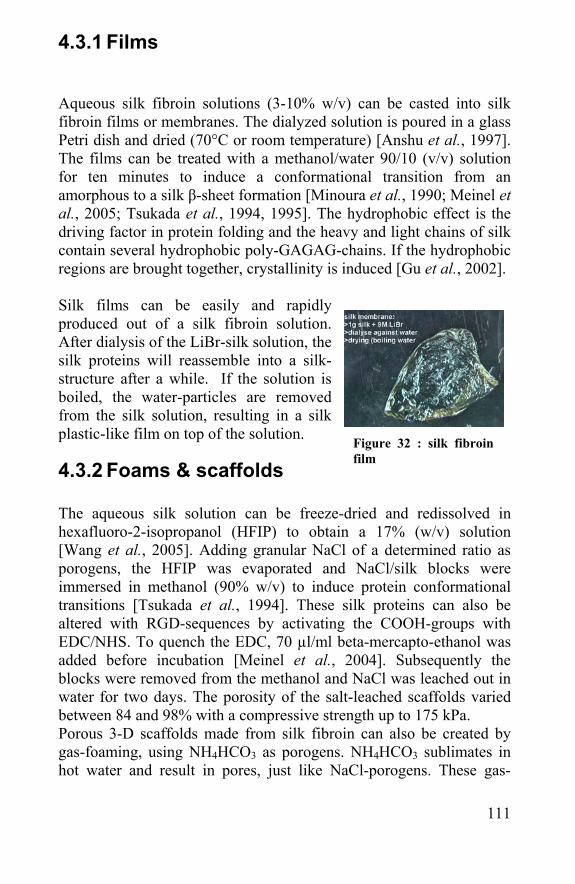
111
4.3.1 Films Aqueous silk fibroin solutions (3-10% w/v) can be casted into silk fibroin films or membranes. The dialyzed solution is poured in a glass Petri dish and dried (70°C or room temperature) [Anshu et al., 1997]. The films can be treated with a methanol/water 90/10 (v/v) solution for ten minutes to induce a conformational transition from an amorphous to a silk β-sheet formation [Minoura et al., 1990; Meinel et al., 2005; Tsukada et al., 1994, 1995]. The hydrophobic effect is the driving factor in protein folding and the heavy and light chains of silk contain several hydrophobic poly-GAGAG-chains. If the hydrophobic regions are brought together, crystallinity is induced [Gu et al., 2002]. Silk films can be easily and rapidly produced out of a silk fibroin solution. After dialysis of the LiBr-silk solution, the silk proteins will reassemble into a silk-structure after a while. If the solution is boiled, the water-particles are removed from the silk solution, resulting in a silk plastic-like film on top of the solution.
4.3.2 Foams & scaffolds The aqueous silk solution can be freeze-dried and redissolved in hexafluoro-2-isopropanol (HFIP) to obtain a 17% (w/v) solution [Wang et al., 2005]. Adding granular NaCl of a determined ratio as porogens, the HFIP was evaporated and NaCl/silk blocks were immersed in methanol (90% w/v) to induce protein conformational transitions [Tsukada et al., 1994]. These silk proteins can also be altered with RGD-sequences by activating the COOH-groups with EDC/NHS. To quench the EDC, 70 µl/ml beta-mercapto-ethanol was added before incubation [Meinel et al., 2004]. Subsequently the blocks were removed from the methanol and NaCl was leached out in water for two days. The porosity of the salt-leached scaffolds varied between 84 and 98% with a compressive strength up to 175 kPa. Porous 3-D scaffolds made from silk fibroin can also be created by gas-foaming, using NH4HCO3 as porogens. NH4HCO3 sublimates in hot water and result in pores, just like NaCl-porogens. These gas-
Figure 32 : silk fibroin film
112
foamed scaffolds had a porosity of 87-97% and compressive strength up to 280 kPa. Silk scaffolds were also created by methanol-treatment of aqueous silk solution and freeze-drying to obtain a scaffold foam, but the mechanical properties were not as good as the previous described scaffolds; 30 kPa. The porosity of freeze-dried scaffold is not as controllable as salt-leaching or gas-foaming, but its porosity was up to 99% [Nazarov et al., 2004]. For ligament regeneration, a silk matrix was created by twisting the silk fibers into a porous scaffold [Altman et al., 2002]. Endothelial, epithelial, fibroblast, glial, keratinocyte and osteoblast cells were already grown on silk fibroin nets [Unger et al., 2004]. These scaffold and other silk protein matrices were examined for stem cell and other cell supports [Wang et al., 2005]. Preparation and characterisation of silk scaffolds made with silkworm and spider egg sac silk will be discussed in chapter 8.
4.3.3 Enzyme immobilisation Various forms of silk fibroin can be used as enzyme immobilisators, like fibers, powders and membranes [Zhang et al., 1998]. These are already used successfully in biosensors for detecting glucose, hydrogen peroxide and uric acid in samples like blood and serum. In many fields, including food, fermentation, biological pharmacy, clinical diagnosis, environmental protection and power production, enzyme immobilisation on natural polymers is already known. Besides cellulose, dextrans, starch, tannin, chitin, chitosan, collagen, gelatine, albumin and lipids, silk fibroin can be used as well. The immobilisation by fibroin increases the enzymes thermal stability and activity [Grasset et al., 1979]. This immobilisation occurs by absorption and covalent bonding or specifically using the diazo-coupling method [Cordier et al., 1982], glutaraldehyde and azide coupling methods
4.3.4 Electrospun mats Electrospinning of polymers creates fibres with nanoscale diameters. This provides a high surface area. This is an advantage in many biomaterials like vascular grafts and wound dressings and also in cartilage tissue engineering. Cartilage is composed of collagen and
113
proteoglycan fibres that form hierarchical structure from nanoscale multifibrils to macroscale tissue architecture. To mimic this structure, nanoscaled fibres can be used to improve the similarity of tissue engineering scaffold to real ECM. Electrospun mats have already been created with silk fibres of 700 ±50 nm [Jin et al., 2004]. Their diameter was around 40 times smaller than native silk yarns. With an aqueous silk solution with a concentration of 8 wt %, electrospinning could be performed in combination with polyethylene-oxide (PEO). Silk/PEO blends (80/20 wt/wt) in water were electrospun through a steel capillary of 1.5 mm diameter in a high electrical potential. Subsequently the mats were immersed into a methanol solution to reform the silk β-sheet structure. The mats were evaluated and used for cell growth [Min et al., 2004]. The biggest problem with electrospun mats is their lack of mechanical strength, although the PEO could reinforce the electrospun silk fibres.
4.3.5 Hydrogels In aqueous fibroin solutions and even in fibroin-salt solutions there is an aggregation of fibroin chains within the solution. Finally, there is a self-assembly of silk fibroin into a hydrogel. This happens really slowly in distilled water and is accelerated a lot by adding methanol. The gelation is characterised by a structural transformation from a random coil structure to a β-sheet structure. It is a result of the inter- and intra-molecular interactions among the protein chains, including hydrophobic and hydrogen bonds, leading to physical crosslinks. This gel formation is affected by the temperature, Ca2+-concentration, pH and PEO-addition [Kim et al., 2004]. Gelation time decreases with an increase in fibroin concentration, a decrease in pH, an increase in temperature and the addition of Ca2+ or PEO. Mechanical properties and pore sizes of freeze-dried hydrogels were depending on previously described parameters. Fibroin can also be blended with other polymers to create new hydrogels with new properties [Li et al., 2002]. Fibroin hydrogel can also be formed by phase separation from freezed fibroin solution after a water-soluble organic solvent was added. After removal of the water-soluble organic solvent the sponge had a porous structure with a mean pore size of about 80 µm [Aoki et al., 2003]. These fibroin gels can be used for cell culture and biomedical
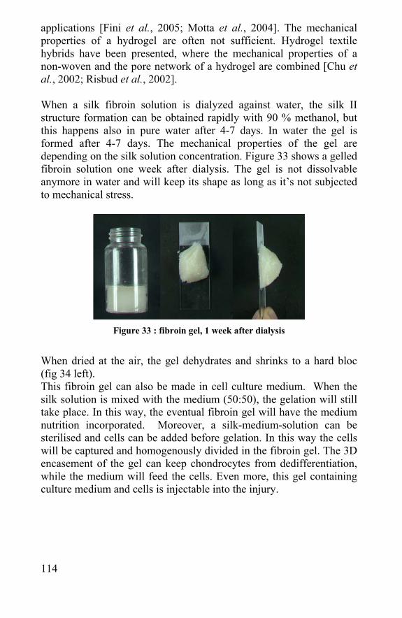
114
applications [Fini et al., 2005; Motta et al., 2004]. The mechanical properties of a hydrogel are often not sufficient. Hydrogel textile hybrids have been presented, where the mechanical properties of a non-woven and the pore network of a hydrogel are combined [Chu et al., 2002; Risbud et al., 2002]. When a silk fibroin solution is dialyzed against water, the silk II structure formation can be obtained rapidly with 90 % methanol, but this happens also in pure water after 4-7 days. In water the gel is formed after 4-7 days. The mechanical properties of the gel are depending on the silk solution concentration. Figure 33 shows a gelled fibroin solution one week after dialysis. The gel is not dissolvable anymore in water and will keep its shape as long as it’s not subjected to mechanical stress.
Figure 33 : fibroin gel, 1 week after dialysis
When dried at the air, the gel dehydrates and shrinks to a hard bloc (fig 34 left). This fibroin gel can also be made in cell culture medium. When the silk solution is mixed with the medium (50:50), the gelation will still take place. In this way, the eventual fibroin gel will have the medium nutrition incorporated. Moreover, a silk-medium-solution can be sterilised and cells can be added before gelation. In this way the cells will be captured and homogenously divided in the fibroin gel. The 3D encasement of the gel can keep chondrocytes from dedifferentiation, while the medium will feed the cells. Even more, this gel containing culture medium and cells is injectable into the injury.
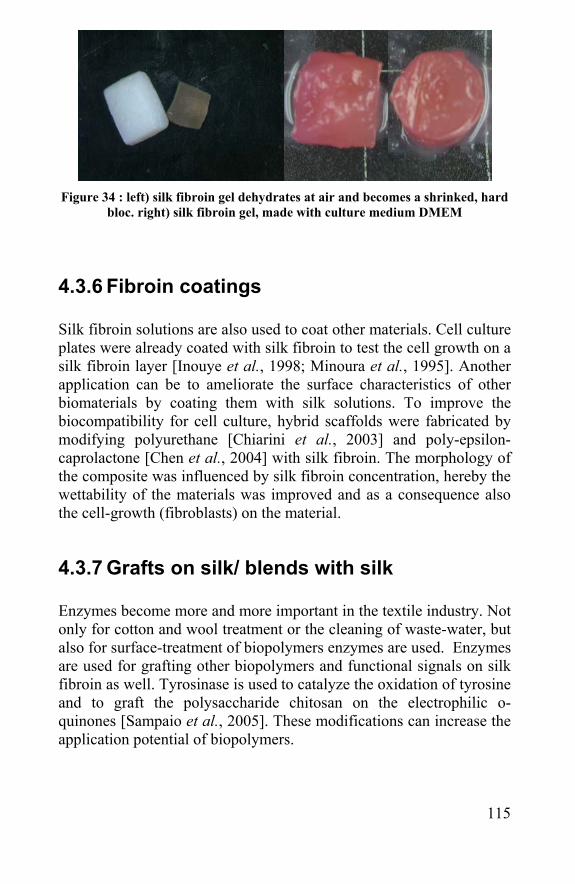
115
Figure 34 : left) silk fibroin gel dehydrates at air and becomes a shrinked, hard
bloc. right) silk fibroin gel, made with culture medium DMEM
4.3.6 Fibroin coatings Silk fibroin solutions are also used to coat other materials. Cell culture plates were already coated with silk fibroin to test the cell growth on a silk fibroin layer [Inouye et al., 1998; Minoura et al., 1995]. Another application can be to ameliorate the surface characteristics of other biomaterials by coating them with silk solutions. To improve the biocompatibility for cell culture, hybrid scaffolds were fabricated by modifying polyurethane [Chiarini et al., 2003] and poly-epsilon-caprolactone [Chen et al., 2004] with silk fibroin. The morphology of the composite was influenced by silk fibroin concentration, hereby the wettability of the materials was improved and as a consequence also the cell-growth (fibroblasts) on the material.
4.3.7 Grafts on silk/ blends with silk
Enzymes become more and more important in the textile industry. Not only for cotton and wool treatment or the cleaning of waste-water, but also for surface-treatment of biopolymers enzymes are used. Enzymes are used for grafting other biopolymers and functional signals on silk fibroin as well. Tyrosinase is used to catalyze the oxidation of tyrosine and to graft the polysaccharide chitosan on the electrophilic o-quinones [Sampaio et al., 2005]. These modifications can increase the application potential of biopolymers.
116
Silk foams and films are also made in combination with other polymers. Blends are already made with poly-vinylalcohol [Tsukada et al., 1994], lactose [Gotoh et al., 2004], Antheraea pernyi silk fibroin [Tsukada et al., 1994] and others. Bovine Mesenchymal Stem Cells (bMSC) were grown on the silk/PEO electrospun fiber mats. Residual PEO inhibited the cell adhesion, but as this PEO was extracted after two days, cell proliferation could start [Jin et al., 2004].
4.4 Degradation of silkworm silk fibroin Silk is, as an FDA (US Food and Drug Administration) approved biomaterial, defined by the USP (US Pharmacopoeia) as non-biodegradable, because it retains more than half of its tensile integrity 60 days post-implantation in vivo. As a protein, silk will be proteolytically degraded and resorbed in vivo over a longer time period, typically within a year. The in vivo degradation rates of silk are not only slow, but also variable [Altman et al., 2003], which explains the choice of synthetic material for surgical sutures to silk sutures. Bombyx mori yarns were tested in vitro for their resistance to different enzymes, e.g. protease XIV [Horan et al., 2005]. Their weight and thickness was measured after lyophilization and their mechanical properties were compared with untreated fibres. Fibroin was shown to proteolytically degrade with predictable rates of change in fibroin diameter, but their thickness and microstructure stayed unvaried for a long period. A silk yarn is expected to lose 100% of its tensile strength approximately five months post-implantation. This biodegradation is mediated by a foreign body response by the host [Rossich et al., 1987]. Inflammation seems to be essential for degradation and macrophage produced proteases such as chymotrypsin, shown to degrade silk in vitro may be the mechanism to which this occurs. These rates can be altered through scaffold design and surface modification. Porous silk fibroin sheets were tested to their resistance towards α-chymotrypsin, collagenase IA and protease XIV. The porous sheet degraded faster than the silk yarns. The freeze-dried porous sheets were torn away by protease XIV the fastest as the pore size increased. The silk II crystalline structures disappeared after protease treatment and silk I structures were formed. The degradation products were
117
mostly free amino acids [Li et al., 2003]. The maintenance of the mechanical properties of spider egg sac silk fibres after an enzymatic treatment with trypsin and proteinase K is discussed in chapter 7. As there is a significant need for long-term degradable biomaterials for slowly and predictably support in load-bearing tissues, the slow biodegradation of silk can fulfil this need.
4.5 Silkworm Silk biocompatibility The biocompatibility of spider silk will be discussed in chapter 6. As silk is already used for a long time as suture material, it is accepted as biocompatible. Allergic reactions to silk have been reported and those antigenic properties were associated with sericins, the residual glue-like proteins forming a coat around silk fibres [Soong et al., 1984, Altman et al., 2003]. However, it is possible to remove this layer by thoroughly washing with a boiling Marseille soap and sodium carbonate solution or by enzymes [Freddi et al., 2003]. In this way a sericin-free silk is obtained without antigenic effects, which is called virgin silk. Meinel et al. (2005) investigated the inflammatory responses of silk films in vivo and in vitro. Human Mesenchymal Stem Cells (hMSC) were seeded on silk films (with and without RGD-sequences attached to it) and the begin stadium of the inflammatory reaction were examined and compared with collagen. The reaction to silk (with and without RGD) was bio-equivalent as towards collagen (an FDA approved implant material) [Riesle et al., 1998]. The interleukin expression was even more pronounced in the collagen films. The in vivo tests consisted of intramuscular implantation of these silk films compared to collagen and PLA films. They suggest an equivalent or lesser reaction to virgin silk than to the other biomaterials [Santin et al., 1999]. The evaluation of several suture threads revealed that Vicryl® gave the lowest tissue reaction when implanted in rat tissue. Debris and bacterial accumulations on the surface of silk fibers are common, resulting in an inflammation of the wound [Yaltirik et al., 2003]. The blood-biocompatibility and the anti-thrombogenicity properties of silkworm silk could be improved by SO2-plasma treatment which reduces platelets deposition [Gu et al., 2002].
118
Besides some reports on silk allergens [Zaoming et al., 1996] and silk induced astma [Wen et al., 1990], it can be concluded that silkworm silk can be made biocompatible by removing the sericin layer.
4.6 References
- Altman GH, Diaz F, Jakuba C, Calabro T, Horan RL, Chen J, Lu H, Richmond J, Kaplan DL. Silk-based biomaterials. Biomaterials. 2003 Feb;24(3):401-16 - Altman GH, Horan RL, Lu HH, Moreau J, Martin I, Richmond JC, Kaplan DL. Silk matrix for tissue engineered anterior cruciate ligaments. Biomaterials. 2002 Oct;23(20):4131-41 - Anshu, B. M., Alan, T., Thomas, R., Hudson S., The dissolution and characterization of Bombyx mori silk fibroin in Calcium nitrate-methanol solution and the regeneration of films, Biopoly, 1997, 42: 61i 74 - Aoki H, Tomita N, Morita Y, Hattori K, Harada Y, Sonobe M, Wakitani S, Tamada Y. Culture of chondrocytes in fibroin-hydrogel sponge. Biomed Mater Eng. 2003;13(4):309-16. - Armato U, Dal Pra I, Motta A, Migliaresi C, Kecenski K. Method for the preparation of a non-woven silk fabric. Patent PCT/ITO1/00501 - 2003 - Chu C, Zhang X, Van Buskirk R. Biodegradable Hydrogel-Textile Hybrid for tissue engineering. NTC Project: M01-CR01. June 2002 - Chu CC. A comparison of the effect of pH on the biodegradation of two synthetic absorbable sutures. Ann Surg. 1982 Jan;195(1):55-9. - Chen G, Zhou P, Mei N, Chen X, Shao Z, Pan L, Wu C. Silk fibroin modified porous poly(epsilon-caprolactone) scaffold for human fibroblast culture in vitro. J Mater Sci Mater Med. 2004 Jun;15(6):671-7. - Chiarini A, Petrini P, Bozzini S, Pra ID, Armato U. Silk fibroin/poly(carbonate)-urethane as a substrate for cell growth: in vitro interactions with human cells. Biomaterials. 2003 Feb;24(5):789-99 - Cordier D, Counturier R, Grasset L, Ville A. Ribonuclease insolubilisation using diazotized sik. Enzyme Microb. Techn. 1982. 4, 249-55
119
- Dewair M, Baur X, Ziegler K. Use of immunoblot technique for detection of human IgE and IgG antibodies to individual silk proteins. J Allergy Clin Immunol. 1985 Oct;76(4):537-42. - Fini M, Motta A, Torricelli P, Giavaresi G, Nicoli Aldini N, Tschon M, Giardino R, Migliaresi C. The healing of confined critical size cancellous defects in the presence of silk fibroin hydrogel. Biomaterials. 2005 Jun;26(17):3527-36 - Freddi G, Mossotti R, Innocenti R. Degumming of silk fabric with several proteases. J Biotechnol. 2003 Dec 5;106(1):101-12 - Gotoh Y, Niimi S, Hayakawa T, Miyashita T. Preparation of lactose-silk fibroin conjugates and their application as a scaffold for hepatocyte attachment. Biomaterials. 2004 Mar;25(6):1131-40 - Grasset L, Cordier D, Ville A. Silk: A natural protein for enzyme immobilisation. Process Biochem. 1979. 14, 2-5 - Gu J, Yang X, Zhu H. Surface sulfonation of silk fibropin film by plasma treatment and in vitro antithrombogenicity study. Materials and engineering C 20. 2002: 199-202 - Horan RL, Antle K, Collette AL, Wang Y, Huang J, Moreau JE, Volloch V, Kaplan DL, Altman GH. In vitro degradation of silk fibroin. Biomaterials. 2005 Jun;26(17):3385-93. - Ilaria Dal Pra, Giuliano Freddi, Silvia Farč, Anna Chiarini, M. Cristina Tanzi, Martin Dauner, Ubaldo Armato: Mechanical Properties and in Vitro Biocompatibility of 3D Non-Wovens Based on Bombyx mori Silk Fibroin autex 2005 Slovenia 117-120 - Inouye K, Kurokawa M, Nishikawa S, Tsukada M. Use of Bombyx mori silk fibroin as a substratum for cultivation of animal cells. J Biochem Biophys Methods. 1998 Nov 18;37(3):159-64. - Jin HJ, Chen J, Karageorgiou V, Altman GH, Kaplan DL. Human bone marrow stromal cell responses on electrospun –silk fibroin mats. Biomaterials. 2004 Mar;25(6):1039-47. - Kim UJ, Park J, Li C, Jin HJ, Valluzzi R, Kaplan DL. Structure and properties of silk hydrogels. Biomacromolecules. 2004 May-Jun;5(3):786-92 - Lange F. Künstliche Bänder aus Seide. Münch Med Wochenscchr 1907. 17: 834-836 - Lee KH, Chu CC. The role of superoxide ions in the degradation of synthetic absorbable sutures. J Biomed Mater Res. 2000 Jan;49(1):25-35. - Li M, Ogiso M, Minoura N. Enzymatic degradation behaviour of porous silk fibroin sheets. Biomaterials. 2003 Jan;24(2):357-65
120
- Rossich Jr E. On delayed reactions to buried silk sutures. N.C. MED. J 1987;48: 669-70 - Li M, Lu S, Wu Z, Tan K, Minoura N, Kuga S. Structure and properties of silk fibroin-poly(vinyl alcohol) gel. Int J Biol Macromol. 2002 Apr 8;30(2):89-94 - Meinel L, Hofmann S, Karageorgiou V, Kirker-Head C, McCool J, Gronowicz G, Zichner L, Langer R, Vunjak-Novakovic G, Kaplan DL. The inflammatory responses to silk films in vitro and in vivo. Biomaterials. 2005 Jan;26(2):147-55. - Min BM, Lee G, Kim SH, Nam YS, Lee TS, Park WH. Electrospinning of silk fibroin nanofibres and its effect on the adhesion and spreading of normal human keratinocytes and fibroblasts in vitro. Biomaterials. 2004 Mar-Apr;25(7-8):1289-97 - Minoura N, Tsukada M, Nagura M. Physico-chemical properties of silk fibroin membrane as a biomaterial. Biomaterials. 1990 Aug;11(6):430-4 - Minoura N, Aiba S, Gotoh Y, Tsukada M, Imai Y. Attachment and growth of cultured fibroblast cells on silk protein matrices. J Biomed Mater Res. 1995 Oct;29(10):1215-21 - Nazarov R, Jin HJ, Kaplan DL.Porous 3-D scaffolds from regenerated silk fibroin. Biomacromolecules. 2004 May-Jun;5(3):718-26. - Motta A, Migliaresi C, Faccioni F, Torricelli P, Fini M, Giardino R. Fibroin hydrogels for biomedical applications: preparation, characterization and in vitro cell culture studies. J Biomater Sci Polym Ed. 2004;15(7):851-64 - Riesle J, Hollander AP, Langer R, Freed LE, Vunjak-Novakovic G. Collagen in tissue-engineered cartilage: types, structure, and crosslinks. J Cell Biochem. 1998 Dec 1;71(3):313-27 - Risbud MV, Karamuk E, Mayer J. Designing hydrogel coated textile scaffolds for tissue engineering: effect of casting conditions and degradation behaviour studied at microstructure level. J. of Materials science Letters 2002. 21: 1191-1194 - Sampaio S, Taddei P, Monti P, Buchert J, Freddi G. Enzymatic grafting of chitosan onto Bombyx mori silk fibroin: kinetic and IR vibrational studies. J Biotechnol. 2005 Mar 2;116(1):21-33. Epub 2004 Nov 30 - Santin M, Motta A, Freddi G, Cannas M. In vitro evaluation of the inflammatory potential of the silk fibroin. J Biomed Mater Res. 1999 Sep 5;46(3):382-9
121
- Soong HK, Kenyon KR. Adverse reactions to virgin silk sutures in cataract surgery. Ophthalmology 1984; 91: 479-83 - Tashiro Y, Otsuki E. Studies on the posterior silk gland of the silkworm Bombix mori. IV. Ultracentrifugal analyses of native silk proteins, especially fibroin extracted from the middle silk gland of the mature silkworm. J Cell Biol. 1970 Jul;46(1):1-16 - Tsukada M, Freddi G, Crighton JS. Structure and compatibility of Poly (vinyl alcohol) silk fibroin (PVA/SF Blend Films. Journal of polymer science. 1994, 32: 243-248 - Tsukada M, Freddi G, Kasai N. Physical properties and Phase separation structure of anthereae pernyi/ Bombyx mori silk fibroin blend films. Journal of Polymer science. 1994,32: 1175-1182 - Tsukada m, Freddi g, Monti P, Bertoluzza A, Kasai N. Structure and Molecular conformation opf Tussah silk fibroin films: Effect of methanol. Journal of polymer science. 1995, 33: 1995-2001 - Tsukada M, Freddi G, Minoura N, Allara G. Preparation and application of porous silk fibroin materials. Journal of Applied Polymer Science, 1994, 54: 507-514 - Unger RE, Wolf M, Peters K, Motta A, Migliaresi C, James Kirkpatrick C. Growth of human cells on a non-woven silk fibroin net: a potential for use in tissue engineering. Biomaterials. 2004 Mar;25(6):1069-75 - Wen CM, Ye ST, Zhou LX, Yu Y. Silk-induced asthma in children: a report of 64 cases. Ann Allergy. 1990 Nov;65(5):375-8. - Wang Y, Kim UJ, Blasioli DJ, Kim HJ, Kaplan DL. In vitro cartilage tissue engineering with 3D porous aqueous-derived silk scaffolds and mesenchymal stem cells. Biomaterials. 2005 Dec;26(34):7082-94. - Yaltirik M, Dedeoglu K, Bilgic B, Koray M, Ersev H, Issever H, Dulger O, Soley S. Comparison of four different suture materials in soft tissues of rats. Oral Dis. 2003 Nov;9(6):284-6 - Yamada H, Nakao H, Takasu Y, Tsubouchi K. Preparation of undegraded native molecular fibroin solution from silkworm cocoons. Materials science and engineering 2001. 14: 41-46 - Zaoming W, Codina R, Fernandez-Caldas E, Lockey RF. Partial characterization of the silk allergens in mulberry silk extract. J Investig Allergol Clin Immunol. 1996 Jul-Aug;6(4):237-41 - Zhang Y. Natural silk fibroin as a support for enzyme immobilization. Biotechnology Advances. 1998 16(5/6): 961-71

122
123
Chapter 5 Antibacterial prperties and sterilization
of spider silk

124
125
5.1 Introduction According to the application, equipment used for biomedical purposes needs to disinfected or sterilized before use. When the material is going to be implanted in sterile tissue or to be put in contact with blood or blood vessels, it is called critical and should be sterile. This means the material is free of all living organisms, including spores (SFS-EN 556 sterile: Probability to contain living microbes is under 10-6). This can be done by fire, usage of strong oxidants, dry or moist heat (incineration, boiling, intermittent boiling, autoclave, and pasteurization), radiation (Gamma, e-beam) or other chemicals (EtO). Usage of fire and strong oxidants is effective but not in use anymore as it destroys the biomaterial [Matthews et al., 1995]. In packaging of medical material the utilisation of ethylene-oxide is widely in use, due to the low cost. This is a toxic gas that destroys all living residues in the biomaterial. The advantages are that it gets into all the pores, is really effective and as a gas it has less effect on the material, although it can affect the polymer properties. The disadvantages are that it is dangerous for people having to work with it and it leaves toxic residues on the surface and in the pores of the biomaterial. The last disadvantage is the reason why this method is not used for implant material, as they are meant to support cell growth afterwards. For the same reason strong oxidants, like nitric acid, hydrochloric acid, chromic acid and hydrogen peroxide, are not used for implant devices. E-beam sterilization is a rather new method that has a high volume throughput, but is not that frequent in use due to a limited penetration of the radiation and it is a complex and high-priced method [Rodriguez et al., 2002]. UV/Gamma radiation and autoclave sterilization are 2 methods that are easier to handle and a lot in use in smaller labs and hospitals, especially for the re-usage of medical material. They are both effective and leave no toxic residues, but they can affect the mechanical properties of the device.
126
Radiation is already in use for more than 30 years as it can sterilize high volumes with a complete product penetration. This method has its dose limits; there is a minimal dose necessary to assure the microbial effect and a maximum dose to avoid material degradation as the radiation can change polymer structure and inter- and intra-molecular bonds [Jayabalan et al., 1995]. The effect of the radiation on the mechanical properties has to be tested for every new material. Some products are more brittle after irradiation. The same is valid for steam sterilization: the combination of heat and moisture can hydrolyse a polymer or a protein and this will affect the overall properties of the material. There are also newer methods like gas plasma sterilization, where hydrogen peroxide infiltrates in the material and forms radicals by plasma excitation by RF-electric field for 15 minutes. After excitation components are recombining and forming non-toxic residues like water [Woo et al., 2002]. In our case where we want to use silk and spider silk as implant material, disinfecting the material is not enough. The silk, used as threads or transformed into a scaffold or a film has to be free from bacteria before cell seeding or implantation. This means the silk should both be obtained and processed sterile or there should be a method to sterilize silk without destroying the fibre properties too much.
5.2 Antibacterial properties of spider silk
5.2.1 Phosphate in spider cocoon silk Introduction It is known that some peptide phosphonates have an antibacterial activity [Allen et al, 1978; Zboinska et al, 1993; Michal et al, 1996] and it is suggested that such molecules are present in spider cocoon fibres. The presence of phosphate molecules could easily be tested by the formation of a phosphate-molybdate-complex, which forms a UV-Vis-detectable molybdene-blue. These complex concentrations can then be compared with standard phosphate concentrations.
127
Material and methods A spider egg sac silk was brought in 20 ml distilled water and cut in smaller pieces. After 15 minutes, the mixture was filtered which gave the first sample. The filtered fibres were boiled in water for a better phosphate release and filtered again which gave the second sample. Both samples (20 ml) were mixed with 5 ml of Scheel I (1 g metol (mono-methyl-p-amino-fenolsulfaat), 5 g Na2SO3.7H20 and 137 g Na2S2O5 diluted with water till 1 litre) and 5 ml of Scheel II (50 g (NH4)6Mo7O24.4H2O solved in 200 ml water, 140 ml concentrated H2SO4 added and diluted with water till 1 litre). After 15 minutes, 10 ml of Scheel III (340 g NaAc.3H2O of 205 g NaAc diluted in 1l destillated water) is added to the solution. Further more, four standard solutions with KH2PO4 were made in the concentrations 0, 2.5, 5 and 10 ppm PO4
2-. Ortho-phosphate, together with ammonium molybdate, forms a molybdo-fosforic acid in a diluted and acid solution. Scheel I reagent transforms this molybdo-fosforic acid to molybdene blue, which can be measured colorimetrically. The transformed samples and standard solutions were -spectroscopically scanned from 400 to 850 nm to detect their maximum absorption. At this wavelength with maximum absorption, the four standard solutions and two samples were measured to calculate the concentration of phosphate in the two samples. Results The standard phosphate solutions and the test-samples had a maximum absorbance at the same wavelength, around 700 nm (fig 35). This alone already suggested that molybdene-blue was formed in both samples and that they contained phosphate. The four standard phosphate solutions and the test samples were measured at 700 nm. A calibration curve was set up with the measured absorbances and the known concentrations of the standard phosphate solutions.
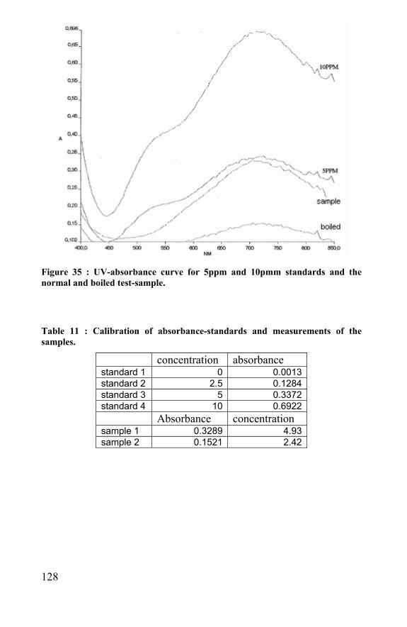
128
Figure 35 : UV-absorbance curve for 5ppm and 10pmm standards and the normal and boiled test-sample.
Table 11 : Calibration of absorbance-standards and measurements of the samples.
concentration absorbance standard 1 0 0.0013standard 2 2.5 0.1284standard 3 5 0.3372standard 4 10 0.6922 Absorbance concentration sample 1 0.3289 4.93sample 2 0.1521 2.42
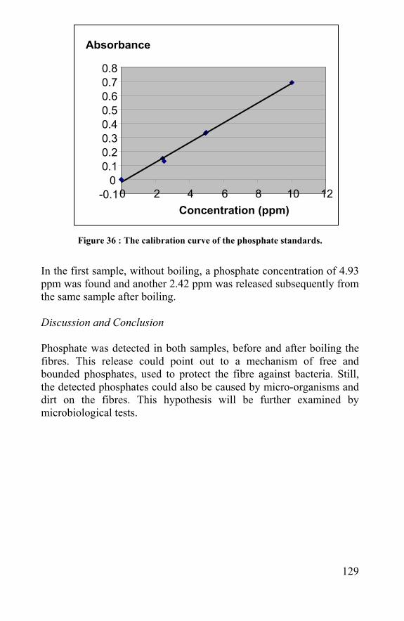
129
Figure 36 : The calibration curve of the phosphate standards.
In the first sample, without boiling, a phosphate concentration of 4.93 ppm was found and another 2.42 ppm was released subsequently from the same sample after boiling. Discussion and Conclusion Phosphate was detected in both samples, before and after boiling the fibres. This release could point out to a mechanism of free and bounded phosphates, used to protect the fibre against bacteria. Still, the detected phosphates could also be caused by micro-organisms and dirt on the fibres. This hypothesis will be further examined by microbiological tests.
-0.1 0
0.1 0.2 0.3 0.4 0.5 0.6 0.7 0.8
0 2 4 6 8 10 12 Concentration (ppm)
Absorbance
130
5.2.2 Anti-bacterial activity of spider silk Introduction As a spider egg sac and a silkworm cocoon have to protect the eggs in nature for several months, it would be not surprising that a kind of protection against bacteria is present in the fibres. If not, the fibres would be biodegraded very fast and would not be able to protect the eggs till hatching. Bombyx mori silkworm silk has a sericin coating that protects the silk fibres. Sericin is not biocompatible, so microbes will not attach and grow on the silkworm cocoon. However, such a sericin layer has not been detected on spider silk fibres, neither on egg sac and dragline fibres. Some hypotheses declare that sticky threads of spiders contain anti-microbial agents like phosphates, nitrates …., which prevent bacteria from growing on these fibres. These molecules could be present in the core of the fibres and could be released by moisture. Another hypothesis is that the possible anti-microbial activity is due to the growth of specific microbes on the fibres producing anti-microbial agents. The survival of the spider silk fibres in nature could also be explained by their indestructible nature. As spider silk is very hard to dissolve and is resistant to a lot of enzymes, it is possible that microbes are able to grow on the fibres but can hardly harm it and in this way the fibres stay un-degraded in nature for several months to protect the eggs. Hypothesis: The spider egg sac silk fibres: 1) Are free from bacteria. 2) Have an active or static anti-bacterial activity against bacteria. Materials and methods After oviposition of Araneus diadematus in the laboratory, the egg sac was directly examined. 1) The plastic box was brought in a sterile flow and the egg sac was taken out with a sterile tweezers, the eggs were removed and the egg sac was brought in a suspension medium (1ml, 0, 86% NaCl, 0, 5% Tween 80 in distillate water, autoclaved). The egg sac fibres were
131
shaken (1 min, vortex) and the egg sac fibres were separated from the suspension medium. This suspension was plated on an agar medium (R2A and Bennets) with a sterile Drigalsky spatula. The plates were incubated (20°C, aerobe) and growth of possible bacteria was followed and analysed with fatty acid analysis. 2) Fibres of a few egg sacs were brought in distilled water (1 ml) and sterilised (autoclave, 15 min, 121°C, 1 Bar). The egg sac fibres were separated from the suspension in a sterile manner. Beforehand, several test bacteria colonies were precultured on ISO sensitest agar (Oxoid) plates for 24 hours: Bacillus subtilis LMG 8198, Staphylococcus aureus LMG 8064, Klebsiella pneumoniae subsp. pneumoniae LMG 3128, en Pseudomonas aeruginosa LMG 10268. The agar-diffusion test (Kirby-Bauer Method) was preformed. For every type of bacteria, 10µl of the suspension was put in the middle of the plate, which was repeated several times at the same spot after drying up. On the other samples, the egg sac fibres were put in the middle of the colony. All plates were incubated at 37°C and their growth was followed. The fibres with possible attaching bacteria were brought on an empty culture medium to control if there were any bacteria attached on the fibres. Results 1) On each agar medium, bacteria colonies were found. Fatty acid analysis showed that the Staphylococcus type was the most abundant bacteria. 2) The distilled water suspension medium did not show any anti-bacterial activity whereas all tested bacteria flourished. The plates with egg sac fibres showed a bacterial growth till 1 mm of the silk threads. This inhibition area was so small that it could be induced by physical reasons rather than by any active growth inhibition. Therefore, silk threads were put on another sterile, medium plate. This plate was overgrown very fast with the same bacteria of the first plate, what mans that this bacteria was already present on the spider silk fibres. Although the fibres were overgrown with bacteria for up to two weeks they did not seem to biodegrade during the test.
132
Discussion and conclusion The egg sac fibres, as made in the laboratory, are not free from bacteria as a bacterial growth is started when these threads or their liquid extract is brought on a sterile agar medium. The fibres, or their liquid extract, do not have an antibacterial activity because the four tested types of bacteria grew around and on the fibres. The reason why those fibres stay intact for so long in nature and even under bacterial attack can be found in the resistance of those fibres against solvents and enzymes. The fact that they do not biodegrade is rather due to a resistance than to an antibacterial activity. As they are hard to dissolve, they are hard to biodegrade by bacteria. The resistance against fungi was not included in these tests. How spiders protect their eggs against bacteria and fungi can not be concluded from these tests. We can only conclude that these fibres have to be sterilized before used for any biomedical purposes.
5.3 Effect of radiation and autoclave sterilization methods
Introduction Although spider egg sac fibres can release small amounts of phosphate, bacteria are able to grow on the fibres. This means that the fibres need to be sterilized before use in biomedical applications. Because spider fibres are made up of proteins, the usage of radiation, moisture and/or heat can affect the fibre in microstructure and mechanical properties. This could be performed by steam-, UV-, EtO or e-beam- sterilisation. EtO is not used is it often leaves toxic residues and e-beam-sterilisation could not be performed as there was no access to such an equipment. In this chapter the effect of the two most used methods, autoclave sterilization and UV-radiation, is examined by means of the tensile properties of spider egg sac silk fibres. Material and methods In this experiment, fibres of A. diadematus egg sacs, grown in the lab, were used. Each egg sac was torn in two parts. Cutting them in two
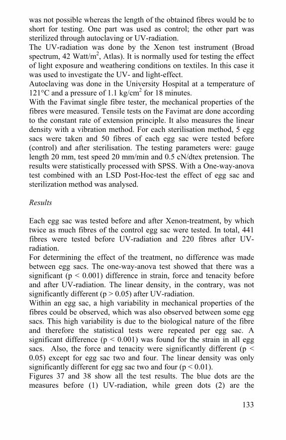
133
was not possible whereas the length of the obtained fibres would be to short for testing. One part was used as control; the other part was sterilized through autoclaving or UV-radiation. The UV-radiation was done by the Xenon test instrument (Broad spectrum, 42 Watt/m2, Atlas). It is normally used for testing the effect of light exposure and weathering conditions on textiles. In this case it was used to investigate the UV- and light-effect. Autoclaving was done in the University Hospital at a temperature of 121°C and a pressure of 1.1 kg/cm2 for 18 minutes. With the Favimat single fibre tester, the mechanical properties of the fibres were measured. Tensile tests on the Favimat are done according to the constant rate of extension principle. It also measures the linear density with a vibration method. For each sterilisation method, 5 egg sacs were taken and 50 fibres of each egg sac were tested before (control) and after sterilisation. The testing parameters were: gauge length 20 mm, test speed 20 mm/min and 0.5 cN/dtex pretension. The results were statistically processed with SPSS. With a One-way-anova test combined with an LSD Post-Hoc-test the effect of egg sac and sterilization method was analysed. Results Each egg sac was tested before and after Xenon-treatment, by which twice as much fibres of the control egg sac were tested. In total, 441 fibres were tested before UV-radiation and 220 fibres after UV-radiation. For determining the effect of the treatment, no difference was made between egg sacs. The one-way-anova test showed that there was a significant (p < 0.001) difference in strain, force and tenacity before and after UV-radiation. The linear density, in the contrary, was not significantly different (p > 0.05) after UV-radiation. Within an egg sac, a high variability in mechanical properties of the fibres could be observed, which was also observed between some egg sacs. This high variability is due to the biological nature of the fibre and therefore the statistical tests were repeated per egg sac. A significant difference (p < 0.001) was found for the strain in all egg sacs. Also, the force and tenacity were significantly different (p < 0.05) except for egg sac two and four. The linear density was only significantly different for egg sac two and four (p < 0.01). Figures 37 and 38 show all the test results. The blue dots are the measures before (1) UV-radiation, while green dots (2) are the
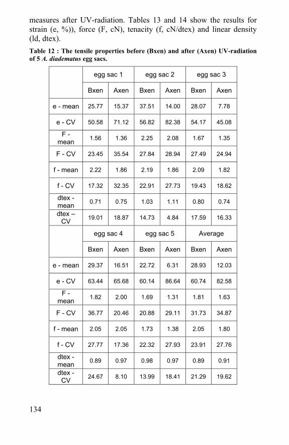
134
measures after UV-radiation. Tables 13 and 14 show the results for strain (e, %)), force (F, cN), tenacity (f, cN/dtex) and linear density (ld, dtex). Table 12 : The tensile properties before (Bxen) and after (Axen) UV-radiation of 5 A. diadematus egg sacs.
egg sac 1 egg sac 2 egg sac 3
Bxen Axen Bxen Axen Bxen Axen
e - mean 25.77 15.37 37.51 14.00 28.07 7.78
e - CV 50.58 71.12 56.82 82.38 54.17 45.08
F - mean 1.56 1.36 2.25 2.08 1.67 1.35
F - CV 23.45 35.54 27.84 28.94 27.49 24.94
f - mean 2.22 1.86 2.19 1.86 2.09 1.82
f - CV 17.32 32.35 22.91 27.73 19.43 18.62
dtex - mean 0.71 0.75 1.03 1.11 0.80 0.74
dtex – CV 19.01 18.87 14.73 4.84 17.59 16.33
egg sac 4 egg sac 5 Average
Bxen Axen Bxen Axen Bxen Axen
e - mean 29.37 16.51 22.72 6.31 28.93 12.03
e - CV 63.44 65.68 60.14 86.64 60.74 82.58
F - mean 1.82 2.00 1.69 1.31 1.81 1.63
F - CV 36.77 20.46 20.88 29.11 31.73 34.87
f - mean 2.05 2.05 1.73 1.38 2.05 1.80
f - CV 27.77 17.36 22.32 27.93 23.91 27.76
dtex - mean 0.89 0.97 0.98 0.97 0.89 0.91
dtex - CV 24.67 8.10 13.99 18.41 21.29 19.62
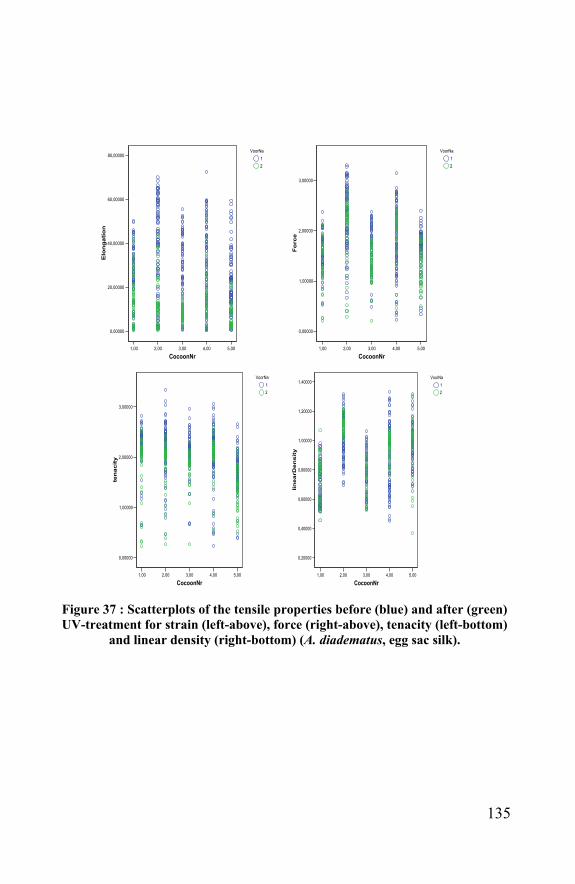
135
1,00 2,00 3,00 4,00 5,00
CocoonNr
0,00000
20,00000
40,00000
60,00000
80,00000
Elo
ng
atio
n
VoorNa12
1,00 2,00 3,00 4,00 5,00
CocoonNr
0,00000
1,00000
2,00000
3,00000
Fo
rce
VoorNa12
1,00 2,00 3,00 4,00 5,00
CocoonNr
0,00000
1,00000
2,00000
3,00000
ten
acit
y
VoorNa12
1,00 2,00 3,00 4,00 5,00
CocoonNr
0,20000
0,40000
0,60000
0,80000
1,00000
1,20000
1,40000
lin
earD
en
sit
y
VoorNa12
Figure 37 : Scatterplots of the tensile properties before (blue) and after (green) UV-treatment for strain (left-above), force (right-above), tenacity (left-bottom)
and linear density (right-bottom) (A. diadematus, egg sac silk).
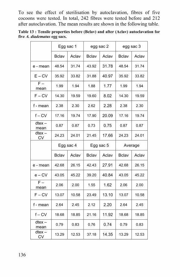
136
To see the effect of sterilisation by autoclavation, fibres of five cocoons were tested. In total, 242 fibres were tested before and 212 after autoclavation. The mean results are shown in the following table. Table 13 : Tensile properties before (Bclav) and after (Aclav) autoclavation for five A. diadematus egg sacs.
Egg sac 1 egg sac 2 egg sac 3
Bclav Aclav Bclav Aclav Bclav Aclav
e - mean 48.54 31.74 43.92 31.78 48.54 31.74
E – CV 35.92 33.82 31.88 40.97 35.92 33.82
F – mean 1.99 1.94 1.88 1.77 1.99 1.94
F – CV 14.30 19.59 19.60 8.02 14.30 19.59
f - mean 2.38 2.30 2.62 2.28 2.38 2.30
f – CV 17.16 19.74 17.90 20.09 17.16 19.74
dtex – mean 0.87 0.87 0.73 0.75 0.87 0.87
dtex – CV 24.23 24.01 21.45 17.66 24.23 24.01
Egg sac 4 Egg sac 5 Average
Bclav Aclav Bclav Aclav Bclav Aclav
e - mean 42.68 26.15 42.43 27.91 42.68 26.15
e – CV 43.05 45.22 39.20 40.84 43.05 45.22
F – mean 2.06 2.00 1.55 1.62 2.06 2.00
F – CV 13.07 10.58 23.49 13.10 13.07 10.58
f - mean 2.64 2.45 2.12 2.20 2.64 2.45
f – CV 18.68 18.85 21.16 11.92 18.68 18.85
dtex – mean 0.79 0.83 0.76 0.74 0.79 0.83
dtex – CV 13.29 12.53 37.18 14.35 13.29 12.53
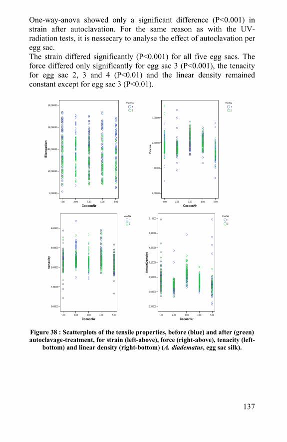
137
One-way-anova showed only a significant difference (P<0.001) in strain after autoclavation. For the same reason as with the UV-radiation tests, it is nessecary to analyse the effect of autoclavation per egg sac. The strain differed significantly (P<0.001) for all five egg sacs. The force differed only significantly for egg sac 3 (P<0.001), the tenacity for egg sac 2, 3 and 4 (P<0.01) and the linear density remained constant except for egg sac 3 (P<0.01).
1,00 2,00 3,00 4,00 5,00
CocoonNr
0,00000
20,00000
40,00000
60,00000
80,00000
Elo
ngat
ion
VoorNa12
1,00 2,00 3,00 4,00 5,00
CocoonNr
0,00000
1,00000
2,00000
3,00000
Fo
rce
VoorNa12
1,00 2,00 3,00 4,00 5,00
CocoonNr
0,00000
1,00000
2,00000
3,00000
4,00000
ten
acit
y
VoorNa12
1,00 2,00 3,00 4,00 5,00
CocoonNr
0,30000
0,60000
0,90000
1,20000
1,50000
1,80000
2,10000
linea
rDen
sity
VoorNa12
Figure 38 : Scatterplots of the tensile properties, before (blue) and after (green) autoclavage-treatment, for strain (left-above), force (right-above), tenacity (left-
bottom) and linear density (right-bottom) (A. diadematus, egg sac silk).

138
Discussion and conclusion These results clearly show that sterilisation by UV-radiation and autoclavation affect the mechanical properties of the fibres a lot. The strain, the most variable property, is most affected by both methods. Sterilisation by autoclavation only affects the force and tenacity of the fibres in some cases. Compared to UV-sterilisation, steam sterilisation does not significantly change the mechanical properties of the spider egg sac silk fibers. The strain of the fibres after autoclavation is diminished but still good compared to many other fibres used in biomedical applications. These tests showed that it is better to sterilise spider silk fibres in an autoclave than with UV-light.
5.4 Conclusion Spiders have to protect their eggs against bacteria and fungi, so the eggs are protected until they hatch. Although there is no bacterial growth seen on the eggs, the silk fibres do not have an antibacterial activity and for this reason they need to be sterilized if used for biomaterial purposes. UV-radiation and autoclavation are the easiest and most frequent used sterilisation methods in hospitals. These methods both affect the mechanical properties of the material, but steam sterilisation affects it in a less significant extend than UV-sterilisation. Other methods like ethylene-oxide and e-beam-sterilisation do not affect the mechanical properties and can also be used for these fibers. The influence of any treatment can not only change the mechanical properties, but also the biocompatibility and other biomedical properties. In this research, all silk fibres and scaffolds that will be used for cell support will be sterilized by autoclavation.
139
5.5 References - Jayabalan M. Sterilization and reprocessing of materials and medical devices--reusability. J Biomater Appl. 1995 Jul;10(1):97-112. Review - Matthews IP, Gibson C, Samuel AH. Sterilisation of implantable devices. Clin Mater. 1994;15(3):191-215. Review. - Rodriguez-Benot A, Santamaria R, Martin-Malo A, Aljama P. Sterilization procedures and biocompatibility. Contrib Nephrol. 2002;(137):138-45. Review. - Woo L, Purohit KS. Advancements and opportunities in sterilisation. Med Device Technol. 2002 Mar;13(2):12-7

140
141
Chapter 6 Biocompatibility and cytotoxity of spider silk

142
143
6.1 Biocompatibility “The ability of a material to perform, with an appropriate host, a response in a specific application“ The interaction between the living tissue and biomaterial is one of the biggest issues in tissue engineering. Living organisms react in less than a second if a foreign material is implanted. Within several minutes, a protein film is formed on the surface of the material, and this film will be used by cells to attach on [Castelli et al., 1978]. Immunological signals are sended to other cells resulting in a body reaction cascade within a few hours. The implantation of a biomaterial can alter cell and tissue behaviour in a few minutes to several years [Setzen et al., 1997]. Besides the effect of the biomaterial on the tissue, there is an effect of the tissue on the material as well. Physical-mechanical effects, like abrasive wear, corrosion and degeneration can help to biodegrade the implant. The immune cells attached to the material can attract specialized cells, like macrophages, that produce enzymes which can attack the biomaterial. In this chapter, the effect of the biomaterial on the living tissue is discussed. The term toxicity generally refers to the degree of being poisonous. Toxicity can be local and cause cell death or it can damage tissues in an area adjacent to the material. The reaction can also be systematic and alter tissues at a distance of the initial substance. Cytotoxicity is the toxicity towards cells. An implant of a foreign material can cause cell death in the surrounding tissue. Cell death can be either necrotic (caused by outside sources (chemical or physical agents)) or apoptotic (induced by the cell itself due to cell damage. Cells are programmed to destroy theirselves in certain conditions) [Varma et al., 1981]. The response of the body to the material is an immune reaction, when it is not dose related and it has low threshold levels. The internal defence mechanism recognizes the implant as a foreign body antigen and produces antibodies (immunoglobulin) mediated by B-lymphocytes, which differentiate to plasma cells. Specific antigens are recognized by T-lymphocytes, what explains the cell-mediated response which decreases the threshold of toxicity after several exposures to the material.
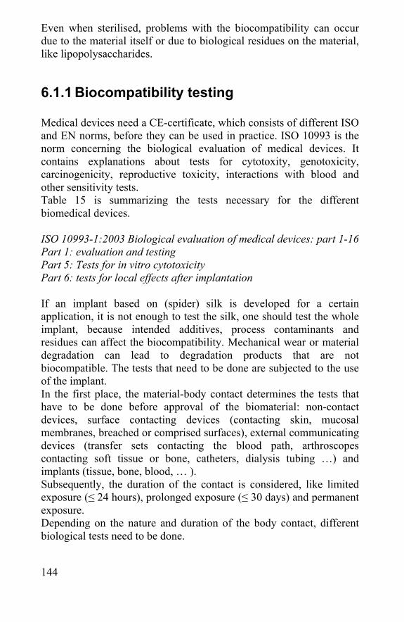
144
Even when sterilised, problems with the biocompatibility can occur due to the material itself or due to biological residues on the material, like lipopolysaccharides.
6.1.1 Biocompatibility testing Medical devices need a CE-certificate, which consists of different ISO and EN norms, before they can be used in practice. ISO 10993 is the norm concerning the biological evaluation of medical devices. It contains explanations about tests for cytotoxity, genotoxicity, carcinogenicity, reproductive toxicity, interactions with blood and other sensitivity tests. Table 15 is summarizing the tests necessary for the different biomedical devices. ISO 10993-1:2003 Biological evaluation of medical devices: part 1-16 Part 1: evaluation and testing Part 5: Tests for in vitro cytotoxicity Part 6: tests for local effects after implantation If an implant based on (spider) silk is developed for a certain application, it is not enough to test the silk, one should test the whole implant, because intended additives, process contaminants and residues can affect the biocompatibility. Mechanical wear or material degradation can lead to degradation products that are not biocompatible. The tests that need to be done are subjected to the use of the implant. In the first place, the material-body contact determines the tests that have to be done before approval of the biomaterial: non-contact devices, surface contacting devices (contacting skin, mucosal membranes, breached or comprised surfaces), external communicating devices (transfer sets contacting the blood path, arthroscopes contacting soft tissue or bone, catheters, dialysis tubing …) and implants (tissue, bone, blood, … ). Subsequently, the duration of the contact is considered, like limited exposure (≤ 24 hours), prolonged exposure (≤ 30 days) and permanent exposure. Depending on the nature and duration of the body contact, different biological tests need to be done.
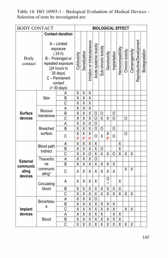
145
Table 14: ISO 10993-1 - Biological Evaluation of Medical Devices - Selection of tests be investigated are: BODY CONTACT BIOLOGICAL EFFECT
Body contact
Contact duration
A – Limited exposure
( 24 h) B – Prolonged or
repeated exposure (24 hours to
30 days) C – Permanent
contact (> 30 days)
Cytot
oxici
ty Se
nsitiz
ation
Irr
iratio
n or in
tracu
taneo
us
Acute
syste
mic t
oxici
ty Su
b-ch
ronic
toxic
ity
Geno
toxici
ty Im
planta
tion
Hemo
comp
atibil
ity
Chro
nic to
xicity
Ca
rcero
genic
ity
Repr
oduc
tive/D
evelo
pmen
t Bi
odeg
rada
tion
A X X X Skin B X X X
C X X X A X X X B X X X O O O Mucous
membrane C X X X O X X O O A X X X O B X X X O O O
Surface devices
Breached surface C X
P XP
XP O X X
P O O
A X X X X X B X X X X O X Blood path
indirect C X X O X X X O X X X A X X X O B X X X X X X X
Tissue/bone
communicating1 C X X X X X X X X X
A X X X X O² X
B X X X X X X X X
External communic
ating devices
Circulating blood
C X X X X X X X X X X A X X X O B X X X X X X X Bone/tissu
e C X X X X X X X X X A X X X X X X X B X X X X X X X X
Implant devices
Blood C X X X X X X X X X X
146
- Cytotoxity: by means of a cell culture, cell death and cell growth inhibition caused by the material can be determined (10933-5). - Sensitation: testing allergic or sensitization reactions of the medical device, material or their extracts (10933-10). - Irritation or intracutaneous reactivity: estimation of the irritation potential using appropriate sites like skin, eye or mucous membrane (10933-10). - Systemic (acute, subacute and subchronic) toxicity: test the potential harmful effects of single or multiple exposures to the material, during a period less than a day (acute) or less than 10% of the total life span of the test animal (subacute to subchronic) (10933-11). - Genotoxicity: these tests need the usage of cell cultures to determine gene mutations, changes in chromosome structure and number (10933-3). - Implantation: assessing the local pathological effects of living tissue at the gross and microscopic level. A sample is surgically implanted. The implantation time is according to the application time of the device (10933-6). - Haemocompatibility: testing the effect on blood or blood components. These tests can also be used to simulate the flow dynamics during clinical applications (10933-4). If silk or any other material is considered to use in tissue engineering all these tests should have a positive outcome. In tissue engineering, like cartilage regeneration, the material-body contact and duration time of an implant is permanent as the scaffold will not be removed anymore. As silk is biodegradable, biodegradation tests still need to be done to investigate the effect of the biodegradation products. In the following paragraphs, the needed tests to determine if spider silk is suitable as a material in tissue engineering are discussed.
147
6.1.2 Cytotoxity of spider silk Introduction If a material is toxic, it normally will be cytotoxic as well. The cytotoxicity can be tested in vitro before the toxicity tests on animals. This test can easily be done by growing cells nearby the material. Actually, this test has already been done in the previous chapter about anti-microbial activity. Because bacteria grew all over the spider silk threads, means that these fibres are not cytotoxic towards these bacteria. To test cytotoxicity for cartilage regeneration application, chondrocytes were isolated and grown on spider egg sac and dragline fibres. Material and methods
- Articular chondrocyte isolation Human articular cartilage, obtained from knee joints, was cut in small pieces and respectively incubated with hyaluronidase (250 % w/v, Sigma-Aldrich, Bornem, Belgium) and pronase (200 % w/v, 1h, Sigma-Aldrich, Bornem) both dissolved in DMEM (Sigma-Aldrich, Bornem) within 24 hours after the operation. After a day of incubation, collagenase (200 % w/v, 4 hours dissolved in culture medium (DMEM + 10% fytocalf-serum)) was used to isolate the cells from their extra-cellular matrix (ECM). The isolated cells were filtered, washed and counted with a haemocytometer. A trypan blue test was used to test cell viability. The cells were cultured for maximum one week in a culture flask before seeding to avoid dedifferentiation.
- Articular chondrocytes attachment on spider silk fibres
A 96-well was filled with sterile agarose and put in the fridge for hardening. Spider egg sac and dragline silk fibres were sterilized by autoclaving and put on the agarose. Articular chondrocytes (106) in culture medium (0,5ml) were brought on the fibres and the agarose.
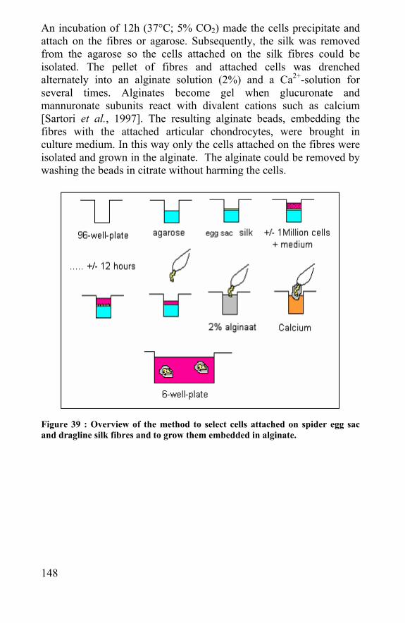
148
An incubation of 12h (37°C; 5% CO2) made the cells precipitate and attach on the fibres or agarose. Subsequently, the silk was removed from the agarose so the cells attached on the silk fibres could be isolated. The pellet of fibres and attached cells was drenched alternately into an alginate solution (2%) and a Ca2+-solution for several times. Alginates become gel when glucuronate and mannuronate subunits react with divalent cations such as calcium [Sartori et al., 1997]. The resulting alginate beads, embedding the fibres with the attached articular chondrocytes, were brought in culture medium. In this way only the cells attached on the fibres were isolated and grown in the alginate. The alginate could be removed by washing the beads in citrate without harming the cells.
Figure 39 : Overview of the method to select cells attached on spider egg sac and dragline silk fibres and to grow them embedded in alginate.
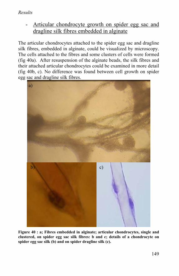
149
Results
- Articular chondrocyte growth on spider egg sac and dragline silk fibres embedded in alginate
The articular chondrocytes attached to the spider egg sac and dragline silk fibres, embedded in alginate, could be visualized by microscopy. The cells attached to the fibres and some clusters of cells were formed (fig 40a). After resuspension of the alginate beads, the silk fibres and their attached articular chondrocytes could be examined in more detail (fig 40b, c). No difference was found between cell growth on spider egg sac and dragline silk fibres.
Figure 40 : a; Fibres embedded in alginate; articular chondrocytes, single and clustered, on spider egg sac silk fibres: b and c; details of a chondrocyte on spider egg sac silk (b) and on spider dragline silk (c).
a)
b) c)
150
Conclusion The growth of articular chondrocytes on the fibers in the alginate means that they really attach on the silk fibres. This attachment indicates as well that the spider egg sac and dragline fibres are not cytotoxic. A cytotoxic material is generally not biocompatible, but not vice versa. Sometimes cells can grow on a material surface and still cause a severe immune reaction after implantation of the material. Therefore the immune reaction is further investigated in the next paragraph.
6.2 Implantation of spider silk: comparison with Vicryl®.
Introduction When a medical device is implanted, the implantation site can be evaluated after several time periods. Several biological evaluations can be made, like an interaction between the implanted material and the body tissue. The material can be biodegraded, deformed, accepted by the body and the body can get infected or diseased by the implant. In order to implant a material, the surgeon has to injure good tissue and remove the diseased tissue. The tissue response afterwards is crucial for healing the wound. In normal wound healing, adjacent cells respond to repair the wound. This inflammatory reaction starts with a constriction of the capillaries, which get covered by adjacent leukocytes, erythrocytes and platelets. Accumulation of these cells form an abscess, this can also happen with a non-bacterial inflammation which can lead to the classic inflammatory signs: redness, heat and local pain. This can extend and lead to tissue destruction. If it persists and no healing occurs after five days, a chronic inflammatory process starts in which macrophages are formed for removing the foreign material. Adjacent cells also will produce collagen to cover of foreign material. Normally, repair starts after the acute inflammation when neutrophils and monocytes disappear and collagen is formed and structured.
151
The general response to a foreign material (wood splinter, etc.) is to remove it from the body by encasing it or ingesting it by giant cells. A typical tissue response is that polymorphonuclear leukocytes appear near the implant followed by the macrophages, called foreign body giant cells, which will not form if the material is chemically and physically inert. If the implant irritates, the inflammation will delay the normal healing and can lead to necrosis of the tissue. Most pure metals, except the noble ones, provoke a severe tissue reaction. In contrast, ceramic oxides show minimal tissue reactions. The physical properties of a material are important as well; monofilament nylon is much more inert than the multifilament counterpart. During the slow biodegradation of silk (see chapter 7) it is possible that small peptides are released that provoke a heavier inflammatory reaction than the fibres itself. The only method for testing this is by implanting the fibres in an animal body and evaluates the reaction after several periods. Besides spider egg sac samples, Vicryl® fibres were tested. Vicryl® is the brand name of polyglactin 910-suture material. It is a synthetic absorbable surgical suture composed of a copolymer made from 90% glycolide and 10% L-Lactide. It is relatively non-antigenic, non-pyrogenic and elicits only a mild tissue reaction during absorption [ethicon-website]. There is also a braided suture made from Bombyx mori silk fibers, named Mersilk® (Ethicon). This material is sterilised by irradiation and is non-absorbable, it provides prolonged tensile strength retention in tissue for up to 3 months. This suture has also an accepted biocompatibility (510(k) NO: K012124 (FDA-website). As it is already stated that this suture does not biodegrade during the first 3 months, Vicryl® was used to compare the speed of biodegradation between an absorbable fiber and our spider cocoon silk fibers. A. diadematus spider egg sac fibres were used for the following reasons; high abundance of the species, much silk available in one egg sac compared to other species and the mechanical properties of the fibres [Van Nimmen et al., 2002, Gosline et al., 1999]. The fibres were enzymatically cleaned and tensile tests were done to measure the effect of cleaning on the mechanical properties. Subsequently, cleaned and uncleaned spider fibres as well as Vicryl® fibres, were implanted in white Wistar rats.
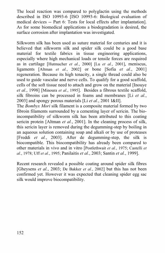
152
The local reaction was compared to polyglactin using the methods described in ISO 10993-6 [ISO 10993-6: Biological evaluation of medical devices -- Part 6: Tests for local effects after implantation]. As for some biomedical applications a biodegradation is desired, the surface corrosion after implantation was investigated. Silkworm silk has been used as suture material for centuries and it is believed that silkworm silk and spider silk could be a good base material for textile fabrics in tissue engineering applications, especially where high mechanical loads or tensile forces are required as in cartilage [Hutmacher et al., 2000] [Lu et al., 2001], meniscus, ligaments [Altman et al., 2002] or bone [Sofia et al., 2001] regeneration. Because its high tenacity, a single thread could also be used to guide vascular and nerve cells. To qualify for a good scaffold, cells of the soft tissue need to attach and grow on the material [Inouye et al., 1998] [Minoura et al., 1995]. Besides a fibrous textile scaffold, silk fibroins can be processed in foams and membranes [Li et al., 2003] and spongy porous materials [Li et al., 2001 I&II]. The Bombyx Mori silk filament is a composite material formed by two fibroin filaments surrounded by a cementing layer of sericin. The bio-incompatibility of silkworm silk has been attributed to this coating sericin protein [Altman et al., 2001]. In the cleaning process of silk, this sericin layer is removed during the degumming-step by boiling in an aqueous solution containing soap and alkali or by use of proteases [Freddi et al., 2003]. After de degumming-step, the silk is biocompatible. This biocompatibility has already been compared to other materials in vivo and in vitro [Postlethwait et al., 1975; Castelli et al., 1978; Uff et al., 1995; Panilaitis et al., 2003; Santin et al., 1999]. Recent research revealed a possible coating around spider silk fibres [Gheysens et al., 2003; De Bakker et al., 2002] but this has not been confirmed yet. However it was expected that cleaning spider egg sac silk would improve biocompatibility.
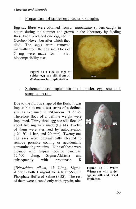
153
Material and methods
- Preparation of spider egg sac silk samples Egg sac fibres were obtained from A. diadematus spiders caught in nature during the summer and grown in the laboratory by feeding flies. Each produced one egg sac in October/ November after which they died. The eggs were removed manually from the egg sac. Flocs of 5 mg were made for in vivo biocompatibility tests.
- Subcutaneous implantation of spider egg sac silk samples in rats
Due to the fibrous shape of the flocs, it was impossible to make test strips of a defined size as explained in ISO-norm 10 993-6. Therefore flocs of a definite weight were implanted. Thirty-three egg sac silk flocs of about five mg were made (fig 41). Twelve of them were sterilized by autoclavation (121 °C, 1 bar, and 20 min). Twenty-one egg sacs were enzymatically cleaned to remove possible coating or accidentally contaminating proteins. Nine of these were cleaned with trypsin (bovine pancreas, 12.400 U/mg, Sigma-Aldrich) and subsequently with proteinase K
(Tritrachium album, 47 U/mg, Sigma-Aldrich) both 1 mg/ml for 4 h at 55°C in Phosphate Buffered Saline (PBS). The rest of them were cleaned only with trypsin, nine
Figure 41 : Floc (5 mg) of spider egg sac silk from A.diadematus for implantation.
Figure 42 : White Wistar-rat with spider egg sac silk and vicryl implanted.
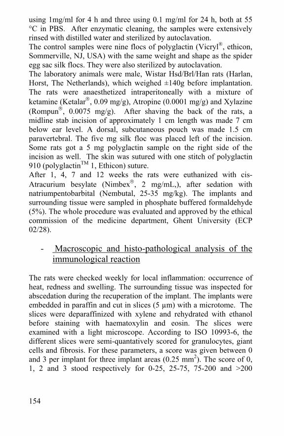
154
using 1mg/ml for 4 h and three using 0.1 mg/ml for 24 h, both at 55 °C in PBS. After enzymatic cleaning, the samples were extensively rinsed with distilled water and sterilized by autoclavation. The control samples were nine flocs of polyglactin (Vicryl®, ethicon, Sommerville, NJ, USA) with the same weight and shape as the spider egg sac silk flocs. They were also sterilized by autoclavation. The laboratory animals were male, Wistar Hsd/Brl/Han rats (Harlan, Horst, The Netherlands), which weighed ±140g before implantation. The rats were anaesthetized intraperitoneally with a mixture of ketamine (Ketalar, 0.09 mg/g), Atropine (0.0001 mg/g) and Xylazine (Rompun, 0.0075 mg/g). After shaving the back of the rats, a midline stab incision of approximately 1 cm length was made 7 cm below ear level. A dorsal, subcutaneous pouch was made 1.5 cm paravertebral. The five mg silk floc was placed left of the incision. Some rats got a 5 mg polyglactin sample on the right side of the incision as well. The skin was sutured with one stitch of polyglactin 910 (polyglactinTM 1, Ethicon) suture. After 1, 4, 7 and 12 weeks the rats were euthanized with cis-Atracurium besylate (Nimbex, 2 mg/mL,), after sedation with natriumpentobarbital (Nembutal, 25-35 mg/kg). The implants and surrounding tissue were sampled in phosphate buffered formaldehyde (5%). The whole procedure was evaluated and approved by the ethical commission of the medicine department, Ghent University (ECP 02/28).
- Macroscopic and histo-pathological analysis of the immunological reaction
The rats were checked weekly for local inflammation: occurrence of heat, redness and swelling. The surrounding tissue was inspected for abscedation during the recuperation of the implant. The implants were embedded in paraffin and cut in slices (5 µm) with a microtome. The slices were deparaffinized with xylene and rehydrated with ethanol before staining with haematoxylin and eosin. The slices were examined with a light microscope. According to ISO 10993-6, the different slices were semi-quantatively scored for granulocytes, giant cells and fibrosis. For these parameters, a score was given between 0 and 3 per implant for three implant areas (0.25 mm2). The score of 0, 1, 2 and 3 stood respectively for 0-25, 25-75, 75-200 and >200
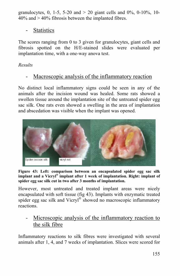
155
granulocytes, 0, 1-5, 5-20 and > 20 giant cells and 0%, 0-10%, 10-40% and > 40% fibrosis between the implanted fibres.
- Statistics The scores ranging from 0 to 3 given for granulocytes, giant cells and fibrosis spotted on the H/E-stained slides were evaluated per implantation time, with a one-way anova test. Results
- Macroscopic analysis of the inflammatory reaction No distinct local inflammatory signs could be seen in any of the animals after the incision wound was healed. Some rats showed a swollen tissue around the implantation site of the untreated spider egg sac silk. One rats even showed a swelling in the area of implantation and abscedation was visible when the implant was opened.
Figure 43: Left: comparison between an encapsulated spider egg sac silk implant and a Vicryl® implant after 1 week of implantation. Right: implant of spider egg sac silk cut in two after 3 months of implantation.
However, most untreated and treated implant areas were nicely encapsulated with soft tissue (fig 43). Implants with enzymatic treated spider egg sac silk and Vicryl® showed no macroscopic inflammatory reactions.
- Microscopic analysis of the inflammatory reaction to the silk fibre
Inflammatory reactions to silk fibres were investigated with several animals after 1, 4, and 7 weeks of implantation. Slices were scored for
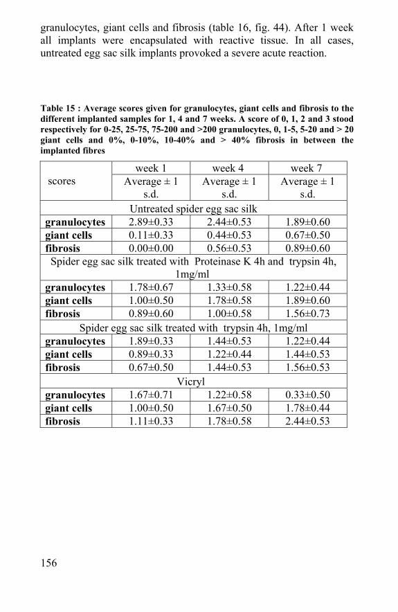
156
granulocytes, giant cells and fibrosis (table 16, fig. 44). After 1 week all implants were encapsulated with reactive tissue. In all cases, untreated egg sac silk implants provoked a severe acute reaction. Table 15 : Average scores given for granulocytes, giant cells and fibrosis to the different implanted samples for 1, 4 and 7 weeks. A score of 0, 1, 2 and 3 stood respectively for 0-25, 25-75, 75-200 and >200 granulocytes, 0, 1-5, 5-20 and > 20 giant cells and 0%, 0-10%, 10-40% and > 40% fibrosis in between the implanted fibres
week 1 week 4 week 7 scores
Average ± 1 s.d.
Average ± 1 s.d.
Average ± 1 s.d.
Untreated spider egg sac silk granulocytes 2.89±0.33 2.44±0.53 1.89±0.60 giant cells 0.11±0.33 0.44±0.53 0.67±0.50 fibrosis 0.00±0.00 0.56±0.53 0.89±0.60 Spider egg sac silk treated with Proteinase K 4h and trypsin 4h,
1mg/ml granulocytes 1.78±0.67 1.33±0.58 1.22±0.44 giant cells 1.00±0.50 1.78±0.58 1.89±0.60 fibrosis 0.89±0.60 1.00±0.58 1.56±0.73
Spider egg sac silk treated with trypsin 4h, 1mg/ml granulocytes 1.89±0.33 1.44±0.53 1.22±0.44 giant cells 0.89±0.33 1.22±0.44 1.44±0.53 fibrosis 0.67±0.50 1.44±0.53 1.56±0.53
Vicryl granulocytes 1.67±0.71 1.22±0.58 0.33±0.50 giant cells 1.00±0.50 1.67±0.50 1.78±0.44 fibrosis 1.11±0.33 1.78±0.58 2.44±0.53
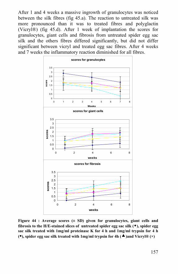
157
After 1 and 4 weeks a massive ingrowth of granulocytes was noticed between the silk fibres (fig 45.a). The reaction to untreated silk was more pronounced than it was to treated fibres and polyglactin (Vicryl®) (fig 45.d). After 1 week of implantation the scores for granulocytes, giant cells and fibrosis from untreated spider egg sac silk and the others fibres differed significantly, but did not differ significant between vicryl and treated egg sac fibres. After 4 weeks and 7 weeks the inflammatory reaction diminished for all fibres.
Figure 44 : Average scores (± SD) given for granulocytes, giant cells and fibrosis to the H/E-stained slices of untreated spider egg sac silk ( ), spider egg sac silk treated with 1mg/ml proteinase K for 4 h and 1mg/ml trypsin for 4 h ( ), spider egg sac silk treated with 1mg/ml trypsin for 4h ( )and Vicryl® (×)
scores for granulocytes
0
0.5
1
1.5
2
2.5
3
3.5
0 1 2 3 4 5 6 7 8
Weeks
scor
e
scores for giant cells
00.5
11.5
22.5
33.5
0 2 4 6 8
weeks
scor
es
scores for fibrosis
00.5
11.5
22.5
33.5
0 2 4 6 8
weeks
scor
es
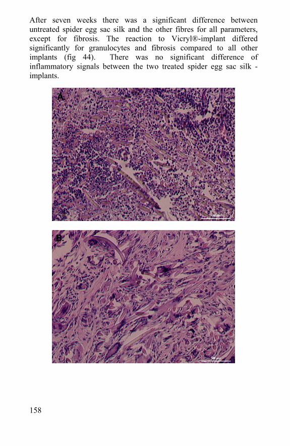
158
After seven weeks there was a significant difference between untreated spider egg sac silk and the other fibres for all parameters, except for fibrosis. The reaction to Vicryl®-implant differed significantly for granulocytes and fibrosis compared to all other implants (fig 44). There was no significant difference of inflammatory signals between the two treated spider egg sac silk -implants.
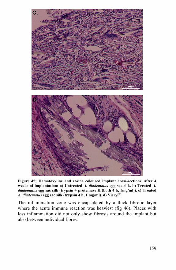
159
Figure 45: Hematoxyline and eosine coloured implant cross-sections, after 4 weeks of implantation: a) Untreated A. diadematus egg sac silk. b) Treated A. diadematus egg sac silk (trypsin + proteinase K (both 4 h, 1mg/ml)). c) Treated A. diadematus egg sac silk (trypsin 4 h, 1 mg/ml). d) Vicryl®.
The inflammation zone was encapsulated by a thick fibrotic layer where the acute immune reaction was heaviest (fig 46). Places with less inflammation did not only show fibrosis around the implant but also between individual fibres.
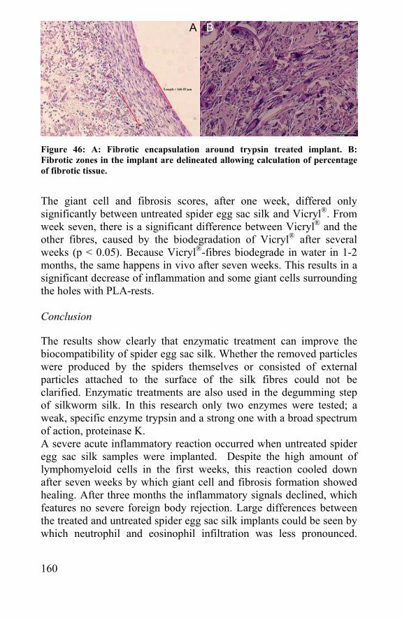
160
Figure 46: A: Fibrotic encapsulation around trypsin treated implant. B: Fibrotic zones in the implant are delineated allowing calculation of percentage of fibrotic tissue.
The giant cell and fibrosis scores, after one week, differed only significantly between untreated spider egg sac silk and Vicryl®. From week seven, there is a significant difference between Vicryl® and the other fibres, caused by the biodegradation of Vicryl® after several weeks (p < 0.05). Because Vicryl®-fibres biodegrade in water in 1-2 months, the same happens in vivo after seven weeks. This results in a significant decrease of inflammation and some giant cells surrounding the holes with PLA-rests. Conclusion The results show clearly that enzymatic treatment can improve the biocompatibility of spider egg sac silk. Whether the removed particles were produced by the spiders themselves or consisted of external particles attached to the surface of the silk fibres could not be clarified. Enzymatic treatments are also used in the degumming step of silkworm silk. In this research only two enzymes were tested; a weak, specific enzyme trypsin and a strong one with a broad spectrum of action, proteinase K. A severe acute inflammatory reaction occurred when untreated spider egg sac silk samples were implanted. Despite the high amount of lymphomyeloid cells in the first weeks, this reaction cooled down after seven weeks by which giant cell and fibrosis formation showed healing. After three months the inflammatory signals declined, which features no severe foreign body rejection. Large differences between the treated and untreated spider egg sac silk implants could be seen by which neutrophil and eosinophil infiltration was less pronounced.
A B
161
Giant cells and fibrosis were observed from the start, which nested massively in between the individual fibres. This demonstrates the higher tolerance of the inflammatory system to the enzymatically cleaned implanted fibres. The proteinase K/trypsin- and trypsin treatment resulted in fibres who gave a comparable body reaction as the widely accepted polyglactin biomaterial. Like silkworm silk, spider egg sac silk seems to biodegrade not or very slowly in vivo [Aria et al., 2003], what will be further discussed in chapter 7. These in vivo tests did not quantify the rate of biodegradation whereas the remaining silk flocs could not be recovered for weighing without losing some implanted material or leaving some rat tissue behind. The in vitro biodegradation tests in chapter 7 show a huge difference between Vicryl® and the silk fibres. The tensile properties decreased significantly after 2 weeks and after 2 months the fibre was fully degraded. The biodegradation presumable goes even faster in vivo, due to enzymatic and mechanical effects. This explains the significant difference of granulocytes and fibrosis after 7 weeks of implantation on Vicryl®. To acquire a sufficiently biocompatible fibre, it is necessary to treat the egg sac silk from A. diadematus in an enzyme bath. Reckoning the influence of the enzymes on the mechanical properties of the fibres (see chapter 7), it can be concluded that a trypsin treatment is permitted and is sufficient to make the silk fibres as biocompatible as polyglactin. This simple treatment makes the strong and flexible protein fibre ready for use in many biomedical applications, where the slow biodegradability can be useful. Looking back on these in vivo experiments, knowing that spider cocoon silk fibers biodegraded so slowly and that their rate of biodegradation is not quantitatively measurable in vivo, it would have been better to add some mersilk® fibers as a comparison too. The trypsin cleaning did remove probable molecules attached on the fiber-surface; it would have been interesting to see whether a cleaning with a Marseillesoap solution would have a similar effect.

162
6.3 References - Altman GH, Diaz F, Jakuba C, Calabro T, Horan RL, Chen J, Lu H, Richmond J, Kaplan DL. Silk-based biomaterials. Biomaterials. 2003 Feb;24(3):401-16 - Altman GH, Horan RL, Lu HH, Moreau J, Martin I, Richmond JC, Kaplan DL. Silk matrix for tissue engineered anterior cruciate ligaments. Biomaterials. 2002 Oct;23(20):4131-41 - Arai T, Freddi G, Inocenti R, Tsukada M. Biodegradation of Bombyx mori silk fibroin fibres and films. 18th European conference on biomaterials, Ocober 1-4, 2003, Stuttgart, Germany. TO55 - Castelli WA, Nasjleti CF, Diaz-Perez R, Caffesse RG. Cheek mucosa response to silk, cotton, and nylon suture materials. Oral Surg Oral Med Oral Pathol. 1978 Feb;45(2):186-9 - De Bakker D., Gellynck K., Van Nimmen E., Mertens J., Kiekens P.; Structural analysis and differences in egg sac structure revealed by means of Scanning Electron Microscopy between several spider species; 20th European Colloquium of Arachnology, Szombathely, Hungary, 22-26 July 2002 -Ethicon: http://www.ethicon.com/content/backgrounders/www .ethicon.com/www.ethicon.com/Vicryl® _epi.pdf - Gheysens T., Beladjal L., Gellynck K., Van Nimmen E., Van Langenhove L., Mertens J. 2005. Egg sac structure of Zygiella x-notata (Arachnida, Araneidae). The Journal of Arachnology 33: 549-557 - Gosline JM, Guerette PA, Ortlepp CS, Savage KN. The mechanical design of spider silks: from fibroin sequence to mechanical function. J Exp Biol. 1999 Dec;202(Pt 23):3295-303. Review - Freddi G, Mossotti R, Innocenti R. Degumming of silk fabric with several proteases. J Biotechnol. 2003 Dec 5;106(1):101-12. - Hutmacher DW. Scaffolds in tissue engineering bone and cartilage. Biomaterials. 2000 Dec;21(24):2529-43 - Inouye K, Kurokawa M, Nishikawa S, Tsukada M. Use of Bombyx mori silk fibroin as a substratum for cultivation of animal cells. J Biochem Biophys Methods. 1998 Nov 18;37(3):159-64. - Li MZ, Lu SZ, Wu ZY. Study on Porous Silk Fibroin Materials 1: Fine Structure of Freeze-dried Silk Fibroin. Journal of Applied Polymer Science, 2001, 79: 2185-2191.
163
- Li MZ, Wu Z, Zhang C, Lu S, Yan H, Huang D, Ye H. Study on porous silk fibroin materials II. Preparation and characteristics of spongy porous silk fibroin materials. Journal of Applied Polymer Science, 2001, 79: 2192-2199 - Li M, Ogiso M, Minoura N. Enzymatic degradation behaviour of porous silk fibroin sheets. Biomaterials. 2003 Jan;24(2):357-65 - Lu L, Zhu X, Valenzuela RG, Currier BL, Yaszemski MJ. Biodegradable polymer scaffolds for cartilage tissue engineering. Clin Orthop. 2001 Oct;(391 Suppl):S251-70. Review - Minoura N, Aiba S, Gotoh Y, Tsukada M, Imai Y. Attachment and growth of cultured fibroblast cells on silk protein matrices. J Biomed Mater Res. 1995 Oct;29(10):1215-21 - Panilaitis B, Altman GH, Chen J, Jin HJ, Karageorgiou V, Kaplan DL. Macrophage responses to silk. Biomaterials. 2003 Aug;24(18):3079-85 - Postlethwait RW, Willigan DA, Ulin AW. Human tissue reaction to sutures. Ann Surg. 1975 Feb;181(2):144-50. - Santin M, Motta A, Freddi G, Cannas M. In vitro evaluation of the inflammatory potential of the silk fibroin. J Biomed Mater Res. 1999 Sep 5;46(3):382-9 - Setzen G, Williams EF 3rd. Tissue response to suture materials implanted subcutaneously in a rabbit model. Plast Reconstr Surg. 1997 Dec;100(7):1788-95 - Sofia S, McCarthy MB, Gronowicz G, Kaplan DL. Functionalized silk-based biomaterials for bone formation. J Biomed Mater Res. 2001 Jan;54(1):139-48 - Uff CR, Scott AD, Pockley AG, Phillips RK. Influence of soluble suture factors on in vitro macrophage function. Biomaterials. 1995 Mar;16(5):355-60 - Van Nimmen E., Gheysens T., Van Langenhove L., Mertens J. 2005. Modeling of the stress-strain behavior of egg sack silk of the spider Araneus diadematus. The Journal of Arachnology 33: 629-639 - Varma S, Johnson LW, Ferguson HL, Lumb WV Tissue reaction to suture materials in infected surgical wounds--a histopathologic evaluation. Am J Vet Res. 1981 Apr;42(4):563-70

164

165
Chapter 7 Biodegradation of silk and spider silk

166
167
7.1 Introduction As in this research the main focus is on articular cartilage tissue engineering, most results and biomaterial requirements can be generalised to other biomedical areas. Complete biodegradation and an appropriate rate of biodegradation are requirements differing from one biomedical application to another. For materials, biodegradation is often a negative characteristic. Prosthesis and other devices may not degrade; they have to maintain their strength indefinitely. Sutures and tissue engineering scaffolds may degrade, but at an appropriate speed. It is important to know the rate of biodegradation of a material before use in biomaterial applications. In this chapter the rate of biodegradation of spider egg sac silk is tested in vivo and in vitro. A comparison is made between the rate of biodegradation of spider egg sac silk, Bombyx mori cocoon silk and Vicryl® fibres.
7.2 In vivo biodegradation of spider egg sac silk
Introduction The most accurate way to measure the rate of biodegradation of a material is to implant a sample in several laboratory animals and compare their weight and mechanical properties over different implantation times. In vivo tests are more reliable than in vitro, because biomaterials implanted in human tissue are also affected by the tissue fluid, the immune response, enzymes, mechanical load and friction. When flocs of egg sac silk were implanted to test biocompatibility (see chapter 6), the biodegradation was measured simultaneously. Materials and methods Spider egg sac silk samples were weighed (±5mg), sterilised by autoclavation and implanted in white Wistar rats (see chapter 6). In some rats, Vicryl® samples of an equal weight were implanted next to the egg sac silk samples.
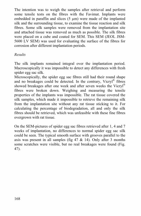
168
The intention was to weigh the samples after retrieval and perform some tensile tests on the fibres with the Favimat. Implants were embedded in paraffin and slices (5 µm) were made of the implanted silk and the surrounding tissue, to examine the tissue reaction and silk fibres. Some silk samples were removed from the implantation site and attached tissue was removed as much as possible. The silk fibres were placed on a cube and coated for SEM. This SEM (JEOL JSM-5600 LV SEM) was used for evaluating the surface of the fibres for corrosion after different implantation periods. Results The silk implants remained integral over the implantation period. Macroscopically it was impossible to detect any differences with fresh spider egg sac silk. Microscopically, the spider egg sac fibres still had their round shape and no breakages could be detected. In the contrary, Vicryl® fibres showed breakages after one week and after seven weeks the Vicryl® fibres were broken down. Weighing and measuring the tensile properties of the implants was impossible. The rat tissue covered the silk samples, which made it impossible to retrieve the remaining silk from the implantation site without any rat tissue sticking to it. For calculating the percentage of biodegradation, all and only the silk fibres should be retrieved, which was unfeasible with these fine fibres overgrown with rat tissue. On the SEM-pictures of spider egg sac fibres retrieved after 1, 4 and 7 weeks of implantation, no differences to normal spider egg sac silk could be seen. The typical smooth surface with grooves parallel to the axis was present in all samples (fig 47 & 14). Only after 3 months some scratches were visible, but no real breakages were found (Fig. 47).
169
Figure 47: After three months of implantation only some small scratches were visible on the spider egg sac fibres.
7.3 In vitro biodegradation of spider egg sac silk, silkworm silk and Vicryl®
Introduction Because the in vivo biodegradation tests gave no numerical results, the rate of biodegradation was measured in vitro. A big disadvantage of in vitro testing is that not all body tissue effects on the implant are present in vitro, like no mechanical pressure, immune response, enzymes, etc. Although enzymes can be added to the solution, it always stays a method of approach. In most cases, the rate of in vitro biodegradation is slower than in vivo biodegradation, because of the lack of these tissue effects [Panilaitis et al., 2003, Uff et al., 1995]. In this chapter no enzymes were used [Li et al., 2004] and degradation of the silk fibres (spider and silkworm) was measured by comparing them with alginate and Vicryl® fibres. Materials and methods Fibres of B. mori (50-100), A. diadematus egg sac, Vicryl® (ethicon) and alginate (Acordis, Humberside, UK) were unsterilized, submerged in physiological water (PBS) at body temperature (37°C) in the dark, to mimic in vivo conditions. Tensile tests were done to investigate the effect of PBS after respectively 1, 2, 4, 8 and 12 weeks. Each time a
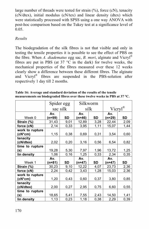
170
large number of threads were tested for strain (%), force (cN), tenacity (cN/dtex), initial modulus (cN/tex) and linear density (dtex) which were statistically processed with SPSS using a one way ANOVA with post-hoc comparison based on the Tukey test at a significance level of 0.05. Results The biodegradation of the silk fibres is not that visible and only in testing the tensile properties it is possible to see the effect of PBS on the fibre. When A. diadematus egg sac, B. mori, alginate and Vicryl® fibres are put in PBS (at 37 °C in the dark) for twelve weeks, the mechanical properties of the fibres measured over these 12 weeks clearly show a difference between these different fibres. The alginate and Vicryl® fibres are suspended in the PBS-solution after respectively 1 day till 2 months. Table 16: Average and standard deviation of the results of the tensile measurements on biodegraded fibres over these twelve weeks in PBS at 37 °C.
Spider egg
sac silk Silkworm
silk Vicryl®
Week 0 Av.
(n=99) SD Av.
(n=46) SD Av.
(n=29) SD Strain (%) 31,43 9,01 12,89 3,28 22,44 2,09 force (cN) 2,14 0,33 3,95 1,11 15,07 1,44 work to rupture (cN*cm) 1,15 0,38 0,69 0,31 3,54 0,60 tenacity (cN/dtex) 2,02 0,20 3,16 0,56 6,54 0,82 time to rupture (s) 19,28 5,30 7,97 1,96 13,72 1,25 lin density 1,06 0,16 1,25 0,33 2,34 0,35
Week 1 Av.
(n=81) SD Av.
(n=47) SD Av.
(n=47) SD Strain (%) 30,23 9,10 12,22 4,07 23,73 2,36 force (cN) 2,24 0,42 3,43 1,28 15,03 2,36 work to rupture (cN*cm) 1,20 0,43 0,60 0,37 3,80 0,85 tenacity (cN/dtex) 2,00 0,27 2,95 0,75 6,60 0,55 time to rupture (s) 18,65 5,41 7,55 2,43 14,50 1,41 lin density 1,13 0,23 1,18 0,38 2,29 0,39
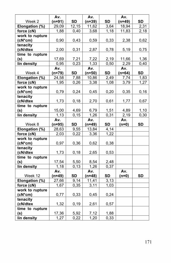
171
Week 2 Av.
(n=91) SD Av.
(n=39) SD Av.
(n=49) SD Elongation (%) 29,09 12,15 11,62 3,64 18,94 2,31 force (cN) 1,88 0,40 3,68 1,18 11,83 2,18 work to rupture (cN*cm) 0,90 0,43 0,59 0,33 2,38 0,62 tenacity (cN/dtex 2,00 0,31 2,87 0,78 5,19 0,75 time to rupture (s) 17,69 7,21 7,22 2,19 11,66 1,36 lin density 0,95 0,23 1,33 0,50 2,29 0,40
Week 4 Av.
(n=79) SD Av.
(n=50) SD Av.
(n=64) SD Elongation (%) 24,58 7,88 10,86 2,49 7,74 1,83 force (cN) 1,95 0,26 3,38 1,08 3,79 1,27 work to rupture (cN*cm) 0,79 0,24 0,45 0,20 0,35 0,16 tenacity (cN/dtex 1,73 0,18 2,70 0,61 1,77 0,67 time to rupture (s) 15,00 4,69 6,79 1,51 4,89 1,10 lin density 1,13 0,15 1,26 0,31 2,19 0,30
Week 8 Av.
(n=95) SD Av.
(n=49) SD Av.
(n=0) SD Elongation (%) 28,63 9,55 13,84 4,14 force (cN) 2,03 0,22 3,36 1,22 work to rupture (cN*cm) 0,97 0,36 0,62 0,38 tenacity (cN/dtex 1,73 0,18 2,65 0,53 time to rupture (s) 17,54 5,50 8,54 2,48 lin density 1,18 0,13 1,26 0,37
Week 12 Av.
(n=49) SD Av.
(n=48) SD Av.
(n=0) SD Elongation (%) 27,66 9,14 11,41 3,13 force (cN) 1,67 0,35 3,11 1,03 work to rupture (cN*cm) 0,77 0,33 0,45 0,24 tenacity (cN/dtex 1,32 0,19 2,61 0,57 time to rupture (s) 17,36 5,92 7,12 1,88 lin density 1,27 0,22 1,20 0,33
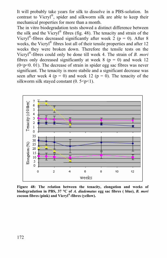
172
It will probably take years for silk to dissolve in a PBS-solution. In contrast to Vicryl®, spider and silkworm silk are able to keep their mechanical properties for more than a month. The in vitro biodegradation tests showed a distinct difference between the silk and the Vicryl® fibres (fig. 48). The tenacity and strain of the Vicryl®-fibres decreased significantly after week 2 (p = 0). After 8 weeks, the Vicryl® fibres lost all of their tensile properties and after 12 weeks they were broken down. Therefore the tensile tests on the Vicryl®-fibres could only be done till week 4. The strain of B. mori fibres only decreased significantly at week 8 (p = 0) and week 12 (0<p<0. 01). The decrease of strain in spider egg sac fibres was never significant. The tenacity is more stabile and a significant decrease was seen after week 4 (p = 0) and week 12 (p = 0). The tenacity of the silkworm silk stayed constant (0. 5<p<1).
Figure 48: The relation between the tenacity, elongation and weeks of biodegradation in PBS, 37 °C of A. diadematus egg sac fibres ( blue), B. mori cocoon fibres (pink) and Vicryl®-fibres (yellow).

173
Conclusion First of all, it is clear that alginate biodegrades the fastest. It only needs a day in PBS to be totally dissolved. From the in vitro biodegradation experiments, it can be concluded that Vicryl® is biodegrading much faster than both types of silk fibres. After two weeks there is a significant decrease in strength, after two months the fibres lost their strength and could not be tested anymore and after three months they were broken down. In contrast, silk fibres loose their strength, elongation and linear density only slightly over time. This again shows the high resistance of the silk fibers. As the PBS and the fibers were not sterile during these weeks, there were certainly bacteria growing in the physiological water that could attack the fibers. As discussed in chapter 5, the fibres do not have an anti-bacterial property, but bacteria can hardly degrade the fiber structure. The slight decrease in strength means that in vivo the fibres will eventually loose their mechanical properties due to biodegradation and will break due to mechanical load and friction. They will break down and biodegrade further, but it will take up to several years till the silk is completely biodegraded.
7.4 Degradation of spider egg sac silk by enzymes
Introduction It is already stated in the previous paragraphs that in vivo the immune system produces enzymes that attack foreign material inside the body [Dal Pra et al., 2003]. One can imitate this attack by investigating the effect of an enzymatic treatment on the tensile properties of the fibres [Minoura et al., 1990]. Another reason for evaluating this effect is the use of an enzymatic cleaning for improving the biocompatibility (chapter 6). In this chapter proteinase K and trypsin are used to see their effect.
174
Materials and methods Egg sac silk fibres were obtained from A. diadematus spiders caught in nature during the summer and grown in the laboratory by feeding flies. They each produced one egg sac in October/November after which they died. The eggs were removed manually from the egg sac using a pair of tweezers. 5 cm long threads for the tensile tests. To test the effect of an enzymatic treatment on the mechanical properties of the spider egg sac fibres, tensile tests were done on three different egg sacs. These three egg sacs were divided in eight parts; four parts were treated with trypsin (bovine pancreas, 12.400 U/mg, Sigma-Aldrich, Bornem, Belgium) and four with proteinase K (Tritrachium album, 47 U/mg, Sigma-Aldrich). Both enzymes were used in four concentrations (1 mg/ml, 0.1 mg/ml, 0.01 mg/ml and 0.001 mg/ml) in phosphate buffered saline (PBS, GIBCO Invitrogen Co, Merelbeke, Belgium) for 4 h at 55 °C. Tensile tests (25) were performed per enzyme type, enzyme concentration and egg sac, which made 600 tests in total. The tensile measurements were done with an automatic single fibre strength tester (FAVIMAT). Tensile tests with the FAVIMAT are carried out according to the constant rate of extension principle. All tests were done on 20 mm gauge-length, at an extension speed of 20 mm/min, in a controlled climate condition of 20 ± 2 °C and a relative humidity of 65 ± 2%. A two factor anova-test was used (SPSS) to see the effect of enzyme concentration and enzyme type on the mechanical properties of the fibres. The egg sac number was taken as a random factor and the concentration of the two enzymes as the fixed factor.
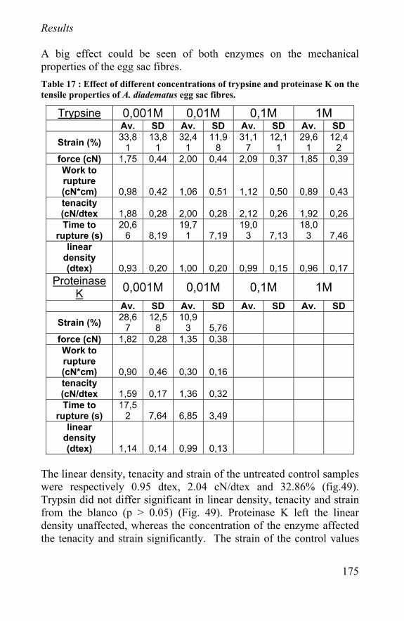
175
Results A big effect could be seen of both enzymes on the mechanical properties of the egg sac fibres. Table 17 : Effect of different concentrations of trypsine and proteinase K on the tensile properties of A. diadematus egg sac fibres.
Trypsine 0,001M 0,01M 0,1M 1M Av. SD Av. SD Av. SD Av. SD
Strain (%) 33,81
13,81
32,41
11,98
31,17
12,11
29,61
12,42
force (cN) 1,75 0,44 2,00 0,44 2,09 0,37 1,85 0,39 Work to rupture (cN*cm) 0,98 0,42 1,06 0,51 1,12 0,50 0,89 0,43 tenacity (cN/dtex 1,88 0,28 2,00 0,28 2,12 0,26 1,92 0,26 Time to
rupture (s) 20,6
6 8,19 19,7
1 7,19 19,0
3 7,13 18,0
3 7,46 linear
density (dtex) 0,93 0,20 1,00 0,20 0,99 0,15 0,96 0,17
Proteinase K 0,001M 0,01M 0,1M 1M Av. SD Av. SD Av. SD Av. SD
Strain (%) 28,67
12,58
10,93 5,76
force (cN) 1,82 0,28 1,35 0,38 Work to rupture (cN*cm) 0,90 0,46 0,30 0,16
tenacity (cN/dtex 1,59 0,17 1,36 0,32
Time to rupture (s)
17,52 7,64 6,85 3,49
linear density (dtex) 1,14 0,14 0,99 0,13
The linear density, tenacity and strain of the untreated control samples were respectively 0.95 dtex, 2.04 cN/dtex and 32.86% (fig.49). Trypsin did not differ significant in linear density, tenacity and strain from the blanco (p > 0.05) (Fig. 49). Proteinase K left the linear density unaffected, whereas the concentration of the enzyme affected the tenacity and strain significantly. The strain of the control values
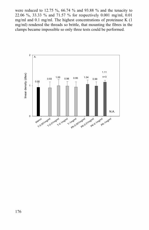
176
were reduced to 12.75 %, 66.74 % and 93.88 % and the tenacity to 22.06 %, 33.33 % and 71.57 % for respectively 0.001 mg/ml, 0.01 mg/ml and 0.1 mg/ml. The highest concentrations of proteinase K (1 mg/ml) rendered the threads so brittle, that mounting the fibres in the clamps became impossible so only three tests could be performed.
blanco
T-0.001mg/ml
T-0.01mg/ml
T-0.1mg/ml
T-1mg/ml
PK-0.001mg/ml
PK-0.01mg/ml
PK-0.1mg/ml
PK-1mg/ml
linea
r den
sity
(dte
x)
0
1
2
N.A.
n=3
0.950.99
1.040.950.981.000.93
A.
1.11
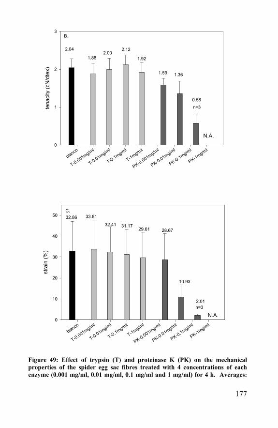
177
blanco
T-0.001mg/ml
T-0.01mg/ml
T-0.1mg/ml
T-1mg/ml
PK-0.001mg/ml
PK-0.01mg/ml
PK-0.1mg/ml
PK-1mg/ml
tena
city
(cN
/dte
x)
0
1
2
3
N.A.
1.361.59
1.92
2.122.00
1.88
2.04
B.
n=30.58
blanco
T-0.001mg/ml
T-0.01mg/ml
T-0.1mg/ml
T-1mg/ml
PK-0.001mg/ml
PK-0.01mg/ml
PK-0.1mg/ml
PK-1mg/ml
stra
in (%
)
0
10
20
30
40
50
N.A.n=3
C.
2.01
10.93
28.6729.6131.1732.41
33.8132.86
Figure 49: Effect of trypsin (T) and proteinase K (PK) on the mechanical properties of the spider egg sac fibres treated with 4 concentrations of each enzyme (0.001 mg/ml, 0.01 mg/ml, 0.1 mg/ml and 1 mg/ml) for 4 h. Averages:
178
A. linear density (dtex) B. tenacity (cN/dtex) and C. strain (%) (N = 75 (3 cocoons, 25 tests), error bar is 1 SD)
Conclusion The results from the tensile tests tell us that enzymes used on silk fibres, or on a protein fibre in general, can affect mechanical properties of the fibre. Trypsin is a weaker enzyme, only cutting on specific sites what does not change the tensile properties of the egg sac fibres significantly. Proteinase K is a stronger enzyme and tensile properties of the egg sac fibres are diminished significantly in proportion with the enzyme-concentration. The proteinase K probably cuts most in the easily accessible helices, which are thought to be responsible for the elasticity of the silk fibre. The impenetrable β-sheets are more packed and protected to enzymatic cuts; as a consequence the tenacity was only diminished by an early breakage. This means that an enzyme like proteinase K can not be used to treat protein fibres. Trypsin, which did not change the mechanical properties significantly, can be used to improve the biocompatibility of the spider egg sac silk threads. The removed part could not have been a thick coating, as the linear density of the fibres did not diminish in proportion to the enzyme concentration.
7.5 Modeling of rate of biodegradation of a scaffold
Simple mathematical models can help to analyze what happens during the process of tissue engineering [Wilson et al., 2002]. Such a model simplifies both in a mathematical and biological view point, but it should capture the essential features of the different processes going on. The goal of the following model is to calculate the mass changes (or volume changes) and the eventual masses (or volumes) of the chondrocytes, the scaffold and the ECM during biodegradation and tissue regeneration. Due to many unknown variables, the resulting model will let a lot of unanswered questions. However, making a mathematical model and stating the different variables clearly marks the many influences in scaffold-based tissue engineering. Even without comparing to the biological experiments, a mathematical
179
model can stand on its own, as an attempt to analyze how the different mechanisms involved interact with each other during growth.
7.5.1 Different variables The main variables are the masses of the implant (synthetic- or biological material). The volumes of the scaffold, cells and ECM could also have been taken into account, as it is sometimes a matter of space, but the volume and the mass are dependent of each other, so the model would not change. Mass scaffold = S Mass cells = C Mass ECM/Cartilage = E Also the effect of the medium, growth factors and environmental, mechanical or biochemical interactions can be included, but this would make the model overcomplicated.
7.5.2 Modeling scaffold biodegradation and tissue regeneration
The first step in modeling is to identify the biological and physical features of interest, which are the variables. For each variable, it has to be stated what governs its evolution and what can influence its reduction or augmentation. Subsequently, mathematical expressions can be formulated for each phenomenon that is identified. After practical, biological tests, these theoretical equations can be revised.
- Scaffold biodegradation
In the simplest case, the scaffold biodegrades over time in a medium due to hydrolysis or enzymatic cuts [Riminucci et al., 2003]. No cells are seeded, so there is no ECM produced, what makes that only S is variable. This is illustrated by the pink line in figure 50. The mass change over time can be formulated as follows:
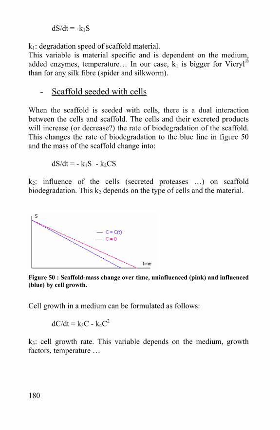
180
dS/dt = -k1S
k1: degradation speed of scaffold material. This variable is material specific and is dependent on the medium, added enzymes, temperature… In our case, k1 is bigger for Vicryl® than for any silk fibre (spider and silkworm).
- Scaffold seeded with cells When the scaffold is seeded with cells, there is a dual interaction between the cells and scaffold. The cells and their excreted products will increase (or decrease?) the rate of biodegradation of the scaffold. This changes the rate of biodegradation to the blue line in figure 50 and the mass of the scaffold change into:
dS/dt = - k1S - k2CS k2: influence of the cells (secreted proteases …) on scaffold biodegradation. This k2 depends on the type of cells and the material.
Figure 50 : Scaffold-mass change over time, uninfluenced (pink) and influenced (blue) by cell growth.
Cell growth in a medium can be formulated as follows:
dC/dt = k3C - k4C2
k3: cell growth rate. This variable depends on the medium, growth factors, temperature …
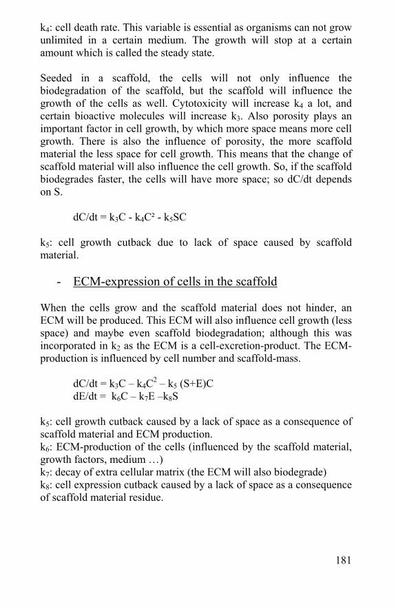
181
k4: cell death rate. This variable is essential as organisms can not grow unlimited in a certain medium. The growth will stop at a certain amount which is called the steady state. Seeded in a scaffold, the cells will not only influence the biodegradation of the scaffold, but the scaffold will influence the growth of the cells as well. Cytotoxicity will increase k4 a lot, and certain bioactive molecules will increase k3. Also porosity plays an important factor in cell growth, by which more space means more cell growth. There is also the influence of porosity, the more scaffold material the less space for cell growth. This means that the change of scaffold material will also influence the cell growth. So, if the scaffold biodegrades faster, the cells will have more space; so dC/dt depends on S. dC/dt = k3C - k4C² - k5SC k5: cell growth cutback due to lack of space caused by scaffold material.
- ECM-expression of cells in the scaffold
When the cells grow and the scaffold material does not hinder, an ECM will be produced. This ECM will also influence cell growth (less space) and maybe even scaffold biodegradation; although this was incorporated in k2 as the ECM is a cell-excretion-product. The ECM-production is influenced by cell number and scaffold-mass.
dC/dt = k3C – k4C2 – k5 (S+E)C dE/dt = k6C – k7E –k8S
k5: cell growth cutback caused by a lack of space as a consequence of scaffold material and ECM production. k6: ECM-production of the cells (influenced by the scaffold material, growth factors, medium …) k7: decay of extra cellular matrix (the ECM will also biodegrade) k8: cell expression cutback caused by a lack of space as a consequence of scaffold material residue.
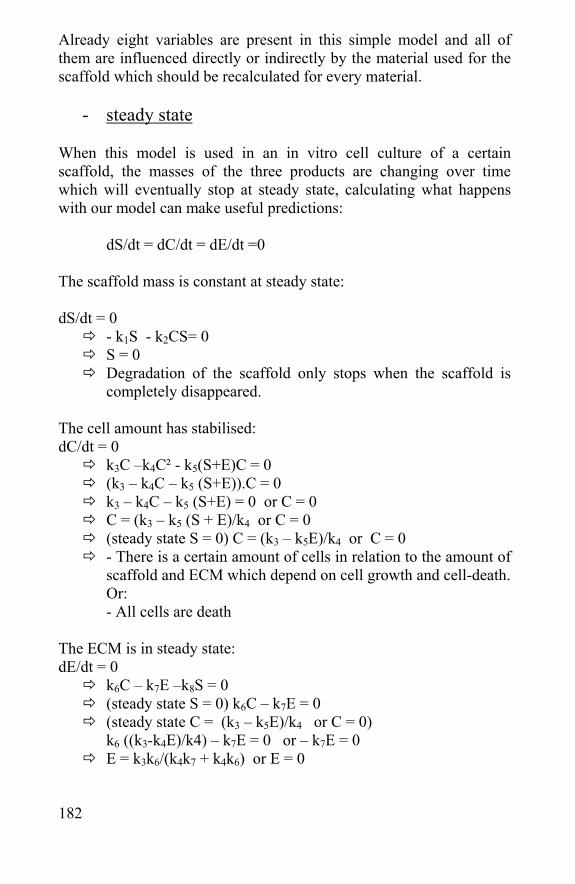
182
Already eight variables are present in this simple model and all of them are influenced directly or indirectly by the material used for the scaffold which should be recalculated for every material.
- steady state
When this model is used in an in vitro cell culture of a certain scaffold, the masses of the three products are changing over time which will eventually stop at steady state, calculating what happens with our model can make useful predictions:
dS/dt = dC/dt = dE/dt =0
The scaffold mass is constant at steady state: dS/dt = 0
- k1S - k2CS= 0 S = 0 Degradation of the scaffold only stops when the scaffold is
completely disappeared. The cell amount has stabilised: dC/dt = 0
k3C –k4C² - k5(S+E)C = 0 (k3 – k4C – k5 (S+E)).C = 0 k3 – k4C – k5 (S+E) = 0 or C = 0 C = (k3 – k5 (S + E)/k4 or C = 0 (steady state S = 0) C = (k3 – k5E)/k4 or C = 0 - There is a certain amount of cells in relation to the amount of
scaffold and ECM which depend on cell growth and cell-death. Or: - All cells are death
The ECM is in steady state: dE/dt = 0
k6C – k7E –k8S = 0 (steady state S = 0) k6C – k7E = 0 (steady state C = (k3 – k5E)/k4 or C = 0)
k6 ((k3-k4E)/k4) – k7E = 0 or – k7E = 0 E = k3k6/(k4k7 + k4k6) or E = 0
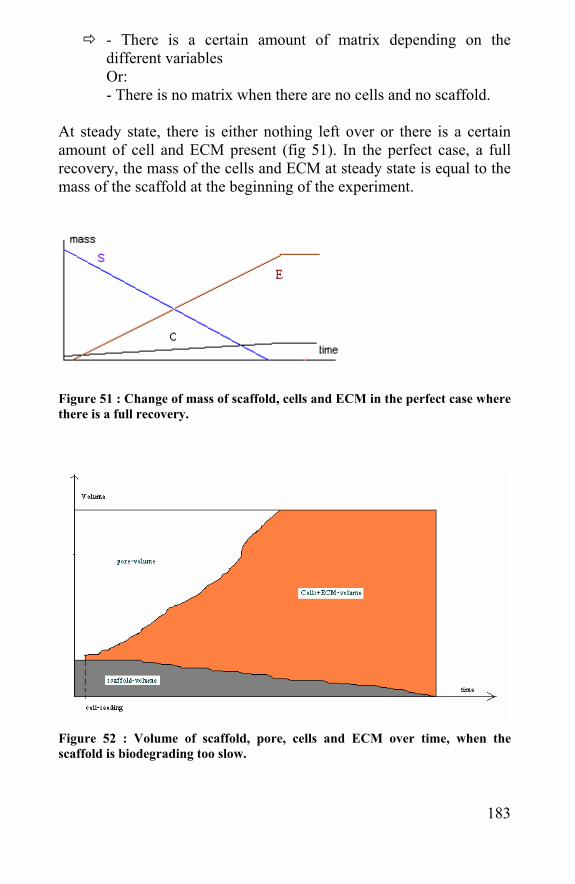
183
- There is a certain amount of matrix depending on the different variables Or: - There is no matrix when there are no cells and no scaffold.
At steady state, there is either nothing left over or there is a certain amount of cell and ECM present (fig 51). In the perfect case, a full recovery, the mass of the cells and ECM at steady state is equal to the mass of the scaffold at the beginning of the experiment.
Figure 51 : Change of mass of scaffold, cells and ECM in the perfect case where there is a full recovery.
Figure 52 : Volume of scaffold, pore, cells and ECM over time, when the scaffold is biodegrading too slow.
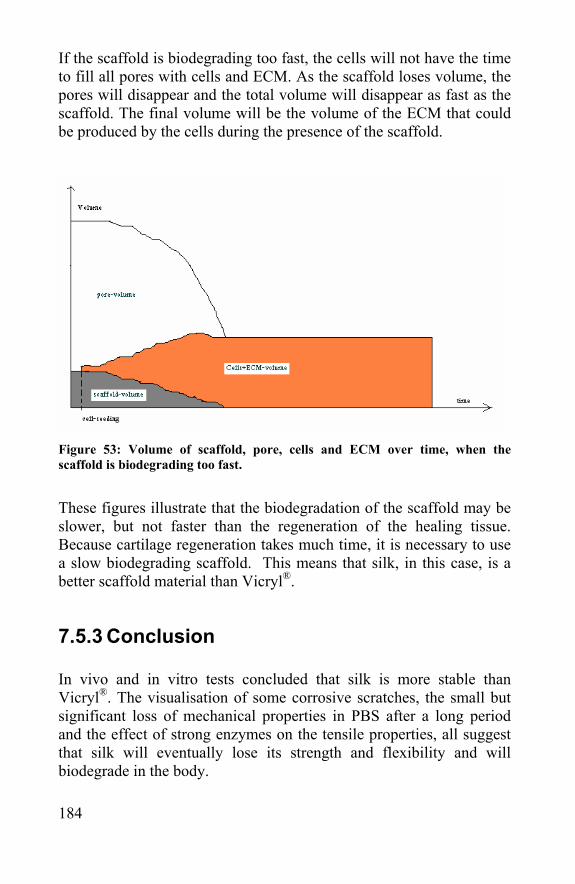
184
If the scaffold is biodegrading too fast, the cells will not have the time to fill all pores with cells and ECM. As the scaffold loses volume, the pores will disappear and the total volume will disappear as fast as the scaffold. The final volume will be the volume of the ECM that could be produced by the cells during the presence of the scaffold.
Figure 53: Volume of scaffold, pore, cells and ECM over time, when the scaffold is biodegrading too fast.
These figures illustrate that the biodegradation of the scaffold may be slower, but not faster than the regeneration of the healing tissue. Because cartilage regeneration takes much time, it is necessary to use a slow biodegrading scaffold. This means that silk, in this case, is a better scaffold material than Vicryl®.
7.5.3 Conclusion In vivo and in vitro tests concluded that silk is more stable than Vicryl®. The visualisation of some corrosive scratches, the small but significant loss of mechanical properties in PBS after a long period and the effect of strong enzymes on the tensile properties, all suggest that silk will eventually lose its strength and flexibility and will biodegrade in the body.
185
The slow biodegradability of silk in scaffolds can be an advantage in some biomedical applications like cartilage engineering, where a slow regeneration of ECM-material is observed. This slow biodegradability means a longer time of cell support and function replacement. Rapid biodegradation as seen for Vicryl® would only lead to a partial regeneration of the tissue.
7.6 References - Dal Pra I, Petrini P, Charini A, Bozzini S, Fare S, Armato U. Silk fibroin-coated three-dimensional polyurethane scaffolds for tissue engineering: interactions with normal human fibroblasts. Tissue Eng. 2003 Dec;9(6):1113-21. - Li M, Ogiso M, Minoura N. Enzymatic degradation behavior of porous silk fibroin sheets.Biomaterials. 2003 Jan;24(2):357-65. - Minoura N, Tsukada M, Nagura M. Physico-chemical properties of silk fibroin membrane as a biomaterial.Biomaterials. 1990 Aug;11(6):430-4. - Panilaitis B, Altman GH, Chen J, Jin HJ, Karageorgiou V, Kaplan DL. Macrophage responses to silk.Biomaterials. 2003 Aug;24(18):3079-85. - Riminucci M, Bianco P. Building bone tissue: matrices and scaffolds in physiology and biotechnology.Braz J Med Biol Res. 2003 Aug;36(8):1027-36. Epub 2003 Jul 23. - Uff CR, Scott AD, Pockley AG, Phillips RK. Influence of soluble suture factors on in vitro macrophage function.Biomaterials. 1995 Mar;16(5):355-60. -Wilson CG, Bonassar LJ, Kohles SS. Modeling the dynamic composition of engineered cartilage. Arch Biochem Biophys. 2002 Dec 15;408(2):246-54.

186
187
Chapter 8 Silkworm and spider silk scaffolds

188
189
8.1 Scaffolds in tissue engineering Using autologous cells for regenerating tissue is a promising technique in biomedical engineering [Hutmacher et al., 2000]. It could eliminate the problem of donor site scarcity, immune rejection and pathogen transfer [Naughton et al., 1995]. Cells can be obtained in small amounts from the patient and cultured to bulk amounts in vitro. This technique is already clinically in use for skin tissue engineering, where epithelial cells from the patient are cultured and processed in large pieces of skin to heal burn wounds [Bannasch et al., 2003]. Cells and tissues can not be implanted without supporting material, so in many cases biocompatible and biodegradable scaffolds which can support the cells, are required. Even in skin tissue engineering, where large pieces of tissue can be produced without any support, cell supporting scaffolds are helpful [Llames et al., 2004]. A scaffold can help dividing the cells homogenously and offers mechanical support to areas where the tissue is not full-grown yet. In orthopaedic tissue engineering, the need for a scaffold is even bigger because the function of the healing tissue has to be replaced during regeneration. Scaffolds do not only keep the cells on their place, they replace the function of the bone or cartilage and release the patient from its pain and malfunction.
8.2 Scaffolds in cartilage regeneration Scaffold free Autologous Cell Implantation (ACI) [Brittberg et al., 1999] is also used for cartilage regeneration, but merely for patients with small lesions (2-10 cm²) or only localized areas of osteoarthritis. ACI is not applicable for patients who have advanced osteoarthritis or osteoarthritis on both sides of the joint (femur and tibia). When it is decided to perform ACI, a biopsy is taken from an area with normal cartilage. Chondrocytes are isolated from the biopsy sample and cultured in vitro for 3-4 weeks. The cartilage gap is closed with a periosteal flap, stitched to the normal cartilage surrounding the lesion and the defect is filled with the propagated cell culture. Although this procedure has been used for more then 10.000 patients [Brittberg et al., 2003], the regeneration is unsatisfactory in many
190
cases. This is mainly due to the loss of chondrocytes; implanted chondrocytes do not stay in place and accumulation of chondrocytes due to gravity. For this reason alone it is suitable to use scaffolds. Macro-porous biomaterials could keep the chondrocytes in place and support their cartilage reformation. A second reason to use scaffolds is the replacement of the cartilage function. When scaffold-free ACI is used, the patient is placed into a knee immobilizer for stability immediately after surgery. This has to be maintained on a non-weight-bearing status using crutches for approximately four weeks. This revalidation period depends on the location and size of the lesion. If a biomaterial scaffold could replace the repairing cartilage, the patient would be able to use his knee after a short healing time after surgery. The weight-bearing motion could even promote the cells in the scaffold to produce cartilage in stead of being pushed out by this motion. Several scaffold materials are already presented. Some hydrogels, like alginate [Almqvist et al., 2001], polyvinylalcohol [Kobayashi, 2004], silanized hydroxypropyl methylcellulose [Vinatier et al., 2005], poly(ethylene glycol) fumarate [Holland et al., 2005] were already tested for their cell supportive characteristics.
8.3 Scaffolds made of silkworm and spider silk
8.3.1 Preparation of different silk scaffolds
- Silk scaffold preparation without dissolving: silk non-wovens
Two types of non-wovens could be made with respectively silkworm silk and spider egg sac silk. A silkworm silk non-woven was made by cutting a rectangle (5 cm2) out of an un-degummed silkworm silk cocoon. A grid (4 mm2 spaces) was stitched on the rectangle with a silkworm silk yarn after which the stitched rectangle was degummed. Consequently, the sericin was removed and the silkworm silk fibres were kept together in a random
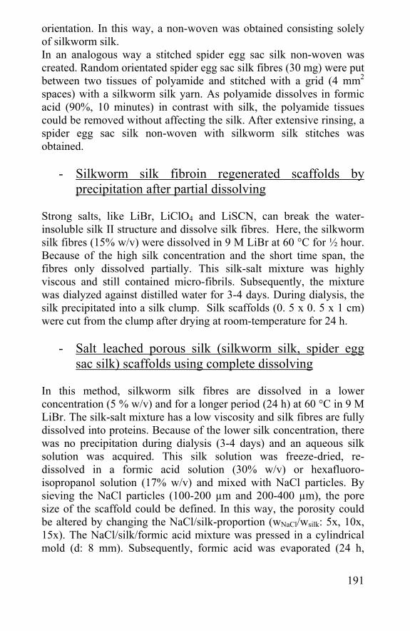
191
orientation. In this way, a non-woven was obtained consisting solely of silkworm silk. In an analogous way a stitched spider egg sac silk non-woven was created. Random orientated spider egg sac silk fibres (30 mg) were put between two tissues of polyamide and stitched with a grid (4 mm2 spaces) with a silkworm silk yarn. As polyamide dissolves in formic acid (90%, 10 minutes) in contrast with silk, the polyamide tissues could be removed without affecting the silk. After extensive rinsing, a spider egg sac silk non-woven with silkworm silk stitches was obtained.
- Silkworm silk fibroin regenerated scaffolds by
precipitation after partial dissolving Strong salts, like LiBr, LiClO4 and LiSCN, can break the water-insoluble silk II structure and dissolve silk fibres. Here, the silkworm silk fibres (15% w/v) were dissolved in 9 M LiBr at 60 °C for ½ hour. Because of the high silk concentration and the short time span, the fibres only dissolved partially. This silk-salt mixture was highly viscous and still contained micro-fibrils. Subsequently, the mixture was dialyzed against distilled water for 3-4 days. During dialysis, the silk precipitated into a silk clump. Silk scaffolds (0. 5 x 0. 5 x 1 cm) were cut from the clump after drying at room-temperature for 24 h.
- Salt leached porous silk (silkworm silk, spider egg sac silk) scaffolds using complete dissolving
In this method, silkworm silk fibres are dissolved in a lower concentration (5 % w/v) and for a longer period (24 h) at 60 °C in 9 M LiBr. The silk-salt mixture has a low viscosity and silk fibres are fully dissolved into proteins. Because of the lower silk concentration, there was no precipitation during dialysis (3-4 days) and an aqueous silk solution was acquired. This silk solution was freeze-dried, re-dissolved in a formic acid solution (30% w/v) or hexafluoro-isopropanol solution (17% w/v) and mixed with NaCl particles. By sieving the NaCl particles (100-200 µm and 200-400 µm), the pore size of the scaffold could be defined. In this way, the porosity could be altered by changing the NaCl/silk-proportion (wNaCl/wsilk: 5x, 10x, 15x). The NaCl/silk/formic acid mixture was pressed in a cylindrical mold (d: 8 mm). Subsequently, formic acid was evaporated (24 h,
192
room temperature) and the mold was removed. The NaCl/silk cylinders were brought into methanol (98%) for ½ hour to form the water insoluble silk II structure [Tsukada et al., 1995]. The NaCl particles in the cylinder were dissolved in distilled water forming a highly porous silkworm silk scaffold. Spider egg sac fibres are not soluble in salt solutions. However, washing the egg sac fibres with a soap solution, like the one used for degumming silkworm silk fibres (1 % Marseille soap, 0.5 % NaCO3, 98 °C, ½ h, 2x), did not only remove the yellow color but also their resistance to strong salts. Subsequently, the fibres could be dissolved in 9 M LiBr (1 h, 60 °C, 1 % w/v). As previously described for silkworm silk, the solution was dialyzed, freeze-dried, redissolved, and blended with NaCl particles and restructured in a methanol solution. Finally, the NaCl particles were removed to obtain a porous spider egg sac silk scaffold.
8.3.2 Physical characterization of the scaffolds Introduction In the first place, all physical characteristics of the different scaffolds should be tested. The shape, surface, pore size and porosity can be evaluated by microscopy. It is important to check the pore distribution, because a homogeneous pore distribution leads to a better cell spreading in the scaffold. Besides the distribution of the pores, the interconnectivity needs to be checked as well. Using salt-leaching, it is plausible that the pores are interconnected; otherwise the salt could not have left the scaffold. To check whether the cells, nutrients and ECM are able to reach all pores of the scaffold, permanent black ink is often used [Rodrigues-Garcia et al., 1996]. The compression of the scaffold is the most important of the mechanical properties. For cartilage regeneration it should be compressible, able to bear load as well and protect the cells and underlying bone material. Native cartilage tissue has a compressive modulus of approximately 0.79 MPa, a shear modulus of 0.68 MPa and a tensile modulus in the range of 0.32 to 10.2 MPa [Akizuki et al., 1986]. The force to compress the scaffold is as important as the
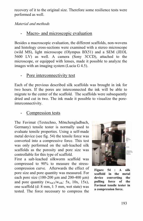
193
recovery of it to the original size. Therefore some resilience tests were performed as well. Material and methods
- Macro- and microscopic evaluation
Besides a macroscopic evaluation, the different scaffolds, non-wovens and histology cross-sections were examined with a stereo microscope (wild MS), light microscope (Olympus BX51) and a SEM (JEOL 5600 LV) as well. A camera (Sony 3CCD), attached to the microscope, or equipped with lenses, made it possible to analyze the images with an imaging system (Lucia G 4.5).
- Pore interconnectivity test Each of the previous described silk scaffolds was brought in ink for two hours. If the pores are interconnected the ink will be able to migrate to the center of the scaffold. The scaffolds were subsequently dried and cut in two. The ink made it possible to visualize the pore-interconnectivity.
- Compression tests The Favimat (Textechno, Mönchengladbach, Germany) tensile tester is normally used to evaluate tensile properties. Using a self-made metal device (see fig. 54) the tensile force was converted into a compressive force. This test was only performed on the salt-leached silk scaffolds as the porosity and pore size was controllable for this type of scaffold. First a salt-leached silkworm scaffold was compressed to 90% to measure the stress-compression curve. Afterwards the effect of pore size and pore quantity was measured. For each pore size (100-200 µm and 200-400 µm) and pore quantity (wNaCl/wsilk: 5x, 10x, 15x), one scaffold (d: 8 mm, l: 5 mm, wet state) was tested. The force necessary to compress the
Figure 54 : A silk scaffold in the metal device converting the pulling force of the Favimat tensile tester in a compression force.
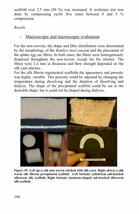
194
scaffold over 2.5 mm (50 %) was measured. A resilience test was done by compressing cyclic five times between 0 and 5 % compression. Results
- Macroscopic and microscopic evaluation For the non-wovens, the shape and fibre distribution were determined by the morphology of the Bombyx mori cocoon and the placement of the spider egg sac fibres. In both cases, the fibres were homogenously dispersed throughout the non-woven, except for the stitches. The fibres were 1-2 mm in thickness and their strength depended on the silk yarn stitches. For the silk fibroin regenerated scaffolds the appearance and porosity was highly variable. This porosity could be adjusted by changing the temperature during dissolving and the duration of dissolving and dialysis. The shape of the precipitated scaffold could be cut in the desirable shape, but it could not be shaped during dialyses.
Figure 55: Left up) a silk non woven stitched with silk-yarn. Right above) a silk worm silk fibroin precipitated scaffold. Left bottom) cylindrical salt-leached silkworm silk scaffold. Right bottom) meniscus-shaped salt-leached silkworm silk scaffold
d)
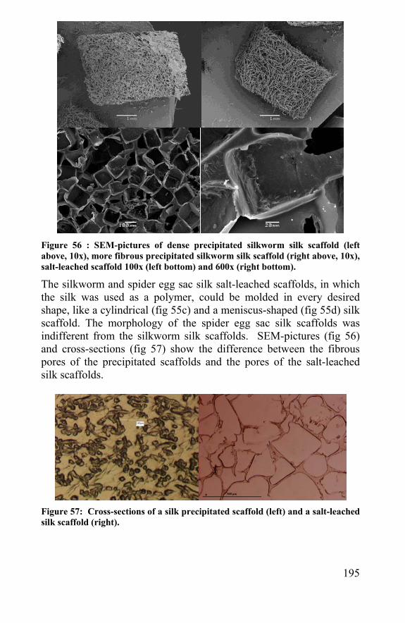
195
Figure 56 : SEM-pictures of dense precipitated silkworm silk scaffold (left above, 10x), more fibrous precipitated silkworm silk scaffold (right above, 10x), salt-leached scaffold 100x (left bottom) and 600x (right bottom).
The silkworm and spider egg sac silk salt-leached scaffolds, in which the silk was used as a polymer, could be molded in every desired shape, like a cylindrical (fig 55c) and a meniscus-shaped (fig 55d) silk scaffold. The morphology of the spider egg sac silk scaffolds was indifferent from the silkworm silk scaffolds. SEM-pictures (fig 56) and cross-sections (fig 57) show the difference between the fibrous pores of the precipitated scaffolds and the pores of the salt-leached silk scaffolds.
Figure 57: Cross-sections of a silk precipitated scaffold (left) and a salt-leached silk scaffold (right).
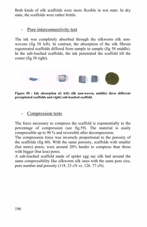
196
Both kinds of silk scaffolds were more flexible in wet state. In dry state, the scaffolds were rather brittle.
- Pore interconnectivity test The ink was completely absorbed through the silkworm silk non-wovens (fig 58 left). In contrast, the absorption of the silk fibroin regenerated scaffolds differed from sample to sample (fig 58 middle). In the salt-leached scaffolds, the ink penetrated the scaffold till the center (fig 58 right).
Figure 58 : Ink absorption of: left) silk non-woven, middle) three different precipitated scaffolds and right) salt-leached scaffold.
- Compression tests The force necessary to compress the scaffold is exponentially to the percentage of compression (see fig.59). The material is easily compressible up to 90 % and reversible after decompression. The compression force was inversely proportional to the porosity of the scaffolds (fig 60). With the same porosity, scaffolds with smaller (but more) pores, were around 20% harder to compress than those with bigger (but less) pores. A salt-leached scaffold made of spider egg sac silk had around the same compressibility like silkworm silk ones with the same pore size, pore number and porosity (118. 23 cN vs. 126. 77 cN).
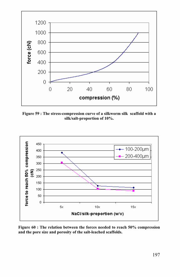
197
Figure 59 : The stress-compression curve of a silkworm silk scaffold with a
silk/salt-proportion of 10%.
Figure 60 : The relation between the forces needed to reach 50% compression and the pore size and porosity of the salt-leached scaffolds.
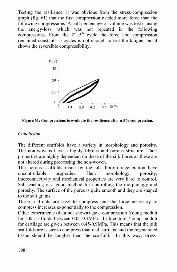
198
Testing the resilience, it was obvious from the stress-compression graph (fig. 61) that the first compression needed more force than the following compressions. A half percentage of volume was lost causing the energy-loss, which was not repeated in the following compressions. From the 2nd-5th cycle the force and compression remained constant. 5 cycles is not enough to test the fatigue, but it shows the reversible compressibility.
Figure 61: Compressions to evaluate the resilience after a 5% compression.
Conclusion The different scaffolds have a variety in morphology and porosity. The non-wovens have a highly fibrous and porous structure. Their properties are highly dependent on these of the silk fibres as these are not altered during processing the non-woven. The porous scaffolds made by the silk fibroin regeneration have uncontrollable properties. Their morphology, porosity, interconnectivity and mechanical properties are very hard to control. Salt-leaching is a good method for controlling the morphology and porosity. The surface of the pores is quite smooth and they are shaped to the salt grains. These scaffolds are easy to compress and the force necessary to compress increases exponentially to the compression. Other experiments (data not shown) gave compression Young moduli for silk scaffolds between 0.05-0.1MPa. In literature Young moduli for cartilage are given between 0.45-0.9MPa. This means that the silk scaffolds are easier to compress than real cartilage and the regenerated tissue should be tougher than the scaffold. In this way, stress-
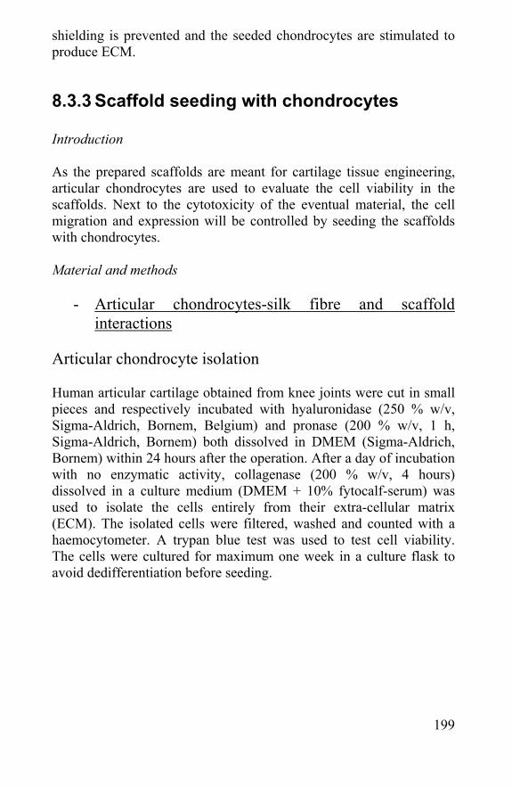
199
shielding is prevented and the seeded chondrocytes are stimulated to produce ECM.
8.3.3 Scaffold seeding with chondrocytes Introduction As the prepared scaffolds are meant for cartilage tissue engineering, articular chondrocytes are used to evaluate the cell viability in the scaffolds. Next to the cytotoxicity of the eventual material, the cell migration and expression will be controlled by seeding the scaffolds with chondrocytes. Material and methods
- Articular chondrocytes-silk fibre and scaffold interactions
Articular chondrocyte isolation Human articular cartilage obtained from knee joints were cut in small pieces and respectively incubated with hyaluronidase (250 % w/v, Sigma-Aldrich, Bornem, Belgium) and pronase (200 % w/v, 1 h, Sigma-Aldrich, Bornem) both dissolved in DMEM (Sigma-Aldrich, Bornem) within 24 hours after the operation. After a day of incubation with no enzymatic activity, collagenase (200 % w/v, 4 hours) dissolved in a culture medium (DMEM + 10% fytocalf-serum) was used to isolate the cells entirely from their extra-cellular matrix (ECM). The isolated cells were filtered, washed and counted with a haemocytometer. A trypan blue test was used to test cell viability. The cells were cultured for maximum one week in a culture flask to avoid dedifferentiation before seeding.
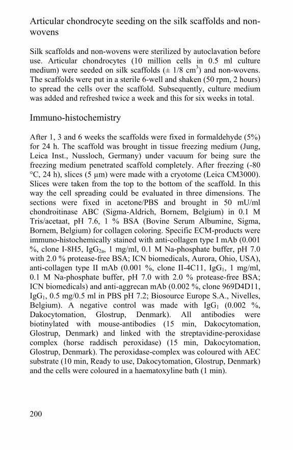
200
Articular chondrocyte seeding on the silk scaffolds and non-wovens Silk scaffolds and non-wovens were sterilized by autoclavation before use. Articular chondrocytes (10 million cells in 0.5 ml culture medium) were seeded on silk scaffolds (± 1/8 cm3) and non-wovens. The scaffolds were put in a sterile 6-well and shaken (50 rpm, 2 hours) to spread the cells over the scaffold. Subsequently, culture medium was added and refreshed twice a week and this for six weeks in total. Immuno-histochemistry After 1, 3 and 6 weeks the scaffolds were fixed in formaldehyde (5%) for 24 h. The scaffold was brought in tissue freezing medium (Jung, Leica Inst., Nussloch, Germany) under vacuum for being sure the freezing medium penetrated scaffold completely. After freezing (-80 °C, 24 h), slices (5 µm) were made with a cryotome (Leica CM3000). Slices were taken from the top to the bottom of the scaffold. In this way the cell spreading could be evaluated in three dimensions. The sections were fixed in acetone/PBS and brought in 50 mU/ml chondroitinase ABC (Sigma-Aldrich, Bornem, Belgium) in 0.1 M Tris/acetaat, pH 7.6, 1 % BSA (Bovine Serum Albumine, Sigma, Bornem, Belgium) for collagen coloring. Specific ECM-products were immuno-histochemically stained with anti-collagen type I mAb (0.001 %, clone I-8H5, IgG2a, 1 mg/ml, 0.1 M Na-phosphate buffer, pH 7.0 with 2.0 % protease-free BSA; ICN biomedicals, Aurora, Ohio, USA), anti-collagen type II mAb (0.001 %, clone II-4C11, IgG1, 1 mg/ml, 0.1 M Na-phosphate buffer, pH 7.0 with 2.0 % protease-free BSA; ICN biomedicals) and anti-aggrecan mAb (0.002 %, clone 969D4D11, IgG1, 0.5 mg/0.5 ml in PBS pH 7.2; Biosource Europe S.A., Nivelles, Belgium). A negative control was made with IgG1 (0.002 %, Dakocytomation, Glostrup, Denmark). All antibodies were biotinylated with mouse-antibodies (15 min, Dakocytomation, Glostrup, Denmark) and linked with the streptavidine-peroxidase complex (horse raddisch peroxidase) (15 min, Dakocytomation, Glostrup, Denmark). The peroxidase-complex was coloured with AEC substrate (10 min, Ready to use, Dakocytomation, Glostrup, Denmark) and the cells were coloured in a haematoxyline bath (1 min).
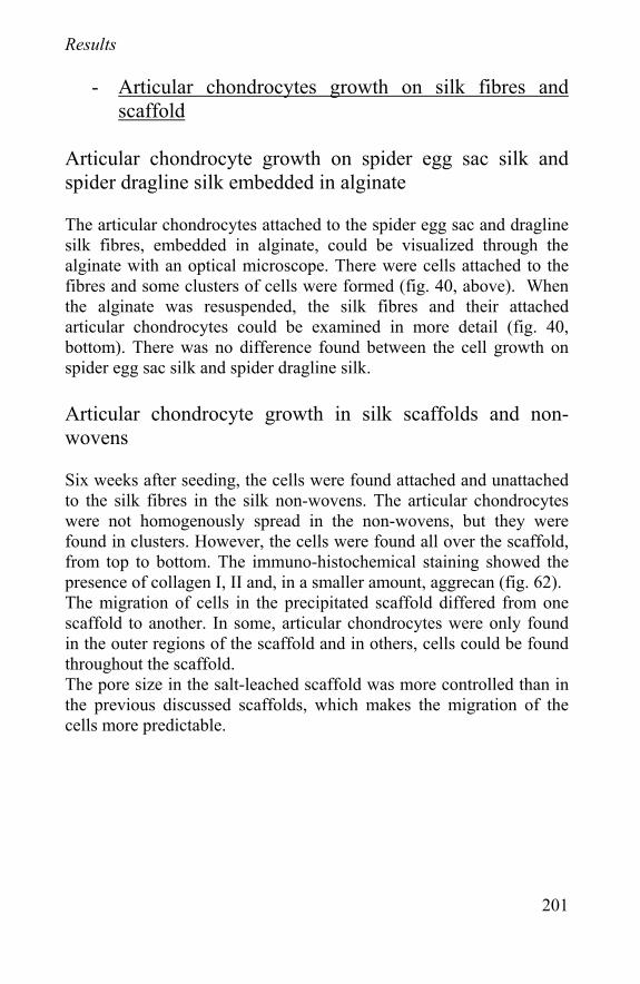
201
Results
- Articular chondrocytes growth on silk fibres and scaffold
Articular chondrocyte growth on spider egg sac silk and spider dragline silk embedded in alginate The articular chondrocytes attached to the spider egg sac and dragline silk fibres, embedded in alginate, could be visualized through the alginate with an optical microscope. There were cells attached to the fibres and some clusters of cells were formed (fig. 40, above). When the alginate was resuspended, the silk fibres and their attached articular chondrocytes could be examined in more detail (fig. 40, bottom). There was no difference found between the cell growth on spider egg sac silk and spider dragline silk. Articular chondrocyte growth in silk scaffolds and non-wovens Six weeks after seeding, the cells were found attached and unattached to the silk fibres in the silk non-wovens. The articular chondrocytes were not homogenously spread in the non-wovens, but they were found in clusters. However, the cells were found all over the scaffold, from top to bottom. The immuno-histochemical staining showed the presence of collagen I, II and, in a smaller amount, aggrecan (fig. 62). The migration of cells in the precipitated scaffold differed from one scaffold to another. In some, articular chondrocytes were only found in the outer regions of the scaffold and in others, cells could be found throughout the scaffold. The pore size in the salt-leached scaffold was more controlled than in the previous discussed scaffolds, which makes the migration of the cells more predictable.
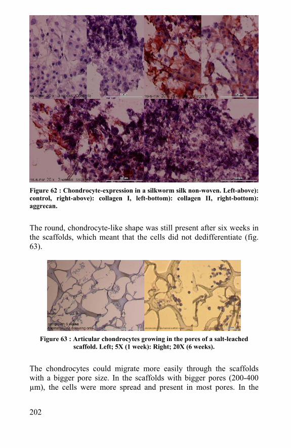
202
d)
Figure 62 : Chondrocyte-expression in a silkworm silk non-woven. Left-above): control, right-above): collagen I, left-bottom): collagen II, right-bottom): aggrecan.
The round, chondrocyte-like shape was still present after six weeks in the scaffolds, which meant that the cells did not dedifferentiate (fig. 63).
Figure 63 : Articular chondrocytes growing in the pores of a salt-leached
scaffold. Left; 5X (1 week): Right; 20X (6 weeks).
The chondrocytes could migrate more easily through the scaffolds with a bigger pore size. In the scaffolds with bigger pores (200-400 µm), the cells were more spread and present in most pores. In the
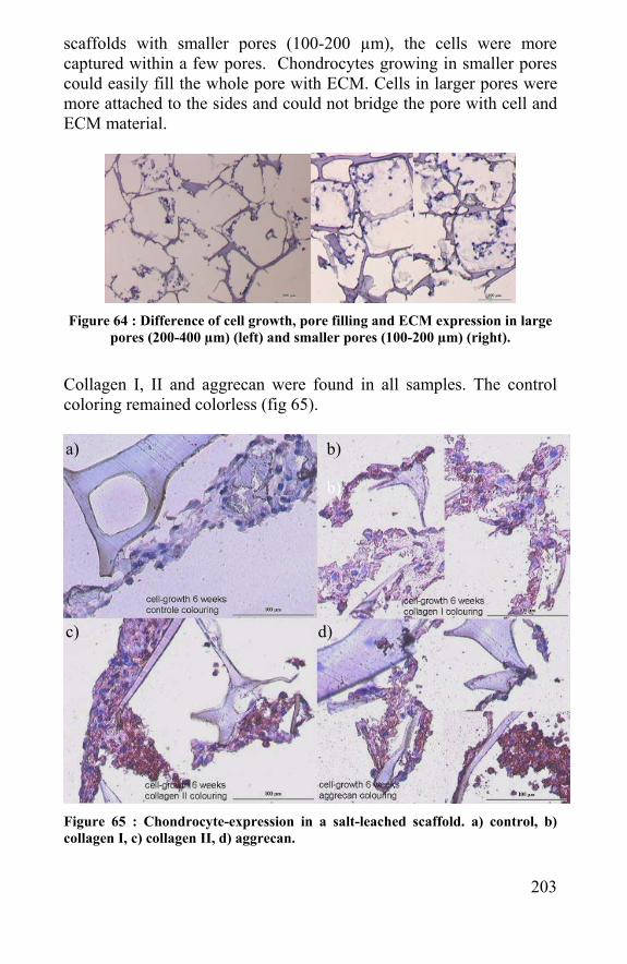
203
scaffolds with smaller pores (100-200 µm), the cells were more captured within a few pores. Chondrocytes growing in smaller pores could easily fill the whole pore with ECM. Cells in larger pores were more attached to the sides and could not bridge the pore with cell and ECM material.
Figure 64 : Difference of cell growth, pore filling and ECM expression in large
pores (200-400 µm) (left) and smaller pores (100-200 µm) (right).
Collagen I, II and aggrecan were found in all samples. The control coloring remained colorless (fig 65).
Figure 65 : Chondrocyte-expression in a salt-leached scaffold. a) control, b) collagen I, c) collagen II, d) aggrecan.
b)
a) b)
c) d)
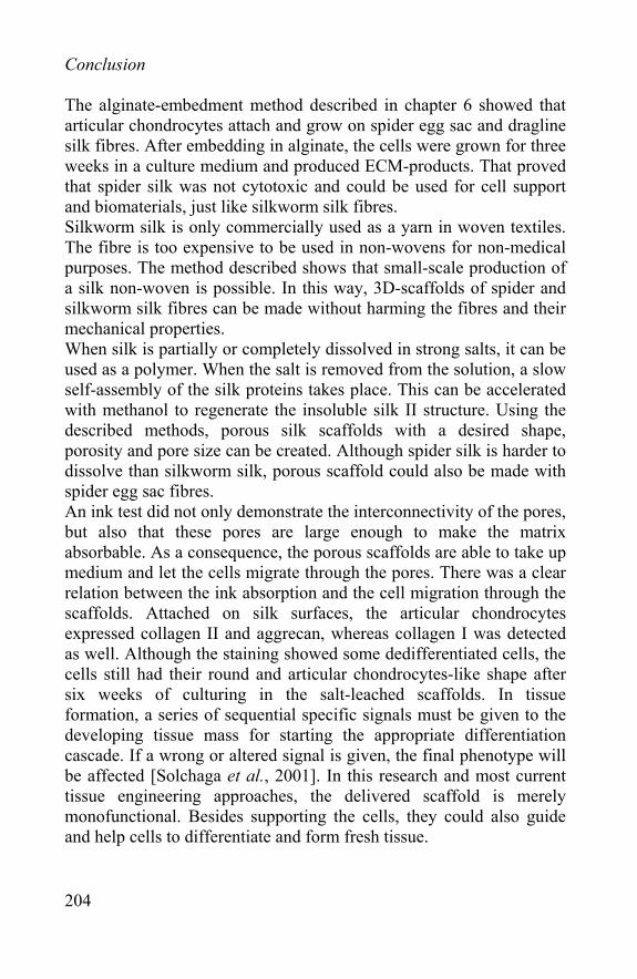
204
Conclusion The alginate-embedment method described in chapter 6 showed that articular chondrocytes attach and grow on spider egg sac and dragline silk fibres. After embedding in alginate, the cells were grown for three weeks in a culture medium and produced ECM-products. That proved that spider silk was not cytotoxic and could be used for cell support and biomaterials, just like silkworm silk fibres. Silkworm silk is only commercially used as a yarn in woven textiles. The fibre is too expensive to be used in non-wovens for non-medical purposes. The method described shows that small-scale production of a silk non-woven is possible. In this way, 3D-scaffolds of spider and silkworm silk fibres can be made without harming the fibres and their mechanical properties. When silk is partially or completely dissolved in strong salts, it can be used as a polymer. When the salt is removed from the solution, a slow self-assembly of the silk proteins takes place. This can be accelerated with methanol to regenerate the insoluble silk II structure. Using the described methods, porous silk scaffolds with a desired shape, porosity and pore size can be created. Although spider silk is harder to dissolve than silkworm silk, porous scaffold could also be made with spider egg sac fibres. An ink test did not only demonstrate the interconnectivity of the pores, but also that these pores are large enough to make the matrix absorbable. As a consequence, the porous scaffolds are able to take up medium and let the cells migrate through the pores. There was a clear relation between the ink absorption and the cell migration through the scaffolds. Attached on silk surfaces, the articular chondrocytes expressed collagen II and aggrecan, whereas collagen I was detected as well. Although the staining showed some dedifferentiated cells, the cells still had their round and articular chondrocytes-like shape after six weeks of culturing in the salt-leached scaffolds. In tissue formation, a series of sequential specific signals must be given to the developing tissue mass for starting the appropriate differentiation cascade. If a wrong or altered signal is given, the final phenotype will be affected [Solchaga et al., 2001]. In this research and most current tissue engineering approaches, the delivered scaffold is merely monofunctional. Besides supporting the cells, they could also guide and help cells to differentiate and form fresh tissue.
205
The force necessary for compressing the scaffolds was quite low and they returned immediately to their original shape after compression. The compression modulus of the scaffold should be smaller than the one of real cartilage to avoid stress-shielding and accelerate differentiation and ECM-expression. The silk scaffolds are strong enough to keep the cells spread over the injury during cartilage regeneration. The advantage of the non-wovens towards the other scaffolds is that the silk fibres are not damaged and so keep their mechanical properties. The compressibility properties of the salt-leached silk scaffolds are good, but by tearing one apart by hand it is clear that the tensile strength is far beyond the one of undamaged silk fibres. Although a high tensile strength is not required for cartilage repair, scaffold could be reinforced with spider silk fibres. Using these reinforcements, one can combine the mechanical properties of draglines and the cell culturing properties of a porous silk scaffold. Cell growth and expression did not differ between spider egg sac and silkworm silk fibres or scaffolds. As the advantage of using spider silk is merely in their toughness, these fibres could better be used as unharmed fibres in sutures, matrices for tendon regeneration, nerve cell support or reinforcements of other biomaterials. Silkworm and spider silk have, besides high-performance mechanical properties and a slow biodegradability, good biomedical properties. They are not cytotoxic as cells can adhere and grow on the fibres for several weeks. The different silk fibres can be processed in non-wovens and porous scaffolds, in which human articular chondrocytes can migrate, culture and express their ECM-products. As these porous scaffolds can be made in any shape and reinforced with fibres with appropriate mechanical properties, these scaffolds can be used in tissue engineering applications like cartilage and meniscus regeneration.
8.4 Mathematical model revision after biological tests
In chapter 7, a simplified theoretical model of cells (C) growing in a porous biodegrading scaffold (S) producing ECM-products (E) was presented. Some variables and formulas were formulated to describe
206
the biological problem in a simple mathematical way. In previous chapters scaffolds have been created and cells have grown in them while producing ECM for several weeks. So, in this chapter the model will be adjusted with the biological results. The first adjustment is the biodegradation of the scaffold, with and without cells seeded on it. Scaffolds could be kept in medium for several weeks without any visible biodegradation. If this is compared with the in vitro biodegradation results from chapter 7, it is likely that silkworm silk and spider silk can stay undamaged for several months in the medium:
dS/dt ~= 0 and dS/dt = -k1S
k1 = degradation speed of scaffold material (very small) During the in vitro tests of 1, 3 and 6 weeks a scaffold material biodegradation could not be detected:
dS/dt ~= 0 and dS/dt = - k1S - k2CS and k1 = very small
C or k2 is very small As the cells survived and grew sufficiently in the pores, it can be concluded that k2 will be very small as well.
The cells in the scaffolds could have died from the toxicity of the material or proliferation in the pores. The decrease or proliferation of the cell mass was described in the model as follows:
dC/dt = k3C - k4C² - k5SC C0 (the starting number of cells) is approximately 10 million cells per scaffold. However during seeding, lots of cells fell next to the scaffold or were taken by the medium away from the scaffold. In this way, not all cells got into the scaffold. During the weeks of culturing, the cell growth in the scaffold could not be observed. The cell viability, distribution and expression could be examined by cross-sections, but the remaining cell mass was not quantified. The k3 and k4 variables are only chondrocyte-dependent and depend only on the cells, culture media and conditions.
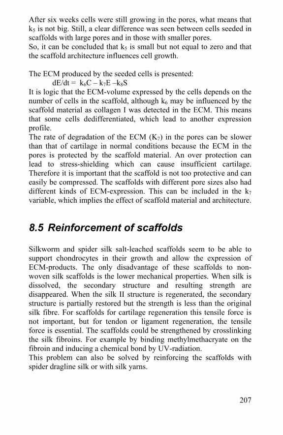
207
After six weeks cells were still growing in the pores, what means that k5 is not big. Still, a clear difference was seen between cells seeded in scaffolds with large pores and in those with smaller pores. So, it can be concluded that k5 is small but not equal to zero and that the scaffold architecture influences cell growth. The ECM produced by the seeded cells is presented:
dE/dt = k6C – k7E –k8S It is logic that the ECM-volume expressed by the cells depends on the number of cells in the scaffold, although k6 may be influenced by the scaffold material as collagen I was detected in the ECM. This means that some cells dedifferentiated, which lead to another expression profile. The rate of degradation of the ECM (K7) in the pores can be slower than that of cartilage in normal conditions because the ECM in the pores is protected by the scaffold material. An over protection can lead to stress-shielding which can cause insufficient cartilage. Therefore it is important that the scaffold is not too protective and can easily be compressed. The scaffolds with different pore sizes also had different kinds of ECM-expression. This can be included in the k7 variable, which implies the effect of scaffold material and architecture.
8.5 Reinforcement of scaffolds Silkworm and spider silk salt-leached scaffolds seem to be able to support chondrocytes in their growth and allow the expression of ECM-products. The only disadvantage of these scaffolds to non-woven silk scaffolds is the lower mechanical properties. When silk is dissolved, the secondary structure and resulting strength are disappeared. When the silk II structure is regenerated, the secondary structure is partially restored but the strength is less than the original silk fibre. For scaffolds for cartilage regeneration this tensile force is not important, but for tendon or ligament regeneration, the tensile force is essential. The scaffolds could be strengthened by crosslinking the silk fibroins. For example by binding methylmethacryate on the fibroin and inducing a chemical bond by UV-radiation. This problem can also be solved by reinforcing the scaffolds with spider dragline silk or with silk yarns.
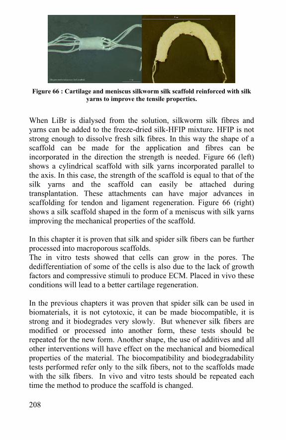
208
Figure 66 : Cartilage and meniscus silkworm silk scaffold reinforced with silk
yarns to improve the tensile properties.
When LiBr is dialysed from the solution, silkworm silk fibres and yarns can be added to the freeze-dried silk-HFIP mixture. HFIP is not strong enough to dissolve fresh silk fibres. In this way the shape of a scaffold can be made for the application and fibres can be incorporated in the direction the strength is needed. Figure 66 (left) shows a cylindrical scaffold with silk yarns incorporated parallel to the axis. In this case, the strength of the scaffold is equal to that of the silk yarns and the scaffold can easily be attached during transplantation. These attachments can have major advances in scaffolding for tendon and ligament regeneration. Figure 66 (right) shows a silk scaffold shaped in the form of a meniscus with silk yarns improving the mechanical properties of the scaffold. In this chapter it is proven that silk and spider silk fibers can be further processed into macroporous scaffolds. The in vitro tests showed that cells can grow in the pores. The dedifferentiation of some of the cells is also due to the lack of growth factors and compressive stimuli to produce ECM. Placed in vivo these conditions will lead to a better cartilage regeneration. In the previous chapters it was proven that spider silk can be used in biomaterials, it is not cytotoxic, it can be made biocompatible, it is strong and it biodegrades very slowly. But whenever silk fibers are modified or processed into another form, these tests should be repeated for the new form. Another shape, the use of additives and all other interventions will have effect on the mechanical and biomedical properties of the material. The biocompatibility and biodegradability tests performed refer only to the silk fibers, not to the scaffolds made with the silk fibers. In vivo and vitro tests should be repeated each time the method to produce the scaffold is changed.
209
8.6 References - Akizuki S, Mow VC, Muller F, Pita JC, Howell DS, Manicourt DH. Tensile properties of human knee joint cartilage: I. Influence of ionic conditions, weight bearing, and fibrillation on the tensile modulus. J Orthop Res. 1986;4(4):379-92 - Almqvist KF, Wang L, Wang J, Baeten D, Cornelissen M, Verdonk R, Veys EM, Verbruggen G. Culture of chondrocytes in alginate surrounded by fibrin gel: characteristics of the cells over a period of eight weeks. Ann Rheum Dis. 2001 Aug;60(8):781-90. - Bannasch H, Fohn M, Unterberg T, Bach AD, Weyand B, Stark GB. Skin tissue engineering. Clin Plast Surg. 2003 Oct;30(4):573-9. Review - Brittberg M. Autologous chondrocyte transplantation. Clin Orthop Relat Res. 1999 Oct;(367 Suppl):S147-55. Review - Brittberg M, Peterson L, Sjogren-Jansson E, Tallheden T, Lindahl A. Articular cartilage engineering with autologous chondrocyte transplantation. A review of recent developments. J Bone Joint Surg Am. 2003;85-A Suppl 3:109-15. Review - Holland TA, Tabata Y, Mikos AG. Dual growth factor delivery from degradable oligo(poly(ethylene glycol) fumarate) hydrogel scaffolds for cartilage tissue engineering. J Control Release. 2005 Jan 3;101(1-3):111-25 - Hutmacher DW. Scaffolds in tissue engineering bone and cartilage. Biomaterials. 2000 Dec;21(24):2529-43 - Kobayashi M. A study of polyvinyl alcohol-hydrogel (PVA-H) artificial meniscus in vivo. Biomed Mater Eng. 2004;14(4):505-15 - Llames SG, Del Rio M, Larcher F, Garcia E, Garcia M, Escamez MJ, Jorcano JL, Holguin P, Meana A. Human plasma as a dermal scaffold for the generation of a completely autologous bioengineered skin. Transplantation. 2004 Feb 15;77(3):350-5. - Naughton GK. Emerging developments in tissue engineering and cell technology. Tissue eng. 1995;1(2): 211-9
210
- Rodrigues-Garcia RC, del Bel-Cury AA. Accuracy and porosity of denture bases submitted to two polymerization cycles. Indian J Dent Res. 1996 Oct-Dec;7(4):122-6. - Solchaga LA, Goldberg VM, Caplan AI. Cartilage regeneration using principles of tissue engineering. Clin Orthop. 2001 Oct;(391 Suppl):S161-70. - Tsukada m, Freddi g, Monti P, Bertoluzza A, Kasai N. Structure and Molecular conformation opf Tussah silk fibroin films: Effect of methanol. Journal of polymer science. 1995, 33: 1995-2001 - Vinatier C, Magne D, Weiss P, Trojani C, Rochet N, Carle GF, Vignes-Colombeix C, Chadjichristos C, Galera P, Daculsi G, Guicheux J. A silanized hydroxypropyl methylcellulose hydrogel for the three-dimensional culture of chondrocytes. Biomaterials. 2005 Jun 8
211
Chapter 9 Conclusion

212
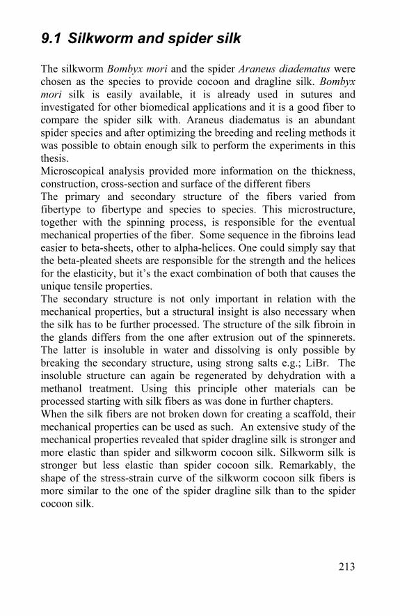
213
9.1 Silkworm and spider silk The silkworm Bombyx mori and the spider Araneus diadematus were chosen as the species to provide cocoon and dragline silk. Bombyx mori silk is easily available, it is already used in sutures and investigated for other biomedical applications and it is a good fiber to compare the spider silk with. Araneus diadematus is an abundant spider species and after optimizing the breeding and reeling methods it was possible to obtain enough silk to perform the experiments in this thesis. Microscopical analysis provided more information on the thickness, construction, cross-section and surface of the different fibers The primary and secondary structure of the fibers varied from fibertype to fibertype and species to species. This microstructure, together with the spinning process, is responsible for the eventual mechanical properties of the fiber. Some sequence in the fibroins lead easier to beta-sheets, other to alpha-helices. One could simply say that the beta-pleated sheets are responsible for the strength and the helices for the elasticity, but it’s the exact combination of both that causes the unique tensile properties. The secondary structure is not only important in relation with the mechanical properties, but a structural insight is also necessary when the silk has to be further processed. The structure of the silk fibroin in the glands differs from the one after extrusion out of the spinnerets. The latter is insoluble in water and dissolving is only possible by breaking the secondary structure, using strong salts e.g.; LiBr. The insoluble structure can again be regenerated by dehydration with a methanol treatment. Using this principle other materials can be processed starting with silk fibers as was done in further chapters. When the silk fibers are not broken down for creating a scaffold, their mechanical properties can be used as such. An extensive study of the mechanical properties revealed that spider dragline silk is stronger and more elastic than spider and silkworm cocoon silk. Silkworm silk is stronger but less elastic than spider cocoon silk. Remarkably, the shape of the stress-strain curve of the silkworm cocoon silk fibers is more similar to the one of the spider dragline silk than to the spider cocoon silk.
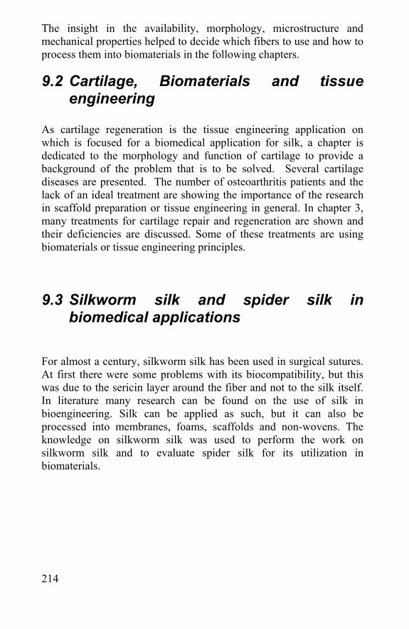
214
The insight in the availability, morphology, microstructure and mechanical properties helped to decide which fibers to use and how to process them into biomaterials in the following chapters.
9.2 Cartilage, Biomaterials and tissue engineering
As cartilage regeneration is the tissue engineering application on which is focused for a biomedical application for silk, a chapter is dedicated to the morphology and function of cartilage to provide a background of the problem that is to be solved. Several cartilage diseases are presented. The number of osteoarthritis patients and the lack of an ideal treatment are showing the importance of the research in scaffold preparation or tissue engineering in general. In chapter 3, many treatments for cartilage repair and regeneration are shown and their deficiencies are discussed. Some of these treatments are using biomaterials or tissue engineering principles.
9.3 Silkworm silk and spider silk in biomedical applications
For almost a century, silkworm silk has been used in surgical sutures. At first there were some problems with its biocompatibility, but this was due to the sericin layer around the fiber and not to the silk itself. In literature many research can be found on the use of silk in bioengineering. Silk can be applied as such, but it can also be processed into membranes, foams, scaffolds and non-wovens. The knowledge on silkworm silk was used to perform the work on silkworm silk and to evaluate spider silk for its utilization in biomaterials.
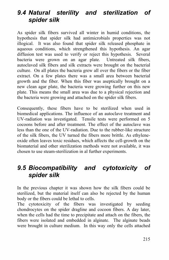
215
9.4 Natural sterility and sterilization of spider silk
As spider silk fibers survived all winter in humid conditions, the hypothesis that spider silk had antimicrobials properties was not illogical. It was also found that spider silk released phosphate in aqueous conditions, which strengthened this hypothesis. An agar diffusion test was used to verify or reject this hypothesis. Several bacteria were grown on an agar plate. Untreated silk fibers, autoclaved silk fibers and silk extracts were brought on the bacterial culture. On all plates the bacteria grew all over the fibers or the fiber extract. On a few plates there was a small area between bacterial growth and the fiber. When this fiber was aseptically brought on a new clean agar plate, the bacteria were growing further on this new plate. This means the small area was due to a physical rejection and the bacteria were growing and attached on the spider silk fibers. Consequently, these fibers have to be sterilized when used in biomedical applications. The influence of an autoclave treatment and UV-radiation was investigated. Tensile tests were performed on 5 cocoons before and after treatment. The effect of the autoclave was less than the one of the UV-radiation. Due to the rubber-like structure of the silk fibers, the UV turned the fibers more brittle. As ethylene-oxide often leaves toxic residues, which affects the cell-growth on the biomaterial and other sterilization methods were not available, it was chosen to use steam-sterilization in al further experiments.
9.5 Biocompatibility and cytotoxicity of spider silk
In the previous chapter it was shown how the silk fibers could be sterilized, but the material itself can also be rejected by the human body or the fibers could be lethal to cells. The cytotoxicity of the fibers was investigated by seeding chondrocytes on the spider dragline and cocoon fibers. A day later, when the cells had the time to precipitate and attach on the fibers, the fibers were isolated and embedded in alginate. The alginate beads were brought in culture medium. In this way only the cells attached
216
on the silk fibers could grow in the alginate beads. As cells were clearly visible all around the fibers, this test showed that silk fibers are not cytotoxic and even more, cells can attach and grow on the spider silk fibers, both cocoon and dragline fibers. Next to being lethal to cells, materials can also provoke an inflammatory reaction in the body. Used as a suture material and in many other biomedical applications the spider silk will be exposed to the immune system. The best way to found out is to sterilize the material and implant it in vivo and investigate the tissue reaction after several time periods. According to ISO-norm 10.993-6, spider cocoon silk fibers were implanted next to Vicryl®-samples for comparison, as Vicryl® is a known and accepted suture material. The granulocyte production was significantly higher towards the spider silk than towards the Vicryl®. An enzyme treatment using trypsin and proteinase K could improve the biocompatibility of spider cocoon silk. The granulocyte and giant cell production and the fibrotic tissue formation were comparable to the one towards the Vicryl®-implants. Proteinase K did harm the mechanical properties of the spider silk fibers. As the trypsin treatment did not degrade the tensile properties significantly, this enzyme can be used for the improvement of the biocompatibility of spider silk. This chapter showed that spider silk can be sterilized with an autoclave and by using a trypsin cleaning; the fibers are as biocompatible as the widely accepted Vicryl® fibers.
9.6 Biodegradation of silk and spider silk In many biomedical applications and especially in tissue engineering it is necessary that the applied biomaterial biodegrades after a certain time. A biodegradation is not enough the body has to resorb the degradation products. In other biomedical applications it is important to know whether the material biodegrades or not. During the in vivo experiments for the biodegradability-tests it was already clear that silk did not biodegrade as fast as the Vicryl® fibers. The Vicryl® fibers showed cracks after 1 week of implantation. The silk fibers stayed unharmed even after 3 months of implantation. To quantify this difference spider cocoon silk, silkworm silk and Vicryl® fibers were immersed in PBS for up to 3 months and tensile properties were performed after different time periods. The Vicryl® fibers lost their strength gradually after 4 and 8 weeks, after 12 weeks they were
217
already totally dissolved. Both the silk fibers kept their mechanical properties over the 3 month period. As all effects of enzymes and body movements were lacking in this experiment it gives only a relative result, but the slow biodegradability of the silk is obvious in both the in vivo and in vitro tests. The slow biodegradation of silk is a disadvantage for some application, but for scaffolds in tissue engineering this is an advantage. When a scaffold biodegrades too fast, the cells seeded in the scaffold do not have the time to regenerate the tissue. When the scaffold biodegrades slowly, the scaffold material will still be in the regenerated tissue when the tissue is regenerated. The latter is not that negative as long as the scaffold does not stop the cells to produce extracellular matrix.
9.7 Silkworm and spider silk scaffolds In the previous chapters it is proven that silk and spider silk can be used in a biomaterial and that it is slowly biodegradable. In this chapter several scaffolds were created with silkworm silk and spider cocoon silk. These were created by developing a non-woven and by producing macroporous scaffolds by silk fibroin precipitation and by using a salt-leaching technique. The advantage of the non-woven is that the fibers were not harmed and the eventual scaffold still had the mechanical properties of the silk fibers. The porosity is depending of the fiber distribution. The silk fibroin precipitated scaffolds were really strong, but the porosity was not controllable. Pore-size and porosity could be controlled and defined when the scaffolds were made using the salt-leaching method. The compression modulus of the scaffolds could be determined by converting the tensile tester into a compression tester. The salt-leached silk and spider silk scaffolds were compressible up to 90% of its volume and did revert to its original volume immediately. The force necessary to compress the scaffold was dependent on the pore-size and porosity of the scaffold.
218
These scaffolds were seeded with chondrocytes isolated from human knee cartilage. A few days after seeding, the isolated cells could be found viable distributed over the pores, which proved that the scaffolds are not cytotoxic and the cells can penetrate through the pores. After 1, 3 and 6 weeks of culturing, the seeded scaffolds were cut in 5µm slices using a cryotome. The slices were immunohistochemically stained for collagen I, II and aggrecan; a heamatoxyline-staining colored the viable cells. A quantification of the cells was not possible, but cells and ECM could be retrieved for at least 6 weeks after seeding. Besides a clear collagen II and aggrecan coloring, there was also some color visible when specific antibodies for collagen I were used. This means that some cells dedifferentiated when seeded in the scaffold. Nevertheless, the round morphology, typical for chondrocytes, showed that most cells stayed differentiated when seeded in the silk scaffolds. This chapter showed that it is possible to create non-wovens and macroporous scaffolds with silkworm and spider cocoon silk. Their mechanical properties are appropriate to be used in tissue engineering applications like cartilage regeneration. Chondrocytes could grow in, attach to and migrate through the pores and produce collagen II and aggrecan when seeded in the macroporous silk scaffolds.