
AlarmNet 7847i/7847i-E - DIY Alarm Forum
64
A A l l a a r r m m N N e e t t 7 7 8 8 4 4 7 7 i i / / 7 7 8 8 4 4 7 7 i i - - E E Internet/Intranet Communication Modules With Remote Services Installation and Setup Guide K14175 11/07 Requires Compass Version 1.5.8.54A (or higher) for IP Downloading WWW.DIYALARMFORUM.COM WWW.DIYALARMFORUM.COM
Transcript of AlarmNet 7847i/7847i-E - DIY Alarm Forum
AAAAAAAAllllllllaaaaaaaarrrrrrrrmmmmmmmmNNNNNNNNeeeeeeeetttttttt 77777777888888884444444477777777iiiiiiii////////77777777888888884444444477777777iiiiiiii--------EEEEEEEE IInntteerrnneett//IInnttrraanneett CCoommmmuunniiccaattiioonn MMoodduulleess
With Remote Services
Installation and Setup Guide
K14175 11/07
Requires
Compass Version 1.5.8.54A (or higher) for IP Downloading
WWW.DIYALARMFORUM.COM WWW.DIYALARMFORUM.COM

WWW.DIYALARMFORUM.COM WWW.DIYALARMFORUM.COM
i
Table of Contents • • • • • • • • • • • • • • • • • • • • • • • • • • • • • • • • • • • • • • • • • • • • • • • • •
SECTION 1: General Information........................................................................................................... 1-1
Introduction ............................................................................................................................................................... 1-1
System Features......................................................................................................................................................... 1-1
About Private Network Application .......................................................................................................................... 1-1
About AlarmNet-i Internet Application..................................................................................................................... 1-2
Encryption ................................................................................................................................................................. 1-2
Enterprise Encryption Related Functions .................................................................................................................. 1-2
Installation Key (for Private LAN)............................................................................................................................ 1-2
Recovery Mode ......................................................................................................................................................... 1-2
Remote Services ........................................................................................................................................................ 1-3
Modes of Operation ................................................................................................................................................... 1-3
ECP Mode ................................................................................................................................................... 1-3
Zone Trigger Mode ..................................................................................................................................... 1-3
4204 Mode and Two-4204 Mode................................................................................................................ 1-3
Module Supervision Features .................................................................................................................................... 1-4
Specifications ............................................................................................................................................................ 1-4
Mechanical .................................................................................................................................................. 1-4
Electrical ..................................................................................................................................................... 1-4
Ethernet ....................................................................................................................................................... 1-4
Environmental ............................................................................................................................................. 1-4
SECTION 2: Mounting and Wiring ......................................................................................................... 2-1
Mounting the 7847i/7847i-E...................................................................................................................................... 2-1
Wiring the 7847i/7847i-E .......................................................................................................................................... 2-2
Wiring for ECP, 4204 and Two-4204 Modes.............................................................................................. 2-2
Wiring for Zone Trigger Mode.................................................................................................................... 2-3
Power Connections and Options................................................................................................................................ 2-4
Ethernet Connections................................................................................................................................................. 2-4
Initial Power-Up Sequence.......................................................................................................................... 2-5
SECTION 3: Programming the 7847i/7847i-E ....................................................................................... 3-1
General Information .................................................................................................................................................. 3-1
Using the AlarmNet Direct Website............................................................................................................ 3-1
Using a 7720P Programming Tool .............................................................................................................. 3-1
Using the Control Panel Programming Mode ............................................................................................. 3-2
Programming Conventions.......................................................................................................................... 3-2
ECP Mode Programming........................................................................................................................................... 3-2 ECP Status Codes ................................................................................................................................................ 3-9
WWW.DIYALARMFORUM.COM WWW.DIYALARMFORUM.COM
7847i/7847i-E Installation and Setup Guide
ii
Alternative Modes (Zone Trigger, 4204 and Two-4204) .......................................................................................... 3-9
Zone Trigger Mode ..................................................................................................................................... 3-9
4204 Emulation Mode................................................................................................................................. 3-9
4204 Emulation Mode Options ................................................................................................................... 3-9
Alternative Mode Programming .............................................................................................................................. 3-10
Exiting Programming Mode .................................................................................................................................... 3-20 Setting Factory Defaults .................................................................................................................................... 3-20
SECTION 4: Registration .......................................................................................................................... 4-1
Registering the 7847i/7847i-E................................................................................................................................... 4-1
Registering through AlarmNet Direct Website (does not apply if using Private LAN) .............................. 4-1
Using the Tamper Switch ............................................................................................................................ 4-2
Using the Programming Tool ...................................................................................................................... 4-2
Register by Phone........................................................................................................................................ 4-4
SECTION 5: Programmer Keyboard Commands ................................................................................ 5-1
Programmer Keyboard Commands ........................................................................................................................... 5-1
System Status Displays ............................................................................................................................... 5-2
SECTION 6: Network Diagnostics .......................................................................................................... 6-1
Running Network Diagnostics on the 7847i/7847i-E using AlarmNet ..................................................................... 6-1
Possible Errors Running Network Diagnostics ........................................................................................... 6-2
Running Network Diagnostics on the 7847i-E using a Private LAN ........................................................................ 6-3
Possible Errors Running Network Diagnostics using a Private LAN.......................................................... 6-4
Appendices ...................................................................................................................................................A-1
Appendix A : Summary of LED Operation .............................................................................................................. A-1
Status Display Operation............................................................................................................................ A-1
Network Connectivity Display................................................................................................................... A-3
Mode and Status LED Display................................................................................................................... A-4
Mode and Status Indicator Switch.............................................................................................................. A-4
Appendix B : Central Station Messages ....................................................................................................................B-1
Appendix C : IP Downloading ..................................................................................................................................C-1
General Information ....................................................................................................................................C-1
Direct Wire Setup........................................................................................................................................C-1
Appendix D : Glossary ............................................................................................................................................. D-1 Summary of Connections Diagram…………………………………………………………..……….Inside Back Cover
WWW.DIYALARMFORUM.COM WWW.DIYALARMFORUM.COM
1-1
S E C T I O N 1
General Information • • • • • • • • • • • • • • • • • • • • • • • • • • • • • • • • • • • • • • • • • • • • • • • • •
In This Section � Introduction � System Features
� About Private Network Application
� About AlarmNet-i Internet Application
� Encryption
� Enterprise Related Encryption Functions
� Installation Key
� Recovery Mode � Remote Services � Modes of Operation
� Specifications
• • • • • • • • • • • • • • • • • • • • • • • • • • • • • • • • • • • • • • • • • • • • • • • • •
Introduction AlarmNet’s 7847i Internet Communication Module and 7847i-E Internet/Intranet Communication Module were developed to transport alarm signals via the Internet or Private LAN (7847i-E only). These easy-to-install devices provide sophisticated data security and communicate with all AlarmNet central stations through AlarmNet’s server, or directly to a 7810iR-ent Internet/Intranet receiver in a private network application (7847i-E). In addition to alarm reporting, the 7847i and 7847i-E provide upload/downloading capability via the internet or a Private LAN (7847i-E only).
System Features Basic features of the 7847i and 7847i-E include:
• Easy CAT-5 10 BaseT connection to a hub or router
• Installs behind firewalls without compromising network security
• Supports dynamic or static IP addressing
• Quick connection to compatible Honeywell series control panels
• Simple programming using a 7720P programming tool or AlarmNet Direct website
• Reports fire, burg, and status messages via the Internet (or Intranet for 7847i-E)
• Allows uploading and downloading of control panel data over the Internet (or Intranet for 7847i-E)
• Supports remote control of alarm systems via Remote Access feature, and email notification of events via Multi-Mode feature (Web Service)
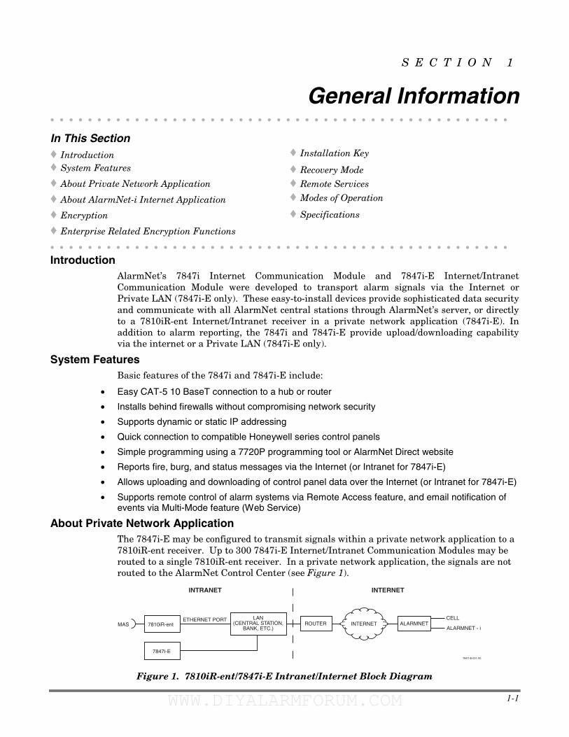
About Private Network Application The 7847i-E may be configured to transmit signals within a private network application to a 7810iR-ent receiver. Up to 300 7847i-E Internet/Intranet Communication Modules may be routed to a single 7810iR-ent receiver. In a private network application, the signals are not routed to the AlarmNet Control Center (see Figure 1).
MAS
7847i-E
ALARMNETROUTERLAN
(CENTRAL STATION,BANK, ETC.)
7810iR-entETHERNET PORT
INTERNETALARMNET - i
CELL
INTERNETINTRANET
7847i-E-031-V0
Figure 1. 7810iR-ent/7847i-E Intranet/Internet Block Diagram
WWW.DIYALARMFORUM.COM WWW.DIYALARMFORUM.COM
7847i/7847i-E Installation and Setup Guide
1-2
The 7847i/7847i-E module requires an AlarmNet–i account. For new installations, please obtain the account information from the central station prior to programming this module. For replacement installations, the AlarmNet-i account is created automatically when the module is registered (based on the existing "C Series" account).
About AlarmNet-i Internet Application AlarmNet-i is a fully encrypted, secure method of delivering alarm messages from a protected premise to an AlarmNet equipped central station. An Internet Communicator Module transmits status, supervisory, and alarm messages to the AlarmNet Control Center using a broadband Internet connection (see Figure 1).
The AlarmNet Control Center identifies, validates, and forwards the messages to the appropriate AlarmNet central station. An Internet receiver, 7810iR or 7810iR-ent, is required when receiving Internet signals from the AlarmNet Control Center. AlarmNet-i has an unlimited account capacity.
Encryption The 7847i/7847i-E and 7810iR-ent support private key encryption. Private key encryption means that both the sender and the receiver know the KEY used to encrypt the data. Each device produced by Honeywell is loaded with a globally unique identifier called a MAC number, and a large random number or KEY. This KEY and MAC number are also stored in the AlarmNet servers. When a device contacts AlarmNet it sends the MAC number in the clear followed by the message that is encrypted using the KEY data. The server looks up its copy of the KEY based on the MAC number and uses that KEY to decrypt the message.
The communication devices use 256 bit AES (Rijndael) encryption (which is required for certain government installations). The AlarmNet-i AES Encryption Software Module Version 1.0 contained in the Honeywell products has NIST approval. Listings for this approval can be found at http://csrc.nist.gov/cryptval/aes/aesval.html Certification number 127.
Enterprise Encryption Related Functions The previous paragraph described general encryption, and how it functions with AlarmNet. When used in a Private closed network or Enterprise installations, some additional processes are required to support encryption. In an enterprise installation the 7810iR-ent takes on the server function that exists in the AlarmNet Internet installation and has a process to learn the MAC numbers and KEYs for which it will be responsible.
Installation Key (for Private LAN) At installation a 10-digit installation key needs to be programmed into every device in the network. This 10-digit key should be the same for all devices used in the Private LAN mode. The purpose of this key is to encrypt the private KEY of each subscriber device as it is registered to the 7810iR-ent so this sensitive data is never sent in the clear. This KEY is only used for registration purposes and is not used for supervision or alarm transmission. Once a device is registered the 7810iR-ent will have a copy of the 7847i-E’s factory KEY. From this point on the unique factory key is used for communications.
Recovery Mode Recovery Mode is only available when in Private LAN mode. In the event of a failure of the 7810iR-ent requiring the replacement of the hardware or the erasure of its memory, the 7810iR-ent supports a Recovery Mode. In Recovery Mode, the 7810iR-ent is programmed with the same 10-digit installation key. When a 7847i-E communicates with the 7810iR-ent and is found not to exist in its database, a special response is sent back to the 7847i-E requesting it to re-register itself. The 7847i-E then registers using the 10-digit installation key. When all accounts have been recovered, Recovery Mode can be turned off to provide better control of registration.
WWW.DIYALARMFORUM.COM WWW.DIYALARMFORUM.COM
Section 1: General Information
1-3
Remote Services
UL Remote Access and Multi-Mode have not been evaluated by UL.
Honeywell now offers a new series of web based services that provides consumers with the ability to communicate with their security system remotely in a number of ways. These new web services will allow users to:
• Access their security system from a computer via a website (Remote Access feature)
• Receive email and text message notifications of system events (Multi-Mode feature)
• Perform system functions and receive confirmations using text messages (SMS feature)
Dealers will initially enroll their customers for web services during account programming through the AlarmNet Direct website. The features that can be enabled include Remote Access and Multi-Mode. Once enabled, the specific programming fields associated with these features can be programmed into the communications device either remotely using the AlarmNet Direct website or locally using the 7720P local keypad programming tool.
Modes of Operation The 7847i and 7847i-E provide four modes of operation so they can be used with various types of control panels, as summarized below:
ECP Mode
• This mode is for use with Honeywell controls that support LRR-ECP communication
• The module connects to the control’s keypad terminals and provides 2-way communication with the control using ECP messaging
• The control treats the module as a Long Range Radio (LRR) device, so program the control accordingly, including setting the module’s proper LRR device address
• Panel-generated reports are sent in Contact ID format
• The module also supports two hardwire zone trigger inputs (zones 6 and 7) – these report in Ademco High-Speed format
Zone Trigger Mode
• This mode is for use with controls that do not support LRR-ECP communication nor 4204 Relay Modules
• The module provides six input zones
• Each zone can be configured for +V, -V, or EOLR triggering
• Each zone can be programmed for inverted operation, delayed reporting, and restoral reporting
• Zone 1 and 2 inputs can distinguish between pulsed and steady signals and report fire or burglary alarms respectively
• Zone 1 and 2 inputs can also be programmed to report LYNX panic (if used with LYNX control)
• Reports are sent in ADEMCO High-Speed format
4204 Mode and Two-4204 Mode
• This mode is for use with Honeywell controls that do not support LRR-ECP communication, but that do support 4204 Relay Modules
• The module connects to the control’s keypad terminals
• The control treats the module as 4204 Relay Module(s), so program the control accordingly, including setting the module’s proper 4204 device address
• 4204 mode provides up to four zone inputs, plus two optional trigger zones, depending on options programmed
• Two-4204 mode provides up to eight zone inputs, depending on options programmed
WWW.DIYALARMFORUM.COM WWW.DIYALARMFORUM.COM
7847i/7847i-E Installation and Setup Guide
1-4
• Each 4204 zone can be programmed for delayed reporting and restoral reporting
• Reports are sent in ADEMCO High-Speed format
Module Supervision Features
The 7847i/7847i-E provides the following types of supervision and module fault detection:
• Network communication failure: In the event the AlarmNet network does not hear a supervisory message from the module within a specified time (“Supervision” option), AlarmNet notifies the central station of a communication failure.
• Communication path failure: In the event the module detects a communication path failure, the control panel can be notified of a trouble condition with the module after a specified time has elapsed (“Notify Panel Of” option).
• Fault output: Terminal 11 can serve as a fail-safe trigger for module fault conditions.
If used, the fault relay will trip when the following conditions occur: tamper*, loss of network connectivity*, the device is not registered and the device is remotely disabled by AlarmNet.
* Alarm reporting for the noted condition must be enabled for it to trigger the fault relay.
• Cover tamper condition (“Tamper Rpt” option).
Specifications
Mechanical Dimensions: 8.4" x 8.0" x 1.5" Weight: 1 lb.
Electrical
Input Power: 12VDC Current Drain: 20mA average standby, 75mA peak transmit
Radio Fault Output: Open collector
Input Trigger Levels: (V+) 2V – 14V
(V-) 0V – 1V
Ethernet
Network Standard: IEEE 802.3u compliant Data Rate: 10Base-T / 100Base-T with auto detect
Ethernet Cable: Cat. 5 (min.), MDI/MDI-X auto crossover
Environmental
Operating temperature: -20º to +55ºC Storage temperature: -40º to +70ºC
Humidity: 0 to 95% relative humidity, non-condensing
Altitude: to 10,000 ft. operating, to 40,000 ft. storage
WWW.DIYALARMFORUM.COM WWW.DIYALARMFORUM.COM
2-1
S E C T I O N 2
Mounting and Wiring • • • • • • • • • • • • • • • • • • • • • • • • • • • • • • • • • • • • • • • • • • • • • • • • • In This Section
� Mounting the 7847i/7847i-E
� Wiring the 7847i/7847i-E
� Power Connections and Options
� Ethernet Connections
• • • • • • • • • • • • • • • • • • • • • • • • • • • • • • • • • • • • • • • • • • • • • • • • •
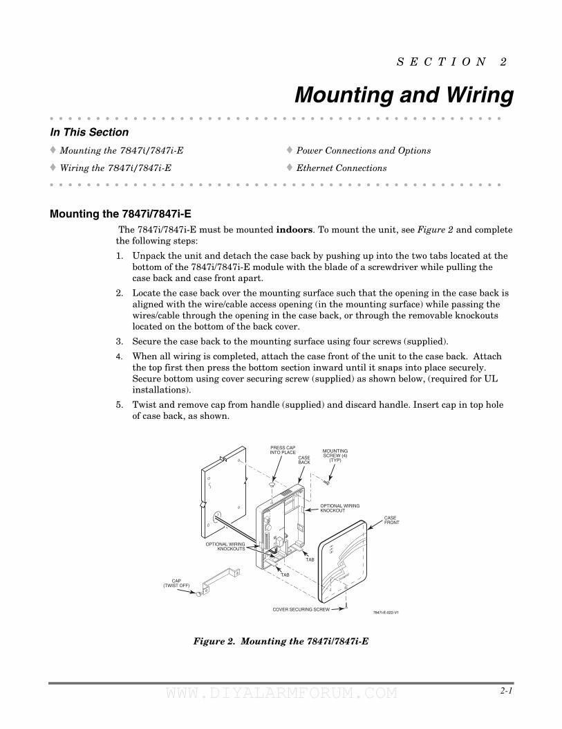
Mounting the 7847i/7847i-E The 7847i/7847i-E must be mounted indoors. To mount the unit, see Figure 2 and complete the following steps:
1. Unpack the unit and detach the case back by pushing up into the two tabs located at the bottom of the 7847i/7847i-E module with the blade of a screwdriver while pulling the case back and case front apart.
2. Locate the case back over the mounting surface such that the opening in the case back is aligned with the wire/cable access opening (in the mounting surface) while passing the wires/cable through the opening in the case back, or through the removable knockouts located on the bottom of the back cover.
3. Secure the case back to the mounting surface using four screws (supplied).
4. When all wiring is completed, attach the case front of the unit to the case back. Attach the top first then press the bottom section inward until it snaps into place securely. Secure bottom using cover securing screw (supplied) as shown below, (required for UL installations).
5. Twist and remove cap from handle (supplied) and discard handle. Insert cap in top hole of case back, as shown.
7847i-E-022-V1
MOUNTINGSCREW (4)
(TYP)
CAP(TWIST OFF)
TAB
COVER SECURING SCREW
OPTIONAL WIRINGKNOCKOUT
OPTIONAL WIRINGKNOCKOUTS
TAB
CASEFRONT
PRESS CAPINTO PLACE
CASEBACK
Figure 2. Mounting the 7847i/7847i-E
WWW.DIYALARMFORUM.COM WWW.DIYALARMFORUM.COM
7847i/7847i-E Installation and Setup Guide
2-2
Wiring the 7847i/7847i-E
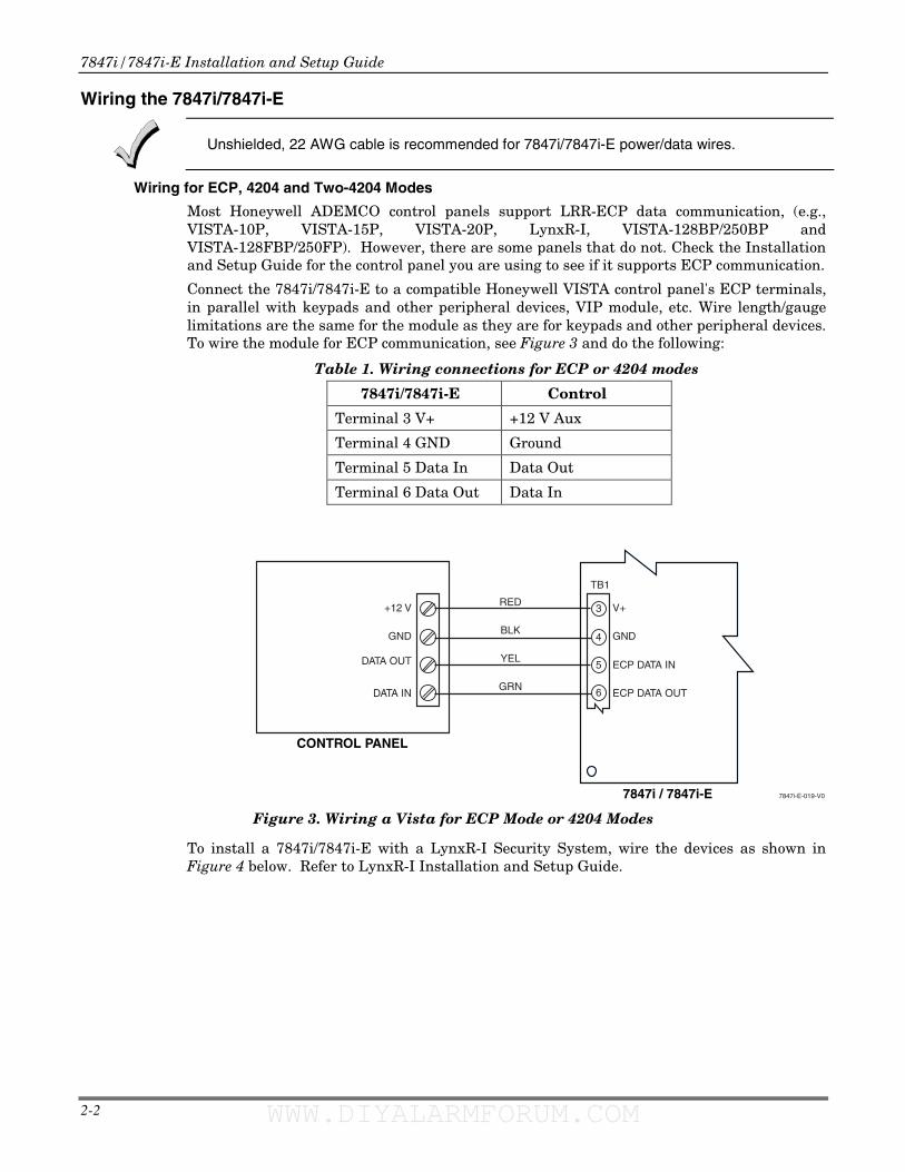
Unshielded, 22 AWG cable is recommended for 7847i/7847i-E power/data wires.
Wiring for ECP, 4204 and Two-4204 Modes
Most Honeywell ADEMCO control panels support LRR-ECP data communication, (e.g., VISTA-10P, VISTA-15P, VISTA-20P, LynxR-I, VISTA-128BP/250BP and VISTA-128FBP/250FP). However, there are some panels that do not. Check the Installation and Setup Guide for the control panel you are using to see if it supports ECP communication.
Connect the 7847i/7847i-E to a compatible Honeywell VISTA control panel's ECP terminals, in parallel with keypads and other peripheral devices, VIP module, etc. Wire length/gauge limitations are the same for the module as they are for keypads and other peripheral devices. To wire the module for ECP communication, see Figure 3 and do the following:
Table 1. Wiring connections for ECP or 4204 modes
7847i/7847i-E Control
Terminal 3 V+ +12 V Aux
Terminal 4 GND Ground
Terminal 5 Data In Data Out
Terminal 6 Data Out Data In
7847i / 7847i-E
CONTROL PANEL
7847i-E-019-V0
GND
ECP DATA OUT
ECP DATA IN
V+RED
BLK
YEL
GRN
GND
DATA IN
DATA OUT
+12 V
4
5
6
3
TB1
Figure 3. Wiring a Vista for ECP Mode or 4204 Modes
To install a 7847i/7847i-E with a LynxR-I Security System, wire the devices as shown in Figure 4 below. Refer to LynxR-I Installation and Setup Guide.
WWW.DIYALARMFORUM.COM WWW.DIYALARMFORUM.COM
Section 2: Mounting and Wiring
2-3
LYNXR-I CONTROL PANEL
7847
i-E-0
18-V
0
GND
ECP DATA OUT
ECP DATA IN
V+RED
NC
BLK
GRN
YEL
RE
D
BLK
GR
N
YE
L
+12
VD
C
GN
D
DAT
A IN
DAT
A O
UT
4
5
6
3
4-WIRE CABLE (N4632-4)TB1
7847i / 7847i-E
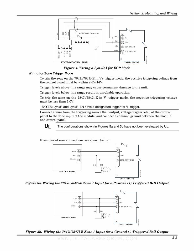
Figure 4. Wiring a LynxR-I for ECP Mode
Wiring for Zone Trigger Mode
To trip the zone on the 7847i/7847i-E in V+ trigger mode, the positive triggering voltage from the control panel must be within 2.0V-14V.
Trigger levels above this range may cause permanent damage to the unit.
Trigger levels below this range result in unreliable operation.
To trip the zone on the 7847i/7847i-E in V- trigger mode, the negative triggering voltage must be less than 1.0V.
NOTE: LynxR and LynxR-EN have a designated trigger for V- trigger.
Connect a wire from the triggering source (bell output, voltage trigger, etc.) of the control panel to the zone input of the module, and connect a common ground between the module and control panel.
UL The configurations shown in Figures 5a and 5b have not been evaluated by UL.
Examples of zone connections are shown below:
CONTROL PANEL
7847
i-E-0
20-V
0
GND
BELL (+)
+12 V
GND
ZONE INPUT Z1/Z2
V+
( ) (+)
4
5
3
TB1
7847i / 7847i-E Figure 5a. Wiring the 7847i/7847i-E Zone 1 Input for a Positive (+) Triggered Bell Output
CONTROL PANEL
7847
i-E-0
21-V
0
GND
BELL ( )
+12 V
GND
ZONE INPUT Z1/Z2
V+
( ) (+)
4
5
3
TB1
7847i / 7847i-E
Figure 5b. Wiring the 7847i/7847i-E Zone 1 Input for a Ground (-) Triggered Bell Output
WWW.DIYALARMFORUM.COM WWW.DIYALARMFORUM.COM
7847i/7847i-E Installation and Setup Guide
2-4
LYNXR/LYNXR-ENCONTROL PANEL
7847
i-E-0
24-V
0
2K EOLRESISTOR
LRR / AAVTRIGGER
7847i / 7847i-E
GND
ZONE INPUT Z1/Z2
2
1
4
5
9
8
TB1
NOT USED
NOT USED
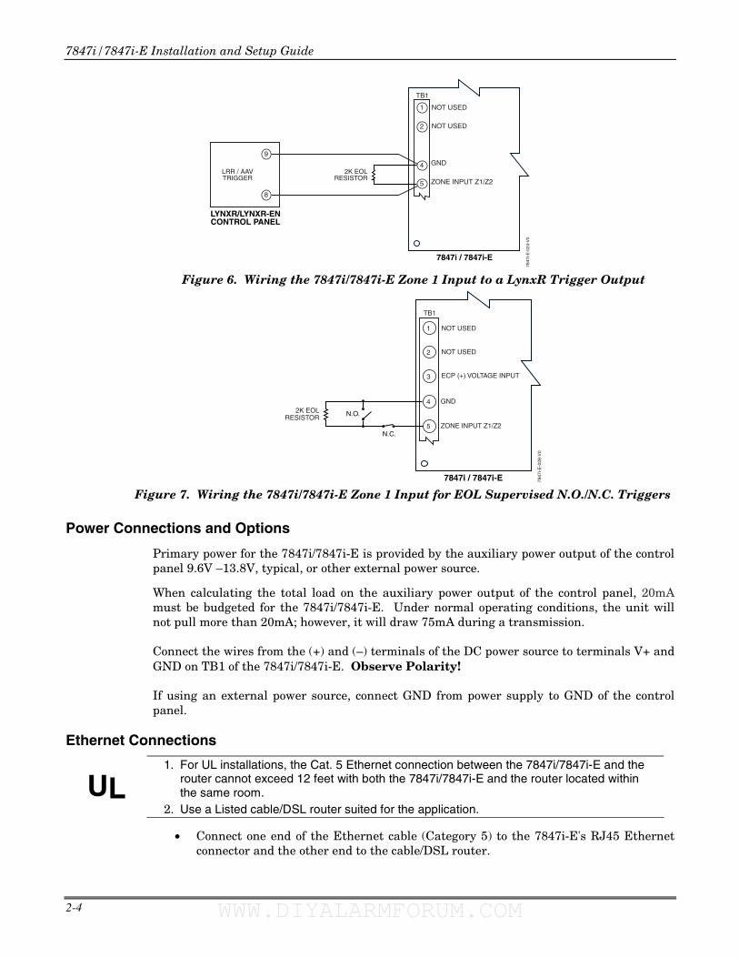
Figure 6. Wiring the 7847i/7847i-E Zone 1 Input to a LynxR Trigger Output
7847
i-E-0
28-V
0
2K EOLRESISTOR
GND
ZONE INPUT Z1/Z2
3
2
1
4
5
TB1
NOT USED
ECP (+) VOLTAGE INPUT
NOT USED
N.C.
N.O.
7847i / 7847i-E Figure 7. Wiring the 7847i/7847i-E Zone 1 Input for EOL Supervised N.O./N.C. Triggers
Power Connections and Options
Primary power for the 7847i/7847i-E is provided by the auxiliary power output of the control panel 9.6V –13.8V, typical, or other external power source.
When calculating the total load on the auxiliary power output of the control panel, 20mA must be budgeted for the 7847i/7847i-E. Under normal operating conditions, the unit will not pull more than 20mA; however, it will draw 75mA during a transmission.
Connect the wires from the (+) and (–) terminals of the DC power source to terminals V+ and GND on TB1 of the 7847i/7847i-E. Observe Polarity!
If using an external power source, connect GND from power supply to GND of the control panel.
Ethernet Connections
UL 1. For UL installations, the Cat. 5 Ethernet connection between the 7847i/7847i-E and the
router cannot exceed 12 feet with both the 7847i/7847i-E and the router located within the same room.
2. Use a Listed cable/DSL router suited for the application.
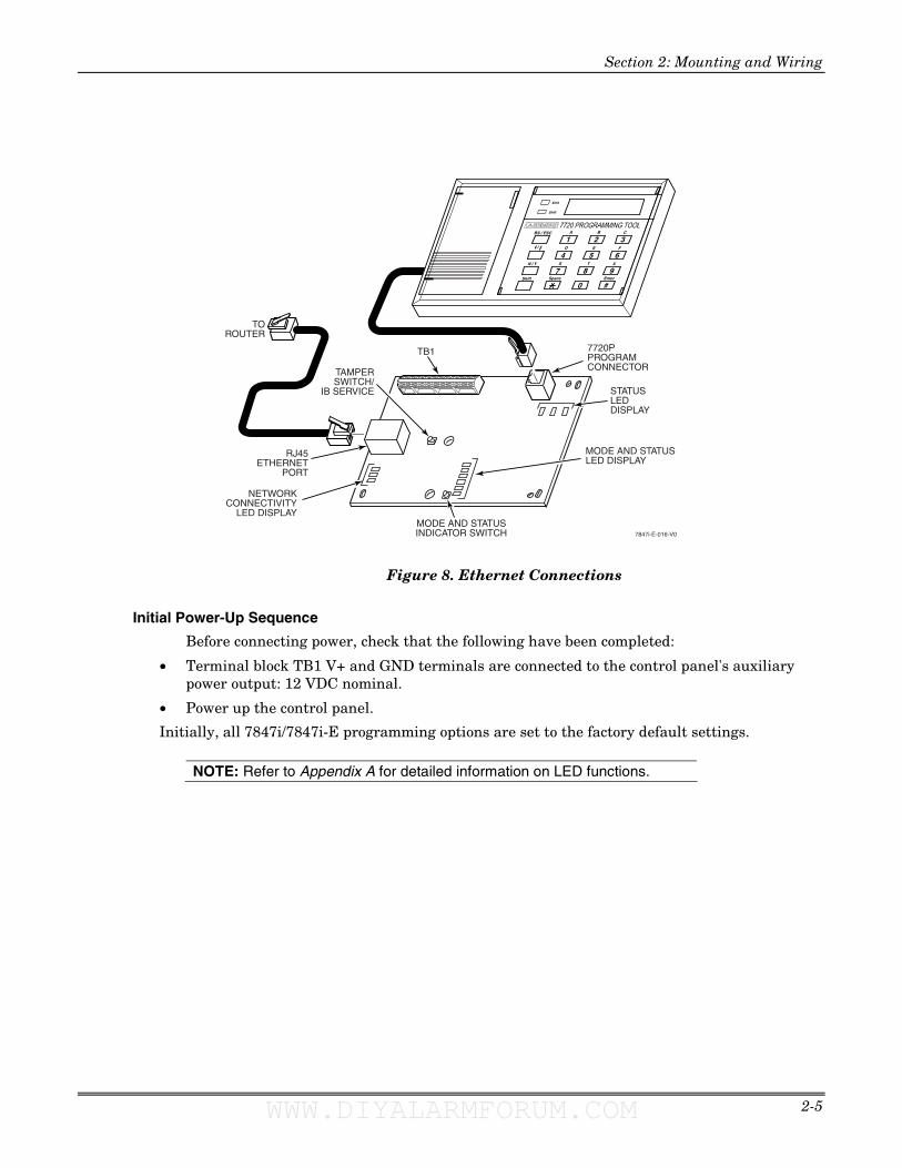
• Connect one end of the Ethernet cable (Category 5) to the 7847i-E's RJ45 Ethernet connector and the other end to the cable/DSL router.
WWW.DIYALARMFORUM.COM WWW.DIYALARMFORUM.COM
Section 2: Mounting and Wiring
2-5
TOROUTER
NETWORKCONNECTIVITY
LED DISPLAY
RJ45ETHERNET
PORT
TB1
MODE AND STATUSLED DISPLAY
STATUSLEDDISPLAY
7720PPROGRAMCONNECTOR
7847i-E-016-V0
A B C
D E F
S T X
1 2 3
4 5 6
987
#0
Xmit
Shift
Space EnterShift
N / Y
BS / ESC
/
7720 PROGRAMMING TOOL
MODE AND STATUSINDICATOR SWITCH
TAMPERSWITCH/
IB SERVICE
Figure 8. Ethernet Connections
Initial Power-Up Sequence
Before connecting power, check that the following have been completed:
• Terminal block TB1 V+ and GND terminals are connected to the control panel's auxiliary power output: 12 VDC nominal.
• Power up the control panel.
Initially, all 7847i/7847i-E programming options are set to the factory default settings.
NOTE: Refer to Appendix A for detailed information on LED functions.
WWW.DIYALARMFORUM.COM WWW.DIYALARMFORUM.COM

7847i/7847i-E Installation and Setup Guide
2-6
WWW.DIYALARMFORUM.COM WWW.DIYALARMFORUM.COM
3-1
S E C T I O N 3
Programming the 7847i/7847i-E • • • • • • • • • • • • • • • • • • • • • • • • • • • • • • • • • • • • • • • • • • • • • • • • •
In This Section � General Information
� ECP Mode Programming
� Alternative Modes (Zone Trigger, 4204 and Two-4204)
� Alternative Mode Programming
� Exiting Programming Mode
• • • • • • • • • • • • • • • • • • • • • • • • • • • • • • • • • • • • • • • • • • • • • • • • •
General Information
To the control panel, the 7847i/7847i-E Internet/Intranet Communication Modules, when in ECP Mode, is treated as a long-range radio device.
The 7847i/7847i-E can be configured to deliver alarms via the Internet to an AlarmNet central station or via a Private LAN (7847i-E only) directly to a 7810iR-ent receiver. Both methods of communication are encrypted to ensure security. The 7847i and 7847i-E use 256-bit AES (Rijndael) encryption (which is required for certain government installations).
The 7847i/7847i-E modules require an AlarmNet–i account, except when Private LAN is enabled on the 7847i-E. Obtain the account information from the central station prior to programming this module.
You can program a 7847i/7847i-E by one of the following methods:
• Through the AlarmNet Direct website
• Through use of a 7720P Programming Tool
• Through a programming mode in control panel, on panels that support this option (e.g., Vista-128BP and FBP)
Using the AlarmNet Direct Website To program the module via the website (if you are already signed up for this service), go to: https://services.alarmnet.com/AlarmNetDirect/userlogin.aspx.
If you are not signed up for this service, click on “Dealer Sign-Up".
Log in and follow the on-screen prompts.
Please have the following information available when programming the module:
1. Primary City ID (two-digit hexadecimal number)
2. Primary Central Station ID (two-digit number)
3. Primary Subscriber ID (four-digit number)
4. MAC ID and MAC CRC number (located on the outside of box and on label inside module)
After programming is complete, you must transfer the data to the module and the module must be registered. Refer to Section 4: Registration, for further instructions.
Using a 7720P Programming Tool Connect the 7720P Programming Tool; refer to Figure 8 in Section 2. The 7847i and 7847i-E power the 7720P Programming Tool via the programming jack, and automatically senses the presence of the 7720P when it is plugged in.
WWW.DIYALARMFORUM.COM WWW.DIYALARMFORUM.COM
7847i/7847i-E Installation and Setup Guide
3-2
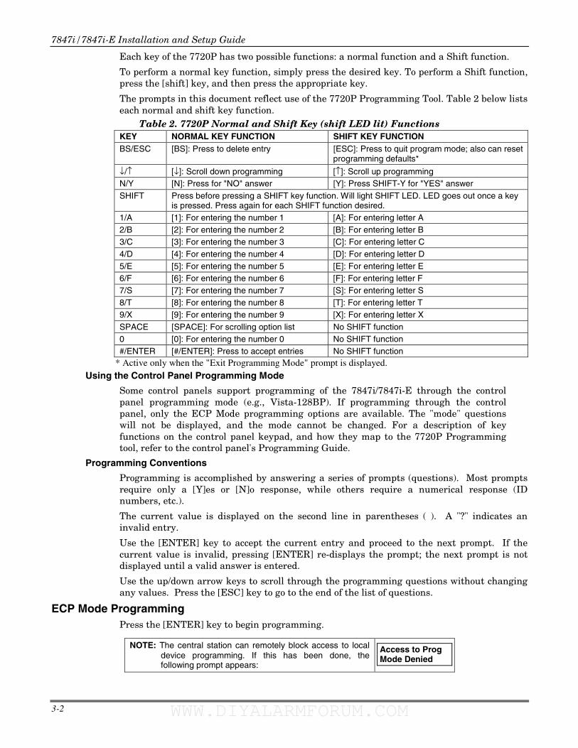
Each key of the 7720P has two possible functions: a normal function and a Shift function.
To perform a normal key function, simply press the desired key. To perform a Shift function, press the [shift] key, and then press the appropriate key.
The prompts in this document reflect use of the 7720P Programming Tool. Table 2 below lists each normal and shift key function.
Table 2. 7720P Normal and Shift Key (shift LED lit) Functions KEY NORMAL KEY FUNCTION SHIFT KEY FUNCTION BS/ESC [BS]: Press to delete entry [ESC]: Press to quit program mode; also can reset
programming defaults*
↓/↑ [↓]: Scroll down programming [↑]: Scroll up programming N/Y [N]: Press for "NO" answer [Y]: Press SHIFT-Y for "YES" answer SHIFT Press before pressing a SHIFT key function. Will light SHIFT LED. LED goes out once a key
is pressed. Press again for each SHIFT function desired. 1/A [1]: For entering the number 1 [A]: For entering letter A 2/B [2]: For entering the number 2 [B]: For entering letter B 3/C [3]: For entering the number 3 [C]: For entering letter C 4/D [4]: For entering the number 4 [D]: For entering letter D 5/E [5]: For entering the number 5 [E]: For entering letter E 6/F [6]: For entering the number 6 [F]: For entering letter F 7/S [7]: For entering the number 7 [S]: For entering letter S 8/T [8]: For entering the number 8 [T]: For entering letter T 9/X [9]: For entering the number 9 [X]: For entering letter X SPACE [SPACE]: For scrolling option list No SHIFT function 0 [0]: For entering the number 0 No SHIFT function #/ENTER [#/ENTER]: Press to accept entries No SHIFT function
* Active only when the "Exit Programming Mode" prompt is displayed. Using the Control Panel Programming Mode
Some control panels support programming of the 7847i/7847i-E through the control panel programming mode (e.g., Vista-128BP). If programming through the control panel, only the ECP Mode programming options are available. The "mode" questions will not be displayed, and the mode cannot be changed. For a description of key functions on the control panel keypad, and how they map to the 7720P Programming tool, refer to the control panel's Programming Guide.
Programming Conventions
Programming is accomplished by answering a series of prompts (questions). Most prompts require only a [Y]es or [N]o response, while others require a numerical response (ID numbers, etc.).
The current value is displayed on the second line in parentheses ( ). A "?" indicates an invalid entry.
Use the [ENTER] key to accept the current entry and proceed to the next prompt. If the current value is invalid, pressing [ENTER] re-displays the prompt; the next prompt is not displayed until a valid answer is entered.
Use the up/down arrow keys to scroll through the programming questions without changing any values. Press the [ESC] key to go to the end of the list of questions.
ECP Mode Programming Press the [ENTER] key to begin programming.
NOTE: The central station can remotely block access to local device programming. If this has been done, the following prompt appears:
Access to Prog Mode Denied
WWW.DIYALARMFORUM.COM WWW.DIYALARMFORUM.COM
Section 3: Programming the 7847i/7847i-E
3-3
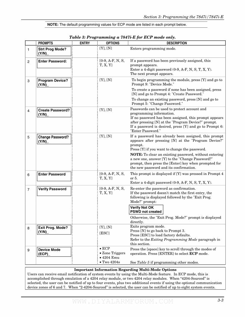
NOTE: The default programming values for ECP mode are listed in each prompt below.
Table 3: Programming a 7847i-E for ECP mode only. PROMPTS ENTRY OPTIONS DESCRIPTION
1
Strt Prog Mode? (Y/N)_
[Y], [N] Enters programming mode.
2
Enter Password:
[0-9, A-F, N, S, T, X, Y]
If a password has been previously assigned, this prompt appears. Enter a 4-digit password (0-9, A-F, N, S, T, X, Y). The next prompt appears.
3
Program Device? (Y/N)_
[Y], [N] To begin programming the module, press [Y] and go to Prompt 9: "Device Mode."
To create a password if none has been assigned, press [N] and go to Prompt 4: "Create Password."
To change an existing password, press [N] and go to Prompt 5: "Change Password."
4 Create Password? (Y/N)_
[Y], [N] Passwords can be used to protect account and programming information. If no password has been assigned, this prompt appears after pressing [N] at the "Program Device?" prompt. If a password is desired, press [Y] and go to Prompt 6: "Enter Password."
5 Change Password? (Y/N)_
[Y], [N] If a password has already been assigned, this prompt appears after pressing [N] at the "Program Device?" prompt. Press [Y] if you want to change the password. NOTE: To clear an existing password, without entering a new one, answer [Y] to the "Change Password?" prompt, then press the [Enter] key when prompted for the new password and its confirmation.
6 Enter Password
[0-9, A-F, N, S, T, X, Y]
This prompt is displayed if [Y] was pressed in Prompt 4 or 5. Enter a 4-digit password (0-9, A-F, N, S, T, X, Y).
Re-enter the password as confirmation. If the password doesn't match the first entry, the following is displayed followed by the "Exit Prog. Mode?" prompt:
7 [0-9, A-F, N, S, T, X, Y]
Verify Not OK PSWD not created
Verify Password
Otherwise, the "Exit Prog. Mode?" prompt is displayed directly.
8 Exit Prog. Mode? (Y/N)_
[Y], [N]
[ESC]
Exits program mode. Press [N] to go back to Prompt 3. Press [ESC] to load factory defaults. Refer to the Exiting Programming Mode paragraph in this section.
9
Device Mode (ECP)_
• ECP • Zone Triggers • 4204 Emu • Two 4204s
Press the [space] key to scroll through the modes of operation. Press [ENTER] to select ECP mode. See Table 5 if programming other modes.
Important Information Regarding Multi-Mode Options Users can receive email notification of system events by using the Multi-Mode feature. In ECP mode, this is accomplished through emulation of a 4204 relay module, or two 4204 relay modules. When “4204-Sourced” is selected, the user can be notified of up to four events, plus two additional events if using the optional communication device zones of 6 and 7. When “2-4204-Sourced” is selected, the user can be notified of up to eight system events.
WWW.DIYALARMFORUM.COM WWW.DIYALARMFORUM.COM
7847i/7847i-E Installation and Setup Guide
3-4
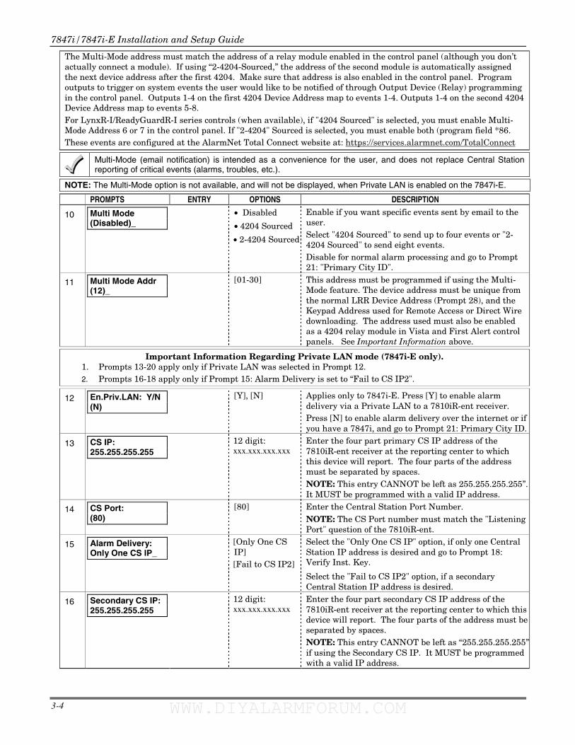
The Multi-Mode address must match the address of a relay module enabled in the control panel (although you don’t actually connect a module). If using “2-4204-Sourced,” the address of the second module is automatically assigned the next device address after the first 4204. Make sure that address is also enabled in the control panel. Program outputs to trigger on system events the user would like to be notified of through Output Device (Relay) programming in the control panel. Outputs 1-4 on the first 4204 Device Address map to events 1-4. Outputs 1-4 on the second 4204 Device Address map to events 5-8. For LynxR-I/ReadyGuardR-I series controls (when available), if "4204 Sourced" is selected, you must enable Multi-Mode Address 6 or 7 in the control panel. If "2-4204" Sourced is selected, you must enable both (program field *86. These events are configured at the AlarmNet Total Connect website at: https://services.alarmnet.com/TotalConnect
Multi-Mode (email notification) is intended as a convenience for the user, and does not replace Central Station reporting of critical events (alarms, troubles, etc.).
NOTE: The Multi-Mode option is not available, and will not be displayed, when Private LAN is enabled on the 7847i-E.
PROMPTS ENTRY OPTIONS DESCRIPTION
10 Multi Mode (Disabled)_
• Disabled
• 4204 Sourced
• 2-4204 Sourced
Enable if you want specific events sent by email to the user. Select "4204 Sourced" to send up to four events or "2-4204 Sourced" to send eight events. Disable for normal alarm processing and go to Prompt 21: "Primary City ID".
11 Multi Mode Addr (12)_
[01-30]
This address must be programmed if using the Multi-Mode feature. The device address must be unique from the normal LRR Device Address (Prompt 28), and the Keypad Address used for Remote Access or Direct Wire downloading. The address used must also be enabled as a 4204 relay module in Vista and First Alert control panels. See Important Information above.
Important Information Regarding Private LAN mode (7847i-E only). 1. Prompts 13-20 apply only if Private LAN was selected in Prompt 12. 2. Prompts 16-18 apply only if Prompt 15: Alarm Delivery is set to “Fail to CS IP2".
12
En.Priv.LAN: Y/N (N)
[Y], [N]
Applies only to 7847i-E. Press [Y] to enable alarm delivery via a Private LAN to a 7810iR-ent receiver. Press [N] to enable alarm delivery over the internet or if you have a 7847i, and go to Prompt 21: Primary City ID.
13
CS IP: 255.255.255.255
12 digit: xxx.xxx.xxx.xxx
Enter the four part primary CS IP address of the 7810iR-ent receiver at the reporting center to which this device will report. The four parts of the address must be separated by spaces. NOTE: This entry CANNOT be left as 255.255.255.255”. It MUST be programmed with a valid IP address.
14
CS Port: (80)
[80] Enter the Central Station Port Number. NOTE: The CS Port number must match the "Listening Port" question of the 7810iR-ent.
15
Alarm Delivery: Only One CS IP_
[Only One CS IP] [Fail to CS IP2]
Select the "Only One CS IP" option, if only one Central Station IP address is desired and go to Prompt 18: Verify Inst. Key.
Select the "Fail to CS IP2" option, if a secondary Central Station IP address is desired.
16
Secondary CS IP: 255.255.255.255
12 digit: xxx.xxx.xxx.xxx
Enter the four part secondary CS IP address of the 7810iR-ent receiver at the reporting center to which this device will report. The four parts of the address must be separated by spaces. NOTE: This entry CANNOT be left as “255.255.255.255” if using the Secondary CS IP. It MUST be programmed with a valid IP address.
WWW.DIYALARMFORUM.COM WWW.DIYALARMFORUM.COM
Section 3: Programming the 7847i/7847i-E
3-5
PROMPTS ENTRY OPTIONS DESCRIPTION
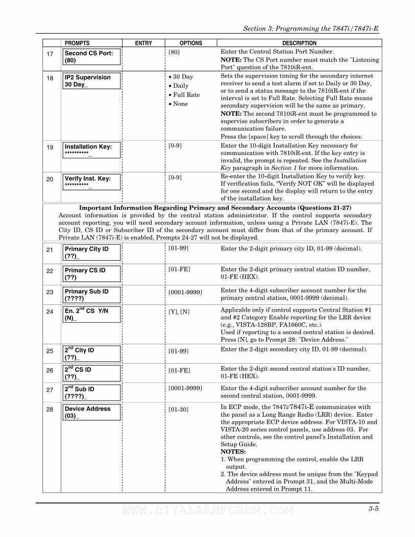
17
Second CS Port: (80)
[80] Enter the Central Station Port Number. NOTE: The CS Port number must match the "Listening Port" question of the 7810iR-ent.
18 IP2 Supervision 30 Day_
• 30 Day • Daily • Full Rate • None
Sets the supervision timing for the secondary internet receiver to send a test alarm if set to Daily or 30 Day, or to send a status message to the 7810iR-ent if the interval is set to Full Rate. Selecting Full Rate means secondary supervision will be the same as primary. NOTE: The second 7810iR-ent must be programmed to supervise subscribers in order to generate a communication failure. Press the [space] key to scroll through the choices.
19
Installation Key: **********_
[0-9] Enter the 10-digit Installation Key necessary for communication with 7810iR-ent. If the key entry is invalid, the prompt is repeated. See the Installation Key paragraph in Section 1 for more information.
20
Verify Inst. Key: **********_
[0-9] Re-enter the 10-digit Installation Key to verify key. If verification fails, “Verify NOT OK” will be displayed for one second and the display will return to the entry of the installation key.
Important Information Regarding Primary and Secondary Accounts (Questions 21-27) Account information is provided by the central station administrator. If the control supports secondary account reporting, you will need secondary account information, unless using a Private LAN (7847i-E). The City ID, CS ID or Subscriber ID of the secondary account must differ from that of the primary account. If Private LAN (7847i-E) is enabled, Prompts 24-27 will not be displayed.
21 Primary City ID (??)_
[01-99]
Enter the 2-digit primary city ID, 01-99 (decimal).
22
Primary CS ID (??)
[01-FE] Enter the 2-digit primary central station ID number, 01-FE (HEX).
23
Primary Sub ID (????)
[0001-9999] Enter the 4-digit subscriber account number for the primary central station, 0001-9999 (decimal).
24
En. 2nd CS Y/N (N)_
[Y], [N] Applicable only if control supports Central Station #1 and #2 Category Enable reporting for the LRR device (e.g., VISTA-128BP, FA1660C, etc.). Used if reporting to a second central station is desired. Press [N], go to Prompt 28: "Device Address."
25
2nd City ID (??)_
[01-99] Enter the 2-digit secondary city ID, 01-99 (decimal).
26
2nd CS ID (??)_
[01-FE] Enter the 2-digit second central station's ID number, 01-FE (HEX).
27
2nd Sub ID (????)_
[0001-9999] Enter the 4-digit subscriber account number for the second central station, 0001-9999.
28
Device Address (03)_
[01-30]
In ECP mode, the 7847i/7847i-E communicates with the panel as a Long Range Radio (LRR) device. Enter the appropriate ECP device address. For VISTA-10 and VISTA-20 series control panels, use address 03. For other controls, see the control panel’s Installation and Setup Guide. NOTES: 1. When programming the control, enable the LRR
output. 2. The device address must be unique from the "Keypad
Address" entered in Prompt 31, and the Multi-Mode Address entered in Prompt 11.
WWW.DIYALARMFORUM.COM WWW.DIYALARMFORUM.COM
7847i/7847i-E Installation and Setup Guide
3-6
NOTE: The Remote Access option is not available, and will not be displayed, when Private LAN is enabled on the 7847i-E.
PROMPTS ENTRY OPTIONS DESCRIPTION
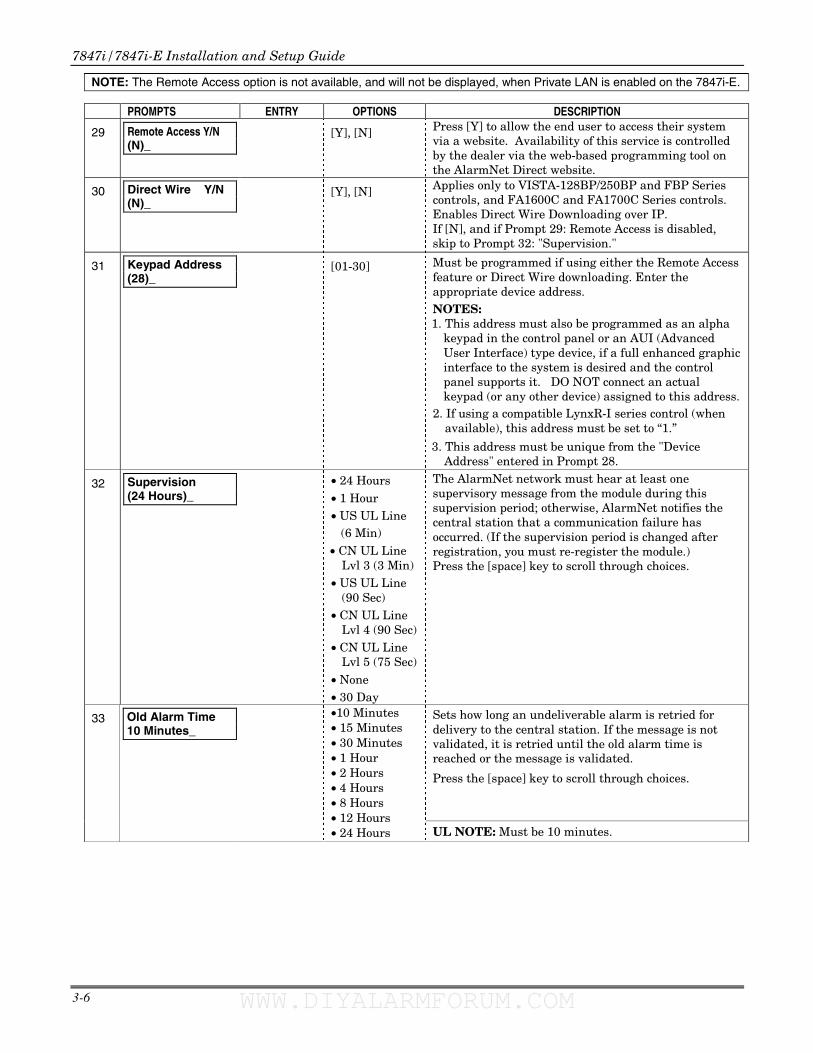
29
Remote Access Y/N (N)_
[Y], [N] Press [Y] to allow the end user to access their system via a website. Availability of this service is controlled by the dealer via the web-based programming tool on the AlarmNet Direct website.
30 Direct Wire Y/N (N)_
[Y], [N] Applies only to VISTA-128BP/250BP and FBP Series controls, and FA1600C and FA1700C Series controls. Enables Direct Wire Downloading over IP. If [N], and if Prompt 29: Remote Access is disabled, skip to Prompt 32: "Supervision."
31
Keypad Address (28)_
[01-30] Must be programmed if using either the Remote Access feature or Direct Wire downloading. Enter the appropriate device address. NOTES: 1. This address must also be programmed as an alpha
keypad in the control panel or an AUI (Advanced User Interface) type device, if a full enhanced graphic interface to the system is desired and the control panel supports it. DO NOT connect an actual keypad (or any other device) assigned to this address.
2. If using a compatible LynxR-I series control (when available), this address must be set to “1.”
3. This address must be unique from the "Device Address" entered in Prompt 28.
32
Supervision (24 Hours)_
• 24 Hours • 1 Hour • US UL Line (6 Min) • CN UL Line
Lvl 3 (3 Min) • US UL Line
(90 Sec) • CN UL Line
Lvl 4 (90 Sec) • CN UL Line
Lvl 5 (75 Sec) • None • 30 Day
The AlarmNet network must hear at least one supervisory message from the module during this supervision period; otherwise, AlarmNet notifies the central station that a communication failure has occurred. (If the supervision period is changed after registration, you must re-register the module.) Press the [space] key to scroll through choices.
Sets how long an undeliverable alarm is retried for delivery to the central station. If the message is not validated, it is retried until the old alarm time is reached or the message is validated.
Press the [space] key to scroll through choices.
33
Old Alarm Time 10 Minutes_
•10 Minutes• 15 Minutes• 30 Minutes• 1 Hour• 2 Hours • 4 Hours • 8 Hours • 12 Hours • 24 Hours UL NOTE: Must be 10 minutes.
WWW.DIYALARMFORUM.COM WWW.DIYALARMFORUM.COM
Section 3: Programming the 7847i/7847i-E
3-7
PROMPTS ENTRY OPTIONS DESCRIPTION
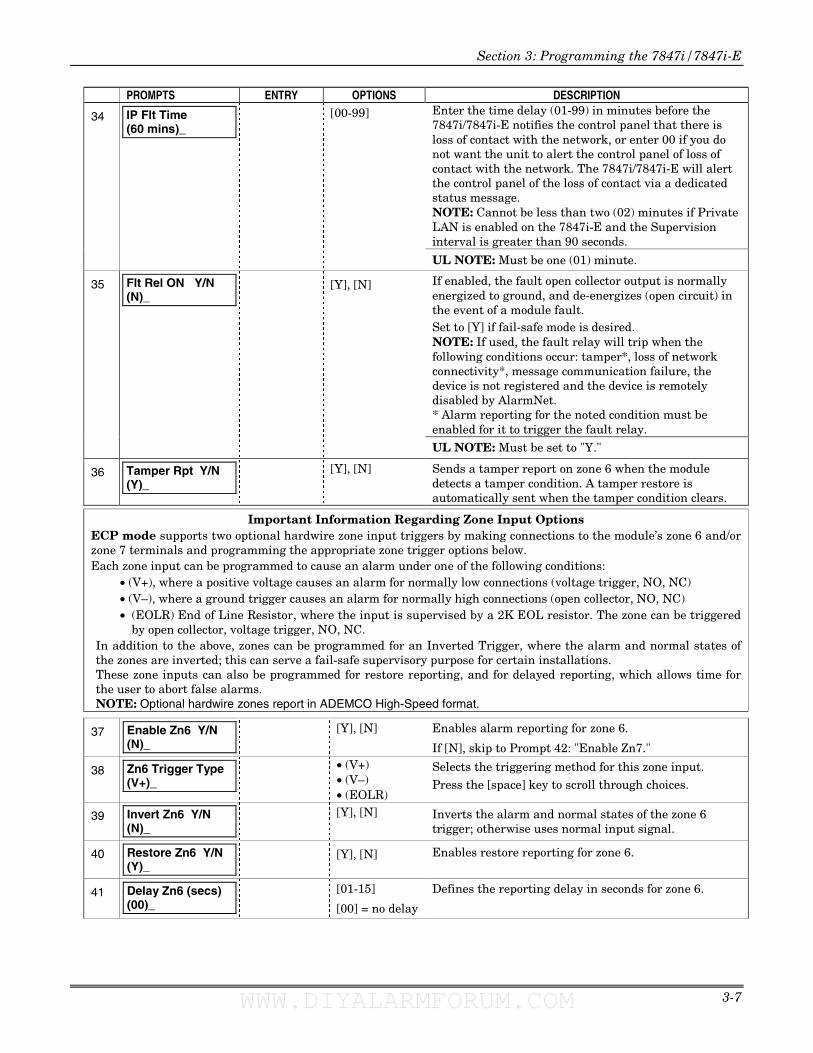
34
IP Flt Time (60 mins)_
[00-99] Enter the time delay (01-99) in minutes before the 7847i/7847i-E notifies the control panel that there is loss of contact with the network, or enter 00 if you do not want the unit to alert the control panel of loss of contact with the network. The 7847i/7847i-E will alert the control panel of the loss of contact via a dedicated status message. NOTE: Cannot be less than two (02) minutes if Private LAN is enabled on the 7847i-E and the Supervision interval is greater than 90 seconds.
UL NOTE: Must be one (01) minute.
35
Flt Rel ON Y/N (N)_
[Y], [N] If enabled, the fault open collector output is normally energized to ground, and de-energizes (open circuit) in the event of a module fault. Set to [Y] if fail-safe mode is desired. NOTE: If used, the fault relay will trip when the following conditions occur: tamper*, loss of network connectivity*, message communication failure, the device is not registered and the device is remotely disabled by AlarmNet. * Alarm reporting for the noted condition must be enabled for it to trigger the fault relay.
UL NOTE: Must be set to "Y."
36
Tamper Rpt Y/N (Y)_
[Y], [N] Sends a tamper report on zone 6 when the module detects a tamper condition. A tamper restore is automatically sent when the tamper condition clears.
Important Information Regarding Zone Input Options ECP mode supports two optional hardwire zone input triggers by making connections to the module’s zone 6 and/or zone 7 terminals and programming the appropriate zone trigger options below. Each zone input can be programmed to cause an alarm under one of the following conditions:
• (V+), where a positive voltage causes an alarm for normally low connections (voltage trigger, NO, NC) • (V–), where a ground trigger causes an alarm for normally high connections (open collector, NO, NC) • (EOLR) End of Line Resistor, where the input is supervised by a 2K EOL resistor. The zone can be triggered
by open collector, voltage trigger, NO, NC. In addition to the above, zones can be programmed for an Inverted Trigger, where the alarm and normal states of the zones are inverted; this can serve a fail-safe supervisory purpose for certain installations. These zone inputs can also be programmed for restore reporting, and for delayed reporting, which allows time for the user to abort false alarms. NOTE: Optional hardwire zones report in ADEMCO High-Speed format.
37
Enable Zn6 Y/N (N)_
[Y], [N] Enables alarm reporting for zone 6.
If [N], skip to Prompt 42: "Enable Zn7."
38
Zn6 Trigger Type (V+)_
• (V+) • (V–) • (EOLR)
Selects the triggering method for this zone input.
Press the [space] key to scroll through choices.
39
Invert Zn6 Y/N (N)_
[Y], [N] Inverts the alarm and normal states of the zone 6 trigger; otherwise uses normal input signal.
40
Restore Zn6 Y/N (Y)_
[Y], [N] Enables restore reporting for zone 6.
41
Delay Zn6 (secs) (00)_
[01-15]
[00] = no delay
Defines the reporting delay in seconds for zone 6.
WWW.DIYALARMFORUM.COM WWW.DIYALARMFORUM.COM
7847i/7847i-E Installation and Setup Guide
3-8
PROMPTS ENTRY OPTIONS DESCRIPTION
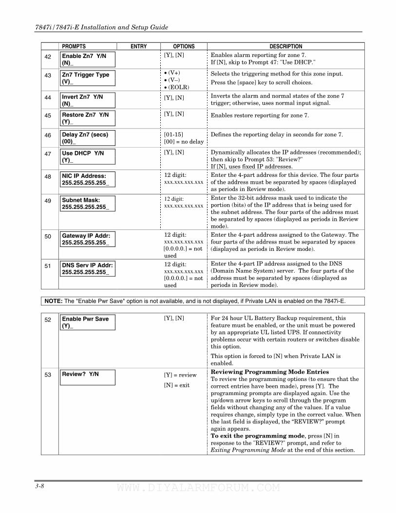
42
Enable Zn7 Y/N (N)_
[Y], [N] Enables alarm reporting for zone 7. If [N], skip to Prompt 47: "Use DHCP."
43
Zn7 Trigger Type (V)_
• (V+) • (V–) • (EOLR)
Selects the triggering method for this zone input.
Press the [space] key to scroll choices.
44
Invert Zn7 Y/N (N)_
[Y], [N] Inverts the alarm and normal states of the zone 7 trigger; otherwise, uses normal input signal.
45
Restore Zn7 Y/N (Y)_
[Y], [N] Enables restore reporting for zone 7.
46
Delay Zn7 (secs) (00)_
[01-15] [00] = no delay
Defines the reporting delay in seconds for zone 7.
47
Use DHCP Y/N (Y)_
[Y], [N] Dynamically allocates the IP addresses (recommended); then skip to Prompt 53: "Review?" If [N], uses fixed IP addresses.
48
NIC IP Address: 255.255.255.255_
12 digit: xxx.xxx.xxx.xxx
Enter the 4-part address for this device. The four parts of the address must be separated by spaces (displayed as periods in Review mode).
49
Subnet Mask: 255.255.255.255_
12 digit: xxx.xxx.xxx.xxx
Enter the 32-bit address mask used to indicate the portion (bits) of the IP address that is being used for the subnet address. The four parts of the address must be separated by spaces (displayed as periods in Review mode).
50
Gateway IP Addr: 255.255.255.255_
12 digit: xxx.xxx.xxx.xxx [0.0.0.0.] = not used
Enter the 4-part address assigned to the Gateway. The four parts of the address must be separated by spaces (displayed as periods in Review mode).
51
DNS Serv IP Addr: 255.255.255.255_
12 digit: xxx.xxx.xxx.xxx [0.0.0.0.] = not used
Enter the 4-part IP address assigned to the DNS (Domain Name System) server. The four parts of the address must be separated by spaces (displayed as periods in Review mode).
NOTE: The "Enable Pwr Save" option is not available, and is not displayed, if Private LAN is enabled on the 7847i-E.
52 Enable Pwr Save (Y)_
[Y], [N] For 24 hour UL Battery Backup requirement, this feature must be enabled, or the unit must be powered by an appropriate UL listed UPS. If connectivity problems occur with certain routers or switches disable this option.
This option is forced to [N] when Private LAN is enabled.
53
Review? Y/N
[Y] = review
[N] = exit
Reviewing Programming Mode Entries To review the programming options (to ensure that the correct entries have been made), press [Y]. The programming prompts are displayed again. Use the up/down arrow keys to scroll through the program fields without changing any of the values. If a value requires change, simply type in the correct value. When the last field is displayed, the “REVIEW?” prompt again appears. To exit the programming mode, press [N] in response to the "REVIEW?" prompt, and refer to Exiting Programming Mode at the end of this section.
WWW.DIYALARMFORUM.COM WWW.DIYALARMFORUM.COM
Section 3: Programming the 7847i/7847i-E
3-9
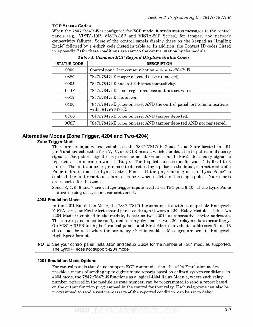
ECP Status Codes When the 7847i/7847i-E is configured for ECP mode, it sends status messages to the control panels (e.g., VISTA-10P, VISTA-15P and VISTA-20P Series), for tamper, and network connectivity failures. Some of the control panels display these on the keypad as "LngRng Radio" followed by a 4-digit code (listed in table 4). In addition, the Contact ID codes (listed in Appendix B) for these conditions are sent to the central station by the module.
Table 4. Common ECP Keypad Displays Status Codes STATUS CODE DESCRIPTION
0000 Control panel lost communication with 7847i/7847i-E.
0880 7847i/7847i-E tamper detected (cover removed).
0005 7847i/7847i-E has lost Ethernet connectivity.
000F 7847i/7847i-E is not registered; account not activated.
0019 7847i/7847i-E shutdown.
0400 7847i/7847i-E power on reset AND the control panel lost communications with 7847i/7847i-E.
0C80 7847i/7847i-E power on reset AND tamper detected.
0C8F 7847i/7847i-E power on reset AND tamper detected AND not registered.
Alternative Modes (Zone Trigger, 4204 and Two-4204)
Zone Trigger Mode There are six input zones available on the 7847i/7847i-E. Zones 1 and 2 are located on TB1 pin 5 and are selectable for +V, -V, or EOLR modes, which can detect both pulsed and steady signals. The pulsed signal is reported as an alarm on zone 1 (Fire); the steady signal is reported as an alarm on zone 2 (Burg). The implied pulse count for zone 1 is fixed to 3 pulses. The unit can be programmed to detect a single pulse on the input, characteristic of a Panic indication on the Lynx Control Panel. If the programming option “Lynx Panic” is enabled, the unit reports an alarm on zone 3 when it detects this single pulse. No restores are reported for this zone. Zones 3, 4, 5, 6 and 7 are voltage trigger inputs located on TB1 pins 6-10. If the Lynx Panic feature is being used, do not connect zone 3.
4204 Emulation Mode In the 4204 Emulation Mode, the 7847i/7847i-E communicates with a compatible Honeywell VISTA series or First Alert control panel as though it were a 4204 Relay Module. If the Two 4204 Mode is enabled in the module, it acts as two 4204s at consecutive device addresses. The control panel must be configured to recognize one or two 4204 relay modules accordingly. On VISTA-32FB (or higher) control panels and First Alert equivalents, addresses 6 and 13 should not be used when the secondary 4204 is enabled. Messages are sent in Honeywell High-Speed format.
NOTE: See your control panel Installation and Setup Guide for the number of 4204 modules supported. The LynxR-I does not support 4204 mode.
4204 Emulation Mode Options
For control panels that do not support ECP communication, the 4204 Emulation modes provide a means of sending up to eight unique reports based on defined system conditions. In 4204 mode, the 7847i/7847i-E functions as a logical 4204 Relay Module, where each relay number, referred in the module as zone number, can be programmed to send a report based on the output function programmed in the control for that relay. Each relay-zone can also be programmed to send a restore message of the reported condition, can be set to delay
WWW.DIYALARMFORUM.COM WWW.DIYALARMFORUM.COM
7847i/7847i-E Installation and Setup Guide
3-10
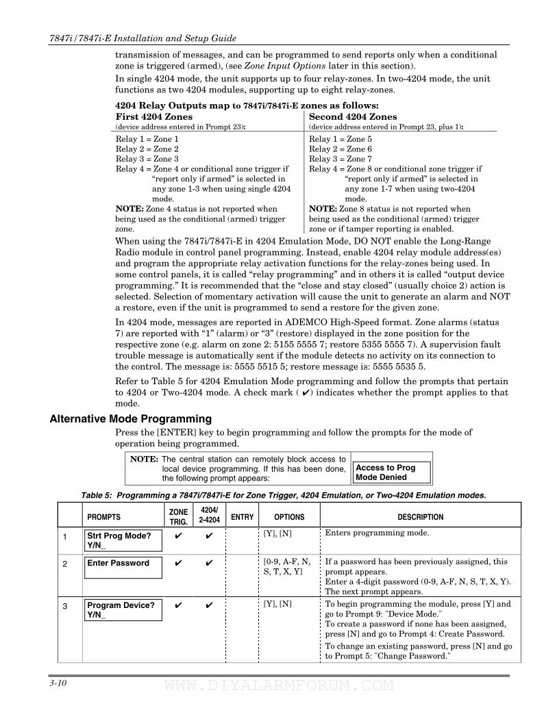
transmission of messages, and can be programmed to send reports only when a conditional zone is triggered (armed), (see Zone Input Options later in this section). In single 4204 mode, the unit supports up to four relay-zones. In two-4204 mode, the unit functions as two 4204 modules, supporting up to eight relay-zones.
4204 Relay Outputs map to 7847i/7847i-E zones as follows: First 4204 Zones (device address entered in Prompt 23):
Second 4204 Zones (device address entered in Prompt 23, plus 1):
Relay 1 = Zone 1 Relay 2 = Zone 2 Relay 3 = Zone 3 Relay 4 = Zone 4 or conditional zone trigger if
“report only if armed” is selected in any zone 1-3 when using single 4204 mode.
NOTE: Zone 4 status is not reported when being used as the conditional (armed) trigger zone.
Relay 1 = Zone 5 Relay 2 = Zone 6 Relay 3 = Zone 7 Relay 4 = Zone 8 or conditional zone trigger if
“report only if armed” is selected in any zone 1-7 when using two-4204 mode.
NOTE: Zone 8 status is not reported when being used as the conditional (armed) trigger zone or if tamper reporting is enabled.
When using the 7847i/7847i-E in 4204 Emulation Mode, DO NOT enable the Long-Range Radio module in control panel programming. Instead, enable 4204 relay module address(es) and program the appropriate relay activation functions for the relay-zones being used. In some control panels, it is called “relay programming” and in others it is called “output device programming.” It is recommended that the “close and stay closed” (usually choice 2) action is selected. Selection of momentary activation will cause the unit to generate an alarm and NOT a restore, even if the unit is programmed to send a restore for the given zone.
In 4204 mode, messages are reported in ADEMCO High-Speed format. Zone alarms (status 7) are reported with “1” (alarm) or “3” (restore) displayed in the zone position for the respective zone (e.g. alarm on zone 2: 5155 5555 7; restore 5355 5555 7). A supervision fault trouble message is automatically sent if the module detects no activity on its connection to the control. The message is: 5555 5515 5; restore message is: 5555 5535 5.
Refer to Table 5 for 4204 Emulation Mode programming and follow the prompts that pertain to 4204 or Two-4204 mode. A check mark ( ✔) indicates whether the prompt applies to that mode.
Alternative Mode Programming Press the [ENTER] key to begin programming and follow the prompts for the mode of operation being programmed.
NOTE: The central station can remotely block access to local device programming. If this has been done, the following prompt appears:
Access to Prog Mode Denied
Table 5: Programming a 7847i/7847i-E for Zone Trigger, 4204 Emulation, or Two-4204 Emulation modes.
PROMPTS
ZONE TRIG.
4204/ 2-4204 ENTRY OPTIONS DESCRIPTION
1
Strt Prog Mode? Y/N_
✔
✔ [Y], [N] Enters programming mode.
2
Enter Password
✔ ✔ [0-9, A-F, N, S, T, X, Y]
If a password has been previously assigned, this prompt appears. Enter a 4-digit password (0-9, A-F, N, S, T, X, Y). The next prompt appears.
3
Program Device? Y/N_
✔ ✔ [Y], [N] To begin programming the module, press [Y] and go to Prompt 9: "Device Mode." To create a password if none has been assigned, press [N] and go to Prompt 4: Create Password.
To change an existing password, press [N] and go to Prompt 5: "Change Password."
WWW.DIYALARMFORUM.COM WWW.DIYALARMFORUM.COM
Section 3: Programming the 7847i/7847i-E
3-11
PROMPTS
ZONE TRIG.
4204/ 2-4204 ENTRY OPTIONS DESCRIPTION
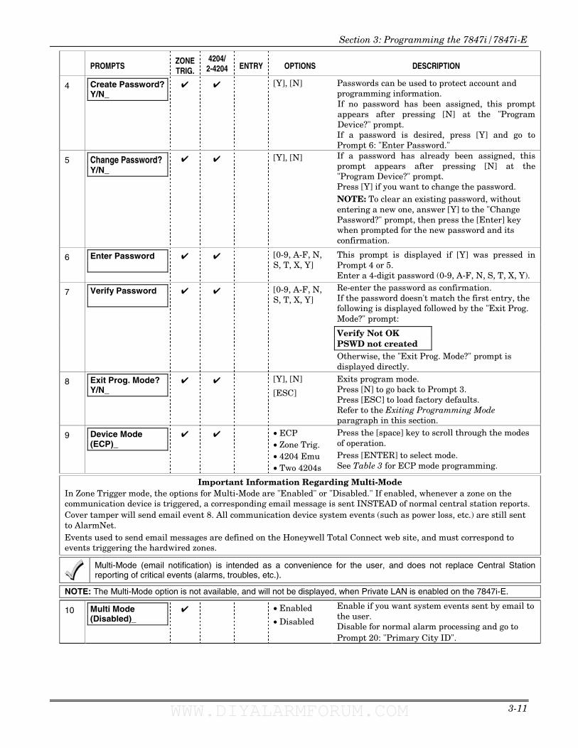
4 Create Password? Y/N_
✔ ✔ [Y], [N] Passwords can be used to protect account and programming information. If no password has been assigned, this prompt appears after pressing [N] at the "Program Device?" prompt. If a password is desired, press [Y] and go to Prompt 6: "Enter Password."
5 Change Password? Y/N_
✔ ✔ [Y], [N] If a password has already been assigned, this prompt appears after pressing [N] at the "Program Device?" prompt. Press [Y] if you want to change the password. NOTE: To clear an existing password, without entering a new one, answer [Y] to the "Change Password?" prompt, then press the [Enter] key when prompted for the new password and its confirmation.
6 Enter Password
✔ ✔ [0-9, A-F, N, S, T, X, Y]
This prompt is displayed if [Y] was pressed in Prompt 4 or 5. Enter a 4-digit password (0-9, A-F, N, S, T, X, Y). Re-enter the password as confirmation. If the password doesn't match the first entry, the following is displayed followed by the "Exit Prog. Mode?" prompt:
7 ✔ ✔ [0-9, A-F, N, S, T, X, Y]
Verify Not OK PSWD not created
Verify Password
Otherwise, the "Exit Prog. Mode?" prompt is displayed directly.
8 Exit Prog. Mode? Y/N_
✔ ✔ [Y], [N]
[ESC]
Exits program mode. Press [N] to go back to Prompt 3. Press [ESC] to load factory defaults. Refer to the Exiting Programming Mode paragraph in this section.
9
Device Mode (ECP)_
✔ ✔ • ECP • Zone Trig. • 4204 Emu • Two 4204s
Press the [space] key to scroll through the modes of operation. Press [ENTER] to select mode. See Table 3 for ECP mode programming.
Important Information Regarding Multi-Mode In Zone Trigger mode, the options for Multi-Mode are "Enabled" or "Disabled." If enabled, whenever a zone on the communication device is triggered, a corresponding email message is sent INSTEAD of normal central station reports. Cover tamper will send email event 8. All communication device system events (such as power loss, etc.) are still sent to AlarmNet. Events used to send email messages are defined on the Honeywell Total Connect web site, and must correspond to events triggering the hardwired zones.
Multi-Mode (email notification) is intended as a convenience for the user, and does not replace Central Station reporting of critical events (alarms, troubles, etc.).
NOTE: The Multi-Mode option is not available, and will not be displayed, when Private LAN is enabled on the 7847i-E.
10 Multi Mode (Disabled)_
✔ • Enabled
• Disabled
Enable if you want system events sent by email to the user. Disable for normal alarm processing and go to Prompt 20: "Primary City ID".
WWW.DIYALARMFORUM.COM WWW.DIYALARMFORUM.COM
7847i/7847i-E Installation and Setup Guide
3-12
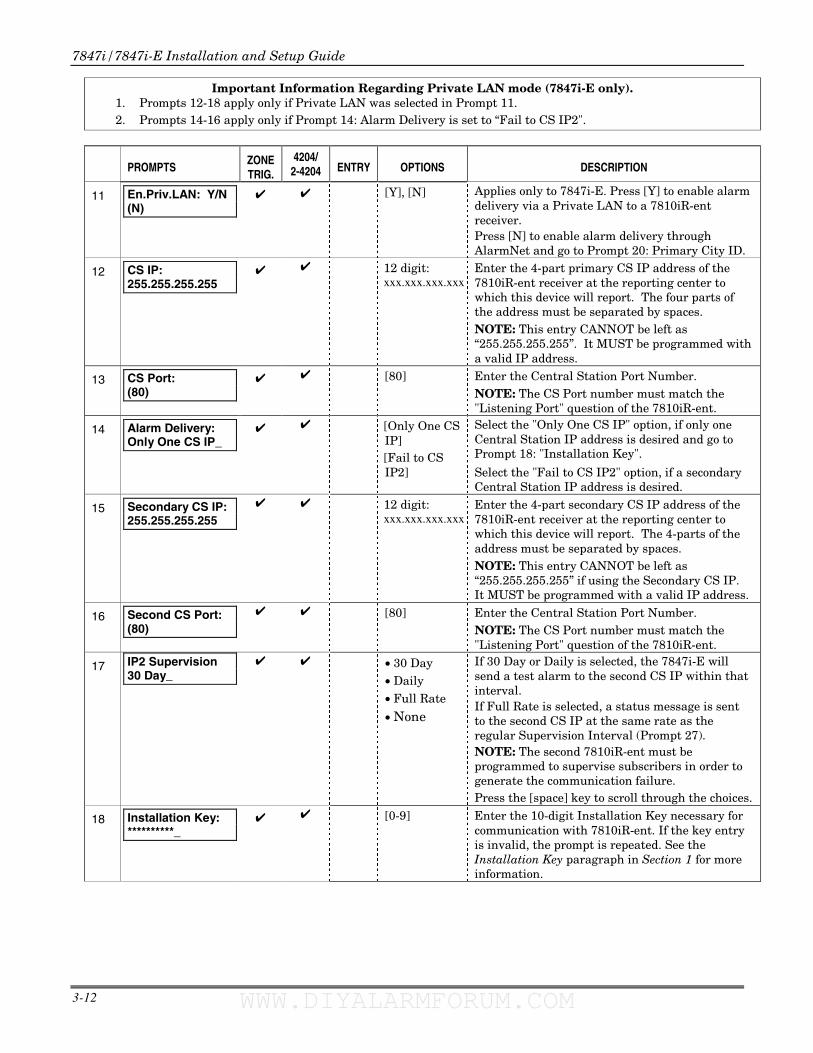
Important Information Regarding Private LAN mode (7847i-E only). 1. Prompts 12-18 apply only if Private LAN was selected in Prompt 11. 2. Prompts 14-16 apply only if Prompt 14: Alarm Delivery is set to “Fail to CS IP2".
PROMPTS
ZONE TRIG.
4204/ 2-4204 ENTRY OPTIONS DESCRIPTION
11
En.Priv.LAN: Y/N (N)
✔ ✔ [Y], [N]
Applies only to 7847i-E. Press [Y] to enable alarm delivery via a Private LAN to a 7810iR-ent receiver. Press [N] to enable alarm delivery through AlarmNet and go to Prompt 20: Primary City ID.
12
CS IP: 255.255.255.255
✔ ✔ 12 digit: xxx.xxx.xxx.xxx
Enter the 4-part primary CS IP address of the 7810iR-ent receiver at the reporting center to which this device will report. The four parts of the address must be separated by spaces. NOTE: This entry CANNOT be left as “255.255.255.255”. It MUST be programmed with a valid IP address.
13
CS Port: (80)
✔ ✔ [80] Enter the Central Station Port Number. NOTE: The CS Port number must match the "Listening Port" question of the 7810iR-ent.
14
Alarm Delivery: Only One CS IP_
✔ ✔ [Only One CS IP] [Fail to CS IP2]
Select the "Only One CS IP" option, if only one Central Station IP address is desired and go to Prompt 18: "Installation Key".
Select the "Fail to CS IP2" option, if a secondary Central Station IP address is desired.
15
Secondary CS IP: 255.255.255.255
✔ ✔ 12 digit: xxx.xxx.xxx.xxx
Enter the 4-part secondary CS IP address of the 7810iR-ent receiver at the reporting center to which this device will report. The 4-parts of the address must be separated by spaces. NOTE: This entry CANNOT be left as “255.255.255.255” if using the Secondary CS IP. It MUST be programmed with a valid IP address.
16
Second CS Port: (80)
✔ ✔ [80] Enter the Central Station Port Number. NOTE: The CS Port number must match the "Listening Port" question of the 7810iR-ent.
17 IP2 Supervision 30 Day_
✔ ✔ • 30 Day • Daily • Full Rate
• None
If 30 Day or Daily is selected, the 7847i-E will send a test alarm to the second CS IP within that interval. If Full Rate is selected, a status message is sent to the second CS IP at the same rate as the regular Supervision Interval (Prompt 27). NOTE: The second 7810iR-ent must be programmed to supervise subscribers in order to generate the communication failure. Press the [space] key to scroll through the choices.
18
Installation Key: **********_
✔ ✔ [0-9] Enter the 10-digit Installation Key necessary for communication with 7810iR-ent. If the key entry is invalid, the prompt is repeated. See the Installation Key paragraph in Section 1 for more information.
WWW.DIYALARMFORUM.COM WWW.DIYALARMFORUM.COM
Section 3: Programming the 7847i/7847i-E
3-13
PROMPTS
ZONE TRIG.
4204/ 2-4204 ENTRY OPTIONS DESCRIPTION
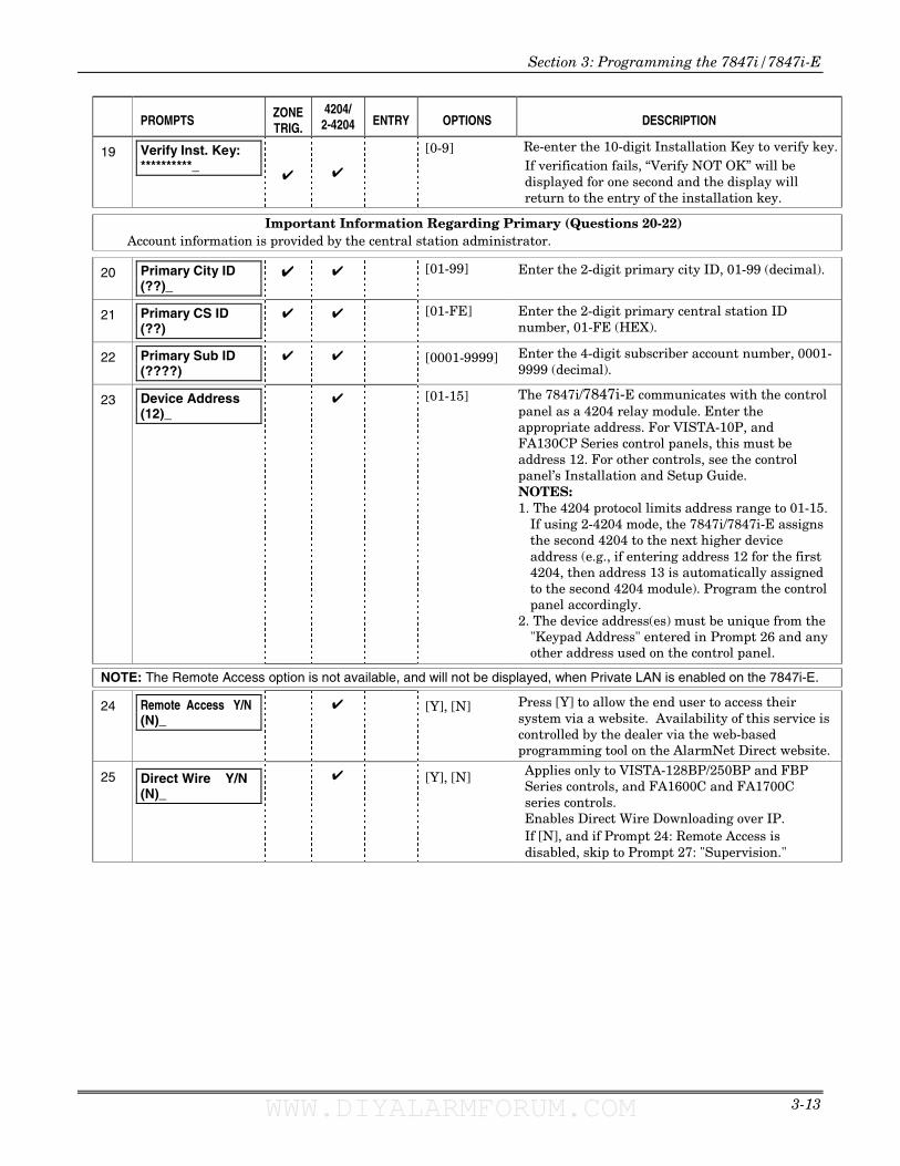
19
Verify Inst. Key: **********_ ✔ ✔
[0-9] Re-enter the 10-digit Installation Key to verify key.If verification fails, “Verify NOT OK” will be displayed for one second and the display will return to the entry of the installation key.
Important Information Regarding Primary (Questions 20-22) Account information is provided by the central station administrator.
20 Primary City ID (??)_
✔ ✔ [01-99]
Enter the 2-digit primary city ID, 01-99 (decimal).
21
Primary CS ID (??)
✔ ✔ [01-FE] Enter the 2-digit primary central station ID number, 01-FE (HEX).
22
Primary Sub ID (????)
✔ ✔ [0001-9999] Enter the 4-digit subscriber account number, 0001-9999 (decimal).
23
Device Address (12)_
✔ [01-15]
The 7847i/7847i-E communicates with the control panel as a 4204 relay module. Enter the appropriate address. For VISTA-10P, and FA130CP Series control panels, this must be address 12. For other controls, see the control panel’s Installation and Setup Guide. NOTES: 1. The 4204 protocol limits address range to 01-15.
If using 2-4204 mode, the 7847i/7847i-E assigns the second 4204 to the next higher device address (e.g., if entering address 12 for the first 4204, then address 13 is automatically assigned to the second 4204 module). Program the control panel accordingly.
2. The device address(es) must be unique from the "Keypad Address" entered in Prompt 26 and any other address used on the control panel.
NOTE: The Remote Access option is not available, and will not be displayed, when Private LAN is enabled on the 7847i-E.
24
Remote Access Y/N (N)_
✔ [Y], [N] Press [Y] to allow the end user to access their system via a website. Availability of this service is controlled by the dealer via the web-based programming tool on the AlarmNet Direct website.
25
Direct Wire Y/N (N)_
✔ [Y], [N] Applies only to VISTA-128BP/250BP and FBP Series controls, and FA1600C and FA1700C series controls. Enables Direct Wire Downloading over IP. If [N], and if Prompt 24: Remote Access is disabled, skip to Prompt 27: "Supervision."
WWW.DIYALARMFORUM.COM WWW.DIYALARMFORUM.COM
7847i/7847i-E Installation and Setup Guide
3-14
PROMPTS
ZONE TRIG.
4204/ 2-4204 ENTRY OPTIONS DESCRIPTION
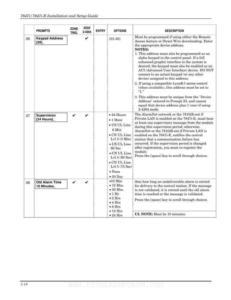
26
Keypad Address (28)_
✔ [01-30] Must be programmed if using either the Remote Access feature or Direct Wire downloading. Enter the appropriate device address. NOTES: 1. This address must also be programmed as an
alpha keypad in the control panel. If a full enhanced graphic interface to the system is desired, the keypad must also be enabled as an AUI (Advanced User Interface) device. DO NOT connect to an actual keypad (or any other device) assigned to this address.
2. If using a compatible LynxR-I series control (when available), this address must be set to “1.”
3. This address must be unique from the "Device Address" entered in Prompt 23, and cannot equal that device address plus 1 (one) if using 2-4204 mode.
27
Supervision (24 Hours)_
✔ ✔ • 24 Hours • 1 Hour • US UL Line 6 Min • CN UL Line Lvl 3 (3 Min)
• US UL Line 90 Sec
• CN UL Line Lvl 4 (90 Sec)
• CN UL Line Lvl 5 (75 Sec)
• None • 30 Day
The AlarmNet network or the 7810iR-ent if Private LAN is enabled on the 7847i-E, must hear at least one supervisory message from the module during this supervision period; otherwise, AlarmNet or the 7810iR-ent if Private LAN is enabled on the 7847i-E, notifies the central station that a communication failure has occurred. If the supervision period is changed after registration, you must re-register the module. Press the [space] key to scroll through choices.
✔ ✔ Sets how long an undeliverable alarm is retried for delivery to the central station. If the message is not validated, it is retried until the old alarm time is reached or the message is validated.
Press the [space] key to scroll through choices.
28
Old Alarm Time 10 Minutes_
•10 Min.• 15 Min.• 30 Min.• 1 Hr• 2 Hrs • 4 Hrs • 8 Hrs • 12 Hrs • 24 Hrs UL NOTE: Must be 10 minutes.
WWW.DIYALARMFORUM.COM WWW.DIYALARMFORUM.COM
Section 3: Programming the 7847i/7847i-E
3-15
PROMPTS
ZONE TRIG.
4204/ 2-4204 ENTRY OPTIONS DESCRIPTION
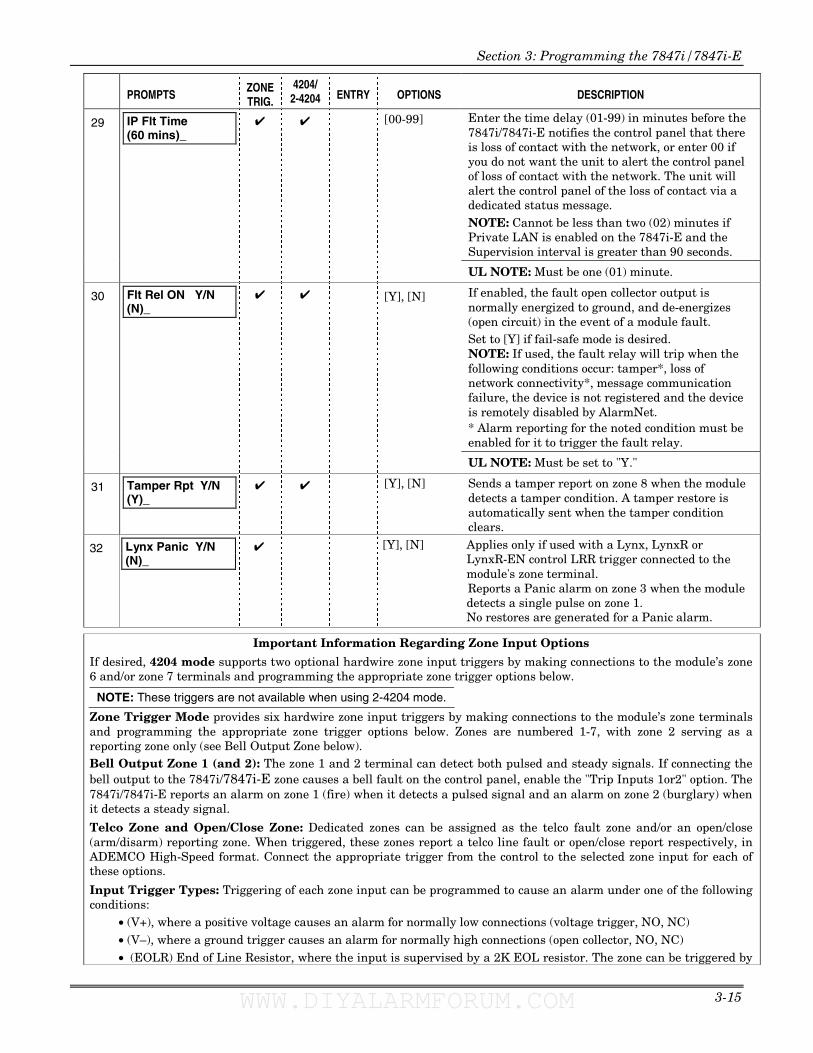
29
IP Flt Time (60 mins)_
✔ ✔ [00-99] Enter the time delay (01-99) in minutes before the 7847i/7847i-E notifies the control panel that there is loss of contact with the network, or enter 00 if you do not want the unit to alert the control panel of loss of contact with the network. The unit will alert the control panel of the loss of contact via a dedicated status message. NOTE: Cannot be less than two (02) minutes if Private LAN is enabled on the 7847i-E and the Supervision interval is greater than 90 seconds.
UL NOTE: Must be one (01) minute.
30
Flt Rel ON Y/N (N)_
✔ ✔ [Y], [N] If enabled, the fault open collector output is normally energized to ground, and de-energizes (open circuit) in the event of a module fault. Set to [Y] if fail-safe mode is desired. NOTE: If used, the fault relay will trip when the following conditions occur: tamper*, loss of network connectivity*, message communication failure, the device is not registered and the device is remotely disabled by AlarmNet. * Alarm reporting for the noted condition must be enabled for it to trigger the fault relay.
UL NOTE: Must be set to "Y."
31
Tamper Rpt Y/N (Y)_
✔ ✔ [Y], [N] Sends a tamper report on zone 8 when the module detects a tamper condition. A tamper restore is automatically sent when the tamper condition clears.
32
Lynx Panic Y/N (N)_
✔ [Y], [N] Applies only if used with a Lynx, LynxR or LynxR-EN control LRR trigger connected to the module's zone terminal. Reports a Panic alarm on zone 3 when the module detects a single pulse on zone 1. No restores are generated for a Panic alarm.
Important Information Regarding Zone Input Options
If desired, 4204 mode supports two optional hardwire zone input triggers by making connections to the module’s zone 6 and/or zone 7 terminals and programming the appropriate zone trigger options below.
NOTE: These triggers are not available when using 2-4204 mode.
Zone Trigger Mode provides six hardwire zone input triggers by making connections to the module’s zone terminals and programming the appropriate zone trigger options below. Zones are numbered 1-7, with zone 2 serving as a reporting zone only (see Bell Output Zone below). Bell Output Zone 1 (and 2): The zone 1 and 2 terminal can detect both pulsed and steady signals. If connecting the bell output to the 7847i/7847i-E zone causes a bell fault on the control panel, enable the "Trip Inputs 1or2" option. The 7847i/7847i-E reports an alarm on zone 1 (fire) when it detects a pulsed signal and an alarm on zone 2 (burglary) when it detects a steady signal.
Telco Zone and Open/Close Zone: Dedicated zones can be assigned as the telco fault zone and/or an open/close (arm/disarm) reporting zone. When triggered, these zones report a telco line fault or open/close report respectively, in ADEMCO High-Speed format. Connect the appropriate trigger from the control to the selected zone input for each of these options.
Input Trigger Types: Triggering of each zone input can be programmed to cause an alarm under one of the following conditions:
• (V+), where a positive voltage causes an alarm for normally low connections (voltage trigger, NO, NC) • (V–), where a ground trigger causes an alarm for normally high connections (open collector, NO, NC) • (EOLR) End of Line Resistor, where the input is supervised by a 2K EOL resistor. The zone can be triggered by
WWW.DIYALARMFORUM.COM WWW.DIYALARMFORUM.COM
7847i/7847i-E Installation and Setup Guide
3-16
open collector, voltage trigger, NO, NC.
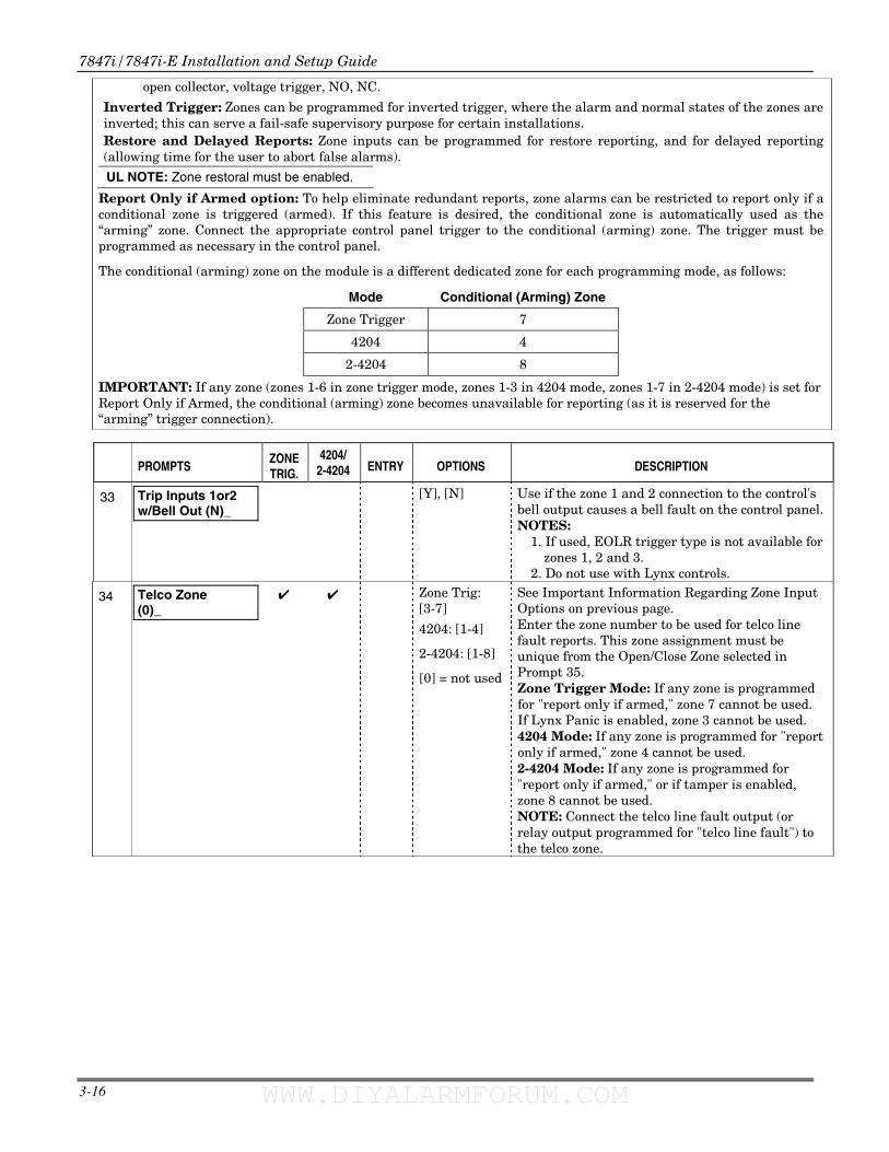
Inverted Trigger: Zones can be programmed for inverted trigger, where the alarm and normal states of the zones are inverted; this can serve a fail-safe supervisory purpose for certain installations. Restore and Delayed Reports: Zone inputs can be programmed for restore reporting, and for delayed reporting (allowing time for the user to abort false alarms).
UL NOTE: Zone restoral must be enabled.
Report Only if Armed option: To help eliminate redundant reports, zone alarms can be restricted to report only if a conditional zone is triggered (armed). If this feature is desired, the conditional zone is automatically used as the “arming” zone. Connect the appropriate control panel trigger to the conditional (arming) zone. The trigger must be programmed as necessary in the control panel.
The conditional (arming) zone on the module is a different dedicated zone for each programming mode, as follows:
Mode Conditional (Arming) Zone
Zone Trigger 7
4204 4
2-4204 8
IMPORTANT: If any zone (zones 1-6 in zone trigger mode, zones 1-3 in 4204 mode, zones 1-7 in 2-4204 mode) is set for Report Only if Armed, the conditional (arming) zone becomes unavailable for reporting (as it is reserved for the “arming” trigger connection).
PROMPTS
ZONE TRIG.
4204/ 2-4204 ENTRY OPTIONS DESCRIPTION
33
Trip Inputs 1or2 w/Bell Out (N)_
[Y], [N]
Use if the zone 1 and 2 connection to the control's bell output causes a bell fault on the control panel. NOTES:
1. If used, EOLR trigger type is not available for zones 1, 2 and 3.
2. Do not use with Lynx controls.
34
Telco Zone (0)_
✔ ✔ Zone Trig: [3-7]
4204: [1-4]
2-4204: [1-8]
[0] = not used
See Important Information Regarding Zone Input Options on previous page. Enter the zone number to be used for telco line fault reports. This zone assignment must be unique from the Open/Close Zone selected in Prompt 35. Zone Trigger Mode: If any zone is programmed for "report only if armed," zone 7 cannot be used. If Lynx Panic is enabled, zone 3 cannot be used. 4204 Mode: If any zone is programmed for "report only if armed," zone 4 cannot be used. 2-4204 Mode: If any zone is programmed for "report only if armed," or if tamper is enabled, zone 8 cannot be used. NOTE: Connect the telco line fault output (or relay output programmed for "telco line fault") to the telco zone.
WWW.DIYALARMFORUM.COM WWW.DIYALARMFORUM.COM
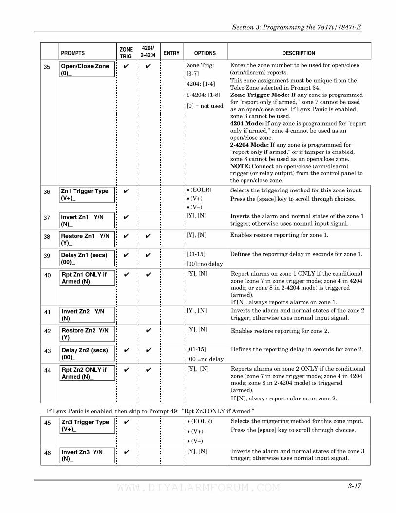
Section 3: Programming the 7847i/7847i-E
3-17
PROMPTS
ZONE TRIG.
4204/ 2-4204 ENTRY OPTIONS DESCRIPTION
35
Open/Close Zone (0)_
✔ ✔ Zone Trig: [3-7]
4204: [1-4]
2-4204: [1-8]
[0] = not used
Enter the zone number to be used for open/close (arm/disarm) reports. This zone assignment must be unique from the Telco Zone selected in Prompt 34. Zone Trigger Mode: If any zone is programmed for "report only if armed," zone 7 cannot be used as an open/close zone. If Lynx Panic is enabled, zone 3 cannot be used. 4204 Mode: If any zone is programmed for "report only if armed," zone 4 cannot be used as an open/close zone. 2-4204 Mode: If any zone is programmed for "report only if armed," or if tamper is enabled, zone 8 cannot be used as an open/close zone. NOTE: Connect an open/close (arm/disarm) trigger (or relay output) from the control panel to the open/close zone.
36
Zn1 Trigger Type (V+)_
✔ • (EOLR) • (V+) • (V–)
Selects the triggering method for this zone input.
Press the [space] key to scroll through choices.
37
Invert Zn1 Y/N (N)_
✔ [Y], [N] Inverts the alarm and normal states of the zone 1 trigger; otherwise uses normal input signal.
38
Restore Zn1 Y/N (Y)_
✔
✔ [Y], [N] Enables restore reporting for zone 1.
39
Delay Zn1 (secs) (00)_
✔ ✔ [01-15]
[00]=no delay
Defines the reporting delay in seconds for zone 1.
40
Rpt Zn1 ONLY if Armed (N)_
✔ ✔ [Y], [N]
Report alarms on zone 1 ONLY if the conditional zone (zone 7 in zone trigger mode; zone 4 in 4204 mode; or zone 8 in 2-4204 mode) is triggered (armed). If [N], always reports alarms on zone 1.
41
Invert Zn2 Y/N (N)_
[Y], [N] Inverts the alarm and normal states of the zone 2 trigger; otherwise uses normal input signal.
42
Restore Zn2 Y/N (Y)_
✔ [Y], [N] Enables restore reporting for zone 2.
43
Delay Zn2 (secs) (00)_
✔ ✔ [01-15]
[00]=no delay
Defines the reporting delay in seconds for zone 2.
44
Rpt Zn2 ONLY if Armed (N)_
✔ ✔ [Y], [N] Reports alarms on zone 2 ONLY if the conditional zone (zone 7 in zone trigger mode; zone 4 in 4204 mode; zone 8 in 2-4204 mode) is triggered (armed). If [N], always reports alarms on zone 2.
If Lynx Panic is enabled, then skip to Prompt 49: "Rpt Zn3 ONLY if Armed."
45
Zn3 Trigger Type (V+)_
✔ • (EOLR)
• (V+)
• (V–)
Selects the triggering method for this zone input.
Press the [space] key to scroll through choices.
46
Invert Zn3 Y/N (N)_
✔
[Y], [N] Inverts the alarm and normal states of the zone 3 trigger; otherwise uses normal input signal.
WWW.DIYALARMFORUM.COM WWW.DIYALARMFORUM.COM
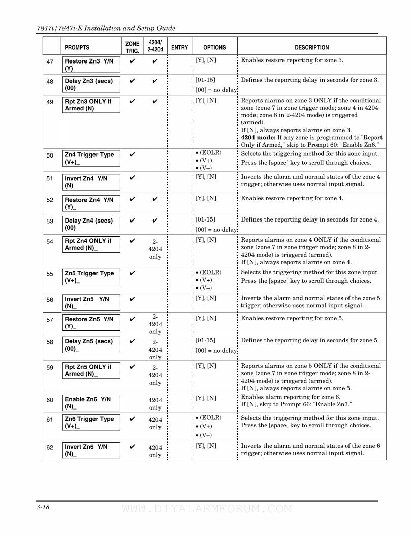
7847i/7847i-E Installation and Setup Guide
3-18
PROMPTS
ZONE TRIG.
4204/ 2-4204 ENTRY OPTIONS DESCRIPTION
47
Restore Zn3 Y/N (Y)_
✔
✔ [Y], [N] Enables restore reporting for zone 3.
48
Delay Zn3 (secs) (00)
✔ ✔ [01-15]
[00] = no delay
Defines the reporting delay in seconds for zone 3.
49
Rpt Zn3 ONLY if Armed (N)_
✔ ✔ [Y], [N]
Reports alarms on zone 3 ONLY if the conditional zone (zone 7 in zone trigger mode; zone 4 in 4204 mode; zone 8 in 2-4204 mode) is triggered (armed). If [N], always reports alarms on zone 3. 4204 mode: If any zone is programmed to "Report Only if Armed," skip to Prompt 60: "Enable Zn6."
50
Zn4 Trigger Type (V+)_
✔ • (EOLR) • (V+) • (V–)
Selects the triggering method for this zone input. Press the [space] key to scroll through choices.
51
Invert Zn4 Y/N (N)_
✔
[Y], [N] Inverts the alarm and normal states of the zone 4
trigger; otherwise uses normal input signal.
52
Restore Zn4 Y/N (Y)_
✔
✔ [Y], [N] Enables restore reporting for zone 4.
53
Delay Zn4 (secs) (00)
✔ ✔ [01-15]
[00] = no delay
Defines the reporting delay in seconds for zone 4.
54
Rpt Zn4 ONLY if Armed (N)_
✔ 2-4204 only
[Y], [N]
Reports alarms on zone 4 ONLY if the conditional zone (zone 7 in zone trigger mode; zone 8 in 2-4204 mode) is triggered (armed). If [N], always reports alarms on zone 4.
55
Zn5 Trigger Type (V+)_
✔ • (EOLR) • (V+) • (V–)
Selects the triggering method for this zone input. Press the [space] key to scroll through choices.
56
Invert Zn5 Y/N (N)_
✔ [Y], [N] Inverts the alarm and normal states of the zone 5 trigger; otherwise uses normal input signal.
57
Restore Zn5 Y/N (Y)_
✔ 2-4204 only
[Y], [N] Enables restore reporting for zone 5.
58
Delay Zn5 (secs) (00)_
✔ 2-4204 only
[01-15]
[00] = no delay
Defines the reporting delay in seconds for zone 5.
59
Rpt Zn5 ONLY if Armed (N)_
✔ 2-4204 only
[Y], [N]
Reports alarms on zone 5 ONLY if the conditional zone (zone 7 in zone trigger mode; zone 8 in 2-4204 mode) is triggered (armed). If [N], always reports alarms on zone 5.
60
Enable Zn6 Y/N (N)_
4204 only
[Y], [N] Enables alarm reporting for zone 6. If [N], skip to Prompt 66: "Enable Zn7."
61
Zn6 Trigger Type (V+)_
✔ 4204 only
• (EOLR) • (V+) • (V–)
Selects the triggering method for this zone input. Press the [space] key to scroll through choices.
62
Invert Zn6 Y/N (N)_
✔
4204 only
[Y], [N] Inverts the alarm and normal states of the zone 6 trigger; otherwise uses normal input signal.
WWW.DIYALARMFORUM.COM WWW.DIYALARMFORUM.COM
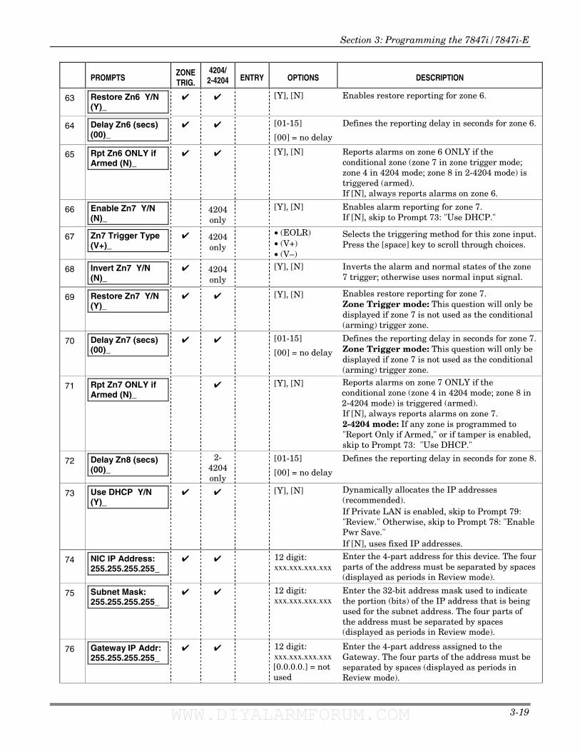
Section 3: Programming the 7847i/7847i-E
3-19
PROMPTS
ZONE TRIG.
4204/ 2-4204 ENTRY OPTIONS DESCRIPTION
63
Restore Zn6 Y/N (Y)_
✔
✔ [Y], [N] Enables restore reporting for zone 6.
64
Delay Zn6 (secs) (00)_
✔ ✔ [01-15]
[00] = no delay
Defines the reporting delay in seconds for zone 6.
65
Rpt Zn6 ONLY if Armed (N)_
✔ ✔ [Y], [N]
Reports alarms on zone 6 ONLY if the conditional zone (zone 7 in zone trigger mode; zone 4 in 4204 mode; zone 8 in 2-4204 mode) is triggered (armed). If [N], always reports alarms on zone 6.
66
Enable Zn7 Y/N (N)_
4204 only
[Y], [N] Enables alarm reporting for zone 7. If [N], skip to Prompt 73: "Use DHCP."
67
Zn7 Trigger Type (V+)_
✔ 4204 only
• (EOLR) • (V+) • (V–)
Selects the triggering method for this zone input. Press the [space] key to scroll through choices.
68
Invert Zn7 Y/N (N)_
✔
4204 only
[Y], [N] Inverts the alarm and normal states of the zone 7 trigger; otherwise uses normal input signal.
69
Restore Zn7 Y/N (Y)_
✔ ✔ [Y], [N] Enables restore reporting for zone 7. Zone Trigger mode: This question will only be displayed if zone 7 is not used as the conditional (arming) trigger zone.
70
Delay Zn7 (secs) (00)_
✔ ✔ [01-15]
[00] = no delay
Defines the reporting delay in seconds for zone 7. Zone Trigger mode: This question will only be displayed if zone 7 is not used as the conditional (arming) trigger zone.
71
Rpt Zn7 ONLY if Armed (N)_
✔ [Y], [N]
Reports alarms on zone 7 ONLY if the conditional zone (zone 4 in 4204 mode; zone 8 in 2-4204 mode) is triggered (armed). If [N], always reports alarms on zone 7. 2-4204 mode: If any zone is programmed to "Report Only if Armed," or if tamper is enabled, skip to Prompt 73: "Use DHCP."
72
Delay Zn8 (secs) (00)_
2-4204 only
[01-15]
[00] = no delay
Defines the reporting delay in seconds for zone 8.
73
Use DHCP Y/N (Y)_
✔ ✔ [Y], [N] Dynamically allocates the IP addresses (recommended). If Private LAN is enabled, skip to Prompt 79: "Review." Otherwise, skip to Prompt 78: "Enable Pwr Save." If [N], uses fixed IP addresses.
74
NIC IP Address: 255.255.255.255_
✔ ✔ 12 digit: xxx.xxx.xxx.xxx
Enter the 4-part address for this device. The four parts of the address must be separated by spaces (displayed as periods in Review mode).
75
Subnet Mask: 255.255.255.255_
✔ ✔ 12 digit: xxx.xxx.xxx.xxx
Enter the 32-bit address mask used to indicate the portion (bits) of the IP address that is being used for the subnet address. The four parts of the address must be separated by spaces (displayed as periods in Review mode).
76
Gateway IP Addr: 255.255.255.255_
✔ ✔ 12 digit: xxx.xxx.xxx.xxx [0.0.0.0.] = not used
Enter the 4-part address assigned to the Gateway. The four parts of the address must be separated by spaces (displayed as periods in Review mode).
WWW.DIYALARMFORUM.COM WWW.DIYALARMFORUM.COM
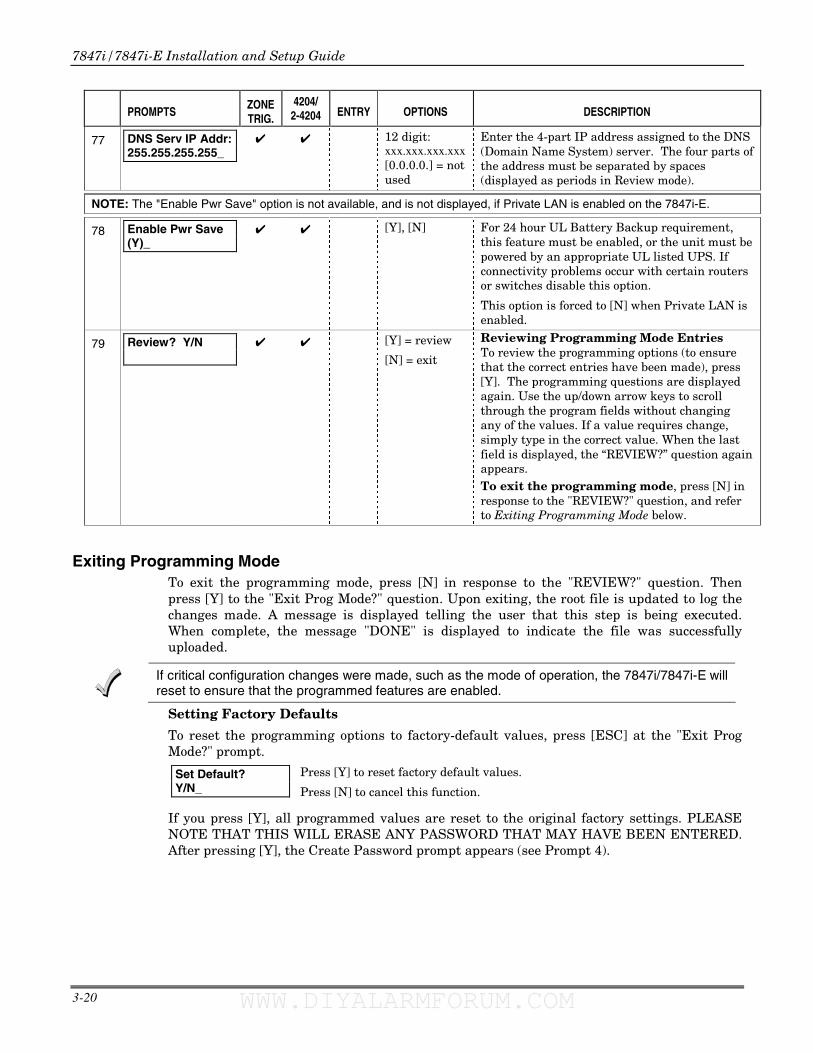
7847i/7847i-E Installation and Setup Guide
3-20
PROMPTS
ZONE TRIG.
4204/ 2-4204 ENTRY OPTIONS DESCRIPTION
77
DNS Serv IP Addr: 255.255.255.255_
✔ ✔ 12 digit: xxx.xxx.xxx.xxx [0.0.0.0.] = not used
Enter the 4-part IP address assigned to the DNS (Domain Name System) server. The four parts of the address must be separated by spaces (displayed as periods in Review mode).
NOTE: The "Enable Pwr Save" option is not available, and is not displayed, if Private LAN is enabled on the 7847i-E.
78 Enable Pwr Save (Y)_
✔ ✔ [Y], [N]
For 24 hour UL Battery Backup requirement, this feature must be enabled, or the unit must be powered by an appropriate UL listed UPS. If connectivity problems occur with certain routers or switches disable this option.
This option is forced to [N] when Private LAN is enabled.
79
Review? Y/N
✔ ✔ [Y] = review
[N] = exit
Reviewing Programming Mode Entries To review the programming options (to ensure that the correct entries have been made), press [Y]. The programming questions are displayed again. Use the up/down arrow keys to scroll through the program fields without changing any of the values. If a value requires change, simply type in the correct value. When the last field is displayed, the “REVIEW?” question again appears. To exit the programming mode, press [N] in response to the "REVIEW?" question, and refer to Exiting Programming Mode below.
Exiting Programming Mode To exit the programming mode, press [N] in response to the "REVIEW?" question. Then press [Y] to the "Exit Prog Mode?" question. Upon exiting, the root file is updated to log the changes made. A message is displayed telling the user that this step is being executed. When complete, the message "DONE" is displayed to indicate the file was successfully uploaded.
Setting Factory Defaults
To reset the programming options to factory-default values, press [ESC] at the "Exit Prog Mode?" prompt.
Set Default? Y/N_
Press [Y] to reset factory default values.
Press [N] to cancel this function.
If you press [Y], all programmed values are reset to the original factory settings. PLEASE NOTE THAT THIS WILL ERASE ANY PASSWORD THAT MAY HAVE BEEN ENTERED. After pressing [Y], the Create Password prompt appears (see Prompt 4).
If critical configuration changes were made, such as the mode of operation, the 7847i/7847i-E will reset to ensure that the programmed features are enabled.
WWW.DIYALARMFORUM.COM WWW.DIYALARMFORUM.COM
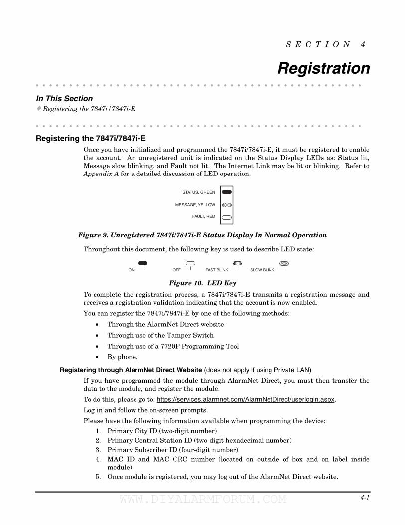
4-1
S E C T I O N 4
Registration • • • • • • • • • • • • • • • • • • • • • • • • • • • • • • • • • • • • • • • • • • • • • • • • •
In This Section � Registering the 7847i/7847i-E
• • • • • • • • • • • • • • • • • • • • • • • • • • • • • • • • • • • • • • • • • • • • • • • • •
Registering the 7847i/7847i-E Once you have initialized and programmed the 7847i/7847i-E, it must be registered to enable the account. An unregistered unit is indicated on the Status Display LEDs as: Status lit, Message slow blinking, and Fault not lit. The Internet Link may be lit or blinking. Refer to Appendix A for a detailed discussion of LED operation.
FAULT, RED
MESSAGE, YELLOW
STATUS, GREEN
Figure 9. Unregistered 7847i/7847i-E Status Display In Normal Operation
Throughout this document, the following key is used to describe LED state:
ON OFF FAST BLINK SLOW BLINK
Figure 10. LED Key
To complete the registration process, a 7847i/7847i-E transmits a registration message and receives a registration validation indicating that the account is now enabled.
You can register the 7847i/7847i-E by one of the following methods:
• Through the AlarmNet Direct website
• Through use of the Tamper Switch
• Through use of a 7720P Programming Tool
• By phone.
Registering through AlarmNet Direct Website (does not apply if using Private LAN)
If you have programmed the module through AlarmNet Direct, you must then transfer the data to the module, and register the module.
To do this, please go to: https://services.alarmnet.com/AlarmNetDirect/userlogin.aspx.
Log in and follow the on-screen prompts.
Please have the following information available when programming the device:
1. Primary City ID (two-digit number) 2. Primary Central Station ID (two-digit hexadecimal number) 3. Primary Subscriber ID (four-digit number) 4. MAC ID and MAC CRC number (located on outside of box and on label inside
module) 5. Once module is registered, you may log out of the AlarmNet Direct website.
WWW.DIYALARMFORUM.COM WWW.DIYALARMFORUM.COM
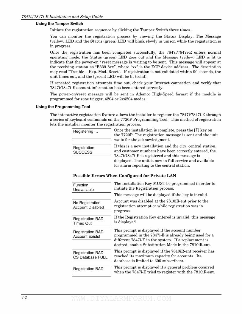
7847i/7847i-E Installation and Setup Guide
4-2
Using the Tamper Switch
Initiate the registration sequence by clicking the Tamper Switch three times.
You can monitor the registration process by viewing the Status Display. The Message (yellow) LED and the Status (green) LED will blink slowly in unison while the registration is in progress.
Once the registration has been completed successfully, the 7847i/7847i-E enters normal operating mode; the Status (green) LED goes out and the Message (yellow) LED is lit to indicate that the power-on / reset message is waiting to be sent. This message will appear at the receiving station as “E339 8xx”, where “xx” is the ECP device address. The description may read “Trouble – Exp. Mod. Reset”. If registration is not validated within 90 seconds, the unit times out, and the (green) LED will be lit (solid).
If repeated registration attempts time out, check your Internet connection and verify that 7847i/7847i-E account information has been entered correctly.
The power-on/reset message will be sent in Ademco High-Speed format if the module is programmed for zone trigger, 4204 or 2x4204 modes.
Using the Programming Tool
The interactive registration feature allows the installer to register the 7847i/7847i-E through a series of keyboard commands on the 7720P Programming Tool. This method of registration lets the installer monitor the registration process.
Registering …
Once the installation is complete, press the [↑] key on the 7720P. The registration message is sent and the unit waits for the acknowledgment.
Registration SUCCESS
If this is a new installation and the city, central station, and customer numbers have been correctly entered, the 7847i/7847i-E is registered and this message is displayed. The unit is now in full service and available for alarm reporting to the central station.
Possible Errors When Configured for Private LAN
Function Unavailable
The Installation Key MUST be programmed in order to initiate the Registration process.
This message will be displayed if the key is invalid.
No Registration Account Disabled
Account was disabled at the 7810iR-ent prior to the registration attempt or while registration was in progress.
Registration BAD Timed Out
If the Registration Key entered is invalid, this message is displayed.
Registration BAD Account Exists!
This prompt is displayed if the account number programmed in the 7847i-E is already being used for a different 7847i-E in the system. If a replacement is desired, enable Substitution Mode in the 7810iR-ent.
Registration BAD CS Database FULL
This prompt is displayed if the 7810iR-ent receiver has reached its maximum capacity for accounts. Its database is limited to 300 subscribers.
Registration BAD
This prompt is displayed if a general problem occurred when the 7847i-E tried to register with the 7810iR-ent.
WWW.DIYALARMFORUM.COM WWW.DIYALARMFORUM.COM
Section 4: Registration
4-3
Possible Errors When Configured for AlarmNet-i
Registration BAD Timed Out
Displayed if no response to the registration request is received.
Registration BAD Pri Sub ID BAD
Indicates the city, central station, or customer number for the Primary account(s) is not accepted. The ID information was either entered in error, or the central station failed to pre-authorize programmed ID numbers with AlarmNet customer service.
Registration BAD 2nd Sub ID BAD
Indicates the city, central station, or customer number for the Secondary account is not accepted. The ID information was either entered in error, or the central station failed to pre-authorize programmed ID numbers with AlarmNet customer service.
Registration BAD Pri&Sec IDs BAD
Displayed when both Primary and Secondary subscriber IDs are invalid.
Registration BAD Pri ID – Need PIN
Displayed if this is a repair/replacement, or an error was made in programming the Primary account information of 7847i/7847i-E for an existing account. This prompt appears for 2 seconds. See the Replacing an existing module section below for further displays.
Registration BAD 2nd ID – Need PIN
Displayed if this is a repair/replacement, or an error was made in programming the Secondary account information of 7847i/7847i-E for an existing account. This prompt appears for 2 seconds. See the Replacing an existing module section below for further displays.
Registration BAD Pri&2nd – Need PIN
Displayed if this is a repair/replacement, or an error was made in programming BOTH the Primary and Secondary account information of 7847i/7847i-E for an existing account. This prompt appears for 2 seconds. See the Replacing an existing module section below for further displays.
Replacing an existing module using the programming tool
Enter PIN#
This prompt appears after pressing the down arrow [↓↓↓↓] on the 7720P.
NOTE: If it is necessary to exit registration mode, press ESC from the 7720P programming tool.
Enter a 4-digit alphanumeric PIN number provided by an authorized AlarmNet representative.
Press the [ENTER] key.
Registering …
The registration message is sent and the unit waits for acknowledgement.
Registration SUCCESS
If the PIN is valid, the new 7847i/7847i-E is registered and the old unit unregistered. Additionally, AlarmNet sends a substitution alarm to the central station.
WWW.DIYALARMFORUM.COM WWW.DIYALARMFORUM.COM
7847i/7847i-E Installation and Setup Guide
4-4
Registration BAD
If you entered an invalid PIN, the appropriate message is displayed depending on which account number is being replaced (see above for exact wording). The registration process is repeated.
NOTE: Each attempt causes a substitution alarm to be sent to the central station.
Register by Phone
You can register the module by calling the AlarmNet Technical Assistance Center (TAC) at 1-800-222-6525.
You will need the following information:
• MAC number (found on the label).
• Subscriber information (provided by the central station), including a city code, CSID, and a subscriber ID.
• When instructed to do so, triple-click the tamper switch to complete the registration.
WWW.DIYALARMFORUM.COM WWW.DIYALARMFORUM.COM
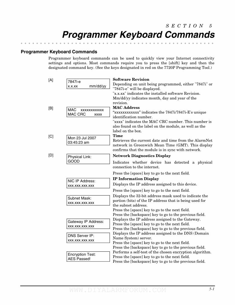
5-1
S E C T I O N 5
Programmer Keyboard Commands • • • • • • • • • • • • • • • • • • • • • • • • • • • • • • • • • • • • • • • • • • • • • • • • • •
Programmer Keyboard Commands Programmer keyboard commands can be used to quickly view your Internet connectivity settings and options. Most commands require you to press the [shift] key and then the designated command key. (See the keys designated in red on the 7720P Programming Tool.)
[A]
7847i-e x.x.xx mm/dd/yy
Software Revision Depending on unit being programmed, either "7847i" or "7847i-e" will be displayed. "x.x.xx" indicates the installed software Revision. Mm/dd/yy indicates month, day and year of the revision.
[B]
MAC xxxxxxxxxxxx MAC CRC xxxx
MAC Address “xxxxxxxxxxxx” indicates the 7847i/7847i-E's unique identification number. "xxxx" indicates the MAC CRC number. This number is also found on the label on the module, as well as the label on the box.
[C]
Mon 23 Jul 2007 03:45:23 am
Time Retrieves the current date and time from the AlarmNet network in Greenwich Mean Time (GMT). This display confirms that the module is in sync with network.
[D]
Physical Link: GOOD
Network Diagnostics Display
Indicates whether device has detected a physical connection to the internet.
Press the [space] key to go to the next field.
NIC IP Address: xxx.xxx.xxx.xxx
IP Information Display Displays the IP address assigned to this device.
Press the [space] key to go to the next field.
Subnet Mask: xxx.xxx.xxx.xxx
Displays the 32-bit address mask used to indicate the portion (bits) of the IP address that is being used for the subnet address. Press the [space] key to go to the next field. Press the [backspace] key to go to the previous field.
Gateway IP Address: xxx.xxx.xxx.xxx
Displays the IP address assigned to the Gateway. Press the [space] key to go to the next field. Press the [backspace] key to go to the previous field.
DNS Server IP: xxx.xxx.xxx.xxx
Displays the IP address assigned to the DNS (Domain Name System) server. Press the [space] key to go to the next field. Press the [backspace] key to go to the previous field.
Encryption Test: AES Passed!
Performs a self-test of the chosen encryption algorithm. Press the [space] key to go to the next field. Press the [backspace] key to go to the previous field.
WWW.DIYALARMFORUM.COM WWW.DIYALARMFORUM.COM
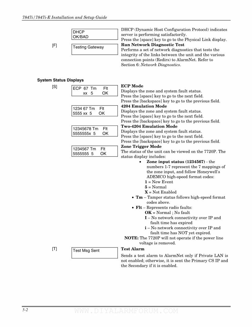
7847i/7847i-E Installation and Setup Guide
5-2
DHCP OK/BAD
DHCP (Dynamic Host Configuration Protocol) indicates server is performing satisfactorily. Press the [space] key to go to the Physical Link display.
[F]
Testing Gateway
Run Network Diagnostic Test Performs a set of network diagnostics that tests the integrity of the links between the unit and the various connection points (Redirs) to AlarmNet. Refer to Section 6: Network Diagnostics.
System Status Displays
[S]
ECP 67 Tm Flt xx 5 OK
ECP Mode Displays the zone and system fault status. Press the [space] key to go to the next field. Press the [backspace] key to go to the previous field.
1234 67 Tm Flt 5555 xx 5 OK
4204 Emulation Mode Displays the zone and system fault status. Press the [space] key to go to the next field. Press the [backspace] key to go to the previous field.
12345678 Tm Flt 5555555x 5 OK
Two-4204 Emulation Mode Displays the zone and system fault status. Press the [space] key to go to the next field. Press the [backspace] key to go to the previous field.
1234567 Tm Flt 5555555 5 OK
Zone Trigger Mode The status of the unit can be viewed on the 7720P. The status display includes:
• Zone input status (1234567) - the numbers 1-7 represent the 7 mappings of the zone input, and follow Honeywell's ADEMCO high-speed format codes:
1 = New Event 5 = Normal X = Not Enabled
• Tm – Tamper status follows high-speed format codes above.
• Flt – Represents radio faults: OK = Normal ; No fault I – No network connectivity over IP and
fault time has expired i – No network connectivity over IP and
fault time has NOT yet expired. NOTE: The 7720P will not operate if the power line
voltage is removed. [T]
Test Msg Sent
Test Alarm
Sends a test alarm to AlarmNet only if Private LAN is not enabled; otherwise, it is sent the Primary CS IP and the Secondary if it is enabled.
WWW.DIYALARMFORUM.COM WWW.DIYALARMFORUM.COM
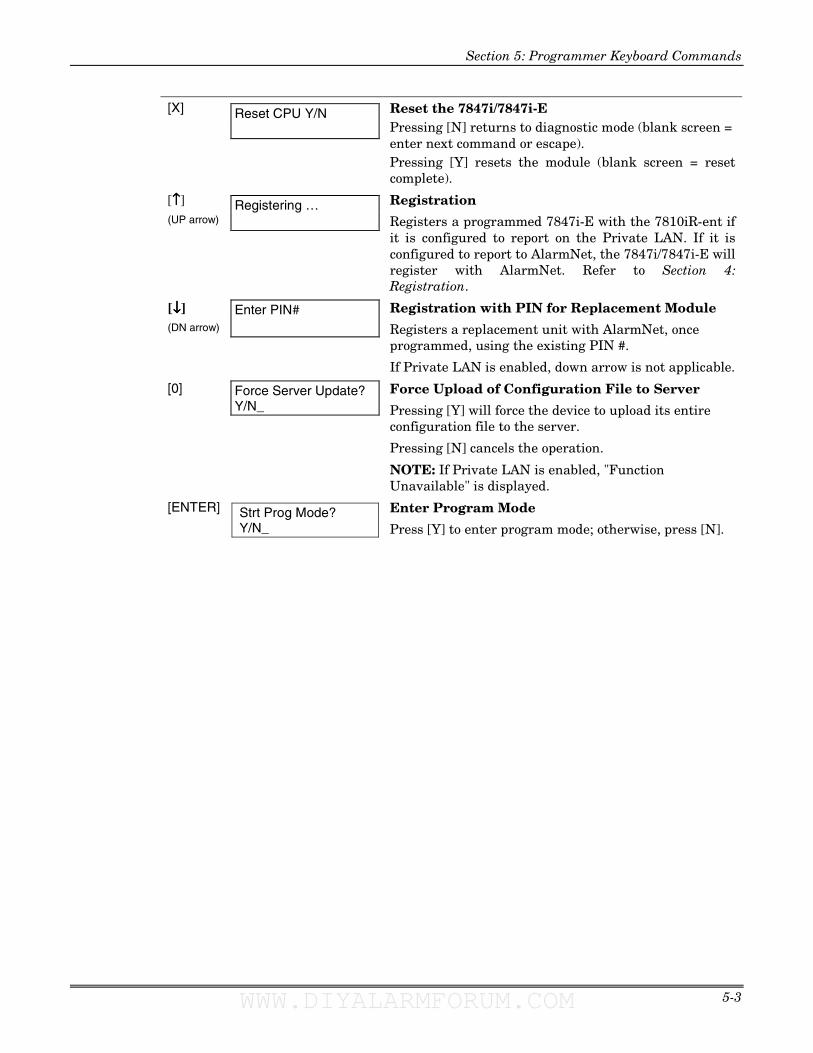
Section 5: Programmer Keyboard Commands
5-3
[X]
Reset CPU Y/N
Reset the 7847i/7847i-E Pressing [N] returns to diagnostic mode (blank screen = enter next command or escape). Pressing [Y] resets the module (blank screen = reset complete).
[↑↑↑↑] (UP arrow)
Registering …
Registration
Registers a programmed 7847i-E with the 7810iR-ent if it is configured to report on the Private LAN. If it is configured to report to AlarmNet, the 7847i/7847i-E will register with AlarmNet. Refer to Section 4: Registration.
[↓↓↓↓] (DN arrow)
Enter PIN#
Registration with PIN for Replacement Module
Registers a replacement unit with AlarmNet, once programmed, using the existing PIN #.
If Private LAN is enabled, down arrow is not applicable.
[0]
Force Server Update? Y/N_
Force Upload of Configuration File to Server
Pressing [Y] will force the device to upload its entire configuration file to the server.
Pressing [N] cancels the operation.
NOTE: If Private LAN is enabled, "Function Unavailable" is displayed.
[ENTER]
Strt Prog Mode? Y/N_
Enter Program Mode
Press [Y] to enter program mode; otherwise, press [N].
WWW.DIYALARMFORUM.COM WWW.DIYALARMFORUM.COM

7847i/7847i-E Installation and Setup Guide
5-4
WWW.DIYALARMFORUM.COM WWW.DIYALARMFORUM.COM
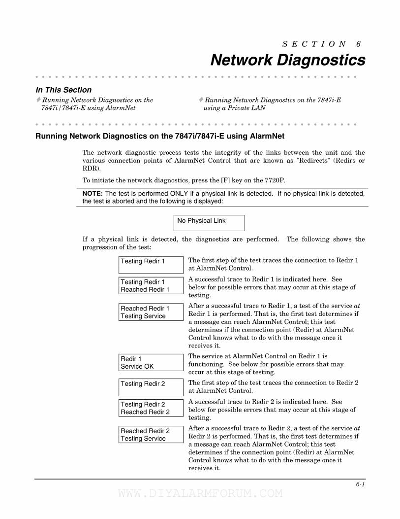
6-1
S E C T I O N 6
Network Diagnostics • • • • • • • • • • • • • • • • • • • • • • • • • • • • • • • • • • • • • • • • • • • • • • • • •
In This Section � Running Network Diagnostics on the
7847i/7847i-E using AlarmNet � Running Network Diagnostics on the 7847i-E
using a Private LAN
• • • • • • • • • • • • • • • • • • • • • • • • • • • • • • • • • • • • • • • • • • • • • • • • •
Running Network Diagnostics on the 7847i/7847i-E using AlarmNet
The network diagnostic process tests the integrity of the links between the unit and the various connection points of AlarmNet Control that are known as "Redirects" (Redirs or RDR).
To initiate the network diagnostics, press the [F] key on the 7720P.
NOTE: The test is performed ONLY if a physical link is detected. If no physical link is detected, the test is aborted and the following is displayed:
No Physical Link
If a physical link is detected, the diagnostics are performed. The following shows the progression of the test:
Testing Redir 1
The first step of the test traces the connection to Redir 1 at AlarmNet Control.
Testing Redir 1 Reached Redir 1
A successful trace to Redir 1 is indicated here. See below for possible errors that may occur at this stage of testing.
Reached Redir 1 Testing Service
After a successful trace to Redir 1, a test of the service at Redir 1 is performed. That is, the first test determines if a message can reach AlarmNet Control; this test determines if the connection point (Redir) at AlarmNet Control knows what to do with the message once it receives it.
Redir 1 Service OK
The service at AlarmNet Control on Redir 1 is functioning. See below for possible errors that may occur at this stage of testing.
Testing Redir 2
The first step of the test traces the connection to Redir 2 at AlarmNet Control.
Testing Redir 2 Reached Redir 2
A successful trace to Redir 2 is indicated here. See below for possible errors that may occur at this stage of testing.
Reached Redir 2 Testing Service
After a successful trace to Redir 2, a test of the service at Redir 2 is performed. That is, the first test determines if a message can reach AlarmNet Control; this test determines if the connection point (Redir) at AlarmNet Control knows what to do with the message once it receives it.
WWW.DIYALARMFORUM.COM WWW.DIYALARMFORUM.COM
7847i/7847i-E Installation and Setup Guide
6-2
Redir 2 Service OK
The service at AlarmNet Control on Redir 2 is functioning. See below for possible errors that may occur at this stage of testing.
Testing Redir 3
The first step of the test traces the connection to Redir 3 at AlarmNet Control.
Testing Redir 3 Reached Redir 3
A successful trace to Redir 3 is indicated here. See below for possible errors that may occur at this stage of testing.
Reached Redir 3 Testing Service
After a successful trace to Redir 3, a test of the service at Redir 1 is performed. That is, the first test determines if a message can reach AlarmNet Control; this test determines if the connection point (Redir) at AlarmNet Control knows what to do with the message once it receives it.
Redir 3 Service OK
The service at AlarmNet Control on Redir 3 is functioning. See below for possible errors that may occur at this stage of testing.
RDR1 RDR2 RDR3 OK OK OK
A summary of the tests is displayed after Redir 3 is tested. The example shows that the tests of all three connection points, or Redirs, were successful. If an error occurred at any point, the summary will display “FAIL” under the faulty Redir.
Possible Errors Running Network Diagnostics
Errors may occur at either while tracing the connection to a given Redir or while testing the service at a given Redir. The following list highlights the most common errors. Please contact the AlarmNet Technical Assistance Center (TAC) for help regarding any errors NOT listed below:
Possible Errors
Testing Redir x FAIL before Gtwy
While tracing the connection to Redir x, the trace fails before ever reaching the local gateway (router).
Testing Redir x FAIL at Gtwy
While tracing the connection to Redir x, the trace fails after reaching the local gateway (router).
Testing Redir x FAIL at Pvt IP
While tracing the connection to Redir x, the trace fails after reaching the private IP.
Testing Redir x FAIL on IP Addr
While tracing the connection to Redir x, the trace fails after reaching the public IP.
Redir x ERR:Proxy 18
After a successful trace to Redir x, the test of the service timed out without a response.
WWW.DIYALARMFORUM.COM WWW.DIYALARMFORUM.COM
Section 6: Network Diagnostics
6-3
Running Network Diagnostics on the 7847i-E using a Private LAN
The network diagnostic process tests the integrity of the links between the 7847i-E and the 7810iR-ent to which it should report.
To initiate the network diagnostics, press the [F] key on the 7720P.
NOTE: The test is performed ONLY if a physical link is detected. If no physical link is detected, the test is aborted and the following is displayed:
No Physical Link
If a physical link is detected, the diagnostics are performed. The following shows the progression of the test:
Testing CSIP 1
The first step of the test traces the connection to CS IP 1.
Testing CSIP 1 Reached CSIP 1
A successful trace to CS IP 1 is indicated here. See below for possible errors that may occur at this stage of testing.
Reached CSIP 1 Testing Service
After a successful trace to CS IP 1, a test of the service at CS IP 1 is performed. That is, the first test determines if a message can reach 7810iR-ent; this test determines if the connection point (CSIP) at the 7810iR-ent knows what to do with the message once it receives it.
CSIP 1 Service OK
The service at the 7810iR-ent on CS IP 1 is functioning. See below for possible errors that may occur at this stage of testing.
Testing CSIP 2
The first step of the test traces the connection to CS IP 2 at the 7810iR-ent.
Testing CSIP 2 Reached CSIP 2
A successful trace to CS IP 2 is indicated here. See below for possible errors that may occur at this stage of testing.
Reached CSIP 2 Testing Service
After a successful trace to CS IP 2, a test of the service at CS IP 2 is performed. That is, the first test determines if a message can reach the 7810iR-ent; this test determines if the connection point (CSIP) at the 7810iR-ent knows what to do with the message once it receives it.
CSIP 2 Service OK
The service at the 7810iR-ent on CS IP 2 is functioning. See below for possible errors that may occur at this stage of testing.
Testing CSIP 3
The first step of the test traces the connection to CS IP 3 at the 7810iR-ent.
Testing CSIP 3 Reached CSIP 3
A successful trace to CS IP 3 is indicated here. See below for possible errors that may occur at this stage of testing.
WWW.DIYALARMFORUM.COM WWW.DIYALARMFORUM.COM
7847i/7847i-E Installation and Setup Guide
6-4
Reached CSIP 3 Testing Service
After a successful trace to CS IP 3, a test of the service at CS IP 1 is performed. That is, the first test determines if a message can reach the 7810iR-ent; this test determines if the connection point (CSIP) at the 7810iR-ent knows what to do with the message once it receives it.
CSIP 3 Service OK
The service at the 7810iR-ent on CS IP 3 is functioning. See below for possible errors that may occur at this stage of testing.
Testing CSIP 2 Does Not Exist
If CS IP 2 and/or CS IP 3 are not programmed, display will read.
CIP1 CIP2 CIP3 OK/Fail N/A N/A
A summary of the tests is displayed after CS IP 3 is tested. The example shows that CS IP 2 and/or CS IP 3 are not programmed.
Possible Errors Running Network Diagnostics using a Private LAN
Errors may occur at either while tracing the connection to a given 7810iR-ent or while testing the service at a given 7810iR-ent. The following list highlights the most common errors. Please contact the AlarmNet Technical Assistance Center (TAC) for help regarding any errors NOT listed below:
Possible Errors
Testing CSIP x FAIL before Gtwy
While tracing the connection to CS IP x, the trace fails before ever reaching the local gateway (router).
Testing CSIP x FAIL at Gtwy
While tracing the connection to CS IP x, the trace fails after reaching the local gateway (router).
Testing CSIP x FAIL on IP Addr
While tracing the connection to CS IP x, the trace fails after reaching the CS IP.
WWW.DIYALARMFORUM.COM WWW.DIYALARMFORUM.COM
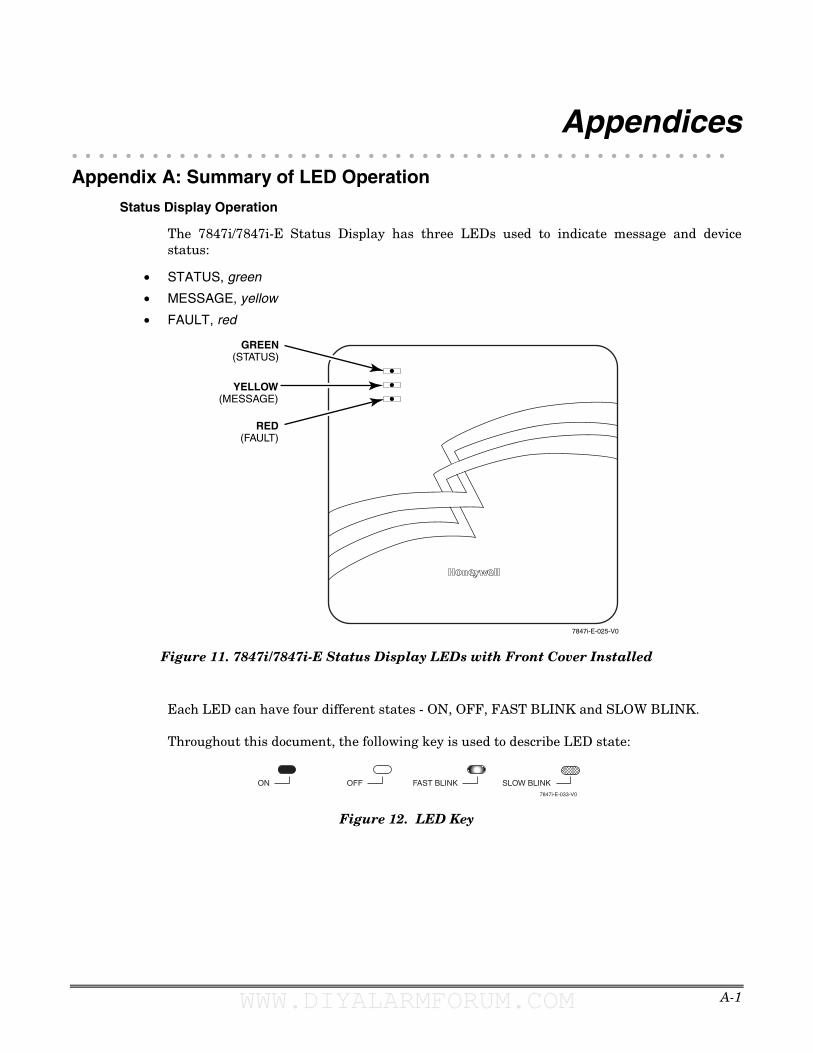
A-1
Appendices • • • • • • • • • • • • • • • • • • • • • • • • • • • • • • • • • • • • • • • • • • • • • • • • •
Appendix A: Summary of LED Operation
Status Display Operation
The 7847i/7847i-E Status Display has three LEDs used to indicate message and device status:
• STATUS, green
• MESSAGE, yellow
• FAULT, red
7847i-E-025-V0
YELLOW(MESSAGE)
RED(FAULT)
GREEN(STATUS)
Figure 11. 7847i/7847i-E Status Display LEDs with Front Cover Installed
Each LED can have four different states - ON, OFF, FAST BLINK and SLOW BLINK.
Throughout this document, the following key is used to describe LED state:
ON7847i-E-033-V0
OFF FAST BLINK SLOW BLINK
Figure 12. LED Key
WWW.DIYALARMFORUM.COM WWW.DIYALARMFORUM.COM
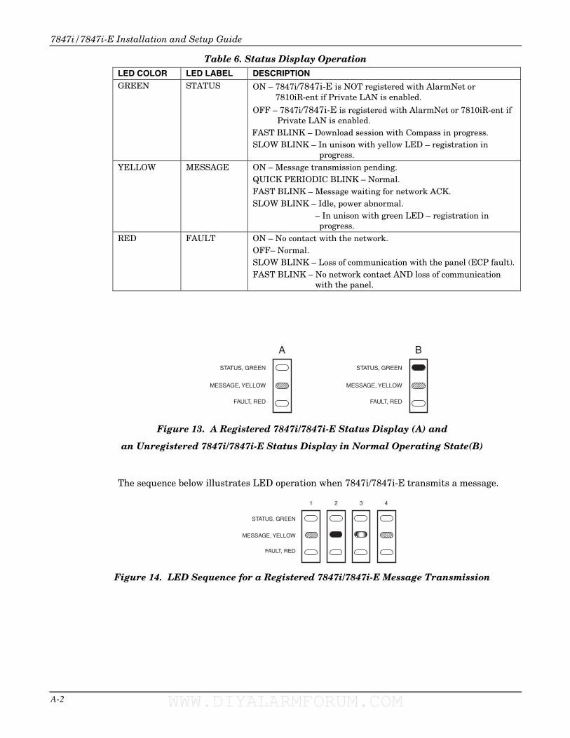
7847i/7847i-E Installation and Setup Guide
A-2
Table 6. Status Display Operation LED COLOR LED LABEL DESCRIPTION GREEN STATUS ON – 7847i/7847i-E is NOT registered with AlarmNet or
7810iR-ent if Private LAN is enabled.
OFF – 7847i/7847i-E is registered with AlarmNet or 7810iR-ent if Private LAN is enabled.
FAST BLINK – Download session with Compass in progress. SLOW BLINK – In unison with yellow LED – registration in
progress. YELLOW MESSAGE ON – Message transmission pending.
QUICK PERIODIC BLINK – Normal. FAST BLINK – Message waiting for network ACK. SLOW BLINK – Idle, power abnormal.
– In unison with green LED – registration in progress.
RED FAULT ON – No contact with the network. OFF– Normal. SLOW BLINK – Loss of communication with the panel (ECP fault). FAST BLINK – No network contact AND loss of communication
with the panel.
FAULT, RED
MESSAGE, YELLOW
STATUS, GREEN
A
FAULT, RED
MESSAGE, YELLOW
STATUS, GREEN
B
Figure 13. A Registered 7847i/7847i-E Status Display (A) and
an Unregistered 7847i/7847i-E Status Display in Normal Operating State(B)
The sequence below illustrates LED operation when 7847i/7847i-E transmits a message.
FAULT, RED
MESSAGE, YELLOW
STATUS, GREEN
4321
Figure 14. LED Sequence for a Registered 7847i/7847i-E Message Transmission
WWW.DIYALARMFORUM.COM WWW.DIYALARMFORUM.COM
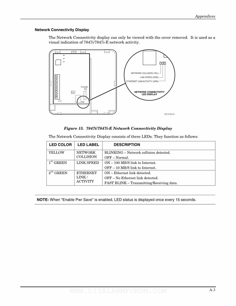
Appendices
A-3
Network Connectivity Display
The Network Connectivity display can only be viewed with the cover removed. It is used as a visual indication of 7847i/7847i-E network activity.
7847i-E-032-V0
NETWORK CONNECTIVITYLED DISPLAY
NETWORK COLLISION (YEL)
LINK SPEED (GRN)
ETHERNET LINK/ACTIVITY (GRN)
Figure 15. 7847i/7847i-E Network Connectivity Display
The Network Connectivity Display consists of three LEDs. They function as follows:
LED COLOR LED LABEL DESCRIPTION
YELLOW NETWORK COLLISION
BLINKING – Network collision detected. OFF – Normal.
1ST GREEN LINK SPEED ON – 100 MB/S link to Internet. OFF – 10 MB/S link to Internet.
2ND GREEN ETHERNET LINK / ACTIVITY
ON – Ethernet link detected. OFF – No Ethernet link detected. FAST BLINK – Transmitting/Receiving data.
NOTE: When "Enable Pwr Save" is enabled, LED status is displayed once every 15 seconds.
WWW.DIYALARMFORUM.COM WWW.DIYALARMFORUM.COM
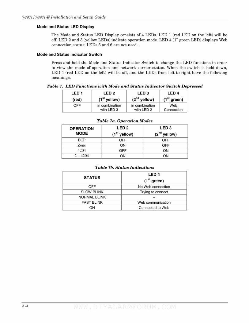
7847i/7847i-E Installation and Setup Guide
A-4
Mode and Status LED Display
The Mode and Status LED Display consists of 4 LEDs. LED 1 (red LED on the left) will be off, LED 2 and 3 (yellow LEDs) indicate operation mode. LED 4 (1st green LED) displays Web connection status; LEDs 5 and 6 are not used.
Mode and Status Indicator Switch
Press and hold the Mode and Status Indicator Switch to change the LED functions in order to view the mode of operation and network carrier status. When the switch is held down, LED 1 (red LED on the left) will be off, and the LEDs from left to right have the following meanings:
Table 7. LED Functions with Mode and Status Indicator Switch Depressed
LED 1
(red)
LED 2
(1st yellow)
LED 3
(2nd yellow)
LED 4
(1st green) OFF in combination
with LED 3 in combination
with LED 2 Web
Connection
Table 7a. Operation Modes
OPERATION MODE
LED 2
(1st yellow)
LED 3
(2nd yellow) ECP OFF OFF Zone ON OFF 4204 OFF ON
2 – 4204 ON ON
Table 7b. Status Indications
STATUS LED 4
(1st green) OFF No Web connection
SLOW BLINK Trying to connect NORMAL BLINK –
FAST BLINK Web communication ON Connected to Web
WWW.DIYALARMFORUM.COM WWW.DIYALARMFORUM.COM
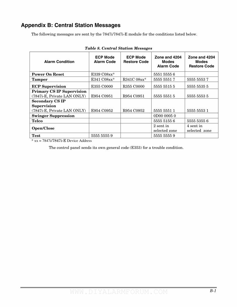
B-1
Appendix B: Central Station Messages
The following messages are sent by the 7847i/7847i-E module for the conditions listed below.
Table 8. Central Station Messages
Alarm Condition ECP Mode
Alarm Code
ECP Mode Restore Code
Zone and 4204 Modes
Alarm Code
Zone and 4204 Modes
Restore Code
Power On Reset E339 C08xx* 5551 5555 6 Tamper E341 C08xx* R341C 08xx* 5555 5551 7 5555 5553 7
ECP Supervision E355 C0000 R355 C0000 5555 5515 5 5555 5535 5 Primary CS IP Supervision (7847i-E, Private LAN ONLY) E954 C0951 R954 C0951 5555 5551 5 5555 5553 5 Secondary CS IP Supervision (7847i-E, Private LAN ONLY) E954 C0952 R954 C0952 5555 5551 1 5555 5553 1 Swinger Suppression 0D00 0005 0 Telco 5555 5155 6 5555 5355 6
Open/Close 2 sent in selected zone
4 sent in selected zone
Test 5555 5555 9 5555 5555 9 * xx = 7847i/7847i-E Device Address
The control panel sends its own general code (E353) for a trouble condition.
WWW.DIYALARMFORUM.COM WWW.DIYALARMFORUM.COM

7847i/7847i-E Installation and Setup Guide
B-2
WWW.DIYALARMFORUM.COM WWW.DIYALARMFORUM.COM
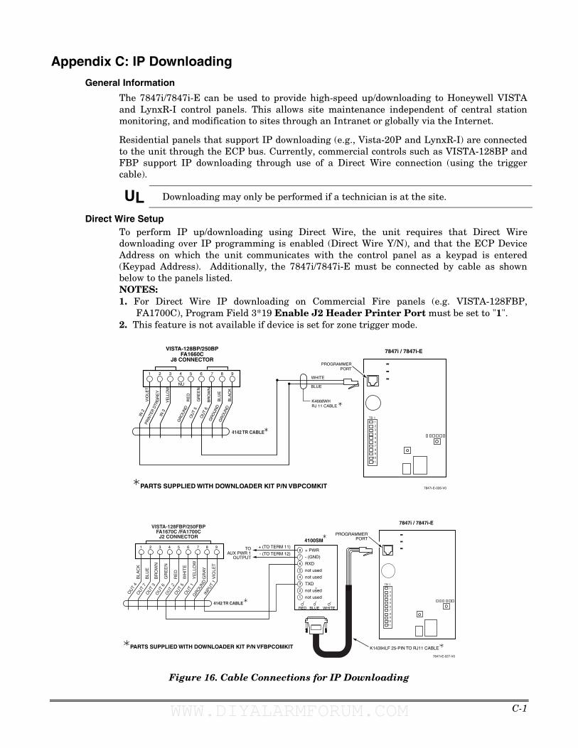
C-1
Appendix C: IP Downloading
General Information
The 7847i/7847i-E can be used to provide high-speed up/downloading to Honeywell VISTA and LynxR-I control panels. This allows site maintenance independent of central station monitoring, and modification to sites through an Intranet or globally via the Internet.
Residential panels that support IP downloading (e.g., Vista-20P and LynxR-I) are connected to the unit through the ECP bus. Currently, commercial controls such as VISTA-128BP and FBP support IP downloading through use of a Direct Wire connection (using the trigger cable).
UL Downloading may only be performed if a technician is at the site.
Direct Wire Setup To perform IP up/downloading using Direct Wire, the unit requires that Direct Wire downloading over IP programming is enabled (Direct Wire Y/N), and that the ECP Device Address on which the unit communicates with the control panel as a keypad is entered (Keypad Address). Additionally, the 7847i/7847i-E must be connected by cable as shown below to the panels listed. NOTES: 1. For Direct Wire IP downloading on Commercial Fire panels (e.g. VISTA-128FBP,
FA1700C), Program Field 3*19 Enable J2 Header Printer Port must be set to "1". 2. This feature is not available if device is set for zone trigger mode.
1 2 3 4 5 6 7 8 9
NU
VISTA-128BP/250BPFA1660C
J8 CONNECTOR
VIO
LET
GR
EY
YE
LLO
W
RE
D
GR
EE
N
BR
OW
N
BLU
E
BLUE
WHITE
BLA
CK
IN 2
IN 3
GR
OU
ND
OU
T 5
OU
T 6
GR
OU
ND
GR
OU
ND
PRIN
TER
DTR
K4668WHRJ 11 CABLE
7847i-E-026-V0
TB 1
678
5
1110
9
234
1
PROGRAMMERPORT
4142 TR CABLE
PARTS SUPPLIED WITH DOWNLOADER KIT P/N VBPCOMKIT
7847i / 7847i-E
1 2 3 4 5 6 7 8 9
7847i-E-027-V0
INPU
T 1
GRO
UN
D
OU
T 1
OU
T 4
OU
T 7
OU
T 3
OU
T 6
OUT
2O
UT
5
VISTA-128FBP/250FBPFA1670C /FA1700C
J2 CONNECTOR
VIO
LET
GR
AY
YE
LLO
W
WH
ITE
RE
D
GR
EE
N
BR
OW
N
BLU
E
BLA
CK
6
5
4
3
2
1
+ PWR
- (GND)
RXD
not used
not used
TXD
not used
not used
BLUE WHITE
+ (TO TERM 11)
- (TO TERM 12)
RED
8
7
TOAUX PWR 1
OUTPUT
TB 1
678
5
1110
9
234
1
PROGRAMMERPORT
4142 TR CABLE
4100SM
K14394LF 25-PIN TO RJ11 CABLEPARTS SUPPLIED WITH DOWNLOADER KIT P/N VFBPCOMKIT
7847i / 7847i-E
Figure 16. Cable Connections for IP Downloading
WWW.DIYALARMFORUM.COM WWW.DIYALARMFORUM.COM
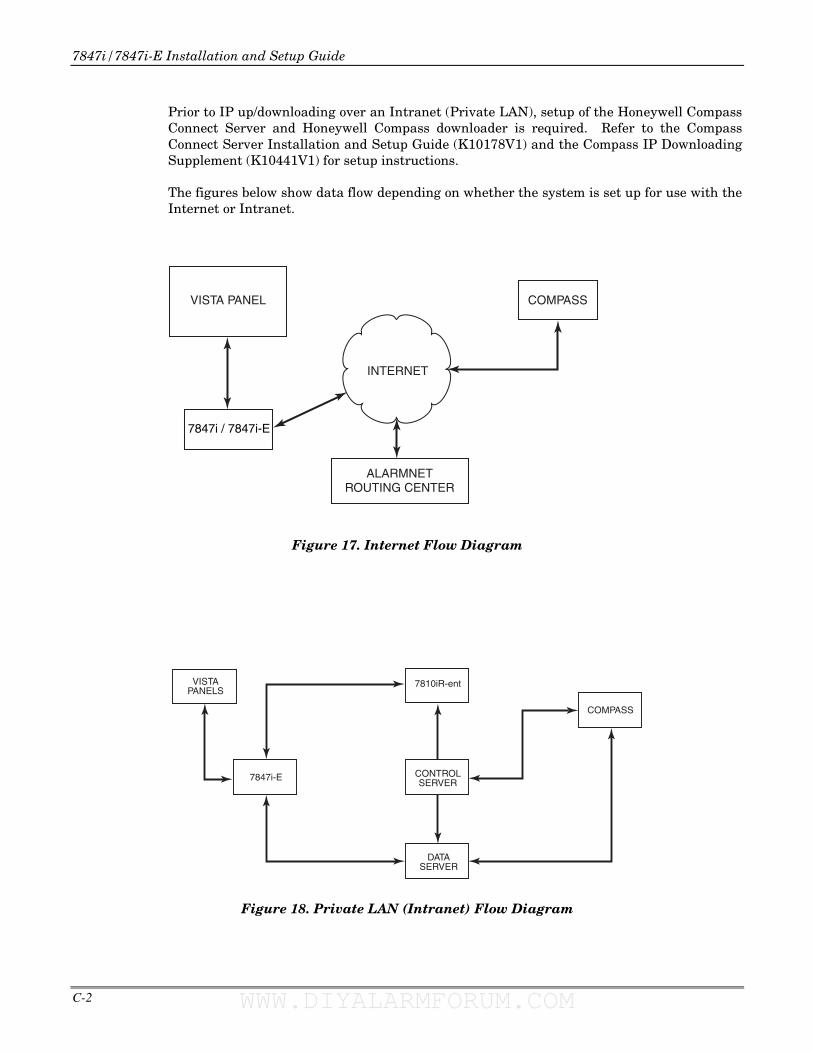
7847i/7847i-E Installation and Setup Guide
C-2
Prior to IP up/downloading over an Intranet (Private LAN), setup of the Honeywell Compass Connect Server and Honeywell Compass downloader is required. Refer to the Compass Connect Server Installation and Setup Guide (K10178V1) and the Compass IP Downloading Supplement (K10441V1) for setup instructions.
The figures below show data flow depending on whether the system is set up for use with the Internet or Intranet.
INTERNET
ALARMNETROUTING CENTER
COMPASSVISTA PANEL
7847i / 7847i-E
Figure 17. Internet Flow Diagram
VISTAPANELS
CONTROLSERVER
COMPASS
7847i-E
DATASERVER
7810iR-ent
Figure 18. Private LAN (Intranet) Flow Diagram
WWW.DIYALARMFORUM.COM WWW.DIYALARMFORUM.COM
D-1
Appendix D: Glossary
AES – Advanced Encryption Standard
DHCP – Dynamic Host Configuration Protocol. Provides a mechanism for allocating IP addresses dynamically so that addresses can be reused when hosts no longer need them.
DNS – Domain Name System. A distributed hierarchical naming system used to resolve domain names (e.g., www.yahoo.com) into numerical IP addresses (e.g., 204.17.25.1.).
DSL – Digital Subscriber Line
Gateway IP Address – A gateway (sometimes called a router) is a computer and/or software used to connect two or more networks (including incompatible networks) and translates information from one network to the other. The Gateway IP address is the IP address for the gateway.
IP – Internet Protocol
IP Address – A unique number consisting of four parts separated by periods, sometimes called a "dotted quad.," for example: 204.17.29.11, assigned to every computer/workstation connected to the Internet. IP numbers can be "static" (assigned and unchanging) or "dynamic," assigned via DHCP at each and every startup.
ISP – Internet Service Provider
LAN – Local Area Network
MAC Address – The hardware address of a device connected to a network.
NAT – Network Address Translation
PPP – Point-to-Point Protocol
PPPoE – Point-to-Point Protocol over Ethernet
Subnet Mask – A Subnet is a portion of a network that shares a network address with other portions of the network, and is distinguished by a subnet number. The Subnet Mask is a 32-bit address mask used in IP to indicate the bits of an IP address that are being used for the subnet address.
TCP/IP – Transmission Control Protocol / Internet protocol
WWW.DIYALARMFORUM.COM WWW.DIYALARMFORUM.COM

7847i/7847i-E Installation and Setup Guide
D-2 WWW.DIYALARMFORUM.COM WWW.DIYALARMFORUM.COM

NOTES:
WWW.DIYALARMFORUM.COM WWW.DIYALARMFORUM.COM

7847i/7847i-E Installation and Setup Guide
NOTES:
WWW.DIYALARMFORUM.COM WWW.DIYALARMFORUM.COM

NOTES:
WWW.DIYALARMFORUM.COM WWW.DIYALARMFORUM.COM

7847i/7847i-E Installation and Setup Guide
NOTES:
WWW.DIYALARMFORUM.COM WWW.DIYALARMFORUM.COM

NOTES:
WWW.DIYALARMFORUM.COM WWW.DIYALARMFORUM.COM

7847i/7847i-E Installation and Setup Guide
NOTES:
WWW.DIYALARMFORUM.COM WWW.DIYALARMFORUM.COM
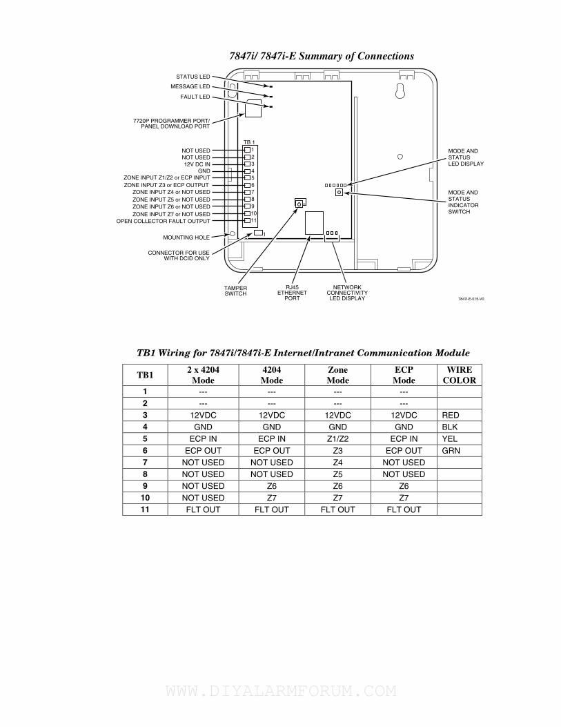
7847i/ 7847i-E Summary of Connections
7847i-E-015-V0
NETWORKCONNECTIVITYLED DISPLAY
RJ45ETHERNET
PORT
MESSAGE LED
FAULT LED
STATUS LED
MOUNTING HOLE
7720P PROGRAMMER PORT/PANEL DOWNLOAD PORT
ZONE INPUT Z5 or NOT USEDZONE INPUT Z4 or NOT USED
ZONE INPUT Z3 or ECP OUTPUT ZONE INPUT Z1/Z2 or ECP INPUT
OPEN COLLECTOR FAULT OUTPUTZONE INPUT Z7 or NOT USEDZONE INPUT Z6 or NOT USED
GND12V DC IN
NOT USEDNOT USED MODE AND
STATUSLED DISPLAY
MODE ANDSTATUSINDICATORSWITCH
TB 1
678
5
1011
9
234
1
TAMPERSWITCH
CONNECTOR FOR USEWITH DCID ONLY
1
TB1 Wiring for 7847i/7847i-E Internet/Intranet Communication Module
TB1 2 x 4204
Mode 4204 Mode
Zone Mode
ECP Mode
WIRE COLOR
1 --- --- --- --- 2 --- --- --- --- 3 12VDC 12VDC 12VDC 12VDC RED 4 GND GND GND GND BLK 5 ECP IN ECP IN Z1/Z2 ECP IN YEL 6 ECP OUT ECP OUT Z3 ECP OUT GRN 7 NOT USED NOT USED Z4 NOT USED 8 NOT USED NOT USED Z5 NOT USED 9 NOT USED Z6 Z6 Z6
10 NOT USED Z7 Z7 Z7 11 FLT OUT FLT OUT FLT OUT FLT OUT
WWW.DIYALARMFORUM.COM WWW.DIYALARMFORUM.COM

LIMITED WARRANTY Honeywell International Inc., acting through its Security & Custom Electronics business ("Seller"), 2 Corporate Center Drive, Melville, NY, 11747, warrants its product(s) to be in conformance with its own plans and specifications and to be free from defects in materials and workmanship under normal use and service for 24 months from the date stamp control on the product(s) or, for product(s) not having a manufacturer’s date stamp, for 12 months from date of original purchase unless the installation instructions or catalog sets forth a shorter period, in which case the shorter period shall apply. Seller's obligation shall be limited to repairing or replacing, at its option, free of charge for materials or labor, any product(s) which is proved not in compliance with Seller's specifications or proves defective in materials or workmanship under normal use and service. Seller shall have no obligation under this Limited Warranty or otherwise if the product(s) is altered or improperly repaired or serviced by anyone other than Honeywell factory service. Connection of any device(s) to a communicating bus of a Honeywell security system (e.g., keypad bus, polling loop) other than those manufactured or approved by Honeywell shall void this warranty. For warranty service, return product(s) transportation prepaid, to your local authorized Honeywell representative.
THERE ARE NO WARRANTIES, EXPRESS OR IMPLIED, OF MERCHANTABILITY, OR FITNESS FOR A PARTICULAR PURPOSE OR OTHERWISE, WHICH EXTEND BEYOND THE DESCRIPTION ON THE FACE HEREOF. IN NO CASE SHALL SELLER BE LIABLE TO ANYONE FOR ANY CONSEQUENTIAL OR INCIDENTAL DAMAGES FOR BREACH OF THIS OR ANY OTHER WARRANTY, EXPRESS OR IMPLIED, OR UPON ANY OTHER BASIS OF LIABILITY WHATSOEVER, EVEN IF THE LOSS OR DAMAGE IS CAUSED BY THE SELLER'S OWN NEGLIGENCE OR FAULT.
Seller does not represent that the product(s) it sells may not be compromised or circumvented; that the product(s) will prevent any personal injury or property loss by burglary, robbery, fire or otherwise; or that the product(s) will in all cases provide adequate warning or protection. Customer understands that a properly installed and maintained alarm system may only reduce the risk of a burglary, robbery, fire, or other events occurring without providing an alarm, but it is not insurance or a guarantee that such will not occur or that there will be no personal injury or property loss as a result. CONSEQUENTLY, SELLER SHALL HAVE NO LIABILITY FOR ANY PERSONAL INJURY, PROPERTY DAMAGE OR OTHER LOSS BASED ON A CLAIM THAT THE PRODUCT(S) FAILED TO GIVE WARNING. HOWEVER, IF SELLER IS HELD LIABLE, WHETHER DIRECTLY OR INDIRECTLY, FOR ANY LOSS OR DAMAGE ARISING UNDER THIS LIMITED WARRANTY OR OTHERWISE, REGARDLESS OF CAUSE OR ORIGIN, SELLER'S MAXIMUM LIABILITY SHALL NOT IN ANY CASE EXCEED THE PURCHASE PRICE OF THE PRODUCT(S), WHICH SHALL BE THE COMPLETE AND EXCLUSIVE REMEDY AGAINST SELLER.
This warranty replaces any previous warranties and is the only warranty made by Seller on this product(s). No increase or alteration, written or verbal, of the obligations of this Limited Warranty is authorized.
2 Corporate Center Drive, Suite 100 P.O. Box 9040, Melville, NY 11747
Copyright 2007 Honeywell International Inc.
www.honeywell.com/security.com
ÊK14175CŠ K14175 11/07
WWW.DIYALARMFORUM.COM WWW.DIYALARMFORUM.COM