Abb 07kt94 PLC
66
Advant Controller 31 Intelligent Decentralized Automation System Programming Advant Controller 31 / Issued: 09.99 Programming and test aids Access, operating an d test functions Monitor functions Memory overviews Functions in the instruction list 7.3
-
Upload
gogutagigel -
Category
Documents
-
view
243 -
download
1
Transcript of Abb 07kt94 PLC
8/9/2019 Abb 07kt94 PLC
http://slidepdf.com/reader/full/abb-07kt94-plc 1/66

8/9/2019 Abb 07kt94 PLC
http://slidepdf.com/reader/full/abb-07kt94-plc 2/66
8/9/2019 Abb 07kt94 PLC
http://slidepdf.com/reader/full/abb-07kt94-plc 3/66

8/9/2019 Abb 07kt94 PLC
http://slidepdf.com/reader/full/abb-07kt94-plc 4/66
Contents-2 Advant Controller 31 / Issued: 05.997.3

8/9/2019 Abb 07kt94 PLC
http://slidepdf.com/reader/full/abb-07kt94-plc 5/66
Advant Controller 31 / Issued: 01.99 1 Programming software 907 PC 33 7.3
1 Programming and test aids
1.1 Programming software
907 PC 33
General
The programming and test software 907 PC 33 isavailable as
• Programming and test software 907 PC 331 for ABBProcontic CS31 / Advant Controller 31 (basic units07 KR 31, 07 KR 91, 07 KT 92, 07 KT 93, 07 KT 94)and ABB Procontic T200 (Communication processor07 KP 62), order number GJP5204500R0102.
• Programming and test software 907 PC 332 for ABBProcontic T200, order number GJP5204300R0102.
The software products 907 PC 331 and 907 PC 332 aredelivered respectively including system-specific documen-tation.
The functions which are indentical for both software prod-ucts are described in the documentation "General part907 PC 33". This documentation folder can be orderedseparately with the following order number:GJP5203900R0102.
The software can be run on IBM/AT-compatible personal
computers. An extensively automatic installation programinstalls the software package 907 PC 33 on this unit or onanother IBM/AT-compatible personal computer.
The programming and test software 907 PC 33 permits asimple and economic programming of PLC programs inthe following notations:
• Function block diagram (FBD)
• Ladder diagram (LD)
• Extended instruction list (Exxt. IL)
Both symbolic and absolute program input is possible.The PLC program is supplemented by symbolic identifi-ers, long text, and commentary. Auxiliary and error mes-sages which can be called at all times facilitate programinput. Program creation as a FBD or as a LD takes placein a joint editor. Elements from the FBD and LD are there-fore mixable and can be linked together. The library con-tains numerous connection elements and function blockswhich considerably simplify the realization of complex func-tions (e.g. PID-type controller).
Features
The scope of the listed features depends on the capabili-ties of the individual PLCs.
General features
• All of the functions can be controlled with the mouse
• Clear display of project data and program configura-tion at one glance
• Scrollability in all directions in the editors
• Automatic recognition of revisions
Menu prompting
• Modern, clearly arranged menu interface employingpop-up menus
• Color display
• Quick selection of menu options with the mouse or onthe keyboard
• Call-up of external programs on the DOS level directlyfrom the menu (DOS shell)
Path information
• Input of data name with the affiliated DOS path
• Display of the project overview in a file directory
Take-over of the file name incl. path, selection via cur-sor.
Password protection
• Several access privilege levels
Data safeguarding
• Data safeguarding directly from the editor
• Data safeguarding of complete projects on discs
8/9/2019 Abb 07kt94 PLC
http://slidepdf.com/reader/full/abb-07kt94-plc 6/66
7.3 2 Advant Controller 31 / Issued: 01.99Programming software 907 PC 33
Modularization
• Handling of large projects
• Arrangement of projects in logical structures
• Subdivision into program and variable modules
• Module change within the FBD/LD and the extendedIL possible
• Modules can be called up from all levels (total project/
program module function selection)
• Simplified input of the module name and the correspond-ing file name
Segment plans
• The subdivision of the programs and/or program mod-ules into segment plan yields a good program over-view.
• Simple administration due to segment plan name andsegment plan number
FBD/LD editor
• Uniform editor for programming with graphic symbolsas function block diagram and ladder diagram
• Connection of ladder diagram networks with elementsof the function block diagram
Extended IL editor
• Notation with symbols and long text in various forms
• Selection of links via a selection menu with the mouse
• Integration of the IL capabilites in the extended IL
• Translation is not conducted when the extended IL doesnot contain any connection elements
• The translated IL can be displayed, the segment planstructure is retained thereby. Also possible online.
Editor functions
An extensive spectrum of commands is available in theeditors for program creation:
• Syntax test and plausibility test during the input ofvariables
• Block commands – for processing of program seg-
mentsand variables
– delete – shift – copy – store – load – print – delete unused variables
• Search commands – according to sentence number – according to word number – according to variable – according to symbol
– according to command – according to line number – repeat – according to segment plan – according to connection element – according to unassigned terminal
• Search and replace
• Insert
• Delete
Library
• Operating interface with mouse
• Programming of a connection element in the FBD/LD
• Hierarchical arrangement possibility of the connectionelements (similar to DOS directories)
• Auxiliary texts and short commentaries for connectionelements
• Terminal allocation test for the timely recognition ofprogram errors.
• For every manufacturer connection element a detailedfunction description can be called up directly out of
the FBD as a help text.Variable editor
• Complete list of all of the entered variables
• Sorting selectable according to absolute or symbolicvariables
• One or more symbol names can be allocated to thevariables
• Adoption and transfer of the variable lists to and fromany word processing system
• Provision and adoption of variable lists for specific CAD/
CAE systems
8/9/2019 Abb 07kt94 PLC
http://slidepdf.com/reader/full/abb-07kt94-plc 7/66
Advant Controller 31 / Issued: 01.99 3 Programming software 907 PC 33 7.3
Text editor
• Input of any ASCII files, up to 255 characters per line
Commentaries
• Verbal description of networks or program segments
ONLINE functions
Numerous ONLINE functions support the user during thecommissioning phase, e.g.
• Status display in – function block diagram – ladder diagram – instruction list – variable list
• Program – transfer – start – abort – stop – continuation – status
•
Single cycle on/off• Single step on/off
• Breakpoint – setting – display – tracing during the complete
program – delete
• Triggering – time – variable
• Overwriting
• Jogging
• Forcing
• Modification of – time and counter setpoints – variables – programm segments
• Online program modification
In addition selected variables can be summarized in ON-LINE lists and their status can be displayed on the screen.
• "Hotkeys" for quicker operation
• Switch into ONLINE operation directly out of the FBD/ LD, extended IL, variable list, ONLINE list.
• Direct PLC communication, e.g. "Send program" outof the editors
• Translate and transfer program modifications with pressof a key
• Direct "overwriting" and "forcing" out of the editors
• ONLINE list with direct adoption of variables from thePLC program to "forcing", "overwriting"
• Simple setting of breakpoints with the cursor also inthe FBD
• ONLINE notation of variables in various numeric forms(decimal, octal, hexadecimal, binary).
Program documentation
The automatic program documentation includes the print-ing of the following lists:
• Function block diagram
• Instruction list
• Connection element library
• Logic plan diagram
• Ladder diagram
•
Variable list• Cross reference list
• Commentary list
• ONLINE list
• Text page
• Data area
• Modularization list
• Total variable list
• Total cross reference list
• System configuration
Outputs can be adapted to any printer.
Printing format editor
A special printing format enables the addition of individualheaders and footers to the respective list. Specific datacan be included in this header and/or footer, e.g. name ofthe project file, date and time.
8/9/2019 Abb 07kt94 PLC
http://slidepdf.com/reader/full/abb-07kt94-plc 8/66
7.3 4 Advant Controller 31 / Issued: 01.99Programming software 907 PC 33
1.2 Programming via ARCNET
It is possible to program the control system of the AC31series via ARCNET on DOS level. The following is requiredto do this:
• PC with installed ARCNET card or coupler connectedto a parallel printer interface
• AC31 basic modules with integrated ARCNET coupler
• Special driver software
• 907 PC 331
For further information see description 907 PC 331 R0402.
8/9/2019 Abb 07kt94 PLC
http://slidepdf.com/reader/full/abb-07kt94-plc 9/66

8/9/2019 Abb 07kt94 PLC
http://slidepdf.com/reader/full/abb-07kt94-plc 10/66
7.3 6 Advant Controller 31 / Issued: 01.99Access, operating and test functions
8/9/2019 Abb 07kt94 PLC
http://slidepdf.com/reader/full/abb-07kt94-plc 11/66
Advant Controller 31 / Issued: 01.99 7 Introduction 7.3
2.1 Introduction
2.1.1 Access to the basic units
07 KR/KT 31, 07 KR 91, 07 KT 92,
07 KT 93, 07 KT 94 and to the
communication processor 07 KP 62
of ABB Procontic T200
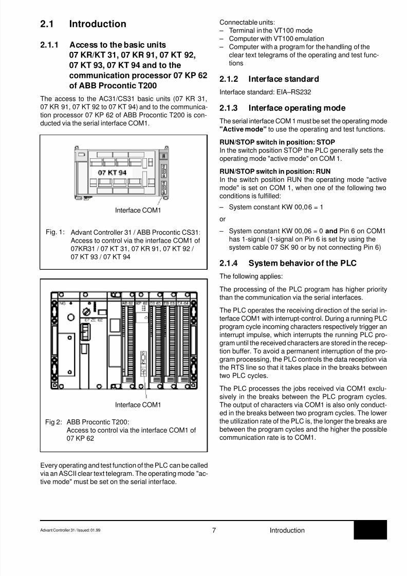
The access to the AC31/CS31 basic units (07 KR 31,07 KR 91, 07 KT 92 to 07 KT 94) and to the communica-tion processor 07 KP 62 of ABB Procontic T200 is con-ducted via the serial interface COM1.
Connectable units: – Terminal in the VT100 mode – Computer with VT100 emulation – Computer with a program for the handling of the
clear text telegrams of the operating and test func-tions
2.1.2 Interface standard
Interface standard: EIA–RS232
2.1.3 Interface operating mode
The serial interface COM 1 must be set the operating mode"Active mode" to use the operating and test functions.
RUN/STOP switch in position: STOPIn the switch position STOP the PLC generally sets theoperating mode "active mode" on COM 1.
RUN/STOP switch in position: RUNIn the switch position RUN the operating mode "activemode" is set on COM 1, when one of the following twoconditions is fulfilled:
– System constant KW 00,06 = 1
or
– System constant KW 00,06 = 0 and Pin 6 on COM1has 1-signal (1-signal on Pin 6 is set by using thesystem cable 07 SK 90 or by not connecting Pin 6)
2.1.4 System behavior of the PLC
The following applies:
The processing of the PLC program has higher prioritythan the communication via the serial interfaces.
The PLC operates the receiving direction of the serial in-terface COM1 with interrupt-control. During a running PLCprogram cycle incoming characters respectively trigger aninterrupt impulse, which interrupts the running PLC pro-gram until the received characters are stored in the recep-tion buffer. To avoid a permanent interruption of the pro-gram processing, the PLC controls the data reception viathe RTS line so that it takes place in the breaks betweentwo PLC cycles.
The PLC processes the jobs received via COM1 exclu-sively in the breaks between the PLC program cycles.
The output of characters via COM1 is also only conduct-ed in the breaks between two program cycles. The lowerthe utilization rate of the PLC is, the longer the breaks arebetween the program cycles and the higher the possiblecommunication rate is to COM1.
Every operating and test function of the PLC can be calledvia an ASCII clear text telegram. The operating mode "ac-tive mode" must be set on the serial interface.
Interface COM1
ABB Procontic T200:Access to control via the interface COM1 of07 KP 62
Fig 2:
Interface COM1
Advant Controller 31 / ABB Procontic CS31:Access to control via the interface COM1 of07KR31 / 07 KT 31, 07 KR 91, 07 KT 92 / 07 KT 93 / 07 KT 94
Fig. 1:

8/9/2019 Abb 07kt94 PLC
http://slidepdf.com/reader/full/abb-07kt94-plc 12/66
8/9/2019 Abb 07kt94 PLC
http://slidepdf.com/reader/full/abb-07kt94-plc 13/66
7.3Advant Controller 31 / Issued: 09.99 9 Operands
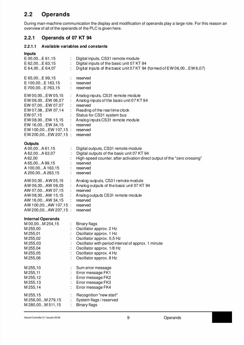
2.2 Operands
During man-machine communication the display and modification of operands play a large role. For this reason anoverview of all of the operands of the PLC is given here.
2.2.1 Operands of 07 KT 94
2.2.1.1 Available variables and constants
Inputs
E 00,00...E 61,15 : Digital inputs, CS31 remote moduleE 62,00...E 63,15 : Digital inputs of the basic unit 07 KT 94E 64,00...E 64,07 : Digital inputs of the basic unit 07 KT 94 (formed of EW 06,00...EW 6,07)
E 65,00...E 99,15 : reservedE 100,00...E 163,15 : reservedE 200,00...E 263,15 : reserved
EW 00,00...EW 05,15 : Analog inputs, CS31 remote moduleEW 06,00...EW 06,07 : Analog inputs of the basic unit 07 KT 94EW 07,00...EW 07,07 : reservedEW 07,08...EW 07,14 : Reading of the real time clockEW 07,15 : Status for CS31 system bus
EW 08,00...EW 15,15 : Analog inputs CS31 remote moduleEW 16,00...EW 34,15 : reservedEW 100,00...EW 107,15 : reservedEW 200,00...EW 207,15 : reserved
OutputsA 00,00...A 61,15 : Digital outputs, CS31 remote moduleA 62,00...A 63,07 : Digital outputs of the basic unit 07 KT 94A 62,00 : High-speed counter, after activation direct output of the "zero crossing"A 65,00...A 99,15 : reservedA 100,00...A 163,15 : reservedA 200,00...A 263,15 : reserved
AW 00,00...AW 05,15 : Analog outputs, CS31 remote moduleAW 06,00...AW 06,03 : Analog outputs of the basic unit 07 KT 94AW 07,00...AW 07,15 : reservedAW 08,00...AW 15,15 : Analog outputs CS31 remote moduleAW 16,00...AW 34,15 : reservedAW 100,00...AW 107,15 : reservedAW 200,00...AW 207,15 : reserved
Internal OperandsM 00,00...M 254,15 : Binary flagsM 255,00 : Oscillator approx. 2 HzM 255,01 : Oscillator approx. 1 HzM 255,02 : Oscillator approx. 0,5 Hz
M 255,03 : Oscillator with period interval of approx. 1 minuteM 255,04 : Oscillator approx. 1/8 HzM 255,05 : Oscillator approx. 4 HzM 255,06 : Oscillator approx. 8 Hz
M 255,10 : Sum error messageM 255,11 : Error message FK1M 255,12 : Error message FK2M 255,13 : Error message FK3M 255,14 : Error message FK4
M 255,15 : Recognition "new start"M 256,00...M 279,15 : System flags / reservedM 280,00...M 511,15 : Binary flags
8/9/2019 Abb 07kt94 PLC
http://slidepdf.com/reader/full/abb-07kt94-plc 14/66
7.3 10 Advant Controller 31 / Issued: 09.99Operands
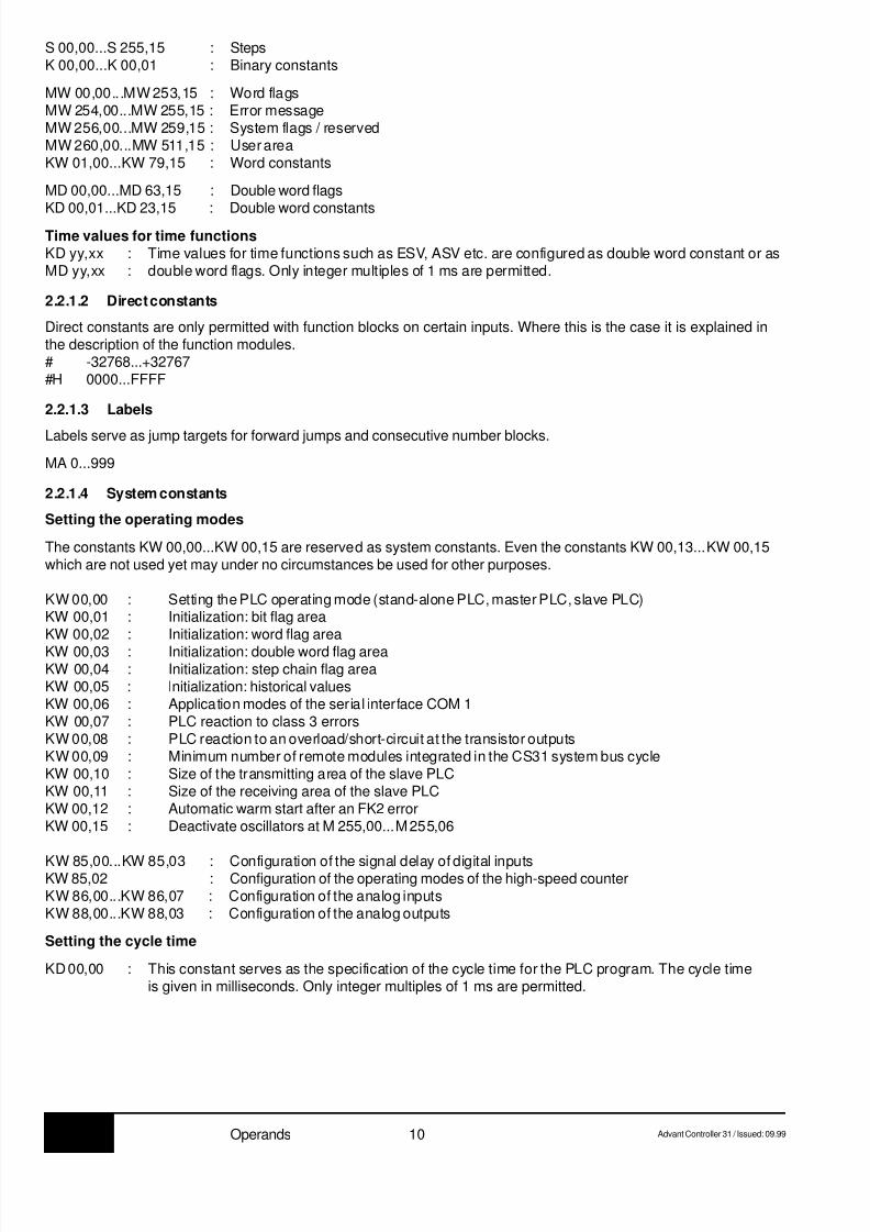
S 00,00...S 255,15 : StepsK 00,00...K 00,01 : Binary constants
MW 00,00...MW 253,15 : Word flagsMW 254,00...MW 255,15 : Error messageMW 256,00...MW 259,15 : System flags / reservedMW 260,00...MW 511,15 : User areaKW 01,00...KW 79,15 : Word constants
MD 00,00...MD 63,15 : Double word flags
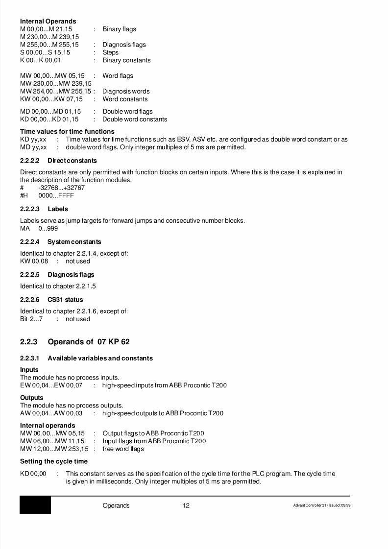
KD 00,01...KD 23,15 : Double word constantsTime values for time functionsKD yy,xx : Time values for time functions such as ESV, ASV etc. are configured as double word constant or asMD yy,xx : double word flags. Only integer multiples of 1 ms are permitted.
2.2.1.2 Direct constants
Direct constants are only permitted with function blocks on certain inputs. Where this is the case it is explained inthe description of the function modules.# -32768...+32767#H 0000...FFFF
2.2.1.3 Labels
Labels serve as jump targets for forward jumps and consecutive number blocks.
MA 0...999
2.2.1.4 System constants
Setting the operating modes
The constants KW 00,00...KW 00,15 are reserved as system constants. Even the constants KW 00,13...KW 00,15which are not used yet may under no circumstances be used for other purposes.
KW 00,00 : Setting the PLC operating mode (stand-alone PLC, master PLC, slave PLC)KW 00,01 : Initialization: bit flag areaKW 00,02 : Initialization: word flag area
KW 00,03 : Initialization: double word flag areaKW 00,04 : Initialization: step chain flag areaKW 00,05 : Initialization: historical valuesKW 00,06 : Application modes of the serial interface COM 1KW 00,07 : PLC reaction to class 3 errorsKW 00,08 : PLC reaction to an overload/short-circuit at the transistor outputsKW 00,09 : Minimum number of remote modules integrated in the CS31 system bus cycleKW 00,10 : Size of the transmitting area of the slave PLCKW 00,11 : Size of the receiving area of the slave PLCKW 00,12 : Automatic warm start after an FK2 errorKW 00,15 : Deactivate oscillators at M 255,00...M 255,06
KW 85,00...KW 85,03 : Configuration of the signal delay of digital inputsKW 85,02 : Configuration of the operating modes of the high-speed counterKW 86,00...KW 86,07 : Configuration of the analog inputsKW 88,00...KW 88,03 : Configuration of the analog outputs
Setting the cycle time
KD 00,00 : This constant serves as the specification of the cycle time for the PLC program. The cycle timeis given in milliseconds. Only integer multiples of 1 ms are permitted.

8/9/2019 Abb 07kt94 PLC
http://slidepdf.com/reader/full/abb-07kt94-plc 15/66
7.3Advant Controller 31 / Issued: 09.99 11 Operands
2.2.1.5 System flags / Diagnosis flags
M 00,00...M 254,15 : Binary flagsM 255,00 : Oscillator approx. 2 HzM 255,01 : Oscillator approx. 1 HzM 255,02 : Oscillator approx. 0.5 HzM 255,03 : Oscillator with period interval of approx. 1 minuteM 255,04 : Oscillator approx. 1/8 HzM 255,05 : Oscillator approx. 4 HzM 255,06 : Oscillator approx. 8 Hz
M 255,10 : Sum error message, signalizes that an error was detected by the PLCM 255,11 : Error messageFK1, fatal error, detailed information in MW 254,00...MW 254,07M 255,12 : Error messageFK2, serious error, detailed information in MW 254,08...MW 254,15M 255,13 : Error messageFK3, light error, detailed information in MW 255,00...MW 255,07M 255,14 : Error messageFK4, warning, detailed information in MW 255,08...MW 255,15
M 255,15 : Detection "new start"
MW 254,00...MW 255,15 : error messages
First cycle detection
M 255,15This binary flag can be used for detection of the first program cycle after a program start. It is always set to "zero"after each program start, independent of the initialization instructions given by the system constants. If this flag isrequested by the user program and then set to "1", it can be determined whether or not the user program was re-started.
2.2.1.6 CS31 status word
EW 07,15Bit 0 = 1 : no CS31 error of class 2 presentBit 1 = 1 : PLC has been adopted in CS31 cycle (only relevant when used as a slave)Bit 2 = 1 : Time and date are validBit 3 = 1 : Battery presentBit 4...7 : unusedBit 8..15 : currently determined maximum number of modules on CS31 system bus
(only relevant when used as a master)
2.2.2 Operands of 07 KR 31 and 07 KT 31
2.2.2.1 Available variables and constants
InputsE 00,00...E 61,15 : Digital inputs, CS31 remote moduleE 62,00...E 62,11 : Digital inputs of the basic unit 07 KR 31 / 07 KT 31E 63,14 : Digital inputs high-speed (Tv = 0.02 ms), signal identical to E 62,00
E 63,13 : high-speed counter, request "zero crossing"EW 00,00...EW 05,15 : Analog inputs, CS31 remote moduleEW 06,15 : high-speed counter, request "zero crossing"EW 07,00...EW 07,07 : reserved (for diagnosis on the CS31 system bus)EW 07,08...EW 07,14 : Read the real time clockEW 07,15 : Status for CS31 system bus
OutputsA 00,00...A 61,15 : Digital outputs, CS31 remote moduleA 62,00...A 62,07 : Digital relay outputs of the basic unit 07 KR 31 / 07 KT 31A 63,15 : high-speed counter, adopt inital value
AW 00,00...AW 05,15 : Analog outputs, CS31 remote module
AW 06,15 : high-speed counter, initial value
8/9/2019 Abb 07kt94 PLC
http://slidepdf.com/reader/full/abb-07kt94-plc 16/66
7.3 12 Advant Controller 31 / Issued: 09.99Operands
Internal OperandsM 00,00...M 21,15 : Binary flagsM 230,00...M 239,15M 255,00...M 255,15 : Diagnosis flagsS 00,00...S 15,15 : StepsK 00...K 00,01 : Binary constants
MW 00,00...MW 05,15 : Word flagsMW 230,00...MW 239,15MW 254,00...MW 255,15 : Diagnosis wordsKW 00,00...KW 07,15 : Word constants
MD 00,00...MD 01,15 : Double word flagsKD 00,00...KD 01,15 : Double word constants
Time values for time functionsKD yy,xx : Time values for time functions such as ESV, ASV etc. are configured as double word constant or asMD yy,xx : double word flags. Only integer multiples of 5 ms are permitted.
2.2.2.2 Direct constants
Direct constants are only permitted with function blocks on certain inputs. Where this is the case it is explained inthe description of the function modules.# -32768...+32767#H 0000...FFFF
2.2.2.3 Labels
Labels serve as jump targets for forward jumps and consecutive number blocks.MA 0...999
2.2.2.4 System constants
Identical to chapter 2.2.1.4, except of:KW 00,08 : not used
2.2.2.5 Diagnosis flags
Identical to chapter 2.2.1.5
2.2.2.6 CS31 status
Identical to chapter 2.2.1.6, except of:Bit 2...7 : not used
2.2.3 Operands of 07 KP 62
2.2.3.1 Available variables and constants
InputsThe module has no process inputs.
EW 00,04...EW 00,07 : high-speed inputs from ABB Procontic T200
OutputsThe module has no process outputs.AW 00,04...AW 00,03 : high-speed outputs to ABB Procontic T200
Internal operandsMW 00,00...MW 05,15 : Output flags to ABB Procontic T200MW 06,00...MW 11,15 : Input flags from ABB Procontic T200MW 12,00...MW 253,15 : free word flags
Setting the cycle time
KD 00,00 : This constant serves as the specification of the cycle time for the PLC program. The cycle time
is given in milliseconds. Only integer multiples of 5 ms are permitted.

8/9/2019 Abb 07kt94 PLC
http://slidepdf.com/reader/full/abb-07kt94-plc 17/66
7.3Advant Controller 31 / Issued: 09.99 13 Operands
Time values for time functions
KD yy,xx : Time values for time functions such as ESV, ASV etc. are configured as double word constant or asMD yy,xx : double word flags. Only integer multiples of 5 ms are permitted.
2.2.3.2 Direct constants
Direct constants are only permitted with function blocks on certain inputs. Where this is the case it is explained inthe description of the function modules.# -32768...+32767#H 0000...FFFF
2.2.3.3 Labels
Labels serve as jump targets for forward jumps and consecutive number blocks.MA 0...999
2.2.3.4 System constants
Setting the operating modes
The constants KW 00,00...KW 00,15 are reserved as system constants. Even the constants KW 00,12...KW 00,15which are not used yet may under no circumstances be used for other purposes.
In module 07 KP 62 there are only the system constants KW 00,01...KW 00,07.
Setting the cycle time
KD 00,00 : This constant serves as the specification of the cycle time for the PLC program. The cycle timeis given in milliseconds. Only integer multiples of 5 ms are permitted.
2.2.3.5 Diagnosis flags
M 255,10 : Sum error message, signalizes that an error was detected by the PLCM 255,11 : Error message FK1, fatal error, detailed information in MW 254,00...MW 254,07M 255,12 : Error message FK2, serious error, detailed information in MW 254,08...MW 254,15M 255,13 : Error message FK3, light error, detailed information in MW 255,00...MW 255,07M 255,14 : Error message FK4, warning, detailed information in MW 255,08...MW 255,15
First cycle detection
M 255,15This binary flag can be used for detection of the first program cycle after a program start. It is always set to "zero"after each program start, independent of the initialization instructions given by the system constants. If this flag isrequested by the user program and then set to "1", it can be determined whether or not the user program was re-started.
8/9/2019 Abb 07kt94 PLC
http://slidepdf.com/reader/full/abb-07kt94-plc 18/66
7.3 14 Advant Controller 31 / Issued: 09.99Serial interface COM1
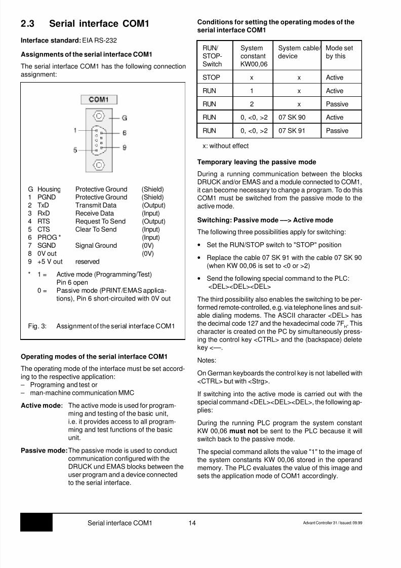
2.3 Serial interface COM1
Interface standard: EIA RS-232
Assignments of the serial interface COM1
The serial interface COM1 has the following connectionassignment:
Fig. 3: Assignment of the serial interface COM1
G Housing Protective Ground (Shield)
1 PGND Protective Ground (Shield)2 TxD Transmit Data (Output)3 RxD Receive Data (Input)4 RTS Request To Send (Output)5 CTS Clear To Send (Input)6 PROG * (Input)7 SGND Signal Ground (0V)8 0V out (0V)9 +5 V out reserved
* 1 = Active mode (Programming/Test)Pin 6 open
0 = Passive mode (PRINT/EMAS applica-
tions), Pin 6 short-circuited with 0V out
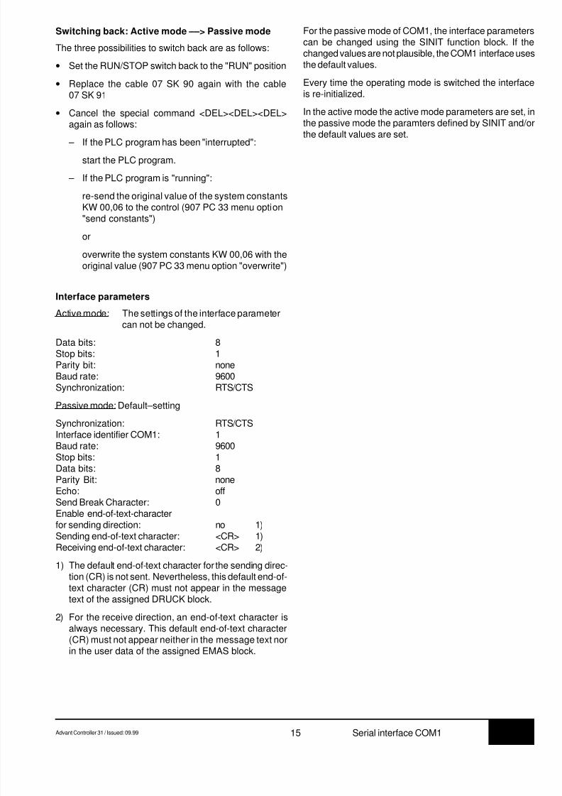
Operating modes of the serial interface COM1
The operating mode of the interface must be set accord-ing to the respective application: – Programing and test or – man-machine communication MMC
Active mode: The active mode is used for program-ming and testing of the basic unit,i.e. it provides access to all program-ming and test functions of the basicunit.
Passive mode:The passive mode is used to conductcommunication configured with theDRUCK und EMAS blocks between theuser program and a device connectedto the serial interface.
Conditions for setting the operating modes of theserial interface COM1
STOP x x Active
RUN 1 x Active
RUN 2 x Passive
RUN 0, <0, >2 07 SK 90 Active
RUN 0, <0, >2 07 SK 91 Passive
x: without effect
RUN/ System System cable/ Mode setSTOP- constant device by thisSwitch KW00,06
Temporary leaving the passive mode
During a running communication between the blocksDRUCK and/or EMAS and a module connected to COM1,it can become necessary to change a program. To do this
COM1 must be switched from the passive mode to theactive mode.
Switching: Passive mode ––> Active mode
The following three possibilities apply for switching:
• Set the RUN/STOP switch to "STOP" position
• Replace the cable 07 SK 91 with the cable 07 SK 90(when KW 00,06 is set to <0 or >2)
• Send the following special command to the PLC: <DEL><DEL><DEL>
The third possibility also enables the switching to be per-formed remote-controlled, e.g. via telephone lines and suit-able dialing modems. The ASCII character <DEL> hasthe decimal code 127 and the hexadecimal code 7F
H. This
character is created on the PC by simultaneously press-ing the control key <CTRL> and the (backspace) deletekey <––.
Notes:
On German keyboards the control key is not labelled with<CTRL> but with <Strg>.
If switching into the active mode is carried out with thespecial command <DEL><DEL><DEL>, the following ap-plies:
During the running PLC program the system constantKW 00,06 must not be sent to the PLC because it willswitch back to the passive mode.
The special command allots the value "1" to the image ofthe system constants KW 00,06 stored in the operandmemory. The PLC evaluates the value of this image andsets the application mode of COM1 accordingly.
8/9/2019 Abb 07kt94 PLC
http://slidepdf.com/reader/full/abb-07kt94-plc 19/66
8/9/2019 Abb 07kt94 PLC
http://slidepdf.com/reader/full/abb-07kt94-plc 20/66
7.3 16 Advant Controller 31 / Issued: 05.99Operating and test functions
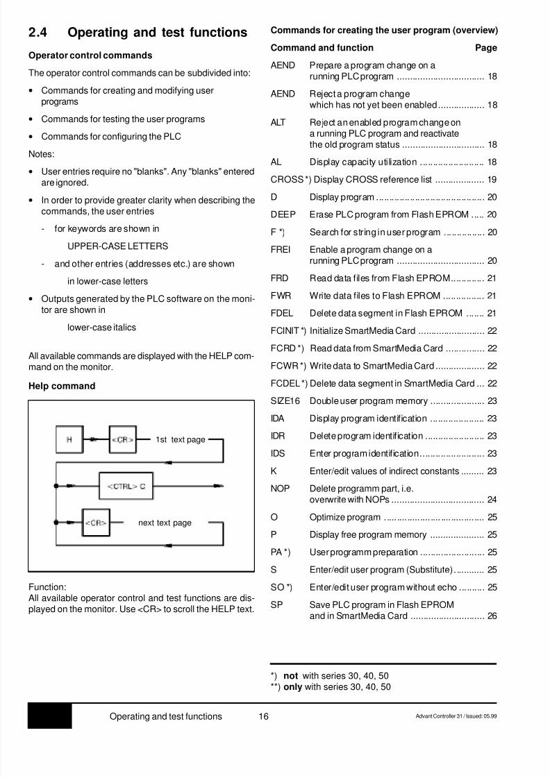
2.4 Operating and test functions
Operator control commands
The operator control commands can be subdivided into:
• Commands for creating and modifying userprograms
• Commands for testing the user programs
• Commands for configuring the PLC
Notes:
• User entries require no "blanks". Any "blanks" enteredare ignored.
• In order to provide greater clarity when describing thecommands, the user entries
- for keywords are shown in
UPPER-CASE LETTERS
- and other entries (addresses etc.) are shown
in lower-case letters
• Outputs generated by the PLC software on the moni-tor are shown in
lower-case italics
All available commands are displayed with the HELP com-mand on the monitor.
Help command
Commands for creating the user program (overview)
Command and function Page
AEND Prepare a program change on arunning PLC program .................................. 18
AEND Reject a program changewhich has not yet been enabled.................. 18
ALT Reject an enabled program change on
a running PLC program and reactivatethe old program status ................................ 18
AL Display capacity utilization ......................... 18
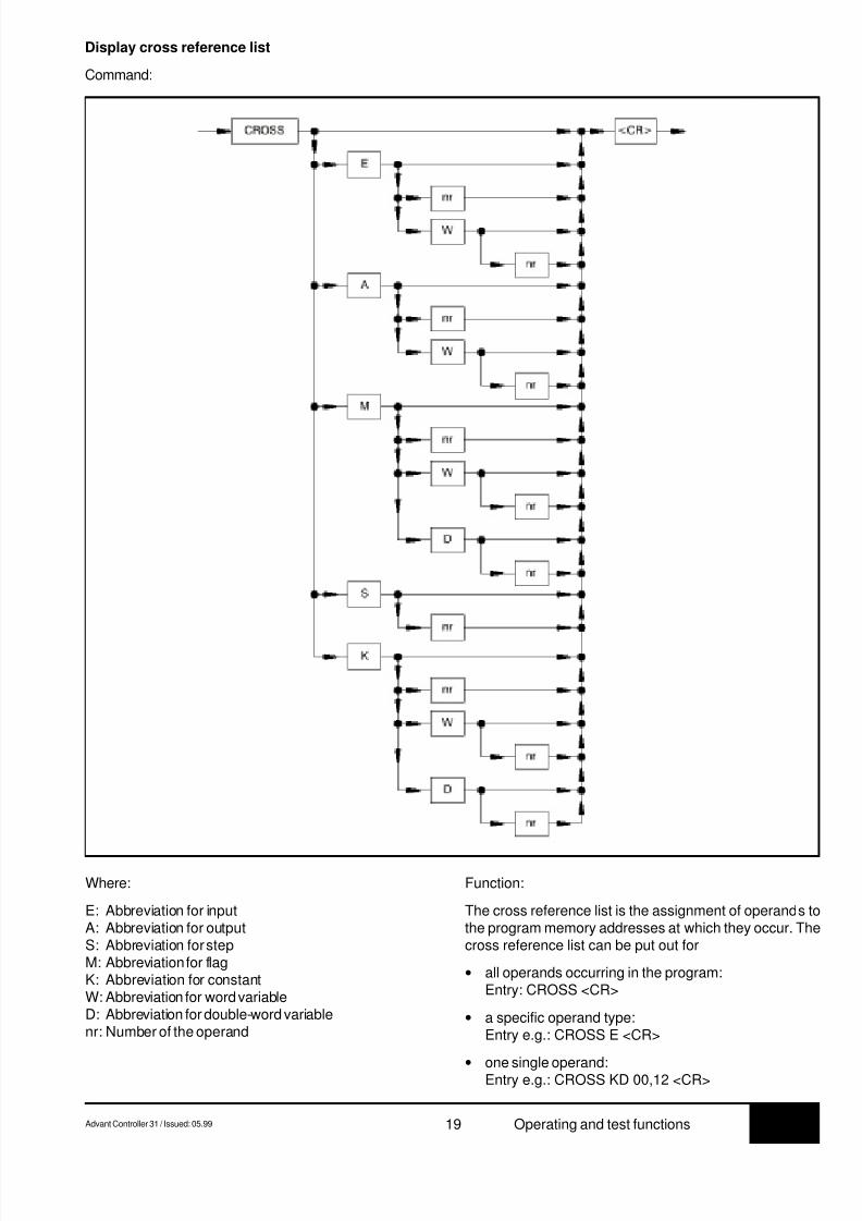
CROSS *) Display CROSS reference list ................... 19
D Display program .......................................... 20
DEEP Erase PLC program from Flash EPROM ..... 20
F *) Search for string in user program ................ 20
FREI Enable a program change on arunning PLC program .................................. 20
FRD Read data files from Flash EPROM............. 21
FWR Write data files to Flash EPROM ................ 21
FDEL Delete data segment in Flash EPROM ....... 21
FCINIT *) Initialize SmartMedia Card .......................... 22
FCRD *) Read data from SmartMedia Card ............... 22
FCWR *) Write data to SmartMedia Card ................... 22
FCDEL *) Delete data segment in SmartMedia Card ... 22
SIZE16 Double user program memory ..................... 23
IDA Display program identification ..................... 23
IDR Delete program identification ....................... 23
IDS Enter program identification......................... 23
K Enter/edit values of indirect constants ......... 23
NOP Delete programm part, i.e.overwrite with NOPs .................................... 24
O Optimize program ....................................... 25
P Display free program memory ..................... 25
PA *) User programm preparation ......................... 25
S Enter/edit user program (Substitute)............ 25
SO *) Enter/edit user program without echo .......... 25
SP Save PLC program in Flash EPROMand in SmartMedia Card ............................. 26
Function:All available operator control and test functions are dis-played on the monitor. Use <CR> to scroll the HELP text.
*) not with series 30, 40, 50**) only with series 30, 40, 50
1st text page
next text page

8/9/2019 Abb 07kt94 PLC
http://slidepdf.com/reader/full/abb-07kt94-plc 21/66
7.3Advant Controller 31 / Issued: 05.99 17 Operating and test functions
Commands for testing the user program (overview)
Command and function Page
V Move user program ..................................... 26
A Abort user program ..................................... 27
BA*) Diplay break points ..................................... 27
BR *) Reset break points ...................................... 27
BS *) Set break points.......................................... 27
<CTRL>W *) Switching between operatorcontrol functions <––> monitor ............. 28
EA *) I/O test mode ............................................. 28
EAA *) Deactivate I/O test mode ............................. 28
ES *) Single step mode ON.................................. 28
ESA *) Single step mode OFF ................................ 28
EZ *) Single cycle mode ON ................................ 28
EZA *) Single cycle mode OFF .............................. 29FEHLER Display contents of the error register........... 29
FORC Enter force value ......................................... 30
FORC A Display force value ...................................... 30
FORC R Delete forcing .............................................. 30
G Start user program ...................................... 30
KALT Perform cold start ....................................... 31
WARM Perform warm start ..................................... 31
**) not with series 30, 40, 50**) only with series 30, 40, 50
Command and function Page
L *) Continue user program ................................ 31
PS Display program status ............................... 31
ST Display PLC status ..................................... 32
TRACE *) TRACE-mode ....................................... 32
TRACE *) Display TRACE memory ...................... 32
TRACE E *) Activate TRACE mode ......................... 32
TRACE A *) Deactivate TRACE mode...................... 32
W *) Stop user program....................................... 33
Y Overwrite value of a variable with avalue to be defined ...................................... 33
Z Display status of variables........................... 33
ZZ Display only the values of the variables ....... 34
ZD Display and continually updatestatus of variables ....................................... 34
Commands for configuration
KONFS Display/change operating modes ................ 35
MAIL Configuration of CS31 remote modules ....... 35
PASS **) Password .................................................... 39
UHR Display time and date ................................. 39
UHRS Set time and date ....................................... 40

8/9/2019 Abb 07kt94 PLC
http://slidepdf.com/reader/full/abb-07kt94-plc 22/66
7.3 18 Advant Controller 31 / Issued: 05.99Operating and test functions
2.4.1 Commands for creating the user program
Preparing a program change on a running PLCprogram
Command:
Rejecting an enabled change on a running PLCprogram and reactivating the old program status
Command:
Function:
The command announces to the PLC that modificationsare to be carried out on the running PLC program. Afterthis command has been entered, the PLC is ready to ac-cept the program and constant modifications.
When command AEND is entered, all currently active testfunctions are deactivated. However, force values of I/O sig-
nals remain active.The following commands for program modifications andoperation of the PLC are permitted after entering com-mand AEND:
AL, CROSS, D, F, IDA, IDR, IDS, K, N, NOP, O, P, PA, S,SO, V, CTRL W, FEHLER, LED.
Rejecting a program change which has not beenenabled yet
Entering the AEND command again rejects all programmodifications performed to date, and the PLC is ready to
accept program modifications again.The following commands are activated during the runningprogram and in addition reject the AEND command andthus all program modifications performed after entry of theAEND command:
A, BA, BR, BS, EA, EAA, ES, ESA, EZ, EZA, FORC,FORC A, FORC R, G, L, PS, ST, TRACE, TRACE E, W,Y. In order to perform new program modifications, the com-mand AEND must be entered again.
Function:
Modifications which have been performed on a running PLCprogram and which have been enabled are rejected again.In addition, the PLC restores the old program status. Theold program status is the status of the program whichexisted before the program modification, i.e. before entryof command AEND to the PLC.
After command ALT is entered, the old program status isreactivated within approximately 1 ms without further in-tervention on the part of the user.
The command can be used if the user recognizes that theprogram modifications implemented do not achieve theintended result.
Display capacity utilization
Command:
Function:
The PLC’s present capacity utilization is displayed in per-cent. This display indicates to what extent the capacity ofthe PLC is being utilized owing to execution of the userprogram.
The processor capacity which corresponds to the differ-ence between 100 % and the capacity utilization displayis available for operation of the serial interfaces, i.e. forcommunication with the devices connected to the serialinterfaces. The utilization should not be greater than 95 %
for the longest program path so that communication isstill possible via the serial interfaces. Note that the ca-pacity utilization of the PLC is also determined by thecurrent program branches (conditional jumps and consec-utive number blocks).
Note:
The capacity utlization display indicates the correct utili-zation caused by the user program only if at the momentof display no communication is occurring via the serialinterfaces.
8/9/2019 Abb 07kt94 PLC
http://slidepdf.com/reader/full/abb-07kt94-plc 23/66
8/9/2019 Abb 07kt94 PLC
http://slidepdf.com/reader/full/abb-07kt94-plc 24/66
7.3 20 Advant Controller 31 / Issued: 05.99Operating and test functions
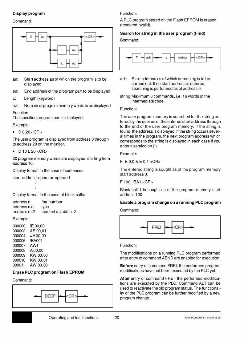
Display program
Command:
aa: Start address as of which the program is to bedisplayed
ea: End address of the program part to be displayed
L: Length (keyword)
az: Number of program memory words to be displayed
Function:The specified program part is displayed.
Example:
• D 0,20 <CR>
The user program is displayed from address 0 throughto address 20 on the monitor.
• D 10 L 20 <CR>
20 program memory words are displayed, starting fromaddress 10.
Display format in the case of sentences:
start address operator operand
: :
Display format in the case of block calls:
address n !ba numberaddress n+1 typeaddress n+2 content of addr n+2
Example:
000000 !E 00,00000002 &E 00,01000004 =A 00,00
000006 !BA001000007 AWT000008 A 00,00000009 KW 00,00000010 KW 00,01000011 AW 00,00
Erase PLC program on Flash EPROM
Command:
Function:
A PLC program stored on the Flash EPROM is erased(rendered invalid).
Search for string in the user program (Find)
Command:
adr: Start address as of which searching is to becarried out. If no start address is entered,searching is performed as of address 0.
string:Maximum 8 commands, i.e. 16 words of theintermediate code.
Function:
The user program memory is searched for the string en-
tered by the user as of the entered start address throughto the end of the user program memory. If the string isfound, the address is displayed. If the string occurs sever-al times in the program, the next program address whichcorresponds to the string is displayed in each case if youenter a semicolon (;).
Example:
F, E 0,0 & E 0,1 <CR>
The entered string is sought as of the program memorystart address 0.
F 100, !BA1 <CR>
Block call 1 is sought as of the program memory startaddress 100.
Enable a program change on a running PLC program
Command:
Function:
The modifications on a running PLC program performedafter entry of command AEND are enabled for execution.
Before entry of command FREI, the performed programmodifications have not been executed by the PLC yet.
After entry of command FREI, the performed modifica-tions are executed by the PLC. Command ALT can beused to reactivate the old program status. The functional-ity of the PLC program can be further modified by a newprogram change.
,
,
8/9/2019 Abb 07kt94 PLC
http://slidepdf.com/reader/full/abb-07kt94-plc 25/66
7.3Advant Controller 31 / Issued: 05.99 21 Operating and test functions
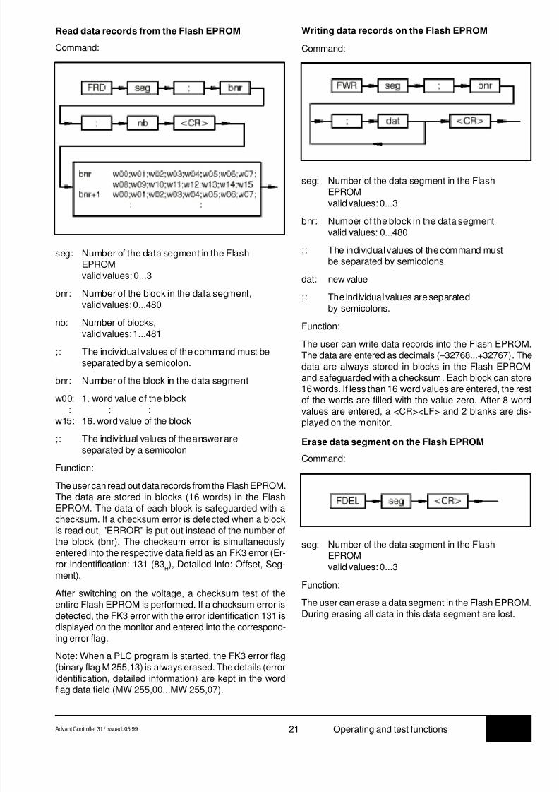
Read data records from the Flash EPROM
Command:
Writing data records on the Flash EPROM
Command:
seg: Number of the data segment in the FlashEPROM
valid values: 0...3
bnr: Number of the block in the data segment,valid values: 0...480
nb: Number of blocks,valid values: 1...481
;: The individual values of the command must beseparated by a semicolon.
bnr: Number of the block in the data segment
w00: 1. word value of the block: : :
w15: 16. word value of the block
;: The individual values of the answer areseparated by a semicolon
Function:
The user can read out data records from the Flash EPROM.The data are stored in blocks (16 words) in the FlashEPROM. The data of each block is safeguarded with achecksum. If a checksum error is detected when a blockis read out, "ERROR" is put out instead of the number ofthe block (bnr). The checksum error is simultaneously
entered into the respective data field as an FK3 error (Er-ror indentification: 131 (83
H), Detailed Info: Offset, Seg-
ment).
After switching on the voltage, a checksum test of theentire Flash EPROM is performed. If a checksum error isdetected, the FK3 error with the error identification 131 isdisplayed on the monitor and entered into the correspond-ing error flag.
Note: When a PLC program is started, the FK3 error flag(binary flag M 255,13) is always erased. The details (erroridentification, detailed information) are kept in the word
flag data field (MW 255,00...MW 255,07).
seg: Number of the data segment in the FlashEPROMvalid values: 0...3
bnr: Number of the block in the data segmentvalid values: 0...480
;: The individual values of the command mustbe separated by semicolons.
dat: new value
;: The individual values are separatedby semicolons.
Function:
The user can write data records into the Flash EPROM.The data are entered as decimals (–32768...+32767). Thedata are always stored in blocks in the Flash EPROMand safeguarded with a checksum. Each block can store16 words. If less than 16 word values are entered, the restof the words are filled with the value zero. After 8 word
values are entered, a <CR><LF> and 2 blanks are dis-played on the monitor.
Erase data segment on the Flash EPROM
Command:
seg: Number of the data segment in the Flash
EPROMvalid values: 0...3
Function:
The user can erase a data segment in the Flash EPROM.During erasing all data in this data segment are lost.

8/9/2019 Abb 07kt94 PLC
http://slidepdf.com/reader/full/abb-07kt94-plc 26/66
7.3 22 Advant Controller 31 / Issued: 05.99Operating and test functions
Read data records from the SmartMedia Card
Command:
Writing data records to the SmartMedia Card
Command:
seg: Number of the data segment in theSmartMedia Cardvalid values: 1...250
bnr: Number of the block in the data segment,valid values: 0...127
;: The individual values of the command must beseparated by a semicolon.
bnr: Number of the block in the data segmentw00: 1st word value of the block
: : :w31: 32nd word value of the block
;: The individual values of the answer areseparated by a semicolon
Function:
The user can read out data records from the SmartMediaCard. The data are stored in blocks (32 words) in theSmartMedia Card. The data of each block is safeguarded
with a checksum.
seg: Number of the data segment in theSmartMedia Cardvalid values: 1...250
bnr: Number of the block in the data segmentvalid values: 0...127
;: The individual values of the command mustbe separated by semicolons.
dat: new value
;: The individual values are separatedby semicolons.
Function:
The user can write data records into the Smart Media Card.The data are entered as decimals (–32768...+32767). Thedata are always stored in blocks in the SmartMedia Cardand safeguarded with a checksum. Each block can store32 words. If less than 32 word values are entered, the restof the words are filled with the value zero. After 8 word
values are entered, a <CR><LF> and 2 blanks are dis-played on the monitor. A block only can be written once tothe SmartMedia Card. Before rewriting the block, the seg-ment has to be deleted.
Delete data segment on the SmartMedia Card
Command:
seg: Number of the data segment in theSmartMedia Cardvalid values: 1...250
Function:
The user can delete a data segment in the Smart MediaCard. During deleting all data in this data segment is lost.
FCRD seg ; bnr
<CR>
bnr w00;w01;w02;w03;w04;w05;w06;w07;w08;w09;w10;w11;w12;w13;w14;w15w16;w17;w18;w19;w20;w21;w22;w23;w24;w25;w26;w27;w28;w29;w30;w31
*)
Initialize SmartMedia Card
Command:
Function:
The SmartMedia Card is initialized as a user data card.Only on initalized cards data can be written.
When the SmartMedia Card is initialized, all previous datais deleted. A card, initialized for user data, can no morebe used for storing user programs.
FCINIT <CR> FCWR seg ; bnr
; dat <CR>
*)
FCDEL seg <CR>*)
*) A block only can be written once to the SmartMediaCard. Before rewriting the block, the segment has to bedeleted.
8/9/2019 Abb 07kt94 PLC
http://slidepdf.com/reader/full/abb-07kt94-plc 27/66
7.3Advant Controller 31 / Issued: 05.99 23 Operating and test functions
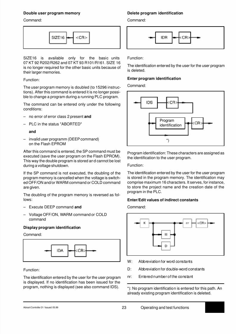
Double user program memory
Command:
SIZE16 is available only for the basic units07 KT 92 R202/R262 and 07 KT 93 R101/R161. SIZE 16is no longer required for the other basic units because oftheir larger memories.
Function:
The user program memory is doubled (to 15296 instruc-tions). After this command is entered it is no longer possi-ble to change a program during a running PLC program.
The command can be entered only under the followingconditions:
– no error of error class 2 present and
– PLC in the status "ABORTED"
and
– invalid user programm (DEEP command)on the Flash EPROM
After this command is entered, the SP command must beexecuted (save the user program on the Flash EPROM).This way the double program is stored and cannot be lostduring a voltage shutdown.
If the SP command is not executed, the doubling of theprogram memory is cancelled when the voltage is switch-ed OFF/ON and/or WARM command or COLD commandare given.
The doubling of the program memory is reversed as fol-lows:
– Execute DEEP command and
– Voltage OFF/ON, WARM command or COLDcommand
Display program identification
Command:
Function:
The identification entered by the user for the user programis displayed. If no identification has been issued for theprogram, nothing is displayed (see also command IDS).
Delete program identification
Command:
Function:
The identification entered by the user for the user programis deleted.
Enter program identification
Command:
*): No program identification is entered for this path. An
already existing program identification is deleted.
Program identification: These characters are assigned asthe identification to the user program.
Function:
The identification entered by the user for the user programis stored in the program memory. The identification maycomprise maximum 16 characters. It serves, for instance,to store the project name and the creation date of theprogram in the PLC.
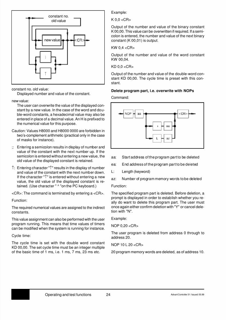
Enter/Edit values of indirect constants
Command:
W: Abbreviation for word constants
D: Abbreviation for double-word constants
nr: Entered number of the constant
Programidentification
*)
8/9/2019 Abb 07kt94 PLC
http://slidepdf.com/reader/full/abb-07kt94-plc 28/66
7.3 24 Advant Controller 31 / Issued: 05.99Operating and test functions
constant no. old value:Displayed number and value of the constant.
new value:The user can overwrite the value of the displayed con-stant by a new value. In the case of the word and dou-ble-word constants, a hexadecimal value may also beentered in place of a decimal value. An H is prefixed tothe numerical value for this purpose.
Caution: Values H8000 and H8000 0000 are forbidden intwo’s-complement arithmetic (practical only in the caseof masks for instance).
;: Entering a semicolon results in display of number andvalue of the constant with the next number up. If thesemicolon is entered without entering a new value, theold value of the displayed constant is retained.
↑: Entering character "↑" results in the display of numberand value of the constant with the next number down.If the character "↑" is entered without entering a newvalue, the old value of the displayed constant is re-tained. (Use character " ^ "on the PC keyboard.)
<CR>: The command is terminated by entering a <CR>.
Function:
The required numerical values are assigned to the indirectconstants.
This value assignment can also be performed with the user
program running. This means that time values of timerscan be modified when the system is running for instance.
Cycle time:
The cycle time is set with the double word constantKD 00,00. The set cycle time must be an integer multipleof the basic time of 1 ms, i.e. 1 ms, 7 ms, 23 ms etc.
Example:
K 0,0 <CR>
Output of the number and value of the binary constantK 00,00. This value can be overwritten if required. If a semi-colon is entered, the number and value of the next binaryconstant (K 00,01) is output.
KW 0,4 <CR>
Output of the number and value of the word constantKW 00,04.
KD 0,0 <CR>
Output of the number and value of the double-word con-stant KD 00,00. The cycle time is preset with this con-stant.
Delete program part, i.e. overwrite with NOPs
Command:
aa: Start address of the program part to be deleted
ea: End address of the program part to be deleted
L: Length (keyword)
az: Number of program memory words to be deleted
Function:
The specified program part is deleted. Before deletion, aprompt is displayed in order to establish whether you re-ally do want to delete this program part. The user mustonce again either confirm deletion with "Y" or cancel dele-tion with "N".
Example:
NOP 0,20 <CR>
The user program is deleted from address 0 through toaddress 20.
NOP 10 L 20 <CR>
20 program memory words are deleted, as of address 10.
constant no.old value
new value
,
8/9/2019 Abb 07kt94 PLC
http://slidepdf.com/reader/full/abb-07kt94-plc 29/66
7.3Advant Controller 31 / Issued: 05.99 25 Operating and test functions
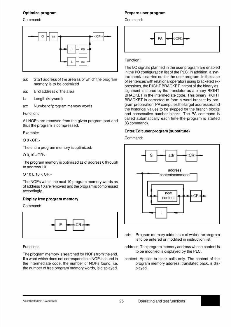
Optimize program
Command:
Prepare user program
Command:
aa: Start address of the area as of which the programmemory is to be optimized
ea: End address of the area
L: Length (keyword)
az: Number of program memory words
Function:All NOPs are removed from the given program part andthus the program is compressed.
Example:
O 0 <CR>
The entire program memory is optimized.
O 0,10 <CR>
The program memory is optimized as of address 0 throughto address 10.
O 10 L 10 < CR>
The NOPs within the next 10 program memory words asof address 10 are removed and the program is compressedaccordingly.
Display free program memory
Command:
Function:
The program memory is searched for NOPs from the end.If a word which does not correspond to a NOP is found inthe intermediate code, the number of NOPs found, i.e.the number of free program memory words, is displayed.
Function:
The I/O signals planned in the user program are enabledin the I/O configuration list of the PLC. In addition, a syn-tax check is carried out for the user program. In the caseof sentences with relational operators using bracketed ex-pressions, the RIGHT BRACKET in front of the binary as-signment is stored by the translator as a binary RIGHTBRACKET in the intermediate code. This binary RIGHTBRACKET is corrected to form a word bracket by pro-gram preparation. PA computes the target addresses andthe historical values to be skipped for the branch blocks
and consecutive number blocks. The PA command iscalled automatically each time the program is started(G command).
Enter/Edit user program (substitute)
Command:
adr: Program memory address as of which the programis to be entered or modified in instruction list.
address: The program memory address whose content isto be modified is displayed by the PLC.
content: Applies to block calls only. The content of theprogram memory address, translated back, is dis-played.
,
addresscontent/command
newcontent

8/9/2019 Abb 07kt94 PLC
http://slidepdf.com/reader/full/abb-07kt94-plc 30/66
7.3 26 Advant Controller 31 / Issued: 05.99Operating and test functions
command: Applies to sentences and the block header(number and type). The command or block header,translated back, is displayed, always as an entire com-mand, i.e. operand and operator or block call and blocktype. If an address which does not point to the start ofa command or to a block call is entered, this is cor-rected to the start of the command by the PLC.
new content: New content of the user program.
;: Entering a semicolon displays the subsequent programmemory address and its content, and this can be mod-ified if required. If no new "content" is entered beforethe semicolon, the old content of the displayed pro-gram memory address remains unchanged.
Function:
Entering or modifying the PLC program in instruction list.A program memory word is selected and displayed on themonitor as an instruction or operand. The displayed con-tent can then be overwritten.
Note:
You will also find the following information for entering/ modifying the instruction list with this command at theend of this Appendix:
- Syntactic structure of the instruction list.
- Instructions on how texts for function blocksDRUCK/EMAS are entered and displayed.
Enter/Edit user program without echo
Command:
adr: Program memory address as of which the pro-
gram is to be entered or modified
content new: New content of the user program
Function:
The program memory address as of which the program isto be entered is preset. The program can then be enteredconsecutively. The PLC returns no echo of the enteredprogram. However, in the event of an error, the PLC re-turns an error message (e.g. Incorrect Entry).
Save PLC program in Flash EPROM and in the
SmartMedia Card
Command:
Function:
The PLC program is transferred from the RAM to the FlashEPROM and, if existing, also to the SmartMedia Card.Character <*> is displayed on the monitor at intervals ofapproximately 1 second during programming.
Move user program
Command:
aa: Start address of program part to be moved
ea: End address
L: Length (keyword)
az: Number of program memory words by which theprogram part is to be moved
Function:
The program is moved from address aa to address ea orfrom address aa by the specified number of program mem-ory words. The gap which results is filled with NOPs. Newprogram parts can be inserted in this gap. Moving is pos-sible only if the required space is still available at the endof the user program. However, this is checked automati-cally.
Example:
V 0,10 <CR>
The program is moved from address 0 to address 10.NOPs are inserted from address 0 through to address 9.
V 10 L 20 <CR>
The program is moved from address 10 by 20 programmemory words to address 30, and 20 NOPs are inserted.
contentnew
,
8/9/2019 Abb 07kt94 PLC
http://slidepdf.com/reader/full/abb-07kt94-plc 31/66
7.3Advant Controller 31 / Issued: 05.99 27 Operating and test functions
2.4.1 Commands to test the user program
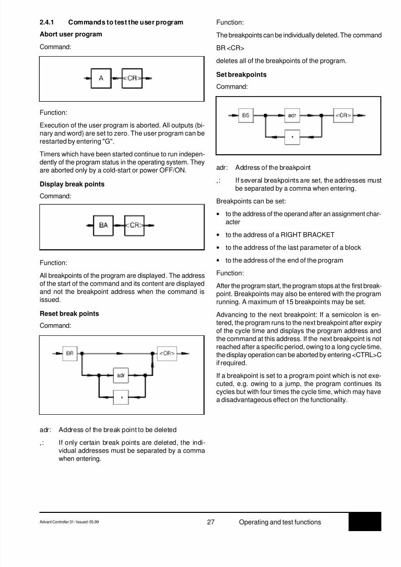
Abort user program
Command:
Function:
Execution of the user program is aborted. All outputs (bi-nary and word) are set to zero. The user program can berestarted by entering "G".
Timers which have been started continue to run indepen-dently of the program status in the operating system. Theyare aborted only by a cold-start or power OFF/ON.
Display break points
Command:
Function:
The breakpoints can be individually deleted. The command
BR <CR>
deletes all of the breakpoints of the program.
Set breakpoints
Command:
Function:
All breakpoints of the program are displayed. The addressof the start of the command and its content are displayedand not the breakpoint address when the command is
issued.
Reset break points
Command:
adr: Address of the break point to be deleted
,: If only certain break points are deleted, the indi-vidual addresses must be separated by a commawhen entering.
adr: Address of the breakpoint
,: If several breakpoints are set, the addresses mustbe separated by a comma when entering.
Breakpoints can be set:
• to the address of the operand after an assignment char-acter
• to the address of a RIGHT BRACKET
• to the address of the last parameter of a block
• to the address of the end of the program
Function:
After the program start, the program stops at the first break-point. Breakpoints may also be entered with the programrunning. A maximum of 15 breakpoints may be set.
Advancing to the next breakpoint: If a semicolon is en-tered, the program runs to the next breakpoint after expiryof the cycle time and displays the program address andthe command at this address. If the next breakpoint is notreached after a specific period, owing to a long cycle time,the display operation can be aborted by entering <CTRL>Cif required.
If a breakpoint is set to a program point which is not exe-cuted, e.g. owing to a jump, the program continues itscycles but with four times the cycle time, which may have
a disadvantageous effect on the functionality.
,
,

8/9/2019 Abb 07kt94 PLC
http://slidepdf.com/reader/full/abb-07kt94-plc 32/66
7.3 28 Advant Controller 31 / Issued: 05.99Operating and test functions
Change over between operator control functions
<–––> Monitor
Command:
Function:
Pressing key <CTRL> and key W simultaneously takesyou to the monitor program of the PLC. This makes avail-able certain basic functions at the monitor level to theuser. If you are in the monitor program, you can switchback to the operating program of the PLC by entering<CTRL> and W again.
I/O-Test
Command:
Function:
This mode permits the user to check the wiring of his I/Osignals from the PLC through to the process in order toensure that the wiring is correct.
After starting the user program, it is not executed. Onlythe I/O signals planned in the program are operated, i.e.the input signals are read in and the output signals arebrought out.
By actuating limit switches etc., it is possible to checkwhether the signals arrive under the declared designationin the PLC. By setting outputs in targeted manner, it ispossible to check whether the signals arrive at the correctpoint in the process. Command Z or ZD can be used todisplay the required I/O variables in the PLC.
Command "EA" can also be entered with the program run-ning. In this case, the mode does not take effect until the
start of the next program cycle.
Deactivate I/O test mode
Command:
Function:
Mode I/O test is deactivated with this command, i.e. theuser program continues to run normally as of this point. Itis advisable to abort the program before deactivating theI/O test.
Activate single step mode
Command:
Function:
After starting the program, only one sentence or one blockis executed and the program stops after each assignment,RIGHT BRACKET and at the end of each block.
Command Z can be used to display variable values.
Command "ES" can also be entered with the program run-ning. In this case, the mode does not take effect until thestart of the next program cycle.
Advancing by one step:
If you enter a semicolon, the program runs to the nextbreakpoint after expiry of the cycle time and displays theprogram address and the command at this address. If thenext breakpoint is not reached after a specific period, owingto a long cycle time, the display operation can be abortedby entering <CTRL>C if required.
Deactivate single step mode
Command:
Single-step mode is deactivated, i.e. the user program
continues to run normally as of the current breakpoint.
Activate single step mode
Command:

8/9/2019 Abb 07kt94 PLC
http://slidepdf.com/reader/full/abb-07kt94-plc 33/66
7.3Advant Controller 31 / Issued: 05.99 29 Operating and test functions
Function:
When the program is started, the program stops at theend of the program. Command "EZ" can also be enteredwith the program running.
The mode does not come into effect until the start of thenext program cycle.
Advancing by one program cycle:
If a semicolon is entered, the program is run through onceafter expiry of the cycle time and displays the programaddress and the command at this address (!PE). If thenext breakpoint is not reached after a specific period, owingto a long cycle time, the display operation can be abortedby entering <CTRL>C if required.
Deactivate single cycle mode:
Command:
Function:
Single-cycle mode is deactivated, i.e. the program is ex-ecuted normally again.
Display the contents of the error registers
Command:
Maximum number of I/O signals to be forced:
• Digital inputs: 64
• Word inputs: 16
• Digital outputs: 64
• Word outputs: 16
Forcing is performed in the following way:
Forcing inputs
The PLC generates an image of the input signals plannedin the PLC program at the start of each program cycle. Ifinputs are to be forced, their real values are replaced bythe force values preset by the user after read-in. The PLCoperates only with the modified input image during theprogram cycle, and, thus, signal changes on the inputdevice during the program cycle are unimportant.
Forcing outputs
At the end of the program cycle, the PLC transfers theoutput image of the output signals planned in the PLCprogram to the output devices. If outputs are to be forced,their real values are replaced by the force values beforethey are output in the output image.
Behavior after power failure, RESET or warm start
After a power failure, the PLC has "forgotten" the force job. The list of I/O signals to be forced, entered before thepower failure, is, however, still present in the PLC and canalso be displayed with command FORC A <CR>. The over-all force list is reactivated and forcing is placed back intoeffect by entering a single signal to be forced.
The following commands are available for forcing I/O sig-nals:
• FORC: Enter force value
• FORC A: Display force value
• FORC R: Delete forcingFunction:
The error information stored in the PLC is output.
Forcing I/O signals
On the PLC, the user can "force" input signals and outputsignals. This means that values are preset for I/O signals
by the user. The PLC then operates with the force valuesinstead of the real input signals. In turn, the PLC issuesthe force values to the output devices and not the outputsignals computed in the PLC program. The force valuesapply until forcing is cancelled for individual I/O signals orfor all I/O signals. Both the values supplied by the inputdevices and the values assigned to outputs in the PLCprogram thus have no effect during forcing. Forcing canbe applied both to binary I/O signals and to word I/O sig-nals.

8/9/2019 Abb 07kt94 PLC
http://slidepdf.com/reader/full/abb-07kt94-plc 34/66
7.3 30 Advant Controller 31 / Issued: 05.99Operating and test functions
Enter force value
The name of the I/O signal to be forced and the force valueare entered with the command FORC.
Command:
name:Name of the input or output signal to be forced
value: Force value for the input or output
;: A semicolon is used as the separator between thename and the force value. If several inputs/outputsare to be forced, they must also be separated by asemicolon.
Display force value
Command:
Function:
• Display of all of the inputs and outputs to be forced
• Display of all of the inputs and outputs of a specificgroup of inputs/outputs to be forced
Delete forcing
Command:
name:Name of the inputs/outputs for which forcing is tobe terminated
;: If forcing is terminated only for specific inputs/out-puts, the individual names must be separated by a
semicolon when entering them.
Function:
(1) Terminating forcing for all I/O signals
(2) Terminating forcing for single I/O signals
(3) Terminating forcing for one specific group of I/Osignals
Start user program
Command:
Function:
The user program is started and the operands are initial-ized.
The operand areas are initialized according to the corre-sponding system constant.
name value;
;
;
name
8/9/2019 Abb 07kt94 PLC
http://slidepdf.com/reader/full/abb-07kt94-plc 35/66
7.3Advant Controller 31 / Issued: 05.99 31 Operating and test functions
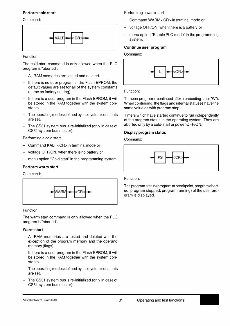
Perform cold start
Command:
Performing a warm start
– Command WARM <CR> in terminal mode or
– voltage OFF/ON, when there is a battery or
– menu option "Enable PLC mode" in the programmingsystem.
Continue user program
Command:Function:
The cold start command is only allowed when the PLCprogram is "aborted".
– All RAM memories are tested and deleted.
– If there is no user program in the Flash EPROM, thedefault values are set for all of the system constants(same as factory setting).
– If there is a user program in the Flash EPROM, it willbe stored in the RAM together with the system con-stants.
– The operating modes defined by the system constantsare set.
– The CS31 system bus is re-initialized (only in case ofCS31 system bus master).
Performing a cold start
– Command KALT <CR> in terminal mode or
– voltage OFF/ON, when there is no battery or
– menu option "Cold start" in the programming system.
Perform warm start
Command:
Function:
The warm start command is only allowed when the PLCprogram is "aborted".
Warm start
– All RAM memories are tested and deleted with theexception of the program memory and the operandmemory (flags).
– If there is a user program in the Flash EPROM, it willbe stored in the RAM together with the system con-stants.
– The operating modes defined by the system constantsare set.
– The CS31 system bus is re-initialized (only in case of
CS31 system bus master).
Function:
The program status (program at breakpoint, program abort-ed, program stopped, program running) of the user pro-gram is displayed.
Function:
The user program is continued after a preceding stop ("W").When continuing, the flags and internal statuses have thesame value as with program stop.
Timers which have started continue to run independentlyof the program status in the operating system. They areaborted only by a cold-start or power OFF/ON.
Display program status
Command:
8/9/2019 Abb 07kt94 PLC
http://slidepdf.com/reader/full/abb-07kt94-plc 36/66
7.3 32 Advant Controller 31 / Issued: 05.99Operating and test functions
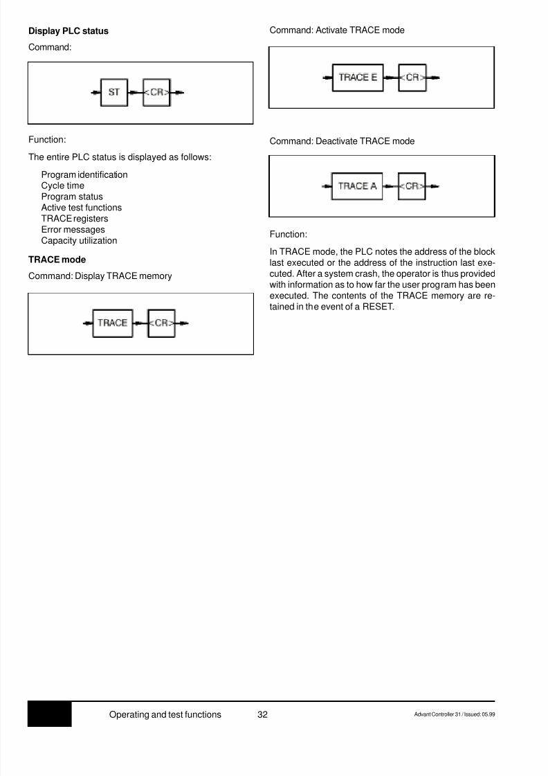
Display PLC status
Command:
Function:
In TRACE mode, the PLC notes the address of the blocklast executed or the address of the instruction last exe-
cuted. After a system crash, the operator is thus providedwith information as to how far the user program has beenexecuted. The contents of the TRACE memory are re-tained in the event of a RESET.
Function:
The entire PLC status is displayed as follows:
Program identificationCycle timeProgram statusActive test functionsTRACE registersError messagesCapacity utilization
TRACE mode
Command: Display TRACE memory
Command: Activate TRACE mode
Command: Deactivate TRACE mode
8/9/2019 Abb 07kt94 PLC
http://slidepdf.com/reader/full/abb-07kt94-plc 37/66
7.3Advant Controller 31 / Issued: 05.99 33 Operating and test functions
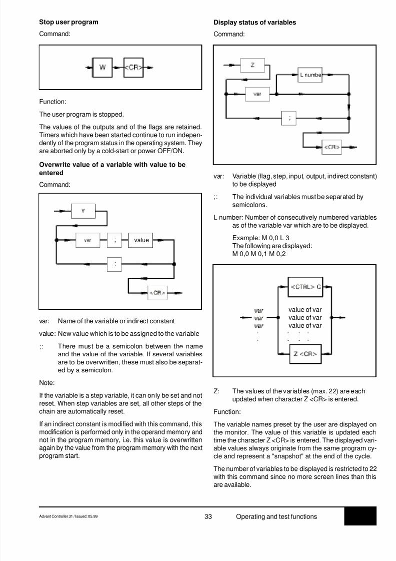
Stop user program
Command:
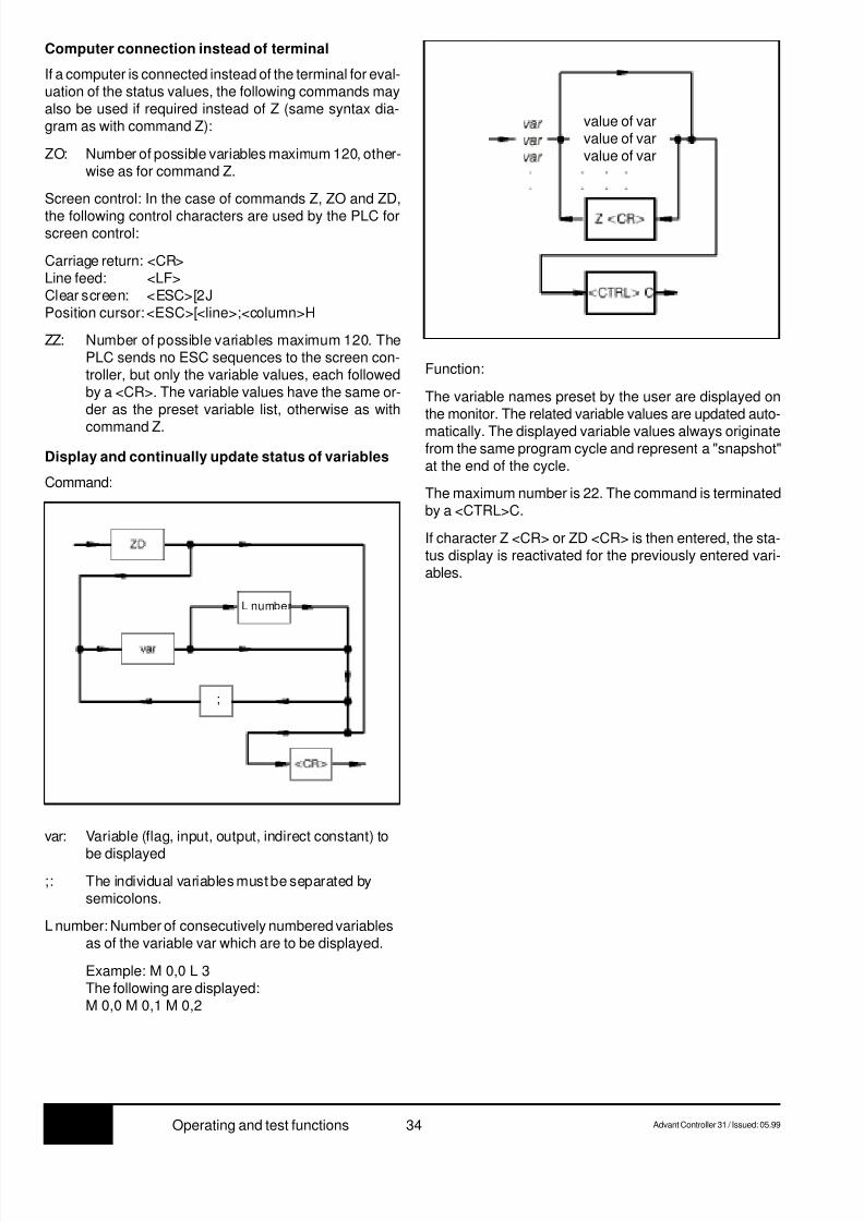
var: Variable (flag, step, input, output, indirect constant)to be displayed
;: The individual variables must be separated bysemicolons.
L number: Number of consecutively numbered variablesas of the variable var which are to be displayed.
Example: M 0,0 L 3The following are displayed:M 0,0 M 0,1 M 0,2
Function:
The user program is stopped.
The values of the outputs and of the flags are retained.Timers which have been started continue to run indepen-dently of the program status in the operating system. Theyare aborted only by a cold-start or power OFF/ON.
Overwrite value of a variable with value to be
entered
Command:
var: Name of the variable or indirect constant
value: New value which is to be assigned to the variable
;: There must be a semicolon between the nameand the value of the variable. If several variablesare to be overwritten, these must also be separat-ed by a semicolon.
Note:
If the variable is a step variable, it can only be set and notreset. When step variables are set, all other steps of thechain are automatically reset.
If an indirect constant is modified with this command, thismodification is performed only in the operand memory andnot in the program memory, i.e. this value is overwrittenagain by the value from the program memory with the nextprogram start.
Display status of variables
Command:
Z: The values of the variables (max. 22) are eachupdated when character Z <CR> is entered.
Function:
The variable names preset by the user are displayed onthe monitor. The value of this variable is updated eachtime the character Z <CR> is entered. The displayed vari-able values always originate from the same program cy-cle and represent a "snapshot" at the end of the cycle.
The number of variables to be displayed is restricted to 22with this command since no more screen lines than thisare available.
value of varvalue of varvalue of var
value
;
;
L number
;
8/9/2019 Abb 07kt94 PLC
http://slidepdf.com/reader/full/abb-07kt94-plc 38/66
8/9/2019 Abb 07kt94 PLC
http://slidepdf.com/reader/full/abb-07kt94-plc 39/66
7.3Advant Controller 31 / Issued: 05.99 35 Operating and test functions
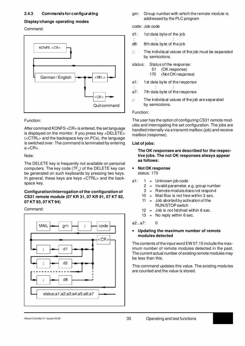
2.4.3 Commands for configurating
Display/change operating modes
Command:
grn: Group number with which the remote module isaddressed by the PLC program
code: Job code
d1: 1st data byte of the job : : :d8: 8th data byte of the job
;: The individual values of the job must be separatedby semicolons.
status: Status of the response: 51 (OK response)170 (Not OK response)
a1: 1st data byte of the response : : :a7: 7th data byte of the response
;: The individual values of the job are separatedby semicolons.
Function:
The user has the option of configuring CS31 remote mod-ules and interrogating the set configuration. The jobs arehandled internally via a transmit mailbox (job) and receivemailbox (response).
List of jobs:
The OK responses are described for the respec-tive jobs. The not OK responses always appearas follows:
• Not OK responsestatus: 170
a1: 1 = Unknown job code2 = Invalid parameter, e.g. group number3 = Remote module does not respond
10 = Mail Box is not free within 3 sec.11 = Job aborted by activation of the
RUN/STOP switch12 = Job is not fetched within 6 sec.13 = No reply within 6 sec.
a2...a7: 0
• Updating the maximum number of remotemodules detected
The contents of the input word EW 07,15 include the max-imum number of remote modules detected in the past.The current actual number of existing remote modules maybe less than this.
This command updates this value. The existing modulesare counted and the value is stored.
Function:
After command KONFS <CR> is entered, the set languageis displayed on the monitor. If you press key <DELETE>(<CTRL> and the backspace key on PCs), the languageis switched over. The command is terminated by enteringa <CR>.
Note:
The DELETE key is frequently not available on personalcomputers. The key code (7F
H) of the DELETE key can
be generated on such keyboards by pressing two keys.In general, these keys are keys <CTRL> and the back-
space key.
Configuration/interrogation of the configuration of
CS31 remote module (07 KR 31, 07 KR 91, 07 KT 92,
07 KT 93, 07 KT 94)
Command:
German / English
Quit command
status;a1;a2;a3;a4;a5;a6;a7
8/9/2019 Abb 07kt94 PLC
http://slidepdf.com/reader/full/abb-07kt94-plc 40/66
7.3 36 Advant Controller 31 / Issued: 05.99Operating and test functions
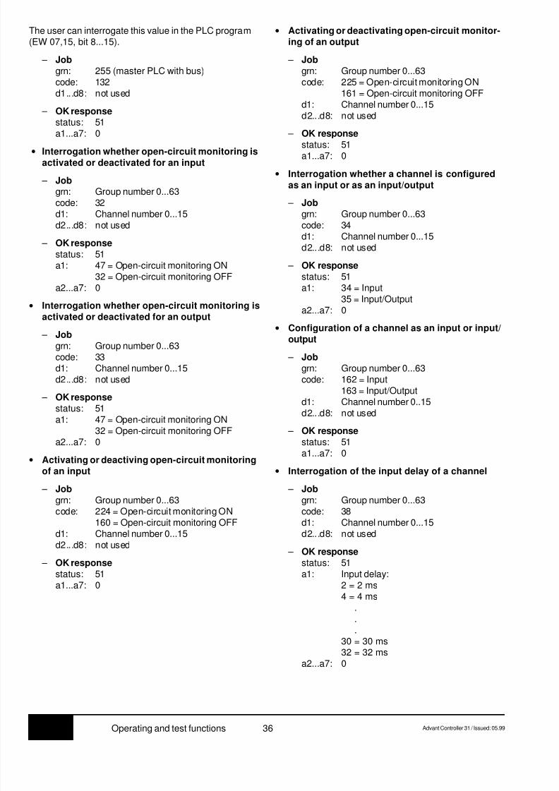
The user can interrogate this value in the PLC program(EW 07,15, bit 8...15).
– Jobgrn: 255 (master PLC with bus)code: 132d1...d8: not used
– OK responsestatus: 51
a1...a7: 0 • Interrogation whether open-circuit monitoring is
activated or deactivated for an input
– Jobgrn: Group number 0...63code: 32d1: Channel number 0...15d2...d8: not used
– OK responsestatus: 51a1: 47 = Open-circuit monitoring ON
32 = Open-circuit monitoring OFFa2...a7: 0
• Interrogation whether open-circuit monitoring isactivated or deactivated for an output
– Jobgrn: Group number 0...63code: 33d1: Channel number 0...15d2...d8: not used
– OK responsestatus: 51a1: 47 = Open-circuit monitoring ON
32 = Open-circuit monitoring OFFa2...a7: 0
• Activating or deactiving open-circuit monitoringof an input
– Jobgrn: Group number 0...63code: 224 = Open-circuit monitoring ON
160 = Open-circuit monitoring OFFd1: Channel number 0...15d2...d8: not used
– OK responsestatus: 51a1...a7: 0
• Activating or deactivating open-circuit monitor-ing of an output
– Jobgrn: Group number 0...63code: 225 = Open-circuit monitoring ON
161 = Open-circuit monitoring OFFd1: Channel number 0...15d2...d8: not used
– OK responsestatus: 51a1...a7: 0
• Interrogation whether a channel is configuredas an input or as an input/output
– Jobgrn: Group number 0...63code: 34d1: Channel number 0...15d2...d8: not used
– OK response
status: 51a1: 34 = Input
35 = Input/Outputa2...a7: 0
• Configuration of a channel as an input or input/output
– Jobgrn: Group number 0...63code: 162 = Input
163 = Input/Outputd1: Channel number 0..15
d2...d8: not used – OK response
status: 51a1...a7: 0
• Interrogation of the input delay of a channel
– Jobgrn: Group number 0...63code: 38d1: Channel number 0...15d2...d8: not used
– OK responsestatus: 51a1: Input delay:
2 = 2 ms4 = 4 ms
.
.
.30 = 30 ms32 = 32 ms
a2...a7: 0
8/9/2019 Abb 07kt94 PLC
http://slidepdf.com/reader/full/abb-07kt94-plc 41/66
7.3Advant Controller 31 / Issued: 05.99 37 Operating and test functions
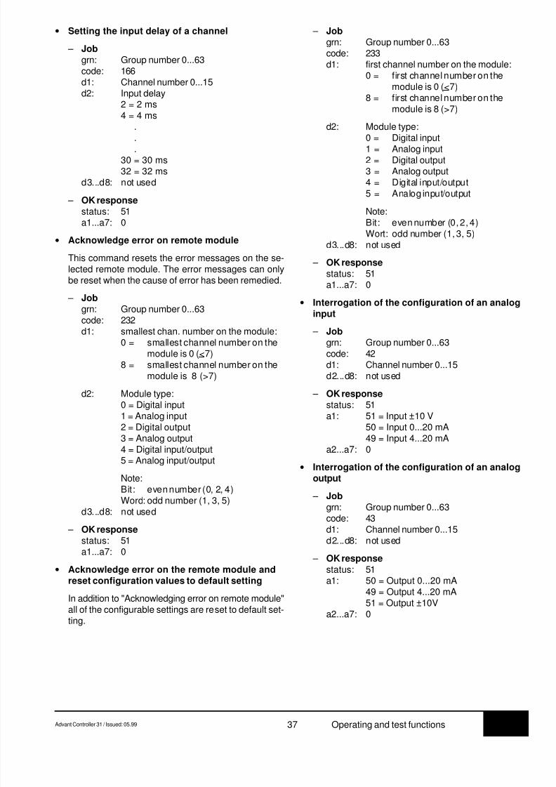
• Setting the input delay of a channel
– Jobgrn: Group number 0...63code: 166d1: Channel number 0...15d2: Input delay
2 = 2 ms4 = 4 ms
.
.
.30 = 30 ms32 = 32 ms
d3...d8: not used
– OK responsestatus: 51a1...a7: 0
• Acknowledge error on remote module
This command resets the error messages on the se-lected remote module. The error messages can onlybe reset when the cause of error has been remedied.
– Jobgrn: Group number 0...63code: 232d1: smallest chan. number on the module:
0 = smallest channel number on themodule is 0 (<7)
8 = smallest channel number on themodule is 8 (>7)
d2: Module type:0 = Digital input
1 = Analog input2 = Digital output3 = Analog output4 = Digital input/output5 = Analog input/output
Note:Bit: even number (0, 2, 4)Word: odd number (1, 3, 5)
d3...d8: not used
– OK responsestatus: 51
a1...a7: 0
• Acknowledge error on the remote module andreset configuration values to default setting
In addition to "Acknowledging error on remote module"all of the configurable settings are reset to default set-ting.
– Jobgrn: Group number 0...63code: 233d1: first channel number on the module:
0 = first channel number on themodule is 0 (<7)
8 = first channel number on themodule is 8 (>7)
d2: Module type:
0 = Digital input1 = Analog input2 = Digital output3 = Analog output4 = Digital input/output5 = Analog input/output
Note:Bit: even number (0, 2, 4)Wort: odd number (1, 3, 5)
d3...d8: not used
– OK response
status: 51a1...a7: 0
• Interrogation of the configuration of an analoginput
– Jobgrn: Group number 0...63code: 42d1: Channel number 0...15d2...d8: not used
– OK responsestatus: 51
a1: 51 = Input ±10 V50 = Input 0...20 mA49 = Input 4...20 mA
a2...a7: 0
• Interrogation of the configuration of an analogoutput
– Jobgrn: Group number 0...63code: 43d1: Channel number 0...15d2...d8: not used
– OK responsestatus: 51a1: 50 = Output 0...20 mA
49 = Output 4...20 mA51 = Output ±10V
a2...a7: 0

8/9/2019 Abb 07kt94 PLC
http://slidepdf.com/reader/full/abb-07kt94-plc 42/66
7.3 38 Advant Controller 31 / Issued: 05.99Operating and test functions
• Configuration of an analog input
– Jobgrn: Group number 0...63code: 170d1: Chanel number 0...15d2: 51 = Input 10 V
50 = Input 0...20 mA49 = Input 4...20 mA
d3...d8: not used
– OK responsestatus: 51a1...a7: 0
• Configuration of an analog output
– Jobgrn: Group number 0...63code: 171d1: Channel number 0...15d2: 50 = Output 0...20 mA
49 = Output 4...20 mA51 = Output ±10V
d3...d8: not used
– OK responsestatus: 51a1...a7: 0
• Interrogation of the bus configuration
The bus interface of the master PLC has a list which storesspecific data of the remote modules. In this list, the re-mote modules are numbered in the order in which theyare encountered on the CS31 bus. This command involvesspecifying the internal number of the modules. The re-
sponse received is the group number stored under thisnumber and the status information on the correspondingmodule.
– Jobgrn: 0 (is not evaluated)code: 80d1: Number from the module list (1...31)d2...d8: not used
– OK responsestatus: 51a1: Status of the remote module:
Bit 0...3: Number of process data bytes(binary module) and/or words(word module) sent to the masterby the module
Bit 4...7: Number of process data bytes(binary module) and/or words(word module) sent to the moduleby the master
a2: Group number (0...63)a3: Bit 0: 0 = smallest channel number <7
1 = smallest channel number >7Bit 1: 0 = Binary module
1 = Word module
a4...a7: 0
• Reading 1...6 bytes (07 KR 91, 07 KT 92, 07 KT 93and 07 KT 94)
– Jobgrn: Group number 0...63code: 49 = Read 1 byte
50 = Read 2 bytes51 = Read 3 bytes52 = Read 4 bytes53 = Read 5 bytes
54 = Read 6 bytesd1: first channel number on the module:
0 = first channel number on themodule is 0 (<7)
8 = first channel number on themodule is 8 (>7)
d2: Module type:0 = Digital input1 = Analog input2 = Digital output3 = Analog output4 = Digital input/output
5 = Analog input/output
Note:Bit: even number (0, 2, 4)Word: odd number (1, 3, 5)
d3: Byte start address (low byte)d4: Byte start address (high byte)d5...d8: not used
– OK responsestatus: 51a1: Value of the 1st bytea2: Value of the 2nd byte or 0a3: Value of the 3rd byte or 0a4: Value of the 4th byte or 0a5: Value of the 5th byte or 0a6: Value of the 6th byte or 0a7: 0
• Reading 1 bit of a byte
– Jobgrn: Group number 0...63code: 63d1: first channel number on the module:
0 = first channel number on the
module is 0 (<7)8 = first channel number on the
module is 8 (>7)
d2: Module type:0 = Digital input1 = Analog input2 = Digital output3 = Analog output4 = Digital input/output5 = Analog input/output
Note:Bit: even number (0, 2, 4)Word: odd number (1, 3, 5)
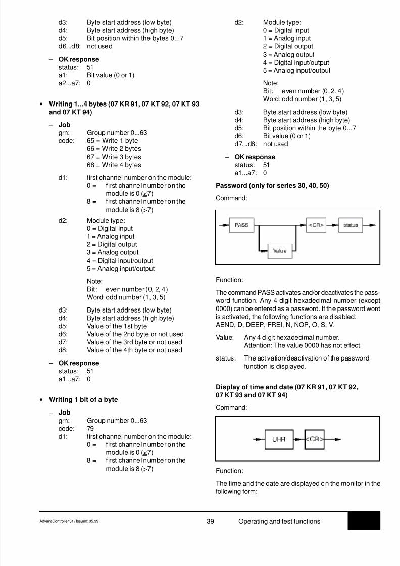
8/9/2019 Abb 07kt94 PLC
http://slidepdf.com/reader/full/abb-07kt94-plc 43/66
7.3Advant Controller 31 / Issued: 05.99 39 Operating and test functions
d3: Byte start address (low byte)d4: Byte start address (high byte)d5: Bit position within the bytes 0...7d6...d8: not used
– OK responsestatus: 51a1: Bit value (0 or 1)a2...a7: 0
• Writing 1...4 bytes (07 KR 91, 07 KT 92, 07 KT 93and 07 KT 94)
– Jobgrn: Group number 0...63code: 65 = Write 1 byte
66 = Write 2 bytes67 = Write 3 bytes68 = Write 4 bytes
d1: first channel number on the module:0 = first channel number on the
module is 0 (<7)8 = first channel number on the
module is 8 (>7)
d2: Module type:0 = Digital input1 = Analog input2 = Digital output3 = Analog output4 = Digital input/output5 = Analog input/output
Note:Bit: even number (0, 2, 4)
Word: odd number (1, 3, 5)
d3: Byte start address (low byte)d4: Byte start address (high byte)d5: Value of the 1st byted6: Value of the 2nd byte or not usedd7: Value of the 3rd byte or not usedd8: Value of the 4th byte or not used
– OK responsestatus: 51a1...a7: 0
• Writing 1 bit of a byte
– Jobgrn: Group number 0...63code: 79d1: first channel number on the module:
0 = first channel number on themodule is 0 (<7)
8 = first channel number on themodule is 8 (>7)
d2: Module type:0 = Digital input1 = Analog input2 = Digital output3 = Analog output4 = Digital input/output5 = Analog input/output
Note:Bit: even number (0, 2, 4)
Word: odd number (1, 3, 5)
d3: Byte start address (low byte)d4: Byte start address (high byte)d5: Bit position within the byte 0...7d6: Bit value (0 or 1)d7...d8: not used
– OK responsestatus: 51a1...a7: 0
Password (only for series 30, 40, 50)
Command:
Function:
The command PASS activates and/or deactivates the pass-word function. Any 4 digit hexadecimal number (except0000) can be entered as a password. If the password wordis activated, the following functions are disabled:AEND, D, DEEP, FREI, N, NOP, O, S, V.
Value: Any 4 digit hexadecimal number.Attention: The value 0000 has not effect.
status: The activation/deactivation of the passwordfunction is displayed.
Display of time and date (07 KR 91, 07 KT 92,
07 KT 93 and 07 KT 94)
Command:
Function:
The time and the date are displayed on the monitor in thefollowing form:
UHR
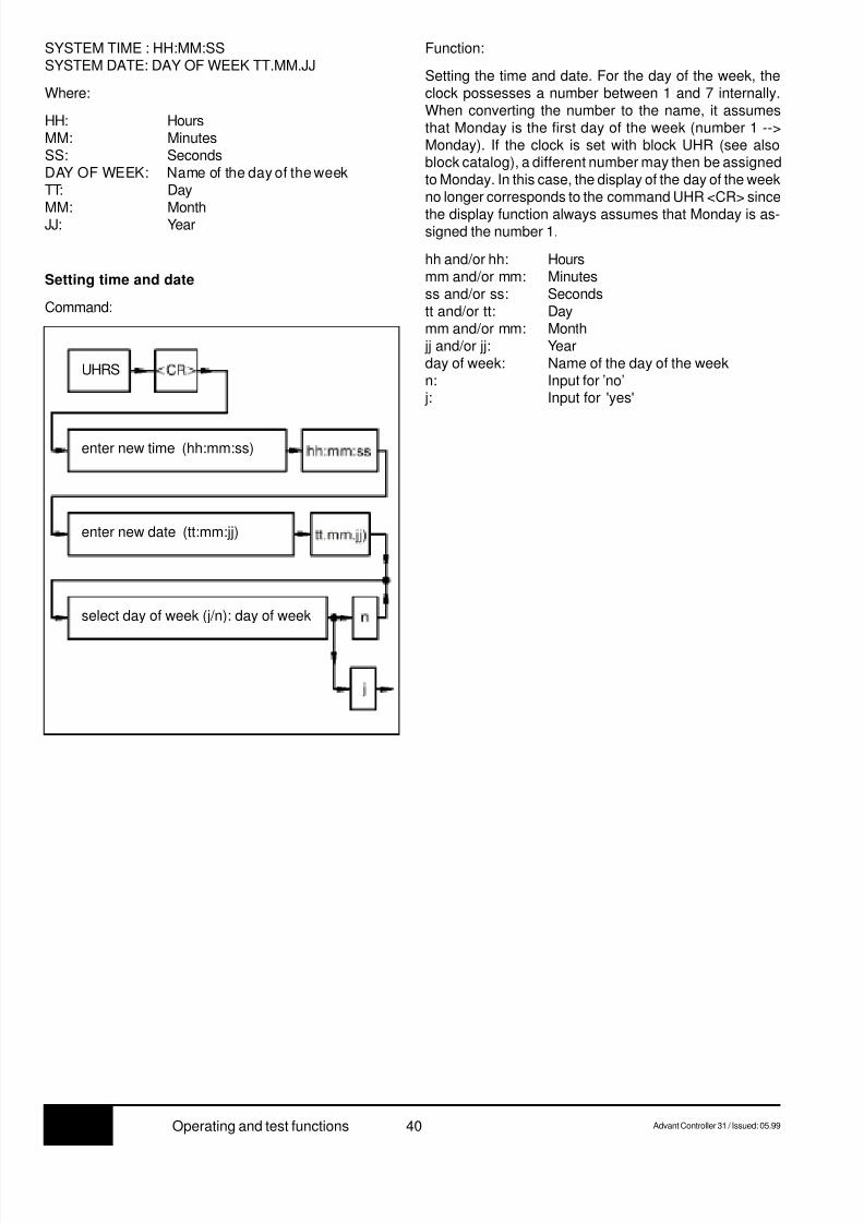
8/9/2019 Abb 07kt94 PLC
http://slidepdf.com/reader/full/abb-07kt94-plc 44/66
7.3 40 Advant Controller 31 / Issued: 05.99Operating and test functions
SYSTEM TIME : HH:MM:SSSYSTEM DATE: DAY OF WEEK TT.MM.JJ
Where:
HH: HoursMM: MinutesSS: SecondsDAY OF WEEK: Name of the day of the weekTT: Day
MM: MonthJJ: Year
Setting time and date
Command:
Function:
Setting the time and date. For the day of the week, theclock possesses a number between 1 and 7 internally.When converting the number to the name, it assumesthat Monday is the first day of the week (number 1 -->Monday). If the clock is set with block UHR (see alsoblock catalog), a different number may then be assignedto Monday. In this case, the display of the day of the weekno longer corresponds to the command UHR <CR> since
the display function always assumes that Monday is as-signed the number 1.
hh and/or hh: Hoursmm and/or mm: Minutesss and/or ss: Secondstt and/or tt: Daymm and/or mm: Month jj and/or jj: Yearday of week: Name of the day of the weekn: Input for ’no’ j: Input for 'yes'
enter new time (hh:mm:ss)
enter new date (tt:mm:jj)
select day of week (j/n): day of week
UHRS

8/9/2019 Abb 07kt94 PLC
http://slidepdf.com/reader/full/abb-07kt94-plc 45/66
7.3Advant Controller 31 / Issued: 05.99 41 Monitor functions
The monitor program offers the specialist access at hexa-
decimal level to the entire address range of the PLC. Mem-ory areas can be displayed and modified, and hardwaretests can be conducted.
Monitor commands which change memory storageareas may endanger the functionality of the PLC. Forthis reason the monitor functions should be handledwith care.
• The modules work with monitor commands with 32 bitaddresses. The high word of the 32 bit address is setwith the Y command.
Example:
Y = 20 <CR> } The value of the addressDW0 <CR> } 0020 0000
H is displayed.
Switchoveroperator control functions <--> Monitor functions
Command:
• The blank character (space) is ignored and can be used
for more clearly structured entries.
• The character CTRL-C aborts the currently runningoperation.
• Every display on the screen can be stopped with<CTRL>S (XOFF) and be continued with <CTRL>Q(XON).
• If no segment is specified when entering an address,the working segment is used (see Y instruction).
Overview of the monitor functions
Function and explanation Page
H Display help text / calculate hexadecimal ... 42
D Display memory contents ........................... 42
I Fill memory area with a value ...................... 43
M Transfer memory areas ............................... 43
P Read/write port............................................ 44
S Display/edit memory contents..................... 45
Y Display/edit working segment ..................... 45
ZG Simultaneous output of 3 values .................. 46
ZR RAM test .................................................... 46
ZZA Output of 3 values after enteringa semicolon (;) ............................................ 47
ZZF Search for string.......................................... 47
ZZV Compare memory commands word-serially. 48
R Read Intel HEX file ...................................... 49
W Write Intel HEX file ...................................... 49
3 Monitor functions for 07 KR 91 and 07 KT 92 to 07 KT 94
Command not available in 07 KR 31.
Function:
By pressing key <CTRL> and key W simultaneously themonitor program of the PLC is accessed. If the you are inthe monitor program, you can change back to the opera-tor-control program of the PLC by re-entering <CTRL>and W.
Explanation of the syntax:
• The monitor pogram responds with the character * and
waits for an entry.
• All of the numbers are hexadecimal numbers (leadingzeors may be omitted).
• If more digits than necessary are entered, only the lastdigits are valid (with byte commands the last two dig-its and with word commands the last 4 digits).
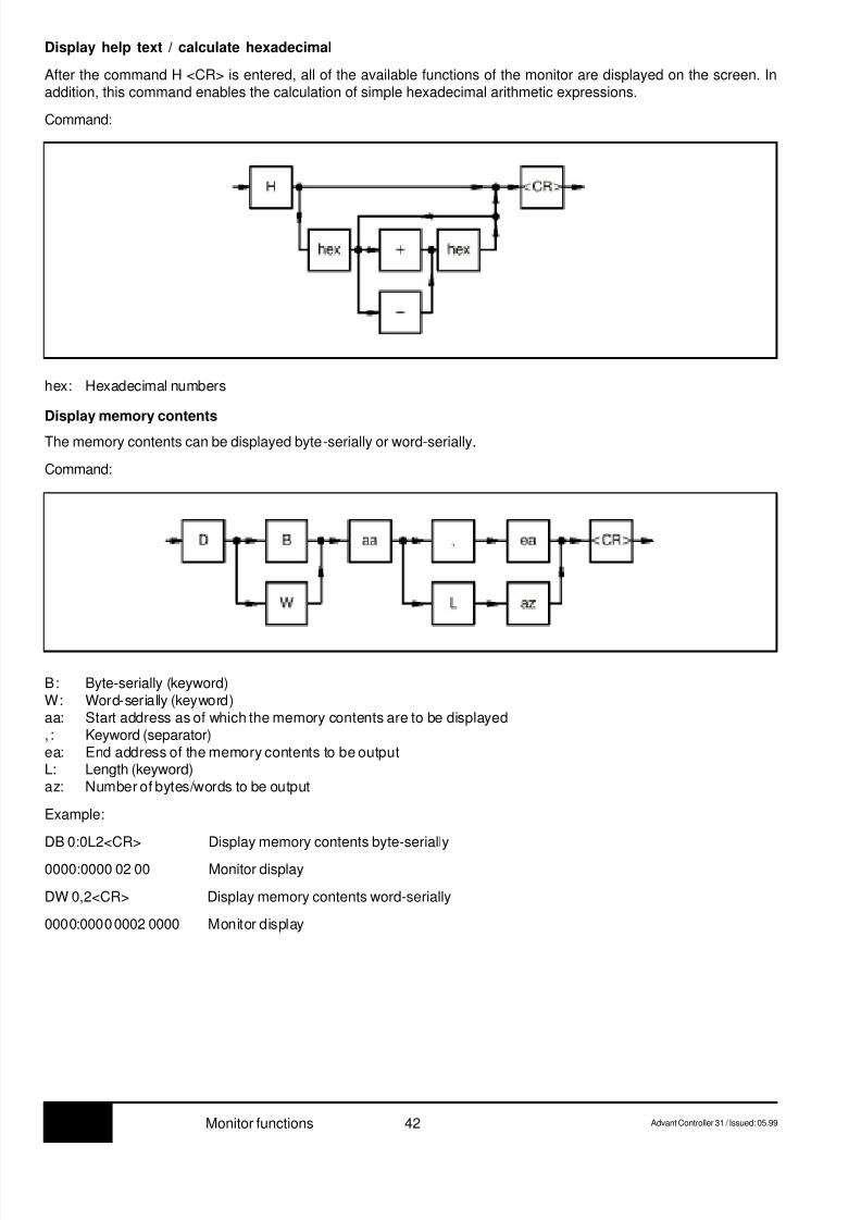
8/9/2019 Abb 07kt94 PLC
http://slidepdf.com/reader/full/abb-07kt94-plc 46/66
7.3 42 Advant Controller 31 / Issued: 05.99Monitor functions
Display help text / calculate hexadecimal
After the command H <CR> is entered, all of the available functions of the monitor are displayed on the screen. Inaddition, this command enables the calculation of simple hexadecimal arithmetic expressions.
Command:
hex: Hexadecimal numbers
Display memory contents
The memory contents can be displayed byte-serially or word-serially.
Command:
B: Byte-serially (keyword)W: Word-serially (keyword)aa: Start address as of which the memory contents are to be displayed, : Keyword (separator)ea: End address of the memory contents to be outputL: Length (keyword)az: Number of bytes/words to be output
Example:
DB 0:0L2<CR> Display memory contents byte-serially
0000:0000 02 00 Monitor display
DW 0,2<CR> Display memory contents word-serially
0000:0000 0002 0000 Monitor display
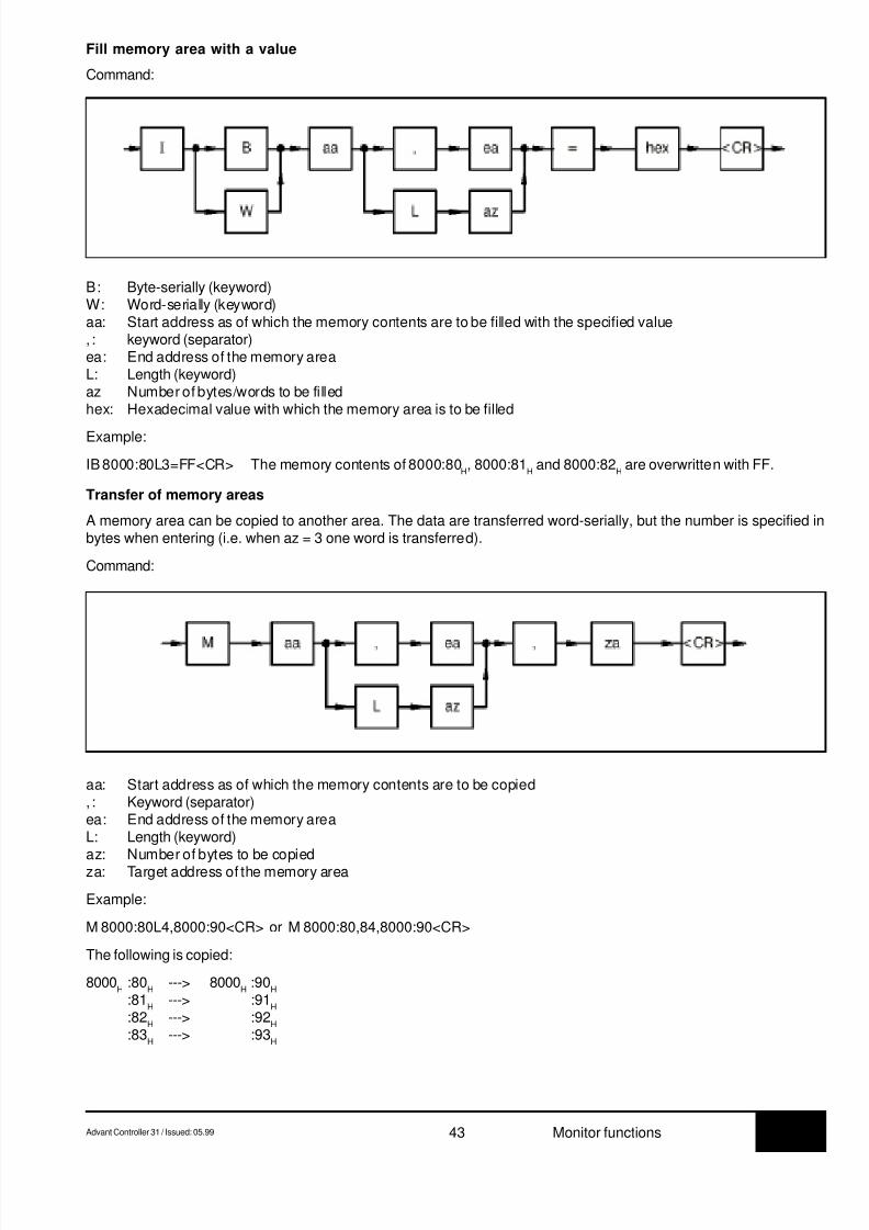
8/9/2019 Abb 07kt94 PLC
http://slidepdf.com/reader/full/abb-07kt94-plc 47/66
7.3Advant Controller 31 / Issued: 05.99 43 Monitor functions
aa: Start address as of which the memory contents are to be copied, : Keyword (separator)ea: End address of the memory areaL: Length (keyword)
az: Number of bytes to be copiedza: Target address of the memory area
Example:
M 8000:80L4,8000:90<CR> or M 8000:80,84,8000:90<CR>
The following is copied:
8000H
:80H
---> 8000H
:90H
:81H
---> :91H
:82H
---> :92H
:83H
---> :93H
Fill memory area with a value
Command:
B: Byte-serially (keyword)W: Word-serially (keyword)aa: Start address as of which the memory contents are to be filled with the specified value, : keyword (separator)ea: End address of the memory areaL: Length (keyword)az Number of bytes/words to be filledhex: Hexadecimal value with which the memory area is to be filled
Example:
IB 8000:80L3=FF<CR> The memory contents of 8000:80H, 8000:81
H and 8000:82
H are overwritten with FF.
Transfer of memory areas
A memory area can be copied to another area. The data are transferred word-serially, but the number is specified inbytes when entering (i.e. when az = 3 one word is transferred).
Command:

8/9/2019 Abb 07kt94 PLC
http://slidepdf.com/reader/full/abb-07kt94-plc 48/66
7.3 44 Advant Controller 31 / Issued: 05.99Monitor functions
adr: I/O-Addressvalue: Byte value to which the I/O address is written=: Keyword
Read/write port
Command:
adr
value
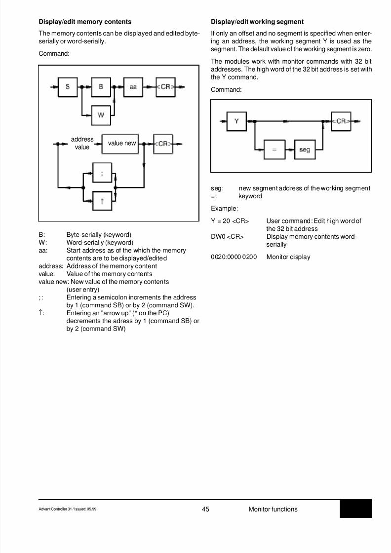
8/9/2019 Abb 07kt94 PLC
http://slidepdf.com/reader/full/abb-07kt94-plc 49/66
7.3Advant Controller 31 / Issued: 05.99 45 Monitor functions
Display/edit working segment
If only an offset and no segment is specified when enter-ing an address, the working segment Y is used as thesegment. The default value of the working segment is zero.
The modules work with monitor commands with 32 bitaddresses. The high word of the 32 bit address is set withthe Y command.
Command:
Display/edit memory contents
The memory contents can be displayed and edited byte-serially or word-serially.
Command:
B: Byte-serially (keyword)W: Word-serially (keyword)aa: Start address as of the which the memory
contents are to be displayed/editedaddress: Address of the memory contentvalue: Value of the memory contentsvalue new: New value of the memory contents
(user entry); : Entering a semicolon increments the address
by 1 (command SB) or by 2 (command SW).↑: Entering an "arrow up" (^ on the PC)
decrements the adress by 1 (command SB) orby 2 (command SW)
seg: new segment address of the working segment
=: keyword
Example:
Y = 20 <CR> User command: Edit high word ofthe 32 bit address
DW0 <CR> Display memory contents word-serially
0020:0000 0200 Monitor display
addressvalue
value new
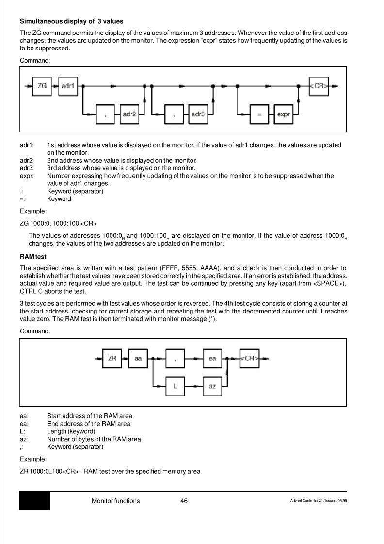
8/9/2019 Abb 07kt94 PLC
http://slidepdf.com/reader/full/abb-07kt94-plc 50/66
7.3 46 Advant Controller 31 / Issued: 05.99Monitor functions
adr1: 1st address whose value is displayed on the monitor. If the value of adr1 changes, the values are updatedon the monitor.
adr2: 2nd address whose value is displayed on the monitor.adr3: 3rd address whose value is displayed on the monitor.expr: Number expressing how frequently updating of the values on the monitor is to be suppressed when the
value of adr1 changes.
,: Keyword (separator)=: Keyword
Example:
ZG 1000:0, 1000:100 <CR>
The values of addresses 1000:0H and 1000:100
H are displayed on the monitor. If the value of address 1000:0
H
changes, the values of the two addresses are updated on the monitor.
RAM test
The specified area is written with a test pattern (FFFF, 5555, AAAA), and a check is then conducted in order toestablish whether the test values have been stored correctly in the specified area. If an error is established, the address,
actual value and required value are output. The test can be continued by pressing any key (apart from <SPACE>).CTRL C aborts the test.
3 test cycles are performed with test values whose order is reversed. The 4th test cycle consists of storing a counter atthe start address, checking for correct storage and repeating the test with the decremented counter until it reachesvalue zero. The RAM test is then terminated with monitor message (*).
Command:
Simultaneous display of 3 values
The ZG command permits the display of the values of maximum 3 addresses. Whenever the value of the first addresschanges, the values are updated on the monitor. The expression "expr" states how frequently updating of the values isto be suppressed.
Command:
aa: Start address of the RAM areaea: End address of the RAM areaL: Length (keyword)az: Number of bytes of the RAM area,: Keyword (separator)
Example:
ZR 1000:0L100<CR> RAM test over the specified memory area.
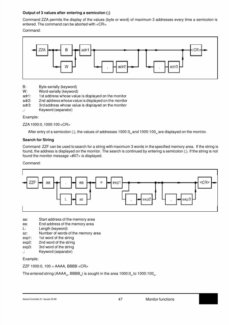
8/9/2019 Abb 07kt94 PLC
http://slidepdf.com/reader/full/abb-07kt94-plc 51/66
7.3Advant Controller 31 / Issued: 05.99 47 Monitor functions
aa: Start address of the memory areaea: End address of the memory area
L: Length (keyword)az: Number of words of the memory areaexp1: 1st word of the stringexp2: 2nd word of the stringexp3: 3rd word of the string,: Keyword (separator)
Example:
ZZF 1000:0, 100 = AAAA, BBBB <CR>
The entered string (AAAAH, BBBB
H) is sought in the area 1000:0
H to 1000:100
H.
Output of 3 values after entering a semicolon (;)
Command ZZA permits the display of the values (byte or word) of maximum 3 addresses every time a semicolon isentered. The command can be aborted with <CR>.
Command:
B: Byte-serially (keyword)W: Word-serially (keyword)adr1: 1st address whose value is displayed on the monitoradr2: 2nd address whose value is displayed on the monitoradr3: 3rd address whose value is displayed on the monitor,: Keyword (separator)
Example:
ZZA 1000:0, 1000:100 <CR>
After entry of a semicolon (;), the values of addresses 1000:0H and 1000:100
H are displayed on the monitor.
Search for String
Command ZZF can be used to search for a string with maximum 3 words in the specified memory area. If the string isfound, the address is displayed on the monitor. The search is continued by entering a semicolon (;). If the string is notfound the monitor message <#07> is displayed.
Command:
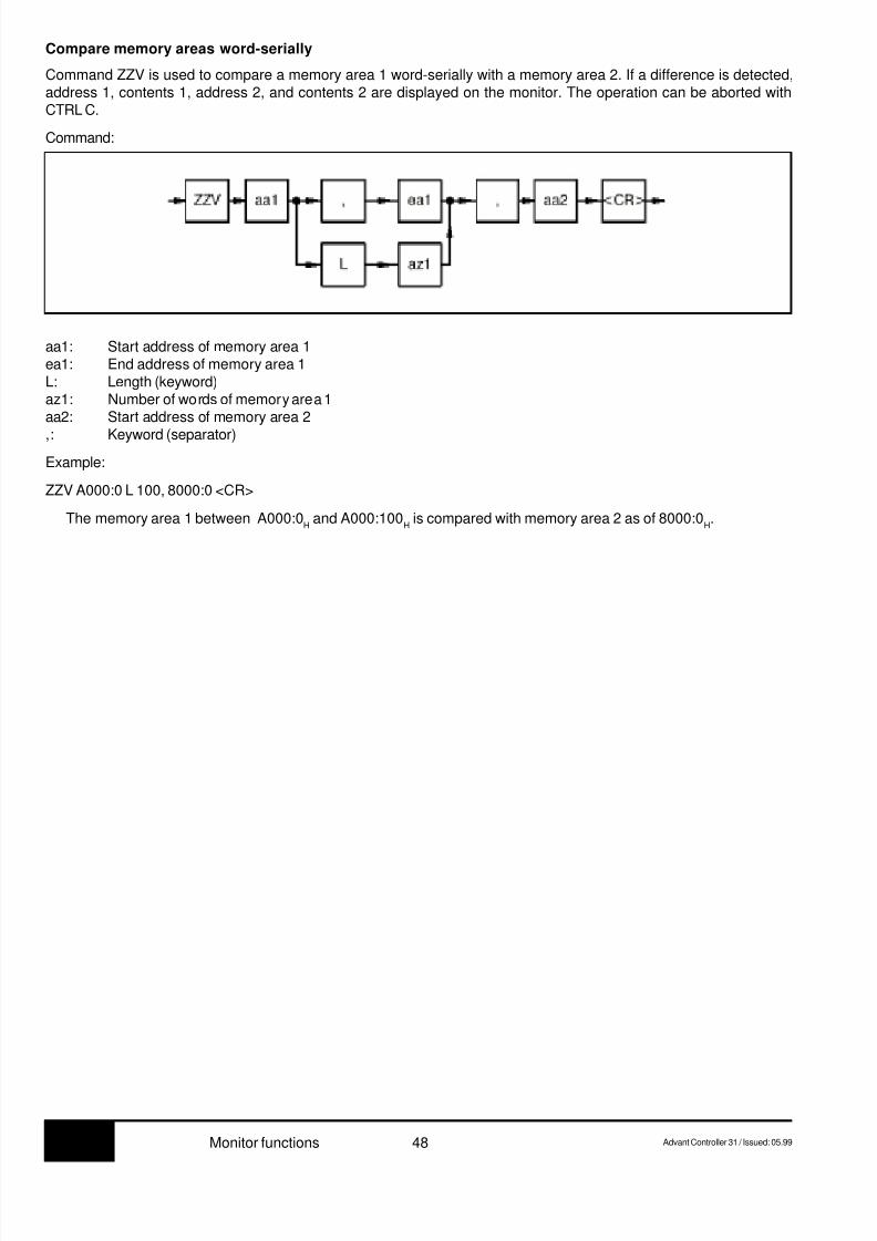
8/9/2019 Abb 07kt94 PLC
http://slidepdf.com/reader/full/abb-07kt94-plc 52/66
7.3 48 Advant Controller 31 / Issued: 05.99Monitor functions
Compare memory areas word-serially
Command ZZV is used to compare a memory area 1 word-serially with a memory area 2. If a difference is detected,address 1, contents 1, address 2, and contents 2 are displayed on the monitor. The operation can be aborted withCTRL C.
Command:
aa1: Start address of memory area 1ea1: End address of memory area 1L: Length (keyword)az1: Number of words of memory area 1aa2: Start address of memory area 2
,: Keyword (separator)
Example:
ZZV A000:0 L 100, 8000:0 <CR>
The memory area 1 between A000:0H and A000:100
H is compared with memory area 2 as of 8000:0
H.
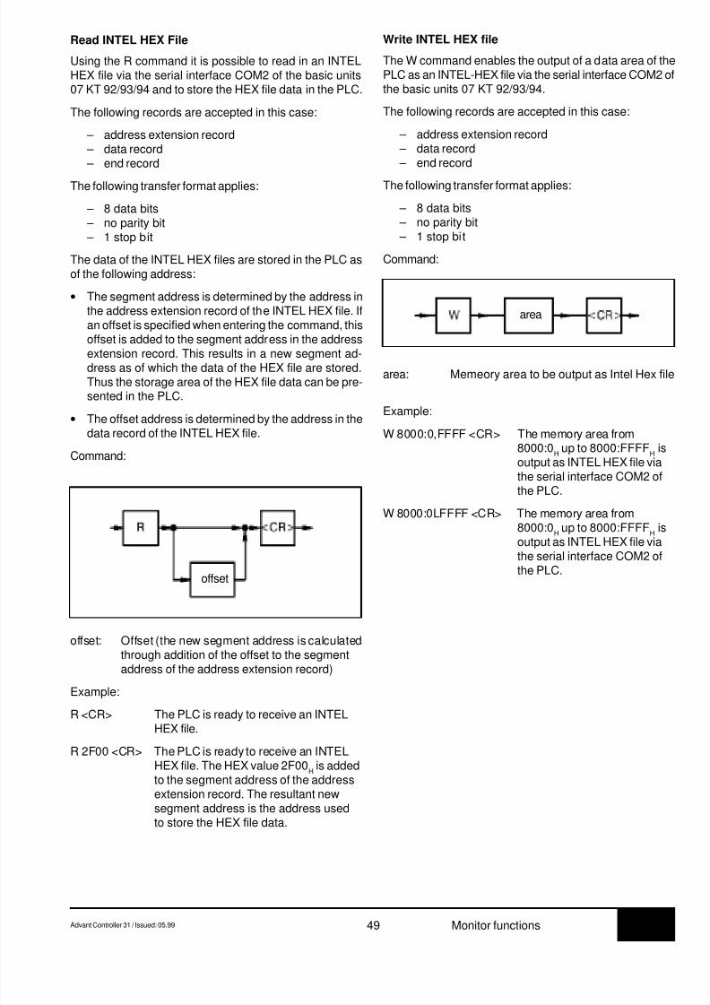
8/9/2019 Abb 07kt94 PLC
http://slidepdf.com/reader/full/abb-07kt94-plc 53/66
7.3Advant Controller 31 / Issued: 05.99 49 Monitor functions
Read INTEL HEX File
Using the R command it is possible to read in an INTELHEX file via the serial interface COM2 of the basic units07 KT 92/93/94 and to store the HEX file data in the PLC.
The following records are accepted in this case:
– address extension record – data record – end record
The following transfer format applies:
– 8 data bits – no parity bit – 1 stop bit
The data of the INTEL HEX files are stored in the PLC asof the following address:
• The segment address is determined by the address inthe address extension record of the INTEL HEX file. Ifan offset is specified when entering the command, thisoffset is added to the segment address in the address
extension record. This results in a new segment ad-dress as of which the data of the HEX file are stored.Thus the storage area of the HEX file data can be pre-sented in the PLC.
• The offset address is determined by the address in thedata record of the INTEL HEX file.
Command:
offset: Offset (the new segment address is calculatedthrough addition of the offset to the segmentaddress of the address extension record)
Example:
R <CR> The PLC is ready to receive an INTELHEX file.
R 2F00 <CR> The PLC is ready to receive an INTELHEX file. The HEX value 2F00
H is added
to the segment address of the addressextension record. The resultant newsegment address is the address usedto store the HEX file data.
Write INTEL HEX file
The W command enables the output of a data area of thePLC as an INTEL-HEX file via the serial interface COM2 ofthe basic units 07 KT 92/93/94.
The following records are accepted in this case:
– address extension record – data record – end record
The following transfer format applies:
– 8 data bits – no parity bit – 1 stop bit
Command:
area: Memeory area to be output as Intel Hex file
Example:
W 8000:0,FFFF <CR> The memory area from8000:0
H up to 8000:FFFF
H is
output as INTEL HEX file viathe serial interface COM2 ofthe PLC.
W 8000:0LFFFF <CR> The memory area from
8000:0H up to 8000:FFFFH isoutput as INTEL HEX file viathe serial interface COM2 ofthe PLC.
offset
area
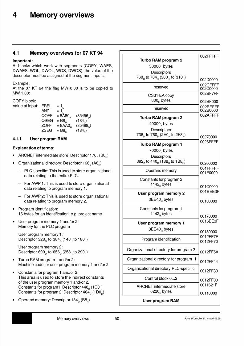
8/9/2019 Abb 07kt94 PLC
http://slidepdf.com/reader/full/abb-07kt94-plc 54/66
7.3 50 Advant Controller 31 / Issued: 06.99Memory overviews
4.1 Memory overviews for 07 KT 94
Important:At blocks which work with segments (COPY, WAES,DWAES, WOL, DWOL, WOS, DWOS), the value of thedescriptor must be assigned at the segment inputs.
Example:At the 07 KT 94 the flag MW 0,00 is to be copied toMW 1,00:
COPY block:Value at input: FREI = 1
D
ANZ = 1D
QOFF = 8A80H
(35456D)
QSEG = B8H (184D)ZOFF = 8AA0
H(35488
D)
ZSEG = B8H
(184D)
4.1.1 User program RAM
Explanation of terms:
• ARCNET intermediate store: Descriptor 176D (B0
H)
• Organizational directory: Descriptor 168D (A8
H)
– PLC-specific: This is used to store organizationaldata relating to the entire PLC.
– For AWP 1: This is used to store organizationaldata relating to program memory 1.
– For AWP 2: This is used to store organizationaldata relating to program memory 2.
• Program identification:16 bytes for an identification, e.g. project name
• User program memory 1 and/or 2:Memory for the PLC program
User program memory 1:Descriptor 328
D to 384
D (148
H to 180
H)
User program memory 2:Descriptor 600
D to 656
D (258
H to 290
H)
• Turbo RAM program 1 and/or 2:Machine code for user program memory 1 and/or 2
• Constants for program 1 and/or 2:This area is used to store the indirect constantsof the user program memory 1 and/or 2.Constants for program1: Descriptor 448
D (1C0
H)
Constants for program 2: Descriptor 464D (1D0
H)
• Operand memory: Descriptor 184D (B8
H)
4 Memory overviews
Turbo RAM program 230000
H bytes
Descriptors768
D to 784
D (300
H to 310
H)
reserved
CS31 EA copy800
H bytes
Turbo RAM program 2
40000H bytes
Descriptors736
D to 760
D (2E0
H to 2F8
H)
Turbo RAM program 1
70000H bytes
Descriptors392
D to 440
D (188
H to 1B8
H)
reserved
Operand memory
Constants for program 21142
H bytes
User program memory 2
3EE40H bytes
Program identification
Constants for program 11142
H bytes
User program memory 1
3EE40H bytes
Organizational directory for program 2
Organizational directory PLC-specific
Organizational directory for program 1
Control block 0...2
ARCNET intermediate store6220
H bytes
User program RAM
002FFFFF
002D0000
00270000
002BEFFF
002AFFFF002B0000
0026FFFF
00200000001FFFFF001F0000
001C0000001BEE3F
00180000
001700000016EE3F
001300000012FF7F
0012FF70
0012FF5A
0012FF44
0012FF30
0011621F0012FF00
00110000
002CFFFF002C0000002BF7FF
002BF000
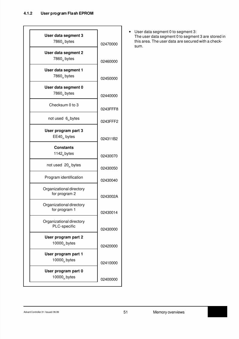
8/9/2019 Abb 07kt94 PLC
http://slidepdf.com/reader/full/abb-07kt94-plc 55/66
7.3Advant Controller 31 / Issued: 06.99 51 Memory overviews
Checksum 0 to 3
Program identification
02470000
0243FFF8
02450000
02440000
0243FFF2
024311B2
02430070
02430050
02430040
0243002A
02430014
02430000
02420000
02410000
02400000
02460000
4.1.2 User program Flash EPROM
User data segment 2
7860H bytes
User data segment 3
7860H bytes
User data segment 1
7860H bytes
User data segment 0
7860H bytes
not used 6H bytes
User program part 3
EE40H bytes
Constants
1142Hbytes
not used 20H bytes
Organizational directoryfor program 2
Organizational directoryfor program 1
Organizational directoryPLC-specific
User program part 210000
H bytes
User program part 1
10000H bytes
User program part 0
10000H bytes
• User data segment 0 to segment 3:The user data segment 0 to segment 3 are stored inthis area. The user data are secured with a check-sum.

8/9/2019 Abb 07kt94 PLC
http://slidepdf.com/reader/full/abb-07kt94-plc 56/66
7.3 52 Advant Controller 31 / Issued: 06.99Memory overviews
4.1.3 Operand memory 07 KT 94
SEG:F2001FF200
SEG:F100Stack 2
100H
1FF100
SEG:F000ASAS 100H
1FF000
SEG:EA80580H
1FEA80
SEG:DA80S
1000H
1FDA80
SEG:CA80MD
1000H
1FCA80
SEG:8A80MW
4000H
1F8A80
SEG:6A80M
2000H
1F6A80
SEG:6420AW
660H
1F6420
SEG:55E0A
E40H
1F55E0
SEG:4F80EW
660H
1F4F80
SEG:4140E
E40H
1F4140
SEG:3B40KD
600H
1F3B40
SEG:3000KW
B40H
1F3000
SEG:2FFEK
2H
1F2FFE
SEG:2EF0
Free Pool
10EH1F2EF0
SEG:2200CF0H
1F2200
SEG:0200VWS
2000H
1F0200
SEG:0100Stack 1
100H
1F0100
SEG:0000ASAS 1
100H
1F0000
SEG=001FH
(High word of the 32 bit address,descriptor 0B8
H = 184
DEC)
Explanation of terms:
ASAS 1: Work memory program 1
Stack1: Stack for program 1
VWS: Historical value memory
K: Indirect constants BINARYK 00,00...K 00,01
KW: Indirect constants WORD
KW 00,00...KW 89,15
KD: Indirect constants DOUBLE WORDKD 00,00...KD 23,15
E: Process image of the inputs BINARYE 00,00...E 99,15E 100...E 163,15E 200...E 263,15
EW: Process image of the inputs WORDEW 00,00...EW 34,15EW 100,00...EW 107,15
EW 200,00...EW 207,15A: Process image of the outputs BINARY
A 00,00...A 99,15A 100,00...A 163,15A 200,00...A 263,15
AW: Process image of the outputs WORDAW 00,00...AW 34,15AW 100,00...AW 107,15AW 200,00...AW 207,15
M: Flags BINARYM 00,00...M 511,15
MW: Flags WORDMW 00,00...MW 511,15
MD: Flags DOUBLEWORDMD 00,00...MD 63,15
S: Step chainsS 00,00...S 255,15
ASAS2: Work memory for program 2
Stack 2: Stack for program 2
Important:At blocks which work with segments (COPY, WAES,DWAES, WOL, DWOL, WOS, DWOS), the value of thedescriptor must be assigned at the segment inputs.
For examples see chapter 4.1.
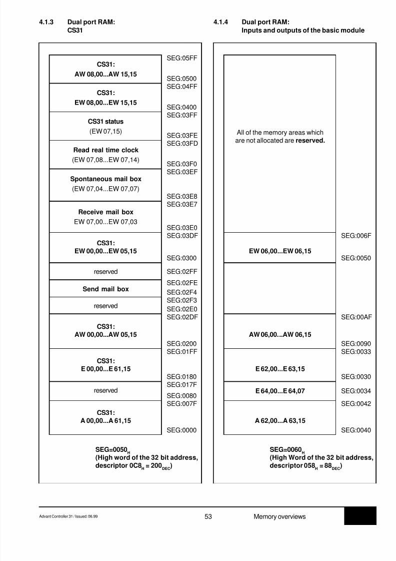
8/9/2019 Abb 07kt94 PLC
http://slidepdf.com/reader/full/abb-07kt94-plc 57/66
7.3Advant Controller 31 / Issued: 06.99 53 Memory overviews
reserved
SEG:0500
SEG:03FE
SEG:03E7
SEG:03DF
SEG:0300
SEG:02FE
SEG:02DF
SEG:0180
SEG:0080SEG:007F
SEG:0400
4.1.3 Dual port RAM:
CS31
CS31:
EW 08,00...EW 15,15
CS31:
AW 08,00...AW 15,15
CS31 status
(EW 07,15)
Read real time clock
(EW 07,08...EW 07,14)
Receive mail box
EW 07,00...EW 07,03
CS31:EW 00,00...EW 05,15
Spontaneous mail box
(EW 07,04...EW 07,07)
CS31:AW 00,00...AW 05,15
CS31:E 00,00...E 61,15
reserved
CS31:A 00,00...A 61,15
SEG:05FF
SEG:04FF
SEG:03FF
SEG:03FD
SEG:03E8
SEG:03E0
SEG:02FF
SEG:01FF
SEG:017F
SEG:0000
SEG:03F0SEG:03EF
Send mail box
SEG:02F4reserved
SEG:02F3
SEG:02E0
SEG:0200
SEG=0050H
(High word of the 32 bit address,descriptor 0C8
H = 200
DEC)
SEG:006F
SEG:0050
SEG:00AF
SEG:0030
SEG:0042
4.1.4 Dual port RAM:
Inputs and outputs of the basic module
EW 06,00...EW 06,15
AW 06,00...AW 06,15
E 62,00...E 63,15
A 62,00...A 63,15
SEG:0033
SEG:0040
SEG:0090
SEG=0060H
(High Word of the 32 bit address,descriptor 058
H = 88
DEC)
E 64,00...E 64,07 SEG:0034
All of the memory areas whichare not allocated are reserved.

8/9/2019 Abb 07kt94 PLC
http://slidepdf.com/reader/full/abb-07kt94-plc 58/66
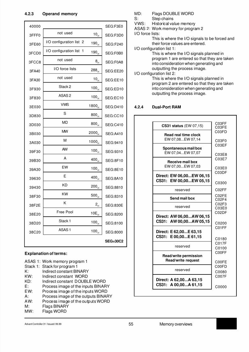
8/9/2019 Abb 07kt94 PLC
http://slidepdf.com/reader/full/abb-07kt94-plc 59/66
7.3Advant Controller 31 / Issued: 06.99 55 Memory overviews
4.2.3 Operand memory
SEG:F3E040000
not used 10H SEG:F3D03FFF0
I/O configuration list 2 190H SEG:F2403FE60
I/O configuration list 1 190H SEG:F0B03FCD0
not used 8H SEG:F0A83FCC8
I/O force lists 288H SEG:EE203FA40
not used 10H SEG:EE103FA30
Stack 2 100H SEG:ED103F930
ASAS 2 100H SEG:EC103F830
VWS 1800H SEG:D4103E030
S 800H SEG:CC103D830
MD 800H SEG:C4103D030
MW 2000H SEG:A4103B030
M 1000H SEG:94103A030
AW 100H SEG:931039F30
A 400H SEG:8F1039B30
EW 100H SEG:8E1039A30
E 400H SEG:8A1039630
KD 200H SEG:881039430
KW 500H SEG:831038F30
K 2H SEG:830E38F2E
Free Pool 10EH SEG:820038E20
Stack 1 100H SEG:810038D20
ASAS 1 100H SEG:800038C20
SEG=30C2
Explanation of terms:
ASAS 1: Work memory program 1Stack 1: Stack for program 1K: Indirect constant BINARYKW: Indirect constant WORDKD: Indirect constant DOUBLE WORDE: Process image of the inputs BINARYEW: Process image of the inputs WORDA: Process image of the outputs BINARYAW: Process image of the outputs WORD
M: Flags BINARYMW: Flags WORD
MD: Flags DOUBLE WORDS: Step chainsVWS: Historical value memoryASAS 2: Work memory for program 2I/O force lists:
This is where the I/O signals to be forced andtheir force values are entered.
I/O configuration list 1:This is where the I/O signals planned inprogram 1 are entered so that they are takeninto consideration when generating andoutputting the process image.
I/O configuration list 2:This is where the I/O signals planned inprogram 2 are entered so that they are takeninto consideration when generating andoutputting the process image.
4.2.4 Dual-Port RAM
C03FF
Read real time clockEW 07,08...EW 07,14
Spontaneous mail boxEW 07,04...EW 07,07
Receive mail boxEW 07,00...EW 07,03
Direct:CS31:
reserved
Send mail box
reserved
EW 06,00...EW 06,15EW 00,00...EW 05,15
Direct:CS31:
AW 06,00...AW 06,15AW 00,00...AW 05,15
Direct:CS31:
E 62,00...E 63,15E 00,00...E 61,15
reserved
CS31 status (EW 07,15)
Direct:CS31:
A 62,00...A 63,15A 00,00...A 61,15
Read/write permissionRead/write request
reserved
C03FEC03FD
C03F0C03EF
C03E8C03E7
C03E0C03DF
C0300
C02FF
C02FEC02F4C02F3C03E0C02DF
C0200
C0000
C007FC0080
C00FDC00FE
C00FFC0100
C017FC0180
C01FF

8/9/2019 Abb 07kt94 PLC
http://slidepdf.com/reader/full/abb-07kt94-plc 60/66
7.3 56 Advant Controller 31 / Issued: 05.99Functions in the instruction list
5.1 Texts in the instruction list
Some PLC blocks (DRUCK, EMAS) operate with textsstored in the user program.
Entering the texts in the user program
With a terminal, text is entered embedded in the codecharacters #" and "#. The key code character #" identifiesthe start of a text string and the key code character "#identifies the end of a text string.
All ASCII characters between 0H and 7F
H may be entered.
Storing the texts in the user program
Each text character entered occupies one word in the userprogram. The ASCII code of the text character is stored inthe low byte and the prefix FA is stored in the high byte.
Example:
Text entry and storage as of address 100 in the PLC pro-gram:
Entry: S 100 <CR>00100 NOP#"ABB"#<CR>
Storage: 00100 FA41
00101 FA4200102 FA42
5 Functions in the instruction list for 07 KR 91 and07 KT 92 to 07 KT 94
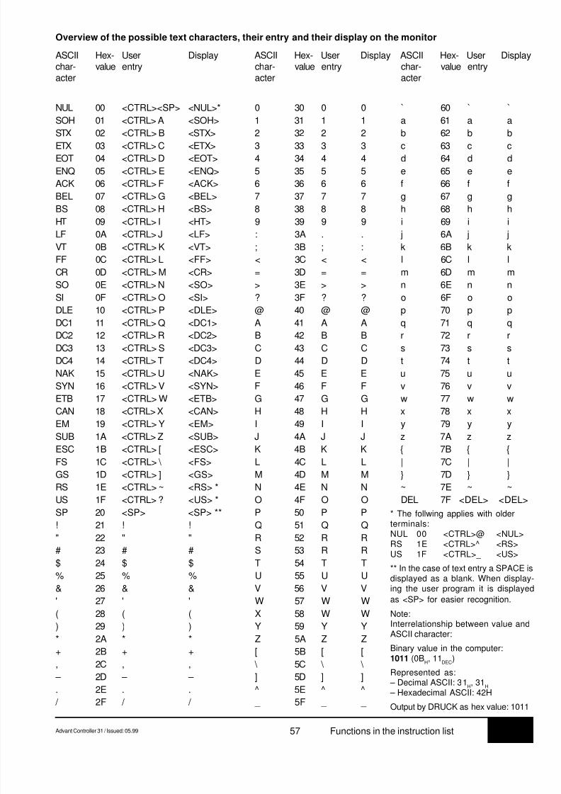
8/9/2019 Abb 07kt94 PLC
http://slidepdf.com/reader/full/abb-07kt94-plc 61/66
7.3Advant Controller 31 / Issued: 05.99 57 Functions in the instruction list
Overview of the possible text characters, their entry and their display on the monitor
ASCII Hex- User Display ASCII Hex- User Display ASCII Hex- User Displaychar- value entry char- value entry char- value entryacter acter acter
NUL 00 <CTRL><SP> <NUL>* 0 30 0 0 ` 60 ` `
SOH 01 <CTRL> A <SOH> 1 31 1 1 a 61 a a
STX 02 <CTRL> B <STX> 2 32 2 2 b 62 b b
ETX 03 <CTRL> C <ETX> 3 33 3 3 c 63 c c
EOT 04 <CTRL> D <EOT> 4 34 4 4 d 64 d d
ENQ 05 <CTRL> E <ENQ> 5 35 5 5 e 65 e e
ACK 06 <CTRL> F <ACK> 6 36 6 6 f 66 f f
BEL 07 <CTRL> G <BEL> 7 37 7 7 g 67 g g
BS 08 <CTRL> H <BS> 8 38 8 8 h 68 h h
HT 09 <CTRL> I <HT> 9 39 9 9 i 69 i i
LF 0A <CTRL> J <LF> : 3A . . j 6A j j
VT 0B <CTRL> K <VT> ; 3B ; : k 6B k k
FF 0C <CTRL> L <FF> < 3C < < l 6C l l
CR 0D <CTRL> M <CR> = 3D = = m 6D m m
SO 0E <CTRL> N <SO> > 3E > > n 6E n n
SI 0F <CTRL> O <SI> ? 3F ? ? o 6F o o
DLE 10 <CTRL> P <DLE> @ 40 @ @ p 70 p p
DC1 11 <CTRL> Q <DC1> A 41 A A q 71 q q
DC2 12 <CTRL> R <DC2> B 42 B B r 72 r r
DC3 13 <CTRL> S <DC3> C 43 C C s 73 s s
DC4 14 <CTRL> T <DC4> D 44 D D t 74 t t
NAK 15 <CTRL> U <NAK> E 45 E E u 75 u u
SYN 16 <CTRL> V <SYN> F 46 F F v 76 v v
ETB 17 <CTRL> W <ETB> G 47 G G w 77 w w
CAN 18 <CTRL> X <CAN> H 48 H H x 78 x x
EM 19 <CTRL> Y <EM> I 49 I I y 79 y y
SUB 1A <CTRL> Z <SUB> J 4A J J z 7A z z
ESC 1B <CTRL> [ <ESC> K 4B K K { 7B { {
FS 1C <CTRL> \ <FS> L 4C L L | 7C | |
GS 1D <CTRL> ] <GS> M 4D M M } 7D } }
RS 1E <CTRL> ~ <RS> * N 4E N N ~ 7E ~ ~
US 1F <CTRL> ? <US> * O 4F O O DEL 7F <DEL> <DEL>
SP 20 <SP> <SP> ** P 50 P P
! 21 ! ! Q 51 Q Q
" 22 " " R 52 R R
# 23 # # S 53 R R
$ 24 $ $ T 54 T T
% 25 % % U 55 U U
& 26 & & V 56 V V
' 27 ' ' W 57 W W
( 28 ( ( X 58 W W
) 29 ) ) Y 59 Y Y
* 2A * * Z 5A Z Z
+ 2B + + [ 5B [ [
, 2C , , \ 5C \ \
– 2D – – ] 5D ] ]
. 2E . . ^ 5E ^ ^
/ 2F / / _ 5F _ _
* The follwing applies with olderterminals:NUL 00 <CTRL>@ <NUL>RS 1E <CTRL>^ <RS>
US 1F <CTRL>_ <US>** In the case of text entry a SPACE isdisplayed as a blank. When display-ing the user program it is displayed
as <SP> for easier recognition.
Note:Interrelationship between value andASCII character:
Binary value in the computer:1011 (0B
H, 11
DEC)
Represented as: – Decimal ASCII: 31
H, 31
H
– Hexadecimal ASCII: 42HOutput by DRUCK as hex value: 1011

8/9/2019 Abb 07kt94 PLC
http://slidepdf.com/reader/full/abb-07kt94-plc 62/66
7.3 58 Advant Controller 31 / Issued: 05.99Functions in the instruction list
5.2 Syntax diagrams for instruction list (IL)
5.2.1 Syntax diagram: BOOLEAN SENTENCE
Signal flow: In the direction of the arrow, otherwise from left to right
Brackets: Sum "LEFT BRACKET" = Sum "RIGHT BRACKET", nesting depth: 15
B-OPR: Binary operand (E, A, M, S, K)Examples: E 00,03 A 07,15 M 05,01 S 05,04 K 00,01
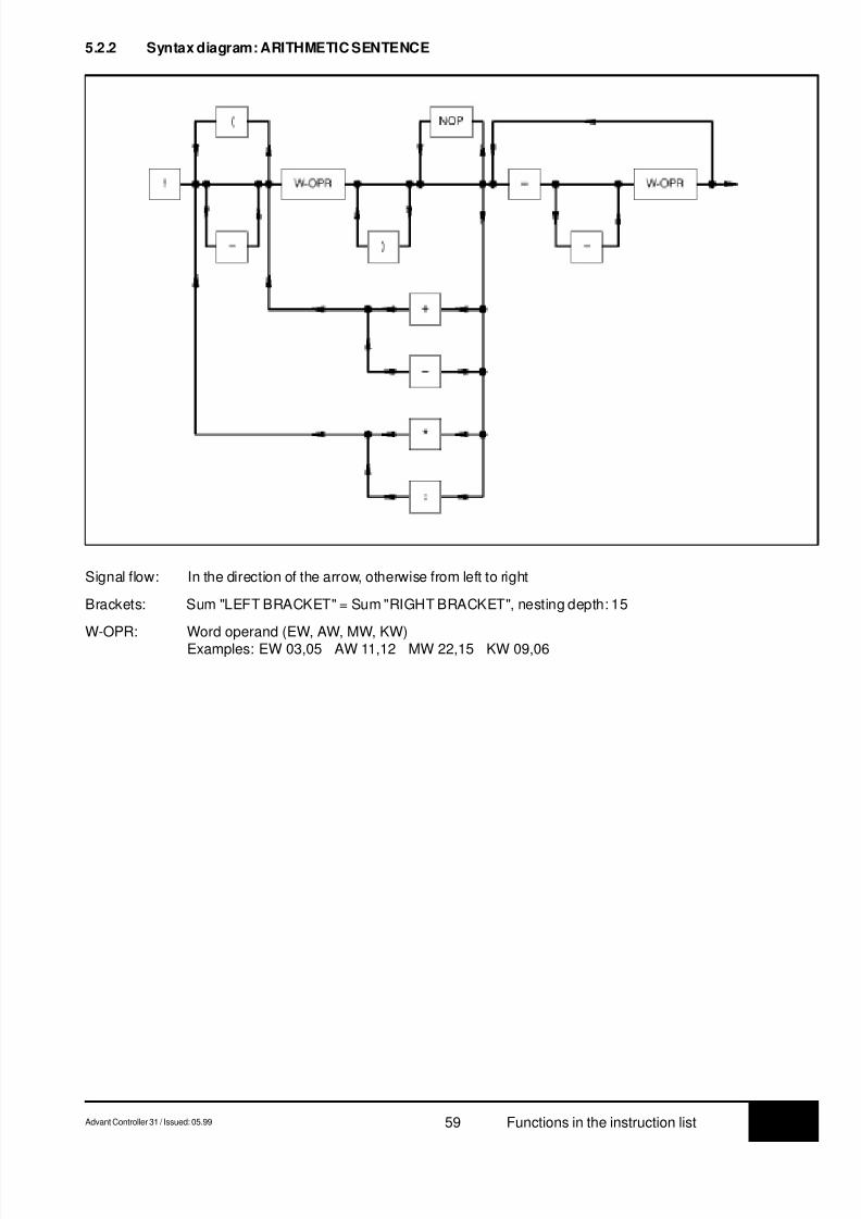
8/9/2019 Abb 07kt94 PLC
http://slidepdf.com/reader/full/abb-07kt94-plc 63/66
7.3Advant Controller 31 / Issued: 05.99 59 Functions in the instruction list
5.2.2 Syntax diagram: ARITHMETIC SENTENCE
Signal flow: In the direction of the arrow, otherwise from left to right
Brackets: Sum "LEFT BRACKET" = Sum "RIGHT BRACKET", nesting depth: 15
W-OPR: Word operand (EW, AW, MW, KW)Examples: EW 03,05 AW 11,12 MW 22,15 KW 09,06

8/9/2019 Abb 07kt94 PLC
http://slidepdf.com/reader/full/abb-07kt94-plc 64/66
7.3 60 Advant Controller 31 / Issued: 05.99Functions in the instruction list
5.2.3 Syntax diagram: HYBRID SENTENCE
see also chapter "Language repertoire", Relational operators
Signal flow: In the direction of the arrow, otherwise from left to right
Brackets: Sum "LEFT BRACKET" = Sum "RIGHT BRACKET", nesting depth: 15
W-OPR: Word operand (EW, AW, MW, KW)Examples: EW 03,05 AW 11,12 MW 22,15 KW 09,06
B-OPR: Binary operand (E, A, M, S, K)Examples: E 00,03 A 07,06 M 05,01

8/9/2019 Abb 07kt94 PLC
http://slidepdf.com/reader/full/abb-07kt94-plc 65/66

8/9/2019 Abb 07kt94 PLC
http://slidepdf.com/reader/full/abb-07kt94-plc 66/66