
A HIGH EFFICIENCY MICROTURBINE CONCEPT · A HIGH EFFICIENCY MICROTURBINE CONCEPT M. Malkamäki 1...
12
A HIGH EFFICIENCY MICROTURBINE CONCEPT M. Malkamäki 1 – A. Jaatinen-Värri 2 – J. Honkatukia 2 – J. Backman 2 – J. Larjola 2 1 Aurelia Turbines Oy, Lahti, Finland, [email protected] 2 Institute of Energy Technology, Lappeenranta University of Technology, Finland, [email protected] ABSTRACT – A HIGH EFFICIENCY MICROTURBINE CONCEPT There is a growing trend towards decentralized electricity and heat production throughout the world. Reciprocating engines and gas turbines have an essential role in the global decentralized energy markets and any improvement in their electrical efficiency has a significant impact from the environmental and economic viewpoints. This paper introduces an intercooled and recuperated two-shaft microturbine at 500 kW electric output range. The microturbine is optimized for a realistic combination of the turbine inlet temperature, the recuperation rate and the pressure ratio. The new microturbine design aims to achieve significantly increased performance within the range of microturbines and even competing with the efficiencies achieved in large industrial gas turbines. The simulated electrical efficiency is 45%. Improving the efficiency of combined heat and power (CHP) systems will significantly decrease the emissions and operating costs of decentralized heat and electricity production. Cost-effective, compact and environmentally friendly micro- and small-scale CHP turbine systems with high electrical efficiency will have an opportunity to successfully compete against reciprocating engines, which today are used in heat and power generation all over the world and manufactured in large production series. This paper presents a small-scale gas turbine process, capable of competing with reciprocating engine in terms of electrical efficiency. NOMENCLATURE Latin alphabet Abbreviations N speed, rpm AMB Active magnet bearings p pressure, bar Capex Capital expenditures qm mass flow, kg/s CHP Combined heat and power production T temperature, K GT Gas turbine t temperature, °C HP High-pressure HRSG Heat Recovery Steam Generator Greek alphabet LP Low-pressure LUT Lappeenranta University of Technology ε effectiveness OEM Original Engine Manufacturer η efficiency TIT Turbine inlet temperature π pressure ratio Subscripts e electric f fuel th thermal 1 Proceedings of 11 th European Conference on Turbomachinery Fluid dynamics & Thermodynamics ETC11, March 23-27, 2015, Madrid, Spain OPEN ACCESS Downloaded from www.euroturbo.eu Copyright © by the Authors
Transcript of A HIGH EFFICIENCY MICROTURBINE CONCEPT · A HIGH EFFICIENCY MICROTURBINE CONCEPT M. Malkamäki 1...
A HIGH EFFICIENCY MICROTURBINE CONCEPT
M. Malkamäki1 – A. Jaatinen-Värri2 – J. Honkatukia2 – J. Backman2 – J. Larjola2
1Aurelia Turbines Oy, Lahti, Finland, [email protected] 2Institute of Energy Technology, Lappeenranta University of Technology, Finland,
ABSTRACT – A HIGH EFFICIENCY MICROTURBINE CONCEPT There is a growing trend towards decentralized electricity and heat production throughout
the world. Reciprocating engines and gas turbines have an essential role in the global decentralized energy markets and any improvement in their electrical efficiency has a significant impact from the environmental and economic viewpoints.
This paper introduces an intercooled and recuperated two-shaft microturbine at 500 kW electric output range. The microturbine is optimized for a realistic combination of the turbine inlet temperature, the recuperation rate and the pressure ratio. The new microturbine design aims to achieve significantly increased performance within the range of microturbines and even competing with the efficiencies achieved in large industrial gas turbines. The simulated electrical efficiency is 45%.
Improving the efficiency of combined heat and power (CHP) systems will significantly decrease the emissions and operating costs of decentralized heat and electricity production. Cost-effective, compact and environmentally friendly micro- and small-scale CHP turbine systems with high electrical efficiency will have an opportunity to successfully compete against reciprocating engines, which today are used in heat and power generation all over the world and manufactured in large production series. This paper presents a small-scale gas turbine process, capable of competing with reciprocating engine in terms of electrical efficiency.
NOMENCLATURE Latin alphabet Abbreviations N speed, rpm AMB Active magnet bearings p pressure, bar Capex Capital expenditures qm mass flow, kg/s CHP Combined heat and power production T temperature, K GT Gas turbine t temperature, °C HP High-pressure HRSG Heat Recovery Steam Generator Greek alphabet LP Low-pressure LUT Lappeenranta University of Technology ε effectiveness OEM Original Engine Manufacturer η efficiency TIT Turbine inlet temperature π pressure ratio Subscripts e electric f fuel th thermal
1
Proceedings of
11th European Conference on Turbomachinery Fluid dynamics & Thermodynamics
ETC11, March 23-27, 2015, Madrid, Spain
OPEN ACCESS
Downloaded from www.euroturbo.eu Copyright © by the Authors
INTRODUCTION The distributed power generation is becoming more and more important part of power industry.
The distributed power generation can utilize different technologies, like wind, photovoltaic, biomass, natural gas, etc. Nevertheless, all the published documents seen so far only underline the growth of distributed power generation. Regarding the usage of gaseous and liquid fuels, Owens (2014) points out several reasons that drive the investments on distributed power installations: 1) quick installations, 2) smaller investments & operation costs, 3) possibility to increase capacity incrementally to meet the demand, 4) close proximity of the power plant to its customers. These reasons can be regarded general and they don’t as such make any difference to the technology used in the CHP plant. Actually, the only one that even slightly qualifies the CHP plant is the third reason by reflecting to the size of the plant.
The used technologies in liquid and gaseous fuel installations mostly comprise of reciprocating engines, gas turbines and microturbines. Of these, the reciprocating engines dominate the market below 3.5 MWe capacity level (DGTW, 2014). Typical new investments on this scale can be divided into standby, peaking and continuous driven applications. Furthermore, the continuous driven applications can be further divided into CHP and power-only installations. During 2013 of all the approximately 31 000 ordered engines and gas turbines in the range of 0.5 to 3.5 MWe, 14 000 units i.e. 45% were installed on continuous driven applications. Of these continuous driven applications, a majority is estimated to be plants without or only with partial heat recovery. As a summary of this, as the pure power generation from the small plants is the driving force for these applications, the net electrical efficiency of the installed plant is an essential figure for the investor. If this can be combined with flexible and highly efficient heat recovery, it is a bonus for the plant competitiveness.
Krulla et al. (2013) have estimated the near-term CHP market potential in USA. Even though the study was made from fuel cells’ point of view, it still shows the main structures of the market potential. In this study, the applications were divided into three categories by the electrical output; 1) below 100 kW, 2) 100 to 400 kW, and 3) 400 kW to 2 MW. According to the study, the installations in all of these categories totalled almost equally between 700 and 800. If one adds the investment costs and calculates the market size, the volume of the largest segment is about five times bigger than the smaller ones. Furthermore the same study underlines, that the biggest future potential on decentralized power-only market is in above 300 kWe installations.
The microturbines available at the market today comprise a set of products up to 330 kW from one single engine (FlexEnergy). Even larger units, up to 1 MW are being sold as one package (Capstone), but these are in reality a combination of 5 turbines each having an output of 200 kW. However, providing such a package directly from the OEM already underlines the need – and possibilities – of larger units.
These larger microturbines compete against reciprocating engines and small gas turbines. Of these, the non-regenerated gas turbines typically have the electrical efficiency below 25% and are thus used in special installations only. According to ASUE (2011) the reciprocating engines have electrical efficiencies up to 42% below 1 MW capacity.
Overall market potential of decentralized energy solutions is remarkable. According to Kiss et al. (2011), in Europe alone the natural gas based power generation will be increased by 122 GW to 178 GW from 2011 to 2025. According to DGTW (2014) the total orders for natural gas engines and turbines comprised 35 GW and investments below 3.5 MW capacity level were in total 3.5 GW. Thus it can be estimated that small- to midscale decentralized energy market on natural gas marks a good 10% of the total investment volume to the natural gas installations.
According to Owens (2014), this share is growing with an annual rate of 4.4%. Still, even with today’s numbers, based on average 1 000 € per kW investment rate, we are talking about some 12 000 million € total investment only in Europe and only in natural gas applications by 2025. According to Priddle et al. (2011) and COSPP (2013) the main growth for decentralized market does not exist in Europe, as China alone is estimated to invest according to its 12th and 13th five-year plan some 50 GW of new natural gas power plant capacity by 2020. As most of this is targeted to be below 6 MW
2
capacity level, the total market potential for China alone is carefully estimated multiple times bigger than the one in Europe.
In this study an intercooled and recuperated gas turbine process is studied from the technical and economical perspective. The commercial potential of the investigated turbine is mostly based on two factors; 1) the electrical efficiency, and 2) the possibility to utilize heat efficiently in a CHP application. On top of these factors, the investigated turbine will benefit of its flexibility in terms of fuel as it can utilize fuels like syngas that are difficult to utilize with the other existing technologies. This, however, is not within the scope of this presentation.
The technology presented in this study suits well to the market needs as it has comparable or even higher efficiency than the one of the reciprocating engines, matches with the market needs of bigger units and is still able to provide very flexible heat recovery possibilities for real estate and industrial applications.
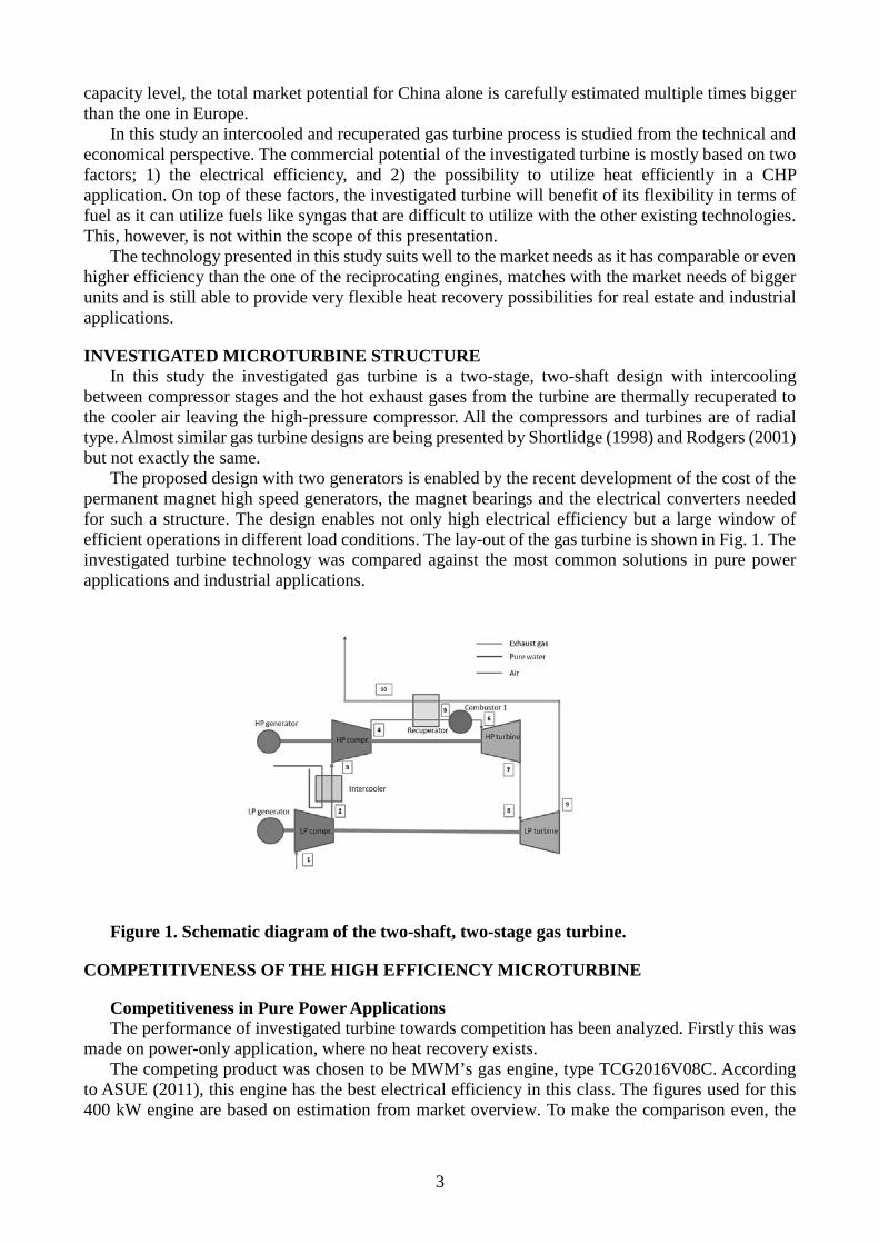
INVESTIGATED MICROTURBINE STRUCTURE In this study the investigated gas turbine is a two-stage, two-shaft design with intercooling
between compressor stages and the hot exhaust gases from the turbine are thermally recuperated to the cooler air leaving the high-pressure compressor. All the compressors and turbines are of radial type. Almost similar gas turbine designs are being presented by Shortlidge (1998) and Rodgers (2001) but not exactly the same.
The proposed design with two generators is enabled by the recent development of the cost of the permanent magnet high speed generators, the magnet bearings and the electrical converters needed for such a structure. The design enables not only high electrical efficiency but a large window of efficient operations in different load conditions. The lay-out of the gas turbine is shown in Fig. 1. The investigated turbine technology was compared against the most common solutions in pure power applications and industrial applications.
Figure 1. Schematic diagram of the two-shaft, two-stage gas turbine.
COMPETITIVENESS OF THE HIGH EFFICIENCY MICROTURBINE
Competitiveness in Pure Power Applications The performance of investigated turbine towards competition has been analyzed. Firstly this was
made on power-only application, where no heat recovery exists. The competing product was chosen to be MWM’s gas engine, type TCG2016V08C. According
to ASUE (2011), this engine has the best electrical efficiency in this class. The figures used for this 400 kW engine are based on estimation from market overview. To make the comparison even, the
3
investigated turbine was adjusted to be the same 400 kW in its size but to have the same efficiency as the real one has. For the investigated turbine the investment price was estimated to be 1 000 €/kW, i.e. 400 000 € as this is a target price set from the markets as described in introduction. For neither of the products, no project related costs were included in the calculation. Furthermore, the service costs of the investigated turbine were estimated to be 1.25 ct/kWhe, which can be regarded a safe estimate on a high-speed generator product with active magnetic bearings based on existing experiences. For the MWM engine the service cost was estimated to be 1.6 ct/kWhe. The higher service costs in the engine are due to the initial need and regular change of lubrication oil and the number of other, spare part changing services needed within the life-cycle.
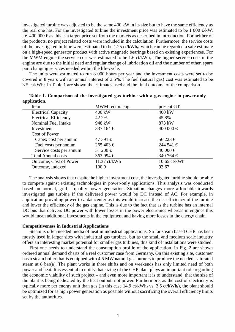
The units were estimated to run 8 000 hours per year and the investment costs were set to be covered in 8 years with an annual interest of 3.5%. The fuel (natural gas) cost was estimated to be 3.5 ct/kWhf. In Table 1 are shown the estimates used and the final outcome of the comparison.
Table 1. Comparison of the investigated gas turbine with a gas engine in power-only
application. Item MWM recipr. eng. present GT Electrical Capacity 400 kW 400 kW Electrical Efficiency 42.2% 45.8% Nominal Fuel Intake 948 kW 873 kW Investment 337 164 € 400 000 € Cost of Power Capex cost per annum 47 391 € 56 223 € Fuel costs per annum 265 403 € 244 541 € Service costs per annum 51 200 € 40 000 € Total Annual costs 363 994 € 340 764 € Outcome, Cost of Power Outcome, indexed
11.37 ct/kWh 100.0
10.65 ct/kWh 93.67
The analysis shows that despite the higher investment cost, the investigated turbine should be able
to compete against existing technologies in power-only applications. This analysis was conducted based on normal, grid – quality power generation. Situation changes more affordable towards investigated gas turbine if the delivered power would be DC instead of AC. For example, in application providing power to a datacenter as this would increase the net efficiency of the turbine and lower the efficiency of the gas engine. This is due to the fact that as the turbine has an internal DC bus that delivers DC power with lower losses in the power electronics whereas in engines this would mean additional investments in the equipment and having more losses in the energy chain.
Competitiveness in Industrial Applications Steam is often needed media of heat in industrial applications. So far steam based CHP has been
mostly used in larger sites with industrial gas turbines, but as the small and medium scale industry offers an interesting market potential for smaller gas turbines, this kind of installations were studied.
First one needs to understand the consumption profile of the application. In Fig. 2 are shown ordered annual demand charts of a real customer case from Germany. On this existing site, customer has a steam boiler that is equipped with 4.5 MW natural gas burners to produce the needed, saturated steam at 8 bar(a). The plant works in three shifts and on weekends has only limited need of both power and heat. It is essential to notify that sizing of the CHP plant plays an important role regarding the economic viability of such project – and even more important it is to understand, that the size of the plant is being dedicated by the heat output, not power. Furthermore, as the cost of electricity is typically more per energy unit than gas (in this case 14.9 ct/kWhe vs. 3.5 ct/kWhf), the plant should be optimized for as high power generation as possible without sacrificing the overall efficiency limits set by the authorities.
4
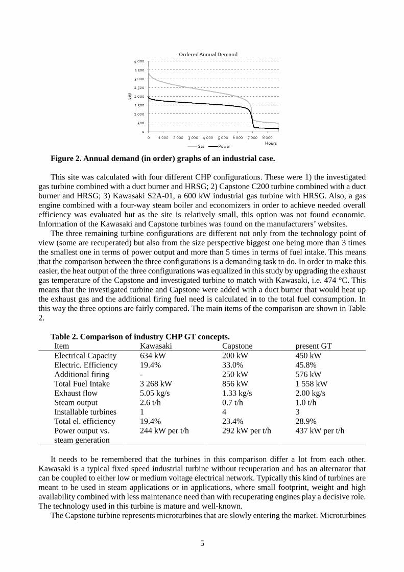
Figure 2. Annual demand (in order) graphs of an industrial case. This site was calculated with four different CHP configurations. These were 1) the investigated
gas turbine combined with a duct burner and HRSG; 2) Capstone C200 turbine combined with a duct burner and HRSG; 3) Kawasaki S2A-01, a 600 kW industrial gas turbine with HRSG. Also, a gas engine combined with a four-way steam boiler and economizers in order to achieve needed overall efficiency was evaluated but as the site is relatively small, this option was not found economic. Information of the Kawasaki and Capstone turbines was found on the manufacturers’ websites.
The three remaining turbine configurations are different not only from the technology point of view (some are recuperated) but also from the size perspective biggest one being more than 3 times the smallest one in terms of power output and more than 5 times in terms of fuel intake. This means that the comparison between the three configurations is a demanding task to do. In order to make this easier, the heat output of the three configurations was equalized in this study by upgrading the exhaust gas temperature of the Capstone and investigated turbine to match with Kawasaki, i.e. 474 °C. This means that the investigated turbine and Capstone were added with a duct burner that would heat up the exhaust gas and the additional firing fuel need is calculated in to the total fuel consumption. In this way the three options are fairly compared. The main items of the comparison are shown in Table 2.
Table 2. Comparison of industry CHP GT concepts. Item Kawasaki Capstone present GT Electrical Capacity 634 kW 200 kW 450 kW Electric. Efficiency 19.4% 33.0% 45.8% Additional firing - 250 kW 576 kW Total Fuel Intake 3 268 kW 856 kW 1 558 kW Exhaust flow 5.05 kg/s 1.33 kg/s 2.00 kg/s Steam output 2.6 t/h 0.7 t/h 1.0 t/h Installable turbines 1 4 3 Total el. efficiency 19.4% 23.4% 28.9% Power output vs. 244 kW per t/h 292 kW per t/h 437 kW per t/h steam generation
It needs to be remembered that the turbines in this comparison differ a lot from each other.
Kawasaki is a typical fixed speed industrial turbine without recuperation and has an alternator that can be coupled to either low or medium voltage electrical network. Typically this kind of turbines are meant to be used in steam applications or in applications, where small footprint, weight and high availability combined with less maintenance need than with recuperating engines play a decisive role. The technology used in this turbine is mature and well-known.
The Capstone turbine represents microturbines that are slowly entering the market. Microturbines
5
are younger technology than the conventional gas turbines are. Still, due to the new design methods and very rapid deployment of the power technology needed in these turbines also to other applications, the microturbines are becoming more and more competitive towards other technologies used in power generation. Microturbines are being sold to multiple different applications and the manufacturers are working hard to proof them being versatile in almost any installation. Yet one can’t state that a general acknowledgement of this technology has taken place at the market.
The following conclusions can be drawn from Table 2: 1) the heat output of industrial gas turbine is so big that only one of this kind of units can be installed on this site; 2) the total electrical efficiency of investigated turbine approaches the one of industrial turbines that are 10 to 20 times bigger in similar applications, and; 3) the power output vs. steam generated of the investigated turbine enables even three such turbines to be installed on this site. If this installation would be calculated with 6 500 full running hours (see the ordered annual demand in Fig. 2) for each option, this would mean that power produced by CHP covers of the total need (11 335 000 kWh) more than 77% for the investigated turbine and 36 % to 46% for Kawasaki and Capstone solutions respectively. Naturally, the higher this share is, the more profitable the plant will be for the customer.
GAS TURBINE PERFORMANCE ANALYSIS The optimum pressure ratio for a recuperated microturbine is usually below five. With moderate
turbine inlet temperatures a higher pressure ratio decreases the useful amount of available heat after the turbine (Kaikko, 1998). In this study these basic assumptions were tested in the intercooled and recuperated microturbine design. The study was done with LUT’s own simulation tool and retested with commercial simulation product (IPSEPro).
In this study the process values for a two-stage gas turbine process were optimized regarding the rotational speed, pressure ratio, turbine inlet temperature (TIT), and recuperation degree. In the first stage optimization pressure losses were omitted, and the working fluid was assumed to be air with constant properties (gas constant and specific heat capacity). In addition, the compressor and turbine polytropic efficiencies were assumed as constant, irrespective of the pressure ratios. The assumed efficiencies are realistic for lower pressure ratios, but with higher pressure ratios lead to somewhat overestimated cycle efficiency.
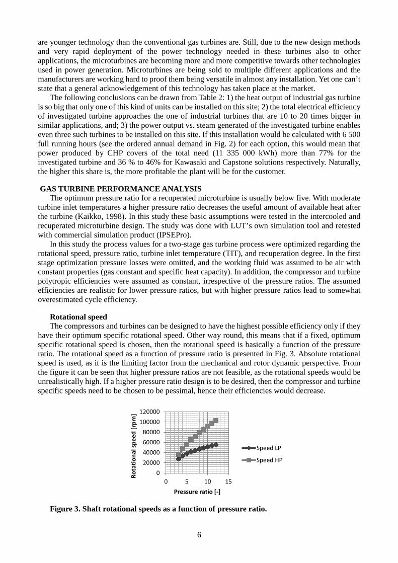
Rotational speed The compressors and turbines can be designed to have the highest possible efficiency only if they
have their optimum specific rotational speed. Other way round, this means that if a fixed, optimum specific rotational speed is chosen, then the rotational speed is basically a function of the pressure ratio. The rotational speed as a function of pressure ratio is presented in Fig. 3. Absolute rotational speed is used, as it is the limiting factor from the mechanical and rotor dynamic perspective. From the figure it can be seen that higher pressure ratios are not feasible, as the rotational speeds would be unrealistically high. If a higher pressure ratio design is to be desired, then the compressor and turbine specific speeds need to be chosen to be pessimal, hence their efficiencies would decrease.
Figure 3. Shaft rotational speeds as a function of pressure ratio.
020000400006000080000
100000120000
0 5 10 15
Rota
tiona
l spe
ed [r
pm]
Pressure ratio [-]
Speed LP
Speed HP
6
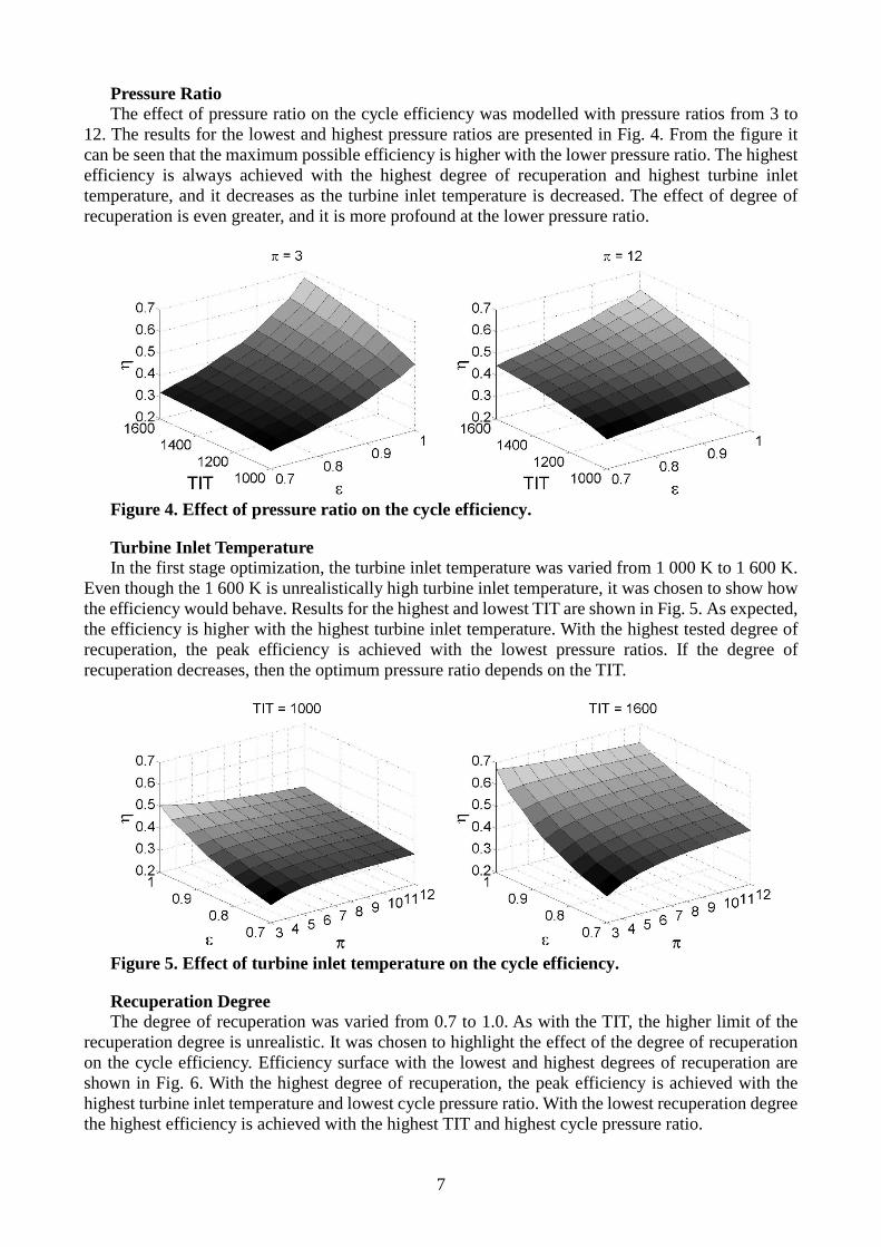
Pressure Ratio The effect of pressure ratio on the cycle efficiency was modelled with pressure ratios from 3 to
12. The results for the lowest and highest pressure ratios are presented in Fig. 4. From the figure it can be seen that the maximum possible efficiency is higher with the lower pressure ratio. The highest efficiency is always achieved with the highest degree of recuperation and highest turbine inlet temperature, and it decreases as the turbine inlet temperature is decreased. The effect of degree of recuperation is even greater, and it is more profound at the lower pressure ratio.
Figure 4. Effect of pressure ratio on the cycle efficiency.
Turbine Inlet Temperature In the first stage optimization, the turbine inlet temperature was varied from 1 000 K to 1 600 K.
Even though the 1 600 K is unrealistically high turbine inlet temperature, it was chosen to show how the efficiency would behave. Results for the highest and lowest TIT are shown in Fig. 5. As expected, the efficiency is higher with the highest turbine inlet temperature. With the highest tested degree of recuperation, the peak efficiency is achieved with the lowest pressure ratios. If the degree of recuperation decreases, then the optimum pressure ratio depends on the TIT.
Figure 5. Effect of turbine inlet temperature on the cycle efficiency.
Recuperation Degree The degree of recuperation was varied from 0.7 to 1.0. As with the TIT, the higher limit of the
recuperation degree is unrealistic. It was chosen to highlight the effect of the degree of recuperation on the cycle efficiency. Efficiency surface with the lowest and highest degrees of recuperation are shown in Fig. 6. With the highest degree of recuperation, the peak efficiency is achieved with the highest turbine inlet temperature and lowest cycle pressure ratio. With the lowest recuperation degree the highest efficiency is achieved with the highest TIT and highest cycle pressure ratio.
7
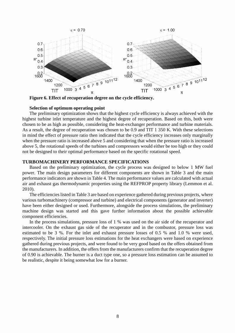
Figure 6. Effect of recuperation degree on the cycle efficiency.
Selection of optimum operating point The preliminary optimization shows that the highest cycle efficiency is always achieved with the
highest turbine inlet temperature and the highest degree of recuperation. Based on this, both were chosen to be as high as possible, considering the heat-exchanger performance and turbine materials. As a result, the degree of recuperation was chosen to be 0.9 and TIT 1 350 K. With these selections in mind the effect of pressure ratio then indicated that the cycle efficiency increases only marginally when the pressure ratio is increased above 5 and considering that when the pressure ratio is increased above 5, the rotational speeds of the turbines and compressors would either be too high or they could not be designed to their optimal performance based on the specific rotational speed.
TURBOMACHINERY PERFORMANCE SPECIFICATIONS Based on the preliminary optimization, the cycle process was designed to below 1 MW fuel
power. The main design parameters for different components are shown in Table 3 and the main performance indicators are shown in Table 4. The main performance values are calculated with actual air and exhaust gas thermodynamic properties using the REFPROP property library (Lemmon et al. 2010).
The efficiencies listed in Table 3 are based on experience gathered during previous projects, where various turbomachinery (compressor and turbine) and electrical components (generator and inverter) have been either designed or used. Furthermore, alongside the process simulations, the preliminary machine design was started and this gave further information about the possible achievable component efficiencies.
In the process simulations, pressure loss of 1 % was used on the air side of the recuperator and intercooler. On the exhaust gas side of the recuperator and in the combustor, pressure loss was estimated to be 3 %. For the inlet and exhaust pressure losses of 0.5 % and 1.0 % were used, respectively. The initial pressure loss estimations for the heat exchangers were based on experience gathered during previous projects, and were found to be very good based on the offers obtained from the manufacturers. In addition, the offers from the manufacturers confirm that the recuperation degree of 0.90 is achievable. The burner is a duct type one, so a pressure loss estimation can be assumed to be realistic, despite it being somewhat low for a burner.
8
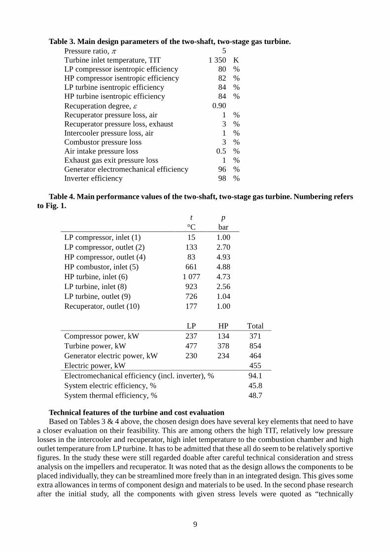
Table 3. Main design parameters of the two-shaft, two-stage gas turbine. Pressure ratio, π 5 Turbine inlet temperature, TIT 1 350 K LP compressor isentropic efficiency 80 % HP compressor isentropic efficiency 82 % LP turbine isentropic efficiency 84 % HP turbine isentropic efficiency 84 % Recuperation degree, ε 0.90 Recuperator pressure loss, air 1 % Recuperator pressure loss, exhaust 3 % Intercooler pressure loss, air 1 % Combustor pressure loss 3 % Air intake pressure loss 0.5 % Exhaust gas exit pressure loss 1 % Generator electromechanical efficiency 96 % Inverter efficiency 98 %
Table 4. Main performance values of the two-shaft, two-stage gas turbine. Numbering refers
to Fig. 1. t p °C bar LP compressor, inlet (1) 15 1.00 LP compressor, outlet (2) 133 2.70 HP compressor, outlet (4) 83 4.93 HP combustor, inlet (5) 661 4.88 HP turbine, inlet (6) 1 077 4.73 LP turbine, inlet (8) 923 2.56 LP turbine, outlet (9) 726 1.04 Recuperator, outlet (10) 177 1.00 LP HP Total Compressor power, kW 237 134 371 Turbine power, kW 477 378 854 Generator electric power, kW 230 234 464 Electric power, kW 455 Electromechanical efficiency (incl. inverter), % 94.1 System electric efficiency, % 45.8 System thermal efficiency, % 48.7
Technical features of the turbine and cost evaluation Based on Tables 3 & 4 above, the chosen design does have several key elements that need to have
a closer evaluation on their feasibility. This are among others the high TIT, relatively low pressure losses in the intercooler and recuperator, high inlet temperature to the combustion chamber and high outlet temperature from LP turbine. It has to be admitted that these all do seem to be relatively sportive figures. In the study these were still regarded doable after careful technical consideration and stress analysis on the impellers and recuperator. It was noted that as the design allows the components to be placed individually, they can be streamlined more freely than in an integrated design. This gives some extra allowances in terms of component design and materials to be used. In the second phase research after the initial study, all the components with given stress levels were quoted as “technically
9
possible” from all the relevant component suppliers. Another topic that will be raised from the use of – as an example – high graded steel alloys, is of
course the cost structure of the whole turbine. A brief calculation on this one has been done and again the possibility to keep the design simple for those high graded materials does seem to allow such manufacturing processes to be used that unrealistic costs would rise. This will be reviewed more carefully later in future research.
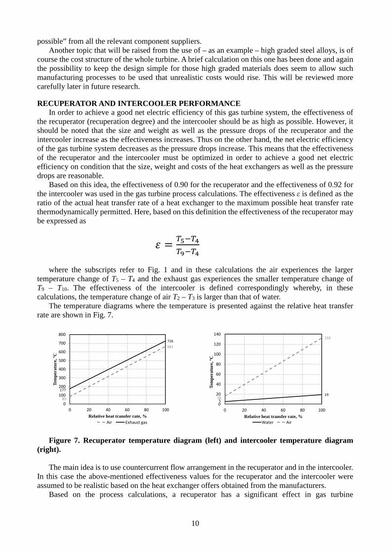
RECUPERATOR AND INTERCOOLER PERFORMANCE In order to achieve a good net electric efficiency of this gas turbine system, the effectiveness of
the recuperator (recuperation degree) and the intercooler should be as high as possible. However, it should be noted that the size and weight as well as the pressure drops of the recuperator and the intercooler increase as the effectiveness increases. Thus on the other hand, the net electric efficiency of the gas turbine system decreases as the pressure drops increase. This means that the effectiveness of the recuperator and the intercooler must be optimized in order to achieve a good net electric efficiency on condition that the size, weight and costs of the heat exchangers as well as the pressure drops are reasonable.
Based on this idea, the effectiveness of 0.90 for the recuperator and the effectiveness of 0.92 for the intercooler was used in the gas turbine process calculations. The effectiveness ε is defined as the ratio of the actual heat transfer rate of a heat exchanger to the maximum possible heat transfer rate thermodynamically permitted. Here, based on this definition the effectiveness of the recuperator may be expressed as
𝜀𝜀 = 𝑇𝑇5−𝑇𝑇4𝑇𝑇9−𝑇𝑇4
where the subscripts refer to Fig. 1 and in these calculations the air experiences the larger
temperature change of T5 – T4 and the exhaust gas experiences the smaller temperature change of T9 – T10. The effectiveness of the intercooler is defined correspondingly whereby, in these calculations, the temperature change of air T2 – T3 is larger than that of water.
The temperature diagrams where the temperature is presented against the relative heat transfer rate are shown in Fig. 7.
Figure 7. Recuperator temperature diagram (left) and intercooler temperature diagram
(right). The main idea is to use countercurrent flow arrangement in the recuperator and in the intercooler.
In this case the above-mentioned effectiveness values for the recuperator and the intercooler were assumed to be realistic based on the heat exchanger offers obtained from the manufacturers.
Based on the process calculations, a recuperator has a significant effect in gas turbine
83
661
177
726
0
100
200
300
400
500
600
700
800
0 20 40 60 80 100
Tem
pera
ture
, °C
Relative heat transfer rate, %Air Exhaust gas
519
16
133
0
20
40
60
80
100
120
140
0 20 40 60 80 100
Tem
pera
ture
, °C
Relative heat transfer rate, %Water Air
10
performance. Compared to a similar, non-intercooled process without a recuperator, using a recuperator with recuperation degree (effectiveness) of 0.90 increases the net electric efficiency of the gas turbine system by 20 percentage points, and intercooling with an intercooler effectiveness of 0.92 increases the efficiency further with another 3.5 percentage points.
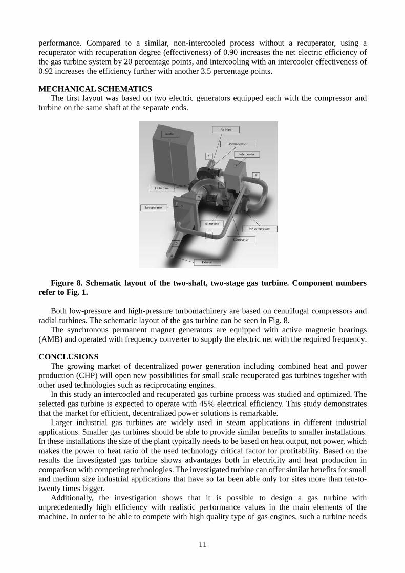
MECHANICAL SCHEMATICS The first layout was based on two electric generators equipped each with the compressor and
turbine on the same shaft at the separate ends.
Figure 8. Schematic layout of the two-shaft, two-stage gas turbine. Component numbers
refer to Fig. 1. Both low-pressure and high-pressure turbomachinery are based on centrifugal compressors and
radial turbines. The schematic layout of the gas turbine can be seen in Fig. 8. The synchronous permanent magnet generators are equipped with active magnetic bearings
(AMB) and operated with frequency converter to supply the electric net with the required frequency.
CONCLUSIONS The growing market of decentralized power generation including combined heat and power
production (CHP) will open new possibilities for small scale recuperated gas turbines together with other used technologies such as reciprocating engines.
In this study an intercooled and recuperated gas turbine process was studied and optimized. The selected gas turbine is expected to operate with 45% electrical efficiency. This study demonstrates that the market for efficient, decentralized power solutions is remarkable.
Larger industrial gas turbines are widely used in steam applications in different industrial applications. Smaller gas turbines should be able to provide similar benefits to smaller installations. In these installations the size of the plant typically needs to be based on heat output, not power, which makes the power to heat ratio of the used technology critical factor for profitability. Based on the results the investigated gas turbine shows advantages both in electricity and heat production in comparison with competing technologies. The investigated turbine can offer similar benefits for small and medium size industrial applications that have so far been able only for sites more than ten-to-twenty times bigger.
Additionally, the investigation shows that it is possible to design a gas turbine with unprecedentedly high efficiency with realistic performance values in the main elements of the machine. In order to be able to compete with high quality type of gas engines, such a turbine needs
11
to be based on special gas turbine concepts; these include recuperation, intercooling and two-spool design.
Based on the preliminary research Aurelia Turbines and LUT have started the detailed design of the two-shaft, two-stage intercooled and recuperated gas turbine and the first prototype is expected to be tested by the end of 2015.
ACKNOWLEDGEMENTS The authors gratefully acknowledge Tekes - the Finnish Funding Agency for Innovation, Ladec -
Lahti Region Development Company and Centre for Economic Development, Transport and the Environment / Lahti for their part in funding this project.
REFERENCES ASUE Arbeitsgemeinschaft für sparsamen und umweltfreundlichen Energieverbrauch e.V.
(2011), BHKW Kenndaten 2011, 64 pages COSPP China’s CHP expansion programme. (2013), In Co-Generation & On-Site Power
Production Magazine, May-June 2013, pages 38-42, www.cospp.com DGTW Diesel & Gasturbine Worldwide (2014), In the 38th Annual Orders Report Kaikko J. (1998), Performance prediction of gas turbines by solving a system of non-linear
equations, In Research Papers, Dissertation, Lappeenranta University of Technology. Kiss P., Murphy D. (2011), Power Sector Development in Europe – Lenders’ Perspectives 2011,
In KPMG Publications Krulla K. (ed., 2013), Assessment of the Distributed Generation Market Potential for Solid Oxide
Fuel Cells, In U.S. Department of Energy publications, DOE/NETL- 342/093013 Lemmon E.W, Huber M.L. and McLinden M.O. (2010), Reference fluid Thermodynamic and
Transport Properties (REFPROP), Version 9.0, National Institute of Standards and Technology. Owens B. (2014), The Rise of Distributed Power, In GE publication Priddle R (ed., 2011), Are we entering a golden age of gas?, In Special report – World Energy
Outlook 2011, IEA Publications Rodgers C. (2001), Microturbine Cycle Options, ASME Paper 2001-GT-0552 Shortlidge C. C. (1998), Control System for a 373 kW, Intercooled, Two-Spool Gas Turbine Engine
Powering a Hybrid Electric World Sports Car Class Vehicle, ASME Paper 1998-GT-120
12