BASICMICROdownloads.basicmicro.com/docs/roboclaw_user_manual.pdf• Fixed power up Home switch...
104
RoboClaw Series Brushed DC Motor Controllers RoboClaw Solo RoboClaw 2x5A RoboClaw 2x7A RoboClaw 2x15A RoboClaw 2x30A RoboClaw 2x45A RoboClaw 2x45A ST RoboClaw 2x60A Roboclaw 2x60HV Roboclaw 2x120A Roboclaw 2x160A Roboclaw 2x200A User Manual Firmware 4.1.20 and Newer Hardware V3, V4, V5 and V6 User Manual Revision 5.6 (c) 2014, 2015 Ion Motion Control. All Rights Reserved BASICMICRO
Transcript of BASICMICROdownloads.basicmicro.com/docs/roboclaw_user_manual.pdf• Fixed power up Home switch...
RoboClaw Series Brushed DC Motor ControllersRoboClaw SoloRoboClaw 2x5A RoboClaw 2x7ARoboClaw 2x15ARoboClaw 2x30ARoboClaw 2x45ARoboClaw 2x45A STRoboClaw 2x60A Roboclaw 2x60HVRoboclaw 2x120ARoboclaw 2x160ARoboclaw 2x200A
User Manual
Firmware 4.1.20 and NewerHardware V3, V4, V5 and V6User Manual Revision 5.6
(c) 2014, 2015 Ion Motion Control. All Rights Reserved
BASICMICRO
RoboClaw Series Brushed DC Motor Controllers
RoboClaw Series User Manual 2
BASICMICRO
ContentsFirmware History ................................................................................................8
Warnings ............................................................................................................9
Introduction .....................................................................................................10Motor Selection ........................................................................................... 10Stall Current ............................................................................................... 10Running Current .......................................................................................... 10Shut Down .................................................................................................. 10Run Away ................................................................................................... 10Wire Lengths ............................................................................................... 10Power Sources ............................................................................................. 10Logic Power ................................................................................................ 11Encoders .................................................................................................... 11
Getting Started .................................................................................................12Initial Setup ................................................................................................ 12Encoder Setup ............................................................................................. 12
Hardware Overview ..........................................................................................13I/O ............................................................................................................ 13Headers ...................................................................................................... 13Control Inputs ............................................................................................. 13Encoder Inputs ............................................................................................ 13Logic Battery (LB IN) .................................................................................... 13BEC Source (LB-MB) .................................................................................... 13Encoder Power (+ -) ..................................................................................... 14Main Battery Screw Terminals ........................................................................ 14Main Battery Disconnect ............................................................................... 14Motor Screw Terminals ................................................................................. 14Easy to use Libraries .................................................................................... 14
Ion Studio Overview .........................................................................................15Ion Studio................................................................................................... 15Connection ................................................................................................. 15Device Status .............................................................................................. 16Device Status Screen Layout ......................................................................... 16Status Indicator (4) ..................................................................................... 17General Settings .......................................................................................... 18Configuration Options ................................................................................... 18PWM Settings .............................................................................................. 19Velocity Settings .......................................................................................... 21Position Settings .......................................................................................... 23
Firmware Updates .............................................................................................26Ion Studio Setup ......................................................................................... 26Firmware Update ......................................................................................... 26
RoboClaw Series Brushed DC Motor Controllers
RoboClaw Series User Manual 3
BASICMICRO
Control Modes ...................................................................................................28Setup ......................................................................................................... 28USB Control ................................................................................................ 28RC ............................................................................................................. 28Analog ....................................................................................................... 28Simple Serial ............................................................................................... 28Packet Serial ............................................................................................... 28
Configuration Using Ion Studio .........................................................................29Mode Setup................................................................................................. 29Control Mode Setup ...................................................................................... 30Control Mode Options ................................................................................... 31
Configuration with Buttons ...............................................................................35Mode Setup................................................................................................. 35Modes ........................................................................................................ 35Mode Options .............................................................................................. 36RC and Analog Mode Options ......................................................................... 36Standard Serial and Packet Serial Mode Options ............................................... 36Battery Cut Off Settings ................................................................................ 37Battery Options ........................................................................................... 37
Battery Settings ................................................................................................38Automatic Battery Detection on Startup .......................................................... 38Manual Voltage Settings................................................................................ 38
Wiring ..............................................................................................................39Basic Wiring ................................................................................................ 39Safety Wiring .............................................................................................. 40Encoder Wiring ............................................................................................ 40Logic Battery Wiring ..................................................................................... 41Logic Battery Jumper.................................................................................... 41
Status LEDs .......................................................................................................42Status and Error LEDs .................................................................................. 42Message Types ............................................................................................ 42LED Blink Sequences .................................................................................... 43
Inputs ..............................................................................................................44S3, S4 and S5 Setup .................................................................................... 44Limit / Home / E-Stop Wiring ......................................................................... 45
Regenerative Voltage Clamping ........................................................................46Voltage Clamp ............................................................................................ 46Voltage Clamp Circuit ................................................................................... 46Voltage Clamp Setup and Testing ................................................................... 47
Bridge Mode ......................................................................................................48Bridging Channels ........................................................................................ 48Bridged Channel Wiring ................................................................................ 48Bridged Motor Control .................................................................................. 48
RoboClaw Series Brushed DC Motor Controllers
RoboClaw Series User Manual 4
BASICMICRO
USB Control ......................................................................................................49USB Connection ........................................................................................... 49USB Power .................................................................................................. 49USB Comport and Baudrate ........................................................................... 49
RC Control .........................................................................................................50RC Mode ..................................................................................................... 50RC Mode With Mixing .................................................................................... 50RC Mode with feedback for velocity or position control ...................................... 50RC Mode Options ......................................................................................... 50Pulse Ranges ............................................................................................... 50RC Wiring Example ...................................................................................... 51RC Control - Arduino Example ....................................................................... 52
Analog Control ..................................................................................................53Analog Mode ............................................................................................... 53Analog Mode With Mixing .............................................................................. 53Analog Mode with feedback for velocity or position control ................................. 53Analog Mode Options .................................................................................... 53Analog Wiring Example ................................................................................. 54
Stand Serial Control ..........................................................................................55Standard Serial Mode ................................................................................... 55Serial Mode Baud Rates ................................................................................ 55Standard Serial Command Syntax .................................................................. 55Standard Serial Wiring Example ..................................................................... 56Standard Serial Mode With Slave Select .......................................................... 57Standard Serial - Arduino Example ................................................................. 58
Packet Serial .....................................................................................................59Packet Serial Mode ....................................................................................... 59Address ...................................................................................................... 59Packet Modes .............................................................................................. 59Packet Serial Baud Rate ................................................................................ 59Serial Mode Options ..................................................................................... 59Packet Timeout ............................................................................................ 60Packet Acknowledgement .............................................................................. 60CRC16 Checksum Calculation ........................................................................ 60CRC16 Checksum Calculation for Received data ............................................... 60Easy to use Libraries .................................................................................... 60Handling values larger than a byte ................................................................. 61Packet Serial Wiring ..................................................................................... 62Multi-Unit Packet Serial Wiring ....................................................................... 63Commands 0 - 7 Compatibility Commands ...................................................... 640 - Drive Forward M1 .................................................................................... 641 - Drive Backwards M1 ................................................................................ 642 - Set Minimum Main Voltage (Command 57 Preferred) .................................. 643 - Set Maximum Main Voltage (Command 57 Preferred) .................................. 654 - Drive Forward M2 .................................................................................... 655 - Drive Backwards M2 ................................................................................ 656 - Drive M1 (7 Bit) ..................................................................................... 657 - Drive M2 (7 Bit) ..................................................................................... 65Commands 8 - 13 Mixed Mode Compatibility Commands ................................... 66
RoboClaw Series Brushed DC Motor Controllers
RoboClaw Series User Manual 5
BASICMICRO
8 - Drive Forward ......................................................................................... 669 - Drive Backwards ..................................................................................... 6610 - Turn right ............................................................................................. 6611 - Turn left ............................................................................................... 6612 - Drive Forward or Backward (7 Bit) ........................................................... 6613 - Turn Left or Right (7 Bit) ........................................................................ 66Packet Serial - Arduino Example .................................................................... 67
Advance Packet Serial .......................................................................................69Commands ................................................................................................. 6921 - Read Firmware Version .......................................................................... 7024 - Read Main Battery Voltage Level ............................................................. 7025 - Read Logic Battery Voltage Level ............................................................. 7026 - Set Minimum Logic Voltage Level ............................................................. 7027 - Set Maximum Logic Voltage Level ............................................................ 7148 - Read Motor PWM values ......................................................................... 7149 - Read Motor Currents .............................................................................. 7157 - Set Main Battery Voltages ...................................................................... 7158 - Set Logic Battery Voltages ...................................................................... 7159 - Read Main Battery Voltage Settings ......................................................... 7160 - Read Logic Battery Voltage Settings ......................................................... 7268 - Set M1 Default Duty Acceleration ............................................................ 7269 - Set M2 Default Duty Acceleration ............................................................ 7274 - Set S3, S4 and S5 Modes ....................................................................... 7275 - Get S3, S4 amd S5 Modes ...................................................................... 7376 - Set DeadBand for RC/Analog controls ...................................................... 7377 - Read DeadBand for RC/Analog controls .................................................... 7380 - Restore Defaults ................................................................................... 7381 - Read Default Duty Acceleration Settings ................................................... 7382 - Read Temperature ................................................................................. 7383 - Read Temperature 2 .............................................................................. 7390 - Read Status.......................................................................................... 7491 - Read Encoder Mode ............................................................................... 7492 - Set Motor 1 Encoder Mode ...................................................................... 7493 - Set Motor 2 Encoder Mode ...................................................................... 7494 - Write Settings to EEPROM ...................................................................... 7595 - Read Settings from EEPROM ................................................................... 7598 - Set Standard Config Settings .................................................................. 7699 - Read Standard Config Settings ................................................................ 77100 - Set CTRL Modes .................................................................................. 77101 - Read CTRL Modes ................................................................................ 77102 - Set CTRL1 .......................................................................................... 78103 - Set CTRL2 .......................................................................................... 78104 - Read CTRL Settings ............................................................................. 78133 - Set M1 Max Current Limit ..................................................................... 78134 - Set M2 Max Current Limit ..................................................................... 78135 - Read M1 Max Current Limit ................................................................... 78136 - Read M2 Max Current Limit ................................................................... 79148 - Set PWM Mode .................................................................................... 79149 - Read PWM Mode .................................................................................. 79
RoboClaw Series Brushed DC Motor Controllers
RoboClaw Series User Manual 6
BASICMICRO
Encoders ...........................................................................................................80Cloose Loop Modes....................................................................................... 80Encoder Tunning .......................................................................................... 80Quadrature Encoders Wiring .......................................................................... 80Absolute Encoder Wiring ............................................................................... 81Encoder Tuning ............................................................................................ 82Auto Tuning ................................................................................................ 82Manual Velocity Calibration Procedure ............................................................. 83Manual Position Calibration Procedure ............................................................. 83Encoder Commands ..................................................................................... 8516 - Read Encoder Count/Value M1 ................................................................ 8517 - Read Quadrature Encoder Count/Value M2 ................................................ 8618 - Read Encoder Speed M1 ......................................................................... 8619 - Read Encoder Speed M2 ......................................................................... 8620 - Reset Quadrature Encoder Counters ........................................................ 8622 - Set Quadrature Encoder 1 Value .............................................................. 8723 - Set Quadrature Encoder 2 Value .............................................................. 8730 - Read Raw Speed M1 .............................................................................. 8731 - Read Raw Speed M2 .............................................................................. 8778 - Read Encoder Counters .......................................................................... 8779 - Read ISpeeds Counters .......................................................................... 87
Advance Motor Control ......................................................................................88Advanced Motor Control Commands ............................................................... 8828 - Set Velocity PID Constants M1 ................................................................ 8929 - Set Velocity PID Constants M2 ................................................................ 8932 - Drive M1 With Signed Duty Cycle ............................................................ 8933 - Drive M2 With Signed Duty Cycle ............................................................ 9034 - Drive M1 / M2 With Signed Duty Cycle ..................................................... 9035 - Drive M1 With Signed Speed ................................................................... 9136 - Drive M2 With Signed Speed ................................................................... 9137 - Drive M1 / M2 With Signed Speed ........................................................... 9138 - Drive M1 With Signed Speed And Acceleration ........................................... 9139 - Drive M2 With Signed Speed And Acceleration ........................................... 9240 - Drive M1 / M2 With Signed Speed And Acceleration ................................... 9241 - Buffered M1 Drive With Signed Speed And Distance ................................... 9242 - Buffered M2 Drive With Signed Speed And Distance ................................... 9343 - Buffered Drive M1 / M2 With Signed Speed And Distance ........................... 9344 - Buffered M1 Drive With Signed Speed, Accel And Distance .......................... 9345 - Buffered M2 Drive With Signed Speed, Accel And Distance .......................... 9446 - Buffered Drive M1 / M2 With Signed Speed, Accel And Distance................... 9447 - Read Buffer Length ................................................................................ 9450 - Drive M1 / M2 With Signed Speed And Individual Acceleration ..................... 9551 - Buffered Drive M1 / M2 With Signed Speed, Individual Accel And Distance .... 9552 - Drive M1 With Signed Duty And Acceleration ............................................. 9553 - Drive M2 With Signed Duty And Acceleration ............................................. 9654 - Drive M1 / M2 With Signed Duty And Acceleration ..................................... 9655 - Read Motor 1 Velocity PID and QPPS Settings............................................ 9656 - Read Motor 2 Velocity PID and QPPS Settings............................................ 9661 - Set Motor 1 Position PID Constants .......................................................... 9662 - Set Motor 2 Position PID Constants .......................................................... 9763 - Read Motor 1 Position PID Constants ....................................................... 9764 - Read Motor 2 Position PID Constants ....................................................... 97
RoboClaw Series Brushed DC Motor Controllers
RoboClaw Series User Manual 7
BASICMICRO
65 - Buffered Drive M1 with signed Speed, Accel, Deccel and Position ................. 9766 - Buffered Drive M2 with signed Speed, Accel, Deccel and Position ................. 9767 - Buffered Drive M1 & M2 with signed Speed, Accel, Deccel and Position ......... 98
Reading Quadrature Encoder - Arduino Example............................................... 99Speed Controlled by Quadrature Encoders - Arduino Example ...........................101
Warranty ........................................................................................................104Copyrights and Trademarks ............................................................................104Disclaimer .......................................................................................................104Contacts ..........................................................................................................104Discussion List ................................................................................................104Technical Support ...........................................................................................104
RoboClaw Series Brushed DC Motor Controllers
RoboClaw Series User Manual 8
BASICMICRO
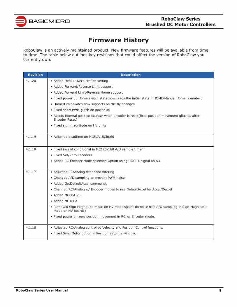
Firmware HistoryRoboClaw is an actively maintained product. New firmware features will be available from time to time. The table below outlines key revisions that could affect the version of RoboClaw you currently own.
Revision Description
4.1.20 • Added Default Deceleration setting
• Added Forward/Reverse Limit support
• Added Forward Limit/Reverse Home support
• Fixed power up Home switch state(now reads the initial state if HOME/Manual Home is enabeld
• Home/Limit switch now supports on the fly changes
• Fixed short PWM glitch on power up
• Resets internal position counter when encoder is reset(fixes position movement glitches after Encoder Reset)
• Fixed sign magnitude on HV units
4.1.19 • Adjusted deadtime on MC5,7,15,30,60
4.1.18 • Fixed invalid conditional in MC120-160 A/D sample timer
• Fixed Set/Zero Encoders
• Added RC Encoder Mode selection Option using RC/TTL signal on S3
4.1.17 • Adjusted RC/Analog deadband filtering
• Changed A/D sampling to prevent PWM noise
• Added GetDefaultAccel commands
• Changed RC/Analog w/ Encoder modes to use DefaultAccel for Accel/Deccel
• Added MC60A V5
• Added MC160A
• Removed Sign Magnitude mode on HV models(cant do noise free A/D sampling in Sign Magnitude mode on HV boards)
• Fixed power on zero position movement in RC w/ Encoder mode.
4.1.16 • Adjusted RC/Analog controlled Velocity and Position Control functions.
• Fixed Sync Motor option in Position Settings window.
RoboClaw Series Brushed DC Motor Controllers
RoboClaw Series User Manual 9
BASICMICRO
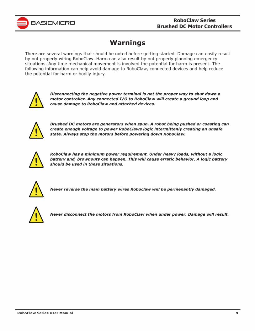
WarningsThere are several warnings that should be noted before getting started. Damage can easily result by not properly wiring RoboClaw. Harm can also result by not properly planning emergency situations. Any time mechanical movement is involved the potential for harm is present. The following information can help avoid damage to RoboClaw, connected devices and help reduce the potential for harm or bodily injury.
Disconnecting the negative power terminal is not the proper way to shut down a motor controller. Any connected I/O to RoboClaw will create a ground loop and cause damage to RoboClaw and attached devices.
Brushed DC motors are generators when spun. A robot being pushed or coasting can create enough voltage to power RoboClaws logic intermittenly creating an unsafe state. Always stop the motors before powering down RoboClaw.
RoboClaw has a minimum power requirement. Under heavy loads, without a logic battery and, brownouts can happen. This will cause erratic behavior. A logic battery should be used in these situations.
Never reverse the main battery wires Roboclaw will be permenantly damaged.
Never disconnect the motors from RoboClaw when under power. Damage will result.
!
!
!
!
!
RoboClaw Series Brushed DC Motor Controllers
RoboClaw Series User Manual 10
BASICMICRO
IntroductionMotor Selection
When selecting a motor controller several factors should be considered. All DC brushed motors will have two current ratings, maximum stall current and continuous current. The most important rating is the stall current. Choose a model that can support the stall current of the motor selected to insure the motor can be driven properly without damage to the motor controller.
Stall CurrentA motor at rest is in a stall condition. This means during start up the motors stall current will be reached. The loading of the motor will determine how long maximum stall current is required. A motor that is required to start and stop or change directions rapidly but with light load will still require maximum stall current often.
Running CurrentThe continuous current rating of a motor is the maximum current the motor can run without overheating and eventually failing. The average running current of the motor should not excede the continuous current rating of the motor.
Shut DownTo shut down a motor controller the positive power connections should be removed first after the motors have stopped moving. Powering off in an emergency, a properly sized switch or contactor can be used. A path to ground for regeneration energy to return to the battery should always be provided. This can be accomplish by using a power diode with proper ratings to provide a path across the switch or contactor when in an open circuit state.
Run AwayDuring development of your project caution should be taken to avoid run away conditions. The wheels of a robot should not be in contact with any surface until all development is complete. If the motor is embedded, ensure you have a safe and easy method to remove power from RoboClaw as a fail safe.
Wire LengthsWire lengths to the motors and from the battery should be kept as short as possible. Longer wires will create increased inductance which will produce undesirable effects such as electrical noise or increased current and voltage ripple. The power supply/battery wires must be as short as possible. They should also be sized appropriately for the amout of current being drawn. Increased inductance in the power source wires will increase the ripple current/voltage at the RoboClaw which can damage the filter caps on the board or even causing voltage spikes over the rated voltage of the Roboclaw, leading to board failure.
Power SourcesA battery is recommended as the main power source for the motor controller. Some power supplies can also be used without additional hardware if they have built in voltage clamps or if used with very low current motors. Most Linear and Switching power supplies are not capable of handling the regeneration energy generated by DC motors. Switching power supplies will momentarily reduce voltage and/or shut down, causing brown outs which will leave the controller in an unsafe state. The MCPs minimum and maximum voltage levels can be set to prevent some of these voltage spikes, however this will cause the motors to brake when slowing down in an attempt to reduce the over voltage spikes. This will also limit power output when accelerating motors or when the load changes to prevent undervoltage conditions. Voltage clamp solutions may be required for higher power motors when using power supplies.
RoboClaw Series Brushed DC Motor Controllers
RoboClaw Series User Manual 11
BASICMICRO
Logic PowerWhen powering external devices from RoboClaw ensure the maximum BEC output rating is not exceeded. This can cause RoboClaw to suffer logic brown out which will cause erratic behavior. Some low quality encoders can cause excessive noise being put on the +5VDC rail of the RoboClaw. This excessive noise will cause unpredictable behavior.
EncodersRoboClaw features dual channel quadrature/absolute decoding. When wiring encoders make sure the direction of spin is correct to the motor direction. Incorrect encoder connections can cause a run away state. Refer to the encoder section of this user manual for proper setup.
RoboClaw Series Brushed DC Motor Controllers
RoboClaw Series User Manual 12
BASICMICRO
Getting StartedInitial Setup
RoboClaw offers several methods of control. Each control scheme has several configuration options. The following is quick start guide which will cover the basic initialization of RoboClaw. Most control schemes require very little configuration. The control options are covered in detail in this manual. The following is a basic setup procedure.
1. Read the Introduction and Hardware Overview sections of this manual. It is important to ensure the RoboClaw model chosen is rated to drive the selected motors. RoboClaw must be paired by the motor stall current ratings. Not running current.
2. Before configuring RoboClaw. Make sure a reliable power source is available such as a fully charged battery. See Wiring section of this manual for proper wiring instructions.
3. The RoboClaw main modes can be configured using Ion Studio or on-board buttons. Ion Studio is the preferred method of configuration with additional options not available using the on-board buttons. However these additional options are not critical to RoboClaw's operation. This manual covers both configuration methods.
4. Once the configuration is complete see Wiring section of this manual. The basic wiring diagram should only be used for basic for testing purposes. The Safety Wiring diagram is recommended for safe and reliable operation.
Encoder SetupRoboClaw supports several encoder types. All encoders require tunning to properly pair with the selected motors. The auto tune function can automatically tune for most all combinations. However some manual adjustment maybe required. The final auto tune settings can be adjusted for optimal performance.
1. Once Initial Setup is complete. Attached an encoder to your motor and wire as shown in the encoder section of this manual. Make sure the encoder can be powered from a 5VDC power source.
2. After the encoder is wired double check the wiring. Then proceed to the auto tune function in the Encoder section of this manual.
3. Auto tune will work in most all cases. Some manual tweaks may be necessary. If additional assistance is required contact support at [email protected]
RoboClaw Series Brushed DC Motor Controllers
RoboClaw Series User Manual 13
BASICMICRO
Hardware OverviewI/O
RoboClaw's I/O is setup to interface to both 5V and 3.3V logic. This is accomplished by internally current limiting and clipping any voltages over 3.3V. RoboClaw outputs 3.3V which will work with any 5V or 3.3V logic. This is also done to protect the I/O from damage.
HeadersRoboClaw's share the same header and screw terminal pinouts accross models in this user manual. The main control I/O are arranged for easy connectivity to control devices such as R/C controllers. The headers are also arranged to provide easy access to ground and power for supplying power to external controllers. see the specific model of RoboClaw's data sheet for pinout details.
Control InputsS1, S2, S3, S4 and S5 are setup for standard servo style headers I/O(except on ST models), +5V and GND. S1 and S2 are the control inputs for serial, analog and RC modes. S3 can be used as a flip switch input when in RC or Analog modes. In serial mode S3, S4 and S5 can be used as emergency stop inputs or as voltage clamp control outputs. When set as E-Stop inputs they are active when pulled low and have internal pullups so they will not accidentally trip when left floating. S4 and S5 can also optionally be used as home signal inputs. The pins closest to the board edge are the I/0s, center pin is the +5V and the inside pins are ground. Some RC receivers have their own supply and will conflict with the RoboClaw’s 5v logic supply. It may be necessary to remove the +5V pin from the RC receivers cable in those cases.
Encoder InputsEN1 and EN2 are the inputs from the encoders on pin header versions of RoboClaw. 1B, 1A, 2B and 2A are the encoders inputs on screw terminal versions of RoboClaw. Channel A of both EN1 and EN2 are located at the board edge on the pin header. Channel B pins are located near the heatsink on the pin header. The A and B channels are labeled appropriately on screw terminal versions.
When connecting the encoder make sure the leading channel for the direction of rotation is connected to A. If one encoder is backwards to the other you will have one internal counter counting up and the other counting down. Refer to the data sheet of the encoder you are using for channel direction. Which encoder is used on which motor can be swapped via a software setting.
Logic Battery (LB IN)
The logic side of RoboClaw can be powered from a secondary battery wired to LB IN. The positive (+) terminal is located at the board edge and ground (-) is the inside pin closest to the heatsink. Remove the LB-MB jumper if a secondary battery for logic will be used.
BEC Source (LB-MB)RoboClaw logic requires 5VDC which is provided from the on board BEC circuit. The BEC source input is set with the LB-MB jumper. Install a jumper on the 2 pins labeled LB-MB to use the main battery as the BEC power source. Remove this jumper if using a separate logic battery. On models without this jumper the power source is selected automatically.
RoboClaw Series Brushed DC Motor Controllers
RoboClaw Series User Manual 14
BASICMICRO
Encoder Power (+ -)The pins labeled + and - are the source power pins for encoders. The positive (+) is located at the board edge and supplies +5VDC. The ground (-) pin is near the heatsink. On ST models all power must come from the single 5v screw terminal and the single GND screw terminal
Main Battery Screw TerminalsThe main power input can be from 6VDC to 34VDC on a standard RoboClaw and 10.5VDC to 60VDC on an HV (High Voltage) RoboClaw. The connections are marked + and - on the main screw terminal. The plus (+) symbol marks the positive terminal and the negative (-) marks the negative terminal. The main battery wires should be as short as possible.
Do not reverse main battery wires. Roboclaw will be permenantly damaged.
Main Battery DisconnectThe main battery should have a disconnect in case of a run away situation and power needs to be cut. The switch must be rated to handle the maximum current and voltage from the battery. This will vary depending on the type of motors and or power source you are using. A typically solution would be an inexpensive contactor which can be sourced from sites like Ebay. A power diode rated for the maximum current the battery will deliver should be placed across the switch/contactor to provide a path back to the battery when disconnected while the motors are spinning. The diode will provice a path back to the battery for regenerative power even if the switch is opened.
Motor Screw TerminalsThe motor screw terminals are marked with M1A / M1B for channel 1 and M2A / M2B for channel 2. For both motors to turn in the same direction the wiring of one motor should be reversed from the other in a typical differential drive robot. The motor and battery wires should be as short as possible. Long wires can increase the inductance and therefore increase potentially harmful voltage spikes.
Easy to use LibrariesSource code and Libraries are available on the Ion Motion Control website. Libraries are available for Arduino(C++), C# on Windows(.NET) or Linux(Mono) and Python(Raspberry Pi, Linux, OSX, etc).
!
RoboClaw Series Brushed DC Motor Controllers
RoboClaw Series User Manual 15
BASICMICRO
Ion Studio OverviewIon Studio
The Ion Studio software suite is design to configure, monitor and maintain RoboClaw. It's used to configure all the available RoboClaw modes and options. Ion Studio can be used to monitor and control RoboClaw. It can be download from http://www.ionmc.com. Once installed, each time Ion Studio is ran it will check for the latest version online.
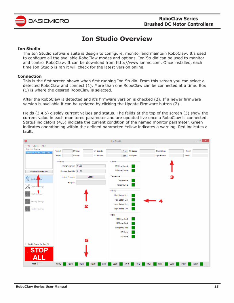
ConnectionThis is the first screen shown when first running Ion Studio. From this screen you can select a detected RoboClaw and connect (1). More than one RoboClaw can be connected at a time. Box (1) is where the desired RoboClaw is selected.
After the RoboClaw is detected and it's firmware version is checked (2). If a newer firmware version is available it can be updated by clicking the Update Firmware button (2).
Fields (3,4,5) display current values and status. The feilds at the top of the screen (3) show the current value in each monitored parameter and are updated live once a RoboClaw is connected. Status indicators (4,5) indicate the current condition of the named monitor parameter. Green indicates operationing within the defined parameter. Yellow indicates a warning. Red indicates a fault.
24
1
5
3
RoboClaw Series Brushed DC Motor Controllers
RoboClaw Series User Manual 16
BASICMICRO
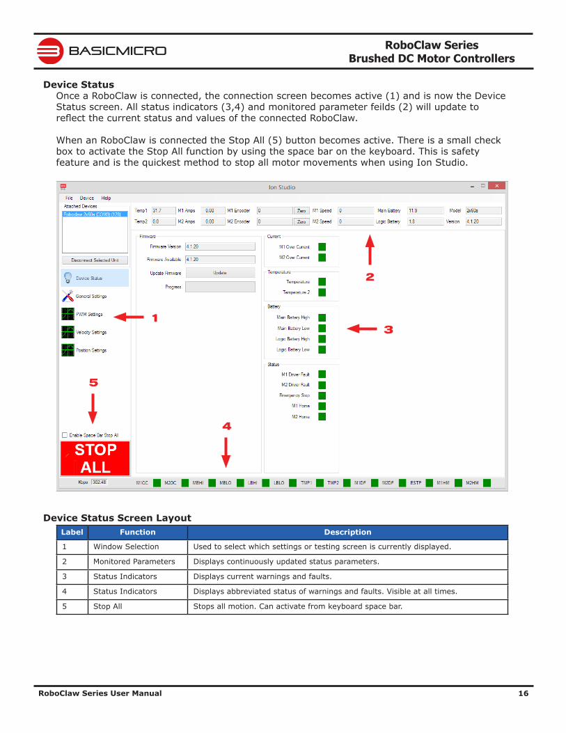
Device StatusOnce a RoboClaw is connected, the connection screen becomes active (1) and is now the Device Status screen. All status indicators (3,4) and monitored parameter feilds (2) will update to reflect the current status and values of the connected RoboClaw.
When an RoboClaw is connected the Stop All (5) button becomes active. There is a small check box to activate the Stop All function by using the space bar on the keyboard. This is safety feature and is the quickest method to stop all motor movements when using Ion Studio.
Device Status Screen LayoutLabel Function Description
1 Window Selection Used to select which settings or testing screen is currently displayed.
2 Monitored Parameters Displays continuously updated status parameters.
3 Status Indicators Displays current warnings and faults.
4 Status Indicators Displays abbreviated status of warnings and faults. Visible at all times.
5 Stop All Stops all motion. Can activate from keyboard space bar.
4
2
13
5
RoboClaw Series Brushed DC Motor Controllers
RoboClaw Series User Manual 17
BASICMICRO
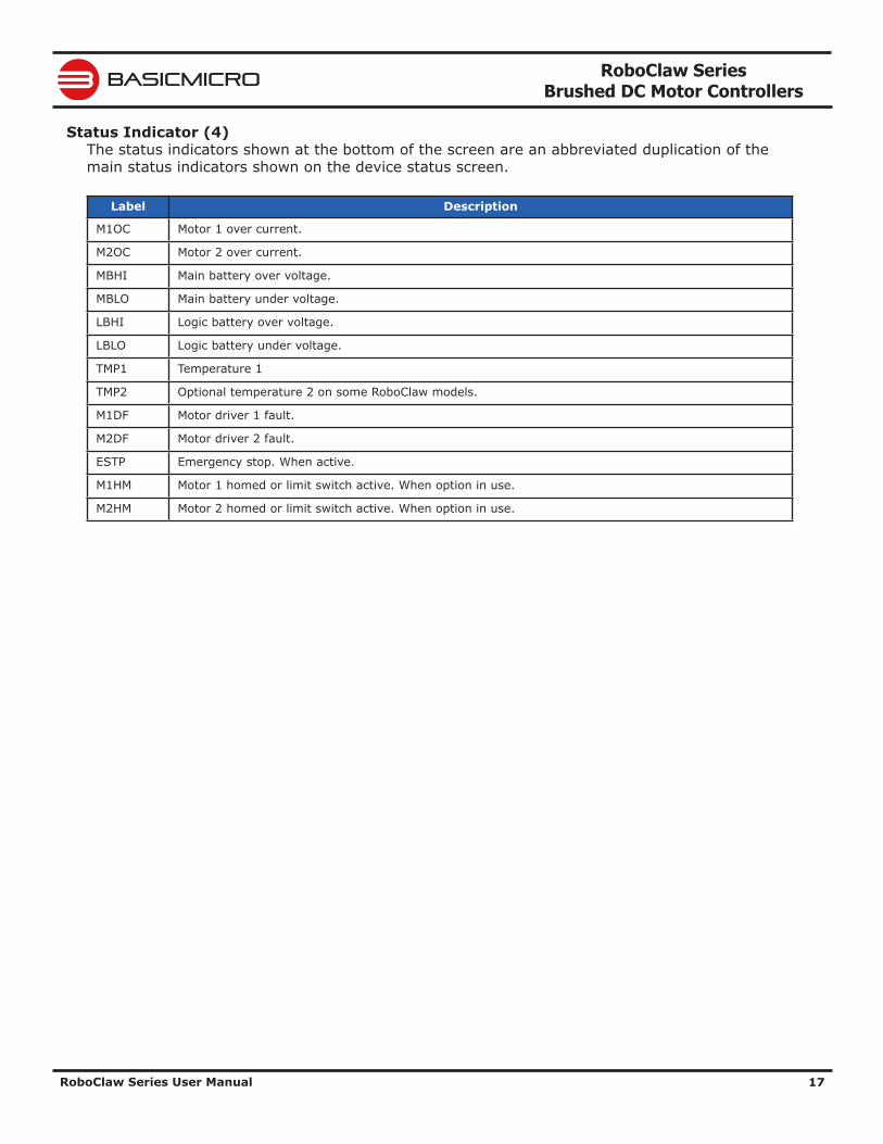
Status Indicator (4)The status indicators shown at the bottom of the screen are an abbreviated duplication of the main status indicators shown on the device status screen.
Label Description
M1OC Motor 1 over current.
M2OC Motor 2 over current.
MBHI Main battery over voltage.
MBLO Main battery under voltage.
LBHI Logic battery over voltage.
LBLO Logic battery under voltage.
TMP1 Temperature 1
TMP2 Optional temperature 2 on some RoboClaw models.
M1DF Motor driver 1 fault.
M2DF Motor driver 2 fault.
ESTP Emergency stop. When active.
M1HM Motor 1 homed or limit switch active. When option in use.
M2HM Motor 2 homed or limit switch active. When option in use.
RoboClaw Series Brushed DC Motor Controllers
RoboClaw Series User Manual 18
BASICMICRO
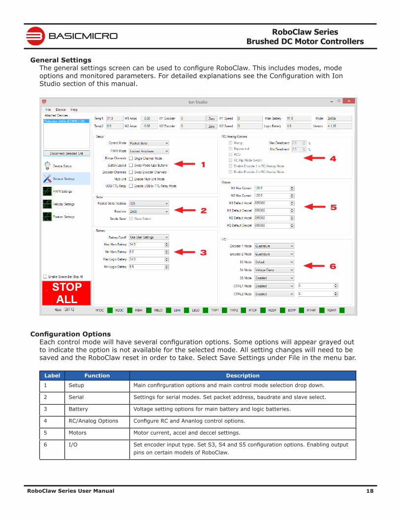
General SettingsThe general settings screen can be used to configure RoboClaw. This includes modes, mode options and monitored parameters. For detailed explanations see the Configuration with Ion Studio section of this manual.
Configuration OptionsEach control mode will have several configuration options. Some options will appear grayed out to indicate the option is not available for the selected mode. All setting changes will need to be saved and the RoboClaw reset in order to take. Select Save Settings under File in the menu bar.
Label Function Description
1 Setup Main confirguration options and main control mode selection drop down.
2 Serial Settings for serial modes. Set packet address, baudrate and slave select.
3 Battery Voltage setting options for main battery and logic batteries.
4 RC/Analog Options Configure RC and Ananlog control options.
5 Motors Motor current, accel and deccel settings.
6 I/O Set encoder input type. Set S3, S4 and S5 configuration options. Enabling output pins on certain models of RoboClaw.
1
2
3
4
5
6
RoboClaw Series Brushed DC Motor Controllers
RoboClaw Series User Manual 19
BASICMICRO
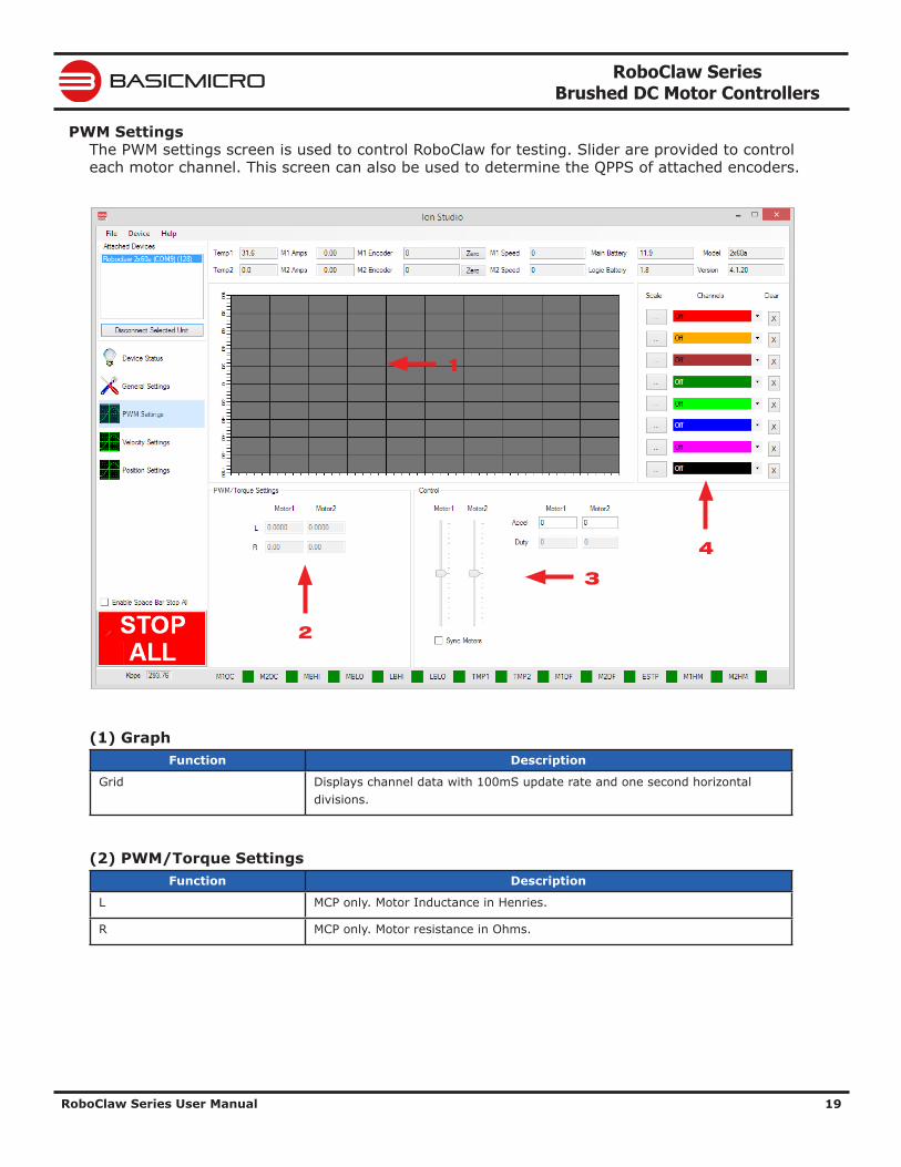
PWM SettingsThe PWM settings screen is used to control RoboClaw for testing. Slider are provided to control each motor channel. This screen can also be used to determine the QPPS of attached encoders.
(1) GraphFunction Description
Grid Displays channel data with 100mS update rate and one second horizontal divisions.
(2) PWM/Torque SettingsFunction Description
L MCP only. Motor Inductance in Henries.
R MCP only. Motor resistance in Ohms.
2
1
3
4
RoboClaw Series Brushed DC Motor Controllers
RoboClaw Series User Manual 20
BASICMICRO
(3) ControlFunction Description
Motor 1 Controls motor 1 duty percentage forward and reverse.
Motor 2 Controls motor 2 duty percentage forward and reverse.
Sync Motors Synchronises Motor 1 and Motor 2 Sliders.
Accel Acceleration rate used when moving the sliders.
Duty Displays the numberic value of the motor slider in 10ths of a Percent (0 to +/-1000).
(4) Graph ChannelsFunction Description
Scale Sets vertical scale to fit the range of the specified Channel.
Channels Select data to display on the channel. The channel is graphed in the color shown. Channel options:
• M1 or M2 Setpoint - User input for channel
• M1 or M2 PWM - Motor PWM output
• M1 or M2 Velocity - Motors Encoder Velocity
• M1 or M2 Position - Motors Encoder Position
• M1 or M2 Current - Motor running current
• Temperature
• Main Battery Voltage
• Logic Battery Voltage
Clear Clears channels graphed line.
RoboClaw Series Brushed DC Motor Controllers
RoboClaw Series User Manual 21
BASICMICRO
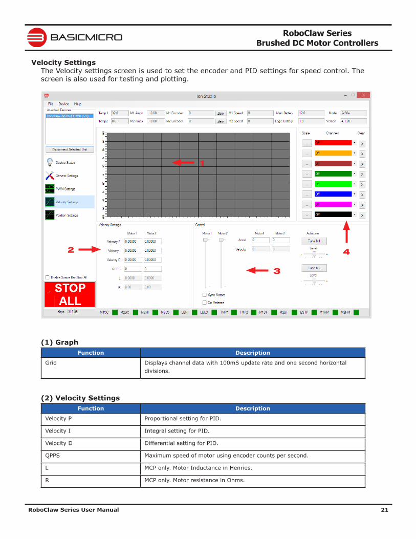
Velocity SettingsThe Velocity settings screen is used to set the encoder and PID settings for speed control. The screen is also used for testing and plotting.
(1) GraphFunction Description
Grid Displays channel data with 100mS update rate and one second horizontal divisions.
(2) Velocity SettingsFunction Description
Velocity P Proportional setting for PID.
Velocity I Integral setting for PID.
Velocity D Differential setting for PID.
QPPS Maximum speed of motor using encoder counts per second.
L MCP only. Motor Inductance in Henries.
R MCP only. Motor resistance in Ohms.
1
3
2 4
RoboClaw Series Brushed DC Motor Controllers
RoboClaw Series User Manual 22
BASICMICRO
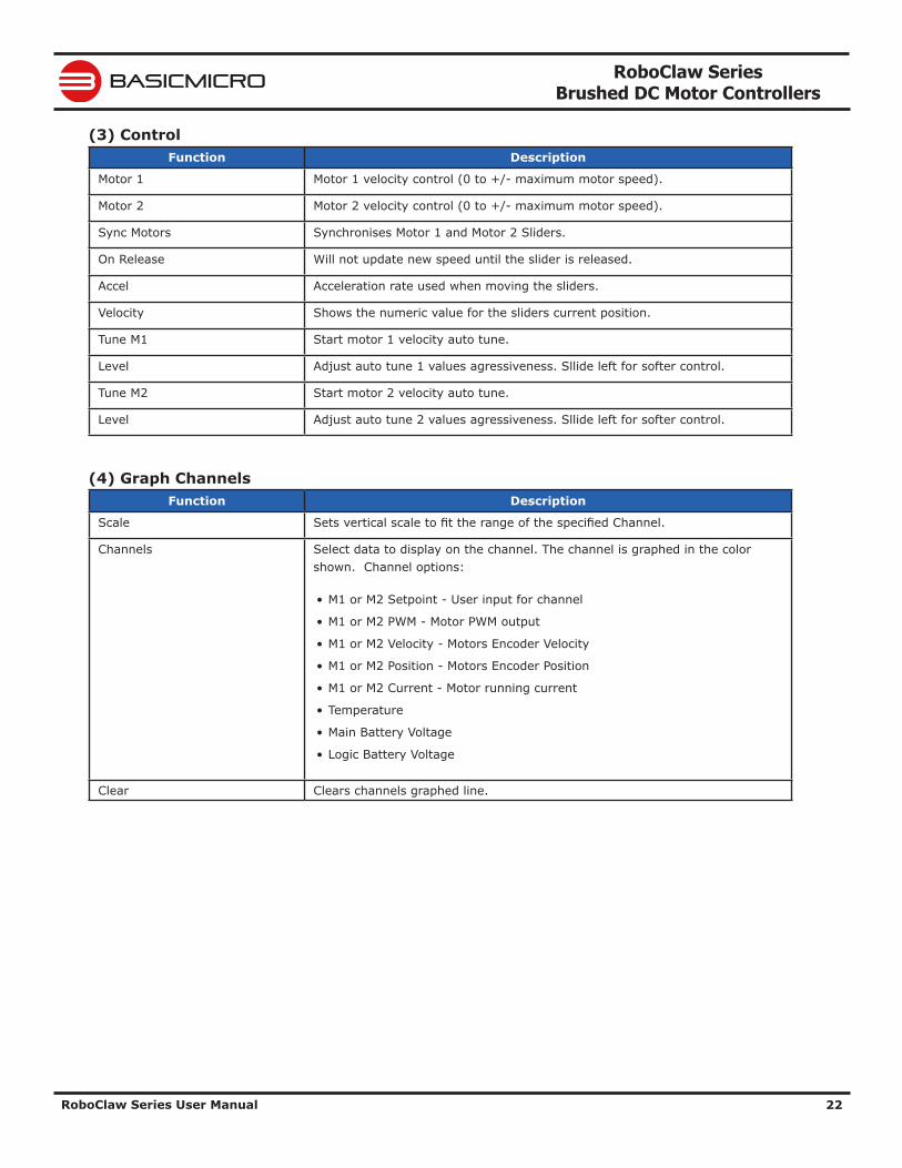
(3) ControlFunction Description
Motor 1 Motor 1 velocity control (0 to +/- maximum motor speed).
Motor 2 Motor 2 velocity control (0 to +/- maximum motor speed).
Sync Motors Synchronises Motor 1 and Motor 2 Sliders.
On Release Will not update new speed until the slider is released.
Accel Acceleration rate used when moving the sliders.
Velocity Shows the numeric value for the sliders current position.
Tune M1 Start motor 1 velocity auto tune.
Level Adjust auto tune 1 values agressiveness. Sllide left for softer control.
Tune M2 Start motor 2 velocity auto tune.
Level Adjust auto tune 2 values agressiveness. Sllide left for softer control.
(4) Graph ChannelsFunction Description
Scale Sets vertical scale to fit the range of the specified Channel.
Channels Select data to display on the channel. The channel is graphed in the color shown. Channel options:
• M1 or M2 Setpoint - User input for channel
• M1 or M2 PWM - Motor PWM output
• M1 or M2 Velocity - Motors Encoder Velocity
• M1 or M2 Position - Motors Encoder Position
• M1 or M2 Current - Motor running current
• Temperature
• Main Battery Voltage
• Logic Battery Voltage
Clear Clears channels graphed line.
RoboClaw Series Brushed DC Motor Controllers
RoboClaw Series User Manual 23
BASICMICRO
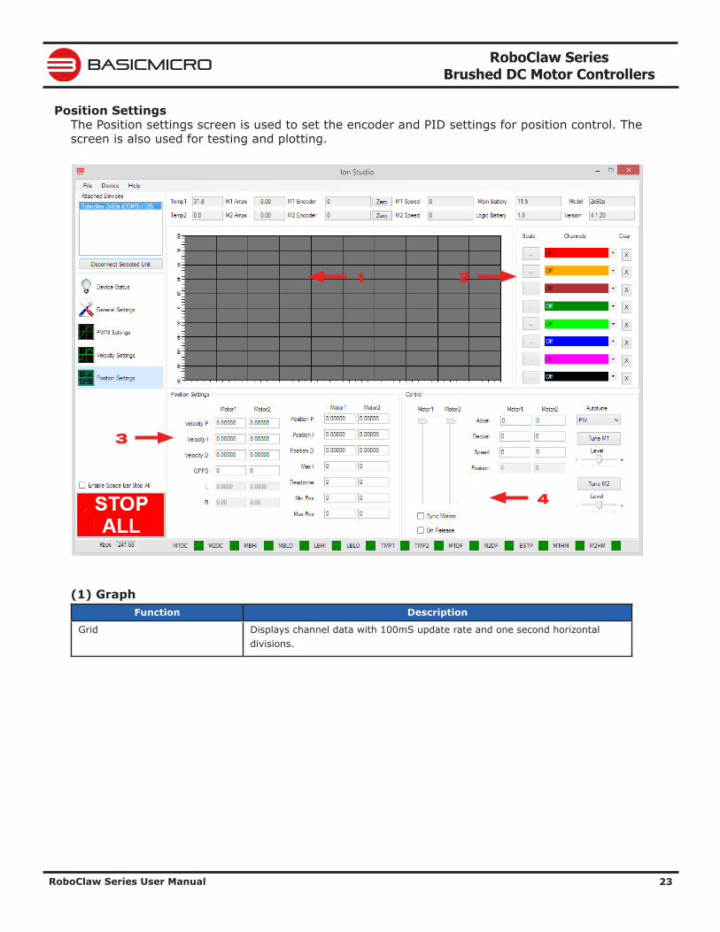
Position SettingsThe Position settings screen is used to set the encoder and PID settings for position control. The screen is also used for testing and plotting.
(1) GraphFunction Description
Grid Displays channel data with 100mS update rate and one second horizontal divisions.
3
1 2
4
RoboClaw Series Brushed DC Motor Controllers
RoboClaw Series User Manual 24
BASICMICRO
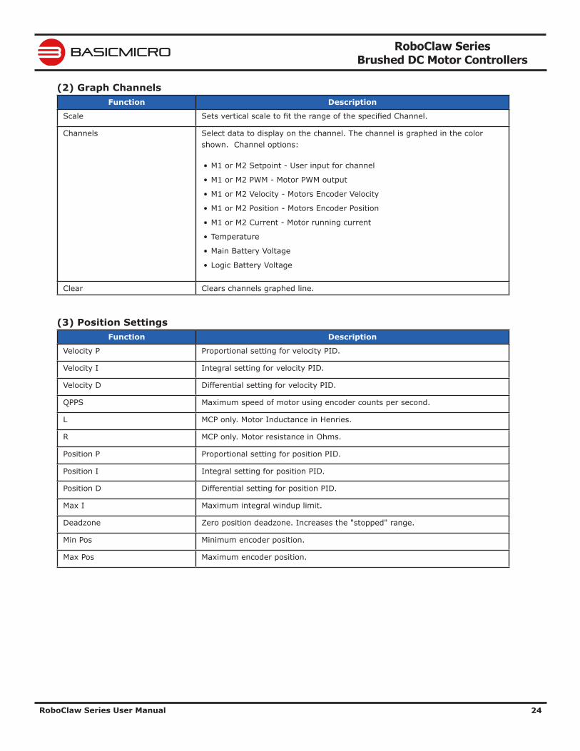
(2) Graph ChannelsFunction Description
Scale Sets vertical scale to fit the range of the specified Channel.
Channels Select data to display on the channel. The channel is graphed in the color shown. Channel options:
• M1 or M2 Setpoint - User input for channel
• M1 or M2 PWM - Motor PWM output
• M1 or M2 Velocity - Motors Encoder Velocity
• M1 or M2 Position - Motors Encoder Position
• M1 or M2 Current - Motor running current
• Temperature
• Main Battery Voltage
• Logic Battery Voltage
Clear Clears channels graphed line.
(3) Position SettingsFunction Description
Velocity P Proportional setting for velocity PID.
Velocity I Integral setting for velocity PID.
Velocity D Differential setting for velocity PID.
QPPS Maximum speed of motor using encoder counts per second.
L MCP only. Motor Inductance in Henries.
R MCP only. Motor resistance in Ohms.
Position P Proportional setting for position PID.
Position I Integral setting for position PID.
Position D Differential setting for position PID.
Max I Maximum integral windup limit.
Deadzone Zero position deadzone. Increases the "stopped" range.
Min Pos Minimum encoder position.
Max Pos Maximum encoder position.
RoboClaw Series Brushed DC Motor Controllers
RoboClaw Series User Manual 25
BASICMICRO
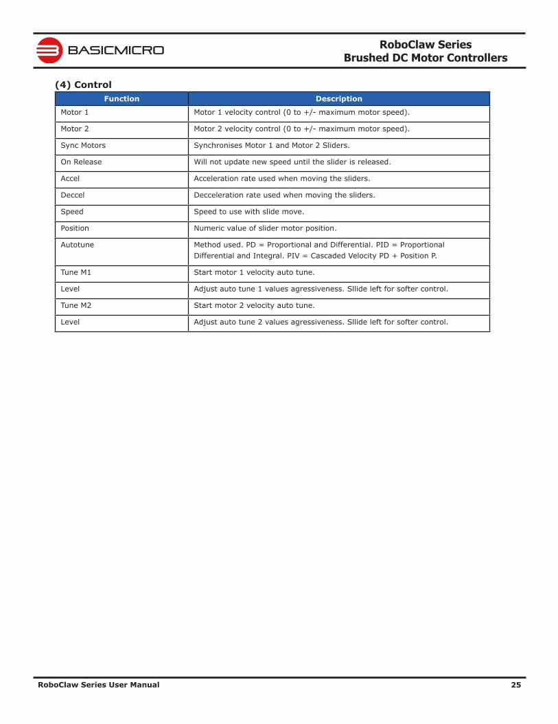
(4) ControlFunction Description
Motor 1 Motor 1 velocity control (0 to +/- maximum motor speed).
Motor 2 Motor 2 velocity control (0 to +/- maximum motor speed).
Sync Motors Synchronises Motor 1 and Motor 2 Sliders.
On Release Will not update new speed until the slider is released.
Accel Acceleration rate used when moving the sliders.
Deccel Decceleration rate used when moving the sliders.
Speed Speed to use with slide move.
Position Numeric value of slider motor position.
Autotune Method used. PD = Proportional and Differential. PID = Proportional Differential and Integral. PIV = Cascaded Velocity PD + Position P.
Tune M1 Start motor 1 velocity auto tune.
Level Adjust auto tune 1 values agressiveness. Sllide left for softer control.
Tune M2 Start motor 2 velocity auto tune.
Level Adjust auto tune 2 values agressiveness. Sllide left for softer control.
RoboClaw Series Brushed DC Motor Controllers
RoboClaw Series User Manual 26
BASICMICRO
Firmware Updates
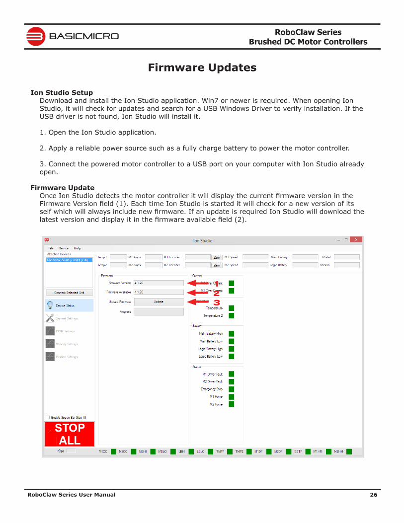
Ion Studio SetupDownload and install the Ion Studio application. Win7 or newer is required. When opening Ion Studio, it will check for updates and search for a USB Windows Driver to verify installation. If the USB driver is not found, Ion Studio will install it.
1. Open the Ion Studio application.
2. Apply a reliable power source such as a fully charge battery to power the motor controller.
3. Connect the powered motor controller to a USB port on your computer with Ion Studio already open.
Firmware UpdateOnce Ion Studio detects the motor controller it will display the current firmware version in the Firmware Version field (1). Each time Ion Studio is started it will check for a new version of its self which will always include new firmware. If an update is required Ion Studio will download the latest version and display it in the firmware available field (2).
123
RoboClaw Series Brushed DC Motor Controllers
RoboClaw Series User Manual 27
BASICMICRO
1. When a new version of firmware is shown click the update button (3) to start the process.
2. Ion Studio will begin to update the firmware. While the firmware update is in progress the onboard LEDs will begin to flash. The onboard flash memory will first be erased. It is important power is not lost during this process or the motor controller will no longer function. There is no recovery if power fails during the erase process.
3. Once the firmware update is complete the motor controller will reset. Click the "Connect Selected Unit" button to re-connect.
RoboClaw Series Brushed DC Motor Controllers
RoboClaw Series User Manual 28
BASICMICRO
Control ModesSetup
RoboClaw has several fucntional control modes. There are two methods to configure these modes. Using the built-in buttons or Ion Studio. This manaul covers both methods of configuration. Ion Studio offers greater options for each mode and can be easier to configure the RoboClaw in several situations. However the built-in buttons are more than adequate in most all modes. Refer to the configuration section of this manual for mode setup instructions using Ion Studio or the built-in buttons.
There are 4 main modes with several variations. Each mode enables RoboClaw to be controlled in a very specific way. The following list explains each mode and the ideal application.
USB ControlUSB can be used in any mode. When RoboClaw is in packet serial mode and another device, such as an Arduino, is connected commands from the USB and Arduino will be executed and can potential over ride one another. However if Roboclaw is not in packet serial mode, motor movement commands will not function. USB packet serial commands can then only be used to read status information and set configuration settings.
RCUsing RC mode RoboClaw can be controlled from any hobby RC radio system. RC input mode also allows low powered microcontrollers such as a Basic Stamp to control RoboClaw. RoboClaw expects servo pulse inputs to control the direction and speed. Very similar to how a regular servo is controlled. RC mode can use encoders if properly setup(See Encoder section).
AnalogAnalog mode uses an analog signal from 0V to 2V to control the speed and direction of each motor. RoboClaw can be controlled using a potentiometer or filtered PWM from a microcontroller. Analog mode is ideal for interfacing RoboClaw with joystick positioning systems or other non microcontroller interfacing hardware. Analog mode can use encoders if properly setup(See Encoder section).
Simple SerialIn simple serial mode RoboClaw expects TTL level RS-232 serial data to control direction and speed of each motor. Simple serial is typically used to control RoboClaw from a microcontroller or PC. If using a PC, a MAX232 or an equivilent level converter circuit must be used since RoboClaw only works with TTL level inputs. Simple serial includes a slave select mode which allows multiple RoboClaws to be controlled from a signal RS-232 port (PC or microcontroller). Simple serial is a one way format, RoboClaw can only receive data. Encoders are not supported in Simple Serial mode.
Packet SerialIn packet serial mode RoboClaw expects TTL level RS-232 serial data to control direction and speed of each motor. Packet serial is typically used to control RoboClaw from a microcontroller or PC. If using a PC a MAX232 or an equivilent level converter circuit must be used since RoboClaw only works with TTL level input. In packet serial mode each RoboClaw is assigned a unique address. There are 8 addresses available. This means up to 8 RoboClaws can be on the same serial port. Encoders are support in Packet Serial mode(See Encoder section).
RoboClaw Series Brushed DC Motor Controllers
RoboClaw Series User Manual 29
BASICMICRO
Configuration Using Ion StudioMode Setup
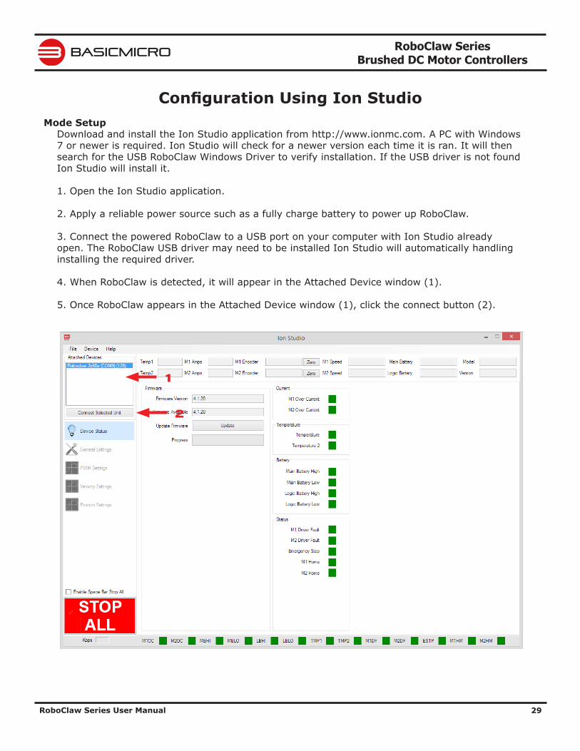
Download and install the Ion Studio application from http://www.ionmc.com. A PC with Windows 7 or newer is required. Ion Studio will check for a newer version each time it is ran. It will then search for the USB RoboClaw Windows Driver to verify installation. If the USB driver is not found Ion Studio will install it.
1. Open the Ion Studio application.
2. Apply a reliable power source such as a fully charge battery to power up RoboClaw.
3. Connect the powered RoboClaw to a USB port on your computer with Ion Studio already open. The RoboClaw USB driver may need to be installed Ion Studio will automatically handling installing the required driver.
4. When RoboClaw is detected, it will appear in the Attached Device window (1).
5. Once RoboClaw appears in the Attached Device window (1), click the connect button (2).
1
2
RoboClaw Series Brushed DC Motor Controllers
RoboClaw Series User Manual 30
BASICMICRO
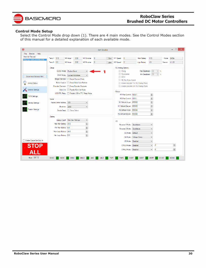
Control Mode SetupSelect the Control Mode drop down (1). There are 4 main modes. See the Control Modes section of this manual for a detailed explanation of each available mode.
1
RoboClaw Series Brushed DC Motor Controllers
RoboClaw Series User Manual 31
BASICMICRO
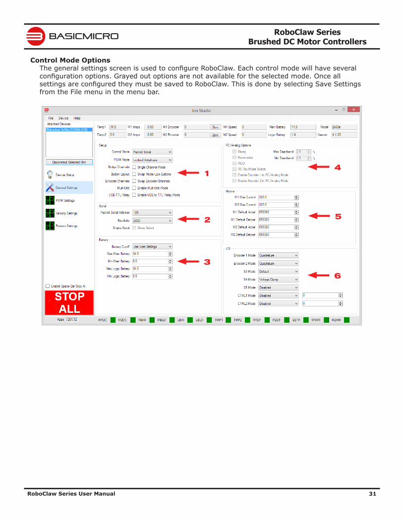
Control Mode OptionsThe general settings screen is used to configure RoboClaw. Each control mode will have several configuration options. Grayed out options are not available for the selected mode. Once all settings are configured they must be saved to RoboClaw. This is done by selecting Save Settings from the File menu in the menu bar.
1
2
3
4
5
6
RoboClaw Series Brushed DC Motor Controllers
RoboClaw Series User Manual 32
BASICMICRO
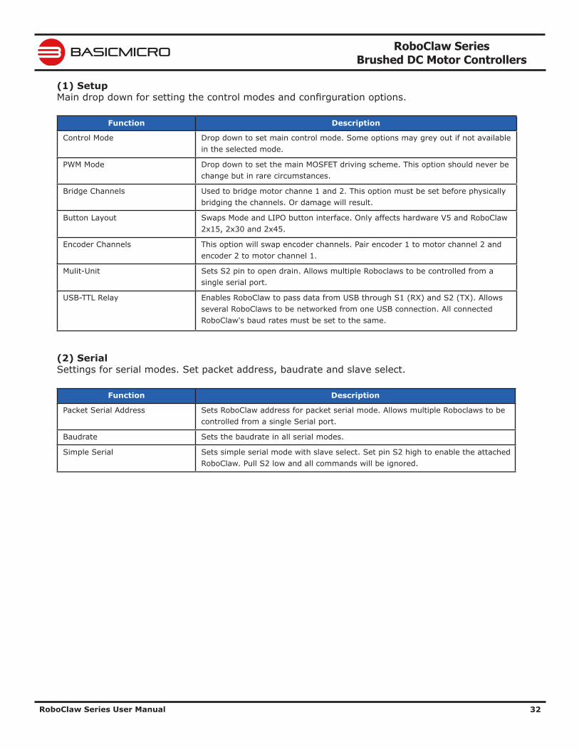
(1) SetupMain drop down for setting the control modes and confirguration options.
Function Description
Control Mode Drop down to set main control mode. Some options may grey out if not available in the selected mode.
PWM Mode Drop down to set the main MOSFET driving scheme. This option should never be change but in rare circumstances.
Bridge Channels Used to bridge motor channe 1 and 2. This option must be set before physically bridging the channels. Or damage will result.
Button Layout Swaps Mode and LIPO button interface. Only affects hardware V5 and RoboClaw 2x15, 2x30 and 2x45.
Encoder Channels This option will swap encoder channels. Pair encoder 1 to motor channel 2 and encoder 2 to motor channel 1.
Mulit-Unit Sets S2 pin to open drain. Allows multiple Roboclaws to be controlled from a single serial port.
USB-TTL Relay Enables RoboClaw to pass data from USB through S1 (RX) and S2 (TX). Allows several RoboClaws to be networked from one USB connection. All connected RoboClaw's baud rates must be set to the same.
(2) SerialSettings for serial modes. Set packet address, baudrate and slave select.
Function Description
Packet Serial Address Sets RoboClaw address for packet serial mode. Allows multiple Roboclaws to be controlled from a single Serial port.
Baudrate Sets the baudrate in all serial modes.
Simple Serial Sets simple serial mode with slave select. Set pin S2 high to enable the attached RoboClaw. Pull S2 low and all commands will be ignored.
RoboClaw Series Brushed DC Motor Controllers
RoboClaw Series User Manual 33
BASICMICRO
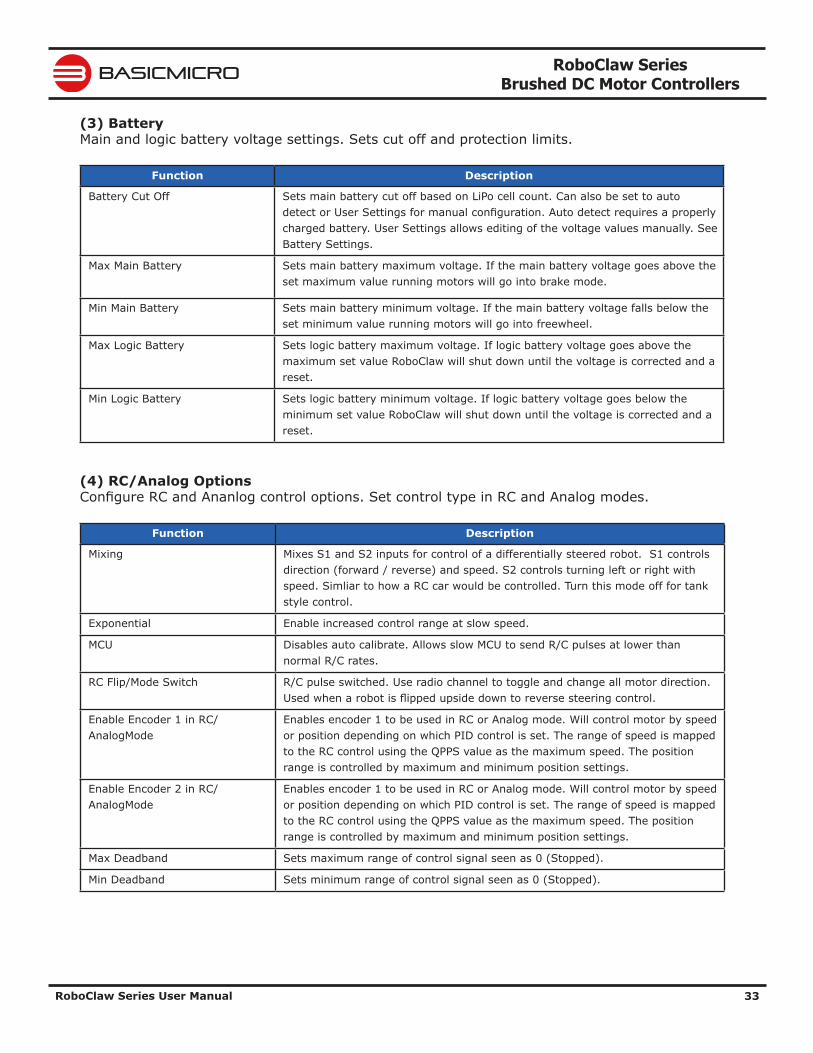
(3) BatteryMain and logic battery voltage settings. Sets cut off and protection limits.
Function Description
Battery Cut Off Sets main battery cut off based on LiPo cell count. Can also be set to auto detect or User Settings for manual configuration. Auto detect requires a properly charged battery. User Settings allows editing of the voltage values manually. See Battery Settings.
Max Main Battery Sets main battery maximum voltage. If the main battery voltage goes above the set maximum value running motors will go into brake mode.
Min Main Battery Sets main battery minimum voltage. If the main battery voltage falls below the set minimum value running motors will go into freewheel.
Max Logic Battery Sets logic battery maximum voltage. If logic battery voltage goes above the maximum set value RoboClaw will shut down until the voltage is corrected and a reset.
Min Logic Battery Sets logic battery minimum voltage. If logic battery voltage goes below the minimum set value RoboClaw will shut down until the voltage is corrected and a reset.
(4) RC/Analog OptionsConfigure RC and Ananlog control options. Set control type in RC and Analog modes.
Function Description
Mixing Mixes S1 and S2 inputs for control of a differentially steered robot. S1 controls direction (forward / reverse) and speed. S2 controls turning left or right with speed. Simliar to how a RC car would be controlled. Turn this mode off for tank style control.
Exponential Enable increased control range at slow speed.
MCU Disables auto calibrate. Allows slow MCU to send R/C pulses at lower than normal R/C rates.
RC Flip/Mode Switch R/C pulse switched. Use radio channel to toggle and change all motor direction. Used when a robot is flipped upside down to reverse steering control.
Enable Encoder 1 in RC/AnalogMode
Enables encoder 1 to be used in RC or Analog mode. Will control motor by speed or position depending on which PID control is set. The range of speed is mapped to the RC control using the QPPS value as the maximum speed. The position range is controlled by maximum and minimum position settings.
Enable Encoder 2 in RC/AnalogMode
Enables encoder 1 to be used in RC or Analog mode. Will control motor by speed or position depending on which PID control is set. The range of speed is mapped to the RC control using the QPPS value as the maximum speed. The position range is controlled by maximum and minimum position settings.
Max Deadband Sets maximum range of control signal seen as 0 (Stopped).
Min Deadband Sets minimum range of control signal seen as 0 (Stopped).
RoboClaw Series Brushed DC Motor Controllers
RoboClaw Series User Manual 34
BASICMICRO
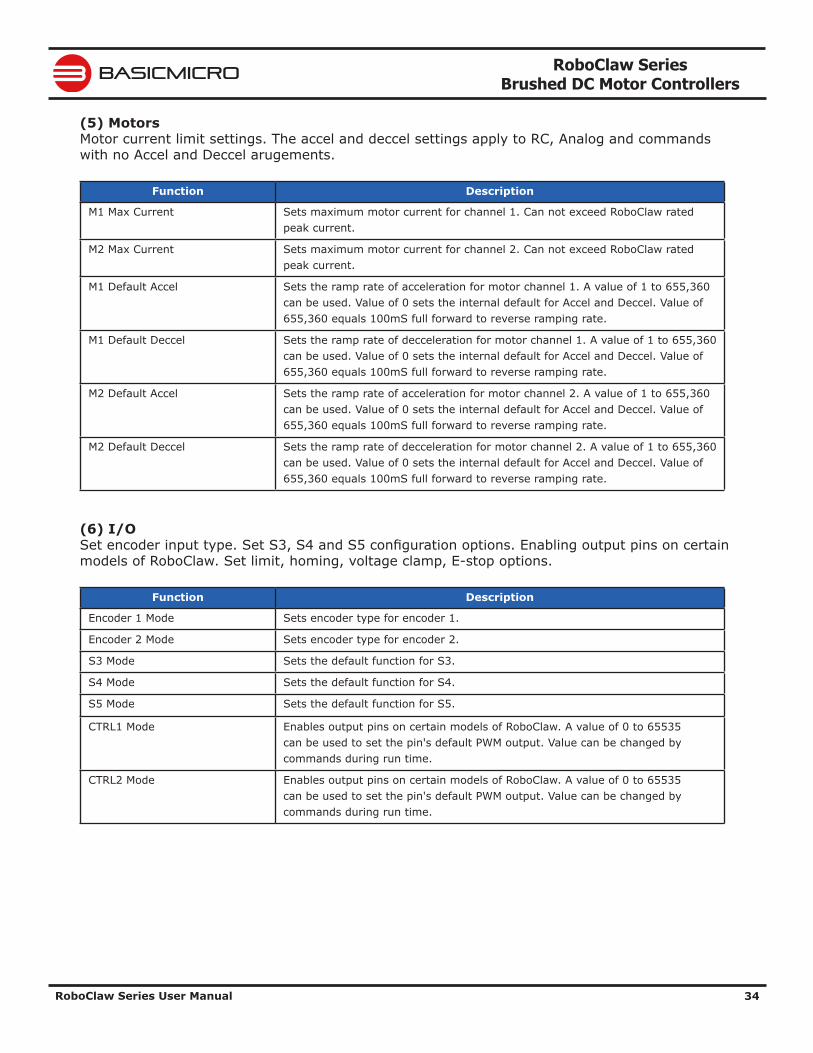
(5) MotorsMotor current limit settings. The accel and deccel settings apply to RC, Analog and commands with no Accel and Deccel arugements.
Function Description
M1 Max Current Sets maximum motor current for channel 1. Can not exceed RoboClaw rated peak current.
M2 Max Current Sets maximum motor current for channel 2. Can not exceed RoboClaw rated peak current.
M1 Default Accel Sets the ramp rate of acceleration for motor channel 1. A value of 1 to 655,360 can be used. Value of 0 sets the internal default for Accel and Deccel. Value of 655,360 equals 100mS full forward to reverse ramping rate.
M1 Default Deccel Sets the ramp rate of decceleration for motor channel 1. A value of 1 to 655,360 can be used. Value of 0 sets the internal default for Accel and Deccel. Value of 655,360 equals 100mS full forward to reverse ramping rate.
M2 Default Accel Sets the ramp rate of acceleration for motor channel 2. A value of 1 to 655,360 can be used. Value of 0 sets the internal default for Accel and Deccel. Value of 655,360 equals 100mS full forward to reverse ramping rate.
M2 Default Deccel Sets the ramp rate of decceleration for motor channel 2. A value of 1 to 655,360 can be used. Value of 0 sets the internal default for Accel and Deccel. Value of 655,360 equals 100mS full forward to reverse ramping rate.
(6) I/OSet encoder input type. Set S3, S4 and S5 configuration options. Enabling output pins on certain models of RoboClaw. Set limit, homing, voltage clamp, E-stop options.
Function Description
Encoder 1 Mode Sets encoder type for encoder 1.
Encoder 2 Mode Sets encoder type for encoder 2.
S3 Mode Sets the default function for S3.
S4 Mode Sets the default function for S4.
S5 Mode Sets the default function for S5.
CTRL1 Mode Enables output pins on certain models of RoboClaw. A value of 0 to 65535 can be used to set the pin's default PWM output. Value can be changed by commands during run time.
CTRL2 Mode Enables output pins on certain models of RoboClaw. A value of 0 to 65535 can be used to set the pin's default PWM output. Value can be changed by commands during run time.
RoboClaw Series Brushed DC Motor Controllers
RoboClaw Series User Manual 35
BASICMICRO
Configuration with ButtonsMode Setup
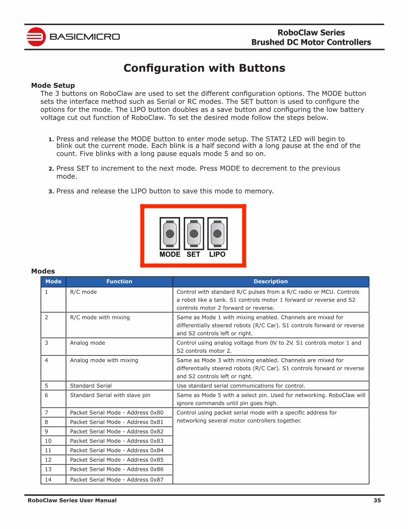
The 3 buttons on RoboClaw are used to set the different configuration options. The MODE button sets the interface method such as Serial or RC modes. The SET button is used to configure the options for the mode. The LIPO button doubles as a save button and configuring the low battery voltage cut out function of RoboClaw. To set the desired mode follow the steps below.
1. Press and release the MODE button to enter mode setup. The STAT2 LED will begin to blink out the current mode. Each blink is a half second with a long pause at the end of the count. Five blinks with a long pause equals mode 5 and so on.
2. Press SET to increment to the next mode. Press MODE to decrement to the previous mode.
3. Press and release the LIPO button to save this mode to memory.
ModesMode Function Description
1 R/C mode Control with standard R/C pulses from a R/C radio or MCU. Controls a robot like a tank. S1 controls motor 1 forward or reverse and S2 controls motor 2 forward or reverse.
2 R/C mode with mixing Same as Mode 1 with mixing enabled. Channels are mixed for differentially steered robots (R/C Car). S1 controls forward or reverse and S2 controls left or right.
3 Analog mode Control using analog voltage from 0V to 2V. S1 controls motor 1 and S2 controls motor 2.
4 Analog mode with mixing Same as Mode 3 with mixing enabled. Channels are mixed for differentially steered robots (R/C Car). S1 controls forward or reverse and S2 controls left or right.
5 Standard Serial Use standard serial communications for control.
6 Standard Serial with slave pin Same as Mode 5 with a select pin. Used for networking. RoboClaw will ignore commands until pin goes high.
7 Packet Serial Mode - Address 0x80 Control using packet serial mode with a specific address for networking several motor controllers together.8 Packet Serial Mode - Address 0x81
9 Packet Serial Mode - Address 0x82
10 Packet Serial Mode - Address 0x83
11 Packet Serial Mode - Address 0x84
12 Packet Serial Mode - Address 0x85
13 Packet Serial Mode - Address 0x86
14 Packet Serial Mode - Address 0x87
LIPOSETMODE
RoboClaw Series Brushed DC Motor Controllers
RoboClaw Series User Manual 36
BASICMICRO
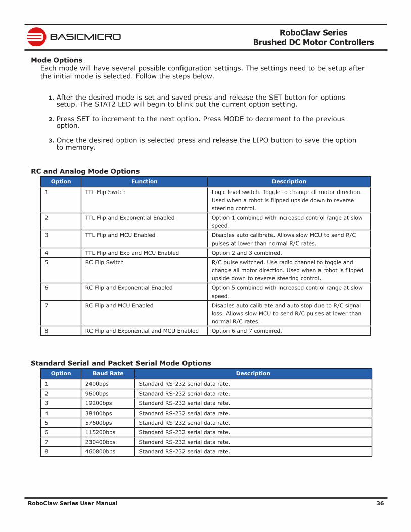
Mode OptionsEach mode will have several possible configuration settings. The settings need to be setup after the initial mode is selected. Follow the steps below.
1. After the desired mode is set and saved press and release the SET button for options setup. The STAT2 LED will begin to blink out the current option setting.
2. Press SET to increment to the next option. Press MODE to decrement to the previous option.
3. Once the desired option is selected press and release the LIPO button to save the option to memory.
RC and Analog Mode OptionsOption Function Description
1 TTL Flip Switch Logic level switch. Toggle to change all motor direction. Used when a robot is flipped upside down to reverse steering control.
2 TTL Flip and Exponential Enabled Option 1 combined with increased control range at slow speed.
3 TTL Flip and MCU Enabled Disables auto calibrate. Allows slow MCU to send R/C pulses at lower than normal R/C rates.
4 TTL Flip and Exp and MCU Enabled Option 2 and 3 combined.
5 RC Flip Switch R/C pulse switched. Use radio channel to toggle and change all motor direction. Used when a robot is flipped upside down to reverse steering control.
6 RC Flip and Exponential Enabled Option 5 combined with increased control range at slow speed.
7 RC Flip and MCU Enabled Disables auto calibrate and auto stop due to R/C signal loss. Allows slow MCU to send R/C pulses at lower than normal R/C rates.
8 RC Flip and Exponential and MCU Enabled Option 6 and 7 combined.
Standard Serial and Packet Serial Mode OptionsOption Baud Rate Description
1 2400bps Standard RS-232 serial data rate.
2 9600bps Standard RS-232 serial data rate.
3 19200bps Standard RS-232 serial data rate.
4 38400bps Standard RS-232 serial data rate.
5 57600bps Standard RS-232 serial data rate.
6 115200bps Standard RS-232 serial data rate.
7 230400bps Standard RS-232 serial data rate.
8 460800bps Standard RS-232 serial data rate.
RoboClaw Series Brushed DC Motor Controllers
RoboClaw Series User Manual 37
BASICMICRO
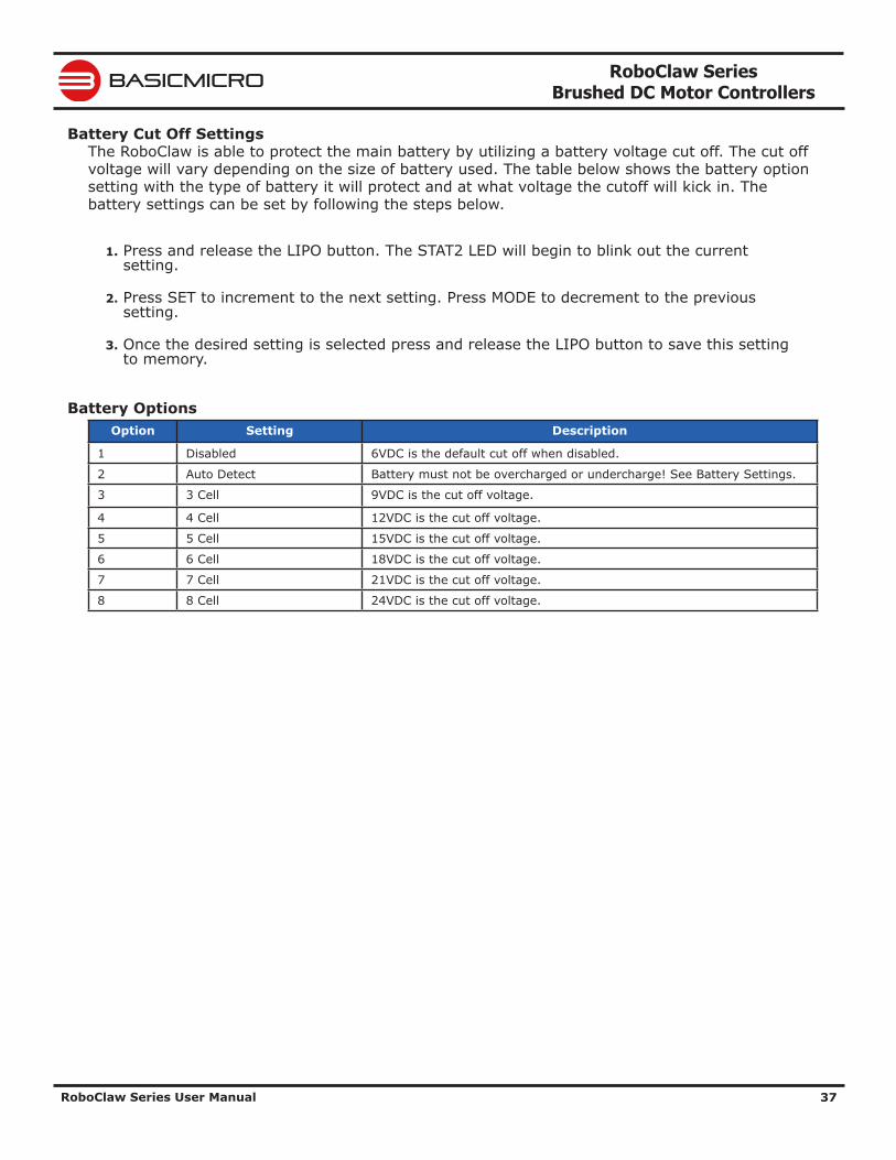
Battery Cut Off SettingsThe RoboClaw is able to protect the main battery by utilizing a battery voltage cut off. The cut off voltage will vary depending on the size of battery used. The table below shows the battery option setting with the type of battery it will protect and at what voltage the cutoff will kick in. The battery settings can be set by following the steps below.
1. Press and release the LIPO button. The STAT2 LED will begin to blink out the current setting.
2. Press SET to increment to the next setting. Press MODE to decrement to the previous setting.
3. Once the desired setting is selected press and release the LIPO button to save this setting to memory.
Battery OptionsOption Setting Description
1 Disabled 6VDC is the default cut off when disabled.
2 Auto Detect Battery must not be overcharged or undercharge! See Battery Settings.
3 3 Cell 9VDC is the cut off voltage.
4 4 Cell 12VDC is the cut off voltage.
5 5 Cell 15VDC is the cut off voltage.
6 6 Cell 18VDC is the cut off voltage.
7 7 Cell 21VDC is the cut off voltage.
8 8 Cell 24VDC is the cut off voltage.
RoboClaw Series Brushed DC Motor Controllers
RoboClaw Series User Manual 38
BASICMICRO
Battery Settings
Automatic Battery Detection on StartupAuto detect will sample the main battery voltage on power up or after a reset. All Lipo batteries, depending on cell count will have a minimum and maximum safe voltage range. The attached battery must be within this acceptable voltage range to be correctly detected. Undercharged or overcharged batteries will cause false readings and RoboClaw will not properly protect the battery. If the automatic battery detection mode is enabled using the on-board buttons, the Stat2 LED will blink to indicate the battery cell count that was detected. Each blink indicates the number of LIPO cells detected. When automatic battery detection is used the number of cells detected should be confirmed on power up.
Undercharged or overcharged batteries can cause an incorrect auto detection voltage.
Manual Voltage SettingsThe minimum and maximum voltage can be set using the Ion Studio application or packet serial commands. Values can be set to any value between the boards minimum and maximum voltage limits. This feature can be useful when using a power supply to power RoboClaw. A minimum voltage just below the power supply voltage of 2VDC will prevent the power supply voltage from dipping too low under heavy load. A maximum voltage set to just above the power supply voltage 2VDC will help protect the power supply from regenerative voltage spikes if an external voltage clamp circuit is not being used. However when the minimum or maximum voltages are reached RoboClaw will go into either braking or freewheel mode. This feature will only help to protect a power supply not correct regenerative voltages issues. A voltage clamping circuit is required to correct any regenerative voltage issues when a power supply is used as the main power source. See Voltage Clamping.
!
RoboClaw Series Brushed DC Motor Controllers
RoboClaw Series User Manual 39
BASICMICRO
WiringBasic Wiring
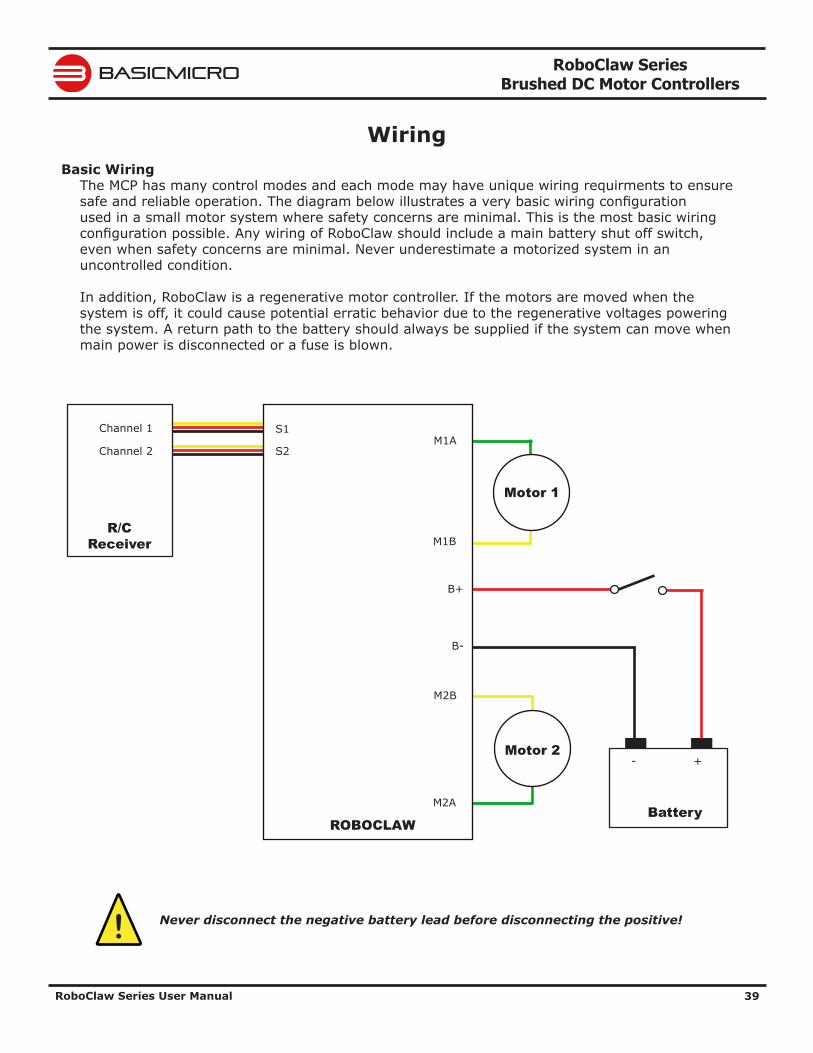
The MCP has many control modes and each mode may have unique wiring requirments to ensure safe and reliable operation. The diagram below illustrates a very basic wiring configuration used in a small motor system where safety concerns are minimal. This is the most basic wiring configuration possible. Any wiring of RoboClaw should include a main battery shut off switch, even when safety concerns are minimal. Never underestimate a motorized system in an uncontrolled condition.
In addition, RoboClaw is a regenerative motor controller. If the motors are moved when the system is off, it could cause potential erratic behavior due to the regenerative voltages powering the system. A return path to the battery should always be supplied if the system can move when main power is disconnected or a fuse is blown.
Never disconnect the negative battery lead before disconnecting the positive!
M1A
M1B
M2B
M2A
B-
B+
+-
Battery
S2
ROBOCLAW
Motor 1
Motor 2
Channel 1
Channel 2
R/C Receiver
S1
!
RoboClaw Series Brushed DC Motor Controllers
RoboClaw Series User Manual 40
BASICMICRO
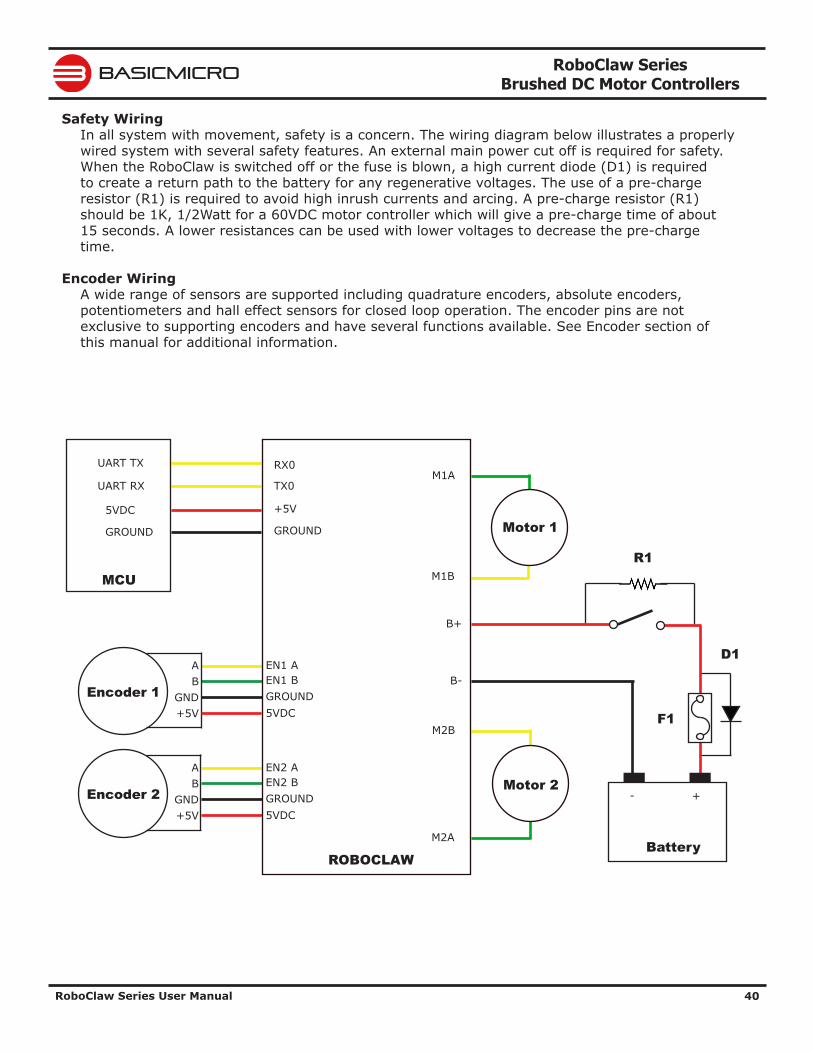
Safety WiringIn all system with movement, safety is a concern. The wiring diagram below illustrates a properly wired system with several safety features. An external main power cut off is required for safety. When the RoboClaw is switched off or the fuse is blown, a high current diode (D1) is required to create a return path to the battery for any regenerative voltages. The use of a pre-charge resistor (R1) is required to avoid high inrush currents and arcing. A pre-charge resistor (R1) should be 1K, 1/2Watt for a 60VDC motor controller which will give a pre-charge time of about 15 seconds. A lower resistances can be used with lower voltages to decrease the pre-charge time.
Encoder WiringA wide range of sensors are supported including quadrature encoders, absolute encoders, potentiometers and hall effect sensors for closed loop operation. The encoder pins are not exclusive to supporting encoders and have several functions available. See Encoder section of this manual for additional information.
Encoder 1
AB
GND+5V
EN1 AEN1 B
5VDCGROUND
Encoder 2
AB
GND+5V
EN2 AEN2 B
5VDCGROUND
M1A
M1B
M2B
M2A
B-
B+
+-
Battery
RX0
TX0
+5V
GROUND
ROBOCLAW
Motor 1
Motor 2
UART TX
UART RX
5VDC
GROUND
MCUR1
F1
D1
RoboClaw Series Brushed DC Motor Controllers
RoboClaw Series User Manual 41
BASICMICRO
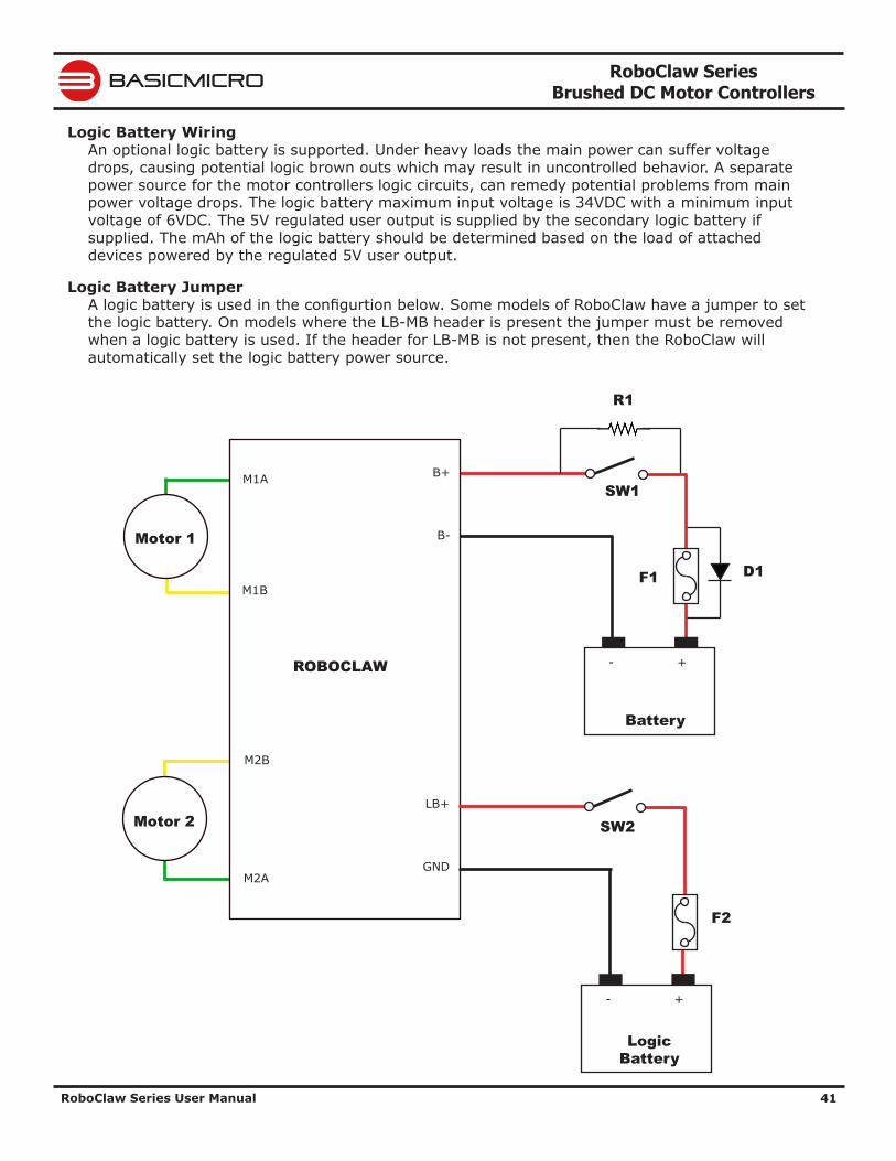
Logic Battery WiringAn optional logic battery is supported. Under heavy loads the main power can suffer voltage drops, causing potential logic brown outs which may result in uncontrolled behavior. A separate power source for the motor controllers logic circuits, can remedy potential problems from main power voltage drops. The logic battery maximum input voltage is 34VDC with a minimum input voltage of 6VDC. The 5V regulated user output is supplied by the secondary logic battery if supplied. The mAh of the logic battery should be determined based on the load of attached devices powered by the regulated 5V user output.
Logic Battery JumperA logic battery is used in the configurtion below. Some models of RoboClaw have a jumper to set the logic battery. On models where the LB-MB header is present the jumper must be removed when a logic battery is used. If the header for LB-MB is not present, then the RoboClaw will automatically set the logic battery power source.
+-
Battery
Motor 1
Motor 2
R1
F1 D1
M1A
M1B
M2B
M2A
B-
B+
ROBOCLAW
F2
+-
LogicBattery
SW1
SW2
GND
LB+
RoboClaw Series Brushed DC Motor Controllers
RoboClaw Series User Manual 42
BASICMICRO
Status LEDs
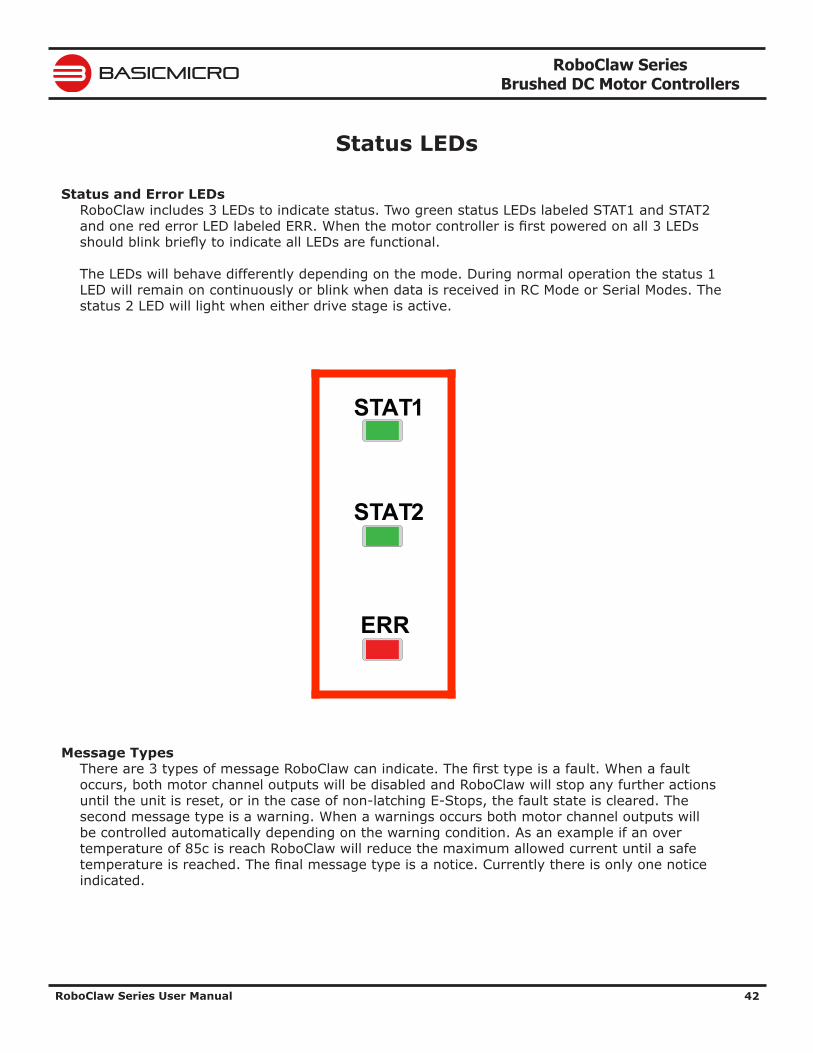
Status and Error LEDsRoboClaw includes 3 LEDs to indicate status. Two green status LEDs labeled STAT1 and STAT2 and one red error LED labeled ERR. When the motor controller is first powered on all 3 LEDs should blink briefly to indicate all LEDs are functional.
The LEDs will behave differently depending on the mode. During normal operation the status 1 LED will remain on continuously or blink when data is received in RC Mode or Serial Modes. The status 2 LED will light when either drive stage is active.
Message TypesThere are 3 types of message RoboClaw can indicate. The first type is a fault. When a fault occurs, both motor channel outputs will be disabled and RoboClaw will stop any further actions until the unit is reset, or in the case of non-latching E-Stops, the fault state is cleared. The second message type is a warning. When a warnings occurs both motor channel outputs will be controlled automatically depending on the warning condition. As an example if an over temperature of 85c is reach RoboClaw will reduce the maximum allowed current until a safe temperature is reached. The final message type is a notice. Currently there is only one notice indicated.
ERR
STAT2
STAT1
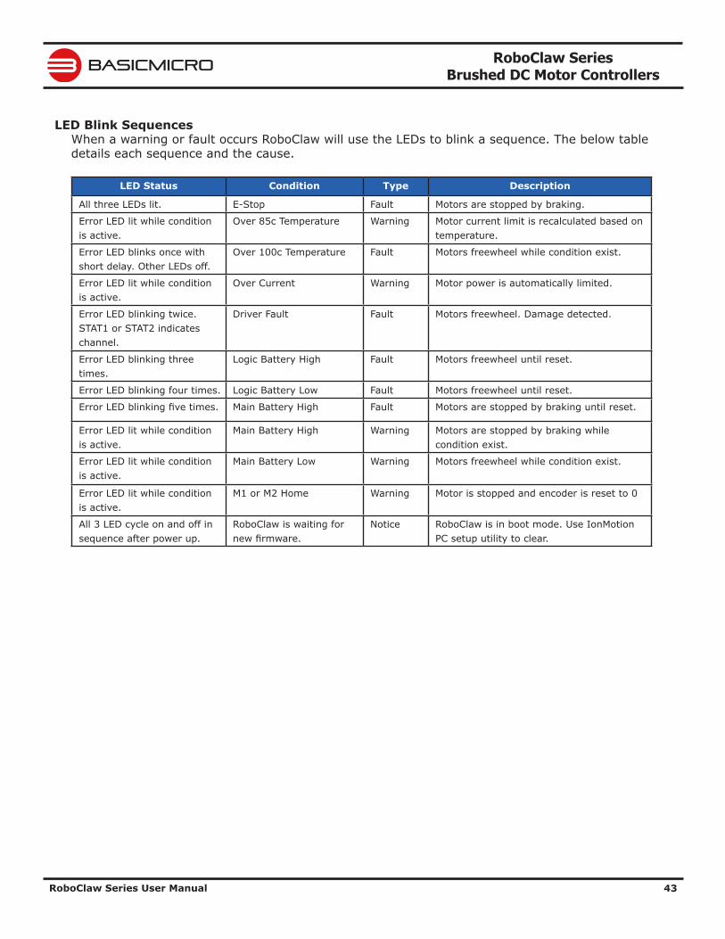
RoboClaw Series Brushed DC Motor Controllers
RoboClaw Series User Manual 43
BASICMICRO
LED Blink SequencesWhen a warning or fault occurs RoboClaw will use the LEDs to blink a sequence. The below table details each sequence and the cause.
LED Status Condition Type Description
All three LEDs lit. E-Stop Fault Motors are stopped by braking.
Error LED lit while condition is active.
Over 85c Temperature Warning Motor current limit is recalculated based on temperature.
Error LED blinks once with short delay. Other LEDs off.
Over 100c Temperature Fault Motors freewheel while condition exist.
Error LED lit while condition is active.
Over Current Warning Motor power is automatically limited.
Error LED blinking twice. STAT1 or STAT2 indicates channel.
Driver Fault Fault Motors freewheel. Damage detected.
Error LED blinking three times.
Logic Battery High Fault Motors freewheel until reset.
Error LED blinking four times. Logic Battery Low Fault Motors freewheel until reset.
Error LED blinking five times. Main Battery High Fault Motors are stopped by braking until reset.
Error LED lit while condition is active.
Main Battery High Warning Motors are stopped by braking while condition exist.
Error LED lit while condition is active.
Main Battery Low Warning Motors freewheel while condition exist.
Error LED lit while condition is active.
M1 or M2 Home Warning Motor is stopped and encoder is reset to 0
All 3 LED cycle on and off in sequence after power up.
RoboClaw is waiting for new firmware.
Notice RoboClaw is in boot mode. Use IonMotion PC setup utility to clear.
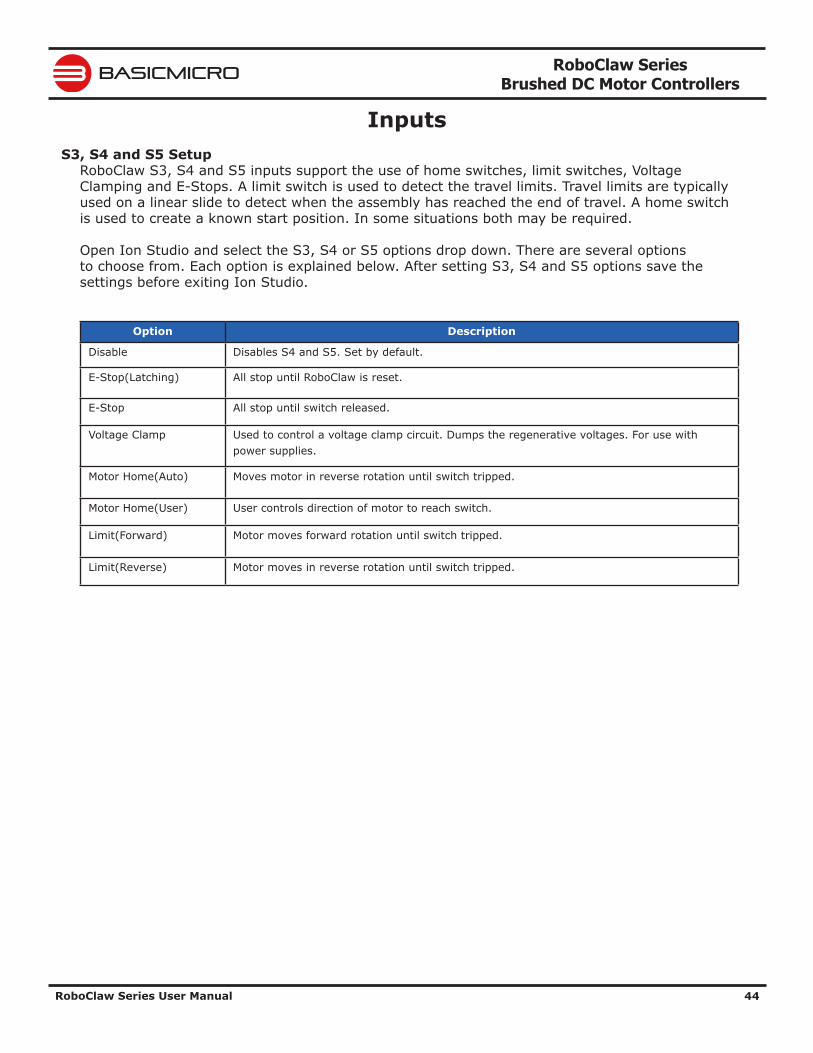
RoboClaw Series Brushed DC Motor Controllers
RoboClaw Series User Manual 44
BASICMICRO
InputsS3, S4 and S5 Setup
RoboClaw S3, S4 and S5 inputs support the use of home switches, limit switches, Voltage Clamping and E-Stops. A limit switch is used to detect the travel limits. Travel limits are typically used on a linear slide to detect when the assembly has reached the end of travel. A home switch is used to create a known start position. In some situations both may be required.
Open Ion Studio and select the S3, S4 or S5 options drop down. There are several options to choose from. Each option is explained below. After setting S3, S4 and S5 options save the settings before exiting Ion Studio.
Option Description
Disable Disables S4 and S5. Set by default.
E-Stop(Latching) All stop until RoboClaw is reset.
E-Stop All stop until switch released.
Voltage Clamp Used to control a voltage clamp circuit. Dumps the regenerative voltages. For use with power supplies.
Motor Home(Auto) Moves motor in reverse rotation until switch tripped.
Motor Home(User) User controls direction of motor to reach switch.
Limit(Forward) Motor moves forward rotation until switch tripped.
Limit(Reverse) Motor moves in reverse rotation until switch tripped.
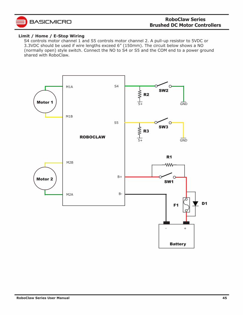
RoboClaw Series Brushed DC Motor Controllers
RoboClaw Series User Manual 45
BASICMICRO
Limit / Home / E-Stop WiringS4 controls motor channel 1 and S5 controls motor channel 2. A pull-up resistor to 5VDC or 3.3VDC should be used if wire lengths exceed 6” (150mm). The circuit below shows a NO (normally open) style switch. Connect the NO to S4 or S5 and the COM end to a power ground shared with RoboClaw.
Motor 1
Motor 2
M1A
M1B
M2B
M2A
ROBOCLAW
+-
Battery
R1
F1 D1
B-
B+SW1
S5
5+
R3SW3
GND
S4
5+
R2SW2
GND
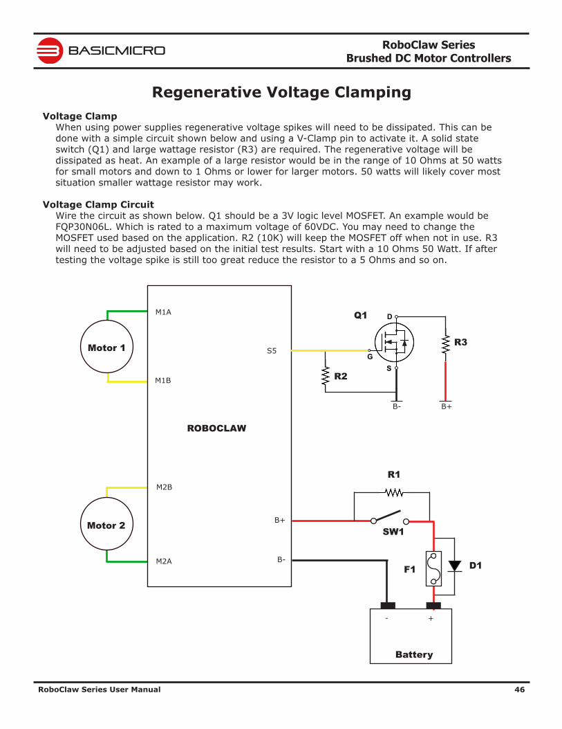
RoboClaw Series Brushed DC Motor Controllers
RoboClaw Series User Manual 46
BASICMICRO
Regenerative Voltage ClampingVoltage Clamp
When using power supplies regenerative voltage spikes will need to be dissipated. This can be done with a simple circuit shown below and using a V-Clamp pin to activate it. A solid state switch (Q1) and large wattage resistor (R3) are required. The regenerative voltage will be dissipated as heat. An example of a large resistor would be in the range of 10 Ohms at 50 watts for small motors and down to 1 Ohms or lower for larger motors. 50 watts will likely cover most situation smaller wattage resistor may work.
Voltage Clamp CircuitWire the circuit as shown below. Q1 should be a 3V logic level MOSFET. An example would be FQP30N06L. Which is rated to a maximum voltage of 60VDC. You may need to change the MOSFET used based on the application. R2 (10K) will keep the MOSFET off when not in use. R3 will need to be adjusted based on the initial test results. Start with a 10 Ohms 50 Watt. If after testing the voltage spike is still too great reduce the resistor to a 5 Ohms and so on.
Motor 1
Motor 2
M1A
M1B
M2B
M2A
ROBOCLAW
B-
B+
+-
Battery
R1
F1 D1
SW1
S
D
GS5
B- B+
R2
R3
Q1
RoboClaw Series Brushed DC Motor Controllers
RoboClaw Series User Manual 47
BASICMICRO
Voltage Clamp Setup and TestingOpen Ion Studio and set S5 to the Voltage Clamp option in the drop down and save the setting before exiting the application (see user manual).
The circuit shown will need to be tuned for each application to properly dissipate the regenerative voltages. Testing should consist of a running the motor up to 25% of its speed and then quickly slowing down without braking or e-stop while checking the voltage spike. Repeat, by increasing the speed and power by 5% and checking the voltage spikes again. Repeat this process until 100% power is achieved without a major spike or until the voltage clamp is not dissipating the voltage spikes. If over voltages are not completely clamped, either a lower Ohm resistor is required or additional capacitance is required. Add a capacitor of 5000uF to 10000uF or more across B+ and B-.
RoboClaw Series Brushed DC Motor Controllers
RoboClaw Series User Manual 48
BASICMICRO
Bridge ModeBridging Channels
RoboClaws dual channels can be bridge to run as one channel, effectively doubling its current capability for one motor. RoboClaw will be damaged if it is not set to bridged channel mode before wiring.
Download and install Ion Studio application. Connect the motor controller to the computer using an available USB port. Run Ion Studio and in general settings check the option to "Bridge Channels". Then click “Save Settings” in the device menu at the top of the window.
When operating in bridged channel mode the total peak current output is combined from both channels. The peak current run time is dependant on heat build up. Adequate cooling must be maintained.
Bridged Channel WiringWhen bridged channel mode is active the internal driver scheme for the output stage is modified. The output leads must be wired correctly or damage will result. Each RoboClaw varies on the correct wiring. See each models data sheet for wiring schematic.
Bridged Motor ControlWhen RoboClaw is set to bridged mode all motor control commands for M1 will control the attached motor. All commands for M2 will be ignored. In RC and Analog modes S1 will control the motor and S2 will be ignored.
RoboClaw Series Brushed DC Motor Controllers
RoboClaw Series User Manual 49
BASICMICRO
USB ControlUSB Connection
When RoboClaw is connected, it will automatically detect it has been connected to a powered USB master and will enable USB communications. USB can be connected in any mode. When the Roboclaw is not in packet serial mode USB packet serial commands can be used to read status information and set configuration settings, however motor movement commands will not function. When in packet serial mode if another device such as an Arduino is connected to S1 and S2 pins and sending commands to the RoboClaw, both those commands and USB packet serial commands will execute.
USB PowerThe USB RoboClaw is self powered. This means it receives no power from the USB cable. The USB RoboClaw must be externally powered to function.
USB Comport and BaudrateThe RoboClaw will be detected as a CDC Virtual Comport. When connected to a Windows PC a driver must be installed. The driver is available for download from our website. On Linux or OSX the RoboClaw will be automatically detected as a virtual comport and an appropriate driver will be automatically loaded.
Unlike a real comport the USB CDC Virtual Comport does not need a baud rate to be set. It will always communicate at the fastest speed the master and slave device can reach. This will typically be around 1mb/s.
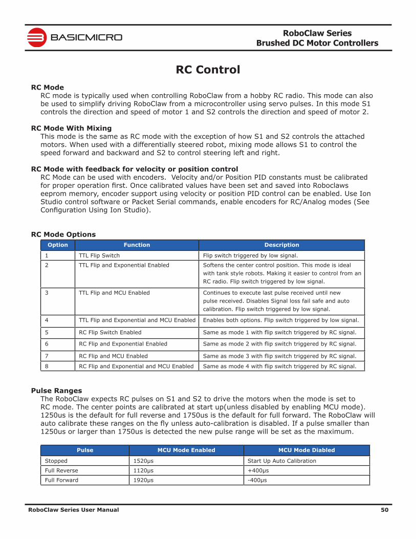
RoboClaw Series Brushed DC Motor Controllers
RoboClaw Series User Manual 50
BASICMICRO
RC ControlRC Mode
RC mode is typically used when controlling RoboClaw from a hobby RC radio. This mode can also be used to simplify driving RoboClaw from a microcontroller using servo pulses. In this mode S1 controls the direction and speed of motor 1 and S2 controls the direction and speed of motor 2.
RC Mode With MixingThis mode is the same as RC mode with the exception of how S1 and S2 controls the attached motors. When used with a differentially steered robot, mixing mode allows S1 to control the speed forward and backward and S2 to control steering left and right.
RC Mode with feedback for velocity or position controlRC Mode can be used with encoders. Velocity and/or Position PID constants must be calibrated for proper operation first. Once calibrated values have been set and saved into Roboclaws eeprom memory, encoder support using velocity or position PID control can be enabled. Use Ion Studio control software or Packet Serial commands, enable encoders for RC/Analog modes (See Configuration Using Ion Studio).
RC Mode OptionsOption Function Description
1 TTL Flip Switch Flip switch triggered by low signal.
2 TTL Flip and Exponential Enabled Softens the center control position. This mode is ideal with tank style robots. Making it easier to control from an RC radio. Flip switch triggered by low signal.
3 TTL Flip and MCU Enabled Continues to execute last pulse received until new pulse received. Disables Signal loss fail safe and auto calibration. Flip switch triggered by low signal.
4 TTL Flip and Exponential and MCU Enabled Enables both options. Flip switch triggered by low signal.
5 RC Flip Switch Enabled Same as mode 1 with flip switch triggered by RC signal.
6 RC Flip and Exponential Enabled Same as mode 2 with flip switch triggered by RC signal.
7 RC Flip and MCU Enabled Same as mode 3 with flip switch triggered by RC signal.
8 RC Flip and Exponential and MCU Enabled Same as mode 4 with flip switch triggered by RC signal.
Pulse RangesThe RoboClaw expects RC pulses on S1 and S2 to drive the motors when the mode is set to RC mode. The center points are calibrated at start up(unless disabled by enabling MCU mode). 1250us is the default for full reverse and 1750us is the default for full forward. The RoboClaw will auto calibrate these ranges on the fly unless auto-calibration is disabled. If a pulse smaller than 1250us or larger than 1750us is detected the new pulse range will be set as the maximum.
Pulse MCU Mode Enabled MCU Mode Diabled
Stopped 1520μs Start Up Auto Calibration
Full Reverse 1120μs +400μs
Full Forward 1920μs -400μs
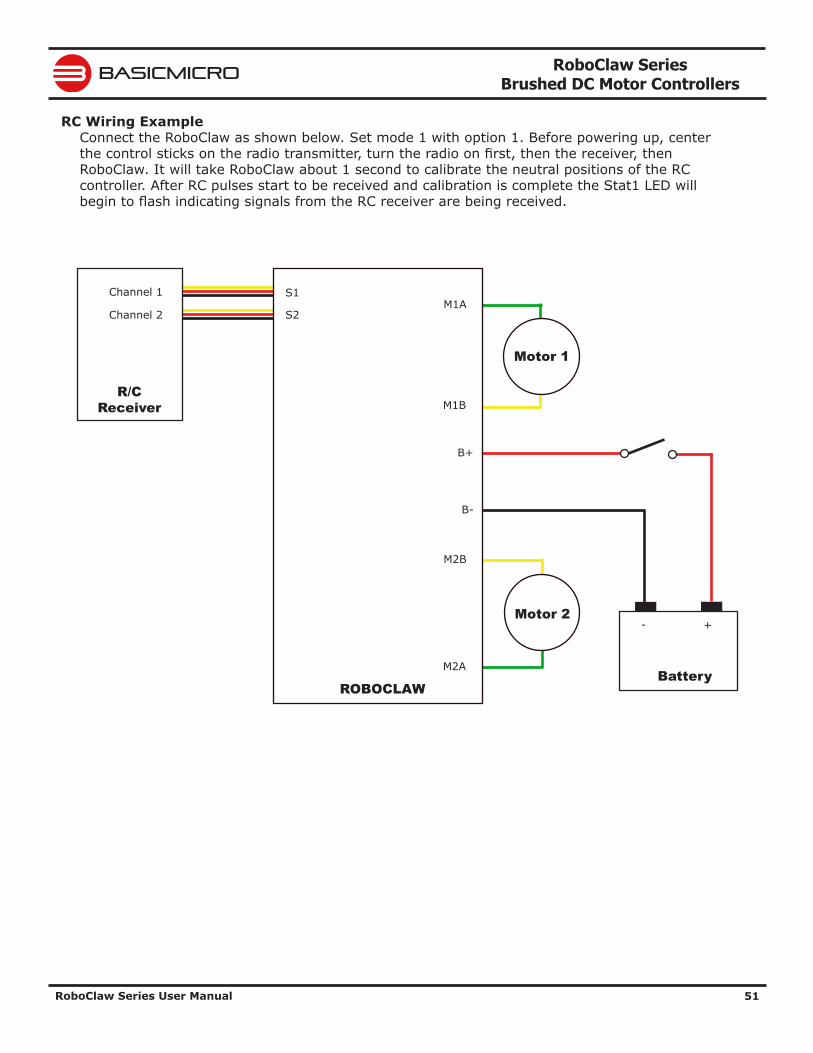
RoboClaw Series Brushed DC Motor Controllers
RoboClaw Series User Manual 51
BASICMICRO
RC Wiring ExampleConnect the RoboClaw as shown below. Set mode 1 with option 1. Before powering up, center the control sticks on the radio transmitter, turn the radio on first, then the receiver, then RoboClaw. It will take RoboClaw about 1 second to calibrate the neutral positions of the RC controller. After RC pulses start to be received and calibration is complete the Stat1 LED will begin to flash indicating signals from the RC receiver are being received.
M1A
M1B
M2B
M2A
B-
B+
+-
Battery
S2
ROBOCLAW
Motor 1
Motor 2
Channel 1
Channel 2
R/C Receiver
S1
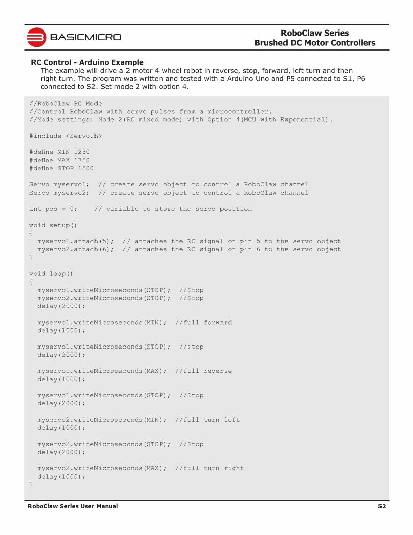
RoboClaw Series Brushed DC Motor Controllers
RoboClaw Series User Manual 52
BASICMICRO
RC Control - Arduino ExampleThe example will drive a 2 motor 4 wheel robot in reverse, stop, forward, left turn and then right turn. The program was written and tested with a Arduino Uno and P5 connected to S1, P6 connected to S2. Set mode 2 with option 4.
//RoboClaw RC Mode //Control RoboClaw with servo pulses from a microcontroller. //Mode settings: Mode 2(RC mixed mode) with Option 4(MCU with Exponential). #include <Servo.h> #define MIN 1250 #define MAX 1750 #define STOP 1500 Servo myservo1; // create servo object to control a RoboClaw channel Servo myservo2; // create servo object to control a RoboClaw channel int pos = 0; // variable to store the servo position void setup() { myservo1.attach(5); // attaches the RC signal on pin 5 to the servo object myservo2.attach(6); // attaches the RC signal on pin 6 to the servo object } void loop() { myservo1.writeMicroseconds(STOP); //Stop myservo2.writeMicroseconds(STOP); //Stop delay(2000); myservo1.writeMicroseconds(MIN); //full forward delay(1000); myservo1.writeMicroseconds(STOP); //stop delay(2000); myservo1.writeMicroseconds(MAX); //full reverse delay(1000); myservo1.writeMicroseconds(STOP); //Stop delay(2000); myservo2.writeMicroseconds(MIN); //full turn left delay(1000); myservo2.writeMicroseconds(STOP); //Stop delay(2000); myservo2.writeMicroseconds(MAX); //full turn right delay(1000); }
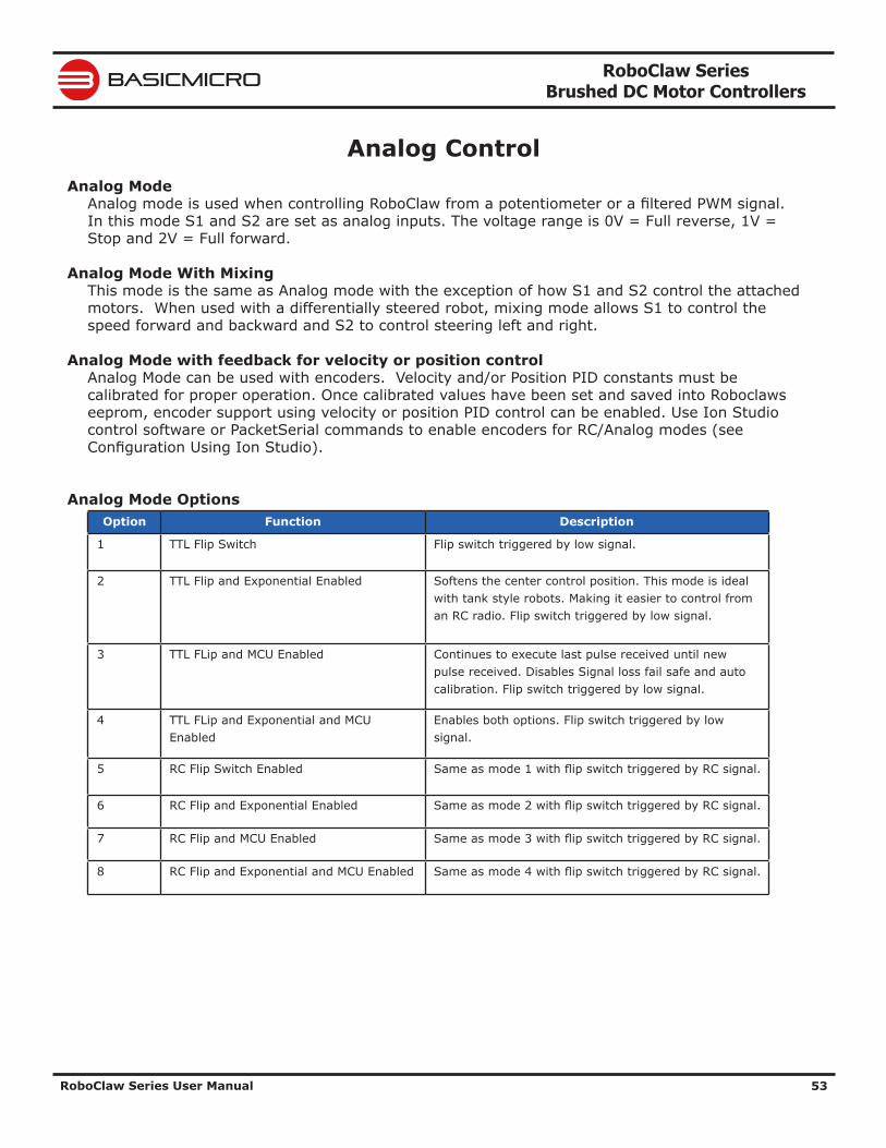
RoboClaw Series Brushed DC Motor Controllers
RoboClaw Series User Manual 53
BASICMICRO
Analog ControlAnalog Mode
Analog mode is used when controlling RoboClaw from a potentiometer or a filtered PWM signal. In this mode S1 and S2 are set as analog inputs. The voltage range is 0V = Full reverse, 1V = Stop and 2V = Full forward.
Analog Mode With MixingThis mode is the same as Analog mode with the exception of how S1 and S2 control the attached motors. When used with a differentially steered robot, mixing mode allows S1 to control the speed forward and backward and S2 to control steering left and right.
Analog Mode with feedback for velocity or position controlAnalog Mode can be used with encoders. Velocity and/or Position PID constants must be calibrated for proper operation. Once calibrated values have been set and saved into Roboclaws eeprom, encoder support using velocity or position PID control can be enabled. Use Ion Studio control software or PacketSerial commands to enable encoders for RC/Analog modes (see Configuration Using Ion Studio).
Analog Mode OptionsOption Function Description
1 TTL Flip Switch Flip switch triggered by low signal.
2 TTL Flip and Exponential Enabled Softens the center control position. This mode is ideal with tank style robots. Making it easier to control from an RC radio. Flip switch triggered by low signal.
3 TTL FLip and MCU Enabled Continues to execute last pulse received until new pulse received. Disables Signal loss fail safe and auto calibration. Flip switch triggered by low signal.
4 TTL FLip and Exponential and MCU Enabled
Enables both options. Flip switch triggered by low signal.
5 RC Flip Switch Enabled Same as mode 1 with flip switch triggered by RC signal.
6 RC Flip and Exponential Enabled Same as mode 2 with flip switch triggered by RC signal.
7 RC Flip and MCU Enabled Same as mode 3 with flip switch triggered by RC signal.
8 RC Flip and Exponential and MCU Enabled Same as mode 4 with flip switch triggered by RC signal.
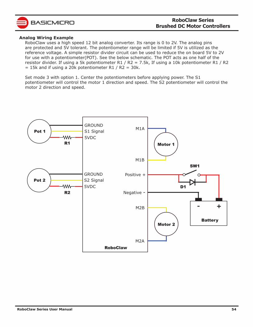
RoboClaw Series Brushed DC Motor Controllers
RoboClaw Series User Manual 54
BASICMICRO
Analog Wiring ExampleRoboClaw uses a high speed 12 bit analog converter. Its range is 0 to 2V. The analog pins are protected and 5V tolerant. The potentiometer range will be limited if 5V is utilized as the reference voltage. A simple resistor divider circuit can be used to reduce the on board 5V to 2V for use with a potentiometer(POT). See the below schematic. The POT acts as one half of the resistor divider. If using a 5k potentiometer R1 / R2 = 7.5k, If using a 10k potentiometer R1 / R2 = 15k and if using a 20k potentiometer R1 / R2 = 30k. Set mode 3 with option 1. Center the potentiometers before applying power. The S1 potentiometer will control the motor 1 direction and speed. The S2 potentiometer will control the motor 2 direction and speed.
S2 Signal5VDC
GROUNDPot 2
S1 Signal5VDC
GROUNDPot 1 M1A
M1B
M2B
M2A
Negative -
Positive +
+-
Battery
RoboClaw
Motor 1
Motor 2
R2
R1
D1
SW1
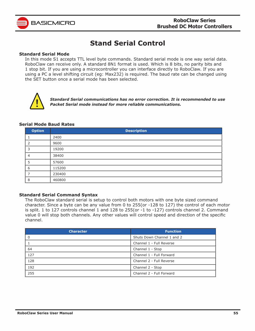
RoboClaw Series Brushed DC Motor Controllers
RoboClaw Series User Manual 55
BASICMICRO
Stand Serial ControlStandard Serial Mode
In this mode S1 accepts TTL level byte commands. Standard serial mode is one way serial data. RoboClaw can receive only. A standard 8N1 format is used. Which is 8 bits, no parity bits and 1 stop bit. If you are using a microcontroller you can interface directly to RoboClaw. If you are using a PC a level shifting circuit (eg: Max232) is required. The baud rate can be changed using the SET button once a serial mode has been selected.
Standard Serial communications has no error correction. It is recommended to use Packet Serial mode instead for more reliable communications.
Serial Mode Baud RatesOption Description
1 2400
2 9600
3 19200
4 38400
5 57600
6 115200
7 230400
8 460800
Standard Serial Command SyntaxThe RoboClaw standard serial is setup to control both motors with one byte sized command character. Since a byte can be any value from 0 to 255(or -128 to 127) the control of each motor is split. 1 to 127 controls channel 1 and 128 to 255(or -1 to -127) controls channel 2. Command value 0 will stop both channels. Any other values will control speed and direction of the specific channel.
Character Function
0 Shuts Down Channel 1 and 2
1 Channel 1 - Full Reverse
64 Channel 1 - Stop
127 Channel 1 - Full Forward
128 Channel 2 - Full Reverse
192 Channel 2 - Stop
255 Channel 2 - Full Forward
!
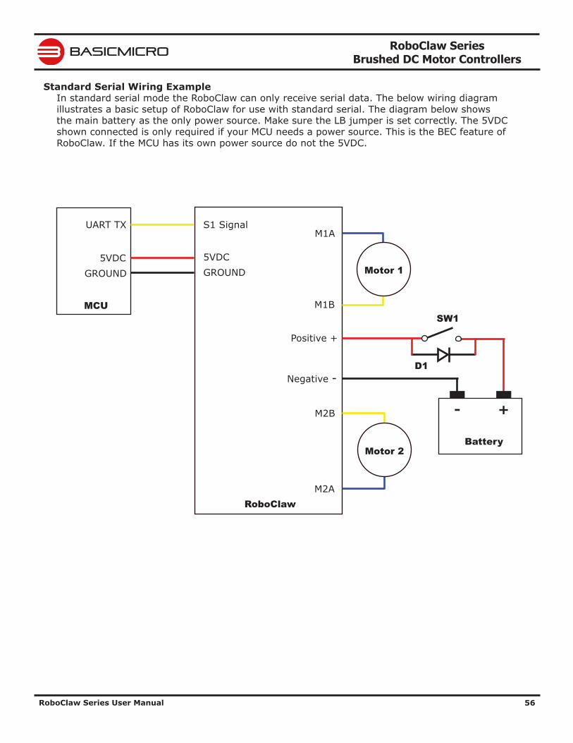
RoboClaw Series Brushed DC Motor Controllers
RoboClaw Series User Manual 56
BASICMICRO
Standard Serial Wiring ExampleIn standard serial mode the RoboClaw can only receive serial data. The below wiring diagram illustrates a basic setup of RoboClaw for use with standard serial. The diagram below shows the main battery as the only power source. Make sure the LB jumper is set correctly. The 5VDC shown connected is only required if your MCU needs a power source. This is the BEC feature of RoboClaw. If the MCU has its own power source do not the 5VDC.
M1A
M1B
M2B
M2A
Negative -
Positive +
+-
Battery
S1 Signal
5VDC
UART TX
GROUND5VDC
GROUND
MCU
RoboClaw
Motor 1
Motor 2
D1
SW1
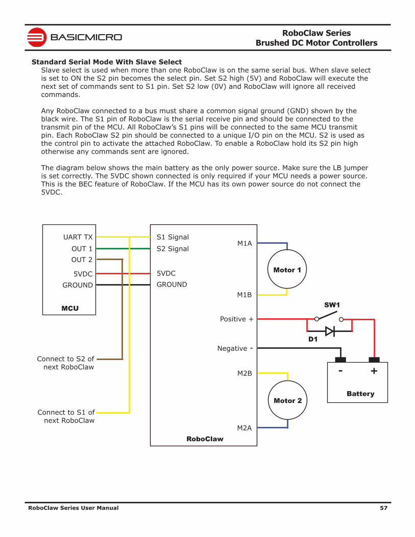
RoboClaw Series Brushed DC Motor Controllers
RoboClaw Series User Manual 57
BASICMICRO
Standard Serial Mode With Slave SelectSlave select is used when more than one RoboClaw is on the same serial bus. When slave select is set to ON the S2 pin becomes the select pin. Set S2 high (5V) and RoboClaw will execute the next set of commands sent to S1 pin. Set S2 low (0V) and RoboClaw will ignore all received commands.
Any RoboClaw connected to a bus must share a common signal ground (GND) shown by the black wire. The S1 pin of RoboClaw is the serial receive pin and should be connected to the transmit pin of the MCU. All RoboClaw’s S1 pins will be connected to the same MCU transmit pin. Each RoboClaw S2 pin should be connected to a unique I/O pin on the MCU. S2 is used as the control pin to activate the attached RoboClaw. To enable a RoboClaw hold its S2 pin high otherwise any commands sent are ignored.
The diagram below shows the main battery as the only power source. Make sure the LB jumper is set correctly. The 5VDC shown connected is only required if your MCU needs a power source. This is the BEC feature of RoboClaw. If the MCU has its own power source do not connect the 5VDC.
M1A
M1B
M2B
M2A
Negative -
Positive +
+-
Battery
S1 Signal
S2 Signal
5VDC
UART TX
OUT 1
GROUND5VDC
GROUND
MCU
RoboClaw
Motor 1
Motor 2
OUT 2
Connect to S2 of next RoboClaw
Connect to S1 of next RoboClaw
D1
SW1
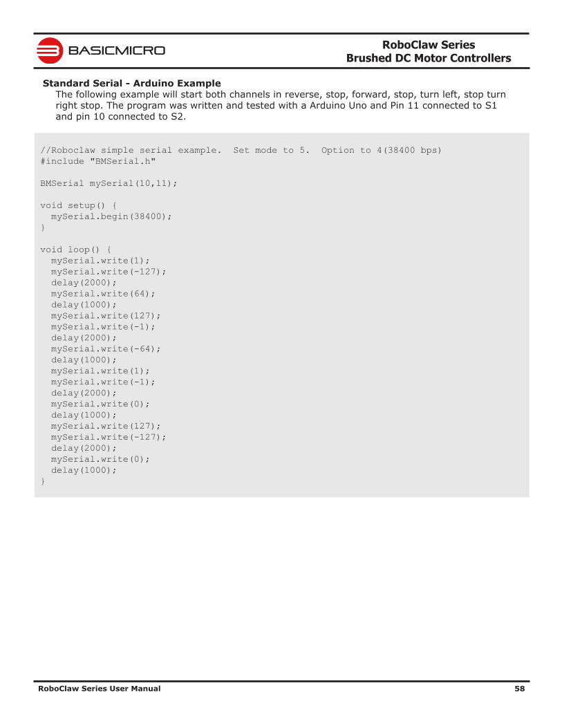
RoboClaw Series Brushed DC Motor Controllers
RoboClaw Series User Manual 58
BASICMICRO
Standard Serial - Arduino ExampleThe following example will start both channels in reverse, stop, forward, stop, turn left, stop turn right stop. The program was written and tested with a Arduino Uno and Pin 11 connected to S1 and pin 10 connected to S2.
//Roboclaw simple serial example. Set mode to 5. Option to 4(38400 bps) #include "BMSerial.h" BMSerial mySerial(10,11); void setup() { mySerial.begin(38400); } void loop() { mySerial.write(1); mySerial.write(-127); delay(2000); mySerial.write(64); delay(1000); mySerial.write(127); mySerial.write(-1); delay(2000); mySerial.write(-64); delay(1000); mySerial.write(1); mySerial.write(-1); delay(2000); mySerial.write(0); delay(1000); mySerial.write(127); mySerial.write(-127); delay(2000); mySerial.write(0); delay(1000); }
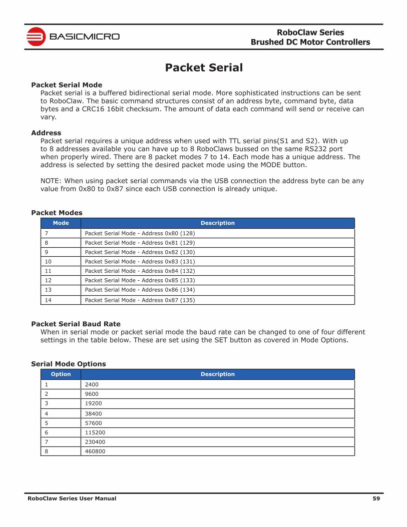
RoboClaw Series Brushed DC Motor Controllers
RoboClaw Series User Manual 59
BASICMICRO
Packet SerialPacket Serial Mode
Packet serial is a buffered bidirectional serial mode. More sophisticated instructions can be sent to RoboClaw. The basic command structures consist of an address byte, command byte, data bytes and a CRC16 16bit checksum. The amount of data each command will send or receive can vary.
AddressPacket serial requires a unique address when used with TTL serial pins(S1 and S2). With up to 8 addresses available you can have up to 8 RoboClaws bussed on the same RS232 port when properly wired. There are 8 packet modes 7 to 14. Each mode has a unique address. The address is selected by setting the desired packet mode using the MODE button.
NOTE: When using packet serial commands via the USB connection the address byte can be any value from 0x80 to 0x87 since each USB connection is already unique.
Packet ModesMode Description
7 Packet Serial Mode - Address 0x80 (128)
8 Packet Serial Mode - Address 0x81 (129)
9 Packet Serial Mode - Address 0x82 (130)
10 Packet Serial Mode - Address 0x83 (131)
11 Packet Serial Mode - Address 0x84 (132)
12 Packet Serial Mode - Address 0x85 (133)
13 Packet Serial Mode - Address 0x86 (134)
14 Packet Serial Mode - Address 0x87 (135)
Packet Serial Baud RateWhen in serial mode or packet serial mode the baud rate can be changed to one of four different settings in the table below. These are set using the SET button as covered in Mode Options.
Serial Mode OptionsOption Description
1 2400
2 9600
3 19200
4 38400
5 57600
6 115200
7 230400
8 460800
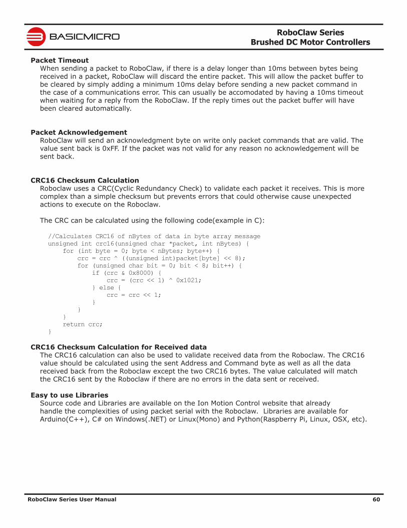
RoboClaw Series Brushed DC Motor Controllers
RoboClaw Series User Manual 60
BASICMICRO
Packet TimeoutWhen sending a packet to RoboClaw, if there is a delay longer than 10ms between bytes being received in a packet, RoboClaw will discard the entire packet. This will allow the packet buffer to be cleared by simply adding a minimum 10ms delay before sending a new packet command in the case of a communications error. This can usually be accomodated by having a 10ms timeout when waiting for a reply from the RoboClaw. If the reply times out the packet buffer will have been cleared automatically.
Packet AcknowledgementRoboClaw will send an acknowledgment byte on write only packet commands that are valid. The value sent back is 0xFF. If the packet was not valid for any reason no acknowledgement will be sent back.
CRC16 Checksum CalculationRoboclaw uses a CRC(Cyclic Redundancy Check) to validate each packet it receives. This is more complex than a simple checksum but prevents errors that could otherwise cause unexpected actions to execute on the Roboclaw.
The CRC can be calculated using the following code(example in C):
//Calculates CRC16 of nBytes of data in byte array messageunsigned int crc16(unsigned char *packet, int nBytes) { for (int byte = 0; byte < nBytes; byte++) { crc = crc ^ ((unsigned int)packet[byte] << 8); for (unsigned char bit = 0; bit < 8; bit++) { if (crc & 0x8000) { crc = (crc << 1) ^ 0x1021; } else { crc = crc << 1; } } } return crc;}
CRC16 Checksum Calculation for Received dataThe CRC16 calculation can also be used to validate received data from the Roboclaw. The CRC16 value should be calculated using the sent Address and Command byte as well as all the data received back from the Roboclaw except the two CRC16 bytes. The value calculated will match the CRC16 sent by the Roboclaw if there are no errors in the data sent or received.
Easy to use LibrariesSource code and Libraries are available on the Ion Motion Control website that already handle the complexities of using packet serial with the Roboclaw. Libraries are available for Arduino(C++), C# on Windows(.NET) or Linux(Mono) and Python(Raspberry Pi, Linux, OSX, etc).
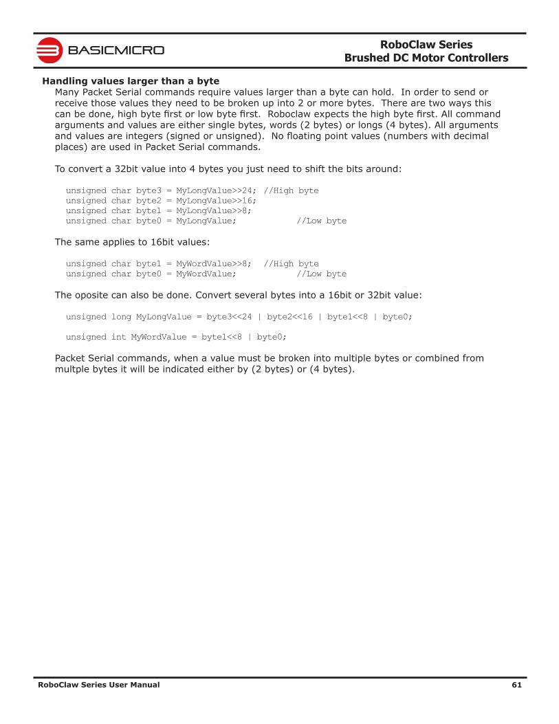
RoboClaw Series Brushed DC Motor Controllers
RoboClaw Series User Manual 61
BASICMICRO
Handling values larger than a byteMany Packet Serial commands require values larger than a byte can hold. In order to send or receive those values they need to be broken up into 2 or more bytes. There are two ways this can be done, high byte first or low byte first. Roboclaw expects the high byte first. All command arguments and values are either single bytes, words (2 bytes) or longs (4 bytes). All arguments and values are integers (signed or unsigned). No floating point values (numbers with decimal places) are used in Packet Serial commands.
To convert a 32bit value into 4 bytes you just need to shift the bits around:
unsigned char byte3 = MyLongValue>>24; //High byteunsigned char byte2 = MyLongValue>>16;unsigned char byte1 = MyLongValue>>8;unsigned char byte0 = MyLongValue; //Low byte
The same applies to 16bit values:
unsigned char byte1 = MyWordValue>>8; //High byteunsigned char byte0 = MyWordValue; //Low byte
The oposite can also be done. Convert several bytes into a 16bit or 32bit value:
unsigned long MyLongValue = byte3<<24 | byte2<<16 | byte1<<8 | byte0;
unsigned int MyWordValue = byte1<<8 | byte0;
Packet Serial commands, when a value must be broken into multiple bytes or combined from multple bytes it will be indicated either by (2 bytes) or (4 bytes).
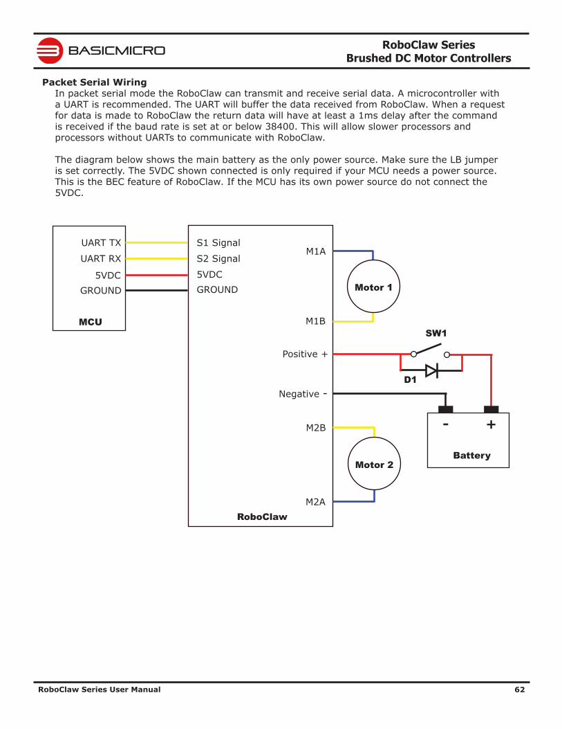
RoboClaw Series Brushed DC Motor Controllers
RoboClaw Series User Manual 62
BASICMICRO
Packet Serial WiringIn packet serial mode the RoboClaw can transmit and receive serial data. A microcontroller with a UART is recommended. The UART will buffer the data received from RoboClaw. When a request for data is made to RoboClaw the return data will have at least a 1ms delay after the command is received if the baud rate is set at or below 38400. This will allow slower processors and processors without UARTs to communicate with RoboClaw.
The diagram below shows the main battery as the only power source. Make sure the LB jumper is set correctly. The 5VDC shown connected is only required if your MCU needs a power source. This is the BEC feature of RoboClaw. If the MCU has its own power source do not connect the 5VDC.
M1A
M1B
M2B
M2A
Negative -
Positive +
+-
Battery
S1 Signal
S2 Signal
5VDC
UART TX
UART RX
GROUND5VDC
GROUND
MCU
RoboClaw
Motor 1
Motor 2
D1
SW1
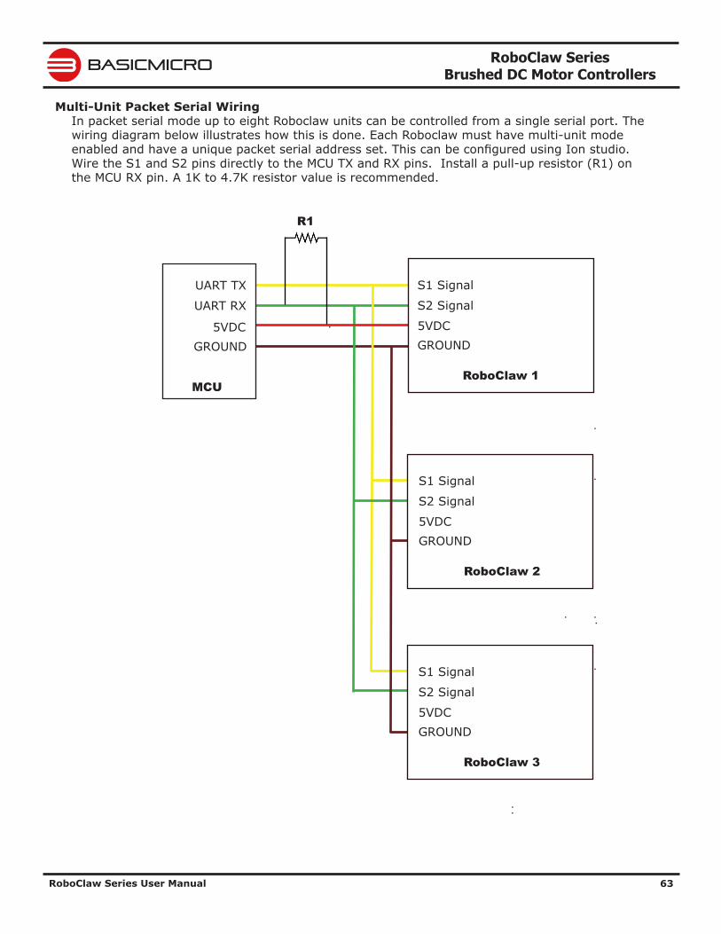
RoboClaw Series Brushed DC Motor Controllers
RoboClaw Series User Manual 63
BASICMICRO
Multi-Unit Packet Serial WiringIn packet serial mode up to eight Roboclaw units can be controlled from a single serial port. The wiring diagram below illustrates how this is done. Each Roboclaw must have multi-unit mode enabled and have a unique packet serial address set. This can be configured using Ion studio. Wire the S1 and S2 pins directly to the MCU TX and RX pins. Install a pull-up resistor (R1) on the MCU RX pin. A 1K to 4.7K resistor value is recommended.
S1 Signal
S2 Signal
5VDCGROUND
RoboClaw 2
S1 Signal
S2 Signal
5VDCGROUND
RoboClaw 3
S1 Signal
S2 Signal
5VDCGROUND
RoboClaw 1
UART TX
UART RX
5VDCGROUND
MCU
R1
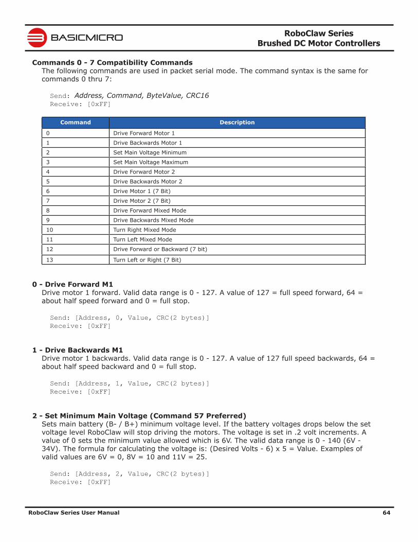
RoboClaw Series Brushed DC Motor Controllers
RoboClaw Series User Manual 64
BASICMICRO
Commands 0 - 7 Compatibility CommandsThe following commands are used in packet serial mode. The command syntax is the same for commands 0 thru 7:
Send: Address, Command, ByteValue, CRC16 Receive: [0xFF]
Command Description
0 Drive Forward Motor 1
1 Drive Backwards Motor 1
2 Set Main Voltage Minimum
3 Set Main Voltage Maximum
4 Drive Forward Motor 2
5 Drive Backwards Motor 2
6 Drive Motor 1 (7 Bit)
7 Drive Motor 2 (7 Bit)
8 Drive Forward Mixed Mode
9 Drive Backwards Mixed Mode
10 Turn Right Mixed Mode
11 Turn Left Mixed Mode
12 Drive Forward or Backward (7 bit)
13 Turn Left or Right (7 Bit)
0 - Drive Forward M1Drive motor 1 forward. Valid data range is 0 - 127. A value of 127 = full speed forward, 64 = about half speed forward and 0 = full stop.
Send: [Address, 0, Value, CRC(2 bytes)] Receive: [0xFF]
1 - Drive Backwards M1 Drive motor 1 backwards. Valid data range is 0 - 127. A value of 127 full speed backwards, 64 = about half speed backward and 0 = full stop.
Send: [Address, 1, Value, CRC(2 bytes)] Receive: [0xFF]
2 - Set Minimum Main Voltage (Command 57 Preferred) Sets main battery (B- / B+) minimum voltage level. If the battery voltages drops below the set voltage level RoboClaw will stop driving the motors. The voltage is set in .2 volt increments. A value of 0 sets the minimum value allowed which is 6V. The valid data range is 0 - 140 (6V - 34V). The formula for calculating the voltage is: (Desired Volts - 6) x 5 = Value. Examples of valid values are 6V = 0, 8V = 10 and 11V = 25.
Send: [Address, 2, Value, CRC(2 bytes)] Receive: [0xFF]
RoboClaw Series Brushed DC Motor Controllers
RoboClaw Series User Manual 65
BASICMICRO
3 - Set Maximum Main Voltage (Command 57 Preferred) Sets main battery (B- / B+) maximum voltage level. The valid data range is 30 - 175 (6V - 34V). During regenerative breaking a back voltage is applied to charge the battery. When using a power supply, by setting the maximum voltage level, RoboClaw will, before exceeding it, go into hard braking mode until the voltage drops below the maximum value set. This will prevent overvoltage conditions when using power supplies. The formula for calculating the voltage is: Desired Volts x 5.12 = Value. Examples of valid values are 12V = 62, 16V = 82 and 24V = 123.
Send: [Address, 3, Value, CRC(2 bytes)] Receive: [0xFF]
4 - Drive Forward M2Drive motor 2 forward. Valid data range is 0 - 127. A value of 127 full speed forward, 64 = about half speed forward and 0 = full stop.
Send: [Address, 4, Value, CRC(2 bytes)] Receive: [0xFF]
5 - Drive Backwards M2 Drive motor 2 backwards. Valid data range is 0 - 127. A value of 127 full speed backwards, 64 = about half speed backward and 0 = full stop.
Send: [Address, 5, Value, CRC(2 bytes)] Receive: [0xFF]
6 - Drive M1 (7 Bit) Drive motor 1 forward or reverse. Valid data range is 0 - 127. A value of 0 = full speed reverse, 64 = stop and 127 = full speed forward.
Send: [Address, 6, Value, CRC(2 bytes)] Receive: [0xFF]
7 - Drive M2 (7 Bit) Drive motor 2 forward or reverse. Valid data range is 0 - 127. A value of 0 = full speed reverse, 64 = stop and 127 = full speed forward.
Send: [Address, 7, Value, CRC(2 bytes)] Receive: [0xFF]
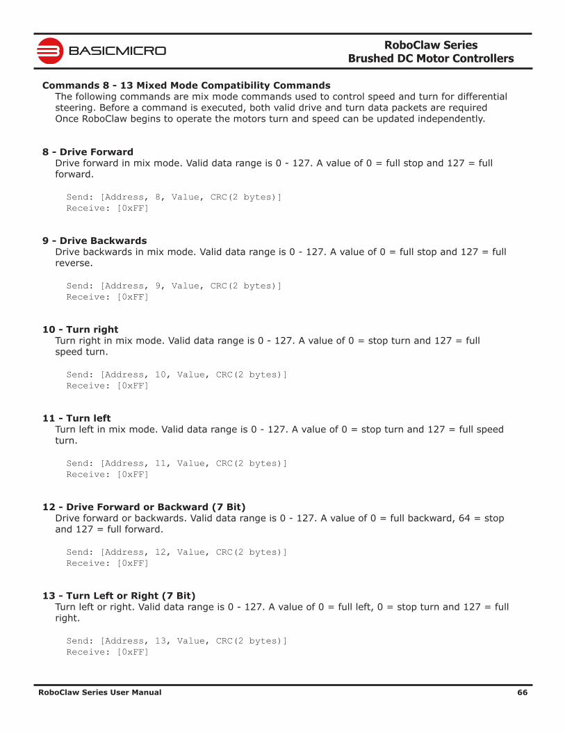
RoboClaw Series Brushed DC Motor Controllers
RoboClaw Series User Manual 66
BASICMICRO
Commands 8 - 13 Mixed Mode Compatibility CommandsThe following commands are mix mode commands used to control speed and turn for differential steering. Before a command is executed, both valid drive and turn data packets are required Once RoboClaw begins to operate the motors turn and speed can be updated independently.
8 - Drive ForwardDrive forward in mix mode. Valid data range is 0 - 127. A value of 0 = full stop and 127 = full forward.
Send: [Address, 8, Value, CRC(2 bytes)] Receive: [0xFF]
9 - Drive BackwardsDrive backwards in mix mode. Valid data range is 0 - 127. A value of 0 = full stop and 127 = full reverse.
Send: [Address, 9, Value, CRC(2 bytes)] Receive: [0xFF]
10 - Turn rightTurn right in mix mode. Valid data range is 0 - 127. A value of 0 = stop turn and 127 = full speed turn.
Send: [Address, 10, Value, CRC(2 bytes)] Receive: [0xFF]
11 - Turn leftTurn left in mix mode. Valid data range is 0 - 127. A value of 0 = stop turn and 127 = full speed turn.
Send: [Address, 11, Value, CRC(2 bytes)] Receive: [0xFF]
12 - Drive Forward or Backward (7 Bit)Drive forward or backwards. Valid data range is 0 - 127. A value of 0 = full backward, 64 = stop and 127 = full forward.
Send: [Address, 12, Value, CRC(2 bytes)] Receive: [0xFF]
13 - Turn Left or Right (7 Bit)Turn left or right. Valid data range is 0 - 127. A value of 0 = full left, 0 = stop turn and 127 = full right.
Send: [Address, 13, Value, CRC(2 bytes)] Receive: [0xFF]
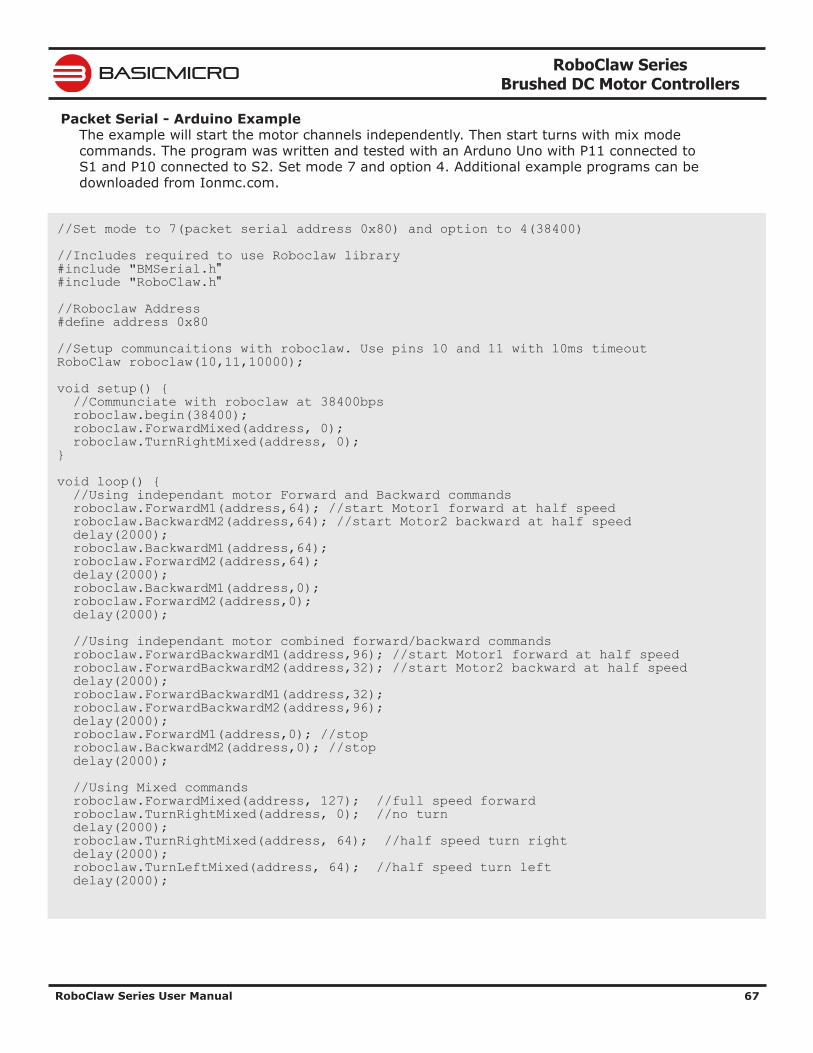
RoboClaw Series Brushed DC Motor Controllers
RoboClaw Series User Manual 67
BASICMICRO
Packet Serial - Arduino ExampleThe example will start the motor channels independently. Then start turns with mix mode commands. The program was written and tested with an Arduno Uno with P11 connected to S1 and P10 connected to S2. Set mode 7 and option 4. Additional example programs can be downloaded from Ionmc.com.
//Set mode to 7(packet serial address 0x80) and option to 4(38400) //Includes required to use Roboclaw library #include "BMSerial.h" #include "RoboClaw.h" //Roboclaw Address #define address 0x80 //Setup communcaitions with roboclaw. Use pins 10 and 11 with 10ms timeout RoboClaw roboclaw(10,11,10000); void setup() { //Communciate with roboclaw at 38400bps roboclaw.begin(38400); roboclaw.ForwardMixed(address, 0); roboclaw.TurnRightMixed(address, 0); } void loop() { //Using independant motor Forward and Backward commands roboclaw.ForwardM1(address,64); //start Motor1 forward at half speed roboclaw.BackwardM2(address,64); //start Motor2 backward at half speed delay(2000); roboclaw.BackwardM1(address,64); roboclaw.ForwardM2(address,64); delay(2000); roboclaw.BackwardM1(address,0); roboclaw.ForwardM2(address,0); delay(2000); //Using independant motor combined forward/backward commands roboclaw.ForwardBackwardM1(address,96); //start Motor1 forward at half speed roboclaw.ForwardBackwardM2(address,32); //start Motor2 backward at half speed delay(2000); roboclaw.ForwardBackwardM1(address,32); roboclaw.ForwardBackwardM2(address,96); delay(2000); roboclaw.ForwardM1(address,0); //stop roboclaw.BackwardM2(address,0); //stop delay(2000); //Using Mixed commands roboclaw.ForwardMixed(address, 127); //full speed forward roboclaw.TurnRightMixed(address, 0); //no turn delay(2000); roboclaw.TurnRightMixed(address, 64); //half speed turn right delay(2000); roboclaw.TurnLeftMixed(address, 64); //half speed turn left delay(2000);
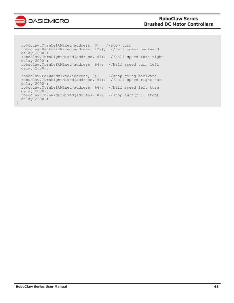
RoboClaw Series Brushed DC Motor Controllers
RoboClaw Series User Manual 68
BASICMICRO
roboclaw.TurnLeftMixed(address, 0); //stop turn roboclaw.BackwardMixed(address, 127); //half speed backward delay(2000); roboclaw.TurnRightMixed(address, 64); //half speed turn right delay(2000); roboclaw.TurnLeftMixed(address, 64); //half speed turn left delay(2000); roboclaw.ForwardMixed(address, 0); //stop going backward roboclaw.TurnRightMixed(address, 64); //half speed right turn delay(2000); roboclaw.TurnLeftMixed(address, 64); //half speed left turn delay(2000); roboclaw.TurnRightMixed(address, 0); //stop turn(full stop) delay(2000); }
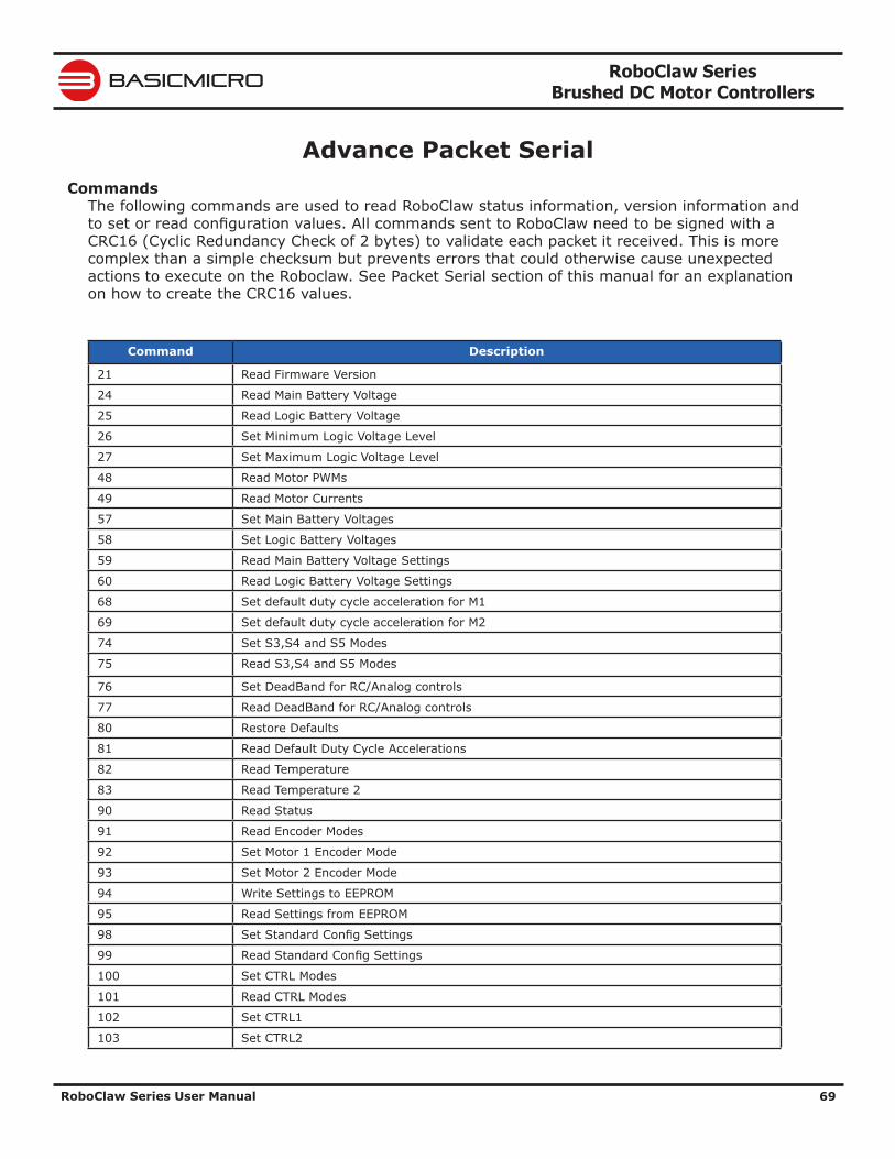
RoboClaw Series Brushed DC Motor Controllers
RoboClaw Series User Manual 69
BASICMICRO
Advance Packet Serial Commands
The following commands are used to read RoboClaw status information, version information and to set or read configuration values. All commands sent to RoboClaw need to be signed with a CRC16 (Cyclic Redundancy Check of 2 bytes) to validate each packet it received. This is more complex than a simple checksum but prevents errors that could otherwise cause unexpected actions to execute on the Roboclaw. See Packet Serial section of this manual for an explanation on how to create the CRC16 values.
Command Description
21 Read Firmware Version
24 Read Main Battery Voltage
25 Read Logic Battery Voltage
26 Set Minimum Logic Voltage Level
27 Set Maximum Logic Voltage Level
48 Read Motor PWMs
49 Read Motor Currents
57 Set Main Battery Voltages
58 Set Logic Battery Voltages
59 Read Main Battery Voltage Settings
60 Read Logic Battery Voltage Settings
68 Set default duty cycle acceleration for M1
69 Set default duty cycle acceleration for M2
74 Set S3,S4 and S5 Modes
75 Read S3,S4 and S5 Modes
76 Set DeadBand for RC/Analog controls
77 Read DeadBand for RC/Analog controls
80 Restore Defaults
81 Read Default Duty Cycle Accelerations
82 Read Temperature
83 Read Temperature 2
90 Read Status
91 Read Encoder Modes
92 Set Motor 1 Encoder Mode
93 Set Motor 2 Encoder Mode
94 Write Settings to EEPROM
95 Read Settings from EEPROM
98 Set Standard Config Settings
99 Read Standard Config Settings
100 Set CTRL Modes
101 Read CTRL Modes
102 Set CTRL1
103 Set CTRL2
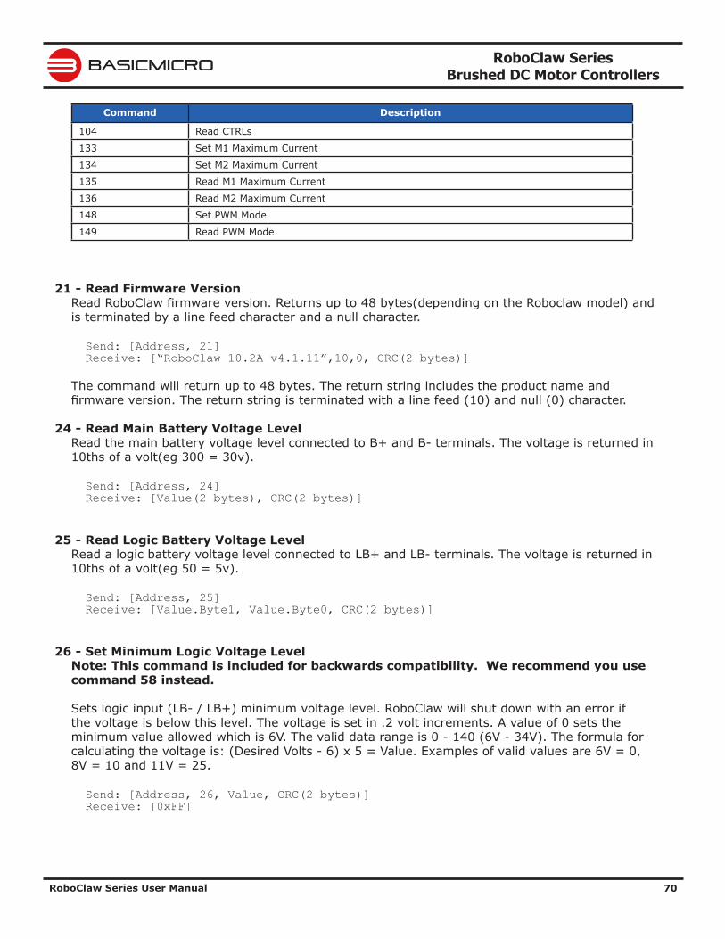
RoboClaw Series Brushed DC Motor Controllers
RoboClaw Series User Manual 70
BASICMICRO
Command Description
104 Read CTRLs
133 Set M1 Maximum Current
134 Set M2 Maximum Current
135 Read M1 Maximum Current
136 Read M2 Maximum Current
148 Set PWM Mode
149 Read PWM Mode
21 - Read Firmware VersionRead RoboClaw firmware version. Returns up to 48 bytes(depending on the Roboclaw model) and is terminated by a line feed character and a null character.
Send: [Address, 21] Receive: [“RoboClaw 10.2A v4.1.11”,10,0, CRC(2 bytes)]
The command will return up to 48 bytes. The return string includes the product name and firmware version. The return string is terminated with a line feed (10) and null (0) character.
24 - Read Main Battery Voltage LevelRead the main battery voltage level connected to B+ and B- terminals. The voltage is returned in 10ths of a volt(eg 300 = 30v).
Send: [Address, 24] Receive: [Value(2 bytes), CRC(2 bytes)]
25 - Read Logic Battery Voltage LevelRead a logic battery voltage level connected to LB+ and LB- terminals. The voltage is returned in 10ths of a volt(eg 50 = 5v).
Send: [Address, 25] Receive: [Value.Byte1, Value.Byte0, CRC(2 bytes)]
26 - Set Minimum Logic Voltage LevelNote: This command is included for backwards compatibility. We recommend you use command 58 instead.
Sets logic input (LB- / LB+) minimum voltage level. RoboClaw will shut down with an error if the voltage is below this level. The voltage is set in .2 volt increments. A value of 0 sets the minimum value allowed which is 6V. The valid data range is 0 - 140 (6V - 34V). The formula for calculating the voltage is: (Desired Volts - 6) x 5 = Value. Examples of valid values are 6V = 0, 8V = 10 and 11V = 25.
Send: [Address, 26, Value, CRC(2 bytes)] Receive: [0xFF]
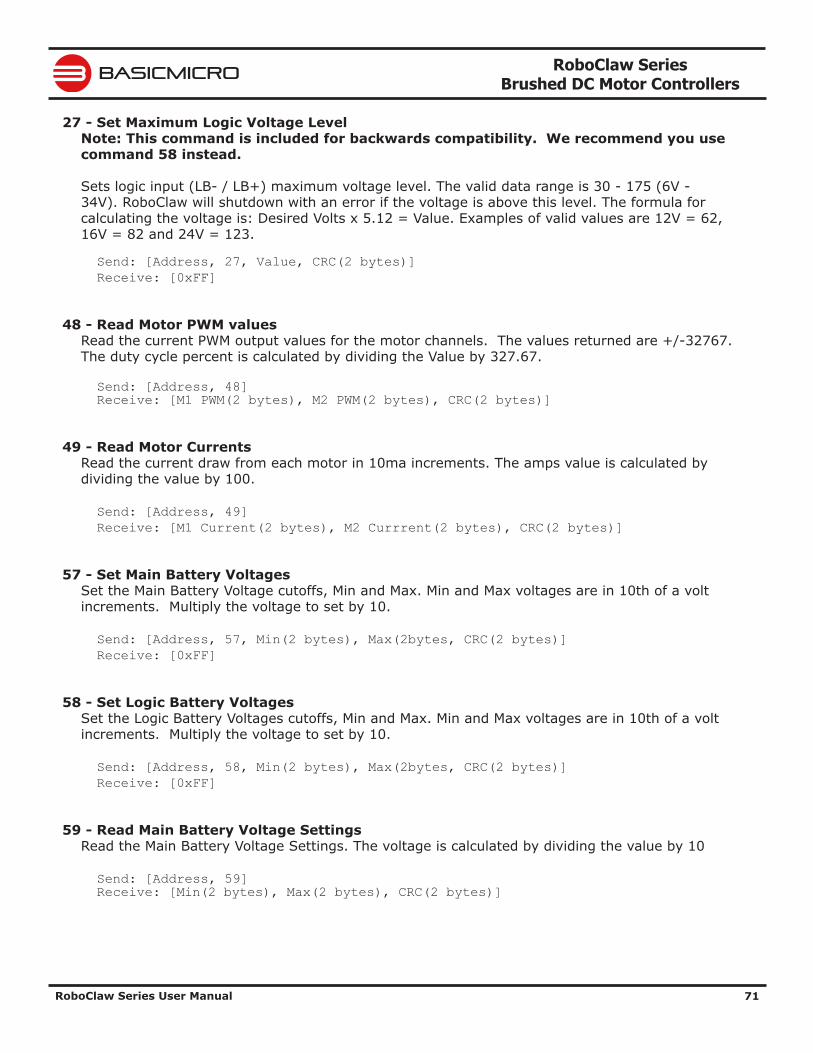
RoboClaw Series Brushed DC Motor Controllers
RoboClaw Series User Manual 71
BASICMICRO
27 - Set Maximum Logic Voltage LevelNote: This command is included for backwards compatibility. We recommend you use command 58 instead.
Sets logic input (LB- / LB+) maximum voltage level. The valid data range is 30 - 175 (6V - 34V). RoboClaw will shutdown with an error if the voltage is above this level. The formula for calculating the voltage is: Desired Volts x 5.12 = Value. Examples of valid values are 12V = 62, 16V = 82 and 24V = 123.
Send: [Address, 27, Value, CRC(2 bytes)] Receive: [0xFF]
48 - Read Motor PWM valuesRead the current PWM output values for the motor channels. The values returned are +/-32767. The duty cycle percent is calculated by dividing the Value by 327.67.
Send: [Address, 48] Receive: [M1 PWM(2 bytes), M2 PWM(2 bytes), CRC(2 bytes)]
49 - Read Motor CurrentsRead the current draw from each motor in 10ma increments. The amps value is calculated by dividing the value by 100.
Send: [Address, 49] Receive: [M1 Current(2 bytes), M2 Currrent(2 bytes), CRC(2 bytes)]
57 - Set Main Battery VoltagesSet the Main Battery Voltage cutoffs, Min and Max. Min and Max voltages are in 10th of a volt increments. Multiply the voltage to set by 10.
Send: [Address, 57, Min(2 bytes), Max(2bytes, CRC(2 bytes)] Receive: [0xFF]
58 - Set Logic Battery VoltagesSet the Logic Battery Voltages cutoffs, Min and Max. Min and Max voltages are in 10th of a volt increments. Multiply the voltage to set by 10.
Send: [Address, 58, Min(2 bytes), Max(2bytes, CRC(2 bytes)] Receive: [0xFF]
59 - Read Main Battery Voltage SettingsRead the Main Battery Voltage Settings. The voltage is calculated by dividing the value by 10
Send: [Address, 59] Receive: [Min(2 bytes), Max(2 bytes), CRC(2 bytes)]
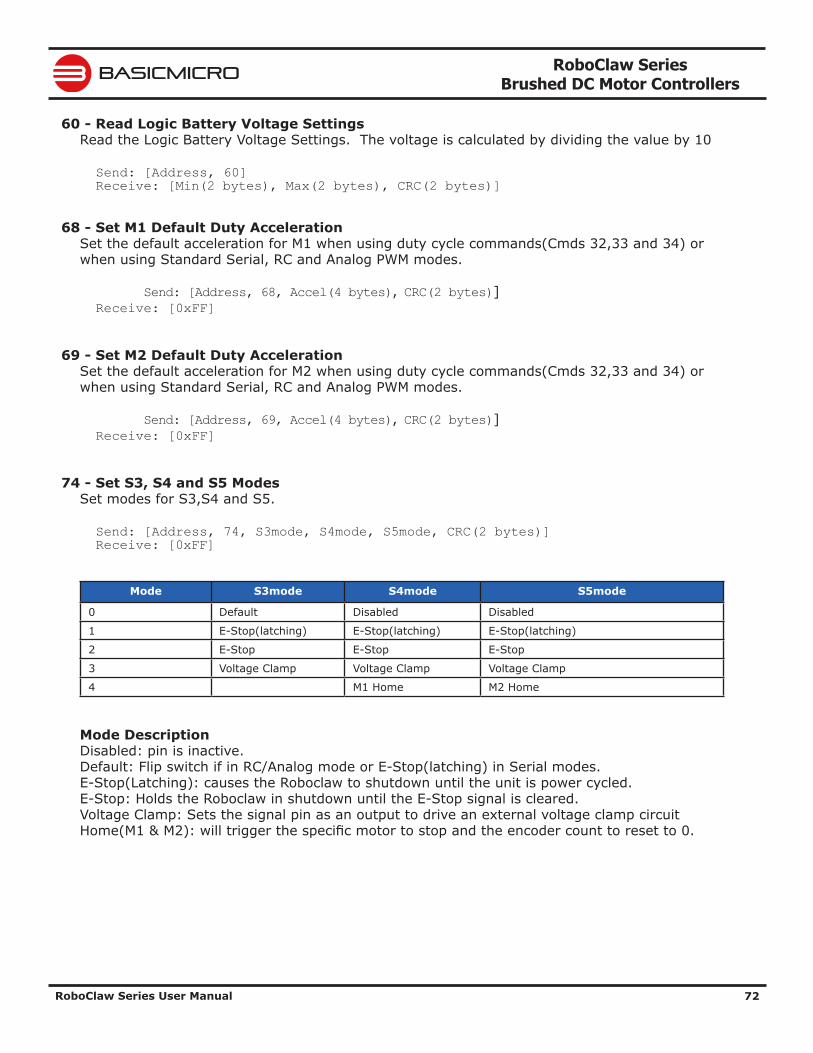
RoboClaw Series Brushed DC Motor Controllers
RoboClaw Series User Manual 72
BASICMICRO
60 - Read Logic Battery Voltage SettingsRead the Logic Battery Voltage Settings. The voltage is calculated by dividing the value by 10
Send: [Address, 60] Receive: [Min(2 bytes), Max(2 bytes), CRC(2 bytes)]
68 - Set M1 Default Duty AccelerationSet the default acceleration for M1 when using duty cycle commands(Cmds 32,33 and 34) or when using Standard Serial, RC and Analog PWM modes.
Send: [Address, 68, Accel(4 bytes), CRC(2 bytes)] Receive: [0xFF]
69 - Set M2 Default Duty AccelerationSet the default acceleration for M2 when using duty cycle commands(Cmds 32,33 and 34) or when using Standard Serial, RC and Analog PWM modes.
Send: [Address, 69, Accel(4 bytes), CRC(2 bytes)] Receive: [0xFF]
74 - Set S3, S4 and S5 ModesSet modes for S3,S4 and S5.
Send: [Address, 74, S3mode, S4mode, S5mode, CRC(2 bytes)] Receive: [0xFF]
Mode S3mode S4mode S5mode
0 Default Disabled Disabled
1 E-Stop(latching) E-Stop(latching) E-Stop(latching)
2 E-Stop E-Stop E-Stop
3 Voltage Clamp Voltage Clamp Voltage Clamp
4 M1 Home M2 Home
Mode DescriptionDisabled: pin is inactive.Default: Flip switch if in RC/Analog mode or E-Stop(latching) in Serial modes.E-Stop(Latching): causes the Roboclaw to shutdown until the unit is power cycled.E-Stop: Holds the Roboclaw in shutdown until the E-Stop signal is cleared.Voltage Clamp: Sets the signal pin as an output to drive an external voltage clamp circuitHome(M1 & M2): will trigger the specific motor to stop and the encoder count to reset to 0.
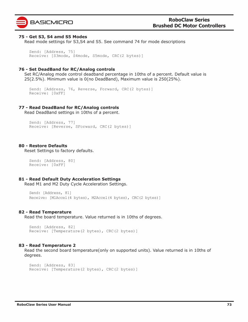
RoboClaw Series Brushed DC Motor Controllers
RoboClaw Series User Manual 73
BASICMICRO
75 - Get S3, S4 amd S5 ModesRead mode settings for S3,S4 and S5. See command 74 for mode descriptions
Send: [Address, 75] Receive: [S3mode, S4mode, S5mode, CRC(2 bytes)]
76 - Set DeadBand for RC/Analog controlsSet RC/Analog mode control deadband percentage in 10ths of a percent. Default value is 25(2.5%). Minimum value is 0(no DeadBand), Maximum value is 250(25%).
Send: [Address, 76, Reverse, Forward, CRC(2 bytes)] Receive: [0xFF]
77 - Read DeadBand for RC/Analog controlsRead DeadBand settings in 10ths of a percent.
Send: [Address, 77] Receive: [Reverse, SForward, CRC(2 bytes)]
80 - Restore DefaultsReset Settings to factory defaults.
Send: [Address, 80] Receive: [0xFF]
81 - Read Default Duty Acceleration SettingsRead M1 and M2 Duty Cycle Acceleration Settings.
Send: [Address, 81]Receive: [M1Accel(4 bytes), M2Accel(4 bytes), CRC(2 bytes)]
82 - Read TemperatureRead the board temperature. Value returned is in 10ths of degrees.
Send: [Address, 82] Receive: [Temperature(2 bytes), CRC(2 bytes)]
83 - Read Temperature 2Read the second board temperature(only on supported units). Value returned is in 10ths of degrees.
Send: [Address, 83] Receive: [Temperature(2 bytes), CRC(2 bytes)]
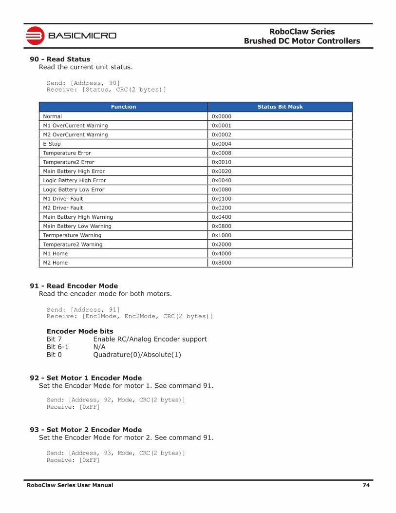
RoboClaw Series Brushed DC Motor Controllers
RoboClaw Series User Manual 74
BASICMICRO
90 - Read StatusRead the current unit status.
Send: [Address, 90] Receive: [Status, CRC(2 bytes)]
Function Status Bit Mask
Normal 0x0000
M1 OverCurrent Warning 0x0001
M2 OverCurrent Warning 0x0002
E-Stop 0x0004
Temperature Error 0x0008
Temperature2 Error 0x0010
Main Battery High Error 0x0020
Logic Battery High Error 0x0040
Logic Battery Low Error 0x0080
M1 Driver Fault 0x0100
M2 Driver Fault 0x0200
Main Battery High Warning 0x0400
Main Battery Low Warning 0x0800
Termperature Warning 0x1000
Temperature2 Warning 0x2000
M1 Home 0x4000
M2 Home 0x8000
91 - Read Encoder ModeRead the encoder mode for both motors.
Send: [Address, 91] Receive: [Enc1Mode, Enc2Mode, CRC(2 bytes)]
Encoder Mode bits Bit 7 Enable RC/Analog Encoder support Bit 6-1 N/A Bit 0 Quadrature(0)/Absolute(1)
92 - Set Motor 1 Encoder ModeSet the Encoder Mode for motor 1. See command 91.
Send: [Address, 92, Mode, CRC(2 bytes)]Receive: [0xFF]
93 - Set Motor 2 Encoder ModeSet the Encoder Mode for motor 2. See command 91.
Send: [Address, 93, Mode, CRC(2 bytes)]Receive: [0xFF]
RoboClaw Series Brushed DC Motor Controllers
RoboClaw Series User Manual 75
BASICMICRO
94 - Write Settings to EEPROMWrites all settings to non-volatile memory. Values will be loaded after each power up.
Send: [Address, 94]Receive: [0xFF]
95 - Read Settings from EEPROMRead all settings from non-volatile memory.
Send: [Address, 95]Receive: [Enc1Mode, Enc2Mode, CRC(2 bytes)]
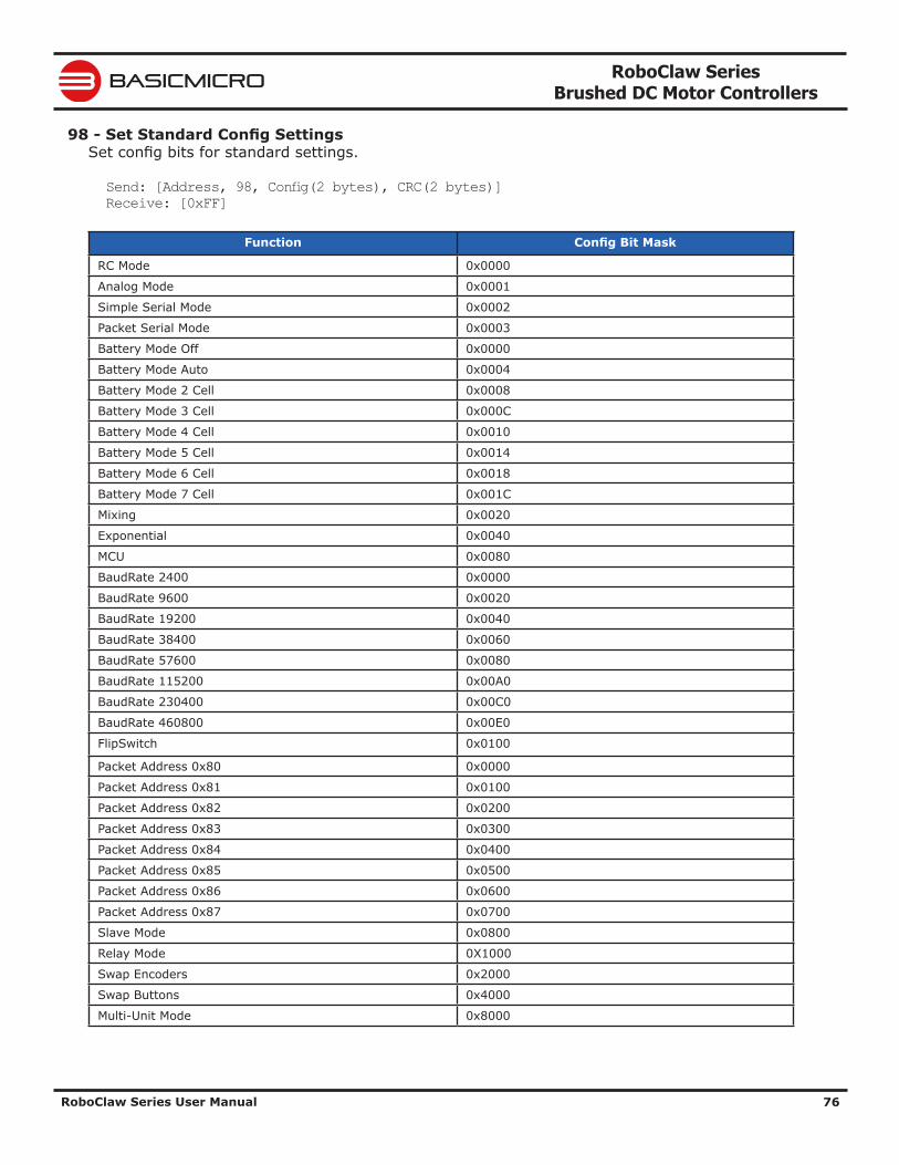
RoboClaw Series Brushed DC Motor Controllers
RoboClaw Series User Manual 76
BASICMICRO
98 - Set Standard Config SettingsSet config bits for standard settings.
Send: [Address, 98, Config(2 bytes), CRC(2 bytes)]Receive: [0xFF]
Function Config Bit Mask
RC Mode 0x0000
Analog Mode 0x0001
Simple Serial Mode 0x0002
Packet Serial Mode 0x0003
Battery Mode Off 0x0000
Battery Mode Auto 0x0004
Battery Mode 2 Cell 0x0008
Battery Mode 3 Cell 0x000C
Battery Mode 4 Cell 0x0010
Battery Mode 5 Cell 0x0014
Battery Mode 6 Cell 0x0018
Battery Mode 7 Cell 0x001C
Mixing 0x0020
Exponential 0x0040
MCU 0x0080
BaudRate 2400 0x0000
BaudRate 9600 0x0020
BaudRate 19200 0x0040
BaudRate 38400 0x0060
BaudRate 57600 0x0080
BaudRate 115200 0x00A0
BaudRate 230400 0x00C0
BaudRate 460800 0x00E0
FlipSwitch 0x0100
Packet Address 0x80 0x0000
Packet Address 0x81 0x0100
Packet Address 0x82 0x0200
Packet Address 0x83 0x0300
Packet Address 0x84 0x0400
Packet Address 0x85 0x0500
Packet Address 0x86 0x0600
Packet Address 0x87 0x0700
Slave Mode 0x0800
Relay Mode 0X1000
Swap Encoders 0x2000
Swap Buttons 0x4000
Multi-Unit Mode 0x8000
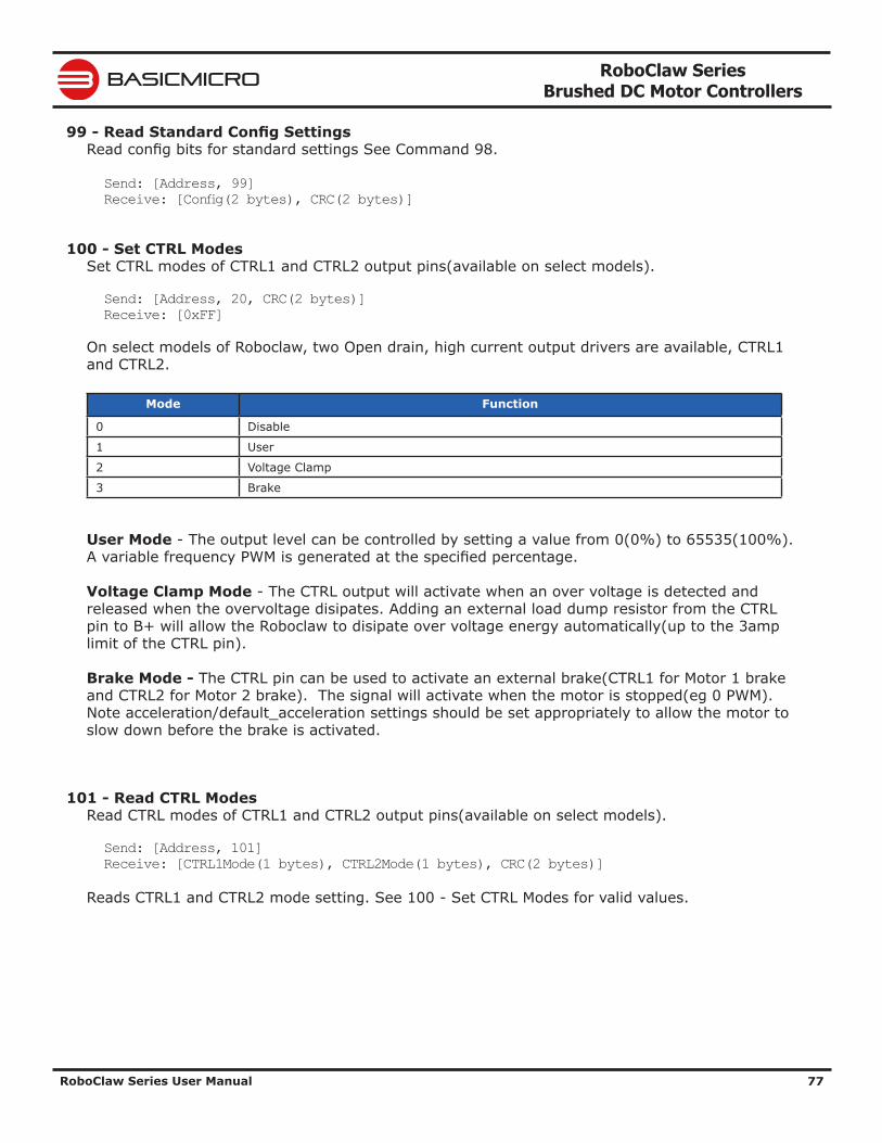
RoboClaw Series Brushed DC Motor Controllers
RoboClaw Series User Manual 77
BASICMICRO
99 - Read Standard Config SettingsRead config bits for standard settings See Command 98.
Send: [Address, 99]Receive: [Config(2 bytes), CRC(2 bytes)]
100 - Set CTRL ModesSet CTRL modes of CTRL1 and CTRL2 output pins(available on select models).
Send: [Address, 20, CRC(2 bytes)]Receive: [0xFF]
On select models of Roboclaw, two Open drain, high current output drivers are available, CTRL1 and CTRL2.
Mode Function
0 Disable
1 User
2 Voltage Clamp
3 Brake
User Mode - The output level can be controlled by setting a value from 0(0%) to 65535(100%). A variable frequency PWM is generated at the specified percentage.
Voltage Clamp Mode - The CTRL output will activate when an over voltage is detected and released when the overvoltage disipates. Adding an external load dump resistor from the CTRL pin to B+ will allow the Roboclaw to disipate over voltage energy automatically(up to the 3amp limit of the CTRL pin).
Brake Mode - The CTRL pin can be used to activate an external brake(CTRL1 for Motor 1 brake and CTRL2 for Motor 2 brake). The signal will activate when the motor is stopped(eg 0 PWM). Note acceleration/default_acceleration settings should be set appropriately to allow the motor to slow down before the brake is activated.
101 - Read CTRL ModesRead CTRL modes of CTRL1 and CTRL2 output pins(available on select models).
Send: [Address, 101]Receive: [CTRL1Mode(1 bytes), CTRL2Mode(1 bytes), CRC(2 bytes)]
Reads CTRL1 and CTRL2 mode setting. See 100 - Set CTRL Modes for valid values.
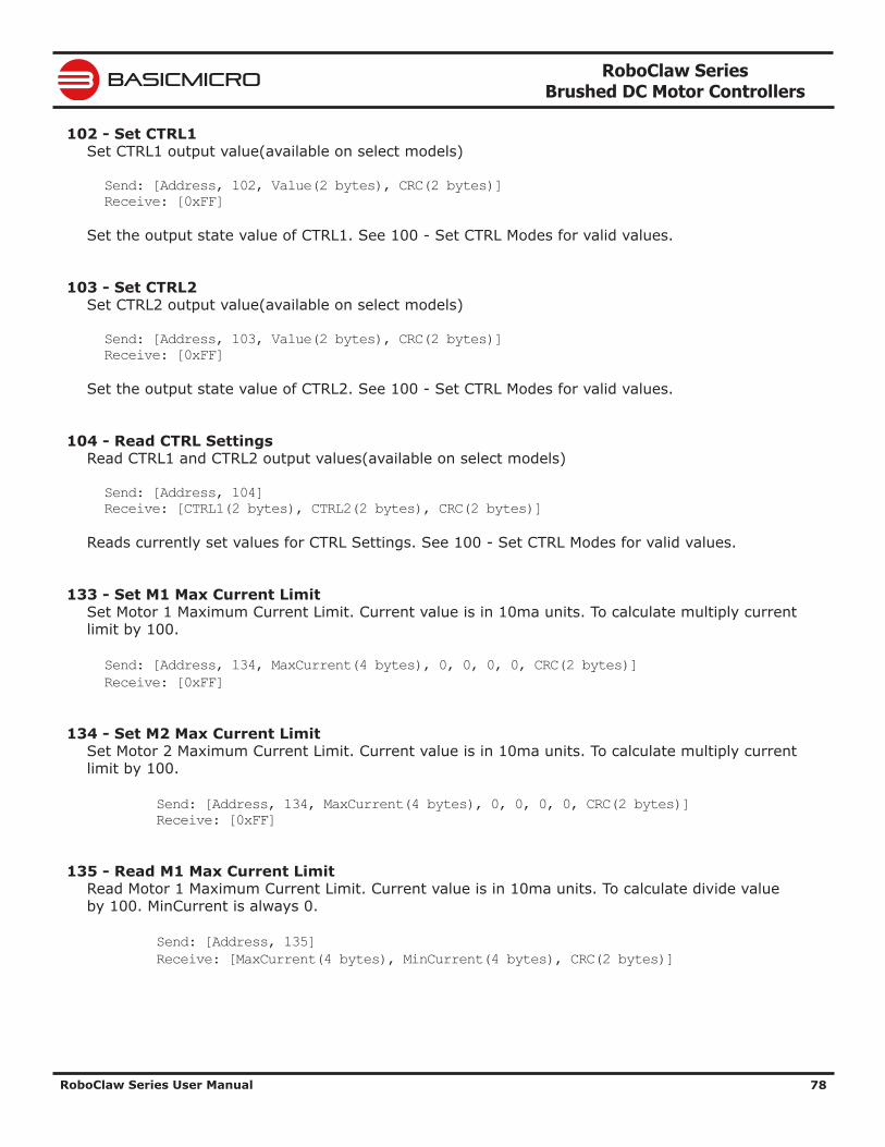
RoboClaw Series Brushed DC Motor Controllers
RoboClaw Series User Manual 78
BASICMICRO
102 - Set CTRL1Set CTRL1 output value(available on select models)
Send: [Address, 102, Value(2 bytes), CRC(2 bytes)]Receive: [0xFF]
Set the output state value of CTRL1. See 100 - Set CTRL Modes for valid values.
103 - Set CTRL2Set CTRL2 output value(available on select models)
Send: [Address, 103, Value(2 bytes), CRC(2 bytes)]Receive: [0xFF]
Set the output state value of CTRL2. See 100 - Set CTRL Modes for valid values.
104 - Read CTRL SettingsRead CTRL1 and CTRL2 output values(available on select models)
Send: [Address, 104]Receive: [CTRL1(2 bytes), CTRL2(2 bytes), CRC(2 bytes)]
Reads currently set values for CTRL Settings. See 100 - Set CTRL Modes for valid values.
133 - Set M1 Max Current LimitSet Motor 1 Maximum Current Limit. Current value is in 10ma units. To calculate multiply current limit by 100.
Send: [Address, 134, MaxCurrent(4 bytes), 0, 0, 0, 0, CRC(2 bytes)]Receive: [0xFF]
134 - Set M2 Max Current LimitSet Motor 2 Maximum Current Limit. Current value is in 10ma units. To calculate multiply current limit by 100.
Send: [Address, 134, MaxCurrent(4 bytes), 0, 0, 0, 0, CRC(2 bytes)] Receive: [0xFF]
135 - Read M1 Max Current LimitRead Motor 1 Maximum Current Limit. Current value is in 10ma units. To calculate divide value by 100. MinCurrent is always 0.
Send: [Address, 135] Receive: [MaxCurrent(4 bytes), MinCurrent(4 bytes), CRC(2 bytes)]
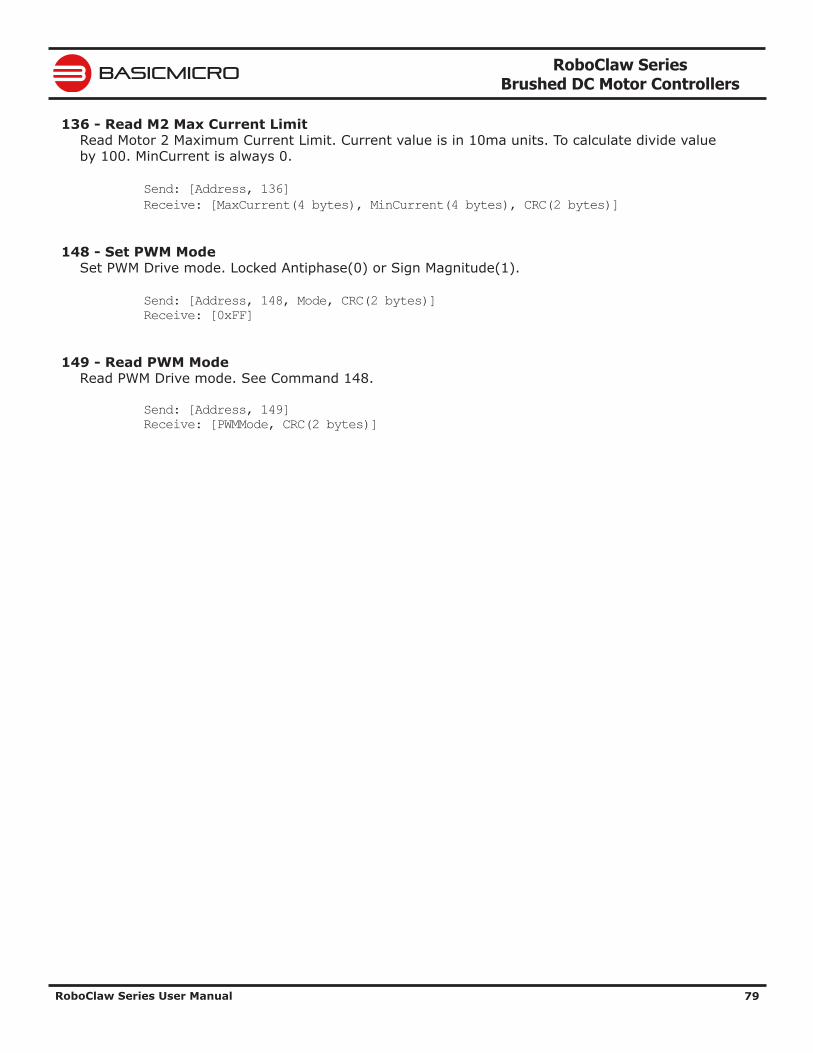
RoboClaw Series Brushed DC Motor Controllers
RoboClaw Series User Manual 79
BASICMICRO
136 - Read M2 Max Current LimitRead Motor 2 Maximum Current Limit. Current value is in 10ma units. To calculate divide value by 100. MinCurrent is always 0.
Send: [Address, 136] Receive: [MaxCurrent(4 bytes), MinCurrent(4 bytes), CRC(2 bytes)]
148 - Set PWM ModeSet PWM Drive mode. Locked Antiphase(0) or Sign Magnitude(1).
Send: [Address, 148, Mode, CRC(2 bytes)] Receive: [0xFF]
149 - Read PWM ModeRead PWM Drive mode. See Command 148.
Send: [Address, 149] Receive: [PWMMode, CRC(2 bytes)]
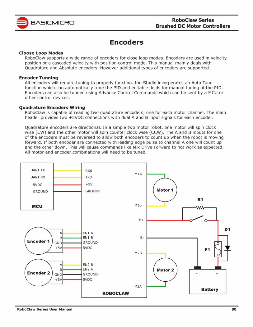
RoboClaw Series Brushed DC Motor Controllers
RoboClaw Series User Manual 80
BASICMICRO
EncodersCloose Loop Modes
RoboClaw supports a wide range of encoders for close loop modes. Encoders are used in velocity, position or a cascaded velocity with position control mode. This manual mainly deals with Quadrature and Absolute encoders. However additional types of encoders are supported.
Encoder TunningAll encoders will require tuning to properly function. Ion Studio incorperates an Auto Tune function which can automatically tune the PID and editable fields for manual tuning of the PID. Encoders can also be tunned using Advance Control Commands which can be sent by a MCU or other control devices.
Quadrature Encoders WiringRoboClaw is capable of reading two quadrature encoders, one for each motor channel. The main header provides two +5VDC connections with dual A and B input signals for each encoder.
Quadrature encoders are directional. In a simple two motor robot, one motor will spin clock wise (CW) and the other motor will spin counter clock wise (CCW). The A and B inputs for one of the encoders must be reversed to allow both encoders to count up when the robot is moving forward. If both encoder are connected with leading edge pulse to channel A one will count up and the other down. This will cause commands like Mix Drive Forward to not work as expected. All motor and encoder combinations will need to be tuned.
Encoder 1
AB
GND+5V
EN1 AEN1 B
5VDCGROUND
Encoder 2
AB
GND+5V
EN2 BEN2 A
5VDCGROUND
M1A
M1B
M2B
M2A
B-
B+
+-
Battery
RX0
TX0
+5V
GROUND
ROBOCLAW
Motor 1
Motor 2
UART TX
UART RX
5VDC
GROUND
MCUR1
F1
D1
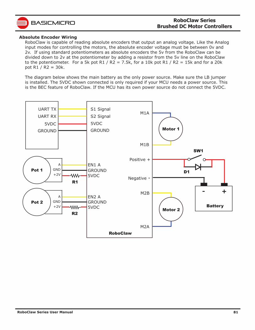
RoboClaw Series Brushed DC Motor Controllers
RoboClaw Series User Manual 81
BASICMICRO
Absolute Encoder WiringRoboClaw is capable of reading absolute encoders that output an analog voltage. Like the Analog input modes for controlling the motors, the absolute encoder voltage must be between 0v and 2v. If using standard potentiometers as absolute encoders the 5v from the RoboClaw can be divided down to 2v at the potentiometer by adding a resistor from the 5v line on the RoboClaw to the potentiometer. For a 5k pot R1 / R2 = 7.5k, for a 10k pot R1 / R2 = 15k and for a 20k pot R1 / R2 = 30k.
The diagram below shows the main battery as the only power source. Make sure the LB jumper is installed. The 5VDC shown connected is only required if your MCU needs a power source. This is the BEC feature of RoboClaw. If the MCU has its own power source do not connect the 5VDC.
Motor 1
AGND+2V
M1A
M1B
Positive +
+-
Battery
S1 Signal
S2 Signal
5VDC
UART TX
UART RX
GROUND5VDC
GROUND
RoboClaw
Motor 2
EN1 A
5VDCGROUND
Pot 2A
GND+2V
EN2 A
5VDCGROUND
Pot 1
R1
R2
M2B
M2A
Negative -D1
SW1
RoboClaw Series Brushed DC Motor Controllers
RoboClaw Series User Manual 82
BASICMICRO
Encoder TuningTo control motor speed and or position with an encoder the PID must be calibrated for the specific motor and encoder being used. Using Ion Studio the PID can be tuned manually or by the auto tune fucntion. Once the encoders are tuned the settings can be saved to the onboard eeprom and will be loaded each time the unit powers up.
The Ion Studio window for Velocity Settings will auto tune for velocity. The window for Position Settings can tune a simple PD position controller, a PID position controller or a cascaded Position with Velocity controller(PIV). The cascaded tune will determine both the velocity and position values for the motor but still requires the QPPS be manually set for the motor before starting. Auto tune functions usually return reasonable values but manually adjustments may be required for optimum performance.
Auto TuningIon Studio provides the option to auto tune velocity and position control. To use the auto tune option make sure the encoder and motor are running in the desired direction and the basic PWM control of the motor works as expected. It is recommend to ensure the motor and encoder combination are functioning properly before using the auto tune feature.
1. Go to the PWM Settings screen in Ion Studio.
2. Slide the motor slider up to start moving the motor forward. Check the encoder is increasing in value. If it is not either reverse the motor wires or the encoder wires. The recheck.
Before using auto tune you must first set the motors and encoders maximum speed. For the purpose of auto tune the maximum quadrature pulse per second (QPPS) is the maximum speed the motor and encoder can acheive. When using an absolute encoder the QPPS will be the maximum rotational speed of the absolute encoder. Check the encoders data sheet to ensure the maximum rotational speed is not exceeded. Auto tune for position control can not automatically measure the maximum QPPS due to most position control systems having a limited range of movement.
3. To determine the maximum QPPS value, use the PWM settings screen to run the motor and encoder at 100% duty by moving the slider bar full up or down. Record the value from M1 Speed or M2 Speed fields at the top of the window. This is your maximum QPPS speed. If the motor can not be ran at full speed due to physical constraints, then an estimated maximum speed in encoder counts is required.
4. Enter the QPPS speed obtained from step 3 into the QPPS fields under settings. Ensure the correct QPPS is entered for the corresponding motor channel. Two identical motors and encoders may not function exactly the same so the maximum QPPS may vary.
5. To start auto tune click the auto tune button for the motor channel that is will be tuned first. The auto tune function will try to determine the best settings for that motor channel.
If the motor or encoder are wired incorrectly, the auto tune function can lock up and the motor controller will become unresponsive. Correct the wiring problem and reset the motor controller to continue.!
RoboClaw Series Brushed DC Motor Controllers
RoboClaw Series User Manual 83
BASICMICRO
Manual Velocity Calibration Procedure1. Determine the quadrature pulses per second(QPPS) value for your motor. The simplest method to do this is to run the Motor at 100% duty using Ion Studio and read back the speed value from the encoder attached to the motor. If you are unable to run the motor like this due to physical constraints you will need to estimate the maximum speed in encoder counts the motor can produce.
2. Set the initial P,I and D values in the Velocity control window to 1,0 and 0. Try moving the motor using the slider controls in IonMotion. If the motor does not move it may not be wired correctly or the P value needs to be increased. If the motor immediately runs at max speed when you change the slider position you probably have the motor or encoder wires reversed. The motor is trying to go at the speed specified but the encoder reading is coming back in the opposite direction so the motor increases power until it eventually hits 100% power. Reverse the encoder or motor wires(not both) and test again.
3. Once the motor has some semblance of control you can set a moderate speed. Then start increasing the P value until the speed reading is near the set value. If the motor feels like it is vibrating at higher P values you should reduce the P value to about 2/3rds that value. Move on to the I setting.
4. Start increasing the I setting. You will usually want to increase this value by .1 increments. The I value helps the motor reach the exact speed specified. Too high an I value will also cause the motor to feel rough/vibrate. This is because the motor will over shoot the set speed and then the controller will reduce power to get the speed back down which will also under shoot and this will continue oscillating back and forth form too fast to too slow, causing a vibration in the motor.
5. Once P and I are set reasonably well usually you will leave D = 0. D is only required if you are unable to get reasonable speed control out of the motor using just P and I. D will help dampen P and I over shoot allowing higher P and I values, but D also increases noise in the calculation which can cause oscillations in the speed as well.
Manual Position Calibration Procedure1. Position mode requires the Velocity mode QPPS value be set as described above. For simple Position control you can set Velocity P, I and D all to 0.
2. Set the Position I and D settings to 0. Set the P setting to 2000 as a reasonable starting point. To test the motor you must also set the Speed argument to some value. We recommend setting it to the same value as the QPPS setting(eg maximum motor speed). Set the minimum and maximum position values to safe numbers. If your motor has no dead stops this can be +-2 billion. If your motor has specific dead stops(like on a linear actuator) you will need to manually move the motor to its dead stops to determine these numbers. Leave some margin infront of each deadstop. Note that when using quadrature encoders you will need to home your motor on every power up since the quadrature readings are all relative to the starting position unless you set/reset the encoder values.
3. At this point the motor should move in the appropriate direction and stop, not necessarily close to the set position when you move the slider. Increase the P setting until the position is over shooting some each time you change the position slider. Now start increasing the D setting(leave I at 0). Increasing D will add dampening to the movement when getting close to the set position. This will help prevent the over shoot. D will usually be anywhere from 5 to 20 times larger than P but not always. Continue increasing P and D until the motor is working reasonably well. Once it is you have tuned a simple PD system.
RoboClaw Series Brushed DC Motor Controllers
RoboClaw Series User Manual 84
BASICMICRO
4. Once your position control is acting relatively smoothly and coming close to the set position you can think about adjusting the I setting. Adding I will help reach the exact set point specified but in most motor systems there is enough slop in the gears that instead you will end up causing an oscillation around the specified position. This is called hunting. The I setting causes this when there is any slop in the motor/encoder/gear train. You can compensate some for this by adding deadzone. Deadzone is the area around the specified position the controller will consider to be equal to the position specified.
5. One more setting must be adjusted in order to use the I setting. The Imax value sets the maximum wind up allowed for the I setting calculation. Increasing Imax will allow I to affect a larger amount of the movement of the motor but will also allow the system to oscillate if used with a badly tuned I and/or set too high.
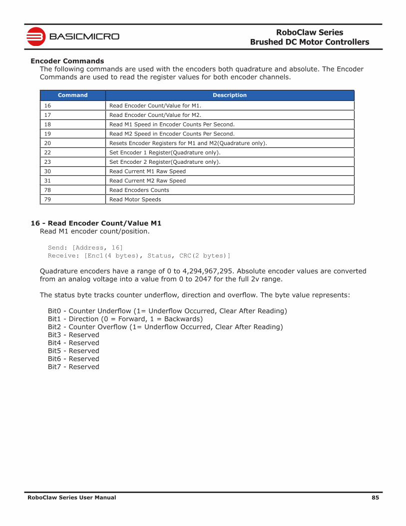
RoboClaw Series Brushed DC Motor Controllers
RoboClaw Series User Manual 85
BASICMICRO
Encoder CommandsThe following commands are used with the encoders both quadrature and absolute. The Encoder Commands are used to read the register values for both encoder channels.
Command Description
16 Read Encoder Count/Value for M1.
17 Read Encoder Count/Value for M2.
18 Read M1 Speed in Encoder Counts Per Second.
19 Read M2 Speed in Encoder Counts Per Second.
20 Resets Encoder Registers for M1 and M2(Quadrature only).
22 Set Encoder 1 Register(Quadrature only).
23 Set Encoder 2 Register(Quadrature only).
30 Read Current M1 Raw Speed
31 Read Current M2 Raw Speed
78 Read Encoders Counts
79 Read Motor Speeds
16 - Read Encoder Count/Value M1Read M1 encoder count/position.
Send: [Address, 16] Receive: [Enc1(4 bytes), Status, CRC(2 bytes)]
Quadrature encoders have a range of 0 to 4,294,967,295. Absolute encoder values are converted from an analog voltage into a value from 0 to 2047 for the full 2v range.
The status byte tracks counter underflow, direction and overflow. The byte value represents:
Bit0 - Counter Underflow (1= Underflow Occurred, Clear After Reading) Bit1 - Direction (0 = Forward, 1 = Backwards) Bit2 - Counter Overflow (1= Underflow Occurred, Clear After Reading) Bit3 - Reserved Bit4 - Reserved Bit5 - Reserved Bit6 - Reserved Bit7 - Reserved
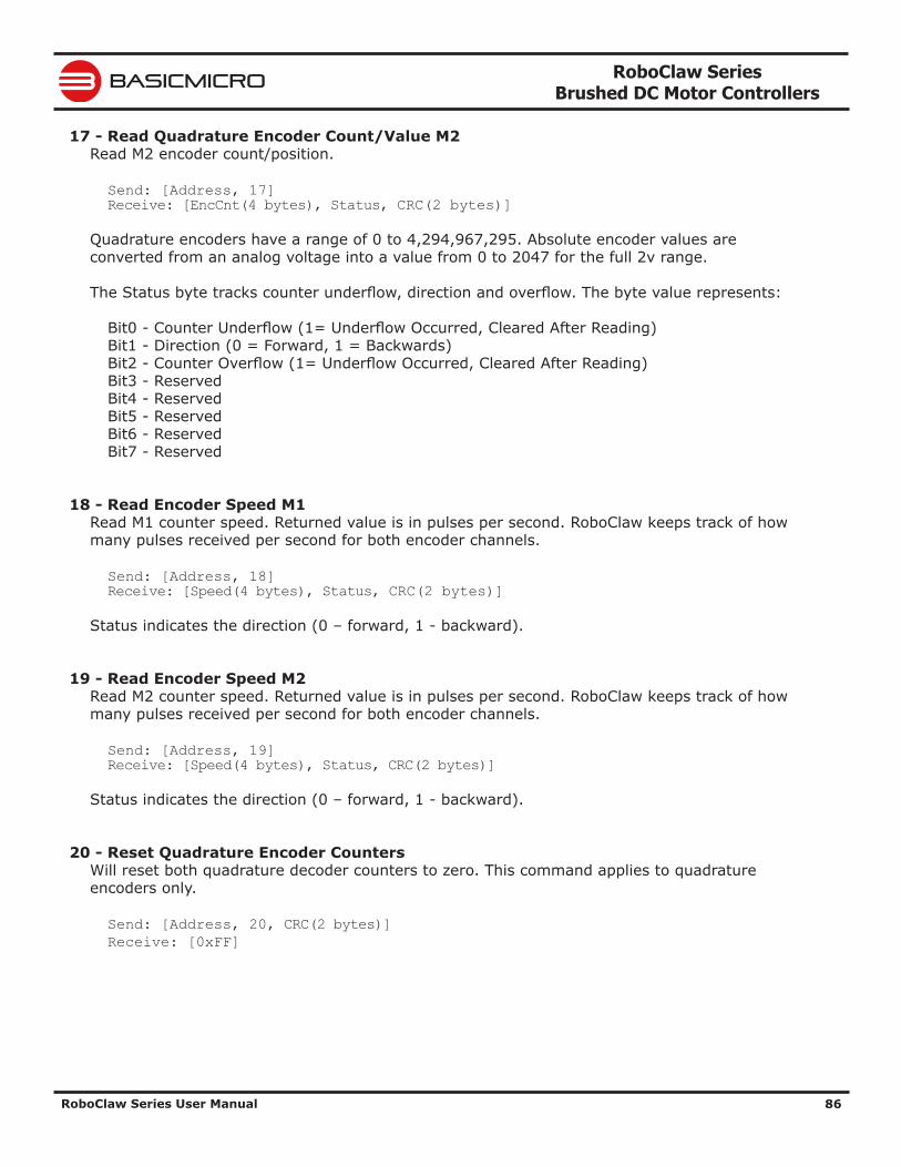
RoboClaw Series Brushed DC Motor Controllers
RoboClaw Series User Manual 86
BASICMICRO
17 - Read Quadrature Encoder Count/Value M2Read M2 encoder count/position.
Send: [Address, 17] Receive: [EncCnt(4 bytes), Status, CRC(2 bytes)]
Quadrature encoders have a range of 0 to 4,294,967,295. Absolute encoder values are converted from an analog voltage into a value from 0 to 2047 for the full 2v range.
The Status byte tracks counter underflow, direction and overflow. The byte value represents:
Bit0 - Counter Underflow (1= Underflow Occurred, Cleared After Reading) Bit1 - Direction (0 = Forward, 1 = Backwards) Bit2 - Counter Overflow (1= Underflow Occurred, Cleared After Reading) Bit3 - Reserved Bit4 - Reserved Bit5 - Reserved Bit6 - Reserved Bit7 - Reserved
18 - Read Encoder Speed M1Read M1 counter speed. Returned value is in pulses per second. RoboClaw keeps track of how many pulses received per second for both encoder channels.
Send: [Address, 18] Receive: [Speed(4 bytes), Status, CRC(2 bytes)]
Status indicates the direction (0 – forward, 1 - backward).
19 - Read Encoder Speed M2Read M2 counter speed. Returned value is in pulses per second. RoboClaw keeps track of how many pulses received per second for both encoder channels.
Send: [Address, 19] Receive: [Speed(4 bytes), Status, CRC(2 bytes)]
Status indicates the direction (0 – forward, 1 - backward).
20 - Reset Quadrature Encoder CountersWill reset both quadrature decoder counters to zero. This command applies to quadrature encoders only.
Send: [Address, 20, CRC(2 bytes)] Receive: [0xFF]
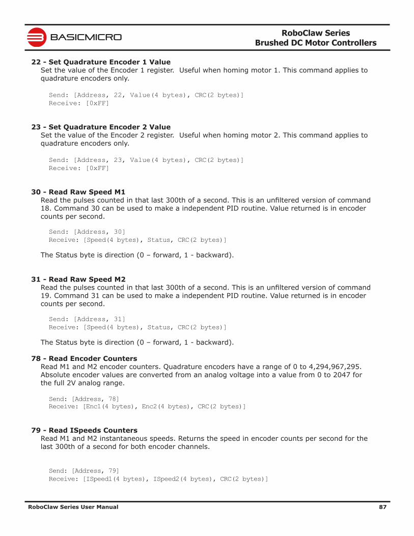
RoboClaw Series Brushed DC Motor Controllers
RoboClaw Series User Manual 87
BASICMICRO
22 - Set Quadrature Encoder 1 ValueSet the value of the Encoder 1 register. Useful when homing motor 1. This command applies to quadrature encoders only.
Send: [Address, 22, Value(4 bytes), CRC(2 bytes)] Receive: [0xFF]
23 - Set Quadrature Encoder 2 ValueSet the value of the Encoder 2 register. Useful when homing motor 2. This command applies to quadrature encoders only.
Send: [Address, 23, Value(4 bytes), CRC(2 bytes)] Receive: [0xFF]
30 - Read Raw Speed M1Read the pulses counted in that last 300th of a second. This is an unfiltered version of command 18. Command 30 can be used to make a independent PID routine. Value returned is in encoder counts per second.
Send: [Address, 30] Receive: [Speed(4 bytes), Status, CRC(2 bytes)]
The Status byte is direction (0 – forward, 1 - backward).
31 - Read Raw Speed M2Read the pulses counted in that last 300th of a second. This is an unfiltered version of command 19. Command 31 can be used to make a independent PID routine. Value returned is in encoder counts per second.
Send: [Address, 31] Receive: [Speed(4 bytes), Status, CRC(2 bytes)]
The Status byte is direction (0 – forward, 1 - backward).
78 - Read Encoder CountersRead M1 and M2 encoder counters. Quadrature encoders have a range of 0 to 4,294,967,295. Absolute encoder values are converted from an analog voltage into a value from 0 to 2047 for the full 2V analog range.
Send: [Address, 78]Receive: [Enc1(4 bytes), Enc2(4 bytes), CRC(2 bytes)]
79 - Read ISpeeds CountersRead M1 and M2 instantaneous speeds. Returns the speed in encoder counts per second for the last 300th of a second for both encoder channels.
Send: [Address, 79]Receive: [ISpeed1(4 bytes), ISpeed2(4 bytes), CRC(2 bytes)]
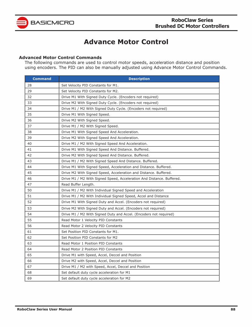
RoboClaw Series Brushed DC Motor Controllers
RoboClaw Series User Manual 88
BASICMICRO
Advance Motor Control
Advanced Motor Control CommandsThe following commands are used to control motor speeds, acceleration distance and position using encoders. The PID can also be manually adjusted using Advance Motor Control Commands.
Command Description
28 Set Velocity PID Constants for M1.
29 Set Velocity PID Constants for M2.
32 Drive M1 With Signed Duty Cycle. (Encoders not required)
33 Drive M2 With Signed Duty Cycle. (Encoders not required)
34 Drive M1 / M2 With Signed Duty Cycle. (Encoders not required)
35 Drive M1 With Signed Speed.
36 Drive M2 With Signed Speed.
37 Drive M1 / M2 With Signed Speed.
38 Drive M1 With Signed Speed And Acceleration.
39 Drive M2 With Signed Speed And Acceleration.
40 Drive M1 / M2 With Signed Speed And Acceleration.
41 Drive M1 With Signed Speed And Distance. Buffered.
42 Drive M2 With Signed Speed And Distance. Buffered.
43 Drive M1 / M2 With Signed Speed And Distance. Buffered.
44 Drive M1 With Signed Speed, Acceleration and Distance. Buffered.
45 Drive M2 With Signed Speed, Acceleration and Distance. Buffered.
46 Drive M1 / M2 With Signed Speed, Acceleration And Distance. Buffered.
47 Read Buffer Length.
50 Drive M1 / M2 With Individual Signed Speed and Acceleration
51 Drive M1 / M2 With Individual Signed Speed, Accel and Distance
52 Drive M1 With Signed Duty and Accel. (Encoders not required)
53 Drive M2 With Signed Duty and Accel. (Encoders not required)
54 Drive M1 / M2 With Signed Duty and Accel. (Encoders not required)
55 Read Motor 1 Velocity PID Constants
56 Read Motor 2 Velocity PID Constants
61 Set Position PID Constants for M1.
62 Set Position PID Constants for M2
63 Read Motor 1 Position PID Constants
64 Read Motor 2 Position PID Constants
65 Drive M1 with Speed, Accel, Deccel and Position
66 Drive M2 with Speed, Accel, Deccel and Position
67 Drive M1 / M2 with Speed, Accel, Deccel and Position
68 Set default duty cycle acceleration for M1
69 Set default duty cycle acceleration for M2
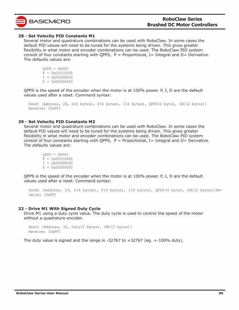
RoboClaw Series Brushed DC Motor Controllers
RoboClaw Series User Manual 89
BASICMICRO
28 - Set Velocity PID Constants M1Several motor and quadrature combinations can be used with RoboClaw. In some cases the default PID values will need to be tuned for the systems being driven. This gives greater flexibility in what motor and encoder combinations can be used. The RoboClaw PID system consist of four constants starting with QPPS, P = Proportional, I= Integral and D= Derivative. The defaults values are:
QPPS = 44000 P = 0x00010000 I = 0x00008000 D = 0x00004000
QPPS is the speed of the encoder when the motor is at 100% power. P, I, D are the default values used after a reset. Command syntax:
Send: [Address, 28, D(4 bytes), P(4 bytes), I(4 bytes), QPPS(4 byte), CRC(2 bytes)]Receive: [0xFF]
29 - Set Velocity PID Constants M2Several motor and quadrature combinations can be used with RoboClaw. In some cases the default PID values will need to be tuned for the systems being driven. This gives greater flexibility in what motor and encoder combinations can be used. The RoboClaw PID system consist of four constants starting with QPPS, P = Proportional, I= Integral and D= Derivative. The defaults values are:
QPPS = 44000 P = 0x00010000 I = 0x00008000 D = 0x00004000
QPPS is the speed of the encoder when the motor is at 100% power. P, I, D are the default values used after a reset. Command syntax:
Send: [Address, 29, D(4 bytes), P(4 bytes), I(4 bytes), QPPS(4 byte), CRC(2 bytes)]Re-ceive: [0xFF]
32 - Drive M1 With Signed Duty CycleDrive M1 using a duty cycle value. The duty cycle is used to control the speed of the motor without a quadrature encoder.
Send: [Address, 32, Duty(2 Bytes), CRC(2 bytes)]Receive: [0xFF]
The duty value is signed and the range is -32767 to +32767 (eg. +-100% duty).
RoboClaw Series Brushed DC Motor Controllers
RoboClaw Series User Manual 90
BASICMICRO
33 - Drive M2 With Signed Duty CycleDrive M2 using a duty cycle value. The duty cycle is used to control the speed of the motor without a quadrature encoder. The command syntax:
Send: [Address, 33, Duty(2 Bytes), CRC(2 bytes)]Receive: [0xFF]
The duty value is signed and the range is -32768 to +32767 (eg. +-100% duty).
34 - Drive M1 / M2 With Signed Duty CycleDrive both M1 and M2 using a duty cycle value. The duty cycle is used to control the speed of the motor without a quadrature encoder. The command syntax:
Send: [Address, 34, DutyM1(2 Bytes), DutyM2(2 Bytes), CRC(2 bytes)]Receive: [0xFF]
The duty value is signed and the range is -32768 to +32767 (eg. +-100% duty).
RoboClaw Series Brushed DC Motor Controllers
RoboClaw Series User Manual 91
BASICMICRO
35 - Drive M1 With Signed SpeedDrive M1 using a speed value. The sign indicates which direction the motor will turn. This command is used to drive the motor by quad pulses per second. Different quadrature encoders will have different rates at which they generate the incoming pulses. The values used will differ from one encoder to another. Once a value is sent the motor will begin to accelerate as fast as possible until the defined rate is reached.
Send: [Address, 35, Speed(4 Bytes), CRC(2 bytes)]Receive: [0xFF]
36 - Drive M2 With Signed SpeedDrive M2 with a speed value. The sign indicates which direction the motor will turn. This command is used to drive the motor by quad pulses per second. Different quadrature encoders will have different rates at which they generate the incoming pulses. The values used will differ from one encoder to another. Once a value is sent, the motor will begin to accelerate as fast as possible until the rate defined is reached.
Send: [Address, 36, Speed(4 Bytes), CRC(2 bytes)]Receive: [0xFF]
37 - Drive M1 / M2 With Signed SpeedDrive M1 and M2 in the same command using a signed speed value. The sign indicates which direction the motor will turn. This command is used to drive both motors by quad pulses per second. Different quadrature encoders will have different rates at which they generate the incoming pulses. The values used will differ from one encoder to another. Once a value is sent the motor will begin to accelerate as fast as possible until the rate defined is reached.
Send: [Address, 37, SpeedM1(4 Bytes), SpeedM2(4 Bytes), CRC(2 bytes)]Receive: [0xFF]
38 - Drive M1 With Signed Speed And AccelerationDrive M1 with a signed speed and acceleration value. The sign indicates which direction the motor will run. The acceleration values are not signed. This command is used to drive the motor by quad pulses per second and using an acceleration value for ramping. Different quadrature encoders will have different rates at which they generate the incoming pulses. The values used will differ from one encoder to another. Once a value is sent the motor will begin to accelerate incrementally until the rate defined is reached.
Send: [Address, 38, Accel(4 Bytes), Speed(4 Bytes), CRC(2 bytes)]Receive: [0xFF]
The acceleration is measured in speed increase per second. An acceleration value of 12,000 QPPS with a speed of 12,000 QPPS would accelerate a motor from 0 to 12,000 QPPS in 1 second. Another example would be an acceleration value of 24,000 QPPS and a speed value of 12,000 QPPS would accelerate the motor to 12,000 QPPS in 0.5 seconds.
RoboClaw Series Brushed DC Motor Controllers
RoboClaw Series User Manual 92
BASICMICRO
39 - Drive M2 With Signed Speed And AccelerationDrive M2 with a signed speed and acceleration value. The sign indicates which direction the motor will run. The acceleration value is not signed. This command is used to drive the motor by quad pulses per second and using an acceleration value for ramping. Different quadrature encoders will have different rates at which they generate the incoming pulses. The values used will differ from one encoder to another. Once a value is sent the motor will begin to accelerate incrementally until the rate defined is reached.
Send: [Address, 39, Accel(4 Bytes), Speed(4 Bytes), CRC(2 bytes)] Receive: [0xFF]
The acceleration is measured in speed increase per second. An acceleration value of 12,000 QPPS with a speed of 12,000 QPPS would accelerate a motor from 0 to 12,000 QPPS in 1 second. Another example would be an acceleration value of 24,000 QPPS and a speed value of 12,000 QPPS would accelerate the motor to 12,000 QPPS in 0.5 seconds.
40 - Drive M1 / M2 With Signed Speed And AccelerationDrive M1 and M2 in the same command using one value for acceleration and two signed speed values for each motor. The sign indicates which direction the motor will run. The acceleration value is not signed. The motors are sync during acceleration. This command is used to drive the motor by quad pulses per second and using an acceleration value for ramping. Different quadrature encoders will have different rates at which they generate the incoming pulses. The values used will differ from one encoder to another. Once a value is sent the motor will begin to accelerate incrementally until the rate defined is reached.
Send: [Address, 40, Accel(4 Bytes), SpeedM1(4 Bytes), SpeedM2(4 Bytes), CRC(2 bytes)]Receive: [0xFF]
The acceleration is measured in speed increase per second. An acceleration value of 12,000 QPPS with a speed of 12,000 QPPS would accelerate a motor from 0 to 12,000 QPPS in 1 second. Another example would be an acceleration value of 24,000 QPPS and a speed value of 12,000 QPPS would accelerate the motor to 12,000 QPPS in 0.5 seconds.
41 - Buffered M1 Drive With Signed Speed And DistanceDrive M1 with a signed speed and distance value. The sign indicates which direction the motor will run. The distance value is not signed. This command is buffered. This command is used to control the top speed and total distance traveled by the motor. Each motor channel M1 and M2 have separate buffers. This command will execute immediately if no other command for that channel is executing, otherwise the command will be buffered in the order it was sent. Any buffered or executing command can be stopped when a new command is issued by setting the Buffer argument. All values used are in quad pulses per second.
Send: [Address, 41, Speed(4 Bytes), Distance(4 Bytes), Buffer, CRC(2 bytes)]Receive: [0xFF]
The Buffer argument can be set to a 1 or 0. If a value of 0 is used the command will be buffered and executed in the order sent. If a value of 1 is used the current running command is stopped, any other commands in the buffer are deleted and the new command is executed.
RoboClaw Series Brushed DC Motor Controllers
RoboClaw Series User Manual 93
BASICMICRO
42 - Buffered M2 Drive With Signed Speed And DistanceDrive M2 with a speed and distance value. The sign indicates which direction the motor will run. The distance value is not signed. This command is buffered. Each motor channel M1 and M2 have separate buffers. This command will execute immediately if no other command for that channel is executing, otherwise the command will be buffered in the order it was sent. Any buffered or executing command can be stopped when a new command is issued by setting the Buffer argument. All values used are in quad pulses per second.
Send: [Address, 42, Speed(4 Bytes), Distance(4 Bytes), Buffer, CRC(2 bytes)]Receive: [0xFF]
The Buffer argument can be set to a 1 or 0. If a value of 0 is used the command will be buffered and executed in the order sent. If a value of 1 is used the current running command is stopped, any other commands in the buffer are deleted and the new command is executed.
43 - Buffered Drive M1 / M2 With Signed Speed And DistanceDrive M1 and M2 with a speed and distance value. The sign indicates which direction the motor will run. The distance value is not signed. This command is buffered. Each motor channel M1 and M2 have separate buffers. This command will execute immediately if no other command for that channel is executing, otherwise the command will be buffered in the order it was sent. Any buffered or executing command can be stopped when a new command is issued by setting the Buffer argument. All values used are in quad pulses per second.
Send: [Address, 43, SpeedM1(4 Bytes), DistanceM1(4 Bytes), SpeedM2(4 Bytes), DistanceM2(4 Bytes), Buffer, CRC(2 bytes)]Receive: [0xFF]
The Buffer argument can be set to a 1 or 0. If a value of 0 is used the command will be buffered and executed in the order sent. If a value of 1 is used the current running command is stopped, any other commands in the buffer are deleted and the new command is executed.
44 - Buffered M1 Drive With Signed Speed, Accel And DistanceDrive M1 with a speed, acceleration and distance value. The sign indicates which direction the motor will run. The acceleration and distance values are not signed. This command is used to control the motors top speed, total distanced traveled and at what incremental acceleration value to use until the top speed is reached. Each motor channel M1 and M2 have separate buffers. This command will execute immediately if no other command for that channel is executing, otherwise the command will be buffered in the order it was sent. Any buffered or executing command can be stopped when a new command is issued by setting the Buffer argument. All values used are in quad pulses per second.
Send: [Address, 44, Accel(4 bytes), Speed(4 Bytes), Distance(4 Bytes), Buffer, CRC(2 bytes)]Receive: [0xFF]
The Buffer argument can be set to a 1 or 0. If a value of 0 is used the command will be buffered and executed in the order sent. If a value of 1 is used the current running command is stopped, any other commands in the buffer are deleted and the new command is executed.
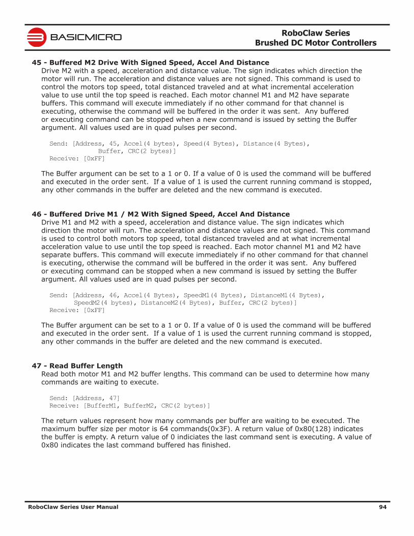
RoboClaw Series Brushed DC Motor Controllers
RoboClaw Series User Manual 94
BASICMICRO
45 - Buffered M2 Drive With Signed Speed, Accel And DistanceDrive M2 with a speed, acceleration and distance value. The sign indicates which direction the motor will run. The acceleration and distance values are not signed. This command is used to control the motors top speed, total distanced traveled and at what incremental acceleration value to use until the top speed is reached. Each motor channel M1 and M2 have separate buffers. This command will execute immediately if no other command for that channel is executing, otherwise the command will be buffered in the order it was sent. Any buffered or executing command can be stopped when a new command is issued by setting the Buffer argument. All values used are in quad pulses per second.
Send: [Address, 45, Accel(4 bytes), Speed(4 Bytes), Distance(4 Bytes), Buffer, CRC(2 bytes)]Receive: [0xFF]
The Buffer argument can be set to a 1 or 0. If a value of 0 is used the command will be buffered and executed in the order sent. If a value of 1 is used the current running command is stopped, any other commands in the buffer are deleted and the new command is executed.
46 - Buffered Drive M1 / M2 With Signed Speed, Accel And DistanceDrive M1 and M2 with a speed, acceleration and distance value. The sign indicates which direction the motor will run. The acceleration and distance values are not signed. This command is used to control both motors top speed, total distanced traveled and at what incremental acceleration value to use until the top speed is reached. Each motor channel M1 and M2 have separate buffers. This command will execute immediately if no other command for that channel is executing, otherwise the command will be buffered in the order it was sent. Any buffered or executing command can be stopped when a new command is issued by setting the Buffer argument. All values used are in quad pulses per second.
Send: [Address, 46, Accel(4 Bytes), SpeedM1(4 Bytes), DistanceM1(4 Bytes), SpeedM2(4 bytes), DistanceM2(4 Bytes), Buffer, CRC(2 bytes)]Receive: [0xFF]
The Buffer argument can be set to a 1 or 0. If a value of 0 is used the command will be buffered and executed in the order sent. If a value of 1 is used the current running command is stopped, any other commands in the buffer are deleted and the new command is executed.
47 - Read Buffer LengthRead both motor M1 and M2 buffer lengths. This command can be used to determine how many commands are waiting to execute.
Send: [Address, 47]Receive: [BufferM1, BufferM2, CRC(2 bytes)]
The return values represent how many commands per buffer are waiting to be executed. The maximum buffer size per motor is 64 commands(0x3F). A return value of 0x80(128) indicates the buffer is empty. A return value of 0 indiciates the last command sent is executing. A value of 0x80 indicates the last command buffered has finished.
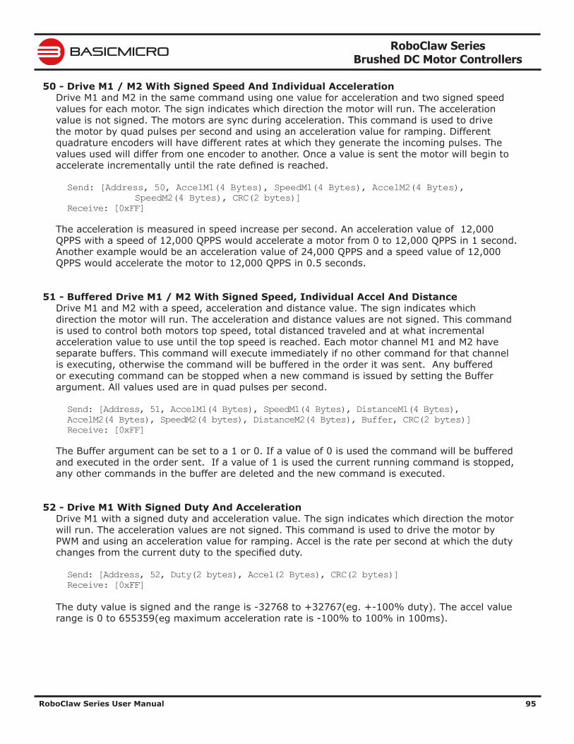
RoboClaw Series Brushed DC Motor Controllers
RoboClaw Series User Manual 95
BASICMICRO
50 - Drive M1 / M2 With Signed Speed And Individual AccelerationDrive M1 and M2 in the same command using one value for acceleration and two signed speed values for each motor. The sign indicates which direction the motor will run. The acceleration value is not signed. The motors are sync during acceleration. This command is used to drive the motor by quad pulses per second and using an acceleration value for ramping. Different quadrature encoders will have different rates at which they generate the incoming pulses. The values used will differ from one encoder to another. Once a value is sent the motor will begin to accelerate incrementally until the rate defined is reached.
Send: [Address, 50, AccelM1(4 Bytes), SpeedM1(4 Bytes), AccelM2(4 Bytes), SpeedM2(4 Bytes), CRC(2 bytes)]Receive: [0xFF]
The acceleration is measured in speed increase per second. An acceleration value of 12,000 QPPS with a speed of 12,000 QPPS would accelerate a motor from 0 to 12,000 QPPS in 1 second. Another example would be an acceleration value of 24,000 QPPS and a speed value of 12,000 QPPS would accelerate the motor to 12,000 QPPS in 0.5 seconds.
51 - Buffered Drive M1 / M2 With Signed Speed, Individual Accel And DistanceDrive M1 and M2 with a speed, acceleration and distance value. The sign indicates which direction the motor will run. The acceleration and distance values are not signed. This command is used to control both motors top speed, total distanced traveled and at what incremental acceleration value to use until the top speed is reached. Each motor channel M1 and M2 have separate buffers. This command will execute immediately if no other command for that channel is executing, otherwise the command will be buffered in the order it was sent. Any buffered or executing command can be stopped when a new command is issued by setting the Buffer argument. All values used are in quad pulses per second.
Send: [Address, 51, AccelM1(4 Bytes), SpeedM1(4 Bytes), DistanceM1(4 Bytes), AccelM2(4 Bytes), SpeedM2(4 bytes), DistanceM2(4 Bytes), Buffer, CRC(2 bytes)]Receive: [0xFF]
The Buffer argument can be set to a 1 or 0. If a value of 0 is used the command will be buffered and executed in the order sent. If a value of 1 is used the current running command is stopped, any other commands in the buffer are deleted and the new command is executed.
52 - Drive M1 With Signed Duty And AccelerationDrive M1 with a signed duty and acceleration value. The sign indicates which direction the motor will run. The acceleration values are not signed. This command is used to drive the motor by PWM and using an acceleration value for ramping. Accel is the rate per second at which the duty changes from the current duty to the specified duty.
Send: [Address, 52, Duty(2 bytes), Accel(2 Bytes), CRC(2 bytes)]Receive: [0xFF]
The duty value is signed and the range is -32768 to +32767(eg. +-100% duty). The accel value range is 0 to 655359(eg maximum acceleration rate is -100% to 100% in 100ms).
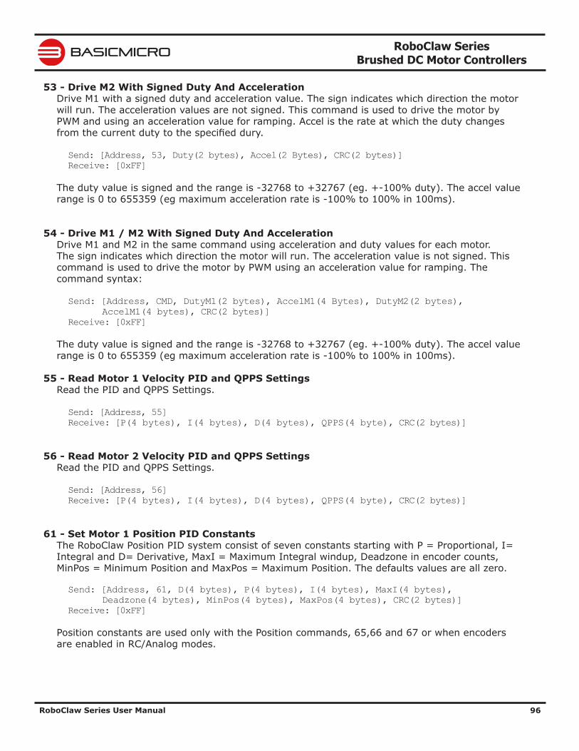
RoboClaw Series Brushed DC Motor Controllers
RoboClaw Series User Manual 96
BASICMICRO
53 - Drive M2 With Signed Duty And AccelerationDrive M1 with a signed duty and acceleration value. The sign indicates which direction the motor will run. The acceleration values are not signed. This command is used to drive the motor by PWM and using an acceleration value for ramping. Accel is the rate at which the duty changes from the current duty to the specified dury.
Send: [Address, 53, Duty(2 bytes), Accel(2 Bytes), CRC(2 bytes)]Receive: [0xFF]
The duty value is signed and the range is -32768 to +32767 (eg. +-100% duty). The accel value range is 0 to 655359 (eg maximum acceleration rate is -100% to 100% in 100ms).
54 - Drive M1 / M2 With Signed Duty And AccelerationDrive M1 and M2 in the same command using acceleration and duty values for each motor. The sign indicates which direction the motor will run. The acceleration value is not signed. This command is used to drive the motor by PWM using an acceleration value for ramping. The command syntax:
Send: [Address, CMD, DutyM1(2 bytes), AccelM1(4 Bytes), DutyM2(2 bytes), AccelM1(4 bytes), CRC(2 bytes)]Receive: [0xFF]
The duty value is signed and the range is -32768 to +32767 (eg. +-100% duty). The accel value range is 0 to 655359 (eg maximum acceleration rate is -100% to 100% in 100ms).
55 - Read Motor 1 Velocity PID and QPPS SettingsRead the PID and QPPS Settings.
Send: [Address, 55]Receive: [P(4 bytes), I(4 bytes), D(4 bytes), QPPS(4 byte), CRC(2 bytes)]
56 - Read Motor 2 Velocity PID and QPPS SettingsRead the PID and QPPS Settings.
Send: [Address, 56]Receive: [P(4 bytes), I(4 bytes), D(4 bytes), QPPS(4 byte), CRC(2 bytes)]
61 - Set Motor 1 Position PID ConstantsThe RoboClaw Position PID system consist of seven constants starting with P = Proportional, I= Integral and D= Derivative, MaxI = Maximum Integral windup, Deadzone in encoder counts, MinPos = Minimum Position and MaxPos = Maximum Position. The defaults values are all zero.
Send: [Address, 61, D(4 bytes), P(4 bytes), I(4 bytes), MaxI(4 bytes), Deadzone(4 bytes), MinPos(4 bytes), MaxPos(4 bytes), CRC(2 bytes)]Receive: [0xFF]
Position constants are used only with the Position commands, 65,66 and 67 or when encoders are enabled in RC/Analog modes.
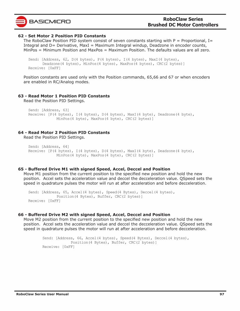
RoboClaw Series Brushed DC Motor Controllers
RoboClaw Series User Manual 97
BASICMICRO
62 - Set Motor 2 Position PID ConstantsThe RoboClaw Position PID system consist of seven constants starting with P = Proportional, I= Integral and D= Derivative, MaxI = Maximum Integral windup, Deadzone in encoder counts, MinPos = Minimum Position and MaxPos = Maximum Position. The defaults values are all zero.
Send: [Address, 62, D(4 bytes), P(4 bytes), I(4 bytes), MaxI(4 bytes), Deadzone(4 bytes), MinPos(4 bytes), MaxPos(4 bytes), CRC(2 bytes)]Receive: [0xFF]
Position constants are used only with the Position commands, 65,66 and 67 or when encoders are enabled in RC/Analog modes.
63 - Read Motor 1 Position PID ConstantsRead the Position PID Settings.
Send: [Address, 63]Receive: [P(4 bytes), I(4 bytes), D(4 bytes), MaxI(4 byte), Deadzone(4 byte), MinPos(4 byte), MaxPos(4 byte), CRC(2 bytes)]
64 - Read Motor 2 Position PID ConstantsRead the Position PID Settings.
Send: [Address, 64]Receive: [P(4 bytes), I(4 bytes), D(4 bytes), MaxI(4 byte), Deadzone(4 byte), MinPos(4 byte), MaxPos(4 byte), CRC(2 bytes)]
65 - Buffered Drive M1 with signed Speed, Accel, Deccel and PositionMove M1 position from the current position to the specified new position and hold the new position. Accel sets the acceleration value and deccel the decceleration value. QSpeed sets the speed in quadrature pulses the motor will run at after acceleration and before decceleration.
Send: [Address, 65, Accel(4 bytes), Speed(4 Bytes), Deccel(4 bytes), Position(4 Bytes), Buffer, CRC(2 bytes)]Receive: [0xFF]
66 - Buffered Drive M2 with signed Speed, Accel, Deccel and PositionMove M2 position from the current position to the specified new position and hold the new position. Accel sets the acceleration value and deccel the decceleration value. QSpeed sets the speed in quadrature pulses the motor will run at after acceleration and before decceleration.
Send: [Address, 66, Accel(4 bytes), Speed(4 Bytes), Deccel(4 bytes), Position(4 Bytes), Buffer, CRC(2 bytes)] Receive: [0xFF]
RoboClaw Series Brushed DC Motor Controllers
RoboClaw Series User Manual 98
BASICMICRO
67 - Buffered Drive M1 & M2 with signed Speed, Accel, Deccel and PositionMove M1 & M2 positions from their current positions to the specified new positions and hold the new positions. Accel sets the acceleration value and deccel the decceleration value. QSpeed sets the speed in quadrature pulses the motor will run at after acceleration and before decceleration.
Send: [Address, 67, AccelM1(4 bytes), SpeedM1(4 Bytes), DeccelM1(4 bytes), PositionM1(4 Bytes), AccelM2(4 bytes), SpeedM2(4 Bytes), DeccelM2(4 bytes), PositionM2(4 Bytes), Buffer, CRC(2 bytes)]Receive: [0xFF]
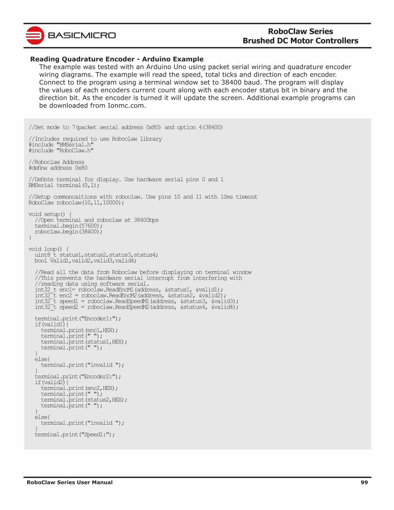
RoboClaw Series Brushed DC Motor Controllers
RoboClaw Series User Manual 99
BASICMICRO
Reading Quadrature Encoder - Arduino ExampleThe example was tested with an Arduino Uno using packet serial wiring and quadrature encoder wiring diagrams. The example will read the speed, total ticks and direction of each encoder. Connect to the program using a terminal window set to 38400 baud. The program will display the values of each encoders current count along with each encoder status bit in binary and the direction bit. As the encoder is turned it will update the screen. Additional example programs can be downloaded from Ionmc.com.
//Set mode to 7(packet serial address 0x80) and option 4(38400) //Includes required to use Roboclaw library #include "BMSerial.h" #include "RoboClaw.h" //Roboclaw Address #define address 0x80 //Definte terminal for display. Use hardware serial pins 0 and 1 BMSerial terminal(0,1); //Setup communcaitions with roboclaw. Use pins 10 and 11 with 10ms timeout RoboClaw roboclaw(10,11,10000); void setup() { //Open terminal and roboclaw at 38400bps terminal.begin(57600); roboclaw.begin(38400); } void loop() { uint8_t status1,status2,status3,status4; bool valid1,valid2,valid3,valid4; //Read all the data from Roboclaw before displaying on terminal window //This prevents the hardware serial interrupt from interfering with //reading data using software serial. int32_t enc1= roboclaw.ReadEncM1(address, &status1, &valid1); int32_t enc2 = roboclaw.ReadEncM2(address, &status2, &valid2); int32_t speed1 = roboclaw.ReadSpeedM1(address, &status3, &valid3); int32_t speed2 = roboclaw.ReadSpeedM2(address, &status4, &valid4); terminal.print("Encoder1:"); if(valid1){ terminal.print(enc1,HEX); terminal.print(" "); terminal.print(status1,HEX); terminal.print(" "); } else{ terminal.print("invalid "); } terminal.print("Encoder2:"); if(valid2){ terminal.print(enc2,HEX); terminal.print(" "); terminal.print(status2,HEX); terminal.print(" "); } else{ terminal.print("invalid "); } terminal.print("Speed1:");

RoboClaw Series Brushed DC Motor Controllers
RoboClaw Series User Manual 100
BASICMICRO
if(valid3){ terminal.print(speed1,HEX); terminal.print(" "); } else{ terminal.print("invalid "); } terminal.print("Speed2:"); if(valid4){ terminal.print(speed2,HEX); terminal.print(" "); } else{ terminal.print("invalid "); } terminal.println(); delay(100); }
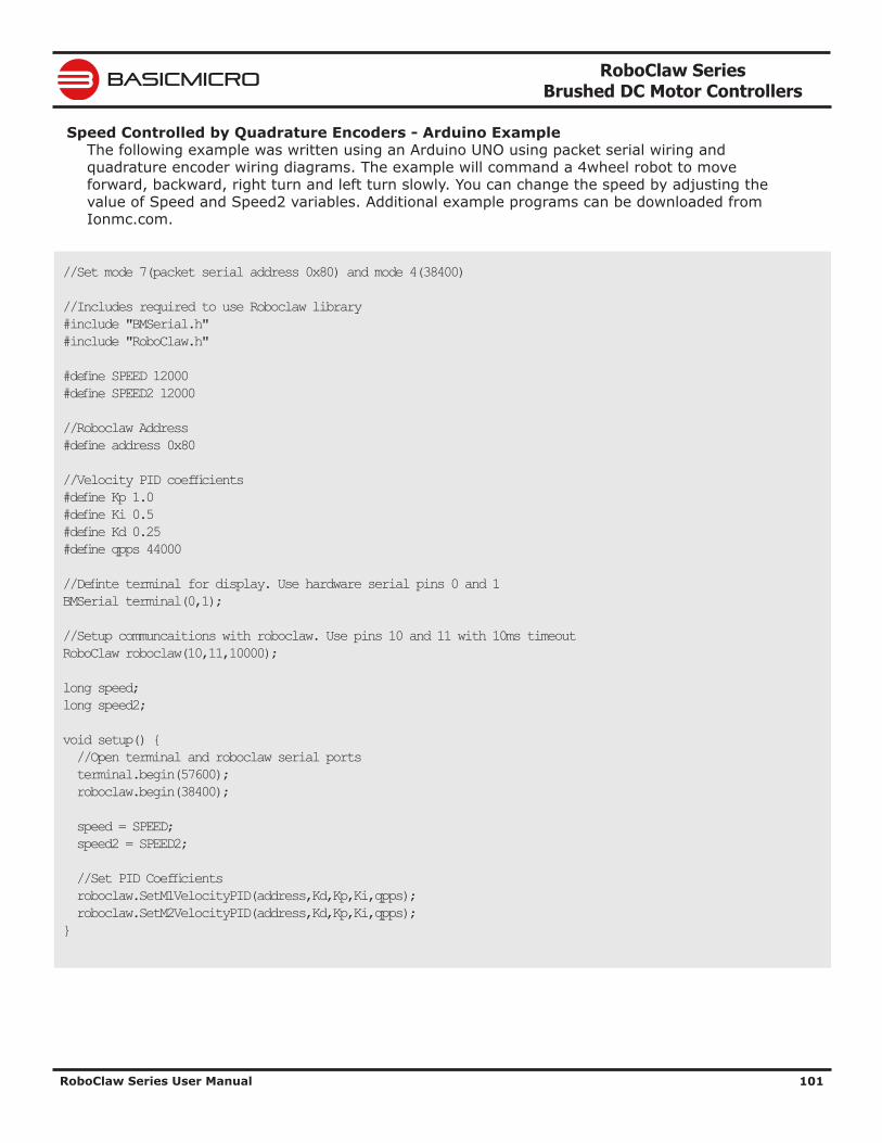
RoboClaw Series Brushed DC Motor Controllers
RoboClaw Series User Manual 101
BASICMICRO
Speed Controlled by Quadrature Encoders - Arduino ExampleThe following example was written using an Arduino UNO using packet serial wiring and quadrature encoder wiring diagrams. The example will command a 4wheel robot to move forward, backward, right turn and left turn slowly. You can change the speed by adjusting the value of Speed and Speed2 variables. Additional example programs can be downloaded from Ionmc.com.
//Set mode 7(packet serial address 0x80) and mode 4(38400) //Includes required to use Roboclaw library #include "BMSerial.h" #include "RoboClaw.h" #define SPEED 12000 #define SPEED2 12000 //Roboclaw Address #define address 0x80 //Velocity PID coefficients #define Kp 1.0 #define Ki 0.5 #define Kd 0.25 #define qpps 44000 //Definte terminal for display. Use hardware serial pins 0 and 1 BMSerial terminal(0,1); //Setup communcaitions with roboclaw. Use pins 10 and 11 with 10ms timeout RoboClaw roboclaw(10,11,10000); long speed; long speed2; void setup() { //Open terminal and roboclaw serial ports terminal.begin(57600); roboclaw.begin(38400); speed = SPEED; speed2 = SPEED2; //Set PID Coefficients roboclaw.SetM1VelocityPID(address,Kd,Kp,Ki,qpps); roboclaw.SetM2VelocityPID(address,Kd,Kp,Ki,qpps); }
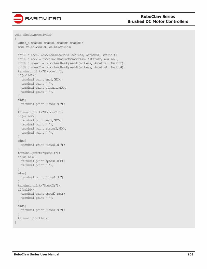
RoboClaw Series Brushed DC Motor Controllers
RoboClaw Series User Manual 102
BASICMICRO
void displayspeed(void) { uint8_t status1,status2,status3,status4; bool valid1,valid2,valid3,valid4; int32_t enc1= roboclaw.ReadEncM1(address, &status1, &valid1); int32_t enc2 = roboclaw.ReadEncM2(address, &status2, &valid2); int32_t speed1 = roboclaw.ReadSpeedM1(address, &status3, &valid3); int32_t speed2 = roboclaw.ReadSpeedM2(address, &status4, &valid4); terminal.print("Encoder1:"); if(valid1){ terminal.print(enc1,DEC); terminal.print(" "); terminal.print(status1,HEX); terminal.print(" "); } else{ terminal.print("invalid "); } terminal.print("Encoder2:"); if(valid2){ terminal.print(enc2,DEC); terminal.print(" "); terminal.print(status2,HEX); terminal.print(" "); } else{ terminal.print("invalid "); } terminal.print("Speed1:"); if(valid3){ terminal.print(speed1,DEC); terminal.print(" "); } else{ terminal.print("invalid "); } terminal.print("Speed2:"); if(valid4){ terminal.print(speed2,DEC); terminal.print(" "); } else{ terminal.print("invalid "); } terminal.println(); }
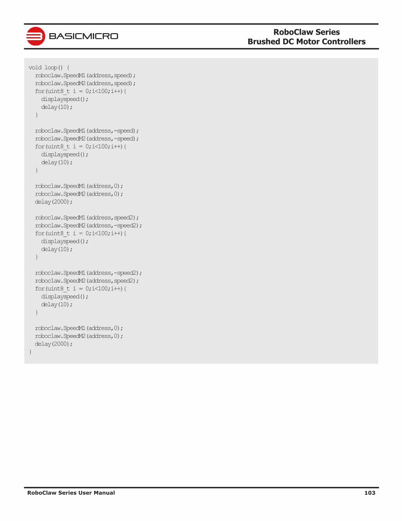
RoboClaw Series Brushed DC Motor Controllers
RoboClaw Series User Manual 103
BASICMICRO
void loop() { roboclaw.SpeedM1(address,speed); roboclaw.SpeedM2(address,speed); for(uint8_t i = 0;i<100;i++){ displayspeed(); delay(10); } roboclaw.SpeedM1(address,-speed); roboclaw.SpeedM2(address,-speed); for(uint8_t i = 0;i<100;i++){ displayspeed(); delay(10); } roboclaw.SpeedM1(address,0); roboclaw.SpeedM2(address,0); delay(2000); roboclaw.SpeedM1(address,speed2); roboclaw.SpeedM2(address,-speed2); for(uint8_t i = 0;i<100;i++){ displayspeed(); delay(10); } roboclaw.SpeedM1(address,-speed2); roboclaw.SpeedM2(address,speed2); for(uint8_t i = 0;i<100;i++){ displayspeed(); delay(10); } roboclaw.SpeedM1(address,0); roboclaw.SpeedM2(address,0); delay(2000); }
RoboClaw Series Brushed DC Motor Controllers
RoboClaw Series User Manual 104
BASICMICRO
WarrantyBasicmicro warranties its products against defects in material and workmanship for a period of 1 year. If a defect is discovered, Basicmicro will, at our sole discretion, repair, replace, or refund the purchase price of the product in question. Contact us at [email protected]. No returns will be accepted without the proper authorization.
Copyrights and TrademarksCopyright© 2015 by Basicmicro, Inc. All rights reserved. All referenced trademarks mentioned are registered trademarks of their respective holders.
DisclaimerBasicmicro cannot be held responsible for any incidental or consequential damages resulting from use of products manufactured or sold by Basicmicro or its distributors. No products from Basicmicro should be used in any medical devices and/or medical situations. No product should be used in any life support situations.
Contacts Email: [email protected] Tech support: [email protected] Web: http://www.basicmicro.com
Discussion ListA web based discussion board is maintained at http://www.basicmicro.com
Technical SupportTechnical support is available by sending an email to [email protected], by opening a support ticket on the Ion Motion Control website or by calling 800-535-9161 during normal operating hours. All email will be answered within 48 hours.