6350 series...Harmony og Metso DNA software og til oFUNDATI N Fieldbus via Emerson Del-taV, Yokogawa...
28
6350 PROFIBUS ® PA / FOUNDATION™ Fieldbus transmitter Nr. 6350V103-DK Fra serienr. 090449300
Transcript of 6350 series...Harmony og Metso DNA software og til oFUNDATI N Fieldbus via Emerson Del-taV, Yokogawa...

6 3 5 0PROFIBUS® PA / FOUNDATION™ Fieldbus transmitter
N r . 6 3 5 0 V 1 0 3 - D KF r a s e r i e n r . 0 9 0 4 4 9 3 0 0
1431
DK
UK
FR
DE
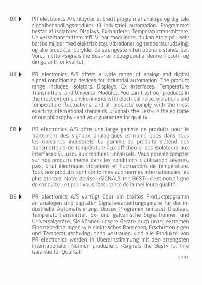
PR electronics A/S tilbyder et bredt program af analoge og digitale signalbehandlingsmoduler til industriel automation. Programmet består af Isolatorer, Displays, Ex-barrierer, Temperaturtransmittere, Universaltransmittere mfl. Vi har modulerne, du kan stole på i selv barske miljøer med elektrisk støj, vibrationer og temperaturudsving, og alle produkter opfylder de strengeste internationale standarder. Vores motto »Signals the Best« er indbegrebet af denne filosofi – og din garanti for kvalitet.
PR electronics A/S offers a wide range of analog and digital signal conditioning devices for industrial automation. The product range includes Isolators, Displays, Ex Interfaces, Temperature Transmitters, and Universal Modules. You can trust our products in the most extreme environments with electrical noise, vibrations and temperature fluctuations, and all products comply with the most exacting international standards. »Signals the Best« is the epitome of our philosophy – and your guarantee for quality.
PR electronics A/S offre une large gamme de produits pour le traite ment des signaux analogiques et numériques dans tous les domaines industriels. La gamme de produits s’étend des transmetteurs de température aux afficheurs, des isolateurs aux interfaces SI, jusqu’aux modules universels. Vous pouvez compter sur nos produits même dans les conditions d’utilisation sévères, p.ex. bruit électrique, vibrations et fluctuations de température. Tous nos produits sont conformes aux normes internationales les plus strictes. Notre devise »SIGNALS the BEST« c’est notre ligne de conduite - et pour vous l’assurance de la meilleure qualité.
PR electronics A/S verfügt über ein breites Produktprogramm an analogen und digitalen Signalverarbeitungsgeräte für die in-dustrielle Automatisierung. Dieses Programm umfasst Displays, Temperaturtransmitter, Ex- und galvanische Signaltrenner, und Universalgeräte. Sie können unsere Geräte auch unter extremen Einsatzbedingungen wie elektrisches Rauschen, Erschütterungen und Temperaturschwingungen vertrauen, und alle Produkte von PR electronics werden in Überein stimmung mit den strengsten internationalen Normen produziert. »Signals the Best« ist Ihre Garantie für Qualität!
6350V103-DK 1
PROFIBUS® PA / FOUNDATION™ FIELDBUS TRANSMITTER
PRETRANS 6350
INDhOLDSFORTEgNELSE
Anvendelse ................................................................................................ 2Teknisk karakteristik ............................................................................. 2Montage / installation ........................................................................... 2Applikationer ............................................................................................ 3Bestillingsskema: 6350 ........................................................................ 4Elektriske specifikationer .................................................................... 4Tilslutninger .............................................................................................. 8Blokdiagram .............................................................................................. 11Bus-installation........................................................................................ 12Appendix .................................................................................................... 13 ATEX Installation Drawing - 6350A ........................................... 14 ATEX Installation Drawing - 6350B ........................................... 15 FM / CSA Installation Drawing ...................................................... 18
2 6350V103-DK
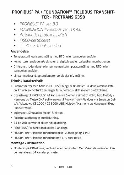
PROFIBUS® PA / FOUNDATION™ FIELDBUS TRANSMIT-TER - PRETRANS 6350
• PROFIBUS® PA ver. 3.0 • FOUNDATION™ Fieldbus ver. ITK 4.6 • Automatisk protokol-switch • FISCO-certificeret • 1- eller 2-kanals version
Anvendelse• TemperaturlineariseretmålingmedRTD-ellertermoelementføler.
• KonvertereranalogemA-signalertildigitalværdierpåbuskommunikationen.
• Differens-,redundans-ellergennemsnitstemperaturmålingmedRTD-eller termoelementføler.
• Lineærmodstand,potentiometerogbipolarmV-måling.
Teknisk karakteristik• BustransmittermedbådePRoFIBUS® PA og FoUNDATIoN™ Fieldbus kommunikati-
on. En unik switchfunktion sørger for automatisk skift mellem protokollerne.
• OpsætningtilPRoFIBUS® PA kan ske via Siemens Simatic® PDM®, ABB Melody / Harmony og Metso DNA software og til FoUNDATIoN™ Fieldbus via Emerson Del-taV, Yokogawa CS 1000 / CS 3000, ABB Melody / Harmony og Honeywell Expe-rion software.
• Indbygget„Simulationmode“-funktion.
• Polaritetsuafhængigbustilslutning.
• 24bitA/Dkonvertersikrerhøjopløsning.
• PRoFIBUS® PA funktionsblokke: 2 analoge.
• FoUNDATIoN™ Fieldbus funktionsblokke: 2 analoge og 1 PID.
• FoUNDATIoN™ Fieldbus funktionalitet: LAS eller Basic.
Montage / installation• MonterespåDIN-skinne,vertikaltellerhorisontalt.Med2-kanalsversionenkan
der installeres 84 kanaler pr. meter.
6350V103-DK 3
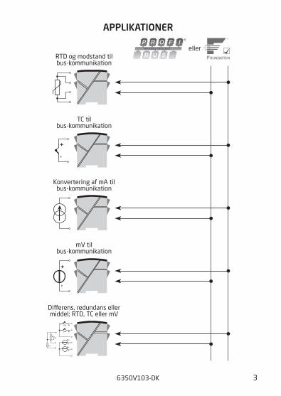
APPLIKATIONER
+- 1
+2
+-
+-
2
12
1
-
+
-
+
-
RTD og modstand tilbus-kommunikation
Dierens, redundans ellermiddel; RTD, TC eller mV
mV tilbus-kommunikation
Konvertering af mA tilbus-kommunikation
TC tilbus-kommunikation
eller
4 6350V103-DK
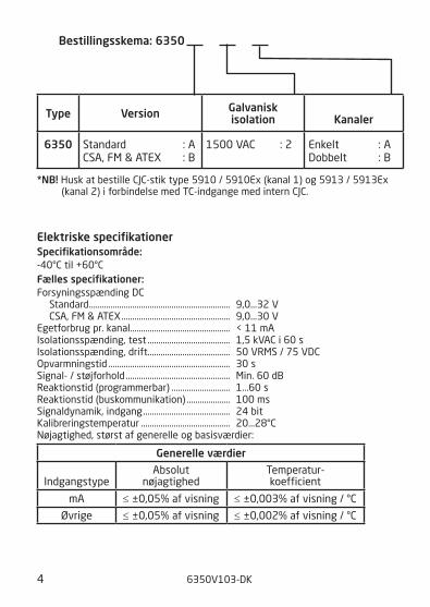
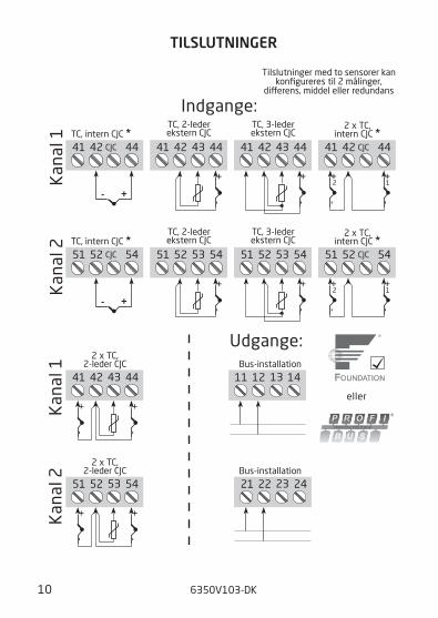
*NB! Husk at bestille CJC-stik type 5910 / 5910Ex (kanal 1) og 5913 / 5913Ex (kanal 2) i forbindelse med TC-indgange med intern CJC.
Elektriske specifikationerSpecifikationsområde:-40°C til +60°C Fælles specifikationer:ForsyningsspændingDC Standard ................................................................. 9,0...32 V CSA, FM & ATEX .................................................. 9,0...30 V Egetforbrug pr. kanal .............................................. < 11 mA Isolationsspænding,test ...................................... 1,5 kVAC i 60 s Isolationsspænding,drift...................................... 50 VRMS / 75 VDC opvarmningstid ........................................................ 30 s Signal- / støjforhold ................................................ Min. 60 dB Reaktionstid (programmerbar) ........................... 1...60 s Reaktionstid (buskommunikation) .................... 100 ms Signaldynamik, indgang ........................................ 24 bit Kalibreringstemperatur ......................................... 20...28°C Nøjagtighed,størstafgenerelleogbasisværdier:
generelle værdier
Indgangstype
Absolut nøjagtighed
Temperatur- koefficient
mA ≤ ±0,05% af visning ≤ ±0,003% af visning / °C
Øvrige ≤ ±0,05% af visning ≤ ±0,002% af visning / °C
Bestillingsskema: 6350
Type Version galvanisk isolation
Kanaler
6350 Standard : A CSA, FM & ATEX : B
1500 VAC : 2 Enkelt : A Dobbelt : B
6350V103-DK 5
Virkningafforsyningsspændings- ændring ....................................................................... < 0,005% af visning / VDC Ledningskvadrat (max.) ......................................... 1 x 2,5 mm2 flerkoret ledning Klemskruetilspændingsmoment ........................ 0,5 NmLuftfugtighed ............................................................ < 95% RH (ikke kond.) Mål (H x B x D) .......................................................... 109 x 23,5 x 104 mmDIN-skinne type........................................................ DIN 46277 Kapslingsklasse ........................................................ IP20 Vægt(1/2kanaler) ............................................... 145 / 185 g
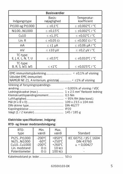
Elektriske specifikationer, indgang:RTD- og lineær modstandsindgang:
Kabelmodstand pr. leder ....................................... 50 Ω
Basisværdier
Indgangstype
Basis- nøjagtighed
Temperatur- koefficient
Pt100 og Pt1000 ≤ ±0,1°C ≤ ±0,002°C / °C
Ni100...Ni1000 ≤ ±0,15°C ≤ ±0,002°C / °C
Cu10 ≤ ±1,3°C ≤ ±0,02°C / °C
Lin. R ≤ ±0,05 Ω ≤ ±0,002 Ω / °C
mA ≤ ±1 µA ≤ ±0,06 µA / °C
mV ≤ ±10 µV ≤ ±0,2 µV / °C
TC-type: E, J, K, L, N, T, U
≤ ±0,5°C
≤ ±0,010°C / °C
TC-type: B, R, S, W3, W5
≤ ±1°C
≤ ±0,025°C / °C
EMC-immunitetspåvirkning ...................................... < ±0,1% af visning Udvidet EMC-immunitet:NAMUR NE 21, A kriterium, gniststøj .................. < ±1% af visning
RTD- type
Min. værdi
Max. værdi
Standard
Pt25...Pt1000 Ni25...Ni1000 Cu10...Cu1000 Lin. modstand Potentiometer
-200°C -60°C
-200°C 0 Ω 0 Ω
+850°C +250°C +260°C
10 kΩ 100 kΩ
IEC 60751 / JIS C 1604 DIN 43760
α = 0,00427 - -
6 6350V103-DK
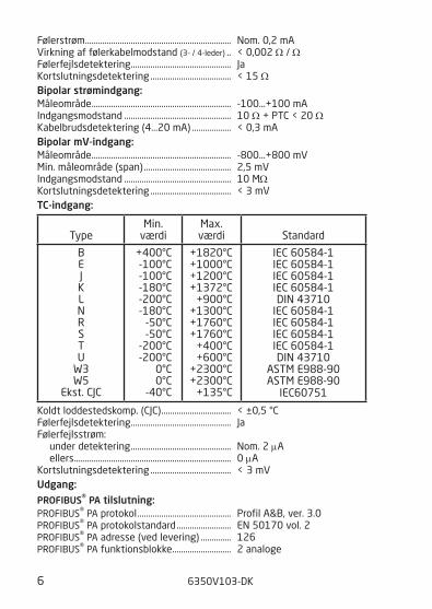
Følerstrøm ................................................................... Nom. 0,2 mA Virkning af følerkabelmodstand (3- / 4-leder) .. < 0,002 Ω / Ω Følerfejlsdetektering .............................................. Ja Kortslutningsdetektering ..................................... < 15 ΩBipolar strømindgang:Måleområde ................................................................ -100...+100 mA Indgangsmodstand ................................................. 10 Ω + PTC < 20 Ω Kabelbrudsdetektering (4...20 mA) .................. < 0,3 mA Bipolar mV-indgang:Måleområde ................................................................ -800...+800 mV Min. måleområde (span) ........................................ 2,5 mV Indgangsmodstand ................................................. 10 MΩKortslutningsdetektering ..................................... < 3 mVTC-indgang:
Koldt loddestedskomp. (CJC) ................................ < ±0,5 °C Følerfejlsdetektering .............................................. Ja Følerfejlsstrøm: under detektering .............................................. Nom. 2 μA ellers ........................................................................ 0 μA Kortslutningsdetektering ..................................... < 3 mV Udgang:PROFIBUS® PA tilslutning:PRoFIBUS® PA protokol ........................................... Profil A&B, ver. 3.0 PRoFIBUS® PA protokolstandard ......................... EN 50170 vol. 2 PRoFIBUS® PA adresse (ved levering) .............. 126 PRoFIBUS® PA funktionsblokke ........................... 2 analoge
Type
Min. værdi
Max. værdi
Standard
B E J K L N R S T U
W3 W5
Ekst. CJC
+400°C -100°C -100°C -180°C -200°C -180°C
-50°C -50°C
-200°C -200°C
0°C 0°C
-40°C
+1820°C +1000°C +1200°C +1372°C
+900°C +1300°C +1760°C +1760°C
+400°C +600°C
+2300°C +2300°C
+135°C
IEC 60584-1 IEC 60584-1 IEC 60584-1 IEC 60584-1 DIN 43710
IEC 60584-1 IEC 60584-1 IEC 60584-1 IEC 60584-1 DIN 43710
ASTM E988-90 ASTM E988-90
IEC60751
6350V103-DK 7
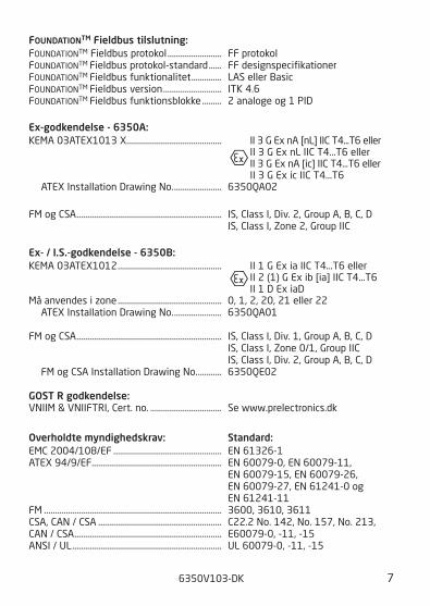
FOUNDATIONTM Fieldbus tilslutning:FoUNDATIoNTM Fieldbus protokol ......................... FF protokol FoUNDATIoNTM Fieldbus protokol-standard ...... FF designspecifikationer FoUNDATIoNTM Fieldbus funktionalitet .............. LAS eller Basic FoUNDATIoNTM Fieldbus version ........................... ITK 4.6 FoUNDATIoNTM Fieldbus funktionsblokke ......... 2 analoge og 1 PID
Ex-godkendelse - 6350A:KEMA 03ATEX1013 X............................................ II 3 G Ex nA [nL] IIC T4...T6 eller II 3 G Ex nL IIC T4...T6 eller II 3 G Ex nA [ic] IIC T4...T6 eller II 3 G Ex ic IIC T4...T6 ATEX Installation Drawing No. ...................... 6350QA02
FM og CSA ................................................................... IS, Class I, Div. 2, Group A, B, C, D IS, Class I, Zone 2, Group IIC
Ex- / I.S.-godkendelse - 6350B:KEMA 03ATEX1012 ................................................ II 1 G Ex ia IIC T4...T6 eller II 2 (1) G Ex ib [ia] IIC T4...T6 II 1 D Ex iaDMå anvendes i zone ................................................ 0, 1, 2, 20, 21 eller 22 ATEX Installation Drawing No. ...................... 6350QA01
FM og CSA ................................................................... IS, Class I, Div. 1, Group A, B, C, D IS, Class I, Zone 0/1, Group IIC IS, Class I, Div. 2, Group A, B, C, D FM og CSA Installation Drawing No. ........... 6350QE02
gOST R godkendelse:VNIIM & VNIIFTRI, Cert. no. ................................. Se www.prelectronics.dk
Overholdte myndighedskrav: Standard:EMC 2004/108/EF .................................................. EN 61326-1 ATEX 94/9/EF ............................................................ EN 60079-0, EN 60079-11, EN 60079-15, EN 60079-26, EN 60079-27, EN 61241-0 og EN 61241-11FM .................................................................................. 3600, 3610, 3611 CSA, CAN / CSA ......................................................... C22.2 No. 142, No. 157, No. 213,CAN / CSA .................................................................... E60079-0, -11, -15 ANSI / UL ..................................................................... UL 60079-0, -11, -15
8 6350V103-DK
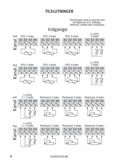
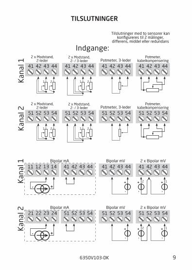
TILSLUTNINgER
41 42 4443
51 52 5453
51 52 545351 52 5453
51 52 5453 51 52 5453
41 42 444342 444341 41 42 4443
41 42 444341 42 4443
1 2
51 52 5453
1 2
51 52 5453
1 2
41 42 4443
1 2
41 42 4443
51 52 5453
Kan
al 2
Kan
al 1
Kan
al 1
Kan
al 2
RTD, 2-leder RTD, 3-leder RTD, 4-leder
RTD, 2-leder RTD, 3-leder RTD, 4-leder
Modstand, 2-leder Modstand, 3-leder Modstand, 4-leder
Modstand, 2-leder Modstand, 3-leder Modstand, 4-leder
Indgange:
2 x RTD,2- / 3-leder
2 x RTD,2- / 3-leder
2 x RTD,2-leder
Tilslutninger med to sensorer kankonfigureres til 2 målinger,
dierens, middel eller redundans
2 x RTD,2-leder
6350V103-DK 9
TILSLUTNINgER
41 42 4443
51 52 545351 52 5453
41 42 444341 42 4443
1 2
51 52 5453
1 2
51 52 5453
1 2
41 42 4443
1 2
41 42 444311 12 1413
+-
21 22 2423
+-
51 52 5453
41 42 4443
+-
51 52 5453
+-
51 52 5453
+-
+-
12
41 42 4443+
-
+-
12
Bipolar mA
Bipolar mA
Kan
al 2
Kan
al 1
Kan
al 1
Kan
al 2
Indgange:2 x Modstand,
2- / 3-leder
2 x Modstand,2- / 3-leder
2 x Modstand,2-leder
2 x Modstand,2-leder
Potmeter, 3-leder
Potmeter, 3-leder
Potmeter,kabelkompensering
Potmeter,kabelkompensering
2 x Bipolar mV
2 x Bipolar mV
Bipolar mV
Bipolar mV
Tilslutninger med to sensorer kankonfigureres til 2 målinger,
dierens, middel eller redundans
10 6350V103-DK
TILSLUTNINgER
51 52 5453
-
+
41 42 4443
-
+
41 42 4443
-
+
51 54CJC52
+-
41 42 44CJC
+-
51 54CJC52
12
-
+
-
+
41 42 44CJC
12
-
+
-
+
41 42 4443
-
+
-
+
-
+
-
+
51 52 5453
-
+
51 52 5453
11 12 1413
21 22 2423
TC, 2-lederekstern CJC
TC, 2-lederekstern CJC
TC, 3-lederekstern CJC
TC, 3-lederekstern CJC
TC, intern CJC *
TC, intern CJC *
eller
Bus-installation
Bus-installation
Udgange:
Kan
al 2
Kan
al 1
Kan
al 1
Kan
al 2
Indgange:
2 x TC,2-leder CJC
2 x TC,2-leder CJC
2 x TC,intern CJC *
2 x TC,intern CJC *
Tilslutninger med to sensorer kankonfigureres til 2 målinger,
dierens, middel eller redundans
6350V103-DK 11
44
141311
12
43
42
41
53
54
51
52
23 24
2221
CH
1
CH
263
50
CPU
PR
OF
IBU
S
FO
UN
DA
TIO
N
Gal
vani
skis
olat
ion
EE
PR
OM
Fu
nkt
ion
s-b
lokk
e
AI1
, AI2
Pro
toko
l
Pro
toko
l
Ana
log
til
Dig
ital
konv
erte
r
Kom
plet
kon
figu
rati
onKo
rrek
tion
skoe
ci
ente
rFa
brik
sind
still
inge
r
AI1
, AI2
PID
LAS
Fu
nkt
ion
s-b
lokk
e
Fo
un
dat
ion
Fie
ldb
us
PR
OF
IBU
S
Automatiskkommunikations-
switch
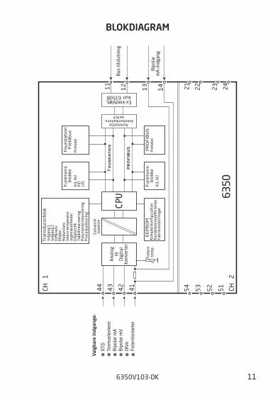
Ex-kredsløb,kun 6350B
Inte
rnte
mp.
Valg
bare
indg
ange
:
Bus
-tils
lutn
ing
Bip
olar
mA
-indg
ang
RTD
Term
oele
men
tB
ipol
ar m
AB
ipol
ar m
VO
hmPo
tent
iom
eter
Tra
nsd
uce
rblo
kIn
dgan
g 1
Indg
ang
2D
ier
ens
Mid
del
Red
unda
nsIn
tern
tem
pera
tur
Inge
niør
enhe
der
Dia
gnos
tik
Tabe
lline
aris
erin
gPo
lyno
mie
linea
rise
ring
Pro
cesk
alib
reri
ng
BLOKDIAgRAM
12 6350V103-DK
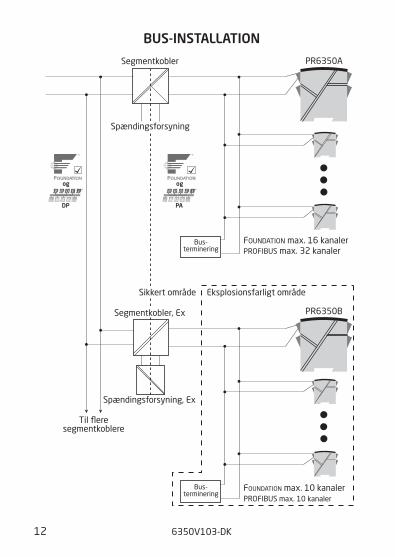
BUS-INSTALLATION
PR6350A
DP PA
PR6350B
Spændingsforsyning
Spændingsforsyning, Ex
Bus-terminering
Bus-terminering
Segmentkobler
FOUNDATION max. 16 kanaler
FOUNDATION max. 10 kanaler
PROFIBUS max. 32 kanaler
PROFIBUS max. 10 kanaler
Segmentkobler, Ex
Eksplosionsfarligt områdeSikkert område
Til fleresegmentkoblere
og og
APPENDIx
ATEx INSTALLATION DRAwINgS - 6350A
ATEx INSTALLATION DRAwINgS - 6350B
FM & CSA INSTALLATION DRAwINg NO. 6350QE02
6350V103-DK 13
ATEx Installation Drawing - 6350A
14 6350V103-DK
6350QA02LERBAKKEN 10, 8410 RØNDE DENMARK. WWW.PRELECTRONICS.COM
Revision date:
2009-11-17 Version Revision
V1R0-DK01 Page:
1/1
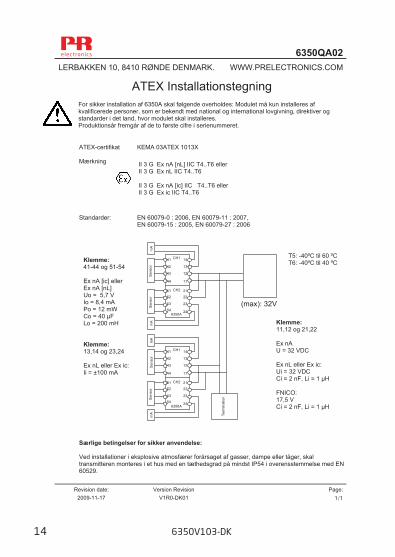
ATEX Installationstegning For sikker installation af 6350A skal følgende overholdes: Modulet må kun installeres af kvalificerede personer, som er bekendt med national og international lovgivning, direktiver og standarder i det land, hvor modulet skal installeres. Produktionsår fremgår af de to første cifre i serienummeret. ATEX-certifikat KEMA 03ATEX 1013X Mærkning Standarder: EN 60079-0 : 2006, EN 60079-11 : 2007,
EN 60079-15 : 2005, EN 60079-27 : 2006 Særlige betingelser for sikker anvendelse: Ved installationer i eksplosive atmosfærer forårsaget af gasser, dampe eller tåger, skal transmitteren monteres i et hus med en tæthedsgrad på mindst IP54 i overensstemmelse med EN 60529.
II 3 G Ex nA [nL] IIC T4..T6 eller II 3 G Ex nL IIC T4..T6 II 3 G Ex nA [ic] IIC T4..T6 eller II 3 G Ex ic IIC T4..T6
11
12
13
1441
42
43
44
2122
23
24
53
5152
546350A
CH2
CH1
11
12
13
1441
42
43
44
2122
23
24
53
5152
546350A
CH2
CH1
Sens
orSe
nsor
Sens
orSe
nsor
mA
mA
mA
mA
Term
inat
ion
(max): 32V
T5: -40ºC til 60 ºC T6: -40ºC til 40 ºC
Klemme: 11,12 og 21,22 Ex nA U = 32 VDC Ex nL eller Ex ic: Ui = 32 VDC Ci = 2 nF, Li = 1 μH FNICO: 17,5 V Ci = 2 nF, Li = 1 μH
Klemme: 41-44 og 51-54 Ex nA [ic] eller Ex nA [nL] Uo = 5,7 V Io = 8,4 mA Po = 12 mW Co = 40 μF Lo = 200 mH Klemme: 13,14 og 23,24 Ex nL eller Ex ic:Ii = ±100 mA
ATEx Installation Drawing - 6350B
6350V103-DK 15
6350QA01LERBAKKEN 10, 8410 RØNDE DENMARK. WWW.PRELECTRONICS.COM
Revision date:
2009-09-24 Version Revision
V3R0-DK01 Page:
1/3
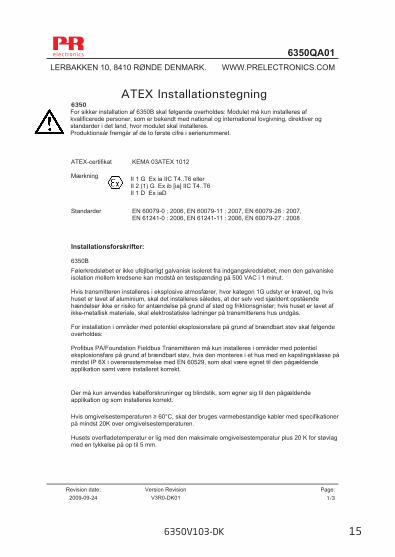
ATEX Installationstegning 6350 For sikker installation af 6350B skal følgende overholdes: Modulet må kun installeres af kvalificerede personer, som er bekendt med national og international lovgivning, direktiver og standarder i det land, hvor modulet skal installeres. Produktionsår fremgår af de to første cifre i serienummeret. ATEX-certifikat KEMA 03ATEX 1012 Mærkning Standarder EN 60079-0 : 2006, EN 60079-11 : 2007, EN 60079-26 : 2007, EN 61241-0 : 2006, EN 61241-11 : 2006, EN 60079-27 : 2008 Installationsforskrifter: 6350B Følerkredsløbet er ikke ufejlbarligt galvanisk isoleret fra indgangskredsløbet, men den galvaniske isolation mellem kredsene kan modstå en testspænding på 500 VAC i 1 minut. Hvis transmitteren installeres i eksplosive atmosfærer, hvor kategori 1G udstyr er krævet, og hvis huset er lavet af aluminium, skal det installeres således, at der selv ved sjældent opstående hændelser ikke er risiko for antændelse på grund af stød og friktionsgnister; hvis huset er lavet af ikke-metallisk materiale, skal elektrostatiske ladninger på transmitterens hus undgås. For installation i områder med potentiel eksplosionsfare på grund af brændbart støv skal følgende overholdes: Profibus PA/Foundation Fieldbus Transmitteren må kun installeres i områder med potentiel eksplosionsfare på grund af brændbart støv, hvis den monteres i et hus med en kapslingsklasse på mindst IP 6X i overensstemmelse med EN 60529, som skal være egnet til den pågældende applikation samt være installeret korrekt. Der må kun anvendes kabelforskruninger og blindstik, som egner sig til den pågældende applikation og som installeres korrekt. Hvis omgivelsestemperaturen ≥ 60°C, skal der bruges varmebestandige kabler med specifikationer på mindst 20K over omgivelsestemperaturen. Husets overfladetemperatur er lig med den maksimale omgivelsestemperatur plus 20 K for støvlag med en tykkelse på op til 5 mm.
II 1 G Ex ia IIC T4..T6 eller II 2 (1) G Ex ib [ia] IIC T4..T6 II 1 D Ex iaD
16 6350V103-DK
6350QA01LERBAKKEN 10, 8410 RØNDE DENMARK. WWW.PRELECTRONICS.COM
Revision date:
2009-09-24 Version Revision
V3R0-DK01 Page:
2/3
11
12
13
1441
42
43
44
2122
23
24
53
5152
546350B
CH2
CH1
11
12
13
1441
42
43
44
2122
23
24
53
5152
546350B
CH2
CH1
11
12
13
1441
42
43
44
2122
23
24
53
5152
546350B
CH2
CH1
Sens
orSe
nsor
Sens
orSe
nsor
Sens
orSe
nsor
mA
mA
mA
mA
mA
mA
Term
inat
ion
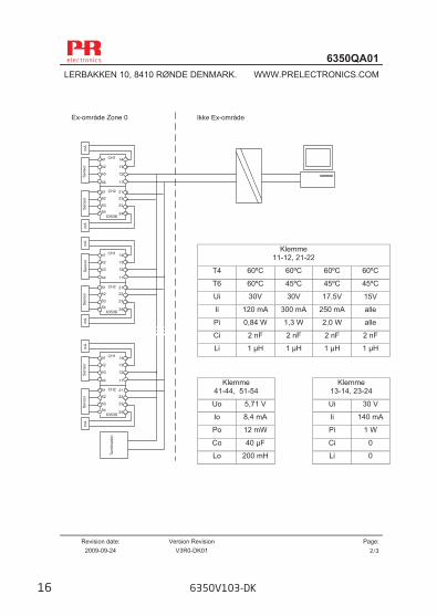
Klemme 11-12, 21-22
T4 60ºC 60ºC 60ºC 60ºC
T6 60ºC 45ºC 45ºC 45ºC
Ui 30V 30V 17.5V 15V
Ii 120 mA 300 mA 250 mA alle
Pi 0,84 W 1,3 W 2,0 W alle
Ci 2 nF 2 nF 2 nF 2 nF
Li 1 μH 1 μH 1 μH 1 μH
Klemme 41-44, 51-54
Klemme 13-14, 23-24
Uo 5,71 V Ui 30 V
Io 8,4 mA Ii 140 mA
Po 12 mW Pi 1 W
Co 40 μF Ci 0
Lo 200 mH Li 0
Ikke Ex-område Ex-område Zone 0
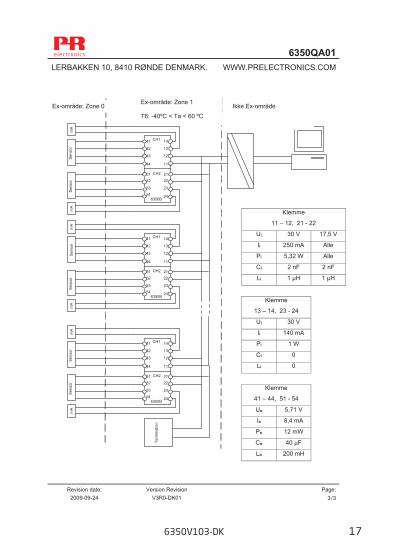
6350V103-DK 17
6350QA01LERBAKKEN 10, 8410 RØNDE DENMARK. WWW.PRELECTRONICS.COM
Revision date:
2009-09-24 Version Revision
V3R0-DK01 Page:
3/3
Klemme
11 – 12, 21 - 22
Ui 30 V 17,5 V
Ii 250 mA Alle
Pi 5,32 W Alle
Ci 2 nF 2 nF
Li 1 μH 1 μH
Klemme
13 – 14, 23 - 24
Ui 30 V
Ii 140 mA
Pi 1 W
Ci 0
Li 0
Klemme
41 – 44, 51 - 54
Uo 5,71 V
Io 8,4 mA
Po 12 mW
Co 40 μF
Lo 200 mH
11
12
13
1441
42
43
44
2122
23
24
53
5152
546350B
CH2
CH1
11
12
13
1441
42
43
44
2122
23
24
53
5152
546350B
CH2
CH1
11
12
13
1441
42
43
44
2122
23
24
53
5152
546350B
CH2
CH1
Term
inat
ion
Sens
orSe
nsor
Sens
orSe
nsor
Sens
orSe
nsor
mA
mA
mA
mA
mA
mA
Ex-område: Zone 1 T6: -40ºC < Ta < 60 ºC
Ex-område: Zone 0 Ikke Ex-område
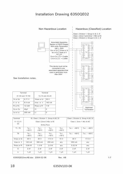
FM / CSA Installation Drawing
Installation Drawing 6350QE02
See Installation notes.
Terminal
41-44 and 51-54
Vt or Uo 5.71 V
It or Io 8.4 mA
Pt or Po 12 mW
Ca or Co 40µF
La or Lo 200 mH
Terminal
13,14 and 23,24
Vmax or Ui 30 V
Imax or Ii 140 mA
Pmax or Pi 1 W
Ci 0
Li 0
Terminal
11-12 21-22
IS, Class I, Division 1, Group A,B,C,D
Class I,Zone 0 AEx ia IIC
Entity,Fisco
Class I, Division 2, Group A,B,C,D
Class I, Zone 1 AEx ib IIC
T1..T5 Ta ≤ +60°C
Ta ≤ +60°C
Ta ≤ +60°C
Ta ≤ +60°C
Ta ≤ +60°C Ta ≤ +60°C
T6 Ta ≤ +60°C
Ta ≤ +45°C
Ta ≤ +45°C
Ta ≤ +45°C
Ta ≤ +60°C Ta ≤ +60°C
Vmax or Ui 30 V 30 V 17.5 V 15 V 30 V 17.5 V
Imax or Ii 120 mA 300 mA 250 mA any 250 mA any
Pmax or Pi 0.84 W 1.3 W 2.0 W any 5.32 W any
Ci 2 nF 2 nF 2 nF 2 nF 2 nF 2 nF
Li 1 µH 1 µH 1 µH 1 µH 1 µH 1 µH
Non Hazardous Location Hazardous (Classified) Location
11
12
13
14 41
42
43
44
2122
23
24
53
5152
546350B
CH2
CH1
11
12
13
14 41
42
43
44
2122
23
24
53
5152
546350B
CH2
CH1
11
12
13
14 41
42
43
44
2122
23
24
53
5152
546350B
CH2
CH1
SensorSensor
SensorSensor
SensorSensor
mA
mA
mA
mA
mA
mA
ApprovedTermination
Class I, Division 1, Group A, B, C, DClass I, Zone 0 and Zone 1 AEx ia IICClass I, Division 2, Groups A, B, C, D
Associated ApparatusBarrier or FISCO SupplyWith entity Parameters
UM < 250VVoc or Uo < Vmax or Ui
Isc or Io < Imax or IiPo < Pi
Ca or Co > Ci + CcableLa or Lo > Li + Lcable
This device must not beconnected to any
associated apparatus thatuses or generates more
than 250V
6350QE02revAB.doc 2004-02-06 Rev. AB 1/7
18 6350V103-DK
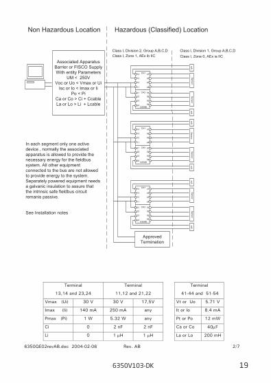
Non Hazardous Location Hazardous (Classified) Location
11
12
13
14 41
42
43
44
2122
23
24
53
5152
546350B
CH2
CH1
11
12
13
14 41
42
43
44
2122
23
24
53
5152
546350B
CH2
CH1
11
12
13
14 41
42
43
44
2122
23
24
53
5152
546350B
CH2
CH1
ApprovedTermination
SensorSensor
SensorSensor
SensorSensor
mA
mA
mA
mA
mA
mA
Class I, Division 1, Group A,B,C,DClass I, Division 2, Group A,B,C,DClass I, Zone 1, AEx ib IIC Class I, Zone 0, AEx ia IIC
In each segment only one activedevice , normally the associatedapparatus is allowed to provide thenecessary energy for the fieldbussystem. All other equipmentconnected to the bus are not allowedto provide energy to the system.Separately powered equipment needsa galvanic insulation to assure thatthe intrinsic safe fieldbus circuitremanis passive.
See Installation notes
Associated ApparatusBarrier or FISCO SupplyWith entity Parameters
UM < 250VVoc or Uo < Vmax or Ui
Isc or Io < Imax or IiPo < Pi
Ca or Co > Ci + CcableLa or Lo > Li + Lcable
Terminal
13,14 and 23,24
Terminal
11,12 and 21,22
Vmax (Ui) 30 V 30 V 17,5V
Imax (Ii) 140 mA 250 mA any
Pmax (Pi) 1 W 5.32 W any
Ci 0 2 nF 2 nF
Li 0 1 µH 1 µH
Terminal
41-44 and 51-54
Vt or Uo 5.71 V
It or Io 8.4 mA
Pt or Po 12 mW
Ca or Co 40µF
La or Lo 200 mH
6350QE02revAB.doc 2004-02-06 Rev. AB 2/7
6350V103-DK 19
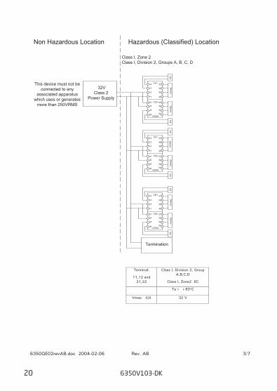
Non Hazardous Location Hazardous (Classified) Location
11
12
13
14 41
42
43
44
2122
23
24
53
5152
546350A
CH2
CH1
11
12
13
14 41
42
43
44
2122
23
24
53
5152
546350A
CH2
CH1
11
12
13
14 41
42
43
44
2122
23
24
53
5152
546350A
CH2
CH1
SensorSensor
SensorSensor
SensorSensor
mA
mA
mA
mA
mA
mA
Class I, Zone 2Class I, Division 2, Groups A, B, C, D
32VClass 2
Power Supply
This device must not beconnected to any
associated apparatuswhich uses or generates
more than 250VRMS
Termination
Terminal:
11,12 and 21,22
Class I, Division 2, Group A,B,C,D
Class I, Zone2 IIC
Ta ≤ +60°C
Vmax (Ui) 32 V
6350QE02revAB.doc 2004-02-06 Rev. AB 3/7
20 6350V103-DK
Installation notes:
FM / CSA:
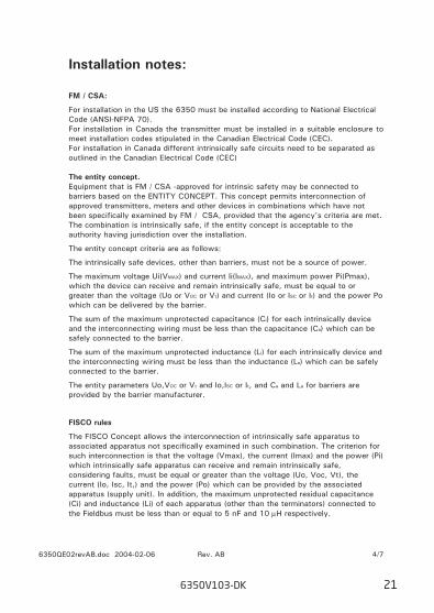
For installation in the US the 6350 must be installed according to National Electrical Code (ANSI-NFPA 70). For installation in Canada the transmitter must be installed in a suitable enclosure to meet installation codes stipulated in the Canadian Electrical Code (CEC).
For installation in Canada different intrinsically safe circuits need to be separated as outlined in the Canadian Electrical Code (CEC)
The entity concept. Equipment that is FM / CSA -approved for intrinsic safety may be connected to
barriers based on the ENTITY CONCEPT. This concept permits interconnection of approved transmitters, meters and other devices in combinations which have not been specifically examined by FM / CSA, provided that the agency's criteria are met. The combination is intrinsically safe, if the entity concept is acceptable to the authority having jurisdiction over the installation.
The entity concept criteria are as follows:
The intrinsically safe devices, other than barriers, must not be a source of power.
The maximum voltage Ui(VMAX) and current Ii(IMAX), and maximum power Pi(Pmax), which the device can receive and remain intrinsically safe, must be equal to or greater than the voltage (Uo or VOC or Vt) and current (Io or ISC or It) and the power Po which can be delivered by the barrier.
The sum of the maximum unprotected capacitance (Ci) for each intrinsically device and the interconnecting wiring must be less than the capacitance (Ca) which can be safely connected to the barrier.
The sum of the maximum unprotected inductance (Li) for each intrinsically device and the interconnecting wiring must be less than the inductance (La) which can be safely connected to the barrier.
The entity parameters Uo,VOC or Vt and Io,ISC or It, and Ca and La for barriers are provided by the barrier manufacturer.
FISCO rules
The FISCO Concept allows the interconnection of intrinsically safe apparatus to associated apparatus not specifically examined in such combination. The criterion for such interconnection is that the voltage (Vmax), the current (Imax) and the power (Pi) which intrinsically safe apparatus can receive and remain intrinsically safe, considering faults, must be equal or greater than the voltage (Uo, Voc, Vt), the current (Io, Isc, It,) and the power (Po) which can be provided by the associated apparatus (supply unit). In addition, the maximum unprotected residual capacitance (Ci) and inductance (Li) of each apparatus (other than the terminators) connected to the Fieldbus must be less than or equal to 5 nF and 10 µH respectively.
6350QE02revAB.doc 2004-02-06 Rev. AB 4/7
6350V103-DK 21
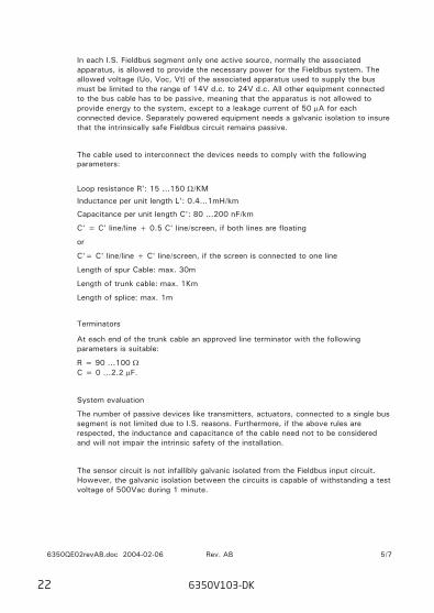
In each I.S. Fieldbus segment only one active source, normally the associated apparatus, is allowed to provide the necessary power for the Fieldbus system. The allowed voltage (Uo, Voc, Vt) of the associated apparatus used to supply the bus must be limited to the range of 14V d.c. to 24V d.c. All other equipment connected to the bus cable has to be passive, meaning that the apparatus is not allowed to provide energy to the system, except to a leakage current of 50 µA for each connected device. Separately powered equipment needs a galvanic isolation to insure that the intrinsically safe Fieldbus circuit remains passive.
The cable used to interconnect the devices needs to comply with the following parameters:
Loop resistance R': 15 ...150 Ω/KM
Inductance per unit length L': 0.4…1mH/km
Capacitance per unit length C': 80 ...200 nF/km
C' = C' line/line + 0.5 C' line/screen, if both lines are floating
or
C'= C' line/line + C' line/screen, if the screen is connected to one line
Length of spur Cable: max. 30m
Length of trunk cable: max. 1Km
Length of splice: max. 1m
Terminators
At each end of the trunk cable an approved line terminator with the following parameters is suitable:
R = 90 ...100 Ω C = 0 ...2.2 µF.
System evaluation
The number of passive devices like transmitters, actuators, connected to a single bus segment is not limited due to I.S. reasons. Furthermore, if the above rules are respected, the inductance and capacitance of the cable need not to be considered and will not impair the intrinsic safety of the installation.
The sensor circuit is not infallibly galvanic isolated from the Fieldbus input circuit. However, the galvanic isolation between the circuits is capable of withstanding a test voltage of 500Vac during 1 minute.
6350QE02revAB.doc 2004-02-06 Rev. AB 5/7
22 6350V103-DK
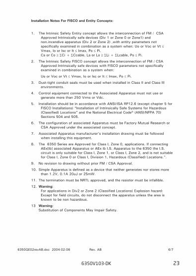
Installation Notes For FISCO and Entity Concepts:
1. The Intrinsic Safety Entity concept allows the interconnection of FM / CSA Approved Intrinsically safe devices (Div 1 or Zone 0 or Zone1) and non.incendive apparatus (Div 2 or Zone 2) ,with entity parameters not specifically examined in combination as a system when: Uo or Voc or Vt ≤ Vmax, Io or Isc or It ≤ Imax, Po ≤ Pi. Ca or Co ≥ ΣCi + ΣCcable, La or Lo ≥ ΣLi + ΣLcable, Po ≤ Pi.
2. The Intrinsic Safety FISCO concept allows the interconnection of FM / CSA Approved Intrinsically safe devices with FISCO parameters not specifically examined in combination as a system when:
Uo or Voc or Vt ≤ Vmax, Io or Isc or It ≤ Imax, Po ≤ Pi.
3. Dust-tight conduit seals must be used when installed in Class II and Class III environments.
4. Control equipment connected to the Associated Apparatus must not use or generate more than 250 Vrms or Vdc.
5. Installation should be in accordance with ANSI/ISA RP12.6 (except chapter 5 for FISCO Installations) “Installation of Intrinsically Safe Systems for Hazardous (Classified) Locations” and the National Electrical Code® (ANSI/NFPA 70) Sections 504 and 505.
6. The configuration of associated Apparatus must be Factory Mutual Research or CSA Approved under the associated concept.
7. Associated Apparatus manufacturer’s installation drawing must be followed when installing this equipment.
8. The 6350 Series are Approved for Class I, Zone 0, applications. If connecting AEx[ib] associated Apparatus or AEx ib I.S. Apparatus to the 6350 the I.S. circuit is only suitable for Class I, Zone 1, or Class I, Zone 2, and is not suitable for Class I, Zone 0 or Class I, Division 1, Hazardous (Classified) Locations.".
9. No revision to drawing without prior FM / CSA Approval.
10. Simple Apparatus is defined as a device that neither generates nor stores more than 1.2V, 0.1A 20uJ or 25mW.
11. The termination must be NRTL approved, and the resistor must be infallible.
12. Warning: For applications in Div2 or Zone 2 (Classified Locations) Explosion hazard: Except for field circuits, do not disconnect the apparatus unless the area is known to be non hazardous.
13 Warning: Substitution of Components May Impair Safety.
6350QE02revAB.doc 2004-02-06 Rev. AB 6/7
6350V103-DK 23
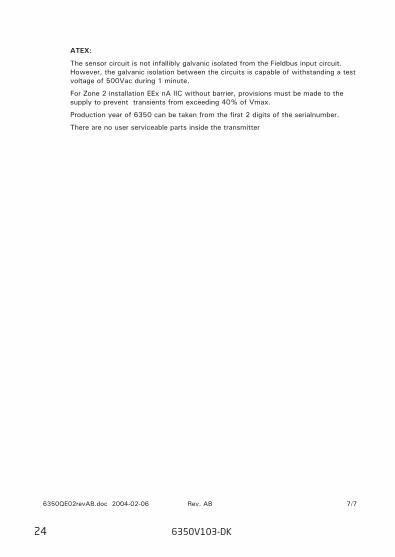
ATEX:
The sensor circuit is not infallibly galvanic isolated from the Fieldbus input circuit. However, the galvanic isolation between the circuits is capable of withstanding a test voltage of 500Vac during 1 minute.
For Zone 2 installation EEx nA IIC without barrier, provisions must be made to the supply to prevent transients from exceeding 40% of Vmax.
Production year of 6350 can be taken from the first 2 digits of the serialnumber.
There are no user serviceable parts inside the transmitter
6350QE02revAB.doc 2004-02-06 Rev. AB 7/7
24 6350V103-DK
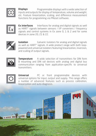
Programmable displays with a wide selection of inputs and outputs for display of temperature, volume and weight, etc. Feature linearization, scaling, and difference measurement functions for programming via PReset software.
Displays
A wide selection of transmitters for DIN form B mounting and DIN rail devices with analog and digital bus communication ranging from application-specific to universal transmitters.
Temperature
Galvanic isolators for analog and digital signals as well as HART® signals. A wide product range with both loop-powered and universal isolators featuring linearization, inversion, and scaling of output signals.
Isolation
Interfaces for analog and digital signals as well as HART® signals between sensors / I/P converters / frequency signals and control systems in Ex zone 0, 1 & 2 and for some devices in zone 20, 21 & 22.
Ex interfaces
PC or front programmable devices with universal options for input, output and supply. This range offers a number of advanced features such as process calibration, linearization and auto-diagnosis.
Universal

www.prelectronics.fr [email protected]
www.prelectronics.de [email protected]
www.prelectronics.es [email protected]
www.prelectronics.it [email protected]
www.prelectronics.se [email protected]
www.prelectronics.co.uk [email protected]
www.prelectronics.com [email protected]
www.prelectronics.cn [email protected]
head office
Denmark www.prelectronics.comPR electronics A/S [email protected] 10 tel. +45 86 37 26 77DK-8410 Rønde fax +45 86 37 30 85