210x297 a4 v 01 1008 bw de - calor
26
GB Installation and operating instructions Wilo-DrainLift XXL 2 532 170-Ed.02/2010-10-Wilo
Transcript of 210x297 a4 v 01 1008 bw de - calor
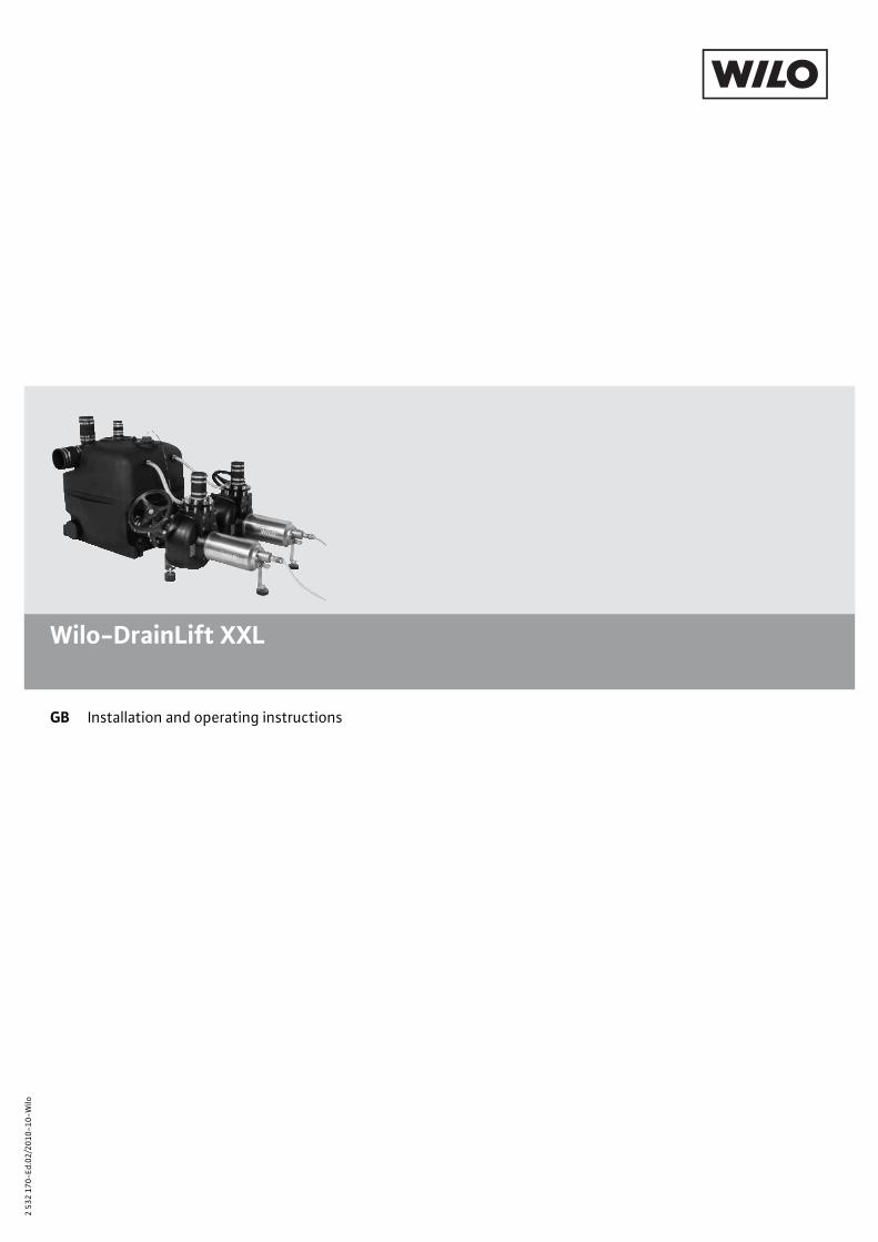
GB Installation and operating instructions
Wilo-DrainLift XXL
2 53
2 17
0-Ed
.02/
2010
-10-
Wilo
valentin.volocariu
Text Box
Distribuitor: CALOR SRL Str. Progresului nr. 30-40, sector 5, Bucuresti tel: 021.411.44.44, fax: 021.411.36.14 www.calorserv.ro - www.calor.ro

English
Installation and operating instructions1 General
About this documentThe language of the original operating instructions is German. All other languages of these instructions are translations of the original operating instructions.These installation and operating instructions are an integral part of the product. They must be kept readily available at the place where the product is installed. Strict adherence to these instructions is a precondition for the proper use and correct operation of the product.These installation and operating instructions correspond to the relevant version of the product and the underlying safety standards valid at the time of going to print.EC declaration of conformityA copy of the EC declaration of conformity is a component of these operating instructions.If a technical modification is made on the designs named there without our agreement, this declaration loses its validity.
2 SafetyThese operating instructions contain basic information which must be adhered to during installation and operation. For this reason, these operating instructions must, without fail, be read by the service technician and the responsible operator before installation and commissioning.It is not only the general safety instructions listed under the main point “safety” that must be adhered to but also the special safety instructions with danger symbols included under the following main points.
2.1 Indication of instructions in the operating instructions
Symbols:General danger symbol
Danger due to electrical voltage
NOTE: ...
Signal words:
DANGER!Acutely dangerous situation.Non-observance results in death or the most serious of injuries.
WARNING!The user can suffer (serious) injuries. 'Warning' implies that (serious) injury to persons is probable if this information is disregarded.
CAUTION!There is a risk of damaging the product/unit. 'Caution' implies that damage to the prod-uct is likely if this information is disregarded.
NOTE: Useful information on handling the product. It draws attention to possible prob-lems.
2.2 Personnel qualificationsThe installation personnel must have the appropriate qualifications for this work.
2.3 Danger in the event of non-observance of the safety instructionsNon-observance of the safety instructions can result in risk of injury to persons and dam-age to the product/unit. Non-observance of the safety instructions can result in the loss of any claims to damages.In detail, non-observance can, for example, result in the following risks:
• Failure of important product/unit functions• Failure of required maintenance and repair procedures• Danger to persons from electrical, mechanical and bacteriological influences• Property damage
Installation and operating instructions Wilo-DrainLift XXL 3

English
4
2.4 Safety instructions for the operatorThe existing directives for accident prevention must be adhered to.Danger from electrical current must be eliminated. Local directives or general directives [e.g. IEC, VDE etc.] and local energy supply companies must be adhered to.This appliance is not intended for use by persons (including children) with reduced physi-cal, sensory or mental capabilities, or lack of experience and knowledge, unless they have been given supervision or instruction concerning use of the appliance by a person respon-sible for their safety. Children should be supervised to ensure that they do not play with the appliance.
2.5 Safety instructions for inspection and installation workThe operator must ensure that all inspection and installation work is carried out by author-ised and qualified personnel, who are sufficiently informed from their own detailed study of the operating instructions.Work on the product/unit must only be carried out when at a standstill. It is mandatory that the procedure described in the installation and operating instructions for shutting down the product/unit be complied with.
2.6 Unauthorised modification and manufacture of spare partsModifications to the product are only permissible after consultation with the manufac-turer. Original spare parts and accessories authorised by the manufacturer ensure safety. The use of other parts can nullify the liability from the results of their usage.
2.7 Improper useThe operating safety of the supplied product is only guaranteed for conventional use in accordance with Section 4 of the operating instructions. The limit values must on no account fall under or exceed those specified in the catalogue/data sheet.
3 Transport and interim storageThe unit and individual components are delivered on a pallet.Immediately after receiving the product:
• Check the product for damage in transit.• In the event of damage in transit, take the necessary steps with the forwarding agent
within the respective time limits.
CAUTION! Risk of property damage!Inappropriate transport and interim storage can cause damage to the product.
• Transport the product only on the pallet and use only approved handling equipment.• Make sure the product remains stable and does not suffer any mechanical damage dur-
ing transport.• Prior to installation, store the product on the pallet in such a manner that it remains dry
and frost-proof and is not exposed to direct sunlight.• Do not stack.
4 Intended useThe DrainLift L XXL sewage lifting unit is an automatic sewage lifting unit according to EN 12050-1 for collecting and pumping sewage which is free of faeces or contains faeces for the backflow-proof drainage from discharge points at buildings and sites below the backflow level.The unit is only suitable for domestic sewage as defined in EN 12056-1. No explosive or harmful substances may be introduced in high concentrations, such as solid substances, debris, ash, garbage, sand, plaster, cement, lime, mortar, fibrous materials, textiles, paper towels, nappies, cardboard, coarse paper, synthetic resins, tar, kitchen waste, grease, oil, slaughterhouse waste, disposal of slaughtered animals and animal waste (liquid manure, etc.), toxic, aggressive and corrosive substances, such as heavy metals, biocides, pesti-cides, acids, bases, salts, cleaning agents, disinfectants, dishwashing or laundry deter-gents, and such which have a high degree of foam formation or swimming-pool water.A grease trap should to be provided if greasy sewage accumulates.According to EN 12056-1, no sewage from drainage objects may be introduced which lie above the backflow level and can be drained by means of gravity.
WILO SE 10/2010

English
NOTE: Make sure the national and regional applicable standards and regulations are observed during installation and operation.The details in the operating instructions for the switchgear should also to be observed.
DANGER! Danger of explosion!Sewage containing faeces in collection reservoirs can cause gas accumulation which may ignite as a result of improper installation and operation.
• If the unit is used for sewage containing faeces, the valid regulations for potentially explosive areas are to be observed.
WARNING! Health hazard!Not suitable for pumping potable water due to the materials used! Contaminated sew-age is a health hazard.
CAUTION! Risk of property damage!Discharging inadmissible substances can cause damage to the product.
• Never discharge solids, fibrous substances, tar, sand, cement, ash, coarse paper, paper towels, cardboard, debris, rubbish, animal waste, grease, or oil. A grease trap should to be provided if greasy sewage accumulates.
• Improper use and overstraining causes damage to the product.• The maximum possible inflow quantity must always be lower than the volume flow of a
pump at the respective duty point.
Application limitsThe unit is not designed for permanent operation. The specified maximum volume flow applies to permanent operation and intermittent operation (S3 – 25 %/60 s). The unit must switch on a maximum of 60 times per hour and pump. The operating time and follow-up time (if required) should be set as short as possi-ble.Furthermore, the operating parameters should be observed in accordance with Table 5.2.
WARNING! Danger due to overpressure!If the lowest inlet head is higher than 5 m, this will cause dangerous overpressure in the reservoir in the event of a unit failure. If this happens, there will be a risk of the tank bursting. The inlet must be blocked immediately in the event of a malfunction.
Intended use also includes the observance of these instructions.Any other use is regarded as incorrect use.
5 Product information
5.1 Type key
Example: DrainLift XXL 840-2/1.7
DrainLift Sewage lifting unitXXL Size8 8 = DN 80 pressure connection
10 = DN 100 pressure connection 40 40 = total volume of 400 l
80 = total volume of 800 l (2 tanks of 400 l)-2 2 = double-pump system/1.7 Nominal power per pump [kW]
Installation and operating instructions Wilo-DrainLift XXL 5

English
6
5.2 Technical data
DrainLift XXL ...
840-2/1. 840-2/2.1 1040-2/3.9 1040-2/5.2 1040-2/7.0 1040-2/8.4
Connection voltage [V] 3~400 ± 10 %Connection version Switchgear with main switchPower consumption P1 [kW] 2 x 2.3 2 x 2.7 2 x 4.4 2 x 6.2 2 x 8.4 2 x 10.0Nominal current [A] 2 x 6.7 2 x 7.1 2 x 10.5 2 x 12.8 2 x 15.6 2 x 18.1Mains frequency [Hz] 50Protection class Unit: IP 67 (2 mwc, 7 days)
Switchgear: IP 54Speed [rpm] 1450Start-up type Direct Star-deltaOperating mode(with regard to the pump)
S1; S3 25 % 60 sec
Max. switching frequency [1/h] 120 (60 per pump)Max. total delivery head [mwc] 8.5 10.5 12 15.5 18.5 21Max. permitted geodesic delivery head
[mwc] 6.5 8.5 9.5 12 15 17.5
Max. permissible pressure in the pressure pipe
[bar] 3
Max. volume flow *1) [m³/h] 75 85 140 140 140 140
Min. volume flow *1) [m³/h] 19 20 36 38 44 47Max. fluid temperature [°C] 40 (briefly 3 min, 60°C)Min. fluid temperature [°C] 3Max. ambient temperature [°C] 40Max. solid grain size [mm] 80 95Sound-pressure level (depending on the duty point) *2)
[dB(A)] < 70
Gross volume [l] 400Recommended levelPump 1 ON switching point *3)
[mm] 560
Minimum value of levelPump 1 ON switching point *3)
[mm] 500 550
Minimum value of levelPump OFF switching point *3)
[mm] 140 160
Switching volume (pump 1 only; with recommended switching level ON and minimum switching level OFF)
[l] 230 220
Max. permissible inlet quantity in one hour (switching operation, switching volume with recom-mended switching level) *4)
[l] 25% of volume flow value at duty point
Dimensions (W/D/H) [mm] 1965/930/880 1990/960/880Net weight(complete, without packaging)
[kg] 160 195
Pressure connection [DN] 80 100Inlet connections [DN] 100, 150Ventilation connection [DN] 70
*1) Observe the permissible flow rate in the pressure pipe: 0.7 to 2.3 m/s according to EN 12056*2) Improper unit and pipe installation, as well as impermissible operation, can increase the acoustic emissions.*3) Measured in relation to installation level*4) The current peak flow must always be lower than the volume flow of a pump at the duty point
WILO SE 10/2010

English
DrainLift XXL ...
880-2/1.7 880-2/2.1 1080-2/3.9 1080-2/5.2 1080-2/7.0 1080-2/8.4
Connection voltage [V] 3~400 ± 10 %Connection version Switchgear with main switchPower consumption P1 [kW] 2 x 2.3 2 x 2.7 2 x 4.4 2 x 6.2 2 x 8.4 2 x 10.0Nominal current [A] 2 x 6.7 2 x 7.1 2 x 10.5 2 x 12.8 2 x 15.6 2 x 18.1Mains frequency [Hz] 50Protection class Unit: IP 67 (2 mwc, 7 days)
Switchgear: IP 54Speed [rpm] 1450Start-up type Direct Star-deltaOperating mode(with regard to the pump)
S1; S3 25 % 60 sec
Max. switching frequency [1/h] 120 (60 per pump)Max. total delivery head [mwc] 8.5 10.5 12 15.5 18.5 21Max. permitted geodesic delivery head
[mwc] 6.5 8.5 9.5 12 15 17.5
Max. permissible pressure in the pressure pipe
[bar] 3
Max. volume flow *1) [m³/h] 75 85 140 140 140 140
Min. volume flow *1) [m³/h] 19 20 36 38 44 47Max. fluid temperature [°C] 40 (briefly 3 min, 60°C)Min. fluid temperature [°C] 3Max. ambient temperature [°C] 40Max. solid grain size [mm] 80 95Sound-pressure level (depending on the duty point) *2)
[dB(A)] < 70
Gross volume [l] 800Recommended levelSwitching point, pump 1 ON *3)
[mm] 560
Minimum value of levelSwitching point, pump 1 ON *3)
[mm] 500 550
Minimum value of levelSwitching point, pump OFF *3)
[mm] 140 160
Switching volume (pump 1 only; with recommended switching level ON and minimum switching level OFF)
[l] 460 440
Max. permissible inlet quantity in one hour (switching operation, switching volume with recom-mended switching level) *4)
[l] 25% of volume flow value at duty point
Dimensions (W/D/H) [mm] 1965/1695/880 1990/1710/880Net weight(complete, without packaging)
[kg] 195 230
Pressure connection [DN] 80 100Inlet connections [DN] 100, 150Ventilation connection [DN] 70
*1) Observe the permissible flow rate in the pressure pipe: 0.7 to 2.3 m/s according to EN 12056*2) Improper unit and pipe installation, as well as impermissible operation, can increase the acoustic emissions.*3) Measured in relation to installation level*4) The current peak flow must always be lower than the volume flow of a pump at the duty point
Installation and operating instructions Wilo-DrainLift XXL 7

English
8
Please submit all the details on the unit's rating plate when ordering spare parts.
5.3 Scope of deliverySewage lifting unit, delivered on pallets in the assemblies:2 pumps, complete, in horizontal installation1 tank, complete (2 x for units with 2 tanks)1 switchgear (3~400 V)1 Zener barrier in the housing with 1 m cable, pre-installed1 level sensor 0-1 mwc, 10 m cable1 set of fixation material for tank and pumps on the floor1 DN 150 hose section with clamps for DN 150 inlet connection1 DN 150 hose section with clamps for tank connection
(only for units with 2 tanks)1 DN 75 hose section with clamps for connection of the ventilation line
(2 x for units with 2 tanks)1 DN 50 hose section with clamps for connection of the suction line to the diaphragm
hand pump (2 x for units with 2 tanks)2 vent flanges with flat gaskets, DN 19 hose sections and hose clamps1 Installation and operating instructions
5.4 AccessoriesAccessories must be ordered separately. For a detailed list and description, see catalogue/price list.The following accessories are available:
• DN 80 cast gate valve for pressure pipe• DN 100 cast gate valve, pressure pipe and pump suction pipe• DN 80 cast non-return valve for pressure pipe• DN 100 cast non-return valve for pressure pipe• Flange pieces DN 80, DN 80/100, DN 100, for connection of the slide valve on the pressure
side to the pressure pipe• Y-pipe DN 80, DN 100 for units with 1 tank• Plastic gate valve DN 100, DN for inlet pipe• Diaphragm hand pump R 1½ (without hose)• 3-way cock for switch-over to manual extraction from the pump sump/tank• Alarm switchgear• Horn 230 V/50 Hz • Flash light 230 V/50 Hz • Signal lamp 230 V/50 Hz
CEWILO SE Dortmund
Nortkirchenstr. 100, 44263 Dortmund, Germany10
EN 12050-1 Faeces lifting unit for building DN 80, DN 100Lifting power - See pump curveNoise level - TRSExplosion protection - TRSCorrosion protection – coated, or corrosion-resistant
materials, inox/composite
WILO SE 10/2010

English
6 Description and function
6.1 Description of the unit The DrainLift XXL sewage lifting unit (Fig. 1) is a pre-assembled, fully submersible sewage lifting unit (flooding height: 2 mwc, flooding time: 7 days) with a gas and watertight col-lection tank and buoyancy safeguards. It is equipped with three-phase current pumps (3~400 V). The integrated level sensor (Fig. 1, Pos. 3) registers the level in the tank and passes this value on to the switchgear, which automatically switches the pumps on or off. The switchgear is equipped with a main switch, integrated motor protection and automatic/hand/acknowledgement switch. A detailed description of the functions can be taken from the operating instructions for the switchgear.Inlets can be connected to three sides of the DN 100/DN 150 combination socket. Sockets on the top of the tank allow the pipe connection of a DN 50 inlet and DN 70 vent (see sec-tion “Connecting the pipes”). An inspection opening enables easy maintenance of the unit. Attachment slots are provided on both face sides of the collection reservoirs in order to anchor the unit to the floor by means of the supplied fastening elements so that they are anti-buoyant and cannot twist. The double-pump system is equipped with a base-load pump and peak-load pump. The pumps are positioned horizontally in front of the tank and suck the sewage out of the tank through the suction pipes. The suction pipes end in the tank with a 90° elbow facing the base of the tank. This prevents deposits on the base to a great extent. Likewise, a lower residual water volume and a higher switching volume is achieved in this way.
6.2 FunctionThe discharged sewage is collected in the collection tank of the lifting unit. This is done via sewage inlet pipes which can be connected to the existing pipe sockets as desired. The DrainLift XXL sewage lifting unit is delivered with switchgear, Zener barrier (accesso-ries kit) and pre-assembled level sensor. The water level in the tank is registered by means of the integrated level sensor. If the water level rises up to the set activation point, one of the pumps installed in front of the tank(s) is switched on and the collected sewage automatically pumped into the connected external sewage line. The second pump is additionally activated if the water level continues to rise after the acti-vation of the base-load pump. When the high level is reached, an optical signal is issued, the alarm signal contact is actuated and there is a forced switch-on of all pumps. In order for both pumps to be loaded evenly, pump cycling occurs after each pump cycle. If one of the pumps fails, the other pump takes over the entire pumping work. The pump(s) are deactivated once the deactivation level is reached.
Fig. 1: Description of the unit
1 Pump2 Tank3 Level switch with level sensor4 Zener barrier5 Switchgear6 Suction pipe7 DN 100/DN 150 inlet connecting piece8 Emergency drain connection, DN 509 Ventilation connection10 Inspection opening11 Pump ventilation line12 Suction line (slide valve, optional)13 Buoyancy safeguards
12
3
4
5
7
6 8
12
11
9
10
13
0
I
Installation and operating instructions Wilo-DrainLift XXL 9

English
10
To avoid sudden valve closures, a follow-up time can be set in the switchgear in order for the base-load pump to be operated up to slurping operation (refer to 8.2.3 for the setting). The follow-up time is the period from when the deactivation point is fallen short of until the base-load pump is switched off.
7 Installation and electrical connectionThe product is delivered in single components to be assembled in accordance with these installation and operating instructions. All protective equipment is to be activated. Non-observance of the notes on the assembly and installation will put the safety of the product/personnel at risk and invalidate the statements regarding safety.
DANGER! Risk of fatal injury!Incorrect installation and electrical connection can pose a risk of fatal injury.
• The installation and electrical connection may be carried out only by qualified person-nel in accordance with the applicable regulations!
• Observe the accident prevention regulations!
DANGER! Danger of suffocation!Toxic or harmful substances in sewage sumps can cause infections or suffocation.
• For safety reasons, a second person must be present at all times when working in sumps.
• Make sure the installation location is ventilated sufficiently.
7.1 Preparing the installation
CAUTION! Risk of property damage!Incorrect installation can result in property damage.
• Have installation work carried out only by qualified personnel!• Observe the national and regional regulations!• Observe the installation and operating instructions for the accessories!• Never pull the cable when installing the unit.
In particular the valid regional regulations (e.g. in Germany, the “Landesbauordnung (fed-eral regulations for buildings), DIN 1986-100”) and, in general, the corresponding specifi-cations of EN 12050-1 and EN 12056 (Gravity Drainage Systems Inside Buildings) should be observed when installing lifting units.
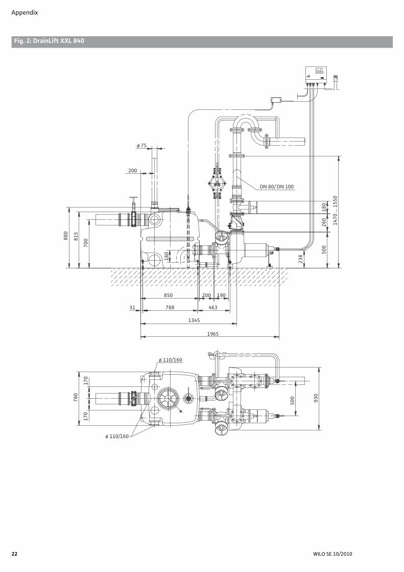
• Observe the dimensions according to the installation plan in the appendix (Fig. 2).• According to EN 12056-4, installation rooms for lifting units must be of sufficient size so
that the unit is freely accessible for operating and maintenance work.• There must be a sufficient working space of at least 60 cm in width and height available
next to and above all parts to be operated and subjected to maintenance.• The installation room must be frost-proof, ventilated and well-lit.• The installation surface must be firm (suitable for accommodating dowels), horizontal and
flat.• The course of any existing or still-to-be installed inlet, pressure and ventilation lines is to
be checked with regard to connection options to the unit.• Observe the installation and operating instructions for the accessories!• Install the switchgear and Zener barrier at a dry and frost-proof location.• The installation site must be protected from exposure to direct sunlight.• Observe the accessories and catalogue specifications for outdoor installations.
7.2 InstallationAccording to EN 12056-4, sewage lifting units must be installed in such a manner that they cannot twist and turn.Units which threaten to float must be installed so that they are anti-buoyant.
WILO SE 10/2010
English
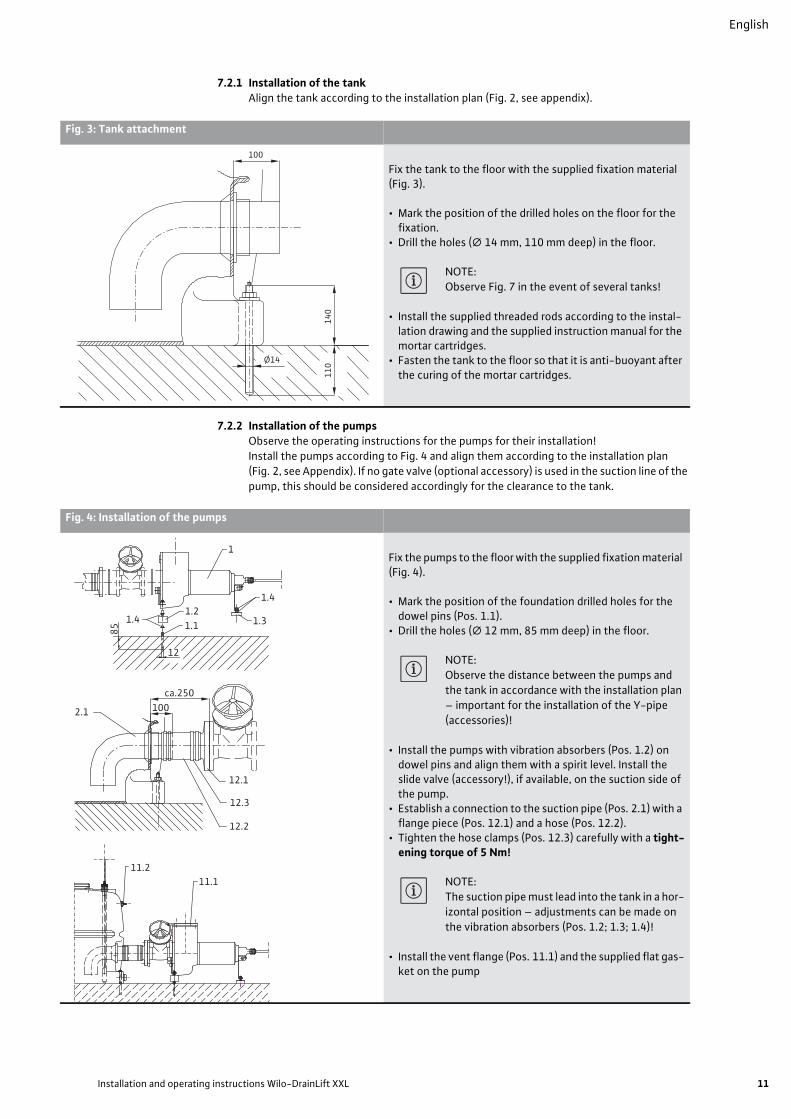
7.2.1 Installation of the tankAlign the tank according to the installation plan (Fig. 2, see appendix).
7.2.2 Installation of the pumpsObserve the operating instructions for the pumps for their installation!Install the pumps according to Fig. 4 and align them according to the installation plan (Fig. 2, see Appendix). If no gate valve (optional accessory) is used in the suction line of the pump, this should be considered accordingly for the clearance to the tank.
Fig. 3: Tank attachment
Fix the tank to the floor with the supplied fixation material (Fig. 3).
• Mark the position of the drilled holes on the floor for the fixation.
• Drill the holes (∅ 14 mm, 110 mm deep) in the floor.
NOTE: Observe Fig. 7 in the event of several tanks!
• Install the supplied threaded rods according to the instal-lation drawing and the supplied instruction manual for the mortar cartridges.
• Fasten the tank to the floor so that it is anti-buoyant after the curing of the mortar cartridges.
140
110Ø14
100
Fig. 4: Installation of the pumps
Fix the pumps to the floor with the supplied fixation material (Fig. 4).
• Mark the position of the foundation drilled holes for the dowel pins (Pos. 1.1).
• Drill the holes (∅ 12 mm, 85 mm deep) in the floor.
NOTE: Observe the distance between the pumps and the tank in accordance with the installation plan – important for the installation of the Y-pipe (accessories)!
• Install the pumps with vibration absorbers (Pos. 1.2) on dowel pins and align them with a spirit level. Install the slide valve (accessory!), if available, on the suction side of the pump.
• Establish a connection to the suction pipe (Pos. 2.1) with a flange piece (Pos. 12.1) and a hose (Pos. 12.2).
• Tighten the hose clamps (Pos. 12.3) carefully with a tight-ening torque of 5 Nm!
NOTE: The suction pipe must lead into the tank in a hor-izontal position – adjustments can be made on the vibration absorbers (Pos. 1.2; 1.3; 1.4)!
• Install the vent flange (Pos. 11.1) and the supplied flat gas-ket on the pump
1
1.21.1 1.3
1.4
1.4
12
85
2.1
12.1
12.2
12.3
100ca.250
11.111.2
Installation and operating instructions Wilo-DrainLift XXL 11

English
12
7.3 Connection of the pipingAll piping must be installed without tension in a noise-insulated and flexible manner. The unit must not be subjected to any pipeline forces or torques. The pipes (including valves) are to be fastened and supported in such a manner that neither tensile nor compressive forces are applied to the unit.All line connections must be established with care. Carefully tighten any connections with hose clamps (tightening torque of 5 Nm).Do not reduce the pipe diameter in the direction of flow.According to EN 12056-4, a gate valve is always required in the inlet pipe in front of the tank and behind the non-return valve (Fig. 9).
7.3.1 Discharge piping
CAUTION! Risk of property damage!Pressure surges which occur (e.g. when closing the non-return valve) may be several times higher than the pump pressure, depending on the operating conditions.
• The longitudinal force-fitted connection elements of the piping should therefore be observed in addition to the corresponding pressure resistance.
• The discharge piping, including all installation parts, must reliably withstand the oper-ating pressures which occur.
• Avoid long horizontal pipe sections, since they contribute to fluid hammers of the non-return valves and thus dangerous pressure surges that may exceed the permissible value and thus pose a risk to the unit and the pressure pipe. If they are unavoidable, appropriate onsite measures should be taken (e.g. additional valve with counter-weight).
To prevent any backflow from the main public sewer, the discharge piping is to be designed as a “pipe loop” of which the bottom edge must be at the highest point above the locally defined backflow level (usually street level) (see also Fig. 9).The discharge piping is to be installed so that it is frost-proof.Fit first the non-return valves and then the DN 80 or DN 100 gate valve (available as acces-sory, nuts, discs, flat gasket supplied) onto the pressure connection of the unit (pump pressure socket with vent flange). Support the weight of the valves!
CAUTION! Risk of property damage!Using valves which are not Wilo accessories may cause malfunctions or damage to the product.
Then connect the discharge piping directly to the gate valve (flange piece, flexible hose section, flat gasket and connection elements supplied).
Fig. 4: Installation of the pumps (continued)
• Connect the supplied DN 19 hose piece (Pos. 11.3) to the vent flange and hose connection (Pos. 11.2) on the tank.
• Tighten the hose clamps (Pos. 11.4) carefully with a tightening torque of 5 Nm!
11.4
11.3
WILO SE 10/2010
English
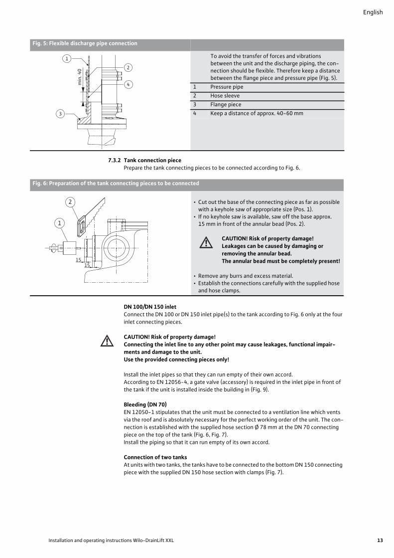
7.3.2 Tank connection piecePrepare the tank connecting pieces to be connected according to Fig. 6.
DN 100/DN 150 inletConnect the DN 100 or DN 150 inlet pipe(s) to the tank according to Fig. 6 only at the four inlet connecting pieces.
CAUTION! Risk of property damage!Connecting the inlet line to any other point may cause leakages, functional impair-ments and damage to the unit. Use the provided connecting pieces only!
Install the inlet pipes so that they can run empty of their own accord.According to EN 12056-4, a gate valve (accessory) is required in the inlet pipe in front of the tank if the unit is installed inside the building in (Fig. 9).
Bleeding (DN 70)EN 12050-1 stipulates that the unit must be connected to a ventilation line which vents via the roof and is absolutely necessary for the perfect working order of the unit. The con-nection is established with the supplied hose section Ø 78 mm at the DN 70 connecting piece on the top of the tank (Fig. 6, Fig. 7). Install the piping so that it can run empty of its own accord.
Connection of two tanksAt units with two tanks, the tanks have to be connected to the bottom DN 150 connecting piece with the supplied DN 150 hose section with clamps (Fig. 7).
Fig. 5: Flexible discharge pipe connection
To avoid the transfer of forces and vibrations between the unit and the discharge piping, the con-nection should be flexible. Therefore keep a distance between the flange piece and pressure pipe (Fig. 5).
1 Pressure pipe2 Hose sleeve3 Flange piece4 Keep a distance of approx. 40-60 mm
min
. 40
1
3
2
4
Fig. 6: Preparation of the tank connecting pieces to be connected
• Cut out the base of the connecting piece as far as possible with a keyhole saw of appropriate size (Pos. 1).
• If no keyhole saw is available, saw off the base approx. 15 mm in front of the annular bead (Pos. 2).
CAUTION! Risk of property damage!Leakages can be caused by damaging or removing the annular bead.The annular bead must be completely present!
• Remove any burrs and excess material.• Establish the connections carefully with the supplied hose
and hose clamps.
1515
2
1
Installation and operating instructions Wilo-DrainLift XXL 13

English
14
Emergency drain connection (diaphragm hand pump)It is always recommended to install a diaphragm hand pump (accessory) for draining the tank in an emergency. Four connecting pieces (∅ 50 mm) are available near the floor for this purpose. The connection is established according to Fig. 8 with the supplied DN 50 hose section and hose clamps.
7.3.3 Basement drainageAccording to EN 12056-4, a pump sump is to provided for the automatic drainage of the installation room for faeces lifting units (Fig. 9).
• Select the pump (Pos. 10) according to the delivery head of the unit. The dimensions of the pit in the floor of the installation room should be at least 500 x 500 x 500 mm.
Fig. 7: Ventilation connection and tank connection for two tanks
1 Hose Ø 160 x 180 mm2 Hose clamps, 160-180/123 Hose, Ø 78 x 130 mm4 Hose clamps, 80-100/12
1
22
34 4 3
280
60
Fig. 8: Emergency drain connection (diaphragm hand pump)
• The connecting piece is opened by sawing off (Pos. 1) the base or with a suitable keyhole saw (Pos. 2).
• Remove any burrs and excess material. • Establish the connections carefully with the supplied hose
section and hose clamps.
15
1
2
WILO SE 10/2010

English
• A three-way cock (Pos. 11, accessory) can be switched over to allow the manual drainage of both the tank as well as the pump sump by means of a diaphragm hand pump (Pos. 12).
7.4 Electrical connection
DANGER! Risk of fatal injury!Improper electrical connections pose a risk of fatal injury due to electric shock.
• Have the electrical connection established only by an electrician approved by the local electricity supplier and in accordance with the applicable local regulations.
• Observe the installation and operating instructions for the switchgear and the acces-sories.
• Disconnect the mains prior to any work.
• Wire the switchgear with the Zener barrier, level sensor and pumps in accordance with the supplied wiring diagram.
• The current type and voltage of the mains connection must correspond to the details on the rating plate.
NOTE: To increase the operational reliability, it is mandatory for an automatic circuit breaker (which disconnects all power leads) with K characteristic to be used.
• Earth the unit according to regulations.• Lay the connecting cable in accordance with the applicable standards/regulations and the
wire assignments.• Provide a residual-current-operated protection switch ≤ 30 mA in accordance with the
applicable local regulations.• The switchgear, Zener barrier and alarm must be installed in dry, overflow-proof rooms.
The national regulations are to be observed for the positioning [in Germany: VDE 0100].• Ensure the separate supply of the alarm switchgear in accordance with the rating plate
data. Connect the alarm switchgear.• Apply a clockwise rotating field to the switchgear.• The technical connection conditions of the local energy supply company are to be
observed for the connection.
Fig. 9: Installation example
Backflow level (usually top edge of street)
1 Ventilation line (via roof)
2 Pressure pipe with backflow loop
3 Inlet
4 Gate valve for inlet pipe
5 Valve support for weight relief (recommended)
6 Gate valve for pressure pipe
7 Non-return valve
8 Tank drainage pipe
9 Pump sump drainage pipe
10 Drainage pump
11 Three-way cock
12 Diaphragm hand pump
13 DrainControl 2 switchgear
14 Zener barrier
0I1 2
3 4 5 6 7 8 9
10
11
12 13
Installation and operating instructions Wilo-DrainLift XXL 15

English
16
7.4.1 Switchgear mains connection • Mains connection 3~400 V + N + PE (L1, L2, L3, N, PE)
• Mans voltage preselection in the device: Bridge the terminal according to the note “3 x 400 V +N” on the printed circuit board.
• Mains connection 3~400 V + PE (L1, L2, L3, PE)• Mains voltage preselection in the device:
Bridge the terminal according to the note “3 x 400 V” on the printed circuit board.• Connect the clockwise rotating field.
7.4.2 Mains connection of the pumpsThe pumps are to be wired with the switchgear.
• Undo the housing screws and remove the terminal cover.• Feed the cable ends of the pump connection cable through the threaded cable connec-
tions.• Connect the cable ends as indicated on the terminal strips and in accordance with the
details in the wiring diagram.
7.4.3 Level sensor connection
DANGER! Danger of explosion!There is a danger of explosion when using a level sensor in potentially explosive areas.Always use a breakdown barrier (Zener barrier) between the switchgear and the level sensor in potentially explosive areas.Observe the safety instructions in the operating instructions for the breakdown bar-rier.
NOTE: Observe the correct polarity when connecting the level sensor and the Zener barrier.
The level sensor must be wired directly with the Zener barrier. • Undo the housing screws and remove the cover.• Feed the cable ends from the level sensor through the cable bushing.• Connect the cable ends in accordance with the details in the wiring diagram:
• Brown wire (+) to terminal 23 (+) of the Zener barrier• Green wire (–) to terminal 13 (–) of the Zener barrier• Blue wire (shield) to PE terminal
• The Zener barrier cable is to be connected to the (+) and (–) terminals in the switchgear with a signal level of 4-20 mA in two-wire technology.
NOTE: Connect the Zener barrier to the equipotential bus bar (PA) of the unit (min. 4.0 mm² cop-per cable).
• Close the cover of the Zener barrier and switchgear and tighten the housing screws.
7.4.4 Alarm signal connectionAn external alarm switchgear, a horn or a flash light can be connected via a potential-free contact (SSM) in the switchgear.Contact load:
• Permitted minimum: 12 V DC, 10 mA• Permitted maximum: 250 V AC, 1 A
Connection of the external alarm signal
DANGER! Risk of fatal injury!There is a danger of electric shock by touching live components when working on the open switchgear. This work may only be carried out by qualified personnel.To connect the alarm signal, switch off the device so that it is voltage-free and secure it against being switched back on again by unauthorised persons.
NOTE: Observe the installation and operating instructions for the DrainControl switchgear and the alarm switchgear!
WILO SE 10/2010
English
• Switch off the switchgears so that they are voltage-free! • Open the cover of the switchgear.• Remove the protective cover from the threaded cable connection.• Feed the cable through the screwed connection and connect it to the potential-free alarm
contact in accordance with the wiring diagram.• After connecting the cable for the alarm signal, close the cover of the switchgear and
tighten the threaded cable connection.• Switch on the switchgears.
8 Commissioning It is recommended to have commissioning performed by Wilo's customer service.
8.1 Inspection of the unit
CAUTION! Risk of property damage!Dirt and solids as well as incorrect commissioning can cause damage to the unit or indi-vidual components during operation.
• Clean the entire unit to remove any dirt, in particular solids, prior to commissioning.• Observe the installation and operating instructions for the pump, switchgear and
accessories!
Commissioning may be carried out only if the relevant safety regulations, VDE regulations as well as regional regulations are met.
• Verify the presence and correct versions of all required components and connections (inlets with check valve, tank connection, discharge pipe with non-return valve and check valve, suction line, ventilation via roof, floor fixation, electrical connection).
• Check the setting of the venting screw of the non-return valve (accessory).
CAUTION! Risk of property damage!If the venting screw of the non-return valve is screwed too deep into the housing, this may cause damage to the valve and unit or considerable noise. Make sure the position of the venting screw ensures the closing of the valve!
8.2 Initial commissioning• Switch on the unit by the main switch.• Check or make the settings in accordance with Section 8.2.1 and 8.2.2.• Open the check valves.• Fill the unit via the connected inlet until each pump has pumped out at least once and the
discharge piping is completely filled. The filling level in the tank must not rise when the discharge piping is filled and the inlet closed. If the filling level continues to rise, the flap of the non-return valves is leaky (inspection of the flap and the position of the venting screw required).The “manual mode” button on the switchgear can be pressed before reaching the activa-tion level in the tank to test the starting procedure.
• Check the unit and pipe connections for impermeability.• Fill the unit with a maximum possible inlet and check whether the unit is working perfectly.
Observe in particular:• The correct position of the switching points.• Sufficient volume flow of the pumps at maximum flow while the pumps are running (level
muss drop).• Vibration-free operation of the pump without air bubbles in the fluid
CAUTION! Risk of property damage!Air in the fluid causes considerable vibrations which can destroy the pumps and the entire unit, depending on the respective operating conditions of the pumps.The minimum water level in the tank for the “Pump 1 ON switching point level” (see Technical data) must be ensured.
Installation and operating instructions Wilo-DrainLift XXL 17

English
18
8.2.1 Switchgear settingsDuring the initial commissioning it is necessary to set the unit parameters on the switch-gear (see installation and operating instructions for the switchgear).
• Compare the default value of the motor current with the details on the motor's rating plate and, if necessary, correct the settings.
• Set the maximum value of the sensor to 1.0 mwc in the menu item 2.25 “Sensor”. A data record with factory settings for the activation and deactivation level and the alarm level is loaded from the memory.
• Set, check and, if necessary, correct the activation and deactivation level and alarm level.
8.2.2 Adjustment of the switching level (differently from the factory setting)The level for switching the pumps and the alarm on the switchgear can be set differently from the factory settings (see switchgear operating instructions) and can be selected as desired in steps of 1 cm.According to EN 12056-4, the switching volume should be sufficient to allow the volume of the discharge piping to be replaced during each pump cycle. In addition, the switching level from the tank filling curve can be defined in accordance with Fig. 10. However, the level specifications in the technical data table should be observed (minimum values for activation and deactivation level). If the pump activation level is set higher than the inlet height, there will be a risk of backflow in the connected objects.
8.2.3 Adjustment of the follow-up timeThe pump follow-up time is to be set in the “Follow-up” menu in the switchgear.It causes the further operation of the base-load pump by the set time value after reaching the deactivation level. The switching volume can be increased in this way. The follow-up time also causes slurping operation (pumping of a water-air mixture). In the event of unit-related fluid hammers of the non-return valve, slurping operation can reduce or even elim-inate these fluid hammers.CAUTION! Risk of property damage!The follow-up time should be activated only for pumps with vortex impellers, since pumps with non-clog impellers tend to vibrate heavily in slurping operation and thus put the durability of the pump and unit at risk. Since only pumps with non-clog impellers are used in the DrainLift XXL, no follow-up time may be set for safety reasons.
Fig. 10: Tank volume based on the filling level
1 Tank filling volume 1 [l] 4 Minimum pump OFF level (for TP80 pumps)
2 Filling level above installation level [cm] 5 Minimum pump OFF level (for TP100 pumps)
3 Filling level curve (1 tank) 6 Minimum pump ON level (for TP80 pumps)7 Minimum pump ON level (for TP100 pumps)
020406080100120140160180200220240260280300320340360380400420440460480500
0 2 4 6 8 10 12 14 16 18 20 22 24 26 28 30 32 34 36 38 40 42 44 46 48 50 52 54 56 58 60 62 64 66 68 70 72 74 76 78 80
[l] 1
2 [cm]
4 75 6
3
WILO SE 10/2010
English
8.3 DecommissioningThe unit must be decommissioned prior to maintenance or dismantling work.Observe the information in the installation and operating instructions for the TP pumps!
Dismantling and installation• Dismantling and installation by qualified personnel only!• Disconnect the unit from the mains supply and secure it against being switched back on
again by unauthorised persons!• Depressurise any pressure parts before carrying out any work on them.• Close gate valves (inlet and pressure pipe).• Empty the collection reservoir (e.g. with diaphragm hand pump).• Unscrew and remove the maintenance cover for cleaning.
DANGER! Risk of infection!If the unit or unit components are to be sent in for repairs, the used unit should be drained and cleaned before transport for reasons of hygiene. Furthermore, all parts which may be touched must be disinfected (spray disinfection). The parts must be packed in tear-proof plastic bags of sufficient size in such a manner that they are tightly sealed and leak-proof. They are to be sent in without delay via instructed for-warding agents.
Check the unit for contaminants and clean it if necessary in the event of long standstill periods.
9 Maintenance
DANGER! Risk of fatal injury!There is risk of fatal injury due to electric shock when working on electrical equipment.
• Disconnect the unit from the mains supply and secure it against being switched on again by unauthorised persons prior to any maintenance and repair work.
• Have work on the electrical part of the unit carried out only by a qualified electrician as a basic principle.DANGER!Toxic or harmful substances in sewage can cause infections or suffocation.
• Ventilate the installation site sufficiently prior to any maintenance work.• Use appropriate protective equipment during maintenance work to prevent any risk of
infection.• For safety reasons, a second person must be present at all times when working in
sumps.• Danger of explosion when opening (avoid open sources of ignition)!• Observe the installation and operating instructions for the unit, switchgear and acces-
sories!
Read the “Decommissioning” chapter prior to maintenance work.The unit operator must make sure all the maintenance, inspection and installation work is performed by authorised and qualified personnel who have informed themselves suffi-ciently by studying the installation and operating instructions in detail.
• Sewage lifting units are to be subjected to maintenance by experts in accordance with EN 12056-4. The intervals must not exceed:• ¼ year in the case of commercial companies• ½ year for units in multi-family houses• 1 year for units in single-family houses.
• A maintenance report should be compiled.It is recommended to have the unit serviced and inspected by Wilo's customer service.
NOTE: Expensive repairs can be avoided and trouble-free operation of the unit achieved with a minimum of maintenance by compiling a maintenance plan. Wilo's customer service is available for commissioning and maintenance work.
Install and connect the unit as described in the chapter “Installation and electrical connec-tion” after maintenance and repair work. Switch on the unit as described in the “Commis-sioning” chapter.
Installation and operating instructions Wilo-DrainLift XXL 19

English
20
10 Faults, causes and remediesHave faults remedied only by qualified personnel. Observe the safety instructions in 9 Maintenance.
• Observe the installation and operating instructions for the unit, switchgear and accesso-ries!
• If the operating fault is unable to be remedied, please consult a specialist technician, Wilo service or the closest Wilo representative.
1) To remedy faults on parts under pressure, depressurise them first (vent the non-return valve and drain the tank, if necessary with diaphragm hand pump).
2) Further enquiry required
Faults Code: cause and remedy
Pump is not pumping 1, 3, 5, 6, 7, 8, 9, 10, 11, 12, 15, 16, 17, 18Volume flow too low 1, 2, 3, 4, 5, 7, 8, 11, 12, 13
Current consumption too high 1, 2, 3, 4, 5, 7, 13
Delivery head too small 1, 2, 3, 4, 5, 8, 11, 12, 13, 16, 18
Pump running roughly/loud noise 1, 2, 3, 9, 12, 13, 14, 16
Cause Remedy 1)
1 Pump inlet or impeller clogged• Remove deposits from the pump and/or tank
2 Incorrect direction of rotation• Swap two phases of the current feed
3 Wear to inner parts (impeller, bearing)• Replace worn parts
4 Operating voltage too low
5 Running on two phases (only with 3~ version)• Replace defective fuse• Check line connections
6 Motor not running, since no voltage available• Check electrical installation
7 Motor winding or electrical line defective 2)
8 Non-return valve clogged • Clean non-return valve
9 Excess water level drop in the tank• Check level sensor with switching level
10 Level sensor faulty• Check level sensor
11 Slide valve in pressure pipe not or insufficiently open• Open slide valve completely
12 Impermissible amount of air or gas in fluid • Check inlet for air bubbles in tank; check deactivation level.
13 Radial bearing in motor defective 2)
14 Unit-related vibrations• Check piping for flexible connection
15 Temperature monitor for winding monitoring switched off due to excessive winding temperature• Motor switches on again automatically after cooling down.
16 Pump ventilation clogged• Clean ventilation line
17 Thermal overcurrent monitor triggered• Reset overcurrent monitor in switchgear.
18 Geodesic delivery head too high 2)
WILO SE 10/2010

English
11 Spare partsSpare parts are ordered from a local specialist retailer and/or Wilo's customer service.To avoid queries and incorrect orders, all details on the rating plate should be submitted for each order.
12 DisposalDamage to the environment and risks to personal health are avoided by the proper disposal and appropriate recycling of this product.
1. Draw on public or private waste management companies for the disposal of the prod-uct or components.
2. For more information on the correct disposal, please contact your local council or waste disposal office or the supplier from whom you obtained the product.
Subject to technical change without prior notice!
Installation and operating instructions Wilo-DrainLift XXL 21
Appendix
Anhang/Appendix/Annexe/Załącznik
Fig. 2: DrainLift XXL 840
ø 75
880
20018
0
815
700
238
500
260
180
1470
... 1
550
DN 80/ DN 100
850 200 190
31 788 463
1345
1965
780
170
170
500
930
ø 110/160
ø 110/160
22 WILO SE 10/2010

Appendix
Fig. 2: DrainLift XXL 880
ø 75
880
200
815
700
DN 80/DN 100
850 200 190
31 788 463
1345
1965
180
238 50
026
018
0
1470
... 1
550
560 17
017
0
1620
60
560
840
1695
ø 110/160
ø 110/160ø 110
Wilo-DrainLift XXL 23

Appendix
Fig. 2: DrainLift XXL 1040
ø 75
880
20018
0
815
700
260
547
300
190
1650
DN 100
850 200 190
31 788 463
1355
1990
780
170
170
500
960
ø 110/160
ø 110/160
24 WILO SE 10/2010

Appendix
Fig. 2: DrainLift XXL 1080
ø 75
880
200
815
700
DN 100
850 200 190
31 788 463
1355
1990
180
260 54
730
019
0
165
0
560 17
017
0
1620
60
560
840
1710
ø 110/160
ø 110/160
ø 110
Wilo-DrainLift XXL 25

D EG – Konformitätserklärung GB EC – Declaration of conformity F Déclaration de conformité CE
(gemäß 2006/42/EG Anhang II,1A, 89/106/EWG Anhang 4 und 2004/108/EG Anhang IV,2, according 2006/42/EC annex II,1A, 89/106/EEC annex 4 and 2004/108/EC annex IV,2,
conforme 2006/42/CE appendice II,1A, 89/106/CEE appendice 4 et 2004/108/CE appendice IV,2) Hiermit erklären wir, dass die Bauart der Baureihe : DrainLift XXLHerewith, we declare that the product type of the series:Par le présent, nous déclarons que l’agrégat de la série :
(Die Seriennummer ist auf dem Typenschild des Produktes angegeben. / The serial number is marked on the product site plate. / Le numéro de série est inscrit sur la plaque signalétique du produit.)
in der gelieferten Ausführung folgenden einschlägigen Bestimmungen entspricht:in its delivered state complies with the following relevant provisions:est conforme aux dispositions suivantes dont il relève: EG-Maschinenrichtlinie 2006/42/EG EC-Machinery directive Directives CE relatives aux machines Die Schutzziele der Niederspannungsrichtlinie 2006/95/EG werden gemäß Anhang I, Nr. 1.5.1 der Maschinenrichtlinie 2006/42/EG eingehalten. The protection objectives of the low-voltage directive 2006/95/EC are realized according annex I, No. 1.5.1 of the EC-Machinery directive 2006/42/EC. Les objectifs protection de la directive basse-tension 2006/95/CE sont respectées conformément à appendice I, no 1.5.1 de la directive CE relatives aux machines 2006/42/CE. Elektromagnetische Verträglichkeit - Richtlinie 2004/108/EGElectromagnetic compatibility - directive Compatibilité électromagnétique- directive Bauproduktenrichtlinie 89/106/EWG Construction product directive i.d.F/ as amended/ avec les amendements suivants :
Directive de produit de construction 93/68/EWG Angewendete harmonisierte Normen, insbesondere: EN ISO 14121-1 EN 55014-1Applied harmonized standards, in particular: EN 60034-1 EN 55014-2Normes harmonisées, notamment: EN 60204-1 EN 61000-3-2 EN 60335-2-41 EN 61000-3-3 EN 60730-2-16 DIN EN 12050-1 Bei einer mit uns nicht abgestimmten technischen Änderung der oben genannten Bauarten, verliert diese Erklärung ihre Gültigkeit. If the above mentioned series are technically modified without our approval, this declaration shall no longer be applicable. Si les gammes mentionnées ci-dessus sont modifiées sans notre approbation, cette déclaration perdra sa validité. Bevollmächtigter für die Zusammenstellung der technischen Unterlagen ist:Authorized representative for the completion of the technical documentation: Mandataire pour le complément de la documentation technique est :
WILO SE, Werk Hof Division Submersible & High Flow Pumps Quality Heimgartenstr. 1-3 95030 Hof, Germany
Dortmund, 09.08.2010
Erwin Prieß Quality Manager
WILO SE Nortkirchenstraße 100 44263 Dortmund Germany
Document: 2109740.2
valentin.volocariu
Rectangle
valentin.volocariu
Rectangle