WAKE: A Behind-the-ear Wearable System for Microsleep ...
15
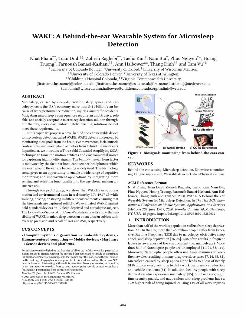
WAKE: A Behind-the-ear Wearable System for Microsleep Detection Nhat Pham †‡ , Tuan Dinh §‡ , Zohreh Raghebi †† , Taeho Kim † , Nam Bui † , Phuc Nguyen †★ , Hoang Truong † , Farnoush Banaei-Kashani †† , Ann Halbower ‡‡ , Thang Dinh §§ and Tam Vu †‡ † University of Colorado Boulder, ‡ University of Oxford, § University of Wisconsin Madison, †† University of Colorado Denver, ★ University of Texas at Arlington, ‡‡ Children’s Hospital Colorado, §§ Virginia Commonwealth University {frstname.lastname}@colorado.edu,{frstname.lastname}@cs.ox.ac.uk,{frstname.lastname}@ucdenver.edu [email protected],[email protected],[email protected] ABSTRACT Microsleep, caused by sleep deprivation, sleep apnea, and nar- colepsy, costs the U.S.’s economy more than $411 billion/year be- cause of work performance reduction, injuries, and trafc accidents. Mitigating microsleep’s consequences require an unobtrusive, reli- able, and socially acceptable microsleep detection solution through- out the day, every day. Unfortunately, existing solutions do not meet these requirements. In this paper, we propose a novel behind-the-ear wearable device for microsleep detection, called WAKE. WAKE detects microsleep by monitoring biosignals from the brain, eye movements, facial muscle contractions, and sweat gland activities from behind the user’s ears. In particular, we introduce a Three-fold Cascaded Amplifying (3CA) technique to tame the motion artifacts and environmental noises for capturing high fdelity signals. The behind-the-ear form factor is motivated by the fact that bone-conductance headphones, which are worn around the ear, are becoming widely used. This technology trend gives us an opportunity to enable a wide range of cognitive monitoring and improvement applications by integrating more sensing and actuating functionality into the ear-phone, making it a smarter one. Through our prototyping, we show that WAKE can suppress motion and environmental noise in real-time by 9.74-19.47 dB while walking, driving, or staying in diferent environments ensuring that the biosignals are captured reliably. We evaluated WAKE against gold-standard devices on 19 sleep-deprived and narcoleptic subjects. The Leave-One-Subject-Out Cross-Validation results show the fea- sibility of WAKE in microsleep detection on an unseen subject with average precision and recall of 76% and 85%, respectively. CCS CONCEPTS · Computer systems organization → Embedded systems; · Human-centered computing → Mobile devices; · Hardware → Sensor devices and platforms. Permission to make digital or hard copies of all or part of this work for personal or classroom use is granted without fee provided that copies are not made or distributed for proft or commercial advantage and that copies bear this notice and the full citation on the frst page. Copyrights for components of this work owned by others than ACM must be honored. Abstracting with credit is permitted. To copy otherwise, or republish, to post on servers or to redistribute to lists, requires prior specifc permission and/or a fee. Request permissions from [email protected]. MobiSys ’20, June 15ś19, 2020, Toronto, ON, Canada © 2020 Association for Computing Machinery. ACM ISBN 978-1-4503-7954-0/20/06. . . $15.00 https://doi.org/10.1145/3386901.3389032 Microsleep Detection c) COTS Earphones a) WAKE device b) Applications Z Z Z Fatigue Monitoring Z Z Z WAKE Earpiece WAKE Hardware Figure 1: Biosignals monitoring from behind the ears con- cept. KEYWORDS Behind-the-ear sensing, Microsleep detection, Drowsiness monitor- ing, Fatigue supervising, Wearable devices, Cyber-Physical systems. ACM Reference Format: Nhat Pham, Tuan Dinh, Zohreh Raghebi, Taeho Kim, Nam Bui, Phuc Nguyen, Hoang Truong, Farnoush Banaei-Kashani, Ann Hal- bower, Thang Dinh and Tam Vu. 2020. WAKE: A Behind-the-ear Wearable System for Microsleep Detection. In The 18th ACM Inter- national Conference on Mobile Systems, Applications, and Services (MobiSys’20), June 15-19, 2020, Toronto, Canada. ACM, NewYork, NY, USA, 15 pages. https://doi.org/10.1145/3386901.3389032 1 INTRODUCTION More than half of the world’s population sufers from sleep depriva- tion [63]. In the U.S, more than 65 million people sufer from Exces- sive Daytime Sleepiness (EDS) due to narcolepsy, obstructive sleep apnea, and sleep deprivation [76, 85]. EDS often results in frequent lapses in awareness of the environment (i.e. microsleeps). More than half of Narcoleptic people are unemployed [11, 21, 55, 111]. Moreover, Narcoleptic people often use Amphetamines to keep them awake, resulting in many drug overdose cases [7, 14, 33, 82]. Microsleep caused by sleep apnea alone leads to a loss of nearly $150 million every year due to daily work performance reduction and vehicle accidents [81]. In addition, healthy people with sleep deprivation also experience microsleep [85]. Shift workers, night time security guards, and navy sailors with sleep problems have a 1.6x higher risk of being injured, causing 13% of all work injuries 404
Transcript of WAKE: A Behind-the-ear Wearable System for Microsleep ...
WAKE: A Behind-the-ear Wearable System for MicrosleepDetection
Nhat Pham†‡, Tuan Dinh§‡, Zohreh Raghebi††, Taeho Kim†, Nam Bui†, Phuc Nguyen†★, HoangTruong†, Farnoush Banaei-Kashani††, Ann Halbower‡‡, Thang Dinh§§ and Tam Vu†‡
†University of Colorado Boulder, ‡University of Oxford, §University of Wisconsin Madison,††University of Colorado Denver, ★University of Texas at Arlington,
‡‡Children’s Hospital Colorado, §§Virginia Commonwealth University{firstname.lastname}@colorado.edu,{firstname.lastname}@cs.ox.ac.uk,{firstname.lastname}@ucdenver.edu
[email protected],[email protected],[email protected]
ABSTRACT
Microsleep, caused by sleep deprivation, sleep apnea, and nar-colepsy, costs the U.S.’s economy more than $411 billion/year be-cause of work performance reduction, injuries, and traffic accidents.Mitigating microsleep’s consequences require an unobtrusive, reli-able, and socially acceptable microsleep detection solution through-out the day, every day. Unfortunately, existing solutions do notmeet these requirements.
In this paper, we propose a novel behind-the-ear wearable deviceformicrosleep detection, calledWAKE.WAKE detects microsleep bymonitoring biosignals from the brain, eye movements, facial musclecontractions, and sweat gland activities from behind the user’s ears.In particular, we introduce a Three-fold Cascaded Amplifying (3CA)technique to tame the motion artifacts and environmental noisesfor capturing high fidelity signals. The behind-the-ear form factoris motivated by the fact that bone-conductance headphones, whichare worn around the ear, are becomingwidely used. This technologytrend gives us an opportunity to enable a wide range of cognitivemonitoring and improvement applications by integrating moresensing and actuating functionality into the ear-phone, making it asmarter one.
Through our prototyping, we show that WAKE can suppressmotion and environmental noise in real-time by 9.74-19.47 dB whilewalking, driving, or staying in different environments ensuring thatthe biosignals are captured reliably. We evaluated WAKE againstgold-standard devices on 19 sleep-deprived and narcoleptic subjects.The Leave-One-Subject-Out Cross-Validation results show the fea-sibility of WAKE in microsleep detection on an unseen subject withaverage precision and recall of 76% and 85%, respectively.
CCS CONCEPTS
· Computer systems organization → Embedded systems; ·Human-centered computing → Mobile devices; · Hardware
→ Sensor devices and platforms.
Permission to make digital or hard copies of all or part of this work for personal orclassroom use is granted without fee provided that copies are not made or distributedfor profit or commercial advantage and that copies bear this notice and the full citationon the first page. Copyrights for components of this work owned by others than ACMmust be honored. Abstracting with credit is permitted. To copy otherwise, or republish,to post on servers or to redistribute to lists, requires prior specific permission and/or afee. Request permissions from [email protected].
MobiSys ’20, June 15ś19, 2020, Toronto, ON, Canada
© 2020 Association for Computing Machinery.ACM ISBN 978-1-4503-7954-0/20/06. . . $15.00https://doi.org/10.1145/3386901.3389032
Microsleep Detection
c) COTS Earphonesa) WAKE device
b) Applications
ZZZFatigue Monitoring
ZZZ
WAKE Earpiece
WAKE Hardware
Figure 1: Biosignals monitoring from behind the ears con-
cept.
KEYWORDS
Behind-the-ear sensing, Microsleep detection, Drowsiness monitor-ing, Fatigue supervising, Wearable devices, Cyber-Physical systems.
ACM Reference Format:
Nhat Pham, Tuan Dinh, Zohreh Raghebi, Taeho Kim, Nam Bui,Phuc Nguyen, Hoang Truong, Farnoush Banaei-Kashani, Ann Hal-bower, Thang Dinh and Tam Vu. 2020. WAKE: A Behind-the-earWearable System for Microsleep Detection. In The 18th ACM Inter-
national Conference on Mobile Systems, Applications, and Services
(MobiSys’20), June 15-19, 2020, Toronto, Canada. ACM, NewYork,NY, USA, 15 pages. https://doi.org/10.1145/3386901.3389032
1 INTRODUCTION
More than half of the world’s population suffers from sleep depriva-tion [63]. In the U.S, more than 65 million people suffer from Exces-sive Daytime Sleepiness (EDS) due to narcolepsy, obstructive sleepapnea, and sleep deprivation [76, 85]. EDS often results in frequentlapses in awareness of the environment (i.e. microsleeps). Morethan half of Narcoleptic people are unemployed [11, 21, 55, 111].Moreover, Narcoleptic people often use Amphetamines to keepthem awake, resulting in many drug overdose cases [7, 14, 33, 82].Microsleep caused by sleep apnea alone leads to a loss of nearly$150 million every year due to daily work performance reductionand vehicle accidents [81]. In addition, healthy people with sleepdeprivation also experience microsleep [85]. Shift workers, nighttime security guards, and navy sailors with sleep problems have a1.6x higher risk of being injured, causing 13% of all work injuries
404
MobiSys ’20, June 15–19, 2020, Toronto, ON, Canada N. Pham, et al.
Front ViewSide View
Orexin Neurons
Sweat
Glands Hypothalamus
Ventrolateral
Medulla
Wakefulness, Arousal
Wakefulness, Arousal
Spinal Cord
Visual Motor
Pathway
Sympatheic Nervous
System Pathway
Muscle
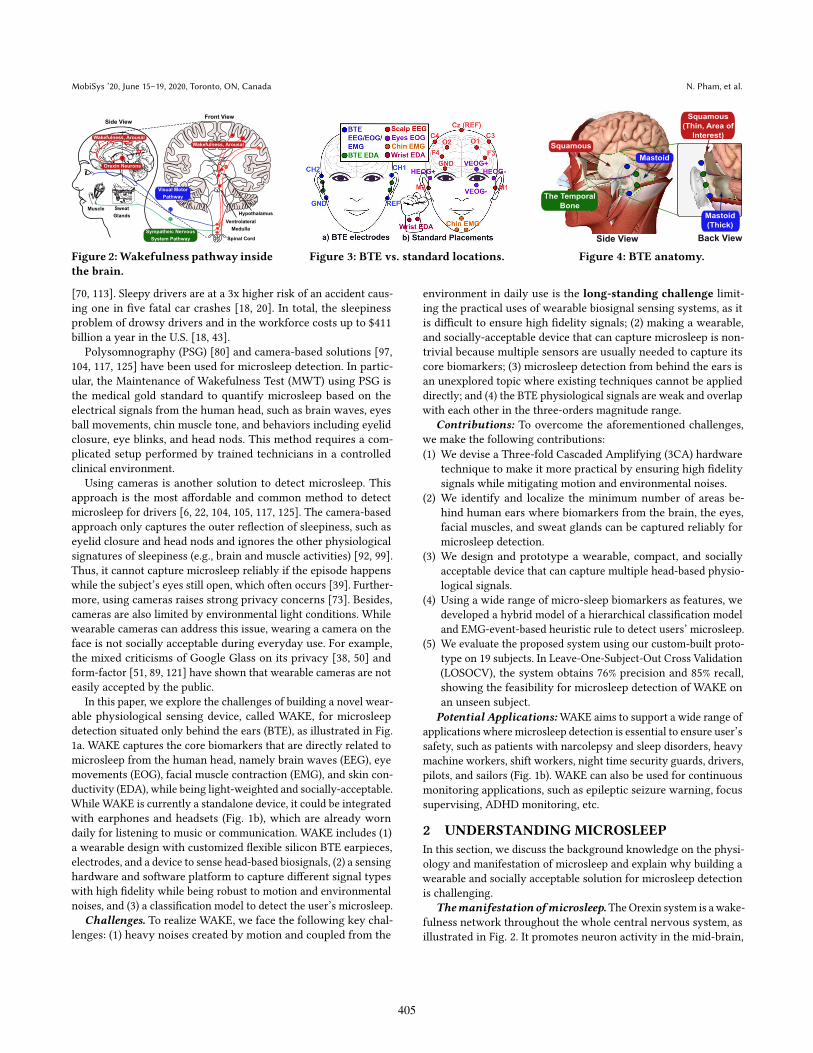
Figure 2:Wakefulness pathway inside
the brain.
Figure 3: BTE vs. standard locations.
Side View
The Temporal
Bone
Mastoid
Squamous
Back View
Squamous
(Thin, Area of
Interest)
Mastoid
(Thick)
Figure 4: BTE anatomy.
[70, 113]. Sleepy drivers are at a 3x higher risk of an accident caus-ing one in five fatal car crashes [18, 20]. In total, the sleepinessproblem of drowsy drivers and in the workforce costs up to $411billion a year in the U.S. [18, 43].
Polysomnography (PSG) [80] and camera-based solutions [97,104, 117, 125] have been used for microsleep detection. In partic-ular, the Maintenance of Wakefulness Test (MWT) using PSG isthe medical gold standard to quantify microsleep based on theelectrical signals from the human head, such as brain waves, eyesball movements, chin muscle tone, and behaviors including eyelidclosure, eye blinks, and head nods. This method requires a com-plicated setup performed by trained technicians in a controlledclinical environment.
Using cameras is another solution to detect microsleep. Thisapproach is the most affordable and common method to detectmicrosleep for drivers [6, 22, 104, 105, 117, 125]. The camera-basedapproach only captures the outer reflection of sleepiness, such aseyelid closure and head nods and ignores the other physiologicalsignatures of sleepiness (e.g., brain and muscle activities) [92, 99].Thus, it cannot capture microsleep reliably if the episode happenswhile the subject’s eyes still open, which often occurs [39]. Further-more, using cameras raises strong privacy concerns [73]. Besides,cameras are also limited by environmental light conditions. Whilewearable cameras can address this issue, wearing a camera on theface is not socially acceptable during everyday use. For example,the mixed criticisms of Google Glass on its privacy [38, 50] andform-factor [51, 89, 121] have shown that wearable cameras are noteasily accepted by the public.
In this paper, we explore the challenges of building a novel wear-able physiological sensing device, called WAKE, for microsleepdetection situated only behind the ears (BTE), as illustrated in Fig.1a. WAKE captures the core biomarkers that are directly related tomicrosleep from the human head, namely brain waves (EEG), eyemovements (EOG), facial muscle contraction (EMG), and skin con-ductivity (EDA), while being light-weighted and socially-acceptable.While WAKE is currently a standalone device, it could be integratedwith earphones and headsets (Fig. 1b), which are already worndaily for listening to music or communication. WAKE includes (1)a wearable design with customized flexible silicon BTE earpieces,electrodes, and a device to sense head-based biosignals, (2) a sensinghardware and software platform to capture different signal typeswith high fidelity while being robust to motion and environmentalnoises, and (3) a classification model to detect the user’s microsleep.
Challenges. To realize WAKE, we face the following key chal-lenges: (1) heavy noises created by motion and coupled from the
environment in daily use is the long-standing challenge limit-ing the practical uses of wearable biosignal sensing systems, as itis difficult to ensure high fidelity signals; (2) making a wearable,and socially-acceptable device that can capture microsleep is non-trivial because multiple sensors are usually needed to capture itscore biomarkers; (3) microsleep detection from behind the ears isan unexplored topic where existing techniques cannot be applieddirectly; and (4) the BTE physiological signals are weak and overlapwith each other in the three-orders magnitude range.
Contributions: To overcome the aforementioned challenges,we make the following contributions:
(1) We devise a Three-fold Cascaded Amplifying (3CA) hardwaretechnique to make it more practical by ensuring high fidelitysignals while mitigating motion and environmental noises.
(2) We identify and localize the minimum number of areas be-hind human ears where biomarkers from the brain, the eyes,facial muscles, and sweat glands can be captured reliably formicrosleep detection.
(3) We design and prototype a wearable, compact, and sociallyacceptable device that can capture multiple head-based physio-logical signals.
(4) Using a wide range of micro-sleep biomarkers as features, wedeveloped a hybrid model of a hierarchical classification modeland EMG-event-based heuristic rule to detect users’ microsleep.
(5) We evaluate the proposed system using our custom-built proto-type on 19 subjects. In Leave-One-Subject-Out Cross Validation(LOSOCV), the system obtains 76% precision and 85% recall,showing the feasibility for microsleep detection of WAKE onan unseen subject.
Potential Applications:WAKE aims to support a wide range ofapplications where microsleep detection is essential to ensure user’ssafety, such as patients with narcolepsy and sleep disorders, heavymachine workers, shift workers, night time security guards, drivers,pilots, and sailors (Fig. 1b). WAKE can also be used for continuousmonitoring applications, such as epileptic seizure warning, focussupervising, ADHD monitoring, etc.
2 UNDERSTANDING MICROSLEEP
In this section, we discuss the background knowledge on the physi-ology and manifestation of microsleep and explain why building awearable and socially acceptable solution for microsleep detectionis challenging.
Themanifestation ofmicrosleep.TheOrexin system is awake-fulness network throughout the whole central nervous system, asillustrated in Fig. 2. It promotes neuron activity in the mid-brain,
405
WAKE: A Behind-the-ear Wearable System for Microsleep Detection MobiSys ’20, June 15–19, 2020, Toronto, ON, Canada
Ear1
20uVEar2
a) Eyes-closed Alpha Rhythms (0.3 to 35Hz)
0
10
100
Spectrogram
Fre
q (
Hz)
Time (s)0
10
100
2 4
2 4
Po
we
r/Fre
q (d
B/H
z)
-12
-12
6
6
0 2 4
Eyes open
Eyes
close Ear1
Ear2 20uV
BlinkDouble Blink
0 3 6
Time (s)0 3 6
Gaze left
Gaze right
Time (s)
b) Vertical and Horizontal EOG (0.3 - 10Hz)
Arousal
Right
Ear
Left
Ear
d) EDA (0.1-1.5Hz)c) Facial EMG (0.3 - 100Hz)
Ear1
Ear2
SpectrogramTeeth grinding
0 2 4
1m
V
Fre
q (
Hz)
100
0 2 4
40
-10
Po
we
r/Fre
q (d
B/H
z)
0 2 4
100 40
-10
Time (s) Time (s)
10s
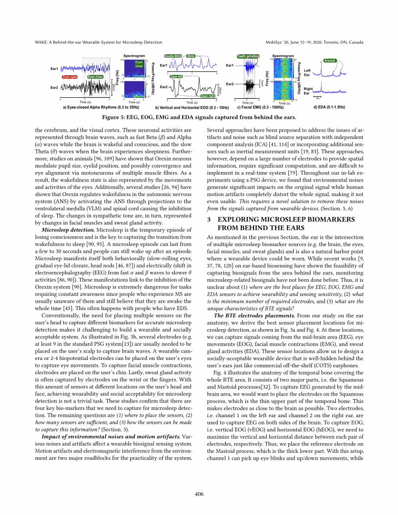
Figure 5: EEG, EOG, EMG and EDA signals captured from behind the ears.
the cerebrum, and the visual cortex. These neuronal activities arerepresented through brain waves, such as fast Beta (𝛽) and Alpha(𝛼) waves while the brain is wakeful and conscious, and the slowTheta (𝜃 ) waves when the brain experiences sleepiness. Further-more, studies on animals [96, 109] have shown that Orexin neuronsmodulate pupil size, eyelid position, and possibly convergence andeye alignment via motoneurons of multiple muscle fibers. As aresult, the wakefulness state is also represented by the movementsand activities of the eyes. Additionally, several studies [26, 94] haveshown that Orexin regulates wakefulness in the autonomic nervoussystem (ANS) by activating the ANS through projections to theventrolateral medulla (VLM) and spinal cord causing the inhibitionof sleep. The changes in sympathetic tone are, in turn, representedby changes in facial muscles and sweat gland activity.
Microsleep detection. Microsleep is the temporary episode oflosing consciousness and is the key to capturing the transition fromwakefulness to sleep [90, 95]. A microsleep episode can last froma few to 30 seconds and people can still wake up after an episode.Microsleep manifests itself both behaviorally (slow-rolling eyes,gradual eye-lid closure, head nods [46, 87]) and electrically (shift inelectroencephalography (EEG) from fast 𝛼 and 𝛽 waves to slower 𝜃activities [86, 90]). These manifestations link to the inhibition of theOrexin system [90]. Microsleep is extremely dangerous for tasksrequiring constant awareness since people who experience MS areusually unaware of them and still believe that they are awake thewhole time [45]. This often happens with people who have EDS.
Conventionally, the need for placing multiple sensors on theuser’s head to capture different biomarkers for accurate microsleepdetection makes it challenging to build a wearable and sociallyacceptable system. As illustrated in Fig. 3b, several electrodes (e.g.at least 9 in the standard PSG system[13]) are usually needed to beplaced on the user’s scalp to capture brain waves. A wearable cam-era or 2-4 biopotential electrodes can be placed on the user’s eyesto capture eye movements. To capture facial muscle contractions,electrodes are placed on the user’s chin. Lastly, sweat gland activityis often captured by electrodes on the wrist or the fingers. Withthis amount of sensors at different locations on the user’s head andface, achieving wearability and social acceptability for microsleepdetection is not a trivial task. These studies confirm that there arefour key bio-markers that we need to capture for microsleep detec-tion. The remaining questions are (1) where to place the sensors, (2)how many sensors are sufficient, and (3) how the sensors can be made
to capture this information? (Section. 3).Impact of environmental noises and motion artifacts. Var-
ious noises and artifacts affect a wearable biosignal sensing system.Motion artifacts and electromagnetic interference from the environ-ment are two major roadblocks for the practicality of the system.
Several approaches have been proposed to address the issues of ar-tifacts and noise such as blind source separation with independentcomponent analysis (ICA) [41, 114] or incorporating additional sen-sors such as inertial measurement units [19, 83]. These approaches,however, depend on a large number of electrodes to provide spatialinformation, require significant computation, and are difficult toimplement in a real-time system [79]. Throughout our in-lab ex-periments using a PSG device, we found that environmental noisesgenerate significant impacts on the original signal while humanmotion artifacts completely distort the whole signal, making it noteven usable. This requires a novel solution to remove these noises
from the signals captured from wearable devices. (Section. 5, 6)
3 EXPLORING MICROSLEEP BIOMARKERSFROM BEHIND THE EARS
As mentioned in the previous Section, the ear is the intersectionof multiple microsleep biomarker sources (e.g. the brain, the eyes,facial muscles, and sweat glands) and is also a natural harbor pointwhere a wearable device could be worn. While recent works [9,37, 78, 120] on ear-based biosensing have shown the feasibility ofcapturing biosignals from the area behind the ears, monitoringmicrosleep-related biosignals have not been done before. Thus, it isunclear about (1) where are the best places for EEG, EOG, EMG and
EDA sensors to achieve wearability and sensing sensitivity, (2) whatis the minimum number of required electrodes, and (3) what are theunique characteristics of BTE signals?
The BTE electrodes placements. From our study on the earanatomy, we derive the best sensor placement locations for mi-crosleep detection, as shown in Fig. 3a and Fig. 4. At these locations,we can capture signals coming from the mid-brain area (EEG), eyemovements (EOG), facial muscle contractions (EMG), and sweatgland activities (EDA). These sensor locations allow us to design asocially-acceptable wearable device that is well-hidden behind theuser’s ears just like commercial off-the-shelf (COTS) earphones.
Fig. 4 illustrates the anatomy of the temporal bone covering thewhole BTE area. It consists of two major parts, i.e. the Squamousand Mastoid processes[32]. To capture EEG generated by the mid-brain area, we would want to place the electrodes on the Squamousprocess, which is the thin upper part of the temporal bone. Thismakes electrodes as close to the brain as possible. Two electrodes,i.e. channel 1 on the left ear and channel 2 on the right ear, areused to capture EEG on both sides of the brain. To capture EOG,i.e. vertical EOG (vEOG) and horizontal EOG (hEOG), we need tomaximize the vertical and horizontal distance between each pair ofelectrodes, respectively. Thus, we place the reference electrode onthe Mastoid process, which is the thick lower part. With this setup,channel 1 can pick up eye blinks and up/down movements, while
406
MobiSys ’20, June 15–19, 2020, Toronto, ON, Canada N. Pham, et al.
Hardware
Silicon earpieces
Three-fold Cascaded
Amplifying
EEG/EOG/EMG, EDA
Sensors
Firmware
Adaptive gain control
Contact Impedance
Checking
Bluetooth and SD card
streaming
Behind-The-Ear Sensing Software
Sensor data stream
BTE EEG/EOG/EMG
signals
EDA signals
Signal Preprocessing Signal Separation
EEG EOG EMG
Microsleep Detection
Awake/Microsleep
Classification
Contact ImpedanceOversampling &
Averaging
Cleaned overlapped
EEG/EOG/EMG
Lead-Off Signal
Removal
WAKE Wearable Device Host Computer
DC removal
Notch FilterFrequency filtering
Microsleep Feature
Extraction
Machine learning
model
Cleaned EDA
signals
SCR SCL
Decomposition
Analysis
Median and Outlier
Filter
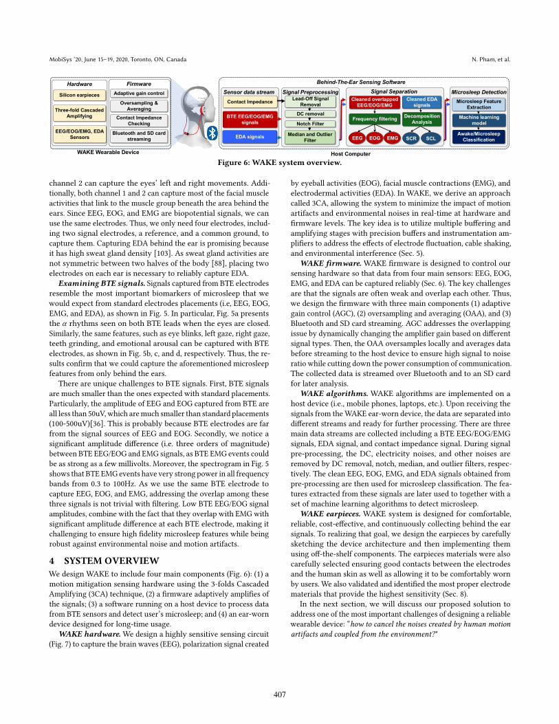
Figure 6: WAKE system overview.
channel 2 can capture the eyes’ left and right movements. Addi-tionally, both channel 1 and 2 can capture most of the facial muscleactivities that link to the muscle group beneath the area behind theears. Since EEG, EOG, and EMG are biopotential signals, we canuse the same electrodes. Thus, we only need four electrodes, includ-ing two signal electrodes, a reference, and a common ground, tocapture them. Capturing EDA behind the ear is promising becauseit has high sweat gland density [103]. As sweat gland activities arenot symmetric between two halves of the body [88], placing twoelectrodes on each ear is necessary to reliably capture EDA.
Examining BTE signals. Signals captured from BTE electrodesresemble the most important biomarkers of microsleep that wewould expect from standard electrodes placements (i.e, EEG, EOG,EMG, and EDA), as shown in Fig. 5. In particular, Fig. 5a presentsthe 𝛼 rhythms seen on both BTE leads when the eyes are closed.Similarly, the same features, such as eye blinks, left gaze, right gaze,teeth grinding, and emotional arousal can be captured with BTEelectrodes, as shown in Fig. 5b, c, and d, respectively. Thus, the re-sults confirm that we could capture the aforementioned microsleepfeatures from only behind the ears.
There are unique challenges to BTE signals. First, BTE signalsare much smaller than the ones expected with standard placements.Particularly, the amplitude of EEG and EOG captured from BTE areall less than 50uV, which aremuch smaller than standard placements(100-500uV)[36]. This is probably because BTE electrodes are farfrom the signal sources of EEG and EOG. Secondly, we notice asignificant amplitude difference (i.e. three orders of magnitude)between BTE EEG/EOG and EMG signals, as BTE EMG events couldbe as strong as a few millivolts. Moreover, the spectrogram in Fig. 5shows that BTE EMGevents have very strong power in all frequencybands from 0.3 to 100Hz. As we use the same BTE electrode tocapture EEG, EOG, and EMG, addressing the overlap among thesethree signals is not trivial with filtering. Low BTE EEG/EOG signalamplitudes, combine with the fact that they overlap with EMG withsignificant amplitude difference at each BTE electrode, making itchallenging to ensure high fidelity microsleep features while beingrobust against environmental noise and motion artifacts.
4 SYSTEM OVERVIEW
We design WAKE to include four main components (Fig. 6): (1) amotion mitigation sensing hardware using the 3-folds CascadedAmplifying (3CA) technique, (2) a firmware adaptively amplifies ofthe signals; (3) a software running on a host device to process datafrom BTE sensors and detect user’s microsleep; and (4) an ear-worndevice designed for long-time usage.
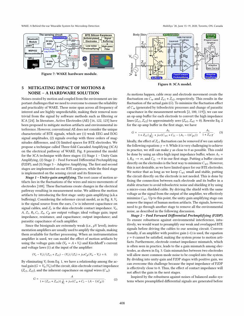
WAKE hardware. We design a highly sensitive sensing circuit(Fig. 7) to capture the brain waves (EEG), polarization signal created
by eyeball activities (EOG), facial muscle contractions (EMG), andelectrodermal activities (EDA). In WAKE, we derive an approachcalled 3CA, allowing the system to minimize the impact of motionartifacts and environmental noises in real-time at hardware andfirmware levels. The key idea is to utilize multiple buffering andamplifying stages with precision buffers and instrumentation am-plifiers to address the effects of electrode fluctuation, cable shaking,and environmental interference (Sec. 5).
WAKE firmware. WAKE firmware is designed to control oursensing hardware so that data from four main sensors: EEG, EOG,EMG, and EDA can be captured reliably (Sec. 6). The key challengesare that the signals are often weak and overlap each other. Thus,we design the firmware with three main components (1) adaptivegain control (AGC), (2) oversampling and averaging (OAA), and (3)Bluetooth and SD card streaming. AGC addresses the overlappingissue by dynamically changing the amplifier gain based on differentsignal types. Then, the OAA oversamples locally and averages databefore streaming to the host device to ensure high signal to noiseratio while cutting down the power consumption of communication.The collected data is streamed over Bluetooth and to an SD cardfor later analysis.
WAKE algorithms. WAKE algorithms are implemented on ahost device (i.e., mobile phones, laptops, etc.). Upon receiving thesignals from theWAKE ear-worn device, the data are separated intodifferent streams and ready for further processing. There are threemain data streams are collected including a BTE EEG/EOG/EMGsignals, EDA signal, and contact impedance signal. During signalpre-processing, the DC, electricity noises, and other noises areremoved by DC removal, notch, median, and outlier filters, respec-tively. The clean EEG, EOG, EMG, and EDA signals obtained frompre-processing are then used for microsleep classification. The fea-tures extracted from these signals are later used to together with aset of machine learning algorithms to detect microsleep.
WAKE earpieces. WAKE system is designed for comfortable,reliable, cost-effective, and continuously collecting behind the earsignals. To realizing that goal, we design the earpieces by carefullysketching the device architecture and then implementing themusing off-the-shelf components. The earpieces materials were alsocarefully selected ensuring good contacts between the electrodesand the human skin as well as allowing it to be comfortably wornby users. We also validated and identified the most proper electrodematerials that provide the highest sensitivity (Sec. 8).
In the next section, we will discuss our proposed solution toaddress one of the most important challenges of designing a reliablewearable device: łhow to cancel the noises created by human motion
artifacts and coupled from the environment?"
407
WAKE: A Behind-the-ear Wearable System for Microsleep Detection MobiSys ’20, June 15–19, 2020, Toronto, ON, Canada
BTE Silicon Earpieces
8xGold-plated
Electrodes
Low noise
PreAmplifying
Signal
Buffering
High-pass
Filter
The sensing circuit
24 bits
ADC
MSP432
Microcontroller
16 bits
ADC
Bluetooth
Module
UART
SPI
EEG/EOG/EMG
EDA
R protection
R protection
2.5V
I < 25uA
I = 6nA
Driven Right
Leg Circuit
8
Figure 7: WAKE hardware module.
5 MITIGATING IMPACT OF MOTIONS &NOISE ś A HARDWARE SOLUTION
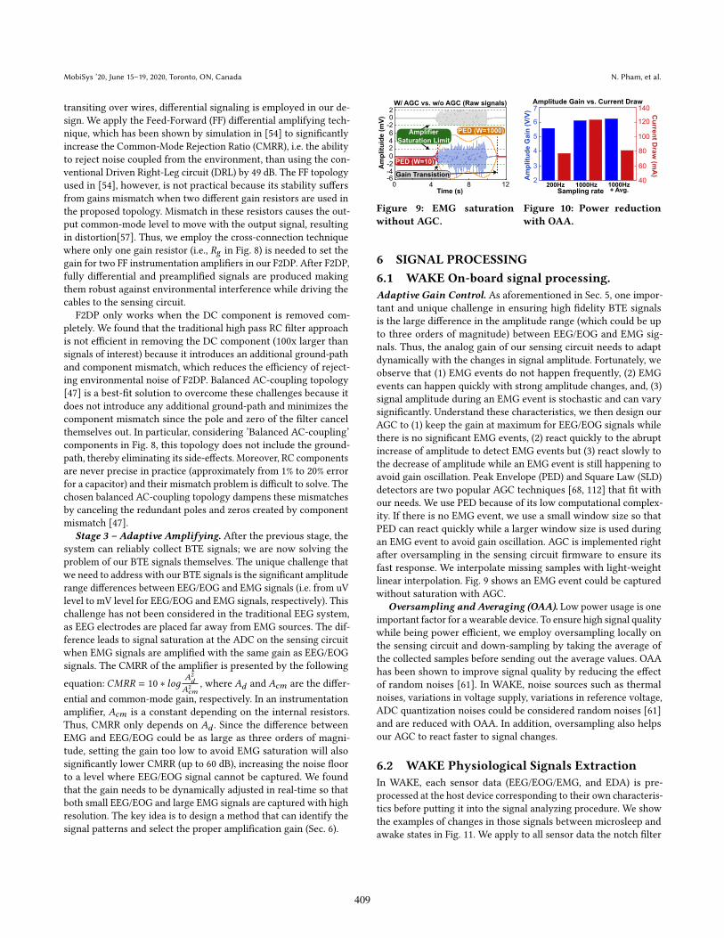
Noises created by motion and coupled from the environment are im-portant challenges that we need to overcome to ensure the reliabilityand practicality of WAKE. These noise span across all frequency ofinterest and are highly unpredictable, making their removal non-trivial from the signal by software methods such as filtering orICA [24]. In literature, Active Electrodes (AE) [16, 122, 123] havebeen proposed to mitigate motion artifacts and environmental in-terference. However, conventional AE does not consider the uniquecharacteristic of BTE signals, which are (1) weak EEG and EOGsignal amplitudes, (2) signals overlap with three orders of mag-nitudes difference, and (3) limited spaces for BTE electrodes. Wepropose a technique called Three-fold Cascaded Amplifying (3CA)on the electrical pathway of WAKE. Fig. 8 presented the modelfor the 3CA technique with three stages: (1) Stage 1 ś Unity GainAmplifying, (2) Stage 2 ś Feed Forward Differential PreAmplifying(F2DP), and (3) Stage 3 ś Adaptive Amplifying. The first and secondstages are implemented on our BTE earpieces, while the third stageis implemented on the sensing circuit and its firmware.
Stage 1 ś Unity-gain amplifying. The root cause of motion ar-tifacts lies in the fluctuations of the wires and micro-movements ofelectrodes [108]. These fluctuations create changes in the electricalpathway resulting in measurement noise. We address the motionartifacts by introducing the first stage: unity-gain amplifying (a.k.abuffering). Considering the reference circuit model, as in Fig. 8, 𝑉𝑠is the signal source from the ears, 𝐶𝑤 is inherent capacitance onsignal cables, and 𝑍𝑐 is the skin-electrode contact impedance. 𝑉𝑜 ,𝐴, 𝑍𝑖 , 𝑅𝑖 ,𝐶𝑖 , 𝑍𝑜 , 𝐶𝑝 are output voltage; ideal voltage gain; inputimpedance, resistance, and capacitance; output impedance; andparasitic capacitance of each amplifier.
Since the biosignals are extremely weak (i.e., 𝜇V level), instru-mentation amplifiers are usually used to amplify the signals, makingthem available for further processing. When an instrumentationamplifier is used, we can model the effect of motion artifacts byusing the voltage gain rule (𝑉𝑜 = 𝐴 ∗𝑉𝑖 ) and Kirchhoff’s currentand voltage laws (1) at the input of the amplifier:
(𝑉𝑠 −𝑉𝑖 )/(𝑍𝑐1 + 𝑍𝑐2) − (𝑉𝑖 )/(𝑍𝑖 ) + 𝑗𝜔𝐶𝑝 (𝑉𝑜 −𝑉𝑖 ) = 0. (1)
By eliminating 𝑉𝑖 from Eq. 1, we have a relationship among the ac-tual gain (𝐺 = 𝑉𝑜/𝑉𝑠 ) of the circuit, skin-electrode contact impedance(𝑍𝑐1, 𝑍𝑐2), and the inherent capacitance on signal wires (𝐶𝑤 ):
𝐺 =
𝐴
1 + (𝑍𝑐1 + 𝑍𝑐2) (1𝑅𝑖
+ 𝑗𝜔 (𝐶𝑤 +𝐶𝑖 − (𝐴 − 1)𝐶𝑝 )). (2)
Zc1
Zc2
Cw
SkinBody
Vs
VCM-Noise
Figure 8: 3CA model.
As motions happen, cable sway and electrode movement create thefluctuation on 𝐶𝑤 and 𝑍𝑐1 + 𝑍𝑐2, respectively. This results in thefluctuation of the actual gain (𝐺). To minimize the fluctuation effectof 𝐶𝑤 (generated by triboelectric processes and change of parasiticcapacitance in the measurement network [2, 100, 119]), we can usean op-amp buffer for each electrode to convert the high impedancelines (𝑍𝑐1, 𝑍𝑐2) to approximately zero (𝑍𝑜1, 𝑍𝑜2 ≈ 0). Rewrite Eq. 2for the op-amp buffer in the first stage, we have
𝐺 =
𝐴1
1 + 𝑍𝑐1 (1
𝑅𝑖1+ 𝑗𝜔 (𝐶𝑤1 +𝐶𝑖1 − (𝐴1 − 1)𝐶𝑝1))
=
𝐴1
1 + 𝑍𝑐1𝛾. (3)
Ideally, the effect of𝑍𝑐1 fluctuation can be removed if we can satisfythe following equation:𝛾 = 0.While it is very challenging to achievein practice, we still can make 𝛾 as close to 0 as possible. This couldbe done by using an ultra-high input impedance buffer, where𝐴1 =
1, 𝑅𝑖1 → ∞, and 𝐶𝑖1 → 0 in our first stage. Putting a buffer circuitdirectly on the electrodes is the best way to minimize𝐶𝑤1. However,this is not desirable, as we have limited space for our BTE electrodes.We notice that as long as we keep 𝐶𝑤1 small and stable, puttingthe circuit directly on the electrode is not needed. This is done byfixing the connection between each electrode and its buffer in astable structure to avoid triboelectric noise and shielding it by usinga micro-coax shielded cable. By driving the shield with the samevoltage as the signal from the output of the amplifier, we effectivelyminimize𝐶𝑤1. Up to this point, the unity-gain amplifying stage canremove the impact of human motion artifacts. The signals, however,need to go through another stage to remove all the environmentalnoise, as described in the following discussion.
Stage 2 ś Feed Forward Differential PreAmplifying (F2DP).
To ensure robustness against environmental interference, intu-itively, we would want to preamplify our weak and overlapped BTEsignals before driving the cables to our sensing circuit. Conven-tionally, if an amplifier with positive gain (>1) is used, the equation𝛾 = 0 cannot be satisfied, making the system prone to motion arti-facts. Furthermore, electrode contact impedance mismatch, whichis often seen in practice, leads to the a gain mismatch among elec-trodes, as shown in Eq. 3. Gain mismatches between two electrodeswill allow more common-mode noise to be coupled into the system.By dividing into unity-gain and F2DP stages with positive gain, wecan overcome this challenge because the input impedance of F2DPis effectively close to 0. Thus, the effect of contact impedance willnot affect the gain in the next stages.
Inspired by the robustness against noises of balanced audio sys-tems where preamplified differential signals are generated before
408
MobiSys ’20, June 15–19, 2020, Toronto, ON, Canada N. Pham, et al.
transiting over wires, differential signaling is employed in our de-sign. We apply the Feed-Forward (FF) differential amplifying tech-nique, which has been shown by simulation in [54] to significantlyincrease the Common-Mode Rejection Ratio (CMRR), i.e. the abilityto reject noise coupled from the environment, than using the con-ventional Driven Right-Leg circuit (DRL) by 49 dB. The FF topologyused in [54], however, is not practical because its stability suffersfrom gains mismatch when two different gain resistors are used inthe proposed topology. Mismatch in these resistors causes the out-put common-mode level to move with the output signal, resultingin distortion[57]. Thus, we employ the cross-connection techniquewhere only one gain resistor (i.e., 𝑅𝑔 in Fig. 8) is needed to set thegain for two FF instrumentation amplifiers in our F2DP. After F2DP,fully differential and preamplified signals are produced makingthem robust against environmental interference while driving thecables to the sensing circuit.
F2DP only works when the DC component is removed com-pletely. We found that the traditional high pass RC filter approachis not efficient in removing the DC component (100x larger thansignals of interest) because it introduces an additional ground-pathand component mismatch, which reduces the efficiency of reject-ing environmental noise of F2DP. Balanced AC-coupling topology[47] is a best-fit solution to overcome these challenges because itdoes not introduce any additional ground-path and minimizes thecomponent mismatch since the pole and zero of the filter cancelthemselves out. In particular, considering ’Balanced AC-coupling’components in Fig. 8, this topology does not include the ground-path, thereby eliminating its side-effects. Moreover, RC componentsare never precise in practice (approximately from 1% to 20% errorfor a capacitor) and their mismatch problem is difficult to solve. Thechosen balanced AC-coupling topology dampens these mismatchesby canceling the redundant poles and zeros created by componentmismatch [47].
Stage 3 ś Adaptive Amplifying. After the previous stage, thesystem can reliably collect BTE signals; we are now solving theproblem of our BTE signals themselves. The unique challenge thatwe need to address with our BTE signals is the significant amplituderange differences between EEG/EOG and EMG signals (i.e. from uVlevel to mV level for EEG/EOG and EMG signals, respectively). Thischallenge has not been considered in the traditional EEG system,as EEG electrodes are placed far away from EMG sources. The dif-ference leads to signal saturation at the ADC on the sensing circuitwhen EMG signals are amplified with the same gain as EEG/EOGsignals. The CMRR of the amplifier is presented by the following
equation: 𝐶𝑀𝑅𝑅 = 10 ∗ 𝑙𝑜𝑔𝐴2𝑑
𝐴2𝑐𝑚
, where 𝐴𝑑 and 𝐴𝑐𝑚 are the differ-
ential and common-mode gain, respectively. In an instrumentationamplifier, 𝐴𝑐𝑚 is a constant depending on the internal resistors.Thus, CMRR only depends on 𝐴𝑑 . Since the difference betweenEMG and EEG/EOG could be as large as three orders of magni-tude, setting the gain too low to avoid EMG saturation will alsosignificantly lower CMRR (up to 60 dB), increasing the noise floorto a level where EEG/EOG signal cannot be captured. We foundthat the gain needs to be dynamically adjusted in real-time so thatboth small EEG/EOG and large EMG signals are captured with highresolution. The key idea is to design a method that can identify thesignal patterns and select the proper amplification gain (Sec. 6).
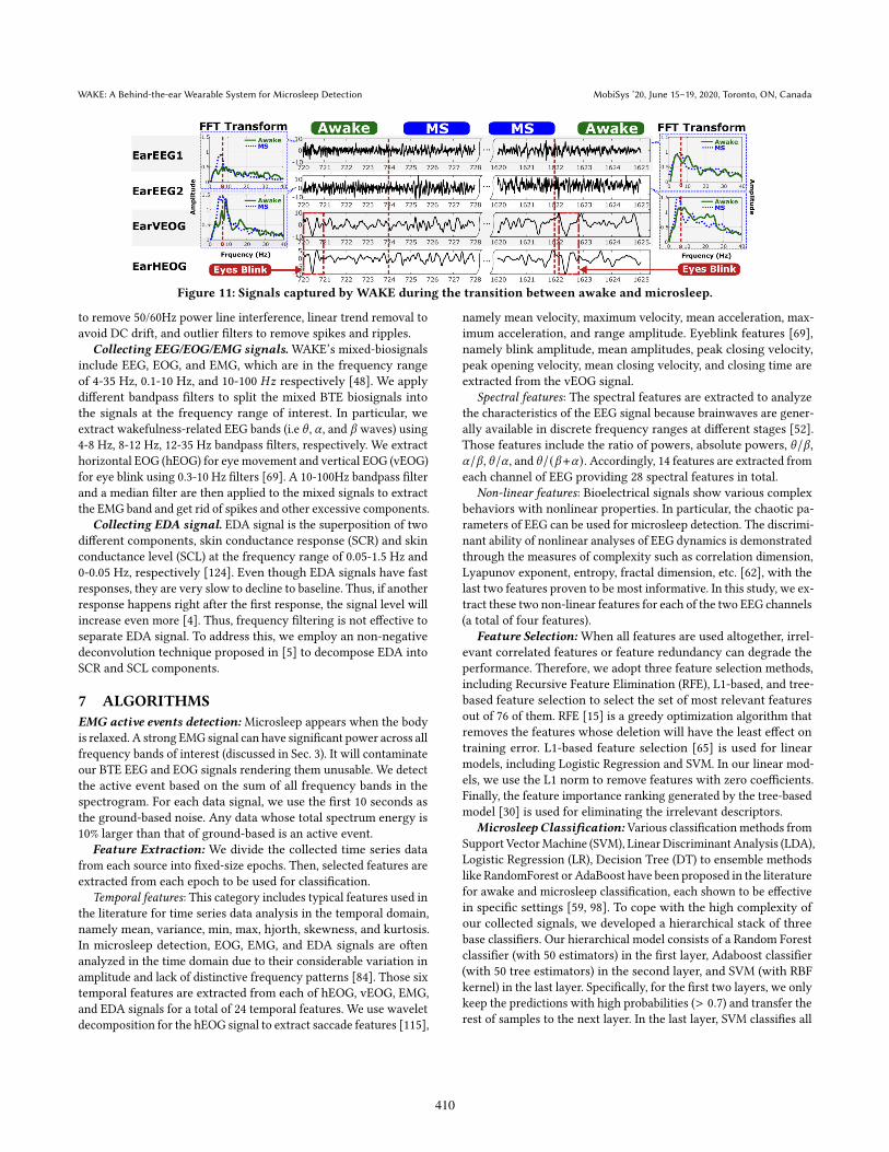
Figure 9: EMG saturation
without AGC.
Figure 10: Power reduction
with OAA.
6 SIGNAL PROCESSING
6.1 WAKE On-board signal processing.
Adaptive Gain Control. As aforementioned in Sec. 5, one impor-tant and unique challenge in ensuring high fidelity BTE signalsis the large difference in the amplitude range (which could be upto three orders of magnitude) between EEG/EOG and EMG sig-nals. Thus, the analog gain of our sensing circuit needs to adaptdynamically with the changes in signal amplitude. Fortunately, weobserve that (1) EMG events do not happen frequently, (2) EMGevents can happen quickly with strong amplitude changes, and, (3)signal amplitude during an EMG event is stochastic and can varysignificantly. Understand these characteristics, we then design ourAGC to (1) keep the gain at maximum for EEG/EOG signals whilethere is no significant EMG events, (2) react quickly to the abruptincrease of amplitude to detect EMG events but (3) react slowly tothe decrease of amplitude while an EMG event is still happening toavoid gain oscillation. Peak Envelope (PED) and Square Law (SLD)detectors are two popular AGC techniques [68, 112] that fit withour needs. We use PED because of its low computational complex-ity. If there is no EMG event, we use a small window size so thatPED can react quickly while a larger window size is used duringan EMG event to avoid gain oscillation. AGC is implemented rightafter oversampling in the sensing circuit firmware to ensure itsfast response. We interpolate missing samples with light-weightlinear interpolation. Fig. 9 shows an EMG event could be capturedwithout saturation with AGC.
Oversampling and Averaging (OAA). Low power usage is oneimportant factor for a wearable device. To ensure high signal qualitywhile being power efficient, we employ oversampling locally onthe sensing circuit and down-sampling by taking the average ofthe collected samples before sending out the average values. OAAhas been shown to improve signal quality by reducing the effectof random noises [61]. In WAKE, noise sources such as thermalnoises, variations in voltage supply, variations in reference voltage,ADC quantization noises could be considered random noises [61]and are reduced with OAA. In addition, oversampling also helpsour AGC to react faster to signal changes.
6.2 WAKE Physiological Signals Extraction
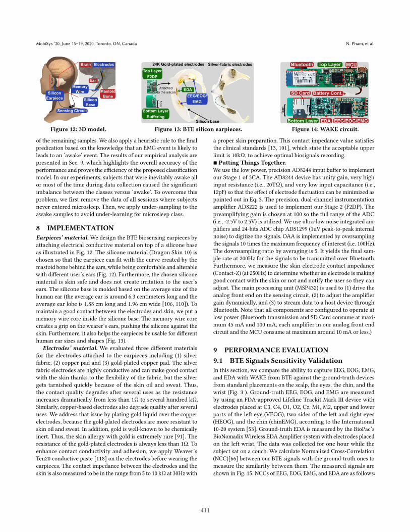
In WAKE, each sensor data (EEG/EOG/EMG, and EDA) is pre-processed at the host device corresponding to their own characteris-tics before putting it into the signal analyzing procedure. We showthe examples of changes in those signals between microsleep andawake states in Fig. 11. We apply to all sensor data the notch filter
409
WAKE: A Behind-the-ear Wearable System for Microsleep Detection MobiSys ’20, June 15–19, 2020, Toronto, ON, Canada
Figure 11: Signals captured by WAKE during the transition between awake and microsleep.
to remove 50/60Hz power line interference, linear trend removal toavoid DC drift, and outlier filters to remove spikes and ripples.
Collecting EEG/EOG/EMG signals. WAKE’s mixed-biosignalsinclude EEG, EOG, and EMG, which are in the frequency rangeof 4-35 Hz, 0.1-10 Hz, and 10-100 𝐻𝑧 respectively [48]. We applydifferent bandpass filters to split the mixed BTE biosignals intothe signals at the frequency range of interest. In particular, weextract wakefulness-related EEG bands (i.e 𝜃 , 𝛼 , and 𝛽 waves) using4-8 Hz, 8-12 Hz, 12-35 Hz bandpass filters, respectively. We extracthorizontal EOG (hEOG) for eye movement and vertical EOG (vEOG)for eye blink using 0.3-10 Hz filters [69]. A 10-100Hz bandpass filterand a median filter are then applied to the mixed signals to extractthe EMG band and get rid of spikes and other excessive components.
Collecting EDA signal. EDA signal is the superposition of twodifferent components, skin conductance response (SCR) and skinconductance level (SCL) at the frequency range of 0.05-1.5 Hz and0-0.05 Hz, respectively [124]. Even though EDA signals have fastresponses, they are very slow to decline to baseline. Thus, if anotherresponse happens right after the first response, the signal level willincrease even more [4]. Thus, frequency filtering is not effective toseparate EDA signal. To address this, we employ an non-negativedeconvolution technique proposed in [5] to decompose EDA intoSCR and SCL components.
7 ALGORITHMS
EMG active events detection: Microsleep appears when the bodyis relaxed. A strong EMG signal can have significant power across allfrequency bands of interest (discussed in Sec. 3). It will contaminateour BTE EEG and EOG signals rendering them unusable. We detectthe active event based on the sum of all frequency bands in thespectrogram. For each data signal, we use the first 10 seconds asthe ground-based noise. Any data whose total spectrum energy is10% larger than that of ground-based is an active event.
Feature Extraction: We divide the collected time series datafrom each source into fixed-size epochs. Then, selected features areextracted from each epoch to be used for classification.
Temporal features: This category includes typical features used inthe literature for time series data analysis in the temporal domain,namely mean, variance, min, max, hjorth, skewness, and kurtosis.In microsleep detection, EOG, EMG, and EDA signals are oftenanalyzed in the time domain due to their considerable variation inamplitude and lack of distinctive frequency patterns [84]. Those sixtemporal features are extracted from each of hEOG, vEOG, EMG,and EDA signals for a total of 24 temporal features. We use waveletdecomposition for the hEOG signal to extract saccade features [115],
namely mean velocity, maximum velocity, mean acceleration, max-imum acceleration, and range amplitude. Eyeblink features [69],namely blink amplitude, mean amplitudes, peak closing velocity,peak opening velocity, mean closing velocity, and closing time areextracted from the vEOG signal.
Spectral features: The spectral features are extracted to analyzethe characteristics of the EEG signal because brainwaves are gener-ally available in discrete frequency ranges at different stages [52].Those features include the ratio of powers, absolute powers, 𝜃/𝛽 ,𝛼/𝛽 , 𝜃/𝛼 , and 𝜃/(𝛽+𝛼). Accordingly, 14 features are extracted fromeach channel of EEG providing 28 spectral features in total.
Non-linear features: Bioelectrical signals show various complexbehaviors with nonlinear properties. In particular, the chaotic pa-rameters of EEG can be used for microsleep detection. The discrimi-nant ability of nonlinear analyses of EEG dynamics is demonstratedthrough the measures of complexity such as correlation dimension,Lyapunov exponent, entropy, fractal dimension, etc. [62], with thelast two features proven to be most informative. In this study, we ex-tract these two non-linear features for each of the two EEG channels(a total of four features).
Feature Selection: When all features are used altogether, irrel-evant correlated features or feature redundancy can degrade theperformance. Therefore, we adopt three feature selection methods,including Recursive Feature Elimination (RFE), L1-based, and tree-based feature selection to select the set of most relevant featuresout of 76 of them. RFE [15] is a greedy optimization algorithm thatremoves the features whose deletion will have the least effect ontraining error. L1-based feature selection [65] is used for linearmodels, including Logistic Regression and SVM. In our linear mod-els, we use the L1 norm to remove features with zero coefficients.Finally, the feature importance ranking generated by the tree-basedmodel [30] is used for eliminating the irrelevant descriptors.
Microsleep Classification: Various classification methods fromSupport VectorMachine (SVM), Linear Discriminant Analysis (LDA),Logistic Regression (LR), Decision Tree (DT) to ensemble methodslike RandomForest or AdaBoost have been proposed in the literaturefor awake and microsleep classification, each shown to be effectivein specific settings [59, 98]. To cope with the high complexity ofour collected signals, we developed a hierarchical stack of threebase classifiers. Our hierarchical model consists of a Random Forestclassifier (with 50 estimators) in the first layer, Adaboost classifier(with 50 tree estimators) in the second layer, and SVM (with RBFkernel) in the last layer. Specifically, for the first two layers, we onlykeep the predictions with high probabilities (> 0.7) and transfer therest of samples to the next layer. In the last layer, SVM classifies all
410
MobiSys ’20, June 15–19, 2020, Toronto, ON, Canada N. Pham, et al.
Silicon
Earpiece
Sensing Circuit
Silicon
Base
ElectrodesBrain
Ear
Mastoid
Bone
Memory
Wire
Figure 12: 3D model.
Silver-fabric electrodes
Silicon base
EEG/EOG/
EMG
24K Gold-plated electrodes
EDA
Bottom Layer
Buffering
Top Layer
F2DP
Attached
to the silicon
1cm
Figure 13: BTE silicon earpieces.
Bluetooth MCU
SD Card
EDA
Top Layer
Bottom Layer
Battery Cont.
EEG/EOG/EMG
1cm
Figure 14: WAKE circuit.
of the remaining samples. We also apply a heuristic rule to the finalpredication based on the knowledge that an EMG event is likely toleads to an ‘awake’ event. The results of our empirical analysis arepresented in Sec. 9, which highlights the overall accuracy of theperformance and proves the efficiency of the proposed classificationmodel. In our experiments, subjects that were inevitably awake allor most of the time during data collection caused the significantimbalance between the classes versus ‘awake’. To overcome thisproblem, we first remove the data of all sessions where subjectsnever entered microsleep. Then, we apply under-sampling to theawake samples to avoid under-learning for microsleep class.
8 IMPLEMENTATION
Earpieces’ material.We design the BTE biosensing earpieces byattaching electrical conductive material on top of a silicone baseas illustrated in Fig. 12. The silicone material (Dragon Skin 10) ischosen so that the earpiece can fit with the curve created by themastoid bone behind the ears, while being comfortable and alterablewith different user’s ears (Fig. 12). Furthermore, the chosen siliconematerial is skin safe and does not create irritation to the user’sears. The silicone base is molded based on the average size of thehuman ear (the average ear is around 6.3 centimeters long and theaverage ear lobe is 1.88 cm long and 1.96 cm wide [106, 110]). Tomaintain a good contact between the electrodes and skin, we put amemory wire core inside the silicone base. The memory wire corecreates a grip on the wearer’s ears, pushing the silicone against theskin. Furthermore, it also helps the earpieces be usable for differenthuman ear sizes and shapes (Fig. 13).
Electrodes’ material. We evaluated three different materialsfor the electrodes attached to the earpieces including (1) silverfabric, (2) copper pad and (3) gold-plated copper pad. The silverfabric electrodes are highly conductive and can make good contactwith the skin thanks to the flexibility of the fabric, but the silvergets tarnished quickly because of the skin oil and sweat. Thus,the contact quality degrades after several uses as the resistanceincreases dramatically from less than 1Ω to several hundred kΩ.Similarly, copper-based electrodes also degrade quality after severaluses. We address that issue by plating gold liquid over the copperelectrodes, because the gold-plated electrodes are more resistant toskin oil and sweat. In addition, gold is well-known to be chemicallyinert. Thus, the skin allergy with gold is extremely rare [91]. Theresistance of the gold-plated electrodes is always less than 1Ω. Toenhance contact conductivity and adhesion, we apply Weaver’sTen20 conductive paste [118] on the electrodes before wearing theearpieces. The contact impedance between the electrodes and theskin is also measured to be in the range from 5 to 10 kΩ at 30Hz with
a proper skin preparation. This contact impedance value satisfiesthe clinical standards [13, 101], which state the acceptable upperlimit is 10kΩ, to achieve optimal biosignals recording.■ Putting Things Together.
We use the low power, precision AD8244 input buffer to implementour Stage 1 of 3CA. The AD8244 device has unity gain, very highinput resistance (i.e., 20TΩ), and very low input capacitance (i.e.,12pF) so that the effect of electrode fluctuation can be minimized aspointed out in Eq. 3. The precision, dual-channel instrumentationamplifier AD8222 is used to implement our Stage 2 (F2DP). Thepreamplifying gain is chosen at 100 so the full range of the ADC(i.e., -2.5V to 2.5V) is utilized. We use ultra-low noise integrated am-plifiers and 24-bits ADC chip ADS1299 (1uV peak-to-peak internalnoise) to digitize the signals. OAA is implemented by oversamplingthe signals 10 times the maximum frequency of interest (i.e. 100Hz).The downsampling ratio by averaging is 5. It yields the final sam-ple rate at 200Hz for the signals to be transmitted over Bluetooth.Furthermore, we measure the skin-electrode contact impedance(Contact-Z) (at 250Hz) to determine whether an electrode is makinggood contact with the skin or not and notify the user so they canadjust. The main processing unit (MSP432) is used to (1) drive theanalog front end on the sensing circuit, (2) to adjust the amplifiergain dynamically, and (3) to stream data to a host device throughBluetooth. Note that all components are configured to operate atlow power (Bluetooth transmission and SD Card consume at maxi-mum 45 mA and 100 mA, each amplifier in our analog front endcircuit and the MCU consume at maximum around 10 mA or less.)
9 PERFORMANCE EVALUATION
9.1 BTE Signals Sensitivity Validation
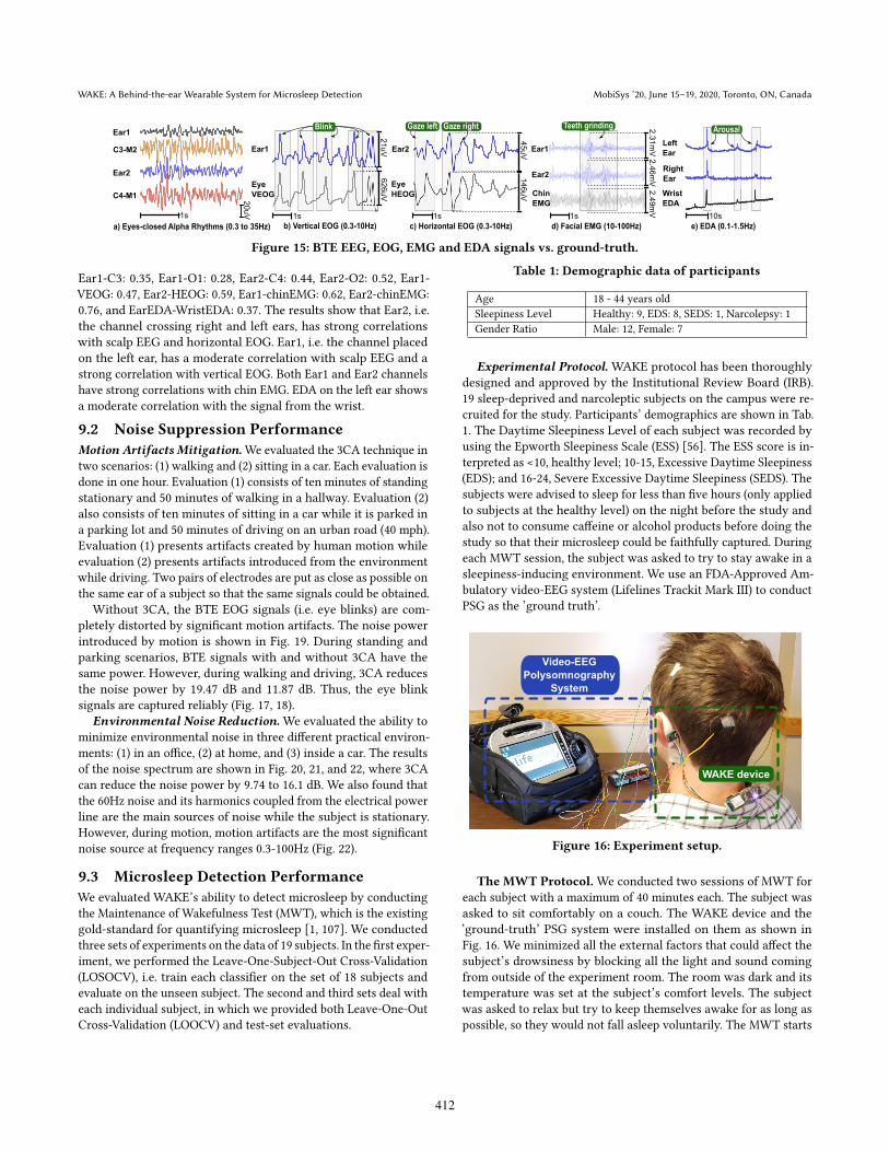
In this section, we compare the ability to capture EEG, EOG, EMG,and EDA with WAKE from BTE against the ground-truth devicesfrom standard placements on the scalp, the eyes, the chin, and thewrist (Fig. 3 ). Ground-truth EEG, EOG, and EMG are measuredby using an FDA-approved Lifeline Trackit Mark III device withelectrodes placed at C3, C4, O1, O2, Cz, M1, M2, upper and lowerparts of the left eye (VEOG), two sides of the left and right eyes(HEOG), and the chin (chinEMG), according to the International10-20 system [53]. Ground-truth EDA is measured by the BioPac’sBioNomadixWireless EDA Amplifier system with electrodes placedon the left wrist. The data was collected for one hour while thesubject sat on a couch. We calculate Normalized Cross-Correlation(NCC)[66] between our BTE signals with the ground-truth ones tomeasure the similarity between them. The measured signals areshown in Fig. 15. NCCs of EEG, EOG, EMG, and EDA are as follows:
411
WAKE: A Behind-the-ear Wearable System for Microsleep Detection MobiSys ’20, June 15–19, 2020, Toronto, ON, Canada
Ear1
C3-M2
C4-M1
1s
20uV
Ear1
Eye
VEOG
21uV
626uV
Ear2
Eye
HEOG
45uV
146uV
Ear2
Ear1
Chin
EMG
2.31mV2.46mV2.49mV
ArousalTeeth grindingGaze left Gaze rightBlink
Ear2
a) Eyes-closed Alpha Rhythms (0.3 to 35Hz) b) Vertical EOG (0.3-10Hz) c) Horizontal EOG (0.3-10Hz) d) Facial EMG (10-100Hz) e) EDA (0.1-1.5Hz)
1s 1s 1s 10s
Right
Ear
Left
Ear
Wrist
EDA
Figure 15: BTE EEG, EOG, EMG and EDA signals vs. ground-truth.
Ear1-C3: 0.35, Ear1-O1: 0.28, Ear2-C4: 0.44, Ear2-O2: 0.52, Ear1-VEOG: 0.47, Ear2-HEOG: 0.59, Ear1-chinEMG: 0.62, Ear2-chinEMG:0.76, and EarEDA-WristEDA: 0.37. The results show that Ear2, i.e.the channel crossing right and left ears, has strong correlationswith scalp EEG and horizontal EOG. Ear1, i.e. the channel placedon the left ear, has a moderate correlation with scalp EEG and astrong correlation with vertical EOG. Both Ear1 and Ear2 channelshave strong correlations with chin EMG. EDA on the left ear showsa moderate correlation with the signal from the wrist.
9.2 Noise Suppression Performance
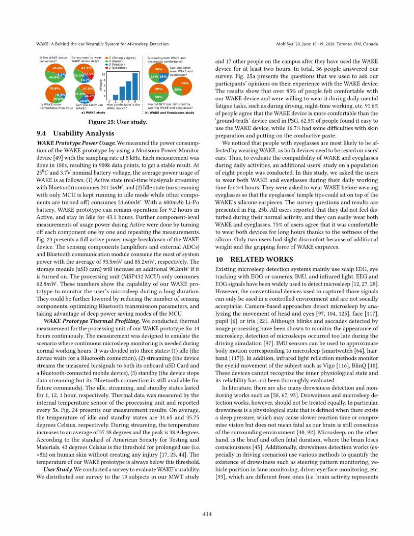
Motion Artifacts Mitigation.We evaluated the 3CA technique intwo scenarios: (1) walking and (2) sitting in a car. Each evaluation isdone in one hour. Evaluation (1) consists of ten minutes of standingstationary and 50 minutes of walking in a hallway. Evaluation (2)also consists of ten minutes of sitting in a car while it is parked ina parking lot and 50 minutes of driving on an urban road (40 mph).Evaluation (1) presents artifacts created by human motion whileevaluation (2) presents artifacts introduced from the environmentwhile driving. Two pairs of electrodes are put as close as possible onthe same ear of a subject so that the same signals could be obtained.
Without 3CA, the BTE EOG signals (i.e. eye blinks) are com-pletely distorted by significant motion artifacts. The noise powerintroduced by motion is shown in Fig. 19. During standing andparking scenarios, BTE signals with and without 3CA have thesame power. However, during walking and driving, 3CA reducesthe noise power by 19.47 dB and 11.87 dB. Thus, the eye blinksignals are captured reliably (Fig. 17, 18).
Environmental Noise Reduction.We evaluated the ability tominimize environmental noise in three different practical environ-ments: (1) in an office, (2) at home, and (3) inside a car. The resultsof the noise spectrum are shown in Fig. 20, 21, and 22, where 3CAcan reduce the noise power by 9.74 to 16.1 dB. We also found thatthe 60Hz noise and its harmonics coupled from the electrical powerline are the main sources of noise while the subject is stationary.However, during motion, motion artifacts are the most significantnoise source at frequency ranges 0.3-100Hz (Fig. 22).
9.3 Microsleep Detection Performance
We evaluated WAKE’s ability to detect microsleep by conductingthe Maintenance of Wakefulness Test (MWT), which is the existinggold-standard for quantifying microsleep [1, 107]. We conductedthree sets of experiments on the data of 19 subjects. In the first exper-iment, we performed the Leave-One-Subject-Out Cross-Validation(LOSOCV), i.e. train each classifier on the set of 18 subjects andevaluate on the unseen subject. The second and third sets deal witheach individual subject, in which we provided both Leave-One-OutCross-Validation (LOOCV) and test-set evaluations.
Table 1: Demographic data of participants
Age 18 - 44 years old
Sleepiness Level Healthy: 9, EDS: 8, SEDS: 1, Narcolepsy: 1
Gender Ratio Male: 12, Female: 7
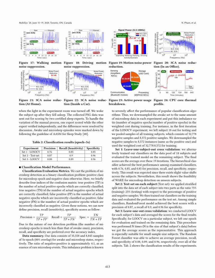
Experimental Protocol. WAKE protocol has been thoroughlydesigned and approved by the Institutional Review Board (IRB).19 sleep-deprived and narcoleptic subjects on the campus were re-cruited for the study. Participants’ demographics are shown in Tab.1. The Daytime Sleepiness Level of each subject was recorded byusing the Epworth Sleepiness Scale (ESS) [56]. The ESS score is in-terpreted as <10, healthy level; 10-15, Excessive Daytime Sleepiness(EDS); and 16-24, Severe Excessive Daytime Sleepiness (SEDS). Thesubjects were advised to sleep for less than five hours (only appliedto subjects at the healthy level) on the night before the study andalso not to consume caffeine or alcohol products before doing thestudy so that their microsleep could be faithfully captured. Duringeach MWT session, the subject was asked to try to stay awake in asleepiness-inducing environment. We use an FDA-Approved Am-bulatory video-EEG system (Lifelines Trackit Mark III) to conductPSG as the ’ground truth’.
Video-EEG
Polysomnography
System
WAKE device
Figure 16: Experiment setup.
The MWT Protocol. We conducted two sessions of MWT foreach subject with a maximum of 40 minutes each. The subject wasasked to sit comfortably on a couch. The WAKE device and the’ground-truth’ PSG system were installed on them as shown inFig. 16. We minimized all the external factors that could affect thesubject’s drowsiness by blocking all the light and sound comingfrom outside of the experiment room. The room was dark and itstemperature was set at the subject’s comfort levels. The subjectwas asked to relax but try to keep themselves awake for as long aspossible, so they would not fall asleep voluntarily. The MWT starts
412
MobiSys ’20, June 15–19, 2020, Toronto, ON, Canada N. Pham, et al.
Standing Walking
WalkingStanding
Raw Filtered
[w/o 3CA]
[w/ 3CA]
-40
-20
0
20
40
60
-20
0
20
40
60
Am
plit
ude (
uV
)
0 2 4 6 8 10 12 14 16 18
Time (sec)
Figure 17: Walking motion
noise suppression.
0 2 4 6 8 10 12 14 16 18
Time (sec)
-40
-20
0
20
40
60
-20
0
20
40
60
Am
plit
ude (
uV
)
[w/o 3CA]
Parking Driving
Parking Driving
[w/ 3CA]
Raw Filtered
Figure 18: Driving motion
noise suppression.
Signal Power (0.3-100Hz)
w/o 3CAw/ 3CA
Motion noise
reduction
19.47 dB
11.87 dB
0
10
15
20
25
30
35
40
5
Standing Walking Parking Driving
Pow
er
(dB
)
Activity/Scenario
Figure 19: Motion noise power
reduction.
Figure 20: 3CA noise reduc-
tion (In an Office).
Figure 21: 3CA noise reduc-
tion (At Home).
Figure 22: 3CA noise reduc-
tion (Inside a Car).
93.5mW
85.2mW62.8mW
90.2mW
Sensing
(Amplifiers,
ADCs)
Communication
(Bluetooth module)
Processing
(MSP432 MCU)
Storage
(uSD Card)
Figure 23: Active power usage
breakdown.
720 780 8400 60 120
Time (minutes)
30
32
34
36
38
40
Tem
pe
ratu
re (
oC
)
...
10h
RawTrend
//...
...//...
StreamingIdle Standby
Figure 24: CPU core thermal
profile.
when the light in the experiment room was turned off. We wokethe subject up after they fell asleep. The collected PSG data wassent out for scoring by two certified sleep experts. To handle thevariation of the manual process, one expert scored while the otherexpert verified independently, and the differences were resolved bydiscussion. Awake and microsleep episodes were marked down byfollowing the guideline of AASM for Sleep Study [48].
Table 2: Classification results (epoch=5s)
Experiment Precision Recall (Sensitivity) Specificity
Set 1 - LOSOCV 0.76 0.85 0.85
Set 2 - Test-set 0.87 0.9 0.96
Set 3 - LOOCV 0.88 0.89 0.96
■ Classification Model Performance.
Classification EvaluationMetrics.We cast the problem of mi-crosleep detection as a binary classification problem: positive classfor microsleep epoch and negative class otherwise. Here, we brieflydescribe four indices of the confusion matrix: true positive (TP) isthe number of actual positive epochs which are correctly classified;true negative (TN) id the number of actual negative epochs whichare correctly classified; false positive (FP) is the number of actualnegative epochs which are incorrectly classified as positive; falsenegative (FN) is the number of actual positive epochs which areincorrectly classified as negative. Given these notions, we can nowdefine precision, recall (sensitivity), specificity scores as follow:
Precision =
𝑇𝑃
𝑇𝑃 + 𝐹𝑃; Recall =
𝑇𝑃
𝑇𝑃 + 𝐹𝑁; Spec. =
𝑇𝑁
𝑇𝑁 + 𝐹𝑃
Due to the nature of our detection problem (the number of mi-crosleep epochs is much less than that of awake ones), precision,recall, and specificity are preferred over the accuracy index.
Data summary. Our data consists of 35,558 and 8,845 samplesof 5s-epoch (80% overlap) for awake and microsleep states, respec-tively. The ratio of negative:positive is approximately 4:1, as anessence of rare microsleep events. This imbalance problem is known
to severely affect the performance of popular classification algo-rithms. Thus, we downsampled the awake set to the same amountof microsleep data in each experiment and put this imbalance ra-tio (number of negative epochs/number of positive epochs) in theweighted cost during training. For instance, in the first iterationof the LOSOCV experiment, we left subject 18 out for testing andwe pooled samples of all training subjects, which consists of 32,778negative samples and 8,572 positive samples. We downsampled thenegative samples to 8,572 instances (same as the positive one) andused the weighted cost of 32,778:8,572 for training.
Set 1: Leave-one-subject-out cross validation: we alterna-tively trained our classifiers on the data pool of 18 subjects andevaluated the trained model on the remaining subject. The finalscores are the average over these 19 iterations. The hierarchical clas-sifier achieved the best performance among examined classifiers,with 0.76, 0.85, and 0.85 for precision, recall, and specificity, respec-tively. This result was expected since there exists slight value-shiftsacross the subjects. Nevertheless, this result shows the feasibilityof WAKE for microsleep detection on unseen subjects.
Set 2: Test-set on each subject (Test-set): we applied stratifiedsplit into the data set of each subject into two parts as the ratio 75%(training): 25% (testing) with respect to the percentage of positiveand negative samples.We then trained our classifiers on the trainingdata and evaluated the performance on the test set. Among simpleclassifiers, RandomForest model achieved the best scores with aprecision of 0.87, a recall of 0.9, and 0.96 for specificity.
Set 3: Leave-one-out cross validation: we conducted LOOCVfor each subject’s data and averaged the scores for the final results.Specifically, for LOOCV on a particular subject, we left one epochfor evaluation and trained on the remaining data. This procedurewas performed N times (N is the size of that subject’s data) beforewe got the average scores as the representative. This approachis especially suitable for small sample-size subjects. The RandomForest classifier was able to achieve an average precision, recall,and specificity of 0.88, 0.89, and 0.96, respectively, over all of thesubjects. Tab. 2 shows the classification results of the experiments.
413
WAKE: A Behind-the-ear Wearable System for Microsleep Detection MobiSys ’20, June 15–19, 2020, Toronto, ON, Canada
1 2 53 4
2
4
6
8
10
How comfortable is the
WAKE device? Can you easily use
WAKE?
Do you want to wear
WAKE device daily?
Is WAKE more
comfortable than PSG?
Is the WAKE device
convenient?5 (Strongly Agree)4 (Agree)3 (Neutral)2 (Disagree)
37.5%
25.0%
20.8%
26.7%
41.7%
29.2%
16.7%
12.5%
70.8%
20.8%
8.3%
45.8%
45.8%8.3%
#People
50%
25% 25%
75%
25%50%
50%
Is wearing both WAKE and
eyeglasses comfortable?
a) WAKE study b) WAKE and Eyeglasses study
Can you easily
wear WAKE and
eyeglasses?
You did NOT feel disturbed by
wearing WAKE and eyeglasses?
Figure 25: User study.
9.4 Usability Analysis
WAKE Prototype Power Usage.Wemeasured the power consump-tion of the WAKE prototype by using a Monsoon Power Monitordevice [49] with the sampling rate at 5 kHz. Each measurement wasdone in 180s, resulting in 900k data points, to get a stable result. At250𝐶 and 3.7V nominal battery voltage, the average power usage ofWAKE is as follows: (1) Active state (real-time biosignals streamingwith Bluetooth) consumes 241.5𝑚𝑊 , and (2) Idle state (no streamingwith only MCU is kept running in idle mode while other compo-nents are turned off) consumes 51.60𝑚𝑊 . With a 600𝑚𝐴ℎ Li-Pobattery, WAKE prototype can remain operation for 9.2 hours inActive, and stay in Idle for 43.1 hours. Further component-levelmeasurements of usage power during Active were done by turningoff each component one by one and repeating the measurements.Fig. 23 presents a full active power usage breakdown of the WAKEdevice. The sensing components (amplifiers and external ADCs)and Bluetooth communication module consume the most of systempower with the average of 93.5𝑚𝑊 and 85.2𝑚𝑊 , respectively. Thestorage module (uSD card) will increase an additional 90.2𝑚𝑊 if itis turned on. The processing unit (MSP432 MCU) only consumes62.8𝑚𝑊 . These numbers show the capability of our WAKE pro-totype to monitor the user’s microsleep during a long duration.They could be further lowered by reducing the number of sensingcomponents, optimizing Bluetooth transmission parameters, andtaking advantage of deep power saving modes of the MCU.
WAKE Prototype Thermal Profiling. We conducted thermalmeasurement for the processing unit of our WAKE prototype for 14hours continuously. The measurement was designed to emulate thescenario where continuous microsleep monitoring is needed duringnormal working hours. It was divided into three states: (1) idle (thedevice waits for a Bluetooth connection), (2) streaming (the devicestreams the measured biosignals to both its onboard uSD Card anda Bluetooth-connected mobile device), (3) standby (the device stopsdata streaming but its Bluetooth connection is still available forfuture commands). The idle, streaming, and standby states lastedfor 1, 12, 1 hour, respectively. Thermal data was measured by theinternal temperature sensor of the processing unit and reportedevery 5s. Fig. 24 presents our measurement results. On average,the temperature of idle and standby states are 31.65 and 35.75degrees Celsius, respectively. During streaming, the temperatureincreases to an average of 37.38 degrees and the peak is 38.9 degrees.According to the standard of American Society for Testing andMaterials, 43 degrees Celsius is the threshold for prolonged use (i.e.>8h) on human skin without creating any injury [17, 25, 44]. Thetemperature of our WAKE prototype is always below this threshold.
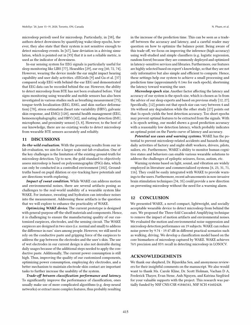
User Study.We conducted a survey to evaluateWAKE’s usability.We distributed our survey to the 19 subjects in our MWT study
and 17 other people on the campus after they have used the WAKEdevice for at least two hours. In total, 36 people answered oursurvey. Fig. 25a presents the questions that we used to ask ourparticipants’ opinions on their experience with the WAKE device.The results show that over 85% of people felt comfortable withour WAKE device and were willing to wear it during daily mentalfatigue tasks, such as during driving, night-time working, etc. 91.6%of people agree that the WAKE device is more comfortable than the‘ground-truth’ device used in PSG. 62.5% of people found it easy touse the WAKE device, while 16.7% had some difficulties with skinpreparation and putting on the conductive paste.
We noticed that people with eyeglasses are most likely to be af-fected by wearingWAKE, as both devices need to be rested on users’ears. Thus, to evaluate the compatibility of WAKE and eyeglassesduring daily activities, an additional users’ study on a populationof eight people was conducted. In this study, we asked the usersto wear both WAKE and eyeglasses during their daily workingtime for 3-4 hours. They were asked to wear WAKE before wearingeyeglasses so that the eyeglasses’ temple tips could sit on top of theWAKE’s silicone earpieces. The survey questions and results arepresented in Fig. 25b. All users reported that they did not feel dis-turbed during their normal activity, and they can easily wear bothWAKE and eyeglasses. 75% of users agree that it was comfortableto wear both devices for long hours thanks to the softness of thesilicon. Only two users had slight discomfort because of additionalweight and the gripping force of WAKE earpieces.
10 RELATEDWORKS
Existing microsleep detection systems mainly use scalp EEG, eyetracking with EOG or cameras, IMU, and infrared light. EEG andEOG signals have been widely used to detect microsleep [12, 27, 28].However, the conventional devices used to captured those signalscan only be used in a controlled environment and are not sociallyacceptable. Camera-based approaches detect microsleep by ana-lyzing the movement of head and eyes [97, 104, 125], face [117],pupil [6] or iris [22]. Although blinks and saccades detected byimage processing have been shown to monitor the appearance ofmicrosleep, detection of microsleeps occurred too late during thedriving simulation [97]. IMU sensors can be used to approximatebody motion corresponding to microsleep (smartwatch [64], hair-band [117]). In addition, infrared light reflection methods monitorthe eyelid movement of the subject such as Vigo [116], BlinQ [10].These devices cannot recognize the inner physiological state andits reliability has not been thoroughly evaluated.
In literature, there are also many drowsiness detection and mon-itoring works such as [58, 67, 93]. Drowsiness and microsleep de-tection works, however, should not be treated equally. In particular,drowsiness is a physiological state that is defined when there existsa sleep pressure, which may cause slower reaction time or compro-mise vision but does not mean fatal as our brain is still consciousof the surrounding environment [40, 92]. Microsleep, on the otherhand, is the brief and often fatal duration, where the brain losesconsciousness [45]. Additionally, drowsiness detection works (es-pecially in driving scenarios) use various methods to quantify theexistence of drowsiness such as steering pattern monitoring, ve-hicle position in lane monitoring, driver eye/face monitoring, etc.[93], which are different from ones (i.e. brain activity represents
414
MobiSys ’20, June 15–19, 2020, Toronto, ON, Canada N. Pham, et al.
microsleep period) used for microsleep. Particularly, in [58], theauthors detect drowsiness by quantifying wake/sleep epochs, how-ever, they also state that their system is not sensitive enough todetect microsleep events. In [67], lane deviation in a driving simu-lation, which is pointed out in [93] that it is not a reliable metric, isused as the indicator of drowsiness.
In-ear sensing system for EEG signals is particularly useful forsleep monitoring like LIBS [77], Hearables [29], ear-eeg [60, 72, 74].However, wearing the device inside the ear might impact hearingcapability and user daily activities. cEEGrids [9] and Gu et al. [37]compared scalp EEG with behind-the-ear EEG and demonstratedthat EEG data can be recorded behind the ear. However, the abilityto detect microsleep from BTE has not been evaluated before. Vitalsigns monitoring using wearable and mobile sensors has also beeninvestigated in various studies such as breathing measurement [75],tongue-teeth localization (EEG, EMG, and skin surface deforma-tion) [78], stress estimation (heart rate variability (HRV), galvanicskin response, and EMG) [120], mental health management (EEG,hemoencephalography, and HRV) [42], and eating detection (IMU,microphone, and proximity sensor) [3, 8]. However, to the best ofour knowledge, there are no existing works to detect microsleepfrom wearable BTE sensors accurately and reliably.
11 DISCUSSIONS
In-the-wild evaluation. With the promising results from our in-lab evaluation, we aim for a larger scale out-lab evaluation. One ofthe key challenges is the limitation of the existing ground-truth formicrosleep detection. Up to now, the gold standard to objectivelyassess microsleep is based on polysomnographic (PSG) data, whichcan only be conducted in a controlled environment [102]. Ground-truths based on pupil dilation or eye-tracking have potentials andare directions worth exploring.
Impact of sweat condition.While WAKE can address motionand environmental noises, there are several artifacts posing aschallenges to the real-world usability of a wearable system likeWAKE. For instance, sweating and hydration can introduce noisesinto the measurement. Addressing these artifacts is the questionthat we will explore to enhance the practicality of WAKE.
Optimizing WAKE device. The current prototype is designedwith general-purpose off-the-shelf materials and components. Hence,it is challenging to ensure the manufacturing quality of our cus-tomized earpieces, electrodes, and the sensing circuit. The WAKEearpieces are designed in two sizes (i.e. normal and small) to addressthe difference in ears’ sizes among people. However, we still need torely on the conductive paste and gripping force of the earpieces toaddress the gap between the electrodes and the user’s skin. The useof wet electrodes in our current design is also not desirable duringdaily usages because of the additional steps needed to apply the con-ductive paste. Additionally, The current power consumption is stillhigh. Thus, improving the quality of our customized components,optimizing power consumption, employing dry electrodes, and abetter mechanism to maintain electrode-skin contact are importanttasks to further increase the usability of the system.
Trade-off between classification performance and latency.
To significantly improve the performance of classification, onesusually make use of more complicated algorithms (e.g. deep neuralnetworks) or extract more complex features, thus probably resulting
in the increase of the prediction time. This can be seen as a trade-off between the accuracy and latency, and a careful reader mayquestion on how to optimize the balance point. Being aware ofthis trade-off, we focus on improving the inference (high accuracy)using well-studied and simple classifiers (e.g. logistic regression,random forest) because they are commonly deployed and optimizedin latency-sensitive services and libraries. Furthermore, our featuresare highly selected based on expert’s knowledge, so that they are notonly informative but also simple and efficient to compute. Hence,these settings help our system to achieve a small processing andprediction time (approximately 0.1𝑚𝑠 for each epoch), shorteningthe latency toward warning the user.
Microsleep epoch size. Another factor affecting the latency andaccuracy of our system is the epoch size, which is chosen as 5s fromthe advice of our sleep experts and based on previous study [12, 27].Specifically, [12] points out that epoch size can vary between 4 and10s without any degradation while the other study [27] points outthat 5s epoch yields the best detection accuracy. Too short epochsmay prevent optimal features to be extracted from the signals. Witha 5s epoch setting, our model shows a good prediction accuracywith a reasonably low detection latency, which probably indicatesan optimal point on the Pareto curve of latency and accuracy.
Potential use cases and warning systems. WAKE has the po-tential to prevent microsleep-related accidents and hazards duringdaily activities of factory and night-shift workers, drivers, pilots,sailors, etc. Furthermore, WAKE’s ability to monitor human cogni-tive states and behaviors can enable various wearable solutions toaddress the challenges of epileptic seizures, focus, autism, etc.
Warning systems based on light, sound, and vibration are widelyemployed in literature and commercialized systems [6, 23, 31, 71,116]. They could be easily integrated with WAKE to provide warn-ings to the users. Furthermore, recent advancements in non-invasivebrain stimulation techniques [34, 35] could provide a new directionon preventing microsleep without the need for a warning alarm.
12 CONCLUSION
We presented WAKE, a novel compact, lightweight, and sociallyacceptable wearable device to detect microsleep from behind theears. We proposed the Three-fold Cascaded Amplifying techniqueto remove the impact of motion artifacts and environmental noises.We evaluated the motion and environmental noise suppression andmicrosleep detection performance on 19 subjects. WAKE can reducenoise power by 9.74 - 19.47 dB in different practical scenarios suchas walking, driving. We develop a classification model based on thecore biomarkers of microsleep captured by WAKE. WAKE achieves76% precision and 85% recall in detecting microsleep in LOSOCV.
ACKNOWLEDGEMENTS
We thank our shepherd, Dr. Rijurekha Sen, and anonymous review-ers for their insightful comments on the manuscript. We also wouldwant to thank Ms. Carole Kline, Dr. Scott Holman, Vachan D A,Frederick Thayer, Evan Stene, Anh Nguyen, and Katrina Siegfriedfor your valuable supports with the project. This research was par-tially funded by NSF CNS/CSR #1846541, NSF SCH #1602428.
415
WAKE: A Behind-the-ear Wearable System for Microsleep Detection MobiSys ’20, June 15–19, 2020, Toronto, ON, Canada
REFERENCES[1] A. M. Anniss, A. Young, and D. M. O’Driscoll. Importance of urinary drug
screening in the multiple sleep latency test and maintenance of wakefulnesstest. Journal of Clinical Sleep Medicine, 12(12):1633ś1640, 2016.
[2] G. Ballou. Handbook for sound engineers. Taylor & Francis, 2013.[3] A. Bedri, R. Li, M. Haynes, R. P. Kosaraju, I. Grover, T. Prioleau, M. Y. Beh,
M. Goel, T. Starner, and G. Abowd. Earbit: using wearable sensors to detecteating episodes in unconstrained environments. Proceedings of the ACM oninteractive, mobile, wearable and ubiquitous technologies, 1(3):37, 2017.
[4] M. Benedek and C. Kaernbach. A continuous measure of phasic electrodermalactivity. Journal of neuroscience methods, 190(1):80ś91, 2010.
[5] M. Benedek and C. Kaernbach. Decomposition of skin conductance data bymeans of nonnegative deconvolution. Psychophysiology, 47(4):647ś658, 2010.
[6] L. M. Bergasa, J. Nuevo, M. A. Sotelo, R. Barea, andM. E. Lopez. Real-time systemfor monitoring driver vigilance. IEEE Transactions on Intelligent TransportationSystems, 7(1):63ś77, 2006.
[7] S. Berman, J. O’neill, S. Fears, G. Bartzokis, and E. D. London. Abuse of am-phetamines and structural abnormalities in the brain. Annals of the New YorkAcademy of Sciences, 1141(1):195ś220, 2008.
[8] S. Bi, T. Wang, N. Tobias, J. Nordrum, S. Wang, G. Halvorsen, S. Sen, R. Peterson,K. Odame, K. Caine, et al. Auracle: Detecting eating episodes with an ear-mounted sensor. Proceedings of the ACM on Interactive, Mobile, Wearable andUbiquitous Technologies, 2(3):1ś27, 2018.
[9] M. G. Bleichner and S. Debener. Concealed, unobtrusive ear-centered eegacquisition: ceegrids for transparent eeg. Frontiers in human neuroscience, 11:163,2017.
[10] BlinQ. Blinq system. https://tinyurl.com/yxlkcsr5. [Online; accessed Mar 28,2019].
[11] W. A. Broughton and R. J. Broughton. Psychosocial impact of narcolepsy. Sleep,17(suppl_8):S45śS49, 1994.
[12] A. B. Buriro, R. Shoorangiz, S. J. Weddell, and R. D. Jones. Predicting microsleepstates using eeg inter-channel relationships. IEEE Transactions on Neural Systemsand Rehabilitation Engineering, 26(12):2260ś2269, 2018.
[13] T. P. R. Center. Procedure manual for polysomnography. https://tinyurl.com/yc9ptdjz. [Online; accessed Apr 21, 2020].
[14] A. A. Centers. Narcolepsy and How Substance Abuse Effects It, 2018. https://americanaddictioncenters.org/co-occurring-disorders/narcolepsy.
[15] X. Chen and J. C. Jeong. Enhanced recursive feature elimination. In SixthInternational Conference on Machine Learning and Applications (ICMLA 2007),pages 429ś435, Dec 2007.
[16] Y. M. Chi and G. Cauwenberghs. Wireless non-contact eeg/ecg electrodes forbody sensor networks. In 2010 International Conference on Body Sensor Networks,pages 297ś301. IEEE, 2010.
[17] I. E. Commission. Electrotechnical equipment - temperatures of touchable hotsurfaces. 2010.
[18] N. S. Council. Fatigue − You’re More Than Just Tired, 2019. https://www.nsc.org/work-safety/safety-topics/fatigue.
[19] I. Daly, M. Billinger, R. Scherer, and G. Müller-Putz. On the automated removalof artifacts related to head movement from the eeg. IEEE Transactions on neuralsystems and rehabilitation engineering, 21(3):427ś434, 2013.
[20] D. Dawson, A. C. Reynolds, H. P. Van Dongen, and M. J. Thomas. Determiningthe likelihood that fatigue was present in a road accident: a theoretical reviewand suggested accident taxonomy. Sleep medicine reviews, 2018.
[21] R. Dodel, H. Peter, T. Walbert, A. Spottke, C. Noelker, K. Berger, U. Siebert, W. H.Oertel, K. Kesper, H. F. Becker, et al. The socioeconomic impact of narcolepsy.Sleep, 27(6):1123ś1128, 2004.
[22] T. D’Orazio, M. Leo, C. Guaragnella, and A. Distante. A visual approach fordriver inattention detection. Pattern Recognition, 40(8):2341ś2355, 2007.
[23] M. Flores, J. Armingol, and A. de la Escalera. Driver drowsiness warning systemusing visual information for both diurnal and nocturnal illumination conditions.EURASIP journal on advances in signal processing, 2010(1):438205, 2010.
[24] R. Fog. Stereotyped and non-stereotyped behaviour in rats induced by variousstimulant drugs. Psychopharmacologia, 14(4):299ś304, 1969.
[25] A. S. for Testing and Materials. Astm c1055 - 03 standard guide for heatedsystem surface conditions that produce contact burn injuries. 2014.
[26] P. M. Fuller, J. J. Gooley, and C. B. Saper. Neurobiology of the sleep-wake cycle:sleep architecture, circadian regulation, and regulatory feedback. Journal ofbiological rhythms, 21(6):482ś493, 2006.
[27] M. Golz, A. Schenka, F. Haselbeck, and M. P. Pauli. Inter-individual variabilityof eeg features during microsleep events. Current Directions in BiomedicalEngineering, 5(1):13ś16, 2019.
[28] M. Golz, D. Sommer, M. Holzbrecher, and T. Schnupp. Detection and predictionof driver’s microsleep events. In Proc 14th Int Conf Road Safety on Four Continents,volume 11. Citeseer, 2007.
[29] V. Goverdovsky, W. von Rosenberg, T. Nakamura, D. Looney, D. J. Sharp, C. Pa-pavassiliou, M. J. Morrell, and D. P. Mandic. Hearables: Multimodal physiologicalin-ear sensing. Scientific reports, 7(1):6948, 2017.
[30] K. Grabczewski and N. Jankowski. Feature selection with decision tree criterion.page 6 pp., 12 2005.
[31] R. Grace and S. Steward. Drowsy driver monitor and warning system. 2001.[32] H. Gray. Gray’s anatomy: with original illustrations by Henry Carter. Arcturus
Publishing, 2009.[33] S. L. Greene, F. Kerr, and G. Braitberg. Amphetamines and related drugs of
abuse. Emergency Medicine Australasia, 20(5):391ś402, 2008.[34] N. Grossman. Modulation without surgical intervention. Science, 361(6401):461ś
462, 2018.[35] N. Grossman, D. Bono, N. Dedic, S. B. Kodandaramaiah, A. Rudenko, H.-J. Suk,
A. M. Cassara, E. Neufeld, N. Kuster, L.-H. Tsai, et al. Noninvasive deep brainstimulation via temporally interfering electric fields. Cell, 169(6):1029ś1041,2017.
[36] B. Grundlehner and V. Mihajlović. Ambulatory eeg monitoring. 2019.[37] Y. Gu, E. Cleeren, J. Dan, K. Claes, W. Van Paesschen, S. Van Huffel, and B. Hun-
yadi. Comparison between scalp eeg and behind-the-ear eeg for developmentof a wearable seizure detection system for patients with focal epilepsy. Sensors,18(1):29, 2018.
[38] T. Guardian. Google Glass security failings may threaten owner’s pri-vacy. https://www.theguardian.com/technology/2013/may/01/google-glass-security-privacy-risk.
[39] C. Guilleminault, M. Billiard, J. Montplaisir, and W. C. Dement. Altered statesof consciousness in disorders of daytime sleepiness. Journal of the neurologicalsciences, 26(3):377ś393, 1975.
[40] C. Guilleminault and S. N. Brooks. Excessive daytime sleepiness: a challengefor the practising neurologist. Brain, 124(8):1482ś1491, 2001.
[41] J. T. Gwin, K. Gramann, S. Makeig, and D. P. Ferris. Removal of movementartifact from high-density eeg recorded during walking and running. Journal ofneurophysiology, 103(6):3526ś3534, 2010.
[42] U. Ha, Y. Lee, H. Kim, T. Roh, J. Bae, C. Kim, and H.-J. Yoo. A wearable EEG-HEG-HRV multimodal system with simultaneous monitoring of tES for mental healthmanagement. IEEE transactions on biomedical circuits and systems, 9(6):758ś766,2015.
[43] M. Hafner, M. Stepanek, J. Taylor, W. M. Troxel, and C. Van Stolk. Why sleepmattersÐthe economic costs of insufficient sleep: a cross-country comparativeanalysis. Rand health quarterly, 6(4), 2017.
[44] A. Q. Han. Thermal management and safety regulation of smart watches. In 201615th IEEE Intersociety Conference on Thermal and Thermomechanical Phenomenain Electronic Systems (ITherm), pages 939ś944. IEEE, 2016.
[45] L. Higgins and B. Fette. Drowsy driving. 2012.[46] J. Horne, L. Reyner, and P. Barrett. Driving impairment due to sleepiness is
exacerbated by low alcohol intake. Occupational and environmental medicine,60(9):689ś692, 2003.
[47] J. C. Huhta and J. G. Webster. 60-hz interference in electrocardiography. IEEETransactions on Biomedical Engineering, (2):91ś101, 1973.
[48] C. Iber and C. Iber. The AASMmanual for the scoring of sleep and associated events:rules, terminology and technical specifications, volume 1. American Academy ofSleep Medicine Westchester, IL, 2007.
[49] M. S. Inc. Power monitor. https://www.msoon.com/high-voltage-power-monitor. [Online; accessed Apr 21, 2020].
[50] T. Independent. Google Glass will make ’privacy impossible’ warn ’Stop TheCyborgs’ campaigners. https://tinyurl.com/vphjxrv.
[51] Investopedia. How and Why Google Glass Failed. https://www.investopedia.com/articles/investing/052115/how-why-google-glass-failed.asp.
[52] B. T. Jap, S. Lal, P. Fischer, and E. Bekiaris. Using eeg spectral components toassess algorithms for detecting fatigue. Expert Systems with Applications, 36(2,Part 1):2352 ś 2359, 2009.
[53] H. H. Jasper. The ten-twenty electrode system of the international federation.Electroencephalogr. Clin. Neurophysiol., 10:370ś375, 1958.
[54] E. Jedari, R. Rashidzadeh, M. Mirhassani, and M. Ahmadi. Two-electrode ecgmeasurement circuit using a feed forward cmrr enhancement method. In 2017IEEE 30th Canadian Conference on Electrical and Computer Engineering (CCECE),pages 1ś4. IEEE, 2017.
[55] P. Jennum, S. Knudsen, and J. Kjellberg. The economic consequences of nar-colepsy. Journal of Clinical Sleep Medicine, 5(03):240ś245, 2009.
[56] M. W. Johns. A new method for measuring daytime sleepiness: the epworthsleepiness scale. sleep, 14(6):540ś545, 1991.
[57] R. Juszkiewicz. Achieving a Fully Differential Output Using Single-Ended Instru-mentation Amplifiers, 2019. https://www.analog.com/en/analog-dialogue/raqs/raq-issue-161.html.
[58] W. Karlen. Adaptive wake and sleep detection for wearable systems. Technicalreport, EPFL, 2009.
[59] R. N. Khushaba, S. Kodagoda, S. Lal, and G. Dissanayake. Driver drowsinessclassification using fuzzy wavelet-packet-based feature-extraction algorithm.IEEE Transactions on Biomedical Engineering, 58(1):121ś131, Jan 2011.
[60] P. Kidmose, D. Looney, and D. P. Mandic. Auditory evoked responses fromear-eeg recordings. In Engineering in Medicine and Biology Society (EMBC), 2012Annual International Conference of the IEEE, pages 586ś589. IEEE, 2012.
416
MobiSys ’20, June 15–19, 2020, Toronto, ON, Canada N. Pham, et al.
[61] S. Labs. Improving ADC Resolution by Oversampling and Averaging, 2013. https://www.silabs.com/documents/public/application-notes/an118.pdf.
[62] L. lan Chen, Y. Zhao, J. Zhang, and J. zhong Zou. Automatic detection ofalertness/drowsiness from physiological signals using wavelet-based nonlinearfeatures and machine learning. Expert Systems with Applications, 42(21):7344 ś7355, 2015.
[63] D. S. Lauderdale, K. L. Knutson, L. L. Yan, K. Liu, and P. J. Rathouz. Sleepduration: how well do self-reports reflect objective measures? the cardia sleepstudy. Epidemiology (Cambridge, Mass.), 19(6):838, 2008.
[64] B.-L. Lee, B.-G. Lee, and W.-Y. Chung. Standalone wearable driver drowsinessdetection system in a smartwatch. IEEE Sensors journal, 16(13):5444ś5451, 2016.
[65] S.-I. Lee, H. Lee, P. Abbeel, and A. Y. Ng. Efficient l1 regularized logistic regres-sion. In AAAI, 2006.
[66] J. Lewis. Fast template matching. 1995. URL http://www. scribblethink.org/Work/nvisionInterface/vi95_lewis. pdf. Cited on, page 6.
[67] C.-T. Lin, C.-J. Chang, B.-S. Lin, S.-H. Hung, C.-F. Chao, and I.-J. Wang. Areal-time wireless brainścomputer interface system for drowsiness detection.IEEE transactions on biomedical circuits and systems, 4(4):214ś222, 2010.
[68] R. G. Lyons. Understanding digital signal processing, 3/E. Pearson EducationIndia, 2004.
[69] J.-X. Ma, L.-C. Shi, and B.-L. Lu. An eog-based vigilance estimation methodapplied for driver fatigue detection. Neuroscience and Biomedical Engineering,2(1):41ś51, 2014.
[70] P. Matsangas and N. Shattuck. 0172 prevalence of insomnia and excessivedaytime sleepiness in us navy sailors. Journal of Sleep and Sleep DisordersResearch, 40(suppl_1):A64śA64, 2017.
[71] Mazda. Driver attention alert. https://www.mazda.com/en/innovation/technology/safety/active_safety/daa/. [Online; accessed Apr 21, 2020].
[72] K. B. Mikkelsen, S. L. Kappel, D. P. Mandic, and P. Kidmose. Eeg recorded fromthe ear: Characterizing the ear-eeg method. Frontiers in neuroscience, 9:438,2015.
[73] V. G. Motti and K. Caine. Users’ privacy concerns about wearables. In Interna-tional Conference on Financial Cryptography and Data Security, pages 231ś244.Springer, 2015.
[74] T. Nakamura, Y. D. Alqurashi, M. J. Morrell, and D. P. Mandic. Automaticdetection of drowsiness using in-ear eeg. In 2018 International Joint Conferenceon Neural Networks (IJCNN), pages 1ś6. IEEE, 2018.
[75] R. Nandakumar, S. Gollakota, and N. Watson. Contactless sleep apnea detectionon smartphones. In Proceedings of the 13th annual international conference onmobile systems, applications, and services, pages 45ś57. ACM, 2015.
[76] N. Network. Narcolepsy Fast Facts, 2013. https://narcolepsynetwork.org/about-narcolepsy/narcolepsy-fast-facts/.
[77] A. Nguyen, R. Alqurashi, Z. Raghebi, F. Banaei-Kashani, A. C. Halbower, andT. Vu. A lightweight and inexpensive in-ear sensing system for automaticwhole-night sleep stage monitoring. In Proceedings of the 14th ACM Conferenceon Embedded Network Sensor Systems CD-ROM, pages 230ś244. ACM, 2016.
[78] P. Nguyen, N. Bui, A. Nguyen, H. Truong, A. Suresh, M. Whitlock, D. Pham,T. Dinh, and T. Vu. Tyth-typing on your teeth: Tongue-teeth localization forhuman-computer interface. In Proceedings of the 16th Annual InternationalConference on Mobile Systems, Applications, and Services, pages 269ś282. ACM,2018.
[79] A. D. Nordin, W. D. Hairston, and D. P. Ferris. Dual-electrode motion artifactcancellation for mobile electroencephalography. Journal of neural engineering,15(5):056024, 2018.
[80] U. D. of Health and H. Services. Types of Sleep Studies. https://tinyurl.com/y232zaac.
[81] A. A. of Sleep Medicine. Economic burden of undiagnosed sleep apnea in U.S. isnearly $150B per year. https://tinyurl.com/yxkfe5zh.
[82] D. of Sleep Medicine at Harvard Medical School. Narcolepsy Medications,2018. http://healthysleep.med.harvard.edu/narcolepsy/treating-narcolepsy/medications.
[83] K. Onikura and K. Iramina. Evaluation of a head movement artifact removalmethod for eeg considering real-time prosessing. In 2015 8th Biomedical Engi-neering International Conference (BMEiCON), pages 1ś4. IEEE, 2015.
[84] S. Özs̃en, S. Günes̃, and S̃. Yosunkaya. Examining the effect of time and frequencydomain features of eeg, eog, and chin emg signals on sleep staging. In 2010 15thNational Biomedical Engineering Meeting, pages 1ś4, April 2010.
[85] J. Pagel. Excessive Daytime Sleepiness, May 2009. https://www.aafp.org/afp/2009/0301/p391.html.
[86] A. Paul, L. N. Boyle, J. Tippin, and M. Rizzo. Variability of driving performanceduring microsleeps. 2005.
[87] M. T. Peiris, R. D. Jones, P. R. Davidson, G. J. Carroll, and P. J. Bones. Frequentlapses of responsiveness during an extended visuomotor tracking task in non-sleep-deprived subjects. Journal of sleep research, 15(3):291ś300, 2006.
[88] R. W. Picard, S. Fedor, and Y. Ayzenberg. Multiple arousal theory and daily-lifeelectrodermal activity asymmetry. Emotion Review, 8(1):62ś75, 2016.
[89] N. Y. post. The revolt against Google ’Glassholes’. https://tinyurl.com/v9ruu6h.
[90] G. R. Poudel, C. R. Innes, P. J. Bones, R.Watts, and R. D. Jones. Losing the struggleto stay awake: divergent thalamic and cortical activity during microsleeps.Human brain mapping, 35(1):257ś269, 2014.
[91] W. Rapson. Skin contact with gold and gold alloys. Contact Dermatitis, 13(2):56ś65, 1985.
[92] C. M. D. W. . R. T. Roehrs, T. Daytime sleepiness and alertness. In Principlesand Practice of Sleep Medicine: Fifth Edition. Elsevier Inc., 2010.
[93] A. Sahayadhas, K. Sundaraj, and M. Murugappan. Detecting driver drowsinessbased on sensors: a review. Sensors, 12(12):16937ś16953, 2012.
[94] T. Sakurai. The neural circuit of orexin (hypocretin): maintaining sleep andwakefulness. Nature Reviews Neuroscience, 8(3):171, 2007.
[95] M. J. Sateia. International classification of sleep disorders. Chest, 146(5):1387ś1394, 2014.
[96] S. Schreyer, J. A. Büttner-Ennever, X. Tang, M. J. Mustari, and A. K. Horn. Orexin-a inputs onto visuomotor cell groups in the monkey brainstem. Neuroscience,164(2):629ś640, 2009.
[97] C. Schwarz, J. Gaspar, T. Miller, and R. Yousefian. The detection of drowsinessusing a driver monitoring system. Traffic injury prevention, 20(sup1):S157śS161,2019.
[98] B. Sen, M. Peker, A. Cavusoglu, and F. V. Celebi. A Comparative Study onClassification of Sleep Stage Based on EEG Signals Using Feature Selection andClassification Algorithms. Journal of Medical Systems, 38(3):1ś21, 2014.
[99] S. H. Sheldon, R. Ferber, and M. H. Kryger. Principles and practice of pediatricsleep medicine. Elsevier Health Sciences, 2005.
[100] A. Simakov and J. Webster. Motion artifact from electrodes and cables. 2010.[101] S. R. Sinha, L. R. Sullivan, D. Sabau, D. S. J. Orta, K. E. Dombrowski, J. J. Halford,
A. J. Hani, F. W. Drislane, and M. M. Stecker. American clinical neurophysiologysociety guideline 1: minimum technical requirements for performing clinicalelectroencephalography. The Neurodiagnostic Journal, 56(4):235ś244, 2016.
[102] J. Skorucak, A. Hertig-Godeschalk, D. R. Schreier, A. Malafeev, J. Mathis, andP. Achermann. Automatic detection of microsleep episodes with feature-basedmachine learning. Sleep, 2019.
[103] C. J. Smith and G. Havenith. Body mapping of sweating patterns in male athletesin mild exercise-induced hyperthermia. European journal of applied physiology,111(7):1391ś1404, 2011.
[104] P. Smith, M. Shah, and N. da Vitoria Lobo. Monitoring head/eye motion fordriver alertness with one camera. In Proceedings 15th International Conferenceon Pattern Recognition. ICPR-2000, volume 4, pages 636ś642. IEEE, 2000.
[105] J. Solaz, J. Laparra-Hernández, D. Bande, N. Rodríguez, S. Veleff, J. Gerpe, andE.Medina. Drowsiness detection based on the analysis of breathing rate obtainedfrom real-time image recognition. Transportation research procedia, 14:3867ś3876, 2016.
[106] P. K. Sullivan, M. J. Brucker, and J. Patel. A morphometric study of the externalear: Age and sex related differences, 2010.
[107] B. Y. Sunwoo, N. Jackson, G. Maislin, I. Gurubhagavatula, C. F. George, and A. I.Pack. Reliability of a single objective measure in assessing sleepiness. Sleep,35(1):149ś158, 2012.
[108] E.-R. Symeonidou, A. Nordin, W. Hairston, and D. Ferris. Effects of cable sway,electrode surface area, and electrode mass on electroencephalography signalquality during motion. Sensors, 18(4):1073, 2018.
[109] K. Takahashi, J.-S. Lin, and K. Sakai. Neuronal activity of orexin and non-orexinwaking-active neurons during wakeśsleep states in the mouse. Neuroscience,153(3):860ś870, 2008.
[110] R. Tan, V. Osman, and G. Tan. Ear size as a predictor of chronological age.Archives of gerontology and geriatrics, 25(2):187ś191, 1997.
[111] M. J. Thorpy and G. Hiller. The medical and economic burden of narcolepsy:implications for managed care. American health & drug benefits, 10(5):233, 2017.
[112] S. A. Tretter. Communication system design using DSP algorithms: with laboratoryexperiments for the TMS320C6713TM DSK. Springer Science & Business Media,2008.
[113] K. Uehli, A. J. Mehta, D. Miedinger, K. Hug, C. Schindler, E. Holsboer-Trachsler,J. D. Leuppi, and N. Künzli. Sleep problems and work injuries: a systematicreview and meta-analysis. Sleep medicine reviews, 18(1):61ś73, 2014.
[114] J. A. Urigüen and B. Garcia-Zapirain. EEG artifact removal − state-of-the-artand guidelines. Journal of neural engineering, 12(3):031001, 2015.
[115] M. Vidal, A. Bulling, and H. Gellersen. Analysing eog signal features for thediscrimination of eye movements with wearable devices. In Proceedings of the 1stinternational workshop on pervasive eye tracking & mobile eye-based interaction,pages 15ś20. ACM, 2011.
[116] Vigo. Vigo smart headset. https://www.wearvigo.com/. [Online; accessed Mar28, 2019].
[117] E. Vural, M. Cetin, A. Ercil, G. Littlewort, M. Bartlett, and J. Movellan. Drowsydriver detection through facial movement analysis. In International Workshopon Human-Computer Interaction, pages 6ś18. Springer, 2007.
[118] Weaver and Company. Ten20 conductive paste. https://www.weaverandcompany.com/products/ten20/. [Online; accessed Apr 21,2020].
417
WAKE: A Behind-the-ear Wearable System for Microsleep Detection MobiSys ’20, June 15–19, 2020, Toronto, ON, Canada
[119] J. Webster. Interference and motion artifact in biopotentials. In IEEE 1977 RegionSix Conference Record, 1977., pages 53ś64. IEEE, 1977.
[120] W. Wen, D. Tomoi, H. Yamakawa, S. Hamasaki, K. Takakusaki, Q. An, Y. Tamura,A. Yamashita, andH. Asama. Continuous estimation of stress using physiologicalsignals during a car race. Psychology, 8(07):978, 2017.
[121] WIRED. I, Glasshole: My Year With Google Glass. https://www.wired.com/2013/12/glasshole/.
[122] J. Xu, S.Mitra, C. VanHoof, R. F. Yazicioglu, and K. A.Makinwa. Active electrodesfor wearable eeg acquisition: Review and electronics design methodology. IEEEreviews in biomedical engineering, 10:187ś198, 2017.
[123] J. Xu, R. F. Yazicioglu, B. Grundlehner, P. Harpe, K. A. Makinwa, and C. Van Hoof.A 160 𝜇W 8-Channel Active Electrode System for EEG Monitoring. IEEE Trans-actions on Biomedical circuits and systems, 5(6):555ś567, 2011.
[124] R. Zangróniz, A. Martínez-Rodrigo, J. Pastor, M. López, and A. Fernández-Caballero. Electrodermal activity sensor for classification of calm/distresscondition. Sensors, 17(10):2324, 2017.
[125] Z. Zhang and J. Zhang. A new real-time eye tracking based on nonlinearunscented kalman filter for monitoring driver fatigue. Journal of Control Theoryand Applications, 8(2):181ś188, 2010.
418