Nevac blad 46-nr4 2008 · vacuümmeetapparatuur serie 2000. Met het grote meetbereik, de hoge...
13
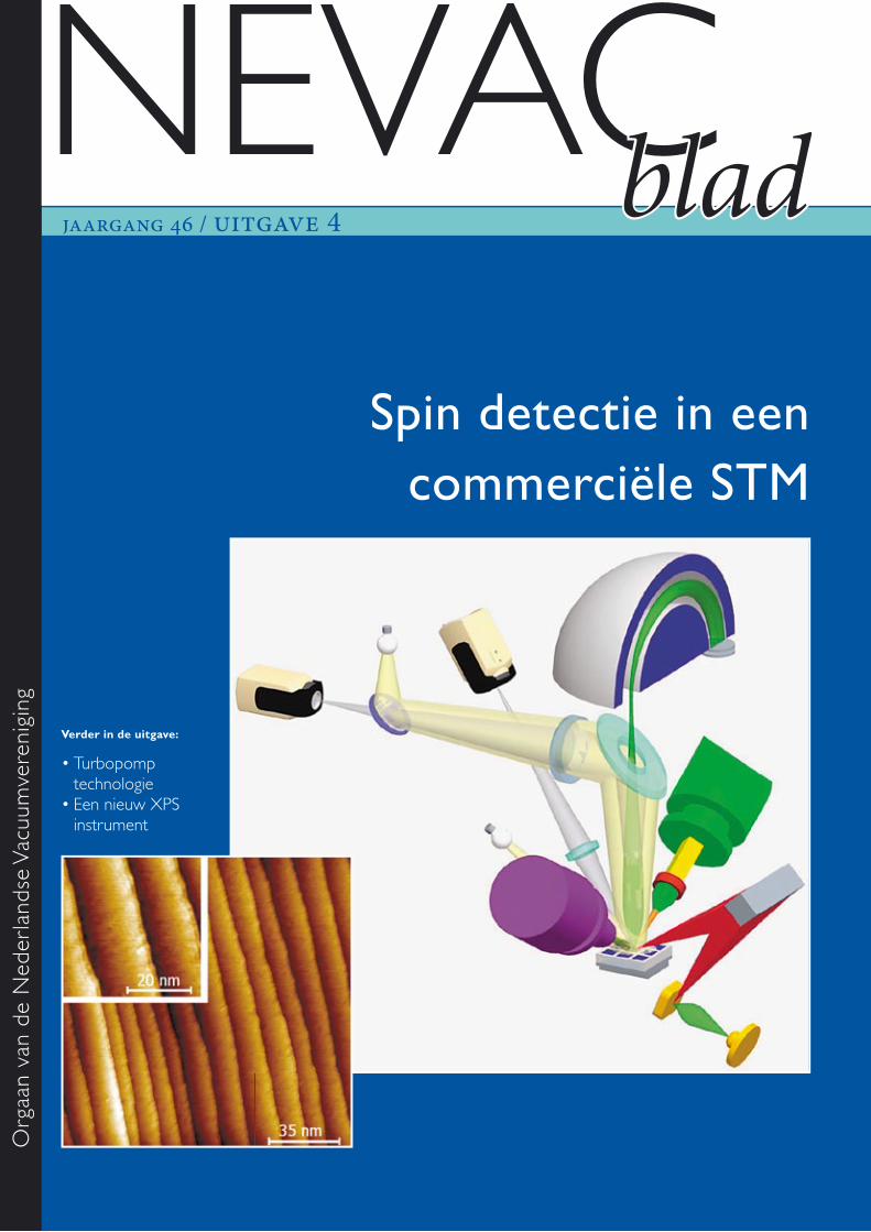
jaargang 46 / uitgave 4 Orgaan van de Nederlandse Vacuumvereniging NEVAC blad Verder in de uitgave: • Turbopomp technologie • Een nieuw XPS instrument Spin detectie in een commerciële STM
Transcript of Nevac blad 46-nr4 2008 · vacuümmeetapparatuur serie 2000. Met het grote meetbereik, de hoge...
jaargang 46 / uitgave 4
Org
aan
van
de N
eder
land
se V
acuu
mve
reni
ging
NEVACblad
Verder in de uitgave:
• Turbopomp technologie• Een nieuw XPS instrument
Spin detectie in een commerciële STM
Alcatel Vacuum Technology · Landzichtweg 60 · 4105 DP CulemborgTel: + 31 (0) 345 478 400 · Fax: +31 (0) 345 531 076 · e-mail: [email protected] · web www.adixen.nl
De AHC 2010 is ADIXENs nieuwe topproduct in de vacuümmeetapparatuur serie 2000. Met het grote meetbereik, de hoge nauwkeurigheid en de uitste-kende reproduceerbaarheid is het de nieuwe stand-aard in zijn klasse.
� Verbeterde nauwkeurigheid bij hoge drukken� Meetbereik van 4 · 10-10 mbar tot 1000 mbar� Kleurendisplay met afpompcurve met
de ACM 2000
Graag sturen wij u informatie over onze producten toe. Maak hiervoor gebruik van de info-voucher. U kunt ons ook bereiken per telefoon, tel.nr. + 31 (0) 345 478 400, of via onze website: www.adixen.nl
�
INFO-VOUCHERBedrijf ....................................................................................
Naam ......................................................................................
Straat .....................................................................................
PC+plaats ...............................................................................
Tel ..................................... Fax .........................................
Stuur mij de volgende brochures toe:
� Vacuüm Meetinstrumenten Serie 2000� AHC 2010 � ACM 2000
� Draaischuifpompen � Heliumlekzoekers� Turbomoleculaire Pompen � Waterstoflekzoekers � Olievrije Vacuümpompen
� Complete Catalogus
An Alcatel-Lucent Company
NIEUW
MAG HET IETS NAUWKEURIGER ZIJN?
september 2008 NEVAC blad 3
Op de voorpaginaHet grote fi guur toont de analytische componenten die aanwezig zijn in het nieuwe XPS apparaat, waarop uitvoerig ingegaan wordt in het derde en laatste artikel van dit blad.
Het kleine fi guur toont een een Wolfraam(110) oppervlak met stapranden na een in situ schoonmaakprocedure, zoals gemeten met een UHV-STM. Dit fi guur komt terug in het eerste artikel van deze uitgave.
Agenda pagina 4
Implementatie van spin... pagina 5
Van Becker’s baffl e tot turbo... pagina 12
K-Alpha, an Exciting New ... pagina 16
Colofon
Redactie Dr. ir. B.J. Kooi
Web-adres www.nevac.nl
Redactiesecretariaat Dr. ir. B.J. KooiRijks Universiteit GroningenApplied PhysicsZernike Institute for Advanced MaterialsNijenborgh 49747 AG Groningentelefoon: 050-3634896e-mail: [email protected]
Adres abonnementenadministratieDr. A.R.H.F. EttemaSPECS Nanotechnology BVDelftechpark 262628 XH Delft, The NetherlandsTelefoon: +31 15 2600406Fax: +31 15 2600405e-mail: [email protected]
AbonnementenBinnenland € 25,- per jaarBuitenland € 35,- per jaar
Advertentie-exploitatie en drukAriëS Grafi sche vormgeving / Ben MobachTorenberglaan 425628 EP EindhovenTelefoon 040 - 242 23 66 / 06 248 60 322e-mail: [email protected]
Grafi sche vormgeving, pre-press en productieAriëS Grafi sche vormgeving / Ben MobachEindhoven
Verschijningstijdstippen 2008Tweede helft februariEerste helft meiTweede helft septemberEerste helft december
DiversenKopij inzenden naar het redactiesecretariaat. Lidmaatschap opgeven bij de ledenadmini-stratie. Abonnementen opgeven bij abonne-mentenadministratie.
Vergoeding kopij Artikelen in het Nederlands van welke aard dan ook over va cuümtechniek en haar toe-passingen worden door de redactie zeer op prijs gesteld. In bepaalde gevallen kan voor artikelen zonder commerciële achtergronden een vergoeding van € 20,- per pagina tekst worden gegeven.
ISSN 0169-9431
VerenigingsgegevensEreledenG. Ikking, Artemisstraat 34, 2624 ZN DelftProf.dr. J. Kistemaker, Jan Steenlaan 27, fl at C2, 3723 BT BilthovenIr. J.H. Makkink, Wilhelminasingel 36, 2641 JD PijnackerProf.dr. J. v.d. Veen, Schubertlaan 8, 1411 HZ NaardenDr.ir. E.P.Th.M. Suurmeijer, Elzenlaan 11, 9321 GL PeizeIr. J. Verhoeven, Kon. Julianaweg 23, 3628 BN KockengenL.G.J.M. Hassink, Stibbe 23, 2421 MR NieuwkoopTh. Mulder, Ambachtsheerelaan 60, 3481 GM Harmelen
BestuurProf.dr. P.M. Koenraad, voorzitter Dr. P.A. Zeijlmans van Emmichoven, vice-voorzitterJ.W.M. van Kessel, secretaris Dr. A.R.H.F. Ettema, penningmeester
Adres secretariaat Jan W.M. van KesselDept. of Solid State Chemistry (Kamer HG 03.616), Faculty of Sciences, Radboud Universiteit Nijmegen, Toernooiveld 1 6525 ED Nijmegen. Telefoon: 024-3653068, e-mail: [email protected]
Adres ledenadministratie p/a Dr. A.R.H.F. EttemaSPECS Nanotechnology BV, Delftechpark 26, 2628 XH Delft, The NetherlandsTelefoon: +31 15 2600406, Fax: +31 15 2600405, e-mail: [email protected]
Inlichtingen over opleidingen en examens Dr.ir. E.P.Th.M. SuurmeijerElzenlaan 11, 9321 GL Peize. Telefoon: 050-5032556, e-mail: [email protected]
Penningmeester NEVAC Postgiro 1851529, o.v.v.: Penningmeester NEVAC, t.a.v. Dr. A.R.H.F. Ettema, Delftechpark 26, 2628 XH Delft
ContributiesContributie € 18,- per jaar Studenten/promovendi € 4,50 per jaarBedrijfsleden € 136,- per jaar
Inhoud
september 2008 NEVAC blad 5 jaargang 46 / uitgave 3
Dit vierde nummer van 2008 bevat een verhaal van een universitaire groep en twee verhalen van bedrijven. Het eerste verhaal, geschreven door Joris Keizer van de Technische Universi-teit Eindhoven, Technische Natuurkunde (Pho-tonics & Semiconductor Nanophysics) gaat over de aanpassingen die nodig zijn voor spin detectie met een commerciële scanning tunne-ling microscope.
Het tweede korte artikel, van de hand van Pie-ter Heidema van Pfeiff er Vacuum GmbH, geeft wat inzicht en beschrijft nieuwe ontwikkelin-gen rond de turbopomp.
Het laatste artikel van Cees Heijboer (Th ermo Fisher Scientifi c) beschrijft een nieuw ontwor-pen en geconstrueerd apparaat voor X-Ray Photoelectron Spectroscopy.
De afgelopen jaren waren de artikelen vrijwel uitsluitend afk omstig uit academische hoek en daarom is het verheugend dat nu weer bijdra-gen vanuit bedrijven zijn geleverd. Er is veel tijd in de redactie van deze artikelen gestoken om ze niet te veel een advertentie te laten wor-den. Hopelijk vindt u de artikelen in dit num-mer weer geslaagd.
Redactioneel
De sluitingsdatum van kopij voor het
eerste nummer van het NEVAC-blad 2009
is 19 januari 2009.
Agenda
13-17 januari 2009The Conference on the Physics and Chemistry of Se-miconductor Interfaces (PCSI-35), Santa Fe, NM, USAVoor meer informatie zie: http://www.pcsiconference.org/
23-24 maart 2009 “Vakuumphysik und Vakuumtechnik”, Dresden, Duits-landVoor meer informatie zie: http://dresden09.dpg-tagungen.de/index.html
16-20 maart 2009APS March meeting, Pittsburg, PA, USAVoor meer informatie zie: http://www.aps.org/meetings/march/index.cfm
22-26 maart 2009The 16th International Conference on Atomic Proces-ses in Plasmas (APIP), Monterey, CA, USAVoor meer informatie zie: http://www.aps.org/meetings/meeting.cfm?name=APIP09
9 april 2009NEVACdag, Leiden, NederlandVoor meer informatie zie: http://www.nevac.nl/
13-17 april 2009Materials Research Society Spring Meeting, San Fran-cisco, CA, USAVoor meer informatie zie: http://www.mrs.org/s_mrs/sec.asp?CID=10891&DID=201200
28-30 april 2009Tenth International Vacuum Electronics Conference - IVEC 2009, Rome, ItaliëVoor meer informatie zie: http://www.congrex.nl/09a01/
9-14 meiSociety of Vacuum Coaters Annual Technical Confe-rence, Santa Clara, CA, USAVoor meer informatie zie: http://www.svc.org/ConferencesExhibits/Technical-Conference-Overview.cfm
26-29 mei53rd International Conference on EIPBN (lithography), San Jose, California, USAVoor meer informatie zie: http://www.avs.org/calendar.popup.aspx?id=545
4 NEVAC blad
Implementatie van spin detectie in een commerciële scanning tunneling microscopeJ.G. Keizer , Photonics & Semiconductor Nanophysics, Technische Natuurkunde, Technische Universiteit Eindhoven, Postbus 513, 5600 MB Eindhoven, [email protected]
In scanning tunneling microscopie (STM) kan het oppervlak van een elektrisch geleidend preparaat worden weergeven met atomaire resolutie. In additie tot een weergave van de lokale ladingsdichtheids toestanden van het oppervlak kunnen ook de lokale magnetische eigenschappen van het oppervlak worden bestudeerd door een STM-tip gevoelig te maken voor de spin van de elektronen in de tunnelstroom. In dit ar-tikel zullen de experimentele aspecten van de implementatie van spin detectie in een commerciële lage temperatuur STM worden belicht.
Scanning tunneling microscopieIn STM wordt een scherpe tip in nabijheid van het te bestuderen oppervlak gebracht. Als de tip zeer dicht bij het oppervlak is, ty-pisch in de orde van een nanometer, kunnen elektronen door de vacuümbarrière van de tip naar het oppervlak tunnelen en visa versa. De statistiek van het quantum mechanisch tunnel eff ect kan worden gestuurd door een bias voltage aan te leggen tussen het op-pervlak en de tip. Met deze bias voltage kan de richting waarin de elektronen tunnelen worden opgelegd wat resulteert in een netto stroom, typische een nanoampère, tussen het oppervlak en de tip. Uitwerking van de quantum mechanische vergelijkingen van een dergelijk oppervlak-tip systeem leert dat de resulterende stroom exponentieel afneemt als functie van de afstand tussen het oppervlak en tip; voor elke Ångström dat de afstand tussen het oppervlak en de tip groter wordt neemt de tunnelstroom een orde van grote af. Daar roosterconstanten typische een grootte hebben van enkele Ångström zal de tun-nelstroom dus hoofdzakelijk door het laatste atoom van de tip stromen. Door de stroom, en dus de afstand, tussen het oppervlak en tip constant te houden met een feedback loop en vervolgens de tip met piëzo actuators over het oppervlak te scannen is mogelijk de structu-rele en elektronische eigenschappen van een geleidend oppervlak op atomaire schaal te bestuderen. Door de tip gevoelig te maken voor de spin van de elektronen in de tunnel-stroom kunnen naast deze twee eigenschap-pen ook de magnetische eigenschappen van een geleidend preparaat worden onderzocht [1]. In principe betekent dit dat de magneti-sche domeinstructuur van een preparaat met atomaire resolutie kan worden onderzocht.
Juist deze atomaire resolutie van spin-pola-rized scanning tunneling microscopie (SP-STM) kan een grote bijdrage leveren aan het beantwoorden van fundamentele vragen over magnetisme op de nanoschaal.
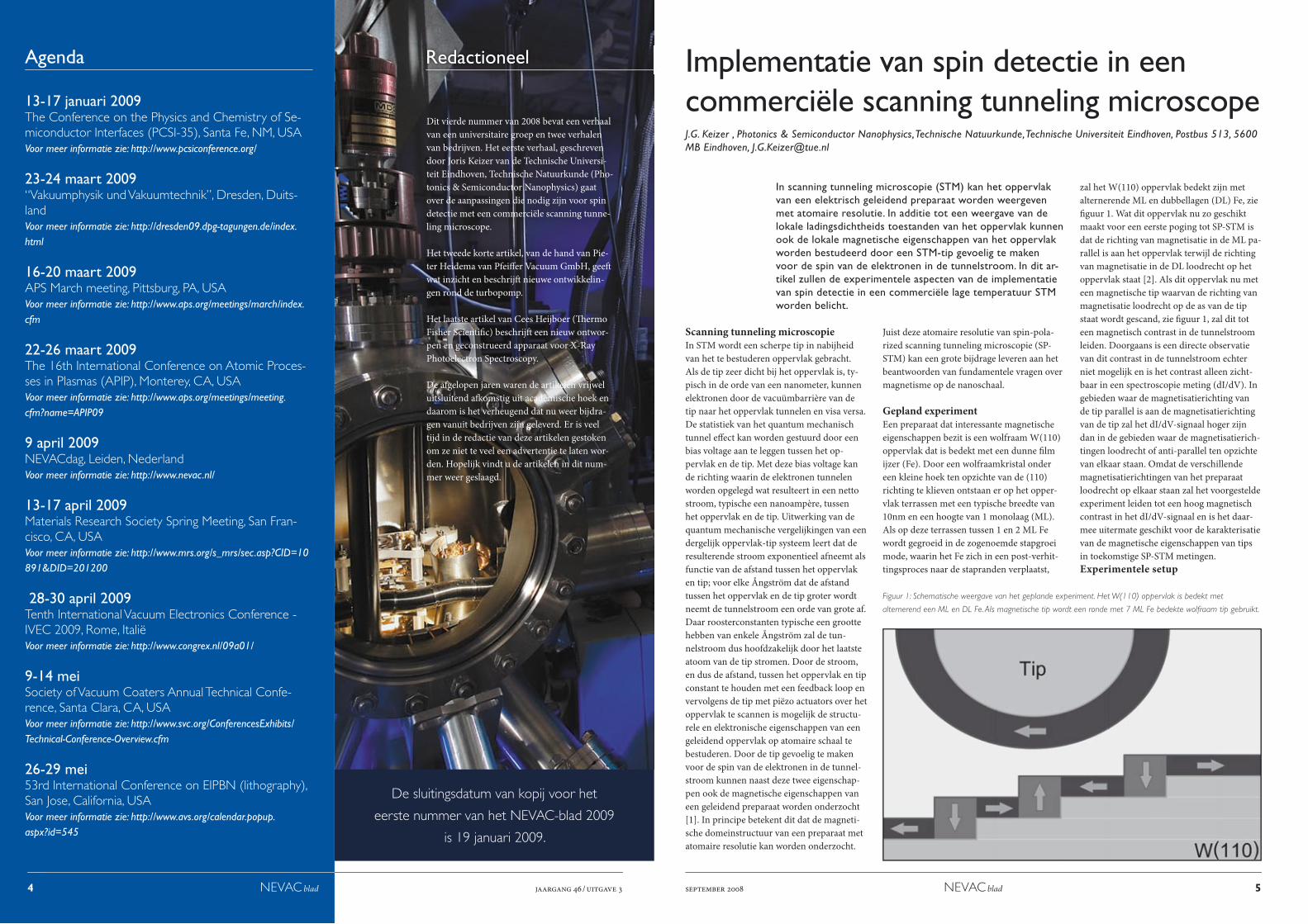
Gepland experimentEen preparaat dat interessante magnetische eigenschappen bezit is een wolfraam W(110) oppervlak dat is bedekt met een dunne fi lm ijzer (Fe). Door een wolfraamkristal onder een kleine hoek ten opzichte van de (110) richting te klieven ontstaan er op het opper-vlak terrassen met een typische breedte van 10nm en een hoogte van 1 monolaag (ML). Als op deze terrassen tussen 1 en 2 ML Fe wordt gegroeid in de zogenoemde stapgroei mode, waarin het Fe zich in een post-verhit-tingsproces naar de stapranden verplaatst,
zal het W(110) oppervlak bedekt zijn met alternerende ML en dubbellagen (DL) Fe, zie fi guur 1. Wat dit oppervlak nu zo geschikt maakt voor een eerste poging tot SP-STM is dat de richting van magnetisatie in de ML pa-rallel is aan het oppervlak terwijl de richting van magnetisatie in de DL loodrecht op het oppervlak staat [2]. Als dit oppervlak nu met een magnetische tip waarvan de richting van magnetisatie loodrecht op de as van de tip staat wordt gescand, zie fi guur 1, zal dit tot een magnetisch contrast in de tunnelstroom leiden. Doorgaans is een directe observatie van dit contrast in de tunnelstroom echter niet mogelijk en is het contrast alleen zicht-baar in een spectroscopie meting (dI/dV). In gebieden waar de magnetisatierichting van de tip parallel is aan de magnetisatierichting van de tip zal het dI/dV-signaal hoger zijn dan in de gebieden waar de magnetisatierich-tingen loodrecht of anti-parallel ten opzichte van elkaar staan. Omdat de verschillende magnetisatierichtingen van het preparaat loodrecht op elkaar staan zal het voorgestelde experiment leiden tot een hoog magnetisch contrast in het dI/dV-signaal en is het daar-mee uitermate geschikt voor de karakterisatie van de magnetische eigenschappen van tips in toekomstige SP-STM metingen.Experimentele setup
Figuur 1: Schematische weergave van het geplande experiment. Het W(110) oppervlak is bedekt met
alternerend een ML en DL Fe. Als magnetische tip wordt een ronde met 7 ML Fe bedekte wolfraam tip gebruikt.
6 NEVAC blad jaargang 46 / uitgave 3 september 2008 NEVAC blad 7
De STM in kwestie is een commercieel ver-krijgbare Omicron Low Temperature STM. Deze STM bestaat uit twee gedeelten: een preparatie compartiment met een basisdruk van 1·10-10 mbar en een STM comparti-ment met een basisdruk van 1·10-11 mbar, zie figuur 2. Om het boven beschreven experiment uit te voeren zijn een aantal addities voor deze STM vereist. Ten eerste moet het W(110) oppervlak grondig schoongemaakt wor-den. Hiervoor is een electron-beam heater ontwikkeld waarmee het wolfraamkristal in situ tot boven de 2200K kan worden ver-hit. Op het met de hoge temperatuur oven schoongemaakte W(110) oppervlak zal vervolgens 1 tot 2 ML Fe worden gegroeid in de zogenaamde stapgroei mode om de alternerende ML en DL Fe te verkrijgen. Voor de depositie van Fe kan één van de Omicron EFM-3 verdampers gebruikt worden waarmee de STM is uitgerust. Als de Fe depositie voltooid is kan door een 5 minuten durende post-verhitting van het wolfraamkristal tot 550K het proces van de stapgroei mode zich voltrekken. Dit post-verhittingsproces wordt in situ uitgevoerd in een standaard Omicron oven waarmee preparaten gecontroleerd tot 1200K kunnen worden verhit. Na deze stap is het wol-fraamkristal klaar voor het experiment en rest nu nog de creatie van een magnetische tip. Deze tip moet, om controle te krijgen
over de richting van magnetisatie van het laatste atoom van de apex ,een kromtestraal hebben met een orde grootte van 100nm. Van een dergelijke tip kan een magnetische tip worden gemaakt door er in situ 7 ML Fe op te dampen wat resulteert in een magne-tisatierichting loodrecht op de symmetrie-as van de tip. In de volgende twee para-grafen zal de gebruikte hoge temperatuur oven en de tip preparatie in detail worden beschreven.
Hoge temperatuur ovenHet geplande SP-STM experiment vereist een zuiver wolfraamkristal dat is ontdaan van zijn oxidelaag en vervuilingen op het oppervlak. Voor dit doel is een hoge tem-peratuur oven ontworpen waarmee het W(110) oppervlak verhit kan worden tot boven de 2200K. Het ontwerp van de oven is schematisch weergeven in figuur 3. De oven, die door een CF35 flens kan worden ingebracht, kan worden geclassificeerd als een elektronen stookoven; een stroom wordt door een filament gestuurd dat elek-tronen emitteert die vervolgens naar de op
een +2kV potentiaal liggende tip worden geaccelereerd. Om de oven en de sample houder te ontzien is er ook een triode op-genomen in het ontwerp. Met deze triode, die op een potentiaal van -300V ligt, kan de elektronenbundel gefocust worden op het W(110) kristal. Zoals te zien is in het explosiefiguur 3b is de oven opgebouwd uit een verscheidenheid aan onderdelen. Het materiaal waar de meeste van deze onder-delen van gemaakt zijn is gekozen om het hoge smeltpunt. De witte spacers zijn gemaakt van alumini-umoxide en isoleren elektrisch de onderde-len van de oven met een verschillende po-tentiaal. De bouten, moeren, afscherming, en triode zijn gemaakt van tantalium en molybdeen. Het centrale blok dat de oven bij elkaar houdt is gemaakt van saffier, wat gekozen is om zowel zijn hoge smeltpunt als zijn elektrisch isolerende eigenschappen. Om extra elektronen vrij te maken uit het filament is hiervoor niet een zuivere wolfraamdraad gebruikt maar een met 1% thorium gedoneerde wolfraamdraad. Het thorium verlaagt de werkfunctie van het wolfraam wat resulteert in een hogere elektronenemissie. Met boven beschreven hoge temperatuur oven is het mogelijk het W(110) oppervlak schoon te maken; in fi-
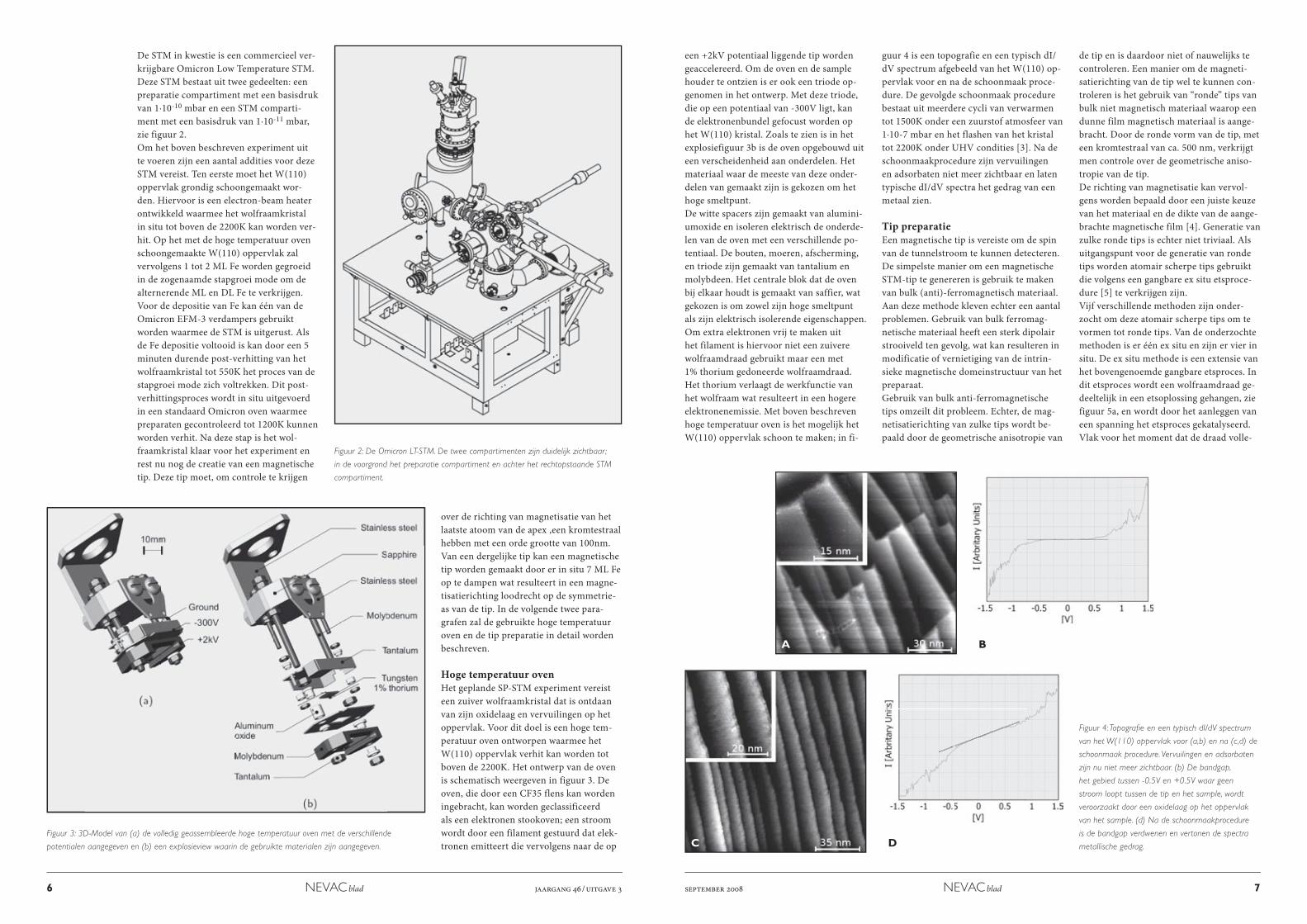
guur 4 is een topografie en een typisch dI/dV spectrum afgebeeld van het W(110) op-pervlak voor en na de schoonmaak proce-dure. De gevolgde schoonmaak procedure bestaat uit meerdere cycli van verwarmen tot 1500K onder een zuurstof atmosfeer van 1·10-7 mbar en het flashen van het kristal tot 2200K onder UHV condities [3]. Na de schoonmaakprocedure zijn vervuilingen en adsorbaten niet meer zichtbaar en laten typische dI/dV spectra het gedrag van een metaal zien. Tip preparatieEen magnetische tip is vereiste om de spin van de tunnelstroom te kunnen detecteren. De simpelste manier om een magnetische STM-tip te genereren is gebruik te maken van bulk (anti)-ferromagnetisch materiaal. Aan deze methode kleven echter een aantal problemen. Gebruik van bulk ferromag-netische materiaal heeft een sterk dipolair strooiveld ten gevolg, wat kan resulteren in modificatie of vernietiging van de intrin-sieke magnetische domeinstructuur van het preparaat. Gebruik van bulk anti-ferromagnetische tips omzeilt dit probleem. Echter, de mag-netisatierichting van zulke tips wordt be-paald door de geometrische anisotropie van
Figuur 2: De Omicron LT-STM. De twee compartimenten zijn duidelijk zichtbaar ;
in de voorgrond het preparatie compartiment en achter het rechtopstaande STM
compartiment.
Figuur 3: 3D-Model van (a) de volledig geassembleerde hoge temperatuur oven met de verschillende
potentialen aangegeven en (b) een explosieview waarin de gebruikte materialen zijn aangegeven.
Figuur 4: Topografi e en een typisch dI/dV spectrum
van het W(110) oppervlak voor (a,b) en na (c,d) de
schoonmaak procedure. Vervuilingen en adsorbaten
zijn nu niet meer zichtbaar. (b) De bandgap,
het gebied tussen -0.5V en +0.5V waar geen
stroom loopt tussen de tip en het sample, wordt
veroorzaakt door een oxidelaag op het oppervlak
van het sample. (d) Na de schoonmaakprocedure
is de bandgap verdwenen en vertonen de spectra
metallische gedrag.
de tip en is daardoor niet of nauwelijks te controleren. Een manier om de magneti-satierichting van de tip wel te kunnen con-troleren is het gebruik van “ronde” tips van bulk niet magnetisch materiaal waarop een dunne film magnetisch materiaal is aange-bracht. Door de ronde vorm van de tip, met een kromtestraal van ca. 500 nm, verkrijgt men controle over de geometrische aniso-tropie van de tip. De richting van magnetisatie kan vervol-gens worden bepaald door een juiste keuze van het materiaal en de dikte van de aange-brachte magnetische film [4]. Generatie van zulke ronde tips is echter niet triviaal. Als uitgangspunt voor de generatie van ronde tips worden atomair scherpe tips gebruikt die volgens een gangbare ex situ etsproce-dure [5] te verkrijgen zijn. Vijf verschillende methoden zijn onder-zocht om deze atomair scherpe tips om te vormen tot ronde tips. Van de onderzochte methoden is er één ex situ en zijn er vier in situ. De ex situ methode is een extensie van het bovengenoemde gangbare etsproces. In dit etsproces wordt een wolfraamdraad ge-deeltelijk in een etsoplossing gehangen, zie figuur 5a, en wordt door het aanleggen van een spanning het etsproces gekatalyseerd. Vlak voor het moment dat de draad volle-
C
A
D
B
8 NEVAC blad jaargang 46 / uitgave 3 september 2008 NEVAC blad 9
Figuur 5: Vier van de vijf
geteste methoden om een
ronde tip te genereren
met bijhorende SEM
afbeeldingen van de tip.
(a) Ex situ etsen. R ≈
200mn. (b) In situ gloeien
van de tip door een ohms
punt kontact. R < 25nm.
(c) In situ smelten van de
tip met de setup voor de
veldemissie. De tip is veel
te stomp, R>10μm, en
bovendien niet uniform
rond. (d) In situ verhitting
van de tip in de hoge
temperatuur oven. R <
50nm.
dig doorgeëtst is breekt deze abrupt op het dunste punt, de zogenaamde drop off, wat resulteert in een atomair scherpe tip. Op het moment van de drop off wordt auto-matisch de aangelegde spanning onderbro-ken. Om nu van de atomair scherpe tip een ronde tip te maken wordt voor een aantal seconden de spanning weer aangelegd zodat de apex van de tip rond geëtst wordt.
Uit figuur 5a wordt meteen duidelijk dat deze ex situ etsmethode resulteert in een mooie ronde tip met een kromtestaal, R, van ca. 200nm. Deze procedure heeft als groot voordeel dat ze zeer reproduceerbaar ronde tips oplevert en bovendien erg een-voudig is; er hoeft alleen maar iets langer door geëtst te worden dan in de gangbare ets procedure. Een groot nadeel is echter dat het een ex situ procedure betreft: er zul-len contaminaties aanwezig zijn op de tip die weer in situ verwijderd moeten worden. Om deze reden is er dan ook gezocht om in situ met dezelfde reproduceerbaarheid zulke ronde tips te creëren.
De eerste in situ methode die onderzocht is het gloeien/smelten van tip apex met be-hulp van een ohms punt kontakt; er wordt een metalen plaat tegen de zijkant van de tip geschoven waar een stroom door wordt gestuurd, zie figuur 5b. Het resultaat is een voor SP-STM doeleinden te scherpe tip met
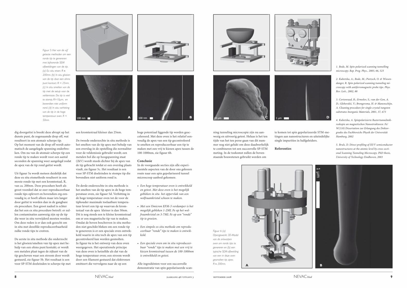
Figuur 6: (a)
Opengewerkt 3D-Model
van de ontworpen
oven om ronde tips te
genereren en (b) een
typische SEM-afbeelding
van een in deze oven
gesmolten tip apex.
R ≈ 200mn.
een kromtestraal kleiner dan 25nm.
De tweede onderzochte in situ methode is het smelten van de tip apex met behulp van een overslag in de opstelling die normaliter voor de veldemissie gebruikt wordt; een metalen bol die op hoogspanning staat (2kV) wordt steeds dichter bij de apex van de tip gebracht totdat er een overslag plaats vindt, zie figuur 5c. Het resultaat is een voor SP-STM doeleinden te stompe tip die bovendien niet uniform rond is.
De derde onderzochte in situ methode is het smelten van de tip apex in de hoge tem-peratuur oven, zie figuur 5d. Verhitting in de hoge temperatuur oven tot de voor de tiphouder maximale toelaatbare tempera-tuur levert een tip op waarvan de krom-testaal van de apex kleiner is dan 50nm. Dit is nog steeds een te kleine kromtestraal om er een magnetische tip van te maken.Omdat de boven beschreven in situ metho-den niet geschikt bleken om een ronde tip te genereren is er een speciale oven ontwik-keld waarin in situ toch de apex van een tip gecontroleerd kan worden gesmolten. In figuur 6a is het ontwerp van deze oven weergegeven. Het operationele principe van deze oven is hetzelfde als dat van de hoge temperatuur oven; een stroom wordt door een filament gestuurd dat elektronen emitteert die vervolgens naar de op een
hoge potentiaal liggende tip worden geac-celereerd. Met deze oven is het relatief een-voudig de apex van een tip gecontroleerd te smelten en reproduceerbaar een tip te maken met een vrij te kiezen apex tussen de 100-1000nm, zie figuur 6b. ConclusieIn de voorgaande secties zijn alle experi-mentele aspecten van de door ons gekozen route naar een spin gepolariseerd tunnel microscoop aanbod gekomen:
• Een hoge temperatuur oven is ontwikkeld en getest. Met deze oven is het mogelijk gebleken in situ het oppervlak van een wolfraamkristal schoon te maken.
• Met een Omicron EFM-3 verdamper is het mogelijk gebleken 1-2ML Fe op het wol-fraamkristal en 3-7ML Fe op een “ronde” tip te groeien.
• Een simpele ex situ methode om reprodu-ceerbaar “ronde” tips te maken is ontwik-keld.
• Een speciale oven om in situ reproduceer-baar “ronde” tips te maken met een vrij te kiezen kromtestraal tussen de 100-1000nm is ontwikkeld en getest.
Alle ingrediënten voor een succesvolle demonstratie van spin gepolariseerde scan-
CA DB
A B
ning tunneling microscopie zijn nu aan-wezig en uitvoerig getest. Helaas is het ten tijde van het ten perse gaan van dit num-mer nog niet gelukt om deze daadwerkelijk te combineren tot een succesvolle SP-STM meting. In de toekomst zullen de boven-staande bouwstenen gebruikt worden om
te komen tot spin gepolarizeerde STM-me-tingen aan nanostructuren en uiteindelijke single impurities in halfgeleiders.
Referenties
1. Bode, M. Spin-polarized scanning tunnelling microscopy. Rep. Prog. Phys., 2003, 66, 523
2. Kubetzka, A.; Bode, M.; Pietzsch, O. & Wiesen-danger, R. Spin-polarized scanning tunneling mi-croscopy with antiferromagnetic probe tips. Phys. Rev. Lett., 2002, 88
3. Cortenraad, R.; Ermolov, S.; van der Gon, A. D.; Glebovskii, V.; Brongersma, H. & Manenschijn, A. Cleaning procedure for single-crystal tungsten substrates Inorganic Materials, 2001, 37, 673
4. Kubetzka, A. Spinpolarisierte Rastertunnelmik-roskopie an magnetischen Nanostrukturen: Fe/W(110) Dissertation zur Erlangung des Doktor-grades des Fachbereichs Physik der Universität Hamburg, 2002
5. Bruls, D. Direct profiling of III/V semiconductor nanostructures at the atomic level by cross-secti-onal Scanning Tunneling Microscopy. PhD thesis, University of Technology Eindhoven, 2003
DeMaCo Holland bv Tel: +31 (0)226 33 21 00 Oester 2 Fax: +31 (0)226 33 21 11 Postbus 4 [email protected] 1723 ZG Noord-Scharwoude www.DeMaCo.nl
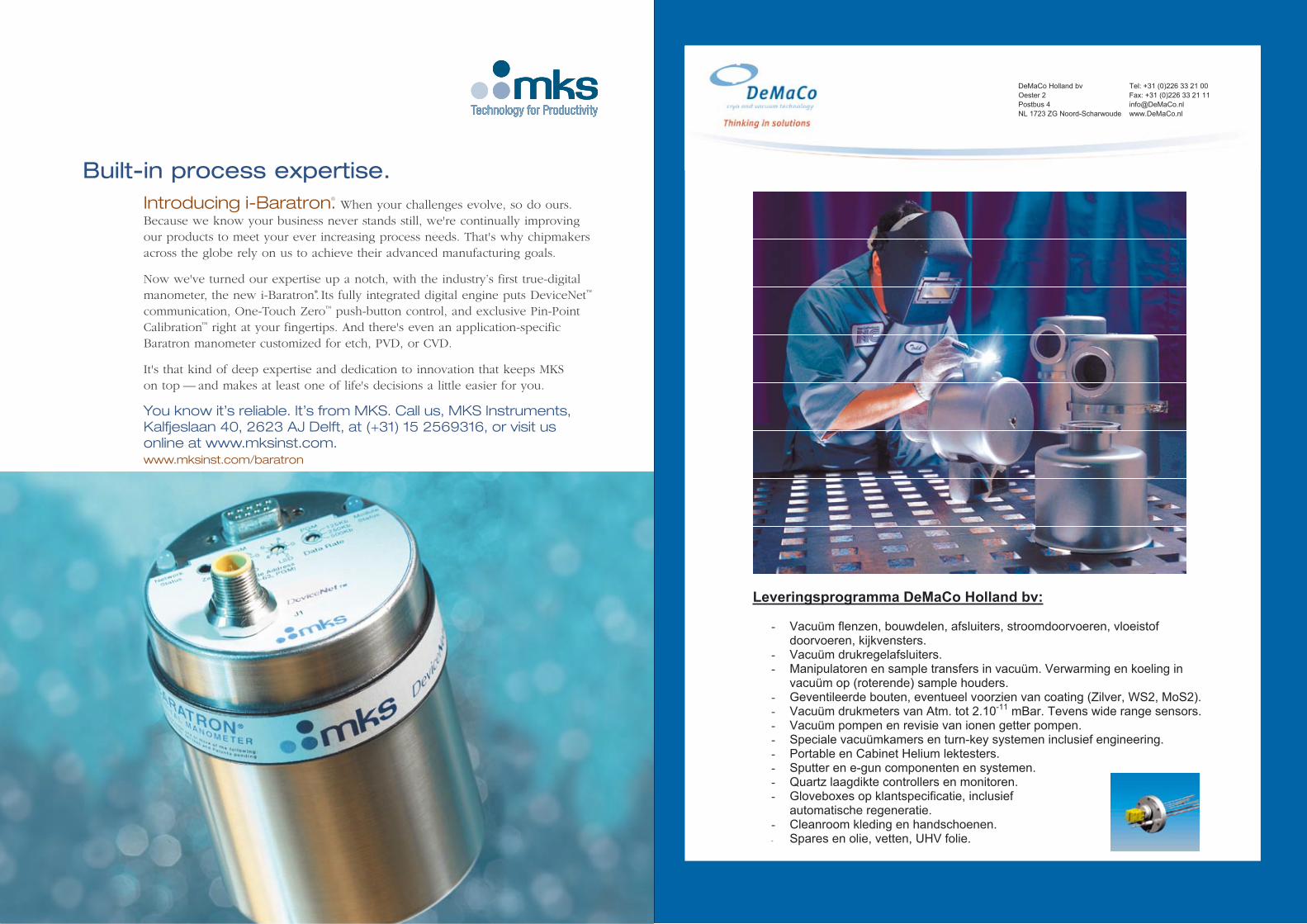
Leveringsprogramma DeMaCo Holland bv:
- Vacuüm flenzen, bouwdelen, afsluiters, stroomdoorvoeren, vloeistof doorvoeren, kijkvensters.
- Vacuüm drukregelafsluiters.- Manipulatoren en sample transfers in vacuüm. Verwarming en koeling in
vacuüm op (roterende) sample houders. - Geventileerde bouten, eventueel voorzien van coating (Zilver, WS2, MoS2). - Vacuüm drukmeters van Atm. tot 2.10-11 mBar. Tevens wide range sensors. - Vacuüm pompen en revisie van ionen getter pompen. - Speciale vacuümkamers en turn-key systemen inclusief engineering. - Portable en Cabinet Helium lektesters. - Sputter en e-gun componenten en systemen.
-
- Quartz laagdikte controllers en monitoren. - Gloveboxes op klantspecificatie, inclusief
automatische regeneratie. - Cleanroom kleding en handschoenen.- Spares en olie, vetten, UHV folie.
�������������� ���������������������
Built-in process expertise.Introducing i-Baratron.® When your challenges evolve, so do ours. Because we know your business never stands still, we're continually improving our products to meet your ever increasing process needs. That's why chipmakersacross the globe rely on us to achieve their advanced manufacturing goals.
Now we've turned our expertise up a notch, with the industry’s first true-digitalmanometer, the new i-Baratron*. Its fully integrated digital engine puts DeviceNet™
communication, One-Touch Zero™ push-button control, and exclusive Pin-PointCalibration™ right at your fingertips. And there's even an application-specific Baratron manometer customized for etch, PVD, or CVD.
It's that kind of deep expertise and dedication to innovation that keeps MKS on top — and makes at least one of life's decisions a little easier for you.
You know it’s reliable. It’s from MKS. Call us, MKS Instruments,Kalfjeslaan 40, 2623 AJ Delft, at (+31) 15 2569316, or visit usonline at www.mksinst.com.www.mksinst.com/baratron
MKS_AD_BARATRON_A4 01-12-2005 14:59 Pagina 1
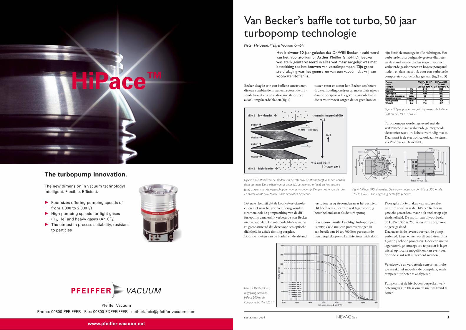
The turbopump innovation.
The new dimension in vacuum technology!Intelligent. Flexible. Efficient.
Four sizes offering pumping speeds of from 1,000 to 2,000 l/sHigh pumping speeds for light gases (H2, He) and heavy gases (Ar, CF4)The utmost in process suitability, resistantto particles
HiPace™
www.pfeiffer-vacuum.net
Pfeiffer Vacuum
Phone: 00800-PFEIFFER · Fax: 00800-FXPFEIFFER · [email protected]
Nevac_HP_groß_Stern_210x297_E_NL.qxd 27.10.2008 11:10 Uhr Seite 1
september 2008 NEVAC blad 13
Van Becker’s baffle tot turbo, 50 jaar turbopomp technologiePieter Heidema, Pfeiffer Vacuum GmbH
Het is alweer 50 jaar geleden dat Dr. Willi Becker hoofd werd van het laboratorium bij Arthur Pfeiffer GmbH. Dr. Becker was sterk geïnteresseerd in alles wat maar mogelijk was met betrekking tot het bouwen van vacuümpompen. Zijn groot-ste uitdaging was het genereren van een vacuüm dat vrij van koolwaterstoffen is.
zijn flexibele montage in alle richtingen. Het verbeterde rotordesign, de grotere diameter en de stand van de bladen zorgen voor een verbeterde gasdoorvoer en hogere pompsnel-heden, en daarnaast ook voor een verbeterde compressie voor de lichte gassen. (fig.2 en 3)
Figuur 3. Specificaties, vergelijking tussen de HiPace
300 en de TMH/U 261 P
Turbopompen worden geleverd met de vertrouwde maar verbeterde geïntegreerde electronica wat dure kabels overbodig maakt. Daarnaast is de electronica ook aan te sturen via Profibus en DeviceNet.
Door gebruik te maken van andere alu-minium soorten is de HiPace™ lichter in gewicht geworden, maar ook sneller op zijn eindsnelheid. De motor van bijvoorbeeld de HiPace 300 is 250 W en deze zorgt voor hogere gasload. Daarnaast is de levensduur van de pomp verlengd. Lagerwissel wordt geadviseerd na 4 jaar bij schone processen. Door een nieuw lagercartridge concept toe te passen is lager-wissel op locatie mogelijk en kan eventueel door de klant zelf uitgevoerd worden.
Vernieuwde en verbeterde sensor technolo-gie maakt het mogelijk de pompdata, zoals temperatuur beter te analyseren.
Pompen met de hierboven besproken ver-beteringen zijn klaar om de nieuwe trend te zetten!
Becker slaagde erin een baffle te construeren die een combinatie is van een roterende drij-vende kracht en een stationaire stator met axiaal-omgekeerde bladen.(fig.1)
Dat naast het feit dat de koolwaterstofmole-culen niet naar het recipient terug konden stromen, ook de pompwerking van de dif-fusiepomp aanzienlijk verbeterde kon Becker niet vermoeden. De roterende bladen waren zo geconstrueerd dat deze voor een optische dichtheid in axiale richting zorgden.Door de hoeken van de bladen en de afstand
Figuur 1. De stand van de bladen van de rotor tov de stator zorgt voor een optisch
dicht systeem. De snelheid van de rotor (v), de geometrie (geo) en het gastype
(gas) zorgen voor de eigenschappen van de turbopomp. De geometrie van de rotor
en stator wordt dmv Monte Carlo simulaties berekend.
tussen rotor en stator kon Becker een betere drukverhouding creëren op moleculair niveau dan de oorspronkelijk geconstrueerde baffle die er voor moest zorgen dat er geen koolwa-
Figuur 2. Pompsnelheid,
vergelijking tussen de
HiPace 300 en de
Compactturbo TMH 261 P
terstoffen terug stroomden naar het recipient. Dit heeft geresulteerd in wat tegenwoordig beter bekend staat als de turbopomp.
Een nieuwe familie krachtige turbopompen is ontwikkeld met een pompvermogen in een bereik van 10 tot 700 liter per seconde. Een dergelijke pomp karakteriseert zich door
Fig. 4. HiPace 300 dimensies. De inbouwmaten van de HiPace 300 en de
TMH/U 261 P zijn nagenoeg hetzelfde gebleven.
Let’s put our effort better together, and we search for improvement.
With your unique contribution we will _
make the difference !_
Benelux Process Begoniastraat 17 ~ 9810 Eke ~ Belgium
Tel +32 (0)9 231 18 64 ~ Fax +32 (0)9 252 23 93 [email protected]
www.benelux-process.com
For detailed information please visit our website
TRIVAC NT”The Cool Generation“
© B
ICO
M_0
9785
.02
11.2
008
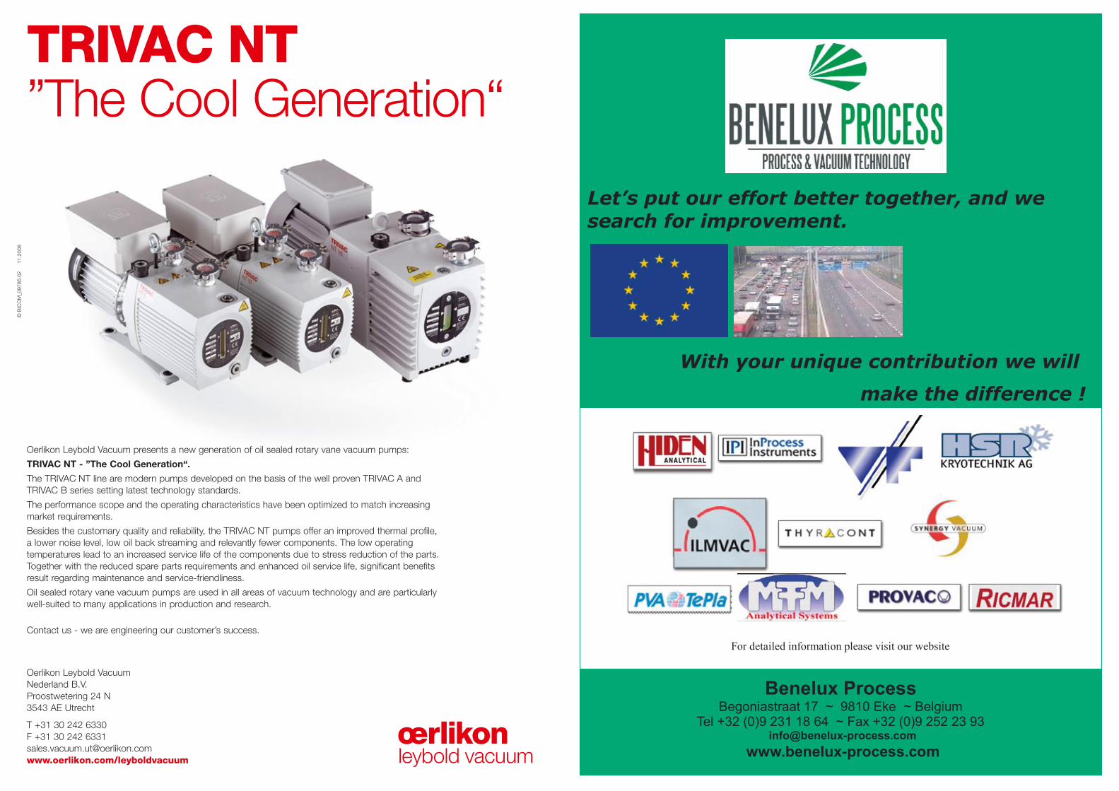
Oerlikon Leybold Vacuum presents a new generation of oil sealed rotary vane vacuum pumps:
TRIVAC NT - ”The Cool Generation“.
The TRIVAC NT line are modern pumps developed on the basis of the well proven TRIVAC A and TRIVAC B series setting latest technology standards.
The performance scope and the operating characteristics have been optimized to match increasingmarket requirements.
Besides the customary quality and reliability, the TRIVAC NT pumps offer an improved thermal profile, a lower noise level, low oil back streaming and relevantly fewer components. The low operating temperatures lead to an increased service life of the components due to stress reduction of the parts.Together with the reduced spare parts requirements and enhanced oil service life, significant benefitsresult regarding maintenance and service-friendliness.
Oil sealed rotary vane vacuum pumps are used in all areas of vacuum technology and are particularlywell-suited to many applications in production and research.
Contact us - we are engineering our customer’s success.
Oerlikon Leybold Vacuum Nederland B.V.Proostwetering 24 N3543 AE Utrecht
T +31 30 242 6330F +31 30 242 [email protected]/leyboldvacuum
Anz_TRIVAC NT_EN_1108 26.11.2008 17:05 Uhr Seite 1
ElementAtomic
Concentration (%)
C 17.1
O 5.5
F 77.4
16 NEVAC blad jaargang 46 / uitgave 3 september 2008 NEVAC blad 17
K-Alpha, an Exciting New Concept for Surface Analysis Using XPSCees Heijboer, Surface Analysis and X-ray microanalysis systems, Thermo Fisher Scientific, Takkebijsters 1, 4817 BL Breda, The Net-herlands
XPS (X-ray photoelectron spectroscopy) is a powerful method for the quantitative chemical characterisation of solid surfa-
hout compromise to the performance of the instrument. It is expected that in this way the technique has become more accessible and can be operated in a multi-user envi-ronment.
Why is Surface Analysis Necessary?All solid materials interact with their sur-roundings via their surfaces. It is therefore crucial that the surface properties of any material are suitable for the proposed ap-plication. Modern, high-performance materials will only be suitable for their intended purpose if their surface properties are correctly engineered. Surfaces are very important in a very wide range of materials a few examples are:· Glasses· Biomaterials· Semiconductor devices· Solar cells· Adhesion· Corrosion protection
The need for the engineering of surface properties gives rise to the requirement for the detailed chemical characterisation of the surface. X-ray Photoelectron Spectros-copy (XPS) provides a method for quantita-tive chemical analysis of surfaces and thin films and, consequently, is a valuable tool
sodium chloride in 1954. By the late sixties he had performed a wide ranging study showing the value of the technique. In 1969 he cooperated with Hewlett-Packard in the USA to produce the first commercial XPS instrument. In recognition of his work in the area Siegbahn received the Nobel Prize for Physics in 1981. To emphasise the fact that XPS provides a method for the chemi-cal characterisation of a surface, Siegbahn referred to the technique as ESCA (electron spectroscopy for chemical analysis), a term which continues to be used alongside the term XPS, the two terms having the same meaning.
Why is XPS Surface Specific?When X-rays strike a solid, they penetrate into the material to a great depth causing photoemission along the whole of their path. However, as the photoelectrons travel through the material, they undergo col-lisions in which they lose energy and these electrons do not contribute to the peak in the photoelectron spectrum and many do not escape the solid. Only photoelectrons originating close to the surface (within the top 5 to 10 nm, depending on the material) stand a chance of escaping without energy loss. These are the ones than can be detec-ted in the spectrometer.
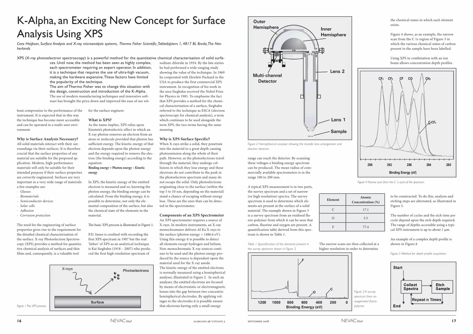
Components of an XPS SpectrometerAn XPS spectrometer requires a source of X-rays. In modern instruments, an X-ray monochromator delivers Al Ka X-rays to the surface (photon energy = 1486.6 eV). Using this energy it is possible to detect all elements except hydrogen and helium. Non-monochromatic X-ray sources conti-nue to be used and the photon energy pro-duced by the source is dependent upon the material used for the X-ray anode. The kinetic energy of the emitted electrons is normally measured using a hemispherical analyser, illustrated in Figure 2. In such an analyser, the emitted electrons are focused by means of electrostatic or electromagnetic lenses into the gap between two concentric hemispherical electrodes. By applying vol-tages to the electrodes it is possible ensure that electrons having only a small energy
ces. Until now, the method has been seen as highly complex, each spectrometer requiring an expert operator. In addition, it is a technique that requires the use of ultra-high vacuum, making the hardware expensive. These factors have limited the popularity of the technique.The aim of Thermo Fisher was to change this situation with the design, construction and introduction of the K-Alpha. The use of modern manufacturing techniques and innovative soft-ware has brought the price down and improved the ease of use wit-
for the surface engineer.
What is XPS?As the name implies, XPS relies upon Einstein’s photoelectric effect in which an X-ray photon removes an electron from an atom or molecule provided that photon has sufficient energy. The kinetic energy of that electron depends upon the photon energy and the energy required to remove the elec-tron (the binding energy) according to the equation:Binding energy = Photon energy – Kinetic energy
In XPS, the kinetic energy of the emitted electron is measured and so, knowing the photon energy, the binding energy can be calculated. From the binding energy, it is possible to determine, not only the ele-mental composition of the surface, but also the chemical state of the elements in the material.
The basic XPS process is illustrated in Figure 1.
P.D. Innes is credited with recording the first XPS spectrum in 1907 but the real ‘father’ of XPS as an analytical technique is Kai Siegbahn (1918 – 2007) who produ-ced the first high-resolution spectrum of
range can reach the detector. By scanning these voltages a binding energy spectrum can be produced. The mean radius of com-mercially available spectrometers is in the range 100 to 200 mm.
A typical XPS measurement is in two parts, the survey spectrum and a set of narrow (or high resolution) spectra. The survey spectrum is used to determine which ele-ments are present at the surface of a solid material. The example shown in Figure 3 is a survey spectrum from an oxidised flu-oro-polymer from which it can be seen that carbon, fluorine and oxygen are present. A quantification table derived from this spec-trum is shown in Table 1.
Table 1 Quantification of the elements present in
the survey spectrum shown in Figure 3.
The narrow scans are then collected at a higher resolution in order to determine
the chemical states in which each element exists.
Figure 4 shows, as an example, the narrow scan from the C 1s region of Figure 3 in which the various chemical states of carbon present in the sample have been labelled.
Using XPS in combination with an ion beam allows concentration depth profiles
to be constructed. To do this, analysis and etching steps are alternated, as illustrated in Figure 5.
The number of cycles and the etch time per cycle depend upon the etch depth required. The range of depths accessible using a typi-cal XPS instrument is up to about 1 µm.
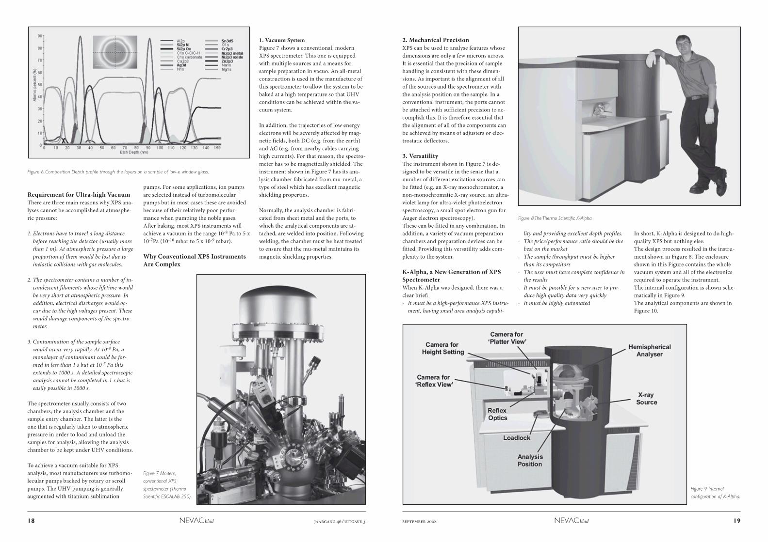
An example of a complex depth profile is shown in Figure 6
Figure 4 Narrow scan from the C 1s part of the spectrum.
Figure 1 The XPS process
Figure 2 Hemispherical analyser showing the transfer lens arrangement and
electron detector.
Figure 3 A survey
spectrum from an
oxygenated fluoro-
polymer.
Figure 5 Method for depth profile acquisition.
18 NEVAC blad jaargang 46 / uitgave 3 september 2008 NEVAC blad 19
Requirement for Ultra-high VacuumThere are three main reasons why XPS ana-lyses cannot be accomplished at atmosphe-ric pressure:
1. Electrons have to travel a long distance before reaching the detector (usually more than 1 m). At atmospheric pressure a large proportion of them would be lost due to inelastic collisions with gas molecules.
2. The spectrometer contains a number of in-candescent filaments whose lifetime would be very short at atmospheric pressure. In addition, electrical discharges would oc-cur due to the high voltages present. These would damage components of the spectro-meter.
3. Contamination of the sample surface would occur very rapidly. At 10-4 Pa, a monolayer of contaminant could be for-med in less than 1 s but at 10-7 Pa this extends to 1000 s. A detailed spectroscopic analysis cannot be completed in 1 s but is easily possible in 1000 s.
The spectrometer usually consists of two chambers; the analysis chamber and the sample entry chamber. The latter is the one that is regularly taken to atmospheric pressure in order to load and unload the samples for analysis, allowing the analysis chamber to be kept under UHV conditions.
To achieve a vacuum suitable for XPS analysis, most manufacturers use turbomo-lecular pumps backed by rotary or scroll pumps. The UHV pumping is generally augmented with titanium sublimation
pumps. For some applications, ion pumps are selected instead of turbomolecular pumps but in most cases these are avoided because of their relatively poor perfor-mance when pumping the noble gases. After baking, most XPS instruments will achieve a vacuum in the range 10-8 Pa to 5 x 10⁻⁷Pa (10-10 mbar to 5 x 10⁻⁹ mbar).
Why Conventional XPS Instruments Are Complex
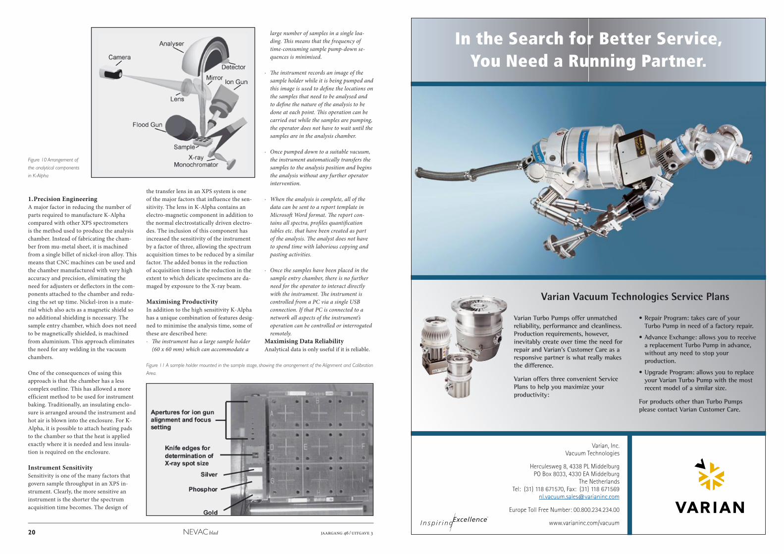
1. Vacuum SystemFigure 7 shows a conventional, modern XPS spectrometer. This one is equipped with multiple sources and a means for sample preparation in vacuo. An all-metal construction is used in the manufacture of this spectrometer to allow the system to be baked at a high temperature so that UHV conditions can be achieved within the va-cuum system.
In addition, the trajectories of low energy electrons will be severely affected by mag-netic fields, both DC (e.g. from the earth) and AC (e.g. from nearby cables carrying high currents). For that reason, the spectro-meter has to be magnetically shielded. The instrument shown in Figure 7 has its ana-lysis chamber fabricated from mu-metal, a type of steel which has excellent magnetic shielding properties.
Normally, the analysis chamber is fabri-cated from sheet metal and the ports, to which the analytical components are at-tached, are welded into position. Following welding, the chamber must be heat treated to ensure that the mu-metal maintains its magnetic shielding properties.
Figure 7 Modern,
conventional XPS
spectrometer (Thermo
Scientific ESCALAB 250).
Figure 8 The Thermo Scientific K-Alpha
Figure 9 Internal
configuration of K-Alpha.
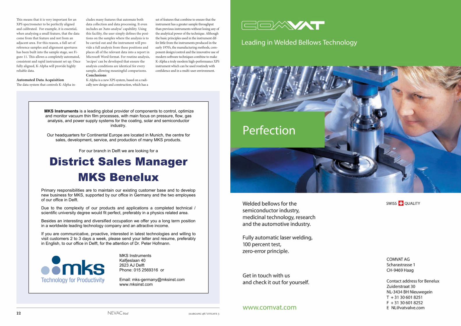
2. Mechanical PrecisionXPS can be used to analyse features whose dimensions are only a few microns across. It is essential that the precision of sample handling is consistent with these dimen-sions. As important is the alignment of all of the sources and the spectrometer with the analysis position on the sample. In a conventional instrument, the ports cannot be attached with sufficient precision to ac-complish this. It is therefore essential that the alignment of all of the components can be achieved by means of adjusters or elec-trostatic deflectors.
3. VersatilityThe instrument shown in Figure 7 is de-signed to be versatile in the sense that a number of different excitation sources can be fitted (e.g. an X-ray monochromator, a non-monochromatic X-ray source, an ultra-violet lamp for ultra-violet photoelectron spectroscopy, a small spot electron gun for Auger electron spectroscopy). These can be fitted in any combination. In addition, a variety of vacuum preparation chambers and preparation devices can be fitted. Providing this versatility adds com-plexity to the system.
K-Alpha, a New Generation of XPS SpectrometerWhen K-Alpha was designed, there was a clear brief:· It must be a high-performance XPS instru-
ment, having small area analysis capabi-
lity and providing excellent depth profiles.· The price/performance ratio should be the
best on the market· The sample throughput must be higher
than its competitors· The user must have complete confidence in
the results· It must be possible for a new user to pro-
duce high quality data very quickly· It must be highly automated
In short, K-Alpha is designed to do high-quality XPS but nothing else.The design process resulted in the instru-ment shown in Figure 8. The enclosure shown in this Figure contains the whole vacuum system and all of the electronics required to operate the instrument.The internal configuration is shown sche-matically in Figure 9. The analytical components are shown in Figure 10.
Figure 6 Composition Depth profile through the layers on a sample of low-e window glass.
In the Search for Better Service,You Need a Running Partner.
Varian, Inc.Vacuum Technologies
Herculesweg 8, 4338 PL MiddelburgPO Box 8033, 4330 EA Middelburg
The NetherlandsTel: (31) 118 671570, Fax: (31) 118 671569
Europe Toll Free Number: 00.800.234.234.00
www.varianinc.com/vacuum
Varian Vacuum Technologies Service Plans
Varian Turbo Pumps offer unmatchedreliability, performance and cleanliness.Production requirements, however,inevitably create over time the need forrepair and Varian’s Customer Care as aresponsive partner is what really makesthe difference.
Varian offers three convenient ServicePlans to help you maximize yourproductivity:
• Repair Program: takes care of yourTurbo Pump in need of a factory repair.
• Advance Exchange: allows you to receivea replacement Turbo Pump in advance,without any need to stop yourproduction.
• Upgrade Program: allows you to replaceyour Varian Turbo Pump with the mostrecent model of a similar size.
For products other than Turbo Pumpsplease contact Varian Customer Care.
Pag Varian Dog A4 2008 20-10-2008 11:22 Page 1
20 NEVAC blad jaargang 46 / uitgave 3
1. Precision EngineeringA major factor in reducing the number of parts required to manufacture K-Alpha compared with other XPS spectrometers is the method used to produce the analysis chamber. Instead of fabricating the cham-ber from mu-metal sheet, it is machined from a single billet of nickel-iron alloy. This means that CNC machines can be used and the chamber manufactured with very high accuracy and precision, eliminating the need for adjusters or deflectors in the com-ponents attached to the chamber and redu-cing the set up time. Nickel-iron is a mate-rial which also acts as a magnetic shield so no additional shielding is necessary. The sample entry chamber, which does not need to be magnetically shielded, is machined from aluminium. This approach eliminates the need for any welding in the vacuum chambers.
One of the consequences of using this approach is that the chamber has a less complex outline. This has allowed a more efficient method to be used for instrument baking. Traditionally, an insulating enclo-sure is arranged around the instrument and hot air is blown into the enclosure. For K-Alpha, it is possible to attach heating pads to the chamber so that the heat is applied exactly where it is needed and less insula-tion is required on the enclosure.
Instrument SensitivitySensitivity is one of the many factors that govern sample throughput in an XPS in-strument. Clearly, the more sensitive an instrument is the shorter the spectrum acquisition time becomes. The design of
the transfer lens in an XPS system is one of the major factors that influence the sen-sitivity. The lens in K-Alpha contains an electro-magnetic component in addition to the normal electrostatically driven electro-des. The inclusion of this component has increased the sensitivity of the instrument by a factor of three, allowing the spectrum acquisition times to be reduced by a similar factor. The added bonus in the reduction of acquisition times is the reduction in the extent to which delicate specimens are da-maged by exposure to the X-ray beam.
Maximising ProductivityIn addition to the high sensitivity K-Alpha has a unique combination of features desig-ned to minimise the analysis time, some of these are described here:· The instrument has a large sample holder
(60 x 60 mm) which can accommodate a
Figure 11 A sample holder mounted in the sample stage, showing the arrangement of the Alignment and Calibration
Area.
large number of samples in a single loa-ding. This means that the frequency of time-consuming sample pump-down se-quences is minimised.
· The instrument records an image of the sample holder while it is being pumped and this image is used to define the locations on the samples that need to be analysed and to define the nature of the analysis to be done at each point. This operation can be carried out while the samples are pumping, the operator does not have to wait until the samples are in the analysis chamber.
· Once pumped down to a suitable vacuum, the instrument automatically transfers the samples to the analysis position and begins the analysis without any further operator intervention.
· When the analysis is complete, all of the data can be sent to a report template in Microsoft Word format. The report con-tains all spectra, profiles quantification tables etc. that have been created as part of the analysis. The analyst does not have to spend time with laborious copying and pasting activities.
· Once the samples have been placed in the sample entry chamber, there is no further need for the operator to interact directly with the instrument. The instrument is controlled from a PC via a single USB connection. If that PC is connected to a network all aspects of the instrument’s operation can be controlled or interrogated remotely.
Maximising Data ReliabilityAnalytical data is only useful if it is reliable.
Figure 10 Arrangement of
the analytical components
in K-Alpha
MKS Instruments is a leading global provider of components to control, optimize and monitor vacuum thin film processes, with main focus on pressure, flow, gas analysis, and power supply systems for the coating, solar and semiconductor
industry.
Our headquarters for Continental Europe are located in Munich, the centre for sales, development, service, and production of many MKS products.
For our branch in Delft we are looking for a
District Sales ManagerMKS Benelux
Primary responsibilities are to maintain our existing customer base and to develop new business for MKS, supported by our office in Germany and the two employees of our office in Delft.
Due to the complexity of our products and applications a completed technical / scientific university degree would fit perfect, preferably in a physics related area.
Besides an interesting and diversified occupation we offer you a long term position in a worldwide leading technology company and an attractive income.
If you are communicative, proactive, interested in latest technologies and willing to visit customers 2 to 3 days a week, please send your letter and resume, preferably in English, to our office in Delft, for the attention of Dr. Peter Hofmann.
MKS InstrumentsKalfjeslaan 40 2623 AJ DelftPhone: 015 2569316 or
Email: [email protected] www.mksinst.com
22 NEVAC blad jaargang 46 / uitgave 3
Th is means that it is very important for an XPS spectrometer to be perfectly aligned and calibrated. For example, it is essential, when analysing a small feature, that the data come from that feature and not from an adjacent area. For this reason, a full set of reference samples and alignment apertures has been built into the sample stage, see Fi-gure 11. Th is allows a completely automated, consistent and rapid instrument set up. Once fully aligned, K-Alpha will provide highly reliable data.
Automated Data AcquisitionTh e data system that controls K-Alpha in-
cludes many features that automate both data collection and data processing. It even includes an ‘Auto analyse’ capability. Using this facility, the user simply defi nes the posi-tions on the samples where the analysis is to be carried out and the instrument will pro-vide a full analysis from these positions and places all of the relevant data into a report in Microsoft Word format. For routine analysis, ‘recipes’ can be developed that ensure the analysis conditions are identical for every sample, allowing meaningful comparisons.ConclusionsK-Alpha is a new XPS system, based on a radi-cally new design and construction, which has a
set of features that combine to ensure that the instrument has a greater sample throughput than previous instruments without losing any of the analytical power of the technique. Although the basic principles used in the instrument dif-fer little from the instruments produced in the early 1970’s, the manufacturing methods, com-ponent design/control and the innovative use of modern soft ware techniques combine to make K-Alpha a truly modern high-performance XPS instrument which can be used routinely with confi dence and in a multi-user environment.

Orgaan van de Nederlandse Vacuumvereniging
NEVAC blad