MiniVent M1/100/120 F - heliosselect.de · MiniVent M1/100/120 F Montage- und Betriebsvorschrift 3...
56
Kleinlüfter - Mini fan - Mini ventilateur MiniVent M1/100/120 F Mit Feuchteverlaufssteuerung With automatic humidity control Avec hygrostat électronique Helios Ventilatoren MONTAGE- UND BETRIEBSVORSCHRIFT INSTALLATION AND OPERATING INSTRUCTIONS NOTICE DE MONTAGE ET D‘UTILISATION EN FR DE
Transcript of MiniVent M1/100/120 F - heliosselect.de · MiniVent M1/100/120 F Montage- und Betriebsvorschrift 3...
Kleinlüfter - Mini fan - Mini ventilateur
MiniVent M1/100/120 F
Mit FeuchteverlaufssteuerungWith automatic humidity controlAvec hygrostat électronique
Helios VentilatorenMONTAGE- UND BETRIEBSVORSCHRIFTINSTALLATION AND OPERATING INSTRUCTIONSNOTICE DE MONTAGE ET D‘UTILISATION
EN
FR
DE
Inhaltsverzeichnis
KAPITEL 1 ALLGEMEINE HINWEISE . . . . . . . . . . . . . . . . . . . . . . . . . . . . . . . . . . . . . . . . . . . . . . . . . . . . . . . . . . Seite 11.0 Wichtige Informationen . . . . . . . . . . . . . . . . . . . . . . . . . . . . . . . . . . . . . . . . . . . . . . . . . . . . . . . . . . . . . . . . . Seite 11.1 Warnhinweise . . . . . . . . . . . . . . . . . . . . . . . . . . . . . . . . . . . . . . . . . . . . . . . . . . . . . . . . . . . . . . . . . . . . . . . . Seite 11.2 Sicherheitshinweise . . . . . . . . . . . . . . . . . . . . . . . . . . . . . . . . . . . . . . . . . . . . . . . . . . . . . . . . . . . . . . . . . . . . Seite 11.3 Garantieansprüche – Haftungsausschluss . . . . . . . . . . . . . . . . . . . . . . . . . . . . . . . . . . . . . . . . . . . . . . . . . . . Seite 21.4 Vorschriften – Richtlinien . . . . . . . . . . . . . . . . . . . . . . . . . . . . . . . . . . . . . . . . . . . . . . . . . . . . . . . . . . . . . . . . Seite 21.5 Transport . . . . . . . . . . . . . . . . . . . . . . . . . . . . . . . . . . . . . . . . . . . . . . . . . . . . . . . . . . . . . . . . . . . . . . . . . . . Seite 21.6 Sendungsannahme . . . . . . . . . . . . . . . . . . . . . . . . . . . . . . . . . . . . . . . . . . . . . . . . . . . . . . . . . . . . . . . . . . . . Seite 21.7 Einlagerung . . . . . . . . . . . . . . . . . . . . . . . . . . . . . . . . . . . . . . . . . . . . . . . . . . . . . . . . . . . . . . . . . . . . . . . . . . Seite 21.8 Einsatzbereich . . . . . . . . . . . . . . . . . . . . . . . . . . . . . . . . . . . . . . . . . . . . . . . . . . . . . . . . . . . . . . . . . . . . . . . . Seite 21.9 Leistungsdaten . . . . . . . . . . . . . . . . . . . . . . . . . . . . . . . . . . . . . . . . . . . . . . . . . . . . . . . . . . . . . . . . . . . . . . . Seite 31.10 Geräuschangaben . . . . . . . . . . . . . . . . . . . . . . . . . . . . . . . . . . . . . . . . . . . . . . . . . . . . . . . . . . . . . . . . . . . . . Seite 3
KAPITEL 2 ALLGEMEINE BETRIEBSHINWEISE . . . . . . . . . . . . . . . . . . . . . . . . . . . . . . . . . . . . . . . . . . . . . . . . . . Seite 32.0 Personalqualifikation . . . . . . . . . . . . . . . . . . . . . . . . . . . . . . . . . . . . . . . . . . . . . . . . . . . . . . . . . . . . . . . . . . . Seite 32.1 Berührungsschutz . . . . . . . . . . . . . . . . . . . . . . . . . . . . . . . . . . . . . . . . . . . . . . . . . . . . . . . . . . . . . . . . . . . . . Seite 3 2.2 Motorschutz . . . . . . . . . . . . . . . . . . . . . . . . . . . . . . . . . . . . . . . . . . . . . . . . . . . . . . . . . . . . . . . . . . . . . . . . . Seite 3
KAPITEL 3 TECHNISCHE DATEN/ABMESSUNGEN . . . . . . . . . . . . . . . . . . . . . . . . . . . . . . . . . . . . . . . . . . . . . . . Seite 33.0 Typenübersicht MiniVent M1/1... F . . . . . . . . . . . . . . . . . . . . . . . . . . . . . . . . . . . . . . . . . . . . . . . . . . . . . . . . Seite 33.1 Technische Daten . . . . . . . . . . . . . . . . . . . . . . . . . . . . . . . . . . . . . . . . . . . . . . . . . . . . . . . . . . . . . . . . . . . . . Seite 33.2 Zubehör . . . . . . . . . . . . . . . . . . . . . . . . . . . . . . . . . . . . . . . . . . . . . . . . . . . . . . . . . . . . . . . . . . . . . . . . . . . . Seite 43.3 Produktlebensdauer . . . . . . . . . . . . . . . . . . . . . . . . . . . . . . . . . . . . . . . . . . . . . . . . . . . . . . . . . . . . . . . . . . . Seite 43.4 Abmessungen . . . . . . . . . . . . . . . . . . . . . . . . . . . . . . . . . . . . . . . . . . . . . . . . . . . . . . . . . . . . . . . . . . . . . . . . Seite 4
KAPITEL 4 FUNKTION . . . . . . . . . . . . . . . . . . . . . . . . . . . . . . . . . . . . . . . . . . . . . . . . . . . . . . . . . . . . . . . . . . . . . . Seite 44.0 Funktionsbeschreibung M1/100/120 F . . . . . . . . . . . . . . . . . . . . . . . . . . . . . . . . . . . . . . . . . . . . . . . . . . . . . Seite 4
KAPITEL 5 REINIGUNG/DEMONTAGE . . . . . . . . . . . . . . . . . . . . . . . . . . . . . . . . . . . . . . . . . . . . . . . . . . . . . . . . . Seite 65.0 Reinigung . . . . . . . . . . . . . . . . . . . . . . . . . . . . . . . . . . . . . . . . . . . . . . . . . . . . . . . . . . . . . . . . . . . . . . . . . . . Seite 6 5.1 Demontage der Fassade . . . . . . . . . . . . . . . . . . . . . . . . . . . . . . . . . . . . . . . . . . . . . . . . . . . . . . . . . . . . . . . . Seite 6 KAPITEL 6 INSTALLATION . . . . . . . . . . . . . . . . . . . . . . . . . . . . . . . . . . . . . . . . . . . . . . . . . . . . . . . . . . . . . . . . . Seite 76.0 Lieferumfang / Konstruktiver Aufbau . . . . . . . . . . . . . . . . . . . . . . . . . . . . . . . . . . . . . . . . . . . . . . . . . . . . . . . Seite 76.1 Vorbereitung zur Wand- oder Deckenmontage (Aufputz). . . . . . . . . . . . . . . . . . . . . . . . . . . . . . . . . . . . . . . . Seite 76.2 Installation . . . . . . . . . . . . . . . . . . . . . . . . . . . . . . . . . . . . . . . . . . . . . . . . . . . . . . . . . . . . . . . . . . . . . . . . . . . Seite 76.3 Elektrischer Anschluss . . . . . . . . . . . . . . . . . . . . . . . . . . . . . . . . . . . . . . . . . . . . . . . . . . . . . . . . . . . . . . . . . Seite 96.4 Anschluss der Zuleitung / Inbetriebnahme. . . . . . . . . . . . . . . . . . . . . . . . . . . . . . . . . . . . . . . . . . . . . . . . . . . Seite 96.5 Einbau . . . . . . . . . . . . . . . . . . . . . . . . . . . . . . . . . . . . . . . . . . . . . . . . . . . . . . . . . . . . . . . . . . . . . . . . . . . . . Seite 106.6 Betrieb . . . . . . . . . . . . . . . . . . . . . . . . . . . . . . . . . . . . . . . . . . . . . . . . . . . . . . . . . . . . . . . . . . . . . . . . . . . . Seite 11
KAPITEL 7 FUNKTION FÜR INSTALLATEUR . . . . . . . . . . . . . . . . . . . . . . . . . . . . . . . . . . . . . . . . . . . . . . . . . . . Seite 117.0 Funktion M1/100/120 F . . . . . . . . . . . . . . . . . . . . . . . . . . . . . . . . . . . . . . . . . . . . . . . . . . . . . . . . . . . . . . . Seite 117.1 Funktionsbeschreibung im Detail . . . . . . . . . . . . . . . . . . . . . . . . . . . . . . . . . . . . . . . . . . . . . . . . . . . . . . . . . Seite 127.2 Schaltplanübersicht für M1/100/120 F . . . . . . . . . . . . . . . . . . . . . . . . . . . . . . . . . . . . . . . . . . . . . . . . . . . . Seite 15
KAPITEL 8 INSTANDHALTUNG UND WARTUNG . . . . . . . . . . . . . . . . . . . . . . . . . . . . . . . . . . . . . . . . . . . . . . . . Seite 168.0 Instandhaltung und Wartung . . . . . . . . . . . . . . . . . . . . . . . . . . . . . . . . . . . . . . . . . . . . . . . . . . . . . . . . . . . . Seite 168.1 Störungsursachen . . . . . . . . . . . . . . . . . . . . . . . . . . . . . . . . . . . . . . . . . . . . . . . . . . . . . . . . . . . . . . . . . . . . Seite 178.2 Stilllegen und Entsorgen . . . . . . . . . . . . . . . . . . . . . . . . . . . . . . . . . . . . . . . . . . . . . . . . . . . . . . . . . . . . . . . Seite 17
DEUTSCH
MiniVent M1/100/120 FMontage- und Betriebsvorschrift
1
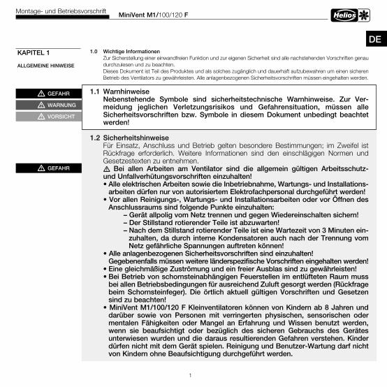
1 .0 Wichtige InformationenZur Sicherstellung einer einwandfreien Funktion und zur eigenen Sicherheit sind alle nachstehenden Vorschriften genau durchzulesen und zu beachten.Dieses Dokument ist Teil des Produktes und als solches zugänglich und dauerhaft aufzubewahren um einen sicheren Betrieb des Ventilators zu gewährleisten. Alle anlagenbezogenen Sicherheitsvorschriften müssen eingehalten werden.
1 .1 WarnhinweiseNebenstehende Symbole sind sicherheitstechnische Warnhinweise . Zur Ver-meidung jeglichen Verletzungsrisikos und Gefahrensituation, müssen alle Sicherheitsvorschriften bzw . Symbole in diesem Dokument unbedingt beachtet werden!
1 .2 Sicherheitshinweise Für Einsatz, Anschluss und Betrieb gelten besondere Bestimmungen; im Zweifel ist Rückfrage erforderlich. Weitere Informationen sind den einschlägigen Normen und Gesetzestexten zu entnehmen. m Bei allen Arbeiten am Ventilator sind die allgemein gültigen Arbeitsschutz- und Unfallverhütungsvorschriften einzuhalten!
• Alle elektrischen Arbeiten sowie die Inbetriebnahme, Wartungs- und Installations-arbeiten dürfen nur von autorisiertem Elektrofachpersonal durchgeführt werden!
• Vor allen Reinigungs-, Wartungs- und Installationsarbeiten oder vor Öffnen des Anschlussraums sind folgende Punkte einzuhalten:
– Gerät allpolig vom Netz trennen und gegen Wiedereinschalten sichern! – Der Stillstand rotierender Teile ist abzuwarten!
– Nach dem Stillstand rotierender Teile ist eine Wartezeit von 3 Minuten ein-zuhalten, da durch interne Kondensatoren auch nach der Trennung vom Netz gefährliche Spannungen auftreten können!
• Alle anlagenbezogenen Sicherheitsvorschriften sind einzuhalten! Gegebenenfalls müssen weitere länderspezifische Vorschriften eingehalten werden!
• Eine gleichmäßige Zuströmung und ein freier Ausblas sind zu gewährleisten!• Bei Betrieb von schornsteinabhängigen Feuerstellen im entlüfteten Raum muss
bei allen Betriebsbedingungen für ausreichend Zuluft gesorgt werden (Rückfrage beim Schornsteinfeger) . Die örtlich aktuell gültigen Vorschriften und Gesetzen sind zu beachten!
• MiniVent M1/100/120 F Kleinventilatoren können von Kindern ab 8 Jahren und darüber sowie von Personen mit verringerten physischen, sensorischen oder mentalen Fähigkeiten oder Mangel an Erfahrung und Wissen benutzt werden, wenn sie beaufsichtigt oder bezüglich des sicheren Gebrauchs des Gerätes unterwiesen wurden und die daraus resultierenden Gefahren verstehen . Kinder dürfen nicht mit dem Gerät spielen . Reinigung und Benutzer-Wartung darf nicht von Kindern ohne Beaufsichtigung durchgeführt werden .
KAPITEL 1
ALLGEMEINE HINWEISE
DE
mGEFAHR
mWARNUNG
mVORSICHT
mGEFAHR
MiniVent M1/100/120 FMontage- und Betriebsvorschrift
2
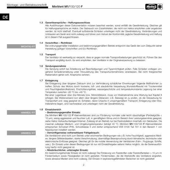
1 .3 Garantieansprüche – HaftungsausschlussAlle Ausführungen dieser Dokumentation müssen beachtet werden, sonst entfällt die Gewährleistung. Gleiches gilt für Haftungsansprüche an Helios. Der Gebrauch von Zubehörteilen, die nicht von Helios empfohlen oder angeboten werden, ist nicht statthaft. Eventuell auftretende Schäden unterliegen nicht der Gewährleistung. Veränderungen und Umbauten am Gerät sind nicht zulässig und führen zum Verlust der Konformität, jegliche Gewährleistung und Haftung ist in diesem Fall ausgeschlossen.
1 .4 Vorschriften – RichtlinienBei ordnungsgemäßer Installation und bestimmungsgemäßem Betrieb entspricht das Gerät den zum Zeitpunkt seiner Herstellung gültigen Vorschriften und EU-Richtlinien.
1 .5 Transport Der Ventilator ist werkseitig so verpackt, dass er gegen normale Transportbelastungen geschützt ist. Führen Sie den Transport sorgfältig durch. Es wird empfohlen, den Ventilator in der Originalverpackung zu belassen.
1 .6 SendungsannahmeDie Sendung sofort bei Anlieferung auf Beschädigungen und Typenrichtigkeit prüfen. Falls Schäden vorliegen um-gehend Schadensmeldung unter Hinzuziehung des Transportunternehmens veranlassen. Bei nicht fristgerechter Reklamation gehen evtl. Ansprüche verloren.
1 .7 EinlagerungBei Einlagerung über längeren Zeitraum sind zur Verhinderung schädlicher Einwirkungen folgende Maßnahmen zu treffen: Schutz des Motors durch trockene, luft- und staubdichte Verpackung (Kunststoffbeutel mit Trockenmittel und Feuchtigkeitsindikatoren). Erschütterungsfreie, wassergeschützte und temperaturkonstante Lagerung bei einer Temperatur zwischen -20 °C bis +40 °C.Bei einer Lagerdauer über drei Monate bzw. Motorstillstand, muss vor Inbetriebnahme eine Wartung laut Kapitel 8 erfolgen. Bei Weiterversand (vor allem über längere Distanzen; z.B. Seeweg) ist zu prüfen, ob die Verpackung für Transportart und -weg geeignet ist. Schäden, deren Ursache in unsachgemäßem Transport, Einlagerung oder Inbe-triebnahme liegen, sind nachweisbar und unterliegen nicht der Gewährleistung.
1 .8 Einsatzbereich– Bestimmungsgemäßer Einsatz: Die MiniVent M1/100/120 F Kleinventilatoren sind zur Förderung normaler oder leicht staubhaltiger (Partikelgröße < 10 µm), wenig aggressiver und feuchter Luft, in gemäßigtem Klima und im Bereich ihrer Leistungskennlinie geeignet, siehe Helios Verkaufsunterlagen/Internet. Zulässig ist ein Betrieb nur bei Festinstallation innerhalb von Gebäuden. Die maximal zulässige Medium- und Umgebungstemperatur beträgt 40 °C. MiniVent M1/100/120 F Kleinventilatoren entsprechen Schutzart IP45, Schutzklasse II und dürfen entsprechend VDE 0100 Teil 701 in den Bereich 1 von Nassräumen installiert werden.– Vernünftigerweise vorhersehbarer Fehlgebrauch: Die Ventilatoren sind nicht zum Betrieb unter erschwerten Bedingungen wie z.B. hohe Feuchtigkeit, aggressive Medi-en, längere Stillstandszeiten, starke Verschmutzung, übermäßige Beanspruchung durch klimatische, technische oder elektronische Einflüsse geeignet. Gleiches gilt für die mobile Verwendung der Ventilatoren (Fahr-, Flugzeuge, Schiffe, usw.). Ein Einsatz unter diesen Bedingungen ist nur mit Einsatzfreigabe seitens Helios möglich, da die Serienausfüh-rung hierfür nicht geeignet ist.– Missbräuchlicher, untersagter Einsatz: Ein bestimmungsfremder Einsatz ist nicht zulässig! Die Förderung von Feststoffen oder Feststoffanteilen > 10 µm im Fördermedium sowie Flüssigkeiten ist nicht gestattet. Fördermedien, die die Werkstoffe des Ventilators angreifen, sowie abrasive Medien sind nicht zulässig. Der Einsatz in explosionsgefährdeten Bereichen ist nicht gestattet!
WICHTIG +
HINWEIS +
HINWEIS +
HINWEIS +
DE
MiniVent M1/100/120 FMontage- und Betriebsvorschrift
3
DE
KAPITEL 2
ALLGEMEINE BETRIEBSHINWEISE
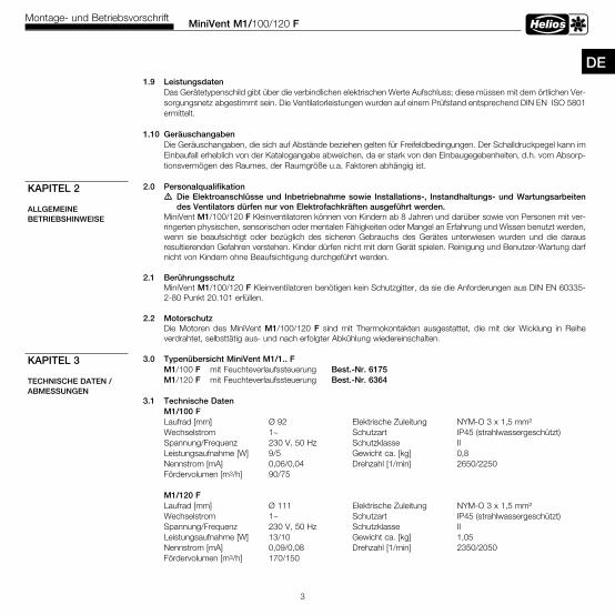
1 .9 LeistungsdatenDas Gerätetypenschild gibt über die verbindlichen elektrischen Werte Aufschluss; diese müssen mit dem örtlichen Ver-sorgungsnetz abgestimmt sein. Die Ventilatorleistungen wurden auf einem Prüfstand entsprechend DIN EN ISO 5801 ermittelt.
1 .10 GeräuschangabenDie Geräuschangaben, die sich auf Abstände beziehen gelten für Freifeldbedingungen. Der Schalldruckpegel kann im Einbaufall erheblich von der Katalogangabe abweichen, da er stark von den Einbaugegebenheiten, d.h. vom Absorp-tionsvermögen des Raumes, der Raumgröße u.a. Faktoren abhängig ist.
2 .0 Personalqualifikationm Die Elektroanschlüsse und Inbetriebnahme sowie Installations-, Instandhaltungs- und Wartungsarbeiten des Ventilators dürfen nur von Elektrofachkräften ausgeführt werden .MiniVent M1/100/120 F Kleinventilatoren können von Kindern ab 8 Jahren und darüber sowie von Personen mit ver-ringerten physischen, sensorischen oder mentalen Fähigkeiten oder Mangel an Erfahrung und Wissen benutzt werden, wenn sie beaufsichtigt oder bezüglich des sicheren Gebrauchs des Gerätes unterwiesen wurden und die daraus resultierenden Gefahren verstehen. Kinder dürfen nicht mit dem Gerät spielen. Reinigung und Benutzer-Wartung darf nicht von Kindern ohne Beaufsichtigung durchgeführt werden.
2 .1 BerührungsschutzMiniVent M1/100/120 F Kleinventilatoren benötigen kein Schutzgitter, da sie die Anforderungen aus DIN EN 60335-2-80 Punkt 20.101 erfüllen.
2 .2 MotorschutzDie Motoren des MiniVent M1/100/120 F sind mit Thermokontakten ausgestattet, die mit der Wicklung in Reihe verdrahtet, selbsttätig aus- und nach erfolgter Abkühlung wiedereinschalten.
3 .0 Typenübersicht MiniVent M1/1 . . FM1/100 F mit Feuchteverlaufssteuerung Best .-Nr . 6175M1/120 F mit Feuchteverlaufssteuerung Best .-Nr . 6364
3 .1 Technische DatenM1/100 FLaufrad [mm] Ø 92 Elektrische Zuleitung NYM-O 3 x 1,5 mm²Wechselstrom 1~ Schutzart IP45 (strahlwassergeschützt)Spannung/Frequenz 230 V, 50 Hz Schutzklasse IILeistungsaufnahme [W] 9/5 Gewicht ca. [kg] 0,8Nennstrom [mA] 0,06/0,04 Drehzahl [1/min] 2650/2250Fördervolumen [m3/h] 90/75
M1/120 FLaufrad [mm] Ø 111 Elektrische Zuleitung NYM-O 3 x 1,5 mm²Wechselstrom 1~ Schutzart IP45 (strahlwassergeschützt)Spannung/Frequenz 230 V, 50 Hz Schutzklasse IILeistungsaufnahme [W] 13/10 Gewicht ca. [kg] 1,05Nennstrom [mA] 0,09/0,08 Drehzahl [1/min] 2350/2050Fördervolumen [m3/h] 170/150
KAPITEL 3
TECHNISCHE DATEN / ABMESSUNGEN
MiniVent M1/100/120 FMontage- und Betriebsvorschrift
4
3 .2 Zubehör WES 100 Wandeinbauset Best .-Nr . 0717 WES 120 Wandeinbauset Best .-Nr . 0486 MF 100 Montageflansch Best .-Nr . 6188 TWH 100 Teleskop-Wandhülse Best .-Nr . 6352 TWH 120 Teleskop-Wandhülse Best .-Nr . 6353 MBR Montageblende Best .-Nr . 0281
3 .3 Produktlebensdauer Dieses Gerät ist auf eine Produktlebensdauer von mindestens 40.000 h, bei S1-Betrieb mit maximaler Leistung in maximal zulässiger Umgebungstemperatur ausgelegt.
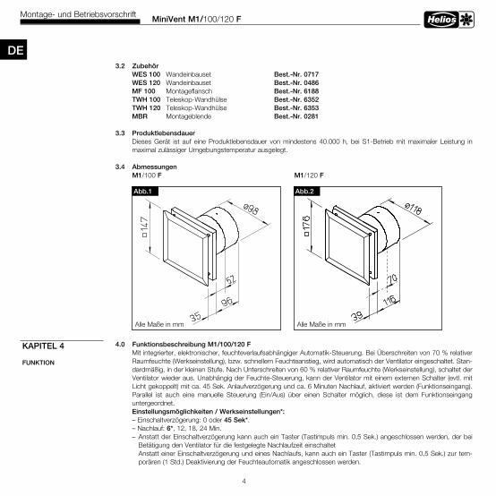
3 .4 AbmessungenM1/100 F M1/120 F
4 .0 Funktionsbeschreibung M1/100/120 F Mit integrierter, elektronischer, feuchteverlaufsabhängiger Automatik-Steuerung. Bei Überschreiten von 70 % relativer Raumfeuchte (Werkseinstellung), bzw. schnellem Feuchteanstieg, wird automatisch der Ventilator eingeschaltet. Stan- dardmäßig, in der kleinen Stufe. Nach Unterschreiten von 60 % relativer Raumfeuchte (Werkseinstellung), schaltet der Ventilator wieder aus. Unabhängig der Feuchte-Steuerung, kann der Ventilator mit einem externen Schalter (evtl. mit Licht gekoppelt) mit ca. 45 Sek. Anlaufverzögerung und ca. 6 Minuten Nachlauf, aktiviert werden (Funktionseingang). Parallel ist auch eine manuelle Steuerung (Ein/Aus) über einen Schalter möglich, diese ist dem Funktionseingang untergeordnet. Einstellungsmöglichkeiten / Werkseinstellungen*: – Einschaltverzögerung: 0 oder 45 Sek*. – Nachlauf: 6*, 12, 18, 24 Min. – Anstatt der Einschaltverzögerung kann auch ein Taster (Tastimpuls min. 0,5 Sek.) angeschlossen werden, der bei Betätigung den Ventilator für die festgelegte Nachlaufzeit einschaltet Anstatt einer Einschaltverzögerung und eines Nachlaufs, kann auch ein Taster (Tastimpuls min. 0,5 Sek.) zur tem- porären (1 Std.) Deaktivierung der Feuchteautomatik angeschlossen werden.
KAPITEL 4
FUNKTION
Abb .2Abb .1
Alle Maße in mm Alle Maße in mm
DE
MiniVent M1/100/120 FMontage- und Betriebsvorschrift
5
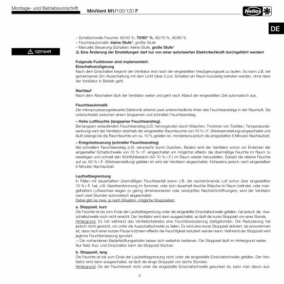
DE – Schaltschwelle Feuchte: 60/50 %, 70/60* %, 80/70 %, 90/80 % – Feuchteautomatik: kleine Stufe*, großer Stufe – Manuelle Steuerung (Schalter): kleine Stufe, große Stufe* m Eine Änderung der Einstellungen darf nur von einer autorisierten Elektrofachkraft durchgeführt werden!
Folgende Funktionen sind implementiert: Einschaltverzögerung Nach dem Einschalten beginnt der Ventilator erst nach der eingestellten Verzögerungszeit zu laufen. So kann z.B. bei gemeinsamer Ein-/Ausschaltung mit dem Licht (über 2 pol. Schalter) ein Raum kurzzeitig betreten werden, ohne dass der Ventilator in Betrieb geht.
Nachlauf Nach dem Abschalten läuft der Ventilator weiter und geht nach Ablauf der eingestellten Zeit automatisch aus.
Feuchteautomatik Die mikroprozessorgesteuerte Elektronik erkennt zwei unterschiedliche Arten des Feuchteanstiegs in der Raumluft. Sie unterscheidet zwischen einem langsamen und schnellen Feuchteanstieg.
– Hohe Luftfeuchte (langsamer Feuchteanstieg) .Bei langsam verlaufendem Feuchteanstieg (z.B. hervorgerufen durch Waschen, Trocknen von Textilien, Temperaturab-senkung) wird der Ventilator oberhalb der eingestellter Raumfeuchte von 70 % r.F. (Werkseinstellung) eingeschaltet und läuft solange bis die Raumfeuchte um ca. 10 % gefallen ist, mindestens jedoch die eingestellten 6 Minuten Nachlaufzeit.
– Ereignissteuerung (schneller Feuchteanstieg)Bei schnellem Feuchteanstieg (z.B. verursacht durch Duschen, Baden) wird der Ventilator schon vor Erreichen der eingestellter Schaltschwelle von 70 % r.F. eingeschaltet um möglichst effektiv die übermäßige Feuchte im Raum zu beseitigen und schnell den Wohlfühlbereich (40-70 % r.F.) im Raum wieder herzustellen. Sobald die relative Feuchte auf ca. 60 % r.F. (Werkseinstellung) gefallen ist wird der Ventilator abgeschaltet, frühestens jedoch nach eingestellten 6 Minuten Nachlaufzeit.
Laufzeitbegrenzung In Fällen mit dauerhaftem übermäßigen Feuchteanfall (wenn z.B. die nachströmende Luft schon über eingestellten 70 % r.F. hat, z.B. Gewitterstimmung im Sommer, oder sich dauerhaft feuchte Wäsche im Raum befindet, oder man- gelhaftem Luftwechsel wegen zu gering dimensionierten oder verstopften Nachströmöffnungen), wird der Ventilator nach zwei Stunden automatisch abgeschaltet. Dabei gibt es zwei, je nach Situation, mögliche Stoppzeiten:
a . Stoppzeit, kurzDie Feuchte ist bis zum Ende der Laufzeitbegrenzung unter die eingestellte Einschaltschwelle gefallen, hat jedoch die Aus-schaltschwelle noch nicht erreicht. Der Ventilator wird dann ausgeschaltet, es läuft die kurze Stoppzeit von einer Stunde.
Hintergrund: Es hat während des Ventilatorbetriebs eine Feuchtereduzierung stattgefunden. Die Reduzierung hat jedoch nicht gereicht, um unter die Ausschaltschwelle zu fallen. Es wird eine kurze Stoppzeit aktiviert, da anzunehmen ist, dass nach einer kurzen Pause trotzdem effektiv die Feuchtigkeit reduziert werden kann. Während der Stoppzeit wird jegliche Feuchtemessung ignoriert. → Die vorhandenen Bedarfslüftungsstufen lassen sich weiterhin bedienen. Die Stoppzeit läuft im Hintergrund weiter. Nur Netz Aus- und Einschalten kann die Stoppzeit löschen.
b . Stoppzeit, lang Die Feuchte ist bis zum Ende der Laufzeitbegrenzung nicht unter die eingestellte Einschaltschwelle gefallen. Der Ven- tilator wird dann ausgeschaltet, es läuft die lange Stoppzeit von sechs Stunden. Hintergrund: Da der Feuchtewert nicht unter die eingestellte Einschaltschwelle gesunken ist, kann man davon aus-
mGEFAHR
MiniVent M1/100/120 FMontage- und Betriebsvorschrift
6
gehen, dass ein weiteres Entlüften keinen Sinn macht. Es wird eine lange Stoppzeit aktiviert. Während der Stoppzeit wird jegliche Feuchtemessung ignoriert. → Die vorhandenen Bedarfslüftungsstufen lassen sich weiterhin bedienen. Die Stoppzeit läuft im Hintergrund weiter. Nur Netz Aus- und Einschalten kann die Stoppzeit löschen. Mit diesen Funktionen der Feuchteverlaufssteuerung wird ein Gleichgewicht zwischen minimiertem Energieverbrauch und optimaler Feuchtereduzierung erreicht. Feuchte Oberflächen durch Kondensation und das damit verbundene Risiko der Schimmelbildung, so wie lästige Gerüche werden weitgehend vermieden.
Testmodus Nach Spannungsfreiheit (Stromausfall, Sicherung, usw.) befindet sich der Ventilator für 1 min im Testmodus (Voraus- setzung: Gerät mit Werkseinstellung). Hierbei sind die Einschaltverzögerung und der Nachlauf innerhalb der ersten Minute, bzw. für einen Schaltzyklus, deaktiviert. Um eine korrekte Feuchtemessung zu ermöglichen, muss der Ventilator, bzw. die Ventilatortemperatur an die Tempe- ratur des Einbauortes angepasst sein. Ein warmer Ventilator in kalter Umgebung, bzw. ein kalter Ventilator in warmer Umgebung führt zu Verschiebung des Feuchte-Messwertes. Dies kann dazu führen, dass sich der Ventilator abhängig der Umgebungsbedingungen, evtl. einschaltet.
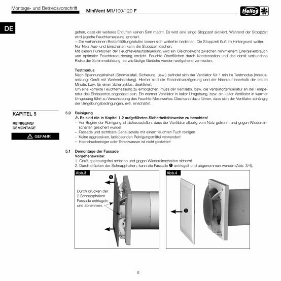
5 .0 Reinigung m Es sind die in Kapitel 1 .2 aufgeführten Sicherheitshinweise zu beachten! – Vor Beginn der Reinigung ist sicherzustellen, dass der Ventilator allpolig vom Netz getrennt und gegen Wiederein- schalten gesichert wurde! – Fassade und sichtbare Gehäuseteile mit einem feuchten Tuch reinigen – Keine aggressiven, lacklösenden Reinigungsmittel verwenden! – Hochdruckreiniger oder Strahlwasser ist nicht gestattet!
5 .1 Demontage der Fassade Vorgehensweise: 1. Gerät spannungsfrei schalten und gegen Wiedereinschalten sichern! 2. Durch drücken der Schnapphaken, kann die Fassade ò entriegelt und abgenommen werden (Abb. 3/4).
KAPITEL 5
REINIGUNG/DEMONTAGE
mGEFAHR
Abb .3
Durch drücken der 2 Schnapphaken Fassade entriegeln und abnehmen.
òAbb .4
ò
DE
MiniVent M1/100/120 FMontage- und Betriebsvorschrift
7
DEAlle nachfolgenden Informationen und Anweisungen sind nur für eine autorisierte Elektrofachkraft bestimmt!
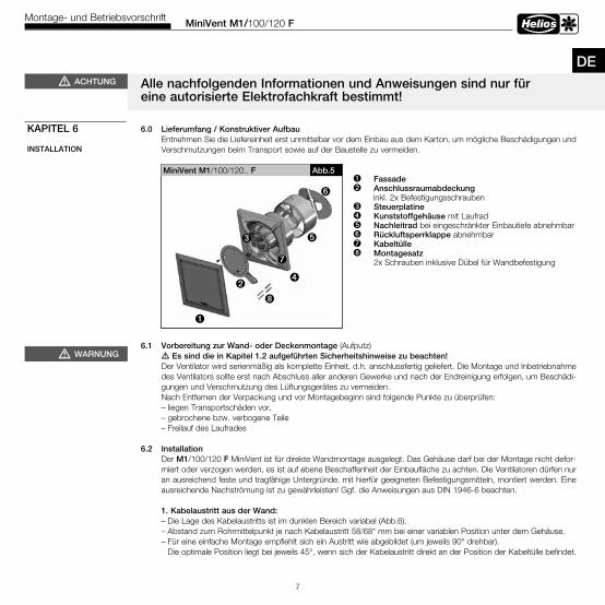
6 .0 Lieferumfang / Konstruktiver AufbauEntnehmen Sie die Liefereinheit erst unmittelbar vor dem Einbau aus dem Karton, um mögliche Beschädigungen und Verschmutzungen beim Transport sowie auf der Baustelle zu vermeiden.
6 .1 Vorbereitung zur Wand- oder Deckenmontage (Aufputz) m Es sind die in Kapitel 1 .2 aufgeführten Sicherheitshinweise zu beachten! Der Ventilator wird serienmäßig als komplette Einheit, d.h. anschlussfertig geliefert. Die Montage und Inbetriebnahme des Ventilators sollte erst nach Abschluss aller anderen Gewerke und nach der Endreinigung erfolgen, um Beschädi- gungen und Verschmutzung des Lüftungsgerätes zu vermeiden. Nach Entfernen der Verpackung und vor Montagebeginn sind folgende Punkte zu überprüfen: – liegen Transportschäden vor, – gebrochene bzw. verbogene Teile – Freilauf des Laufrades
6 .2 Installation Der M1/100/120 F MiniVent ist für direkte Wandmontage ausgelegt. Das Gehäuse darf bei der Montage nicht defor- miert oder verzogen werden, es ist auf ebene Beschaffenheit der Einbaufläche zu achten. Die Ventilatoren dürfen nur an ausreichend feste und tragfähige Untergründe, mit hierfür geeigneten Befestigungsmitteln, montiert werden. Eine ausreichende Nachströmung ist zu gewährleisten! Ggf. die Anweisungen aus DIN 1946-6 beachten.
1 . Kabelaustritt aus der Wand: – Die Lage des Kabelaustritts ist im dunklen Bereich variabel (Abb.6). – Abstand zum Rohrmittelpunkt je nach Kabelaustritt 58/68* mm bei einer variablen Position unter dem Gehäuse. – Für eine einfache Montage empfiehlt sich ein Austritt wie abgebildet (um jeweils 90° drehbar). Die optimale Position liegt bei jeweils 45°, wenn sich der Kabelaustritt direkt an der Position der Kabeltülle befindet.
KAPITEL 6
INSTALLATION
mWARNUNG
ò Fassade ù Anschlussraumabdeckung inkl. 2x Befestigungsschraubenä Steuerplatine ë Kunststoffgehäuse mit Laufrad ö Nachleitrad bei eingeschränkter Einbautiefe abnehmbarü Rückluftsperrklappe abnehmbarÅ Kabeltülleî Montagesatz 2x Schrauben inklusive Dübel für Wandbefestigung
MiniVent M1/100/120.. F
ë
ö
ü
ò
Abb .5
ù
î
mACHTUNG
ä
Å

MiniVent M1/100/120 FMontage- und Betriebsvorschrift
8
Abb .7
Kabelführung unter dem Gehäuse . Ka-bellänge aus der Wand mindestens 180 mm .
Abb .6
Ø 1
00 m
mØ
120
mm
*
r=58 mm
r=68 mm
*min . 90 mm
min
. 90
mm
Kabelaustritt im dunklen Bereich beliebig möglich
Bohrlöcher
Empfohlener Kabelaustritt beliebig0 . . .-360 °,ideal jeweils 45°
* Type M1/120..
Abb .8 Bei Einbau des Gerätes, muss das Nachleitrad ö senkrecht montiert werden (wie dargestellt). Raste- rung jeweils um 90° drehbar.
Nachleitrad ö abnehmbar
Rückluft-sperr-klappe ü abnehmbar
ö
Schaum-stoffstreifenanbringen
senkrecht bei Wandeinbau
oben
unten
Abb .9
ù Kondensatablaufbohrungen für Deckenmontage.
ò Bei Aufputz-montage Aussparungfür Kabeleintritt ausbrechen
ù
äù
DE – Rohrinnendurchmesser M1/100 F = 100 mm bzw. M1/120 F = 120 mm und Abstand zu Raum-Ecken: mindestens 90 mm. – Bei Aufputzleitungsverlegung, muss die seitliche Aussparung für den Kabeleintritt (Abb.9, Pos ò) im Gehäuse aus gebrochen werden! – Das Anschlusskabel ist so zu verwahren, dass bei Wasserbeaufschlagung kein Wasser entlang des Kabels ein- dringen kann. Das Kabel darf nicht über scharfe Kanten geführt werden!
2 . Bohrlöcher: Gehäuse ansetzen Löcher markieren und abbohren und mit mind. zwei Befestigungsschrauben und Dübeln montieren.
3 . Rückluftsperrklappe und Nachleitrad – Bei Einbau des Gerätes, muss das Nachleitrad senkrecht montiert werden (Abb.8). Rasterung jeweils um 90° drehbar. – Vor der Endmontage Schaumstoffstreifen (Lieferumfang) aufkleben (Abb.8)
ò

MiniVent M1/100/120 FMontage- und Betriebsvorschrift
9
DE 4 . Montageflansch MF 100 (Zubehör) Bei beengten Platzverhältnissen in Decken, in dünnen Wänden sowie in engen Schächten. MF 100 winkelgerecht an die Wand oder die Decke dübeln (beliebige Anzahl übereinander möglich). Anschließend Ventilator mittels beigefüg- ten Schrauben an MF 100 befestigen (Abb. 10/11). Auch für Montage eines Zugschnurschalters geeignet (Zubehör).
6 .3 Elektrischer Anschluss m Es sind die in Kapitel 1 .2 aufgeführten Sicherheitshinweise zu beachten! – Der elektrische Anschluss, bzw . die Erstinbetriebnahme darf nur von einer autorisierten Elektrofachkraft entsprechend den Angaben in den beiliegenden Anschlussplänen ausgeführt werden . – Die einschlägigen Normen, Sicherheitsbestimmungen (z . B . DIN VDE 0100) sowie die Technischen Anschluss- bedingungen der Energieversorgungsunternehmen sind unbedingt zu beachten! – Ein allpoliger Netztrennschalter/Revisionsschalter, mit mindestens 3 mm Kontaktöffnung (VDE 0700 T1 7 .12 .2 / EN 60335-1) ist zwingend vorgeschrieben! – Netzform, Spannung und Frequenz müssen mit den Angaben des Leistungsschildes übereinstimmen .
6 .4 Anschluss der Zuleitung / Inbetriebnahme – Es ist eine NYM-Leitung einzusetzen, handelsüblicher maximaler Durchmesser 11 mm – Tülle mit rundem Werkzeug vorstechen oder mit der Zuleitung direkt durchstechen (Abb.9, Pos ä) – Mantel auf 100 mm entfernen. Drähte 7 mm abisolieren (Abb.12) – Leitung vorsichtig durch die Tülle schieben – Drähte im Leitungskanal verlegen und laut Schaltplan (Seite 14) anschließen – Abdichtung des Anschlusskabels und festen Klemmsitz der Adern prüfen – Falls bei montierter Zuleitung die Tülle die Mantelleitung nicht gleichmäßig umschließt, muss die Tülle z.B. mit Silikon zusätzlich abgedichtet werden. Ansonsten erlischt der IP-Schutz
– Das Anschlusskabel ist so zu verwahren, dass bei Wasserbeaufschlagung kein Wasser entlang des Kabels eindrin-gen kann. Das Kabel darf nicht über scharfe Kanten geführt werden!
– Bestimmungsgemäßen Einsatz des Ventilators überprüfen – Netzspannung mit Typenschildangabe vergleichen – Ventilator auf solide Befestigung und fachgerechte elektrische Installation prüfen
mGEFAHR
mWARNUNG
Abb .11
Decke
MF 100
Abb .10MF 100 aufsteckbar
Wand
Einbautiefe
1232 52
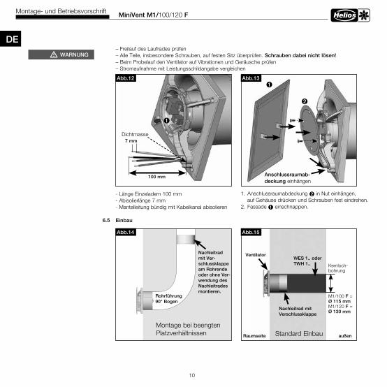
– Freilauf des Laufrades prüfen – Alle Teile, insbesondere Schrauben, auf festen Sitz überprüfen. Schrauben dabei nicht lösen! – Beim Probelauf den Ventilator auf Vibrationen und Geräusche prüfen – Stromaufnahme mit Leistungsschildangabe vergleichen
6 .5 Einbau
MiniVent M1/100/120 FMontage- und Betriebsvorschrift
10
Abb .12
100 mm
7 mm
Abb .13ò
ù
Anschlussraumab-deckung einhängen
Dichtmasse
DE
1. Anschlussraumabdeckung ù in Nut einhängen, auf Gehäuse drücken und Schrauben fest eindrehen.2. Fassade ò einschnappen.
- Länge Einzeladern 100 mm - Abisolierlänge 7 mm- Mantelleitung bündig mit Kabelkanal abisolieren
Abb .14
Nachleitrad mit Ver- schlussklappe am Rohrende oder ohne Ver-wendung des Nachleitradesmontieren .
Rohrführung 90° Bogen
Montage bei beengten Platzverhältnissen
Abb .15
Standard Einbau
WES 1 . . oder TWH 1 . .
Nachleitrad mit Verschlussklappe
Ventilator
Raumseite außen
Kernloch-bohrung
M1/100 F =Ø 115 mmM1/120 F =Ø 130 mm
mWARNUNG
ò
MiniVent M1/100/120 FMontage- und Betriebsvorschrift
11
DE6 .6 Betrieb mEs sind die in Kapitel 1 .2 aufgeführten Sicherheitshinweise zu beachten! Zur Gewährleistung der einwandfreien Funktion des Ventilators, ist regelmäßig Folgendes zu prüfen: – Auftreten von Staub- oder Schmutzablagerungen im Gehäuse bzw. am Motor und Laufrad – Freilauf des Laufrades – Auftreten von übermäßigen Schwingungen und Geräuschen Bei Problemen mit einem der oben aufgeführten Punkte, ist eine Wartung nach den Anweisungen aus Kapitel 8 durch zuführen.
7 .0 Funktion M1/100/120 F mEs sind die in Kapitel 1 .2 aufgeführten Sicherheitshinweise zu beachten!
Elektrische Anschlüsse
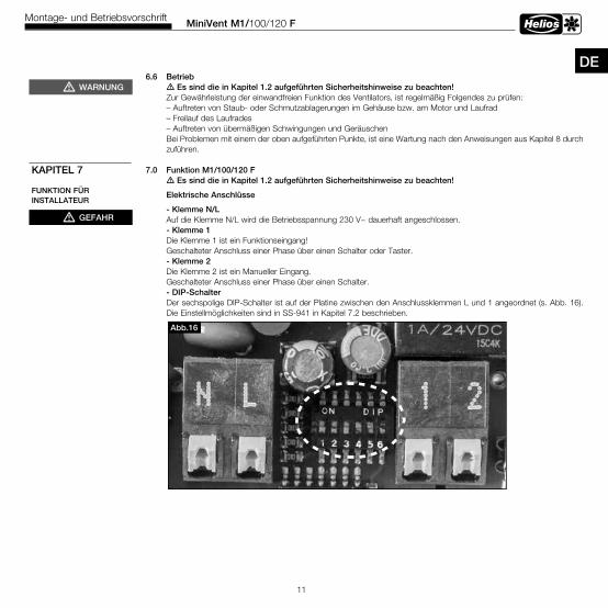
- Klemme N/L Auf die Klemme N/L wird die Betriebsspannung 230 V~ dauerhaft angeschlossen. - Klemme 1 Die Klemme 1 ist ein Funktionseingang! Geschalteter Anschluss einer Phase über einen Schalter oder Taster. - Klemme 2 Die Klemme 2 ist ein Manueller Eingang. Geschalteter Anschluss einer Phase über einen Schalter. - DIP-Schalter
Der sechspolige DIP-Schalter ist auf der Platine zwischen den Anschlussklemmen L und 1 angeordnet (s. Abb. 16). Die Einstellmöglichkeiten sind in SS-941 in Kapitel 7.2 beschrieben.
mWARNUNG
mGEFAHR
KAPITEL 7
FUNKTION FÜR INSTALLATEUR
Abb .16
MiniVent M1/100/120 FMontage- und Betriebsvorschrift
12
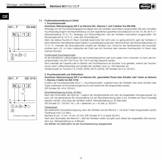
DE7 .1 Funktionsbeschreibung im Detail 1 . Feuchteautomatik Anschluss: Netzversorgung 230 V an Klemme N/L, Klemme 1 und 2 bleiben frei (SS-948) Abhängig von der Feuchteanstiegsgeschwindigkeit wird der Ventilator automatisch eingeschaltet. Bei sehr schnellem Feuchteanstieg beginnt die Raumentlüftung vor dem eigentlichen gewählten Einschaltpunkt von 60, 70, 80, 90 % r.F. (Werkseinstellung 70 % r.F.). Abhängig vom Rückschaltpunkt, wird der Ventilator automatisch ausgeschaltet. Der Rückschaltpunkt ist 10 % r.F. unter dem Einschaltpunkt. Wenn die relative Feuchte im Raum innerhalb bestimmter Zeit nicht oder nur gering abnimmt, geht der Ventilator in einen definierten Intervallbetrieb (siehe Kapitel 4 Laufzeitbegrenzung) über. Nach Erreichen des Rückschaltpunktes von 10 % r.F. unterhalb des Einschaltpunkts schaltet der Ventilator aus. Grund für das Nichterreichen des Ausschalt- punktes kann z.B. zu hohe Luftfeuchte der Zuluft sein (im Sommer) oder intensive Feuchtezufuhr im Raum über mehrere Stunden.
Funktionstest Feuchteautomatik:Ist die erforderliche Luftfeuchtigkeit bei der Erstinbetriebnahme oder auch später nicht vorhanden, so kann das Ein-schaltverhalten vom M1/100 F bzw. M1/120 F wie folgt überprüft werden:Wird unterhalb der Fassade oder im Bereich des Feuchtesensors ein feuchtes Tuch gehalten, erkennt der Feuchte-sensor einen Luftfeuchteanstieg und schaltet den Ventilator nach ca. 180 Sekunden ein.Schaltschwelle rel. Feuchte in % (70/60, 90/80, 80/70, 60/50), DIP-Schalter S4+5 (s. SS-941)
2 . Feuchteautomatik und ZeitfunktionAnschluss: Netzversorgung 230 V an Klemme N/L, geschaltete Phase über Schalter oder Taster an Klemme 1, Klemme 2 bleibt frei (SS-1219)Funktion der Feuchteautomatik wie in 1. „Feuchteautomatik“, zusätzlich kann der Ventilator über einen Schalter oder Taster wahlweise mit Einschaltverzögerung für eine bestimmte Zeit eingeschaltet werden.DIP-Schalter S6: off (s. SS-941)
Einschaltverzögerung (0 bzw. 45 Sek.) Nach dem Einschalten der Klemme 1, beginnt der Ventilatorbetrieb erst nach der eingestellten Verzögerungszeit. So kann z.B. bei gemeinsamer Ein-/Ausschaltung mit der Raumbeleuchtung (über 2 pol. Schalter) ein Raum kurzzeitig betreten werden, ohne dass der Ventilator anläuft. Werkseinstellung ca. 45 Sekunden. DIP-Schalter S1.1 SS-941: Nr.1: off = deaktiviert, on = 45 Sek. (s. SS-941)
TasterbetriebBei deaktivierter Einschaltverzögerung, kann der Ventilator auf der Klemme 1, mit einem Taster eingeschaltet werden (Tastimpuls mind. 0,5 Sek.).
Nachlauf (6 min, 12 min, 18 min, 24 min), DIP-Schalter S1.2+3 (siehe SS-941)Nach dem Abschalten der Klemme 1, läuft der Ventilator weiter und geht nach Ablauf der eingestellten Zeit automa-tisch aus. Werkseinstellung ca. 6 Minuten.
Der Betrieb mit Zeitfunktion ist der Feuchtesteuerung übergeordnet.
1 2LN
NL
M1/... F SS-948
2r.F.%1
MiniVent M1/100/120 FMontage- und Betriebsvorschrift
13
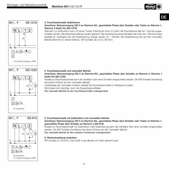
DE 3 . Feuchteautomatik deaktivieren
Anschluss: Netzversorgung 230 V an Klemme N/L, geschaltete Phase über Schalter oder Taster an Klemme 1, Klemme 2 bleibt frei (SS-1219)Alternativ zur Zeitfunktion kann mit einem Taster (Tastimpuls mind. 0,5 Sek.) die Feuchteautomatik für 1 Stunde ausge-schaltet werden. Alle Speicherzustände werden gelöscht. Bei Verwendung eines Schalters der über die 1 Stunde hinaus betätigt ist, verlängert sich die Deaktivierung, jeweils wieder um 1 Stunde. Die Deaktivierung hat auf den manuellen Betrieb (Klemme 2), keinen Einfluss. DIP-Schalter S6: on (s. SS-941)
4 . Feuchteautomatik und manueller BetriebAnschluss: Netzversorgung 230 V an Klemme N/L, geschaltete Phase über Schalter an Klemme 2, Klemme 1 bleibt frei (SS-1220)Parallel zur Feuchteautomatik kann der Ventilator über einen Schalter eingeschaltet werden. Die DIP-Schalter Einstellung hat keinen Einfluss auf den manuellen Betrieb.Unabhängig der manuellen Funktion arbeitet die Feuchteautomatik im Hintergrund weiter.Wird diese nicht benötigt, kann die Dauerphase entfallen.Der manuelle Betrieb ist der Feuchteautomatik untergeordnet.
5 . Feuchteautomatik mit Zeitfunktion und manuellem BetriebAnschluss: Netzversorgung 230 V an Klemme N/L, geschaltete Phase über Schalter oder Taster an Klemme 1, geschaltete Phase über Schalter an Klemme 2 (SS-919)Parallel zur Feuchteautomatik mit Zeitfunktion oder Deaktivierung kann der Ventilator über einen Schalter eingeschaltet werden. Die DIP-Schalter Einstellung hat keinen Einfluss auf den manuellen Betrieb.Der manuelle Betrieb ist den anderen Funktionen untergeordnet.
6 . Werkseinstellung verändern DIP-Schalter (s. SS-941). Das Gerät muss allpolig vom Netz getrennt sein!
1 2LN
NL
M1/... F
b)
SS-919
2
r.F.%
b) manuell Einc) Funktions Eingang MBV
c)
1
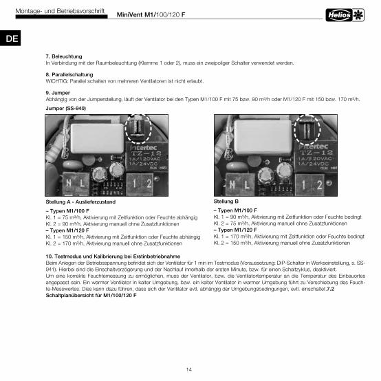
7 . BeleuchtungIn Verbindung mit der Raumbeleuchtung (Klemme 1 oder 2), muss ein zweipoliger Schalter verwendet werden.
8 . ParallelschaltungWICHTIG: Parallel schalten von mehreren Ventilatoren ist nicht erlaubt.
9 . JumperAbhängig von der Jumperstellung, läuft der Ventilator bei den Typen M1/100 F mit 75 bzw. 90 m³/h oder M1/120 F mit 150 bzw. 170 m³/h.
Jumper (SS-940)
Stellung A - Auslieferzustand
– Typen M1/100 F Kl. 1 = 75 m³/h, Aktivierung mit Zeitfunktion oder Feuchte abhängig Kl. 2 = 90 m³/h, Aktivierung manuell ohne Zusatzfunktionen – Typen M1/120 F Kl. 1 = 150 m³/h, Aktivierung mit Zeitfunktion oder Feuchte abhängig Kl. 2 = 170 m³/h, Aktivierung manuell ohne Zusatzfunktionen
10 . Testmodus und Kalibrierung bei ErstinbetriebnahmeBeim Anlegen der Betriebsspannung befindet sich der Ventilator für 1 min im Testmodus (Voraussetzung: DIP-Schalter in Werkseinstellung, s. SS-941). Hierbei sind die Einschaltverzögerung und der Nachlauf innerhalb der ersten Minute, bzw. für einen Schaltzyklus, deaktiviert.Um eine korrekte Feuchtemessung zu ermöglichen, muss der Ventilator, bzw. die Ventilatortemperatur an die Temperatur des Einbauortes angepasst sein. Ein warmer Ventilator in kalter Umgebung, bzw. ein kalter Ventilator in warmer Umgebung führt zu Verschiebung des Feuch-te-Messwertes. Dies kann dazu führen, dass sich der Ventilator evtl. abhängig der Umgebungsbedingungen, evtl. einschaltet.7 .2 Schaltplanübersicht für M1/100/120 F
MiniVent M1/100/120 FMontage- und Betriebsvorschrift
14
DE
Stellung B
– Typen M1/100 FKl. 1 = 90 m³/h, Aktivierung mit Zeitfunktion oder Feuchte bedingtKl. 2 = 75 m³/h, Aktivierung manuell ohne Zusatzfunktionen– Typen M1/120 FKl. 1 = 170 m³/h, Aktivierung mit Zeitfunktion oder Feuchte bedingt Kl. 2 = 150 m³/h, Aktivierung manuell ohne Zusatzfunktionen
MiniVent M1/100/120 FMontage- und Betriebsvorschrift
15
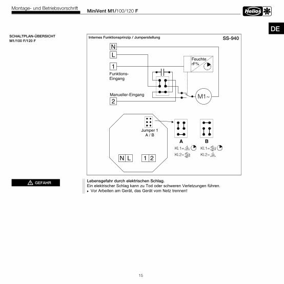
DESS-940Internes Funktionsprinzip / JumperstellungM1/... F, Prinzip SS-940
M1~
LN
1
2
Jumper 1A / B
A B
Manueller-Eingang
1 2LN
FeuchterF%
Funktions-Eingang
Kl.1=
Kl.2=
Kl.1=
Kl.2=
SCHALTPLAN-ÜBERSICHTM1/100 F/120 F
Lebensgefahr durch elektrischen Schlag . Ein elektrischer Schlag kann zu Tod oder schweren Verletzungen führen. Vor Arbeiten am Gerät, das Gerät vom Netz trennen!
mGEFAHR
MiniVent M1/100/120 FMontage- und Betriebsvorschrift
16
8 .0 Instandhaltung und Wartung
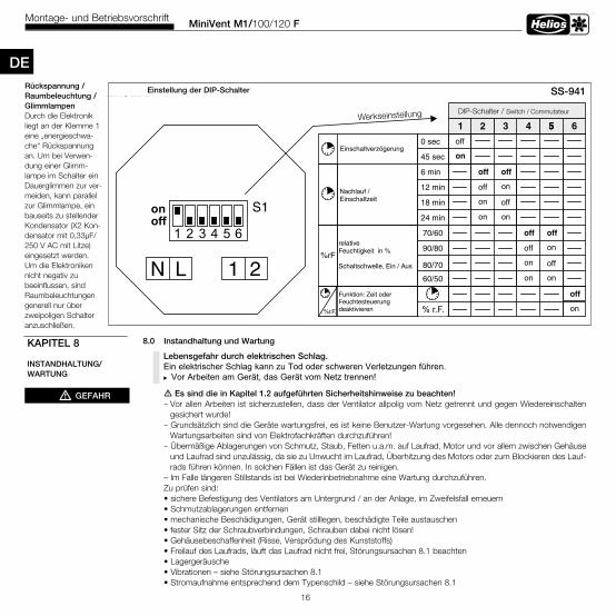
m Es sind die in Kapitel 1 .2 aufgeführten Sicherheitshinweise zu beachten! – Vor allen Arbeiten ist sicherzustellen, dass der Ventilator allpolig vom Netz getrennt und gegen Wiedereinschalten gesichert wurde! – Grundsätzlich sind die Geräte wartungsfrei, es ist keine Benutzer-Wartung vorgesehen. Alle dennoch notwendigen Wartungsarbeiten sind von Elektrofachkräften durchzuführen! – Übermäßige Ablagerungen von Schmutz, Staub, Fetten u.a.m. auf Laufrad, Motor und vor allem zwischen Gehäuse und Laufrad sind unzulässig, da sie zu Unwucht im Laufrad, Überhitzung des Motors oder zum Blockieren des Lauf- rads führen können. In solchen Fällen ist das Gerät zu reinigen. – Im Falle längeren Stillstands ist bei Wiederinbetriebnahme eine Wartung durchzuführen. Zu prüfen sind: • sichere Befestigung des Ventilators am Untergrund / an der Anlage, im Zweifelsfall erneuern • Schmutzablagerungen entfernen • mechanische Beschädigungen, Gerät stilllegen, beschädigte Teile austauschen • fester Sitz der Schraubverbindungen, Schrauben dabei nicht lösen! • Gehäusebeschaffenheit (Risse, Versprödung des Kunststoffs) • Freilauf des Laufrads, läuft das Laufrad nicht frei, Störungsursachen 8.1 beachten • Lagergeräusche • Vibrationen – siehe Störungsursachen 8.1 • Stromaufnahme entsprechend dem Typenschild – siehe Störungsursachen 8.1
DE
S1
1 2LN
M1/... F
Einschaltverzögerung
Nachlauf /Einschaltzeit
relativeFeuchtigkeit in %
Schaltschwelle, Ein / Aus
1 2 3 4 55
off
on
off off
off on
on off
on on
off off
off on
on off
on on
0 sec
45 sec
6 min
12 min
18 min
24 min
70/60
90/80
80/70
60/50
DIP-Schalter / Switch / Commutateur
SS-941
off
on
1 2 3 4 5 6
6
% rF
off
on
Funktion: Zeit oderFeuchtesteuerungdeaktivieren
%rF
%rF
SS-941Einstellung der DIP-SchalterRückspannung / Raumbeleuchtung / GlimmlampenDurch die Elektronik liegt an der Klemme 1 eine „energieschwa-che“ Rückspannung an. Um bei Verwen-dung einer Glimm-lampe im Schalter ein Dauerglimmen zur ver-meiden, kann parallel zur Glimmlampe, ein bauseits zu stellender Kondensator (X2 Kon-densator mit 0,33µF/ 250 V AC mit Litze) eingesetzt werden.Um die Elektroniken nicht negativ zu beeinflussen, sind Raumbeleuchtungen generell nur über zweipoligen Schalter anzuschließen.
KAPITEL 8
INSTANDHALTUNG/WARTUNG
mGEFAHR
% r.F.
Werkseinstellung
Lebensgefahr durch elektrischen Schlag . Ein elektrischer Schlag kann zu Tod oder schweren Verletzungen führen. Vor Arbeiten am Gerät, das Gerät vom Netz trennen!
DE
MiniVent M1/100/120 FMontage- und Betriebsvorschrift
17
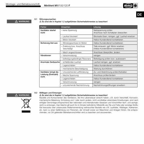
Fehler Ursachen Lösung
Ventilator startet nicht
– keine Spannung Netzspannung prüfen Anschluss nach Schaltplan überprüfen
– Laufrad blockiert Blockade lösen, reinigen, ggf. Laufrad ersetzen
– Motor blockiert Helios Kundendienst kontaktieren
Sicherung löst aus – Windungsschluss im Motor Helios Kundendienst kontaktieren
– Zuleitung bzw. Anschluss beschädigt
Teile erneuern, ggf. Motor ersetzen (Helios Kundendienst kontaktieren)
– falsch angeschlossen Anschluss überprüfen, ändern
Vibrationen – Verschmutzung reinigen
– befestigungsbedingte Resonanz Befestigung prüfen bzw. ausbessern
Anormale Geräusche – schleifendes Laufrad Laufrad reinigen, ggf. ersetzen
– Lagerschäden Helios Kundendienst kontaktieren
– mechanische Beschädigung Wartung durchführen
Ventilator bringt die Leistung (Drehzahl) nicht
– Unzureichende Luftförderung Zu- und Abströmung prüfen/freihalten
– falsche Spannung Anschluss prüfen/ändern
– Lagerschäden Helios Kundendienst kontaktieren
– Verschmutzung reinigen
– unzureichende Nachströmung Nachströmungsöffnungen erweitern
8 .1 Störungsursachen m Es sind die in Kapitel 1 .2 aufgeführten Sicherheitshinweise zu beachten!
8 .2 Stilllegen und Entsorgen m Es sind die in Kapitel 1 .2 aufgeführten Sicherheitshinweise zu beachten!
Bauteile und Komponenten des Ventilators, die ihre Lebensdauer erreicht haben, z.B. durch Verschleiß, Korrosion, mechanische Belastung, Ermüdung und / oder durch andere, nicht unmittelbar erkennbare Einwirkungen, sind nach erfolgter Demontage entsprechend den nationalen und internationalen Gesetzen und Vorschriften fach- und sachge-recht zu entsorgen. Das Gleiche gilt auch für im Einsatz befindliche Hilfsstoffe wie Öle und Fette oder sonstige Stoffe. Die bewusste oder unbewusste Weiterverwendung verbrauchter Bauteile wie z.B. Laufräder, Wälzlager, Keilriemen, etc. kann zu einer Gefährdung von Personen, der Umwelt sowie von Maschinen und Anlagen führen. Die entspre-chenden, vor Ort geltenden Betreibervorschriften sind zu beachten und anzuwenden.
mWARNUNG
mWARNUNG

Table of Contents
CHAPTER 1 GENERAL INFORMATION . . . . . . . . . . . . . . . . . . . . . . . . . . . . . . . . . . . . . . . . . . . . . . . . . . . . . . . . . Page 11.0 Important information . . . . . . . . . . . . . . . . . . . . . . . . . . . . . . . . . . . . . . . . . . . . . . . . . . . . . . . . . . . . . . . . . . Page 11.1 Warning instructions . . . . . . . . . . . . . . . . . . . . . . . . . . . . . . . . . . . . . . . . . . . . . . . . . . . . . . . . . . . . . . . . . . . Page 11.2 Safety instructions . . . . . . . . . . . . . . . . . . . . . . . . . . . . . . . . . . . . . . . . . . . . . . . . . . . . . . . . . . . . . . . . . . . . . Page 11.3 Warranty claims – Exclusion of liability . . . . . . . . . . . . . . . . . . . . . . . . . . . . . . . . . . . . . . . . . . . . . . . . . . . . . . Page 21.4 Provisions – Guidelines . . . . . . . . . . . . . . . . . . . . . . . . . . . . . . . . . . . . . . . . . . . . . . . . . . . . . . . . . . . . . . . . . Page 21.5 Shipping . . . . . . . . . . . . . . . . . . . . . . . . . . . . . . . . . . . . . . . . . . . . . . . . . . . . . . . . . . . . . . . . . . . . . . . . . . . . Page 21.6 Receipt . . . . . . . . . . . . . . . . . . . . . . . . . . . . . . . . . . . . . . . . . . . . . . . . . . . . . . . . . . . . . . . . . . . . . . . . . . . . . Page 21.7 Storage . . . . . . . . . . . . . . . . . . . . . . . . . . . . . . . . . . . . . . . . . . . . . . . . . . . . . . . . . . . . . . . . . . . . . . . . . . . . . Page 21.8 Area of application . . . . . . . . . . . . . . . . . . . . . . . . . . . . . . . . . . . . . . . . . . . . . . . . . . . . . . . . . . . . . . . . . . . . Page 21.9 Performance data . . . . . . . . . . . . . . . . . . . . . . . . . . . . . . . . . . . . . . . . . . . . . . . . . . . . . . . . . . . . . . . . . . . . . Page 31.10 Noise data . . . . . . . . . . . . . . . . . . . . . . . . . . . . . . . . . . . . . . . . . . . . . . . . . . . . . . . . . . . . . . . . . . . . . . . . . . Page 3
CHAPTER 2 GENERAL OPERATING INSTRUCTIONS . . . . . . . . . . . . . . . . . . . . . . . . . . . . . . . . . . . . . . . . . . . . . Page 32.0 Personnel qualification. . . . . . . . . . . . . . . . . . . . . . . . . . . . . . . . . . . . . . . . . . . . . . . . . . . . . . . . . . . . . . . . . . Page 32.1 Protection against contact . . . . . . . . . . . . . . . . . . . . . . . . . . . . . . . . . . . . . . . . . . . . . . . . . . . . . . . . . . . . . . Page 3 2.2 Motor protection . . . . . . . . . . . . . . . . . . . . . . . . . . . . . . . . . . . . . . . . . . . . . . . . . . . . . . . . . . . . . . . . . . . . . . Page 3
CHAPTER 3 TECHNICAL DATA/DIMENSIONS . . . . . . . . . . . . . . . . . . . . . . . . . . . . . . . . . . . . . . . . . . . . . . . . . . . Page 33.0 Type overview MiniVent M1/1... F . . . . . . . . . . . . . . . . . . . . . . . . . . . . . . . . . . . . . . . . . . . . . . . . . . . . . . . . . Page 33.1 Technical data. . . . . . . . . . . . . . . . . . . . . . . . . . . . . . . . . . . . . . . . . . . . . . . . . . . . . . . . . . . . . . . . . . . . . . . . Page 33.2 Accessories . . . . . . . . . . . . . . . . . . . . . . . . . . . . . . . . . . . . . . . . . . . . . . . . . . . . . . . . . . . . . . . . . . . . . . . . . Page 43.3 Product service life . . . . . . . . . . . . . . . . . . . . . . . . . . . . . . . . . . . . . . . . . . . . . . . . . . . . . . . . . . . . . . . . . . . . Page 43.4 Dimensions . . . . . . . . . . . . . . . . . . . . . . . . . . . . . . . . . . . . . . . . . . . . . . . . . . . . . . . . . . . . . . . . . . . . . . . . . . Page 4
CHAPTER 4 FUNCTION . . . . . . . . . . . . . . . . . . . . . . . . . . . . . . . . . . . . . . . . . . . . . . . . . . . . . . . . . . . . . . . . . . . . . Page 44.0 Functional description M1/100/120 F . . . . . . . . . . . . . . . . . . . . . . . . . . . . . . . . . . . . . . . . . . . . . . . . . . . . . . Page 4
CHAPTER 5 CLEANING/DISMANTLING . . . . . . . . . . . . . . . . . . . . . . . . . . . . . . . . . . . . . . . . . . . . . . . . . . . . . . . . Page 65.0 Cleaning . . . . . . . . . . . . . . . . . . . . . . . . . . . . . . . . . . . . . . . . . . . . . . . . . . . . . . . . . . . . . . . . . . . . . . . . . . . . Page 6 5.1 Dismantling of the facia . . . . . . . . . . . . . . . . . . . . . . . . . . . . . . . . . . . . . . . . . . . . . . . . . . . . . . . . . . . . . . . . . Page 6 CHAPTER 6 INSTALLATION . . . . . . . . . . . . . . . . . . . . . . . . . . . . . . . . . . . . . . . . . . . . . . . . . . . . . . . . . . . . . . . . Page 76.0 Scope of delivery / Design . . . . . . . . . . . . . . . . . . . . . . . . . . . . . . . . . . . . . . . . . . . . . . . . . . . . . . . . . . . . . . Page 76.1 Preparation for wall or ceiling installation (surface mounted) . . . . . . . . . . . . . . . . . . . . . . . . . . . . . . . . . . . . . Page 76.2 Installation . . . . . . . . . . . . . . . . . . . . . . . . . . . . . . . . . . . . . . . . . . . . . . . . . . . . . . . . . . . . . . . . . . . . . . . . . . . Page 76.3 Electrical connection . . . . . . . . . . . . . . . . . . . . . . . . . . . . . . . . . . . . . . . . . . . . . . . . . . . . . . . . . . . . . . . . . . . Page 96.4 Connection of supply line / Commissioning . . . . . . . . . . . . . . . . . . . . . . . . . . . . . . . . . . . . . . . . . . . . . . . . . . Page 96.5 Assembly . . . . . . . . . . . . . . . . . . . . . . . . . . . . . . . . . . . . . . . . . . . . . . . . . . . . . . . . . . . . . . . . . . . . . . . . . . Page 106.6 Operation . . . . . . . . . . . . . . . . . . . . . . . . . . . . . . . . . . . . . . . . . . . . . . . . . . . . . . . . . . . . . . . . . . . . . . . . . . Page 11
CHAPTER 7 FUNCTION FOR INSTALLER . . . . . . . . . . . . . . . . . . . . . . . . . . . . . . . . . . . . . . . . . . . . . . . . . . . . . Page 117.0 Function M1/100/120 F . . . . . . . . . . . . . . . . . . . . . . . . . . . . . . . . . . . . . . . . . . . . . . . . . . . . . . . . . . . . . . . Page 117.1 Detailed functional description. . . . . . . . . . . . . . . . . . . . . . . . . . . . . . . . . . . . . . . . . . . . . . . . . . . . . . . . . . . Page 127.2 Wiring diagram overview for M1/100/120 F. . . . . . . . . . . . . . . . . . . . . . . . . . . . . . . . . . . . . . . . . . . . . . . . . Page 15
CHAPTER 8 SERVICING AND MAINTENANCE . . . . . . . . . . . . . . . . . . . . . . . . . . . . . . . . . . . . . . . . . . . . . . . . . . Page 168.0 Servicing and maintenance . . . . . . . . . . . . . . . . . . . . . . . . . . . . . . . . . . . . . . . . . . . . . . . . . . . . . . . . . . . . . Page 168.1 Fault causes . . . . . . . . . . . . . . . . . . . . . . . . . . . . . . . . . . . . . . . . . . . . . . . . . . . . . . . . . . . . . . . . . . . . . . . . Page 178.2 Standstill and disposal . . . . . . . . . . . . . . . . . . . . . . . . . . . . . . . . . . . . . . . . . . . . . . . . . . . . . . . . . . . . . . . . Page 17
ENGLISH
MiniVent M1/100/120 FInstallation and Operating Instructions
1
1 .0 Important informationIn order to ensure complete and effective operation and for your own safety, all of the following instructions should beread carefully and observed.This document should be regarded as part of the product and as such should be kept accessible and durable. The operator is responsible for observing all plant-related safety regulations.
1 .1 Warning instructionsThe adjacent symbols are safety-relevant warning symbols . All safety regulations and/or symbols in must be absolutely adhered to, so that any risks of injury and dangerous situations are avoided!
1 .2 Safety instructions Special regulations apply for use, connection and operation; consultation is required in case of doubt. Further information can be found in the relevant standards and legal texts. mWith regard to all work on the fan, the generally applicable safety at work
and accident prevention regulations must be observed!• All electrical work as well as the commissioning, maintenance and installation
work must only be carried out by authorised, qualified electricians!• The following must be observed before all cleaning, maintenance and installation work or before opening the terminal compartment: – Isolate the unit from the mains power supply and secured against being switched on again! – The rotating parts must first come to a standstill!
– Once the rotating parts come to a standstill, a waiting time of 3 min . must be observed, as dangerous voltages may be present due to internal capa-citors even after disconnection from the mains!
• All plant-related safety regulations must be observed! If applicable, further country-specific regulations must also be observed!• A uniform inflow and free outlet must be ensured!• When using vented fire places in ventilated rooms, there must be sufficient sup-
ply air for all operating conditions (consult chimney sweep) . The current locally applicable regulations and laws must be observed!
• MiniVent M1/100/120 F mini fans can be used by children over the age of 8 as well as persons with physical, sensory, or mental disabilities or lack of experien-ce and knowledge, if they are supervised or instructed with regard to the safe use of the unit and they understand the resulting risks . Children must not play with the unit . Cleaning or user maintenance must not be carried out by unsupervised children .
CHAPTER 1
GENERAL INFORMATION
EN
mDANGER
mWARNING
mCAUTION
mDANGER
MiniVent M1/100/120 FInstallation and Operating Instructions
2
1 .3 Warranty claims – Exclusion of liabilityAll versions of this documentation must be observed, otherwise the warranty shall cease to apply. The same appliesto liability claims against Helios. The use of accessory parts, which are not recommended or offered by Helios, is notpermitted. Any possible damages are not covered by the warranty. Changes and modifications to the unit are notpermitted and lead to a loss of conformity, and any warranty and liability shall be excluded in this case.
1 .4 Provisions – GuidelinesIf the product is installed correctly and used to its intended purpose, it conforms to all applicable provisions and EUguidelines at its date of manufacture.
1 .5 Shipping The fan is packed ex works in such a way that it is protected against normal transport strain. Carry out the shipping carefully. It is recommended to leave the fan in the original packaging.
1 .6 ReceiptThe shipment must be checked for damage and correctness immediately upon delivery. If there is any damage, promptly report the damage with the assistance of the transport company. If complaints are not made within the agreed period, any claims could be lost.
1 .7 StorageWhen storing for a prolonged time, the following steps are to be taken to avoid damaging influences: Motor protectionby dry, airtight and dust-proof packaging (plastic bag with desiccant and humidity indicators). Vibration-free, wa-ter-tight and constant-temperature storage at a temperature between -20 °C to +40 °C.In case of a storage period of more than three months or motor standstill, maintenance must be carried out beforecommissioning according to chapter 8. In case of reshipment (above all, over longer distances; e.g. by sea), it must bechecked whether the packaging is suitable for the form and route of transport. Damages due to improper transporta-tion, storage or commissioning are not liable for warranty.
1 .8 Area of application– Intended use: The MiniVent M1/100/120 F mini fans are suitable for conveying normal or slightly dusty (particle size < 10 µm), less aggressive and humid air, moderate climates and in the range of their performance curves, see Helios sales docu-ments / internet. Operation is only admissible with fixed installation within buildings. The maximumadmissible media and ambient temperature is 40 °C. MiniVent M1/100/120 F mini fans correspond to protection category IP45, protection class II and they may be installed in zone 1 of bathrooms according to VDE 0100 part 701.– Reasonably foreseeable misuse: The fans are not suitable for operation under difficult conditions, such as high levels of humidity, aggressive media, long standstill periods, heavy contamination, excessive loads due to climatic, technical or electronic influences. The same applies for the mobile use of fans (vehicles, aircraft, ships, etc.). Usage under these conditions is only possible with release approval from Helios, as the standard version is not suitable in this case.– Improper, prohibited use: Any use other than the intended use is not permitted! The conveying of solid matter or solid matter content > 10µm inair and liquid is not permitted. Transport media, which affect the materials of the fan, and abrasive media are not permitted. Use in explosive atmospheres is not permitted! Outside operation of the fan is not permitted!
NOTE +
NOTE +
NOTE +
EN
MiniVent M1/100/120 FInstallation and Operating Instructions
3
EN
CHAPTER 2
GENERAL OPERATINGINSTRUCTIONS
1 .9 Performance dataThe unit type plate gives an indication of the mandatory electrical values; which must be coordinated with the localsupply network. The fan performances were established on a test stand according to DIN EN ISO 5801.
1 .10 Noise dataNoise data that refers to certain distances apply to free field conditions. With regard to installation, the sound pressurelevel can differ significantly from the catalogue data, as it is highly dependent on the installation conditions, i.e. on theabsorption capability of the room and the room size among other factors.
2 .0 Personnel qualificationm The electrical connection and commissioning as well as the installation, servicing and maintenance of the fan must only be carried out by qualified electricians .MiniVent M1/100/120 F mini fans can be used by children over the age of 8 as well as persons with physical, sensory, or mental disabilities or lack of experience and knowledge, if they are supervised or instructed with regard to the safe use of the unit and they understand the resulting risks. Children must not play with the unit. Cleaning or user main-tenance must not be carried out by unsupervised children.
2 .1 Protection against contactMiniVent M1/100/120 F mini fans do not require protection guards, since they meet the requirements from DIN EN 60335-2-80 section 20.101.
2 .2 Motor protectionThe motors of the MiniVent M1/100/120 F have thermal contacts, which are wired in series with the coil and switch off automatically and restart after cooling.
3 .0 Type overview MiniVent M1/1 . . FM1/100 F with automatic humidity control Ref no . 6175M1/120 F with automatic humidity control Ref no . 6364
3 .1 Technical dataM1/100 FImpeller [mm] Ø 92 Electrical supply line NYM-O 3 x 1.5 mm²Alternating current 1~ Protection category IP45 (water jet protection)Voltage/frequency 230 V, 50 Hz Protection class IIPower consumption [W] 9/5 Weight approx. [kg] 0.8Rated current [mA] 0.06/0.04 Speed [1/min] 2650/2250Flow volumes [m3/h] 90/75
M1/120 FImpeller [mm] Ø 111 Electrical supply line NYM-O 3 x 1.5 mm²Alternating current 1~ Protection category IP45 (water jet protection)Voltage/frequency 230 V, 50 Hz Protection class IIPower consumption [W] 13/10 Weight approx. [kg] 1.05Rated current [mA] 0.09/0.08 Speed [1/min] 2350/2050Flow volumes [m3/h] 170/150
CHAPTER 3
TECHNCAL DATA / DIMENSIONS
MiniVent M1/100/120 FInstallation and Operating Instructions
4
3 .2 Accessories WES 100 Wall mounting kit Ref . no . 0717 WES 120 Wall mounting kit Ref . no . 0486 MF 100 Mounting flange Ref . no . 6188 TWH 100 Telescopic wall sleeve Ref . no . 6352 TWH 120 Telescopic wall sleeve Ref . no . 6353 MBR Mounting plate Ref . no . 0281
3 .3 Product service life This unit is designed for a service life of at least 40,000 h, at S1 operation with maximum power in the maximum permissible ambient temperature.
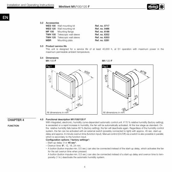
3 .4 DimensionsM1/100 F M1/120 F
4 .0 Functional description M1/100/120 F With integrated, electronic, humidity curve-dependent automatic control unit. If 70 % relative humidity (factory setting), is exceeded or a rapid increase in humidity, the fan will be automatically activated. At the low stage as standard. On the relative humidity falls below 60 % (factory setting), the fan will deactivate again. Regardless of the humidity control system, the fan can be activated with an external switch (possibly connected to light) with approx. 45 sec. start-up delay and approx. 6-minute overrun time (function input). Manual control (On/Off) via a switch is also possible in parallel, which is secondary to the function input. Configuration options / factory settings*: – Start-up delay: 0 or 45 sec*. – Overrun time: 6*, 12, 18, 24 min. – A button (button impulse min. 0.5 sec.) can also be connected instead of the start-up delay, which activates the fan for the set overrun time when pressed. A button (button impulse min. 0.5 sec.) can also be connected instead of a start-up delay and overrun time to tem- porarily (1 hr.) deactivate the automatic humidity system.
CHAPTER 4
FUNCTION
Fig .2Fig .1
All dimensions in mm All dimensions in mm
EN
MiniVent M1/100/120 FInstallation and Operating Instructions
5
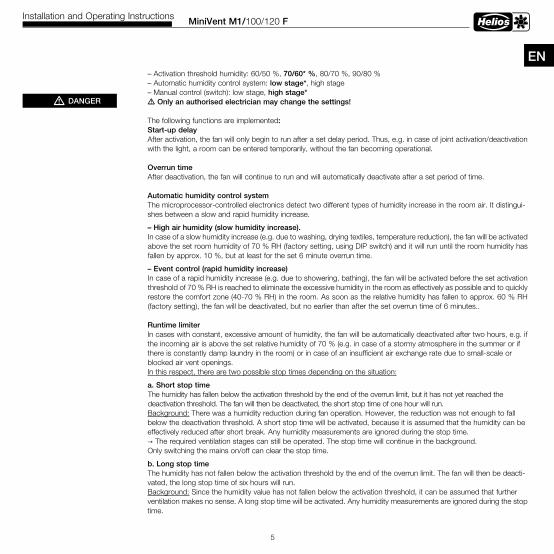
EN – Activation threshold humidity: 60/50 %, 70/60* %, 80/70 %, 90/80 % – Automatic humidity control system: low stage*, high stage – Manual control (switch): low stage, high stage* m Only an authorised electrician may change the settings!
The following functions are implemented: Start-up delay After activation, the fan will only begin to run after a set delay period. Thus, e.g. in case of joint activation/deactivation with the light, a room can be entered temporarily, without the fan becoming operational.
Overrun time After deactivation, the fan will continue to run and will automatically deactivate after a set period of time.
Automatic humidity control system The microprocessor-controlled electronics detect two different types of humidity increase in the room air. It distingui- shes between a slow and rapid humidity increase.
– High air humidity (slow humidity increase) .In case of a slow humidity increase (e.g. due to washing, drying textiles, temperature reduction), the fan will be activated above the set room humidity of 70 % RH (factory setting, using DIP switch) and it will run until the room humidity has fallen by approx. 10 %, but at least for the set 6 minute overrun time.
– Event control (rapid humidity increase)In case of a rapid humidity increase (e.g. due to showering, bathing), the fan will be activated before the set activationthreshold of 70 % RH is reached to eliminate the excessive humidity in the room as effectively as possible and to quicklyrestore the comfort zone (40-70 % RH) in the room. As soon as the relative humidity has fallen to approx. 60 % RH (factory setting), the fan will be deactivated, but no earlier than after the set overrun time of 6 minutes..
Runtime limiter In cases with constant, excessive amount of humidity, the fan will be automatically deactivated after two hours, e.g. if the incoming air is above the set relative humidity of 70 % (e.g. in case of a stormy atmosphere in the summer or if there is constantly damp laundry in the room) or in case of an insufficient air exchange rate due to small-scale or blocked air vent openings. In this respect, there are two possible stop times depending on the situation:
a . Short stop timeThe humidity has fallen below the activation threshold by the end of the overrun limit, but it has not yet reached thedeactivation threshold. The fan will then be deactivated, the short stop time of one hour will run.
Background: There was a humidity reduction during fan operation. However, the reduction was not enough to fall below the deactivation threshold. A short stop time will be activated, because it is assumed that the humidity can be effectively reduced after short break. Any humidity measurements are ignored during the stop time. → The required ventilation stages can still be operated. The stop time will continue in the background. Only switching the mains on/off can clear the stop time.
b . Long stop time The humidity has not fallen below the activation threshold by the end of the overrun limit. The fan will then be deacti- vated, the long stop time of six hours will run. Background: Since the humidity value has not fallen below the activation threshold, it can be assumed that further ventilation makes no sense. A long stop time will be activated. Any humidity measurements are ignored during the stop time.
mDANGER
MiniVent M1/100/120 FInstallation and Operating Instructions
6
→ The required ventilation stages can still be operated. The stop time will continue in the background. Only switching the mains on/off can clear the stop time. A balance between minimised energy consumption and optimal humidity reduction is achieved with these humidity curve control functions. Damp surfaces due to condensation and the associated risk of mould formation and unplea- sant odours are largely avoided.
Test mode Once there is no voltage present (power failure, fuse, etc.), the fan will go into test mode for 1 min (condition: unit with factory setting). In this case the delayed start and the overrun function is deactivated within the first minute, or for a switching cycle. In order to enable a correct humidity measurement, the fan or the fan temperature must be adjusted to the temperature of the installation site. A warm fan in a cold environment or a cold fan in a warm environment will lead to a shift in the humidity measurement value. This may cause the fan to activate depending on the environmental conditions.
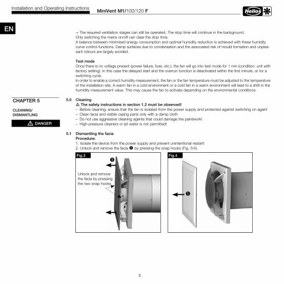
5 .0 Cleaning m The safety instructions in section 1 .2 must be observed! – Before cleaning, ensure that the fan is isolated from the power supply and protected against switching on again! – Clean facia and visible casing parts only with a damp cloth – Do not use aggressive cleaning agents that could damage the paintwork! – High-pressure cleaners or jet water is not permitted!
5 .1 Dismantling the facia Procedure: 1. Isolate the device from the power supply and prevent unintentional restart! 2. Unlock and remove the facia ò by pressing the snap hooks (Fig. 3/4).
CHAPTER 5
CLEANING/DISMANTLING
mDANGER
Fig .3
Unlock and remove the facia by pressing the two snap hooks.
òFig .4
ò
EN
Installation and Operating Instructions
MiniVent M1/100/120 FInstallation and Operating Instructions
7
ENAll of the following information and instructions are only intended for an authorised qualified electrician!
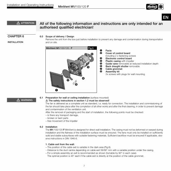
6 .0 Scope of delivery / DesignRemove the unit from the box just before installation to prevent any damage and contamination during transportation and on site.
6 .1 Preparation for wall or ceiling installation (surface mounted) m The safety instructions in section 1 .2 must be observed! The fan is delivered as a complete unit as standard, i.e. ready for connection. The installation and commissioning of the fan should take place after the completion of all other works and after the final cleaning, in order to prevent damage and contamination of the ventilation unit. After the removal of packaging and the start of installation, the following points must be checked: – is there any transport damage, – broken or bent parts – free movement of the impeller
6 .2 Installation The M1/100/120 F MiniVent is designed for direct wall installation. The casing must not be deformed or warped during installation and the flatness of the installation surface must be ensured. The fans must only be installed on sufficiently solid and stable subsurfaces with suitable fastening materials. Sufficient backflow must be ensured! If applicable, obs- erve instructions in DIN 1946-6.
1 . Cable exit from the wall: – The position of the cable exit is variable in the dark area (Fig.6). – Distance to the duct centre depending on cable exit 58/68* mm with a variable position under the casing. – For a simple assembly an exit is recommended as shown (turnable by 90° in each case). The optimal position is 45° each if the cable exit is directly at the position of the cable grommet.
CHAPTER 6
INSTALLATION
mWARNING
ò Facia ù Cover of control board including 2 x fastening screwsä Electronic control board ë Plastic casing with impeller ö Guide vane removable at reduced installation depthü Back draught shutter removableÅ Cable grommetî Assembly kit 2x screws with plugs for wall mounting
MiniVent M1/100/120.. F
ë
ö
ü
ò
Fig .5
ù
î
mATTENTION
ä
Å
MiniVent M1/100/120 FInstallation and Operating Instructions
8
Fig .7
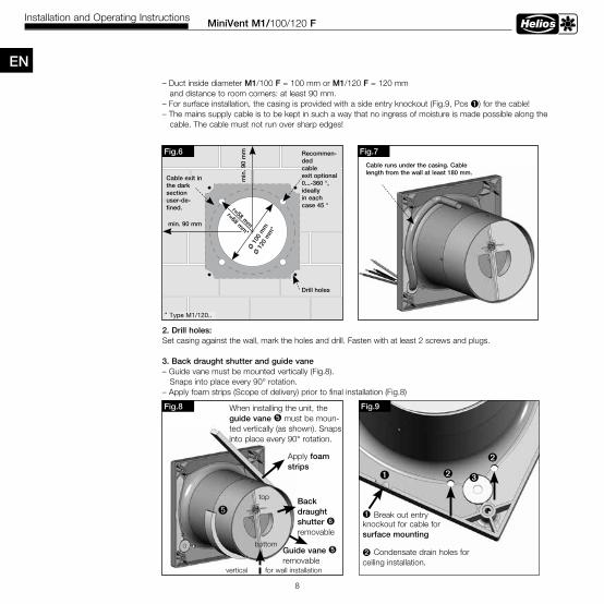
Cable runs under the casing . Cablelength from the wall at least 180 mm .
Fig .6
Ø 1
00 m
mØ
120
mm
*
r=58 mm
r=68 mm
*min . 90 mm
min
. 90
mm
Cable exit inthe darksectionuser-de-fined .
Drill holes
Recommen-dedcableexit optional0 . . .-360 °, ideallyin eachcase 45 °
* Type M1/120..
Fig .8 When installing the unit, the guide vane ö must be moun-ted vertically (as shown). Snaps into place every 90° rotation.
Guide vane ö removable
Back draught shutter ü removable
ö
Apply foam strips
vertical for wall installation
top
bottom
Fig .9
ù Condensate drain holes forceiling installation.
ò Break out entryknockout for cable forsurface mounting
ù
äù
EN – Duct inside diameter M1/100 F = 100 mm or M1/120 F = 120 mm and distance to room corners: at least 90 mm. – For surface installation, the casing is provided with a side entry knockout (Fig.9, Pos ò) for the cable! – The mains supply cable is to be kept in such a way that no ingress of moisture is made possible along the cable. The cable must not run over sharp edges!
2 . Drill holes: Set casing against the wall, mark the holes and drill. Fasten with at least 2 screws and plugs.
3 . Back draught shutter and guide vane – Guide vane must be mounted vertically (Fig.8). Snaps into place every 90° rotation. – Apply foam strips (Scope of delivery) prior to final installation (Fig.8)
ò
MiniVent M1/100/120 FInstallation and Operating Instructions
9
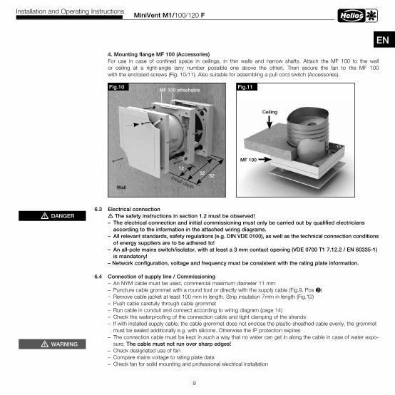
EN 4 . Mounting flange MF 100 (Accessories) For use in case of confined space in ceilings, in thin walls and narrow shafts. Attach the MF 100 to the wall or ceiling at a right-angle (any number possible one above the other). Then secure the fan to the MF 100 with the enclosed screws (Fig. 10/11). Also suitable for assembling a pull cord switch (Accessories).
6 .3 Electrical connection m The safety instructions in section 1 .2 must be observed! – The electrical connection and initial commissioning must only be carried out by qualified electricians according to the information in the attached wiring diagrams . – All relevant standards, safety regulations (e .g . DIN VDE 0100), as well as the technical connection conditions of energy suppliers are to be adhered to! – An all-pole mains switch/isolator, with at least a 3 mm contact opening (VDE 0700 T1 7 .12 .2 / EN 60335-1) is mandatory! – Network configuration, voltage and frequency must be consistent with the rating plate information .
6 .4 Connection of supply line / Commissioning – An NYM cable must be used, commercial maximum diameter 11 mm – Puncture cable grommet with a round tool or directly with the supply cable (Fig.9, Pos ä) – Remove cable jacket at least 100 mm in length. Strip insulation 7mm in length (Fig.12) – Push cable carefully through cable grommet – Run cable in conduit and connect according to wiring diagram (page 14) – Check the waterproofing of the connection cable and tight clamping of the strands – If with installed supply cable, the cable grommet does not enclose the plastic-sheathed cable evenly, the grommet must be sealed additionally e.g. with silicone. Otherwise the IP protection expires
– The connection cable must be kept in such a way that no water can get in along the cable in case of water expo-sure. The cable must not run over sharp edges!
– Check designated use of fan – Compare mains voltage to rating plate data – Check fan for solid mounting and professional electrical installation
mDANGER
mWARNING
Fig .11
Ceiling
MF 100
Fig .10MF 100 attachable
Wall
Install depth
1232 52

– Check free movement of the impeller – Check all parts for tightness, particularly screws. Do not loosen screws in the process! – Check fan for vibrations and noises during trial run – Compare power consumption to rating plate data
6 .5 Installation
MiniVent M1/100/120 FInstallation and Operating Instructions
10
Fig .12
100 mm
7 mm
Fig .13ò
ù
Mount controlboard cover
Sealant
EN
1. Mount cover of control board ù on groove, press on casing and fasten with screws.2. Snap in facia ò.
- Length of single conductor 100 mm - Length of stripped insulation 7 mm- Strip plastic-sheathed cable flush with conduit
Fig .14
Mount guidevane withback draughtshutter at theend of theduct or justomit it .
Duct channel 90° bend
Installation with cram-ped space conditions
Fig .15
Standard install
WES 1 . . or TWH 1 . .
Guide vane withback draughtshutter
Fan
Room side Outside
Core drill hole
M1/100 F =Ø 115 mmM1/120 F =Ø 130 mm
mWARNING
ò
MiniVent M1/100/120 FInstallation and Operating Instructions
11
EN6 .6 Operation mThe safety instructions in section 1 .2 must be observed! In order to ensure the proper functioning of the fan, the following must be checked regularly: – Formation of dust or dirt deposits in the casing or on the motor and impeller – Free movement of impeller – Occurrence of excessive vibration and noise If there are problems with one or more of these points, maintenance must be carried out according to the instructions in chapter 8.
7 .0 Function M1/100/120 F mThe safety instructions in section 1 .2 must be observed!
Electrical connection
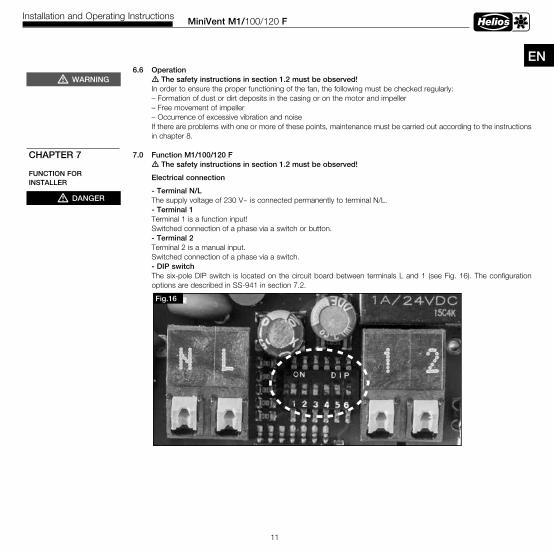
- Terminal N/L The supply voltage of 230 V~ is connected permanently to terminal N/L. - Terminal 1 Terminal 1 is a function input! Switched connection of a phase via a switch or button. - Terminal 2 Terminal 2 is a manual input. Switched connection of a phase via a switch. - DIP switch
The six-pole DIP switch is located on the circuit board between terminals L and 1 (see Fig. 16). The configuration options are described in SS-941 in section 7.2.
mWARNING
mDANGER
CHAPTER 7
FUNCTION FOR INSTALLER
Fig .16
MiniVent M1/100/120 FInstallation and Operating Instructions
12
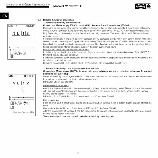
EN7 .1 Detailed functional description 1 . Automatic humidity control system Connection: Mains supply 230 V to terminal N/L, terminal 1 and 2 remain free (SS-948) Depending on the speed at which the humidity increases, the fan will start automatically. If the increase of humidity is very fast, the ventilation starts before the actual selected set point of 60, 70, 80, 90 % RH (factory setting 70 % RH). Depending on the reset point, the fan will automatically deactivate. The reset point is 10 % RH below the set activation point. If the relative humidity in the room does not decrease or only decreases slightly within a set period, the fan will go into defined interval operation (see Chapter 4 Runtime limiter). Once the reset point of 10 % RH below the activation point is reached, the fan will deactivate. A reason for not reaching the deactivation point may be that the supply air is too humid (in summer) or intensive humidity supply in the room over several hours. Function test Automatic humidity control system:
If the humidity required for the initial commissioning is not available, then the activation behaviour of the M1/100 F or M1/120 F can be checked as follows:If a damp cloth is held below the facade, the humidity sensor will detect a rapid humidity increase and it will activate thefan after approx. 180 seconds.Switching threshold RH in % (70/60, 90/80, 80/70, 60/50), DIP switch S4+5 (see SS-941)
2 . Automatic humidity control system and time functionConnection: Mains supply 230 V to terminal N/L, switched phase via switch or button to terminal 1, terminal 2 remains free (SS-1219)Automatic humidity control system like in 1. “Automatic humidity control system”, but the fan can also be activated for a set period via a switch or button with a delayed start.DIP switch S6: off (see SS-941)
Delayed start (0 or 45 sec.) After the activation of terminal 1, the ventilation will only begin after the set delay period. Thus a room can be entered with joint activation/deactivation with the room lighting (via 2 pol. switch) for a short time, without the fan running. Factory setting approx. 45 seconds. DIP switch S1.1 SS-941: No.1: off = deactivated, on = 45 sec. (see SS-941)
Button operationIf the delayed start is deactivated, the fan can be activated on terminal 1 with a button (button impulse at least 0.5 sec.).
Overrun time (6 min, 12 min, 18 min, 24 min), DIP switch S1.2+3 (see SS-941)After the deactivation of terminal 1, the fan will continue to run and will automatically deactivate after a set period. Factory setting approx. 6 minutes.
The operation with time function will override the humidity control system.
1 2LN
NL
M1/... F SS-948
2r.F.%1
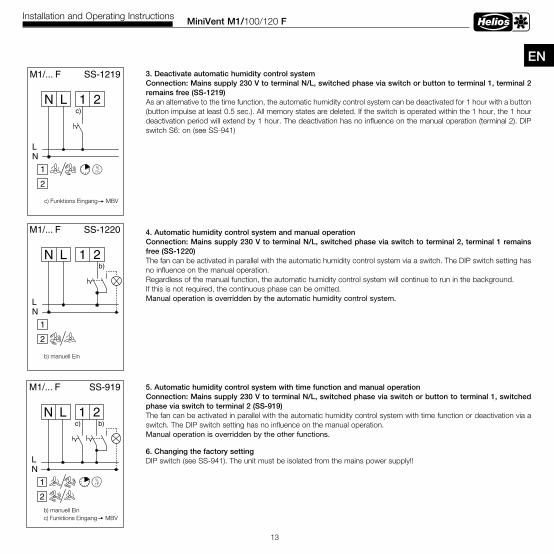
MiniVent M1/100/120 FInstallation and Operating Instructions
13
EN 3 . Deactivate automatic humidity control system
Connection: Mains supply 230 V to terminal N/L, switched phase via switch or button to terminal 1, terminal 2 remains free (SS-1219)As an alternative to the time function, the automatic humidity control system can be deactivated for 1 hour with a button (button impulse at least 0.5 sec.). All memory states are deleted. If the switch is operated within the 1 hour, the 1 hour deactivation period will extend by 1 hour. The deactivation has no influence on the manual operation (terminal 2). DIP switch S6: on (see SS-941)
4 . Automatic humidity control system and manual operationConnection: Mains supply 230 V to terminal N/L, switched phase via switch to terminal 2, terminal 1 remains free (SS-1220)The fan can be activated in parallel with the automatic humidity control system via a switch. The DIP switch setting has no influence on the manual operation.Regardless of the manual function, the automatic humidity control system will continue to run in the background.If this is not required, the continuous phase can be omitted.Manual operation is overridden by the automatic humidity control system.
5 . Automatic humidity control system with time function and manual operationConnection: Mains supply 230 V to terminal N/L, switched phase via switch or button to terminal 1, switched phase via switch to terminal 2 (SS-919)The fan can be activated in parallel with the automatic humidity control system with time function or deactivation via a switch. The DIP switch setting has no influence on the manual operation.Manual operation is overridden by the other functions.
6 . Changing the factory setting DIP switch (see SS-941). The unit must be isolated from the mains power supply!!
1 2LN
NL
M1/... F
b)
SS-919
2
r.F.%
b) manuell Einc) Funktions Eingang MBV
c)
1
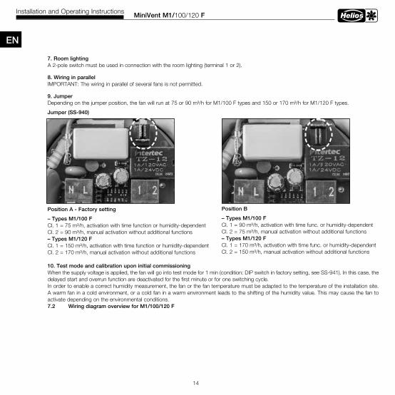
7 . Room lightingA 2-pole switch must be used in connection with the room lighting (terminal 1 or 2).
8 . Wiring in parallelIMPORTANT: The wiring in parallel of several fans is not permitted.
9 . JumperDepending on the jumper position, the fan will run at 75 or 90 m³/h for M1/100 F types and 150 or 170 m³/h for M1/120 F types.
Jumper (SS-940)
Position A - Factory setting
– Types M1/100 F Cl. 1 = 75 m³/h, activation with time function or humidity-dependent Cl. 2 = 90 m³/h, manual activation without additional functions – Types M1/120 F Cl. 1 = 150 m³/h, activation with time function or humidity-dependent Cl. 2 = 170 m³/h, manual activation without additional functions
10 . Test mode and calibration upon initial commissioningWhen the supply voltage is applied, the fan will go into test mode for 1 min (condition: DIP switch in factory setting, see SS-941). In this case, the delayed start and overrun function are deactivated for the first minute or for one switching cycle.In order to enable a correct humidity measurement, the fan or the fan temperature must be adapted to the temperature of the installation site. A warm fan in a cold environment, or a cold fan in a warm environment leads to the shifting of the humidity value. This may cause the fan to activate depending on the environmental conditions.7 .2 Wiring diagram overview for M1/100/120 F
MiniVent M1/100/120 FInstallation and Operating Instructions
14
EN
Position B
– Types M1/100 FCl. 1 = 90 m³/h, activation with time func. or humidity-dependentCl. 2 = 75 m³/h, manual activation without additional functions– Types M1/120 FCl. 1 = 170 m³/h, activation with time func. or humidity-dependent Cl. 2 = 150 m³/h, manual activation without additional functions

MiniVent M1/100/120 FInstallation and Operating Instructions
15
ENSS-940Internal functional principle / Jumper positionM1/... F, Prinzip SS-940
M1~
LN
1
2
Jumper 1A / B
A B
Manueller-Eingang
1 2LN
FeuchterF%
Funktions-Eingang
Kl.1=
Kl.2=
Kl.1=
Kl.2=
WIRING DIAGRAM OVERVIEWM1/100 F/120 F
Danger to life from electric shock . An electric shock can result in death or severe injury. Isolate the unit from the mains power supply before working on the unit!
mDANGER
Manual input
Function input
Humidity

MiniVent M1/100/120 FInstallation and Operating Instructions
16
8 .0 Servicing and maintenance
m The safety instructions in section 1 .2 must be observed! – Before any work, isolate the fan from the mains power supply and protect against being switching on again! – In principle, the units are maintenance-free, there are no user maintenance provisions. All necessary maintenance work must be carried out by a qualified electrician! – Excessive deposits of dirt, dust, grease, etc. on the impeller, motor, protection guard and, above all, between the casing and the impeller, are not permitted, as these can lead to an unbalance in the impeller, overheating of the motor or the blocking of the impeller. In such cases, the unit must be cleaned. – In cases of longer periods of standstill, maintenance must be carried out when the unit is restarted. The following must be checked: • Secure attachment of the fan to the subsurface / system, replace in case of doubt • Remove contaminant deposits • Mechanical damage, disconnect unit, replace damaged parts • Tight fit of screw connections, do not loosen screws in the process! • Casing quality (cracks, brittleness of the plastic) • Free movement of the impeller, impeller does not move freely, see Fault causes 8.1 • Bearing noises • Vibrations – see Fault causes 8.1 • Power consumption according to type plate – see Fault causes 8.1
EN
S1
1 2LN
M1/... F
Einschaltverzögerung
Nachlauf /Einschaltzeit
relativeFeuchtigkeit in %
Schaltschwelle, Ein / Aus
1 2 3 4 55
off
on
off off
off on
on off
on on
off off
off on
on off
on on
0 sec
45 sec
6 min
12 min
18 min
24 min
70/60
90/80
80/70
60/50
DIP-Schalter / Switch / Commutateur
SS-941
off
on
1 2 3 4 5 6
6
% rF
off
on
Funktion: Zeit oderFeuchtesteuerungdeaktivieren
%rF
%rF
SS-941DIP switch adjustmentReverse voltage / room lighting / glow lampDue to the electronics, there is a “low-energy” reverse voltage at terminal 1. In order to avoid a permanent glow when using a glow lamp in the switch, a capacitor (X2 capacitor with 0.33 µF/250 V AC with wire) can be used in parallel with the glow lamp.In order not to nega-tively affect the elec-tronics, room lighting is to be connected via a two-pole switch in general.
CHAPTER 8
SERVICING/MAINTENANCE
mDANGER
% r.F.
Factory setting
Danger to life from electric shock . An electric shock can result in death or severe injury. Isolate the unit from the mains power supply before working on the unit!
EN
MiniVent M1/100/120 FInstallation and Operating Instructions
17
8 .1 Fault causes m The safety instructions in section 1 .2 must be observed!
8 .2 Standstill and disposal m The safety instructions in section 1 .2 must be observed!
Parts and components of the fan, whose service life has expired, e.g. due to wear and tear, corrosion, mechanical load, fatigue and/or other effects that cannot be directly discerned, must be disposed of expertly and properly after disassembly in accordance with the national and international laws and regulations. The same also applies to auxiliary materials in use. Such as oils and greases or other substances. The intended and unintended further use of worn parts, e.g. impellers, rolling bearings, filters, etc. can result in danger to persons, the environment as well as machines and systems. The corresponding operator guidelines applicable on-site must be observed and used.
mWARNING
mWARNING
Sommaire
CHAPITRE 1 . INFORMATIONS GÉNÉRALES . . . . . . . . . . . . . . . . . . . . . . . . . . . . . . . . . . . . . . . . . . . . . . . . . . . . Page 11.0 Informations importantes . . . . . . . . . . . . . . . . . . . . . . . . . . . . . . . . . . . . . . . . . . . . . . . . . . . . . . . . . . . . . . . . Page 11.1 Mises en garde . . . . . . . . . . . . . . . . . . . . . . . . . . . . . . . . . . . . . . . . . . . . . . . . . . . . . . . . . . . . . . . . . . . . . . . Page 11.2 Consignes de sécurité. . . . . . . . . . . . . . . . . . . . . . . . . . . . . . . . . . . . . . . . . . . . . . . . . . . . . . . . . . . . . . . . . . Page 11.3 Garantie – Réserves du constructeur . . . . . . . . . . . . . . . . . . . . . . . . . . . . . . . . . . . . . . . . . . . . . . . . . . . . . . Page 21.4 Réglementations et normes . . . . . . . . . . . . . . . . . . . . . . . . . . . . . . . . . . . . . . . . . . . . . . . . . . . . . . . . . . . . . Page 21.5 Transport . . . . . . . . . . . . . . . . . . . . . . . . . . . . . . . . . . . . . . . . . . . . . . . . . . . . . . . . . . . . . . . . . . . . . . . . . . . Page 21.6 Réception de la marchandise . . . . . . . . . . . . . . . . . . . . . . . . . . . . . . . . . . . . . . . . . . . . . . . . . . . . . . . . . . . . Page 21.7 Stockage . . . . . . . . . . . . . . . . . . . . . . . . . . . . . . . . . . . . . . . . . . . . . . . . . . . . . . . . . . . . . . . . . . . . . . . . . . . Page 21.8 Domaines d’utilisations . . . . . . . . . . . . . . . . . . . . . . . . . . . . . . . . . . . . . . . . . . . . . . . . . . . . . . . . . . . . . . . . . Page 21.9 Performances . . . . . . . . . . . . . . . . . . . . . . . . . . . . . . . . . . . . . . . . . . . . . . . . . . . . . . . . . . . . . . . . . . . . . . . Page 31.10 Données acoustiques . . . . . . . . . . . . . . . . . . . . . . . . . . . . . . . . . . . . . . . . . . . . . . . . . . . . . . . . . . . . . . . . . . Page 3
CHAPITRE 2 . REMARQUES GÉNÉRALES . . . . . . . . . . . . . . . . . . . . . . . . . . . . . . . . . . . . . . . . . . . . . . . . . . . . . . Page 32.0 Qualification du personnel . . . . . . . . . . . . . . . . . . . . . . . . . . . . . . . . . . . . . . . . . . . . . . . . . . . . . . . . . . . . . . . Page 3 2.1 Protection contre tous contacts accidentels . . . . . . . . . . . . . . . . . . . . . . . . . . . . . . . . . . . . . . . . . . . . . . . . . Page 3 2.2 Protection moteur . . . . . . . . . . . . . . . . . . . . . . . . . . . . . . . . . . . . . . . . . . . . . . . . . . . . . . . . . . . . . . . . . . . . . Page 3
CHAPITRE 3 . DONNÉES TECHNIQUES/MESURES . . . . . . . . . . . . . . . . . . . . . . . . . . . . . . . . . . . . . . . . . . . . . . . Page 33.0 Vue d’ensemble du MiniVent M1/1...F . . . . . . . . . . . . . . . . . . . . . . . . . . . . . . . . . . . . . . . . . . . . . . . . . . . . . Page 33.1 Données techniques . . . . . . . . . . . . . . . . . . . . . . . . . . . . . . . . . . . . . . . . . . . . . . . . . . . . . . . . . . . . . . . . . . . Page 33.2 Accessoires . . . . . . . . . . . . . . . . . . . . . . . . . . . . . . . . . . . . . . . . . . . . . . . . . . . . . . . . . . . . . . . . . . . . . . . . . Page 43.3 Durée de vie du produit . . . . . . . . . . . . . . . . . . . . . . . . . . . . . . . . . . . . . . . . . . . . . . . . . . . . . . . . . . . . . . . . Page 43.4 Mesures . . . . . . . . . . . . . . . . . . . . . . . . . . . . . . . . . . . . . . . . . . . . . . . . . . . . . . . . . . . . . . . . . . . . . . . . . . . . Page 4
CHAPITRE 4 . FONCTIONNALITÉS . . . . . . . . . . . . . . . . . . . . . . . . . . . . . . . . . . . . . . . . . . . . . . . . . . . . . . . . . . . . Page 44.0 Description des fonctionnalités M1/100/120 F . . . . . . . . . . . . . . . . . . . . . . . . . . . . . . . . . . . . . . . . . . . . . . . Page 4
CHAPITRE 5 . ENTRETIEN/DÉMONTAGE . . . . . . . . . . . . . . . . . . . . . . . . . . . . . . . . . . . . . . . . . . . . . . . . . . . . . . . Page 65.0 Entretien . . . . . . . . . . . . . . . . . . . . . . . . . . . . . . . . . . . . . . . . . . . . . . . . . . . . . . . . . . . . . . . . . . . . . . . . . . . . Page 6 5.1 Démontage de la façade . . . . . . . . . . . . . . . . . . . . . . . . . . . . . . . . . . . . . . . . . . . . . . . . . . . . . . . . . . . . . . . . Page 6
CHAPITRE 6 . INSTALLATION . . . . . . . . . . . . . . . . . . . . . . . . . . . . . . . . . . . . . . . . . . . . . . . . . . . . . . . . . . . . . . . . Page 76.0 Contenu de la livraison / Composition . . . . . . . . . . . . . . . . . . . . . . . . . . . . . . . . . . . . . . . . . . . . . . . . . . . . . . Page 76.1 Préparation au montage mural ou plafonnier (apparent) . . . . . . . . . . . . . . . . . . . . . . . . . . . . . . . . . . . . . . . . Page 76.2 Installation . . . . . . . . . . . . . . . . . . . . . . . . . . . . . . . . . . . . . . . . . . . . . . . . . . . . . . . . . . . . . . . . . . . . . . . . . . . Page 76.3 Raccordement électrique . . . . . . . . . . . . . . . . . . . . . . . . . . . . . . . . . . . . . . . . . . . . . . . . . . . . . . . . . . . . . . . Page 96.4 Raccordement électrique / Mise en service . . . . . . . . . . . . . . . . . . . . . . . . . . . . . . . . . . . . . . . . . . . . . . . . . Page 96.5 Montage . . . . . . . . . . . . . . . . . . . . . . . . . . . . . . . . . . . . . . . . . . . . . . . . . . . . . . . . . . . . . . . . . . . . . . . . . . . Page 106.6 Utilisation . . . . . . . . . . . . . . . . . . . . . . . . . . . . . . . . . . . . . . . . . . . . . . . . . . . . . . . . . . . . . . . . . . . . . . . . . . Page 11
CHAPITRE 7 . FONCTIONNALITÉS POUR L’INSTALLATEUR . . . . . . . . . . . . . . . . . . . . . . . . . . . . . . . . . . . . . . Page 117.0 Fonctionnalités du M1/100/120 F . . . . . . . . . . . . . . . . . . . . . . . . . . . . . . . . . . . . . . . . . . . . . . . . . . . . . . . . Page 117.1 Description détaillée des fonctionnalités . . . . . . . . . . . . . . . . . . . . . . . . . . . . . . . . . . . . . . . . . . . . . . . . . . . Page 127.2 Aperçu des schémas de raccordement du M1/100/120 F . . . . . . . . . . . . . . . . . . . . . . . . . . . . . . . . . . . . . Page 14
CHAPITRE 8 . MAINTENANCE ET ENTRETIEN . . . . . . . . . . . . . . . . . . . . . . . . . . . . . . . . . . . . . . . . . . . . . . . . . . Page 168.0 Maintenance et entretien . . . . . . . . . . . . . . . . . . . . . . . . . . . . . . . . . . . . . . . . . . . . . . . . . . . . . . . . . . . . . . . Page 168.1 Origine des dysfonctionnements . . . . . . . . . . . . . . . . . . . . . . . . . . . . . . . . . . . . . . . . . . . . . . . . . . . . . . . . . Page 178.2 Démontage et recyclage . . . . . . . . . . . . . . . . . . . . . . . . . . . . . . . . . . . . . . . . . . . . . . . . . . . . . . . . . . . . . . . Page 17
FRANÇAIS
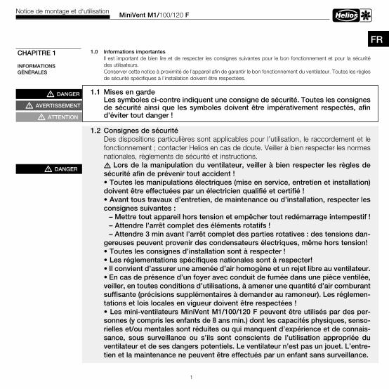
MiniVent M1/100/120 FNotice de montage et d‘utilisation
1
1 .0 Informations importantesIl est important de bien lire et de respecter les consignes suivantes pour le bon fonctionnement et pour la sécurité des utilisateurs.Conserver cette notice à proximité de l’appareil afin de garantir le bon fonctionnement du ventilateur. Toutes les règles de sécurité spécifiques à l’installation doivent être respectées.
1 .1 Mises en gardeLes symboles ci-contre indiquent une consigne de sécurité . Toutes les consignes de sécurité ainsi que les symboles doivent être impérativement respectés, afin d’éviter tout danger !
1 .2 Consignes de sécuritéDes dispositions particulières sont applicables pour l’utilisation, le raccordement et le fonctionnement ; contacter Helios en cas de doute. Veiller à bien respecter les normes nationales, règlements de sécurité et instructions.mLors de la manipulation du ventilateur, veiller à bien respecter les règles de sécurité afin de prévenir tout accident !• Toutes les manipulations électriques (mise en service, entretien et installation) doivent être effectuées par un électricien qualifié et certifié !• Avant tous travaux d’entretien, de maintenance ou d’installation, respecter les consignes suivantes : – Mettre tout appareil hors tension et empêcher tout redémarrage intempestif ! – Attendre l’arrêt complet des éléments rotatifs ! – Attendre 3 min avant l’arrêt complet des parties rotatives : des tensions dan-gereuses peuvent provenir des condensateurs électriques, même hors tension!• Toutes les consignes d’installation sont à respecter !• Les réglementations spécifiques nationales sont à respecter!• Il convient d’assurer une amenée d’air homogène et un rejet libre au ventilateur .• En cas de présence d’un foyer avec conduit de fumée dans une pièce ventilée, veiller, en toutes conditions d’utilisations, à amener une quantité d’air comburant suffisante (précisions supplémentaires à demander au ramoneur) . Les réglemen-tations et lois locales en vigueur doivent être respectées !• Les mini-ventilateurs MiniVent M1/100/120 F peuvent être utilisés par des per-sonnes (y compris les enfants de 8 ans min .) dont les capacités physiques, senso-rielles et/ou mentales sont réduites ou qui manquent d’expérience et de connais-sance, sous surveillance ou s’ils sont conscients de l’utilisation appropriée du ventilateur et de ses dangers potentiels . Le ventilateur n’est pas un jouet . L’entre-tien et la maintenance ne peuvent être effectués par un enfant sans surveillance .
CHAPITRE 1
INFORMATIONSGÉNÉRALES
FR
mDANGER
mAVERTISSEMENT
mATTENTION
mDANGER
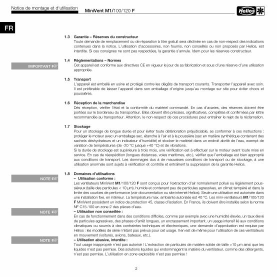
MiniVent M1/100/120 FNotice de montage et d‘utilisation
2
1 .3 Garantie – Réserves du constructeurToute demande de remplacement ou de réparation à titre gratuit sera déclinée en cas de non-respect des indications contenues dans la notice. L’utilisation d’accessoires, non fournis, non conseillés ou non proposés par Helios, est interdite. Si ces consignes ne sont pas respectées, la garantie s’annule. Idem pour les réserves constructeur.
1 .4 Réglementations – NormesCet appareil est conforme aux directives CE en vigueur le jour de sa fabrication et sous d’une réserve d’une utilisation appropriée.
1 .5 TransportL’appareil est emballé en usine et protégé contre les dégâts de transport courants. Transporter l’appareil avec soin. Il est préférable de laisser l’appareil dans son emballage d’origine jusqu’au montage sur site pour éviter chocs et poussières.
1 .6 Réception de la marchandiseDès réception, vérifier l’état et la conformité du matériel commandé. En cas d’avaries, des réserves doivent être portées sur le bordereau du transporteur. Elles doivent être précises, significatives, complètes et confirmées par lettre recommandée au transporteur. Attention, le non-respect de ces procédures peut entraîner le rejet de la réclamation.
1 .7 StockagePour un stockage de longue durée et pour éviter toute détérioration préjudiciable, se conformer à ces instructions : protéger le moteur avec un emballage sec, étanche à l’air et à la poussière (sac en matière synthétique contenant des sachets déshydrateurs et un indicateur d’humidité) et stocker le matériel dans un endroit abrité de l’eau, exempt de variation de températures (de -20 °C jusque +40 °C) et de vibrations.Si la durée de stockage est supérieure à trois mois, une vérification est à effectuer sur le moteur avant toute mise en service. En cas de réexpédition (longues distances, voies maritimes, etc.), vérifier que l’emballage est bien approprié aux conditions de transport. Les dommages dus à de mauvaises conditions de transport ou de stockage, à une utilisation anormale sont sujets à vérification et contrôle et entraînent la suppression de la garantie Helios.
1 .8 Domaines d’utilisations– Utilisation conforme : Les ventilateurs MiniVent M1/100/120 F sont conçus pour l’extraction d’air normalement pollué ou légèrement pous-siéreux (taille des particules < 10 µm), humide et contenant peu de particules agressives, en climat tempéré et dans la limite des courbes de performance (voir documentation ou site internet Helios). Seule une utilisation est autorisée dans une installation fixe, en intérieur. La température max. ambiante autorisée est 40 °C. Les mini-ventilateurs M1/100/120 F MiniVent possèdent un indice de protection 45, classe d’isolation. En France, ils doivent être installés selon la norme NF C15-100 en zone 2 des pièces d’eau.– Utilisation non conseillée : En cas de fonctionnement dans des conditions difficiles, comme par exemple avec une humidité élevée, un taux élevé de particules agressives, des phases d’arrêt longues, un encrassement important, un usage intensif lié aux conditions climatiques ou soumis à des contraintes techniques et électroniques, une demande d’approbation est requise par Helios : les modèles de série n’étant pas prévus pour cet usage. Il en est de même pour l’utilisation de ces ventilateurs en mouvement (voitures, avions, bateaux, etc.).– Utilisation abusive, interdite : Tout usage inapproprié n’est pas autorisé ! L’extraction de particules de matière solide de taille >10 µm ainsi que lesliquides n’est pas permise. Des solutions liquides qui endommagent la matière du ventilateur, comme des détergents, n’est pas permise. L’utilisation en zone explosible n’est pas permise !
IMPORTANT +
NOTE +
NOTE +
NOTE +
FR
MiniVent M1/100/120 FNotice de montage et d‘utilisation
3
FR
CHAPITRE 2
REMARQUESGÉNÉRALES
1 .9 PerformancesLa plaque signalétique de l’appareil indique les valeurs de raccordement électrique nécessaires ; l’appareil doit être raccordé à l’alimentation électrique locale. Les performances du ventilateur ont été testées selon les normes DIN EN ISO 5801.
1 .10 Données acoustiquesLes données acoustiques ont été mesurées en champ libre. Le niveau de pression sonore peut différer de celui indiqué dans le catalogue, car il dépend fortement des configurations de montage (capacité d’absorption de la pièce, taille de la pièce, etc.).
2 .0 Qualification du personnelm Les raccordements électriques, mise en service, installation, entretien et maintenance doivent êtreeffectués par un électricien qualifié et habilité .– Les mini-ventilateurs MiniVent M1/100/120 F peuvent être utilisés par des personnes (y compris les enfants à partir de 8 ans) dont les capacités physiques, sensorielles ou mentales sont réduites ou qui manquent d’expérience et de connaissance, sous surveillance ou s’ils sont conscients de l’utilisation appropriée du ventilateurs et de ses dangers potentiels. Le ventilateur n’est pas un jouet. L’entretien et la maintenance ne peuvent être effectués par un enfant sous surveillance.
2 .1 Protection contre tous contacts accidentels Aucune grille de protection n’est nécessaire pour les mini-ventilateurs MiniVent M1/100/120 F, car la norme EN 60335-2-80, section 20.101 est respectée.
2 .2 Protection moteurLes moteurs des MiniVent M1/100/120 F sont équipés de thermocontacts montés en série dans le bobinage qui s’ouvre en cas de surchauffe et se referme automatiquement après refroidissement.
3 .0 Vue d’ensemble du MiniVent M1/1 . . F M1/100 F à deux vitesses Réf . n° 6175 M1/120 F à deux vitesses Réf . n° 6364
3 .1 Données techniquesM1/100 FDiamètre ventilateur Ø [mm] 92 Raccordement électrique NYM-O 3 x 1,5 mm²Courant alternatif 1~ Indice de protection IP 45 (étanche contre projections d’eau)Tension/Fréquence 230 V, 50 Hz Classe de protection IIPuissance absorbée [W] 9/5 Poids approx. [kg] 0,8Courant nominatif [mA] 0,06/0,04 Vitesse [1/min] 2650/2250Volume d’extraction [m3/h] 90/75
M1/120 FDiamètre ventilateur Ø [mm] 111 Raccordement électrique NYM-O 3 x 1,5 mm²Courant alternatif 1~ Indice de protection IP 45 (étanche contre projections d’eau)Tension/Fréquence 230 V, 50 Hz Classe de protection IIPuissance absorbée [W] 13/10 Poids approx. [kg] 1,05Courant nominatif [mA] 0,09/0,08 Vitesse [1/min] 2350/2050Volume d’extraction [m3/h] 170/150
CHAPITRE 3
DONNÉES TECHNIQUES / MESURES
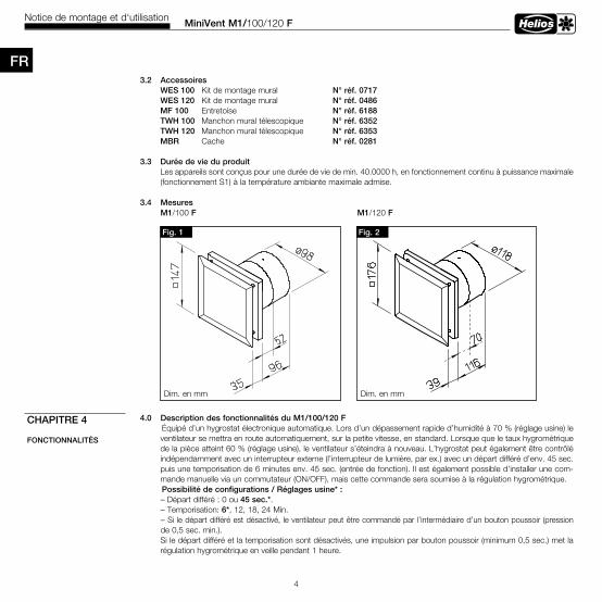
MiniVent M1/100/120 FNotice de montage et d‘utilisation
4
3 .2 Accessoires WES 100 Kit de montage mural N° réf . 0717 WES 120 Kit de montage mural N° réf . 0486 MF 100 Entretoise N° réf . 6188 TWH 100 Manchon mural télescopique N° réf . 6352 TWH 120 Manchon mural télescopique N° réf . 6353 MBR Cache N° réf . 0281
3 .3 Durée de vie du produit Les appareils sont conçus pour une durée de vie de min. 40.0000 h, en fonctionnement continu à puissance maximale (fonctionnement S1) à la température ambiante maximale admise.
3 .4 MesuresM1/100 F M1/120 F
4 .0 Description des fonctionnalités du M1/100/120 F Équipé d’un hygrostat électronique automatique. Lors d’un dépassement rapide d’humidité à 70 % (réglage usine) le ventilateur se mettra en route automatiquement, sur la petite vitesse, en standard. Lorsque que le taux hygrométrique de la pièce atteint 60 % (réglage usine), le ventilateur s’éteindra à nouveau. L’hygrostat peut également être contrôlé indépendamment avec un interrupteur externe (l’interrupteur de lumière, par ex.) avec un départ différé d’env. 45 sec. puis une temporisation de 6 minutes env. 45 sec. (entrée de fonction). Il est également possible d’installer une com-mande manuelle via un commutateur (ON/OFF), mais cette commande sera soumise à la régulation hygrométrique. Possibilité de configurations / Réglages usine* :– Départ différé : 0 ou 45 sec .*.– Temporisation: 6*, 12, 18, 24 Min.– Si le départ différé est désactivé, le ventilateur peut être commandé par l’intermédiaire d’un bouton poussoir (pression de 0,5 sec. min.). Si le départ différé et la temporisation sont désactivés, une impulsion par bouton poussoir (minimum 0,5 sec.) met la régulation hygrométrique en veille pendant 1 heure.
CHAPITRE 4
FONCTIONNALITÉS
Fig . 2Fig . 1
Dim. en mm Dim. en mm
FR
MiniVent M1/100/120 FNotice de montage et d‘utilisation
5
FR – Seuil de commutation hygrométrique : 60/50 %, 70/60* %, 80/70 %, 90/80 % – Régulation hygrométrique : petite vitesse*, grande vitesse – Commande manuelle (interrupteur): petite vitesse, grande vitesse* m Tout changement de paramètre doit être effectué par un électricien qualifié !
Les fonctionnalités suivantes sont implémantées : Départ différé
Après mise en route, le ventilateur démarre au bout du temps programmé. Ainsi, par exemple en cas de marche/arrêt commun avec la lumière (en employant un interrupteur bipolaire), on peut pénétrer un court instant dans la pièce, sans que le ventilateur se mette en route.
Temporisation Le ventilateur fonctionne pendant la durée définie et s’éteind automatiquement.
Régulation hygrométriqueL’électronique distingue deux types d’augmentation du taux d’hygrométrie dans une pièce : une augmentation lente et une augmentation rapide.
– Hygrométrie élevée (augmentation lente de l’humidité)En cas d’augmentation lente du taux d’hygrométrie (par ex. lors de lessives, de séchage de linge, de baisse de température), le ventilateur ne s’enclenche que lorsque le taux d’hygrométrie défini est atteint (réglage d’usine env. 70 % HR) et fonctionne jusqu’à que l’hygrométrie de la pièce descende 10 % en-dessous du seuil réglé avec une temporisation min. de 6 minutes.
– Régulation réactive (augmentation rapide du taux d’hygrométrie)Lors d’une augmentation rapide du taux d’hygrométrie (par ex. lors de douche ou de bain), le ventilateur s’enclenche avant d’avoir atteint le seuil de mise en route (réglage usine : 70 %) afin d’évacuer rapidement et efficacement l’humidité excessive présente dans la pièce et y rétablir rapidement le degré de confort (40-70% HR). Lors que le taux d’humidité relative est descendu à env. 60 % (réglage usine) le ventilateur arrêtera de fonctionner après la temporisation définie (6 minutes - réglage usine).
Limitation de temps de fonctionnement
Lorsque le taux d’hygrométrie ne baisse pas (par ex. lors d’orage en été, de présence de linge humide dans la pièce, lors d’un manque de renouvellement d’air dû à des entrées d’air sous-dimensionnées ou obstruées) le ventilateur s’arrête automatiquement après 2 heures de fonctionnement.
Il existe deux temps d’arrêt disponibles selon la situation :
a . Temps d’arrêt courtAprès 2 heures, l’humidité est redescendue sous le seuil de déclenchement, mais reste au-delà du seuil d’enclenchement.Le ventilateur s’arrête pendant un temps d’arrêt court de une heure. Raison : Le fonctionnement du ventilateur a entraîné une baisse du taux d’hygrométrie mais cette réduction est insuffisante pour passer sous le seuil d’arrêt. Un temps d‘arrêt de courte durée est activé car il faut supposer que l‘humidité pourra quand même être réduite efficacement après cet arrêt court. Pendant le temps d‘arrêt, la régulation hygrométrique est désactivée.→ Seule la régulation hygrométrique est désactivée, le ventilateur continue de fonctionner en mode manuel. Le décompte „arrêt court“ a lieu en arrière-plan. Seule une coupure de courant peut suspendre le décompte du temps d‘arrêt.
mDANGER
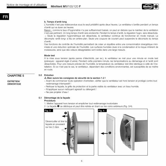
MiniVent M1/100/120 FNotice de montage et d‘utilisation
6
b . Temps d’arrêt long L’humidité n’est pas redescendue sous le seuil prédéfini après deux heures. Le ventilateur s’arrête pendant un temps
d’arrêt qui va durer six heures. Raison : comme le taux d’hygrométrie n’a pas suffisamment baissé, on peut en déduire que le maintien de la ventilation
n’est pas pertinent. Un long temps d’arrêt sera enclenché. Pendant le temps d‘arrêt, la régulation hygro. sera désactivée. → Seule la régulation hygrométrique est désactivée, le ventilateur continue de fonctionner en mode manuel. Le décompte «arrêt long» a lieu en arrière-plan. Seule une coupure de courant peut suspendre le décompte du temps d’arrêt.Ces fonctions de contrôle de l’humidité permettent de créer un équilibre entre une consommation énergétique mini-misée et une réduction optimale de l’humidité. Les surfaces humides dues à la condensation et le risque inhérent de moisissures, ainsi que des odeurs désagréables sont évités dans une large mesure.
Mode testÀ la mise sous tension (après panne d’électricité, par ex.), le ventilateur se met pour une minute en mode test (prérequis : appareil réglé d’usine). Pendant cette première minute, les temporisations au démarrage et à l’arrêt sont désactivées. Pour une mesure précise de l’humidité, la température du ventilateur doit être identique à celle de l’ins-tallation. Si ce n’est pas le cas, le ventilateur, dépendant des conditions environnantes, est susceptible de se mettre en route.
5 .0 Entretien m Bien suivre les consignes de sécurité de la section 1 .2 ! – Avant de commencer toute opération d’entretien, vérifier que le ventilateur est hors tension et protégé contre tout redémarrage intempestif !– Nettoyer la façade, la grille de protection et la partie visible du ventilateur avec un tissu humide.– N’appliquer aucun nettoyant agressif ou détergent !– Ne pas projeter d’eau !
5 .1 Démontage de la façade Procédure: 1. Mettre l’appareil hors tension et empêcher tout redémarrage involontaire 2. La façade ò se débloque et peut être retirée en tirant sur les coins extérieurs (Fig. 3/4).
CHAPITRE 5
ENTRETIEN/DÉMONTAGE
Fig . 3
Déverrouiller et tirer la façade en poussant sur les 2 clips
òFig . 4
ò
FR

MiniVent M1/100/120 FNotice de montage et d‘utilisation
7
FRToutes les informations et consignes suivantes sont destinées à unélectricien qualifié et habilité !
6 .0 Contenu de la livraison / CompositionNe déballer qu’au moment de l’installation, afin d’éviter tous dommages et salissures lors du transport ou sur lechantier.
6 .1 Préparation au montage mural ou plafonnier (apparent) m Bien suivre les consignes de sécurité de la section 1 .2 ! Le ventilateur est livré de série en une seule unité, c’est-à-dire monté. Le montage et la mise en service doivent s’effectuer avant l’assemblage de tous les autres composants et après le nettoyage, afin d’éviter tous dommages et salissures de l’appareil de ventilation. Après le déballage et avant le montage, les points suivants sont à vérifier : – les dégâts de transport éventuels. – les parties cassées ou tordues. – la rotation libre de l’hélice.
6 .2 InstallationLe MiniVent M1/100/120 F est destiné à être monté directement dans le mur. Le boîtier ne doit pas être déformé ou bombé, veiller à ce que la surface soit plate. Les ventilateurs ne peuvent être mon-tés que sur des supports suffisamment solides et porteurs, à l’aide des fixations adaptées. Il faut veiller à ce que le débit d’air entrant soit suffisant. Voir éventuellement les indications de DIN 1946-6.
1 . Sortie de câbles du mur – La position de la sortie câble peut être choisie dans la zone sombre (Fig.6). – Distance de la sortie de câble, jusqu’au milieu du conduit : 58/68* mm pour une position variable sous le boîtier. – Pour un montage simple, il convient de prévoir une sortie de câble comme dessiné sur le schéma (rotation possible à 90°). La position idéale se situe à 45°, si la sortie de câble se trouve directement à l’endroit du guide.
CHAPITRE 6
INSTALLATION
mAVERTISSEMENT
ò Façade ù Couvercle du bornier de raccordement 2 x vis de fixation inclusesä Platine de commande ë Virole en matière synthétique avec turbine ö Redresseur de flux démontable lorsque la profondeur d’encastrement est restreinteü Clapet anti-retour amovibleÅ Passe-câblesî Kit de fixation 2 x vis avec chevilles pour fixation murale inclus
MiniVent M1/100/120.. F
ë
ö
ü
ò
Fig . 5
ù
î
mATTENTION
ä
Å
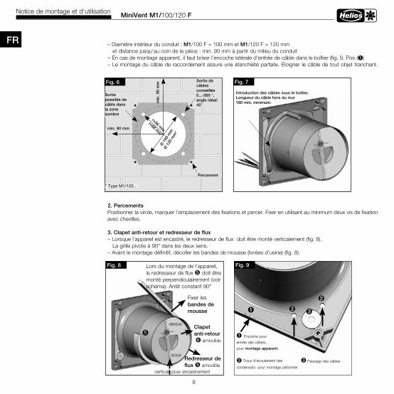
MiniVent M1/100/120 FNotice de montage et d‘utilisation
8
– Diamètre intérieur du conduit : M1/100 F = 100 mm et M1/120 F = 120 mm et distance jusqu’au coin de la pièce : min. 90 mm à partir du milieu du conduit – En cas de montage apparent, il faut briser l’encoche latérale d’entrée de câble dans le boîtier (fig. 9, Pos (ò) – Le montage du câble de raccordement assure une étanchéité parfaite. Éloigner le câble de tout objet tranchant.
2 . PercementsPositionner la virole, marquer l’emplacement des fixations et percer. Fixer en utilisant au minimum deux vis de fixation avec chevilles.
3 . Clapet anti-retour et redresseur de flux – Lorsque l’appareil est encastré, le redresseur de flux doit être monté verticalement (fig. 8). La grille pivote à 90° dans les deux sens. – Avant le montage définitif, décoller les bandes de mousse (livrées d’usine) (fig. 8).
Fig . 7
Introduction des câbles sous le boitier . Longueur du câble hors du mur 180 mm . minimum .
Fig . 6
Ø 1
00 m
mØ
120
mm
*
r=58 mm
r=68 mm
*min . 90 mm
min
. 90
mm
Sortie possible de câble dans la zone sombre
Percement
Sortie de câbles conseillée 0 . . .-360 °,angle idéal: 45°
* Type M1/120..
Fig . 8 Lors du montage de l‘appareil, le redresseur de flux ö doit être monté perpendiculairement (voir schéma). Arrêt constant 90°
Redresseur de flux ö amovible
Clapet anti-retour ü amovible
ö
Fixer les bandes de mousse
vertical pour encastrement
dessus
sous
Fig . 9
ù Trous d‘écoulement des
condensats pour montage plafonnier
ò Encoche pour
entrée des câbles,
pour montage apparent .
ù
äù
FR
ò
ä Passage des câbles
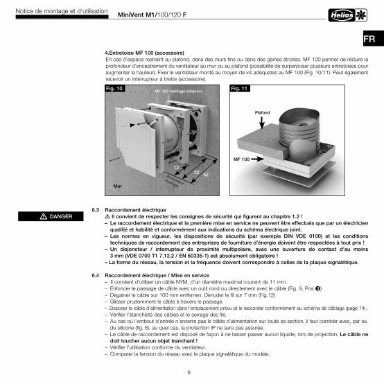
MiniVent M1/100/120 FNotice de montage et d‘utilisation
9
FR 4 .Entretoise MF 100 (accessoire)
En cas d’espace restreint au plafond, dans des murs fins ou dans des gaines étroites. MF 100 permet de réduire la profondeur d’encastrement du ventilateur au mur ou au plafond (possibilité de surperposer plusieurs entretoises pour augmenter la hauteur). Fixer le ventilateur monté au moyen de vis adéquates au MF 100 (Fig. 10/11). Peut également recevoir un interrupteur à tirette (accessoire).
6 .3 Raccordement électrique m Il convient de respecter les consignes de sécurité qui figurent au chapitre 1 .2 ! – Le raccordement électrique et la première mise en service ne peuvent être effectués que par un électricien qualifié et habilité et conformément aux indications du schéma électrique joint . – Les normes en vigueur, les dispositions de sécurité (par exemple DIN VDE 0100) et les conditions techniques de raccordement des entreprises de fourniture d’énergie doivent être respectées à tout prix ! – Un disjoncteur / interrupteur de proximité multipolaire, avec une ouverture de contact d’au moins 3 mm (VDE 0700 T1 7 .12 .2 / EN 60335-1) est absolument obligatoire ! – La forme du réseau, la tension et la fréquence doivent correspondre à celles de la plaque signalétique .
6 .4 Raccordement électrique / Mise en service – Il convient d’utiliser un câble NYM, d’un diamètre maximal courant de 11 mm. – Enfoncer le passage de câble avec un outil rond ou directement avec le câble (Fig. 9, Pos ä) – Dégainer le câble sur 100 mm entfernen. Dénuder le fil sur 7 mm (Fig.12) – Glisser prudemment le câble à travers le passage. – Disposer le câble d’alimentation dans l’emplacement prévu et le raccorder conformément au schéma de câblage (page 14). – Vérifier l’étanchéité des câbles et le serrage des fils. – Au cas où l’embout d’entrée n’enserre pas le câble d’alimentation sur toute sa section, il faut combler avec, par ex. du silicone (fig. 6), au quel cas, la protection IP ne sera pas assurée.
– Le câble de raccordement est disposé de façon à ne laisser passer aucun liquide, lors de projection. Le câble ne doit toucher aucun objet tranchant !
– Vérifier l’utilisation conforme du ventilateur. – Comparer la tension du réseau avec la plaque signalétique du modèle.
mDANGER
Fig . 11
Plafond
MF 100
Fig . 10 MF 100 montage extérieur
Mur
Profondeurmontage
1232 52
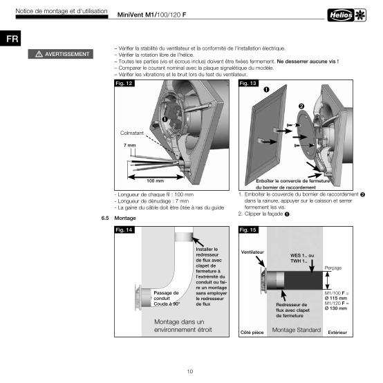
MiniVent M1/100/120 FNotice de montage et d‘utilisation
10
– Vérifier la stabilité du ventilateur et la conformité de l’installation électrique. – Vérifier la rotation libre de l’hélice. – Toutes les parties (vis et écrous inclus) doivent être fixées fermement. Ne desserrer aucune vis ! – Comparer le courant nominal avec la plaque signalétique du modèle. – Vérifier les vibrations et le bruit lors du test du ventilateur.
6 .5 Montage
Fig . 12
100 mm
7 mm
Fig . 13ò
ù
Enboîter le convercle de fermeture du bornier de raccordement
Colmatant
FR
1. Emboiter le couvercle du bornier de raccordement ù
dans la rainure, appuyer sur le caisson et serrer fermement les vis. 2. Clipper la façade ò.
- Longueur de chaque fil : 100 mm - Longueur de dénudage : 7 mm- La gaine du câble doit être ôtée à ras du guide
Fig . 14
Installer le redresseur de flux avec clapet de fermeture à l‘extrémité du conduit ou fai-re un montage sans employer le redresseur de flux
Passage de conduitCoude à 90°
Montage dans un environnement étroit
Fig . 15
Montage Standard
WES 1 . . ou TWH 1 . .
Redresseur de flux avec clapet de fermeture
Ventilateur
Côté pièce Extérieur
Perçage
M1/100 F =Ø 115 mmM1/120 F =Ø 130 mm
mAVERTISSEMENT
ò
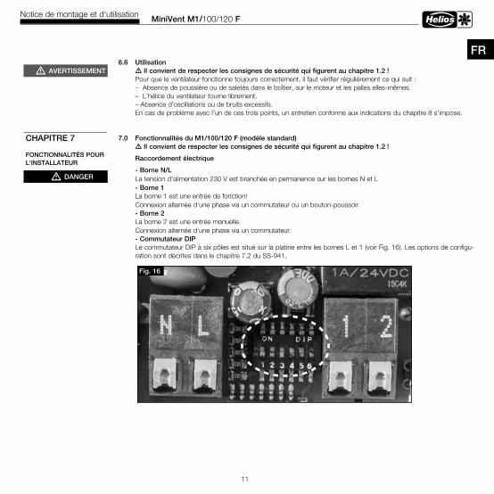
MiniVent M1/100/120 FNotice de montage et d‘utilisation
11
FR6 .6 Utilisation mIl convient de respecter les consignes de sécurité qui figurent au chapitre 1 .2 ! Pour que le ventilateur fonctionne toujours correctement, il faut vérifier régulièrement ce qui suit : – Absence de poussière ou de saletés dans le boîtier, sur le moteur et les palles elles-mêmes. – L’hélice du ventilateur tourne librement. – Absence d’oscillations ou de bruits excessifs. En cas de problème avec l’un de ces trois points, un entretien conforme aux indications du chapitre 8 s’impose.
7 .0 Fonctionnalités du M1/100/120 F (modèle standard) mIl convient de respecter les consignes de sécurité qui figurent au chapitre 1 .2 !
Raccordement électrique
- Borne N/L La tension d‘alimentation 230 V est branchée en permanence sur les bornes N et L - Borne 1 La borne 1 est une entrée de fonction! Connexion alternée d‘une phase via un commutateur ou un bouton-poussoir. - Borne 2 La borne 2 est une entrée manuelle. Connexion alternée d‘une phase via un commutateur. - Commutateur DIP
Le commutateur DIP à six pôles est situé sur la platine entre les bornes L et 1 (voir Fig. 16). Les options de configu-ration sont décrites dans le chapitre 7.2 du SS-941.
mAVERTISSEMENT
mDANGER
CHAPITRE 7
FONCTIONNALITÉS POUR L‘INSTALLATEUR
Fig . 16
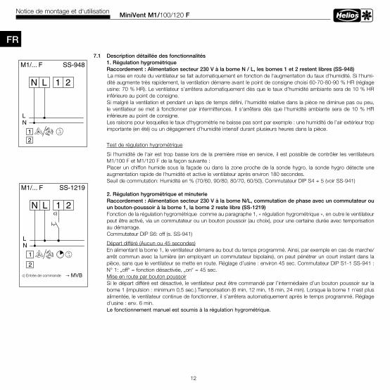
MiniVent M1/100/120 FNotice de montage et d‘utilisation
12
FR
7 .1 Description détaillée des fonctionnalités 1 . Régulation hygrométrique Raccordement : Alimentation secteur 230 V à la borne N / L, les bornes 1 et 2 restent libres (SS-948)
La mise en route du ventilateur se fait automatiquement en fonction de l‘augmentation du taux d’humidité. Si l‘humi-dité augmente très rapidement, la ventilation démarre avant le point de consigne choisi 60-70-80-90 % HR (réglage usine: 70 % HR). Le ventilateur s’arrêtera automatiquement dès que le taux d’humidité ambiante sera de 10 % HR inférieure au point de consigne. Si malgré la ventilation et pendant un laps de temps défini, l’humidité relative dans la pièce ne diminue pas ou peu, le ventilateur se met à fonctionner par intermittences. Il s‘arrêtera dés que l‘humidité ambiante sera de 10 % HR inférieure au point de consigne. Les raisons pour lesquelles le taux d‘hygrométrie ne baisse pas sont par exemple : une humidité de l’air extérieur trop importante (en été) ou un dégagement d’humidité intensif durant plusieurs heures dans la pièce.
Test de régulation hygrométrique
Si l‘humidité de l‘air est trop basse lors de la première mise en service, il est possible de contrôler les ventilateurs M1/100 F et M1/120 F de la façon suivante :Placer un chiffon humide sous la façade ou dans la zone proche de la sonde hygro, la sonde hygro détecte une augmentation rapide de l‘humidité et active le ventilateur après environ 180 secondes.Seuil de commutation: Humidité en % (70/60, 90/80, 80/70, 60/50), Commutateur DIP S4 + 5 (voir SS-941)
2 . Régulation hygrométrique et minuterieRaccordement : Alimentation secteur 230 V à la borne N/L, commutation de phase avec un commutateur ou un bouton-poussoir à la borne 1, la borne 2 reste libre (SS-1219)Fonction de la régulation hygrométrique comme au paragraphe 1, « régulation hygrométrique », en outre le ventilateur peut être activé, via un commutateur ou un bouton poussoir (au choix), pour une certaine durée avec temporisation au démarrage.Commutateur DIP S6: off (s. SS-941)
Départ différé (Aucun ou 45 secondes) En alimentant la borne 1, le ventilateur démarre au bout du temps programmé. Ainsi, par exemple en cas de marche/arrêt commun avec la lumière (en employant un commutateur bipolaire), on peut pénétrer un court instant dans la pièce, sans que le ventilateur se mette en route. Réglage d’usine : environ 45 sec. Commutateur DIP S1-1 SS-941 : N° 1: „off“ = fonction désactivée, „on“ = 45 sec.
Mise en route par bouton poussoirSi le départ différé est désactivé, le ventilateur peut être commandé par l’intermédiaire d’un bouton poussoir sur la borne 1 (impulsion : minimum 0,5 sec.).Temporisation (6 min, 12 min, 18 min, 24 min). Lorsque la borne 1 n‘est plus alimentée, le ventilateur continue de fonctionner, il s’arrêtera automatiquement après le temps programmé. Réglage d’usine : env. 6 min. Le fonctionnement manuel est soumis à la régulation hygrométrique.
1 2LN
NL
M1/... F SS-948
2r.F.%1
c) Entrée de commande →MVB
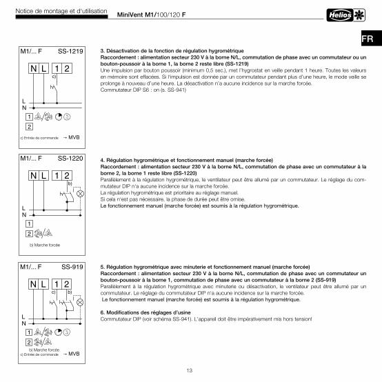
MiniVent M1/100/120 FNotice de montage et d‘utilisation
13
FR 3 . Désactivation de la fonction de régulation hygrométrique
Raccordement : alimentation secteur 230 V à la borne N/L, commutation de phase avec un commutateur ou un bouton-poussoir à la borne 1, la borne 2 reste libre (SS-1219)Une impulsion par bouton poussoir (minimum 0,5 sec.), met l’hygrostat en veille pendant 1 heure. Toutes les valeurs en mémoire sont effacées. Si l‘impulsion est donnée par un commutateur pendant plus d’une heure, le mode veille se prolonge à nouveau d’une heure. La désactivation n’a aucune incidence sur la marche forcée. Commutateur DIP S6 : on (s. SS-941)
4 . Régulation hygrométrique et fonctionnement manuel (marche forcée)Raccordement : alimentation secteur 230 V à la borne N/L, commutation de phase avec un commutateur à la borne 2, la borne 1 reste libre (SS-1220)Parallèlement à la régulation hygrométrique, le ventilateur peut être allumé par un commutateur. Le réglage du com-mutateur DIP n‘a aucune incidence sur la marche forcée.La régulation hygrométrique est prioritaire au réglage manuel. Si cela n‘est pas nécessaire, la phase de durée peut être omise.Le fonctionnement manuel (marche forcée) est soumis à la régulation hygrométrique.
5 . Régulation hygrométrique avec minuterie et fonctionnement manuel (marche forcée)Raccordement : alimentation secteur 230 V à la borne N/L, commutation de phase avec un commutateur un bouton-poussoir à la borne 1, commutation de phase avec un commutateur à la borne 2 (SS-919)Parallèlement à la régulation hygrométrique avec minuterie ou désactivation, le ventilateur peut être allumé par un commutateur. Le réglage du commutateur DIP n‘a aucune incidence sur la marche forcée.Le fonctionnement manuel (marche forcée) est soumis à la régulation hygrométrique.
6 . Modifications des réglages d’usine Commutateur DIP (voir schéma SS-941). L’appareil doit être impérativement mis hors tension!
1 2LN
NL
M1/... F
b)
SS-919
2
r.F.%
b) manuell Einc) Funktions Eingang MBV
c)
1
b) Marche forcée
b) Marche forcée
c) Entrée de commande →MVB
c) Entrée de commande →MVB
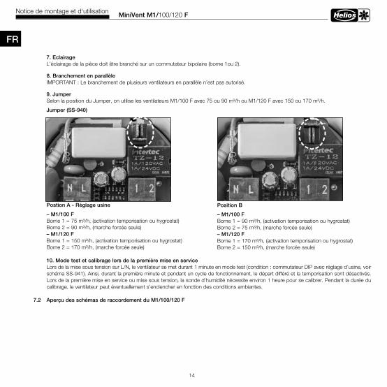
MiniVent M1/100/120 FNotice de montage et d‘utilisation
14
7 . Eclairage L’éclairage de la pièce doit être branché sur un commutateur bipolaire (borne 1ou 2).
8 . Branchement en parallèleIMPORTANT : Le branchement de plusieurs ventilateurs en parallèle n’est pas autorisé.
9 . JumperSelon la position du Jumper, on utilise les ventilateurs M1/100 F avec 75 ou 90 m³/h ou M1/120 F avec 150 ou 170 m³/h.
Jumper (SS-940)
Postion A - Réglage usine
– M1/100 F Borne 1 = 75 m³/h, (activation temporisation ou hygrostat) Borne 2 = 90 m³/h, (marche forcée seule) – M1/120 F Borne 1 = 150 m³/h, (activation temporisation ou hygrostat) Borne 2 = 170 m³/h, (marche forcée seule)
10 . Mode test et calibrage lors de la première mise en serviceLors de la mise sous tension sur L/N, le ventilateur se met durant 1 minute en mode test (condition : commutateur DIP avec réglage d’usine, voir schéma SS-941). Ainsi, durant la première minute et pendant un cycle de fonctionnement, le départ différé et la temporisation sont désactivés. Lors de la première mise en service ou mise sous tension, la sonde d’humidité nécessite environ 1 heure pour se calibrer. Pendant la durée du calibrage, le ventilateur peut éventuellement s’enclencher en fonction des conditions ambiantes.
7 .2 Aperçu des schémas de raccordement du M1/100/120 F
FR
Position B
– M1/100 FBorne 1 = 90 m³/h, (activation temporisation ou hygrostat)Borne 2 = 75 m³/h, (marche forcée seule)– M1/120 FBorne 1 = 170 m³/h, (activation temporisation ou hygrostat)Borne 2 = 150 m³/h, (marche forcée seule)
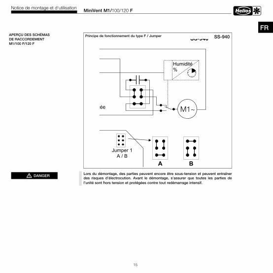
MiniVent M1/100/120 FNotice de montage et d‘utilisation
15
FRSS-940Principe de fonctionnement du type F / Jumper SS-940
M1~
LN
1
2
Jumper 1A / B
B
Marche forcée
1 2LN
Humidité%
Entrée de commande
A Borne1=
Borne 2 =
Borne 1=
Borne 2=
APERÇU DES SCHÉMAS DE RACCORDEMENTM1/100 F/120 F
Lors du démontage, des parties peuvent encore être sous-tension et peuvent entraîner des risques d’électrocution . Avant le démontage, s’assurer que toutes les parties de l’unité sont hors tension et protégées contre tout redémarrage intensif .
mDANGER
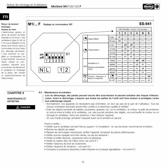
MiniVent M1/100/120 FNotice de montage et d‘utilisation
16
8 .0 Maintenance et entretien
– Normalement, nos appareils ne nécessitent pas d‘entretien, en tout cas pas de la part de l‘utilisateur. Tous les travaux d‘entretien éventuels doivent être confiés à un électricien qualifié et habilité !
– Éviter les dépôts excessifs de saletés, poussières, graisses, etc. sur le ventilateur, le moteur, la grille de protection et surtout entre le boîtier et le ventilateur, car cela pourrait entraîner des dégâts, une surchauffe du moteur ou un blocage du ventilateur. Dans ces situations, il faut nettoyer l‘appareil.
– En cas d‘arrêt prolongé, entretenir l‘appareil avant de le remettre en service.
Points à vérifier : • Vérifier que le ventilateur est bien fixé au support / à l‘installation ; en cas de doute, recommencer la fixation. • Éliminer les dépôts de saleté. • Réparer les dommages mécaniques, arrêter l‘appareil, remplacer les pièces défectueuses. • Vérifier que les vissages sont bien serrés, ne pas les desserrer !
• Vérifier le boîtier (fissures, craquelures dans le plastique).• Vérifier la rotation libre de l‘hélice sinon voir point 8.1.• Vérifier l‘absence de bruit de roulements.• Vérifier l‘absence de vibrations - voir point 8.1.• Comparer la puissance absorbée à celle indiquée sur la plaque signalétique - voir point 8.1.
FR
S1
1 2LN
M1/... F
Départ différé
Temporisation
Humidité en %
Seuil de commutation on/off
1 2 3 4 55off
on
off off
off on
on off
on on
off off
off on
on off
on on
0 sec
45 sec
6 min
12 min
18 min
24 min
70/60
90/80
80/7060/50
DIP-Schalter / Switch / Commutateur
SS-941
off
on
1 2 3 4 5 6
6
% rF
off
on
Fonction: Désactiver le temps ou l'hygrostat
%rF
%rF
Réglage du commutateur DIPRetour de tension/éclairage/lampes au néonL‘électronique génère un retour de tension de faible intensité sur la borne 1 des ventilateurs types N, NC et F. En cas d‘utilisation d‘une lampe néon témoin dans le commutateur et pour éviter son allumage permanent, il faut brancher en par-allèle un condensateur de 0,33µF/250VAC (fourniture client). Utiliser un com-mutateur bipolaire pour commander simultanément le ventilateur et l‘éclairage de la pièce, afin d‘éviter un dysfonctionnement de l‘électronique.
CHAPITRE 8
MAINTENANCE ET ENTRETIEN
mDANGER
% r.F.
Lors du démontage, des parties peuvent encore être sous-tension et peuvent entraîner des risques d’électro-cution . Avant le démontage, s’assurer que toutes les parties de l’unité sont hors tension et protégées contre tout redémarrage intensif .
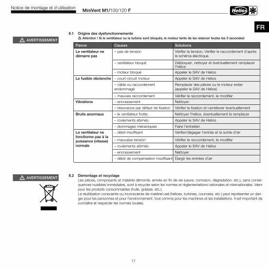
MiniVent M1/100/120 FNotice de montage et d‘utilisation
17
FR
Panne Causes Solutions
Le ventilateur ne démarre pas
– pas de tension Vérifier la tension. Vérifier le raccordement d’après le schéma électrique.
– ventilateur bloqué Débloquer, nettoyer et éventuellement remplacer l‘hélice
– moteur bloqué Appeler le SAV de Helios
Le fusible déclenche – court-circuit moteur Appeler le SAV de Helios
– câble ou raccordement endommagé
Remplacer des pièces ou le moteur entier (appeler le SAV de Helios)
– mauvais raccordement Vérifier le raccordement, le modifier
Vibrations – encrassement Nettoyer.
– résonance par défaut de fixation Vérifier la fixation et l›améliorer éventuellement
Bruits anormaux – le ventilateur frotte. Nettoyer l’hélice, éventuellement la remplacer
– roulements abimés Appeler le SAV de Helios
– dommages mécaniques Faire l‘entretien
Le ventilateur ne fonctionne pas à la puissance (vitesse) normale
– débit insuffisant Vérifier/dégager l‘entrée et la sortie d‘air
– mauvaise tension Vérifier le raccordement, le modifier
– roulements abimés Appeler le SAV de Helios
– encrassement Nettoyer
– débit de compensation insuffisant Élargir les entrées d‘air
mAVERTISSEMENT
mAVERTISSEMENT
8 .1 Origine des dysfonctionnements m Attention ! Si le ventilateur ou la turbine sont bloqués, le moteur tente de les relancer toutes les 3 secondes!
8 .2 Démontage et recyclageLes pièces, composants et matériel démonté, arrivés en fin de vie (usure, corrosion, dégradation, etc.), sans consé-quences nuisibles immédiates, sont à recycler selon les normes et règlementations nationales et internationales. Idem pour les produits consommables (huile, graisse, etc.).La réutilisation consciente ou inconsciente de matériel usé (hélices, turbines, courroies, etc.) peut représenter un dan-ger pour les personnes et pour l’environnement, tout comme pour les machines et les installations. Il est important de connaître et respecter les normes locales.
Service / InformationD HELIOS Ventilatoren GmbH & Co · Lupfenstraße 8 · 78056 VS-Schwenningen A HELIOS Ventilatoren · Postfach 854 · Siemensstraße 15 · 6023 Innsbruck F HELIOS Ventilateurs · Le Carré des Aviateurs · 157 av. Charles Floquet · 93155 Le Blanc Mesnil CedexCH HELIOS Ventilatoren AG · Tannstrasse 4 · 8112 Otelfingen GB HELIOS Ventilation Systems Ltd. · 5 Crown Gate · Wyncolls Road · Severalls Industrial Park · Colchester · Essex · CO4 9HZ
Als Referenz am Gerät griffbereit aufbewahren! Druckschrift-Nr . Please keep this manual for reference with the unit! Print-No .Conservez cette notice à proximité de l’apapreil! N° Réf . 19 053-005/0317 www.heliosventilatoren.de