LZ-702W - KENWOODEN).pdfMONITOR TOUCH SCREEN PANORAMICO 7 pagina 66-81 ISTRUZIONI PER L’USO...
17
LZ-702W WIDE TOUCH SCREEN MONITOR 7 page 2-17 INSTRUCTION MANUAL MONITEUR ECRAN LARGE TACTILE 7 page 18-33 MODE D’EMPLOI WIDE TOUCH SCREEN MONITOR 7 Seite 34-49 BEDIENUNGSANLEITUNG BREEDBEELD MONITOR MET AANRAAKSCHERM 7 blz 50-65 GEBRUIKSAANWIJZING MONITOR TOUCH SCREEN PANORAMICO 7 pagina 66-81 ISTRUZIONI PER L’USO MONITOR DE PANTALLA TÁCTIL PANORÁMICA 7 página 82-97 MANUAL DE INSTRUCCIONES MONITOR DE ECRÃ LARGO DE TOQUE 7 página 98-113 MANUAL DE INSTRUÇÕES 寬屏幕觸控顯示器 7 114-129 頁 使用說明書 © B64-3411-00/00 (WV)
Transcript of LZ-702W - KENWOODEN).pdfMONITOR TOUCH SCREEN PANORAMICO 7 pagina 66-81 ISTRUZIONI PER L’USO...
LZ-702WWIDE TOUCH SCREEN MONITOR 7 page 2-17
INSTRUCTION MANUALMONITEUR ECRAN LARGE TACTILE 7 page 18-33
MODE D’EMPLOIWIDE TOUCH SCREEN MONITOR 7 Seite 34-49
BEDIENUNGSANLEITUNGBREEDBEELD MONITOR MET AANRAAKSCHERM 7 blz 50-65
GEBRUIKSAANWIJZINGMONITOR TOUCH SCREEN PANORAMICO 7 pagina 66-81
ISTRUZIONI PER L’USOMONITOR DE PANTALLA TÁCTIL PANORÁMICA 7 página 82-97
MANUAL DE INSTRUCCIONESMONITOR DE ECRÃ LARGO DE TOQUE 7 página 98-113
MANUAL DE INSTRUÇÕES寬屏幕觸控顯示器 7 114-129 頁
使用說明書
© B64-3411-00/00 (WV)
B64-3411-00_00.indb 1B64-3411-00_00.indb 1 06.1.20 0:17:35 PM06.1.20 0:17:35 PM
pd
Highlight

2 | English
Safety precautions
2 CAUTION
To prevent damage to the machine, take the following precautions:• Make sure to ground the unit to a negative 12V
DC power supply.
• Do not install the unit in a spot exposed to direct
sunlight or excessive heat or humidity. Also avoid
places with too much dust or the possibility of
water splashing.
• When replacing a fuse, only use a new fuse with
the prescribed rating. Using a fuse with the wrong
rating may cause your unit to malfunction.
• Do not use your own screws. Use only the screws
provided. If you use the wrong screws, you could
damage the unit.
• You cannot view video pictures whilst the vehicle
is moving. To enjoy video pictures, find a safe
place to park and engage the parking brake.
2 WARNING
To prevent injury or fire, take the following precautions:• To prevent a short circuit, never put or leave any
metallic objects (such as coins or metal tools)
inside the unit.
• Do not watch or fix your eyes on the unit’s display
when you are driving for any extended period.
• Mounting and wiring this product requires
skills and experience. For safety’s sake, leave the
mounting and wiring work to professionals.
• Do not touch the liquid crystal fluid if the LCD
is damaged or broken due to shock. The liquid
crystal fluid may be dangerous to your health or
even fatal.
If the liquid crystal fluid from the LCD contacts
your body or clothing, wash it off with soap
immediately.
B64-3411-00_00.indb 2B64-3411-00_00.indb 2 06.1.20 0:17:36 PM06.1.20 0:17:36 PM
English | 3
Notes
• If you experience problems during installation,
consult your Kenwood dealer.
• When you purchase optional accessories, check
with your Kenwood dealer to make sure that they
work with your model and in your area.
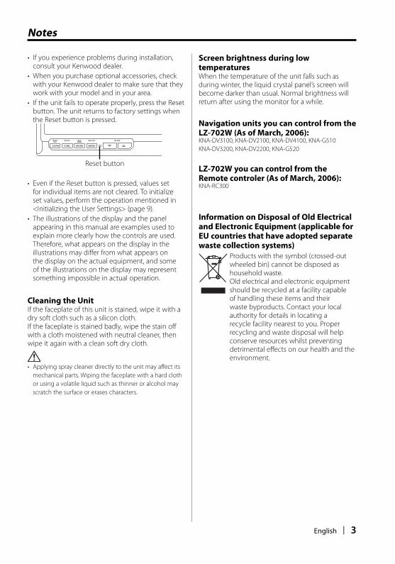
• If the unit fails to operate properly, press the Reset
button. The unit returns to factory settings when
the Reset button is pressed.
Reset button
SCRN V.SEL MODE MENU
AV OUT VOLUMEV.OFF PWROFF
SPMODE
• Even if the Reset button is pressed, values set
for individual items are not cleared. To initialize
set values, perform the operation mentioned in
<Initializing the User Settings> (page 9).
• The illustrations of the display and the panel
appearing in this manual are examples used to
explain more clearly how the controls are used.
Therefore, what appears on the display in the
illustrations may differ from what appears on
the display on the actual equipment, and some
of the illustrations on the display may represent
something impossible in actual operation.
Cleaning the UnitIf the faceplate of this unit is stained, wipe it with a
dry soft cloth such as a silicon cloth.
If the faceplate is stained badly, wipe the stain off
with a cloth moistened with neutral cleaner, then
wipe it again with a clean soft dry cloth.
• Applying spray cleaner directly to the unit may affect its
mechanical parts. Wiping the faceplate with a hard cloth
or using a volatile liquid such as thinner or alcohol may
scratch the surface or erases characters.
Screen brightness during low temperaturesWhen the temperature of the unit falls such as
during winter, the liquid crystal panel’s screen will
become darker than usual. Normal brightness will
return after using the monitor for a while.
Navigation units you can control from the LZ-702W (As of March, 2006):KNA-DV3100, KNA-DV2100, KNA-DV4100, KNA-G510
KNA-DV3200, KNA-DV2200, KNA-G520
LZ-702W you can control from the Remote controler (As of March, 2006):KNA-RC300
Information on Disposal of Old Electrical and Electronic Equipment (applicable for EU countries that have adopted separate waste collection systems)
Products with the symbol (crossed-out
wheeled bin) cannot be disposed as
household waste.
Old electrical and electronic equipment
should be recycled at a facility capable
of handling these items and their
waste byproducts. Contact your local
authority for details in locating a
recycle facility nearest to you. Proper
recycling and waste disposal will help
conserve resources whilst preventing
detrimental effects on our health and the
environment.
B64-3411-00_00.indb 3B64-3411-00_00.indb 3 06.1.20 0:17:37 PM06.1.20 0:17:37 PM

4 | English
Operations
SCRN V.SEL MODE MENU
AV OUTV.OFF
WIDE LCD TOUCH SCREEN MONITOR LZ-702W
VOLUME PWROFF
SPMODE
SCRN
MENU 5∞V.SEL
MODE
Power
Turning ON the PowerPress the [SCRN] button.
Turning OFF the PowerPress the [SCRN] button for at least 1 second.
Video Source SelectionPress the [V.SEL] button.
Each time the button is pressed, the video source
switches as follows:
Display Setting"Video 1" Video 1 ("NAV" setting during "RGB" or "Off")
"Video 2"/"R-Cam"
Video 2 ("AV-IN2" setting during "Video 2" or "R-Cam")
"NAV" Navigation ("NAV" setting during "RGB" or "AV-IN1")
• For "NAV" and "AV-IN2" setting, refer to <Setting the
NAV input> (page 8) or <Setting the AV-IN2 input>
(page 8).
• You cannot view video pictures whilst the vehicle is
moving. To enjoy video pictures, find a safe place to
park and engage the parking brake.
Volume
Increasing Volume:Press the [5] button.
Decreasing Volume:Press the [∞] button.
• You can not control this function when <Setting the
Speaker Mode> (page 5) is set to "Off".
Auto Dimmer sensor
Swithing the Display off mode You can set the display off mode for the monitor.
Press the [V.SEL] button for at least 1 second.
Exit the Display off modePress any button.
Press the button other than the [5] and [∞]
buttons.
B64-3411-00_00.indb 4B64-3411-00_00.indb 4 06.1.20 0:17:37 PM06.1.20 0:17:37 PM
English | 5
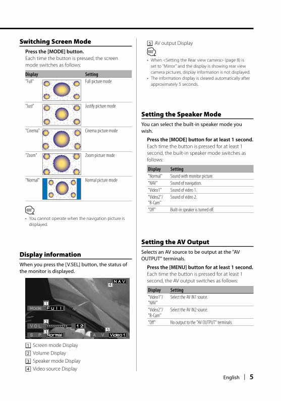
Switching Screen Mode Press the [MODE] button.
Each time the button is pressed, the screen
mode switches as follows:
Display Setting"Full" Full picture mode
"Just" Justify picture mode
"Cinema" Cinema picture mode
"Zoom" Zoom picture mode
"Normal" Normal picture mode
• You cannot operate when the navigation picture is
displayed.
Setting the Speaker ModeYou can select the built-in speaker mode you wish.
Press the [MODE] button for at least 1 second.
Each time the button is pressed for at least 1
second, the built-in speaker mode switches as
follows:
Display Setting"Normal" Sound with monitor picture.
"NAV" Sound of navigation.
"Video1" Sound of video 1.
"Video2"/"R-Cam"
Sound of video 2.
"Off" Built-in speaker is turned off.
Setting the AV Output Selects an AV source to be output at the "AV OUTPUT" terminals.
Press the [MENU] button for at least 1 second.
Each time the button is pressed for at least 1
second, the AV output switches as follows:
Display Setting"Video1"/"NAV"
Select the AV IN1 source.
"Video2"/"R-Cam"
Select the AV IN2 source.
"Off" No output to the "AV OUTPUT" terminals.
Display information When you press the [V.SEL] button, the status of the monitor is displayed.
1
4
2
3 5
1 Screen mode Display
2 Volume Display
3 Speaker mode Display
4 Video source Display
5 AV output Display
• When <Setting the Rear view camera> (page 8) is
set to "Mirror" and the display is showing rear view
camera pictures, display information is not displayed.
• The information display is cleared automatically after
approximately 5 seconds.
B64-3411-00_00.indb 5B64-3411-00_00.indb 5 06.1.20 0:17:38 PM06.1.20 0:17:38 PM

6 | English
Adjusting the Screen ControlYou can adjust the picture quality and Auto dimmer control of the monitor.
1 Enter the Screen Control mode
Press the [SCRN] button.
2 Adjusting the Picture Quality
Each time you touch the button, the setting
alternates between the settings shown in the
table below.
Item Touch Setting"BRT" [3]
[2]Brighter screenDarker screen
"TIN" [3][2]
Stronger red levelStronger green level
"COL" [3][2]
Deeper colorPaler color
"CONT" [3][2]
Stronger contrastLess contrast
"BLK" [3][2]
Less black levelStronger black level
Auto Dimmer
Item Touch Setting"Auto DIM" [7On] When it gets dark, the brightness of
display lowers automatically.
[7Off] The display doesn't dim.
• The "BRT" can be adjusted when "Auto DIM" is set to
"Off".
• The "TIN" can be adjusted when NTSC video signal is
input.
• The "TIN" and "COL" cannot be adjusted for the
navigation picture (RGB) or the control screen.
3 Exit the Screen Control mode
Touch the [OK] button.
• Separate picture quality settings can be stored for the
video, control screens and navigation picture.
• The Screen Control is displayed only when you have
applied the parking brake.
• If you make no operation for 15 seconds, this mode is
automatically canceled.
Operations
B64-3411-00_00.indb 6B64-3411-00_00.indb 6 06.1.20 0:17:38 PM06.1.20 0:17:38 PM

English | 7
Setup Menu
Setup MenuThe Setup menu operation method is explained here. The reference for the Menu items and their setting content is after this operation explanation.
1 Enter Setup Menu
Press the [MENU] button.
2 Select the Setup item
Touch the [System Setup] or [Touch Adjust]
button.
Touch Setting[System Setup] Displays the System Setup-1. (page 8)
[Touch Adjust] Displays the Touch Panel Adjust. (page 10)
[Return] Exit the Setup Menu.
3 Exit Setup Menu
Press the [MENU] button.
• If you cannot select a setup menu item, press the
[MENU] button, the touch panel position settings are
reset to the factory defaults.
• If you make no operation for 15 seconds, this mode is
automatically canceled.
SCRN V.SEL MODE MENU
AV OUTV.OFF
WIDE LCD TOUCH SCREEN MONITOR LZ-702W
VOLUME PWROFF
SPMODE
MENU
B64-3411-00_00.indb 7B64-3411-00_00.indb 7 06.1.20 0:17:39 PM06.1.20 0:17:39 PM
8 | English
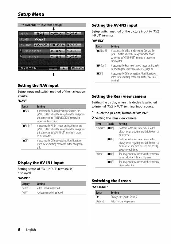
Setting the AV-IN2 inputSetup switch method of the picture input to "AV2 INPUT" terminal.
"AV-IN2"
Touch Setting[7Video 2] It becomes the video mode setting. Operate the
[V.SEL] button when the image from the device connected to "AV2 INPUT" terminal is shown on the monitor.
[7R-Cam] It becomes the Rear view camera mode setting. refer to <Setting the Rear view camera> (page 8).
[7Off] It becomes the Off mode setting. Use this setting when there’s nothing connected to the "AV2 INPUT" terminal.
Setting the Rear view cameraSetting the display when this device is switched to internal "AV2 INPUT" terminal input source.
1 Touch the [R-Cam] button of "AV-IN2".
2 Setting the Rear view camera.
Item Touch Setting"Reverse" [7On] Switches to the rear view camera video
display when engaging the shift knob of car to "Reverse".
[7Off] Switches to the rear view camera video display when engaging the shift knob of car to "Reverse" and then pressing the [V.SEL] switch several times.
"Mirror" [7On] The image which appeares in the camera is turned left-side right and displayed.
[7Off] The image which appeares in the camera is displayed as it is.
Switching the Screen"SYSTEM1"
Touch Setting[3] Displays the System Setup-2.
[Return] Return to the setup menu.
Setup Menu
Setting the NAV inputSetup input and switch method of the navigation picture.
"NAV"
Touch Setting[7RGB] It becomes the RGB mode setting. Operate the
[V.SEL] button when the image from the navigation unit connected to "TO NAVIGATION" terminal is shown on the monitor.
[7AV-IN1] It becomes the AV-IN1 mode setting. Operate the [V.SEL] button when the image from the navigation unit connected to "AV1 INPUT" terminal is shown on the monitor.
[7Off] It becomes the Off mode setting. Use this setting when there’s nothing connected to the navigation unit.
Display the AV-IN1 inputSetting status of "AV1 INPUT" terminal is displayed.
"AV-IN1"
Display Setting"Video 1" Video 1 mode is selected.
"NAV" Navigation mode is selected.
= [MENU] = [System Setup]
«
«
B64-3411-00_00.indb 8B64-3411-00_00.indb 8 06.1.20 0:17:40 PM06.1.20 0:17:40 PM

English | 9
Initializing the User SettingsThe setting value is set to the initial state of factory.
1 Touch the [Clear] button of "Memory".
2 Touch the [Yes] button.
Touch the [Yes] button, restores the factory set
default values for individual items from those set
by the user.
"System Settings were Initialized" is displayed.
Initialization is cancelled.Touch the [No] button.
Setting the AV Output Selects an AV source to be output at the "AV OUTPUT" terminals.
"AV-OUT"
Touch Setting[7AV-IN1] Select the AV IN1 source.
[7AV-IN2] Select the AV IN2 source.
[7Off] No output to the "AV OUTPUT" terminals.
Setting the Speaker Mode You can select the built-in speaker mode you wish.
Touch the [ 2 ] or [ 3 ] button of "SP".
Display Setting"Normal" Sound with monitor picture.
"NAV" Sound of navigation.
"Video1" Sound of video 1.
"Video2"/ "R-Cam" Sound of video 2.
"Off" Built-in speaker is turned off.
Switching the Screen"SYSTEM2"
Touch Setting[2] Displays the System Setup-1.
[3] Displays the System Setup-3.
[Return] Return to the setup menu.
Switching the Screen"SYSTEM3"
Touch Setting[2] Displays the System Setup-2.
[Return] Return to the setup menu.
= [MENU] = [System Setup] = [3]
«
= [MENU] = [System Setup] = [3] = [3]
«
« «
B64-3411-00_00.indb 9B64-3411-00_00.indb 9 06.1.20 0:17:40 PM06.1.20 0:17:40 PM
10 | English
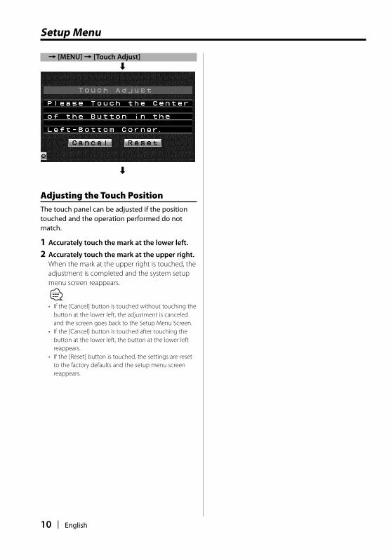
Adjusting the Touch PositionThe touch panel can be adjusted if the position touched and the operation performed do not match.
1 Accurately touch the mark at the lower left.
2 Accurately touch the mark at the upper right.
When the mark at the upper right is touched, the
adjustment is completed and the system setup
menu screen reappears.
• If the [Cancel] button is touched without touching the
button at the lower left, the adjustment is canceled
and the screen goes back to the Setup Menu Screen.
• If the [Cancel] button is touched after touching the
button at the lower left, the button at the lower left
reappears.
• If the [Reset] button is touched, the settings are reset
to the factory defaults and the setup menu screen
reappears.
= [MENU] = [Touch Adjust]
«
«
Setup Menu
B64-3411-00_00.indb 10B64-3411-00_00.indb 10 06.1.20 0:17:41 PM06.1.20 0:17:41 PM

English | 11
Accessories
1
..........1
2
..........1
3
..........1
4
..........5
5
..........1
6
..........2
(Ø4 × 12 mm)
(Ø4 × 16 mm)
7
..........1
8
..........1
9
..........1
B64-3411-00_00.indb 11B64-3411-00_00.indb 11 06.1.20 0:17:41 PM06.1.20 0:17:41 PM
12 | English
1. To prevent short circuits, remove the key from
the ignition and disconnect the · terminal of
the battery.
2. Make the proper input and output cable
connections for each unit.
3. Connect the wiring harness wires in the
following order: ground, ignition.
4. Connect the wiring harness connector to the
unit.
5. Install the unit in your car.
6. Reconnect the · terminal of the battery.
7. Press the reset button. (page 3)
2 WARNING• This product is intended for use with 12V DC negative
ground power only. Do not connect it to any other
power supply.
• To prevent shorting, disconnect the battery cable from
the negative terminal of the battery during installation.
• Be sure to firmly stabilise this product. Do not install it in
a location which is not stable.
• Follow the installation and wiring procedures described
in this manual. Improper wiring or modified installation
can not only result in malfunction or damage to the unit
but may also result in an accident.
• Do not install the unit in the following locations. • A location which interferes with the operation of the air
bag system.
• A location which is not made of plastic.
\ Installing on leather, wood or cloth may damage the
surface.
• A location subject to direct sunlight, subject to the air
from the air conditioner, or subject to moisture or high
temperature.
\ This may cause deformation of the monitor unit.
• If you are not going to install the unit using the supplied
monitor stand, be sure to use a commercially available
monitor stand. (Mounting holes for such a stand are
located on the bottom of the monitor unit.)
• If your car’s ignition does not come with an ACC position,
connect the ignition wires to a power source that can be
turned on and off with the ignition key. If you connect
the ignition wire to a power source that receives a
constant voltage supply, as with battery wires, the battery
may die.
• If the fuse blows, first make sure that the wires have not
caused a short circuit, then replace the old fuse with one
with the same rating.
• Do not let unconnected wires or terminals touch metal
on the car or anything else conducting electricity. To
prevent short circuits do not remove the caps from
unused terminals or from the ends of the unconnected
wires.
• After the unit is installed, check whether the brake lamps,
blinkers, wipers, etc. on the car are working properly.
• Insulate unconnected wires with vinyl tape or other
similar material.
• Thoroughly wipe away oil and other dirt from the
installation surface.
Please avoid installation on uneven surfaces.
• Do not install the Hideaway unit under the carpet.
Otherwise heat build-up occurs and the unit may be
damaged.
Installation Procedure
B64-3411-00_00.indb 12B64-3411-00_00.indb 12 06.1.20 0:17:42 PM06.1.20 0:17:42 PM

English | 13
Connection
+
POWER TO MONITOR
LF
M/A
MA
NT
EN
NA
( 5A )
PRK SW
REVERSE
TO NAVIGATION
AV1 INPUT
RVIDEO L (MONO)
AV2 INPUT
RVIDEO L
AV OUTPUT
RVIDEO L
+12V
Accessory 2
Ignition cable (Red)
Parking sensor cable (Light Green)
Ignition key switch
Car fuse box (Main fuse)
ACC
Ground cable (Black) · (To car chassis)
Battery
Monitor Unit
Connection cable (Provided with the Kenwood Navigation Unit)
Hideaway Unit
Kenwood Navigation Unit
For the sake of safety, be sure to
connect the parking sensor.
To parking brake detection switch harness of car.
Audio/Visual input 1• Visual input (Yellow)• Audio left input (White)• Audio right input (Red)
Audio/Visual input 2• Visual input (Yellow)• Audio left input (White)• Audio right input (Red)
Audio/Visual Output• Visual output (Yellow)• Audio left output (White)• Audio right output (Red)
Acc
ess
ory
1
Reverse sensor cable (Purple/White)When the Rear view camera is connected.
B64-3411-00_00.indb 13B64-3411-00_00.indb 13 06.1.20 0:17:42 PM06.1.20 0:17:42 PM

14 | English
Installation
Installation for Monitor Unit
Installation location and cleaningSelect for installation a location where the stand
can be placed completely horizontal or where the
front edge of the support (petal-shaped part) can
be attached horizontally as shown in Figure A.
Do not install in locations where the entire support
is at a diagonal such as in Figure B or where the
monitor unit is facing down such as in Figure C.
��������������������������������������������������������������������������������������������������������������
���������������������������������������������������������������������������������������������������
������������������������������������������������������������������������
A B C
• Thoroughly wipe away and dust or grease from the
installation location using a cloth which has been soaked
in a neutral cleaning agent and wrung out. Attach the
stand after allowing the installation location to dry.
Installation for Monitor Unit
1 Install the shoe on the rear of the TV monitor
temporarily using the supplied hexagon wrench
(Accessary 5).
• When adjusting the fixing screw of the shoe, use the
hexagon wrench (Accessary 5) that came with the
product. Using other hexagon wrenches may damage
the screw.
2 Bend the stand support to conform to the shape
of the installation location.
3 Adjust the shape of the support so that there is
no rattling or gap when the stand is placed on
the support.
4 Peel off the protective strip from the double-
sided tape on the bottom of the stand and
securely attach the stand.
• Do not attach the double-sided tape more than once or
touch the adhesive with your fingers as this will weaken
its adhesive strength.
• If the temperature of the surface of the installation
location is low, warm it up using a heater or other means
before attaching the stand. Low temperature may
weaken the adhesive strength of the tape.
• The supplied stand is specially intended for this product.
Do not use it with another monitor.
5 Secure the stand using the supplied tapping
screw (Accessory 4).
6 After attaching the stand, allow it to sit
undisturbed for 24 hours. Take care not to apply
any force to the stand during this time.
7 Insert the shoe of the monitor unit into the
bracket (Accessory 3).
• Insert the shoe into the bracket (Accessory 3) as far as it
goes. (Fig. 1)
8 Adjust the height, horizontal and vertical angle
of the monitor unit, and securely tighten the
installation screws using the supplied hexagon
wrench (Accessary 5).
You can also adjust the monitor unit's forward
position by loosening the angle adjustment
knobs and adjusting the angle of the monitor
unit's installation stand.
Accessory 3
Accessory 4
Protective strip
Installation surface
Accessory 5
Shoe
Accessory 5
Tighten
Loosen
Fig. 1
B64-3411-00_00.indb 14B64-3411-00_00.indb 14 06.1.20 0:17:44 PM06.1.20 0:17:44 PM

English | 15
Installation for Hideaway Unit
Use screws (Accessory 6) to fix Hideaway Unit onto
an audio board or another.
Accessory 6
Installation
Installation for Monitor Unit (For Headrest)Mounting and wiring this product requires skills and experience. For safety's sake, leave the mounting and
wiring work to professionals.
Before mounting the monitor to the headrest:
• Perform the required external connections first (Accessory 2).
• Using the supplied paper pattern, mark the area to be cut out of the headrest, then carefully cut it.
1 Connect Monitor and system cord (Accessory 2).
2 Install the monitor unit in the bracket (Accessory 7).
Headrest
Accessory 7
Accessory 2
Screws (not supplied)
Monitor Unit
Installation plate (not supplied)
Paper template (Accessory 9) Accessory 2
Removing the Monitor Unit (For Headrest)
1 Insert the removal tool (Accessory 8) deeply
into the slots on each side, as shown.
Accessory 8
2 Pull the monitor unit all the way out with your
hands, being careful not to drop it.
B64-3411-00_00.indb 15B64-3411-00_00.indb 15 06.1.20 0:17:45 PM06.1.20 0:17:45 PM

16 | English
Troubleshooting Guide
What might seem to be a malfunction in your unit may just be the result of slight misoperation or miswiring. Before calling service, first check the following table for possible problems.
? The power does not turn ON.
✔ The fuse has blown.
☞ After checking for short circuits in the wires,
replace the fuse with one with the same
rating.
✔ The motor is not attached to the bracket securely.
☞ Attach the motor to the bracket until it clicks.
? Nothing happens when the buttons are pressed.
✔ The computer chip in the unit is not functioning
normally.
☞ Press the reset button on the unit (page 3).
? The screen is dark.
✔ The unit is in a location where temperature is low.
☞ If the temperature of the monitor unit drops,
the screen may appear darker when power is
first turned on due to the characteristics of a
liquid crystal panel. Wait a while after turning
power on for the temperature to rise. Normal
brightness will return.
✔ The "BRT", "BLK", "CONT", and other screen control
levels are too low.
☞ Adjust the "BRT", "BLK", "CONT", and other
screen controls to obtain appropriate
illumination, or restore them to factory-set
levels with reference to <Initializing the User
Settings> (page 10).
B64-3411-00_00.indb 16B64-3411-00_00.indb 16 06.1.20 0:17:45 PM06.1.20 0:17:45 PM
English | 17
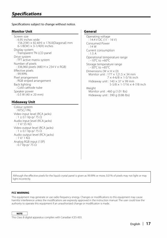
Monitor Unit
Screen size: 6.95 inches wide
156.2(W) × 82.4(H) × 176.0(Diagonal) mm6-1/8(W) × 3-1/4(H) inches
Display system: Transparent TN LCD panel
Drive system: TFT active matrix system
Number of pixels: 336,960 pixels (480 H × 234 V × RGB)
Effective pixels: 99.99%
Pixel arrangement: RGB striped arrangement
Back lighting: Cold cathode tube
Speaker power : 0.5 W (40 × 20 mm)
Hideaway Unit
Colour system : NTSC/ PAL
Video input level (RCA jacks): 1 ± 0.1 Vp-p/ 75 Ω
Audio input level (RCA jacks): 1 V/ 55 KΩ
Video output level (RCA jacks): 1 ± 0.1 Vp-p/ 75 Ω
Audio output level (RCA jacks): 1 V/ 1 KΩ
Analog RGB input (13P): 0.7 Vp-p/ 75 Ω
Specifications subject to change without notice.
General
Operating voltage: 14.4 V DC (11 - 16 V)
Consumed Power: 14 W
Current consumption: 1.5 A
Operational temperature range: –10°C to +60°C
Storage temperature range: –30°C to +85°C
Dimensions (W × H × D)Monitor unit : 177 × 121.5 × 34 mm
7 × 4-6/8 × 1-5/16 inch
Hideaway unit : 143 × 37 × 99 mm5-5/8 × 1-7/16 × 4-7/8 inch
WeightMonitor unit : 460 g (1.01 lbs)
Hideaway unit : 390 g (0.86 lbs)
Specifications
Although the effective pixels for the liquid crystal panel is given as 99.99% or more, 0.01% of pixels may not light or may
light incorrectly.
FCC WARNING
This equipment may generate or use radio frequency energy. Changes or modifications to this equipment may cause
harmful interference unless the modifications are expressly approved in the instruction manual. The user could lose the
authority to operate this equipment if an unauthorized change or modification is made.
NOTE
This Class B digital apparatus complies with Canadian ICES-003.
B64-3411-00_00.indb 17B64-3411-00_00.indb 17 06.1.20 0:17:46 PM06.1.20 0:17:46 PM