· J000 J032 a MS2SS e e u u u D10.1 0 - 0.010 0 - 0.020 D4 =12 0 - 0.008 0 - 0.009 0 - 0.011 D1...
444
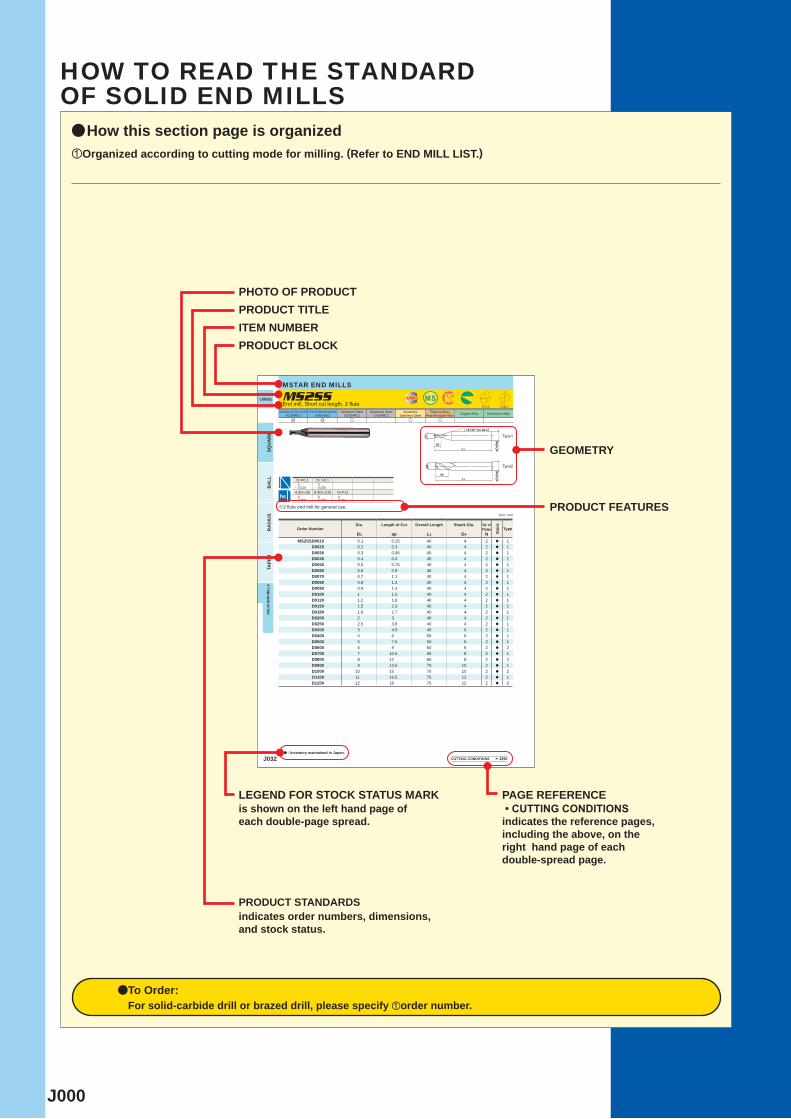
J000 J032 a MS2SS e e u u u D1<3 D1=0.1 D1>0.1 0 - 0.010 0 - 0.020 D4=12 0 - 0.008 0 - 0.009 0 - 0.011 D1 ap L1 D4 N MS2SSD0010 0.1 0.15 40 4 2 a 1 D0020 0.2 0.3 40 4 2 a 1 D0030 0.3 0.45 40 4 2 a 1 D0040 0.4 0.6 40 4 2 a 1 D0050 0.5 0.75 40 4 2 a 1 D0060 0.6 0.9 40 4 2 a 1 D0070 0.7 1.1 40 4 2 a 1 D0080 0.8 1.2 40 4 2 a 1 D0090 0.9 1.4 40 4 2 a 1 D0100 1 1.5 40 4 2 a 1 D0120 1.2 1.8 40 4 2 a 1 D0150 1.5 2.3 40 4 2 a 1 D0180 1.8 2.7 40 4 2 a 1 D0200 2 3 40 4 2 a 1 D0250 2.5 3.8 40 4 2 a 1 D0300 3 4.5 45 6 2 a 1 D0400 4 6 50 6 2 a 1 D0500 5 7.5 50 6 2 a 1 D0600 6 9 50 6 2 a 2 D0700 7 10.5 60 8 2 a 1 D0800 8 12 60 8 2 a 2 D0900 9 13.5 70 10 2 a 1 D1000 10 15 70 10 2 a 2 D1100 11 16.5 75 12 2 a 1 D1200 12 18 75 12 2 a 2 øD4(h6) L1 ap øD1 15° UWC MS 30° øD4(h6) L1 ap øD1 h6 CARBIDE a: Inventory maintained in Japan. BALL RADIUS TAPER SOLID END MILLS SQUARE Unit : mm Carbon Steel, Alloy Steel, Cast Iron (<30HRC) Tool Steel, Pre-Hardened Steel,Hardened Steel (<45HRC) Hardened Steel (<55HRC) Hardened Steel (>55HRC) Austenitic Stainless Steel Titanium Alloy, Heat Resistant Alloy Copper Alloy Aluminium Alloy MSTAR END MILLS 2 flute end mill for general use. End mill, Short cut length, 2 flute Type1 (10° for ø0.1) Order Number Dia. Length of Cut Overall Length Shank Dia. No. of Flutes Stock Type CUTTING CONDITIONS J290 D1>3 Type2 4 <D4 <6 8 <D4 <10 a How this section page is organized zOrganized according to cutting mode for milling. (Refer to END MILL LIST.) PHOTO OF PRODUCT PRODUCT TITLE ITEM NUMBER PRODUCT BLOCK GEOMETRY PRODUCT FEATURES LEGEND FOR STOCK STATUS MARK is shown on the left hand page of each double-page spread. PAGE REFERENCE • CUTTING CONDITIONS indicates the reference pages, including the above, on the right hand page of each double-spread page. PRODUCT STANDARDS indicates order numbers, dimensions, and stock status. aTo Order: For solid-carbide drill or brazed drill, please specify zorder number. HOW TO READ THE STANDARD OF SOLID END MILLS
Transcript of · J000 J032 a MS2SS e e u u u D10.1 0 - 0.010 0 - 0.020 D4 =12 0 - 0.008 0 - 0.009 0 - 0.011 D1...
J000
J032
a
MS2SS
e e u u u
D1<3
D1=0.1 D1 >0.1 0- 0.010
0- 0.020
D4=12 0- 0.008
0- 0.009
0- 0.011
D1 ap L1 D4 NMS2SSD0010 0.1 0.15 40 4 2 a 1
D0020 0.2 0.3 40 4 2 a 1D0030 0.3 0.45 40 4 2 a 1D0040 0.4 0.6 40 4 2 a 1D0050 0.5 0.75 40 4 2 a 1D0060 0.6 0.9 40 4 2 a 1D0070 0.7 1.1 40 4 2 a 1D0080 0.8 1.2 40 4 2 a 1D0090 0.9 1.4 40 4 2 a 1D0100 1 1.5 40 4 2 a 1D0120 1.2 1.8 40 4 2 a 1D0150 1.5 2.3 40 4 2 a 1D0180 1.8 2.7 40 4 2 a 1D0200 2 3 40 4 2 a 1D0250 2.5 3.8 40 4 2 a 1D0300 3 4.5 45 6 2 a 1D0400 4 6 50 6 2 a 1D0500 5 7.5 50 6 2 a 1D0600 6 9 50 6 2 a 2D0700 7 10.5 60 8 2 a 1D0800 8 12 60 8 2 a 2D0900 9 13.5 70 10 2 a 1D1000 10 15 70 10 2 a 2D1100 11 16.5 75 12 2 a 1D1200 12 18 75 12 2 a 2
øD4(
h6)
L1
ap
øD1
15°
UWC MS 30°
øD4(
h6)
L1
ap
øD1
h6
CARBIDE
a : Inventory maintained in Japan.
BA
LLR
AD
IUS
TAPE
RSO
LID
EN
D M
ILLS
SQU
AR
E
Unit : mm
Carbon Steel, Alloy Steel, Cast Iron(<30HRC)
Tool Steel, Pre-Hardened Steel,Hardened Steel(<45HRC)
Hardened Steel(<55HRC)
Hardened Steel(>55HRC)
AusteniticStainless Steel
Titanium Alloy,Heat Resistant Alloy Copper Alloy Aluminium Alloy
MSTAR END MILLS
2 flute end mill for general use.
End mill, Short cut length, 2 flute
Type1
(10° for ø0.1)
Order NumberDia. Length of Cut Overall Length Shank Dia. No. of
Flutes
Stoc
k
Type
CUTTING CONDITIONS J290
D1>3
Type2
4 <D4 <6 8 <D4 <10
aHow this section page is organizedzOrganized according to cutting mode for milling. (Refer to END MILL LIST.)
PHOTO OF PRODUCTPRODUCT TITLEITEM NUMBERPRODUCT BLOCK
GEOMETRY
PRODUCT FEATURES
LEGEND FOR STOCK STATUS MARKis shown on the left hand page ofeach double-page spread.
PAGE REFERENCE • CUTTING CONDITIONSindicates the reference pages,including the above, on theright hand page of eachdouble-spread page.
PRODUCT STANDARDSindicates order numbers, dimensions, and stock status.
aTo Order: For solid-carbide drill or brazed drill, please specify zorder number.
HOW TO READ THE STANDARDOF SOLID END MILLS
J001
J002J003J004J006
J286
J418
J242J282
J032J124J182J222J233J240
J063J066J064J065J172J068J060J067J059J077J193J104J105J103J171J192J076J118J163J189J053J054J164J190J098J117J194J167J168J177J099J100J214J101J102J056J170J250J267J116J263J278J271J418J280
J260J281J126J125J124J127J279J284J043J036J037J134J035J182J033J222J233J132J032J140J038J041J135J184J071J088J084J227J235J083J195J082J085J081J079J197J070J078J282J248J258J266J262J058J057
J069J106J107J277J245J244J261J275J276J273J259J274J272J240J155J052J160J158J159J050J226J156J157J048J176J096J209J181J095J208J238J113J115J210J112J097J075J212J185J122J161J044J045J145J147
J148J144J143J046J150J149J173J179J089J090J178J108J111J216J219J123J114J220J199J092J110J218J120J091J093J203J204J109J217J119J121J180J094J205J207J072J074J243J242J254J256J252J246J269J264
C-2JSC-2LAC-2LSC-2MAC-2MBC-2MHAC-2MSC-2SAC-2SSC-3SAC-3SARBC-4JCC-4LCC-4MCCBN-2XLBCBN-2XLRBC-MHC-MRACRN-2MBCRN-2MRBCRN-2MSCRN-2XLCRN-2XLBCRN-2XLRBCRN-4JCC-SRAC-SRARBDF-2MBDF-2XLBDF-3XBDF-4JCDF-4XLDF-PSRBDFC-4JCDFC-JRTDLC-2MADLC-2MBG-2MSG-4LCGBEG-4MCG-MRG-SFPRIMXJR
K-MHLRMP2MBMP2SBMP2SSBMP2XLBMRMRBMS2ESMS2JSMS2LSMS2MBMS2MDMS2MRBMS2MSMS2MTMS2MTBMS2SBMS2SSMS2XBMS2XLMS2XL6MS2XLBMS2XLRBMS3ESMS4ECMS4JCMS4LTMS4LTBMS4MCMS4MRBMS4SCMS4XLMSJHDMSMHDMSMHDRBMSMHZDMSSHDS-2MBS-2MDS-2SDAS-4JCS-4MDSED2KMGSED2KPG
SEE2LSEE4LSEG4SASRVA-2MSVA-2SSVA-4MCVA-JRVA-LRVA-MFPRVA-MHVA-MRVA-SFPRVC-2CVC-2ESBVC-2JSVC-2LBVC-2MBVC-2MDBVC-2MSVC-2MTVC-2PSBVC-2PSB-PVC-2SSVC-3MBVC-4JCVC-4JRBVC-4MBVC-4MCVC-4SRBVC-4STBVC-6MHVC-8MHVC-HFRBVC-LDVC-MD-SCVC-MHVC-MHDRBVC-PSRBVC-SFPRVC-XBVF-2MDVF-2MVVF-2SBVF-2SDB
VF-2SDBLVF-2SSBVF-2WBVF-2XLVF-2XLBVF-2XLBSVF-3XBVF-4MBVF-4MDVF-4MVVF-4SVBVF-6MHVVF-6MHV-CHVF-6MHVRBVF-6MHVRB-CHVF-6SVR-CHVF-8MHV-CHVF-8MHVRB-CHVF-HVRBVF-JHVVF-MDVF-MDRBVF-MFPRVF-MHVVF-MHV-CHVF-MHVRBVF-MHVRB-CHVF-SDVF-SDRBVF-SFPRVF-SFPR-CHVQ-4SVBVQ-MHVVQ-MHVRBVQ-MHVRB-FVQ-MHZVVQ-MHZV-OH1LA1MA2LS2MK2MS2SS4LC4MC
MILLING TOOLS
SOLID END MILLSIDENTIFICATION ..............................................SYMBOL DESCRIPTIONS ...............................COATING TECHNOLOGY ................................END MILLS SELECTION CHART ....................
RECOMMENDED CUTTING CONDITONS FOR END MILLS ..............
CARBIDE INDEXABLE HEAD END MILLS....HSS SQUARE .................................... BALL .........................................
SOLID END MILLS STANDARDCARBIDE SQUARE .................................... BALL ......................................... RADIUS ..................................... TAPER ....................................... TAPER BALL ............................ CHAMFERING ...........................
*Arranged by Alphabetical order
J002
MS
SE E 2 040 S G
S D0100 ***M2
SOLI
D E
ND
MIL
LSSOLID END MILLS
IDENTIFICATIONORDER NUMBER OF END MILLS
End mill names
End mill names Helix angle Number of flutes Diameter Shape Coating
Number offlutes Flute length Features Dimensions Others
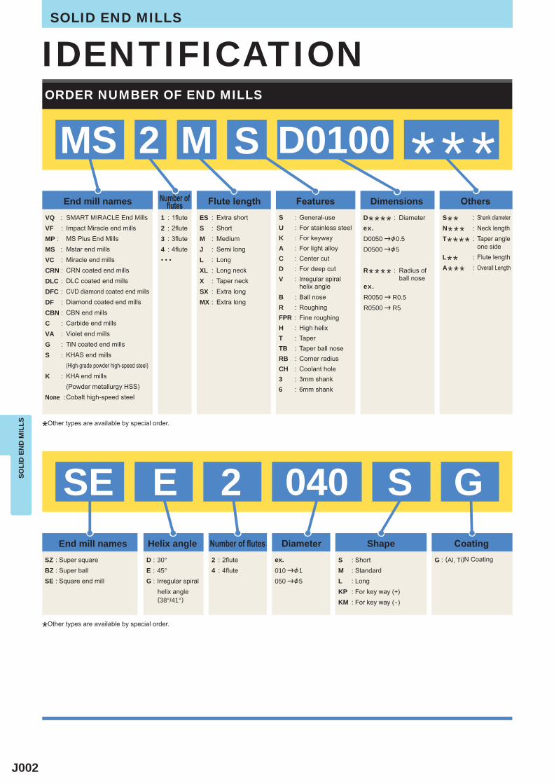
VQ : VF :MP : MS : VC :CRN : DLC :DFC :DF :CBN :C :VA :G : S :
K :
None :
ES : S :M :J : L :XL :X :SX : MX :
S : U :K :A : C :D : V :
B :R : FPR : H :T : TB :RB :CH :3 :6 :
1 :2 :3 :4 :• • •
1flute2flute3flute4flute
SMART MIRACLE End MillsImpact Miracle end millsMS Plus End MillsMstar end millsMiracle end millsCRN coated end millsDLC coated end millsCVD diamond coated end millsDiamond coated end millsCBN end millsCarbide end millsViolet end millsTiN coated end millsKHAS end mills(High-grade powder high-speed steel)KHA end mills(Powder metallurgy HSS)Cobalt high-speed steel
SZ : Super squareBZ : Super ballSE : Square end mill
2 : 2flute4 : 4flute
S : ShortM : StandardL : LongKP : For key way (+)KM : For key way ( -)
G : (Al, Ti)N CoatingD : 30°E : 45°G : Irregular spiral
helix angle(38°/41°)
Extra shortShortMediumSemi longLongLong neckTaper neckExtra longExtra long
General-useFor stainless steelFor keywayFor light alloyCenter cutFor deep cutIrregular spiralhelix angleBall noseRoughingFine roughingHigh helixTaperTaper ball noseCorner radiusCoolant hole3mm shank6mm shank
Shank diameterNeck lengthTaper angleone sideFlute lengthOverall Length
S** :N*** :T**** :
L** :A*** :
D**** : Diameter
R**** : Radius ofball nose
D0050 |&0.5D0500 |&5
R0050 | R0.5R0500 | R5
010 |&1050 |&5
ex.
ex.
ex.
*Other types are available by special order.
*Other types are available by special order.
J003
UWC
CBN
KHA S
KHA
CO HSS
HSS
VQ
VF
VC
CRN
DLC
DFC
DF
V
G
10°
h6
SOLI
D E
ND
MIL
LS
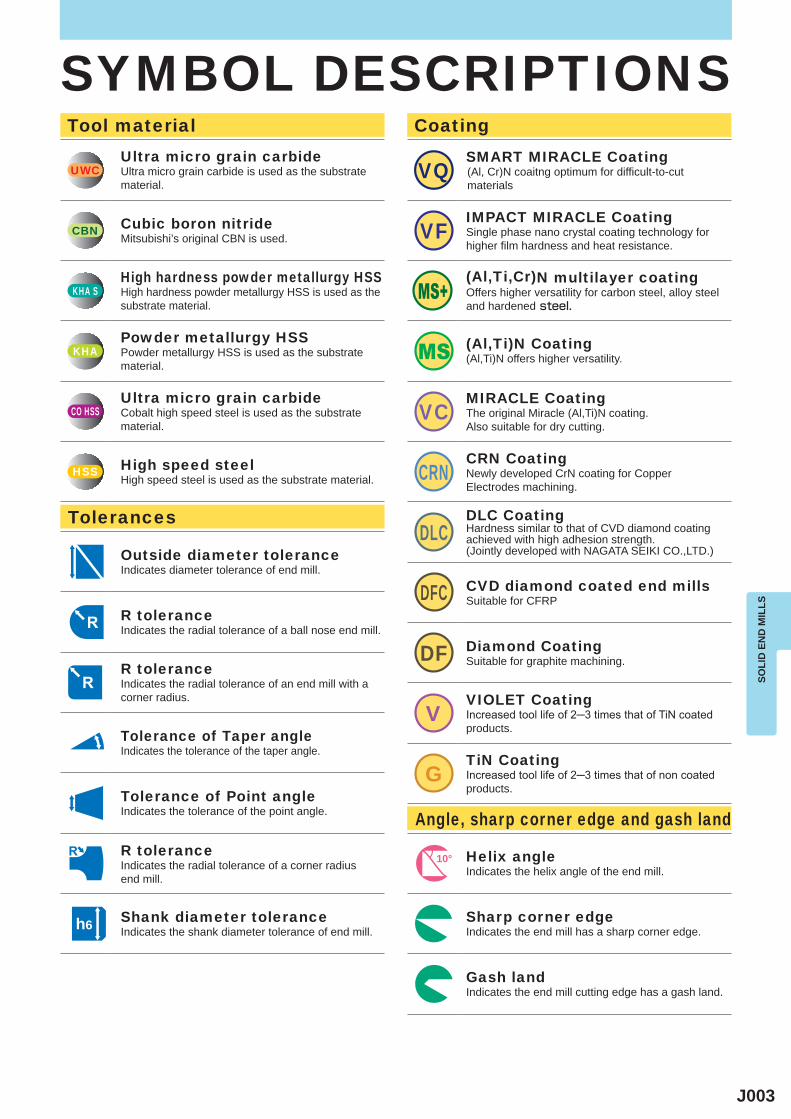
SYMBOL DESCRIPTIONSTool material
Tolerances
Angle, sharp corner edge and gash land
CoatingUltra micro grain carbideUltra micro grain carbide is used as the substrate material.
Cubic boron nitrideMitsubishi’s original CBN is used.
High hardness powder metallurgy HSSHigh hardness powder metallurgy HSS is used as thesubstrate material.
Powder metallurgy HSSPowder metallurgy HSS is used as the substrate material.
Ultra micro grain carbideCobalt high speed steel is used as the substrate material.
High speed steelHigh speed steel is used as the substrate material.
SMART MIRACLE Coating(Al, Cr)N coaitng optimum for difficult-to-cut materials
IMPACT MIRACLE CoatingSingle phase nano crystal coating technology for higher film hardness and heat resistance.
(Al,Ti,Cr)N multilayer coatingOffers higher versatility for carbon steel, alloy steel and hardened steel.
(Al,Ti)N Coating(Al,Ti)N offers higher versatility.
MIRACLE CoatingThe original Miracle (Al,Ti)N coating.Also suitable for dry cutting.
CRN CoatingNewly developed CrN coating for CopperElectrodes machining.
DLC CoatingHardness similar to that of CVD diamond coating achieved with high adhesion strength. (Jointly developed with NAGATA SEIKI CO.,LTD.)
CVD diamond coated end millsSuitable for CFRP
Diamond CoatingSuitable for graphite machining.
VIOLET CoatingIncreased tool life of 2─3 times that of TiN coated products.
TiN CoatingIncreased tool life of 2─3 times that of non coated products.
Helix angleIndicates the helix angle of the end mill.
Sharp corner edgeIndicates the end mill has a sharp corner edge.
Gash landIndicates the end mill cutting edge has a gash land.
Outside diameter toleranceIndicates diameter tolerance of end mill.
R toleranceIndicates the radial tolerance of a ball nose end mill.
R toleranceIndicates the radial tolerance of an end mill with a corner radius.
Tolerance of Taper angleIndicates the tolerance of the taper angle.
Tolerance of Point angleIndicates the tolerance of the point angle.
R toleranceIndicates the radial tolerance of a corner radius end mill.
Shank diameter toleranceIndicates the shank diameter tolerance of end mill.
J004
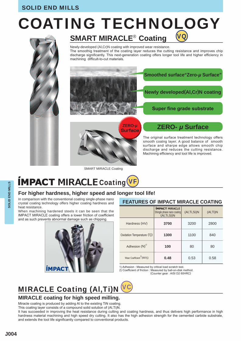
(Al,Ti,Si)N (Al,Ti)N
3700 3200 2800
1300 1100 840
100 80 80
0.48 0.53 0.58
VQ
VF
VC
SOLI
D E
ND
MIL
LSSOLID END MILLS
For higher hardness, higher speed and longer tool life!
COATING TECHNOLOGY
In comparison with the conventional coating single-phase nano crystal coating technology offers higher coating hardness and heat resistance.When machining hardened steels it can be seen that the IMPACT MIRACLE coating offers a lower friction of coefficient and as such prevents abnormal damage such as chipping.
MIRACLE Coating (Al,Ti)NMIRACLE coating for high speed milling.Miracle coating is produced by adding Al to the existing TiN coating.This coating layer consists of a compound solid solution of (Al,Ti)N.It has succeeded in improving the heat resistance during cutting and coating hardness, and thus delivers high performance in high hardness material machining and high speed dry cutting. It also has the high adhesion strength for the cemented carbide substrate, and extends the tool life significantly compared to conventional products.
1) Adhesion : Measured by critical load scratch test.2) Coefficient of friction : Measured by ball-on-disk method. ..............................(Counter gear : AISI D2 60HRC)
FEATURES OF IMPACT MIRACLE COATING
Hardness (HV)
Oxidation Temperature (r)
Adhesion (N)1)
Wear Coefficient2)
(800r)
Shingle phase nano coating(Al,Ti,Si)N
Coating
The original surface treatment technology offers smooth coatng layer. A good balance of smooth surface and sharpe edge allows smooth chip discharge and reduces the cutting resistance. Machining efficiency and tool life is improved.
SMART MIRACLE® CoatingNewly-developed (Al,Cr)N coating with improved wear resistance.The smoothig treatment of the coating layer reduces the cutting resistance and improves chip discharge significantly. This next-generation coating offers longer tool life and higher efficiency in machining difficult-to-cut materials.
SMART MIRACLE Coating
Smoothed surface“Zero-μ Surface”
Newly developed(Al,Cr)N coating
Super fine grade substrate
ZERO- μ SurfaceZERO-µSurface
J005
DFC
CRN
DLC
DF
V
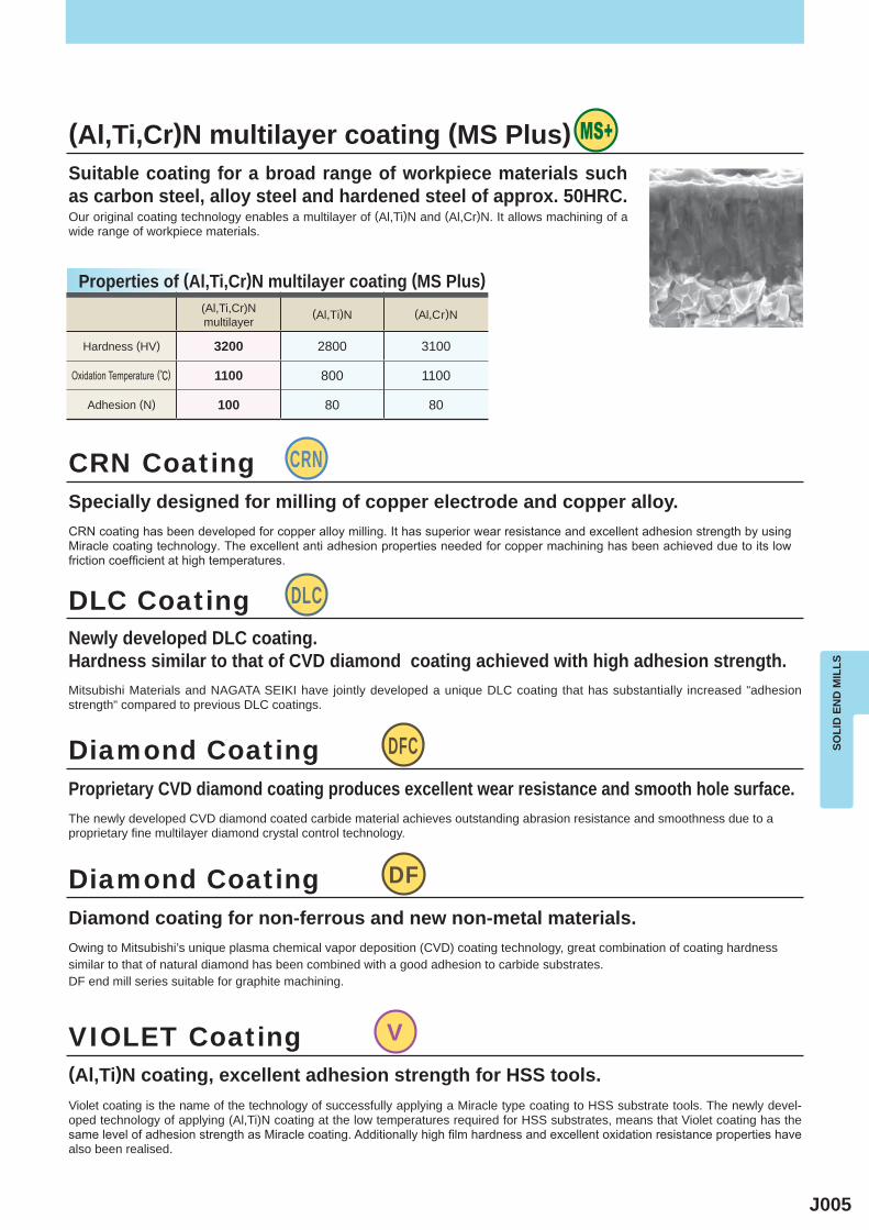
(Al,Ti)N (Al,Cr)N
3200 2800 3100
1100 800 1100
100 80 80
SOLI
D E
ND
MIL
LS
(Al,Ti,Cr)N multilayer coating (MS Plus)Suitable coating for a broad range of workpiece materials such as carbon steel, alloy steel and hardened steel of approx. 50HRC.Our original coating technology enables a multilayer of (Al,Ti)N and (Al,Cr)N. It allows machining of a wide range of workpiece materials.
Properties of (Al,Ti,Cr)N multilayer coating (MS Plus)
DLC CoatingNewly developed DLC coating.Hardness similar to that of CVD diamond coating achieved with high adhesion strength.Mitsubishi Materials and NAGATA SEIKI have jointly developed a unique DLC coating that has substantially increased "adhesion strength" compared to previous DLC coatings.
Diamond Coating
Diamond Coating
Proprietary CVD diamond coating produces excellent wear resistance and smooth hole surface.
Diamond coating for non-ferrous and new non-metal materials.
The newly developed CVD diamond coated carbide material achieves outstanding abrasion resistance and smoothness due to a proprietary fine multilayer diamond crystal control technology.
Owing to Mitsubishi’s unique plasma chemical vapor deposition (CVD) coating technology, great combination of coating hardness similar to that of natural diamond has been combined with a good adhesion to carbide substrates.DF end mill series suitable for graphite machining.
VIOLET Coating(Al,Ti)N coating, excellent adhesion strength for HSS tools.Violet coating is the name of the technology of successfully applying a Miracle type coating to HSS substrate tools. The newly devel-oped technology of applying (Al,Ti)N coating at the low temperatures required for HSS substrates, means that Violet coating has the same level of adhesion strength as Miracle coating. Additionally high film hardness and excellent oxidation resistance properties have also been realised.
(Al,Ti,Cr)N multilayer
Hardness (HV)
Oxidation Temperature (r)
CRN CoatingSpecially designed for milling of copper electrode and copper alloy.CRN coating has been developed for copper alloy milling. It has superior wear resistance and excellent adhesion strength by using Miracle coating technology. The excellent anti adhesion properties needed for copper machining has been achieved due to its low friction coefficient at high temperatures.
Adhesion (N)
J006
P H M S N
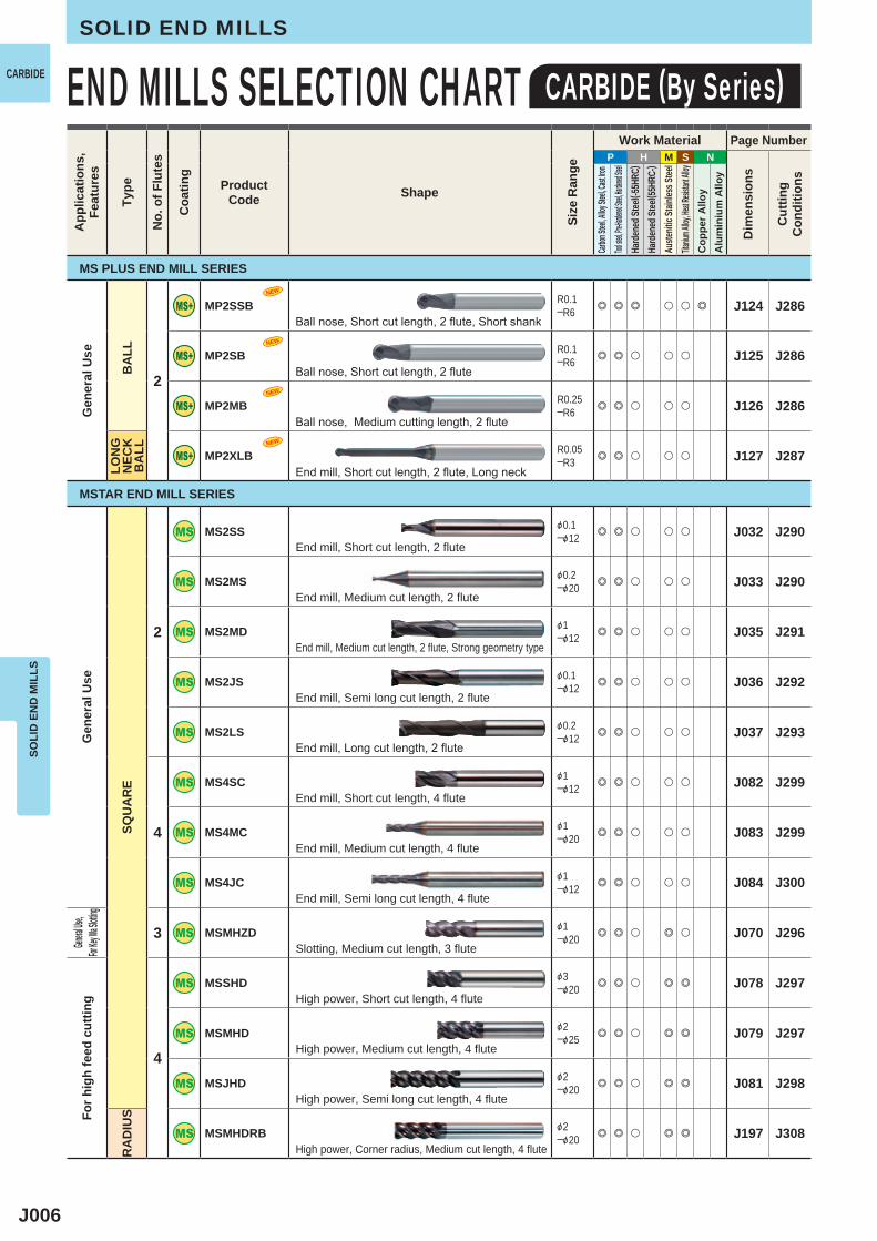
2
MP2SSB R0.1─R6 e e e u u e J124 J286
MP2SB R0.1─R6 e e u u u J125 J286
MP2MB R0.25─R6 e e u u u J126 J286
MP2XLB R0.05─R3 e e u u u J127 J287
2
MS2SS &0.1─&12 e e u u u J032 J290
MS2MS &0.2─&20 e e u u u J033 J290
MS2MD &1─&12 e e u u u J035 J291
MS2JS &0.1─&12 e e u u u J036 J292
MS2LS &0.2─&12 e e u u u J037 J293
4
MS4SC &1─&12 e e u u u J082 J299
MS4MC &1─&20 e e u u u J083 J299
MS4JC &1─&12 e e u u u J084 J300
3 MSMHZD &1─&20 e e u e u J070 J296
4
MSSHD &3─&20 e e u e e J078 J297
MSMHD &2─&25 e e u e e J079 J297
MSJHD &2─&20 e e u e e J081 J298
MSMHDRB &2─&20 e e u e e J197 J308
NEW
NEW
NEW
NEW
SOLI
D E
ND
MIL
LSSOLID END MILLS
END MILLS SELECTION CHART CARBIDE (By Series)CARBIDEA
pplic
atio
ns,
Feat
ures
Type
No.
of F
lute
s
Coa
ting
ProductCode Shape
Size
Ran
ge
Work Material Page Number
Dim
ensi
ons
Cut
ting
Con
ditio
ns
Carbon
Steel, A
lloy Ste
el, Cast
Iron
Tool stee
l, Pre-Ha
rdened S
teel, Har
dened St
eelHa
rden
ed St
eel( -5
5HRC
)Ha
rden
ed St
eel( 5
5HRC
-)Au
stenit
ic St
ainles
s Stee
lTita
nium A
lloy, He
at Resis
tant Al
loyC
oppe
r Allo
yA
lum
iniu
m A
lloy
Ball nose, Short cut length, 2 flute, Short shank
Ball nose, Short cut length, 2 flute
Ball nose, Medium cutting length, 2 flute
End mill, Short cut length, 2 flute, Long neck
End mill, Short cut length, 2 flute
End mill, Medium cut length, 2 flute
End mill, Medium cut length, 2 flute, Strong geometry type
End mill, Semi long cut length, 2 flute
End mill, Long cut length, 2 flute
End mill, Short cut length, 4 flute
End mill, Medium cut length, 4 flute
End mill, Semi long cut length, 4 flute
Slotting, Medium cut length, 3 flute
High power, Short cut length, 4 flute
High power, Medium cut length, 4 flute
High power, Semi long cut length, 4 flute
High power, Corner radius, Medium cut length, 4 flute
MS PLUS END MILL SERIES
MSTAR END MILL SERIES
Gen
eral
Use
BA
LLLO
NG
N
ECK
BA
LL
Gen
eral
Use
SQU
AR
E
General
Use,
For Key
Wa Slo
ttingFo
r hig
h fe
ed c
uttin
g
RA
DIU
S
J007
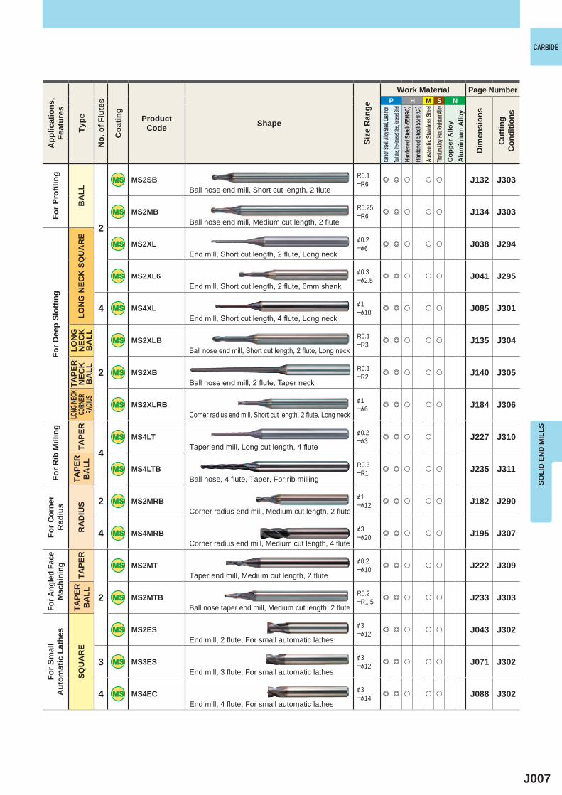
P H M S N
2
MS2SB R0.1─R6 e e u u u J132 J303
MS2MB R0.25─R6 e e u u u J134 J303
MS2XL &0.2─&6 e e u u u J038 J294
MS2XL6 &0.3─&2.5 e e u u u J041 J295
4 MS4XL &1─&10 e e u u u J085 J301
2
MS2XLB R0.1─R3 e e u u u J135 J304
MS2XB R0.1─R2 e e u u u J140 J305
MS2XLRB &1─&6 e e u u u J184 J306
4
MS4LT &0.2─&3 e e u u J227 J310
MS4LTB R0.3─R1 e e u u u J235 J311
2 MS2MRB &1─&12 e e u u u J182 J290
4 MS4MRB &3─&20 e e u u u J195 J307
2
MS2MT &0.2─&10 e e u u u J222 J309
MS2MTB R0.2─R1.5 e e u u u J233 J303
MS2ES &3─&12 e e u u u J043 J302
3 MS3ES &3─&12 e e u u u J071 J302
4 MS4EC &3─&14 e e u u u J088 J302
SOLI
D E
ND
MIL
LS
CARBIDEA
pplic
atio
ns,
Feat
ures
Type
No.
of F
lute
s
Coa
ting
ProductCode Shape
Size
Ran
ge
Work Material Page Number
Dim
ensi
ons
Cut
ting
Con
ditio
ns
Carbon
Steel, A
lloy Ste
el, Cast
Iron
Tool stee
l, Pre-Ha
rdened S
teel, Har
dened St
eelHa
rden
ed St
eel( -5
5HRC
)Ha
rden
ed St
eel( 5
5HRC
-)Au
stenit
ic St
ainles
s Stee
lTita
nium A
lloy, He
at Resis
tant Al
loyC
oppe
r Allo
yA
lum
iniu
m A
lloy
For P
rofil
ing
BA
LL
For D
eep
Slot
ting
LON
G N
ECK
SQ
UA
RE
LON
G
NEC
KB
ALL
TAPE
R
NEC
KB
ALL
LONG
NECK
CORN
ER
RADIU
S
For R
ib M
illin
g
TAPE
RTA
PER
B
ALL
For C
orne
rR
adiu
s
RA
DIU
S
For A
ngle
d Fa
ceM
achi
ning
TAPE
RTA
PER
B
ALL
For S
mal
l A
utom
atic
Lat
hes
SQU
AR
E
Ball nose end mill, Short cut length, 2 flute
Ball nose end mill, Medium cut length, 2 flute
End mill, Short cut length, 2 flute, Long neck
End mill, Short cut length, 2 flute, 6mm shank
End mill, Short cut length, 4 flute, Long neck
Ball nose end mill, Short cut length, 2 flute, Long neck
Ball nose end mill, 2 flute, Taper neck
Corner radius end mill, Short cut length, 2 flute, Long neck
Taper end mill, Long cut length, 4 flute
Ball nose, 4 flute, Taper, For rib milling
Corner radius end mill, Medium cut length, 2 flute
Corner radius end mill, Medium cut length, 4 flute
Taper end mill, Medium cut length, 2 flute
Ball nose taper end mill, Medium cut length, 2 flute
End mill, 2 flute, For small automatic lathes
End mill, 3 flute, For small automatic lathes
End mill, 4 flute, For small automatic lathes
J008
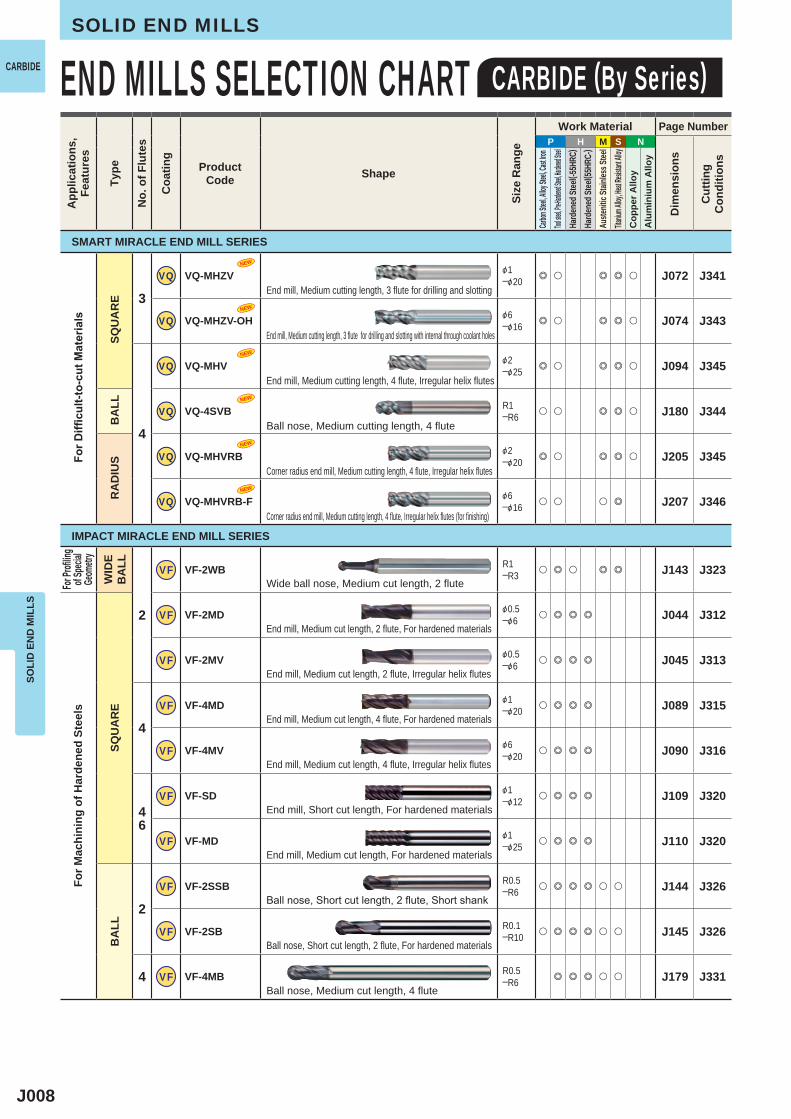
P H M S N
3
VQ VQ-MHZV &1─&20 e u e e u J072 J341
VQ VQ-MHZV-OH &6─&16 e u e e u J074 J343
4
VQ VQ-MHV &2─&25 e u e e u J094 J345
VQ VQ-4SVB R1─R6 u u e e u J180 J344
VQ VQ-MHVRB &2─&20 e u e e u J205 J345
VQ VQ-MHVRB-F &6─&16 u u u e J207 J346
2
VF VF-2WB R1─R3 u e u e e J143 J323
VF VF-2MD &0.5─&6 u e e e J044 J312
VF VF-2MV &0.5─&6 u e e e J045 J313
4
VF VF-4MD &1─&20 u e e e J089 J315
VF VF-4MV &6─&20 u e e e J090 J316
46
VF VF-SD &1─&12 u e e e J109 J320
VF VF-MD &1─&25 u e e e J110 J320
2
VF VF-2SSB R0.5─R6 u e e e u u J144 J326
VF VF-2SB R0.1─R10 u e e e u u J145 J326
4 VF VF-4MB R0.5─R6 e e e u u J179 J331
NEW
NEW
NEW
NEW
NEW
NEW
SOLI
D E
ND
MIL
LSSOLID END MILLS
END MILLS SELECTION CHART CARBIDE (By Series)CARBIDEA
pplic
atio
ns,
Feat
ures
Type
No.
of F
lute
s
Coa
ting
ProductCode Shape
Size
Ran
ge
Work Material Page Number
Dim
ensi
ons
Cut
ting
Con
ditio
ns
Carbon
Steel, A
lloy Ste
el, Cast
Iron
Tool stee
l, Pre-Ha
rdened S
teel, Har
dened St
eelHa
rden
ed St
eel( -5
5HRC
)Ha
rden
ed St
eel( 5
5HRC
-)Au
stenit
ic St
ainles
s Stee
lTita
nium A
lloy, He
at Resis
tant Al
loyC
oppe
r Allo
yA
lum
iniu
m A
lloy
For D
ifficu
lt-to
-cut
Mat
eria
ls
SQU
AR
EB
ALL
RA
DIU
S
For P
rofilin
gof
Speci
alGe
ometr
y
WID
E B
ALL
For M
achi
ning
of H
arde
ned
Stee
ls
SQU
AR
EB
ALL
End mill, Medium cutting length, 3 flute for drilling and slotting
End mill, Medium cutting length, 3 flute for drilling and slotting with internal through coolant holes
End mill, Medium cutting length, 4 flute, Irregular helix flutes
Ball nose, Medium cutting length, 4 flute
Corner radius end mill, Medium cutting length, 4 flute, Irregular helix flutes
Corner radius end mill, Medium cutting length, 4 flute, Irregular helix flutes (for finishing)
Wide ball nose, Medium cut length, 2 flute
End mill, Medium cut length, 2 flute, For hardened materials
End mill, Medium cut length, 2 flute, Irregular helix flutes
End mill, Medium cut length, 4 flute, For hardened materials
End mill, Medium cut length, 4 flute, Irregular helix flutes
End mill, Short cut length, For hardened materials
End mill, Medium cut length, For hardened materials
Ball nose, Short cut length, 2 flute, Short shank
Ball nose, Short cut length, 2 flute, For hardened materials
Ball nose, Medium cut length, 4 flute
SMART MIRACLE END MILL SERIES
IMPACT MIRACLE END MILL SERIES
J009
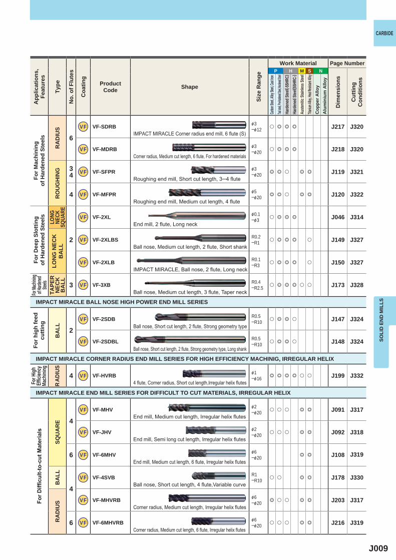
P H M S N
6
VF VF-SDRB &3─&12 u e e e J217 J320
VF VF-MDRB &3─&20 u e e e J218 J320
34 VF VF-SFPR &3
─&20 e e u e e J119 J321
4 VF VF-MFPR &5─&20 e e u e e J120 J322
2
VF VF-2XL &0.1─&3 u e e e J046 J314
VF VF-2XLBS R0.2─R1 u e e e u J149 J327
VF VF-2XLB R0.1─R3 u e e e u J150 J327
3 VF VF-3XB R0.4─R2.5 u e e e u u J173 J328
2VF VF-2SDB R0.5
─R10 u e e u J147 J324
VF VF-2SDBL R0.5─R10 u e e u J148 J324
4 VF VF-HVRB &1─&16 e e e e u u J199 J332
4
VF VF-MHV &2─&20 u u u e e J091 J317
VF VF-JHV &2─&20 u u u e e J092 J318
6 VF VF-6MHV &6─&20 e e J108 J319
4
VF VF-4SVB R1─R10 u u e e J178 J330
VF VF-MHVRB &6─&20 e u u e e J203 J317
6 VF VF-6MHVRB
&6─&20 u u u e e J216 J319
SOLI
D E
ND
MIL
LS
CARBIDEA
pplic
atio
ns,
Feat
ures
Type
No.
of F
lute
s
Coa
ting
ProductCode Shape
Size
Ran
ge
Work Material Page Number
Dim
ensi
ons
Cut
ting
Con
ditio
ns
Carbon
Steel, A
lloy Ste
el, Cast
Iron
Tool stee
l, Pre-Ha
rdened S
teel, Har
dened St
eelHa
rden
ed St
eel( -5
5HRC
)Ha
rden
ed St
eel( 5
5HRC
-)Au
stenit
ic St
ainles
s Stee
lTita
nium A
lloy, He
at Resis
tant Al
loyC
oppe
r Allo
yA
lum
iniu
m A
lloy
For M
achi
ning
of
Har
dene
d St
eels
RA
DIU
SR
OU
GH
ING
For D
eep
Slot
ting
of H
arde
ned
Stee
lsLO
NG
NECK
SQUA
RELO
NG
NEC
KB
ALL
For Ma
chinin
g of H
ardene
d Ste
elsTA
PER
N
ECK
B
ALL
For H
igh
Effic
iency
Ma
chini
ng
RAD
IUS
For D
ifficu
lt-to
-cut
Mat
eria
ls
SQU
AR
EB
ALL
RA
DIU
S
For h
igh
feed
cu
tting
BA
LL
IMPACT MIRACLE BALL NOSE HIGH POWER END MILL SERIES
IMPACT MIRACLE CORNER RADIUS END MILL SERIES FOR HIGH EFFICIENCY MACHINIG, IRREGULAR HELIX
IMPACT MIRACLE END MILL SERIES FOR DIFFICULT TO CUT MATERIALS, IRREGULAR HELIX
IMPACT MIRACLE Corner radius end mill, 6 flute (S)
Corner radius, Medium cut length, 6 flute, For hardened materials
Roughing end mill, Short cut length, 3─4 flute
Roughing end mill, Medium cut length, 4 flute
End mill, 2 flute, Long neck
Ball nose, Medium cut length, 2 flute, Short shank
IMPACT MIRACLE, Ball nose, 2 flute, Long neck
Ball nose, Medium cut length, 3 flute, Taper neck
Ball nose, Short cut length, 2 flute, Strong geometry type
Ball nose, Short cut length, 2 flute, Strong geometry type, Long shank
4 flute, Corner radius, Short cut length,Irregular helix flutes
End mill, Medium cut length, Irregular helix flutes
End mill, Semi long cut length, Irregular helix flutes
End mill, Medium cut length, 6 flute, Irregular helix flutes
Ball nose, Short cut length, 4 flute,Variable curve
Corner radius, Medium cut length, Irregular helix flutes
Corner radius, Medium cut length, 6 flute, Irregular helix flutes
J010
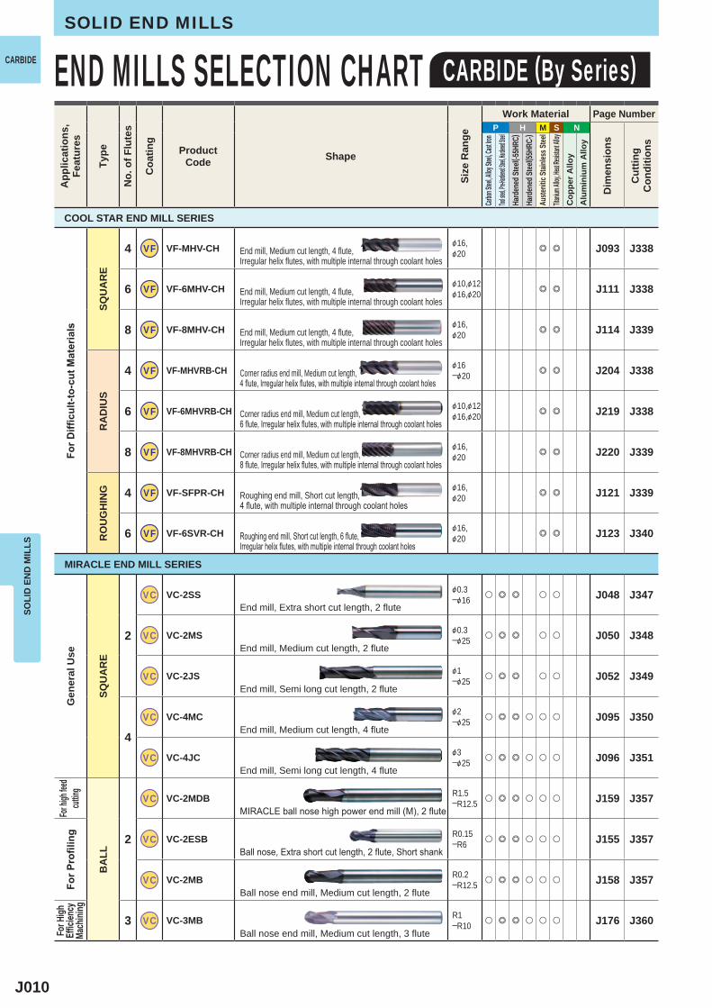
P H M S N
4 VF VF-MHV-CH &16,&20 e e J093 J338
6 VF VF-6MHV-CH &10,&12&16,&20 e e J111 J338
8 VF VF-8MHV-CH &16,&20 e e J114 J339
4 VF VF-MHVRB-CH &16─&20 e e J204 J338
6 VF VF-6MHVRB-CH &10,&12&16,&20 e e J219 J338
8 VF VF-8MHVRB-CH &16,&20 e e J220 J339
4 VF VF-SFPR-CH &16,&20 e e J121 J339
6 VF VF-6SVR-CH &16,&20 e e J123 J340
2
VC VC-2SS &0.3─&16 u e e u u J048 J347
VC VC-2MS &0.3─&25 u e e u u J050 J348
VC VC-2JS &1─&25 u e e u u J052 J349
4
VC VC-4MC &2─&25 u e e u u u J095 J350
VC VC-4JC &3─&25 u e e u u u J096 J351
2
VC VC-2MDB R1.5─R12.5 u e e u u u J159 J357
VC VC-2ESB R0.15─R6 u e e u u u J155 J357
VC VC-2MB R0.2─R12.5 u e e u u u J158 J357
3 VC VC-3MB R1─R10 u e e u u u J176 J360
SOLI
D E
ND
MIL
LSSOLID END MILLS
END MILLS SELECTION CHART CARBIDE (By Series)CARBIDEA
pplic
atio
ns,
Feat
ures
Type
No.
of F
lute
s
Coa
ting
ProductCode Shape
Size
Ran
ge
Work Material Page Number
Dim
ensi
ons
Cut
ting
Con
ditio
ns
Carbon
Steel, A
lloy Ste
el, Cast
Iron
Tool stee
l, Pre-Ha
rdened S
teel, Har
dened St
eelHa
rden
ed St
eel( -5
5HRC
)Ha
rden
ed St
eel( 5
5HRC
-)Au
stenit
ic St
ainles
s Stee
lTita
nium A
lloy, He
at Resis
tant Al
loyC
oppe
r Allo
yA
lum
iniu
m A
lloy
For D
ifficu
lt-to
-cut
Mat
eria
ls
SQU
AR
ER
AD
IUS
RO
UG
HIN
G
Gen
eral
Use
SQU
AR
E
For h
igh fee
d cut
ting
BA
LL
For P
rofil
ing
For H
igh
Effic
iency
Ma
chini
ng
End mill, Medium cut length, 4 flute, Irregular helix flutes, with multiple internal through coolant holes
End mill, Medium cut length, 4 flute, Irregular helix flutes, with multiple internal through coolant holes
End mill, Medium cut length, 4 flute, Irregular helix flutes, with multiple internal through coolant holes
Corner radius end mill, Medium cut length, 4 flute, Irregular helix flutes, with multiple internal through coolant holes
Corner radius end mill, Medium cut length, 6 flute, Irregular helix flutes, with multiple internal through coolant holes
Corner radius end mill, Medium cut length, 8 flute, Irregular helix flutes, with multiple internal through coolant holes
Roughing end mill, Short cut length, 4 flute, with multiple internal through coolant holes
Roughing end mill, Short cut length, 6 flute, Irregular helix flutes, with multiple internal through coolant holes
End mill, Extra short cut length, 2 flute
End mill, Medium cut length, 2 flute
End mill, Semi long cut length, 2 flute
End mill, Medium cut length, 4 flute
End mill, Semi long cut length, 4 flute
MIRACLE ball nose high power end mill (M), 2 flute
Ball nose, Extra short cut length, 2 flute, Short shank
Ball nose end mill, Medium cut length, 2 flute
Ball nose end mill, Medium cut length, 3 flute
COOL STAR END MILL SERIES
MIRACLE END MILL SERIES
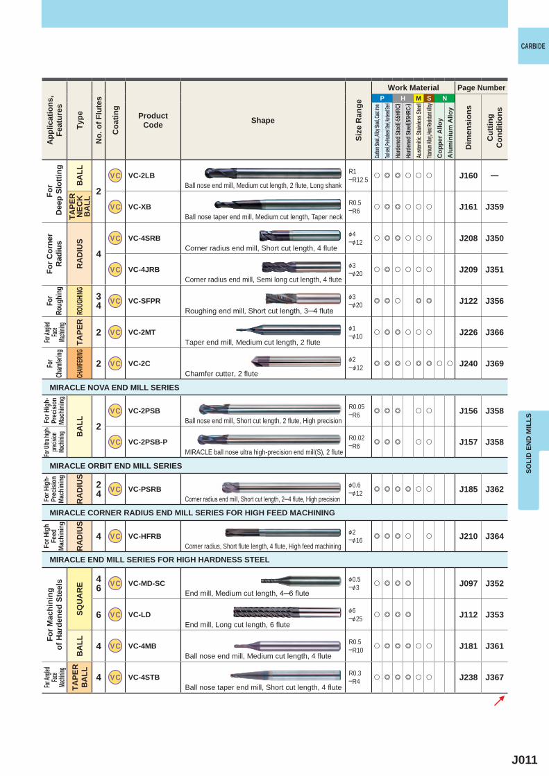
J011
P H M S N
2
VC VC-2LB R1─R12.5 u e e u u u J160 ―
VC VC-XB R0.5─R6 u e e u u u J161 J359
4
VC VC-4SRB &4─&12 u e e u u u J208 J350
VC VC-4JRB &3─&20 u e u u u u J209 J351
34 VC VC-SFPR &3
─&20 e e u e e J122 J356
2 VC VC-2MT &1─&10 u e e u u u J226 J366
2 VC VC-2C &2─&12 e e e u e e u u J240 J369
2VC VC-2PSB R0.05
─R6 e e e u u J156 J358
VC VC-2PSB-P R0.02─R6 e e e u u J157 J358
24 VC VC-PSRB &0.6
─&12 e e e e u u J185 J362
4 VC VC-HFRB &2─&16 e e e u u J210 J364
46 VC VC-MD-SC &0.5
─&3 u e e e J097 J352
6 VC VC-LD &6─&25 u e e e J112 J353
4 VC VC-4MB R0.5─R10 u e e e u u J181 J361
4 VC VC-4STB R0.3─R4 u e e e u u J238 J367
SOLI
D E
ND
MIL
LS
CARBIDEA
pplic
atio
ns,
Feat
ures
Type
No.
of F
lute
s
Coa
ting
ProductCode Shape
Size
Ran
ge
Work Material Page Number
Dim
ensi
ons
Cut
ting
Con
ditio
ns
Carbon
Steel, A
lloy Ste
el, Cast
Iron
Tool stee
l, Pre-Ha
rdened S
teel, Har
dened St
eelHa
rden
ed St
eel( -5
5HRC
)Ha
rden
ed St
eel( 5
5HRC
-)Au
stenit
ic St
ainles
s Stee
lTita
nium A
lloy, He
at Resis
tant Al
loyC
oppe
r Allo
yA
lum
iniu
m A
lloy
For
Dee
p Sl
ottin
g
BA
LLTA
PER
N
ECK
B
ALL
For C
orne
rR
adiu
s
RA
DIU
S
For
Roug
hing
ROUG
HING
For An
gled
Face
Machin
ing
TAPE
R
For
Cham
fering
CHAM
FERING
For H
igh-
Prec
ision
Ma
chin
ing
BA
LL
For U
ltra hi
gh-
precis
ion
Mach
ining
For H
igh-
Prec
ision
Ma
chin
ing
RA
DIU
S
For H
igh
Feed
Mach
inin
g
RA
DIU
S
For M
achi
ning
of
Har
dene
d St
eels
SQU
AR
EB
ALL
For An
gled
Face
Machin
ingTA
PER
B
ALL
MIRACLE NOVA END MILL SERIES
MIRACLE ORBIT END MILL SERIES
MIRACLE CORNER RADIUS END MILL SERIES FOR HIGH FEED MACHINING
MIRACLE END MILL SERIES FOR HIGH HARDNESS STEEL
Ball nose end mill, Medium cut length, 2 flute, Long shank
Ball nose taper end mill, Medium cut length, Taper neck
Corner radius end mill, Short cut length, 4 flute
Corner radius end mill, Semi long cut length, 4 flute
Roughing end mill, Short cut length, 3─4 flute
Taper end mill, Medium cut length, 2 flute
Chamfer cutter, 2 flute
Ball nose end mill, Short cut length, 2 flute, High precision
MIRACLE ball nose ultra high-precision end mill(S), 2 flute
Corner radius end mill, Short cut length, 2─4 flute, High precision
Corner radius, Short flute length, 4 flute, High feed machining
End mill, Medium cut length, 4─6 flute
End mill, Long cut length, 6 flute
Ball nose end mill, Medium cut length, 4 flute
Ball nose taper end mill, Short cut length, 4 flute
J012
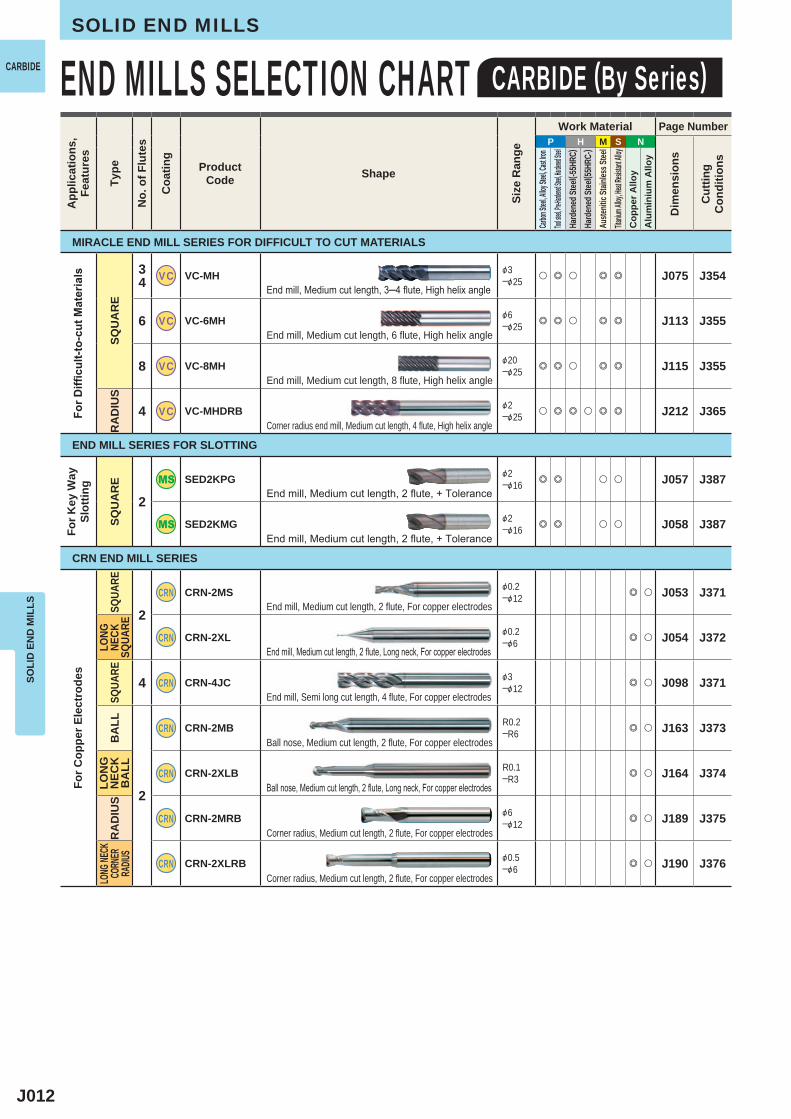
P H M S N
34 VC VC-MH &3
─&25 u e u e e J075 J354
6 VC VC-6MH &6─&25 e e u e e J113 J355
8 VC VC-8MH &20─&25 e e u e e J115 J355
4 VC VC-MHDRB &2─&25 u e e u e e J212 J365
2
SED2KPG &2─&16 e e u u J057 J387
SED2KMG &2─&16 e e u u J058 J387
2
CRN CRN-2MS &0.2─&12 e u J053 J371
CRN CRN-2XL &0.2─&6 e u J054 J372
4 CRN CRN-4JC &3─&12 e u J098 J371
2
CRN CRN-2MB R0.2─R6 e u J163 J373
CRN CRN-2XLB R0.1─R3 e u J164 J374
CRN CRN-2MRB &6─&12 e u J189 J375
CRN CRN-2XLRB &0.5─&6 e u J190 J376
SOLI
D E
ND
MIL
LSSOLID END MILLS
END MILLS SELECTION CHART CARBIDE (By Series)CARBIDEA
pplic
atio
ns,
Feat
ures
Type
No.
of F
lute
s
Coa
ting
ProductCode Shape
Size
Ran
ge
Work Material Page Number
Dim
ensi
ons
Cut
ting
Con
ditio
ns
Carbon
Steel, A
lloy Ste
el, Cast
Iron
Tool stee
l, Pre-Ha
rdened S
teel, Har
dened St
eelHa
rden
ed St
eel( -5
5HRC
)Ha
rden
ed St
eel( 5
5HRC
-)Au
stenit
ic St
ainles
s Stee
lTita
nium A
lloy, He
at Resis
tant Al
loyC
oppe
r Allo
yA
lum
iniu
m A
lloy
For D
ifficu
lt-to
-cut
Mat
eria
ls
SQU
AR
ER
AD
IUS
For K
ey W
aySl
ottin
g
SQU
AR
ESQ
UARE
LONG
NE
CKSQ
UARE
SQUA
REB
ALL
LON
G
NEC
KB
ALL
RA
DIU
SLO
NG NE
CKCO
RNER
RA
DIUS
End mill, Medium cut length, 3─4 flute, High helix angle
End mill, Medium cut length, 6 flute, High helix angle
End mill, Medium cut length, 8 flute, High helix angle
Corner radius end mill, Medium cut length, 4 flute, High helix angle
End mill, Medium cut length, 2 flute, For copper electrodes
End mill, Medium cut length, 2 flute, Long neck, For copper electrodes
End mill, Semi long cut length, 4 flute, For copper electrodes
End mill, Medium cut length, 2 flute, + Tolerance
End mill, Medium cut length, 2 flute, + Tolerance
Ball nose, Medium cut length, 2 flute, For copper electrodes
Ball nose, Medium cut length, 2 flute, Long neck, For copper electrodes
Corner radius, Medium cut length, 2 flute, For copper electrodes
Corner radius, Medium cut length, 2 flute, For copper electrodes
MIRACLE END MILL SERIES FOR DIFFICULT TO CUT MATERIALS
END MILL SERIES FOR SLOTTING
CRN END MILL SERIES
For C
oppe
r Ele
ctro
des
J013
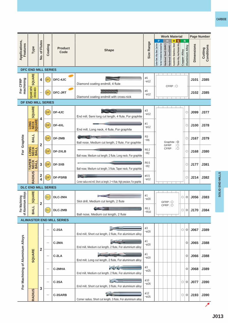
P H M S N
4 DFC DFC-4JC &6─&12 J101 J385
― DFC DFC-JRT &6─&12 J102 J385
4
DF DF-4JC &3─&12 u J099 J377
DF DF-4XL &1─&12 u J100 J378
2
DF DF-2MB R3─R6 u J167 J379
DF DF-2XLB R0.2─R2 u J168 J380
3 DF DF-3XB R0.5─R2 u J177 J381
24 DF DF-PSRB &0.5
─&12 u J214 J382
2DLC DLC-2MA &1
─&20 u e J056 J383
DLC DLC-2MB R0.1─R10 u e J170 J384
2
― C-2SA &3─&20 u e J067 J389
― C-2MA &1─&20 e J065 J388
― C-2LA &1─&20 e J066 J388
― C-2MHA &3─&25 e J068 J389
3
― C-3SA &10─&26 u e J077 J390
― C-3SARB &12─&25 u e J193 J390
NEW
NEW
SOLI
D E
ND
MIL
LS
CARBIDEA
pplic
atio
ns,
Feat
ures
Type
No.
of F
lute
s
Coa
ting
ProductCode Shape
Size
Ran
ge
Work Material Page Number
Dim
ensi
ons
Cut
ting
Con
ditio
ns
Carbon
Steel, A
lloy Ste
el, Cast
Iron
Tool stee
l, Pre-Ha
rdened S
teel, Har
dened St
eelHa
rden
ed St
eel( -5
5HRC
)Ha
rden
ed St
eel( 5
5HRC
-)Au
stenit
ic St
ainles
s Stee
lTita
nium A
lloy, He
at Resis
tant Al
loyC
oppe
r Allo
yA
lum
iniu
m A
lloy
DFC END MILL SERIES
DF END MILL SERIES
DLC END MILL SERIES
ALIMASTER END MILL SERIES
For C
FRP
mac
hini
ng
SQUA
RESQ
UARE
WITH
CROS
S-NICK
For
Gra
phite
SQUA
RELO
NG
NECK
SQUA
REB
ALL
LON
G
NEC
KB
ALL
TAPE
R
NEC
K
BA
LLR
AD
IUS
SQUA
REB
ALL
SQU
AR
ER
AD
IUS
Diamond coating endmill, 4 flute
Diamond coating endmill with cross-nick
End mill, Semi long cut length, 4 flute, For graphite
End mill, Long neck, 4 flute, For graphite
Ball nose, Medium cut length, 2 flute, For graphite
Ball nose, Medium cut length, 2 flute, Long neck, For graphite
Ball nose, Medium cut length, 3 flute, Taper neck, For graphite
Corner radius end mill, Short cut length, 2─4 flute, High precision, For graphite
Slot drill, Medium cut length, 2 flute
Ball nose, Medium cut length, 2 flute
End mill, Short cut length, 2 flute, For aluminium alloy
End mill, Medium cut length, 2 flute, For aluminium alloy
End mill, Long cut length, 2 flute, For aluminium alloy
End mill, Medium cut length, 2 flute, For aluminium alloy
End mill, Short cut length, 3 flute, For aluminium alloy
Corner radius, Short cut length, 3 flute, For aluminium alloy
CFRP : u
GFRP : uCFRP : u
Graphite : eGFRP : uCFRP : u
For M
achin
ing of
Alum
inium
Allo
ysFo
r Mac
hini
ng o
f Alu
min
ium
Allo
ys

J014
P H M S N
3
― C-SRA &10─&25 e J117 J393
― C-MRA &3─&25 e J118 J394
― C-SRARB &10─&25 e J194 J393
2
― C-2SS &0.4─&6 u u u u u u J059 J391
― C-2MS &1─&20 u u u u u u J060 J391
― C-2JS &1─&25 u u u u u u J063 J391
― C-2LS &1─&20 u u u u u u J064 J391
4
― C-4MC &3─&20 u u u u u u J103 J392
― C-4JC &3─&25 u u u u u u J104 J392
― C-4LC &3─&20 u u u u u u J105 J392
2
― C-2MB R0.5─R10 e u u u u u J172 J396
― SEE2L &3─&20 e u u u u u J069 J397
4 ― SEE4L &3─&25 e u u u u J106 J398
4 ― SEG4SA &6─&25 u e J107 J395
3 ― C-MH &6─&16 u e u u u J076 ―
1 ― GBE &6─&12 u e e J116 J116
SOLI
D E
ND
MIL
LSSOLID END MILLS
END MILLS SELECTION CHART CARBIDE (By Series)CARBIDEA
pplic
atio
ns,
Feat
ures
Type
No.
of F
lute
s
Coa
ting
ProductCode Shape
Size
Ran
ge
Work Material Page Number
Dim
ensi
ons
Cut
ting
Con
ditio
ns
Carbon
Steel, A
lloy Ste
el, Cast
Iron
Tool stee
l, Pre-Ha
rdened S
teel, Har
dened St
eelHa
rden
ed St
eel( -5
5HRC
)Ha
rden
ed St
eel( 5
5HRC
-)Au
stenit
ic St
ainles
s Stee
lTita
nium A
lloy, He
at Resis
tant Al
loyC
oppe
r Allo
yA
lum
iniu
m A
lloy
For M
achi
ning
of
Alu
min
ium
Allo
ys
RO
UG
HIN
GRO
UGHIN
GRA
DIUS
Gen
eral
Use
SQU
AR
E
For
Profi
ling
BA
LL
Hig
h H
elix
SQU
AR
E
For Ma
chinin
g of A
luminiu
m Allo
ys
For D
ifficu
lt-to-
cut
Mater
ials
For Ma
chinin
g of H
ardene
d Ste
els
SQUA
RE
Roughing end mill, Short cut length, 3 flute, For aluminium alloy
Roughing end mill, Medium cut length, 3 flute, For aluminium alloy
Corner radius roughing end mill, Short cut length, 3 flute, For aluminium alloy
End mill, Short cut length, 2 flute
End mill, Medium cut length, 2 flute
End mill, Semi long cut length, 2 flute
End mill, Long cut length, 2 flute
End mill, Medium cut length, 4 flute, Center cutting
End mill, Semi long cut length, 4 flute, Center cutting
End mill, Long cut length, 4 flute, Center cutting
Ball nose end mill, Medium cut length, 2 flute
End mill, Long cut length, 2 flute
End mill, Long cut length, 4 flute
End mill, Medium cut length, 4 flute, Irregular spiral helix angle, For aluminium alloy
End mill, Medium cut length, 3 flute
End mill, 1 flute, Brazed type (CBN)
ALIMASTER END MILL SERIES
CARBIDE END MILL SERIES
CBN END MILL SERIES
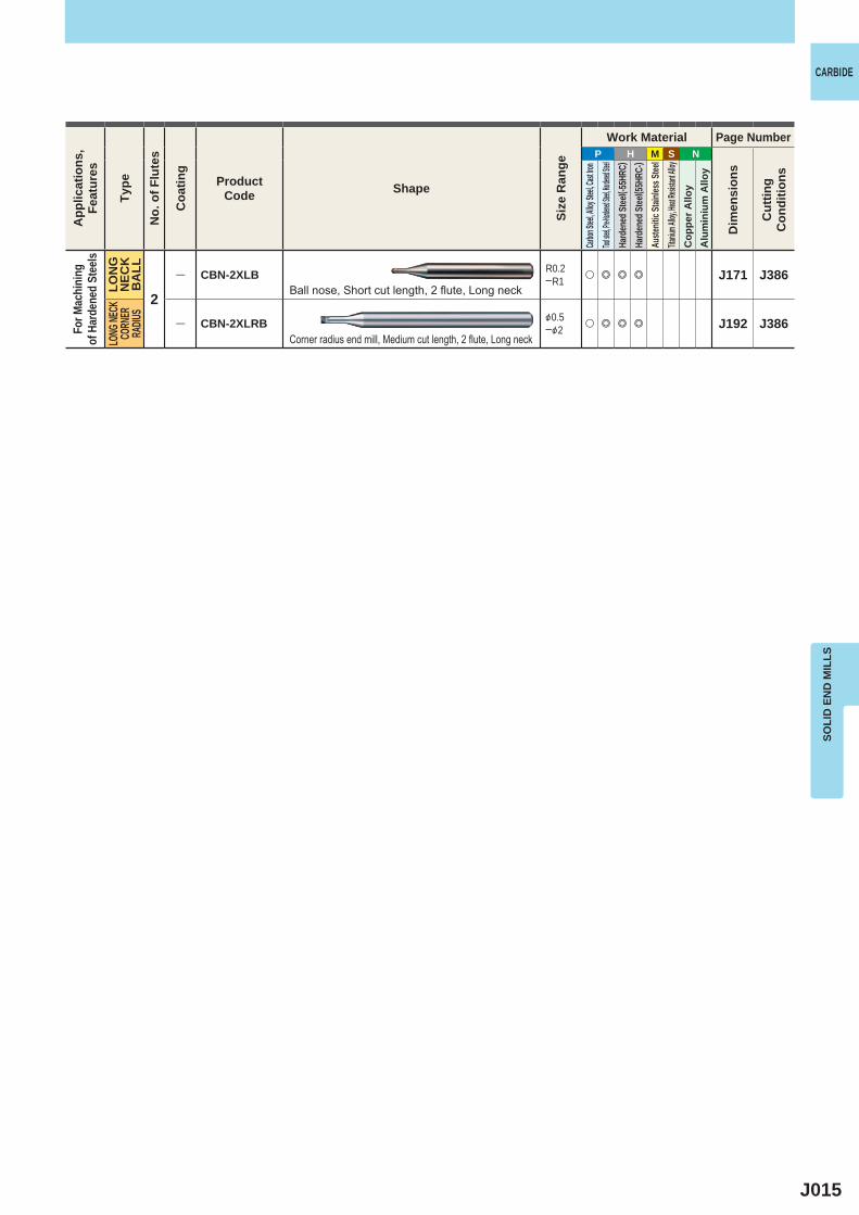
J015
P H M S N
2
― CBN-2XLB R0.2─R1 u e e e J171 J386
― CBN-2XLRB &0.5─&2 u e e e J192 J386
SOLI
D E
ND
MIL
LS
CARBIDEA
pplic
atio
ns,
Feat
ures
Type
No.
of F
lute
s
Coa
ting
ProductCode Shape
Size
Ran
ge
Work Material Page Number
Dim
ensi
ons
Cut
ting
Con
ditio
ns
Carbon
Steel, A
lloy Ste
el, Cast
Iron
Tool stee
l, Pre-Ha
rdened S
teel, Har
dened St
eelHa
rden
ed St
eel( -5
5HRC
)Ha
rden
ed St
eel( 5
5HRC
-)Au
stenit
ic St
ainles
s Stee
lTita
nium A
lloy, He
at Resis
tant Al
loyC
oppe
r Allo
yA
lum
iniu
m A
lloy
For M
achi
ning
of
Har
dene
d St
eels
LON
G
NEC
KB
ALL
LONG
NECK
CORN
ER
RADIU
S
Ball nose, Short cut length, 2 flute, Long neck
Corner radius end mill, Medium cut length, 2 flute, Long neck
J016
P H M S N
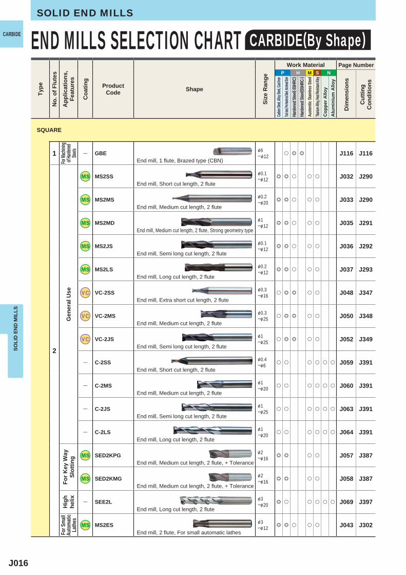
1 ― GBE &6─&12 u e e J116 J116
2
MS2SS &0.1─&12 e e u u u J032 J290
MS2MS &0.2─&20 e e u u u J033 J290
MS2MD &1─&12 e e u u u J035 J291
MS2JS &0.1─&12 e e u u u J036 J292
MS2LS &0.2─&12 e e u u u J037 J293
VC VC-2SS &0.3─&16 u e e u u J048 J347
VC VC-2MS &0.3─&25 u e e u u J050 J348
VC VC-2JS &1─&25 u e e u u J052 J349
― C-2SS &0.4─&6 u u u u u u J059 J391
― C-2MS &1─&20 u u u u u u J060 J391
― C-2JS &1─&25 u u u u u u J063 J391
― C-2LS &1─&20 u u u u u u J064 J391
SED2KPG &2─&16 e e u u J057 J387
SED2KMG &2─&16 e e u u J058 J387
― SEE2L &3─&20 e u u u u u J069 J397
MS2ES &3─&12 e e u u u J043 J302
SOLI
D E
ND
MIL
LSSOLID END MILLS
END MILLS SELECTION CHART CARBIDE(By Shape)CARBIDETy
pe
No.
of F
lute
s
App
licat
ions
,Fe
atur
es
Coa
ting
ProductCode Shape
Size
Ran
ge
Work Material Page Number
Dim
ensi
ons
Cut
ting
Con
ditio
ns
Carbon
Steel, A
lloy Ste
el, Cast
Iron
Tool stee
l, Pre-Har
dened St
eel, Hard
ened Stee
lHa
rden
ed St
eel( -5
5HRC
)Ha
rden
ed St
eel( 5
5HRC
-)Au
stenit
ic Sta
inles
s Stee
lTita
nium A
lloy, He
at Resis
tant Al
loyC
oppe
r Allo
yA
lum
iniu
m A
lloy
For Ma
chinin
gof H
ardene
dSte
elsG
ener
al U
seFo
r Key
Way
Slot
ting
Hig
h he
lixFo
r Sma
llAu
toma
tic
Lath
es
End mill, 1 flute, Brazed type (CBN)
End mill, Short cut length, 2 flute
End mill, Medium cut length, 2 flute
End mill, Medium cut length, 2 flute, Strong geometry type
End mill, Semi long cut length, 2 flute
End mill, Long cut length, 2 flute
End mill, Extra short cut length, 2 flute
End mill, Medium cut length, 2 flute
End mill, Semi long cut length, 2 flute
End mill, Short cut length, 2 flute
End mill, Medium cut length, 2 flute
End mill, Semi long cut length, 2 flute
End mill, Long cut length, 2 flute
End mill, Medium cut length, 2 flute, + Tolerance
End mill, Medium cut length, 2 flute, + Tolerance
End mill, Long cut length, 2 flute
End mill, 2 flute, For small automatic lathes
SQUARE
J017
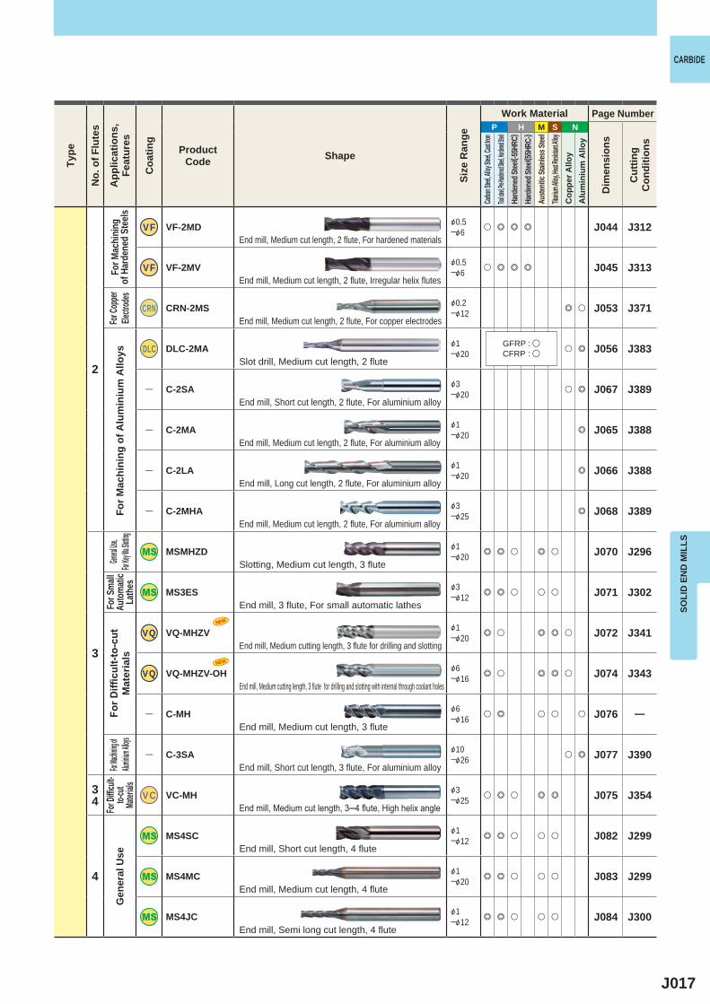
P H M S N
2
VF VF-2MD &0.5─&6 u e e e J044 J312
VF VF-2MV &0.5─&6 u e e e J045 J313
CRN CRN-2MS &0.2─&12 e u J053 J371
DLC DLC-2MA &1─&20 u e J056 J383
― C-2SA &3─&20 u e J067 J389
― C-2MA &1─&20 e J065 J388
― C-2LA &1─&20 e J066 J388
― C-2MHA &3─&25 e J068 J389
3
MSMHZD &1─&20 e e u e u J070 J296
MS3ES &3─&12 e e u u u J071 J302
VQ VQ-MHZV &1─&20 e u e e u J072 J341
VQ VQ-MHZV-OH &6─&16 e u e e u J074 J343
― C-MH &6─&16 u e u u u J076 ―
― C-3SA &10─&26 u e J077 J390
34 VC VC-MH &3
─&25 u e u e e J075 J354
4
MS4SC &1─&12 e e u u u J082 J299
MS4MC &1─&20 e e u u u J083 J299
MS4JC &1─&12 e e u u u J084 J300
NEW
NEW
SOLI
D E
ND
MIL
LS
CARBIDE
For M
achi
ning
of
Har
dene
d St
eels
For M
achi
ning
of A
lum
iniu
m A
lloys
General
Use,For
Key Wa S
lotting
For S
mall
Auto
matic
La
thes
For D
ifficu
lt-to
-cut
M
ater
ials
For Mac
hining of
Alumini
um Alloys
For D
ifficu
lt-to-
cut
Mater
ialsG
ener
al U
se
End mill, Medium cut length, 2 flute, For hardened materials
End mill, Medium cut length, 2 flute, Irregular helix flutes
End mill, Medium cut length, 2 flute, For copper electrodes
Slot drill, Medium cut length, 2 flute
End mill, Short cut length, 2 flute, For aluminium alloy
End mill, Medium cut length, 2 flute, For aluminium alloy
End mill, Long cut length, 2 flute, For aluminium alloy
End mill, Medium cut length, 2 flute, For aluminium alloy
Slotting, Medium cut length, 3 flute
End mill, 3 flute, For small automatic lathes
End mill, Medium cutting length, 3 flute for drilling and slotting
End mill, Medium cutting length, 3 flute for drilling and slotting with internal through coolant holes
End mill, Medium cut length, 3 flute
End mill, Short cut length, 3 flute, For aluminium alloy
End mill, Medium cut length, 3─4 flute, High helix angle
End mill, Short cut length, 4 flute
End mill, Medium cut length, 4 flute
End mill, Semi long cut length, 4 flute
Type
No.
of F
lute
s
App
licat
ions
,Fe
atur
es
Coa
ting
ProductCode Shape
Size
Ran
ge
Work Material Page Number
Dim
ensi
ons
Cut
ting
Con
ditio
ns
Carbon
Steel, A
lloy Ste
el, Cast
Iron
Tool stee
l, Pre-Har
dened St
eel, Hard
ened Stee
lHa
rden
ed St
eel( -5
5HRC
)Ha
rden
ed St
eel( 5
5HRC
-)Au
stenit
ic Sta
inles
s Stee
lTita
nium A
lloy, He
at Resis
tant Al
loyC
oppe
r Allo
yA
lum
iniu
m A
lloy
GFRP : uCFRP : u
For C
oppe
r Ele
ctrod
es
J018
NEW
P H M S N
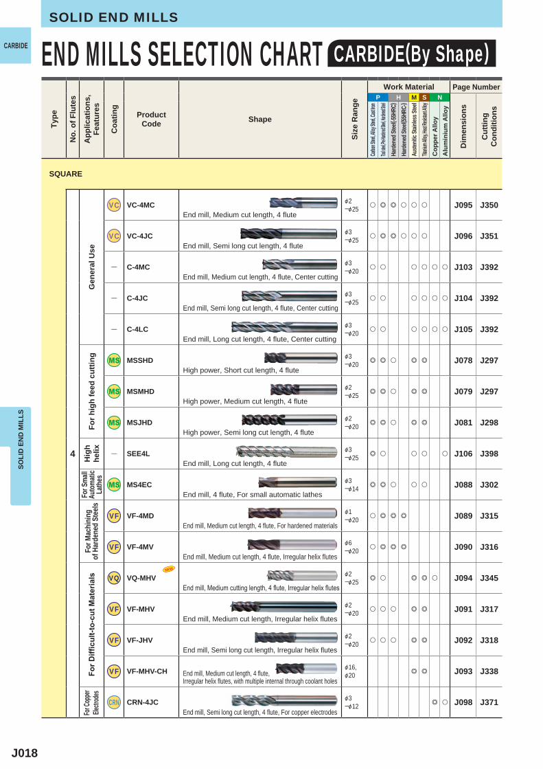
4
VC VC-4MC &2─&25 u e e u u u J095 J350
VC VC-4JC &3─&25 u e e u u u J096 J351
― C-4MC &3─&20 u u u u u u J103 J392
― C-4JC &3─&25 u u u u u u J104 J392
― C-4LC &3─&20 u u u u u u J105 J392
MSSHD &3─&20 e e u e e J078 J297
MSMHD &2─&25 e e u e e J079 J297
MSJHD &2─&20 e e u e e J081 J298
― SEE4L &3─&25 e u u u u J106 J398
MS4EC &3─&14 e e u u u J088 J302
VF VF-4MD &1─&20 u e e e J089 J315
VF VF-4MV &6─&20 u e e e J090 J316
VQ VQ-MHV &2─&25 e u e e u J094 J345
VF VF-MHV &2─&20 u u u e e J091 J317
VF VF-JHV &2─&20 u u u e e J092 J318
VF VF-MHV-CH &16,&20 e e J093 J338
CRN CRN-4JC &3─&12 e u J098 J371
SOLI
D E
ND
MIL
LSSOLID END MILLS
END MILLS SELECTION CHART CARBIDE(By Shape)CARBIDETy
pe
No.
of F
lute
s
App
licat
ions
,Fe
atur
es
Coa
ting
ProductCode Shape
Size
Ran
ge
Work Material Page Number
Dim
ensi
ons
Cut
ting
Con
ditio
ns
Carbon
Steel, A
lloy Ste
el, Cast
Iron
Tool stee
l, Pre-Har
dened St
eel, Hard
ened Stee
lHa
rden
ed St
eel( -5
5HRC
)Ha
rden
ed St
eel( 5
5HRC
-)Au
stenit
ic Sta
inles
s Stee
lTita
nium A
lloy, He
at Resis
tant Al
loyC
oppe
r Allo
yA
lum
iniu
m A
lloy
Gen
eral
Use
For h
igh
feed
cut
ting
Hig
h he
lixFo
r Sma
llAu
toma
tic
Lath
esFo
r Mac
hini
ng
of H
arde
ned
Stee
lsFo
r Diffi
cult-
to-c
ut M
ater
ials
End mill, Medium cut length, 4 flute
End mill, Semi long cut length, 4 flute
End mill, Medium cut length, 4 flute, Center cutting
End mill, Semi long cut length, 4 flute, Center cutting
End mill, Long cut length, 4 flute, Center cutting
High power, Short cut length, 4 flute
High power, Medium cut length, 4 flute
High power, Semi long cut length, 4 flute
End mill, Long cut length, 4 flute
End mill, 4 flute, For small automatic lathes
End mill, Medium cut length, 4 flute, For hardened materials
End mill, Medium cut length, 4 flute, Irregular helix flutes
End mill, Medium cutting length, 4 flute, Irregular helix flutes
End mill, Medium cut length, Irregular helix flutes
End mill, Semi long cut length, Irregular helix flutes
End mill, Medium cut length, 4 flute, Irregular helix flutes, with multiple internal through coolant holes
End mill, Semi long cut length, 4 flute, For copper electrodes
SQUARE
For C
oppe
r Ele
ctrod
es
J019
NEW
P H M S N
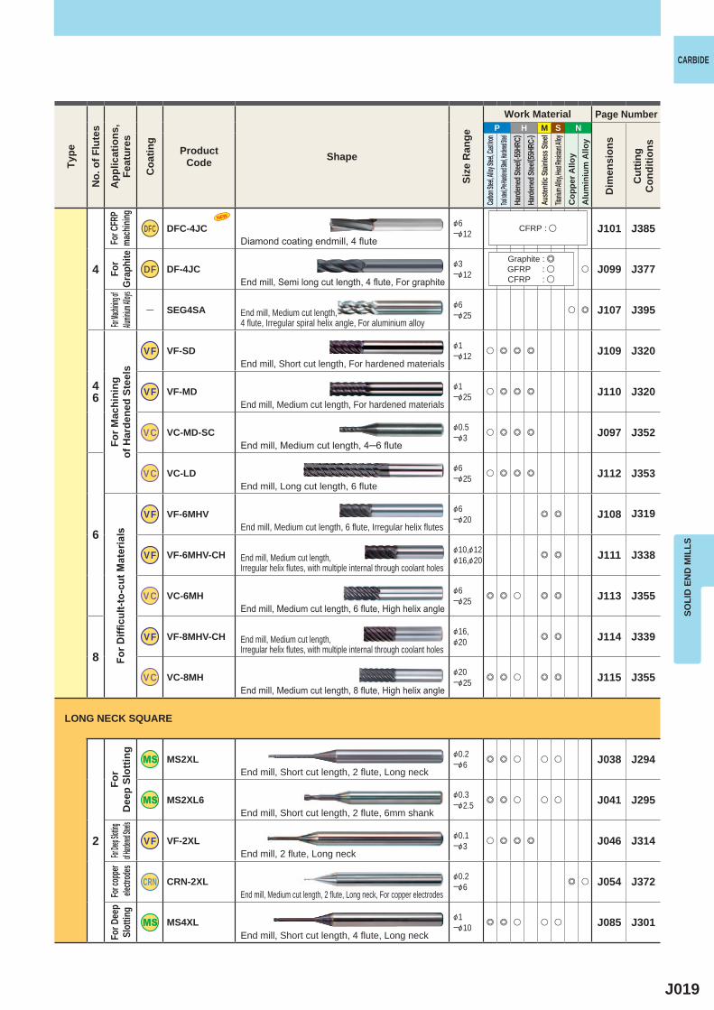
4
DFC DFC-4JC &6─&12 J101 J385
DF DF-4JC &3─&12 u J099 J377
― SEG4SA &6─&25 u e J107 J395
46
VF VF-SD &1─&12 u e e e J109 J320
VF VF-MD &1─&25 u e e e J110 J320
VC VC-MD-SC &0.5─&3 u e e e J097 J352
6
VC VC-LD &6─&25 u e e e J112 J353
VF VF-6MHV &6─&20 e e J108 J319
VF VF-6MHV-CH &10,&12&16,&20 e e J111 J338
VC VC-6MH &6─&25 e e u e e J113 J355
8VF VF-8MHV-CH &16,
&20 e e J114 J339
VC VC-8MH &20─&25 e e u e e J115 J355
2
MS2XL &0.2─&6 e e u u u J038 J294
MS2XL6 &0.3─&2.5 e e u u u J041 J295
VF VF-2XL &0.1─&3 u e e e J046 J314
CRN CRN-2XL &0.2─&6 e u J054 J372
MS4XL &1─&10 e e u u u J085 J301
SOLI
D E
ND
MIL
LS
CARBIDETy
pe
No.
of F
lute
s
App
licat
ions
,Fe
atur
es
Coa
ting
ProductCode Shape
Size
Ran
ge
Work Material Page Number
Dim
ensi
ons
Cut
ting
Con
ditio
ns
Carbon
Steel, A
lloy Ste
el, Cast
Iron
Tool stee
l, Pre-Har
dened St
eel, Hard
ened Stee
lHa
rden
ed St
eel( -5
5HRC
)Ha
rden
ed St
eel( 5
5HRC
-)Au
stenit
ic Sta
inles
s Stee
lTita
nium A
lloy, He
at Resis
tant Al
loyC
oppe
r Allo
yA
lum
iniu
m A
lloy
For C
FRP
mach
ining
For
Grap
hite
For Mac
hining o
f Alum
inium A
lloys
For M
achi
ning
of
Har
dene
d St
eels
For D
ifficu
lt-to
-cut
Mat
eria
lsFo
r D
eep
Slot
ting
For Dee
p Slottin
gof H
ardened
Steels
For c
oppe
r ele
ctrod
esFo
r Dee
p Sl
ottin
g
Diamond coating endmill, 4 flute
End mill, Semi long cut length, 4 flute, For graphite
End mill, Medium cut length, 4 flute, Irregular spiral helix angle, For aluminium alloy
End mill, Short cut length, For hardened materials
End mill, Medium cut length, For hardened materials
End mill, Medium cut length, 4─6 flute
End mill, Long cut length, 6 flute
End mill, Medium cut length, 6 flute, Irregular helix flutes
End mill, Medium cut length, Irregular helix flutes, with multiple internal through coolant holes
End mill, Medium cut length, 6 flute, High helix angle
End mill, Medium cut length, Irregular helix flutes, with multiple internal through coolant holes
End mill, Medium cut length, 8 flute, High helix angle
End mill, Short cut length, 2 flute, Long neck
End mill, Short cut length, 2 flute, 6mm shank
End mill, 2 flute, Long neck
End mill, Medium cut length, 2 flute, Long neck, For copper electrodes
End mill, Short cut length, 4 flute, Long neck
LONG NECK SQUARE
CFRP : u
Graphite : eGFRP : uCFRP : u
J020
P H M S N
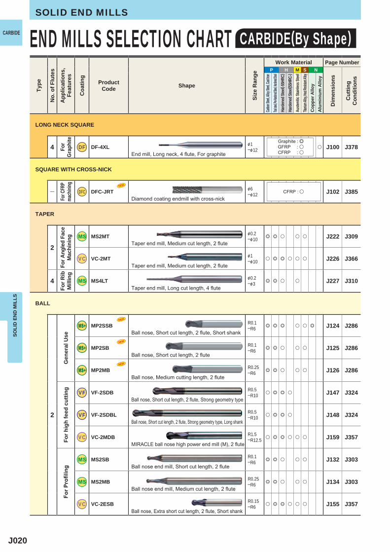
4 DF DF-4XL &1─&12 u J100 J378
― DFC DFC-JRT &6─&12 J102 J385
2
MS2MT &0.2─&10 e e u u u J222 J309
VC VC-2MT &1─&10 u e e u u u J226 J366
4 MS4LT &0.2─&3 e e u u J227 J310
2
MP2SSB R0.1─R6 e e e u u e J124 J286
MP2SB R0.1─R6 e e u u u J125 J286
MP2MB R0.25─R6 e e u u u J126 J286
VF VF-2SDB R0.5─R10 u e e u J147 J324
VF VF-2SDBL R0.5─R10 u e e u J148 J324
VC VC-2MDB R1.5─R12.5 u e e u u u J159 J357
MS2SB R0.1─R6 e e u u u J132 J303
MS2MB R0.25─R6 e e u u u J134 J303
VC VC-2ESB R0.15─R6 u e e u u u J155 J357
NEW
NEW
NEW
NEW
SOLI
D E
ND
MIL
LSSOLID END MILLS
END MILLS SELECTION CHART CARBIDE(By Shape)CARBIDETy
pe
No.
of F
lute
s
App
licat
ions
,Fe
atur
es
Coa
ting
ProductCode Shape
Size
Ran
ge
Work Material Page Number
Dim
ensi
ons
Cut
ting
Con
ditio
ns
Carbon
Steel, A
lloy Ste
el, Cast
Iron
Tool stee
l, Pre-Har
dened St
eel, Hard
ened Stee
lHa
rden
ed St
eel( -5
5HRC
)Ha
rden
ed St
eel( 5
5HRC
-)Au
stenit
ic Sta
inles
s Stee
lTita
nium A
lloy, He
at Resis
tant Al
loyC
oppe
r Allo
yA
lum
iniu
m A
lloy
For
Grap
hite
For C
FRP
mach
ining
For A
ngle
d Fa
ceM
achi
ning
For R
ib
Mill
ing
Gen
eral
Use
For h
igh
feed
cut
ting
For P
rofil
ing
End mill, Long neck, 4 flute, For graphite
Diamond coating endmill with cross-nick
Taper end mill, Medium cut length, 2 flute
Taper end mill, Medium cut length, 2 flute
Taper end mill, Long cut length, 4 flute
Ball nose, Short cut length, 2 flute, Short shank
Ball nose, Short cut length, 2 flute
Ball nose, Medium cutting length, 2 flute
Ball nose, Short cut length, 2 flute, Strong geometry type
Ball nose, Short cut length, 2 flute, Strong geometry type, Long shank
MIRACLE ball nose high power end mill (M), 2 flute
Ball nose end mill, Short cut length, 2 flute
Ball nose end mill, Medium cut length, 2 flute
Ball nose, Extra short cut length, 2 flute, Short shank
LONG NECK SQUARE
SQUARE WITH CROSS-NICK
TAPER
BALL
CFRP : u
Graphite : eGFRP : uCFRP : u
J021
P H M S N
2
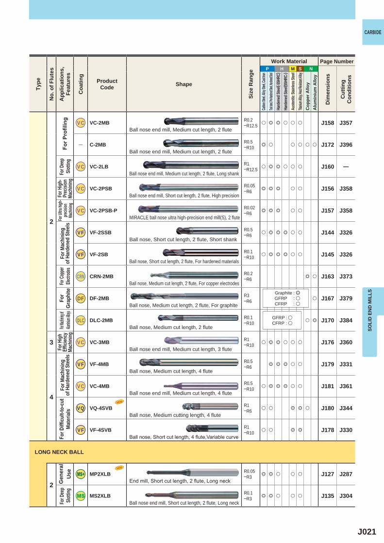
VC VC-2MB R0.2─R12.5 u e e u u u J158 J357
― C-2MB R0.5─R10 e u u u u u J172 J396
VC VC-2LB R1─R12.5 u e e u u u J160 ―
VC VC-2PSB R0.05─R6 e e e u u J156 J358
VC VC-2PSB-P R0.02─R6 e e e u u J157 J358
VF VF-2SSB R0.5─R6 u e e e u u J144 J326
VF VF-2SB R0.1─R10 u e e e u u J145 J326
CRN CRN-2MB R0.2─R6 e u J163 J373
DF DF-2MB R3─R6 u J167 J379
DLC DLC-2MB R0.1─R10 u e J170 J384
3 VC VC-3MB R1─R10 u e e u u u J176 J360
4
VF VF-4MB R0.5─R6 e e e u u J179 J331
VC VC-4MB R0.5─R10 u e e e u u J181 J361
VQ VQ-4SVB R1─R6 u u e e u J180 J344
VF VF-4SVB R1─R10 u u e e J178 J330
2
MP2XLB R0.05─R3 e e u u u J127 J287
MS2XLB R0.1─R3 e e u u u J135 J304
NEW
NEW
SOLI
D E
ND
MIL
LS
CARBIDETy
pe
No.
of F
lute
s
App
licat
ions
,Fe
atur
es
Coa
ting
ProductCode Shape
Size
Ran
ge
Work Material Page Number
Dim
ensi
ons
Cut
ting
Con
ditio
ns
Carbon
Steel, A
lloy Ste
el, Cast
Iron
Tool stee
l, Pre-Har
dened St
eel, Hard
ened Stee
lHa
rden
ed St
eel( -5
5HRC
)Ha
rden
ed St
eel( 5
5HRC
-)Au
stenit
ic Sta
inles
s Stee
lTita
nium A
lloy, He
at Resis
tant Al
loyC
oppe
r Allo
yA
lum
iniu
m A
lloy
For P
rofil
ing
For H
igh-
Prec
ision
Ma
chini
ng
For U
ltra hi
gh-
precis
ion
Mach
ining
For M
achi
ning
of
Har
dene
d St
eels
For
Grap
hite
For H
igh
Effic
iency
Ma
chini
ngFo
r Mac
hini
ng
of H
arde
ned
Stee
lsFo
r Diffi
cult-
to-c
ut
Mat
eria
lsG
ener
al
Use
Ball nose end mill, Medium cut length, 2 flute
Ball nose end mill, Medium cut length, 2 flute
Ball nose end mill, Medium cut length, 2 flute, Long shank
Ball nose end mill, Short cut length, 2 flute, High precision
MIRACLE ball nose ultra high-precision end mill(S), 2 flute
Ball nose, Short cut length, 2 flute, Short shank
Ball nose, Short cut length, 2 flute, For hardened materials
Ball nose, Medium cut length, 2 flute, For copper electrodes
Ball nose, Medium cut length, 2 flute, For graphite
Ball nose, Medium cut length, 2 flute
Ball nose end mill, Medium cut length, 3 flute
Ball nose, Medium cut length, 4 flute
Ball nose end mill, Medium cut length, 4 flute
Ball nose, Medium cutting length, 4 flute
Ball nose, Short cut length, 4 flute,Variable curve
End mill, Short cut length, 2 flute, Long neck
Ball nose end mill, Short cut length, 2 flute, Long neck
LONG NECK BALL
Graphite : eGFRP : uCFRP : u
GFRP : uCFRP : u
For D
eep
Slott
ingFo
r Dee
p Sl
otting
For C
oppe
r Ele
ctrod
esFor
Machinin
g of Alu
minium A
lloys
J022
P H M S N
2
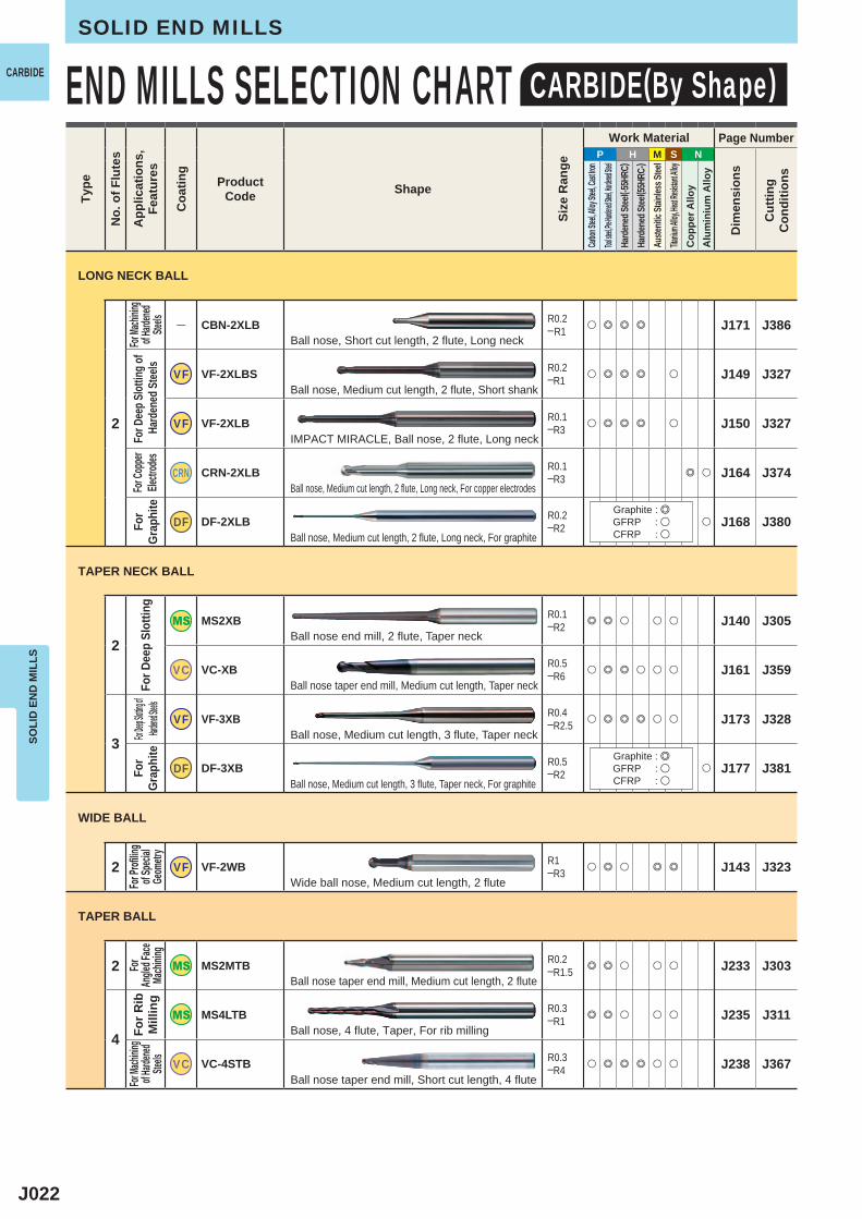
― CBN-2XLB
R0.2─R1 u e e e J171 J386
VF VF-2XLBS R0.2─R1 u e e e u J149 J327
VF VF-2XLB R0.1─R3 u e e e u J150 J327
CRN CRN-2XLB R0.1─R3 e u J164 J374
DF DF-2XLB R0.2─R2 u J168 J380
2
MS2XB R0.1─R2 e e u u u J140 J305
VC VC-XB R0.5─R6 u e e u u u J161 J359
3VF VF-3XB R0.4
─R2.5 u e e e u u J173 J328
DF DF-3XB R0.5─R2 u J177 J381
2 VF VF-2WB R1─R3 u e u e e J143 J323
2 MS2MTB R0.2─R1.5 e e u u u J233 J303
4
MS4LTB R0.3─R1 e e u u u J235 J311
VC VC-4STB R0.3─R4 u e e e u u J238 J367
SOLI
D E
ND
MIL
LSSOLID END MILLS
END MILLS SELECTION CHART CARBIDE(By Shape)CARBIDETy
pe
No.
of F
lute
s
App
licat
ions
,Fe
atur
es
Coa
ting
ProductCode Shape
Size
Ran
ge
Work Material Page Number
Dim
ensi
ons
Cut
ting
Con
ditio
ns
Carbon
Steel, A
lloy Ste
el, Cast
Iron
Tool stee
l, Pre-Har
dened St
eel, Hard
ened Stee
lHa
rden
ed St
eel( -5
5HRC
)Ha
rden
ed St
eel( 5
5HRC
-)Au
stenit
ic Sta
inles
s Stee
lTita
nium A
lloy, He
at Resis
tant Al
loyC
oppe
r Allo
yA
lum
iniu
m A
lloy
Ball nose, Short cut length, 2 flute, Long neck
Ball nose, Medium cut length, 2 flute, Short shank
IMPACT MIRACLE, Ball nose, 2 flute, Long neck
Ball nose, Medium cut length, 2 flute, Long neck, For copper electrodes
Ball nose, Medium cut length, 2 flute, Long neck, For graphite
Ball nose end mill, 2 flute, Taper neck
Ball nose taper end mill, Medium cut length, Taper neck
Ball nose, Medium cut length, 3 flute, Taper neck
Ball nose, Medium cut length, 3 flute, Taper neck, For graphite
Wide ball nose, Medium cut length, 2 flute
Ball nose taper end mill, Medium cut length, 2 flute
Ball nose, 4 flute, Taper, For rib milling
Ball nose taper end mill, Short cut length, 4 flute
For Ma
chinin
g of H
ardene
d Ste
elsFo
r Cop
per
Electr
odes
For
Grap
hite
For D
eep
Slot
ting
For
Grap
hite
For P
rofilin
gof
Speci
alGe
ometr
y
For
Angle
d Face
Mach
ining
For R
ib
Mill
ing
For Ma
chinin
g of H
ardene
d Ste
els
TAPER BALL
WIDE BALL
TAPER NECK BALL
LONG NECK BALL
Graphite : eGFRP : uCFRP : u
Graphite : eGFRP : uCFRP : u
For D
eep S
lottin
g of
Har
dene
d Stee
lsFor D
eep Slott
ing of
Hardened
Steels

J023
P H M S N
2
MS2MRB &1─&12 e e u u u J182 J290
CRN CRN-2MRB &6─&12 e u J189 J375
3 ― C-3SARB &12─&25 u e J193 J390
24
VC VC-PSRB &0.6─&12 e e e e u u J185 J362
DF DF-PSRB &0.5─&12 u J214 J382
4
MSMHDRB &2─&20 e e u e e J197 J308
VF VF-HVRB &1─&16 e e e e u u J199 J332
VC VC-HFRB &2─&16 e e e u u J210 J364
MS4MRB &3─&20 e e u u u J195 J307
VC VC-4SRB &4─&12 u e e u u u J208 J350
VC VC-4JRB &3─&20 u e u u u u J209 J351
VQ VQ-MHVRB &2─&20 e u e e u J205 J345
VQ VQ-MHVRB-F &6─&16 u u u e J207 J346
VF VF-MHVRB &6─&20 e u u e e J203 J317
VF VF-MHVRB-CH &16─&20 e e J204 J338
VC VC-MHDRB &2─&25 u e e u e e J212 J365
NEW
NEW
SOLI
D E
ND
MIL
LS
CARBIDETy
pe
No.
of F
lute
s
App
licat
ions
,Fe
atur
es
Coa
ting
ProductCode Shape
Size
Ran
ge
Work Material Page Number
Dim
ensi
ons
Cut
ting
Con
ditio
ns
Carbon
Steel, A
lloy Ste
el, Cast
Iron
Tool stee
l, Pre-Har
dened St
eel, Hard
ened Stee
lHa
rden
ed St
eel( -5
5HRC
)Ha
rden
ed St
eel( 5
5HRC
-)Au
stenit
ic Sta
inles
s Stee
lTita
nium A
lloy, He
at Resis
tant Al
loyC
oppe
r Allo
yA
lum
iniu
m A
lloy
Corner radius end mill, Medium cut length, 2 flute
Corner radius, Medium cut length, 2 flute, For copper electrodes
Corner radius, Short cut length, 3 flute, For aluminium alloy
Corner radius end mill, Short cut length, 2─4 flute, High precision
Corner radius end mill, Short cut length, 2─4 flute, High precision, For graphite
High power, Corner radius, Medium cut length, 4 flute
4 flute, Corner radius, Short cut length,Irregular helix flutes
Corner radius, Short flute length, 4 flute, High feed machining
Corner radius end mill, Medium cut length, 4 flute
Corner radius end mill, Short cut length, 4 flute
Corner radius end mill, Semi long cut length, 4 flute
Corner radius end mill, Medium cutting length, 4 flute, Irregular helix flutes
Corner radius end mill, Medium cutting length, 4 flute, Irregular helix flutes (for finishing)
Corner radius, Medium cut length, Irregular helix flutes
Corner radius end mill, Medium cut length, 4 flute, Irregular helix flutes, with multiple internal through coolant holes
Corner radius end mill, Medium cut length, 4 flute, High helix angle
For C
orner
Radiu
sFo
r Cop
per
Electr
odes
For Mac
hining of
Alumini
um Alloys
For H
igh-
Prec
ision
Ma
chini
ngFo
r Gr
aphi
teFo
r high
feed
cuttin
gFo
r High
Ef
ficien
cy
Mach
ining
For H
ighFe
edMa
chini
ngFo
r Cor
ner R
adiu
sFo
r Diffi
cult-
to-c
ut M
ater
ials
RADIUS
Graphite : eGFRP : uCFRP : u
J024
P H M S N
6
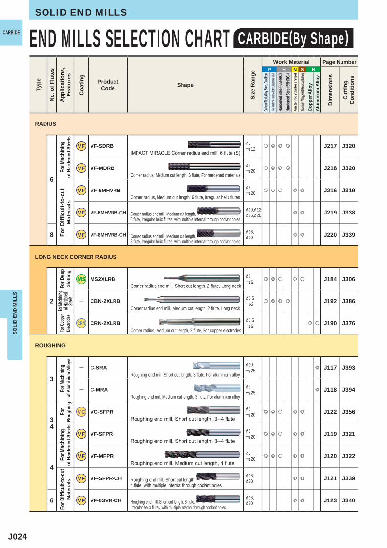
VF VF-SDRB &3─&12 u e e e J217 J320
VF VF-MDRB &3─&20 u e e e J218 J320
VF VF-6MHVRB &6─&20 u u u e e J216 J319
VF VF-6MHVRB-CH &10,&12&16,&20 e e J219 J338
8 VF VF-8MHVRB-CH &16,&20 e e J220 J339
2
MS2XLRB &1─&6 e e u u u J184 J306
― CBN-2XLRB &0.5─&2 u e e e J192 J386
CRN CRN-2XLRB &0.5─&6 e u J190 J376
3
― C-SRA &10─&25 e J117 J393
― C-MRA &3─&25 e J118 J394
34
VC VC-SFPR &3─&20 e e u e e J122 J356
VF VF-SFPR &3─&20 e e u e e J119 J321
4
VF VF-MFPR &5─&20 e e u e e J120 J322
VF VF-SFPR-CH &16,&20 e e J121 J339
6 VF VF-6SVR-CH &16,&20 e e J123 J340
SOLI
D E
ND
MIL
LSSOLID END MILLS
END MILLS SELECTION CHART CARBIDE(By Shape)CARBIDETy
pe
No.
of F
lute
s
App
licat
ions
,Fe
atur
es
Coa
ting
ProductCode Shape
Size
Ran
ge
Work Material Page Number
Dim
ensi
ons
Cut
ting
Con
ditio
ns
Carbon
Steel, A
lloy Ste
el, Cast
Iron
Tool stee
l, Pre-Har
dened St
eel, Hard
ened Stee
lHa
rden
ed St
eel( -5
5HRC
)Ha
rden
ed St
eel( 5
5HRC
-)Au
stenit
ic Sta
inles
s Stee
lTita
nium A
lloy, He
at Resis
tant Al
loyC
oppe
r Allo
yA
lum
iniu
m A
lloy
IMPACT MIRACLE Corner radius end mill, 6 flute (S)
Corner radius, Medium cut length, 6 flute, For hardened materials
Corner radius, Medium cut length, 6 flute, Irregular helix flutes
Corner radius end mill, Medium cut length, 6 flute, Irregular helix flutes, with multiple internal through coolant holes
Corner radius end mill, Medium cut length, 8 flute, Irregular helix flutes, with multiple internal through coolant holes
Corner radius end mill, Short cut length, 2 flute, Long neck
Corner radius end mill, Medium cut length, 2 flute, Long neck
Corner radius, Medium cut length, 2 flute, For copper electrodes
Roughing end mill, Short cut length, 3 flute, For aluminium alloy
Roughing end mill, Medium cut length, 3 flute, For aluminium alloy
Roughing end mill, Short cut length, 3─4 flute
Roughing end mill, Short cut length, 3─4 flute
Roughing end mill, Medium cut length, 4 flute
Roughing end mill, Short cut length, 4 flute, with multiple internal through coolant holes
Roughing end mill, Short cut length, 6 flute, Irregular helix flutes, with multiple internal through coolant holes
For M
achi
ning
of
Har
dene
d St
eels
For D
ifficu
lt-to
-cut
M
ater
ials
For D
eep
Slot
ting
For Ma
chinin
g of H
ardene
d Ste
elsFo
r Cop
per
Electr
odes
For M
achin
ing of
Alum
inium
Allo
ysFo
r Ro
ughin
gFo
r Mac
hini
ng
of H
arde
ned
Stee
lsFo
r Diffi
cult-
to-c
ut
Mat
eria
ls
RADIUS
LONG NECK CORNER RADIUS
ROUGHING
J025
P H M S N
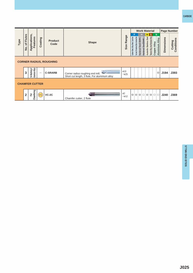
3 ― C-SRARB &10─&25 e J194 J393
2 VC VC-2C &2─&12 e e e u e e u u J240 J369
SOLI
D E
ND
MIL
LS
CARBIDETy
pe
No.
of F
lute
s
App
licat
ions
,Fe
atur
es
Coa
ting
ProductCode Shape
Size
Ran
ge
Work Material Page Number
Dim
ensi
ons
Cut
ting
Con
ditio
ns
Carbon
Steel, A
lloy Ste
el, Cast
Iron
Tool stee
l, Pre-Har
dened St
eel, Hard
ened Stee
lHa
rden
ed St
eel( -5
5HRC
)Ha
rden
ed St
eel( 5
5HRC
-)Au
stenit
ic Sta
inles
s Stee
lTita
nium A
lloy, He
at Resis
tant Al
loyC
oppe
r Allo
yA
lum
iniu
m A
lloy
Corner radius roughing end mill, Short cut length, 3 flute, For aluminium alloy
Chamfer cutter, 2 flute
CORNER RADIUS, ROUGHING
CHAMFER CUTTER
For Mac
hining o
f Alum
inium A
lloys
For
Cham
fering
J026
P H M S N
2
V VA-2SS &3─&20 e u u u J244 J399
V VA-2MS &3─&40 e u u u J245 J399
4 V VA-4MC &3─&30 e u u u J261 J401
234
V VA-MH &5─&30 e u e u J259 J400
456
V VA-SFPR &5─&50 e u e u J272 J402
V VA-MFPR &5─&50 e u e u J273 J403
V VA-MR &5─&50 e u e u J274 J404
V VA-JR &10─&50 e u e u J275 J405
V VA-LR &10─&50 e u e u J276 J405
2 G G-2MS &1─&40 e u u u u J250 J408
4
G G-4MC &3─&30 e u u u u J263 J411
G G-4LC &3─&40 e u u u u J267 J411
346
G G-SFPR &5─&50 e u u u u J271 J415
456
G G-MR &5─&50 e u u u u J278 J415
2
― 2SS &0.5─&20 e u u u u J246 J406
― S-2MD &0.4─&20 e u u u u J248 J407
SOLI
D E
ND
MIL
LSSOLID END MILLS
HSS END MILLS SELECTION CHART HSS (By Series)
VIOLET END MILLS
Gen
eral
Use
SQU
AR
E
For R
ough
ing
RO
UG
HIN
G
Gen
eral
Use
SQU
AR
E
For D
ifficu
lt-to-
cut
Mater
ialsFo
r Rou
ghin
g
RO
UG
HIN
G
Gen
eral
Use
SQU
AR
E
TIN COATED END MILLS
TWO-FLUTE END MILLS
End mill, Short cut length, 2 flute
End mill, Medium cut length, 2 flute
End mill, Medium cut length, 4 flute
End mill, Medium cut length, 2─4 flute
Roughing end mill, Short cut length, 4─6 flute, Fine pitch form
Roughing end mill, Medium cut length, 4─6 flute, Fine pitch form
Roughing end mill, Medium cut length, 4─6 flute
Roughing end mill, Semi long cut length, 4─6 flute
Roughing end mill, Long cut length, 4─6 flute
End mill, Medium cut length, 2 flute
End mill, Medium cut length, 4 flute
End mill, Long cut length, 4 flute, Center cutting
Roughing end mill, Short cut length, 3─6 flute, Fine pitch form
Roughing end mill, Medium cut length, 4─6 flute
End mill, Short cut length, 2 flute
End mill, Short cut length, 2 flute, KHA Super
App
licat
ions
,Fe
atur
es
Type
No.
of F
lute
s
Coa
ting
ProductCode Shape
Size
Ran
ge
Work Material Page Number
Dim
ensi
ons
Cut
ting
Con
ditio
ns
Carbon
Steel, A
lloy Ste
el, Cast
Iron
Tool stee
l, Pre-Har
dened St
eel, Hard
ened Stee
lHa
rden
ed St
eel( -5
5HRC
)Ha
rden
ed St
eel( 5
5HRC
-)Au
stenit
ic Sta
inles
s Stee
lTita
nium A
lloy, He
at Resis
tant Al
loyC
oppe
r Allo
yA
lum
iniu
m A
lloy
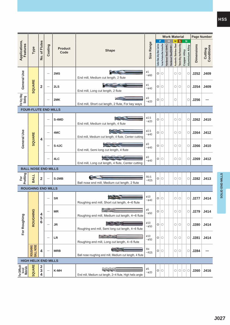
J027
P H M S N
2
― 2MS &1─&60 e u u u u J252 J409
― 2LS &1─&40 e u u u u J254 J409
― 2MK &3─&20 e u u u J256 ―
4
― S-4MD &2.5─&20 e u u u u J262 J410
― 4MC &2.5─&40 e u u u u J264 J412
― S-4JC &3─&40 e u u u u J266 J410
― 4LC &3─&40 e u u u u J269 J412
2 ― S-2MB R0.5─R25 e u u u u J282 J413
456
― SR &10─&40 e u u u u J277 J414
― MR &5─&50 e u u u u J279 J414
― JR &10─&50 e u u u u J280 J414
― LR &10─&50 e u u u u J281 J414
4 ― MRB R4─R25 e u u u u J284 ―
234
― K-MH &5─&20 e u u u u u J260 J416
SOLI
D E
ND
MIL
LS
HSSA
pplic
atio
ns,
Feat
ures
Type
No.
of F
lute
s
Coa
ting
ProductCode Shape
Size
Ran
ge
Work Material Page Number
Dim
ensi
ons
Cut
ting
Con
ditio
ns
Carbon
Steel, A
lloy Ste
el, Cast
Iron
Tool stee
l, Pre-Har
dened St
eel, Hard
ened Stee
lHa
rden
ed St
eel( -5
5HRC
)Ha
rden
ed St
eel( 5
5HRC
-)Au
stenit
ic Sta
inles
s Stee
lTita
nium A
lloy, He
at Resis
tant Al
loyC
oppe
r Allo
yA
lum
iniu
m A
lloy
For D
ifficu
lt-to-
cut
Mater
ials
SQUA
RE
Gen
eral
Use
SQU
AR
E
For K
ey Wa
ySlo
tting
FOUR-FLUTE END MILLS
Gen
eral
Use
SQU
AR
E
BALL NOSE END MILLS
For
Profi
ling
BA
LL
ROUGHING END MILLS
For R
ough
ing
RO
UG
HIN
GRO
UGHIN
GBA
LL NO
SE
HIGH HELIX END MILLS
End mill, Medium cut length, 2 flute
End mill, Long cut length, 2 flute
End mill, Short cut length, 2 flute, For key ways
End mill, Medium cut length, 4 flute
End mill, Medium cut length, 4 flute, Center cutting
End mill, Semi long cut length, 4 flute
End mill, Long cut length, 4 flute, Center cutting
Ball nose end mill, Medium cut length, 2 flute
Roughing end mill, Short cut length, 4─6 flute
Roughing end mill, Medium cut length, 4─6 flute
Roughing end mill, Semi long cut length, 4─6 flute
Roughing end mill, Long cut length, 4─6 flute
Ball nose roughing end mill, Medium cut length, 4 flute
End mill, Medium cut length, 2─4 flute, High helix angle
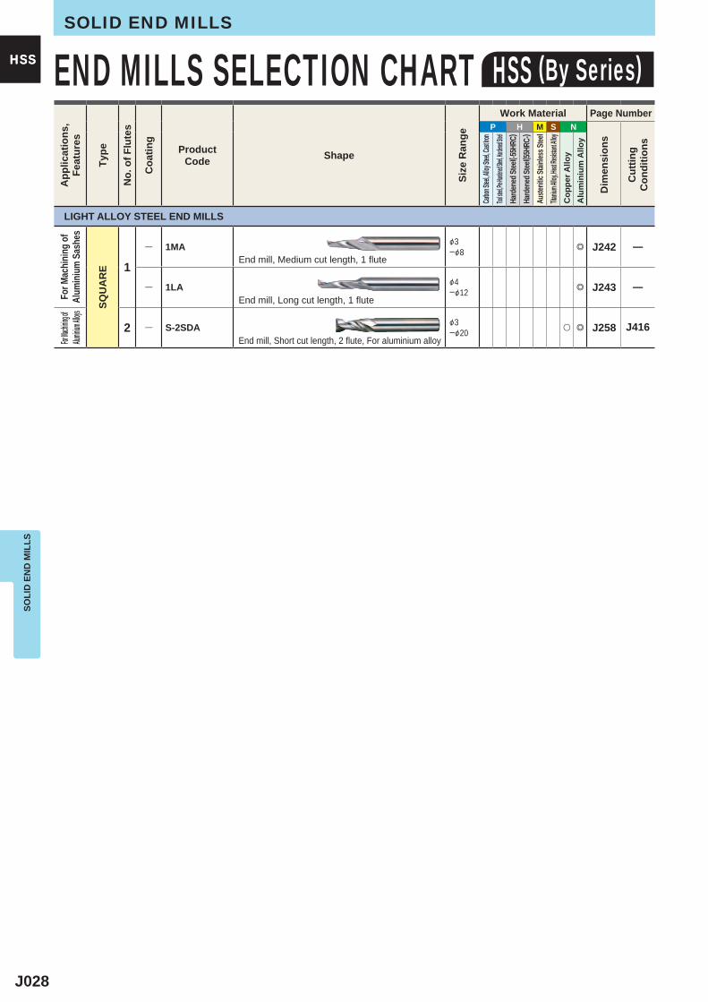
J028
P H M S N
1
― 1MA &3─&8 e J242 ―
― 1LA &4─&12 e J243 ―
2 ― S-2SDA &3─&20 u e J258 J416
SOLI
D E
ND
MIL
LSSOLID END MILLS
HSS END MILLS SELECTION CHART HSS (By Series)HSSA
pplic
atio
ns,
Feat
ures
Type
No.
of F
lute
s
Coa
ting
ProductCode Shape
Size
Ran
ge
Work Material Page Number
Dim
ensi
ons
Cut
ting
Con
ditio
ns
Carbon
Steel, A
lloy Ste
el, Cast
Iron
Tool stee
l, Pre-Har
dened St
eel, Hard
ened Stee
lHa
rden
ed St
eel( -5
5HRC
)Ha
rden
ed St
eel( 5
5HRC
-)Au
stenit
ic Sta
inles
s Stee
lTita
nium A
lloy, He
at Resis
tant Al
loyC
oppe
r Allo
yA
lum
iniu
m A
lloy
LIGHT ALLOY STEEL END MILLS
For M
achi
ning
of
Alum
iniu
m S
ashe
s
SQU
AR
E
For Mac
hining of
Alumini
um Alloys
End mill, Medium cut length, 1 flute
End mill, Long cut length, 1 flute
End mill, Short cut length, 2 flute, For aluminium alloy
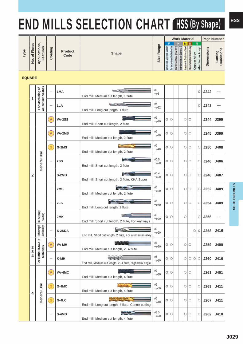
J029
P H M S N
1
― 1MA &3─&8 e J242 ―
― 1LA &4─&12 e J243 ―
2
V VA-2SS &3─&20 e u u u J244 J399
V VA-2MS &3─&40 e u u u J245 J399
G G-2MS &1─&40 e u u u u J250 J408
― 2SS &0.5─&20 e u u u u J246 J406
― S-2MD &0.4─&20 e u u u u J248 J407
― 2MS &1─&60 e u u u u J252 J409
― 2LS &1─&40 e u u u u J254 J409
― 2MK &3─&20 e u u u J256 ―
― S-2SDA &3─&20 u e J258 J416
234
V VA-MH &5─&30 e u e u J259 J400
― K-MH &5─&20 e u u u u u J260 J416
4
V VA-4MC &3─&30 e u u u J261 J401
G G-4MC &3─&30 e u u u u J263 J411
G G-4LC &3─&40 e u u u u J267 J411
― S-4MD &2.5─&20 e u u u u J262 J410
SOLI
D E
ND
MIL
LS
HSS
SQUARE
For M
achi
ning
of
Alum
iniu
m S
ashe
sG
ener
al U
seFo
r Key
Way
Slottin
gFor
Machinin
g of Alu
minium A
lloysFo
r Diffi
cult-
to-c
ut
Mat
eria
lsG
ener
al U
se
End mill, Medium cut length, 1 flute
End mill, Long cut length, 1 flute
End mill, Short cut length, 2 flute
End mill, Medium cut length, 2 flute
End mill, Medium cut length, 2 flute
End mill, Short cut length, 2 flute
End mill, Short cut length, 2 flute, KHA Super
End mill, Medium cut length, 2 flute
End mill, Long cut length, 2 flute
End mill, Short cut length, 2 flute, For key ways
End mill, Short cut length, 2 flute, For aluminium alloy
End mill, Medium cut length, 2─4 flute
End mill, Medium cut length, 2─4 flute, High helix angle
End mill, Medium cut length, 4 flute
End mill, Medium cut length, 4 flute
End mill, Long cut length, 4 flute, Center cutting
End mill, Medium cut length, 4 flute
Type
No.
of F
lute
s
App
licat
ions
,Fe
atur
es
Coa
ting
ProductCode Shape
Size
Ran
ge
Work Material Page Number
Dim
ensi
ons
Cut
ting
Con
ditio
ns
Carbon
Steel, A
lloy Ste
el, Cast
Iron
Tool stee
l, Pre-Har
dened St
eel, Hard
ened Stee
lHa
rden
ed St
eel( -5
5HRC
)Ha
rden
ed St
eel( 5
5HRC
-)Au
stenit
ic Sta
inles
s Stee
lTita
nium A
lloy, He
at Resis
tant Al
loyC
oppe
r Allo
yA
lum
iniu
m A
lloy
END MILLS SELECTION CHART HSS (By Shape)
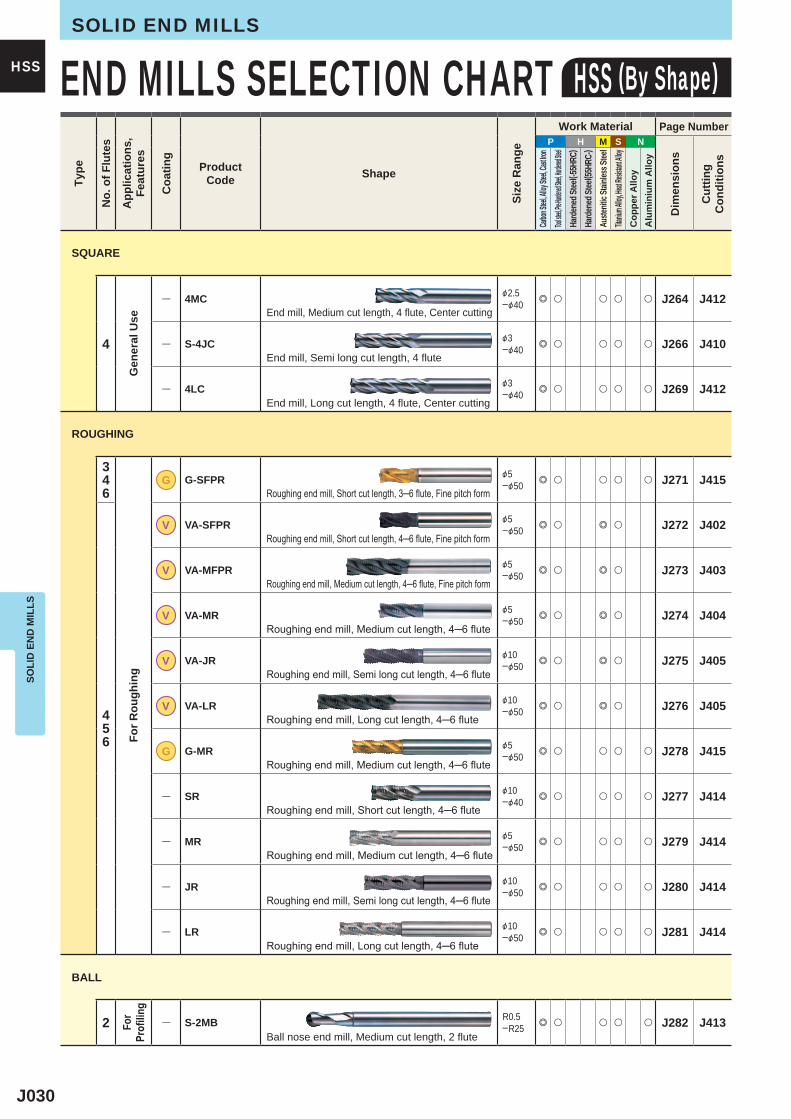
J030
P H M S N
4
― 4MC &2.5─&40 e u u u u J264 J412
― S-4JC &3─&40 e u u u u J266 J410
― 4LC &3─&40 e u u u u J269 J412
346
G G-SFPR &5─&50 e u u u u J271 J415
456
V VA-SFPR &5─&50 e u e u J272 J402
V VA-MFPR &5─&50 e u e u J273 J403
V VA-MR &5─&50 e u e u J274 J404
V VA-JR &10─&50 e u e u J275 J405
V VA-LR &10─&50 e u e u J276 J405
G G-MR &5─&50 e u u u u J278 J415
― SR &10─&40 e u u u u J277 J414
― MR &5─&50 e u u u u J279 J414
― JR &10─&50 e u u u u J280 J414
― LR &10─&50 e u u u u J281 J414
2 ― S-2MB R0.5─R25 e u u u u J282 J413
SOLI
D E
ND
MIL
LSSOLID END MILLS
HSS END MILLS SELECTION CHART HSS (By Shape)Ty
pe
No.
of F
lute
s
App
licat
ions
,Fe
atur
es
Coa
ting
ProductCode Shape
Size
Ran
ge
Work Material Page Number
Dim
ensi
ons
Cut
ting
Con
ditio
ns
Carbon
Steel, A
lloy Ste
el, Cast
Iron
Tool stee
l, Pre-Har
dened St
eel, Hard
ened Stee
lHa
rden
ed St
eel( -5
5HRC
)Ha
rden
ed St
eel( 5
5HRC
-)Au
stenit
ic Sta
inles
s Stee
lTita
nium A
lloy, He
at Resis
tant Al
loyC
oppe
r Allo
yA
lum
iniu
m A
lloy
SQUARE
Gen
eral
Use End mill, Medium cut length, 4 flute, Center cutting
End mill, Semi long cut length, 4 flute
End mill, Long cut length, 4 flute, Center cutting
ROUGHING
For R
ough
ing
Roughing end mill, Short cut length, 3─6 flute, Fine pitch form
Roughing end mill, Short cut length, 4─6 flute, Fine pitch form
Roughing end mill, Medium cut length, 4─6 flute, Fine pitch form
Roughing end mill, Medium cut length, 4─6 flute
Roughing end mill, Semi long cut length, 4─6 flute
Roughing end mill, Long cut length, 4─6 flute
Roughing end mill, Medium cut length, 4─6 flute
Roughing end mill, Short cut length, 4─6 flute
Roughing end mill, Medium cut length, 4─6 flute
Roughing end mill, Semi long cut length, 4─6 flute
Roughing end mill, Long cut length, 4─6 flute
BALL
For
Profi
ling
Ball nose end mill, Medium cut length, 2 flute
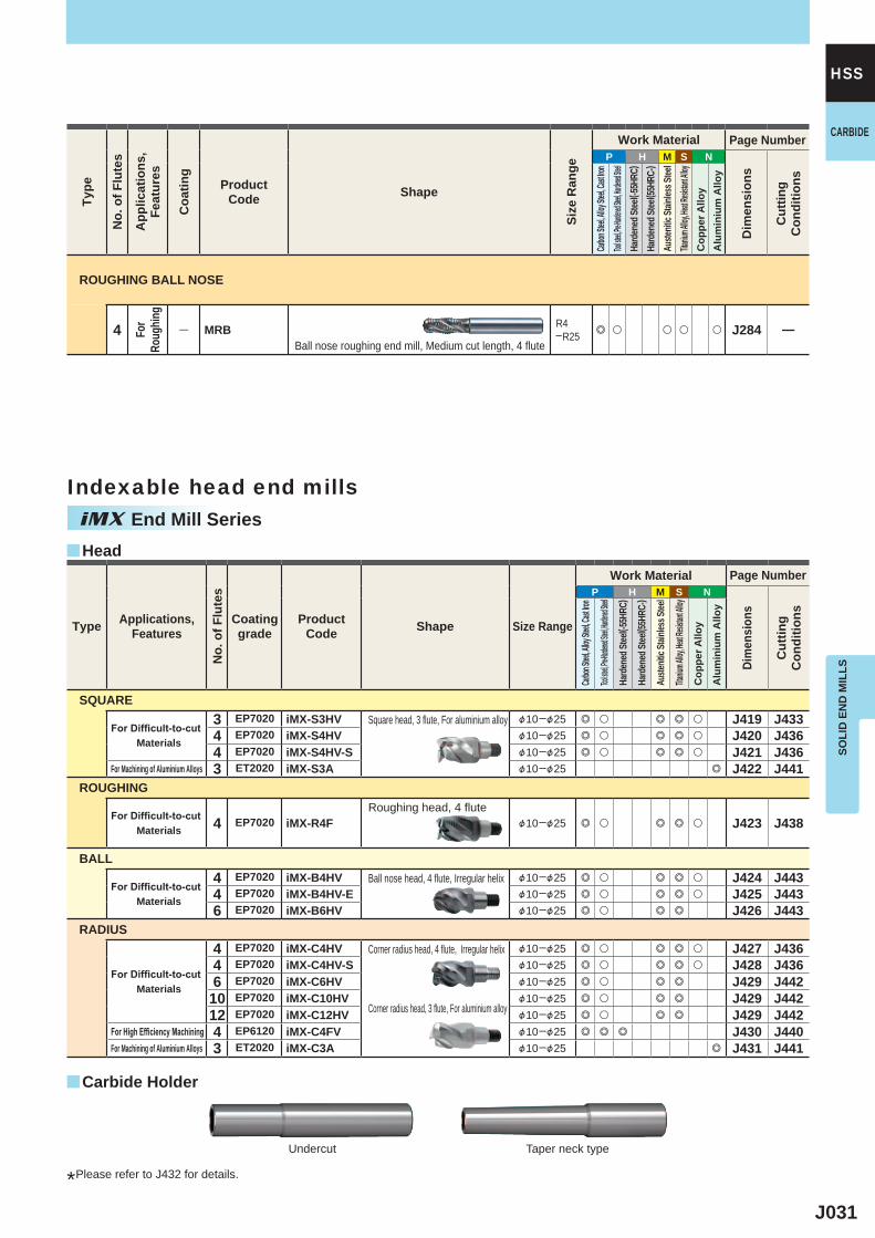
J031
P H M S N
4 ― MRB R4─R25 e u u u u J284 ―
P H M S N
3 EP7020 iMX-S3HV &10─&25 e u e e u J419 J4334 EP7020 iMX-S4HV &10─&25 e u e e u J420 J4364 EP7020 iMX-S4HV-S &10─&25 e u e e u J421 J4363 ET2020 iMX-S3A &10─&25 e J422 J441
4 EP7020 iMX-R4F &10─&25 e u e e u J423 J438
4 EP7020 iMX-B4HV &10─&25 e u e e u J424 J4434 EP7020 iMX-B4HV-E &10─&25 e u e e u J425 J4436 EP7020 iMX-B6HV &10─&25 e u e e J426 J443
4 EP7020 iMX-C4HV &10─&25 e u e e u J427 J4364 EP7020 iMX-C4HV-S &10─&25 e u e e u J428 J4366 EP7020 iMX-C6HV &10─&25 e u e e J429 J442
10 EP7020 iMX-C10HV &10─&25 e u e e J429 J44212 EP7020 iMX-C12HV &10─&25 e u e e J429 J4424 EP6120 iMX-C4FV &10─&25 e e e J430 J4403 ET2020 iMX-C3A &10─&25 e J431 J441
y
y
SOLI
D E
ND
MIL
LS
HSSTy
pe
No.
of F
lute
s
App
licat
ions
,Fe
atur
es
Coa
ting
ProductCode Shape
Size
Ran
ge
Work Material Page Number
Dim
ensi
ons
Cut
ting
Con
ditio
ns
Carbon
Steel, A
lloy Ste
el, Cast
Iron
Tool stee
l, Pre-Har
dened St
eel, Hard
ened Stee
lHa
rden
ed St
eel( -5
5HRC
)Ha
rden
ed St
eel( 5
5HRC
-)Au
stenit
ic Sta
inles
s Stee
lTita
nium A
lloy, He
at Resis
tant Al
loyC
oppe
r Allo
yA
lum
iniu
m A
lloy
ROUGHING BALL NOSE
For
Roug
hing
Ball nose roughing end mill, Medium cut length, 4 flute
CARBIDE
Type Applications,Features
No.
of F
lute
s
Coating grade
ProductCode Shape Size Range
Work Material Page Number
Dim
ensi
ons
Cut
ting
Con
ditio
ns
Carbon
Steel, A
lloy Ste
el, Cast
Iron
Tool stee
l, Pre-Har
dened St
eel, Hard
ened Stee
l
Hard
ened
Stee
l( -55H
RC)
Hard
ened
Stee
l( 55H
RC-)
Auste
nitic
Stainl
ess S
teel
Titaniu
m Alloy
, Heat R
esistan
t Alloy
Cop
per A
lloy
Alu
min
ium
Allo
ySQUARE
For Difficult-to-cut Materials
Square head, 3 flute, For aluminium alloy
For Machining of Aluminium Alloys
ROUGHING
For Difficult-to-cut Materials
Roughing head, 4 flute
BALL
For Difficult-to-cut Materials
Ball nose head, 4 flute, Irregular helix
RADIUS
For Difficult-to-cut Materials
Corner radius head, 4 flute, Irregular helix
Corner radius head, 3 flute, For aluminium alloy
For High Efficiency MachiningFor Machining of Aluminium Alloys
Head
Carbide Holder
iMX End Mill SeriesIndexable head end mills
*Please refer to J432 for details.
Undercut Taper neck type
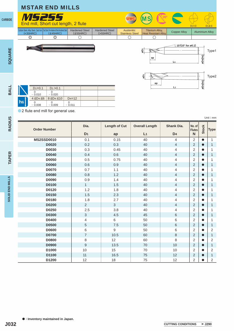
J032
a
MS2SS
e e u u u
D1<3
D1=0.1 D1 >0.1 0- 0.010
0- 0.020
D4=12 0- 0.008
0- 0.009
0- 0.011
D1 ap L1 D4 NMS2SSD0010 0.1 0.15 40 4 2 a 1
D0020 0.2 0.3 40 4 2 a 1D0030 0.3 0.45 40 4 2 a 1D0040 0.4 0.6 40 4 2 a 1D0050 0.5 0.75 40 4 2 a 1D0060 0.6 0.9 40 4 2 a 1D0070 0.7 1.1 40 4 2 a 1D0080 0.8 1.2 40 4 2 a 1D0090 0.9 1.4 40 4 2 a 1D0100 1 1.5 40 4 2 a 1D0120 1.2 1.8 40 4 2 a 1D0150 1.5 2.3 40 4 2 a 1D0180 1.8 2.7 40 4 2 a 1D0200 2 3 40 4 2 a 1D0250 2.5 3.8 40 4 2 a 1D0300 3 4.5 45 6 2 a 1D0400 4 6 50 6 2 a 1D0500 5 7.5 50 6 2 a 1D0600 6 9 50 6 2 a 2D0700 7 10.5 60 8 2 a 1D0800 8 12 60 8 2 a 2D0900 9 13.5 70 10 2 a 1D1000 10 15 70 10 2 a 2D1100 11 16.5 75 12 2 a 1D1200 12 18 75 12 2 a 2
øD4(
h6)
L1
ap
øD1
15°
UWC MS 30°
øD4(
h6)
L1
ap
øD1
h6
CARBIDE
a : Inventory maintained in Japan.
BA
LLR
AD
IUS
TAPE
RSO
LID
EN
D M
ILLS
SQU
AR
E
Unit : mm
Carbon Steel, Alloy Steel, Cast Iron(<30HRC)
Tool Steel, Pre-Hardened Steel,Hardened Steel(<45HRC)
Hardened Steel(<55HRC)
Hardened Steel(>55HRC)
AusteniticStainless Steel
Titanium Alloy,Heat Resistant Alloy Copper Alloy Aluminium Alloy
MSTAR END MILLS
2 flute end mill for general use.
End mill, Short cut length, 2 flute
Type1
(10° for ø0.1)
Order NumberDia. Length of Cut Overall Length Shank Dia. No. of
Flutes
Stoc
k
Type
CUTTING CONDITIONS J290
D1>3
Type2
4 <D4 <6 8 <D4 <10
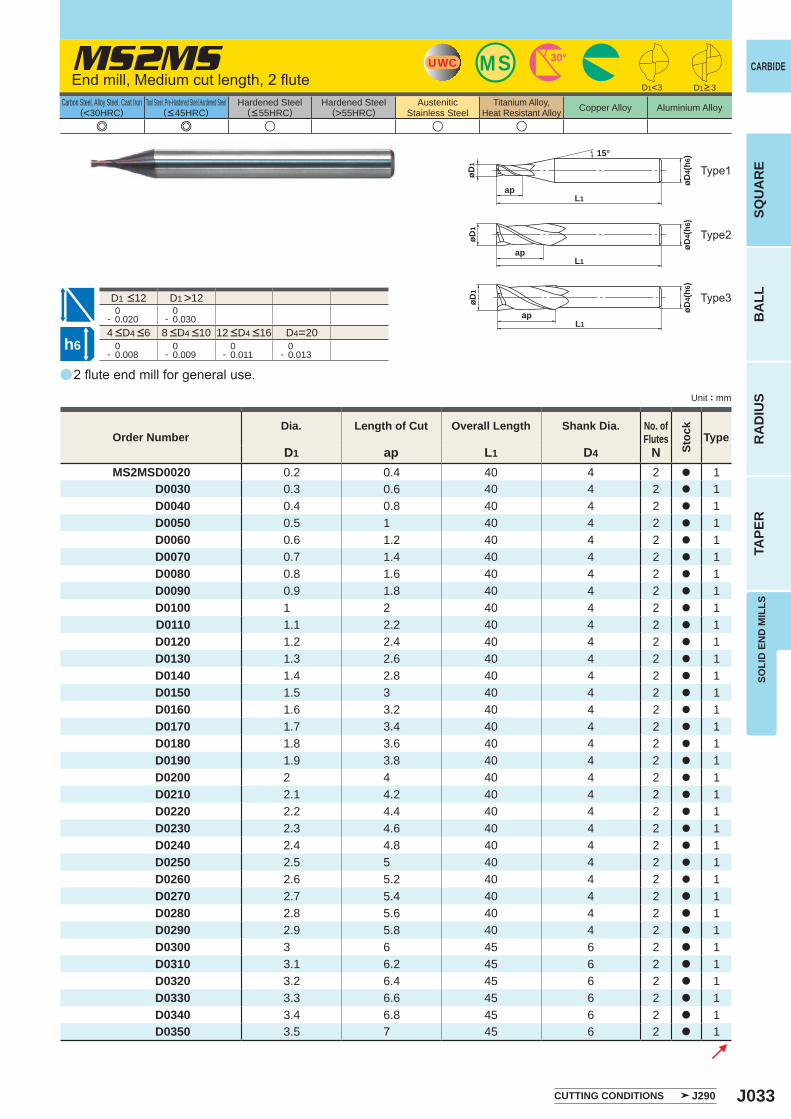
J033
a
e e u u u
MS2MS
D1 ap L1 D4 NMS2MSD0020 0.2 0.4 40 4 2 a 1
D0030 0.3 0.6 40 4 2 a 1D0040 0.4 0.8 40 4 2 a 1D0050 0.5 1 40 4 2 a 1D0060 0.6 1.2 40 4 2 a 1D0070 0.7 1.4 40 4 2 a 1D0080 0.8 1.6 40 4 2 a 1D0090 0.9 1.8 40 4 2 a 1D0100 1 2 40 4 2 a 1D0110 1.1 2.2 40 4 2 a 1D0120 1.2 2.4 40 4 2 a 1D0130 1.3 2.6 40 4 2 a 1D0140 1.4 2.8 40 4 2 a 1D0150 1.5 3 40 4 2 a 1D0160 1.6 3.2 40 4 2 a 1D0170 1.7 3.4 40 4 2 a 1D0180 1.8 3.6 40 4 2 a 1D0190 1.9 3.8 40 4 2 a 1D0200 2 4 40 4 2 a 1D0210 2.1 4.2 40 4 2 a 1D0220 2.2 4.4 40 4 2 a 1D0230 2.3 4.6 40 4 2 a 1D0240 2.4 4.8 40 4 2 a 1D0250 2.5 5 40 4 2 a 1D0260 2.6 5.2 40 4 2 a 1D0270 2.7 5.4 40 4 2 a 1D0280 2.8 5.6 40 4 2 a 1D0290 2.9 5.8 40 4 2 a 1D0300 3 6 45 6 2 a 1D0310 3.1 6.2 45 6 2 a 1D0320 3.2 6.4 45 6 2 a 1D0330 3.3 6.6 45 6 2 a 1D0340 3.4 6.8 45 6 2 a 1D0350 3.5 7 45 6 2 a 1
D1 >12 0- 0.020
0- 0.030
D4=20 0- 0.008
0- 0.009
0- 0.011
0- 0.013
D1<3
UWC MS 30°
L1ap
øD1
øD4(
h6)
L1ap
øD1
øD4(
h6)
L1ap
øD1
15°
øD4(
h6)
h6
CARBIDE
SQU
AR
EB
ALL
RA
DIU
STA
PER
SOLI
D E
ND
MIL
LS
Unit : mm
Carbon Steel, Alloy Steel, Cast Iron(<30HRC)
Tool Steel, Pre-Hardened Steel,Hardened Steel(<45HRC)
Hardened Steel(<55HRC)
Hardened Steel(>55HRC)
AusteniticStainless Steel
Titanium Alloy,Heat Resistant Alloy Copper Alloy Aluminium Alloy
2 flute end mill for general use.
End mill, Medium cut length, 2 flute
Type2
Type3
Type1
Order NumberDia. Length of Cut Overall Length Shank Dia. No. of
Flutes
Stoc
k
Type
D1>3
CUTTING CONDITIONS J290
4 <D4 <6 8 <D4 <10 12 <D4 <16
D1 <12
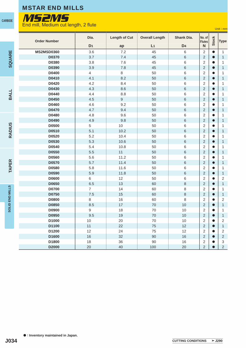
J034
D1 ap L1 D4 NMS2MSD0360 3.6 7.2 45 6 2 a 1
D0370 3.7 7.4 45 6 2 a 1D0380 3.8 7.6 45 6 2 a 1D0390 3.9 7.8 45 6 2 a 1D0400 4 8 50 6 2 a 1D0410 4.1 8.2 50 6 2 a 1D0420 4.2 8.4 50 6 2 a 1D0430 4.3 8.6 50 6 2 a 1D0440 4.4 8.8 50 6 2 a 1D0450 4.5 9 50 6 2 a 1D0460 4.6 9.2 50 6 2 a 1D0470 4.7 9.4 50 6 2 a 1D0480 4.8 9.6 50 6 2 a 1D0490 4.9 9.8 50 6 2 a 1D0500 5 10 50 6 2 a 1D0510 5.1 10.2 50 6 2 a 1D0520 5.2 10.4 50 6 2 a 1D0530 5.3 10.6 50 6 2 a 1D0540 5.4 10.8 50 6 2 a 1D0550 5.5 11 50 6 2 a 1D0560 5.6 11.2 50 6 2 a 1D0570 5.7 11.4 50 6 2 a 1D0580 5.8 11.6 50 6 2 a 1D0590 5.9 11.8 50 6 2 a 1D0600 6 12 50 6 2 a 2D0650 6.5 13 60 8 2 a 1D0700 7 14 60 8 2 a 1D0750 7.5 15 60 8 2 a 1D0800 8 16 60 8 2 a 2D0850 8.5 17 70 10 2 a 1D0900 9 18 70 10 2 a 1D0950 9.5 19 70 10 2 a 1D1000 10 20 70 10 2 a 2D1100 11 22 75 12 2 a 1D1200 12 24 75 12 2 a 2D1600 16 32 90 16 2 a 2D1800 18 36 90 16 2 a 3D2000 20 40 100 20 2 a 2
MS2MSCARBIDE
a : Inventory maintained in Japan.
BA
LLR
AD
IUS
TAPE
RSO
LID
EN
D M
ILLS
SQU
AR
E
Unit : mm
MSTAR END MILLS
End mill, Medium cut length, 2 flute
Order NumberDia. Length of Cut Overall Length Shank Dia. No. of
Flutes
Stoc
k
Type
CUTTING CONDITIONS J290
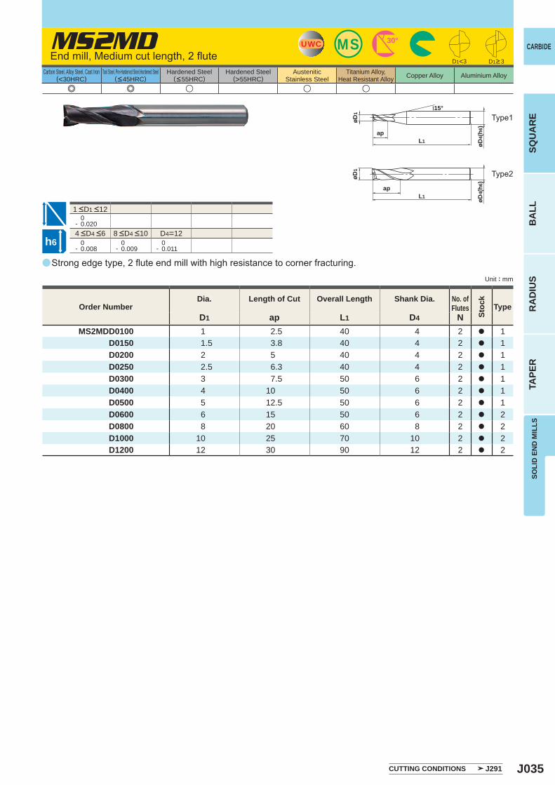
J035
a
e e u u u
MS2MD
D1 ap L1 D4 NMS2MDD0100 1 2.5 40 4 2 a 1
D0150 1.5 3.8 40 4 2 a 1D0200 2 5 40 4 2 a 1D0250 2.5 6.3 40 4 2 a 1D0300 3 7.5 50 6 2 a 1D0400 4 10 50 6 2 a 1D0500 5 12.5 50 6 2 a 1D0600 6 15 50 6 2 a 2D0800 8 20 60 8 2 a 2D1000 10 25 70 10 2 a 2D1200 12 30 90 12 2 a 2
0- 0.020
D4=12 0- 0.008
0- 0.009
0- 0.011
D1<3
MSUWC 30°
L1ap
øD1
15°
øD4(
h6)
øD1
L1ap
øD4(
h6)
h6
CARBIDE
SQU
AR
EB
ALL
RA
DIU
STA
PER
SOLI
D E
ND
MIL
LS
Unit : mm
Carbon Steel, Alloy Steel, Cast Iron(<30HRC)
Tool Steel, Pre-Hardened Steel,Hardened Steel(<45HRC)
Hardened Steel(<55HRC)
Hardened Steel(>55HRC)
AusteniticStainless Steel
Titanium Alloy,Heat Resistant Alloy Copper Alloy Aluminium Alloy
Strong edge type, 2 flute end mill with high resistance to corner fracturing.
End mill, Medium cut length, 2 flute
Type2
Type1
Order NumberDia. Length of Cut Overall Length Shank Dia. No. of
Flutes
Stoc
k
Type
D1>3
CUTTING CONDITIONS J291
4 <D4 <6 8 <D4 <10
1 <D1 <12
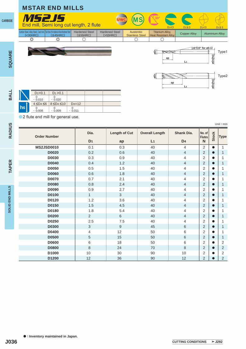
J036
a
e e u u u
MS2JS
D1 ap L1 D4 NMS2JSD0010 0.1 0.3 40 4 2 a 1
D0020 0.2 0.6 40 4 2 a 1D0030 0.3 0.9 40 4 2 a 1D0040 0.4 1.2 40 4 2 a 1D0050 0.5 1.5 40 4 2 a 1D0060 0.6 1.8 40 4 2 a 1D0070 0.7 2.1 40 4 2 a 1D0080 0.8 2.4 40 4 2 a 1D0090 0.9 2.7 40 4 2 a 1D0100 1 3 40 4 2 a 1D0120 1.2 3.6 40 4 2 a 1D0150 1.5 4.5 40 4 2 a 1D0180 1.8 5.4 40 4 2 a 1D0200 2 6 40 4 2 a 1D0250 2.5 7.5 40 4 2 a 1D0300 3 9 45 6 2 a 1D0400 4 12 50 6 2 a 1D0500 5 15 50 6 2 a 1D0600 6 18 50 6 2 a 2D0800 8 24 70 8 2 a 2D1000 10 30 90 10 2 a 2D1200 12 36 90 12 2 a 2
D1<3 D1<3
D1=0.1 D1 >0.1 0- 0.010
0- 0.020
D4=12 0- 0.008
0- 0.009
0- 0.011
UWC MS 30°
øD4(
h6)
L1ap
øD1
15°
øD4(
h6)øD
1
L1
ap
h6
CARBIDE
a : Inventory maintained in Japan.
BA
LLR
AD
IUS
TAPE
RSO
LID
EN
D M
ILLS
SQU
AR
E
Unit : mm
Carbon Steel, Alloy Steel, Cast Iron(<30HRC)
Tool Steel, Pre-Hardened Steel,Hardened Steel(<45HRC)
Hardened Steel(<55HRC)
Hardened Steel(>55HRC)
AusteniticStainless Steel
Titanium Alloy,Heat Resistant Alloy Copper Alloy Aluminium Alloy
MSTAR END MILLS
2 flute end mill for general use.
End mill, Semi long cut length, 2 flute
Type2
Type1(10° for ø0.1)
Order NumberDia. Length of Cut Overall Length Shank Dia. No. of
Flutes
Stoc
k
Type
D1>3 D1>3
CUTTING CONDITIONS J292
4 <D4 <6 8 <D4 <10
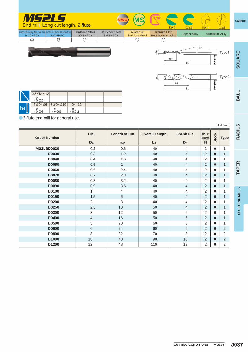
J037
a
e e u u u
MS2LS
D1 ap L1 D4 NMS2LSD0020 0.2 0.8 40 4 2 a 1
D0030 0.3 1.2 40 4 2 a 1D0040 0.4 1.6 40 4 2 a 1D0050 0.5 2 40 4 2 a 1D0060 0.6 2.4 40 4 2 a 1D0070 0.7 2.8 40 4 2 a 1D0080 0.8 3.2 40 4 2 a 1D0090 0.9 3.6 40 4 2 a 1D0100 1 4 40 4 2 a 1D0150 1.5 6 40 4 2 a 1D0200 2 8 40 4 2 a 1D0250 2.5 10 50 4 2 a 1D0300 3 12 50 6 2 a 1D0400 4 16 50 6 2 a 1D0500 5 20 60 6 2 a 1D0600 6 24 60 6 2 a 2D0800 8 32 70 8 2 a 2D1000 10 40 90 10 2 a 2D1200 12 48 110 12 2 a 2
0- 0.020
D4=12 0- 0.008
0- 0.009
0- 0.011
D1<3 D1<3
MSUWC 30°
L1
ap
øD1
15°
øD4(
h6)
øD1
L1
ap
øD4(
h6)
h6
CARBIDE
SQU
AR
EB
ALL
RA
DIU
STA
PER
SOLI
D E
ND
MIL
LS
Unit : mm
Carbon Steel, Alloy Steel, Cast Iron(<30HRC)
Tool Steel, Pre-Hardened Steel,Hardened Steel(<45HRC)
Hardened Steel(<55HRC)
Hardened Steel(>55HRC)
AusteniticStainless Steel
Titanium Alloy,Heat Resistant Alloy Copper Alloy Aluminium Alloy
2 flute end mill for general use.
End mill, Long cut length, 2 flute
Type2
Type1
Order NumberDia. Length of Cut Overall Length Shank Dia. No. of
Flutes
Stoc
k
Type
D1>3 D1>3
CUTTING CONDITIONS J293
4 <D4 <6 8 <D4 <10
0.2 <D1 <12
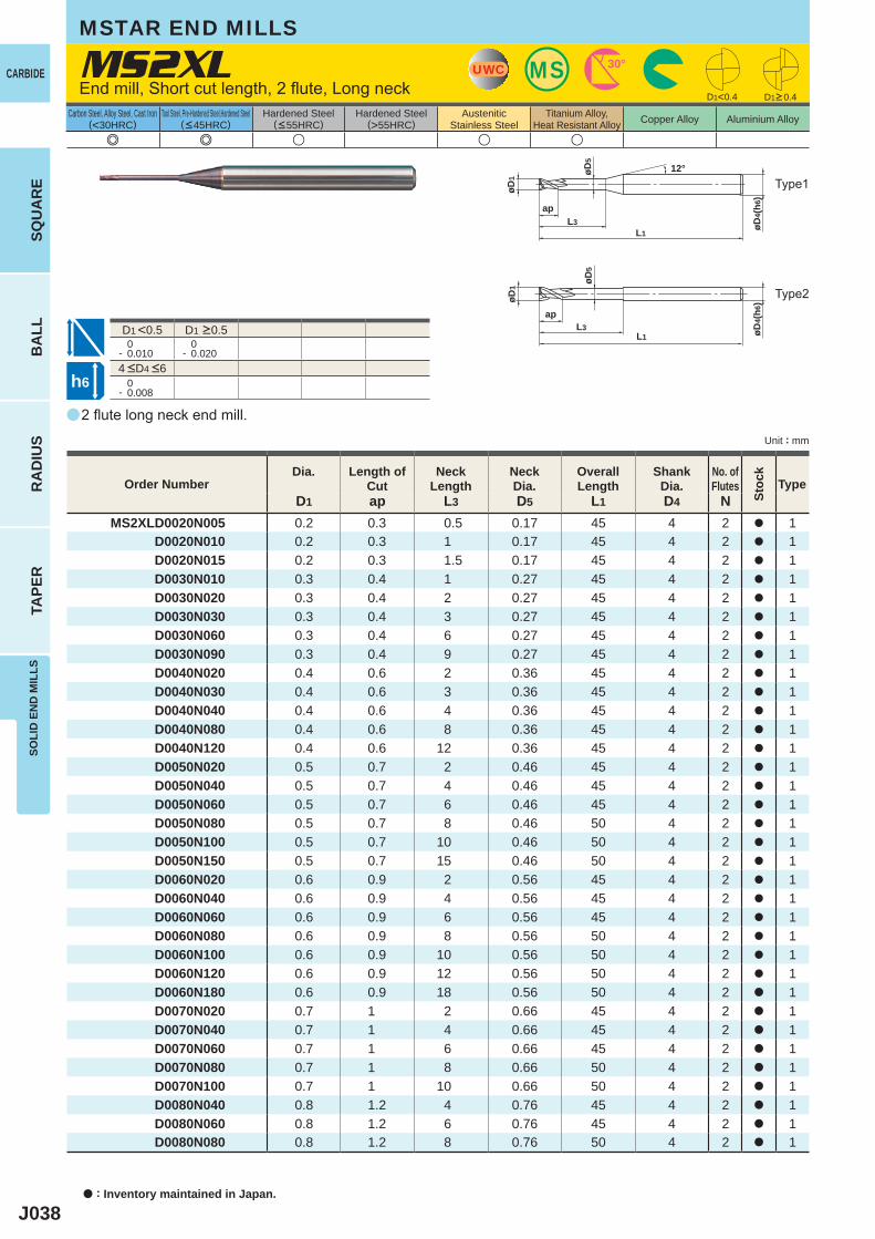
J038
a
e e u u u
MS2XL
D1 ap L3 D5 L1 D4 NMS2XLD0020N005 0.2 0.3 0.5 0.17 45 4 2 a 1
D0020N010 0.2 0.3 1 0.17 45 4 2 a 1D0020N015 0.2 0.3 1.5 0.17 45 4 2 a 1D0030N010 0.3 0.4 1 0.27 45 4 2 a 1D0030N020 0.3 0.4 2 0.27 45 4 2 a 1D0030N030 0.3 0.4 3 0.27 45 4 2 a 1D0030N060 0.3 0.4 6 0.27 45 4 2 a 1D0030N090 0.3 0.4 9 0.27 45 4 2 a 1D0040N020 0.4 0.6 2 0.36 45 4 2 a 1D0040N030 0.4 0.6 3 0.36 45 4 2 a 1D0040N040 0.4 0.6 4 0.36 45 4 2 a 1D0040N080 0.4 0.6 8 0.36 45 4 2 a 1D0040N120 0.4 0.6 12 0.36 45 4 2 a 1D0050N020 0.5 0.7 2 0.46 45 4 2 a 1D0050N040 0.5 0.7 4 0.46 45 4 2 a 1D0050N060 0.5 0.7 6 0.46 45 4 2 a 1D0050N080 0.5 0.7 8 0.46 50 4 2 a 1D0050N100 0.5 0.7 10 0.46 50 4 2 a 1D0050N150 0.5 0.7 15 0.46 50 4 2 a 1D0060N020 0.6 0.9 2 0.56 45 4 2 a 1D0060N040 0.6 0.9 4 0.56 45 4 2 a 1D0060N060 0.6 0.9 6 0.56 45 4 2 a 1D0060N080 0.6 0.9 8 0.56 50 4 2 a 1D0060N100 0.6 0.9 10 0.56 50 4 2 a 1D0060N120 0.6 0.9 12 0.56 50 4 2 a 1D0060N180 0.6 0.9 18 0.56 50 4 2 a 1D0070N020 0.7 1 2 0.66 45 4 2 a 1D0070N040 0.7 1 4 0.66 45 4 2 a 1D0070N060 0.7 1 6 0.66 45 4 2 a 1D0070N080 0.7 1 8 0.66 50 4 2 a 1D0070N100 0.7 1 10 0.66 50 4 2 a 1D0080N040 0.8 1.2 4 0.76 45 4 2 a 1D0080N060 0.8 1.2 6 0.76 45 4 2 a 1D0080N080 0.8 1.2 8 0.76 50 4 2 a 1
D1<0.4
D1 <0.5 0- 0.010
0- 0.020
0- 0.008
UWC MS 30°
øD4(
h6)
L1L3
ap
øD1
12°øD5
L1L3
ap
øD1
øD4(
h6)
øD5
h6
CARBIDE
a : Inventory maintained in Japan.
BA
LLR
AD
IUS
TAPE
RSO
LID
EN
D M
ILLS
SQU
AR
E
Unit : mm
Carbon Steel, Alloy Steel, Cast Iron(<30HRC)
Tool Steel, Pre-Hardened Steel,Hardened Steel(<45HRC)
Hardened Steel(<55HRC)
Hardened Steel(>55HRC)
AusteniticStainless Steel
Titanium Alloy,Heat Resistant Alloy Copper Alloy Aluminium Alloy
MSTAR END MILLS
2 flute long neck end mill.
End mill, Short cut length, 2 flute, Long neck
Type2
Type1
Order NumberDia. Length of
CutNeck
LengthNeckDia.
Overall Length
ShankDia.
No. ofFlutes
Stoc
k
Type
D1>0.4
4 <D4 <6
D1 >0.5
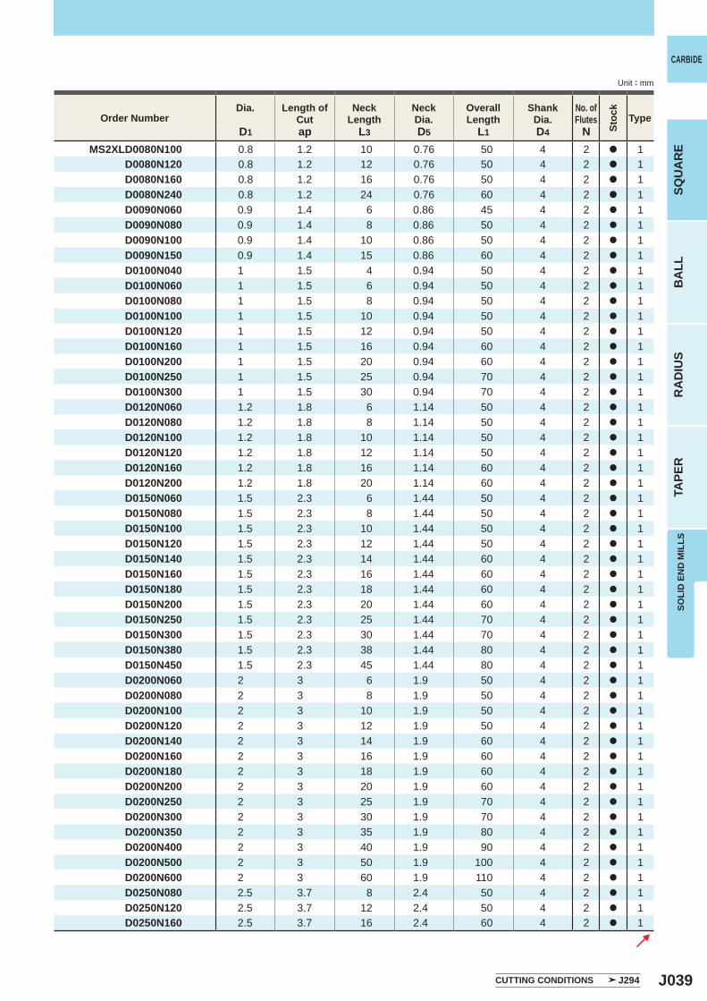
J039
D1 ap L3 D5 L1 D4 NMS2XLD0080N100 0.8 1.2 10 0.76 50 4 2 a 1
D0080N120 0.8 1.2 12 0.76 50 4 2 a 1D0080N160 0.8 1.2 16 0.76 50 4 2 a 1D0080N240 0.8 1.2 24 0.76 60 4 2 a 1D0090N060 0.9 1.4 6 0.86 45 4 2 a 1D0090N080 0.9 1.4 8 0.86 50 4 2 a 1D0090N100 0.9 1.4 10 0.86 50 4 2 a 1D0090N150 0.9 1.4 15 0.86 60 4 2 a 1D0100N040 1 1.5 4 0.94 50 4 2 a 1D0100N060 1 1.5 6 0.94 50 4 2 a 1D0100N080 1 1.5 8 0.94 50 4 2 a 1D0100N100 1 1.5 10 0.94 50 4 2 a 1D0100N120 1 1.5 12 0.94 50 4 2 a 1D0100N160 1 1.5 16 0.94 60 4 2 a 1D0100N200 1 1.5 20 0.94 60 4 2 a 1D0100N250 1 1.5 25 0.94 70 4 2 a 1D0100N300 1 1.5 30 0.94 70 4 2 a 1D0120N060 1.2 1.8 6 1.14 50 4 2 a 1D0120N080 1.2 1.8 8 1.14 50 4 2 a 1D0120N100 1.2 1.8 10 1.14 50 4 2 a 1D0120N120 1.2 1.8 12 1.14 50 4 2 a 1D0120N160 1.2 1.8 16 1.14 60 4 2 a 1D0120N200 1.2 1.8 20 1.14 60 4 2 a 1D0150N060 1.5 2.3 6 1.44 50 4 2 a 1D0150N080 1.5 2.3 8 1.44 50 4 2 a 1D0150N100 1.5 2.3 10 1.44 50 4 2 a 1D0150N120 1.5 2.3 12 1.44 50 4 2 a 1D0150N140 1.5 2.3 14 1.44 60 4 2 a 1D0150N160 1.5 2.3 16 1.44 60 4 2 a 1D0150N180 1.5 2.3 18 1.44 60 4 2 a 1D0150N200 1.5 2.3 20 1.44 60 4 2 a 1D0150N250 1.5 2.3 25 1.44 70 4 2 a 1D0150N300 1.5 2.3 30 1.44 70 4 2 a 1D0150N380 1.5 2.3 38 1.44 80 4 2 a 1D0150N450 1.5 2.3 45 1.44 80 4 2 a 1D0200N060 2 3 6 1.9 50 4 2 a 1D0200N080 2 3 8 1.9 50 4 2 a 1D0200N100 2 3 10 1.9 50 4 2 a 1D0200N120 2 3 12 1.9 50 4 2 a 1D0200N140 2 3 14 1.9 60 4 2 a 1D0200N160 2 3 16 1.9 60 4 2 a 1D0200N180 2 3 18 1.9 60 4 2 a 1D0200N200 2 3 20 1.9 60 4 2 a 1D0200N250 2 3 25 1.9 70 4 2 a 1D0200N300 2 3 30 1.9 70 4 2 a 1D0200N350 2 3 35 1.9 80 4 2 a 1D0200N400 2 3 40 1.9 90 4 2 a 1D0200N500 2 3 50 1.9 100 4 2 a 1D0200N600 2 3 60 1.9 110 4 2 a 1D0250N080 2.5 3.7 8 2.4 50 4 2 a 1D0250N120 2.5 3.7 12 2.4 50 4 2 a 1D0250N160 2.5 3.7 16 2.4 60 4 2 a 1
CARBIDE
SQU
AR
EB
ALL
RA
DIU
STA
PER
SOLI
D E
ND
MIL
LS
Unit : mm
Order NumberDia. Length of
CutNeck
LengthNeckDia.
Overall Length
ShankDia.
No. ofFlutes
Stoc
k
Type
CUTTING CONDITIONS J294
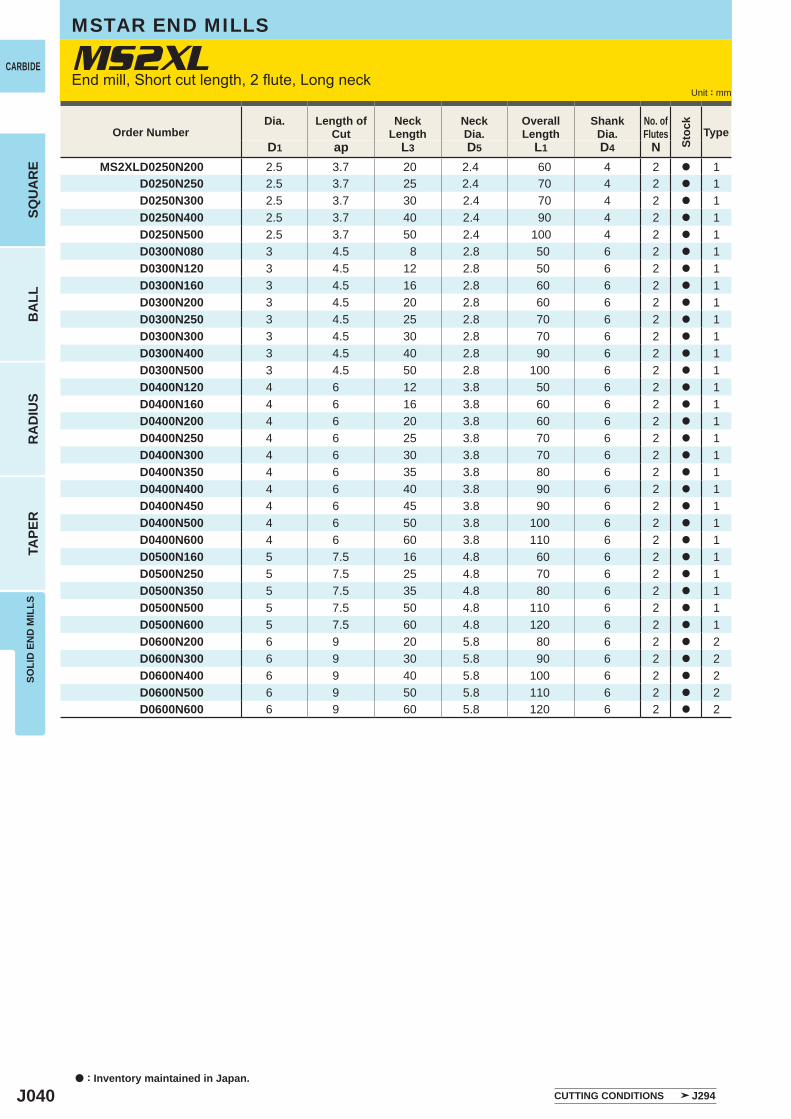
J040
D1 ap L3 D5 L1 D4 NMS2XLD0250N200 2.5 3.7 20 2.4 60 4 2 a 1
D0250N250 2.5 3.7 25 2.4 70 4 2 a 1D0250N300 2.5 3.7 30 2.4 70 4 2 a 1D0250N400 2.5 3.7 40 2.4 90 4 2 a 1D0250N500 2.5 3.7 50 2.4 100 4 2 a 1D0300N080 3 4.5 8 2.8 50 6 2 a 1D0300N120 3 4.5 12 2.8 50 6 2 a 1D0300N160 3 4.5 16 2.8 60 6 2 a 1D0300N200 3 4.5 20 2.8 60 6 2 a 1D0300N250 3 4.5 25 2.8 70 6 2 a 1D0300N300 3 4.5 30 2.8 70 6 2 a 1D0300N400 3 4.5 40 2.8 90 6 2 a 1D0300N500 3 4.5 50 2.8 100 6 2 a 1D0400N120 4 6 12 3.8 50 6 2 a 1D0400N160 4 6 16 3.8 60 6 2 a 1D0400N200 4 6 20 3.8 60 6 2 a 1D0400N250 4 6 25 3.8 70 6 2 a 1D0400N300 4 6 30 3.8 70 6 2 a 1D0400N350 4 6 35 3.8 80 6 2 a 1D0400N400 4 6 40 3.8 90 6 2 a 1D0400N450 4 6 45 3.8 90 6 2 a 1D0400N500 4 6 50 3.8 100 6 2 a 1D0400N600 4 6 60 3.8 110 6 2 a 1D0500N160 5 7.5 16 4.8 60 6 2 a 1D0500N250 5 7.5 25 4.8 70 6 2 a 1D0500N350 5 7.5 35 4.8 80 6 2 a 1D0500N500 5 7.5 50 4.8 110 6 2 a 1D0500N600 5 7.5 60 4.8 120 6 2 a 1D0600N200 6 9 20 5.8 80 6 2 a 2D0600N300 6 9 30 5.8 90 6 2 a 2D0600N400 6 9 40 5.8 100 6 2 a 2D0600N500 6 9 50 5.8 110 6 2 a 2D0600N600 6 9 60 5.8 120 6 2 a 2
MS2XLCARBIDE
a : Inventory maintained in Japan.
BA
LLR
AD
IUS
TAPE
RSO
LID
EN
D M
ILLS
SQU
AR
E
Unit : mm
MSTAR END MILLS
End mill, Short cut length, 2 flute, Long neck
Order NumberDia. Length of
CutNeck
LengthNeckDia.
Overall Length
ShankDia.
No. ofFlutes
Stoc
k
Type
CUTTING CONDITIONS J294
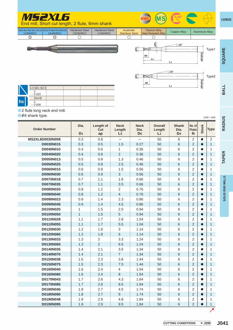
J041
a
a
e e u u u
MS2XL6
D1 ap L3 D5 L1 D4 NMS2XL6D0030N008 0.3 0.8 ─ ─ 50 6 2 a 2
D0030N015 0.3 0.5 1.5 0.27 50 6 2 a 1D0040N010 0.4 0.6 1 0.36 50 6 2 a 1D0040N020 0.4 0.6 2 0.36 50 6 2 a 1D0050N013 0.5 0.8 1.3 0.46 50 6 2 a 1D0050N025 0.5 0.8 2.5 0.46 50 6 2 a 1D0060N015 0.6 0.9 1.5 0.56 50 6 2 a 1D0060N030 0.6 0.9 3 0.56 50 6 2 a 1D0070N018 0.7 1.1 1.8 0.66 50 6 2 a 1D0070N035 0.7 1.1 3.5 0.66 50 6 2 a 1D0080N020 0.8 1.2 2 0.76 50 6 2 a 1D0080N040 0.8 1.2 4 0.76 50 6 2 a 1D0090N023 0.9 1.4 2.3 0.86 50 6 2 a 1D0090N045 0.9 1.4 4.5 0.86 50 6 2 a 1D0100N025 1 1.5 2.5 0.94 50 6 2 a 1D0100N050 1 1.5 5 0.94 50 6 2 a 1D0110N028 1.1 1.7 2.8 1.04 50 6 2 a 1D0110N055 1.1 1.7 5.5 1.04 50 6 2 a 1D0120N030 1.2 1.8 3 1.14 50 6 2 a 1D0120N060 1.2 1.8 6 1.14 50 6 2 a 1D0130N033 1.3 2 3.3 1.24 50 6 2 a 1D0130N065 1.3 2 6.5 1.24 50 6 2 a 1D0140N035 1.4 2.1 3.5 1.34 50 6 2 a 1D0140N070 1.4 2.1 7 1.34 50 6 2 a 1D0150N038 1.5 2.3 3.8 1.44 50 6 2 a 1D0150N075 1.5 2.3 7.5 1.44 50 6 2 a 1D0160N040 1.6 2.4 4 1.54 50 6 2 a 1D0160N080 1.6 2.4 8 1.54 50 6 2 a 1D0170N043 1.7 2.6 4.3 1.64 50 6 2 a 1D0170N085 1.7 2.6 8.5 1.64 50 6 2 a 1D0180N045 1.8 2.7 4.5 1.74 50 6 2 a 1D0180N090 1.8 2.7 9 1.74 50 6 2 a 1D0190N048 1.9 2.9 4.8 1.84 50 6 2 a 1D0190N095 1.9 2.9 9.5 1.84 50 6 2 a 1
0- 0.020
D4=6 0- 0.008
UWC MS 30°
øD4(
h6)
L1L3
øD5
ap
øD1
15°
L1ap
15°
øD1
øD4(
h6)
h6
CARBIDE
SQU
AR
EB
ALL
RA
DIU
STA
PER
SOLI
D E
ND
MIL
LS
Unit : mm
Carbon Steel, Alloy Steel, Cast Iron(<30HRC)
Tool Steel, Pre-Hardened Steel,Hardened Steel(<45HRC)
Hardened Steel(<55HRC)
Hardened Steel(>55HRC)
AusteniticStainless Steel
Titanium Alloy,Heat Resistant Alloy Copper Alloy Aluminium Alloy
2 flute long neck end mill.&6 shank type.
End mill, Short cut length, 2 flute, 6mm shank
Type2
Type1
Order NumberDia. Length of
CutNeck
LengthNeckDia.
Overall Length
ShankDia.
No. ofFlutes
Stoc
k
Type
CUTTING CONDITIONS J295
0.3 <D1 <2.5
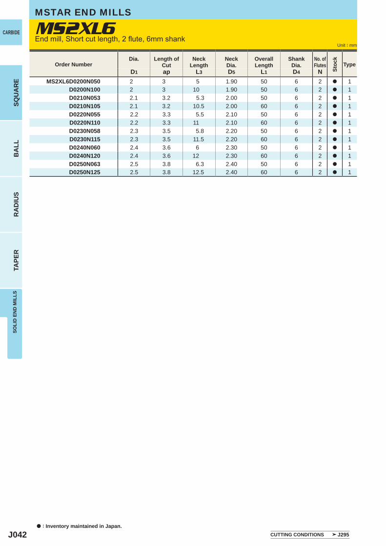
J042
D1 ap L3 D5 L1 D4 NMS2XL6D0200N050 2 3 5 1.90 50 6 2 a 1
D0200N100 2 3 10 1.90 50 6 2 a 1D0210N053 2.1 3.2 5.3 2.00 50 6 2 a 1D0210N105 2.1 3.2 10.5 2.00 60 6 2 a 1D0220N055 2.2 3.3 5.5 2.10 50 6 2 a 1D0220N110 2.2 3.3 11 2.10 60 6 2 a 1D0230N058 2.3 3.5 5.8 2.20 50 6 2 a 1D0230N115 2.3 3.5 11.5 2.20 60 6 2 a 1D0240N060 2.4 3.6 6 2.30 50 6 2 a 1D0240N120 2.4 3.6 12 2.30 60 6 2 a 1D0250N063 2.5 3.8 6.3 2.40 50 6 2 a 1D0250N125 2.5 3.8 12.5 2.40 60 6 2 a 1
MS2XL6CARBIDE
a : Inventory maintained in Japan.
BA
LLR
AD
IUS
TAPE
RSO
LID
EN
D M
ILLS
SQU
AR
E
Unit : mm
MSTAR END MILLS
End mill, Short cut length, 2 flute, 6mm shank
Order NumberDia. Length of
CutNeck
LengthNeckDia.
Overall Length
ShankDia.
No. ofFlutes
Stoc
k
Type
CUTTING CONDITIONS J295
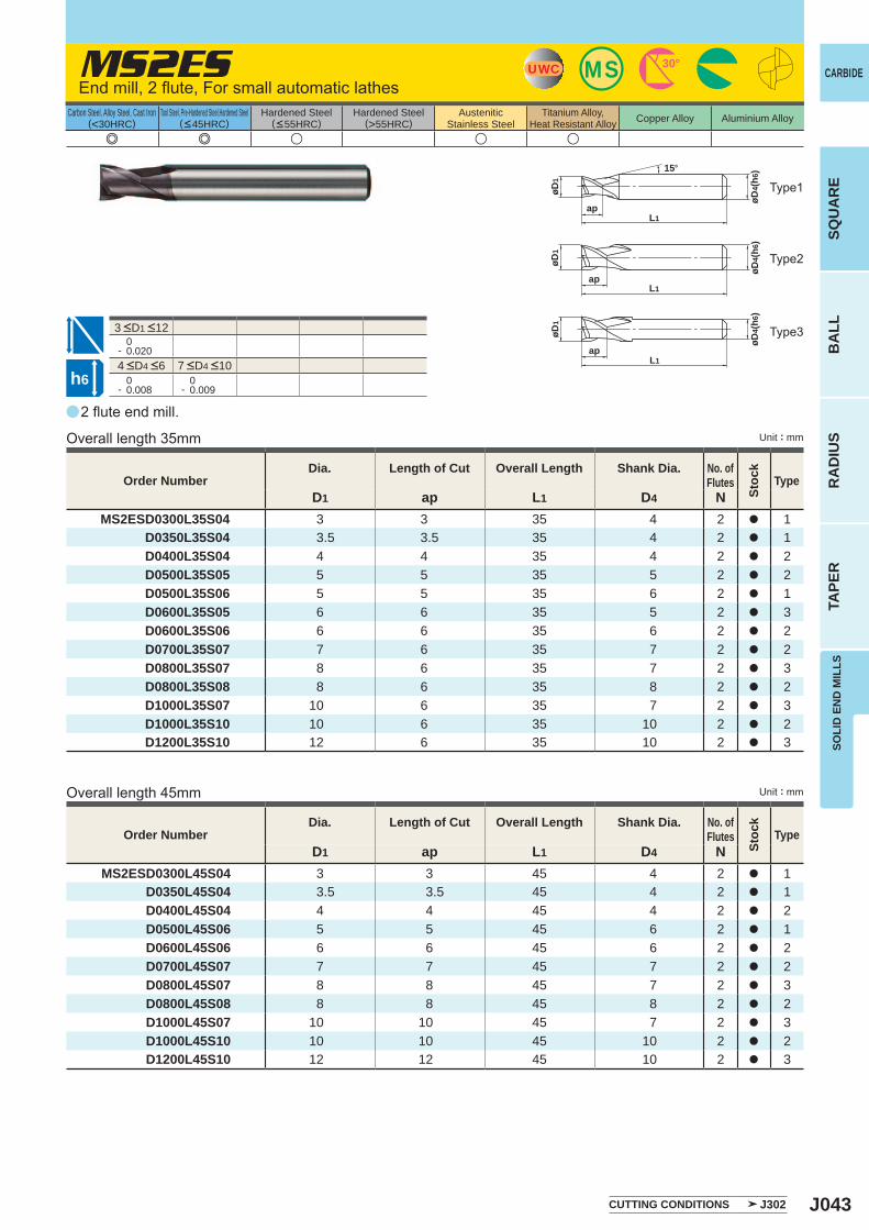
J043
a
e e u u u
MS2ES
D1 ap L1 D4 NMS2ESD0300L45S04 3 3 45 4 2 a 1
D0350L45S04 3.5 3.5 45 4 2 a 1D0400L45S04 4 4 45 4 2 a 2D0500L45S06 5 5 45 6 2 a 1D0600L45S06 6 6 45 6 2 a 2D0700L45S07 7 7 45 7 2 a 2D0800L45S07 8 8 45 7 2 a 3D0800L45S08 8 8 45 8 2 a 2D1000L45S07 10 10 45 7 2 a 3D1000L45S10 10 10 45 10 2 a 2D1200L45S10 12 12 45 10 2 a 3
D1 ap L1 D4 NMS2ESD0300L35S04 3 3 35 4 2 a 1
D0350L35S04 3.5 3.5 35 4 2 a 1D0400L35S04 4 4 35 4 2 a 2D0500L35S05 5 5 35 5 2 a 2D0500L35S06 5 5 35 6 2 a 1D0600L35S05 6 6 35 5 2 a 3D0600L35S06 6 6 35 6 2 a 2D0700L35S07 7 6 35 7 2 a 2D0800L35S07 8 6 35 7 2 a 3D0800L35S08 8 6 35 8 2 a 2D1000L35S07 10 6 35 7 2 a 3D1000L35S10 10 6 35 10 2 a 2D1200L35S10 12 6 35 10 2 a 3
0- 0.020
0- 0.008
0- 0.009
UWC MS 30°
15°
ap
øD1
øD4(
h6)
L1
øD4(
h6)
øD1
apL1
øD1
øD4(
h6)
apL1
h6
CARBIDE
SQU
AR
EB
ALL
RA
DIU
STA
PER
SOLI
D E
ND
MIL
LS
Unit : mm
Carbon Steel, Alloy Steel, Cast Iron(<30HRC)
Tool Steel, Pre-Hardened Steel,Hardened Steel(<45HRC)
Hardened Steel(<55HRC)
Hardened Steel(>55HRC)
AusteniticStainless Steel
Titanium Alloy,Heat Resistant Alloy Copper Alloy Aluminium Alloy
2 flute end mill.
End mill, 2 flute, For small automatic lathes
Overall length 35mm
Overall length 45mm
Type1
Type2
Type3
Unit : mm
Order NumberDia. Length of Cut Overall Length Shank Dia. No. of
Flutes
Stoc
k
Type
Order NumberDia. Length of Cut Overall Length Shank Dia. No. of
Flutes
Stoc
k
Type
CUTTING CONDITIONS J302
4 <D4 <6 7 <D4 <10
3 <D1 <12
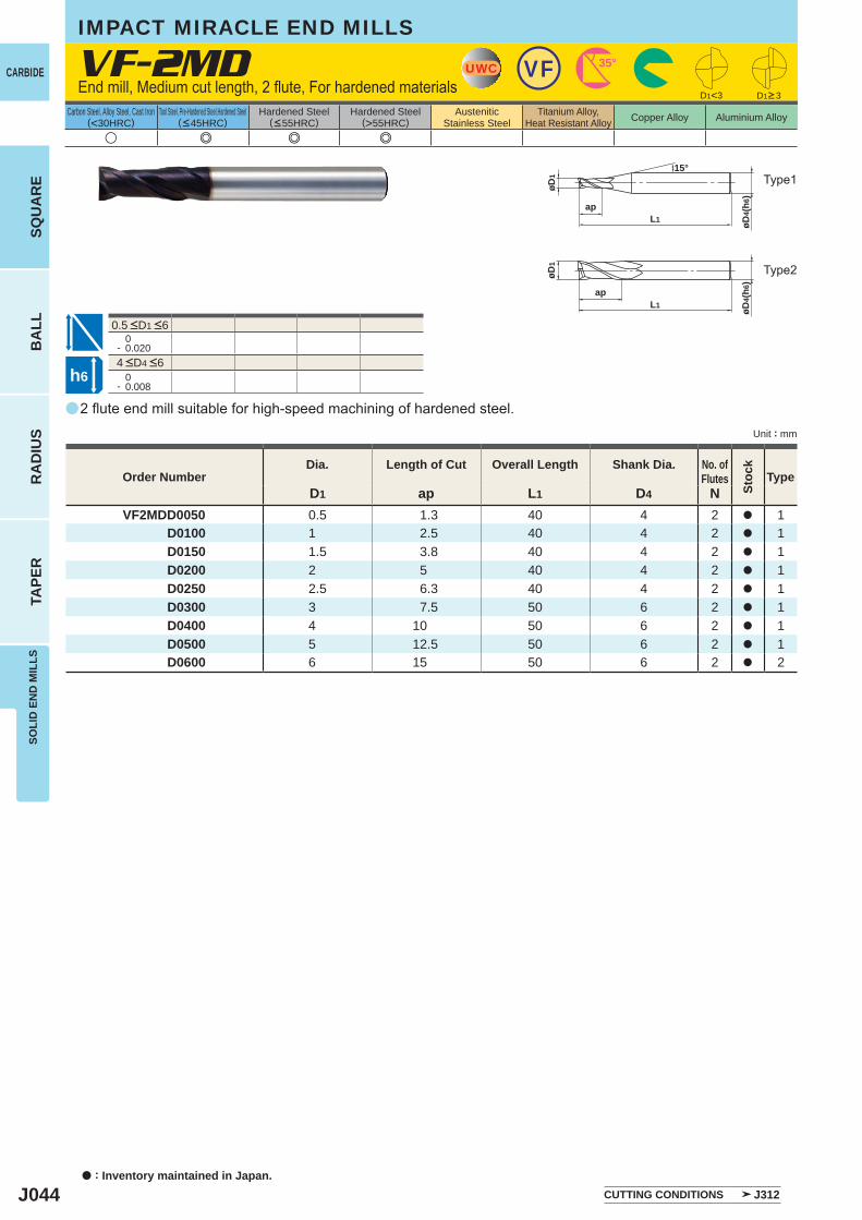
J044
a
VF-2MD
u e e e
D1 ap L1 D4 NVF2MDD0050 0.5 1.3 40 4 2 a 1
D0100 1 2.5 40 4 2 a 1 D0150 1.5 3.8 40 4 2 a 1 D0200 2 5 40 4 2 a 1 D0250 2.5 6.3 40 4 2 a 1 D0300 3 7.5 50 6 2 a 1 D0400 4 10 50 6 2 a 1 D0500 5 12.5 50 6 2 a 1 D0600 6 15 50 6 2 a 2
0- 0.020
0- 0.008
UWC 35°VF
L1ap
øD1
øD4(
h6)
15°
D1<3
øD4 (
h6)øD
1
L1ap
h6
CARBIDE
a : Inventory maintained in Japan.
BA
LLR
AD
IUS
TAPE
RSO
LID
EN
D M
ILLS
SQU
AR
E
Unit : mm
Carbon Steel, Alloy Steel, Cast Iron(<30HRC)
Tool Steel, Pre-Hardened Steel,Hardened Steel(<45HRC)
Hardened Steel(<55HRC)
Hardened Steel(>55HRC)
AusteniticStainless Steel
Titanium Alloy,Heat Resistant Alloy Copper Alloy Aluminium Alloy
2 flute end mill suitable for high-speed machining of hardened steel.
End mill, Medium cut length, 2 flute, For hardened materials
IMPACT MIRACLE END MILLS
Type2
Type1
Order NumberDia. Length of Cut Overall Length Shank Dia. No. of
Flutes
Stoc
k
Type
D1>3
CUTTING CONDITIONS J312
4 <D4 <6
0.5 <D1 <6
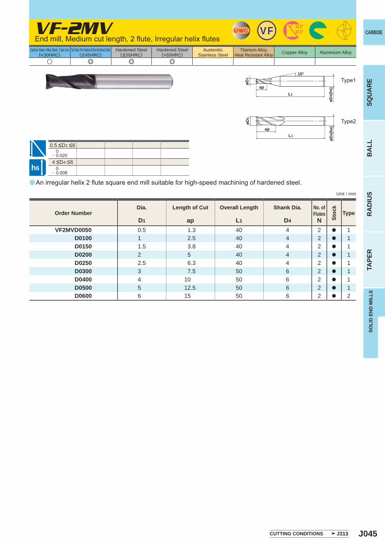
J045
a
VF-2MV
u e e e
D1 ap L1 D4 NVF2MVD0050 0.5 1.3 40 4 2 a 1
D0100 1 2.5 40 4 2 a 1D0150 1.5 3.8 40 4 2 a 1D0200 2 5 40 4 2 a 1D0250 2.5 6.3 40 4 2 a 1D0300 3 7.5 50 6 2 a 1D0400 4 10 50 6 2 a 1D0500 5 12.5 50 6 2 a 1D0600 6 15 50 6 2 a 2
0- 0.020
0- 0.008
UWC VF 32.5°37.5°
L1
ap
øD1
15°
øD4(
h6)
L1
ap
øD1
øD4(
h6)
h6
CARBIDE
SQU
AR
EB
ALL
RA
DIU
STA
PER
SOLI
D E
ND
MIL
LS
Unit : mm
Carbon Steel, Alloy Steel, Cast Iron(<30HRC)
Tool Steel, Pre-Hardened Steel,Hardened Steel(<45HRC)
Hardened Steel(<55HRC)
Hardened Steel(>55HRC)
AusteniticStainless Steel
Titanium Alloy,Heat Resistant Alloy Copper Alloy Aluminium Alloy
An irregular helix 2 flute square end mill suitable for high-speed machining of hardened steel.
End mill, Medium cut length, 2 flute, Irregular helix flutes
Type2
Type1
Order NumberDia. Length of Cut Overall Length Shank Dia. No. of
Flutes
Stoc
k
Type
CUTTING CONDITIONS J313
4 <D4 <6
0.5 <D1 <6
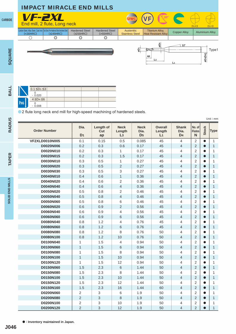
J046
a
VF-2XL
u e e e
D1 ap L3 D5 L1 D4 NVF2XLD0010N005 0.1 0.15 0.5 0.085 45 4 2 a 1
D0020N006 0.2 0.3 0.6 0.17 45 4 2 a 1 D0020N010 0.2 0.3 1 0.17 45 4 2 a 1 D0020N015 0.2 0.3 1.5 0.17 45 4 2 a 1 D0030N010 0.3 0.5 1 0.27 45 4 2 a 1 D0030N020 0.3 0.5 2 0.27 45 4 2 a 1 D0030N030 0.3 0.5 3 0.27 45 4 2 a 1 D0040N010 0.4 0.6 1 0.36 45 4 2 a 1 D0040N020 0.4 0.6 2 0.36 45 4 2 a 1 D0040N040 0.4 0.6 4 0.36 45 4 2 a 1 D0050N020 0.5 0.8 2 0.46 45 4 2 a 1 D0050N040 0.5 0.8 4 0.46 45 4 2 a 1 D0050N060 0.5 0.8 6 0.46 45 4 2 a 1 D0060N020 0.6 0.9 2 0.56 45 4 2 a 1 D0060N040 0.6 0.9 4 0.56 45 4 2 a 1 D0060N060 0.6 0.9 6 0.56 45 4 2 a 1 D0080N040 0.8 1.2 4 0.76 45 4 2 a 1 D0080N060 0.8 1.2 6 0.76 45 4 2 a 1 D0080N080 0.8 1.2 8 0.76 50 4 2 a 1 D0080N100 0.8 1.2 10 0.76 50 4 2 a 1 D0100N040 1 1.5 4 0.94 50 4 2 a 1 D0100N060 1 1.5 6 0.94 50 4 2 a 1 D0100N080 1 1.5 8 0.94 50 4 2 a 1 D0100N100 1 1.5 10 0.94 50 4 2 a 1 D0100N120 1 1.5 12 0.94 50 4 2 a 1 D0150N060 1.5 2.3 6 1.44 50 4 2 a 1 D0150N080 1.5 2.3 8 1.44 50 4 2 a 1 D0150N100 1.5 2.3 10 1.44 50 4 2 a 1 D0150N120 1.5 2.3 12 1.44 50 4 2 a 1 D0150N160 1.5 2.3 16 1.44 60 4 2 a 1 D0200N060 2 3 6 1.9 50 4 2 a 1 D0200N080 2 3 8 1.9 50 4 2 a 1 D0200N100 2 3 10 1.9 50 4 2 a 1 D0200N120 2 3 12 1.9 50 4 2 a 1
0- 0.020
0- 0.008
D1<3 D1=3
UWC VF 30°
øD4(
h6)
L1L3
øD5
ap
øD1
12°
h6
CARBIDE
a : Inventory maintained in Japan.
BA
LLR
AD
IUS
TAPE
RSO
LID
EN
D M
ILLS
SQU
AR
E
Unit : mm
Carbon Steel, Alloy Steel, Cast Iron(<30HRC)
Tool Steel, Pre-Hardened Steel,Hardened Steel(<45HRC)
Hardened Steel(<55HRC)
Hardened Steel(>55HRC)
AusteniticStainless Steel
Titanium Alloy,Heat Resistant Alloy Copper Alloy Aluminium Alloy
2 flute long neck end mill for high-speed machining of hardened steels.
End mill, 2 flute, Long neck
Type1
IMPACT MIRACLE END MILLS
Order NumberDia. Length of
CutNeck
LengthNeckDia.
OverallLength
ShankDia.
No. ofFlutes
Stoc
k
Type
4 <D4 <6
0.1 <D1 <3
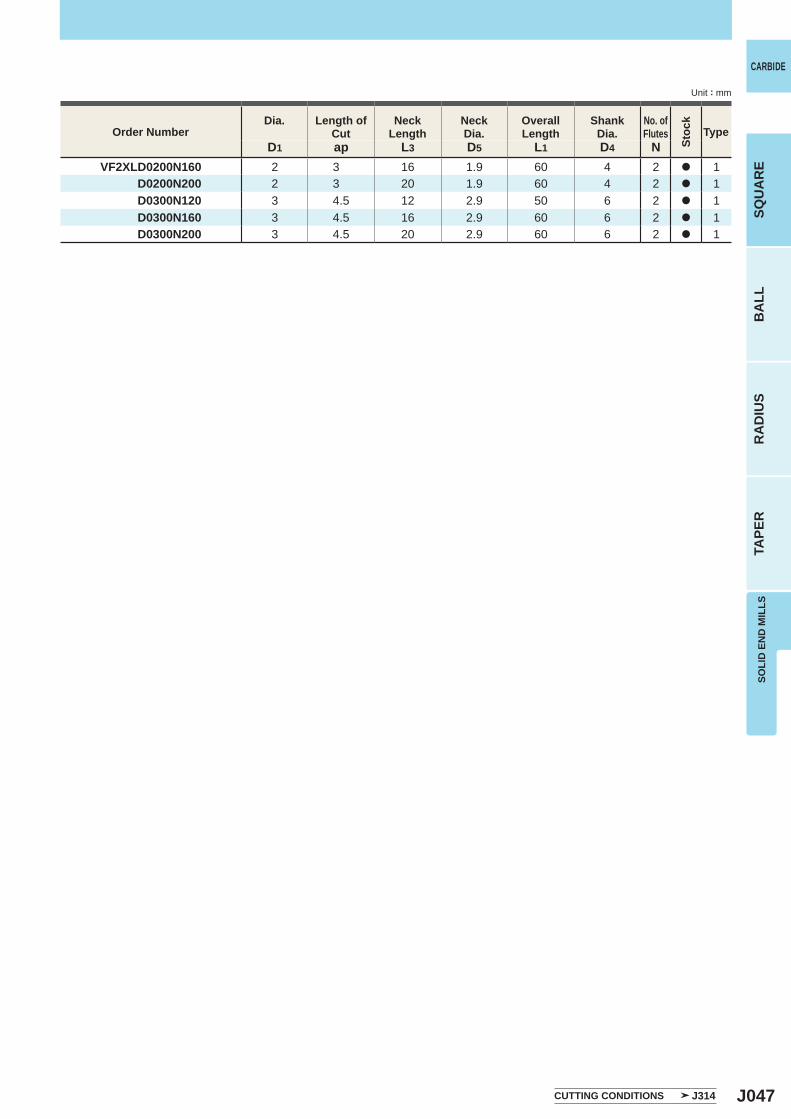
J047
D1 ap L3 D5 L1 D4 N VF2XLD0200N160 2 3 16 1.9 60 4 2 a 1 D0200N200 2 3 20 1.9 60 4 2 a 1 D0300N120 3 4.5 12 2.9 50 6 2 a 1 D0300N160 3 4.5 16 2.9 60 6 2 a 1 D0300N200 3 4.5 20 2.9 60 6 2 a 1
CARBIDE
SQU
AR
EB
ALL
RA
DIU
STA
PER
SOLI
D E
ND
MIL
LS
Unit : mm
CUTTING CONDITIONS J314
Order NumberDia. Length of
CutNeck
LengthNeckDia.
OverallLength
ShankDia.
No. ofFlutes
Stoc
k
Type
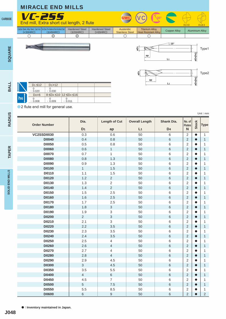
J048
a
u e e u u
VC-2SS
D1 ap L1 D4 NVC2SSD0030 0.3 0.6 50 6 2 a 1
D0040 0.4 0.8 50 6 2 a 1D0050 0.5 0.8 50 6 2 a 1D0060 0.6 1 50 6 2 a 1D0070 0.7 1 50 6 2 a 1D0080 0.8 1.3 50 6 2 a 1D0090 0.9 1.3 50 6 2 a 1D0100 1 1.5 50 6 2 a 1D0110 1.1 1.5 50 6 2 a 1D0120 1.2 2 50 6 2 a 1D0130 1.3 2 50 6 2 a 1D0140 1.4 2 50 6 2 a 1D0150 1.5 2.5 50 6 2 a 1D0160 1.6 2.5 50 6 2 a 1D0170 1.7 2.5 50 6 2 a 1D0180 1.8 3 50 6 2 a 1D0190 1.9 3 50 6 2 a 1D0200 2 3 50 6 2 a 1D0210 2.1 3 50 6 2 a 1D0220 2.2 3.5 50 6 2 a 1D0230 2.3 3.5 50 6 2 a 1D0240 2.4 3.5 50 6 2 a 1D0250 2.5 4 50 6 2 a 1D0260 2.6 4 50 6 2 a 1D0270 2.7 4 50 6 2 a 1D0280 2.8 4 50 6 2 a 1D0290 2.9 4.5 50 6 2 a 1D0300 3 4.5 50 6 2 a 1D0350 3.5 5.5 50 6 2 a 1D0400 4 6 50 6 2 a 1D0450 4.5 7 50 6 2 a 1D0500 5 7.5 50 6 2 a 1D0550 5.5 8.5 50 6 2 a 1D0600 6 9 50 6 2 a 2
D1>12 0- 0.020
0- 0.030
D4=6 0- 0.008
0- 0.009
0- 0.011
UWC VC 30°
øD4(
h6)
L1
ap
øD1
15°
øD4(
h6)
L1
ap
øD1
D1<3
h6
CARBIDE
a : Inventory maintained in Japan.
BA
LLR
AD
IUS
TAPE
RSO
LID
EN
D M
ILLS
SQU
AR
E
Unit : mm
Carbon Steel, Alloy Steel, Cast Iron(<30HRC)
Tool Steel, Pre-Hardened Steel,Hardened Steel(<45HRC)
Hardened Steel(<55HRC)
Hardened Steel(>55HRC)
AusteniticStainless Steel
Titanium Alloy,Heat Resistant Alloy Copper Alloy Aluminium Alloy
MIRACLE END MILLS
2 flute end mill for general use.
End mill, Extra short cut length, 2 flute
Type2
Type1
Order NumberDia. Length of Cut Overall Length Shank Dia. No. of
Flutes
Stoc
k
Type
D1>3
8 <D4 <10 12 <D4 <16
D1 <12
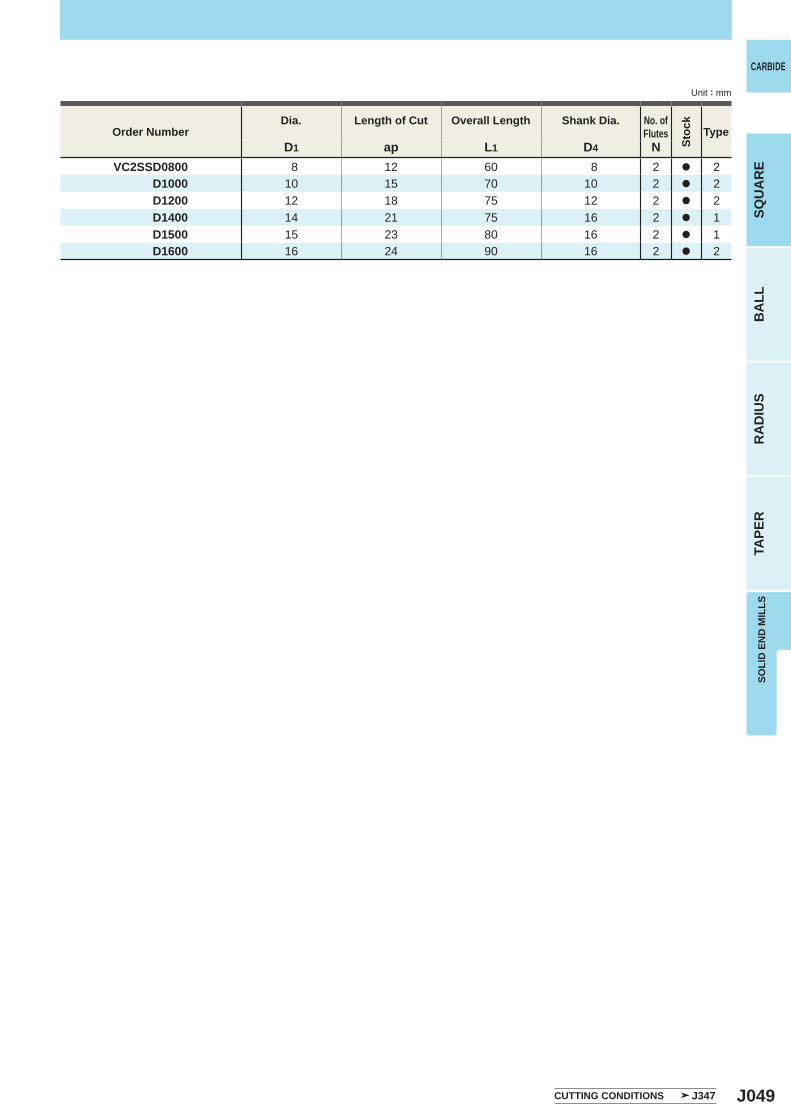
J049
D1 ap L1 D4 NVC2SSD0800 8 12 60 8 2 a 2
D1000 10 15 70 10 2 a 2D1200 12 18 75 12 2 a 2D1400 14 21 75 16 2 a 1D1500 15 23 80 16 2 a 1D1600 16 24 90 16 2 a 2
CARBIDE
SQU
AR
EB
ALL
RA
DIU
STA
PER
SOLI
D E
ND
MIL
LS
Unit : mm
CUTTING CONDITIONS J347
Order NumberDia. Length of Cut Overall Length Shank Dia. No. of
Flutes
Stoc
k
Type
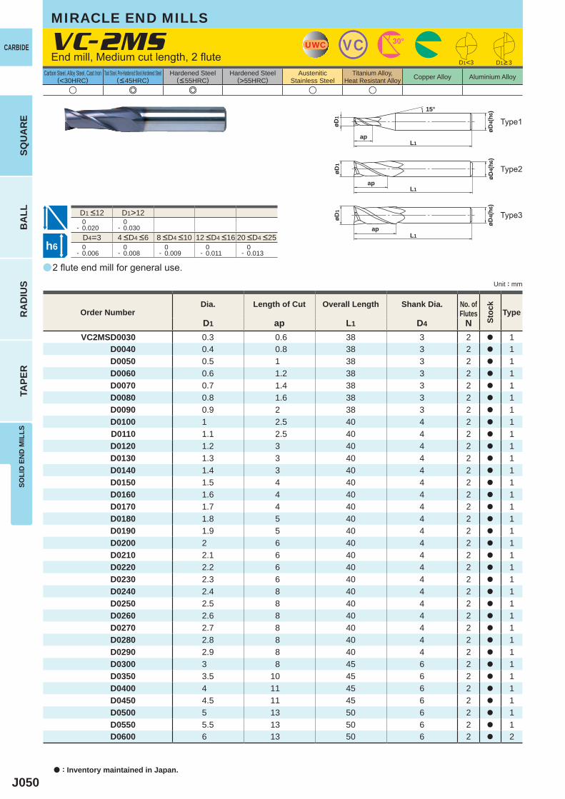
J050
a
u e e u u
VC-2MS
D1 ap L1 D4 NVC2MSD0030 0.3 0.6 38 3 2 a 1
D0040 0.4 0.8 38 3 2 a 1D0050 0.5 1 38 3 2 a 1D0060 0.6 1.2 38 3 2 a 1D0070 0.7 1.4 38 3 2 a 1D0080 0.8 1.6 38 3 2 a 1D0090 0.9 2 38 3 2 a 1D0100 1 2.5 40 4 2 a 1D0110 1.1 2.5 40 4 2 a 1D0120 1.2 3 40 4 2 a 1D0130 1.3 3 40 4 2 a 1D0140 1.4 3 40 4 2 a 1D0150 1.5 4 40 4 2 a 1D0160 1.6 4 40 4 2 a 1D0170 1.7 4 40 4 2 a 1D0180 1.8 5 40 4 2 a 1D0190 1.9 5 40 4 2 a 1D0200 2 6 40 4 2 a 1D0210 2.1 6 40 4 2 a 1D0220 2.2 6 40 4 2 a 1D0230 2.3 6 40 4 2 a 1D0240 2.4 8 40 4 2 a 1D0250 2.5 8 40 4 2 a 1D0260 2.6 8 40 4 2 a 1D0270 2.7 8 40 4 2 a 1D0280 2.8 8 40 4 2 a 1D0290 2.9 8 40 4 2 a 1D0300 3 8 45 6 2 a 1D0350 3.5 10 45 6 2 a 1D0400 4 11 45 6 2 a 1D0450 4.5 11 45 6 2 a 1D0500 5 13 50 6 2 a 1D0550 5.5 13 50 6 2 a 1D0600 6 13 50 6 2 a 2
D1>12 0- 0.020
0- 0.030
D4=3 0- 0.006
0- 0.008
0- 0.009
0- 0.011
0- 0.013
D1<3
UWC VC 30°
øD4(
h6)
L1ap
øD1
15°
øD4(
h6)
L1ap
øD1
øD4(
h6)
L1ap
øD1
h6
CARBIDE
a : Inventory maintained in Japan.
BA
LLR
AD
IUS
TAPE
RSO
LID
EN
D M
ILLS
SQU
AR
E
Unit : mm
Carbon Steel, Alloy Steel, Cast Iron(<30HRC)
Tool Steel, Pre-Hardened Steel,Hardened Steel(<45HRC)
Hardened Steel(<55HRC)
Hardened Steel(>55HRC)
AusteniticStainless Steel
Titanium Alloy,Heat Resistant Alloy Copper Alloy Aluminium Alloy
MIRACLE END MILLS
2 flute end mill for general use.
End mill, Medium cut length, 2 flute
Type2
Type3
Type1
Order NumberDia. Length of Cut Overall Length Shank Dia. No. of
Flutes
Stoc
k
Type
D1>3
4 <D4 <6 8 <D4 <10 12 <D4 <16 20 <D4 <25
D1 <12
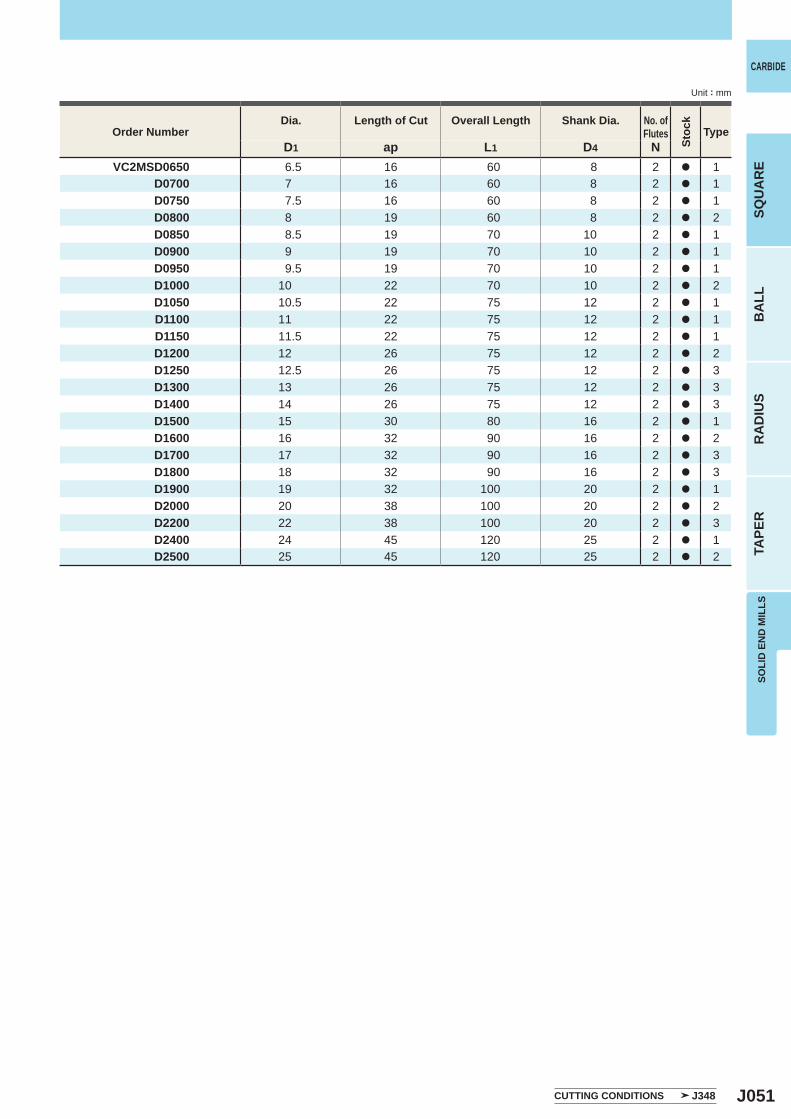
J051
D1 ap L1 D4 NVC2MSD0650 6.5 16 60 8 2 a 1
D0700 7 16 60 8 2 a 1D0750 7.5 16 60 8 2 a 1D0800 8 19 60 8 2 a 2D0850 8.5 19 70 10 2 a 1D0900 9 19 70 10 2 a 1D0950 9.5 19 70 10 2 a 1D1000 10 22 70 10 2 a 2D1050 10.5 22 75 12 2 a 1D1100 11 22 75 12 2 a 1D1150 11.5 22 75 12 2 a 1D1200 12 26 75 12 2 a 2D1250 12.5 26 75 12 2 a 3D1300 13 26 75 12 2 a 3D1400 14 26 75 12 2 a 3D1500 15 30 80 16 2 a 1D1600 16 32 90 16 2 a 2D1700 17 32 90 16 2 a 3D1800 18 32 90 16 2 a 3D1900 19 32 100 20 2 a 1D2000 20 38 100 20 2 a 2D2200 22 38 100 20 2 a 3D2400 24 45 120 25 2 a 1D2500 25 45 120 25 2 a 2
CARBIDE
SQU
AR
EB
ALL
RA
DIU
STA
PER
SOLI
D E
ND
MIL
LS
Unit : mm
Order NumberDia. Length of Cut Overall Length Shank Dia. No. of
Flutes
Stoc
k
Type
CUTTING CONDITIONS J348
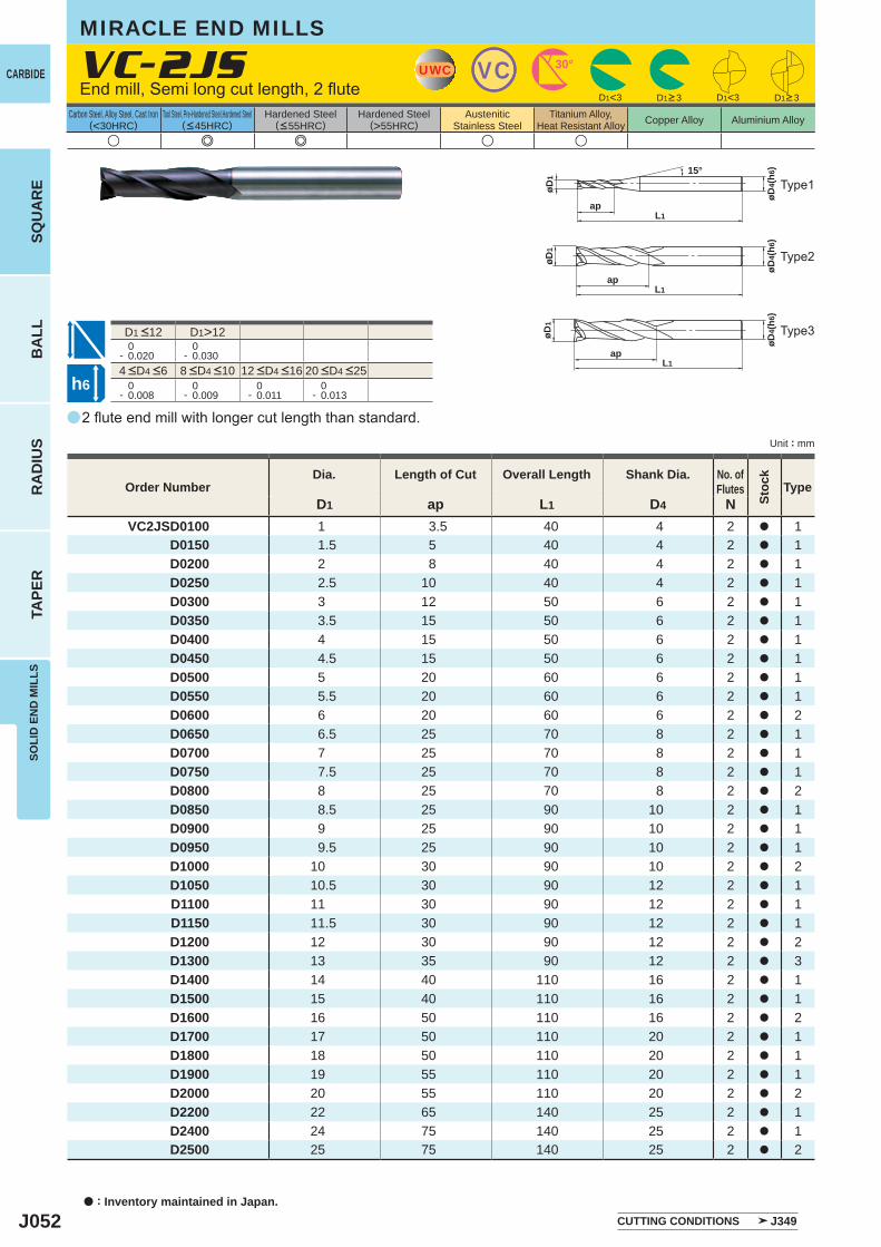
J052
a
u e e u u
VC-2JS
D1 ap L1 D4 NVC2JSD0100 1 3.5 40 4 2 a 1
D0150 1.5 5 40 4 2 a 1D0200 2 8 40 4 2 a 1D0250 2.5 10 40 4 2 a 1D0300 3 12 50 6 2 a 1D0350 3.5 15 50 6 2 a 1D0400 4 15 50 6 2 a 1D0450 4.5 15 50 6 2 a 1D0500 5 20 60 6 2 a 1D0550 5.5 20 60 6 2 a 1D0600 6 20 60 6 2 a 2D0650 6.5 25 70 8 2 a 1D0700 7 25 70 8 2 a 1D0750 7.5 25 70 8 2 a 1D0800 8 25 70 8 2 a 2D0850 8.5 25 90 10 2 a 1D0900 9 25 90 10 2 a 1D0950 9.5 25 90 10 2 a 1D1000 10 30 90 10 2 a 2D1050 10.5 30 90 12 2 a 1D1100 11 30 90 12 2 a 1D1150 11.5 30 90 12 2 a 1D1200 12 30 90 12 2 a 2D1300 13 35 90 12 2 a 3D1400 14 40 110 16 2 a 1D1500 15 40 110 16 2 a 1D1600 16 50 110 16 2 a 2D1700 17 50 110 20 2 a 1D1800 18 50 110 20 2 a 1D1900 19 55 110 20 2 a 1D2000 20 55 110 20 2 a 2D2200 22 65 140 25 2 a 1D2400 24 75 140 25 2 a 1D2500 25 75 140 25 2 a 2
D1>12 0- 0.020
0- 0.030
0- 0.008
0- 0.009
0- 0.011
0- 0.013
D1<3 D1<3
UWC VC 30°
øD4(
h6)
L1ap
øD1
15°
øD4(
h6)
øD1
L1ap
øD4(
h6)
øD1
L1ap
h6
CARBIDE
a : Inventory maintained in Japan.
BA
LLR
AD
IUS
TAPE
RSO
LID
EN
D M
ILLS
SQU
AR
E
Unit : mm
Carbon Steel, Alloy Steel, Cast Iron(<30HRC)
Tool Steel, Pre-Hardened Steel,Hardened Steel(<45HRC)
Hardened Steel(<55HRC)
Hardened Steel(>55HRC)
AusteniticStainless Steel
Titanium Alloy,Heat Resistant Alloy Copper Alloy Aluminium Alloy
2 flute end mill with longer cut length than standard.
End mill, Semi long cut length, 2 flute
Type2
Type3
Type1
Order NumberDia. Length of Cut Overall Length Shank Dia. No. of
Flutes
Stoc
k
Type
D1>3 D1>3
CUTTING CONDITIONS J349
MIRACLE END MILLS
4 <D4 <6 8 <D4 <10 12 <D4 <16 20 <D4 <25
D1 <12
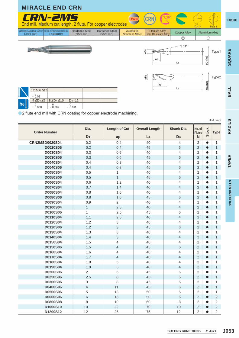
J053
a
e u
CRN-2MS
D1 ap L1 D4 NCRN2MSD0020S04 0.2 0.4 40 4 2 a 1
D0020S06 0.2 0.4 45 6 2 a 1 D0030S04 0.3 0.6 40 4 2 a 1 D0030S06 0.3 0.6 45 6 2 a 1 D0040S04 0.4 0.8 40 4 2 a 1 D0040S06 0.4 0.8 45 6 2 a 1 D0050S04 0.5 1 40 4 2 a 1 D0050S06 0.5 1 45 6 2 a 1 D0060S04 0.6 1.2 40 4 2 a 1 D0070S04 0.7 1.4 40 4 2 a 1 D0080S04 0.8 1.6 40 4 2 a 1 D0080S06 0.8 1.6 45 6 2 a 1 D0090S04 0.9 2 40 4 2 a 1 D0100S04 1 2.5 40 4 2 a 1 D0100S06 1 2.5 45 6 2 a 1 D0110S04 1.1 2.5 40 4 2 a 1 D0120S04 1.2 3 40 4 2 a 1 D0120S06 1.2 3 45 6 2 a 1 D0130S04 1.3 3 40 4 2 a 1 D0140S04 1.4 3 40 4 2 a 1 D0150S04 1.5 4 40 4 2 a 1 D0150S06 1.5 4 45 6 2 a 1 D0160S04 1.6 4 40 4 2 a 1 D0170S04 1.7 4 40 4 2 a 1 D0180S04 1.8 5 40 4 2 a 1 D0190S04 1.9 5 40 4 2 a 1 D0200S06 2 6 45 6 2 a 1 D0250S06 2.5 8 45 6 2 a 1 D0300S06 3 8 45 6 2 a 1 D0400S06 4 11 45 6 2 a 1 D0500S06 5 13 50 6 2 a 1 D0600S06 6 13 50 6 2 a 2 D0800S08 8 19 60 8 2 a 2 D1000S10 10 22 70 10 2 a 2 D1200S12 12 26 75 12 2 a 2
0- 0.02
D4=12 0- 0.008
0- 0.009
0- 0.011
D1<3
UWC CRN 30°
øD4(
h6)
L1ap
øD1
15°
øD4(
h6)
L1
ap
øD1
h6
CARBIDE
SQU
AR
EB
ALL
RA
DIU
STA
PER
SOLI
D E
ND
MIL
LS
Unit : mm
Carbon Steel, Alloy Steel, Cast Iron(<30HRC)
Tool Steel, Pre-Hardened Steel,Hardened Steel(<45HRC)
Hardened Steel(<55HRC)
Hardened Steel(>55HRC)
AusteniticStainless Steel
Titanium Alloy,Heat Resistant Alloy Copper Alloy Aluminium Alloy
2 flute end mill with CRN coating for copper electrode machining.
End mill, Medium cut length, 2 flute, For copper electrodes
MIRACLE END CRN
Type2
Type1
D1>3
Order NumberDia. Length of Cut Overall Length Shank Dia. No. of
Flutes
Stoc
k
Type
CUTTING CONDITIONS J371
4 <D4 <6 8 <D4 <10
0.2 <D1 <12
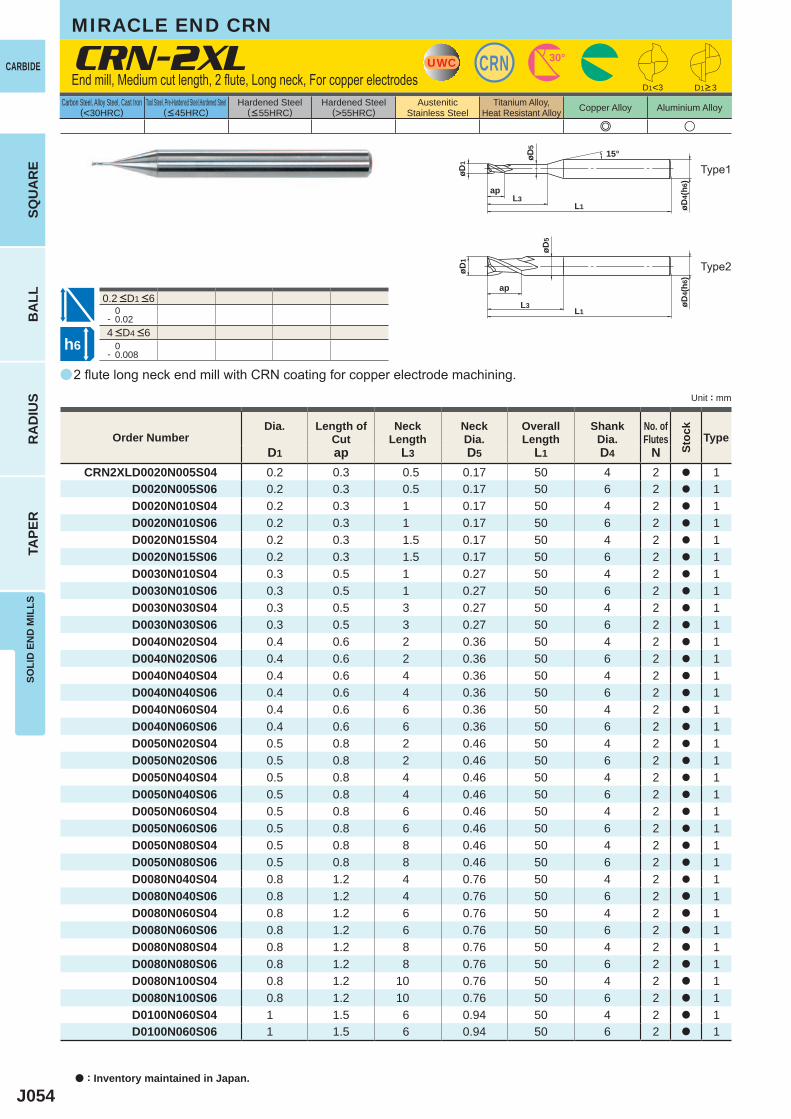
J054
a
e u
CRN-2XL
D1 ap L3 D5 L1 D4 NCRN2XLD0020N005S04 0.2 0.3 0.5 0.17 50 4 2 a 1
D0020N005S06 0.2 0.3 0.5 0.17 50 6 2 a 1 D0020N010S04 0.2 0.3 1 0.17 50 4 2 a 1 D0020N010S06 0.2 0.3 1 0.17 50 6 2 a 1 D0020N015S04 0.2 0.3 1.5 0.17 50 4 2 a 1 D0020N015S06 0.2 0.3 1.5 0.17 50 6 2 a 1 D0030N010S04 0.3 0.5 1 0.27 50 4 2 a 1 D0030N010S06 0.3 0.5 1 0.27 50 6 2 a 1 D0030N030S04 0.3 0.5 3 0.27 50 4 2 a 1 D0030N030S06 0.3 0.5 3 0.27 50 6 2 a 1 D0040N020S04 0.4 0.6 2 0.36 50 4 2 a 1 D0040N020S06 0.4 0.6 2 0.36 50 6 2 a 1 D0040N040S04 0.4 0.6 4 0.36 50 4 2 a 1 D0040N040S06 0.4 0.6 4 0.36 50 6 2 a 1 D0040N060S04 0.4 0.6 6 0.36 50 4 2 a 1 D0040N060S06 0.4 0.6 6 0.36 50 6 2 a 1 D0050N020S04 0.5 0.8 2 0.46 50 4 2 a 1 D0050N020S06 0.5 0.8 2 0.46 50 6 2 a 1 D0050N040S04 0.5 0.8 4 0.46 50 4 2 a 1 D0050N040S06 0.5 0.8 4 0.46 50 6 2 a 1 D0050N060S04 0.5 0.8 6 0.46 50 4 2 a 1 D0050N060S06 0.5 0.8 6 0.46 50 6 2 a 1 D0050N080S04 0.5 0.8 8 0.46 50 4 2 a 1 D0050N080S06 0.5 0.8 8 0.46 50 6 2 a 1 D0080N040S04 0.8 1.2 4 0.76 50 4 2 a 1 D0080N040S06 0.8 1.2 4 0.76 50 6 2 a 1 D0080N060S04 0.8 1.2 6 0.76 50 4 2 a 1 D0080N060S06 0.8 1.2 6 0.76 50 6 2 a 1 D0080N080S04 0.8 1.2 8 0.76 50 4 2 a 1 D0080N080S06 0.8 1.2 8 0.76 50 6 2 a 1 D0080N100S04 0.8 1.2 10 0.76 50 4 2 a 1 D0080N100S06 0.8 1.2 10 0.76 50 6 2 a 1 D0100N060S04 1 1.5 6 0.94 50 4 2 a 1 D0100N060S06 1 1.5 6 0.94 50 6 2 a 1
D1<3
0- 0.02
0- 0.008
UWC CRN 30°
øD4(
h6)
L1L3
ap
øD1
15°øD5
øD4(
h6)
L1L3
ap
øD1
øD5
h6
CARBIDE
a : Inventory maintained in Japan.
BA
LLR
AD
IUS
TAPE
RSO
LID
EN
D M
ILLS
SQU
AR
E
Unit : mm
Carbon Steel, Alloy Steel, Cast Iron(<30HRC)
Tool Steel, Pre-Hardened Steel,Hardened Steel(<45HRC)
Hardened Steel(<55HRC)
Hardened Steel(>55HRC)
AusteniticStainless Steel
Titanium Alloy,Heat Resistant Alloy Copper Alloy Aluminium Alloy
2 flute long neck end mill with CRN coating for copper electrode machining.
End mill, Medium cut length, 2 flute, Long neck, For copper electrodes
Type2
Type1
D1>3
Order NumberDia. Length of
CutNeck
LengthNeckDia.
Overall Length
ShankDia.
No. ofFlutes
Stoc
k
Type
4 <D4 <6
0.2 <D1 <6
MIRACLE END CRN
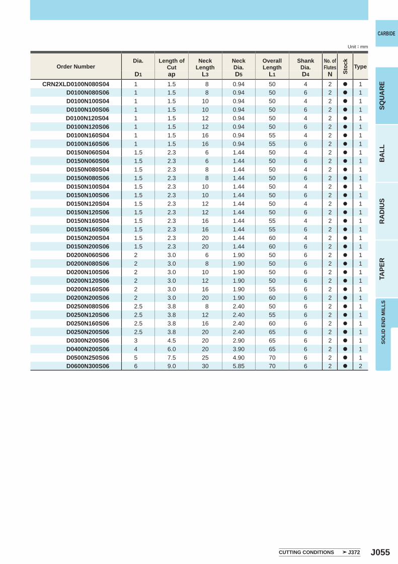
J055
D1 ap L3 D5 L1 D4 NCRN2XLD0100N080S04 1 1.5 8 0.94 50 4 2 a 1
D0100N080S06 1 1.5 8 0.94 50 6 2 a 1 D0100N100S04 1 1.5 10 0.94 50 4 2 a 1 D0100N100S06 1 1.5 10 0.94 50 6 2 a 1 D0100N120S04 1 1.5 12 0.94 50 4 2 a 1 D0100N120S06 1 1.5 12 0.94 50 6 2 a 1 D0100N160S04 1 1.5 16 0.94 55 4 2 a 1 D0100N160S06 1 1.5 16 0.94 55 6 2 a 1 D0150N060S04 1.5 2.3 6 1.44 50 4 2 a 1 D0150N060S06 1.5 2.3 6 1.44 50 6 2 a 1 D0150N080S04 1.5 2.3 8 1.44 50 4 2 a 1 D0150N080S06 1.5 2.3 8 1.44 50 6 2 a 1 D0150N100S04 1.5 2.3 10 1.44 50 4 2 a 1 D0150N100S06 1.5 2.3 10 1.44 50 6 2 a 1 D0150N120S04 1.5 2.3 12 1.44 50 4 2 a 1 D0150N120S06 1.5 2.3 12 1.44 50 6 2 a 1 D0150N160S04 1.5 2.3 16 1.44 55 4 2 a 1 D0150N160S06 1.5 2.3 16 1.44 55 6 2 a 1 D0150N200S04 1.5 2.3 20 1.44 60 4 2 a 1 D0150N200S06 1.5 2.3 20 1.44 60 6 2 a 1 D0200N060S06 2 3.0 6 1.90 50 6 2 a 1 D0200N080S06 2 3.0 8 1.90 50 6 2 a 1 D0200N100S06 2 3.0 10 1.90 50 6 2 a 1 D0200N120S06 2 3.0 12 1.90 50 6 2 a 1 D0200N160S06 2 3.0 16 1.90 55 6 2 a 1 D0200N200S06 2 3.0 20 1.90 60 6 2 a 1 D0250N080S06 2.5 3.8 8 2.40 50 6 2 a 1 D0250N120S06 2.5 3.8 12 2.40 55 6 2 a 1 D0250N160S06 2.5 3.8 16 2.40 60 6 2 a 1 D0250N200S06 2.5 3.8 20 2.40 65 6 2 a 1 D0300N200S06 3 4.5 20 2.90 65 6 2 a 1 D0400N200S06 4 6.0 20 3.90 65 6 2 a 1 D0500N250S06 5 7.5 25 4.90 70 6 2 a 1 D0600N300S06 6 9.0 30 5.85 70 6 2 a 2
CARBIDE
SQU
AR
EB
ALL
RA
DIU
STA
PER
SOLI
D E
ND
MIL
LS
Unit : mm
Order NumberDia. Length of
CutNeck
LengthNeckDia.
Overall Length
ShankDia.
No. ofFlutes
Stoc
k
Type
CUTTING CONDITIONS J372
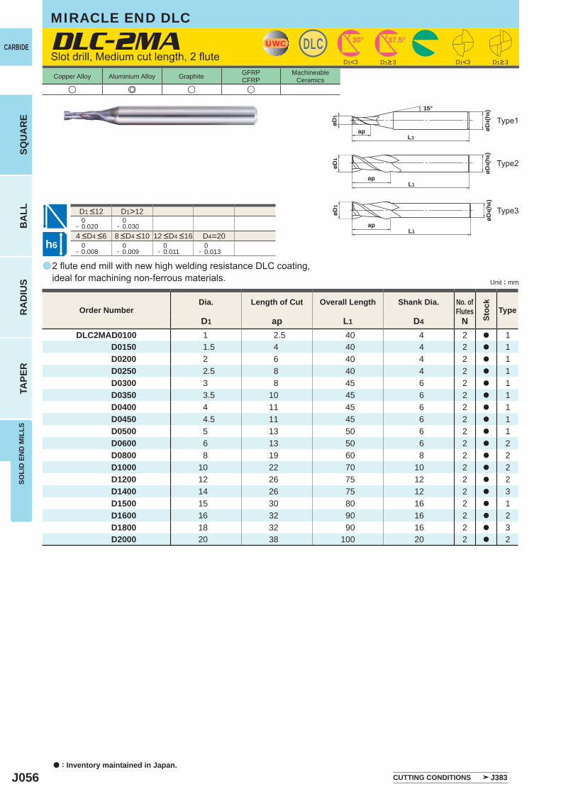
J056
a
DLC-2MA
u e u u
D1 ap L1 D4 NDLC2MAD0100 1 2.5 40 4 2 a 1
D0150 1.5 4 40 4 2 a 1 D0200 2 6 40 4 2 a 1 D0250 2.5 8 40 4 2 a 1 D0300 3 8 45 6 2 a 1 D0350 3.5 10 45 6 2 a 1 D0400 4 11 45 6 2 a 1 D0450 4.5 11 45 6 2 a 1 D0500 5 13 50 6 2 a 1 D0600 6 13 50 6 2 a 2 D0800 8 19 60 8 2 a 2 D1000 10 22 70 10 2 a 2 D1200 12 26 75 12 2 a 2 D1400 14 26 75 12 2 a 3 D1500 15 30 80 16 2 a 1 D1600 16 32 90 16 2 a 2 D1800 18 32 90 16 2 a 3 D2000 20 38 100 20 2 a 2
D1<3 D1<3
D1>12 0- 0.020
0- 0.030
D4=20 0- 0.008
0- 0.009
0- 0.011
0- 0.013
UWC DLC 30° 37.5°
øD4(
h6)
L1ap
øD1
15°
øD4(
h6)
L1
øD1
ap
øD4(
h6)
L1
øD1
ap
h6
CARBIDE
a : Inventory maintained in Japan.
BA
LLR
AD
IUS
TAPE
RSO
LID
EN
D M
ILLS
SQU
AR
E
Unit : mm
Copper Alloy Aluminium Alloy Graphite GFRPCFRP
MachineableCeramics
2 flute end mill with new high welding resistance DLC coating, ideal for machining non-ferrous materials.
Slot drill, Medium cut length, 2 flute
Type2
Type1
Type3
Order NumberDia. Length of Cut Overall Length Shank Dia. No. of
Flutes
Stoc
k
Type
D1>3 D1>3
CUTTING CONDITIONS J383
4 <D4 <6 8 <D4 <10 12 <D4 <16
D1 <12
MIRACLE END DLC
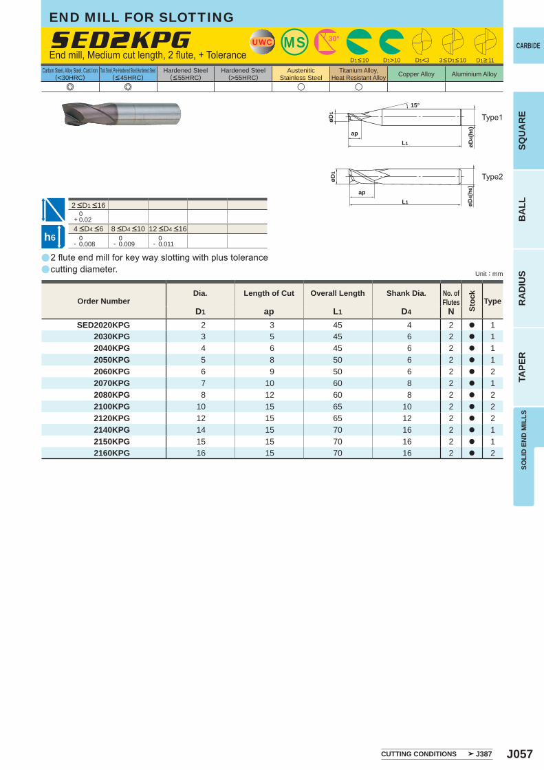
J057
a
a
e e u u
SED2KPG
D1 ap L1 D4 NSED2020KPG 2 3 45 4 2 a 1
2030KPG 3 5 45 6 2 a 1 2040KPG 4 6 45 6 2 a 1 2050KPG 5 8 50 6 2 a 1 2060KPG 6 9 50 6 2 a 2 2070KPG 7 10 60 8 2 a 1 2080KPG 8 12 60 8 2 a 2 2100KPG 10 15 65 10 2 a 2 2120KPG 12 15 65 12 2 a 2 2140KPG 14 15 70 16 2 a 1 2150KPG 15 15 70 16 2 a 1 2160KPG 16 15 70 16 2 a 2
0+ 0.02
0- 0.008
0- 0.009
0- 0.011
D1<3D1>10
MSUWC 30°
øD4(
h6)
L1
ap
øD1
15°
øD4(
h6)
L1
ap
øD1
h6
CARBIDE
SQU
AR
EB
ALL
RA
DIU
STA
PER
SOLI
D E
ND
MIL
LS
Unit : mm
Carbon Steel, Alloy Steel, Cast Iron(<30HRC)
Tool Steel, Pre-Hardened Steel,Hardened Steel(<45HRC)
Hardened Steel(<55HRC)
Hardened Steel(>55HRC)
AusteniticStainless Steel
Titanium Alloy,Heat Resistant Alloy Copper Alloy Aluminium Alloy
2 flute end mill for key way slotting with plus tolerancecutting diameter.
End mill, Medium cut length, 2 flute, + Tolerance
END MILL FOR SLOTTING
Type2
Type1
Order NumberDia. Length of Cut Overall Length Shank Dia. No. of
Flutes
Stoc
k
Type
D1<10 3<D1<10
CUTTING CONDITIONS J387
D1>11
4 <D4 <6 8 <D4 <10 12 <D4 <16
2 <D1 <16
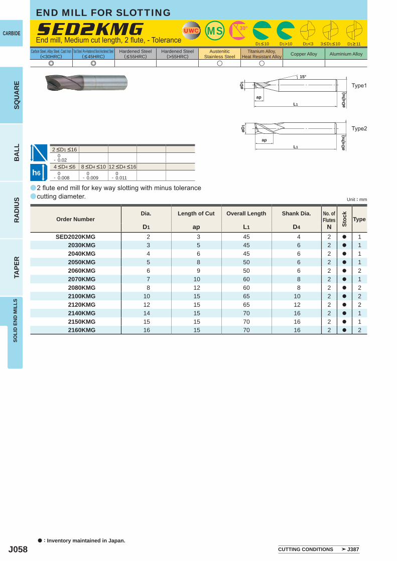
J058
a
a
e e u u
SED2KMG
D1 ap L1 D4 NSED2020KMG 2 3 45 4 2 a 1
2030KMG 3 5 45 6 2 a 1 2040KMG 4 6 45 6 2 a 1 2050KMG 5 8 50 6 2 a 1 2060KMG 6 9 50 6 2 a 2 2070KMG 7 10 60 8 2 a 1 2080KMG 8 12 60 8 2 a 2 2100KMG 10 15 65 10 2 a 2 2120KMG 12 15 65 12 2 a 2 2140KMG 14 15 70 16 2 a 1 2150KMG 15 15 70 16 2 a 1 2160KMG 16 15 70 16 2 a 2
0- 0.02
0- 0.008
0- 0.009
0- 0.011
D1<3D1>10
MSUWC 30°
øD4(
h6)
L1
ap
øD1
15°
øD4(
h6)
L1
ap
øD1
h6
CARBIDE
a : Inventory maintained in Japan.
BA
LLR
AD
IUS
TAPE
RSO
LID
EN
D M
ILLS
SQU
AR
E
Unit : mm
Carbon Steel, Alloy Steel, Cast Iron(<30HRC)
Tool Steel, Pre-Hardened Steel,Hardened Steel(<45HRC)
Hardened Steel(<55HRC)
Hardened Steel(>55HRC)
AusteniticStainless Steel
Titanium Alloy,Heat Resistant Alloy Copper Alloy Aluminium Alloy
2 flute end mill for key way slotting with minus tolerance cutting diameter.
End mill, Medium cut length, 2 flute, - Tolerance
Type2
Type1
Order NumberDia. Length of Cut Overall Length Shank Dia. No. of
Flutes
Stoc
k
Type
CUTTING CONDITIONS J387
D1<10 3<D1<10 D1>11
4 <D4 <6 8 <D4 <10 12 <D4 <16
2 <D1 <16
END MILL FOR SLOTTING
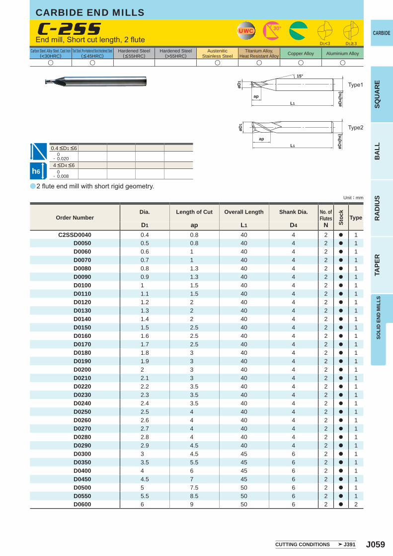
J059
a
u u u u u u
C-2SS
D1 ap L1 D4 NC2SSD0040 0.4 0.8 40 4 2 a 1
D0050 0.5 0.8 40 4 2 a 1 D0060 0.6 1 40 4 2 a 1 D0070 0.7 1 40 4 2 a 1 D0080 0.8 1.3 40 4 2 a 1 D0090 0.9 1.3 40 4 2 a 1 D0100 1 1.5 40 4 2 a 1 D0110 1.1 1.5 40 4 2 a 1 D0120 1.2 2 40 4 2 a 1 D0130 1.3 2 40 4 2 a 1 D0140 1.4 2 40 4 2 a 1 D0150 1.5 2.5 40 4 2 a 1 D0160 1.6 2.5 40 4 2 a 1 D0170 1.7 2.5 40 4 2 a 1 D0180 1.8 3 40 4 2 a 1 D0190 1.9 3 40 4 2 a 1 D0200 2 3 40 4 2 a 1 D0210 2.1 3 40 4 2 a 1 D0220 2.2 3.5 40 4 2 a 1 D0230 2.3 3.5 40 4 2 a 1 D0240 2.4 3.5 40 4 2 a 1 D0250 2.5 4 40 4 2 a 1 D0260 2.6 4 40 4 2 a 1 D0270 2.7 4 40 4 2 a 1 D0280 2.8 4 40 4 2 a 1 D0290 2.9 4.5 40 4 2 a 1 D0300 3 4.5 45 6 2 a 1 D0350 3.5 5.5 45 6 2 a 1 D0400 4 6 45 6 2 a 1 D0450 4.5 7 45 6 2 a 1 D0500 5 7.5 50 6 2 a 1 D0550 5.5 8.5 50 6 2 a 1 D0600 6 9 50 6 2 a 2
0- 0.020
0- 0.008
UWC 30°
øD4(
h6)
L1
ap
øD1
15°
D1<3
øD4(
h 6)
L1
ap
øD1
h6
CARBIDE
SQU
AR
EB
ALL
RA
DIU
STA
PER
SOLI
D E
ND
MIL
LS
Unit : mm
Carbon Steel, Alloy Steel, Cast Iron(<30HRC)
Tool Steel, Pre-Hardened Steel,Hardened Steel(<45HRC)
Hardened Steel(<55HRC)
Hardened Steel(>55HRC)
AusteniticStainless Steel
Titanium Alloy,Heat Resistant Alloy Copper Alloy Aluminium Alloy
0.4 <D1 <6
2 flute end mill with short rigid geometry.
End mill, Short cut length, 2 flute
CARBIDE END MILLS
Type2
Type1
Order NumberDia. Length of Cut Overall Length Shank Dia. No. of
Flutes
Stoc
k
Type
CUTTING CONDITIONS J391
D1>3
4 <D4 <6
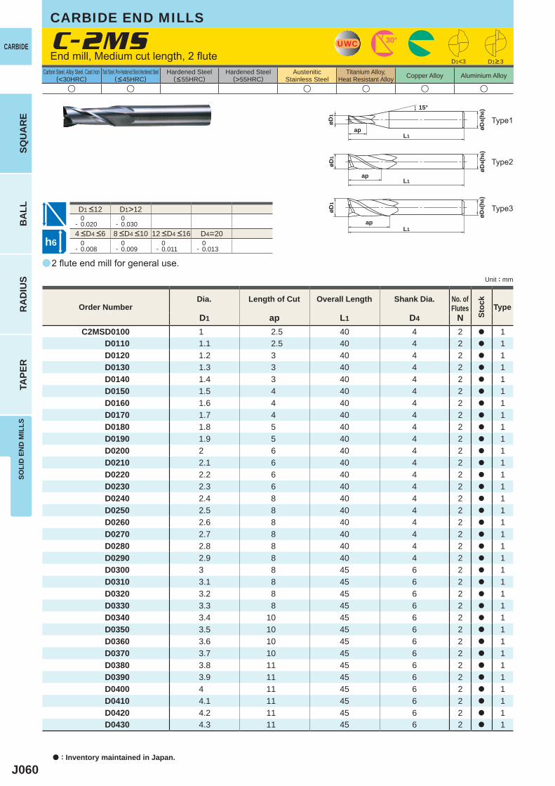
J060
a
u u u u u u
C-2MS
D1 ap L1 D4 NC2MSD0100 1 2.5 40 4 2 a 1
D0110 1.1 2.5 40 4 2 a 1 D0120 1.2 3 40 4 2 a 1 D0130 1.3 3 40 4 2 a 1 D0140 1.4 3 40 4 2 a 1 D0150 1.5 4 40 4 2 a 1 D0160 1.6 4 40 4 2 a 1 D0170 1.7 4 40 4 2 a 1 D0180 1.8 5 40 4 2 a 1 D0190 1.9 5 40 4 2 a 1 D0200 2 6 40 4 2 a 1 D0210 2.1 6 40 4 2 a 1 D0220 2.2 6 40 4 2 a 1 D0230 2.3 6 40 4 2 a 1 D0240 2.4 8 40 4 2 a 1 D0250 2.5 8 40 4 2 a 1 D0260 2.6 8 40 4 2 a 1 D0270 2.7 8 40 4 2 a 1 D0280 2.8 8 40 4 2 a 1 D0290 2.9 8 40 4 2 a 1 D0300 3 8 45 6 2 a 1 D0310 3.1 8 45 6 2 a 1 D0320 3.2 8 45 6 2 a 1 D0330 3.3 8 45 6 2 a 1 D0340 3.4 10 45 6 2 a 1 D0350 3.5 10 45 6 2 a 1 D0360 3.6 10 45 6 2 a 1 D0370 3.7 10 45 6 2 a 1 D0380 3.8 11 45 6 2 a 1 D0390 3.9 11 45 6 2 a 1 D0400 4 11 45 6 2 a 1 D0410 4.1 11 45 6 2 a 1 D0420 4.2 11 45 6 2 a 1 D0430 4.3 11 45 6 2 a 1
D1>12 0- 0.020
0- 0.030
D4=20 0- 0.008
0- 0.009
0- 0.011
0- 0.013
D1<3
UWC 30°
øD4(
h6)
L1ap
øD1
15°
øD4(
h6)
L1ap
øD1
øD4(
h6)
L1ap
øD1
h6
CARBIDE
a : Inventory maintained in Japan.
BA
LLR
AD
IUS
TAPE
RSO
LID
EN
D M
ILLS
SQU
AR
E
Unit : mm
Carbon Steel, Alloy Steel, Cast Iron(<30HRC)
Tool Steel, Pre-Hardened Steel,Hardened Steel(<45HRC)
Hardened Steel(<55HRC)
Hardened Steel(>55HRC)
AusteniticStainless Steel
Titanium Alloy,Heat Resistant Alloy Copper Alloy Aluminium Alloy
2 flute end mill for general use.
End mill, Medium cut length, 2 flute
Type2
Type3
Type1
Order NumberDia. Length of Cut Overall Length Shank Dia. No. of
Flutes
Stoc
k
Type
D1>3
4 <D4 <6 8 <D4 <10 12 <D4 <16
D1 <12
CARBIDE END MILLS
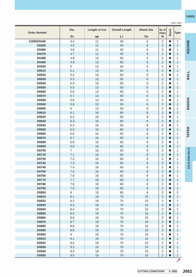
J061
D1 ap L1 D4 N C2MSD0440 4.4 11 45 6 2 a 1 D0450 4.5 11 45 6 2 a 1 D0460 4.6 11 45 6 2 a 1 D0470 4.7 11 45 6 2 a 1 D0480 4.8 13 50 6 2 a 1 D0490 4.9 13 50 6 2 a 1 D0500 5 13 50 6 2 a 1 D0510 5.1 13 50 6 2 a 1 D0520 5.2 13 50 6 2 a 1 D0530 5.3 13 50 6 2 a 1 D0540 5.4 13 50 6 2 a 1 D0550 5.5 13 50 6 2 a 1 D0560 5.6 13 50 6 2 a 1 D0570 5.7 13 50 6 2 a 1 D0580 5.8 13 50 6 2 a 1 D0590 5.9 13 50 6 2 a 1 D0600 6 13 50 6 2 a 2 D0610 6.1 16 60 8 2 a 1 D0620 6.2 16 60 8 2 a 1 D0630 6.3 16 60 8 2 a 1 D0640 6.4 16 60 8 2 a 1 D0650 6.5 16 60 8 2 a 1 D0660 6.6 16 60 8 2 a 1 D0670 6.7 16 60 8 2 a 1 D0680 6.8 16 60 8 2 a 1 D0690 6.9 16 60 8 2 a 1 D0700 7 16 60 8 2 a 1 D0710 7.1 16 60 8 2 a 1 D0720 7.2 16 60 8 2 a 1 D0730 7.3 16 60 8 2 a 1 D0740 7.4 16 60 8 2 a 1 D0750 7.5 16 60 8 2 a 1 D0760 7.6 19 60 8 2 a 1 D0770 7.7 19 60 8 2 a 1 D0780 7.8 19 60 8 2 a 1 D0790 7.9 19 60 8 2 a 1 D0800 8 19 60 8 2 a 2 D0810 8.1 19 70 10 2 a 1 D0820 8.2 19 70 10 2 a 1 D0830 8.3 19 70 10 2 a 1 D0840 8.4 19 70 10 2 a 1 D0850 8.5 19 70 10 2 a 1 D0860 8.6 19 70 10 2 a 1 D0870 8.7 19 70 10 2 a 1 D0880 8.8 19 70 10 2 a 1 D0890 8.9 19 70 10 2 a 1 D0900 9 19 70 10 2 a 1 D0910 9.1 19 70 10 2 a 1 D0920 9.2 19 70 10 2 a 1 D0930 9.3 19 70 10 2 a 1 D0940 9.4 19 70 10 2 a 1 D0950 9.5 19 70 10 2 a 1
CARBIDE
SQU
AR
EB
ALL
RA
DIU
STA
PER
SOLI
D E
ND
MIL
LS
Unit : mm
CUTTING CONDITIONS J391
Order NumberDia. Length of Cut Overall Length Shank Dia. No. of
Flutes
Stoc
k
Type
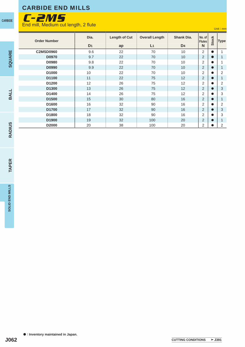
J062
D1 ap L1 D4 N C2MSD0960 9.6 22 70 10 2 a 1 D0970 9.7 22 70 10 2 a 1 D0980 9.8 22 70 10 2 a 1 D0990 9.9 22 70 10 2 a 1 D1000 10 22 70 10 2 a 2 D1100 11 22 75 12 2 a 1 D1200 12 26 75 12 2 a 2 D1300 13 26 75 12 2 a 3 D1400 14 26 75 12 2 a 3 D1500 15 30 80 16 2 a 1 D1600 16 32 90 16 2 a 2 D1700 17 32 90 16 2 a 3 D1800 18 32 90 16 2 a 3 D1900 19 32 100 20 2 a 1 D2000 20 38 100 20 2 a 2
C-2MSCARBIDE
a : Inventory maintained in Japan.
BA
LLR
AD
IUS
TAPE
RSO
LID
EN
D M
ILLS
SQU
AR
E
Unit : mm
Order NumberDia. Length of Cut Overall Length Shank Dia. No. of
Flutes
Stoc
k
Type
CUTTING CONDITIONS J391
End mill, Medium cut length, 2 flute
CARBIDE END MILLS
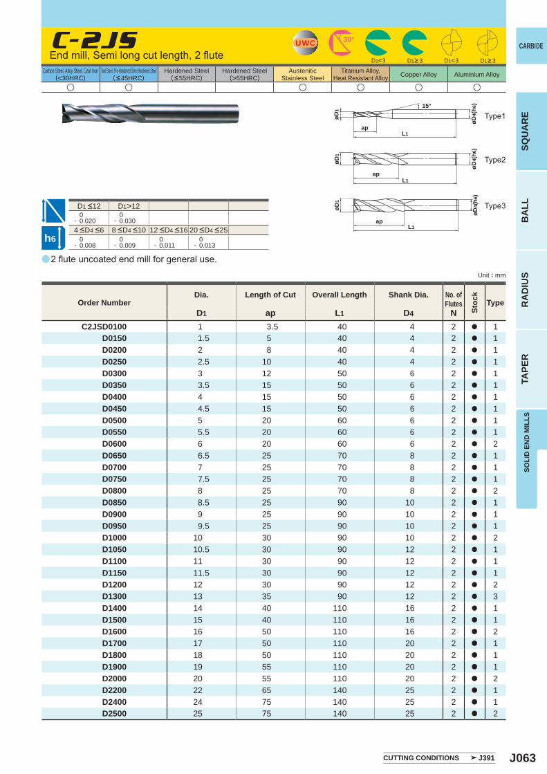
J063
a
u u u u u u
C-2JS
D1 ap L1 D4 NC2JSD0100 1 3.5 40 4 2 a 1
D0150 1.5 5 40 4 2 a 1 D0200 2 8 40 4 2 a 1 D0250 2.5 10 40 4 2 a 1 D0300 3 12 50 6 2 a 1 D0350 3.5 15 50 6 2 a 1 D0400 4 15 50 6 2 a 1 D0450 4.5 15 50 6 2 a 1 D0500 5 20 60 6 2 a 1 D0550 5.5 20 60 6 2 a 1 D0600 6 20 60 6 2 a 2 D0650 6.5 25 70 8 2 a 1 D0700 7 25 70 8 2 a 1 D0750 7.5 25 70 8 2 a 1 D0800 8 25 70 8 2 a 2 D0850 8.5 25 90 10 2 a 1 D0900 9 25 90 10 2 a 1 D0950 9.5 25 90 10 2 a 1 D1000 10 30 90 10 2 a 2 D1050 10.5 30 90 12 2 a 1 D1100 11 30 90 12 2 a 1 D1150 11.5 30 90 12 2 a 1 D1200 12 30 90 12 2 a 2 D1300 13 35 90 12 2 a 3 D1400 14 40 110 16 2 a 1 D1500 15 40 110 16 2 a 1 D1600 16 50 110 16 2 a 2 D1700 17 50 110 20 2 a 1 D1800 18 50 110 20 2 a 1 D1900 19 55 110 20 2 a 1 D2000 20 55 110 20 2 a 2 D2200 22 65 140 25 2 a 1 D2400 24 75 140 25 2 a 1 D2500 25 75 140 25 2 a 2
D1>12 0- 0.020
0- 0.030
0- 0.008
0- 0.009
0- 0.011
0- 0.013
D1<3 D1<3
UWC 30°
øD4(
h6)
L1ap
øD1
15°
øD4(
h6)
øD1
L1ap
øD4(
h6)
øD1
L1ap
h6
CARBIDE
SQU
AR
EB
ALL
RA
DIU
STA
PER
SOLI
D E
ND
MIL
LS
Unit : mm
Carbon Steel, Alloy Steel, Cast Iron(<30HRC)
Tool Steel, Pre-Hardened Steel,Hardened Steel(<45HRC)
Hardened Steel(<55HRC)
Hardened Steel(>55HRC)
AusteniticStainless Steel
Titanium Alloy,Heat Resistant Alloy Copper Alloy Aluminium Alloy
2 flute uncoated end mill for general use.
End mill, Semi long cut length, 2 flute
Type1
Type2
Type3
Order NumberDia. Length of Cut Overall Length Shank Dia. No. of
Flutes
Stoc
k
Type
CUTTING CONDITIONS J391
D1>3 D1>3
4 <D4 <6 8 <D4 <10 12 <D4 <16 20 <D4 <25
D1 <12

J064
a
u u u u u u
C-2LS
D1 ap L1 D4 NC2LSD0100 1 4 40 4 2 a 1
D0150 1.5 6 40 4 2 a 1 D0200 2 9 40 4 2 a 1 D0250 2.5 12 40 4 2 a 1 D0300 3 20 60 6 2 a 1 D0350 3.5 22 60 6 2 a 1 D0400 4 25 60 6 2 a 1 D0450 4.5 25 60 6 2 a 1 D0500 5 30 70 6 2 a 1 D0550 5.5 30 70 6 2 a 1 D0600 6 30 70 6 2 a 2 D0650 6.5 30 90 8 2 a 1 D0700 7 40 90 8 2 a 1 D0750 7.5 40 90 8 2 a 1 D0800 8 40 90 8 2 a 2 D0850 8.5 40 100 10 2 a 1 D0900 9 40 100 10 2 a 1 D0950 9.5 40 100 10 2 a 1 D1000 10 50 100 10 2 a 2 D1050 10.5 50 110 12 2 a 1 D1100 11 50 110 12 2 a 1 D1150 11.5 50 110 12 2 a 1 D1200 12 50 110 12 2 a 2 D1250 12.5 50 120 12 2 a 3 D1300 13 50 120 12 2 a 3 D1400 14 70 130 16 2 a 1 D1500 15 70 130 16 2 a 1 D1600 16 70 130 16 2 a 2 D1700 17 70 140 20 2 a 1 D1800 18 70 140 20 2 a 1 D1900 19 70 140 20 2 a 1 D2000 20 70 140 20 2 a 2
D1>12 0- 0.020
0- 0.030
D4=20 0- 0.008
0- 0.009
0- 0.011
0- 0.013
UWC 30°
øD4(
h6)
L1ap
øD1
15°
øD4(
h6)
øD1
L1
ap
øD4(
h6)
øD1
L1
ap
h6
CARBIDE
a : Inventory maintained in Japan.
BA
LLR
AD
IUS
TAPE
RSO
LID
EN
D M
ILLS
SQU
AR
E
Unit : mm
Carbon Steel, Alloy Steel, Cast Iron(<30HRC)
Tool Steel, Pre-Hardened Steel,Hardened Steel(<45HRC)
Hardened Steel(<55HRC)
Hardened Steel(>55HRC)
AusteniticStainless Steel
Titanium Alloy,Heat Resistant Alloy Copper Alloy Aluminium Alloy
2 flute end mill with longer cut length than standard.
End mill, Long cut length, 2 flute
Type2
Type1
Type3
Order NumberDia. Length of Cut Overall Length Shank Dia. No. of
Flutes
Stoc
k
Type
CUTTING CONDITIONS J391
4 <D4 <6 8 <D4 <10 12 <D4 <16
D1 <12
CARBIDE END MILLS
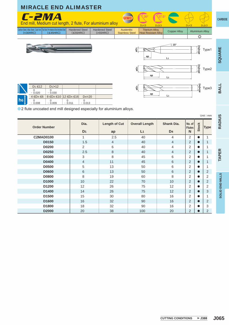
J065
a
e
C-2MA
D1 ap L1 D4 NC2MAD0100 1 2.5 40 4 2 a 1
D0150 1.5 4 40 4 2 a 1 D0200 2 6 40 4 2 a 1 D0250 2.5 8 40 4 2 a 1 D0300 3 8 45 6 2 a 1 D0400 4 11 45 6 2 a 1 D0500 5 13 50 6 2 a 1 D0600 6 13 50 6 2 a 2 D0800 8 19 60 8 2 a 2 D1000 10 22 70 10 2 a 2 D1200 12 26 75 12 2 a 2 D1400 14 26 75 12 2 a 3 D1500 15 30 80 16 2 a 1 D1600 16 32 90 16 2 a 2 D1800 18 32 90 16 2 a 3 D2000 20 38 100 20 2 a 2
D1>12 0- 0.020
0- 0.030
D4=20 0- 0.008
0- 0.009
0- 0.011
0- 0.013
D1<3 D1<3
UWC 30° 37.5°
øD4(
h6)
L1ap
øD1
15°
øD4(
h6)
L1
øD1
ap
øD4(
h6)
L1
øD1
ap
h6
CARBIDE
SQU
AR
EB
ALL
RA
DIU
STA
PER
SOLI
D E
ND
MIL
LS
Unit : mm
Carbon Steel, Alloy Steel, Cast Iron(<30HRC)
Tool Steel, Pre-Hardened Steel,Hardened Steel(<45HRC)
Hardened Steel(<55HRC)
Hardened Steel(>55HRC)
AusteniticStainless Steel
Titanium Alloy,Heat Resistant Alloy Copper Alloy Aluminium Alloy
2 flute uncoated end mill designed especially for aluminium alloys.
End mill, Medium cut length, 2 flute, For aluminium alloy
Type2
Type3
Type1
Order NumberDia. Length of Cut Overall Length Shank Dia. No. of
Flutes
Stoc
k
Type
CUTTING CONDITIONS J388
D1>3 D1>3
4 <D4 <6 8 <D4 <10 12 <D4 <16
D1 <12
MIRACLE END ALIMASTER
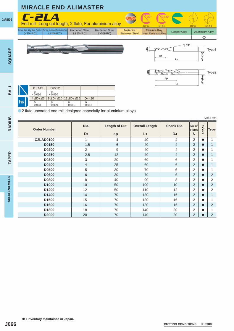
J066
a
e
C-2LA
D1 ap L1 D4 NC2LAD0100 1 4 40 4 2 a 1
D0150 1.5 6 40 4 2 a 1 D0200 2 9 40 4 2 a 1 D0250 2.5 12 40 4 2 a 1 D0300 3 20 60 6 2 a 1 D0400 4 25 60 6 2 a 1 D0500 5 30 70 6 2 a 1 D0600 6 30 70 6 2 a 2 D0800 8 40 90 8 2 a 2 D1000 10 50 100 10 2 a 2 D1200 12 50 110 12 2 a 2 D1400 14 70 130 16 2 a 1 D1500 15 70 130 16 2 a 1 D1600 16 70 130 16 2 a 2 D1800 18 70 140 20 2 a 1 D2000 20 70 140 20 2 a 2
D1>12 0- 0.020
0- 0.030
D4=20 0- 0.008
0- 0.009
0- 0.011
0- 0.013
D1<3 D1<3
UWC 30° 37.5°
L1
ap
øD4(
h6)øD
1
15°
øD4(
h6)øD
1
L1
ap
h6
CARBIDE
a : Inventory maintained in Japan.
BA
LLR
AD
IUS
TAPE
RSO
LID
EN
D M
ILLS
SQU
AR
E
Unit : mm
Carbon Steel, Alloy Steel, Cast Iron(<30HRC)
Tool Steel, Pre-Hardened Steel,Hardened Steel(<45HRC)
Hardened Steel(<55HRC)
Hardened Steel(>55HRC)
AusteniticStainless Steel
Titanium Alloy,Heat Resistant Alloy Copper Alloy Aluminium Alloy
2 flute uncoated end mill designed especially for aluminium alloys.
End mill, Long cut length, 2 flute, For aluminium alloy
Type2
Type1
Order NumberDia. Length of Cut Overall Length Shank Dia. No. of
Flutes
Stoc
k
Type
CUTTING CONDITIONS J388
D1>3 D1>3
4 <D4 <6 8 <D4 <10 12 <D4 <16
D1 <12
MIRACLE END ALIMASTER
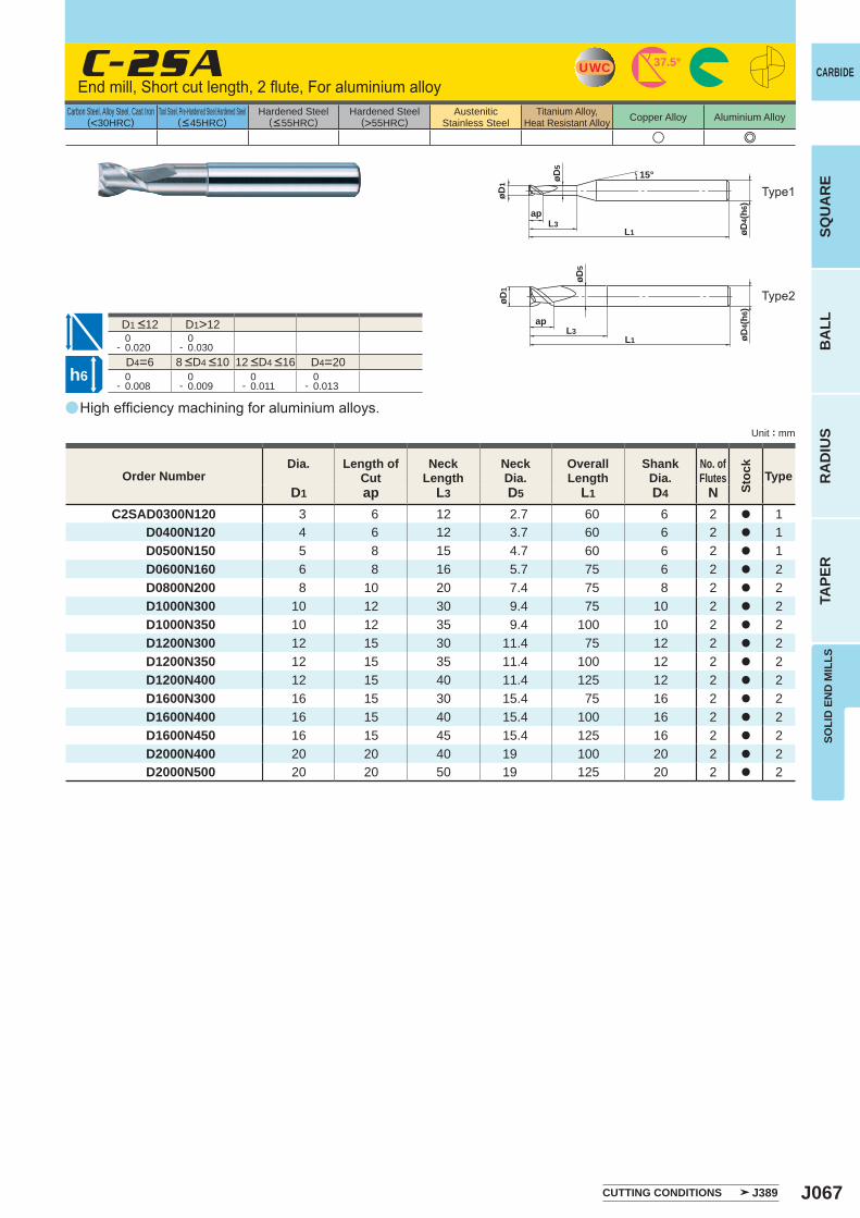
J067
a
u e
C-2SA
D1 ap L3 D5 L1 D4 NC2SAD0300N120 3 6 12 2.7 60 6 2 a 1
D0400N120 4 6 12 3.7 60 6 2 a 1 D0500N150 5 8 15 4.7 60 6 2 a 1 D0600N160 6 8 16 5.7 75 6 2 a 2 D0800N200 8 10 20 7.4 75 8 2 a 2 D1000N300 10 12 30 9.4 75 10 2 a 2 D1000N350 10 12 35 9.4 100 10 2 a 2 D1200N300 12 15 30 11.4 75 12 2 a 2 D1200N350 12 15 35 11.4 100 12 2 a 2 D1200N400 12 15 40 11.4 125 12 2 a 2 D1600N300 16 15 30 15.4 75 16 2 a 2 D1600N400 16 15 40 15.4 100 16 2 a 2 D1600N450 16 15 45 15.4 125 16 2 a 2 D2000N400 20 20 40 19 100 20 2 a 2 D2000N500 20 20 50 19 125 20 2 a 2
D1>12 0- 0.020
0- 0.030
D4=6 D4=20 0- 0.008
0- 0.009
0- 0.011
0- 0.013
UWC 37.5°
øD4(
h6)
L1L3
øD5
ap
øD1
15°
øD5
øD4(
h6)
L1L3
ap
øD1
h6
CARBIDE
SQU
AR
EB
ALL
RA
DIU
STA
PER
SOLI
D E
ND
MIL
LS
Unit : mm
Carbon Steel, Alloy Steel, Cast Iron(<30HRC)
Tool Steel, Pre-Hardened Steel,Hardened Steel(<45HRC)
Hardened Steel(<55HRC)
Hardened Steel(>55HRC)
AusteniticStainless Steel
Titanium Alloy,Heat Resistant Alloy Copper Alloy Aluminium Alloy
High efficiency machining for aluminium alloys.
End mill, Short cut length, 2 flute, For aluminium alloy
Type2
Type1
Order NumberDia. Length of
CutNeck
LengthNeckDia.
Overall Length
ShankDia.
No. ofFlutes
Stoc
k
Type
CUTTING CONDITIONS J389
8 <D4 <10 12 <D4 <16
D1 <12
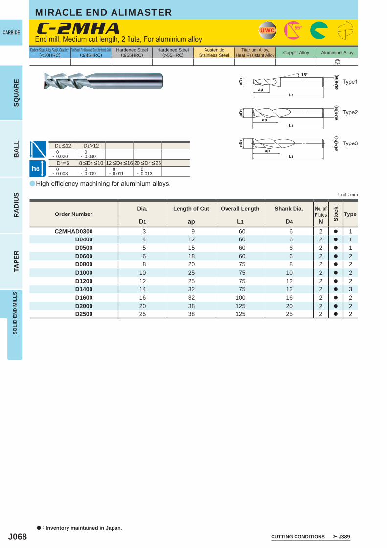
J068
a
e
C-2MHA
D1 ap L1 D4 NC2MHAD0300 3 9 60 6 2 a 1
D0400 4 12 60 6 2 a 1 D0500 5 15 60 6 2 a 1 D0600 6 18 60 6 2 a 2 D0800 8 20 75 8 2 a 2 D1000 10 25 75 10 2 a 2 D1200 12 25 75 12 2 a 2 D1400 14 32 75 12 2 a 3 D1600 16 32 100 16 2 a 2 D2000 20 38 125 20 2 a 2 D2500 25 38 125 25 2 a 2
D1>12 0- 0.020
0- 0.030
D4=6 0- 0.008
0- 0.009
0- 0.011
0- 0.013
UWC 55°
L1ap
øD1
øD4(
h6)15°
L1ap
øD1
øD4(
h6)
L1ap
øD1
øD4(
h6)
h6
CARBIDE
a : Inventory maintained in Japan.
BA
LLR
AD
IUS
TAPE
RSO
LID
EN
D M
ILLS
SQU
AR
E
Unit : mm
Carbon Steel, Alloy Steel, Cast Iron(<30HRC)
Tool Steel, Pre-Hardened Steel,Hardened Steel(<45HRC)
Hardened Steel(<55HRC)
Hardened Steel(>55HRC)
AusteniticStainless Steel
Titanium Alloy,Heat Resistant Alloy Copper Alloy Aluminium Alloy
High efficiency machining for aluminium alloys.
End mill, Medium cut length, 2 flute, For aluminium alloy
Type2
Type1
Type3
Order NumberDia. Length of Cut Overall Length Shank Dia. No. of
Flutes
Stoc
k
Type
CUTTING CONDITIONS J389
8 <D4 <10 12 <D4 <16 20 <D4 <25
D1 <12
MIRACLE END ALIMASTER
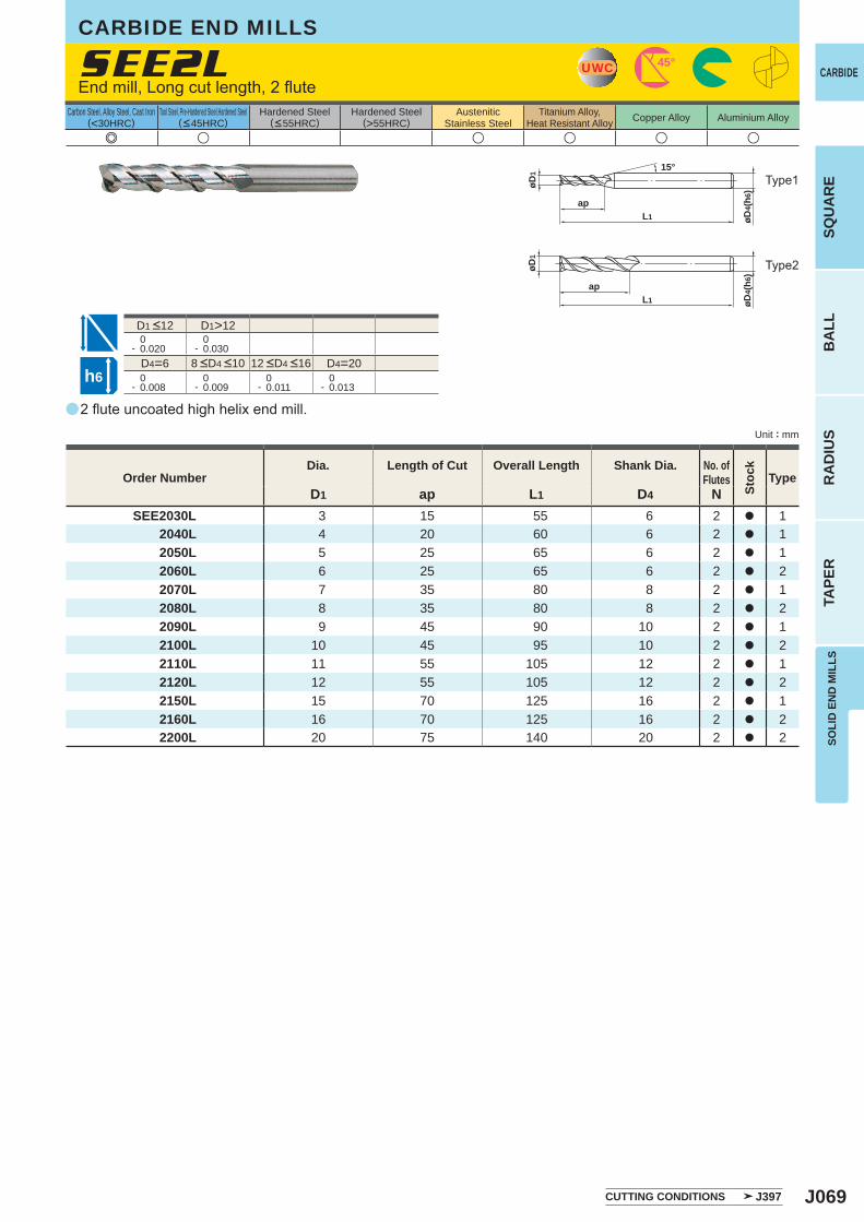
J069
a
e u u u u u
SEE2L
D1 ap L1 D4 NSEE2030L 3 15 55 6 2 a 1
2040L 4 20 60 6 2 a 1 2050L 5 25 65 6 2 a 1 2060L 6 25 65 6 2 a 2 2070L 7 35 80 8 2 a 1 2080L 8 35 80 8 2 a 2 2090L 9 45 90 10 2 a 1 2100L 10 45 95 10 2 a 2 2110L 11 55 105 12 2 a 1 2120L 12 55 105 12 2 a 2 2150L 15 70 125 16 2 a 1 2160L 16 70 125 16 2 a 2 2200L 20 75 140 20 2 a 2
D1>12 0- 0.020
0- 0.030
D4=6 D4=20 0- 0.008
0- 0.009
0- 0.011
0- 0.013
UWC 45°
øD1
øD4(
h6)
L1
ap
15°
øD1
øD4(
h6)
L1
ap
h6
CARBIDE
SQU
AR
EB
ALL
RA
DIU
STA
PER
SOLI
D E
ND
MIL
LS
Unit : mm
Carbon Steel, Alloy Steel, Cast Iron(<30HRC)
Tool Steel, Pre-Hardened Steel,Hardened Steel(<45HRC)
Hardened Steel(<55HRC)
Hardened Steel(>55HRC)
AusteniticStainless Steel
Titanium Alloy,Heat Resistant Alloy Copper Alloy Aluminium Alloy
2 flute uncoated high helix end mill.
End mill, Long cut length, 2 flute
Type2
Type1
Order NumberDia. Length of Cut Overall Length Shank Dia. No. of
Flutes
Stoc
k
Type
CUTTING CONDITIONS J397
8 <D4 <10 12 <D4 <16
D1 <12
CARBIDE END MILLS
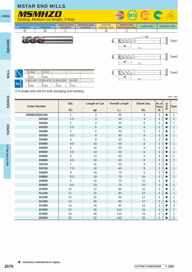
J070
a
e e u e u
MSMHZD
D1 ap L1 D4 NMSMHZDD0100 1 2 45 4 3 a 1
D0150 1.5 3 45 4 3 a 1D0200 2 4 50 6 3 a 1D0250 2.5 5 50 6 3 a 1D0300 3 6 50 6 3 a 1D0350 3.5 8 50 6 3 a 1D0400 4 8 50 6 3 a 1D0450 4.5 10 50 6 3 a 1D0500 5 10 50 6 3 a 1D0550 5.5 13 50 6 3 a 1D0600 6 13 60 6 3 a 2D0650 6.5 16 60 8 3 a 1D0700 7 16 60 8 3 a 1D0750 7.5 16 60 8 3 a 1D0800 8 19 70 8 3 a 2D0850 8.5 19 70 10 3 a 1D0900 9 19 70 10 3 a 1D0950 9.5 19 70 10 3 a 1D1000 10 22 80 10 3 a 2D1100 11 22 80 12 3 a 1D1200 12 26 90 12 3 a 2D1300 13 26 90 12 3 a 3D1400 14 26 90 12 3 a 3D1500 15 26 110 16 3 a 1D1600 16 30 110 16 3 a 2D2000 20 32 140 20 3 a 2
D1>12 0- 0.020
0- 0.030
D4=20 0- 0.008
0- 0.009
0- 0.011
0- 0.013
UWC MS 45°
L1ap
øD4(
h6)
øD1
15°
øD4(
h6)
øD1
apL1
L1ap
øD4(
h6)
øD1
h6
CARBIDE
a : Inventory maintained in Japan.
BA
LLR
AD
IUS
TAPE
RSO
LID
EN
D M
ILLS
SQU
AR
E
Unit : mm
Carbon Steel, Alloy Steel, Cast Iron(<30HRC)
Tool Steel, Pre-Hardened Steel,Hardened Steel(<45HRC)
Hardened Steel(<55HRC)
Hardened Steel(>55HRC)
AusteniticStainless Steel
Titanium Alloy,Heat Resistant Alloy Copper Alloy Aluminium Alloy
A single end mill for both plunging and slotting.
Slotting, Medium cut length, 3 flute
Type2
Type1
Type3
MSTAR END MILLS
Order NumberDia. Length of Cut Overall Length Shank Dia. No. of
Flutes
Stoc
k
Type
CUTTING CONDITIONS J296
4 <D4 <6 8 <D4 <10 12 <D4 <16
D1 <12
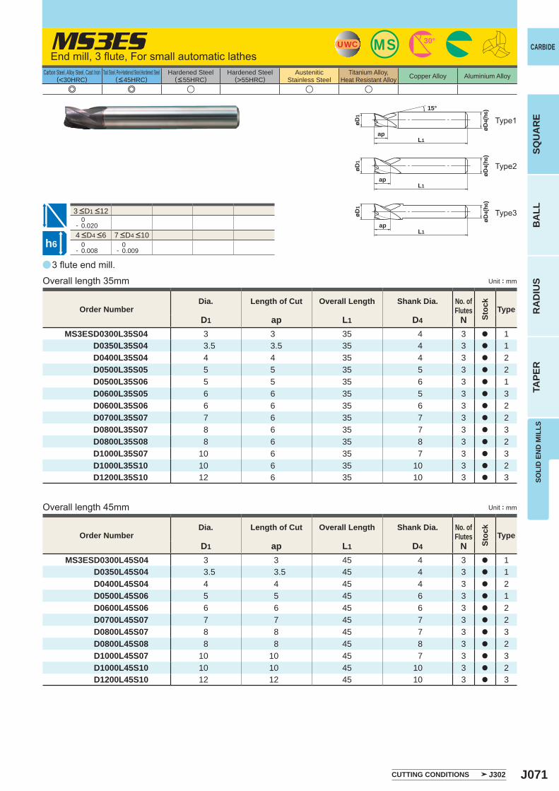
J071
a
e e u u u
MS3ES
D1 ap L1 D4 NMS3ESD0300L35S04 3 3 35 4 3 a 1
D0350L35S04 3.5 3.5 35 4 3 a 1D0400L35S04 4 4 35 4 3 a 2D0500L35S05 5 5 35 5 3 a 2D0500L35S06 5 5 35 6 3 a 1D0600L35S05 6 6 35 5 3 a 3D0600L35S06 6 6 35 6 3 a 2D0700L35S07 7 6 35 7 3 a 2D0800L35S07 8 6 35 7 3 a 3D0800L35S08 8 6 35 8 3 a 2D1000L35S07 10 6 35 7 3 a 3D1000L35S10 10 6 35 10 3 a 2D1200L35S10 12 6 35 10 3 a 3
D1 ap L1 D4 NMS3ESD0300L45S04 3 3 45 4 3 a 1
D0350L45S04 3.5 3.5 45 4 3 a 1D0400L45S04 4 4 45 4 3 a 2D0500L45S06 5 5 45 6 3 a 1D0600L45S06 6 6 45 6 3 a 2D0700L45S07 7 7 45 7 3 a 2D0800L45S07 8 8 45 7 3 a 3D0800L45S08 8 8 45 8 3 a 2D1000L45S07 10 10 45 7 3 a 3D1000L45S10 10 10 45 10 3 a 2D1200L45S10 12 12 45 10 3 a 3
0- 0.020
0- 0.008
0- 0.009
UWC MS 30°
15°
ap
øD1
øD4(
h6)
L1
øD4(
h6)
øD1
apL1
øD1
øD4(
h6)
apL1
h6
CARBIDE
SQU
AR
EB
ALL
RA
DIU
STA
PER
SOLI
D E
ND
MIL
LS
Unit : mm
Carbon Steel, Alloy Steel, Cast Iron(<30HRC)
Tool Steel, Pre-Hardened Steel,Hardened Steel(<45HRC)
Hardened Steel(<55HRC)
Hardened Steel(>55HRC)
AusteniticStainless Steel
Titanium Alloy,Heat Resistant Alloy Copper Alloy Aluminium Alloy
3 flute end mill.
End mill, 3 flute, For small automatic lathes
Overall length 35mm
Overall length 45mm
Type2
Type1
Type3
Unit : mm
Order NumberDia. Length of Cut Overall Length Shank Dia. No. of
Flutes
Stoc
k
Type
Order NumberDia. Length of Cut Overall Length Shank Dia. No. of
Flutes
Stoc
k
Type
CUTTING CONDITIONS J302
4 <D4 <6 7 <D4 <10
3 <D1 <12
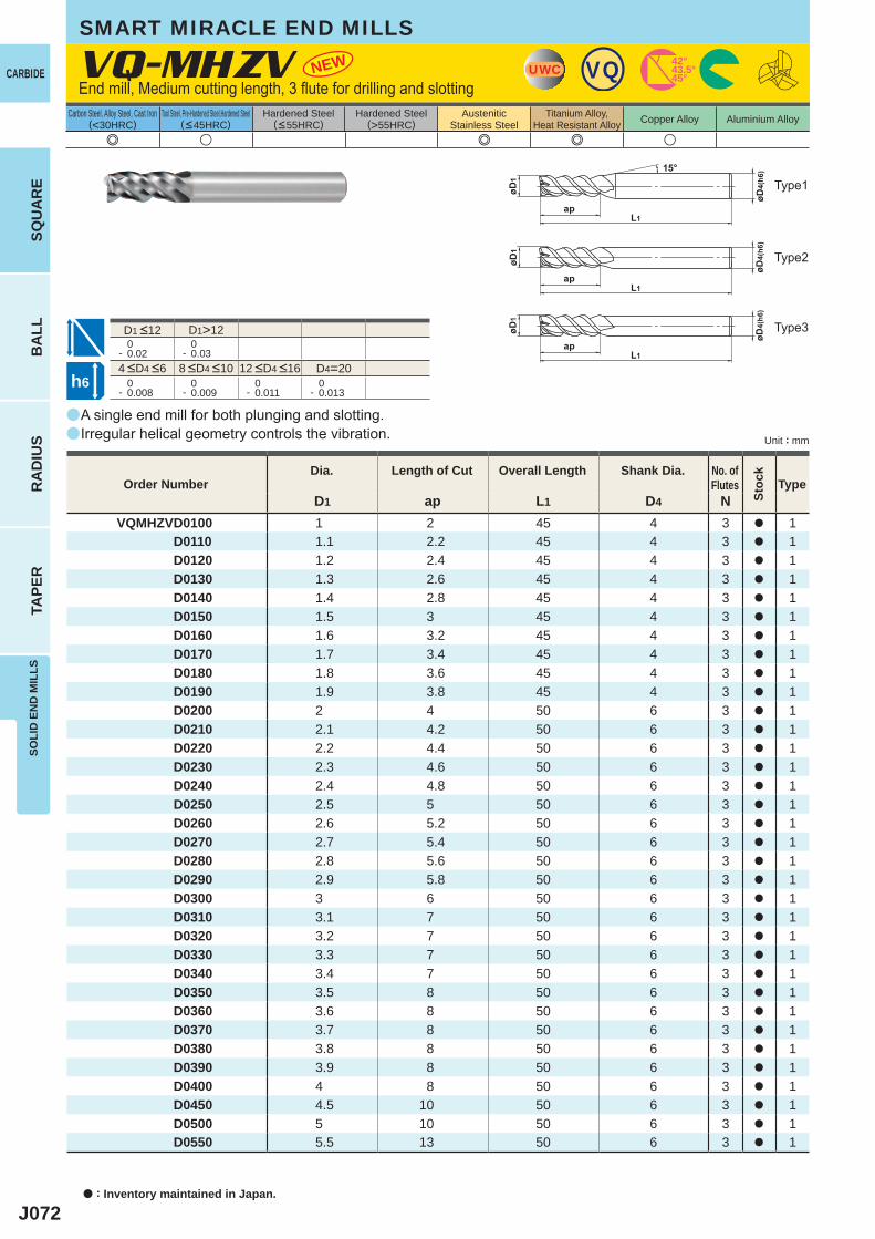
J072
a
a
VQ-MHZV NEW
e u e e u
D1 ap L1 D4 NVQMHZVD0100 1 2 45 4 3 a 1 D0110 1.1 2.2 45 4 3 a 1 D0120 1.2 2.4 45 4 3 a 1 D0130 1.3 2.6 45 4 3 a 1 D0140 1.4 2.8 45 4 3 a 1 D0150 1.5 3 45 4 3 a 1 D0160 1.6 3.2 45 4 3 a 1 D0170 1.7 3.4 45 4 3 a 1 D0180 1.8 3.6 45 4 3 a 1 D0190 1.9 3.8 45 4 3 a 1 D0200 2 4 50 6 3 a 1 D0210 2.1 4.2 50 6 3 a 1 D0220 2.2 4.4 50 6 3 a 1 D0230 2.3 4.6 50 6 3 a 1 D0240 2.4 4.8 50 6 3 a 1 D0250 2.5 5 50 6 3 a 1 D0260 2.6 5.2 50 6 3 a 1 D0270 2.7 5.4 50 6 3 a 1 D0280 2.8 5.6 50 6 3 a 1 D0290 2.9 5.8 50 6 3 a 1 D0300 3 6 50 6 3 a 1 D0310 3.1 7 50 6 3 a 1 D0320 3.2 7 50 6 3 a 1 D0330 3.3 7 50 6 3 a 1 D0340 3.4 7 50 6 3 a 1 D0350 3.5 8 50 6 3 a 1 D0360 3.6 8 50 6 3 a 1 D0370 3.7 8 50 6 3 a 1 D0380 3.8 8 50 6 3 a 1 D0390 3.9 8 50 6 3 a 1 D0400 4 8 50 6 3 a 1 D0450 4.5 10 50 6 3 a 1 D0500 5 10 50 6 3 a 1 D0550 5.5 13 50 6 3 a 1
D1>12 0- 0.02
0- 0.03
D4=20 0- 0.008
0- 0.009
0- 0.011
0- 0.013
UWC VQ 45°43.5°42°
h6
CARBIDE
a : Inventory maintained in Japan.
BA
LLR
AD
IUS
TAPE
RSO
LID
EN
D M
ILLS
SQU
AR
E
Unit : mm
Carbon Steel, Alloy Steel, Cast Iron(<30HRC)
Tool Steel, Pre-Hardened Steel,Hardened Steel(<45HRC)
Hardened Steel(<55HRC)
Hardened Steel(>55HRC)
AusteniticStainless Steel
Titanium Alloy,Heat Resistant Alloy Copper Alloy Aluminium Alloy
End mill, Medium cutting length, 3 flute for drilling and slotting
A single end mill for both plunging and slotting.Irregular helical geometry controls the vibration.
Type2
Type1
Type3
Order NumberDia. Length of Cut Overall Length Shank Dia. No. of
Flutes
Stoc
k
Type
SMART MIRACLE END MILLS
4 <D4 <6 8 <D4 <10 12 <D4 <16
D1 <12
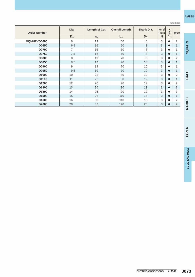
J073
D1 ap L1 D4 NVQMHZVD0600 6 13 60 6 3 a 2 D0650 6.5 16 60 8 3 a 1 D0700 7 16 60 8 3 a 1 D0750 7.5 16 60 8 3 a 1 D0800 8 19 70 8 3 a 2 D0850 8.5 19 70 10 3 a 1 D0900 9 19 70 10 3 a 1 D0950 9.5 19 70 10 3 a 1 D1000 10 22 80 10 3 a 2 D1100 11 22 80 12 3 a 1 D1200 12 26 90 12 3 a 2 D1300 13 26 90 12 3 a 3 D1400 14 26 90 12 3 a 3 D1500 15 26 110 16 3 a 1 D1600 16 30 110 16 3 a 2 D2000 20 32 140 20 3 a 2
CARBIDE
SQU
AR
EB
ALL
RA
DIU
STA
PER
SOLI
D E
ND
MIL
LS
Unit : mm
Order NumberDia. Length of Cut Overall Length Shank Dia. No. of
Flutes
Stoc
k
Type
CUTTING CONDITIONS J341
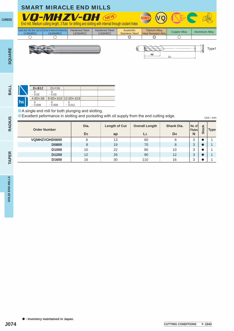
J074
a
a
u u e e u
D1 ap L1 D4 NVQMHZVOHD0600 6 13 60 6 3 a 1 D0800 8 19 70 8 3 a 1 D1000 10 22 80 10 3 a 1 D1200 12 26 90 12 3 a 1 D1600 16 30 110 16 3 a 1
VQ-MHZV-OH NEW
D1=16 0- 0.02
0- 0.03
0- 0.008
0- 0.009
0- 0.011
UWC VQ 45°43.5°42°
D1≦12
h6
CARBIDE
a : Inventory maintained in Japan.
BA
LLR
AD
IUS
TAPE
RSO
LID
EN
D M
ILLS
SQU
AR
E
Unit : mm
Carbon Steel, Alloy Steel, Cast Iron(<30HRC)
Tool Steel, Pre-Hardened Steel,Hardened Steel(<45HRC)
Hardened Steel(<55HRC)
Hardened Steel(>55HRC)
AusteniticStainless Steel
Titanium Alloy,Heat Resistant Alloy Copper Alloy Aluminium Alloy
End mill, Medium cutting length, 3 flute for drilling and slotting with internal through coolant holes
A single end mill for both plunging and slotting.Excellent peformance in slotting and pocketing with oil supply from the end cutting edge.
Type1
Order NumberDia. Length of Cut Overall Length Shank Dia. No. of
Flutes
Stoc
k
Type
4 <D4 <6 8 <D4 <10 12 <D4 <16
CUTTING CONDITIONS J343
SMART MIRACLE END MILLS
D1 <12
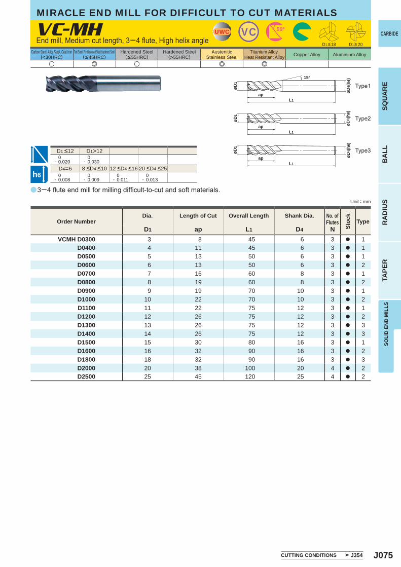
J075
a
u e u e e
VC-MH
D1 ap L1 D4 NVCMH D0300 3 8 45 6 3 a 1
D0400 4 11 45 6 3 a 1D0500 5 13 50 6 3 a 1D0600 6 13 50 6 3 a 2D0700 7 16 60 8 3 a 1D0800 8 19 60 8 3 a 2D0900 9 19 70 10 3 a 1D1000 10 22 70 10 3 a 2D1100 11 22 75 12 3 a 1D1200 12 26 75 12 3 a 2D1300 13 26 75 12 3 a 3D1400 14 26 75 12 3 a 3D1500 15 30 80 16 3 a 1D1600 16 32 90 16 3 a 2D1800 18 32 90 16 3 a 3D2000 20 38 100 20 4 a 2D2500 25 45 120 25 4 a 2
D1>12 0- 0.020
0- 0.030
D4=6 0- 0.008
0- 0.009
0- 0.011
0- 0.013
UWC VC 50°
L1ap øD
4(h6
)
øD1
15°
øD1
L1ap øD
4(h6
)
L1ap øD
4(h6
)
øD1
h6
CARBIDE
SQU
AR
EB
ALL
RA
DIU
STA
PER
SOLI
D E
ND
MIL
LS
Unit : mm
Carbon Steel, Alloy Steel, Cast Iron(<30HRC)
Tool Steel, Pre-Hardened Steel,Hardened Steel(<45HRC)
Hardened Steel(<55HRC)
Hardened Steel(>55HRC)
AusteniticStainless Steel
Titanium Alloy,Heat Resistant Alloy Copper Alloy Aluminium Alloy
End mill, Medium cut length, 3─4 flute, High helix angle
3─4 flute end mill for milling difficult-to-cut and soft materials.
Type2
Type3
Type1
Order NumberDia. Length of Cut Overall Length Shank Dia. No. of
Flutes
Stoc
k
Type
CUTTING CONDITIONS J354
D1<18 D1>20
8 <D4 <10 12 <D4 <16 20 <D4 <25
D1 <12
MIRACLE END MILL FOR DIFFICULT TO CUT MATERIALS
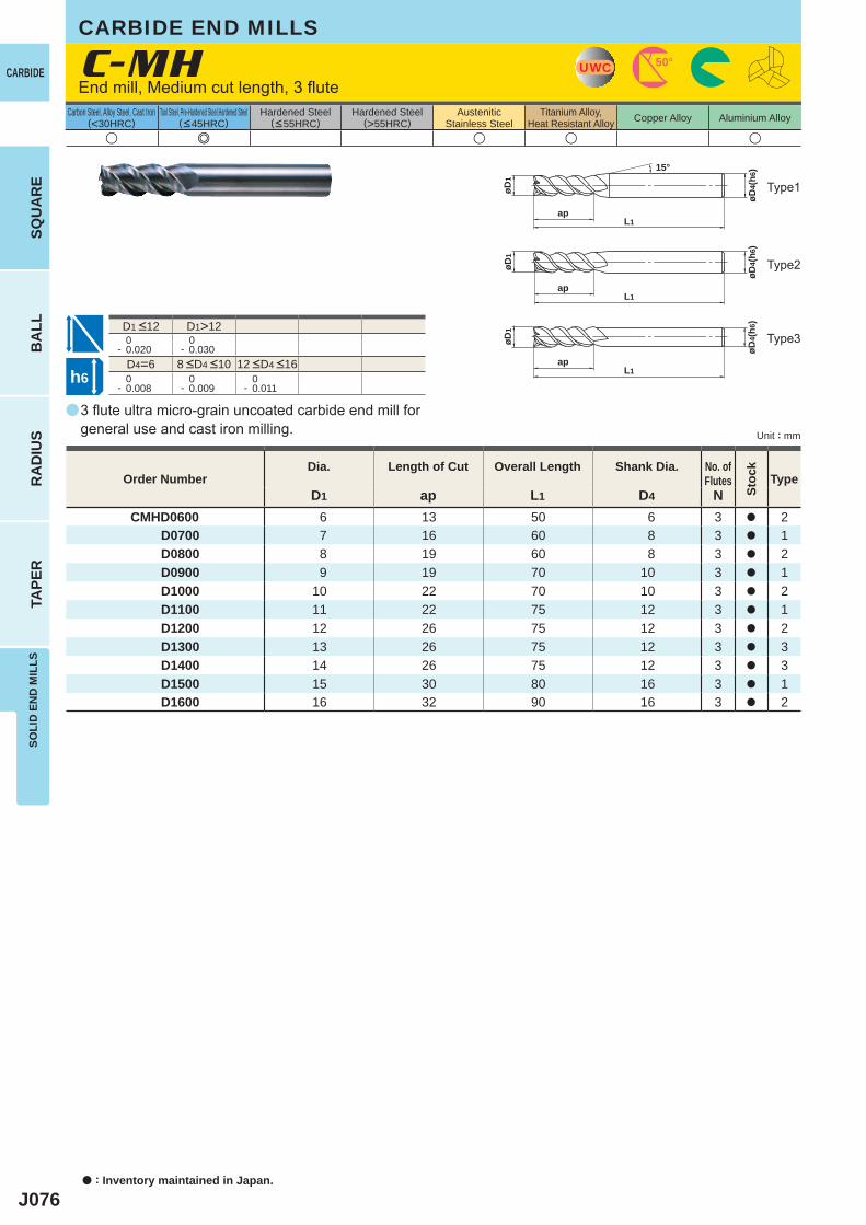
J076
a
u e u u u
C-MH
D1 ap L1 D4 NCMHD0600 6 13 50 6 3 a 2
D0700 7 16 60 8 3 a 1 D0800 8 19 60 8 3 a 2 D0900 9 19 70 10 3 a 1 D1000 10 22 70 10 3 a 2 D1100 11 22 75 12 3 a 1 D1200 12 26 75 12 3 a 2 D1300 13 26 75 12 3 a 3 D1400 14 26 75 12 3 a 3 D1500 15 30 80 16 3 a 1 D1600 16 32 90 16 3 a 2
D1>12 0- 0.020
0- 0.030
D4=6 0- 0.008
0- 0.009
0- 0.011
UWC 50°
L1ap
øD4(
h6)
øD1
15°
øD1
L1ap
øD4(
h6)
L1ap
øD4(
h6)
øD1
h6
CARBIDE
a : Inventory maintained in Japan.
BA
LLR
AD
IUS
TAPE
RSO
LID
EN
D M
ILLS
SQU
AR
E
Unit : mm
Carbon Steel, Alloy Steel, Cast Iron(<30HRC)
Tool Steel, Pre-Hardened Steel,Hardened Steel(<45HRC)
Hardened Steel(<55HRC)
Hardened Steel(>55HRC)
AusteniticStainless Steel
Titanium Alloy,Heat Resistant Alloy Copper Alloy Aluminium Alloy
3 flute ultra micro-grain uncoated carbide end mill for general use and cast iron milling.
End mill, Medium cut length, 3 flute
Type2
Type3
Type1
CARBIDE END MILLS
Order NumberDia. Length of Cut Overall Length Shank Dia. No. of
Flutes
Stoc
k
Type
8 <D4 <10 12 <D4 <16
D1 <12
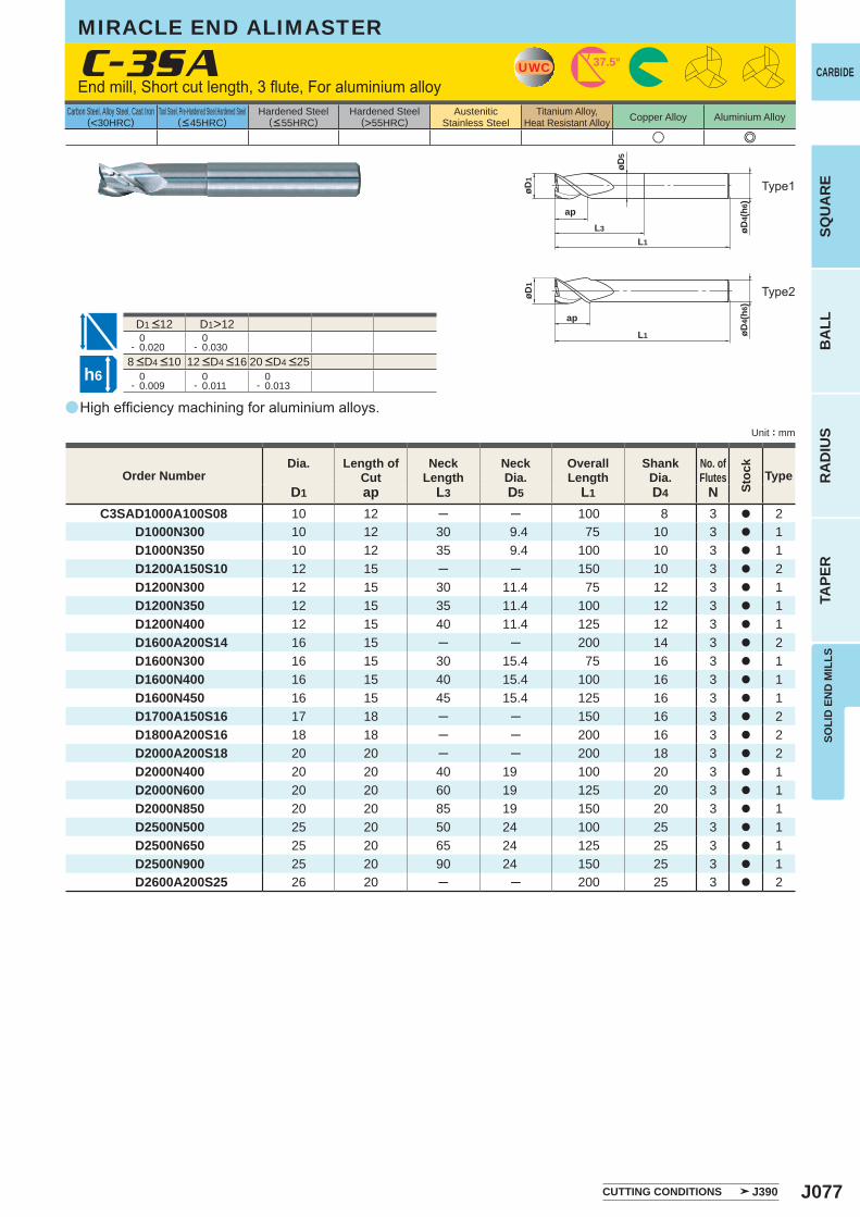
J077
a
u e
C-3SA
D1 ap L3 D5 L1 D4 NC3SAD1000A100S08 10 12 ─ ─ 100 8 3 a 2
D1000N300 10 12 30 9.4 75 10 3 a 1 D1000N350 10 12 35 9.4 100 10 3 a 1 D1200A150S10 12 15 ─ ─ 150 10 3 a 2 D1200N300 12 15 30 11.4 75 12 3 a 1 D1200N350 12 15 35 11.4 100 12 3 a 1 D1200N400 12 15 40 11.4 125 12 3 a 1 D1600A200S14 16 15 ─ ─ 200 14 3 a 2 D1600N300 16 15 30 15.4 75 16 3 a 1 D1600N400 16 15 40 15.4 100 16 3 a 1 D1600N450 16 15 45 15.4 125 16 3 a 1 D1700A150S16 17 18 ─ ─ 150 16 3 a 2 D1800A200S16 18 18 ─ ─ 200 16 3 a 2 D2000A200S18 20 20 ─ ─ 200 18 3 a 2 D2000N400 20 20 40 19 100 20 3 a 1 D2000N600 20 20 60 19 125 20 3 a 1 D2000N850 20 20 85 19 150 20 3 a 1 D2500N500 25 20 50 24 100 25 3 a 1 D2500N650 25 20 65 24 125 25 3 a 1 D2500N900 25 20 90 24 150 25 3 a 1 D2600A200S25 26 20 ─ ─ 200 25 3 a 2
D1>12 0- 0.020
0- 0.030
0- 0.009
0- 0.011
0- 0.013
UWC 37.5°
øD1
L1
øD4(
h6)
L3
ap
øD5
L1 øD4(
h6)
ap
øD1
h6
CARBIDE
SQU
AR
EB
ALL
RA
DIU
STA
PER
SOLI
D E
ND
MIL
LS
Unit : mm
Carbon Steel, Alloy Steel, Cast Iron(<30HRC)
Tool Steel, Pre-Hardened Steel,Hardened Steel(<45HRC)
Hardened Steel(<55HRC)
Hardened Steel(>55HRC)
AusteniticStainless Steel
Titanium Alloy,Heat Resistant Alloy Copper Alloy Aluminium Alloy
High efficiency machining for aluminium alloys.
End mill, Short cut length, 3 flute, For aluminium alloy
Type2
Type1
Order NumberDia. Length of
CutNeck
LengthNeckDia.
Overall Length
ShankDia.
No. ofFlutes
Stoc
k
Type
CUTTING CONDITIONS J390
8 <D4 <10 12 <D4 <16 20 <D4 <25
D1 <12
MIRACLE END ALIMASTER
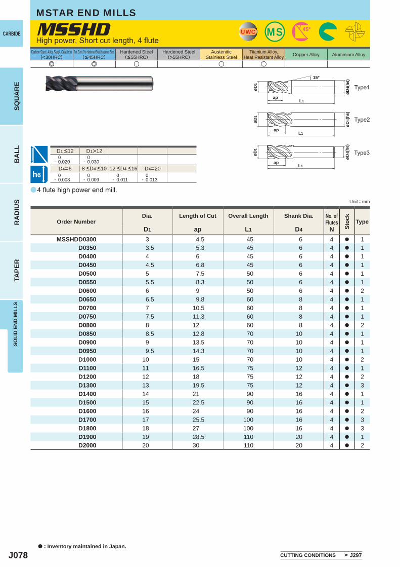
J078
a
e e u u u
MSSHD
D1 ap L1 D4 NMSSHDD0300 3 4.5 45 6 4 a 1
D0350 3.5 5.3 45 6 4 a 1D0400 4 6 45 6 4 a 1D0450 4.5 6.8 45 6 4 a 1D0500 5 7.5 50 6 4 a 1D0550 5.5 8.3 50 6 4 a 1D0600 6 9 50 6 4 a 2D0650 6.5 9.8 60 8 4 a 1D0700 7 10.5 60 8 4 a 1D0750 7.5 11.3 60 8 4 a 1D0800 8 12 60 8 4 a 2D0850 8.5 12.8 70 10 4 a 1D0900 9 13.5 70 10 4 a 1D0950 9.5 14.3 70 10 4 a 1D1000 10 15 70 10 4 a 2D1100 11 16.5 75 12 4 a 1D1200 12 18 75 12 4 a 2D1300 13 19.5 75 12 4 a 3D1400 14 21 90 16 4 a 1D1500 15 22.5 90 16 4 a 1D1600 16 24 90 16 4 a 2D1700 17 25.5 100 16 4 a 3D1800 18 27 100 16 4 a 3D1900 19 28.5 110 20 4 a 1D2000 20 30 110 20 4 a 2
D1>12 0- 0.020
0- 0.030
D4=6 D4=20 0- 0.008
0- 0.009
0- 0.011
0- 0.013
MSUWC 45°
15°
øD4(
h6)
L1ap
øD1
øD4(
h6)
øD1
apL1
øD4(
h6)
L1ap
øD1
h6
CARBIDE
a : Inventory maintained in Japan.
BA
LLR
AD
IUS
TAPE
RSO
LID
EN
D M
ILLS
SQU
AR
E
Unit : mm
Carbon Steel, Alloy Steel, Cast Iron(<30HRC)
Tool Steel, Pre-Hardened Steel,Hardened Steel(<45HRC)
Hardened Steel(<55HRC)
Hardened Steel(>55HRC)
AusteniticStainless Steel
Titanium Alloy,Heat Resistant Alloy Copper Alloy Aluminium Alloy
MSTAR END MILLS
4 flute high power end mill.
High power, Short cut length, 4 flute
Type2
Type1
Type3
Order NumberDia. Length of Cut Overall Length Shank Dia. No. of
Flutes
Stoc
k
Type
CUTTING CONDITIONS J297
8 <D4 <10 12 <D4 <16
D1 <12
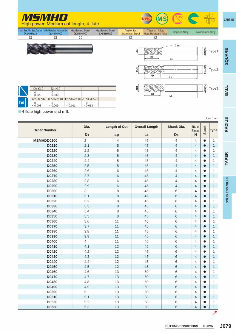
J079
a
e e u e e
MSMHD
D1 ap L1 D4 NMSMHDD0200 2 4 45 4 4 a 1
D0210 2.1 5 45 4 4 a 1D0220 2.2 5 45 4 4 a 1D0230 2.3 5 45 4 4 a 1D0240 2.4 5 45 4 4 a 1D0250 2.5 5 45 4 4 a 1D0260 2.6 6 45 4 4 a 1D0270 2.7 6 45 4 4 a 1D0280 2.8 6 45 4 4 a 1D0290 2.9 6 45 4 4 a 1D0300 3 8 45 6 4 a 1D0310 3.1 8 45 6 4 a 1D0320 3.2 8 45 6 4 a 1D0330 3.3 8 45 6 4 a 1D0340 3.4 8 45 6 4 a 1D0350 3.5 8 45 6 4 a 1D0360 3.6 11 45 6 4 a 1D0370 3.7 11 45 6 4 a 1D0380 3.8 11 45 6 4 a 1D0390 3.9 11 45 6 4 a 1D0400 4 11 45 6 4 a 1D0410 4.1 12 45 6 4 a 1D0420 4.2 12 45 6 4 a 1D0430 4.3 12 45 6 4 a 1D0440 4.4 12 45 6 4 a 1D0450 4.5 12 45 6 4 a 1D0460 4.6 13 50 6 4 a 1D0470 4.7 13 50 6 4 a 1D0480 4.8 13 50 6 4 a 1D0490 4.9 13 50 6 4 a 1D0500 5 13 50 6 4 a 1D0510 5.1 13 50 6 4 a 1D0520 5.2 13 50 6 4 a 1D0530 5.3 13 50 6 4 a 1
D1>12 0- 0.020
0- 0.030
0- 0.008
0- 0.009
0- 0.011
0- 0.013
øD4(
h6)
L1ap
øD1
15°
MSUWC 45°
øD4(
h6)
øD1
apL1
øD4(
h6)
L1ap
øD1
h6
CARBIDE
SQU
AR
EB
ALL
RA
DIU
STA
PER
SOLI
D E
ND
MIL
LS
Unit : mm
Carbon Steel, Alloy Steel, Cast Iron(<30HRC)
Tool Steel, Pre-Hardened Steel,Hardened Steel(<45HRC)
Hardened Steel(<55HRC)
Hardened Steel(>55HRC)
AusteniticStainless Steel
Titanium Alloy,Heat Resistant Alloy Copper Alloy Aluminium Alloy
4 flute high power end mill.
High power, Medium cut length, 4 flute
Type1
Type2
Type3
Order NumberDia. Length of Cut Overall Length Shank Dia. No. of
Flutes
Stoc
k
Type
4 <D4 <6 8 <D4 <10 12 <D4 <16 20 <D4 <25
D1 <12
CUTTING CONDITIONS J297
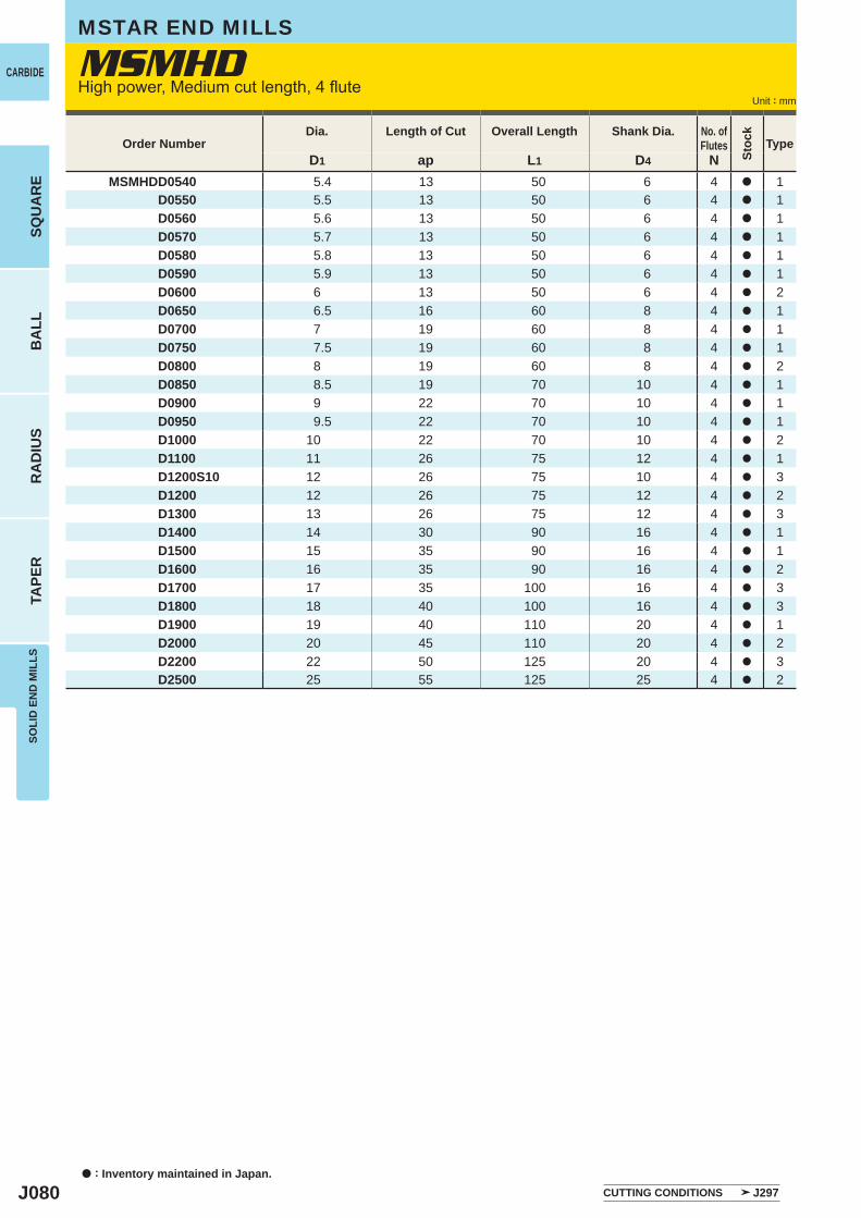
J080
D1 ap L1 D4 NMSMHDD0540 5.4 13 50 6 4 a 1 D0550 5.5 13 50 6 4 a 1 D0560 5.6 13 50 6 4 a 1 D0570 5.7 13 50 6 4 a 1 D0580 5.8 13 50 6 4 a 1 D0590 5.9 13 50 6 4 a 1 D0600 6 13 50 6 4 a 2 D0650 6.5 16 60 8 4 a 1 D0700 7 19 60 8 4 a 1 D0750 7.5 19 60 8 4 a 1 D0800 8 19 60 8 4 a 2 D0850 8.5 19 70 10 4 a 1 D0900 9 22 70 10 4 a 1 D0950 9.5 22 70 10 4 a 1 D1000 10 22 70 10 4 a 2 D1100 11 26 75 12 4 a 1 D1200S10 12 26 75 10 4 a 3 D1200 12 26 75 12 4 a 2 D1300 13 26 75 12 4 a 3 D1400 14 30 90 16 4 a 1 D1500 15 35 90 16 4 a 1 D1600 16 35 90 16 4 a 2 D1700 17 35 100 16 4 a 3 D1800 18 40 100 16 4 a 3 D1900 19 40 110 20 4 a 1 D2000 20 45 110 20 4 a 2 D2200 22 50 125 20 4 a 3 D2500 25 55 125 25 4 a 2
MSMHDCARBIDE
a : Inventory maintained in Japan.
BA
LLR
AD
IUS
TAPE
RSO
LID
EN
D M
ILLS
SQU
AR
E
Unit : mm
Order NumberDia. Length of Cut Overall Length Shank Dia. No. of
Flutes
Stoc
k
Type
CUTTING CONDITIONS J297
MSTAR END MILLS
High power, Medium cut length, 4 flute
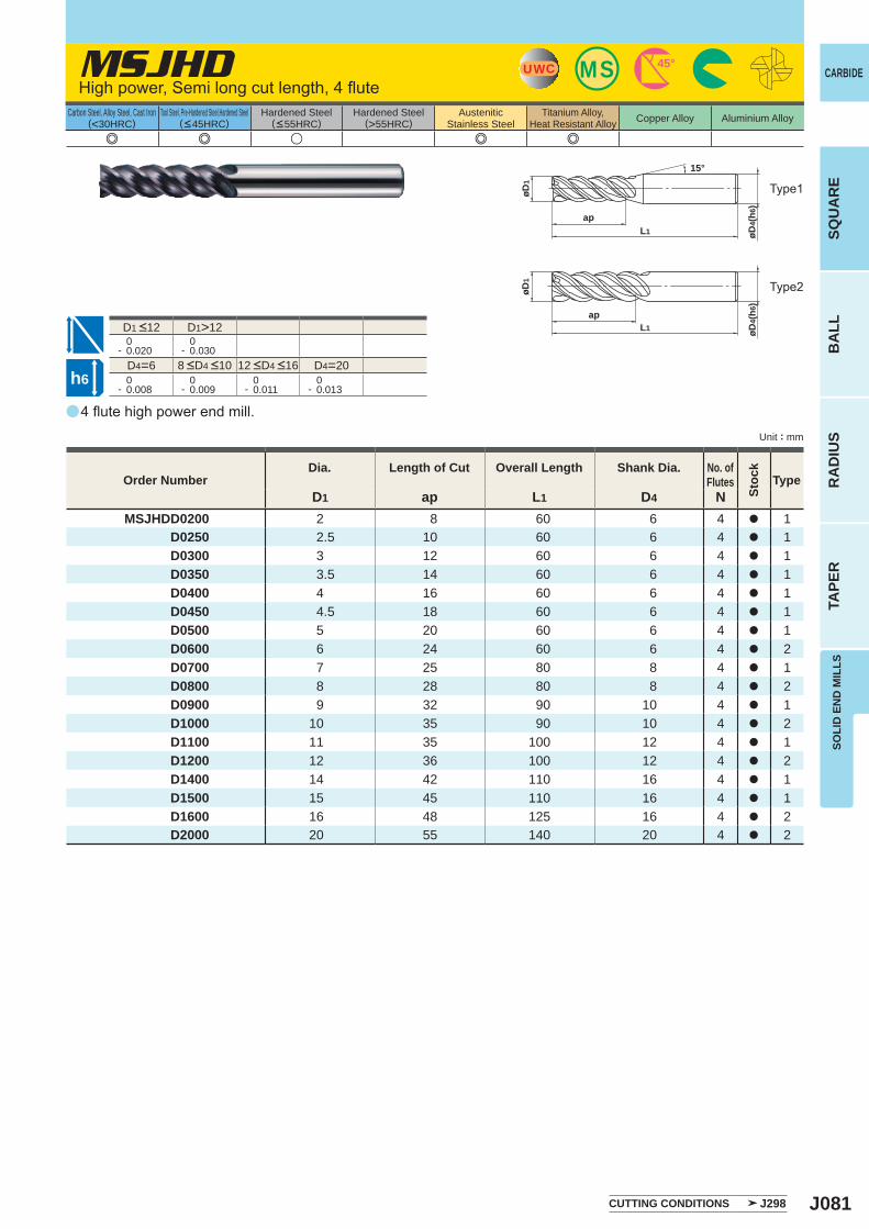
J081
a
e e u e e
MSJHD
D1 ap L1 D4 NMSJHDD0200 2 8 60 6 4 a 1
D0250 2.5 10 60 6 4 a 1D0300 3 12 60 6 4 a 1D0350 3.5 14 60 6 4 a 1D0400 4 16 60 6 4 a 1D0450 4.5 18 60 6 4 a 1D0500 5 20 60 6 4 a 1D0600 6 24 60 6 4 a 2D0700 7 25 80 8 4 a 1D0800 8 28 80 8 4 a 2D0900 9 32 90 10 4 a 1D1000 10 35 90 10 4 a 2D1100 11 35 100 12 4 a 1D1200 12 36 100 12 4 a 2D1400 14 42 110 16 4 a 1D1500 15 45 110 16 4 a 1D1600 16 48 125 16 4 a 2D2000 20 55 140 20 4 a 2
D1>12 0- 0.020
0- 0.030
D4=6 D4=20 0- 0.008
0- 0.009
0- 0.011
0- 0.013
MSUWC 45°
15°
øD4(
h6)
L1
ap
øD1
øD4(
h6)
L1ap
øD1
h6
CARBIDE
SQU
AR
EB
ALL
RA
DIU
STA
PER
SOLI
D E
ND
MIL
LS
Unit : mm
Carbon Steel, Alloy Steel, Cast Iron(<30HRC)
Tool Steel, Pre-Hardened Steel,Hardened Steel(<45HRC)
Hardened Steel(<55HRC)
Hardened Steel(>55HRC)
AusteniticStainless Steel
Titanium Alloy,Heat Resistant Alloy Copper Alloy Aluminium Alloy
4 flute high power end mill.
High power, Semi long cut length, 4 flute
Type2
Type1
Order NumberDia. Length of Cut Overall Length Shank Dia. No. of
Flutes
Stoc
k
Type
CUTTING CONDITIONS J298
8 <D4 <10 12 <D4 <16
D1 <12
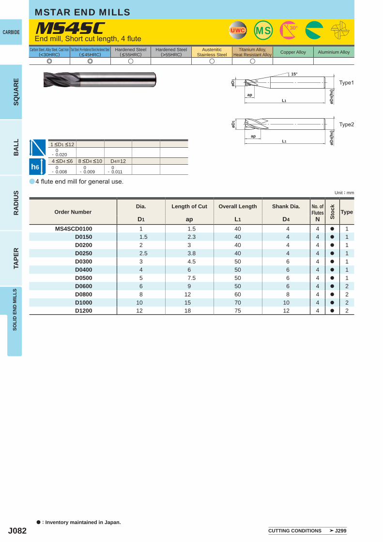
J082
a
e e u u u
MS4SC
D1 ap L1 D4 NMS4SCD0100 1 1.5 40 4 4 a 1
D0150 1.5 2.3 40 4 4 a 1D0200 2 3 40 4 4 a 1D0250 2.5 3.8 40 4 4 a 1D0300 3 4.5 50 6 4 a 1D0400 4 6 50 6 4 a 1D0500 5 7.5 50 6 4 a 1D0600 6 9 50 6 4 a 2D0800 8 12 60 8 4 a 2D1000 10 15 70 10 4 a 2D1200 12 18 75 12 4 a 2
0- 0.020
D4=12 0- 0.008
0- 0.009
0- 0.011
øD4(
h6)
apL1
øD1
15°
UWC MS 30°
øD1
øD4(
h6)
apL1
h6
CARBIDE
a : Inventory maintained in Japan.
BA
LLR
AD
IUS
TAPE
RSO
LID
EN
D M
ILLS
SQU
AR
E
Unit : mm
Carbon Steel, Alloy Steel, Cast Iron(<30HRC)
Tool Steel, Pre-Hardened Steel,Hardened Steel(<45HRC)
Hardened Steel(<55HRC)
Hardened Steel(>55HRC)
AusteniticStainless Steel
Titanium Alloy,Heat Resistant Alloy Copper Alloy Aluminium Alloy
4 flute end mill for general use.
End mill, Short cut length, 4 flute
Type2
Type1
Order NumberDia. Length of Cut Overall Length Shank Dia. No. of
Flutes
Stoc
k
Type
CUTTING CONDITIONS J299
4 <D4 <6 8 <D4 <10
1 <D1 <12
MSTAR END MILLS
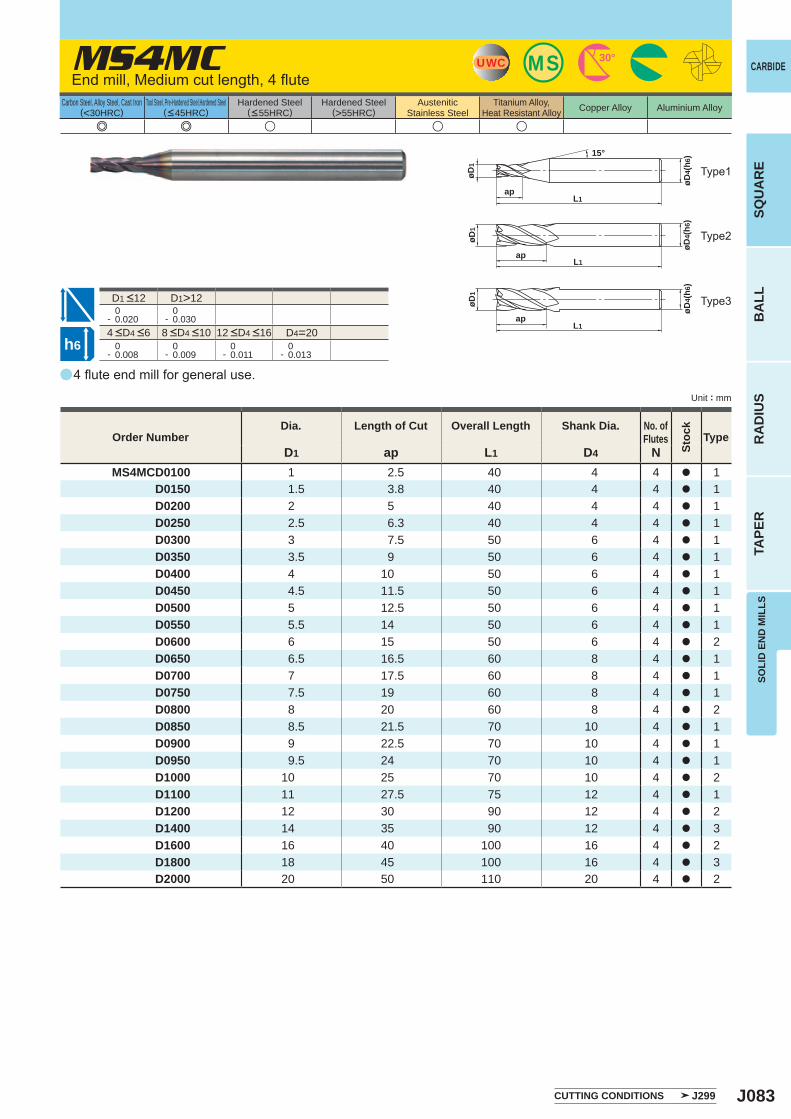
J083
aa
e e u u u
MS4MC
D1 ap L1 D4 NMS4MCD0100 1 2.5 40 4 4 a 1
D0150 1.5 3.8 40 4 4 a 1D0200 2 5 40 4 4 a 1D0250 2.5 6.3 40 4 4 a 1D0300 3 7.5 50 6 4 a 1D0350 3.5 9 50 6 4 a 1D0400 4 10 50 6 4 a 1D0450 4.5 11.5 50 6 4 a 1D0500 5 12.5 50 6 4 a 1D0550 5.5 14 50 6 4 a 1D0600 6 15 50 6 4 a 2D0650 6.5 16.5 60 8 4 a 1D0700 7 17.5 60 8 4 a 1D0750 7.5 19 60 8 4 a 1D0800 8 20 60 8 4 a 2D0850 8.5 21.5 70 10 4 a 1D0900 9 22.5 70 10 4 a 1D0950 9.5 24 70 10 4 a 1D1000 10 25 70 10 4 a 2D1100 11 27.5 75 12 4 a 1D1200 12 30 90 12 4 a 2D1400 14 35 90 12 4 a 3D1600 16 40 100 16 4 a 2D1800 18 45 100 16 4 a 3D2000 20 50 110 20 4 a 2
D1>12 0- 0.020
0- 0.030
D4=20 0- 0.008
0- 0.009
0- 0.011
0- 0.013
øD4(
h 6)
apL1
øD1
15°
UWC MS 30°
øD4(
h6)
øD1
apL1
øD1
øD4(
h6)
apL1
h6
CARBIDE
SQU
AR
EB
ALL
RA
DIU
STA
PER
SOLI
D E
ND
MIL
LS
Unit : mm
Carbon Steel, Alloy Steel, Cast Iron(<30HRC)
Tool Steel, Pre-Hardened Steel,Hardened Steel(<45HRC)
Hardened Steel(<55HRC)
Hardened Steel(>55HRC)
AusteniticStainless Steel
Titanium Alloy,Heat Resistant Alloy Copper Alloy Aluminium Alloy
4 flute end mill for general use.
End mill, Medium cut length, 4 flute
Type2
Type1
Type3
Order NumberDia. Length of Cut Overall Length Shank Dia. No. of
Flutes
Stoc
k
Type
CUTTING CONDITIONS J299
4 <D4 <6 8 <D4 <10 12 <D4 <16
D1 <12
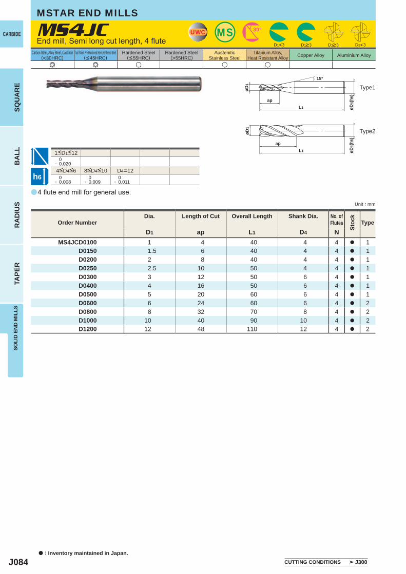
J084
a
e e u u u
MS4JC
D1 ap L1 D4 NMS4JCD0100 1 4 40 4 4 a 1
D0150 1.5 6 40 4 4 a 1D0200 2 8 40 4 4 a 1D0250 2.5 10 50 4 4 a 1D0300 3 12 50 6 4 a 1D0400 4 16 50 6 4 a 1D0500 5 20 60 6 4 a 1D0600 6 24 60 6 4 a 2D0800 8 32 70 8 4 a 2D1000 10 40 90 10 4 a 2D1200 12 48 110 12 4 a 2
D1<3 D1<3
0- 0.020
D4=12 0- 0.008
0- 0.009
0- 0.011
øD4(
h6)
apL1
øD1
15°
UWC MS 30°
øD1
øD4(
h6)
apL1
h6
CARBIDE
SQU
AR
EB
ALL
RA
DIU
STA
PER
SOLI
D E
ND
MIL
LS
a : Inventory maintained in Japan.
Carbon Steel, Alloy Steel, Cast Iron(<30HRC)
Tool Steel, Pre-Hardened Steel,Hardened Steel(<45HRC)
Hardened Steel(<55HRC)
Hardened Steel(>55HRC)
AusteniticStainless Steel
Titanium Alloy,Heat Resistant Alloy Copper Alloy Aluminium Alloy
Unit : mm
MSTAR END MILLS
D1>3 D1>3
Type1
Type2
4<D4<6 8<D4<10
1<D1<12
4 flute end mill for general use.
Order NumberDia. Length of Cut Overall Length Shank Dia. No. of
Flutes
Stoc
k
Type
CUTTING CONDITIONS J300
End mill, Semi long cut length, 4 flute

J085
a
e e u u u
MS4XL
D1 ap L3 D5 L1 D4 NMS4XLD0100N040 1 1 4 0.94 50 4 4 a 1
D0100N060 1 1 6 0.94 50 4 4 a 1D0100N080 1 1 8 0.94 50 4 4 a 1D0100N100 1 1 10 0.94 50 4 4 a 1D0100N120 1 1 12 0.94 50 4 4 a 1D0100N160 1 1 16 0.94 60 4 4 a 1D0110N060 1.1 1.1 6 1.04 50 4 4 a 1D0110N100 1.1 1.1 10 1.04 50 4 4 a 1D0110N160 1.1 1.1 16 1.04 60 4 4 a 1D0120N060 1.2 1.2 6 1.14 50 4 4 a 1D0120N080 1.2 1.2 8 1.14 50 4 4 a 1D0120N100 1.2 1.2 10 1.14 50 4 4 a 1D0120N120 1.2 1.2 12 1.14 50 4 4 a 1D0120N160 1.2 1.2 16 1.14 60 4 4 a 1D0130N060 1.3 1.3 6 1.24 50 4 4 a 1D0130N120 1.3 1.3 12 1.24 50 4 4 a 1D0130N180 1.3 1.3 18 1.24 60 4 4 a 1D0140N060 1.4 1.4 6 1.34 50 4 4 a 1D0140N080 1.4 1.4 8 1.34 50 4 4 a 1D0140N100 1.4 1.4 10 1.34 50 4 4 a 1D0140N120 1.4 1.4 12 1.34 50 4 4 a 1D0140N140 1.4 1.4 14 1.34 60 4 4 a 1D0140N160 1.4 1.4 16 1.34 60 4 4 a 1D0140N220 1.4 1.4 22 1.34 60 4 4 a 1D0150N060 1.5 1.5 6 1.44 50 4 4 a 1D0150N080 1.5 1.5 8 1.44 50 4 4 a 1D0150N100 1.5 1.5 10 1.44 50 4 4 a 1D0150N120 1.5 1.5 12 1.44 50 4 4 a 1D0150N140 1.5 1.5 14 1.44 60 4 4 a 1D0150N160 1.5 1.5 16 1.44 60 4 4 a 1D0150N180 1.5 1.5 18 1.44 60 4 4 a 1D0150N200 1.5 1.5 20 1.44 60 4 4 a 1D0160N060 1.6 1.6 6 1.54 50 4 4 a 1D0160N080 1.6 1.6 8 1.54 50 4 4 a 1
0- 0.020
0- 0.008
0- 0.009
UWC MS 30°
øD4(
h6)
L1L3
øD5
ap
øD1
15°
øD5
øD4(
h6)
L1L3
ap
øD1
h6
SOLI
D E
ND
MIL
LSSQ
UA
RE
BA
LLR
AD
IUS
TAPE
R
CARBIDE
Carbon Steel, Alloy Steel, Cast Iron(<30HRC)
Tool Steel, Pre-Hardened Steel,Hardened Steel(<45HRC)
Hardened Steel(<55HRC)
Hardened Steel(>55HRC)
AusteniticStainless Steel
Titanium Alloy,Heat Resistant Alloy Copper Alloy Aluminium Alloy
Unit : mm
End mill, Short cut length, 4 flute, Long neck
Type2
Type1
4<D4<6 8<D4<10
4 flute long neck end mill.
Order NumberDia. Length of
CutNeck
LengthNeckDia.
Overall Length
ShankDia.
No. ofFlutes
Stoc
k
Type
CUTTING CONDITIONS J301
1<D1<10
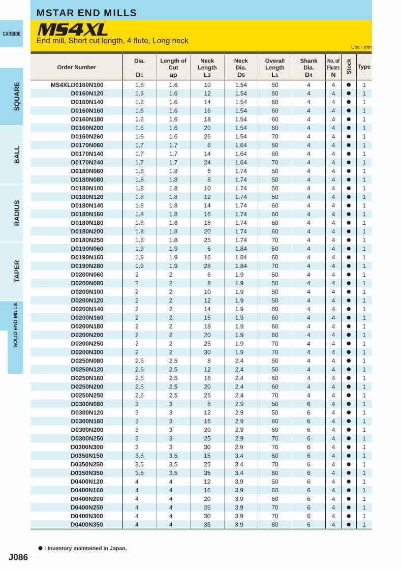
J086
D1 ap L3 D5 L1 D4 NMS4XLD0160N100 1.6 1.6 10 1.54 50 4 4 a 1
D0160N120 1.6 1.6 12 1.54 50 4 4 a 1D0160N140 1.6 1.6 14 1.54 60 4 4 a 1D0160N160 1.6 1.6 16 1.54 60 4 4 a 1D0160N180 1.6 1.6 18 1.54 60 4 4 a 1D0160N200 1.6 1.6 20 1.54 60 4 4 a 1D0160N260 1.6 1.6 26 1.54 70 4 4 a 1D0170N060 1.7 1.7 6 1.64 50 4 4 a 1D0170N140 1.7 1.7 14 1.64 60 4 4 a 1D0170N240 1.7 1.7 24 1.64 70 4 4 a 1D0180N060 1.8 1.8 6 1.74 50 4 4 a 1D0180N080 1.8 1.8 8 1.74 50 4 4 a 1D0180N100 1.8 1.8 10 1.74 50 4 4 a 1D0180N120 1.8 1.8 12 1.74 50 4 4 a 1D0180N140 1.8 1.8 14 1.74 60 4 4 a 1D0180N160 1.8 1.8 16 1.74 60 4 4 a 1D0180N180 1.8 1.8 18 1.74 60 4 4 a 1D0180N200 1.8 1.8 20 1.74 60 4 4 a 1D0180N250 1.8 1.8 25 1.74 70 4 4 a 1D0190N060 1.9 1.9 6 1.84 50 4 4 a 1D0190N160 1.9 1.9 16 1.84 60 4 4 a 1D0190N280 1.9 1.9 28 1.84 70 4 4 a 1D0200N060 2 2 6 1.9 50 4 4 a 1D0200N080 2 2 8 1.9 50 4 4 a 1D0200N100 2 2 10 1.9 50 4 4 a 1D0200N120 2 2 12 1.9 50 4 4 a 1D0200N140 2 2 14 1.9 60 4 4 a 1D0200N160 2 2 16 1.9 60 4 4 a 1D0200N180 2 2 18 1.9 60 4 4 a 1D0200N200 2 2 20 1.9 60 4 4 a 1D0200N250 2 2 25 1.9 70 4 4 a 1D0200N300 2 2 30 1.9 70 4 4 a 1D0250N080 2.5 2.5 8 2.4 50 4 4 a 1D0250N120 2.5 2.5 12 2.4 50 4 4 a 1D0250N160 2.5 2.5 16 2.4 60 4 4 a 1D0250N200 2.5 2.5 20 2.4 60 4 4 a 1D0250N250 2.5 2.5 25 2.4 70 4 4 a 1D0300N080 3 3 8 2.9 50 6 4 a 1D0300N120 3 3 12 2.9 50 6 4 a 1D0300N160 3 3 16 2.9 60 6 4 a 1D0300N200 3 3 20 2.9 60 6 4 a 1D0300N250 3 3 25 2.9 70 6 4 a 1D0300N300 3 3 30 2.9 70 6 4 a 1D0350N150 3.5 3.5 15 3.4 60 6 4 a 1D0350N250 3.5 3.5 25 3.4 70 6 4 a 1D0350N350 3.5 3.5 35 3.4 80 6 4 a 1D0400N120 4 4 12 3.9 50 6 4 a 1D0400N160 4 4 16 3.9 60 6 4 a 1D0400N200 4 4 20 3.9 60 6 4 a 1D0400N250 4 4 25 3.9 70 6 4 a 1D0400N300 4 4 30 3.9 70 6 4 a 1D0400N350 4 4 35 3.9 80 6 4 a 1
MS4XLCARBIDE
SQU
AR
EB
ALL
RA
DIU
STA
PER
SOLI
D E
ND
MIL
LS
a : Inventory maintained in Japan.
Unit : mm
Order NumberDia. Length of
CutNeck
LengthNeckDia.
Overall Length
ShankDia.
No. ofFlutes
Stoc
k
Type
MSTAR END MILLS
End mill, Short cut length, 4 flute, Long neck
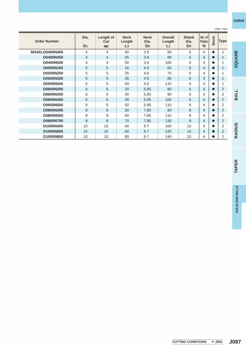
J087
D1 ap L3 D5 L1 D4 NMS4XLD0400N400 4 4 40 3.9 90 6 4 a 1
D0400N450 4 4 45 3.9 90 6 4 a 1D0400N500 4 4 50 3.9 100 6 4 a 1D0500N160 5 5 16 4.9 60 6 4 a 1D0500N250 5 5 25 4.9 70 6 4 a 1D0500N350 5 5 35 4.9 80 6 4 a 1D0500N500 5 5 50 4.9 110 6 4 a 1D0600N200 6 6 20 5.85 80 6 4 a 2D0600N300 6 6 30 5.85 90 6 4 a 2D0600N400 6 6 40 5.85 100 6 4 a 2D0600N500 6 6 50 5.85 110 6 4 a 2D0800N300 8 8 30 7.85 90 8 4 a 2D0800N500 8 8 50 7.85 110 8 4 a 2D0800N700 8 8 70 7.85 130 8 4 a 2D1000N400 10 10 40 9.7 100 10 4 a 2D1000N600 10 10 60 9.7 120 10 4 a 2D1000N800 10 10 80 9.7 140 10 4 a 2
SOLI
D E
ND
MIL
LSSQ
UA
RE
BA
LLR
AD
IUS
TAPE
R
CARBIDE
Unit : mm
Order NumberDia. Length of
CutNeck
LengthNeckDia.
Overall Length
ShankDia.
No. ofFlutes
Stoc
k
Type
CUTTING CONDITIONS J301
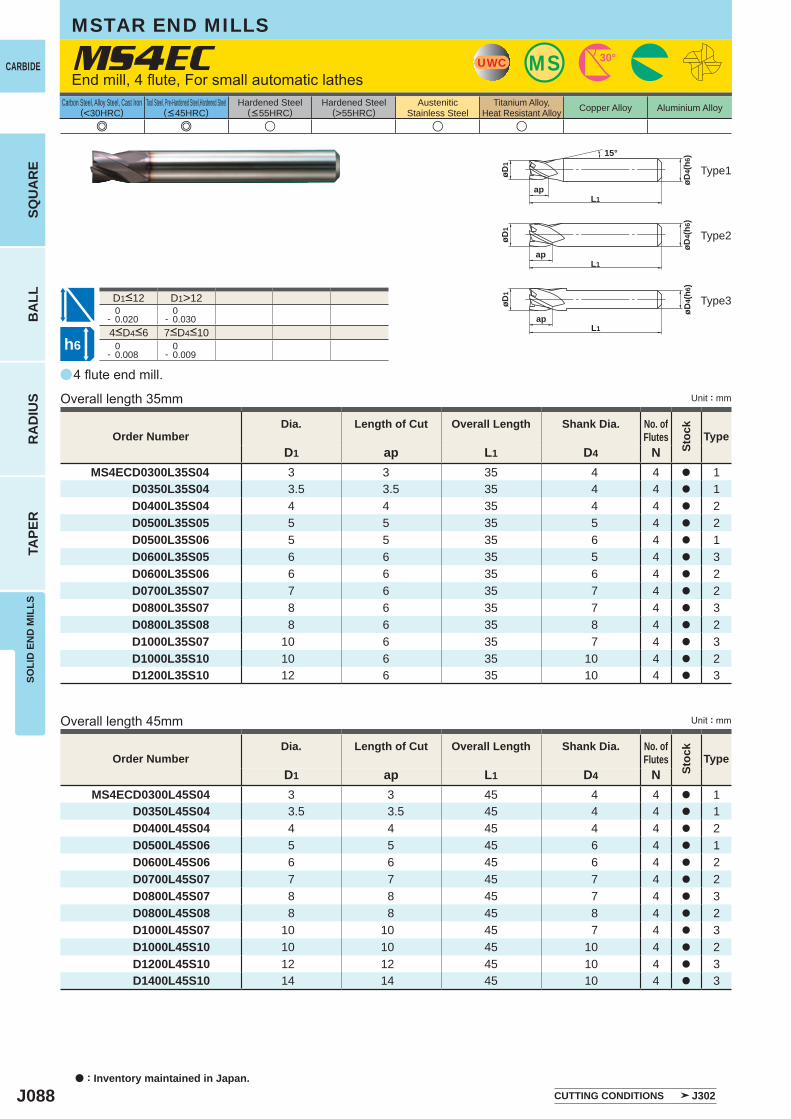
J088
a
e e u u u
MS4EC
D1 ap L1 D4 NMS4ECD0300L45S04 3 3 45 4 4 a 1
D0350L45S04 3.5 3.5 45 4 4 a 1D0400L45S04 4 4 45 4 4 a 2D0500L45S06 5 5 45 6 4 a 1D0600L45S06 6 6 45 6 4 a 2D0700L45S07 7 7 45 7 4 a 2D0800L45S07 8 8 45 7 4 a 3D0800L45S08 8 8 45 8 4 a 2D1000L45S07 10 10 45 7 4 a 3D1000L45S10 10 10 45 10 4 a 2D1200L45S10 12 12 45 10 4 a 3D1400L45S10 14 14 45 10 4 a 3
D1 ap L1 D4 NMS4ECD0300L35S04 3 3 35 4 4 a 1
D0350L35S04 3.5 3.5 35 4 4 a 1D0400L35S04 4 4 35 4 4 a 2D0500L35S05 5 5 35 5 4 a 2D0500L35S06 5 5 35 6 4 a 1D0600L35S05 6 6 35 5 4 a 3D0600L35S06 6 6 35 6 4 a 2D0700L35S07 7 6 35 7 4 a 2D0800L35S07 8 6 35 7 4 a 3D0800L35S08 8 6 35 8 4 a 2D1000L35S07 10 6 35 7 4 a 3D1000L35S10 10 6 35 10 4 a 2D1200L35S10 12 6 35 10 4 a 3
D1>12 0- 0.020
0- 0.030
0- 0.008
0- 0.009
UWC MS 30°
øD1
øD4(
h6)
apL1
15°
ap
øD1
øD4(
h6)
L1
øD4(
h6)
øD1
apL1
h6
CARBIDE
SQU
AR
EB
ALL
RA
DIU
STA
PER
SOLI
D E
ND
MIL
LS
a : Inventory maintained in Japan.
Carbon Steel, Alloy Steel, Cast Iron(<30HRC)
Tool Steel, Pre-Hardened Steel,Hardened Steel(<45HRC)
Hardened Steel(<55HRC)
Hardened Steel(>55HRC)
AusteniticStainless Steel
Titanium Alloy,Heat Resistant Alloy Copper Alloy Aluminium Alloy
Unit : mm
MSTAR END MILLS
End mill, 4 flute, For small automatic lathes
Type1
Type2
Type3
4 flute end mill.
Overall length 35mm
4<D4<6 7<D4<10
D1<12
Order NumberDia. Length of Cut Overall Length Shank Dia. No. of
Flutes
Stoc
k
Type
Order NumberDia. Length of Cut Overall Length Shank Dia. No. of
Flutes
Stoc
k
Type
CUTTING CONDITIONS J302
Overall length 45mm Unit : mm
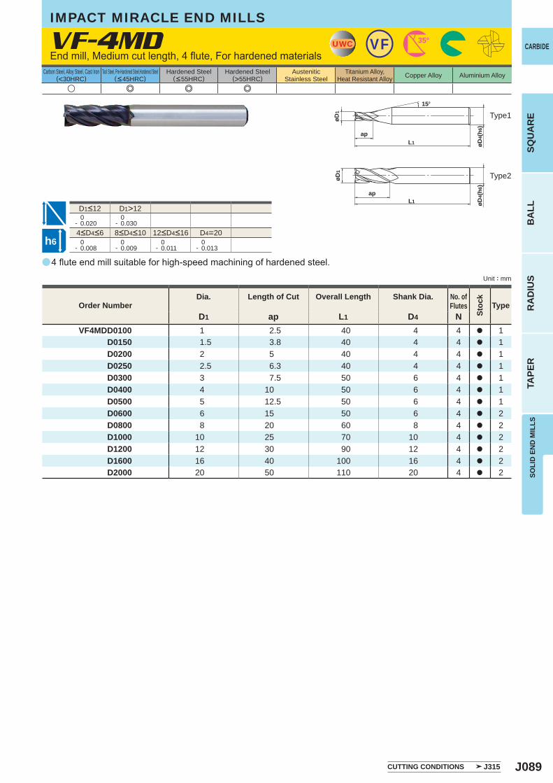
J089
a
VF-4MD
u e e e
D1 ap L1 D4 NVF4MDD0100 1 2.5 40 4 4 a 1
D0150 1.5 3.8 40 4 4 a 1 D0200 2 5 40 4 4 a 1 D0250 2.5 6.3 40 4 4 a 1 D0300 3 7.5 50 6 4 a 1 D0400 4 10 50 6 4 a 1 D0500 5 12.5 50 6 4 a 1 D0600 6 15 50 6 4 a 2 D0800 8 20 60 8 4 a 2 D1000 10 25 70 10 4 a 2 D1200 12 30 90 12 4 a 2 D1600 16 40 100 16 4 a 2 D2000 20 50 110 20 4 a 2
D1>12 0- 0.020
0- 0.030
D4=20 0- 0.008
0- 0.009
0- 0.011
0- 0.013
UWC 35°VF
øD4(
h6)
apL1
øD1
15°
øD1
øD4(
h6)
apL1
h6
SOLI
D E
ND
MIL
LSSQ
UA
RE
BA
LLR
AD
IUS
TAPE
R
CARBIDE
Carbon Steel, Alloy Steel, Cast Iron(<30HRC)
Tool Steel, Pre-Hardened Steel,Hardened Steel(<45HRC)
Hardened Steel(<55HRC)
Hardened Steel(>55HRC)
AusteniticStainless Steel
Titanium Alloy,Heat Resistant Alloy Copper Alloy Aluminium Alloy
Unit : mm
Type1
Type2
Order NumberDia. Length of Cut Overall Length Shank Dia. No. of
Flutes
Stoc
k
Type
IMPACT MIRACLE END MILLS
End mill, Medium cut length, 4 flute, For hardened materials
4<D4<6 8<D4<10 12<D4<16
D1<12
4 flute end mill suitable for high-speed machining of hardened steel.
CUTTING CONDITIONS J315
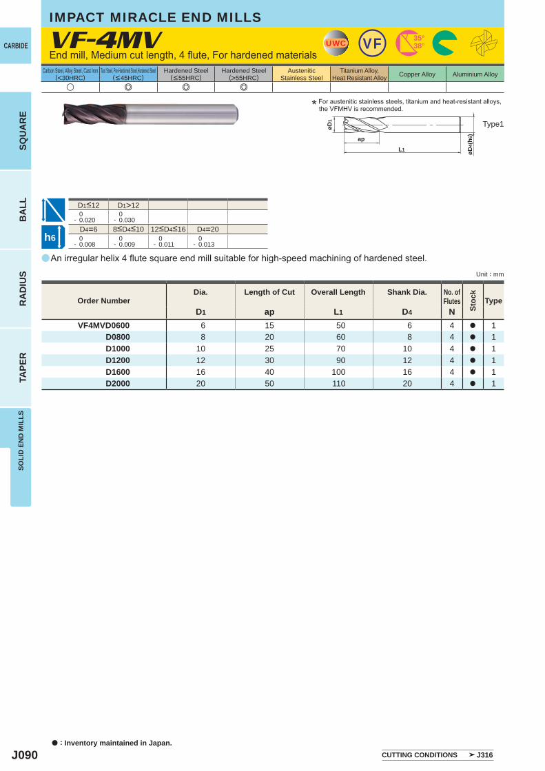
J090
a
VF-4MV
u e e e
D1 ap L1 D4 NVF4MVD0600 6 15 50 6 4 a 1
D0800 8 20 60 8 4 a 1D1000 10 25 70 10 4 a 1D1200 12 30 90 12 4 a 1D1600 16 40 100 16 4 a 1D2000 20 50 110 20 4 a 1
D1>12 0- 0.020
0- 0.030
D4=6 D4=20 0- 0.008
0- 0.009
0- 0.011
0- 0.013
UWC VF 35°38°
øD1
ap
L1 øD4(
h6)
h6
CARBIDE
SQU
AR
EB
ALL
RA
DIU
STA
PER
SOLI
D E
ND
MIL
LS
a : Inventory maintained in Japan.
Carbon Steel, Alloy Steel, Cast Iron(<30HRC)
Tool Steel, Pre-Hardened Steel,Hardened Steel(<45HRC)
Hardened Steel(<55HRC)
Hardened Steel(>55HRC)
AusteniticStainless Steel
Titanium Alloy,Heat Resistant Alloy Copper Alloy Aluminium Alloy
Unit : mm
IMPACT MIRACLE END MILLS
End mill, Medium cut length, 4 flute, For hardened materials
* For austenitic stainless steels, titanium and heat-resistant alloys, the VFMHV is recommended.
Type1
8<D4<10 12<D4<16
D1<12
An irregular helix 4 flute square end mill suitable for high-speed machining of hardened steel.
Order NumberDia. Length of Cut Overall Length Shank Dia. No. of
Flutes
Stoc
k
Type
CUTTING CONDITIONS J316
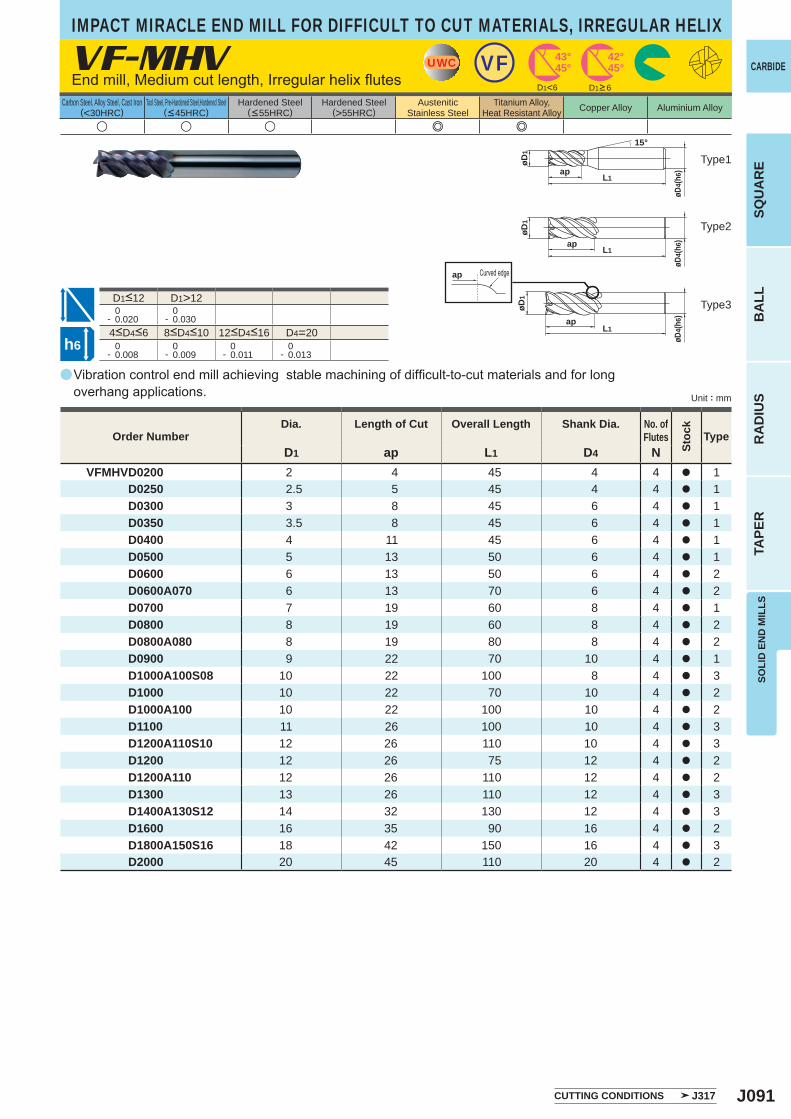
J091
a
VF-MHV
u u u e e
D1 ap L1 D4 NVFMHVD0200 2 4 45 4 4 a 1
D0250 2.5 5 45 4 4 a 1D0300 3 8 45 6 4 a 1D0350 3.5 8 45 6 4 a 1D0400 4 11 45 6 4 a 1D0500 5 13 50 6 4 a 1D0600 6 13 50 6 4 a 2D0600A070 6 13 70 6 4 a 2D0700 7 19 60 8 4 a 1D0800 8 19 60 8 4 a 2D0800A080 8 19 80 8 4 a 2D0900 9 22 70 10 4 a 1D1000A100S08 10 22 100 8 4 a 3D1000 10 22 70 10 4 a 2D1000A100 10 22 100 10 4 a 2D1100 11 26 100 10 4 a 3D1200A110S10 12 26 110 10 4 a 3D1200 12 26 75 12 4 a 2D1200A110 12 26 110 12 4 a 2D1300 13 26 110 12 4 a 3D1400A130S12 14 32 130 12 4 a 3D1600 16 35 90 16 4 a 2D1800A150S16 18 42 150 16 4 a 3D2000 20 45 110 20 4 a 2
D1>12 0- 0.020
0- 0.030
D4=20 0- 0.008
0- 0.009
0- 0.011
0- 0.013
D1<6
UWC VF 43°45°
42°45°
ap
øD1
apL1
øD4(
h6)
15°
øD4(
h6)
øD1
apL1
øD4(
h6)
øD1
apL1
h6
SOLI
D E
ND
MIL
LSSQ
UA
RE
BA
LLR
AD
IUS
TAPE
R
CARBIDE
Carbon Steel, Alloy Steel, Cast Iron(<30HRC)
Tool Steel, Pre-Hardened Steel,Hardened Steel(<45HRC)
Hardened Steel(<55HRC)
Hardened Steel(>55HRC)
AusteniticStainless Steel
Titanium Alloy,Heat Resistant Alloy Copper Alloy Aluminium Alloy
Unit : mm
Type1
Type2
Type3
Order NumberDia. Length of Cut Overall Length Shank Dia. No. of
Flutes
Stoc
k
Type
CUTTING CONDITIONS J317
End mill, Medium cut length, Irregular helix flutes
Curved edge
D1<12
4<D4<6 8<D4<10 12<D4<16
Vibration control end mill achieving stable machining of difficult-to-cut materials and for long overhang applications.
D1>6
IMPACT MIRACLE END MILL FOR DIFFICULT TO CUT MATERIALS, IRREGULAR HELIX
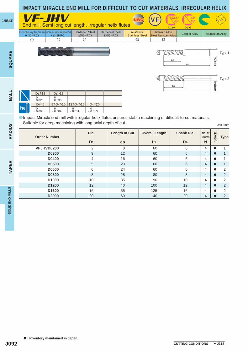
J092
a
VF-JHV
u u u e e
D1 ap L1 D4 NVFJHVD0200 2 8 60 6 4 a 1
D0300 3 12 60 6 4 a 1D0400 4 16 60 6 4 a 1D0500 5 20 60 6 4 a 1D0600 6 24 60 6 4 a 2D0800 8 28 80 8 4 a 2D1000 10 35 90 10 4 a 2D1200 12 40 100 12 4 a 2D1600 16 55 125 16 4 a 2D2000 20 60 140 20 4 a 2
D1>6
D1>12 0- 0.020
0- 0.030
D4=6 D4=20 0- 0.008
0- 0.009
0- 0.011
0- 0.013
UWC VF 43.5°45°
43°45°
øD1
L1ap
øD4(
h6)
øD1
L1ap
øD4(
h6)
h6
CARBIDE
SQU
AR
EB
ALL
RA
DIU
STA
PER
SOLI
D E
ND
MIL
LS
a : Inventory maintained in Japan.
Carbon Steel, Alloy Steel, Cast Iron(<30HRC)
Tool Steel, Pre-Hardened Steel,Hardened Steel(<45HRC)
Hardened Steel(<55HRC)
Hardened Steel(>55HRC)
AusteniticStainless Steel
Titanium Alloy,Heat Resistant Alloy Copper Alloy Aluminium Alloy
Unit : mm
IMPACT MIRACLE END MILL FOR DIFFICULT TO CUT MATERIALS, IRREGULAR HELIX
End mill, Semi long cut length, Irregular helix flutes
Type1
Type2
8<D4<10 12<D4<16
D1<12
Impact Miracle end mill with irregular helix flutes ensures stable machining of difficult-to-cut materials. Suitable for deep machining with long axial depth of cut.
Order NumberDia. Length of Cut Overall Length Shank Dia. No. of
Flutes
Stoc
k
Type
CUTTING CONDITIONS J318
D1<6
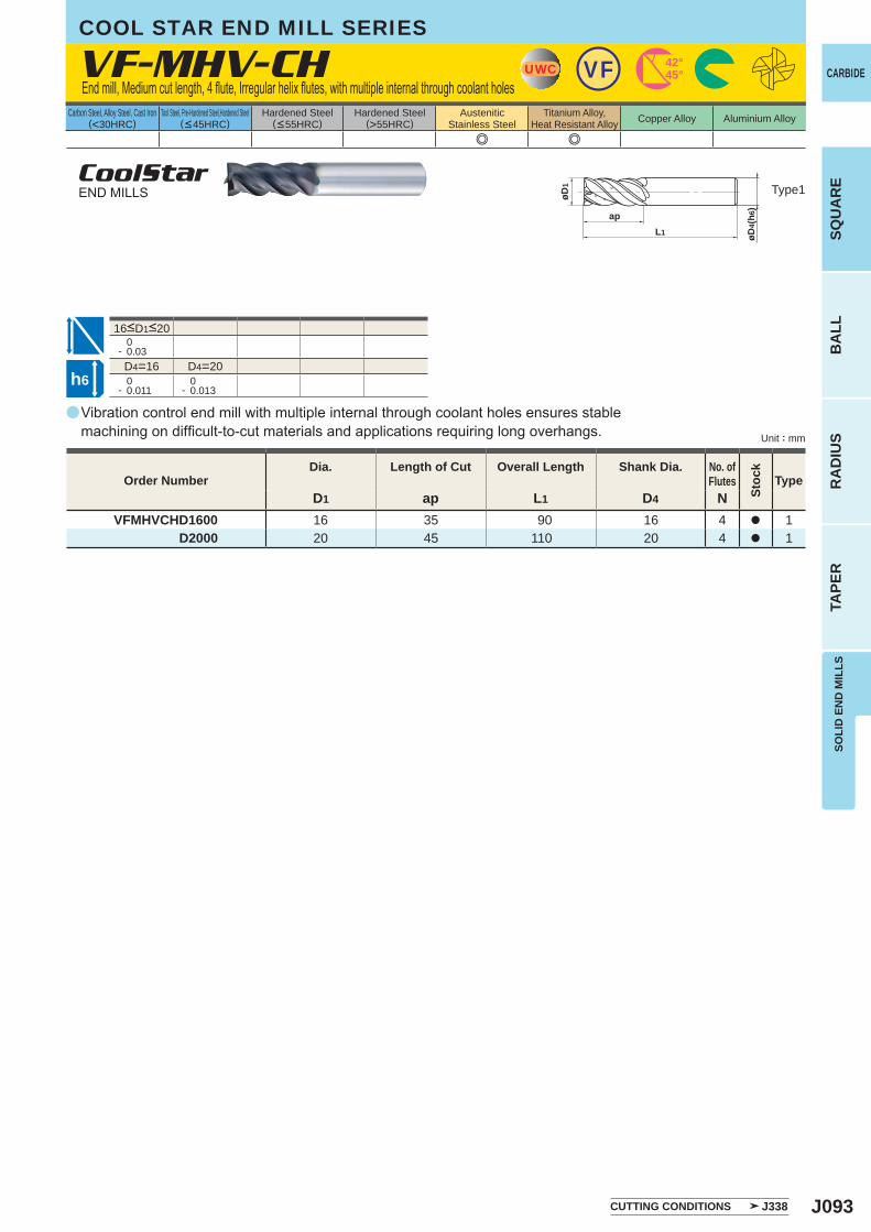
J093
a
VF-MHV-CH
e e
D1 ap L1 D4 NVFMHVCHD1600 16 35 90 16 4 a 1
D2000 20 45 110 20 4 a 1
0- 0.03D4=16 D4=20
0- 0.011
0- 0.013
UWC VF 42°45°
øD1
apL1 øD
4(h6
)
h6
SOLI
D E
ND
MIL
LSSQ
UA
RE
BA
LLR
AD
IUS
TAPE
R
CARBIDE
Carbon Steel, Alloy Steel, Cast Iron(<30HRC)
Tool Steel, Pre-Hardened Steel,Hardened Steel(<45HRC)
Hardened Steel(<55HRC)
Hardened Steel(>55HRC)
AusteniticStainless Steel
Titanium Alloy,Heat Resistant Alloy Copper Alloy Aluminium Alloy
Unit : mm
Type1
Order NumberDia. Length of Cut Overall Length Shank Dia. No. of
Flutes
Stoc
k
Type
CUTTING CONDITIONS J338
COOL STAR END MILL SERIES
End mill, Medium cut length, 4 flute, Irregular helix flutes, with multiple internal through coolant holes
CoolStarEND MILLS
16<D1<20
Vibration control end mill with multiple internal through coolant holes ensures stable machining on difficult-to-cut materials and applications requiring long overhangs.
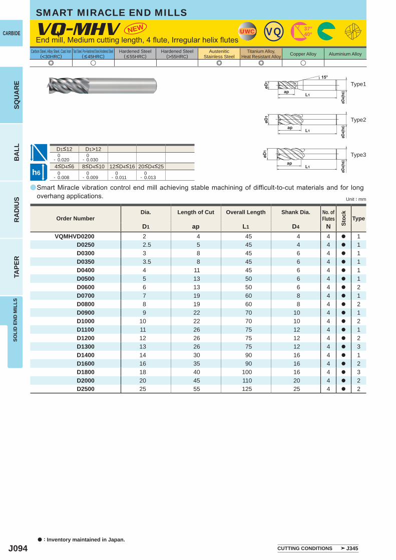
J094
a
NEWVQ-MHV
e u e e u
D1 ap L1 D4 NVQMHVD0200 2 4 45 4 4 a 1 D0250 2.5 5 45 4 4 a 1 D0300 3 8 45 6 4 a 1 D0350 3.5 8 45 6 4 a 1 D0400 4 11 45 6 4 a 1 D0500 5 13 50 6 4 a 1 D0600 6 13 50 6 4 a 2 D0700 7 19 60 8 4 a 1 D0800 8 19 60 8 4 a 2 D0900 9 22 70 10 4 a 1 D1000 10 22 70 10 4 a 2 D1100 11 26 75 12 4 a 1 D1200 12 26 75 12 4 a 2 D1300 13 26 75 12 4 a 3 D1400 14 30 90 16 4 a 1 D1600 16 35 90 16 4 a 2 D1800 18 40 100 16 4 a 3 D2000 20 45 110 20 4 a 2 D2500 25 55 125 25 4 a 2
D1>12 0- 0.020
0- 0.030
0- 0.008
0- 0.009
0- 0.011
0- 0.013
UWC VQ 37°40°
h6
CARBIDE
SQU
AR
EB
ALL
RA
DIU
STA
PER
SOLI
D E
ND
MIL
LS
a : Inventory maintained in Japan.
Carbon Steel, Alloy Steel, Cast Iron(<30HRC)
Tool Steel, Pre-Hardened Steel,Hardened Steel(<45HRC)
Hardened Steel(<55HRC)
Hardened Steel(>55HRC)
AusteniticStainless Steel
Titanium Alloy,Heat Resistant Alloy Copper Alloy Aluminium Alloy
Unit : mm
Type1
Type2
Type3
8<D4<10 12<D4<164<D4<6 20<D4<25
D1<12
SMART MIRACLE END MILLS
End mill, Medium cutting length, 4 flute, Irregular helix flutes
Smart Miracle vibration control end mill achieving stable machining of difficult-to-cut materials and for long overhang applications.
Order NumberDia. Length of Cut Overall Length Shank Dia. No. of
Flutes
Stoc
k
Type
CUTTING CONDITIONS J345

J095
a
u e e u u u
VC-4MC
D1 ap L1 D4 NVC4MCD0200 2 6 40 4 4 a 1
D0250 2.5 8 40 4 4 a 1D0300 3 8 45 6 4 a 1D0350 3.5 10 45 6 4 a 1D0400 4 11 45 6 4 a 1D0450 4.5 11 45 6 4 a 1D0500 5 13 50 6 4 a 1D0550 5.5 13 50 6 4 a 1D0600 6 13 50 6 4 a 2D0650 6.5 16 60 8 4 a 1D0700 7 16 60 8 4 a 1D0750 7.5 16 60 8 4 a 1D0800 8 19 60 8 4 a 2D0850 8.5 19 70 10 4 a 1D0900 9 19 70 10 4 a 1D0950 9.5 19 70 10 4 a 1D1000 10 22 70 10 4 a 2D1050 10.5 22 75 12 4 a 1D1100 11 22 75 12 4 a 1D1150 11.5 22 75 12 4 a 1D1200 12 26 75 12 4 a 2D1250 12.5 26 75 12 4 a 3D1300 13 26 75 12 4 a 3D1400 14 26 75 12 4 a 3D1500 15 30 80 16 4 a 1D1600 16 32 90 16 4 a 2D1700 17 32 90 16 4 a 3D1800 18 32 90 16 4 a 3D1900 19 32 100 20 4 a 1D2000 20 38 100 20 4 a 2D2200 22 38 100 20 4 a 3D2400 24 45 120 25 4 a 1D2500 25 45 120 25 4 a 2
D1>12 0- 0.020
0- 0.030
0- 0.008
0- 0.009
0- 0.011
0- 0.013
UWC VC 30°
øD4(
h6)
apL1
øD1
15°
øD1
øD4(
h6)
apL1
øD1
øD4(
h6)
apL1
h6
SOLI
D E
ND
MIL
LSSQ
UA
RE
BA
LLR
AD
IUS
TAPE
R
CARBIDE
Carbon Steel, Alloy Steel, Cast Iron(<30HRC)
Tool Steel, Pre-Hardened Steel,Hardened Steel(<45HRC)
Hardened Steel(<55HRC)
Hardened Steel(>55HRC)
AusteniticStainless Steel
Titanium Alloy,Heat Resistant Alloy Copper Alloy Aluminium Alloy
Unit : mm
Type1
Type2
Type3
Order NumberDia. Length of Cut Overall Length Shank Dia. No. of
Flutes
Stoc
k
Type
CUTTING CONDITIONS J350
MIRACLE END MILLS
End mill, Medium cut length, 4 flute
4<D4<6 8<D4<10 12<D4<16 20<D4<25
D1<12
4 flute end mill for general use.
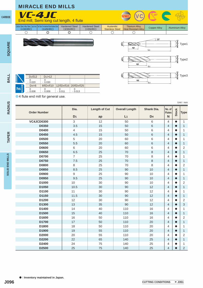
J096
a
u e e u u u
VC-4JC
D1 ap L1 D4 NVC4JCD0300 3 12 50 6 4 a 1
D0350 3.5 15 50 6 4 a 1D0400 4 15 50 6 4 a 1D0450 4.5 15 50 6 4 a 1D0500 5 20 60 6 4 a 1D0550 5.5 20 60 6 4 a 1D0600 6 20 60 6 4 a 2D0650 6.5 25 70 8 4 a 1D0700 7 25 70 8 4 a 1D0750 7.5 25 70 8 4 a 1D0800 8 25 70 8 4 a 2D0850 8.5 25 90 10 4 a 1D0900 9 25 90 10 4 a 1D0950 9.5 25 90 10 4 a 1D1000 10 30 90 10 4 a 2D1050 10.5 30 90 12 4 a 1D1100 11 30 90 12 4 a 1D1150 11.5 30 90 12 4 a 1D1200 12 30 90 12 4 a 2D1300 13 35 90 12 4 a 3D1400 14 40 110 16 4 a 1D1500 15 40 110 16 4 a 1D1600 16 50 110 16 4 a 2D1700 17 50 110 20 4 a 1D1800 18 50 110 20 4 a 1D1900 19 55 110 20 4 a 1D2000 20 55 110 20 4 a 2D2200 22 65 140 25 4 a 1D2400 24 75 140 25 4 a 1D2500 25 75 140 25 4 a 2
D1>12 0- 0.020
0- 0.030
D4=6 0- 0.008
0- 0.009
0- 0.011
0- 0.013
UWC VC 30°
øD4(
h6)
apL1
øD1
15°
øD1
øD4(
h6)
apL1
øD1
øD4(
h6)
apL1
h6
CARBIDE
SQU
AR
EB
ALL
RA
DIU
STA
PER
SOLI
D E
ND
MIL
LS
a : Inventory maintained in Japan.
Carbon Steel, Alloy Steel, Cast Iron(<30HRC)
Tool Steel, Pre-Hardened Steel,Hardened Steel(<45HRC)
Hardened Steel(<55HRC)
Hardened Steel(>55HRC)
AusteniticStainless Steel
Titanium Alloy,Heat Resistant Alloy Copper Alloy Aluminium Alloy
Unit : mm
MIRACLE END MILLS
End mill, Semi long cut length, 4 flute
Type3
Type2
Type1
8<D4<10 12<D4<16 20<D4<25
D1<12
Order NumberDia. Length of Cut Overall Length Shank Dia. No. of
Flutes
Stoc
k
Type
CUTTING CONDITIONS J351
4 flute end mill for general use.
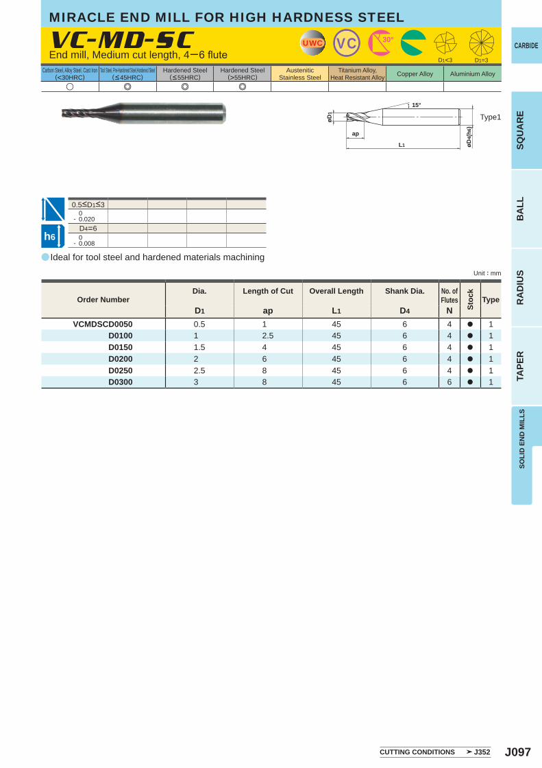
J097
a
u e e e
VC-MD-SC
D1 ap L1 D4 NVCMDSCD0050 0.5 1 45 6 4 a 1
D0100 1 2.5 45 6 4 a 1D0150 1.5 4 45 6 4 a 1D0200 2 6 45 6 4 a 1D0250 2.5 8 45 6 4 a 1D0300 3 8 45 6 6 a 1
0- 0.020
D4=6 0- 0.008
D1<3 D1=3
UWC VC 30°
ap
L1
øD1
øD4(
h6)
15°
h6
SOLI
D E
ND
MIL
LSSQ
UA
RE
BA
LLR
AD
IUS
TAPE
R
CARBIDE
Carbon Steel, Alloy Steel, Cast Iron(<30HRC)
Tool Steel, Pre-Hardened Steel,Hardened Steel(<45HRC)
Hardened Steel(<55HRC)
Hardened Steel(>55HRC)
AusteniticStainless Steel
Titanium Alloy,Heat Resistant Alloy Copper Alloy Aluminium Alloy
Unit : mm
Type1
Order NumberDia. Length of Cut Overall Length Shank Dia. No. of
Flutes
Stoc
k
Type
CUTTING CONDITIONS J352
End mill, Medium cut length, 4─6 flute
0.5<D1<3
Ideal for tool steel and hardened materials machining
MIRACLE END MILL FOR HIGH HARDNESS STEEL
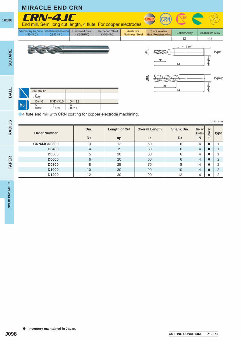
J098
a
e u
CRN-4JC
D1 ap L1 D4 NCRN4JCD0300 3 12 50 6 4 a 1
D0400 4 15 50 6 4 a 1 D0500 5 20 60 6 4 a 1 D0600 6 20 60 6 4 a 2 D0800 8 25 70 8 4 a 2 D1000 10 30 90 10 4 a 2 D1200 12 30 90 12 4 a 2
0- 0.02
D4=6 D4=12 0- 0.008
0- 0.009
0- 0.011
UWC CRN 30°
øD4(
h6)
apL1
øD1
15°
øD1
øD4(
h6)
apL1
h6
CARBIDE
SQU
AR
EB
ALL
RA
DIU
STA
PER
SOLI
D E
ND
MIL
LS
a : Inventory maintained in Japan.
Carbon Steel, Alloy Steel, Cast Iron(<30HRC)
Tool Steel, Pre-Hardened Steel,Hardened Steel(<45HRC)
Hardened Steel(<55HRC)
Hardened Steel(>55HRC)
AusteniticStainless Steel
Titanium Alloy,Heat Resistant Alloy Copper Alloy Aluminium Alloy
Unit : mm
End mill, Semi long cut length, 4 flute, For copper electrodes
Type1
Type2
8<D4<10
3<D1<12
4 flute end mill with CRN coating for copper electrode machining.
Order NumberDia. Length of Cut Overall Length Shank Dia. No. of
Flutes
Stoc
k
Type
CUTTING CONDITIONS J371
MIRACLE END CRN
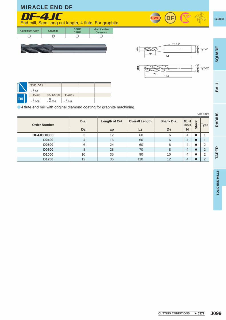
J099
a
DF-4JC
D1 ap L1 D4 NDF4JCD0300 3 12 60 6 4 a 1
D0400 4 16 60 6 4 a 1D0600 6 24 60 6 4 a 2D0800 8 28 70 8 4 a 2D1000 10 35 90 10 4 a 2D1200 12 36 110 12 4 a 2
u e u u
0- 0.02
D4=6 D4=12 0- 0.008
0- 0.009
0- 0.011
UWC 30°DF
øD4(
h6)
apL1
øD1
15°
øD1
øD4(
h6)
apL1
h6
SOLI
D E
ND
MIL
LSSQ
UA
RE
BA
LLR
AD
IUS
TAPE
R
CARBIDE
Unit : mm
Aluminium Alloy Graphite GFRPCFRP
MachineableCeramics
Type1
Type2
Order NumberDia. Length of Cut Overall Length Shank Dia. No. of
Flutes
Stoc
k
Type
CUTTING CONDITIONS J377
MIRACLE END DF
End mill, Semi long cut length, 4 flute, For graphite
3<D1<12
8<D4<10
4 flute end mill with original diamond coating for graphite machining.
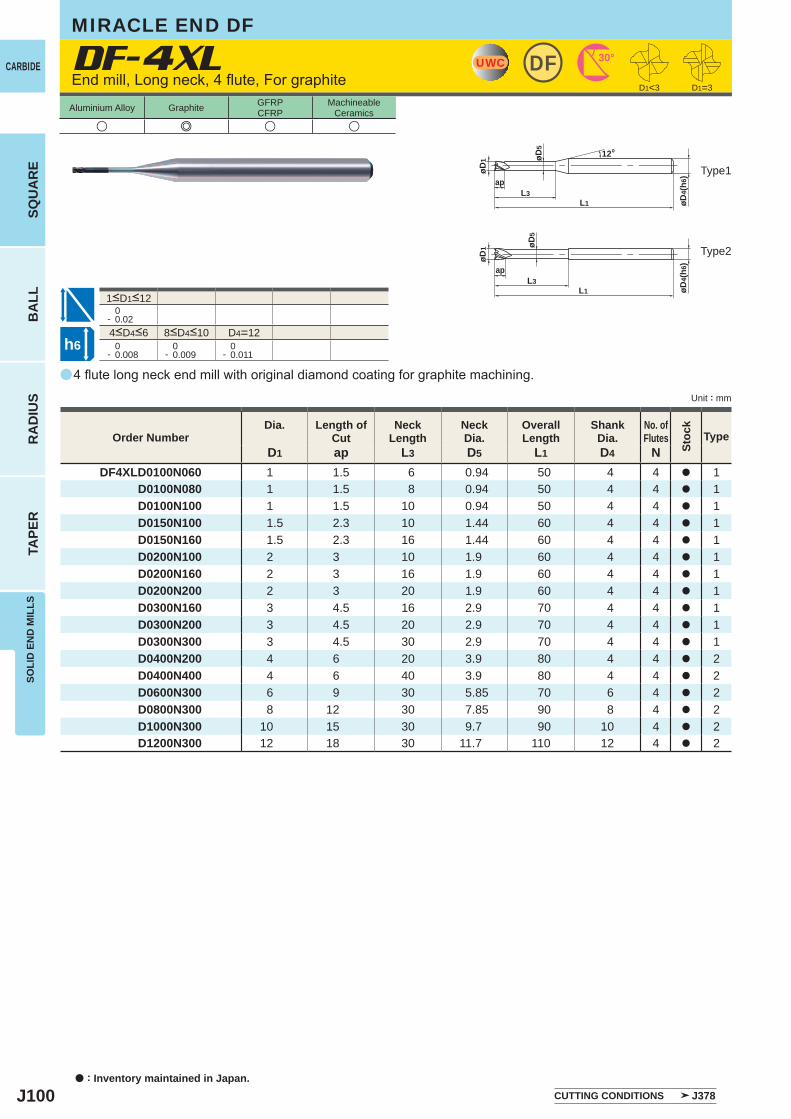
J100
a
DF-4XL
u e u u
D1 ap L3 D5 L1 D4 NDF4XLD0100N060 1 1.5 6 0.94 50 4 4 a 1
D0100N080 1 1.5 8 0.94 50 4 4 a 1D0100N100 1 1.5 10 0.94 50 4 4 a 1D0150N100 1.5 2.3 10 1.44 60 4 4 a 1D0150N160 1.5 2.3 16 1.44 60 4 4 a 1D0200N100 2 3 10 1.9 60 4 4 a 1D0200N160 2 3 16 1.9 60 4 4 a 1D0200N200 2 3 20 1.9 60 4 4 a 1D0300N160 3 4.5 16 2.9 70 4 4 a 1D0300N200 3 4.5 20 2.9 70 4 4 a 1D0300N300 3 4.5 30 2.9 70 4 4 a 1D0400N200 4 6 20 3.9 80 4 4 a 2D0400N400 4 6 40 3.9 80 4 4 a 2D0600N300 6 9 30 5.85 70 6 4 a 2D0800N300 8 12 30 7.85 90 8 4 a 2D1000N300 10 15 30 9.7 90 10 4 a 2D1200N300 12 18 30 11.7 110 12 4 a 2
D1=3
0- 0.02
D4=12 0- 0.008
0- 0.009
0- 0.011
UWC 30°DF
øD4(
h6)
øD5
L1L3
ap
øD1
12°
D1<3
øD4(
h6)
L1L3
øD5
ap
øD1
h6
CARBIDE
SQU
AR
EB
ALL
RA
DIU
STA
PER
SOLI
D E
ND
MIL
LS
a : Inventory maintained in Japan.
Unit : mm
Aluminium Alloy Graphite GFRPCFRP
MachineableCeramics
End mill, Long neck, 4 flute, For graphite
Type1
Type2
4<D4<6 8<D4<10
1<D1<12
Order NumberDia. Length of
CutNeck
LengthNeckDia.
Overall Length
ShankDia.
No. ofFlutes
Stoc
k
Type
4 flute long neck end mill with original diamond coating for graphite machining.
CUTTING CONDITIONS J378
MIRACLE END DF
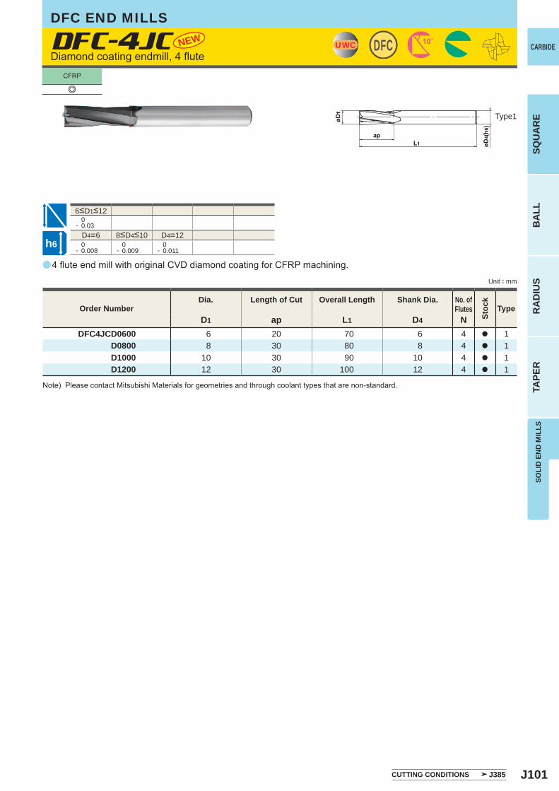
J101
a
DFC-4JC
D1 ap L1 D4 NDFC4JCD0600 6 20 70 6 4 a 1
D0800 8 30 80 8 4 a 1D1000 10 30 90 10 4 a 1D1200 12 30 100 12 4 a 1
NEW
e
0- 0.03
D4=6 D4=12 0- 0.008
0- 0.009
0- 0.011
DFCUWC
h6
SOLI
D E
ND
MIL
LSSQ
UA
RE
BA
LLR
AD
IUS
TAPE
R
CARBIDE
Unit : mm
Type1
Order NumberDia. Length of Cut Overall Length Shank Dia. No. of
Flutes
Stoc
k
Type
CUTTING CONDITIONS J385
DFC END MILLS
Diamond coating endmill, 4 flute
8<D4<10
6<D1<12
4 flute end mill with original CVD diamond coating for CFRP machining.
Note) Please contact Mitsubishi Materials for geometries and through coolant types that are non-standard.
CFRP
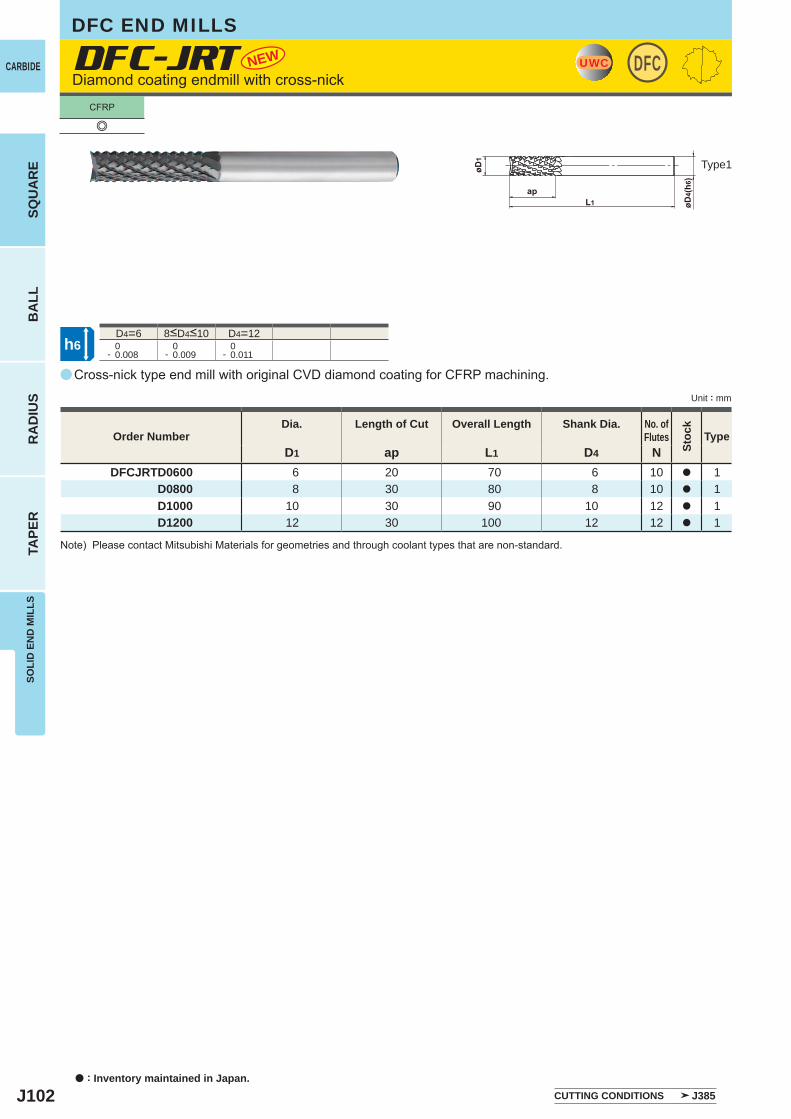
J102
a
DFC-JRT
D1 ap L1 D4 NDFCJRTD0600 6 20 70 6 10 a 1
D0800 8 30 80 8 10 a 1D1000 10 30 90 10 12 a 1D1200 12 30 100 12 12 a 1
NEW
e
D4=6 D4=12 0- 0.008
0- 0.009
0- 0.011
DFCUWC
h6
CARBIDE
SQU
AR
EB
ALL
RA
DIU
STA
PER
SOLI
D E
ND
MIL
LS
a : Inventory maintained in Japan.
Unit : mm
DFC END MILLS
Diamond coating endmill with cross-nick
Type1
8<D4<10
Cross-nick type end mill with original CVD diamond coating for CFRP machining.
Order NumberDia. Length of Cut Overall Length Shank Dia. No. of
Flutes
Stoc
k
Type
Note) Please contact Mitsubishi Materials for geometries and through coolant types that are non-standard.
CUTTING CONDITIONS J385
CFRP
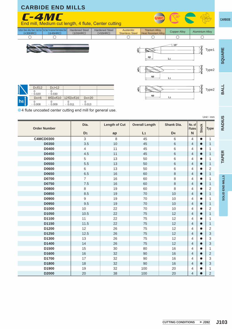
J103
a
u u u u u u
C-4MC
D1 ap L1 D4 NC4MCD0300 3 8 45 6 4 a 1
D0350 3.5 10 45 6 4 a 1 D0400 4 11 45 6 4 a 1 D0450 4.5 11 45 6 4 a 1 D0500 5 13 50 6 4 a 1 D0550 5.5 13 50 6 4 a 1 D0600 6 13 50 6 4 a 2 D0650 6.5 16 60 8 4 a 1 D0700 7 16 60 8 4 a 1 D0750 7.5 16 60 8 4 a 1 D0800 8 19 60 8 4 a 2 D0850 8.5 19 70 10 4 a 1 D0900 9 19 70 10 4 a 1 D0950 9.5 19 70 10 4 a 1 D1000 10 22 70 10 4 a 2 D1050 10.5 22 75 12 4 a 1 D1100 11 22 75 12 4 a 1 D1150 11.5 22 75 12 4 a 1 D1200 12 26 75 12 4 a 2 D1250 12.5 26 75 12 4 a 3 D1300 13 26 75 12 4 a 3 D1400 14 26 75 12 4 a 3 D1500 15 30 80 16 4 a 1 D1600 16 32 90 16 4 a 2 D1700 17 32 90 16 4 a 3 D1800 18 32 90 16 4 a 3 D1900 19 32 100 20 4 a 1 D2000 20 38 100 20 4 a 2
D1>12 0- 0.020
0- 0.030
D4=6 D4=20 0- 0.008
0- 0.009
0- 0.011
0- 0.013
UWC 30°
øD4(
h6)
apL1
øD1
15°
øD4(
h6)
øD1
apL1
øD1
øD4(
h6)
ap L1
h6
SOLI
D E
ND
MIL
LSSQ
UA
RE
BA
LLR
AD
IUS
TAPE
R
CARBIDE
Carbon Steel, Alloy Steel, Cast Iron(<30HRC)
Tool Steel, Pre-Hardened Steel,Hardened Steel(<45HRC)
Hardened Steel(<55HRC)
Hardened Steel(>55HRC)
AusteniticStainless Steel
Titanium Alloy,Heat Resistant Alloy Copper Alloy Aluminium Alloy
Unit : mm
Type1
Type2
Type2
Order NumberDia. Length of Cut Overall Length Shank Dia. No. of
Flutes
Stoc
k
Type
CUTTING CONDITIONS J392
CARBIDE END MILLS
End mill, Medium cut length, 4 flute, Center cutting
8<D4<10 12<D4<16
D1<12
4 flute uncoated center cutting end mill for general use.
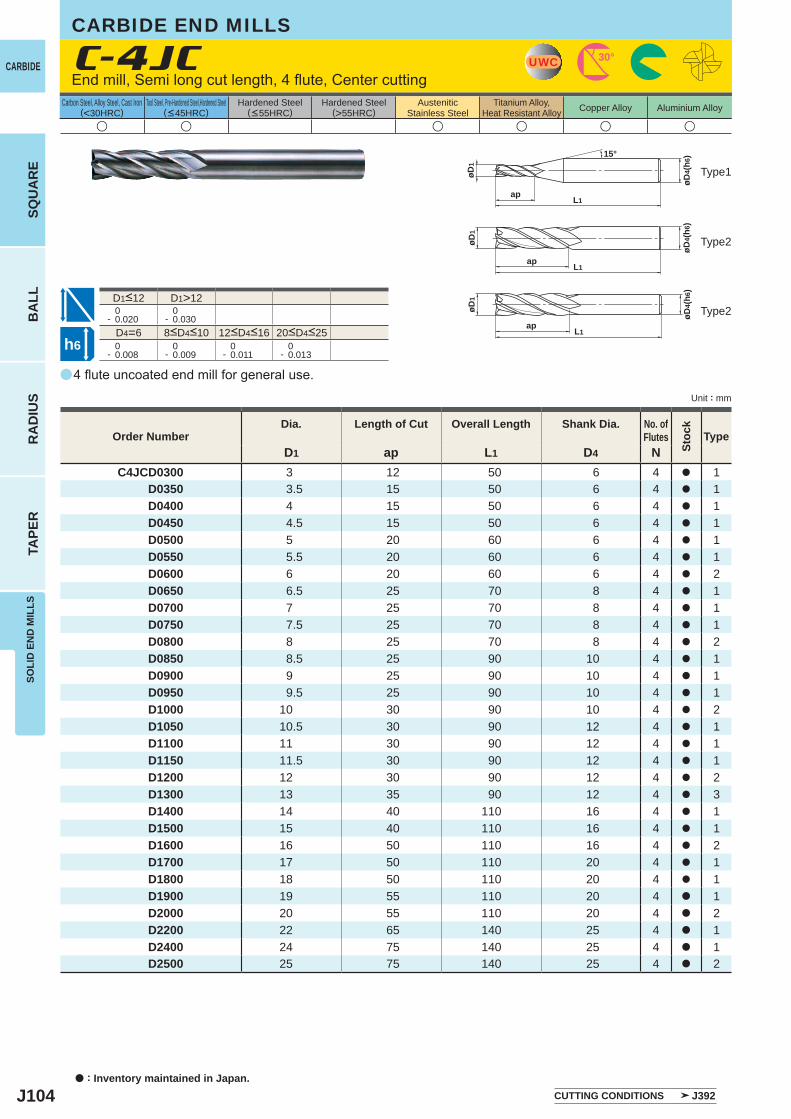
J104
a
u u u u u u
C-4JC
D1 ap L1 D4 NC4JCD0300 3 12 50 6 4 a 1
D0350 3.5 15 50 6 4 a 1 D0400 4 15 50 6 4 a 1 D0450 4.5 15 50 6 4 a 1 D0500 5 20 60 6 4 a 1 D0550 5.5 20 60 6 4 a 1 D0600 6 20 60 6 4 a 2 D0650 6.5 25 70 8 4 a 1 D0700 7 25 70 8 4 a 1 D0750 7.5 25 70 8 4 a 1 D0800 8 25 70 8 4 a 2 D0850 8.5 25 90 10 4 a 1 D0900 9 25 90 10 4 a 1 D0950 9.5 25 90 10 4 a 1 D1000 10 30 90 10 4 a 2 D1050 10.5 30 90 12 4 a 1 D1100 11 30 90 12 4 a 1 D1150 11.5 30 90 12 4 a 1 D1200 12 30 90 12 4 a 2 D1300 13 35 90 12 4 a 3 D1400 14 40 110 16 4 a 1 D1500 15 40 110 16 4 a 1 D1600 16 50 110 16 4 a 2 D1700 17 50 110 20 4 a 1 D1800 18 50 110 20 4 a 1 D1900 19 55 110 20 4 a 1 D2000 20 55 110 20 4 a 2 D2200 22 65 140 25 4 a 1 D2400 24 75 140 25 4 a 1 D2500 25 75 140 25 4 a 2
D1>12 0- 0.020
0- 0.030
D4=6 0- 0.008
0- 0.009
0- 0.011
0- 0.013
UWC 30°
øD4(
h6)
ap L1
øD1
15°
øD1
ap L1
øD4(
h6)
øD4(
h6)
øD1
ap L1
h6
CARBIDE
SQU
AR
EB
ALL
RA
DIU
STA
PER
SOLI
D E
ND
MIL
LS
a : Inventory maintained in Japan.
Carbon Steel, Alloy Steel, Cast Iron(<30HRC)
Tool Steel, Pre-Hardened Steel,Hardened Steel(<45HRC)
Hardened Steel(<55HRC)
Hardened Steel(>55HRC)
AusteniticStainless Steel
Titanium Alloy,Heat Resistant Alloy Copper Alloy Aluminium Alloy
Unit : mm
CARBIDE END MILLS
End mill, Semi long cut length, 4 flute, Center cutting
Type1
Type2
Type2
8<D4<10 12<D4<16 20<D4<25
D1<12
4 flute uncoated end mill for general use.
Order NumberDia. Length of Cut Overall Length Shank Dia. No. of
Flutes
Stoc
k
Type
CUTTING CONDITIONS J392
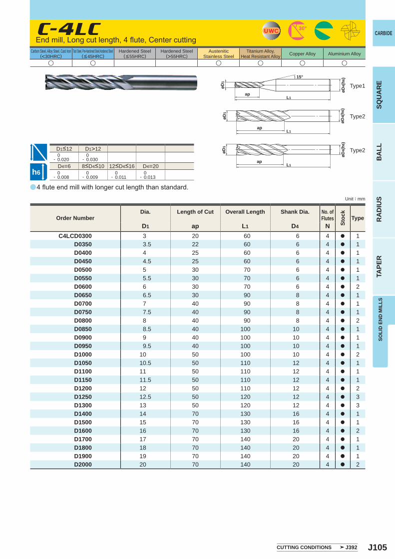
J105
a
u u u u u u
C-4LC
D1 ap L1 D4 NC4LCD0300 3 20 60 6 4 a 1
D0350 3.5 22 60 6 4 a 1 D0400 4 25 60 6 4 a 1 D0450 4.5 25 60 6 4 a 1 D0500 5 30 70 6 4 a 1 D0550 5.5 30 70 6 4 a 1 D0600 6 30 70 6 4 a 2 D0650 6.5 30 90 8 4 a 1 D0700 7 40 90 8 4 a 1 D0750 7.5 40 90 8 4 a 1 D0800 8 40 90 8 4 a 2 D0850 8.5 40 100 10 4 a 1 D0900 9 40 100 10 4 a 1 D0950 9.5 40 100 10 4 a 1 D1000 10 50 100 10 4 a 2 D1050 10.5 50 110 12 4 a 1 D1100 11 50 110 12 4 a 1 D1150 11.5 50 110 12 4 a 1 D1200 12 50 110 12 4 a 2 D1250 12.5 50 120 12 4 a 3 D1300 13 50 120 12 4 a 3 D1400 14 70 130 16 4 a 1 D1500 15 70 130 16 4 a 1 D1600 16 70 130 16 4 a 2 D1700 17 70 140 20 4 a 1 D1800 18 70 140 20 4 a 1 D1900 19 70 140 20 4 a 1 D2000 20 70 140 20 4 a 2
D1>12 0- 0.020
0- 0.030
D4=6 D4=20 0- 0.008
0- 0.009
0- 0.011
0- 0.013
UWC 30°
øD4(
h6)
apL1
øD1
15°
øD1
øD4(
h6)
apL1
øD1
øD4(
h6)
apL1
h6
SOLI
D E
ND
MIL
LSSQ
UA
RE
BA
LLR
AD
IUS
TAPE
R
CARBIDE
Carbon Steel, Alloy Steel, Cast Iron(<30HRC)
Tool Steel, Pre-Hardened Steel,Hardened Steel(<45HRC)
Hardened Steel(<55HRC)
Hardened Steel(>55HRC)
AusteniticStainless Steel
Titanium Alloy,Heat Resistant Alloy Copper Alloy Aluminium Alloy
Unit : mm
Type1
Type2
Type2
Order NumberDia. Length of Cut Overall Length Shank Dia. No. of
Flutes
Stoc
k
Type
CUTTING CONDITIONS J392
End mill, Long cut length, 4 flute, Center cutting
8<D4<10 12<D4<16
D1<12
4 flute end mill with longer cut length than standard.
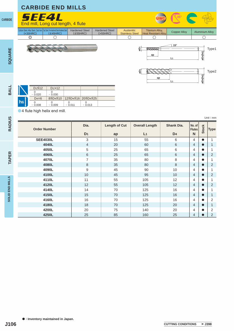
J106
a
SEE4L
e u u u u
D1 ap L1 D4 NSEE4030L 3 15 55 6 4 a 1
4040L 4 20 60 6 4 a 1 4050L 5 25 65 6 4 a 1 4060L 6 25 65 6 4 a 2 4070L 7 35 80 8 4 a 1 4080L 8 35 80 8 4 a 2 4090L 9 45 90 10 4 a 1 4100L 10 45 95 10 4 a 2 4110L 11 55 105 12 4 a 1 4120L 12 55 105 12 4 a 2 4140L 14 70 125 16 4 a 1 4150L 15 70 125 16 4 a 1 4160L 16 70 125 16 4 a 2 4180L 18 70 125 20 4 a 1 4200L 20 75 140 20 4 a 2 4250L 25 85 160 25 4 a 2
D1>12 0- 0.020
0- 0.030
D4=6 0- 0.008
0- 0.009
0- 0.011
0- 0.013
UWC 45°
øD1
L1ap
15°
øD4(
h6)
øD1
L1ap
øD4(
h6)
h6
CARBIDE
SQU
AR
EB
ALL
RA
DIU
STA
PER
SOLI
D E
ND
MIL
LS
a : Inventory maintained in Japan.
Carbon Steel, Alloy Steel, Cast Iron(<30HRC)
Tool Steel, Pre-Hardened Steel,Hardened Steel(<45HRC)
Hardened Steel(<55HRC)
Hardened Steel(>55HRC)
AusteniticStainless Steel
Titanium Alloy,Heat Resistant Alloy Copper Alloy Aluminium Alloy
Unit : mm
CARBIDE END MILLS
End mill, Long cut length, 4 flute
Type1
Type2
8<D4<10 12<D4<16 20<D4<25
D1<12
4 flute high helix end mill.
Order NumberDia. Length of Cut Overall Length Shank Dia. No. of
Flutes
Stoc
k
Type
CUTTING CONDITIONS J398
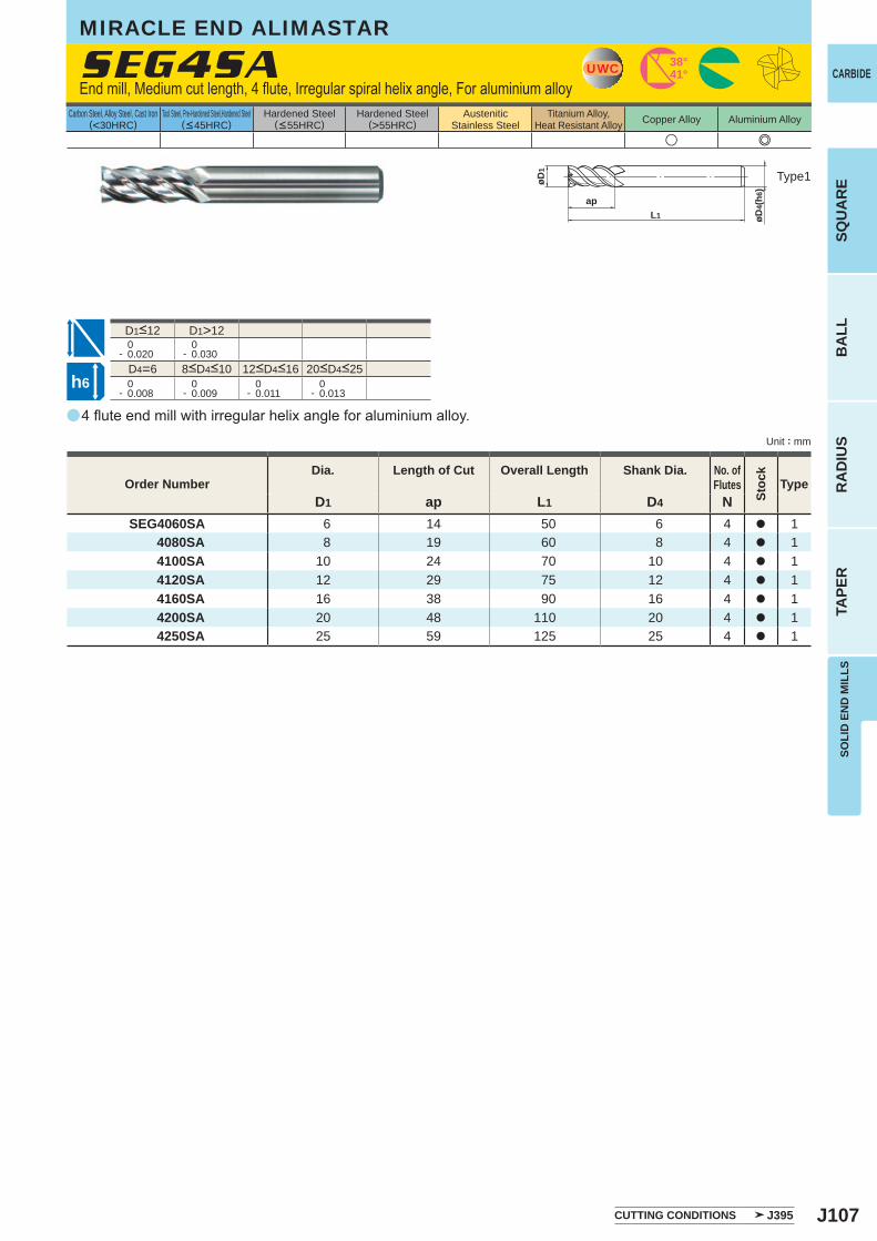
J107
a
u e
SEG4SA
D1 ap L1 D4 NSEG4060SA 6 14 50 6 4 a 1
4080SA 8 19 60 8 4 a 1 4100SA 10 24 70 10 4 a 1 4120SA 12 29 75 12 4 a 1 4160SA 16 38 90 16 4 a 1 4200SA 20 48 110 20 4 a 1 4250SA 25 59 125 25 4 a 1
D1>12 0- 0.020
0- 0.030
D4=6 0- 0.008
0- 0.009
0- 0.011
0- 0.013
UWC 38°41°
apL1 øD
4(h6
)
øD1
h6
SOLI
D E
ND
MIL
LSSQ
UA
RE
BA
LLR
AD
IUS
TAPE
R
CARBIDE
Carbon Steel, Alloy Steel, Cast Iron(<30HRC)
Tool Steel, Pre-Hardened Steel,Hardened Steel(<45HRC)
Hardened Steel(<55HRC)
Hardened Steel(>55HRC)
AusteniticStainless Steel
Titanium Alloy,Heat Resistant Alloy Copper Alloy Aluminium Alloy
Unit : mm
Type1
Order NumberDia. Length of Cut Overall Length Shank Dia. No. of
Flutes
Stoc
k
Type
CUTTING CONDITIONS J395
End mill, Medium cut length, 4 flute, Irregular spiral helix angle, For aluminium alloy
8<D4<10 12<D4<16 20<D4<25
D1<12
4 flute end mill with irregular helix angle for aluminium alloy.
MIRACLE END ALIMASTAR
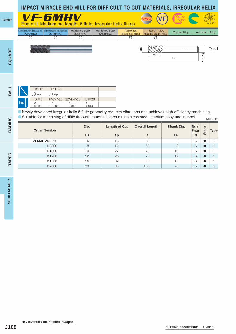
J108
aa
a
u u u e e
VF-6MHV
D1 ap L1 D4 NVF6MHVD0600 6 13 50 6 6 a 1
D0800 8 19 60 8 6 a 1D1000 10 22 70 10 6 a 1D1200 12 26 75 12 6 a 1D1600 16 32 90 16 6 a 1D2000 20 38 100 20 6 a 1
D1>12 0- 0.020
0- 0.030
D4=6 D4=20 0- 0.008
0- 0.009
0- 0.011
0- 0.013
UWC VF 43.5°45°
øD1
L1
ap
øD4(
h6)
h6
CARBIDE
SQU
AR
EB
ALL
RA
DIU
STA
PER
SOLI
D E
ND
MIL
LS
a : Inventory maintained in Japan.
Carbon Steel, Alloy Steel, Cast Iron(<30HRC)
Tool Steel, Pre-Hardened Steel,Hardened Steel(<45HRC)
Hardened Steel(<55HRC)
Hardened Steel(>55HRC)
AusteniticStainless Steel
Titanium Alloy,Heat Resistant Alloy Copper Alloy Aluminium Alloy
Unit : mm
IMPACT MIRACLE END MILL FOR DIFFICULT TO CUT MATERIALS, IRREGULAR HELIX
End mill, Medium cut length, 6 flute, Irregular helix flutes
Type1
8<D4<10 12<D4<16
D1<12
Order NumberDia. Length of Cut Overall Length Shank Dia. No. of
Flutes
Stoc
k
Type
Newly developed irregular helix 6 flute geometry reduces vibrations and achieves high efficiency machining. Suitable for machining of difficult-to-cut materials such as stainless steel, titanium alloy and inconel.
CUTTING CONDITIONS J319
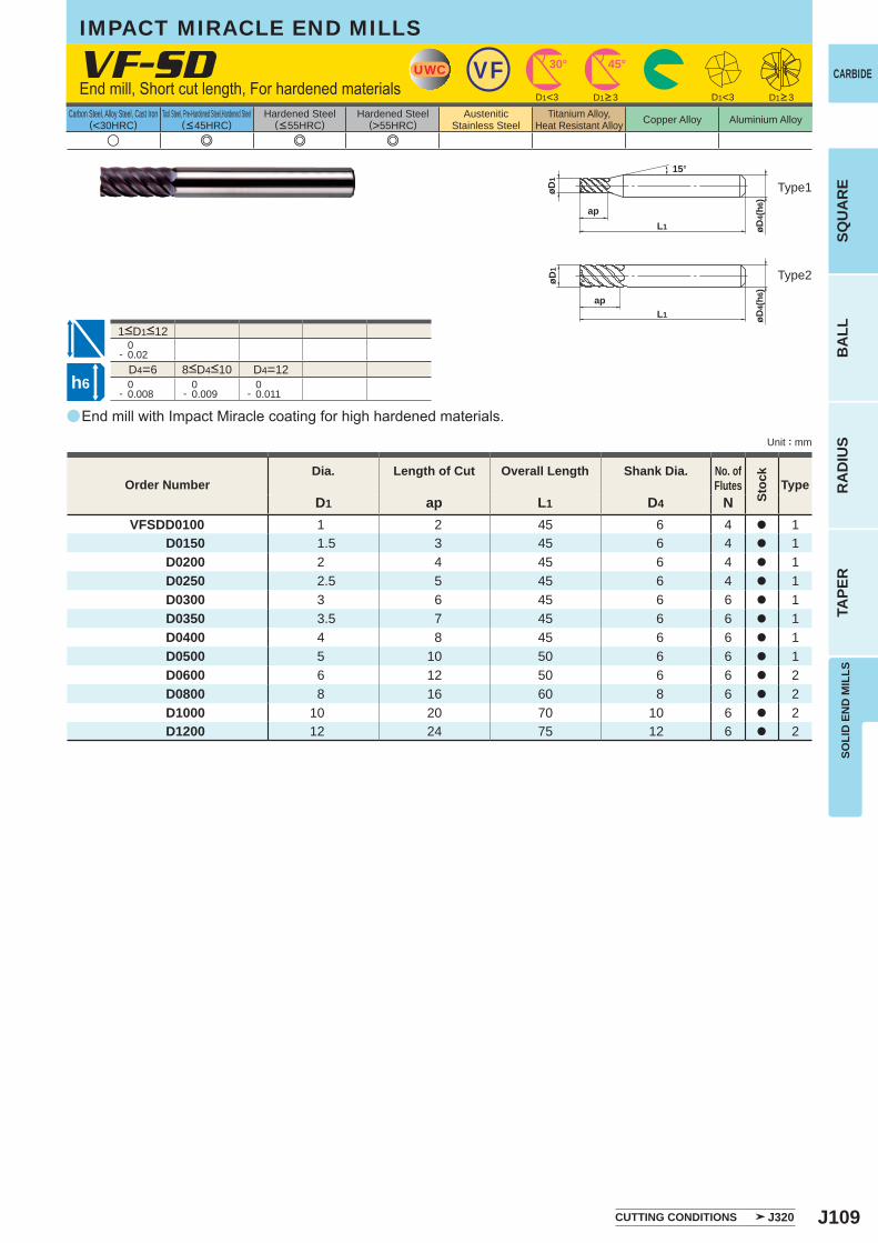
J109
a
VF-SD
D1 ap L1 D4 NVFSDD0100 1 2 45 6 4 a 1
D0150 1.5 3 45 6 4 a 1 D0200 2 4 45 6 4 a 1 D0250 2.5 5 45 6 4 a 1 D0300 3 6 45 6 6 a 1 D0350 3.5 7 45 6 6 a 1 D0400 4 8 45 6 6 a 1 D0500 5 10 50 6 6 a 1 D0600 6 12 50 6 6 a 2 D0800 8 16 60 8 6 a 2 D1000 10 20 70 10 6 a 2 D1200 12 24 75 12 6 a 2
u e e e
D1<3 D1<3
0- 0.02
D4=6 D4=12 0- 0.008
0- 0.009
0- 0.011
UWC VF 45°30°
L1
ap
øD1
øD4(
h6)
15°
L1
ap
øD4(
h6)
øD1
h6
SOLI
D E
ND
MIL
LSSQ
UA
RE
BA
LLR
AD
IUS
TAPE
R
CARBIDE
Carbon Steel, Alloy Steel, Cast Iron(<30HRC)
Tool Steel, Pre-Hardened Steel,Hardened Steel(<45HRC)
Hardened Steel(<55HRC)
Hardened Steel(>55HRC)
AusteniticStainless Steel
Titanium Alloy,Heat Resistant Alloy Copper Alloy Aluminium Alloy
Unit : mm
Order NumberDia. Length of Cut Overall Length Shank Dia. No. of
Flutes
Stoc
k
Type
CUTTING CONDITIONS J320
D1>3 D1>3End mill, Short cut length, For hardened materials
Type1
Type2
8<D4<10
1<D1<12
End mill with Impact Miracle coating for high hardened materials.
IMPACT MIRACLE END MILLS
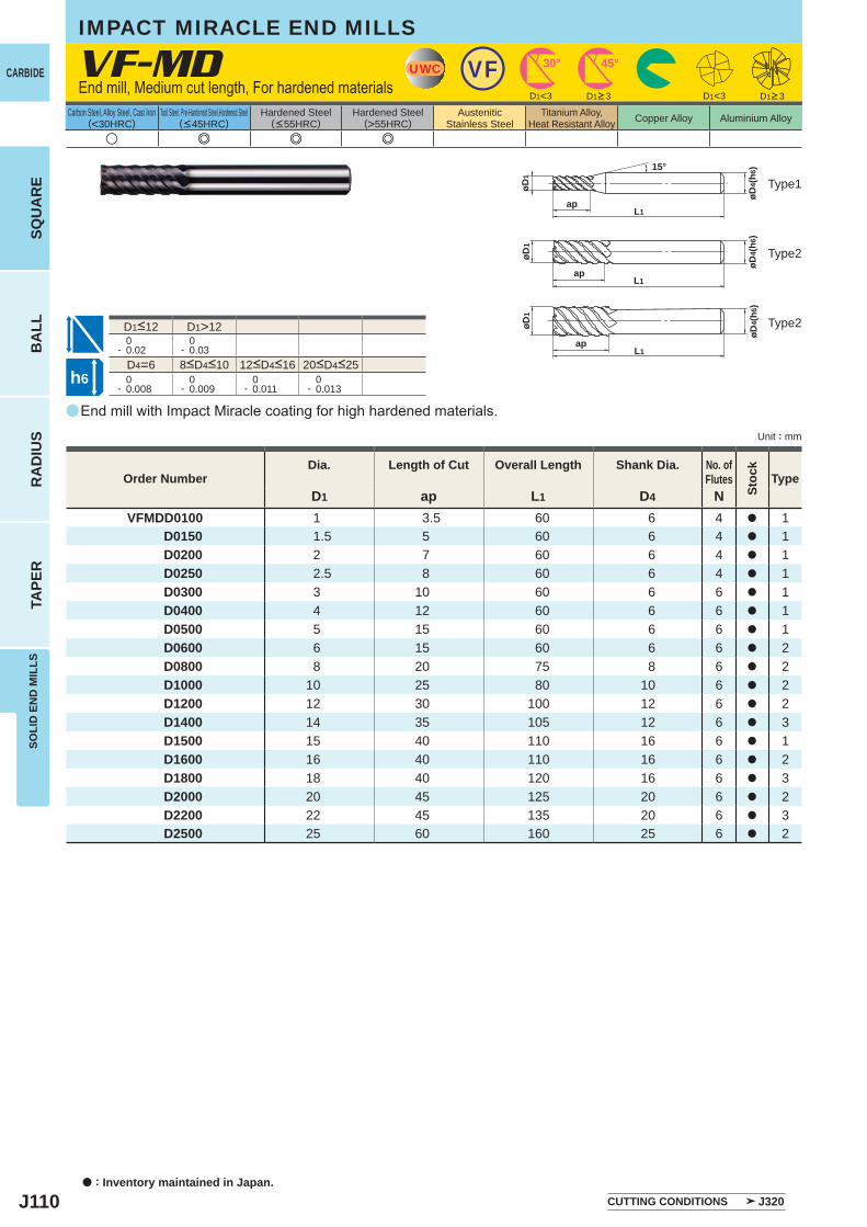
J110
a
VF-MD
D1 ap L1 D4 NVFMDD0100 1 3.5 60 6 4 a 1
D0150 1.5 5 60 6 4 a 1 D0200 2 7 60 6 4 a 1 D0250 2.5 8 60 6 4 a 1 D0300 3 10 60 6 6 a 1 D0400 4 12 60 6 6 a 1 D0500 5 15 60 6 6 a 1 D0600 6 15 60 6 6 a 2 D0800 8 20 75 8 6 a 2 D1000 10 25 80 10 6 a 2 D1200 12 30 100 12 6 a 2 D1400 14 35 105 12 6 a 3 D1500 15 40 110 16 6 a 1 D1600 16 40 110 16 6 a 2 D1800 18 40 120 16 6 a 3 D2000 20 45 125 20 6 a 2 D2200 22 45 135 20 6 a 3 D2500 25 60 160 25 6 a 2
u e e e
D1<3 D1<3
D1>12 0- 0.02
0- 0.03
D4=6 0- 0.008
0- 0.009
0- 0.011
0- 0.013
UWC VF 45°30°
øD4(
h6)
L1ap
øD1
L1ap
øD4(
h6)
øD1
L1ap
øD1
øD4(
h6)15°
h6
CARBIDE
SQU
AR
EB
ALL
RA
DIU
STA
PER
SOLI
D E
ND
MIL
LS
a : Inventory maintained in Japan.
Carbon Steel, Alloy Steel, Cast Iron(<30HRC)
Tool Steel, Pre-Hardened Steel,Hardened Steel(<45HRC)
Hardened Steel(<55HRC)
Hardened Steel(>55HRC)
AusteniticStainless Steel
Titanium Alloy,Heat Resistant Alloy Copper Alloy Aluminium Alloy
Unit : mm
D1>3 D1>3
CUTTING CONDITIONS J320
IMPACT MIRACLE END MILLS
End mill, Medium cut length, For hardened materials
Type1
Type2
Type2
8<D4<10 12<D4<16 20<D4<25
D1<12
End mill with Impact Miracle coating for high hardened materials.
Order NumberDia. Length of Cut Overall Length Shank Dia. No. of
Flutes
Stoc
k
Type
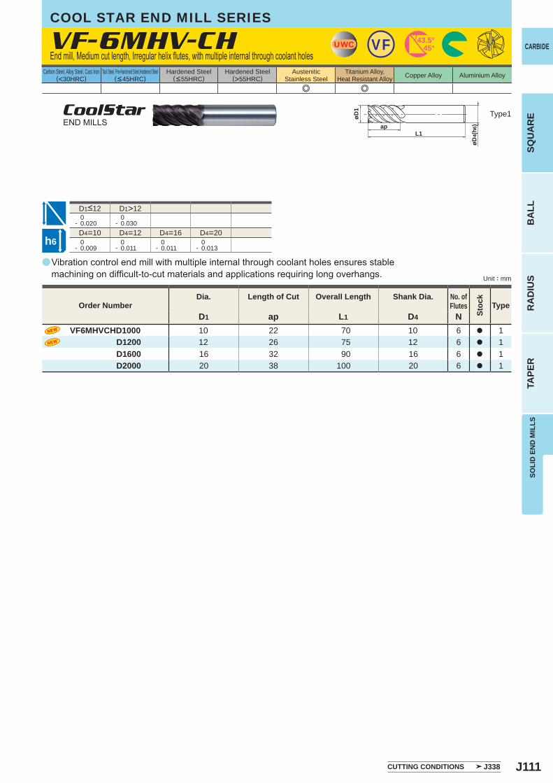
J111
a
e e
VF-6MHV-CH
D1 ap L1 D4 NVF6MHVCHD1000 10 22 70 10 6 a 1
D1200 12 26 75 12 6 a 1D1600 16 32 90 16 6 a 1D2000 20 38 100 20 6 a 1
D1>12 0- 0.020
0- 0.030
D4=10 D4=12 D4=16 D4=20 0- 0.009
0- 0.011
0- 0.011
0- 0.013
UWC VF 43.5°45°
øD1
apL1
øD4(
h6)
h6
SOLI
D E
ND
MIL
LSSQ
UA
RE
BA
LLR
AD
IUS
TAPE
R
CARBIDE
Carbon Steel, Alloy Steel, Cast Iron(<30HRC)
Tool Steel, Pre-Hardened Steel,Hardened Steel(<45HRC)
Hardened Steel(<55HRC)
Hardened Steel(>55HRC)
AusteniticStainless Steel
Titanium Alloy,Heat Resistant Alloy Copper Alloy Aluminium Alloy
Unit : mm
CUTTING CONDITIONS J338
Type1
Order NumberDia. Length of Cut Overall Length Shank Dia. No. of
Flutes
Stoc
k
Type
COOL STAR END MILL SERIES
End mill, Medium cut length, Irregular helix flutes, with multiple internal through coolant holes
CoolStarEND MILLS
D1<12
Vibration control end mill with multiple internal through coolant holes ensures stable machining on difficult-to-cut materials and applications requiring long overhangs.
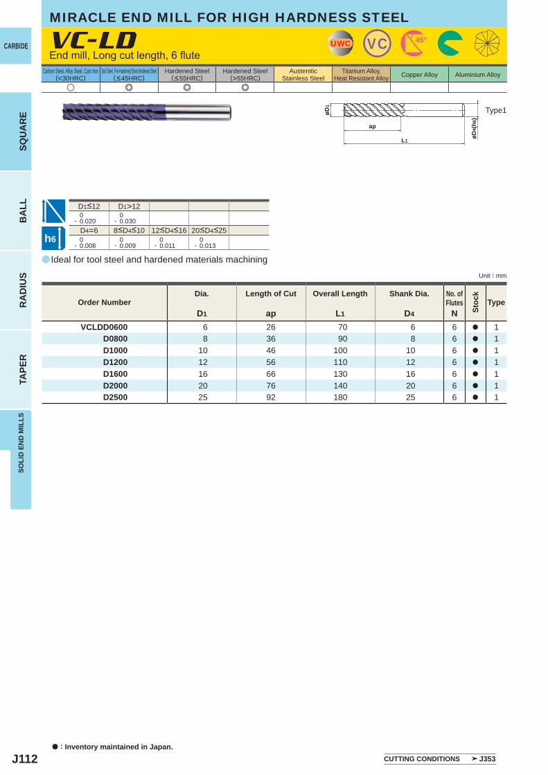
J112
a
u e e e
VC-LD
D1 ap L1 D4 NVCLDD0600 6 26 70 6 6 a 1
D0800 8 36 90 8 6 a 1D1000 10 46 100 10 6 a 1D1200 12 56 110 12 6 a 1D1600 16 66 130 16 6 a 1D2000 20 76 140 20 6 a 1D2500 25 92 180 25 6 a 1
D1>12 0- 0.020
0- 0.030
D4=6 0- 0.008
0- 0.009
0- 0.011
0- 0.013
UWC VC 45°
L1
ap
øD4(
h6)
øD1
h6
CARBIDE
SQU
AR
EB
ALL
RA
DIU
STA
PER
SOLI
D E
ND
MIL
LS
a : Inventory maintained in Japan.
Carbon Steel, Alloy Steel, Cast Iron(<30HRC)
Tool Steel, Pre-Hardened Steel,Hardened Steel(<45HRC)
Hardened Steel(<55HRC)
Hardened Steel(>55HRC)
AusteniticStainless Steel
Titanium Alloy,Heat Resistant Alloy Copper Alloy Aluminium Alloy
Unit : mm
MIRACLE END MILL FOR HIGH HARDNESS STEEL
End mill, Long cut length, 6 flute
Type1
8<D4<10 12<D4<16 20<D4<25
D1<12
Order NumberDia. Length of Cut Overall Length Shank Dia. No. of
Flutes
Stoc
k
Type
CUTTING CONDITIONS J353
Ideal for tool steel and hardened materials machining

J113
a
e e u e e
VC-6MH
D1 ap L1 D4 NVC6MHD0600 6 13 50 6 6 a 1
D0800 8 19 60 8 6 a 1D1000 10 22 70 10 6 a 1D1200 12 26 75 12 6 a 1D1600 16 32 90 16 6 a 1D2000 20 38 100 20 6 a 1D2500 25 45 120 25 6 a 1
D1>12 0- 0.02
0- 0.03
D4=6 0- 0.008
0- 0.009
0- 0.011
0- 0.013
UWC VC 45°
L1
ap
øD4(
h6)
øD1
h6
SOLI
D E
ND
MIL
LSSQ
UA
RE
BA
LLR
AD
IUS
TAPE
R
CARBIDE
Carbon Steel, Alloy Steel, Cast Iron(<30HRC)
Tool Steel, Pre-Hardened Steel,Hardened Steel(<45HRC)
Hardened Steel(<55HRC)
Hardened Steel(>55HRC)
AusteniticStainless Steel
Titanium Alloy,Heat Resistant Alloy Copper Alloy Aluminium Alloy
Unit : mm
Type1
Order NumberDia. Length of Cut Overall Length Shank Dia. No. of
Flutes
Stoc
k
Type
CUTTING CONDITIONS J355
MIRACLE END MILL FOR DIFFICULT TO CUT MATERIALS
End mill, Medium cut length, 6 flute, High helix angle
8<D4<10 12<D4<16 20<D4<25
D1<12
6 flute end mill for milling difficult-to-cut and soft materials.
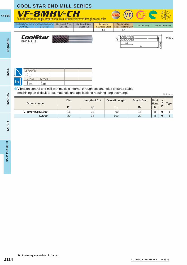
J114
a
e e
VF-8MHV-CH
D1 ap L1 D4 NVF8MHVCHD1600 16 32 90 16 8 a 1
D2000 20 38 100 20 8 a 1
0- 0.03D4=16 D4=20
0- 0.011
0- 0.013
UWC VF 44°45°
L1
ap
øD4(
h6)
øD1
h6
CARBIDE
SQU
AR
EB
ALL
RA
DIU
STA
PER
SOLI
D E
ND
MIL
LS
a : Inventory maintained in Japan.
Carbon Steel, Alloy Steel, Cast Iron(<30HRC)
Tool Steel, Pre-Hardened Steel,Hardened Steel(<45HRC)
Hardened Steel(<55HRC)
Hardened Steel(>55HRC)
AusteniticStainless Steel
Titanium Alloy,Heat Resistant Alloy Copper Alloy Aluminium Alloy
Unit : mm
COOL STAR END MILL SERIES
End mill, Medium cut length, Irregular helix flutes, with multiple internal through coolant holes
Type1CoolStarEND MILLS
16<D1<20
Vibration control end mill with multiple internal through coolant holes ensures stable machining on difficult-to-cut materials and applications requiring long overhangs.
Order NumberDia. Length of Cut Overall Length Shank Dia. No. of
Flutes
Stoc
k
Type
CUTTING CONDITIONS J339
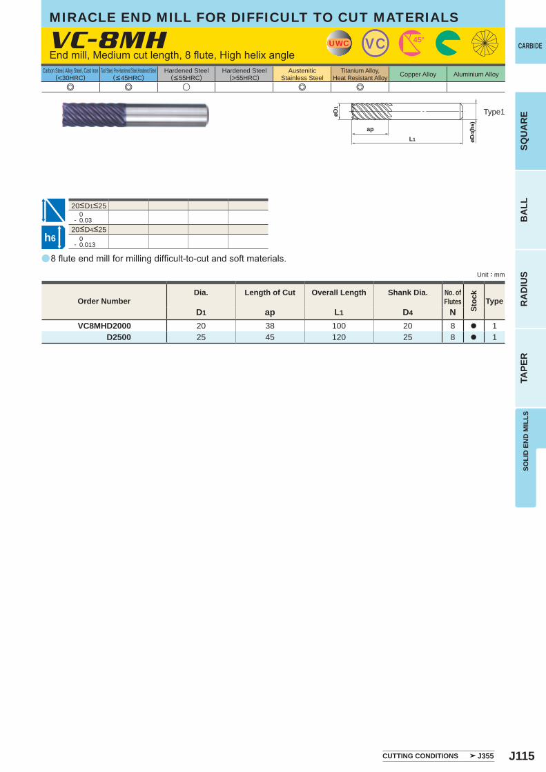
J115
a
e e u e e
VC-8MH
D1 ap L1 D4 NVC8MHD2000 20 38 100 20 8 a 1
D2500 25 45 120 25 8 a 1
0- 0.03
0- 0.013
UWC VC 45°
L1
ap
øD4(
h6)
øD1
h6
SOLI
D E
ND
MIL
LSSQ
UA
RE
BA
LLR
AD
IUS
TAPE
R
CARBIDE
Carbon Steel, Alloy Steel, Cast Iron(<30HRC)
Tool Steel, Pre-Hardened Steel,Hardened Steel(<45HRC)
Hardened Steel(<55HRC)
Hardened Steel(>55HRC)
AusteniticStainless Steel
Titanium Alloy,Heat Resistant Alloy Copper Alloy Aluminium Alloy
Unit : mm
Type1
Order NumberDia. Length of Cut Overall Length Shank Dia. No. of
Flutes
Stoc
k
Type
CUTTING CONDITIONS J355
MIRACLE END MILL FOR DIFFICULT TO CUT MATERIALS
End mill, Medium cut length, 8 flute, High helix angle
20<D4<25
20<D1<25
8 flute end mill for milling difficult-to-cut and soft materials.
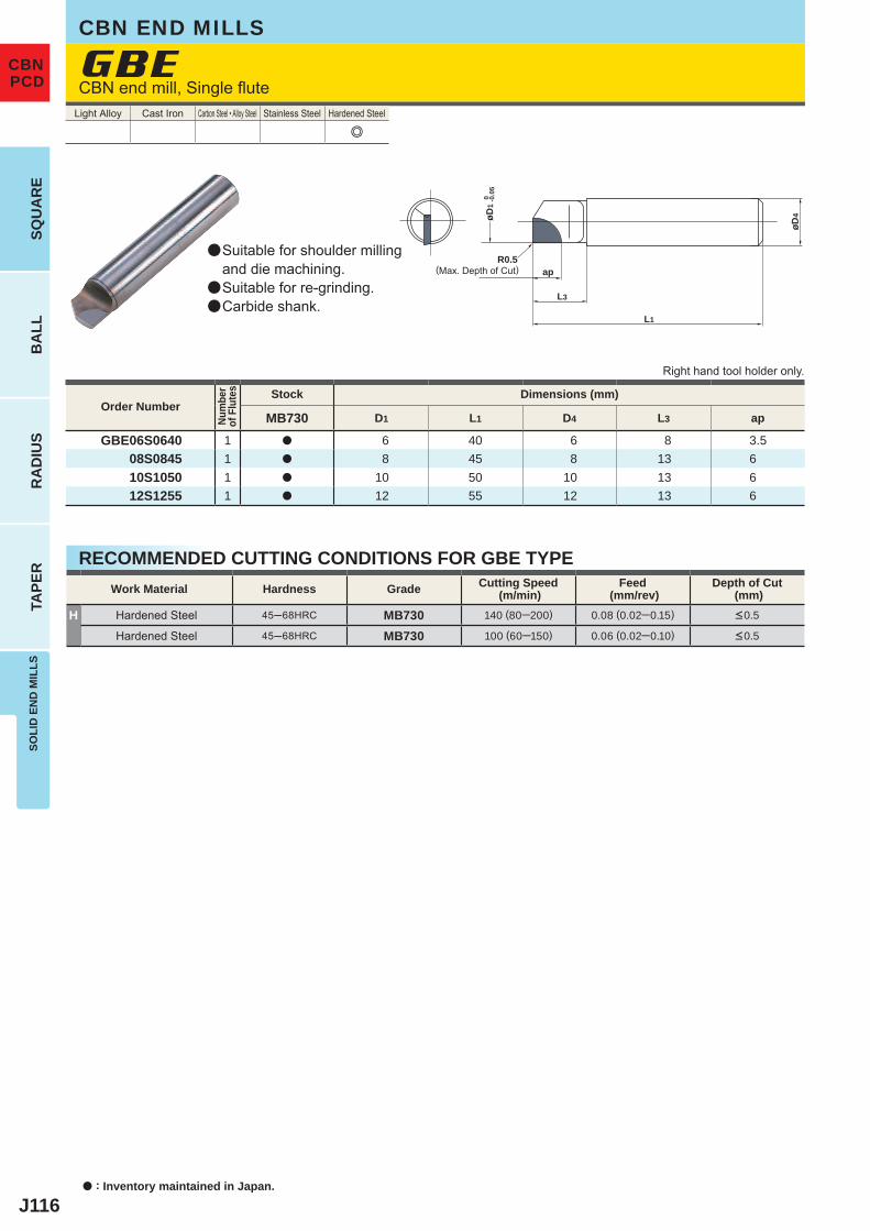
J116
e
MB730 D1 L1 D4 L3 ap
GBE06S0640 1 a 6 40 6 8 3.508S0845 1 a 8 45 8 13 610S1050 1 a 10 50 10 13 612S1255 1 a 12 55 12 13 6
H 45─68HRC MB730 140 (80─200) 0.08 (0.02─0.15)
45─68HRC MB730 100 (60─150) 0.06 (0.02─0.10)
GBE
øD4
L3
apR0.5
L1
0 -0.0
5øD
1
a : Inventory maintained in Japan.
SQU
AR
EB
ALL
RA
DIU
STA
PER
SOLI
D E
ND
MIL
LS
CBNPCD
CBN END MILLS
CBN end mill, Single flute
(Max. Depth of Cut)
Suitable for shoulder millingand die machining.Suitable for re-grinding.Carbide shank.
Light Alloy Cast Iron Carbon Steel • Alloy Steel Stainless Steel Hardened Steel
a
a
a
Right hand tool holder only.
Order Number
Num
ber
of F
lute
s Stock Dimensions (mm)
RECOMMENDED CUTTING CONDITIONS FOR GBE TYPEWork Material Hardness Grade Cutting Speed
(m/min)Feed
(mm/rev)Depth of Cut
(mm)Hardened Steel <0.5
Hardened Steel <0.5
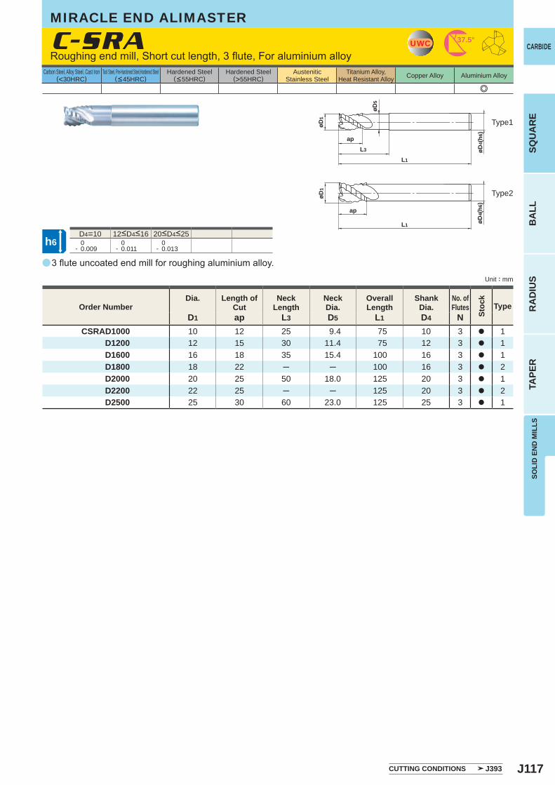
J117
a
e
C-SRA
D1 ap L3 D5 L1 D4 NCSRAD1000 10 12 25 9.4 75 10 3 a 1
D1200 12 15 30 11.4 75 12 3 a 1 D1600 16 18 35 15.4 100 16 3 a 1 D1800 18 22 ─ ─ 100 16 3 a 2 D2000 20 25 50 18.0 125 20 3 a 1 D2200 22 25 ─ ─ 125 20 3 a 2 D2500 25 30 60 23.0 125 25 3 a 1
D4=10 0- 0.009
0- 0.011
0- 0.013
UWC 37.5°
øD4(
h6)
apL3
L1
øD5
øD1
øD4(
h6)
ap
L1
øD1
h6
SOLI
D E
ND
MIL
LSSQ
UA
RE
BA
LLR
AD
IUS
TAPE
R
CARBIDE
Carbon Steel, Alloy Steel, Cast Iron(<30HRC)
Tool Steel, Pre-Hardened Steel,Hardened Steel(<45HRC)
Hardened Steel(<55HRC)
Hardened Steel(>55HRC)
AusteniticStainless Steel
Titanium Alloy,Heat Resistant Alloy Copper Alloy Aluminium Alloy
Unit : mm
Roughing end mill, Short cut length, 3 flute, For aluminium alloy
Type1
Type2
12<D4<16 20<D4<25
3 flute uncoated end mill for roughing aluminium alloy.
Order NumberDia. Length of
CutNeck
LengthNeckDia.
Overall Length
ShankDia.
No. ofFlutes
Stoc
k
Type
CUTTING CONDITIONS J393
MIRACLE END ALIMASTER
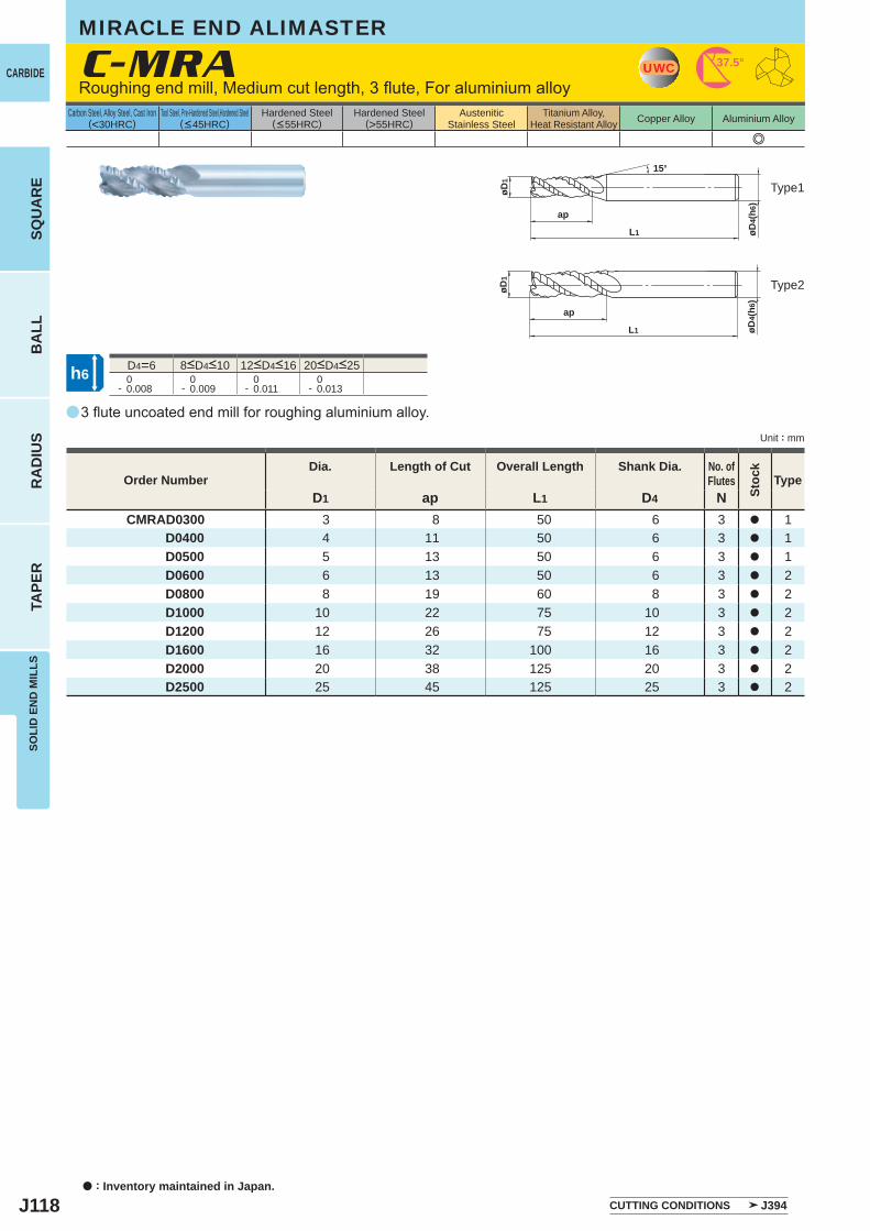
J118
a
e
C-MRA
D1 ap L1 D4 NCMRAD0300 3 8 50 6 3 a 1
D0400 4 11 50 6 3 a 1 D0500 5 13 50 6 3 a 1 D0600 6 13 50 6 3 a 2 D0800 8 19 60 8 3 a 2 D1000 10 22 75 10 3 a 2 D1200 12 26 75 12 3 a 2 D1600 16 32 100 16 3 a 2 D2000 20 38 125 20 3 a 2 D2500 25 45 125 25 3 a 2
D4=6 0- 0.008
0- 0.009
0- 0.011
0- 0.013
UWC 37.5°
øD4(
h6)
ap
L1
15°
øD1
øD4(
h6)
ap
L1
øD1
h6
CARBIDE
SQU
AR
EB
ALL
RA
DIU
STA
PER
SOLI
D E
ND
MIL
LS
a : Inventory maintained in Japan.
Carbon Steel, Alloy Steel, Cast Iron(<30HRC)
Tool Steel, Pre-Hardened Steel,Hardened Steel(<45HRC)
Hardened Steel(<55HRC)
Hardened Steel(>55HRC)
AusteniticStainless Steel
Titanium Alloy,Heat Resistant Alloy Copper Alloy Aluminium Alloy
Unit : mm
Roughing end mill, Medium cut length, 3 flute, For aluminium alloy
Type1
Type2
8<D4<10 12<D4<16 20<D4<25
3 flute uncoated end mill for roughing aluminium alloy.
Order NumberDia. Length of Cut Overall Length Shank Dia. No. of
Flutes
Stoc
k
Type
CUTTING CONDITIONS J394
MIRACLE END ALIMASTER
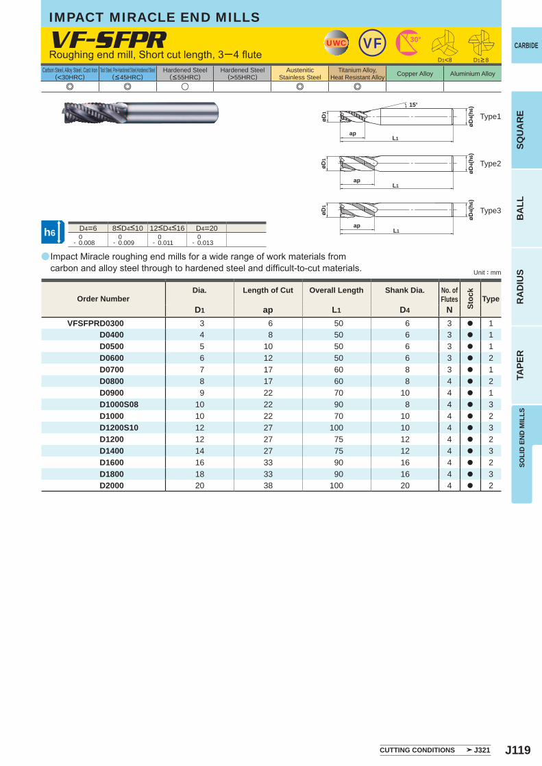
J119
a
VF-SFPR
D1 ap L1 D4 NVFSFPRD0300 3 6 50 6 3 a 1
D0400 4 8 50 6 3 a 1 D0500 5 10 50 6 3 a 1 D0600 6 12 50 6 3 a 2 D0700 7 17 60 8 3 a 1 D0800 8 17 60 8 4 a 2 D0900 9 22 70 10 4 a 1 D1000S08 10 22 90 8 4 a 3 D1000 10 22 70 10 4 a 2 D1200S10 12 27 100 10 4 a 3 D1200 12 27 75 12 4 a 2 D1400 14 27 75 12 4 a 3 D1600 16 33 90 16 4 a 2 D1800 18 33 90 16 4 a 3 D2000 20 38 100 20 4 a 2
e e u e e
D4=6 D4=20 0- 0.008
0- 0.009
0- 0.011
0- 0.013
UWC VF 30°
øD4(
h6)
apL1
15°
øD1
D1<8
øD1
øD4(
h6)
apL1
øD1
øD4(
h6)
apL1
h6
SOLI
D E
ND
MIL
LSSQ
UA
RE
BA
LLR
AD
IUS
TAPE
R
CARBIDE
Carbon Steel, Alloy Steel, Cast Iron(<30HRC)
Tool Steel, Pre-Hardened Steel,Hardened Steel(<45HRC)
Hardened Steel(<55HRC)
Hardened Steel(>55HRC)
AusteniticStainless Steel
Titanium Alloy,Heat Resistant Alloy Copper Alloy Aluminium Alloy
Unit : mm
D1>8
Type1
Type2
Type3
Order NumberDia. Length of Cut Overall Length Shank Dia. No. of
Flutes
Stoc
k
Type
CUTTING CONDITIONS J321
IMPACT MIRACLE END MILLS
Roughing end mill, Short cut length, 3─4 flute
8<D4<10 12<D4<16
Impact Miracle roughing end mills for a wide range of work materials from carbon and alloy steel through to hardened steel and difficult-to-cut materials.
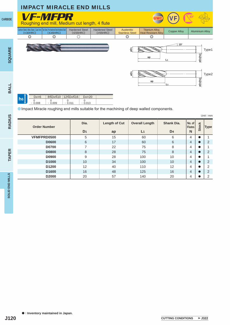
J120
a
VF-MFPR
D1 ap L1 D4 NVFMFPRD0500 5 15 60 6 4 a 1
D0600 6 17 60 6 4 a 2 D0700 7 22 75 8 4 a 1 D0800 8 28 75 8 4 a 2 D0900 9 28 100 10 4 a 1 D1000 10 34 100 10 4 a 2 D1200 12 40 110 12 4 a 2 D1600 16 48 125 16 4 a 2 D2000 20 57 140 20 4 a 2
e e u e e
D4=6 D4=20 0- 0.008
0- 0.009
0- 0.011
0- 0.013
UWC VF 30°
øD4(
h6)
apL1
øD1
15°
øD1
øD4(
h6)
apL1
h6
CARBIDE
SQU
AR
EB
ALL
RA
DIU
STA
PER
SOLI
D E
ND
MIL
LS
a : Inventory maintained in Japan.
Carbon Steel, Alloy Steel, Cast Iron(<30HRC)
Tool Steel, Pre-Hardened Steel,Hardened Steel(<45HRC)
Hardened Steel(<55HRC)
Hardened Steel(>55HRC)
AusteniticStainless Steel
Titanium Alloy,Heat Resistant Alloy Copper Alloy Aluminium Alloy
Unit : mm
Roughing end mill, Medium cut length, 4 flute
IMPACT MIRACLE END MILLS
Type1
Type2
8<D4<10 12<D4<16
Impact Miracle roughing end mills suitable for the machining of deep walled components.
Order NumberDia. Length of Cut Overall Length Shank Dia. No. of
Flutes
Stoc
k
Type
CUTTING CONDITIONS J322
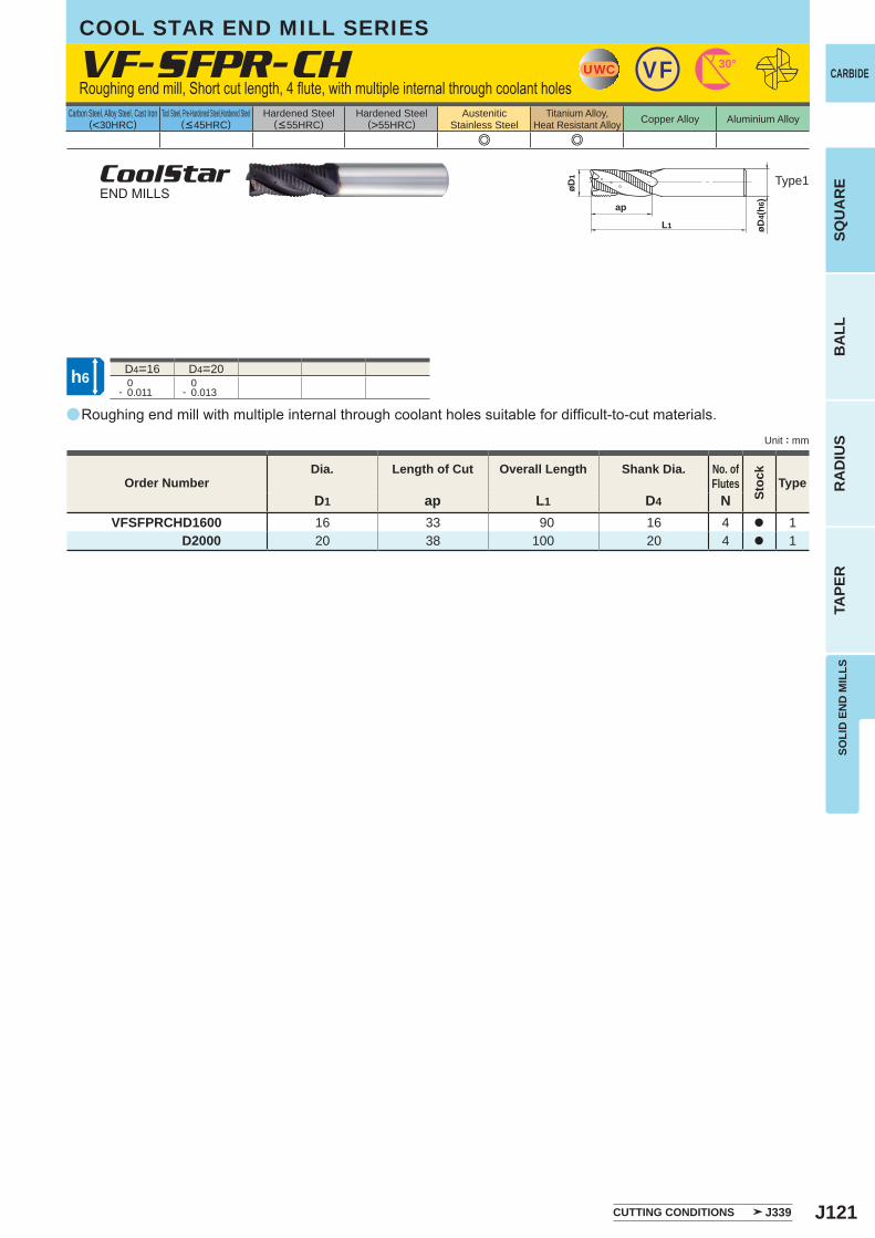
J121
a
VF-SFPR-CH
D1 ap L1 D4 NVFSFPRCHD1600 16 33 90 16 4 a 1
D2000 20 38 100 20 4 a 1
e e
D4=16 D4=20 0- 0.011
0- 0.013
UWC VF 30°
øD1
ap
L1 øD4(
h6)
h6
SOLI
D E
ND
MIL
LSSQ
UA
RE
BA
LLR
AD
IUS
TAPE
R
CARBIDE
Carbon Steel, Alloy Steel, Cast Iron(<30HRC)
Tool Steel, Pre-Hardened Steel,Hardened Steel(<45HRC)
Hardened Steel(<55HRC)
Hardened Steel(>55HRC)
AusteniticStainless Steel
Titanium Alloy,Heat Resistant Alloy Copper Alloy Aluminium Alloy
Unit : mm
Type1
Order NumberDia. Length of Cut Overall Length Shank Dia. No. of
Flutes
Stoc
k
Type
CUTTING CONDITIONS J339
COOL STAR END MILL SERIES
Roughing end mill, Short cut length, 4 flute, with multiple internal through coolant holes
CoolStarEND MILLS
Roughing end mill with multiple internal through coolant holes suitable for difficult-to-cut materials.
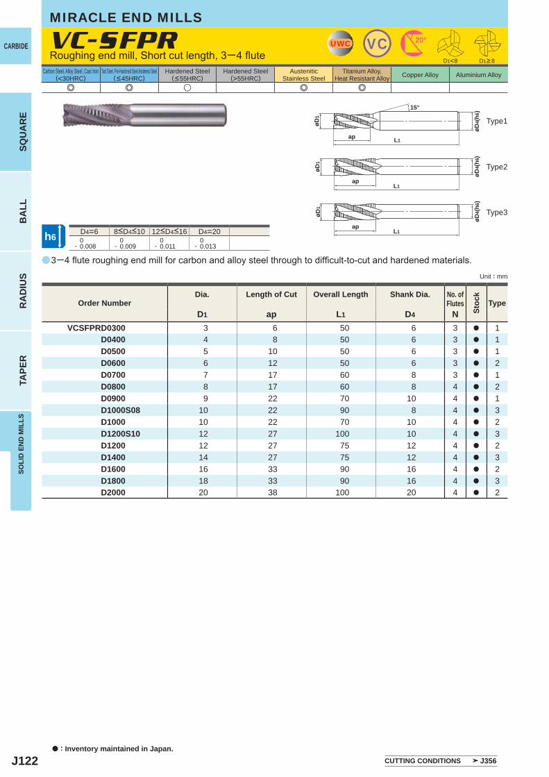
J122
a
e e u e e
VC-SFPR
D1 ap L1 D4 NVCSFPRD0300 3 6 50 6 3 a 1
D0400 4 8 50 6 3 a 1D0500 5 10 50 6 3 a 1D0600 6 12 50 6 3 a 2D0700 7 17 60 8 3 a 1D0800 8 17 60 8 4 a 2D0900 9 22 70 10 4 a 1D1000S08 10 22 90 8 4 a 3D1000 10 22 70 10 4 a 2D1200S10 12 27 100 10 4 a 3D1200 12 27 75 12 4 a 2D1400 14 27 75 12 4 a 3D1600 16 33 90 16 4 a 2D1800 18 33 90 16 4 a 3D2000 20 38 100 20 4 a 2
D4=6 D4=20 0- 0.008
0- 0.009
0- 0.011
0- 0.013
D1<8
UWC VC 20°
øD1
øD4(
h6)
L1ap
15°
øD1
øD4(
h6)
L1ap
øD1
øD4(
h6)
L1ap
h6
CARBIDE
SQU
AR
EB
ALL
RA
DIU
STA
PER
SOLI
D E
ND
MIL
LS
a : Inventory maintained in Japan.
Carbon Steel, Alloy Steel, Cast Iron(<30HRC)
Tool Steel, Pre-Hardened Steel,Hardened Steel(<45HRC)
Hardened Steel(<55HRC)
Hardened Steel(>55HRC)
AusteniticStainless Steel
Titanium Alloy,Heat Resistant Alloy Copper Alloy Aluminium Alloy
Unit : mm
D1>8Roughing end mill, Short cut length, 3─4 flute
MIRACLE END MILLS
Type1
Type2
Type3
8<D4<10 12<D4<16
3─4 flute roughing end mill for carbon and alloy steel through to difficult-to-cut and hardened materials.
Order NumberDia. Length of Cut Overall Length Shank Dia. No. of
Flutes
Stoc
k
Type
CUTTING CONDITIONS J356
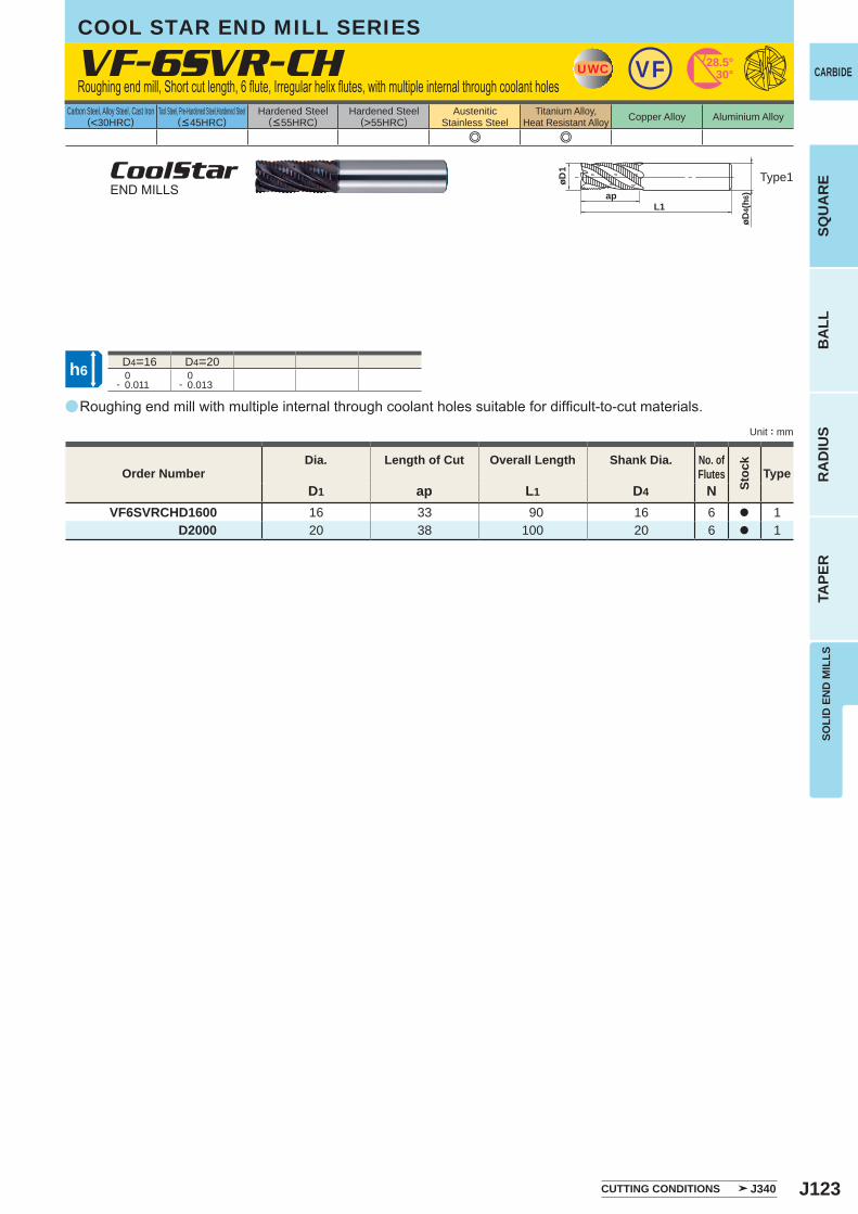
J123
a
VF-6SVR-CH
D1 ap L1 D4 NVF6SVRCHD1600 16 33 90 16 6 a 1
D2000 20 38 100 20 6 a 1
e e
D4=16 D4=20 0- 0.011
0- 0.013
UWC VF 28.5°30°
øD1
apL1
øD4(
h6)
h6
SOLI
D E
ND
MIL
LSSQ
UA
RE
BA
LLR
AD
IUS
TAPE
R
CARBIDE
Carbon Steel, Alloy Steel, Cast Iron(<30HRC)
Tool Steel, Pre-Hardened Steel,Hardened Steel(<45HRC)
Hardened Steel(<55HRC)
Hardened Steel(>55HRC)
AusteniticStainless Steel
Titanium Alloy,Heat Resistant Alloy Copper Alloy Aluminium Alloy
Unit : mm
Type1
Order NumberDia. Length of Cut Overall Length Shank Dia. No. of
Flutes
Stoc
k
Type
CUTTING CONDITIONS J340
COOL STAR END MILL SERIES
Roughing end mill, Short cut length, 6 flute, Irregular helix flutes, with multiple internal through coolant holes
CoolStarEND MILLS
Roughing end mill with multiple internal through coolant holes suitable for difficult-to-cut materials.
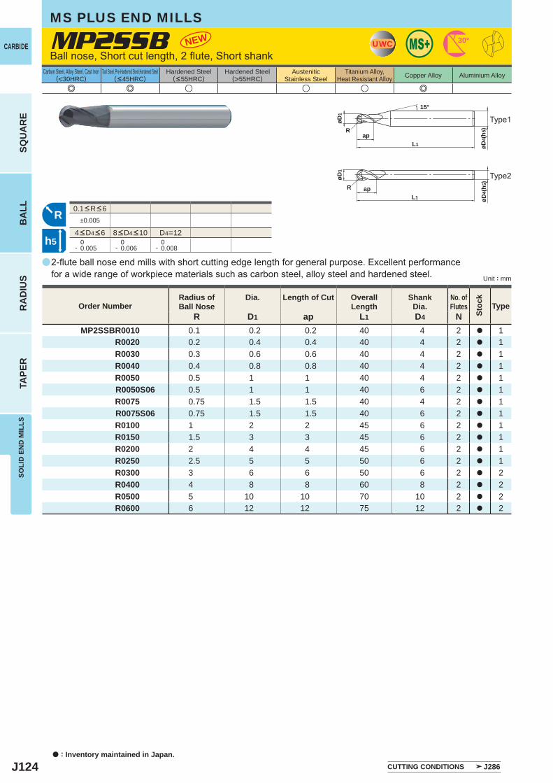
J124
a
e e u u u e
MP2SSB
MP2SSBR0010 0.1 0.2 0.2 40 4 2 a 1R0020 0.2 0.4 0.4 40 4 2 a 1R0030 0.3 0.6 0.6 40 4 2 a 1R0040 0.4 0.8 0.8 40 4 2 a 1R0050 0.5 1 1 40 4 2 a 1R0050S06 0.5 1 1 40 6 2 a 1R0075 0.75 1.5 1.5 40 4 2 a 1R0075S06 0.75 1.5 1.5 40 6 2 a 1R0100 1 2 2 45 6 2 a 1R0150 1.5 3 3 45 6 2 a 1R0200 2 4 4 45 6 2 a 1R0250 2.5 5 5 50 6 2 a 1R0300 3 6 6 50 6 2 a 2R0400 4 8 8 60 8 2 a 2R0500 5 10 10 70 10 2 a 2R0600 6 12 12 75 12 2 a 2
±0.005
D4=12 0- 0.005
0- 0.006
0- 0.008
NEW UWC 30°
L1
øD1
Rap
15°
L1ap
øD1
R
R
h5
øD4(
h)5
øD4(
h) 5
CARBIDE
SQU
AR
EB
ALL
RA
DIU
STA
PER
SOLI
D E
ND
MIL
LS
Carbon Steel, Alloy Steel, Cast Iron(<30HRC)
Tool Steel, Pre-Hardened Steel,Hardened Steel(<45HRC)
Hardened Steel(<55HRC)
Hardened Steel(>55HRC)
AusteniticStainless Steel
Titanium Alloy,Heat Resistant Alloy Copper Alloy Aluminium Alloy
Unit : mm
MS PLUS END MILLS
Order NumberRadius ofBall Nose
Dia. Length of Cut OverallLength
ShankDia.
No. ofFlutes
Stoc
k
TypeR D1 ap L1 D4 N
Ball nose, Short cut length, 2 flute, Short shank
2-flute ball nose end mills with short cutting edge length for general purpose. Excellent performance for a wide range of workpiece materials such as carbon steel, alloy steel and hardened steel.
Type2
4<D4<6 8<D4<10
0.1<R<6
CUTTING CONDITIONS J286
Type1
a : Inventory maintained in Japan.
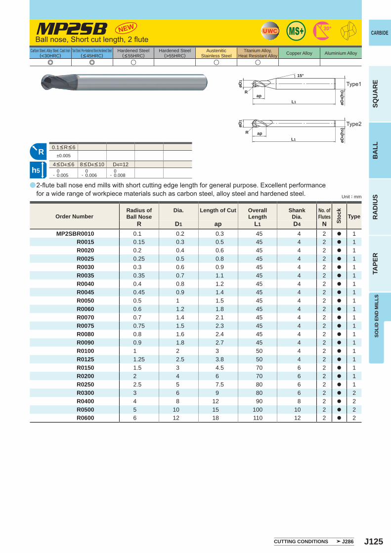
J125
a
e e u u u
MP2SB
MP2SBR0010 0.1 0.2 0.3 45 4 2 a 1R0015 0.15 0.3 0.5 45 4 2 a 1R0020 0.2 0.4 0.6 45 4 2 a 1R0025 0.25 0.5 0.8 45 4 2 a 1R0030 0.3 0.6 0.9 45 4 2 a 1R0035 0.35 0.7 1.1 45 4 2 a 1R0040 0.4 0.8 1.2 45 4 2 a 1R0045 0.45 0.9 1.4 45 4 2 a 1R0050 0.5 1 1.5 45 4 2 a 1R0060 0.6 1.2 1.8 45 4 2 a 1R0070 0.7 1.4 2.1 45 4 2 a 1R0075 0.75 1.5 2.3 45 4 2 a 1R0080 0.8 1.6 2.4 45 4 2 a 1R0090 0.9 1.8 2.7 45 4 2 a 1R0100 1 2 3 50 4 2 a 1R0125 1.25 2.5 3.8 50 4 2 a 1R0150 1.5 3 4.5 70 6 2 a 1R0200 2 4 6 70 6 2 a 1R0250 2.5 5 7.5 80 6 2 a 1R0300 3 6 9 80 6 2 a 2R0400 4 8 12 90 8 2 a 2R0500 5 10 15 100 10 2 a 2R0600 6 12 18 110 12 2 a 2
±0.005
D4=12 0- 0.005
0- 0.006
0- 0.008
NEW UWC 30°
L1
øD1
Rap
15°
L1ap
øD1
R
R
øD4(
h)5
øD4(
h)5
h5
SOLI
D E
ND
MIL
LS
CARBIDE
SQU
AR
EB
ALL
RA
DIU
STA
PER
Carbon Steel, Alloy Steel, Cast Iron(<30HRC)
Tool Steel, Pre-Hardened Steel,Hardened Steel(<45HRC)
Hardened Steel(<55HRC)
Hardened Steel(>55HRC)
AusteniticStainless Steel
Titanium Alloy,Heat Resistant Alloy Copper Alloy Aluminium Alloy
Unit : mm
Order NumberRadius ofBall Nose
Dia. Length of Cut OverallLength
ShankDia.
No. ofFlutes
Stoc
k
TypeR D1 ap L1 D4 N
Ball nose, Short cut length, 2 flute
2-flute ball nose end mills with short cutting edge length for general purpose. Excellent performance for a wide range of workpiece materials such as carbon steel, alloy steel and hardened steel.
4<D4<6 8<D4<10
0.1<R<6
CUTTING CONDITIONS J286
Type1
Type2
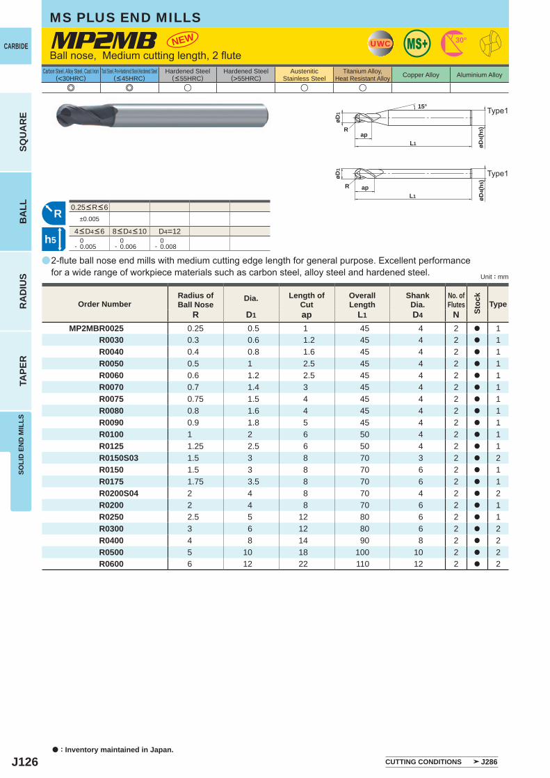
J126
a
e e u u u
MP2MB
R D1 ap L1 D4 NMP2MBR0025 0.25 0.5 1 45 4 2 a 1 R0030 0.3 0.6 1.2 45 4 2 a 1 R0040 0.4 0.8 1.6 45 4 2 a 1 R0050 0.5 1 2.5 45 4 2 a 1 R0060 0.6 1.2 2.5 45 4 2 a 1 R0070 0.7 1.4 3 45 4 2 a 1 R0075 0.75 1.5 4 45 4 2 a 1 R0080 0.8 1.6 4 45 4 2 a 1 R0090 0.9 1.8 5 45 4 2 a 1 R0100 1 2 6 50 4 2 a 1 R0125 1.25 2.5 6 50 4 2 a 1 R0150S03 1.5 3 8 70 3 2 a 2 R0150 1.5 3 8 70 6 2 a 1 R0175 1.75 3.5 8 70 6 2 a 1 R0200S04 2 4 8 70 4 2 a 2 R0200 2 4 8 70 6 2 a 1 R0250 2.5 5 12 80 6 2 a 1 R0300 3 6 12 80 6 2 a 2 R0400 4 8 14 90 8 2 a 2 R0500 5 10 18 100 10 2 a 2 R0600 6 12 22 110 12 2 a 2
±0.005
D4=12 0- 0.005
0- 0.006
0- 0.008
NEW UWC 30°
L1
øD1
Rap
15°
L1ap
øD1
R
R
h5
øD4(
h)5
øD4(
h) 5
a : Inventory maintained in Japan.
CARBIDE
SQU
AR
EB
ALL
RA
DIU
STA
PER
SOLI
D E
ND
MIL
LSMS PLUS END MILLS
Carbon Steel, Alloy Steel, Cast Iron(<30HRC)
Tool Steel, Pre-Hardened Steel,Hardened Steel(<45HRC)
Hardened Steel(<55HRC)
Hardened Steel(>55HRC)
AusteniticStainless Steel
Titanium Alloy,Heat Resistant Alloy Copper Alloy Aluminium Alloy
Unit : mm
Order NumberRadius ofBall Nose
Dia. Length ofCut
OverallLength
ShankDia.
No. ofFlutes
Stoc
k
Type
Ball nose, Medium cutting length, 2 flute
2-flute ball nose end mills with medium cutting edge length for general purpose. Excellent performance for a wide range of workpiece materials such as carbon steel, alloy steel and hardened steel.
4<D4<6 8<D4<10
0.25<R<6
Type1
Type1
CUTTING CONDITIONS J286
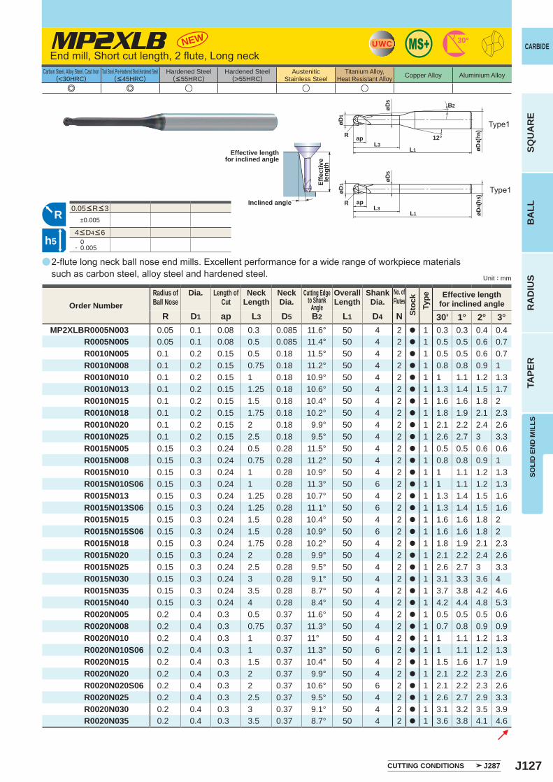
J127
a
e e u u u
MP2XLB
R D1 ap L3 D5 B2 L1 D4 N 30' 1° 2° 3°MP2XLBR0005N003 0.05 0.1 0.08 0.3 0.085 11.6° 50 4 2 a 1 0.3 0.3 0.4 0.4 R0005N005 0.05 0.1 0.08 0.5 0.085 11.4° 50 4 2 a 1 0.5 0.5 0.6 0.7 R0010N005 0.1 0.2 0.15 0.5 0.18 11.5° 50 4 2 a 1 0.5 0.5 0.6 0.7 R0010N008 0.1 0.2 0.15 0.75 0.18 11.2° 50 4 2 a 1 0.8 0.8 0.9 1 R0010N010 0.1 0.2 0.15 1 0.18 10.9° 50 4 2 a 1 1 1.1 1.2 1.3 R0010N013 0.1 0.2 0.15 1.25 0.18 10.6° 50 4 2 a 1 1.3 1.4 1.5 1.7 R0010N015 0.1 0.2 0.15 1.5 0.18 10.4° 50 4 2 a 1 1.6 1.6 1.8 2 R0010N018 0.1 0.2 0.15 1.75 0.18 10.2° 50 4 2 a 1 1.8 1.9 2.1 2.3 R0010N020 0.1 0.2 0.15 2 0.18 9.9° 50 4 2 a 1 2.1 2.2 2.4 2.6 R0010N025 0.1 0.2 0.15 2.5 0.18 9.5° 50 4 2 a 1 2.6 2.7 3 3.3 R0015N005 0.15 0.3 0.24 0.5 0.28 11.5° 50 4 2 a 1 0.5 0.5 0.6 0.6 R0015N008 0.15 0.3 0.24 0.75 0.28 11.2° 50 4 2 a 1 0.8 0.8 0.9 1 R0015N010 0.15 0.3 0.24 1 0.28 10.9° 50 4 2 a 1 1 1.1 1.2 1.3 R0015N010S06 0.15 0.3 0.24 1 0.28 11.3° 50 6 2 a 1 1 1.1 1.2 1.3 R0015N013 0.15 0.3 0.24 1.25 0.28 10.7° 50 4 2 a 1 1.3 1.4 1.5 1.6 R0015N013S06 0.15 0.3 0.24 1.25 0.28 11.1° 50 6 2 a 1 1.3 1.4 1.5 1.6 R0015N015 0.15 0.3 0.24 1.5 0.28 10.4° 50 4 2 a 1 1.6 1.6 1.8 2 R0015N015S06 0.15 0.3 0.24 1.5 0.28 10.9° 50 6 2 a 1 1.6 1.6 1.8 2 R0015N018 0.15 0.3 0.24 1.75 0.28 10.2° 50 4 2 a 1 1.8 1.9 2.1 2.3 R0015N020 0.15 0.3 0.24 2 0.28 9.9° 50 4 2 a 1 2.1 2.2 2.4 2.6 R0015N025 0.15 0.3 0.24 2.5 0.28 9.5° 50 4 2 a 1 2.6 2.7 3 3.3 R0015N030 0.15 0.3 0.24 3 0.28 9.1° 50 4 2 a 1 3.1 3.3 3.6 4 R0015N035 0.15 0.3 0.24 3.5 0.28 8.7° 50 4 2 a 1 3.7 3.8 4.2 4.6 R0015N040 0.15 0.3 0.24 4 0.28 8.4° 50 4 2 a 1 4.2 4.4 4.8 5.3 R0020N005 0.2 0.4 0.3 0.5 0.37 11.6° 50 4 2 a 1 0.5 0.5 0.5 0.6 R0020N008 0.2 0.4 0.3 0.75 0.37 11.3° 50 4 2 a 1 0.7 0.8 0.9 0.9 R0020N010 0.2 0.4 0.3 1 0.37 11° 50 4 2 a 1 1 1.1 1.2 1.3 R0020N010S06 0.2 0.4 0.3 1 0.37 11.3° 50 6 2 a 1 1 1.1 1.2 1.3 R0020N015 0.2 0.4 0.3 1.5 0.37 10.4° 50 4 2 a 1 1.5 1.6 1.7 1.9 R0020N020 0.2 0.4 0.3 2 0.37 9.9° 50 4 2 a 1 2.1 2.2 2.3 2.6 R0020N020S06 0.2 0.4 0.3 2 0.37 10.6° 50 6 2 a 1 2.1 2.2 2.3 2.6 R0020N025 0.2 0.4 0.3 2.5 0.37 9.5° 50 4 2 a 1 2.6 2.7 2.9 3.3 R0020N030 0.2 0.4 0.3 3 0.37 9.1° 50 4 2 a 1 3.1 3.2 3.5 3.9 R0020N035 0.2 0.4 0.3 3.5 0.37 8.7° 50 4 2 a 1 3.6 3.8 4.1 4.6
±0.005
0- 0.005
NEW UWC 30°
L1
apL3
øD1
R
øD5
B2
RL1
apL3
øD1
øD5
R
h5
øD4(
h)5
øD4(
h)5
12°
SOLI
D E
ND
MIL
LS
CARBIDE
SQU
AR
EB
ALL
RA
DIU
STA
PER
Carbon Steel, Alloy Steel, Cast Iron(<30HRC)
Tool Steel, Pre-Hardened Steel,Hardened Steel(<45HRC)
Hardened Steel(<55HRC)
Hardened Steel(>55HRC)
AusteniticStainless Steel
Titanium Alloy,Heat Resistant Alloy Copper Alloy Aluminium Alloy
Unit : mm
Order NumberRadius ofBall Nose
Dia. Length ofCut
NeckLength
NeckDia.
Cutting Edgeto Shank
Angle
OverallLength
ShankDia.
No. ofFlutes
Stoc
kTy
pe Effective lengthfor inclined angle
End mill, Short cut length, 2 flute, Long neck
2-flute long neck ball nose end mills. Excellent performance for a wide range of workpiece materials such as carbon steel, alloy steel and hardened steel.
Effective lengthfor inclined angle
Inclined angle
Effe
ctiv
ele
ngth
4<D4<6
CUTTING CONDITIONS J287
0.05<R<3
Type1
Type1
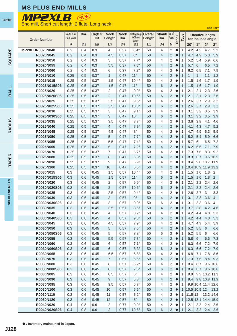
J128
R D1 ap L3 D5 B2 L1 D4 N 30' 1° 2° 3°MP2XLBR0020N040 0.2 0.4 0.3 4 0.37 8.4° 50 4 2 a 1 4.2 4.3 4.7 5.2 R0020N045 0.2 0.4 0.3 4.5 0.37 8° 50 4 2 a 1 4.7 4.9 5.3 5.9 R0020N050 0.2 0.4 0.3 5 0.37 7.7° 50 4 2 a 1 5.2 5.4 5.9 6.6 R0020N055 0.2 0.4 0.3 5.5 0.37 7.5° 50 4 2 a 1 5.7 6 6.5 7.2 R0020N060 0.2 0.4 0.3 6 0.37 7.2° 50 4 2 a 1 6.2 6.5 7.1 7.9 R0025N010 0.25 0.5 0.37 1 0.47 11° 50 4 2 a 1 1 1 1.1 1.2 R0025N015 0.25 0.5 0.37 1.5 0.47 10.4° 50 4 2 a 1 1.5 1.6 1.7 1.9 R0025N015S06 0.25 0.5 0.37 1.5 0.47 11° 50 6 2 a 1 1.5 1.6 1.7 1.9 R0025N020 0.25 0.5 0.37 2 0.47 9.9° 50 4 2 a 1 2.1 2.1 2.3 2.6 R0025N020S06 0.25 0.5 0.37 2 0.47 10.6° 50 6 2 a 1 2.1 2.1 2.3 2.6 R0025N025 0.25 0.5 0.37 2.5 0.47 9.5° 50 4 2 a 1 2.6 2.7 2.9 3.2 R0025N025S06 0.25 0.5 0.37 2.5 0.47 10.3° 50 6 2 a 1 2.6 2.7 2.9 3.2 R0025N030 0.25 0.5 0.37 3 0.47 9.1° 50 4 2 a 1 3.1 3.2 3.5 3.9 R0025N030S06 0.25 0.5 0.37 3 0.47 10° 50 6 2 a 1 3.1 3.2 3.5 3.9 R0025N035 0.25 0.5 0.37 3.5 0.47 8.7° 50 4 2 a 1 3.6 3.8 4.1 4.6 R0025N040 0.25 0.5 0.37 4 0.47 8.3° 50 4 2 a 1 4.1 4.3 4.7 5.2 R0025N045 0.25 0.5 0.37 4.5 0.47 8° 50 4 2 a 1 4.7 4.9 5.3 5.9 R0025N050 0.25 0.5 0.37 5 0.47 7.7° 50 4 2 a 1 5.2 5.4 5.9 6.6 R0025N055 0.25 0.5 0.37 5.5 0.47 7.4° 50 4 2 a 1 5.7 6 6.5 7.2 R0025N060 0.25 0.5 0.37 6 0.47 7.2° 50 4 2 a 1 6.2 6.5 7.1 7.9 R0025N070 0.25 0.5 0.37 7 0.47 6.7° 50 4 2 a 1 7.3 7.6 8.3 9.2 R0025N080 0.25 0.5 0.37 8 0.47 6.3° 50 4 2 a 1 8.3 8.7 9.5 10.5 R0025N090 0.25 0.5 0.37 9 0.47 5.9° 50 4 2 a 1 9.4 9.8 10.7 11.9 R0025N100 0.25 0.5 0.37 10 0.47 5.6° 50 4 2 a 1 10.4 10.9 11.9 13.2 R0030N015 0.3 0.6 0.45 1.5 0.57 10.4° 50 4 2 a 1 1.5 1.6 1.8 2 R0030N015S06 0.3 0.6 0.45 1.5 0.57 11° 50 6 2 a 1 1.5 1.6 1.8 2 R0030N020 0.3 0.6 0.45 2 0.57 9.9° 50 4 2 a 1 2.1 2.2 2.4 2.6 R0030N020S06 0.3 0.6 0.45 2 0.57 10.6° 50 6 2 a 1 2.1 2.2 2.4 2.6 R0030N025 0.3 0.6 0.45 2.5 0.57 9.4° 50 4 2 a 1 2.6 2.7 3 3.3 R0030N030 0.3 0.6 0.45 3 0.57 9° 50 4 2 a 1 3.1 3.3 3.6 4 R0030N030S06 0.3 0.6 0.45 3 0.57 9.9° 50 6 2 a 1 3.1 3.3 3.6 4 R0030N035 0.3 0.6 0.45 3.5 0.57 8.6° 50 4 2 a 1 3.7 3.8 4.2 4.6 R0030N040 0.3 0.6 0.45 4 0.57 8.2° 50 4 2 a 1 4.2 4.4 4.8 5.3 R0030N040S06 0.3 0.6 0.45 4 0.57 9.3° 50 6 2 a 1 4.2 4.4 4.8 5.3 R0030N045 0.3 0.6 0.45 4.5 0.57 7.9° 50 4 2 a 1 4.7 4.9 5.4 5.9 R0030N050 0.3 0.6 0.45 5 0.57 7.6° 50 4 2 a 1 5.2 5.5 6 6.6 R0030N050S06 0.3 0.6 0.45 5 0.57 8.8° 50 6 2 a 1 5.2 5.5 6 6.6 R0030N055 0.3 0.6 0.45 5.5 0.57 7.3° 50 4 2 a 1 5.8 6 6.6 7.3 R0030N060 0.3 0.6 0.45 6 0.57 7.1° 50 4 2 a 1 6.3 6.6 7.2 7.9 R0030N060S06 0.3 0.6 0.45 6 0.57 8.3° 50 6 2 a 1 6.3 6.6 7.2 7.9 R0030N065 0.3 0.6 0.45 6.5 0.57 6.8° 50 4 2 a 1 6.8 7.1 7.8 8.6 R0030N070 0.3 0.6 0.45 7 0.57 6.6° 50 4 2 a 1 7.3 7.6 8.4 9.3 R0030N080 0.3 0.6 0.45 8 0.57 6.2° 50 4 2 a 1 8.4 8.7 9.6 10.6 R0030N080S06 0.3 0.6 0.45 8 0.57 7.6° 50 6 2 a 1 8.4 8.7 9.6 10.6 R0030N085 0.3 0.6 0.45 8.5 0.57 6° 50 4 2 a 1 8.9 9.3 10.2 11.3 R0030N090 0.3 0.6 0.45 9 0.57 5.8° 50 4 2 a 1 9.4 9.8 10.8 11.9 R0030N095 0.3 0.6 0.45 9.5 0.57 5.7° 50 4 2 a 1 9.9 10.4 11.4 12.6 R0030N100 0.3 0.6 0.45 10 0.57 5.5° 50 4 2 a 1 10.5 10.9 12 13.2 R0030N110 0.3 0.6 0.45 11 0.57 5.2° 50 4 2 a 1 11.5 12 13.2 14.6 R0030N120 0.3 0.6 0.45 12 0.57 5° 50 4 2 a 1 12.5 13.1 14.4 15.9 R0040N020 0.4 0.8 0.6 2 0.77 9.9° 50 4 2 a 1 2.1 2.2 2.4 2.6 R0040N020S06 0.4 0.8 0.6 2 0.77 10.6° 50 6 2 a 1 2.1 2.2 2.4 2.6
MP2XLB NEW
a : Inventory maintained in Japan.
Unit : mm
CARBIDE
SQU
AR
EB
ALL
RA
DIU
STA
PER
SOLI
D E
ND
MIL
LSMS PLUS END MILLS
Order NumberRadius ofBall Nose
Dia. Length ofCut
NeckLength
NeckDia.
Cutting Edgeto Shank
Angle
OverallLength
ShankDia.
No. ofFlutes
Stoc
kTy
pe Effective lengthfor inclined angle
End mill, Short cut length, 2 flute, Long neck
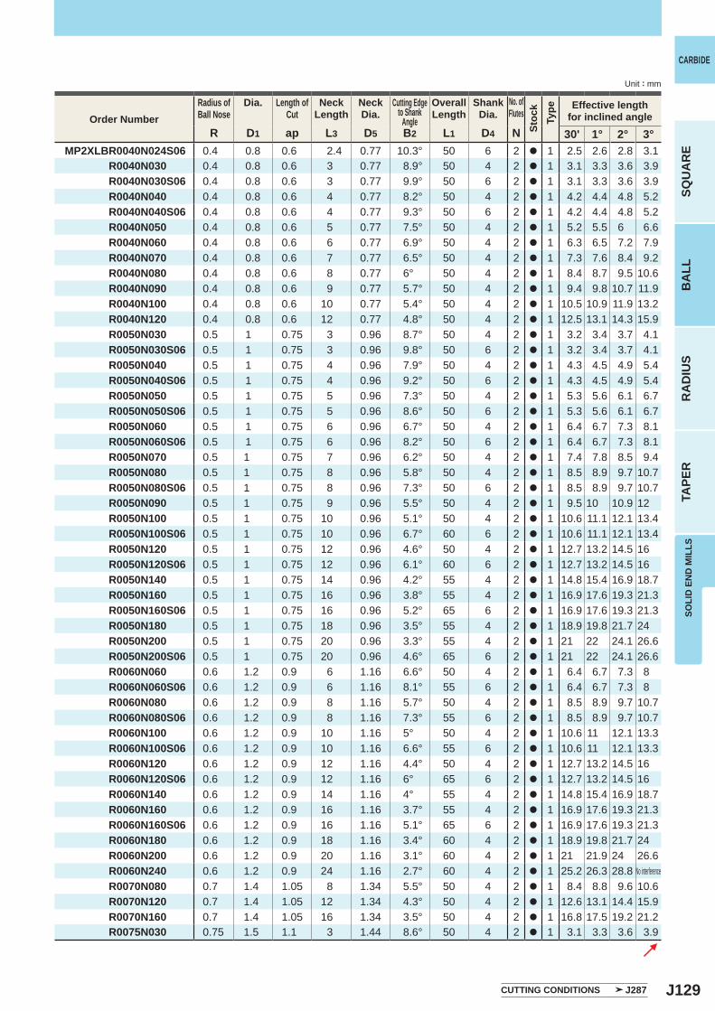
J129
R D1 ap L3 D5 B2 L1 D4 N 30' 1° 2° 3°MP2XLBR0040N024S06 0.4 0.8 0.6 2.4 0.77 10.3° 50 6 2 a 1 2.5 2.6 2.8 3.1 R0040N030 0.4 0.8 0.6 3 0.77 8.9° 50 4 2 a 1 3.1 3.3 3.6 3.9 R0040N030S06 0.4 0.8 0.6 3 0.77 9.9° 50 6 2 a 1 3.1 3.3 3.6 3.9 R0040N040 0.4 0.8 0.6 4 0.77 8.2° 50 4 2 a 1 4.2 4.4 4.8 5.2 R0040N040S06 0.4 0.8 0.6 4 0.77 9.3° 50 6 2 a 1 4.2 4.4 4.8 5.2 R0040N050 0.4 0.8 0.6 5 0.77 7.5° 50 4 2 a 1 5.2 5.5 6 6.6 R0040N060 0.4 0.8 0.6 6 0.77 6.9° 50 4 2 a 1 6.3 6.5 7.2 7.9 R0040N070 0.4 0.8 0.6 7 0.77 6.5° 50 4 2 a 1 7.3 7.6 8.4 9.2 R0040N080 0.4 0.8 0.6 8 0.77 6° 50 4 2 a 1 8.4 8.7 9.5 10.6 R0040N090 0.4 0.8 0.6 9 0.77 5.7° 50 4 2 a 1 9.4 9.8 10.7 11.9 R0040N100 0.4 0.8 0.6 10 0.77 5.4° 50 4 2 a 1 10.5 10.9 11.9 13.2 R0040N120 0.4 0.8 0.6 12 0.77 4.8° 50 4 2 a 1 12.5 13.1 14.3 15.9 R0050N030 0.5 1 0.75 3 0.96 8.7° 50 4 2 a 1 3.2 3.4 3.7 4.1 R0050N030S06 0.5 1 0.75 3 0.96 9.8° 50 6 2 a 1 3.2 3.4 3.7 4.1 R0050N040 0.5 1 0.75 4 0.96 7.9° 50 4 2 a 1 4.3 4.5 4.9 5.4 R0050N040S06 0.5 1 0.75 4 0.96 9.2° 50 6 2 a 1 4.3 4.5 4.9 5.4 R0050N050 0.5 1 0.75 5 0.96 7.3° 50 4 2 a 1 5.3 5.6 6.1 6.7 R0050N050S06 0.5 1 0.75 5 0.96 8.6° 50 6 2 a 1 5.3 5.6 6.1 6.7 R0050N060 0.5 1 0.75 6 0.96 6.7° 50 4 2 a 1 6.4 6.7 7.3 8.1 R0050N060S06 0.5 1 0.75 6 0.96 8.2° 50 6 2 a 1 6.4 6.7 7.3 8.1 R0050N070 0.5 1 0.75 7 0.96 6.2° 50 4 2 a 1 7.4 7.8 8.5 9.4 R0050N080 0.5 1 0.75 8 0.96 5.8° 50 4 2 a 1 8.5 8.9 9.7 10.7 R0050N080S06 0.5 1 0.75 8 0.96 7.3° 50 6 2 a 1 8.5 8.9 9.7 10.7 R0050N090 0.5 1 0.75 9 0.96 5.5° 50 4 2 a 1 9.5 10 10.9 12 R0050N100 0.5 1 0.75 10 0.96 5.1° 50 4 2 a 1 10.6 11.1 12.1 13.4 R0050N100S06 0.5 1 0.75 10 0.96 6.7° 60 6 2 a 1 10.6 11.1 12.1 13.4 R0050N120 0.5 1 0.75 12 0.96 4.6° 50 4 2 a 1 12.7 13.2 14.5 16 R0050N120S06 0.5 1 0.75 12 0.96 6.1° 60 6 2 a 1 12.7 13.2 14.5 16 R0050N140 0.5 1 0.75 14 0.96 4.2° 55 4 2 a 1 14.8 15.4 16.9 18.7 R0050N160 0.5 1 0.75 16 0.96 3.8° 55 4 2 a 1 16.9 17.6 19.3 21.3 R0050N160S06 0.5 1 0.75 16 0.96 5.2° 65 6 2 a 1 16.9 17.6 19.3 21.3 R0050N180 0.5 1 0.75 18 0.96 3.5° 55 4 2 a 1 18.9 19.8 21.7 24 R0050N200 0.5 1 0.75 20 0.96 3.3° 55 4 2 a 1 21 22 24.1 26.6 R0050N200S06 0.5 1 0.75 20 0.96 4.6° 65 6 2 a 1 21 22 24.1 26.6 R0060N060 0.6 1.2 0.9 6 1.16 6.6° 50 4 2 a 1 6.4 6.7 7.3 8 R0060N060S06 0.6 1.2 0.9 6 1.16 8.1° 55 6 2 a 1 6.4 6.7 7.3 8 R0060N080 0.6 1.2 0.9 8 1.16 5.7° 50 4 2 a 1 8.5 8.9 9.7 10.7 R0060N080S06 0.6 1.2 0.9 8 1.16 7.3° 55 6 2 a 1 8.5 8.9 9.7 10.7 R0060N100 0.6 1.2 0.9 10 1.16 5° 50 4 2 a 1 10.6 11 12.1 13.3 R0060N100S06 0.6 1.2 0.9 10 1.16 6.6° 55 6 2 a 1 10.6 11 12.1 13.3 R0060N120 0.6 1.2 0.9 12 1.16 4.4° 50 4 2 a 1 12.7 13.2 14.5 16 R0060N120S06 0.6 1.2 0.9 12 1.16 6° 65 6 2 a 1 12.7 13.2 14.5 16 R0060N140 0.6 1.2 0.9 14 1.16 4° 55 4 2 a 1 14.8 15.4 16.9 18.7 R0060N160 0.6 1.2 0.9 16 1.16 3.7° 55 4 2 a 1 16.9 17.6 19.3 21.3 R0060N160S06 0.6 1.2 0.9 16 1.16 5.1° 65 6 2 a 1 16.9 17.6 19.3 21.3 R0060N180 0.6 1.2 0.9 18 1.16 3.4° 60 4 2 a 1 18.9 19.8 21.7 24 R0060N200 0.6 1.2 0.9 20 1.16 3.1° 60 4 2 a 1 21 21.9 24 26.6 R0060N240 0.6 1.2 0.9 24 1.16 2.7° 60 4 2 a 1 25.2 26.3 28.8 R0070N080 0.7 1.4 1.05 8 1.34 5.5° 50 4 2 a 1 8.4 8.8 9.6 10.6 R0070N120 0.7 1.4 1.05 12 1.34 4.3° 50 4 2 a 1 12.6 13.1 14.4 15.9 R0070N160 0.7 1.4 1.05 16 1.34 3.5° 50 4 2 a 1 16.8 17.5 19.2 21.2 R0075N030 0.75 1.5 1.1 3 1.44 8.6° 50 4 2 a 1 3.1 3.3 3.6 3.9
Unit : mm
SOLI
D E
ND
MIL
LS
CARBIDE
SQU
AR
EB
ALL
RA
DIU
STA
PER
Order NumberRadius ofBall Nose
Dia. Length ofCut
NeckLength
NeckDia.
Cutting Edgeto Shank
Angle
OverallLength
ShankDia.
No. ofFlutes
Stoc
kTy
pe Effective lengthfor inclined angle
No interference
CUTTING CONDITIONS J287
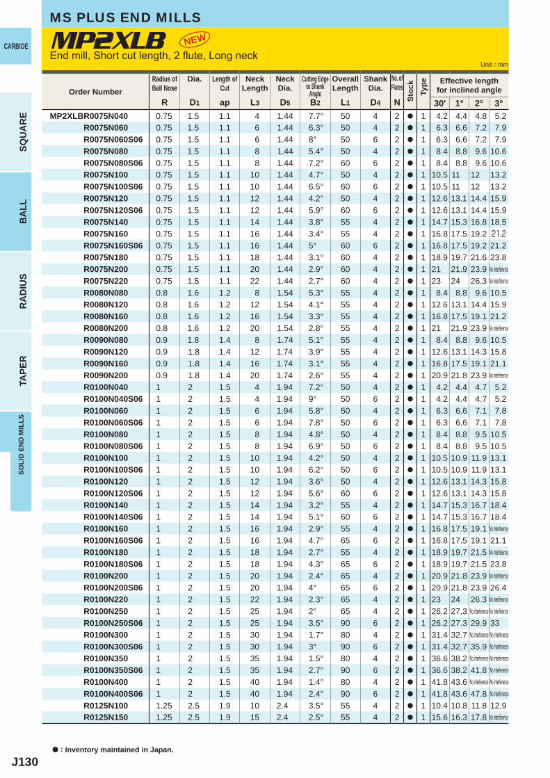
J130
MP2XLB
R D1 ap L3 D5 B2 L1 D4 N 30' 1° 2° 3°MP2XLBR0075N040 0.75 1.5 1.1 4 1.44 7.7° 50 4 2 a 1 4.2 4.4 4.8 5.2 R0075N060 0.75 1.5 1.1 6 1.44 6.3° 50 4 2 a 1 6.3 6.6 7.2 7.9 R0075N060S06 0.75 1.5 1.1 6 1.44 8° 50 6 2 a 1 6.3 6.6 7.2 7.9 R0075N080 0.75 1.5 1.1 8 1.44 5.4° 50 4 2 a 1 8.4 8.8 9.6 10.6 R0075N080S06 0.75 1.5 1.1 8 1.44 7.2° 60 6 2 a 1 8.4 8.8 9.6 10.6 R0075N100 0.75 1.5 1.1 10 1.44 4.7° 50 4 2 a 1 10.5 11 12 13.2 R0075N100S06 0.75 1.5 1.1 10 1.44 6.5° 60 6 2 a 1 10.5 11 12 13.2 R0075N120 0.75 1.5 1.1 12 1.44 4.2° 50 4 2 a 1 12.6 13.1 14.4 15.9 R0075N120S06 0.75 1.5 1.1 12 1.44 5.9° 60 6 2 a 1 12.6 13.1 14.4 15.9 R0075N140 0.75 1.5 1.1 14 1.44 3.8° 55 4 2 a 1 14.7 15.3 16.8 18.5 R0075N160 0.75 1.5 1.1 16 1.44 3.4° 55 4 2 a 1 16.8 17.5 19.2 21.2 R0075N160S06 0.75 1.5 1.1 16 1.44 5° 60 6 2 a 1 16.8 17.5 19.2 21.2 R0075N180 0.75 1.5 1.1 18 1.44 3.1° 60 4 2 a 1 18.9 19.7 21.6 23.8 R0075N200 0.75 1.5 1.1 20 1.44 2.9° 60 4 2 a 1 21 21.9 23.9 R0075N220 0.75 1.5 1.1 22 1.44 2.7° 60 4 2 a 1 23 24 26.3 R0080N080 0.8 1.6 1.2 8 1.54 5.3° 55 4 2 a 1 8.4 8.8 9.6 10.5 R0080N120 0.8 1.6 1.2 12 1.54 4.1° 55 4 2 a 1 12.6 13.1 14.4 15.9 R0080N160 0.8 1.6 1.2 16 1.54 3.3° 55 4 2 a 1 16.8 17.5 19.1 21.2 R0080N200 0.8 1.6 1.2 20 1.54 2.8° 55 4 2 a 1 21 21.9 23.9 R0090N080 0.9 1.8 1.4 8 1.74 5.1° 55 4 2 a 1 8.4 8.8 9.6 10.5 R0090N120 0.9 1.8 1.4 12 1.74 3.9° 55 4 2 a 1 12.6 13.1 14.3 15.8 R0090N160 0.9 1.8 1.4 16 1.74 3.1° 55 4 2 a 1 16.8 17.5 19.1 21.1 R0090N200 0.9 1.8 1.4 20 1.74 2.6° 55 4 2 a 1 20.9 21.8 23.9 R0100N040 1 2 1.5 4 1.94 7.2° 50 4 2 a 1 4.2 4.4 4.7 5.2 R0100N040S06 1 2 1.5 4 1.94 9° 50 6 2 a 1 4.2 4.4 4.7 5.2 R0100N060 1 2 1.5 6 1.94 5.8° 50 4 2 a 1 6.3 6.6 7.1 7.8 R0100N060S06 1 2 1.5 6 1.94 7.8° 50 6 2 a 1 6.3 6.6 7.1 7.8 R0100N080 1 2 1.5 8 1.94 4.8° 50 4 2 a 1 8.4 8.8 9.5 10.5 R0100N080S06 1 2 1.5 8 1.94 6.9° 50 6 2 a 1 8.4 8.8 9.5 10.5 R0100N100 1 2 1.5 10 1.94 4.2° 50 4 2 a 1 10.5 10.9 11.9 13.1 R0100N100S06 1 2 1.5 10 1.94 6.2° 50 6 2 a 1 10.5 10.9 11.9 13.1 R0100N120 1 2 1.5 12 1.94 3.6° 50 4 2 a 1 12.6 13.1 14.3 15.8 R0100N120S06 1 2 1.5 12 1.94 5.6° 60 6 2 a 1 12.6 13.1 14.3 15.8 R0100N140 1 2 1.5 14 1.94 3.2° 55 4 2 a 1 14.7 15.3 16.7 18.4 R0100N140S06 1 2 1.5 14 1.94 5.1° 60 6 2 a 1 14.7 15.3 16.7 18.4 R0100N160 1 2 1.5 16 1.94 2.9° 55 4 2 a 1 16.8 17.5 19.1 R0100N160S06 1 2 1.5 16 1.94 4.7° 65 6 2 a 1 16.8 17.5 19.1 21.1 R0100N180 1 2 1.5 18 1.94 2.7° 55 4 2 a 1 18.9 19.7 21.5 R0100N180S06 1 2 1.5 18 1.94 4.3° 65 6 2 a 1 18.9 19.7 21.5 23.8 R0100N200 1 2 1.5 20 1.94 2.4° 65 4 2 a 1 20.9 21.8 23.9 R0100N200S06 1 2 1.5 20 1.94 4° 65 6 2 a 1 20.9 21.8 23.9 26.4 R0100N220 1 2 1.5 22 1.94 2.3° 65 4 2 a 1 23 24 26.3 R0100N250 1 2 1.5 25 1.94 2° 65 4 2 a 1 26.2 27.3 R0100N250S06 1 2 1.5 25 1.94 3.5° 90 6 2 a 1 26.2 27.3 29.9 33 R0100N300 1 2 1.5 30 1.94 1.7° 80 4 2 a 1 31.4 32.7 R0100N300S06 1 2 1.5 30 1.94 3° 90 6 2 a 1 31.4 32.7 35.9 R0100N350 1 2 1.5 35 1.94 1.5° 80 4 2 a 1 36.6 38.2 R0100N350S06 1 2 1.5 35 1.94 2.7° 90 6 2 a 1 36.6 38.2 41.8 R0100N400 1 2 1.5 40 1.94 1.4° 80 4 2 a 1 41.8 43.6 R0100N400S06 1 2 1.5 40 1.94 2.4° 90 6 2 a 1 41.8 43.6 47.8 R0125N100 1.25 2.5 1.9 10 2.4 3.5° 55 4 2 a 1 10.4 10.8 11.8 12.9 R0125N150 1.25 2.5 1.9 15 2.4 2.5° 55 4 2 a 1 15.6 16.3 17.8
NEW
a : Inventory maintained in Japan.
Unit : mm
CARBIDE
SQU
AR
EB
ALL
RA
DIU
STA
PER
SOLI
D E
ND
MIL
LSMS PLUS END MILLS
Order NumberRadius ofBall Nose
Dia. Length ofCut
NeckLength
NeckDia.
Cutting Edgeto Shank
Angle
OverallLength
ShankDia.
No. ofFlutes
Stoc
kTy
pe Effective lengthfor inclined angle
No interferenceNo interference
No interference
No interference
No interference
No interference
No interference
No interferenceNo interference No interference
No interference No interferenceNo interference
No interference No interferenceNo interference
No interference No interferenceNo interference
No interference
End mill, Short cut length, 2 flute, Long neck
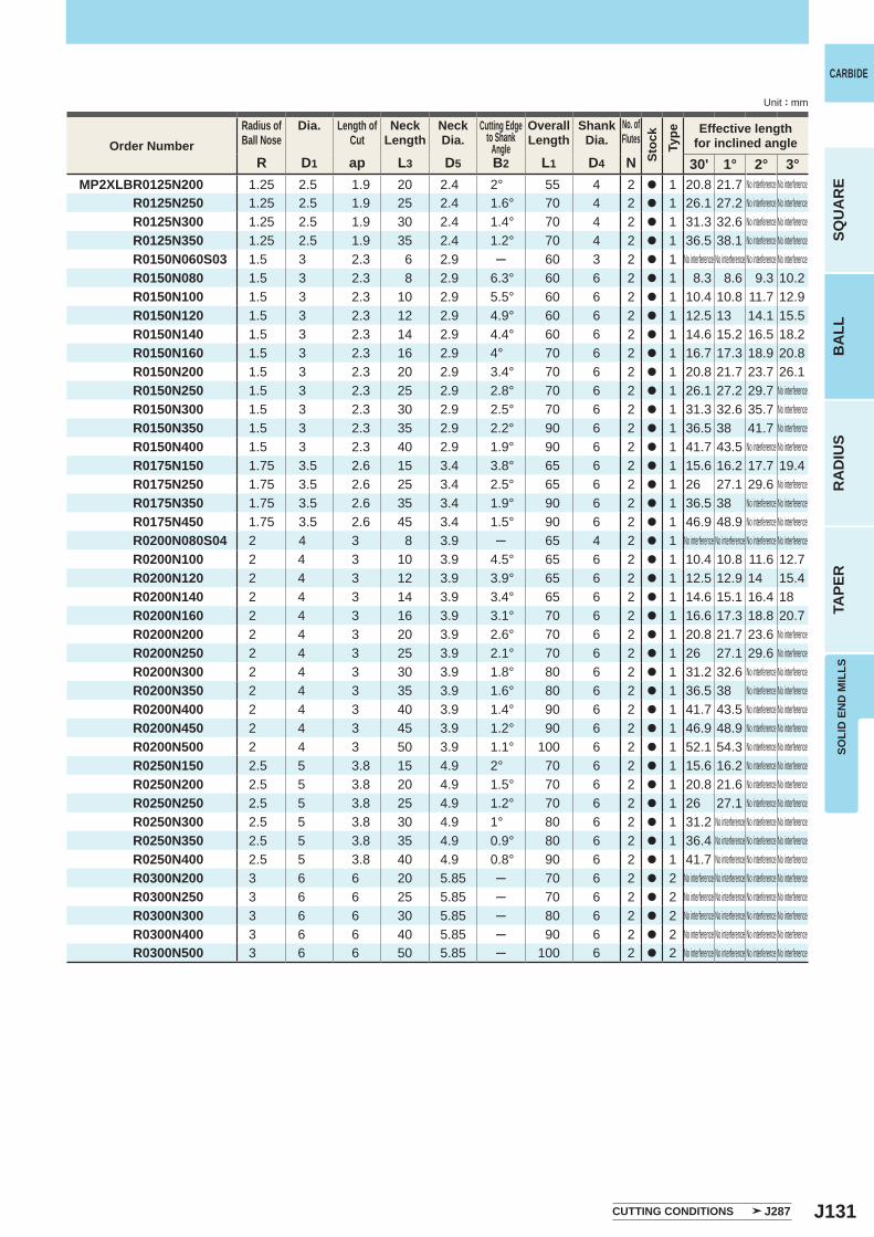
J131
R D1 ap L3 D5 B2 L1 D4 N 30' 1° 2° 3°MP2XLBR0125N200 1.25 2.5 1.9 20 2.4 2° 55 4 2 a 1 20.8 21.7 R0125N250 1.25 2.5 1.9 25 2.4 1.6° 70 4 2 a 1 26.1 27.2 R0125N300 1.25 2.5 1.9 30 2.4 1.4° 70 4 2 a 1 31.3 32.6 R0125N350 1.25 2.5 1.9 35 2.4 1.2° 70 4 2 a 1 36.5 38.1 R0150N060S03 1.5 3 2.3 6 2.9 ─ 60 3 2 a 1 R0150N080 1.5 3 2.3 8 2.9 6.3° 60 6 2 a 1 8.3 8.6 9.3 10.2 R0150N100 1.5 3 2.3 10 2.9 5.5° 60 6 2 a 1 10.4 10.8 11.7 12.9 R0150N120 1.5 3 2.3 12 2.9 4.9° 60 6 2 a 1 12.5 13 14.1 15.5 R0150N140 1.5 3 2.3 14 2.9 4.4° 60 6 2 a 1 14.6 15.2 16.5 18.2 R0150N160 1.5 3 2.3 16 2.9 4° 70 6 2 a 1 16.7 17.3 18.9 20.8 R0150N200 1.5 3 2.3 20 2.9 3.4° 70 6 2 a 1 20.8 21.7 23.7 26.1 R0150N250 1.5 3 2.3 25 2.9 2.8° 70 6 2 a 1 26.1 27.2 29.7 R0150N300 1.5 3 2.3 30 2.9 2.5° 70 6 2 a 1 31.3 32.6 35.7 R0150N350 1.5 3 2.3 35 2.9 2.2° 90 6 2 a 1 36.5 38 41.7 R0150N400 1.5 3 2.3 40 2.9 1.9° 90 6 2 a 1 41.7 43.5 R0175N150 1.75 3.5 2.6 15 3.4 3.8° 65 6 2 a 1 15.6 16.2 17.7 19.4 R0175N250 1.75 3.5 2.6 25 3.4 2.5° 65 6 2 a 1 26 27.1 29.6 R0175N350 1.75 3.5 2.6 35 3.4 1.9° 90 6 2 a 1 36.5 38 R0175N450 1.75 3.5 2.6 45 3.4 1.5° 90 6 2 a 1 46.9 48.9 R0200N080S04 2 4 3 8 3.9 ─ 65 4 2 a 1 R0200N100 2 4 3 10 3.9 4.5° 65 6 2 a 1 10.4 10.8 11.6 12.7 R0200N120 2 4 3 12 3.9 3.9° 65 6 2 a 1 12.5 12.9 14 15.4 R0200N140 2 4 3 14 3.9 3.4° 65 6 2 a 1 14.6 15.1 16.4 18 R0200N160 2 4 3 16 3.9 3.1° 70 6 2 a 1 16.6 17.3 18.8 20.7 R0200N200 2 4 3 20 3.9 2.6° 70 6 2 a 1 20.8 21.7 23.6 R0200N250 2 4 3 25 3.9 2.1° 70 6 2 a 1 26 27.1 29.6 R0200N300 2 4 3 30 3.9 1.8° 80 6 2 a 1 31.2 32.6 R0200N350 2 4 3 35 3.9 1.6° 80 6 2 a 1 36.5 38 R0200N400 2 4 3 40 3.9 1.4° 90 6 2 a 1 41.7 43.5 R0200N450 2 4 3 45 3.9 1.2° 90 6 2 a 1 46.9 48.9 R0200N500 2 4 3 50 3.9 1.1° 100 6 2 a 1 52.1 54.3 R0250N150 2.5 5 3.8 15 4.9 2° 70 6 2 a 1 15.6 16.2 R0250N200 2.5 5 3.8 20 4.9 1.5° 70 6 2 a 1 20.8 21.6 R0250N250 2.5 5 3.8 25 4.9 1.2° 70 6 2 a 1 26 27.1 R0250N300 2.5 5 3.8 30 4.9 1° 80 6 2 a 1 31.2 R0250N350 2.5 5 3.8 35 4.9 0.9° 80 6 2 a 1 36.4 R0250N400 2.5 5 3.8 40 4.9 0.8° 90 6 2 a 1 41.7 R0300N200 3 6 6 20 5.85 ─ 70 6 2 a 2 R0300N250 3 6 6 25 5.85 ─ 70 6 2 a 2 R0300N300 3 6 6 30 5.85 ─ 80 6 2 a 2 R0300N400 3 6 6 40 5.85 ─ 90 6 2 a 2 R0300N500 3 6 6 50 5.85 ─ 100 6 2 a 2
SOLI
D E
ND
MIL
LS
CARBIDE
SQU
AR
EB
ALL
RA
DIU
STA
PER
Unit : mm
Order NumberRadius ofBall Nose
Dia. Length ofCut
NeckLength
NeckDia.
Cutting Edgeto Shank
Angle
OverallLength
ShankDia.
No. ofFlutes
Stoc
kTy
pe Effective lengthfor inclined angle
No interferenceNo interferenceNo interference
No interference No interference
No interferenceNo interference No interferenceNo interference No interference
No interference No interference No interference No interference
No interferenceNo interference
No interference No interferenceNo interference No interferenceNo interference No interferenceNo interference No interferenceNo interference No interferenceNo interference No interferenceNo interference No interferenceNo interference No interference
No interference No interference No interferenceNo interference No interference No interferenceNo interference No interference No interference
No interference No interference No interference No interferenceNo interference No interference No interference No interferenceNo interference No interference No interference No interferenceNo interference No interference No interference No interferenceNo interference No interference No interference No interference
No interference No interferenceNo interference No interferenceNo interference No interferenceNo interference No interference
No interference No interference No interference No interference
CUTTING CONDITIONS J287
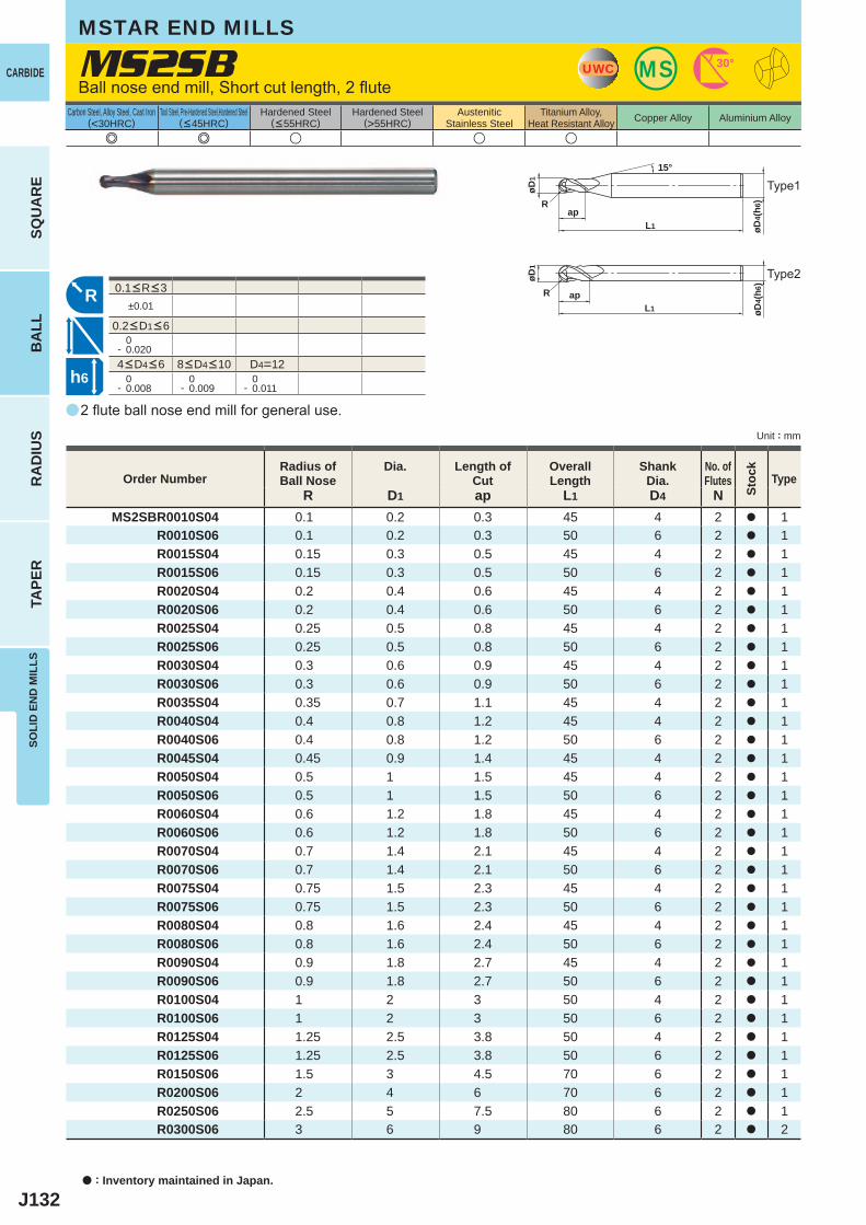
J132
a
e e u u u
±0.01
0- 0.020
D4=12 0- 0.008
0- 0.009
0- 0.011
R D1 ap L1 D4 NMS2SBR0010S04 0.1 0.2 0.3 45 4 2 a 1
R0010S06 0.1 0.2 0.3 50 6 2 a 1R0015S04 0.15 0.3 0.5 45 4 2 a 1R0015S06 0.15 0.3 0.5 50 6 2 a 1R0020S04 0.2 0.4 0.6 45 4 2 a 1R0020S06 0.2 0.4 0.6 50 6 2 a 1R0025S04 0.25 0.5 0.8 45 4 2 a 1R0025S06 0.25 0.5 0.8 50 6 2 a 1R0030S04 0.3 0.6 0.9 45 4 2 a 1R0030S06 0.3 0.6 0.9 50 6 2 a 1R0035S04 0.35 0.7 1.1 45 4 2 a 1R0040S04 0.4 0.8 1.2 45 4 2 a 1R0040S06 0.4 0.8 1.2 50 6 2 a 1R0045S04 0.45 0.9 1.4 45 4 2 a 1R0050S04 0.5 1 1.5 45 4 2 a 1R0050S06 0.5 1 1.5 50 6 2 a 1R0060S04 0.6 1.2 1.8 45 4 2 a 1R0060S06 0.6 1.2 1.8 50 6 2 a 1R0070S04 0.7 1.4 2.1 45 4 2 a 1R0070S06 0.7 1.4 2.1 50 6 2 a 1R0075S04 0.75 1.5 2.3 45 4 2 a 1R0075S06 0.75 1.5 2.3 50 6 2 a 1R0080S04 0.8 1.6 2.4 45 4 2 a 1R0080S06 0.8 1.6 2.4 50 6 2 a 1R0090S04 0.9 1.8 2.7 45 4 2 a 1R0090S06 0.9 1.8 2.7 50 6 2 a 1R0100S04 1 2 3 50 4 2 a 1R0100S06 1 2 3 50 6 2 a 1R0125S04 1.25 2.5 3.8 50 4 2 a 1R0125S06 1.25 2.5 3.8 50 6 2 a 1R0150S06 1.5 3 4.5 70 6 2 a 1R0200S06 2 4 6 70 6 2 a 1R0250S06 2.5 5 7.5 80 6 2 a 1R0300S06 3 6 9 80 6 2 a 2
MS2SB UWC MS 30°
øD4(
h6)
L1
øD1
Rap
15°
R
øD4(
h6)
L1ap
øD1
R
h6
a : Inventory maintained in Japan.
CARBIDE
SQU
AR
EB
ALL
RA
DIU
STA
PER
SOLI
D E
ND
MIL
LS
Unit : mm
Carbon Steel, Alloy Steel, Cast Iron(<30HRC)
Tool Steel, Pre-Hardened Steel,Hardened Steel(<45HRC)
Hardened Steel(<55HRC)
Hardened Steel(>55HRC)
AusteniticStainless Steel
Titanium Alloy,Heat Resistant Alloy Copper Alloy Aluminium Alloy
MSTAR END MILLS
2 flute ball nose end mill for general use.
Ball nose end mill, Short cut length, 2 flute
Order NumberRadius ofBall Nose
Dia. Length ofCut
OverallLength
ShankDia.
No. ofFlutes
Stoc
k
Type
4<D4<6 8<D4<10
0.1<R<3
0.2<D1<6
Type1
Type2
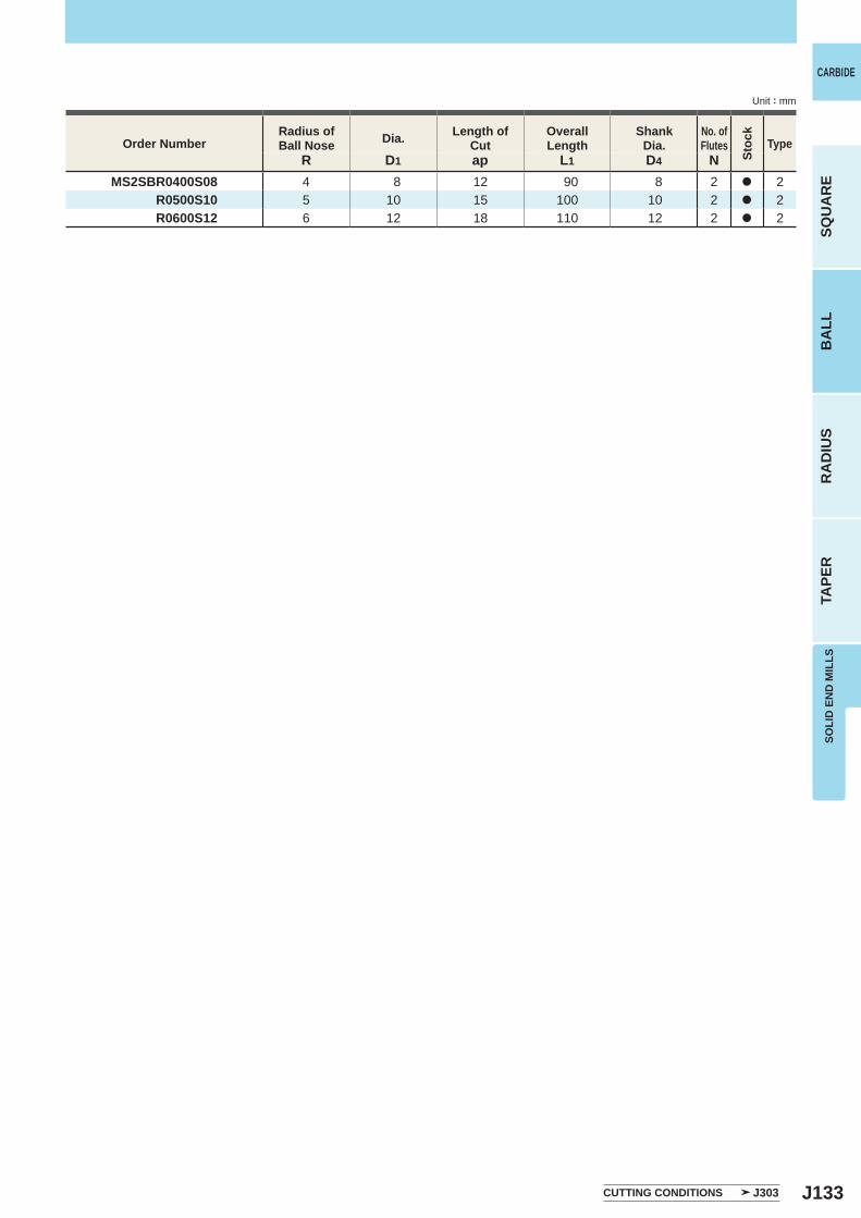
J133
R D1 ap L1 D4 NMS2SBR0400S08 4 8 12 90 8 2 a 2
R0500S10 5 10 15 100 10 2 a 2R0600S12 6 12 18 110 12 2 a 2
SOLI
D E
ND
MIL
LS
CARBIDE
SQU
AR
EB
ALL
RA
DIU
STA
PER
Unit : mm
CUTTING CONDITIONS J303
Order NumberRadius ofBall Nose Dia. Length of
CutOverallLength
ShankDia.
No. ofFlutes
Stoc
k
Type

J134
a
e e u u u
MS2MB
R D1 ap L1 D4 NMS2MBR0025 0.25 0.5 1 45 4 2 a 1 R0030 0.3 0.6 1.2 45 4 2 a 1 R0040 0.4 0.8 1.6 45 4 2 a 1 R0050 0.5 1 2.5 45 4 2 a 1 R0060 0.6 1.2 2.5 45 4 2 a 1 R0070 0.7 1.4 3 45 4 2 a 1 R0075 0.75 1.5 4 45 4 2 a 1 R0080 0.8 1.6 4 45 4 2 a 1 R0090 0.9 1.8 5 45 4 2 a 1 R0100 1 2 6 50 4 2 a 1 R0125 1.25 2.5 6 50 4 2 a 1 R0150S03 1.5 3 8 70 3 2 a 2 R0150 1.5 3 8 70 6 2 a 1 R0175 1.75 3.5 8 70 6 2 a 1 R0200S04 2 4 8 70 4 2 a 2 R0200 2 4 8 70 6 2 a 1 R0250 2.5 5 12 80 6 2 a 1 R0300 3 6 12 80 6 2 a 2 R0400 4 8 14 90 8 2 a 2 R0500 5 10 18 100 10 2 a 2 R0600 6 12 22 110 12 2 a 2
±0.01
0- 0.020
D4=3 D4=12 0- 0.006
0- 0.008
0- 0.009
0- 0.011
UWC MS 30°
øD4(
h6)
L1
øD1
Rap
15°
R
øD4(
h6)
L1ap
øD1
R
h6
a : Inventory maintained in Japan.
CARBIDE
SQU
AR
EB
ALL
RA
DIU
STA
PER
SOLI
D E
ND
MIL
LS
Unit : mm
Carbon Steel, Alloy Steel, Cast Iron(<30HRC)
Tool Steel, Pre-Hardened Steel,Hardened Steel(<45HRC)
Hardened Steel(<55HRC)
Hardened Steel(>55HRC)
AusteniticStainless Steel
Titanium Alloy,Heat Resistant Alloy Copper Alloy Aluminium Alloy
2 flute ball nose end mill for general use.
Ball nose end mill, Medium cut length, 2 flute
Order NumberRadius ofBall Nose
Dia. Length ofCut
OverallLength
ShankDia.
No. ofFlutes
Stoc
k
Type
CUTTING CONDITIONS J303
4<D4<6 8<D4<10
0.25<R<6
0.5<D1<6
MSTAR END MILLS
Type1
Type2
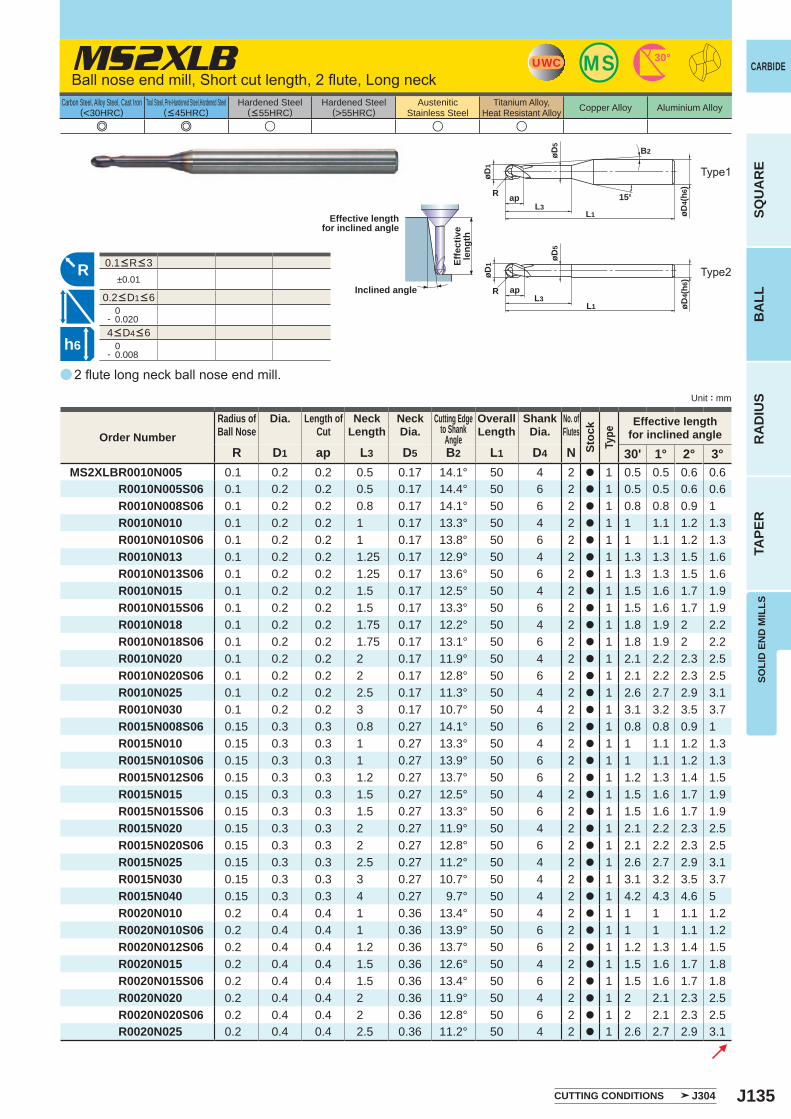
J135
a
e e u u u
MS2XLB
R D1 ap L3 D5 B2 L1 D4 N 30' 1° 2° 3°MS2XLBR0010N005 0.1 0.2 0.2 0.5 0.17 14.1° 50 4 2 a 1 0.5 0.5 0.6 0.6 R0010N005S06 0.1 0.2 0.2 0.5 0.17 14.4° 50 6 2 a 1 0.5 0.5 0.6 0.6 R0010N008S06 0.1 0.2 0.2 0.8 0.17 14.1° 50 6 2 a 1 0.8 0.8 0.9 1 R0010N010 0.1 0.2 0.2 1 0.17 13.3° 50 4 2 a 1 1 1.1 1.2 1.3 R0010N010S06 0.1 0.2 0.2 1 0.17 13.8° 50 6 2 a 1 1 1.1 1.2 1.3 R0010N013 0.1 0.2 0.2 1.25 0.17 12.9° 50 4 2 a 1 1.3 1.3 1.5 1.6 R0010N013S06 0.1 0.2 0.2 1.25 0.17 13.6° 50 6 2 a 1 1.3 1.3 1.5 1.6 R0010N015 0.1 0.2 0.2 1.5 0.17 12.5° 50 4 2 a 1 1.5 1.6 1.7 1.9 R0010N015S06 0.1 0.2 0.2 1.5 0.17 13.3° 50 6 2 a 1 1.5 1.6 1.7 1.9 R0010N018 0.1 0.2 0.2 1.75 0.17 12.2° 50 4 2 a 1 1.8 1.9 2 2.2 R0010N018S06 0.1 0.2 0.2 1.75 0.17 13.1° 50 6 2 a 1 1.8 1.9 2 2.2 R0010N020 0.1 0.2 0.2 2 0.17 11.9° 50 4 2 a 1 2.1 2.2 2.3 2.5 R0010N020S06 0.1 0.2 0.2 2 0.17 12.8° 50 6 2 a 1 2.1 2.2 2.3 2.5 R0010N025 0.1 0.2 0.2 2.5 0.17 11.3° 50 4 2 a 1 2.6 2.7 2.9 3.1 R0010N030 0.1 0.2 0.2 3 0.17 10.7° 50 4 2 a 1 3.1 3.2 3.5 3.7 R0015N008S06 0.15 0.3 0.3 0.8 0.27 14.1° 50 6 2 a 1 0.8 0.8 0.9 1 R0015N010 0.15 0.3 0.3 1 0.27 13.3° 50 4 2 a 1 1 1.1 1.2 1.3 R0015N010S06 0.15 0.3 0.3 1 0.27 13.9° 50 6 2 a 1 1 1.1 1.2 1.3 R0015N012S06 0.15 0.3 0.3 1.2 0.27 13.7° 50 6 2 a 1 1.2 1.3 1.4 1.5 R0015N015 0.15 0.3 0.3 1.5 0.27 12.5° 50 4 2 a 1 1.5 1.6 1.7 1.9 R0015N015S06 0.15 0.3 0.3 1.5 0.27 13.3° 50 6 2 a 1 1.5 1.6 1.7 1.9 R0015N020 0.15 0.3 0.3 2 0.27 11.9° 50 4 2 a 1 2.1 2.2 2.3 2.5 R0015N020S06 0.15 0.3 0.3 2 0.27 12.8° 50 6 2 a 1 2.1 2.2 2.3 2.5 R0015N025 0.15 0.3 0.3 2.5 0.27 11.2° 50 4 2 a 1 2.6 2.7 2.9 3.1 R0015N030 0.15 0.3 0.3 3 0.27 10.7° 50 4 2 a 1 3.1 3.2 3.5 3.7 R0015N040 0.15 0.3 0.3 4 0.27 9.7° 50 4 2 a 1 4.2 4.3 4.6 5 R0020N010 0.2 0.4 0.4 1 0.36 13.4° 50 4 2 a 1 1 1 1.1 1.2 R0020N010S06 0.2 0.4 0.4 1 0.36 13.9° 50 6 2 a 1 1 1 1.1 1.2 R0020N012S06 0.2 0.4 0.4 1.2 0.36 13.7° 50 6 2 a 1 1.2 1.3 1.4 1.5 R0020N015 0.2 0.4 0.4 1.5 0.36 12.6° 50 4 2 a 1 1.5 1.6 1.7 1.8 R0020N015S06 0.2 0.4 0.4 1.5 0.36 13.4° 50 6 2 a 1 1.5 1.6 1.7 1.8 R0020N020 0.2 0.4 0.4 2 0.36 11.9° 50 4 2 a 1 2 2.1 2.3 2.5 R0020N020S06 0.2 0.4 0.4 2 0.36 12.8° 50 6 2 a 1 2 2.1 2.3 2.5 R0020N025 0.2 0.4 0.4 2.5 0.36 11.2° 50 4 2 a 1 2.6 2.7 2.9 3.1
±0.01
0- 0.020
0- 0.008
UWC MS 30°
L1
apL3
øD1
R
øD4(
h6)
15°
øD5
B2
R
øD4(
h6)
RL1
apL3
øD1
øD5
h6
SOLI
D E
ND
MIL
LS
CARBIDE
SQU
AR
EB
ALL
RA
DIU
STA
PER
Unit : mm
Carbon Steel, Alloy Steel, Cast Iron(<30HRC)
Tool Steel, Pre-Hardened Steel,Hardened Steel(<45HRC)
Hardened Steel(<55HRC)
Hardened Steel(>55HRC)
AusteniticStainless Steel
Titanium Alloy,Heat Resistant Alloy Copper Alloy Aluminium Alloy
0.1<R<3
0.2<D1<6
Ball nose end mill, Short cut length, 2 flute, Long neck
2 flute long neck ball nose end mill.
Effective lengthfor inclined angle
Inclined angle
Effe
ctiv
ele
ngth
Order NumberRadius ofBall Nose
Dia. Length ofCut
NeckLength
NeckDia.
Cutting Edgeto Shank
Angle
OverallLength
ShankDia.
No. ofFlutes
Stoc
kTy
pe
Effective lengthfor inclined angle
4<D4<6
CUTTING CONDITIONS J304
Type1
Type2
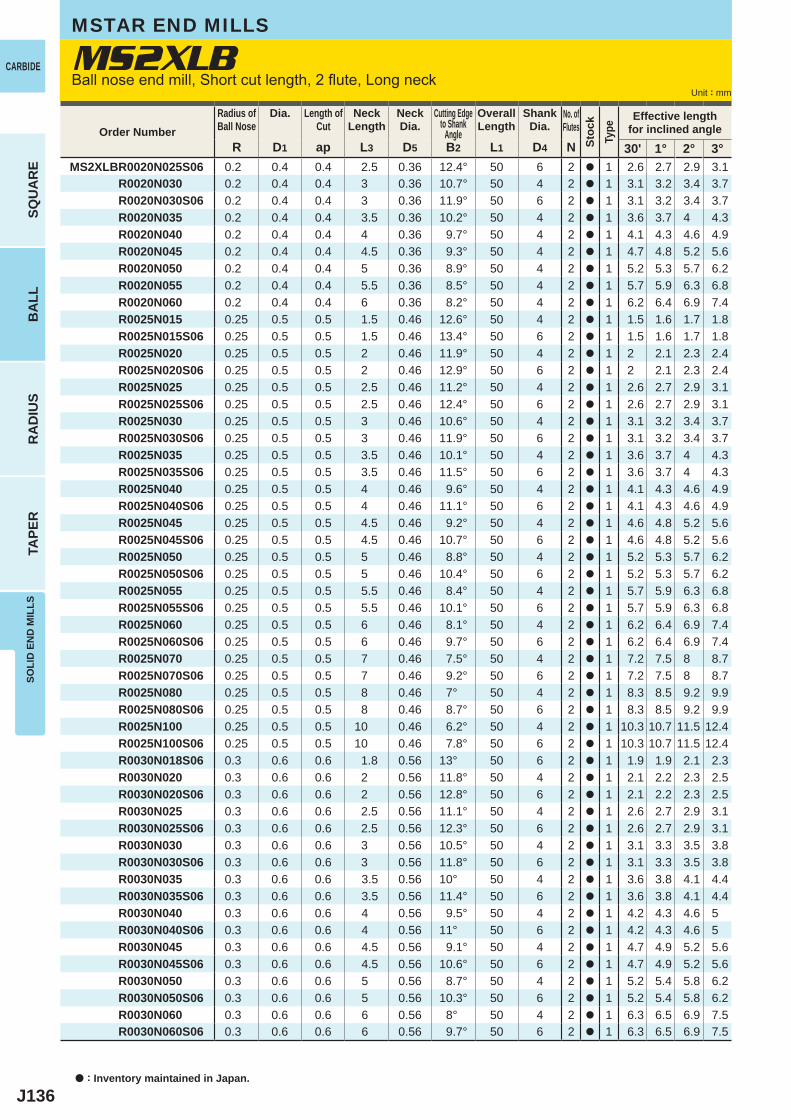
J136
R D1 ap L3 D5 B2 L1 D4 N 30' 1° 2° 3°MS2XLBR0020N025S06 0.2 0.4 0.4 2.5 0.36 12.4° 50 6 2 a 1 2.6 2.7 2.9 3.1 R0020N030 0.2 0.4 0.4 3 0.36 10.7° 50 4 2 a 1 3.1 3.2 3.4 3.7 R0020N030S06 0.2 0.4 0.4 3 0.36 11.9° 50 6 2 a 1 3.1 3.2 3.4 3.7 R0020N035 0.2 0.4 0.4 3.5 0.36 10.2° 50 4 2 a 1 3.6 3.7 4 4.3 R0020N040 0.2 0.4 0.4 4 0.36 9.7° 50 4 2 a 1 4.1 4.3 4.6 4.9 R0020N045 0.2 0.4 0.4 4.5 0.36 9.3° 50 4 2 a 1 4.7 4.8 5.2 5.6 R0020N050 0.2 0.4 0.4 5 0.36 8.9° 50 4 2 a 1 5.2 5.3 5.7 6.2 R0020N055 0.2 0.4 0.4 5.5 0.36 8.5° 50 4 2 a 1 5.7 5.9 6.3 6.8 R0020N060 0.2 0.4 0.4 6 0.36 8.2° 50 4 2 a 1 6.2 6.4 6.9 7.4 R0025N015 0.25 0.5 0.5 1.5 0.46 12.6° 50 4 2 a 1 1.5 1.6 1.7 1.8 R0025N015S06 0.25 0.5 0.5 1.5 0.46 13.4° 50 6 2 a 1 1.5 1.6 1.7 1.8 R0025N020 0.25 0.5 0.5 2 0.46 11.9° 50 4 2 a 1 2 2.1 2.3 2.4 R0025N020S06 0.25 0.5 0.5 2 0.46 12.9° 50 6 2 a 1 2 2.1 2.3 2.4 R0025N025 0.25 0.5 0.5 2.5 0.46 11.2° 50 4 2 a 1 2.6 2.7 2.9 3.1 R0025N025S06 0.25 0.5 0.5 2.5 0.46 12.4° 50 6 2 a 1 2.6 2.7 2.9 3.1 R0025N030 0.25 0.5 0.5 3 0.46 10.6° 50 4 2 a 1 3.1 3.2 3.4 3.7 R0025N030S06 0.25 0.5 0.5 3 0.46 11.9° 50 6 2 a 1 3.1 3.2 3.4 3.7 R0025N035 0.25 0.5 0.5 3.5 0.46 10.1° 50 4 2 a 1 3.6 3.7 4 4.3 R0025N035S06 0.25 0.5 0.5 3.5 0.46 11.5° 50 6 2 a 1 3.6 3.7 4 4.3 R0025N040 0.25 0.5 0.5 4 0.46 9.6° 50 4 2 a 1 4.1 4.3 4.6 4.9 R0025N040S06 0.25 0.5 0.5 4 0.46 11.1° 50 6 2 a 1 4.1 4.3 4.6 4.9 R0025N045 0.25 0.5 0.5 4.5 0.46 9.2° 50 4 2 a 1 4.6 4.8 5.2 5.6 R0025N045S06 0.25 0.5 0.5 4.5 0.46 10.7° 50 6 2 a 1 4.6 4.8 5.2 5.6 R0025N050 0.25 0.5 0.5 5 0.46 8.8° 50 4 2 a 1 5.2 5.3 5.7 6.2 R0025N050S06 0.25 0.5 0.5 5 0.46 10.4° 50 6 2 a 1 5.2 5.3 5.7 6.2 R0025N055 0.25 0.5 0.5 5.5 0.46 8.4° 50 4 2 a 1 5.7 5.9 6.3 6.8 R0025N055S06 0.25 0.5 0.5 5.5 0.46 10.1° 50 6 2 a 1 5.7 5.9 6.3 6.8 R0025N060 0.25 0.5 0.5 6 0.46 8.1° 50 4 2 a 1 6.2 6.4 6.9 7.4 R0025N060S06 0.25 0.5 0.5 6 0.46 9.7° 50 6 2 a 1 6.2 6.4 6.9 7.4 R0025N070 0.25 0.5 0.5 7 0.46 7.5° 50 4 2 a 1 7.2 7.5 8 8.7 R0025N070S06 0.25 0.5 0.5 7 0.46 9.2° 50 6 2 a 1 7.2 7.5 8 8.7 R0025N080 0.25 0.5 0.5 8 0.46 7° 50 4 2 a 1 8.3 8.5 9.2 9.9 R0025N080S06 0.25 0.5 0.5 8 0.46 8.7° 50 6 2 a 1 8.3 8.5 9.2 9.9 R0025N100 0.25 0.5 0.5 10 0.46 6.2° 50 4 2 a 1 10.3 10.7 11.5 12.4 R0025N100S06 0.25 0.5 0.5 10 0.46 7.8° 50 6 2 a 1 10.3 10.7 11.5 12.4 R0030N018S06 0.3 0.6 0.6 1.8 0.56 13° 50 6 2 a 1 1.9 1.9 2.1 2.3 R0030N020 0.3 0.6 0.6 2 0.56 11.8° 50 4 2 a 1 2.1 2.2 2.3 2.5 R0030N020S06 0.3 0.6 0.6 2 0.56 12.8° 50 6 2 a 1 2.1 2.2 2.3 2.5 R0030N025 0.3 0.6 0.6 2.5 0.56 11.1° 50 4 2 a 1 2.6 2.7 2.9 3.1 R0030N025S06 0.3 0.6 0.6 2.5 0.56 12.3° 50 6 2 a 1 2.6 2.7 2.9 3.1 R0030N030 0.3 0.6 0.6 3 0.56 10.5° 50 4 2 a 1 3.1 3.3 3.5 3.8 R0030N030S06 0.3 0.6 0.6 3 0.56 11.8° 50 6 2 a 1 3.1 3.3 3.5 3.8 R0030N035 0.3 0.6 0.6 3.5 0.56 10° 50 4 2 a 1 3.6 3.8 4.1 4.4 R0030N035S06 0.3 0.6 0.6 3.5 0.56 11.4° 50 6 2 a 1 3.6 3.8 4.1 4.4 R0030N040 0.3 0.6 0.6 4 0.56 9.5° 50 4 2 a 1 4.2 4.3 4.6 5 R0030N040S06 0.3 0.6 0.6 4 0.56 11° 50 6 2 a 1 4.2 4.3 4.6 5 R0030N045 0.3 0.6 0.6 4.5 0.56 9.1° 50 4 2 a 1 4.7 4.9 5.2 5.6 R0030N045S06 0.3 0.6 0.6 4.5 0.56 10.6° 50 6 2 a 1 4.7 4.9 5.2 5.6 R0030N050 0.3 0.6 0.6 5 0.56 8.7° 50 4 2 a 1 5.2 5.4 5.8 6.2 R0030N050S06 0.3 0.6 0.6 5 0.56 10.3° 50 6 2 a 1 5.2 5.4 5.8 6.2 R0030N060 0.3 0.6 0.6 6 0.56 8° 50 4 2 a 1 6.3 6.5 6.9 7.5 R0030N060S06 0.3 0.6 0.6 6 0.56 9.7° 50 6 2 a 1 6.3 6.5 6.9 7.5
MS2XLB
a : Inventory maintained in Japan.
CARBIDE
SQU
AR
EB
ALL
RA
DIU
STA
PER
SOLI
D E
ND
MIL
LS
Unit : mm
Order NumberRadius ofBall Nose
Dia. Length ofCut
NeckLength
NeckDia.
Cutting Edgeto Shank
Angle
OverallLength
ShankDia.
No. ofFlutes
Stoc
kTy
pe
Effective lengthfor inclined angle
MSTAR END MILLS
Ball nose end mill, Short cut length, 2 flute, Long neck
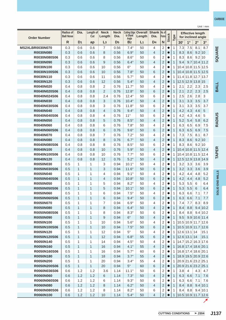
J137
R D1 ap L3 D5 B2 L1 D4 N 30' 1° 2° 3°MS2XLBR0030N070 0.3 0.6 0.6 7 0.56 7.4° 50 4 2 a 1 7.3 7.5 8.1 8.7 R0030N080 0.3 0.6 0.6 8 0.56 6.9° 50 4 2 a 1 8.3 8.6 9.2 10 R0030N080S06 0.3 0.6 0.6 8 0.56 8.6° 50 6 2 a 1 8.3 8.6 9.2 10 R0030N090 0.3 0.6 0.6 9 0.56 6.4° 50 4 2 a 1 9.4 9.7 10.4 11.2 R0030N100 0.3 0.6 0.6 10 0.56 6° 50 4 2 a 1 10.4 10.8 11.5 12.5 R0030N100S06 0.3 0.6 0.6 10 0.56 7.8° 50 6 2 a 1 10.4 10.8 11.5 12.5 R0030N110 0.3 0.6 0.6 11 0.56 5.7° 50 4 2 a 1 11.4 11.8 12.7 13.7 R0030N120 0.3 0.6 0.6 12 0.56 5.4° 50 4 2 a 1 12.5 12.9 13.8 15 R0040N020 0.4 0.8 0.8 2 0.76 11.7° 50 4 2 a 1 2.1 2.2 2.3 2.5 R0040N020S06 0.4 0.8 0.8 2 0.76 12.8° 50 6 2 a 1 2.1 2.2 2.3 2.5 R0040N024S06 0.4 0.8 0.8 2.4 0.76 12.4° 50 6 2 a 1 2.5 2.6 2.8 3 R0040N030 0.4 0.8 0.8 3 0.76 10.4° 50 4 2 a 1 3.1 3.3 3.5 3.7 R0040N030S06 0.4 0.8 0.8 3 0.76 11.8° 50 6 2 a 1 3.1 3.3 3.5 3.7 R0040N040 0.4 0.8 0.8 4 0.76 9.4° 50 4 2 a 1 4.2 4.3 4.6 5 R0040N040S06 0.4 0.8 0.8 4 0.76 11° 50 6 2 a 1 4.2 4.3 4.6 5 R0040N050 0.4 0.8 0.8 5 0.76 8.5° 50 4 2 a 1 5.2 5.4 5.8 6.2 R0040N060 0.4 0.8 0.8 6 0.76 7.8° 50 4 2 a 1 6.3 6.5 6.9 7.5 R0040N060S06 0.4 0.8 0.8 6 0.76 9.6° 50 6 2 a 1 6.3 6.5 6.9 7.5 R0040N070 0.4 0.8 0.8 7 0.76 7.2° 50 4 2 a 1 7.3 7.5 8.1 8.7 R0040N080 0.4 0.8 0.8 8 0.76 6.7° 50 4 2 a 1 8.3 8.6 9.2 10 R0040N080S06 0.4 0.8 0.8 8 0.76 8.5° 50 6 2 a 1 8.3 8.6 9.2 10 R0040N100 0.4 0.8 0.8 10 0.76 5.9° 50 4 2 a 1 10.4 10.8 11.5 12.4 R0040N100S06 0.4 0.8 0.8 10 0.76 7.7° 50 6 2 a 1 10.4 10.8 11.5 12.4 R0040N120 0.4 0.8 0.8 12 0.76 5.2° 50 4 2 a 1 12.5 12.9 13.8 14.9 R0050N030 0.5 1 1 3 0.94 10.1° 50 4 2 a 1 3.2 3.3 3.6 3.9 R0050N030S06 0.5 1 1 3 0.94 11.6° 50 6 2 a 1 3.2 3.3 3.6 3.9 R0050N040 0.5 1 1 4 0.94 9.1° 50 4 2 a 1 4.2 4.4 4.8 5.2 R0050N040S06 0.5 1 1 4 0.94 10.8° 50 6 2 a 1 4.2 4.4 4.8 5.2 R0050N050 0.5 1 1 5 0.94 8.2° 50 4 2 a 1 5.3 5.5 6 6.4 R0050N050S06 0.5 1 1 5 0.94 10.1° 50 6 2 a 1 5.3 5.5 6 6.4 R0050N060 0.5 1 1 6 0.94 7.5° 50 4 2 a 1 6.3 6.6 7.1 7.7 R0050N060S06 0.5 1 1 6 0.94 9.4° 50 6 2 a 1 6.3 6.6 7.1 7.7 R0050N070 0.5 1 1 7 0.94 6.9° 50 4 2 a 1 7.4 7.7 8.3 8.9 R0050N080 0.5 1 1 8 0.94 6.4° 50 4 2 a 1 8.4 8.8 9.4 10.2 R0050N080S06 0.5 1 1 8 0.94 8.3° 50 6 2 a 1 8.4 8.8 9.4 10.2 R0050N090 0.5 1 1 9 0.94 6° 50 4 2 a 1 9.5 9.9 10.6 11.4 R0050N100 0.5 1 1 10 0.94 5.6° 50 4 2 a 1 10.5 10.9 11.7 12.6 R0050N100S06 0.5 1 1 10 0.94 7.5° 50 6 2 a 1 10.5 10.9 11.7 12.6 R0050N120 0.5 1 1 12 0.94 5° 50 4 2 a 1 12.6 13.1 14 15.1 R0050N120S06 0.5 1 1 12 0.94 6.8° 55 6 2 a 1 12.6 13.1 14 15.1 R0050N140 0.5 1 1 14 0.94 4.5° 50 4 2 a 1 14.7 15.2 16.3 17.6 R0050N160 0.5 1 1 16 0.94 4.1° 55 4 2 a 1 16.8 17.4 18.6 20.1 R0050N160S06 0.5 1 1 16 0.94 5.7° 60 6 2 a 1 16.8 17.4 18.6 20.1 R0050N180 0.5 1 1 18 0.94 3.7° 55 4 2 a 1 18.9 19.5 20.9 22.6 R0050N200 0.5 1 1 20 0.94 3.4° 55 4 2 a 1 20.9 21.6 23.2 25.1 R0050N200S06 0.5 1 1 20 0.94 5° 60 6 2 a 1 20.9 21.6 23.2 25.1 R0060N036S06 0.6 1.2 1.2 3.6 1.14 11.1° 50 6 2 a 1 3.8 4 4.3 4.7 R0060N060 0.6 1.2 1.2 6 1.14 7.3° 50 4 2 a 1 6.3 6.6 7.1 7.6 R0060N060S06 0.6 1.2 1.2 6 1.14 9.3° 50 6 2 a 1 6.3 6.6 7.1 7.6 R0060N080 0.6 1.2 1.2 8 1.14 6.2° 50 4 2 a 1 8.4 8.8 9.4 10.1 R0060N080S06 0.6 1.2 1.2 8 1.14 8.2° 50 6 2 a 1 8.4 8.8 9.4 10.1 R0060N100 0.6 1.2 1.2 10 1.14 5.4° 50 4 2 a 1 10.5 10.9 11.7 12.6
SOLI
D E
ND
MIL
LS
CARBIDE
SQU
AR
EB
ALL
RA
DIU
STA
PER
Unit : mm
Order NumberRadius ofBall Nose
Dia. Length ofCut
NeckLength
NeckDia.
Cutting Edgeto Shank
Angle
OverallLength
ShankDia.
No. ofFlutes
Stoc
kTy
pe
Effective lengthfor inclined angle
CUTTING CONDITIONS J304
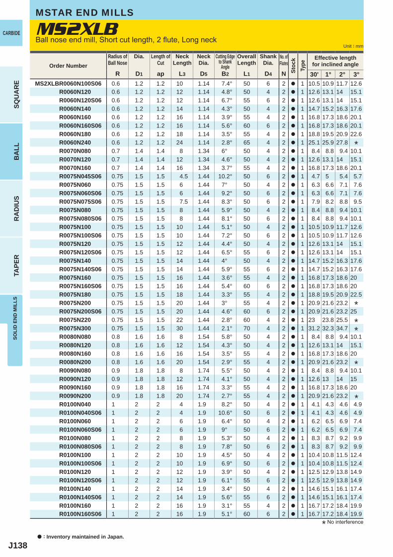
J138
R D1 ap L3 D5 B2 L1 D4 N 30' 1° 2° 3°MS2XLBR0060N100S06 0.6 1.2 1.2 10 1.14 7.4° 50 6 2 a 1 10.5 10.9 11.7 12.6 R0060N120 0.6 1.2 1.2 12 1.14 4.8° 50 4 2 a 1 12.6 13.1 14 15.1 R0060N120S06 0.6 1.2 1.2 12 1.14 6.7° 55 6 2 a 1 12.6 13.1 14 15.1 R0060N140 0.6 1.2 1.2 14 1.14 4.3° 50 4 2 a 1 14.7 15.2 16.3 17.6 R0060N160 0.6 1.2 1.2 16 1.14 3.9° 55 4 2 a 1 16.8 17.3 18.6 20.1 R0060N160S06 0.6 1.2 1.2 16 1.14 5.6° 60 6 2 a 1 16.8 17.3 18.6 20.1 R0060N180 0.6 1.2 1.2 18 1.14 3.5° 55 4 2 a 1 18.8 19.5 20.9 22.6 R0060N240 0.6 1.2 1.2 24 1.14 2.8° 65 4 2 a 1 25.1 25.9 27.8 R0070N080 0.7 1.4 1.4 8 1.34 6° 50 4 2 a 1 8.4 8.8 9.4 10.1 R0070N120 0.7 1.4 1.4 12 1.34 4.6° 50 4 2 a 1 12.6 13.1 14 15.1 R0070N160 0.7 1.4 1.4 16 1.34 3.7° 55 4 2 a 1 16.8 17.3 18.6 20.1 R0075N045S06 0.75 1.5 1.5 4.5 1.44 10.2° 50 6 2 a 1 4.7 5 5.4 5.7 R0075N060 0.75 1.5 1.5 6 1.44 7° 50 4 2 a 1 6.3 6.6 7.1 7.6 R0075N060S06 0.75 1.5 1.5 6 1.44 9.2° 50 6 2 a 1 6.3 6.6 7.1 7.6 R0075N075S06 0.75 1.5 1.5 7.5 1.44 8.3° 50 6 2 a 1 7.9 8.2 8.8 9.5 R0075N080 0.75 1.5 1.5 8 1.44 5.9° 50 4 2 a 1 8.4 8.8 9.4 10.1 R0075N080S06 0.75 1.5 1.5 8 1.44 8.1° 50 6 2 a 1 8.4 8.8 9.4 10.1 R0075N100 0.75 1.5 1.5 10 1.44 5.1° 50 4 2 a 1 10.5 10.9 11.7 12.6 R0075N100S06 0.75 1.5 1.5 10 1.44 7.2° 50 6 2 a 1 10.5 10.9 11.7 12.6 R0075N120 0.75 1.5 1.5 12 1.44 4.4° 50 4 2 a 1 12.6 13.1 14 15.1 R0075N120S06 0.75 1.5 1.5 12 1.44 6.5° 55 6 2 a 1 12.6 13.1 14 15.1 R0075N140 0.75 1.5 1.5 14 1.44 4° 50 4 2 a 1 14.7 15.2 16.3 17.6 R0075N140S06 0.75 1.5 1.5 14 1.44 5.9° 55 6 2 a 1 14.7 15.2 16.3 17.6 R0075N160 0.75 1.5 1.5 16 1.44 3.6° 55 4 2 a 1 16.8 17.3 18.6 20 R0075N160S06 0.75 1.5 1.5 16 1.44 5.4° 60 6 2 a 1 16.8 17.3 18.6 20 R0075N180 0.75 1.5 1.5 18 1.44 3.3° 55 4 2 a 1 18.8 19.5 20.9 22.5 R0075N200 0.75 1.5 1.5 20 1.44 3° 55 4 2 a 1 20.9 21.6 23.2 R0075N200S06 0.75 1.5 1.5 20 1.44 4.6° 60 6 2 a 1 20.9 21.6 23.2 25 R0075N220 0.75 1.5 1.5 22 1.44 2.8° 60 4 2 a 1 23 23.8 25.5 R0075N300 0.75 1.5 1.5 30 1.44 2.1° 70 4 2 a 1 31.2 32.3 34.7 R0080N080 0.8 1.6 1.6 8 1.54 5.8° 50 4 2 a 1 8.4 8.8 9.4 10.1 R0080N120 0.8 1.6 1.6 12 1.54 4.3° 50 4 2 a 1 12.6 13.1 14 15.1 R0080N160 0.8 1.6 1.6 16 1.54 3.5° 55 4 2 a 1 16.8 17.3 18.6 20 R0080N200 0.8 1.6 1.6 20 1.54 2.9° 55 4 2 a 1 20.9 21.6 23.2 R0090N080 0.9 1.8 1.8 8 1.74 5.5° 50 4 2 a 1 8.4 8.8 9.4 10.1 R0090N120 0.9 1.8 1.8 12 1.74 4.1° 50 4 2 a 1 12.6 13 14 15 R0090N160 0.9 1.8 1.8 16 1.74 3.3° 55 4 2 a 1 16.8 17.3 18.6 20 R0090N200 0.9 1.8 1.8 20 1.74 2.7° 55 4 2 a 1 20.9 21.6 23.2 R0100N040 1 2 2 4 1.9 8.2° 50 4 2 a 1 4.1 4.3 4.6 4.9 R0100N040S06 1 2 2 4 1.9 10.6° 50 6 2 a 1 4.1 4.3 4.6 4.9 R0100N060 1 2 2 6 1.9 6.4° 50 4 2 a 1 6.2 6.5 6.9 7.4 R0100N060S06 1 2 2 6 1.9 9° 50 6 2 a 1 6.2 6.5 6.9 7.4 R0100N080 1 2 2 8 1.9 5.3° 50 4 2 a 1 8.3 8.7 9.2 9.9 R0100N080S06 1 2 2 8 1.9 7.8° 50 6 2 a 1 8.3 8.7 9.2 9.9 R0100N100 1 2 2 10 1.9 4.5° 50 4 2 a 1 10.4 10.8 11.5 12.4 R0100N100S06 1 2 2 10 1.9 6.9° 50 6 2 a 1 10.4 10.8 11.5 12.4 R0100N120 1 2 2 12 1.9 3.9° 50 4 2 a 1 12.5 12.9 13.8 14.9 R0100N120S06 1 2 2 12 1.9 6.1° 55 6 2 a 1 12.5 12.9 13.8 14.9 R0100N140 1 2 2 14 1.9 3.4° 50 4 2 a 1 14.6 15.1 16.1 17.4 R0100N140S06 1 2 2 14 1.9 5.6° 55 6 2 a 1 14.6 15.1 16.1 17.4 R0100N160 1 2 2 16 1.9 3.1° 55 4 2 a 1 16.7 17.2 18.4 19.9 R0100N160S06 1 2 2 16 1.9 5.1° 60 6 2 a 1 16.7 17.2 18.4 19.9
MS2XLB
a : Inventory maintained in Japan.
CARBIDE
SQU
AR
EB
ALL
RA
DIU
STA
PER
SOLI
D E
ND
MIL
LS
Unit : mm
* No interference
Order NumberRadius ofBall Nose
Dia. Length ofCut
NeckLength
NeckDia.
Cutting Edgeto Shank
Angle
OverallLength
ShankDia.
No. ofFlutes
Stoc
kTy
pe
Effective lengthfor inclined angle
MSTAR END MILLS
Ball nose end mill, Short cut length, 2 flute, Long neck
*
**
*
*
*
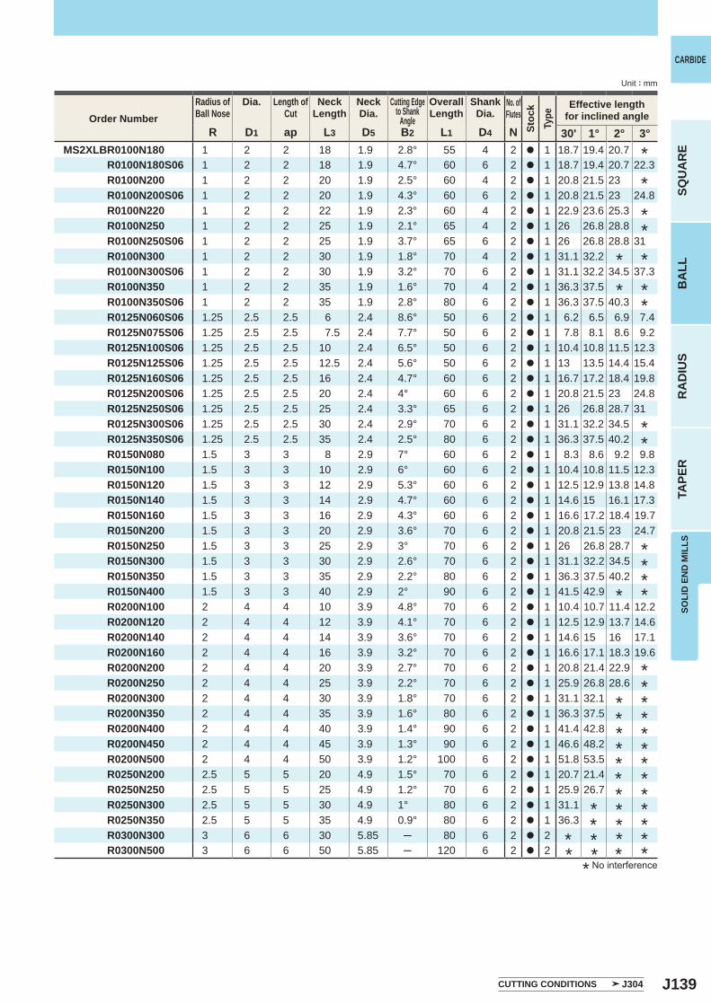
J139
R D1 ap L3 D5 B2 L1 D4 N 30' 1° 2° 3°MS2XLBR0100N180 1 2 2 18 1.9 2.8° 55 4 2 a 1 18.7 19.4 20.7 R0100N180S06 1 2 2 18 1.9 4.7° 60 6 2 a 1 18.7 19.4 20.7 22.3 R0100N200 1 2 2 20 1.9 2.5° 60 4 2 a 1 20.8 21.5 23 R0100N200S06 1 2 2 20 1.9 4.3° 60 6 2 a 1 20.8 21.5 23 24.8 R0100N220 1 2 2 22 1.9 2.3° 60 4 2 a 1 22.9 23.6 25.3 R0100N250 1 2 2 25 1.9 2.1° 65 4 2 a 1 26 26.8 28.8 R0100N250S06 1 2 2 25 1.9 3.7° 65 6 2 a 1 26 26.8 28.8 31 R0100N300 1 2 2 30 1.9 1.8° 70 4 2 a 1 31.1 32.2 R0100N300S06 1 2 2 30 1.9 3.2° 70 6 2 a 1 31.1 32.2 34.5 37.3 R0100N350 1 2 2 35 1.9 1.6° 70 4 2 a 1 36.3 37.5 R0100N350S06 1 2 2 35 1.9 2.8° 80 6 2 a 1 36.3 37.5 40.3 R0125N060S06 1.25 2.5 2.5 6 2.4 8.6° 50 6 2 a 1 6.2 6.5 6.9 7.4 R0125N075S06 1.25 2.5 2.5 7.5 2.4 7.7° 50 6 2 a 1 7.8 8.1 8.6 9.2 R0125N100S06 1.25 2.5 2.5 10 2.4 6.5° 50 6 2 a 1 10.4 10.8 11.5 12.3 R0125N125S06 1.25 2.5 2.5 12.5 2.4 5.6° 50 6 2 a 1 13 13.5 14.4 15.4 R0125N160S06 1.25 2.5 2.5 16 2.4 4.7° 60 6 2 a 1 16.7 17.2 18.4 19.8 R0125N200S06 1.25 2.5 2.5 20 2.4 4° 60 6 2 a 1 20.8 21.5 23 24.8 R0125N250S06 1.25 2.5 2.5 25 2.4 3.3° 65 6 2 a 1 26 26.8 28.7 31 R0125N300S06 1.25 2.5 2.5 30 2.4 2.9° 70 6 2 a 1 31.1 32.2 34.5 R0125N350S06 1.25 2.5 2.5 35 2.4 2.5° 80 6 2 a 1 36.3 37.5 40.2 R0150N080 1.5 3 3 8 2.9 7° 60 6 2 a 1 8.3 8.6 9.2 9.8 R0150N100 1.5 3 3 10 2.9 6° 60 6 2 a 1 10.4 10.8 11.5 12.3 R0150N120 1.5 3 3 12 2.9 5.3° 60 6 2 a 1 12.5 12.9 13.8 14.8 R0150N140 1.5 3 3 14 2.9 4.7° 60 6 2 a 1 14.6 15 16.1 17.3 R0150N160 1.5 3 3 16 2.9 4.3° 60 6 2 a 1 16.6 17.2 18.4 19.7 R0150N200 1.5 3 3 20 2.9 3.6° 70 6 2 a 1 20.8 21.5 23 24.7 R0150N250 1.5 3 3 25 2.9 3° 70 6 2 a 1 26 26.8 28.7 R0150N300 1.5 3 3 30 2.9 2.6° 70 6 2 a 1 31.1 32.2 34.5 R0150N350 1.5 3 3 35 2.9 2.2° 80 6 2 a 1 36.3 37.5 40.2 R0150N400 1.5 3 3 40 2.9 2° 90 6 2 a 1 41.5 42.9 R0200N100 2 4 4 10 3.9 4.8° 70 6 2 a 1 10.4 10.7 11.4 12.2 R0200N120 2 4 4 12 3.9 4.1° 70 6 2 a 1 12.5 12.9 13.7 14.6 R0200N140 2 4 4 14 3.9 3.6° 70 6 2 a 1 14.6 15 16 17.1 R0200N160 2 4 4 16 3.9 3.2° 70 6 2 a 1 16.6 17.1 18.3 19.6 R0200N200 2 4 4 20 3.9 2.7° 70 6 2 a 1 20.8 21.4 22.9 R0200N250 2 4 4 25 3.9 2.2° 70 6 2 a 1 25.9 26.8 28.6 R0200N300 2 4 4 30 3.9 1.8° 70 6 2 a 1 31.1 32.1 R0200N350 2 4 4 35 3.9 1.6° 80 6 2 a 1 36.3 37.5 R0200N400 2 4 4 40 3.9 1.4° 90 6 2 a 1 41.4 42.8 R0200N450 2 4 4 45 3.9 1.3° 90 6 2 a 1 46.6 48.2 R0200N500 2 4 4 50 3.9 1.2° 100 6 2 a 1 51.8 53.5 R0250N200 2.5 5 5 20 4.9 1.5° 70 6 2 a 1 20.7 21.4 R0250N250 2.5 5 5 25 4.9 1.2° 70 6 2 a 1 25.9 26.7 R0250N300 2.5 5 5 30 4.9 1° 80 6 2 a 1 31.1 R0250N350 2.5 5 5 35 4.9 0.9° 80 6 2 a 1 36.3 R0300N300 3 6 6 30 5.85 ─ 80 6 2 a 2 R0300N500 3 6 6 50 5.85 ─ 120 6 2 a 2
SOLI
D E
ND
MIL
LS
CARBIDE
SQU
AR
EB
ALL
RA
DIU
STA
PER
Unit : mm
* No interference
Order NumberRadius ofBall Nose
Dia. Length ofCut
NeckLength
NeckDia.
Cutting Edgeto Shank
Angle
OverallLength
ShankDia.
No. ofFlutes
Stoc
kTy
pe
Effective lengthfor inclined angle
*
*
* *
**
**
****
************
*** ** *
*** *
**
*****
*
*
*
*
*
CUTTING CONDITIONS J304
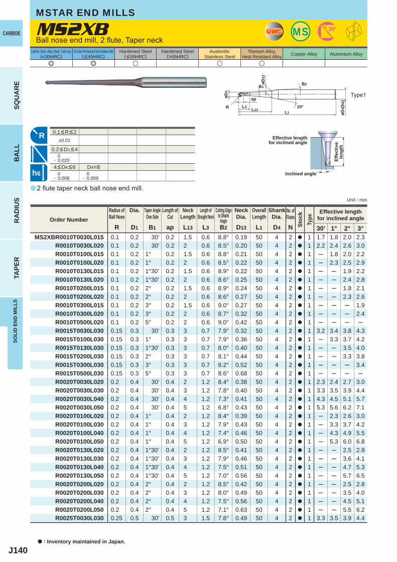
J140
a
e e u u u
MS2XB
R D1 B1 ap L13 L3 B2 D13 L1 D4 N 30' 1° 2° 3°MS2XBR0010T0030L015 0.1 0.2 30' 0.2 1.5 0.6 8.8° 0.19 50 4 2 a 1 1.7 1.8 2.0 2.3
R0010T0030L020 0.1 0.2 30' 0.2 2 0.6 8.5° 0.20 50 4 2 a 1 2.2 2.4 2.6 3.0R0010T0100L015 0.1 0.2 1° 0.2 1.5 0.6 8.8° 0.21 50 4 2 a 1 ─ 1.8 2.0 2.2R0010T0100L020 0.1 0.2 1° 0.2 2 0.6 8.5° 0.22 50 4 2 a 1 ─ 2.3 2.5 2.9R0010T0130L015 0.1 0.2 1°30' 0.2 1.5 0.6 8.9° 0.22 50 4 2 a 1 ─ ─ 1.9 2.2R0010T0130L020 0.1 0.2 1°30' 0.2 2 0.6 8.6° 0.25 50 4 2 a 1 ─ ─ 2.4 2.8R0010T0200L015 0.1 0.2 2° 0.2 1.5 0.6 8.9° 0.24 50 4 2 a 1 ─ ─ 1.8 2.1R0010T0200L020 0.1 0.2 2° 0.2 2 0.6 8.6° 0.27 50 4 2 a 1 ─ ─ 2.3 2.6R0010T0300L015 0.1 0.2 3° 0.2 1.5 0.6 9.0° 0.27 50 4 2 a 1 ─ ─ ─ 1.9R0010T0300L020 0.1 0.2 3° 0.2 2 0.6 8.7° 0.32 50 4 2 a 1 ─ ─ ─ 2.4R0010T0500L020 0.1 0.2 5° 0.2 2 0.6 9.0° 0.42 50 4 2 a 1 ─ ─ ─ ─R0015T0030L030 0.15 0.3 30' 0.3 3 0.7 7.9° 0.32 50 4 2 a 1 3.2 3.4 3.8 4.3R0015T0100L030 0.15 0.3 1° 0.3 3 0.7 7.9° 0.36 50 4 2 a 1 ─ 3.3 3.7 4.2R0015T0130L030 0.15 0.3 1°30' 0.3 3 0.7 8.0° 0.40 50 4 2 a 1 ─ ─ 3.5 4.0R0015T0200L030 0.15 0.3 2° 0.3 3 0.7 8.1° 0.44 50 4 2 a 1 ─ ─ 3.3 3.8R0015T0300L030 0.15 0.3 3° 0.3 3 0.7 8.2° 0.52 50 4 2 a 1 ─ ─ ─ 3.4R0015T0500L030 0.15 0.3 5° 0.3 3 0.7 8.6° 0.68 50 4 2 a 1 ─ ─ ─ ─R0020T0030L020 0.2 0.4 30' 0.4 2 1.2 8.4° 0.38 50 4 2 a 1 2.3 2.4 2.7 3.0R0020T0030L030 0.2 0.4 30' 0.4 3 1.2 7.8° 0.40 50 4 2 a 1 3.3 3.5 3.9 4.4R0020T0030L040 0.2 0.4 30' 0.4 4 1.2 7.3° 0.41 50 4 2 a 1 4.3 4.5 5.1 5.7R0020T0030L050 0.2 0.4 30' 0.4 5 1.2 6.8° 0.43 50 4 2 a 1 5.3 5.6 6.2 7.1R0020T0100L020 0.2 0.4 1° 0.4 2 1.2 8.4° 0.39 50 4 2 a 1 ─ 2.3 2.6 3.0R0020T0100L030 0.2 0.4 1° 0.4 3 1.2 7.9° 0.43 50 4 2 a 1 ─ 3.3 3.7 4.2R0020T0100L040 0.2 0.4 1° 0.4 4 1.2 7.4° 0.46 50 4 2 a 1 ─ 4.3 4.9 5.5R0020T0100L050 0.2 0.4 1° 0.4 5 1.2 6.9° 0.50 50 4 2 a 1 ─ 5.3 6.0 6.8R0020T0130L020 0.2 0.4 1°30' 0.4 2 1.2 8.5° 0.41 50 4 2 a 1 ─ ─ 2.5 2.9R0020T0130L030 0.2 0.4 1°30' 0.4 3 1.2 7.9° 0.46 50 4 2 a 1 ─ ─ 3.6 4.1R0020T0130L040 0.2 0.4 1°30' 0.4 4 1.2 7.5° 0.51 50 4 2 a 1 ─ ─ 4.7 5.3R0020T0130L050 0.2 0.4 1°30' 0.4 5 1.2 7.0° 0.56 50 4 2 a 1 ─ ─ 5.7 6.5R0020T0200L020 0.2 0.4 2° 0.4 2 1.2 8.5° 0.42 50 4 2 a 1 ─ ─ 2.5 2.8R0020T0200L030 0.2 0.4 2° 0.4 3 1.2 8.0° 0.49 50 4 2 a 1 ─ ─ 3.5 4.0R0020T0200L040 0.2 0.4 2° 0.4 4 1.2 7.5° 0.56 50 4 2 a 1 ─ ─ 4.5 5.1R0020T0200L050 0.2 0.4 2° 0.4 5 1.2 7.1° 0.63 50 4 2 a 1 ─ ─ 5.5 6.2R0025T0030L030 0.25 0.5 30' 0.5 3 1.5 7.8° 0.49 50 4 2 a 1 3.3 3.5 3.9 4.4
±0.01
0- 0.020
D4=8 0- 0.008
0- 0.009
UWC MS 30°
øD4(
h6)
L1
apøD1
L13L3R
B1B2
10°
øD13
R
h6
a : Inventory maintained in Japan.
CARBIDE
SQU
AR
EB
ALL
RA
DIU
STA
PER
SOLI
D E
ND
MIL
LS
Unit : mm
Carbon Steel, Alloy Steel, Cast Iron(<30HRC)
Tool Steel, Pre-Hardened Steel,Hardened Steel(<45HRC)
Hardened Steel(<55HRC)
Hardened Steel(>55HRC)
AusteniticStainless Steel
Titanium Alloy,Heat Resistant Alloy Copper Alloy Aluminium Alloy
2 flute taper neck ball nose end mill.
Ball nose end mill, 2 flute, Taper neck
Type1
Effective lengthfor inclined angle
Inclined angle
Effe
ctiv
ele
ngth
Order NumberRadius ofBall Nose
Dia. Taper AngleOne Side
Length ofCut
NeckLength
Length ofStraight Neck
Cutting Edgeto Shank
Angle
NeckDia.
OverallLength
ShankDia.
No. ofFlutes
Stoc
kTy
pe
Effective lengthfor inclined angle
MSTAR END MILLS
4<D4<6
0.1<R<2
0.2<D1<4
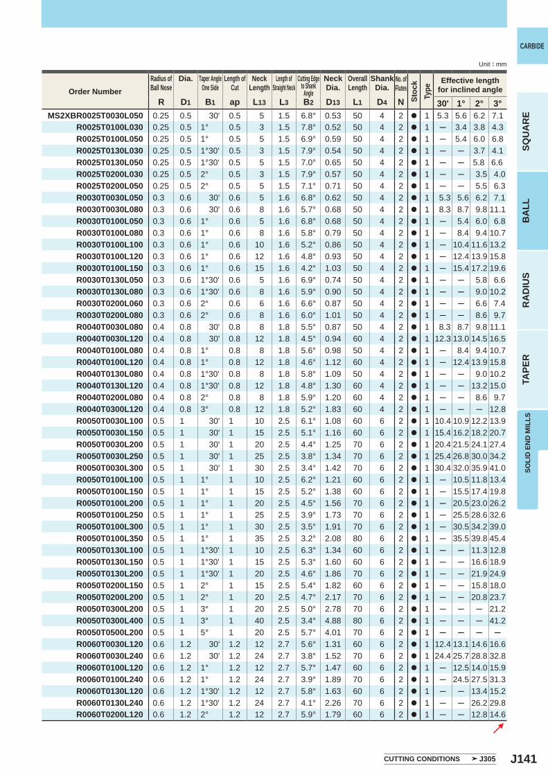
J141
R D1 B1 ap L13 L3 B2 D13 L1 D4 N 30' 1° 2° 3°MS2XBR0025T0030L050 0.25 0.5 30' 0.5 5 1.5 6.8° 0.53 50 4 2 a 1 5.3 5.6 6.2 7.1
R0025T0100L030 0.25 0.5 1° 0.5 3 1.5 7.8° 0.52 50 4 2 a 1 ─ 3.4 3.8 4.3R0025T0100L050 0.25 0.5 1° 0.5 5 1.5 6.9° 0.59 50 4 2 a 1 ─ 5.4 6.0 6.8R0025T0130L030 0.25 0.5 1°30' 0.5 3 1.5 7.9° 0.54 50 4 2 a 1 ─ ─ 3.7 4.1R0025T0130L050 0.25 0.5 1°30' 0.5 5 1.5 7.0° 0.65 50 4 2 a 1 ─ ─ 5.8 6.6R0025T0200L030 0.25 0.5 2° 0.5 3 1.5 7.9° 0.57 50 4 2 a 1 ─ ─ 3.5 4.0R0025T0200L050 0.25 0.5 2° 0.5 5 1.5 7.1° 0.71 50 4 2 a 1 ─ ─ 5.5 6.3R0030T0030L050 0.3 0.6 30' 0.6 5 1.6 6.8° 0.62 50 4 2 a 1 5.3 5.6 6.2 7.1R0030T0030L080 0.3 0.6 30' 0.6 8 1.6 5.7° 0.68 50 4 2 a 1 8.3 8.7 9.8 11.1R0030T0100L050 0.3 0.6 1° 0.6 5 1.6 6.8° 0.68 50 4 2 a 1 ─ 5.4 6.0 6.8R0030T0100L080 0.3 0.6 1° 0.6 8 1.6 5.8° 0.79 50 4 2 a 1 ─ 8.4 9.4 10.7R0030T0100L100 0.3 0.6 1° 0.6 10 1.6 5.2° 0.86 50 4 2 a 1 ─ 10.4 11.6 13.2R0030T0100L120 0.3 0.6 1° 0.6 12 1.6 4.8° 0.93 50 4 2 a 1 ─ 12.4 13.9 15.8R0030T0100L150 0.3 0.6 1° 0.6 15 1.6 4.2° 1.03 50 4 2 a 1 ─ 15.4 17.2 19.6R0030T0130L050 0.3 0.6 1°30' 0.6 5 1.6 6.9° 0.74 50 4 2 a 1 ─ ─ 5.8 6.6R0030T0130L080 0.3 0.6 1°30' 0.6 8 1.6 5.9° 0.90 50 4 2 a 1 ─ ─ 9.0 10.2R0030T0200L060 0.3 0.6 2° 0.6 6 1.6 6.6° 0.87 50 4 2 a 1 ─ ─ 6.6 7.4R0030T0200L080 0.3 0.6 2° 0.6 8 1.6 6.0° 1.01 50 4 2 a 1 ─ ─ 8.6 9.7R0040T0030L080 0.4 0.8 30' 0.8 8 1.8 5.5° 0.87 50 4 2 a 1 8.3 8.7 9.8 11.1R0040T0030L120 0.4 0.8 30' 0.8 12 1.8 4.5° 0.94 60 4 2 a 1 12.3 13.0 14.5 16.5R0040T0100L080 0.4 0.8 1° 0.8 8 1.8 5.6° 0.98 50 4 2 a 1 ─ 8.4 9.4 10.7R0040T0100L120 0.4 0.8 1° 0.8 12 1.8 4.6° 1.12 60 4 2 a 1 ─ 12.4 13.9 15.8R0040T0130L080 0.4 0.8 1°30' 0.8 8 1.8 5.8° 1.09 50 4 2 a 1 ─ ─ 9.0 10.2R0040T0130L120 0.4 0.8 1°30' 0.8 12 1.8 4.8° 1.30 60 4 2 a 1 ─ ─ 13.2 15.0R0040T0200L080 0.4 0.8 2° 0.8 8 1.8 5.9° 1.20 60 4 2 a 1 ─ ─ 8.6 9.7R0040T0300L120 0.4 0.8 3° 0.8 12 1.8 5.2° 1.83 60 4 2 a 1 ─ ─ ─ 12.8R0050T0030L100 0.5 1 30' 1 10 2.5 6.1° 1.08 60 6 2 a 1 10.4 10.9 12.2 13.9R0050T0030L150 0.5 1 30' 1 15 2.5 5.1° 1.16 60 6 2 a 1 15.4 16.2 18.2 20.7R0050T0030L200 0.5 1 30' 1 20 2.5 4.4° 1.25 70 6 2 a 1 20.4 21.5 24.1 27.4R0050T0030L250 0.5 1 30' 1 25 2.5 3.8° 1.34 70 6 2 a 1 25.4 26.8 30.0 34.2R0050T0030L300 0.5 1 30' 1 30 2.5 3.4° 1.42 70 6 2 a 1 30.4 32.0 35.9 41.0R0050T0100L100 0.5 1 1° 1 10 2.5 6.2° 1.21 60 6 2 a 1 ─ 10.5 11.8 13.4R0050T0100L150 0.5 1 1° 1 15 2.5 5.2° 1.38 60 6 2 a 1 ─ 15.5 17.4 19.8R0050T0100L200 0.5 1 1° 1 20 2.5 4.5° 1.56 70 6 2 a 1 ─ 20.5 23.0 26.2R0050T0100L250 0.5 1 1° 1 25 2.5 3.9° 1.73 70 6 2 a 1 ─ 25.5 28.6 32.6R0050T0100L300 0.5 1 1° 1 30 2.5 3.5° 1.91 70 6 2 a 1 ─ 30.5 34.2 39.0R0050T0100L350 0.5 1 1° 1 35 2.5 3.2° 2.08 80 6 2 a 1 ─ 35.5 39.8 45.4R0050T0130L100 0.5 1 1°30' 1 10 2.5 6.3° 1.34 60 6 2 a 1 ─ ─ 11.3 12.8R0050T0130L150 0.5 1 1°30' 1 15 2.5 5.3° 1.60 60 6 2 a 1 ─ ─ 16.6 18.9R0050T0130L200 0.5 1 1°30' 1 20 2.5 4.6° 1.86 70 6 2 a 1 ─ ─ 21.9 24.9R0050T0200L150 0.5 1 2° 1 15 2.5 5.4° 1.82 60 6 2 a 1 ─ ─ 15.8 18.0R0050T0200L200 0.5 1 2° 1 20 2.5 4.7° 2.17 70 6 2 a 1 ─ ─ 20.8 23.7R0050T0300L200 0.5 1 3° 1 20 2.5 5.0° 2.78 70 6 2 a 1 ─ ─ ─ 21.2R0050T0300L400 0.5 1 3° 1 40 2.5 3.4° 4.88 80 6 2 a 1 ─ ─ ─ 41.2R0050T0500L200 0.5 1 5° 1 20 2.5 5.7° 4.01 70 6 2 a 1 ─ ─ ─ ─R0060T0030L120 0.6 1.2 30' 1.2 12 2.7 5.6° 1.31 60 6 2 a 1 12.4 13.1 14.6 16.6R0060T0030L240 0.6 1.2 30' 1.2 24 2.7 3.8° 1.52 70 6 2 a 1 24.4 25.7 28.8 32.8R0060T0100L120 0.6 1.2 1° 1.2 12 2.7 5.7° 1.47 60 6 2 a 1 ─ 12.5 14.0 15.9R0060T0100L240 0.6 1.2 1° 1.2 24 2.7 3.9° 1.89 70 6 2 a 1 ─ 24.5 27.5 31.3R0060T0130L120 0.6 1.2 1°30' 1.2 12 2.7 5.8° 1.63 60 6 2 a 1 ─ ─ 13.4 15.2R0060T0130L240 0.6 1.2 1°30' 1.2 24 2.7 4.1° 2.26 70 6 2 a 1 ─ ─ 26.2 29.8R0060T0200L120 0.6 1.2 2° 1.2 12 2.7 5.9° 1.79 60 6 2 a 1 ─ ─ 12.8 14.6
SOLI
D E
ND
MIL
LS
CARBIDE
SQU
AR
EB
ALL
RA
DIU
STA
PER
Unit : mm
CUTTING CONDITIONS J305
Order NumberRadius ofBall Nose
Dia. Taper AngleOne Side
Length ofCut
NeckLength
Length ofStraight Neck
Cutting Edgeto Shank
Angle
NeckDia.
OverallLength
ShankDia.
No. ofFlutes
Stoc
kTy
pe
Effective lengthfor inclined angle
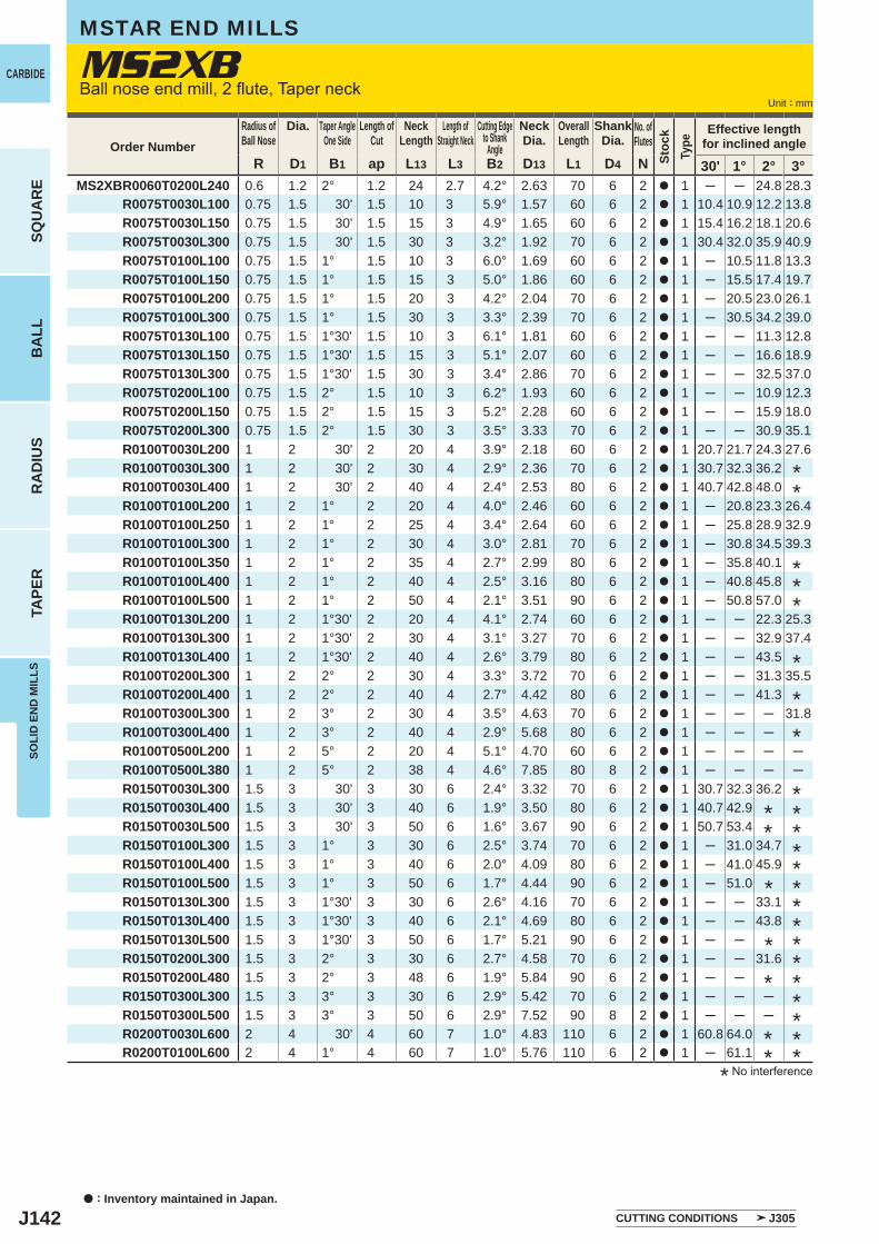
J142
R D1 B1 ap L13 L3 B2 D13 L1 D4 N 30' 1° 2° 3°MS2XBR0060T0200L240 0.6 1.2 2° 1.2 24 2.7 4.2° 2.63 70 6 2 a 1 ─ ─ 24.8 28.3
R0075T0030L100 0.75 1.5 30' 1.5 10 3 5.9° 1.57 60 6 2 a 1 10.4 10.9 12.2 13.8R0075T0030L150 0.75 1.5 30' 1.5 15 3 4.9° 1.65 60 6 2 a 1 15.4 16.2 18.1 20.6R0075T0030L300 0.75 1.5 30' 1.5 30 3 3.2° 1.92 70 6 2 a 1 30.4 32.0 35.9 40.9R0075T0100L100 0.75 1.5 1° 1.5 10 3 6.0° 1.69 60 6 2 a 1 ─ 10.5 11.8 13.3R0075T0100L150 0.75 1.5 1° 1.5 15 3 5.0° 1.86 60 6 2 a 1 ─ 15.5 17.4 19.7R0075T0100L200 0.75 1.5 1° 1.5 20 3 4.2° 2.04 70 6 2 a 1 ─ 20.5 23.0 26.1R0075T0100L300 0.75 1.5 1° 1.5 30 3 3.3° 2.39 70 6 2 a 1 ─ 30.5 34.2 39.0R0075T0130L100 0.75 1.5 1°30' 1.5 10 3 6.1° 1.81 60 6 2 a 1 ─ ─ 11.3 12.8R0075T0130L150 0.75 1.5 1°30' 1.5 15 3 5.1° 2.07 60 6 2 a 1 ─ ─ 16.6 18.9R0075T0130L300 0.75 1.5 1°30' 1.5 30 3 3.4° 2.86 70 6 2 a 1 ─ ─ 32.5 37.0R0075T0200L100 0.75 1.5 2° 1.5 10 3 6.2° 1.93 60 6 2 a 1 ─ ─ 10.9 12.3R0075T0200L150 0.75 1.5 2° 1.5 15 3 5.2° 2.28 60 6 2 a 1 ─ ─ 15.9 18.0R0075T0200L300 0.75 1.5 2° 1.5 30 3 3.5° 3.33 70 6 2 a 1 ─ ─ 30.9 35.1R0100T0030L200 1 2 30' 2 20 4 3.9° 2.18 60 6 2 a 1 20.7 21.7 24.3 27.6R0100T0030L300 1 2 30' 2 30 4 2.9° 2.36 70 6 2 a 1 30.7 32.3 36.2R0100T0030L400 1 2 30' 2 40 4 2.4° 2.53 80 6 2 a 1 40.7 42.8 48.0R0100T0100L200 1 2 1° 2 20 4 4.0° 2.46 60 6 2 a 1 ─ 20.8 23.3 26.4R0100T0100L250 1 2 1° 2 25 4 3.4° 2.64 60 6 2 a 1 ─ 25.8 28.9 32.9R0100T0100L300 1 2 1° 2 30 4 3.0° 2.81 70 6 2 a 1 ─ 30.8 34.5 39.3R0100T0100L350 1 2 1° 2 35 4 2.7° 2.99 80 6 2 a 1 ─ 35.8 40.1R0100T0100L400 1 2 1° 2 40 4 2.5° 3.16 80 6 2 a 1 ─ 40.8 45.8R0100T0100L500 1 2 1° 2 50 4 2.1° 3.51 90 6 2 a 1 ─ 50.8 57.0R0100T0130L200 1 2 1°30' 2 20 4 4.1° 2.74 60 6 2 a 1 ─ ─ 22.3 25.3R0100T0130L300 1 2 1°30' 2 30 4 3.1° 3.27 70 6 2 a 1 ─ ─ 32.9 37.4R0100T0130L400 1 2 1°30' 2 40 4 2.6° 3.79 80 6 2 a 1 ─ ─ 43.5R0100T0200L300 1 2 2° 2 30 4 3.3° 3.72 70 6 2 a 1 ─ ─ 31.3 35.5R0100T0200L400 1 2 2° 2 40 4 2.7° 4.42 80 6 2 a 1 ─ ─ 41.3R0100T0300L300 1 2 3° 2 30 4 3.5° 4.63 70 6 2 a 1 ─ ─ ─ 31.8R0100T0300L400 1 2 3° 2 40 4 2.9° 5.68 80 6 2 a 1 ─ ─ ─R0100T0500L200 1 2 5° 2 20 4 5.1° 4.70 60 6 2 a 1 ─ ─ ─ ─R0100T0500L380 1 2 5° 2 38 4 4.6° 7.85 80 8 2 a 1 ─ ─ ─ ─R0150T0030L300 1.5 3 30' 3 30 6 2.4° 3.32 70 6 2 a 1 30.7 32.3 36.2R0150T0030L400 1.5 3 30' 3 40 6 1.9° 3.50 80 6 2 a 1 40.7 42.9R0150T0030L500 1.5 3 30' 3 50 6 1.6° 3.67 90 6 2 a 1 50.7 53.4R0150T0100L300 1.5 3 1° 3 30 6 2.5° 3.74 70 6 2 a 1 ─ 31.0 34.7R0150T0100L400 1.5 3 1° 3 40 6 2.0° 4.09 80 6 2 a 1 ─ 41.0 45.9R0150T0100L500 1.5 3 1° 3 50 6 1.7° 4.44 90 6 2 a 1 ─ 51.0R0150T0130L300 1.5 3 1°30' 3 30 6 2.6° 4.16 70 6 2 a 1 ─ ─ 33.1R0150T0130L400 1.5 3 1°30' 3 40 6 2.1° 4.69 80 6 2 a 1 ─ ─ 43.8R0150T0130L500 1.5 3 1°30' 3 50 6 1.7° 5.21 90 6 2 a 1 ─ ─R0150T0200L300 1.5 3 2° 3 30 6 2.7° 4.58 70 6 2 a 1 ─ ─ 31.6R0150T0200L480 1.5 3 2° 3 48 6 1.9° 5.84 90 6 2 a 1 ─ ─R0150T0300L300 1.5 3 3° 3 30 6 2.9° 5.42 70 6 2 a 1 ─ ─ ─R0150T0300L500 1.5 3 3° 3 50 6 2.9° 7.52 90 8 2 a 1 ─ ─ ─R0200T0030L600 2 4 30' 4 60 7 1.0° 4.83 110 6 2 a 1 60.8 64.0R0200T0100L600 2 4 1° 4 60 7 1.0° 5.76 110 6 2 a 1 ─ 61.1
MS2XB
a : Inventory maintained in Japan.
CARBIDE
SQU
AR
EB
ALL
RA
DIU
STA
PER
SOLI
D E
ND
MIL
LS
Unit : mm
CUTTING CONDITIONS J305
Order NumberRadius ofBall Nose
Dia. Taper AngleOne Side
Length ofCut
NeckLength
Length ofStraight Neck
Cutting Edgeto Shank
Angle
NeckDia.
OverallLength
ShankDia.
No. ofFlutes
Stoc
kTy
pe
Effective lengthfor inclined angle
Ball nose end mill, 2 flute, Taper neck
MSTAR END MILLS
* No interference
*
***
**
*
***********
*
* ** *
**
*
*
**
*
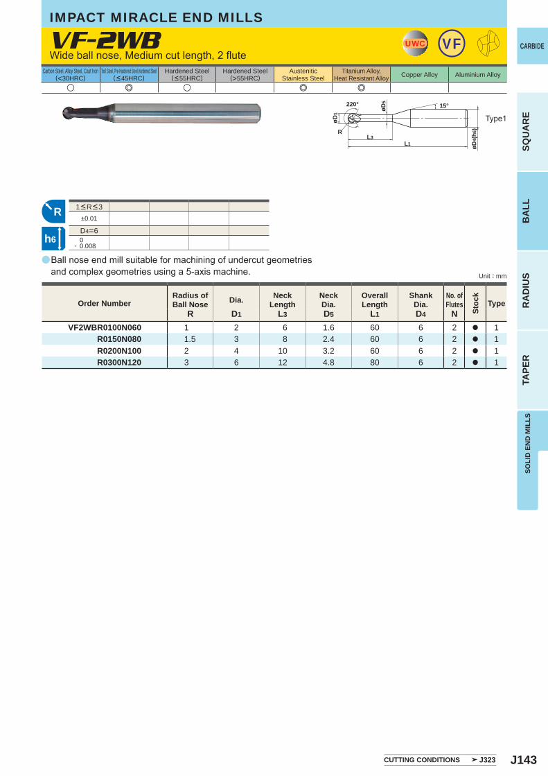
J143
a
VF-2WB
R D1 L3 D5 L1 D4 NVF2WBR0100N060 1 2 6 1.6 60 6 2 a 1
R0150N080 1.5 3 8 2.4 60 6 2 a 1R0200N100 2 4 10 3.2 60 6 2 a 1R0300N120 3 6 12 4.8 80 6 2 a 1
u e u e e
±0.01
D4=6 0- 0.008
UWC VF
øD1
øD4(
h6)
L1L3
15°
R
220°
øD5
R
h6
SOLI
D E
ND
MIL
LS
CARBIDE
SQU
AR
EB
ALL
RA
DIU
STA
PER
Unit : mm
Carbon Steel, Alloy Steel, Cast Iron(<30HRC)
Tool Steel, Pre-Hardened Steel,Hardened Steel(<45HRC)
Hardened Steel(<55HRC)
Hardened Steel(>55HRC)
AusteniticStainless Steel
Titanium Alloy,Heat Resistant Alloy Copper Alloy Aluminium Alloy
Ball nose end mill suitable for machining of undercut geometriesand complex geometries using a 5-axis machine.
Wide ball nose, Medium cut length, 2 flute
IMPACT MIRACLE END MILLS
Type1
CUTTING CONDITIONS J323
Order NumberRadius ofBall Nose Dia. Neck
LengthNeckDia.
OverallLength
ShankDia.
No. ofFlutes
Stoc
k
Type
1<R<3
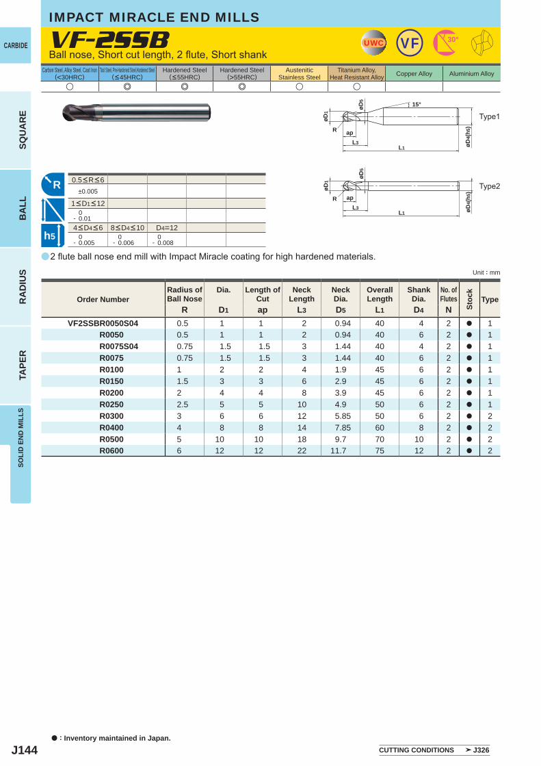
J144
a
VF-2SSB
R D1 ap L3 D5 L1 D4 NVF2SSBR0050S04 0.5 1 1 2 0.94 40 4 2 a 1
R0050 0.5 1 1 2 0.94 40 6 2 a 1 R0075S04 0.75 1.5 1.5 3 1.44 40 4 2 a 1 R0075 0.75 1.5 1.5 3 1.44 40 6 2 a 1 R0100 1 2 2 4 1.9 45 6 2 a 1 R0150 1.5 3 3 6 2.9 45 6 2 a 1 R0200 2 4 4 8 3.9 45 6 2 a 1 R0250 2.5 5 5 10 4.9 50 6 2 a 1 R0300 3 6 6 12 5.85 50 6 2 a 2 R0400 4 8 8 14 7.85 60 8 2 a 2 R0500 5 10 10 18 9.7 70 10 2 a 2 R0600 6 12 12 22 11.7 75 12 2 a 2
u e e e u u
±0.005
0- 0.01
D4=12 0- 0.005
0- 0.006
0- 0.008
UWC VF 30°
L1
apL3 øD
4(h5
)
øD1
øD5
R
15°
R
L1 øD4(
h5)
øD5
R apL3
øD1
h5
a : Inventory maintained in Japan.
CARBIDE
SQU
AR
EB
ALL
RA
DIU
STA
PER
SOLI
D E
ND
MIL
LS
Unit : mm
Carbon Steel, Alloy Steel, Cast Iron(<30HRC)
Tool Steel, Pre-Hardened Steel,Hardened Steel(<45HRC)
Hardened Steel(<55HRC)
Hardened Steel(>55HRC)
AusteniticStainless Steel
Titanium Alloy,Heat Resistant Alloy Copper Alloy Aluminium Alloy
2 flute ball nose end mill with Impact Miracle coating for high hardened materials.
Ball nose, Short cut length, 2 flute, Short shank
Type2
Type1
CUTTING CONDITIONS J326
Order NumberRadius ofBall Nose
Dia. Length ofCut
NeckLength
NeckDia.
OverallLength
ShankDia.
No. ofFlutes
Stoc
k
Type
IMPACT MIRACLE END MILLS
4<D4<6 8<D4<10
1<D1<12
0.5<R<6
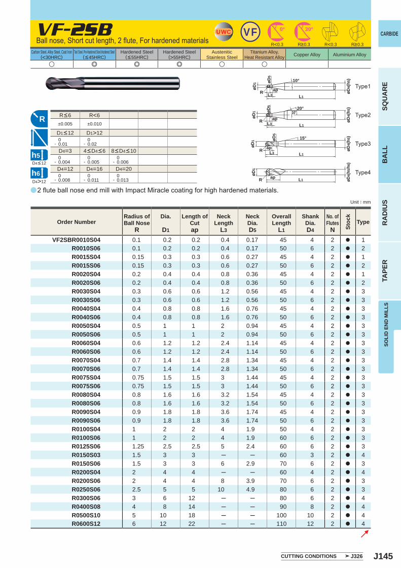
J145
a
VF-2SB
R D1 ap L3 D5 L1 D4 NVF2SBR0010S04 0.1 0.2 0.2 0.4 0.17 45 4 2 a 1
R0010S06 0.1 0.2 0.2 0.4 0.17 50 6 2 a 2 R0015S04 0.15 0.3 0.3 0.6 0.27 45 4 2 a 1 R0015S06 0.15 0.3 0.3 0.6 0.27 50 6 2 a 2 R0020S04 0.2 0.4 0.4 0.8 0.36 45 4 2 a 1 R0020S06 0.2 0.4 0.4 0.8 0.36 50 6 2 a 2 R0030S04 0.3 0.6 0.6 1.2 0.56 45 4 2 a 3 R0030S06 0.3 0.6 0.6 1.2 0.56 50 6 2 a 3 R0040S04 0.4 0.8 0.8 1.6 0.76 45 4 2 a 3 R0040S06 0.4 0.8 0.8 1.6 0.76 50 6 2 a 3 R0050S04 0.5 1 1 2 0.94 45 4 2 a 3 R0050S06 0.5 1 1 2 0.94 50 6 2 a 3 R0060S04 0.6 1.2 1.2 2.4 1.14 45 4 2 a 3 R0060S06 0.6 1.2 1.2 2.4 1.14 50 6 2 a 3 R0070S04 0.7 1.4 1.4 2.8 1.34 45 4 2 a 3 R0070S06 0.7 1.4 1.4 2.8 1.34 50 6 2 a 3 R0075S04 0.75 1.5 1.5 3 1.44 45 4 2 a 3 R0075S06 0.75 1.5 1.5 3 1.44 50 6 2 a 3 R0080S04 0.8 1.6 1.6 3.2 1.54 45 4 2 a 3 R0080S06 0.8 1.6 1.6 3.2 1.54 50 6 2 a 3 R0090S04 0.9 1.8 1.8 3.6 1.74 45 4 2 a 3 R0090S06 0.9 1.8 1.8 3.6 1.74 50 6 2 a 3 R0100S04 1 2 2 4 1.9 50 4 2 a 3 R0100S06 1 2 2 4 1.9 60 6 2 a 3 R0125S06 1.25 2.5 2.5 5 2.4 60 6 2 a 3 R0150S03 1.5 3 3 ─ ─ 60 3 2 a 4 R0150S06 1.5 3 3 6 2.9 70 6 2 a 3 R0200S04 2 4 4 ─ ─ 60 4 2 a 4 R0200S06 2 4 4 8 3.9 70 6 2 a 3 R0250S06 2.5 5 5 10 4.9 80 6 2 a 3 R0300S06 3 6 12 ─ ─ 80 6 2 a 4 R0400S08 4 8 14 ─ ─ 90 8 2 a 4 R0500S10 5 10 18 ─ ─ 100 10 2 a 4
R0600S12 6 12 22 ─ ─ 110 12 2 a 4
u e e e u u
R<6±0.005 ±0.010
D1>12 0- 0.01
0- 0.02
D4=3 0- 0.004
0- 0.005
0- 0.006
D4=12 D4=16 D4=20 0- 0.008
0- 0.011
0- 0.013
UWC VF 30°0°
R<0.3 R<0.3
R
øD1
L1
apL3
øD5
R
15°
øD4(
h5)
20°10°
R
øD5
øD4(
h5)
øD1
L1
apL3
øD4(
h5/h
6)
L1apøD1
R
10°øD5
øD1
L1
øD4(
h5)
apL3
R
D4>12
h5
h6
SOLI
D E
ND
MIL
LS
CARBIDE
SQU
AR
EB
ALL
RA
DIU
STA
PER
Unit : mm
Carbon Steel, Alloy Steel, Cast Iron(<30HRC)
Tool Steel, Pre-Hardened Steel,Hardened Steel(<45HRC)
Hardened Steel(<55HRC)
Hardened Steel(>55HRC)
AusteniticStainless Steel
Titanium Alloy,Heat Resistant Alloy Copper Alloy Aluminium Alloy
2 flute ball nose end mill with Impact Miracle coating for high hardened materials.
Ball nose, Short cut length, 2 flute, For hardened materials
CUTTING CONDITIONS J326
Order NumberRadius ofBall Nose
Dia. Length ofCut
NeckLength
NeckDia.
OverallLength
ShankDia.
No. ofFlutes
Stoc
k
Type
R>0.3 R>0.3
D4<12
Type2
Type3
Type4
Type1
4<D4<6 8<D4<10
R<6
D1<12
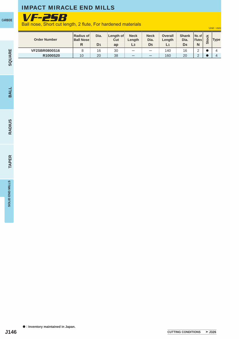
J146
R D1 ap L3 D5 L1 D4 N VF2SBR0800S16 8 16 30 ─ ─ 140 16 2 a 4 R1000S20 10 20 38 ─ ─ 160 20 2 a 4
a : Inventory maintained in Japan.
CARBIDE
SQU
AR
EB
ALL
RA
DIU
STA
PER
SOLI
D E
ND
MIL
LS
Unit : mm
Order NumberRadius ofBall Nose
Dia. Length ofCut
NeckLength
NeckDia.
OverallLength
ShankDia.
No. ofFlutes
Stoc
k
Type
VF-2SBBall nose, Short cut length, 2 flute, For hardened materials
IMPACT MIRACLE END MILLS
CUTTING CONDITIONS J326
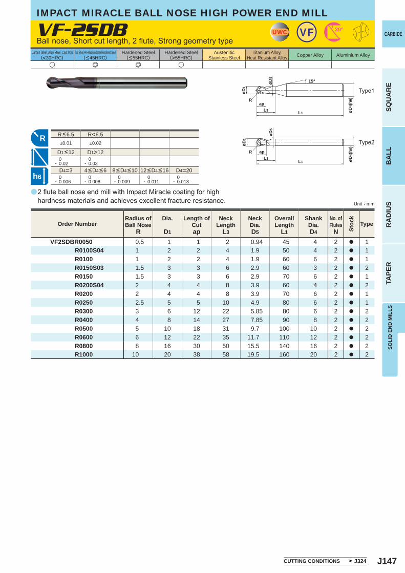
J147
a
VF-2SDB
R D1 ap L3 D5 L1 D4 NVF2SDBR0050 0.5 1 1 2 0.94 45 4 2 a 1 R0100S04 1 2 2 4 1.9 50 4 2 a 1 R0100 1 2 2 4 1.9 60 6 2 a 1 R0150S03 1.5 3 3 6 2.9 60 3 2 a 2 R0150 1.5 3 3 6 2.9 70 6 2 a 1 R0200S04 2 4 4 8 3.9 60 4 2 a 2 R0200 2 4 4 8 3.9 70 6 2 a 1 R0250 2.5 5 5 10 4.9 80 6 2 a 1 R0300 3 6 12 22 5.85 80 6 2 a 2 R0400 4 8 14 27 7.85 90 8 2 a 2 R0500 5 10 18 31 9.7 100 10 2 a 2 R0600 6 12 22 35 11.7 110 12 2 a 2 R0800 8 16 30 50 15.5 140 16 2 a 2 R1000 10 20 38 58 19.5 160 20 2 a 2
u e e u
R<6.5±0.01 ±0.02
D1>12 0- 0.02
0- 0.03
D4=3 D4=20 0- 0.006
0- 0.008
0- 0.009
0- 0.011
0- 0.013
UWC VF 30°
L1
apL3 øD
4(h6
)
øD1
øD5
R
15°
R
L1
øD5
R
øD4(
h6)
apL3
øD1
h6
SOLI
D E
ND
MIL
LS
CARBIDE
SQU
AR
EB
ALL
RA
DIU
STA
PER
Unit : mm
Carbon Steel, Alloy Steel, Cast Iron(<30HRC)
Tool Steel, Pre-Hardened Steel,Hardened Steel(<45HRC)
Hardened Steel(<55HRC)
Hardened Steel(>55HRC)
AusteniticStainless Steel
Titanium Alloy,Heat Resistant Alloy Copper Alloy Aluminium Alloy
2 flute ball nose end mill with Impact Miracle coating for high hardness materials and achieves excellent fracture resistance.
Ball nose, Short cut length, 2 flute, Strong geometry type
Type1
CUTTING CONDITIONS J324
Order NumberRadius ofBall Nose
Dia. Length ofCut
NeckLength
NeckDia.
OverallLength
ShankDia.
No. ofFlutes
Stoc
k
Type
4<D4<6 8<D4<10 12<D4<16
R<6.5
D1<12
Type2
IMPACT MIRACLE BALL NOSE HIGH POWER END MILL
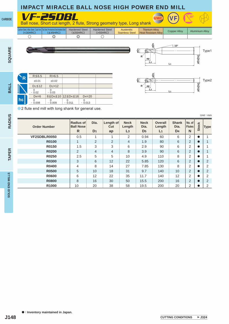
J148
a
VF-2SDBL
R D1 ap L3 D5 L1 D4 NVF2SDBLR0050 0.5 1 1 2 0.94 60 6 2 a 1
R0100 1 2 2 4 1.9 80 6 2 a 1 R0150 1.5 3 3 6 2.9 90 6 2 a 1 R0200 2 4 4 8 3.9 90 6 2 a 1 R0250 2.5 5 5 10 4.9 110 8 2 a 1 R0300 3 6 12 22 5.85 120 6 2 a 2 R0400 4 8 14 27 7.85 130 8 2 a 2 R0500 5 10 18 31 9.7 140 10 2 a 2 R0600 6 12 22 35 11.7 140 12 2 a 2 R0800 8 16 30 50 15.5 200 16 2 a 2 R1000 10 20 38 58 19.5 200 20 2 a 2
u e e u
R>6.5±0.01 ±0.02
D1>12 0- 0.02
0- 0.03
D4=6 D4=20 0- 0.008
0- 0.009
0- 0.011
0- 0.013
UWC VF 30°
L1
apL3 øD
4(h6
)
øD1
øD5
R
10°
R
L1
øD5
R
øD4(
h6)
apL3
øD1
h6
a : Inventory maintained in Japan.
CARBIDE
SQU
AR
EB
ALL
RA
DIU
STA
PER
SOLI
D E
ND
MIL
LS
Unit : mm
Carbon Steel, Alloy Steel, Cast Iron(<30HRC)
Tool Steel, Pre-Hardened Steel,Hardened Steel(<45HRC)
Hardened Steel(<55HRC)
Hardened Steel(>55HRC)
AusteniticStainless Steel
Titanium Alloy,Heat Resistant Alloy Copper Alloy Aluminium Alloy
2 flute end mill with long shank for general use.
Ball nose, Short cut length, 2 flute, Strong geometry type, Long shank
IMPACT MIRACLE BALL NOSE HIGH POWER END MILL
Type1
CUTTING CONDITIONS J324
Order NumberRadius ofBall Nose
Dia. Length ofCut
NeckLength
NeckDia.
OverallLength
ShankDia.
No. ofFlutes
Stoc
k
Type
8<D4<10 12<D4<16
R<6.5
D1<12
Type2
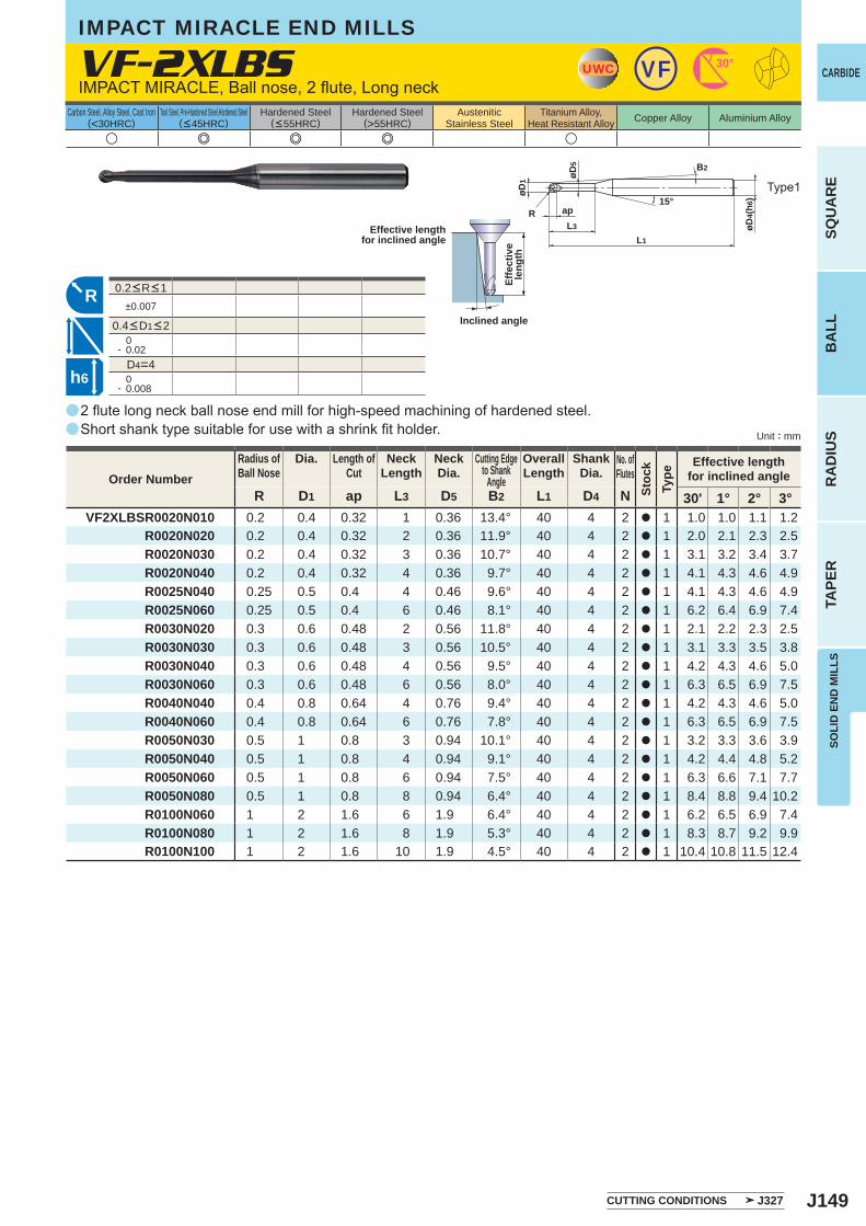
J149
a
a
VF-2XLBS
R D1 ap L3 D5 B2 L1 D4 N 30' 1° 2° 3°VF2XLBSR0020N010 0.2 0.4 0.32 1 0.36 13.4° 40 4 2 a 1 1.0 1.0 1.1 1.2
R0020N020 0.2 0.4 0.32 2 0.36 11.9° 40 4 2 a 1 2.0 2.1 2.3 2.5 R0020N030 0.2 0.4 0.32 3 0.36 10.7° 40 4 2 a 1 3.1 3.2 3.4 3.7 R0020N040 0.2 0.4 0.32 4 0.36 9.7° 40 4 2 a 1 4.1 4.3 4.6 4.9 R0025N040 0.25 0.5 0.4 4 0.46 9.6° 40 4 2 a 1 4.1 4.3 4.6 4.9 R0025N060 0.25 0.5 0.4 6 0.46 8.1° 40 4 2 a 1 6.2 6.4 6.9 7.4 R0030N020 0.3 0.6 0.48 2 0.56 11.8° 40 4 2 a 1 2.1 2.2 2.3 2.5 R0030N030 0.3 0.6 0.48 3 0.56 10.5° 40 4 2 a 1 3.1 3.3 3.5 3.8 R0030N040 0.3 0.6 0.48 4 0.56 9.5° 40 4 2 a 1 4.2 4.3 4.6 5.0 R0030N060 0.3 0.6 0.48 6 0.56 8.0° 40 4 2 a 1 6.3 6.5 6.9 7.5 R0040N040 0.4 0.8 0.64 4 0.76 9.4° 40 4 2 a 1 4.2 4.3 4.6 5.0 R0040N060 0.4 0.8 0.64 6 0.76 7.8° 40 4 2 a 1 6.3 6.5 6.9 7.5 R0050N030 0.5 1 0.8 3 0.94 10.1° 40 4 2 a 1 3.2 3.3 3.6 3.9 R0050N040 0.5 1 0.8 4 0.94 9.1° 40 4 2 a 1 4.2 4.4 4.8 5.2 R0050N060 0.5 1 0.8 6 0.94 7.5° 40 4 2 a 1 6.3 6.6 7.1 7.7 R0050N080 0.5 1 0.8 8 0.94 6.4° 40 4 2 a 1 8.4 8.8 9.4 10.2 R0100N060 1 2 1.6 6 1.9 6.4° 40 4 2 a 1 6.2 6.5 6.9 7.4 R0100N080 1 2 1.6 8 1.9 5.3° 40 4 2 a 1 8.3 8.7 9.2 9.9 R0100N100 1 2 1.6 10 1.9 4.5° 40 4 2 a 1 10.4 10.8 11.5 12.4
u e e e u
±0.007
0- 0.02
D4=4 0- 0.008
UWC VF 30°
øD1
R
L1
apL3 øD
4(h6
)
øD5 B2
15°
R
h6
SOLI
D E
ND
MIL
LS
CARBIDE
SQU
AR
EB
ALL
RA
DIU
STA
PER
Unit : mm
Carbon Steel, Alloy Steel, Cast Iron(<30HRC)
Tool Steel, Pre-Hardened Steel,Hardened Steel(<45HRC)
Hardened Steel(<55HRC)
Hardened Steel(>55HRC)
AusteniticStainless Steel
Titanium Alloy,Heat Resistant Alloy Copper Alloy Aluminium Alloy
0.2<R<1
0.4<D1<2
2 flute long neck ball nose end mill for high-speed machining of hardened steel.Short shank type suitable for use with a shrink fit holder.
IMPACT MIRACLE, Ball nose, 2 flute, Long neck
Type1
Effective lengthfor inclined angle
Inclined angle
Effe
ctiv
ele
ngth
CUTTING CONDITIONS J327
Order NumberRadius ofBall Nose
Dia. Length ofCut
NeckLength
NeckDia.
Cutting Edgeto Shank
Angle
OverallLength
ShankDia.
No. ofFlutes
Stoc
kTy
pe
Effective lengthfor inclined angle
IMPACT MIRACLE END MILLS
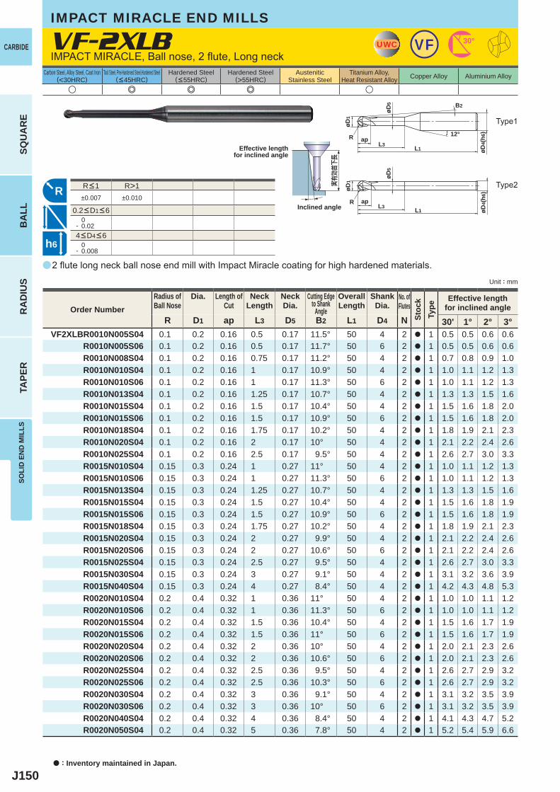
J150
a
VF-2XLB
u e e e u
R D1 ap L3 D5 B2 L1 D4 N 30' 1° 2° 3°VF2XLBR0010N005S04 0.1 0.2 0.16 0.5 0.17 11.5° 50 4 2 a 1 0.5 0.5 0.6 0.6
R0010N005S06 0.1 0.2 0.16 0.5 0.17 11.7° 50 6 2 a 1 0.5 0.5 0.6 0.6 R0010N008S04 0.1 0.2 0.16 0.75 0.17 11.2° 50 4 2 a 1 0.7 0.8 0.9 1.0 R0010N010S04 0.1 0.2 0.16 1 0.17 10.9° 50 4 2 a 1 1.0 1.1 1.2 1.3 R0010N010S06 0.1 0.2 0.16 1 0.17 11.3° 50 6 2 a 1 1.0 1.1 1.2 1.3 R0010N013S04 0.1 0.2 0.16 1.25 0.17 10.7° 50 4 2 a 1 1.3 1.3 1.5 1.6 R0010N015S04 0.1 0.2 0.16 1.5 0.17 10.4° 50 4 2 a 1 1.5 1.6 1.8 2.0 R0010N015S06 0.1 0.2 0.16 1.5 0.17 10.9° 50 6 2 a 1 1.5 1.6 1.8 2.0 R0010N018S04 0.1 0.2 0.16 1.75 0.17 10.2° 50 4 2 a 1 1.8 1.9 2.1 2.3 R0010N020S04 0.1 0.2 0.16 2 0.17 10° 50 4 2 a 1 2.1 2.2 2.4 2.6 R0010N025S04 0.1 0.2 0.16 2.5 0.17 9.5° 50 4 2 a 1 2.6 2.7 3.0 3.3 R0015N010S04 0.15 0.3 0.24 1 0.27 11° 50 4 2 a 1 1.0 1.1 1.2 1.3 R0015N010S06 0.15 0.3 0.24 1 0.27 11.3° 50 6 2 a 1 1.0 1.1 1.2 1.3 R0015N013S04 0.15 0.3 0.24 1.25 0.27 10.7° 50 4 2 a 1 1.3 1.3 1.5 1.6 R0015N015S04 0.15 0.3 0.24 1.5 0.27 10.4° 50 4 2 a 1 1.5 1.6 1.8 1.9 R0015N015S06 0.15 0.3 0.24 1.5 0.27 10.9° 50 6 2 a 1 1.5 1.6 1.8 1.9 R0015N018S04 0.15 0.3 0.24 1.75 0.27 10.2° 50 4 2 a 1 1.8 1.9 2.1 2.3 R0015N020S04 0.15 0.3 0.24 2 0.27 9.9° 50 4 2 a 1 2.1 2.2 2.4 2.6 R0015N020S06 0.15 0.3 0.24 2 0.27 10.6° 50 6 2 a 1 2.1 2.2 2.4 2.6 R0015N025S04 0.15 0.3 0.24 2.5 0.27 9.5° 50 4 2 a 1 2.6 2.7 3.0 3.3 R0015N030S04 0.15 0.3 0.24 3 0.27 9.1° 50 4 2 a 1 3.1 3.2 3.6 3.9 R0015N040S04 0.15 0.3 0.24 4 0.27 8.4° 50 4 2 a 1 4.2 4.3 4.8 5.3 R0020N010S04 0.2 0.4 0.32 1 0.36 11° 50 4 2 a 1 1.0 1.0 1.1 1.2 R0020N010S06 0.2 0.4 0.32 1 0.36 11.3° 50 6 2 a 1 1.0 1.0 1.1 1.2 R0020N015S04 0.2 0.4 0.32 1.5 0.36 10.4° 50 4 2 a 1 1.5 1.6 1.7 1.9 R0020N015S06 0.2 0.4 0.32 1.5 0.36 11° 50 6 2 a 1 1.5 1.6 1.7 1.9 R0020N020S04 0.2 0.4 0.32 2 0.36 10° 50 4 2 a 1 2.0 2.1 2.3 2.6 R0020N020S06 0.2 0.4 0.32 2 0.36 10.6° 50 6 2 a 1 2.0 2.1 2.3 2.6 R0020N025S04 0.2 0.4 0.32 2.5 0.36 9.5° 50 4 2 a 1 2.6 2.7 2.9 3.2 R0020N025S06 0.2 0.4 0.32 2.5 0.36 10.3° 50 6 2 a 1 2.6 2.7 2.9 3.2 R0020N030S04 0.2 0.4 0.32 3 0.36 9.1° 50 4 2 a 1 3.1 3.2 3.5 3.9 R0020N030S06 0.2 0.4 0.32 3 0.36 10° 50 6 2 a 1 3.1 3.2 3.5 3.9 R0020N040S04 0.2 0.4 0.32 4 0.36 8.4° 50 4 2 a 1 4.1 4.3 4.7 5.2 R0020N050S04 0.2 0.4 0.32 5 0.36 7.8° 50 4 2 a 1 5.2 5.4 5.9 6.6
R>1±0.007 ±0.010
0- 0.02
0- 0.008
UWC VF 30°
L1
apL3
øD1
R
øD4(
h6)12°
øD5 B2
R
øD4(
h6)
L1
apL3
øD1
øD5
R
h6
a : Inventory maintained in Japan.
CARBIDE
SQU
AR
EB
ALL
RA
DIU
STA
PER
SOLI
D E
ND
MIL
LS
Unit : mm
Carbon Steel, Alloy Steel, Cast Iron(<30HRC)
Tool Steel, Pre-Hardened Steel,Hardened Steel(<45HRC)
Hardened Steel(<55HRC)
Hardened Steel(>55HRC)
AusteniticStainless Steel
Titanium Alloy,Heat Resistant Alloy Copper Alloy Aluminium Alloy
2 flute long neck ball nose end mill with Impact Miracle coating for high hardened materials.
IMPACT MIRACLE, Ball nose, 2 flute, Long neck
IMPACT MIRACLE END MILLS
Type2
Type1
Effective lengthfor inclined angle
Inclined angle
実有効首下長
Order NumberRadius ofBall Nose
Dia. Length ofCut
NeckLength
NeckDia.
Cutting Edgeto Shank
Angle
OverallLength
ShankDia.
No. ofFlutes
Stoc
kTy
pe
Effective lengthfor inclined angle
4<D4<6
R<1
0.2<D1<6
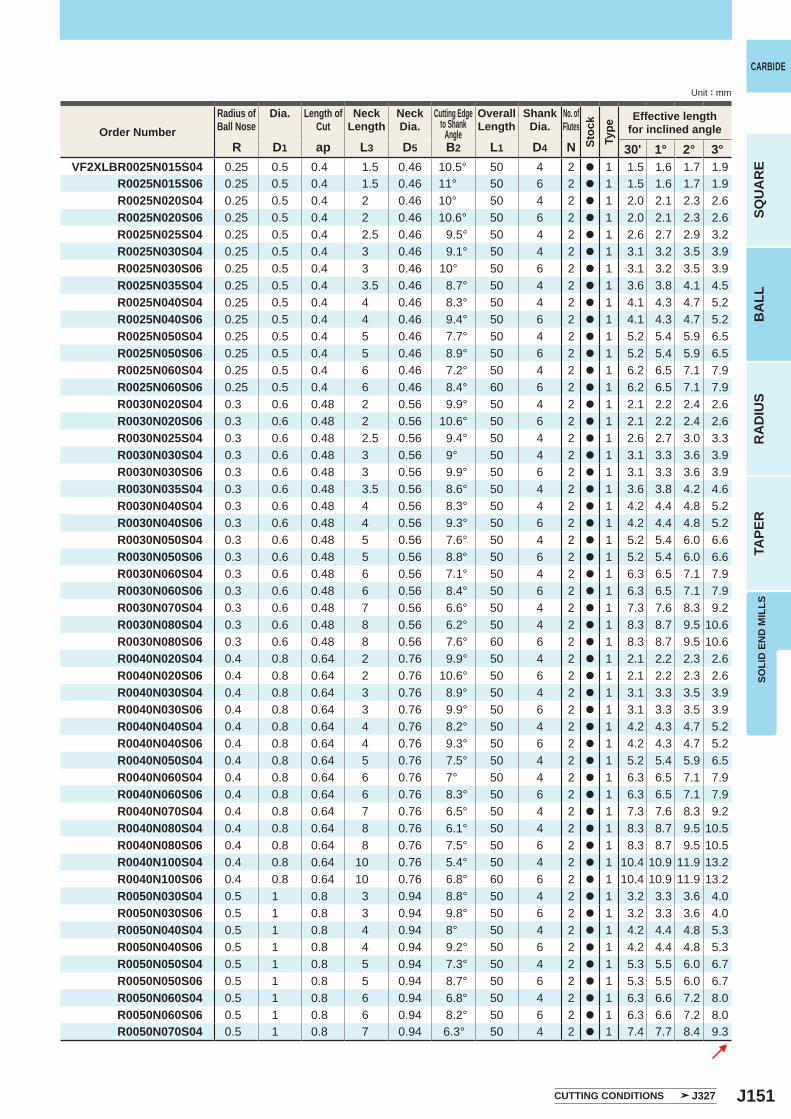
J151
R D1 ap L3 D5 B2 L1 D4 N 30' 1° 2° 3° VF2XLBR0025N015S04 0.25 0.5 0.4 1.5 0.46 10.5° 50 4 2 a 1 1.5 1.6 1.7 1.9 R0025N015S06 0.25 0.5 0.4 1.5 0.46 11° 50 6 2 a 1 1.5 1.6 1.7 1.9 R0025N020S04 0.25 0.5 0.4 2 0.46 10° 50 4 2 a 1 2.0 2.1 2.3 2.6 R0025N020S06 0.25 0.5 0.4 2 0.46 10.6° 50 6 2 a 1 2.0 2.1 2.3 2.6 R0025N025S04 0.25 0.5 0.4 2.5 0.46 9.5° 50 4 2 a 1 2.6 2.7 2.9 3.2 R0025N030S04 0.25 0.5 0.4 3 0.46 9.1° 50 4 2 a 1 3.1 3.2 3.5 3.9 R0025N030S06 0.25 0.5 0.4 3 0.46 10° 50 6 2 a 1 3.1 3.2 3.5 3.9 R0025N035S04 0.25 0.5 0.4 3.5 0.46 8.7° 50 4 2 a 1 3.6 3.8 4.1 4.5 R0025N040S04 0.25 0.5 0.4 4 0.46 8.3° 50 4 2 a 1 4.1 4.3 4.7 5.2 R0025N040S06 0.25 0.5 0.4 4 0.46 9.4° 50 6 2 a 1 4.1 4.3 4.7 5.2 R0025N050S04 0.25 0.5 0.4 5 0.46 7.7° 50 4 2 a 1 5.2 5.4 5.9 6.5 R0025N050S06 0.25 0.5 0.4 5 0.46 8.9° 50 6 2 a 1 5.2 5.4 5.9 6.5 R0025N060S04 0.25 0.5 0.4 6 0.46 7.2° 50 4 2 a 1 6.2 6.5 7.1 7.9 R0025N060S06 0.25 0.5 0.4 6 0.46 8.4° 60 6 2 a 1 6.2 6.5 7.1 7.9 R0030N020S04 0.3 0.6 0.48 2 0.56 9.9° 50 4 2 a 1 2.1 2.2 2.4 2.6 R0030N020S06 0.3 0.6 0.48 2 0.56 10.6° 50 6 2 a 1 2.1 2.2 2.4 2.6 R0030N025S04 0.3 0.6 0.48 2.5 0.56 9.4° 50 4 2 a 1 2.6 2.7 3.0 3.3 R0030N030S04 0.3 0.6 0.48 3 0.56 9° 50 4 2 a 1 3.1 3.3 3.6 3.9 R0030N030S06 0.3 0.6 0.48 3 0.56 9.9° 50 6 2 a 1 3.1 3.3 3.6 3.9 R0030N035S04 0.3 0.6 0.48 3.5 0.56 8.6° 50 4 2 a 1 3.6 3.8 4.2 4.6 R0030N040S04 0.3 0.6 0.48 4 0.56 8.3° 50 4 2 a 1 4.2 4.4 4.8 5.2 R0030N040S06 0.3 0.6 0.48 4 0.56 9.3° 50 6 2 a 1 4.2 4.4 4.8 5.2 R0030N050S04 0.3 0.6 0.48 5 0.56 7.6° 50 4 2 a 1 5.2 5.4 6.0 6.6 R0030N050S06 0.3 0.6 0.48 5 0.56 8.8° 50 6 2 a 1 5.2 5.4 6.0 6.6 R0030N060S04 0.3 0.6 0.48 6 0.56 7.1° 50 4 2 a 1 6.3 6.5 7.1 7.9 R0030N060S06 0.3 0.6 0.48 6 0.56 8.4° 50 6 2 a 1 6.3 6.5 7.1 7.9 R0030N070S04 0.3 0.6 0.48 7 0.56 6.6° 50 4 2 a 1 7.3 7.6 8.3 9.2 R0030N080S04 0.3 0.6 0.48 8 0.56 6.2° 50 4 2 a 1 8.3 8.7 9.5 10.6 R0030N080S06 0.3 0.6 0.48 8 0.56 7.6° 60 6 2 a 1 8.3 8.7 9.5 10.6 R0040N020S04 0.4 0.8 0.64 2 0.76 9.9° 50 4 2 a 1 2.1 2.2 2.3 2.6 R0040N020S06 0.4 0.8 0.64 2 0.76 10.6° 50 6 2 a 1 2.1 2.2 2.3 2.6 R0040N030S04 0.4 0.8 0.64 3 0.76 8.9° 50 4 2 a 1 3.1 3.3 3.5 3.9 R0040N030S06 0.4 0.8 0.64 3 0.76 9.9° 50 6 2 a 1 3.1 3.3 3.5 3.9 R0040N040S04 0.4 0.8 0.64 4 0.76 8.2° 50 4 2 a 1 4.2 4.3 4.7 5.2 R0040N040S06 0.4 0.8 0.64 4 0.76 9.3° 50 6 2 a 1 4.2 4.3 4.7 5.2 R0040N050S04 0.4 0.8 0.64 5 0.76 7.5° 50 4 2 a 1 5.2 5.4 5.9 6.5 R0040N060S04 0.4 0.8 0.64 6 0.76 7° 50 4 2 a 1 6.3 6.5 7.1 7.9 R0040N060S06 0.4 0.8 0.64 6 0.76 8.3° 50 6 2 a 1 6.3 6.5 7.1 7.9 R0040N070S04 0.4 0.8 0.64 7 0.76 6.5° 50 4 2 a 1 7.3 7.6 8.3 9.2 R0040N080S04 0.4 0.8 0.64 8 0.76 6.1° 50 4 2 a 1 8.3 8.7 9.5 10.5 R0040N080S06 0.4 0.8 0.64 8 0.76 7.5° 50 6 2 a 1 8.3 8.7 9.5 10.5 R0040N100S04 0.4 0.8 0.64 10 0.76 5.4° 50 4 2 a 1 10.4 10.9 11.9 13.2 R0040N100S06 0.4 0.8 0.64 10 0.76 6.8° 60 6 2 a 1 10.4 10.9 11.9 13.2 R0050N030S04 0.5 1 0.8 3 0.94 8.8° 50 4 2 a 1 3.2 3.3 3.6 4.0 R0050N030S06 0.5 1 0.8 3 0.94 9.8° 50 6 2 a 1 3.2 3.3 3.6 4.0 R0050N040S04 0.5 1 0.8 4 0.94 8° 50 4 2 a 1 4.2 4.4 4.8 5.3 R0050N040S06 0.5 1 0.8 4 0.94 9.2° 50 6 2 a 1 4.2 4.4 4.8 5.3 R0050N050S04 0.5 1 0.8 5 0.94 7.3° 50 4 2 a 1 5.3 5.5 6.0 6.7 R0050N050S06 0.5 1 0.8 5 0.94 8.7° 50 6 2 a 1 5.3 5.5 6.0 6.7 R0050N060S04 0.5 1 0.8 6 0.94 6.8° 50 4 2 a 1 6.3 6.6 7.2 8.0 R0050N060S06 0.5 1 0.8 6 0.94 8.2° 50 6 2 a 1 6.3 6.6 7.2 8.0 R0050N070S04 0.5 1 0.8 7 0.94 6.3° 50 4 2 a 1 7.4 7.7 8.4 9.3
SOLI
D E
ND
MIL
LS
CARBIDE
SQU
AR
EB
ALL
RA
DIU
STA
PER
Unit : mm
Order NumberRadius ofBall Nose
Dia. Length ofCut
NeckLength
NeckDia.
Cutting Edgeto Shank
Angle
OverallLength
ShankDia.
No. ofFlutes
Stoc
kTy
pe
Effective lengthfor inclined angle
CUTTING CONDITIONS J327
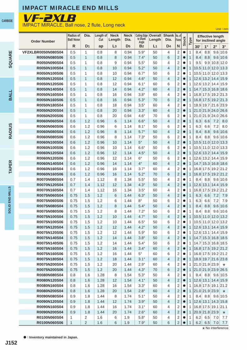
J152
R D1 ap L3 D5 B2 L1 D4 N 30' 1° 2° 3° VF2XLBR0050N080S04 0.5 1 0.8 8 0.94 5.9° 50 4 2 a 1 8.4 8.8 9.6 10.6 R0050N080S06 0.5 1 0.8 8 0.94 7.4° 50 6 2 a 1 8.4 8.8 9.6 10.6 R0050N090S04 0.5 1 0.8 9 0.94 5.5° 50 4 2 a 1 9.5 9.9 10.8 12.0 R0050N100S04 0.5 1 0.8 10 0.94 5.2° 50 4 2 a 1 10.5 11.0 12.0 13.3 R0050N100S06 0.5 1 0.8 10 0.94 6.7° 50 6 2 a 1 10.5 11.0 12.0 13.3
R0050N120S04 0.5 1 0.8 12 0.94 4.6° 50 4 2 a 1 12.6 13.2 14.4 15.9 R0050N120S06 0.5 1 0.8 12 0.94 6.1° 60 6 2 a 1 12.6 13.2 14.4 15.9 R0050N140S04 0.5 1 0.8 14 0.94 4.2° 60 4 2 a 1 14.7 15.3 16.8 18.6 R0050N160S04 0.5 1 0.8 16 0.94 3.8° 60 4 2 a 1 16.8 17.5 19.2 21.3 R0050N160S06 0.5 1 0.8 16 0.94 5.3° 70 6 2 a 1 16.8 17.5 19.2 21.3 R0050N180S04 0.5 1 0.8 18 0.94 3.5° 60 4 2 a 1 18.9 19.7 21.6 23.9 R0050N200S04 0.5 1 0.8 20 0.94 3.3° 60 4 2 a 1 21.0 21.9 24.0 26.6 R0050N200S06 0.5 1 0.8 20 0.94 4.6° 70 6 2 a 1 21.0 21.9 24.0 26.6 R0060N060S04 0.6 1.2 0.96 6 1.14 6.6° 50 4 2 a 1 6.3 6.6 7.2 8.0 R0060N060S06 0.6 1.2 0.96 6 1.14 8.1° 50 6 2 a 1 6.3 6.6 7.2 8.0 R0060N080S04 0.6 1.2 0.96 8 1.14 5.7° 50 4 2 a 1 8.4 8.8 9.6 10.6 R0060N080S06 0.6 1.2 0.96 8 1.14 7.3° 50 6 2 a 1 8.4 8.8 9.6 10.6 R0060N100S04 0.6 1.2 0.96 10 1.14 5° 50 4 2 a 1 10.5 11.0 12.0 13.3 R0060N100S06 0.6 1.2 0.96 10 1.14 6.6° 50 6 2 a 1 10.5 11.0 12.0 13.3 R0060N120S04 0.6 1.2 0.96 12 1.14 4.5° 50 4 2 a 1 12.6 13.2 14.4 15.9 R0060N120S06 0.6 1.2 0.96 12 1.14 6° 50 6 2 a 1 12.6 13.2 14.4 15.9 R0060N140S04 0.6 1.2 0.96 14 1.14 4° 60 4 2 a 1 14.7 15.3 16.8 18.6 R0060N160S04 0.6 1.2 0.96 16 1.14 3.7° 60 4 2 a 1 16.8 17.5 19.2 21.2 R0060N160S06 0.6 1.2 0.96 16 1.14 5.2° 70 6 2 a 1 16.8 17.5 19.2 21.2 R0070N080S04 0.7 1.4 1.12 8 1.34 5.5° 50 4 2 a 1 8.4 8.8 9.6 10.6 R0070N120S04 0.7 1.4 1.12 12 1.34 4.3° 50 4 2 a 1 12.6 13.1 14.4 15.9 R0070N160S04 0.7 1.4 1.12 16 1.34 3.5° 60 4 2 a 1 16.8 17.5 19.2 21.2 R0075N060S04 0.75 1.5 1.2 6 1.44 6.3° 50 4 2 a 1 6.3 6.6 7.2 7.9 R0075N060S06 0.75 1.5 1.2 6 1.44 8° 50 6 2 a 1 6.3 6.6 7.2 7.9 R0075N080S04 0.75 1.5 1.2 8 1.44 5.4° 50 4 2 a 1 8.4 8.8 9.6 10.6 R0075N080S06 0.75 1.5 1.2 8 1.44 7.2° 50 6 2 a 1 8.4 8.8 9.6 10.6 R0075N100S04 0.75 1.5 1.2 10 1.44 4.7° 50 4 2 a 1 10.5 11.0 12.0 13.2 R0075N100S06 0.75 1.5 1.2 10 1.44 6.5° 50 6 2 a 1 10.5 11.0 12.0 13.2 R0075N120S04 0.75 1.5 1.2 12 1.44 4.2° 50 4 2 a 1 12.6 13.1 14.4 15.9 R0075N120S06 0.75 1.5 1.2 12 1.44 5.9° 50 6 2 a 1 12.6 13.1 14.4 15.9 R0075N140S04 0.75 1.5 1.2 14 1.44 3.8° 50 4 2 a 1 14.7 15.3 16.8 18.5 R0075N140S06 0.75 1.5 1.2 14 1.44 5.4° 50 6 2 a 1 14.7 15.3 16.8 18.5 R0075N160S04 0.75 1.5 1.2 16 1.44 3.4° 60 4 2 a 1 16.8 17.5 19.2 21.2 R0075N160S06 0.75 1.5 1.2 16 1.44 5° 60 6 2 a 1 16.8 17.5 19.2 21.2 R0075N180S04 0.75 1.5 1.2 18 1.44 3.1° 60 4 2 a 1 18.9 19.7 21.6 23.8
R0075N200S04 0.75 1.5 1.2 20 1.44 2.9° 60 4 2 a 1 21.0 21.9 23.9 R0075N200S06 0.75 1.5 1.2 20 1.44 4.3° 70 6 2 a 1 21.0 21.9 23.9 26.5 R0080N080S04 0.8 1.6 1.28 8 1.54 5.3° 50 4 2 a 1 8.4 8.8 9.6 10.5 R0080N120S04 0.8 1.6 1.28 12 1.54 4.1° 50 4 2 a 1 12.6 13.1 14.4 15.9 R0080N160S04 0.8 1.6 1.28 16 1.54 3.3° 60 4 2 a 1 16.8 17.5 19.1 21.2 R0080N200S04 0.8 1.6 1.28 20 1.54 2.8° 60 4 2 a 1 21.0 21.9 23.9 R0090N080S04 0.9 1.8 1.44 8 1.74 5.1° 50 4 2 a 1 8.4 8.8 9.6 10.5 R0090N120S04 0.9 1.8 1.44 12 1.74 3.9° 50 4 2 a 1 12.6 13.1 14.3 15.8 R0090N160S04 0.9 1.8 1.44 16 1.74 3.1° 60 4 2 a 1 16.8 17.5 19.1 21.1 R0090N200S04 0.9 1.8 1.44 20 1.74 2.6° 60 4 2 a 1 20.9 21.8 23.9 R0100N060S04 1 2 1.6 6 1.9 5.8° 50 4 2 a 1 6.2 6.5 7.0 7.7 R0100N060S06 1 2 1.6 6 1.9 7.9° 50 6 2 a 1 6.2 6.5 7.0 7.7
VF-2XLB
a : Inventory maintained in Japan.
CARBIDE
SQU
AR
EB
ALL
RA
DIU
STA
PER
SOLI
D E
ND
MIL
LS
Unit : mm
IMPACT MIRACLE END MILLS
* No interference
IMPACT MIRACLE, Ball nose, 2 flute, Long neck
Order NumberRadius ofBall Nose
Dia. Length ofCut
NeckLength
NeckDia.
Cutting Edgeto Shank
Angle
OverallLength
ShankDia.
No. ofFlutes
Stoc
kTy
pe
Effective lengthfor inclined angle
*
*
*
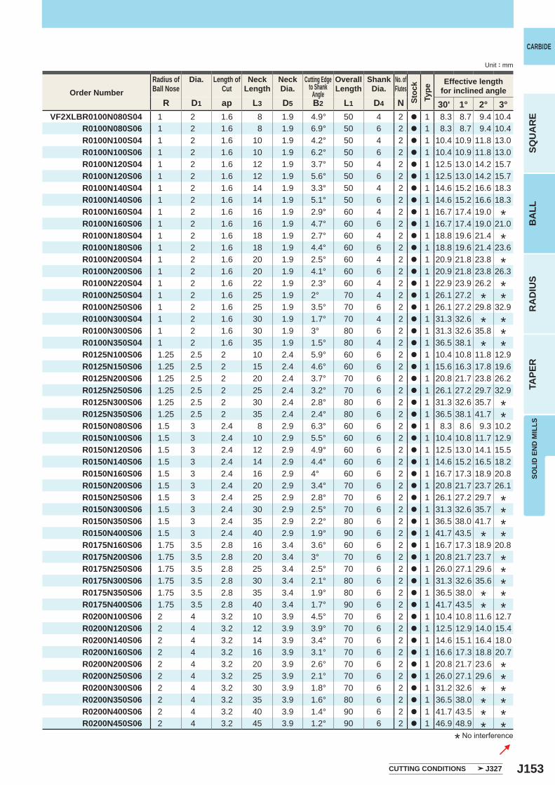
J153
R D1 ap L3 D5 B2 L1 D4 N 30' 1° 2° 3° VF2XLBR0100N080S04 1 2 1.6 8 1.9 4.9° 50 4 2 a 1 8.3 8.7 9.4 10.4 R0100N080S06 1 2 1.6 8 1.9 6.9° 50 6 2 a 1 8.3 8.7 9.4 10.4 R0100N100S04 1 2 1.6 10 1.9 4.2° 50 4 2 a 1 10.4 10.9 11.8 13.0 R0100N100S06 1 2 1.6 10 1.9 6.2° 50 6 2 a 1 10.4 10.9 11.8 13.0 R0100N120S04 1 2 1.6 12 1.9 3.7° 50 4 2 a 1 12.5 13.0 14.2 15.7
R0100N120S06 1 2 1.6 12 1.9 5.6° 50 6 2 a 1 12.5 13.0 14.2 15.7 R0100N140S04 1 2 1.6 14 1.9 3.3° 50 4 2 a 1 14.6 15.2 16.6 18.3 R0100N140S06 1 2 1.6 14 1.9 5.1° 50 6 2 a 1 14.6 15.2 16.6 18.3 R0100N160S04 1 2 1.6 16 1.9 2.9° 60 4 2 a 1 16.7 17.4 19.0 R0100N160S06 1 2 1.6 16 1.9 4.7° 60 6 2 a 1 16.7 17.4 19.0 21.0 R0100N180S04 1 2 1.6 18 1.9 2.7° 60 4 2 a 1 18.8 19.6 21.4 R0100N180S06 1 2 1.6 18 1.9 4.4° 60 6 2 a 1 18.8 19.6 21.4 23.6 R0100N200S04 1 2 1.6 20 1.9 2.5° 60 4 2 a 1 20.9 21.8 23.8 R0100N200S06 1 2 1.6 20 1.9 4.1° 60 6 2 a 1 20.9 21.8 23.8 26.3 R0100N220S04 1 2 1.6 22 1.9 2.3° 60 4 2 a 1 22.9 23.9 26.2 R0100N250S04 1 2 1.6 25 1.9 2° 70 4 2 a 1 26.1 27.2 R0100N250S06 1 2 1.6 25 1.9 3.5° 70 6 2 a 1 26.1 27.2 29.8 32.9 R0100N300S04 1 2 1.6 30 1.9 1.7° 70 4 2 a 1 31.3 32.6 R0100N300S06 1 2 1.6 30 1.9 3° 80 6 2 a 1 31.3 32.6 35.8 R0100N350S04 1 2 1.6 35 1.9 1.5° 80 4 2 a 1 36.5 38.1 R0125N100S06 1.25 2.5 2 10 2.4 5.9° 60 6 2 a 1 10.4 10.8 11.8 12.9 R0125N150S06 1.25 2.5 2 15 2.4 4.6° 60 6 2 a 1 15.6 16.3 17.8 19.6 R0125N200S06 1.25 2.5 2 20 2.4 3.7° 70 6 2 a 1 20.8 21.7 23.8 26.2 R0125N250S06 1.25 2.5 2 25 2.4 3.2° 70 6 2 a 1 26.1 27.2 29.7 32.9 R0125N300S06 1.25 2.5 2 30 2.4 2.8° 80 6 2 a 1 31.3 32.6 35.7 R0125N350S06 1.25 2.5 2 35 2.4 2.4° 80 6 2 a 1 36.5 38.1 41.7 R0150N080S06 1.5 3 2.4 8 2.9 6.3° 60 6 2 a 1 8.3 8.6 9.3 10.2 R0150N100S06 1.5 3 2.4 10 2.9 5.5° 60 6 2 a 1 10.4 10.8 11.7 12.9 R0150N120S06 1.5 3 2.4 12 2.9 4.9° 60 6 2 a 1 12.5 13.0 14.1 15.5 R0150N140S06 1.5 3 2.4 14 2.9 4.4° 60 6 2 a 1 14.6 15.2 16.5 18.2 R0150N160S06 1.5 3 2.4 16 2.9 4° 60 6 2 a 1 16.7 17.3 18.9 20.8 R0150N200S06 1.5 3 2.4 20 2.9 3.4° 70 6 2 a 1 20.8 21.7 23.7 26.1 R0150N250S06 1.5 3 2.4 25 2.9 2.8° 70 6 2 a 1 26.1 27.2 29.7 R0150N300S06 1.5 3 2.4 30 2.9 2.5° 70 6 2 a 1 31.3 32.6 35.7 R0150N350S06 1.5 3 2.4 35 2.9 2.2° 80 6 2 a 1 36.5 38.0 41.7 R0150N400S06 1.5 3 2.4 40 2.9 1.9° 90 6 2 a 1 41.7 43.5 R0175N160S06 1.75 3.5 2.8 16 3.4 3.6° 60 6 2 a 1 16.7 17.3 18.9 20.8 R0175N200S06 1.75 3.5 2.8 20 3.4 3° 70 6 2 a 1 20.8 21.7 23.7
R0175N250S06 1.75 3.5 2.8 25 3.4 2.5° 70 6 2 a 1 26.0 27.1 29.6 R0175N300S06 1.75 3.5 2.8 30 3.4 2.1° 80 6 2 a 1 31.3 32.6 35.6 R0175N350S06 1.75 3.5 2.8 35 3.4 1.9° 80 6 2 a 1 36.5 38.0 R0175N400S06 1.75 3.5 2.8 40 3.4 1.7° 90 6 2 a 1 41.7 43.5 R0200N100S06 2 4 3.2 10 3.9 4.5° 70 6 2 a 1 10.4 10.8 11.6 12.7 R0200N120S06 2 4 3.2 12 3.9 3.9° 70 6 2 a 1 12.5 12.9 14.0 15.4 R0200N140S06 2 4 3.2 14 3.9 3.4° 70 6 2 a 1 14.6 15.1 16.4 18.0 R0200N160S06 2 4 3.2 16 3.9 3.1° 70 6 2 a 1 16.6 17.3 18.8 20.7 R0200N200S06 2 4 3.2 20 3.9 2.6° 70 6 2 a 1 20.8 21.7 23.6 R0200N250S06 2 4 3.2 25 3.9 2.1° 70 6 2 a 1 26.0 27.1 29.6 R0200N300S06 2 4 3.2 30 3.9 1.8° 70 6 2 a 1 31.2 32.6 R0200N350S06 2 4 3.2 35 3.9 1.6° 80 6 2 a 1 36.5 38.0 R0200N400S06 2 4 3.2 40 3.9 1.4° 90 6 2 a 1 41.7 43.5 R0200N450S06 2 4 3.2 45 3.9 1.2° 90 6 2 a 1 46.9 48.9
SOLI
D E
ND
MIL
LS
CARBIDE
SQU
AR
EB
ALL
RA
DIU
STA
PER
Unit : mm
* No interference
Order NumberRadius ofBall Nose
Dia. Length ofCut
NeckLength
NeckDia.
Cutting Edgeto Shank
Angle
OverallLength
ShankDia.
No. ofFlutes
Stoc
kTy
pe
Effective lengthfor inclined angle
*
*
*
***
*****
*
*
*
*
*
*
**
*
*
**
*
*
**
**
**
****
CUTTING CONDITIONS J327
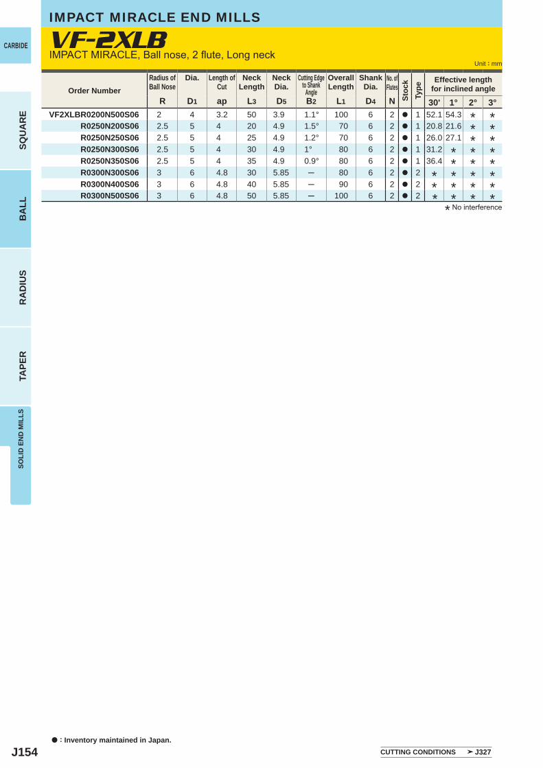
J154
R D1 ap L3 D5 B2 L1 D4 N 30' 1° 2° 3° VF2XLBR0200N500S06 2 4 3.2 50 3.9 1.1° 100 6 2 a 1 52.1 54.3 R0250N200S06 2.5 5 4 20 4.9 1.5° 70 6 2 a 1 20.8 21.6 R0250N250S06 2.5 5 4 25 4.9 1.2° 70 6 2 a 1 26.0 27.1 R0250N300S06 2.5 5 4 30 4.9 1° 80 6 2 a 1 31.2 R0250N350S06 2.5 5 4 35 4.9 0.9° 80 6 2 a 1 36.4 R0300N300S06 3 6 4.8 30 5.85 ─ 80 6 2 a 2 R0300N400S06 3 6 4.8 40 5.85 ─ 90 6 2 a 2 R0300N500S06 3 6 4.8 50 5.85 ─ 100 6 2 a 2
VF-2XLB
a : Inventory maintained in Japan.
CARBIDE
SQU
AR
EB
ALL
RA
DIU
STA
PER
SOLI
D E
ND
MIL
LS
Unit : mm
IMPACT MIRACLE END MILLS
IMPACT MIRACLE, Ball nose, 2 flute, Long neck
Order NumberRadius ofBall Nose
Dia. Length ofCut
NeckLength
NeckDia.
Cutting Edgeto Shank
Angle
OverallLength
ShankDia.
No. ofFlutes
Stoc
kTy
pe
Effective lengthfor inclined angle
* No interference
CUTTING CONDITIONS J327
************
****
********
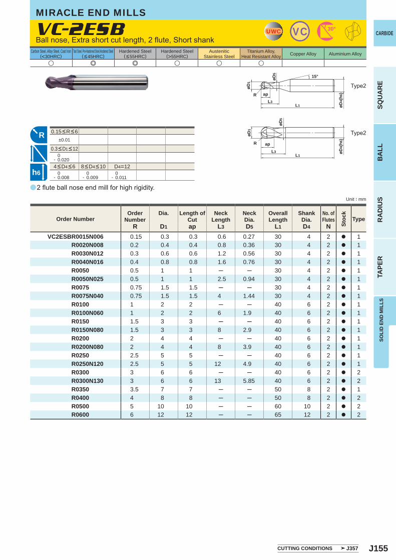
J155
u e e u u u
a
VC-2ESB
R D1 ap L3 D5 L1 D4 NVC2ESBR0015N006 0.15 0.3 0.3 0.6 0.27 30 4 2 a 1 R0020N008 0.2 0.4 0.4 0.8 0.36 30 4 2 a 1 R0030N012 0.3 0.6 0.6 1.2 0.56 30 4 2 a 1 R0040N016 0.4 0.8 0.8 1.6 0.76 30 4 2 a 1 R0050 0.5 1 1 ─ ─ 30 4 2 a 1 R0050N025 0.5 1 1 2.5 0.94 30 4 2 a 1 R0075 0.75 1.5 1.5 ─ ─ 30 4 2 a 1 R0075N040 0.75 1.5 1.5 4 1.44 30 4 2 a 1 R0100 1 2 2 ─ ─ 40 6 2 a 1 R0100N060 1 2 2 6 1.9 40 6 2 a 1 R0150 1.5 3 3 ─ ─ 40 6 2 a 1 R0150N080 1.5 3 3 8 2.9 40 6 2 a 1 R0200 2 4 4 ─ ─ 40 6 2 a 1 R0200N080 2 4 4 8 3.9 40 6 2 a 1 R0250 2.5 5 5 ─ ─ 40 6 2 a 1 R0250N120 2.5 5 5 12 4.9 40 6 2 a 1 R0300 3 6 6 ─ ─ 40 6 2 a 2 R0300N130 3 6 6 13 5.85 40 6 2 a 2 R0350 3.5 7 7 ─ ─ 50 8 2 a 1 R0400 4 8 8 ─ ─ 50 8 2 a 2 R0500 5 10 10 ─ ─ 60 10 2 a 2 R0600 6 12 12 ─ ─ 65 12 2 a 2
±0.01
0- 0.020
D4=12 0- 0.008
0- 0.009
0- 0.011
UWC VC 30°
L1
apL3
R
øD4(
h6)
øD1
15°øD5
L1
R apL3 øD
4(h6
)
øD1
øD5
R
h6
SOLI
D E
ND
MIL
LS
CARBIDE
SQU
AR
EB
ALL
RA
DIU
STA
PER
Unit : mm
Carbon Steel, Alloy Steel, Cast Iron(<30HRC)
Tool Steel, Pre-Hardened Steel,Hardened Steel(<45HRC)
Hardened Steel(<55HRC)
Hardened Steel(>55HRC)
AusteniticStainless Steel
Titanium Alloy,Heat Resistant Alloy Copper Alloy Aluminium Alloy
2 flute ball nose end mill for high rigidity.
Type2
Type2
MIRACLE END MILLS
CUTTING CONDITIONS J357
Order NumberOrder
NumberDia. Length of
CutNeck
LengthNeckDia.
OverallLength
ShankDia.
No. ofFlutes
Stoc
k
Type
4<D4<6 8<D4<10
0.15<R<6
0.3<D1<12
Ball nose, Extra short cut length, 2 flute, Short shank
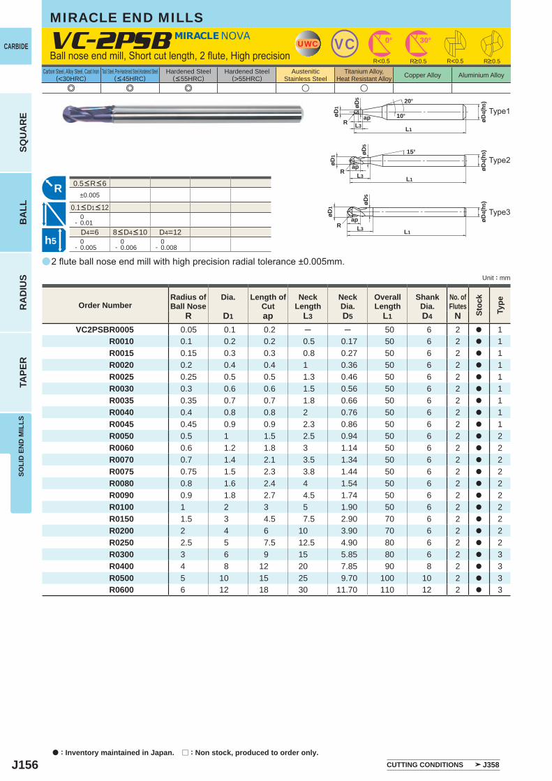
J156
e e e u u
a
VC-2PSB
R D1 ap L3 D5 L1 D4 NVC2PSBR0005 0.05 0.1 0.2 ─ ─ 50 6 2 a 1
R0010 0.1 0.2 0.2 0.5 0.17 50 6 2 a 1R0015 0.15 0.3 0.3 0.8 0.27 50 6 2 a 1R0020 0.2 0.4 0.4 1 0.36 50 6 2 a 1R0025 0.25 0.5 0.5 1.3 0.46 50 6 2 a 1R0030 0.3 0.6 0.6 1.5 0.56 50 6 2 a 1R0035 0.35 0.7 0.7 1.8 0.66 50 6 2 a 1R0040 0.4 0.8 0.8 2 0.76 50 6 2 a 1R0045 0.45 0.9 0.9 2.3 0.86 50 6 2 a 1R0050 0.5 1 1.5 2.5 0.94 50 6 2 a 2R0060 0.6 1.2 1.8 3 1.14 50 6 2 a 2R0070 0.7 1.4 2.1 3.5 1.34 50 6 2 a 2R0075 0.75 1.5 2.3 3.8 1.44 50 6 2 a 2R0080 0.8 1.6 2.4 4 1.54 50 6 2 a 2R0090 0.9 1.8 2.7 4.5 1.74 50 6 2 a 2R0100 1 2 3 5 1.90 50 6 2 a 2R0150 1.5 3 4.5 7.5 2.90 70 6 2 a 2R0200 2 4 6 10 3.90 70 6 2 a 2R0250 2.5 5 7.5 12.5 4.90 80 6 2 a 2R0300 3 6 9 15 5.85 80 6 2 a 3R0400 4 8 12 20 7.85 90 8 2 a 3R0500 5 10 15 25 9.70 100 10 2 a 3R0600 6 12 18 30 11.70 110 12 2 a 3
±0.005
0- 0.01
D4=6 D4=12 0- 0.005
0- 0.006
0- 0.008
UWC VC 0° 30°
apL3R
L1
øD4(
h5)20°
10°øD1 øD
5
R<0.5 R<0.5
R
apL3
øD1
L1R
15°
øD4(
h5)øD
5
øD1
L1R
apL3
øD4(
h5)øD
5
h5
CARBIDE
SQU
AR
EB
ALL
RA
DIU
STA
PER
SOLI
D E
ND
MIL
LS
Unit : mm
Carbon Steel, Alloy Steel, Cast Iron(<30HRC)
Tool Steel, Pre-Hardened Steel,Hardened Steel(<45HRC)
Hardened Steel(<55HRC)
Hardened Steel(>55HRC)
AusteniticStainless Steel
Titanium Alloy,Heat Resistant Alloy Copper Alloy Aluminium Alloy
2 flute ball nose end mill with high precision radial tolerance ±0.005mm.
Type1
MIRACLE END MILLS
CUTTING CONDITIONS J358
Order NumberRadius ofBall Nose
Dia. Length ofCut
NeckLength
NeckDia.
OverallLength
ShankDia.
No. ofFlutes
Stoc
k
Type
R>0.5 R>0.5
8<D4<10
0.5<R<6
0.1<D1<12
Ball nose end mill, Short cut length, 2 flute, High precision
Type2
Type3
a : Inventory maintained in Japan. r : Non stock, produced to order only.
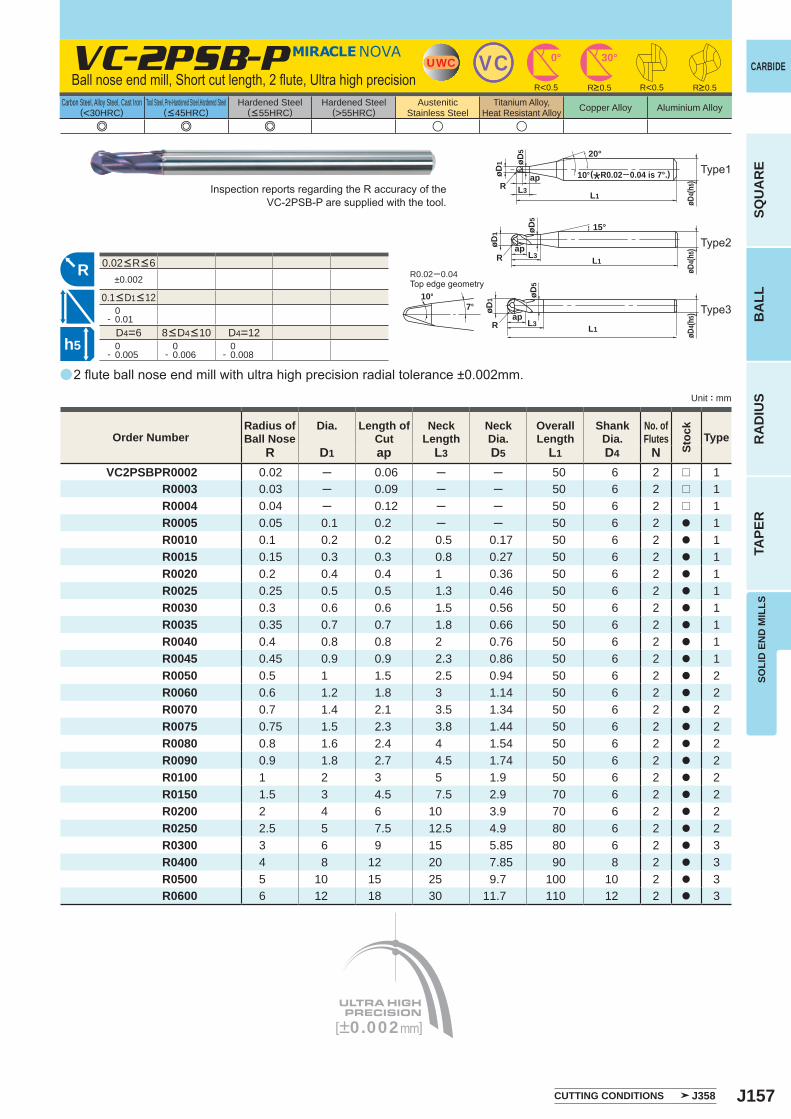
J157
e e e u u
a
VC-2PSB-P
R D1 ap L3 D5 L1 D4 NVC2PSBPR0002 0.02 ─ 0.06 ─ ─ 50 6 2 r 1
R0003 0.03 ─ 0.09 ─ ─ 50 6 2 r 1R0004 0.04 ─ 0.12 ─ ─ 50 6 2 r 1R0005 0.05 0.1 0.2 ─ ─ 50 6 2 a 1R0010 0.1 0.2 0.2 0.5 0.17 50 6 2 a 1R0015 0.15 0.3 0.3 0.8 0.27 50 6 2 a 1R0020 0.2 0.4 0.4 1 0.36 50 6 2 a 1R0025 0.25 0.5 0.5 1.3 0.46 50 6 2 a 1R0030 0.3 0.6 0.6 1.5 0.56 50 6 2 a 1R0035 0.35 0.7 0.7 1.8 0.66 50 6 2 a 1R0040 0.4 0.8 0.8 2 0.76 50 6 2 a 1R0045 0.45 0.9 0.9 2.3 0.86 50 6 2 a 1R0050 0.5 1 1.5 2.5 0.94 50 6 2 a 2R0060 0.6 1.2 1.8 3 1.14 50 6 2 a 2R0070 0.7 1.4 2.1 3.5 1.34 50 6 2 a 2R0075 0.75 1.5 2.3 3.8 1.44 50 6 2 a 2R0080 0.8 1.6 2.4 4 1.54 50 6 2 a 2R0090 0.9 1.8 2.7 4.5 1.74 50 6 2 a 2R0100 1 2 3 5 1.9 50 6 2 a 2R0150 1.5 3 4.5 7.5 2.9 70 6 2 a 2R0200 2 4 6 10 3.9 70 6 2 a 2R0250 2.5 5 7.5 12.5 4.9 80 6 2 a 2R0300 3 6 9 15 5.85 80 6 2 a 3R0400 4 8 12 20 7.85 90 8 2 a 3R0500 5 10 15 25 9.7 100 10 2 a 3R0600 6 12 18 30 11.7 110 12 2 a 3
±0.002
0- 0.01
D4=6 D4=12 0- 0.005
0- 0.006
0- 0.008
UWC VC 30°0°
apL3R
L1
øD4(h
5)
20°
10°øD1 øD
5
R<0.5 R<0.5
[±0.002mm]
R10°
7° øD1
L1Rap
L3
øD4(h
5)
øD5
apL3
øD1
L1R
15°
øD4(h
5)
øD5
h5
SOLI
D E
ND
MIL
LS
CARBIDE
SQU
AR
EB
ALL
RA
DIU
STA
PER
Unit : mm
Carbon Steel, Alloy Steel, Cast Iron(<30HRC)
Tool Steel, Pre-Hardened Steel,Hardened Steel(<45HRC)
Hardened Steel(<55HRC)
Hardened Steel(>55HRC)
AusteniticStainless Steel
Titanium Alloy,Heat Resistant Alloy Copper Alloy Aluminium Alloy
0.02<R<6
0.1<D1<12
2 flute ball nose end mill with ultra high precision radial tolerance ±0.002mm.
Inspection reports regarding the R accuracy of the VC-2PSB-P are supplied with the tool.
R0.02─0.04Top edge geometry
(*R0.02─0.04 is 7°.)
Order NumberRadius ofBall Nose
Dia. Length ofCut
NeckLength
NeckDia.
OverallLength
ShankDia.
No. ofFlutes
Stoc
k
Type
CUTTING CONDITIONS J358
R>0.5 R>0.5
8<D4<10
Ball nose end mill, Short cut length, 2 flute, Ultra high precision
Type1
Type2
Type3

J158
u e e u u u
a
VC-2MB
R D1 ap L1 D4 NVC2MBR0020 0.2 0.4 0.8 38 3 2 a 1
R0025 0.25 0.5 1 38 3 2 a 1R0030 0.3 0.6 1.2 38 3 2 a 1R0040 0.4 0.8 1.6 38 3 2 a 1R0050 0.5 1 2.5 40 4 2 a 1R0060 0.6 1.2 3 40 4 2 a 1R0070 0.7 1.4 3 40 4 2 a 1R0075 0.75 1.5 4 40 4 2 a 1R0080 0.8 1.6 4 40 4 2 a 1R0090 0.9 1.8 5 40 4 2 a 1R0100 1 2 6 60 6 2 a 1R0150 1.5 3 8 70 6 2 a 1R0200 2 4 8 70 6 2 a 1R0250 2.5 5 12 80 6 2 a 1R0300 3 6 12 80 6 2 a 2R0350 3.5 7 14 90 8 2 a 1R0400 4 8 14 90 8 2 a 2R0450 4.5 9 18 100 10 2 a 1R0500 5 10 18 100 10 2 a 2R0600 6 12 22 110 12 2 a 2R0700 7 14 26 120 12 2 a 3R0750 7.5 15 30 140 16 2 a 1R0800 8 16 30 140 16 2 a 2R0900 9 18 34 140 16 2 a 3R1000 10 20 38 160 20 2 a 2R1250 12.5 25 55 180 25 2 a 2
R>6.5±0.01 ±0.02
D1>12 0- 0.020
0- 0.030
D4=3 0- 0.006
0- 0.008
0- 0.009
0- 0.011
0- 0.013
UWC VC 30°
øD4(
h6)
L1
øD1
R ap
15°
R
øD4(
h6)
L1ap
øD1
R
øD4(
h6)
L1
øD1
R ap
h6
a : Inventory maintained in Japan.
CARBIDE
SQU
AR
EB
ALL
RA
DIU
STA
PER
SOLI
D E
ND
MIL
LS
Unit : mm
Carbon Steel, Alloy Steel, Cast Iron(<30HRC)
Tool Steel, Pre-Hardened Steel,Hardened Steel(<45HRC)
Hardened Steel(<55HRC)
Hardened Steel(>55HRC)
AusteniticStainless Steel
Titanium Alloy,Heat Resistant Alloy Copper Alloy Aluminium Alloy
MIRACLE END MILLS
2 flute end mill for general use.
Type1
Order NumberRadius ofBall Nose
Dia. Length ofCut
OverallLength
ShankDia.
No. ofFlutes
Stoc
k
Type
4<D4<6 8<D4<10 12<D4<16 20<D4<25
R<6.5
D1<12
CUTTING CONDITIONS J357
Ball nose end mill, Medium cut length, 2 flute
Type2
Type3
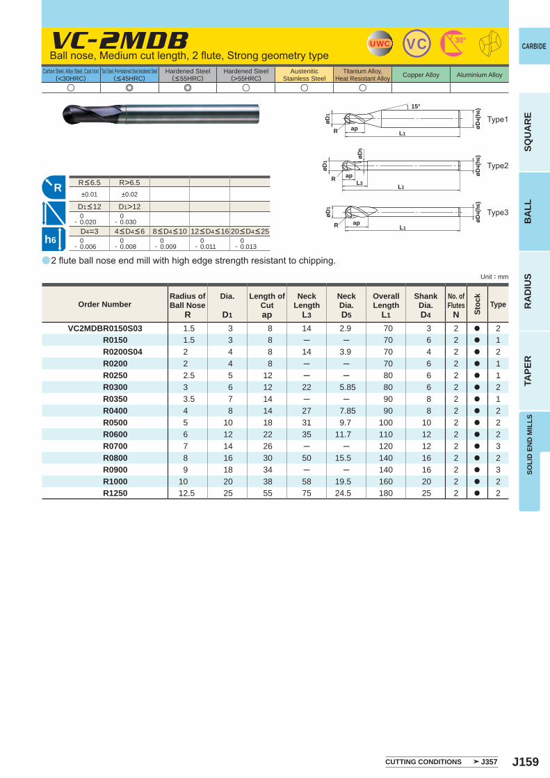
J159
a
u e e u u u
VC-2MDB
R D1 ap L3 D5 L1 D4 NVC2MDBR0150S03 1.5 3 8 14 2.9 70 3 2 a 2 R0150 1.5 3 8 ─ ─ 70 6 2 a 1
R0200S04 2 4 8 14 3.9 70 4 2 a 2R0200 2 4 8 ─ ─ 70 6 2 a 1R0250 2.5 5 12 ─ ─ 80 6 2 a 1R0300 3 6 12 22 5.85 80 6 2 a 2R0350 3.5 7 14 ─ ─ 90 8 2 a 1R0400 4 8 14 27 7.85 90 8 2 a 2R0500 5 10 18 31 9.7 100 10 2 a 2R0600 6 12 22 35 11.7 110 12 2 a 2R0700 7 14 26 ─ ─ 120 12 2 a 3R0800 8 16 30 50 15.5 140 16 2 a 2R0900 9 18 34 ─ ─ 140 16 2 a 3R1000 10 20 38 58 19.5 160 20 2 a 2R1250 12.5 25 55 75 24.5 180 25 2 a 2
R>6.5±0.01 ±0.02
D1>12 0- 0.020
0- 0.030
D4=3 0- 0.006
0- 0.008
0- 0.009
0- 0.011
0- 0.013
UWC VC 30°
øD4(
h6)
L1
øD1
R ap
15°
R
L1ap
øD1
R
øD4(
h6)
RL1
apL3
øD1
øD4(
h6)øD
5
h6
SOLI
D E
ND
MIL
LS
CARBIDE
SQU
AR
EB
ALL
RA
DIU
STA
PER
Unit : mm
Carbon Steel, Alloy Steel, Cast Iron(<30HRC)
Tool Steel, Pre-Hardened Steel,Hardened Steel(<45HRC)
Hardened Steel(<55HRC)
Hardened Steel(>55HRC)
AusteniticStainless Steel
Titanium Alloy,Heat Resistant Alloy Copper Alloy Aluminium Alloy
Type1
2 flute ball nose end mill with high edge strength resistant to chipping.
Order NumberRadius ofBall Nose
Dia. Length ofCut
NeckLength
NeckDia.
OverallLength
ShankDia.
No. ofFlutes
Stoc
k
Type
4<D4<6 8<D4<10 12<D4<16 20<D4<25
R<6.5
D1<12
Type2
Type3
Ball nose, Medium cut length, 2 flute, Strong geometry type
CUTTING CONDITIONS J357
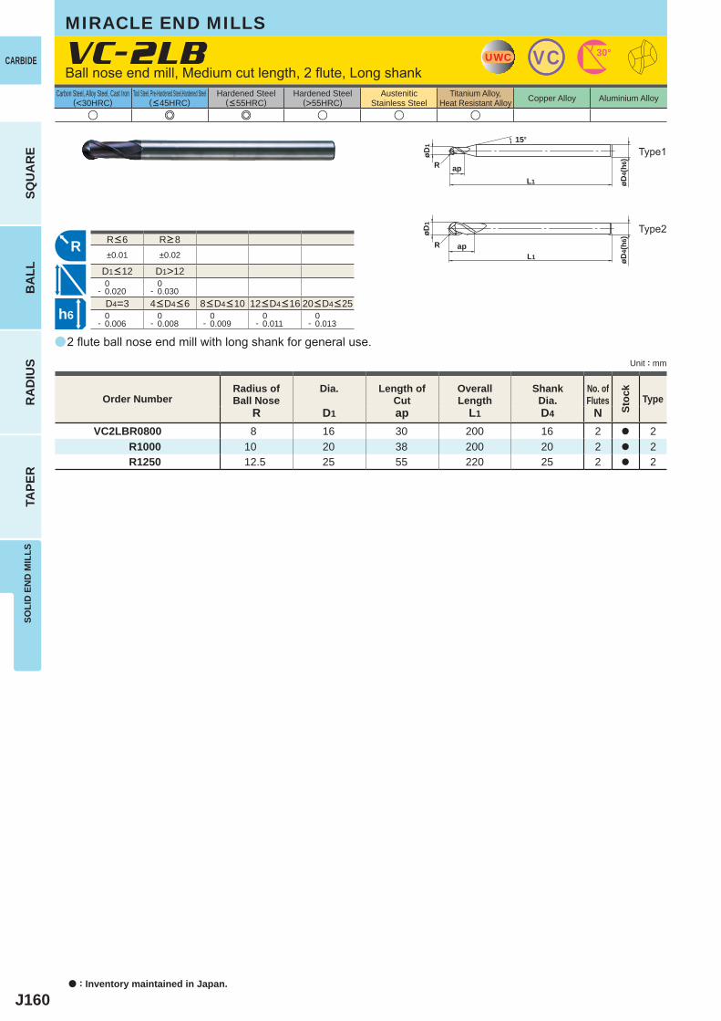
J160
a
u e e u u u
VC-2LB
R D1 ap L1 D4 NVC2LBR0800 8 16 30 200 16 2 a 2
R1000 10 20 38 200 20 2 a 2R1250 12.5 25 55 220 25 2 a 2
±0.01 ±0.02
D1>12 0- 0.020
0- 0.030
D4=3 0- 0.006
0- 0.008
0- 0.009
0- 0.011
0- 0.013
UWC VC 30°
øD4(
h6)
L1
øD1
R ap
15°
R
øD4(
h6)
L1
øD1
R ap
h6
a : Inventory maintained in Japan.
CARBIDE
SQU
AR
EB
ALL
RA
DIU
STA
PER
SOLI
D E
ND
MIL
LS
Unit : mm
Carbon Steel, Alloy Steel, Cast Iron(<30HRC)
Tool Steel, Pre-Hardened Steel,Hardened Steel(<45HRC)
Hardened Steel(<55HRC)
Hardened Steel(>55HRC)
AusteniticStainless Steel
Titanium Alloy,Heat Resistant Alloy Copper Alloy Aluminium Alloy
MIRACLE END MILLS
2 flute ball nose end mill with long shank for general use.
Order NumberRadius ofBall Nose
Dia. Length ofCut
OverallLength
ShankDia.
No. ofFlutes
Stoc
k
Type
4<D4<6 8<D4<10 12<D4<16 20<D4<25
R<6 R>8
D1<12
Ball nose end mill, Medium cut length, 2 flute, Long shank
Type1
Type2
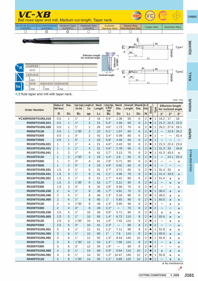
J161
a
u e e u u u
VC-XB
R D1 B1 ap L3 B2 D3 L1 D4 N 1° 2° 3°VCXBR0050T0100L016 0.5 1 1° 2 16 6.6° 1.38 50 6 2 a 1 16.2 17 18
R0050T0100L021 0.5 1 1° 2 21 5.4° 1.56 60 6 2 a 1 21.2 22.3 23.5R0050T0100L026 0.5 1 1° 2 26 4.6° 1.73 70 6 2 a 1 26.2 27.6 29.1R0050T0130 0.5 1 1°30' 2 23 5.1° 1.97 60 6 2 a 1 ─ 23.9 25.2R0050T0300 0.5 1 3° 2 42 3.4° 5.08 80 6 2 a 1 ─ ─ 42.4R0050T0500 0.5 1 5° 2 23 5.8° 4.46 60 6 2 a 1 ─ ─ ─R0100T0100L021 1 2 1° 4 21 4.6° 2.43 50 6 2 a 1 21.3 22.4 23.6R0100T0100L031 1 2 1° 4 31 3.4° 2.78 60 6 2 a 1 31.3 33 34.8R0100T0100L041 1 2 1° 4 41 2.7° 3.13 70 6 2 a 1 41.3 43.5R0100T0130 1 2 1°30' 4 23 4.4° 2.8 60 6 2 a 1 ─ 24.1 25.4R0100T0300 1 2 3° 4 41 2.9° 5.71 80 6 2 a 1 ─ ─R0100T0500 1 2 5° 4 23 4.9° 5.02 60 6 2 a 1 ─ ─ ─R0150T0100L031 1.5 3 1° 6 31 2.7° 3.71 60 6 2 a 1 31.4 33R0150T0100L041 1.5 3 1° 6 41 2.1° 4.06 70 6 2 a 1 41.4 43.5R0150T0100L051 1.5 3 1° 6 51 1.7° 4.41 80 6 2 a 1 51.4R0150T0130 1.5 3 1°30' 6 52 1.7° 5.21 90 6 2 a 1 ─R0150T0300 1.5 3 3° 6 32 2.8° 5.56 70 6 2 a 1 ─ ─R0200T0100L036 2 4 1° 8 36 1.7° 4.81 70 6 2 a 1 36.5R0200T0100L046 2 4 1° 8 46 1.3° 5.16 80 6 2 a 1 46.5R0200T0100L060 2 4 1° 8 60 1° 5.65 90 6 2 a 1 60.5R0200T0130 2 4 1°30' 8 49 1.3° 5.95 90 6 2 a 1 ─R0200T0300 2 4 3° 8 28 2.2° ─ 70 6 2 a 2 ─ ─R0250T0100L036 2.5 5 1° 10 36 0.9° 5.71 80 6 2 a 1R0250T0100L065 2.5 5 1° 10 65 1.4° 6.72 110 8 2 a 1 65.6R0250T0130 2.5 5 1°30' 10 61 1.5° 7.42 110 8 2 a 1 ─R0250T0300 2.5 5 3° 10 41 2.3° ─ 90 8 2 a 2 ─ ─R0300T0100L051 3 6 1° 12 51 1.2° 7.11 90 8 2 a 1 51.8R0300T0100L065 3 6 1° 12 65 1° 7.6 110 8 2 a 1 65.8R0300T0100L092 3 6 1° 12 92 1.3° 8.54 140 10 2 a 1 92.8R0300T0130 3 6 1°30' 12 53 1.2° 7.85 110 8 2 a 1 ─R0300T0300 3 6 3° 12 34 1.9° ─ 90 8 2 a 2 ─ ─R0400T0100L068 4 8 1° 14 68 0.9° 9.64 110 10 2 a 1R0400T0100L092 4 8 1° 14 92 1.3° 10.47 140 12 2 a 1 92.8R0400T0130 4 8 1°30' 14 55 1.2° 9.85 120 10 2 a 1 ─
±0.01
0- 0.020
D4=6 0- 0.008
0- 0.009
0- 0.011
UWC VC 30°
L1
ap
øD1
L3R
øD4(
h6)
B1 B2R
øD4(
h6)
L1
ap
øD1
L3
R
B2B1
øD3
h6
SOLI
D E
ND
MIL
LS
CARBIDE
SQU
AR
EB
ALL
RA
DIU
STA
PER
Unit : mm
Carbon Steel, Alloy Steel, Cast Iron(<30HRC)
Tool Steel, Pre-Hardened Steel,Hardened Steel(<45HRC)
Hardened Steel(<55HRC)
Hardened Steel(>55HRC)
AusteniticStainless Steel
Titanium Alloy,Heat Resistant Alloy Copper Alloy Aluminium Alloy
2 flute taper end mill with taper neck.
* No interference
Effective lengthfor inclined angle
Inclined angle
Effe
ctiv
ele
ngth
Order NumberRadius ofBall Nose
Dia. Taper AngleOne Side
Length ofCut
NeckLength
Cutting Edgeto Shank
Angle
NeckDia.
OverallLength
ShankDia.
No. ofFlutes
Stoc
kTy
pe
Effective lengthfor inclined angle
*
*
*
**
**
**
**
**
**
*
**
**
**
**
*
**
*
*
**
*
***
***
****
8<D4<10 12<D4<16
0.5<R<6
1<D1<12
CUTTING CONDITIONS J359
Type1
Type2
Ball nose taper end mill, Medium cut length, Taper neck
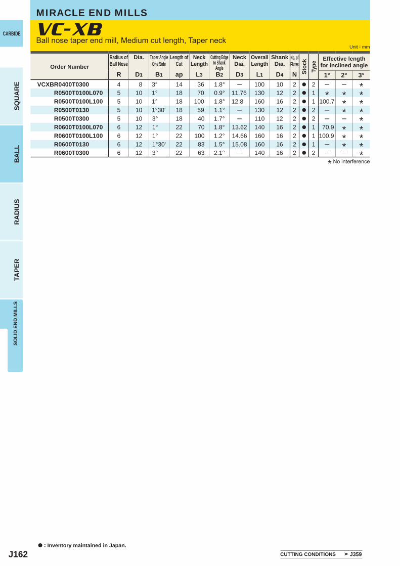
J162
R D1 B1 ap L3 B2 D3 L1 D4 N 1° 2° 3°VCXBR0400T0300 4 8 3° 14 36 1.8° ─ 100 10 2 a 2 ─ ─
R0500T0100L070 5 10 1° 18 70 0.9° 11.76 130 12 2 a 1R0500T0100L100 5 10 1° 18 100 1.8° 12.8 160 16 2 a 1 100.7R0500T0130 5 10 1°30' 18 59 1.1° ─ 130 12 2 a 2 ─R0500T0300 5 10 3° 18 40 1.7° ─ 110 12 2 a 2 ─ ─R0600T0100L070 6 12 1° 22 70 1.8° 13.62 140 16 2 a 1 70.9R0600T0100L100 6 12 1° 22 100 1.2° 14.66 160 16 2 a 1 100.9R0600T0130 6 12 1°30' 22 83 1.5° 15.08 160 16 2 a 1 ─R0600T0300 6 12 3° 22 63 2.1° ─ 140 16 2 a 2 ─ ─
a : Inventory maintained in Japan.
CARBIDE
SQU
AR
EB
ALL
RA
DIU
STA
PER
SOLI
D E
ND
MIL
LS
Unit : mm
Order NumberRadius ofBall Nose
Dia. Taper AngleOne Side
Length ofCut
NeckLength
Cutting Edgeto Shank
Angle
NeckDia.
OverallLength
ShankDia.
No. ofFlutes
Stoc
kTy
pe
Effective lengthfor inclined angle
CUTTING CONDITIONS J359
VC-XBMIRACLE END MILLS
* No interference
****
***
****
*****
Ball nose taper end mill, Medium cut length, Taper neck
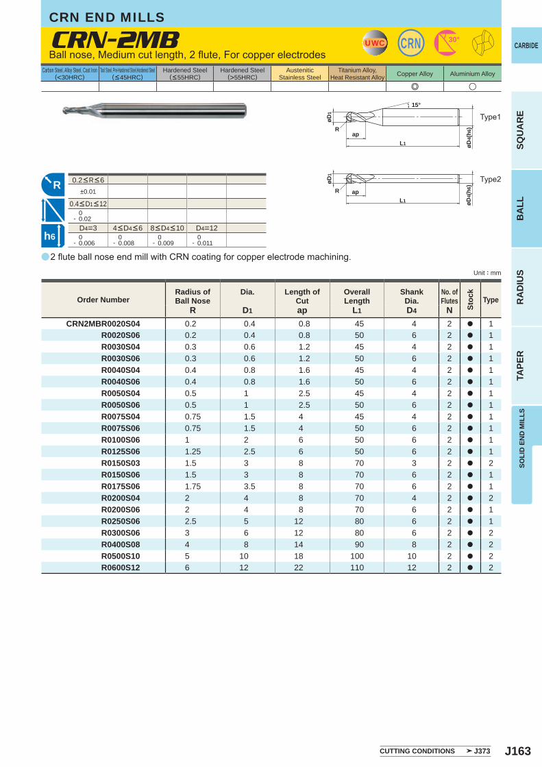
J163
e u
CRN-2MB
R D1 ap L1 D4 NCRN2MBR0020S04 0.2 0.4 0.8 45 4 2 a 1
R0020S06 0.2 0.4 0.8 50 6 2 a 1 R0030S04 0.3 0.6 1.2 45 4 2 a 1 R0030S06 0.3 0.6 1.2 50 6 2 a 1 R0040S04 0.4 0.8 1.6 45 4 2 a 1 R0040S06 0.4 0.8 1.6 50 6 2 a 1 R0050S04 0.5 1 2.5 45 4 2 a 1 R0050S06 0.5 1 2.5 50 6 2 a 1 R0075S04 0.75 1.5 4 45 4 2 a 1 R0075S06 0.75 1.5 4 50 6 2 a 1 R0100S06 1 2 6 50 6 2 a 1 R0125S06 1.25 2.5 6 50 6 2 a 1 R0150S03 1.5 3 8 70 3 2 a 2 R0150S06 1.5 3 8 70 6 2 a 1 R0175S06 1.75 3.5 8 70 6 2 a 1 R0200S04 2 4 8 70 4 2 a 2 R0200S06 2 4 8 70 6 2 a 1 R0250S06 2.5 5 12 80 6 2 a 1 R0300S06 3 6 12 80 6 2 a 2 R0400S08 4 8 14 90 8 2 a 2 R0500S10 5 10 18 100 10 2 a 2 R0600S12 6 12 22 110 12 2 a 2
a
±0.01
0- 0.02
D4=3 D4=12 0- 0.006
0- 0.008
0- 0.009
0- 0.011
UWC CRN 30°
øD4(
h6)
L1
øD1
Rap
15°
R
øD4(
h6)
L1
øD1
R ap
h6
SOLI
D E
ND
MIL
LS
CARBIDE
SQU
AR
EB
ALL
RA
DIU
STA
PER
Unit : mm
Carbon Steel, Alloy Steel, Cast Iron(<30HRC)
Tool Steel, Pre-Hardened Steel,Hardened Steel(<45HRC)
Hardened Steel(<55HRC)
Hardened Steel(>55HRC)
AusteniticStainless Steel
Titanium Alloy,Heat Resistant Alloy Copper Alloy Aluminium Alloy
2 flute ball nose end mill with CRN coating for copper electrode machining.
Ball nose, Medium cut length, 2 flute, For copper electrodes
CUTTING CONDITIONS J373
Order NumberRadius ofBall Nose
Dia. Length ofCut
OverallLength
ShankDia.
No. ofFlutes
Stoc
k
Type
4<D4<6 8<D4<10
0.2<R<6
0.4<D1<12
Type1
Type2
CRN END MILLS
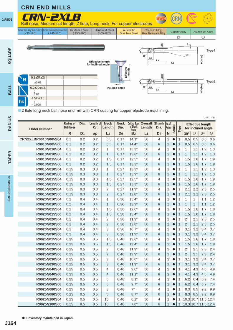
J164
a
e u
CRN-2XLB
R D1 ap L3 D5 B2 L1 D4 N 30' 1° 2° 3°CRN2XLBR0010N005S04 0.1 0.2 0.2 0.5 0.17 14.1° 50 4 2 a 1 0.5 0.5 0.6 0.6
R0010N005S06 0.1 0.2 0.2 0.5 0.17 14.4° 50 6 2 a 1 0.5 0.5 0.6 0.6 R0010N010S04 0.1 0.2 0.2 1 0.17 13.3° 50 4 2 a 1 1 1.1 1.2 1.3 R0010N010S06 0.1 0.2 0.2 1 0.17 13.8° 50 6 2 a 1 1 1.1 1.2 1.3 R0010N015S04 0.1 0.2 0.2 1.5 0.17 12.5° 50 4 2 a 1 1.5 1.6 1.7 1.9 R0010N015S06 0.1 0.2 0.2 1.5 0.17 13.3° 50 6 2 a 1 1.5 1.6 1.7 1.9 R0015N010S04 0.15 0.3 0.3 1 0.27 13.3° 50 4 2 a 1 1 1.1 1.2 1.3 R0015N010S06 0.15 0.3 0.3 1 0.27 13.9° 50 6 2 a 1 1 1.1 1.2 1.3 R0015N015S04 0.15 0.3 0.3 1.5 0.27 12.5° 50 4 2 a 1 1.5 1.6 1.7 1.9 R0015N015S06 0.15 0.3 0.3 1.5 0.27 13.3° 50 6 2 a 1 1.5 1.6 1.7 1.9 R0015N020S04 0.15 0.3 0.3 2 0.27 11.9° 50 4 2 a 1 2.1 2.2 2.3 2.5 R0015N020S06 0.15 0.3 0.3 2 0.27 12.8° 50 6 2 a 1 2.1 2.2 2.3 2.5 R0020N010S04 0.2 0.4 0.4 1 0.36 13.4° 50 4 2 a 1 1 1 1.1 1.2 R0020N010S06 0.2 0.4 0.4 1 0.36 13.9° 50 6 2 a 1 1 1 1.1 1.2 R0020N015S04 0.2 0.4 0.4 1.5 0.36 12.6° 50 4 2 a 1 1.5 1.6 1.7 1.8 R0020N015S06 0.2 0.4 0.4 1.5 0.36 13.4° 50 6 2 a 1 1.5 1.6 1.7 1.8 R0020N020S04 0.2 0.4 0.4 2 0.36 11.9° 50 4 2 a 1 2 2.1 2.3 2.5 R0020N020S06 0.2 0.4 0.4 2 0.36 12.8° 50 6 2 a 1 2 2.1 2.3 2.5 R0020N030S04 0.2 0.4 0.4 3 0.36 10.7° 50 4 2 a 1 3.1 3.2 3.4 3.7 R0020N030S06 0.2 0.4 0.4 3 0.36 11.9° 50 6 2 a 1 3.1 3.2 3.4 3.7 R0025N015S04 0.25 0.5 0.5 1.5 0.46 12.6° 50 4 2 a 1 1.5 1.6 1.7 1.8 R0025N015S06 0.25 0.5 0.5 1.5 0.46 13.4° 50 6 2 a 1 1.5 1.6 1.7 1.8 R0025N020S04 0.25 0.5 0.5 2 0.46 11.9° 50 4 2 a 1 2 2.1 2.3 2.4 R0025N020S06 0.25 0.5 0.5 2 0.46 12.9° 50 6 2 a 1 2 2.1 2.3 2.4 R0025N030S04 0.25 0.5 0.5 3 0.46 10.6° 50 4 2 a 1 3.1 3.2 3.4 3.7 R0025N030S06 0.25 0.5 0.5 3 0.46 11.9° 50 6 2 a 1 3.1 3.2 3.4 3.7 R0025N040S04 0.25 0.5 0.5 4 0.46 9.6° 50 4 2 a 1 4.1 4.3 4.6 4.9 R0025N040S06 0.25 0.5 0.5 4 0.46 11.1° 50 6 2 a 1 4.1 4.3 4.6 4.9 R0025N060S04 0.25 0.5 0.5 6 0.46 8.1° 50 4 2 a 1 6.2 6.4 6.9 7.4 R0025N060S06 0.25 0.5 0.5 6 0.46 9.7° 50 6 2 a 1 6.2 6.4 6.9 7.4 R0025N080S04 0.25 0.5 0.5 8 0.46 7° 50 4 2 a 1 8.3 8.5 9.2 9.9 R0025N080S06 0.25 0.5 0.5 8 0.46 8.7° 50 6 2 a 1 8.3 8.5 9.2 9.9 R0025N100S04 0.25 0.5 0.5 10 0.46 6.2° 50 4 2 a 1 10.3 10.7 11.5 12.4 R0025N100S06 0.25 0.5 0.5 10 0.46 7.8° 50 6 2 a 1 10.3 10.7 11.5 12.4
±0.01
0- 0.02
0- 0.008
UWC CRN 30°
L1
apL3
øD1
R
øD4(
h6)15°
B2
øD5
RR
øD4(
h6)
L1
apL3
øD1
øD5
h6
a : Inventory maintained in Japan.
CARBIDE
SQU
AR
EB
ALL
RA
DIU
STA
PER
SOLI
D E
ND
MIL
LS
Unit : mm
Carbon Steel, Alloy Steel, Cast Iron(<30HRC)
Tool Steel, Pre-Hardened Steel,Hardened Steel(<45HRC)
Hardened Steel(<55HRC)
Hardened Steel(>55HRC)
AusteniticStainless Steel
Titanium Alloy,Heat Resistant Alloy Copper Alloy Aluminium Alloy
2 flute long neck ball nose end mill with CRN coating for copper electrode machining.
Ball nose, Medium cut length, 2 flute, Long neck, For copper electrodes
Effective lengthfor inclined angle
Inclined angle
Effe
ctiv
ele
ngth
Order NumberRadius ofBall Nose
Dia. Length ofCut
NeckLength
NeckDia.
Cutting Edgeto Shank
Angle
OverallLength
ShankDia.
No. ofFlutes
Stoc
kTy
pe
Effective lengthfor inclined angle
4<D4<6
0.1<R<3
0.2<D1<6
Type1
Type2
CRN END MILLS
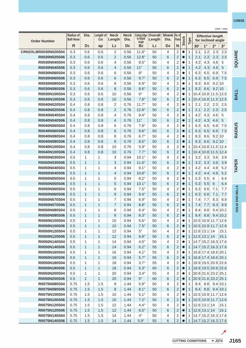
J165
R D1 ap L3 D5 B2 L1 D4 N 30' 1° 2° 3°CRN2XLBR0030N020S04 0.3 0.6 0.6 2 0.56 11.8° 50 4 2 a 1 2.1 2.2 2.3 2.5
R0030N020S06 0.3 0.6 0.6 2 0.56 12.8° 50 6 2 a 1 2.1 2.2 2.3 2.5 R0030N040S04 0.3 0.6 0.6 4 0.56 9.5° 50 4 2 a 1 4.2 4.3 4.6 5 R0030N040S06 0.3 0.6 0.6 4 0.56 11° 50 6 2 a 1 4.2 4.3 4.6 5
R0030N060S04 0.3 0.6 0.6 6 0.56 8° 50 4 2 a 1 6.3 6.5 6.9 7.5 R0030N060S06 0.3 0.6 0.6 6 0.56 9.7° 50 6 2 a 1 6.3 6.5 6.9 7.5 R0030N080S04 0.3 0.6 0.6 8 0.56 6.9° 50 4 2 a 1 8.3 8.6 9.2 10 R0030N080S06 0.3 0.6 0.6 8 0.56 8.6° 50 6 2 a 1 8.3 8.6 9.2 10 R0030N100S04 0.3 0.6 0.6 10 0.56 6° 50 4 2 a 1 10.4 10.8 11.5 12.5 R0030N100S06 0.3 0.6 0.6 10 0.56 7.8° 50 6 2 a 1 10.4 10.8 11.5 12.5 R0040N020S04 0.4 0.8 0.8 2 0.76 11.7° 50 4 2 a 1 2.1 2.2 2.3 2.5 R0040N020S06 0.4 0.8 0.8 2 0.76 12.8° 50 6 2 a 1 2.1 2.2 2.3 2.5 R0040N040S04 0.4 0.8 0.8 4 0.76 9.4° 50 4 2 a 1 4.2 4.3 4.6 5 R0040N040S06 0.4 0.8 0.8 4 0.76 11° 50 6 2 a 1 4.2 4.3 4.6 5 R0040N060S04 0.4 0.8 0.8 6 0.76 7.8° 50 4 2 a 1 6.3 6.5 6.9 7.5 R0040N060S06 0.4 0.8 0.8 6 0.76 9.6° 50 6 2 a 1 6.3 6.5 6.9 7.5 R0040N080S04 0.4 0.8 0.8 8 0.76 6.7° 50 4 2 a 1 8.3 8.6 9.2 10 R0040N080S06 0.4 0.8 0.8 8 0.76 8.5° 50 6 2 a 1 8.3 8.6 9.2 10 R0040N100S04 0.4 0.8 0.8 10 0.76 5.9° 50 4 2 a 1 10.4 10.8 11.5 12.4 R0040N100S06 0.4 0.8 0.8 10 0.76 7.7° 50 6 2 a 1 10.4 10.8 11.5 12.4 R0050N030S04 0.5 1 1 3 0.94 10.1° 50 4 2 a 1 3.2 3.3 3.6 3.9 R0050N030S06 0.5 1 1 3 0.94 11.6° 50 6 2 a 1 3.2 3.3 3.6 3.9 R0050N040S04 0.5 1 1 4 0.94 9.1° 50 4 2 a 1 4.2 4.4 4.8 5.2 R0050N040S06 0.5 1 1 4 0.94 10.8° 50 6 2 a 1 4.2 4.4 4.8 5.2 R0050N050S04 0.5 1 1 5 0.94 8.2° 50 4 2 a 1 5.3 5.5 6 6.4 R0050N050S06 0.5 1 1 5 0.94 10.1° 50 6 2 a 1 5.3 5.5 6 6.4 R0050N060S04 0.5 1 1 6 0.94 7.5° 50 4 2 a 1 6.3 6.6 7.1 7.7 R0050N060S06 0.5 1 1 6 0.94 9.4° 50 6 2 a 1 6.3 6.6 7.1 7.7 R0050N070S04 0.5 1 1 7 0.94 6.9° 50 4 2 a 1 7.4 7.7 8.3 8.9 R0050N070S06 0.5 1 1 7 0.94 8.8° 50 6 2 a 1 7.4 7.7 8.3 8.9 R0050N080S04 0.5 1 1 8 0.94 6.4° 50 4 2 a 1 8.4 8.8 9.4 10.2 R0050N080S06 0.5 1 1 8 0.94 8.3° 50 6 2 a 1 8.4 8.8 9.4 10.2 R0050N100S04 0.5 1 1 10 0.94 5.6° 50 4 2 a 1 10.5 10.9 11.7 12.6 R0050N100S06 0.5 1 1 10 0.94 7.5° 50 6 2 a 1 10.5 10.9 11.7 12.6 R0050N120S04 0.5 1 1 12 0.94 5° 50 4 2 a 1 12.6 13.1 14 15.1 R0050N120S06 0.5 1 1 12 0.94 6.8° 50 6 2 a 1 12.6 13.1 14 15.1 R0050N140S04 0.5 1 1 14 0.94 4.5° 50 4 2 a 1 14.7 15.2 16.3 17.6 R0050N140S06 0.5 1 1 14 0.94 6.2° 55 6 2 a 1 14.7 15.2 16.3 17.6 R0050N160S04 0.5 1 1 16 0.94 4.1° 55 4 2 a 1 16.8 17.4 18.6 20.1 R0050N160S06 0.5 1 1 16 0.94 5.7° 55 6 2 a 1 16.8 17.4 18.6 20.1 R0050N180S04 0.5 1 1 18 0.94 3.7° 55 4 2 a 1 18.9 19.5 20.9 22.6 R0050N180S06 0.5 1 1 18 0.94 5.3° 60 6 2 a 1 18.9 19.5 20.9 22.6 R0050N200S04 0.5 1 1 20 0.94 3.4° 55 4 2 a 1 20.9 21.6 23.2 25.1 R0050N200S06 0.5 1 1 20 0.94 5° 60 6 2 a 1 20.9 21.6 23.2 25.1 R0075N080S04 0.75 1.5 1.5 8 1.44 5.9° 50 4 2 a 1 8.4 8.8 9.4 10.1 R0075N080S06 0.75 1.5 1.5 8 1.44 8.1° 50 6 2 a 1 8.4 8.8 9.4 10.1 R0075N100S04 0.75 1.5 1.5 10 1.44 5.1° 50 4 2 a 1 10.5 10.9 11.7 12.6 R0075N100S06 0.75 1.5 1.5 10 1.44 7.2° 50 6 2 a 1 10.5 10.9 11.7 12.6 R0075N120S04 0.75 1.5 1.5 12 1.44 4.4° 50 4 2 a 1 12.6 13.1 14 15.1 R0075N120S06 0.75 1.5 1.5 12 1.44 6.5° 50 6 2 a 1 12.6 13.1 14 15.1 R0075N140S04 0.75 1.5 1.5 14 1.44 4° 50 4 2 a 1 14.7 15.2 16.3 17.6 R0075N140S06 0.75 1.5 1.5 14 1.44 5.9° 55 6 2 a 1 14.7 15.2 16.3 17.6
SOLI
D E
ND
MIL
LS
CARBIDE
SQU
AR
EB
ALL
RA
DIU
STA
PER
Unit : mm
Order NumberRadius ofBall Nose
Dia. Length ofCut
NeckLength
NeckDia.
Cutting Edgeto Shank
Angle
OverallLength
ShankDia.
No. ofFlutes
Stoc
kTy
pe
Effective lengthfor inclined angle
CUTTING CONDITIONS J374
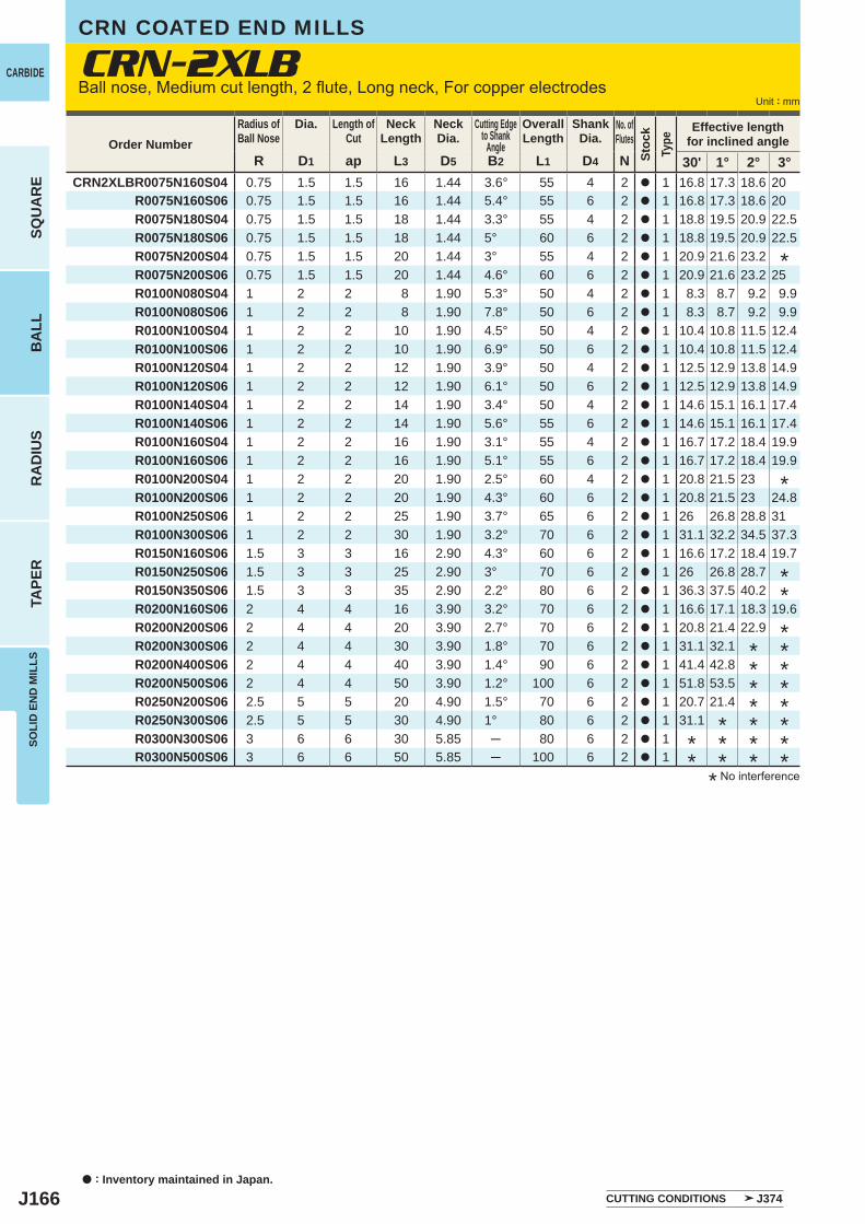
J166
R D1 ap L3 D5 B2 L1 D4 N 30' 1° 2° 3°CRN2XLBR0075N160S04 0.75 1.5 1.5 16 1.44 3.6° 55 4 2 a 1 16.8 17.3 18.6 20
R0075N160S06 0.75 1.5 1.5 16 1.44 5.4° 55 6 2 a 1 16.8 17.3 18.6 20R0075N180S04 0.75 1.5 1.5 18 1.44 3.3° 55 4 2 a 1 18.8 19.5 20.9 22.5
R0075N180S06 0.75 1.5 1.5 18 1.44 5° 60 6 2 a 1 18.8 19.5 20.9 22.5 R0075N200S04 0.75 1.5 1.5 20 1.44 3° 55 4 2 a 1 20.9 21.6 23.2
R0075N200S06 0.75 1.5 1.5 20 1.44 4.6° 60 6 2 a 1 20.9 21.6 23.2 25 R0100N080S04 1 2 2 8 1.90 5.3° 50 4 2 a 1 8.3 8.7 9.2 9.9 R0100N080S06 1 2 2 8 1.90 7.8° 50 6 2 a 1 8.3 8.7 9.2 9.9 R0100N100S04 1 2 2 10 1.90 4.5° 50 4 2 a 1 10.4 10.8 11.5 12.4 R0100N100S06 1 2 2 10 1.90 6.9° 50 6 2 a 1 10.4 10.8 11.5 12.4 R0100N120S04 1 2 2 12 1.90 3.9° 50 4 2 a 1 12.5 12.9 13.8 14.9 R0100N120S06 1 2 2 12 1.90 6.1° 50 6 2 a 1 12.5 12.9 13.8 14.9 R0100N140S04 1 2 2 14 1.90 3.4° 50 4 2 a 1 14.6 15.1 16.1 17.4 R0100N140S06 1 2 2 14 1.90 5.6° 55 6 2 a 1 14.6 15.1 16.1 17.4 R0100N160S04 1 2 2 16 1.90 3.1° 55 4 2 a 1 16.7 17.2 18.4 19.9 R0100N160S06 1 2 2 16 1.90 5.1° 55 6 2 a 1 16.7 17.2 18.4 19.9 R0100N200S04 1 2 2 20 1.90 2.5° 60 4 2 a 1 20.8 21.5 23 R0100N200S06 1 2 2 20 1.90 4.3° 60 6 2 a 1 20.8 21.5 23 24.8 R0100N250S06 1 2 2 25 1.90 3.7° 65 6 2 a 1 26 26.8 28.8 31 R0100N300S06 1 2 2 30 1.90 3.2° 70 6 2 a 1 31.1 32.2 34.5 37.3 R0150N160S06 1.5 3 3 16 2.90 4.3° 60 6 2 a 1 16.6 17.2 18.4 19.7 R0150N250S06 1.5 3 3 25 2.90 3° 70 6 2 a 1 26 26.8 28.7 R0150N350S06 1.5 3 3 35 2.90 2.2° 80 6 2 a 1 36.3 37.5 40.2 R0200N160S06 2 4 4 16 3.90 3.2° 70 6 2 a 1 16.6 17.1 18.3 19.6 R0200N200S06 2 4 4 20 3.90 2.7° 70 6 2 a 1 20.8 21.4 22.9 R0200N300S06 2 4 4 30 3.90 1.8° 70 6 2 a 1 31.1 32.1 R0200N400S06 2 4 4 40 3.90 1.4° 90 6 2 a 1 41.4 42.8 R0200N500S06 2 4 4 50 3.90 1.2° 100 6 2 a 1 51.8 53.5 R0250N200S06 2.5 5 5 20 4.90 1.5° 70 6 2 a 1 20.7 21.4 R0250N300S06 2.5 5 5 30 4.90 1° 80 6 2 a 1 31.1 R0300N300S06 3 6 6 30 5.85 ─ 80 6 2 a 1 R0300N500S06 3 6 6 50 5.85 ─ 100 6 2 a 1
a : Inventory maintained in Japan.
CARBIDE
SQU
AR
EB
ALL
RA
DIU
STA
PER
SOLI
D E
ND
MIL
LS
Unit : mm
Order NumberRadius ofBall Nose
Dia. Length ofCut
NeckLength
NeckDia.
Cutting Edgeto Shank
Angle
OverallLength
ShankDia.
No. ofFlutes
Stoc
kTy
pe
Effective lengthfor inclined angle
* No interference
*
**
********************
CRN-2XLBCRN COATED END MILLS
Ball nose, Medium cut length, 2 flute, Long neck, For copper electrodes
*
CUTTING CONDITIONS J374
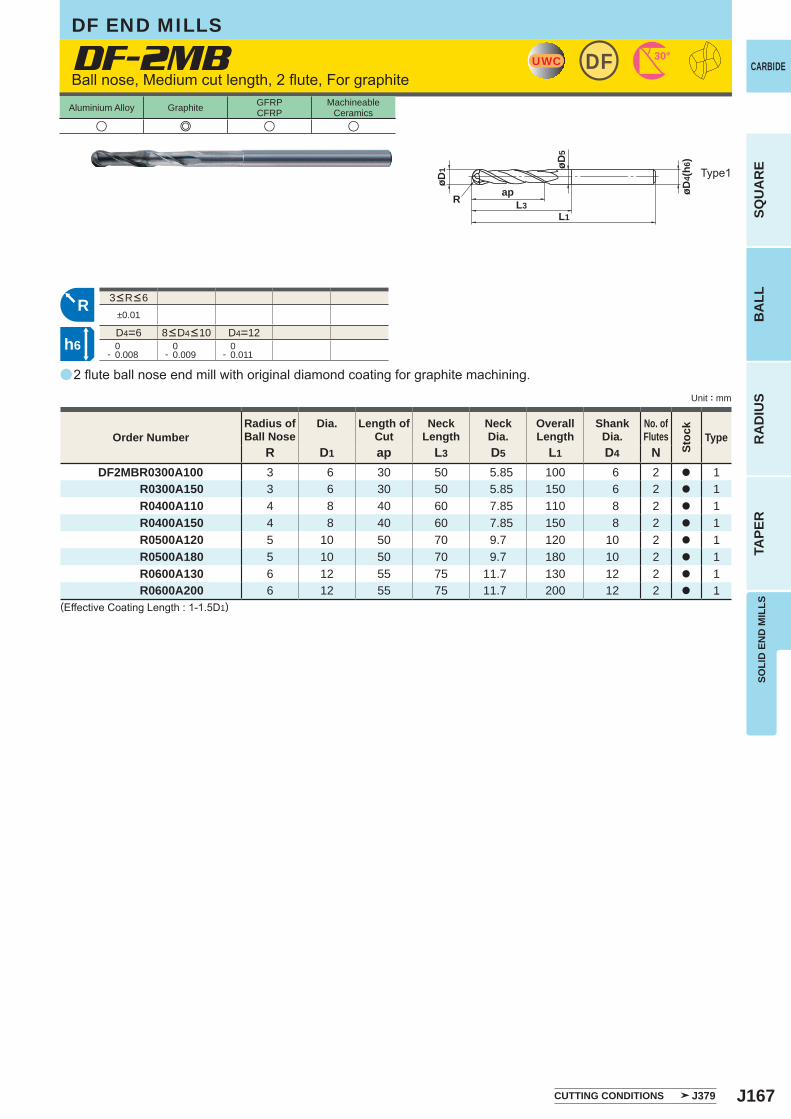
J167
a
u e u u
DF-2MB
R D1 ap L3 D5 L1 D4 NDF2MBR0300A100 3 6 30 50 5.85 100 6 2 a 1
R0300A150 3 6 30 50 5.85 150 6 2 a 1R0400A110 4 8 40 60 7.85 110 8 2 a 1R0400A150 4 8 40 60 7.85 150 8 2 a 1R0500A120 5 10 50 70 9.7 120 10 2 a 1R0500A180 5 10 50 70 9.7 180 10 2 a 1R0600A130 6 12 55 75 11.7 130 12 2 a 1R0600A200 6 12 55 75 11.7 200 12 2 a 1
±0.01
D4=6 D4=12 0- 0.008
0- 0.009
0- 0.011
UWC DF 30°
øD4(
h6)
øD1 øD
5
L1L3
apR
R
h6
SOLI
D E
ND
MIL
LS
CARBIDE
SQU
AR
EB
ALL
RA
DIU
STA
PER
Unit : mm
Aluminium Alloy Graphite GFRPCFRP
MachineableCeramics
Ball nose, Medium cut length, 2 flute, For graphite
2 flute ball nose end mill with original diamond coating for graphite machining.
(Effective Coating Length : 1-1.5D1)
Order NumberRadius ofBall Nose
Dia. Length ofCut
NeckLength
NeckDia.
OverallLength
ShankDia.
No. ofFlutes
Stoc
k
Type
8<D4<10
3<R<6
Type1
CUTTING CONDITIONS J379
DF END MILLS
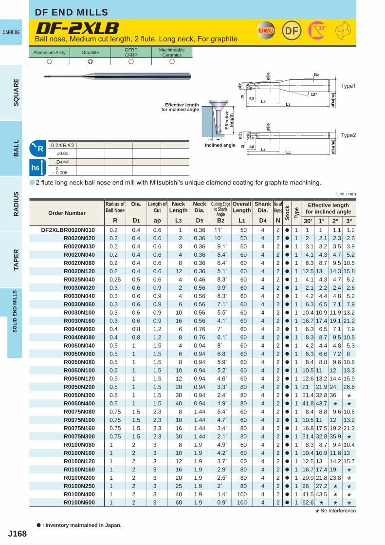
J168
a
DF-2XLB
u e u u
R D1 ap L3 D5 B2 L1 D4 N 30' 1° 2° 3°DF2XLBR0020N010 0.2 0.4 0.6 1 0.36 11˚ 50 4 2 a 1 1 1 1.1 1.2
R0020N020 0.2 0.4 0.6 2 0.36 10˚ 50 4 2 a 1 2 2.1 2.3 2.6R0020N030 0.2 0.4 0.6 3 0.36 9.1˚ 50 4 2 a 1 3.1 3.2 3.5 3.9R0020N040 0.2 0.4 0.6 4 0.36 8.4˚ 60 4 2 a 1 4.1 4.3 4.7 5.2R0020N080 0.2 0.4 0.6 8 0.36 6.4˚ 60 4 2 a 1 8.3 8.7 9.5 10.5R0020N120 0.2 0.4 0.6 12 0.36 5.1˚ 60 4 2 a 1 12.5 13 14.3 15.8R0025N040 0.25 0.5 0.6 4 0.46 8.3˚ 60 4 2 a 1 4.1 4.3 4.7 5.2R0030N020 0.3 0.6 0.9 2 0.56 9.9˚ 60 4 2 a 1 2.1 2.2 2.4 2.6R0030N040 0.3 0.6 0.9 4 0.56 8.3˚ 60 4 2 a 1 4.2 4.4 4.8 5.2R0030N060 0.3 0.6 0.9 6 0.56 7.1˚ 60 4 2 a 1 6.3 6.5 7.1 7.9R0030N100 0.3 0.6 0.9 10 0.56 5.5˚ 60 4 2 a 1 10.4 10.9 11.9 13.2R0030N160 0.3 0.6 0.9 16 0.56 4.1˚ 60 4 2 a 1 16.7 17.4 19.1 21.2R0040N060 0.4 0.8 1.2 6 0.76 7˚ 60 4 2 a 1 6.3 6.5 7.1 7.9R0040N080 0.4 0.8 1.2 8 0.76 6.1˚ 60 4 2 a 1 8.3 8.7 9.5 10.5R0050N040 0.5 1 1.5 4 0.94 8˚ 60 4 2 a 1 4.2 4.4 4.8 5.3R0050N060 0.5 1 1.5 6 0.94 6.8˚ 60 4 2 a 1 6.3 6.6 7.2 8R0050N080 0.5 1 1.5 8 0.94 5.9˚ 60 4 2 a 1 8.4 8.8 9.6 10.6R0050N100 0.5 1 1.5 10 0.94 5.2˚ 60 4 2 a 1 10.5 11 12 13.3R0050N120 0.5 1 1.5 12 0.94 4.6˚ 60 4 2 a 1 12.6 13.2 14.4 15.9R0050N200 0.5 1 1.5 20 0.94 3.3˚ 80 4 2 a 1 21 21.9 24 26.6R0050N300 0.5 1 1.5 30 0.94 2.4˚ 80 4 2 a 1 31.4 32.8 36R0050N400 0.5 1 1.5 40 0.94 1.9˚ 80 4 2 a 1 41.8 43.7R0075N080 0.75 1.5 2.3 8 1.44 5.4˚ 60 4 2 a 1 8.4 8.8 9.6 10.6R0075N100 0.75 1.5 2.3 10 1.44 4.7˚ 60 4 2 a 1 10.5 11 12 13.2R0075N160 0.75 1.5 2.3 16 1.44 3.4˚ 80 4 2 a 1 16.8 17.5 19.2 21.2R0075N300 0.75 1.5 2.3 30 1.44 2.1˚ 80 4 2 a 1 31.4 32.8 35.9R0100N080 1 2 3 8 1.9 4.9˚ 60 4 2 a 1 8.3 8.7 9.4 10.4R0100N100 1 2 3 10 1.9 4.2˚ 60 4 2 a 1 10.4 10.9 11.8 13R0100N120 1 2 3 12 1.9 3.7˚ 60 4 2 a 1 12.5 13 14.2 15.7R0100N160 1 2 3 16 1.9 2.9˚ 80 4 2 a 1 16.7 17.4 19R0100N200 1 2 3 20 1.9 2.5˚ 80 4 2 a 1 20.9 21.8 23.8R0100N250 1 2 3 25 1.9 2˚ 80 4 2 a 1 26 27.2R0100N400 1 2 3 40 1.9 1.4˚ 100 4 2 a 1 41.5 43.5R0100N600 1 2 3 60 1.9 0.9˚ 100 4 2 a 1 62.6
±0.01
D4=4 0- 0.008
UWC DF 30°
L1
apL3
øD1
R
øD4(
h6)12°
øD5 B2
R
øD4(
h6)
L1
apL3
øD1
øD5
R
h6
a : Inventory maintained in Japan.
CARBIDE
SQU
AR
EB
ALL
RA
DIU
STA
PER
SOLI
D E
ND
MIL
LS
Unit : mm
Aluminium Alloy Graphite GFRPCFRP
MachineableCeramics
Ball nose, Medium cut length, 2 flute, Long neck, For graphite
2 flute long neck ball nose end mill with Mitsubishi's unique diamond coating for graphite machining.
* No interference
Effective lengthfor inclined angle
Inclined angle
Effe
ctiv
ele
ngth
Order NumberRadius ofBall Nose
Dia. Length ofCut
NeckLength
NeckDia.
Cutting Edgeto Shank
Angle
OverallLength
ShankDia.
No. ofFlutes
Stoc
kTy
pe
Effective lengthfor inclined angle
*
*
**
*
********
0.2<R<2
Type1
Type2
DF END MILLS
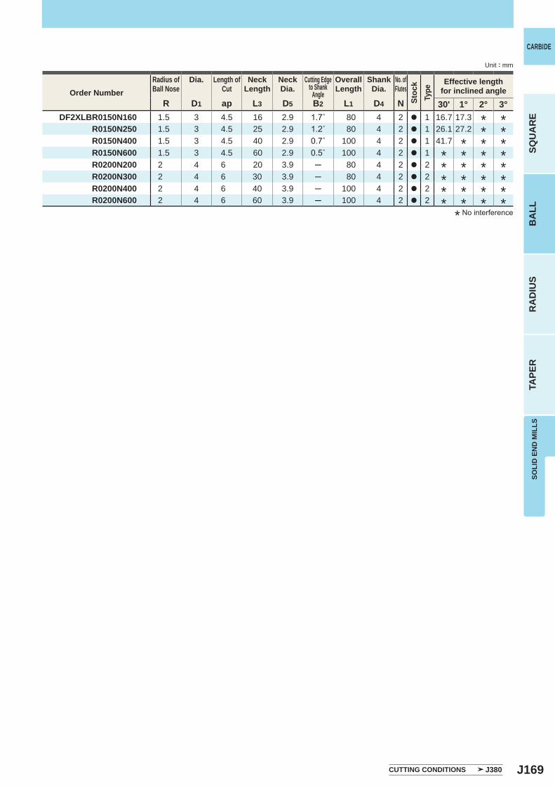
J169
R D1 ap L3 D5 B2 L1 D4 N 30' 1° 2° 3°DF2XLBR0150N160 1.5 3 4.5 16 2.9 1.7˚ 80 4 2 a 1 16.7 17.3
R0150N250 1.5 3 4.5 25 2.9 1.2˚ 80 4 2 a 1 26.1 27.2R0150N400 1.5 3 4.5 40 2.9 0.7˚ 100 4 2 a 1 41.7R0150N600 1.5 3 4.5 60 2.9 0.5˚ 100 4 2 a 1R0200N200 2 4 6 20 3.9 ─ 80 4 2 a 2R0200N300 2 4 6 30 3.9 ─ 80 4 2 a 2R0200N400 2 4 6 40 3.9 ─ 100 4 2 a 2R0200N600 2 4 6 60 3.9 ─ 100 4 2 a 2
SOLI
D E
ND
MIL
LS
CARBIDE
SQU
AR
EB
ALL
RA
DIU
STA
PER
Unit : mm
Order NumberRadius ofBall Nose
Dia. Length ofCut
NeckLength
NeckDia.
Cutting Edgeto Shank
Angle
OverallLength
ShankDia.
No. ofFlutes
Stoc
kTy
pe
Effective lengthfor inclined angle
* No interference
************
*************
**
CUTTING CONDITIONS J380
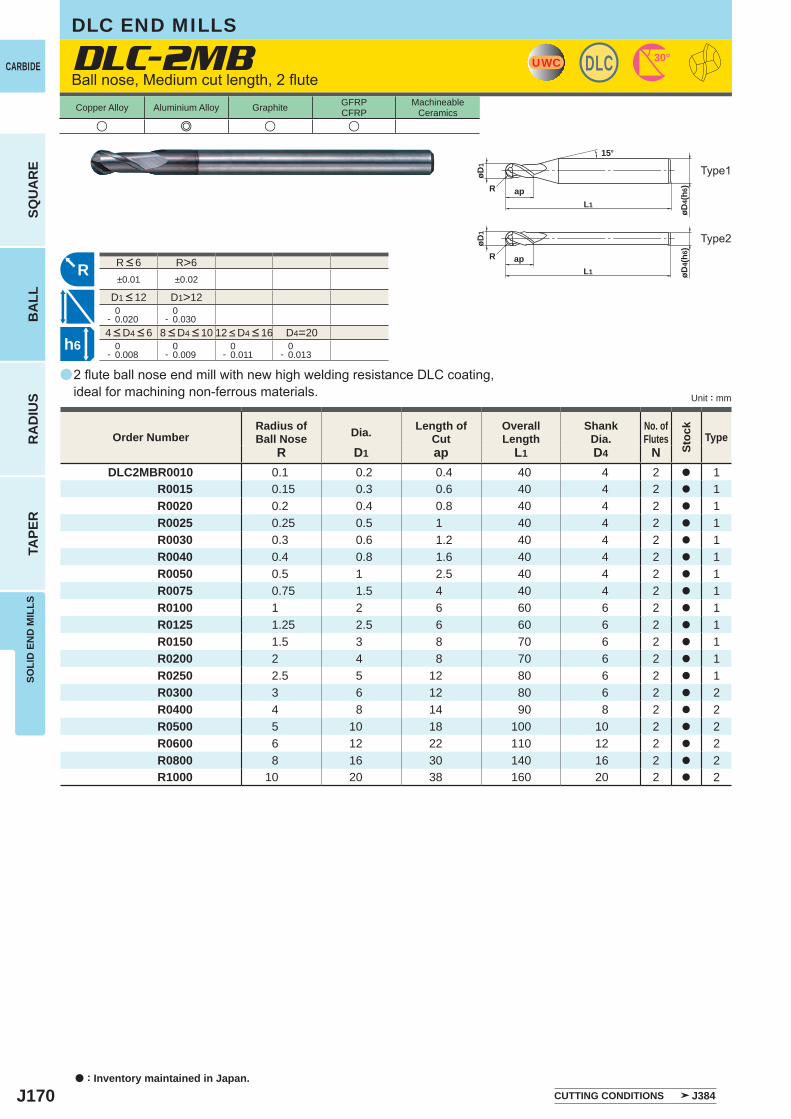
J170
a
DLC-2MB
R D1 ap L1 D4 NDLC2MBR0010 0.1 0.2 0.4 40 4 2 a 1
R0015 0.15 0.3 0.6 40 4 2 a 1 R0020 0.2 0.4 0.8 40 4 2 a 1 R0025 0.25 0.5 1 40 4 2 a 1 R0030 0.3 0.6 1.2 40 4 2 a 1 R0040 0.4 0.8 1.6 40 4 2 a 1 R0050 0.5 1 2.5 40 4 2 a 1 R0075 0.75 1.5 4 40 4 2 a 1 R0100 1 2 6 60 6 2 a 1 R0125 1.25 2.5 6 60 6 2 a 1 R0150 1.5 3 8 70 6 2 a 1 R0200 2 4 8 70 6 2 a 1 R0250 2.5 5 12 80 6 2 a 1 R0300 3 6 12 80 6 2 a 2 R0400 4 8 14 90 8 2 a 2 R0500 5 10 18 100 10 2 a 2 R0600 6 12 22 110 12 2 a 2 R0800 8 16 30 140 16 2 a 2 R1000 10 20 38 160 20 2 a 2
u e u u
R>6±0.01 ±0.02
D1>12 0- 0.020
0- 0.030
D4=20 0- 0.008
0- 0.009
0- 0.011
0- 0.013
UWC DLC 30°
øD4(
h6)
øD4(
h6)
L1
L1
øD1
øD1
R
R ap
ap
15°
R
h6
a : Inventory maintained in Japan.
CARBIDE
SQU
AR
EB
ALL
RA
DIU
STA
PER
SOLI
D E
ND
MIL
LS
Unit : mm
Copper Alloy Aluminium Alloy Graphite GFRPCFRP
MachineableCeramics
Ball nose, Medium cut length, 2 flute
2 flute ball nose end mill with new high welding resistance DLC coating, ideal for machining non-ferrous materials.
Type2
Type1
Order NumberRadius ofBall Nose Dia. Length of
CutOverallLength
ShankDia.
No. ofFlutes
Stoc
k
Type
4 < D4 < 6 8 < D4 < 10 12 < D4 < 16
R < 6
D1 < 12
CUTTING CONDITIONS J384
DLC END MILLS
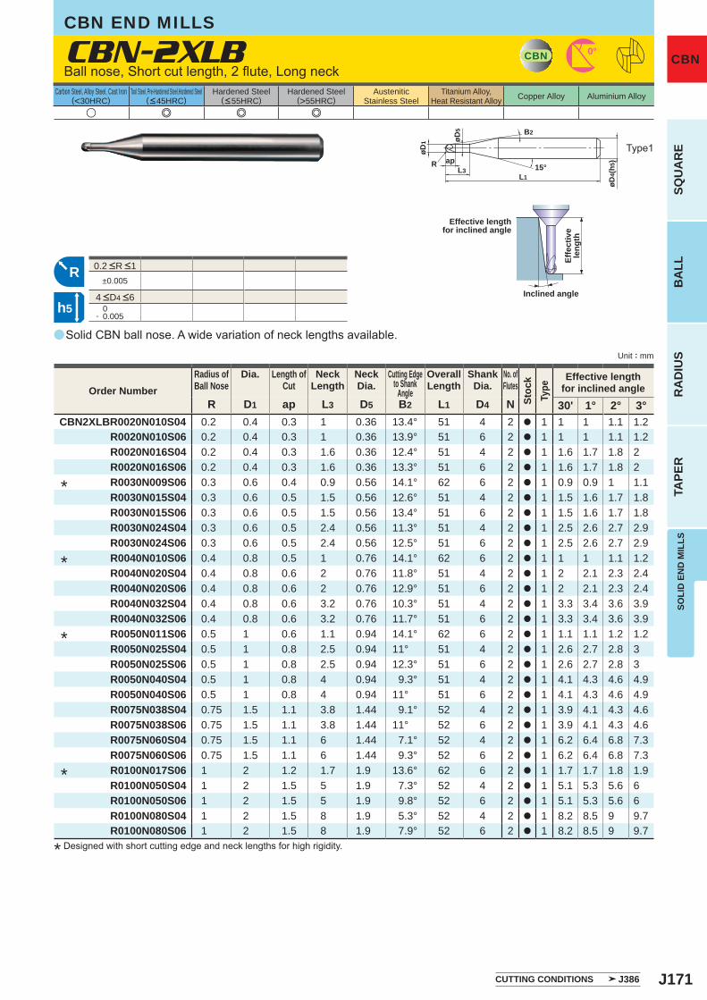
J171
a
u e e e
CBN-2XLB
R D1 ap L3 D5 B2 L1 D4 N 30' 1° 2° 3°CBN2XLBR0020N010S04 0.2 0.4 0.3 1 0.36 13.4° 51 4 2 a 1 1 1 1.1 1.2
R0020N010S06 0.2 0.4 0.3 1 0.36 13.9° 51 6 2 a 1 1 1 1.1 1.2 R0020N016S04 0.2 0.4 0.3 1.6 0.36 12.4° 51 4 2 a 1 1.6 1.7 1.8 2 R0020N016S06 0.2 0.4 0.3 1.6 0.36 13.3° 51 6 2 a 1 1.6 1.7 1.8 2 R0030N009S06 0.3 0.6 0.4 0.9 0.56 14.1° 62 6 2 a 1 0.9 0.9 1 1.1 R0030N015S04 0.3 0.6 0.5 1.5 0.56 12.6° 51 4 2 a 1 1.5 1.6 1.7 1.8 R0030N015S06 0.3 0.6 0.5 1.5 0.56 13.4° 51 6 2 a 1 1.5 1.6 1.7 1.8 R0030N024S04 0.3 0.6 0.5 2.4 0.56 11.3° 51 4 2 a 1 2.5 2.6 2.7 2.9 R0030N024S06 0.3 0.6 0.5 2.4 0.56 12.5° 51 6 2 a 1 2.5 2.6 2.7 2.9 R0040N010S06 0.4 0.8 0.5 1 0.76 14.1° 62 6 2 a 1 1 1 1.1 1.2 R0040N020S04 0.4 0.8 0.6 2 0.76 11.8° 51 4 2 a 1 2 2.1 2.3 2.4 R0040N020S06 0.4 0.8 0.6 2 0.76 12.9° 51 6 2 a 1 2 2.1 2.3 2.4 R0040N032S04 0.4 0.8 0.6 3.2 0.76 10.3° 51 4 2 a 1 3.3 3.4 3.6 3.9 R0040N032S06 0.4 0.8 0.6 3.2 0.76 11.7° 51 6 2 a 1 3.3 3.4 3.6 3.9 R0050N011S06 0.5 1 0.6 1.1 0.94 14.1° 62 6 2 a 1 1.1 1.1 1.2 1.2 R0050N025S04 0.5 1 0.8 2.5 0.94 11° 51 4 2 a 1 2.6 2.7 2.8 3 R0050N025S06 0.5 1 0.8 2.5 0.94 12.3° 51 6 2 a 1 2.6 2.7 2.8 3 R0050N040S04 0.5 1 0.8 4 0.94 9.3° 51 4 2 a 1 4.1 4.3 4.6 4.9 R0050N040S06 0.5 1 0.8 4 0.94 11° 51 6 2 a 1 4.1 4.3 4.6 4.9 R0075N038S04 0.75 1.5 1.1 3.8 1.44 9.1° 52 4 2 a 1 3.9 4.1 4.3 4.6 R0075N038S06 0.75 1.5 1.1 3.8 1.44 11° 52 6 2 a 1 3.9 4.1 4.3 4.6 R0075N060S04 0.75 1.5 1.1 6 1.44 7.1° 52 4 2 a 1 6.2 6.4 6.8 7.3 R0075N060S06 0.75 1.5 1.1 6 1.44 9.3° 52 6 2 a 1 6.2 6.4 6.8 7.3 R0100N017S06 1 2 1.2 1.7 1.9 13.6° 62 6 2 a 1 1.7 1.7 1.8 1.9 R0100N050S04 1 2 1.5 5 1.9 7.3° 52 4 2 a 1 5.1 5.3 5.6 6 R0100N050S06 1 2 1.5 5 1.9 9.8° 52 6 2 a 1 5.1 5.3 5.6 6 R0100N080S04 1 2 1.5 8 1.9 5.3° 52 4 2 a 1 8.2 8.5 9 9.7 R0100N080S06 1 2 1.5 8 1.9 7.9° 52 6 2 a 1 8.2 8.5 9 9.7
±0.005
0- 0.005
CBN 0°
L1
apL3
øD1 øD
5
øD4(
h5)R 15°
B2
R
h5
Unit : mm
Carbon Steel, Alloy Steel, Cast Iron(<30HRC)
Tool Steel, Pre-Hardened Steel,Hardened Steel(<45HRC)
Hardened Steel(<55HRC)
Hardened Steel(>55HRC)
AusteniticStainless Steel
Titanium Alloy,Heat Resistant Alloy Copper Alloy Aluminium Alloy
SOLI
D E
ND
MIL
LSSQ
UA
RE
BA
LLR
AD
IUS
TAPE
R
CBN
Solid CBN ball nose. A wide variation of neck lengths available.
Ball nose, Short cut length, 2 flute, Long neck
CBN END MILLS
* Designed with short cutting edge and neck lengths for high rigidity.
Type1
Effective lengthfor inclined angle
Inclined angle
Effe
ctiv
ele
ngth
Order NumberRadius ofBall Nose
Dia. Length ofCut
NeckLength
NeckDia.
Cutting Edgeto Shank
Angle
OverallLength
ShankDia.
No. ofFlutes
Stoc
kTy
pe
Effective lengthfor inclined angle
4 <D4 <6
0.2 <R <1
*
*
*
*
CUTTING CONDITIONS J386
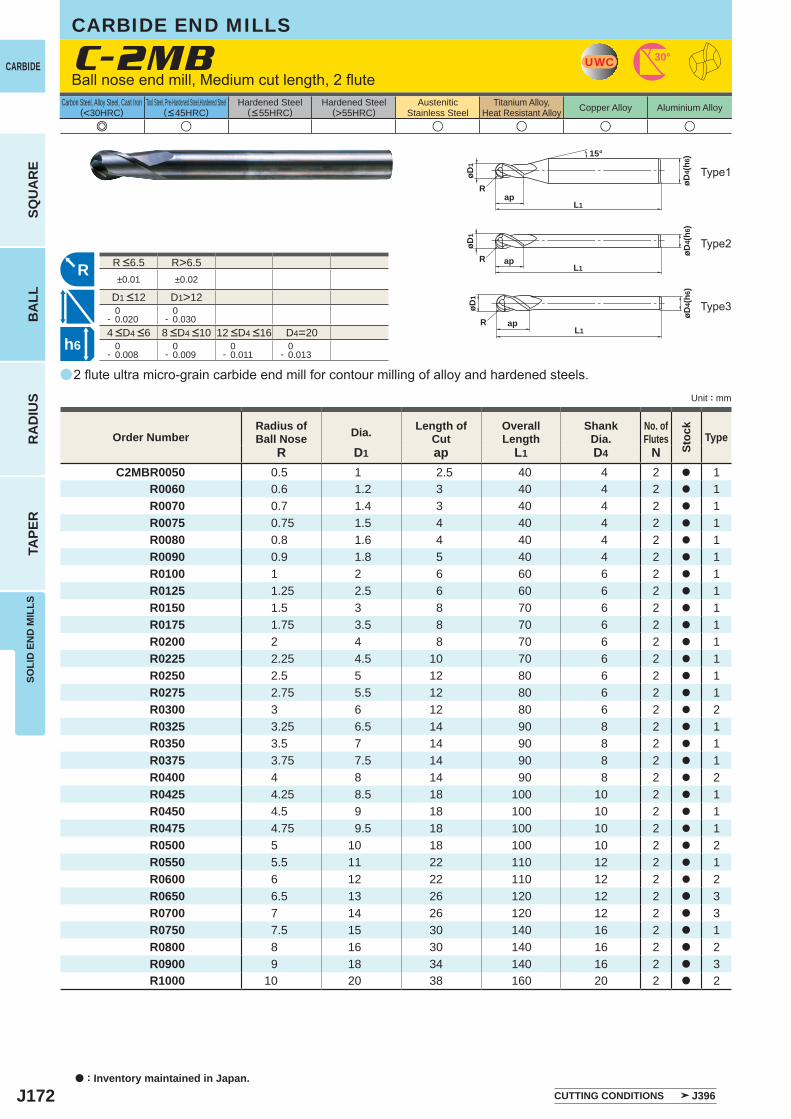
J172
a
e u u u u u
C-2MB
R D1 ap L1 D4 NC2MBR0050 0.5 1 2.5 40 4 2 a 1
R0060 0.6 1.2 3 40 4 2 a 1 R0070 0.7 1.4 3 40 4 2 a 1 R0075 0.75 1.5 4 40 4 2 a 1 R0080 0.8 1.6 4 40 4 2 a 1 R0090 0.9 1.8 5 40 4 2 a 1 R0100 1 2 6 60 6 2 a 1 R0125 1.25 2.5 6 60 6 2 a 1 R0150 1.5 3 8 70 6 2 a 1 R0175 1.75 3.5 8 70 6 2 a 1 R0200 2 4 8 70 6 2 a 1 R0225 2.25 4.5 10 70 6 2 a 1 R0250 2.5 5 12 80 6 2 a 1 R0275 2.75 5.5 12 80 6 2 a 1 R0300 3 6 12 80 6 2 a 2 R0325 3.25 6.5 14 90 8 2 a 1 R0350 3.5 7 14 90 8 2 a 1 R0375 3.75 7.5 14 90 8 2 a 1 R0400 4 8 14 90 8 2 a 2 R0425 4.25 8.5 18 100 10 2 a 1 R0450 4.5 9 18 100 10 2 a 1 R0475 4.75 9.5 18 100 10 2 a 1 R0500 5 10 18 100 10 2 a 2 R0550 5.5 11 22 110 12 2 a 1 R0600 6 12 22 110 12 2 a 2 R0650 6.5 13 26 120 12 2 a 3 R0700 7 14 26 120 12 2 a 3 R0750 7.5 15 30 140 16 2 a 1 R0800 8 16 30 140 16 2 a 2 R0900 9 18 34 140 16 2 a 3 R1000 10 20 38 160 20 2 a 2
R>6.5±0.01 ±0.02
D1>12 0- 0.020
0- 0.030
D4=20 0- 0.008
0- 0.009
0- 0.011
0- 0.013
UWC 30°
øD4(
h6)
L1
øD1
Rap
15°
R
L1ap
øD1
R
øD4(
h6)
øD4(
h6)
øD1
RL1
ap
h6
a : Inventory maintained in Japan.
CARBIDE
SQU
AR
EB
ALL
RA
DIU
STA
PER
SOLI
D E
ND
MIL
LS
Unit : mm
Carbon Steel, Alloy Steel, Cast Iron(<30HRC)
Tool Steel, Pre-Hardened Steel,Hardened Steel(<45HRC)
Hardened Steel(<55HRC)
Hardened Steel(>55HRC)
AusteniticStainless Steel
Titanium Alloy,Heat Resistant Alloy Copper Alloy Aluminium Alloy
2 flute ultra micro-grain carbide end mill for contour milling of alloy and hardened steels.
Ball nose end mill, Medium cut length, 2 flute
CARBIDE END MILLS
Type1
Order NumberRadius ofBall Nose Dia. Length of
CutOverallLength
ShankDia.
No. ofFlutes
Stoc
k
Type
4 <D4 <6 8 <D4 <10 12 <D4 <16
R <6.5
D1 <12
Type2
Type3
CUTTING CONDITIONS J396
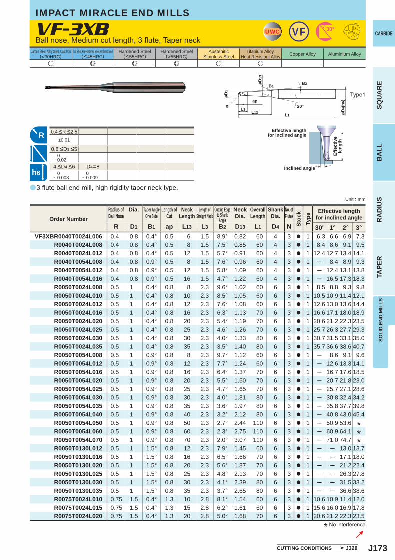
J173
a
VF-3XB
R D1 B1 ap L13 L3 B2 D13 L1 D4 N 30' 1° 2° 3°VF3XBR0040T0024L006 0.4 0.8 0.4° 0.5 6 1.5 8.9° 0.82 60 4 3 a 1 6.3 6.6 6.9 7.3
R0040T0024L008 0.4 0.8 0.4° 0.5 8 1.5 7.5° 0.85 60 4 3 a 1 8.4 8.6 9.1 9.5 R0040T0024L012 0.4 0.8 0.4° 0.5 12 1.5 5.7° 0.91 60 4 3 a 1 12.4 12.7 13.4 14.1 R0040T0054L008 0.4 0.8 0.9° 0.5 8 1.5 7.6° 0.96 60 4 3 a 1 ─ 8.4 8.9 9.3 R0040T0054L012 0.4 0.8 0.9° 0.5 12 1.5 5.8° 1.09 60 4 3 a 1 ─ 12.4 13.1 13.8 R0040T0054L016 0.4 0.8 0.9° 0.5 16 1.5 4.7° 1.22 60 4 3 a 1 ─ 16.5 17.3 18.3 R0050T0024L008 0.5 1 0.4° 0.8 8 2.3 9.6° 1.02 60 6 3 a 1 8.5 8.8 9.3 9.8 R0050T0024L010 0.5 1 0.4° 0.8 10 2.3 8.5° 1.05 60 6 3 a 1 10.5 10.9 11.4 12.1 R0050T0024L012 0.5 1 0.4° 0.8 12 2.3 7.6° 1.08 60 6 3 a 1 12.6 13.0 13.6 14.4 R0050T0024L016 0.5 1 0.4° 0.8 16 2.3 6.3° 1.13 70 6 3 a 1 16.6 17.1 18.0 18.9 R0050T0024L020 0.5 1 0.4° 0.8 20 2.3 5.4° 1.19 70 6 3 a 1 20.6 21.2 22.3 23.5 R0050T0024L025 0.5 1 0.4° 0.8 25 2.3 4.6° 1.26 70 6 3 a 1 25.7 26.3 27.7 29.3 R0050T0024L030 0.5 1 0.4° 0.8 30 2.3 4.0° 1.33 80 6 3 a 1 30.7 31.5 33.1 35.0 R0050T0024L035 0.5 1 0.4° 0.8 35 2.3 3.5° 1.40 80 6 3 a 1 35.7 36.6 38.6 40.7 R0050T0054L008 0.5 1 0.9° 0.8 8 2.3 9.7° 1.12 60 6 3 a 1 ─ 8.6 9.1 9.6 R0050T0054L012 0.5 1 0.9° 0.8 12 2.3 7.7° 1.24 60 6 3 a 1 ─ 12.6 13.3 14.1 R0050T0054L016 0.5 1 0.9° 0.8 16 2.3 6.4° 1.37 70 6 3 a 1 ─ 16.7 17.6 18.5 R0050T0054L020 0.5 1 0.9° 0.8 20 2.3 5.5° 1.50 70 6 3 a 1 ─ 20.7 21.8 23.0 R0050T0054L025 0.5 1 0.9° 0.8 25 2.3 4.7° 1.65 70 6 3 a 1 ─ 25.7 27.1 28.6 R0050T0054L030 0.5 1 0.9° 0.8 30 2.3 4.0° 1.81 80 6 3 a 1 ─ 30.8 32.4 34.2 R0050T0054L035 0.5 1 0.9° 0.8 35 2.3 3.6° 1.97 80 6 3 a 1 ─ 35.8 37.7 39.8 R0050T0054L040 0.5 1 0.9° 0.8 40 2.3 3.2° 2.12 80 6 3 a 1 ─ 40.8 43.0 45.4 R0050T0054L050 0.5 1 0.9° 0.8 50 2.3 2.7° 2.44 110 6 3 a 1 ─ 50.9 53.6 R0050T0054L060 0.5 1 0.9° 0.8 60 2.3 2.3° 2.75 110 6 3 a 1 ─ 60.9 64.1 R0050T0054L070 0.5 1 0.9° 0.8 70 2.3 2.0° 3.07 110 6 3 a 1 ─ 71.0 74.7 R0050T0130L012 0.5 1 1.5° 0.8 12 2.3 7.9° 1.45 60 6 3 a 1 ─ ─ 13.0 13.7 R0050T0130L016 0.5 1 1.5° 0.8 16 2.3 6.5° 1.66 70 6 3 a 1 ─ ─ 17.1 18.0 R0050T0130L020 0.5 1 1.5° 0.8 20 2.3 5.6° 1.87 70 6 3 a 1 ─ ─ 21.2 22.4 R0050T0130L025 0.5 1 1.5° 0.8 25 2.3 4.8° 2.13 70 6 3 a 1 ─ ─ 26.3 27.8 R0050T0130L030 0.5 1 1.5° 0.8 30 2.3 4.1° 2.39 80 6 3 a 1 ─ ─ 31.5 33.2 R0050T0130L035 0.5 1 1.5° 0.8 35 2.3 3.7° 2.65 80 6 3 a 1 ─ ─ 36.6 38.6 R0075T0024L010 0.75 1.5 0.4° 1.3 10 2.8 8.1° 1.54 60 6 3 a 1 10.6 10.9 11.4 12.0 R0075T0024L015 0.75 1.5 0.4° 1.3 15 2.8 6.2° 1.61 60 6 3 a 1 15.6 16.0 16.9 17.8
R0075T0024L020 0.75 1.5 0.4° 1.3 20 2.8 5.0° 1.68 70 6 3 a 1 20.6 21.2 22.3 23.5
u e e e u u
±0.01
0- 0.02
D4=8 0- 0.008
0- 0.009
UWC VF 30°
øD4(
h6)
L1
ap
øD1
L13L3
R
B1
øD13
B2
20°
R
h6
SOLI
D E
ND
MIL
LS
CARBIDE
SQU
AR
EB
ALL
RA
DIU
STA
PER
Unit : mm
Carbon Steel, Alloy Steel, Cast Iron(<30HRC)
Tool Steel, Pre-Hardened Steel,Hardened Steel(<45HRC)
Hardened Steel(<55HRC)
Hardened Steel(>55HRC)
AusteniticStainless Steel
Titanium Alloy,Heat Resistant Alloy Copper Alloy Aluminium Alloy
3 flute ball end mill, high rigidity taper neck type.
Ball nose, Medium cut length, 3 flute, Taper neck
Type1
IMPACT MIRACLE END MILLS
* No interference
Effective lengthfor inclined angle
Inclined angle
Effe
ctiv
ele
ngth
Order NumberRadius ofBall Nose
Dia. Taper AngleOne Side
Length ofCut
NeckLength
Length ofStraight Neck
Cutting Edgeto Shank
Angle
NeckDia.
OverallLength
ShankDia.
No. ofFlutes
Stoc
kTy
pe
Effective lengthfor inclined angle
***
4 <D4 <6
0.4 <R <2.5
0.8 <D1 <5
CUTTING CONDITIONS J328
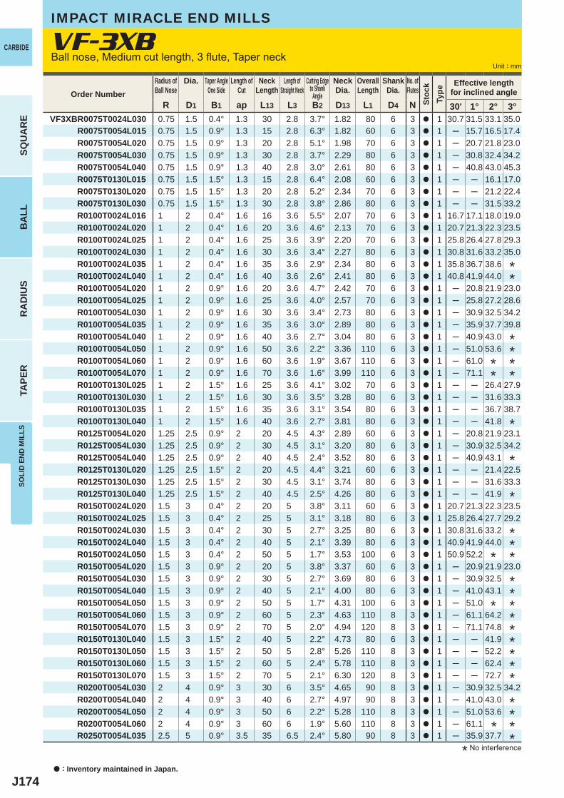
J174
R D1 B1 ap L13 L3 B2 D13 L1 D4 N 30' 1° 2° 3°VF3XBR0075T0024L030 0.75 1.5 0.4° 1.3 30 2.8 3.7° 1.82 80 6 3 a 1 30.7 31.5 33.1 35.0
R0075T0054L015 0.75 1.5 0.9° 1.3 15 2.8 6.3° 1.82 60 6 3 a 1 ─ 15.7 16.5 17.4 R0075T0054L020 0.75 1.5 0.9° 1.3 20 2.8 5.1° 1.98 70 6 3 a 1 ─ 20.7 21.8 23.0 R0075T0054L030 0.75 1.5 0.9° 1.3 30 2.8 3.7° 2.29 80 6 3 a 1 ─ 30.8 32.4 34.2
R0075T0054L040 0.75 1.5 0.9° 1.3 40 2.8 3.0° 2.61 80 6 3 a 1 ─ 40.8 43.0 45.3 R0075T0130L015 0.75 1.5 1.5° 1.3 15 2.8 6.4° 2.08 60 6 3 a 1 ─ ─ 16.1 17.0 R0075T0130L020 0.75 1.5 1.5° 1.3 20 2.8 5.2° 2.34 70 6 3 a 1 ─ ─ 21.2 22.4 R0075T0130L030 0.75 1.5 1.5° 1.3 30 2.8 3.8° 2.86 80 6 3 a 1 ─ ─ 31.5 33.2 R0100T0024L016 1 2 0.4° 1.6 16 3.6 5.5° 2.07 70 6 3 a 1 16.7 17.1 18.0 19.0 R0100T0024L020 1 2 0.4° 1.6 20 3.6 4.6° 2.13 70 6 3 a 1 20.7 21.3 22.3 23.5 R0100T0024L025 1 2 0.4° 1.6 25 3.6 3.9° 2.20 70 6 3 a 1 25.8 26.4 27.8 29.3 R0100T0024L030 1 2 0.4° 1.6 30 3.6 3.4° 2.27 80 6 3 a 1 30.8 31.6 33.2 35.0 R0100T0024L035 1 2 0.4° 1.6 35 3.6 2.9° 2.34 80 6 3 a 1 35.8 36.7 38.6 R0100T0024L040 1 2 0.4° 1.6 40 3.6 2.6° 2.41 80 6 3 a 1 40.8 41.9 44.0 R0100T0054L020 1 2 0.9° 1.6 20 3.6 4.7° 2.42 70 6 3 a 1 ─ 20.8 21.9 23.0 R0100T0054L025 1 2 0.9° 1.6 25 3.6 4.0° 2.57 70 6 3 a 1 ─ 25.8 27.2 28.6 R0100T0054L030 1 2 0.9° 1.6 30 3.6 3.4° 2.73 80 6 3 a 1 ─ 30.9 32.5 34.2 R0100T0054L035 1 2 0.9° 1.6 35 3.6 3.0° 2.89 80 6 3 a 1 ─ 35.9 37.7 39.8 R0100T0054L040 1 2 0.9° 1.6 40 3.6 2.7° 3.04 80 6 3 a 1 ─ 40.9 43.0 R0100T0054L050 1 2 0.9° 1.6 50 3.6 2.2° 3.36 110 6 3 a 1 ─ 51.0 53.6 R0100T0054L060 1 2 0.9° 1.6 60 3.6 1.9° 3.67 110 6 3 a 1 ─ 61.0 R0100T0054L070 1 2 0.9° 1.6 70 3.6 1.6° 3.99 110 6 3 a 1 ─ 71.1 R0100T0130L025 1 2 1.5° 1.6 25 3.6 4.1° 3.02 70 6 3 a 1 ─ ─ 26.4 27.9 R0100T0130L030 1 2 1.5° 1.6 30 3.6 3.5° 3.28 80 6 3 a 1 ─ ─ 31.6 33.3 R0100T0130L035 1 2 1.5° 1.6 35 3.6 3.1° 3.54 80 6 3 a 1 ─ ─ 36.7 38.7 R0100T0130L040 1 2 1.5° 1.6 40 3.6 2.7° 3.81 80 6 3 a 1 ─ ─ 41.8 R0125T0054L020 1.25 2.5 0.9° 2 20 4.5 4.3° 2.89 60 6 3 a 1 ─ 20.8 21.9 23.1 R0125T0054L030 1.25 2.5 0.9° 2 30 4.5 3.1° 3.20 80 6 3 a 1 ─ 30.9 32.5 34.2 R0125T0054L040 1.25 2.5 0.9° 2 40 4.5 2.4° 3.52 80 6 3 a 1 ─ 40.9 43.1 R0125T0130L020 1.25 2.5 1.5° 2 20 4.5 4.4° 3.21 60 6 3 a 1 ─ ─ 21.4 22.5 R0125T0130L030 1.25 2.5 1.5° 2 30 4.5 3.1° 3.74 80 6 3 a 1 ─ ─ 31.6 33.3 R0125T0130L040 1.25 2.5 1.5° 2 40 4.5 2.5° 4.26 80 6 3 a 1 ─ ─ 41.9 R0150T0024L020 1.5 3 0.4° 2 20 5 3.8° 3.11 60 6 3 a 1 20.7 21.3 22.3 23.5 R0150T0024L025 1.5 3 0.4° 2 25 5 3.1° 3.18 80 6 3 a 1 25.8 26.4 27.7 29.2 R0150T0024L030 1.5 3 0.4° 2 30 5 2.7° 3.25 80 6 3 a 1 30.8 31.6 33.2 R0150T0024L040 1.5 3 0.4° 2 40 5 2.1° 3.39 80 6 3 a 1 40.9 41.9 44.0 R0150T0024L050 1.5 3 0.4° 2 50 5 1.7° 3.53 100 6 3 a 1 50.9 52.2 R0150T0054L020 1.5 3 0.9° 2 20 5 3.8° 3.37 60 6 3 a 1 ─ 20.9 21.9 23.0 R0150T0054L030 1.5 3 0.9° 2 30 5 2.7° 3.69 80 6 3 a 1 ─ 30.9 32.5 R0150T0054L040 1.5 3 0.9° 2 40 5 2.1° 4.00 80 6 3 a 1 ─ 41.0 43.1 R0150T0054L050 1.5 3 0.9° 2 50 5 1.7° 4.31 100 6 3 a 1 ─ 51.0 R0150T0054L060 1.5 3 0.9° 2 60 5 2.3° 4.63 110 8 3 a 1 ─ 61.1 64.2
R0150T0054L070 1.5 3 0.9° 2 70 5 2.0° 4.94 120 8 3 a 1 ─ 71.1 74.8 R0150T0130L040 1.5 3 1.5° 2 40 5 2.2° 4.73 80 6 3 a 1 ─ ─ 41.9 R0150T0130L050 1.5 3 1.5° 2 50 5 2.8° 5.26 110 8 3 a 1 ─ ─ 52.2 R0150T0130L060 1.5 3 1.5° 2 60 5 2.4° 5.78 110 8 3 a 1 ─ ─ 62.4 R0150T0130L070 1.5 3 1.5° 2 70 5 2.1° 6.30 120 8 3 a 1 ─ ─ 72.7 R0200T0054L030 2 4 0.9° 3 30 6 3.5° 4.65 90 8 3 a 1 ─ 30.9 32.5 34.2 R0200T0054L040 2 4 0.9° 3 40 6 2.7° 4.97 90 8 3 a 1 ─ 41.0 43.0 R0200T0054L050 2 4 0.9° 3 50 6 2.2° 5.28 110 8 3 a 1 ─ 51.0 53.6 R0200T0054L060 2 4 0.9° 3 60 6 1.9° 5.60 110 8 3 a 1 ─ 61.1 R0250T0054L035 2.5 5 0.9° 3.5 35 6.5 2.4° 5.80 90 8 3 a 1 ─ 35.9 37.7
a : Inventory maintained in Japan.
CARBIDE
SQU
AR
EB
ALL
RA
DIU
STA
PER
SOLI
D E
ND
MIL
LS
Unit : mm
Order NumberRadius ofBall Nose
Dia. Taper AngleOne Side
Length ofCut
NeckLength
Length ofStraight Neck
Cutting Edgeto Shank
Angle
NeckDia.
OverallLength
ShankDia.
No. ofFlutes
Stoc
kTy
pe
Effective lengthfor inclined angle
* No interference
**
******
*
*
*
****
**********
****
VF-3XBBall nose, Medium cut length, 3 flute, Taper neck
IMPACT MIRACLE END MILLS
*
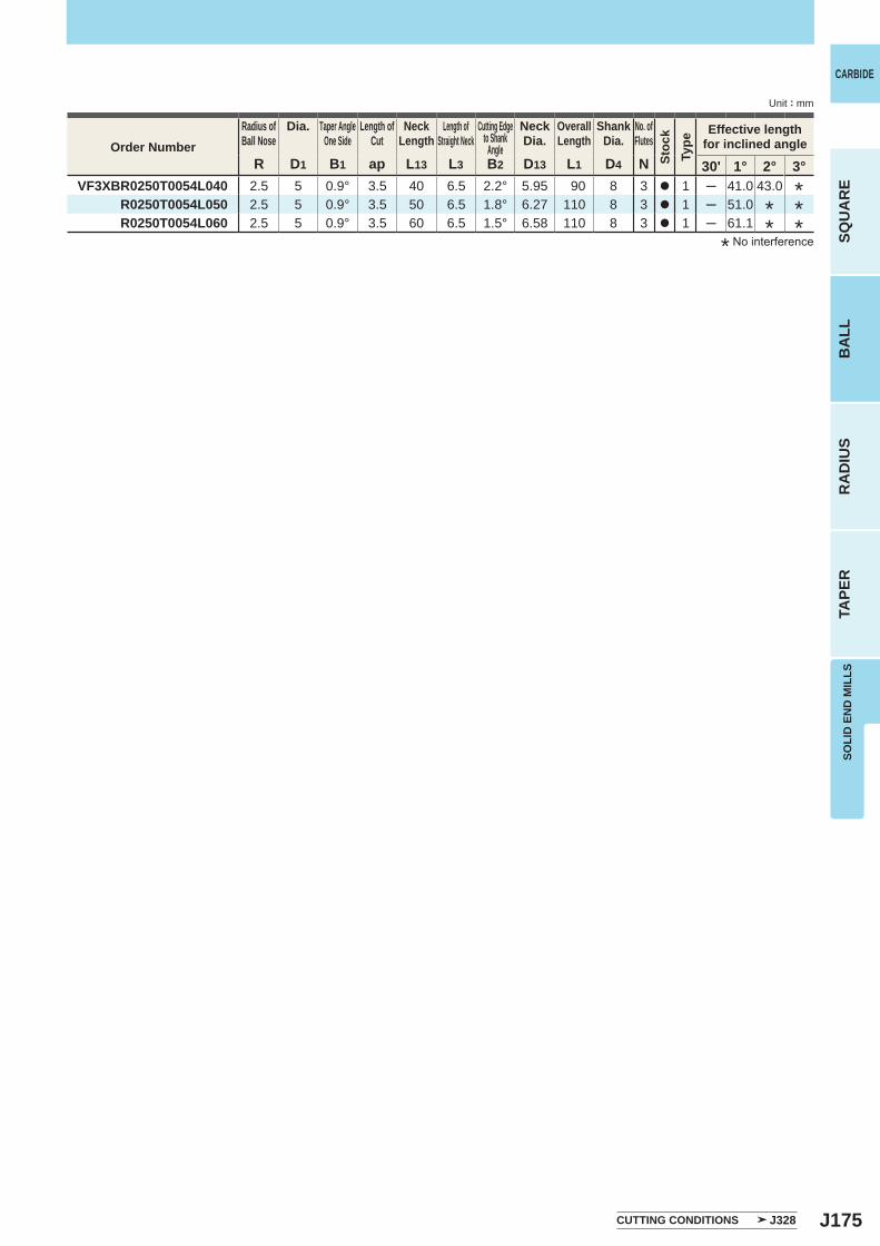
J175
R D1 B1 ap L13 L3 B2 D13 L1 D4 N 30' 1° 2° 3°VF3XBR0250T0054L040 2.5 5 0.9° 3.5 40 6.5 2.2° 5.95 90 8 3 a 1 ─ 41.0 43.0
R0250T0054L050 2.5 5 0.9° 3.5 50 6.5 1.8° 6.27 110 8 3 a 1 ─ 51.0 R0250T0054L060 2.5 5 0.9° 3.5 60 6.5 1.5° 6.58 110 8 3 a 1 ─ 61.1
SOLI
D E
ND
MIL
LS
CARBIDE
SQU
AR
EB
ALL
RA
DIU
STA
PER
Unit : mm
CUTTING CONDITIONS J328
Order NumberRadius ofBall Nose
Dia. Taper AngleOne Side
Length ofCut
NeckLength
Length ofStraight Neck
Cutting Edgeto Shank
Angle
NeckDia.
OverallLength
ShankDia.
No. ofFlutes
Stoc
kTy
pe
Effective lengthfor inclined angle
*****
* No interference
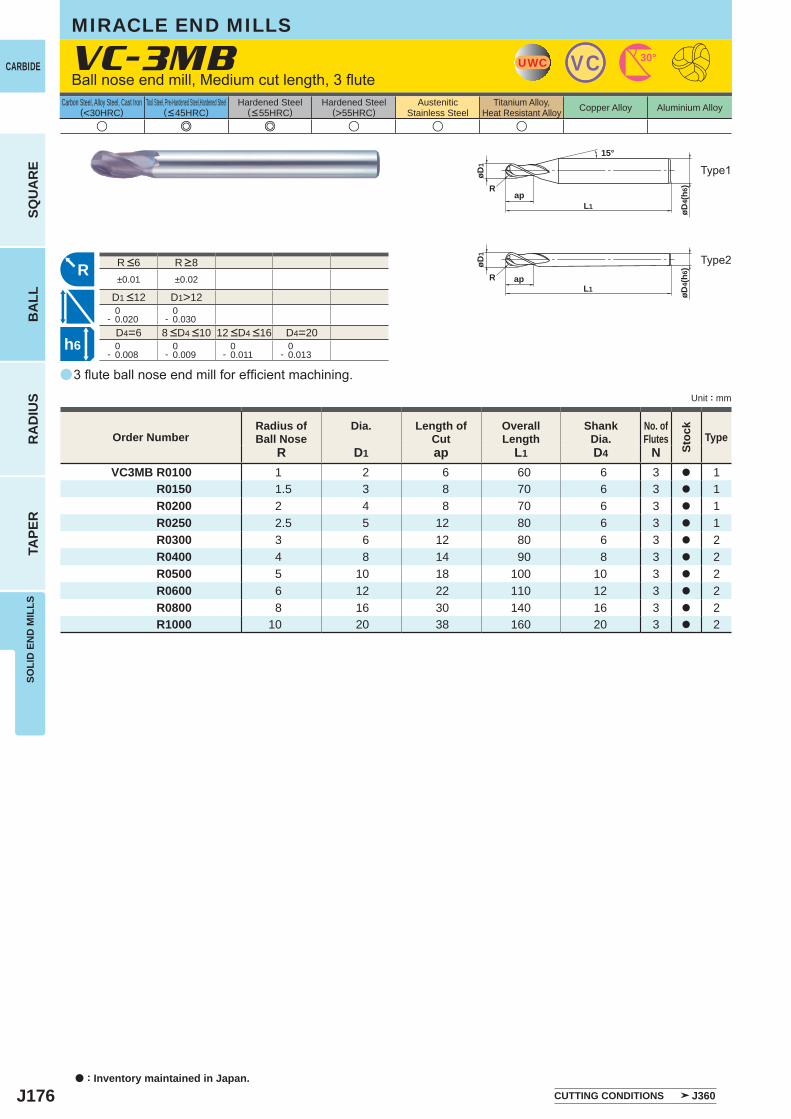
J176
a
u e e u u u
VC-3MB
R D1 ap L1 D4 NVC3MB R0100 1 2 6 60 6 3 a 1
R0150 1.5 3 8 70 6 3 a 1R0200 2 4 8 70 6 3 a 1R0250 2.5 5 12 80 6 3 a 1R0300 3 6 12 80 6 3 a 2R0400 4 8 14 90 8 3 a 2R0500 5 10 18 100 10 3 a 2R0600 6 12 22 110 12 3 a 2R0800 8 16 30 140 16 3 a 2R1000 10 20 38 160 20 3 a 2
±0.01 ±0.02
D1>12 0- 0.020
0- 0.030
D4=6 D4=20 0- 0.008
0- 0.009
0- 0.011
0- 0.013
UWC VC 30°
øD4(
h6)
L1
øD1
Rap
15°
R
øD4(
h6)
L1
øD1
R ap
h6
a : Inventory maintained in Japan.
CARBIDE
SQU
AR
EB
ALL
RA
DIU
STA
PER
SOLI
D E
ND
MIL
LS
Unit : mm
Carbon Steel, Alloy Steel, Cast Iron(<30HRC)
Tool Steel, Pre-Hardened Steel,Hardened Steel(<45HRC)
Hardened Steel(<55HRC)
Hardened Steel(>55HRC)
AusteniticStainless Steel
Titanium Alloy,Heat Resistant Alloy Copper Alloy Aluminium Alloy
MIRACLE END MILLS
3 flute ball nose end mill for efficient machining.
CUTTING CONDITIONS J360
Order NumberRadius ofBall Nose
Dia. Length ofCut
OverallLength
ShankDia.
No. ofFlutes
Stoc
k
Type
8 <D4 <10 12 <D4 <16
R <6 R >8
D1 <12
Ball nose end mill, Medium cut length, 3 flute
Type1
Type2
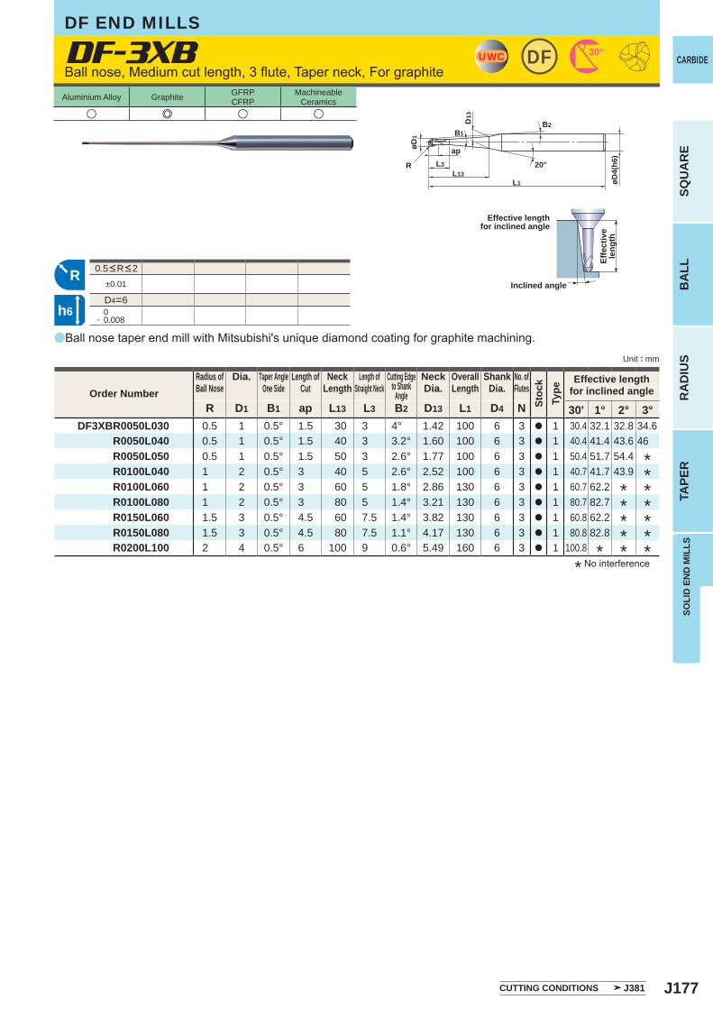
J177
a
DF-3XB
u e u u
R D1 B1 ap L13 L3 B2 D13 L1 D4 N 30' 1° 2° 3°DF3XBR0050L030 0.5 1 0.5° 1.5 30 3 4° 1.42 100 6 3 a 1 30.4 32.1 32.8 34.6
R0050L040 0.5 1 0.5° 1.5 40 3 3.2° 1.60 100 6 3 a 1 40.4 41.4 43.6 46 R0050L050 0.5 1 0.5° 1.5 50 3 2.6° 1.77 100 6 3 a 1 50.4 51.7 54.4R0100L040 1 2 0.5° 3 40 5 2.6° 2.52 100 6 3 a 1 40.7 41.7 43.9R0100L060 1 2 0.5° 3 60 5 1.8° 2.86 130 6 3 a 1 60.7 62.2R0100L080 1 2 0.5° 3 80 5 1.4° 3.21 130 6 3 a 1 80.7 82.7R0150L060 1.5 3 0.5° 4.5 60 7.5 1.4° 3.82 130 6 3 a 1 60.8 62.2R0150L080 1.5 3 0.5° 4.5 80 7.5 1.1° 4.17 130 6 3 a 1 80.8 82.8R0200L100 2 4 0.5° 6 100 9 0.6° 5.49 160 6 3 a 1 100.8
±0.01
D4=6 0- 0.008
UWC 30°DF
L1
apøD1
L13L3R
B1B2
20°
D13
øD4(
h6)
R
h6
Unit : mm
Aluminium Alloy Graphite GFRPCFRP
MachineableCeramics
SOLI
D E
ND
MIL
LS
CARBIDE
SQU
AR
EB
ALL
RA
DIU
STA
PER
Ball nose, Medium cut length, 3 flute, Taper neck, For graphite
0.5<R<2
Effective lengthfor inclined angle
Inclined angle
Effe
ctiv
ele
ngth
* No interference
Order NumberRadius ofBall Nose
Dia. Taper AngleOne Side
Length ofCut
NeckLength
Length ofStraight Neck
Cutting Edgeto Shank
Angle
NeckDia.
OverallLength
ShankDia.
No. ofFlutes
Stoc
kTy
pe
Effective lengthfor inclined angle
Ball nose taper end mill with Mitsubishi's unique diamond coating for graphite machining.
*
**
*
**
**
*****
CUTTING CONDITIONS J381
DF END MILLS
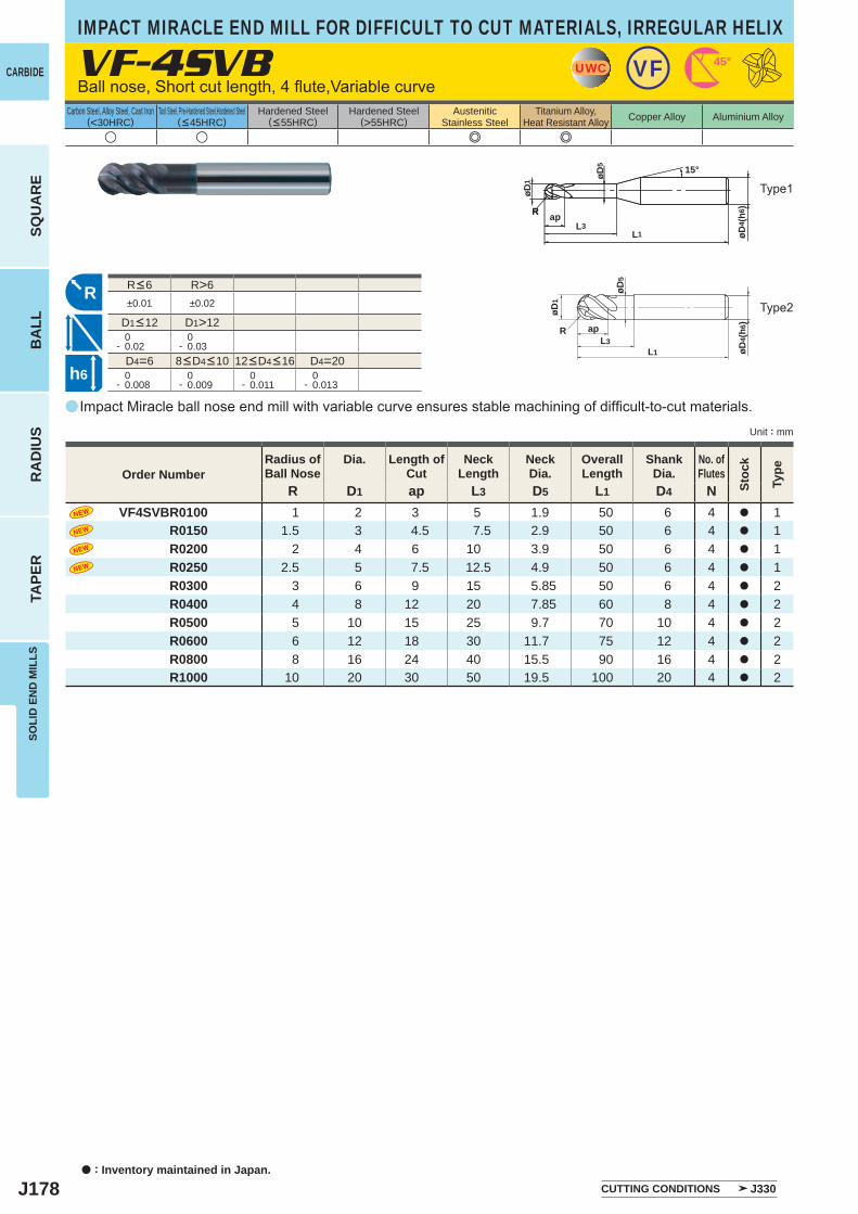
J178
a
VF-4SVB
R D1 ap L3 D5 L1 D4 N VF4SVBR0100 1 2 3 5 1.9 50 6 4 a 1 R0150 1.5 3 4.5 7.5 2.9 50 6 4 a 1 R0200 2 4 6 10 3.9 50 6 4 a 1 R0250 2.5 5 7.5 12.5 4.9 50 6 4 a 1
R0300 3 6 9 15 5.85 50 6 4 a 2R0400 4 8 12 20 7.85 60 8 4 a 2R0500 5 10 15 25 9.7 70 10 4 a 2R0600 6 12 18 30 11.7 75 12 4 a 2R0800 8 16 24 40 15.5 90 16 4 a 2R1000 10 20 30 50 19.5 100 20 4 a 2
u u e e
R>6±0.01 ±0.02
D1>12 0- 0.02
0- 0.03
D4=6 D4=20 0- 0.008
0- 0.009
0- 0.011
0- 0.013
UWC VF 45°
øD1
øD5
ap
L1L3
øD4(
h6)
R
R
h6
apL3
L1
øD1
øD4 (
h6)
øD5 15°
RR
a : Inventory maintained in Japan.
CARBIDE
SQU
AR
EB
ALL
RA
DIU
STA
PER
SOLI
D E
ND
MIL
LS
Unit : mm
Carbon Steel, Alloy Steel, Cast Iron(<30HRC)
Tool Steel, Pre-Hardened Steel,Hardened Steel(<45HRC)
Hardened Steel(<55HRC)
Hardened Steel(>55HRC)
AusteniticStainless Steel
Titanium Alloy,Heat Resistant Alloy Copper Alloy Aluminium Alloy
Impact Miracle ball nose end mill with variable curve ensures stable machining of difficult-to-cut materials.
Ball nose, Short cut length, 4 flute,Variable curve
IMPACT MIRACLE END MILL FOR DIFFICULT TO CUT MATERIALS, IRREGULAR HELIX
Type2
CUTTING CONDITIONS J330
Order NumberRadius ofBall Nose
Dia. Length ofCut
NeckLength
NeckDia.
OverallLength
ShankDia.
No. ofFlutes
Stoc
k
Type
Type1
8<D4<10 12<D4<16
R<6
D1<12
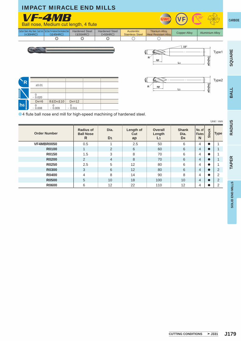
J179
a
VF-4MB
R D1 ap L1 D4 NVF4MBR0050 0.5 1 2.5 50 6 4 a 1
R0100 1 2 6 60 6 4 a 1 R0150 1.5 3 8 70 6 4 a 1 R0200 2 4 8 70 6 4 a 1 R0250 2.5 5 12 80 6 4 a 1 R0300 3 6 12 80 6 4 a 2 R0400 4 8 14 90 8 4 a 2 R0500 5 10 18 100 10 4 a 2 R0600 6 12 22 110 12 4 a 2
e e e u u
±0.01
0- 0.020
D4=6 D4=12 0- 0.008
0- 0.009
0- 0.011
UWC VF 30°
øD4(
h6)
L1
øD1
Rap
15°
RL1
R ap
øD4(
h6)
øD1
h6
SOLI
D E
ND
MIL
LS
CARBIDE
SQU
AR
EB
ALL
RA
DIU
STA
PER
Unit : mm
Carbon Steel, Alloy Steel, Cast Iron(<30HRC)
Tool Steel, Pre-Hardened Steel,Hardened Steel(<45HRC)
Hardened Steel(<55HRC)
Hardened Steel(>55HRC)
AusteniticStainless Steel
Titanium Alloy,Heat Resistant Alloy Copper Alloy Aluminium Alloy
4 flute ball nose end mill for high-speed machining of hardened steel.
Ball nose, Medium cut length, 4 flute
CUTTING CONDITIONS J331
Order NumberRadius ofBall Nose
Dia. Length ofCut
OverallLength
ShankDia.
No. ofFlutes
Stoc
k
Type
IMPACT MIRACLE END MILLS
8<D4<10
Type1
Type2
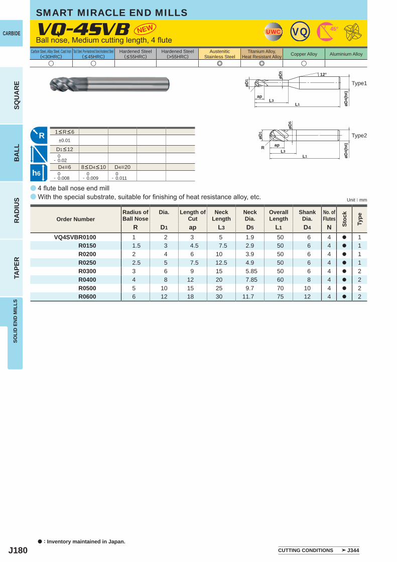
J180
±0.01
0- 0.02
D4=6 D4=20 0- 0.008
0- 0.009
0- 0.011
u u e e u
R D1 ap L3 D5 L1 D4 NVQ4SVBR0100 1 2 3 5 1.9 50 6 4 a 1
R0150 1.5 3 4.5 7.5 2.9 50 6 4 a 1R0200 2 4 6 10 3.9 50 6 4 a 1R0250 2.5 5 7.5 12.5 4.9 50 6 4 a 1R0300 3 6 9 15 5.85 50 6 4 a 2R0400 4 8 12 20 7.85 60 8 4 a 2R0500 5 10 15 25 9.7 70 10 4 a 2R0600 6 12 18 30 11.7 75 12 4 a 2
NEW
a
a
VQ-4SVB
R
apL3
L1
øD1
øD4 (
h6)
øD5 12°
R apL3
L1
øD1
øD5
øD4 (
h6)
UWC 45°VQ
h6
a : Inventory maintained in Japan.
CARBIDE
SQU
AR
EB
ALL
RA
DIU
STA
PER
SOLI
D E
ND
MIL
LS
Unit : mm
Carbon Steel, Alloy Steel, Cast Iron(<30HRC)
Tool Steel, Pre-Hardened Steel,Hardened Steel(<45HRC)
Hardened Steel(<55HRC)
Hardened Steel(>55HRC)
AusteniticStainless Steel
Titanium Alloy,Heat Resistant Alloy Copper Alloy Aluminium Alloy
8<D4<10
1<R<6
D1<12
Type2
Type1
4 flute ball nose end millWith the special substrate, suitable for finishing of heat resistance alloy, etc.
Order NumberRadius ofBall Nose
Dia. Length ofCut
NeckLength
NeckDia.
OverallLength
ShankDia.
No. ofFlutes
Stoc
k
Type
CUTTING CONDITIONS J344
SMART MIRACLE END MILLS
Ball nose, Medium cutting length, 4 flute
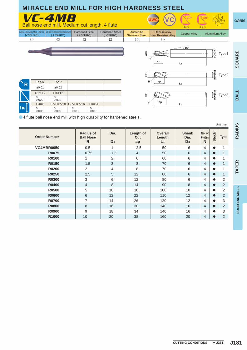
J181
u e e e u u
a
VC-4MB
R D1 ap L1 D4 NVC4MBR0050 0.5 1 2.5 50 6 4 a 1
R0075 0.75 1.5 4 50 6 4 a 1R0100 1 2 6 60 6 4 a 1R0150 1.5 3 8 70 6 4 a 1R0200 2 4 8 70 6 4 a 1R0250 2.5 5 12 80 6 4 a 1R0300 3 6 12 80 6 4 a 2R0400 4 8 14 90 8 4 a 2R0500 5 10 18 100 10 4 a 2R0600 6 12 22 110 12 4 a 2R0700 7 14 26 120 12 4 a 3R0800 8 16 30 140 16 4 a 2R0900 9 18 34 140 16 4 a 3R1000 10 20 38 160 20 4 a 2
±0.01 ±0.02
D1>12 0- 0.020
0- 0.030
D4=6 D4=20 0- 0.008
0- 0.009
0- 0.011
0- 0.013
UWC VC 30°20°
L1R ap
øD4(
h6)
øD1
L1R ap
øD4(
h6)
øD1
øD4(
h6)
L1
øD1
Rap
15°
R<3
R
h6
SOLI
D E
ND
MIL
LS
CARBIDE
SQU
AR
EB
ALL
RA
DIU
STA
PER
Unit : mm
Carbon Steel, Alloy Steel, Cast Iron(<30HRC)
Tool Steel, Pre-Hardened Steel,Hardened Steel(<45HRC)
Hardened Steel(<55HRC)
Hardened Steel(>55HRC)
AusteniticStainless Steel
Titanium Alloy,Heat Resistant Alloy Copper Alloy Aluminium Alloy
MIRACLE END MILL FOR HIGH HARDNESS STEEL
4 flute ball nose end mill with high durability for hardened steels.
Ball nose end mill, Medium cut length, 4 flute
Type2
Type3
Type1
CUTTING CONDITIONS J361
Order NumberRadius ofBall Nose
Dia. Length ofCut
OverallLength
ShankDia.
No. ofFlutes
Stoc
k
Type
R > 3
8<D4<10 12<D4<16
R<6 R>7
D1<12
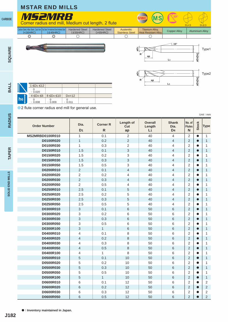
J182
a
MS2MRB
e e u u u
D1 R ap L1 D4 NMS2MRBD0100R010 1 0.1 2 40 4 2 a 1
D0100R020 1 0.2 2 40 4 2 a 1D0100R030 1 0.3 2 40 4 2 a 1D0150R010 1.5 0.1 3 40 4 2 a 1D0150R020 1.5 0.2 3 40 4 2 a 1D0150R030 1.5 0.3 3 40 4 2 a 1D0150R050 1.5 0.5 3 40 4 2 a 1D0200R010 2 0.1 4 40 4 2 a 1D0200R020 2 0.2 4 40 4 2 a 1D0200R030 2 0.3 4 40 4 2 a 1D0200R050 2 0.5 4 40 4 2 a 1D0250R010 2.5 0.1 5 40 4 2 a 1D0250R020 2.5 0.2 5 40 4 2 a 1D0250R030 2.5 0.3 5 40 4 2 a 1D0250R050 2.5 0.5 5 40 4 2 a 1D0300R010 3 0.1 6 50 6 2 a 1D0300R020 3 0.2 6 50 6 2 a 1D0300R030 3 0.3 6 50 6 2 a 1D0300R050 3 0.5 6 50 6 2 a 1D0300R100 3 1 6 50 6 2 a 1D0400R010 4 0.1 8 50 6 2 a 1D0400R020 4 0.2 8 50 6 2 a 1D0400R030 4 0.3 8 50 6 2 a 1D0400R050 4 0.5 8 50 6 2 a 1D0400R100 4 1 8 50 6 2 a 1D0500R010 5 0.1 10 50 6 2 a 1D0500R020 5 0.2 10 50 6 2 a 1D0500R030 5 0.3 10 50 6 2 a 1D0500R050 5 0.5 10 50 6 2 a 1D0500R100 5 1 10 50 6 2 a 1D0600R010 6 0.1 12 50 6 2 a 2D0600R020 6 0.2 12 50 6 2 a 2D0600R030 6 0.3 12 50 6 2 a 2D0600R050 6 0.5 12 50 6 2 a 2
D1<3
0- 0.020
D4=12 0- 0.008
0- 0.009
0- 0.011
UWC MS 30°
apL1
øD1
øD4(
h6)R
15°
øD4(
h6)
øD1
apL1
R
h6
a : Inventory maintained in Japan.
CARBIDE
SQU
AR
EB
ALL
RA
DIU
STA
PER
SOLI
D E
ND
MIL
LS
Unit : mm
Carbon Steel, Alloy Steel, Cast Iron(<30HRC)
Tool Steel, Pre-Hardened Steel,Hardened Steel(<45HRC)
Hardened Steel(<55HRC)
Hardened Steel(>55HRC)
AusteniticStainless Steel
Titanium Alloy,Heat Resistant Alloy Copper Alloy Aluminium Alloy
2 flute corner radius end mill for general use.
Corner radius end mill, Medium cut length, 2 flute
MSTAR END MILLS
Order Number Dia. Corner R Length of Cut
Overall Length
Shank Dia.
No. ofFlutes
Stoc
k
Type
D1>3
4 <D4 <6 8 <D4 <10
1 <D1 <12
Type1
Type2
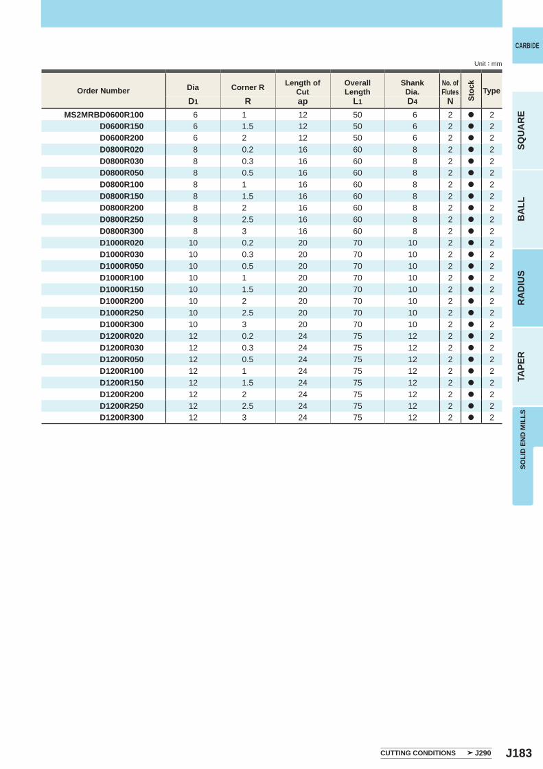
J183
D1 R ap L1 D4 NMS2MRBD0600R100 6 1 12 50 6 2 a 2
D0600R150 6 1.5 12 50 6 2 a 2D0600R200 6 2 12 50 6 2 a 2D0800R020 8 0.2 16 60 8 2 a 2D0800R030 8 0.3 16 60 8 2 a 2D0800R050 8 0.5 16 60 8 2 a 2D0800R100 8 1 16 60 8 2 a 2D0800R150 8 1.5 16 60 8 2 a 2D0800R200 8 2 16 60 8 2 a 2D0800R250 8 2.5 16 60 8 2 a 2D0800R300 8 3 16 60 8 2 a 2D1000R020 10 0.2 20 70 10 2 a 2D1000R030 10 0.3 20 70 10 2 a 2D1000R050 10 0.5 20 70 10 2 a 2D1000R100 10 1 20 70 10 2 a 2D1000R150 10 1.5 20 70 10 2 a 2D1000R200 10 2 20 70 10 2 a 2D1000R250 10 2.5 20 70 10 2 a 2D1000R300 10 3 20 70 10 2 a 2D1200R020 12 0.2 24 75 12 2 a 2D1200R030 12 0.3 24 75 12 2 a 2D1200R050 12 0.5 24 75 12 2 a 2D1200R100 12 1 24 75 12 2 a 2D1200R150 12 1.5 24 75 12 2 a 2D1200R200 12 2 24 75 12 2 a 2D1200R250 12 2.5 24 75 12 2 a 2D1200R300 12 3 24 75 12 2 a 2
CARBIDE
SQU
AR
EB
ALL
RA
DIU
STA
PER
SOLI
D E
ND
MIL
LS
Unit : mm
Order Number Dia Corner R Length of Cut
Overall Length
Shank Dia.
No. ofFlutes
Stoc
k
Type
CUTTING CONDITIONS J290
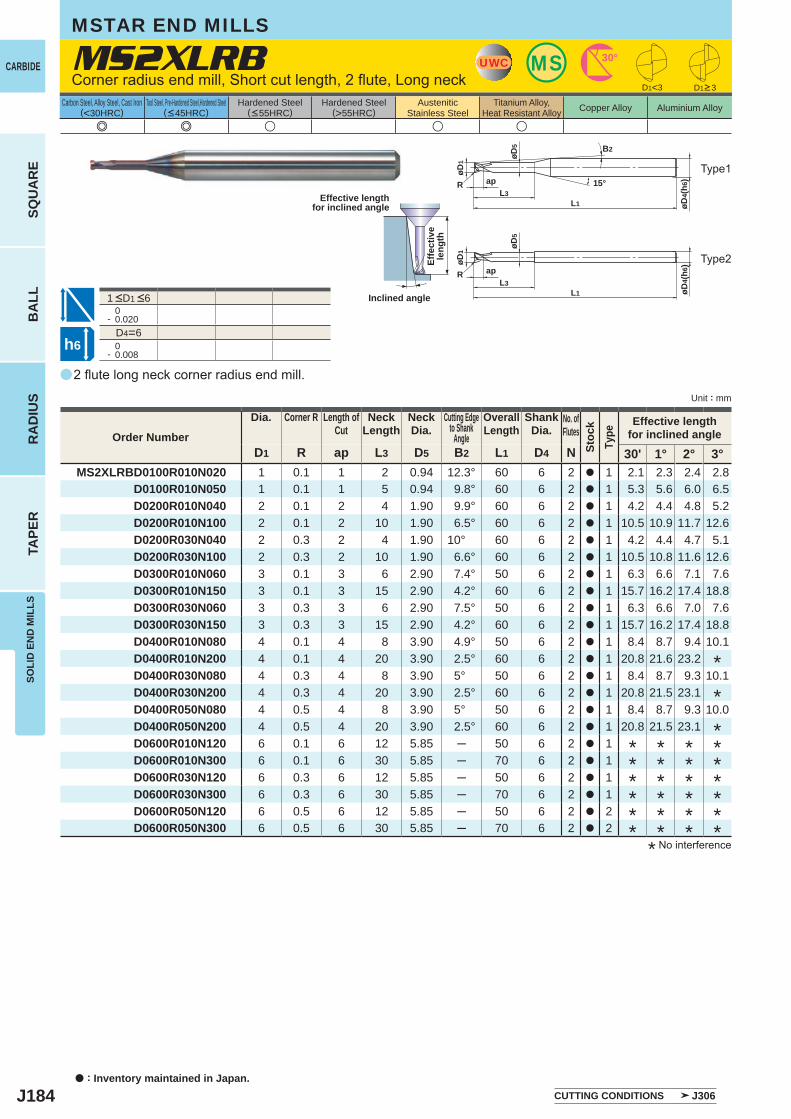
J184
a
e e u u u
MS2XLRB
D1 R ap L3 D5 B2 L1 D4 N 30' 1° 2° 3°MS2XLRBD0100R010N020 1 0.1 1 2 0.94 12.3° 60 6 2 a 1 2.1 2.3 2.4 2.8
D0100R010N050 1 0.1 1 5 0.94 9.8° 60 6 2 a 1 5.3 5.6 6.0 6.5D0200R010N040 2 0.1 2 4 1.90 9.9° 60 6 2 a 1 4.2 4.4 4.8 5.2D0200R010N100 2 0.1 2 10 1.90 6.5° 60 6 2 a 1 10.5 10.9 11.7 12.6D0200R030N040 2 0.3 2 4 1.90 10° 60 6 2 a 1 4.2 4.4 4.7 5.1D0200R030N100 2 0.3 2 10 1.90 6.6° 60 6 2 a 1 10.5 10.8 11.6 12.6D0300R010N060 3 0.1 3 6 2.90 7.4° 50 6 2 a 1 6.3 6.6 7.1 7.6D0300R010N150 3 0.1 3 15 2.90 4.2° 60 6 2 a 1 15.7 16.2 17.4 18.8D0300R030N060 3 0.3 3 6 2.90 7.5° 50 6 2 a 1 6.3 6.6 7.0 7.6D0300R030N150 3 0.3 3 15 2.90 4.2° 60 6 2 a 1 15.7 16.2 17.4 18.8D0400R010N080 4 0.1 4 8 3.90 4.9° 50 6 2 a 1 8.4 8.7 9.4 10.1D0400R010N200 4 0.1 4 20 3.90 2.5° 60 6 2 a 1 20.8 21.6 23.2D0400R030N080 4 0.3 4 8 3.90 5° 50 6 2 a 1 8.4 8.7 9.3 10.1D0400R030N200 4 0.3 4 20 3.90 2.5° 60 6 2 a 1 20.8 21.5 23.1D0400R050N080 4 0.5 4 8 3.90 5° 50 6 2 a 1 8.4 8.7 9.3 10.0D0400R050N200 4 0.5 4 20 3.90 2.5° 60 6 2 a 1 20.8 21.5 23.1D0600R010N120 6 0.1 6 12 5.85 ─ 50 6 2 a 1D0600R010N300 6 0.1 6 30 5.85 ─ 70 6 2 a 1D0600R030N120 6 0.3 6 12 5.85 ─ 50 6 2 a 1D0600R030N300 6 0.3 6 30 5.85 ─ 70 6 2 a 1D0600R050N120 6 0.5 6 12 5.85 ─ 50 6 2 a 2D0600R050N300 6 0.5 6 30 5.85 ─ 70 6 2 a 2
D1<3
0- 0.020
D4=6 0- 0.008
UWC MS 30°
L3
øD5
ap
øD1
R
øD4(
h6)
L1
15°
B2
øD5
L1L3
ap
øD1
R
øD4(
h6)
h6
a : Inventory maintained in Japan.
CARBIDE
SQU
AR
EB
ALL
RA
DIU
STA
PER
SOLI
D E
ND
MIL
LS
Unit : mm
Carbon Steel, Alloy Steel, Cast Iron(<30HRC)
Tool Steel, Pre-Hardened Steel,Hardened Steel(<45HRC)
Hardened Steel(<55HRC)
Hardened Steel(>55HRC)
AusteniticStainless Steel
Titanium Alloy,Heat Resistant Alloy Copper Alloy Aluminium Alloy
2 flute long neck corner radius end mill.
Corner radius end mill, Short cut length, 2 flute, Long neck
MSTAR END MILLS
Effective lengthfor inclined angle
Inclined angle
Effe
ctiv
ele
ngth
D1>3
* No interference
Order Number
Dia. Corner R Length ofCut
NeckLength
NeckDia.
Cutting Edgeto Shank
Angle
OverallLength
ShankDia.
No. ofFlutes
Stoc
kTy
pe
Effective lengthfor inclined angle
*******
*
*
******
******
******
CUTTING CONDITIONS J306
1 <D1 <6
Type1
Type2
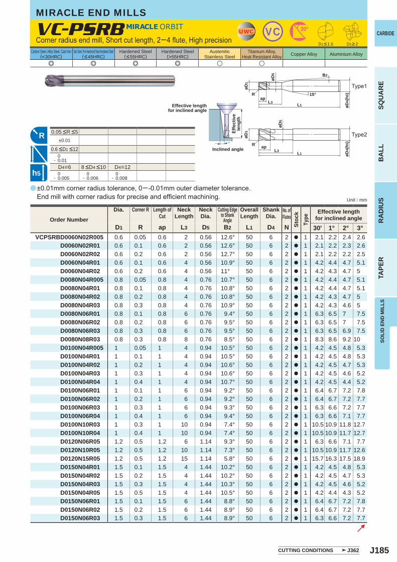
J185
a
e e e e u u
VC-PSRB
D1 R ap L3 D5 B2 L1 D4 N 30' 1° 2° 3°VCPSRBD0060N02R005 0.6 0.05 0.6 2 0.56 12.6° 50 6 2 a 1 2.1 2.2 2.4 2.6
D0060N02R01 0.6 0.1 0.6 2 0.56 12.6° 50 6 2 a 1 2.1 2.2 2.3 2.6D0060N02R02 0.6 0.2 0.6 2 0.56 12.7° 50 6 2 a 1 2.1 2.2 2.2 2.5D0060N04R01 0.6 0.1 0.6 4 0.56 10.9° 50 6 2 a 1 4.2 4.4 4.7 5.1D0060N04R02 0.6 0.2 0.6 4 0.56 11° 50 6 2 a 1 4.2 4.3 4.7 5D0080N04R005 0.8 0.05 0.8 4 0.76 10.7° 50 6 2 a 1 4.2 4.4 4.7 5.1D0080N04R01 0.8 0.1 0.8 4 0.76 10.8° 50 6 2 a 1 4.2 4.4 4.7 5.1D0080N04R02 0.8 0.2 0.8 4 0.76 10.8° 50 6 2 a 1 4.2 4.3 4.7 5D0080N04R03 0.8 0.3 0.8 4 0.76 10.9° 50 6 2 a 1 4.2 4.3 4.6 5D0080N06R01 0.8 0.1 0.8 6 0.76 9.4° 50 6 2 a 1 6.3 6.5 7 7.5D0080N06R02 0.8 0.2 0.8 6 0.76 9.5° 50 6 2 a 1 6.3 6.5 7 7.5D0080N06R03 0.8 0.3 0.8 6 0.76 9.5° 50 6 2 a 1 6.3 6.5 6.9 7.5D0080N08R03 0.8 0.3 0.8 8 0.76 8.5° 50 6 2 a 1 8.3 8.6 9.2 10D0100N04R005 1 0.05 1 4 0.94 10.5° 50 6 2 a 1 4.2 4.5 4.8 5.3D0100N04R01 1 0.1 1 4 0.94 10.5° 50 6 2 a 1 4.2 4.5 4.8 5.3D0100N04R02 1 0.2 1 4 0.94 10.6° 50 6 2 a 1 4.2 4.5 4.7 5.3D0100N04R03 1 0.3 1 4 0.94 10.6° 50 6 2 a 1 4.2 4.5 4.6 5.2D0100N04R04 1 0.4 1 4 0.94 10.7° 50 6 2 a 1 4.2 4.5 4.4 5.2D0100N06R01 1 0.1 1 6 0.94 9.2° 50 6 2 a 1 6.4 6.7 7.2 7.8D0100N06R02 1 0.2 1 6 0.94 9.2° 50 6 2 a 1 6.4 6.7 7.2 7.7D0100N06R03 1 0.3 1 6 0.94 9.3° 50 6 2 a 1 6.3 6.6 7.2 7.7D0100N06R04 1 0.4 1 6 0.94 9.4° 50 6 2 a 1 6.3 6.6 7.1 7.7D0100N10R03 1 0.3 1 10 0.94 7.4° 50 6 2 a 1 10.5 10.9 11.8 12.7D0100N10R04 1 0.4 1 10 0.94 7.4° 50 6 2 a 1 10.5 10.9 11.7 12.7D0120N06R05 1.2 0.5 1.2 6 1.14 9.3° 50 6 2 a 1 6.3 6.6 7.1 7.7D0120N10R05 1.2 0.5 1.2 10 1.14 7.3° 50 6 2 a 1 10.5 10.9 11.7 12.6D0120N15R05 1.2 0.5 1.2 15 1.14 5.8° 50 6 2 a 1 15.7 16.3 17.5 18.9D0150N04R01 1.5 0.1 1.5 4 1.44 10.2° 50 6 2 a 1 4.2 4.5 4.8 5.3D0150N04R02 1.5 0.2 1.5 4 1.44 10.2° 50 6 2 a 1 4.2 4.5 4.7 5.3D0150N04R03 1.5 0.3 1.5 4 1.44 10.3° 50 6 2 a 1 4.2 4.5 4.6 5.2D0150N04R05 1.5 0.5 1.5 4 1.44 10.5° 50 6 2 a 1 4.2 4.4 4.3 5.2D0150N06R01 1.5 0.1 1.5 6 1.44 8.8° 50 6 2 a 1 6.4 6.7 7.2 7.8D0150N06R02 1.5 0.2 1.5 6 1.44 8.9° 50 6 2 a 1 6.4 6.7 7.2 7.7D0150N06R03 1.5 0.3 1.5 6 1.44 8.9° 50 6 2 a 1 6.3 6.6 7.2 7.7
±0.01
0- 0.01
D4=6 D4=12 0- 0.005
0- 0.006
0- 0.008
UWC VC 30°
15°
øD5
øD4(
h5)
L1L3
ap
øD1
R
B2
L1L3
ap
øD5
øD4(
h5)
øD1
R
h5
R
CARBIDE
SQU
AR
EB
ALL
RA
DIU
STA
PER
SOLI
D E
ND
MIL
LS
Unit : mm
Carbon Steel, Alloy Steel, Cast Iron(<30HRC)
Tool Steel, Pre-Hardened Steel,Hardened Steel(<45HRC)
Hardened Steel(<55HRC)
Hardened Steel(>55HRC)
AusteniticStainless Steel
Titanium Alloy,Heat Resistant Alloy Copper Alloy Aluminium Alloy
MIRACLE END MILLS
±0.01mm corner radius tolerance, 0─-0.01mm outer diameter tolerance. End mill with corner radius for precise and efficient machining.
Corner radius end mill, Short cut length, 2─4 flute, High precision
Effective lengthfor inclined angle
Inclined angle
Effe
ctiv
ele
ngth
D1<1.5 D1>2
Order Number
Dia. Corner R Length ofCut
NeckLength
NeckDia.
Cutting Edgeto Shank
Angle
OverallLength
ShankDia.
No. ofFlutes
Stoc
kTy
pe
Effective lengthfor inclined angle
CUTTING CONDITIONS J362
8 <D4 <10
0.6 <D1 <12
0.05 <R <5
Type1
Type2
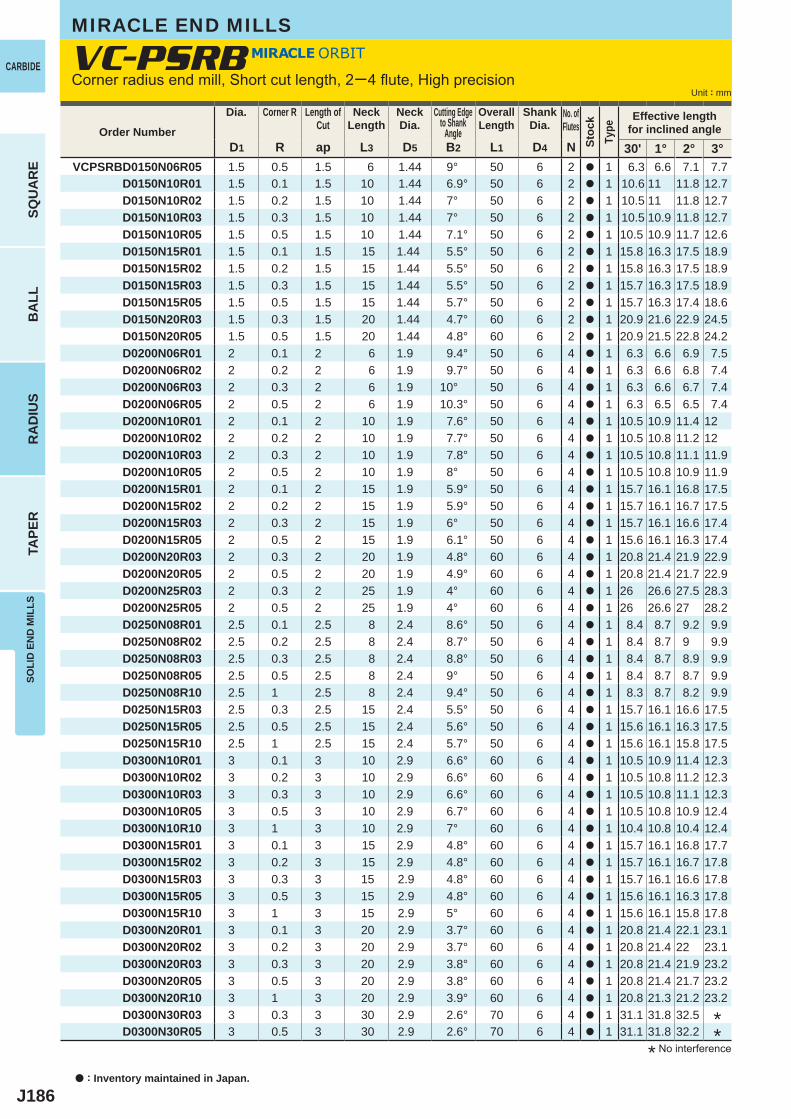
J186
D1 R ap L3 D5 B2 L1 D4 N 30' 1° 2° 3°VCPSRBD0150N06R05 1.5 0.5 1.5 6 1.44 9° 50 6 2 a 1 6.3 6.6 7.1 7.7
D0150N10R01 1.5 0.1 1.5 10 1.44 6.9° 50 6 2 a 1 10.6 11 11.8 12.7D0150N10R02 1.5 0.2 1.5 10 1.44 7° 50 6 2 a 1 10.5 11 11.8 12.7D0150N10R03 1.5 0.3 1.5 10 1.44 7° 50 6 2 a 1 10.5 10.9 11.8 12.7D0150N10R05 1.5 0.5 1.5 10 1.44 7.1° 50 6 2 a 1 10.5 10.9 11.7 12.6D0150N15R01 1.5 0.1 1.5 15 1.44 5.5° 50 6 2 a 1 15.8 16.3 17.5 18.9 D0150N15R02 1.5 0.2 1.5 15 1.44 5.5° 50 6 2 a 1 15.8 16.3 17.5 18.9 D0150N15R03 1.5 0.3 1.5 15 1.44 5.5° 50 6 2 a 1 15.7 16.3 17.5 18.9 D0150N15R05 1.5 0.5 1.5 15 1.44 5.7° 50 6 2 a 1 15.7 16.3 17.4 18.6 D0150N20R03 1.5 0.3 1.5 20 1.44 4.7° 60 6 2 a 1 20.9 21.6 22.9 24.5 D0150N20R05 1.5 0.5 1.5 20 1.44 4.8° 60 6 2 a 1 20.9 21.5 22.8 24.2 D0200N06R01 2 0.1 2 6 1.9 9.4° 50 6 4 a 1 6.3 6.6 6.9 7.5 D0200N06R02 2 0.2 2 6 1.9 9.7° 50 6 4 a 1 6.3 6.6 6.8 7.4 D0200N06R03 2 0.3 2 6 1.9 10° 50 6 4 a 1 6.3 6.6 6.7 7.4 D0200N06R05 2 0.5 2 6 1.9 10.3° 50 6 4 a 1 6.3 6.5 6.5 7.4 D0200N10R01 2 0.1 2 10 1.9 7.6° 50 6 4 a 1 10.5 10.9 11.4 12 D0200N10R02 2 0.2 2 10 1.9 7.7° 50 6 4 a 1 10.5 10.8 11.2 12 D0200N10R03 2 0.3 2 10 1.9 7.8° 50 6 4 a 1 10.5 10.8 11.1 11.9 D0200N10R05 2 0.5 2 10 1.9 8° 50 6 4 a 1 10.5 10.8 10.9 11.9 D0200N15R01 2 0.1 2 15 1.9 5.9° 50 6 4 a 1 15.7 16.1 16.8 17.5 D0200N15R02 2 0.2 2 15 1.9 5.9° 50 6 4 a 1 15.7 16.1 16.7 17.5 D0200N15R03 2 0.3 2 15 1.9 6° 50 6 4 a 1 15.7 16.1 16.6 17.4 D0200N15R05 2 0.5 2 15 1.9 6.1° 50 6 4 a 1 15.6 16.1 16.3 17.4 D0200N20R03 2 0.3 2 20 1.9 4.8° 60 6 4 a 1 20.8 21.4 21.9 22.9 D0200N20R05 2 0.5 2 20 1.9 4.9° 60 6 4 a 1 20.8 21.4 21.7 22.9 D0200N25R03 2 0.3 2 25 1.9 4° 60 6 4 a 1 26 26.6 27.5 28.3 D0200N25R05 2 0.5 2 25 1.9 4° 60 6 4 a 1 26 26.6 27 28.2 D0250N08R01 2.5 0.1 2.5 8 2.4 8.6° 50 6 4 a 1 8.4 8.7 9.2 9.9 D0250N08R02 2.5 0.2 2.5 8 2.4 8.7° 50 6 4 a 1 8.4 8.7 9 9.9 D0250N08R03 2.5 0.3 2.5 8 2.4 8.8° 50 6 4 a 1 8.4 8.7 8.9 9.9 D0250N08R05 2.5 0.5 2.5 8 2.4 9° 50 6 4 a 1 8.4 8.7 8.7 9.9 D0250N08R10 2.5 1 2.5 8 2.4 9.4° 50 6 4 a 1 8.3 8.7 8.2 9.9 D0250N15R03 2.5 0.3 2.5 15 2.4 5.5° 50 6 4 a 1 15.7 16.1 16.6 17.5 D0250N15R05 2.5 0.5 2.5 15 2.4 5.6° 50 6 4 a 1 15.6 16.1 16.3 17.5 D0250N15R10 2.5 1 2.5 15 2.4 5.7° 50 6 4 a 1 15.6 16.1 15.8 17.5 D0300N10R01 3 0.1 3 10 2.9 6.6° 60 6 4 a 1 10.5 10.9 11.4 12.3 D0300N10R02 3 0.2 3 10 2.9 6.6° 60 6 4 a 1 10.5 10.8 11.2 12.3 D0300N10R03 3 0.3 3 10 2.9 6.6° 60 6 4 a 1 10.5 10.8 11.1 12.3 D0300N10R05 3 0.5 3 10 2.9 6.7° 60 6 4 a 1 10.5 10.8 10.9 12.4 D0300N10R10 3 1 3 10 2.9 7° 60 6 4 a 1 10.4 10.8 10.4 12.4 D0300N15R01 3 0.1 3 15 2.9 4.8° 60 6 4 a 1 15.7 16.1 16.8 17.7 D0300N15R02 3 0.2 3 15 2.9 4.8° 60 6 4 a 1 15.7 16.1 16.7 17.8D0300N15R03 3 0.3 3 15 2.9 4.8° 60 6 4 a 1 15.7 16.1 16.6 17.8 D0300N15R05 3 0.5 3 15 2.9 4.8° 60 6 4 a 1 15.6 16.1 16.3 17.8 D0300N15R10 3 1 3 15 2.9 5° 60 6 4 a 1 15.6 16.1 15.8 17.8 D0300N20R01 3 0.1 3 20 2.9 3.7° 60 6 4 a 1 20.8 21.4 22.1 23.1 D0300N20R02 3 0.2 3 20 2.9 3.7° 60 6 4 a 1 20.8 21.4 22 23.1 D0300N20R03 3 0.3 3 20 2.9 3.8° 60 6 4 a 1 20.8 21.4 21.9 23.2 D0300N20R05 3 0.5 3 20 2.9 3.8° 60 6 4 a 1 20.8 21.4 21.7 23.2 D0300N20R10 3 1 3 20 2.9 3.9° 60 6 4 a 1 20.8 21.3 21.2 23.2 D0300N30R03 3 0.3 3 30 2.9 2.6° 70 6 4 a 1 31.1 31.8 32.5 D0300N30R05 3 0.5 3 30 2.9 2.6° 70 6 4 a 1 31.1 31.8 32.2
VC-PSRB
a : Inventory maintained in Japan.
CARBIDE
SQU
AR
EB
ALL
RA
DIU
STA
PER
SOLI
D E
ND
MIL
LS
Unit : mm
MIRACLE END MILLS
* No interference
Corner radius end mill, Short cut length, 2─4 flute, High precision
Order Number
Dia. Corner R Length ofCut
NeckLength
NeckDia.
Cutting Edgeto Shank
Angle
OverallLength
ShankDia.
No. ofFlutes
Stoc
kTy
pe
Effective lengthfor inclined angle
**
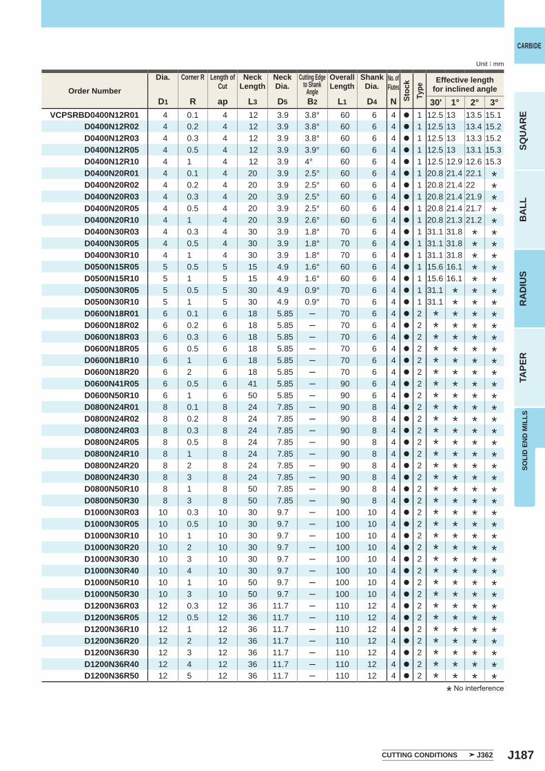
J187
D1 R ap L3 D5 B2 L1 D4 N 30' 1° 2° 3° VCPSRBD0400N12R01 4 0.1 4 12 3.9 3.8° 60 6 4 a 1 12.5 13 13.5 15.1
D0400N12R02 4 0.2 4 12 3.9 3.8° 60 6 4 a 1 12.5 13 13.4 15.2 D0400N12R03 4 0.3 4 12 3.9 3.8° 60 6 4 a 1 12.5 13 13.3 15.2 D0400N12R05 4 0.5 4 12 3.9 3.9° 60 6 4 a 1 12.5 13 13.1 15.3 D0400N12R10 4 1 4 12 3.9 4° 60 6 4 a 1 12.5 12.9 12.6 15.3D0400N20R01 4 0.1 4 20 3.9 2.5° 60 6 4 a 1 20.8 21.4 22.1 D0400N20R02 4 0.2 4 20 3.9 2.5° 60 6 4 a 1 20.8 21.4 22 D0400N20R03 4 0.3 4 20 3.9 2.5° 60 6 4 a 1 20.8 21.4 21.9 D0400N20R05 4 0.5 4 20 3.9 2.5° 60 6 4 a 1 20.8 21.4 21.7 D0400N20R10 4 1 4 20 3.9 2.6° 60 6 4 a 1 20.8 21.3 21.2 D0400N30R03 4 0.3 4 30 3.9 1.8° 70 6 4 a 1 31.1 31.8 D0400N30R05 4 0.5 4 30 3.9 1.8° 70 6 4 a 1 31.1 31.8 D0400N30R10 4 1 4 30 3.9 1.8° 70 6 4 a 1 31.1 31.8 D0500N15R05 5 0.5 5 15 4.9 1.6° 60 6 4 a 1 15.6 16.1 D0500N15R10 5 1 5 15 4.9 1.6° 60 6 4 a 1 15.6 16.1 D0500N30R05 5 0.5 5 30 4.9 0.9° 70 6 4 a 1 31.1 D0500N30R10 5 1 5 30 4.9 0.9° 70 6 4 a 1 31.1 D0600N18R01 6 0.1 6 18 5.85 ─ 70 6 4 a 2 D0600N18R02 6 0.2 6 18 5.85 ─ 70 6 4 a 2 D0600N18R03 6 0.3 6 18 5.85 ─ 70 6 4 a 2 D0600N18R05 6 0.5 6 18 5.85 ─ 70 6 4 a 2 D0600N18R10 6 1 6 18 5.85 ─ 70 6 4 a 2 D0600N18R20 6 2 6 18 5.85 ─ 70 6 4 a 2 D0600N41R05 6 0.5 6 41 5.85 ─ 90 6 4 a 2 D0600N50R10 6 1 6 50 5.85 ─ 90 6 4 a 2 D0800N24R01 8 0.1 8 24 7.85 ─ 90 8 4 a 2 D0800N24R02 8 0.2 8 24 7.85 ─ 90 8 4 a 2 D0800N24R03 8 0.3 8 24 7.85 ─ 90 8 4 a 2 D0800N24R05 8 0.5 8 24 7.85 ─ 90 8 4 a 2 D0800N24R10 8 1 8 24 7.85 ─ 90 8 4 a 2 D0800N24R20 8 2 8 24 7.85 ─ 90 8 4 a 2 D0800N24R30 8 3 8 24 7.85 ─ 90 8 4 a 2 D0800N50R10 8 1 8 50 7.85 ─ 90 8 4 a 2 D0800N50R30 8 3 8 50 7.85 ─ 90 8 4 a 2 D1000N30R03 10 0.3 10 30 9.7 ─ 100 10 4 a 2 D1000N30R05 10 0.5 10 30 9.7 ─ 100 10 4 a 2 D1000N30R10 10 1 10 30 9.7 ─ 100 10 4 a 2 D1000N30R20 10 2 10 30 9.7 ─ 100 10 4 a 2 D1000N30R30 10 3 10 30 9.7 ─ 100 10 4 a 2 D1000N30R40 10 4 10 30 9.7 ─ 100 10 4 a 2D1000N50R10 10 1 10 50 9.7 ─ 100 10 4 a 2
D1000N50R30 10 3 10 50 9.7 ─ 100 10 4 a 2 D1200N36R03 12 0.3 12 36 11.7 ─ 110 12 4 a 2 D1200N36R05 12 0.5 12 36 11.7 ─ 110 12 4 a 2 D1200N36R10 12 1 12 36 11.7 ─ 110 12 4 a 2 D1200N36R20 12 2 12 36 11.7 ─ 110 12 4 a 2 D1200N36R30 12 3 12 36 11.7 ─ 110 12 4 a 2 D1200N36R40 12 4 12 36 11.7 ─ 110 12 4 a 2 D1200N36R50 12 5 12 36 11.7 ─ 110 12 4 a 2
CARBIDE
SQU
AR
EB
ALL
RA
DIU
STA
PER
SOLI
D E
ND
MIL
LS
Unit : mm
* No interference
Order Number
Dia. Corner R Length ofCut
NeckLength
NeckDia.
Cutting Edgeto Shank
Angle
OverallLength
ShankDia.
No. ofFlutes
Stoc
kTy
pe
Effective lengthfor inclined angle
CUTTING CONDITIONS J362
********************************************
***************************************
**********************************
********************************
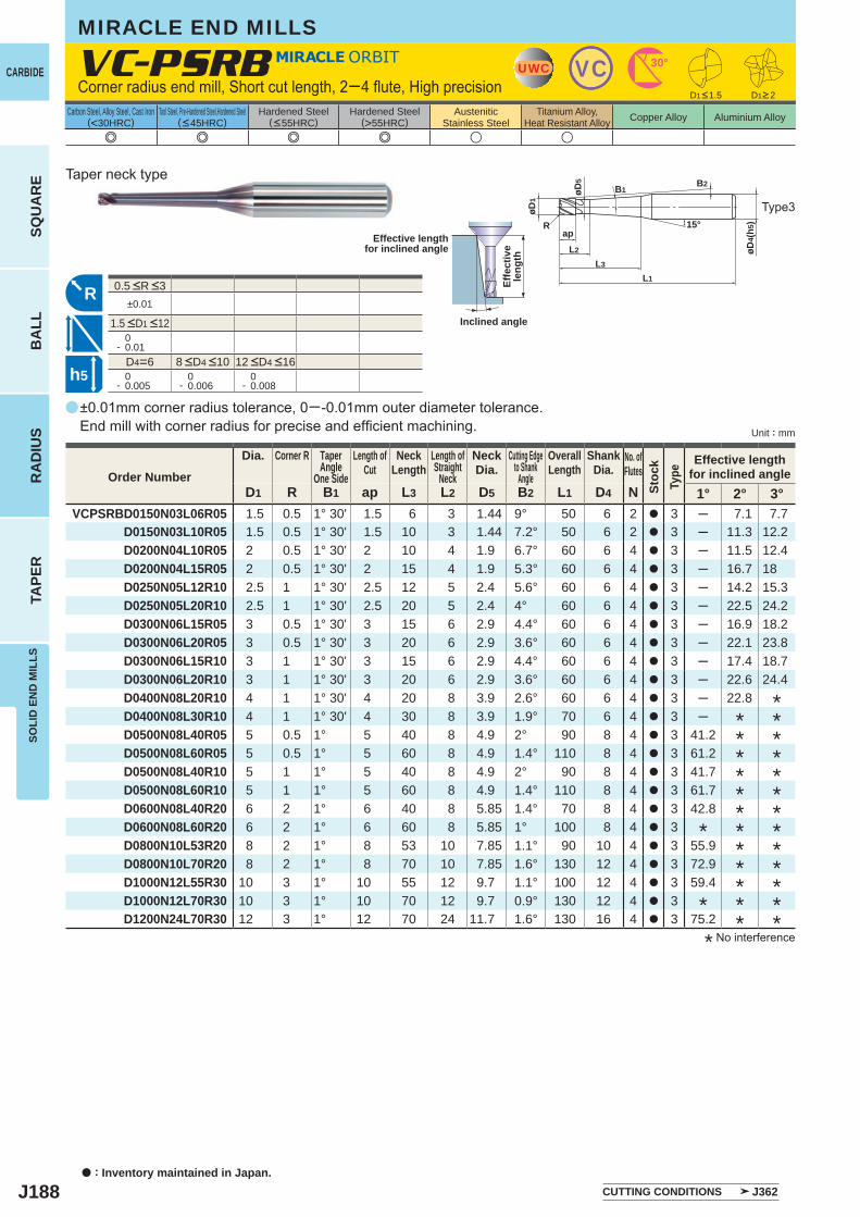
J188
a
e e e e u u
VC-PSRB
D1 R B1 ap L3 L2 D5 B2 L1 D4 N 1° 2° 3°VCPSRBD0150N03L06R05 1.5 0.5 1° 30' 1.5 6 3 1.44 9° 50 6 2 a 3 ─ 7.1 7.7
D0150N03L10R05 1.5 0.5 1° 30' 1.5 10 3 1.44 7.2° 50 6 2 a 3 ─ 11.3 12.2D0200N04L10R05 2 0.5 1° 30' 2 10 4 1.9 6.7° 60 6 4 a 3 ─ 11.5 12.4D0200N04L15R05 2 0.5 1° 30' 2 15 4 1.9 5.3° 60 6 4 a 3 ─ 16.7 18D0250N05L12R10 2.5 1 1° 30' 2.5 12 5 2.4 5.6° 60 6 4 a 3 ─ 14.2 15.3D0250N05L20R10 2.5 1 1° 30' 2.5 20 5 2.4 4° 60 6 4 a 3 ─ 22.5 24.2D0300N06L15R05 3 0.5 1° 30' 3 15 6 2.9 4.4° 60 6 4 a 3 ─ 16.9 18.2D0300N06L20R05 3 0.5 1° 30' 3 20 6 2.9 3.6° 60 6 4 a 3 ─ 22.1 23.8D0300N06L15R10 3 1 1° 30' 3 15 6 2.9 4.4° 60 6 4 a 3 ─ 17.4 18.7D0300N06L20R10 3 1 1° 30' 3 20 6 2.9 3.6° 60 6 4 a 3 ─ 22.6 24.4D0400N08L20R10 4 1 1° 30' 4 20 8 3.9 2.6° 60 6 4 a 3 ─ 22.8D0400N08L30R10 4 1 1° 30' 4 30 8 3.9 1.9° 70 6 4 a 3 ─D0500N08L40R05 5 0.5 1° 5 40 8 4.9 2° 90 8 4 a 3 41.2D0500N08L60R05 5 0.5 1° 5 60 8 4.9 1.4° 110 8 4 a 3 61.2D0500N08L40R10 5 1 1° 5 40 8 4.9 2° 90 8 4 a 3 41.7D0500N08L60R10 5 1 1° 5 60 8 4.9 1.4° 110 8 4 a 3 61.7D0600N08L40R20 6 2 1° 6 40 8 5.85 1.4° 70 8 4 a 3 42.8D0600N08L60R20 6 2 1° 6 60 8 5.85 1° 100 8 4 a 3D0800N10L53R20 8 2 1° 8 53 10 7.85 1.1° 90 10 4 a 3 55.9D0800N10L70R20 8 2 1° 8 70 10 7.85 1.6° 130 12 4 a 3 72.9D1000N12L55R30 10 3 1° 10 55 12 9.7 1.1° 100 12 4 a 3 59.4D1000N12L70R30 10 3 1° 10 70 12 9.7 0.9° 130 12 4 a 3D1200N24L70R30 12 3 1° 12 70 24 11.7 1.6° 130 16 4 a 3 75.2
±0.01
0- 0.01
D4=6 0- 0.005
0- 0.006
0- 0.008
UWC VC 30°
15°
øD5
øD4(
h5)
L1
L2
ap
L3
øD1
R
B1B2
R
h5
a : Inventory maintained in Japan.
CARBIDE
SQU
AR
EB
ALL
RA
DIU
STA
PER
SOLI
D E
ND
MIL
LS
Unit : mm
Carbon Steel, Alloy Steel, Cast Iron(<30HRC)
Tool Steel, Pre-Hardened Steel,Hardened Steel(<45HRC)
Hardened Steel(<55HRC)
Hardened Steel(>55HRC)
AusteniticStainless Steel
Titanium Alloy,Heat Resistant Alloy Copper Alloy Aluminium Alloy
MIRACLE END MILLS
±0.01mm corner radius tolerance, 0─-0.01mm outer diameter tolerance. End mill with corner radius for precise and efficient machining.
Corner radius end mill, Short cut length, 2─4 flute, High precision
Type3
Taper neck type
Effective lengthfor inclined angle
Inclined angle
Effe
ctiv
ele
ngth
* No interference
Order Number
Dia. Corner R TaperAngle
One Side
Length ofCut
NeckLength
Length ofStraight
Neck
NeckDia.
Cutting Edgeto Shank
Angle
OverallLength
ShankDia.
No. ofFlutes
Stoc
kTy
pe
Effective lengthfor inclined angle
*************
************
*
*
CUTTING CONDITIONS J362
8 <D4 <10 12 <D4 <16
D1<1.5 D1>2
0.5 <R <3
1.5 <D1 <12
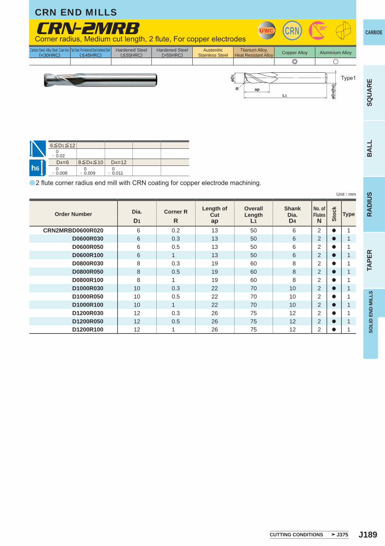
J189
a
e u
CRN-2MRB
D1 R ap L1 D4 NCRN2MRBD0600R020 6 0.2 13 50 6 2 a 1
D0600R030 6 0.3 13 50 6 2 a 1 D0600R050 6 0.5 13 50 6 2 a 1 D0600R100 6 1 13 50 6 2 a 1 D0800R030 8 0.3 19 60 8 2 a 1 D0800R050 8 0.5 19 60 8 2 a 1 D0800R100 8 1 19 60 8 2 a 1 D1000R030 10 0.3 22 70 10 2 a 1 D1000R050 10 0.5 22 70 10 2 a 1 D1000R100 10 1 22 70 10 2 a 1 D1200R030 12 0.3 26 75 12 2 a 1 D1200R050 12 0.5 26 75 12 2 a 1 D1200R100 12 1 26 75 12 2 a 1
0- 0.02
D4=6 D4=12 0- 0.008
0- 0.009
0- 0.011
UWC CRN 30°
øD4(
h6)
øD1
apL1
R
h6
CARBIDE
SQU
AR
EB
ALL
RA
DIU
STA
PER
SOLI
D E
ND
MIL
LS
Unit : mm
Carbon Steel, Alloy Steel, Cast Iron(<30HRC)
Tool Steel, Pre-Hardened Steel,Hardened Steel(<45HRC)
Hardened Steel(<55HRC)
Hardened Steel(>55HRC)
AusteniticStainless Steel
Titanium Alloy,Heat Resistant Alloy Copper Alloy Aluminium Alloy
2 flute corner radius end mill with CRN coating for copper electrode machining.
Corner radius, Medium cut length, 2 flute, For copper electrodes
Type1
Order Number Dia. Corner R Length of Cut
Overall Length
Shank Dia.
No. ofFlutes
Stoc
k
Type
CUTTING CONDITIONS J375
8≦D4≦10
6≦D1≦12
CRN END MILLS
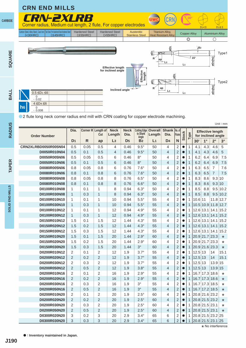
J190
a
e u
CRN-2XLRB
D1 R ap L3 D5 B2 L1 D4 N 30' 1° 2° 3°CRN2XLRBD0050R005N04 0.5 0.05 0.5 4 0.46 9.5° 50 4 2 a 1 4.1 4.3 4.6 5
D0050R010N04 0.5 0.1 0.5 4 0.46 9.5° 50 4 2 a 1 4.1 4.3 4.6 5 D0050R005N06 0.5 0.05 0.5 6 0.46 8° 50 4 2 a 1 6.2 6.4 6.9 7.5 D0050R010N06 0.5 0.1 0.5 6 0.46 8° 50 4 2 a 1 6.2 6.4 6.9 7.5 D0080R005N06 0.8 0.05 0.8 6 0.76 7.6° 50 4 2 a 1 6.3 6.5 7 7.6 D0080R010N06 0.8 0.1 0.8 6 0.76 7.6° 50 4 2 a 1 6.3 6.5 7 7.5 D0080R005N08 0.8 0.05 0.8 8 0.76 6.5° 50 4 2 a 1 8.3 8.6 9.3 10 D0080R010N08 0.8 0.1 0.8 8 0.76 6.6° 50 4 2 a 1 8.3 8.6 9.3 10 D0100R010N08 1 0.1 1 8 0.94 6.3° 50 4 2 a 1 8.5 8.8 9.5 10.2 D0100R030N08 1 0.3 1 8 0.94 6.3° 50 4 2 a 1 8.5 8.8 9.5 10.2 D0100R010N10 1 0.1 1 10 0.94 5.5° 55 4 2 a 1 10.6 11 11.8 12.7 D0100R030N10 1 0.3 1 10 0.94 5.5° 55 4 2 a 1 10.5 10.9 11.8 12.7 D0100R010N12 1 0.1 1 12 0.94 4.9° 55 4 2 a 1 12.6 13.1 14.1 15.2 D0100R030N12 1 0.3 1 12 0.94 4.9° 55 4 2 a 1 12.6 13.1 14.1 15.2 D0150R010N12 1.5 0.1 1.5 12 1.44 4.3° 55 4 2 a 1 12.6 13.1 14.1 15.2 D0150R020N12 1.5 0.2 1.5 12 1.44 4.3° 55 4 2 a 1 12.6 13.1 14.1 15.2 D0150R030N12 1.5 0.3 1.5 12 1.44 4.3° 55 4 2 a 1 12.6 13.1 14.1 15.2 D0150R010N20 1.5 0.1 1.5 20 1.44 2.9° 60 4 2 a 1 20.9 21.7 23.3 D0150R020N20 1.5 0.2 1.5 20 1.44 2.9° 60 4 2 a 1 20.9 21.7 23.3 D0150R030N20 1.5 0.3 1.5 20 1.44 3° 60 4 2 a 1 20.9 21.6 23.3 D0200R010N12 2 0.1 2 12 1.9 3.7° 55 4 2 a 1 12.5 13 14 15.1 D0200R020N12 2 0.2 2 12 1.9 3.7° 55 4 2 a 1 12.5 13 14 15.1 D0200R030N12 2 0.3 2 12 1.9 3.7° 55 4 2 a 1 12.5 13 13.9 15 D0200R050N12 2 0.5 2 12 1.9 3.8° 55 4 2 a 1 12.5 13 13.9 15 D0200R010N16 2 0.1 2 16 1.9 2.9° 55 4 2 a 1 16.7 17.3 18.6 D0200R020N16 2 0.2 2 16 1.9 2.9° 55 4 2 a 1 16.7 17.3 18.6 D0200R030N16 2 0.3 2 16 1.9 3° 55 4 2 a 1 16.7 17.3 18.5 D0200R050N16 2 0.5 2 16 1.9 3° 55 4 2 a 1 16.7 17.2 18.5 D0200R010N20 2 0.1 2 20 1.9 2.5° 60 4 2 a 1 20.8 21.6 23.2 D0200R020N20 2 0.2 2 20 1.9 2.5° 60 4 2 a 1 20.8 21.5 23.2 D0200R030N20 2 0.3 2 20 1.9 2.5° 60 4 2 a 1 20.8 21.5 23.1 D0200R050N20 2 0.5 2 20 1.9 2.5° 60 4 2 a 1 20.8 21.5 23.1 D0300R020N20 3 0.2 3 20 2.9 3.4° 65 6 2 a 1 20.8 21.5 23.2 25 D0300R030N20 3 0.3 3 20 2.9 3.4° 65 6 2 a 1 20.8 21.5 23.1 25
0- 0.02
0- 0.008
UWC CRN 30°
øD4(
h6)
L1L3
ap
øD1 øD
5
R
B2
15°
D1<3
øD4(
h6)
L1L3
apR
øD1
øD5
h6
a : Inventory maintained in Japan.
CARBIDE
SQU
AR
EB
ALL
RA
DIU
STA
PER
SOLI
D E
ND
MIL
LS
Unit : mm
Carbon Steel, Alloy Steel, Cast Iron(<30HRC)
Tool Steel, Pre-Hardened Steel,Hardened Steel(<45HRC)
Hardened Steel(<55HRC)
Hardened Steel(>55HRC)
AusteniticStainless Steel
Titanium Alloy,Heat Resistant Alloy Copper Alloy Aluminium Alloy
2 flute long neck corner radius end mill with CRN coating for copper electrode machining.
Corner radius, Medium cut length, 2 flute, For copper electrodes
Type1
Type2
* No interference
Effective lengthfor inclined angle
Inclined angle
Effe
ctiv
ele
ngth
D1>3
Order NumberDia. Corner R Length of
CutNeck
LengthNeckDia.
Cutting Edgeto Shank
Angle
OverallLength
ShankDia.
No. ofFlutes
Stoc
kTy
pe
Effective lengthfor inclined angle
********
***
4 <D4 <6
0.5 <D1 <6
CRN END MILLS
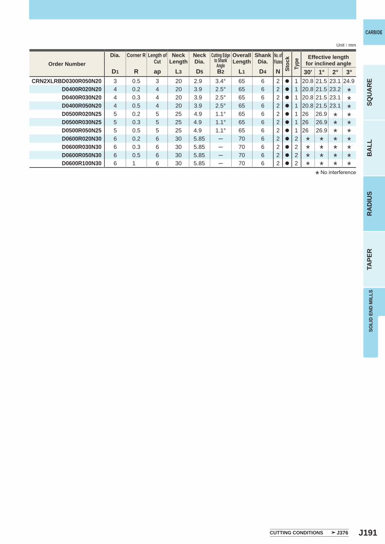
J191
D1 R ap L3 D5 B2 L1 D4 N 30' 1° 2° 3° CRN2XLRBD0300R050N20 3 0.5 3 20 2.9 3.4° 65 6 2 a 1 20.8 21.5 23.1 24.9 D0400R020N20 4 0.2 4 20 3.9 2.5° 65 6 2 a 1 20.8 21.5 23.2 D0400R030N20 4 0.3 4 20 3.9 2.5° 65 6 2 a 1 20.8 21.5 23.1 D0400R050N20 4 0.5 4 20 3.9 2.5° 65 6 2 a 1 20.8 21.5 23.1 D0500R020N25 5 0.2 5 25 4.9 1.1° 65 6 2 a 1 26 26.9
D0500R030N25 5 0.3 5 25 4.9 1.1° 65 6 2 a 1 26 26.9 D0500R050N25 5 0.5 5 25 4.9 1.1° 65 6 2 a 1 26 26.9 D0600R020N30 6 0.2 6 30 5.85 ─ 70 6 2 a 2 D0600R030N30 6 0.3 6 30 5.85 ─ 70 6 2 a 2 D0600R050N30 6 0.5 6 30 5.85 ─ 70 6 2 a 2 D0600R100N30 6 1 6 30 5.85 ─ 70 6 2 a 2
CARBIDE
SQU
AR
EB
ALL
RA
DIU
STA
PER
SOLI
D E
ND
MIL
LS
Unit : mm
*****
* No interference
Order NumberDia. Corner R Length of
CutNeck
LengthNeckDia.
Cutting Edgeto Shank
Angle
OverallLength
ShankDia.
No. ofFlutes
Stoc
kTy
pe
Effective lengthfor inclined angle
******
******
****
****
CUTTING CONDITIONS J376

J192
a
u e e e
CBN-2XLRB
R D1 ap L3 D5 B2 L1 D4 N 30' 1° 2° 3°CBN2XLRBD0050R005N02 0.05 0.5 0.3 2 0.46 11.6° 51 4 2 a 1 2.1 2.1 2.3 2.5
D0050R005N03 0.05 0.5 0.3 3 0.46 10.4° 51 4 2 a 1 3.1 3.2 3.5 3.7 D0050R010N02 0.1 0.5 0.3 2 0.46 11.7° 51 4 2 a 1 2.1 2.1 2.3 2.5 D0050R010N03 0.1 0.5 0.3 3 0.46 10.5° 51 4 2 a 1 3.1 3.2 3.4 3.7 D0100R005N03 0.05 1 0.6 3 0.94 9.7° 51 4 2 a 1 3.2 3.4 3.7 4 D0100R005N05 0.05 1 0.6 5 0.94 7.9° 51 4 2 a 1 5.3 5.6 6 6.5 D0100R010N03 0.1 1 0.6 3 0.94 9.7° 51 4 2 a 1 3.2 3.4 3.6 4 D0100R010N05 0.1 1 0.6 5 0.94 8° 51 4 2 a 1 5.3 5.6 6 6.5 D0100R020N03 0.2 1 0.6 3 0.94 9.8° 51 4 2 a 1 3.2 3.4 3.5 4 D0100R020N05 0.2 1 0.6 5 0.94 8° 51 4 2 a 1 5.3 5.6 6 6.5 D0100R030N03 0.3 1 0.6 3 0.94 9.9° 51 4 2 a 1 3.2 3.4 3.4 4 D0100R030N05 0.3 1 0.6 5 0.94 8.1° 51 4 2 a 1 5.3 5.6 6 6.5 D0150R010N05 0.1 1.5 0.9 5 1.44 7.3° 52 4 2 a 1 5.3 5.6 6 6.5 D0150R010N08 0.1 1.5 0.9 8 1.44 5.6° 52 4 2 a 1 8.5 8.8 9.5 10.2 D0150R020N05 0.2 1.5 0.9 5 1.44 7.3° 52 4 2 a 1 5.3 5.6 6 6.5 D0150R020N08 0.2 1.5 0.9 8 1.44 5.6° 52 4 2 a 1 8.5 8.8 9.5 10.2 D0150R030N05 0.3 1.5 0.9 5 1.44 7.4° 52 4 2 a 1 5.3 5.6 6 6.5 D0150R030N08 0.3 1.5 0.9 8 1.44 5.7° 52 4 2 a 1 8.5 8.8 9.5 10.2 D0200R010N06 0.1 2 1.2 6 1.9 5.9° 52 4 2 a 1 6.3 6.6 7.1 7.6 D0200R010N10 0.1 2 1.2 10 1.9 4.2° 52 4 2 a 1 10.5 10.9 11.7 12.6 D0200R020N06 0.2 2 1.2 6 1.9 5.9° 52 4 2 a 1 6.3 6.6 7.1 7.6 D0200R020N10 0.2 2 1.2 10 1.9 4.2° 52 4 2 a 1 10.5 10.9 11.7 12.6 D0200R030N06 0.3 2 1.2 6 1.9 6° 52 4 2 a 1 6.3 6.6 7 7.6 D0200R030N10 0.3 2 1.2 10 1.9 4.2° 52 4 2 a 1 10.5 10.8 11.6 12.6 D0200R050N06 0.5 2 1.2 6 1.9 6.1° 52 4 2 a 1 6.3 6.5 7 7.5 D0200R050N10 0.5 2 1.2 10 1.9 4.3° 52 4 2 a 1 10.5 10.8 11.6 12.5
±0.005
0- 0.010
D4=4 0- 0.005
CBN 0°
øD4(
h5)
L1
apL3
øD5
15°
B2
øD1
R
R
h5
CBN
Unit : mm
Carbon Steel, Alloy Steel, Cast Iron(<30HRC)
Tool Steel, Pre-Hardened Steel,Hardened Steel(<45HRC)
Hardened Steel(<55HRC)
Hardened Steel(>55HRC)
AusteniticStainless Steel
Titanium Alloy,Heat Resistant Alloy Copper Alloy Aluminium Alloy
a : Inventory maintained in Japan.
SQU
AR
EB
ALL
RA
DIU
STA
PER
SOLI
D E
ND
MIL
LS
CBN long neck radius end mill. A wide variation of neck lengths available.
Corner radius end mill, Medium cut length, 2 flute, Long neck
Type1
CBN END MILLS
Effective lengthfor inclined angle
Inclined angle
Effe
ctiv
ele
ngth
Order NumberCorner R Dia. Length of
CutNeck
LengthNeckDia.
Cutting Edgeto Shank
Angle
OverallLength
ShankDia.
No. ofFlutes
Stoc
kTy
pe
Effective lengthfor inclined angle
CUTTING CONDITIONS J386
0.05 <R <0.5
0.5 <D1 <2
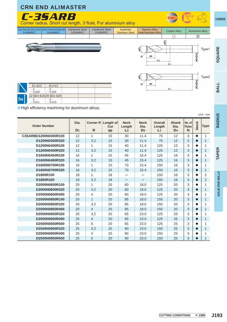
J193
a
u e
C-3SARB
D1 R ap L3 D5 L1 D4 NC3SARBD1200N0300R100 12 1 15 30 11.4 75 12 3 a 1
D1200N0300R320 12 3.2 15 30 11.4 75 12 3 a 1 D1200N0400R100 12 1 15 40 11.4 125 12 3 a 1 D1200N0400R320 12 3.2 15 40 11.4 125 12 3 a 1 D1600N0450R100 16 1 15 45 15.4 125 16 3 a 1 D1600N0450R320 16 3.2 15 45 15.4 125 16 3 a 1 D1600N0700R100 16 1 15 70 15.4 150 16 3 a 1 D1600N0700R320 16 3.2 15 70 15.4 150 16 3 a 1 D1800R100 18 1 18 ─ ─ 150 16 3 a 2 D1800R320 18 3.2 18 ─ ─ 150 16 3 a 2 D2000N0600R100 20 1 20 60 18.0 125 20 3 a 1 D2000N0600R320 20 3.2 20 60 18.0 125 20 3 a 1 D2000N0600R400 20 4 20 60 18.0 125 20 3 a 1 D2000N0850R100 20 1 20 85 18.0 150 20 3 a 1 D2000N0850R320 20 3.2 20 85 18.0 150 20 3 a 1 D2000N0850R400 20 4 20 85 18.0 150 20 3 a 1 D2500N0650R320 25 3.2 20 65 23.0 125 25 3 a 1 D2500N0650R400 25 4 20 65 23.0 125 25 3 a 1 D2500N0650R500 25 5 20 65 23.0 125 25 3 a 1 D2500N0900R320 25 3.2 20 90 23.0 150 25 3 a 1 D2500N0900R400 25 4 20 90 23.0 150 25 3 a 1 D2500N0900R500 25 5 20 90 23.0 150 25 3 a 1
D1>12 0- 0.020
0- 0.030
0- 0.011
0- 0.013
UWC 37.5°
øD1
øD4(
h6)
L1
L3
apR
øD5
øD4(
h6)
L1
R
øD1
ap
h6
CARBIDE
SQU
AR
EB
ALL
RA
DIU
STA
PER
SOLI
D E
ND
MIL
LS
Unit : mm
Carbon Steel, Alloy Steel, Cast Iron(<30HRC)
Tool Steel, Pre-Hardened Steel,Hardened Steel(<45HRC)
Hardened Steel(<55HRC)
Hardened Steel(>55HRC)
AusteniticStainless Steel
Titanium Alloy,Heat Resistant Alloy Copper Alloy Aluminium Alloy
High efficiency machining for aluminium alloys.
Corner radius, Short cut length, 3 flute, For aluminium alloy
Type2
Type1
Order NumberDia. Corner R Length of
CutNeck
LengthNeckDia.
OverallLength
ShankDia.
No. ofFlutes
Stoc
k
Type
CUTTING CONDITIONS J390
12 <D4 <16 20 <D4 <25
D1 <12
CRN END ALIMASTER
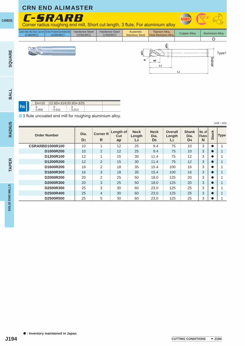
J194
a
e
C-SRARB
D1 R ap L3 D5 L1 D4 NCSRARBD1000R100 10 1 12 25 9.4 75 10 3 a 1
D1000R200 10 2 12 25 9.4 75 10 3 a 1 D1200R100 12 1 15 30 11.4 75 12 3 a 1 D1200R200 12 2 15 30 11.4 75 12 3 a 1 D1600R200 16 2 18 35 15.4 100 16 3 a 1 D1600R300 16 3 18 35 15.4 100 16 3 a 1 D2000R200 20 2 25 50 18.0 125 20 3 a 1 D2000R300 20 3 25 50 18.0 125 20 3 a 1 D2500R300 25 3 30 60 23.0 125 25 3 a 1 D2500R400 25 4 30 60 23.0 125 25 3 a 1 D2500R500 25 5 30 60 23.0 125 25 3 a 1
D4=10 0- 0.009
0- 0.011
0- 0.013
UWC 37.5°
øD1
øD4(
h6)
ap
L3
L1
R
øD5
h6
a : Inventory maintained in Japan.
CARBIDE
SQU
AR
EB
ALL
RA
DIU
STA
PER
SOLI
D E
ND
MIL
LS
Unit : mm
Carbon Steel, Alloy Steel, Cast Iron(<30HRC)
Tool Steel, Pre-Hardened Steel,Hardened Steel(<45HRC)
Hardened Steel(<55HRC)
Hardened Steel(>55HRC)
AusteniticStainless Steel
Titanium Alloy,Heat Resistant Alloy Copper Alloy Aluminium Alloy
3 flute uncoated end mill for roughing aluminium alloy.
Corner radius roughing end mill, Short cut length, 3 flute, For aluminium alloy
Type1
Order Number Dia. Corner R Length ofCut
NeckLength
NeckDia.
OverallLength
ShankDia.
No. ofFlutes
Stoc
k
Type
CUTTING CONDITIONS J194
12 <D4 <16 20 <D4 <25
CRN END ALIMASTER
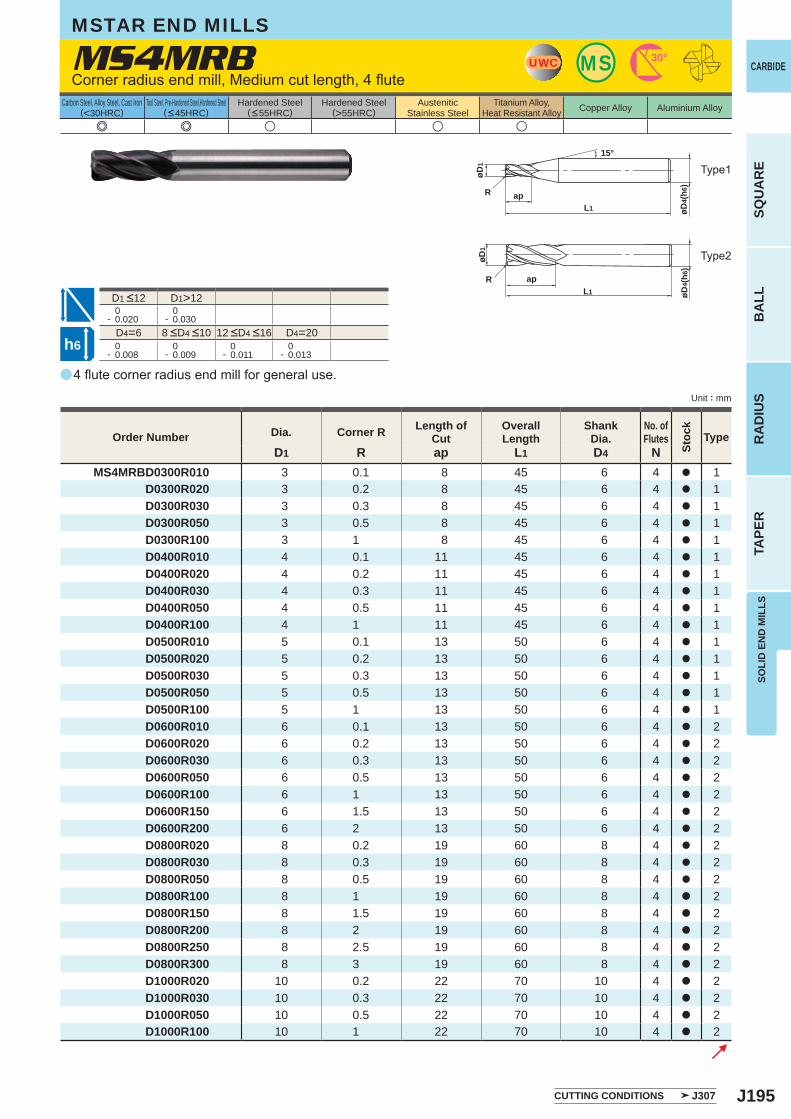
J195
a
MS4MRB
e e u u u
D1 R ap L1 D4 NMS4MRBD0300R010 3 0.1 8 45 6 4 a 1
D0300R020 3 0.2 8 45 6 4 a 1D0300R030 3 0.3 8 45 6 4 a 1D0300R050 3 0.5 8 45 6 4 a 1D0300R100 3 1 8 45 6 4 a 1D0400R010 4 0.1 11 45 6 4 a 1D0400R020 4 0.2 11 45 6 4 a 1D0400R030 4 0.3 11 45 6 4 a 1D0400R050 4 0.5 11 45 6 4 a 1D0400R100 4 1 11 45 6 4 a 1D0500R010 5 0.1 13 50 6 4 a 1D0500R020 5 0.2 13 50 6 4 a 1D0500R030 5 0.3 13 50 6 4 a 1D0500R050 5 0.5 13 50 6 4 a 1D0500R100 5 1 13 50 6 4 a 1D0600R010 6 0.1 13 50 6 4 a 2D0600R020 6 0.2 13 50 6 4 a 2D0600R030 6 0.3 13 50 6 4 a 2D0600R050 6 0.5 13 50 6 4 a 2D0600R100 6 1 13 50 6 4 a 2D0600R150 6 1.5 13 50 6 4 a 2D0600R200 6 2 13 50 6 4 a 2D0800R020 8 0.2 19 60 8 4 a 2D0800R030 8 0.3 19 60 8 4 a 2D0800R050 8 0.5 19 60 8 4 a 2D0800R100 8 1 19 60 8 4 a 2D0800R150 8 1.5 19 60 8 4 a 2D0800R200 8 2 19 60 8 4 a 2D0800R250 8 2.5 19 60 8 4 a 2D0800R300 8 3 19 60 8 4 a 2D1000R020 10 0.2 22 70 10 4 a 2D1000R030 10 0.3 22 70 10 4 a 2D1000R050 10 0.5 22 70 10 4 a 2D1000R100 10 1 22 70 10 4 a 2
D1>12 0- 0.020
0- 0.030
D4=6 D4=20 0- 0.008
0- 0.009
0- 0.011
0- 0.013
UWC MS 30°
apL1
øD1
øD4(
h6)
R
15°
øD4(
h6)
øD1
apL1
R
h6
CARBIDE
SQU
AR
EB
ALL
RA
DIU
STA
PER
SOLI
D E
ND
MIL
LS
Unit : mm
Carbon Steel, Alloy Steel, Cast Iron(<30HRC)
Tool Steel, Pre-Hardened Steel,Hardened Steel(<45HRC)
Hardened Steel(<55HRC)
Hardened Steel(>55HRC)
AusteniticStainless Steel
Titanium Alloy,Heat Resistant Alloy Copper Alloy Aluminium Alloy
4 flute corner radius end mill for general use.
Corner radius end mill, Medium cut length, 4 flute
Type2
Type1
MSTAR END MILLS
CUTTING CONDITIONS J307
Order Number Dia. Corner R Length of Cut
Overall Length
Shank Dia.
No. ofFlutes
Stoc
k
Type
8 <D4 <10 12 <D4 <16
D1 <12
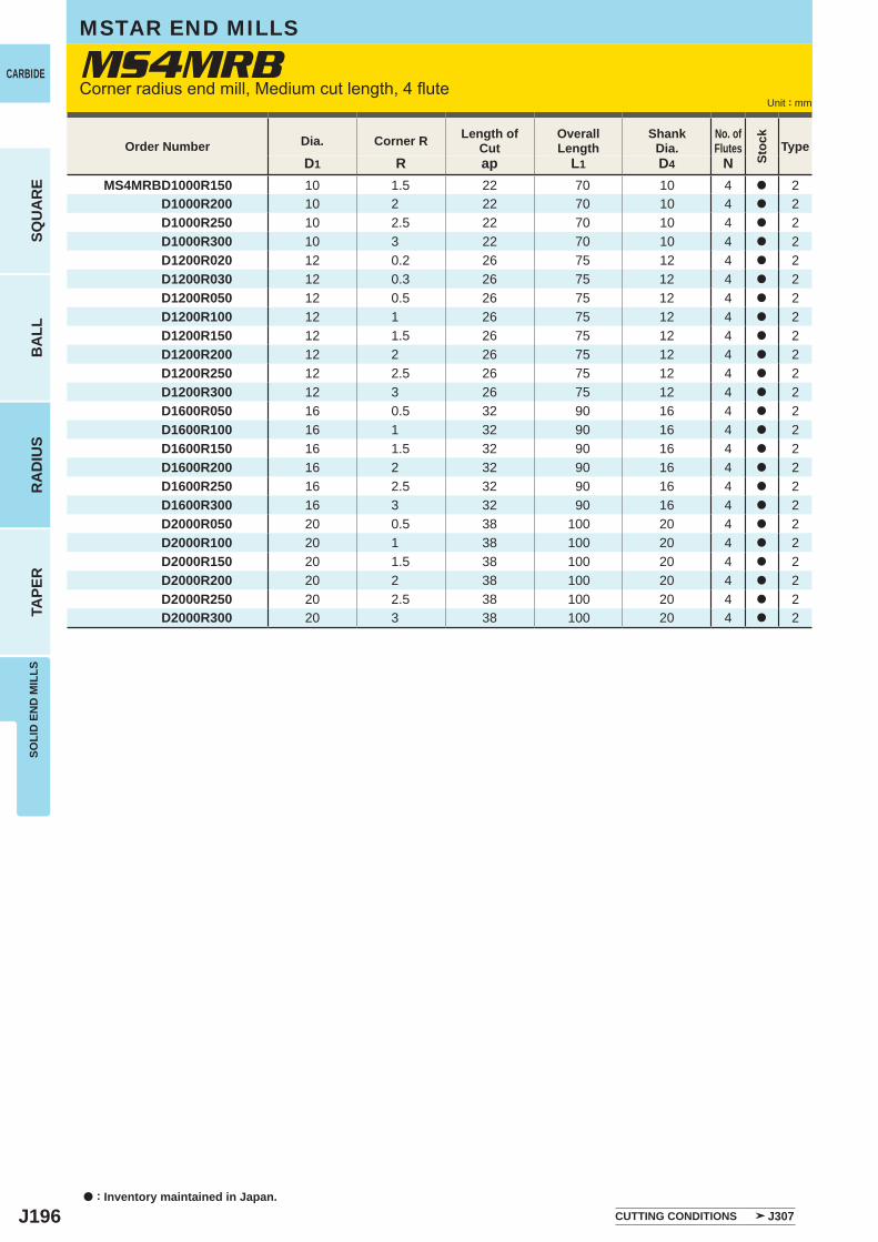
J196
D1 R ap L1 D4 NMS4MRBD1000R150 10 1.5 22 70 10 4 a 2
D1000R200 10 2 22 70 10 4 a 2D1000R250 10 2.5 22 70 10 4 a 2D1000R300 10 3 22 70 10 4 a 2D1200R020 12 0.2 26 75 12 4 a 2D1200R030 12 0.3 26 75 12 4 a 2D1200R050 12 0.5 26 75 12 4 a 2D1200R100 12 1 26 75 12 4 a 2D1200R150 12 1.5 26 75 12 4 a 2D1200R200 12 2 26 75 12 4 a 2D1200R250 12 2.5 26 75 12 4 a 2D1200R300 12 3 26 75 12 4 a 2D1600R050 16 0.5 32 90 16 4 a 2D1600R100 16 1 32 90 16 4 a 2D1600R150 16 1.5 32 90 16 4 a 2D1600R200 16 2 32 90 16 4 a 2D1600R250 16 2.5 32 90 16 4 a 2D1600R300 16 3 32 90 16 4 a 2D2000R050 20 0.5 38 100 20 4 a 2D2000R100 20 1 38 100 20 4 a 2D2000R150 20 1.5 38 100 20 4 a 2D2000R200 20 2 38 100 20 4 a 2D2000R250 20 2.5 38 100 20 4 a 2D2000R300 20 3 38 100 20 4 a 2
MS4MRB
a : Inventory maintained in Japan.
CARBIDE
SQU
AR
EB
ALL
RA
DIU
STA
PER
SOLI
D E
ND
MIL
LS
Unit : mm
MSTAR END MILLS
Corner radius end mill, Medium cut length, 4 flute
Order Number Dia. Corner R Length of Cut
Overall Length
Shank Dia.
No. ofFlutes
Stoc
k
Type
CUTTING CONDITIONS J307
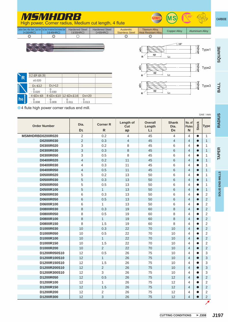
J197
a
e e u e e
MSMHDRB
D1 R ap L1 D4 NMSMHDRBD0200R020 2 0.2 4 45 4 4 a 1 D0200R030 2 0.3 4 45 4 4 a 1 D0300R020 3 0.2 8 45 6 4 a 1 D0300R030 3 0.3 8 45 6 4 a 1 D0300R050 3 0.5 8 45 6 4 a 1 D0400R020 4 0.2 11 45 6 4 a 1 D0400R030 4 0.3 11 45 6 4 a 1 D0400R050 4 0.5 11 45 6 4 a 1 D0500R020 5 0.2 13 50 6 4 a 1 D0500R030 5 0.3 13 50 6 4 a 1 D0500R050 5 0.5 13 50 6 4 a 1 D0500R100 5 1 13 50 6 4 a 1 D0600R030 6 0.3 13 50 6 4 a 2 D0600R050 6 0.5 13 50 6 4 a 2 D0600R100 6 1 13 50 6 4 a 2 D0800R030 8 0.3 19 60 8 4 a 2 D0800R050 8 0.5 19 60 8 4 a 2 D0800R100 8 1 19 60 8 4 a 2 D0800R150 8 1.5 19 60 8 4 a 2 D1000R030 10 0.3 22 70 10 4 a 2 D1000R050 10 0.5 22 70 10 4 a 2 D1000R100 10 1 22 70 10 4 a 2 D1000R150 10 1.5 22 70 10 4 a 2 D1000R200 10 2 22 70 10 4 a 2 D1200R050S10 12 0.5 26 75 10 4 a 3 D1200R100S10 12 1 26 75 10 4 a 3 D1200R150S10 12 1.5 26 75 10 4 a 3 D1200R200S10 12 2 26 75 10 4 a 3 D1200R300S10 12 3 26 75 10 4 a 3 D1200R050 12 0.5 26 75 12 4 a 2 D1200R100 12 1 26 75 12 4 a 2 D1200R150 12 1.5 26 75 12 4 a 2 D1200R200 12 2 26 75 12 4 a 2 D1200R300 12 3 26 75 12 4 a 2
±0.020
D1>12 0- 0.020
0- 0.030
D4=20 0- 0.008
0- 0.009
0- 0.011
0- 0.013
MSUWC 45°
L1ap
R
15°
øD4(
h6)
øD1
øD4(
h6)
øD1
apL1R
L1ap
R
øD4(
h6)
øD1
h6
CARBIDE
SQU
AR
EB
ALL
RA
DIU
STA
PER
SOLI
D E
ND
MIL
LS
Unit : mm
Carbon Steel, Alloy Steel, Cast Iron(<30HRC)
Tool Steel, Pre-Hardened Steel,Hardened Steel(<45HRC)
Hardened Steel(<55HRC)
Hardened Steel(>55HRC)
AusteniticStainless Steel
Titanium Alloy,Heat Resistant Alloy Copper Alloy Aluminium Alloy
4 flute high power corner radius end mill.
High power, Corner radius, Medium cut length, 4 flute
Type2
Type1
Type3
Order Number Dia. Corner R Length of Cut
Overall Length
Shank Dia.
No. ofFlutes
Stoc
k
Type
CUTTING CONDITIONS J308
4 <D4 <6 8 <D4 <10 12 <D4≦16
0.2 <R <6.35
D1 <12
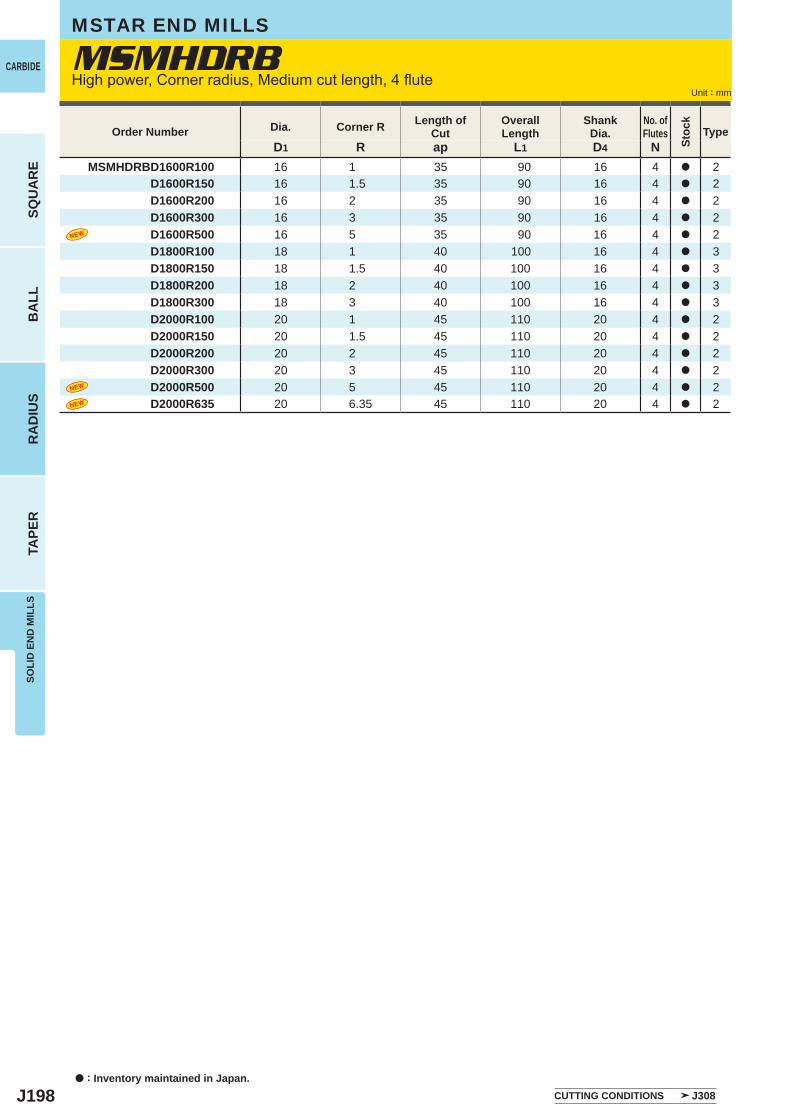
J198
D1 R ap L1 D4 NMSMHDRBD1600R100 16 1 35 90 16 4 a 2 D1600R150 16 1.5 35 90 16 4 a 2 D1600R200 16 2 35 90 16 4 a 2 D1600R300 16 3 35 90 16 4 a 2 D1600R500 16 5 35 90 16 4 a 2 D1800R100 18 1 40 100 16 4 a 3
D1800R150 18 1.5 40 100 16 4 a 3 D1800R200 18 2 40 100 16 4 a 3 D1800R300 18 3 40 100 16 4 a 3 D2000R100 20 1 45 110 20 4 a 2 D2000R150 20 1.5 45 110 20 4 a 2 D2000R200 20 2 45 110 20 4 a 2 D2000R300 20 3 45 110 20 4 a 2
D2000R500 20 5 45 110 20 4 a 2D2000R635 20 6.35 45 110 20 4 a 2
MSMHDRB
a : Inventory maintained in Japan.
CARBIDE
SQU
AR
EB
ALL
RA
DIU
STA
PER
SOLI
D E
ND
MIL
LS
Unit : mm
MSTAR END MILLS
High power, Corner radius, Medium cut length, 4 flute
Order Number Dia. Corner R Length of Cut
Overall Length
Shank Dia.
No. ofFlutes
Stoc
k
Type
CUTTING CONDITIONS J308
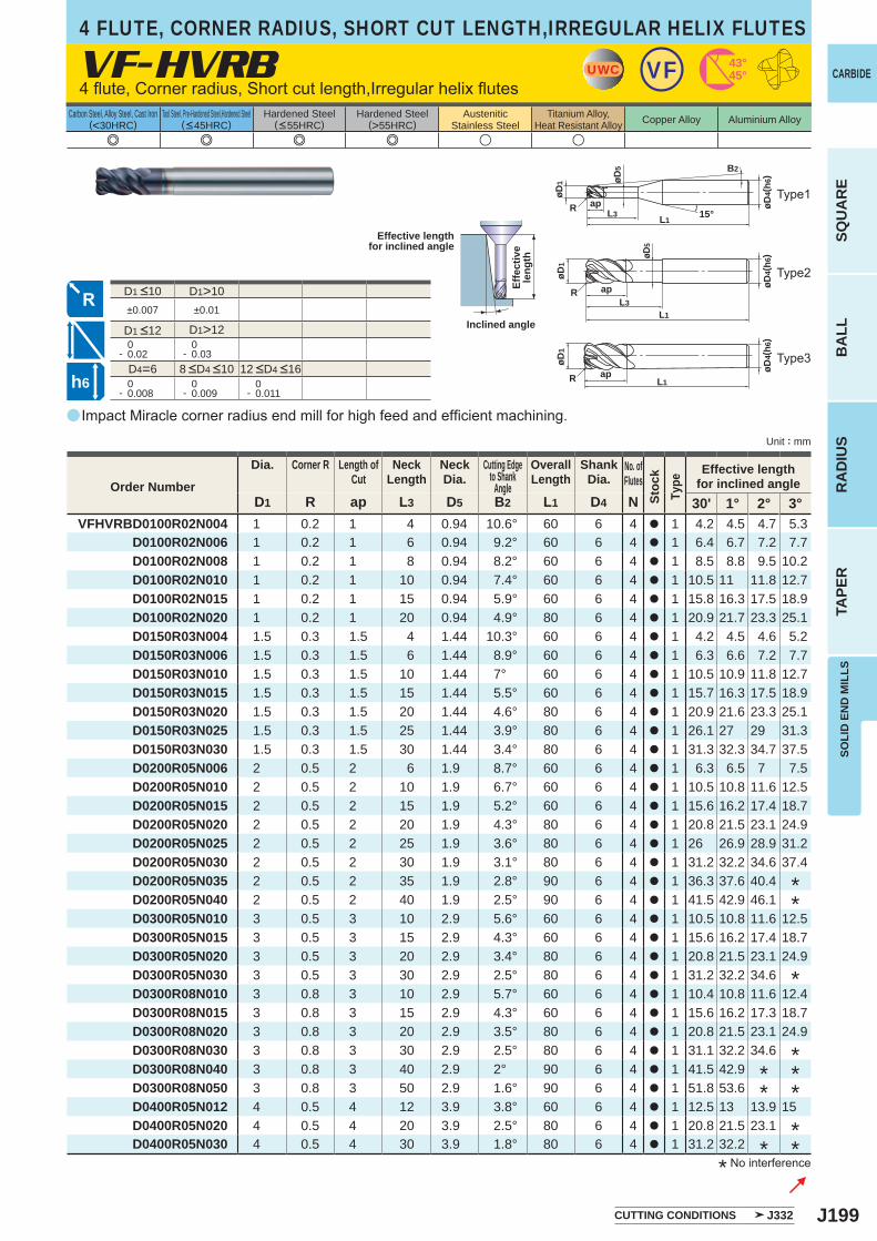
J199
a
e e e e u u
VF-HVRB
D1 R ap L3 D5 B2 L1 D4 N 30' 1° 2° 3°VFHVRBD0100R02N004 1 0.2 1 4 0.94 10.6° 60 6 4 a 1 4.2 4.5 4.7 5.3
D0100R02N006 1 0.2 1 6 0.94 9.2° 60 6 4 a 1 6.4 6.7 7.2 7.7D0100R02N008 1 0.2 1 8 0.94 8.2° 60 6 4 a 1 8.5 8.8 9.5 10.2D0100R02N010 1 0.2 1 10 0.94 7.4° 60 6 4 a 1 10.5 11 11.8 12.7D0100R02N015 1 0.2 1 15 0.94 5.9° 60 6 4 a 1 15.8 16.3 17.5 18.9D0100R02N020 1 0.2 1 20 0.94 4.9° 80 6 4 a 1 20.9 21.7 23.3 25.1D0150R03N004 1.5 0.3 1.5 4 1.44 10.3° 60 6 4 a 1 4.2 4.5 4.6 5.2D0150R03N006 1.5 0.3 1.5 6 1.44 8.9° 60 6 4 a 1 6.3 6.6 7.2 7.7D0150R03N010 1.5 0.3 1.5 10 1.44 7° 60 6 4 a 1 10.5 10.9 11.8 12.7D0150R03N015 1.5 0.3 1.5 15 1.44 5.5° 60 6 4 a 1 15.7 16.3 17.5 18.9D0150R03N020 1.5 0.3 1.5 20 1.44 4.6° 80 6 4 a 1 20.9 21.6 23.3 25.1D0150R03N025 1.5 0.3 1.5 25 1.44 3.9° 80 6 4 a 1 26.1 27 29 31.3D0150R03N030 1.5 0.3 1.5 30 1.44 3.4° 80 6 4 a 1 31.3 32.3 34.7 37.5D0200R05N006 2 0.5 2 6 1.9 8.7° 60 6 4 a 1 6.3 6.5 7 7.5D0200R05N010 2 0.5 2 10 1.9 6.7° 60 6 4 a 1 10.5 10.8 11.6 12.5D0200R05N015 2 0.5 2 15 1.9 5.2° 60 6 4 a 1 15.6 16.2 17.4 18.7D0200R05N020 2 0.5 2 20 1.9 4.3° 80 6 4 a 1 20.8 21.5 23.1 24.9D0200R05N025 2 0.5 2 25 1.9 3.6° 80 6 4 a 1 26 26.9 28.9 31.2D0200R05N030 2 0.5 2 30 1.9 3.1° 80 6 4 a 1 31.2 32.2 34.6 37.4D0200R05N035 2 0.5 2 35 1.9 2.8° 90 6 4 a 1 36.3 37.6 40.4D0200R05N040 2 0.5 2 40 1.9 2.5° 90 6 4 a 1 41.5 42.9 46.1D0300R05N010 3 0.5 3 10 2.9 5.6° 60 6 4 a 1 10.5 10.8 11.6 12.5D0300R05N015 3 0.5 3 15 2.9 4.3° 60 6 4 a 1 15.6 16.2 17.4 18.7D0300R05N020 3 0.5 3 20 2.9 3.4° 80 6 4 a 1 20.8 21.5 23.1 24.9D0300R05N030 3 0.5 3 30 2.9 2.5° 80 6 4 a 1 31.2 32.2 34.6D0300R08N010 3 0.8 3 10 2.9 5.7° 60 6 4 a 1 10.4 10.8 11.6 12.4D0300R08N015 3 0.8 3 15 2.9 4.3° 60 6 4 a 1 15.6 16.2 17.3 18.7D0300R08N020 3 0.8 3 20 2.9 3.5° 80 6 4 a 1 20.8 21.5 23.1 24.9D0300R08N030 3 0.8 3 30 2.9 2.5° 80 6 4 a 1 31.1 32.2 34.6D0300R08N040 3 0.8 3 40 2.9 2° 90 6 4 a 1 41.5 42.9D0300R08N050 3 0.8 3 50 2.9 1.6° 90 6 4 a 1 51.8 53.6D0400R05N012 4 0.5 4 12 3.9 3.8° 60 6 4 a 1 12.5 13 13.9 15 D0400R05N020 4 0.5 4 20 3.9 2.5° 80 6 4 a 1 20.8 21.5 23.1D0400R05N030 4 0.5 4 30 3.9 1.8° 80 6 4 a 1 31.2 32.2
D1>10±0.007 ±0.01
D1>12 0- 0.02
0- 0.03
D4=6 0- 0.008
0- 0.009
0- 0.011
UWC 43°45°VF
øD1
R
B2
øD5
15°L1L3
ap øD4(
h6)
R
øD1
L1ap øD
4(h6
)
R
øD1
øD5
L1L3
ap øD4(
h6)
h6
CARBIDE
SQU
AR
EB
ALL
RA
DIU
STA
PER
SOLI
D E
ND
MIL
LS
Unit : mm
Carbon Steel, Alloy Steel, Cast Iron(<30HRC)
Tool Steel, Pre-Hardened Steel,Hardened Steel(<45HRC)
Hardened Steel(<55HRC)
Hardened Steel(>55HRC)
AusteniticStainless Steel
Titanium Alloy,Heat Resistant Alloy Copper Alloy Aluminium Alloy
4 flute, Corner radius, Short cut length,Irregular helix flutes
4 FLUTE, CORNER RADIUS, SHORT CUT LENGTH,IRREGULAR HELIX FLUTES
Type2
Type1
Type3
Impact Miracle corner radius end mill for high feed and efficient machining.
* No interference
Effective lengthfor inclined angle
Inclined angle
Effe
ctiv
ele
ngth
CUTTING CONDITIONS J332
Order Number
Dia. Corner R Length ofCut
NeckLength
NeckDia.
Cutting Edgeto Shank
Angle
OverallLength
ShankDia.
No. ofFlutes
Stoc
kTy
pe
Effective lengthfor inclined angle
***
** *
**
**
*
8 <D4 <10 12 <D4 <16
D1 <12
D1 <10
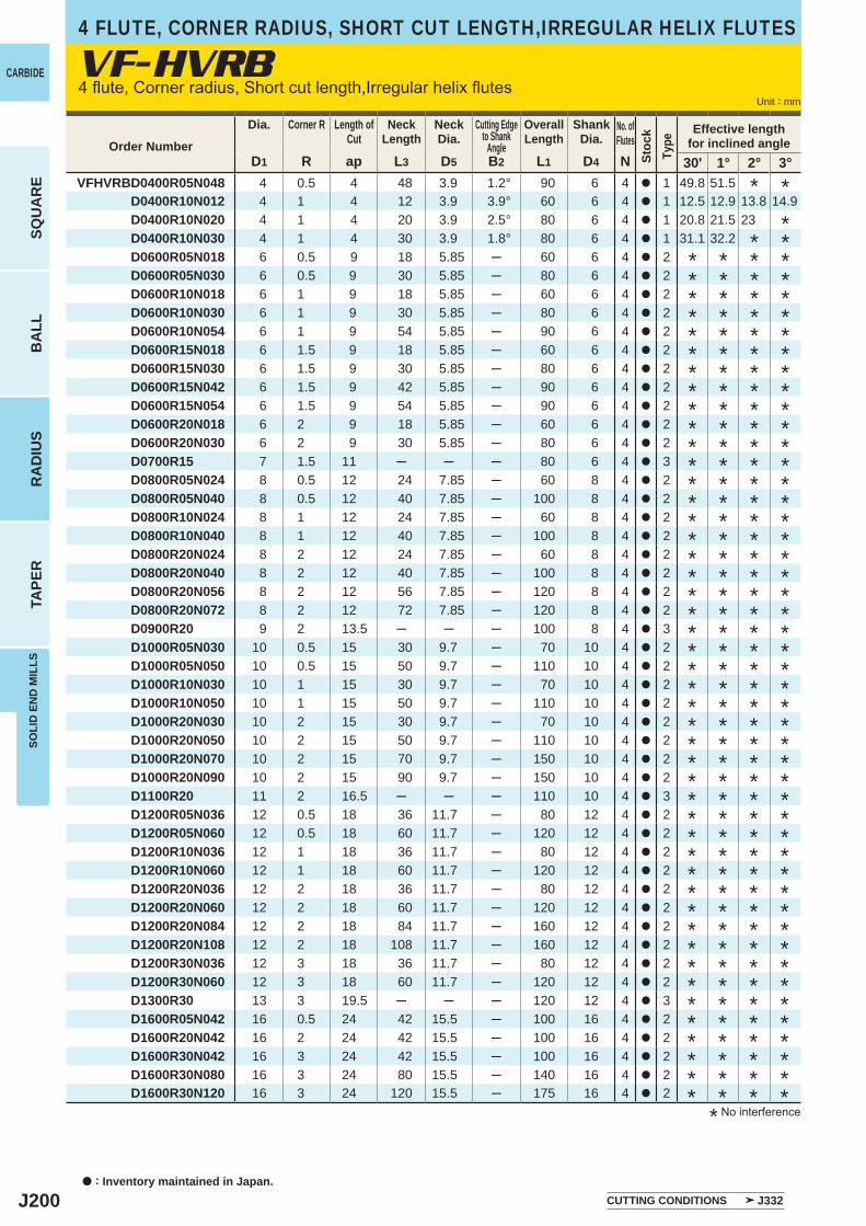
J200
D1 R ap L3 D5 B2 L1 D4 N 30' 1° 2° 3°VFHVRBD0400R05N048 4 0.5 4 48 3.9 1.2° 90 6 4 a 1 49.8 51.5
D0400R10N012 4 1 4 12 3.9 3.9° 60 6 4 a 1 12.5 12.9 13.8 14.9D0400R10N020 4 1 4 20 3.9 2.5° 80 6 4 a 1 20.8 21.5 23D0400R10N030 4 1 4 30 3.9 1.8° 80 6 4 a 1 31.1 32.2D0600R05N018 6 0.5 9 18 5.85 ─ 60 6 4 a 2D0600R05N030 6 0.5 9 30 5.85 ─ 80 6 4 a 2D0600R10N018 6 1 9 18 5.85 ─ 60 6 4 a 2D0600R10N030 6 1 9 30 5.85 ─ 80 6 4 a 2D0600R10N054 6 1 9 54 5.85 ─ 90 6 4 a 2D0600R15N018 6 1.5 9 18 5.85 ─ 60 6 4 a 2D0600R15N030 6 1.5 9 30 5.85 ─ 80 6 4 a 2D0600R15N042 6 1.5 9 42 5.85 ─ 90 6 4 a 2D0600R15N054 6 1.5 9 54 5.85 ─ 90 6 4 a 2D0600R20N018 6 2 9 18 5.85 ─ 60 6 4 a 2D0600R20N030 6 2 9 30 5.85 ─ 80 6 4 a 2D0700R15 7 1.5 11 ─ ─ ─ 80 6 4 a 3D0800R05N024 8 0.5 12 24 7.85 ─ 60 8 4 a 2D0800R05N040 8 0.5 12 40 7.85 ─ 100 8 4 a 2D0800R10N024 8 1 12 24 7.85 ─ 60 8 4 a 2D0800R10N040 8 1 12 40 7.85 ─ 100 8 4 a 2D0800R20N024 8 2 12 24 7.85 ─ 60 8 4 a 2D0800R20N040 8 2 12 40 7.85 ─ 100 8 4 a 2D0800R20N056 8 2 12 56 7.85 ─ 120 8 4 a 2D0800R20N072 8 2 12 72 7.85 ─ 120 8 4 a 2D0900R20 9 2 13.5 ─ ─ ─ 100 8 4 a 3D1000R05N030 10 0.5 15 30 9.7 ─ 70 10 4 a 2D1000R05N050 10 0.5 15 50 9.7 ─ 110 10 4 a 2D1000R10N030 10 1 15 30 9.7 ─ 70 10 4 a 2D1000R10N050 10 1 15 50 9.7 ─ 110 10 4 a 2D1000R20N030 10 2 15 30 9.7 ─ 70 10 4 a 2D1000R20N050 10 2 15 50 9.7 ─ 110 10 4 a 2D1000R20N070 10 2 15 70 9.7 ─ 150 10 4 a 2D1000R20N090 10 2 15 90 9.7 ─ 150 10 4 a 2D1100R20 11 2 16.5 ─ ─ ─ 110 10 4 a 3D1200R05N036 12 0.5 18 36 11.7 ─ 80 12 4 a 2D1200R05N060 12 0.5 18 60 11.7 ─ 120 12 4 a 2D1200R10N036 12 1 18 36 11.7 ─ 80 12 4 a 2D1200R10N060 12 1 18 60 11.7 ─ 120 12 4 a 2D1200R20N036 12 2 18 36 11.7 ─ 80 12 4 a 2D1200R20N060 12 2 18 60 11.7 ─ 120 12 4 a 2D1200R20N084 12 2 18 84 11.7 ─ 160 12 4 a 2D1200R20N108 12 2 18 108 11.7 ─ 160 12 4 a 2D1200R30N036 12 3 18 36 11.7 ─ 80 12 4 a 2D1200R30N060 12 3 18 60 11.7 ─ 120 12 4 a 2D1300R30 13 3 19.5 ─ ─ ─ 120 12 4 a 3D1600R05N042 16 0.5 24 42 15.5 ─ 100 16 4 a 2D1600R20N042 16 2 24 42 15.5 ─ 100 16 4 a 2D1600R30N042 16 3 24 42 15.5 ─ 100 16 4 a 2D1600R30N080 16 3 24 80 15.5 ─ 140 16 4 a 2D1600R30N120 16 3 24 120 15.5 ─ 175 16 4 a 2
VF-HVRB
a : Inventory maintained in Japan.
CARBIDE
SQU
AR
EB
ALL
RA
DIU
STA
PER
SOLI
D E
ND
MIL
LS
Unit : mm
* No interference
4 flute, Corner radius, Short cut length,Irregular helix flutes
Order Number
Dia. Corner R Length ofCut
NeckLength
NeckDia.
Cutting Edgeto Shank
Angle
OverallLength
ShankDia.
No. ofFlutes
Stoc
kTy
pe
Effective lengthfor inclined angle
* * * ** * * ** * * ** * * ** * * ** * * ** * * ** * * ** * * ** * * ** * * ** * * ** * * ** * * ** * * ** * * ** * * ** * * ** * * ** * * ** * * ** * * ** * * ** * * ** * * ** * * ** * * ** * * ** * * ** * * ** * * ** * * ** * * ** * * ** * * ** * * ** * * ** * * ** * * ** * * ** * * ** * * ** * * ** * * ** * * *
CUTTING CONDITIONS J332
*
***
*
****
4 FLUTE, CORNER RADIUS, SHORT CUT LENGTH,IRREGULAR HELIX FLUTES
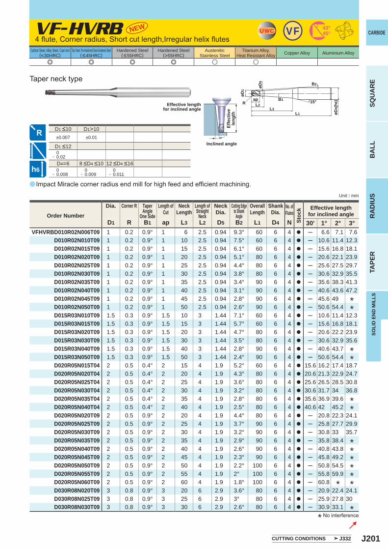
J201
a
e e e e u u
VF-HVRB
D1 R B1 ap L3 L2 D5 B2 L1 D4 N 30' 1° 2° 3°VFHVRBD010R02N006T09 1 0.2 0.9° 1 6 2.5 0.94 9.3° 60 6 4 a ─ 6.6 7.1 7.6
D010R02N010T09 1 0.2 0.9° 1 10 2.5 0.94 7.5° 60 6 4 a ─ 10.6 11.4 12.3D010R02N015T09 1 0.2 0.9° 1 15 2.5 0.94 6.1° 60 6 4 a ─ 15.6 16.8 18.1D010R02N020T09 1 0.2 0.9° 1 20 2.5 0.94 5.1° 80 6 4 a ─ 20.6 22.1 23.9D010R02N025T09 1 0.2 0.9° 1 25 2.5 0.94 4.4° 80 6 4 a ─ 25.6 27.5 29.7D010R02N030T09 1 0.2 0.9° 1 30 2.5 0.94 3.8° 80 6 4 a ─ 30.6 32.9 35.5D010R02N035T09 1 0.2 0.9° 1 35 2.5 0.94 3.4° 90 6 4 a ─ 35.6 38.3 41.3D010R02N040T09 1 0.2 0.9° 1 40 2.5 0.94 3.1° 90 6 4 a ─ 40.6 43.6 47.2D010R02N045T09 1 0.2 0.9° 1 45 2.5 0.94 2.8° 90 6 4 a ─ 45.6 49D010R02N050T09 1 0.2 0.9° 1 50 2.5 0.94 2.6° 90 6 4 a ─ 50.6 54.4D015R03N010T09 1.5 0.3 0.9° 1.5 10 3 1.44 7.1° 60 6 4 a ─ 10.6 11.4 12.3D015R03N015T09 1.5 0.3 0.9° 1.5 15 3 1.44 5.7° 60 6 4 a ─ 15.6 16.8 18.1D015R03N020T09 1.5 0.3 0.9° 1.5 20 3 1.44 4.7° 80 6 4 a ─ 20.6 22.2 23.9D015R03N030T09 1.5 0.3 0.9° 1.5 30 3 1.44 3.5° 80 6 4 a ─ 30.6 32.9 35.6D015R03N040T09 1.5 0.3 0.9° 1.5 40 3 1.44 2.8° 90 6 4 a ─ 40.6 43.7D015R03N050T09 1.5 0.3 0.9° 1.5 50 3 1.44 2.4° 90 6 4 a ─ 50.6 54.4D020R05N015T04 2 0.5 0.4° 2 15 4 1.9 5.2° 60 6 4 a 15.6 16.2 17.4 18.7D020R05N020T04 2 0.5 0.4° 2 20 4 1.9 4.3° 80 6 4 a 20.6 21.3 22.9 24.7D020R05N025T04 2 0.5 0.4° 2 25 4 1.9 3.6° 80 6 4 a 25.6 26.5 28.5 30.8D020R05N030T04 2 0.5 0.4° 2 30 4 1.9 3.2° 80 6 4 a 30.6 31.7 34 36.8D020R05N035T04 2 0.5 0.4° 2 35 4 1.9 2.8° 80 6 4 a 35.6 36.9 39.6D020R05N040T04 2 0.5 0.4° 2 40 4 1.9 2.5° 80 6 4 a 40.6 42 45.2D020R05N020T09 2 0.5 0.9° 2 20 4 1.9 4.4° 80 6 4 a ─ 20.8 22.3 24.1D020R05N025T09 2 0.5 0.9° 2 25 4 1.9 3.7° 90 6 4 a ─ 25.8 27.7 29.9D020R05N030T09 2 0.5 0.9° 2 30 4 1.9 3.2° 90 6 4 a ─ 30.8 33 35.7D020R05N035T09 2 0.5 0.9° 2 35 4 1.9 2.9° 90 6 4 a ─ 35.8 38.4D020R05N040T09 2 0.5 0.9° 2 40 4 1.9 2.6° 90 6 4 a ─ 40.8 43.8D020R05N045T09 2 0.5 0.9° 2 45 4 1.9 2.3° 90 6 4 a ─ 45.8 49.2D020R05N050T09 2 0.5 0.9° 2 50 4 1.9 2.2° 100 6 4 a ─ 50.8 54.5D020R05N055T09 2 0.5 0.9° 2 55 4 1.9 2° 100 6 4 a ─ 55.8 59.9D020R05N060T09 2 0.5 0.9° 2 60 4 1.9 1.8° 100 6 4 a ─ 60.8D030R08N020T09 3 0.8 0.9° 3 20 6 2.9 3.6° 80 6 4 a ─ 20.9 22.4 24.1D030R08N025T09 3 0.8 0.9° 3 25 6 2.9 3° 80 6 4 a ─ 25.9 27.8 30D030R08N030T09 3 0.8 0.9° 3 30 6 2.9 2.6° 80 6 4 a ─ 30.9 33.1
D1>10±0.007 ±0.01
0- 0.02
D4=6 0- 0.008
0- 0.009
0- 0.011
NEW UWC 43°45°VF
øD4(
h 6)
øD1
øD5
Rap
L3L1
L2
B2
B1 15°
h6
CARBIDE
SQU
AR
EB
ALL
RA
DIU
STA
PER
SOLI
D E
ND
MIL
LS
Unit : mm
Carbon Steel, Alloy Steel, Cast Iron(<30HRC)
Tool Steel, Pre-Hardened Steel,Hardened Steel(<45HRC)
Hardened Steel(<55HRC)
Hardened Steel(>55HRC)
AusteniticStainless Steel
Titanium Alloy,Heat Resistant Alloy Copper Alloy Aluminium Alloy
4 flute, Corner radius, Short cut length,Irregular helix flutes
Impact Miracle corner radius end mill for high feed and efficient machining.
* No interference
Effective lengthfor inclined angle
Inclined angle
Effe
ctiv
ele
ngth
Taper neck type
CUTTING CONDITIONS J332
******
*
**
**
**
*
Order Number
Dia. Corner R TaperAngle
One Side
Length ofCut
NeckLength
Length ofStraight
Neck
NeckDia.
Cutting Edgeto Shank
Angle
OverallLength
ShankDia.
No. ofFlutes
Stoc
k Effective lengthfor inclined angle
8 <D4 <10 12 <D4 <16
D1 <12
D1 <10
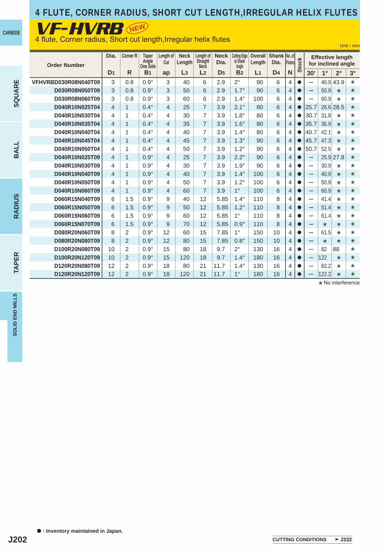
J202
D1 R B1 ap L3 L2 D5 B2 L1 D4 N 30' 1° 2° 3°VFHVRBD030R08N040T09 3 0.8 0.9° 3 40 6 2.9 2° 90 6 4 a ─ 40.9 43.9
D030R08N050T09 3 0.8 0.9° 3 50 6 2.9 1.7° 90 6 4 a ─ 50.9D030R08N060T09 3 0.8 0.9° 3 60 6 2.9 1.4° 100 6 4 a ─ 60.9D040R10N025T04 4 1 0.4° 4 25 7 3.9 2.1° 80 6 4 a 25.7 26.6 28.5D040R10N030T04 4 1 0.4° 4 30 7 3.9 1.8° 80 6 4 a 30.7 31.8D040R10N035T04 4 1 0.4° 4 35 7 3.9 1.6° 80 6 4 a 35.7 36.9D040R10N040T04 4 1 0.4° 4 40 7 3.9 1.4° 80 6 4 a 40.7 42.1D040R10N045T04 4 1 0.4° 4 45 7 3.9 1.3° 90 6 4 a 45.7 47.3D040R10N050T04 4 1 0.4° 4 50 7 3.9 1.2° 90 6 4 a 50.7 52.5D040R10N025T09 4 1 0.9° 4 25 7 3.9 2.2° 90 6 4 a ─ 25.9 27.8D040R10N030T09 4 1 0.9° 4 30 7 3.9 1.9° 90 6 4 a ─ 30.9D040R10N040T09 4 1 0.9° 4 40 7 3.9 1.4° 100 6 4 a ─ 40.9D040R10N050T09 4 1 0.9° 4 50 7 3.9 1.2° 100 6 4 a ─ 50.9D040R10N060T09 4 1 0.9° 4 60 7 3.9 1° 100 6 4 a ─ 60.9D060R15N040T09 6 1.5 0.9° 9 40 12 5.85 1.4° 110 8 4 a ─ 41.4D060R15N050T09 6 1.5 0.9° 9 50 12 5.85 1.2° 110 8 4 a ─ 51.4D060R15N060T09 6 1.5 0.9° 9 60 12 5.85 1° 110 8 4 a ─ 61.4D060R15N070T09 6 1.5 0.9° 9 70 12 5.85 0.9° 110 8 4 a ─D080R20N060T09 8 2 0.9° 12 60 15 7.85 1° 150 10 4 a ─ 61.5D080R20N080T09 8 2 0.9° 12 80 15 7.85 0.8° 150 10 4 a ─D100R20N080T09 10 2 0.9° 15 80 18 9.7 2° 130 16 4 a ─ 82 88D100R20N120T09 10 2 0.9° 15 120 18 9.7 1.4° 180 16 4 a ─ 122D120R20N080T09 12 2 0.9° 18 80 21 11.7 1.4° 130 16 4 a ─ 82.2D120R20N120T09 12 2 0.9° 18 120 21 11.7 1° 180 16 4 a ─ 122.2
VF-HVRB NEW
a : Inventory maintained in Japan.
CARBIDE
SQU
AR
EB
ALL
RA
DIU
STA
PER
SOLI
D E
ND
MIL
LS
Unit : mm4 flute, Corner radius, Short cut length,Irregular helix flutes
* No interference
CUTTING CONDITIONS J332
Order NumberDia. Corner R Taper
AngleOne Side
Length ofCut
NeckLength
Length ofStraight
Neck
NeckDia.
Cutting Edgeto Shank
Angle
OverallLength
ShankDia.
No. ofFlutes
Stoc
k Effective lengthfor inclined angle
*******************
**********
***
****
*
*
*****
**
*
4 FLUTE, CORNER RADIUS, SHORT CUT LENGTH,IRREGULAR HELIX FLUTES
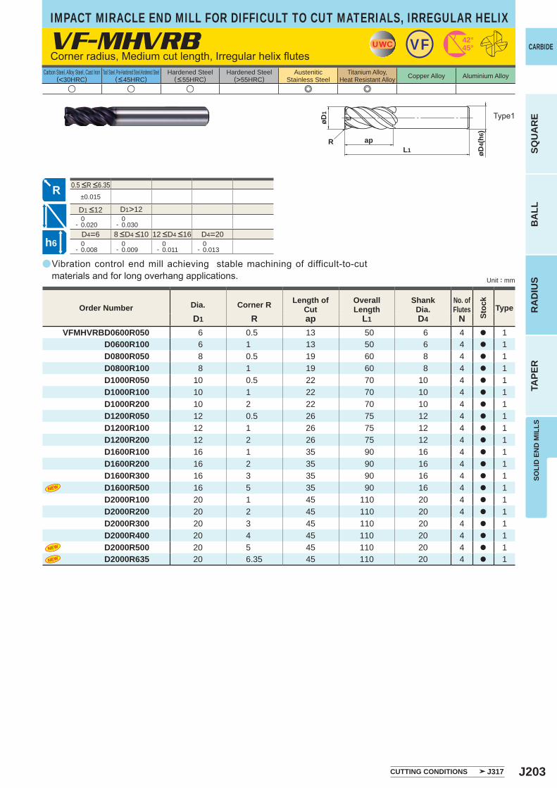
J203
a
VF-MHVRB
u u u e e
D1 R ap L1 D4 NVFMHVRBD0600R050 6 0.5 13 50 6 4 a 1
D0600R100 6 1 13 50 6 4 a 1 D0800R050 8 0.5 19 60 8 4 a 1 D0800R100 8 1 19 60 8 4 a 1 D1000R050 10 0.5 22 70 10 4 a 1 D1000R100 10 1 22 70 10 4 a 1 D1000R200 10 2 22 70 10 4 a 1 D1200R050 12 0.5 26 75 12 4 a 1 D1200R100 12 1 26 75 12 4 a 1 D1200R200 12 2 26 75 12 4 a 1 D1600R100 16 1 35 90 16 4 a 1 D1600R200 16 2 35 90 16 4 a 1 D1600R300 16 3 35 90 16 4 a 1
D1600R500 16 5 35 90 16 4 a 1 D2000R100 20 1 45 110 20 4 a 1 D2000R200 20 2 45 110 20 4 a 1 D2000R300 20 3 45 110 20 4 a 1 D2000R400 20 4 45 110 20 4 a 1
D2000R500 20 5 45 110 20 4 a 1 D2000R635 20 6.35 45 110 20 4 a 1
±0.015
D1>12 0- 0.020
0- 0.030
D4=6 D4=20 0- 0.008
0- 0.009
0- 0.011
0- 0.013
UWC VF 42°45°
L1
øD1
R ap
øD4(
h6)
h6
CARBIDE
SQU
AR
EB
ALL
RA
DIU
STA
PER
SOLI
D E
ND
MIL
LS
Unit : mm
Carbon Steel, Alloy Steel, Cast Iron(<30HRC)
Tool Steel, Pre-Hardened Steel,Hardened Steel(<45HRC)
Hardened Steel(<55HRC)
Hardened Steel(>55HRC)
AusteniticStainless Steel
Titanium Alloy,Heat Resistant Alloy Copper Alloy Aluminium Alloy
Vibration control end mill achieving stable machining of difficult-to-cut materials and for long overhang applications.
Corner radius, Medium cut length, Irregular helix flutes
Type1
CUTTING CONDITIONS J317
Order Number Dia. Corner R Length of Cut
Overall Length
Shank Dia.
No. ofFlutes
Stoc
k
Type
8 <D4 <10 12 <D4 <16
0.5 <R <6.35
D1 <12
IMPACT MIRACLE END MILL FOR DIFFICULT TO CUT MATERIALS, IRREGULAR HELIX
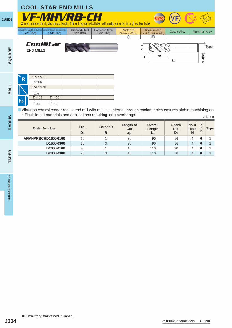
J204
a
e e
VF-MHVRB-CH
D1 R ap L1 D4 NVFMHVRBCHD1600R100 16 1 35 90 16 4 a 1
D1600R300 16 3 35 90 16 4 a 1D2000R100 20 1 45 110 20 4 a 1D2000R300 20 3 45 110 20 4 a 1
±0.015
0- 0.03D4=16 D4=20
0- 0.011
0- 0.013
UWC VF 42°45°
øD1
apL1
R
øD4(
h6)
h6
a : Inventory maintained in Japan.
CARBIDE
SQU
AR
EB
ALL
RA
DIU
STA
PER
SOLI
D E
ND
MIL
LS
Unit : mm
Carbon Steel, Alloy Steel, Cast Iron(<30HRC)
Tool Steel, Pre-Hardened Steel,Hardened Steel(<45HRC)
Hardened Steel(<55HRC)
Hardened Steel(>55HRC)
AusteniticStainless Steel
Titanium Alloy,Heat Resistant Alloy Copper Alloy Aluminium Alloy
Vibration control corner radius end mill with multiple internal through coolant holes ensures stable machining on difficult-to-cut materials and applications requiring long overhangs.
Corner radius end mill, Medium cut length, 4 flute, Irregular helix flutes, with multiple internal through coolant holes
Type1CoolStarEND MILLS
COOL STAR END MILLS
CUTTING CONDITIONS J338
Order Number Dia. Corner R Length of Cut
Overall Length
Shank Dia.
No. ofFlutes
Stoc
k
Type
1 <R <3
16 <D1 <20
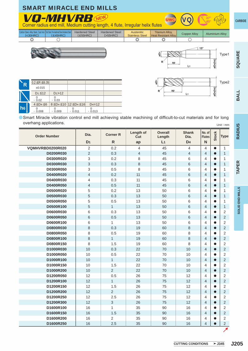
J205
a
NEW
e u e e u
VQ-MHVRB
D1 R ap L1 D4 NVQMHVRBD0200R020 2 0.2 4 45 4 4 a 1 D0200R030 2 0.3 4 45 4 4 a 1 D0300R020 3 0.2 8 45 6 4 a 1 D0300R030 3 0.3 8 45 6 4 a 1 D0300R050 3 0.5 8 45 6 4 a 1 D0400R020 4 0.2 11 45 6 4 a 1 D0400R030 4 0.3 11 45 6 4 a 1 D0400R050 4 0.5 11 45 6 4 a 1 D0500R020 5 0.2 13 50 6 4 a 1 D0500R030 5 0.3 13 50 6 4 a 1 D0500R050 5 0.5 13 50 6 4 a 1 D0500R100 5 1 13 50 6 4 a 1 D0600R030 6 0.3 13 50 6 4 a 2 D0600R050 6 0.5 13 50 6 4 a 2 D0600R100 6 1 13 50 6 4 a 2 D0800R030 8 0.3 19 60 8 4 a 2 D0800R050 8 0.5 19 60 8 4 a 2 D0800R100 8 1 19 60 8 4 a 2 D0800R150 8 1.5 19 60 8 4 a 2 D1000R030 10 0.3 22 70 10 4 a 2 D1000R050 10 0.5 22 70 10 4 a 2 D1000R100 10 1 22 70 10 4 a 2 D1000R150 10 1.5 22 70 10 4 a 2 D1000R200 10 2 22 70 10 4 a 2 D1200R050 12 0.5 26 75 12 4 a 2 D1200R100 12 1 26 75 12 4 a 2 D1200R150 12 1.5 26 75 12 4 a 2 D1200R200 12 2 26 75 12 4 a 2 D1200R250 12 2.5 26 75 12 4 a 2 D1200R300 12 3 26 75 12 4 a 2 D1600R100 16 1 35 90 16 4 a 2 D1600R150 16 1.5 35 90 16 4 a 2 D1600R200 16 2 35 90 16 4 a 2 D1600R250 16 2.5 35 90 16 4 a 2
a
±0.015
D1>12 0- 0.02
0- 0.03
D4=12 0- 0.008
0- 0.009
0- 0.011
0- 0.013
UWC VQ 37°40°
h6
CARBIDE
SQU
AR
EB
ALL
RA
DIU
STA
PER
SOLI
D E
ND
MIL
LS
Unit : mm
Carbon Steel, Alloy Steel, Cast Iron(<30HRC)
Tool Steel, Pre-Hardened Steel,Hardened Steel(<45HRC)
Hardened Steel(<55HRC)
Hardened Steel(>55HRC)
AusteniticStainless Steel
Titanium Alloy,Heat Resistant Alloy Copper Alloy Aluminium Alloy
CUTTING CONDITIONS J345
SMART MIRACLE END MILLS
Corner radius end mill, Medium cutting length, 4 flute, Irregular helix flutes
Smart Miracle vibration control end mill achieving stable machining of difficult-to-cut materials and for long overhang applications.
Type1
Type2
Order Number Dia. Corner R Length of Cut
Overall Length
Shank Dia.
No. ofFlutes
Stoc
k
Type
4 <D4 <6 8 <D4 <10 12 <D4 <16
D1 <12
0.2 <R <6.35
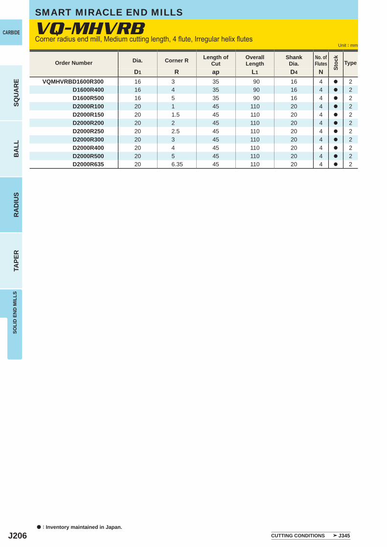
J206
D1 R ap L1 D4 NVQMHVRBD1600R300 16 3 35 90 16 4 a 2 D1600R400 16 4 35 90 16 4 a 2 D1600R500 16 5 35 90 16 4 a 2 D2000R100 20 1 45 110 20 4 a 2 D2000R150 20 1.5 45 110 20 4 a 2 D2000R200 20 2 45 110 20 4 a 2 D2000R250 20 2.5 45 110 20 4 a 2 D2000R300 20 3 45 110 20 4 a 2 D2000R400 20 4 45 110 20 4 a 2 D2000R500 20 5 45 110 20 4 a 2 D2000R635 20 6.35 45 110 20 4 a 2
a : Inventory maintained in Japan.
CARBIDE
SQU
AR
EB
ALL
RA
DIU
STA
PER
SOLI
D E
ND
MIL
LS
Unit : mm
Order Number Dia. Corner R Length of Cut
Overall Length
Shank Dia.
No. ofFlutes
Stoc
k
Type
CUTTING CONDITIONS J345
SMART MIRACLE END MILLS
Corner radius end mill, Medium cutting length, 4 flute, Irregular helix flutesVQ-MHVRB
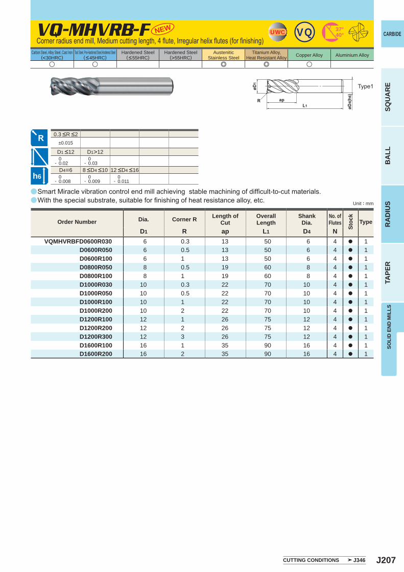
J207
a
±0.015
D1>12 0- 0.02
0- 0.03
D4=6 0- 0.008
0- 0.009
0- 0.011
u u e e u
VQ-MHVRB-F
D1 R ap L1 D4 NVQMHVRBFD0600R030 6 0.3 13 50 6 4 a 1 D0600R050 6 0.5 13 50 6 4 a 1 D0600R100 6 1 13 50 6 4 a 1 D0800R050 8 0.5 19 60 8 4 a 1 D0800R100 8 1 19 60 8 4 a 1 D1000R030 10 0.3 22 70 10 4 a 1 D1000R050 10 0.5 22 70 10 4 a 1 D1000R100 10 1 22 70 10 4 a 1 D1000R200 10 2 22 70 10 4 a 1 D1200R100 12 1 26 75 12 4 a 1 D1200R200 12 2 26 75 12 4 a 1 D1200R300 12 3 26 75 12 4 a 1 D1600R100 16 1 35 90 16 4 a 1 D1600R200 16 2 35 90 16 4 a 1
NEW
a
a
UWC VQ 37°40°
h6
CARBIDE
SQU
AR
EB
ALL
RA
DIU
STA
PER
SOLI
D E
ND
MIL
LS
Unit : mm
Carbon Steel, Alloy Steel, Cast Iron(<30HRC)
Tool Steel, Pre-Hardened Steel,Hardened Steel(<45HRC)
Hardened Steel(<55HRC)
Hardened Steel(>55HRC)
AusteniticStainless Steel
Titanium Alloy,Heat Resistant Alloy Copper Alloy Aluminium Alloy
8 <D4 <10 12 <D4 <16
D1 <12
Smart Miracle vibration control end mill achieving stable machining of difficult-to-cut materials.With the special substrate, suitable for finishing of heat resistance alloy, etc.
Type1
Order Number Dia. Corner R Length of Cut
Overall Length
Shank Dia.
No. ofFlutes
Stoc
k
Type
CUTTING CONDITIONS J346
0.3 <R <2
Corner radius end mill, Medium cutting length, 4 flute, Irregular helix flutes (for finishing)
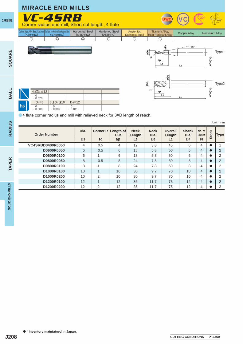
J208
a
u e e u u u
VC-4SRB
D1 R ap L3 D5 L1 D4 NVC4SRBD0400R0050 4 0.5 4 12 3.8 45 6 4 a 1
D0600R0050 6 0.5 6 18 5.8 50 6 4 a 2D0600R0100 6 1 6 18 5.8 50 6 4 a 2D0800R0050 8 0.5 8 24 7.8 60 8 4 a 2D0800R0100 8 1 8 24 7.8 60 8 4 a 2D1000R0100 10 1 10 30 9.7 70 10 4 a 2D1000R0200 10 2 10 30 9.7 70 10 4 a 2D1200R0100 12 1 12 36 11.7 75 12 4 a 2D1200R0200 12 2 12 36 11.7 75 12 4 a 2
0- 0.020
D4=6 D4=12 0- 0.008
0- 0.009
0- 0.011
UWC VC 30°
øD4(
h6)
ap
L1
øD1
L3
R
øD5
15°
L1
øD5
apL3 øD
4(h6
)
øD1
R
h6
a : Inventory maintained in Japan.
CARBIDE
SQU
AR
EB
ALL
RA
DIU
STA
PER
SOLI
D E
ND
MIL
LS
Unit : mm
Carbon Steel, Alloy Steel, Cast Iron(<30HRC)
Tool Steel, Pre-Hardened Steel,Hardened Steel(<45HRC)
Hardened Steel(<55HRC)
Hardened Steel(>55HRC)
AusteniticStainless Steel
Titanium Alloy,Heat Resistant Alloy Copper Alloy Aluminium Alloy
4 flute corner radius end mill with relieved neck for 3×D length of reach.
Corner radius end mill, Short cut length, 4 flute
Type2
Type1
MIRACLE END MILLS
CUTTING CONDITIONS J350
Order NumberDia. Corner R Length of
CutNeck
LengthNeckDia.
OverallLength
ShankDia.
No. ofFlutes
Stoc
k
Type
8 <D4 <10
4 <D1 <12
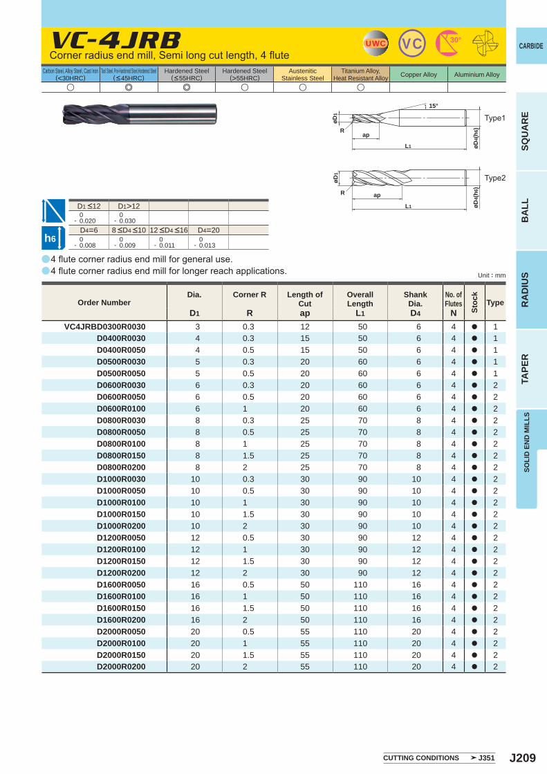
J209
a
u e e u u u
VC-4JRB
D1 R ap L1 D4 NVC4JRBD0300R0030 3 0.3 12 50 6 4 a 1
D0400R0030 4 0.3 15 50 6 4 a 1D0400R0050 4 0.5 15 50 6 4 a 1D0500R0030 5 0.3 20 60 6 4 a 1D0500R0050 5 0.5 20 60 6 4 a 1D0600R0030 6 0.3 20 60 6 4 a 2D0600R0050 6 0.5 20 60 6 4 a 2D0600R0100 6 1 20 60 6 4 a 2D0800R0030 8 0.3 25 70 8 4 a 2D0800R0050 8 0.5 25 70 8 4 a 2D0800R0100 8 1 25 70 8 4 a 2D0800R0150 8 1.5 25 70 8 4 a 2D0800R0200 8 2 25 70 8 4 a 2D1000R0030 10 0.3 30 90 10 4 a 2D1000R0050 10 0.5 30 90 10 4 a 2D1000R0100 10 1 30 90 10 4 a 2D1000R0150 10 1.5 30 90 10 4 a 2D1000R0200 10 2 30 90 10 4 a 2D1200R0050 12 0.5 30 90 12 4 a 2D1200R0100 12 1 30 90 12 4 a 2D1200R0150 12 1.5 30 90 12 4 a 2D1200R0200 12 2 30 90 12 4 a 2D1600R0050 16 0.5 50 110 16 4 a 2D1600R0100 16 1 50 110 16 4 a 2D1600R0150 16 1.5 50 110 16 4 a 2D1600R0200 16 2 50 110 16 4 a 2D2000R0050 20 0.5 55 110 20 4 a 2D2000R0100 20 1 55 110 20 4 a 2D2000R0150 20 1.5 55 110 20 4 a 2D2000R0200 20 2 55 110 20 4 a 2
a
a
D1>12 0- 0.020
0- 0.030
D4=6 D4=20 0- 0.008
0- 0.009
0- 0.011
0- 0.013
UWC VC 30°
R
øD4(
h6)
ap
L1
øD1
15°
R
øD1
øD4(
h6)
ap
L1
h6
CARBIDE
SQU
AR
EB
ALL
RA
DIU
STA
PER
SOLI
D E
ND
MIL
LS
Unit : mm
Carbon Steel, Alloy Steel, Cast Iron(<30HRC)
Tool Steel, Pre-Hardened Steel,Hardened Steel(<45HRC)
Hardened Steel(<55HRC)
Hardened Steel(>55HRC)
AusteniticStainless Steel
Titanium Alloy,Heat Resistant Alloy Copper Alloy Aluminium Alloy
4 flute corner radius end mill for general use. 4 flute corner radius end mill for longer reach applications.
Corner radius end mill, Semi long cut length, 4 flute
Type2
Type1
CUTTING CONDITIONS J351
Order NumberDia. Corner R Length of
CutOverall Length
Shank Dia.
No. ofFlutes
Stoc
k
Type
8 <D4 <10 12 <D4 <16
D1 <12
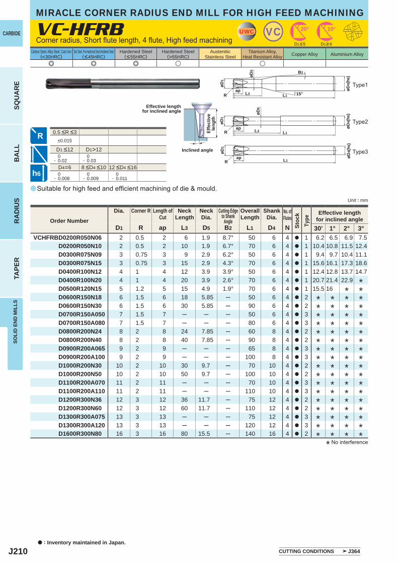
J210
a
e e e u u
VC-HFRB
D1 R ap L3 D5 B2 L1 D4 N 30' 1° 2° 3°VCHFRBD0200R050N06 2 0.5 2 6 1.9 8.7° 50 6 4 a 1 6.2 6.5 6.9 7.5
D0200R050N10 2 0.5 2 10 1.9 6.7° 70 6 4 a 1 10.4 10.8 11.5 12.4D0300R075N09 3 0.75 3 9 2.9 6.2° 50 6 4 a 1 9.4 9.7 10.4 11.1D0300R075N15 3 0.75 3 15 2.9 4.3° 70 6 4 a 1 15.6 16.1 17.3 18.6D0400R100N12 4 1 4 12 3.9 3.9° 50 6 4 a 1 12.4 12.8 13.7 14.7D0400R100N20 4 1 4 20 3.9 2.6° 70 6 4 a 1 20.7 21.4 22.9D0500R120N15 5 1.2 5 15 4.9 1.9° 70 6 4 a 1 15.5 16D0600R150N18 6 1.5 6 18 5.85 ─ 50 6 4 a 2D0600R150N30 6 1.5 6 30 5.85 ─ 90 6 4 a 2D0700R150A050 7 1.5 7 ─ ─ ─ 50 6 4 a 3D0700R150A080 7 1.5 7 ─ ─ ─ 80 6 4 a 3D0800R200N24 8 2 8 24 7.85 ─ 60 8 4 a 2D0800R200N40 8 2 8 40 7.85 ─ 90 8 4 a 2D0900R200A065 9 2 9 ─ ─ ─ 65 8 4 a 3D0900R200A100 9 2 9 ─ ─ ─ 100 8 4 a 3D1000R200N30 10 2 10 30 9.7 ─ 70 10 4 a 2D1000R200N50 10 2 10 50 9.7 ─ 100 10 4 a 2D1100R200A070 11 2 11 ─ ─ ─ 70 10 4 a 3D1100R200A110 11 2 11 ─ ─ ─ 110 10 4 a 3D1200R300N36 12 3 12 36 11.7 ─ 75 12 4 a 2D1200R300N60 12 3 12 60 11.7 ─ 110 12 4 a 2D1300R300A075 13 3 13 ─ ─ ─ 75 12 4 a 3D1300R300A120 13 3 13 ─ ─ ─ 120 12 4 a 3D1600R300N80 16 3 16 80 15.5 ─ 140 16 4 a 2
±0.015
D1>12 0- 0.02
0- 0.03
D4=6 0- 0.008
0- 0.009
0- 0.011
UWC VC 10°20°
15°
øD5
øD4(
h6)
L3ap
L1
øD1
R
B2
øD4(
h6)
ap L1
øD1
R
øD5
øD4(
h6)
ap L3 L1
øD1
R
h6
a : Inventory maintained in Japan.
CARBIDE
SQU
AR
EB
ALL
RA
DIU
STA
PER
SOLI
D E
ND
MIL
LS
Unit : mm
Carbon Steel, Alloy Steel, Cast Iron(<30HRC)
Tool Steel, Pre-Hardened Steel,Hardened Steel(<45HRC)
Hardened Steel(<55HRC)
Hardened Steel(>55HRC)
AusteniticStainless Steel
Titanium Alloy,Heat Resistant Alloy Copper Alloy Aluminium Alloy
Suitable for high feed and efficient machining of die & mould.
Corner radius, Short flute length, 4 flute, High feed machining
Type2
Type3
Type1
Effective lengthfor inclined angle
Inclined angle
Effe
ctiv
ele
ngth
CUTTING CONDITIONS J364
D1<5 D1>6
* No interference
Order Number
Dia. Corner R Length ofCut
NeckLength
NeckDia.
Cutting Edgeto Shank
Angle
OverallLength
ShankDia.
No. ofFlutes
Stoc
kTy
pe
Effective lengthfor inclined angle
** *
* * * ** * * ** * * ** * * ** * * ** * * ** * * ** * * ** * * ** * * ** * * ** * * ** * * ** * * ** * * ** * * ** * * *
8 <D4 <10 12 <D4 <16
0.5 <R <3
D1 <12
MIRACLE CORNER RADIUS END MILL FOR HIGH FEED MACHINING
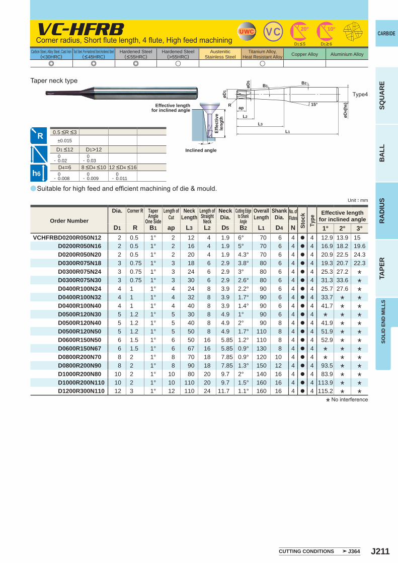
J211
a
e e e u u
VC-HFRB
D1 R B1 ap L3 L2 D5 B2 L1 D4 N 1° 2° 3°VCHFRBD0200R050N12 2 0.5 1° 2 12 4 1.9 6° 70 6 4 a 4 12.9 13.9 15
D0200R050N16 2 0.5 1° 2 16 4 1.9 5° 70 6 4 a 4 16.9 18.2 19.6D0200R050N20 2 0.5 1° 2 20 4 1.9 4.3° 70 6 4 a 4 20.9 22.5 24.3D0300R075N18 3 0.75 1° 3 18 6 2.9 3.8° 80 6 4 a 4 19.3 20.7 22.3D0300R075N24 3 0.75 1° 3 24 6 2.9 3° 80 6 4 a 4 25.3 27.2D0300R075N30 3 0.75 1° 3 30 6 2.9 2.6° 80 6 4 a 4 31.3 33.6D0400R100N24 4 1 1° 4 24 8 3.9 2.2° 90 6 4 a 4 25.7 27.6D0400R100N32 4 1 1° 4 32 8 3.9 1.7° 90 6 4 a 4 33.7D0400R100N40 4 1 1° 4 40 8 3.9 1.4° 90 6 4 a 4 41.7D0500R120N30 5 1.2 1° 5 30 8 4.9 1° 90 6 4 a 4D0500R120N40 5 1.2 1° 5 40 8 4.9 2° 90 8 4 a 4 41.9D0500R120N50 5 1.2 1° 5 50 8 4.9 1.7° 110 8 4 a 4 51.9D0600R150N50 6 1.5 1° 6 50 16 5.85 1.2° 110 8 4 a 4 52.9D0600R150N67 6 1.5 1° 6 67 16 5.85 0.9° 130 8 4 a 4D0800R200N70 8 2 1° 8 70 18 7.85 0.9° 120 10 4 a 4D0800R200N90 8 2 1° 8 90 18 7.85 1.3° 150 12 4 a 4 93.5D1000R200N80 10 2 1° 10 80 20 9.7 2° 140 16 4 a 4 83.9D1000R200N110 10 2 1° 10 110 20 9.7 1.5° 160 16 4 a 4 113.9D1200R300N110 12 3 1° 12 110 24 11.7 1.1° 160 16 4 a 4 115.2
±0.015
D1>12 0- 0.02
0- 0.03
D4=6 0- 0.008
0- 0.009
0- 0.011
UWC VC 10°20°
B2
15°
øD5
øD4(
h6)
L2
ap
L3
L1
øD1
R
B1
h6
CARBIDE
SQU
AR
EB
ALL
RA
DIU
STA
PER
SOLI
D E
ND
MIL
LS
Unit : mm
Carbon Steel, Alloy Steel, Cast Iron(<30HRC)
Tool Steel, Pre-Hardened Steel,Hardened Steel(<45HRC)
Hardened Steel(<55HRC)
Hardened Steel(>55HRC)
AusteniticStainless Steel
Titanium Alloy,Heat Resistant Alloy Copper Alloy Aluminium Alloy
0.5 <R <3
Suitable for high feed and efficient machining of die & mould.
Corner radius, Short flute length, 4 flute, High feed machining
Type4
Effective lengthfor inclined angle
Inclined angle
Effe
ctiv
ele
ngth
Taper neck type
CUTTING CONDITIONS J364
D1<5 D1>6
* No interference
***************
************
*
**
Order Number
Dia. Corner R TaperAngle
One Side
Length ofCut
NeckLength
Length ofStraight
Neck
NeckDia.
Cutting Edgeto Shank
Angle
OverallLength
ShankDia.
No. ofFlutes
Stoc
kTy
pe
Effective lengthfor inclined angle
8 <D4 <10 12 <D4 <16
D1 <12
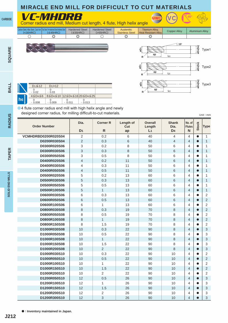
J212
a
u e e u e e
VC-MHDRB
D1 R ap L1 D4 NVCMHDRBD0200R020S04 2 0.2 6 40 4 4 a 1
D0200R030S04 2 0.3 6 40 4 4 a 1D0300R020S06 3 0.2 8 50 6 4 a 1D0300R030S06 3 0.3 8 50 6 4 a 1D0300R050S06 3 0.5 8 50 6 4 a 1D0400R020S06 4 0.2 11 50 6 4 a 1D0400R030S06 4 0.3 11 50 6 4 a 1D0400R050S06 4 0.5 11 50 6 4 a 1D0500R020S06 5 0.2 13 60 6 4 a 1D0500R030S06 5 0.3 13 60 6 4 a 1D0500R050S06 5 0.5 13 60 6 4 a 1D0500R100S06 5 1 13 60 6 4 a 1D0600R030S06 6 0.3 13 60 6 4 a 2D0600R050S06 6 0.5 13 60 6 4 a 2D0600R100S06 6 1 13 60 6 4 a 2D0800R030S08 8 0.3 19 70 8 4 a 2D0800R050S08 8 0.5 19 70 8 4 a 2D0800R100S08 8 1 19 70 8 4 a 2D0800R150S08 8 1.5 19 70 8 4 a 2D1000R030S08 10 0.3 22 90 8 4 a 3D1000R050S08 10 0.5 22 90 8 4 a 3D1000R100S08 10 1 22 90 8 4 a 3D1000R150S08 10 1.5 22 90 8 4 a 3D1000R200S08 10 2 22 90 8 4 a 3D1000R030S10 10 0.3 22 90 10 4 a 2D1000R050S10 10 0.5 22 90 10 4 a 2D1000R100S10 10 1 22 90 10 4 a 2D1000R150S10 10 1.5 22 90 10 4 a 2D1000R200S10 10 2 22 90 10 4 a 2D1200R050S10 12 0.5 26 90 10 4 a 3D1200R100S10 12 1 26 90 10 4 a 3D1200R150S10 12 1.5 26 90 10 4 a 3D1200R200S10 12 2 26 90 10 4 a 3D1200R300S10 12 3 26 90 10 4 a 3
D1>12 0- 0.02
0- 0.03
0- 0.008
0- 0.009
0- 0.011
0- 0.013
UWC VC 45°
L1ap
R
15°
øD4(
h6)
øD1
L1ap
R
øD4(
h6)
øD1
L1ap
R
øD4(
h6)
øD1
h6
a : Inventory maintained in Japan.
CARBIDE
SQU
AR
EB
ALL
RA
DIU
STA
PER
SOLI
D E
ND
MIL
LS
Unit : mm
Carbon Steel, Alloy Steel, Cast Iron(<30HRC)
Tool Steel, Pre-Hardened Steel,Hardened Steel(<45HRC)
Hardened Steel(<55HRC)
Hardened Steel(>55HRC)
AusteniticStainless Steel
Titanium Alloy,Heat Resistant Alloy Copper Alloy Aluminium Alloy
4 flute corner radius end mill with high helix angle and newly designed corner radius, for milling difficult-to-cut materials.
Corner radius end mill, Medium cut length, 4 flute, High helix angle
Type2
Type3
Type1
Order NumberDia. Corner R Length of
CutOverall Length
Shank Dia.
No. ofFlutes
Stoc
k
Type
4≦D4≦6 8≦D4≦10 12≦D4≦16 20≦D4≦25
D1≦12
MIRACLE END MILL FOR DIFFICULT TO CUT MATERIALS
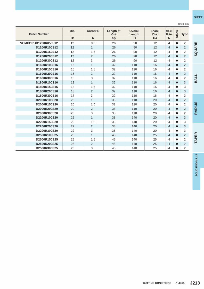
J213
D1 R ap L1 D4 NVCMHDRBD1200R050S12 12 0.5 26 90 12 4 a 2
D1200R100S12 12 1 26 90 12 4 a 2D1200R150S12 12 1.5 26 90 12 4 a 2D1200R200S12 12 2 26 90 12 4 a 2D1200R300S12 12 3 26 90 12 4 a 2D1600R100S16 16 1 32 110 16 4 a 2D1600R150S16 16 1.5 32 110 16 4 a 2D1600R200S16 16 2 32 110 16 4 a 2D1600R300S16 16 3 32 110 16 4 a 2D1800R100S16 18 1 32 110 16 4 a 3D1800R150S16 18 1.5 32 110 16 4 a 3D1800R200S16 18 2 32 110 16 4 a 3D1800R300S16 18 3 32 110 16 4 a 3D2000R100S20 20 1 38 110 20 4 a 2D2000R150S20 20 1.5 38 110 20 4 a 2D2000R200S20 20 2 38 110 20 4 a 2D2000R300S20 20 3 38 110 20 4 a 2D2200R100S20 22 1 38 140 20 4 a 3D2200R150S20 22 1.5 38 140 20 4 a 3D2200R200S20 22 2 38 140 20 4 a 3D2200R300S20 22 3 38 140 20 4 a 3D2500R100S25 25 1 45 140 25 4 a 2D2500R150S25 25 1.5 45 140 25 4 a 2D2500R200S25 25 2 45 140 25 4 a 2D2500R300S25 25 3 45 140 25 4 a 2
CARBIDE
SQU
AR
EB
ALL
RA
DIU
STA
PER
SOLI
D E
ND
MIL
LS
Unit : mm
Order NumberDia. Corner R Length of
CutOverall Length
Shank Dia.
No. ofFlutes
Stoc
k
Type
CUTTING CONDITIONS J365
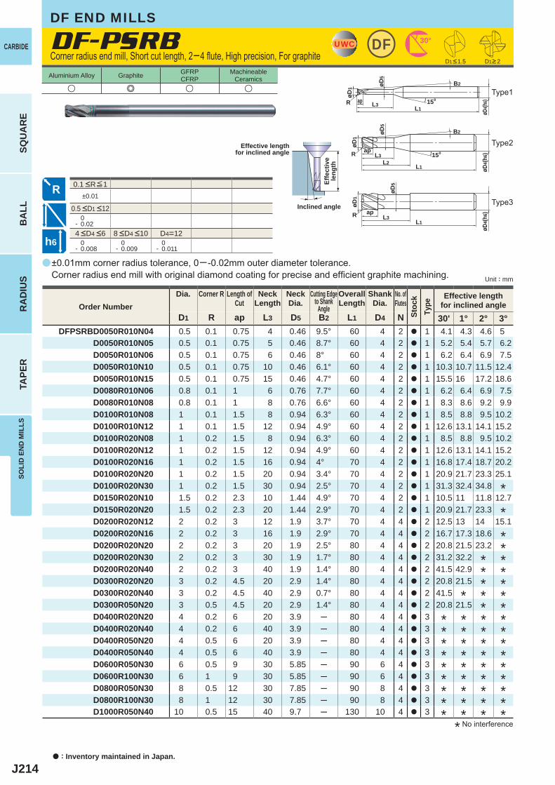
J214
a
DF-PSRB
u e u u
D1 R ap L3 D5 B2 L1 D4 N 30' 1° 2° 3°DFPSRBD0050R010N04 0.5 0.1 0.75 4 0.46 9.5° 60 4 2 a 1 4.1 4.3 4.6 5
D0050R010N05 0.5 0.1 0.75 5 0.46 8.7° 60 4 2 a 1 5.2 5.4 5.7 6.2D0050R010N06 0.5 0.1 0.75 6 0.46 8° 60 4 2 a 1 6.2 6.4 6.9 7.5D0050R010N10 0.5 0.1 0.75 10 0.46 6.1° 60 4 2 a 1 10.3 10.7 11.5 12.4D0050R010N15 0.5 0.1 0.75 15 0.46 4.7° 60 4 2 a 1 15.5 16 17.2 18.6D0080R010N06 0.8 0.1 1 6 0.76 7.7° 60 4 2 a 1 6.2 6.4 6.9 7.5D0080R010N08 0.8 0.1 1 8 0.76 6.6° 60 4 2 a 1 8.3 8.6 9.2 9.9D0100R010N08 1 0.1 1.5 8 0.94 6.3° 60 4 2 a 1 8.5 8.8 9.5 10.2D0100R010N12 1 0.1 1.5 12 0.94 4.9° 60 4 2 a 1 12.6 13.1 14.1 15.2D0100R020N08 1 0.2 1.5 8 0.94 6.3° 60 4 2 a 1 8.5 8.8 9.5 10.2D0100R020N12 1 0.2 1.5 12 0.94 4.9° 60 4 2 a 1 12.6 13.1 14.1 15.2D0100R020N16 1 0.2 1.5 16 0.94 4° 70 4 2 a 1 16.8 17.4 18.7 20.2D0100R020N20 1 0.2 1.5 20 0.94 3.4° 70 4 2 a 1 20.9 21.7 23.3 25.1D0100R020N30 1 0.2 1.5 30 0.94 2.5° 70 4 2 a 1 31.3 32.4 34.8D0150R020N10 1.5 0.2 2.3 10 1.44 4.9° 70 4 2 a 1 10.5 11 11.8 12.7D0150R020N20 1.5 0.2 2.3 20 1.44 2.9° 70 4 2 a 1 20.9 21.7 23.3D0200R020N12 2 0.2 3 12 1.9 3.7° 70 4 4 a 2 12.5 13 14 15.1D0200R020N16 2 0.2 3 16 1.9 2.9° 70 4 4 a 2 16.7 17.3 18.6D0200R020N20 2 0.2 3 20 1.9 2.5° 80 4 4 a 2 20.8 21.5 23.2D0200R020N30 2 0.2 3 30 1.9 1.7° 80 4 4 a 2 31.2 32.2D0200R020N40 2 0.2 3 40 1.9 1.4° 80 4 4 a 2 41.5 42.9D0300R020N20 3 0.2 4.5 20 2.9 1.4° 80 4 4 a 2 20.8 21.5D0300R020N40 3 0.2 4.5 40 2.9 0.7° 80 4 4 a 2 41.5D0300R050N20 3 0.5 4.5 20 2.9 1.4° 80 4 4 a 2 20.8 21.5D0400R020N20 4 0.2 6 20 3.9 ─ 80 4 4 a 3D0400R020N40 4 0.2 6 40 3.9 ─ 80 4 4 a 3D0400R050N20 4 0.5 6 20 3.9 ─ 80 4 4 a 3D0400R050N40 4 0.5 6 40 3.9 ─ 80 4 4 a 3D0600R050N30 6 0.5 9 30 5.85 ─ 90 6 4 a 3D0600R100N30 6 1 9 30 5.85 ─ 90 6 4 a 3D0800R050N30 8 0.5 12 30 7.85 ─ 90 8 4 a 3D0800R100N30 8 1 12 30 7.85 ─ 90 8 4 a 3D1000R050N40 10 0.5 15 40 9.7 ─ 130 10 4 a 3
±0.01
0- 0.02
D4=12 0- 0.008
0- 0.009
0- 0.011
UWC 30°DF
B2
øD1
øD4(h
6)15°
øD5
L3RL1
ap
øD4(
h6)
øD5
øD1
R apL1
L3
B2
øD4(
h6)15°
øD5
L1
øD1
R ap
L2L3
h6
Unit : mm
Aluminium Alloy Graphite GFRPCFRP
MachineableCeramics
a : Inventory maintained in Japan.
CARBIDE
SQU
AR
EB
ALL
RA
DIU
STA
PER
SOLI
D E
ND
MIL
LS
±0.01mm corner radius tolerance, 0─-0.02mm outer diameter tolerance. Corner radius end mill with original diamond coating for precise and efficient graphite machining.
Corner radius end mill, Short cut length, 2─4 flute, High precision, For graphite
Type2
Type3
Type1
Effective lengthfor inclined angle
Inclined angle
Effe
ctiv
ele
ngth
D1<1.5 D1>2
Order NumberDia. Corner R Length of
CutNeck
LengthNeckDia.
Cutting Edgeto Shank
Angle
OverallLength
ShankDia.
No. ofFlutes
Stoc
kTy
pe
Effective lengthfor inclined angle
* * * ** * * ** * * ** * * ** * * ** * * ** * * ** * * ** * * *
*******
*
*
*
*****
4 <D4 <6 8 <D4 <10
0.1 <R≦1
0.5 <D1 <12
* No interference
DF END MILLS
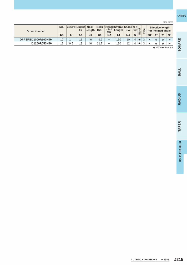
J215
D1 R ap L3 D5 B2 L1 D4 N 30' 1° 2° 3°DFPSRBD1000R100N40 10 1 15 40 9.7 ─ 130 10 4 a 3
D1200R050N40 12 0.5 18 40 11.7 ─ 130 12 4 a 3
CARBIDE
SQU
AR
EB
ALL
RA
DIU
STA
PER
SOLI
D E
ND
MIL
LS
Unit : mm
CUTTING CONDITIONS J382
Order NumberDia. Corner R Length of
CutNeck
LengthNeckDia.
Cutting Edgeto Shank
Angle
OverallLength
ShankDia.
No. ofFlutes
Stoc
kTy
pe
Effective lengthfor inclined angle
* * * ** * * *
* No interference
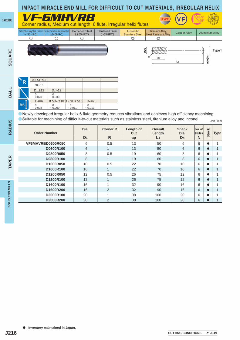
J216
VF-6MHVRB
u u u e e
D1 R ap L1 D4 NVF6MHVRBD0600R050 6 0.5 13 50 6 6 a 1
D0600R100 6 1 13 50 6 6 a 1D0800R050 8 0.5 19 60 8 6 a 1D0800R100 8 1 19 60 8 6 a 1D1000R050 10 0.5 22 70 10 6 a 1D1000R100 10 1 22 70 10 6 a 1D1200R050 12 0.5 26 75 12 6 a 1D1200R100 12 1 26 75 12 6 a 1D1600R100 16 1 32 90 16 6 a 1D1600R200 16 2 32 90 16 6 a 1D2000R100 20 1 38 100 20 6 a 1D2000R200 20 2 38 100 20 6 a 1
±0.015
D1>12 0- 0.020
0- 0.030
D4=6 D4=20 0- 0.008
0- 0.009
0- 0.011
0- 0.013
a
a
UWC VF 43.5°45°
L1
ap
øD4(
h6)
øD1
R
h6
a : Inventory maintained in Japan.
CARBIDE
SQU
AR
EB
ALL
RA
DIU
STA
PER
SOLI
D E
ND
MIL
LS
Unit : mm
Carbon Steel, Alloy Steel, Cast Iron(<30HRC)
Tool Steel, Pre-Hardened Steel,Hardened Steel(<45HRC)
Hardened Steel(<55HRC)
Hardened Steel(>55HRC)
AusteniticStainless Steel
Titanium Alloy,Heat Resistant Alloy Copper Alloy Aluminium Alloy
Newly developed irregular helix 6 flute geometry reduces vibrations and achieves high efficiency machining. Suitable for machining of difficult-to-cut materials such as stainless steel, titanium alloy and inconel.
Corner radius, Medium cut length, 6 flute, Irregular helix flutes
IMPACT MIRACLE END MILL FOR DIFFICULT TO CUT MATERIALS, IRREGULAR HELIX
Type1
CUTTING CONDITIONS J319
Order NumberDia. Corner R Length of
CutOverall Length
Shank Dia.
No. ofFlutes
Stoc
k
Type
8 <D4 <10 12 <D4 <16
0.5 <R <2
D1 <12
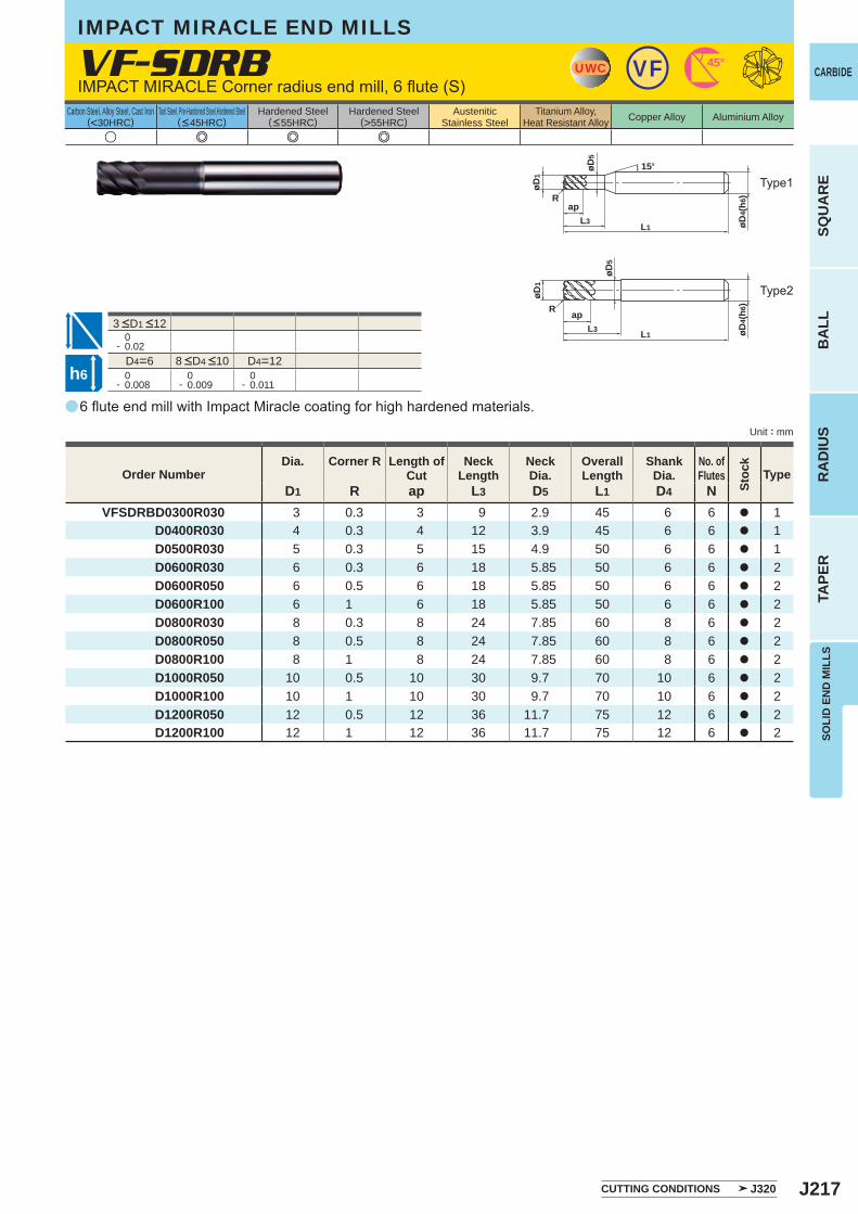
J217
a
VF-SDRB
u e e e
D1 R ap L3 D5 L1 D4 NVFSDRBD0300R030 3 0.3 3 9 2.9 45 6 6 a 1
D0400R030 4 0.3 4 12 3.9 45 6 6 a 1 D0500R030 5 0.3 5 15 4.9 50 6 6 a 1 D0600R030 6 0.3 6 18 5.85 50 6 6 a 2 D0600R050 6 0.5 6 18 5.85 50 6 6 a 2 D0600R100 6 1 6 18 5.85 50 6 6 a 2 D0800R030 8 0.3 8 24 7.85 60 8 6 a 2 D0800R050 8 0.5 8 24 7.85 60 8 6 a 2 D0800R100 8 1 8 24 7.85 60 8 6 a 2 D1000R050 10 0.5 10 30 9.7 70 10 6 a 2 D1000R100 10 1 10 30 9.7 70 10 6 a 2 D1200R050 12 0.5 12 36 11.7 75 12 6 a 2 D1200R100 12 1 12 36 11.7 75 12 6 a 2
0- 0.02
D4=6 D4=12 0- 0.008
0- 0.009
0- 0.011
UWC VF 45°
L1
øD5
apL3 øD
4(h6
)
øD1
R
15°
L1
apL3 øD
4(h6
)
øD1
R
øD5
h6
CARBIDE
SQU
AR
EB
ALL
RA
DIU
STA
PER
SOLI
D E
ND
MIL
LS
Unit : mm
Carbon Steel, Alloy Steel, Cast Iron(<30HRC)
Tool Steel, Pre-Hardened Steel,Hardened Steel(<45HRC)
Hardened Steel(<55HRC)
Hardened Steel(>55HRC)
AusteniticStainless Steel
Titanium Alloy,Heat Resistant Alloy Copper Alloy Aluminium Alloy
3 <D1 <12
6 flute end mill with Impact Miracle coating for high hardened materials.
IMPACT MIRACLE Corner radius end mill, 6 flute (S)
Type2
Type1
CUTTING CONDITIONS J320
Order NumberDia. Corner R Length of
CutNeck
LengthNeckDia.
OverallLength
ShankDia.
No. ofFlutes
Stoc
k
Type
8 <D4 <10
IMPACT MIRACLE END MILLS
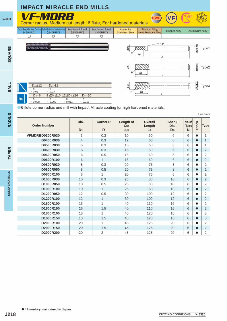
J218
a
VF-MDRB
u e e e
D1 R ap L1 D4 NVFMDRBD0300R030 3 0.3 10 60 6 6 a 1
D0400R030 4 0.3 12 60 6 6 a 1 D0500R030 5 0.3 15 60 6 6 a 1 D0600R030 6 0.3 15 60 6 6 a 2 D0600R050 6 0.5 15 60 6 6 a 2 D0600R100 6 1 15 60 6 6 a 2 D0800R030 8 0.3 20 75 8 6 a 2 D0800R050 8 0.5 20 75 8 6 a 2 D0800R100 8 1 20 75 8 6 a 2 D1000R030 10 0.3 25 80 10 6 a 2 D1000R050 10 0.5 25 80 10 6 a 2 D1000R100 10 1 25 80 10 6 a 2 D1200R050 12 0.5 30 100 12 6 a 2 D1200R100 12 1 30 100 12 6 a 2 D1600R100 16 1 40 110 16 6 a 2 D1600R150 16 1.5 40 110 16 6 a 2 D1800R100 18 1 40 120 16 6 a 3 D1800R150 18 1.5 40 120 16 6 a 3 D2000R100 20 1 45 125 20 6 a 2 D2000R150 20 1.5 45 125 20 6 a 2 D2000R200 20 2 45 125 20 6 a 2
D1>12 0- 0.02
0- 0.03
D4=6 D4=20 0- 0.008
0- 0.009
0- 0.011
0- 0.013
UWC VF 45°
L1ap
øD4(
h6)
øD1
R
15°
RL1
ap
øD4(
h6)
øD1
L1ap
øD4(
h6)
øD1
R
h6
a : Inventory maintained in Japan.
CARBIDE
SQU
AR
EB
ALL
RA
DIU
STA
PER
SOLI
D E
ND
MIL
LS
Unit : mm
Carbon Steel, Alloy Steel, Cast Iron(<30HRC)
Tool Steel, Pre-Hardened Steel,Hardened Steel(<45HRC)
Hardened Steel(<55HRC)
Hardened Steel(>55HRC)
AusteniticStainless Steel
Titanium Alloy,Heat Resistant Alloy Copper Alloy Aluminium Alloy
6 flute corner radius end mill with Impact Miracle coating for high hardened materials.
Corner radius, Medium cut length, 6 flute, For hardened materials
Type2
Type3
Type1
CUTTING CONDITIONS J320
Order NumberDia. Corner R Length of
CutOverall Length
Shank Dia.
No. ofFlutes
Stoc
k
Type
8 <D4 <10 12 <D4 <16
D1 <12
IMPACT MIRACLE END MILLS
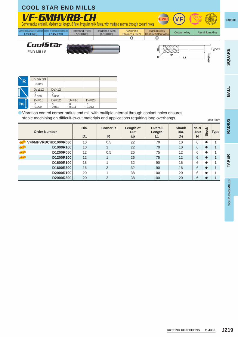
J219
a
e e
VF-6MHVRB-CH
D1 R ap L1 D4 NVF6MHVRBCHD1000R050 10 0.5 22 70 10 6 a 1
D1000R100 10 1 22 70 10 6 a 1D1200R050 12 0.5 26 75 12 6 a 1D1200R100 12 1 26 75 12 6 a 1D1600R100 16 1 32 90 16 6 a 1D1600R300 16 3 32 90 16 6 a 1D2000R100 20 1 38 100 20 6 a 1D2000R300 20 3 38 100 20 6 a 1
±0.015
D1>12 0- 0.020
0- 0.030
D4=10 D4=12 D4=16 D4=20 0- 0.009
0- 0.011
0- 0.011
0- 0.013
UWC VF 43.5°45°
øD1
apL1R
øD4(
h6)
h6
CARBIDE
SQU
AR
EB
ALL
RA
DIU
STA
PER
SOLI
D E
ND
MIL
LS
Unit : mm
Carbon Steel, Alloy Steel, Cast Iron(<30HRC)
Tool Steel, Pre-Hardened Steel,Hardened Steel(<45HRC)
Hardened Steel(<55HRC)
Hardened Steel(>55HRC)
AusteniticStainless Steel
Titanium Alloy,Heat Resistant Alloy Copper Alloy Aluminium Alloy
0.5 <R <3
CoolStarEND MILLS
Vibration control corner radius end mill with multiple internal through coolant holes ensures stable machining on difficult-to-cut materials and applications requiring long overhangs.
Type1
Corner radius end mill, Medium cut length, 6 flute, Irregular helix flutes, with multiple internal through coolant holes
CUTTING CONDITIONS J338
Order NumberDia. Corner R Length of
CutOverall Length
Shank Dia.
No. ofFlutes
Stoc
k
Type
D1 <12
COOL STAR END MILLS
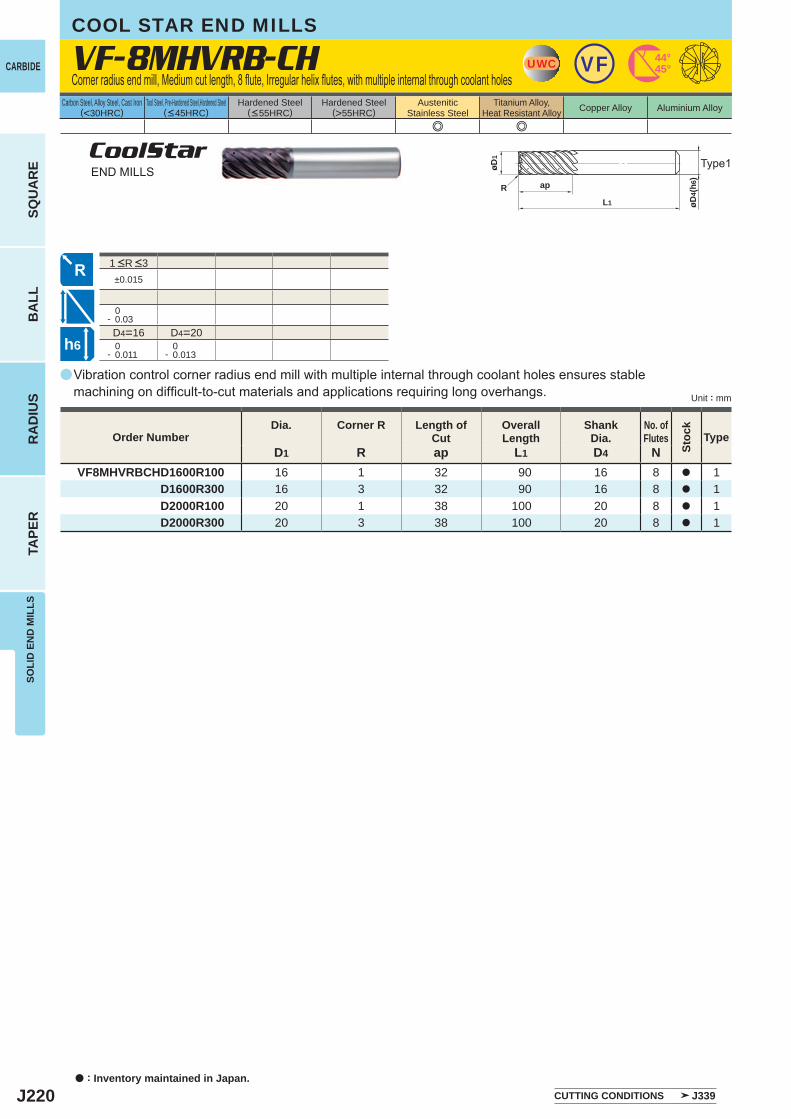
J220
a
e e
VF-8MHVRB-CH
D1 R ap L1 D4 NVF8MHVRBCHD1600R100 16 1 32 90 16 8 a 1
D1600R300 16 3 32 90 16 8 a 1D2000R100 20 1 38 100 20 8 a 1D2000R300 20 3 38 100 20 8 a 1
±0.015
0- 0.03D4=16 D4=20
0- 0.011
0- 0.013
UWC VF 44°45°
øD4(
h6)
ap
L1
øD1
R
h6
a : Inventory maintained in Japan.
CARBIDE
SQU
AR
EB
ALL
RA
DIU
STA
PER
SOLI
D E
ND
MIL
LS
Unit : mm
Carbon Steel, Alloy Steel, Cast Iron(<30HRC)
Tool Steel, Pre-Hardened Steel,Hardened Steel(<45HRC)
Hardened Steel(<55HRC)
Hardened Steel(>55HRC)
AusteniticStainless Steel
Titanium Alloy,Heat Resistant Alloy Copper Alloy Aluminium Alloy
CoolStarEND MILLS
Vibration control corner radius end mill with multiple internal through coolant holes ensures stable machining on difficult-to-cut materials and applications requiring long overhangs.
Type1
Corner radius end mill, Medium cut length, 8 flute, Irregular helix flutes, with multiple internal through coolant holes
CUTTING CONDITIONS J339
Order NumberDia. Corner R Length of
CutOverall Length
Shank Dia.
No. ofFlutes
Stoc
k
Type
COOL STAR END MILLS
1 <R <3

J221
Memo
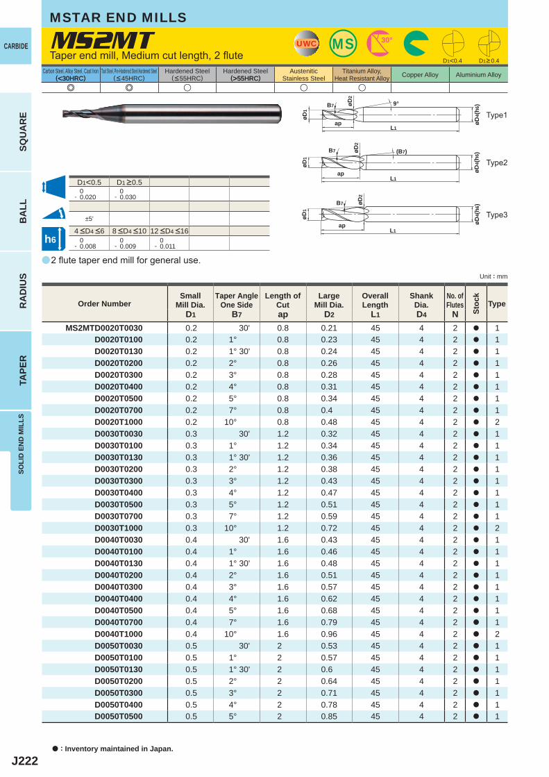
J222
a
(<30HRC) (>55HRC)
MS2MT
e e u u u
D1 B7 ap D2 L1 D4 NMS2MTD0020T0030 0.2 30' 0.8 0.21 45 4 2 a 1
D0020T0100 0.2 1° 0.8 0.23 45 4 2 a 1D0020T0130 0.2 1° 30' 0.8 0.24 45 4 2 a 1D0020T0200 0.2 2° 0.8 0.26 45 4 2 a 1D0020T0300 0.2 3° 0.8 0.28 45 4 2 a 1D0020T0400 0.2 4° 0.8 0.31 45 4 2 a 1D0020T0500 0.2 5° 0.8 0.34 45 4 2 a 1D0020T0700 0.2 7° 0.8 0.4 45 4 2 a 1D0020T1000 0.2 10° 0.8 0.48 45 4 2 a 2D0030T0030 0.3 30' 1.2 0.32 45 4 2 a 1D0030T0100 0.3 1° 1.2 0.34 45 4 2 a 1D0030T0130 0.3 1° 30' 1.2 0.36 45 4 2 a 1D0030T0200 0.3 2° 1.2 0.38 45 4 2 a 1D0030T0300 0.3 3° 1.2 0.43 45 4 2 a 1D0030T0400 0.3 4° 1.2 0.47 45 4 2 a 1D0030T0500 0.3 5° 1.2 0.51 45 4 2 a 1D0030T0700 0.3 7° 1.2 0.59 45 4 2 a 1D0030T1000 0.3 10° 1.2 0.72 45 4 2 a 2D0040T0030 0.4 30' 1.6 0.43 45 4 2 a 1D0040T0100 0.4 1° 1.6 0.46 45 4 2 a 1D0040T0130 0.4 1° 30' 1.6 0.48 45 4 2 a 1D0040T0200 0.4 2° 1.6 0.51 45 4 2 a 1D0040T0300 0.4 3° 1.6 0.57 45 4 2 a 1D0040T0400 0.4 4° 1.6 0.62 45 4 2 a 1D0040T0500 0.4 5° 1.6 0.68 45 4 2 a 1D0040T0700 0.4 7° 1.6 0.79 45 4 2 a 1D0040T1000 0.4 10° 1.6 0.96 45 4 2 a 2D0050T0030 0.5 30' 2 0.53 45 4 2 a 1D0050T0100 0.5 1° 2 0.57 45 4 2 a 1D0050T0130 0.5 1° 30' 2 0.6 45 4 2 a 1D0050T0200 0.5 2° 2 0.64 45 4 2 a 1D0050T0300 0.5 3° 2 0.71 45 4 2 a 1D0050T0400 0.5 4° 2 0.78 45 4 2 a 1D0050T0500 0.5 5° 2 0.85 45 4 2 a 1
D1<0.5 0- 0.020
0- 0.030
±5'
0- 0.008
0- 0.009
0- 0.011
D1<0.4
UWC MS 30°
øD4(
h6)
L1
øD1
ap
B7 9°øD2
øD4(
h6)
L1
øD1
ap
B7 øD2
øD2
øD4(
h6)
L1
øD1
ap
B7 (B7)
h6
CARBIDE
SQU
AR
EB
ALL
RA
DIU
STA
PER
SOLI
D E
ND
MIL
LS
Unit : mm
Carbon Steel, Alloy Steel, Cast Iron(<30HRC)
Tool Steel, Pre-Hardened Steel,Hardened Steel(<45HRC)
Hardened Steel(<55HRC)
Hardened Steel(>55HRC)
AusteniticStainless Steel
Titanium Alloy,Heat Resistant Alloy Copper Alloy Aluminium Alloy
2 flute taper end mill for general use.
Taper end mill, Medium cut length, 2 flute
Type2
Type1
Type3
a : Inventory maintained in Japan.
MSTAR END MILLS
D1>0.4
Order NumberSmall
Mill Dia.Taper Angle
One SideLength of
CutLarge
Mill Dia.Overall Length
ShankDia.
No. ofFlutes Type
4 <D4 <6 8 <D4 <10 12 <D4 <16
D1 >0.5
Stoc
k
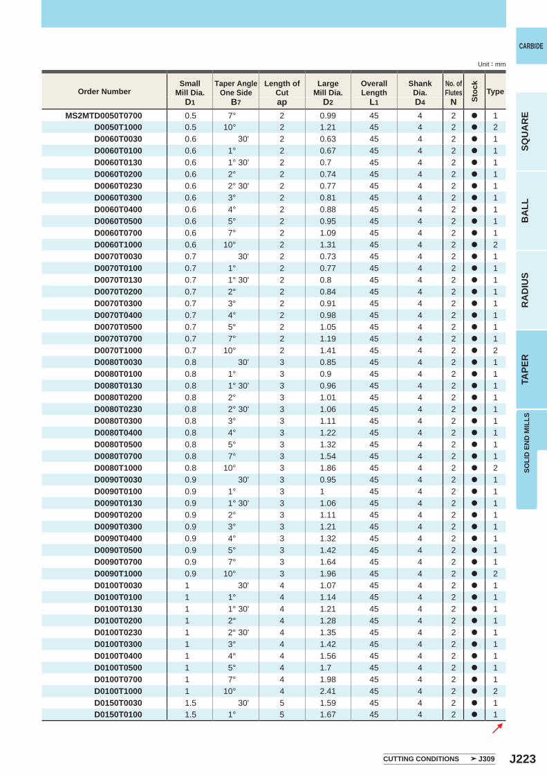
J223
D1 B7 ap D2 L1 D4 NMS2MTD0050T0700 0.5 7° 2 0.99 45 4 2 a 1
D0050T1000 0.5 10° 2 1.21 45 4 2 a 2D0060T0030 0.6 30' 2 0.63 45 4 2 a 1D0060T0100 0.6 1° 2 0.67 45 4 2 a 1D0060T0130 0.6 1° 30' 2 0.7 45 4 2 a 1D0060T0200 0.6 2° 2 0.74 45 4 2 a 1D0060T0230 0.6 2° 30' 2 0.77 45 4 2 a 1D0060T0300 0.6 3° 2 0.81 45 4 2 a 1D0060T0400 0.6 4° 2 0.88 45 4 2 a 1D0060T0500 0.6 5° 2 0.95 45 4 2 a 1D0060T0700 0.6 7° 2 1.09 45 4 2 a 1D0060T1000 0.6 10° 2 1.31 45 4 2 a 2D0070T0030 0.7 30' 2 0.73 45 4 2 a 1D0070T0100 0.7 1° 2 0.77 45 4 2 a 1D0070T0130 0.7 1° 30' 2 0.8 45 4 2 a 1D0070T0200 0.7 2° 2 0.84 45 4 2 a 1D0070T0300 0.7 3° 2 0.91 45 4 2 a 1D0070T0400 0.7 4° 2 0.98 45 4 2 a 1D0070T0500 0.7 5° 2 1.05 45 4 2 a 1D0070T0700 0.7 7° 2 1.19 45 4 2 a 1D0070T1000 0.7 10° 2 1.41 45 4 2 a 2D0080T0030 0.8 30' 3 0.85 45 4 2 a 1D0080T0100 0.8 1° 3 0.9 45 4 2 a 1D0080T0130 0.8 1° 30' 3 0.96 45 4 2 a 1D0080T0200 0.8 2° 3 1.01 45 4 2 a 1D0080T0230 0.8 2° 30' 3 1.06 45 4 2 a 1D0080T0300 0.8 3° 3 1.11 45 4 2 a 1D0080T0400 0.8 4° 3 1.22 45 4 2 a 1D0080T0500 0.8 5° 3 1.32 45 4 2 a 1D0080T0700 0.8 7° 3 1.54 45 4 2 a 1D0080T1000 0.8 10° 3 1.86 45 4 2 a 2D0090T0030 0.9 30' 3 0.95 45 4 2 a 1D0090T0100 0.9 1° 3 1 45 4 2 a 1D0090T0130 0.9 1° 30' 3 1.06 45 4 2 a 1D0090T0200 0.9 2° 3 1.11 45 4 2 a 1D0090T0300 0.9 3° 3 1.21 45 4 2 a 1D0090T0400 0.9 4° 3 1.32 45 4 2 a 1D0090T0500 0.9 5° 3 1.42 45 4 2 a 1D0090T0700 0.9 7° 3 1.64 45 4 2 a 1D0090T1000 0.9 10° 3 1.96 45 4 2 a 2D0100T0030 1 30' 4 1.07 45 4 2 a 1D0100T0100 1 1° 4 1.14 45 4 2 a 1D0100T0130 1 1° 30' 4 1.21 45 4 2 a 1D0100T0200 1 2° 4 1.28 45 4 2 a 1D0100T0230 1 2° 30' 4 1.35 45 4 2 a 1D0100T0300 1 3° 4 1.42 45 4 2 a 1D0100T0400 1 4° 4 1.56 45 4 2 a 1D0100T0500 1 5° 4 1.7 45 4 2 a 1D0100T0700 1 7° 4 1.98 45 4 2 a 1D0100T1000 1 10° 4 2.41 45 4 2 a 2D0150T0030 1.5 30' 5 1.59 45 4 2 a 1D0150T0100 1.5 1° 5 1.67 45 4 2 a 1
SOLI
D E
ND
MIL
LS
CARBIDE
SQU
AR
EB
ALL
RA
DIU
STA
PER
Unit : mm
Order NumberSmall
Mill Dia.Taper Angle
One SideLength of
CutLarge
Mill Dia.Overall Length
ShankDia.
No. ofFlutes Type
CUTTING CONDITIONS J309
Stoc
k
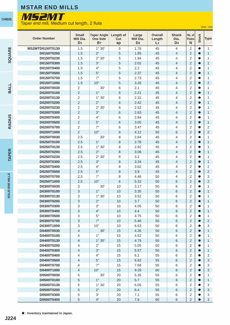
J224
D1 B7 ap D2 L1 D4 NMS2MTD0150T0130 1.5 1° 30' 5 1.76 45 4 2 a 1
D0150T0200 1.5 2° 5 1.85 45 4 2 a 1D0150T0230 1.5 2° 30' 5 1.94 45 4 2 a 1D0150T0300 1.5 3° 5 2.02 45 4 2 a 1D0150T0400 1.5 4° 5 2.2 45 4 2 a 1D0150T0500 1.5 5° 5 2.37 45 4 2 a 1D0150T0700 1.5 7° 5 2.73 45 4 2 a 1D0150T1000 1.5 10° 5 3.26 45 4 2 a 2D0200T0030 2 30' 6 2.1 45 4 2 a 1D0200T0100 2 1° 6 2.21 45 4 2 a 1D0200T0130 2 1° 30' 6 2.31 45 4 2 a 1D0200T0200 2 2° 6 2.42 45 4 2 a 1D0200T0230 2 2° 30' 6 2.52 45 4 2 a 1D0200T0300 2 3° 6 2.63 45 4 2 a 1D0200T0400 2 4° 6 2.84 45 4 2 a 1D0200T0500 2 5° 6 3.05 45 4 2 a 1D0200T0700 2 7° 6 3.47 45 4 2 a 2D0200T1000 2 10° 6 4.12 50 6 2 a 2D0250T0030 2.5 30' 8 2.64 45 4 2 a 1D0250T0100 2.5 1° 8 2.78 45 4 2 a 1D0250T0130 2.5 1° 30' 8 2.92 45 4 2 a 1D0250T0200 2.5 2° 8 3.06 45 4 2 a 1D0250T0230 2.5 2° 30' 8 3.2 45 4 2 a 1D0250T0300 2.5 3° 8 3.34 45 4 2 a 1D0250T0400 2.5 4° 8 3.62 45 4 2 a 2D0250T0500 2.5 5° 8 3.9 45 4 2 a 2D0250T0700 2.5 7° 8 4.46 50 4 2 a 3D0250T1000 2.5 10° 8 5.32 50 6 2 a 2D0300T0030 3 30' 10 3.17 50 6 2 a 1D0300T0100 3 1° 10 3.35 50 6 2 a 1D0300T0130 3 1° 30' 10 3.52 50 6 2 a 1D0300T0200 3 2° 10 3.7 50 6 2 a 1D0300T0300 3 3° 10 4.05 50 6 2 a 1D0300T0400 3 4° 10 4.4 50 6 2 a 1D0300T0500 3 5° 10 4.75 50 6 2 a 1D0300T0700 3 7° 10 5.46 50 6 2 a 2D0300T1000 3 10° 10 6.53 50 6 2 a 3D0400T0030 4 30' 15 4.26 50 6 2 a 1D0400T0100 4 1° 15 4.52 50 6 2 a 1D0400T0130 4 1° 30' 15 4.79 50 6 2 a 1D0400T0200 4 2° 15 5.05 50 6 2 a 1D0400T0300 4 3° 15 5.57 50 6 2 a 1D0400T0400 4 4° 15 6.1 55 6 2 a 3D0400T0500 4 5° 15 6.62 55 6 2 a 3D0400T0700 4 7° 15 7.68 55 6 2 a 3D0400T1000 4 10° 15 9.29 60 8 2 a 3D0500T0030 5 30' 20 5.35 55 6 2 a 1D0500T0100 5 1° 20 5.7 55 6 2 a 1D0500T0130 5 1° 30' 20 6.05 55 6 2 a 3D0500T0200 5 2° 20 6.4 55 6 2 a 3D0500T0300 5 3° 20 7.1 55 6 2 a 3D0500T0400 5 4° 20 7.8 60 6 2 a 3
MS2MTCARBIDE
SQU
AR
EB
ALL
RA
DIU
STA
PER
SOLI
D E
ND
MIL
LS
Unit : mm
a : Inventory maintained in Japan.
MSTAR END MILLS
Taper end mill, Medium cut length, 2 flute
Order NumberSmall
Mill Dia.Taper Angle
One SideLength of
CutLarge
Mill Dia.Overall Length
ShankDia.
No. ofFlutes Type
Stoc
k
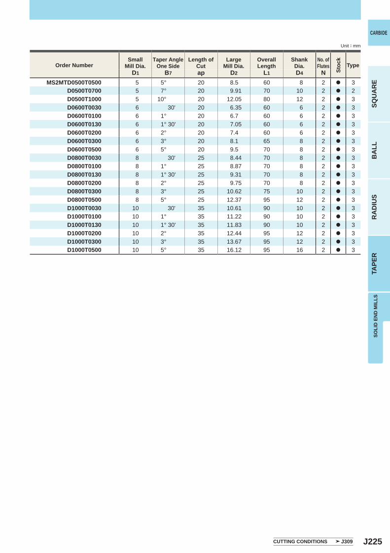
J225
D1 B7 ap D2 L1 D4 NMS2MTD0500T0500 5 5° 20 8.5 60 8 2 a 3
D0500T0700 5 7° 20 9.91 70 10 2 a 2D0500T1000 5 10° 20 12.05 80 12 2 a 3D0600T0030 6 30' 20 6.35 60 6 2 a 3D0600T0100 6 1° 20 6.7 60 6 2 a 3D0600T0130 6 1° 30' 20 7.05 60 6 2 a 3D0600T0200 6 2° 20 7.4 60 6 2 a 3D0600T0300 6 3° 20 8.1 65 8 2 a 3D0600T0500 6 5° 20 9.5 70 8 2 a 3D0800T0030 8 30' 25 8.44 70 8 2 a 3D0800T0100 8 1° 25 8.87 70 8 2 a 3D0800T0130 8 1° 30' 25 9.31 70 8 2 a 3D0800T0200 8 2° 25 9.75 70 8 2 a 3D0800T0300 8 3° 25 10.62 75 10 2 a 3D0800T0500 8 5° 25 12.37 95 12 2 a 3D1000T0030 10 30' 35 10.61 90 10 2 a 3D1000T0100 10 1° 35 11.22 90 10 2 a 3D1000T0130 10 1° 30' 35 11.83 90 10 2 a 3D1000T0200 10 2° 35 12.44 95 12 2 a 3D1000T0300 10 3° 35 13.67 95 12 2 a 3D1000T0500 10 5° 35 16.12 95 16 2 a 3
SOLI
D E
ND
MIL
LS
CARBIDE
SQU
AR
EB
ALL
RA
DIU
STA
PER
Unit : mm
Order NumberSmall
Mill Dia.Taper Angle
One SideLength of
CutLarge
Mill Dia.Overall Length
ShankDia.
No. ofFlutes Type
CUTTING CONDITIONS J309
Stoc
k
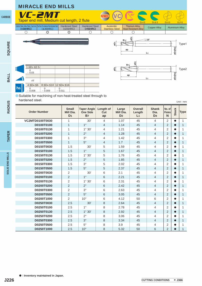
J226
a
(<30HRC) (>55HRC)u e e u u u
VC-2MT
D1 B7 ap D2 L1 D4 NVC2MTD0100T0030 1 30' 4 1.07 45 4 2 a 1
D0100T0100 1 1° 4 1.14 45 4 2 a 1D0100T0130 1 1° 30' 4 1.21 45 4 2 a 1D0100T0200 1 2° 4 1.28 45 4 2 a 1D0100T0300 1 3° 4 1.42 45 4 2 a 1D0100T0500 1 5° 4 1.7 45 4 2 a 1D0150T0030 1.5 30' 5 1.59 45 4 2 a 1D0150T0100 1.5 1° 5 1.67 45 4 2 a 1D0150T0130 1.5 1° 30' 5 1.76 45 4 2 a 1D0150T0200 1.5 2° 5 1.85 45 4 2 a 1D0150T0300 1.5 3° 5 2.02 45 4 2 a 1D0150T0500 1.5 5° 5 2.37 45 4 2 a 1D0200T0030 2 30' 6 2.1 45 4 2 a 1D0200T0100 2 1° 6 2.21 45 4 2 a 1D0200T0130 2 1° 30' 6 2.31 45 4 2 a 1D0200T0200 2 2° 6 2.42 45 4 2 a 1D0200T0300 2 3° 6 2.63 45 4 2 a 1D0200T0500 2 5° 6 3.05 45 4 2 a 1D0200T1000 2 10° 6 4.12 50 6 2 a 1D0250T0030 2.5 30' 8 2.64 45 4 2 a 1D0250T0100 2.5 1° 8 2.78 45 4 2 a 1D0250T0130 2.5 1° 30' 8 2.92 45 4 2 a 1D0250T0200 2.5 2° 8 3.06 45 4 2 a 1D0250T0300 2.5 3° 8 3.34 45 4 2 a 1D0250T0500 2.5 5° 8 3.9 45 4 2 a 1D0250T1000 2.5 10° 8 5.32 50 6 2 a 1
0- 0.03
±5'
0- 0.008
0- 0.009
0- 0.011
D1<3 D1<3 D1>3
UWC VC 30°
øD4(
h6)
L1
øD1
ap
B7 15°øD2
øD4(
h6)
L1
øD1
ap
B7 øD2
h6
CARBIDE
SQU
AR
EB
ALL
RA
DIU
STA
PER
SOLI
D E
ND
MIL
LS
Unit : mm
Carbon Steel, Alloy Steel, Cast Iron(<30HRC)
Tool Steel, Pre-Hardened Steel,Hardened Steel(<45HRC)
Hardened Steel(<55HRC)
Hardened Steel(>55HRC)
AusteniticStainless Steel
Titanium Alloy,Heat Resistant Alloy Copper Alloy Aluminium Alloy
MIRACLE END MILLS
a : Inventory maintained in Japan.
Suitable for machining of non-heat-treated steel through to hardened steel.
Taper end mill, Medium cut length, 2 flute
Type2
Type1
D1>3
Order NumberSmall
Mill Dia.Taper Angle
One SideLength of
CutLarge
Mill Dia.Overall Length
ShankDia.
No. ofFlutes Type
CUTTING CONDITIONS J366
4 <D4 <6 8 <D4 <10 12 <D4 <16
1 <D1 <2.5
Stoc
k
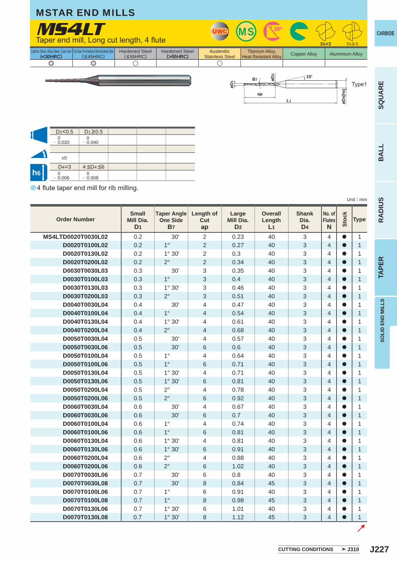
J227
a
(<30HRC) (>55HRC)
MS4LT
e e u u
D1 B7 ap D2 L1 D4 NMS4LTD0020T0030L02 0.2 30' 2 0.23 40 3 4 a 1
D0020T0100L02 0.2 1° 2 0.27 40 3 4 a 1D0020T0130L02 0.2 1° 30' 2 0.3 40 3 4 a 1D0020T0200L02 0.2 2° 2 0.34 40 3 4 a 1D0030T0030L03 0.3 30' 3 0.35 40 3 4 a 1D0030T0100L03 0.3 1° 3 0.4 40 3 4 a 1D0030T0130L03 0.3 1° 30' 3 0.46 40 3 4 a 1D0030T0200L03 0.3 2° 3 0.51 40 3 4 a 1D0040T0030L04 0.4 30' 4 0.47 40 3 4 a 1D0040T0100L04 0.4 1° 4 0.54 40 3 4 a 1D0040T0130L04 0.4 1° 30' 4 0.61 40 3 4 a 1D0040T0200L04 0.4 2° 4 0.68 40 3 4 a 1D0050T0030L04 0.5 30' 4 0.57 40 3 4 a 1D0050T0030L06 0.5 30' 6 0.6 40 3 4 a 1D0050T0100L04 0.5 1° 4 0.64 40 3 4 a 1D0050T0100L06 0.5 1° 6 0.71 40 3 4 a 1D0050T0130L04 0.5 1° 30' 4 0.71 40 3 4 a 1D0050T0130L06 0.5 1° 30' 6 0.81 40 3 4 a 1D0050T0200L04 0.5 2° 4 0.78 40 3 4 a 1D0050T0200L06 0.5 2° 6 0.92 40 3 4 a 1D0060T0030L04 0.6 30' 4 0.67 40 3 4 a 1D0060T0030L06 0.6 30' 6 0.7 40 3 4 a 1D0060T0100L04 0.6 1° 4 0.74 40 3 4 a 1D0060T0100L06 0.6 1° 6 0.81 40 3 4 a 1D0060T0130L04 0.6 1° 30' 4 0.81 40 3 4 a 1D0060T0130L06 0.6 1° 30' 6 0.91 40 3 4 a 1D0060T0200L04 0.6 2° 4 0.88 40 3 4 a 1D0060T0200L06 0.6 2° 6 1.02 40 3 4 a 1D0070T0030L06 0.7 30' 6 0.8 40 3 4 a 1D0070T0030L08 0.7 30' 8 0.84 45 3 4 a 1D0070T0100L06 0.7 1° 6 0.91 40 3 4 a 1D0070T0100L08 0.7 1° 8 0.98 45 3 4 a 1D0070T0130L06 0.7 1° 30' 6 1.01 40 3 4 a 1D0070T0130L08 0.7 1° 30' 8 1.12 45 3 4 a 1
D1<0.5 0- 0.020
0- 0.040
±5'
D4=3 0- 0.006
0- 0.008
D1<3
UWCUWC MSMS 25°25°
øD4(
h6)
L1
ap
øD1 øD
2 15°B7
D1<3
h6
SOLI
D E
ND
MIL
LS
CARBIDE
SQU
AR
EB
ALL
RA
DIU
STA
PER
Unit : mm
Carbon Steel, Alloy Steel, Cast Iron(<30HRC)
Tool Steel, Pre-Hardened Steel,Hardened Steel(<45HRC)
Hardened Steel(<55HRC)
Hardened Steel(>55HRC)
AusteniticStainless Steel
Titanium Alloy,Heat Resistant Alloy Copper Alloy Aluminium Alloy
4 flute taper end mill for rib milling.
Taper end mill, Long cut length, 4 flute
Type1
MSTAR END MILLS
Order NumberSmall
Mill Dia.Taper Angle
One SideLength of
CutLarge
Mill Dia.Overall Length
ShankDia.
No. ofFlutes Type
CUTTING CONDITIONS J310
4 <D4 <6
D1 >0.5
D1>3
Stoc
k
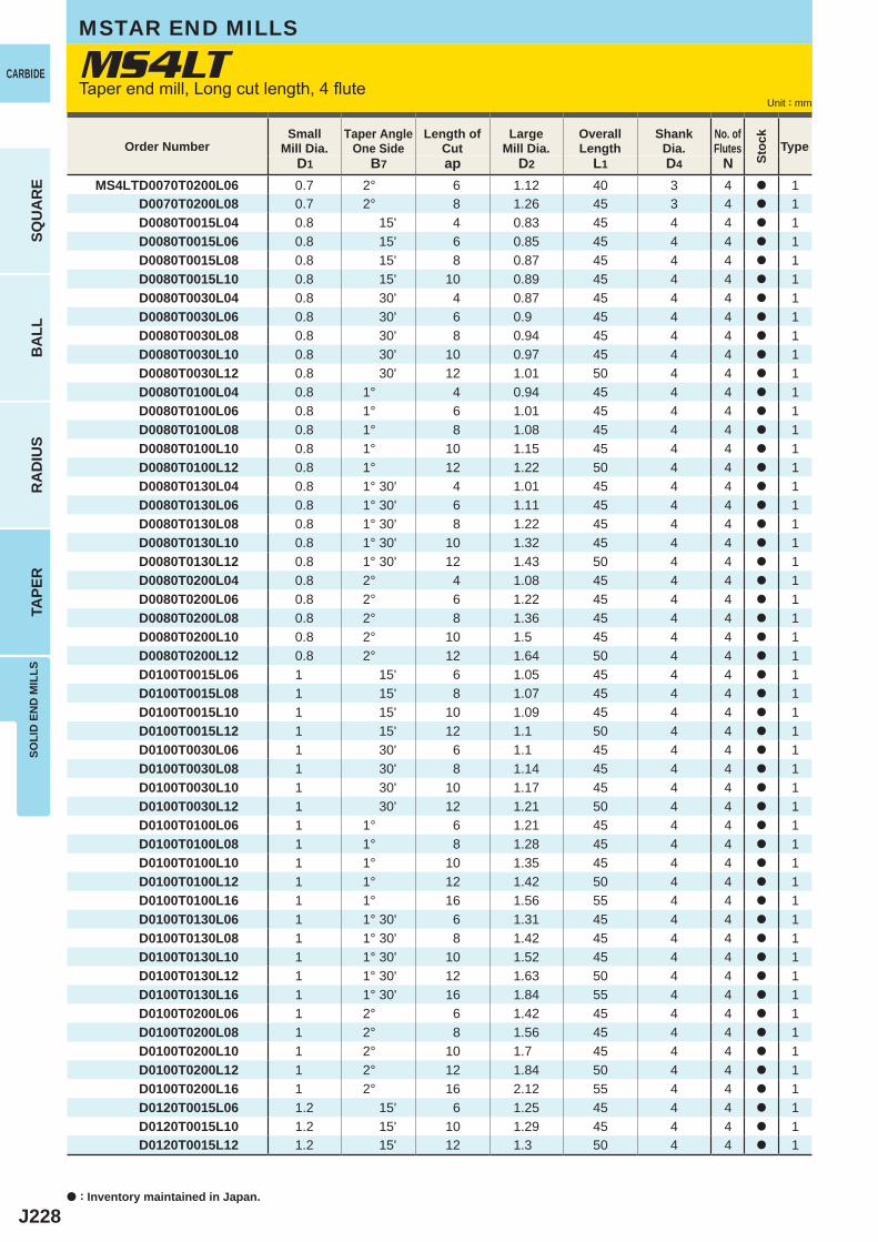
J228
D1 B7 ap D2 L1 D4 NMS4LTD0070T0200L06 0.7 2° 6 1.12 40 3 4 a 1
D0070T0200L08 0.7 2° 8 1.26 45 3 4 a 1D0080T0015L04 0.8 15' 4 0.83 45 4 4 a 1D0080T0015L06 0.8 15' 6 0.85 45 4 4 a 1D0080T0015L08 0.8 15' 8 0.87 45 4 4 a 1D0080T0015L10 0.8 15' 10 0.89 45 4 4 a 1D0080T0030L04 0.8 30' 4 0.87 45 4 4 a 1D0080T0030L06 0.8 30' 6 0.9 45 4 4 a 1D0080T0030L08 0.8 30' 8 0.94 45 4 4 a 1D0080T0030L10 0.8 30' 10 0.97 45 4 4 a 1D0080T0030L12 0.8 30' 12 1.01 50 4 4 a 1D0080T0100L04 0.8 1° 4 0.94 45 4 4 a 1D0080T0100L06 0.8 1° 6 1.01 45 4 4 a 1D0080T0100L08 0.8 1° 8 1.08 45 4 4 a 1D0080T0100L10 0.8 1° 10 1.15 45 4 4 a 1D0080T0100L12 0.8 1° 12 1.22 50 4 4 a 1D0080T0130L04 0.8 1° 30' 4 1.01 45 4 4 a 1D0080T0130L06 0.8 1° 30' 6 1.11 45 4 4 a 1D0080T0130L08 0.8 1° 30' 8 1.22 45 4 4 a 1D0080T0130L10 0.8 1° 30' 10 1.32 45 4 4 a 1D0080T0130L12 0.8 1° 30' 12 1.43 50 4 4 a 1D0080T0200L04 0.8 2° 4 1.08 45 4 4 a 1D0080T0200L06 0.8 2° 6 1.22 45 4 4 a 1D0080T0200L08 0.8 2° 8 1.36 45 4 4 a 1D0080T0200L10 0.8 2° 10 1.5 45 4 4 a 1D0080T0200L12 0.8 2° 12 1.64 50 4 4 a 1D0100T0015L06 1 15' 6 1.05 45 4 4 a 1D0100T0015L08 1 15' 8 1.07 45 4 4 a 1D0100T0015L10 1 15' 10 1.09 45 4 4 a 1D0100T0015L12 1 15' 12 1.1 50 4 4 a 1D0100T0030L06 1 30' 6 1.1 45 4 4 a 1D0100T0030L08 1 30' 8 1.14 45 4 4 a 1D0100T0030L10 1 30' 10 1.17 45 4 4 a 1D0100T0030L12 1 30' 12 1.21 50 4 4 a 1D0100T0100L06 1 1° 6 1.21 45 4 4 a 1D0100T0100L08 1 1° 8 1.28 45 4 4 a 1D0100T0100L10 1 1° 10 1.35 45 4 4 a 1D0100T0100L12 1 1° 12 1.42 50 4 4 a 1D0100T0100L16 1 1° 16 1.56 55 4 4 a 1D0100T0130L06 1 1° 30' 6 1.31 45 4 4 a 1D0100T0130L08 1 1° 30' 8 1.42 45 4 4 a 1D0100T0130L10 1 1° 30' 10 1.52 45 4 4 a 1D0100T0130L12 1 1° 30' 12 1.63 50 4 4 a 1D0100T0130L16 1 1° 30' 16 1.84 55 4 4 a 1D0100T0200L06 1 2° 6 1.42 45 4 4 a 1D0100T0200L08 1 2° 8 1.56 45 4 4 a 1D0100T0200L10 1 2° 10 1.7 45 4 4 a 1D0100T0200L12 1 2° 12 1.84 50 4 4 a 1D0100T0200L16 1 2° 16 2.12 55 4 4 a 1D0120T0015L06 1.2 15' 6 1.25 45 4 4 a 1D0120T0015L10 1.2 15' 10 1.29 45 4 4 a 1D0120T0015L12 1.2 15' 12 1.3 50 4 4 a 1
MS4LTCARBIDE
SQU
AR
EB
ALL
RA
DIU
STA
PER
SOLI
D E
ND
MIL
LS
Unit : mm
Order NumberSmall
Mill Dia.Taper Angle
One SideLength of
CutLarge
Mill Dia.Overall Length
ShankDia.
No. ofFlutes Type
MSTAR END MILLS
Taper end mill, Long cut length, 4 flute
a : Inventory maintained in Japan.
Stoc
k
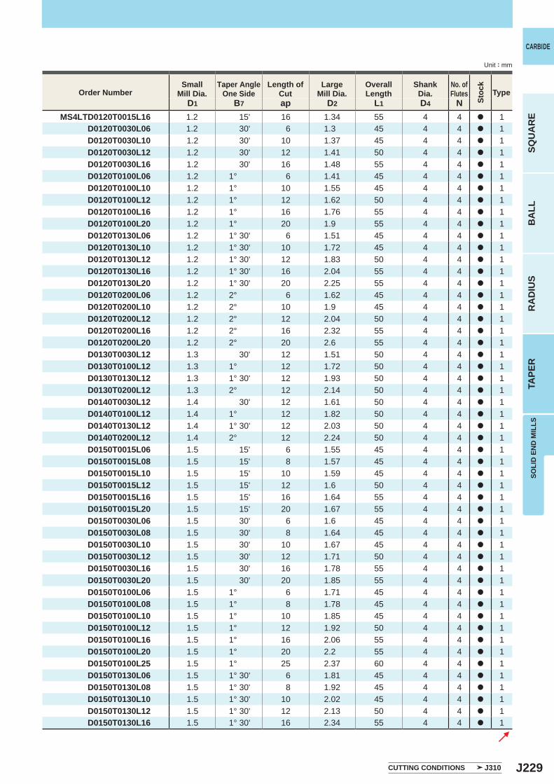
J229
D1 B7 ap D2 L1 D4 NMS4LTD0120T0015L16 1.2 15' 16 1.34 55 4 4 a 1
D0120T0030L06 1.2 30' 6 1.3 45 4 4 a 1D0120T0030L10 1.2 30' 10 1.37 45 4 4 a 1D0120T0030L12 1.2 30' 12 1.41 50 4 4 a 1D0120T0030L16 1.2 30' 16 1.48 55 4 4 a 1D0120T0100L06 1.2 1° 6 1.41 45 4 4 a 1D0120T0100L10 1.2 1° 10 1.55 45 4 4 a 1D0120T0100L12 1.2 1° 12 1.62 50 4 4 a 1D0120T0100L16 1.2 1° 16 1.76 55 4 4 a 1D0120T0100L20 1.2 1° 20 1.9 55 4 4 a 1D0120T0130L06 1.2 1° 30' 6 1.51 45 4 4 a 1D0120T0130L10 1.2 1° 30' 10 1.72 45 4 4 a 1D0120T0130L12 1.2 1° 30' 12 1.83 50 4 4 a 1D0120T0130L16 1.2 1° 30' 16 2.04 55 4 4 a 1D0120T0130L20 1.2 1° 30' 20 2.25 55 4 4 a 1D0120T0200L06 1.2 2° 6 1.62 45 4 4 a 1D0120T0200L10 1.2 2° 10 1.9 45 4 4 a 1D0120T0200L12 1.2 2° 12 2.04 50 4 4 a 1D0120T0200L16 1.2 2° 16 2.32 55 4 4 a 1D0120T0200L20 1.2 2° 20 2.6 55 4 4 a 1D0130T0030L12 1.3 30' 12 1.51 50 4 4 a 1D0130T0100L12 1.3 1° 12 1.72 50 4 4 a 1D0130T0130L12 1.3 1° 30' 12 1.93 50 4 4 a 1D0130T0200L12 1.3 2° 12 2.14 50 4 4 a 1D0140T0030L12 1.4 30' 12 1.61 50 4 4 a 1D0140T0100L12 1.4 1° 12 1.82 50 4 4 a 1D0140T0130L12 1.4 1° 30' 12 2.03 50 4 4 a 1D0140T0200L12 1.4 2° 12 2.24 50 4 4 a 1D0150T0015L06 1.5 15' 6 1.55 45 4 4 a 1D0150T0015L08 1.5 15' 8 1.57 45 4 4 a 1D0150T0015L10 1.5 15' 10 1.59 45 4 4 a 1D0150T0015L12 1.5 15' 12 1.6 50 4 4 a 1D0150T0015L16 1.5 15' 16 1.64 55 4 4 a 1D0150T0015L20 1.5 15' 20 1.67 55 4 4 a 1D0150T0030L06 1.5 30' 6 1.6 45 4 4 a 1D0150T0030L08 1.5 30' 8 1.64 45 4 4 a 1D0150T0030L10 1.5 30' 10 1.67 45 4 4 a 1D0150T0030L12 1.5 30' 12 1.71 50 4 4 a 1D0150T0030L16 1.5 30' 16 1.78 55 4 4 a 1D0150T0030L20 1.5 30' 20 1.85 55 4 4 a 1D0150T0100L06 1.5 1° 6 1.71 45 4 4 a 1D0150T0100L08 1.5 1° 8 1.78 45 4 4 a 1D0150T0100L10 1.5 1° 10 1.85 45 4 4 a 1D0150T0100L12 1.5 1° 12 1.92 50 4 4 a 1D0150T0100L16 1.5 1° 16 2.06 55 4 4 a 1D0150T0100L20 1.5 1° 20 2.2 55 4 4 a 1D0150T0100L25 1.5 1° 25 2.37 60 4 4 a 1D0150T0130L06 1.5 1° 30' 6 1.81 45 4 4 a 1D0150T0130L08 1.5 1° 30' 8 1.92 45 4 4 a 1D0150T0130L10 1.5 1° 30' 10 2.02 45 4 4 a 1D0150T0130L12 1.5 1° 30' 12 2.13 50 4 4 a 1D0150T0130L16 1.5 1° 30' 16 2.34 55 4 4 a 1
SOLI
D E
ND
MIL
LS
CARBIDE
SQU
AR
EB
ALL
RA
DIU
STA
PER
Unit : mm
Order NumberSmall
Mill Dia.Taper Angle
One SideLength of
CutLarge
Mill Dia.Overall Length
ShankDia.
No. ofFlutes Type
CUTTING CONDITIONS J310
Stoc
k
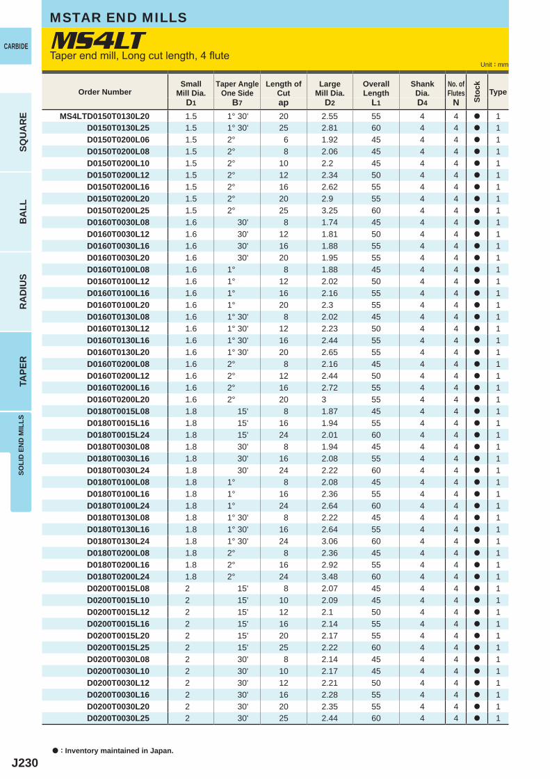
J230
D1 B7 ap D2 L1 D4 NMS4LTD0150T0130L20 1.5 1° 30' 20 2.55 55 4 4 a 1
D0150T0130L25 1.5 1° 30' 25 2.81 60 4 4 a 1D0150T0200L06 1.5 2° 6 1.92 45 4 4 a 1D0150T0200L08 1.5 2° 8 2.06 45 4 4 a 1D0150T0200L10 1.5 2° 10 2.2 45 4 4 a 1D0150T0200L12 1.5 2° 12 2.34 50 4 4 a 1D0150T0200L16 1.5 2° 16 2.62 55 4 4 a 1D0150T0200L20 1.5 2° 20 2.9 55 4 4 a 1D0150T0200L25 1.5 2° 25 3.25 60 4 4 a 1D0160T0030L08 1.6 30' 8 1.74 45 4 4 a 1D0160T0030L12 1.6 30' 12 1.81 50 4 4 a 1D0160T0030L16 1.6 30' 16 1.88 55 4 4 a 1D0160T0030L20 1.6 30' 20 1.95 55 4 4 a 1D0160T0100L08 1.6 1° 8 1.88 45 4 4 a 1D0160T0100L12 1.6 1° 12 2.02 50 4 4 a 1D0160T0100L16 1.6 1° 16 2.16 55 4 4 a 1D0160T0100L20 1.6 1° 20 2.3 55 4 4 a 1D0160T0130L08 1.6 1° 30' 8 2.02 45 4 4 a 1D0160T0130L12 1.6 1° 30' 12 2.23 50 4 4 a 1D0160T0130L16 1.6 1° 30' 16 2.44 55 4 4 a 1D0160T0130L20 1.6 1° 30' 20 2.65 55 4 4 a 1D0160T0200L08 1.6 2° 8 2.16 45 4 4 a 1D0160T0200L12 1.6 2° 12 2.44 50 4 4 a 1D0160T0200L16 1.6 2° 16 2.72 55 4 4 a 1D0160T0200L20 1.6 2° 20 3 55 4 4 a 1D0180T0015L08 1.8 15' 8 1.87 45 4 4 a 1D0180T0015L16 1.8 15' 16 1.94 55 4 4 a 1D0180T0015L24 1.8 15' 24 2.01 60 4 4 a 1D0180T0030L08 1.8 30' 8 1.94 45 4 4 a 1D0180T0030L16 1.8 30' 16 2.08 55 4 4 a 1D0180T0030L24 1.8 30' 24 2.22 60 4 4 a 1D0180T0100L08 1.8 1° 8 2.08 45 4 4 a 1D0180T0100L16 1.8 1° 16 2.36 55 4 4 a 1D0180T0100L24 1.8 1° 24 2.64 60 4 4 a 1D0180T0130L08 1.8 1° 30' 8 2.22 45 4 4 a 1D0180T0130L16 1.8 1° 30' 16 2.64 55 4 4 a 1D0180T0130L24 1.8 1° 30' 24 3.06 60 4 4 a 1D0180T0200L08 1.8 2° 8 2.36 45 4 4 a 1D0180T0200L16 1.8 2° 16 2.92 55 4 4 a 1D0180T0200L24 1.8 2° 24 3.48 60 4 4 a 1D0200T0015L08 2 15' 8 2.07 45 4 4 a 1D0200T0015L10 2 15' 10 2.09 45 4 4 a 1D0200T0015L12 2 15' 12 2.1 50 4 4 a 1D0200T0015L16 2 15' 16 2.14 55 4 4 a 1D0200T0015L20 2 15' 20 2.17 55 4 4 a 1D0200T0015L25 2 15' 25 2.22 60 4 4 a 1D0200T0030L08 2 30' 8 2.14 45 4 4 a 1D0200T0030L10 2 30' 10 2.17 45 4 4 a 1D0200T0030L12 2 30' 12 2.21 50 4 4 a 1D0200T0030L16 2 30' 16 2.28 55 4 4 a 1D0200T0030L20 2 30' 20 2.35 55 4 4 a 1D0200T0030L25 2 30' 25 2.44 60 4 4 a 1
MS4LTCARBIDE
SQU
AR
EB
ALL
RA
DIU
STA
PER
SOLI
D E
ND
MIL
LS
Unit : mm
Order NumberSmall
Mill Dia.Taper Angle
One SideLength of
CutLarge
Mill Dia.Overall Length
ShankDia.
No. ofFlutes Type
MSTAR END MILLS
Taper end mill, Long cut length, 4 flute
a : Inventory maintained in Japan.
Stoc
k
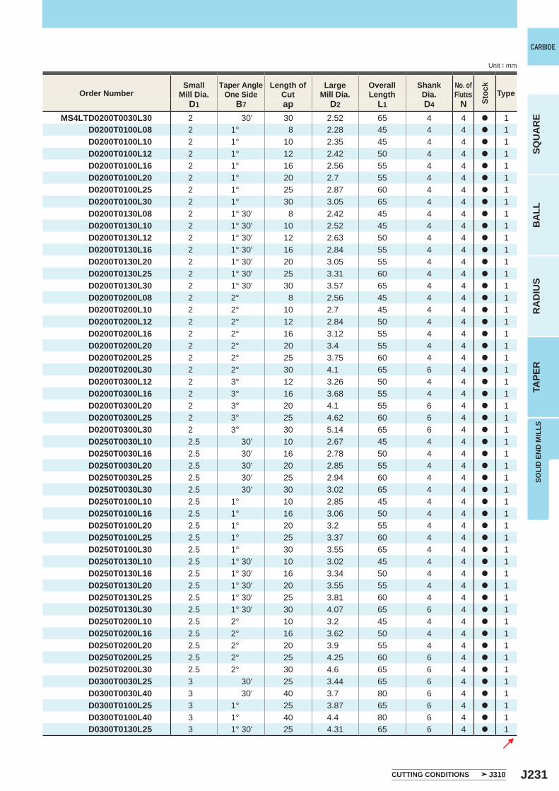
J231
D1 B7 ap D2 L1 D4 NMS4LTD0200T0030L30 2 30' 30 2.52 65 4 4 a 1
D0200T0100L08 2 1° 8 2.28 45 4 4 a 1D0200T0100L10 2 1° 10 2.35 45 4 4 a 1D0200T0100L12 2 1° 12 2.42 50 4 4 a 1D0200T0100L16 2 1° 16 2.56 55 4 4 a 1D0200T0100L20 2 1° 20 2.7 55 4 4 a 1D0200T0100L25 2 1° 25 2.87 60 4 4 a 1D0200T0100L30 2 1° 30 3.05 65 4 4 a 1D0200T0130L08 2 1° 30' 8 2.42 45 4 4 a 1D0200T0130L10 2 1° 30' 10 2.52 45 4 4 a 1D0200T0130L12 2 1° 30' 12 2.63 50 4 4 a 1D0200T0130L16 2 1° 30' 16 2.84 55 4 4 a 1D0200T0130L20 2 1° 30' 20 3.05 55 4 4 a 1D0200T0130L25 2 1° 30' 25 3.31 60 4 4 a 1D0200T0130L30 2 1° 30' 30 3.57 65 4 4 a 1D0200T0200L08 2 2° 8 2.56 45 4 4 a 1D0200T0200L10 2 2° 10 2.7 45 4 4 a 1D0200T0200L12 2 2° 12 2.84 50 4 4 a 1D0200T0200L16 2 2° 16 3.12 55 4 4 a 1D0200T0200L20 2 2° 20 3.4 55 4 4 a 1D0200T0200L25 2 2° 25 3.75 60 4 4 a 1D0200T0200L30 2 2° 30 4.1 65 6 4 a 1D0200T0300L12 2 3° 12 3.26 50 4 4 a 1D0200T0300L16 2 3° 16 3.68 55 4 4 a 1D0200T0300L20 2 3° 20 4.1 55 6 4 a 1D0200T0300L25 2 3° 25 4.62 60 6 4 a 1D0200T0300L30 2 3° 30 5.14 65 6 4 a 1D0250T0030L10 2.5 30' 10 2.67 45 4 4 a 1D0250T0030L16 2.5 30' 16 2.78 50 4 4 a 1D0250T0030L20 2.5 30' 20 2.85 55 4 4 a 1D0250T0030L25 2.5 30' 25 2.94 60 4 4 a 1D0250T0030L30 2.5 30' 30 3.02 65 4 4 a 1D0250T0100L10 2.5 1° 10 2.85 45 4 4 a 1D0250T0100L16 2.5 1° 16 3.06 50 4 4 a 1D0250T0100L20 2.5 1° 20 3.2 55 4 4 a 1D0250T0100L25 2.5 1° 25 3.37 60 4 4 a 1D0250T0100L30 2.5 1° 30 3.55 65 4 4 a 1D0250T0130L10 2.5 1° 30' 10 3.02 45 4 4 a 1D0250T0130L16 2.5 1° 30' 16 3.34 50 4 4 a 1D0250T0130L20 2.5 1° 30' 20 3.55 55 4 4 a 1D0250T0130L25 2.5 1° 30' 25 3.81 60 4 4 a 1D0250T0130L30 2.5 1° 30' 30 4.07 65 6 4 a 1D0250T0200L10 2.5 2° 10 3.2 45 4 4 a 1D0250T0200L16 2.5 2° 16 3.62 50 4 4 a 1D0250T0200L20 2.5 2° 20 3.9 55 4 4 a 1D0250T0200L25 2.5 2° 25 4.25 60 6 4 a 1D0250T0200L30 2.5 2° 30 4.6 65 6 4 a 1D0300T0030L25 3 30' 25 3.44 65 6 4 a 1D0300T0030L40 3 30' 40 3.7 80 6 4 a 1D0300T0100L25 3 1° 25 3.87 65 6 4 a 1D0300T0100L40 3 1° 40 4.4 80 6 4 a 1D0300T0130L25 3 1° 30' 25 4.31 65 6 4 a 1
SOLI
D E
ND
MIL
LS
CARBIDE
SQU
AR
EB
ALL
RA
DIU
STA
PER
Unit : mm
Order NumberSmall
Mill Dia.Taper Angle
One SideLength of
CutLarge
Mill Dia.Overall Length
ShankDia.
No. ofFlutes Type
CUTTING CONDITIONS J310
Stoc
k
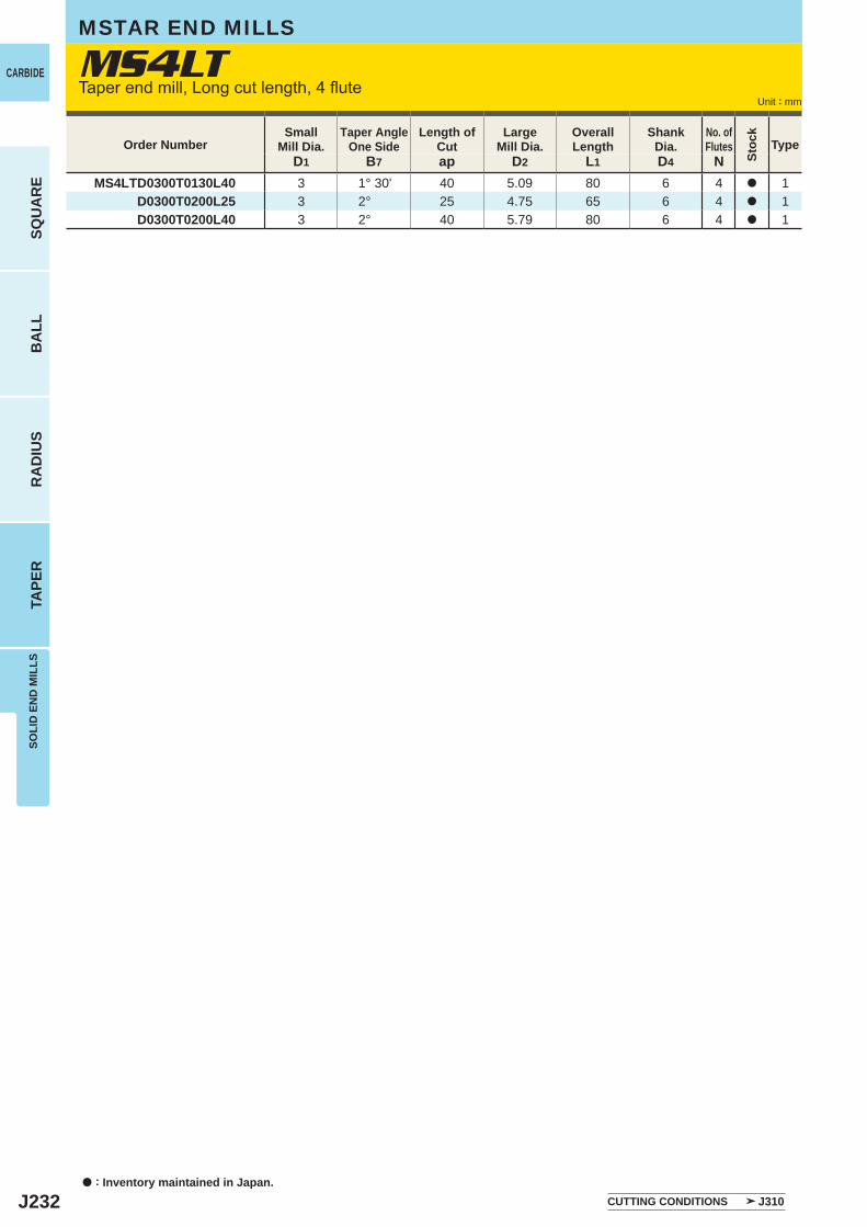
J232
D1 B7 ap D2 L1 D4 NMS4LTD0300T0130L40 3 1° 30' 40 5.09 80 6 4 a 1
D0300T0200L25 3 2° 25 4.75 65 6 4 a 1D0300T0200L40 3 2° 40 5.79 80 6 4 a 1
MS4LTCARBIDE
SQU
AR
EB
ALL
RA
DIU
STA
PER
SOLI
D E
ND
MIL
LS
Unit : mm
Order NumberSmall
Mill Dia.Taper Angle
One SideLength of
CutLarge
Mill Dia.Overall Length
ShankDia.
No. ofFlutes Type
MSTAR END MILLS
Taper end mill, Long cut length, 4 flute
a : Inventory maintained in Japan.CUTTING CONDITIONS J310
Stoc
k
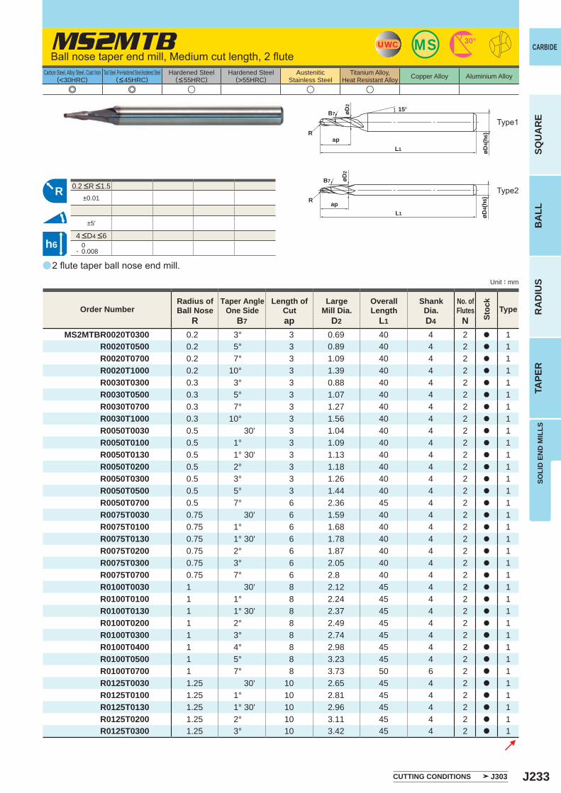
J233
a
MS2MTB
e e u u u
R B7 ap D2 L1 D4 NMS2MTBR0020T0300 0.2 3° 3 0.69 40 4 2 a 1
R0020T0500 0.2 5° 3 0.89 40 4 2 a 1R0020T0700 0.2 7° 3 1.09 40 4 2 a 1R0020T1000 0.2 10° 3 1.39 40 4 2 a 1R0030T0300 0.3 3° 3 0.88 40 4 2 a 1R0030T0500 0.3 5° 3 1.07 40 4 2 a 1R0030T0700 0.3 7° 3 1.27 40 4 2 a 1R0030T1000 0.3 10° 3 1.56 40 4 2 a 1R0050T0030 0.5 30' 3 1.04 40 4 2 a 1R0050T0100 0.5 1° 3 1.09 40 4 2 a 1R0050T0130 0.5 1° 30' 3 1.13 40 4 2 a 1R0050T0200 0.5 2° 3 1.18 40 4 2 a 1R0050T0300 0.5 3° 3 1.26 40 4 2 a 1R0050T0500 0.5 5° 3 1.44 40 4 2 a 1R0050T0700 0.5 7° 6 2.36 45 4 2 a 1R0075T0030 0.75 30' 6 1.59 40 4 2 a 1R0075T0100 0.75 1° 6 1.68 40 4 2 a 1R0075T0130 0.75 1° 30' 6 1.78 40 4 2 a 1R0075T0200 0.75 2° 6 1.87 40 4 2 a 1R0075T0300 0.75 3° 6 2.05 40 4 2 a 1R0075T0700 0.75 7° 6 2.8 40 4 2 a 1R0100T0030 1 30' 8 2.12 45 4 2 a 1R0100T0100 1 1° 8 2.24 45 4 2 a 1R0100T0130 1 1° 30' 8 2.37 45 4 2 a 1R0100T0200 1 2° 8 2.49 45 4 2 a 1R0100T0300 1 3° 8 2.74 45 4 2 a 1R0100T0400 1 4° 8 2.98 45 4 2 a 1R0100T0500 1 5° 8 3.23 45 4 2 a 1R0100T0700 1 7° 8 3.73 50 6 2 a 1R0125T0030 1.25 30' 10 2.65 45 4 2 a 1R0125T0100 1.25 1° 10 2.81 45 4 2 a 1R0125T0130 1.25 1° 30' 10 2.96 45 4 2 a 1R0125T0200 1.25 2° 10 3.11 45 4 2 a 1R0125T0300 1.25 3° 10 3.42 45 4 2 a 1
±0.01
±5'
0- 0.008
UWC MS 30°
L1
ap
15°
øD4(
h6)R
øD2
B7
R
L1
ap
øD2
B7
øD4(
h6)R
h6
SOLI
D E
ND
MIL
LS
CARBIDE
SQU
AR
EB
ALL
RA
DIU
STA
PER
Unit : mm
Carbon Steel, Alloy Steel, Cast Iron(<30HRC)
Tool Steel, Pre-Hardened Steel,Hardened Steel(<45HRC)
Hardened Steel(<55HRC)
Hardened Steel(>55HRC)
AusteniticStainless Steel
Titanium Alloy,Heat Resistant Alloy Copper Alloy Aluminium Alloy
2 flute taper ball nose end mill.
Type1
Type2
CUTTING CONDITIONS J303
4 <D4 <6
0.2 <R <1.5
Order NumberRadius ofBall Nose
Taper AngleOne Side
Length of Cut
LargeMill Dia.
Overall Length
ShankDia.
No. ofFlutes Type
Stoc
k
Ball nose taper end mill, Medium cut length, 2 flute
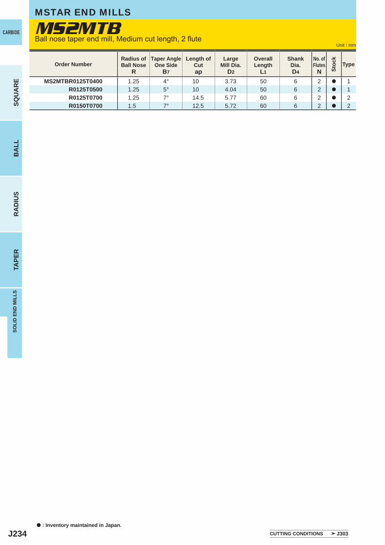
J234
R B7 ap D2 L1 D4 NMS2MTBR0125T0400 1.25 4° 10 3.73 50 6 2 a 1
R0125T0500 1.25 5° 10 4.04 50 6 2 a 1R0125T0700 1.25 7° 14.5 5.77 60 6 2 a 2R0150T0700 1.5 7° 12.5 5.72 60 6 2 a 2
MS2MTB
a : Inventory maintained in Japan.
CARBIDE
SQU
AR
EB
ALL
RA
DIU
STA
PER
SOLI
D E
ND
MIL
LS
Unit : mm
Order NumberRadius ofBall Nose
Taper AngleOne Side
Length of Cut
LargeMill Dia.
Overall Length
ShankDia.
No. ofFlutes Type
MSTAR END MILLS
Ball nose taper end mill, Medium cut length, 2 flute
CUTTING CONDITIONS J303
Stoc
k
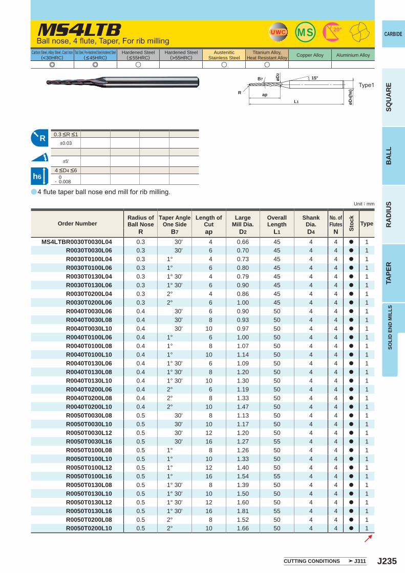
J235
a
MS4LTB
e e u u u
R B7 ap D2 L1 D4 NMS4LTBR0030T0030L04 0.3 30' 4 0.66 45 4 4 a 1
R0030T0030L06 0.3 30' 6 0.70 45 4 4 a 1R0030T0100L04 0.3 1° 4 0.73 45 4 4 a 1R0030T0100L06 0.3 1° 6 0.80 45 4 4 a 1R0030T0130L04 0.3 1° 30' 4 0.79 45 4 4 a 1R0030T0130L06 0.3 1° 30' 6 0.90 45 4 4 a 1R0030T0200L04 0.3 2° 4 0.86 45 4 4 a 1R0030T0200L06 0.3 2° 6 1.00 45 4 4 a 1R0040T0030L06 0.4 30' 6 0.90 50 4 4 a 1R0040T0030L08 0.4 30' 8 0.93 50 4 4 a 1R0040T0030L10 0.4 30' 10 0.97 50 4 4 a 1R0040T0100L06 0.4 1° 6 1.00 50 4 4 a 1R0040T0100L08 0.4 1° 8 1.07 50 4 4 a 1R0040T0100L10 0.4 1° 10 1.14 50 4 4 a 1R0040T0130L06 0.4 1° 30' 6 1.09 50 4 4 a 1R0040T0130L08 0.4 1° 30' 8 1.20 50 4 4 a 1R0040T0130L10 0.4 1° 30' 10 1.30 50 4 4 a 1R0040T0200L06 0.4 2° 6 1.19 50 4 4 a 1R0040T0200L08 0.4 2° 8 1.33 50 4 4 a 1R0040T0200L10 0.4 2° 10 1.47 50 4 4 a 1R0050T0030L08 0.5 30' 8 1.13 50 4 4 a 1R0050T0030L10 0.5 30' 10 1.17 50 4 4 a 1R0050T0030L12 0.5 30' 12 1.20 50 4 4 a 1R0050T0030L16 0.5 30' 16 1.27 55 4 4 a 1R0050T0100L08 0.5 1° 8 1.26 50 4 4 a 1R0050T0100L10 0.5 1° 10 1.33 50 4 4 a 1R0050T0100L12 0.5 1° 12 1.40 50 4 4 a 1R0050T0100L16 0.5 1° 16 1.54 55 4 4 a 1R0050T0130L08 0.5 1° 30' 8 1.39 50 4 4 a 1R0050T0130L10 0.5 1° 30' 10 1.50 50 4 4 a 1R0050T0130L12 0.5 1° 30' 12 1.60 50 4 4 a 1R0050T0130L16 0.5 1° 30' 16 1.81 55 4 4 a 1R0050T0200L08 0.5 2° 8 1.52 50 4 4 a 1R0050T0200L10 0.5 2° 10 1.66 50 4 4 a 1
±0.03
±5'
0- 0.008
MSUWC 20°
B7
øD4(
h6)
L1
ap
øD2
R
15°
R
h6
SOLI
D E
ND
MIL
LS
CARBIDE
SQU
AR
EB
ALL
RA
DIU
STA
PER
Unit : mm
Carbon Steel, Alloy Steel, Cast Iron(<30HRC)
Tool Steel, Pre-Hardened Steel,Hardened Steel(<45HRC)
Hardened Steel(<55HRC)
Hardened Steel(>55HRC)
AusteniticStainless Steel
Titanium Alloy,Heat Resistant Alloy Copper Alloy Aluminium Alloy
4 flute taper ball nose end mill for rib milling.
Ball nose, 4 flute, Taper, For rib milling
Type1
Order NumberRadius ofBall Nose
Taper AngleOne Side
Length of Cut
LargeMill Dia.
Overall Length
ShankDia.
No. ofFlutes Type
CUTTING CONDITIONS J311
4 <D4 <6
0.3 <R <1
Stoc
k
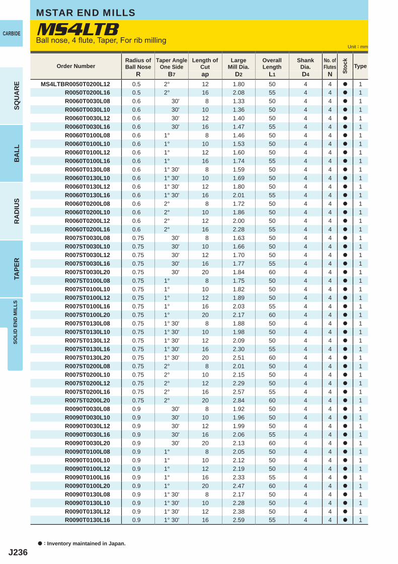
J236
R B7 ap D2 L1 D4 NMS4LTBR0050T0200L12 0.5 2° 12 1.80 50 4 4 a 1
R0050T0200L16 0.5 2° 16 2.08 55 4 4 a 1R0060T0030L08 0.6 30' 8 1.33 50 4 4 a 1R0060T0030L10 0.6 30' 10 1.36 50 4 4 a 1R0060T0030L12 0.6 30' 12 1.40 50 4 4 a 1R0060T0030L16 0.6 30' 16 1.47 55 4 4 a 1R0060T0100L08 0.6 1° 8 1.46 50 4 4 a 1R0060T0100L10 0.6 1° 10 1.53 50 4 4 a 1R0060T0100L12 0.6 1° 12 1.60 50 4 4 a 1R0060T0100L16 0.6 1° 16 1.74 55 4 4 a 1R0060T0130L08 0.6 1° 30' 8 1.59 50 4 4 a 1R0060T0130L10 0.6 1° 30' 10 1.69 50 4 4 a 1R0060T0130L12 0.6 1° 30' 12 1.80 50 4 4 a 1R0060T0130L16 0.6 1° 30' 16 2.01 55 4 4 a 1R0060T0200L08 0.6 2° 8 1.72 50 4 4 a 1R0060T0200L10 0.6 2° 10 1.86 50 4 4 a 1R0060T0200L12 0.6 2° 12 2.00 50 4 4 a 1R0060T0200L16 0.6 2° 16 2.28 55 4 4 a 1R0075T0030L08 0.75 30' 8 1.63 50 4 4 a 1R0075T0030L10 0.75 30' 10 1.66 50 4 4 a 1R0075T0030L12 0.75 30' 12 1.70 50 4 4 a 1R0075T0030L16 0.75 30' 16 1.77 55 4 4 a 1R0075T0030L20 0.75 30' 20 1.84 60 4 4 a 1R0075T0100L08 0.75 1° 8 1.75 50 4 4 a 1R0075T0100L10 0.75 1° 10 1.82 50 4 4 a 1R0075T0100L12 0.75 1° 12 1.89 50 4 4 a 1R0075T0100L16 0.75 1° 16 2.03 55 4 4 a 1R0075T0100L20 0.75 1° 20 2.17 60 4 4 a 1R0075T0130L08 0.75 1° 30' 8 1.88 50 4 4 a 1R0075T0130L10 0.75 1° 30' 10 1.98 50 4 4 a 1R0075T0130L12 0.75 1° 30' 12 2.09 50 4 4 a 1R0075T0130L16 0.75 1° 30' 16 2.30 55 4 4 a 1R0075T0130L20 0.75 1° 30' 20 2.51 60 4 4 a 1R0075T0200L08 0.75 2° 8 2.01 50 4 4 a 1R0075T0200L10 0.75 2° 10 2.15 50 4 4 a 1R0075T0200L12 0.75 2° 12 2.29 50 4 4 a 1R0075T0200L16 0.75 2° 16 2.57 55 4 4 a 1R0075T0200L20 0.75 2° 20 2.84 60 4 4 a 1R0090T0030L08 0.9 30' 8 1.92 50 4 4 a 1R0090T0030L10 0.9 30' 10 1.96 50 4 4 a 1R0090T0030L12 0.9 30' 12 1.99 50 4 4 a 1R0090T0030L16 0.9 30' 16 2.06 55 4 4 a 1R0090T0030L20 0.9 30' 20 2.13 60 4 4 a 1R0090T0100L08 0.9 1° 8 2.05 50 4 4 a 1R0090T0100L10 0.9 1° 10 2.12 50 4 4 a 1R0090T0100L12 0.9 1° 12 2.19 50 4 4 a 1R0090T0100L16 0.9 1° 16 2.33 55 4 4 a 1R0090T0100L20 0.9 1° 20 2.47 60 4 4 a 1R0090T0130L08 0.9 1° 30' 8 2.17 50 4 4 a 1R0090T0130L10 0.9 1° 30' 10 2.28 50 4 4 a 1R0090T0130L12 0.9 1° 30' 12 2.38 50 4 4 a 1R0090T0130L16 0.9 1° 30' 16 2.59 55 4 4 a 1
MS4LTB
a : Inventory maintained in Japan.
CARBIDE
SQU
AR
EB
ALL
RA
DIU
STA
PER
SOLI
D E
ND
MIL
LS
Unit : mm
Order NumberRadius ofBall Nose
Taper AngleOne Side
Length of Cut
LargeMill Dia.
Overall Length
ShankDia.
No. ofFlutes Type
MSTAR END MILLS
Ball nose, 4 flute, Taper, For rib milling
Stoc
k
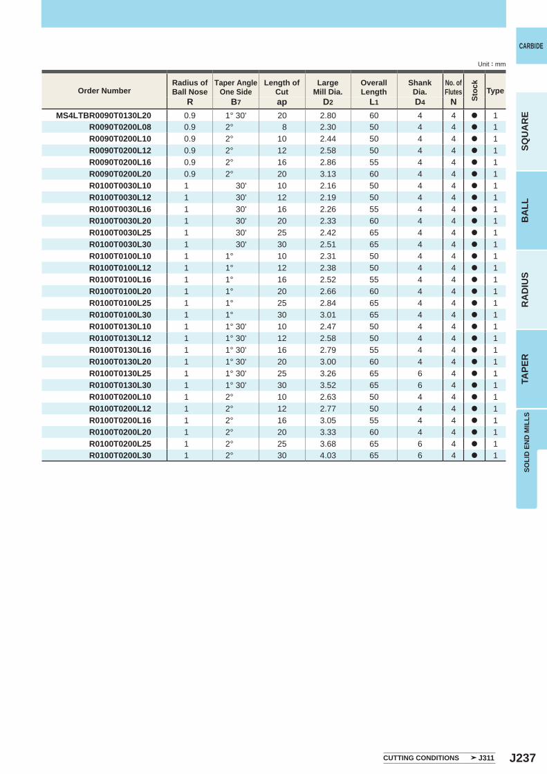
J237
R B7 ap D2 L1 D4 NMS4LTBR0090T0130L20 0.9 1° 30' 20 2.80 60 4 4 a 1
R0090T0200L08 0.9 2° 8 2.30 50 4 4 a 1R0090T0200L10 0.9 2° 10 2.44 50 4 4 a 1R0090T0200L12 0.9 2° 12 2.58 50 4 4 a 1R0090T0200L16 0.9 2° 16 2.86 55 4 4 a 1R0090T0200L20 0.9 2° 20 3.13 60 4 4 a 1R0100T0030L10 1 30' 10 2.16 50 4 4 a 1R0100T0030L12 1 30' 12 2.19 50 4 4 a 1R0100T0030L16 1 30' 16 2.26 55 4 4 a 1R0100T0030L20 1 30' 20 2.33 60 4 4 a 1R0100T0030L25 1 30' 25 2.42 65 4 4 a 1R0100T0030L30 1 30' 30 2.51 65 4 4 a 1R0100T0100L10 1 1° 10 2.31 50 4 4 a 1R0100T0100L12 1 1° 12 2.38 50 4 4 a 1R0100T0100L16 1 1° 16 2.52 55 4 4 a 1R0100T0100L20 1 1° 20 2.66 60 4 4 a 1R0100T0100L25 1 1° 25 2.84 65 4 4 a 1R0100T0100L30 1 1° 30 3.01 65 4 4 a 1R0100T0130L10 1 1° 30' 10 2.47 50 4 4 a 1R0100T0130L12 1 1° 30' 12 2.58 50 4 4 a 1R0100T0130L16 1 1° 30' 16 2.79 55 4 4 a 1R0100T0130L20 1 1° 30' 20 3.00 60 4 4 a 1R0100T0130L25 1 1° 30' 25 3.26 65 6 4 a 1R0100T0130L30 1 1° 30' 30 3.52 65 6 4 a 1R0100T0200L10 1 2° 10 2.63 50 4 4 a 1R0100T0200L12 1 2° 12 2.77 50 4 4 a 1R0100T0200L16 1 2° 16 3.05 55 4 4 a 1R0100T0200L20 1 2° 20 3.33 60 4 4 a 1R0100T0200L25 1 2° 25 3.68 65 6 4 a 1R0100T0200L30 1 2° 30 4.03 65 6 4 a 1
SOLI
D E
ND
MIL
LS
CARBIDE
SQU
AR
EB
ALL
RA
DIU
STA
PER
Unit : mm
Order NumberRadius ofBall Nose
Taper AngleOne Side
Length of Cut
LargeMill Dia.
Overall Length
ShankDia.
No. ofFlutes Type
CUTTING CONDITIONS J311
Stoc
k
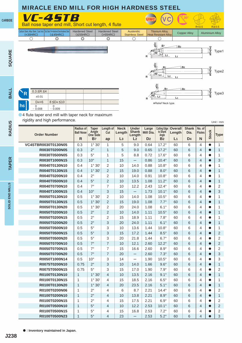
J238
a
u e e e u u
VC-4STB
R B7 ap L3 L2 D2 B2 L1 D4 NVC4STBR0030T0130N05 0.3 1° 30' 1 5 9.0 0.64 17.2° 60 6 4 a 1
R0030T0200N05 0.3 2° 1 5 9.0 0.65 17.2° 60 6 4 a 1R0030T0500N05 0.3 5° 1 5 8.8 0.72 17.6° 60 6 4 a 1R0030T1000N15 0.3 10° 1 15 ─ 0.86 10.4° 60 6 4 a 3R0040T0130N10 0.4 1° 30' 2 10 14.0 0.88 10.8° 60 6 4 a 1R0040T0130N15 0.4 1° 30' 2 15 19.0 0.88 8.0° 60 6 4 a 1R0040T0200N10 0.4 2° 2 10 14.0 0.91 10.8° 60 6 4 a 1R0040T0500N10 0.4 5° 2 10 13.5 1.08 11.2° 60 6 4 a 1R0040T0700N10 0.4 7° 7 10 12.2 2.43 12.4° 60 6 4 a 2R0040T1000N15 0.4 10° 3 15 ─ 1.73 10.1° 60 6 4 a 3R0050T0130N10 0.5 1° 30' 2 10 14.0 1.08 10.5° 60 6 4 a 1R0050T0130N15 0.5 1° 30' 2 15 19.0 1.08 7.7° 60 6 4 a 1R0050T0130N20 0.5 1° 30' 2 20 24.0 1.08 6.1° 60 6 4 a 1R0050T0200N10 0.5 2° 2 10 14.0 1.11 10.5° 60 6 4 a 1R0050T0200N15 0.5 2° 2 15 18.9 1.11 7.8° 60 6 4 a 1R0050T0200N20 0.5 2° 3 20 24.0 1.11 6.1° 60 6 4 a 1R0050T0500N10 0.5 5° 3 10 13.6 1.44 10.8° 60 6 4 a 1R0050T0500N15 0.5 5° 3 15 17.2 1.44 8.5° 60 6 4 a 2R0050T0500N20 0.5 5° 3 20 21.8 1.44 6.7° 60 6 4 a 2R0050T0700N10 0.5 7° 7 10 12.1 2.60 12.2° 60 6 4 a 2R0050T0700N15 0.5 7° 7 15 16.6 2.60 8.9° 60 6 4 a 2R0050T0700N20 0.5 7° 7 20 ─ 2.60 7.3° 60 6 4 a 3R0050T1000N14 0.5 10° 3 14 ─ 1.90 10.5° 60 6 4 a 3R0075T0200N10 0.75 2° 3 10 14.0 1.66 9.6° 60 6 4 a 1R0075T0500N15 0.75 5° 3 15 17.0 1.90 7.9° 60 6 4 a 2R0100T0130N10 1 1° 30' 4 10 13.5 2.16 9.1° 60 6 4 a 1R0100T0130N15 1 1° 30' 4 15 18.5 2.16 6.5° 60 6 4 a 1R0100T0130N20 1 1° 30' 4 20 23.5 2.16 5.1° 60 6 4 a 1R0100T0200N06 1 2° 4 6 8.7 2.21 14.4° 60 6 4 a 2R0100T0200N10 1 2° 4 10 13.8 2.21 8.9° 60 6 4 a 1R0100T0200N15 1 2° 4 15 17.5 2.21 6.9° 60 6 4 a 2R0100T0500N10 1 5° 4 10 12.2 2.53 10.1° 60 6 4 a 2R0100T0500N15 1 5° 4 15 16.8 2.53 7.2° 60 6 4 a 2R0100T0500N23 1 5° 4 23 ─ 2.53 5.2° 60 6 4 a 3
R<0.5
±0.01
D4=6 0- 0.008
0- 0.009
UWC VC 30°
L1
ap L3 L2
B2
øD4(
h6)
R
B7øD2
RB2
øD4(
h6)
L1ap L3
R
B7øD2
L1ap L3 L2
B2
øD4(
h6)
R
B7øD2
h6
a : Inventory maintained in Japan.
CARBIDE
SQU
AR
EB
ALL
RA
DIU
STA
PER
SOLI
D E
ND
MIL
LS
Unit : mm
Carbon Steel, Alloy Steel, Cast Iron(<30HRC)
Tool Steel, Pre-Hardened Steel,Hardened Steel(<45HRC)
Hardened Steel(<55HRC)
Hardened Steel(>55HRC)
AusteniticStainless Steel
Titanium Alloy,Heat Resistant Alloy Copper Alloy Aluminium Alloy
MIRACLE END MILL FOR HIGH HARDNESS STEEL
4 flute taper end mill with taper neck for maximumrigidity and high performance.
Ball nose taper end mill, Short cut length, 4 flute
Type2
Type3
Type1
*Relief Neck type.
R>0.5
Order Number
Radius ofBall Nose
TaperAngle
One Side
Length ofCut
NeckLength
UnderShankLength
LargeMill Dia.
Cutting Edgeto Shank
Angle
OverallLength
ShankDia.
No. ofFlutes Type
8 <D4 <10
0.3 <R <4
Stoc
k
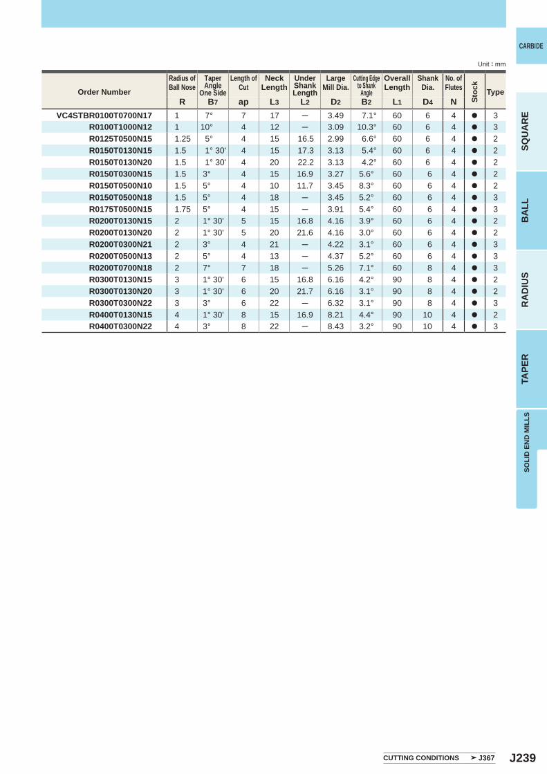
J239
R B7 ap L3 L2 D2 B2 L1 D4 NVC4STBR0100T0700N17 1 7° 7 17 ─ 3.49 7.1° 60 6 4 a 3
R0100T1000N12 1 10° 4 12 ─ 3.09 10.3° 60 6 4 a 3R0125T0500N15 1.25 5° 4 15 16.5 2.99 6.6° 60 6 4 a 2R0150T0130N15 1.5 1° 30' 4 15 17.3 3.13 5.4° 60 6 4 a 2R0150T0130N20 1.5 1° 30' 4 20 22.2 3.13 4.2° 60 6 4 a 2R0150T0300N15 1.5 3° 4 15 16.9 3.27 5.6° 60 6 4 a 2R0150T0500N10 1.5 5° 4 10 11.7 3.45 8.3° 60 6 4 a 2R0150T0500N18 1.5 5° 4 18 ─ 3.45 5.2° 60 6 4 a 3R0175T0500N15 1.75 5° 4 15 ─ 3.91 5.4° 60 6 4 a 3R0200T0130N15 2 1° 30' 5 15 16.8 4.16 3.9° 60 6 4 a 2R0200T0130N20 2 1° 30' 5 20 21.6 4.16 3.0° 60 6 4 a 2R0200T0300N21 2 3° 4 21 ─ 4.22 3.1° 60 6 4 a 3R0200T0500N13 2 5° 4 13 ─ 4.37 5.2° 60 6 4 a 3R0200T0700N18 2 7° 7 18 ─ 5.26 7.1° 60 8 4 a 3R0300T0130N15 3 1° 30' 6 15 16.8 6.16 4.2° 90 8 4 a 2R0300T0130N20 3 1° 30' 6 20 21.7 6.16 3.1° 90 8 4 a 2R0300T0300N22 3 3° 6 22 ─ 6.32 3.1° 90 8 4 a 3R0400T0130N15 4 1° 30' 8 15 16.9 8.21 4.4° 90 10 4 a 2R0400T0300N22 4 3° 8 22 ─ 8.43 3.2° 90 10 4 a 3
SOLI
D E
ND
MIL
LS
CARBIDE
SQU
AR
EB
ALL
RA
DIU
STA
PER
Unit : mm
Order Number
Radius ofBall Nose
TaperAngle
One Side
Length ofCut
NeckLength
UnderShankLength
LargeMill Dia.
Cutting Edgeto Shank
Angle
OverallLength
ShankDia.
No. ofFlutes Type
CUTTING CONDITIONS J367
Stoc
k
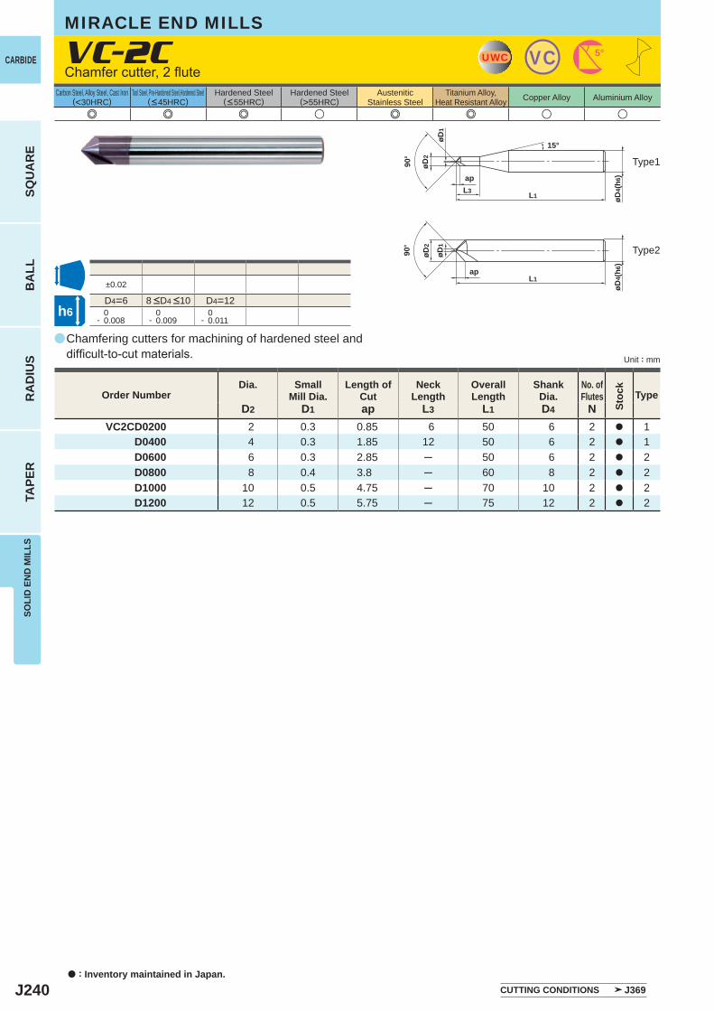
J240
a
e e e u e e u u
VC-2C
D2 D1 ap L3 L1 D4 NVC2CD0200 2 0.3 0.85 6 50 6 2 a 1
D0400 4 0.3 1.85 12 50 6 2 a 1D0600 6 0.3 2.85 ─ 50 6 2 a 2D0800 8 0.4 3.8 ─ 60 8 2 a 2D1000 10 0.5 4.75 ─ 70 10 2 a 2D1200 12 0.5 5.75 ─ 75 12 2 a 2
±0.02
D4=6 D4=12 0- 0.008
0- 0.009
0- 0.011
UWC VC 5°
L1
ap
øD4(
h6)
øD2
øD1
15°
L3
90°
L1ap
øD4(
h6)
øD2
øD1
90°
h6
a : Inventory maintained in Japan.
CARBIDE
SQU
AR
EB
ALL
RA
DIU
STA
PER
SOLI
D E
ND
MIL
LS
Unit : mm
Carbon Steel, Alloy Steel, Cast Iron(<30HRC)
Tool Steel, Pre-Hardened Steel,Hardened Steel(<45HRC)
Hardened Steel(<55HRC)
Hardened Steel(>55HRC)
AusteniticStainless Steel
Titanium Alloy,Heat Resistant Alloy Copper Alloy Aluminium Alloy
MIRACLE END MILLS
Chamfering cutters for machining of hardened steel and difficult-to-cut materials.
Chamfer cutter, 2 flute
Type2
Type1
Order NumberDia. Small
Mill Dia.Length of
CutNeck
LengthOverallLength
ShankDia.
No. ofFlutes Type
CUTTING CONDITIONS J369
8 <D4 <10
Stoc
k

J241
Memo
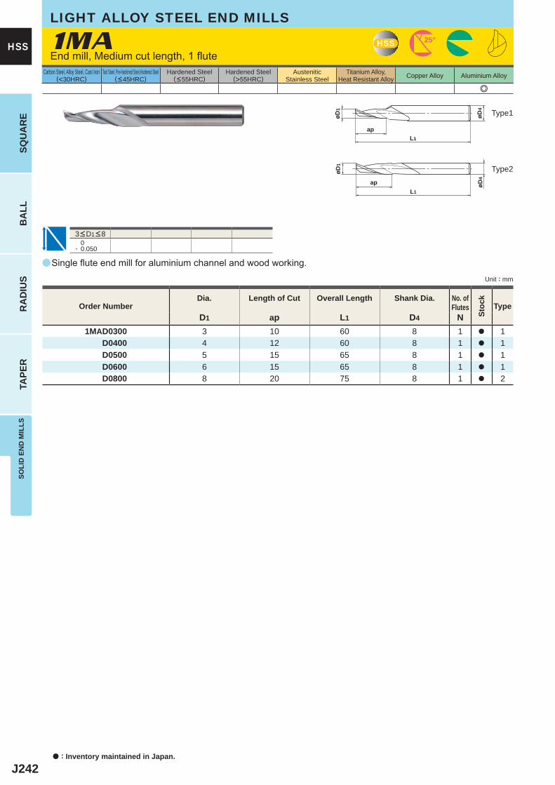
J242
a
e
1MA
0- 0.050
D1 ap L1 D4 N1MAD0300 3 10 60 8 1 a 1
D0400 4 12 60 8 1 a 1D0500 5 15 65 8 1 a 1D0600 6 15 65 8 1 a 1D0800 8 20 75 8 1 a 2
L1
ap
øD4
øD1
L1
ap øD4
øD1
HSS 25°
a : Inventory maintained in Japan.
HSS
SQU
AR
EB
ALL
RA
DIU
STA
PER
SOLI
D E
ND
MIL
LS
Unit : mm
Carbon Steel, Alloy Steel, Cast Iron(<30HRC)
Tool Steel, Pre-Hardened Steel,Hardened Steel(<45HRC)
Hardened Steel(<55HRC)
Hardened Steel(>55HRC)
AusteniticStainless Steel
Titanium Alloy,Heat Resistant Alloy Copper Alloy Aluminium Alloy
LIGHT ALLOY STEEL END MILLS
End mill, Medium cut length, 1 flute
Type2
Type1
3<D1<8
Single flute end mill for aluminium channel and wood working.
Order NumberDia. Length of Cut Overall Length Shank Dia. No. of
Flutes
Stoc
k
Type
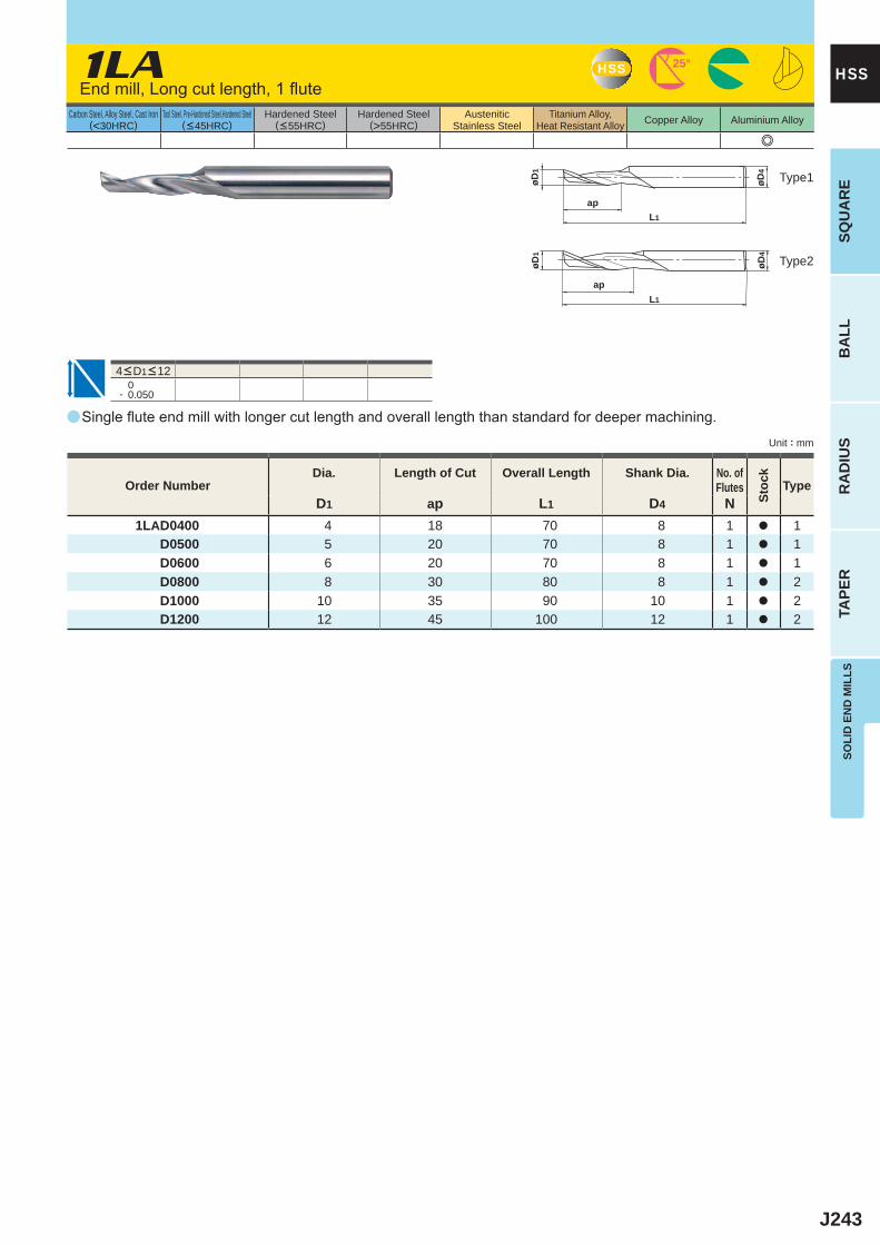
J243
a
e
1LA
0- 0.050
D1 ap L1 D4 N1LAD0400 4 18 70 8 1 a 1
D0500 5 20 70 8 1 a 1D0600 6 20 70 8 1 a 1D0800 8 30 80 8 1 a 2D1000 10 35 90 10 1 a 2D1200 12 45 100 12 1 a 2
HSS 25°
L1
ap
øD4
øD1
L1
ap
øD4
øD1
SOLI
D E
ND
MIL
LSSQ
UA
RE
BA
LLR
AD
IUS
TAPE
R
HSS
Unit : mm
Carbon Steel, Alloy Steel, Cast Iron(<30HRC)
Tool Steel, Pre-Hardened Steel,Hardened Steel(<45HRC)
Hardened Steel(<55HRC)
Hardened Steel(>55HRC)
AusteniticStainless Steel
Titanium Alloy,Heat Resistant Alloy Copper Alloy Aluminium Alloy
Type2
Type1
Order NumberDia. Length of Cut Overall Length Shank Dia. No. of
Flutes
Stoc
k
Type
End mill, Long cut length, 1 flute
4<D1<12
Single flute end mill with longer cut length and overall length than standard for deeper machining.
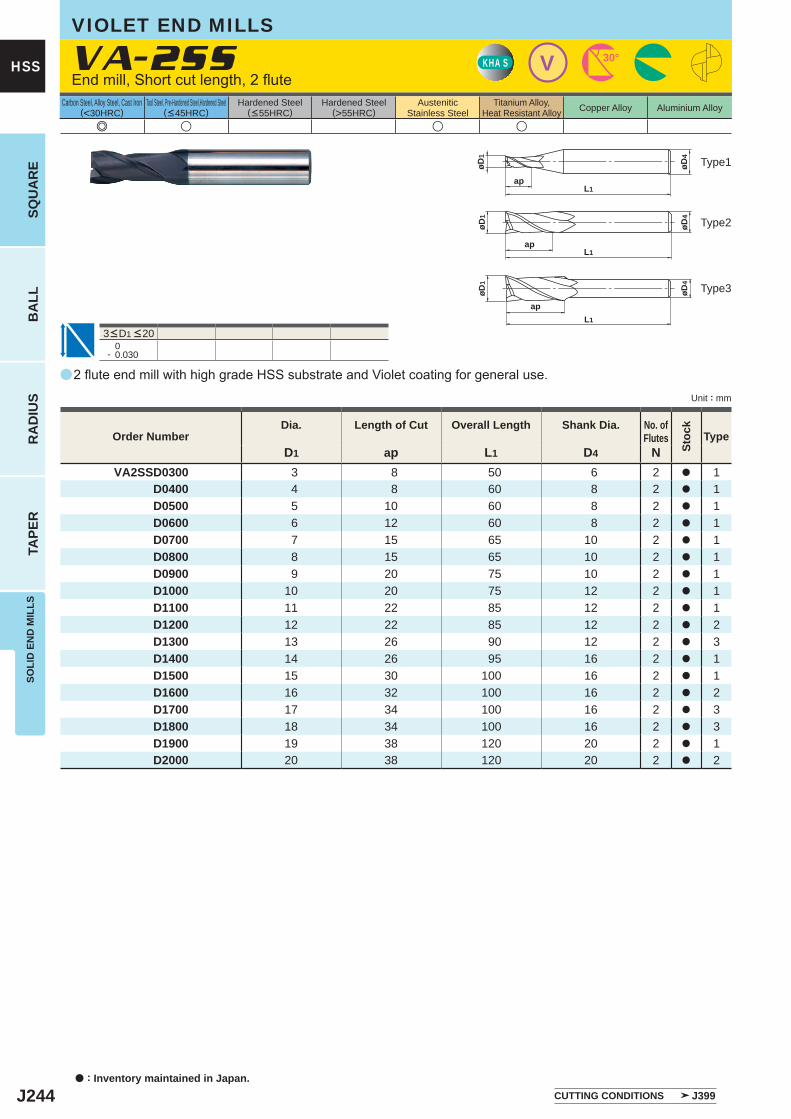
J244
a
e u u u
VA-2SS
D1 ap L1 D4 NVA2SSD0300 3 8 50 6 2 a 1
D0400 4 8 60 8 2 a 1D0500 5 10 60 8 2 a 1D0600 6 12 60 8 2 a 1D0700 7 15 65 10 2 a 1D0800 8 15 65 10 2 a 1D0900 9 20 75 10 2 a 1D1000 10 20 75 12 2 a 1D1100 11 22 85 12 2 a 1D1200 12 22 85 12 2 a 2D1300 13 26 90 12 2 a 3D1400 14 26 95 16 2 a 1D1500 15 30 100 16 2 a 1D1600 16 32 100 16 2 a 2D1700 17 34 100 16 2 a 3D1800 18 34 100 16 2 a 3D1900 19 38 120 20 2 a 1D2000 20 38 120 20 2 a 2
0- 0.030
KHA S V 30°
øD4
L1ap
øD1
øD4
L1ap
øD1
øD4
L1
ap
øD1
a : Inventory maintained in Japan.
HSS
SQU
AR
EB
ALL
RA
DIU
STA
PER
SOLI
D E
ND
MIL
LS
Unit : mm
Carbon Steel, Alloy Steel, Cast Iron(<30HRC)
Tool Steel, Pre-Hardened Steel,Hardened Steel(<45HRC)
Hardened Steel(<55HRC)
Hardened Steel(>55HRC)
AusteniticStainless Steel
Titanium Alloy,Heat Resistant Alloy Copper Alloy Aluminium Alloy
VIOLET END MILLS
Type2
Type3
Type1
3<D1 <20
End mill, Short cut length, 2 flute
2 flute end mill with high grade HSS substrate and Violet coating for general use.
Order NumberDia. Length of Cut Overall Length Shank Dia. No. of
Flutes
Stoc
k
Type
CUTTING CONDITIONS J399
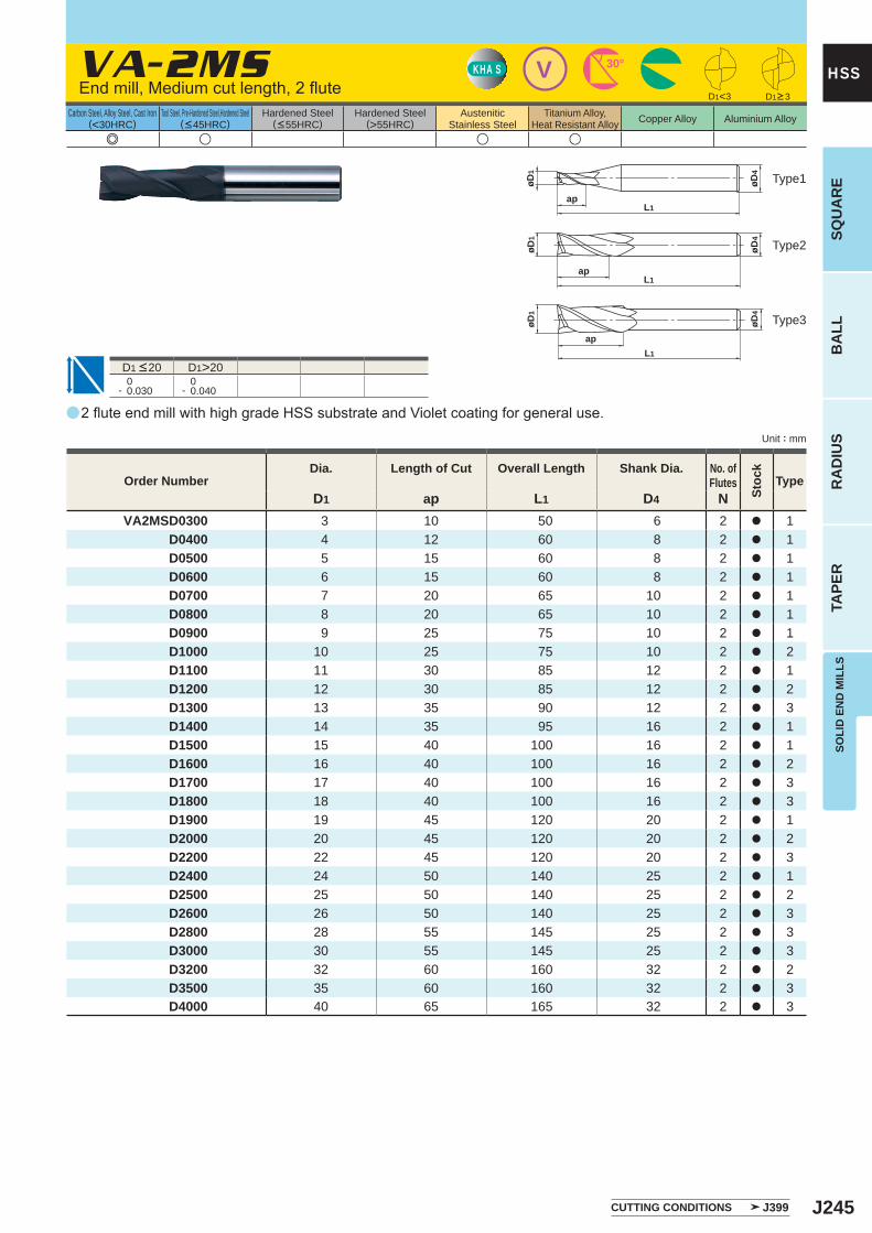
J245
a
e u u u
VA-2MS
D1 ap L1 D4 NVA2MSD0300 3 10 50 6 2 a 1
D0400 4 12 60 8 2 a 1D0500 5 15 60 8 2 a 1D0600 6 15 60 8 2 a 1D0700 7 20 65 10 2 a 1D0800 8 20 65 10 2 a 1D0900 9 25 75 10 2 a 1D1000 10 25 75 10 2 a 2D1100 11 30 85 12 2 a 1D1200 12 30 85 12 2 a 2D1300 13 35 90 12 2 a 3D1400 14 35 95 16 2 a 1D1500 15 40 100 16 2 a 1D1600 16 40 100 16 2 a 2D1700 17 40 100 16 2 a 3D1800 18 40 100 16 2 a 3D1900 19 45 120 20 2 a 1D2000 20 45 120 20 2 a 2D2200 22 45 120 20 2 a 3D2400 24 50 140 25 2 a 1D2500 25 50 140 25 2 a 2D2600 26 50 140 25 2 a 3D2800 28 55 145 25 2 a 3D3000 30 55 145 25 2 a 3D3200 32 60 160 32 2 a 2D3500 35 60 160 32 2 a 3D4000 40 65 165 32 2 a 3
D1>20 0- 0.030
0- 0.040
D1<3
VKHA S 30°
øD4
L1ap
øD1
øD4
L1ap
øD1
øD4
L1
ap
øD1
SOLI
D E
ND
MIL
LSSQ
UA
RE
BA
LLR
AD
IUS
TAPE
R
HSS
Unit : mm
Carbon Steel, Alloy Steel, Cast Iron(<30HRC)
Tool Steel, Pre-Hardened Steel,Hardened Steel(<45HRC)
Hardened Steel(<55HRC)
Hardened Steel(>55HRC)
AusteniticStainless Steel
Titanium Alloy,Heat Resistant Alloy Copper Alloy Aluminium Alloy
Type2
Type3
Type1
2 flute end mill with high grade HSS substrate and Violet coating for general use.
Order NumberDia. Length of Cut Overall Length Shank Dia. No. of
Flutes
Stoc
k
Type
D1 <20
End mill, Medium cut length, 2 flute D1>3
CUTTING CONDITIONS J399
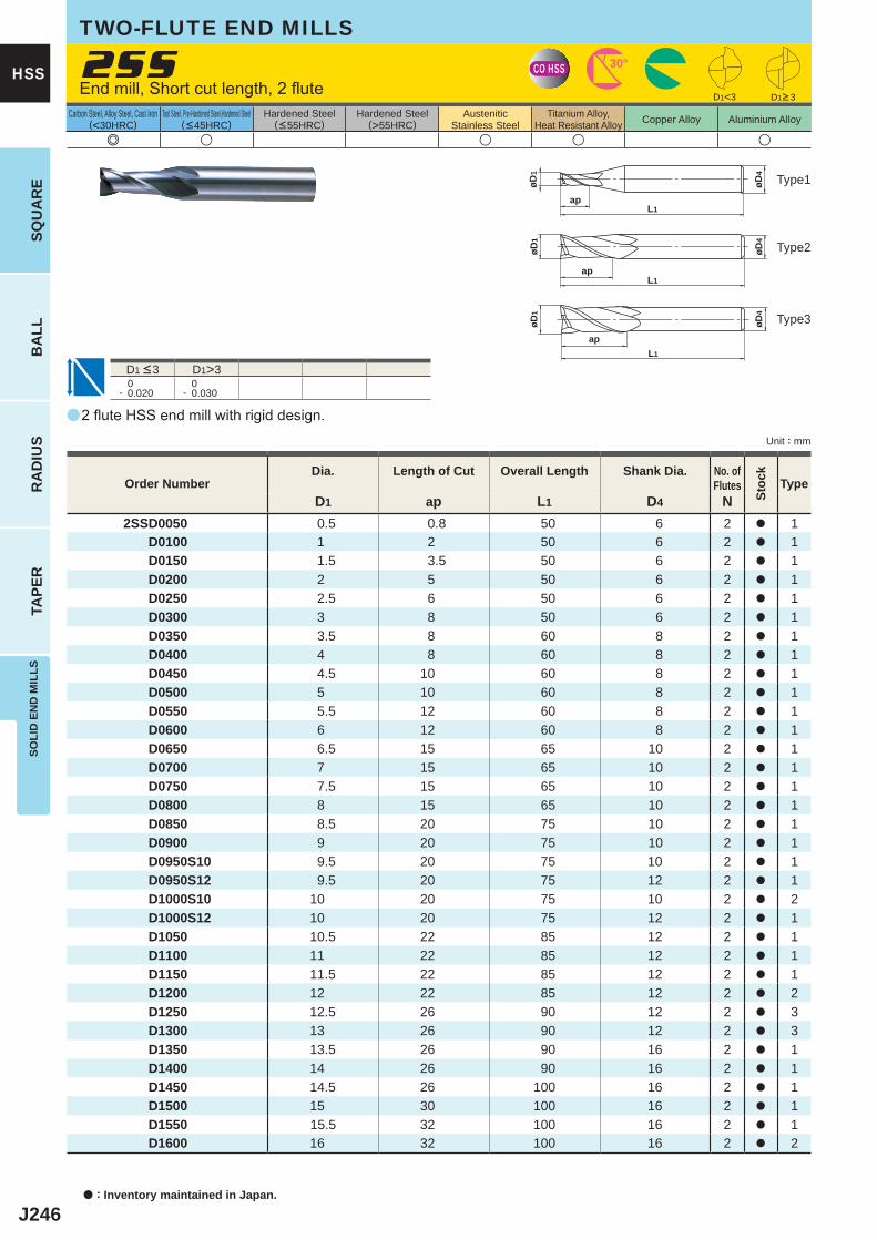
J246
a
e u u u u
2SS
D1 ap L1 D4 N2SSD0050 0.5 0.8 50 6 2 a 1
D0100 1 2 50 6 2 a 1 D0150 1.5 3.5 50 6 2 a 1 D0200 2 5 50 6 2 a 1 D0250 2.5 6 50 6 2 a 1 D0300 3 8 50 6 2 a 1 D0350 3.5 8 60 8 2 a 1 D0400 4 8 60 8 2 a 1 D0450 4.5 10 60 8 2 a 1 D0500 5 10 60 8 2 a 1 D0550 5.5 12 60 8 2 a 1 D0600 6 12 60 8 2 a 1 D0650 6.5 15 65 10 2 a 1 D0700 7 15 65 10 2 a 1 D0750 7.5 15 65 10 2 a 1 D0800 8 15 65 10 2 a 1 D0850 8.5 20 75 10 2 a 1 D0900 9 20 75 10 2 a 1 D0950S10 9.5 20 75 10 2 a 1 D0950S12 9.5 20 75 12 2 a 1 D1000S10 10 20 75 10 2 a 2 D1000S12 10 20 75 12 2 a 1 D1050 10.5 22 85 12 2 a 1 D1100 11 22 85 12 2 a 1 D1150 11.5 22 85 12 2 a 1 D1200 12 22 85 12 2 a 2 D1250 12.5 26 90 12 2 a 3 D1300 13 26 90 12 2 a 3 D1350 13.5 26 90 16 2 a 1 D1400 14 26 90 16 2 a 1 D1450 14.5 26 100 16 2 a 1 D1500 15 30 100 16 2 a 1 D1550 15.5 32 100 16 2 a 1 D1600 16 32 100 16 2 a 2
D1<3
D1>3 0- 0.020
0- 0.030
CO HSS 30°
øD4
L1ap
øD1
øD4
L1ap
øD1
øD4
L1
ap
øD1
a : Inventory maintained in Japan.
HSS
SQU
AR
EB
ALL
RA
DIU
STA
PER
SOLI
D E
ND
MIL
LS
Unit : mm
Carbon Steel, Alloy Steel, Cast Iron(<30HRC)
Tool Steel, Pre-Hardened Steel,Hardened Steel(<45HRC)
Hardened Steel(<55HRC)
Hardened Steel(>55HRC)
AusteniticStainless Steel
Titanium Alloy,Heat Resistant Alloy Copper Alloy Aluminium Alloy
End mill, Short cut length, 2 flute
TWO-FLUTE END MILLS
D1>3
Type2
Type3
Type1
D1 <3
2 flute HSS end mill with rigid design.
Order NumberDia. Length of Cut Overall Length Shank Dia. No. of
Flutes
Stoc
k
Type
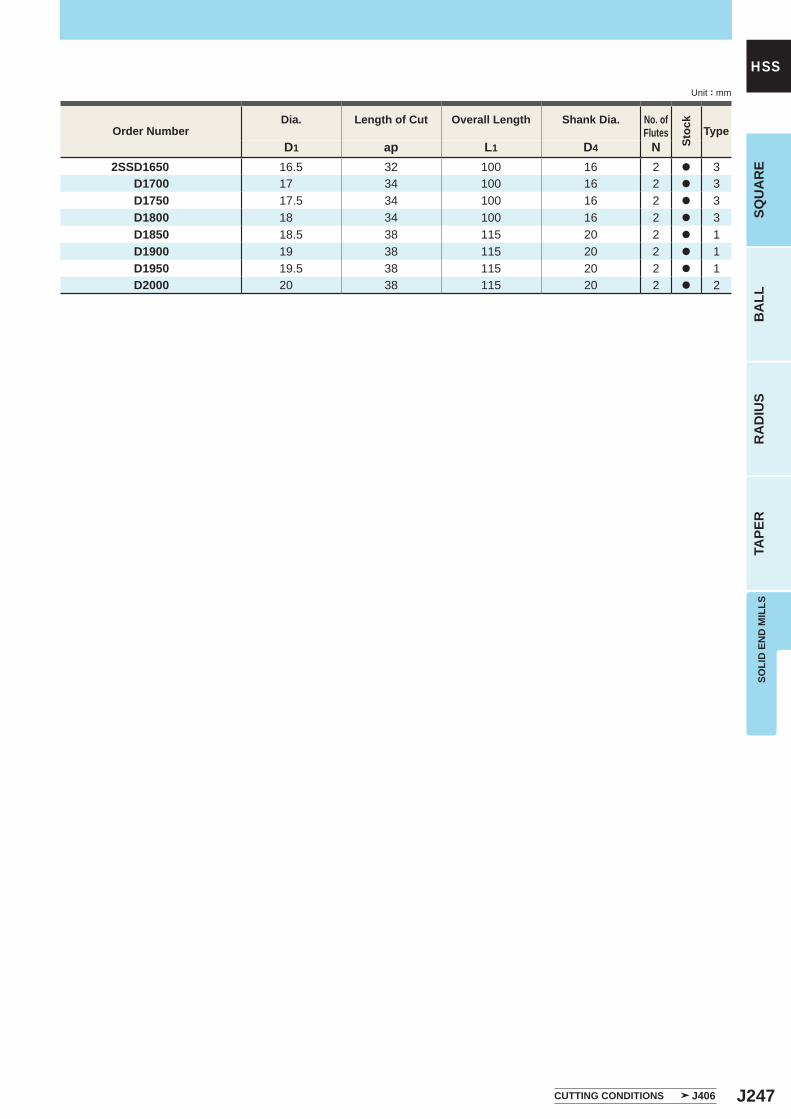
J247
D1 ap L1 D4 N 2SSD1650 16.5 32 100 16 2 a 3 D1700 17 34 100 16 2 a 3 D1750 17.5 34 100 16 2 a 3 D1800 18 34 100 16 2 a 3
D1850 18.5 38 115 20 2 a 1 D1900 19 38 115 20 2 a 1 D1950 19.5 38 115 20 2 a 1 D2000 20 38 115 20 2 a 2
SOLI
D E
ND
MIL
LSSQ
UA
RE
BA
LLR
AD
IUS
TAPE
R
HSSUnit : mm
Order NumberDia. Length of Cut Overall Length Shank Dia. No. of
Flutes
Stoc
k
Type
CUTTING CONDITIONS J406
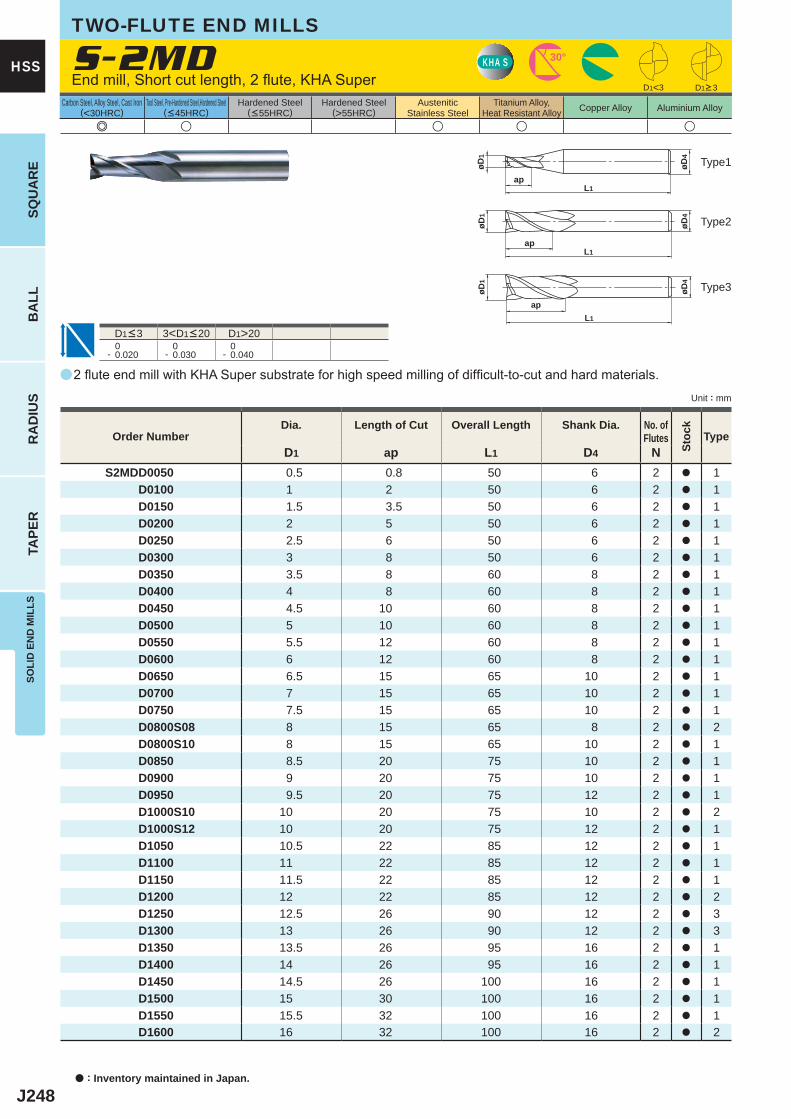
J248
a
e u u u u
S-2MD
D1 ap L1 D4 NS2MDD0050 0.5 0.8 50 6 2 a 1
D0100 1 2 50 6 2 a 1 D0150 1.5 3.5 50 6 2 a 1 D0200 2 5 50 6 2 a 1 D0250 2.5 6 50 6 2 a 1 D0300 3 8 50 6 2 a 1 D0350 3.5 8 60 8 2 a 1 D0400 4 8 60 8 2 a 1 D0450 4.5 10 60 8 2 a 1 D0500 5 10 60 8 2 a 1 D0550 5.5 12 60 8 2 a 1 D0600 6 12 60 8 2 a 1 D0650 6.5 15 65 10 2 a 1 D0700 7 15 65 10 2 a 1 D0750 7.5 15 65 10 2 a 1 D0800S08 8 15 65 8 2 a 2 D0800S10 8 15 65 10 2 a 1 D0850 8.5 20 75 10 2 a 1 D0900 9 20 75 10 2 a 1 D0950 9.5 20 75 12 2 a 1 D1000S10 10 20 75 10 2 a 2 D1000S12 10 20 75 12 2 a 1 D1050 10.5 22 85 12 2 a 1 D1100 11 22 85 12 2 a 1 D1150 11.5 22 85 12 2 a 1 D1200 12 22 85 12 2 a 2 D1250 12.5 26 90 12 2 a 3 D1300 13 26 90 12 2 a 3 D1350 13.5 26 95 16 2 a 1 D1400 14 26 95 16 2 a 1 D1450 14.5 26 100 16 2 a 1 D1500 15 30 100 16 2 a 1 D1550 15.5 32 100 16 2 a 1 D1600 16 32 100 16 2 a 2
D1<3
D1>20 0- 0.020
0- 0.030
0- 0.040
KHA S 30°
øD4
L1ap
øD1
øD4
L1ap
øD1
øD4
L1
ap
øD1
a : Inventory maintained in Japan.
HSS
SQU
AR
EB
ALL
RA
DIU
STA
PER
SOLI
D E
ND
MIL
LS
Unit : mm
Carbon Steel, Alloy Steel, Cast Iron(<30HRC)
Tool Steel, Pre-Hardened Steel,Hardened Steel(<45HRC)
Hardened Steel(<55HRC)
Hardened Steel(>55HRC)
AusteniticStainless Steel
Titanium Alloy,Heat Resistant Alloy Copper Alloy Aluminium Alloy
Type2
Type3
Type1
TWO-FLUTE END MILLS
End mill, Short cut length, 2 flute, KHA Super D1>3
D1<3 3<D1<20
2 flute end mill with KHA Super substrate for high speed milling of difficult-to-cut and hard materials.
Order NumberDia. Length of Cut Overall Length Shank Dia. No. of
Flutes
Stoc
k
Type
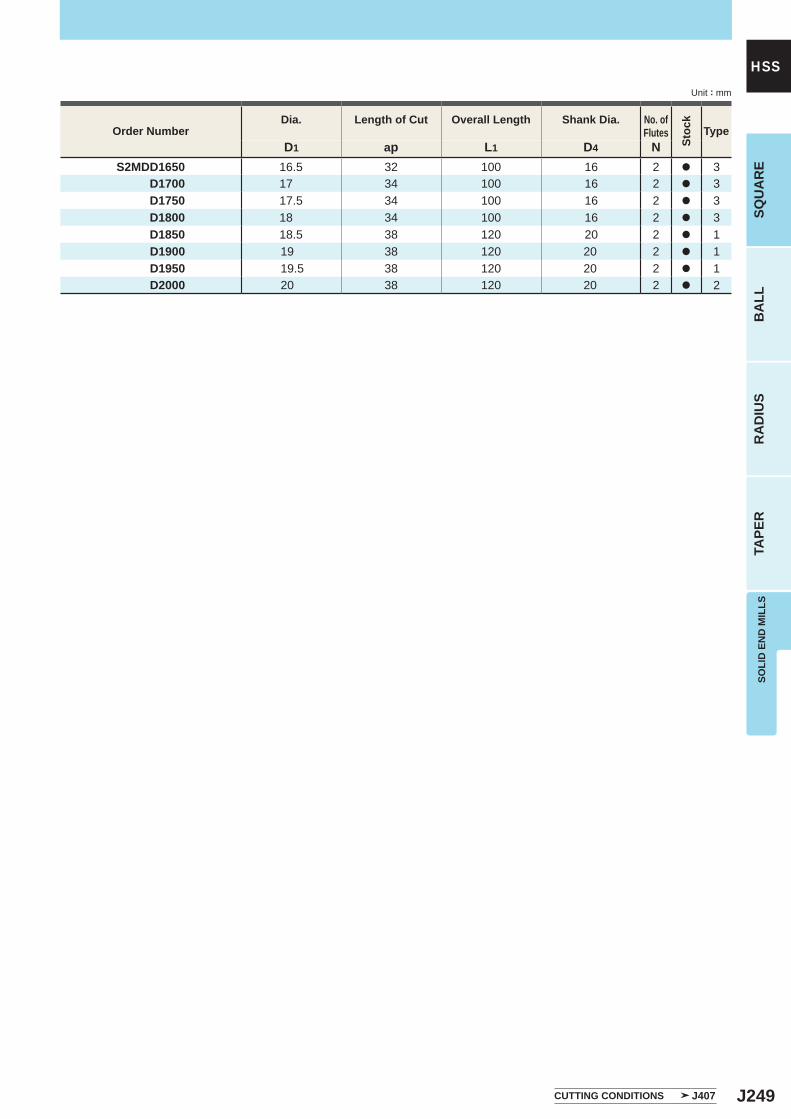
J249
D1 ap L1 D4 N S2MDD1650 16.5 32 100 16 2 a 3 D1700 17 34 100 16 2 a 3 D1750 17.5 34 100 16 2 a 3 D1800 18 34 100 16 2 a 3 D1850 18.5 38 120 20 2 a 1
D1900 19 38 120 20 2 a 1D1950 19.5 38 120 20 2 a 1D2000 20 38 120 20 2 a 2
SOLI
D E
ND
MIL
LSSQ
UA
RE
BA
LLR
AD
IUS
TAPE
R
HSSUnit : mm
Order NumberDia. Length of Cut Overall Length Shank Dia. No. of
Flutes
Stoc
k
Type
CUTTING CONDITIONS J407
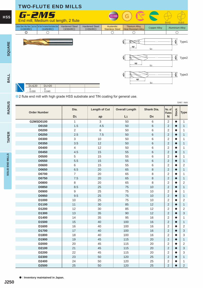
J250
a
e u u u u
G-2MS
D1 ap L1 D4 NG2MSD0100 1 3 50 6 2 a 1
D0150 1.5 4.5 50 6 2 a 1D0200 2 6 50 6 2 a 1D0250 2.5 7.5 50 6 2 a 1D0300 3 10 50 6 2 a 1D0350 3.5 12 50 6 2 a 1D0400 4 12 50 6 2 a 1D0450 4.5 15 55 6 2 a 1D0500 5 15 55 6 2 a 1D0550 5.5 15 55 6 2 a 1D0600 6 15 55 6 2 a 2D0650 6.5 20 65 8 2 a 1D0700 7 20 65 8 2 a 1D0750 7.5 20 65 8 2 a 1D0800 8 20 65 8 2 a 2D0850 8.5 25 75 10 2 a 1D0900 9 25 75 10 2 a 1D0950 9.5 25 75 10 2 a 1D1000 10 25 75 10 2 a 2D1100 11 30 85 12 2 a 1D1200 12 30 85 12 2 a 2D1300 13 35 90 12 2 a 3D1400 14 35 95 16 2 a 1D1500 15 40 100 16 2 a 1D1600 16 40 100 16 2 a 2D1700 17 40 100 16 2 a 3D1800 18 40 100 16 2 a 3D1900 19 45 115 20 2 a 1D2000 20 45 115 20 2 a 2D2100 21 45 115 20 2 a 3D2200 22 45 115 20 2 a 3D2300 23 50 120 25 2 a 1D2400 24 50 120 25 2 a 1D2500 25 50 120 25 2 a 2
D1>20 0- 0.030
0- 0.040
D1<3
CO HSS G 30°
øD4
L1ap
øD1
øD4
L1ap
øD1
øD4
L1
ap
øD1
a : Inventory maintained in Japan.
HSS
SQU
AR
EB
ALL
RA
DIU
STA
PER
SOLI
D E
ND
MIL
LS
Unit : mm
Carbon Steel, Alloy Steel, Cast Iron(<30HRC)
Tool Steel, Pre-Hardened Steel,Hardened Steel(<45HRC)
Hardened Steel(<55HRC)
Hardened Steel(>55HRC)
AusteniticStainless Steel
Titanium Alloy,Heat Resistant Alloy Copper Alloy Aluminium Alloy
TWO-FLUTE END MILLS
End mill, Medium cut length, 2 flute
Type2
Type3
Type1
D1<20
2 flute end mill with high grade HSS substrate and TiN coating for general use.
Order NumberDia. Length of Cut Overall Length Shank Dia. No. of
Flutes
Stoc
k
Type
D1>3
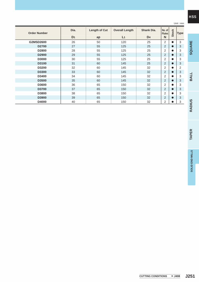
J251
D1 ap L1 D4 NG2MSD2600 26 50 120 25 2 a 3
D2700 27 55 125 25 2 a 3D2800 28 55 125 25 2 a 3D2900 29 55 125 25 2 a 3D3000 30 55 125 25 2 a 3D3100 31 60 145 25 2 a 3D3200 32 60 145 32 2 a 2D3300 33 60 145 32 2 a 3D3400 34 60 145 32 2 a 3D3500 35 60 145 32 2 a 3D3600 36 65 150 32 2 a 3D3700 37 65 150 32 2 a 3D3800 38 65 150 32 2 a 3D3900 39 65 150 32 2 a 3D4000 40 65 150 32 2 a 3
SOLI
D E
ND
MIL
LSSQ
UA
RE
BA
LLR
AD
IUS
TAPE
R
HSSUnit : mm
Order NumberDia. Length of Cut Overall Length Shank Dia. No. of
Flutes
Stoc
k
Type
CUTTING CONDITIONS J408
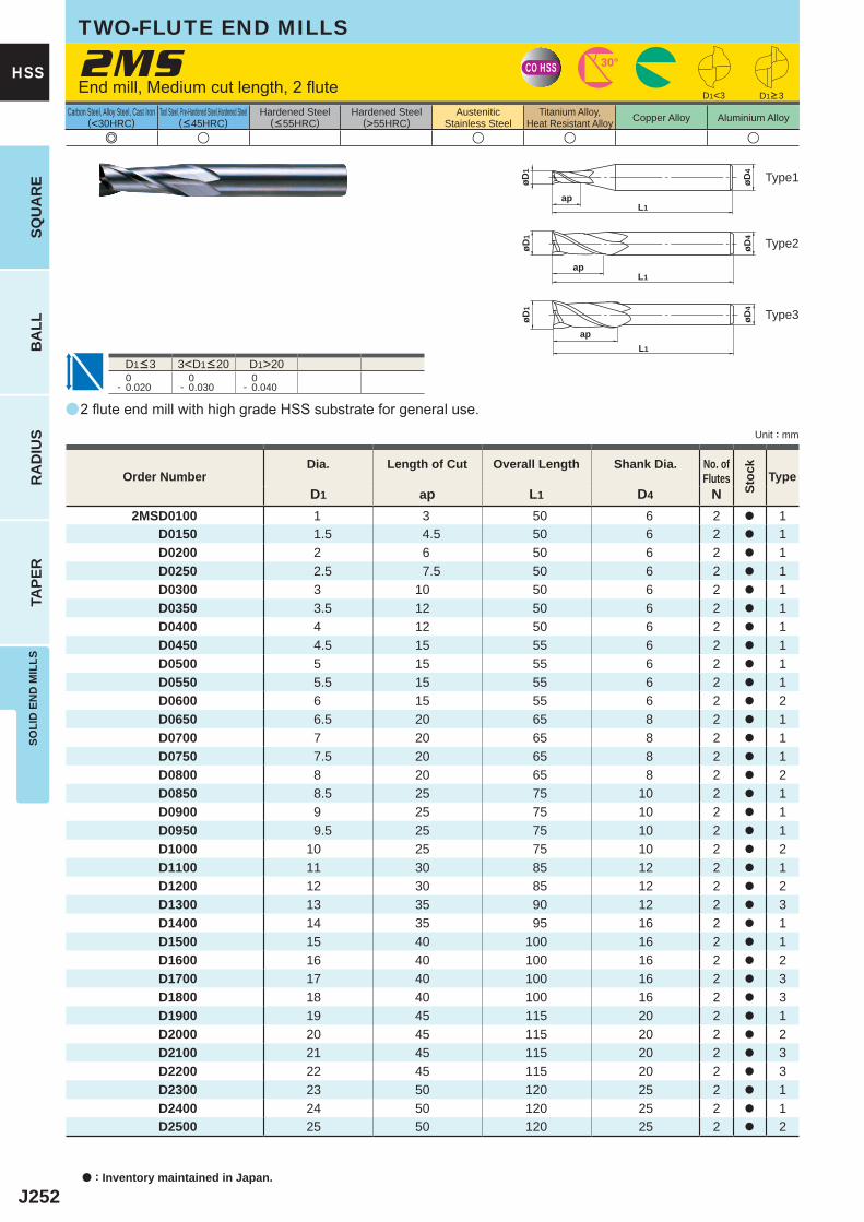
J252
a
e u u u u
2MS
D1 ap L1 D4 N2MSD0100 1 3 50 6 2 a 1
D0150 1.5 4.5 50 6 2 a 1D0200 2 6 50 6 2 a 1D0250 2.5 7.5 50 6 2 a 1D0300 3 10 50 6 2 a 1D0350 3.5 12 50 6 2 a 1D0400 4 12 50 6 2 a 1D0450 4.5 15 55 6 2 a 1D0500 5 15 55 6 2 a 1D0550 5.5 15 55 6 2 a 1D0600 6 15 55 6 2 a 2D0650 6.5 20 65 8 2 a 1D0700 7 20 65 8 2 a 1D0750 7.5 20 65 8 2 a 1D0800 8 20 65 8 2 a 2D0850 8.5 25 75 10 2 a 1D0900 9 25 75 10 2 a 1D0950 9.5 25 75 10 2 a 1D1000 10 25 75 10 2 a 2D1100 11 30 85 12 2 a 1D1200 12 30 85 12 2 a 2D1300 13 35 90 12 2 a 3D1400 14 35 95 16 2 a 1D1500 15 40 100 16 2 a 1D1600 16 40 100 16 2 a 2D1700 17 40 100 16 2 a 3D1800 18 40 100 16 2 a 3D1900 19 45 115 20 2 a 1D2000 20 45 115 20 2 a 2D2100 21 45 115 20 2 a 3D2200 22 45 115 20 2 a 3D2300 23 50 120 25 2 a 1D2400 24 50 120 25 2 a 1D2500 25 50 120 25 2 a 2
D1<3
D1>20 0- 0.020
0- 0.030
0- 0.040
CO HSS 30°
øD4
L1ap
øD1
øD4
L1ap
øD1
øD4
L1
ap
øD1
a : Inventory maintained in Japan.
HSS
SQU
AR
EB
ALL
RA
DIU
STA
PER
SOLI
D E
ND
MIL
LS
Unit : mm
Carbon Steel, Alloy Steel, Cast Iron(<30HRC)
Tool Steel, Pre-Hardened Steel,Hardened Steel(<45HRC)
Hardened Steel(<55HRC)
Hardened Steel(>55HRC)
AusteniticStainless Steel
Titanium Alloy,Heat Resistant Alloy Copper Alloy Aluminium Alloy
TWO-FLUTE END MILLS
End mill, Medium cut length, 2 flute
Type2
Type3
Type1
2 flute end mill with high grade HSS substrate for general use.
D1<3 3<D1<20
Order NumberDia. Length of Cut Overall Length Shank Dia. No. of
Flutes
Stoc
k
Type
D1>3
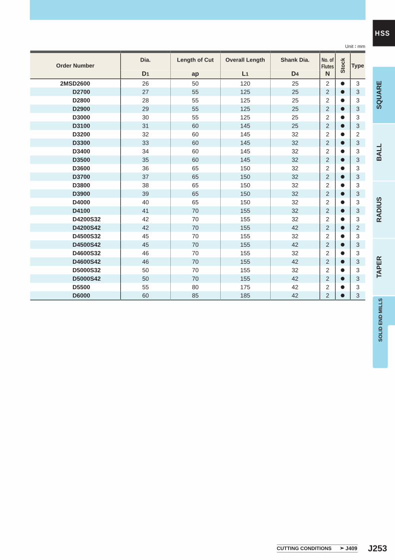
J253
D1 ap L1 D4 N2MSD2600 26 50 120 25 2 a 3
D2700 27 55 125 25 2 a 3D2800 28 55 125 25 2 a 3D2900 29 55 125 25 2 a 3D3000 30 55 125 25 2 a 3D3100 31 60 145 25 2 a 3D3200 32 60 145 32 2 a 2D3300 33 60 145 32 2 a 3D3400 34 60 145 32 2 a 3D3500 35 60 145 32 2 a 3D3600 36 65 150 32 2 a 3D3700 37 65 150 32 2 a 3D3800 38 65 150 32 2 a 3D3900 39 65 150 32 2 a 3D4000 40 65 150 32 2 a 3D4100 41 70 155 32 2 a 3D4200S32 42 70 155 32 2 a 3D4200S42 42 70 155 42 2 a 2D4500S32 45 70 155 32 2 a 3D4500S42 45 70 155 42 2 a 3D4600S32 46 70 155 32 2 a 3D4600S42 46 70 155 42 2 a 3D5000S32 50 70 155 32 2 a 3D5000S42 50 70 155 42 2 a 3D5500 55 80 175 42 2 a 3D6000 60 85 185 42 2 a 3
SOLI
D E
ND
MIL
LSSQ
UA
RE
BA
LLR
AD
IUS
TAPE
R
HSSUnit : mm
Order NumberDia. Length of Cut Overall Length Shank Dia. No. of
Flutes
Stoc
k
Type
CUTTING CONDITIONS J409
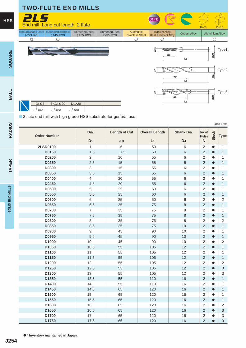
J254
a
e u u u u
2LS
D1 ap L1 D4 N2LSD0100 1 6 50 6 2 a 1
D0150 1.5 7.5 50 6 2 a 1D0200 2 10 55 6 2 a 1D0250 2.5 15 55 6 2 a 1D0300 3 15 55 6 2 a 1D0350 3.5 15 55 6 2 a 1D0400 4 20 55 6 2 a 1D0450 4.5 20 55 6 2 a 1D0500 5 25 60 6 2 a 1D0550 5.5 25 60 6 2 a 1D0600 6 25 60 6 2 a 2D0650 6.5 35 75 8 2 a 1D0700 7 35 75 8 2 a 1D0750 7.5 35 75 8 2 a 1D0800 8 35 75 8 2 a 2D0850 8.5 35 75 10 2 a 1D0900 9 45 90 10 2 a 1D0950 9.5 45 90 10 2 a 1D1000 10 45 90 10 2 a 2D1050 10.5 55 105 12 2 a 1D1100 11 55 105 12 2 a 1D1150 11.5 55 105 12 2 a 1D1200 12 55 105 12 2 a 2D1250 12.5 55 105 12 2 a 3D1300 13 55 105 12 2 a 3D1350 13.5 55 110 16 2 a 1D1400 14 55 110 16 2 a 1D1450 14.5 65 120 16 2 a 1D1500 15 65 120 16 2 a 1D1550 15.5 65 120 16 2 a 1D1600 16 65 120 16 2 a 2D1650 16.5 65 120 16 2 a 3D1700 17 65 120 16 2 a 3D1750 17.5 65 120 16 2 a 3
D1<3
D1>20 0- 0.020
0- 0.030
0- 0.040
CO HSS 30°
øD4
L1
ap
øD1
L1
ap øDøD
44
øD1
øD1
L1
ap
a : Inventory maintained in Japan.
HSS
SQU
AR
EB
ALL
RA
DIU
STA
PER
SOLI
D E
ND
MIL
LS
Unit : mm
Carbon Steel, Alloy Steel, Cast Iron(<30HRC)
Tool Steel, Pre-Hardened Steel,Hardened Steel(<45HRC)
Hardened Steel(<55HRC)
Hardened Steel(>55HRC)
AusteniticStainless Steel
Titanium Alloy,Heat Resistant Alloy Copper Alloy Aluminium Alloy
TWO-FLUTE END MILLS
Type2
Type3
Type1
2 flute end mill with high grade HSS substrate for general use.
End mill, Long cut length, 2 flute
D1<3 3<D1<20
Order NumberDia. Length of Cut Overall Length Shank Dia. No. of
Flutes
Stoc
k
Type
D1>3
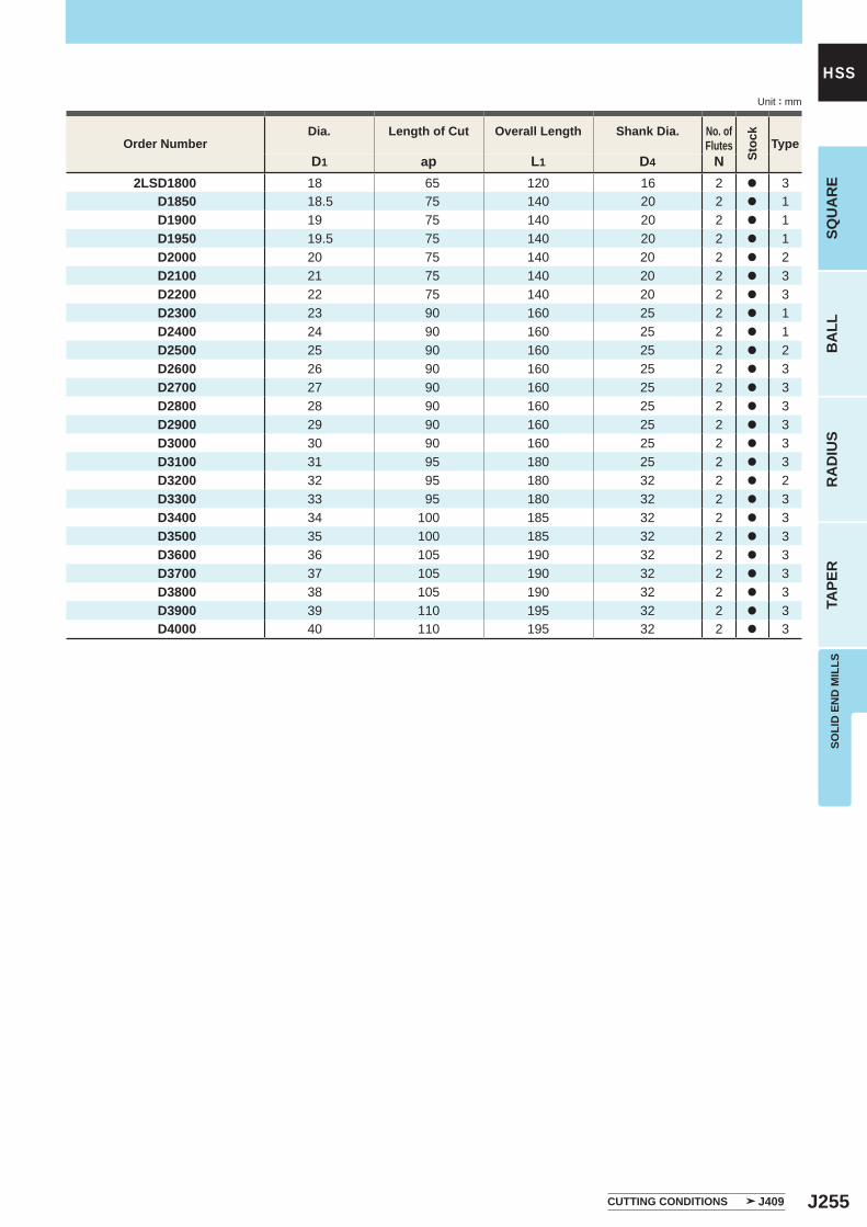
J255
D1 ap L1 D4 N2LSD1800 18 65 120 16 2 a 3
D1850 18.5 75 140 20 2 a 1D1900 19 75 140 20 2 a 1D1950 19.5 75 140 20 2 a 1D2000 20 75 140 20 2 a 2D2100 21 75 140 20 2 a 3D2200 22 75 140 20 2 a 3D2300 23 90 160 25 2 a 1D2400 24 90 160 25 2 a 1D2500 25 90 160 25 2 a 2D2600 26 90 160 25 2 a 3D2700 27 90 160 25 2 a 3D2800 28 90 160 25 2 a 3D2900 29 90 160 25 2 a 3D3000 30 90 160 25 2 a 3D3100 31 95 180 25 2 a 3D3200 32 95 180 32 2 a 2D3300 33 95 180 32 2 a 3D3400 34 100 185 32 2 a 3D3500 35 100 185 32 2 a 3D3600 36 105 190 32 2 a 3D3700 37 105 190 32 2 a 3D3800 38 105 190 32 2 a 3D3900 39 110 195 32 2 a 3D4000 40 110 195 32 2 a 3
SOLI
D E
ND
MIL
LSSQ
UA
RE
BA
LLR
AD
IUS
TAPE
R
HSSUnit : mm
Order NumberDia. Length of Cut Overall Length Shank Dia. No. of
Flutes
Stoc
k
Type
CUTTING CONDITIONS J409
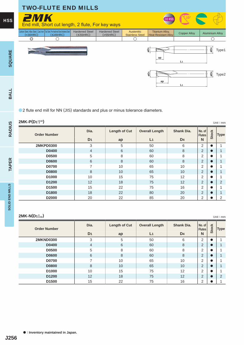
J256
Aço Carbono, Aço Liga, Ferro Fundido(<30HRC)
Aço Ferramenta, Aço Pré-Temperado, Aço Endurecido(<45HRC)
Aço Endurecido(<55HRC)
Aço Endurecido(>55HRC)
Aço InoxidávelAustenítico
Ligas de TiN,Ligas Resist. ao Calor Ligas de Cobre Ligas de Alumínio
a
e u u u
2MK
D1 ap L1 D4 N2MKPD0300 3 5 50 6 2 a 1
D0400 4 6 60 8 2 a 1D0500 5 8 60 8 2 a 1D0600 6 8 60 8 2 a 1D0700 7 10 65 10 2 a 1D0800 8 10 65 10 2 a 1D1000 10 15 75 12 2 a 1D1200 12 18 75 12 2 a 2D1500 15 22 75 16 2 a 1D1800 18 22 80 20 2 a 1D2000 20 22 85 20 2 a 2
D1 ap L1 D4 N2MKND0300 3 5 50 6 2 a 1
D0400 4 6 60 8 2 a 1D0500 5 8 60 8 2 a 1D0600 6 8 60 8 2 a 1D0700 7 10 65 10 2 a 1D0800 8 10 65 10 2 a 1D1000 10 15 75 12 2 a 1D1200 12 18 75 12 2 a 2D1500 15 22 75 16 2 a 1
2MK-P(D1+0.02 0 )
2MK-N(D1 0-0.02)
CO HSS 15°
øD4
L1
ap
øD1
L1ap
øD4
øD1
a : Inventory maintained in Japan.
HSS
SQU
AR
EB
ALL
RA
DIU
STA
PER
SOLI
D E
ND
MIL
LS
Carbon Steel, Alloy Steel, Cast Iron(<30HRC)
Tool Steel, Pre-Hardened Steel,Hardened Steel(<45HRC)
Hardened Steel(<55HRC)
Hardened Steel(>55HRC)
AusteniticStainless Steel
Titanium Alloy,Heat Resistant Alloy Copper Alloy Aluminium Alloy
TWO-FLUTE END MILLS
End mill, Short cut length, 2 flute, For key ways
Type2
Type1
2 flute end mill for NN (JIS) standards and plus or minus tolerance diameters.
Unit : mm
Unit : mm
Order NumberDia. Length of Cut Overall Length Shank Dia. No. of
Flutes
Stoc
k
Type
Order NumberDia. Length of Cut Overall Length Shank Dia. No. of
Flutes
Stoc
k
Type
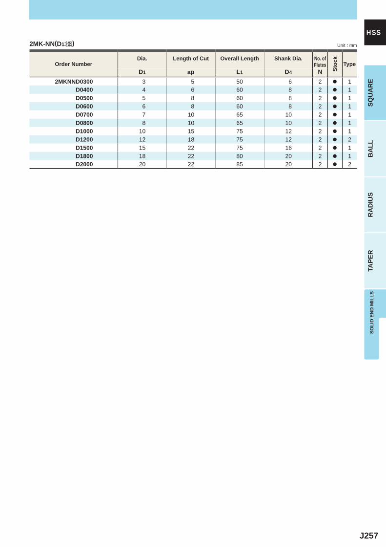
J257
D1 ap L1 D4 N2MKNND0300 3 5 50 6 2 a 1
D0400 4 6 60 8 2 a 1D0500 5 8 60 8 2 a 1D0600 6 8 60 8 2 a 1D0700 7 10 65 10 2 a 1D0800 8 10 65 10 2 a 1D1000 10 15 75 12 2 a 1D1200 12 18 75 12 2 a 2D1500 15 22 75 16 2 a 1D1800 18 22 80 20 2 a 1D2000 20 22 85 20 2 a 2
2MK-NN(D1-0.02-0.04)
SOLI
D E
ND
MIL
LSSQ
UA
RE
BA
LLR
AD
IUS
TAPE
R
HSSUnit : mm
Order NumberDia. Length of Cut Overall Length Shank Dia. No. of
Flutes
Stoc
k
Type
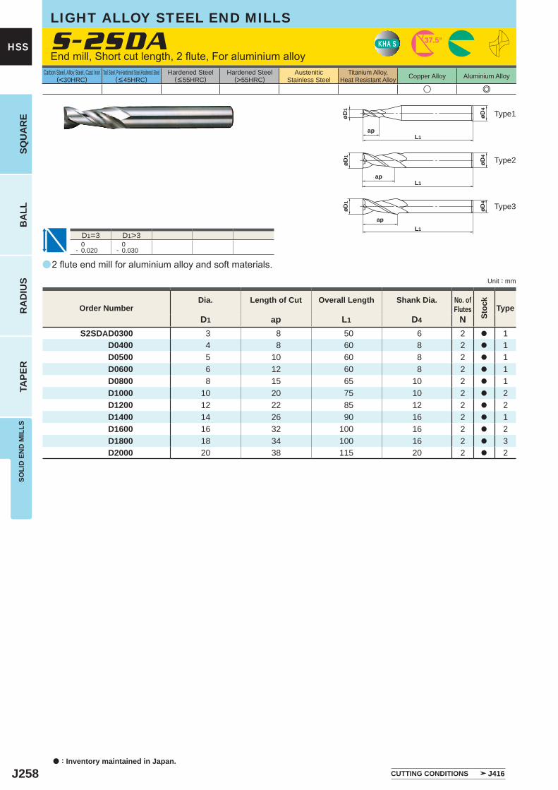
J258
a
u e
S-2SDA
D1 ap L1 D4 NS2SDAD0300 3 8 50 6 2 a 1
D0400 4 8 60 8 2 a 1D0500 5 10 60 8 2 a 1D0600 6 12 60 8 2 a 1D0800 8 15 65 10 2 a 1D1000 10 20 75 10 2 a 2D1200 12 22 85 12 2 a 2D1400 14 26 90 16 2 a 1D1600 16 32 100 16 2 a 2D1800 18 34 100 16 2 a 3D2000 20 38 115 20 2 a 2
D1=3 D1>3 0- 0.020
0- 0.030
KHA S 37.5°
L1ap
øD4
øD1
L1ap
øD4
øD1
L1
ap
øD4
øD1
a : Inventory maintained in Japan.
HSS
SQU
AR
EB
ALL
RA
DIU
STA
PER
SOLI
D E
ND
MIL
LS
Unit : mm
Carbon Steel, Alloy Steel, Cast Iron(<30HRC)
Tool Steel, Pre-Hardened Steel,Hardened Steel(<45HRC)
Hardened Steel(<55HRC)
Hardened Steel(>55HRC)
AusteniticStainless Steel
Titanium Alloy,Heat Resistant Alloy Copper Alloy Aluminium Alloy
2 flute end mill for aluminium alloy and soft materials.
End mill, Short cut length, 2 flute, For aluminium alloy
LIGHT ALLOY STEEL END MILLS
Type2
Type3
Type1
Order NumberDia. Length of Cut Overall Length Shank Dia. No. of
Flutes
Stoc
k
Type
CUTTING CONDITIONS J416

J259
a
e u e u
VA-MH
D1 ap L1 D4 NVAMHD0500 5 12 65 8 2 a 1
D0600 6 15 65 8 3 a 1D0700 7 20 75 10 3 a 1D0800 8 20 75 10 3 a 1D0900 9 25 90 10 3 a 1D1000 10 25 90 12 3 a 1D1100 11 30 95 12 3 a 1D1200 12 30 95 12 3 a 2D1300 13 35 105 16 3 a 1D1400 14 35 105 16 3 a 1D1500 15 40 115 16 3 a 1D1600 16 40 115 16 3 a 2D1800 18 40 125 20 3 a 1D2000 20 45 130 20 3 a 2D2100 21 45 135 25 4 a 1D2200 22 45 135 25 4 a 1D2300 23 50 140 25 4 a 1D2400 24 50 140 25 4 a 1D2500 25 50 140 25 4 a 2D2800 28 55 150 32 4 a 1D3000 30 55 150 32 4 a 1
0- 0.040
D1=5 D1=5
VKHA S 45° 50°
L1
ap
øD4
øD1
15°
L1
ap
øD4
øD1
SOLI
D E
ND
MIL
LSSQ
UA
RE
BA
LLR
AD
IUS
TAPE
R
HSS
Unit : mm
Carbon Steel, Alloy Steel, Cast Iron(<30HRC)
Tool Steel, Pre-Hardened Steel,Hardened Steel(<45HRC)
Hardened Steel(<55HRC)
Hardened Steel(>55HRC)
AusteniticStainless Steel
Titanium Alloy,Heat Resistant Alloy Copper Alloy Aluminium Alloy
Type2
Type1
Order NumberDia. Length of Cut Overall Length Shank Dia. No. of
Flutes
Stoc
k
Type
D1>6 D1>21D1<20
2─4 flute end mill with high grade HSS substrate and Violet coating for general use.
End mill, Medium cut length, 2─4 flute
VIOLET END MILLS
5<D1<30
CUTTING CONDITIONS J400
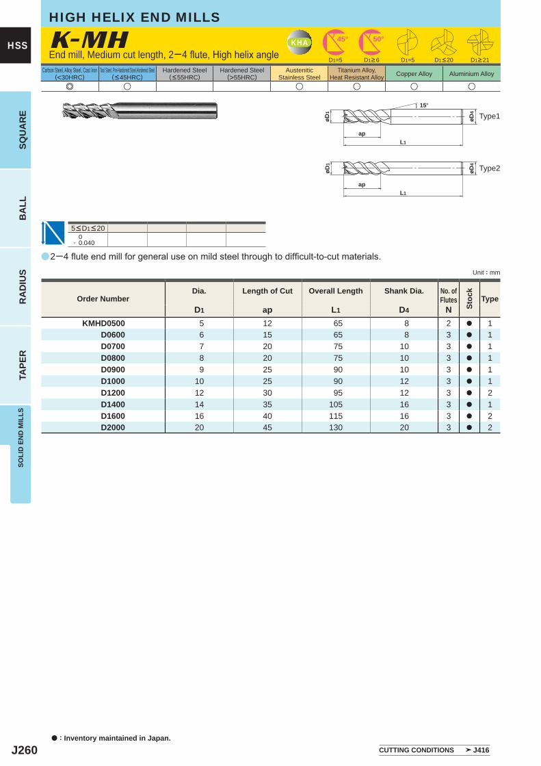
J260
a
e u u u u u
K-MH
D1 ap L1 D4 NKMHD0500 5 12 65 8 2 a 1
D0600 6 15 65 8 3 a 1D0700 7 20 75 10 3 a 1D0800 8 20 75 10 3 a 1D0900 9 25 90 10 3 a 1D1000 10 25 90 12 3 a 1D1200 12 30 95 12 3 a 2D1400 14 35 105 16 3 a 1D1600 16 40 115 16 3 a 2D2000 20 45 130 20 3 a 2
D1=5 D1=5
0- 0.040
KHA 45° 50°
L1
ap
øD4
øD1
15°
L1
ap
øD4
øD1
a : Inventory maintained in Japan.
HSS
SQU
AR
EB
ALL
RA
DIU
STA
PER
SOLI
D E
ND
MIL
LS
Unit : mm
Carbon Steel, Alloy Steel, Cast Iron(<30HRC)
Tool Steel, Pre-Hardened Steel,Hardened Steel(<45HRC)
Hardened Steel(<55HRC)
Hardened Steel(>55HRC)
AusteniticStainless Steel
Titanium Alloy,Heat Resistant Alloy Copper Alloy Aluminium Alloy
2─4 flute end mill for general use on mild steel through to difficult-to-cut materials.
End mill, Medium cut length, 2─4 flute, High helix angle
HIGH HELIX END MILLS
5<D1<20
D1>6 D1>21D1<20
Type2
Type1
Order NumberDia. Length of Cut Overall Length Shank Dia. No. of
Flutes
Stoc
k
Type
CUTTING CONDITIONS J416
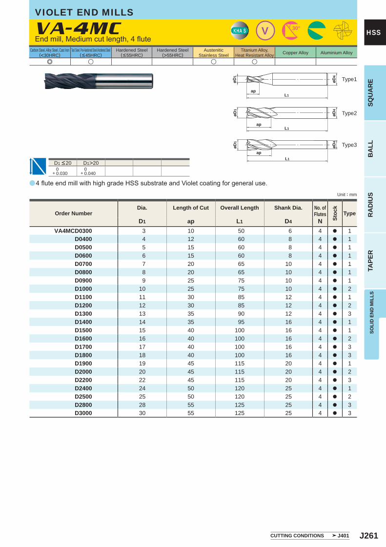
J261
a
e u u u
VA-4MC
D1 ap L1 D4 NVA4MCD0300 3 10 50 6 4 a 1
D0400 4 12 60 8 4 a 1D0500 5 15 60 8 4 a 1D0600 6 15 60 8 4 a 1D0700 7 20 65 10 4 a 1D0800 8 20 65 10 4 a 1D0900 9 25 75 10 4 a 1D1000 10 25 75 10 4 a 2D1100 11 30 85 12 4 a 1D1200 12 30 85 12 4 a 2D1300 13 35 90 12 4 a 3D1400 14 35 95 16 4 a 1D1500 15 40 100 16 4 a 1D1600 16 40 100 16 4 a 2D1700 17 40 100 16 4 a 3D1800 18 40 100 16 4 a 3D1900 19 45 115 20 4 a 1D2000 20 45 115 20 4 a 2D2200 22 45 115 20 4 a 3D2400 24 50 120 25 4 a 1D2500 25 50 120 25 4 a 2D2800 28 55 125 25 4 a 3D3000 30 55 125 25 4 a 3
D1>20 0+ 0.030
0+ 0.040
VKHA S 30°
øD4
apL1
øD1
øD1
øD4
apL1
øD1
øD4
apL1
SOLI
D E
ND
MIL
LSSQ
UA
RE
BA
LLR
AD
IUS
TAPE
R
HSS
Unit : mm
Carbon Steel, Alloy Steel, Cast Iron(<30HRC)
Tool Steel, Pre-Hardened Steel,Hardened Steel(<45HRC)
Hardened Steel(<55HRC)
Hardened Steel(>55HRC)
AusteniticStainless Steel
Titanium Alloy,Heat Resistant Alloy Copper Alloy Aluminium Alloy
Order NumberDia. Length of Cut Overall Length Shank Dia. No. of
Flutes
Stoc
k
Type
4 flute end mill with high grade HSS substrate and Violet coating for general use.
End mill, Medium cut length, 4 flute
VIOLET END MILLS
D1 <20
Type2
Type3
Type1
CUTTING CONDITIONS J401
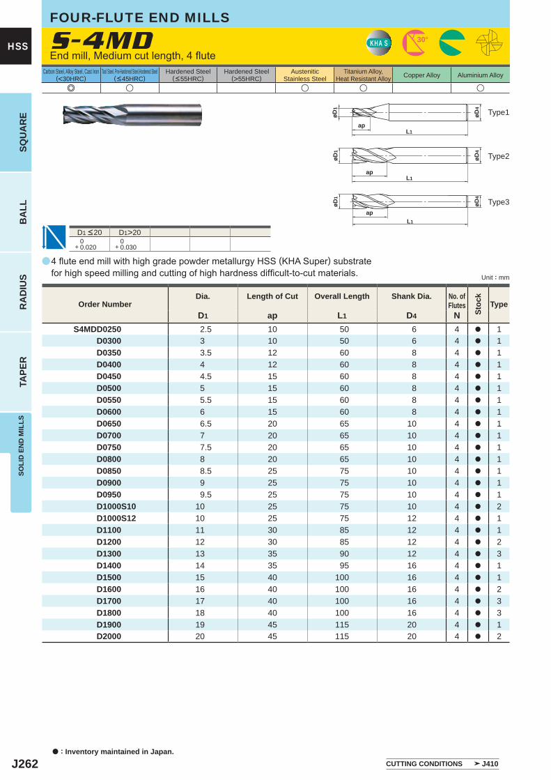
J262
a
S-4MD
e u u u u
D1 ap L1 D4 NS4MDD0250 2.5 10 50 6 4 a 1 D0300 3 10 50 6 4 a 1 D0350 3.5 12 60 8 4 a 1 D0400 4 12 60 8 4 a 1 D0450 4.5 15 60 8 4 a 1 D0500 5 15 60 8 4 a 1 D0550 5.5 15 60 8 4 a 1 D0600 6 15 60 8 4 a 1 D0650 6.5 20 65 10 4 a 1 D0700 7 20 65 10 4 a 1 D0750 7.5 20 65 10 4 a 1 D0800 8 20 65 10 4 a 1 D0850 8.5 25 75 10 4 a 1 D0900 9 25 75 10 4 a 1 D0950 9.5 25 75 10 4 a 1 D1000S10 10 25 75 10 4 a 2 D1000S12 10 25 75 12 4 a 1 D1100 11 30 85 12 4 a 1 D1200 12 30 85 12 4 a 2 D1300 13 35 90 12 4 a 3 D1400 14 35 95 16 4 a 1 D1500 15 40 100 16 4 a 1 D1600 16 40 100 16 4 a 2 D1700 17 40 100 16 4 a 3 D1800 18 40 100 16 4 a 3 D1900 19 45 115 20 4 a 1 D2000 20 45 115 20 4 a 2
D1>20 0+ 0.020
0+ 0.030
KHA S 30°
øD4
apL1
øD1
øD1
øD4
apL1
øD1
øD4
apL1
a : Inventory maintained in Japan.
HSS
SQU
AR
EB
ALL
RA
DIU
STA
PER
SOLI
D E
ND
MIL
LS
Unit : mm
Carbon Steel, Alloy Steel, Cast Iron(<30HRC)
Tool Steel, Pre-Hardened Steel,Hardened Steel(<45HRC)
Hardened Steel(<55HRC)
Hardened Steel(>55HRC)
AusteniticStainless Steel
Titanium Alloy,Heat Resistant Alloy Copper Alloy Aluminium Alloy
4 flute end mill with high grade powder metallurgy HSS (KHA Super) substrate for high speed milling and cutting of high hardness difficult-to-cut materials.
End mill, Medium cut length, 4 flute
FOUR-FLUTE END MILLS
D1 <20
Type2
Type3
Type1
Order NumberDia. Length of Cut Overall Length Shank Dia. No. of
Flutes
Stoc
k
Type
CUTTING CONDITIONS J410
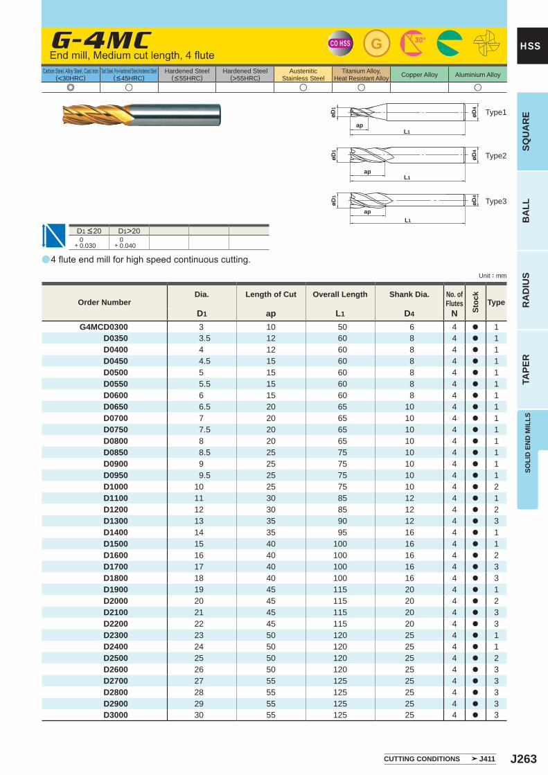
J263
a
e u u u u
G-4MC
D1 ap L1 D4 NG4MCD0300 3 10 50 6 4 a 1
D0350 3.5 12 60 8 4 a 1D0400 4 12 60 8 4 a 1D0450 4.5 15 60 8 4 a 1D0500 5 15 60 8 4 a 1D0550 5.5 15 60 8 4 a 1D0600 6 15 60 8 4 a 1D0650 6.5 20 65 10 4 a 1D0700 7 20 65 10 4 a 1D0750 7.5 20 65 10 4 a 1D0800 8 20 65 10 4 a 1D0850 8.5 25 75 10 4 a 1D0900 9 25 75 10 4 a 1D0950 9.5 25 75 10 4 a 1D1000 10 25 75 10 4 a 2D1100 11 30 85 12 4 a 1D1200 12 30 85 12 4 a 2D1300 13 35 90 12 4 a 3D1400 14 35 95 16 4 a 1D1500 15 40 100 16 4 a 1D1600 16 40 100 16 4 a 2D1700 17 40 100 16 4 a 3D1800 18 40 100 16 4 a 3D1900 19 45 115 20 4 a 1D2000 20 45 115 20 4 a 2D2100 21 45 115 20 4 a 3D2200 22 45 115 20 4 a 3D2300 23 50 120 25 4 a 1D2400 24 50 120 25 4 a 1D2500 25 50 120 25 4 a 2D2600 26 50 120 25 4 a 3D2700 27 55 125 25 4 a 3D2800 28 55 125 25 4 a 3D2900 29 55 125 25 4 a 3D3000 30 55 125 25 4 a 3
D1>20 0+ 0.030
0+ 0.040
CO HSS G 30°
øD4
apL1
øD1
øD1
øD4
apL1
øD1
øD4
apL1
SOLI
D E
ND
MIL
LSSQ
UA
RE
BA
LLR
AD
IUS
TAPE
R
HSS
Unit : mm
Carbon Steel, Alloy Steel, Cast Iron(<30HRC)
Tool Steel, Pre-Hardened Steel,Hardened Steel(<45HRC)
Hardened Steel(<55HRC)
Hardened Steel(>55HRC)
AusteniticStainless Steel
Titanium Alloy,Heat Resistant Alloy Copper Alloy Aluminium Alloy
Type2
Type3
Type1
Order NumberDia. Length of Cut Overall Length Shank Dia. No. of
Flutes
Stoc
k
Type
4 flute end mill for high speed continuous cutting.
End mill, Medium cut length, 4 flute
D1 <20
CUTTING CONDITIONS J411
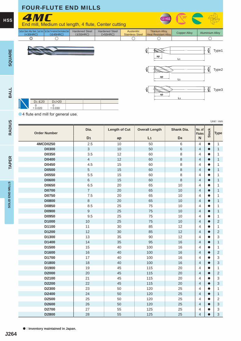
J264
a
e u u u u
4MC
D1 ap L1 D4 N4MCD0250 2.5 10 50 6 4 a 1
D0300 3 10 50 6 4 a 1D0350 3.5 12 60 8 4 a 1D0400 4 12 60 8 4 a 1D0450 4.5 15 60 8 4 a 1D0500 5 15 60 8 4 a 1D0550 5.5 15 60 8 4 a 1D0600 6 15 60 8 4 a 1D0650 6.5 20 65 10 4 a 1D0700 7 20 65 10 4 a 1D0750 7.5 20 65 10 4 a 1D0800 8 20 65 10 4 a 1D0850 8.5 25 75 10 4 a 1D0900 9 25 75 10 4 a 1D0950 9.5 25 75 10 4 a 1D1000 10 25 75 10 4 a 2D1100 11 30 85 12 4 a 1D1200 12 30 85 12 4 a 2D1300 13 35 90 12 4 a 3D1400 14 35 95 16 4 a 1D1500 15 40 100 16 4 a 1D1600 16 40 100 16 4 a 2D1700 17 40 100 16 4 a 3D1800 18 40 100 16 4 a 3D1900 19 45 115 20 4 a 1D2000 20 45 115 20 4 a 2D2100 21 45 115 20 4 a 3D2200 22 45 115 20 4 a 3D2300 23 50 120 25 4 a 1D2400 24 50 120 25 4 a 1D2500 25 50 120 25 4 a 2D2600 26 50 120 25 4 a 3D2700 27 55 125 25 4 a 3D2800 28 55 125 25 4 a 3
D1>20 0+ 0.020
0+ 0.030
CO HSS 30°
øD4
apL1
øD1
øD1
øD4
apL1
øD1
øD4
apL1
a : Inventory maintained in Japan.
HSS
SQU
AR
EB
ALL
RA
DIU
STA
PER
SOLI
D E
ND
MIL
LS
Unit : mm
Carbon Steel, Alloy Steel, Cast Iron(<30HRC)
Tool Steel, Pre-Hardened Steel,Hardened Steel(<45HRC)
Hardened Steel(<55HRC)
Hardened Steel(>55HRC)
AusteniticStainless Steel
Titanium Alloy,Heat Resistant Alloy Copper Alloy Aluminium Alloy
4 flute end mill for general use.
End mill, Medium cut length, 4 flute, Center cutting
D1 <20
FOUR-FLUTE END MILLS
Type2
Type3
Type1
Order NumberDia. Length of Cut Overall Length Shank Dia. No. of
Flutes
Stoc
k
Type
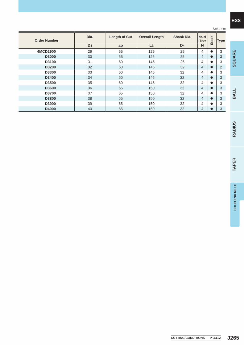
J265
D1 ap L1 D4 N4MCD2900 29 55 125 25 4 a 3
D3000 30 55 125 25 4 a 3D3100 31 60 145 25 4 a 3D3200 32 60 145 32 4 a 2D3300 33 60 145 32 4 a 3D3400 34 60 145 32 4 a 3D3500 35 60 145 32 4 a 3D3600 36 65 150 32 4 a 3D3700 37 65 150 32 4 a 3D3800 38 65 150 32 4 a 3D3900 39 65 150 32 4 a 3D4000 40 65 150 32 4 a 3
SOLI
D E
ND
MIL
LSSQ
UA
RE
BA
LLR
AD
IUS
TAPE
R
HSSUnit : mm
Order NumberDia. Length of Cut Overall Length Shank Dia. No. of
Flutes
Stoc
k
Type
CUTTING CONDITIONS J412
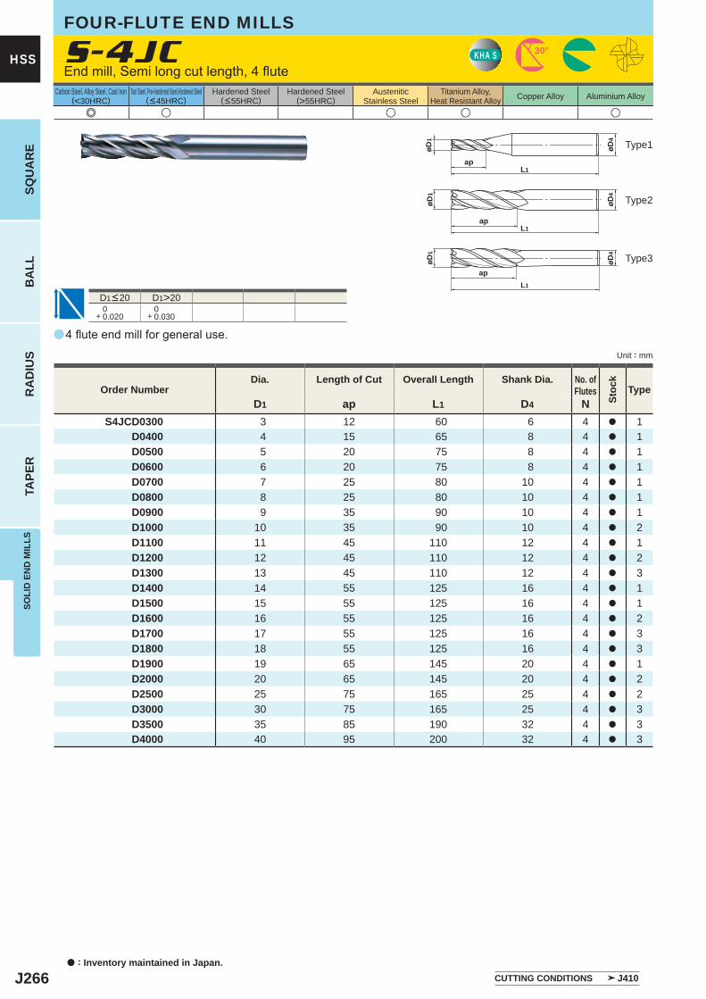
J266
a
e u u u u
S-4JC
D1 ap L1 D4 NS4JCD0300 3 12 60 6 4 a 1
D0400 4 15 65 8 4 a 1D0500 5 20 75 8 4 a 1D0600 6 20 75 8 4 a 1D0700 7 25 80 10 4 a 1D0800 8 25 80 10 4 a 1D0900 9 35 90 10 4 a 1D1000 10 35 90 10 4 a 2D1100 11 45 110 12 4 a 1D1200 12 45 110 12 4 a 2D1300 13 45 110 12 4 a 3D1400 14 55 125 16 4 a 1D1500 15 55 125 16 4 a 1D1600 16 55 125 16 4 a 2D1700 17 55 125 16 4 a 3D1800 18 55 125 16 4 a 3D1900 19 65 145 20 4 a 1D2000 20 65 145 20 4 a 2D2500 25 75 165 25 4 a 2D3000 30 75 165 25 4 a 3D3500 35 85 190 32 4 a 3D4000 40 95 200 32 4 a 3
D1>20 0+ 0.020
0+ 0.030
KHA S 30°
øD4
apL1
øD1
øD4
øD1
apL1
øD4
øD1
apL1
a : Inventory maintained in Japan.
HSS
SQU
AR
EB
ALL
RA
DIU
STA
PER
SOLI
D E
ND
MIL
LS
Unit : mm
Carbon Steel, Alloy Steel, Cast Iron(<30HRC)
Tool Steel, Pre-Hardened Steel,Hardened Steel(<45HRC)
Hardened Steel(<55HRC)
Hardened Steel(>55HRC)
AusteniticStainless Steel
Titanium Alloy,Heat Resistant Alloy Copper Alloy Aluminium Alloy
4 flute end mill for general use.
End mill, Semi long cut length, 4 flute
D1<20
FOUR-FLUTE END MILLS
Type2
Type3
Type1
Order NumberDia. Length of Cut Overall Length Shank Dia. No. of
Flutes
Stoc
k
Type
CUTTING CONDITIONS J410
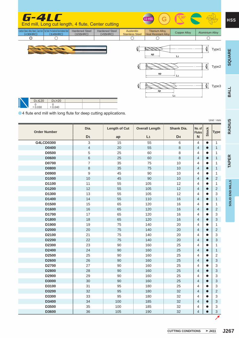
J267
a
e u u u u
G-4LC
D1 ap L1 D4 NG4LCD0300 3 15 55 6 4 a 1
D0400 4 20 55 8 4 a 1D0500 5 25 60 8 4 a 1D0600 6 25 60 8 4 a 1D0700 7 35 75 10 4 a 1D0800 8 35 75 10 4 a 1D0900 9 45 90 10 4 a 1D1000 10 45 90 10 4 a 2D1100 11 55 105 12 4 a 1D1200 12 55 105 12 4 a 2D1300 13 55 105 12 4 a 3D1400 14 55 110 16 4 a 1D1500 15 65 120 16 4 a 1D1600 16 65 120 16 4 a 2D1700 17 65 120 16 4 a 3D1800 18 65 120 16 4 a 3D1900 19 75 140 20 4 a 1D2000 20 75 140 20 4 a 2D2100 21 75 140 20 4 a 3D2200 22 75 140 20 4 a 3D2300 23 90 160 25 4 a 1D2400 24 90 160 25 4 a 1D2500 25 90 160 25 4 a 2D2600 26 90 160 25 4 a 3D2700 27 90 160 25 4 a 3D2800 28 90 160 25 4 a 3D2900 29 90 160 25 4 a 3D3000 30 90 160 25 4 a 3D3100 31 95 180 25 4 a 3D3200 32 95 180 32 4 a 2D3300 33 95 180 32 4 a 3D3400 34 100 185 32 4 a 3D3500 35 100 185 32 4 a 3D3600 36 105 190 32 4 a 3
D1>20 0+ 0.030
0+ 0.040
CO HSS G 30°
øD4
apL1
øD1
øD1
øD4
apL1
øD1
øD4
ap
L1
SOLI
D E
ND
MIL
LSSQ
UA
RE
BA
LLR
AD
IUS
TAPE
R
HSS
Unit : mm
Carbon Steel, Alloy Steel, Cast Iron(<30HRC)
Tool Steel, Pre-Hardened Steel,Hardened Steel(<45HRC)
Hardened Steel(<55HRC)
Hardened Steel(>55HRC)
AusteniticStainless Steel
Titanium Alloy,Heat Resistant Alloy Copper Alloy Aluminium Alloy
Type2
Type3
Type1
Order NumberDia. Length of Cut Overall Length Shank Dia. No. of
Flutes
Stoc
k
Type
4 flute end mill with long flute for deep cutting applications.
End mill, Long cut length, 4 flute, Center cutting
D1<20
CUTTING CONDITIONS J411
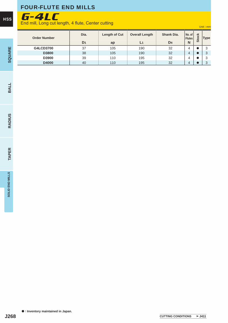
J268
D1 ap L1 D4 NG4LCD3700 37 105 190 32 4 a 3
D3800 38 105 190 32 4 a 3D3900 39 110 195 32 4 a 3D4000 40 110 195 32 4 a 3
G-4LC
a : Inventory maintained in Japan.
HSS
SQU
AR
EB
ALL
RA
DIU
STA
PER
SOLI
D E
ND
MIL
LS
Unit : mm
FOUR-FLUTE END MILLS
End mill, Long cut length, 4 flute, Center cutting
Order NumberDia. Length of Cut Overall Length Shank Dia. No. of
Flutes
Stoc
k
Type
CUTTING CONDITIONS J411
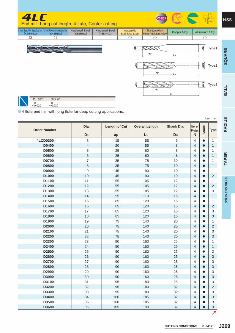
J269
a
e u u u u
4LC
D1 ap L1 D4 N4LCD0300 3 15 55 6 4 a 1
D0400 4 20 55 8 4 a 1D0500 5 25 60 8 4 a 1D0600 6 25 60 8 4 a 1D0700 7 35 75 10 4 a 1D0800 8 35 75 10 4 a 1D0900 9 45 90 10 4 a 1D1000 10 45 90 10 4 a 2D1100 11 55 105 12 4 a 1D1200 12 55 105 12 4 a 2D1300 13 55 105 12 4 a 3D1400 14 55 110 16 4 a 1D1500 15 65 120 16 4 a 1D1600 16 65 120 16 4 a 2D1700 17 65 120 16 4 a 3D1800 18 65 120 16 4 a 3D1900 19 75 140 20 4 a 1D2000 20 75 140 20 4 a 2D2100 21 75 140 20 4 a 3D2200 22 75 140 20 4 a 3D2300 23 90 160 25 4 a 1D2400 24 90 160 25 4 a 1D2500 25 90 160 25 4 a 2D2600 26 90 160 25 4 a 3D2700 27 90 160 25 4 a 3D2800 28 90 160 25 4 a 3D2900 29 90 160 25 4 a 3D3000 30 90 160 25 4 a 3D3100 31 95 180 25 4 a 3D3200 32 95 180 32 4 a 2D3300 33 95 180 32 4 a 3D3400 34 100 185 32 4 a 3D3500 35 100 185 32 4 a 3D3600 36 105 190 32 4 a 3
D1>20 0+ 0.020
0+ 0.030
CO HSS 30°
øD4
apL1
øD1
øD1
øD4
apL1
øD1
øD4
ap
L1
SOLI
D E
ND
MIL
LSSQ
UA
RE
BA
LLR
AD
IUS
TAPE
R
HSS
Unit : mm
Carbon Steel, Alloy Steel, Cast Iron(<30HRC)
Tool Steel, Pre-Hardened Steel,Hardened Steel(<45HRC)
Hardened Steel(<55HRC)
Hardened Steel(>55HRC)
AusteniticStainless Steel
Titanium Alloy,Heat Resistant Alloy Copper Alloy Aluminium Alloy
Order NumberDia. Length of Cut Overall Length Shank Dia. No. of
Flutes
Stoc
k
Type
4 flute end mill with long flute for deep cutting applications.
End mill, Long cut length, 4 flute, Center cutting
D1 <20
Type2
Type3
Type1
CUTTING CONDITIONS J412
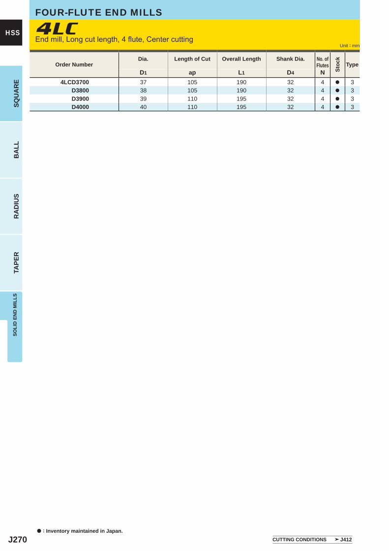
J270
D1 ap L1 D4 N4LCD3700 37 105 190 32 4 a 3
D3800 38 105 190 32 4 a 3D3900 39 110 195 32 4 a 3D4000 40 110 195 32 4 a 3
4LC
a : Inventory maintained in Japan.
HSS
SQU
AR
EB
ALL
RA
DIU
STA
PER
SOLI
D E
ND
MIL
LS
Unit : mm
FOUR-FLUTE END MILLS
End mill, Long cut length, 4 flute, Center cutting
Order NumberDia. Length of Cut Overall Length Shank Dia. No. of
Flutes
Stoc
k
Type
CUTTING CONDITIONS J412
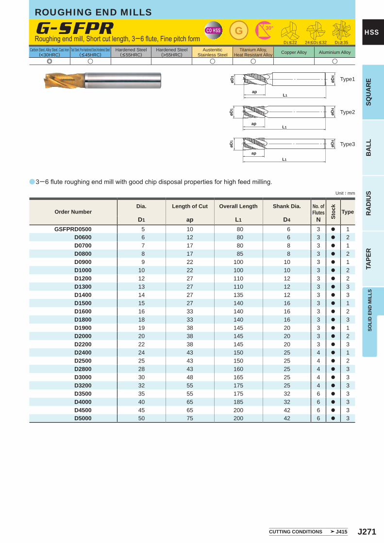
J271
a
e u u u u
G-SFPR
D1 ap L1 D4 NGSFPRD0500 5 10 80 6 3 a 1
D0600 6 12 80 6 3 a 2D0700 7 17 80 8 3 a 1D0800 8 17 85 8 3 a 2D0900 9 22 100 10 3 a 1D1000 10 22 100 10 3 a 2D1200 12 27 110 12 3 a 2D1300 13 27 110 12 3 a 3D1400 14 27 135 12 3 a 3D1500 15 27 140 16 3 a 1D1600 16 33 140 16 3 a 2D1800 18 33 140 16 3 a 3D1900 19 38 145 20 3 a 1D2000 20 38 145 20 3 a 2D2200 22 38 145 20 3 a 3D2400 24 43 150 25 4 a 1D2500 25 43 150 25 4 a 2D2800 28 43 160 25 4 a 3D3000 30 48 165 25 4 a 3D3200 32 55 175 25 4 a 3D3500 35 55 175 32 6 a 3D4000 40 65 185 32 6 a 3D4500 45 65 200 42 6 a 3D5000 50 75 200 42 6 a 3
CO HSS G 30°
øD4
øD1
L1ap
L1ap
øD4
øD1
L1
ap
øD4
øD1
SOLI
D E
ND
MIL
LSSQ
UA
RE
BA
LLR
AD
IUS
TAPE
R
HSS
Unit : mm
Carbon Steel, Alloy Steel, Cast Iron(<30HRC)
Tool Steel, Pre-Hardened Steel,Hardened Steel(<45HRC)
Hardened Steel(<55HRC)
Hardened Steel(>55HRC)
AusteniticStainless Steel
Titanium Alloy,Heat Resistant Alloy Copper Alloy Aluminium Alloy
Order NumberDia. Length of Cut Overall Length Shank Dia. No. of
Flutes
Stoc
k
Type
3─6 flute roughing end mill with good chip disposal properties for high feed milling.
Roughing end mill, Short cut length, 3─6 flute, Fine pitch form
ROUGHING END MILLS
D1<22 D1>3524<D1<32
Type2
Type3
Type1
CUTTING CONDITIONS J415
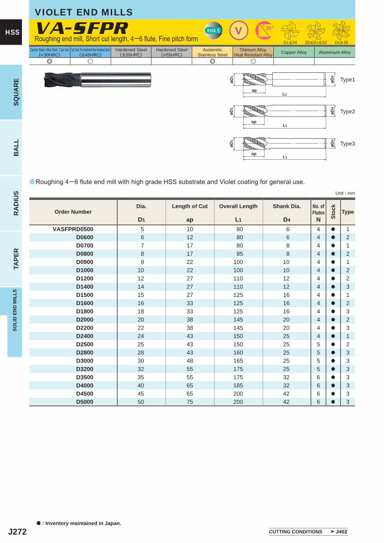
J272
a
VA-SFPR
e u e u
D1 ap L1 D4 NVASFPRD0500 5 10 80 6 4 a 1
D0600 6 12 80 6 4 a 2D0700 7 17 80 8 4 a 1D0800 8 17 85 8 4 a 2D0900 9 22 100 10 4 a 1D1000 10 22 100 10 4 a 2D1200 12 27 110 12 4 a 2D1400 14 27 110 12 4 a 3D1500 15 27 125 16 4 a 1D1600 16 33 125 16 4 a 2D1800 18 33 125 16 4 a 3D2000 20 38 145 20 4 a 2D2200 22 38 145 20 4 a 3D2400 24 43 150 25 4 a 1D2500 25 43 150 25 5 a 2D2800 28 43 160 25 5 a 3D3000 30 48 165 25 5 a 3D3200 32 55 175 25 5 a 3D3500 35 55 175 32 6 a 3D4000 40 65 185 32 6 a 3D4500 45 65 200 42 6 a 3D5000 50 75 200 42 6 a 3
VKHA S 30°
øD4
øD1
L1ap
øD4
øD1
L1ap
øD4
øD1
apL1
a : Inventory maintained in Japan.
HSS
SQU
AR
EB
ALL
RA
DIU
STA
PER
SOLI
D E
ND
MIL
LS
Unit : mm
Carbon Steel, Alloy Steel, Cast Iron(<30HRC)
Tool Steel, Pre-Hardened Steel,Hardened Steel(<45HRC)
Hardened Steel(<55HRC)
Hardened Steel(>55HRC)
AusteniticStainless Steel
Titanium Alloy,Heat Resistant Alloy Copper Alloy Aluminium Alloy
Roughing 4─6 flute end mill with high grade HSS substrate and Violet coating for general use.
VIOLET END MILLS
Roughing end mill, Short cut length, 4─6 flute, Fine pitch form D1>3525<D1<32D1<24
Order NumberDia. Length of Cut Overall Length Shank Dia. No. of
Flutes
Stoc
k
Type
Type2
Type3
Type1
CUTTING CONDITIONS J402
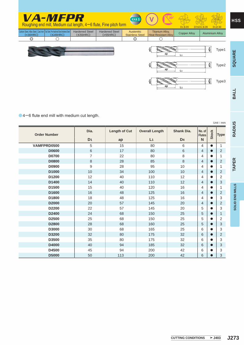
J273
a
e u e u
VA-MFPR
D1 ap L1 D4 NVAMFPRD0500 5 15 80 6 4 a 1
D0600 6 17 80 6 4 a 2D0700 7 22 80 8 4 a 1D0800 8 28 85 8 4 a 2D0900 9 28 95 10 4 a 1D1000 10 34 100 10 4 a 2D1200 12 40 110 12 4 a 2D1400 14 40 110 12 4 a 3D1500 15 40 120 16 4 a 1D1600 16 48 125 16 4 a 2D1800 18 48 125 16 4 a 3D2000 20 57 145 20 4 a 2D2200 22 57 145 20 5 a 3D2400 24 68 150 25 5 a 1D2500 25 68 150 25 5 a 2D2800 28 68 160 25 5 a 3D3000 30 68 165 25 6 a 3D3200 32 80 175 32 6 a 2D3500 35 80 175 32 6 a 3D4000 40 94 185 32 6 a 3D4500 45 94 200 42 6 a 3D5000 50 113 200 42 6 a 3
VKHA S 30°
øD1
øD4
L1ap
øD4
L1ap
øD1
øD4
øD1
ap L1
SOLI
D E
ND
MIL
LSSQ
UA
RE
BA
LLR
AD
IUS
TAPE
R
HSS
Unit : mm
Carbon Steel, Alloy Steel, Cast Iron(<30HRC)
Tool Steel, Pre-Hardened Steel,Hardened Steel(<45HRC)
Hardened Steel(<55HRC)
Hardened Steel(>55HRC)
AusteniticStainless Steel
Titanium Alloy,Heat Resistant Alloy Copper Alloy Aluminium Alloy
Order NumberDia. Length of Cut Overall Length Shank Dia. No. of
Flutes
Stoc
k
Type
Type2
Type3
Type1
Roughing end mill, Medium cut length, 4─6 flute, Fine pitch form
4─6 flute end mill with medium cut length.
D1>3022<D1<28D1<20
CUTTING CONDITIONS J403
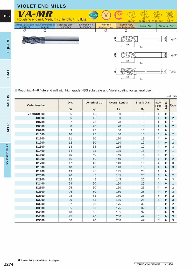
J274
a
e u e u
VA-MR
D1 ap L1 D4 NVAMRD0500 5 15 60 6 4 a 1
D0600 6 15 60 6 4 a 2D0700 7 20 70 8 4 a 1D0800 8 20 70 8 4 a 2D0900 9 25 80 10 4 a 1D1000 10 25 80 10 4 a 2D1100 11 30 110 12 4 a 1D1200 12 30 110 12 4 a 2D1300 13 35 115 12 4 a 3D1400 14 35 135 16 4 a 1D1500 15 40 140 16 4 a 1D1600 16 40 140 16 4 a 2D1700 17 40 140 16 4 a 3D1800 18 40 140 16 4 a 3D1900 19 45 145 20 4 a 1D2000 20 45 145 20 4 a 2D2200 22 45 145 20 4 a 3D2400 24 50 150 25 4 a 1D2500 25 50 150 25 4 a 2D2600 26 50 150 25 4 a 3D2800 28 55 160 25 5 a 3D3000 30 55 165 25 5 a 3D3200 32 60 175 32 5 a 2D3500 35 60 175 32 6 a 3D4000 40 65 185 32 6 a 3D4500 45 70 200 42 6 a 3D5000 50 70 200 42 6 a 3
VKHA S 30°
øD4
øD1
L1ap
øD4
øD1
L1ap
øD4
øD1
apL1
a : Inventory maintained in Japan.
HSS
SQU
AR
EB
ALL
RA
DIU
STA
PER
SOLI
D E
ND
MIL
LS
Unit : mm
Carbon Steel, Alloy Steel, Cast Iron(<30HRC)
Tool Steel, Pre-Hardened Steel,Hardened Steel(<45HRC)
Hardened Steel(<55HRC)
Hardened Steel(>55HRC)
AusteniticStainless Steel
Titanium Alloy,Heat Resistant Alloy Copper Alloy Aluminium Alloy
Roughing 4─6 flute end mill with high grade HSS substrate and Violet coating for general use.
Roughing end mill, Medium cut length, 4─6 flute
VIOLET END MILLS
Type2
Type3
Type1
D1<15 16<D1<26 28<D1<32 D1>35
Order NumberDia. Length of Cut Overall Length Shank Dia. No. of
Flutes
Stoc
k
Type
CUTTING CONDITIONS J404
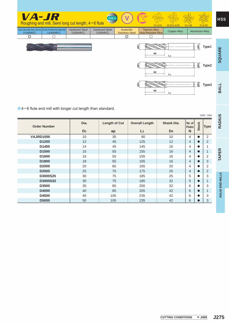
J275
a
e u e u
VA-JR
D1 ap L1 D4 NVAJRD1000 10 35 90 10 4 a 2 D1200 12 45 125 12 4 a 2 D1400 14 45 145 16 4 a 1 D1500 15 55 155 16 4 a 1 D1600 16 55 155 16 4 a 2 D1800 18 55 155 16 4 a 3 D2000 20 65 165 20 4 a 2 D2500 25 75 175 25 4 a 2 D3000S25 30 75 185 25 5 a 3 D3000S32 30 75 185 32 5 a 1 D3500 35 85 200 32 6 a 3 D4000 40 85 205 42 6 a 1 D4500 45 105 235 42 6 a 3 D5000 50 105 235 42 6 a 3
D1=30
VKHA S 30°
øD1
L1ap
øD4
øD1
L1ap
øD4
øD4
øD1
apL1
SOLI
D E
ND
MIL
LSSQ
UA
RE
BA
LLR
AD
IUS
TAPE
R
HSS
Unit : mm
Carbon Steel, Alloy Steel, Cast Iron(<30HRC)
Tool Steel, Pre-Hardened Steel,Hardened Steel(<45HRC)
Hardened Steel(<55HRC)
Hardened Steel(>55HRC)
AusteniticStainless Steel
Titanium Alloy,Heat Resistant Alloy Copper Alloy Aluminium Alloy
Type2Type2
Type3Type3
Type1Type1
Order NumberDia. Length of Cut Overall Length Shank Dia. No. of
Flutes
Stoc
k
Type
4─6 flute end mill with longer cut length than standard.
Roughing end mill, Semi long cut length, 4─6 flute D1<15 16<D1<25 D1>35
CUTTING CONDITIONS J405
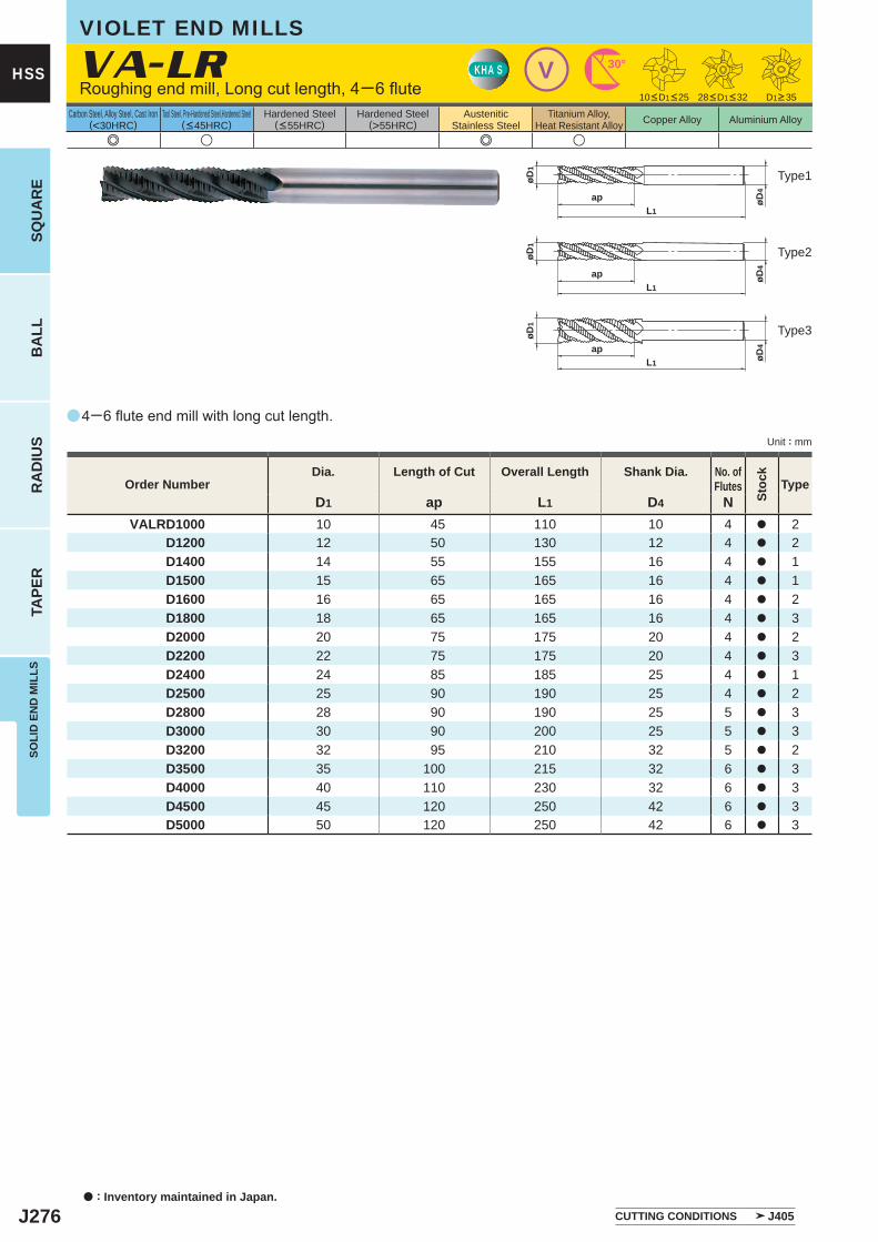
J276
a
e u e u
VA-LR
D1 ap L1 D4 NVALRD1000 10 45 110 10 4 a 2
D1200 12 50 130 12 4 a 2D1400 14 55 155 16 4 a 1D1500 15 65 165 16 4 a 1D1600 16 65 165 16 4 a 2D1800 18 65 165 16 4 a 3D2000 20 75 175 20 4 a 2D2200 22 75 175 20 4 a 3D2400 24 85 185 25 4 a 1D2500 25 90 190 25 4 a 2D2800 28 90 190 25 5 a 3D3000 30 90 200 25 5 a 3D3200 32 95 210 32 5 a 2D3500 35 100 215 32 6 a 3D4000 40 110 230 32 6 a 3D4500 45 120 250 42 6 a 3D5000 50 120 250 42 6 a 3
VKHA S 30°
øD4
L1
ap
øD1
L1
ap øD4
øD1
øD4
øD1
apL1
a : Inventory maintained in Japan.
HSS
SQU
AR
EB
ALL
RA
DIU
STA
PER
SOLI
D E
ND
MIL
LS
Unit : mm
Carbon Steel, Alloy Steel, Cast Iron(<30HRC)
Tool Steel, Pre-Hardened Steel,Hardened Steel(<45HRC)
Hardened Steel(<55HRC)
Hardened Steel(>55HRC)
AusteniticStainless Steel
Titanium Alloy,Heat Resistant Alloy Copper Alloy Aluminium Alloy
4─6 flute end mill with long cut length.
Roughing end mill, Long cut length, 4─6 flute
VIOLET END MILLS
Type2
Type3
Type1
D1>3528<D1<3210<D1<25
Order NumberDia. Length of Cut Overall Length Shank Dia. No. of
Flutes
Stoc
k
Type
CUTTING CONDITIONS J405
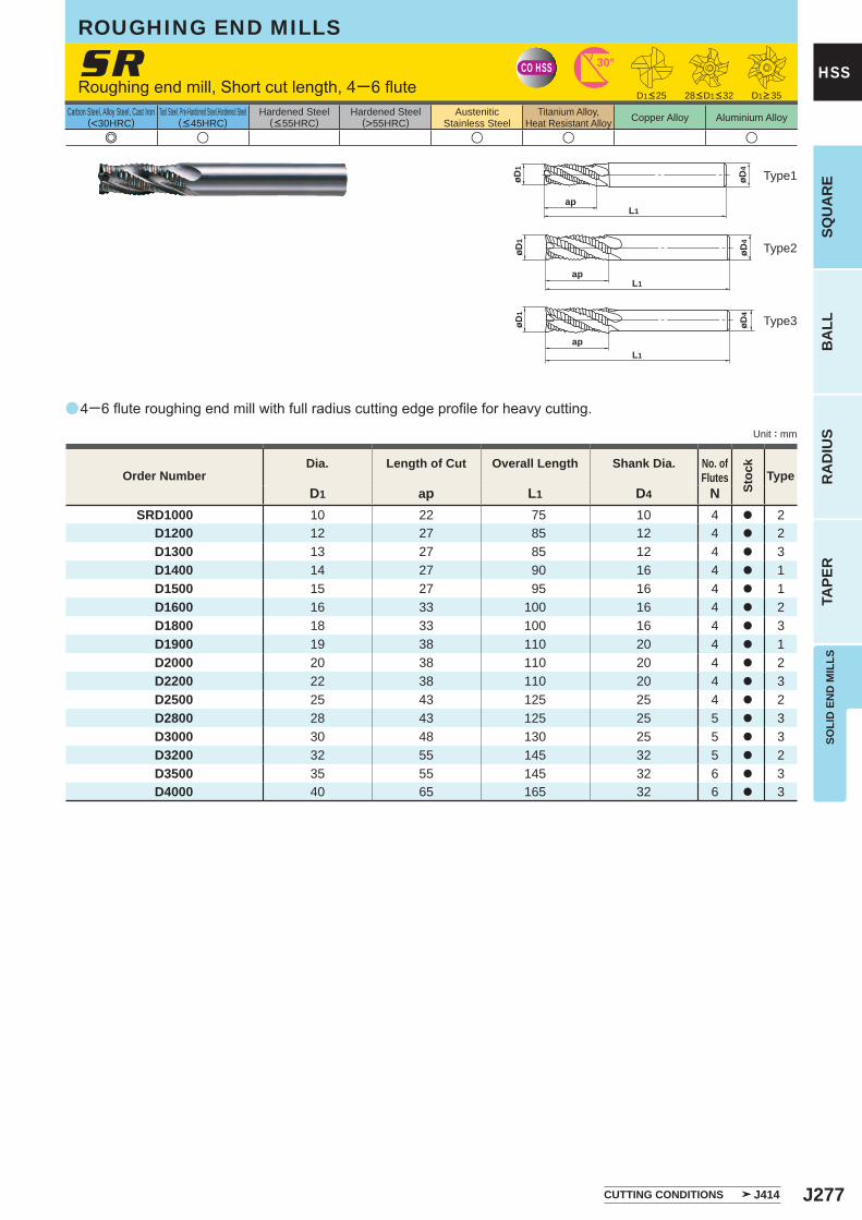
J277
a
e u u u u
SR
D1 ap L1 D4 NSRD1000 10 22 75 10 4 a 2
D1200 12 27 85 12 4 a 2D1300 13 27 85 12 4 a 3D1400 14 27 90 16 4 a 1D1500 15 27 95 16 4 a 1D1600 16 33 100 16 4 a 2D1800 18 33 100 16 4 a 3D1900 19 38 110 20 4 a 1D2000 20 38 110 20 4 a 2D2200 22 38 110 20 4 a 3D2500 25 43 125 25 4 a 2D2800 28 43 125 25 5 a 3D3000 30 48 130 25 5 a 3D3200 32 55 145 32 5 a 2D3500 35 55 145 32 6 a 3D4000 40 65 165 32 6 a 3
CO HSS 30°
øD4
øD1
L1ap
øD4
øD1
L1ap
L1
ap
øD4
øD1
SOLI
D E
ND
MIL
LSSQ
UA
RE
BA
LLR
AD
IUS
TAPE
R
HSS
Unit : mm
Carbon Steel, Alloy Steel, Cast Iron(<30HRC)
Tool Steel, Pre-Hardened Steel,Hardened Steel(<45HRC)
Hardened Steel(<55HRC)
Hardened Steel(>55HRC)
AusteniticStainless Steel
Titanium Alloy,Heat Resistant Alloy Copper Alloy Aluminium Alloy
Type2
Type3
Type1
Order NumberDia. Length of Cut Overall Length Shank Dia. No. of
Flutes
Stoc
k
Type
4─6 flute roughing end mill with full radius cutting edge profile for heavy cutting.
Roughing end mill, Short cut length, 4─6 flute
ROUGHING END MILLS
D1>35D1<25 28<D1<32
CUTTING CONDITIONS J414
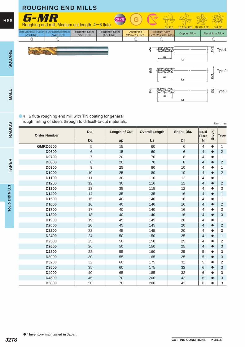
J278
a
e u u u u
G-MR
D1 ap L1 D4 NGMRD0500 5 15 60 6 4 a 1
D0600 6 15 60 6 4 a 2D0700 7 20 70 8 4 a 1D0800 8 20 70 8 4 a 2D0900 9 25 80 10 4 a 1D1000 10 25 80 10 4 a 2D1100 11 30 110 12 4 a 1D1200 12 30 110 12 4 a 2D1300 13 35 115 12 4 a 3D1400 14 35 135 16 4 a 1D1500 15 40 140 16 4 a 1D1600 16 40 140 16 4 a 2D1700 17 40 140 16 4 a 3D1800 18 40 140 16 4 a 3D1900 19 45 145 20 4 a 1D2000 20 45 145 20 4 a 2D2200 22 45 145 20 4 a 3D2400 24 50 150 25 4 a 1D2500 25 50 150 25 4 a 2D2600 26 50 150 25 4 a 3D2800 28 55 160 25 5 a 3D3000 30 55 165 25 5 a 3D3200 32 60 175 32 5 a 2D3500 35 60 175 32 6 a 3D4000 40 65 185 32 6 a 3D4500 45 70 200 42 6 a 3D5000 50 70 200 42 6 a 3
CO HSS G 30°
øD4
øD1
L1ap
L1ap øD
4
øD1
L1
ap
øD4
øD1
a : Inventory maintained in Japan.
HSS
SQU
AR
EB
ALL
RA
DIU
STA
PER
SOLI
D E
ND
MIL
LS
Unit : mm
Carbon Steel, Alloy Steel, Cast Iron(<30HRC)
Tool Steel, Pre-Hardened Steel,Hardened Steel(<45HRC)
Hardened Steel(<55HRC)
Hardened Steel(>55HRC)
AusteniticStainless Steel
Titanium Alloy,Heat Resistant Alloy Copper Alloy Aluminium Alloy
CUTTING CONDITIONS J415
4─6 flute roughing end mill with TiN coating for general rough milling of steels through to difficult-to-cut materials.
Roughing end mill, Medium cut length, 4─6 flute
ROUGHING END MILLS
D1>35D1<15 16<D1<26 28<D1<32
Order NumberDia. Length of Cut Overall Length Shank Dia. No. of
Flutes
Stoc
k
Type
Type2
Type3
Type1
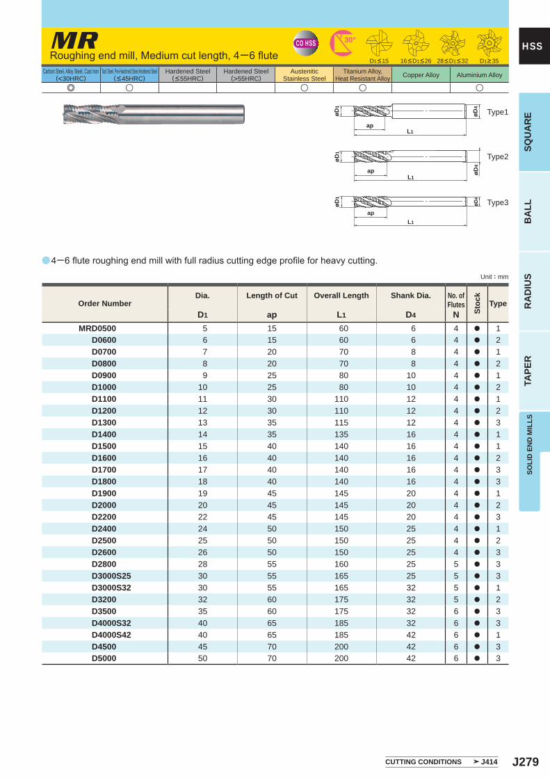
J279
a
e u u u u
MR
D1 ap L1 D4 NMRD0500 5 15 60 6 4 a 1 D0600 6 15 60 6 4 a 2 D0700 7 20 70 8 4 a 1 D0800 8 20 70 8 4 a 2 D0900 9 25 80 10 4 a 1 D1000 10 25 80 10 4 a 2 D1100 11 30 110 12 4 a 1 D1200 12 30 110 12 4 a 2 D1300 13 35 115 12 4 a 3 D1400 14 35 135 16 4 a 1 D1500 15 40 140 16 4 a 1 D1600 16 40 140 16 4 a 2 D1700 17 40 140 16 4 a 3 D1800 18 40 140 16 4 a 3 D1900 19 45 145 20 4 a 1 D2000 20 45 145 20 4 a 2 D2200 22 45 145 20 4 a 3 D2400 24 50 150 25 4 a 1 D2500 25 50 150 25 4 a 2 D2600 26 50 150 25 4 a 3 D2800 28 55 160 25 5 a 3 D3000S25 30 55 165 25 5 a 3 D3000S32 30 55 165 32 5 a 1 D3200 32 60 175 32 5 a 2 D3500 35 60 175 32 6 a 3 D4000S32 40 65 185 32 6 a 3 D4000S42 40 65 185 42 6 a 1 D4500 45 70 200 42 6 a 3 D5000 50 70 200 42 6 a 3
CO HSS 30°
øD4
øD1
L1ap
L1ap øD
4
øD1
L1
ap
øD4
øD1
SOLI
D E
ND
MIL
LSSQ
UA
RE
BA
LLR
AD
IUS
TAPE
R
HSS
Unit : mm
Carbon Steel, Alloy Steel, Cast Iron(<30HRC)
Tool Steel, Pre-Hardened Steel,Hardened Steel(<45HRC)
Hardened Steel(<55HRC)
Hardened Steel(>55HRC)
AusteniticStainless Steel
Titanium Alloy,Heat Resistant Alloy Copper Alloy Aluminium Alloy
CUTTING CONDITIONS J414
Order NumberDia. Length of Cut Overall Length Shank Dia. No. of
Flutes
Stoc
k
Type
Type2
Type3
Type1
Roughing end mill, Medium cut length, 4─6 flute D1<15 D1>3528<D1<3216<D1<26
4─6 flute roughing end mill with full radius cutting edge profile for heavy cutting.
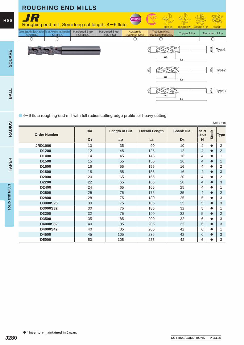
J280
a
e u u u u
JR
D1 ap L1 D4 NJRD1000 10 35 90 10 4 a 2 D1200 12 45 125 12 4 a 2 D1400 14 45 145 16 4 a 1 D1500 15 55 155 16 4 a 1 D1600 16 55 155 16 4 a 2 D1800 18 55 155 16 4 a 3 D2000 20 65 165 20 4 a 2 D2200 22 65 165 20 4 a 3 D2400 24 65 165 25 4 a 1 D2500 25 75 175 25 4 a 2 D2800 28 75 180 25 5 a 3 D3000S25 30 75 185 25 5 a 3 D3000S32 30 75 185 32 5 a 1 D3200 32 75 190 32 5 a 2 D3500 35 85 200 32 6 a 3 D4000S32 40 85 205 32 6 a 3 D4000S42 40 85 205 42 6 a 1 D4500 45 105 235 42 6 a 3 D5000 50 105 235 42 6 a 3
CO HSS 30°
L1ap
øD4
øD1
L1ap
øD4
øD1
L1
ap
øD4
øD1
a : Inventory maintained in Japan.
HSS
SQU
AR
EB
ALL
RA
DIU
STA
PER
SOLI
D E
ND
MIL
LS
Unit : mm
Carbon Steel, Alloy Steel, Cast Iron(<30HRC)
Tool Steel, Pre-Hardened Steel,Hardened Steel(<45HRC)
Hardened Steel(<55HRC)
Hardened Steel(>55HRC)
AusteniticStainless Steel
Titanium Alloy,Heat Resistant Alloy Copper Alloy Aluminium Alloy
CUTTING CONDITIONS J414
4─6 flute roughing end mill with full radius cutting edge profile for heavy cutting.
Roughing end mill, Semi long cut length, 4─6 flute
ROUGHING END MILLS
D1>35D1<15 16<D1<25 28<D1<32
Type2
Type3
Type1
Order NumberDia. Length of Cut Overall Length Shank Dia. No. of
Flutes
Stoc
k
Type
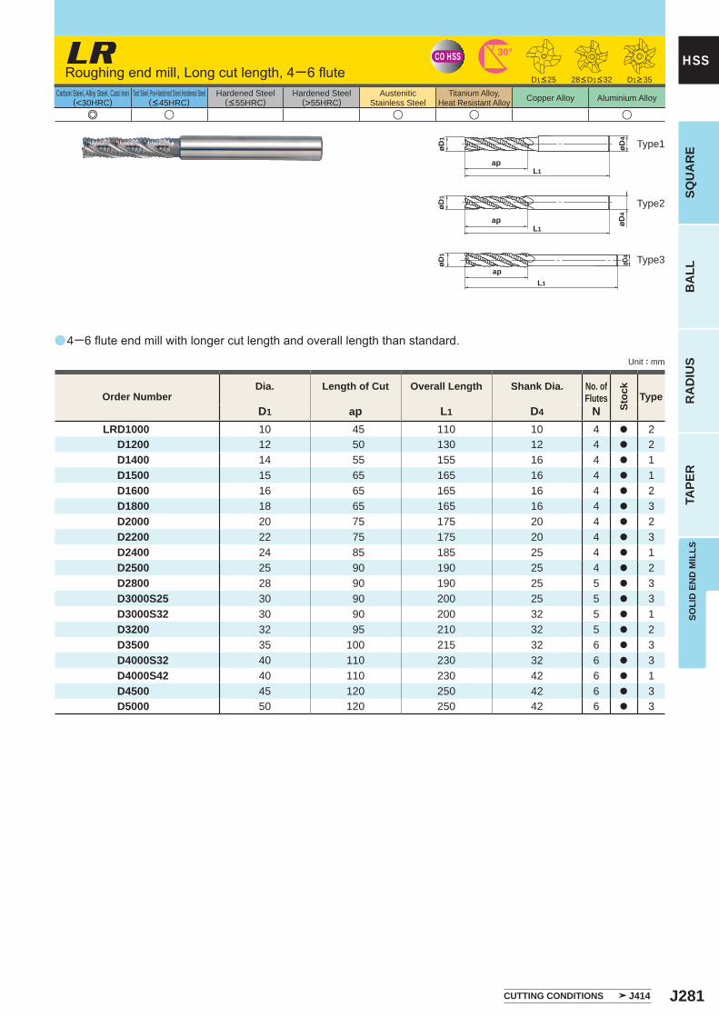
J281
a
e u u u u
LR
D1 ap L1 D4 NLRD1000 10 45 110 10 4 a 2 D1200 12 50 130 12 4 a 2 D1400 14 55 155 16 4 a 1 D1500 15 65 165 16 4 a 1 D1600 16 65 165 16 4 a 2 D1800 18 65 165 16 4 a 3 D2000 20 75 175 20 4 a 2 D2200 22 75 175 20 4 a 3 D2400 24 85 185 25 4 a 1 D2500 25 90 190 25 4 a 2 D2800 28 90 190 25 5 a 3 D3000S25 30 90 200 25 5 a 3 D3000S32 30 90 200 32 5 a 1 D3200 32 95 210 32 5 a 2 D3500 35 100 215 32 6 a 3 D4000S32 40 110 230 32 6 a 3 D4000S42 40 110 230 42 6 a 1 D4500 45 120 250 42 6 a 3 D5000 50 120 250 42 6 a 3
CO HSS 30°
L1ap
øD4
øD1
L1ap øD
4
øD1
L1
ap
øD4
øD1
SOLI
D E
ND
MIL
LSSQ
UA
RE
BA
LLR
AD
IUS
TAPE
R
HSS
Unit : mm
Carbon Steel, Alloy Steel, Cast Iron(<30HRC)
Tool Steel, Pre-Hardened Steel,Hardened Steel(<45HRC)
Hardened Steel(<55HRC)
Hardened Steel(>55HRC)
AusteniticStainless Steel
Titanium Alloy,Heat Resistant Alloy Copper Alloy Aluminium Alloy
CUTTING CONDITIONS J414
Type2
Type3
Type1
Order NumberDia. Length of Cut Overall Length Shank Dia. No. of
Flutes
Stoc
k
Type
Roughing end mill, Long cut length, 4─6 flute D1<25 D1>3528<D1<32
4─6 flute end mill with longer cut length and overall length than standard.
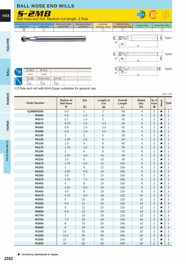
J282
a
e u u u u
S-2MB
R D1 ap L1 D4 NS2MBR0050 0.5 1 2 50 6 2 a 1
R0060 0.6 1.2 2 50 6 2 a 1R0070 0.7 1.4 2 50 6 2 a 1R0075 0.75 1.5 3.5 50 6 2 a 1R0080 0.8 1.6 3.5 50 6 2 a 1R0090 0.9 1.8 3.5 50 6 2 a 1R0100 1 2 5 50 6 2 a 1R0125 1.25 2.5 6 50 6 2 a 1R0150 1.5 3 8 60 6 2 a 1R0175 1.75 3.5 8 70 6 2 a 1R0200 2 4 8 70 6 2 a 1R0225 2.25 4.5 10 90 6 2 a 1R0250 2.5 5 10 90 6 2 a 1R0275 2.75 5.5 12 100 6 2 a 1R0300 3 6 12 100 6 2 a 2R0325 3.25 6.5 14 100 6 2 a 3R0350 3.5 7 14 100 6 2 a 3R0375 3.75 7.5 14 100 8 2 a 1R0400 4 8 14 100 8 2 a 2R0425 4.25 8.5 18 120 8 2 a 3R0450 4.5 9 18 120 8 2 a 3R0475 4.75 9.5 18 120 10 2 a 1R0500 5 10 18 120 10 2 a 2R0550 5.5 11 20 120 10 2 a 3R0600 6 12 22 120 12 2 a 2R0650 6.5 13 24 120 12 2 a 3R0700 7 14 26 120 12 2 a 3R0750 7.5 15 28 120 16 2 a 1R0800 8 16 30 160 16 2 a 2R0900 9 18 34 160 16 2 a 3R1000 10 20 38 180 20 2 a 2R1250 12.5 25 50 200 25 2 a 2R1500 15 30 55 200 25 2 a 3R1600 16 32 55 200 32 2 a 2
R>6.5±0.01 ±0.02
D1>13 0- 0.02
0- 0.03
0- 0.04
KHA S 30°
øD4
L1
øD1
R ap
øD4
L1
øD1
R ap
R
øD4
L1
ap
øD1
R
a : Inventory maintained in Japan.
SQU
AR
EB
ALL
RA
DIU
STA
PER
SOLI
D E
ND
MIL
LS
HSS
Unit : mm
Carbon Steel, Alloy Steel, Cast Iron(<30HRC)
Tool Steel, Pre-Hardened Steel,Hardened Steel(<45HRC)
Hardened Steel(<55HRC)
Hardened Steel(>55HRC)
AusteniticStainless Steel
Titanium Alloy,Heat Resistant Alloy Copper Alloy Aluminium Alloy
2 flute end mill with KHA Super substrate for general use.
Ball nose end mill, Medium cut length, 2 flute
BALL NOSE END MILLS
Type2
Type3
Type1
Order NumberRadius ofBall Nose
Dia. Length of Cut
Overall Length
Shank Dia.
No. ofFlutes Type
N
D1 <3 3<D1 <13
R <6.5
Stoc
k
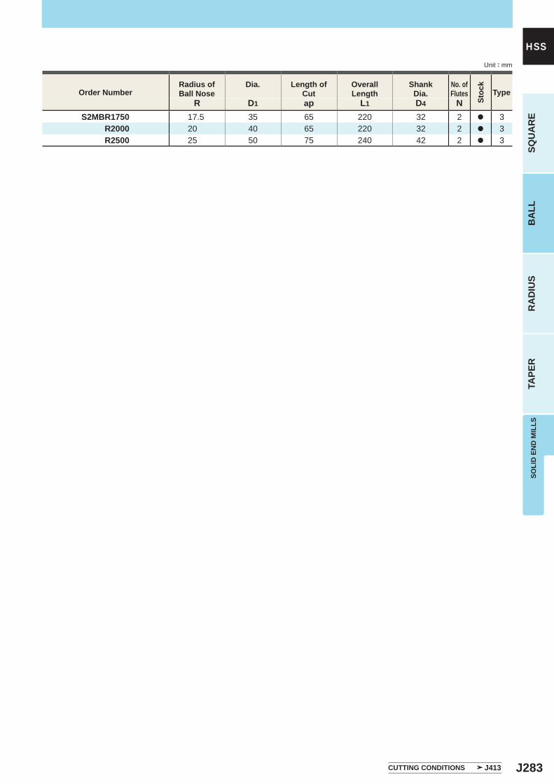
J283
R D1 ap L1 D4 NS2MBR1750 17.5 35 65 220 32 2 a 3
R2000 20 40 65 220 32 2 a 3R2500 25 50 75 240 42 2 a 3
SOLI
D E
ND
MIL
LSSQ
UA
RE
BA
LLR
AD
IUS
TAPE
R
HSSUnit : mm
Order NumberRadius ofBall Nose
Dia. Length of Cut
Overall Length
Shank Dia.
No. ofFlutes Type
CUTTING CONDITIONS J413
Stoc
k
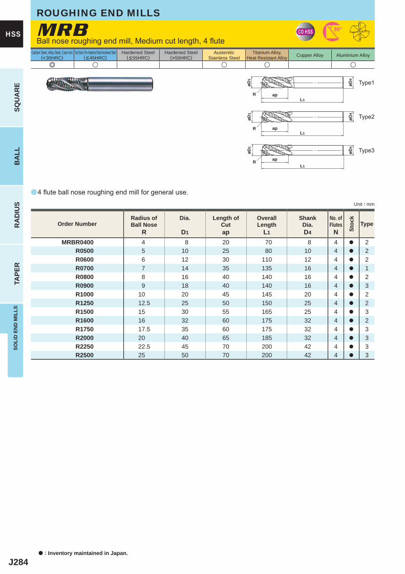
J284
a
e u u u u
MRB
R D1 ap L1 D4 NMRBR0400 4 8 20 70 8 4 a 2
R0500 5 10 25 80 10 4 a 2R0600 6 12 30 110 12 4 a 2R0700 7 14 35 135 16 4 a 1R0800 8 16 40 140 16 4 a 2R0900 9 18 40 140 16 4 a 3R1000 10 20 45 145 20 4 a 2R1250 12.5 25 50 150 25 4 a 2R1500 15 30 55 165 25 4 a 3R1600 16 32 60 175 32 4 a 2R1750 17.5 35 60 175 32 4 a 3R2000 20 40 65 185 32 4 a 3R2250 22.5 45 70 200 42 4 a 3R2500 25 50 70 200 42 4 a 3
CO HSS 30°
L1apR
øD4
øD1
L1apR
øD4
øD1
L1
apR
øD4
øD1
a : Inventory maintained in Japan.
SQU
AR
EB
ALL
RA
DIU
STA
PER
SOLI
D E
ND
MIL
LS
HSS
Unit : mm
Carbon Steel, Alloy Steel, Cast Iron(<30HRC)
Tool Steel, Pre-Hardened Steel,Hardened Steel(<45HRC)
Hardened Steel(<55HRC)
Hardened Steel(>55HRC)
AusteniticStainless Steel
Titanium Alloy,Heat Resistant Alloy Copper Alloy Aluminium Alloy
4 flute ball nose roughing end mill for general use.
Ball nose roughing end mill, Medium cut length, 4 flute
ROUGHING END MILLS
Type2
Type3
Type1
Order NumberRadius ofBall Nose
Dia. Length of Cut
Overall Length
Shank Dia.
No. ofFlutes Type
Stoc
k

J285
Memo
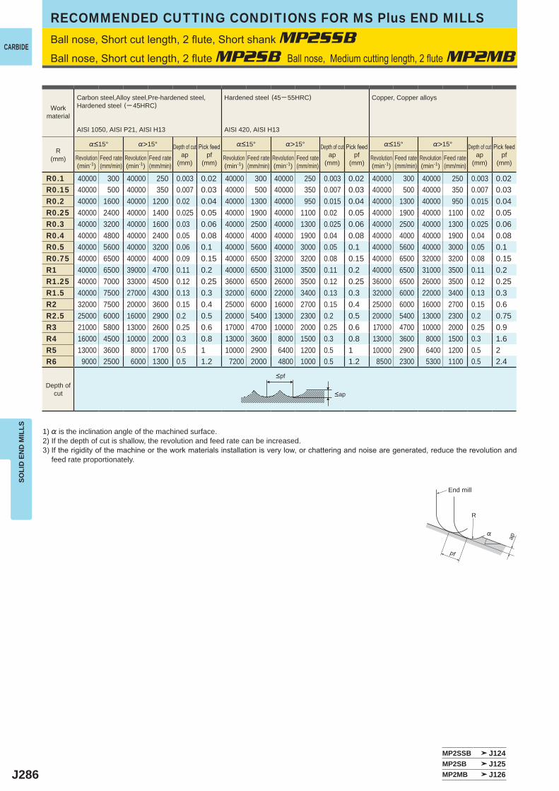
J286
%>15° %>15° %>15°
R0.1 40000 300 40000 250 0.003 0.02 40000 300 40000 250 0.003 0.02 40000 300 40000 250 0.003 0.02R0.15 40000 500 40000 350 0.007 0.03 40000 500 40000 350 0.007 0.03 40000 500 40000 350 0.007 0.03R0.2 40000 1600 40000 1200 0.02 0.04 40000 1300 40000 950 0.015 0.04 40000 1300 40000 950 0.015 0.04R0.25 40000 2400 40000 1400 0.025 0.05 40000 1900 40000 1100 0.02 0.05 40000 1900 40000 1100 0.02 0.05R0.3 40000 3200 40000 1600 0.03 0.06 40000 2500 40000 1300 0.025 0.06 40000 2500 40000 1300 0.025 0.06R0.4 40000 4800 40000 2400 0.05 0.08 40000 4000 40000 1900 0.04 0.08 40000 4000 40000 1900 0.04 0.08R0.5 40000 5600 40000 3200 0.06 0.1 40000 5600 40000 3000 0.05 0.1 40000 5600 40000 3000 0.05 0.1R0.75 40000 6500 40000 4000 0.09 0.15 40000 6500 32000 3200 0.08 0.15 40000 6500 32000 3200 0.08 0.15R1 40000 6500 39000 4700 0.11 0.2 40000 6500 31000 3500 0.11 0.2 40000 6500 31000 3500 0.11 0.2R1.25 40000 7000 33000 4500 0.12 0.25 36000 6500 26000 3500 0.12 0.25 36000 6500 26000 3500 0.12 0.25R1.5 40000 7500 27000 4300 0.13 0.3 32000 6000 22000 3400 0.13 0.3 32000 6000 22000 3400 0.13 0.3R2 32000 7500 20000 3600 0.15 0.4 25000 6000 16000 2700 0.15 0.4 25000 6000 16000 2700 0.15 0.6R2.5 25000 6000 16000 2900 0.2 0.5 20000 5400 13000 2300 0.2 0.5 20000 5400 13000 2300 0.2 0.75R3 21000 5800 13000 2600 0.25 0.6 17000 4700 10000 2000 0.25 0.6 17000 4700 10000 2000 0.25 0.9R4 16000 4500 10000 2000 0.3 0.8 13000 3600 8000 1500 0.3 0.8 13000 3600 8000 1500 0.3 1.6R5 13000 3600 8000 1700 0.5 1 10000 2900 6400 1200 0.5 1 10000 2900 6400 1200 0.5 2R6 9000 2500 6000 1300 0.5 1.2 7200 2000 4800 1000 0.5 1.2 8500 2300 5300 1100 0.5 2.4
MP2SSB J124MP2SB J125MP2MB J126
R
%
ap
pf
CARBIDE
SOLI
D E
ND
MIL
LSRECOMMENDED CUTTING CONDITIONS FOR MS Plus END MILLS
<ap
<pf
Ball nose, Short cut length, 2 flute, Short shank MP2SSBBall nose, Short cut length, 2 flute MP2SB Ball nose, Medium cutting length, 2 flute MP2MB
1) % is the inclination angle of the machined surface. 2) If the depth of cut is shallow, the revolution and feed rate can be increased.3) If the rigidity of the machine or the work materials installation is very low, or chattering and noise are generated, reduce the revolution and
feed rate proportionately.
Workmaterial
Carbon steel,Alloy steel,Pre-hardened steel,Hardened steel (─ 45HRC)
AISI 1050, AISI P21, AISI H13
Hardened steel (45─ 55HRC)
AISI 420, AISI H13
Copper, Copper alloys
R(mm)
%<15° Depth of cutap
(mm)
Pick feedpf
(mm)
%<15° Depth of cutap
(mm)
Pick feedpf
(mm)
%<15° Depth of cutap
(mm)
Pick feedpf
(mm)Revolution(min-1)
Feed rate(mm/min)
Revolution(min-1)
Feed rate(mm/min)
Revolution(min-1)
Feed rate(mm/min)
Revolution(min-1)
Feed rate(mm/min)
Revolution(min-1)
Feed rate(mm/min)
Revolution(min-1)
Feed rate(mm/min)
Depth ofcut
End mill
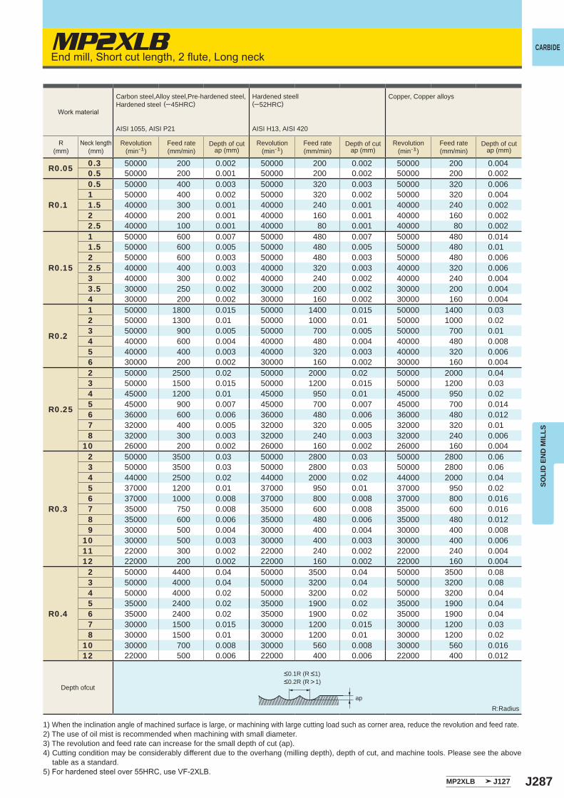
J287
R0.05 0.3 50000 200 0.002 50000 200 0.002 50000 200 0.0040.5 50000 200 0.001 50000 200 0.002 50000 200 0.002
R0.1
0.5 50000 400 0.003 50000 320 0.003 50000 320 0.0061 50000 400 0.002 50000 320 0.002 50000 320 0.0041.5 40000 300 0.001 40000 240 0.001 40000 240 0.0022 40000 200 0.001 40000 160 0.001 40000 160 0.0022.5 40000 100 0.001 40000 80 0.001 40000 80 0.002
R0.15
1 50000 600 0.007 50000 480 0.007 50000 480 0.0141.5 50000 600 0.005 50000 480 0.005 50000 480 0.012 50000 600 0.003 50000 480 0.003 50000 480 0.0062.5 40000 400 0.003 40000 320 0.003 40000 320 0.0063 40000 300 0.002 40000 240 0.002 40000 240 0.0043.5 30000 250 0.002 30000 200 0.002 30000 200 0.0044 30000 200 0.002 30000 160 0.002 30000 160 0.004
R0.2
1 50000 1800 0.015 50000 1400 0.015 50000 1400 0.032 50000 1300 0.01 50000 1000 0.01 50000 1000 0.023 50000 900 0.005 50000 700 0.005 50000 700 0.014 40000 600 0.004 40000 480 0.004 40000 480 0.0085 40000 400 0.003 40000 320 0.003 40000 320 0.0066 30000 200 0.002 30000 160 0.002 30000 160 0.004
R0.25
2 50000 2500 0.02 50000 2000 0.02 50000 2000 0.043 50000 1500 0.015 50000 1200 0.015 50000 1200 0.034 45000 1200 0.01 45000 950 0.01 45000 950 0.025 45000 900 0.007 45000 700 0.007 45000 700 0.0146 36000 600 0.006 36000 480 0.006 36000 480 0.0127 32000 400 0.005 32000 320 0.005 32000 320 0.018 32000 300 0.003 32000 240 0.003 32000 240 0.006
10 26000 200 0.002 26000 160 0.002 26000 160 0.004
R0.3
2 50000 3500 0.03 50000 2800 0.03 50000 2800 0.063 50000 3500 0.03 50000 2800 0.03 50000 2800 0.064 44000 2500 0.02 44000 2000 0.02 44000 2000 0.045 37000 1200 0.01 37000 950 0.01 37000 950 0.026 37000 1000 0.008 37000 800 0.008 37000 800 0.0167 35000 750 0.008 35000 600 0.008 35000 600 0.0168 35000 600 0.006 35000 480 0.006 35000 480 0.0129 30000 500 0.004 30000 400 0.004 30000 400 0.008
10 30000 500 0.003 30000 400 0.003 30000 400 0.00611 22000 300 0.002 22000 240 0.002 22000 240 0.00412 22000 200 0.002 22000 160 0.002 22000 160 0.004
R0.4
2 50000 4400 0.04 50000 3500 0.04 50000 3500 0.083 50000 4000 0.04 50000 3200 0.04 50000 3200 0.084 50000 4000 0.02 50000 3200 0.02 50000 3200 0.045 35000 2400 0.02 35000 1900 0.02 35000 1900 0.046 35000 2400 0.02 35000 1900 0.02 35000 1900 0.047 30000 1500 0.015 30000 1200 0.015 30000 1200 0.038 30000 1500 0.01 30000 1200 0.01 30000 1200 0.02
10 30000 700 0.008 30000 560 0.008 30000 560 0.01612 22000 500 0.006 22000 400 0.006 22000 400 0.012
ap
MP2XLB
MP2XLB J127
CARBIDE
SOLI
D E
ND
MIL
LS
End mill, Short cut length, 2 flute, Long neck
Work material
Carbon steel,Alloy steel,Pre-hardened steel,Hardened steel (─45HRC)
AISI 1055, AISI P21
Hardened steell(─52HRC)
AISI H13, AISI 420
Copper, Copper alloys
R(mm)
Neck length(mm)
Revolution(min-1)
Feed rate(mm/min)
Depth of cutap (mm)
Revolution(min-1)
Feed rate(mm/min)
Depth of cutap (mm)
Revolution(min-1)
Feed rate(mm/min)
Depth of cutap (mm)
Depth ofcut
R:Radius
1) When the inclination angle of machined surface is large, or machining with large cutting load such as corner area, reduce the revolution and feed rate.2) The use of oil mist is recommended when machining with small diameter.3) The revolution and feed rate can increase for the small depth of cut (ap).4) Cutting condition may be considerably different due to the overhang (milling depth), depth of cut, and machine tools. Please see the above table as a standard.5) For hardened steel over 55HRC, use VF-2XLB.
<0.1R (R <1)<0.2R (R >1)
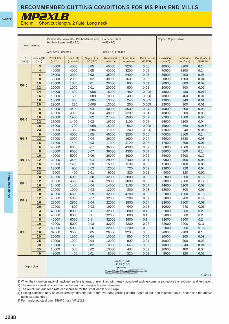
J288
MP2XLB
R0.5
3 40000 4000 0.05 40000 3200 0.05 40000 3200 0.14 40000 4000 0.05 40000 3200 0.05 40000 3200 0.16 35000 3000 0.03 35000 2400 0.03 35000 2400 0.068 30000 2000 0.02 30000 1600 0.02 30000 1600 0.04
10 20000 1000 0.01 20000 800 0.01 20000 800 0.0212 20000 1000 0.01 20000 800 0.01 20000 800 0.0214 18000 600 0.008 18000 480 0.008 18000 480 0.01616 18000 500 0.008 18000 400 0.008 18000 400 0.01618 13000 300 0.005 13000 240 0.005 13000 240 0.0120 13000 250 0.005 13000 200 0.005 13000 200 0.01
R0.6
6 40000 4400 0.04 40000 3500 0.04 40000 3500 0.088 40000 4000 0.04 40000 3200 0.04 40000 3200 0.08
10 27000 1900 0.02 27000 1500 0.02 27000 1500 0.0412 16000 1400 0.02 16000 1100 0.02 16000 1100 0.0418 15000 700 0.008 15000 560 0.008 15000 560 0.01624 11000 300 0.006 11000 240 0.006 11000 240 0.012
R0.78 40000 4000 0.05 40000 3200 0.05 40000 2560 0.1
12 26000 2000 0.04 26000 1600 0.04 26000 1280 0.0816 17000 1400 0.03 17000 1120 0.03 17000 896 0.06
R0.75
6 40000 6000 0.07 36000 4300 0.07 36000 4300 0.148 40000 6000 0.07 36000 4300 0.07 36000 4300 0.14
10 40000 5000 0.06 36000 3600 0.06 36000 3600 0.1212 32000 3400 0.04 29000 2400 0.04 29000 2400 0.0816 15000 1400 0.03 15000 1100 0.03 15000 1100 0.0620 12000 900 0.02 12000 720 0.02 12000 720 0.0422 9000 400 0.01 9000 320 0.01 9000 320 0.02
R0.8
8 40000 6000 0.08 32000 3800 0.08 32000 3800 0.1612 36000 4500 0.06 29000 2800 0.06 29000 2800 0.1216 14000 1400 0.04 14000 1100 0.04 14000 1100 0.0820 12000 1000 0.03 12000 800 0.03 12000 800 0.06
R0.9
8 40000 6600 0.09 32000 4200 0.09 32000 4200 0.1812 40000 5000 0.07 32000 3200 0.07 32000 3200 0.1416 28000 2800 0.04 22000 1800 0.04 22000 1800 0.0820 10000 800 0.03 10000 640 0.03 10000 640 0.06
R1
4 40000 8000 0.1 32000 5000 0.1 32000 5000 0.26 40000 8000 0.1 32000 5000 0.1 32000 5000 0.28 40000 6000 0.1 32000 3800 0.1 32000 3800 0.2
10 40000 5000 0.08 32000 3200 0.08 32000 3200 0.1612 40000 5000 0.08 32000 3200 0.08 32000 3200 0.1616 32000 3500 0.05 26000 2200 0.05 26000 2200 0.120 10000 1000 0.04 10000 800 0.04 10000 800 0.0825 10000 1000 0.04 10000 800 0.04 10000 800 0.0830 10000 800 0.02 10000 640 0.02 10000 640 0.0435 10000 600 0.02 10000 480 0.02 10000 480 0.0440 8000 400 0.01 8000 320 0.01 8000 320 0.02
ap
CARBIDE
SOLI
D E
ND
MIL
LSRECOMMENDED CUTTING CONDITIONS FOR MS Plus END MILLS
Work material
Carbon steel,Alloy steel,Pre-hardened steel,Hardened steel (─45HRC)
AISI 1055, AISI P21
Hardened steell(─52HRC)
AISI H13, AISI 420
Copper, Copper alloys
R(mm)
Neck length(mm)
Revolution(min-1)
Feed rate(mm/min)
Depth of cutap (mm)
Revolution(min-1)
Feed rate(mm/min)
Depth of cutap (mm)
Revolution(min-1)
Feed rate(mm/min)
Depth of cutap (mm)
Depth ofcut
R:Radius
1) When the inclination angle of machined surface is large, or machining with large cutting load such as corner area, reduce the revolution and feed rate.2) The use of oil mist is recommended when machining with small diameter.3) The revolution and feed rate can increase for the small depth of cut (ap).4) Cutting condition may be considerably different due to the overhang (milling depth), depth of cut, and machine tools. Please see the above table as a standard.5) For hardened steel over 55HRC, use VF-2XLB.
<0.1R (R <1)<0.2R (R >1)
End mill, Short cut length, 2 flute, Long neck
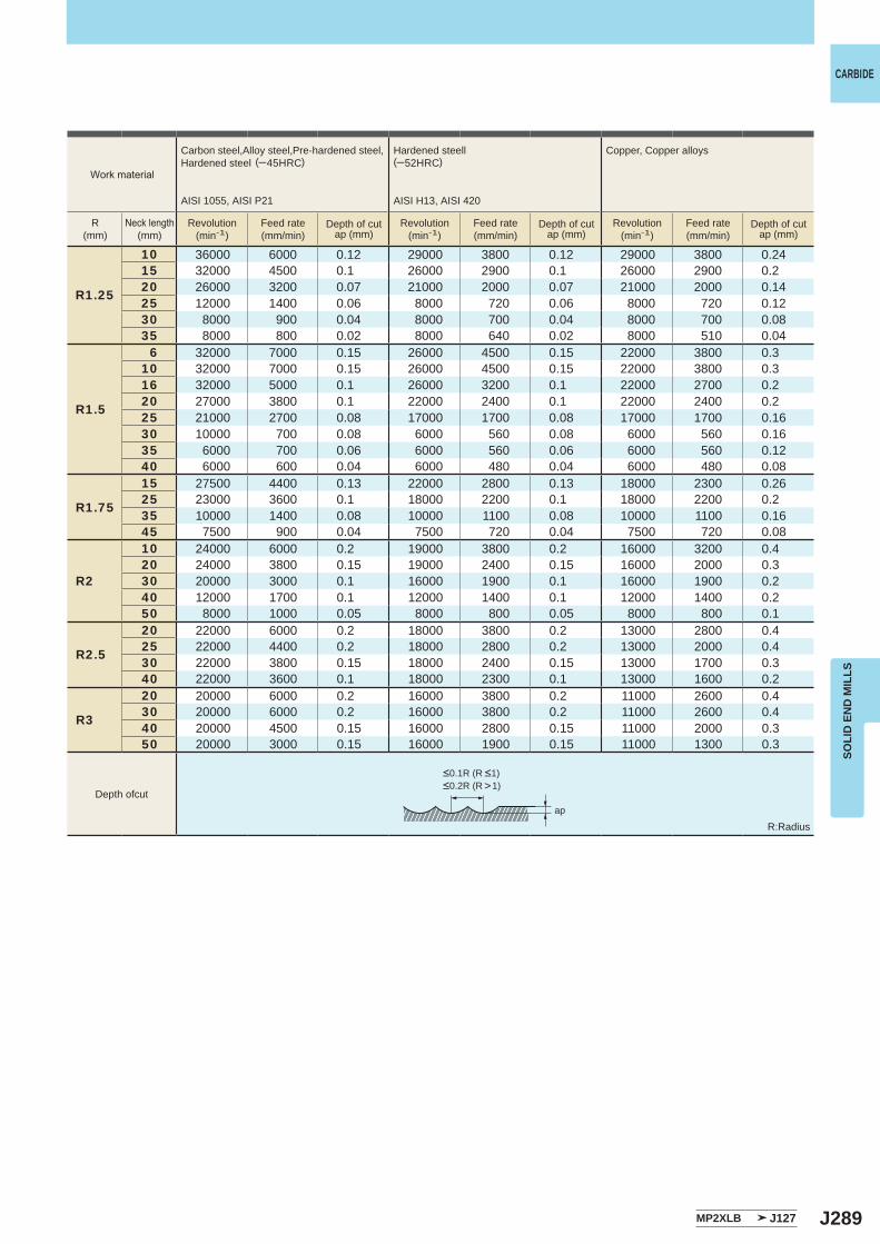
J289
ap
MP2XLB J127
R1.25
10 36000 6000 0.12 29000 3800 0.12 29000 3800 0.2415 32000 4500 0.1 26000 2900 0.1 26000 2900 0.220 26000 3200 0.07 21000 2000 0.07 21000 2000 0.1425 12000 1400 0.06 8000 720 0.06 8000 720 0.1230 8000 900 0.04 8000 700 0.04 8000 700 0.0835 8000 800 0.02 8000 640 0.02 8000 510 0.04
R1.5
6 32000 7000 0.15 26000 4500 0.15 22000 3800 0.310 32000 7000 0.15 26000 4500 0.15 22000 3800 0.316 32000 5000 0.1 26000 3200 0.1 22000 2700 0.220 27000 3800 0.1 22000 2400 0.1 22000 2400 0.225 21000 2700 0.08 17000 1700 0.08 17000 1700 0.1630 10000 700 0.08 6000 560 0.08 6000 560 0.1635 6000 700 0.06 6000 560 0.06 6000 560 0.1240 6000 600 0.04 6000 480 0.04 6000 480 0.08
R1.75
15 27500 4400 0.13 22000 2800 0.13 18000 2300 0.2625 23000 3600 0.1 18000 2200 0.1 18000 2200 0.235 10000 1400 0.08 10000 1100 0.08 10000 1100 0.1645 7500 900 0.04 7500 720 0.04 7500 720 0.08
R2
10 24000 6000 0.2 19000 3800 0.2 16000 3200 0.420 24000 3800 0.15 19000 2400 0.15 16000 2000 0.330 20000 3000 0.1 16000 1900 0.1 16000 1900 0.240 12000 1700 0.1 12000 1400 0.1 12000 1400 0.250 8000 1000 0.05 8000 800 0.05 8000 800 0.1
R2.5
20 22000 6000 0.2 18000 3800 0.2 13000 2800 0.425 22000 4400 0.2 18000 2800 0.2 13000 2000 0.430 22000 3800 0.15 18000 2400 0.15 13000 1700 0.340 22000 3600 0.1 18000 2300 0.1 13000 1600 0.2
R3
20 20000 6000 0.2 16000 3800 0.2 11000 2600 0.430 20000 6000 0.2 16000 3800 0.2 11000 2600 0.440 20000 4500 0.15 16000 2800 0.15 11000 2000 0.350 20000 3000 0.15 16000 1900 0.15 11000 1300 0.3
ap
CARBIDE
SOLI
D E
ND
MIL
LS
Depth ofcut
Work material
Carbon steel,Alloy steel,Pre-hardened steel,Hardened steel (─45HRC)
AISI 1055, AISI P21
Hardened steell(─52HRC)
AISI H13, AISI 420
Copper, Copper alloys
R(mm)
Neck length(mm)
Revolution(min-1)
Feed rate(mm/min)
Depth of cutap (mm)
Revolution(min-1)
Feed rate(mm/min)
Depth of cutap (mm)
Revolution(min-1)
Feed rate(mm/min)
Depth of cutap (mm)
R:Radius
<0.1R (R <1)<0.2R (R >1)
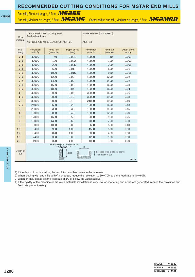
J290
0.1 40000 40 0.001 40000 40 0.0010.2 40000 100 0.002 40000 100 0.0020.3 40000 200 0.005 40000 200 0.0050.4 40000 600 0.01 40000 600 0.010.5 40000 1000 0.015 40000 960 0.0150.6 40000 1200 0.02 40000 1200 0.020.7 40000 1400 0.02 40000 1400 0.020.8 40000 1600 0.03 40000 1600 0.030.9 40000 1800 0.04 40000 1600 0.041 40000 2000 0.06 32000 1600 0.061.5 40000 3000 0.12 32000 1900 0.082 30000 3000 0.18 24000 1900 0.102.5 24000 2600 0.25 19000 1600 0.133 20000 2300 0.30 16000 1400 0.154 15000 2000 0.40 12000 1200 0.205 12000 1600 0.50 9000 900 0.256 10000 1400 0.60 7000 700 0.308 8000 1000 0.80 5600 550 0.40
10 6400 900 1.00 4500 500 0.5012 5400 820 1.00 3800 450 0.5016 2400 380 3.00 1200 100 0.8020 1900 320 4.00 1000 80 1.00
MS2SS J032MS2MS J033MS2MRB J182
D
CARBIDE
SOLI
D E
ND
MIL
LSRECOMMENDED CUTTING CONDITIONS FOR MSTAR END MILLSEnd mill, Short cut length, 2 flute MS2SSEnd mill, Medium cut length, 2 flute MS2MS Corner radius end mill, Medium cut length, 2 flute MS2MRB
1) If the depth of cut is shallow, the revolution and feed rate can be increased.2) When slotting with end mills with &3 or larger, reduce the revolution to 50─70% and the feed rate to 40─60%.3) When drilling, please set the feed rate at 1/3 or below the values above.4) If the rigidity of the machine or the work materials installation is very low, or chattering and noise are generated, reduce the revolution and
feed rate proportionately.
D:Dia.
<Please refer to the list above for depth of cut.
<Please refer to the list above for depth of cut.
Workmaterial
Carbon steel, Cast iron, Alloy steel,Pre-hardened steel
AISI 1050, AISI No 35 B, AISI P20, AISI P21
Hardened steel (45─ 55HRC)
AISI H13
Dia.(mm)
Revolution(min-1)
Feed rate(mm/min)
Depth of cut(mm)
Revolution(min-1)
Feed rate(mm/min)
Depth of cut(mm)
Depth ofcut <1D
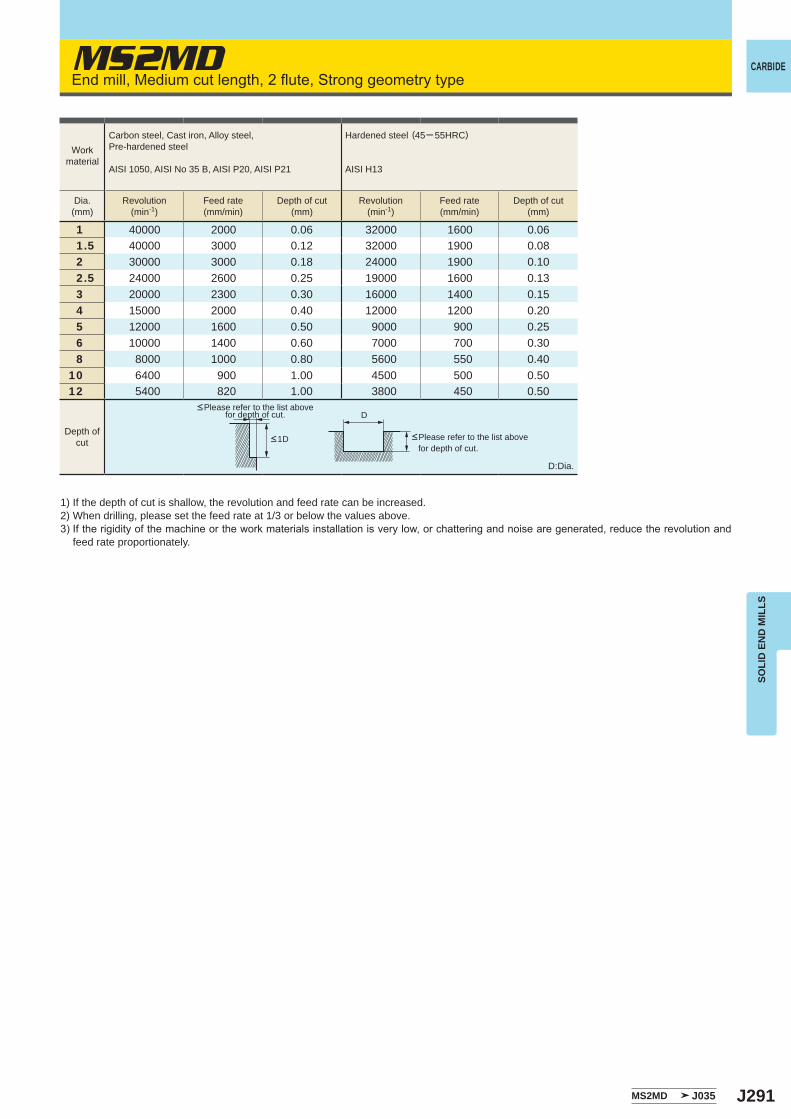
J291
MS2MD
1 40000 2000 0.06 32000 1600 0.061.5 40000 3000 0.12 32000 1900 0.082 30000 3000 0.18 24000 1900 0.102.5 24000 2600 0.25 19000 1600 0.133 20000 2300 0.30 16000 1400 0.154 15000 2000 0.40 12000 1200 0.205 12000 1600 0.50 9000 900 0.256 10000 1400 0.60 7000 700 0.308 8000 1000 0.80 5600 550 0.40
10 6400 900 1.00 4500 500 0.5012 5400 820 1.00 3800 450 0.50
MS2MD J035
D
CARBIDE
SOLI
D E
ND
MIL
LS
End mill, Medium cut length, 2 flute, Strong geometry type
1) If the depth of cut is shallow, the revolution and feed rate can be increased.2) When drilling, please set the feed rate at 1/3 or below the values above.3) If the rigidity of the machine or the work materials installation is very low, or chattering and noise are generated, reduce the revolution and
feed rate proportionately.
D:Dia.
<Please refer to the list above for depth of cut.
<Please refer to the list above for depth of cut.
Workmaterial
Carbon steel, Cast iron, Alloy steel,Pre-hardened steel
AISI 1050, AISI No 35 B, AISI P20, AISI P21
Hardened steel (45─ 55HRC)
AISI H13
Dia.(mm)
Revolution(min-1)
Feed rate(mm/min)
Depth of cut(mm)
Revolution(min-1)
Feed rate(mm/min)
Depth of cut(mm)
Depth ofcut <1D
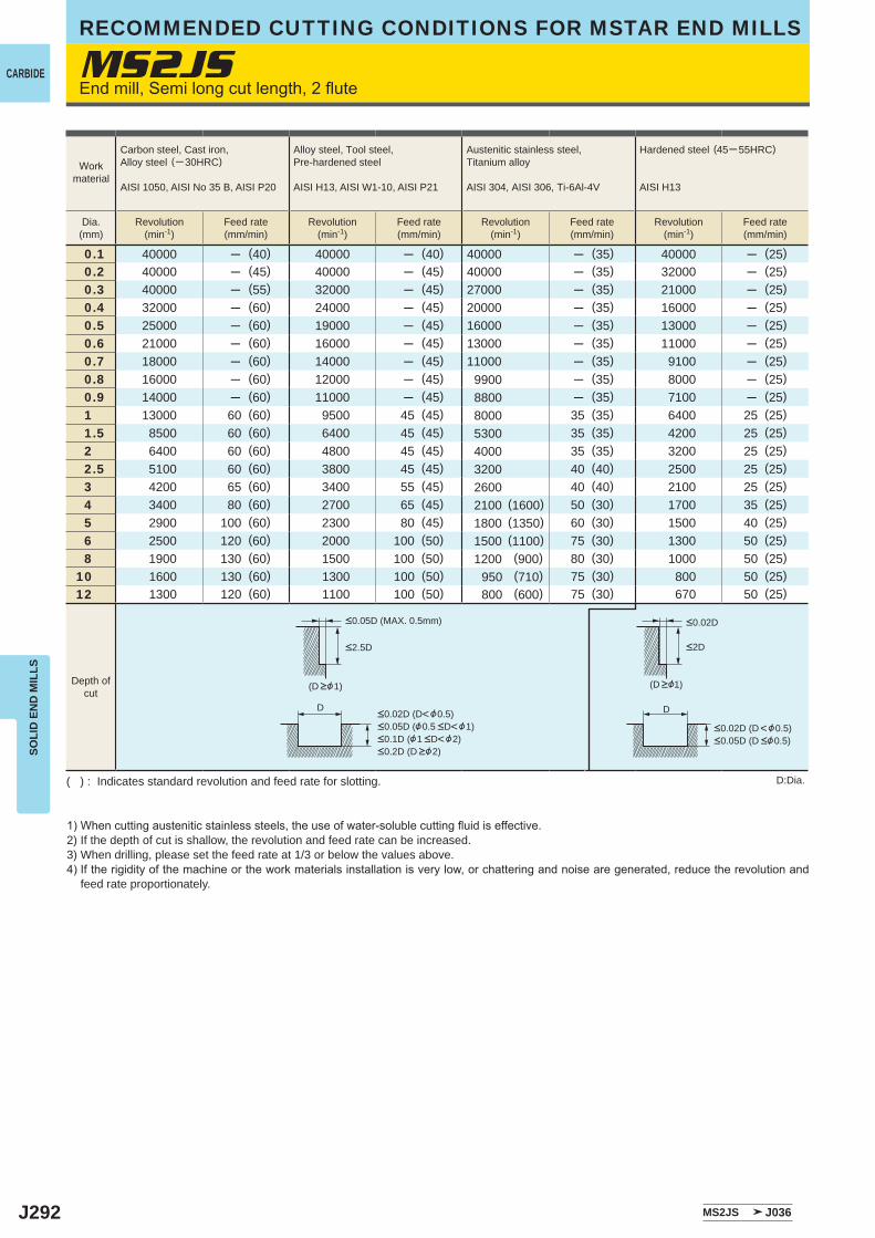
J292
MS2JS
0.1 40000 ─ (40) 40000 ─ (40) 40000 ─ (35) 40000 ─ (25)0.2 40000 ─ (45) 40000 ─ (45) 40000 ─ (35) 32000 ─ (25)0.3 40000 ─ (55) 32000 ─ (45) 27000 ─ (35) 21000 ─ (25)0.4 32000 ─ (60) 24000 ─ (45) 20000 ─ (35) 16000 ─ (25)0.5 25000 ─ (60) 19000 ─ (45) 16000 ─ (35) 13000 ─ (25)0.6 21000 ─ (60) 16000 ─ (45) 13000 ─ (35) 11000 ─ (25)0.7 18000 ─ (60) 14000 ─ (45) 11000 ─ (35) 9100 ─ (25)0.8 16000 ─ (60) 12000 ─ (45) 9900 ─ (35) 8000 ─ (25)0.9 14000 ─ (60) 11000 ─ (45) 8800 ─ (35) 7100 ─ (25)1 13000 60 (60) 9500 45 (45) 8000 35 (35) 6400 25 (25)1.5 8500 60 (60) 6400 45 (45) 5300 35 (35) 4200 25 (25)2 6400 60 (60) 4800 45 (45) 4000 35 (35) 3200 25 (25)2.5 5100 60 (60) 3800 45 (45) 3200 40 (40) 2500 25 (25)3 4200 65 (60) 3400 55 (45) 2600 40 (40) 2100 25 (25)4 3400 80 (60) 2700 65 (45) 2100 (1600) 50 (30) 1700 35 (25)5 2900 100 (60) 2300 80 (45) 1800 (1350) 60 (30) 1500 40 (25)6 2500 120 (60) 2000 100 (50) 1500 (1100) 75 (30) 1300 50 (25)8 1900 130 (60) 1500 100 (50) 1200 (900) 80 (30) 1000 50 (25)
10 1600 130 (60) 1300 100 (50) 950 (710) 75 (30) 800 50 (25)12 1300 120 (60) 1100 100 (50) 800 (600) 75 (30) 670 50 (25)
MS2JS J036
D D
CARBIDE
SOLI
D E
ND
MIL
LSRECOMMENDED CUTTING CONDITIONS FOR MSTAR END MILLS
End mill, Semi long cut length, 2 flute
1) When cutting austenitic stainless steels, the use of water-soluble cutting fluid is effective.2) If the depth of cut is shallow, the revolution and feed rate can be increased.3) When drilling, please set the feed rate at 1/3 or below the values above.4) If the rigidity of the machine or the work materials installation is very low, or chattering and noise are generated, reduce the revolution and
feed rate proportionately.
D:Dia.( ) : Indicates standard revolution and feed rate for slotting.
Workmaterial
Carbon steel, Cast iron, Alloy steel (─ 30HRC)
AISI 1050, AISI No 35 B, AISI P20
Alloy steel, Tool steel,Pre-hardened steel
AISI H13, AISI W1-10, AISI P21
Austenitic stainless steel,Titanium alloy
AISI 304, AISI 306, Ti-6Al-4V
Hardened steel (45─ 55HRC)
AISI H13
Dia.(mm)
Revolution(min-1)
Feed rate(mm/min)
Revolution(min-1)
Feed rate(mm/min)
Revolution(min-1)
Feed rate(mm/min)
Revolution(min-1)
Feed rate(mm/min)
Depth ofcut
<0.05D (MAX. 0.5mm)
<2.5D
<0.02D (D<&0.5)<0.05D (&0.5 <D<&1)<0.1D (&1 <D<&2)<0.2D (D >&2)
<0.02D (D <&0.5)<0.05D (D <&0.5)
<2D
<0.02D
(D >&1) (D >&1)
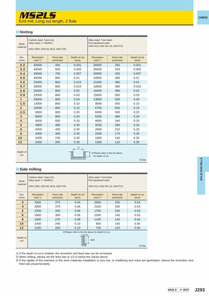
J293
MS2LS
0.2 40000 400 0.001 30000 250 0.0010.3 40000 600 0.005 35000 420 0.0050.4 40000 700 0.007 30000 420 0.0070.5 40000 800 0.01 24000 380 0.010.6 33000 800 0.015 21000 480 0.010.7 28000 800 0.015 18000 480 0.0150.8 25000 800 0.02 16000 480 0.020.9 22000 800 0.03 15000 500 0.031 20000 800 0.04 13000 500 0.041.5 13000 800 0.10 9000 500 0.102 10000 800 0.15 6700 500 0.152.5 9000 800 0.20 6000 500 0.203 8000 800 0.20 5200 460 0.204 6000 600 0.20 4000 340 0.205 4800 480 0.30 3200 280 0.206 4000 400 0.30 2600 210 0.208 3000 300 0.30 2000 170 0.30
10 2400 240 0.30 1600 140 0.3012 2000 200 0.30 1300 110 0.30
3 3500 370 0.05 2600 250 0.034 2800 370 0.06 2100 200 0.035 2200 330 0.06 1700 160 0.036 1800 300 0.06 1500 140 0.038 1600 270 0.08 1100 140 0.04
10 1400 240 0.10 900 140 0.0512 1200 200 0.10 750 120 0.06
MS2LS J037
D
y
y
CARBIDE
SOLI
D E
ND
MIL
LS
End mill, Long cut length, 2 flute
1) If the depth of cut is shallow, the revolution and feed rate can be increased.2) When drilling, please set the feed rate at 1/3 or below the values above.3) If the rigidity of the machine or the work materials installation is very low, or chattering and noise are generated, reduce the revolution and
feed rate proportionately.
D:Dia.
D:Dia.
<Please refer to the list above for depth of cut.
<Please refer to the list above for depth of cut.
Slotting
Side milling
Workmaterial
Carbon steel, Cast iron, Alloy steel (─ 30HRC)
AISI 1050, AISI No 35 B, AISI P20
Alloy steel, Tool steel,Pre-hardened steelAISI H13, AISI W1-10, AISI P21
Dia.(mm)
Revolution(min-1)
Feed rate(mm/min)
Depth of cut(mm)
Revolution(min-1)
Feed rate(mm/min)
Depth of cut(mm)
Depth ofcut
Workmaterial
Carbon steel, Cast iron, Alloy steel (─ 30HRC)
AISI 1050, AISI No 35 B, AISI P20
Alloy steel, Tool steel,Pre-hardened steel
AISI H13, AISI W1-10, AISI P21
Dia.(mm)
Revolution(min-1)
Feed rate(mm/min)
Depth of cut(mm)
Revolution(min-1)
Feed rate(mm/min)
Depth of cut(mm)
Depth ofcut <3D
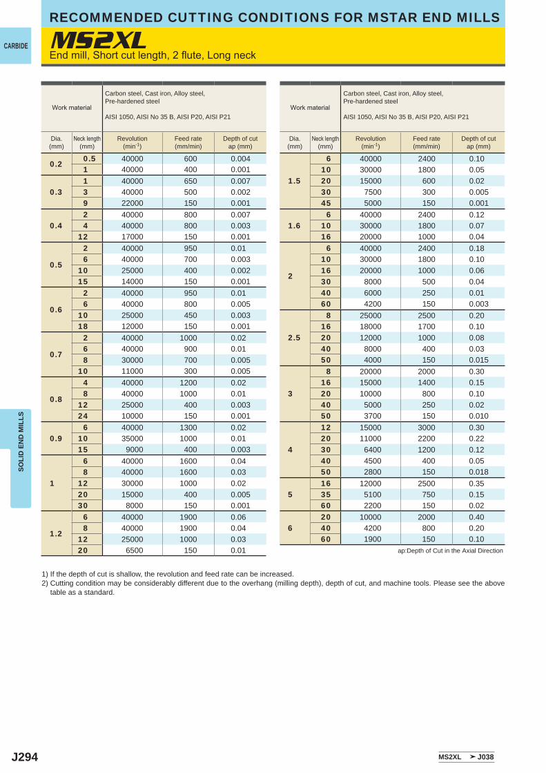
J294
MS2XL
0.20.5 40000 600 0.0041 40000 400 0.001
0.31 40000 650 0.0073 40000 500 0.0029 22000 150 0.001
0.42 40000 800 0.0074 40000 800 0.003
12 17000 150 0.001
0.5
2 40000 950 0.016 40000 700 0.003
10 25000 400 0.00215 14000 150 0.001
0.6
2 40000 950 0.016 40000 800 0.005
10 25000 450 0.00318 12000 150 0.001
0.7
2 40000 1000 0.026 40000 900 0.018 30000 700 0.005
10 11000 300 0.005
0.8
4 40000 1200 0.028 40000 1000 0.01
12 25000 400 0.00324 10000 150 0.001
0.96 40000 1300 0.02
10 35000 1000 0.0115 9000 400 0.003
1
6 40000 1600 0.048 40000 1600 0.03
12 30000 1000 0.0220 15000 400 0.00530 8000 150 0.001
1.2
6 40000 1900 0.068 40000 1900 0.04
12 25000 1000 0.0320 6500 150 0.01
1.5
6 40000 2400 0.1010 30000 1800 0.0520 15000 600 0.0230 7500 300 0.00545 5000 150 0.001
1.66 40000 2400 0.12
10 30000 1800 0.0716 20000 1000 0.04
2
6 40000 2400 0.1810 30000 1800 0.1016 20000 1000 0.0630 8000 500 0.0440 6000 250 0.0160 4200 150 0.003
2.5
8 25000 2500 0.2016 18000 1700 0.1020 12000 1000 0.0840 8000 400 0.0350 4000 150 0.015
3
8 20000 2000 0.3016 15000 1400 0.1520 10000 800 0.1040 5000 250 0.0250 3700 150 0.010
4
12 15000 3000 0.3020 11000 2200 0.2230 6400 1200 0.1240 4500 400 0.0550 2800 150 0.018
516 12000 2500 0.3535 5100 750 0.1560 2200 150 0.02
620 10000 2000 0.4040 4200 800 0.2060 1900 150 0.10
MS2XL J038
CARBIDE
SOLI
D E
ND
MIL
LSRECOMMENDED CUTTING CONDITIONS FOR MSTAR END MILLS
End mill, Short cut length, 2 flute, Long neck
1) If the depth of cut is shallow, the revolution and feed rate can be increased.2) Cutting condition may be considerably different due to the overhang (milling depth), depth of cut, and machine tools. Please see the above
table as a standard.
ap:Depth of Cut in the Axial Direction
Work material
Carbon steel, Cast iron, Alloy steel,Pre-hardened steel
AISI 1050, AISI No 35 B, AISI P20, AISI P21
Dia.(mm)
Neck length(mm)
Revolution(min-1)
Feed rate(mm/min)
Depth of cutap (mm)
Work material
Carbon steel, Cast iron, Alloy steel,Pre-hardened steel
AISI 1050, AISI No 35 B, AISI P20, AISI P21
Dia.(mm)
Neck length(mm)
Revolution(min-1)
Feed rate(mm/min)
Depth of cutap (mm)
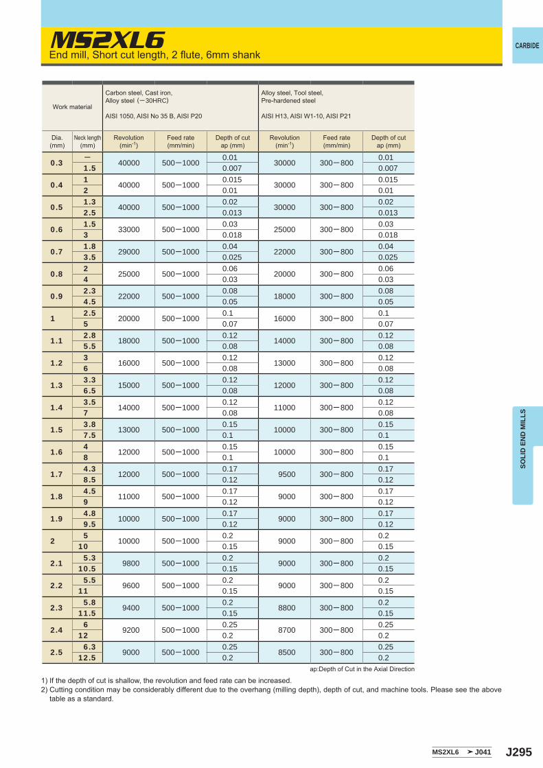
J295
MS2XL6
0.3─
40000 500─10000.01
30000 300─ 8000.01
1.5 0.007 0.007
0.41
40000 500─10000.015
30000 300─ 8000.015
2 0.01 0.01
0.51.3
40000 500─10000.02
30000 300─ 8000.02
2.5 0.013 0.013
0.61.5
33000 500─10000.03
25000 300─ 8000.03
3 0.018 0.018
0.71.8
29000 500─10000.04
22000 300─ 8000.04
3.5 0.025 0.025
0.82
25000 500─10000.06
20000 300─ 8000.06
4 0.03 0.03
0.92.3
22000 500─10000.08
18000 300─ 8000.08
4.5 0.05 0.05
12.5
20000 500─10000.1
16000 300─ 8000.1
5 0.07 0.07
1.12.8
18000 500─10000.12
14000 300─ 8000.12
5.5 0.08 0.08
1.23
16000 500─10000.12
13000 300─ 8000.12
6 0.08 0.08
1.33.3
15000 500─10000.12
12000 300─ 8000.12
6.5 0.08 0.08
1.43.5
14000 500─10000.12
11000 300─ 8000.12
7 0.08 0.08
1.53.8
13000 500─10000.15
10000 300─ 8000.15
7.5 0.1 0.1
1.64
12000 500─10000.15
10000 300─ 8000.15
8 0.1 0.1
1.74.3
12000 500─10000.17
9500 300─ 8000.17
8.5 0.12 0.12
1.84.5
11000 500─10000.17
9000 300─ 8000.17
9 0.12 0.12
1.94.8
10000 500─10000.17
9000 300─ 8000.17
9.5 0.12 0.12
25
10000 500─10000.2
9000 300─ 8000.2
10 0.15 0.15
2.15.3
9800 500─10000.2
9000 300─ 8000.2
10.5 0.15 0.15
2.25.5
9600 500─10000.2
9000 300─ 8000.2
11 0.15 0.15
2.35.8
9400 500─10000.2
8800 300─ 8000.2
11.5 0.15 0.15
2.46
9200 500─10000.25
8700 300─ 8000.25
12 0.2 0.2
2.56.3
9000 500─10000.25
8500 300─ 8000.25
12.5 0.2 0.2
MS2XL6 J041
CARBIDE
SOLI
D E
ND
MIL
LS
End mill, Short cut length, 2 flute, 6mm shank
1) If the depth of cut is shallow, the revolution and feed rate can be increased.2) Cutting condition may be considerably different due to the overhang (milling depth), depth of cut, and machine tools. Please see the above
table as a standard.
ap:Depth of Cut in the Axial Direction
Work material
Carbon steel, Cast iron, Alloy steel (─ 30HRC)
AISI 1050, AISI No 35 B, AISI P20
Alloy steel, Tool steel,Pre-hardened steel
AISI H13, AISI W1-10, AISI P21
Dia.(mm)
Neck length(mm)
Revolution(min-1)
Feed rate(mm/min)
Depth of cutap (mm)
Revolution(min-1)
Feed rate(mm/min)
Depth of cutap (mm)
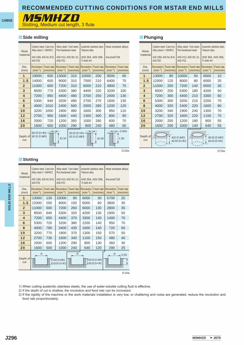
J296
MSMHZD
1 19000 600 13000 310 10000 200 9500 651.5 14000 600 9000 310 7500 210 6400 752 11000 600 7200 310 6000 210 4800 753 8500 770 5300 380 4400 220 3200 1004 7200 850 4400 480 3700 250 2400 1306 5300 940 3200 490 2700 270 1600 1308 4000 1010 2400 560 2000 280 1200 120
10 3200 1000 1900 480 1600 300 950 11012 2700 950 1600 440 1300 300 800 9016 2000 720 1200 350 1000 260 600 7020 1600 600 1000 290 800 240 480 60
1 13000 130 10000 80 6000 30 5700 251.5 12000 250 8000 150 6000 60 3800 302 11000 500 7200 260 6000 130 2800 353 8500 640 5300 320 4200 130 1900 504 7200 650 4400 370 3300 140 1400 706 5300 720 3200 380 2200 140 950 708 4000 780 2400 430 1600 140 720 60
10 3200 770 1900 370 1300 150 570 5012 2700 730 1600 340 1100 150 480 4016 2000 600 1200 290 800 130 360 3020 1600 500 1000 240 640 120 290 25
1 13000 80 10000 50 6000 101.5 12000 120 8000 80 6000 202 11000 200 7200 140 6000 303 8500 250 5300 180 4200 504 7200 300 4400 210 3300 606 5300 300 3200 210 2200 708 4000 320 2400 220 1600 80
10 3200 340 1900 240 1300 7012 2700 320 1600 220 1100 7016 2000 250 1200 180 800 5520 1600 200 1000 140 640 55
MSMHZD J070
0.05D
1.5D
0.2DDDD
y
y y
CARBIDE
SOLI
D E
ND
MIL
LSRECOMMENDED CUTTING CONDITIONS FOR MSTAR END MILLS
Slotting, Medium cut length, 3 flute
1) When cutting austenitic stainless steels, the use of water-soluble cutting fluid is effective.2) If the depth of cut is shallow, the revolution and feed rate can be increased.3) If the rigidity of the machine or the work materials installation is very low, or chattering and noise are generated, reduce the revolution and
feed rate proportionately.
D:Dia.
D:Dia.
D:Dia.
Slotting
Side milling Plunging
Workmaterial
Carbon steel, Cast iron, Alloy steel (─ 30HRC)
AISI 1050, AISI No 35 B,AISI P20
Alloy steel, Tool steel,Pre-hardened steel
AISI H13, AISI W1-10, AISI P21
Austenitic stainless steel,Titanium alloy
AISI 304, AISI 306, Ti-6Al-4V
Heat resistant alloys
Inconel718
Dia.(mm)
Revolution(min-1)
Feed rate(mm/min)
Revolution(min-1)
Feed rate(mm/min)
Revolution(min-1)
Feed rate(mm/min)
Revolution(min-1)
Feed rate(mm/min)
Workmaterial
Carbon steel, Cast iron, Alloy steel (─ 30HRC)
AISI 1050, AISI No 35 B,AISI P20
Alloy steel, Tool steel,Pre-hardened steel
AISI H13, AISI W1-10, AISI P21
Austenitic stainless steel,Titanium alloy
AISI 304, AISI 306, Ti-6Al-4V
Dia.(mm)
Revolution(min-1)
Feed rate(mm/min)
Revolution(min-1)
Feed rate(mm/min)
Revolution(min-1)
Feed rate(mm/min)
<0.2D (D>&3)<0.1D (D <&3)
<0.2D (D>&3)<0.1D (D <&3)
<1.5D <1.5DDepth of
cutDepth of
cut<1D (D >&2)<0.5D (D<&2)
<0.5D (D >&2)<0.2D (D<&2)
Workmaterial
Carbon steel, Cast iron, Alloy steel (─ 30HRC)
AISI 1050, AISI No 35 B,AISI P20
Alloy steel, Tool steel,Pre-hardened steel
AISI H13, AISI W1-10, AISI P21
Austenitic stainless steel,Titanium alloy
AISI 304, AISI 306, Ti-6Al-4V
Heat resistant alloys
Inconel718
Dia.(mm)
Revolution(min-1)
Feed rate(mm/min)
Revolution(min-1)
Feed rate(mm/min)
Revolution(min-1)
Feed rate(mm/min)
Revolution(min-1)
Feed rate(mm/min)
<1D (D >&2)<0.5D (D<&2)
<0.5D (D >&2)<0.2D (D<&2)
Depth ofcut
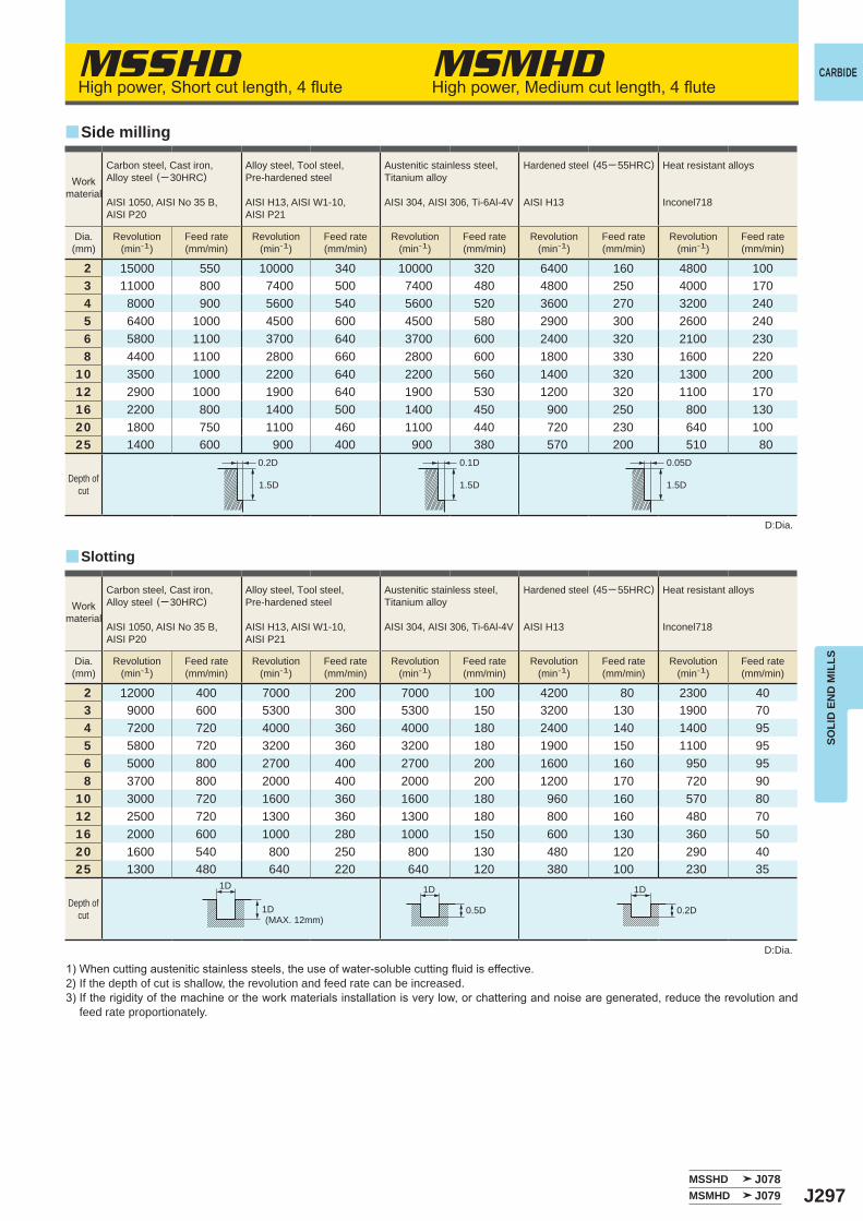
J297
MSSHD MSMHD
MSSHD J078MSMHD J079
2 15000 550 10000 340 10000 320 6400 160 4800 1003 11000 800 7400 500 7400 480 4800 250 4000 1704 8000 900 5600 540 5600 520 3600 270 3200 2405 6400 1000 4500 600 4500 580 2900 300 2600 2406 5800 1100 3700 640 3700 600 2400 320 2100 2308 4400 1100 2800 660 2800 600 1800 330 1600 220
10 3500 1000 2200 640 2200 560 1400 320 1300 20012 2900 1000 1900 640 1900 530 1200 320 1100 17016 2200 800 1400 500 1400 450 900 250 800 13020 1800 750 1100 460 1100 440 720 230 640 10025 1400 600 900 400 900 380 570 200 510 80
2 12000 400 7000 200 7000 100 4200 80 2300 403 9000 600 5300 300 5300 150 3200 130 1900 704 7200 720 4000 360 4000 180 2400 140 1400 955 5800 720 3200 360 3200 180 1900 150 1100 956 5000 800 2700 400 2700 200 1600 160 950 958 3700 800 2000 400 2000 200 1200 170 720 90
10 3000 720 1600 360 1600 180 960 160 570 8012 2500 720 1300 360 1300 180 800 160 480 7016 2000 600 1000 280 1000 150 600 130 360 5020 1600 540 800 250 800 130 480 120 290 4025 1300 480 640 220 640 120 380 100 230 35
0.2D 0.1D 0.05D
1.5D 1.5D 1.5D
1D 1D 1D
1D 0.5D 0.2D
y
y
CARBIDE
SOLI
D E
ND
MIL
LS
High power, Short cut length, 4 flute High power, Medium cut length, 4 flute
1) When cutting austenitic stainless steels, the use of water-soluble cutting fluid is effective.2) If the depth of cut is shallow, the revolution and feed rate can be increased.3) If the rigidity of the machine or the work materials installation is very low, or chattering and noise are generated, reduce the revolution and
feed rate proportionately.
D:Dia.
D:Dia.
Slotting
Side milling
Workmaterial
Carbon steel, Cast iron, Alloy steel (─ 30HRC)
AISI 1050, AISI No 35 B,AISI P20
Alloy steel, Tool steel,Pre-hardened steel
AISI H13, AISI W1-10, AISI P21
Austenitic stainless steel,Titanium alloy
AISI 304, AISI 306, Ti-6Al-4V
Hardened steel (45─ 55HRC)
AISI H13
Heat resistant alloys
Inconel718
Dia.(mm)
Revolution(min-1)
Feed rate(mm/min)
Revolution(min-1)
Feed rate(mm/min)
Revolution(min-1)
Feed rate(mm/min)
Revolution(min-1)
Feed rate(mm/min)
Revolution(min-1)
Feed rate(mm/min)
Depth ofcut
Workmaterial
Carbon steel, Cast iron, Alloy steel (─ 30HRC)
AISI 1050, AISI No 35 B,AISI P20
Alloy steel, Tool steel,Pre-hardened steel
AISI H13, AISI W1-10, AISI P21
Austenitic stainless steel,Titanium alloy
AISI 304, AISI 306, Ti-6Al-4V
Hardened steel (45─ 55HRC)
AISI H13
Heat resistant alloys
Inconel718
Dia.(mm)
Revolution(min-1)
Feed rate(mm/min)
Revolution(min-1)
Feed rate(mm/min)
Revolution(min-1)
Feed rate(mm/min)
Revolution(min-1)
Feed rate(mm/min)
Revolution(min-1)
Feed rate(mm/min)
(MAX. 12mm)
Depth ofcut
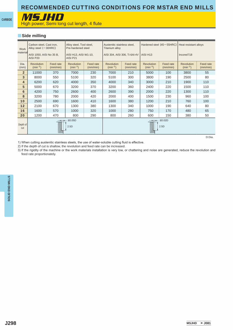
J298
MSJHD
2 11000 370 7000 230 7000 210 5000 100 3800 553 8000 550 5100 320 5100 300 3800 190 2500 804 6200 620 4000 350 4000 340 3000 210 1900 1105 5000 670 3200 370 3200 360 2400 220 1500 1106 4200 750 2600 400 2600 390 2000 220 1300 1108 3200 780 2000 420 2000 400 1500 230 960 100
10 2500 690 1600 410 1600 380 1200 210 760 10012 2100 670 1300 380 1300 340 1000 190 640 8016 1600 570 1000 320 1000 280 750 170 480 6520 1200 470 800 290 800 260 600 150 380 50
MSJHD J081
2.5D 2.5D
y
CARBIDE
SOLI
D E
ND
MIL
LSRECOMMENDED CUTTING CONDITIONS FOR MSTAR END MILLS
High power, Semi long cut length, 4 flute
1) When cutting austenitic stainless steels, the use of water-soluble cutting fluid is effective.2) If the depth of cut is shallow, the revolution and feed rate can be increased.3) If the rigidity of the machine or the work materials installation is very low, or chattering and noise are generated, reduce the revolution and
feed rate proportionately.
D:Dia.
Side milling
Workmaterial
Carbon steel, Cast iron, Alloy steel (─ 30HRC)
AISI 1050, AISI No 35 B,AISI P20
Alloy steel, Tool steel,Pre-hardened steel
AISI H13, AISI W1-10, AISI P21
Austenitic stainless steel,Titanium alloy
AISI 304, AISI 306, Ti-6Al-4V
Hardened steel (45─ 55HRC)
AISI H13
Heat resistant alloys
Inconel718
Dia.(mm)
Revolution(min-1)
Feed rate(mm/min)
Revolution(min-1)
Feed rate(mm/min)
Revolution(min-1)
Feed rate(mm/min)
Revolution(min-1)
Feed rate(mm/min)
Revolution(min-1)
Feed rate(mm/min)
Depth ofcut
<0.05D <0.02D
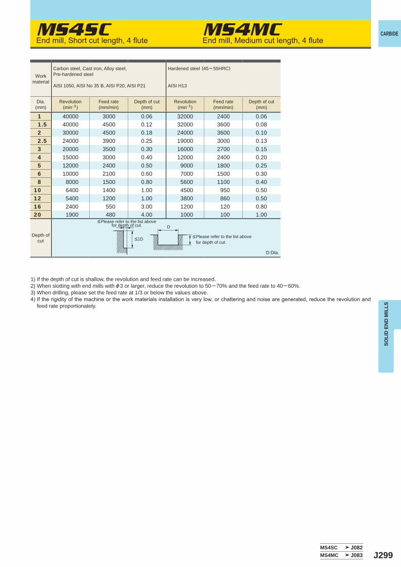
J299
MS4SC MS4MC
1 40000 3000 0.06 32000 2400 0.061.5 40000 4500 0.12 32000 3600 0.082 30000 4500 0.18 24000 3600 0.102.5 24000 3900 0.25 19000 3000 0.133 20000 3500 0.30 16000 2700 0.154 15000 3000 0.40 12000 2400 0.205 12000 2400 0.50 9000 1800 0.256 10000 2100 0.60 7000 1500 0.308 8000 1500 0.80 5600 1100 0.40
10 6400 1400 1.00 4500 950 0.5012 5400 1200 1.00 3800 860 0.5016 2400 550 3.00 1200 120 0.8020 1900 480 4.00 1000 100 1.00
MS4SC J082MS4MC J083
D
CARBIDE
SOLI
D E
ND
MIL
LS
End mill, Short cut length, 4 flute End mill, Medium cut length, 4 flute
1) If the depth of cut is shallow, the revolution and feed rate can be increased.2) When slotting with end mills with &3 or larger, reduce the revolution to 50─70% and the feed rate to 40─60%.3) When drilling, please set the feed rate at 1/3 or below the values above.4) If the rigidity of the machine or the work materials installation is very low, or chattering and noise are generated, reduce the revolution and
feed rate proportionately.
D:Dia.
<Please refer to the list above for depth of cut.
<Please refer to the list above for depth of cut.
Workmaterial
Carbon steel, Cast iron, Alloy steel,Pre-hardened steel
AISI 1050, AISI No 35 B, AISI P20, AISI P21
Hardened steel (45─ 55HRC)
AISI H13
Dia.(mm)
Revolution(min-1)
Feed rate(mm/min)
Depth of cut(mm)
Revolution(min-1)
Feed rate(mm/min)
Depth of cut(mm)
Depth ofcut <1D
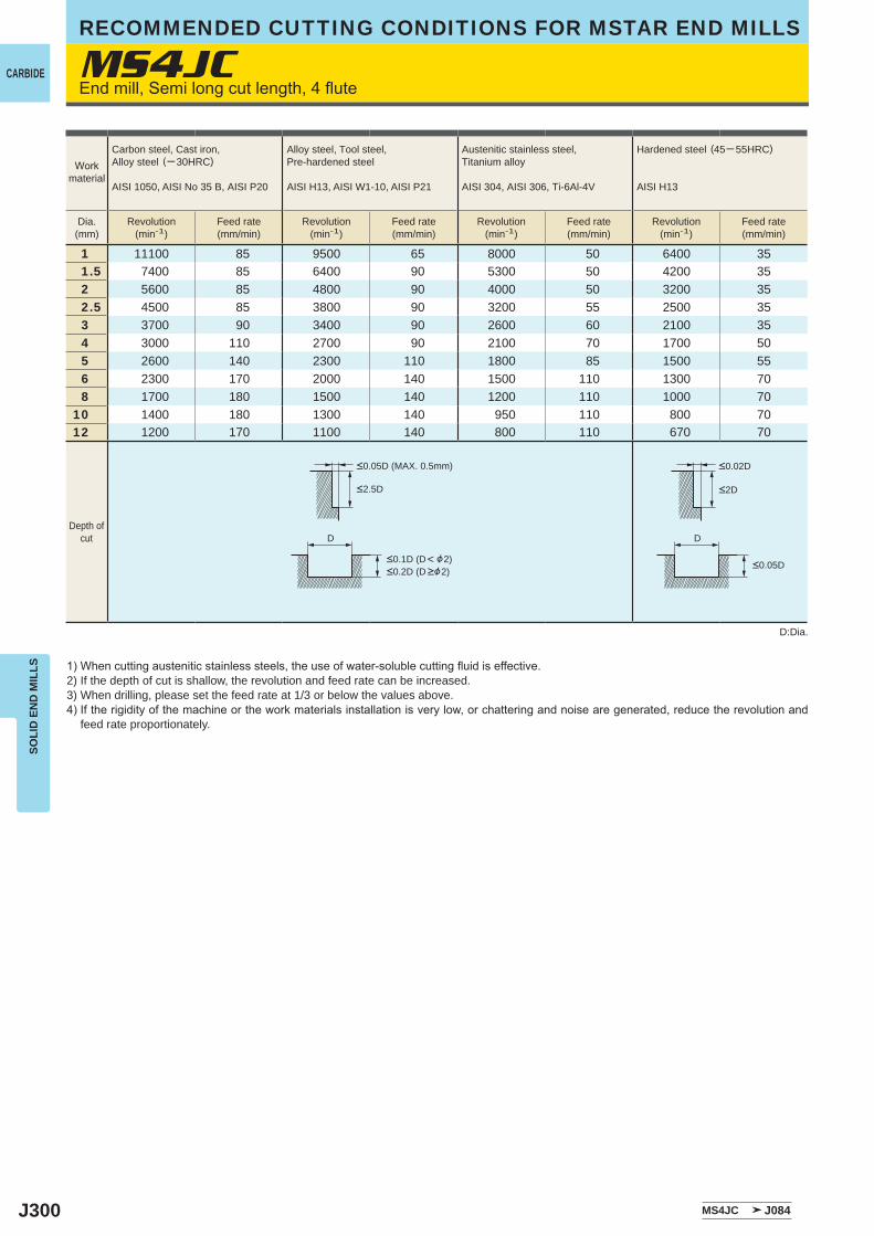
J300
MS4JC
1 11100 85 9500 65 8000 50 6400 351.5 7400 85 6400 90 5300 50 4200 352 5600 85 4800 90 4000 50 3200 352.5 4500 85 3800 90 3200 55 2500 353 3700 90 3400 90 2600 60 2100 354 3000 110 2700 90 2100 70 1700 505 2600 140 2300 110 1800 85 1500 556 2300 170 2000 140 1500 110 1300 708 1700 180 1500 140 1200 110 1000 70
10 1400 180 1300 140 950 110 800 7012 1200 170 1100 140 800 110 670 70
MS4JC J084
D D
CARBIDE
SOLI
D E
ND
MIL
LSRECOMMENDED CUTTING CONDITIONS FOR MSTAR END MILLS
End mill, Semi long cut length, 4 flute
1) When cutting austenitic stainless steels, the use of water-soluble cutting fluid is effective.2) If the depth of cut is shallow, the revolution and feed rate can be increased.3) When drilling, please set the feed rate at 1/3 or below the values above.4) If the rigidity of the machine or the work materials installation is very low, or chattering and noise are generated, reduce the revolution and
feed rate proportionately.
D:Dia.
Workmaterial
Carbon steel, Cast iron, Alloy steel (─ 30HRC)
AISI 1050, AISI No 35 B, AISI P20
Alloy steel, Tool steel,Pre-hardened steel
AISI H13, AISI W1-10, AISI P21
Austenitic stainless steel,Titanium alloy
AISI 304, AISI 306, Ti-6Al-4V
Hardened steel (45─ 55HRC)
AISI H13
Dia.(mm)
Revolution(min-1)
Feed rate(mm/min)
Revolution(min-1)
Feed rate(mm/min)
Revolution(min-1)
Feed rate(mm/min)
Revolution(min-1)
Feed rate(mm/min)
<2.5D
<0.05D (MAX. 0.5mm)
<0.1D (D< &2)<0.2D (D >&2)
<2D
<0.02D
<0.05D
Depth ofcut
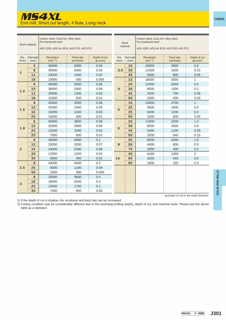
J301
MS4XL
1
4 40000 3000 0.048 36000 2400 0.03
12 20000 1000 0.0216 10000 500 0.005
1.2
6 40000 3000 0.0510 36000 2400 0.0412 20000 1200 0.0316 12000 600 0.01
1.5
6 40000 3200 0.0612 32000 2400 0.0516 16000 1100 0.0320 10000 600 0.01
1.8
6 40000 3600 0.0812 32000 2800 0.0620 12000 1000 0.0225 7000 600 0.01
2
6 40000 4000 0.112 32000 3200 0.0716 24000 2400 0.0520 12000 1200 0.0330 5000 500 0.01
2.58 32000 4000 0.2
25 9000 1100 0.0450 2500 300 0.005
3
8 25000 3600 0.416 18000 2500 0.225 12000 1700 0.130 7000 800 0.05
3.515 20000 3000 0.625 11000 1600 0.1535 5500 800 0.06
4
12 18000 3000 120 12000 2000 0.530 8000 1300 0.240 4200 700 0.0850 2400 400 0.03
5
16 14000 2700 125 9500 1800 0.535 6400 1200 0.250 3200 600 0.05
6
20 11000 2200 1.230 8000 1600 0.640 5400 1100 0.2550 3200 640 0.15
830 8000 1600 1.650 4000 800 0.570 2000 400 0.2
1040 6400 1300 260 3200 640 0.680 1600 320 0.3
MS4XL J085
CARBIDE
SOLI
D E
ND
MIL
LS
End mill, Short cut length, 4 flute, Long neck
1) If the depth of cut is shallow, the revolution and feed rate can be increased.2) Cutting condition may be considerably different due to the overhang (milling depth), depth of cut, and machine tools. Please see the above
table as a standard.
ap:Depth of Cut in the Axial Direction
Workmaterial
Carbon steel, Cast iron, Alloy steel,Pre-hardened steel
AISI 1050, AISI No 35 B, AISI P20, AISI P21
Dia.(mm)
Neck length(mm)
Revolution(min-1)
Feed rate(mm/min)
Depth of cutap (mm)
Work material
Carbon steel, Cast iron, Alloy steel,Pre-hardened steel
AISI 1050, AISI No 35 B, AISI P20, AISI P21
Dia.(mm)
Neck length(mm)
Revolution(min-1)
Feed rate(mm/min)
Depth of cutap (mm)
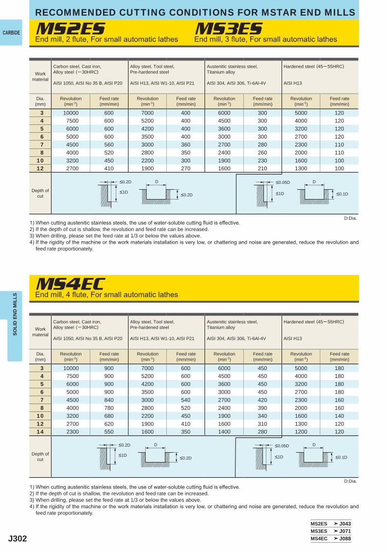
J302
MS2ES
MS4EC
MS3ES
3 10000 600 7000 400 6000 300 5000 1204 7500 600 5200 400 4500 300 4000 1205 6000 600 4200 400 3600 300 3200 1206 5000 600 3500 400 3000 300 2700 1207 4500 560 3000 360 2700 280 2300 1108 4000 520 2800 350 2400 260 2000 110
10 3200 450 2200 300 1900 230 1600 10012 2700 410 1900 270 1600 210 1300 100
3 10000 900 7000 600 6000 450 5000 1804 7500 900 5200 600 4500 450 4000 1805 6000 900 4200 600 3600 450 3200 1806 5000 900 3500 600 3000 450 2700 1807 4500 840 3000 540 2700 420 2300 1608 4000 780 2800 520 2400 390 2000 160
10 3200 680 2200 450 1900 340 1600 14012 2700 620 1900 410 1600 310 1300 12014 2300 550 1600 350 1400 280 1200 120
MS2ES J043MS3ES J071MS4EC J088
D D
D D
CARBIDE
SOLI
D E
ND
MIL
LSRECOMMENDED CUTTING CONDITIONS FOR MSTAR END MILLS
End mill, 2 flute, For small automatic lathes
End mill, 4 flute, For small automatic lathes
End mill, 3 flute, For small automatic lathes
1) When cutting austenitic stainless steels, the use of water-soluble cutting fluid is effective.2) If the depth of cut is shallow, the revolution and feed rate can be increased.3) When drilling, please set the feed rate at 1/3 or below the values above.4) If the rigidity of the machine or the work materials installation is very low, or chattering and noise are generated, reduce the revolution and
feed rate proportionately.
D:Dia.
D:Dia.
Workmaterial
Carbon steel, Cast iron, Alloy steel (─ 30HRC)
AISI 1050, AISI No 35 B, AISI P20
Alloy steel, Tool steel,Pre-hardened steel
AISI H13, AISI W1-10, AISI P21
Austenitic stainless steel,Titanium alloy
AISI 304, AISI 306, Ti-6Al-4V
Hardened steel (45─ 55HRC)
AISI H13
Dia.(mm)
Revolution(min-1)
Feed rate(mm/min)
Revolution(min-1)
Feed rate(mm/min)
Revolution(min-1)
Feed rate(mm/min)
Revolution(min-1)
Feed rate(mm/min)
Depth ofcut
<0.2D <0.05D
<1D <1D<0.2D <0.1D
Depth ofcut
<0.2D <0.05D
<1D <1D<0.2D <0.1D
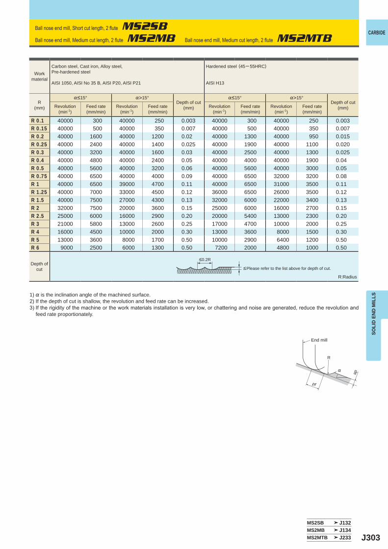
J303
%>15° %>15°
R 0.1 40000 300 40000 250 0.003 40000 300 40000 250 0.003R 0.15 40000 500 40000 350 0.007 40000 500 40000 350 0.007R 0.2 40000 1600 40000 1200 0.02 40000 1300 40000 950 0.015R 0.25 40000 2400 40000 1400 0.025 40000 1900 40000 1100 0.020R 0.3 40000 3200 40000 1600 0.03 40000 2500 40000 1300 0.025R 0.4 40000 4800 40000 2400 0.05 40000 4000 40000 1900 0.04R 0.5 40000 5600 40000 3200 0.06 40000 5600 40000 3000 0.05R 0.75 40000 6500 40000 4000 0.09 40000 6500 32000 3200 0.08R 1 40000 6500 39000 4700 0.11 40000 6500 31000 3500 0.11R 1.25 40000 7000 33000 4500 0.12 36000 6500 26000 3500 0.12R 1.5 40000 7500 27000 4300 0.13 32000 6000 22000 3400 0.13R 2 32000 7500 20000 3600 0.15 25000 6000 16000 2700 0.15R 2.5 25000 6000 16000 2900 0.20 20000 5400 13000 2300 0.20R 3 21000 5800 13000 2600 0.25 17000 4700 10000 2000 0.25R 4 16000 4500 10000 2000 0.30 13000 3600 8000 1500 0.30R 5 13000 3600 8000 1700 0.50 10000 2900 6400 1200 0.50R 6 9000 2500 6000 1300 0.50 7200 2000 4800 1000 0.50
MS2SB J132MS2MB J134MS2MTB J233
R
%
ap
pf
CARBIDE
SOLI
D E
ND
MIL
LS
Ball nose end mill, Short cut length, 2 flute MS2SB
Ball nose end mill, Medium cut length, 2 flute MS2MB Ball nose end mill, Medium cut length, 2 flute MS2MTB
1) % is the inclination angle of the machined surface. 2) If the depth of cut is shallow, the revolution and feed rate can be increased.3) If the rigidity of the machine or the work materials installation is very low, or chattering and noise are generated, reduce the revolution and
feed rate proportionately.
R:Radius
<Please refer to the list above for depth of cut.
Workmaterial
Carbon steel, Cast iron, Alloy steel,Pre-hardened steel
AISI 1050, AISI No 35 B, AISI P20, AISI P21
Hardened steel (45─ 55HRC)
AISI H13
R(mm)
%<15°Depth of cut
(mm)
%<15°Depth of cut
(mm)Revolution(min-1)
Feed rate(mm/min)
Revolution(min-1)
Feed rate(mm/min)
Revolution(min-1)
Feed rate(mm/min)
Revolution(min-1)
Feed rate(mm/min)
Depth ofcut
<0.2R
End mill
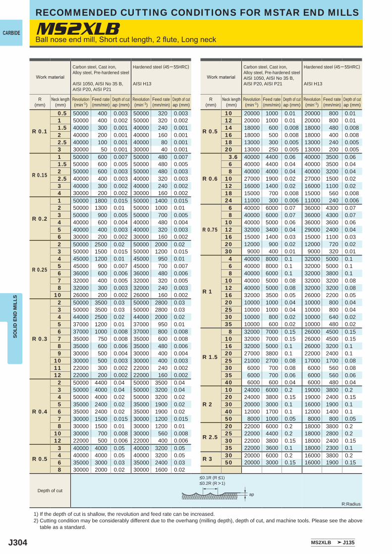
J304
MS2XLB
R 0.1
0.5 50000 400 0.003 50000 320 0.003
R 0.5
10 20000 1000 0.01 20000 800 0.011 50000 400 0.002 50000 320 0.002 12 20000 1000 0.01 20000 800 0.011.5 40000 300 0.001 40000 240 0.001 14 18000 600 0.008 18000 480 0.0082 40000 200 0.001 40000 160 0.001 16 18000 500 0.008 18000 400 0.0082.5 40000 100 0.001 40000 80 0.001 18 13000 300 0.005 13000 240 0.0053 30000 50 0.001 30000 40 0.001 20 13000 250 0.005 13000 200 0.005
R 0.15
1 50000 600 0.007 50000 480 0.007
R 0.6
3.6 40000 4400 0.06 40000 3500 0.061.5 50000 600 0.005 50000 480 0.005 6 40000 4400 0.04 40000 3500 0.042 50000 600 0.003 50000 480 0.003 8 40000 4000 0.04 40000 3200 0.042.5 40000 400 0.003 40000 320 0.003 10 27000 1900 0.02 27000 1500 0.023 40000 300 0.002 40000 240 0.002 12 16000 1400 0.02 16000 1100 0.024 30000 200 0.002 30000 160 0.002 18 15000 700 0.008 15000 560 0.008
R 0.2
1 50000 1800 0.015 50000 1400 0.015 24 11000 300 0.006 11000 240 0.0062 50000 1300 0.01 50000 1000 0.01
R 0.75
6 40000 6000 0.07 36000 4300 0.073 50000 900 0.005 50000 700 0.005 8 40000 6000 0.07 36000 4300 0.074 40000 600 0.004 40000 480 0.004 10 40000 5000 0.06 36000 3600 0.065 40000 400 0.003 40000 320 0.003 12 32000 3400 0.04 29000 2400 0.046 30000 200 0.002 30000 160 0.002 16 15000 1400 0.03 15000 1100 0.03
R 0.25
2 50000 2500 0.02 50000 2000 0.02 20 12000 900 0.02 12000 720 0.023 50000 1500 0.015 50000 1200 0.015 30 9000 400 0.01 9000 320 0.014 45000 1200 0.01 45000 950 0.01
R 1
4 40000 8000 0.1 32000 5000 0.15 45000 900 0.007 45000 700 0.007 6 40000 8000 0.1 32000 5000 0.16 36000 600 0.006 36000 480 0.006 8 40000 6000 0.1 32000 3800 0.17 32000 400 0.005 32000 320 0.005 10 40000 5000 0.08 32000 3200 0.088 32000 300 0.003 32000 240 0.003 12 40000 5000 0.08 32000 3200 0.08
10 26000 200 0.002 26000 160 0.002 16 32000 3500 0.05 26000 2200 0.05
R 0.3
2 50000 3500 0.03 50000 2800 0.03 20 10000 1000 0.04 10000 800 0.043 50000 3500 0.03 50000 2800 0.03 25 10000 1000 0.04 10000 800 0.044 44000 2500 0.02 44000 2000 0.02 30 10000 800 0.02 10000 640 0.025 37000 1200 0.01 37000 950 0.01 35 10000 600 0.02 10000 480 0.026 37000 1000 0.008 37000 800 0.008
R 1.5
8 32000 7000 0.15 26000 4500 0.157 35000 750 0.008 35000 600 0.008 10 32000 7000 0.15 26000 4500 0.158 35000 600 0.006 35000 480 0.006 16 32000 5000 0.1 26000 3200 0.19 30000 500 0.004 30000 400 0.004 20 27000 3800 0.1 22000 2400 0.1
10 30000 500 0.003 30000 400 0.003 25 21000 2700 0.08 17000 1700 0.0811 22000 300 0.002 22000 240 0.002 30 6000 700 0.08 6000 560 0.0812 22000 200 0.002 22000 160 0.002 35 6000 700 0.06 6000 560 0.06
R 0.4
2 50000 4400 0.04 50000 3500 0.04 40 6000 600 0.04 6000 480 0.043 50000 4000 0.04 50000 3200 0.04
R 2
10 24000 6000 0.2 19000 3800 0.24 50000 4000 0.02 50000 3200 0.02 20 24000 3800 0.15 19000 2400 0.155 35000 2400 0.02 35000 1900 0.02 30 20000 3000 0.1 16000 1900 0.16 35000 2400 0.02 35000 1900 0.02 40 12000 1700 0.1 12000 1400 0.17 30000 1500 0.015 30000 1200 0.015 50 8000 1000 0.05 8000 800 0.058 30000 1500 0.01 30000 1200 0.01
R 2.5
20 22000 6000 0.2 18000 3800 0.210 30000 700 0.008 30000 560 0.008 25 22000 4400 0.2 18000 2800 0.212 22000 500 0.006 22000 400 0.006 30 22000 3800 0.15 18000 2400 0.15
R 0.5
3 40000 4000 0.05 40000 3200 0.05 35 22000 3600 0.1 18000 2300 0.14 40000 4000 0.05 40000 3200 0.05 R 3 30 20000 6000 0.2 16000 3800 0.26 35000 3000 0.03 35000 2400 0.03 50 20000 3000 0.15 16000 1900 0.158 30000 2000 0.02 30000 1600 0.02
MS2XLB J135
ap
CARBIDE
SOLI
D E
ND
MIL
LSRECOMMENDED CUTTING CONDITIONS FOR MSTAR END MILLS
Ball nose end mill, Short cut length, 2 flute, Long neck
1) If the depth of cut is shallow, the revolution and feed rate can be increased.2) Cutting condition may be considerably different due to the overhang (milling depth), depth of cut, and machine tools. Please see the above
table as a standard.
R:Radius
Work material
Carbon steel, Cast iron, Alloy steel, Pre-hardened steel
AISI 1050, AISI No 35 B, AISI P20, AISI P21
Hardened steel (45─ 55HRC)
AISI H13
R(mm)
Neck length(mm)
Revolution(min-1)
Feed rate(mm/min)
Depth of cutap (mm)
Revolution(min-1)
Feed rate(mm/min)
Depth of cutap (mm)
Work material
Carbon steel, Cast iron, Alloy steel, Pre-hardened steelAISI 1050, AISI No 35 B, AISI P20, AISI P21
Hardened steel (45─ 55HRC)
AISI H13
R(mm)
Neck length(mm)
Revolution(min-1)
Feed rate(mm/min)
Depth of cutap (mm)
Revolution(min-1)
Feed rate(mm/min)
Depth of cutap (mm)
Depth of cut
<0.1R (R <1)<0.2R (R >1)
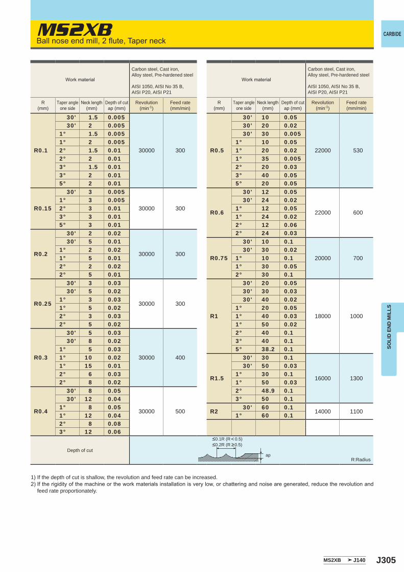
J305
MS2XB
R0.1
30' 1.5 0.005
30000 300 R0.5
30' 10 0.05
22000 530
30' 2 0.005 30' 20 0.021° 1.5 0.005 30' 30 0.0051° 2 0.005 1° 10 0.052° 1.5 0.01 1° 20 0.022° 2 0.01 1° 35 0.0053° 1.5 0.01 2° 20 0.033° 2 0.01 3° 40 0.055° 2 0.01 5° 20 0.05
R0.15
30' 3 0.005
30000 300R0.6
30' 12 0.05
22000 600
1° 3 0.005 30' 24 0.022° 3 0.01 1° 12 0.053° 3 0.01 1° 24 0.025° 3 0.01 2° 12 0.06
R0.2
30' 2 0.02
30000 300
2° 24 0.03 30' 5 0.01
R0.75
30' 10 0.1
20000 7001° 2 0.02 30' 30 0.021° 5 0.01 1° 10 0.12° 2 0.02 1° 30 0.052° 5 0.01 2° 30 0.1
R0.25
30' 3 0.03
30000 300
R1
30' 20 0.05
18000 1000
30' 5 0.02 30' 30 0.031° 3 0.03 30' 40 0.021° 5 0.02 1° 20 0.052° 3 0.03 1° 40 0.032° 5 0.02 1° 50 0.02
R0.3
30' 5 0.03
30000 400
2° 40 0.1 30' 8 0.02 3° 40 0.11° 5 0.03 5° 38.2 0.11° 10 0.02
R1.5
30' 30 0.1
16000 1300
1° 15 0.01 30' 50 0.032° 6 0.03 1° 30 0.12° 8 0.02 1° 50 0.03
R0.4
30' 8 0.05
30000 500
2° 48.9 0.1 30' 12 0.04 3° 50 0.11° 8 0.05
R2 30' 60 0.114000 1100
1° 12 0.04 1° 60 0.12° 8 0.083° 12 0.06
MS2XB J140
ap
CARBIDE
SOLI
D E
ND
MIL
LS
Ball nose end mill, 2 flute, Taper neck
1) If the depth of cut is shallow, the revolution and feed rate can be increased.2) If the rigidity of the machine or the work materials installation is very low, or chattering and noise are generated, reduce the revolution and
feed rate proportionately.
R:Radius
Work material
Carbon steel, Cast iron, Alloy steel, Pre-hardened steel
AISI 1050, AISI No 35 B, AISI P20, AISI P21
R(mm)
Taper angleone side
Neck length(mm)
Depth of cutap (mm)
Revolution(min-1)
Feed rate(mm/min)
Work material
Carbon steel, Cast iron, Alloy steel, Pre-hardened steel
AISI 1050, AISI No 35 B, AISI P20, AISI P21
R(mm)
Taper angleone side
Neck length(mm)
Depth of cutap (mm)
Revolution(min-1)
Feed rate(mm/min)
Depth of cut
<0.1R (R<0.5)<0.2R (R >0.5)
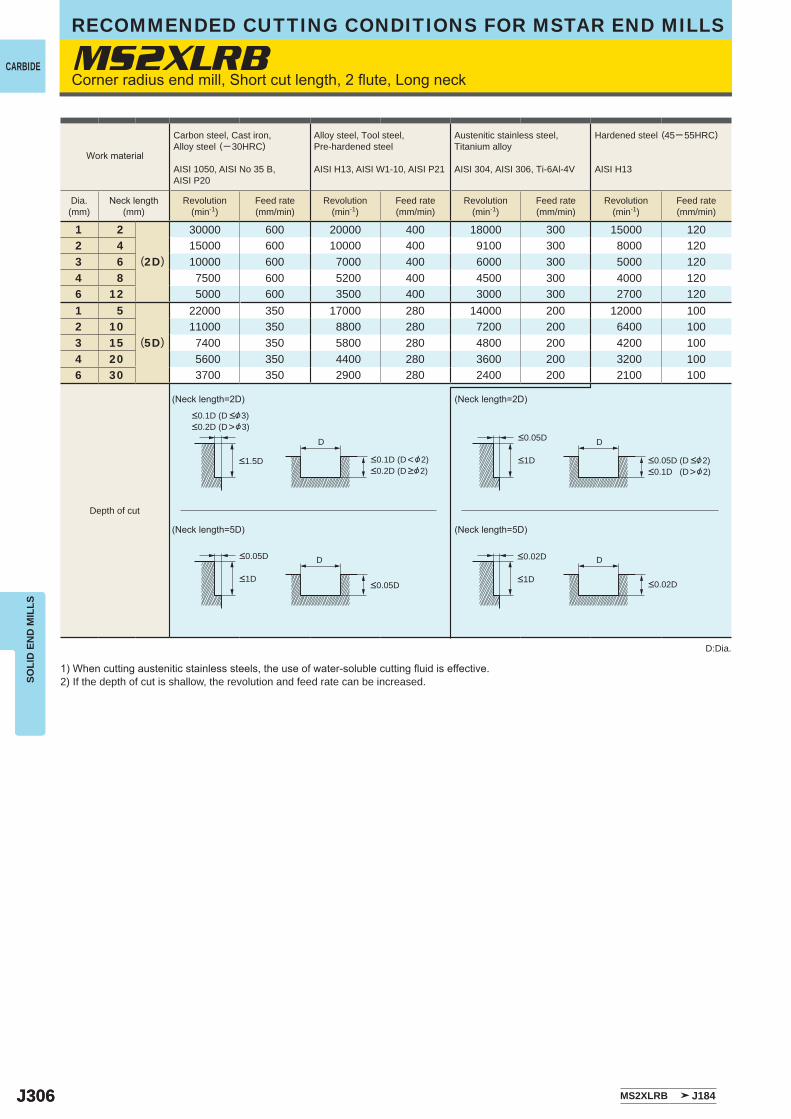
J306J306
MS2XLRB
1 2
(2D)
30000 600 20000 400 18000 300 15000 1202 4 15000 600 10000 400 9100 300 8000 1203 6 10000 600 7000 400 6000 300 5000 1204 8 7500 600 5200 400 4500 300 4000 1206 12 5000 600 3500 400 3000 300 2700 1201 5
(5D)
22000 350 17000 280 14000 200 12000 1002 10 11000 350 8800 280 7200 200 6400 1003 15 7400 350 5800 280 4800 200 4200 1004 20 5600 350 4400 280 3600 200 3200 1006 30 3700 350 2900 280 2400 200 2100 100
MS2XLRB J184
D D
D D
CARBIDE
SOLI
D E
ND
MIL
LSRECOMMENDED CUTTING CONDITIONS FOR MSTAR END MILLS
Corner radius end mill, Short cut length, 2 flute, Long neck
1) When cutting austenitic stainless steels, the use of water-soluble cutting fluid is effective.2) If the depth of cut is shallow, the revolution and feed rate can be increased.
D:Dia.
(Neck length=2D) (Neck length=2D)
(Neck length=5D) (Neck length=5D)
Work material
Carbon steel, Cast iron, Alloy steel (─ 30HRC)
AISI 1050, AISI No 35 B,AISI P20
Alloy steel, Tool steel,Pre-hardened steel
AISI H13, AISI W1-10, AISI P21
Austenitic stainless steel,Titanium alloy
AISI 304, AISI 306, Ti-6Al-4V
Hardened steel (45─ 55HRC)
AISI H13
Dia.(mm)
Neck length(mm)
Revolution(min-1)
Feed rate(mm/min)
Revolution(min-1)
Feed rate(mm/min)
Revolution(min-1)
Feed rate(mm/min)
Revolution(min-1)
Feed rate(mm/min)
<0.1D (D <&3)<0.2D (D>&3)
<0.1D (D<&2)<0.2D (D >&2)
<1.5D
<0.05D
<0.05D<1D
<0.05D (D <&2)<0.1D (D>&2)
<0.05D
<0.02D
<0.02D
<1D
<1D
Depth of cut
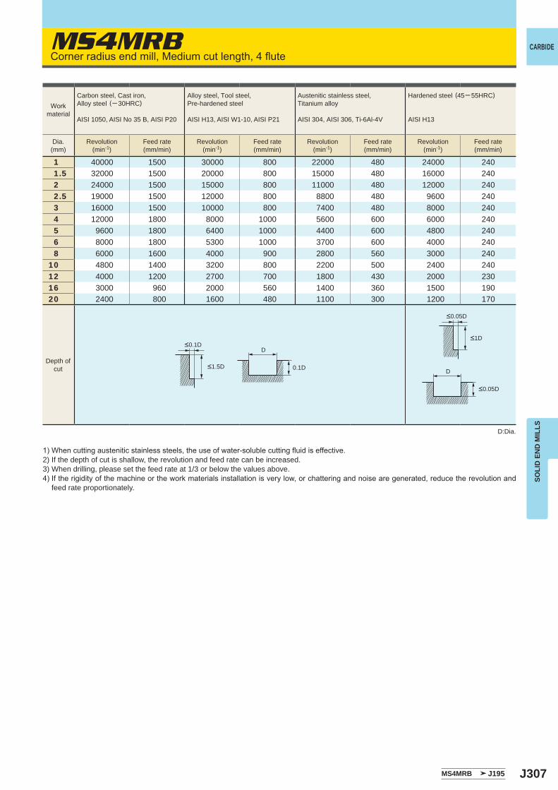
J307
MS4MRB
1 40000 1500 30000 800 22000 480 24000 2401.5 32000 1500 20000 800 15000 480 16000 2402 24000 1500 15000 800 11000 480 12000 2402.5 19000 1500 12000 800 8800 480 9600 2403 16000 1500 10000 800 7400 480 8000 2404 12000 1800 8000 1000 5600 600 6000 2405 9600 1800 6400 1000 4400 600 4800 2406 8000 1800 5300 1000 3700 600 4000 2408 6000 1600 4000 900 2800 560 3000 240
10 4800 1400 3200 800 2200 500 2400 24012 4000 1200 2700 700 1800 430 2000 23016 3000 960 2000 560 1400 360 1500 19020 2400 800 1600 480 1100 300 1200 170
MS4MRB J195
D
D0.1D
CARBIDE
SOLI
D E
ND
MIL
LS
Corner radius end mill, Medium cut length, 4 flute
1) When cutting austenitic stainless steels, the use of water-soluble cutting fluid is effective.2) If the depth of cut is shallow, the revolution and feed rate can be increased.3) When drilling, please set the feed rate at 1/3 or below the values above.4) If the rigidity of the machine or the work materials installation is very low, or chattering and noise are generated, reduce the revolution and
feed rate proportionately.
D:Dia.
Workmaterial
Carbon steel, Cast iron, Alloy steel (─ 30HRC)
AISI 1050, AISI No 35 B, AISI P20
Alloy steel, Tool steel,Pre-hardened steel
AISI H13, AISI W1-10, AISI P21
Austenitic stainless steel,Titanium alloy
AISI 304, AISI 306, Ti-6Al-4V
Hardened steel (45─ 55HRC)
AISI H13
Dia.(mm)
Revolution(min-1)
Feed rate(mm/min)
Revolution(min-1)
Feed rate(mm/min)
Revolution(min-1)
Feed rate(mm/min)
Revolution(min-1)
Feed rate(mm/min)
Depth ofcut
<0.1D
<1.5D
<0.05D
<0.05D
<1D
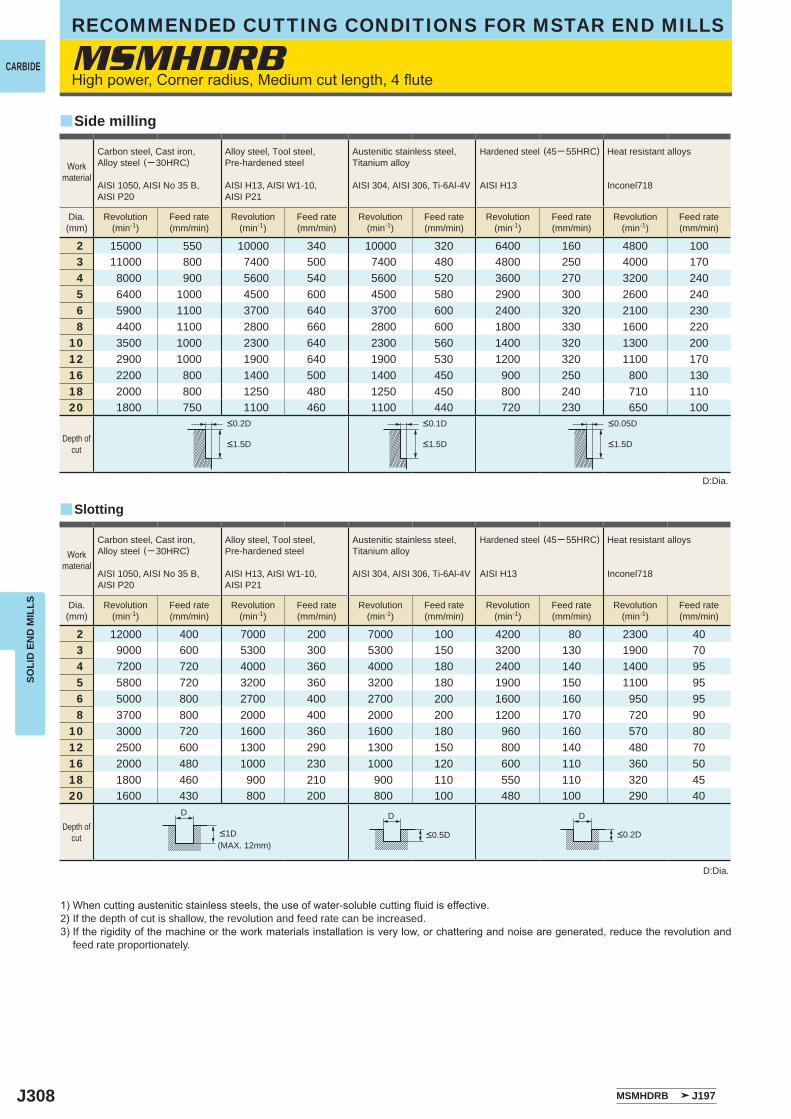
J308
MSMHDRB
2 15000 550 10000 340 10000 320 6400 160 4800 1003 11000 800 7400 500 7400 480 4800 250 4000 1704 8000 900 5600 540 5600 520 3600 270 3200 2405 6400 1000 4500 600 4500 580 2900 300 2600 2406 5900 1100 3700 640 3700 600 2400 320 2100 2308 4400 1100 2800 660 2800 600 1800 330 1600 220
10 3500 1000 2300 640 2300 560 1400 320 1300 20012 2900 1000 1900 640 1900 530 1200 320 1100 17016 2200 800 1400 500 1400 450 900 250 800 13018 2000 800 1250 480 1250 450 800 240 710 11020 1800 750 1100 460 1100 440 720 230 650 100
2 12000 400 7000 200 7000 100 4200 80 2300 403 9000 600 5300 300 5300 150 3200 130 1900 704 7200 720 4000 360 4000 180 2400 140 1400 955 5800 720 3200 360 3200 180 1900 150 1100 956 5000 800 2700 400 2700 200 1600 160 950 958 3700 800 2000 400 2000 200 1200 170 720 90
10 3000 720 1600 360 1600 180 960 160 570 8012 2500 600 1300 290 1300 150 800 140 480 7016 2000 480 1000 230 1000 120 600 110 360 5018 1800 460 900 210 900 110 550 110 320 4520 1600 430 800 200 800 100 480 100 290 40
MSMHDRB J197
D D D
y
y
CARBIDE
SOLI
D E
ND
MIL
LSRECOMMENDED CUTTING CONDITIONS FOR MSTAR END MILLS
High power, Corner radius, Medium cut length, 4 flute
1) When cutting austenitic stainless steels, the use of water-soluble cutting fluid is effective.2) If the depth of cut is shallow, the revolution and feed rate can be increased.3) If the rigidity of the machine or the work materials installation is very low, or chattering and noise are generated, reduce the revolution and
feed rate proportionately.
D:Dia.
D:Dia.
Slotting
Side milling
Workmaterial
Carbon steel, Cast iron, Alloy steel (─ 30HRC)
AISI 1050, AISI No 35 B,AISI P20
Alloy steel, Tool steel,Pre-hardened steel
AISI H13, AISI W1-10, AISI P21
Austenitic stainless steel,Titanium alloy
AISI 304, AISI 306, Ti-6Al-4V
Hardened steel (45─ 55HRC)
AISI H13
Heat resistant alloys
Inconel718
Dia.(mm)
Revolution(min-1)
Feed rate(mm/min)
Revolution(min-1)
Feed rate(mm/min)
Revolution(min-1)
Feed rate(mm/min)
Revolution(min-1)
Feed rate(mm/min)
Revolution(min-1)
Feed rate(mm/min)
Depth ofcut
<0.2D <0.1D <0.05D
<1.5D <1.5D <1.5D
Workmaterial
Carbon steel, Cast iron, Alloy steel (─ 30HRC)
AISI 1050, AISI No 35 B,AISI P20
Alloy steel, Tool steel,Pre-hardened steel
AISI H13, AISI W1-10, AISI P21
Austenitic stainless steel,Titanium alloy
AISI 304, AISI 306, Ti-6Al-4V
Hardened steel (45─ 55HRC)
AISI H13
Heat resistant alloys
Inconel718
Dia.(mm)
Revolution(min-1)
Feed rate(mm/min)
Revolution(min-1)
Feed rate(mm/min)
Revolution(min-1)
Feed rate(mm/min)
Revolution(min-1)
Feed rate(mm/min)
Revolution(min-1)
Feed rate(mm/min)
Depth ofcut <1D <0.5D <0.2D
(MAX. 12mm)
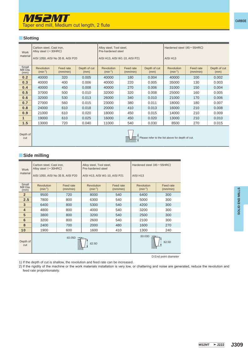
J309
MS2MT
0.2 40000 320 0.005 40000 180 0.004 40000 100 0.0020.3 40000 400 0.006 40000 220 0.005 35000 130 0.0030.4 40000 450 0.008 40000 270 0.006 31000 150 0.0040.5 37000 500 0.010 32000 320 0.008 25000 160 0.0050.6 32000 530 0.013 26000 340 0.010 21000 170 0.0060.7 27000 560 0.015 23000 380 0.011 18000 180 0.0070.8 24000 610 0.018 20000 410 0.013 16000 210 0.0080.9 21000 610 0.020 18000 450 0.015 14000 210 0.0091 19000 610 0.025 16000 450 0.020 13000 210 0.0101.5 13000 720 0.040 11000 540 0.030 8500 270 0.015
2 9500 720 8000 540 6400 3002.5 7800 800 6300 540 5000 3003 6400 800 5300 540 4200 3004 4800 800 4000 540 3200 3005 3800 800 3200 540 2500 3006 3200 800 2600 540 2100 3008 2400 700 2000 480 1600 270
10 1900 600 1600 410 1300 240
MS2MT J222
y
y
CARBIDE
SOLI
D E
ND
MIL
LS
Taper end mill, Medium cut length, 2 flute
1) If the depth of cut is shallow, the revolution and feed rate can be increased.2) If the rigidity of the machine or the work materials installation is very low, or chattering and noise are generated, reduce the revolution and
feed rate proportionately.
D:End point diameter
Please refer to the list above for depth of cut.
Slotting
Side milling
Workmaterial
Carbon steel, Cast iron, Alloy steel (─ 30HRC)
AISI 1050, AISI No 35 B, AISI P20
Alloy steel, Tool steel,Pre-hardened steel
AISI H13, AISI W1-10, AISI P21
Hardened steel (45─ 55HRC)
AISI H13
SmallMill Dia.
(mm)Revolution
(min-1)Feed rate(mm/min)
Depth of cut(mm)
Revolution(min-1)
Feed rate(mm/min)
Depth of cut(mm)
Revolution(min-1)
Feed rate(mm/min)
Depth of cut(mm)
Workmaterial
Carbon steel, Cast iron, Alloy steel (─ 30HRC)
AISI 1050, AISI No 35 B, AISI P20
Alloy steel, Tool steel,Pre-hardened steel
AISI H13, AISI W1-10, AISI P21
Hardened steel (45─ 55HRC)
AISI H13
SmallMill Dia.
(mm)Revolution
(min-1)Feed rate(mm/min)
Revolution(min-1)
Feed rate(mm/min)
Revolution(min-1)
Feed rate(mm/min)
Depth ofcut
<0.05D
<2.5D
<0.03D
<2.5D
Depth ofcut

J310
MS4LT
0.2 2 20000─ 40000 200─ 500 0.001 20000─ 40000 150─ 300 0.0010.3 3 20000─ 40000 200─ 500 0.002 20000─ 40000 150─ 300 0.0010.4 4 20000─ 40000 200─ 500 0.003 20000─ 36000 150─ 300 0.002
0.54
20000─ 38000 200─ 5000.01
16000─29000 200─ 4000.005
6 0.005 0.003
0.64
18000─ 32000 250─ 6000.01
13000─24000 200─ 4000.005
6 0.007 0.004
0.76
16000─27000 250─ 6000.015
11000─20000 200─ 4000.008
8 0.01 0.005
0.84
14000─24000 250─ 6000.03
10000─180000.015
8 0.02 200─ 400 0.0112 0.013 0.007
1.06
11000─19000 300─ 8000.03
8000─140000.015
10 0.02 200─ 500 0.0116 0.015 0.008
1.2
6
9200─16000 300─ 800
0.04
6600─12000 200─ 500
0.0210 0.03 0.01516 0.02 0.0120 0.01 0.007
1.3 12 8500─15000 300─ 800 0.03 6100─11000 200─ 500 0.0151.4 12 8000─14000 300─ 800 0.035 5700─10000 200─ 500 0.018
1.5
6
7500─13000 300─ 800
0.06
5300─ 9500 200─ 500
0.0310 0.04 0.0216 0.03 0.01525 0.015 0.008
1.6
8
7000─12000 300─ 800
0.06
5000─ 9000 200─ 500
0.0312 0.045 0.02516 0.035 0.0220 0.025 0.015
1.88
6200─11000 300─ 8000.08
4400─ 8000 200─ 5000.04
16 0.05 0.0324 0.03 0.015
2.0
8
5500─ 9500 300─ 800
0.1
4000─7200 200─ 500
0.0512 0.07 0.0420 0.04 0.0230 0.02 0.01
2.510
4400─7600 300─ 8000.1
3200─ 57000.05
20 0.06 200─ 500 0.0330 0.03 0.015
3.025
3700─ 6400 300─ 8000.08
2700─ 4800 200─ 5000.04
40 0.04 0.02
MS4LT J227
CARBIDE
SOLI
D E
ND
MIL
LSRECOMMENDED CUTTING CONDITIONS FOR MSTAR END MILLS
Taper end mill, Long cut length, 4 flute
1) If the depth of cut is shallow, the revolution and feed rate can be increased.2) If the rigidity of the machine or the work materials installation is very low, or chattering and noise are generated, reduce the revolution and
feed rate proportionately.
ap:Depth of Cut in the Axial Direction
Work material
Carbon steel, Cast iron, Alloy steel,Pre-hardened steel
AISI 1050, AISI No 35 B, AISI P20, AISI P21
Hardened steel (45─ 55HRC)
AISI H13
Small Mill Dia.(mm)
Length of cut(mm)
Revolution(min-1)
Feed rate(mm/min)
Depth of cutap (mm)
Revolution(min-1)
Feed rate(mm/min)
Depth of cutap (mm)
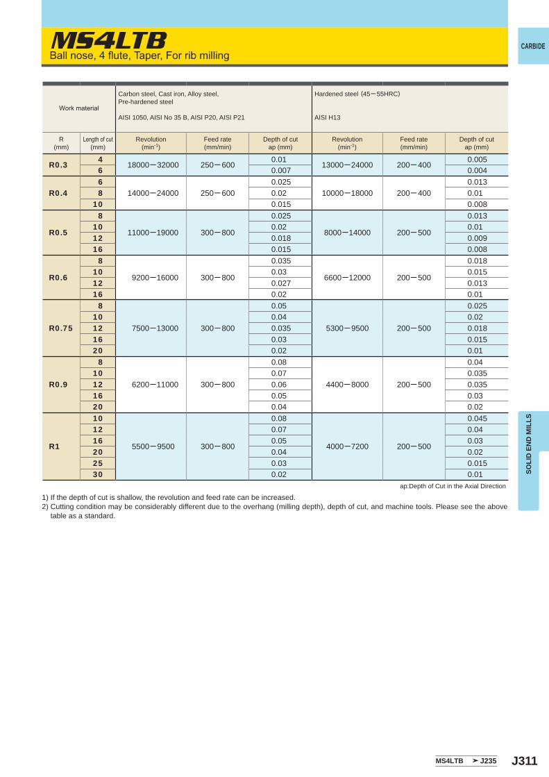
J311
MS4LTB
R0.34
18000─ 32000 250─ 6000.01
13000─24000 200─ 4000.005
6 0.007 0.004
R0.46
14000─24000 250─ 6000.025
10000─18000 200─ 4000.013
8 0.02 0.0110 0.015 0.008
R0.5
8
11000─19000 300─ 800
0.025
8000─14000 200─ 500
0.01310 0.02 0.0112 0.018 0.00916 0.015 0.008
R0.6
8
9200─16000 300─ 800
0.035
6600─12000 200─ 500
0.01810 0.03 0.01512 0.027 0.01316 0.02 0.01
R0.75
8
7500─13000 300─ 800
0.05
5300─ 9500 200─ 500
0.02510 0.04 0.0212 0.035 0.01816 0.03 0.01520 0.02 0.01
R0.9
8
6200─11000 300─ 800
0.08
4400─ 8000 200─ 500
0.0410 0.07 0.03512 0.06 0.03516 0.05 0.0320 0.04 0.02
R1
10
5500─ 9500 300─ 800
0.08
4000─7200 200─ 500
0.04512 0.07 0.0416 0.05 0.0320 0.04 0.0225 0.03 0.01530 0.02 0.01
MS4LTB J235
CARBIDE
SOLI
D E
ND
MIL
LS
Ball nose, 4 flute, Taper, For rib milling
1) If the depth of cut is shallow, the revolution and feed rate can be increased.2) Cutting condition may be considerably different due to the overhang (milling depth), depth of cut, and machine tools. Please see the above
table as a standard.
ap:Depth of Cut in the Axial Direction
Work material
Carbon steel, Cast iron, Alloy steel,Pre-hardened steel
AISI 1050, AISI No 35 B, AISI P20, AISI P21
Hardened steel (45─ 55HRC)
AISI H13
R(mm)
Length of cut(mm)
Revolution(min-1)
Feed rate(mm/min)
Depth of cutap (mm)
Revolution(min-1)
Feed rate(mm/min)
Depth of cutap (mm)
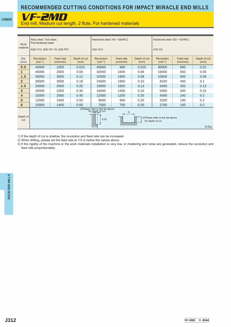
J312
VF-2MD
0.5 40000 1000 0.015 40000 960 0.015 30000 600 0.011 40000 2000 0.06 32000 1600 0.06 16000 550 0.051.5 40000 3000 0.12 32000 1900 0.08 10600 500 0.082 30000 3000 0.18 24000 1900 0.10 8100 400 0.12.5 24000 2600 0.25 19000 1600 0.13 6400 350 0.133 20000 2300 0.30 16000 1400 0.15 5400 300 0.154 15000 2000 0.40 12000 1200 0.20 4000 240 0.25 12000 1600 0.50 9000 900 0.25 3200 190 0.26 10000 1400 0.60 7000 700 0.30 2700 160 0.2
VF-2MD J044
D
CARBIDE
RECOMMENDED CUTTING CONDITIONS FOR IMPACT MIRACLE END MILLSSO
LID
EN
D M
ILLS
End mill, Medium cut length, 2 flute, For hardened materials
D:Dia.
1) If the depth of cut is shallow, the revolution and feed rate can be increased.2) When drilling, please set the feed rate at 1/3 or below the values above.3) If the rigidity of the machine or the work materials installation is very low, or chattering and noise are generated, reduce the revolution and
feed rate proportionately.
<Please refer to the list above for depth of cut.
<Please refer to the list above for depth of cut.
Workmaterial
Dia.(mm)
Depth ofcut <1D
Alloy steel, Tool steel,Pre-hardened steel
AISI H13, AISI W1-10, AISI P21
Hardened steel (45─ 55HRC)
AISI H13
Hardened steel (55─ 62HRC)
AISI D2
Revolution(min-1)
Revolution(min-1)
Revolution(min-1)
Feed rate(mm/min)
Feed rate(mm/min)
Feed rate(mm/min)
Depth of cut(mm)
Depth of cut(mm)
Depth of cut(mm)
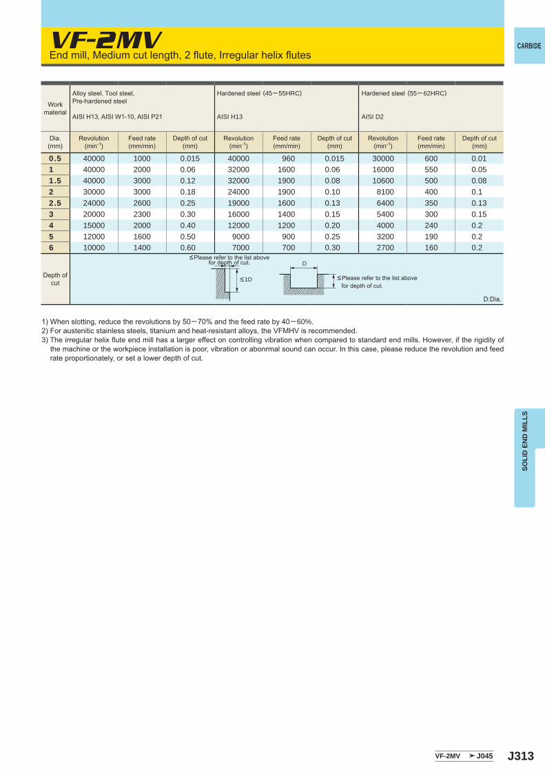
J313
VF-2MV
0.5 40000 1000 0.015 40000 960 0.015 30000 600 0.011 40000 2000 0.06 32000 1600 0.06 16000 550 0.051.5 40000 3000 0.12 32000 1900 0.08 10600 500 0.082 30000 3000 0.18 24000 1900 0.10 8100 400 0.12.5 24000 2600 0.25 19000 1600 0.13 6400 350 0.133 20000 2300 0.30 16000 1400 0.15 5400 300 0.154 15000 2000 0.40 12000 1200 0.20 4000 240 0.25 12000 1600 0.50 9000 900 0.25 3200 190 0.26 10000 1400 0.60 7000 700 0.30 2700 160 0.2
VF-2MV J045
D
CARBIDE
SOLI
D E
ND
MIL
LS
End mill, Medium cut length, 2 flute, Irregular helix flutes
D:Dia.
1) When slotting, reduce the revolutions by 50─70% and the feed rate by 40─60%.2) For austenitic stainless steels, titanium and heat-resistant alloys, the VFMHV is recommended. 3) The irregular helix flute end mill has a larger effect on controlling vibration when compared to standard end mills. However, if the rigidity of
the machine or the workpiece installation is poor, vibration or abonrmal sound can occur. In this case, please reduce the revolution and feed rate proportionately, or set a lower depth of cut.
<Please refer to the list above for depth of cut.
<Please refer to the list above for depth of cut.
Workmaterial
Dia.(mm)
Depth ofcut <1D
Alloy steel, Tool steel,Pre-hardened steel
AISI H13, AISI W1-10, AISI P21
Hardened steel (45─ 55HRC)
AISI H13
Hardened steel (55─ 62HRC)
AISI D2
Revolution(min-1)
Revolution(min-1)
Revolution(min-1)
Feed rate(mm/min)
Feed rate(mm/min)
Feed rate(mm/min)
Depth of cut(mm)
Depth of cut(mm)
Depth of cut(mm)
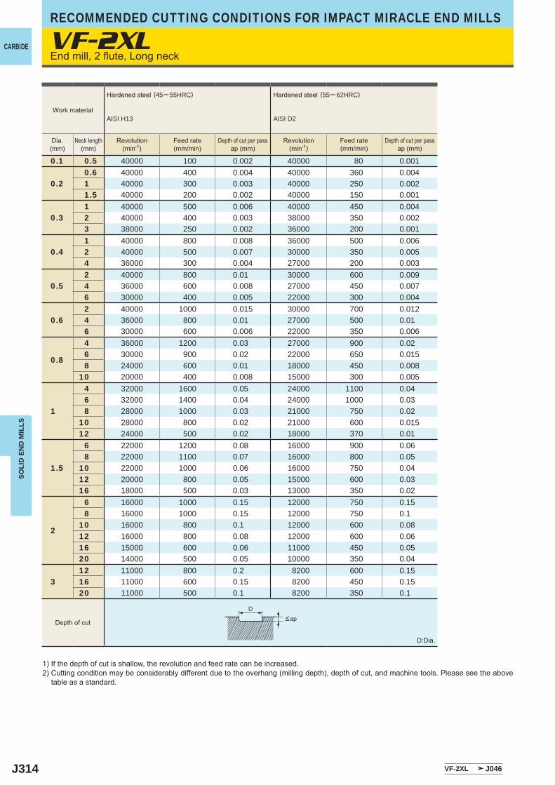
J314
VF-2XL
0.1 0.5 40000 100 0.002 40000 80 0.001
0.20.6 40000 400 0.004 40000 360 0.0041 40000 300 0.003 40000 250 0.0021.5 40000 200 0.002 40000 150 0.001
0.31 40000 500 0.006 40000 450 0.0042 40000 400 0.003 38000 350 0.0023 38000 250 0.002 36000 200 0.001
0.41 40000 800 0.008 36000 500 0.0062 40000 500 0.007 30000 350 0.0054 36000 300 0.004 27000 200 0.003
0.52 40000 800 0.01 30000 600 0.0094 36000 600 0.008 27000 450 0.0076 30000 400 0.005 22000 300 0.004
0.62 40000 1000 0.015 30000 700 0.0124 36000 800 0.01 27000 500 0.016 30000 600 0.006 22000 350 0.006
0.8
4 36000 1200 0.03 27000 900 0.026 30000 900 0.02 22000 650 0.0158 24000 600 0.01 18000 450 0.008
10 20000 400 0.008 15000 300 0.005
1
4 32000 1600 0.05 24000 1100 0.046 32000 1400 0.04 24000 1000 0.038 28000 1000 0.03 21000 750 0.02
10 28000 800 0.02 21000 600 0.01512 24000 500 0.02 18000 370 0.01
1.5
6 22000 1200 0.08 16000 900 0.068 22000 1100 0.07 16000 800 0.05
10 22000 1000 0.06 16000 750 0.0412 20000 800 0.05 15000 600 0.0316 18000 500 0.03 13000 350 0.02
2
6 16000 1000 0.15 12000 750 0.158 16000 1000 0.15 12000 750 0.1
10 16000 800 0.1 12000 600 0.0812 16000 800 0.08 12000 600 0.0616 15000 600 0.06 11000 450 0.0520 14000 500 0.05 10000 350 0.04
312 11000 800 0.2 8200 600 0.1516 11000 600 0.15 8200 450 0.1520 11000 500 0.1 8200 350 0.1
VF-2XL J046
D
CARBIDE
RECOMMENDED CUTTING CONDITIONS FOR IMPACT MIRACLE END MILLSSO
LID
EN
D M
ILLS
End mill, 2 flute, Long neck
1) If the depth of cut is shallow, the revolution and feed rate can be increased.2) Cutting condition may be considerably different due to the overhang (milling depth), depth of cut, and machine tools. Please see the above
table as a standard.
D:Dia.
Work material
Hardened steel (45─ 55HRC)
AISI H13
Hardened steel (55─ 62HRC)
AISI D2
Dia.(mm)
Revolution(min-1)
Revolution(min-1)
Neck length(mm)
Feed rate(mm/min)
Feed rate(mm/min)
Depth of cut per passap (mm)
Depth of cut per passap (mm)
Depth of cut <ap
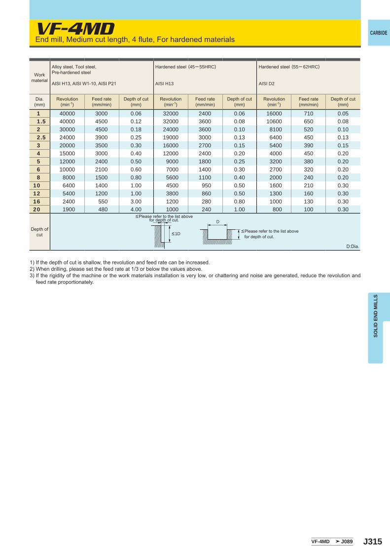
J315
VF-4MD
1 40000 3000 0.06 32000 2400 0.06 16000 710 0.051.5 40000 4500 0.12 32000 3600 0.08 10600 650 0.082 30000 4500 0.18 24000 3600 0.10 8100 520 0.102.5 24000 3900 0.25 19000 3000 0.13 6400 450 0.133 20000 3500 0.30 16000 2700 0.15 5400 390 0.154 15000 3000 0.40 12000 2400 0.20 4000 450 0.205 12000 2400 0.50 9000 1800 0.25 3200 380 0.206 10000 2100 0.60 7000 1400 0.30 2700 320 0.208 8000 1500 0.80 5600 1100 0.40 2000 240 0.20
10 6400 1400 1.00 4500 950 0.50 1600 210 0.3012 5400 1200 1.00 3800 860 0.50 1300 160 0.3016 2400 550 3.00 1200 280 0.80 1000 130 0.3020 1900 480 4.00 1000 240 1.00 800 100 0.30
VF-4MD J089
D
CARBIDE
SOLI
D E
ND
MIL
LS
End mill, Medium cut length, 4 flute, For hardened materials
D:Dia.
1) If the depth of cut is shallow, the revolution and feed rate can be increased.2) When drilling, please set the feed rate at 1/3 or below the values above.3) If the rigidity of the machine or the work materials installation is very low, or chattering and noise are generated, reduce the revolution and
feed rate proportionately.
<Please refer to the list above for depth of cut.
<Please refer to the list above for depth of cut.
Workmaterial
Dia.(mm)
Depth ofcut <1D
Alloy steel, Tool steel,Pre-hardened steel
AISI H13, AISI W1-10, AISI P21
Hardened steel (45─ 55HRC)
AISI H13
Hardened steel (55─ 62HRC)
AISI D2
Revolution(min-1)
Revolution(min-1)
Revolution(min-1)
Feed rate(mm/min)
Feed rate(mm/min)
Feed rate(mm/min)
Depth of cut(mm)
Depth of cut(mm)
Depth of cut(mm)
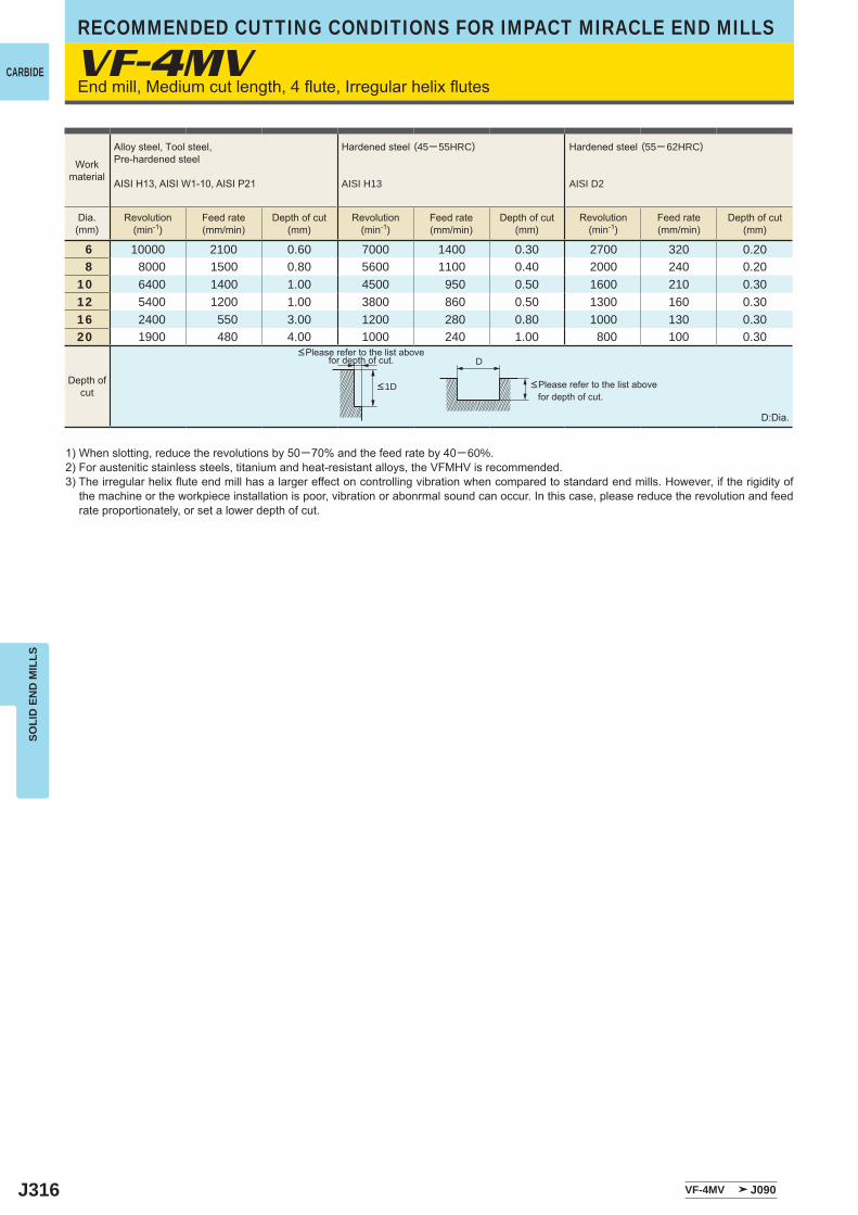
J316
VF-4MV
6 10000 2100 0.60 7000 1400 0.30 2700 320 0.20 8 8000 1500 0.80 5600 1100 0.40 2000 240 0.20 10 6400 1400 1.00 4500 950 0.50 1600 210 0.30 12 5400 1200 1.00 3800 860 0.50 1300 160 0.30 16 2400 550 3.00 1200 280 0.80 1000 130 0.30 20 1900 480 4.00 1000 240 1.00 800 100 0.30
VF-4MV J090
D
CARBIDE
RECOMMENDED CUTTING CONDITIONS FOR IMPACT MIRACLE END MILLSSO
LID
EN
D M
ILLS
End mill, Medium cut length, 4 flute, Irregular helix flutes
D:Dia.
1) When slotting, reduce the revolutions by 50─70% and the feed rate by 40─60%.2) For austenitic stainless steels, titanium and heat-resistant alloys, the VFMHV is recommended. 3) The irregular helix flute end mill has a larger effect on controlling vibration when compared to standard end mills. However, if the rigidity of
the machine or the workpiece installation is poor, vibration or abonrmal sound can occur. In this case, please reduce the revolution and feed rate proportionately, or set a lower depth of cut.
<Please refer to the list above for depth of cut.
<Please refer to the list above for depth of cut.
Workmaterial
Dia.(mm)
Depth ofcut <1D
Alloy steel, Tool steel,Pre-hardened steel
AISI H13, AISI W1-10, AISI P21
Hardened steel (45─ 55HRC)
AISI H13
Hardened steel (55─ 62HRC)
AISI D2
Revolution(min-1)
Revolution(min-1)
Revolution(min-1)
Feed rate(mm/min)
Feed rate(mm/min)
Feed rate(mm/min)
Depth of cut(mm)
Depth of cut(mm)
Depth of cut(mm)
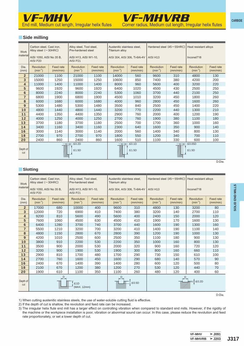
J317
VF-MHV
2 21000 1100 21000 1100 14000 560 9600 310 4800 1303 15000 1250 15000 1250 10600 850 7400 380 4200 2004 11000 1400 11000 1400 8000 960 5600 400 3200 2205 9600 1920 9600 1920 6400 1020 4500 430 2500 2506 8000 2240 8000 2240 5300 1060 3700 440 2100 2507 6800 1900 6800 1900 4500 1010 3200 450 1800 2608 6000 1680 6000 1680 4000 960 2800 450 1600 2609 5300 1480 5300 1480 3500 840 2500 450 1400 220
10 4800 1440 4800 1440 3200 770 2200 440 1300 21011 4400 1350 4400 1350 2900 760 2000 400 1200 19012 4000 1250 4000 1250 2700 760 1900 380 1100 18013 3700 1180 3700 1180 2500 700 1700 360 1000 16014 3400 1160 3400 1160 2300 640 1600 350 900 14016 3000 1140 3000 1140 2000 560 1400 340 800 13018 2700 970 2700 970 1800 550 1200 340 700 11020 2400 860 2400 860 1600 510 1100 330 600 100
2 17000 680 10000 400 9600 310 4800 130 3200 803 12000 720 6900 410 7400 380 3200 140 2700 1104 9200 810 5600 490 5600 400 2400 150 2000 1205 7600 1060 4500 630 4500 410 1900 170 1600 1306 6400 1280 3700 740 3700 440 1600 190 1300 1607 5500 1210 3200 700 3200 410 1400 190 1100 1408 4800 1150 2800 670 2800 390 1200 190 1000 1309 4200 1010 2500 600 2500 350 1100 180 900 130
10 3800 910 2200 530 2200 350 1000 160 800 13011 3500 900 2000 530 2000 320 900 160 720 12012 3200 900 1900 530 1900 300 800 160 660 11013 2900 810 1700 480 1700 290 730 150 610 10014 2700 760 1600 450 1600 290 680 140 570 9016 2400 670 1400 390 1400 280 600 120 500 8018 2100 670 1200 380 1200 270 530 120 440 7020 1900 610 1100 350 1100 260 480 120 400 60
VF-MHV J091VF-MHVRB J203
y
y
VF-MHVRB
D DD
CARBIDE
SOLI
D E
ND
MIL
LS
End mill, Medium cut length, Irregular helix flutes Corner radius, Medium cut length, Irregular helix flutes
1) When cutting austenitic stainless steels, the use of water-soluble cutting fluid is effective.2) If the depth of cut is shallow, the revolution and feed rate can be increased.3) The irregular helix flute end mill has a larger effect on controlling vibration when compared to standard end mills. However, if the rigidity of
the machine or the workpiece installation is poor, vibration or abonrmal sound can occur. In this case, please reduce the revolution and feed rate proportionately, or set a lower depth of cut.
D:Dia.
D:Dia.
Slotting
Side milling
Workmaterial
Workmaterial
Dia.(mm)
Dia.(mm)
Depth ofcut
Depth ofcut
<0.2D <0.1D <0.05D
<1.5D <1.5D <1.5D
Carbon steel, Cast iron, Alloy steel (─ 30HRC)
AISI 1050, AISI No 35 B,AISI P20
Alloy steel, Tool steel,Pre-hardened steel
AISI H13, AISI W1-10, AISI P21
Austenitic stainless steel,Titanium alloy
AISI 304, AISI 306, Ti-6Al-4V
Hardened steel (45─ 55HRC)
AISI H13
Heat resistant alloys
Inconel718
Carbon steel, Cast iron, Alloy steel (─ 30HRC)
AISI 1050, AISI No 35 B,AISI P20
Alloy steel, Tool steel,Pre-hardened steel
AISI H13, AISI W1-10, AISI P21
Austenitic stainless steel,Titanium alloy
AISI 304, AISI 306, Ti-6Al-4V
Hardened steel (45─ 55HRC)
AISI H13
Heat resistant alloys
Inconel718
Revolution(min-1)
Revolution(min-1)
Revolution(min-1)
Revolution(min-1)
Revolution(min-1)
Revolution(min-1)
Revolution(min-1)
Revolution(min-1)
Revolution(min-1)
Revolution(min-1)
Feed rate(mm/min)
Feed rate(mm/min)
Feed rate(mm/min)
Feed rate(mm/min)
Feed rate(mm/min)
Feed rate(mm/min)
Feed rate(mm/min)
Feed rate(mm/min)
Feed rate(mm/min)
Feed rate(mm/min)
<1D <0.5D <0.2D
(MAX. 12mm)
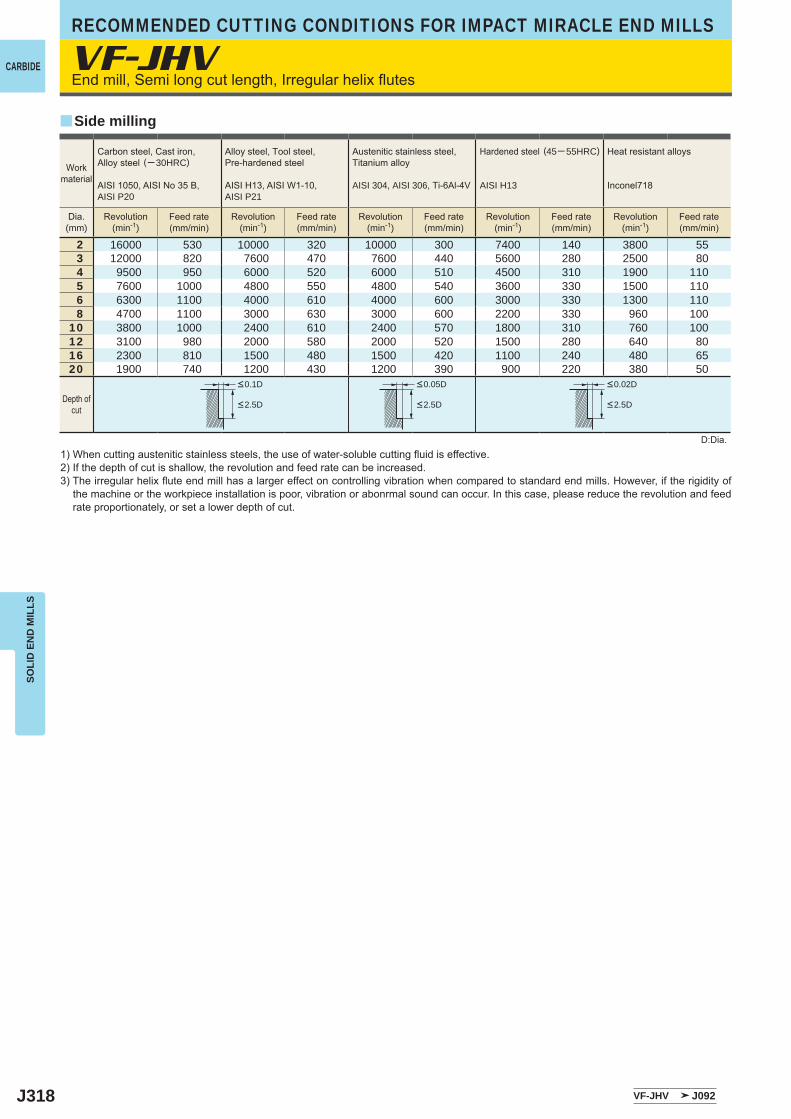
J318
VF-JHV
2 16000 530 10000 320 10000 300 7400 140 3800 553 12000 820 7600 470 7600 440 5600 280 2500 804 9500 950 6000 520 6000 510 4500 310 1900 1105 7600 1000 4800 550 4800 540 3600 330 1500 1106 6300 1100 4000 610 4000 600 3000 330 1300 1108 4700 1100 3000 630 3000 600 2200 330 960 100
10 3800 1000 2400 610 2400 570 1800 310 760 10012 3100 980 2000 580 2000 520 1500 280 640 8016 2300 810 1500 480 1500 420 1100 240 480 6520 1900 740 1200 430 1200 390 900 220 380 50
VF-JHV J092
y
CARBIDE
RECOMMENDED CUTTING CONDITIONS FOR IMPACT MIRACLE END MILLSSO
LID
EN
D M
ILLS
End mill, Semi long cut length, Irregular helix flutes
D:Dia.1) When cutting austenitic stainless steels, the use of water-soluble cutting fluid is effective.2) If the depth of cut is shallow, the revolution and feed rate can be increased.3) The irregular helix flute end mill has a larger effect on controlling vibration when compared to standard end mills. However, if the rigidity of
the machine or the workpiece installation is poor, vibration or abonrmal sound can occur. In this case, please reduce the revolution and feed rate proportionately, or set a lower depth of cut.
Side milling
Workmaterial
Dia.(mm)
Carbon steel, Cast iron, Alloy steel (─ 30HRC)
AISI 1050, AISI No 35 B,AISI P20
Alloy steel, Tool steel,Pre-hardened steel
AISI H13, AISI W1-10, AISI P21
Austenitic stainless steel,Titanium alloy
AISI 304, AISI 306, Ti-6Al-4V
Hardened steel (45─ 55HRC)
AISI H13
Heat resistant alloys
Inconel718
Revolution(min-1)
Revolution(min-1)
Revolution(min-1)
Revolution(min-1)
Revolution(min-1)
Feed rate(mm/min)
Feed rate(mm/min)
Feed rate(mm/min)
Feed rate(mm/min)
Feed rate(mm/min)
Depth ofcut
<0.1D <0.05D <0.02D
<2.5D <2.5D <2.5D
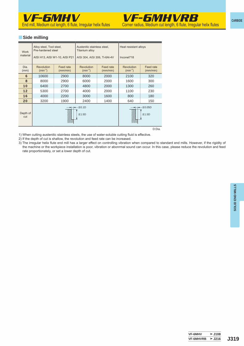
J319
VF-6MHV
6 10600 2900 8000 2000 2100 3208 8000 2900 6000 2000 1600 300
10 6400 2700 4800 2000 1300 26012 5300 2700 4000 2000 1100 23016 4000 2200 3000 1600 800 18020 3200 1900 2400 1400 640 150
VF-6MHV J108VF-6MHVRB J216
y
VF-6MHVRB CARBIDE
SOLI
D E
ND
MIL
LS
End mill, Medium cut length, 6 flute, Irregular helix flutes Corner radius, Medium cut length, 6 flute, Irregular helix flutes
1) When cutting austenitic stainless steels, the use of water-soluble cutting fluid is effective.2) If the depth of cut is shallow, the revolution and feed rate can be increased.3) The irregular helix flute end mill has a larger effect on controlling vibration when compared to standard end mills. However, if the rigidity of
the machine or the workpiece installation is poor, vibration or abonrmal sound can occur. In this case, please reduce the revolution and feed rate proportionately, or set a lower depth of cut.
D:Dia.
Side milling
Workmaterial
Alloy steel, Tool steel,Pre-hardened steel
AISI H13, AISI W1-10, AISI P21
Austenitic stainless steel,Titanium alloy
AISI 304, AISI 306, Ti-6Al-4V
Heat resistant alloys
Inconel718
Dia.(mm)
Revolution(min-1)
Revolution(min-1)
Revolution(min-1)
Feed rate(mm/min)
Feed rate(mm/min)
Feed rate(mm/min)
Depth ofcut
<0.1D <0.05D
<1.5D <1.5D
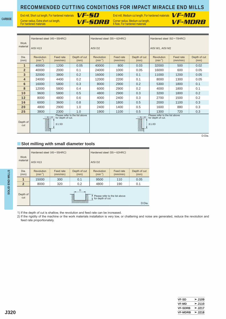
J320
1 40000 1200 0.05 40000 800 0.03 32000 500 0.022 40000 2000 0.1 24000 1000 0.05 16000 600 0.053 32000 3800 0.2 16000 1900 0.1 11000 1200 0.054 24000 4400 0.2 12000 2200 0.1 8000 1300 0.056 16000 5800 0.3 8000 2900 0.2 5300 1800 0.1 8 12000 5800 0.4 6000 2900 0.2 4000 1800 0.1
10 9600 5800 0.5 4800 2900 0.3 3200 1800 0.2 12 8000 4800 0.6 4000 2400 0.3 2700 1500 0.2 16 6000 3600 0.8 3000 1800 0.5 2000 1100 0.3 20 4800 2900 1.0 2400 1400 0.5 1600 880 0.3 25 3800 2300 1.0 1900 1100 0.5 1300 720 0.3
1 15000 300 0.1 9500 110 0.052 8000 320 0.2 4800 190 0.1
VF-SD J109VF-MD J110VF-SDRB J217VF-MDRB J218
y
D
CARBIDE
RECOMMENDED CUTTING CONDITIONS FOR IMPACT MIRACLE END MILLSSO
LID
EN
D M
ILLS
1) If the depth of cut is shallow, the revolution and feed rate can be increased.2) If the rigidity of the machine or the work materials installation is very low, or chattering and noise are generated, reduce the revolution and
feed rate proportionately.
D:Dia.
D:Dia.
Please refer to the list abovefor depth of cut.
Please refer to the list abovefor depth of cut.
Please refer to the list abovefor depth of cut.
Slot milling with small diameter tools
Workmaterial
Hardened steel (45─ 55HRC)
AISI H13
Hardened steel (55─ 62HRC)
AISI D2
Hardened steel (62─70HRC)
AISI W1, AISI M2
Dia.(mm)
Dia.(mm)
Revolution(min-1)
Revolution(min-1)
Revolution(min-1)
Revolution(min-1)
Revolution(min-1)
Feed rate(mm/min)
Feed rate(mm/min)
Feed rate(mm/min)
Feed rate(mm/min)
Feed rate(mm/min)
Depth of cut(mm)
Depth of cut(mm)
Depth of cut(mm)
Depth of cut(mm)
Depth of cut(mm)
Depth ofcut
Depth ofcut
<1.5D <1.0D
Workmaterial
Hardened steel (45─ 55HRC)
AISI H13
Hardened steel (55─ 62HRC)
AISI D2
End mill, Short cut length, For hardened materials VF-SD End mill, Medium cut length, For hardened materials VF-MDCorner radius, Extra short cut length, For hardened materials VF-SDRB Corner radius, Medium cut length,
6 flute, For hardened materials VF-MDRB
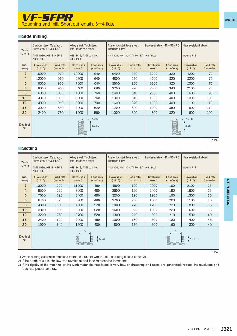
J321
VF-SFPR
3 16000 960 13000 640 6400 260 5300 320 4200 704 12000 960 9500 640 4800 260 4000 320 3200 705 9500 960 7600 640 3800 260 3200 320 2500 706 8000 960 6400 680 3200 290 2700 340 2100 758 6000 1050 4800 760 2400 340 2000 400 1600 95
10 4800 1050 3800 760 1900 340 1600 400 1300 10512 4000 960 3200 700 1600 320 1300 400 1100 11016 3000 840 2400 620 1200 300 1000 360 800 11020 2400 760 1900 560 1000 300 800 320 600 100
3 13000 720 11000 480 4800 190 3200 190 2100 254 9500 720 8000 480 3600 190 2400 190 1600 255 7600 720 6400 480 3200 190 1900 190 1300 256 6400 720 5300 480 2700 200 1600 200 1100 308 4800 800 4000 520 2000 220 1200 220 800 35
10 3800 800 3200 520 1600 220 1000 220 600 3512 3200 750 2700 520 1300 210 800 210 500 4016 2400 620 2000 450 1000 180 600 180 400 4520 1900 540 1600 400 800 160 500 160 300 40
VF-SFPR J119
y
y
D D
CARBIDE
SOLI
D E
ND
MIL
LS
Roughing end mill, Short cut length, 3─4 flute
D:Dia.
D:Dia.
1) When cutting austenitic stainless steels, the use of water-soluble cutting fluid is effective.2) If the depth of cut is shallow, the revolution and feed rate can be increased.3) If the rigidity of the machine or the work materials installation is very low, or chattering and noise are generated, reduce the revolution and
feed rate proportionately.
Slotting
Side milling
Workmaterial
Workmaterial
Carbon steel, Cast iron, Alloy steel (─ 30HRC)
AISI 1050, AISI No 35 B,AISI P20
Alloy steel, Tool steel,Pre-hardened steel
AISI H13, AISI W1-10, AISI P21
Austenitic stainless steel,Titanium alloy
AISI 304, AISI 306, Ti-6Al-4V
Hardened steel (45─ 55HRC)
AISI H13
Heat resistant alloys
Inconel718
Carbon steel, Cast iron, Alloy steel (─ 30HRC)
AISI 1050, AISI No 35 B,AISI P20
Alloy steel, Tool steel,Pre-hardened steel
AISI H13, AISI W1-10, AISI P21
Austenitic stainless steel,Titanium alloy
AISI 304, AISI 306, Ti-6Al-4V
Hardened steel (45─ 55HRC)
AISI H13
Heat resistant alloys
Inconel718
Dia.(mm)
Dia.(mm)
Revolution(min-1)
Revolution(min-1)
Revolution(min-1)
Revolution(min-1)
Revolution(min-1)
Revolution(min-1)
Revolution(min-1)
Revolution(min-1)
Revolution(min-1)
Revolution(min-1)
Feed rate(mm/min)
Feed rate(mm/min)
Feed rate(mm/min)
Feed rate(mm/min)
Feed rate(mm/min)
Feed rate(mm/min)
Feed rate(mm/min)
Feed rate(mm/min)
Feed rate(mm/min)
Feed rate(mm/min)
Depth ofcut
Depth ofcut
<0.5D <0.3D
<1.5D <1D
<0.5D<1D
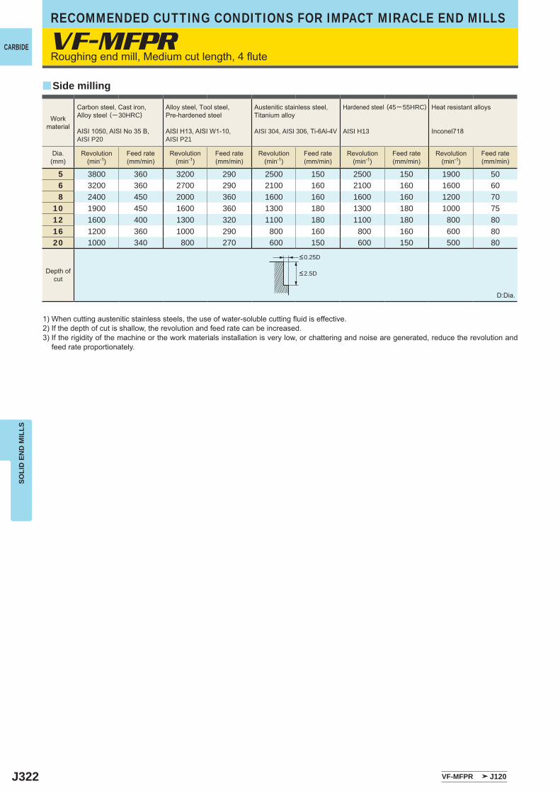
J322
VF-MFPR
5 3800 360 3200 290 2500 150 2500 150 1900 506 3200 360 2700 290 2100 160 2100 160 1600 608 2400 450 2000 360 1600 160 1600 160 1200 70
10 1900 450 1600 360 1300 180 1300 180 1000 7512 1600 400 1300 320 1100 180 1100 180 800 8016 1200 360 1000 290 800 160 800 160 600 8020 1000 340 800 270 600 150 600 150 500 80
VF-MFPR J120
y
CARBIDE
RECOMMENDED CUTTING CONDITIONS FOR IMPACT MIRACLE END MILLSSO
LID
EN
D M
ILLS
Roughing end mill, Medium cut length, 4 flute
1) When cutting austenitic stainless steels, the use of water-soluble cutting fluid is effective.2) If the depth of cut is shallow, the revolution and feed rate can be increased.3) If the rigidity of the machine or the work materials installation is very low, or chattering and noise are generated, reduce the revolution and
feed rate proportionately.
D:Dia.
Side milling
Workmaterial
Carbon steel, Cast iron, Alloy steel (─ 30HRC)
AISI 1050, AISI No 35 B,AISI P20
Alloy steel, Tool steel,Pre-hardened steel
AISI H13, AISI W1-10, AISI P21
Austenitic stainless steel,Titanium alloy
AISI 304, AISI 306, Ti-6Al-4V
Hardened steel (45─ 55HRC)
AISI H13
Heat resistant alloys
Inconel718
Dia.(mm)
Revolution(min-1)
Revolution(min-1)
Revolution(min-1)
Revolution(min-1)
Revolution(min-1)
Feed rate(mm/min)
Feed rate(mm/min)
Feed rate(mm/min)
Feed rate(mm/min)
Feed rate(mm/min)
Depth ofcut
<0.25D
<2.5D
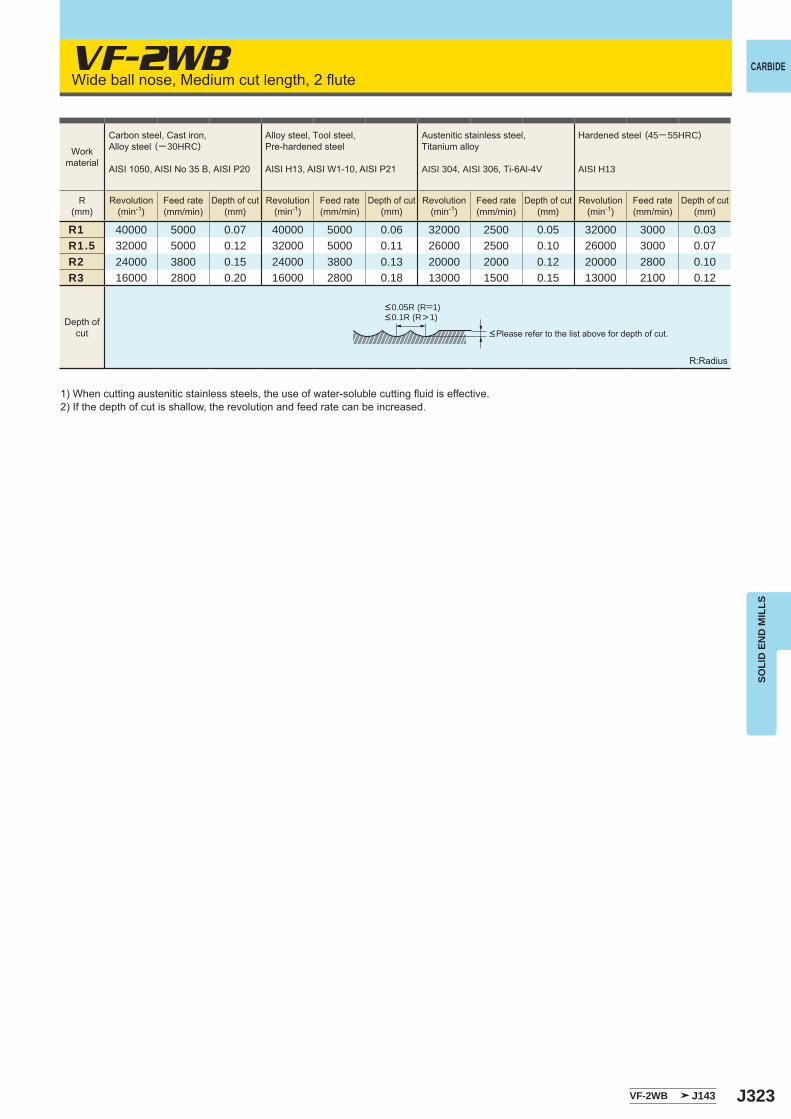
J323
VF-2WB
R1 40000 5000 0.07 40000 5000 0.06 32000 2500 0.05 32000 3000 0.03R1.5 32000 5000 0.12 32000 5000 0.11 26000 2500 0.10 26000 3000 0.07R2 24000 3800 0.15 24000 3800 0.13 20000 2000 0.12 20000 2800 0.10R3 16000 2800 0.20 16000 2800 0.18 13000 1500 0.15 13000 2100 0.12
VF-2WB J143
CARBIDE
SOLI
D E
ND
MIL
LS
Wide ball nose, Medium cut length, 2 flute
1) When cutting austenitic stainless steels, the use of water-soluble cutting fluid is effective.2) If the depth of cut is shallow, the revolution and feed rate can be increased.
R:Radius
<Please refer to the list above for depth of cut.
Workmaterial
Carbon steel, Cast iron, Alloy steel (─ 30HRC)
AISI 1050, AISI No 35 B, AISI P20
Alloy steel, Tool steel,Pre-hardened steel
AISI H13, AISI W1-10, AISI P21
Austenitic stainless steel,Titanium alloy
AISI 304, AISI 306, Ti-6Al-4V
Hardened steel (45─ 55HRC)
AISI H13
R(mm)
Revolution(min-1)
Revolution(min-1)
Revolution(min-1)
Revolution(min-1)
Feed rate(mm/min)
Feed rate(mm/min)
Feed rate(mm/min)
Feed rate(mm/min)
Depth of cut(mm)
Depth of cut(mm)
Depth of cut(mm)
Depth of cut(mm)
Depth ofcut
<0.05R (R=1)<0.1R (R>1)
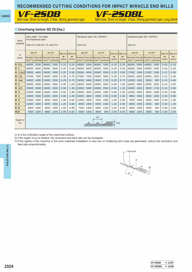
J324
VF-2SDB
%>15° %>15° %>15°
R 0.5 40000 5200 36000 2300 0.10 0.25 40000 5200 36000 2300 0.10 0.25 40000 5000 40000 2400 0.05 0.10R 1 40000 6000 36000 3500 0.20 0.50 40000 6000 36000 3500 0.20 0.50 36000 5000 24000 2400 0.10 0.20R 1.5x3 29000 4600 19000 2400 0.20 0.50 25000 4000 16000 2000 0.20 0.50 17000 2400 11000 1000 0.12 0.30R 1.5 37000 7000 24000 3000 0.30 0.75 37000 7000 24000 3000 0.30 0.75 25000 6000 16000 2200 0.12 0.30R 2x4 24000 4300 15000 2200 0.25 0.70 19000 3400 13000 1700 0.25 0.70 12000 1900 8200 900 0.13 0.40R 2 30000 6500 19000 2800 0.40 1.00 28000 6000 19000 2600 0.40 1.00 18000 4800 12000 2000 0.13 0.40R 2.5 25000 6000 16000 2600 0.50 1.30 22000 5000 16000 2300 0.50 1.25 15000 4200 9500 1700 0.15 0.50R 3 22000 6000 14000 2400 0.60 1.80 18000 4500 12000 1900 0.60 1.50 12000 3500 8000 1600 0.20 0.60R 4 19000 5200 12000 2200 0.80 2.40 15000 3800 9500 1700 0.80 2.00 9800 3000 6500 1300 0.20 0.80R 5 15000 4300 9500 2000 1.00 3.00 11000 3000 7000 1500 1.00 2.50 7500 2400 5000 1000 0.20 1.00R 6 12000 3400 8000 1800 1.20 3.60 9000 2400 6000 1400 1.20 3.00 6000 1900 4000 800 0.30 1.20R 8 9000 2600 6000 1500 1.60 4.80 7000 1900 4500 1100 1.60 4.00 4500 1500 3000 600 0.30 1.60R10 7500 2200 4800 1200 2.00 6.00 5500 1500 3600 900 2.00 5.00 3600 1200 2500 500 0.30 2.00
VF-2SDB J147VF-2SDBL J148
y
VF-2SDBL
ae
R
%
ap
pf
CARBIDE
RECOMMENDED CUTTING CONDITIONS FOR IMPACT MIRACLE END MILLSSO
LID
EN
D M
ILLS
Ball nose, Short cut length, 2 flute, Strong geometry type
1) % is the inclination angle of the machined surface. 2) If the depth of cut is shallow, the revolution and feed rate can be increased.3) If the rigidity of the machine or the work materials installation is very low, or chattering and noise are generated, reduce the revolution and
feed rate proportionately.
Ball nose, Short cut length, 2 flute, Strong geometry type, Long shank
Overhang below 5D (D:Dia.)
Workmaterial
Alloy steel, Tool steel,Pre-hardened steel
AISI H13, AISI W1-10, AISI P21
Hardened steel (45─ 55HRC)
AISI H13
Hardened steel (55─ 62HRC)
AISI D2
R(mm)
%<15° %<15° %<15°
Revolution(min-1)
Revolution(min-1)
Revolution(min-1)
Feed rate(mm/min)
Feed rate(mm/min)
Feed rate(mm/min)
Depth of cutap
(mm)
Depth of cutap
(mm)
Depth of cutap
(mm)
Depth of cutae
(mm)
Depth of cutae
(mm)
Depth of cutae
(mm)
Depth ofcut <ap
Revolution(min-1)
Feed rate(mm/min)
Revolution(min-1)
Revolution(min-1)
Feed rate(mm/min)
Feed rate(mm/min)
End mill
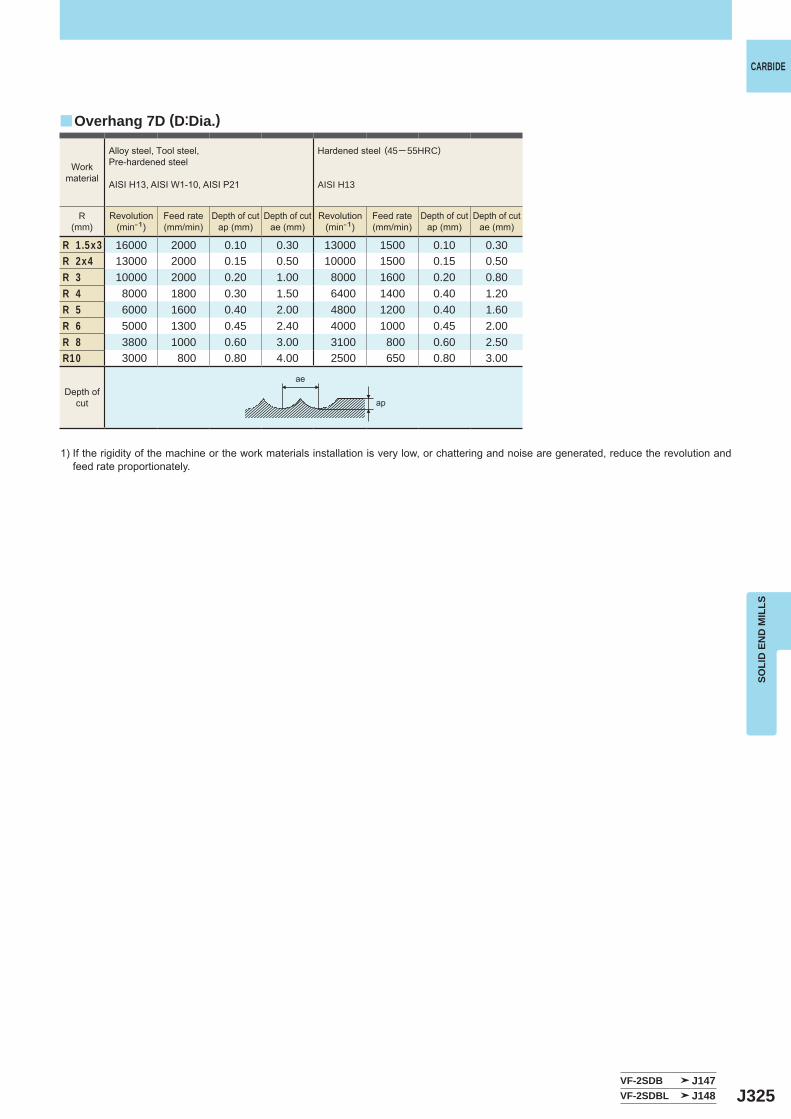
J325
R 1.5x3 16000 2000 0.10 0.30 13000 1500 0.10 0.30R 2x4 13000 2000 0.15 0.50 10000 1500 0.15 0.50R 3 10000 2000 0.20 1.00 8000 1600 0.20 0.80R 4 8000 1800 0.30 1.50 6400 1400 0.40 1.20R 5 6000 1600 0.40 2.00 4800 1200 0.40 1.60R 6 5000 1300 0.45 2.40 4000 1000 0.45 2.00R 8 3800 1000 0.60 3.00 3100 800 0.60 2.50R10 3000 800 0.80 4.00 2500 650 0.80 3.00
VF-2SDB J147VF-2SDBL J148
y
ae
ap
CARBIDE
SOLI
D E
ND
MIL
LS
1) If the rigidity of the machine or the work materials installation is very low, or chattering and noise are generated, reduce the revolution and feed rate proportionately.
Overhang 7D (D:Dia.)
Workmaterial
Alloy steel, Tool steel,Pre-hardened steel
AISI H13, AISI W1-10, AISI P21
Hardened steel (45─ 55HRC)
AISI H13
R(mm)
Revolution(min-1)
Revolution(min-1)
Feed rate(mm/min)
Feed rate(mm/min)
Depth of cutap (mm)
Depth of cutap (mm)
Depth of cutae (mm)
Depth of cutae (mm)
Depth ofcut

J326
VF-2SSB
%>15° %>15° %>15°
R 0.1 40000 320 40000 240 0.003 40000 320 40000 160 0.003 40000 320 40000 160 0.002R 0.15 40000 640 40000 560 0.01 40000 640 40000 400 0.007 40000 640 40000 400 0.005R 0.2 40000 1600 40000 1200 0.02 40000 1400 40000 1000 0.015 40000 1200 40000 1000 0.01R 0.3 40000 3200 40000 1600 0.03 40000 2800 40000 1200 0.025 40000 2000 40000 1200 0.02R 0.4 40000 6400 40000 2400 0.05 40000 4000 40000 1600 0.04 40000 2800 40000 1600 0.03R 0.5 40000 8000 40000 3200 0.06 40000 5600 40000 2400 0.05 40000 3600 32000 1300 0.04R 0.75 40000 9600 40000 4000 0.09 40000 7200 32000 2500 0.075 32000 4500 21000 1200 0.05R 1 40000 9600 39000 4700 0.11 40000 8000 24000 2400 0.1 24000 3800 16000 1000 0.07R 1.25 40000 10400 32000 4500 0.12 37000 8100 19000 2300 0.11 19000 3400 13000 1000 0.08R 1.5 40000 12000 27000 4300 0.13 32000 7700 16000 2200 0.12 16000 3200 11000 880 0.09R 2 32000 10880 20000 3600 0.15 24000 6200 12000 1900 0.13 12000 2400 8000 800 0.1R 2.5 25000 9000 16000 2900 0.2 19000 5300 9600 1700 0.15 9600 2100 6000 600 0.1R 3 21000 8400 13000 2600 0.25 16000 4800 8000 1600 0.2 8000 1700 5000 600 0.11R 4 16000 6400 10000 2000 0.3 12000 3600 6000 1200 0.2 6000 1400 4000 480 0.11R 5 13000 5200 8000 1700 0.5 10000 3200 4800 960 0.2 4800 1100 3000 420 0.12R 6 9000 3600 6000 1300 0.5 7000 2200 3600 720 0.3 3600 860 2200 310 0.12R 8 6000 2400 4000 1000 0.5 5000 1600 2500 500 0.3 2500 650 1500 240 0.15R10 4500 1800 3000 780 0.5 4000 1300 1800 360 0.3 1800 470 1000 160 0.15
VF-2SSB J144VF-2SB J145
R
%
ap
pf
CARBIDE
RECOMMENDED CUTTING CONDITIONS FOR IMPACT MIRACLE END MILLSSO
LID
EN
D M
ILLS
Ball nose, Short cut length, 2 flute, Short shank
1) % is the inclination angle of the machined surface. 2) If the depth of cut is shallow, the revolution and feed rate can be increased.3) If the rigidity of the machine or the work materials installation is very low, or chattering and noise are generated, reduce the revolution and
feed rate proportionately.
R:Radius
Ball nose, Short cut length, 2 flute, For hardened materials
<Please refer to the list above for depth of cut.
Workmaterial
Hardened steel (45─ 55HRC)
AISI H13
Hardened steel (55─ 62HRC)
AISI D2
Hardened steel (62─70HRC)
AISI W1, AISI M2
R(mm)
%<15° %<15° %<15°
Revolution(min-1)
Revolution(min-1)
Revolution(min-1)
Revolution(min-1)
Revolution(min-1)
Revolution(min-1)
Feed rate(mm/min)
Feed rate(mm/min)
Feed rate(mm/min)
Feed rate(mm/min)
Feed rate(mm/min)
Feed rate(mm/min)
Depth of cutap(mm)
Depth of cutap(mm)
Depth of cutap(mm)
Depth ofcut
<0.2R
VF-2SB
End mill
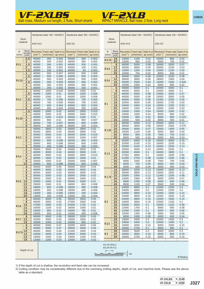
J327
VF-2XLBS
R 0.1
0.5 40000 300 0.003 40000 300 0.002 R 0.75 18 13000 1100 0.02 10000 800 0.02 1 40000 300 0.002 40000 300 0.002 20 12000 900 0.02 9000 700 0.01 1.5 40000 300 0.001 40000 200 0.001
R 0.88 40000 5000 0.08 26000 3200 0.07
2 40000 200 0.001 40000 100 0.001 12 35000 3800 0.05 20000 2100 0.03 2.5 40000 100 0.001 40000 60 0.001 16 13000 1200 0.04 12000 1100 0.02
R 0.15
1 40000 500 0.007 40000 500 0.005 20 10000 750 0.02 8000 600 0.01 1.5 40000 500 0.005 40000 500 0.003
R 0.98 40000 5000 0.09 25000 3100 0.08
2 40000 500 0.003 40000 500 0.002 12 36000 3800 0.06 18000 1900 0.04 2.5 40000 400 0.003 40000 400 0.002 16 25000 2500 0.04 14000 1300 0.025 3 40000 300 0.002 40000 300 0.001 20 10000 1000 0.03 8000 800 0.02 4 30000 200 0.002 30000 200 0.001
R 1
6 40000 6000 0.1 24000 3400 0.1
R 0.2
1 40000 1400 0.015 40000 1400 0.01 8 40000 5000 0.1 24000 3000 0.1 1.5 40000 1000 0.01 40000 1000 0.006 10 40000 5000 0.08 24000 3000 0.07 2 40000 1000 0.01 40000 1000 0.006 12 40000 5000 0.08 24000 2600 0.05 2.5 40000 700 0.005 40000 700 0.003 14 40000 5000 0.06 21000 2300 0.05 3 40000 700 0.005 40000 700 0.003 16 32000 3500 0.05 16000 1700 0.03 4 40000 600 0.004 40000 500 0.003 18 24000 2400 0.04 13000 1300 0.03 5 40000 400 0.003 40000 300 0.002 20 10000 1000 0.04 10000 1000 0.03
R 0.25
1.5 40000 2000 0.02 40000 2000 0.015 22 10000 1000 0.04 10000 1000 0.02 2 40000 2000 0.02 40000 2000 0.015 25 10000 1000 0.04 8000 800 0.02 3 40000 1200 0.015 40000 1200 0.01 30 10000 800 0.02 8000 800 0.015 4 36000 900 0.01 36000 900 0.007 35 10000 500 0.02 8000 400 0.01 5 36000 700 0.007 36000 600 0.005
R 1.25
10 36000 5000 0.12 20000 2600 0.11 6 36000 600 0.006 36000 500 0.004 15 36000 4600 0.08 18000 2000 0.075
R 0.3
2 40000 2800 0.03 40000 2800 0.02 20 26000 3000 0.07 13000 1400 0.05 3 40000 2800 0.03 40000 2800 0.02 25 10000 1100 0.06 8000 800 0.04 4 35000 2000 0.02 35000 2000 0.015 30 8000 800 0.05 7000 700 0.03 5 30000 1000 0.01 30000 1000 0.007 35 8000 500 0.03 5000 400 0.03 6 30000 800 0.008 30000 800 0.005
R 1.5
8 32000 6400 0.15 16000 3000 0.15 7 30000 600 0.008 30000 600 0.005 10 32000 5100 0.15 16000 2200 0.15 8 25000 400 0.006 25000 400 0.004 12 32000 5100 0.13 16000 2200 0.13
R 0.4
2 40000 3500 0.04 40000 3500 0.03 14 32000 4500 0.13 16000 2200 0.1 3 40000 3000 0.04 40000 3000 0.03 16 32000 4500 0.1 16000 1800 0.1 4 40000 3000 0.02 40000 3000 0.015 20 27000 3800 0.1 14000 1600 0.06 6 30000 1600 0.02 30000 1600 0.01 25 21000 2700 0.08 11000 1200 0.06 8 25000 1000 0.01 25000 1000 0.007 30 9000 1000 0.08 7000 700 0.0510 25000 600 0.008 25000 600 0.005 35 6000 700 0.06 6000 600 0.04
R 0.5
3 40000 4000 0.05 40000 4000 0.04 40 6000 600 0.04 5000 400 0.03 4 40000 4000 0.05 40000 4000 0.04
R 1.75
16 28000 4200 0.13 14000 1600 0.13 5 40000 3000 0.03 40000 3000 0.02 20 26000 3800 0.13 13000 1600 0.11 6 35000 2000 0.03 35000 2000 0.02 25 23000 3300 0.12 11000 1200 0.08 8 30000 1600 0.02 30000 1600 0.01 30 13000 1900 0.09 9000 1000 0.0710 20000 1000 0.01 20000 1000 0.01 35 9000 1200 0.08 6000 600 0.0612 20000 1000 0.01 18000 800 0.008 40 8500 1100 0.07 5500 500 0.0414 18000 600 0.008 18000 480 0.008
R 2
10 24000 4800 0.2 12000 2200 0.216 18000 500 0.008 18000 400 0.006 12 24000 4800 0.2 12000 2200 0.218 13000 300 0.005 13000 240 0.004 14 24000 3800 0.15 12000 1500 0.1520 13000 250 0.005 13000 200 0.004 16 24000 3800 0.15 12000 1500 0.15
R 0.6
6 40000 4000 0.05 35000 3500 0.04 20 24000 3800 0.15 12000 1500 0.15 8 40000 3000 0.05 27000 2000 0.04 25 24000 3800 0.15 10000 1100 0.110 27000 1900 0.03 24000 1700 0.02 30 20000 3000 0.1 10000 1100 0.0812 16000 1100 0.02 16000 1000 0.01 35 12000 1700 0.1 8000 900 0.0814 16000 850 0.01 16000 780 0.01 40 11000 1500 0.1 5000 500 0.0616 15000 500 0.01 14000 400 0.006 45 10000 1300 0.08 5000 500 0.05
R 0.7 8 40000 4500 0.06 28000 3200 0.05 50 8000 1000 0.05 4000 400 0.0412 32000 3000 0.03 19000 1800 0.02
R 2.520 19000 3400 0.2 10000 1400 0.2
16 15000 1000 0.02 14000 800 0.01 25 19000 3400 0.2 10000 1400 0.2
R 0.75
6 40000 5000 0.07 32000 4000 0.06 30 19000 3200 0.15 8000 1000 0.15 8 40000 5000 0.07 28000 3500 0.06 35 16000 2700 0.1 8000 900 0.110 40000 4500 0.06 21000 2400 0.04
R 330 16000 3500 0.2 8000 1000 0.2
12 32000 3400 0.04 19000 2000 0.03 40 16000 3000 0.15 8000 800 0.1514 16000 1500 0.04 13000 1200 0.03 50 16000 2700 0.15 6000 500 0.1516 13000 1200 0.03 13000 1200 0.02
VF-2XLBS J149VF-2XLB J150
ap
CARBIDE
SOLI
D E
ND
MIL
LS
Ball nose, Medium cut length, 2 flute, Short shank
1) If the depth of cut is shallow, the revolution and feed rate can be increased.2) Cutting condition may be considerably different due to the overhang (milling depth), depth of cut, and machine tools. Please see the above
table as a standard.
R:Radius
IMPACT MIRACLE, Ball nose, 2 flute, Long neck
Workmaterial
Workmaterial
Hardened steel (45─ 55HRC)
AISI H13
Hardened steel (55─ 62HRC)
AISI D2
Hardened steel (45─ 55HRC)
AISI H13
Hardened steel (55─ 62HRC)
AISI D2
R(mm)
R(mm)
Necklength(mm)
Necklength(mm)
Revolution(min-1)
Revolution(min-1)
Revolution(min-1)
Revolution(min-1)
Feed rate(mm/min)
Feed rate(mm/min)
Feed rate(mm/min)
Feed rate(mm/min)
Depth of cutap (mm)
Depth of cutap (mm)
Depth of cutap (mm)
Depth of cutap (mm)
Depth of cut
<0.1R (R<1)<0.2R (R>1)
VF-2XLB
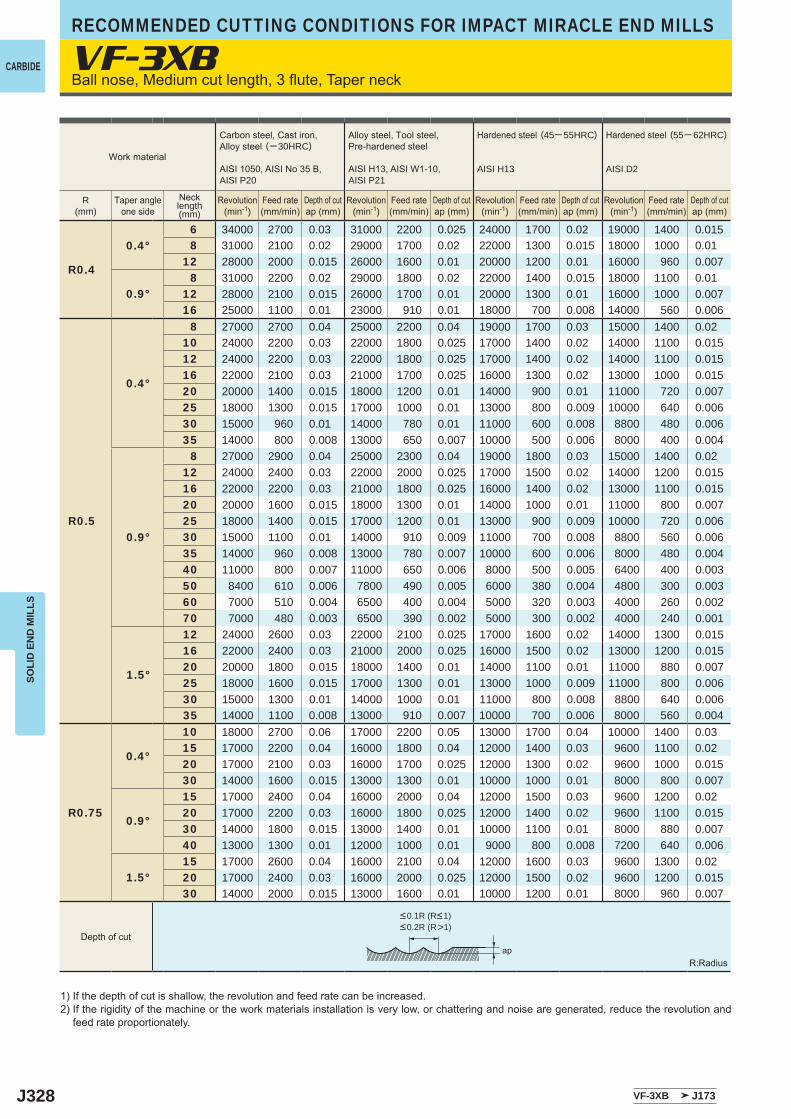
J328
VF-3XB
R0.4
0.4°6 34000 2700 0.03 31000 2200 0.025 24000 1700 0.02 19000 1400 0.0158 31000 2100 0.02 29000 1700 0.02 22000 1300 0.015 18000 1000 0.01
12 28000 2000 0.015 26000 1600 0.01 20000 1200 0.01 16000 960 0.007
0.9°8 31000 2200 0.02 29000 1800 0.02 22000 1400 0.015 18000 1100 0.01
12 28000 2100 0.015 26000 1700 0.01 20000 1300 0.01 16000 1000 0.00716 25000 1100 0.01 23000 910 0.01 18000 700 0.008 14000 560 0.006
R0.5
0.4°
8 27000 2700 0.04 25000 2200 0.04 19000 1700 0.03 15000 1400 0.0210 24000 2200 0.03 22000 1800 0.025 17000 1400 0.02 14000 1100 0.01512 24000 2200 0.03 22000 1800 0.025 17000 1400 0.02 14000 1100 0.01516 22000 2100 0.03 21000 1700 0.025 16000 1300 0.02 13000 1000 0.01520 20000 1400 0.015 18000 1200 0.01 14000 900 0.01 11000 720 0.00725 18000 1300 0.015 17000 1000 0.01 13000 800 0.009 10000 640 0.00630 15000 960 0.01 14000 780 0.01 11000 600 0.008 8800 480 0.00635 14000 800 0.008 13000 650 0.007 10000 500 0.006 8000 400 0.004
0.9°
8 27000 2900 0.04 25000 2300 0.04 19000 1800 0.03 15000 1400 0.0212 24000 2400 0.03 22000 2000 0.025 17000 1500 0.02 14000 1200 0.01516 22000 2200 0.03 21000 1800 0.025 16000 1400 0.02 13000 1100 0.01520 20000 1600 0.015 18000 1300 0.01 14000 1000 0.01 11000 800 0.00725 18000 1400 0.015 17000 1200 0.01 13000 900 0.009 10000 720 0.00630 15000 1100 0.01 14000 910 0.009 11000 700 0.008 8800 560 0.00635 14000 960 0.008 13000 780 0.007 10000 600 0.006 8000 480 0.00440 11000 800 0.007 11000 650 0.006 8000 500 0.005 6400 400 0.00350 8400 610 0.006 7800 490 0.005 6000 380 0.004 4800 300 0.00360 7000 510 0.004 6500 400 0.004 5000 320 0.003 4000 260 0.00270 7000 480 0.003 6500 390 0.002 5000 300 0.002 4000 240 0.001
1.5°
12 24000 2600 0.03 22000 2100 0.025 17000 1600 0.02 14000 1300 0.01516 22000 2400 0.03 21000 2000 0.025 16000 1500 0.02 13000 1200 0.01520 20000 1800 0.015 18000 1400 0.01 14000 1100 0.01 11000 880 0.00725 18000 1600 0.015 17000 1300 0.01 13000 1000 0.009 11000 800 0.00630 15000 1300 0.01 14000 1000 0.01 11000 800 0.008 8800 640 0.00635 14000 1100 0.008 13000 910 0.007 10000 700 0.006 8000 560 0.004
R0.75
0.4°
10 18000 2700 0.06 17000 2200 0.05 13000 1700 0.04 10000 1400 0.0315 17000 2200 0.04 16000 1800 0.04 12000 1400 0.03 9600 1100 0.0220 17000 2100 0.03 16000 1700 0.025 12000 1300 0.02 9600 1000 0.01530 14000 1600 0.015 13000 1300 0.01 10000 1000 0.01 8000 800 0.007
0.9°
15 17000 2400 0.04 16000 2000 0.04 12000 1500 0.03 9600 1200 0.0220 17000 2200 0.03 16000 1800 0.025 12000 1400 0.02 9600 1100 0.01530 14000 1800 0.015 13000 1400 0.01 10000 1100 0.01 8000 880 0.00740 13000 1300 0.01 12000 1000 0.01 9000 800 0.008 7200 640 0.006
1.5°15 17000 2600 0.04 16000 2100 0.04 12000 1600 0.03 9600 1300 0.0220 17000 2400 0.03 16000 2000 0.025 12000 1500 0.02 9600 1200 0.01530 14000 2000 0.015 13000 1600 0.01 10000 1200 0.01 8000 960 0.007
VF-3XB J173
ap
CARBIDE
RECOMMENDED CUTTING CONDITIONS FOR IMPACT MIRACLE END MILLSSO
LID
EN
D M
ILLS
Ball nose, Medium cut length, 3 flute, Taper neck
1) If the depth of cut is shallow, the revolution and feed rate can be increased.2) If the rigidity of the machine or the work materials installation is very low, or chattering and noise are generated, reduce the revolution and
feed rate proportionately.
R:Radius
Work material
Carbon steel, Cast iron, Alloy steel (─ 30HRC)
AISI 1050, AISI No 35 B,AISI P20
Alloy steel, Tool steel,Pre-hardened steel
AISI H13, AISI W1-10, AISI P21
Hardened steel (45─ 55HRC)
AISI H13
Hardened steel (55─ 62HRC)
AISI D2
R(mm)
Taper angleone side
Necklength(mm)
Revolution(min-1)
Revolution(min-1)
Revolution(min-1)
Revolution(min-1)
Feed rate(mm/min)
Feed rate(mm/min)
Feed rate(mm/min)
Feed rate(mm/min)
Depth of cutap (mm)
Depth of cutap (mm)
Depth of cutap (mm)
Depth of cutap (mm)
Depth of cut
<0.1R (R<1)<0.2R (R>1)
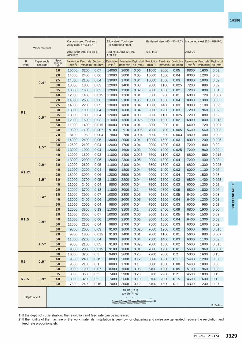
J329
R1
0.4°
16 15000 3200 0.07 14000 2600 0.06 11000 2000 0.05 8800 1600 0.0320 14000 2400 0.06 13000 2000 0.05 10000 1500 0.04 8000 1200 0.0325 14000 2100 0.04 13000 1700 0.04 10000 1300 0.03 8000 1000 0.0230 13000 1800 0.03 12000 1400 0.03 9000 1100 0.025 7200 880 0.0235 13000 1600 0.03 12000 1300 0.025 9000 1000 0.02 7200 800 0.01540 12000 1400 0.015 11000 1200 0.01 8500 900 0.01 6800 720 0.007
0.9°
20 14000 2600 0.06 13000 2100 0.05 10000 1600 0.04 8000 1300 0.0325 14000 2200 0.05 13000 1800 0.04 10000 1400 0.03 8000 1100 0.02530 13000 1900 0.04 12000 1600 0.04 9000 1200 0.03 7200 960 0.0235 13000 1800 0.04 12000 1400 0.03 9000 1100 0.025 7200 880 0.0240 12000 1600 0.03 11000 1300 0.025 8500 1000 0.02 6800 800 0.01550 11000 1400 0.015 10000 1200 0.01 8000 900 0.01 6400 720 0.00760 9800 1100 0.007 9100 910 0.006 7000 700 0.005 5600 560 0.00370 8400 960 0.004 7800 780 0.004 6000 600 0.003 4800 480 0.002
1.5°
25 14000 2400 0.05 13000 2000 0.04 10000 1500 0.03 8000 1200 0.02530 12600 2100 0.04 12000 1700 0.04 9000 1300 0.03 7200 1000 0.0235 13000 1900 0.04 12000 1600 0.03 9000 1200 0.025 7200 960 0.0240 12000 1800 0.03 11000 1400 0.025 8500 1100 0.02 6800 880 0.015
R1.25
0.9°20 13000 2900 0.06 12000 2300 0.05 9000 1800 0.04 7200 1400 0.0330 12000 2600 0.05 11000 2100 0.04 8500 1600 0.03 6800 1300 0.02540 11000 2200 0.04 9800 1800 0.04 7500 1400 0.03 6000 1100 0.02
1.5°20 13000 3000 0.06 12000 2500 0.05 9000 1900 0.04 7200 1500 0.0330 12000 2700 0.05 11050 2200 0.04 8500 1700 0.03 6800 1400 0.02540 11000 2400 0.04 9800 2000 0.04 7500 1500 0.03 6000 1200 0.02
R1.5
0.4°
20 12000 3700 0.13 11000 3000 0.1 8500 2300 0.09 6800 1800 0.0630 11000 2900 0.07 10000 2300 0.06 8000 1800 0.05 6400 1400 0.0340 11000 2400 0.06 10000 2000 0.05 8000 1500 0.04 6400 1200 0.0350 11000 2000 0.04 9800 1600 0.04 7500 1200 0.03 6000 960 0.02
0.9°
20 12000 3800 0.13 11000 3100 0.1 8500 2400 0.09 6800 1900 0.0630 11000 3000 0.07 10000 2500 0.06 8000 1900 0.05 6400 1500 0.0340 11000 2600 0.06 10000 2100 0.05 8000 1600 0.04 6400 1300 0.0350 11000 2100 0.04 9800 1700 0.04 7500 1300 0.03 6000 1000 0.0260 9800 2000 0.03 9100 1600 0.025 7000 1200 0.02 5600 960 0.01570 9800 1800 0.015 9100 1400 0.01 7000 1100 0.01 5600 880 0.007
1.5°50 11000 2200 0.04 9800 1800 0.04 7500 1400 0.03 6000 1100 0.0260 9800 2100 0.03 9100 1700 0.025 7000 1300 0.02 5600 1000 0.01570 9800 2000 0.015 9100 1600 0.01 7000 1200 0.01 5600 960 0.007
R2 0.9°
30 10000 3200 0.3 9400 2600 0.25 7200 2000 0.2 5800 1600 0.1540 9500 2400 0.15 8800 2000 0.12 6800 1500 0.1 5400 1200 0.0750 9500 2100 0.1 8800 1700 0.1 6800 1300 0.08 5400 1000 0.0660 9000 1900 0.07 8300 1600 0.06 6400 1200 0.05 5100 960 0.03
R2.5 0.9°35 8000 3500 0.3 7400 2900 0.25 5700 2200 0.2 4600 1800 0.1540 8000 3200 0.2 7400 2600 0.18 5700 2000 0.15 4600 1600 0.160 7600 2400 0.15 7000 2000 0.12 5400 1500 0.1 4300 1200 0.07
VF-3XB J173
ap
CARBIDE
SOLI
D E
ND
MIL
LS
1) If the depth of cut is shallow, the revolution and feed rate can be increased.2) If the rigidity of the machine or the work materials installation is very low, or chattering and noise are generated, reduce the revolution and
feed rate proportionately.
R:Radius
Work material
Carbon steel, Cast iron, Alloy steel (─ 30HRC)
AISI 1050, AISI No 35 B,AISI P20
Alloy steel, Tool steel,Pre-hardened steel
AISI H13, AISI W1-10, AISI P21
Hardened steel (45─ 55HRC)
AISI H13
Hardened steel (55─ 62HRC)
AISI D2
R(mm)
Taper angleone side
Necklength(mm)
Revolution(min-1)
Revolution(min-1)
Revolution(min-1)
Revolution(min-1)
Feed rate(mm/min)
Feed rate(mm/min)
Feed rate(mm/min)
Feed rate(mm/min)
Depth of cutap (mm)
Depth of cutap (mm)
Depth of cutap (mm)
Depth of cutap (mm)
Depth of cut
<0.1R (R<1)<0.2R (R>1)
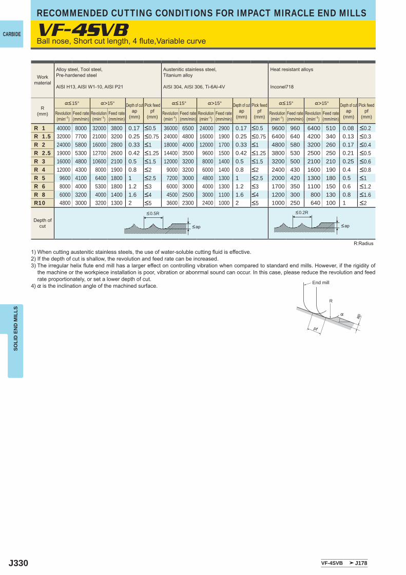
J330
VF-4SVB
VF-4SVB J178
R 1 40000 8000 32000 3800 0.17 36000 6500 24000 2900 0.17 9600 960 6400 510 0.08R 1.5 32000 7700 21000 3200 0.25 24000 4800 16000 1900 0.25 6400 640 4200 340 0.13R 2 24000 5800 16000 2800 0.33 18000 4000 12000 1700 0.33 4800 580 3200 260 0.17R 2.5 19000 5300 12700 2600 0.42 14400 3500 9600 1500 0.42 3800 530 2500 250 0.21R 3 16000 4800 10600 2100 0.5 12000 3200 8000 1400 0.5 3200 500 2100 210 0.25R 4 12000 4300 8000 1900 0.8 9000 3200 6000 1400 0.8 2400 430 1600 190 0.4R 5 9600 4100 6400 1800 1 7200 3000 4800 1300 1 2000 420 1300 180 0.5R 6 8000 4000 5300 1800 1.2 6000 3000 4000 1300 1.2 1700 350 1100 150 0.6R 8 6000 3200 4000 1400 1.6 4500 2500 3000 1100 1.6 1200 300 800 130 0.8R10 4800 3000 3200 1300 2 3600 2300 2400 1000 2 1000 250 640 100 1
R
%
ap
pf
CARBIDE
RECOMMENDED CUTTING CONDITIONS FOR IMPACT MIRACLE END MILLSSO
LID
EN
D M
ILLS
Ball nose, Short cut length, 4 flute,Variable curve
1) When cutting austenitic stainless steels, the use of water-soluble cutting fluid is effective.2) If the depth of cut is shallow, the revolution and feed rate can be increased.3) The irregular helix flute end mill has a larger effect on controlling vibration when compared to standard end mills. However, if the rigidity of
the machine or the workpiece installation is poor, vibration or abonrmal sound can occur. In this case, please reduce the revolution and feed rate proportionately, or set a lower depth of cut.
4) % is the inclination angle of the machined surface.
R:Radius
<0.5R <0.2R
<ap <ap
Workmaterial
Alloy steel, Tool steel,Pre-hardened steel
AISI H13, AISI W1-10, AISI P21
Austenitic stainless steel,Titanium alloy
AISI 304, AISI 306, Ti-6Al-4V
Heat resistant alloys
Inconel718
R(mm)
%<15° %>15° Depth of cutap
(mm)
Pick feedpf
(mm)
%<15° %>15° Depth of cutap
(mm)
Pick feedpf
(mm)
%<15° %>15° Depth of cutap
(mm)
Pick feedpf
(mm)Revolution(min-1)
Feed rate(mm/min)
Revolution(min-1)
Feed rate(mm/min)
Revolution(min-1)
Feed rate(mm/min)
Revolution(min-1)
Feed rate(mm/min)
Revolution(min-1)
Feed rate(mm/min)
Revolution(min-1)
Feed rate(mm/min)
<0.5 <0.5 <0.2<0.75 <0.75 <0.3<1 <1 <0.4<1.25 <1.25 <0.5<1.5 <1.5 <0.6<2 <2 <0.8<2.5 <2.5 <1<3 <3 <1.2<4 <4 <1.6<5 <5 <2
Depth ofcut
End mill
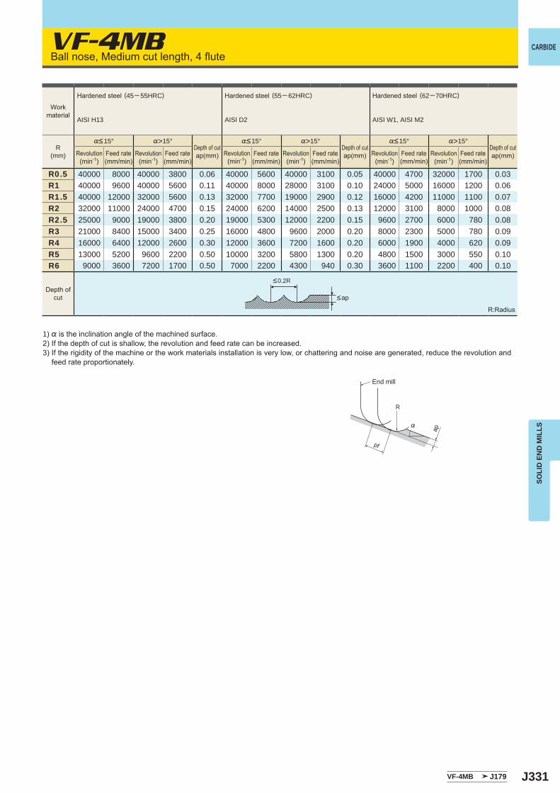
J331
VF-4MB
%>15° %>15° %>15°
R0.5 40000 8000 40000 3800 0.06 40000 5600 40000 3100 0.05 40000 4700 32000 1700 0.03R1 40000 9600 40000 5600 0.11 40000 8000 28000 3100 0.10 24000 5000 16000 1200 0.06R1.5 40000 12000 32000 5600 0.13 32000 7700 19000 2900 0.12 16000 4200 11000 1100 0.07R2 32000 11000 24000 4700 0.15 24000 6200 14000 2500 0.13 12000 3100 8000 1000 0.08R2.5 25000 9000 19000 3800 0.20 19000 5300 12000 2200 0.15 9600 2700 6000 780 0.08R3 21000 8400 15000 3400 0.25 16000 4800 9600 2000 0.20 8000 2300 5000 780 0.09R4 16000 6400 12000 2600 0.30 12000 3600 7200 1600 0.20 6000 1900 4000 620 0.09R5 13000 5200 9600 2200 0.50 10000 3200 5800 1300 0.20 4800 1500 3000 550 0.10R6 9000 3600 7200 1700 0.50 7000 2200 4300 940 0.30 3600 1100 2200 400 0.10
VF-4MB J179
R
%
appf
CARBIDE
SOLI
D E
ND
MIL
LS
Ball nose, Medium cut length, 4 flute
1) % is the inclination angle of the machined surface. 2) If the depth of cut is shallow, the revolution and feed rate can be increased.3) If the rigidity of the machine or the work materials installation is very low, or chattering and noise are generated, reduce the revolution and
feed rate proportionately.
R:Radius
<ap
Revolution(min-1)
Revolution(min-1)
Revolution(min-1)
Revolution(min-1)
Revolution(min-1)
Revolution(min-1)
%<15° %<15° %<15°
Feed rate(mm/min)
Feed rate(mm/min)
Feed rate(mm/min)
Feed rate(mm/min)
Feed rate(mm/min)
Feed rate(mm/min)
Depth ofcut
<0.2R
Workmaterial
Hardened steel (45─ 55HRC)
AISI H13
Hardened steel (55─ 62HRC)
AISI D2
Hardened steel (62─70HRC)
AISI W1, AISI M2
R(mm)
Depth of cutap(mm)
Depth of cutap(mm)
Depth of cutap(mm)
End mill
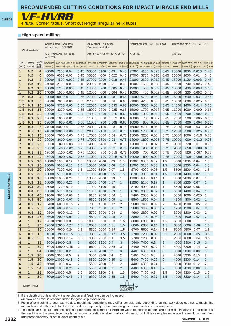
J332
VF-HVRB
y
1 0.2 4 40000 7200 0.04 0.45 33000 5100 0.03 0.45 27000 4100 0.025 0.45 20000 1800 0.013 0.451 0.2 6 40000 6500 0.03 0.45 33000 4600 0.022 0.45 27000 3700 0.018 0.45 20000 1600 0.01 0.451 0.2 8 32000 4500 0.022 0.45 27000 3200 0.018 0.45 21000 2600 0.012 0.45 16000 1100 0.008 0.451 0.2 10 24000 2700 0.015 0.45 20000 1900 0.01 0.45 16000 1500 0.008 0.45 12000 700 0.006 0.451 0.2 15 16000 1200 0.008 0.45 14000 700 0.005 0.45 12000 500 0.003 0.45 10000 400 0.003 0.451 0.2 20 14000 1000 0.005 0.45 12000 600 0.004 0.45 10000 400 0.002 0.45 9000 300 0.002 0.451.5 0.3 4 32000 10000 0.1 0.65 27000 7100 0.08 0.65 21000 5700 0.06 0.65 16000 2500 0.03 0.651.5 0.3 6 32000 7800 0.08 0.65 27000 5500 0.06 0.65 21000 4200 0.05 0.65 16000 2000 0.025 0.651.5 0.3 10 27000 5700 0.05 0.65 22000 4000 0.035 0.65 18000 3000 0.03 0.65 14000 1400 0.014 0.651.5 0.3 15 22000 3200 0.03 0.65 18000 2300 0.025 0.65 15000 1700 0.018 0.65 11000 1000 0.009 0.651.5 0.3 20 16000 1400 0.02 0.65 14000 1200 0.016 0.65 13000 1000 0.012 0.65 9000 700 0.007 0.651.5 0.3 25 13000 1000 0.015 0.65 11000 800 0.012 0.65 10000 700 0.009 0.65 7500 500 0.005 0.651.5 0.3 30 13000 900 0.01 0.65 11000 700 0.008 0.65 10000 600 0.006 0.65 7500 400 0.004 0.652 0.5 6 24000 10000 0.1 0.75 20000 7100 0.08 0.75 16000 5700 0.06 0.75 12000 2500 0.03 0.752 0.5 10 24000 10000 0.08 0.75 20000 7100 0.06 0.75 16000 5700 0.05 0.75 12000 2500 0.025 0.752 0.5 15 20000 7000 0.05 0.75 17000 5000 0.04 0.75 13000 3200 0.03 0.75 10000 1800 0.016 0.752 0.5 20 20000 3600 0.04 0.75 17000 2600 0.03 0.75 13000 1800 0.025 0.75 10000 900 0.012 0.752 0.5 25 16000 1800 0.03 0.75 14000 1400 0.025 0.75 12000 1100 0.02 0.75 9000 720 0.01 0.752 0.5 30 16000 1400 0.025 0.75 14000 1200 0.02 0.75 12000 900 0.016 0.75 9000 650 0.008 0.752 0.5 35 13000 1100 0.02 0.75 11000 800 0.018 0.75 10000 700 0.014 0.75 7000 500 0.007 0.752 0.5 40 13000 1000 0.02 0.75 11000 700 0.015 0.75 10000 600 0.012 0.75 7000 400 0.006 0.753 0.5 10 16000 11000 0.12 1.5 13000 7800 0.09 1.5 11000 6300 0.07 1.5 8000 2800 0.04 1.53 0.5 15 16000 9000 0.11 1.5 13000 6400 0.08 1.5 11000 5100 0.06 1.5 8000 2300 0.04 1.53 0.5 20 13000 7200 0.09 1.5 11000 5100 0.07 1.5 8700 4000 0.05 1.5 6500 1800 0.03 1.53 0.5 30 13000 5700 0.06 1.5 11000 4000 0.05 1.5 8700 3000 0.04 1.5 6500 1400 0.02 1.53 0.8 10 16000 11000 0.24 1 13000 7800 0.19 1 11000 6300 0.14 1 8000 2800 0.07 13 0.8 15 16000 9000 0.22 1 13000 6400 0.17 1 11000 5100 0.13 1 8000 2300 0.07 13 0.8 20 13000 7200 0.19 1 11000 5100 0.15 1 8700 4000 0.11 1 6500 1800 0.06 13 0.8 30 13000 5700 0.12 1 11000 4000 0.09 1 8700 3000 0.07 1 6500 1400 0.04 13 0.8 40 11000 3600 0.08 1 9100 2600 0.06 1 7400 2000 0.05 1 5500 1000 0.025 13 0.8 50 8000 2600 0.07 1 6600 1800 0.05 1 5800 1500 0.04 1 4600 800 0.02 14 0.5 12 8400 6000 0.15 2 7000 4300 0.12 2 5600 3400 0.09 2 4200 1500 0.05 24 0.5 20 8400 6000 0.14 2 7000 4300 0.11 2 5600 3400 0.08 2 4200 1500 0.04 24 0.5 30 6900 4900 0.12 2 5700 3500 0.09 2 4600 2800 0.07 2 3500 1200 0.03 24 0.5 48 5600 2000 0.07 2 4600 1400 0.05 2 3800 1100 0.04 2 2800 500 0.02 24 1 12 12000 12000 0.3 1.5 10000 8500 0.23 1.5 8000 6800 0.18 1.5 6000 3000 0.1 1.54 1 20 12000 12000 0.27 1.5 10000 8500 0.21 1.5 8000 6800 0.16 1.5 6000 3000 0.08 1.54 1 30 10000 9900 0.24 1.5 8300 7000 0.19 1.5 6700 5600 0.14 1.5 5000 2500 0.07 1.56 0.5 18 4000 3900 0.15 3.5 3300 2800 0.12 3.5 2700 2200 0.09 3.5 2000 1000 0.05 3.56 0.5 30 4000 3900 0.14 3.5 3300 2800 0.11 3.5 2700 2200 0.08 3.5 2000 1000 0.04 3.56 1 18 8000 13000 0.5 3 6600 9200 0.4 3 5400 7400 0.3 3 4000 3300 0.15 36 1 30 8000 13000 0.45 3 6600 9200 0.35 3 5400 7400 0.27 3 4000 3300 0.14 36 1 54 6600 11000 0.25 3 5500 7800 0.2 3 4400 6300 0.15 3 3300 2800 0.08 36 1.5 18 8000 13000 0.5 2 6600 9200 0.4 2 5400 7400 0.3 2 4000 3300 0.15 26 1.5 30 8000 13000 0.45 2 6600 9200 0.35 2 5400 7400 0.27 2 4000 3300 0.14 26 1.5 42 6600 11000 0.4 2 5500 7800 0.3 2 4400 6300 0.24 2 3300 2800 0.12 26 1.5 54 6600 11000 0.25 2 5500 7800 0.2 2 4400 6300 0.15 2 3300 2800 0.08 26 2 18 8000 13000 0.5 1.5 6600 9200 0.4 1.5 5400 7400 0.3 1.5 4000 3300 0.15 1.56 2 30 8000 13000 0.45 1.5 6600 9200 0.35 1.5 5400 7400 0.27 1.5 4000 3300 0.14 1.5
VF-HVRB J199
ae
ap
CARBIDE
RECOMMENDED CUTTING CONDITIONS FOR IMPACT MIRACLE END MILLSSO
LID
EN
D M
ILLS
4 flute, Corner radius, Short cut length,Irregular helix flutes
High speed milling
1) If the depth of cut is shallow, the revolution and feed rate can be increased.2) Air blow or oil mist is recommended for good chip evacuation.3) For profile machining such as moulds, machining conditions may differ considerably depending on the workpiece geometry, machining
methods and depth of cut. Reduce the feed rate especially when machining the corner sections of a workpiece.4) The irregular helix flute end mill has a larger effect on controlling vibration when compared to standard end mills. However, if the rigidity of
the machine or the workpiece installation is poor, vibration or abonrmal sound can occur. In this case, please reduce the revolution and feed rate proportionately, or set a lower depth of cut.
Work material
Carbon steel, Cast iron, Alloy steel (─ 30HRC)
AISI 1050, AISI No 35 B,AISI P20
Alloy steel, Tool steel,Pre-hardened steel
AISI H13, AISI W1-10, AISI P21
Hardened steel (45─ 55HRC)
AISI H13
Hardened steel (55─ 62HRC)
AISI D2
Dia.(mm)
Corner R(mm)
Revolution(min-1)
Revolution(min-1)
Revolution(min-1)
Revolution(min-1)
Necklength(mm)
Feed rate(mm/min)
Feed rate(mm/min)
Feed rate(mm/min)
Feed rate(mm/min)
Depth of cutap (mm)
Depth of cutap (mm)
Depth of cutap (mm)
Depth of cutap (mm)
Depth of cutae (mm)
Depth of cutae (mm)
Depth of cutae (mm)
Depth of cutae (mm)
Depth of cut
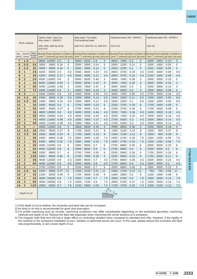
J333
7 1.5 ― 6800 13000 0.5 3 5600 9200 0.4 3 4600 7400 0.3 3 3400 3300 0.15 38 0.5 24 3000 3900 0.18 5 2500 2800 0.14 5 2000 2200 0.11 5 1500 1000 0.05 58 0.5 40 3000 3900 0.16 5 2500 2800 0.12 5 2000 2200 0.1 5 1500 1000 0.05 58 1 24 4200 6500 0.3 4.5 3500 4600 0.23 4.5 2800 3700 0.18 4.5 2100 1600 0.09 4.58 1 40 4200 6500 0.27 4.5 3500 4600 0.21 4.5 2800 3700 0.16 4.5 2100 1600 0.08 4.58 2 24 6000 13000 0.6 3 5000 9200 0.46 3 4000 7400 0.36 3 3000 3300 0.18 38 2 40 6000 13000 0.54 3 5000 9200 0.42 3 4000 7400 0.32 3 3000 3300 0.16 38 2 56 5000 11000 0.48 3 4200 7800 0.37 3 3400 6300 0.3 3 2500 2800 0.14 38 2 72 5000 11000 0.3 3 4200 7800 0.23 3 3400 6300 0.2 3 2500 2800 0.09 39 2 ― 5300 13000 0.6 3.5 4400 9200 0.46 3.5 3600 7400 0.36 3.5 2700 3300 0.18 3.5
10 0.5 30 2400 3900 0.18 6.5 2000 2800 0.14 6.5 1600 2200 0.11 6.5 1200 1000 0.05 6.510 0.5 50 2400 3900 0.16 6.5 2000 2800 0.12 6.5 1600 2200 0.1 6.5 1200 1000 0.05 6.510 1 30 3300 6500 0.3 6 2700 4600 0.23 6 2200 3700 0.18 6 1700 1600 0.09 610 1 50 3300 6500 0.27 6 2700 4600 0.21 6 2200 3700 0.16 6 1700 1600 0.08 610 2 30 4800 13000 0.6 4.5 4000 9200 0.46 4.5 3200 7400 0.36 4.5 2400 3300 0.18 4.510 2 50 4800 13000 0.54 4.5 4000 9200 0.42 4.5 3200 7400 0.32 4.5 2400 3300 0.16 4.510 2 70 4000 11000 0.48 4.5 3300 7800 0.37 4.5 2700 6300 0.3 4.5 2000 2800 0.14 4.510 2 90 4000 11000 0.48 4.5 3300 7800 0.37 4.5 2700 6300 0.3 4.5 2000 2800 0.14 4.511 2 ― 4300 12000 0.6 5 3600 8500 0.46 5 2900 6800 0.36 5 2200 3000 0.18 512 0.5 36 2000 3600 0.27 8 1700 2600 0.21 8 1300 2100 0.14 8 1000 900 0.07 812 0.5 60 2000 3600 0.24 8 1700 2600 0.18 8 1300 2100 0.12 8 1000 900 0.06 812 1 36 2400 4800 0.36 7.5 2000 3400 0.28 7.5 1600 2700 0.18 7.5 1200 1200 0.09 7.512 1 60 2400 4800 0.32 7.5 2000 3400 0.25 7.5 1600 2700 0.16 7.5 1200 1200 0.08 7.512 2 36 4000 12000 0.9 6 3300 8500 0.7 6 2700 6800 0.45 6 2000 3000 0.23 612 2 60 4000 12000 0.8 6 3300 8500 0.6 6 2700 6800 0.4 6 2000 3000 0.2 612 2 84 3300 9900 0.7 6 2700 7000 0.55 6 2200 5600 0.36 6 1700 2500 0.18 612 2 108 3300 9900 0.45 6 2700 7000 0.35 6 2200 5600 0.23 6 1700 2500 0.11 612 3 36 4000 12000 0.9 4.5 3300 8500 0.7 4.5 2700 6800 0.45 4.5 2000 3000 0.23 4.512 3 60 4000 12000 0.8 4.5 3300 8500 0.6 4.5 2700 6800 0.4 4.5 2000 3000 0.2 4.513 3 ― 3700 12000 0.9 5 3100 8500 0.7 5 2500 6800 0.45 5 1900 3000 0.23 516 0.5 42 1500 3000 0.27 11 1200 2100 0.21 11 1000 1700 0.12 11 750 750 0.05 1116 2 42 2100 5000 0.45 9 1700 3600 0.35 9 1400 2900 0.2 9 1100 1300 0.08 916 3 42 3000 10000 0.9 7.5 2500 7100 0.7 7.5 2000 5700 0.4 7.5 1500 2500 0.15 7.516 3 80 3000 10000 0.8 7.5 2500 7100 0.6 7.5 2000 5700 0.37 7.5 1500 2500 0.14 7.516 3 120 2500 8300 0.7 7.5 2100 5900 0.55 7.5 1700 4700 0.32 7.5 1300 2100 0.12 7.5
VF-HVRB J199
ae
ap
CARBIDE
SOLI
D E
ND
MIL
LS
1) If the depth of cut is shallow, the revolution and feed rate can be increased.2) Air blow or oil mist is recommended for good chip evacuation.3) For profile machining such as moulds, machining conditions may differ considerably depending on the workpiece geometry, machining
methods and depth of cut. Reduce the feed rate especially when machining the corner sections of a workpiece.4) The irregular helix flute end mill has a larger effect on controlling vibration when compared to standard end mills. However, if the rigidity of
the machine or the workpiece installation is poor, vibration or abonrmal sound can occur. In this case, please reduce the revolution and feed rate proportionately, or set a lower depth of cut.
Work material
Carbon steel, Cast iron, Alloy steel (─ 30HRC)
AISI 1050, AISI No 35 B,AISI P20
Alloy steel, Tool steel,Pre-hardened steel
AISI H13, AISI W1-10, AISI P21
Hardened steel (45─ 55HRC)
AISI H13
Hardened steel (55─ 62HRC)
AISI D2
Dia.(mm)
Corner R(mm)
Revolution(min-1)
Revolution(min-1)
Revolution(min-1)
Revolution(min-1)
Necklength(mm)
Feed rate(mm/min)
Feed rate(mm/min)
Feed rate(mm/min)
Feed rate(mm/min)
Depth of cutap (mm)
Depth of cutap (mm)
Depth of cutap (mm)
Depth of cutap (mm)
Depth of cutae (mm)
Depth of cutae (mm)
Depth of cutae (mm)
Depth of cutae (mm)
Depth of cut
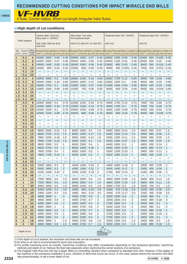
J334
VF-HVRB
y
1 0.2 4 24000 2200 0.08 0.45 20000 1500 0.07 0.45 16000 1200 0.05 0.45 12000 550 0.025 0.451 0.2 6 24000 2000 0.07 0.45 20000 1400 0.05 0.45 16000 1100 0.04 0.45 12000 500 0.02 0.451 0.2 8 19000 1400 0.05 0.45 16000 1000 0.04 0.45 13000 800 0.03 0.45 9500 350 0.016 0.451 0.2 10 14000 800 0.04 0.45 12000 600 0.03 0.45 9000 400 0.025 0.45 7000 200 0.012 0.451 0.2 15 ─ ─ ─ ─ ─ ─ ─ ─ ─ ─ ─ ─ ─ ─ ─ ─1 0.2 20 ─ ─ ─ ─ ─ ─ ─ ─ ─ ─ ─ ─ ─ ─ ─ ─1.5 0.3 4 19000 3000 0.2 0.65 16000 2100 0.16 0.65 13000 1700 0.12 0.65 9500 750 0.06 0.651.5 0.3 6 19000 2300 0.16 0.65 16000 1600 0.13 0.65 13000 1300 0.1 0.65 9500 580 0.05 0.651.5 0.3 10 16000 1700 0.1 0.65 13000 1200 0.07 0.65 11000 1000 0.05 0.65 8000 430 0.03 0.651.5 0.3 15 13000 1000 0.06 0.65 11000 700 0.05 0.65 9000 600 0.04 0.65 6500 250 0.018 0.651.5 0.3 20 ─ ─ ─ ─ ─ ─ ─ ─ ─ ─ ─ ─ ─ ─ ─ ─1.5 0.3 25 ─ ─ ─ ─ ─ ─ ─ ─ ─ ─ ─ ─ ─ ─ ─ ─1.5 0.3 30 ─ ─ ─ ─ ─ ─ ─ ─ ─ ─ ─ ─ ─ ─ ─ ─2 0.5 6 14000 3000 0.2 0.75 12000 2100 0.16 0.75 9400 1700 0.12 0.75 7000 750 0.06 0.752 0.5 10 14000 3000 0.16 0.75 12000 2100 0.13 0.75 9400 1700 0.1 0.75 7000 750 0.05 0.752 0.5 15 12000 2100 0.1 0.75 10000 1500 0.08 0.75 8000 1200 0.06 0.75 6000 530 0.03 0.752 0.5 20 12000 1100 0.08 0.75 10000 800 0.06 0.75 8000 600 0.05 0.75 6000 280 0.025 0.752 0.5 25 ─ ─ ─ ─ ─ ─ ─ ─ ─ ─ ─ ─ ─ ─ ─ ─2 0.5 30 ─ ─ ─ ─ ─ ─ ─ ─ ─ ─ ─ ─ ─ ─ ─ ─2 0.5 35 ─ ─ ─ ─ ─ ─ ─ ─ ─ ─ ─ ─ ─ ─ ─ ─2 0.5 40 ─ ─ ─ ─ ─ ─ ─ ─ ─ ─ ─ ─ ─ ─ ─ ─3 0.5 10 9600 3300 0.24 1.5 8000 2300 0.2 1.5 6400 1800 0.14 1.5 4800 830 0.07 1.53 0.5 15 9600 2700 0.22 1.5 8000 1900 0.17 1.5 6400 1500 0.13 1.5 4800 680 0.06 1.53 0.5 20 7800 2200 0.18 1.5 6500 1500 0.14 1.5 5200 1200 0.11 1.5 3900 550 0.05 1.53 0.5 30 7800 1700 0.12 1.5 6500 1200 0.1 1.5 5200 1000 0.07 1.5 3900 430 0.04 1.53 0.8 10 9600 3300 0.5 1 8000 2300 0.4 1 6400 1800 0.3 1 4800 830 0.14 13 0.8 15 9600 2700 0.5 1 8000 1900 0.35 1 6400 1500 0.25 1 4800 680 0.13 13 0.8 20 7800 2200 0.4 1 6500 1500 0.3 1 5200 1200 0.23 1 3900 550 0.11 13 0.8 30 7800 1700 0.24 1 6500 1200 0.2 1 5200 1000 0.14 1 3900 430 0.05 13 0.8 40 ─ ─ ─ ─ ─ ─ ─ ─ ─ ─ ─ ─ ─ ─ ─ ─3 0.8 50 ─ ─ ─ ─ ─ ─ ─ ─ ─ ─ ─ ─ ─ ─ ─ ─4 0.5 12 5000 1800 0.3 2 4200 1300 0.24 2 3400 1000 0.18 2 2500 450 0.06 24 0.5 20 5000 1800 0.3 2 4200 1300 0.22 2 3400 1000 0.17 2 2500 450 0.06 24 0.5 30 4100 1500 0.24 2 3400 1100 0.19 2 2700 840 0.14 2 2100 380 0.05 24 0.5 48 ─ ─ ─ ─ ─ ─ ─ ─ ─ ─ ─ ─ ─ ─ ─ ─4 1 12 7200 3600 0.6 1.5 6000 2500 0.5 1.5 4800 2000 0.36 1.5 3600 900 0.12 1.54 1 20 7200 3600 0.6 1.5 6000 2500 0.4 1.5 4800 2000 0.32 1.5 3600 900 0.11 1.54 1 30 6000 3000 0.5 1.5 5000 2100 0.4 1.5 4000 1700 0.3 1.5 3000 750 0.1 1.56 0.5 18 2400 1200 0.3 3.5 2000 840 0.24 3.5 1600 670 0.18 3.5 1200 300 0.06 3.56 0.5 30 2400 1200 0.3 3.5 2000 840 0.22 3.5 1600 670 0.17 3.5 1200 300 0.06 3.56 1 18 4800 3900 1 3 4000 2700 0.8 3 3200 2200 0.6 3 2400 980 0.2 36 1 30 4800 3900 0.9 3 4000 2700 0.7 3 3200 2200 0.5 3 2400 980 0.18 36 1 54 4000 3300 0.5 3 3300 2300 0.4 3 2700 1800 0.3 3 2000 830 0.1 36 1.5 18 4800 3900 1 2 4000 2700 0.8 2 3200 2200 0.6 2 2400 980 0.2 26 1.5 30 4800 3900 0.9 2 4000 2700 0.7 2 3200 2200 0.5 2 2400 980 0.18 26 1.5 42 4000 3300 0.8 2 3300 2300 0.6 2 2700 1800 0.5 2 2000 830 0.16 26 1.5 54 4000 3300 0.5 2 3300 2300 0.4 2 2700 1800 0.3 2 2000 830 0.1 26 2 18 4800 3900 1 1.5 4000 2700 0.8 1.5 3200 2200 0.6 1.5 2400 980 0.2 1.56 2 30 4800 3900 0.9 1.5 4000 2700 0.7 1.5 3200 2200 0.5 1.5 2400 980 0.18 1.5
VF-HVRB J199
ae
ap
CARBIDE
RECOMMENDED CUTTING CONDITIONS FOR IMPACT MIRACLE END MILLSSO
LID
EN
D M
ILLS
4 flute, Corner radius, Short cut length,Irregular helix flutes
High depth of cut conditions
1) If the depth of cut is shallow, the revolution and feed rate can be increased.2) Air blow or oil mist is recommended for good chip evacuation.3) For profile machining such as moulds, machining conditions may differ considerably depending on the workpiece geometry, machining
methods and depth of cut. Reduce the feed rate especially when machining the corner sections of a workpiece.4) The irregular helix flute end mill has a larger effect on controlling vibration when compared to standard end mills. However, if the rigidity of
the machine or the workpiece installation is poor, vibration or abonrmal sound can occur. In this case, please reduce the revolution and feed rate proportionately, or set a lower depth of cut.
Work material
Carbon steel, Cast iron, Alloy steel (─ 30HRC)
AISI 1050, AISI No 35 B,AISI P20
Alloy steel, Tool steel,Pre-hardened steel
AISI H13, AISI W1-10, AISI P21
Hardened steel (45─ 55HRC)
AISI H13
Hardened steel (55─ 62HRC)
AISI D2
Dia.(mm)
Corner R(mm)
Necklength(mm)
Revolution(min-1)
Revolution(min-1)
Revolution(min-1)
Revolution(min-1)
Feed rate(mm/min)
Feed rate(mm/min)
Feed rate(mm/min)
Feed rate(mm/min)
Depth of cutap (mm)
Depth of cutap (mm)
Depth of cutap (mm)
Depth of cutap (mm)
Depth of cutae (mm)
Depth of cutae (mm)
Depth of cutae (mm)
Depth of cutae (mm)
Depth of cut
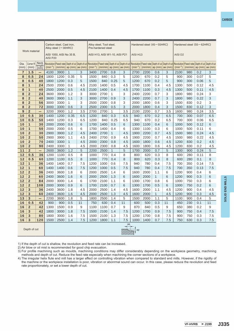
J335
7 1.5 ― 4100 3900 1 3 3400 2700 0.8 3 2700 2200 0.6 3 2100 980 0.2 38 0.5 24 1800 1200 0.35 5 1500 840 0.3 5 1200 670 0.2 5 900 300 0.07 58 0.5 40 1800 1200 0.3 5 1500 840 0.25 5 1200 670 0.2 5 900 300 0.06 58 1 24 2500 2000 0.6 4.5 2100 1400 0.5 4.5 1700 1100 0.4 4.5 1300 500 0.12 4.58 1 40 2500 2000 0.5 4.5 2100 1400 0.4 4.5 1700 1100 0.3 4.5 1300 500 0.11 4.58 2 24 3600 3900 1.2 3 3000 2700 1 3 2400 2200 0.7 3 1800 980 0.24 38 2 40 3600 3900 1.1 3 3000 2700 0.9 3 2400 2200 0.7 3 1800 980 0.22 38 2 56 3000 3300 1 3 2500 2300 0.8 3 2000 1800 0.6 3 1500 830 0.2 38 2 72 3000 3300 0.6 3 2500 2300 0.5 3 2000 1800 0.4 3 1500 830 0.12 39 2 ― 3200 3900 1.2 3.5 2700 2700 1 3.5 2100 2200 0.7 3.5 1600 980 0.24 3.5
10 0.5 30 1400 1200 0.35 6.5 1200 840 0.3 6.5 940 670 0.2 6.5 700 300 0.07 6.510 0.5 50 1400 1200 0.3 6.5 1200 840 0.25 6.5 940 670 0.2 6.5 700 300 0.06 6.510 1 30 2000 2000 0.6 6 1700 1400 0.5 6 1300 1100 0.4 6 1000 500 0.12 610 1 50 2000 2000 0.5 6 1700 1400 0.4 6 1300 1100 0.3 6 1000 500 0.11 610 2 30 2900 3900 1.2 4.5 2400 2700 1 4.5 1900 2200 0.7 4.5 1500 980 0.24 4.510 2 50 2900 3900 1.1 4.5 2400 2700 0.9 4.5 1900 2200 0.7 4.5 1500 980 0.22 4.510 2 70 2400 3300 1 4.5 2000 2300 0.8 4.5 1600 1800 0.6 4.5 1200 830 0.2 4.510 2 90 2400 3300 1 4.5 2000 2300 0.8 4.5 1600 1800 0.6 4.5 1200 830 0.2 4.511 2 ― 2600 3600 1.2 5 2200 2500 1 5 1700 2000 0.7 5 1300 900 0.24 512 0.5 36 1200 1100 0.5 8 1000 770 0.4 8 800 620 0.3 8 600 280 0.11 812 0.5 60 1200 1100 0.5 8 1000 770 0.4 8 800 620 0.3 8 600 280 0.1 812 1 36 1400 1400 0.7 7.5 1200 1000 0.6 7.5 940 780 0.4 7.5 700 350 0.14 7.512 1 60 1400 1400 0.6 7.5 1200 1000 0.5 7.5 940 780 0.4 7.5 700 350 0.13 7.512 2 36 2400 3600 1.8 6 2000 2500 1.4 6 1600 2000 1.1 6 1200 900 0.4 612 2 60 2400 3600 1.6 6 2000 2500 1.3 6 1600 2000 1 6 1200 900 0.3 612 2 84 2000 3000 1.4 6 1700 2100 1.1 6 1300 1700 0.8 6 1000 750 0.3 612 2 108 2000 3000 0.9 6 1700 2100 0.7 6 1300 1700 0.5 6 1000 750 0.2 612 3 36 2400 3600 1.8 4.5 2000 2500 1.4 4.5 1600 2000 1.1 4.5 1200 900 0.4 4.512 3 60 2400 3600 1.6 4.5 2000 2500 1.3 4.5 1600 2000 1 4.5 1200 900 0.3 4.513 3 ― 2200 3600 1.8 5 1800 2500 1.4 5 1500 2000 1.1 5 1100 900 0.4 516 0.5 42 900 900 0.5 11 750 630 0.4 11 600 500 0.3 11 450 230 0.1 1116 2 42 1300 1500 0.9 9 1100 1100 0.7 9 870 840 0.5 9 650 380 0.2 916 3 42 1800 3000 1.8 7.5 1500 2100 1.4 7.5 1200 1700 0.9 7.5 900 750 0.4 7.516 3 80 1800 3000 1.6 7.5 1500 2100 1.3 7.5 1200 1700 0.8 7.5 900 750 0.3 7.516 3 120 1500 2500 1.4 7.5 1200 1800 1.1 7.5 1000 1400 0.7 7.5 750 630 0.3 7.5
VF-HVRB J199
ae
ap
CARBIDE
SOLI
D E
ND
MIL
LS
1) If the depth of cut is shallow, the revolution and feed rate can be increased.2) Air blow or oil mist is recommended for good chip evacuation.3) For profile machining such as moulds, machining conditions may differ considerably depending on the workpiece geometry, machining
methods and depth of cut. Reduce the feed rate especially when machining the corner sections of a workpiece.4) The irregular helix flute end mill has a larger effect on controlling vibration when compared to standard end mills. However, if the rigidity of
the machine or the workpiece installation is poor, vibration or abonrmal sound can occur. In this case, please reduce the revolution and feed rate proportionately, or set a lower depth of cut.
Work material
Carbon steel, Cast iron, Alloy steel (─ 30HRC)
AISI 1050, AISI No 35 B,AISI P20
Alloy steel, Tool steel,Pre-hardened steel
AISI H13, AISI W1-10, AISI P21
Hardened steel (45─ 55HRC)
AISI H13
Hardened steel (55─ 62HRC)
AISI D2
Dia.(mm)
Corner R(mm)
Necklength(mm)
Revolution(min-1)
Revolution(min-1)
Revolution(min-1)
Revolution(min-1)
Feed rate(mm/min)
Feed rate(mm/min)
Feed rate(mm/min)
Feed rate(mm/min)
Depth of cutap (mm)
Depth of cutap (mm)
Depth of cutap (mm)
Depth of cutap (mm)
Depth of cutae (mm)
Depth of cutae (mm)
Depth of cutae (mm)
Depth of cutae (mm)
Depth of cut
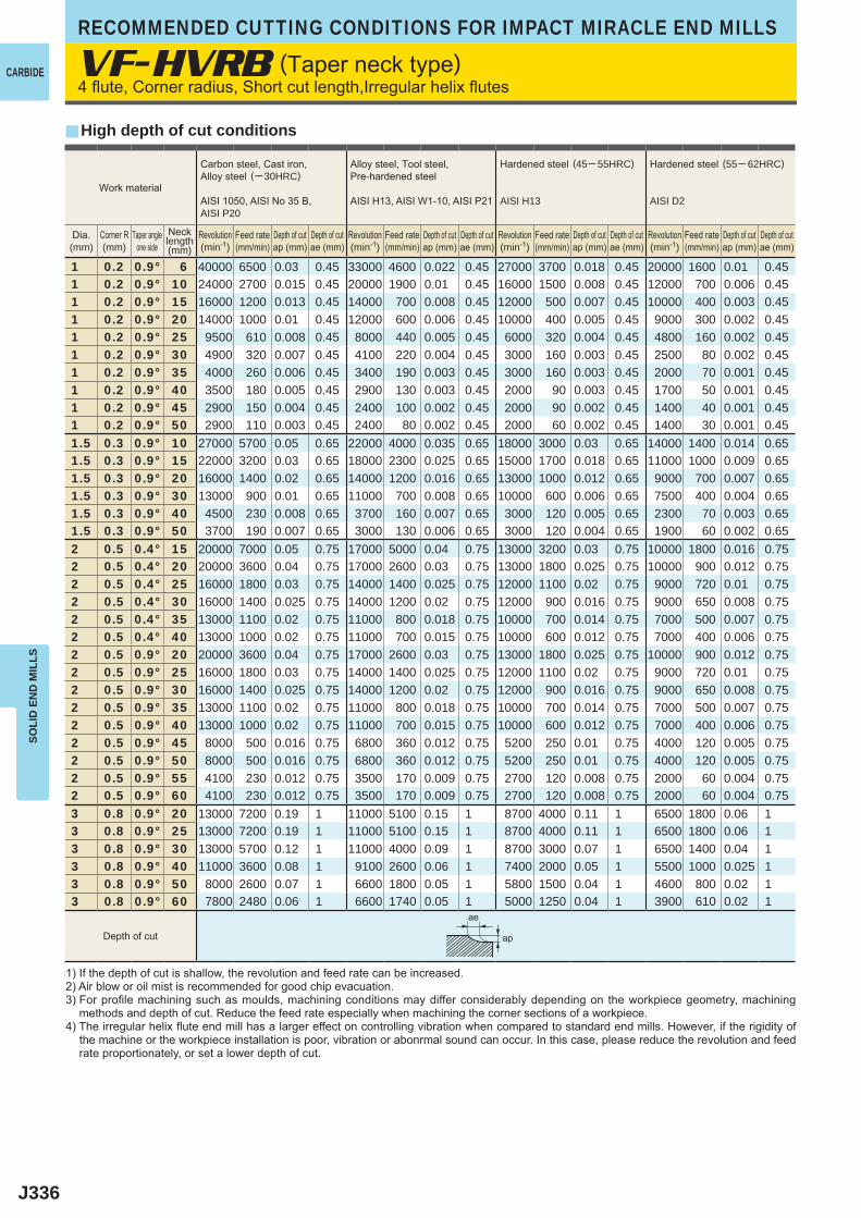
J336
VF-HVRB
y
1 0.2 0.9° 6 40000 6500 0.03 0.45 33000 4600 0.022 0.45 27000 3700 0.018 0.45 20000 1600 0.01 0.451 0.2 0.9° 10 24000 2700 0.015 0.45 20000 1900 0.01 0.45 16000 1500 0.008 0.45 12000 700 0.006 0.451 0.2 0.9° 15 16000 1200 0.013 0.45 14000 700 0.008 0.45 12000 500 0.007 0.45 10000 400 0.003 0.451 0.2 0.9° 20 14000 1000 0.01 0.45 12000 600 0.006 0.45 10000 400 0.005 0.45 9000 300 0.002 0.451 0.2 0.9° 25 9500 610 0.008 0.45 8000 440 0.005 0.45 6000 320 0.004 0.45 4800 160 0.002 0.451 0.2 0.9° 30 4900 320 0.007 0.45 4100 220 0.004 0.45 3000 160 0.003 0.45 2500 80 0.002 0.451 0.2 0.9° 35 4000 260 0.006 0.45 3400 190 0.003 0.45 3000 160 0.003 0.45 2000 70 0.001 0.451 0.2 0.9° 40 3500 180 0.005 0.45 2900 130 0.003 0.45 2000 90 0.003 0.45 1700 50 0.001 0.451 0.2 0.9° 45 2900 150 0.004 0.45 2400 100 0.002 0.45 2000 90 0.002 0.45 1400 40 0.001 0.451 0.2 0.9° 50 2900 110 0.003 0.45 2400 80 0.002 0.45 2000 60 0.002 0.45 1400 30 0.001 0.451.5 0.3 0.9° 10 27000 5700 0.05 0.65 22000 4000 0.035 0.65 18000 3000 0.03 0.65 14000 1400 0.014 0.651.5 0.3 0.9° 15 22000 3200 0.03 0.65 18000 2300 0.025 0.65 15000 1700 0.018 0.65 11000 1000 0.009 0.651.5 0.3 0.9° 20 16000 1400 0.02 0.65 14000 1200 0.016 0.65 13000 1000 0.012 0.65 9000 700 0.007 0.651.5 0.3 0.9° 30 13000 900 0.01 0.65 11000 700 0.008 0.65 10000 600 0.006 0.65 7500 400 0.004 0.651.5 0.3 0.9° 40 4500 230 0.008 0.65 3700 160 0.007 0.65 3000 120 0.005 0.65 2300 70 0.003 0.651.5 0.3 0.9° 50 3700 190 0.007 0.65 3000 130 0.006 0.65 3000 120 0.004 0.65 1900 60 0.002 0.652 0.5 0.4° 15 20000 7000 0.05 0.75 17000 5000 0.04 0.75 13000 3200 0.03 0.75 10000 1800 0.016 0.752 0.5 0.4° 20 20000 3600 0.04 0.75 17000 2600 0.03 0.75 13000 1800 0.025 0.75 10000 900 0.012 0.752 0.5 0.4° 25 16000 1800 0.03 0.75 14000 1400 0.025 0.75 12000 1100 0.02 0.75 9000 720 0.01 0.752 0.5 0.4° 30 16000 1400 0.025 0.75 14000 1200 0.02 0.75 12000 900 0.016 0.75 9000 650 0.008 0.752 0.5 0.4° 35 13000 1100 0.02 0.75 11000 800 0.018 0.75 10000 700 0.014 0.75 7000 500 0.007 0.752 0.5 0.4° 40 13000 1000 0.02 0.75 11000 700 0.015 0.75 10000 600 0.012 0.75 7000 400 0.006 0.752 0.5 0.9° 20 20000 3600 0.04 0.75 17000 2600 0.03 0.75 13000 1800 0.025 0.75 10000 900 0.012 0.752 0.5 0.9° 25 16000 1800 0.03 0.75 14000 1400 0.025 0.75 12000 1100 0.02 0.75 9000 720 0.01 0.752 0.5 0.9° 30 16000 1400 0.025 0.75 14000 1200 0.02 0.75 12000 900 0.016 0.75 9000 650 0.008 0.752 0.5 0.9° 35 13000 1100 0.02 0.75 11000 800 0.018 0.75 10000 700 0.014 0.75 7000 500 0.007 0.752 0.5 0.9° 40 13000 1000 0.02 0.75 11000 700 0.015 0.75 10000 600 0.012 0.75 7000 400 0.006 0.752 0.5 0.9° 45 8000 500 0.016 0.75 6800 360 0.012 0.75 5200 250 0.01 0.75 4000 120 0.005 0.752 0.5 0.9° 50 8000 500 0.016 0.75 6800 360 0.012 0.75 5200 250 0.01 0.75 4000 120 0.005 0.752 0.5 0.9° 55 4100 230 0.012 0.75 3500 170 0.009 0.75 2700 120 0.008 0.75 2000 60 0.004 0.752 0.5 0.9° 60 4100 230 0.012 0.75 3500 170 0.009 0.75 2700 120 0.008 0.75 2000 60 0.004 0.753 0.8 0.9° 20 13000 7200 0.19 1 11000 5100 0.15 1 8700 4000 0.11 1 6500 1800 0.06 13 0.8 0.9° 25 13000 7200 0.19 1 11000 5100 0.15 1 8700 4000 0.11 1 6500 1800 0.06 13 0.8 0.9° 30 13000 5700 0.12 1 11000 4000 0.09 1 8700 3000 0.07 1 6500 1400 0.04 13 0.8 0.9° 40 11000 3600 0.08 1 9100 2600 0.06 1 7400 2000 0.05 1 5500 1000 0.025 13 0.8 0.9° 50 8000 2600 0.07 1 6600 1800 0.05 1 5800 1500 0.04 1 4600 800 0.02 13 0.8 0.9° 60 7800 2480 0.06 1 6600 1740 0.05 1 5000 1250 0.04 1 3900 610 0.02 1
ae
ap
CARBIDE
RECOMMENDED CUTTING CONDITIONS FOR IMPACT MIRACLE END MILLSSO
LID
EN
D M
ILLS
4 flute, Corner radius, Short cut length,Irregular helix flutes(Taper neck type)
High depth of cut conditions
1) If the depth of cut is shallow, the revolution and feed rate can be increased.2) Air blow or oil mist is recommended for good chip evacuation.3) For profile machining such as moulds, machining conditions may differ considerably depending on the workpiece geometry, machining
methods and depth of cut. Reduce the feed rate especially when machining the corner sections of a workpiece.4) The irregular helix flute end mill has a larger effect on controlling vibration when compared to standard end mills. However, if the rigidity of
the machine or the workpiece installation is poor, vibration or abonrmal sound can occur. In this case, please reduce the revolution and feed rate proportionately, or set a lower depth of cut.
Work material
Carbon steel, Cast iron, Alloy steel (─ 30HRC)
AISI 1050, AISI No 35 B,AISI P20
Alloy steel, Tool steel,Pre-hardened steel
AISI H13, AISI W1-10, AISI P21
Hardened steel (45─ 55HRC)
AISI H13
Hardened steel (55─ 62HRC)
AISI D2
Dia.(mm)
Corner R(mm)
Taper angleone side
Necklength(mm)
Revolution(min-1)
Revolution(min-1)
Revolution(min-1)
Revolution(min-1)
Feed rate(mm/min)
Feed rate(mm/min)
Feed rate(mm/min)
Feed rate(mm/min)
Depth of cutap (mm)
Depth of cutap (mm)
Depth of cutap (mm)
Depth of cutap (mm)
Depth of cutae (mm)
Depth of cutae (mm)
Depth of cutae (mm)
Depth of cutae (mm)
Depth of cut
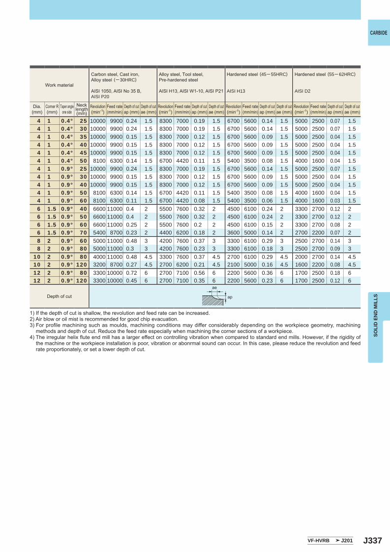
J337
4 1 0.4° 25 10000 9900 0.24 1.5 8300 7000 0.19 1.5 6700 5600 0.14 1.5 5000 2500 0.07 1.54 1 0.4° 30 10000 9900 0.24 1.5 8300 7000 0.19 1.5 6700 5600 0.14 1.5 5000 2500 0.07 1.54 1 0.4° 35 10000 9900 0.15 1.5 8300 7000 0.12 1.5 6700 5600 0.09 1.5 5000 2500 0.04 1.54 1 0.4° 40 10000 9900 0.15 1.5 8300 7000 0.12 1.5 6700 5600 0.09 1.5 5000 2500 0.04 1.54 1 0.4° 45 10000 9900 0.15 1.5 8300 7000 0.12 1.5 6700 5600 0.09 1.5 5000 2500 0.04 1.54 1 0.4° 50 8100 6300 0.14 1.5 6700 4420 0.11 1.5 5400 3500 0.08 1.5 4000 1600 0.04 1.54 1 0.9° 25 10000 9900 0.24 1.5 8300 7000 0.19 1.5 6700 5600 0.14 1.5 5000 2500 0.07 1.54 1 0.9° 30 10000 9900 0.15 1.5 8300 7000 0.12 1.5 6700 5600 0.09 1.5 5000 2500 0.04 1.54 1 0.9° 40 10000 9900 0.15 1.5 8300 7000 0.12 1.5 6700 5600 0.09 1.5 5000 2500 0.04 1.54 1 0.9° 50 8100 6300 0.14 1.5 6700 4420 0.11 1.5 5400 3500 0.08 1.5 4000 1600 0.04 1.54 1 0.9° 60 8100 6300 0.11 1.5 6700 4420 0.08 1.5 5400 3500 0.06 1.5 4000 1600 0.03 1.56 1.5 0.9° 40 6600 11000 0.4 2 5500 7600 0.32 2 4500 6100 0.24 2 3300 2700 0.12 26 1.5 0.9° 50 6600 11000 0.4 2 5500 7600 0.32 2 4500 6100 0.24 2 3300 2700 0.12 26 1.5 0.9° 60 6600 11000 0.25 2 5500 7600 0.2 2 4500 6100 0.15 2 3300 2700 0.08 26 1.5 0.9° 70 5400 8700 0.23 2 4400 6200 0.18 2 3600 5000 0.14 2 2700 2200 0.07 28 2 0.9° 60 5000 11000 0.48 3 4200 7600 0.37 3 3300 6100 0.29 3 2500 2700 0.14 38 2 0.9° 80 5000 11000 0.3 3 4200 7600 0.23 3 3300 6100 0.18 3 2500 2700 0.09 3
10 2 0.9° 80 4000 11000 0.48 4.5 3300 7600 0.37 4.5 2700 6100 0.29 4.5 2000 2700 0.14 4.510 2 0.9° 120 3200 8700 0.27 4.5 2700 6200 0.21 4.5 2100 5000 0.16 4.5 1600 2200 0.08 4.512 2 0.9° 80 3300 10000 0.72 6 2700 7100 0.56 6 2200 5600 0.36 6 1700 2500 0.18 612 2 0.9° 120 3300 10000 0.45 6 2700 7100 0.35 6 2200 5600 0.23 6 1700 2500 0.12 6
VF-HVRB J201
ae
ap
CARBIDE
SOLI
D E
ND
MIL
LS
1) If the depth of cut is shallow, the revolution and feed rate can be increased.2) Air blow or oil mist is recommended for good chip evacuation.3) For profile machining such as moulds, machining conditions may differ considerably depending on the workpiece geometry, machining
methods and depth of cut. Reduce the feed rate especially when machining the corner sections of a workpiece.4) The irregular helix flute end mill has a larger effect on controlling vibration when compared to standard end mills. However, if the rigidity of
the machine or the workpiece installation is poor, vibration or abonrmal sound can occur. In this case, please reduce the revolution and feed rate proportionately, or set a lower depth of cut.
Work material
Carbon steel, Cast iron, Alloy steel (─ 30HRC)
AISI 1050, AISI No 35 B,AISI P20
Alloy steel, Tool steel,Pre-hardened steel
AISI H13, AISI W1-10, AISI P21
Hardened steel (45─ 55HRC)
AISI H13
Hardened steel (55─ 62HRC)
AISI D2
Dia.(mm)
Corner R(mm)
Taper angleone side
Necklength(mm)
Revolution(min-1)
Revolution(min-1)
Revolution(min-1)
Revolution(min-1)
Feed rate(mm/min)
Feed rate(mm/min)
Feed rate(mm/min)
Feed rate(mm/min)
Depth of cutap (mm)
Depth of cutap (mm)
Depth of cutap (mm)
Depth of cutap (mm)
Depth of cutae (mm)
Depth of cutae (mm)
Depth of cutae (mm)
Depth of cutae (mm)
Depth of cut
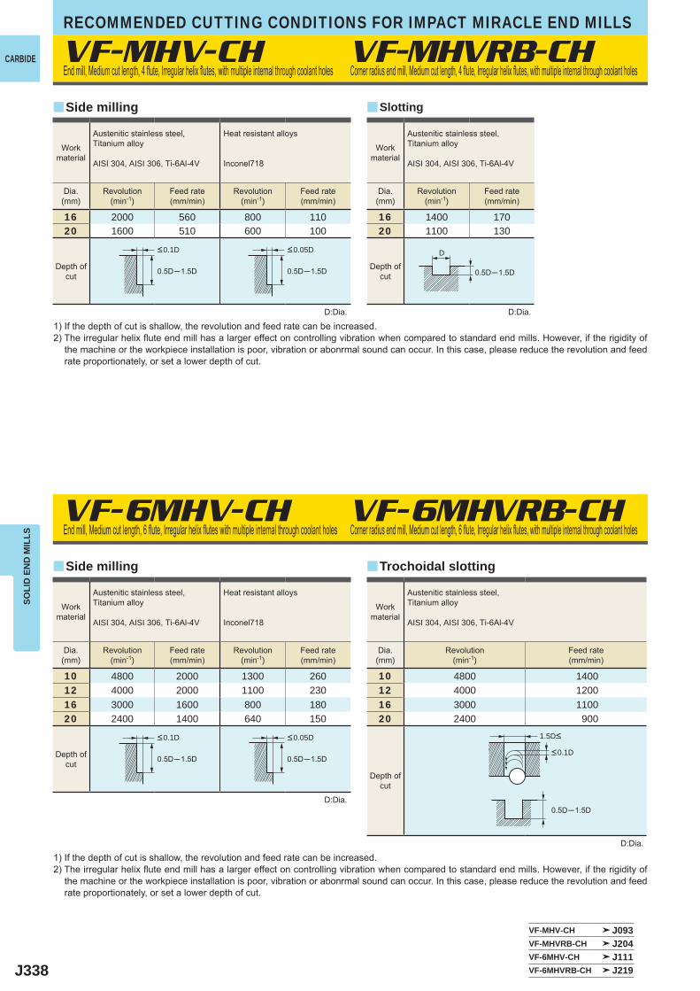
J338
16 2000 560 800 11020 1600 510 600 100
10 4800 2000 1300 26012 4000 2000 1100 23016 3000 1600 800 18020 2400 1400 640 150
16 1400 17020 1100 130
VF-MHV-CH
VF-6MHV-CH VF-6MHVRB-CH
0.5D─1.5D
0.5D─1.5D
0.5D─1.5D
0.5D─1.5D
0.5D─1.5D
VF-MHV-CH J093VF-MHVRB-CH J204VF-6MHV-CH J111VF-6MHVRB-CH J219
VF-MHVRB-CH
yy
y y
10 4800 140012 4000 120016 3000 110020 2400 900
0.5D─1.5D
D
CARBIDE
RECOMMENDED CUTTING CONDITIONS FOR IMPACT MIRACLE END MILLSSO
LID
EN
D M
ILLS
D:Dia.
D:Dia.
D:Dia.
End mill, Medium cut length, 4 flute, Irregular helix flutes, with multiple internal through coolant holes
End mill, Medium cut length, 6 flute, Irregular helix flutes with multiple internal through coolant holes Corner radius end mill, Medium cut length, 6 flute, Irregular helix flutes, with multiple internal through coolant holes
1) If the depth of cut is shallow, the revolution and feed rate can be increased.2) The irregular helix flute end mill has a larger effect on controlling vibration when compared to standard end mills. However, if the rigidity of
the machine or the workpiece installation is poor, vibration or abonrmal sound can occur. In this case, please reduce the revolution and feed rate proportionately, or set a lower depth of cut.
Corner radius end mill, Medium cut length, 4 flute, Irregular helix flutes, with multiple internal through coolant holes
SlottingSide milling
Side milling
Workmaterial
Workmaterial
Austenitic stainless steel,Titanium alloy
AISI 304, AISI 306, Ti-6Al-4V
Heat resistant alloys
Inconel718
Austenitic stainless steel,Titanium alloy
AISI 304, AISI 306, Ti-6Al-4V
Heat resistant alloys
Inconel718
Dia.(mm)
Dia.(mm)
Revolution(min-1)
Revolution(min-1)
Revolution(min-1)
Revolution(min-1)
Feed rate(mm/min)
Feed rate(mm/min)
Feed rate(mm/min)
Feed rate(mm/min)
Workmaterial
Austenitic stainless steel,Titanium alloy
AISI 304, AISI 306, Ti-6Al-4V
Dia.(mm)
Revolution(min-1)
Feed rate(mm/min)
Depth ofcut
Depth ofcut
Depth ofcut
<0.1D <0.05D
<0.1D <0.05D
Trochoidal slotting
<0.1D
1.5D<
Workmaterial
Austenitic stainless steel,Titanium alloy
AISI 304, AISI 306, Ti-6Al-4V
Dia.(mm)
Revolution(min-1)
Feed rate(mm/min)
Depth ofcut
D:Dia.
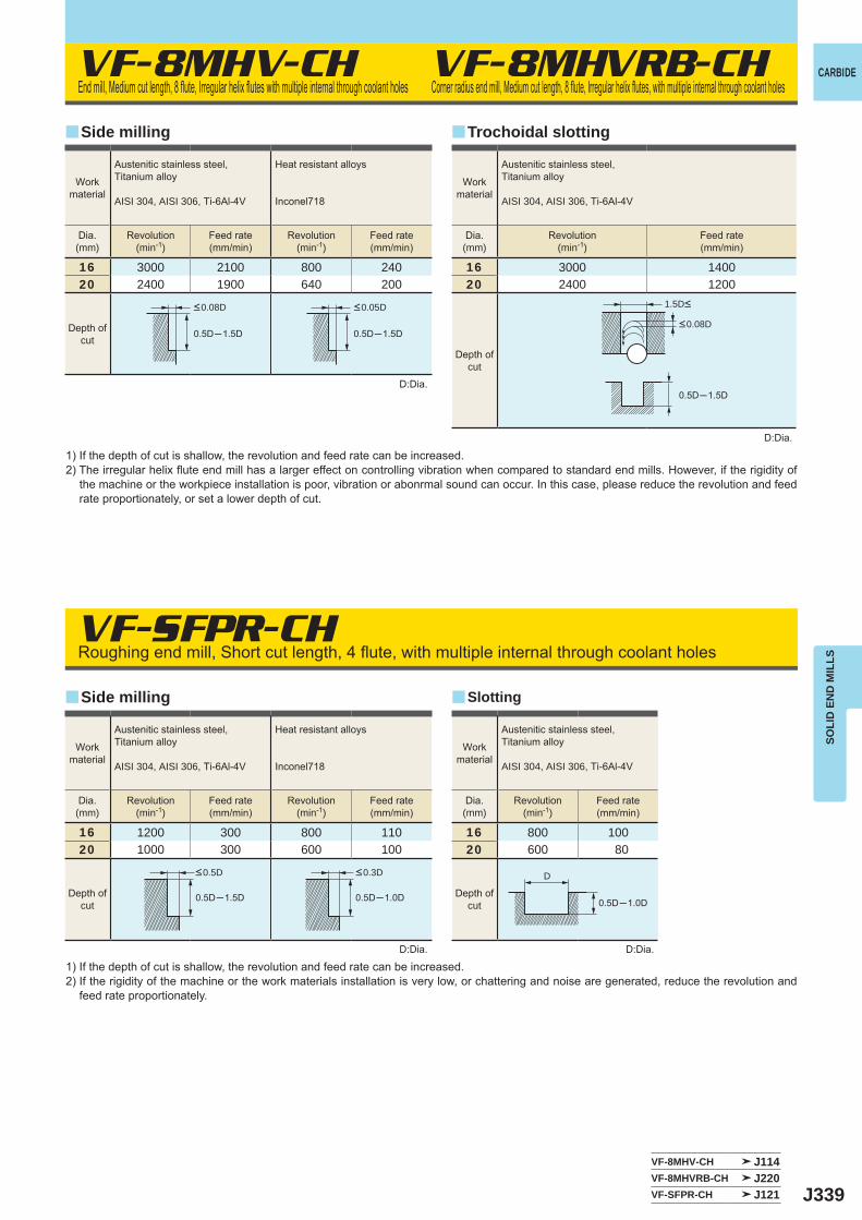
J339
16 3000 2100 800 24020 2400 1900 640 200
16 1200 300 800 11020 1000 300 600 100
16 800 10020 600 80
VF-8MHV-CH
VF-SFPR-CH
0.5D─1.5D
0.5D─1.5D
0.5D─1.5D
0.5D─1.0D 0.5D─1.0D
VF-8MHV-CH J114VF-8MHVRB-CH J220VF-SFPR-CH J121
VF-8MHVRB-CH
y
y
y
y
16 3000 140020 2400 1200
0.5D─1.5D
D
CARBIDE
SOLI
D E
ND
MIL
LS
D:Dia.
D:Dia. D:Dia.
End mill, Medium cut length, 8 flute, Irregular helix flutes with multiple internal through coolant holes
Roughing end mill, Short cut length, 4 flute, with multiple internal through coolant holes
1) If the depth of cut is shallow, the revolution and feed rate can be increased.2) The irregular helix flute end mill has a larger effect on controlling vibration when compared to standard end mills. However, if the rigidity of
the machine or the workpiece installation is poor, vibration or abonrmal sound can occur. In this case, please reduce the revolution and feed rate proportionately, or set a lower depth of cut.
1) If the depth of cut is shallow, the revolution and feed rate can be increased.2) If the rigidity of the machine or the work materials installation is very low, or chattering and noise are generated, reduce the revolution and
feed rate proportionately.
Corner radius end mill, Medium cut length, 8 flute, Irregular helix flutes, with multiple internal through coolant holes
Slotting
Side milling
Side milling
Workmaterial
Workmaterial
Austenitic stainless steel,Titanium alloy
AISI 304, AISI 306, Ti-6Al-4V
Heat resistant alloys
Inconel718
Austenitic stainless steel,Titanium alloy
AISI 304, AISI 306, Ti-6Al-4V
Heat resistant alloys
Inconel718
Dia.(mm)
Dia.(mm)
Revolution(min-1)
Revolution(min-1)
Revolution(min-1)
Revolution(min-1)
Feed rate(mm/min)
Feed rate(mm/min)
Feed rate(mm/min)
Feed rate(mm/min)
Workmaterial
Austenitic stainless steel,Titanium alloy
AISI 304, AISI 306, Ti-6Al-4V
Dia.(mm)
Revolution(min-1)
Feed rate(mm/min)
Depth ofcut
Depth ofcut
Depth ofcut
<0.08D
<0.5D
<0.05D
<0.3D
Trochoidal slotting
D:Dia.
Workmaterial
Austenitic stainless steel,Titanium alloy
AISI 304, AISI 306, Ti-6Al-4V
Dia.(mm)
Revolution(min-1)
Feed rate(mm/min)
Depth ofcut
<0.08D
1.5D<
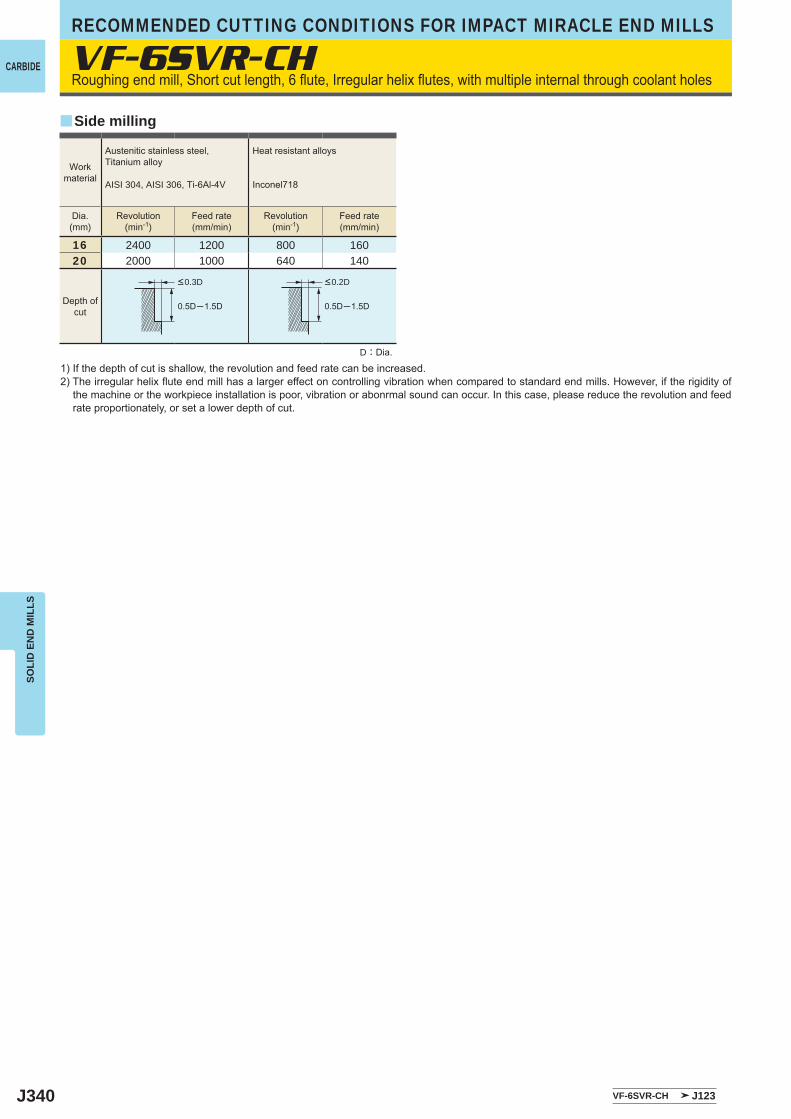
J340
VF-6SVR-CH
16 2400 1200 800 16020 2000 1000 640 140
0.5D─1.5D 0.5D─1.5D
VF-6SVR-CH J123
y
CARBIDE
RECOMMENDED CUTTING CONDITIONS FOR IMPACT MIRACLE END MILLSSO
LID
EN
D M
ILLS
Roughing end mill, Short cut length, 6 flute, Irregular helix flutes, with multiple internal through coolant holes
D:Dia.
1) If the depth of cut is shallow, the revolution and feed rate can be increased.2) The irregular helix flute end mill has a larger effect on controlling vibration when compared to standard end mills. However, if the rigidity of
the machine or the workpiece installation is poor, vibration or abonrmal sound can occur. In this case, please reduce the revolution and feed rate proportionately, or set a lower depth of cut.
Side milling
Workmaterial
Austenitic stainless steel,Titanium alloy
AISI 304, AISI 306, Ti-6Al-4V
Heat resistant alloys
Inconel718
Dia.(mm)
Revolution(min-1)
Revolution(min-1)
Feed rate(mm/min)
Feed rate(mm/min)
Depth ofcut
<0.3D <0.2D
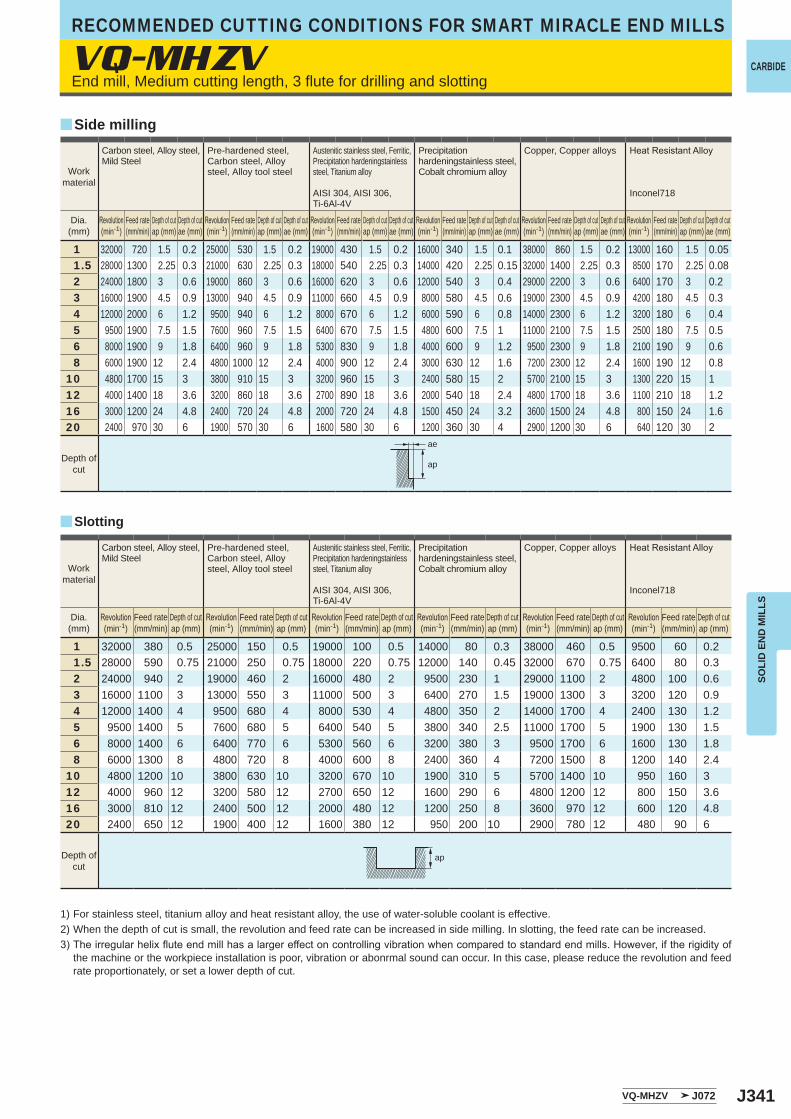
J341
VQ-MHZV
y
y
1 32000 720 1.5 0.2 25000 530 1.5 0.2 19000 430 1.5 0.2 16000 340 1.5 0.1 38000 860 1.5 0.2 13000 160 1.5 0.051.5 28000 1300 2.25 0.3 21000 630 2.25 0.3 18000 540 2.25 0.3 14000 420 2.25 0.15 32000 1400 2.25 0.3 8500 170 2.25 0.082 24000 1800 3 0.6 19000 860 3 0.6 16000 620 3 0.6 12000 540 3 0.4 29000 2200 3 0.6 6400 170 3 0.23 16000 1900 4.5 0.9 13000 940 4.5 0.9 11000 660 4.5 0.9 8000 580 4.5 0.6 19000 2300 4.5 0.9 4200 180 4.5 0.34 12000 2000 6 1.2 9500 940 6 1.2 8000 670 6 1.2 6000 590 6 0.8 14000 2300 6 1.2 3200 180 6 0.45 9500 1900 7.5 1.5 7600 960 7.5 1.5 6400 670 7.5 1.5 4800 600 7.5 1 11000 2100 7.5 1.5 2500 180 7.5 0.56 8000 1900 9 1.8 6400 960 9 1.8 5300 830 9 1.8 4000 600 9 1.2 9500 2300 9 1.8 2100 190 9 0.68 6000 1900 12 2.4 4800 1000 12 2.4 4000 900 12 2.4 3000 630 12 1.6 7200 2300 12 2.4 1600 190 12 0.8
10 4800 1700 15 3 3800 910 15 3 3200 960 15 3 2400 580 15 2 5700 2100 15 3 1300 220 15 112 4000 1400 18 3.6 3200 860 18 3.6 2700 890 18 3.6 2000 540 18 2.4 4800 1700 18 3.6 1100 210 18 1.216 3000 1200 24 4.8 2400 720 24 4.8 2000 720 24 4.8 1500 450 24 3.2 3600 1500 24 4.8 800 150 24 1.620 2400 970 30 6 1900 570 30 6 1600 580 30 6 1200 360 30 4 2900 1200 30 6 640 120 30 2
1 32000 380 0.5 25000 150 0.5 19000 100 0.5 14000 80 0.3 38000 460 0.5 9500 60 0.21.5 28000 590 0.75 21000 250 0.75 18000 220 0.75 12000 140 0.45 32000 670 0.75 6400 80 0.32 24000 940 2 19000 460 2 16000 480 2 9500 230 1 29000 1100 2 4800 100 0.63 16000 1100 3 13000 550 3 11000 500 3 6400 270 1.5 19000 1300 3 3200 120 0.94 12000 1400 4 9500 680 4 8000 530 4 4800 350 2 14000 1700 4 2400 130 1.25 9500 1400 5 7600 680 5 6400 540 5 3800 340 2.5 11000 1700 5 1900 130 1.56 8000 1400 6 6400 770 6 5300 560 6 3200 380 3 9500 1700 6 1600 130 1.88 6000 1300 8 4800 720 8 4000 600 8 2400 360 4 7200 1500 8 1200 140 2.4
10 4800 1200 10 3800 630 10 3200 670 10 1900 310 5 5700 1400 10 950 160 312 4000 960 12 3200 580 12 2700 650 12 1600 290 6 4800 1200 12 800 150 3.616 3000 810 12 2400 500 12 2000 480 12 1200 250 8 3600 970 12 600 120 4.820 2400 650 12 1900 400 12 1600 380 12 950 200 10 2900 780 12 480 90 6
VQ-MHZV J072
ae
ap
ap
CARBIDE
SOLI
D E
ND
MIL
LS
End mill, Medium cutting length, 3 flute for drilling and slotting
Side milling
Slotting
1) For stainless steel, titanium alloy and heat resistant alloy, the use of water-soluble coolant is effective. 2) When the depth of cut is small, the revolution and feed rate can be increased in side milling. In slotting, the feed rate can be increased.3)Theirregularhelixfluteendmillhasalargereffectoncontrollingvibrationwhencomparedtostandardendmills.However,iftherigidityof
the machine or the workpiece installation is poor, vibration or abonrmal sound can occur. In this case, please reduce the revolution and feed rate proportionately, or set a lower depth of cut.
Workmaterial
Carbon steel, Alloy steel,Mild Steel
Pre-hardened steel,Carbon steel, Alloy steel, Alloy tool steel
Austenitic stainless steel, Ferritic, Precipitation hardeningstainless steel, Titanium alloy
AISI 304, AISI 306, Ti-6Al-4V
Precipitation hardeningstainless steel,Cobalt chromium alloy
Copper, Copper alloys HeatResistantAlloy
Inconel718
Dia.(mm)
Revolution(min-1)
Feed rate(mm/min)
Depth of cutap (mm)
Depth of cutae (mm)
Revolution(min-1)
Feed rate(mm/min)
Depth of cutap (mm)
Depth of cutae (mm)
Revolution(min-1)
Feed rate(mm/min)
Depth of cutap (mm)
Depth of cutae (mm)
Revolution(min-1)
Feed rate(mm/min)
Depth of cutap (mm)
Depth of cutae (mm)
Revolution(min-1)
Feed rate(mm/min)
Depth of cutap (mm)
Depth of cutae (mm)
Revolution(min-1)
Feed rate(mm/min)
Depth of cutap (mm)
Depth of cutae (mm)
Depth ofcut
Workmaterial
Carbon steel, Alloy steel,Mild Steel
Pre-hardened steel,Carbon steel, Alloy steel, Alloy tool steel
Austenitic stainless steel, Ferritic, Precipitation hardeningstainless steel, Titanium alloy
AISI 304, AISI 306, Ti-6Al-4V
Precipitation hardeningstainless steel,Cobalt chromium alloy
Copper, Copper alloys HeatResistantAlloy
Inconel718
Dia.(mm)
Revolution(min-1)
Feed rate(mm/min)
Depth of cutap (mm)
Revolution(min-1)
Feed rate(mm/min)
Depth of cutap (mm)
Revolution(min-1)
Feed rate(mm/min)
Depth of cutap (mm)
Revolution(min-1)
Feed rate(mm/min)
Depth of cutap (mm)
Revolution(min-1)
Feed rate(mm/min)
Depth of cutap (mm)
Revolution(min-1)
Feed rate(mm/min)
Depth of cutap (mm)
Depth ofcut
RECOMMENDED CUTTING CONDITIONS FOR SMART MIRACLE END MILLS

J342
y
VQ-MHZV
1 20000 160 0.5 0.1 16000 100 0.5 0.1 16000 50 0.5 0.05 9500 30 0.5 0.05 24000 190 0.5 0.11.5 18000 270 0.75 0.3 13000 120 0.75 0.3 13000 80 0.75 0.1 7400 40 0.75 0.1 21000 320 0.75 0.32 16000 480 2 0.5 11000 200 2 0.4 9500 90 1 0.1 6400 60 1 0.1 19000 570 2 0.53 11000 660 3 1 7400 270 3 0.6 6400 100 1.5 0.2 4200 60 1.5 0.2 13000 780 3 0.994 8000 800 4 2 5600 340 4 0.8 4800 100 2 0.4 3200 60 2 0.4 9500 950 4 25 6400 960 5 2.5 4500 410 5 1 3800 100 2.5 0.5 2500 60 2.5 0.5 7600 1100 5 2.56 5300 950 6 3 3700 440 6 1.2 3200 100 3 0.6 2100 60 3 0.6 6400 1200 6 38 4000 720 8 4 2800 340 8 1.6 2400 70 4 0.6 1600 50 4 0.6 4800 860 8 4
10 3200 580 10 5 2200 260 10 2.5 1900 60 5 0.6 1300 40 5 0.6 3800 680 10 512 2700 490 12 5 1900 230 12 3 1600 50 6 0.6 1100 30 6 0.6 3200 580 12 516 2000 360 16 5 1400 170 16 4 1200 40 8 0.6 800 20 8 0.6 2400 430 16 520 1600 290 20 5 1100 130 20 5 950 30 10 0.6 640 20 10 0.6 1900 340 20 5
VQ-MHZV J072
ap
CARBIDE
SOLI
D E
ND
MIL
LS
Plunging
1) For stainless steel, titanium alloy and heat resistant alloy, the use of water-soluble coolant is effective. 2)Theirregularhelixfluteendmillhasalargereffectoncontrollingvibrationwhencomparedtostandardendmills.However,iftherigidityof
the machine or the workpiece installation is poor, vibration or abonrmal sound can occur. In this case, please reduce the revolution and feed rate proportionately, or set a lower depth of cut.
End mill, Medium cutting length, 3 flute for drilling and slotting
Workmaterial
Carbon steel, Alloy steel,Mild Steel
Pre-hardened steel,Carbon steel, Alloy steel, Alloy tool steel
Austenitic stainless steel, Ferritic, Precipitation hardeningstainless steel, Titanium alloy
AISI 304, AISI 306, Ti-6Al-4V
Precipitation hardeningstainless steel,Cobalt chromium alloy
Copper, Copper alloys
Dia.(mm)
Revolution(min-1)
Feed rate(mm/min)
Drilled Depthap (mm)
Step(mm)
Revolution(min-1)
Feed rate(mm/min)
Drilled Depthap (mm)
Step (mm)
Revolution(min-1)
Feed rate(mm/min)
Drilled Depthap (mm)
Step (mm)
Revolution(min-1)
Feed rate(mm/min)
Drilled Depthap (mm)
Step (mm)
Revolution(min-1)
Feed rate(mm/min)
Drilled Depthap (mm)
Step (mm)
Depth ofcut
RECOMMENDED CUTTING CONDITIONS FOR SMART MIRACLE END MILLS
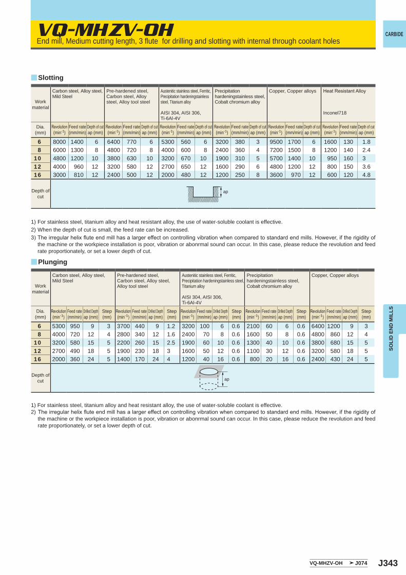
J343
VQ-MHZV-OH
y
6 8000 1400 6 6400 770 6 5300 560 6 3200 380 3 9500 1700 6 1600 130 1.88 6000 1300 8 4800 720 8 4000 600 8 2400 360 4 7200 1500 8 1200 140 2.4
10 4800 1200 10 3800 630 10 3200 670 10 1900 310 5 5700 1400 10 950 160 312 4000 960 12 3200 580 12 2700 650 12 1600 290 6 4800 1200 12 800 150 3.616 3000 810 12 2400 500 12 2000 480 12 1200 250 8 3600 970 12 600 120 4.8
y
6 5300 950 9 3 3700 440 9 1.2 3200 100 6 0.6 2100 60 6 0.6 6400 1200 9 38 4000 720 12 4 2800 340 12 1.6 2400 70 8 0.6 1600 50 8 0.6 4800 860 12 4
10 3200 580 15 5 2200 260 15 2.5 1900 60 10 0.6 1300 40 10 0.6 3800 680 15 512 2700 490 18 5 1900 230 18 3 1600 50 12 0.6 1100 30 12 0.6 3200 580 18 516 2000 360 24 5 1400 170 24 4 1200 40 16 0.6 800 20 16 0.6 2400 430 24 5
ap
VQ-MHZV-OH J074
ap
CARBIDE
SOLI
D E
ND
MIL
LS
End mill, Medium cutting length, 3 flute for drilling and slotting with internal through coolant holes
Slotting
Workmaterial
Carbon steel, Alloy steel,Mild Steel
Pre-hardened steel,Carbon steel, Alloy steel, Alloy tool steel
Austenitic stainless steel, Ferritic, Precipitation hardeningstainless steel, Titanium alloy
AISI 304, AISI 306, Ti-6Al-4V
Precipitation hardeningstainless steel,Cobalt chromium alloy
Copper, Copper alloys HeatResistantAlloy
Inconel718
Dia.(mm)
Revolution(min-1)
Feed rate(mm/min)
Depth of cutap (mm)
Revolution(min-1)
Feed rate(mm/min)
Depth of cutap (mm)
Revolution(min-1)
Feed rate(mm/min)
Depth of cutap (mm)
Revolution(min-1)
Feed rate(mm/min)
Depth of cutap (mm)
Revolution(min-1)
Feed rate(mm/min)
Depth of cutap (mm)
Revolution(min-1)
Feed rate(mm/min)
Depth of cutap (mm)
Depth ofcut
1) For stainless steel, titanium alloy and heat resistant alloy, the use of water-soluble coolant is effective. 2) When the depth of cut is small, the feed rate can be increased.3)Theirregularhelixfluteendmillhasalargereffectoncontrollingvibrationwhencomparedtostandardendmills.However,iftherigidityof
the machine or the workpiece installation is poor, vibration or abonrmal sound can occur. In this case, please reduce the revolution and feed rate proportionately, or set a lower depth of cut.
Plunging
Workmaterial
Carbon steel, Alloy steel,Mild Steel
Pre-hardened steel,Carbon steel, Alloy steel, Alloy tool steel
Austenitic stainless steel, Ferritic, Precipitation hardeningstainless steel, Titanium alloy
AISI 304, AISI 306, Ti-6Al-4V
Precipitation hardeningstainless steel,Cobalt chromium alloy
Copper, Copper alloys
Dia.(mm)
Revolution(min-1)
Feed rate(mm/min)
Drilled Depthap (mm)
Step(mm)
Revolution(min-1)
Feed rate(mm/min)
Drilled Depthap (mm)
Step(mm)
Revolution(min-1)
Feed rate(mm/min)
Drilled Depthap (mm)
Step(mm)
Revolution(min-1)
Feed rate(mm/min)
Drilled Depthap (mm)
Step(mm)
Revolution(min-1)
Feed rate(mm/min)
Drilled Depthap (mm)
Step(mm)
Depth ofcut
1) For stainless steel, titanium alloy and heat resistant alloy, the use of water-soluble coolant is effective. 2) Theirregularhelixfluteendmillhasalargereffectoncontrollingvibrationwhencomparedtostandardendmills.However,iftherigidityof
the machine or the workpiece installation is poor, vibration or abonrmal sound can occur. In this case, please reduce the revolution and feed rate proportionately, or set a lower depth of cut.
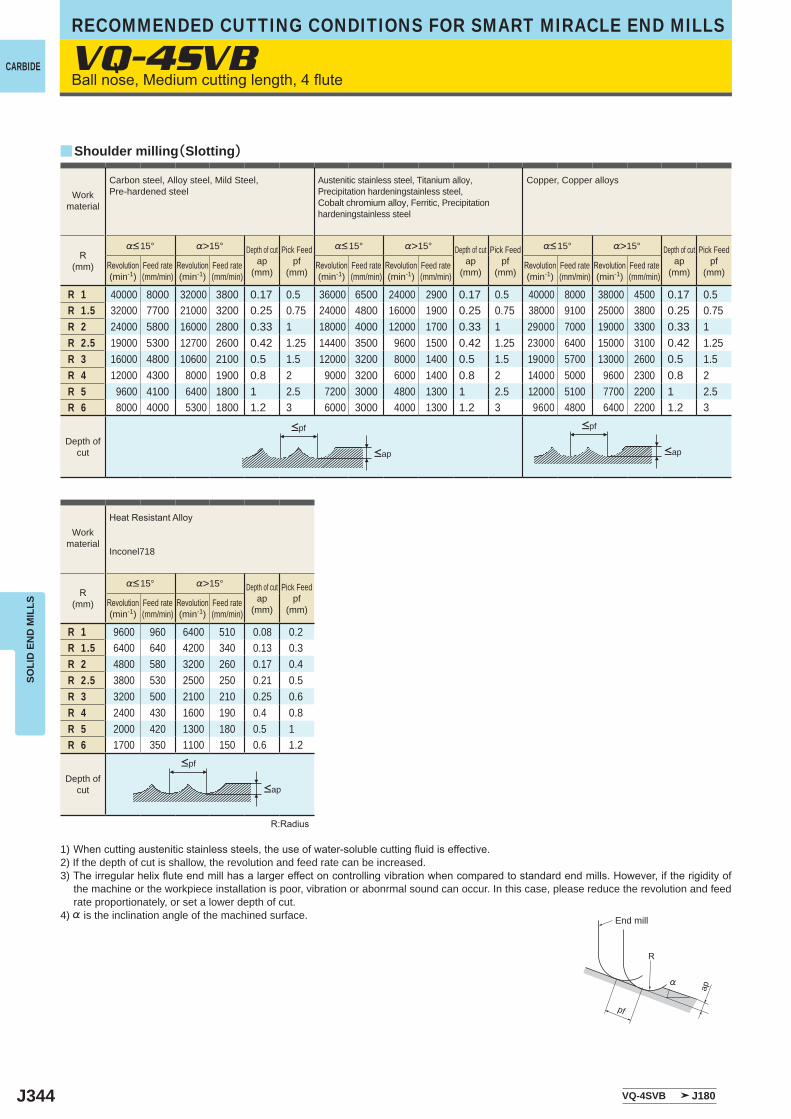
J344
R 1 40000 8000 32000 3800 0.17 0.5 36000 6500 24000 2900 0.17 0.5 40000 8000 38000 4500 0.17 0.5R 1.5 32000 7700 21000 3200 0.25 0.75 24000 4800 16000 1900 0.25 0.75 38000 9100 25000 3800 0.25 0.75R 2 24000 5800 16000 2800 0.33 1 18000 4000 12000 1700 0.33 1 29000 7000 19000 3300 0.33 1R 2.5 19000 5300 12700 2600 0.42 1.25 14400 3500 9600 1500 0.42 1.25 23000 6400 15000 3100 0.42 1.25R 3 16000 4800 10600 2100 0.5 1.5 12000 3200 8000 1400 0.5 1.5 19000 5700 13000 2600 0.5 1.5R 4 12000 4300 8000 1900 0.8 2 9000 3200 6000 1400 0.8 2 14000 5000 9600 2300 0.8 2R 5 9600 4100 6400 1800 1 2.5 7200 3000 4800 1300 1 2.5 12000 5100 7700 2200 1 2.5R 6 8000 4000 5300 1800 1.2 3 6000 3000 4000 1300 1.2 3 9600 4800 6400 2200 1.2 3
R 1 9600 960 6400 510 0.08 0.2R 1.5 6400 640 4200 340 0.13 0.3R 2 4800 580 3200 260 0.17 0.4R 2.5 3800 530 2500 250 0.21 0.5R 3 3200 500 2100 210 0.25 0.6R 4 2400 430 1600 190 0.4 0.8R 5 2000 420 1300 180 0.5 1R 6 1700 350 1100 150 0.6 1.2
y
VQ-4SVB J180
VQ-4SVB
R
%
ap
pf
CARBIDE
SOLI
D E
ND
MIL
LSRECOMMENDED CUTTING CONDITIONS FOR SMART MIRACLE END MILLS
Ballnose,Mediumcuttinglength,4flute
1) Whencuttingausteniticstainlesssteels,theuseofwater-solublecuttingfluidiseffective.2) If the depth of cut is shallow, the revolution and feed rate can be increased.3) Theirregularhelixfluteendmillhasalargereffectoncontrollingvibrationwhencomparedtostandardendmills.However,iftherigidityof
the machine or the workpiece installation is poor, vibration or abonrmal sound can occur. In this case, please reduce the revolution and feed rate proportionately, or set a lower depth of cut.
4) % is the inclination angle of the machined surface.
R:Radius
<ap <ap
<ap
Workmaterial
Carbon steel, Alloy steel, Mild Steel, Pre-hardened steel
Austenitic stainless steel, Titanium alloy, Precipitation hardeningstainless steel, Cobalt chromium alloy, Ferritic, Precipitation hardeningstainless steel
Copper, Copper alloys
R(mm)
%<15° %>15° Depth of cutap
(mm)
Pick Feedpf
(mm)
%<15° %>15° Depth of cutap
(mm)
Pick Feedpf
(mm)
%<15° %>15° Depth of cutap
(mm)
Pick Feedpf
(mm)Revolution(min-1)
Feed rate(mm/min)
Revolution(min-1)
Feed rate(mm/min)
Revolution(min-1)
Feed rate(mm/min)
Revolution(min-1)
Feed rate(mm/min)
Revolution(min-1)
Feed rate(mm/min)
Revolution(min-1)
Feed rate(mm/min)
Depth ofcut
Workmaterial
HeatResistantAlloy
Inconel718
R(mm)
%<15° %>15° Depth of cutap
(mm)
Pick Feedpf
(mm)Revolution(min-1)
Feed rate(mm/min)
Revolution(min-1)
Feed rate(mm/min)
Depth ofcut
End mill
Shoulder milling(Slotting)
<pf <pf
<pf
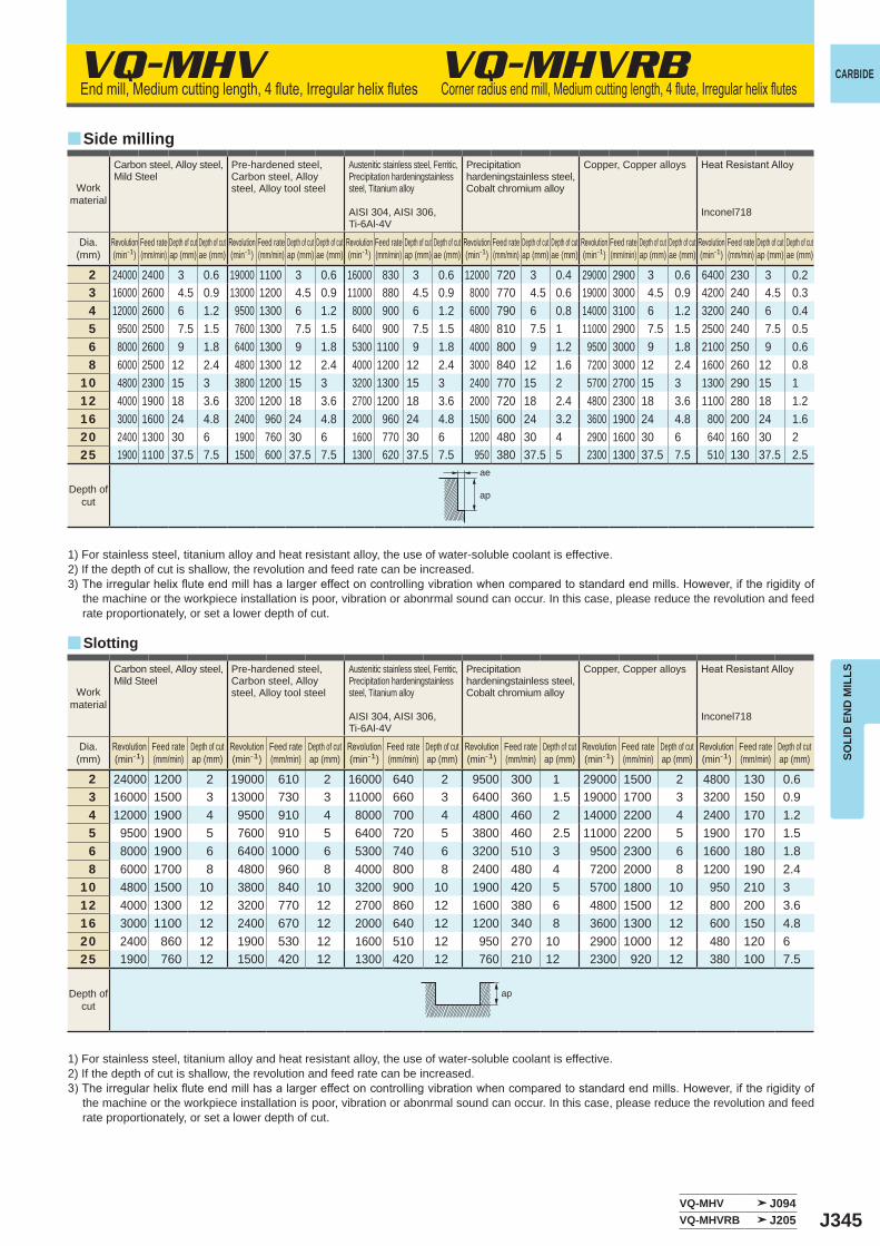
J345
VQ-MHV VQ-MHVRB
y
y
2 24000 2400 3 0.6 19000 1100 3 0.6 16000 830 3 0.6 12000 720 3 0.4 29000 2900 3 0.6 6400 230 3 0.23 16000 2600 4.5 0.9 13000 1200 4.5 0.9 11000 880 4.5 0.9 8000 770 4.5 0.6 19000 3000 4.5 0.9 4200 240 4.5 0.34 12000 2600 6 1.2 9500 1300 6 1.2 8000 900 6 1.2 6000 790 6 0.8 14000 3100 6 1.2 3200 240 6 0.45 9500 2500 7.5 1.5 7600 1300 7.5 1.5 6400 900 7.5 1.5 4800 810 7.5 1 11000 2900 7.5 1.5 2500 240 7.5 0.56 8000 2600 9 1.8 6400 1300 9 1.8 5300 1100 9 1.8 4000 800 9 1.2 9500 3000 9 1.8 2100 250 9 0.68 6000 2500 12 2.4 4800 1300 12 2.4 4000 1200 12 2.4 3000 840 12 1.6 7200 3000 12 2.4 1600 260 12 0.8
10 4800 2300 15 3 3800 1200 15 3 3200 1300 15 3 2400 770 15 2 5700 2700 15 3 1300 290 15 112 4000 1900 18 3.6 3200 1200 18 3.6 2700 1200 18 3.6 2000 720 18 2.4 4800 2300 18 3.6 1100 280 18 1.216 3000 1600 24 4.8 2400 960 24 4.8 2000 960 24 4.8 1500 600 24 3.2 3600 1900 24 4.8 800 200 24 1.620 2400 1300 30 6 1900 760 30 6 1600 770 30 6 1200 480 30 4 2900 1600 30 6 640 160 30 225 1900 1100 37.5 7.5 1500 600 37.5 7.5 1300 620 37.5 7.5 950 380 37.5 5 2300 1300 37.5 7.5 510 130 37.5 2.5
2 24000 1200 2 19000 610 2 16000 640 2 9500 300 1 29000 1500 2 4800 130 0.63 16000 1500 3 13000 730 3 11000 660 3 6400 360 1.5 19000 1700 3 3200 150 0.94 12000 1900 4 9500 910 4 8000 700 4 4800 460 2 14000 2200 4 2400 170 1.25 9500 1900 5 7600 910 5 6400 720 5 3800 460 2.5 11000 2200 5 1900 170 1.56 8000 1900 6 6400 1000 6 5300 740 6 3200 510 3 9500 2300 6 1600 180 1.88 6000 1700 8 4800 960 8 4000 800 8 2400 480 4 7200 2000 8 1200 190 2.4
10 4800 1500 10 3800 840 10 3200 900 10 1900 420 5 5700 1800 10 950 210 312 4000 1300 12 3200 770 12 2700 860 12 1600 380 6 4800 1500 12 800 200 3.616 3000 1100 12 2400 670 12 2000 640 12 1200 340 8 3600 1300 12 600 150 4.820 2400 860 12 1900 530 12 1600 510 12 950 270 10 2900 1000 12 480 120 625 1900 760 12 1500 420 12 1300 420 12 760 210 12 2300 920 12 380 100 7.5
VQ-MHV J094VQ-MHVRB J205
ae
ap
ap
CARBIDE
SOLI
D E
ND
MIL
LS
Endmill,Mediumcuttinglength,4flute,Irregularhelixflutes Cornerradiusendmill,Mediumcuttinglength,4flute,Irregularhelixflutes
Side milling
Slotting
1) For stainless steel, titanium alloy and heat resistant alloy, the use of water-soluble coolant is effective. 2) If the depth of cut is shallow, the revolution and feed rate can be increased.3)Theirregularhelixfluteendmillhasalargereffectoncontrollingvibrationwhencomparedtostandardendmills.However,iftherigidityof
the machine or the workpiece installation is poor, vibration or abonrmal sound can occur. In this case, please reduce the revolution and feed rate proportionately, or set a lower depth of cut.
1) For stainless steel, titanium alloy and heat resistant alloy, the use of water-soluble coolant is effective. 2) If the depth of cut is shallow, the revolution and feed rate can be increased.3) Theirregularhelixfluteendmillhasalargereffectoncontrollingvibrationwhencomparedtostandardendmills.However,iftherigidityof
the machine or the workpiece installation is poor, vibration or abonrmal sound can occur. In this case, please reduce the revolution and feed rate proportionately, or set a lower depth of cut.
Workmaterial
Carbon steel, Alloy steel,Mild Steel
Pre-hardened steel,Carbon steel, Alloy steel, Alloy tool steel
Austenitic stainless steel, Ferritic, Precipitation hardeningstainless steel, Titanium alloy
AISI 304, AISI 306, Ti-6Al-4V
Precipitation hardeningstainless steel,Cobalt chromium alloy
Copper, Copper alloys HeatResistantAlloy
Inconel718
Dia.(mm)
Revolution(min-1)
Feed rate(mm/min)
Depth of cutap (mm)
Depth of cutae (mm)
Revolution(min-1)
Feed rate(mm/min)
Depth of cutap (mm)
Depth of cutae (mm)
Revolution(min-1)
Feed rate(mm/min)
Depth of cutap (mm)
Depth of cutae (mm)
Revolution(min-1)
Feed rate(mm/min)
Depth of cutap (mm)
Depth of cutae (mm)
Revolution(min-1)
Feed rate(mm/min)
Depth of cutap (mm)
Depth of cutae (mm)
Revolution(min-1)
Feed rate(mm/min)
Depth of cutap (mm)
Depth of cutae (mm)
Depth ofcut
Workmaterial
Carbon steel, Alloy steel,Mild Steel
Pre-hardened steel,Carbon steel, Alloy steel, Alloy tool steel
Austenitic stainless steel, Ferritic, Precipitation hardeningstainless steel, Titanium alloy
AISI 304, AISI 306, Ti-6Al-4V
Precipitation hardeningstainless steel,Cobalt chromium alloy
Copper, Copper alloys HeatResistantAlloy
Inconel718
Dia.(mm)
Revolution(min-1)
Feed rate(mm/min)
Depth of cutap (mm)
Revolution(min-1)
Feed rate(mm/min)
Depth of cutap (mm)
Revolution(min-1)
Feed rate(mm/min)
Depth of cutap (mm)
Revolution(min-1)
Feed rate(mm/min)
Depth of cutap (mm)
Revolution(min-1)
Feed rate(mm/min)
Depth of cutap (mm)
Revolution(min-1)
Feed rate(mm/min)
Depth of cutap (mm)
Depth ofcut
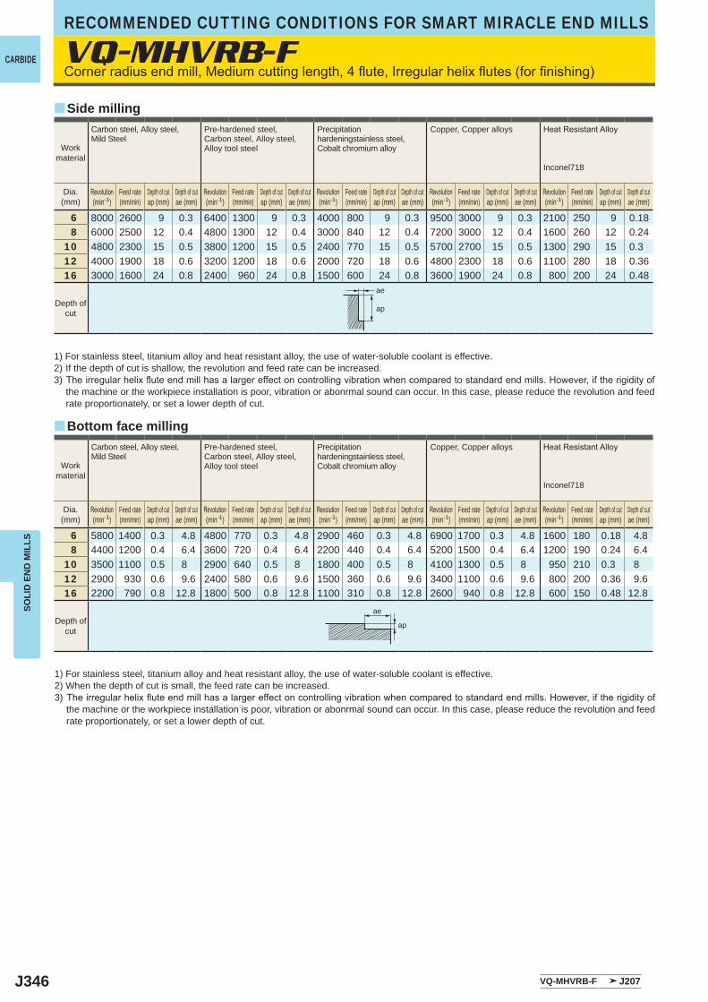
J346
y
y
6 8000 2600 9 0.3 6400 1300 9 0.3 4000 800 9 0.3 9500 3000 9 0.3 2100 250 9 0.188 6000 2500 12 0.4 4800 1300 12 0.4 3000 840 12 0.4 7200 3000 12 0.4 1600 260 12 0.24
10 4800 2300 15 0.5 3800 1200 15 0.5 2400 770 15 0.5 5700 2700 15 0.5 1300 290 15 0.312 4000 1900 18 0.6 3200 1200 18 0.6 2000 720 18 0.6 4800 2300 18 0.6 1100 280 18 0.3616 3000 1600 24 0.8 2400 960 24 0.8 1500 600 24 0.8 3600 1900 24 0.8 800 200 24 0.48
6 5800 1400 0.3 4.8 4800 770 0.3 4.8 2900 460 0.3 4.8 6900 1700 0.3 4.8 1600 180 0.18 4.88 4400 1200 0.4 6.4 3600 720 0.4 6.4 2200 440 0.4 6.4 5200 1500 0.4 6.4 1200 190 0.24 6.4
10 3500 1100 0.5 8 2900 640 0.5 8 1800 400 0.5 8 4100 1300 0.5 8 950 210 0.3 812 2900 930 0.6 9.6 2400 580 0.6 9.6 1500 360 0.6 9.6 3400 1100 0.6 9.6 800 200 0.36 9.616 2200 790 0.8 12.8 1800 500 0.8 12.8 1100 310 0.8 12.8 2600 940 0.8 12.8 600 150 0.48 12.8
VQ-MHVRB-F
VQ-MHVRB-F J207
ae
ap
ae
ap
CARBIDE
SOLI
D E
ND
MIL
LSRECOMMENDED CUTTING CONDITIONS FOR SMART MIRACLE END MILLS
Cornerradiusendmill,Mediumcuttinglength,4flute,Irregularhelixflutes(forfinishing)
Workmaterial
Carbon steel, Alloy steel,Mild Steel
Pre-hardened steel,Carbon steel, Alloy steel, Alloy tool steel
Precipitation hardeningstainless steel,Cobalt chromium alloy
Copper, Copper alloys HeatResistantAlloy
Inconel718
Dia.(mm)
Revolution(min-1)
Feed rate(mm/min)
Depth of cutap (mm)
Depth of cutae (mm)
Revolution(min-1)
Feed rate(mm/min)
Depth of cutap (mm)
Depth of cutae (mm)
Revolution(min-1)
Feed rate(mm/min)
Depth of cutap (mm)
Depth of cutae (mm)
Revolution(min-1)
Feed rate(mm/min)
Depth of cutap (mm)
Depth of cutae (mm)
Revolution(min-1)
Feed rate(mm/min)
Depth of cutap (mm)
Depth of cutae (mm)
Depth ofcut
Side milling
Bottom face milling
1) For stainless steel, titanium alloy and heat resistant alloy, the use of water-soluble coolant is effective. 2) If the depth of cut is shallow, the revolution and feed rate can be increased.3) Theirregularhelixfluteendmillhasalargereffectoncontrollingvibrationwhencomparedtostandardendmills.However,iftherigidityof
the machine or the workpiece installation is poor, vibration or abonrmal sound can occur. In this case, please reduce the revolution and feed rate proportionately, or set a lower depth of cut.
1) For stainless steel, titanium alloy and heat resistant alloy, the use of water-soluble coolant is effective. 2) When the depth of cut is small, the feed rate can be increased.3) Theirregularhelixfluteendmillhasalargereffectoncontrollingvibrationwhencomparedtostandardendmills.However,iftherigidityof
the machine or the workpiece installation is poor, vibration or abonrmal sound can occur. In this case, please reduce the revolution and feed rate proportionately, or set a lower depth of cut.
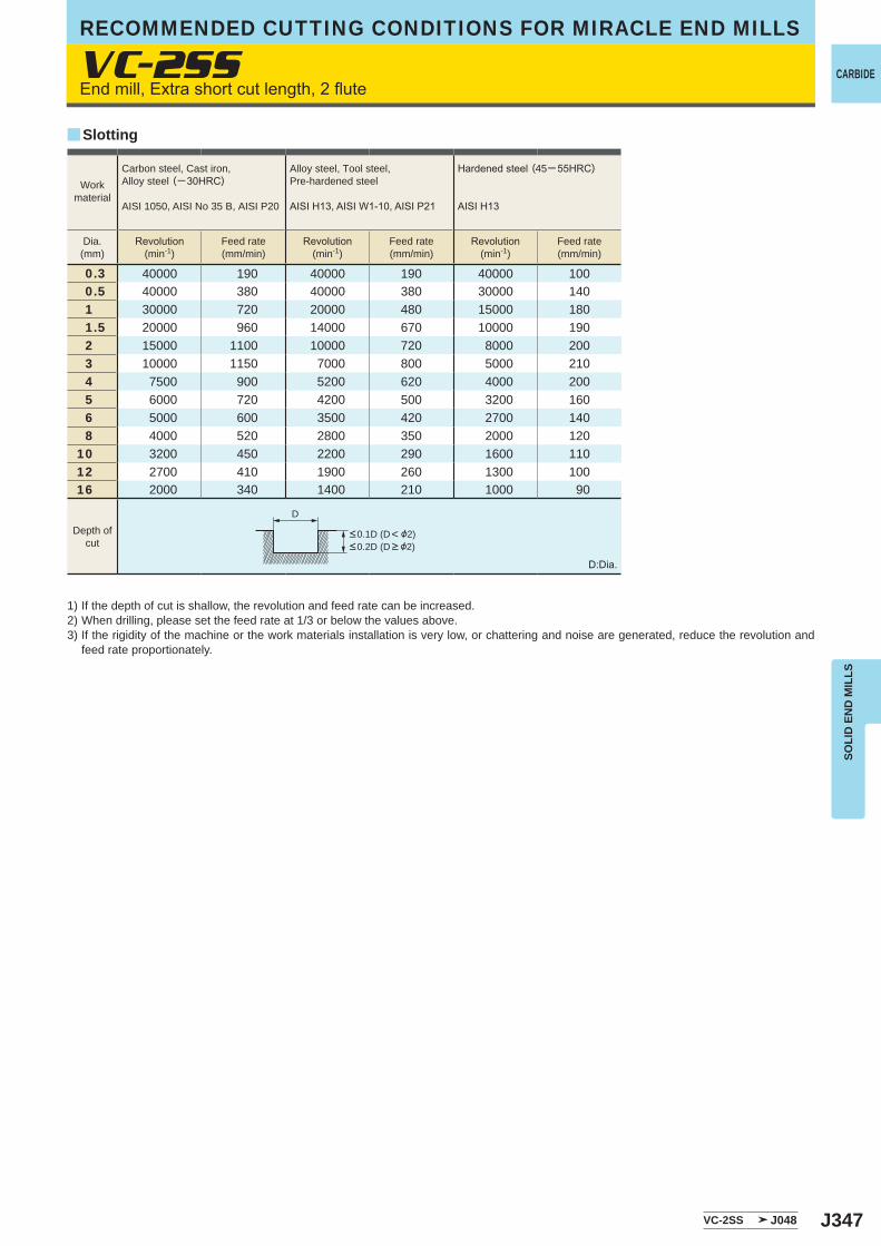
J347
VC-2SS
0.3 40000 190 40000 190 40000 1000.5 40000 380 40000 380 30000 1401 30000 720 20000 480 15000 1801.5 20000 960 14000 670 10000 1902 15000 1100 10000 720 8000 2003 10000 1150 7000 800 5000 2104 7500 900 5200 620 4000 2005 6000 720 4200 500 3200 1606 5000 600 3500 420 2700 1408 4000 520 2800 350 2000 120
10 3200 450 2200 290 1600 11012 2700 410 1900 260 1300 10016 2000 340 1400 210 1000 90
VC-2SS J048
y
D
CARBIDE
SOLI
D E
ND
MIL
LS
Cornerradiusendmill,Mediumcuttinglength,4flute,Irregularhelixflutes(forfinishing) Endmill,Extrashortcutlength,2flute
1) If the depth of cut is shallow, the revolution and feed rate can be increased.2) When drilling, please set the feed rate at 1/3 or below the values above.3) If the rigidity of the machine or the work materials installation is very low, or chattering and noise are generated, reduce the revolution and
feed rate proportionately.
D:Dia.
RECOMMENDED CUTTING CONDITIONS FOR MIRACLE END MILLS
Slotting
Workmaterial
Carbon steel, Cast iron, Alloy steel (─30HRC)
AISI 1050, AISI No 35 B, AISI P20
Alloy steel, Tool steel,Pre-hardened steel
AISIH13,AISIW1-10,AISIP21
Hardenedsteel (45─55HRC)
AISIH13
Dia.(mm)
Revolution(min-1)
Feed rate(mm/min)
Revolution(min-1)
Feed rate(mm/min)
Revolution(min-1)
Feed rate(mm/min)
<0.1D (D< &2)<0.2D (D > &2)
Depth ofcut
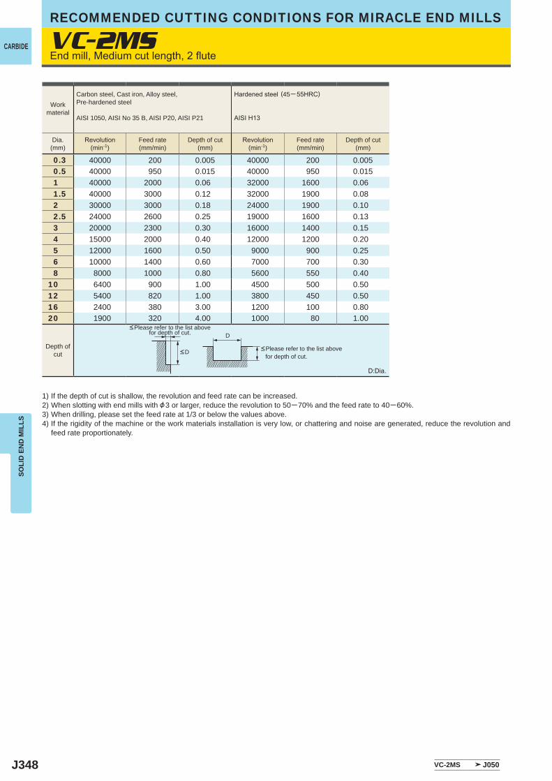
J348
VC-2MS
0.3 40000 200 0.005 40000 200 0.0050.5 40000 950 0.015 40000 950 0.0151 40000 2000 0.06 32000 1600 0.061.5 40000 3000 0.12 32000 1900 0.082 30000 3000 0.18 24000 1900 0.102.5 24000 2600 0.25 19000 1600 0.133 20000 2300 0.30 16000 1400 0.154 15000 2000 0.40 12000 1200 0.205 12000 1600 0.50 9000 900 0.256 10000 1400 0.60 7000 700 0.308 8000 1000 0.80 5600 550 0.40
10 6400 900 1.00 4500 500 0.5012 5400 820 1.00 3800 450 0.5016 2400 380 3.00 1200 100 0.8020 1900 320 4.00 1000 80 1.00
VC-2MS J050
D
RECOMMENDED CUTTING CONDITIONS FOR MIRACLE END MILLS
CARBIDE
SOLI
D E
ND
MIL
LS
Endmill,Mediumcutlength,2flute
1) If the depth of cut is shallow, the revolution and feed rate can be increased.2) When slotting with end mills with &3 or larger, reduce the revolution to 50─70% and the feed rate to 40─60%.3) When drilling, please set the feed rate at 1/3 or below the values above.4) If the rigidity of the machine or the work materials installation is very low, or chattering and noise are generated, reduce the revolution and
feed rate proportionately.
D:Dia.
<Please refer to the list above for depth of cut.
<Please refer to the list above for depth of cut.
Workmaterial
Carbon steel, Cast iron, Alloy steel,Pre-hardened steel
AISI 1050, AISI No 35 B, AISI P20, AISI P21
Hardenedsteel (45─55HRC)
AISIH13
Dia.(mm)
Revolution(min-1)
Feed rate(mm/min)
Depth of cut(mm)
Revolution(min-1)
Feed rate(mm/min)
Depth of cut(mm)
Depth ofcut <D
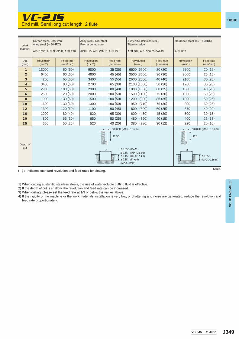
J349
VC-2JS
1 13000 60 (60) 9000 35 (35) 6500 (6500) 20 (20) 5700 20 (15)2 6400 60 (60) 4800 45 (45) 3500 (3500) 30 (30) 3000 25 (15)3 4200 65 (60) 3400 55 (55) 2600 (2600) 40 (40) 2100 30 (20)4 3400 80 (60) 2700 65 (30) 2100 (1600) 50 (20) 1700 35 (20)5 2900 100 (60) 2300 80 (40) 1800 (1350) 60 (25) 1500 40 (20)6 2500 120 (60) 2000 100 (50) 1500 (1100) 75 (30) 1300 50 (25)8 1900 130 (60) 1500 100 (50) 1200 (900) 85 (35) 1000 50 (25)
10 1600 130 (60) 1300 100 (50) 950 (710) 75 (30) 800 50 (25)12 1300 120 (60) 1100 90 (45) 800 (600) 60 (25) 670 40 (20)16 1000 80 (40) 820 65 (30) 600 (450) 45 (20) 500 30 (15)20 800 65 (30) 650 50 (25) 480 (360) 40 (15) 400 25 (13)25 650 50 (25) 520 40 (20) 380 (280) 30 (12) 320 20 (10)
VC-2JS J052
D D
CARBIDE
SOLI
D E
ND
MIL
LS
Endmill,Semilongcutlength,2flute
1)Whencuttingausteniticstainlesssteels,theuseofwater-solublecuttingfluidiseffective.2) If the depth of cut is shallow, the revolution and feed rate can be increased.3) When drilling, please set the feed rate at 1/3 or below the values above.4) If the rigidity of the machine or the work materials installation is very low, or chattering and noise are generated, reduce the revolution and
feed rate proportionately.
D:Dia.():Indicatesstandardrevolutionandfeedratesforslotting.
Depth ofcut
Workmaterial
Carbon steel, Cast iron, Alloy steel (─30HRC)
AISI 1050, AISI No 35 B, AISI P20
Alloy steel, Tool steel,Pre-hardened steel
AISIH13,AISIW1-10,AISIP21
Austenitic stainless steel,Titanium alloy
AISI 304, AISI 306, Ti-6Al-4V
Hardenedsteel (45─55HRC)
AISIH13
Dia.(mm)
Revolution(min-1)
Feed rate(mm/min)
Revolution(min-1)
Feed rate(mm/min)
Revolution(min-1)
Feed rate(mm/min)
Revolution(min-1)
Feed rate(mm/min)
<2.5D
<0.05D (MAX. 0.5mm) <0.02D (MAX. 0.3mm)
<0.05D (MAX. 0.5mm)
<0.05D (D=&1)<0.1D (&1<D< &2)<0.15D (&2<D< &3)<0.3D (D>&3)(MAX. 3mm)
<2D
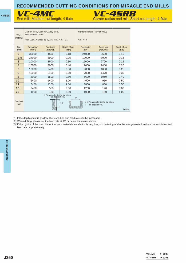
J350
2 30000 4500 0.18 24000 3600 0.10 2.5 24000 3900 0.25 19000 3000 0.13 3 20000 3500 0.30 16000 2700 0.15 4 15000 3000 0.40 12000 2400 0.20 5 12000 2400 0.50 9000 1800 0.25 6 10000 2100 0.60 7000 1470 0.30 8 8000 1500 0.80 5600 1050 0.4010 6400 1400 1.00 4500 950 0.5012 5400 1200 1.00 3800 860 0.5016 2400 550 2.00 1200 120 0.8020 1900 480 3.00 1000 100 1.00
VC-4MC J095VC-4SRB J208
VC-4MC VC-4SRB
D
RECOMMENDED CUTTING CONDITIONS FOR MIRACLE END MILLS
CARBIDE
SOLI
D E
ND
MIL
LS
1) If the depth of cut is shallow, the revolution and feed rate can be increased.2) When drilling, please set the feed rate at 1/3 or below the values above.3) If the rigidity of the machine or the work materials installation is very low, or chattering and noise are generated, reduce the revolution and
feed rate proportionately.
D:Dia.
<Please refer to the list above for depth of cut.
<Please refer to the list above for depth of cut.
Workmaterial
Carbon steel, Cast iron, Alloy steel,Pre-hardened steel
AISI 1050, AISI No 35 B, AISI P20, AISI P21
Hardenedsteel (45─55HRC)
AISIH13
Dia.(mm)
Revolution(min-1)
Feed rate(mm/min)
Depth of cut(mm)
Revolution(min-1)
Feed rate(mm/min)
Depth of cut(mm)
Depth ofcut <D
Endmill,Mediumcutlength,4flute Cornerradiusendmill,Shortcutlength,4flute
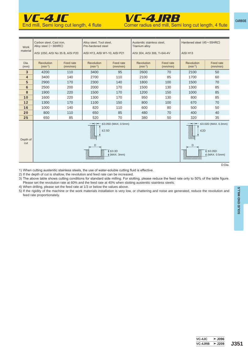
J351
VC-4JC
3 4200 110 3400 95 2600 70 2100 504 3400 140 2700 110 2100 85 1700 605 2900 170 2300 140 1800 100 1500 706 2500 200 2000 170 1500 130 1300 858 1900 220 1500 170 1200 150 1000 85
10 1600 220 1300 170 950 130 800 8512 1300 170 1100 150 800 100 670 7016 1000 140 820 110 600 80 500 5020 800 110 650 85 480 70 400 4025 650 85 520 70 380 50 320 35
VC-4JC J096VC-4JRB J209
VC-4JRB
D D
CARBIDE
SOLI
D E
ND
MIL
LS
Endmill,Semilongcutlength,4flute
1)Whencuttingausteniticstainlesssteels,theuseofwater-solublecuttingfluidiseffective.2) If the depth of cut is shallow, the revolution and feed rate can be increased.3)Theabovetableshowscuttingconditionsforstandardsidemilling.Forslotting,pleasereducethefeedrateonlyto50%ofthetablefigure.
Please set the revolution rate at 60% and the feed rate at 40% when slotting austenitic stainless steels.4) When drilling, please set the feed rate at 1/3 or below the values above.5) If the rigidity of the machine or the work materials installation is very low, or chattering and noise are generated, reduce the revolution and
feed rate proportionately.
D:Dia.
Cornerradiusendmill,Semilongcutlength,4flute
Workmaterial
Carbon steel, Cast iron, Alloy steel (─30HRC)
AISI 1050, AISI No 35 B, AISI P20
Alloy steel, Tool steel,Pre-hardened steel
AISIH13,AISIW1-10,AISIP21
Austenitic stainless steel,Titanium alloy
AISI 304, AISI 306, Ti-6Al-4V
Hardenedsteel (45─55HRC)
AISIH13
Dia.(mm)
Revolution(min-1)
Feed rate(mm/min)
Revolution(min-1)
Feed rate(mm/min)
Revolution(min-1)
Feed rate(mm/min)
Revolution(min-1)
Feed rate(mm/min)
Depth ofcut
<0.05D (MAX. 0.5mm) <0.02D (MAX. 0.3mm)
<0.3D (MAX. 3mm)
<0.05D (MAX. 0.5mm)
<2.5D <2D
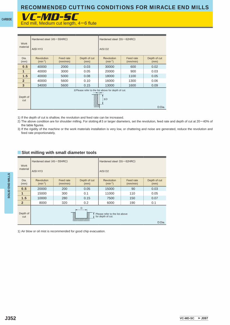
J352
0.5 40000 2000 0.03 30000 600 0.02 1 40000 3000 0.05 20000 900 0.03 1.5 40000 5000 0.08 18000 1100 0.05 2 40000 5600 0.10 16000 1300 0.06 3 34000 5600 0.15 13000 1600 0.09
0.5 20000 200 0.05 15000 90 0.031 15000 300 0.1 11000 110 0.051.5 10000 280 0.15 7500 150 0.072 8000 320 0.2 6000 190 0.1
VC-MD-SC
VC-MD-SC J097
y
D
RECOMMENDED CUTTING CONDITIONS FOR MIRACLE END MILLS
CARBIDE
SOLI
D E
ND
MIL
LS
1) If the depth of cut is shallow, the revolution and feed rate can be increased.2) The above condition are for shoulder milling. For slotting &3 or larger diameters, set the revolution, feed rate and depth of cut at 20─40% of
thetablefigures.3) If the rigidity of the machine or the work materials installation is very low, or chattering and noise are generated, reduce the revolution and
feed rate proportionately.
D:Dia.
1) Air blow or oil mist is recommended for good chip evacuation.
D:Dia.
End mill, Medium cut length, 4─6flute
<Please refer to the list above for depth of cut.
Please refer to the list abovefor depth of cut.
Slot milling with small diameter tools
Workmaterial
Hardenedsteel (45─55HRC)
AISIH13
Hardenedsteel (55─ 62HRC)
AISI D2
Dia.(mm)
Revolution(min-1)
Feed rate(mm/min)
Depth of cut(mm)
Revolution(min-1)
Feed rate(mm/min)
Depth of cut(mm)
Workmaterial
Hardenedsteel (45─55HRC)
AISIH13
Hardenedsteel (55─ 62HRC)
AISI D2
Dia.(mm)
Revolution(min-1)
Feed rate(mm/min)
Depth of cut(mm)
Revolution(min-1)
Feed rate(mm/min)
Depth of cut(mm)
Depth ofcut
Depth ofcut
<D
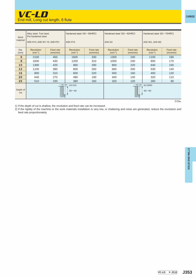
J353
VC-LD
6 2100 450 1600 330 1300 240 1100 1908 1600 430 1200 310 1000 230 800 170
10 1300 420 960 290 800 220 640 15012 1100 380 800 260 660 200 530 14016 800 310 600 220 500 160 400 12020 640 270 480 190 400 140 320 11025 510 230 380 160 320 120 260 90
VC-LD J112
3D─4D 3D─4D
CARBIDE
SOLI
D E
ND
MIL
LS
Endmill,Longcutlength,6flute
1) If the depth of cut is shallow, the revolution and feed rate can be increased.2) If the rigidity of the machine or the work materials installation is very low, or chattering and noise are generated, reduce the revolution and
feed rate proportionately.
D:Dia.
Workmaterial
Alloy steel, Tool steel,Pre-hardened steel
AISIH13,AISIW1-10,AISIP21
Hardenedsteel (45─55HRC)
AISIH13
Hardenedsteel (55─ 62HRC)
AISI D2
Hardenedsteel (62─70HRC)
AISI W1, AISI M2
Dia.(mm)
Revolution(min-1)
Feed rate(mm/min)
Revolution(min-1)
Feed rate(mm/min)
Revolution(min-1)
Feed rate(mm/min)
Revolution(min-1)
Feed rate(mm/min)
Depth ofcut
<0.01D <0.005D
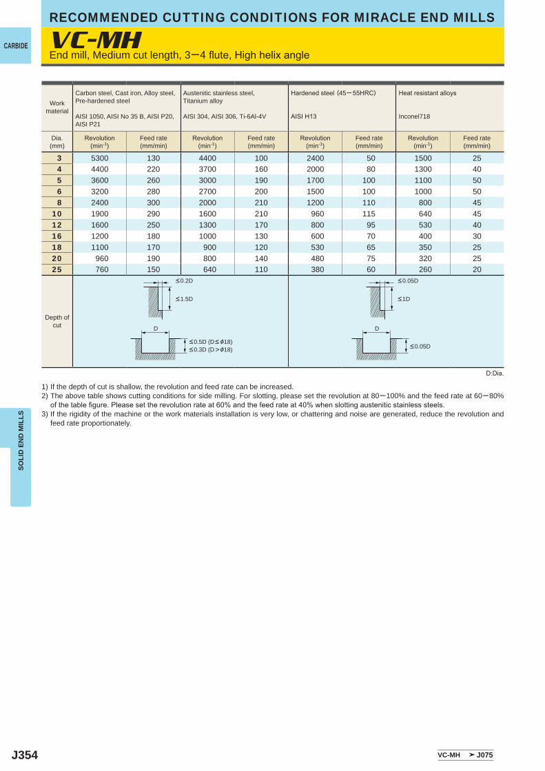
J354
VC-MH
3 5300 130 4400 100 2400 50 1500 254 4400 220 3700 160 2000 80 1300 405 3600 260 3000 190 1700 100 1100 506 3200 280 2700 200 1500 100 1000 508 2400 300 2000 210 1200 110 800 45
10 1900 290 1600 210 960 115 640 4512 1600 250 1300 170 800 95 530 4016 1200 180 1000 130 600 70 400 3018 1100 170 900 120 530 65 350 2520 960 190 800 140 480 75 320 2525 760 150 640 110 380 60 260 20
VC-MH J075
DD
RECOMMENDED CUTTING CONDITIONS FOR MIRACLE END MILLS
CARBIDE
SOLI
D E
ND
MIL
LS
End mill, Medium cut length, 3─4flute,Highhelixangle
Workmaterial
Carbon steel, Cast iron, Alloy steel,Pre-hardened steel
AISI 1050, AISI No 35 B, AISI P20, AISI P21
Austenitic stainless steel,Titanium alloy
AISI 304, AISI 306, Ti-6Al-4V
Hardenedsteel (45─55HRC)
AISIH13
Heatresistantalloys
Inconel718
Dia.(mm)
Revolution(min-1)
Feed rate(mm/min)
Revolution(min-1)
Feed rate(mm/min)
Revolution(min-1)
Feed rate(mm/min)
Revolution(min-1)
Feed rate(mm/min)
Depth ofcut
<0.2D <0.05D
<1.5D <1D
<0.05D<0.5D (D< &18)<0.3D (D>&18)
1) If the depth of cut is shallow, the revolution and feed rate can be increased.2) The above table shows cutting conditions for side milling. For slotting, please set the revolution at 80─100% and the feed rate at 60─80%
ofthetablefigure.Pleasesettherevolutionrateat60%andthefeedrateat40%whenslottingausteniticstainlesssteels.3) If the rigidity of the machine or the work materials installation is very low, or chattering and noise are generated, reduce the revolution and
feed rate proportionately.
D:Dia.
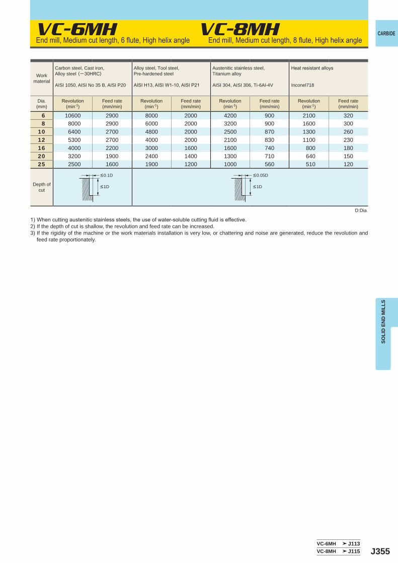
J355
VC-6MH
6 10600 2900 8000 2000 4200 900 2100 3208 8000 2900 6000 2000 3200 900 1600 300
10 6400 2700 4800 2000 2500 870 1300 26012 5300 2700 4000 2000 2100 830 1100 23016 4000 2200 3000 1600 1600 740 800 18020 3200 1900 2400 1400 1300 710 640 15025 2500 1600 1900 1200 1000 560 510 120
VC-6MH J113VC-8MH J115
VC-8MH CARBIDE
SOLI
D E
ND
MIL
LS
Workmaterial
Carbon steel, Cast iron, Alloy steel (─30HRC)
AISI 1050, AISI No 35 B, AISI P20
Alloy steel, Tool steel,Pre-hardened steel
AISIH13,AISIW1-10,AISIP21
Austenitic stainless steel,Titanium alloy
AISI 304, AISI 306, Ti-6Al-4V
Heatresistantalloys
Inconel718
Dia.(mm)
Revolution(min-1)
Feed rate(mm/min)
Revolution(min-1)
Feed rate(mm/min)
Revolution(min-1)
Feed rate(mm/min)
Revolution(min-1)
Feed rate(mm/min)
Endmill,Mediumcutlength,6flute,Highhelixangle Endmill,Mediumcutlength,8flute,Highhelixangle
Depth ofcut
1)Whencuttingausteniticstainlesssteels,theuseofwater-solublecuttingfluidiseffective.2) If the depth of cut is shallow, the revolution and feed rate can be increased.3) If the rigidity of the machine or the work materials installation is very low, or chattering and noise are generated, reduce the revolution and
feed rate proportionately.
D:Dia.
<0.1D <0.05D
<1D <1D
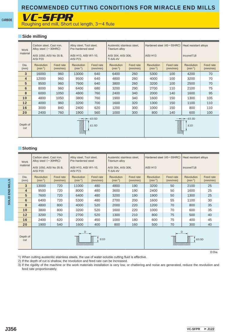
J356
VC-SFPR
3 16000 960 13000 640 6400 260 5300 100 4200 704 12000 960 9500 640 4800 260 4000 100 3200 705 9500 960 7600 640 3800 260 3200 100 2500 706 8000 960 6400 680 3200 290 2700 110 2100 758 6000 1050 4800 760 2400 340 2000 140 1600 95
10 4800 1050 3800 760 1900 340 1600 150 1300 10512 4000 960 3200 700 1600 320 1300 150 1100 11016 3000 840 2400 620 1200 300 1000 150 800 11020 2400 760 1900 560 1000 300 800 140 600 100
3 13000 720 11000 480 4800 190 3200 50 2100 254 9500 720 8000 480 3600 190 2400 50 1600 255 7600 720 6400 480 3200 190 1900 50 1300 256 6400 720 5300 480 2700 200 1600 55 1100 308 4800 800 4000 520 2000 220 1200 70 800 35
10 3800 800 3200 520 1600 220 1000 70 600 3512 3200 750 2700 520 1300 210 800 75 500 4016 2400 620 2000 450 1000 180 600 75 400 4520 1900 540 1600 400 800 160 500 70 300 40
VC-SFPR J122
y
y
D D
RECOMMENDED CUTTING CONDITIONS FOR MIRACLE END MILLS
CARBIDE
SOLI
D E
ND
MIL
LS
D:Dia.
1)Whencuttingausteniticstainlesssteels,theuseofwater-solublecuttingfluidiseffective.2) If the depth of cut is shallow, the revolution and feed rate can be increased.3) If the rigidity of the machine or the work materials installation is very low, or chattering and noise are generated, reduce the revolution and
feed rate proportionately.
Depth ofcut
Depth ofcut
Workmaterial
Carbon steel, Cast iron, Alloy steel (─30HRC)
AISI 1050, AISI No 35 B,AISI P20
Alloy steel, Tool steel,Pre-hardened steel
AISIH13,AISIW1-10,AISI P21
Austenitic stainless steel,Titanium alloy
AISI 304, AISI 306, Ti-6Al-4V
Hardenedsteel (45─55HRC)
AISIH13
Heatresistantalloys
Inconel718
Dia.(mm)
Revolution(min-1)
Feed rate(mm/min)
Revolution(min-1)
Feed rate(mm/min)
Revolution(min-1)
Feed rate(mm/min)
Revolution(min-1)
Feed rate(mm/min)
Revolution(min-1)
Feed rate(mm/min)
Roughingendmill,Shortcutlength,3─4flute
Side milling
Slotting
<0.5D <0.3D
<1.5D <1D
<0.5D<1D
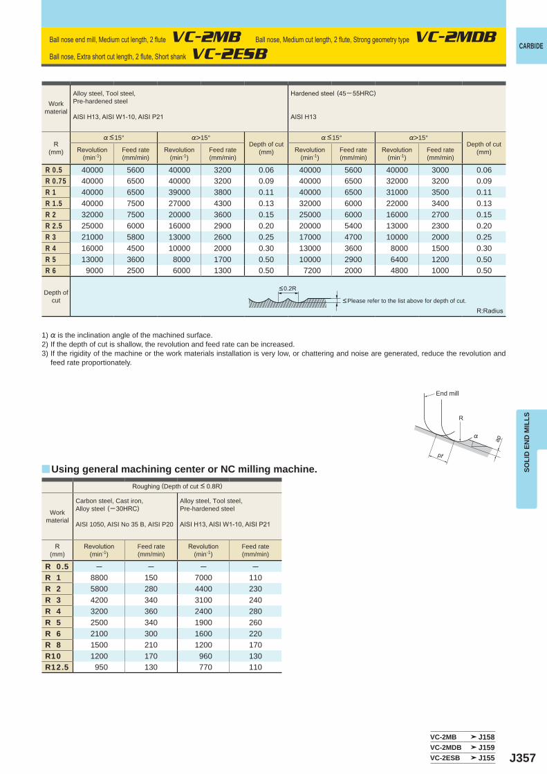
J357
%>15° %>15°
R 0.5 40000 5600 40000 3200 0.06 40000 5600 40000 3000 0.06R 0.75 40000 6500 40000 3200 0.09 40000 6500 32000 3200 0.09R 1 40000 6500 39000 3800 0.11 40000 6500 31000 3500 0.11R 1.5 40000 7500 27000 4300 0.13 32000 6000 22000 3400 0.13R 2 32000 7500 20000 3600 0.15 25000 6000 16000 2700 0.15R 2.5 25000 6000 16000 2900 0.20 20000 5400 13000 2300 0.20R 3 21000 5800 13000 2600 0.25 17000 4700 10000 2000 0.25R 4 16000 4500 10000 2000 0.30 13000 3600 8000 1500 0.30R 5 13000 3600 8000 1700 0.50 10000 2900 6400 1200 0.50R 6 9000 2500 6000 1300 0.50 7200 2000 4800 1000 0.50
R 0.5 ─ ─ ─ ─R 1 8800 150 7000 110R 2 5800 280 4400 230R 3 4200 340 3100 240R 4 3200 360 2400 280R 5 2500 340 1900 260R 6 2100 300 1600 220R 8 1500 210 1200 170R10 1200 170 960 130R12.5 950 130 770 110
VC-2MB J158VC-2MDB J159VC-2ESB J155
y
R
%
ap
pf
CARBIDE
SOLI
D E
ND
MIL
LS
Depth ofcut
Workmaterial
Alloy steel, Tool steel,Pre-hardened steel
AISIH13,AISIW1-10,AISIP21
Hardenedsteel (45─55HRC)
AISIH13
R(mm)
%<15°Depth of cut
(mm)
%<15°Depth of cut
(mm)Revolution(min-1)
Feed rate(mm/min)
Revolution(min-1)
Feed rate(mm/min)
Revolution(min-1)
Feed rate(mm/min)
Revolution(min-1)
Feed rate(mm/min)
Ballnoseendmill,Mediumcutlength,2flute VC-2MB Ballnose,Mediumcutlength,2flute,Stronggeometrytype VC-2MDB
Ballnose,Extrashortcutlength,2flute,ShortshankVC-2ESB
Roughing(Depth of cut <0.8R)
Workmaterial
Carbon steel, Cast iron, Alloy steel (─30HRC)
AISI 1050, AISI No 35 B, AISI P20
Alloy steel, Tool steel,Pre-hardened steel
AISIH13,AISIW1-10,AISIP21
R(mm)
Revolution(min-1)
Feed rate(mm/min)
Revolution(min-1)
Feed rate(mm/min)
<0.2R
R:Radius<Please refer to the list above for depth of cut.
1) % is the inclination angle of the machined surface. 2) If the depth of cut is shallow, the revolution and feed rate can be increased.3) If the rigidity of the machine or the work materials installation is very low, or chattering and noise are generated, reduce the revolution and
feed rate proportionately.
Using general machining center or NC milling machine.
End mill
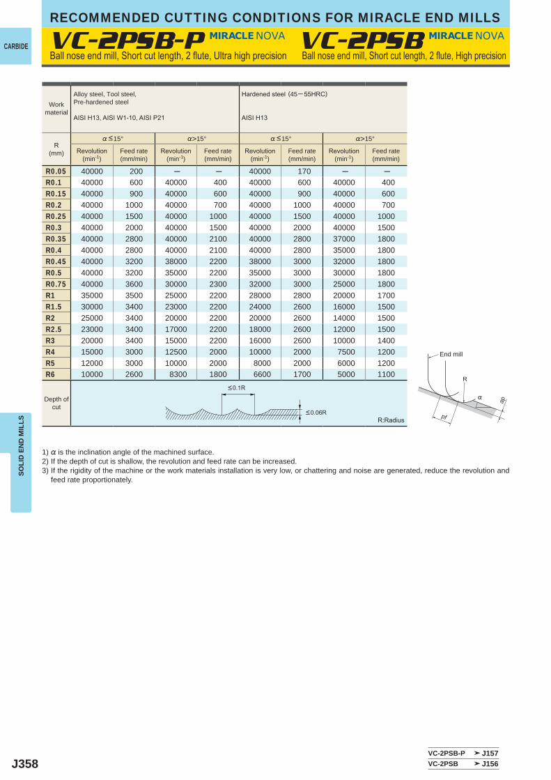
J358
VC-2PSB-P
%>15° %>15°
R0.05 40000 200 ─ ─ 40000 170 ─ ─R0.1 40000 600 40000 400 40000 600 40000 400R0.15 40000 900 40000 600 40000 900 40000 600R0.2 40000 1000 40000 700 40000 1000 40000 700R0.25 40000 1500 40000 1000 40000 1500 40000 1000R0.3 40000 2000 40000 1500 40000 2000 40000 1500R0.35 40000 2800 40000 2100 40000 2800 37000 1800R0.4 40000 2800 40000 2100 40000 2800 35000 1800R0.45 40000 3200 38000 2200 38000 3000 32000 1800R0.5 40000 3200 35000 2200 35000 3000 30000 1800R0.75 40000 3600 30000 2300 32000 3000 25000 1800R1 35000 3500 25000 2200 28000 2800 20000 1700R1.5 30000 3400 23000 2200 24000 2600 16000 1500R2 25000 3400 20000 2200 20000 2600 14000 1500R2.5 23000 3400 17000 2200 18000 2600 12000 1500R3 20000 3400 15000 2200 16000 2600 10000 1400R4 15000 3000 12500 2000 10000 2000 7500 1200R5 12000 3000 10000 2000 8000 2000 6000 1200R6 10000 2600 8300 1800 6600 1700 5000 1100
VC-2PSB
VC-2PSB-P J157VC-2PSB J156
R
%
ap
pf
RECOMMENDED CUTTING CONDITIONS FOR MIRACLE END MILLS
CARBIDE
SOLI
D E
ND
MIL
LS
Workmaterial
Alloy steel, Tool steel,Pre-hardened steel
AISIH13,AISIW1-10,AISIP21
Hardenedsteel (45─55HRC)
AISIH13
R(mm)
%<15° %<15°
Revolution(min-1)
Feed rate(mm/min)
Revolution(min-1)
Feed rate(mm/min)
Revolution(min-1)
Feed rate(mm/min)
Revolution(min-1)
Feed rate(mm/min)
Ballnoseendmill,Shortcutlength,2flute,Ultrahighprecision Ballnoseendmill,Shortcutlength,2flute,Highprecision
Depth ofcut
<0.1R
<0.06RR:Radius
1) % is the inclination angle of the machined surface. 2) If the depth of cut is shallow, the revolution and feed rate can be increased.3) If the rigidity of the machine or the work materials installation is very low, or chattering and noise are generated, reduce the revolution and
feed rate proportionately.
End mill

J359
VC-XB
R0.5
1° 16 0.02
0.1 22000 530 12000 230
1° 21 0.011° 26 0.011°30' 23 0.023° 42 0.055° 23 0.05
R1
1° 21 0.05
0.2 18000 570 10000 260
1° 31 0.041° 41 0.031°30' 23 0.13° 41 0.15° 23 0.1
R2
1° 36 0.2
0.8 14000 670 6000 2001° 46 0.151° 60 0.11°30' 49 0.23° 28 0.2
R3
1° 51 0.3
1.2 10000 840 5000 2201° 65 0.21° 92 0.11°30' 53 0.33° 34 0.3
R41°30' 55 0.4
1.6 8000 840 4000 2703° 36 0.4
R5
1° 70 0.4
2 6000 840 3000 3101° 100 0.31°30' 59 0.53° 40 0.5
R6
1° 70 0.6
2.4 5000 900 2500 3401° 100 0.41°30' 83 0.63° 63 0.6
VC-XB J161
ap
ae
CARBIDE
SOLI
D E
ND
MIL
LS
Ball nose taper end mill, Medium cut length, Taper neck
1) If the depth of cut is shallow, the revolution and feed rate can be increased.2) If the rigidity of the machine or the work materials installation is very low, or chattering and noise are generated, reduce the revolution and
feed rate proportionately.
Work material
Alloy steel, Tool steel,Pre-hardened steel
AISIH13,AISIW1-10,AISIP21
Hardenedsteel (45─55HRC)
AISIH13
R(mm)
Taper angleone side
Neck length(mm)
Depth of cutRevolution
(min-1)Feed rate(mm/min)
Revolution(min-1)
Feed rate(mm/min)ap
(mm)ae
(mm)
Depth of cut
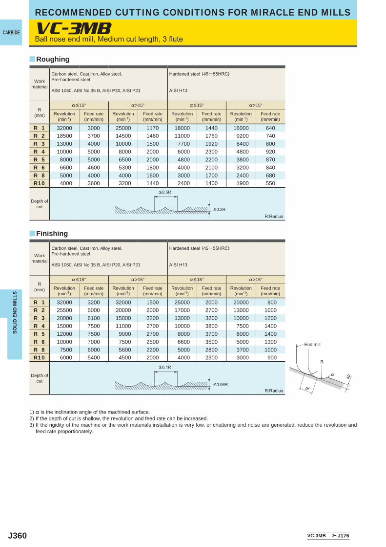
J360
VC-3MB
%>15° %>15°
R 1 32000 3000 25000 1170 18000 1440 16000 640R 2 18500 3700 14500 1460 11000 1760 9200 740R 3 13000 4000 10000 1500 7700 1920 6400 800R 4 10000 5000 8000 2000 6000 2300 4800 920R 5 8000 5000 6500 2000 4800 2200 3800 870R 6 6600 4600 5300 1800 4000 2100 3200 840R 8 5000 4000 4000 1600 3000 1700 2400 680R10 4000 3600 3200 1440 2400 1400 1900 550
%>15° %>15°
R 1 32000 3200 32000 1500 25000 2000 20000 800R 2 25500 5000 20000 2000 17000 2700 13000 1000R 3 20000 6100 15000 2200 13000 3200 10000 1200R 4 15000 7500 11000 2700 10000 3800 7500 1400R 5 12000 7500 9000 2700 8000 3700 6000 1400R 6 10000 7000 7500 2500 6600 3500 5000 1300R 8 7500 6000 5600 2200 5000 2800 3700 1000R10 6000 5400 4500 2000 4000 2300 3000 900
VC-3MB J176
y
y
R
%
ap
pf
RECOMMENDED CUTTING CONDITIONS FOR MIRACLE END MILLS
CARBIDE
SOLI
D E
ND
MIL
LS
Roughing
Finishing
R:Radius
R:Radius
Ballnoseendmill,Mediumcutlength,3flute
1) % is the inclination angle of the machined surface. 2) If the depth of cut is shallow, the revolution and feed rate can be increased.3) If the rigidity of the machine or the work materials installation is very low, or chattering and noise are generated, reduce the revolution and
feed rate proportionately.
Workmaterial
Carbon steel, Cast iron, Alloy steel,Pre-hardened steel
AISI 1050, AISI No 35 B, AISI P20, AISI P21
Hardenedsteel (45─55HRC)
AISIH13
R(mm)
%<15° %<15°
Revolution(min-1)
Feed rate(mm/min)
Revolution(min-1)
Feed rate(mm/min)
Revolution(min-1)
Feed rate(mm/min)
Revolution(min-1)
Feed rate(mm/min)
Depth ofcut
<0.2R
<0.5R
<0.06R
<0.1R
End mill
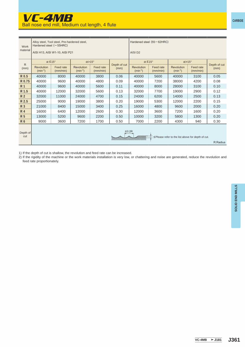
J361
VC-4MB
%>15° %>15°
R 0.5 40000 8000 40000 3800 0.06 40000 5600 40000 3100 0.05R 0.75 40000 9600 40000 4800 0.09 40000 7200 38000 4200 0.08R 1 40000 9600 40000 5600 0.11 40000 8000 28000 3100 0.10R 1.5 40000 12000 32000 5600 0.13 32000 7700 19000 2900 0.12R 2 32000 11000 24000 4700 0.15 24000 6200 14000 2500 0.13R 2.5 25000 9000 19000 3800 0.20 19000 5300 12000 2200 0.15R 3 21000 8400 15000 3400 0.25 16000 4800 9600 2000 0.20R 4 16000 6400 12000 2600 0.30 12000 3600 7200 1600 0.20R 5 13000 5200 9600 2200 0.50 10000 3200 5800 1300 0.20R 6 9000 3600 7200 1700 0.50 7000 2200 4300 940 0.30
VC-4MB J181
CARBIDE
SOLI
D E
ND
MIL
LS
Ballnoseendmill,Mediumcutlength,4flute
R:Radius
<Please refer to the list above for depth of cut.
1) If the depth of cut is shallow, the revolution and feed rate can be increased.2) If the rigidity of the machine or the work materials installation is very low, or chattering and noise are generated, reduce the revolution and
feed rate proportionately.
Workmaterial
Alloy steel, Tool steel, Pre-hardened steel,Hardenedsteel (─55HRC)
AISIH13,AISIW1-10,AISIP21
Hardenedsteel (55─ 62HRC)
AISI D2
R(mm)
%<15°Depth of cut
(mm)
%<15°Depth of cut
(mm)Revolution(min-1)
Feed rate(mm/min)
Revolution(min-1)
Feed rate(mm/min)
Revolution(min-1)
Feed rate(mm/min)
Revolution(min-1)
Feed rate(mm/min)
Depth ofcut
<0.2R
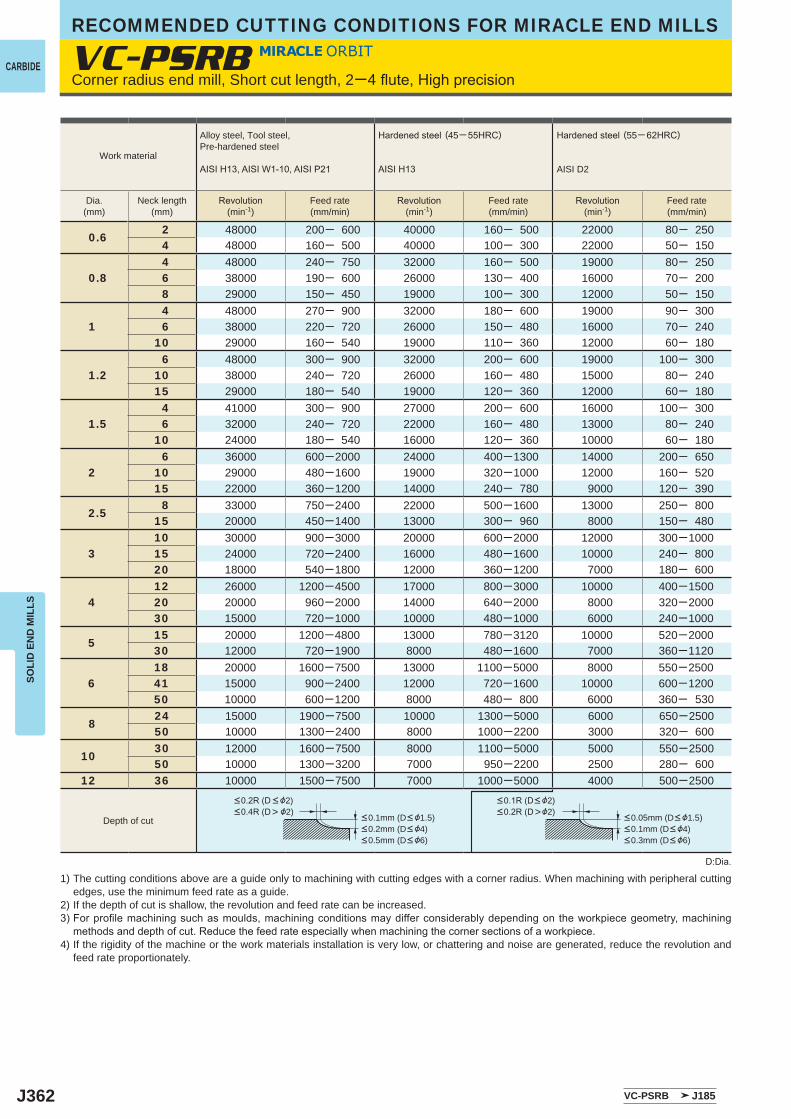
J362
VC-PSRB
0.62 48000 200─ 600 40000 160─ 500 22000 80─ 2504 48000 160─ 500 40000 100─ 300 22000 50─ 150
0.84 48000 240─ 750 32000 160─ 500 19000 80─ 2506 38000 190─ 600 26000 130─ 400 16000 70─ 2008 29000 150─ 450 19000 100─ 300 12000 50─ 150
14 48000 270─ 900 32000 180─ 600 19000 90─ 3006 38000 220─ 720 26000 150─ 480 16000 70─ 240
10 29000 160─ 540 19000 110─ 360 12000 60─ 180
1.26 48000 300─ 900 32000 200─ 600 19000 100─ 300
10 38000 240─ 720 26000 160─ 480 15000 80─ 24015 29000 180─ 540 19000 120─ 360 12000 60─ 180
1.54 41000 300─ 900 27000 200─ 600 16000 100─ 3006 32000 240─ 720 22000 160─ 480 13000 80─ 240
10 24000 180─ 540 16000 120─ 360 10000 60─ 180
26 36000 600─2000 24000 400─1300 14000 200─ 650
10 29000 480─1600 19000 320─1000 12000 160─ 52015 22000 360─1200 14000 240─ 780 9000 120─ 390
2.58 33000 750─2400 22000 500─1600 13000 250─ 800
15 20000 450─1400 13000 300─ 960 8000 150─ 480
310 30000 900─3000 20000 600─2000 12000 300─100015 24000 720─2400 16000 480─1600 10000 240─ 80020 18000 540─1800 12000 360─1200 7000 180─ 600
412 26000 1200─4500 17000 800─3000 10000 400─150020 20000 960─2000 14000 640─2000 8000 320─200030 15000 720─1000 10000 480─1000 6000 240─1000
515 20000 1200─4800 13000 780─3120 10000 520─200030 12000 720─1900 8000 480─1600 7000 360─1120
618 20000 1600─7500 13000 1100─5000 8000 550─250041 15000 900─2400 12000 720─1600 10000 600─120050 10000 600─1200 8000 480─ 800 6000 360─ 530
824 15000 1900─7500 10000 1300─5000 6000 650─250050 10000 1300─2400 8000 1000─2200 3000 320─ 600
1030 12000 1600─7500 8000 1100─5000 5000 550─250050 10000 1300─3200 7000 950─2200 2500 280─ 600
12 36 10000 1500─7500 7000 1000─5000 4000 500─2500
VC-PSRB J185
RECOMMENDED CUTTING CONDITIONS FOR MIRACLE END MILLS
CARBIDE
SOLI
D E
ND
MIL
LS
Corner radius end mill, Short cut length, 2─4flute,Highprecision
D:Dia.
1) The cutting conditions above are a guide only to machining with cutting edges with a corner radius. When machining with peripheral cutting edges, use the minimum feed rate as a guide.
2) If the depth of cut is shallow, the revolution and feed rate can be increased.3)Forprofilemachiningsuchasmoulds,machiningconditionsmaydifferconsiderablydependingontheworkpiecegeometry,machining
methodsanddepthofcut.Reducethefeedrateespeciallywhenmachiningthecornersectionsofaworkpiece.4) If the rigidity of the machine or the work materials installation is very low, or chattering and noise are generated, reduce the revolution and
feed rate proportionately.
Work material
Alloy steel, Tool steel,Pre-hardened steel
AISIH13,AISIW1-10,AISIP21
Hardenedsteel (45─55HRC)
AISIH13
Hardenedsteel (55─ 62HRC)
AISI D2
Dia.(mm)
Neck length(mm)
Revolution(min-1)
Feed rate(mm/min)
Revolution(min-1)
Feed rate(mm/min)
Revolution(min-1)
Feed rate(mm/min)
Depth of cut
<0.2R(D< &2)<0.4R(D> &2)
<0.1R(D< &2)<0.2R(D>&2)
<0.1mm (D< &1.5)<0.2mm (D< &4)<0.5mm (D< &6)
<0.05mm (D< &1.5)<0.1mm (D< &4)<0.3mm (D< &6)
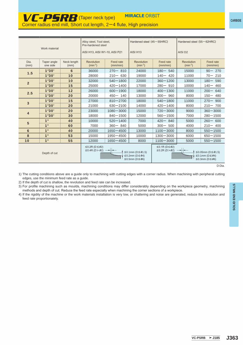
J363
1.51°30' 6 36000 270─ 810 24000 180─ 540 15000 90─ 2701°30' 10 28000 210─ 630 19000 140─ 420 11000 70─ 210
21°30' 10 32000 540─1800 22000 360─1200 13000 180─ 5901°30' 15 25000 420─1400 17000 280─ 910 10000 140─ 460
2.51°30' 12 26000 600─1900 18000 400─1300 11000 200─ 6401°30' 20 20000 450─ 140 13000 300─ 960 8000 150─ 480
31°30' 15 27000 810─2700 18000 540─1800 11000 270─ 9001°30' 20 21000 630─2100 14000 420─1400 8000 210─ 700
41°30' 20 23000 1080─3000 15000 720─3000 9000 360─30001°30' 30 18000 840─1500 12000 560─1500 7000 280─1500
51° 40 10000 520─1400 7000 420─ 840 5000 260─ 6001° 60 7000 360─ 840 5000 300─ 500 4000 210─ 400
6 1° 40 20000 1650─4500 13000 1100─3000 8000 550─1500 8 1° 53 15000 1950─4500 10000 1300─3000 6000 650─150010 1° 55 12000 1650─4500 8000 1100─3000 5000 550─1500
VC-PSRB J185
VC-PSRB CARBIDE
SOLI
D E
ND
MIL
LS
1) The cutting conditions above are a guide only to machining with cutting edges with a corner radius. When machining with peripheral cutting edges, use the minimum feed rate as a guide.
2) If the depth of cut is shallow, the revolution and feed rate can be increased.3)Forprofilemachiningsuchasmoulds,machiningconditionsmaydifferconsiderablydependingontheworkpiecegeometry,machining
methodsanddepthofcut.Reducethefeedrateespeciallywhenmachiningthecornersectionsofaworkpiece.4) If the rigidity of the machine or the work materials installation is very low, or chattering and noise are generated, reduce the revolution and
feed rate proportionately.
D:Dia.
Corner radius end mill, Short cut length, 2─4flute,Highprecision(Taper neck type)
<0.2R(D< &2)<0.4R(D> &2)
<0.1mm (D< &1.5)<0.2mm (D< &4)<0.5mm (D< &6)
<0.1R(D< &2)<0.2R(D>&2)
<0.05mm (D< &1.5)<0.1mm (D< &4)<0.3mm (D< &6)
Work material
Alloy steel, Tool steel,Pre-hardened steel
AISIH13,AISIW1-10,AISIP21
Hardenedsteel (45─55HRC)
AISIH13
Hardenedsteel (55─ 62HRC)
AISI D2
Dia.(mm)
Taper angleone side
Neck length(mm)
Revolution(min-1)
Feed rate(mm/min)
Revolution(min-1)
Feed rate(mm/min)
Revolution(min-1)
Feed rate(mm/min)
Depth of cut
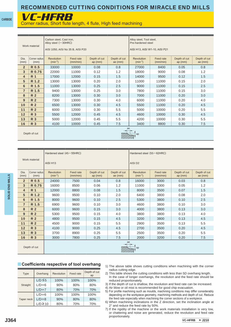
J364
VC-HFRB
2 R 0.5 33000 10000 0.08 0.8 27000 8400 0.05 0.83 R 0.75 22000 11000 0.12 1.2 18000 9000 0.08 1.24 R 1 17000 12000 0.15 1.5 14000 9500 0.12 1.55 R 1.2 13000 13000 0.20 2.0 11000 11000 0.15 2.06 R 1.5 11000 13000 0.25 2.5 9000 11000 0.15 2.57 R 1.5 9400 13000 0.25 3.0 7800 11000 0.15 3.08 R 2 8200 13000 0.30 3.0 7000 11000 0.20 3.09 R 2 7300 13000 0.30 4.0 6000 11000 0.20 4.0
10 R 2 6500 13000 0.30 4.5 5500 11000 0.20 4.511 R 2 6000 12000 0.30 5.5 5000 10000 0.20 5.512 R 3 5500 12000 0.45 4.5 4600 10000 0.30 4.513 R 3 5000 12000 0.45 5.5 4200 10000 0.30 5.516 R 3 4100 10000 0.45 7.5 3400 8800 0.30 7.5
2 R 0.5 24000 7500 0.04 0.8 16000 3000 0.03 0.83 R 0.75 16000 8500 0.06 1.2 11000 3300 0.05 1.24 R 1 12000 8800 0.08 1.5 8000 3500 0.07 1.55 R 1.2 9600 9500 0.10 2.0 6400 3800 0.08 2.06 R 1.5 8000 9600 0.10 2.5 5300 3800 0.10 2.57 R 1.5 6900 9600 0.10 3.0 4600 3800 0.10 3.08 R 2 6000 9600 0.15 3.0 4000 3800 0.13 3.09 R 2 5300 9500 0.15 4.0 3800 3800 0.13 4.0
10 R 2 4800 9500 0.15 4.5 3200 3800 0.13 4.511 R 2 4500 9000 0.15 5.5 2900 3500 0.13 5.512 R 3 4100 9000 0.25 4.5 2700 3500 0.20 4.513 R 3 3700 8900 0.25 5.5 2500 3500 0.20 5.516 R 3 3000 7800 0.25 7.5 2000 3200 0.20 7.5
100% 100% 100%L/D=6 90% 80% 80%L/D=7 80% 70% 70%L/D=6 100% 100% 100%L/D=8 90% 80% 80%
80% 70% 70%
VC-HFRB J210
y
ae
ap
ae
ap
RECOMMENDED CUTTING CONDITIONS FOR MIRACLE END MILLS
CARBIDE
SOLI
D E
ND
MIL
LS
Cornerradius,Shortflutelength,4flute,Highfeedmachining
1) The above table shows cutting conditions when machining with the corner radius cutting edge.
2) This table shows the cutting conditions with less than 5D overhang length. In the case of longer overhangs, the revolution and the feed rate should be
reduced proportionately.3) If the depth of cut is shallow, the revolution and feed rate can be increased.4) Air blow or oil mist is recommended for good chip evacuation.5) Forprofilemachiningsuchasmoulds,machiningconditionsmaydifferconsiderably
dependingontheworkpiecegeometry,machiningmethodsanddepthofcut.Reducethe feed rate especially when machining the corner sections of a workpiece.
6) When machining inclinations in the Z direction, set the inclination angle at 2° and reduce the feed rate by 50%.
7) If the rigidity of the machine or the work materials installation is very low, or chattering and noise are generated, reduce the revolution and feed rate proportionately.
Coefficients respective of tool overhang
Type Overhang Revolution Feed rate Depth of cutap
Straight
L/D <5
Taper neck
L/D >10
Work material
Carbon steel, Cast iron, Alloy steel (─30HRC)
AISI 1050, AISI No 35 B, AISI P20
Alloy steel, Tool steel,Pre-hardened steel
AISIH13,AISIW1-10,AISIP21
Dia.(mm)
Corner radius(mm)
Revolution(min-1)
Feed rate(mm/min)
Depth of cutap (mm)
Depth of cutae (mm)
Revolution(min-1)
Feed rate(mm/min)
Depth of cutap (mm)
Depth of cutae (mm)
Depth of cut
Work material
Hardenedsteel (45─55HRC)
AISIH13
Hardenedsteel (55─ 62HRC)
AISI D2
Dia.(mm)
Corner radius(mm)
Revolution(min-1)
Feed rate(mm/min)
Depth of cutap (mm)
Depth of cutae (mm)
Revolution(min-1)
Feed rate(mm/min)
Depth of cutap (mm)
Depth of cutae (mm)
Depth of cut
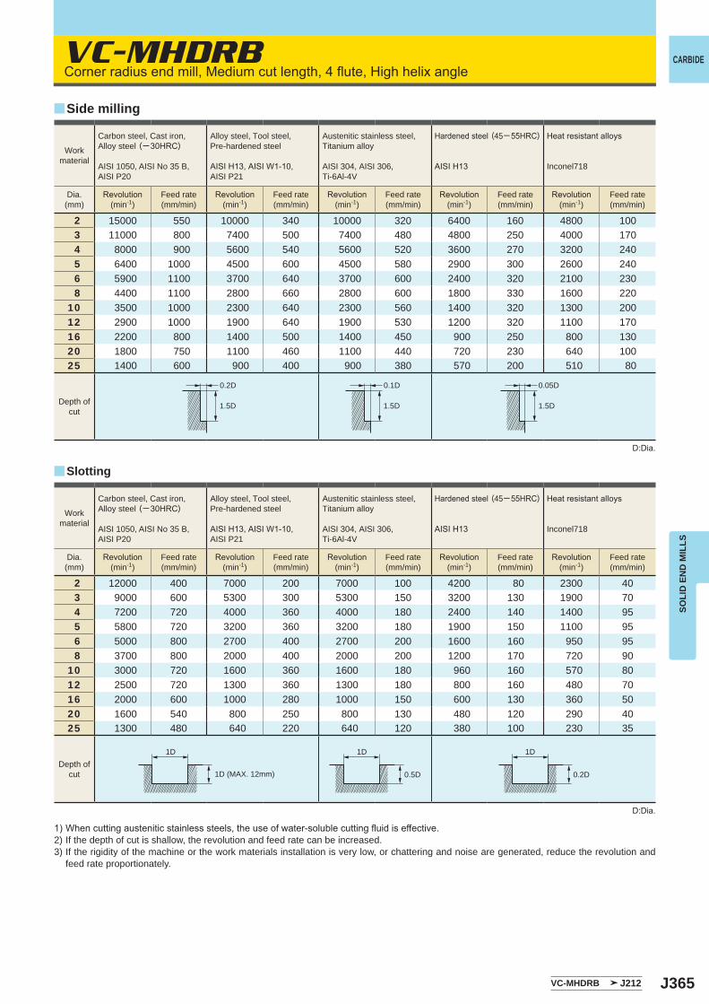
J365
VC-MHDRB
2 15000 550 10000 340 10000 320 6400 160 4800 1003 11000 800 7400 500 7400 480 4800 250 4000 1704 8000 900 5600 540 5600 520 3600 270 3200 2405 6400 1000 4500 600 4500 580 2900 300 2600 2406 5900 1100 3700 640 3700 600 2400 320 2100 2308 4400 1100 2800 660 2800 600 1800 330 1600 220
10 3500 1000 2300 640 2300 560 1400 320 1300 20012 2900 1000 1900 640 1900 530 1200 320 1100 17016 2200 800 1400 500 1400 450 900 250 800 13020 1800 750 1100 460 1100 440 720 230 640 10025 1400 600 900 400 900 380 570 200 510 80
2 12000 400 7000 200 7000 100 4200 80 2300 403 9000 600 5300 300 5300 150 3200 130 1900 704 7200 720 4000 360 4000 180 2400 140 1400 955 5800 720 3200 360 3200 180 1900 150 1100 956 5000 800 2700 400 2700 200 1600 160 950 958 3700 800 2000 400 2000 200 1200 170 720 90
10 3000 720 1600 360 1600 180 960 160 570 8012 2500 720 1300 360 1300 180 800 160 480 7016 2000 600 1000 280 1000 150 600 130 360 5020 1600 540 800 250 800 130 480 120 290 4025 1300 480 640 220 640 120 380 100 230 35
VC-MHDRB J212
y
y
0.2D
1.5D
0.1D
1.5D
0.05D
1.5D
1D 1D
0.5D
1D
0.2D
CARBIDE
SOLI
D E
ND
MIL
LS
Cornerradiusendmill,Mediumcutlength,4flute,Highhelixangle
1)Whencuttingausteniticstainlesssteels,theuseofwater-solublecuttingfluidiseffective.2) If the depth of cut is shallow, the revolution and feed rate can be increased.3) If the rigidity of the machine or the work materials installation is very low, or chattering and noise are generated, reduce the revolution and
feed rate proportionately.
D:Dia.
D:Dia.
Slotting
Side milling
1D (MAX. 12mm)
Workmaterial
Carbon steel, Cast iron, Alloy steel (─30HRC)
AISI 1050, AISI No 35 B,AISI P20
Alloy steel, Tool steel,Pre-hardened steel
AISIH13,AISIW1-10,AISI P21
Austenitic stainless steel,Titanium alloy
AISI 304, AISI 306, Ti-6Al-4V
Hardenedsteel (45─55HRC)
AISIH13
Heatresistantalloys
Inconel718
Dia.(mm)
Revolution(min-1)
Feed rate(mm/min)
Revolution(min-1)
Feed rate(mm/min)
Revolution(min-1)
Feed rate(mm/min)
Revolution(min-1)
Feed rate(mm/min)
Revolution(min-1)
Feed rate(mm/min)
Depth ofcut
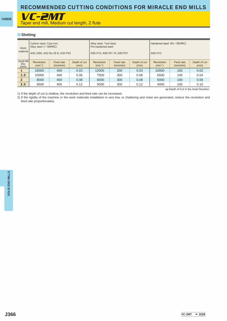
J366
VC-2MT
1 16000 400 0.03 12000 300 0.03 10000 100 0.021.5 10000 400 0.06 7500 300 0.06 6500 100 0.042 8000 400 0.08 6000 300 0.08 5000 100 0.062.5 6500 400 0.12 5000 300 0.12 4000 100 0.10
VC-2MT J226
y
RECOMMENDED CUTTING CONDITIONS FOR MIRACLE END MILLS
CARBIDE
SOLI
D E
ND
MIL
LS
Taperendmill,Mediumcutlength,2flute
1) If the depth of cut is shallow, the revolution and feed rate can be increased.2) If the rigidity of the machine or the work materials installation is very low, or chattering and noise are generated, reduce the revolution and
feed rate proportionately.
Slotting
ap:DepthofCutintheAxialDirection
Workmaterial
Carbon steel, Cast iron, Alloy steel (─30HRC)
AISI 1050, AISI No 35 B, AISI P20
Alloy steel, Tool steel,Pre-hardened steel
AISIH13,AISIW1-10,AISIP21
Hardenedsteel (45─55HRC)
AISIH13
Small MillDia.(mm)
Revolution(min-1)
Feed rate(mm/min)
Depth of cut(mm)
Revolution(min-1)
Feed rate(mm/min)
Depth of cut(mm)
Revolution(min-1)
Feed rate(mm/min)
Depth of cut(mm)
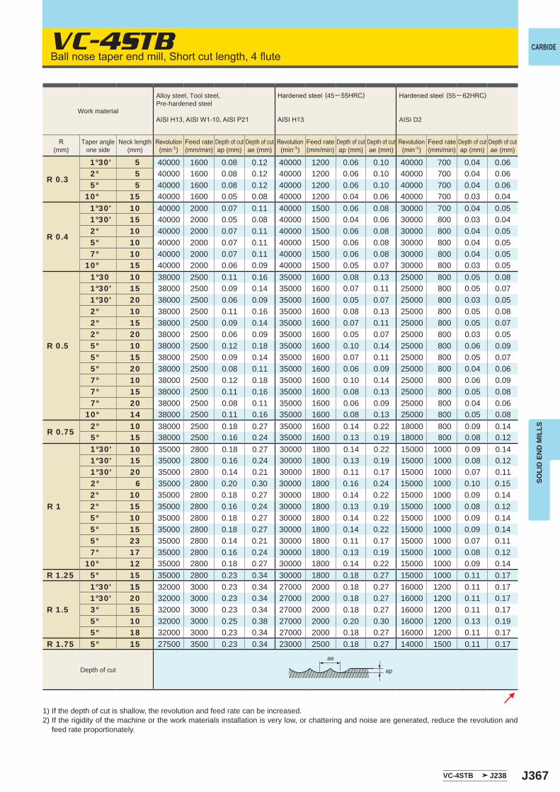
J367
VC-4STB
R 0.3
1°30' 5 40000 1600 0.08 0.12 40000 1200 0.06 0.10 40000 700 0.04 0.06 2° 5 40000 1600 0.08 0.12 40000 1200 0.06 0.10 40000 700 0.04 0.06 5° 5 40000 1600 0.08 0.12 40000 1200 0.06 0.10 40000 700 0.04 0.0610° 15 40000 1600 0.05 0.08 40000 1200 0.04 0.06 40000 700 0.03 0.04
R 0.4
1°30' 10 40000 2000 0.07 0.11 40000 1500 0.06 0.08 30000 700 0.04 0.05 1°30' 15 40000 2000 0.05 0.08 40000 1500 0.04 0.06 30000 800 0.03 0.04 2° 10 40000 2000 0.07 0.11 40000 1500 0.06 0.08 30000 800 0.04 0.05 5° 10 40000 2000 0.07 0.11 40000 1500 0.06 0.08 30000 800 0.04 0.05 7° 10 40000 2000 0.07 0.11 40000 1500 0.06 0.08 30000 800 0.04 0.0510° 15 40000 2000 0.06 0.09 40000 1500 0.05 0.07 30000 800 0.03 0.05
R 0.5
1°30 10 38000 2500 0.11 0.16 35000 1600 0.08 0.13 25000 800 0.05 0.08 1°30' 15 38000 2500 0.09 0.14 35000 1600 0.07 0.11 25000 800 0.05 0.07 1°30' 20 38000 2500 0.06 0.09 35000 1600 0.05 0.07 25000 800 0.03 0.05 2° 10 38000 2500 0.11 0.16 35000 1600 0.08 0.13 25000 800 0.05 0.08 2° 15 38000 2500 0.09 0.14 35000 1600 0.07 0.11 25000 800 0.05 0.07 2° 20 38000 2500 0.06 0.09 35000 1600 0.05 0.07 25000 800 0.03 0.05 5° 10 38000 2500 0.12 0.18 35000 1600 0.10 0.14 25000 800 0.06 0.09 5° 15 38000 2500 0.09 0.14 35000 1600 0.07 0.11 25000 800 0.05 0.07 5° 20 38000 2500 0.08 0.11 35000 1600 0.06 0.09 25000 800 0.04 0.06 7° 10 38000 2500 0.12 0.18 35000 1600 0.10 0.14 25000 800 0.06 0.09 7° 15 38000 2500 0.11 0.16 35000 1600 0.08 0.13 25000 800 0.05 0.08 7° 20 38000 2500 0.08 0.11 35000 1600 0.06 0.09 25000 800 0.04 0.0610° 14 38000 2500 0.11 0.16 35000 1600 0.08 0.13 25000 800 0.05 0.08
R 0.75 2° 10 38000 2500 0.18 0.27 35000 1600 0.14 0.22 18000 800 0.09 0.14 5° 15 38000 2500 0.16 0.24 35000 1600 0.13 0.19 18000 800 0.08 0.12
R 1
1°30' 10 35000 2800 0.18 0.27 30000 1800 0.14 0.22 15000 1000 0.09 0.14 1°30' 15 35000 2800 0.16 0.24 30000 1800 0.13 0.19 15000 1000 0.08 0.12 1°30' 20 35000 2800 0.14 0.21 30000 1800 0.11 0.17 15000 1000 0.07 0.11 2° 6 35000 2800 0.20 0.30 30000 1800 0.16 0.24 15000 1000 0.10 0.15 2° 10 35000 2800 0.18 0.27 30000 1800 0.14 0.22 15000 1000 0.09 0.14 2° 15 35000 2800 0.16 0.24 30000 1800 0.13 0.19 15000 1000 0.08 0.12 5° 10 35000 2800 0.18 0.27 30000 1800 0.14 0.22 15000 1000 0.09 0.14 5° 15 35000 2800 0.18 0.27 30000 1800 0.14 0.22 15000 1000 0.09 0.14 5° 23 35000 2800 0.14 0.21 30000 1800 0.11 0.17 15000 1000 0.07 0.11 7° 17 35000 2800 0.16 0.24 30000 1800 0.13 0.19 15000 1000 0.08 0.1210° 12 35000 2800 0.18 0.27 30000 1800 0.14 0.22 15000 1000 0.09 0.14
R 1.25 5° 15 35000 2800 0.23 0.34 30000 1800 0.18 0.27 15000 1000 0.11 0.17
R 1.5
1°30' 15 32000 3000 0.23 0.34 27000 2000 0.18 0.27 16000 1200 0.11 0.17 1°30' 20 32000 3000 0.23 0.34 27000 2000 0.18 0.27 16000 1200 0.11 0.17 3° 15 32000 3000 0.23 0.34 27000 2000 0.18 0.27 16000 1200 0.11 0.17 5° 10 32000 3000 0.25 0.38 27000 2000 0.20 0.30 16000 1200 0.13 0.19 5° 18 32000 3000 0.23 0.34 27000 2000 0.18 0.27 16000 1200 0.11 0.17
R 1.75 5° 15 27500 3500 0.23 0.34 23000 2500 0.18 0.27 14000 1500 0.11 0.17
VC-4STB J238
ae
ap
CARBIDE
SOLI
D E
ND
MIL
LS
Ballnosetaperendmill,Shortcutlength,4flute
1) If the depth of cut is shallow, the revolution and feed rate can be increased.2) If the rigidity of the machine or the work materials installation is very low, or chattering and noise are generated, reduce the revolution and
feed rate proportionately.
Work material
Alloy steel, Tool steel,Pre-hardened steel
AISIH13,AISIW1-10,AISIP21
Hardenedsteel (45─55HRC)
AISIH13
Hardenedsteel (55─ 62HRC)
AISI D2
R(mm)
Taper angleone side
Neck length(mm)
Revolution(min-1)
Feed rate(mm/min)
Depth of cutap (mm)
Depth of cutae (mm)
Revolution(min-1)
Feed rate(mm/min)
Depth of cutap (mm)
Depth of cutae (mm)
Revolution(min-1)
Feed rate(mm/min)
Depth of cutap (mm)
Depth of cutae (mm)
Depth of cut
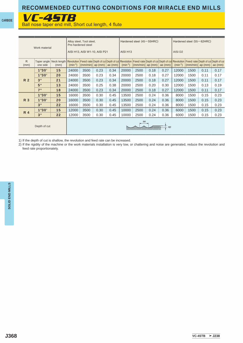
J368
VC-4STB
R 2
1°30' 15 24000 3500 0.23 0.34 20000 2500 0.18 0.27 12000 1500 0.11 0.171°30' 20 24000 3500 0.23 0.34 20000 2500 0.18 0.27 12000 1500 0.11 0.173° 21 24000 3500 0.23 0.34 20000 2500 0.18 0.27 12000 1500 0.11 0.175° 13 24000 3500 0.25 0.38 20000 2500 0.20 0.30 12000 1500 0.13 0.197° 18 24000 3500 0.23 0.34 20000 2500 0.18 0.27 12000 1500 0.11 0.17
R 31°30' 15 16000 3500 0.30 0.45 13500 2500 0.24 0.36 8000 1500 0.15 0.231°30' 20 16000 3500 0.30 0.45 13500 2500 0.24 0.36 8000 1500 0.15 0.233° 22 16000 3500 0.30 0.45 13500 2500 0.24 0.36 8000 1500 0.15 0.23
R 41°30' 15 12000 3500 0.30 0.45 10000 2500 0.24 0.36 6000 1500 0.15 0.233° 22 12000 3500 0.30 0.45 10000 2500 0.24 0.36 6000 1500 0.15 0.23
VC-4STB J238
ae
ap
RECOMMENDED CUTTING CONDITIONS FOR MIRACLE END MILLS
CARBIDE
SOLI
D E
ND
MIL
LS
Ballnosetaperendmill,Shortcutlength,4flute
1) If the depth of cut is shallow, the revolution and feed rate can be increased.2) If the rigidity of the machine or the work materials installation is very low, or chattering and noise are generated, reduce the revolution and
feed rate proportionately.
Work material
Alloy steel, Tool steel,Pre-hardened steel
AISIH13,AISIW1-10,AISIP21
Hardenedsteel (45─55HRC)
AISIH13
Hardenedsteel (55─ 62HRC)
AISI D2
R(mm)
Taper angleone side
Neck length(mm)
Revolution(min-1)
Feed rate(mm/min)
Depth of cutap (mm)
Depth of cutae (mm)
Revolution(min-1)
Feed rate(mm/min)
Depth of cutap (mm)
Depth of cutae (mm)
Revolution(min-1)
Feed rate(mm/min)
Depth of cutap (mm)
Depth of cutae (mm)
Depth of cut
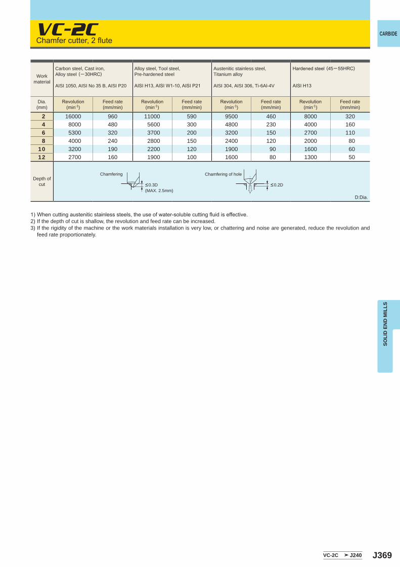
J369
VC-2C
2 16000 960 11000 590 9500 460 8000 3204 8000 480 5600 300 4800 230 4000 1606 5300 320 3700 200 3200 150 2700 1108 4000 240 2800 150 2400 120 2000 80
10 3200 190 2200 120 1900 90 1600 6012 2700 160 1900 100 1600 80 1300 50
VC-2C J240
CARBIDE
SOLI
D E
ND
MIL
LS
Chamfercutter,2flute
1)Whencuttingausteniticstainlesssteels,theuseofwater-solublecuttingfluidiseffective.2) If the depth of cut is shallow, the revolution and feed rate can be increased.3) If the rigidity of the machine or the work materials installation is very low, or chattering and noise are generated, reduce the revolution and
feed rate proportionately.
Chamfering Chamfering of hole
D:Dia.
Workmaterial
Carbon steel, Cast iron, Alloy steel (─30HRC)
AISI 1050, AISI No 35 B, AISI P20
Alloy steel, Tool steel,Pre-hardened steel
AISIH13,AISIW1-10,AISIP21
Austenitic stainless steel,Titanium alloy
AISI 304, AISI 306, Ti-6Al-4V
Hardenedsteel (45─55HRC)
AISIH13
Dia.(mm)
Revolution(min-1)
Feed rate(mm/min)
Revolution(min-1)
Feed rate(mm/min)
Revolution(min-1)
Feed rate(mm/min)
Revolution(min-1)
Feed rate(mm/min)
Depth ofcut <0.3D
(MAX. 2.5mm)<0.2D

J370
Memo
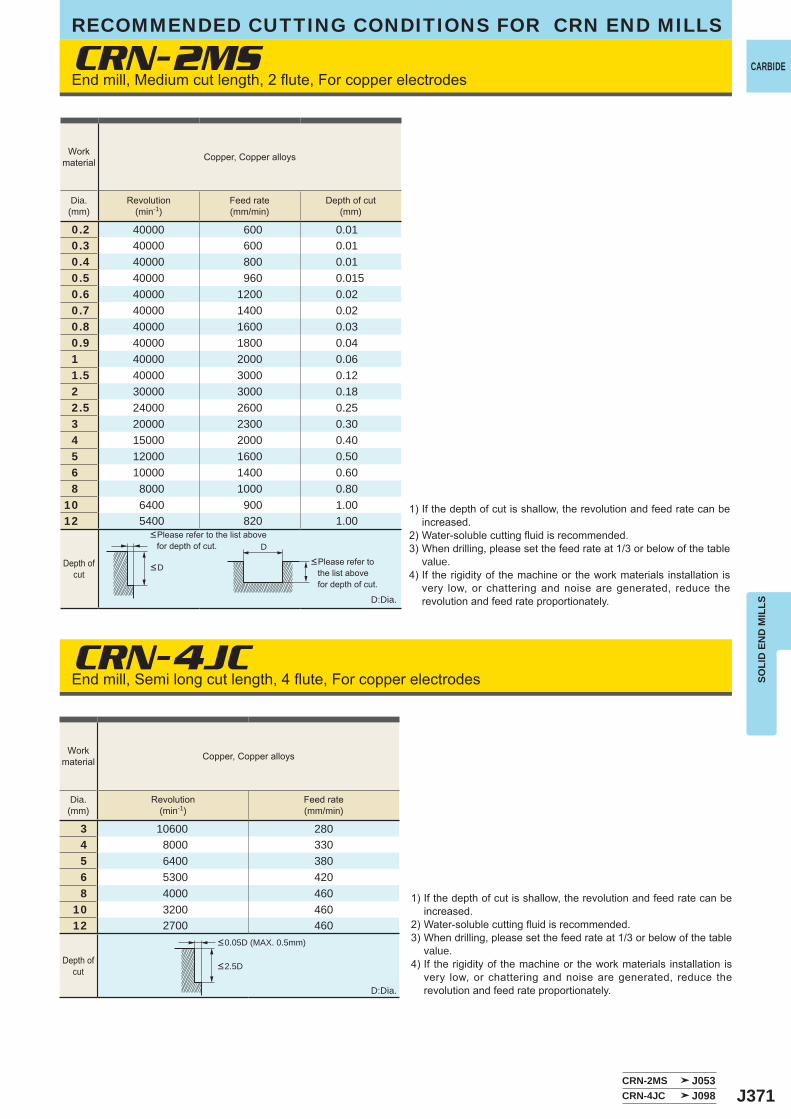
J371
CRN-2MS
CRN-4JC
0.2 40000 600 0.010.3 40000 600 0.010.4 40000 800 0.010.5 40000 960 0.0150.6 40000 1200 0.020.7 40000 1400 0.020.8 40000 1600 0.030.9 40000 1800 0.041 40000 2000 0.061.5 40000 3000 0.122 30000 3000 0.182.5 24000 2600 0.253 20000 2300 0.304 15000 2000 0.405 12000 1600 0.506 10000 1400 0.608 8000 1000 0.80
10 6400 900 1.0012 5400 820 1.00
3 10600 2804 8000 3305 6400 3806 5300 4208 4000 460
10 3200 46012 2700 460
CRN-2MS J053CRN-4JC J098
D
CARBIDE
SOLI
D E
ND
MIL
LS
End mill, Medium cut length, 2 flute, For copper electrodes
End mill, Semi long cut length, 4 flute, For copper electrodes
Workmaterial Copper, Copper alloys
Dia.(mm)
Revolution(min-1)
Feed rate(mm/min)
Depth of cut(mm)
Depth ofcut
Workmaterial Copper, Copper alloys
Dia.(mm)
Revolution(min-1)
Feed rate(mm/min)
Depth ofcut
<D
<2.5D
<0.05D (MAX. 0.5mm)
<Please refer to the list above for depth of cut.
<Please refer to the list above for depth of cut.
D:Dia.
1) If the depth of cut is shallow, the revolution and feed rate can be increased.
2) Water-soluble cutting fluid is recommended.3) When drilling, please set the feed rate at 1/3 or below of the table
value.4) If the rigidity of the machine or the work materials installation is
very low, or chattering and noise are generated, reduce the revolution and feed rate proportionately.D:Dia.
1) If the depth of cut is shallow, the revolution and feed rate can be increased.
2) Water-soluble cutting fluid is recommended.3) When drilling, please set the feed rate at 1/3 or below of the table
value.4) If the rigidity of the machine or the work materials installation is
very low, or chattering and noise are generated, reduce the revolution and feed rate proportionately.
RECOMMENDED CUTTING CONDITIONS FOR CRN END MILLS
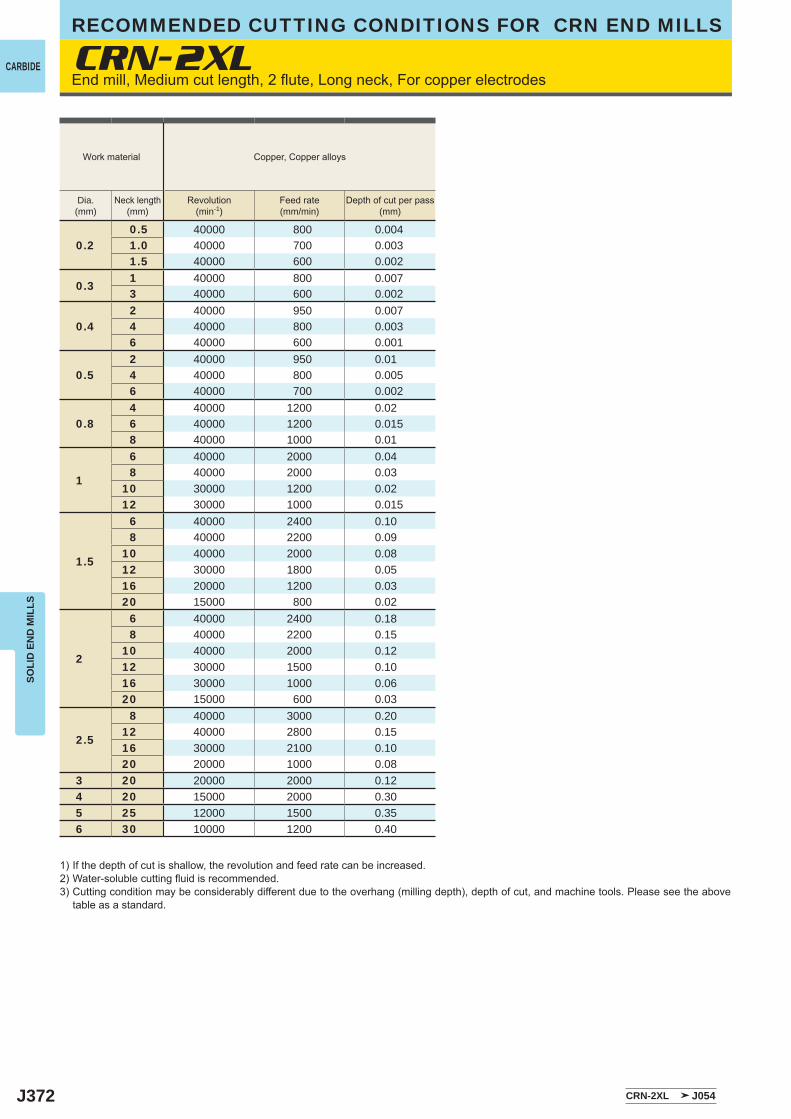
J372
CRN-2XL
0.20.5 40000 800 0.0041.0 40000 700 0.0031.5 40000 600 0.002
0.31 40000 800 0.0073 40000 600 0.002
0.42 40000 950 0.0074 40000 800 0.0036 40000 600 0.001
0.52 40000 950 0.014 40000 800 0.0056 40000 700 0.002
0.84 40000 1200 0.026 40000 1200 0.0158 40000 1000 0.01
1
6 40000 2000 0.048 40000 2000 0.03
10 30000 1200 0.0212 30000 1000 0.015
1.5
6 40000 2400 0.108 40000 2200 0.09
10 40000 2000 0.0812 30000 1800 0.0516 20000 1200 0.0320 15000 800 0.02
2
6 40000 2400 0.188 40000 2200 0.15
10 40000 2000 0.1212 30000 1500 0.1016 30000 1000 0.0620 15000 600 0.03
2.5
8 40000 3000 0.2012 40000 2800 0.1516 30000 2100 0.1020 20000 1000 0.08
3 20 20000 2000 0.124 20 15000 2000 0.305 25 12000 1500 0.356 30 10000 1200 0.40
CRN-2XL J054
CARBIDE
SOLI
D E
ND
MIL
LSRECOMMENDED CUTTING CONDITIONS FOR CRN END MILLS
End mill, Medium cut length, 2 flute, Long neck, For copper electrodes
1) If the depth of cut is shallow, the revolution and feed rate can be increased.2) Water-soluble cutting fluid is recommended.3) Cutting condition may be considerably different due to the overhang (milling depth), depth of cut, and machine tools. Please see the above
table as a standard.
Work material Copper, Copper alloys
Dia.(mm)
Neck length(mm)
Revolution(min-1)
Feed rate(mm/min)
Depth of cut per pass(mm)
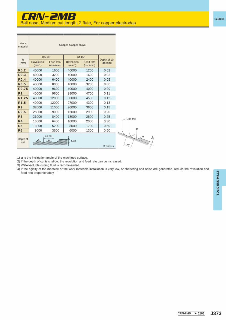
J373
CRN-2MB
R0.2 40000 1600 40000 1200 0.02R0.3 40000 3200 40000 1600 0.03R0.4 40000 6400 40000 2400 0.05R0.5 40000 8000 40000 3200 0.06R0.75 40000 9600 40000 4000 0.09R1 40000 9600 39000 4700 0.11R1.25 40000 12000 30000 4500 0.12R1.5 40000 12000 27000 4300 0.13R2 32000 11000 20000 3600 0.15R2.5 25000 9000 16000 2900 0.20R3 21000 8400 13000 2600 0.25R4 16000 6400 10000 2000 0.30R5 13000 5200 8000 1700 0.50R6 9000 3600 6000 1300 0.50
CRN-2MB J163
R
%
ap
pf
CARBIDE
SOLI
D E
ND
MIL
LS
Ball nose, Medium cut length, 2 flute, For copper electrodes
1) % is the inclination angle of the machined surface. 2) If the depth of cut is shallow, the revolution and feed rate can be increased.3) Water-soluble cutting fluid is recommended.4) If the rigidity of the machine or the work materials installation is very low, or chattering and noise are generated, reduce the revolution and
feed rate proportionately.
R:Radius
<ap
<0.2R
Workmaterial Copper, Copper alloys
R(mm)
%<15° %>15°Depth of cut
ap(mm)Revolution(min-1)
Feed rate(mm/min)
Revolution(min-1)
Feed rate(mm/min)
Depth ofcut
End mill
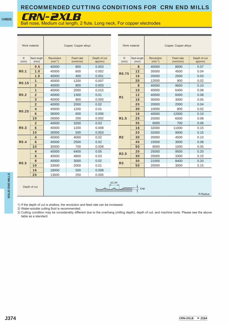
J374
CRN-2XLB
R0.10.5 40000 800 0.003
R0.75
8 40000 8000 0.071.0 40000 600 0.002 12 35000 4500 0.041.5 40000 400 0.001 16 20000 2000 0.03
R0.151 40000 1200 0.007 20 12000 900 0.022 40000 800 0.003
R1
8 40000 9600 0.10
R0.21 40000 2000 0.015 10 40000 6400 0.082 40000 1300 0.01 12 40000 6000 0.083 40000 800 0.005 16 30000 3000 0.05
R0.25
2 40000 2000 0.02 20 20000 2000 0.044 40000 1200 0.01 30 10000 800 0.026 36000 600 0.006
R1.516 40000 12000 0.10
10 26000 200 0.002 25 25000 6000 0.08
R0.32 40000 3200 0.03 35 6000 700 0.066 40000 1200 0.008
R2
16 32000 11000 0.1510 30000 500 0.003 20 32000 9000 0.15
R0.44 40000 4000 0.02 30 20000 4500 0.106 40000 2500 0.02 40 15000 3000 0.08
10 30000 700 0.008 50 8000 1000 0.05
R0.5
4 40000 6400 0.05 R2.520 25000 9500 0.20
6 40000 4800 0.03 30 20000 3300 0.158 40000 3000 0.02
R330 21000 8400 0.20
10 33000 2000 0.01 50 20000 3000 0.1516 18000 500 0.00820 13000 250 0.005
CRN-2XLB J164
CARBIDE
SOLI
D E
ND
MIL
LSRECOMMENDED CUTTING CONDITIONS FOR CRN END MILLS
Ball nose, Medium cut length, 2 flute, Long neck, For copper electrodes
1) If the depth of cut is shallow, the revolution and feed rate can be increased.2) Water-soluble cutting fluid is recommended.3) Cutting condition may be considerably different due to the overhang (milling depth), depth of cut, and machine tools. Please see the above
table as a standard.
R:Radius
<ap
<0.2R
Depth of cut
Work material Copper, Copper alloys Work material Copper, Copper alloys
R(mm)
Neck length(mm)
Revolution(min-1)
Feed rate(mm/min)
Depth of cutap(mm)
R(mm)
Neck length(mm)
Revolution(min-1)
Feed rate(mm/min)
Depth of cutap(mm)
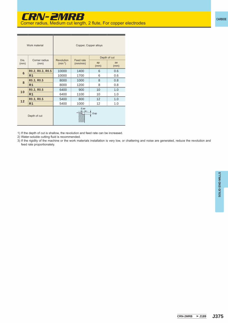
J375
CRN-2MRB
6R0.2, R0.3, R0.5 10000 1400 6 0.6R1 10000 1700 6 0.6
8R0.3, R0.5 8000 1000 8 0.8R1 8000 1200 8 0.8
10R0.3, R0.5 6400 900 10 1.0R1 6400 1100 10 1.0
12R0.3, R0.5 5400 800 12 1.0R1 5400 1000 12 1.0
CRN-2MRB J189
CARBIDE
SOLI
D E
ND
MIL
LS
Corner radius, Medium cut length, 2 flute, For copper electrodes
1) If the depth of cut is shallow, the revolution and feed rate can be increased.2) Water-soluble cutting fluid is recommended.3) If the rigidity of the machine or the work materials installation is very low, or chattering and noise are generated, reduce the revolution and
feed rate proportionately.
<ap
<ae
Depth of cut
Work material Copper, Copper alloys
Dia.(mm)
Corner radius(mm)
Revolution(min-1)
Feed rate(mm/min)
Depth of cut
ap(mm)
ae(mm)

J376
CRN-2XLRB
0.5 R0.05, R0.14 40000 800 0.005 40000 1500 0.01 0.16 40000 700 0.003 40000 1000 0.005 0.1
0.8 R0.05, R0.16 40000 1200 0.02 40000 2500 0.02 0.158 40000 1200 0.015 40000 1600 0.01 0.15
1 R0.1, R0.38 40000 2000 0.03 40000 3000 0.03 0.2
10 35000 1600 0.025 35000 2000 0.025 0.212 30000 1200 0.02 30000 1800 0.02 0.2
1.5 R0.1, R0.2, R0.312 30000 1500 0.05 40000 4500 0.04 0.320 20000 1000 0.02 20000 2000 0.02 0.3
2R0.1, R0.2R0.3, R0.5
12 30000 1500 0.1 40000 4500 0.08 0.416 30000 1000 0.06 30000 3000 0.05 0.420 20000 600 0.04 20000 2000 0.04 0.4
3R0.2, R0.3 20 20000 2000 0.12 35000 6000 0.1 0.6R0.5 20 20000 2200 0.12 35000 8000 0.1 0.6
4R0.2, R0.3 20 15000 2000 0.25 32000 5000 0.15 0.8R0.5 20 15000 2200 0.25 32000 7000 0.15 0.8
5R0.2, R0.3 25 12000 1500 0.3 22000 5000 0.2 1.0R0.5 25 12000 1700 0.3 22000 7000 0.2 1.0
6R0.2, R0.3, R0.5 30 10000 1200 0.4 20000 5000 0.25 1.2R1 30 10000 1500 0.4 20000 7000 0.25 1.2
y y
CRN-2XLRB J190
D
CARBIDE
SOLI
D E
ND
MIL
LSRECOMMENDED CUTTING CONDITIONS FOR CRN END MILLS
Corner radius, Medium cut length, 2 flute, For copper electrodes
1) If the depth of cut is shallow, the revolution and feed rate can be increased.2) Water-soluble cutting fluid is recommended.3) Cutting condition may be considerably different due to the overhang (milling depth), depth of cut, and machine tools. Please see the above
table as a standard.
D:Dia.
Slotting Contour Cutting
<ap<ap
<ae
Work material Copper, Copper alloys Copper, Copper alloys
Dia.(mm)
Corner radius(mm)
Neck length(mm)
Revolution(min-1)
Feed rate(mm/min)
Depth of cutap (mm)
Revolution(min-1)
Feed rate(mm/min)
Depth of cut
ap(mm)
ae(mm)
Depth of cut
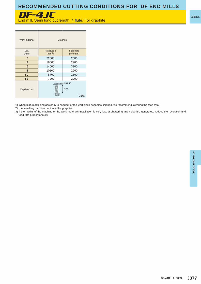
J377
DF-4JC
3 22000 25004 18000 29006 14000 32008 10500 2900
10 8700 260012 7200 2200
DF-4JC J099
SOLI
D E
ND
MIL
LS
CARBIDEEnd mill, Semi long cut length, 4 flute, For graphite
1) When high machining accuracy is needed, or the workpiece becomes chipped, we recommend lowering the feed rate.2) Use a milling machine dedicated for graphite.3) If the rigidity of the machine or the work materials installation is very low, or chattering and noise are generated, reduce the revolution and
feed rate proportionately.
D:Dia.
Work material Graphite
Dia.(mm)
Revolution(min-1)
Feed rate(mm/min)
<0.05D
<2DDepth of cut
RECOMMENDED CUTTING CONDITIONS FOR DF END MILLS
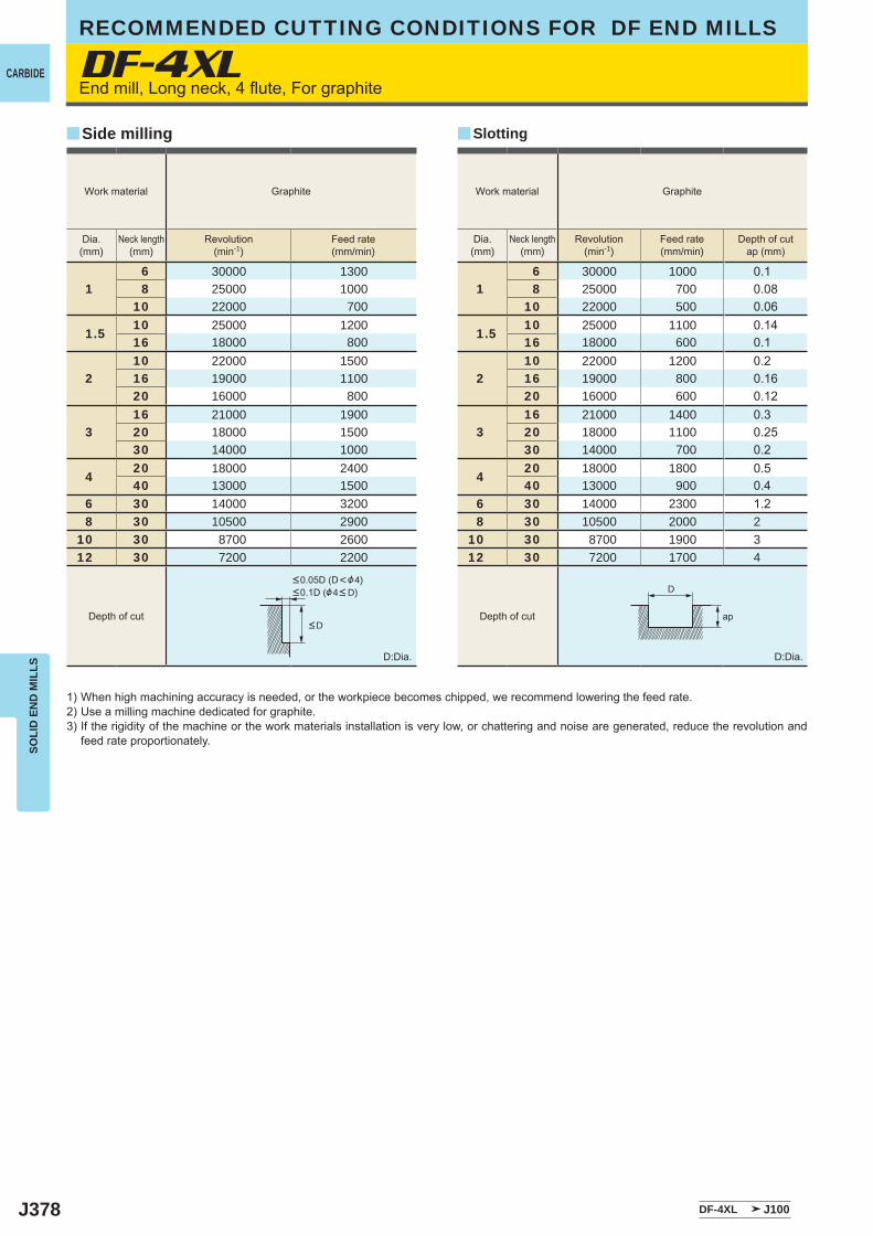
J378
DF-4XL
16 30000 13008 25000 1000
10 22000 700
1.510 25000 120016 18000 800
210 22000 150016 19000 110020 16000 800
316 21000 190020 18000 150030 14000 1000
420 18000 240040 13000 1500
6 30 14000 3200 8 30 10500 290010 30 8700 260012 30 7200 2200
16 30000 1000 0.18 25000 700 0.08
10 22000 500 0.06
1.510 25000 1100 0.1416 18000 600 0.1
210 22000 1200 0.216 19000 800 0.1620 16000 600 0.12
316 21000 1400 0.320 18000 1100 0.2530 14000 700 0.2
420 18000 1800 0.540 13000 900 0.4
6 30 14000 2300 1.2 8 30 10500 2000 210 30 8700 1900 312 30 7200 1700 4
DF-4XL J100
yy
D
ap
SOLI
D E
ND
MIL
LS
CARBIDE
RECOMMENDED CUTTING CONDITIONS FOR DF END MILLS
End mill, Long neck, 4 flute, For graphite
1) When high machining accuracy is needed, or the workpiece becomes chipped, we recommend lowering the feed rate.2) Use a milling machine dedicated for graphite.3) If the rigidity of the machine or the work materials installation is very low, or chattering and noise are generated, reduce the revolution and
feed rate proportionately.
D:Dia. D:Dia.
SlottingSide milling
Work material Graphite Work material Graphite
Dia.(mm)
Neck length(mm)
Revolution(min-1)
Feed rate(mm/min)
Dia.(mm)
Neck length(mm)
Revolution(min-1)
Feed rate(mm/min)
Depth of cutap (mm)
<D
<0.05D (D<&4)<0.1D (&4< D)
Depth of cut Depth of cut
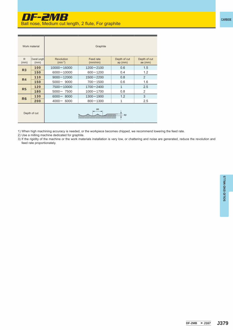
J379
DF-2MB
DF-2MB J167
R3100 10000─16000 1200─2100 0.6 1.5150 6000─10000 600─1200 0.4 1.2
R4110 9000─12000 1500─2200 0.8 2150 5000─ 9000 700─1500 0.6 1.6
R5120 7500─10000 1700─2400 1 2.5180 5000─ 7500 1000─1700 0.8 2
R6 130 6000─ 8000 1300─1900 1.2 3200 4000─ 6000 800─1300 1 2.5
ae
ap
SOLI
D E
ND
MIL
LS
CARBIDEBall nose, Medium cut length, 2 flute, For graphite
1) When high machining accuracy is needed, or the workpiece becomes chipped, we recommend lowering the feed rate.2) Use a milling machine dedicated for graphite.3) If the rigidity of the machine or the work materials installation is very low, or chattering and noise are generated, reduce the revolution and
feed rate proportionately.
Work material Graphite
Depth of cut
R(mm)
Overall Length(mm)
Revolution(min-1)
Feed rate(mm/min)
Depth of cutap (mm)
Depth of cutae (mm)
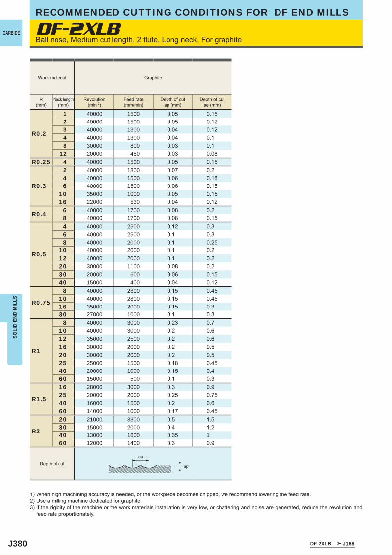
J380
DF-2XLB
DF-2XLB J168
R0.2
1 40000 1500 0.05 0.152 40000 1500 0.05 0.123 40000 1300 0.04 0.124 40000 1300 0.04 0.18 30000 800 0.03 0.1
12 20000 450 0.03 0.08R0.25 4 40000 1500 0.05 0.15
R0.3
2 40000 1800 0.07 0.24 40000 1500 0.06 0.186 40000 1500 0.06 0.15
10 35000 1000 0.05 0.1516 22000 530 0.04 0.12
R0.4 6 40000 1700 0.08 0.28 40000 1700 0.08 0.15
R0.5
4 40000 2500 0.12 0.36 40000 2500 0.1 0.38 40000 2000 0.1 0.25
10 40000 2000 0.1 0.212 40000 2000 0.1 0.220 30000 1100 0.08 0.230 20000 600 0.06 0.1540 15000 400 0.04 0.12
R0.75
8 40000 2800 0.15 0.4510 40000 2800 0.15 0.4516 35000 2000 0.15 0.330 27000 1000 0.1 0.3
R1
8 40000 3000 0.23 0.710 40000 3000 0.2 0.612 35000 2500 0.2 0.616 30000 2000 0.2 0.520 30000 2000 0.2 0.525 25000 1500 0.18 0.4540 20000 1000 0.15 0.460 15000 500 0.1 0.3
R1.5
16 28000 3000 0.3 0.925 20000 2000 0.25 0.7540 16000 1500 0.2 0.660 14000 1000 0.17 0.45
R2
20 21000 3300 0.5 1.530 15000 2000 0.4 1.240 13000 1600 0.35 160 12000 1400 0.3 0.9
ae
ap
SOLI
D E
ND
MIL
LS
CARBIDE
RECOMMENDED CUTTING CONDITIONS FOR DF END MILLS
1) When high machining accuracy is needed, or the workpiece becomes chipped, we recommend lowering the feed rate.2) Use a milling machine dedicated for graphite.3) If the rigidity of the machine or the work materials installation is very low, or chattering and noise are generated, reduce the revolution and
feed rate proportionately.
Ball nose, Medium cut length, 2 flute, Long neck, For graphite
Work material Graphite
Depth of cut
R(mm)
Neck length(mm)
Revolution(min-1)
Feed rate(mm/min)
Depth of cutap (mm)
Depth of cutae (mm)
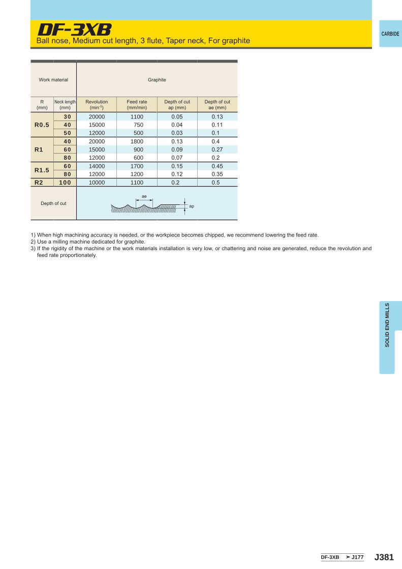
J381
DF-3XB
R0.530 20000 1100 0.05 0.1340 15000 750 0.04 0.1150 12000 500 0.03 0.1
R140 20000 1800 0.13 0.460 15000 900 0.09 0.2780 12000 600 0.07 0.2
R1.5 60 14000 1700 0.15 0.4580 12000 1200 0.12 0.35
R2 100 10000 1100 0.2 0.5
DF-3XB J177
ae
ap
SOLI
D E
ND
MIL
LS
CARBIDEBall nose, Medium cut length, 3 flute, Taper neck, For graphite
1) When high machining accuracy is needed, or the workpiece becomes chipped, we recommend lowering the feed rate.2) Use a milling machine dedicated for graphite.3) If the rigidity of the machine or the work materials installation is very low, or chattering and noise are generated, reduce the revolution and
feed rate proportionately.
Work material Graphite
R(mm)
Neck length(mm)
Revolution(min-1)
Feed rate(mm/min)
Depth of cutap (mm)
Depth of cutae (mm)
Depth of cut
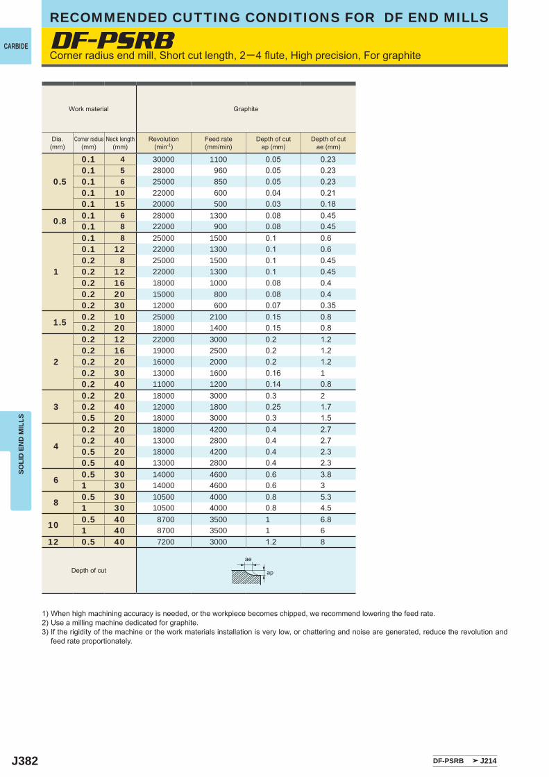
J382
DF-PSRB
0.5
0.1 4 30000 1100 0.05 0.230.1 5 28000 960 0.05 0.230.1 6 25000 850 0.05 0.230.1 10 22000 600 0.04 0.210.1 15 20000 500 0.03 0.18
0.8 0.1 6 28000 1300 0.08 0.450.1 8 22000 900 0.08 0.45
1
0.1 8 25000 1500 0.1 0.60.1 12 22000 1300 0.1 0.60.2 8 25000 1500 0.1 0.450.2 12 22000 1300 0.1 0.450.2 16 18000 1000 0.08 0.40.2 20 15000 800 0.08 0.40.2 30 12000 600 0.07 0.35
1.5 0.2 10 25000 2100 0.15 0.80.2 20 18000 1400 0.15 0.8
2
0.2 12 22000 3000 0.2 1.20.2 16 19000 2500 0.2 1.20.2 20 16000 2000 0.2 1.20.2 30 13000 1600 0.16 10.2 40 11000 1200 0.14 0.8
30.2 20 18000 3000 0.3 20.2 40 12000 1800 0.25 1.70.5 20 18000 3000 0.3 1.5
4
0.2 20 18000 4200 0.4 2.70.2 40 13000 2800 0.4 2.70.5 20 18000 4200 0.4 2.30.5 40 13000 2800 0.4 2.3
6 0.5 30 14000 4600 0.6 3.81 30 14000 4600 0.6 3
8 0.5 30 10500 4000 0.8 5.31 30 10500 4000 0.8 4.5
10 0.5 40 8700 3500 1 6.81 40 8700 3500 1 6
12 0.5 40 7200 3000 1.2 8
DF-PSRB J214
ae
ap
SOLI
D E
ND
MIL
LS
CARBIDE
RECOMMENDED CUTTING CONDITIONS FOR DF END MILLS
Corner radius end mill, Short cut length, 2─4 flute, High precision, For graphite
1) When high machining accuracy is needed, or the workpiece becomes chipped, we recommend lowering the feed rate.2) Use a milling machine dedicated for graphite.3) If the rigidity of the machine or the work materials installation is very low, or chattering and noise are generated, reduce the revolution and
feed rate proportionately.
Work material Graphite
Dia.(mm)
Corner radius(mm)
Neck length(mm)
Revolution(min-1)
Feed rate(mm/min)
Depth of cutap (mm)
Depth of cutae (mm)
Depth of cut
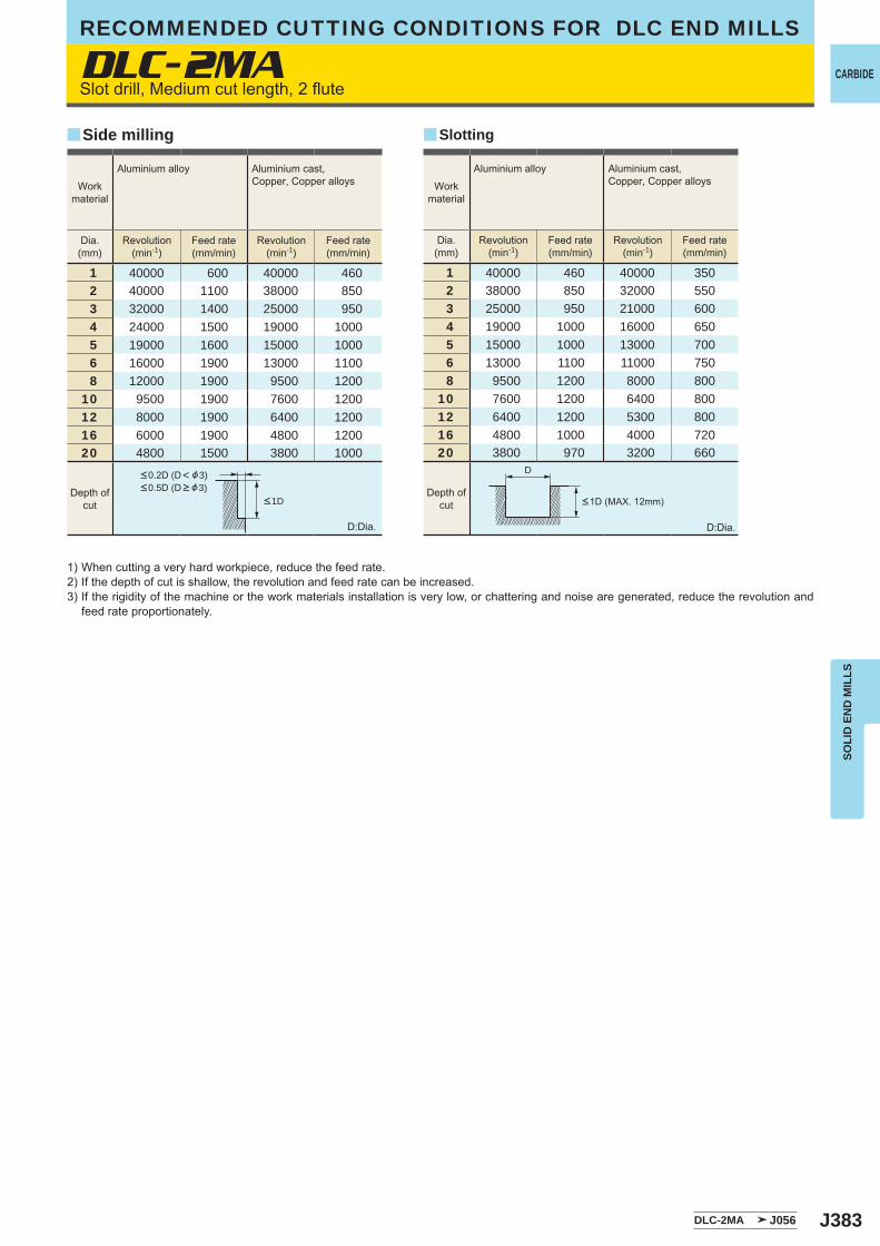
J383
DLC-2MA
1 40000 600 40000 4602 40000 1100 38000 8503 32000 1400 25000 9504 24000 1500 19000 10005 19000 1600 15000 10006 16000 1900 13000 11008 12000 1900 9500 1200
10 9500 1900 7600 120012 8000 1900 6400 120016 6000 1900 4800 120020 4800 1500 3800 1000
1 40000 460 40000 3502 38000 850 32000 5503 25000 950 21000 6004 19000 1000 16000 6505 15000 1000 13000 7006 13000 1100 11000 7508 9500 1200 8000 800
10 7600 1200 6400 80012 6400 1200 5300 80016 4800 1000 4000 72020 3800 970 3200 660
DLC-2MA J056
yy
D
SOLI
D E
ND
MIL
LS
CARBIDE
RECOMMENDED CUTTING CONDITIONS FOR DLC END MILLS
Slot drill, Medium cut length, 2 flute
1) When cutting a very hard workpiece, reduce the feed rate.2) If the depth of cut is shallow, the revolution and feed rate can be increased.3) If the rigidity of the machine or the work materials installation is very low, or chattering and noise are generated, reduce the revolution and
feed rate proportionately.
D:Dia.
Depth ofcut
Depth ofcut
D:Dia.
SlottingSide milling
Dia.(mm)
Revolution(min-1)
Feed rate(mm/min)
Revolution(min-1)
Feed rate(mm/min)
Dia.(mm)
Revolution(min-1)
Feed rate(mm/min)
Revolution(min-1)
Feed rate(mm/min)
Workmaterial
Aluminium alloy Aluminium cast, Copper, Copper alloys Work
material
Aluminium alloy Aluminium cast, Copper, Copper alloys
<1D (MAX. 12mm)
<0.2D (D< &3)<0.5D (D > &3)
<1D
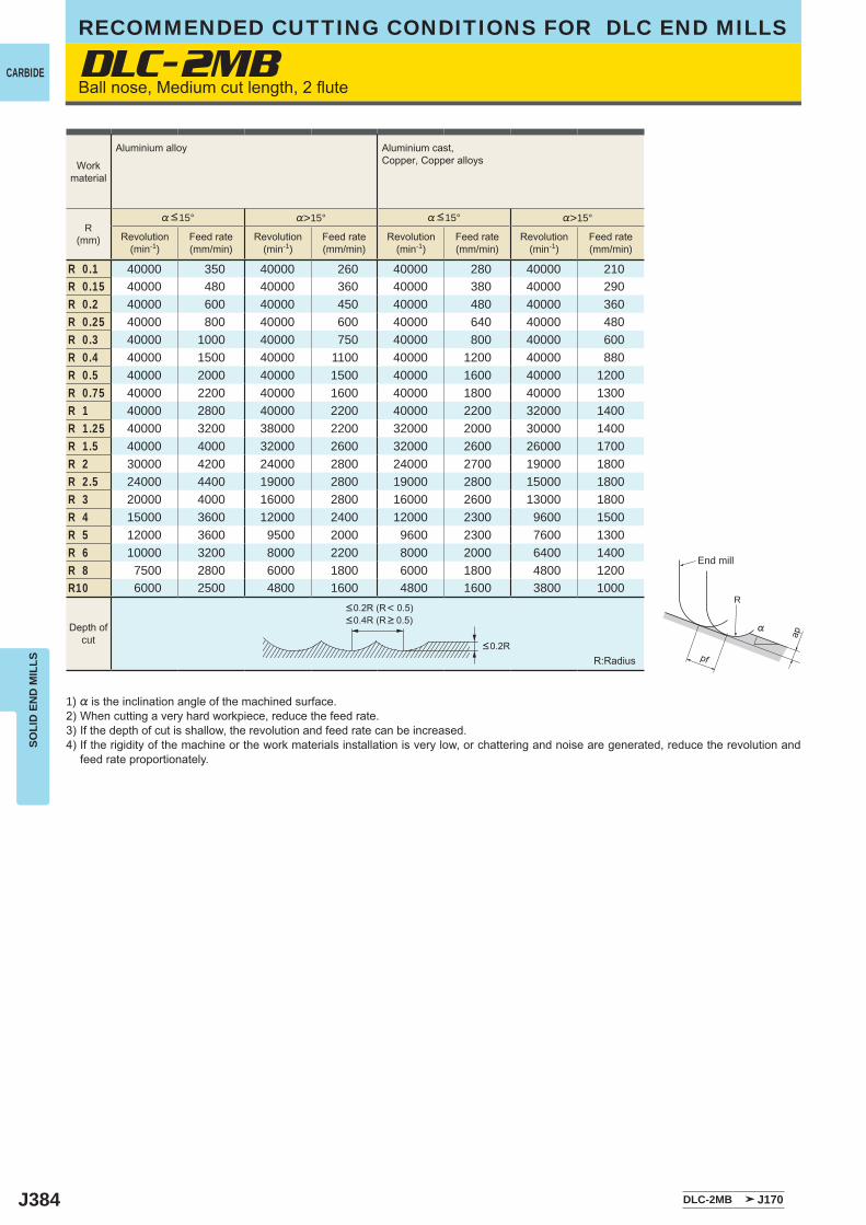
J384 DLC-2MB J170
DLC-2MB
%>15° %>15°
R 0.1 40000 350 40000 260 40000 280 40000 210R 0.15 40000 480 40000 360 40000 380 40000 290R 0.2 40000 600 40000 450 40000 480 40000 360R 0.25 40000 800 40000 600 40000 640 40000 480R 0.3 40000 1000 40000 750 40000 800 40000 600R 0.4 40000 1500 40000 1100 40000 1200 40000 880R 0.5 40000 2000 40000 1500 40000 1600 40000 1200R 0.75 40000 2200 40000 1600 40000 1800 40000 1300R 1 40000 2800 40000 2200 40000 2200 32000 1400R 1.25 40000 3200 38000 2200 32000 2000 30000 1400R 1.5 40000 4000 32000 2600 32000 2600 26000 1700R 2 30000 4200 24000 2800 24000 2700 19000 1800R 2.5 24000 4400 19000 2800 19000 2800 15000 1800R 3 20000 4000 16000 2800 16000 2600 13000 1800R 4 15000 3600 12000 2400 12000 2300 9600 1500R 5 12000 3600 9500 2000 9600 2300 7600 1300R 6 10000 3200 8000 2200 8000 2000 6400 1400R 8 7500 2800 6000 1800 6000 1800 4800 1200R10 6000 2500 4800 1600 4800 1600 3800 1000
R
%
ap
pf
SOLI
D E
ND
MIL
LS
CARBIDE
RECOMMENDED CUTTING CONDITIONS FOR DLC END MILLS
Ball nose, Medium cut length, 2 flute
1) % is the inclination angle of the machined surface. 2) When cutting a very hard workpiece, reduce the feed rate.3) If the depth of cut is shallow, the revolution and feed rate can be increased.4) If the rigidity of the machine or the work materials installation is very low, or chattering and noise are generated, reduce the revolution and
feed rate proportionately.
R:Radius<0.2R
<0.2R (R< 0.5)<0.4R (R > 0.5)
Depth ofcut
Workmaterial
Aluminium alloy Aluminium cast, Copper, Copper alloys
R(mm)
%<15° %<15°
Revolution(min-1)
Feed rate(mm/min)
Revolution(min-1)
Feed rate(mm/min)
Revolution(min-1)
Feed rate(mm/min)
Revolution(min-1)
Feed rate(mm/min)
End mill
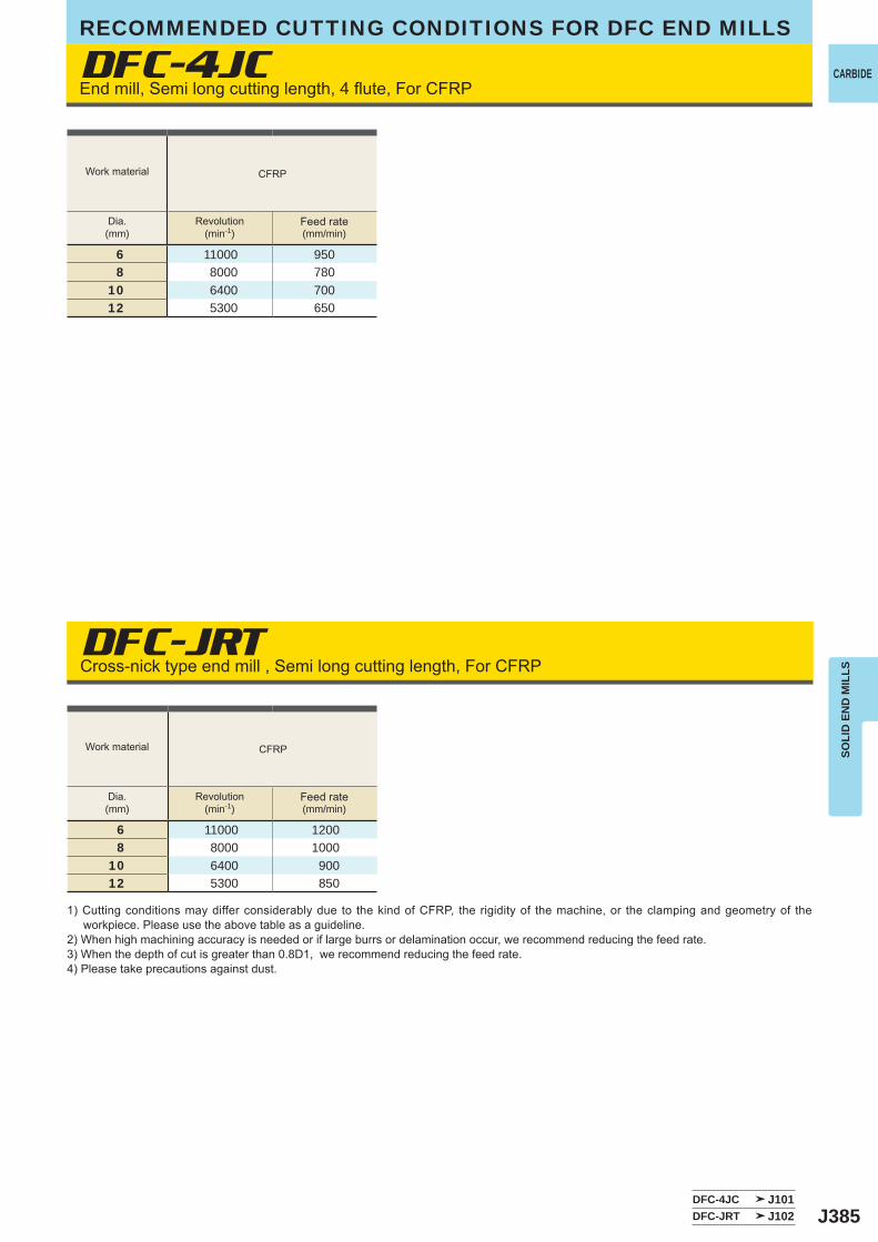
J385
DFC-4JC
CFRP
6 11000 9508 8000 780
10 6400 70012 5300 650
CFRP
6 11000 12008 8000 1000
10 6400 90012 5300 850
DFC-4JC J101DFC-JRT J102
DFC-JRT
SOLI
D E
ND
MIL
LS
CARBIDEEnd mill, Semi long cutting length, 4 flute, For CFRP
Cross-nick type end mill , Semi long cutting length, For CFRP
Work material
Dia.(mm)
Revolution(min-1)
Feed rate(mm/min)
Work material
Dia.(mm)
Revolution(min-1)
Feed rate(mm/min)
1) Cutting conditions may differ considerably due to the kind of CFRP, the rigidity of the machine, or the clamping and geometry of the workpiece. Please use the above table as a guideline.
2) When high machining accuracy is needed or if large burrs or delamination occur, we recommend reducing the feed rate.3) When the depth of cut is greater than 0.8D1, we recommend reducing the feed rate.4) Please take precautions against dust.
RECOMMENDED CUTTING CONDITIONS FOR DFC END MILLS

J386
CBN-2XLB
CBN-2XLRB
R0.2 50000 1500 0.006 0.01 50000 1200 0.006 0.01 50000 1200 0.004 0.008R0.3 50000 2000 0.01 0.02 50000 1500 0.01 0.02 50000 1500 0.008 0.015R0.4 50000 3000 0.02 0.05 50000 2000 0.02 0.04 50000 2000 0.015 0.03R0.5 50000 3000 0.03 0.06 50000 2000 0.03 0.05 50000 2000 0.02 0.03R0.75 50000 3500 0.04 0.08 50000 2500 0.03 0.06 50000 2500 0.02 0.04R1 50000 4000 0.05 0.1 50000 3000 0.04 0.07 50000 3000 0.03 0.05
0.5 50000 750 0.01 0.2 50000 600 0.01 0.1 40000 400 0.005 0.061 38000 1100 0.02 0.3 38000 760 0.01 0.2 25000 400 0.01 0.11.5 25000 900 0.03 0.5 25000 700 0.02 0.4 17000 340 0.02 0.22 20000 800 0.04 0.7 20000 600 0.03 0.6 12000 300 0.02 0.3
CBN-2XLB J171CBN-2XLRB J192
ae
ap
SOLI
D E
ND
MIL
LSRECOMMENDED CUTTING CONDITIONS FOR CBN END MILLS
CBNBall nose, Short cut length, 2 flute, Long neck
Corner radius end mill, Medium cut length, 2 flute, Long neck
1) If the depth of cut is shallow, the revolution and feed rate can be increased.2) Oil mist coolant is recommended.3) Cutting condition may be considerably different due to the overhang (milling depth), depth of cut, and machine tools. Please see the above
table as a standard.
1) If the depth of cut is shallow, the revolution and feed rate can be increased.2) Oil mist coolant is recommended.3) Cutting condition may be considerably different due to the overhang (milling depth), depth of cut, and machine tools. Please see the above
table as a standard.
ae (MAX.)
ap (MAX.)Depth of
cut
Depth ofcut
Workmaterial
Hardened steel (45─55HRC)
AISI H13
Hardened steel (55─62HRC)
AISI D2
Hardened steel (62─70HRC)
AISI W1, AISI M2
Workmaterial
Hardened steel (45─55HRC)
AISI H13
Hardened steel (55─62HRC)
AISI D2
Hardened steel (62─70HRC)
AISI W1, AISI M2
R(mm)
Revolution(min-1)
Feed rate(mm/min)
Depth of cutap (mm)
Depth of cutae (mm)
Revolution(min-1)
Feed rate(mm/min)
Depth of cutap (mm)
Depth of cutae (mm)
Revolution(min-1)
Feed rate(mm/min)
Depth of cutap (mm)
Depth of cutae (mm)
Dia.(mm)
Revolution(min-1)
Feed rate(mm/min)
Depth of cutap (mm)
Depth of cutae (mm)
Revolution(min-1)
Feed rate(mm/min)
Depth of cutap (mm)
Depth of cutae (mm)
Revolution(min-1)
Feed rate(mm/min)
Depth of cutap (mm)
Depth of cutae (mm)
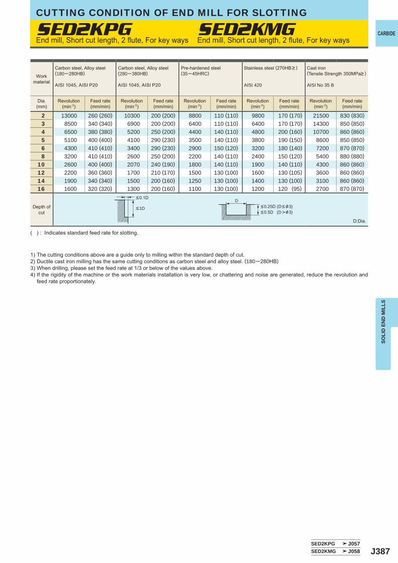
J387SED2KPG J057SED2KMG J058
2 13000 260 (260) 10300 200 (200) 8800 110 (110) 9800 170 (170) 21500 830 (830) 3 8500 340 (340) 6900 200 (200) 6400 110 (110) 6400 170 (170) 14300 850 (850) 4 6500 380 (380) 5200 250 (200) 4400 140 (110) 4800 200 (160) 10700 860 (860) 5 5100 400 (400) 4100 290 (230) 3500 140 (110) 3800 190 (150) 8600 850 (850) 6 4300 410 (410) 3400 290 (230) 2900 150 (120) 3200 180 (140) 7200 870 (870) 8 3200 410 (410) 2600 250 (200) 2200 140 (110) 2400 150 (120) 5400 880 (880)10 2600 400 (400) 2070 240 (190) 1800 140 (110) 1900 140 (110) 4300 860 (860)12 2200 360 (360) 1700 210 (170) 1500 130 (100) 1600 130 (105) 3600 860 (860)14 1900 340 (340) 1500 200 (160) 1250 130 (100) 1400 130 (100) 3100 860 (860)16 1600 320 (320) 1300 200 (160) 1100 130 (100) 1200 120 (95) 2700 870 (870)
SED2KPG SED2KMG
D
SOLI
D E
ND
MIL
LS
CARBIDE
CUTTING CONDITION OF END MILL FOR SLOTTING
1) The cutting conditions above are a guide only to milling within the standard depth of cut.2) Ductile cast iron milling has the same cutting conditions as carbon steel and alloy steel. (180─280HB)3) When drilling, please set the feed rate at 1/3 or below of the values above.4) If the rigidity of the machine or the work materials installation is very low, or chattering and noise are generated, reduce the revolution and
feed rate proportionately.
( ) : Indicates standard feed rate for slotting.
D:Dia.
End mill, Short cut length, 2 flute, For key ways End mill, Short cut length, 2 flute, For key ways
<0.25D (D< &3)<0.5D (D>&3)
<1D
<0.1D
Workmaterial
Carbon steel, Alloy steel(180─280HB)
AISI 1045, AISI P20
Carbon steel, Alloy steel(280─380HB)
AISI 1045, AISI P20
Pre-hardened steel(35─45HRC)
Stainless steel (270HB> )
AISI 420
Cast iron (Tensile Strength 350MPa> )
AISI No 35 B
Dia.(mm)
Revolution(min-1)
Feed rate(mm/min)
Revolution(min-1)
Feed rate(mm/min)
Revolution(min-1)
Feed rate(mm/min)
Revolution(min-1)
Feed rate(mm/min)
Revolution(min-1)
Feed rate(mm/min)
Depth ofcut
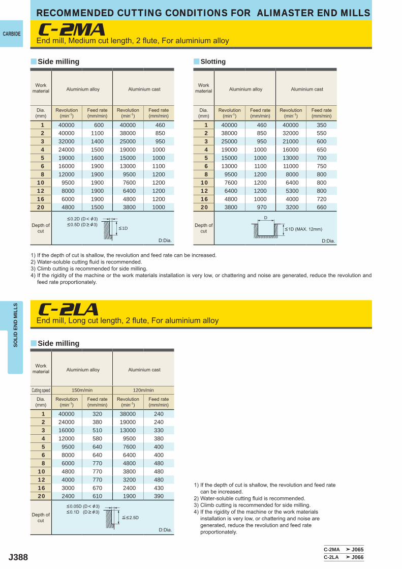
J388
C-2MA
C-2LA
1 40000 600 40000 4602 40000 1100 38000 8503 32000 1400 25000 9504 24000 1500 19000 10005 19000 1600 15000 10006 16000 1900 13000 11008 12000 1900 9500 1200
10 9500 1900 7600 120012 8000 1900 6400 120016 6000 1900 4800 120020 4800 1500 3800 1000
1 40000 460 40000 3502 38000 850 32000 5503 25000 950 21000 6004 19000 1000 16000 6505 15000 1000 13000 7006 13000 1100 11000 7508 9500 1200 8000 800
10 7600 1200 6400 80012 6400 1200 5300 80016 4800 1000 4000 72020 3800 970 3200 660
1 40000 320 38000 2402 24000 380 19000 2403 16000 510 13000 3304 12000 580 9500 3805 9500 640 7600 4006 8000 640 6400 4008 6000 770 4800 480
10 4800 770 3800 48012 4000 770 3200 48016 3000 670 2400 43020 2400 610 1900 390
C-2MA J065C-2LA J066
y
y
y
D
RECOMMENDED CUTTING CONDITIONS FOR ALIMASTER END MILLSSO
LID
EN
D M
ILLS
CARBIDE
RECOMMENDED CUTTING CONDITIONS FOR ALIMASTER END MILLS
End mill, Medium cut length, 2 flute, For aluminium alloy
End mill, Long cut length, 2 flute, For aluminium alloy
1) If the depth of cut is shallow, the revolution and feed rate can be increased.2) Water-soluble cutting fluid is recommended.3) Climb cutting is recommended for side milling.4) If the rigidity of the machine or the work materials installation is very low, or chattering and noise are generated, reduce the revolution and
feed rate proportionately.
1) If the depth of cut is shallow, the revolution and feed rate can be increased.
2) Water-soluble cutting fluid is recommended.3) Climb cutting is recommended for side milling.4) If the rigidity of the machine or the work materials
installation is very low, or chattering and noise are generated, reduce the revolution and feed rate proportionately.
D:Dia.
D:Dia.
D:Dia.
Side milling
Side milling
Slotting
Workmaterial Aluminium alloy Aluminium cast
Workmaterial Aluminium alloy Aluminium cast
Dia.(mm)
Revolution(min-1)
Feed rate(mm/min)
Revolution(min-1)
Feed rate(mm/min)
Dia.(mm)
Revolution(min-1)
Feed rate(mm/min)
Revolution(min-1)
Feed rate(mm/min)
Depth ofcut
Depth ofcut <1D (MAX. 12mm)<1D
<0.2D (D< &3)<0.5D (D > &3)
Workmaterial Aluminium alloy Aluminium cast
Dia.(mm)
Revolution(min-1)
Feed rate(mm/min)
Revolution(min-1)
Feed rate(mm/min)
Cutting speed 150m/min 120m/min
Depth ofcut
<0.05D (D< &3)<0.1D (D > &3)
≦<2.5D
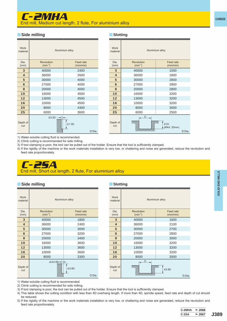
J389
C-2MHA
C-2SA
3 40000 24004 36000 26005 30000 40006 27000 40008 20000 4000
10 16000 450012 13000 450016 10000 450020 8000 430025 6000 3600
3 40000 18004 36000 24005 30000 30006 27000 32008 20000 3400
10 16000 360012 13000 360016 10000 360020 8000 3300
3 40000 15004 36000 18005 30000 28006 27000 28008 20000 2800
10 16000 320012 13000 320016 10000 320020 8000 300025 6000 2500
3 40000 16004 36000 21005 30000 27006 27000 28008 20000 3000
10 16000 320012 13000 320016 10000 320020 8000 3000
C-2MHA J068C-2SA J067
y
y
y
y
D
D
SOLI
D E
ND
MIL
LS
CARBIDEEnd mill, Medium cut length, 2 flute, For aluminium alloy
End mill, Short cut length, 2 flute, For aluminium alloy
1) Water-soluble cutting fluid is recommended.2) Climb cutting is recommended for side milling.3) If tool clamping is poor, the tool can be pulled out of the holder. Ensure that the tool is sufficiently clamped.4) If the rigidity of the machine or the work materials installation is very low, or chattering and noise are generated, reduce the revolution and
feed rate proportionately.
1) Water-soluble cutting fluid is recommended.2) Climb cutting is recommended for side milling.3) If tool clamping is poor, the tool can be pulled out of the holder. Ensure that the tool is sufficiently clamped.4) This table shows the cutting condition with less than 4D overhang length. If more than 4D, spindle speed, feed rate and depth of cut should
be reduced.5) If the rigidity of the machine or the work materials installation is very low, or chattering and noise are generated, reduce the revolution and
feed rate proportionately.
D:Dia.
D:Dia.
D:Dia.
D:Dia.
Side milling
Side milling
Slotting
Slotting
Depth ofcut
Depth ofcut
Depth ofcut
Workmaterial Aluminium alloy
Workmaterial Aluminium alloy
Workmaterial Aluminium alloy
Workmaterial Aluminium alloy
Dia.(mm)
Revolution(min-1)
Feed rate(mm/min)
Dia.(mm)
Revolution(min-1)
Feed rate(mm/min)
Dia.(mm)
Revolution(min-1)
Feed rate(mm/min)
Dia.(mm)
Revolution(min-1)
Feed rate(mm/min)
<0.2D
<1.5D <1D (MAX. 20mm)
Depth ofcut
≦<0.5D
<0.8D <0.8D

J390
C-3SA C-3SARB
12 13000 540016 10000 540018 9000 500020 8000 500025 6000 4500
12 13000 320016 10000 320018 9000 300020 8000 300025 6000 2800
C-3SA J077C-3SARB J193
y y
D
RECOMMENDED CUTTING CONDITIONS FOR ALIMASTER END MILLSSO
LID
EN
D M
ILLS
CARBIDE
RECOMMENDED CUTTING CONDITIONS FOR ALIMASTER END MILLS
End mill, Short cut length, 3 flute, For aluminium alloy Corner radius, Short cut length, 3 flute, For aluminium alloy
1) Water-soluble cutting fluid is recommended.2) Climb cutting is recommended for side milling.3) This table shows the cutting condition with less than 4D overhang length. If more than 4D, spindle speed, feed rate and depth of cut should
be reduced.4) These end mills do not have a centre cutting edge, therefore when entering a workpiece use a ramping process rather than vertical feed.5) If the rigidity of the machine or the work materials installation is very low, or chattering and noise are generated, reduce the revolution and
feed rate proportionately, or set the depth of cut smaller.
D:Dia. D:Dia.
Side milling Slotting
Depth ofcut
Depth ofcut
<0.3D
<0.8D <0.5D
Workmaterial Aluminium alloy
Workmaterial Aluminium alloy
Dia.(mm)
Revolution(min-1)
Feed rate(mm/min)
Dia.(mm)
Revolution(min-1)
Feed rate(mm/min)
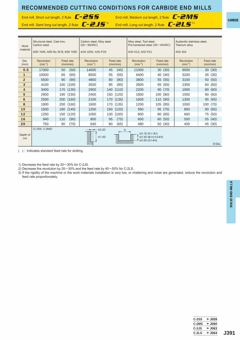
J391
0.5 17000 50 (50) 14000 45 (45) 11000 30 (30) 9000 30 (30)1 10000 65 (65) 8500 55 (55) 6400 40 (40) 5200 35 (35)2 5500 90 (90) 4800 80 (80) 3800 55 (55) 3100 50 (50)3 4100 100 (100) 3500 85 (85) 2800 65 (65) 2300 60 (60)4 3400 170 (135) 2900 140 (110) 2200 90 (70) 1900 80 (60)5 2900 190 (150) 2400 150 (120) 1800 100 (80) 1500 90 (60)6 2500 200 (160) 2100 170 (135) 1600 110 (90) 1300 95 (65)8 1900 200 (160) 1600 170 (135) 1200 105 (85) 1000 100 (70)
10 1500 180 (145) 1250 150 (120) 950 95 (75) 800 90 (65)12 1250 150 (120) 1050 130 (100) 800 80 (65) 660 75 (50)16 940 110 (90) 800 95 (75) 600 60 (50) 500 55 (40)20 750 90 (70) 640 80 (65) 480 50 (40) 400 45 (30)
(C-2SS, C-2MS)
C-2SS J059C-2MS J060C-2JS J063C-2LS J064
D
SOLI
D E
ND
MIL
LS
CARBIDE
SOLI
D E
ND
MIL
LS
CARBIDE
1) Decrease the feed rate by 20─30% for C-2JS.2) Decrease the revolution by 20─30% and the feed rate by 40─50% for C-2LS.3) If the rigidity of the machine or the work materials installation is very low, or chattering and noise are generated, reduce the revolution and
feed rate proportionately.
( ) : Indicates standard feed rate for slotting.
D:Dia.
Workmaterial
Structural steel, Cast iron, Carbon steel
AISI 1045, AISI No 35 B, AISI 1050
Carbon steel, Alloy steel(20─30HRC)
AISI 1050, AISI P20
Alloy steel, Tool steel, Pre-hardened steel (30─45HRC)
AISI H13, AISI P21
Austenitic stainless steel,Titanium alloy
AISI 304
Dia.(mm)
Revolution(min-1)
Feed rate(mm/min)
Revolution(min-1)
Feed rate(mm/min)
Revolution(min-1)
Feed rate(mm/min)
Revolution(min-1)
Feed rate(mm/min)
Depth ofcut
<0.2D
<1.5D<0.1D (D< &2)<0.3D (&2< D< &3)<0.5D (D>&3)
End mill, Short cut length, 2 flute C-2SS End mill, Medium cut length, 2 flute C-2MSEnd mill, Semi long cut length, 2 flute C-2JS 1)
End mill, Long cut length, 2 flute C-2LS 2 )
RECOMMENDED CUTTING CONDITIONS FOR CARBIDE END MILLS
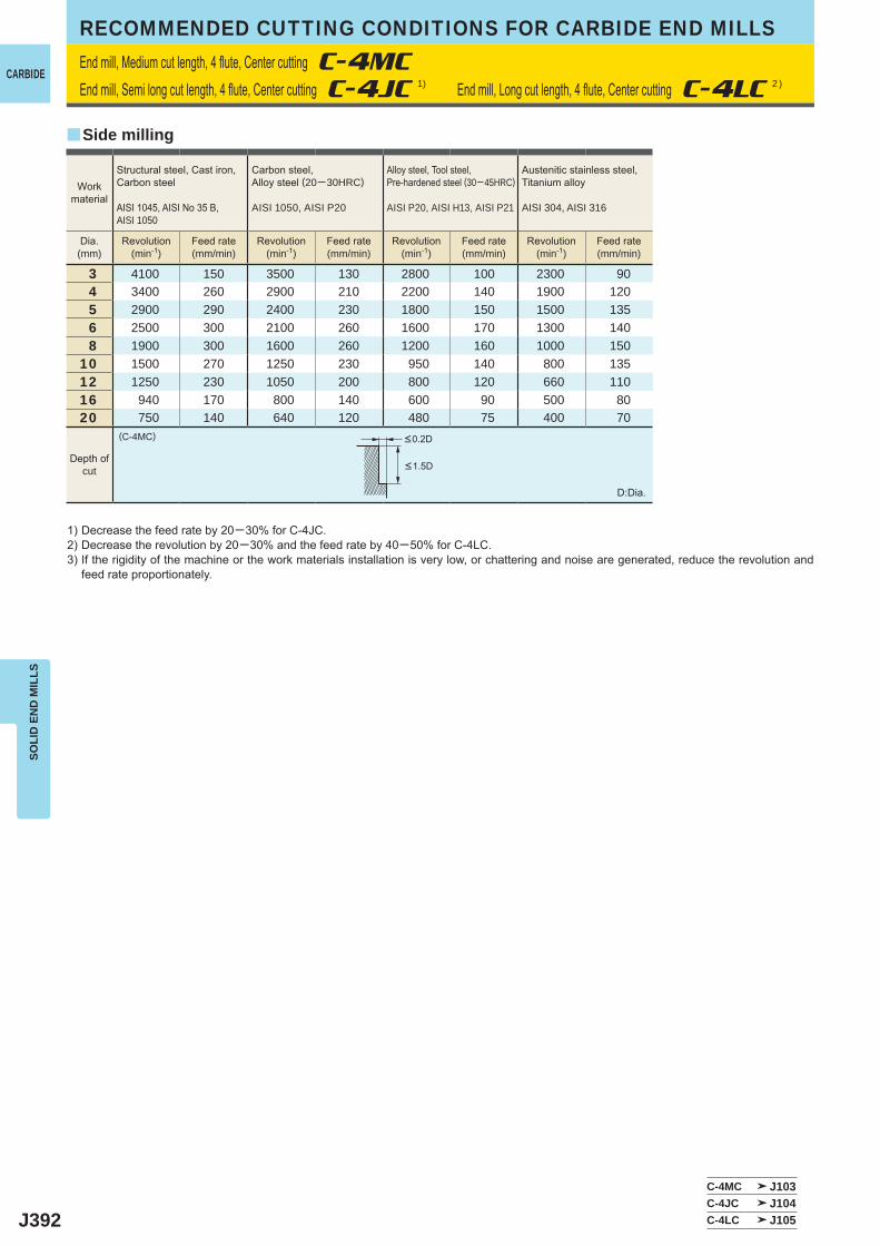
J392
3 4100 150 3500 130 2800 100 2300 904 3400 260 2900 210 2200 140 1900 1205 2900 290 2400 230 1800 150 1500 1356 2500 300 2100 260 1600 170 1300 1408 1900 300 1600 260 1200 160 1000 150
10 1500 270 1250 230 950 140 800 13512 1250 230 1050 200 800 120 660 11016 940 170 800 140 600 90 500 8020 750 140 640 120 480 75 400 70
(C-4MC)
C-4MC J103C-4JC J104C-4LC J105
y
SOLI
D E
ND
MIL
LSRECOMMENDED CUTTING CONDITIONS FOR CARBIDE END MILLS
1) Decrease the feed rate by 20─30% for C-4JC.2) Decrease the revolution by 20─30% and the feed rate by 40─50% for C-4LC.3) If the rigidity of the machine or the work materials installation is very low, or chattering and noise are generated, reduce the revolution and
feed rate proportionately.
D:Dia.
End mill, Medium cut length, 4 flute, Center cutting C-4MC
End mill, Semi long cut length, 4 flute, Center cutting C-4JC 1) End mill, Long cut length, 4 flute, Center cutting C-4LC 2 )
Side milling
Depth ofcut
<0.2D
<1.5D
Workmaterial
Structural steel, Cast iron, Carbon steel
AISI 1045, AISI No 35 B, AISI 1050
Carbon steel, Alloy steel (20─30HRC)
AISI 1050, AISI P20
Alloy steel, Tool steel, Pre-hardened steel (30─45HRC)
AISI P20, AISI H13, AISI P21
Austenitic stainless steel,Titanium alloy
AISI 304, AISI 316
Dia.(mm)
Revolution(min-1)
Feed rate(mm/min)
Revolution(min-1)
Feed rate(mm/min)
Revolution(min-1)
Feed rate(mm/min)
Revolution(min-1)
Feed rate(mm/min)
CARBIDE
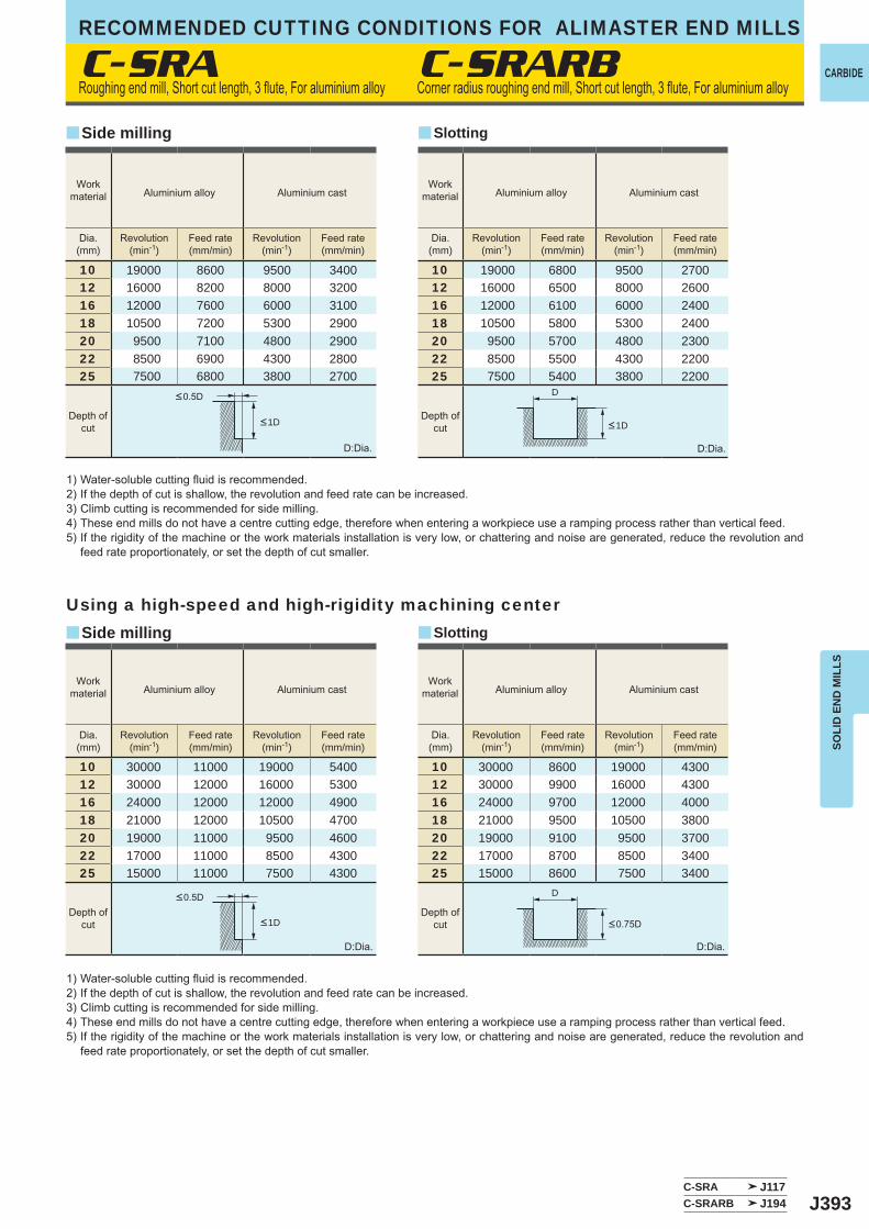
J393
10 19000 8600 9500 340012 16000 8200 8000 320016 12000 7600 6000 310018 10500 7200 5300 290020 9500 7100 4800 290022 8500 6900 4300 280025 7500 6800 3800 2700
10 30000 11000 19000 540012 30000 12000 16000 530016 24000 12000 12000 490018 21000 12000 10500 470020 19000 11000 9500 460022 17000 11000 8500 430025 15000 11000 7500 4300
10 19000 6800 9500 270012 16000 6500 8000 260016 12000 6100 6000 240018 10500 5800 5300 240020 9500 5700 4800 230022 8500 5500 4300 220025 7500 5400 3800 2200
10 30000 8600 19000 430012 30000 9900 16000 430016 24000 9700 12000 400018 21000 9500 10500 380020 19000 9100 9500 370022 17000 8700 8500 340025 15000 8600 7500 3400
C-SRA
C-SRA J117C-SRARB J194
y
y
y
y
C-SRARB
D
D
SOLI
D E
ND
MIL
LS
CARBIDE
RECOMMENDED CUTTING CONDITIONS FOR ALIMASTER END MILLS
1) Water-soluble cutting fluid is recommended.2) If the depth of cut is shallow, the revolution and feed rate can be increased.3) Climb cutting is recommended for side milling.4) These end mills do not have a centre cutting edge, therefore when entering a workpiece use a ramping process rather than vertical feed.5) If the rigidity of the machine or the work materials installation is very low, or chattering and noise are generated, reduce the revolution and
feed rate proportionately, or set the depth of cut smaller.
D:Dia.
D:Dia.
D:Dia.
D:Dia.
Using a high-speed and high-rigidity machining center
Roughing end mill, Short cut length, 3 flute, For aluminium alloy Corner radius roughing end mill, Short cut length, 3 flute, For aluminium alloy
Side milling
Side milling
Slotting
Slotting
Workmaterial Aluminium alloy Aluminium cast
Workmaterial Aluminium alloy Aluminium cast
Workmaterial Aluminium alloy Aluminium cast
Workmaterial Aluminium alloy Aluminium cast
Dia.(mm)
Revolution(min-1)
Feed rate(mm/min)
Revolution(min-1)
Feed rate(mm/min)
Dia.(mm)
Revolution(min-1)
Feed rate(mm/min)
Revolution(min-1)
Feed rate(mm/min)
Dia.(mm)
Revolution(min-1)
Feed rate(mm/min)
Revolution(min-1)
Feed rate(mm/min)
Dia.(mm)
Revolution(min-1)
Feed rate(mm/min)
Revolution(min-1)
Feed rate(mm/min)
Depth ofcut
Depth ofcut
Depth ofcut
Depth ofcut
<0.5D
<0.5D
<0.75D<1D
<1D <1D
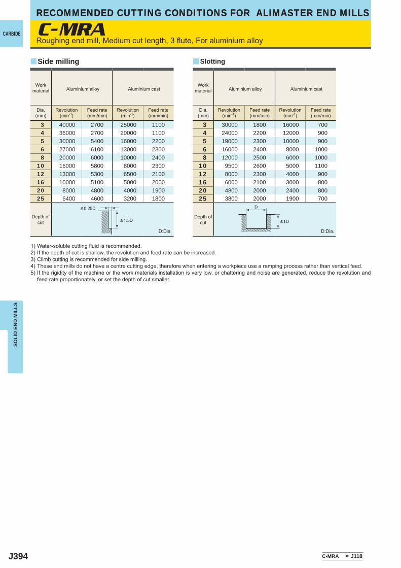
J394
C-MRA
3 40000 2700 25000 11004 36000 2700 20000 11005 30000 5400 16000 22006 27000 6100 13000 23008 20000 6000 10000 2400
10 16000 5800 8000 230012 13000 5300 6500 210016 10000 5100 5000 200020 8000 4800 4000 190025 6400 4600 3200 1800
3 30000 1800 16000 7004 24000 2200 12000 9005 19000 2300 10000 9006 16000 2400 8000 10008 12000 2500 6000 1000
10 9500 2600 5000 110012 8000 2300 4000 90016 6000 2100 3000 80020 4800 2000 2400 80025 3800 2000 1900 700
C-MRA J118
y y
D
RECOMMENDED CUTTING CONDITIONS FOR ALIMASTER END MILLSSO
LID
EN
D M
ILLS
CARBIDE
RECOMMENDED CUTTING CONDITIONS FOR ALIMASTER END MILLS
Roughing end mill, Medium cut length, 3 flute, For aluminium alloy
1) Water-soluble cutting fluid is recommended.2) If the depth of cut is shallow, the revolution and feed rate can be increased.3) Climb cutting is recommended for side milling.4) These end mills do not have a centre cutting edge, therefore when entering a workpiece use a ramping process rather than vertical feed.5) If the rigidity of the machine or the work materials installation is very low, or chattering and noise are generated, reduce the revolution and
feed rate proportionately, or set the depth of cut smaller.
D:Dia. D:Dia.
Side milling Slotting
Workmaterial Aluminium alloy Aluminium cast
Workmaterial Aluminium alloy Aluminium cast
Dia.(mm)
Revolution(min-1)
Feed rate(mm/min)
Revolution(min-1)
Feed rate(mm/min)
Dia.(mm)
Revolution(min-1)
Feed rate(mm/min)
Revolution(min-1)
Feed rate(mm/min)
Depth ofcut
Depth ofcut <1D<1.5D
<0.25D
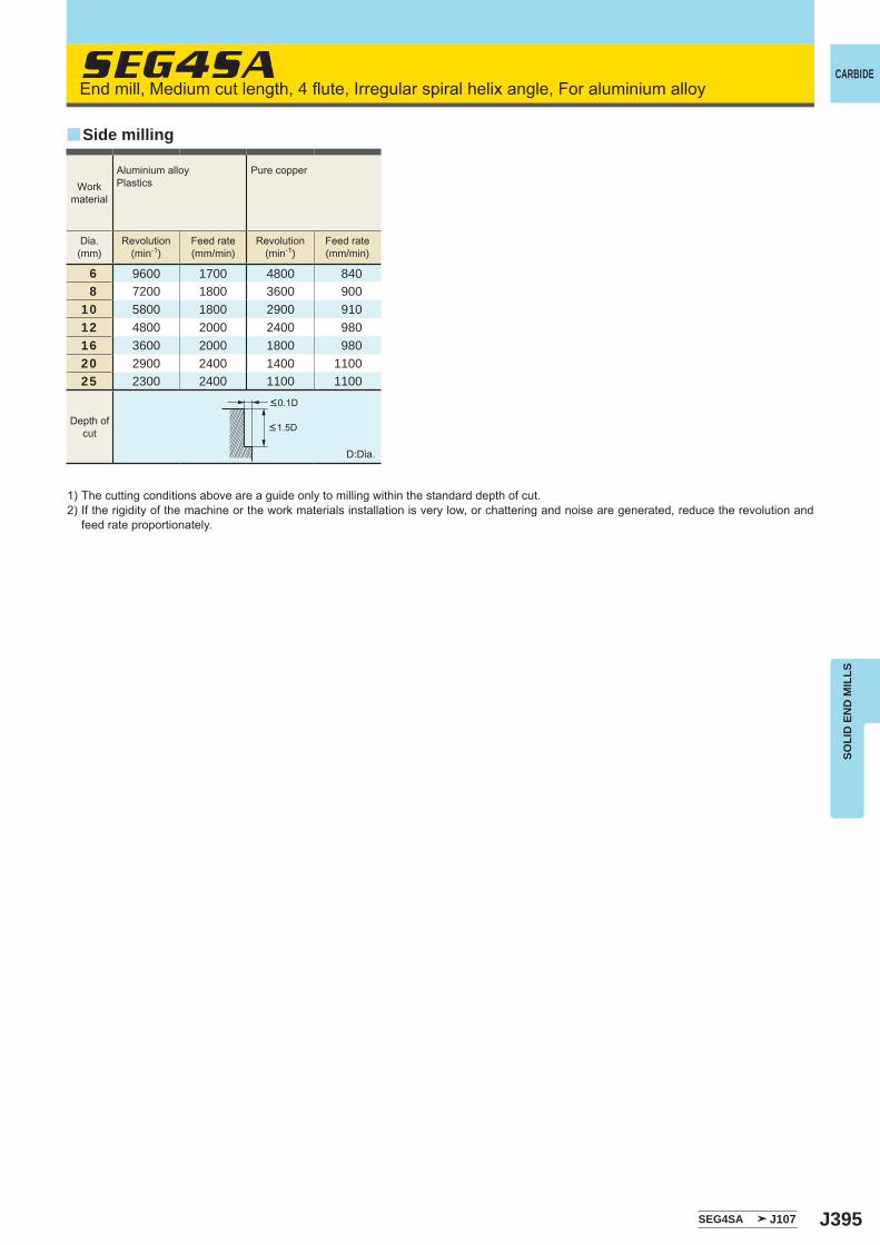
J395
SEG4SA
6 9600 1700 4800 8408 7200 1800 3600 900
10 5800 1800 2900 91012 4800 2000 2400 98016 3600 2000 1800 98020 2900 2400 1400 110025 2300 2400 1100 1100
SEG4SA J107
y
SOLI
D E
ND
MIL
LS
CARBIDEEnd mill, Medium cut length, 4 flute, Irregular spiral helix angle, For aluminium alloy
1) The cutting conditions above are a guide only to milling within the standard depth of cut.2) If the rigidity of the machine or the work materials installation is very low, or chattering and noise are generated, reduce the revolution and
feed rate proportionately.
D:Dia.
Side milling
Dia.(mm)
Revolution(min-1)
Feed rate(mm/min)
Revolution(min-1)
Feed rate(mm/min)
Workmaterial
Aluminium alloyPlastics
Pure copper
<0.1D
<1.5DDepth of
cut
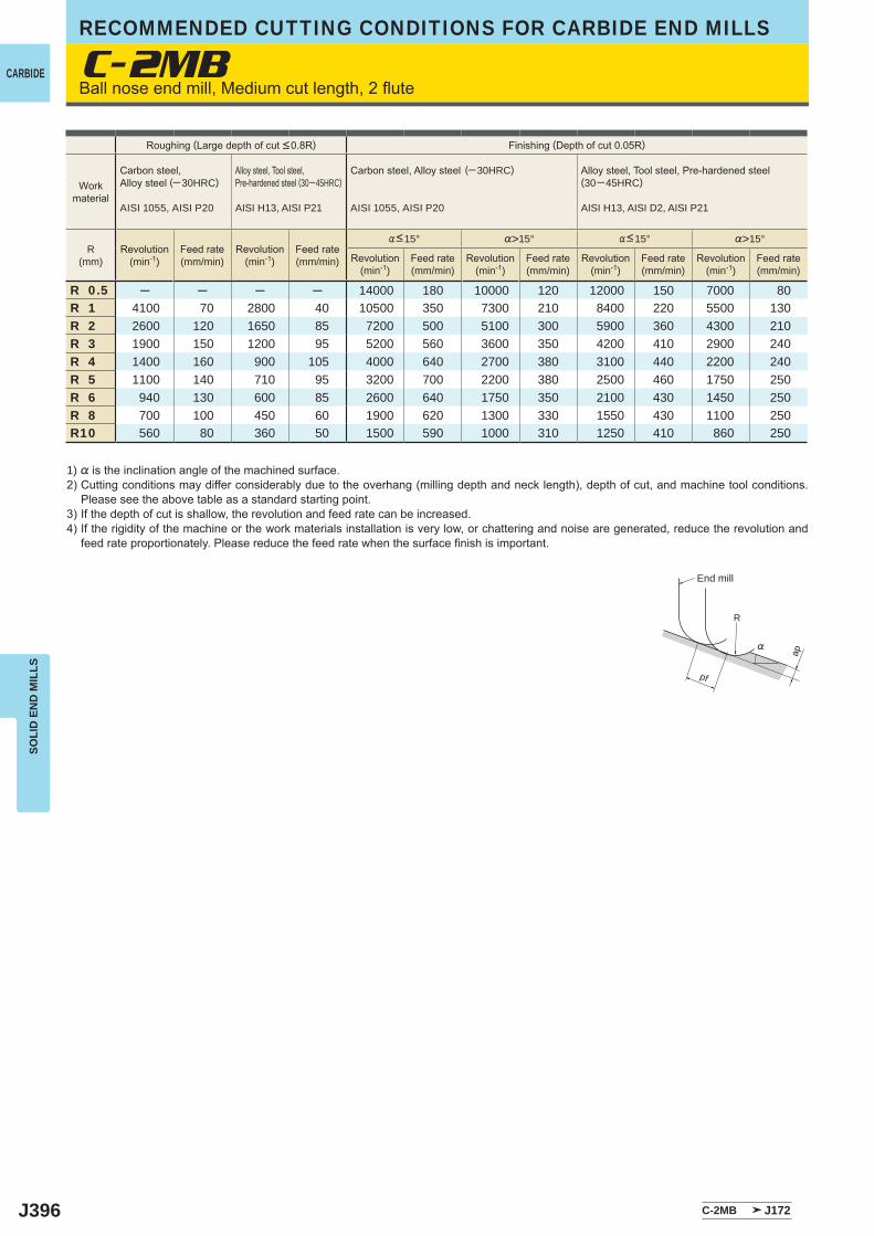
J396
C-2MB
%>15° %>15°
R 0.5 ─ ─ ─ ─ 14000 180 10000 120 12000 150 7000 80R 1 4100 70 2800 40 10500 350 7300 210 8400 220 5500 130R 2 2600 120 1650 85 7200 500 5100 300 5900 360 4300 210R 3 1900 150 1200 95 5200 560 3600 350 4200 410 2900 240R 4 1400 160 900 105 4000 640 2700 380 3100 440 2200 240R 5 1100 140 710 95 3200 700 2200 380 2500 460 1750 250R 6 940 130 600 85 2600 640 1750 350 2100 430 1450 250R 8 700 100 450 60 1900 620 1300 330 1550 430 1100 250R10 560 80 360 50 1500 590 1000 310 1250 410 860 250
C-2MB J172
R
%
ap
pf
SOLI
D E
ND
MIL
LSRECOMMENDED CUTTING CONDITIONS FOR CARBIDE END MILLS
CARBIDEBall nose end mill, Medium cut length, 2 flute
1) % is the inclination angle of the machined surface. 2) Cutting conditions may differ considerably due to the overhang (milling depth and neck length), depth of cut, and machine tool conditions.
Please see the above table as a standard starting point.3) If the depth of cut is shallow, the revolution and feed rate can be increased.4) If the rigidity of the machine or the work materials installation is very low, or chattering and noise are generated, reduce the revolution and
feed rate proportionately. Please reduce the feed rate when the surface finish is important.
Roughing (Large depth of cut <0.8R) Finishing (Depth of cut 0.05R)
Workmaterial
Carbon steel, Alloy steel (─30HRC)
AISI 1055, AISI P20
Alloy steel, Tool steel,Pre-hardened steel (30─45HRC)
AISI H13, AISI P21
Carbon steel, Alloy steel (─30HRC)
AISI 1055, AISI P20
Alloy steel, Tool steel, Pre-hardened steel(30─45HRC)
AISI H13, AISI D2, AISI P21
R(mm)
Revolution(min-1)
Feed rate(mm/min)
Revolution(min-1)
Feed rate(mm/min) Revolution
(min-1)Feed rate(mm/min)
Revolution(min-1)
Feed rate(mm/min)
Revolution(min-1)
Feed rate(mm/min)
Revolution(min-1)
Feed rate(mm/min)
%<15° %<15°
End mill
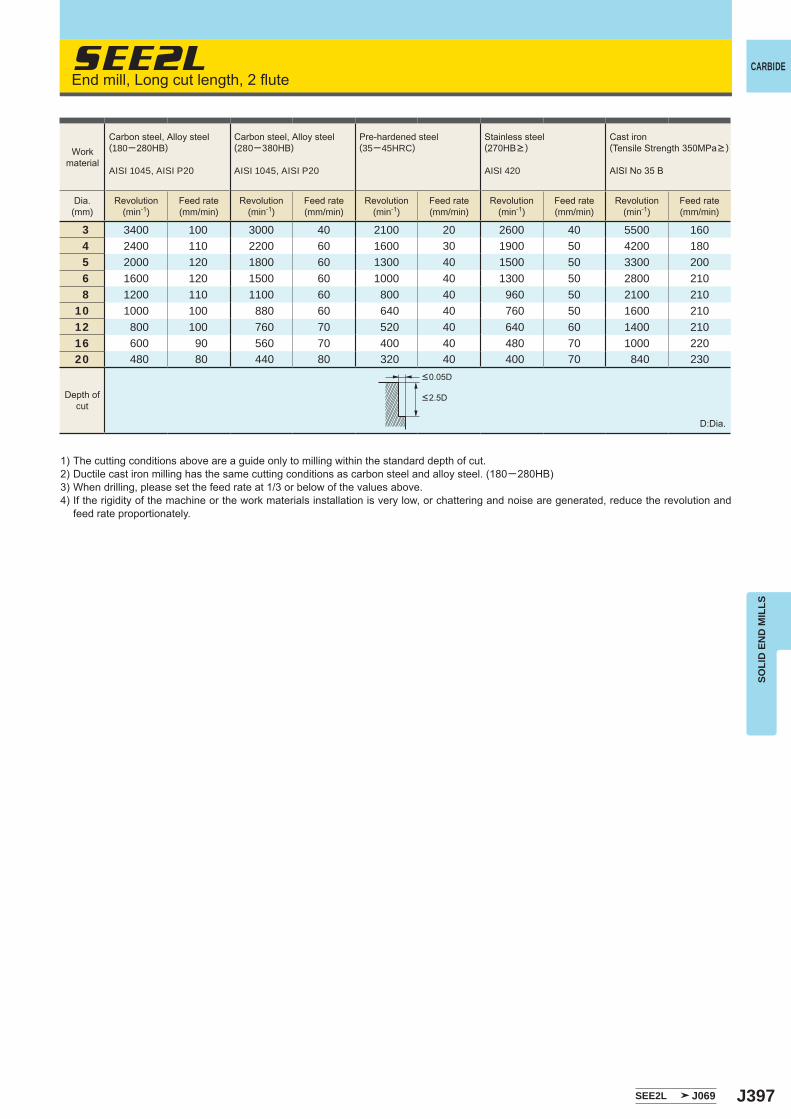
J397
SEE2L
3 3400 100 3000 40 2100 20 2600 40 5500 1604 2400 110 2200 60 1600 30 1900 50 4200 1805 2000 120 1800 60 1300 40 1500 50 3300 2006 1600 120 1500 60 1000 40 1300 50 2800 2108 1200 110 1100 60 800 40 960 50 2100 210
10 1000 100 880 60 640 40 760 50 1600 21012 800 100 760 70 520 40 640 60 1400 21016 600 90 560 70 400 40 480 70 1000 22020 480 80 440 80 320 40 400 70 840 230
SEE2L J069
SOLI
D E
ND
MIL
LS
CARBIDEEnd mill, Long cut length, 2 flute
1) The cutting conditions above are a guide only to milling within the standard depth of cut.2) Ductile cast iron milling has the same cutting conditions as carbon steel and alloy steel. (180─280HB)3) When drilling, please set the feed rate at 1/3 or below of the values above.4) If the rigidity of the machine or the work materials installation is very low, or chattering and noise are generated, reduce the revolution and
feed rate proportionately.
D:Dia.
Depth ofcut
Workmaterial
Carbon steel, Alloy steel(180─280HB)
AISI 1045, AISI P20
Carbon steel, Alloy steel(280─380HB)
AISI 1045, AISI P20
Pre-hardened steel(35─45HRC)
Stainless steel (270HB> )
AISI 420
Cast iron(Tensile Strength 350MPa> )
AISI No 35 B
Dia.(mm)
Revolution(min-1)
Feed rate(mm/min)
Revolution(min-1)
Feed rate(mm/min)
Revolution(min-1)
Feed rate(mm/min)
Revolution(min-1)
Feed rate(mm/min)
Revolution(min-1)
Feed rate(mm/min)
<0.05D
<2.5D
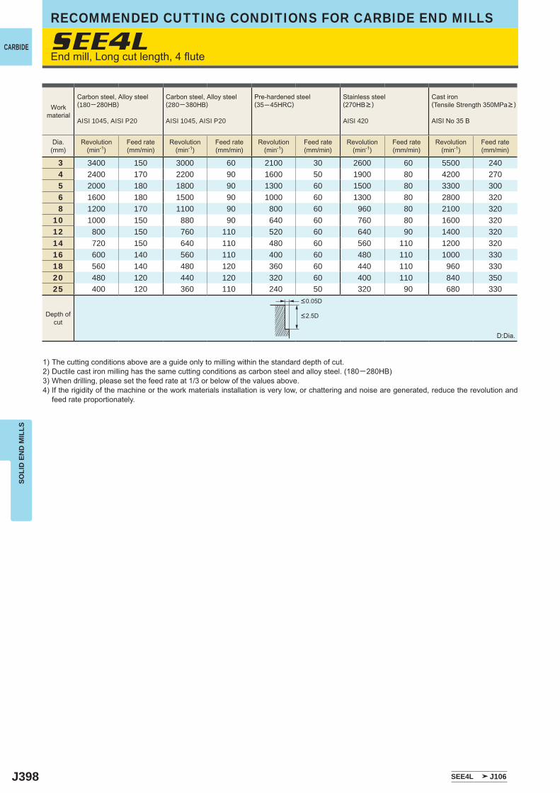
J398
SEE4L
3 3400 150 3000 60 2100 30 2600 60 5500 240 4 2400 170 2200 90 1600 50 1900 80 4200 270 5 2000 180 1800 90 1300 60 1500 80 3300 300 6 1600 180 1500 90 1000 60 1300 80 2800 320 8 1200 170 1100 90 800 60 960 80 2100 32010 1000 150 880 90 640 60 760 80 1600 32012 800 150 760 110 520 60 640 90 1400 32014 720 150 640 110 480 60 560 110 1200 32016 600 140 560 110 400 60 480 110 1000 33018 560 140 480 120 360 60 440 110 960 33020 480 120 440 120 320 60 400 110 840 35025 400 120 360 110 240 50 320 90 680 330
SEE4L J106
SOLI
D E
ND
MIL
LSRECOMMENDED CUTTING CONDITIONS FOR CARBIDE END MILLS
CARBIDEEnd mill, Long cut length, 4 flute
1) The cutting conditions above are a guide only to milling within the standard depth of cut.2) Ductile cast iron milling has the same cutting conditions as carbon steel and alloy steel. (180─280HB)3) When drilling, please set the feed rate at 1/3 or below of the values above.4) If the rigidity of the machine or the work materials installation is very low, or chattering and noise are generated, reduce the revolution and
feed rate proportionately.
D:Dia.
Workmaterial
Carbon steel, Alloy steel(180─280HB)
AISI 1045, AISI P20
Carbon steel, Alloy steel(280─380HB)
AISI 1045, AISI P20
Pre-hardened steel(35─45HRC)
Stainless steel(270HB> )
AISI 420
Cast iron(Tensile Strength 350MPa> )
AISI No 35 B
Dia.(mm)
Revolution(min-1)
Feed rate(mm/min)
Revolution(min-1)
Feed rate(mm/min)
Revolution(min-1)
Feed rate(mm/min)
Revolution(min-1)
Feed rate(mm/min)
Revolution(min-1)
Feed rate(mm/min)
<0.05D
<2.5DDepth ofcut
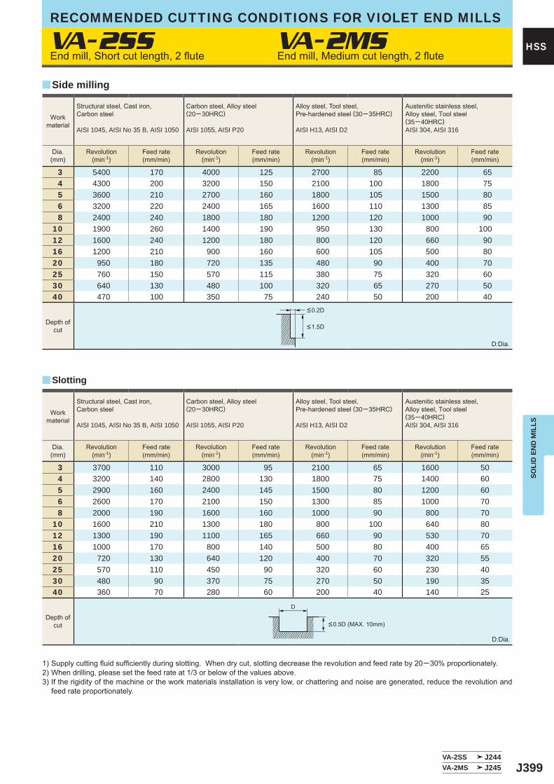
J399
VA-2SS VA-2MS
3 5400 170 4000 125 2700 85 2200 65 4 4300 200 3200 150 2100 100 1800 75 5 3600 210 2700 160 1800 105 1500 80 6 3200 220 2400 165 1600 110 1300 85 8 2400 240 1800 180 1200 120 1000 9010 1900 260 1400 190 950 130 800 10012 1600 240 1200 180 800 120 660 9016 1200 210 900 160 600 105 500 8020 950 180 720 135 480 90 400 7025 760 150 570 115 380 75 320 6030 640 130 480 100 320 65 270 5040 470 100 350 75 240 50 200 40
3 3700 110 3000 95 2100 65 1600 50 4 3200 140 2800 130 1800 75 1400 60 5 2900 160 2400 145 1500 80 1200 60 6 2600 170 2100 150 1300 85 1000 70 8 2000 190 1600 160 1000 90 800 7010 1600 210 1300 180 800 100 640 8012 1300 190 1100 165 660 90 530 7016 1000 170 800 140 500 80 400 6520 720 130 640 120 400 70 320 5525 570 110 450 90 320 60 230 4030 480 90 370 75 270 50 190 3540 360 70 280 60 200 40 140 25
VA-2SS J244VA-2MS J245
y
y
D
HSS
SOLI
D E
ND
MIL
LS
RECOMMENDED CUTTING CONDITIONS FOR VIOLET END MILLS
End mill, Short cut length, 2 flute End mill, Medium cut length, 2 flute
1) Supply cutting fluid sufficiently during slotting. When dry cut, slotting decrease the revolution and feed rate by 20─30% proportionately.2) When drilling, please set the feed rate at 1/3 or below of the values above.3) If the rigidity of the machine or the work materials installation is very low, or chattering and noise are generated, reduce the revolution and
feed rate proportionately.
D:Dia.
D:Dia.
Side milling
Slotting
Workmaterial
Structural steel, Cast iron, Carbon steel
AISI 1045, AISI No 35 B, AISI 1050
Carbon steel, Alloy steel (20─30HRC)
AISI 1055, AISI P20
Alloy steel, Tool steel,Pre-hardened steel (30─35HRC)
AISI H13, AISI D2
Austenitic stainless steel,Alloy steel, Tool steel(35─40HRC)AISI 304, AISI 316
Dia.(mm)
Revolution(min-1)
Feed rate(mm/min)
Revolution(min-1)
Feed rate(mm/min)
Revolution(min-1)
Feed rate(mm/min)
Revolution(min-1)
Feed rate(mm/min)
Depth ofcut
Depth ofcut <0.5D (MAX. 10mm)
<0.2D
<1.5D
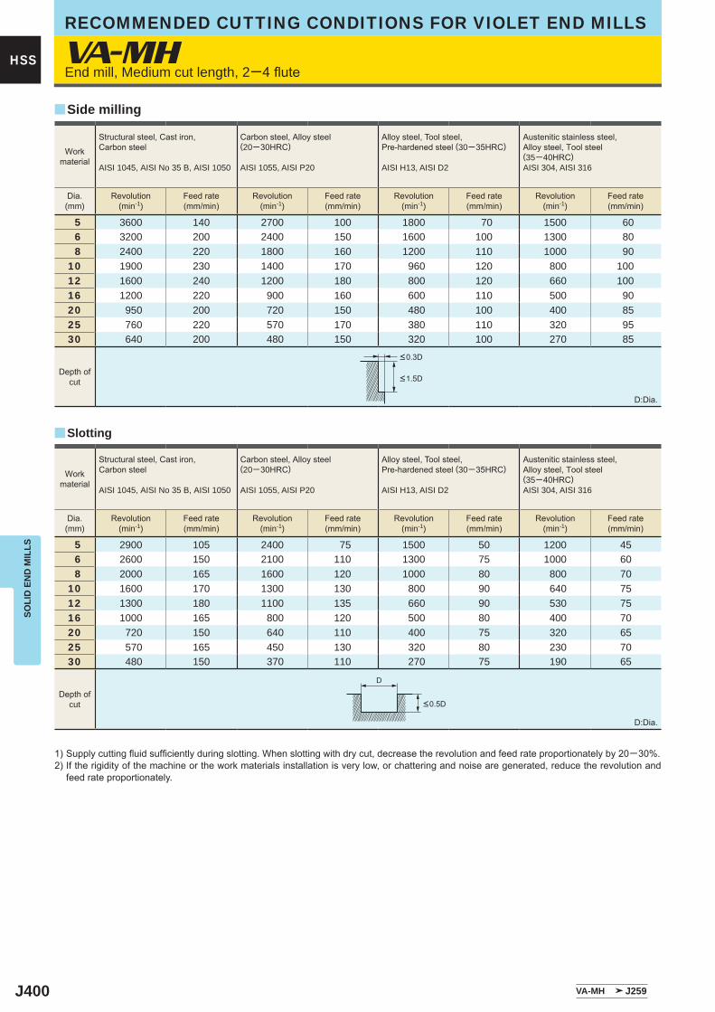
J400
VA-MH
5 3600 140 2700 100 1800 70 1500 60 6 3200 200 2400 150 1600 100 1300 80 8 2400 220 1800 160 1200 110 1000 9010 1900 230 1400 170 960 120 800 10012 1600 240 1200 180 800 120 660 10016 1200 220 900 160 600 110 500 9020 950 200 720 150 480 100 400 8525 760 220 570 170 380 110 320 9530 640 200 480 150 320 100 270 85
5 2900 105 2400 75 1500 50 1200 45 6 2600 150 2100 110 1300 75 1000 60 8 2000 165 1600 120 1000 80 800 7010 1600 170 1300 130 800 90 640 7512 1300 180 1100 135 660 90 530 7516 1000 165 800 120 500 80 400 7020 720 150 640 110 400 75 320 6525 570 165 450 130 320 80 230 7030 480 150 370 110 270 75 190 65
VA-MH J259
y
y
D
HSS
SOLI
D E
ND
MIL
LSRECOMMENDED CUTTING CONDITIONS FOR VIOLET END MILLS
End mill, Medium cut length, 2─4 flute
1) Supply cutting fluid sufficiently during slotting. When slotting with dry cut, decrease the revolution and feed rate proportionately by 20─30%.2) If the rigidity of the machine or the work materials installation is very low, or chattering and noise are generated, reduce the revolution and
feed rate proportionately.
D:Dia.
D:Dia.
Slotting
Side milling
Workmaterial
Structural steel, Cast iron, Carbon steel
AISI 1045, AISI No 35 B, AISI 1050
Carbon steel, Alloy steel (20─30HRC)
AISI 1055, AISI P20
Alloy steel, Tool steel,Pre-hardened steel (30─35HRC)
AISI H13, AISI D2
Austenitic stainless steel,Alloy steel, Tool steel(35─40HRC)AISI 304, AISI 316
Dia.(mm)
Revolution(min-1)
Feed rate(mm/min)
Revolution(min-1)
Feed rate(mm/min)
Revolution(min-1)
Feed rate(mm/min)
Revolution(min-1)
Feed rate(mm/min)
Depth ofcut
Depth ofcut
<0.3D
<1.5D
<0.5D
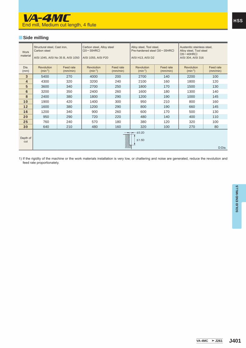
J401
VA-4MC
3 5400 270 4000 200 2700 140 2200 100 4 4300 320 3200 240 2100 160 1800 120 5 3600 340 2700 250 1800 170 1500 130 6 3200 350 2400 260 1600 180 1300 140 8 2400 380 1800 290 1200 190 1000 14510 1900 420 1400 300 950 210 800 16012 1600 380 1200 290 800 190 660 14516 1200 340 900 260 600 170 500 13020 950 290 720 220 480 140 400 11025 760 240 570 180 380 120 320 10030 640 210 480 160 320 100 270 80
VA-4MC J261
y
HSS
SOLI
D E
ND
MIL
LS
End mill, Medium cut length, 4 flute
1) If the rigidity of the machine or the work materials installation is very low, or chattering and noise are generated, reduce the revolution and feed rate proportionately.
D:Dia.
Side milling
Workmaterial
Structural steel, Cast iron, Carbon steel
AISI 1045, AISI No 35 B, AISI 1050
Carbon steel, Alloy steel (20─30HRC)
AISI 1055, AISI P20
Alloy steel, Tool steel,Pre-hardened steel (30─35HRC)
AISI H13, AISI D2
Austenitic stainless steel,Alloy steel, Tool steel(35─40HRC)AISI 304, AISI 316
Dia.(mm)
Revolution(min-1)
Feed rate(mm/min)
Revolution(min-1)
Feed rate(mm/min)
Revolution(min-1)
Feed rate(mm/min)
Revolution(min-1)
Feed rate(mm/min)
Depth ofcut
<0.2D
<1.5D
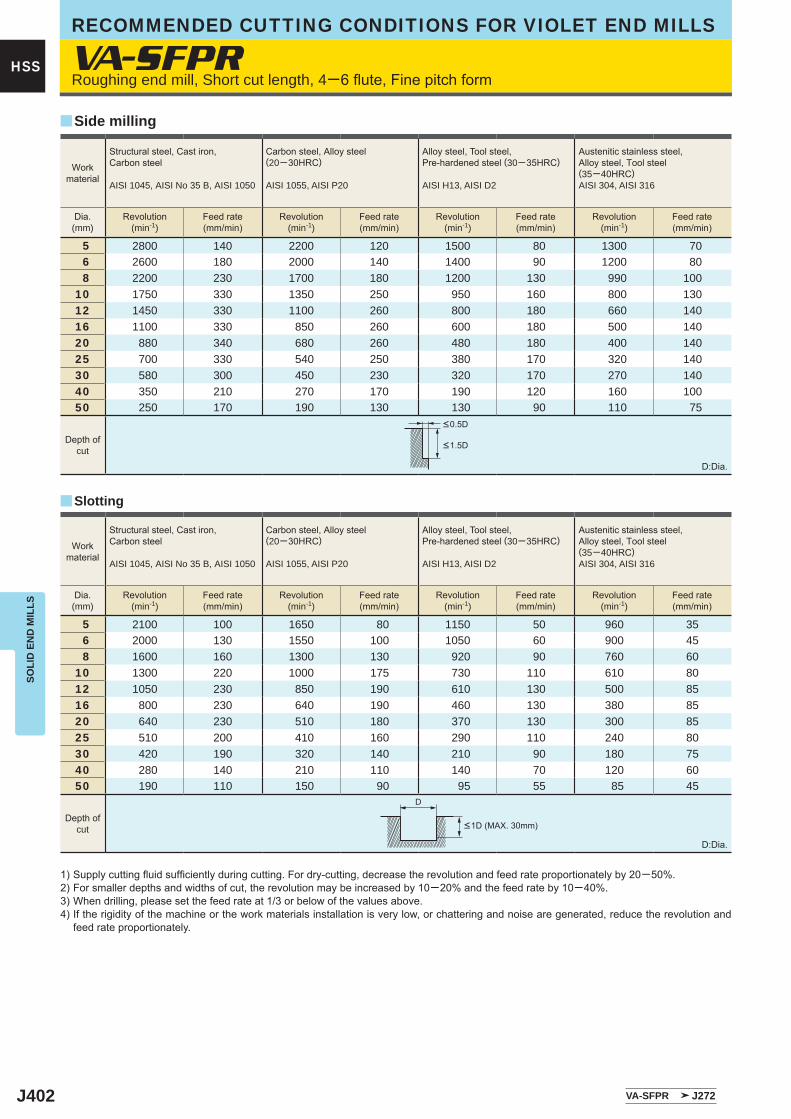
J402
VA-SFPR
5 2800 140 2200 120 1500 80 1300 70 6 2600 180 2000 140 1400 90 1200 80 8 2200 230 1700 180 1200 130 990 10010 1750 330 1350 250 950 160 800 13012 1450 330 1100 260 800 180 660 14016 1100 330 850 260 600 180 500 14020 880 340 680 260 480 180 400 14025 700 330 540 250 380 170 320 14030 580 300 450 230 320 170 270 14040 350 210 270 170 190 120 160 10050 250 170 190 130 130 90 110 75
5 2100 100 1650 80 1150 50 960 35 6 2000 130 1550 100 1050 60 900 45 8 1600 160 1300 130 920 90 760 6010 1300 220 1000 175 730 110 610 8012 1050 230 850 190 610 130 500 8516 800 230 640 190 460 130 380 8520 640 230 510 180 370 130 300 8525 510 200 410 160 290 110 240 8030 420 190 320 140 210 90 180 7540 280 140 210 110 140 70 120 6050 190 110 150 90 95 55 85 45
VA-SFPR J272
y
y
D
HSS
SOLI
D E
ND
MIL
LSRECOMMENDED CUTTING CONDITIONS FOR VIOLET END MILLS
Roughing end mill, Short cut length, 4─6 flute, Fine pitch form
1) Supply cutting fluid sufficiently during cutting. For dry-cutting, decrease the revolution and feed rate proportionately by 20─50%.2) For smaller depths and widths of cut, the revolution may be increased by 10─20% and the feed rate by 10─40%.3) When drilling, please set the feed rate at 1/3 or below of the values above. 4) If the rigidity of the machine or the work materials installation is very low, or chattering and noise are generated, reduce the revolution and
feed rate proportionately.
D:Dia.
D:Dia.
Side milling
Slotting
Workmaterial
Structural steel, Cast iron, Carbon steel
AISI 1045, AISI No 35 B, AISI 1050
Carbon steel, Alloy steel (20─30HRC)
AISI 1055, AISI P20
Alloy steel, Tool steel,Pre-hardened steel (30─35HRC)
AISI H13, AISI D2
Austenitic stainless steel,Alloy steel, Tool steel(35─40HRC)AISI 304, AISI 316
Dia.(mm)
Revolution(min-1)
Feed rate(mm/min)
Revolution(min-1)
Feed rate(mm/min)
Revolution(min-1)
Feed rate(mm/min)
Revolution(min-1)
Feed rate(mm/min)
Depth ofcut
Depth ofcut <1D (MAX. 30mm)
<0.5D
<1.5D
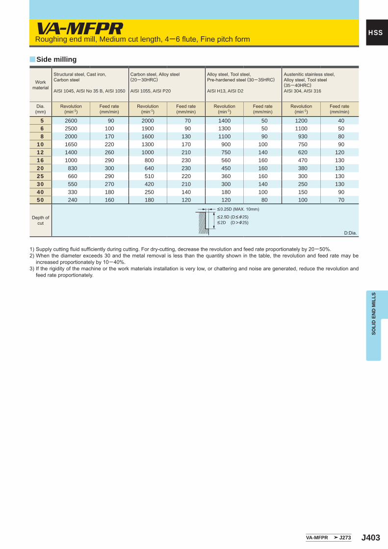
J403
VA-MFPR
5 2600 90 2000 70 1400 50 1200 40 6 2500 100 1900 90 1300 50 1100 50 8 2000 170 1600 130 1100 90 930 8010 1650 220 1300 170 900 100 750 9012 1400 260 1000 210 750 140 620 12016 1000 290 800 230 560 160 470 13020 830 300 640 230 450 160 380 13025 660 290 510 220 360 160 300 13030 550 270 420 210 300 140 250 13040 330 180 250 140 180 100 150 9050 240 160 180 120 120 80 100 70
VA-MFPR J273
y
HSS
SOLI
D E
ND
MIL
LS
Roughing end mill, Medium cut length, 4─6 flute, Fine pitch form
1) Supply cutting fluid sufficiently during cutting. For dry-cutting, decrease the revolution and feed rate proportionately by 20─50%.2) When the diameter exceeds 30 and the metal removal is less than the quantity shown in the table, the revolution and feed rate may be
increased proportionately by 10─40%.3) If the rigidity of the machine or the work materials installation is very low, or chattering and noise are generated, reduce the revolution and
feed rate proportionately.
D:Dia.
Side milling
Workmaterial
Structural steel, Cast iron, Carbon steel
AISI 1045, AISI No 35 B, AISI 1050
Carbon steel, Alloy steel (20─30HRC)
AISI 1055, AISI P20
Alloy steel, Tool steel,Pre-hardened steel (30─35HRC)
AISI H13, AISI D2
Austenitic stainless steel,Alloy steel, Tool steel(35─40HRC)AISI 304, AISI 316
Dia.(mm)
Revolution(min-1)
Feed rate(mm/min)
Revolution(min-1)
Feed rate(mm/min)
Revolution(min-1)
Feed rate(mm/min)
Revolution(min-1)
Feed rate(mm/min)
Depth ofcut
<0.25D (MAX. 10mm)
<2.5D (D< &25)<2D (D>&25)
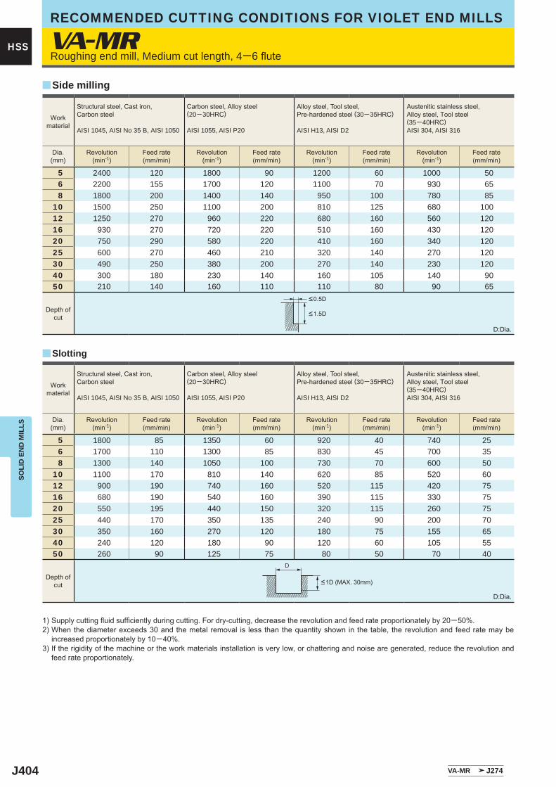
J404
VA-MR
5 2400 120 1800 90 1200 60 1000 50 6 2200 155 1700 120 1100 70 930 65 8 1800 200 1400 140 950 100 780 8510 1500 250 1100 200 810 125 680 10012 1250 270 960 220 680 160 560 12016 930 270 720 220 510 160 430 12020 750 290 580 220 410 160 340 12025 600 270 460 210 320 140 270 12030 490 250 380 200 270 140 230 12040 300 180 230 140 160 105 140 9050 210 140 160 110 110 80 90 65
5 1800 85 1350 60 920 40 740 25 6 1700 110 1300 85 830 45 700 35 8 1300 140 1050 100 730 70 600 5010 1100 170 810 140 620 85 520 6012 900 190 740 160 520 115 420 7516 680 190 540 160 390 115 330 7520 550 195 440 150 320 115 260 7525 440 170 350 135 240 90 200 7030 350 160 270 120 180 75 155 6540 240 120 180 90 120 60 105 5550 260 90 125 75 80 50 70 40
VA-MR J274
y
y
D
HSS
SOLI
D E
ND
MIL
LSRECOMMENDED CUTTING CONDITIONS FOR VIOLET END MILLS
Roughing end mill, Medium cut length, 4─6 flute
D:Dia.
1) Supply cutting fluid sufficiently during cutting. For dry-cutting, decrease the revolution and feed rate proportionately by 20─50%.2) When the diameter exceeds 30 and the metal removal is less than the quantity shown in the table, the revolution and feed rate may be
increased proportionately by 10─40%.3) If the rigidity of the machine or the work materials installation is very low, or chattering and noise are generated, reduce the revolution and
feed rate proportionately.
D:Dia.
Side milling
Slotting
Workmaterial
Structural steel, Cast iron, Carbon steel
AISI 1045, AISI No 35 B, AISI 1050
Carbon steel, Alloy steel (20─30HRC)
AISI 1055, AISI P20
Alloy steel, Tool steel,Pre-hardened steel (30─35HRC)
AISI H13, AISI D2
Austenitic stainless steel,Alloy steel, Tool steel(35─40HRC)AISI 304, AISI 316
Dia.(mm)
Revolution(min-1)
Feed rate(mm/min)
Revolution(min-1)
Feed rate(mm/min)
Revolution(min-1)
Feed rate(mm/min)
Revolution(min-1)
Feed rate(mm/min)
Workmaterial
Structural steel, Cast iron, Carbon steel
AISI 1045, AISI No 35 B, AISI 1050
Carbon steel, Alloy steel (20─30HRC)
AISI 1055, AISI P20
Alloy steel, Tool steel,Pre-hardened steel (30─35HRC)
AISI H13, AISI D2
Austenitic stainless steel,Alloy steel, Tool steel(35─40HRC)AISI 304, AISI 316
Dia.(mm)
Revolution(min-1)
Feed rate(mm/min)
Revolution(min-1)
Feed rate(mm/min)
Revolution(min-1)
Feed rate(mm/min)
Revolution(min-1)
Feed rate(mm/min)
Depth ofcut
Depth ofcut <1D (MAX. 30mm)
<0.5D
<1.5D
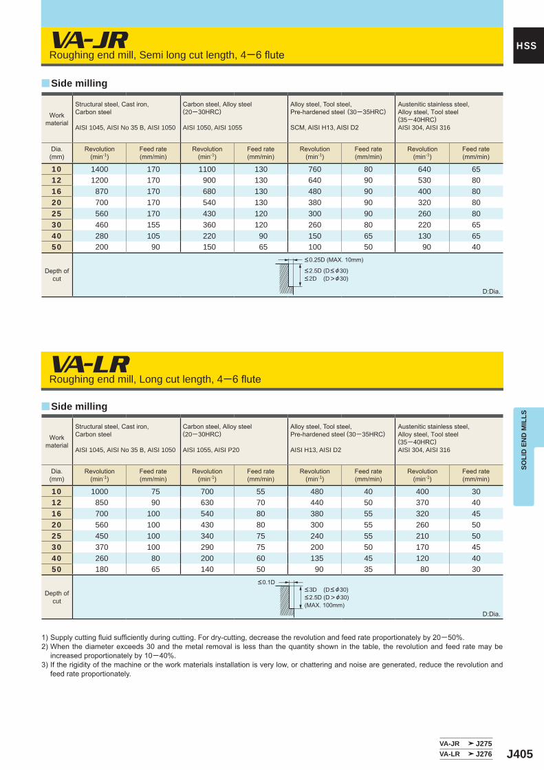
J405
VA-JR
VA-LR
10 1400 170 1100 130 760 80 640 6512 1200 170 900 130 640 90 530 8016 870 170 680 130 480 90 400 8020 700 170 540 130 380 90 320 8025 560 170 430 120 300 90 260 8030 460 155 360 120 260 80 220 6540 280 105 220 90 150 65 130 6550 200 90 150 65 100 50 90 40
10 1000 75 700 55 480 40 400 3012 850 90 630 70 440 50 370 4016 700 100 540 80 380 55 320 4520 560 100 430 80 300 55 260 5025 450 100 340 75 240 55 210 5030 370 100 290 75 200 50 170 4540 260 80 200 60 135 45 120 4050 180 65 140 50 90 35 80 30
VA-JR J275VA-LR J276
y
y
HSS
SOLI
D E
ND
MIL
LS
Roughing end mill, Semi long cut length, 4─6 flute
Roughing end mill, Long cut length, 4─6 flute
1) Supply cutting fluid sufficiently during cutting. For dry-cutting, decrease the revolution and feed rate proportionately by 20─50%.2) When the diameter exceeds 30 and the metal removal is less than the quantity shown in the table, the revolution and feed rate may be
increased proportionately by 10─40%.3) If the rigidity of the machine or the work materials installation is very low, or chattering and noise are generated, reduce the revolution and
feed rate proportionately.
D:Dia.
D:Dia.
Side milling
Side milling
Workmaterial
Structural steel, Cast iron, Carbon steel
AISI 1045, AISI No 35 B, AISI 1050
Carbon steel, Alloy steel (20─30HRC)
AISI 1050, AISI 1055
Alloy steel, Tool steel,Pre-hardened steel (30─35HRC)
SCM, AISI H13, AISI D2
Austenitic stainless steel,Alloy steel, Tool steel(35─40HRC)AISI 304, AISI 316
Dia.(mm)
Revolution(min-1)
Feed rate(mm/min)
Revolution(min-1)
Feed rate(mm/min)
Revolution(min-1)
Feed rate(mm/min)
Revolution(min-1)
Feed rate(mm/min)
Workmaterial
Structural steel, Cast iron, Carbon steel
AISI 1045, AISI No 35 B, AISI 1050
Carbon steel, Alloy steel (20─30HRC)
AISI 1055, AISI P20
Alloy steel, Tool steel,Pre-hardened steel (30─35HRC)
AISI H13, AISI D2
Austenitic stainless steel,Alloy steel, Tool steel(35─40HRC)AISI 304, AISI 316
Dia.(mm)
Revolution(min-1)
Feed rate(mm/min)
Revolution(min-1)
Feed rate(mm/min)
Revolution(min-1)
Feed rate(mm/min)
Revolution(min-1)
Feed rate(mm/min)
Depth ofcut
<0.25D (MAX. 10mm)
<2.5D (D< &30)<2D (D>&30)
Depth ofcut
<0.1D<3D (D< &30)<2.5D (D > &30)(MAX. 100mm)
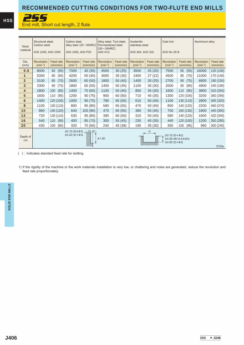
J406
2SS
0.5 8000 60 (50) 7000 40 (35) 4500 30 (25) 3500 25 (20) 7500 65 (55) 16000 120 (100) 1 5300 80 (65) 4200 50 (40) 3000 35 (30) 2400 27 (22) 4500 85 (70) 11000 170 (140) 2 3100 85 (70) 2600 60 (50) 1800 50 (40) 1400 30 (25) 2700 90 (75) 6800 190 (150) 3 2300 90 (75) 1800 65 (55) 1400 55 (45) 1100 35 (30) 2000 95 (80) 4800 240 (190) 4 1800 100 (85) 1400 70 (60) 1100 55 (45) 850 35 (30) 1600 110 (90) 3800 310 (250) 5 1600 110 (95) 1200 90 (75) 900 60 (50) 710 40 (35) 1300 120 (100) 3200 360 (290) 6 1400 120 (100) 1000 90 (75) 780 65 (55) 610 50 (40) 1100 130 (110) 2800 400 (320) 8 1100 130 (110) 800 95 (80) 580 65 (55) 470 50 (40) 850 140 (120) 2200 460 (370)10 860 140 (120) 640 100 (80) 470 65 (55) 380 55 (45) 700 160 (130) 1800 440 (350)12 720 130 (110) 530 95 (80) 390 60 (50) 310 50 (40) 580 140 (120) 1600 420 (340)16 540 110 (95) 400 85 (70) 300 55 (45) 230 40 (35) 440 120 (100) 1200 350 (280)20 430 100 (80) 320 70 (60) 240 45 (38) 190 35 (30) 350 100 (85) 960 300 (240)
2SS J246
D
HSS
SOLI
D E
ND
MIL
LSRECOMMENDED CUTTING CONDITIONS FOR TWO-FLUTE END MILLS
End mill, Short cut length, 2 flute
( ) : Indicates standard feed rate for slotting.
1) If the rigidity of the machine or the work materials installation is very low, or chattering and noise are generated, reduce the revolution and feed rate proportionately.
D:Dia.
Workmaterial
Structural steel, Carbon steel
AISI 1045, AISI 1050
Carbon steel,Alloy steel (20─30HRC)
AISI 1055, AISI P20
Alloy steel, Tool steel,Pre-hardened steel(30─35HRC)AISI H13
Austenitic stainless steel
AISI 304, AISI 316
Cast iron
AISI No 35 B
Aluminium alloy
Dia.(mm)
Revolution(min-1)
Feed rate(mm/min)
Revolution(min-1)
Feed rate(mm/min)
Revolution(min-1)
Feed rate(mm/min)
Revolution(min-1)
Feed rate(mm/min)
Revolution(min-1)
Feed rate(mm/min)
Revolution(min-1)
Feed rate(mm/min)
Depth ofcut
<0.1D (D< &3)<0.2D (D>&3)
<1.5D<0.1D (D<&2)<0.3D (&2 < D< &3)<0.5D (D>&3)
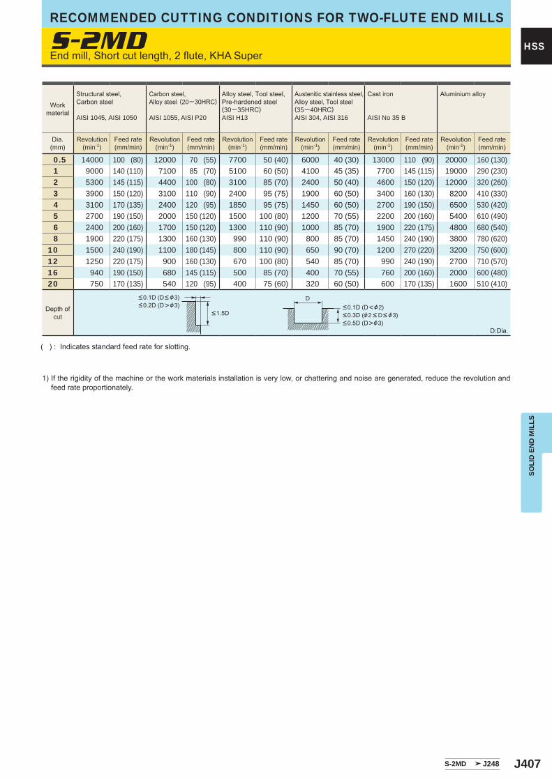
J407
S-2MD
0.5 14000 100 (80) 12000 70 (55) 7700 50 (40) 6000 40 (30) 13000 110 (90) 20000 160 (130) 1 9000 140 (110) 7100 85 (70) 5100 60 (50) 4100 45 (35) 7700 145 (115) 19000 290 (230) 2 5300 145 (115) 4400 100 (80) 3100 85 (70) 2400 50 (40) 4600 150 (120) 12000 320 (260) 3 3900 150 (120) 3100 110 (90) 2400 95 (75) 1900 60 (50) 3400 160 (130) 8200 410 (330) 4 3100 170 (135) 2400 120 (95) 1850 95 (75) 1450 60 (50) 2700 190 (150) 6500 530 (420) 5 2700 190 (150) 2000 150 (120) 1500 100 (80) 1200 70 (55) 2200 200 (160) 5400 610 (490) 6 2400 200 (160) 1700 150 (120) 1300 110 (90) 1000 85 (70) 1900 220 (175) 4800 680 (540) 8 1900 220 (175) 1300 160 (130) 990 110 (90) 800 85 (70) 1450 240 (190) 3800 780 (620)10 1500 240 (190) 1100 180 (145) 800 110 (90) 650 90 (70) 1200 270 (220) 3200 750 (600)12 1250 220 (175) 900 160 (130) 670 100 (80) 540 85 (70) 990 240 (190) 2700 710 (570)16 940 190 (150) 680 145 (115) 500 85 (70) 400 70 (55) 760 200 (160) 2000 600 (480)20 750 170 (135) 540 120 (95) 400 75 (60) 320 60 (50) 600 170 (135) 1600 510 (410)
S-2MD J248
D
HSS
SOLI
D E
ND
MIL
LS
RECOMMENDED CUTTING CONDITIONS FOR TWO-FLUTE END MILLS
End mill, Short cut length, 2 flute, KHA Super
( ) : Indicates standard feed rate for slotting.
1) If the rigidity of the machine or the work materials installation is very low, or chattering and noise are generated, reduce the revolution and feed rate proportionately.
D:Dia.
Workmaterial
Structural steel, Carbon steel
AISI 1045, AISI 1050
Carbon steel,Alloy steel (20─30HRC)
AISI 1055, AISI P20
Alloy steel, Tool steel,Pre-hardened steel(30─35HRC)AISI H13
Austenitic stainless steel,Alloy steel, Tool steel(35─40HRC)AISI 304, AISI 316
Cast iron
AISI No 35 B
Aluminium alloy
Dia.(mm)
Revolution(min-1)
Feed rate(mm/min)
Revolution(min-1)
Feed rate(mm/min)
Revolution(min-1)
Feed rate(mm/min)
Revolution(min-1)
Feed rate(mm/min)
Revolution(min-1)
Feed rate(mm/min)
Revolution(min-1)
Feed rate(mm/min)
Depth ofcut
<0.1D (D< &3)<0.2D (D>&3)
<1.5D<0.1D (D<&2)<0.3D (&2 < D< &3)<0.5D (D>&3)
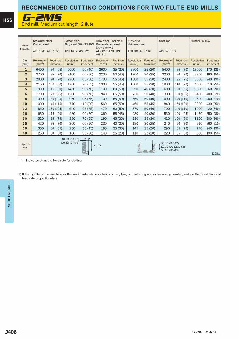
J408
G-2MS
1 6400 80 (65) 5000 50 (40) 3600 35 (30) 2900 25 (20) 5400 85 (70) 13000 170 (135) 2 3700 85 (70) 3100 60 (50) 2200 50 (40) 1700 30 (25) 3200 90 (70) 8200 190 (150) 3 2800 90 (70) 2200 65 (50) 1700 55 (45) 1300 35 (30) 2400 95 (75) 5800 240 (190) 4 2150 100 (80) 1700 70 (55) 1300 55 (45) 1000 35 (30) 1900 110 (90) 4600 310 (250) 5 1900 115 (90) 1450 90 (70) 1100 60 (50) 850 40 (30) 1600 120 (95) 3800 360 (290) 6 1700 120 (95) 1200 90 (70) 940 65 (50) 730 50 (40) 1300 130 (105) 3400 400 (320) 8 1300 130 (105) 960 95 (75) 700 65 (50) 560 50 (40) 1000 140 (110) 2600 460 (370)10 1000 145 (115) 770 110 (90) 560 65 (50) 460 55 (45) 840 160 (130) 2200 430 (350)12 860 130 (105) 640 95 (75) 470 60 (50) 370 50 (40) 700 140 (110) 1900 420 (340)16 650 115 (90) 480 90 (70) 360 55 (45) 280 40 (30) 530 120 (95) 1450 350 (280)20 520 95 (75) 380 70 (55) 290 45 (35) 230 35 (30) 420 100 (80) 1150 300 (240)25 420 85 (70) 300 60 (50) 230 40 (30) 180 30 (25) 340 90 (70) 910 260 (210)30 350 80 (65) 250 55 (45) 190 35 (30) 145 25 (20) 290 85 (70) 770 240 (190)40 250 60 (50) 180 35 (30) 140 25 (20) 110 22 (18) 220 65 (50) 580 190 (150)
G-2MS J250
D
HSS
SOLI
D E
ND
MIL
LSRECOMMENDED CUTTING CONDITIONS FOR TWO-FLUTE END MILLS
End mill, Medium cut length, 2 flute
( ) : Indicates standard feed rate for slotting.
1) If the rigidity of the machine or the work materials installation is very low, or chattering and noise are generated, reduce the revolution and feed rate proportionately.
D:Dia.
Workmaterial
Structural steel, Carbon steel
AISI 1045, AISI 1050
Carbon steel,Alloy steel (20─30HRC)
AISI 1055, AISI P20
Alloy steel, Tool steel,Pre-hardened steel(30─35HRC)AISI P20, AISI H13AISI D2
Austenitic stainless steel
AISI 304, AISI 316
Cast iron
AISI No 35 B
Aluminium alloy
Dia.(mm)
Revolution(min-1)
Feed rate(mm/min)
Revolution(min-1)
Feed rate(mm/min)
Revolution(min-1)
Feed rate(mm/min)
Revolution(min-1)
Feed rate(mm/min)
Revolution(min-1)
Feed rate(mm/min)
Revolution(min-1)
Feed rate(mm/min)
Depth ofcut
<0.1D (D< &3)<0.2D (D>&3)
<1.5D<0.1D (D<&2)<0.3D (&2 < D< &3)<0.5D (D>&3)
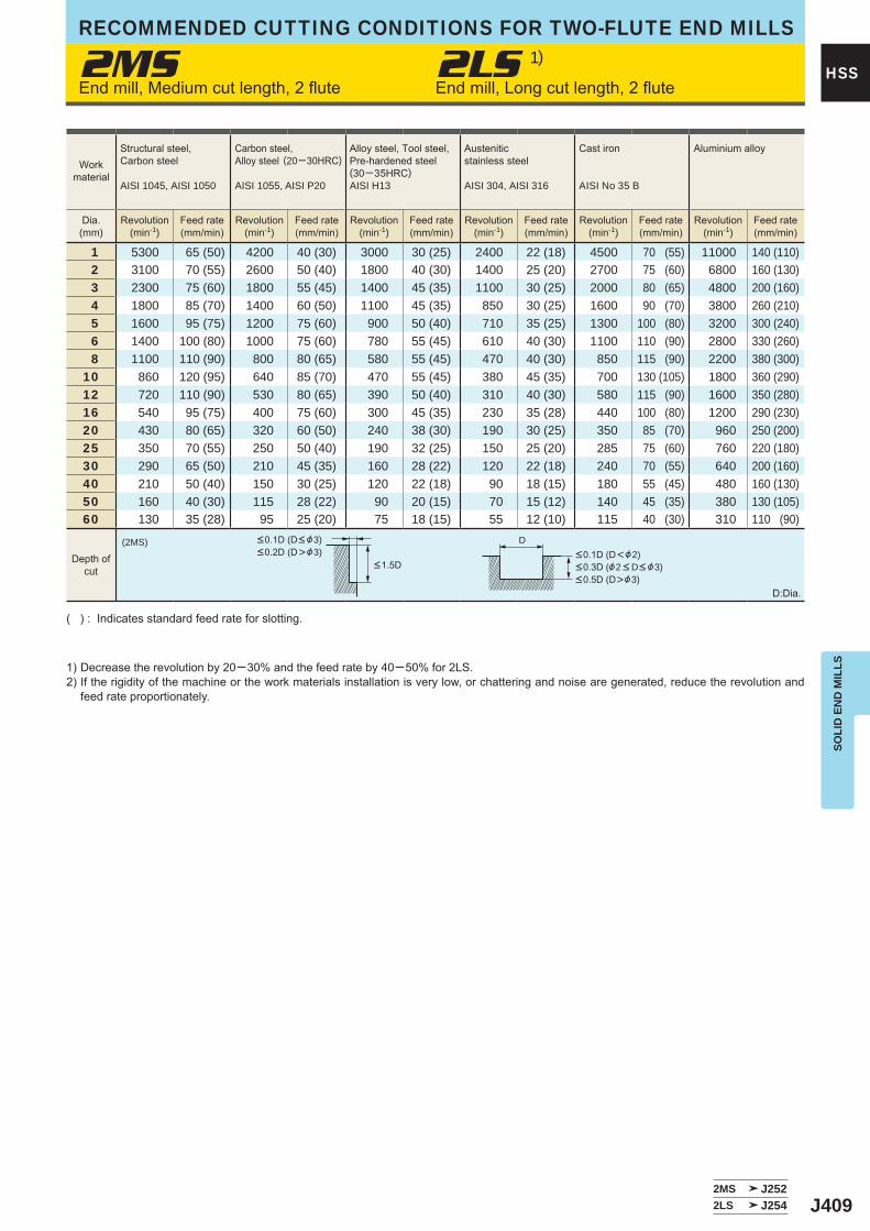
J409
2MS 2LS 1)
1 5300 65 (50) 4200 40 (30) 3000 30 (25) 2400 22 (18) 4500 70 (55) 11000 140 (110) 2 3100 70 (55) 2600 50 (40) 1800 40 (30) 1400 25 (20) 2700 75 (60) 6800 160 (130) 3 2300 75 (60) 1800 55 (45) 1400 45 (35) 1100 30 (25) 2000 80 (65) 4800 200 (160) 4 1800 85 (70) 1400 60 (50) 1100 45 (35) 850 30 (25) 1600 90 (70) 3800 260 (210) 5 1600 95 (75) 1200 75 (60) 900 50 (40) 710 35 (25) 1300 100 (80) 3200 300 (240) 6 1400 100 (80) 1000 75 (60) 780 55 (45) 610 40 (30) 1100 110 (90) 2800 330 (260) 8 1100 110 (90) 800 80 (65) 580 55 (45) 470 40 (30) 850 115 (90) 2200 380 (300)10 860 120 (95) 640 85 (70) 470 55 (45) 380 45 (35) 700 130 (105) 1800 360 (290)12 720 110 (90) 530 80 (65) 390 50 (40) 310 40 (30) 580 115 (90) 1600 350 (280)16 540 95 (75) 400 75 (60) 300 45 (35) 230 35 (28) 440 100 (80) 1200 290 (230)20 430 80 (65) 320 60 (50) 240 38 (30) 190 30 (25) 350 85 (70) 960 250 (200)25 350 70 (55) 250 50 (40) 190 32 (25) 150 25 (20) 285 75 (60) 760 220 (180)30 290 65 (50) 210 45 (35) 160 28 (22) 120 22 (18) 240 70 (55) 640 200 (160)40 210 50 (40) 150 30 (25) 120 22 (18) 90 18 (15) 180 55 (45) 480 160 (130)50 160 40 (30) 115 28 (22) 90 20 (15) 70 15 (12) 140 45 (35) 380 130 (105)60 130 35 (28) 95 25 (20) 75 18 (15) 55 12 (10) 115 40 (30) 310 110 (90)
(2MS)
2MS J2522LS J254
D
HSS
SOLI
D E
ND
MIL
LS
RECOMMENDED CUTTING CONDITIONS FOR TWO-FLUTE END MILLS
End mill, Medium cut length, 2 flute End mill, Long cut length, 2 flute
( ) : Indicates standard feed rate for slotting.
1) Decrease the revolution by 20─30% and the feed rate by 40─50% for 2LS.2) If the rigidity of the machine or the work materials installation is very low, or chattering and noise are generated, reduce the revolution and
feed rate proportionately.
D:Dia.
Workmaterial
Structural steel, Carbon steel
AISI 1045, AISI 1050
Carbon steel,Alloy steel (20─30HRC)
AISI 1055, AISI P20
Alloy steel, Tool steel,Pre-hardened steel(30─35HRC)AISI H13
Austenitic stainless steel
AISI 304, AISI 316
Cast iron
AISI No 35 B
Aluminium alloy
Dia.(mm)
Revolution(min-1)
Feed rate(mm/min)
Revolution(min-1)
Feed rate(mm/min)
Revolution(min-1)
Feed rate(mm/min)
Revolution(min-1)
Feed rate(mm/min)
Revolution(min-1)
Feed rate(mm/min)
Revolution(min-1)
Feed rate(mm/min)
Depth ofcut
<0.1D (D< &3)<0.2D (D>&3)
<1.5D<0.1D (D<&2)<0.3D (&2 < D< &3)<0.5D (D>&3)
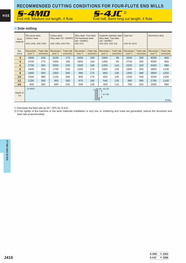
J410
S-4MD S-4JC 1)
3 3900 240 3100 175 2400 150 1900 95 3400 260 8200 660 4 3100 270 2400 190 1850 150 1450 95 2700 300 6500 850 5 2700 300 2000 240 1500 160 1200 110 2200 320 5400 980 6 2400 320 1700 240 1300 175 1000 135 1900 350 4800 1100 8 1900 350 1300 260 990 175 800 135 1450 380 3800 125010 1500 380 1100 290 800 175 650 145 1200 430 3200 120012 1250 350 900 260 670 160 540 135 990 380 2700 110016 940 300 680 230 500 135 400 110 760 320 2000 960
(S-4MD)
S-4MD J262S-4JC J266
y
HSS
SOLI
D E
ND
MIL
LSRECOMMENDED CUTTING CONDITIONS FOR FOUR-FLUTE END MILLS
Workmaterial
Structural steel, Carbon steel
AISI 1045, AISI 1050
Carbon steel,Alloy steel (20─30HRC)
AISI 1055, AISI P20
Alloy steel, Tool steel,Pre-hardened steel(30─35HRC)AISI H13
Austenitic stainless steel,Alloy steel, Tool steel(35─40HRC)AISI 304, AISI 316
Cast iron
AISI No 35 B
Aluminium alloy
Dia.(mm)
Revolution(min-1)
Feed rate(mm/min)
Revolution(min-1)
Feed rate(mm/min)
Revolution(min-1)
Feed rate(mm/min)
Revolution(min-1)
Feed rate(mm/min)
Revolution(min-1)
Feed rate(mm/min)
Revolution(min-1)
Feed rate(mm/min)
<0.2D
<1.5D
Side milling
Depth ofcut
D:Dia.
End mill, Medium cut length, 4 flute End mill, Semi long cut length, 4 flute
1) Decrease the feed rate by 20─30% for S-4JC.2) If the rigidity of the machine or the work materials installation is very low, or chattering and noise are generated, reduce the revolution and
feed rate proportionately.
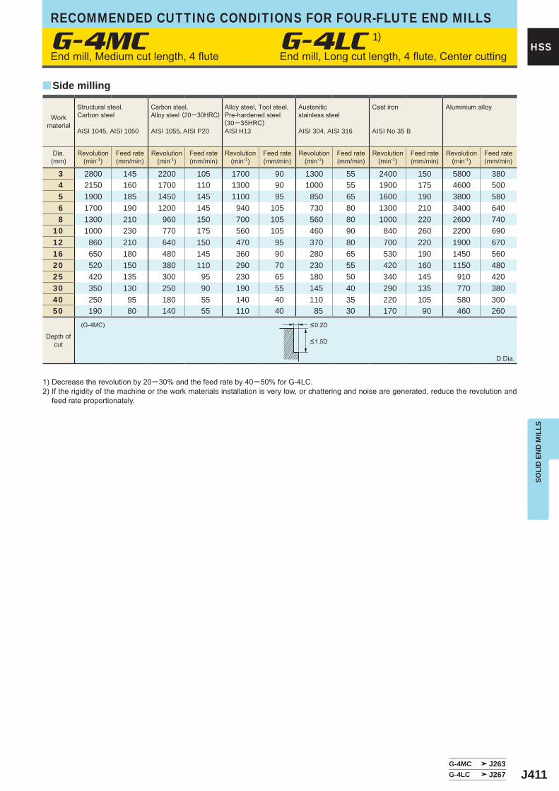
J411
3 2800 145 2200 105 1700 90 1300 55 2400 150 5800 380 4 2150 160 1700 110 1300 90 1000 55 1900 175 4600 500 5 1900 185 1450 145 1100 95 850 65 1600 190 3800 580 6 1700 190 1200 145 940 105 730 80 1300 210 3400 640 8 1300 210 960 150 700 105 560 80 1000 220 2600 74010 1000 230 770 175 560 105 460 90 840 260 2200 69012 860 210 640 150 470 95 370 80 700 220 1900 67016 650 180 480 145 360 90 280 65 530 190 1450 56020 520 150 380 110 290 70 230 55 420 160 1150 48025 420 135 300 95 230 65 180 50 340 145 910 42030 350 130 250 90 190 55 145 40 290 135 770 38040 250 95 180 55 140 40 110 35 220 105 580 30050 190 80 140 55 110 40 85 30 170 90 460 260
G-4MC
G-4MC J263G-4LC J267
(G-4MC)
y
HSS
SOLI
D E
ND
MIL
LS
RECOMMENDED CUTTING CONDITIONS FOR FOUR-FLUTE END MILLS
<0.2D
<1.5D
Workmaterial
Structural steel, Carbon steel
AISI 1045, AISI 1050
Carbon steel,Alloy steel (20─30HRC)
AISI 1055, AISI P20
Alloy steel, Tool steel,Pre-hardened steel(30─35HRC)AISI H13
Austenitic stainless steel
AISI 304, AISI 316
Cast iron
AISI No 35 B
Aluminium alloy
Dia.(mm)
Revolution(min-1)
Feed rate(mm/min)
Revolution(min-1)
Feed rate(mm/min)
Revolution(min-1)
Feed rate(mm/min)
Revolution(min-1)
Feed rate(mm/min)
Revolution(min-1)
Feed rate(mm/min)
Revolution(min-1)
Feed rate(mm/min)
Side milling
Depth ofcut
D:Dia.
End mill, Medium cut length, 4 flute End mill, Long cut length, 4 flute, Center cutting
1) Decrease the revolution by 20─30% and the feed rate by 40─50% for G-4LC.2) If the rigidity of the machine or the work materials installation is very low, or chattering and noise are generated, reduce the revolution and
feed rate proportionately.
G-4LC 1)
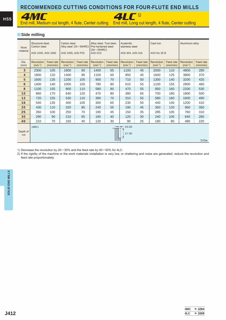
J412
4MC 4LC 1)
3 2300 105 1800 80 1400 65 1100 45 2000 110 4800 280 4 1800 120 1400 85 1100 65 850 45 1600 125 3800 370 5 1600 135 1200 105 900 70 710 50 1300 140 3200 420 6 1400 140 1000 105 780 80 610 55 1100 155 2800 460 8 1100 155 800 110 580 80 470 55 850 160 2200 53010 860 170 640 120 470 80 380 65 700 180 1800 50012 720 155 530 110 390 70 310 55 580 160 1600 49016 540 135 400 105 300 65 230 50 440 140 1200 41020 430 110 320 85 240 55 190 45 350 120 960 35025 350 100 250 70 190 45 150 35 285 105 760 31030 290 90 210 65 160 40 120 30 240 100 640 28040 210 70 150 40 120 30 90 25 180 80 480 220
(4MC)
4MC J2644LC J269
y
HSS
SOLI
D E
ND
MIL
LSRECOMMENDED CUTTING CONDITIONS FOR FOUR-FLUTE END MILLS
<0.2D
<1.5D
Workmaterial
Structural steel, Carbon steel
AISI 1045, AISI 1050
Carbon steel,Alloy steel (20─30HRC)
AISI 1055, AISI P20
Alloy steel, Tool steel,Pre-hardened steel(30─35HRC)AISI H13
Austenitic stainless steel
AISI 304, AISI 316
Cast iron
AISI No 35 B
Aluminium alloy
Dia.(mm)
Revolution(min-1)
Feed rate(mm/min)
Revolution(min-1)
Feed rate(mm/min)
Revolution(min-1)
Feed rate(mm/min)
Revolution(min-1)
Feed rate(mm/min)
Revolution(min-1)
Feed rate(mm/min)
Revolution(min-1)
Feed rate(mm/min)
Side milling
Depth ofcut
D:Dia.
End mill, Medium cut length, 4 flute, Center cutting End mill, Long cut length, 4 flute, Center cutting
1) Decrease the revolution by 20─30% and the feed rate by 40─50% for 4LC.2) If the rigidity of the machine or the work materials installation is very low, or chattering and noise are generated, reduce the revolution and
feed rate proportionately.
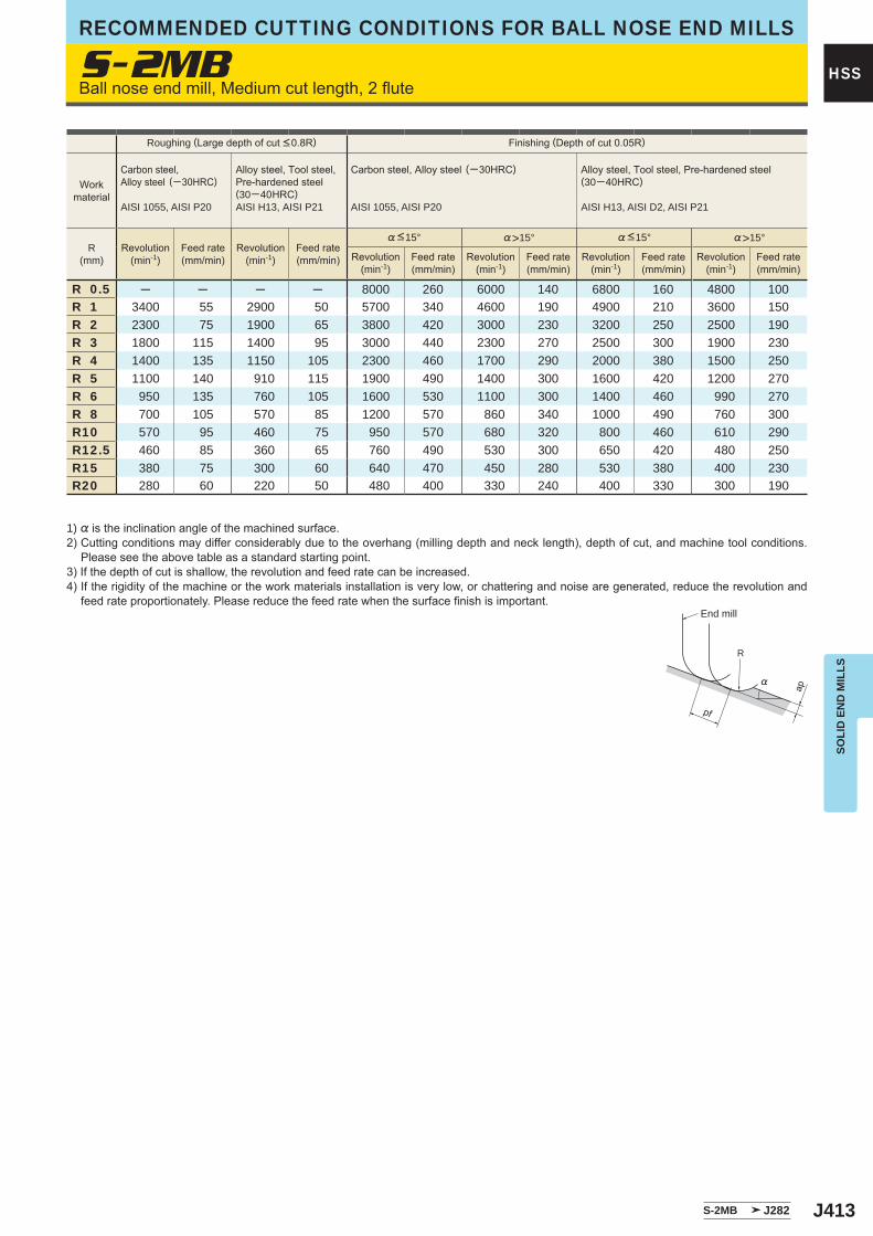
J413
S-2MB
%>15° %>15°
R 0.5 ─ ─ ─ ─ 8000 260 6000 140 6800 160 4800 100R 1 3400 55 2900 50 5700 340 4600 190 4900 210 3600 150R 2 2300 75 1900 65 3800 420 3000 230 3200 250 2500 190R 3 1800 115 1400 95 3000 440 2300 270 2500 300 1900 230R 4 1400 135 1150 105 2300 460 1700 290 2000 380 1500 250R 5 1100 140 910 115 1900 490 1400 300 1600 420 1200 270R 6 950 135 760 105 1600 530 1100 300 1400 460 990 270R 8 700 105 570 85 1200 570 860 340 1000 490 760 300R10 570 95 460 75 950 570 680 320 800 460 610 290R12.5 460 85 360 65 760 490 530 300 650 420 480 250R15 380 75 300 60 640 470 450 280 530 380 400 230R20 280 60 220 50 480 400 330 240 400 330 300 190
S-2MB J282
R
%
ap
pf
HSS
SOLI
D E
ND
MIL
LS
RECOMMENDED CUTTING CONDITIONS FOR BALL NOSE END MILLS
Roughing (Large depth of cut <0.8R) Finishing (Depth of cut 0.05R)
Workmaterial
Carbon steel,Alloy steel (─30HRC)
AISI 1055, AISI P20
Alloy steel, Tool steel,Pre-hardened steel(30─40HRC)AISI H13, AISI P21
Carbon steel, Alloy steel (─30HRC)
AISI 1055, AISI P20
Alloy steel, Tool steel, Pre-hardened steel(30─40HRC)
AISI H13, AISI D2, AISI P21
R(mm)
Revolution(min-1)
Feed rate(mm/min)
Revolution(min-1)
Feed rate(mm/min)
%<15° %<15°
Revolution(min-1)
Feed rate(mm/min)
Revolution(min-1)
Feed rate(mm/min)
Revolution(min-1)
Feed rate(mm/min)
Revolution(min-1)
Feed rate(mm/min)
Ball nose end mill, Medium cut length, 2 flute
1) % is the inclination angle of the machined surface. 2) Cutting conditions may differ considerably due to the overhang (milling depth and neck length), depth of cut, and machine tool conditions.
Please see the above table as a standard starting point.3) If the depth of cut is shallow, the revolution and feed rate can be increased.4) If the rigidity of the machine or the work materials installation is very low, or chattering and noise are generated, reduce the revolution and
feed rate proportionately. Please reduce the feed rate when the surface finish is important.End mill
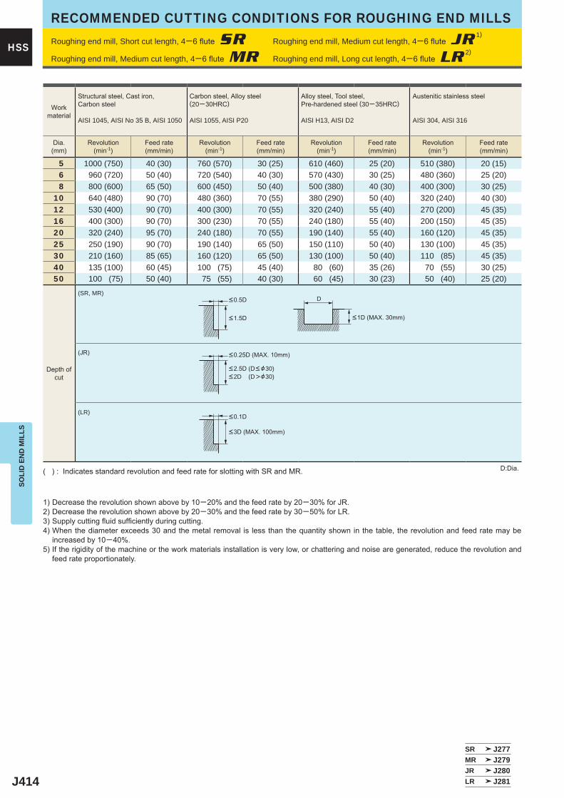
J414
5 1000 (750) 40 (30) 760 (570) 30 (25) 610 (460) 25 (20) 510 (380) 20 (15) 6 960 (720) 50 (40) 720 (540) 40 (30) 570 (430) 30 (25) 480 (360) 25 (20) 8 800 (600) 65 (50) 600 (450) 50 (40) 500 (380) 40 (30) 400 (300) 30 (25)10 640 (480) 90 (70) 480 (360) 70 (55) 380 (290) 50 (40) 320 (240) 40 (30)12 530 (400) 90 (70) 400 (300) 70 (55) 320 (240) 55 (40) 270 (200) 45 (35)16 400 (300) 90 (70) 300 (230) 70 (55) 240 (180) 55 (40) 200 (150) 45 (35)20 320 (240) 95 (70) 240 (180) 70 (55) 190 (140) 55 (40) 160 (120) 45 (35)25 250 (190) 90 (70) 190 (140) 65 (50) 150 (110) 50 (40) 130 (100) 45 (35)30 210 (160) 85 (65) 160 (120) 65 (50) 130 (100) 50 (40) 110 (85) 45 (35)40 135 (100) 60 (45) 100 (75) 45 (40) 80 (60) 35 (26) 70 (55) 30 (25)50 100 (75) 50 (40) 75 (55) 40 (30) 60 (45) 30 (23) 50 (40) 25 (20)
(SR, MR)
(JR)
(LR)
SR J277MR J279JR J280LR J281
D
HSS
SOLI
D E
ND
MIL
LSRECOMMENDED CUTTING CONDITIONS FOR ROUGHING END MILLS
Workmaterial
Structural steel, Cast iron, Carbon steel
AISI 1045, AISI No 35 B, AISI 1050
Carbon steel, Alloy steel (20─30HRC)
AISI 1055, AISI P20
Alloy steel, Tool steel,Pre-hardened steel (30─35HRC)
AISI H13, AISI D2
Austenitic stainless steel
AISI 304, AISI 316
Dia.(mm)
Revolution(min-1)
Feed rate(mm/min)
Revolution(min-1)
Feed rate(mm/min)
Revolution(min-1)
Feed rate(mm/min)
Revolution(min-1)
Feed rate(mm/min)
Depth ofcut
Roughing end mill, Short cut length, 4─6 flute SR Roughing end mill, Medium cut length, 4─6 flute JR1)
Roughing end mill, Medium cut length, 4─6 flute MR Roughing end mill, Long cut length, 4─6 flute LR2)
D:Dia.( ) : Indicates standard revolution and feed rate for slotting with SR and MR.
1) Decrease the revolution shown above by 10─20% and the feed rate by 20─30% for JR.2) Decrease the revolution shown above by 20─30% and the feed rate by 30─50% for LR.3) Supply cutting fluid sufficiently during cutting.4) When the diameter exceeds 30 and the metal removal is less than the quantity shown in the table, the revolution and feed rate may be
increased by 10─40%.5) If the rigidity of the machine or the work materials installation is very low, or chattering and noise are generated, reduce the revolution and
feed rate proportionately.
<0.5D
<1.5D
<0.25D (MAX. 10mm)
<2.5D (D< &30)<2D (D>&30)
<0.1D
<3D (MAX. 100mm)
<1D (MAX. 30mm)
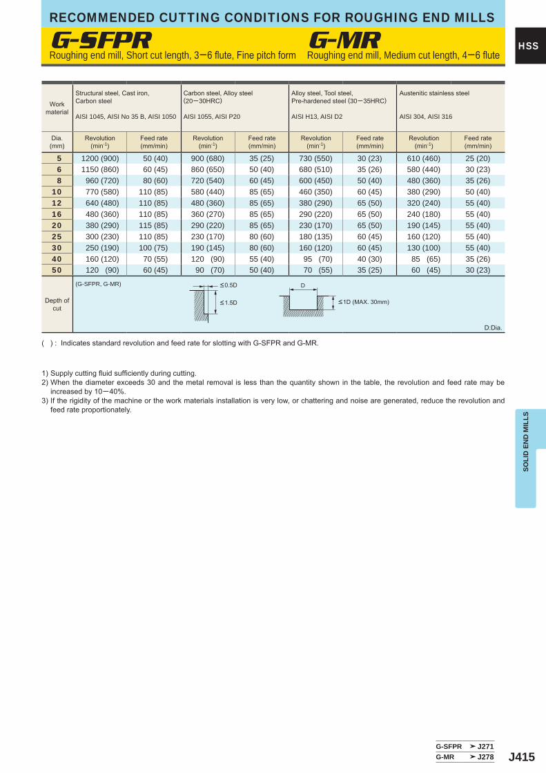
J415
5 1200 (900) 50 (40) 900 (680) 35 (25) 730 (550) 30 (23) 610 (460) 25 (20) 6 1150 (860) 60 (45) 860 (650) 50 (40) 680 (510) 35 (26) 580 (440) 30 (23) 8 960 (720) 80 (60) 720 (540) 60 (45) 600 (450) 50 (40) 480 (360) 35 (26)10 770 (580) 110 (85) 580 (440) 85 (65) 460 (350) 60 (45) 380 (290) 50 (40)12 640 (480) 110 (85) 480 (360) 85 (65) 380 (290) 65 (50) 320 (240) 55 (40)16 480 (360) 110 (85) 360 (270) 85 (65) 290 (220) 65 (50) 240 (180) 55 (40)20 380 (290) 115 (85) 290 (220) 85 (65) 230 (170) 65 (50) 190 (145) 55 (40)25 300 (230) 110 (85) 230 (170) 80 (60) 180 (135) 60 (45) 160 (120) 55 (40)30 250 (190) 100 (75) 190 (145) 80 (60) 160 (120) 60 (45) 130 (100) 55 (40)40 160 (120) 70 (55) 120 (90) 55 (40) 95 (70) 40 (30) 85 (65) 35 (26)50 120 (90) 60 (45) 90 (70) 50 (40) 70 (55) 35 (25) 60 (45) 30 (23)
G-SFPR
(G-SFPR, G-MR)
G-SFPR J271G-MR J278
D
HSS
SOLI
D E
ND
MIL
LS
RECOMMENDED CUTTING CONDITIONS FOR ROUGHING END MILLS
Workmaterial
Structural steel, Cast iron, Carbon steel
AISI 1045, AISI No 35 B, AISI 1050
Carbon steel, Alloy steel (20─30HRC)
AISI 1055, AISI P20
Alloy steel, Tool steel,Pre-hardened steel (30─35HRC)
AISI H13, AISI D2
Austenitic stainless steel
AISI 304, AISI 316
Dia.(mm)
Revolution(min-1)
Feed rate(mm/min)
Revolution(min-1)
Feed rate(mm/min)
Revolution(min-1)
Feed rate(mm/min)
Revolution(min-1)
Feed rate(mm/min)
Depth ofcut
Roughing end mill, Short cut length, 3─6 flute, Fine pitch form Roughing end mill, Medium cut length, 4─6 flute
D:Dia.
( ) : Indicates standard revolution and feed rate for slotting with G-SFPR and G-MR.
1) Supply cutting fluid sufficiently during cutting.2) When the diameter exceeds 30 and the metal removal is less than the quantity shown in the table, the revolution and feed rate may be
increased by 10─40%.3) If the rigidity of the machine or the work materials installation is very low, or chattering and noise are generated, reduce the revolution and
feed rate proportionately.
<0.5D
<1.5D <1D (MAX. 30mm)
G-MR
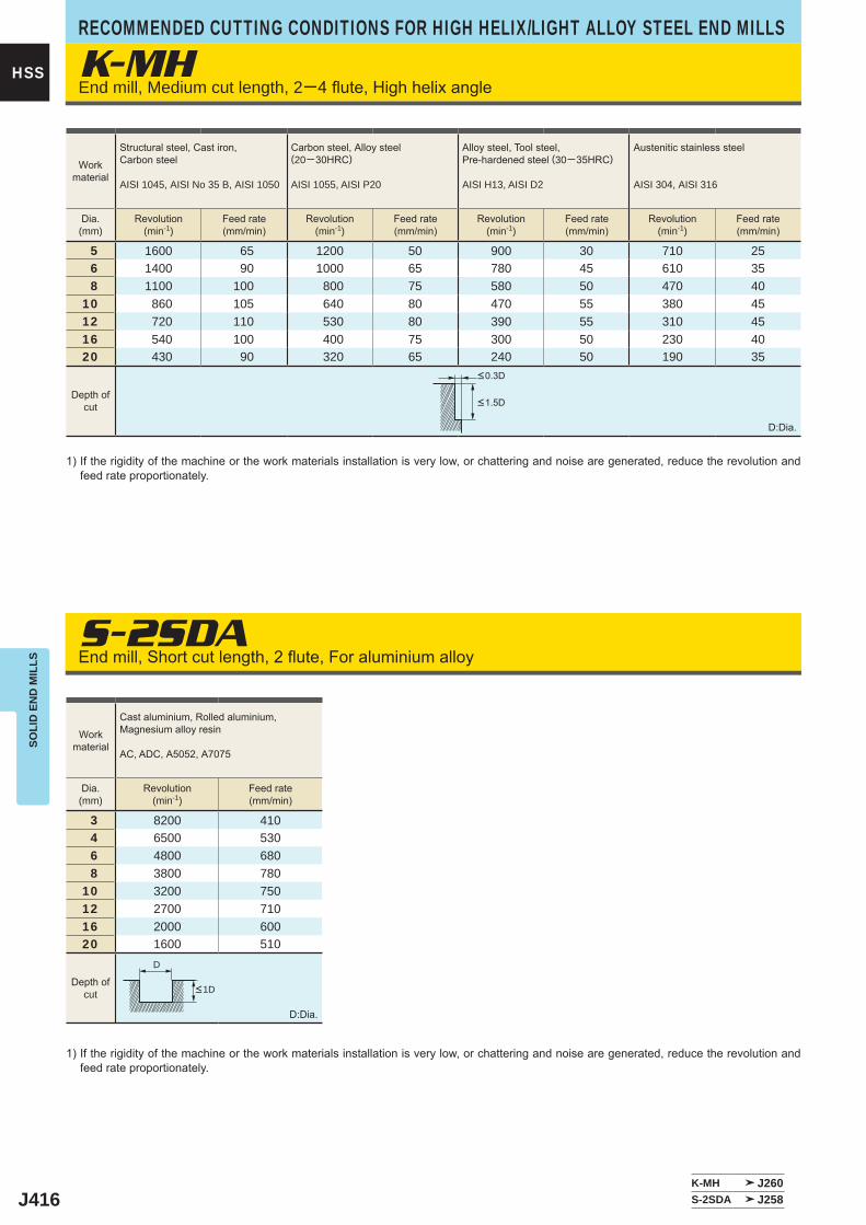
J416
K-MH
S-2SDA
5 1600 65 1200 50 900 30 710 25 6 1400 90 1000 65 780 45 610 35 8 1100 100 800 75 580 50 470 4010 860 105 640 80 470 55 380 4512 720 110 530 80 390 55 310 4516 540 100 400 75 300 50 230 4020 430 90 320 65 240 50 190 35
3 8200 410 4 6500 530 6 4800 680 8 3800 78010 3200 75012 2700 71016 2000 60020 1600 510
K-MH J260S-2SDA J258
D
HSS
SOLI
D E
ND
MIL
LSRECOMMENDED CUTTING CONDITIONS FOR HIGH HELIX/LIGHT ALLOY STEEL END MILLS
Workmaterial
Cast aluminium, Rolled aluminium, Magnesium alloy resin
AC, ADC, A5052, A7075
Dia.(mm)
Revolution(min-1)
Feed rate(mm/min)
D:Dia.
1) If the rigidity of the machine or the work materials installation is very low, or chattering and noise are generated, reduce the revolution and feed rate proportionately.
Depth ofcut
End mill, Medium cut length, 2─4 flute, High helix angle
End mill, Short cut length, 2 flute, For aluminium alloy
D:Dia.
1) If the rigidity of the machine or the work materials installation is very low, or chattering and noise are generated, reduce the revolution and feed rate proportionately.
Depth ofcut
<0.3D
<1.5D
Workmaterial
Structural steel, Cast iron, Carbon steel
AISI 1045, AISI No 35 B, AISI 1050
Carbon steel, Alloy steel (20─30HRC)
AISI 1055, AISI P20
Alloy steel, Tool steel,Pre-hardened steel (30─35HRC)
AISI H13, AISI D2
Austenitic stainless steel
AISI 304, AISI 316
Dia.(mm)
Revolution(min-1)
Feed rate(mm/min)
Revolution(min-1)
Feed rate(mm/min)
Revolution(min-1)
Feed rate(mm/min)
Revolution(min-1)
Feed rate(mm/min)
<1D

J417
Memo
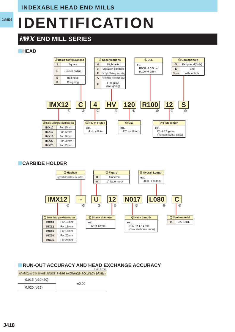
J418
IMX12 - U
S
C
HV R100
N017 L080
120 12
12
HVFA
F
UA
SE
C
IMX10IMX12IMX16IMX20IMX25
IMX10IMX12IMX16IMX20IMX25
y
y
y
z
v
x
b
c
n
v
,
m
m
nb
S
C
BR
IMX12z
Cx
4c
0.015 (ø10~20)±0.02
0.020 (ø25)
INDEXABLE HEAD END MILLS
CARBIDE
HEAD
CARBIDE HOLDER
z Series Description・Fastening sizeFor 10mmFor 12mmFor 16mmFor 20mmFor 25mm
z Series Description・Fastening sizeFor 10mmFor 12mmFor 16mmFor 20mmFor 25mm
v Shank diameter
ex. 12 | 12mm
n Overall Length
ex. L080 | 80mm
m Flute length
ex. 12 | 12.*mm (Truncate decimal places)
n Dia.
ex. R050 | 0.5mm R100 | 1mm
b Neck Length
ex. N17 | 17.*mm (Truncate decimal places)
c FigureUndercut
1° Taper neck
x HyphenHyphen Indicates these are holders.
, Coolant hole Peripheral(Side)
EndNone without hole
m Tool materialCARBIDE
IDENTIFICATION
c No. of Flutes
ex. 4 | 4 flute
b Dia.
ex. 120 | 12mm
v Specifications High helix
Vibration controleFor High Efficiency MachiningFor Machining of Aluminium Alloys
Fine pitch(Roughing)
x Basic configurations Square
Corner radius
Ball noseRoughing
Run-out accuracy for the peripheral cutting edge Head exchange accuracy (Axial)
iMX END MILL SERIES
Unit : mmRUN-OUT ACCURACY AND HEAD EXCHANGE ACCURACY
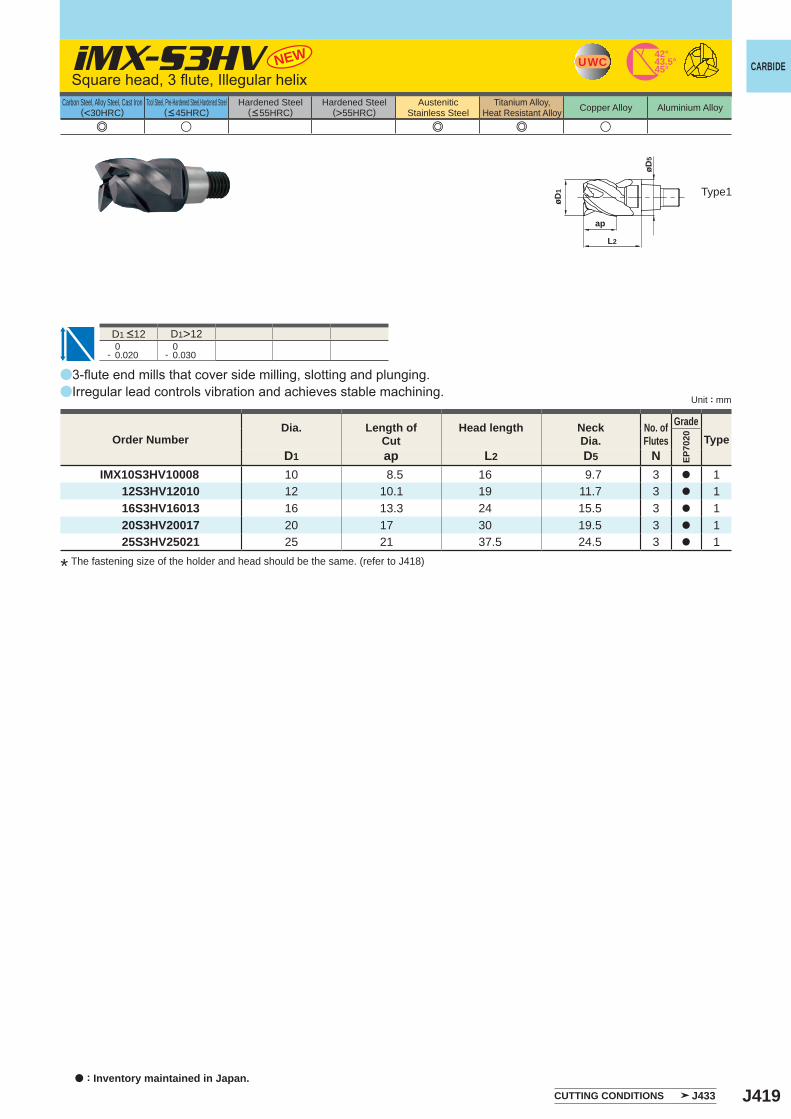
J419
UWC45°43.5°42°
a
a
EP70
20
D1 ap L2 D5 NIMX10S3HV10008 10 8.5 16 9.7 3 a 1 12S3HV12010 12 10.1 19 11.7 3 a 1 16S3HV16013 16 13.3 24 15.5 3 a 1 20S3HV20017 20 17 30 19.5 3 a 1 25S3HV25021 25 21 37.5 24.5 3 a 1
iMX-S3HV NEW
e u e e u
D1>12 0- 0.020
0- 0.030
øD1
ap
L2
øD5
CARBIDE
Unit : mm
Carbon Steel, Alloy Steel, Cast Iron(<30HRC)
Tool Steel, Pre-Hardened Steel,Hardened Steel(<45HRC)
Hardened Steel(<55HRC)
Hardened Steel(>55HRC)
AusteniticStainless Steel
Titanium Alloy,Heat Resistant Alloy Copper Alloy Aluminium Alloy
Type1
Square head, 3 flute, Illegular helix
3-flute end mills that cover side milling, slotting and plunging.Irregular lead controls vibration and achieves stable machining.
D1 <12
* The fastening size of the holder and head should be the same. (refer to J418)
Order NumberDia. Length of
CutHead length Neck
Dia.No. ofFlutes
GradeType
CUTTING CONDITIONS J433a : Inventory maintained in Japan.
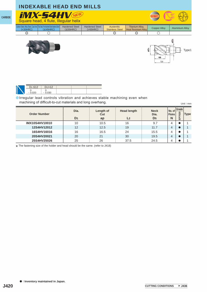
J420
a
e u e e u
EP70
20
D1 ap L2 D5 NIMX10S4HV10010 10 10.5 16 9.7 4 a 1 12S4HV12012 12 12.5 19 11.7 4 a 1 16S4HV16016 16 16.5 24 15.5 4 a 1 20S4HV20021 20 21 30 19.5 4 a 1 25S4HV25026 25 26 37.5 24.5 4 a 1
iMX-S4HV NEW
D1>12 0- 0.020
0- 0.030
ap
øD5
L2
øD1
42°45°UWC
INDEXABLE HEAD END MILLS
a : Inventory maintained in Japan.
CARBIDE
Unit : mm
Carbon Steel, Alloy Steel, Cast Iron(<30HRC)
Tool Steel, Pre-Hardened Steel,Hardened Steel(<45HRC)
Hardened Steel(<55HRC)
Hardened Steel(>55HRC)
AusteniticStainless Steel
Titanium Alloy,Heat Resistant Alloy Copper Alloy Aluminium Alloy
Type1
Square head, 4 flute, Illegular helix
D1 <12
Order NumberDia. Length of
CutHead length Neck
Dia.No. ofFlutes
GradeType
CUTTING CONDITIONS J436
Irregular lead controls vibration and achieves stable machining even when machining of difficult-to-cut materials and long overhang.
* The fastening size of the holder and head should be the same. (refer to J418)
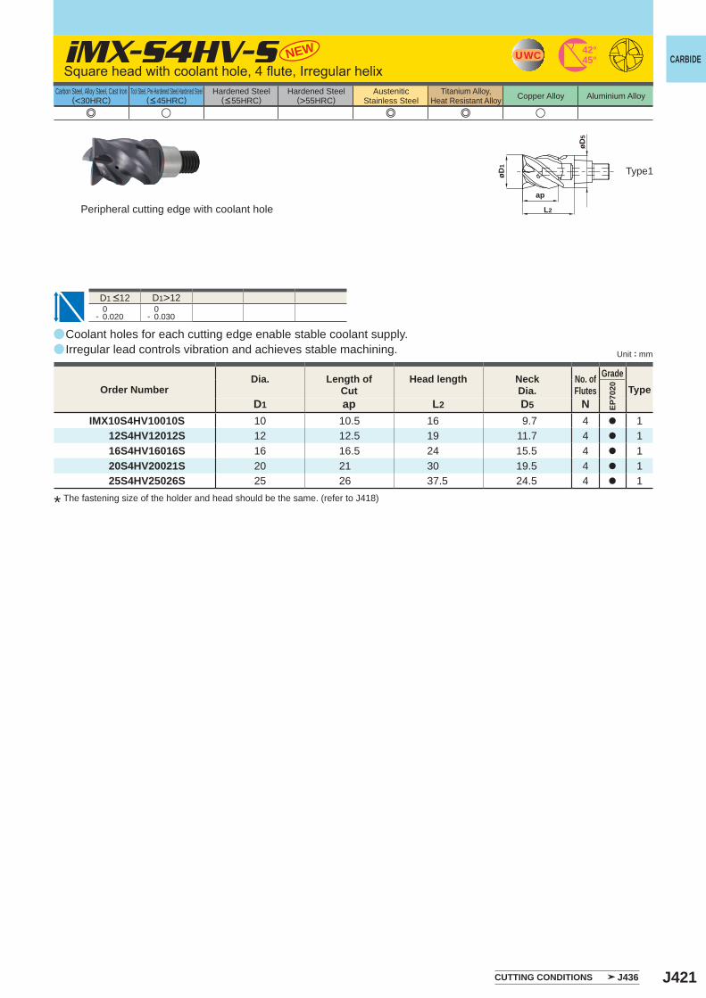
J421
a
e u e e u
EP70
20
D1 ap L2 D5 NIMX10S4HV10010S 10 10.5 16 9.7 4 a 1 12S4HV12012S 12 12.5 19 11.7 4 a 1 16S4HV16016S 16 16.5 24 15.5 4 a 1 20S4HV20021S 20 21 30 19.5 4 a 1 25S4HV25026S 25 26 37.5 24.5 4 a 1
iMX-S4HV-S NEW
D1>12 0- 0.020
0- 0.030
a
a
42°45°UWC
5øD
1øD
ap
2L
CARBIDE
Unit : mm
Carbon Steel, Alloy Steel, Cast Iron(<30HRC)
Tool Steel, Pre-Hardened Steel,Hardened Steel(<45HRC)
Hardened Steel(<55HRC)
Hardened Steel(>55HRC)
AusteniticStainless Steel
Titanium Alloy,Heat Resistant Alloy Copper Alloy Aluminium Alloy
Type1
D1 <12
Coolant holes for each cutting edge enable stable coolant supply.Irregular lead controls vibration and achieves stable machining.
Order NumberDia. Length of
CutHead length Neck
Dia.No. ofFlutes
GradeType
CUTTING CONDITIONS J436
Square head with coolant hole, 4 flute, Irregular helix
* The fastening size of the holder and head should be the same. (refer to J418)
Peripheral cutting edge with coolant hole
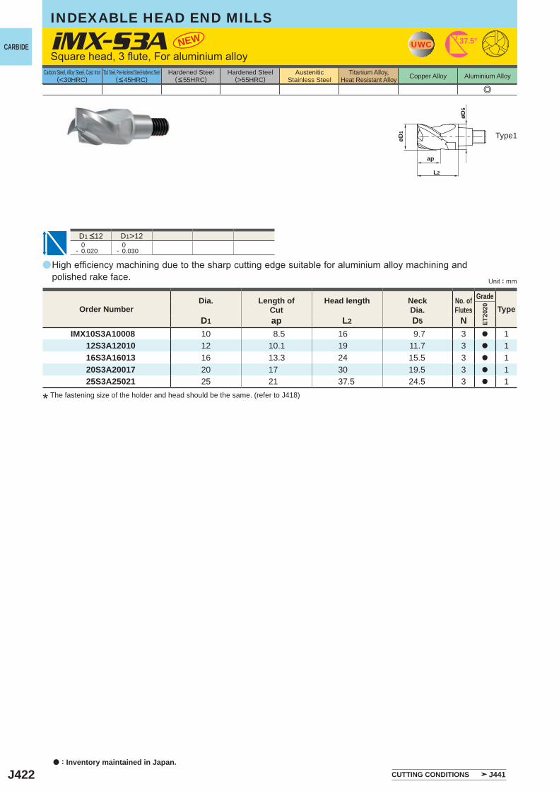
J422
a
D1>12 0- 0.020
0- 0.030
e
ET20
20
D1 ap L2 D5 NIMX10S3A10008 10 8.5 16 9.7 3 a 1 12S3A12010 12 10.1 19 11.7 3 a 1 16S3A16013 16 13.3 24 15.5 3 a 1 20S3A20017 20 17 30 19.5 3 a 1 25S3A25021 25 21 37.5 24.5 3 a 1
iMX-S3A NEW
ap
øD5
L2
øD1
UWC 37.5°
INDEXABLE HEAD END MILLS
a : Inventory maintained in Japan.
CARBIDE
Unit : mm
Carbon Steel, Alloy Steel, Cast Iron(<30HRC)
Tool Steel, Pre-Hardened Steel,Hardened Steel(<45HRC)
Hardened Steel(<55HRC)
Hardened Steel(>55HRC)
AusteniticStainless Steel
Titanium Alloy,Heat Resistant Alloy Copper Alloy Aluminium Alloy
Type1
D1 <12
High efficiency machining due to the sharp cutting edge suitable for aluminium alloy machining and polished rake face.
Order NumberDia. Length of
CutHead length Neck
Dia.No. ofFlutes
GradeType
CUTTING CONDITIONS J441
Square head, 3 flute, For aluminium alloy
* The fastening size of the holder and head should be the same. (refer to J418)
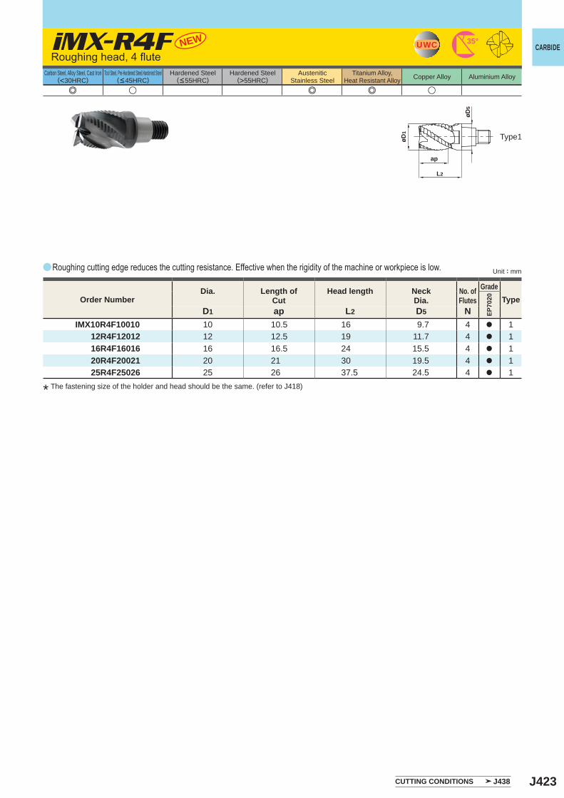
J423
a
e u e e u
EP70
20
D1 ap L2 D5 NIMX10R4F10010 10 10.5 16 9.7 4 a 1 12R4F12012 12 12.5 19 11.7 4 a 1 16R4F16016 16 16.5 24 15.5 4 a 1 20R4F20021 20 21 30 19.5 4 a 1 25R4F25026 25 26 37.5 24.5 4 a 1
iMX-R4F NEW
ap
øD5
L2
øD1
UWC 35°CARBIDE
Unit : mm
Carbon Steel, Alloy Steel, Cast Iron(<30HRC)
Tool Steel, Pre-Hardened Steel,Hardened Steel(<45HRC)
Hardened Steel(<55HRC)
Hardened Steel(>55HRC)
AusteniticStainless Steel
Titanium Alloy,Heat Resistant Alloy Copper Alloy Aluminium Alloy
Type1
Roughing head, 4 flute
Roughing cutting edge reduces the cutting resistance. Effective when the rigidity of the machine or workpiece is low.
Order NumberDia. Length of
CutHead length Neck
Dia.No. ofFlutes
GradeType
CUTTING CONDITIONS J438
* The fastening size of the holder and head should be the same. (refer to J418)
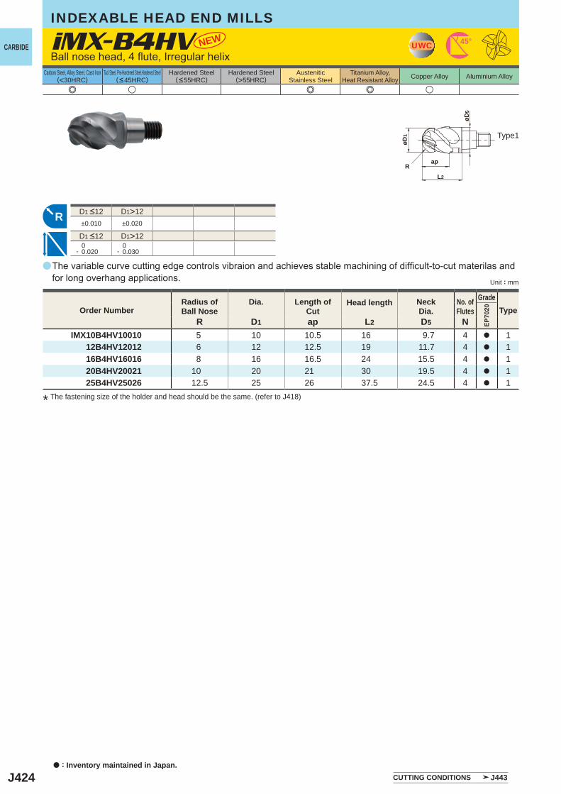
J424
a
e u e e u
iMX-B4HV
EP70
20
R D1 ap L2 D5 NIMX10B4HV10010 5 10 10.5 16 9.7 4 a 1 12B4HV12012 6 12 12.5 19 11.7 4 a 1 16B4HV16016 8 16 16.5 24 15.5 4 a 1 20B4HV20021 10 20 21 30 19.5 4 a 1 25B4HV25026 12.5 25 26 37.5 24.5 4 a 1
D1>12±0.010 ±0.020
D1>12 0- 0.020
0- 0.030
NEW UWC 45°
R
øD1
ap
L2
øD5
R
INDEXABLE HEAD END MILLS
a : Inventory maintained in Japan.
CARBIDE
Unit : mm
Carbon Steel, Alloy Steel, Cast Iron(<30HRC)
Tool Steel, Pre-Hardened Steel,Hardened Steel(<45HRC)
Hardened Steel(<55HRC)
Hardened Steel(>55HRC)
AusteniticStainless Steel
Titanium Alloy,Heat Resistant Alloy Copper Alloy Aluminium Alloy
Ball nose head, 4 flute, Irregular helix
Type1
D1 <12
D1 <12
Order NumberRadius ofBall Nose
Dia. Length ofCut
Head length NeckDia.
No. ofFlutes
GradeType
CUTTING CONDITIONS J443
The variable curve cutting edge controls vibraion and achieves stable machining of difficult-to-cut materilas and for long overhang applications.
* The fastening size of the holder and head should be the same. (refer to J418)
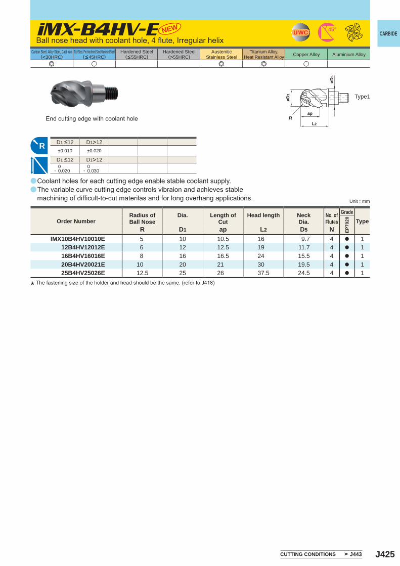
J425
a
e u e e u
iMX-B4HV-E
EP70
20
R D1 ap L2 D5 NIMX10B4HV10010E 5 10 10.5 16 9.7 4 a 1 12B4HV12012E 6 12 12.5 19 11.7 4 a 1 16B4HV16016E 8 16 16.5 24 15.5 4 a 1 20B4HV20021E 10 20 21 30 19.5 4 a 1 25B4HV25026E 12.5 25 26 37.5 24.5 4 a 1
NEW
D1>12±0.010 ±0.020
D1>12 0- 0.020
0- 0.030
a
a
UWC 45°
R
R
øD1
øD5
ap
2L
CARBIDE
Unit : mm
Carbon Steel, Alloy Steel, Cast Iron(<30HRC)
Tool Steel, Pre-Hardened Steel,Hardened Steel(<45HRC)
Hardened Steel(<55HRC)
Hardened Steel(>55HRC)
AusteniticStainless Steel
Titanium Alloy,Heat Resistant Alloy Copper Alloy Aluminium Alloy
Type1
D1 <12
D1 <12
Order NumberRadius ofBall Nose
Dia. Length ofCut
Head length NeckDia.
No. ofFlutes
GradeType
CUTTING CONDITIONS J443
Ball nose head with coolant hole, 4 flute, Irregular helix
Coolant holes for each cutting edge enable stable coolant supply.The variable curve cutting edge controls vibraion and achieves stable machining of difficult-to-cut materilas and for long overhang applications.
* The fastening size of the holder and head should be the same. (refer to J418)
End cutting edge with coolant hole
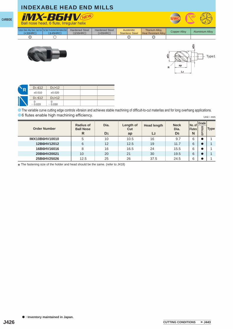
J426
aa
a
e u e e
iMX-B6HV
EP70
20
R D1 ap L2 D5 NIMX10B6HV10010 5 10 10.5 16 9.7 6 a 1 12B6HV12012 6 12 12.5 19 11.7 6 a 1 16B6HV16016 8 16 16.5 24 15.5 6 a 1 20B6HV20021 10 20 21 30 19.5 6 a 1 25B6HV25026 12.5 25 26 37.5 24.5 6 a 1
D1>12±0.010 ±0.020
D1>12 0- 0.020
0- 0.030
NEW UWC 45°
R
øD1
ap
L2
øD5
R
INDEXABLE HEAD END MILLS
a : Inventory maintained in Japan.
CARBIDE
Unit : mm
Carbon Steel, Alloy Steel, Cast Iron(<30HRC)
Tool Steel, Pre-Hardened Steel,Hardened Steel(<45HRC)
Hardened Steel(<55HRC)
Hardened Steel(>55HRC)
AusteniticStainless Steel
Titanium Alloy,Heat Resistant Alloy Copper Alloy Aluminium Alloy
The variable curve cutting edge controls vibraion and achieves stable machining of difficult-to-cut materilas and for long overhang applications.6 flutes enable high machining efficiency.
Ball nose head, 6 flute, Irregular helix
Type1
D1 <12
D1 <12
Order NumberRadius ofBall Nose
Dia. Length ofCut
Head length NeckDia.
No. ofFlutes
GradeType
CUTTING CONDITIONS J443
* The fastening size of the holder and head should be the same. (refer to J418)
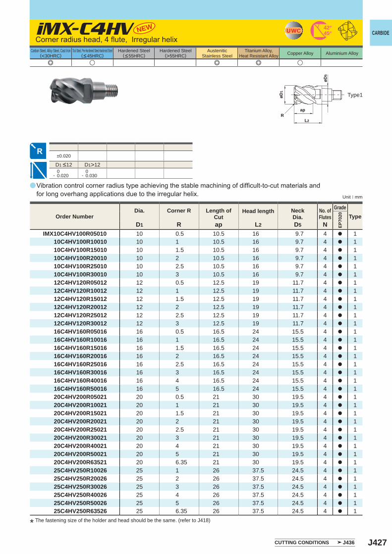
J427
a
e u e e u
EP70
20
D1 R ap L2 D5 NIMX10C4HV100R05010 10 0.5 10.5 16 9.7 4 a 1 10C4HV100R10010 10 1 10.5 16 9.7 4 a 1 10C4HV100R15010 10 1.5 10.5 16 9.7 4 a 1 10C4HV100R20010 10 2 10.5 16 9.7 4 a 1 10C4HV100R25010 10 2.5 10.5 16 9.7 4 a 1 10C4HV100R30010 10 3 10.5 16 9.7 4 a 1 12C4HV120R05012 12 0.5 12.5 19 11.7 4 a 1 12C4HV120R10012 12 1 12.5 19 11.7 4 a 1 12C4HV120R15012 12 1.5 12.5 19 11.7 4 a 1 12C4HV120R20012 12 2 12.5 19 11.7 4 a 1 12C4HV120R25012 12 2.5 12.5 19 11.7 4 a 1 12C4HV120R30012 12 3 12.5 19 11.7 4 a 1 16C4HV160R05016 16 0.5 16.5 24 15.5 4 a 1 16C4HV160R10016 16 1 16.5 24 15.5 4 a 1 16C4HV160R15016 16 1.5 16.5 24 15.5 4 a 1 16C4HV160R20016 16 2 16.5 24 15.5 4 a 1 16C4HV160R25016 16 2.5 16.5 24 15.5 4 a 1 16C4HV160R30016 16 3 16.5 24 15.5 4 a 1 16C4HV160R40016 16 4 16.5 24 15.5 4 a 1 16C4HV160R50016 16 5 16.5 24 15.5 4 a 1 20C4HV200R05021 20 0.5 21 30 19.5 4 a 1 20C4HV200R10021 20 1 21 30 19.5 4 a 1 20C4HV200R15021 20 1.5 21 30 19.5 4 a 1 20C4HV200R20021 20 2 21 30 19.5 4 a 1 20C4HV200R25021 20 2.5 21 30 19.5 4 a 1 20C4HV200R30021 20 3 21 30 19.5 4 a 1 20C4HV200R40021 20 4 21 30 19.5 4 a 1 20C4HV200R50021 20 5 21 30 19.5 4 a 1 20C4HV200R63521 20 6.35 21 30 19.5 4 a 1 25C4HV250R10026 25 1 26 37.5 24.5 4 a 1 25C4HV250R20026 25 2 26 37.5 24.5 4 a 1 25C4HV250R30026 25 3 26 37.5 24.5 4 a 1 25C4HV250R40026 25 4 26 37.5 24.5 4 a 1 25C4HV250R50026 25 5 26 37.5 24.5 4 a 1 25C4HV250R63526 25 6.35 26 37.5 24.5 4 a 1
iMX-C4HV
±0.020
D1>12 0- 0.020
0- 0.030
NEW 42°45°UWC
øD1
Rap
L2
øD5
CARBIDE
Unit : mm
Carbon Steel, Alloy Steel, Cast Iron(<30HRC)
Tool Steel, Pre-Hardened Steel,Hardened Steel(<45HRC)
Hardened Steel(<55HRC)
Hardened Steel(>55HRC)
AusteniticStainless Steel
Titanium Alloy,Heat Resistant Alloy Copper Alloy Aluminium Alloy
Type1
Corner radius head, 4 flute, Irregular helix
D1 <12
Vibration control corner radius type achieving the stable machining of difficult-to-cut materials and for long overhang applications due to the irregular helix.
Order NumberDia. Corner R Length of
CutHead length Neck
Dia.No. ofFlutes
GradeType
CUTTING CONDITIONS J436
* The fastening size of the holder and head should be the same. (refer to J418)

J428
aa
a
e u e e u
iMX-C4HV-S
EP70
20
D1 R ap L2 D5 NIMX10C4HV100R10010S 10 1 10.5 16 9.7 4 a 1 12C4HV120R10012S 12 1 12.5 19 11.7 4 a 1 16C4HV160R10016S 16 1 16.5 24 15.5 4 a 1 20C4HV200R10021S 20 1 21 30 19.5 4 a 1 25C4HV250R10026S 25 1 26 37.5 24.5 4 a 1
±0.020
D1>12 0- 0.020
0- 0.030
NEW 42°45°UWC
øD1
Rap
L2
øD5
INDEXABLE HEAD END MILLS
a : Inventory maintained in Japan.
CARBIDE
Unit : mm
Carbon Steel, Alloy Steel, Cast Iron(<30HRC)
Tool Steel, Pre-Hardened Steel,Hardened Steel(<45HRC)
Hardened Steel(<55HRC)
Hardened Steel(>55HRC)
AusteniticStainless Steel
Titanium Alloy,Heat Resistant Alloy Copper Alloy Aluminium Alloy
Corner radius head, 4 flute, Irregular helix, with coolant hole
Type1
D1 <12
Order NumberDia. Corner R Length of
CutHead length Neck
Dia.No. ofFlutes
GradeType
CUTTING CONDITIONS J436
Coolant holes for each cutting edge enable stable coolant supply.Vibration control corner radius type achieving the stable machining of difficult-to-cut materials and for long overhang applications due to the irregular helix.
* The fastening size of the holder and head should be the same. (refer to J418)
Peripheral cutting edge with coolant hole
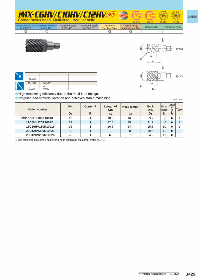
J429
a
a
e u e e
iMX-C6HV/C10HV/C12HV
EP70
20
D1 R ap L2 D5 NIMX10C6HV100R10010 10 1 10.5 16 9.7 6 a 1 12C6HV120R10012 12 1 12.5 19 11.7 6 a 1 16C10HV160R10016 16 1 16.5 24 15.5 10 a 2 20C12HV200R10021 20 1 21 30 19.5 12 a 2 25C12HV250R10026 25 1 26 37.5 24.5 12 a 2
±0.020
D1>12 0- 0.020
0- 0.030
D1>12 D1>12
NEW UWC 43.5°45° 45°
44.5°
Rap
øD5
L2
øD1
R
øD5
L2
øD1
ap
CARBIDE
Unit : mm
Carbon Steel, Alloy Steel, Cast Iron(<30HRC)
Tool Steel, Pre-Hardened Steel,Hardened Steel(<45HRC)
Hardened Steel(<55HRC)
Hardened Steel(>55HRC)
AusteniticStainless Steel
Titanium Alloy,Heat Resistant Alloy Copper Alloy Aluminium Alloy
High machining efficiency due to the multi-flute design.Irregular lead controls vibration and achieves stable machining.
Corner radius head, Multi-flute, Irregular helix
Type1
Type2
D1 <12 D1 <12
D1 <12
Order NumberDia. Corner R Length of
CutHead length Neck
Dia.No. ofFlutes
GradeType
CUTTING CONDITIONS J442
* The fastening size of the holder and head should be the same. (refer to J418)
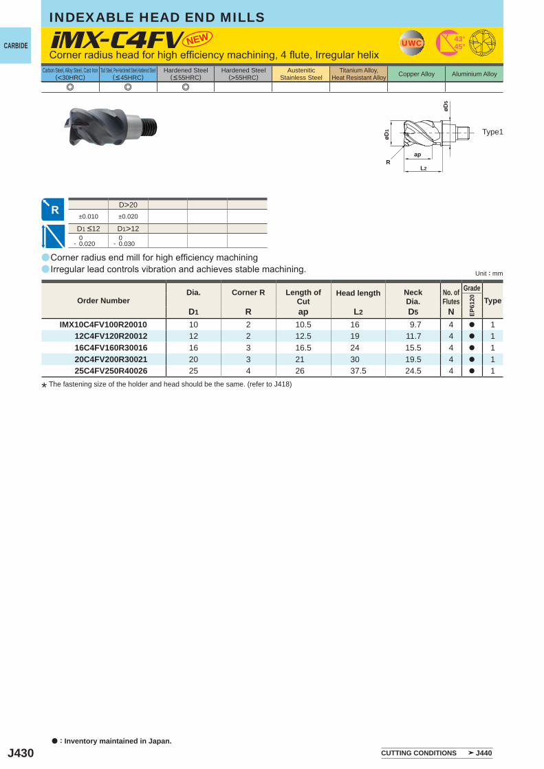
J430
a
a
e e e
EP61
20
D1 R ap L2 D5 NIMX10C4FV100R20010 10 2 10.5 16 9.7 4 a 1 12C4FV120R20012 12 2 12.5 19 11.7 4 a 1 16C4FV160R30016 16 3 16.5 24 15.5 4 a 1 20C4FV200R30021 20 3 21 30 19.5 4 a 1 25C4FV250R40026 25 4 26 37.5 24.5 4 a 1
iMX-C4FV NEW
D>20±0.010 ±0.020
D1>12 0- 0.020
0- 0.030
øD5
øD1
Rap
L2
UWC 43°45°
INDEXABLE HEAD END MILLS
a : Inventory maintained in Japan.
CARBIDE
Unit : mm
Carbon Steel, Alloy Steel, Cast Iron(<30HRC)
Tool Steel, Pre-Hardened Steel,Hardened Steel(<45HRC)
Hardened Steel(<55HRC)
Hardened Steel(>55HRC)
AusteniticStainless Steel
Titanium Alloy,Heat Resistant Alloy Copper Alloy Aluminium Alloy
Type1
Corner radius head for high efficiency machining, 4 flute, Irregular helix
D1 <12
Order NumberDia. Corner R Length of
CutHead length Neck
Dia.No. ofFlutes
GradeType
Corner radius end mill for high efficiency machiningIrregular lead controls vibration and achieves stable machining.
CUTTING CONDITIONS J440
* The fastening size of the holder and head should be the same. (refer to J418)
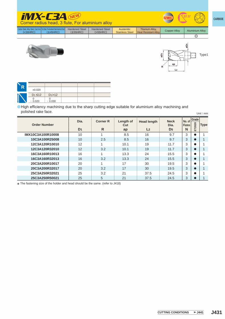
J431
a
e
ET20
20
D1 R ap L2 D5 NIMX10C3A100R10008 10 1 8.5 16 9.7 3 a 1 10C3A100R25008 10 2.5 8.5 16 9.7 3 a 1 12C3A120R10010 12 1 10.1 19 11.7 3 a 1 12C3A120R32010 12 3.2 10.1 19 11.7 3 a 1 16C3A160R10013 16 1 13.3 24 15.5 3 a 1 16C3A160R32013 16 3.2 13.3 24 15.5 3 a 1 20C3A200R10017 20 1 17 30 19.5 3 a 1 20C3A200R32017 20 3.2 17 30 19.5 3 a 1 25C3A250R32021 25 3.2 21 37.5 24.5 3 a 1 25C3A250R50021 25 5 21 37.5 24.5 3 a 1
iMX-C3A NEW
±0.020
D1>12 0- 0.020
0- 0.030
UWC 37.5°
ap
øD5
L2
øD1
R
CARBIDE
Unit : mm
Carbon Steel, Alloy Steel, Cast Iron(<30HRC)
Tool Steel, Pre-Hardened Steel,Hardened Steel(<45HRC)
Hardened Steel(<55HRC)
Hardened Steel(>55HRC)
AusteniticStainless Steel
Titanium Alloy,Heat Resistant Alloy Copper Alloy Aluminium Alloy
Type1
Corner radius head, 3 flute, For aluminium alloy
D1 <12
High efficiency machining due to the sharp cutting edge suitable for aluminium alloy machining and polished rake face.
Order NumberDia. Corner R Length of
CutHead length Neck
Dia.No. ofFlutes
GradeType
CUTTING CONDITIONS J441
* The fastening size of the holder and head should be the same. (refer to J418)
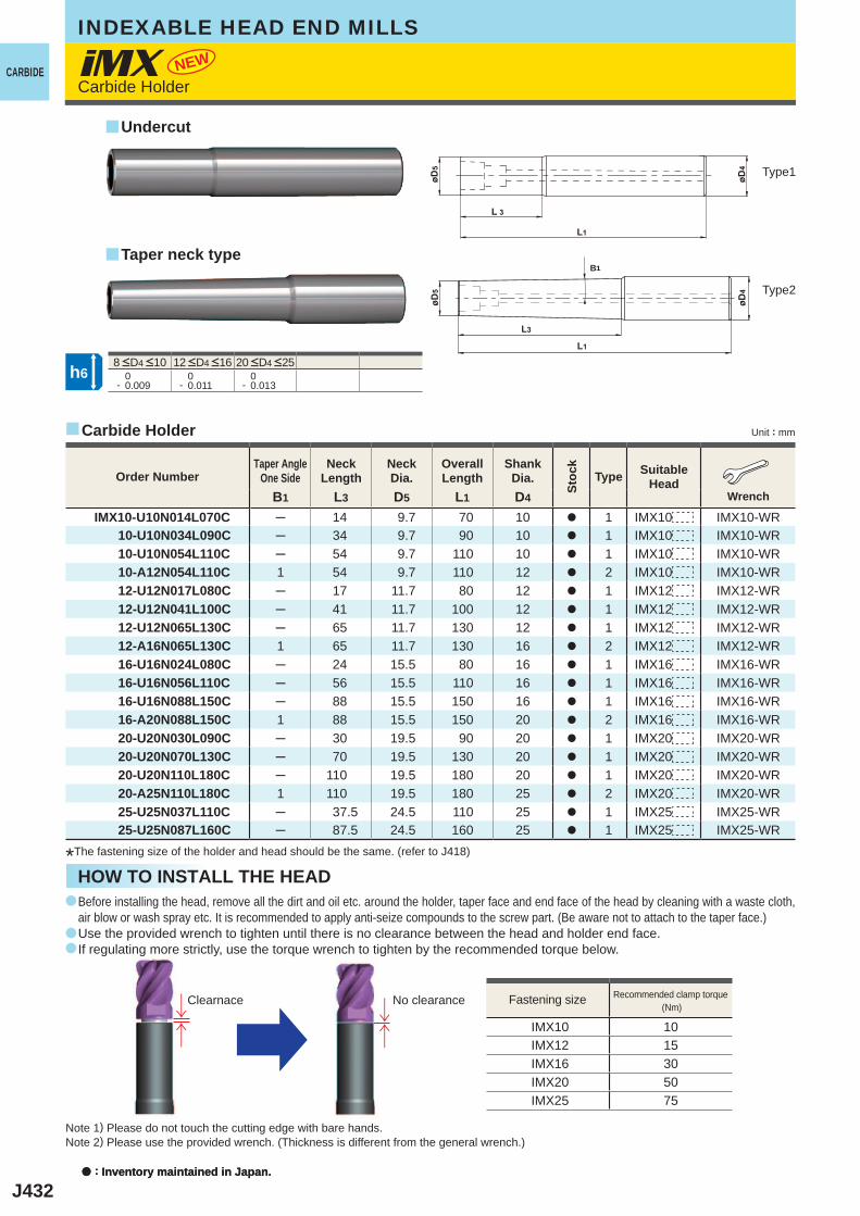
J432
y
y
IMX10 10IMX12 15IMX16 30IMX20 50IMX25 75
y
0- 0.009
0- 0.011
0- 0.013
a
a
a
B1 L3 D5 L1 D4
IMX10-U10N014L070C ─ 14 9.7 70 10 a 1 IMX10 IMX10-WR 10-U10N034L090C ─ 34 9.7 90 10 a 1 IMX10 IMX10-WR 10-U10N054L110C ─ 54 9.7 110 10 a 1 IMX10 IMX10-WR 10-A12N054L110C 1 54 9.7 110 12 a 2 IMX10 IMX10-WR 12-U12N017L080C ─ 17 11.7 80 12 a 1 IMX12 IMX12-WR 12-U12N041L100C ─ 41 11.7 100 12 a 1 IMX12 IMX12-WR 12-U12N065L130C ─ 65 11.7 130 12 a 1 IMX12 IMX12-WR 12-A16N065L130C 1 65 11.7 130 16 a 2 IMX12 IMX12-WR 16-U16N024L080C ─ 24 15.5 80 16 a 1 IMX16 IMX16-WR 16-U16N056L110C ─ 56 15.5 110 16 a 1 IMX16 IMX16-WR 16-U16N088L150C ─ 88 15.5 150 16 a 1 IMX16 IMX16-WR 16-A20N088L150C 1 88 15.5 150 20 a 2 IMX16 IMX16-WR 20-U20N030L090C ─ 30 19.5 90 20 a 1 IMX20 IMX20-WR 20-U20N070L130C ─ 70 19.5 130 20 a 1 IMX20 IMX20-WR 20-U20N110L180C ─ 110 19.5 180 20 a 1 IMX20 IMX20-WR 20-A25N110L180C 1 110 19.5 180 25 a 2 IMX20 IMX20-WR 25-U25N037L110C ─ 37.5 24.5 110 25 a 1 IMX25 IMX25-WR 25-U25N087L160C ─ 87.5 24.5 160 25 a 1 IMX25 IMX25-WR
iMX NEW
↓↑
↓↑
h6
B1
INDEXABLE HEAD END MILLS
a : Inventory maintained in Japan.
CARBIDE
Unit : mm
Type1
Note 1) Please do not touch the cutting edge with bare hands.Note 2) Please use the provided wrench. (Thickness is different from the general wrench.)
Carbide Holder
Fastening size Recommended clamp torque (Nm)
Clearnace No clearance
HOW TO INSTALL THE HEAD
8 <D4 <10 12 <D4 <16 20 <D4 <25
*The fastening size of the holder and head should be the same. (refer to J418)
Order NumberTaper Angle
One SideNeck
LengthNeckDia.
OverallLength
ShankDia.
Stoc
k
Type Suitable Head
Wrench
a : Inventory maintained in Japan.
Undercut
Taper neck type
Before installing the head, remove all the dirt and oil etc. around the holder, taper face and end face of the head by cleaning with a waste cloth, air blow or wash spray etc. It is recommended to apply anti-seize compounds to the screw part. (Be aware not to attach to the taper face.)Use the provided wrench to tighten until there is no clearance between the head and holder end face.If regulating more strictly, use the torque wrench to tighten by the recommended torque below.
Carbide Holder
Type2
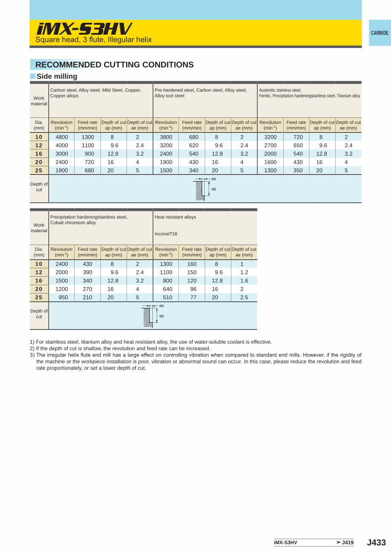
J433
y
10 4800 1300 8 2 3800 680 8 2 3200 720 8 212 4000 1100 9.6 2.4 3200 620 9.6 2.4 2700 650 9.6 2.416 3000 900 12.8 3.2 2400 540 12.8 3.2 2000 540 12.8 3.220 2400 720 16 4 1900 430 16 4 1600 430 16 425 1900 680 20 5 1500 340 20 5 1300 350 20 5
10 2400 430 8 2 1300 160 8 112 2000 390 9.6 2.4 1100 150 9.6 1.216 1500 340 12.8 3.2 800 120 12.8 1.620 1200 270 16 4 640 96 16 225 950 210 20 5 510 77 20 2.5
iMX-S3HV
iMX-S3HV J419
ae
ap
ae
ap
CARBIDESquare head, 3 flute, Illegular helix
RECOMMENDED CUTTING CONDITIONSSide milling
Workmaterial
Carbon steel, Alloy steel, Mild Steel, Copper, Copper alloys
Pre-hardened steel, Carbon steel, Alloy steel, Alloy tool steel
Austenitic stainless steel, Ferritic, Precipitation hardeningstainless steel, Titanium alloy
Dia.(mm)
Revolution(min-1)
Feed rate(mm/min)
Depth of cutap (mm)
Depth of cutae (mm)
Revolution(min-1)
Feed rate(mm/min)
Depth of cutap (mm)
Depth of cutae (mm)
Revolution(min-1)
Feed rate(mm/min)
Depth of cutap (mm)
Depth of cutae (mm)
Depth ofcut
Workmaterial
Precipitation hardeningstainless steel, Cobalt chromium alloy
Heat resistant alloys
Inconel718
Dia.(mm)
Revolution(min-1)
Feed rate(mm/min)
Depth of cutap (mm)
Depth of cutae (mm)
Revolution(min-1)
Feed rate(mm/min)
Depth of cutap (mm)
Depth of cutae (mm)
Depth ofcut
1) For stainless steel, titanium alloy and heat resistant alloy, the use of water-soluble coolant is effective. 2) If the depth of cut is shallow, the revolution and feed rate can be increased.3) The irregular helix flute end mill has a large effect on controlling vibration when compared to standard end mills. However, if the rigidity of
the machine or the workpiece installation is poor, vibration or abnormal sound can occur. In this case, please reduce the revolution and feed rate proportionately, or set a lower depth of cut.
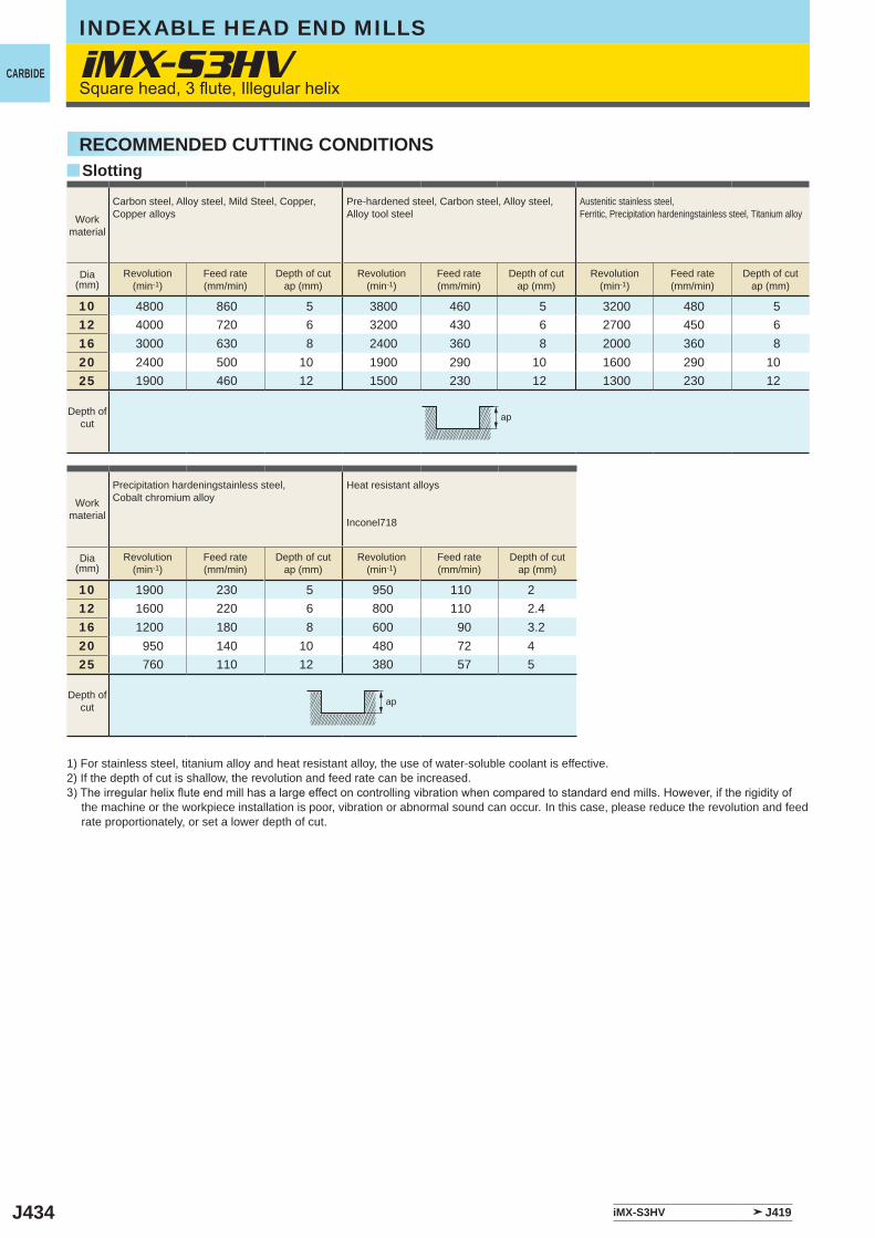
J434
iMX-S3HV
y
10 4800 860 5 3800 460 5 3200 480 512 4000 720 6 3200 430 6 2700 450 616 3000 630 8 2400 360 8 2000 360 820 2400 500 10 1900 290 10 1600 290 1025 1900 460 12 1500 230 12 1300 230 12
10 1900 230 5 950 110 212 1600 220 6 800 110 2.416 1200 180 8 600 90 3.220 950 140 10 480 72 425 760 110 12 380 57 5
iMX-S3HV J419
ap
ap
INDEXABLE HEAD END MILLS
CARBIDESquare head, 3 flute, Illegular helix
SlottingRECOMMENDED CUTTING CONDITIONS
Workmaterial
Carbon steel, Alloy steel, Mild Steel, Copper, Copper alloys
Pre-hardened steel, Carbon steel, Alloy steel, Alloy tool steel
Austenitic stainless steel,Ferritic, Precipitation hardeningstainless steel, Titanium alloy
Dia(mm)
Revolution(min-1)
Feed rate(mm/min)
Depth of cutap (mm)
Revolution(min-1)
Feed rate(mm/min)
Depth of cutap (mm)
Revolution(min-1)
Feed rate(mm/min)
Depth of cutap (mm)
Depth ofcut
Workmaterial
Precipitation hardeningstainless steel, Cobalt chromium alloy
Heat resistant alloys
Inconel718
Dia(mm)
Revolution(min-1)
Feed rate(mm/min)
Depth of cutap (mm)
Revolution(min-1)
Feed rate(mm/min)
Depth of cutap (mm)
Depth ofcut
1) For stainless steel, titanium alloy and heat resistant alloy, the use of water-soluble coolant is effective. 2) If the depth of cut is shallow, the revolution and feed rate can be increased.3) The irregular helix flute end mill has a large effect on controlling vibration when compared to standard end mills. However, if the rigidity of
the machine or the workpiece installation is poor, vibration or abnormal sound can occur. In this case, please reduce the revolution and feed rate proportionately, or set a lower depth of cut.
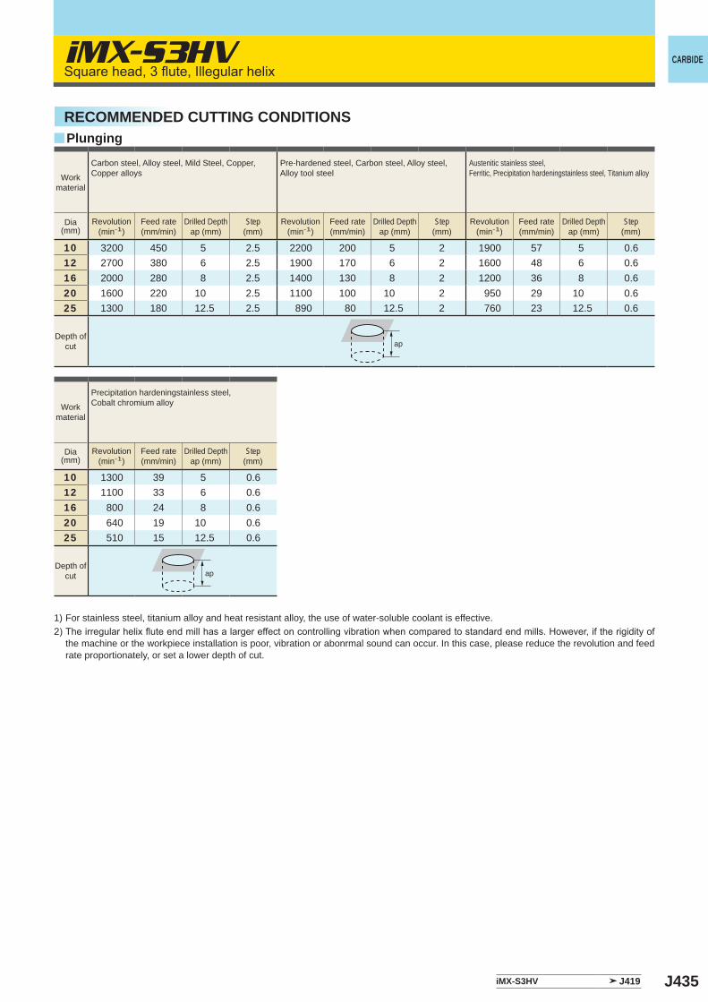
J435
y
iMX-S3HV
10 3200 450 5 2.5 2200 200 5 2 1900 57 5 0.612 2700 380 6 2.5 1900 170 6 2 1600 48 6 0.616 2000 280 8 2.5 1400 130 8 2 1200 36 8 0.620 1600 220 10 2.5 1100 100 10 2 950 29 10 0.625 1300 180 12.5 2.5 890 80 12.5 2 760 23 12.5 0.6
10 1300 39 5 0.612 1100 33 6 0.616 800 24 8 0.620 640 19 10 0.625 510 15 12.5 0.6
iMX-S3HV J419
ap
ap
CARBIDESquare head, 3 flute, Illegular helix
Workmaterial
Carbon steel, Alloy steel, Mild Steel, Copper, Copper alloys
Pre-hardened steel, Carbon steel, Alloy steel, Alloy tool steel
Austenitic stainless steel,Ferritic, Precipitation hardeningstainless steel, Titanium alloy
Dia(mm)
Revolution(min-1)
Feed rate(mm/min)
Drilled Depthap (mm)
Step(mm)
Revolution(min-1)
Feed rate(mm/min)
Drilled Depthap (mm)
Step(mm)
Revolution(min-1)
Feed rate(mm/min)
Drilled Depthap (mm)
Step(mm)
Depth ofcut
Workmaterial
Precipitation hardeningstainless steel, Cobalt chromium alloy
Dia(mm)
Revolution(min-1)
Feed rate(mm/min)
Drilled Depthap (mm)
Step(mm)
Depth ofcut
RECOMMENDED CUTTING CONDITIONSPlunging
1) For stainless steel, titanium alloy and heat resistant alloy, the use of water-soluble coolant is effective. 2) The irregular helix flute end mill has a larger effect on controlling vibration when compared to standard end mills. However, if the rigidity of
the machine or the workpiece installation is poor, vibration or abonrmal sound can occur. In this case, please reduce the revolution and feed rate proportionately, or set a lower depth of cut.
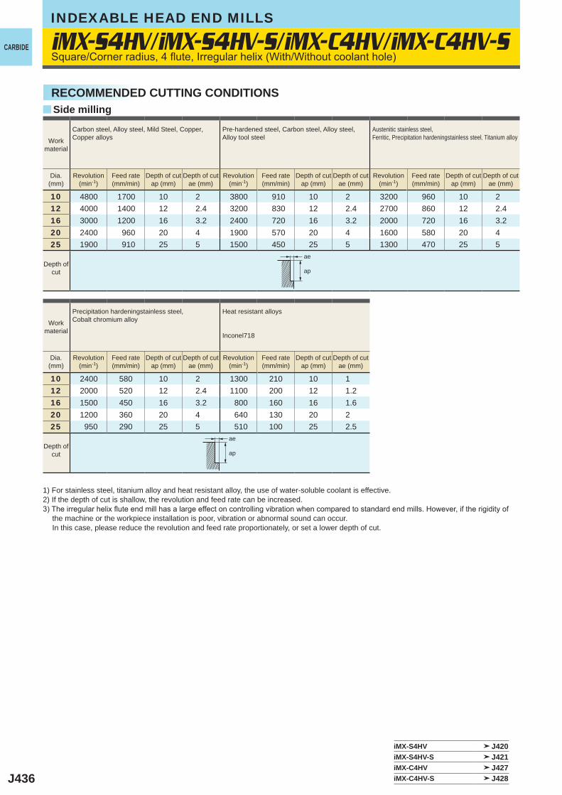
J436
y
10 4800 1700 10 2 3800 910 10 2 3200 960 10 212 4000 1400 12 2.4 3200 830 12 2.4 2700 860 12 2.416 3000 1200 16 3.2 2400 720 16 3.2 2000 720 16 3.220 2400 960 20 4 1900 570 20 4 1600 580 20 425 1900 910 25 5 1500 450 25 5 1300 470 25 5
10 2400 580 10 2 1300 210 10 112 2000 520 12 2.4 1100 200 12 1.216 1500 450 16 3.2 800 160 16 1.620 1200 360 20 4 640 130 20 225 950 290 25 5 510 100 25 2.5
iMX-S4HV/iMX-S4HV-S/iMX-C4HV/iMX-C4HV-S
iMX-S4HV J420iMX-S4HV-S J421iMX-C4HV J427iMX-C4HV-S J428
ae
ap
ae
ap
INDEXABLE HEAD END MILLS
CARBIDE
Side millingRECOMMENDED CUTTING CONDITIONS
Square/Corner radius, 4 flute, Irregular helix (With/Without coolant hole)
Workmaterial
Carbon steel, Alloy steel, Mild Steel, Copper, Copper alloys
Pre-hardened steel, Carbon steel, Alloy steel, Alloy tool steel
Austenitic stainless steel, Ferritic, Precipitation hardeningstainless steel, Titanium alloy
Dia.(mm)
Revolution(min-1)
Feed rate(mm/min)
Depth of cutap (mm)
Depth of cutae (mm)
Revolution(min-1)
Feed rate(mm/min)
Depth of cutap (mm)
Depth of cutae (mm)
Revolution(min-1)
Feed rate(mm/min)
Depth of cutap (mm)
Depth of cutae (mm)
Depth ofcut
Workmaterial
Precipitation hardeningstainless steel, Cobalt chromium alloy
Heat resistant alloys
Inconel718
Dia.(mm)
Revolution(min-1)
Feed rate(mm/min)
Depth of cutap (mm)
Depth of cutae (mm)
Revolution(min-1)
Feed rate(mm/min)
Depth of cutap (mm)
Depth of cutae (mm)
Depth ofcut
1) For stainless steel, titanium alloy and heat resistant alloy, the use of water-soluble coolant is effective. 2) If the depth of cut is shallow, the revolution and feed rate can be increased.3) The irregular helix flute end mill has a large effect on controlling vibration when compared to standard end mills. However, if the rigidity of
the machine or the workpiece installation is poor, vibration or abnormal sound can occur. In this case, please reduce the revolution and feed rate proportionately, or set a lower depth of cut.
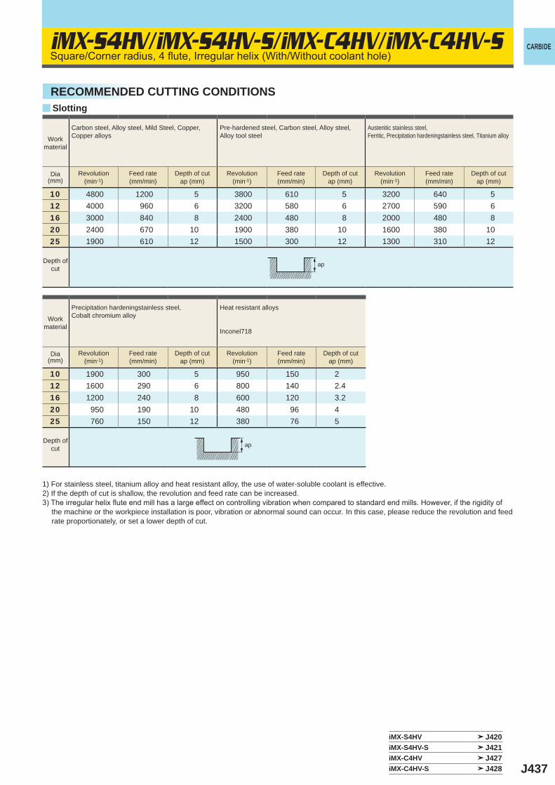
J437
y
iMX-S4HV/iMX-S4HV-S/iMX-C4HV/iMX-C4HV-S
10 4800 1200 5 3800 610 5 3200 640 512 4000 960 6 3200 580 6 2700 590 616 3000 840 8 2400 480 8 2000 480 820 2400 670 10 1900 380 10 1600 380 1025 1900 610 12 1500 300 12 1300 310 12
10 1900 300 5 950 150 212 1600 290 6 800 140 2.416 1200 240 8 600 120 3.220 950 190 10 480 96 425 760 150 12 380 76 5
iMX-S4HV J420iMX-S4HV-S J421iMX-C4HV J427iMX-C4HV-S J428
ap
ap
CARBIDESquare/Corner radius, 4 flute, Irregular helix (With/Without coolant hole)
SlottingRECOMMENDED CUTTING CONDITIONS
Workmaterial
Carbon steel, Alloy steel, Mild Steel, Copper, Copper alloys
Pre-hardened steel, Carbon steel, Alloy steel, Alloy tool steel
Austenitic stainless steel,Ferritic, Precipitation hardeningstainless steel, Titanium alloy
Dia(mm)
Revolution(min-1)
Feed rate(mm/min)
Depth of cutap (mm)
Revolution(min-1)
Feed rate(mm/min)
Depth of cutap (mm)
Revolution(min-1)
Feed rate(mm/min)
Depth of cutap (mm)
Depth ofcut
Workmaterial
Precipitation hardeningstainless steel, Cobalt chromium alloy
Heat resistant alloys
Inconel718
Dia(mm)
Revolution(min-1)
Feed rate(mm/min)
Depth of cutap (mm)
Revolution(min-1)
Feed rate(mm/min)
Depth of cutap (mm)
Depth ofcut
1) For stainless steel, titanium alloy and heat resistant alloy, the use of water-soluble coolant is effective. 2) If the depth of cut is shallow, the revolution and feed rate can be increased.3) The irregular helix flute end mill has a large effect on controlling vibration when compared to standard end mills. However, if the rigidity of
the machine or the workpiece installation is poor, vibration or abnormal sound can occur. In this case, please reduce the revolution and feed rate proportionately, or set a lower depth of cut.
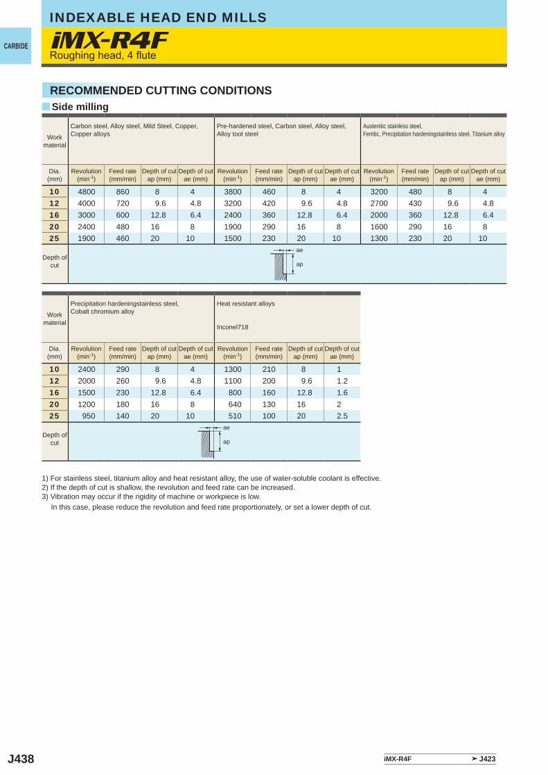
J438
y
10 4800 860 8 4 3800 460 8 4 3200 480 8 412 4000 720 9.6 4.8 3200 420 9.6 4.8 2700 430 9.6 4.816 3000 600 12.8 6.4 2400 360 12.8 6.4 2000 360 12.8 6.420 2400 480 16 8 1900 290 16 8 1600 290 16 825 1900 460 20 10 1500 230 20 10 1300 230 20 10
10 2400 290 8 4 1300 210 8 112 2000 260 9.6 4.8 1100 200 9.6 1.216 1500 230 12.8 6.4 800 160 12.8 1.620 1200 180 16 8 640 130 16 225 950 140 20 10 510 100 20 2.5
iMX-R4F
iMX-R4F J423
ae
ap
ae
ap
INDEXABLE HEAD END MILLS
CARBIDERoughing head, 4 flute
Side millingRECOMMENDED CUTTING CONDITIONS
Workmaterial
Carbon steel, Alloy steel, Mild Steel, Copper, Copper alloys
Pre-hardened steel, Carbon steel, Alloy steel, Alloy tool steel
Austenitic stainless steel, Ferritic, Precipitation hardeningstainless steel, Titanium alloy
Dia.(mm)
Revolution(min-1)
Feed rate(mm/min)
Depth of cutap (mm)
Depth of cutae (mm)
Revolution(min-1)
Feed rate(mm/min)
Depth of cutap (mm)
Depth of cutae (mm)
Revolution(min-1)
Feed rate(mm/min)
Depth of cutap (mm)
Depth of cutae (mm)
Depth ofcut
Workmaterial
Precipitation hardeningstainless steel, Cobalt chromium alloy
Heat resistant alloys
Inconel718
Dia.(mm)
Revolution(min-1)
Feed rate(mm/min)
Depth of cutap (mm)
Depth of cutae (mm)
Revolution(min-1)
Feed rate(mm/min)
Depth of cutap (mm)
Depth of cutae (mm)
Depth ofcut
1) For stainless steel, titanium alloy and heat resistant alloy, the use of water-soluble coolant is effective. 2) If the depth of cut is shallow, the revolution and feed rate can be increased.3) Vibration may occur if the rigidity of machine or workpiece is low. In this case, please reduce the revolution and feed rate proportionately, or set a lower depth of cut.
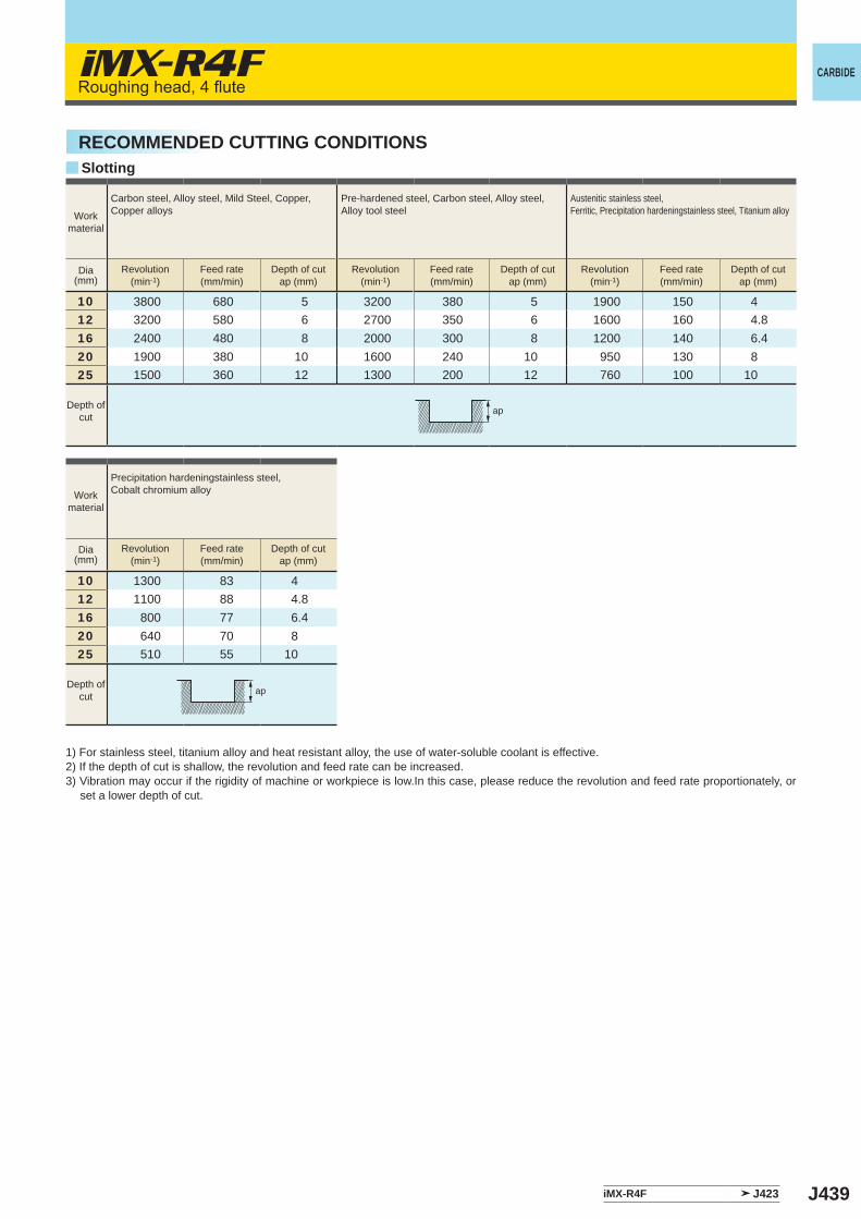
J439
y
10 3800 680 5 3200 380 5 1900 150 412 3200 580 6 2700 350 6 1600 160 4.816 2400 480 8 2000 300 8 1200 140 6.420 1900 380 10 1600 240 10 950 130 825 1500 360 12 1300 200 12 760 100 10
10 1300 83 412 1100 88 4.816 800 77 6.420 640 70 825 510 55 10
iMX-R4F
iMX-R4F J423
ap
ap
CARBIDERoughing head, 4 flute
Workmaterial
Carbon steel, Alloy steel, Mild Steel, Copper, Copper alloys
Pre-hardened steel, Carbon steel, Alloy steel, Alloy tool steel
Austenitic stainless steel,Ferritic, Precipitation hardeningstainless steel, Titanium alloy
Dia(mm)
Revolution(min-1)
Feed rate(mm/min)
Depth of cutap (mm)
Revolution(min-1)
Feed rate(mm/min)
Depth of cutap (mm)
Revolution(min-1)
Feed rate(mm/min)
Depth of cutap (mm)
Depth ofcut
Workmaterial
Precipitation hardeningstainless steel, Cobalt chromium alloy
Dia(mm)
Revolution(min-1)
Feed rate(mm/min)
Depth of cutap (mm)
Depth ofcut
SlottingRECOMMENDED CUTTING CONDITIONS
1) For stainless steel, titanium alloy and heat resistant alloy, the use of water-soluble coolant is effective. 2) If the depth of cut is shallow, the revolution and feed rate can be increased.3) Vibration may occur if the rigidity of machine or workpiece is low.In this case, please reduce the revolution and feed rate proportionately, or
set a lower depth of cut.
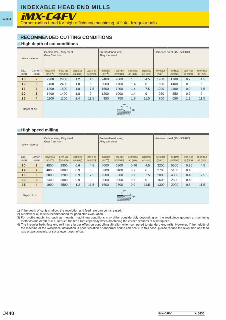
J440
y
y
10 2 2900 2900 1.2 4.5 2400 2000 1 4.5 1900 1700 0.7 4.512 2 2400 2400 1.8 6 2000 1700 1.4 6 1600 1400 0.9 616 3 1800 1800 1.8 7.5 1500 1200 1.4 7.5 1200 1100 0.9 7.520 3 1400 1400 1.8 9 1200 1000 1.4 9 950 850 0.9 925 4 1100 1100 2.4 11.5 950 750 1.8 11.5 750 650 1.2 11.5
10 2 4800 9800 0.6 4.5 4000 6900 0.46 4.5 3200 5500 0.36 4.512 2 4000 9000 0.9 6 3300 6400 0.7 6 2700 5100 0.45 616 3 3000 7200 0.9 7.5 2500 5300 0.7 7.5 2000 4300 0.45 7.520 3 2400 5800 0.9 9 2000 3000 0.7 9 1600 2500 0.45 925 4 1900 4500 1.2 11.5 1600 2500 0.9 11.5 1300 2000 0.6 11.5
iMX-C4FV
iMX-C4FV J430
ae
ap
ae
ap
INDEXABLE HEAD END MILLS
CARBIDECorner radius head for high efficiency machining, 4 flute, Irregular helix
Work material
Carbon steel, Alloy steel, Gray Cast Iron
Pre-hardened steel, Alloy tool steel
Hardened steel (45─ 55HRC)
Dia.(mm)
CornerR(mm)
Revolution(min-1)
Feed rate(mm/min)
Depth of cutap (mm)
Depth of cutae (mm)
Revolution(min-1)
Feed rate(mm/min)
Depth of cutap (mm)
Depth of cutae (mm)
Revolution(min-1)
Feed rate(mm/min)
Depth of cutap (mm)
Depth of cutae (mm)
Depth of cut
RECOMMENDED CUTTING CONDITIONS
1) If the depth of cut is shallow, the revolution and feed rate can be increased.2) Air blow or oil mist is recommended for good chip evacuation.3) For profile machining such as moulds, machining conditions may differ considerably depending on the workpiece geometry, machining
methods and depth of cut. Reduce the feed rate especially when machining the corner sections of a workpiece.4) The irregular helix flute end mill has a larger effect on controlling vibration when compared to standard end mills. However, if the rigidity of
the machine or the workpiece installation is poor, vibration or abonrmal sound can occur. In this case, please reduce the revolution and feed rate proportionately, or set a lower depth of cut.
High depth of cut conditions
High speed milling
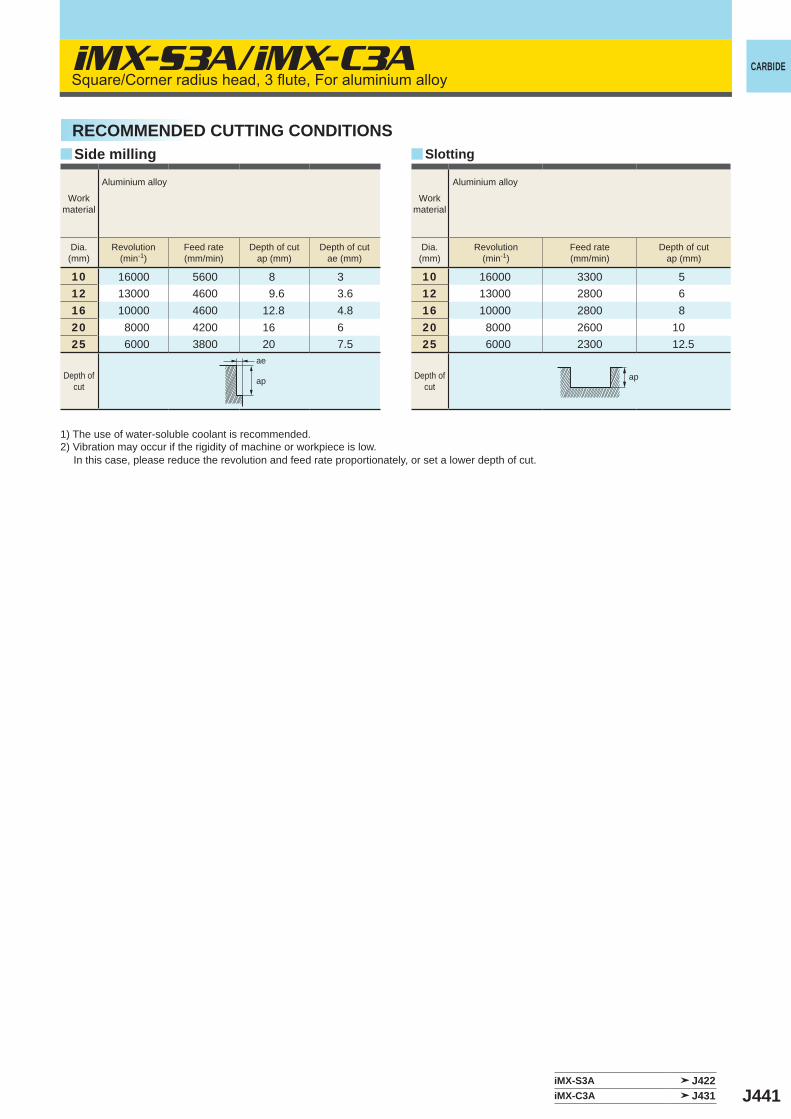
J441
iMX-S3A/iMX-C3A
y y
10 16000 5600 8 312 13000 4600 9.6 3.616 10000 4600 12.8 4.820 8000 4200 16 625 6000 3800 20 7.5
10 16000 3300 512 13000 2800 616 10000 2800 820 8000 2600 1025 6000 2300 12.5
iMX-S3A J422iMX-C3A J431
ae
ap ap
CARBIDE
Workmaterial
Aluminium alloy
Dia.(mm)
Revolution(min-1)
Feed rate(mm/min)
Depth of cutap (mm)
Depth of cutae (mm)
Depth ofcut
Workmaterial
Aluminium alloy
Dia.(mm)
Revolution(min-1)
Feed rate(mm/min)
Depth of cutap (mm)
Depth ofcut
RECOMMENDED CUTTING CONDITIONSSide milling Slotting
Square/Corner radius head, 3 flute, For aluminium alloy
1) The use of water-soluble coolant is recommended.2) Vibration may occur if the rigidity of machine or workpiece is low. In this case, please reduce the revolution and feed rate proportionately, or set a lower depth of cut.
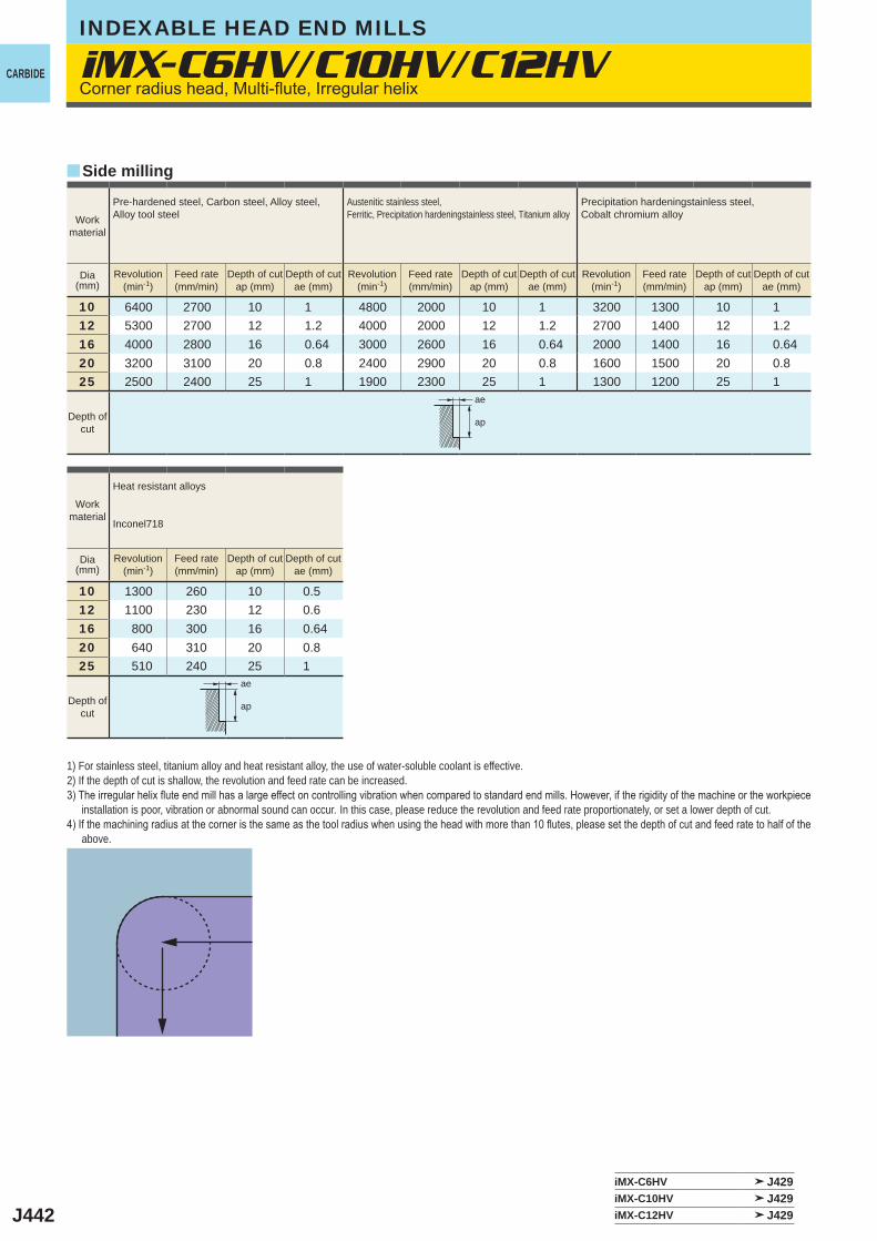
J442
y
iMX-C6HV/C10HV/C12HV
10 6400 2700 10 1 4800 2000 10 1 3200 1300 10 112 5300 2700 12 1.2 4000 2000 12 1.2 2700 1400 12 1.216 4000 2800 16 0.64 3000 2600 16 0.64 2000 1400 16 0.6420 3200 3100 20 0.8 2400 2900 20 0.8 1600 1500 20 0.825 2500 2400 25 1 1900 2300 25 1 1300 1200 25 1
10 1300 260 10 0.512 1100 230 12 0.616 800 300 16 0.6420 640 310 20 0.825 510 240 25 1
iMX-C6HV J429iMX-C10HV J429iMX-C12HV J429
ae
ap
ae
ap
INDEXABLE HEAD END MILLS
CARBIDE
Side milling
Workmaterial
Pre-hardened steel, Carbon steel, Alloy steel, Alloy tool steel
Austenitic stainless steel,Ferritic, Precipitation hardeningstainless steel, Titanium alloy
Precipitation hardeningstainless steel, Cobalt chromium alloy
Dia(mm)
Revolution(min-1)
Feed rate(mm/min)
Depth of cutap (mm)
Depth of cutae (mm)
Revolution(min-1)
Feed rate(mm/min)
Depth of cutap (mm)
Depth of cutae (mm)
Revolution(min-1)
Feed rate(mm/min)
Depth of cutap (mm)
Depth of cutae (mm)
Depth ofcut
Workmaterial
Heat resistant alloys
Inconel718
Dia(mm)
Revolution(min-1)
Feed rate(mm/min)
Depth of cutap (mm)
Depth of cutae (mm)
Depth ofcut
1) For stainless steel, titanium alloy and heat resistant alloy, the use of water-soluble coolant is effective. 2) If the depth of cut is shallow, the revolution and feed rate can be increased.3) The irregular helix flute end mill has a large effect on controlling vibration when compared to standard end mills. However, if the rigidity of the machine or the workpiece
installation is poor, vibration or abnormal sound can occur. In this case, please reduce the revolution and feed rate proportionately, or set a lower depth of cut.4) If the machining radius at the corner is the same as the tool radius when using the head with more than 10 flutes, please set the depth of cut and feed rate to half of the
above.
Corner radius head, Multi-flute, Irregular helix
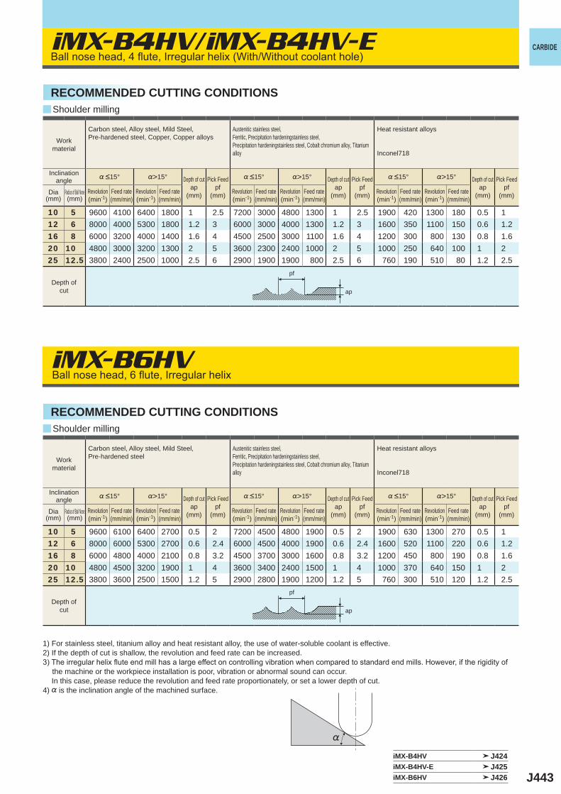
J443
iMX-B4HV/iMX-B4HV-E
iMX-B6HV
y
y
%>15° %>15° %>15°
10 5 9600 4100 6400 1800 1 2.5 7200 3000 4800 1300 1 2.5 1900 420 1300 180 0.5 112 6 8000 4000 5300 1800 1.2 3 6000 3000 4000 1300 1.2 3 1600 350 1100 150 0.6 1.216 8 6000 3200 4000 1400 1.6 4 4500 2500 3000 1100 1.6 4 1200 300 800 130 0.8 1.620 10 4800 3000 3200 1300 2 5 3600 2300 2400 1000 2 5 1000 250 640 100 1 225 12.5 3800 2400 2500 1000 2.5 6 2900 1900 1900 800 2.5 6 760 190 510 80 1.2 2.5
%>15° %>15° %>15°
10 5 9600 6100 6400 2700 0.5 2 7200 4500 4800 1900 0.5 2 1900 630 1300 270 0.5 112 6 8000 6000 5300 2700 0.6 2.4 6000 4500 4000 1900 0.6 2.4 1600 520 1100 220 0.6 1.216 8 6000 4800 4000 2100 0.8 3.2 4500 3700 3000 1600 0.8 3.2 1200 450 800 190 0.8 1.620 10 4800 4500 3200 1900 1 4 3600 3400 2400 1500 1 4 1000 370 640 150 1 225 12.5 3800 3600 2500 1500 1.2 5 2900 2800 1900 1200 1.2 5 760 300 510 120 1.2 2.5
iMX-B4HV J424iMX-B4HV-E J425iMX-B6HV J426
%
CARBIDE
Shoulder milling
Shoulder milling
RECOMMENDED CUTTING CONDITIONS
RECOMMENDED CUTTING CONDITIONS
Workmaterial
Carbon steel, Alloy steel, Mild Steel, Pre-hardened steel, Copper, Copper alloys
Austenitic stainless steel,Ferritic, Precipitation hardeningstainless steel, Precipitation hardeningstainless steel, Cobalt chromium alloy, Titanium alloy
Heat resistant alloys
Inconel718
Inclination angle %<15° Depth of cut
ap (mm)
Pick Feedpf
(mm)
%<15° Depth of cutap
(mm)
Pick Feedpf
(mm)
%<15° Depth of cutap
(mm)
Pick Feedpf
(mm)Dia(mm)
Radius of Ball Nose(mm)
Revolution(min-1)
Feed rate(mm/min)
Revolution(min-1)
Feed rate(mm/min)
Revolution(min-1)
Feed rate(mm/min)
Revolution(min-1)
Feed rate(mm/min)
Revolution(min-1)
Feed rate(mm/min)
Revolution(min-1)
Feed rate(mm/min)
Depth ofcut
Workmaterial
Carbon steel, Alloy steel, Mild Steel, Pre-hardened steel
Austenitic stainless steel,Ferritic, Precipitation hardeningstainless steel, Precipitation hardeningstainless steel, Cobalt chromium alloy, Titanium alloy
Heat resistant alloys
Inconel718
Inclination angle %<15° Depth of cut
ap (mm)
Pick Feedpf
(mm)
%<15° Depth of cutap
(mm)
Pick Feedpf
(mm)
%<15° Depth of cutap
(mm)
Pick Feedpf
(mm)Dia(mm)
Radius of Ball Nose(mm)
Revolution(min-1)
Feed rate(mm/min)
Revolution(min-1)
Feed rate(mm/min)
Revolution(min-1)
Feed rate(mm/min)
Revolution(min-1)
Feed rate(mm/min)
Revolution(min-1)
Feed rate(mm/min)
Revolution(min-1)
Feed rate(mm/min)
Depth ofcut
1) For stainless steel, titanium alloy and heat resistant alloy, the use of water-soluble coolant is effective. 2) If the depth of cut is shallow, the revolution and feed rate can be increased.3) The irregular helix flute end mill has a large effect on controlling vibration when compared to standard end mills. However, if the rigidity of
the machine or the workpiece installation is poor, vibration or abnormal sound can occur. In this case, please reduce the revolution and feed rate proportionately, or set a lower depth of cut.4) % is the inclination angle of the machined surface.
ap
pf
ap
pf
Ball nose head, 4 flute, Irregular helix (With/Without coolant hole)
Ball nose head, 6 flute, Irregular helix