i400enbr Bc
17
MiCOM I400 Digital Transducers MiCOM I400 Digital Transducers T & D Energy Automation & Information
-
Upload
tomuta-stefan -
Category
Documents
-
view
222 -
download
0
Transcript of i400enbr Bc

8/12/2019 i400enbr Bc
http://slidepdf.com/reader/full/i400enbr-bc 1/16
MiCOM I400
Digital Transducers
MiCOM I400
Digital Transducer
T & DEnergy Automation & Information
8/12/2019 i400enbr Bc
http://slidepdf.com/reader/full/i400enbr-bc 2/162
MiCOM I400
Digital Transducers
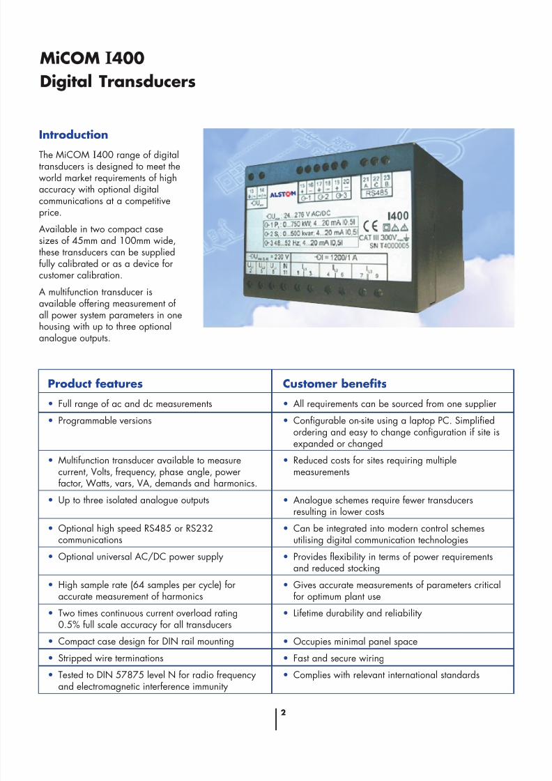
IntroductionThe MiCOM I400 range of digitaltransducers is designed to meet theworld market requirements of highaccuracy with optional digitalcommunications at a competitiveprice.
Available in two compact casesizes of 45mm and 100mm wide,these transducers can be suppliedfully calibrated or as a device for
customer calibration.
A multifunction transducer isavailable offering measurement of all power system parameters in onehousing with up to three optionalanalogue outputs.
Product features
• Full range of ac and dc measurements
• Programmable versions
• Multifunction transducer available to measurecurrent, Volts, frequency, phase angle, powerfactor, Watts, vars, VA, demands and harmonics.
• Up to three isolated analogue outputs
• Optional high speed RS485 or RS232communications
• Optional universal AC/DC power supply
• High sample rate (64 samples per cycle) foraccurate measurement of harmonics
• Two times continuous current overload rating0.5% full scale accuracy for all transducers
• Compact case design for DIN rail mounting
• Stripped wire terminations
• Tested to DIN 57875 level N for radio frequency
and electromagnetic interference immunity
Customer benefits
• All requirements can be sourced from one supplier
• Configurable on-site using a laptop PC. Simplifiedordering and easy to change configuration if site isexpanded or changed
• Reduced costs for sites requiring multiplemeasurements
• Analogue schemes require fewer transducersresulting in lower costs
• Can be integrated into modern control schemesutilising digital communication technologies
• Provides flexibility in terms of power requirementsand reduced stocking
• Gives accurate measurements of parameters criticalfor optimum plant use
• Lifetime durability and reliability
• Occupies minimal panel space
• Fast and secure wiring
• Complies with relevant international standards

8/12/2019 i400enbr Bc
http://slidepdf.com/reader/full/i400enbr-bc 3/163
Applications
Applications are found in electricalutilities, switchgear/switchboardmanufacturers, energymanagement, SCADA, buildingmanagement and control, processcontrol and instrumentation.
MiCOM I400 digital transducersprovide local and remote indicationfor precision electrical measurementand control when used withinstruments, recorders, data loggersand SCADA systems (SupervisoryControl and Data Acquisition).
Provision of both analogue outputsand RS485/RS232 MODBUScommunications facilitatesintegration within existing sites and
new facilities where digitalcommunications are used.
The ease of programmability of digital transducers is an importantfeature in the provision of costeffective system control. Systemscan be easily changed orexpanded as required. Scalingdetails may be delayed while thesystem is being constructed withoutcausing costly project time delays.
Why MiCOM I400 digitaltransducers?
As well as allowing integration intodigital control schemes, MiCOMI400 digital transducers use stateof the art microprocessortechnology to enable customerconfiguration using only a personalcomputer and configurationsoftware.
Stability
The use of microprocessortechnology in the design of theMiCOM I400 digital transducerrange guarantees accuracy andstability over a range of temperatures. The good long termstability achieved reduces theproblem of long term drift that canaffect some analogue transducers.This level of stability means thatMiCOM I400 digital transducers
can endure a lifetime of maintenance-free operation.
Inherent design quality
ALSTOM T&D LtdProtection & Control operatesmanufacturing and quality systemsthat meet and exceed therequirements of ISO 9001.
MiCOM I400 digital
transducer range
Mean sensing current
Mean sensing voltage
The mean sensing current orvoltage transducers do notrequire a power supply.
A range of ‘easy to order’standard scalings are available.
True rms current
True rms voltage
Suppressed zero voltage(true rms)
True rms devices are availablewith optional communicationsoutput.
Frequency
0.1% of centre scale accuracy
Available with optional 0.01%high accuracy communicationsoutput
Watts, vars, phase angle andpower factor
Single phase
Three phase, three wire,balanced or unbalanced load
Three phase, four wire,
balanced or unbalanced loadAvailable with optionalcommunications output
Combination transducers
Dual rms current/voltage
Dual frequency/rms voltage
Dual watt/var
Triple rms current
Triple rms voltage
All rms, frequency, power and dualoutput transducers are suppliedwith ac power supply as standard.
This must be specified at the time of order. Optionally, a universalac/dc power supply is available.
All triple output versions are
supplied with universal ac/dcpower supply as standard.
Multifunction programmable
Each device measures volts,current, frequency Watts, vars, VA,phase angle, power factor, THD%,dynamic demands, maximumdemands and optionally, harmonicanalysis.
All measurements are available viathe communications port.
The multifunction transducer isalways supplied with the universalac/dc power supply andcommunications port for customerconfiguration.
The multi-function transducer isavailable with none, one, two orthree analogue outputs. Eachoutput can be programmed to anyof the following measured functions: -
• RMS current:Phase Ia, Ib, Ic,I average, In
• RMS voltage:Line to neutral: Va, Vb, Vc,
VL-N averageLine to line: Vab, Vbc, Vca
VL-L average
• Frequency
• Power: Watts, vars, VA(per phase and totals)
• Phase angle (V-I) and (V-V)Phase and total
• Power angle atan 2 (PtQt)
• Dynamic demands:
Phase current Ia, Ib, IcTotal Watts, vars and VA
8/12/2019 i400enbr Bc
http://slidepdf.com/reader/full/i400enbr-bc 4/164
DC transducers
DC current
DC voltage
2 wire restance
Measurements also available via communications port:
Total harmonic distortion, %THD
VL-N, Va, Vb, Vc
VL-L, Vab, Vbc, VcaPhase currents Ia, Ib, Ic
Device internal temperature
Phase angles between voltages
Va-Vb, Vb-Vc, Vc-Va
Configuration
Transducers supplied without thecommunications interface aresupplied factory pre-configured forwhich the scaling details must besupplied with the order.
Transducers with thecommunications interface can beordered as factory pre-configuredor as a programmable version forcustomer configuration. Freesoftware to allow customerconfiguration from a PC isavailable at the time of order
The programmable devices aresupplied with one of three outputranges. Each can be programmedfor a unidirectional, a bidirectionalor a bent characteristic.
The three output types can beprogrammed over the ranges asbelow : -
Output reference Type P : -
1…0…1 mA to 5…0…5 mA
Output reference Type Q : -
6…0…6 mA to 20…0…20 mA
Output reference Type R : -
1…0…1 V to 10…0…10 V
Application information
Refer to Application Guide forElectrical Measuring TransducersPublication I9-113.
Information required with order
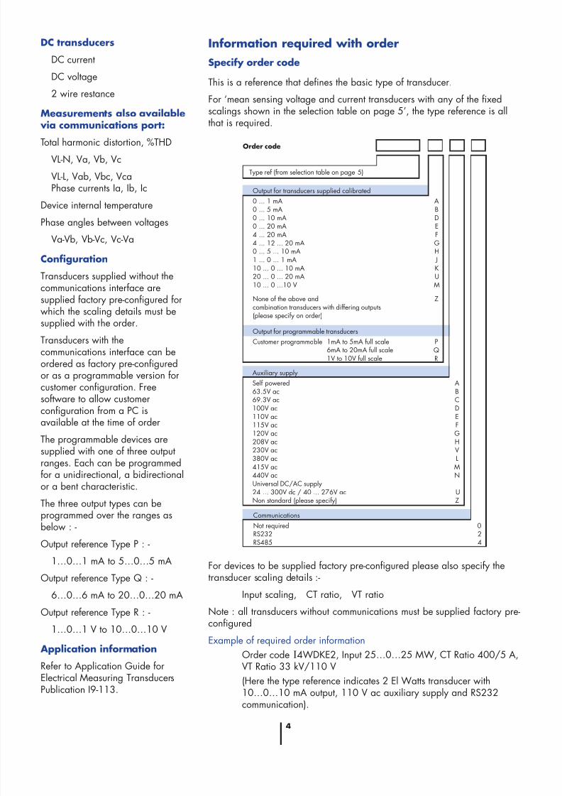
Specify order code
This is a reference that defines the basic type of transducer.
For ‘mean sensing voltage and current transducers with any of the fixedscalings shown in the selection table on page 5’, the type reference is allthat is required.
Order code
Auxiliary supply
Self powered A63.5V ac B69.3V ac C100V ac D
110V ac E115V ac F120V ac G208V ac H230V ac V380V ac L415V ac M440V ac NUniversal DC/AC supply24 ... 300V dc / 40 ... 276V ac UNon standard (please specify) Z
Type ref (from selection table on page 5)
Output for transducers supplied calibrated
0 ... 1 mA A0 ... 5 mA B0 ... 10 mA D0 ... 20 mA E4 ... 20 mA F4 ... 12 ... 20 mA G0 ... 5 ... 10 mA H1 ... 0 ... 1 mA J10 ... 0 ... 10 mA K
20 ... 0 ... 20 mA U10 ... 0 ...10 V M
None of the above and Zcombination transducers with differing outputs(please specify on order)
Output for programmable transducers
Customer programmable PQR
Communications
Not required 0RS232 2RS485 4
1mA to 5mA full scale6mA to 20mA full scale1V to 10V full scale
For devices to be supplied factory pre-configured please also specify thetransducer scaling details :-
Input scaling, CT ratio, VT ratio
Note : all transducers without communications must be supplied factory pre-configured
Example of required order information
Order code I4WDKE2, Input 25…0…25 MW, CT Ratio 400/5 A,VT Ratio 33 kV/110 V
(Here the type reference indicates 2 El Watts transducer with
10…0…10 mA output, 110 V ac auxiliary supply and RS232communication).

8/12/2019 i400enbr Bc
http://slidepdf.com/reader/full/i400enbr-bc 5/165
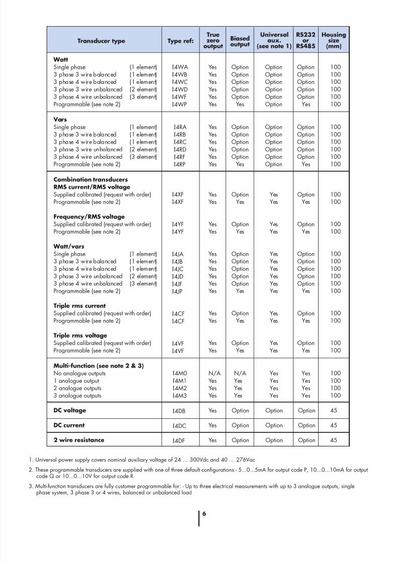
Transducer selection table
Devices offered with fixed scaling must be specified at the time of order.
Programmable devices are supplied scaled in secondary terms (0.5 … 1 … 0.5 cos phi for Phase Angle transducer).
Types shown have ac auxiliaries as standard, except I4CA & I4VA (self powered).
Transducer type
Mean sensing current (see note 2)Fixed scaling 0 ... 1A/0 ... 5mAFixed scaling 0 ... 1A/0 ... 10mAFixed scaling 0 ... 1A/0 ... 20mAFixed scaling 0 ... 5A/0 ... 5mAFixed scaling 0 ... 5A/0 ... 10mAFixed scaling 0 ... 5A/0 ... 20mAOther input/output (request with order)
Type ref:
required with order
True
zerooutput Biasedoutput
Universal
aux.(see note 1)
RS232
orRS485
Housing
size(mm)
I4CAB-1I4CAD-1I4CAE-1I4CAB-5I4CAD-5I4CAE-5I4CA
YesYesYesYesYesYesYes
-------
-------
-------
45454545454545
True rms voltageSupplied calibrated (request with order)Programmable (see note 2)
I4VDI4VD
YesYes
4545
OptionYes
OptionOption
OptionYes
Suppressed zero voltageSupplied calibrated (request with order)Programmable (see note 2)
I4VXI4VX
YesYes
4545
OptionYes
OptionOption
OptionYes
Frequency
Supplied calibrated (request with order)Programmable (see note 2)
I4FAI4FA
YesYes
4545
OptionYes
OptionOption
OptionYes
Phase angleSingle phase (1 element)3 phase 3 wire balanced (1 element)3 phase 4 wire balanced (1 element)3 phase 3 wire unbalanced (2 element)3 phase 4 wire unbalanced (3 element)Programmable (see note 2)
I4PAI4PBI4PCI4PDI4PFI4PP
YesYesYesYesYesYes
100100100100100100
OptionOptionOptionOptionOption
Yes
OptionOptionOptionOptionOptionOption
OptionOptionOptionOptionOption
Yes
True rms currentSupplied calibrated (request with order)Programmable (see note 2)
I4CDI4CD
YesYes
4545
OptionYes
OptionOption
OptionYes
Mean sensing voltage (see note 2)
Fixed scaling 0 ... 110V/0 ... 5mAFixed scaling 0 ... 110V/0 ... 10mAFixed scaling 0 ... 110V/0 ... 20mAFixed scaling 0 ... 120V/0 ... 5mAFixed scaling 0 ... 120V/0 ... 10mAFixed scaling 0 ... 120V/0 ... 20mAFixed scaling 0 ... 250V/0 ... 5mAFixed scaling 0 ... 250V/0 ... 10mAFixed scaling 0 ... 250V/0 ... 20mAFixed scaling 0 ... 500V/0 ... 5mAFixed scaling 0 ... 500V/0 ... 10mAFixed scaling 0 ... 500V/0 ... 20mAOther scaling (request with order)
I
4VAB-110I4VAD-110I4VAE-110I4VAB-120I4VAD-120I4VAE-120I4VAB-250I4VAD-250I4VAE-250I4VAB-500I4VAD-500I4VAE-500I4VA
YesYesYesYesYesYesYesYesYesYesYesYesYes
-------------
-------------
-------------
45454545454545454545454545
8/12/2019 i400enbr Bc
http://slidepdf.com/reader/full/i400enbr-bc 6/166
Transducer type Type ref:Truezero
outputBiasedoutput
Universalaux.
(see note 1)
RS232or
RS485
Housingsize
(mm)
WattSingle phase (1 element)3 phase 3 wire balanced (1 element)3 phase 4 wire balanced (1 element)3 phase 3 wire unbalanced (2 element)
3 phase 4 wire unbalanced (3 element)Programmable (see note 2)
I4WAI4WBI4WCI4WD
I4WFI4WP
YesYesYesYes
YesYes
100100100100
100100
OptionOptionOptionOption
OptionYes
OptionOptionOptionOption
OptionOption
OptionOptionOptionOption
OptionYes
VarsSingle phase (1 element)3 phase 3 wire balanced (1 element)3 phase 4 wire balanced (1 element)3 phase 3 wire unbalanced (2 element)3 phase 4 wire unbalanced (3 element)Programmable (see note 2)
I4RAI4RBI4RCI4RDI4RFI4RP
YesYesYesYesYesYes
100100100100100100
OptionOptionOptionOptionOption
Yes
OptionOptionOptionOptionOptionOption
OptionOptionOptionOptionOption
Yes
Combination transducersRMS current/RMS voltage
Supplied calibrated (request with order)Programmable (see note 2)
Frequency/RMS voltageSupplied calibrated (request with order)Programmable (see note 2)
Watt/varsSingle phase (1 element)3 phase 3 wire balanced (1 element)3 phase 4 wire balanced (1 element)3 phase 3 wire unbalanced (2 element)3 phase 4 wire unbalanced (3 element)Programmable (see note 2)
Triple rms currentSupplied calibrated (request with order)Programmable (see note 2)
Triple rms voltageSupplied calibrated (request with order)Programmable (see note 2)
I
4XFI4XF
I4YFI4YF
I4JAI4JBI4JCI4JDI4JFI4JP
I4CFI4CF
I4VFI4VF
YesYes
YesYes
YesYesYesYesYesYes
YesYes
YesYes
100100
100100
100100100100100100
100100
100100
OptionYes
OptionYes
OptionOptionOptionOptionOption
Yes
OptionYes
OptionYes
YesYes
YesYes
YesYesYesYesYesYes
YesYes
YesYes
OptionYes
OptionYes
OptionOptionOptionOptionOption
Yes
OptionYes
OptionYes
Multi-function (see note 2 & 3)No analogue outputs1 analogue output2 analogue outputs
3 analogue outputs
I4M0I4M1I4M2
I4M3
N/AYesYes
Yes
100100100
100
N/AYesYes
Yes
YesYesYes
Yes
YesYesYes
Yes
DC voltage
DC current
2 wire resistance
I4DB
I4DC
I4DF
Yes
Yes
Yes
45
45
45
Option
Option
Option
Option
Option
Option
Option
Option
Option
1. Universal power supply covers nominal auxiliary voltage of 24 … 300Vdc and 40 … 276Vac
2. These programmable transducers are supplied with one of three default configurations:- 5...0...5mA for output code P, 10...0...10mA for outputcode Q or 10...0...10V for output code R.
3. Multi-function transducers are fully customer programmable for: - Up to three electrical measurements with up to 3 analogue outputs, single
phase system, 3 phase 3 or 4 wires, balanced or unbalanced load
8/12/2019 i400enbr Bc
http://slidepdf.com/reader/full/i400enbr-bc 7/167
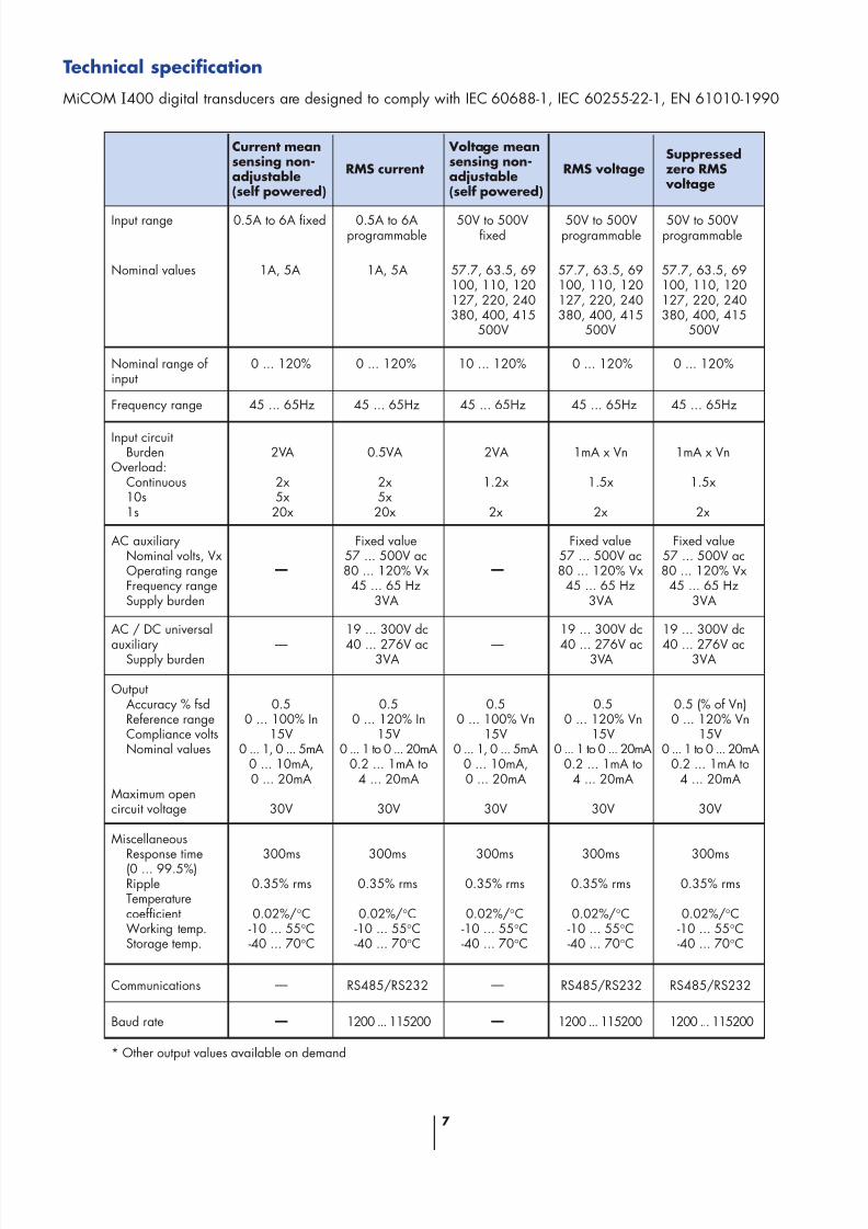
Technical specification
MiCOM I400 digital transducers are designed to comply with IEC 60688-1, IEC 60255-22-1, EN 61010-1990
Current meansensing non-adjustable(self powered)
RMS current
Voltage meansensing non-adjustable(self powered)
RMS voltageSuppressedzero RMS
voltage
Input range 0.5A to 6A fixed 0.5A to 6Aprogrammable
50V to 500Vfixed
50V to 500Vprogrammable
50V to 500Vprogrammable
Nominal values 1A, 5A 1A, 5A 57.7, 63.5, 69100, 110, 120127, 220, 240380, 400, 415
500V
57.7, 63.5, 69100, 110, 120127, 220, 240380, 400, 415
500V
57.7, 63.5, 69100, 110, 120127, 220, 240380, 400, 415
500V
Nominal range of input
0 ... 120% 0 ... 120% 10 ... 120% 0 ... 120% 0 ... 120%
Frequency range 45 ... 65Hz 45 ... 65Hz 45 ... 65Hz 45 ... 65Hz 45 ... 65Hz
Input circuitBurden
Overload:Continuous10s1s
2VA
2x5x20x
0.5VA
2x5x20x
2VA
1.2x
2x
1mA x Vn
1.5x
2x
1mA x Vn
1.5x
2x
AC auxiliaryNominal volts, VxOperating rangeFrequency rangeSupply burden
Fixed value57 ... 500V ac80 ... 120% Vx
45 ... 65 Hz3VA
Fixed value57 ... 500V ac80 ... 120% Vx
45 ... 65 Hz3VA
Fixed value57 ... 500V ac80 ... 120% Vx
45 ... 65 Hz3VA
AC / DC universal
auxiliarySupply burden
19 ... 300V dc
40 ... 276V ac3VA
19 ... 300V dc
40 ... 276V ac3VA
19 ... 300V dc
40 ... 276V ac3VA
OutputAccuracy % fsdReference rangeCompliance voltsNominal values
Maximum opencircuit voltage
0.50 ... 100% In
15V0 ... 1, 0 ... 5mA
0 ... 10mA,0 ... 20mA
30V
0.50 ... 120% In
15V0 ... 1 to 0 ... 20mA
0.2 ... 1mA to4 ... 20mA
30V
0.50 ... 100% Vn
15V0 ... 1, 0 ... 5mA
0 ... 10mA,0 ... 20mA
30V
0.50 ... 120% Vn
15V0 ... 1 to 0 ... 20mA
0.2 ... 1mA to4 ... 20mA
30V
0.5 (% of Vn)0 ... 120% Vn
15V0 ... 1 to 0 ... 20mA
0.2 ... 1mA to4 ... 20mA
30V
MiscellaneousResponse time(0 ... 99.5%)RippleTemperaturecoefficientWorking temp.Storage temp.
300ms
0.35% rms
0.02%/°C-10 ... 55°C-40 ... 70°C
300ms
0.35% rms
0.02%/°C-10 ... 55°C-40 ... 70°C
300ms
0.35% rms
0.02%/°C-10 ... 55°C-40 ... 70°C
300ms
0.35% rms
0.02%/°C-10 ... 55°C-40 ... 70°C
300ms
0.35% rms
0.02%/°C-10 ... 55°C-40 ... 70°C
Communications RS485/RS232 RS485/RS232 RS485/RS232
Baud rate 1200 ... 115200 1200 ... 115200 1200 ... 115200
* Other output values available on demand
8/12/2019 i400enbr Bc
http://slidepdf.com/reader/full/i400enbr-bc 8/168
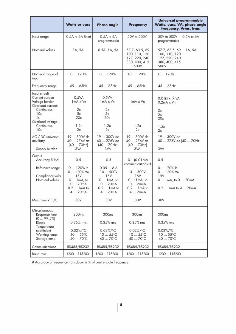
Watts or vars Phase angle Frequency Universal programmable
Watts, vars, VA, phase anglefrequency, Vrms, Irms
Input range 0.5A to 6A fixed 0.5A to 6Aprogrammable
50V to 500V 50V to 500V 0.5A to 6Aprogrammable
Nominal values 1A, 5A 0.5A, 1A, 5A 57.7, 63.5, 69100, 110, 120
127, 220, 240380, 400, 415
500V
57.7, 63.5, 69100, 110, 120
127, 220, 240380, 400, 415500V
Nominal range of input
0 ... 120% 0 ... 120% 10 ... 120% 0 ... 120%
Frequency range 45 ... 65Hz 45 ... 65Hz 45 ... 65Hz 45 ... 65Hz
Input circuitCurrent burdenVoltage burdenOverload current:
Continuous10s
1sOverload voltage:
Continuous10s
0.5VA1mA x Vn
2x5x
20x
1.2x2x
0.5VA1mA x Vn
2x5x
20x
1.2x2x
-1mA x Vn
1.2x2x
AC / DC universalauxiliary
Supply burden
19 ... 300V dc40 ... 276V ac(40 ... 70Hz)
3VA
OutputAccuracy % fsd
Reference range
Compliance voltsNominal values
Maximum V O/C
0.5
0 ... 120% In0 ... 120% Vn
15V0 ... 1mA, to0 ... 20mA
0.2 ... 1mA to4 ... 20mA
30V
MiscellaneousResponse time(0 ... 99.5%)RippleTemperaturecoefficient
Working temp.Storage temp.
300ms
0.35% rms
0.02%/°C
-10 ... 55°C-40 ... 70°C
300ms
0.35% rms
0.02%/°C
-10 ... 55°C-40 ... 70°C
300ms
0.35% rms
0.02%/°C
-10 ... 55°C-40 ... 70°C
300ms
0.35% rms
0.02%/°C
-10 ... 55°C-40 ... 70°C
Communications RS485/RS232 RS485/RS232
1A, 5A
0.01Ω x I2 VA0.2mA x Vn
2x5x20x
1.5x2x
19 ... 300V dc40 ... 276V ac(40 ... 70Hz)
3VA
19 ... 300V dc40 ... 276V ac(40 ... 70Hz)
3VA
19 ... 300V dc40 ... 276V ac (40 ... 70Hz)
3VA
0.5
0.05 ... 6 A10 ... 500V
15V0 ... 1mA, to0 ... 20mA
0.2 ... 1mA to4 ... 20mA
30V
0.1 (0.01 viacommunications) #
-3 ... 500V
15V0 ... 1mA, to0 ... 20mA
0.2 ... 1mA to4 ... 20mA
30V
0.5
0 ... 120% In0 ... 120% Vn
15V0 ... 1mA, to 0 ... 20mA
0.2 ... 1mA to 4 ... 20mA
30V
RS485/RS232 RS485/RS232
Baud rate 1200 ... 115200 1200 ... 115200 1200 ... 115200
# Accuracy of frequency transducer is % of centre scale frequency
1200 ... 115200
8/12/2019 i400enbr Bc
http://slidepdf.com/reader/full/i400enbr-bc 9/169
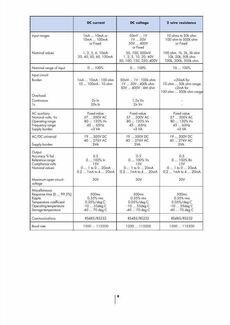
DC current
Input ranges 1mA ... 10mA or10mA ... 100mA
or Fixed
50mV ... 1V1V ... 50V
50V ... 400Vor Fixed
DC voltage 2 wire resistance
10 ohms to 50k ohm100 ohm to 500k ohm
or Fixed
Nominal values 1, 2, 5, 6, 10mA
20, 40, 50, 60, 100mA
50, 100, 500mV
1, 2, 5, 10, 20, 40V50, 100, 150, 250, 400V
100 ohm, 1k, 2k, 5k ohm
10k, 20k, 50k ohm100k, 200k, 500k ohm
Nominal range of input 0 ... 100% 0 ... 100% 10 ... 100%
Input circuit
Burden 1mA ... 10mA : 100 ohm10 ... 100mA : 10 ohm
50mV ... 1V : 100k ohm1V ... 50V : 400k ohm50V ... 400V : 4M ohm
<20mA for10 ohm ... 50k ohm range
<2mA for100 ohm ... 500k ohm range
Overload:
Continuous1s
2x In20x In
1,2x Vn2x Vn
--
AC auxiliaryNominal volts, VxOperating rangeFrequency rangeSupply burden
Fixed value57 ... 500V AC80 ... 120% Vx
45 ... 65Hz<3 VA
Fixed value57 ... 500V AC80 ... 120% Vx
45 ... 65Hz<3 VA
Fixed value57 ... 500V AC80 ... 120% Vx
45 ... 65Hz<3 VA
AC/DC universal
Supply burden
19 ... 300V DC40 ... 276V AC
3VA
19 ... 300V DC40 ... 276V AC
3VA
19 ... 300V DC40 ... 276V AC
3VA
OutputAccuracy % fsdReference rangeCompliance voltsNominal values
Maximum open circuitvoltage
0.50 ... 100% In
15V0 ... 1 to 0 ... 20mA
0.2 ... 1mA to 4 ... 20mA
30V
0.50 ... 100% Vn
15V0 ... 1 to 0 ... 20mA
0.2 ... 1mA to 4 ... 20mA
30V
0.50 ... 100% Rn
15V0 ... 1 to 0 ... 20mA
0.2 ... 1mA to 4 ... 20mA
30V
MiscellaneousResponse time (0 ... 99.5%)RippleTemperature coefficientOperating temperatureStorage temperature
500ms0.35% rms
0.05%/deg C-10 ... 55deg C-40 ... 70 deg C
500ms0.35% rms
0.05%/deg C-10 ... 55deg C-40 ... 70 deg C
500ms0.35% rms
0.05%/deg C-10 ... 55deg C-40 ... 70 deg C
Communications
Baud rate
RS485/RS232
1200 ... 115200
RS485/RS232
1200 ... 115200
RS485/RS232
1200 ... 115200

8/12/2019 i400enbr Bc
http://slidepdf.com/reader/full/i400enbr-bc 10/1610
Climatic class JVE DIN 40040,3 VDI/VDE 3540,EN 60688, 1992 class III
IsolationInsulation Class II. Routinetest at 3.7kV rms toEN61010-1 1990
(500V rms for 60 s between
multiple outputs)Impulse test
5kV (1.2/50µs) toIEC 60255-4/III
Surge withstandIEC 60255-22-1 andANSI C37-90A IEEE Std 472SWC where applicable
Electromagnetic compatibilityEN6100-4-4, 1995-01
Radio Interference protectionLevel N, according to DIN 57875
Safety requirementsEN 61010-1:1990-09protection class III(300V),class II (600V)
Case protectionIP50, terminals IP20 toEN 60529, 1989
Case flammability protectionUL 94 V-0
ElectromagneticCompatibility Directive89/336/EEC
Emissions standardEN 50081-2 1994 Industrialenvironment
Immunity StandardEN 50082-2 1995 Industrial
Environment(IEC 60801 parts 2,3 and 4)
Susceptibility to ElectrostaticDischarge8kV air discharge/4kV contact.
WARNING: This specificationapplies when the transducer case isclosed. If the transducer case isopened then appropriate ESDprotection must be taken.
Low Voltage Directive72/23/EEC
Designed to EN61010-1 and A31993 and 1995 safetyrequirements.
Compliance
VoltageValue of maximum output load (Ω) by output current rating
1mA 5mA 10mA 20mA
15V 15k 3k 1.5k 750
The output loading (kΩ) can be obtained by dividing thecompliance voltage (V) by the maximum rated output (mA)
Voltage output
The minimum load for a 10V voltage output is 500 ohms
Transducer output loading
Current output:

8/12/2019 i400enbr Bc
http://slidepdf.com/reader/full/i400enbr-bc 11/1611
Connection diagrams for MiCOM I400 digital transducers - Input connections
2 11
v
V
u
UL
N
Volts, frequency
1 3
LKL
N
Current
k l
LKL1
N
Power - single phase
k l
1 32 11
VU
u v
Power - 3 wire balanced
1 2 3 5 8
u v
U VL1
L2
L3
U V
u v
k l
K L
Power - 3 wire unbalanced
1 2 3 5 7 8 9
u v
U VL1
L2
L3
U V
u v
k l
K L k l
K L
Power - 4 wire balanced
LKL1
N
k l
1 32 11
VU
u v
L2
L3
Power - 4 wire unbalanced
L3
1 2 3 4 5 6 7 8 9 11
L2
L1
N
U U U
K L
K L
K L
k lk l
k l
X X X
x x x
u u u
Triple current
L3
1 3 4 6 7 9
L2
L1
N
K L
K L
K L
k lk l
k l
Triple voltage
L3
2 5 8 11
L2
L1
N
U U U
X X X
x x x
u u u
2 11
v
V
u
UL
N
Volts + frequency
LKL1
N
Current + volts
k l
1 32 11
VU
u v
Note: The diagrams referred to as “Power” are applicable to Watt, var,
VA, phase angle, Watt+var and multifunction transducers.
8/12/2019 i400enbr Bc
http://slidepdf.com/reader/full/i400enbr-bc 12/1612
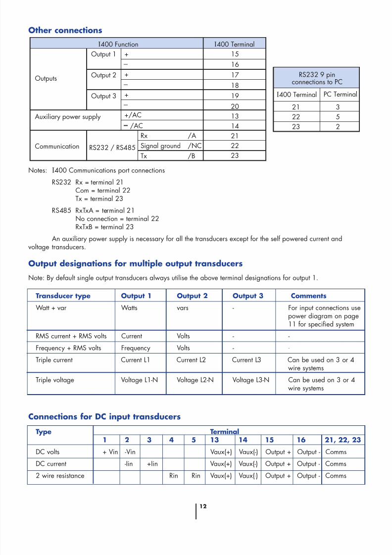
Other connections
Notes: I400 Communications port connections
RS232 Rx = terminal 21Com = terminal 22Tx = terminal 23
RS485 RxTxA = terminal 21No connection = terminal 22RxTxB = terminal 23
An auxiliary power supply is necessary for all the transducers except for the self powered current andvoltage transducers.
Output designations for multiple output transducers
Note: By default single output transducers always utilise the above terminal designations for output 1.
I400 Function I400 Terminal
Outputs
Output 1
Output 2
Output 3
Auxiliary power supply
Communication RS232 / RS485
+
+
+
+/AC
/AC
Rx /A
Tx /B
Signal ground /NC
15
16
17
18
1920
13
14
21
22
23
I400 Terminal
RS232 9 pinconnections to PC
PC Terminal21
22
23
3
5
2
Transducer type Output 1 Output 2 Output 3 Comments
Watt + var Watts vars - For input connections usepower diagram on page11 for specified system
RMS current + RMS volts Current Volts - -
Frequency + RMS volts Frequency Volts - -
Triple current Current L1 Current L2 Current L3 Can be used on 3 or 4wire systems
Triple voltage Voltage L1-N Voltage L2-N Voltage L3-N Can be used on 3 or 4
wire systems
Connections for DC input transducers
Type Terminal1 2 3 4 5 13 14 15 16 21, 22, 23
DC volts + Vin -Vin Vaux(+) Vaux(-) Output + Output - Comms
DC current -Iin +Iin Vaux(+) Vaux(-) Output + Output - Comms
2 wire resistance Rin Rin Vaux(+) Vaux(-) Output + Output - Comms

8/12/2019 i400enbr Bc
http://slidepdf.com/reader/full/i400enbr-bc 13/1613
Case size and fixing details
104.5100
75
All dimensions in mmMaximum section of connection wires
< = 4.0mm2 for one wire< = 1.5mm2 for two wires
44.8 104.5
75
Shipping weights
The following weights apply toindividual transducers:
In practice, export orders will haveadditional secondary packaging -
consult factory for details.
Packed dimensions
Individual Units
• 45mm Housing98 x 113 x 55 mm
• 100mm Housing98 x 113 x 112 mm
Transducer typeMax. net
weight (g)Power supply
Single measurement ac current,ac voltage, frequency, dc current,dc voltage or 2 wire resistance
transducer
AC auxiliary orself powered
Housing
(mm)
45 320
Universal powersupply
45 200
Single measurement powertransducer
AC auxiliary 100 460
Single measurement powertransducer
100 340Universal powersupply
Multiple measurement transducer 100 460Universal power
supply
Single measurement ac current,ac voltage, frequency, dc current,dc voltage or 2 wire resistancetransducer
Associateddocumentation
I9-113 Transducer ApplicationGuide
Caution! Refer to Operating &Maintenance manual beforeinstalling, commissioning, or
operating the equipment
1. Installation, commissioning andmaintenance should only becarried out be suitably qualifiedpersonnel.
2. Terminations exposed duringinstallation, commissioning andmaintenance may present ahazard unless the equipment iselectrically isolated.
3. The equipment should only beoperated as intended eg. withthe covers in place, and withinthe specified electrical andenvironmental limits.
4. Due to the presence of electrostatic sensitive devices onthe printed circuit board,appropriate ESD protection mustbe taken before commencinginstallation, commissioning ormaintenance.

8/12/2019 i400enbr Bc
http://slidepdf.com/reader/full/i400enbr-bc 14/1614
Notes:
Your contact:

8/12/2019 i400enbr Bc
http://slidepdf.com/reader/full/i400enbr-bc 15/1615

8/12/2019 i400enbr Bc
http://slidepdf.com/reader/full/i400enbr-bc 16/16
P u b l i c a t i o
n : i 4 0 0 / E N B
R / B c
©
2 0 0 2 A L S T O M -
0 7 0 2 0 1 C l é m e n t i m p r i m e u r s
Transmission & Distribution Energy Automation & Information, Le Sextant, 3 avenue André Malraux, 92300 Levallois-Perret. FranceTel: +33 (0) 1 41 49 20 00 Fax: +33 (0) 1 41 49 24 85 [email protected] www.tde.alstom.com
Contact Centre on line 24 hours a day : +44 (0) 1785 25 00 70
ALSTOM, the ALSTOM logo and any alternative version thereof are trademarks and service marks of ALSTOM.MiCOM is a registered trademark of ALSTOM. Other names mentioned, registered or not, are the property of their respective companies.
Our policy is one of continuous development. Accordingly the design of our products may change at any time. Whilst every effort is made to produce up to date literature, this


![DDS C ,bc ]^ - NEDO · DDS ˘ˇˆ ... DSBL 3.70 ppm DSBL 1.23 ppm BC 100.00 ppm BC 33.33 ppm BC 11.11 ppm BC 3.70 ppm BC 1.23 ppm DMCBL 100.00 ppm DMCBL 33.33 ppm DMCBL 11.11 ppm](https://static.fdocuments.nl/doc/165x107/5ad6c02a7f8b9a6d708e8ad8/dds-c-bc-dsbl-370-ppm-dsbl-123-ppm-bc-10000-ppm-bc-3333-ppm.jpg)