
Hot Gas Conditioning: Recent Progress With Larger-Scale … · 2013-08-12 · Hot Gas Conditioning:...
103
August 2001 NREL/SR-510-29952 Don J. Stevens Pacific Northwest National Laboratory Richland, Washington Hot Gas Conditioning: Recent Progress With Larger-Scale Biomass Gasification Systems Update and Summary of Recent Progress National Renewable Energy Laboratory 1617 Cole Boulevard Golden, Colorado 80401-3393 NREL is a U.S. Department of Energy Laboratory Operated by Midwest Research Institute • Battelle • Bechtel Contract No. DE-AC36-99-GO10337
Transcript of Hot Gas Conditioning: Recent Progress With Larger-Scale … · 2013-08-12 · Hot Gas Conditioning:...
August 2001 � NREL/SR-510-29952
Don J. StevensPacific Northwest National LaboratoryRichland, Washington
Hot Gas Conditioning: RecentProgress With Larger-ScaleBiomass Gasification Systems
Update and Summary of Recent Progress
National Renewable Energy Laboratory1617 Cole BoulevardGolden, Colorado 80401-3393NREL is a U.S. Department of Energy LaboratoryOperated by Midwest Research Institute •••• Battelle •••• Bechtel
Contract No. DE-AC36-99-GO10337
August 2001 � NREL/SR-510-29952
Hot Gas Conditioning: RecentProgress With Larger-ScaleBiomass Gasification Systems
Update and Summary of Recent Progress
Don J. StevensPacific Northwest National LaboratoryRichland, Washington
NREL Technical Monitor: Richard BainPrepared under Subcontract No. 98 CO 004
National Renewable Energy Laboratory1617 Cole BoulevardGolden, Colorado 80401-3393NREL is a U.S. Department of Energy LaboratoryOperated by Midwest Research Institute •••• Battelle •••• Bechtel
Contract No. DE-AC36-99-GO10337
NOTICE
This report was prepared as an account of work sponsored by an agency of the United Statesgovernment. Neither the United States government nor any agency thereof, nor any of their employees,makes any warranty, express or implied, or assumes any legal liability or responsibility for the accuracy,completeness, or usefulness of any information, apparatus, product, or process disclosed, or representsthat its use would not infringe privately owned rights. Reference herein to any specific commercialproduct, process, or service by trade name, trademark, manufacturer, or otherwise does not necessarilyconstitute or imply its endorsement, recommendation, or favoring by the United States government or anyagency thereof. The views and opinions of authors expressed herein do not necessarily state or reflectthose of the United States government or any agency thereof.
Available electronically at http://www.doe.gov/bridge
Available for a processing fee to U.S. Department of Energyand its contractors, in paper, from:
U.S. Department of EnergyOffice of Scientific and Technical InformationP.O. Box 62Oak Ridge, TN 37831-0062phone: 865.576.8401fax: 865.576.5728email: [email protected]
Available for sale to the public, in paper, from:U.S. Department of CommerceNational Technical Information Service5285 Port Royal RoadSpringfield, VA 22161phone: 800.553.6847fax: 703.605.6900email: [email protected] ordering: http://www.ntis.gov/ordering.htm
Printed on paper containing at least 50% wastepaper, including 20% postconsumer waste

i
ABSTRACT
As a result of environmental and policy considerations, there is increasing interest in usingrenewable biomass resources as feedstock for power, fuels, and chemicals and hydrogen.Biomass gasification is seen as an important technology component for expanding the use ofbiomass. Advanced biomass gasification systems provide clean products that can be usedas fuel or synthesis gases in a variety of environmentally friendly processes.
Advanced end-use technologies such as gas turbines or synthesis gas systems require highquality gases with narrowly defined specifications. Other systems such as boilers may alsohave fuel quality requirements, but they will be substantially less demanding. The gasproduct from biomass gasifiers contains quantities of particulates, tars, and otherconstituents that may exceed these specified limits. As a result, gas cleaning andconditioning will be required in most systems.
Over the past decade, significant research and development activities have been conductedon the topic of gas cleanup and conditioning. This report provides an update of effortsrelated to large-scale biomass gasification systems and summarizes recent progress.Remaining research and development issues are also summarized.

ii
iii
ACRONYMS AND ABBREVIATIONS
atm atmospheresARBRE ARable Biomass Renewable Energy project, UKC centigradeCFB circulating fluidized bedCHP combined heat and powerDOE US Department of EnergyGWh gigawatt hourGJ giga-Joule (109 Joule)ha hectareIEA International Energy AgencyIC internal combustion (engine)IGCC integrated gasification combined cyclekPa kiloPascalskWe kilowatt of electricitykWh kilowatt hourmg milligramMJ mega Joule (106 Joule)MWe megawatt of electricity (106 Watt)MWt megawatt thermalNm3 normal cubic meterOD outside diameterODT oven dried tonPAH polyaromatic hydrocarbonppm parts per millionppm parts per millionR&D research and developmentRD&D research, development and demonstrationRDF refuse-derived fuelsec secondtpd tons per dayµm micrometer

iv

v
ACKNOWLEDGMENTS
The author would like to acknowledge the U.S. Department of Energy and NationalRenewable Energy Laboratory for their support of this work and their assistance inacquiring information and reports.

vi
vii
CONTENTS
ABSTRACT............................................................................................................................................i
ACRONYMS AND ABBREVIATIONS .......................................................................................... iii
ACKNOWLEDGMENTS....................................................................................................................v
CONTENTS....................................................................................................................................... vii
FIGURES..............................................................................................................................................ix
TABLES................................................................................................................................................ix
1. INTRODUCTION........................................................................................................................ 1
2. BIOMASS GASIFICATION TECHNOLOGIES....................................................................... 3
2.1 Basics of Biomass Gasification........................................................................................... 32.1.1 Gasification Approaches............................................................................................. 42.1.2 Gasifier Designs and Influences on Product Gas Composition............................ 4
2.2 Status of Biomass Gasification Technologies................................................................... 72.3 The Relationship Between Biomass Gasification and Combustion.............................. 92.4 Gasification of Other Solid Fuels....................................................................................... 9
3. PRODUCT GAS CLEANUP AND CONDITIONING ......................................................... 11
3.1 General Considerations .................................................................................................... 113.2. Gas Phase Contaminants .................................................................................................. 12
3.2.1 Particulates ................................................................................................................. 123.2.2 Alkali Compounds .................................................................................................... 143.2.3 Tars from Biomass Gasification............................................................................... 163.2.4 Nitrogen Containing Contaminants ....................................................................... 173.2.5 Sulfur ........................................................................................................................... 183.2.6 Other Considerations for Synthesis Gas................................................................. 18
3.3 Gas Cleanup Technologies and Recent Progress .......................................................... 183.3.1 Particulate Removal Technologies .......................................................................... 193.3.2 Technologies for alkali removal .............................................................................. 233.3.3 Tar Removal Technologies ....................................................................................... 243.3.4 Removal of Nitrogen Containing Compounds ..................................................... 323.3.5 Sulfur Removal .......................................................................................................... 323.3.6 Hydrocarbon reduction and gas conditioning for producing synthesis gases
and hydrogen ............................................................................................................. 333.4 Survey of Biomass Gas Conditioning Technologies..................................................... 34
4. INTEGRATED GASIFICATION/END-USE SYSTEMS....................................................... 354.1 Fuel Gases for Systems With Minimal Gas Conditioning Requirements.................. 37
4.1.1 Overall Gas Conditioning Strategy � Minimal Gas Conditioning...................... 374.1.2 Example of a Gasification System Requiring Minimal Gas Conditioning:
Lahti , Finland ............................................................................................................ 37
viii
4.1.3 Example of a Gasification System Requiring Minimal Gas Conditioning:Primenergy, Stuttgart Arkansas .............................................................................. 40
4.2 Cool Fuel Gases for Systems With Significant Gas Conditioning Requirements..... 424.2.1 Overall Gas Conditioning Strategy � Producing Clean, Cool Fuel Gases......... 434.2.2 Example of a Gasification System Producing Cool, Conditioned Gas:
Amergas Facility in Geertruidenberg, Netherlands ............................................. 444.2.3 Example of a Gasification Systems Producing Cool, Conditioned Gas:
ARBRE Facility in United Kingdom ....................................................................... 474.2.4 Example of a Gasification Systems Producing Cool, Conditioned Gas:
Vermont Gasifier Project , Burlington, Vermont, USA ........................................ 504.2.5 Other Related Systems.............................................................................................. 53
4.3 Hot or Warm Fuel Gases for Systems With Significant Gas ConditioningRequirements ..................................................................................................................... 53
4.3.1 Example of a Gasification System Producing Hot, Conditioned Gas:Värnamo Facility in Sweden .................................................................................... 54
4.4 Synthesis Gases for the Production of Fuels and Chemicals, and Hydrogen forUse With Fuel Cells ........................................................................................................... 57
4.4.1 Current Production of Fuels and Chemicals from Synthesis Gas ...................... 584.4.2 Biomass-based Production of Synthesis Gas ......................................................... 584.4.3 Biomass Gasification to Produce Hydrogen for Fuel Cells ................................. 60
5. DISCUSSION AND RESEARCH NEEDS .............................................................................. 63
5.1 Summary of the Status of Gas Conditioning for Large-Scale Gasification Systems 635.1.1 Progress in Understanding Gas Conditioning Processes .................................... 635.1.2 Progress Relating to Gas Conditioning in Integrated Systems ........................... 65
5.2 Summary of Research and Development Needs .......................................................... 68
6. REFERENCES ............................................................................................................................ 71
APPENDIX 1. GAS CONDITIONING TECHNOLOGY SURVEY....................................... 81
ix
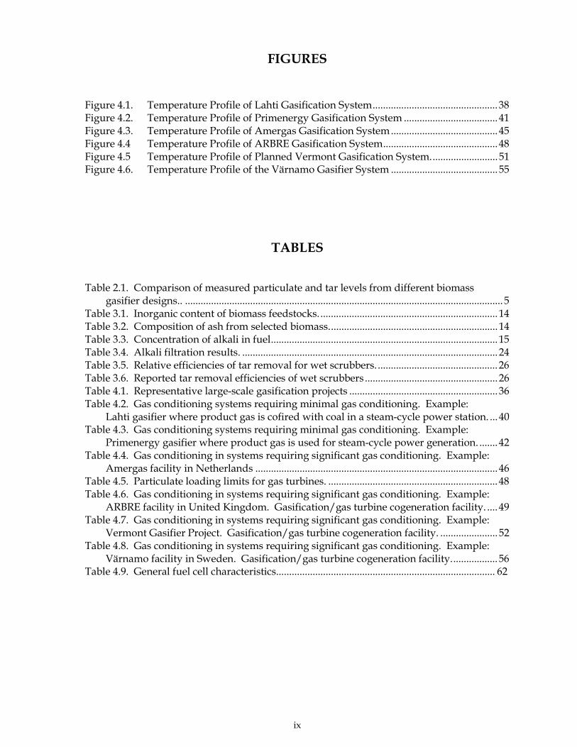
FIGURES
Figure 4.1. Temperature Profile of Lahti Gasification System................................................ 38Figure 4.2. Temperature Profile of Primenergy Gasification System .................................... 41Figure 4.3. Temperature Profile of Amergas Gasification System......................................... 45Figure 4.4 Temperature Profile of ARBRE Gasification System............................................ 48Figure 4.5 Temperature Profile of Planned Vermont Gasification System.......................... 51Figure 4.6. Temperature Profile of the Värnamo Gasifier System ......................................... 55
TABLES
Table 2.1. Comparison of measured particulate and tar levels from different biomassgasifier designs.. .......................................................................................................................... 5
Table 3.1. Inorganic content of biomass feedstocks..................................................................... 14Table 3.2. Composition of ash from selected biomass................................................................. 14Table 3.3. Concentration of alkali in fuel....................................................................................... 15Table 3.4. Alkali filtration results. .................................................................................................. 24Table 3.5. Relative efficiencies of tar removal for wet scrubbers............................................... 26Table 3.6. Reported tar removal efficiencies of wet scrubbers ................................................... 26Table 4.1. Representative large-scale gasification projects ......................................................... 36Table 4.2. Gas conditioning systems requiring minimal gas conditioning. Example:
Lahti gasifier where product gas is cofired with coal in a steam-cycle power station. ... 40Table 4.3. Gas conditioning systems requiring minimal gas conditioning. Example:
Primenergy gasifier where product gas is used for steam-cycle power generation. ....... 42Table 4.4. Gas conditioning in systems requiring significant gas conditioning. Example:
Amergas facility in Netherlands ............................................................................................. 46Table 4.5. Particulate loading limits for gas turbines. ................................................................. 48Table 4.6. Gas conditioning in systems requiring significant gas conditioning. Example:
ARBRE facility in United Kingdom. Gasification/gas turbine cogeneration facility. .... 49Table 4.7. Gas conditioning in systems requiring significant gas conditioning. Example:
Vermont Gasifier Project. Gasification/gas turbine cogeneration facility. ...................... 52Table 4.8. Gas conditioning in systems requiring significant gas conditioning. Example:
Värnamo facility in Sweden. Gasification/gas turbine cogeneration facility.................. 56Table 4.9. General fuel cell characteristics.................................................................................... 62

x
1
1. INTRODUCTION
As a result of environmental and other policy considerations, there is increasing world-wideinterest in the use of biomass resources as feedstocks for producing power, fuels, andchemicals. Biomass resources are a major component of strategies to mitigate global climatechange. Plant growth �recycles� CO2 from the atmosphere, and the use of biomassresources for energy and chemicals results in low net emissions of carbon dioxide. Theemissions of NOx and SOx from biomass facilities are also typically low. This helps biomasstechnologies meet local and regional environmental regulations and reduce emissions thatcontribute to acid rain. The use of these locally produced energy resources also results innew markets for agricultural and forestry products and provides a mechanism for ruraleconomic development. Because of these and other factors, many national governments arecurrently developing policies and regulations intended to expand the use of biomass overthe next decade and beyond.
Biomass gasification technologies are expected to be an important part of the effort to meetthese goals of expanding the use of biomass. Gasification technologies provide theopportunity to convert renewable biomass feedstocks into clean fuel gases or synthesisgases. These gaseous products can be burned to generate heat or electricity, or they canpotentially be used in the synthesis of liquid transportation fuels, hydrogen, or chemicals.Gasification offers a combination of flexibility, efficiency, and environmental acceptabilitythat is essential in meeting future energy requirements.
Historically, development of biomass gasifiers has focused on small-scale units for a varietyof uses. The interest in small-scale gasifiers began over a century ago and has continuedinto the present. Over the past two decades, there has been increasing interest in larger-scale biomass gasifiers that can reliably be used to commercially produce heat, power, orother products.
As a result of the interest in large-scale systems, governments and industries haveconducted extensive research, development, and demonstration (RD&D) activities over thepast two decades. The goal of this work has been to develop efficient, cost-effectivecommercial gasification systems suitable for large-scale applications. �Large-scale� isdefined as including gasifiers capable of utilizing several tons of biomass per day withthermal outputs of 10-20 MWt or higher. These gasifiers would typically provide fuel forcommercial power generation, a source of heat and/or power to meet major industrialneeds, or gases for production of fuels and chemicals.
The development of gasification systems has also included extensive research on productgas cleanup. The importance of producing a high-quality product has been appreciated formany years, at least on a conceptual basis. Raw product gases may contain particulates,tars, ammonia, and other impurities that can interfere with downstream processes andcomponents or create emissions problems. For low-technology applications where theproduct gas is simply burned to provide heat, such as a cement kiln, the gas clean-uprequirements may be minimal. However, high technology systems such as gas turbines orsystems using synthesis gases require much cleaner fuel gases. Extensive clean-up of theraw gasifier product may also be required to meet environmental regulations, even whenthe product is used even in relatively undemanding applications. The critical need to matchfuel quality with end-use requirements was strongly reinforced by several project failures,
2
particularly those in the late 1980's and early 1990's where low-quality biomass gasesdamaged internal combustion and turbine engines.
In 1993, the International Energy Agency (IEA) Bioenergy Gasification Activity prepared adocument summarizing the status of gas clean-up systems at that time (Graham and Bain,1993). This document identified primary gas contaminants, discussed unit operations thatcould potentially remove such contaminants, and discussed gas-cleaning strategies inrelation to the end-use of the product gas. Since then, progress has been made indeveloping a better understanding of the chemistry and mechanisms of hot gas cleanup andconditioning, and recent gasification systems have incorporated technologies to improve gascleanup.
In this report, we provide an update of the status of biomass hot-gas cleanup and relatedgas cleanup issues in these larger-scale systems. Emphasis is placed on events over the past5-7 years to highlight progress since the original report was completed. This reportcontains:
• a summary of recent progress in biomass gasification• an overview of the characterization of raw product from biomass gasifiers• an overview of the methodologies and technologies for gas cleanup,
including comparative work with coal gasification• examples of large-scale gasification/gas cleanup systems• discussion of remaining research and development needs
3
2. BIOMASS GASIFICATION TECHNOLOGIES
Biomass gasification offers several potential advantages over alternative approaches. First,conversion of the solid feedstock to a gaseous fuel significantly increases the opportunitiesfor using biomass as an energy source. Since the gasification product is a fuel or synthesisgas rather than simply a stream of hot combustion products, the fuel can be used fordifferent purposes. When sufficiently cleaned, the product gas can be used for applicationssuch as:
• Powering higher-efficiency (~40%) conversion devices such as gas turbines• Retrofitting existing oil- or natural gas-fired equipment to operate on biomass• Providing fuel for fuel cells or other distributed generation technologies• Synthesizing liquid fuels, or chemicals
Gasification also offers potential environmental advantages when compared to combustionsystems. The fuel gas produced by gasifiers is lower in both volume and temperature thanthe fully combusted product from a combustor. These characteristics provide anopportunity to clean and condition the fuel gas prior to use. Combustion of the resultinggaseous fuel can be more accurately controlled than combustion of the solid biomass. As aresult, the overall emissions from gasification�based power systems, particularly those ofNOx, can be reduced. The ability to produce clean energy potentially allows gasification tobe used in other situations where combustion is unsuitable including:
• Facilities where stringent emission standards are enforced• Locations where public perception of combustors is negative
These combined advantages of flexibility and environmental compatibility makegasification a significant option for new, high-efficiency electricity generation applicationsand for the synthesis of liquid fuels from biomass.
Biomass gasification has been a subject of interest for many decades. Historically, emphasishas been placed on small-scale gasifiers, and numerous designs have been built and tested.The products from these gasifiers have been used in a variety of applications ranging fromfuel for emergency vehicles during World War II to fuel for stationary heat and powergeneration today (National Research Council, 1983; Reed and Das, 1998; Klass, 1998; Quaak,et al, 1999; IEA Bioenergy, 1997; Barker, 1998; Costello and Chum, 1998; Stevens, 1999; BTG,2000). Over the past two decades, there has been increasing interest in the use of larger-scale gasifiers to provide fuels for advanced power generation concepts such as gasturbines, or for use where strict environmental emission regulations exist. In these cases,the raw product gas must be cleaned and conditioned prior to use.
The characteristics of the raw product gas are highly dependent on the type of gasificationprocess used and the design of the gasifier. The basics of gasification and their implicationswith respect to gas quality are discussed below.
2.1 Basics of Biomass Gasification
At temperatures of approximately 600-1000 °C, solid biomass undergoes thermaldecomposition to form gas-phase products that typically include carbon monoxide,hydrogen, methane, carbon dioxide, and water. In most cases, solid char plus tars that
4
would be liquids under ambient conditions are also formed. The product distribution andgas composition depends on many factors including the gasification temperature and thereactor type. The kinetics and mechanisms of biomass gasification have been studiedextensively, and more extensive reviews of gasification can be found elsewhere (Karlschmittand Bridgwater, 1997; Klass, 1998; Quaak, et al, 1998).
As a result of many years of effort, numerous gasifiers have been designed and tested,mostly at small scale with capacities ranging from a few kilograms to a few tons of biomassfeedstock per day. The selection of a particular design has a major influence on the primarycharacteristics of the product gas including its energy content, the concentrations of tars andparticulates in the gas, and the relative amounts of various gaseous products such ashydrogen, carbon monoxide, and carbon dioxide.
2.1.1 Gasification Approaches
While the characteristics of the product gases from different concepts varies significantly,gasification approaches can be grouped into two general types based on the energy contentof the product. The energy content of the gas depends on the approach used to supply heatto drive the gasification reactions. Most designs use oxygen, either in air or in its separatedform, as an oxidizing agent to generate heat by partially combusting the biomass feedstock.When heat is supplied by partial oxidation with air (air-blown gasification), nitrogen in theair dilutes the product. The resulting gas is classified as a low-energy gas and has a heatingvalue of approximately 2.5-8.0 MJ/Nm3. Low-energy gasifiers are best used in situationswhere the heat content of the gas is not a critical issue such as cofiring applications, districtheating systems, and many electric generation systems.
Medium-energy gases can be produced using pure oxygen instead of air as the oxidizingagent to provide heat for the gasification. The use of separated oxygen eliminates thenitrogen diluent, and a medium-energy gas (10-20 MJ/Nm3) can be produced. In theabsence of oxygen, medium-energy gases can also be produced by pyrolytic gasification byusing a reactor where heat for the gasification is provided from an external source(indirectly-fired gasification). In these gasifiers, heat is provided using methods such asheat exchangers and circulating the hot bed material. Medium-energy gasifiers areappropriate for situations where a higher energy-content gas is desired. The synthesis ofliquid fuels requires the use of medium-energy gasifiers since these systems cannoteffectively deal with the dilution of the product by nitrogen that occurs in air-blownsystems.
2.1.2 Gasifier Designs and Influences on Product Gas Composition
Low- and medium-energy gasifiers have been built and operated using a wide variety ofconfigurations including:
• Updraft or downdraft fixed beds• Moving �fluidized� beds where fluidized or entrained solids serve as the
bed material• Others including moving grate beds and molten salt reactors
Most of these configurations can be designed for operation at either ambient conditions orpressurized conditions up to approximately 20 atm. The maximum scale of operation of the
5
gasifier is also influenced by its configuration, as discussed below. Gasifier configurationsare also discussed briefly below, and more detailed information is available elsewhere(Klass, 1998; Quaak, et al, 1998; IEA Bioenergy, 1997; Karlschmitt and Bridgwater, 1997;CEETA, 1995; Stassen, 1995).
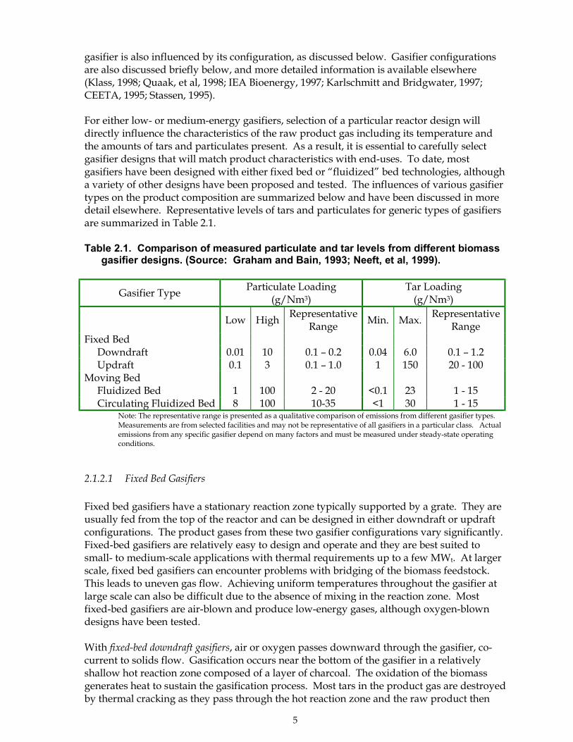
For either low- or medium-energy gasifiers, selection of a particular reactor design willdirectly influence the characteristics of the raw product gas including its temperature andthe amounts of tars and particulates present. As a result, it is essential to carefully selectgasifier designs that will match product characteristics with end-uses. To date, mostgasifiers have been designed with either fixed bed or �fluidized� bed technologies, althougha variety of other designs have been proposed and tested. The influences of various gasifiertypes on the product composition are summarized below and have been discussed in moredetail elsewhere. Representative levels of tars and particulates for generic types of gasifiersare summarized in Table 2.1.
Table 2.1. Comparison of measured particulate and tar levels from different biomassgasifier designs. (Source: Graham and Bain, 1993; Neeft, et al, 1999).
Low High RepresentativeRange Min. Max. Representative
RangeFixed Bed Downdraft 0.01 10 0.1 � 0.2 0.04 6.0 0.1 � 1.2 Updraft 0.1 3 0.1 � 1.0 1 150 20 - 100Moving Bed Fluidized Bed 1 100 2 - 20 <0.1 23 1 - 15 Circulating Fluidized Bed 8 100 10-35 <1 30 1 - 15
Note: The representative range is presented as a qualitative comparison of emissions from different gasifier types.Measurements are from selected facilities and may not be representative of all gasifiers in a particular class. Actualemissions from any specific gasifier depend on many factors and must be measured under steady-state operatingconditions.
2.1.2.1 Fixed Bed Gasifiers
Fixed bed gasifiers have a stationary reaction zone typically supported by a grate. They areusually fed from the top of the reactor and can be designed in either downdraft or updraftconfigurations. The product gases from these two gasifier configurations vary significantly.Fixed-bed gasifiers are relatively easy to design and operate and they are best suited tosmall- to medium-scale applications with thermal requirements up to a few MWt. At largerscale, fixed bed gasifiers can encounter problems with bridging of the biomass feedstock.This leads to uneven gas flow. Achieving uniform temperatures throughout the gasifier atlarge scale can also be difficult due to the absence of mixing in the reaction zone. Mostfixed-bed gasifiers are air-blown and produce low-energy gases, although oxygen-blowndesigns have been tested.
With fixed-bed downdraft gasifiers, air or oxygen passes downward through the gasifier, co-current to solids flow. Gasification occurs near the bottom of the gasifier in a relativelyshallow hot reaction zone composed of a layer of charcoal. The oxidation of the biomassgenerates heat to sustain the gasification process. Most tars in the product gas are destroyedby thermal cracking as they pass through the hot reaction zone and the raw product then
Gasifier Type Particulate Loading(g/Nm3)
Tar Loading(g/Nm3)
6
exits the gasifier at high temperature. The particulate levels in the product gas are typicallylow due to the absence of turbulence in the gasifier, but the gas may contain alkali vapors asit exits the hot reaction zone.
With fixed-bed updraft gasifiers, the air or oxygen passes upward through a hot reactive zonenear the bottom of the gasifier in a direction counter-current to the flow of solid material.Exothermic reactions between air/oxygen and the charcoal in the bed drive the gasificationprocess. Heat in the raw gas is transferred to the biomass feedstock as the hot gases passupward, and biomass descending through the gasifier sequentially undergoes drying,pyrolysis, and finally gasification. The product gas exits at a relatively low temperature.Tar concentrations in the product gas are high since the tar vapors formed by pyrolysisreactions are swept upward through the reactor with the product gas. Particulate levels inthe raw product gas are typically low because of the non-turbulent conditions. In addition,ash is swept along with the solids in the opposite direction of the gas flow and is eventuallywithdrawn from the bottom of the gasifier. Most smaller-scale gasifiers are based on fixed-bed designs.
2.1.2.2 �Fluidized� bed gasifiers
Fluidized bed gasifiers are defined here as those with a moving bed of inert material such assand. Examples include bubbling fluidized bed gasifiers where the bed material is agitatedby gases flowing through it, circulating fluidized bed (CFB) gasifiers where the bed materialcirculates between the gasifier and a secondary vessel, and entrained bed gasifiers where thesolids are entrained in the gas flow at higher velocities. The gas used to fluidize or entrainthe bed material can be air, oxygen, steam, recycled product gas, or a combination.Depending on design, biomass can be fed into the top, bottom, or middle of the moving bed.
Heat to drive the gasification reaction can be provided in a variety of ways in fluidized bedgasifiers. Direct heating occurs when air or oxygen in fluidizing gas partially oxidizes thebiomass and heat is released by the exothermic reactions that occur. Indirect heatingmethods such as internal heat exchangers, using preheated bed material, or other means canalso be used to drive the gasification reactions. The turbulence in the bed promotes effectivemixing and efficient heat transfer. The raw product gas typically exits the reactor atrelatively high temperatures. Fluidized bed gasifiers can be effectively sized for medium- tolarge-scale facilities and are best suited to situations where there is a relatively constantdemand for the gas product. Essentially, all of the larger-scale gasifier facilities built andtested in the last decade use fluidized bed designs.
The product gas exiting from the gasifier typically has high levels of particulates as a resultof the turbulence in the reactor. The particulate matter consists both of ash originating fromthe biomass and fine particles of attrited bed material. Cyclone filters are usually an integralpart of the system and are used as a method to remove the bed material from the gasstream. Since the gas is typically hot, it may also contain vaporized alkali salts, as will bediscussed in more detail later. The amount of tars in the raw gas can vary significantlydepending on the specific reactor design, as shown in Table 2.1. Typical moving bedgasifiers produce lower concentrations of tar than fixed bed updraft types, but more thanfixed bed downdraft reactors. Depending on the reactor design, the composition of the tarscan range from partially cracked pyrolysis products to highly refractory polyaromatichydrocarbons.
7
Other gasifiers: Historically, most biomass gasifiers have been based on the fixed and movingbed designs described above. However, many other design configurations have beenproposed, designed, and tested. For example, moving grate gasifiers similar to somecombustors and incinerators have been tested, as have others derived from fixed beddowndraft designs. In the latter, the lower fixed grate is replaced by a moving or rotatinggrate or platform. Many other designs such as molten salt gasifiers and supercritical fluidgasifiers have also been examined, but these designs have not been tested at a larger scale.In these concepts, the temperature of the product gas and its composition will varydepending on the type of design chosen, but those characteristics generally fall within thelimits of the fixed and moving bed designs described above. Because the performance ofthese designs is more reactor-specific and less generic, they are not addressed in detail here.More complete reviews of biomass gasification history and design are available elsewhere(Reed, 1999, Stassen, 1995).
2.2 Status of Biomass Gasification Technologies
As indicated, biomass gasification technologies have been a subject of commercial interestfor several decades. Interest in biomass gasification increased substantially during the 1970sdue to uncertainties over petroleum supplies. The concept that gasification could providesecure source of energy from locally produced biomass feedstocks attracted manytechnology developers and entrepreneurs. Through the mid-1980s, small-scale gasificationremained in a near-commercial stage of development. While gasifiers were available fromcommercial vendors, the products from that period were often unreliable and ineffective.Since the mid 1980s, improvements in the technology and better selection of opportunitieshave led to improved commercial success. At present, there are several dozen smaller-scalebiomass gasifiers in active service world-wide (Reed, 1999, BTG, 2000) that provide fuel forheat and power needs. These gasifiers are available from vendors with proven technologiesand use a variety of feedstocks including wood, agricultural residues, AND, animal wastes.
For about two decades, there has also been increasing interest in large-scale biomassgasification. Throughout the 1980s, governments and private industries sponsored researchand development efforts on biomass gasification with the goal of developing viable, large-scale gasifiers. The research efforts have helped to create a better understanding of reactionfundamentals, and the development work has resulted in the construction and testing ofseveral demonstration-scale facilities. The sizes of these demonstration facilities varied, butthey typically could process 5 - 20 tons of biomass per day. The facilities were intended toresolve remaining technical questions at a reasonable scale of operation and to provide thebasis for the introduction of large scale, commercial gasifiers. A summary of biomassgasification research sponsored by the U.S. Department of Energy (DOE) is available (USDOE 1996a; Stevens, 1994), and information on international gasification activities has beencompiled (IEA Bioenergy, 1997, NOVEM, 1999). Recent surveys of biomass gasifiers arealso available (Reed, 1999; BTG Group, 2000).
By the early 1990s there was widespread interest in larger-scale gasifier systems for powergeneration. One area of interest focused on the use of gas turbines to replace steam-basedsystems. The high efficiency of turbine systems presented opportunities that encouragedinvestments from both governments and private industry. By the mid-1990s, a second areaof interest had emerged relating to the use of large-scale gasifiers to provide fuel gas frombiomass which could be co-fired in conventional steam-based coal generating facilities.
8
As the development has proceeded, it has been widely recognized that raw product fromlarge-scale gasifiers will require cleaning and conditioning to be compatible with end-usessuch as gas turbines. The large-scale systems almost exclusively use fluidized bed gasifiersthat produce raw gases with particulate and tar levels unsuitable for demandingapplications unless the gases are cleaned. Several demonstration systems were planned thatwould complete gasifier development and test the compatibility of gas turbines with thecleaned fuel. The concepts ranged in size from a few hundred kWe to approximately 75MWe in electric generation capability. Several of the projects were planned using a stepapproach where the gasifier was to be built and tested first, and the gas turbine was to beadded at a later date. These projects also included extensive planning and efforts to ensurethe raw gasifier product gas could be cleaned sufficiently to meet the gas turbinerequirements. These projects are described in more detail elsewhere (Stevens, 1999).
By the late 1990s, several larger-scale biomass gasification facilities with thermal outputs upto about 85 MWt had been built or were in the planning or demonstration stage. Theseinclude gasifiers that provided biomass-derived fuel gases to be co-fired with coal and thosethat provided fuels for generating electricity using advanced gas turbine systems. Selectedgasifier developments are discussed in more detail in Section 4 of this report.
At the beginning of 2000, additional interest has been expressed in the use of biomassgasification as a method to produce synthesis gases and hydrogen. Synthesis gases wouldbe used for producing transportation fuels or chemicals. Interest in biomass-derivedhydrogen has been primarily in the area of providing a clean fuel for fuel cell operation.Fuel cells provide the potential for efficient power generation and are compatible withdistributed energy generation.
As a result of the interest in large-scale biomass gasification systems, progress has beenmade on both the gasification step and on gas cleanup issues over the past decade. For thegasification step, the main progress has been in relation to the scale-up of biomass gasifiers.Work over this period has shown both the potential of these systems and the difficulties ofstarting first-of-a-kind facilities. Gasifier scale-up projects have consistently experiencedoperational difficulties and delays typical of large projects using "new" technologies.Problems with components such as feeders are being solved as they arise, and theoperability of the larger-scale gasifiers is improving. While the problems that have beenencountered appear to be solvable, the overall scale-up of biomass gasifiers has proceededmore slowly than predicted by the optimistic estimates of the early 1990s. Despite thesedifficulties, several gasifiers at a variety of scales are currently in full commercial operation.The successful gasifiers provide fuel gases for applications that can tolerate significant levelsof particulates and tars in the gas. An example is the gasifier located in Lahti, Finlandwhere the fuel gas is co-fired in a coal combustor (Foster Wheeler, 1999). This system isdiscussed in more detail in Section 4.
Gasifier systems capable of producing very clean fuel gases for demanding applicationsremain at the demonstration and near-commercial stage of development. Significantprogress has been made in developing a better understanding of gas cleanup issues and indemonstrating technologies that can solve those problems. In Section 3 of this report,progress to clean gases for highly demanding technologies such as gas turbines issummarized. This work includes the removal of tars, particulates, and alkali from the gasstream as well as control of nitrogen oxide emissions. In Section 4 of this report, integratedgasification/gas cleanup systems are discussed.

9
2.3 The Relationship Between Biomass Gasification and Combustion
While biomass gasification offers significant potential, it should be noted that a vastmajority (> 98%) of all energy from biomass is currently produced using combustionsystems. These systems provide heat for a variety of needs including power generation,industrial processing, space heating, etc. In conventional combustion-based electric powersystems, biomass is burned, the heat is used to generate steam, and the steam is then used todrive a steam turbine. The electric generation efficiency of these systems ranges from about20% in older systems to over 30% in newer ones. In many cases, heat is recovered forheating or industrial processing needs to improve the overall thermal efficiency of thesystem. Combined heat and power (CHP) systems such as district heating systems are wellestablished in Europe and are used by North American industries.
Biomass combustion technologies are technologically mature and are readily available fromcommercial vendors. Since they offer reliable operation with proven results, combustionsystems are likely to continue to be an important option for biomass power in theforeseeable future. Combustion systems will likely continue to compete effectively insituations where conventional steam-cycle power generation is economically feasible.
2.4 Gasification of Other Solid Fuels
The gasification of other solid fuels, particularly coal, has also been of interest for more thana century. Like biomass gasification processes, conversion of these solid energy feedstocksto gaseous fuels provides greater flexibility for their use and can reduce unwantedenvironmental emissions.
Coal has both higher bulk and energy densities than biomass. These factors allow coal to beeconomically transported longer distances, which in turn allows coal facilities to besignificantly larger than those fueled by biomass. By comparison, large-scale biomassgasification facilities will probably have capacities of less than 100 MWe, while present coalgasification power systems in commercial operation have capacities exceeding 250 MWe
(U.S. Department of Energy 1996b; 1996c). The coal facilities include power generationsystems using high efficiency gas turbines. Larger coal-based facilities are also feasible.Coal gasification has also been used over many years to produce synthesis gases for fuelsand chemicals synthesis in several locations including South Africa.
At present, the motivational forces driving development of biomass gasification aredifferent than those for coal. Interest in biomass gasification is being driven at least in partby international concern about carbon dioxide emissions. Since biomass can be grown atabout the same rate it is consumed, this feedstock can provide renewable sources of powerand fuels with low levels of net CO2 emissions. Biomass gasification can thereforepotentially help companies and governments meet CO2 reduction requirements inappropriately sized power facilities.
Coal gasification, by comparison, is of interest in areas where there is abundant coal andwhere alternate resources, particularly natural gas, are in limited supply. In those areas,large-scale coal-gasification facilities can have economic potential. Currently, internationalinterest in reducing global CO2 emissions coupled with low natural gas prices have madecoal a less appealing choice than natural gas. Future interest in coal-based technologies is

10
more difficult to predict. Concerns about CO2 emissions are expected to increase, butnatural gas prices have also climbed significantly. The relative influence of these factors onthe future growth of coal-based power generation is unknown.
Because of the differences in the characteristics and reaction behavior of biomass and coal,the technologies to gasify them and clean the raw product gases will be different. Coaltypically has a higher ash and sulfur content than biomass, which requires additionalprocessing steps to achieve a high quality fuel gas (Newby, 1993). The temperature and tarcontent of the raw product will also be different in biomass and coal systems. In dealingwith the two feedstocks, it is important to recognize the differences and appropriatelyexploit the feedstock characteristics in both systems. The discussions of biomass hot gascleanup in the following sections of this report include references to coal-based technologieswhere commonalities exist.
11
3. PRODUCT GAS CLEANUP AND CONDITIONING
3.1 General Considerations
The raw product gas exiting a biomass gasifier contains particulates, tars, and otherconstituents that may interfere with downstream utilization technologies. Theconcentrations of these constituents will depend on the reactor design and other factors asexplained previously. Regardless of the scale of the gasifier, its design configuration, or thebiomass feedstock, the characteristics of the product gas must match the requirements of theintended use. For some applications such as kilns or co-firing systems, the raw fuel gas maybe used with little or no cleanup. In other applications, such as gas turbines or internalcombustion engines, extensive gas cleanup may be needed to meet stringent fuel qualityrequirements. If the gas is to be used for synthesis of liquid fuels, the product must not onlybe clean but must also have specified molecular ratios of components such as H2 or CO. Inall cases, care must be exercised to ensure the product gas is compatible with the end-use.
The consequences of inadequate gas cleaning have been amply demonstrated with biomassgasification systems. Beginning in the 1970s and continuing into the 1990s, several researchand development groups attempted to commercialize small-scale gasifier/internalcombustion (IC) piston engine systems for electricity and mechanical power generation*.Commercial projects and demonstrations were started in locations including the Americas,Europe, and Asia. While IC engines can effectively use clean fuel gases from biomass, someof these early systems did not provide for adequate tar removal from the product gas. TheIC engines operated reasonably well for a short period of time but then failed within fewhundred hours to difficulties such as tar accumulation in valves. This inability to match thegasifier product with the desired end-use contributed to a poor public perception of thereliability of biomass gasifiers.
Since the mid-1980s, significant research efforts have been directed toward the developmentof methods to clean the raw products from biomass gasifiers. Much of this effort wasrelated to the potential use of large-scale gasifiers coupled with high-efficiency gas turbinegenerating systems. In the mid-and late-1990s, several large-scale gasifier/gas turbineprojects were proposed, and a few of these are in the advanced construction and early stagesof operation. These end-use technologies to achieve high electrical conversion efficiencieshave stringent requirements regarding gas quality.
Research on gas cleanup and conditioning has also been motivated by the need to meetenvironmental emissions limits in urban areas, such as when urban wood wastes are usedas feedstocks. Large-scale systems to provide a biomass-derived fuel gas for cofiring incoal-burning facilities have also been constructed and are entering commercial operation.The cofiring units provide fuel for steam-cycle power generation and must meet localenvironmental regulations.
In addition, the use of biomass gasification to produce fuels such as Fischer-Tropsch liquidshas also received renewed attention. Systems for producing these fuels must address the
* Small gasifiers were also used in some areas of Europe during World War II to provide emergencyfuels for vehicles (National Research Council, 1983). Engine operability problems were encountered,but the need for emergency sources of fuel to harvest food and provide for key transport needsoverrode those considerations.
12
same gas quality issues as high efficiency turbine systems including removal of tars andparticulates. These systems also require the catalytic reforming of product gas to produce asynthesis-quality product with specific compositions and specific molecular ratios ofhydrogen and carbon monoxide gases. The catalysts in these systems and the requirementsfor narrowly defined synthesis gas compositions impose additional requirements on theproduct gas quality as compared to electricity generation systems. For nearly twenty years,the low costs of petroleum have made the option of liquid fuels from biomass economicallyunattractive. Recently, however, the rapid increases in petroleum prices have generatedrenewed interest in liquid fuels from biomass via thermochemical gasification routes.
Recent interest has also been expressed in the use of biomass gasification to producehydrogen for use in fuels cells. Production of clean, hydrogen-rich fuel gases will requiresimilar or perhaps even more demanding gas conditioning including particulate and tarremoval in addition to removal of unwanted light hydrocarbons, carbon monoxide, andothers.
As a result of these and other developments, the topic of gas cleanup has receivedsubstantial attention, both in terms of basic research and of technology development relatedto commercial gasifier demonstrations. Much of this interest has been focused on larger-scale systems capable of commercial power production in highly developed countries.
3.2. Gas Phase Contaminants
While it is desirable to select and design gasifiers that reduce contaminants at the source, thenature of biomass thermal gasification requires additional gas cleanup in most cases. Gascleanup systems may contain several components such as cyclones, scrubbers, or filters;each of which removes one or more contaminants. Systems producing either fuel orsynthesis gas must deal with the cleanup of five primary contaminants including:
! particulates! alkali compounds! tars! nitrogen-containing components! sulfur
These contaminants and the technologies for treating them are discussed in more detailbelow. In addition, synthesis gas systems must address the presence of low molecularweight hydrocarbons such as methane or ethane. These hydrocarbons are beneficial to fuelgases since they tend to increase the heating value of the product. However, they areundesirable in synthesis gases where they are unreactive and reduce overall conversionefficiencies to the desired product. Excess hydrocarbons may also deactivate catalysts in thesystem. In addition, the ratios of various molecular components in the synthesis gas mustbe adjusted. The issues dealing with synthesis gases are discussed later in this report.
3.2.1 Particulates
Particulates are defined here as solid-phase materials entrained in the raw product gasstream as it exits the gasifier. Particulates typically include the inorganic �ash� derivedfrom mineral matter in the biomass feedstock, unconverted biomass in the form of char, or
13
material from the gasifier bed. Most large-scale gasifiers use bubbling or circulatingfluidized configurations to ensure uniform bed conditions during gasification. Theturbulent conditions in these gasifiers produce high particulate loadings in the productgases. As a result, particulate cleanup will typically be necessary with these systems.
Turbulent-flow fluidized bed systems necessarily include cyclones to separate the bedmaterial from the product gases. The cyclone serves as the initial particulate removaltechnology and removes the bulk of coarse particulates, but finer fly ash will remain in thegas stream. The resulting fly ash consists of smaller-diameter material that can createoperational and visual emissions problems if not removed.
A primary source of fly ash particulates is the mineral matter in the biomass feedstock. Asthe feedstock is gasified, the inorganic matter from the feedstock may be either retained inthe gasifier bed or entrained in the product gas and swept from the reactor. Theconcentrations of ash in the product gas are therefore dependent both on reactor design andon the mineral content of the biomass feedstock.
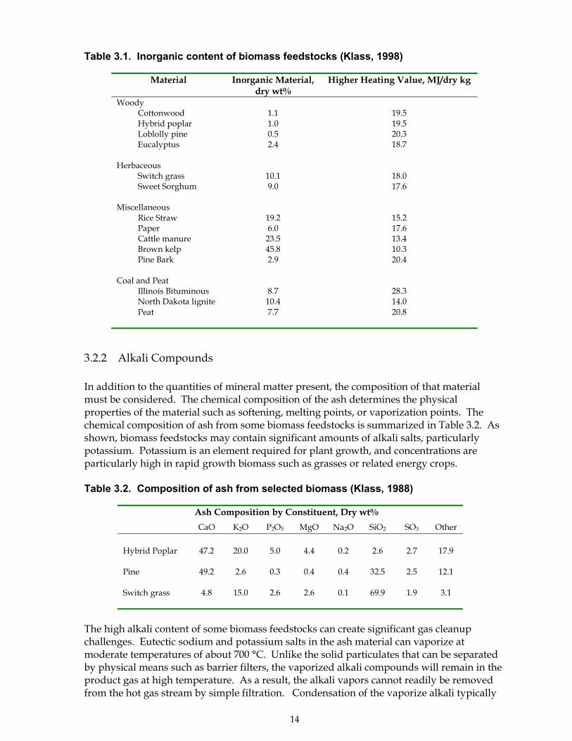
The total concentrations of inorganic material in selected biomass feedstocks are shown inTable 3.1. Total mineral concentrations in clean wood are typically 1-2%, and herbaceouscrops contain approximately 10%. Crop residues such as straw or rice hulls typicallycontain 15-20% inorganic material. Mineral matter from other sources may also contributeto ash in the product gas. For example, silica from soil that is mixed with the biomassduring its handling and preparation may be present. In gasification systems with movingbeds, inorganic particulates may include fine material from the attrition of the bed materialsuch as sand.
Another source of particulates is char formed when the biomass feedstock is incompletelygasified. Char particles undergo devolatilization and subsequent reactions at gasificationtemperatures that leave them less reactive than fresh biomass feedstock. These particlesmay pass through the gasifier before they are completely gasified, particularly in gasifierswith turbulent beds. Char entrained in the product gas also represents unconvertedbiomass that contributes to lower conversion efficiencies. Large-scale gasifiers can obtaincarbon conversion efficiencies of 98-99%, meaning that about 1-2% of the carbon in thefeedstock remains as solids. Collection of this material and subsequent re-injection of thechar into the gasifier can increase overall gasification efficiencies.
Particulates, while unavoidable in biomass gas streams, are undesirable. Mineral matter canabrade and damage downstream equipment, and most emission regulations limit theamount of fly ash that can be present. Systems to control particulates will be needed inessentially all large scale biomass gasification systems.
14
Table 3.1. Inorganic content of biomass feedstocks (Klass, 1998)
Material Inorganic Material,dry wt%
Higher Heating Value, MJ/dry kg
Woody Cottonwood Hybrid poplar Loblolly pine Eucalyptus
1.11.00.52.4
19.519.520.318.7
Herbaceous Switch grass Sweet Sorghum
10.19.0
18.017.6
Miscellaneous Rice Straw Paper Cattle manure Brown kelp Pine Bark
19.26.0
23.545.82.9
15.217.613.410.320.4
Coal and Peat Illinois Bituminous North Dakota lignite Peat
8.710.47.7
28.314.020.8
3.2.2 Alkali Compounds
In addition to the quantities of mineral matter present, the composition of that materialmust be considered. The chemical composition of the ash determines the physicalproperties of the material such as softening, melting points, or vaporization points. Thechemical composition of ash from some biomass feedstocks is summarized in Table 3.2. Asshown, biomass feedstocks may contain significant amounts of alkali salts, particularlypotassium. Potassium is an element required for plant growth, and concentrations areparticularly high in rapid growth biomass such as grasses or related energy crops.
Table 3.2. Composition of ash from selected biomass (Klass, 1988)
Ash Composition by Constituent, Dry wt%
CaO K2O P2O5 MgO Na2O SiO2 SO3 Other
Hybrid Poplar 47.2 20.0 5.0 4.4 0.2 2.6 2.7 17.9
Pine 49.2 2.6 0.3 0.4 0.4 32.5 2.5 12.1
Switch grass 4.8 15.0 2.6 2.6 0.1 69.9 1.9 3.1
The high alkali content of some biomass feedstocks can create significant gas cleanupchallenges. Eutectic sodium and potassium salts in the ash material can vaporize atmoderate temperatures of about 700 °C. Unlike the solid particulates that can be separatedby physical means such as barrier filters, the vaporized alkali compounds will remain in theproduct gas at high temperature. As a result, the alkali vapors cannot readily be removedfrom the hot gas stream by simple filtration. Condensation of the vaporize alkali typically
15
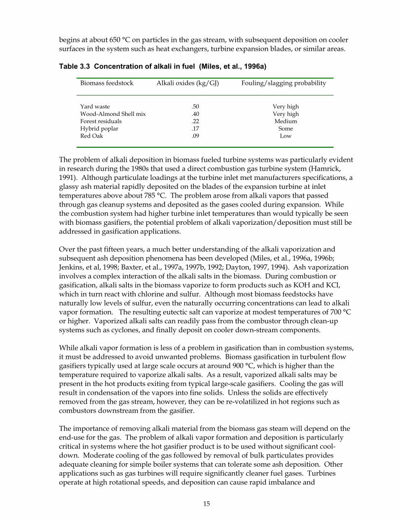
begins at about 650 °C on particles in the gas stream, with subsequent deposition on coolersurfaces in the system such as heat exchangers, turbine expansion blades, or similar areas.
Table 3.3 Concentration of alkali in fuel (Miles, et al., 1996a)
Biomass feedstock Alkali oxides (kg/GJ) Fouling/slagging probability
Yard waste .50 Very highWood-Almond Shell mix .40 Very highForest residuals .22 MediumHybrid poplar .17 SomeRed Oak .09 Low
The problem of alkali deposition in biomass fueled turbine systems was particularly evidentin research during the 1980s that used a direct combustion gas turbine system (Hamrick,1991). Although particulate loadings at the turbine inlet met manufacturers specifications, aglassy ash material rapidly deposited on the blades of the expansion turbine at inlettemperatures above about 785 °C. The problem arose from alkali vapors that passedthrough gas cleanup systems and deposited as the gases cooled during expansion. Whilethe combustion system had higher turbine inlet temperatures than would typically be seenwith biomass gasifiers, the potential problem of alkali vaporization/deposition must still beaddressed in gasification applications.
Over the past fifteen years, a much better understanding of the alkali vaporization andsubsequent ash deposition phenomena has been developed (Miles, et al., 1996a, 1996b;Jenkins, et al, 1998; Baxter, et al., 1997a, 1997b, 1992; Dayton, 1997, 1994). Ash vaporizationinvolves a complex interaction of the alkali salts in the biomass. During combustion orgasification, alkali salts in the biomass vaporize to form products such as KOH and KCl,which in turn react with chlorine and sulfur. Although most biomass feedstocks havenaturally low levels of sulfur, even the naturally occurring concentrations can lead to alkalivapor formation. The resulting eutectic salt can vaporize at modest temperatures of 700 °Cor higher. Vaporized alkali salts can readily pass from the combustor through clean-upsystems such as cyclones, and finally deposit on cooler down-stream components.
While alkali vapor formation is less of a problem in gasification than in combustion systems,it must be addressed to avoid unwanted problems. Biomass gasification in turbulent flowgasifiers typically used at large scale occurs at around 900 °C, which is higher than thetemperature required to vaporize alkali salts. As a result, vaporized alkali salts may bepresent in the hot products exiting from typical large-scale gasifiers. Cooling the gas willresult in condensation of the vapors into fine solids. Unless the solids are effectivelyremoved from the gas stream, however, they can be re-volatilized in hot regions such ascombustors downstream from the gasifier.
The importance of removing alkali material from the biomass gas steam will depend on theend-use for the gas. The problem of alkali vapor formation and deposition is particularlycritical in systems where the hot gasifier product is to be used without significant cool-down. Moderate cooling of the gas followed by removal of bulk particulates providesadequate cleaning for simple boiler systems that can tolerate some ash deposition. Otherapplications such as gas turbines will require significantly cleaner fuel gases. Turbinesoperate at high rotational speeds, and deposition can cause rapid imbalance and

16
catastrophic failure. For these demanding systems, thorough alkali removal of fine particlesor aerosols of alkali salts is necessary.
Even in systems where deposition of hot vapors is not a problem, the presence of alkali saltsmay create other problems. Alkali salts can be corrosive to metal surfaces and can inactivatecatalysts such as those in tar cracking and synthesis gas applications. The methods toeliminate alkali and alkali salts from the gas stream are discussed in Section 3.3.1.
3.2.3 Tars from Biomass Gasification
�Tar� is a generic term describing a complex range of oxygenated organic constituents thatare produced by the partial reaction of the biomass feedstock. Such materials reside in thehot gas stream as vaporized material or as persistent aerosols, but typically condense atcooler temperatures. These tars include a variety of oxygenated aromatics formed in thepyrolysis step of the gasification process. The definition of the term �tars� has been activelydiscussed over the past few years without conclusive resolution. For this discussion, tar isdefined as organic molecules with weights greater than that of benzene 78. This definitionhas been used in some other references to tar formation in biomass gasification systems.(Neeft, et al, 1999).
The composition of the tar is complex and highly dependent on the severity of reactionconditions encountered, including gasification temperature and residence time in thereactor. The mechanisms of tar formation have been reviewed elsewhere in detail (Evansand Milne, 1997; Milne, et al., 1997, Neeft, et al, 1998). As biomass is heated, it dehydratesand then volatilizes as it thermally decomposes. The volatilized material can either undergofurther decomposition to form permanent gases, or it can undergo dehydration,condensation, and polymerization reactions that result in tar formation. The tarcomposition is based on the �severity� of conditions it encounters including temperatureand residence time at temperature (Evans and Milne, 1987). A general correlation betweentemperature and tar composition is shown below with temperature rising from about 450 °Con the left to about 950 °C on the right (Baker, et al, 1986).
Mixed phenolic alkyl heterocyclic polyaromatic largeroxygenates ethers ethers ethers hydrocarbons(PAH) PAH
The tar varies in composition from primary oxygenated pyrolysis products at lowertemperatures to high molecular weight, deoxygenated products for those that haveexperienced severe reaction conditions. Tars from updraft, fixed-bed gasifiers are composedprimarily of mixed oxygenates and phenolic ethers because they are produced at moderatetemperatures. By comparison, tars formed at high temperatures in circulating fluidized bedgasifiers contain heterocyclic ethers and polyaromatic hydrocarbons.
As described in Section 2, the amount of tar will also vary significantly depending on thedesign of the gasifier. Large-scale, turbulent bed gasifiers typically have tar concentrationsin the range of 1 � 15 g/Nm3, while fixed-bed downdraft reactor designs typically producetar concentrations of 20 � 100 g/Nm3 (see table 2.1). Fixed-bed downdraft gasifiers have thepotential to produce very low levels of tars, less than 0.1 g/Nm3, but typically produceconcentrations of 0.5 � 1.5 g/Nm3. Clearly gasifier design is an important consideration forsystems where the end-use application is sensitive to the presence of tar. However, sincelarge-scale systems will primarily use turbulent bed gasifier designs, the gas conditioningsystem must deal with tars characteristic of these technologies.
17
Tars in the product gas can be tolerated in some systems where the gas is used as a fuel inclosely-coupled applications such as burners. In these situations, cooling and condensationof the tars can be avoided, and the energy content of the tars adds to the calorific value ofthe fuel. In more demanding applications, however, tars in the raw product gases, even atlow concentrations, can create major handling and disposal problems. Tars readilycondense on cool components downstream from the gasifier, resulting in plugging andfouling of pipes, tubes, and other equipment. In temperature regions above about 400 °C,the tars can undergo subsequent dehydration reactions to form solid char and coke thatfurther plugs systems. The tars represent a cleanup problem and may be classified ashazardous wastes for disposal purposes.
In addition, the presence of tars in the product gas is highly undesirable in synthesis gas orhydrogen applications. Tar formation represents a reduction in gasification efficiency sinceless of the biomass is converted to a fuel or synthesis gas. More importantly, tars woulddegrade the performance of those systems. Tars can deactivate reforming catalysts, and fuelcell toleration of tars is likely to be low.
The formation of tars and their impact on biomass gasification systems has recently beenreviewed in detail (Neeft, et al, 1999; Barker 1998). The technologies for tar removal fromthe product gas are discussed below in section 3.3.
3.2.4 Nitrogen Containing Contaminants
The primary nitrogen-containing contaminant in the raw gas from biomass gasifiers isammonia, NH3. Ammonia is formed from the protein and other nitrogen-containingcomponents in the biomass. High-protein feedstocks such as animal wastes or alfalfa willresult in greater ammonia production. Ammonia production is also higher in pressurizedgasifiers due to equilibrium considerations and in pyrolytic (rather than air or oxygen-blown units) due to the reducing environment in those gasifiers.
The acceptable levels of ammonia in the gas stream are typically dictated by localregulations. Gasification systems must necessarily meet these emissions regulations, but theconcentrations of ammonia are relatively low with common feedstocks in most gasifiers.Ammonia in the product stream is undesirable primarily because it leads to the formation ofNOx emissions when the product gas is burned. Cleanup of the ammonia is thereforerequired for systems in locations with strict NOx regulations.
NOx is also produced in some gasifiers but is generally not present in high enoughconcentrations to create problems. NOx is produced by the reaction of nitrogen or nitrogen-containing molecules with oxygen at elevated temperatures representative of those incombustion systems. The lower temperatures in gasification and the nature of the reactiveenvironment limit NOx production.
Although the gasifier product itself has low levels of NOx, the total systems emissions of thisproduct must be carefully considered. When the clean biomass fuel gas is eventuallyburned, NOx will be produced, as it is in most combustion systems with all fuels. The use offuel gases rather than solid biomass fuels provides the opportunity to better control thecombustion process, which can potentially result in lower NOx emissions. For this reason,gasification offers potential environmental emissions advantages over combustionalternatives. However, NOx may still occur as the gas is burned, and appropriate NOx
18
control technologies may be necessary. Additional information on NOx cleanup is providedin Section 3.4.
3.2.5 Sulfur
Sulfur in the biomass feedstock can be converted to hydrogen sulfide or sulfur oxidesduring gasification, depending on the gasification approach. Most biomass feedstockscontain low percentages of sulfur. Wood typically contains <0.1% sulfur by weight, andherbaceous crops may contain 0.3�0.4% (Klass, 1998). A few feedstocks such as refuse-derived fuel (RDF) may contain 1% or more, approximately the same as bituminous coal.As a result of the low levels of sulfur in the biomass, the concentrations of H2S and SOx
levels in the product gases are below those requiring cleanup in most applications.
The low concentration of sulfur in biomass offers potential advantages for someapplications. In cofiring applications, for example, the cleaner combustion gases frombiomass dilute those from coal, and the overall concentrations of sulfur per unit ofcombustion gas are reduced. In most applications where the biomass product is used as afuel gas, technologies to remove sulfur will not be needed.
Sulfur, however, is a potential problem even at low levels for synthesis gas systems usingcertain types of catalysts. The production of methanol from synthesis gas, for example, usescatalysts that are poisoned by sulfur. Some tar cracking catalysts are also sulfur sensitive.In those systems, thorough removal of sulfur will be required. Fuel cell systems are alsosulfur sensitive.
3.2.6 Other Considerations for Synthesis Gas
Gasifier products used to synthesize liquid fuels and chemicals must also be cleaned toremove the impurities described above. Synthesis gases must be further conditioned toremove other unwanted components including carbon dioxide and low molecular weighthydrocarbons such as ethane or methane. These components, which would be harmless oreven helpful in fuels systems, both dilute the synthesis gas and can affect synthesis catalystperformance. The gas must have specified ratios of primary constituents carbon dioxide(CO2) and hydrogen (H). Methanol synthesis, for example, requires a H2/CO ratio ofsomewhat over 2:1. Liquid fuels have been synthesized from coal for decades in SouthAfrican and elsewhere, and the technology is well developed and available commercially.Synthesis gases from biomass feedstocks can equally well be used in these technologies ifthe gases are appropriately cleaned and conditioned. Technologies to condition synthesisgases are discussed in Section 3.3.6 and 4.4.1.
3.3 Gas Cleanup Technologies and Recent Progress
As noted above, the contaminants in the raw product gas are incompatible with many end-use systems, and gas cleanup and conditioning will be required in those systems. Varioustechnologies can potentially be used to remove unwanted components from the gas stream,including particulates, alkali, tars, sulfur, and ammonia. The gas cleanup and conditioningtechnologies for biomass gasification systems are outlined and recent progress with
19
technology components are discussed below. In practice, the gasifier and the gasconditioning technologies must be considered as integrated systems. Integrated gas cleanupand conditioning systems are discussed in Section 4 of this report.
3.3.1 Particulate Removal Technologies
Particulate removal requirements vary significantly depending on the use of the productgas. For example, particulate levels must be reduced to below 50 mg/Nm3 for gas engines(Abatzoglou, et al., 2000), to below about 15 mg/Nm3 (> 5µm) for turbines (see Section 4.0),and to perhaps 0.02 mg/Nm3 for synthesis gas systems (Graham and Bain, 1993). Theprimary types of systems include the following, although others have been proposed andsometimes tested:
! Cyclonic filters! Barrier filters! Electrostatic filters! Wet Scrubbers
These particulate removal technologies and recent progress in certain areas is discussed inmore detail below.
3.3.1.1 Cyclone Filters
Cyclonic filters are a primary means of removing bulk particulates from gas streams. Theyuse centrifugal force to separate solids from the gas by directing the gas flow into a circularpath. Because of inertia, the particulates are unable to follow the same path and areseparated from the gas stream. Although the physics of particulate removal are quitecomplex, cyclone filters with predictable performance can be designed in a straightforwardmanner using theoretical and empirical techniques developed over many years.
Cyclonic filters (and closely related designs such as �U� tubes) are routinely used as aninitial gas cleanup step in most gasifier systems because they are effective and relativelyinexpensive to build and operate. In circulating fluidized bed or entrained bed gasifiers,cyclones are an integral part of the reactor design providing for separation of the bedmaterial and other particulates from the gas stream.
Cyclone filters are particularly effective at removing larger particles and can operate over awide range of temperatures, limited primarily by the material of construction. Cyclonefilters, frequently designed as multiple units in series (multi-clones), can remove >90% ofparticulates above about 5 �m in diameter at minimal pressure drops of 0.01 atm. Partialremoval of material in the 1�5 �m range is also possible, but cyclonic filters becomeineffective with sub-micron particles. Since cyclone filters can operate at elevatedtemperatures, the sensible heat in the product gas can be retained.
Cyclone filters also remove condensed tars and alkali material from the gas stream,although the vaporized forms of those constituents remain in the gas stream. In practice,the separation of significant amounts of tars from the gas stream may be done sequentiallyby first removing particulates at higher temperatures where tars remain vaporized. The gasstream is then cooled and condensed tars are removed. The step-wise approach reduces thetendency of particulate material to stick to tar-coated surfaces and contribute to plugging.
20
Cyclonic filters are used extensively in many processes and are available commercially frommany vendors. This is a commercially mature technology, and the future improvements arelikely to be incremental.
3.3.1.2 Barrier Filters
Barrier filters include a range of porous materials that allow gases to penetrate but preventthe passage of particulates. These filters effectively remove small-diameter particulates inthe range of 0.5 to 100 µm in diameter from gas streams. Barrier filters can be designed toremove almost any size of particulate, including those in the sub-micron range, but thepressure differential across the filter will increase as the pore size decreases. As a result,there are technical and economic constraints which effectively limit particulate removal toabout 0.5 µm in systems such as gasifiers that must handle large gas volumes.
Barrier filters are cleaned by periodically passing pulsing clean gas through the filter in thereverse direction of normal gas flow. To reduce the overall particulate load, these filters aretypically placed downstream from cyclone filters. Barrier filters are effective for removingdry particulates but are less suitable for wet or sticky contaminants such as tars. Tars clingto the filter surface and can undergo subsequent carbonization reactions that lead to foulingand plugging. Even in the absence of further decomposition, tars are difficult to removefrom these materials.
Examples of barrier filters suitable for biomass systems include:! rigid, porous �candle� or cross-flow filters constructed of metal or ceramic! bag filters constructed of woven material! Packed bed filters
Rigid barrier filters, sometimes called hot gas filters, provide a potential opportunity toproduce a clean fuel gas while retaining the sensible heat of the fuel gas. In larger-scalebiomass gasification systems, these systems can potentially operate at moderate to hightemperatures, depending on their material of construction, while removing smallparticulates. In most cases, cyclones would be used to reduce the overall loading ofparticulates before passing the gas through barrier filters for �finishing.�
These types of barrier filters are used in other industries for particulate removal, but theyhave been only recently tested in biomass gasification systems. In large-scale biomasssystems, the use of metallic barrier filters may require partial product gas cooling to preventsintering of the metal. In addition, metal filters are also susceptible to corrosion. Ceramicfilters are suitable for higher temperature operation but are fragile and can break fromthermal stress during temperature cycling. Ceramic filters are also susceptible to reactionswith alkali vapors in gasification systems that can lead to decomposition or plugging.
Recent RD&D on larger-scale biomass gasifiers has led to improved understanding of thepotential of rigid barrier filters. This interest has grown from the desire to provide astraightforward method to remove particulates and perhaps alkali from the product gaswhile also retaining most of the heat content. Providing clean gases while also preservingthe sensible heat of the gas is particularly important in closely coupled gasifier/gas turbinesystems. Barrier filters have been tested and shown to have potential in several recentgasification demonstration systems.
21
Ceramic and metal candle-type filters were both tested at a commercial demonstrationfacility at Värnamo, Sweden that was in operation through late 1999 (Sydkraft, 1998). Thisintegrated gasification combined cycle (IGCC) facility consisted of an air-blown, pressurizedfluidized bed gasifier coupled to an Ahlstrom gas turbine. The system capacity wasapproximately 6 MWe. In the tests at Värnamo, the gasifier gas was first cooled to about 350°C in a heat exchanger, and the resulting �warm� gas passed through candle filters. Somebreakage of ceramic candle elements was encountered in early tests. These problems werecaused in part because of the frequent thermal cycling in the demonstration facility thatoperated intermittently. Later tests at Värnamo were made with metallic candle filterelements, which are suitable for use with the �warm� gas at 350 °C. The gasifier facilityoperated successfully in its full gasifier/gas turbine power generation mode for extendedperiods using these filters. The facility, closed in 1999, is described in more detail in Section4 of this report.
Ceramic candle filters were also tested at a research and development gasifier facility inHawaii in the mid-1990�s (Wiant, 1998, 1994a, 1994b; Lau, 1998). In that demonstrationfacility, gas was produced at about 980 °C, and a slip-stream was diverted to a hot-gascleanup unit. The gas was first cooled to about 700 °C by water injection and then passedthrough ceramic candle filters. The filters were cleaned at ~30 minute intervals usingpressure pulses. Tests totaling about 170 hours of operation were performed, and thebarrier filters worked well during that period. The filter elements maintained mechanicalintegrity even with large temperature fluctuations, and no evidence of plugging or bridgingwas found. Measurements of particulate loading in the cleaned gas were not reported. Thetermination of the gasifier project in early 1998 prevented extended tests to determine thelonger-term viability of these filters.
Bag filters are composed of woven material that intercepts small particles on the filter surfaceby impingement and electrostatic attraction. The efficiency of collection increases as thedepth of the filter cake increases, making these filters highly efficient for small diameter,even sub-micron particles size. Filters are periodically shaken or back-flushed to removeparticulate accumulation. These filters are usually constructed of woven materials suitablefor operation at low temperature operation up to about 350 °C.
These filters are well proven for removing particulates in a variety of systems but have notpreviously been used in biomass gasification systems. In biomass systems, these filtersrequire hot product gas to be cooled prior to filtration. For that reason, they are mostappropriate for applications where retaining the sensible heat of the product gas is notcritical. In addition, the presence of tars in the product gas can cause potential problemssince tar condensation on the filter cake or the filter itself can lead to plugging. Care mustbe taken to ensure that tars are either removed from the stream prior to the bag filter or thatthe temperature remains high enough to prevent tar condensation.
Bag filters are being used or have been proposed for several medium- and large-scalegasifiers. These include systems using steam-based and gas turbine based power generationtechnologies. In both types of systems, the product gases are typically cooled below 300 °Cand passed through bag filters.
Examples of bag filter use in steam-based power generation systems include the AmerPower Station in Geertruidenberg, Netherlands (EPZ, 1999). This facility uses a circulatingfluidized-bed gasifier to convert urban wood wastes into fuel gas. The resulting fuel iscofired in a coal-burning steam generation combined heat and power facility. This is
22
currently the largest biomass gasification facility in the world and has a thermal output ofabout 85 MWt. In the facility, the gas is cooled to about 240 °C in a heat exchanger, passedthrough a cyclonic filter for bulk solids separation, and then passed through bag filters priorto wet scrubbing. The facility was beginning shakedown operation in early 2000, sooperating data from the facility is currently unavailable. This system is discussed in moredetail in Section 4 of this report.
Other large-scale gasification facilities that will use bag filters in gas turbine-based systemsare currently in the planning and construction stage. The Arable Biomass RenewableEnergy (ARBRE) project in UK (ARBRE, 1999) and the Bioelectrica project in Italy (DeLang,1998) are currently being constructed. Both of these gasification facilities are based onsimilar designs using circulating, fluidized bed air-blown gasifiers to produce a low-energygas. The raw gas will be cooled in a heat exchanger, passed through cyclones for bulkparticulates removal, and then passed through bag filters for additional cleaning. Tars willbe removed by wet scrubbing following the filtration steps. Because both of these facilitiesare still being constructed, operational data is not yet available. These projects are discussedin more detail in Section 4 of this report.
Packed-bed filters, while quite different in operation, may also act as barrier filters. In thesesystems, the raw product gases pass through a bed of packing material such as ceramicspheres or sawdust. Gas phase products pass through the bed, and particulates are de-entrained from the gas flow. Periodically, the particulates must be removed from the filterbed, typically by back flushing. Small-scale gasifier facilities have used packed beds ofmaterials such as sawdust or activated charcoal to remove both particulates and tars fromthe gas stream. In larger systems, the problem with accumulation of particulates or tars inthe packed bed present potential operability problems. As a result, these types of filters arenot being actively incorporated into larger-scale gasifier systems at this time.
3.3.1.3 Electrostatic Filters
Electrostatic filters have also been used extensively in a variety of gas cleaning operations.In these systems, the product gas flows past high voltage electrodes that impart an electriccharge to particulates, but do not affect the permanent gases. The particulates are thencollected as the gas stream passes collector plates of the opposite polarity. The electricallycharged particulates migrate to the collector plate and deposit on the surface. Particulatesare removed from the scrubber plates by either wet or dry methods. Dry scrubbers usemechanical action to periodically remove material from the surface and can operate attemperatures of 500 °C or more. Wet scrubbers remove particulates with a thin film offlowing water and are limited to temperatures of about 65 °C.
Electrostatic filters have been used in many coal-fired power stations, and they have beenused in some biomass combustion facilities. Their use in medium- or large-scale gasificationsystems is limited. Electrostatic filters are best suited for large-scale operation due to theirphysical size and cost, and the primary impediment to their use in current gasificationsystems is an economic one. Two systems producing fuel for gas engines including theEasymond AG gasifier in Boizenberg, Germany and the Harboore gasifier in Denmark haveelectrostatic filters (BTG, 2000). These systems have electrical generation capacities of about3.5 and 1.0 MWe respectively.
In both cases, gas is produced using updraft, fixed bed gasifiers. In the German facility, thegas is first cooled and then passed through a cyclone and a catalytic tar cracker. The
23
electrostatic precipitator (dry) is located downstream to remove further particulates. InHarboore, the system does not have a tar cracker and the cooled gases pass from a cyclonedirectly into a wet electrostatic precipitator. In both cases, the product gas also passesthrough a wet scrubber before it is used.
3.3.1.4 Wet Scrubbers
Wet scrubbers use liquid sprays, usually water, to remove particulates. Particles arecollected by collision with liquid droplets, and the droplets are then de-entrained from thegas stream in a demister. The most common wet scrubbers use a venturi design to create apressure drop that allows solutions to be easily sprayed into the gas stream. Gas velocitiesare typically 60�125 m/sec in this throat area. Particulate removal efficiency is proportionalto the pressure drop across the venturi. With pressure drops of between 2.5�25 kPa, thesescrubbers can remove 99.9% of particles over 2 µm, and 95-99% of those over 1 µm (Baker,et al, 1986).
The wet particulates from the venturi are subsequently removed from the gas stream by ademister. The demister can be a cyclone, packed bed, or other type of collector. Wetscrubbing requires that the water remain in the liquid phase, which requires that theproduct gas be cooled to below 100 °C. This loss of sensible heat may be undesirable insome systems.
Most biomass gasification systems that currently use wet scrubbers do so primarily as ameans to remove tars rather than particulates from the gas stream. Removing theparticulates separately can prevent condensation of the sticky tars on the particulate surface,and that can prevent fouling and plugging of filter surfaces. The topic of wet scrubbers forremoving tar from the product gas is discussed in more detail in Section 3.3.3 of this report.
3.3.1.5 Standardized Particulate Measurement
While the necessity of removing particulates is understood, the ability to consistentlymeasure particulate levels in different biomass gasification systems has sometimes beendifficult in the past. Recently, standardized particulate measurement protocols have beenproposed both for large-scale (Simell, et al, 2000) and small-scale (Abatzoglou, et al, 2000)gasifiers. These protocols have been developed both for particulates and tars, as discussedin Section 3.3.3 of this report. The work is being assisted by the IEA Biomass GasificationTask (IEA Bioenergy 2000), the European Commission DGXVII, and the U.S. Department ofEnergy. The protocols should provide for a consistent method to evaluate particulateremoval technologies at different gasification facilities.
3.3.2 Technologies for Alkali Removal
As discussed in Section 3.2, the mineral matter in biomass contains high levels of alkali salts,particularly those containing potassium. At temperatures of about 800 °C, the alkali saltscan vaporize and create problems by depositing on cooler surfaces downstream. Sinceturbulent bed gasifiers typical of those used in large-scale systems achieve bed temperaturesof 700-900 °C, alkali vapors are likely to be present in many systems. The alkali will remainas a vapor in the gas until it condenses due to cooling below about 650 °C. The vapors cancondense to form small (<5 µm) particulates or can condense on surfaces such as otherparticulates or other system surfaces. Removal of this condensed material is important in
24
some applications such as gas turbines since it can re-vaporize at the high-temperaturesencountered in subsequent combustion zones.
In current gasification systems, alkali vapors are removed by cooling the hot product gasbelow about 600 °C to allow for condensation of the material into solid particulates. Thesolids are then removed using various filtration systems as described above. In systems thatare sensitive to deposition of alkali salts, filtration systems must account for the smallparticle size and the chemical behavior of the condensed material. Cyclones, for example,will be ineffective at removing the <5 µm solids. In addition, the alkali may cause corrosionto ceramic or metallic barrier filters. Recent progress has been made on providing bettermethods to analyze alkali in the gas stream (Smeenk, et al, 1999). As the potential for alkalivapor formation has become better understood, the methodology to analyze for thismaterial is also being developed.
At present, the most effective method to remove alkali is to cool the gas product to lowertemperatures where technologies such as electrostatic filters, bag filters, or wet scrubberscan be used to remove the small particulates. These systems, while effective, require coolingof the product gas and the accompanying loss of sensible heat that may reduce systemefficiency.
Recent research has shown that alkali �getters� may be effective at removing alkali from thegas stream at high temperature (Turn, et al, 1999). Hot gases from a bench-scale gasifierwere passed through a ceramic filter and then into packed-bed filter loaded with activatedbauxite. The gasifier was operated at about 825 °C, and the bauxite filter at 650�725 °C. Acomparison of the measured gas phase concentration of Na, K, and Cl is shown in Table 3.4
Table 3.4 Alkali filtration results (Turn, et al, 1999)
Alkali Measured concentrationwithout bauxite filter,
ppmw
Measured concentrationwith bauxite filter, ppmw
Na 28 0.07K 11 0.58
The use of the hot gas filter reduced sodium and potassium concentrations in the productgas by more than an order of magnitude. The authors noted that chlorine removal in thetest system was incomplete but suggested that improvements could be made by revising thefilter design. While this approach has not yet been tried in a larger-scale system, the resultssuggest that alkali getter systems may be an effective way to remove alkali while preservingthe heat content of the product. Additional research and development activities on thisconcept will be needed.
3.3.3 Tar Removal Technologies
As discussed previously, removal of tars from the gas stream is important in mostgasification systems. As the product gas cools, vaporized tars will condense either onto coolsurfaces or into aerosols of small droplets. The size distribution of these aerosols is poorlycharacterized in the open literature, but probably includes material less than 1 µm indiameter. The difficulties in characterizing the tars arise in part from the lack of consistenttar sampling and measuring procedures. Recent work in the development of such protocolsis discussed in Section 3.3.3.4 below.
25
Tar removal is particularly necessary in systems where the gas is cooled prior to use sincecondensation in pipes and other equipment will lead to operational problems. Tar removalis also critical in systems where the gas must be compressed prior to use and in somemechanical systems such as piston engines. A recent review of tar removal from biomassgasification systems can be found elsewhere (Neeft, et al, 1999).
In those systems that are sensitive to tar formation, it is important to minimize tarproduction in the raw product gas exiting from the gasifier. This can be done in part byselecting and optimizing gasifier designs that produce lower concentrations of tar, assummarized in Table 2.1. Matching gasifier performance with end-use application is acrucial first step to preventing problems with tar accumulation. However, tars are formedin all biomass gasifiers, and the overall systems must be designed to address this issue. Tarformation not only contributes to operational problems but also represents a reduction ofgasification efficiency. Tars removed from the gas stream can also be difficult to dispose of,as discussed in more detail below. The collected tars are wet and may be classified ashazardous waste, particularly if they were formed at high temperatures.
The raw product gas from the gasifier contains tars in vaporized form, as aerosols ofcondensed tars, or as combinations of both. Two basic approaches have been used toremove tars from product gas streams. Most commonly, condensed tar droplets arephysically removed using technologies similar to those used for particulate removal such aswet scrubbers, electrostatic precipitators, or other technologies. These require that theproduct gas be cooled to ensure the tars are in a condensed form. In addition to physicalmethods of removal, catalytic and thermal tar reduction methods are being developed thatconvert the tars to permanent gases. The catalytic approaches can potentially destroy tars ineither the vaporized or condensed state. These two approaches are discussed below.
3.3.3.1 Technologies for Physical Tar Removal
At present, tars are most frequently removed from the gas stream by cooling the productgas to allow tar condensation into aerosol droplets and then removing the droplets usingtechnologies similar to those for particulate removal. These technologies include wetscrubbers, electrostatic precipitators, or cyclones. Particulates are removed separately fromtars. While it is possible to remove both simultaneously, the condensation of �sticky� tarson particulate surfaces can lead to plugging and fouling of gas conditioning equipment.
Wet scrubbers collect tars through the impingement of the material on water droplets. Thetar and liquid flow to a demister or decanter and the bulk tars are separated from theaqueous phase. The use of water in these scrubbers requires the gas temperature at the exitbe in the range of 35�60 °C. Research using oils as scrubber fluids in biomass systems hasalso been performed but these designs have not gone past the experimental stage ofdevelopment (Bridgwater, 1995).
A wide variety of scrubber designs are available including spray towers, impingementscrubbers, baffle scrubbers, and venturi scrubbers. These technologies are described inmore detail elsewhere (Baker, et al, 1986; Reed and Das, 1998). The relationship betweencomplexity and efficiency of these scrubbers vary as shown in Table 3.5. Wet scrubbershave been used extensively in the coke-oven and the gas processing industry, and theirperformance is well characterized in those applications. In these applications threy are fullymature technologies available from commercial vendors.
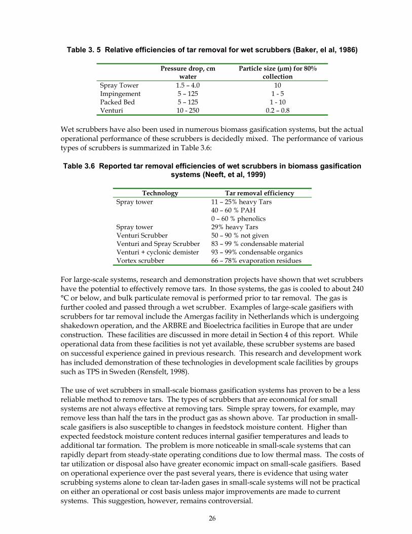
26
Table 3. 5 Relative efficiencies of tar removal for wet scrubbers (Baker, el al, 1986)
Pressure drop, cmwater
Particle size (µm) for 80%collection
Spray Tower 1.5 � 4.0 10Impingement 5 � 125 1 - 5Packed Bed 5 � 125 1 - 10Venturi 10 - 250 0.2 � 0.8
Wet scrubbers have also been used in numerous biomass gasification systems, but the actualoperational performance of these scrubbers is decidedly mixed. The performance of varioustypes of scrubbers is summarized in Table 3.6:
Table 3.6 Reported tar removal efficiencies of wet scrubbers in biomass gasificationsystems (Neeft, et al, 1999)
Technology Tar removal efficiencySpray tower 11 � 25% heavy Tars
40 � 60 % PAH0 � 60 % phenolics
Spray tower 29% heavy TarsVenturi Scrubber 50 � 90 % not givenVenturi and Spray Scrubber 83 � 99 % condensable materialVenturi + cyclonic demister 93 � 99% condensable organicsVortex scrubber 66 � 78% evaporation residues
For large-scale systems, research and demonstration projects have shown that wet scrubbershave the potential to effectively remove tars. In those systems, the gas is cooled to about 240°C or below, and bulk particulate removal is performed prior to tar removal. The gas isfurther cooled and passed through a wet scrubber. Examples of large-scale gasifiers withscrubbers for tar removal include the Amergas facility in Netherlands which is undergoingshakedown operation, and the ARBRE and Bioelectrica facilities in Europe that are underconstruction. These facilities are discussed in more detail in Section 4 of this report. Whileoperational data from these facilities is not yet available, these scrubber systems are basedon successful experience gained in previous research. This research and development workhas included demonstration of these technologies in development scale facilities by groupssuch as TPS in Sweden (Rensfelt, 1998).
The use of wet scrubbers in small-scale biomass gasification systems has proven to be a lessreliable method to remove tars. The types of scrubbers that are economical for smallsystems are not always effective at removing tars. Simple spray towers, for example, mayremove less than half the tars in the product gas as shown above. Tar production in small-scale gasifiers is also susceptible to changes in feedstock moisture content. Higher thanexpected feedstock moisture content reduces internal gasifier temperatures and leads toadditional tar formation. The problem is more noticeable in small-scale systems that canrapidly depart from steady-state operating conditions due to low thermal mass. The costs oftar utilization or disposal also have greater economic impact on small-scale gasifiers. Basedon operational experience over the past several years, there is evidence that using waterscrubbing systems alone to clean tar-laden gases in small-scale systems will not be practicalon either an operational or cost basis unless major improvements are made to currentsystems. This suggestion, however, remains controversial.
27
Wet electrostatic precipitators can also be used to remove tars from product gas streams. Tarremoval is based on the same principles as particulate removal, with ionization of the tardroplet followed by migration of the ionized droplet to a charged collecting point. For tarcollection, wire and tube designs are preferred for the electrostatic precipitator rather thanthe place collectors used for particulates. The collector surfaces are washed continuously toremove the tar material. These technologies can operate up to about 150 °C, but wouldlikely operate at lower temperatures for tar removal to avoid tar vaporization.
Electrostatic precipitators are very efficient at removing either tars or particulates from thegas stream, and can remove up to 99% of materials under 0.1 µm in diameter. Thistechnology is mature and available commercially for a variety of applications. The use ofthese systems with large scale biomass gasifiers, however, is uncommon. The high capitaland operating costs of these systems are the primary barriers to their use. Tests withelectrostatic precipitators have also been completed in small-scale systems (Hasler, et al,1997), but operational difficulties were encountered.
Barrier filters of various types have been used in biomass gasification systems for tarremoval. Tar is captured by impingement of condensed aerosols on the filter surface.Because it exists in a liquid form, tar is more difficult to remove from the filter surface thandry particulates. The problem of removing tars from the filter surface is compounded whenparticulates are also present because the resulting filter cake cannot be readily cleaned fromfilter surfaces. These differences in characteristics make many barrier filters less suitable fortar removal than for particulate removal. Barrier filters including fabric bag filters andrigid �hot gas� filters made of metal or ceramic are generally inappropriate for tar removalin biomass gasification systems. Tar accumulation on the filter surface leads to eventualplugging.
Packed bed filters have been used historically in many smaller-scale biomass gasificationfacilities to remove tars, and some research has recently been conducted on packed bedfilters. Packing materials have included sawdust, wood chips, cork, and sand. While thesepacking materials provide adequate filtration of tars, they also create operational problemsrelated to cleaning the filter and to waste disposal. These filters may be appropriate forsmall systems operating in remote locations where labor is inexpensive, but they are notbeing incorporated into designs for larger-scale commercial facilities due to operational andcost considerations.
Cyclone filters and other centrifugal force separators are also mechanical technologies thatcan potentially be used for tar removal. These technologies operate on the same principlesas those for particulate removal, using centrifugal force to separate solids and aerosols fromgases. Examples include cyclones, u-tubes, or vortex separators. The technologies are bestsuited for removing larger materials, typically those with diameters of 5 µm or greater.
In practice, cyclones and related centrifugal separators are not used for tar removal inbiomass gasification systems. The combination of particulate and �sticky� tar in the gasstream creates a deposition of material on cyclone surfaces that is difficult to remove innormal operation. Even if particulates were removed prior to tar condensation, cyclones areineffective at removing small-diameter tar aerosols that include material under 1 µm . As aresult, cyclones are not a practical means of removing tars from raw biomass gasificationproducts.
28
Recently, interest has been expressed in the use other types of systems based on centrifugalforce separation (Neeft, et al, 1999). These include the so-called �condi-cyclone� and therotating particle separator, which are described in more detail by Neeft. The condi-cyclonehas been used to remove water from gas streams, but no data has been reported for tarcollection. Limited research using a rotating particle separator for tar separation has alsobeen performed (Hasler, 1998; Berkel and Temmink, 1998). Further research will berequired before the viability of these technologies for large-scale systems can be evaluated.
3.3.3.2 Use and Disposal of Collected Tars
Systems that physically separate tar must also deal with the waste products that arecollected. In large-scale gasification systems, the most appropriate technologies for tarremoval currently involve wet scrubbers or wet electrostatic precipitators. In either case, thetar is collected as part of an aqueous rinse. As discussed previously, biomass tars include aspectrum of organics ranging from mixed oxygenates to phenols to multi-ring aromatics,and most of these are at least partially water soluble. As a result, the wet scrubber wastefrom these technologies is recovered as an emulsion that cannot be cleanly separated intoorganic and oil-phase products. Partial separation of the effluent into �oil� and �water�phases can sometimes be achieved by settling, but the resulting oil product still containslarge amounts of water, typically 50 wt% or more. The separated wastewater phase alsocontains lower molecular weight oxygenates including organic acids, aldehydes, andphenols that require cleanup. Both wastewater cleanup and tar disposal add economiccosts and simple disposal is usually prohibited by environmental regulations.
Depending on the system, the collected tar material may be burned to provide process heatAlthough the tar is wet and has a relatively low heating value, burners are commerciallyavailable that can utilize this fuel and provide heat to generate steam or to meet othersystem needs. In steam generation systems, for example, the heat from tar combustion canbe used to generate additional steam and increase system efficiency.
Tars may also potentially be re-injected into the gasifier to produce additional product gas.Reinjection of tar, particularly material that is highly oxygenated, allows that material tofurther react and form additional gas-phase products. However, as tars are reheated, theyalso undergo further dehydration and condensation reactions to form more refractory tars.Thus, reinjection of tar into systems operating under steady-state conditions will result inpartial conversion of the material to gases and partial conversion to more refractory tars.The equilibrium between the two depends on the specific system, but caution must beexercised to avoid buildup of highly aromatic, refractory tars by repeated exposure to severereactor conditions.
Technologies capable of treating the aqueous wastewater are available but add cost togasification systems. Adsorption of dissolved organics by carbon, wet oxidation ofwastewaters, or dilution and biological treatment of wastewaters have all been shown to betechnically feasible (Neeft, et al, 1999). The costs of such processes, rather than theirtechnical feasibility, remain the primary constraint for gasification systems.
In addition to the disposal considerations, tar collection presents possible handlingproblems. Over the past two decades, the toxicological properties of a wide range of liquidproducts from biomass pyrolysis and gasification processes have been examined. This work(Diebold, 1998) suggests that tar-like products formed at temperatures of about 800 OC orless can safely be handled using standard �safe practices� such as eye protection, gloves,
29
and appropriate clothing. While these tars contain a wide range of chemical constituents,they do not present particular health risks if standard handling procedures are followed.Products formed at temperatures above approximately 800 °C or exposed to long residencetimes may also contain refractory polyaromatic products as explained above. Studies haveshown (Elliott, 1985) that these refractory tars may contain materials that are classified ashazardous and will require a higher level of care in handling and disposal.
3.3.3.3 Catalytic and Thermal Tar Destruction
Catalytic or thermal tar destruction processes have also been examined as methods toremove tars from the product gas. In these processes, tars thermally decompose to formadditional product gas and sometimes char. Tar destruction can be accomplished withthermal energy alone at above about 1200 °C or with catalysts at moderate temperatures of750-900 °C. These approaches are intuitively attractive because they have the potential toincrease conversion efficiencies while simultaneously eliminating the need for collectionand disposal of tars. Such approaches are well suited to large-scale systems with turbulent-bed gasifiers where the product gas exits the reactor at temperatures of about 800 °C, theapproximate range where catalytic destruction is most effective.
Catalytic processes for tar destruction
Catalytic tar destruction has been studied in biomass gasification systems for more thantwenty years (see for example: Mudge, et al, 1981; Ekstrom, et al, 1982; Bridgwater, 1994;Beenakers, 1994; Simell, 1994; Aznar, et al, 1997; Abatzoglou, et al, 1997; Milne, et al, 1998,1999; Neeft, 1999, Corella, et al, 1999, Caballero, et al, 1999). These processes use catalysts toassist in the cracking and destruction of tars. Research and development activities havebeen conducted using a variety of metallic and non-metallic catalysts either in the gasifieritself or in separate vessels downstream from the gasifier.
Research on catalysts placed in the gasifier (in situ tar destruction) began in the early 1980sand has continued intermittently since then (Baker, et al, 1986; Espenas and Frostäng, 1996;Sydkraft, 1998). Most of this research has focused on the use of low-cost dolomites andrelated �disposable� catalysts. Tars are cracked to smaller molecules on the catalyst surface,and the mechanisms of tar destruction are reasonably well documented. This conceptualapproach has the potential advantage that tars can be rapidly destroyed as they are formed,eliminating downstream problems. The turbulent flow and high temperatures of large-scale fluidized bed gasifiers result in physical attrition and deactivation of the catalyst. Infixed-bed gasifiers, the contact between catalyst and tars is sometimes insufficient, resultingin incomplete tar destruction.
Testing to reduce tars in the gas stream using in situ dolomite catalysts has been reported atthe Värnamo facility in Sweden (Sydkraft, 1998). The results showed that the catalyst wasdeactivated over time but that tar levels could be reduced. However, the Värnamo systemdid not require thorough tar removal, as will be explained in Section 4. At this time,research suggests the use of in situ tar destruction catalysts can reduce tar levels but thisdoes not appear to be an effective approach for complete tar destruction in large-scalesystems.
More extensive research has been performed on tar destruction systems where catalysts areplaced in a separate reactor downstream from the gasifier (see for example: Neeft, et al,1999; Paisley, 1997; Corella, et al, 1999; Aznar, et al, 1997, 1994;). The separate reaction
30
vessel provides for better temperature control and for reduced bed turbulence that cancontribute to longer catalyst lifetimes. This research has included examination of bothmetallic catalysts of the types used in the petrochemical industry and non-metallic catalystssuch as dolomites as described below.
Extensive basic and applied research with non-metallic catalysts has been performed (Alden,et al, 1997; Orio, et al, 1997; Lammars, et al, 1997; Myrén, et al, 1997; Gebhard, et al, 1994a,1994b; and other references from the previous paragraph). Non-metallic catalysts includedolomites, zeolites, and calcites. and the cost of these catalysts is generally low. Thereactions of these catalysts with biomass tars have been examined extensively using avariety of analytical and modeling techniques. The research generally shows that dolomitesand similar materials have significant potential to crack tars in biomass gasification systems.Under laboratory conditions, dolomite removes 95-99% of the tars in gas streams attemperatures of 750-900 °C. Dolomite can be deactivated through carbonate formation, andit is also sensitive to physical attrition due to bed turbulence. The use of less turbulentbubbling fluidized beds can prolong catalyst lifetimes.
Tests of non-metallic tar cracking catalysts have also been performed in biomass gasificationdevelopment facilities. For example, a fluidized-bed tar cracker has been tested at theBattelle Columbus demonstration-scale (10 ton/day feedstock capacity) gasifier in theUnited States (Paisley, 1997). The tests used a proprietary disposable catalyst named DN34,which as been characterized in biomass systems by others (Gebhard, et al, 1994a, 1994b).Initial testing at this facility showed that wet scrubbing alone was insufficient to clean thegas prior to compression. To remove tars, the fuel gases were passed through a fluidizedbed reactor containing a proprietary disposable cracking catalyst referred to as DN34 priorto wet scrubbing. At operational temperatures of 800 °C, tar concentrations were reducedfrom 23 g/m3 in the raw product gas to 1.4 g/m3 following the cracker (Paisley, 1997c). Tarreduction was dependent on the temperature,with low conversions at lower temperatures.Following the tar cracker, the product gases were then passed through a wet scrubber. Tarconcentrations in the gas following the combination of wet scrubbing and catalytic crackingwere reported to be �essentially zero�, or lower than detection limits (Paisley 1997c). Theintegrated system with the tar cracker operated for more than 200 hours. The larger-scaleFERCO gasifier in Burlington, Vermont, is based on the Battelle-Columbus design and isdiscussed more in Section 4 of this report.
Extensive research has also been performed on the use of metallic tar cracking catalysts forbiomass gasification. This work began in the early 1980s (Mudge, 1981) and has includedstudies of a wide range of metal-based catalysts including Ni, Ni/Mo, Ni/Co/Mo, NiO, Pt,Ru, on supports such as silica alumina, zeolites, and others (Aznar, et al, 1997; Alden, et al,1997; and other references above). Many of these metal-based catalysts are usedcommercially in the petrochemical industry. Several of these, particularly those withNi/Co/Mo blends, have been demonstrated to be effective in cracking biomass tars. Theyoffer the additional advantage of also typically destroying ammonia in the gas stream aswell. Catalyst lifetimes in the laboratory scale tests depend on the catalyst substrate.Commercial steam reforming catalysts can deactivate in a matter of hours, while othersusing zeolite supports maintained activity through numerous regeneration cycles using airto remove deposited carbon (Neeft, et al, 1999). At present, these types of catalysts have notbeen tested in larger biomass gasification systems under continuous, steady-stateconditions. As a result, the technical information necessary to evaluate the technical andeconomic feasibility of metal-based tar cracking catalysts is not available, and additionaltesting will be needed.
31
Thermal processes for tar destruction
While catalysts facilitate tar destruction at intermediate temperatures, tars can also becracked thermally without catalysts at higher temperatures, typically 1200 °C or higher. Theminimum temperature required for efficient destruction is not well characterized and willdepend on the types of tars formed in the gasifier. Thus, thermal destruction of theoxygenated tars from updraft gasifiers might be treated at 900 °C while the refractory onesfrom high temperature reactors may require 1200 °C or more. The difficulties of attainingcomplete thermal cracking along with operational and economic considerations makethermal cracking less attractive in current large-scale gasifiers using cleaner biomassfeedstocks.
Thermal cracking has been tested for disposing of the tars from the pyrolysis or gasificationof various organic wastes. For example, the Thermoselect process has been used to destroytars produced during disposal of various wastes. In this process, O2 is added to the reactorto partially combust the tars and increase temperatures to 1200 °C or greater. Similarapproaches include the Noel Konversion process and the Bibros PEC process. Theseprocesses are reviewed elsewhere (Neeft, et al, 1999). Systems designed primarily for wastereduction, particularly hazardous wastes, have significantly different economic bases thanenergy systems. As a result, waste reduction processes may generate energy by-productsthat would be uneconomical if produced from clean biomass.
Thermal decomposition of biomass tars in electric arc plasmas has also been studied.Plasmas are created by heating gases in the discharge arc between two electrodes. Theelectrical charge and the increased temperature in the arc cause ionization of part of thegases and subsequent reaction. Several plasma arc reactors have been built and tested forapplications with biomass tars and are reviewed elsewhere (Neeft, et al, 1999). At present,these systems have not been tested in continuous operation with larger-scale biomassgasifiers. These reactors have significant potential for waste elimination, and they couldpotentially be used to destroy tars accumulated by physical means as described above.However, they are unlikely to be appropriate as primary tar cracking technologies for large-scale biomass gasification systems due to the costs of electricity and the need to treat largegas volumes.
3.3.3.4 Standardized Testing Protocols for Tar Measurement
As stated previously, the measurement of tar concentrations in gasifier product streams isdifficult. Because various labs and developers have historically used differentmethodologies, the data reported can be difficult to compare with that from other sites. Theneed for improved tar collection and measurement protocols has been recognized by thegeneral gasification community.
As a result of this interest, suggested protocols have been developed for both small- andlarge-scale gasification systems. These protocols have been recently published (Maniatisand Beenakers; Abatzouglou, et al, 2000; Knoef and Koele, 2000; Simell, et al, 2000; Knoef,2000). The proposed protocols provide standardized methods to analyze tars. Theprotocols are expected to improve the consistency and comparability of data obtained bydifferent groups at different sites. While the complete analyses would probably not bemade at large-scale facilities on an ongoing basis, periodic analysis using these protocolsshould produce much-needed data to the gasification research community.
32
3.3.4 Removal of Nitrogen Containing Compounds
Removal of ammonia from the biomass gas stream is necessary in many situations.Ammonia is converted to NOx when the gas is burned, and NOx emissions are limited bylaw in most industrialized areas. The imposition of stringent NOx emission limits in manylocalities over the past ten years has focused additional attention on this issue. Twoprimary approaches are feasible for ammonia removal. Catalytic destruction of ammonia ispossible using catalysts similar to those used for tar cracking or hydrocarbon reforming.Wet scrubbing will also remove ammonia in those systems where low temperature productgases are acceptable.
Catalytic destruction of ammonia has been reported for dolomites, nickel-based steam-reforming catalysts, iron-based catalysts, and others (Leppälahti, et al, 1994, 1991; Simmel, etal, 1997). Destruction of ammonia on the dolomite and nickel-based catalysts is effected atapproximately the same temperatures as those used for tar cracking. Work with iron-basedcatalysts was also conducted at somewhat higher temperatures (about 900 °C). Using thesecatalysts, destruction of >99% of the ammonia is possible. This approach is appealingbecause it has the potential to remove both tars and ammonia from the product gas whilemaintaining the heat of the product gas. Research to date on catalytic ammonia destructionin biomass systems has been conducted primarily in bench-scale facilities, and additionalwork will be required to evaluate the cost and technical feasibility of this approach for large-scale gasification systems.
In systems where the product gas is first cooled, ammonia may also be removed from theproduct gas by wet scrubbing. Wet scrubbing is a well-developed technology used inrelated gas processing industries. Wet scrubbing is also used at the Amergas facility in TheNetherlands to remove ammonia from the product gas (EPZ, 1999). The ammoniarecovered from the scrubber is reinjected into the gasifier to provide for ammonia reductionthrough thermal equilibrium and to react with any NOx formed during gasification.Although nitrogen oxides are formed primarily at temperatures representative ofcombustion systems rather than those found in gasification systems, the addition ofammonia will reduce NOx level due to thermal equilibrium. The Amergas facility, as a�showcase� for utilization of urban wood waste, has chosen to provide a very clean productgas. The Amergas facility is currently undergoing shakedown operation, and long-termoperational data was not available in late 2000.
3.3.5 Sulfur Removal
As mentioned previously, most biomass resources are naturally low in sulfur, and sulfurremoval is not necessary in most applications where the product is used as a fuel gas. Forthose feedstocks such as wastes with unusually high sulfur levels, the sulfur-containingspecies will be converted to sulfur oxides (SOx) when the gas is burned. Wet scrubbers arecommercially available for SOx removal and are well proven commercially. Because thescrubbing adds additional capital and operating costs, the use of high-sulfur biomassfeedstocks will be limited to those situations where waste disposal is necessary.
For synthesis gas applications, however, sulfur concentrations are limited to about 0.1mg/Nm3 (Graham and Bain, 1993). Fuel cell systems will also require sulfur concentrationsof less than 1 ppm. Sulfur containing species poison catalysts used for chemical synthesis,particularly copper-based ones such as those used in methanol synthesis. Technologies for
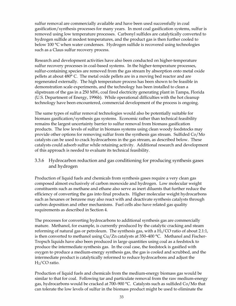
33
sulfur removal are commercially available and have been used successfully in coalgasification/synthesis processes for many years. In most coal gasification systems, sulfur isremoved using low temperature processes. Carbonyl sulfides are catalytically converted tohydrogen sulfide at modest temperatures, and the product gas is then further cooled tobelow 100 °C when water condenses. Hydrogen sulfide is recovered using technologiessuch as a Claus sulfur recovery process.
Research and development activities have also been conducted on higher-temperaturesulfur recovery processes in coal-based systems. In the higher-temperature processes,sulfur-containing species are removed from the gas stream by absorption onto metal oxidepellets at about 480° C. The metal oxide pellets are in a moving bed reactor and areregenerated externally. The high temperature process has been shown to be feasible indemonstration scale experiments, and the technology has been installed to clean aslipstream of the gas in a 250 MWe coal fired electricity generating plant in Tampa, Florida(U.S. Department of Energy, 1996b). While operational difficulties with the hot cleanuptechnology have been encountered, commercial development of the process is ongoing.
The same types of sulfur removal technologies would also be potentially suitable forbiomass gasification/synthesis gas systems. Economic rather than technical feasibilityremains the largest uncertainty barrier to sulfur removal from biomass gasificationproducts. The low levels of sulfur in biomass systems using clean woody feedstocks mayprovide other options for removing sulfur from the synthesis gas stream. Sulfided Co/Mocatalysts can be used to crack hydrocarbons in the gas stream, as described below. Thesecatalysts could adsorb sulfur while retaining activity. Additional research and developmentof this approach is needed to evaluate its technical feasibility.
3.3.6 Hydrocarbon reduction and gas conditioning for producing synthesis gasesand hydrogen
Production of liquid fuels and chemicals from synthesis gases require a very clean gascomposed almost exclusively of carbon monoxide and hydrogen. Low molecular weightconstituents such as methane and ethane also serve as inert diluents that further reduce theefficiency of converting the gas into final products. Higher molecular weight hydrocarbonssuch as hexanes or benzene may also react with and deactivate synthesis catalysts throughcarbon deposition and other mechanisms. Fuel cells also have related gas qualityrequirements as described in Section 4.
The processes for converting hydrocarbons to additional synthesis gas are commerciallymature. Methanol, for example, is currently produced by the catalytic cracking and steamreforming of natural gas or petroleum. The synthesis gas, with a H2/CO ratio of about 2.1:1,is then converted to methanol using Cu/Zn catalysts at 350�400 °C. Methanol and Fischer-Tropsch liquids have also been produced in large quantities using coal as a feedstock toproduce the intermediate synthesis gas. In the coal case, the feedstock is gasified withoxygen to produce a medium-energy synthesis gas, the gas is cooled and scrubbed, and theintermediate product is catalytically reformed to reduce hydrocarbons and adjust theH2/CO ratio.
Production of liquid fuels and chemicals from the medium-energy biomass gas would besimilar to that for coal. Following tar and particulate removal from the raw medium-energygas, hydrocarbons would be cracked at 700�900 °C. Catalysts such as sulfided Co/Mo thatcan tolerate the low levels of sulfur in the biomass product might be used to eliminate the
34
need for a separate sulfur-removal step. Since raw biomass gases are generally deficient inhydrogen, water shift gas reactions would adjust the H2/CO ratio. Following scrubbing toremove CO2 and acid gases, the final synthesis gas would be converted using commercialtechnologies.
Experimental data has also been collected for biomass systems. In bench-scale tests usingcommercial nickel-based catalysts, it has been reported (Berg, et al, 1997) that steamreforming over nickel catalysts can potentially be effective even in the presence of somesulfur-containing species. In these tests, hydrogen sulfide present at levels of 100 and 200ppm partially deactivated the catalyst, but activity could be retained in part by increasingthe reaction temperature.
Related work on steam reforming of biomass gas for production of hydrogen has beenreported (Czernik, et al, 2000; 1999). Pyrolysis products similar to tars from biomassgasifiers were vaporized and reacted with steam over a nickel-based catalyst (U91) usedcommercially in the reforming of natural gas. In bench-scale experiments, yieldsapproached 80% of the theoretical value with some carbon formation on the catalyst surface.In biomass gasification systems, the amounts of tar would be significantly lower than in thereported system, which had different goals. However, the work suggests that shifting thebiomass gas and dealing with residual amounts of tar in the product gas is potentiallyfeasible using commercial catalysts.
Recent interest has also been expressed in the use of biomass thermal gasification to providea hydrogen-rich fuel gas for fuel cells (see, for example, Amos, 1998). The issues of gascleanup are closely related to those of producing a synthesis quality product. Removal ofparticulates and tar from the gas stream is essential, and reforming of the gas is alsorequired. Care must also be exercised to ensure low sulfur content in the fuel gas. Theoverall compatibility of the gasification and fuel cell technologies has not been wellcharacterized, but the gas cleanup demands of the fuel cells will likely be similar inmagnitude to those for synthesis gases. Fuel cell requirements are discussed more inSection 4 of this report.
While the production of fuels and chemicals from biomass synthesis gases is technicallyfeasible, the economic feasibility is more difficult. The subject of integrated biomassgasification systems for synthesis gas and for hydrogen production with fuel cells isdiscussed in more detail in Section 4 of this report.
3.4 Survey of Biomass Gas Conditioning Technologies
As part of the ongoing IEA Bioenergy Agreement Task on biomass gasification (IEABioenergy, 2000), a survey of technologies available for biomass gas conditioning wasdeveloped in 1999. The survey was developed for participants to distribute to industries intheir own countries. The responses were to be used to develop a listing of availabletechnologies and the companies capable of providing them. As the IEA Bioenergy Taskproceeded, it was decided that a world-wide compilation of the capabilities of individualcompanies was lower priority than other efforts, and the survey was not widely distributed.The survey developed through that effort is attached to this document as Appendix A andcan freely be distributed if individuals wish to compile a directory of capabilities for theirown country.
35
4. INTEGRATED GASIFICATION/END-USE SYSTEMS
For biomass gasification systems to be successful, the gasifier, the accompanying gasconditioning technologies, and the end-use application must be carefully designed as anintegrated unit. The end-use application will determine the gas �quality� requirements,with some applications such as kilns being less demanding while others such as gas turbinesor fuel cells being more demanding. Many individual gas conditioning technologies areavailable to meet these requirements, but each has operational and economic implicationsthat will affect overall performance. In addition, different gasifiers produce raw fuel gaseswith different characteristics. As a result, it is essential to design integrated systems that canboth operationally and economically meet end-use requirements.
In the following section of this report, several large-scale biomass gasification systems aresummarized that are either in current operation or are in the design and construction stageof development. The discussion provides an overview of the current strategies being usedfor gas conditioning in large-scale systems and highlights situations where opportunities forimprovements in next-generations systems may exit. It should be noted that the discussionof facilities is not intended to be a comprehensive listing of all current efforts but is intendedinstead to highlight the range of different gas conditioning approaches being taken atpresent.
Four types of gas conditioning approaches are discussed based on the demands of the end-use system and the approach taken to clean the product:
! Systems requiring minimal hot-gas conditioning that produce fuel gases forrelatively undemanding end-use applications
! Systems requiring significant gas conditioning that produce cool (<100 °C) fuel gasesfor demanding applications
! Systems requiring significant gas conditioning that produce warm or hot (>100 °C)fuel gases for demanding applications
! Systems requiring exceptional gas conditioning that produce synthesis gases for themanufacture of fuels and chemicals, or hydrogen for fuel cells
Specific gasifier facilities are discussed below. The selection of gasification facilities fordiscussion is not intended to be a complete listing of all such facilities but is intended toillustrate the variety of approaches that are currently being taken with larger-scalegasification systems. More complete listings of active biomass gasification facilities areavailable elsewhere (BTG, 2000; Reed, 1999). The gasification systems that will be describedare summarized in Table 4.1. At present, there are no stand-alone biomass synthesis gasfacilities, but this topic is discussed in more detail in Section 4.4.
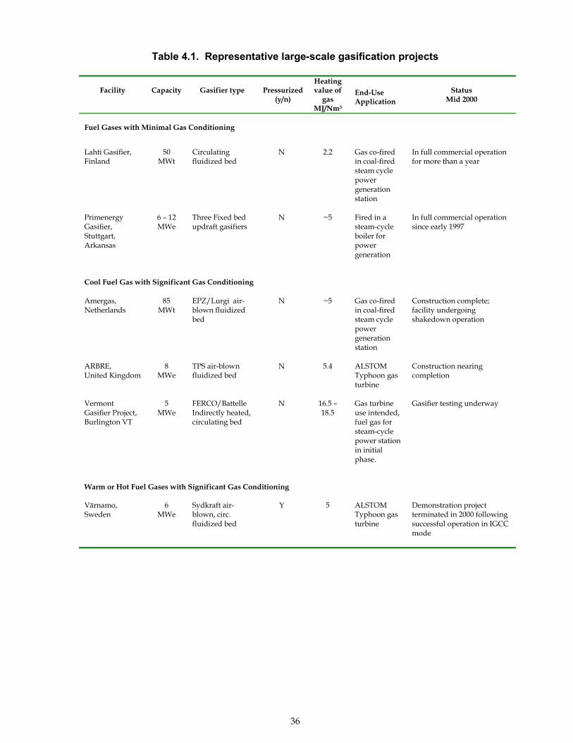
36
Table 4.1. Representative large-scale gasification projects
VermontGasifier Project,Burlington VT
5MWe
FERCO/BattelleIndirectly heated,circulating bed
N 16.5 �18.5
Gas turbineuse intended,fuel gas forsteam-cyclepower stationin initialphase.
Gasifier testing underway
Warm or Hot Fuel Gases with Significant Gas Conditioning
Värnamo,Sweden
6MWe
Sydkraft air-blown, circ.fluidized bed
Y 5 ALSTOMTyphoon gasturbine
Demonstration projectterminated in 2000 followingsuccessful operation in IGCCmode
Facility Capacity Gasifier type Pressurized(y/n)
Heatingvalue of
gasMJ/Nm3
End-UseApplication
StatusMid 2000
Fuel Gases with Minimal Gas Conditioning
Lahti Gasifier,Finland
50MWt
Circulatingfluidized bed
N 2.2 Gas co-firedin coal-firedsteam cyclepowergenerationstation
In full commercial operationfor more than a year
PrimenergyGasifier,Stuttgart,Arkansas
6 � 12MWe
Three Fixed bedupdraft gasifiers
N ~5 Fired in asteam-cycleboiler forpowergeneration
In full commercial operationsince early 1997
Cool Fuel Gas with Significant Gas Conditioning
Amergas,Netherlands
85MWt
EPZ/Lurgi air-blown fluidizedbed
N ~5 Gas co-firedin coal-firedsteam cyclepowergenerationstation
Construction complete;facility undergoingshakedown operation
ARBRE,United Kingdom
8MWe
TPS air-blownfluidized bed
N 5.4 ALSTOMTyphoon gasturbine
Construction nearingcompletion
37
4.1 Fuel Gases for Systems With Minimal Gas Conditioning Requirements
4.1.1 Overall Gas Conditioning Strategy � Minimal Gas Conditioning
Some end-use technologies require only minimal cleanup and conditioning of the rawproduct gas. In these systems, the gases are combusted in burners to provide heat forsystem needs. Examples could include biomass-fired kilns, steam-cycle power generationsystems, or cofiring applications where biomass fuel gases are burned in coal powerstations. These systems have several common characteristics that allow the minimallytreated gas to be used effectively:
! The end-use can tolerate significant amounts of particulates! The system has no special sensitivities to alkali salts! The gasifier and end-use technology are closely coupled, which helps retain the
sensible heat in the raw gas and also prevents tar condensation in pipes! Tars are combusted at the burners! Environmental emissions regulations can be met by treating the cool combustion
gases after the heat is extracted, or emissions requirements are minimal
In uses of this type, the overall gas conditioning strategy is to burn the gas followingminimal treatment of the raw product. Bulk particulate removal is accomplished using acyclone filter, and in some cases heat may be recovered by a heat exchanger for other uses.The gas is kept hot or warm (>200 °C) to both retain the energy in the product gas and toprevent tar condensation. The product gas, including tars and hydrocarbons in the productstream, is burned in closely coupled burners. Fly ash, NOx, SOx, and other emissions arecontrolled by the use of conventional technologies that treat the combustion flue gases. Theapproach lowers capital and operating costs because the gas conditioning technology isminimal, but the resulting fuel product can only be used in relatively undemanding end-uses.
Examples of such systems include the biomass gasifiers in Lahti, Finland, and thePrimenergy gasifier in Stuttgart, Arkansas. These gasification systems are discussed inmore detail below to illustrate the implications for this approach to gas conditioning. Othergasification facilities with similar gas conditioning requirements exist elsewhere. Thesefacilities were selected for discussion because they are representative of newer, large-scalebiomass installations for this type of application.
4.1.2 Example of a Gasification System Requiring Minimal Gas Conditioning:Lahti , Finland
4.1.2.1 System Description
The Lahti gasifier converts wood and other wastes to a low-energy fuel gas that is cofired inan existing coal-fired, steam-cycle power station (Foster Wheeler, 1999). The power stationwas built in the mid-1980s and produces both electricity and hot water for district heating.Electricity and heat production capacities are 167 MWe and 240 MWt respectively. Thegasification unit was added in 1997 to demonstrate the commercial feasibility of using woodand biomass wastes as fuels for power generation. The intent of the effort was to allow the
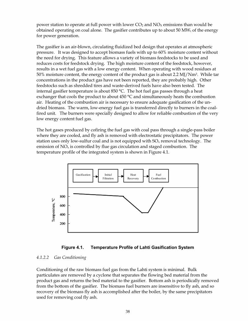
38
power station to operate at full power with lower CO2 and NOX emissions than would beobtained operating on coal alone. The gasifier contributes up to about 50 MWt of the energyfor power generation.
The gasifier is an air-blown, circulating fluidized bed design that operates at atmosphericpressure. It was designed to accept biomass fuels with up to 60% moisture content withoutthe need for drying. This feature allows a variety of biomass feedstocks to be used andreduces costs for feedstock drying. The high moisture content of the feedstock, however,results in a wet fuel gas with a low energy content. When operating with wood residues at50% moisture content, the energy content of the product gas is about 2.2 MJ/Nm3. While tarconcentrations in the product gas have not been reported, they are probably high. Otherfeedstocks such as shredded tires and waste-derived fuels have also been tested. Theinternal gasifier temperature is about 850 °C. The hot fuel gas passes through a heatexchanger that cools the product to about 450 °C and simultaneously heats the combustionair. Heating of the combustion air is necessary to ensure adequate gasification of the un-dried biomass. The warm, low-energy fuel gas is transferred directly to burners in the coal-fired unit. The burners were specially designed to allow for reliable combustion of the verylow energy content fuel gas.
The hot gases produced by cofiring the fuel gas with coal pass through a single-pass boilerwhere they are cooled, and fly ash is removed with electrostatic precipitators. The powerstation uses only low-sulfur coal and is not equipped with SOx removal technology. Theemission of NOx is controlled by flue gas circulation and staged combustion. Thetemperature profile of the integrated system is shown in Figure 4.1.
Figure 4.1. Temperature Profile of Lahti Gasification System
4.1.2.2 Gas Conditioning
Conditioning of the raw biomass fuel gas from the Lahti system is minimal. Bulkparticulates are removed by a cyclone that separates the flowing bed material from theproduct gas and returns the bed material to the gasifier. Bottom ash is periodically removedfrom the bottom of the gasifier. The biomass fuel burners are insensitive to fly ash, and sorecovery of the biomass fly ash is accomplished after the boiler, by the same precipitatorsused for removing coal fly ash.
800
600
400
200
Gasification Initia lFiltration
HeatRecovery
FuelCombustion
Tem
pera
ture
, °C
800
600
400
200
Gasification Initia lFiltration
HeatRecovery
FuelCombustion
Tem
pera
ture
, °C
39
Part of the heat from the fuel gas is recovered by a heat exchanger that is used to preheat thecombustion air. The heat recovery step is dictated by the need to provide extra heat togasify the moist biomass rather than requirements of the combustor. The �warm� productflows directly to the burners where it is consumed. The use of the warm product gas bothprevents tar condensation in the closely coupled system and retains part of the sensible heatto improve conversion efficiencies. This is particularly important in a system where moistbiomass feedstocks are used.
4.1.2.3 Operational Experience and Implications
The gasifier at the Kymijärvi Power station in Lahti has operated successfully for about twoyears. In the first year, about 230 GWh of energy were produced in over 4700 hours ofoperation. Operating availability has exceeded 90% after initial shakedown, and the facilityhas used a variety of feedstocks including of uncontaminated wood residues, railroad ties,refuse-derived fuels, and shredded tires. Cofiring of the biomass-derived gas with coalreduces particulate, NOx, and SOx emissions as compared to combustion of coal alone. Theintegrated system with minimal gas conditioning appears to work as planned.
Despite the minimal product gas conditioning, the system taken in its entirety deals with theconstituents in the biomass product. The strategies for dealing with various raw gasconstituents are summarized in Table 4.2.
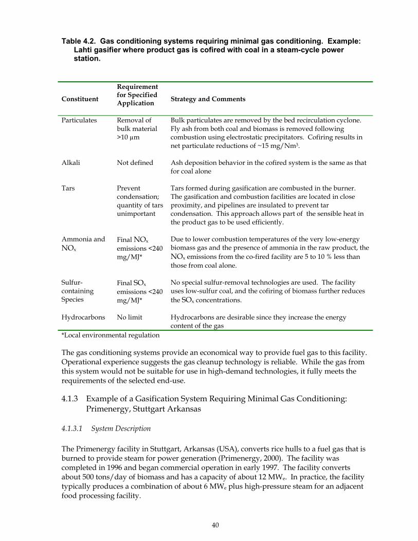
40
Table 4.2. Gas conditioning systems requiring minimal gas conditioning. Example:Lahti gasifier where product gas is cofired with coal in a steam-cycle powerstation.
Constituent
Requirementfor SpecifiedApplication
Strategy and Comments
Particulates Removal ofbulk material>10 µm
Bulk particulates are removed by the bed recirculation cyclone.Fly ash from both coal and biomass is removed followingcombustion using electrostatic precipitators. Cofiring results innet particulate reductions of ~15 mg/Nm3.
Alkali Not defined Ash deposition behavior in the cofired system is the same as thatfor coal alone
Tars Preventcondensation;quantity of tarsunimportant
Tars formed during gasification are combusted in the burner.The gasification and combustion facilities are located in closeproximity, and pipelines are insulated to prevent tarcondensation. This approach allows part of the sensible heat inthe product gas to be used efficiently.
Ammonia andNOx
Final NOx
emissions <240mg/MJ*
Due to lower combustion temperatures of the very low-energybiomass gas and the presence of ammonia in the raw product, theNOx emissions from the co-fired facility are 5 to 10 % less thanthose from coal alone.
Sulfur-containingSpecies
Final SOx
emissions <240mg/MJ*
No special sulfur-removal technologies are used. The facilityuses low-sulfur coal, and the cofiring of biomass further reducesthe SOx concentrations.
Hydrocarbons No limit Hydrocarbons are desirable since they increase the energycontent of the gas
*Local environmental regulation
The gas conditioning systems provide an economical way to provide fuel gas to this facility.Operational experience suggests the gas cleanup technology is reliable. While the gas fromthis system would not be suitable for use in high-demand technologies, it fully meets therequirements of the selected end-use.
4.1.3 Example of a Gasification System Requiring Minimal Gas Conditioning:Primenergy, Stuttgart Arkansas
4.1.3.1 System Description
The Primenergy facility in Stuttgart, Arkansas (USA), converts rice hulls to a fuel gas that isburned to provide steam for power generation (Primenergy, 2000). The facility wascompleted in 1996 and began commercial operation in early 1997. The facility convertsabout 500 tons/day of biomass and has a capacity of about 12 MWe. In practice, the facilitytypically produces a combination of about 6 MWe plus high-pressure steam for an adjacentfood processing facility.
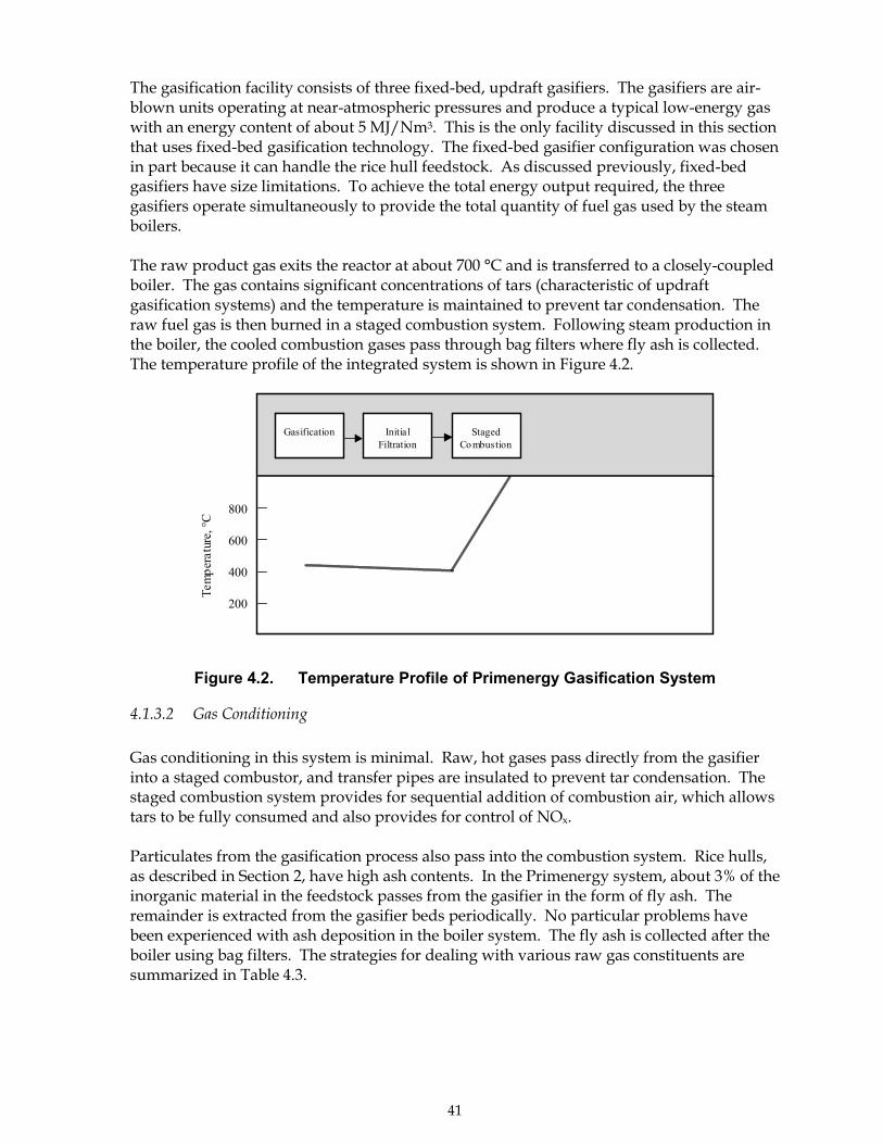
41
The gasification facility consists of three fixed-bed, updraft gasifiers. The gasifiers are air-blown units operating at near-atmospheric pressures and produce a typical low-energy gaswith an energy content of about 5 MJ/Nm3. This is the only facility discussed in this sectionthat uses fixed-bed gasification technology. The fixed-bed gasifier configuration was chosenin part because it can handle the rice hull feedstock. As discussed previously, fixed-bedgasifiers have size limitations. To achieve the total energy output required, the threegasifiers operate simultaneously to provide the total quantity of fuel gas used by the steamboilers.
The raw product gas exits the reactor at about 700 °C and is transferred to a closely-coupledboiler. The gas contains significant concentrations of tars (characteristic of updraftgasification systems) and the temperature is maintained to prevent tar condensation. Theraw fuel gas is then burned in a staged combustion system. Following steam production inthe boiler, the cooled combustion gases pass through bag filters where fly ash is collected.The temperature profile of the integrated system is shown in Figure 4.2.
Figure 4.2. Temperature Profile of Primenergy Gasification System
4.1.3.2 Gas Conditioning
Gas conditioning in this system is minimal. Raw, hot gases pass directly from the gasifierinto a staged combustor, and transfer pipes are insulated to prevent tar condensation. Thestaged combustion system provides for sequential addition of combustion air, which allowstars to be fully consumed and also provides for control of NOx.
Particulates from the gasification process also pass into the combustion system. Rice hulls,as described in Section 2, have high ash contents. In the Primenergy system, about 3% of theinorganic material in the feedstock passes from the gasifier in the form of fly ash. Theremainder is extracted from the gasifier beds periodically. No particular problems havebeen experienced with ash deposition in the boiler system. The fly ash is collected after theboiler using bag filters. The strategies for dealing with various raw gas constituents aresummarized in Table 4.3.
800
600
400
200
Gasification Initia lFiltration
StagedCo mbustion
Tem
pera
ture
, °C
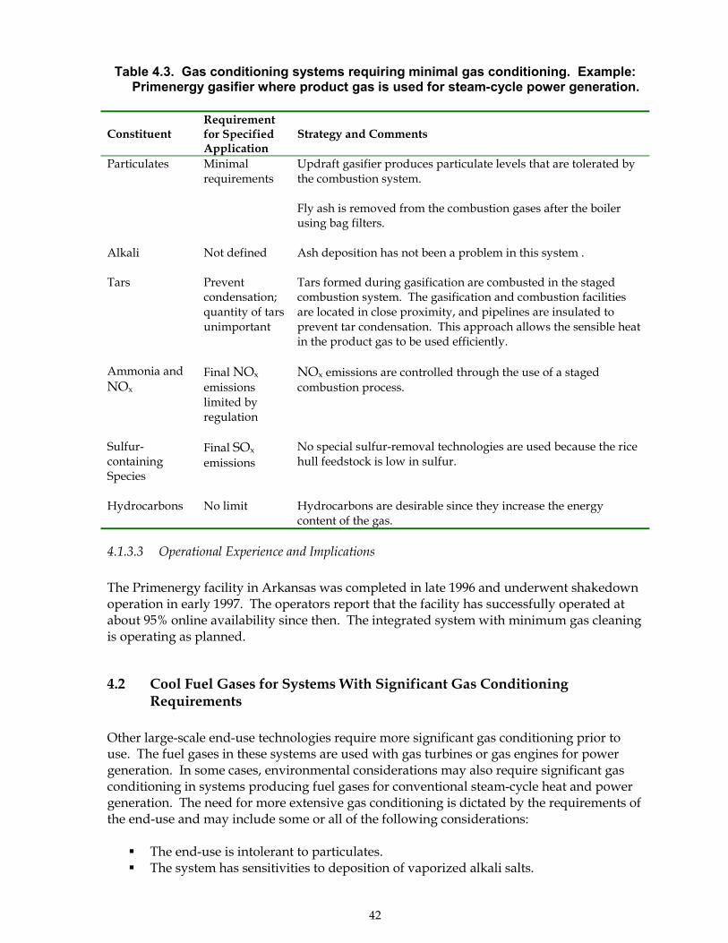
42
Table 4.3. Gas conditioning systems requiring minimal gas conditioning. Example:Primenergy gasifier where product gas is used for steam-cycle power generation.
ConstituentRequirementfor SpecifiedApplication
Strategy and Comments
Particulates Minimalrequirements
Updraft gasifier produces particulate levels that are tolerated bythe combustion system.
Fly ash is removed from the combustion gases after the boilerusing bag filters.
Alkali Not defined Ash deposition has not been a problem in this system .
Tars Preventcondensation;quantity of tarsunimportant
Tars formed during gasification are combusted in the stagedcombustion system. The gasification and combustion facilitiesare located in close proximity, and pipelines are insulated toprevent tar condensation. This approach allows the sensible heatin the product gas to be used efficiently.
Ammonia andNOx
Final NOx
emissionslimited byregulation
NOx emissions are controlled through the use of a stagedcombustion process.
Sulfur-containingSpecies
Final SOx
emissionsNo special sulfur-removal technologies are used because the ricehull feedstock is low in sulfur.
Hydrocarbons No limit Hydrocarbons are desirable since they increase the energycontent of the gas.
4.1.3.3 Operational Experience and Implications
The Primenergy facility in Arkansas was completed in late 1996 and underwent shakedownoperation in early 1997. The operators report that the facility has successfully operated atabout 95% online availability since then. The integrated system with minimum gas cleaningis operating as planned.
4.2 Cool Fuel Gases for Systems With Significant Gas ConditioningRequirements
Other large-scale end-use technologies require more significant gas conditioning prior touse. The fuel gases in these systems are used with gas turbines or gas engines for powergeneration. In some cases, environmental considerations may also require significant gasconditioning in systems producing fuel gases for conventional steam-cycle heat and powergeneration. The need for more extensive gas conditioning is dictated by the requirements ofthe end-use and may include some or all of the following considerations:
! The end-use is intolerant to particulates.! The system has sensitivities to deposition of vaporized alkali salts.
43
! The gasifier and end-use technology are not closely coupled, and tar condensationwould cause plugging in pipes.
! Tars could collect in compressors or engine parts and create operational problems.! Environmental emissions regulations require significant gas conditioning.
Cool fuel gases are required for thermodynamic and efficiency reasons for some systemsincluding those with compressors or those with internal combustion piston engines.However, the gas cooling also results in a loss of the sensible heat in the product gas. Whilepart of the heat of the raw product gas can be recovered using heat exchangers, there isinevitable heat loss as the gas is cooled, and this loss can result in lower overall thermalefficiencies. As a result, this general approach is best suited to those systems where coolgases are required by the end-use or some heat loss can be tolerated. Production of coolgases also allows wet scrubbing systems to be used, which provides additionalopportunities to produce a clean fuel gas.
At present, most large-scale biomass gasification systems are being designed with gasconditioning technologies that produce a cool (<100 °C) fuel gas. In these systems, the gas issequentially cooled, and unwanted constituents such as particulates or tar aerosols aretypically removed using wet scrubbing methods such as scrubbers or wet electrostaticprecipitators. Wet scrubbers operate through the contact of particulates and tars with waterdroplets and require that the system operate at temperatures lower than the boiling point ofwater. These wet scrubbing methods are the most commercially mature technologies forconditioning the raw product gas and provide for effective gas cleaning.
4.2.1 Overall Gas Conditioning Strategy � Producing Clean, Cool Fuel Gases
Biomass systems that produce clean, cool product gases sequentially cool the gas andremove particulates, tars, and other constituents with appropriate technologies. Particulateand tar removal steps are conducted separately to prevent condensation of sticky tarmaterial on the filter cake. A wide variety of particulate filter systems can be used includingbarrier filters, bag filters, and others depending on the temperature of the product stream.Tars can either be removed physically at low temperatures following particulate removal orcatalytically at high temperatures prior to gas cool-down and particulate removal.Remaining particulates, tars, and other constituents are then removed at low temperature bywet scrubbing systems. The wet scrubbing systems remove these materials from the gasstream through contact with liquid droplets and cool the gas to below the boiling point. Inmost systems, the gas is produced at about 35 °C.
Three systems are discussed below to illustrate current approaches that produce clean, coolfuel gases. These examples include the Amergas facility in The Netherlands where cleanfuel gas from urban wood waste is co-fired in a coal power station; the ARBRE facility in theUnited Kingdom where the fuel gas will be fired in a gas turbine; and the Vermont GasifierProject in Burlington, Vermont where the gas will be used for CHP power generation with agas turbine. As stated previously, these are not a complete list of all gasifiers systems of thiskind but were chosen to illustrate a variety of approaches to gas conditioning.
44
4.2.2 Example of a Gasification System Producing Cool, Conditioned Gas:Amergas Facility in Geertruidenberg, Netherlands
4.2.2.1 Project Overview
The Amergas gasifier converts demolition and other wood wastes into a low-energy fuel gasthat is cofired in an existing coal-fired, steam-cycle power station (EPZ, 1999). The AmerPower Station, located in Geertruidenberg, The Netherlands, burns coal to produce steamfor power generation and heat. The gasifier facility was recently added to the power stationto reduce net carbon dioxide emissions from the facility and to reduce urban wood wastes.To meet local environmental regulations and to avoid possible controversy over the use ofurban wood wastes, the developers chose to extensively clean and condition the fuel gasprior to its use. The resulting fuel gas should readily meet the requirements for cofiring itwith coal, and it should also be suitable for other uses requiring a very clean fuel gas. Whilethe end-use for the fuel gas is the same as the Lahti gasifier described above, the gasconditioning approach is very different.
The Amergas facility uses a circulating fluidized bed gasifier with a capacity of about 85MWt. The gasifier is designed to consume about 150,000 tons/year of urban wood wastesconsisting of material that is not impregnated but may have other contamination. Thegasifier was constructed in 1999, and shakedown operation started in 2000.
The gasifier is an air-blown, CFB design that operates at near-atmospheric pressure. Thebed material is composed of sand, and limestone may also be added in later tests. Chippedwood is gasified in the fluidized bed at 850-900 °C. As with most CFB designs, raw productgas is separated from the entrained bed material, unconverted carbon, and bulk particulatesusing a cyclone.
The raw gas is then cooled to 200�240 °C using a heat exchanger that heats water andproduces steam used in the power station. The product gas passes through bag filters toremove particulates. The gas then passes through wet scrubbers that remove tars and coolthe gas to about 35 °C. Finally, additional wet scrubbing is used to remove ammonia fromthe product. Recovered ammonia is re-injected into the gasifier where it is partly destroyedthrough thermal equilibrium and reaction with NOx. The conditioned fuel gas with anenergy content of about 5 MJ/Nm3 is then piped to the power station where it is burned.The temperature profile of this system is shown in Figure 4.3.
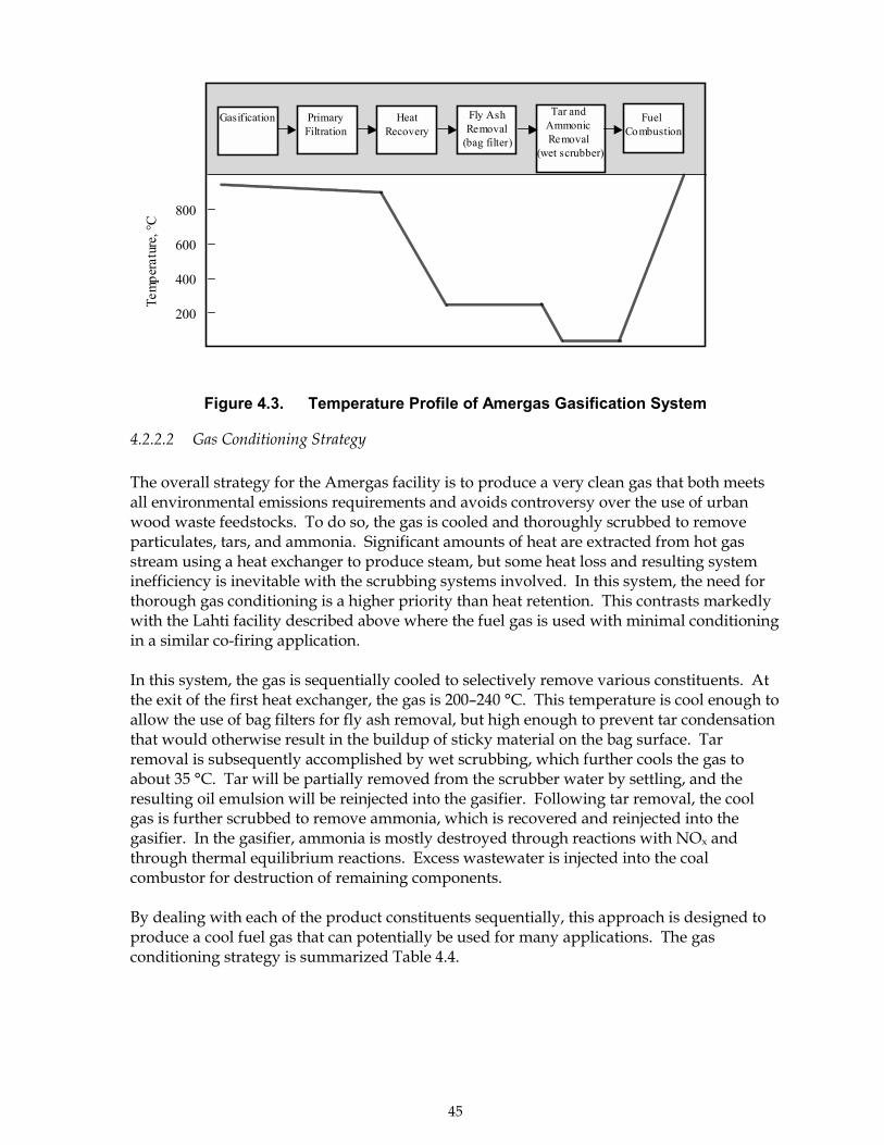
45
Figure 4.3. Temperature Profile of Amergas Gasification System
4.2.2.2 Gas Conditioning Strategy
The overall strategy for the Amergas facility is to produce a very clean gas that both meetsall environmental emissions requirements and avoids controversy over the use of urbanwood waste feedstocks. To do so, the gas is cooled and thoroughly scrubbed to removeparticulates, tars, and ammonia. Significant amounts of heat are extracted from hot gasstream using a heat exchanger to produce steam, but some heat loss and resulting systeminefficiency is inevitable with the scrubbing systems involved. In this system, the need forthorough gas conditioning is a higher priority than heat retention. This contrasts markedlywith the Lahti facility described above where the fuel gas is used with minimal conditioningin a similar co-firing application.
In this system, the gas is sequentially cooled to selectively remove various constituents. Atthe exit of the first heat exchanger, the gas is 200�240 °C. This temperature is cool enough toallow the use of bag filters for fly ash removal, but high enough to prevent tar condensationthat would otherwise result in the buildup of sticky material on the bag surface. Tarremoval is subsequently accomplished by wet scrubbing, which further cools the gas toabout 35 °C. Tar will be partially removed from the scrubber water by settling, and theresulting oil emulsion will be reinjected into the gasifier. Following tar removal, the coolgas is further scrubbed to remove ammonia, which is recovered and reinjected into thegasifier. In the gasifier, ammonia is mostly destroyed through reactions with NOx andthrough thermal equilibrium reactions. Excess wastewater is injected into the coalcombustor for destruction of remaining components.
By dealing with each of the product constituents sequentially, this approach is designed toproduce a cool fuel gas that can potentially be used for many applications. The gasconditioning strategy is summarized Table 4.4.
800
600
400
200
Gasification PrimaryFiltration
HeatRecovery
Fly AshRemoval
(bag filter)Te
mpe
ratu
re, °
C
Tar and Ammonic Removal
(wet scrubber)
Fuel Combustion
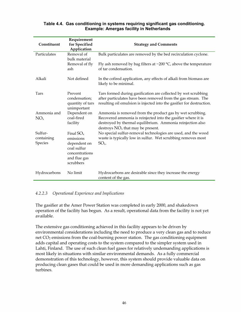
46
Table 4.4. Gas conditioning in systems requiring significant gas conditioning.Example: Amergas facility in Netherlands
ConstituentRequirementfor SpecifiedApplication
Strategy and Comments
Particulates Removal ofbulk materialRemoval of flyash
Bulk particulates are removed by the bed recirculation cyclone.
Fly ash removed by bag filters at ~200 °C, above the temperatureof tar condensation.
Alkali Not defined In the cofired application, any effects of alkali from biomass arelikely to be minimal.
Tars Preventcondensation;quantity of tarsunimportant
Tars formed during gasification are collected by wet scrubbingafter particulates have been removed from the gas stream. Theresulting oil emulsion is injected into the gasifier for destruction.
Ammonia andNOx
Dependent oncoal-firedfacility
Ammonia is removed from the product gas by wet scrubbing.Recovered ammonia is reinjected into the gasifier where it isdestroyed by thermal equilibrium. Ammonia reinjection alsodestroys NOx that may be present.
Sulfur-containingSpecies
Final SOx
emissionsdependent oncoal sulfurconcentrationsand flue gasscrubbers
No special sulfur-removal technologies are used, and the woodwaste is typically low in sulfur. Wet scrubbing removes mostSOx.
Hydrocarbons No limit Hydrocarbons are desirable since they increase the energycontent of the gas.
4.2.2.3 Operational Experience and Implications
The gasifier at the Amer Power Station was completed in early 2000, and shakedownoperation of the facility has begun. As a result, operational data from the facility is not yetavailable.
The extensive gas conditioning achieved in this facility appears to be driven byenvironmental considerations including the need to produce a very clean gas and to reducenet CO2 emissions from the coal-burning power station. The gas conditioning equipmentadds capital and operating costs to the system compared to the simpler system used inLahti, Finland. The use of such clean fuel gases for relatively undemanding applications ismost likely in situations with similar environmental demands. As a fully commercialdemonstration of this technology, however, this system should provide valuable data onproducing clean gases that could be used in more demanding applications such as gasturbines.
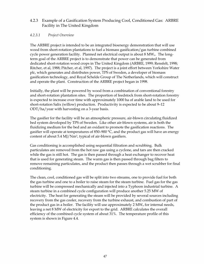
47
4.2.3 Example of a Gasification System Producing Cool, Conditioned Gas: ARBREFacility in The United Kingdom
4.2.3.1 Project Overview
The ARBRE project is intended to be an integrated bioenergy demonstration that will usewood from short-rotation plantations to fuel a biomass gasification/gas turbine combinedcycle power generation facility. Planned net electrical output is about 8 MWe. The long-term goal of the ARBRE project is to demonstrate that power can be generated fromdedicated short-rotation wood crops in The United Kingdom (ARBRE, 1999; Rensfelt, 1998;Ritcher, et al, 1988; Pitcher, et al, 1997). The project is a joint effort between Yorkshire Waterplc, which generates and distributes power, TPS of Sweden, a developer of biomassgasification technology, and Royal Schelde Group of The Netherlands, which will constructand operate the plant. Construction of the ARBRE project began in 1998.
Initially, the plant will be powered by wood from a combination of conventional forestryand short-rotation plantation sites. The proportion of feedstock from short-rotation forestryis expected to increase over time with approximately 1000 ha of arable land to be used forshort-rotation Salix (willow) production. Productivity is expected to be about 9�12ODT/ha/year with harvesting on a 3-year basis.
The gasifier for the facility will be an atmospheric pressure, air-blown circulating fluidizedbed system developed by TPS of Sweden. Like other air-blown systems, air is both thefluidizing medium for the bed and an oxidant to promote the gasification reactions. Thegasifier will operate at temperatures of 850�900 °C, and the product gas will have an energycontent of about 5.4 MJ/Nm3, typical of air-blown gasifiers.
Gas conditioning is accomplished using sequential filtration and scrubbing. Bulkparticulates are removed from the hot raw gas using a cyclone, and tars are then crackedwhile the gas is still hot. The gas is then passed through a heat exchanger to recover heatthat is used for generating steam. The warm gas is then passed through bag filters toremove remaining particulates, and the product then passes through a wet scrubber for finalconditioning.
The clean, cool, conditioned gas will be split into two streams, one to provide fuel for boththe gas turbine and one to a boiler to raise steam for the steam turbine. Fuel gas for the gasturbine will be compressed mechanically and injected into a Typhoon industrial turbine. Asteam turbine in a combined cycle configuration will produce another 5.25 MW ofelectricity. The heat for generating the steam will be provided by several sources includingrecovery from the gas cooler, recovery from the turbine exhaust, and combustion of part ofthe product gas in a boiler. The facility will use approximately 2 MWe for internal needs,leaving a net 8 MW of electricity for export to the grid. ARBRE calculates the overallefficiency of the combined cycle system of about 31%. The temperature profile of thissystem is shown in Figure 4.4.
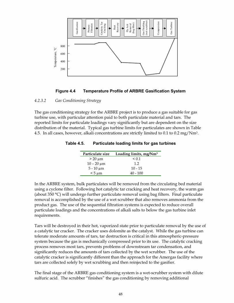
48
Figure 4.4 Temperature Profile of ARBRE Gasification System
4.2.3.2 Gas Conditioning Strategy
The gas conditioning strategy for the ARBRE project is to produce a gas suitable for gasturbine use, with particular attention paid to both particulate material and tars. Thereported limits for particulate loadings vary significantly but are dependent on the sizedistribution of the material. Typical gas turbine limits for particulates are shown in Table4.5. In all cases, however, alkali concentrations are strictly limited to 0.1 to 0.2 mg/Nm3.
Table 4.5. Particulate loading limits for gas turbines
Particulate size Loading limits, mg/Nm3
> 20 µm < 0.110 � 20 µm 1.25 - 10 µm 10 - 15< 5 µm 40 - 100
In the ARBRE system, bulk particulates will be removed from the circulating bed materialusing a cyclone filter. Following hot catalytic tar cracking and heat recovery, the warm gas(about 350 °C) will undergo further particulate removal using bag filters. Final particulateremoval is accomplished by the use of a wet scrubber that also removes ammonia from theproduct gas. The use of the sequential filtration systems is expected to reduce overallparticulate loadings and the concentrations of alkali salts to below the gas turbine inletrequirements.
Tars will be destroyed in their hot, vaporized state prior to particulate removal by the use ofa catalytic tar cracker. The cracker uses dolomite as the catalyst. While the gas turbine cantolerate moderate amounts of tars, tar destruction is critical in this atmospheric-pressuresystem because the gas is mechanically compressed prior to its use. The catalytic crackingprocess removes most tars, prevents problems of downstream tar condensation, andsignificantly reduces the amounts of tars collected by the wet scrubber. The use of thecatalytic cracker is significantly different than the approach for the Amergas facility wheretars are collected solely by wet scrubbing and then reinjected to the gasifier.
The final stage of the ARBRE gas conditioning system is a wet-scrubber system with dilutesulfuric acid. The scrubber �finishes� the gas conditioning by removing additional
800
600
400
200
Tem
pera
ture
, °C
Gas
ifica
tion
Prim
ary
Filtr
atio
n
Cata
lytic
Tar
Crac
king
Hea
tRe
cove
ry
Fly
Ash
Rem
oval
(bag
filte
r)
Gas
Fin
ishi
ng
(wet
scr
ubbe
r)
Com
pres
sion
Gas
Tur
bine
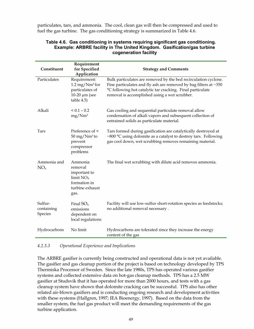
49
particulates, tars, and ammonia. The cool, clean gas will then be compressed and used tofuel the gas turbine. The gas conditioning strategy is summarized in Table 4.6.
Table 4.6. Gas conditioning in systems requiring significant gas conditioning.Example: ARBRE facility in The United Kingdom. Gasification/gas turbine
cogeneration facility
ConstituentRequirementfor SpecifiedApplication
Strategy and Comments
Particulates Requirement:1.2 mg/Nm3 forparticulates of10-20 µm (seetable 4.5)
Bulk particulates are removed by the bed recirculation cyclone.Fine particulates and fly ash are removed by bag filters at ~350°C following hot catalytic tar cracking. Final particulateremoval is accomplished using a wet scrubber.
Alkali < 0.1 � 0.2mg/Nm3
Gas cooling and sequential particulate removal allowcondensation of alkali vapors and subsequent collection ofentrained solids as particulate material.
Tars Preference of <50 mg/Nm3 topreventcompressorproblems
Tars formed during gasification are catalytically destroyed at~800 °C using dolomite as a catalyst to destroy tars. Followinggas cool down, wet scrubbing removes remaining material.
Ammonia andNOx
Ammoniaremovalimportant tolimit NOX
formation inturbine exhaustgas.
The final wet scrubbing with dilute acid removes ammonia.
Sulfur-containingSpecies
Final SOx
emissionsdependent onlocal regulations
Facility will use low-sulfur short-rotation species as feedstocks;no additional removal necessary .
Hydrocarbons No limit Hydrocarbons are tolerated since they increase the energycontent of the gas
4.2.3.3 Operational Experience and Implications
The ARBRE gasifier is currently being constructed and operational data is not yet available.The gasifier and gas cleanup portion of the project is based on technology developed by TPSThermiska Processor of Sweden. Since the late 1980s, TPS has operated various gasifiersystems and collected extensive data on hot-gas cleanup methods. TPS has a 2.5 MWgasifier at Studsvik that it has operated for more than 2000 hours, and tests with a gascleanup system have shown that dolomite cracking can be successful. TPS also has otherrelated air-blown gasifiers and is conducting ongoing research and development activitieswith these systems (Hallgren, 1997; IEA Bioenergy, 1997). Based on the data from thesmaller system, the fuel gas product will meet the demanding requirements of the gasturbine application.
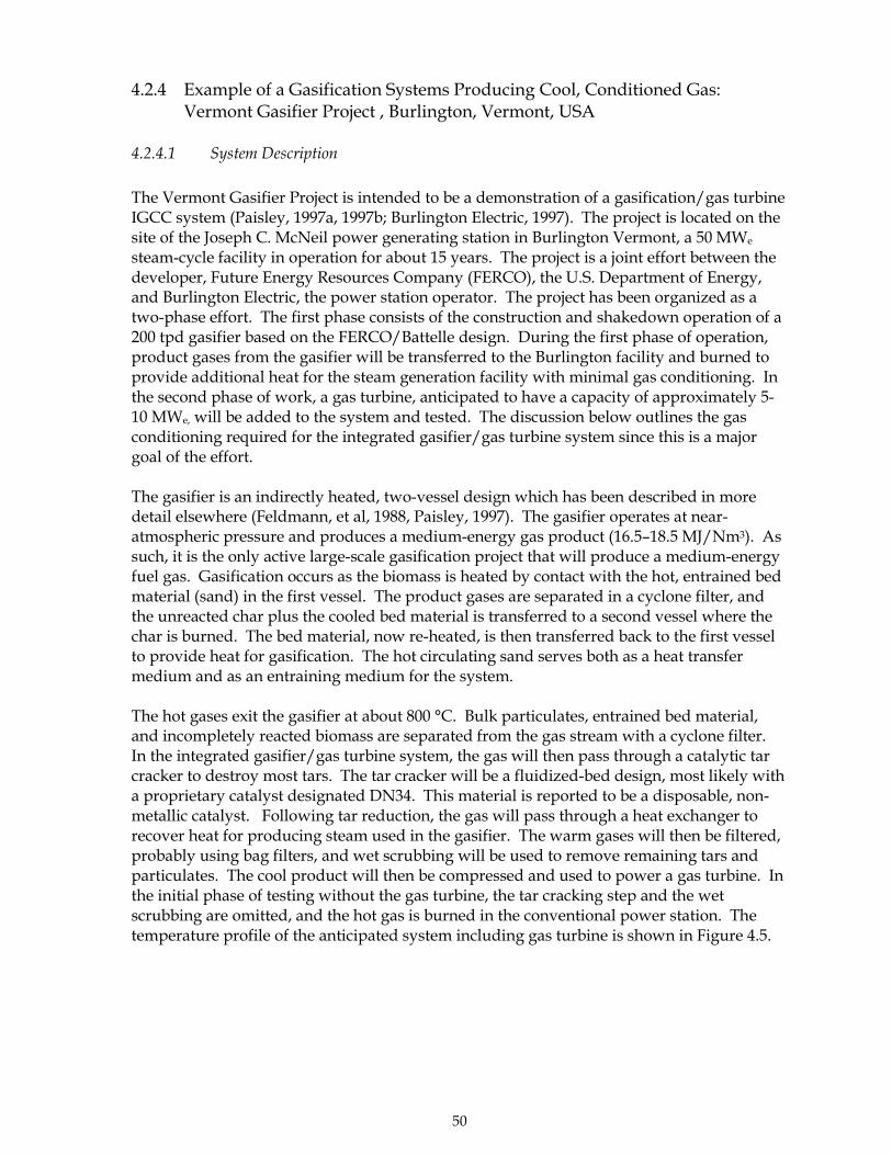
50
4.2.4 Example of a Gasification Systems Producing Cool, Conditioned Gas:Vermont Gasifier Project , Burlington, Vermont, USA
4.2.4.1 System Description
The Vermont Gasifier Project is intended to be a demonstration of a gasification/gas turbineIGCC system (Paisley, 1997a, 1997b; Burlington Electric, 1997). The project is located on thesite of the Joseph C. McNeil power generating station in Burlington Vermont, a 50 MWe
steam-cycle facility in operation for about 15 years. The project is a joint effort between thedeveloper, Future Energy Resources Company (FERCO), the U.S. Department of Energy,and Burlington Electric, the power station operator. The project has been organized as atwo-phase effort. The first phase consists of the construction and shakedown operation of a200 tpd gasifier based on the FERCO/Battelle design. During the first phase of operation,product gases from the gasifier will be transferred to the Burlington facility and burned toprovide additional heat for the steam generation facility with minimal gas conditioning. Inthe second phase of work, a gas turbine, anticipated to have a capacity of approximately 5-10 MWe, will be added to the system and tested. The discussion below outlines the gasconditioning required for the integrated gasifier/gas turbine system since this is a majorgoal of the effort.
The gasifier is an indirectly heated, two-vessel design which has been described in moredetail elsewhere (Feldmann, et al, 1988, Paisley, 1997). The gasifier operates at near-atmospheric pressure and produces a medium-energy gas product (16.5�18.5 MJ/Nm3). Assuch, it is the only active large-scale gasification project that will produce a medium-energyfuel gas. Gasification occurs as the biomass is heated by contact with the hot, entrained bedmaterial (sand) in the first vessel. The product gases are separated in a cyclone filter, andthe unreacted char plus the cooled bed material is transferred to a second vessel where thechar is burned. The bed material, now re-heated, is then transferred back to the first vesselto provide heat for gasification. The hot circulating sand serves both as a heat transfermedium and as an entraining medium for the system.
The hot gases exit the gasifier at about 800 °C. Bulk particulates, entrained bed material,and incompletely reacted biomass are separated from the gas stream with a cyclone filter.In the integrated gasifier/gas turbine system, the gas will then pass through a catalytic tarcracker to destroy most tars. The tar cracker will be a fluidized-bed design, most likely witha proprietary catalyst designated DN34. This material is reported to be a disposable, non-metallic catalyst. Following tar reduction, the gas will pass through a heat exchanger torecover heat for producing steam used in the gasifier. The warm gases will then be filtered,probably using bag filters, and wet scrubbing will be used to remove remaining tars andparticulates. The cool product will then be compressed and used to power a gas turbine. Inthe initial phase of testing without the gas turbine, the tar cracking step and the wetscrubbing are omitted, and the hot gas is burned in the conventional power station. Thetemperature profile of the anticipated system including gas turbine is shown in Figure 4.5.
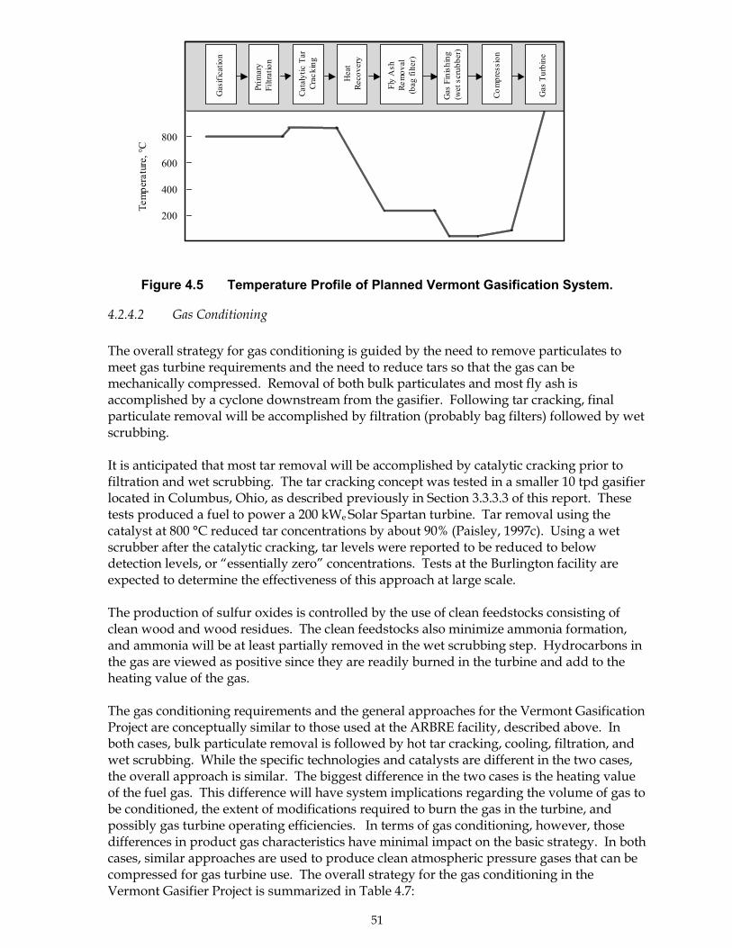
51
Figure 4.5 Temperature Profile of Planned Vermont Gasification System.
4.2.4.2 Gas Conditioning
The overall strategy for gas conditioning is guided by the need to remove particulates tomeet gas turbine requirements and the need to reduce tars so that the gas can bemechanically compressed. Removal of both bulk particulates and most fly ash isaccomplished by a cyclone downstream from the gasifier. Following tar cracking, finalparticulate removal will be accomplished by filtration (probably bag filters) followed by wetscrubbing.
It is anticipated that most tar removal will be accomplished by catalytic cracking prior tofiltration and wet scrubbing. The tar cracking concept was tested in a smaller 10 tpd gasifierlocated in Columbus, Ohio, as described previously in Section 3.3.3.3 of this report. Thesetests produced a fuel to power a 200 kWe Solar Spartan turbine. Tar removal using thecatalyst at 800 °C reduced tar concentrations by about 90% (Paisley, 1997c). Using a wetscrubber after the catalytic cracking, tar levels were reported to be reduced to belowdetection levels, or �essentially zero� concentrations. Tests at the Burlington facility areexpected to determine the effectiveness of this approach at large scale.
The production of sulfur oxides is controlled by the use of clean feedstocks consisting ofclean wood and wood residues. The clean feedstocks also minimize ammonia formation,and ammonia will be at least partially removed in the wet scrubbing step. Hydrocarbons inthe gas are viewed as positive since they are readily burned in the turbine and add to theheating value of the gas.
The gas conditioning requirements and the general approaches for the Vermont GasificationProject are conceptually similar to those used at the ARBRE facility, described above. Inboth cases, bulk particulate removal is followed by hot tar cracking, cooling, filtration, andwet scrubbing. While the specific technologies and catalysts are different in the two cases,the overall approach is similar. The biggest difference in the two cases is the heating valueof the fuel gas. This difference will have system implications regarding the volume of gas tobe conditioned, the extent of modifications required to burn the gas in the turbine, andpossibly gas turbine operating efficiencies. In terms of gas conditioning, however, thosedifferences in product gas characteristics have minimal impact on the basic strategy. In bothcases, similar approaches are used to produce clean atmospheric pressure gases that can becompressed for gas turbine use. The overall strategy for the gas conditioning in theVermont Gasifier Project is summarized in Table 4.7:
800
600
400
200
Tem
pera
ture
, °C
Prim
ary
Filtr
atio
n
Cata
lytic
Tar
Crac
king
Hea
tRe
cove
ry
Fly
Ash
Rem
oval
(bag
filte
r)
Gas
Fin
ishi
ng
(wet
scr
ubbe
r)
Com
pres
sion
Gas
Tur
bine
Gas
ifica
tion
52
Table 4.7. Gas conditioning in systems requiring significant gas conditioning.Example: Vermont Gasifier Project. Gasification/gas turbine cogeneration facility
ConstituentRequirementfor SpecifiedApplication
Strategy and Comments
Particulates Requirement:1.2 mg/Nm3
for particulatesof 10-20 µm(see Table 4.4)
Bulk particulates are removed by the bed recirculation cyclone.Fine particulate and fly ash is removed by bag filters at 200 °Cfollowing hot catalytic tar cracking. Final particulate removal isaccomplished using a wet scrubber
Alkali < 0.1 � 0.2mg/Nm3
Gas cooling and sequential particulate removal allowcondensation of alkali vapors and subsequent collection ofentrained solids as particulate material.
Tars Preference of< 50 mg/Nm3
to preventcompressorproblems
Tars formed during gasification will be catalytically destroyed at~800 °C using DN34 or other catalyst in a fluidized bed reactor.Gas cool-down and wet scrubbing follow. Following gas cooldown, wet scrubbing removes remaining material.
Ammonia andNOx
Ammoniaremovalimportant tolimit NOx
formation inturbineexhaust gas.
The final wet scrubbing with dilute acid removes ammonia.
Sulfur-containingSpecies
Final SOx
emissionsdependent onlocalregulations
Facility uses low-sulfur wood feedstocks; no additional removalnecessary
Hydrocarbons No limit Hydrocarbons are tolerated since they increase the energycontent of the gas
4.2.4.3 Operational Experience and Implications
The first phase of the Vermont Gasification project was to construct the gasifier and providefuel gas to the McNeil power generating station located adjacent to the gasifier. The gasifierwas completed in 1999, and shakedown operations began. Following modifications in early2000, the gasifier successfully operated in a steady-state mode for several extended periods.By the end of 2000, the gasifier had been operated for a total of about 300 hr, and a test toverify continuous operability over weeklong period was completed (Paisley, 2000).
In the near future, additional testing of the gasifier with a 5-10 MWe gas turbine is expected.The previous tests with the smaller process development unit in Ohio have shown that thissystem can be used to power smaller turbines for several hundred hours of operation. It isinteresting to note that the work in the smaller system showed that wet scrubbing alone was
53
insufficient to remove tars from raw product gas. In the absence of the hot catalytic tarcracking, small amounts of tars passed through the wet scrubber and eventually causedproblems in the compressor. At this stage of development, it is unclear whether this wassimply a problem with that particular scrubber at small scale, or whether there are broaderimplications with respect to the effectiveness of wet scrubbers for complete tar removal.This issue has significant impacts on system operability and economics but will only beresolved as more data is collected in large-scale systems.
4.2.5 Other Related Systems
It should be noted that other large-scale biomass gasifiers are currently being designed orconsidered using a similar approach to provide a cool, cleaned fuel gas for use in gasturbines. These include the 35 MWe WBP/SIGAME Demonstration Project in Brazil and the13 MWe Energy Farm Project in Italy. The Brazilian project design is very similar to that ofthe ARBRE project and uses essentially the same gas conditioning approach, andtechnologies. The project in Italy uses the general approach of the Amergas facility withpartial gas cool down, subsequent particulate removal, and thorough wet scrubbing toremove tars and other gas constituents, although the actual technology components aredifferent. These projects are described in more detail elsewhere (Carpentieri, et al, 1998;Overend, 1998; De Lang, 1998). Coal-fired gasification/gas turbine systems such as the 262MWe Wabash River facility in Indiana also use wet scrubbing technologies that produce acool fuel gas (U.S. Department of Energy, 1996b).
4.3 Hot or Warm Fuel Gases for Systems With Significant Gas ConditioningRequirements
While all technologies can use cool product gases, some such as gas turbines could achievehigher efficiencies by using hot fuel gases. The hot gases retain part or most of the sensibleheat from the gasification reaction, and that heat can be used to generate additional electricpower.
For this discussion, we define �cool� gases as those with temperatures of <100 °C, althoughmost are nearer 35 °C. Cool gases will be produced when wet scrubbing systems are used.We define warm gases as those with temperatures in the range of ~200�500 °C where heatexchangers are used to recover part of the heat in the gas stream for other process needs.Hot gases, for this discussion are those with temperatures of > 500 °C where minimal gascooling has occurred. These definitions are intended to be descriptive rather thanquantitative and should only be considered as guidelines.
Systems that produce warm or hot gases must still meet all requirements for gas qualityincluding possible limitations on particulates, alkali, tars, ammonia, and other components.The need to both condition the product gas and retain the heat content has strongimplications for the system design. Wet scrubbing or electrostatic precipitator systems arenot appropriate since they cool the product gas. Particulate and tar removal must thereforebe accomplished at higher temperatures. Particulate removal can potentially beaccomplished using rigid barrier filters or bag filters depending on the final temperature ofthe gas. The particulate removal system must deal effectively with alkali as well. Tarremoval, where necessary, must largely be accomplished by catalytic tar cracking.
54
One system is discussed below to illustrate current approaches that produce clean, elevatedtemperature fuel gases. This example is the Värnamo facility in Sweden. As statedpreviously, this is not a complete list of all gasifiers systems of this kind but it was chosen toillustrate an approach to producing warm product gas.
4.3.1 Example of a Gasification System Producing Hot, Conditioned Gas: VärnamoFacility in Sweden
4.3.1.1 Project Overview
The Värnamo project is a near-commercial scale demonstration of combined cycle heat andpower generation in Sweden. Biomass is gasified to provide fuel for power generationusing a gas turbine, and excess heat is used to generate steam for additional powerproduction. Heat can also be recovered for district heating purposes. The facility has acapability of producing about 6 MWe from biomass plus an additional 9 MWt of district heat(Sydkraft, 1998; Stahl, et al, 1998, 1997; Engstrom, 1998). The project started in the early1990s and has more hours of successful operational experience than any other biomassgasification/gas turbine system. The demonstration facility, however, was not designed forlong-term commercial power generation, and the project was completed in 1999.
Unlike other gasifiers described in this section, the one in Värnamo operates at pressures of18-22 atm. The pressurized operation of the gasifier contrasts with other facilities describedin this report that operate at near-atmospheric conditions. Pressurized operation eliminatesthe need to compress the fuel gas prior to its use in the gas turbine and increases systemtoleration to tars that would otherwise accumulate.
The gasifier for the facility is a pressurized, air-blown, circulating bed system. Compressedair for the gasifier is extracted from the compression turbine (approximately 10% of theflow), and is further compressed mechanically. The facility uses finely ground, dried woodand bark feedstock (10 � 20% moisture content) delivered to the power generation site froman adjacent preparation facility. Limited tests with pelletized straw and RDF have also beenperformed. The feedstock is loaded into a pressurized feed hopper through gate valves andis metered into the gasifier system by screws at a location near the bottom of the gasifier.The bed material for the gasifier includes dolomite or lime that helps destroy tars formedduring the gasification reaction. The gasifier typically operates at temperatures of 950�1000°C, and the fuel gas is a typical low-energy product with a heating value of approximately5-6 MJ/Nm3.
Gas conditioning is accomplished through sequential steps that retain much of the heatcontent of the gas. Bulk particulates are removed by the bed recirculation cyclone, similar toother circulating bed gasifiers described previously. The raw product gas is then cooled toabout 350 °C in a heat exchanger, and the recovered heat is used to generate steam for thesteam turbine. The warm fuel gas then passes through a barrier filter to remove additionalash and particulates. At this temperature, condensed alkali salts can be removed asparticulates. The barrier filter consists of an array of filter candles 60 mm OD, 10 mm thick,with a length of 1500 mm. Candles are arranged in six groups of twelve each and areflushed at 15 minute intervals by back pulsing with high-pressure nitrogen. The originalceramic candles were later replaced with sintered metal ones. The barrier filters arereported to work well in long-term operation. The gas also passes through a cyclone filterthat removes particulates in the event of the breakage of a barrier filter.
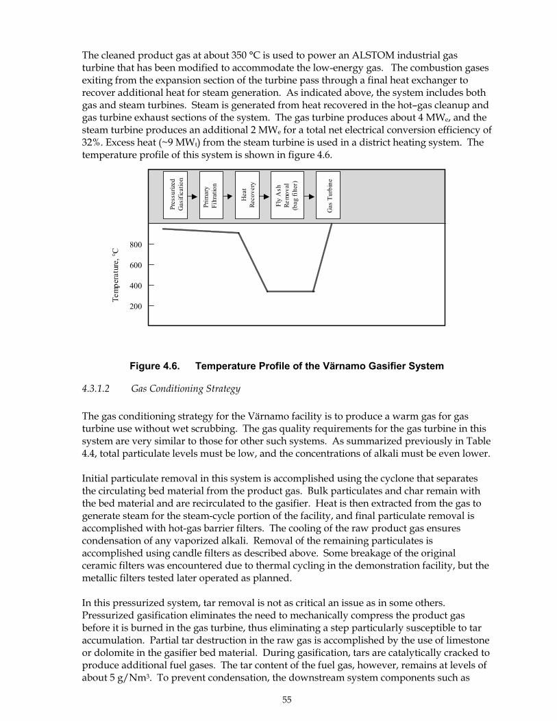
55
The cleaned product gas at about 350 °C is used to power an ALSTOM industrial gasturbine that has been modified to accommodate the low-energy gas. The combustion gasesexiting from the expansion section of the turbine pass through a final heat exchanger torecover additional heat for steam generation. As indicated above, the system includes bothgas and steam turbines. Steam is generated from heat recovered in the hot�gas cleanup andgas turbine exhaust sections of the system. The gas turbine produces about 4 MWe, and thesteam turbine produces an additional 2 MWe for a total net electrical conversion efficiency of32%. Excess heat (~9 MWt) from the steam turbine is used in a district heating system. Thetemperature profile of this system is shown in figure 4.6.
Figure 4.6. Temperature Profile of the Värnamo Gasifier System
4.3.1.2 Gas Conditioning Strategy
The gas conditioning strategy for the Värnamo facility is to produce a warm gas for gasturbine use without wet scrubbing. The gas quality requirements for the gas turbine in thissystem are very similar to those for other such systems. As summarized previously in Table4.4, total particulate levels must be low, and the concentrations of alkali must be even lower.
Initial particulate removal in this system is accomplished using the cyclone that separatesthe circulating bed material from the product gas. Bulk particulates and char remain withthe bed material and are recirculated to the gasifier. Heat is then extracted from the gas togenerate steam for the steam-cycle portion of the facility, and final particulate removal isaccomplished with hot-gas barrier filters. The cooling of the raw product gas ensurescondensation of any vaporized alkali. Removal of the remaining particulates isaccomplished using candle filters as described above. Some breakage of the originalceramic filters was encountered due to thermal cycling in the demonstration facility, but themetallic filters tested later operated as planned.
In this pressurized system, tar removal is not as critical an issue as in some others.Pressurized gasification eliminates the need to mechanically compress the product gasbefore it is burned in the gas turbine, thus eliminating a step particularly susceptible to taraccumulation. Partial tar destruction in the raw gas is accomplished by the use of limestoneor dolomite in the gasifier bed material. During gasification, tars are catalytically cracked toproduce additional fuel gases. The tar content of the fuel gas, however, remains at levels ofabout 5 g/Nm3. To prevent condensation, the downstream system components such as
800
600
400
200
Tem
pera
ture
, °C
Pres
suriz
edG
asifi
catio
n
Prim
ary
Filtr
atio
n
Hea
tRe
cove
ry
Fly
Ash
Rem
oval
(bag
filte
r)
Gas
Tur
bine
56
pipes and filters are insulated. These steps to prevent cooling are very necessary. In earlytests, tar condensation was noted in locations without adequate insulation. Tars alsocondensed on the fly ash when the candle filters were cleared with pulses of cool nitrogengas. Condensation was avoided in later tests by system modifications.
Tars arriving at the gas turbine inlet appeared to be burned effectively. Flue gasmeasurements showed the concentrations of unburned hydrocarbons in the turbine flue gaswere lower when biomass fuel gases were used than when petroleum was used as a fuel.The tar in the fuel gas in fact appears to increase its heating content by ~10% over that seenin typical tar-free gases from similar gasifiers, and the extra heat content adds to theefficiency of power generation in the gas turbine.
Sulfur oxide emissions were managed in the Värnamo facility by using clean wood residues.Emissions were measured to be less than the permitted requirements of 25 mg/MJ.
No particular system was included for ammonia removal. Ammonia in the product gas wasmeasured at concentrations of about 700 ppm. Ammonia is converted to NOx in the gasturbine, and NOx concentrations of about 60 mg/MJ were measured in the turbine flue gas.This met the regulated limits of 150 mg/MJ prescribed in the permitting process. It shouldbe noted, however, that new regulations would require emission limits of < 50 mg/MJ atthis site, and additional efforts to reduce ammonia concentrations in new facilities may beneeded. The gas conditioning strategies for the facility are summarized in Table 4.8.
Table 4.8. Gas conditioning in systems requiring significant gas conditioning.Example: Värnamo facility in Sweden. Gasification/gas turbine cogeneration
ConstituentRequirementfor SpecifiedApplication
Strategy and Comments
Particulates Requirement:1.2 mg/Nm3
for particulatesof 10-20 µm(see table 4.5)
Bulk particulates are removed by the bed recirculation cyclone.Fine particulate and fly ash are removed by hot-gas barrier filters(candle filters) at ~350 °C following heat extraction from the rawgas.
Alkali < 0.1 � 0.2mg/Nm3
Gas cooling prior to the barrier filters allow condensation ofalkali vapors and subsequent collection of entrained solids asparticulate material.
Tars System istolerant to tarsbecause theintermediatecompressionstep iseliminated.
Tars formed during gasification are partially destroyed throughcontact with dolomite in the fluidized bed. Remaining tars(~5g/Nm3) are burned in the gas turbine. Downstream systemsand surfaces are maintained at ~350 °C to prevent tarcondensation.
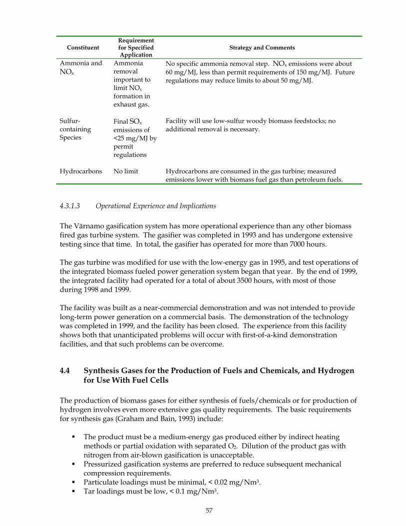
57
ConstituentRequirementfor SpecifiedApplication
Strategy and Comments
Ammonia andNOx
Ammoniaremovalimportant tolimit NOx
formation inexhaust gas.
No specific ammonia removal step. NOx emissions were about60 mg/MJ, less than permit requirements of 150 mg/MJ. Futureregulations may reduce limits to about 50 mg/MJ.
Sulfur-containingSpecies
Final SOx
emissions of<25 mg/MJ bypermitregulations
Facility will use low-sulfur woody biomass feedstocks; noadditional removal is necessary.
Hydrocarbons No limit Hydrocarbons are consumed in the gas turbine; measuredemissions lower with biomass fuel gas than petroleum fuels.
4.3.1.3 Operational Experience and Implications
The Värnamo gasification system has more operational experience than any other biomassfired gas turbine system. The gasifier was completed in 1993 and has undergone extensivetesting since that time. In total, the gasifier has operated for more than 7000 hours.
The gas turbine was modified for use with the low-energy gas in 1995, and test operations ofthe integrated biomass fueled power generation system began that year. By the end of 1999,the integrated facility had operated for a total of about 3500 hours, with most of thoseduring 1998 and 1999.
The facility was built as a near-commercial demonstration and was not intended to providelong-term power generation on a commercial basis. The demonstration of the technologywas completed in 1999, and the facility has been closed. The experience from this facilityshows both that unanticipated problems will occur with first-of-a-kind demonstrationfacilities, and that such problems can be overcome.
4.4 Synthesis Gases for the Production of Fuels and Chemicals, and Hydrogenfor Use With Fuel Cells
The production of biomass gases for either synthesis of fuels/chemicals or for production ofhydrogen involves even more extensive gas quality requirements. The basic requirementsfor synthesis gas (Graham and Bain, 1993) include:
! The product must be a medium-energy gas produced either by indirect heatingmethods or partial oxidation with separated O2. Dilution of the product gas withnitrogen from air-blown gasification is unacceptable.
! Pressurized gasification systems are preferred to reduce subsequent mechanicalcompression requirements.
! Particulate loadings must be minimal, < 0.02 mg/Nm3.! Tar loadings must be low, < 0.1 mg/Nm3.
58
! Sulfur levels must be < 0.1 mg/Nm3.! Hydrocarbons must be low to prevent dilution and/or catalyst poisoning.! Methane, < 3% or reforming is needed.! Olefin content < 4 mg/Nm3.! Ethylene content < 0.1 mg/Nm3.! The ratios of H2 to CO must be appropriate (i.e., for methanol the ratios is ~2.1:1)
The production of a hydrogen-rich fuel gas for fuel cell applications will also require gasconditioning. While fuel cell requirements are less well documented than those forsynthesis systems, the gas quality requirements are likely to be similar to those for synthesisapplications. Fuel cell use is described below.
4.4.1 Current Production of Fuels and Chemicals from Synthesis Gas
The use of fossil- and petroleum-derived synthesis gas to produce fuels and chemicals iswell established commercially. Methanol is produced in large quantities by the conversionof natural gas or petroleum into a synthesis gas. The gas is then reacted over copper/zinccatalysts to produce methanol. Over many years, the catalysts have been improved andnow exhibit very high specificity toward methanol production. These technologies are verylarge in size to take advantage of the economies of scale.
Coal has also been used as a feedstock for producing synthesis gas used in production ofboth methanol and Fischer-Tropsch liquids. Coal is gasified using oxygen-blown gasifiers,and the raw product gas is treated for particulates and tars through the use of multiple wetscrubbers and particulate filters as needed. Sulfur is removed by wet scrubbing in mostsystems. The synthesis gas is cooled before methanol synthesis to avoid problems withoverheating during the exothermic methanol formation reaction. Coal systems, like thosefor natural gas or petroleum, are large and can take advantage of economies of scale.
At present, some biomass-derived wastes and organic residues are being converted tomethanol in multi-fuel gasification facilities. The SVZ Recycling Project in SchwarzePumpe, Germany, is an example (BTG, 2000). The SVG system gasifies low- or negative-value carbon sources including coal, petroleum coke, high sulfur fuel oil, and waste organicmaterials to produce a synthesis gas used in part for methanol production and in part for agas turbine combined cycle power generation system. The facility produces 68 MWe andhas an annual production of 130,000 tons of methanol, equivalent to a total of 250 MWe.
The facility uses gas-conditioning steps representative of those in a coal-based conversionfacility. These include bulk particulate removal, initial heat recovery, catalytic conversion ofsulfur-containing species, cooling, and repeated sequential wet scrubbing to removecontaminants. The clean, cooled gas must then be reformed to remove hydrocarbons andshift the H2 to CO ratios. In this facility, the economics of methanol production are beingdriven in part by the need to eliminate wastes.
4.4.2 Biomass-based Production of Synthesis Gas
Recent interest has been expressed in producing either methanol or Fischer-Tropsch liquidsfrom biomass (Sethi, et al, 1999; Larson and Haiming, 1999). The economics of methanolproduction from biomass have been discussed in more detail elsewhere (Wyman, et al,1993). Facilities based on fossil resources can be larger than those based on biomass, and
59
they enjoy the advantages of economies of scale. The economies of scale are particularlyimportant for the methanol synthesis loop. At present, there are no stand-alone biomassgasification systems that produce methanol, Fischer-Tropsch liquids, or similar products.Feedstock supply limitations make it difficult to compete on the same scale as natural gas orcoal-based facilities. While it is technically feasible to produce clean synthesis gases frombiomass using the same, multiple scrubbing processes as those used in coal-based systems,the smaller biomass facilities have not been economically competitive. In late 1999 and early2000, the prices of both petroleum and natural gas increased rapidly. The impact these pricechanges will have on the opportunities for biomass-based processes is unclear.
For biomass-based synthesis gas systems, the primary challenge is to create integratedsystems that can be economical on a scale compatible with the availability of biomassfeedstocks. Although such systems do not currently exist, it is possible to speculate aboutthe types of approaches that could potentially be used. Such processes would incorporategasifiers that produced raw products with characteristics well-suited for synthesis gasapplications, and the gas conditioning steps would be simple. Some considerations aresummarized below:
! The system might use a pressurized, turbulent bed gasifier that produced a medium-energy synthesis gas with approximately the correct ratio of hydrogen and carbonmonoxide for the gasifier. Pressurized operation would reduce compressionrequirements in the system. The gasifier could use either an oxygen-blown or anindirectly heated design. Indirectly heated gasifiers could eliminate the need for anoxygen separation facility, but pressurized gasifiers of this type are not currentlybeing developed. Oxygen-blown systems require the O2 separation facility but arebetter developed.
! Hot gas conditioning would include initial particulate removal, catalytic tarcracking, hydrocarbon reforming, and sulfur removal. The tar cracking andhydrocarbon reforming would use separate reactors placed in the gas stream toproduce gas with H2, CO, and CO2 as primary constituents in appropriate ratios.Sulfur removal would be by sorbants, similar to those currently used indevelopmental coal gasification systems (U.S. Department of Energy, 1996c).
! The gas would be cooled using heat exchangers to recover heat. The cool gas wouldbe filtered using bag or other barrier filters, and scrubbed as a final step to removeammonia, halides, and any remaining tars and particulates. Carbon dioxide removalby scrubbing may also be necessary.
! Synthesis of fuels and chemicals would be completed using standard processes.
The various technologies that would be part of such a system have been the subjects ofrecent research and development work, but integrated systems to test concepts forproducing synthesis gases from biomass have not yet been demonstrated. Future researchand development activities will be required to produce gases from biomass feedstocks thatcan cost-effectively be used for synthesis of fuels and chemicals.
Although the production of fuels and chemicals via synthesis gases from stand-alonebiomass facilities is not currently cost-effective, it may be possible to co-feed biomass-derived synthesis gases into existing facilities such as natural gas- or coal-based methanolproduction units. Such processes would leverage the economies of scale of already existingin synthesis-based technologies. This could be accomplished either by co-gasifying thebiomass with other fuels such as coal (as is currently done in the Schwarz Pumpe facility
60
described above), or by gasifying biomass separately and cofeeding the product to thesynthesis gas conditioning loop.
The addition of biomass to existing systems would also be facilitated by policies orincentives that mandate or favor renewable fuels that reduce net emissions of CO2. Withoutsuch incentives or mandates, there is little current incentive to convert from proventechnologies and feedstocks to biomass-based systems with risks. The current situationwith biomass derived liquid fuels from synthesis gas is similar to that with biomass fuelsfrom fermentation processes. In both cases, the biomass-derived product costs more than itspetroleum or natural gas derived counterparts. However, liquid biofuels from fermentationprocesses have an increasing market share in some countries. Analysis shows that marketpenetration is occurring only in those countries where national or regional policies/financialincentives support such development (IEA Bioenergy, 2000). The policies and incentivesserve as methods to reach national goals to increase the amounts of chemical and fuelsproduced from renewable resources and to reduce net carbon dioxide emissions to theatmosphere.
4.4.3 Biomass Gasification to Produce Hydrogen for Fuel Cells
Biomass thermal gasification has also attracted recent interest as a source of hydrogen-richfuel for use with fuel cells (Amos, 1998; Brown, et al, 1998). The high efficiencies of fuel cellsmake them potentially attractive for distributed generation applications. At present, thedetailed gas quality specifications for biomass-derived fuels for fuel cells have not been welldocumented. This is due in part to the emerging nature of fuel cell technology and therelatively recent interest in biomass gases for this application. Certain types of fuel cellssuch as alkaline or phosphoric types have been used for many years for specializedapplications or used in near-commercial demonstrations of electricity generation. Thealkaline type, for example, was initially designed to operate with purified hydrogen andoxygen in spacecraft. Newer fuel cell types such as solid oxide, polyelectrolyte membrane(PEM), and molten carbonate types are also commercially available or nearing commercialviability. While it is beyond the scope of this report to examine biomass applications withfuel cells in detail, several general conclusions can be drawn.
As shown in Table 4.9, the demands for fuel gas quality vary widely by fuel cell type. It isimportant to note that the requirements listed in the table refer to the gases entering the fuelcell stack where the actual electricity generation occurs. Present fuel cell manufacturersusually include reformers or similar gas conditioning processes in their system. Regardlessof who provides the gas conditioning technology, the integrated gasification/fuel cellsystem must provide a final gaseous fuel with particular characteristics.
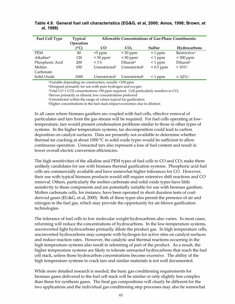
61
Table 4.9. General fuel cell characteristics (EG&G, et al, 2000; Amos, 1998; Brown, etal, 1998)
Fuel Cell Type TypicalOperation
(ºC)
Allowable Concentrations of Gas-Phase Constituents:
CO CO2 Sulfur HydrocarbonsPEM 80 <5 ppm < 50 ppm < 1 ppm Restrictivea
Alkalineb 120 < 50 ppmc < 50 ppmc < 1 ppm < 300 ppmPhosphoric Acid 200 < 1% Diluentd < 1 ppm Diluentd
MoltenCarbonate
650 Unrestrictede Unrestrictede < 0.5 ppm < 10%f
Solid Oxide 1000 Unrestrictede Unrestrictede < 1 ppm < 10%f
aVariable depending on construction, usually <100 ppmbDesigned primarily for use with pure hydrogen and oxygencTotal CO + CO2 concentrations <50 ppm required. Cell particularly sensitive to CO2dServes primarily as diluent; low concentrations preferredeUnrestricted within the range of values typical for gasificationfHigher concentrations in the fuel stack impact economics due to dilution
In all cases where biomass gasifiers are coupled with fuel cells, effective removal ofparticulates and tars from the gas stream will be required. For fuel cells operating at low-temperature, tars would present condensation problems similar to those in other types ofsystems. In the higher temperature systems, tar decomposition could lead to carbondeposition on catalyst surfaces. Data are presently not available to determine whetherthermal tar cracking at about 1000 ºC in solid oxide types would be sufficient to allowcontinuous operation. Unreacted tars also represent a loss of fuel content and result inlower overall electric conversion efficiencies.
The high sensitivities of the alkaline and PEM types of fuel cells to CO and CO2 make themunlikely candidates for use with biomass thermal gasification systems. Phosphoric acid fuelcells are commercially available and have somewhat higher tolerances for CO. However,their use with typical biomass products would still require extensive shift reactions and COremoval. Others, particularly the molten carbonate and solid oxide types have littlesensitivity to these components and are potentially suitable for use with biomass gasifiers.Molten carbonate cells, for instance, have been operated in short duration tests of coal-derived gases (EG&G, et al, 2000). Both of these types also permit the presence of air andnitrogen in the fuel gas, which may provide the opportunity for air-blown gasificationtechnologies.
The tolerance of fuel cells to low molecular weight hydrocarbons also varies. In most cases,reforming will reduce the concentrations of hydrocarbons. In the low-temperature systems,unconverted light hydrocarbons primarily dilute the product gas. In high temperature cells,unconverted hydrocarbons may compete with hydrogen for active sites on catalyst surfacesand reduce reaction rates. However, the catalytic and thermal reactions occurring in thehigh temperature systems also result in reforming of part of the product. As a result, thehigher temperature systems are likely to tolerate unreacted hydrocarbons that reach the fuelcell stack, unless those hydrocarbon concentrations become excessive. The ability of thehigh temperature systems to crack tars and similar materials is not well documented.
While more detailed research is needed, the basic gas conditioning requirements forbiomass gases delivered to the fuel cell stack will be similar or only slightly less complexthan those for synthesis gases. The final gas compositions will clearly be different for thetwo applications and the individual gas conditioning step processes may also be somewhat

62
different. However, the same basic requirements for thorough removal of tars, particulates,and sulfur will be necessary. In addition, shift/reforming reaction issues must be addressedin both systems, although the final product gases will be different. In the fuel cell case, partof the gas conditioning can potentially occur in the fuel cell assembly. However, the finalfuel delivered to the fuel cell stack has relatively demanding quality requirements.Additional research and development are needed to answer both technical and economicquestions for this technology.
63
5. DISCUSSION AND RESEARCH NEEDS
5.1 Summary of the Status of Gas Conditioning for Large-Scale GasificationSystems
Large-scale biomass gasification systems are now being successfully operated for heat andsteam-cycle power generation. These successes build in part on wide-ranging research anddevelopment activities that started in the early 1980s. The successful deployment of large-scale gasifiers has been slower than anticipated by developers. Low prices for conventionalfuels and the difficulties of both developing reliable biomass gasifiers and providingsufficiently conditioned gases have proven to be challenging. Facilities built within the lastfive years, however, have clearly shown that biomass gasification systems can operatereliably, and continuing progress is being made on gas conditioning issues. The progress inseveral areas is summarized below and remaining issues are discussed.
5.1.1 Progress in Understanding Gas Conditioning Processes
Significant progress has been made over the past 5-10 years toward developing a betterunderstanding of biomass gas conditioning processes and technologies for use in biomasssystems. Based on the discussions in Sections 3 and 4 of this report, the progress in specificareas is summarized below.
Particulate Removal:
The application of particulate removal technologies to biomass gasification systems ingeneral has matured over the past decade. Cyclones are routinely being used for bulkparticulate removal, and technologies including bag filters and wet scrubbers are being usedin large-scale systems. While this progress is incremental in nature, it is required for wide-spread deployment of gasification technologies.
Demonstrations show that rigid ceramic and metallic candle filters provide a potentialmethod to remove particulates from hot gas streams. This approach can eliminate the needto cool product gases and can result in higher net conversion efficiencies in some systems.This progress represents a significant achievement for biomass systems.
Vaporized Alkali:
In the past decade, significant progress has been made toward understanding themechanisms of alkali vaporization. Basic and applied studies have provided a gooddescription of reaction pathways and the conditions where alkali salts will vaporize. Usingthe information that has been developed, it is now possible to largely avoid problems withalkali deposition in gasification systems. The development of this information representssignificant progress within the thermochemical conversion research community over thepast 5-10 years.
Tests with alkali �getters� that also act as high temperature barrier filters has shown thatalkali salts in the gas stream can potentially be reduced to even lower levels for thosetechnologies with very demanding requirements. Additional effort in this area will benecessary to test such concepts at large scale.
64
Tar Removal:
The subjects of tar characterization, measurement, and removal have been areas of verysignificant research and development interest over the past decade. The need for better tarmeasurement methodologies has led to the establishment of recommended protocols thatshould provide researchers and developers with consistent documentation of tar loadingsfrom different gasifiers. This consistency has not been available in the past, and theacceptance and use of such standardized methodologies should provide significant benefitsto the entire gasification community.
RD&D efforts over the past few years have also improved the effectiveness of wet scrubbingsystems in removing tars from large-scale systems. Research in various developmentsystems suggests that wet scrubbers are effective in removing tars, at least for someapplications. However, there is not uniform agreement on this point, and some researchersare suggesting that tar-sensitive systems will require catalytic tar cracking as well. Thisresearch issue will be resolved with ongoing research efforts.
Extensive testing of catalytic tar cracking methods has created a significantly betterunderstanding of this technology over the past decade. Tests have been made with bothmetallic and non-metallic catalysts, with each having relative benefits. Testing at reasonablescale has shown these systems are effective in removing most tars. The extent to whichthese technologies can remove tars in full sized, continuously operating units is stillunresolved, and additional effort in that area will be needed.
Nitrogen and Sulfur Removal:
R&D activities in the past decade have developed potential methods to reduce ammonia inthe product gas, a product that contributes to nitrogen oxide emissions when the gas isburned. The issue of NOx emissions has gained more prominence as a research issue overthe past decade as increasingly restrictive emission regulations have been adopted by mostcountries. Wet scrubbing systems can remove the ammonia, and large-scale demonstrationof these technologies is underway. Catalytic processes have also been tested at smaller scalethat have potential for systems where hot fuels gases are preferred.
Sulfur removal from biomass gasifiers continues to be a relatively low priority topic becausethe naturally occurring concentration of sulfur in most biomass feedstock is low. This topicmay increase in priority in the future if higher-sulfur waste materials such as manures orsludges are used in biomass gasifiers.
Hydrocarbon Reforming:
Limited amounts of research have been performed on catalytic reforming of thehydrocarbon components of biomass synthesis gases. Commercial steam reformingcatalysts appear to be effective in this application, and they can tolerate limited amounts ofsulfur. Interest in this area of research could increase if more emphasis is placed on biomassfuels produced via synthesis gas routes or on hydrogen for fuel cells.
65
5.1.2 Progress Relating to Gas Conditioning in Integrated Systems
In addition to the individual technologies, progress has also been made over the last decadeon integrated systems. The progress in these systems is summarized below:
Systems Producing Fuel Gases with Minimal Gas Conditioning:
Several large-scale commercial heat and power generation facilities have been built recently,including the gasifiers in Lahti, Finland, and Stuttgart, Arkansas discussed previously.These systems use the product gas with minimal gas conditioning for heat and steam-cyclepower generation. These facilities have operated successfully over many hours and haveclearly demonstrated that reliable large-scale gasifiers are now available. While the gasifierdesign for each application must be carefully considered, technologies now exist toeffectively gasify a variety of biomass feedstocks. The availability and proven reliability ofthese systems represent significant progress over the past twenty years.
The product gases from these gasifiers can be used reliably in conventional heat and steam-cycle based power generation systems as demonstrated by many hours of successfuloperation. Bulk particulates are removed from the hot gas by cyclone filters, and tarcondensation problems are avoided by keeping the product gas above tar condensationtemperatures until it is used in closely-coupled applications. While the conventional steam-cycle power generation technologies limit the overall system efficiency, these newergasification systems clearly demonstrate that power can be economically produced insituations with low biomass feedstock costs. This accomplishment also representssignificant progress as compared to two decades ago when large-scale gasifiers wereunproven.
Systems Producing Cool Fuel Gases with Significant Gas Conditioning:
As large-scale gasifier operability and reliability have improved, so has the interest indevelopment of systems that require higher quality product gases. These include higher-efficiency power generation systems such as gas turbines, or other uses such as fuels forinternal combustion piston engines. These systems require more rigorous particulate andtar removal from the raw product gas and may require removal of other constituents asdiscussed.
Systems that cool the product gas prior to its end-use inevitably lose part of the heat contentof the product. The resulting loss of overall thermal conversion efficiency, however, may beacceptable or even required to meet end-use requirements. Some technologies includinginternal combustion engines or compressors require cool fuel gases for thermodynamic oroperational reasons. In other integrated systems, the decision to produce cool gas may bebased more on the selection of wet scrubbing technologies to meet product gas qualityrequirements. Wet scrubbers, for example, are effective at removing fine particulates andammonia.
Research and development activities in smaller-scale demonstration systems have shownthat either of two basic approaches have promise for producing clean, cool fuel gases. Inboth cases, bulk particulates are initially removed from the gas stream using cyclonic filters.In the first approach, fine particulates are then separated from the gas stream by filtration attemperatures above tar condensation temperatures, the gases are cooled, and condensedaerosol tars are physically removed by wet scrubbing methods. As an alternative, tar can be
66
destroyed catalytically at high temperature, with fine particulate removal accomplishedsubsequently by filtration and wet scrubbing. These different approaches are reflected inthe Amergas and the ARBRE facilities described previously.
Research and development over the past 5-7 years in smaller facilities has resulted in animproved understanding of these two gas-conditioning approaches. In both approaches,wet scrubbing methods have been shown to effectively eliminate both particulates andammonia from the fuels gas. Research in some smaller demonstration units has also shownthat wet scrubbers can effectively remove at least part of the tar aerosols in those systems.However, there is ongoing controversy about the effectiveness of wet scrubbers, particularlywith their ability to sufficiently remove tar for gases that must be compressed. In somesystems, wet scrubbing alone has proven to be only partially successful. This controversywill ultimately be resolved after additional testing in large-scale facilities.
The high temperature catalytic tar destruction approach potentially eliminates the necessityto handle tars collected from wet scrubbers and produces additional fuel gas. Research oncatalytic tar destruction systems has resulted in the identification of improved catalysts andprocessing techniques. However, the catalytic conversion technology is less well developedand entails higher risk for the first few units.
Because of progress on the gas conditioning issues, several large-scale gasification facilitiesthat will produce cool fuel gases are either being currently tested or are under construction,as discussed in Section 4. The operation of these facilities should provide the data needed toresolve questions about the relative merits of the two basic approaches. The fact that thesefacilities are being constructed and operated represents major progress, both with thegasification technology itself and with a significantly improved understanding of the gasconditioning processes.
Systems Producing Warm or Hot Fuel Gases with Significant Gas Conditioning:
To reduce heat loss encountered in producing cool gases, increasing interest has also beenshown in producing high quality fuel gases that retain much of their heat content. Thewarm or hot fuel gases would increase thermal conversion efficiencies in systems such asthose with gas turbines. Using this approach, tars would be removed by catalytic reaction athigh temperature followed by hot gas filtration using barrier filters. The decision toproduce warm or hot gases using this approach also has other system design implications.Systems producing clean hot gases will probably be produced with pressurized gasificationsystems since compression of hot gases is inefficient. In addition, the desire to produce hotgases precludes the use of wet scrubbing or precipitation systems since those technologiescool the gas.
Research and development efforts over the past few years have significantly improved theability to produce hot or warm biomass gases for uses such as gas turbines. Recentoperation of the Värnamo facility in Sweden showed that hot gas ceramic and metal candlefilters can effectively clean the product gas. Similar results were also obtained in limitedtests at the gasifier demonstration in Hawaii (Lau, 1998; Wiant, et al, 1997, 1994a, 1994b).These filtration systems, which are used extensively in other systems, appear to be suitablefor biomass systems.
The progress in this area is illustrated by the successful operation of the gasification/gasturbine system in Värnamo, Sweden, described in Section 4. The commercial-scale
67
demonstration showed that clean, hot fuel gases could be produced and that they could beused for extended periods to fuel a gas turbine IGCC system. While the technical feasibilityof this approach has been shown at reasonable scale, the longer-term economic feasibility isstill undetermined. The Värnamo facility was intended to be a demonstration project ratherthan a long-term power generation facility, and the project has now been completed. Futurelarge-scale commercial facilities will be needed to prove the economic potential of thesesystems.
The implications of alkali in the hot product gases are also much better understood as aresult of research over the past decade. In hot gases, alkali can be vaporized and createdeposition problems on cooler downstream surfaces. Research has provided a clearerunderstanding of alkali salt vaporization mechanisms, which has led to better operationalprocedures to avoid potential problems. In addition, hot gas alkali �getters� are beingdeveloped to further remove this component from the hot gas stream. This research showsgood potential, but additional research will be required before they can be commerciallytested. Alkali material, viewed several years ago by some as a major impediment to the useof biomass to fuel gas turbine systems, appears to be manageable in these systems ifappropriate measures are taken.
An unresolved technical issue for hot gas systems is ammonia control. Ammonia iseffectively removed from cool gas streams by wet scrubbing, but it tends to remain in hotgas streams where it can subsequently be converted to NOx when the gas is burned.Ammonia levels in the raw gas from most gasifiers are acceptable for gas turbines in manylocations. However, ammonia control becomes more important in �high attainment� areaswhere NOx emissions limits are low (<10 ppm). Some research has been done on catalyticdestruction of ammonia, but these concepts have not been tested in large-scale facilities.Better methods to catalytically destroy ammonia in hot gases may be needed.
Systems Producing Synthesis Gases for Fuels, Chemicals, and Hydrogen:
Product gases for synthesis of fuels and chemicals, as well as hydrogen-rich gases for fuelcells, require more demanding cleaning and conditioning. Clean gases for methanolsynthesis are currently produced primarily from natural gas or petroleum products, butthey are also being produced from dirtier feedstocks including coal and other carbonaceouswastes. Historically, coal has been used as a feedstock for producing both methanol andFischer-Tropsch liquids. This technology involves multiple filtration, wet scrubbing, andreforming steps prior to product synthesis. Clearly the technology to produce synthesisgases from dirty solid fuels is available and can potentially be applied to biomass systems.However, the economic competitiveness of this approach is more difficult to achieve usingbiomass.
Similar approaches could also potentially be used for producing hydrogen-rich gases forfuel cells. The compatibility of biomass gasification with fuel cells remains poorly defined.Hydrogen-rich gases from biomass will have to meet at least the same general qualitystandards as those for synthesis purposes including very low levels of particulates, tars, andalkali in the gas stream. Reforming of the product gas will also be necessary. Depending onthe fuel cell technology chosen, subsequent removal of constituents such as CO or CO2 fromthe gas stream may be required. Additional work to document fuel cell gas qualityrequirements as they relate to biomass-based systems is needed. The requirement for gasprocessing suggests that such systems will be best suited for medium- to large-scale
68
applications initially. Future progress on both hot gas conditioning and on fuel celltechnology will likely be required for these systems to be economical at small scale.
At present, stand-alone biomass facilities for either synthesis gas production or forhydrogen do not exist. This is in part due to the relative cost of biomass as compared tonatural gas or heavy petroleum, and in part due to economy of scale limitations imposed bythe use of biomass feedstocks. While recent increases in the prices of conventional fuelshave made biomass alternatives more appealing, the longer-term differences in feedstockcosts are unclear. Biomass-based systems, even the larger systems now being designed, willalso have difficulties realizing the economic advantages of economies of scale enjoyed bymodern synthesis facilities. Fuel cells offer potential for distributed generation applications,but more R&D is needed for biomass-based systems.
In the opinion of the author, the economical production of synthesis gases from biomass inthe nearer term will depend both on technical breakthroughs and on national policydecisions. Technical progress is needed to improve gas-conditioning technologies so thatthey can be more cost-competitive on the scale appropriate for biomass systems. Examplesinclude improved catalytic systems to both crack tars and reform hydrocarbonssimultaneously and improved sorbants for sulfur or ammonia removal. Other approachesmay be to co-gasify biomass with feedstocks such as coal or to use biomass gases tosupplement the raw products produced from other feedstocks in larger systems. Inaddition, public policies will be needed to provide a business environment whereproduction of fuels, chemicals, and hydrogen from biomass can be successful. Such policieswould recognize the national benefits arising from the use of biomass-derived energy suchas economic development, energy security, and energy sustainability, similar to thoseimplemented in some countries for fermentation ethanol.
5.2 Summary of Research and Development Needs
While significant progress has been made on the cleaning and conditioning of biomass gasin large-scale systems, additional research and development activities could assist in thedeployment of the these technologies. Several issues and needs identified in the preparationof this report are summarized below:
Gas Conditioning Systems:
! Catalysts for tar cracking and hydrocarbon reforming:Better catalysts for tar destruction and hydrocarbon reforming could improve thequality of product gases. R&D is needed to improve catalytic conversion efficienciesand improve catalyst lifetimes. Catalyst development work, screening activities, andtesting of promising candidates would be helpful. Catalyst systems that are effective atboth tar cracking and hydrocarbon reforming would improve synthesis gas quality.Improved catalytic destruction of ammonia would also be useful.
! Tar removal in wet scrubbers:The efficiency of wet scrubbers to sufficiently remove tars from product gases remainscontroversial for systems with compressors or IC engines. Data from the newlyconstructed gasifier facilities is needed to resolve this ongoing question.
69
! Tar characterization and measurement:Excellent progress has been made in establishing protocols for tar measurements.Ongoing emphasis needs to be placed on using those methods to collect and comparedata from various locations.
! Ammonia:Wet scrubbers effectively remove ammonia, but removal is more difficult in systemsproducing hot gases. Better catalytic destruction methods are needed for those systems.
! Sorbants:Recent research on sorbants for alkali removal in biomass systems and sulfur removal incoal-based systems is promising. Additional research on sorbants could lead toimproved biomass gas quality. Removal of alkali is very important in systemsproducing hot fuel gases, and sulfur removal is necessary for synthesis gases. Sulfurremoval may also be needed in future facilities that operate on wastes and residues withhigher sulfur contents.
! Alkali measurement systems:Improved analytical techniques and sensors are needed to allow real-time tar,particulate, alkali, and ammonia concentration in gas streams. As improved sensors aredeveloped, more consistent reporting methods also need to be developed to ensure thatmeasurements made at different facilities are made on a comparable basis.
! Integrated gas conditioning systems:Production of either synthesis gases or hydrogen for fuel cells requires extensive gasprocessing. Better, integrated gas conditioning systems are needed, particularly thosethat would be appropriate for the scale of facilities appropriate for biomass.
! Specific needs related to fuel cells:The need for improvements in small-scale gas conditioning systems is particularlycrucial for fuel cell applications. At present, the requirements of fuel cells as they relateto biomass gasification are not well documented. Improved documentation of the issuesrelated to coupling these technologies needs to be made available. Research to developbetter, small scale gas conditioning systems is also needed if biomass-powered fuel cellsare to reach their full potential.
Gasifiers:
! Pressurized gasification:Most large-scale gasification systems being built or designed operate at near-atmospheric pressure. Particularly for gas turbine use (but also synthesis gases),pressurized operation would be desirable. Pressurized operation adds additionalcomplexity to many process components including feeding systems. Additional large-scale demonstration of pressurized gasification processes, either air-blown or indirectlyheated, is needed to prove the operability and reliability of these systems.
! Feeding systems:While biomass feeders are available from commercial vendors, experience in many ofthe gasification facilities has demonstrated that improvements to these systems wouldbe beneficial. This applies to both atmospheric and pressurized systems. R&D is
70
needed to better understand the handling characteristics of the fibrous biomassfeedstock and to develop improved feeders.
Information Dissemination and Policy:
! Technical information dissemination:It is crucial to document the performance of the new, large-scale biomass gasificationsystems that are being built and operated at this time. This information is important notonly in highlighting success stories but also in showing solutions to problems that mayarise. The experience at the Värnamo, Sweden facility has been well documented, andthis information serves as a valuable technical resource. While large, commercialfacilities may have proprietary aspects, detailed reports and operational summariesneed to be available to a wide audience. Governments providing funding for theseprojects are urged to arrange for reasonable documentation, similar in detail to thatprovided from Värnamo.
! Policy:The deployment of biomass gasification systems for heat, power and fuel applicationswill benefit from policies that encourage the use of renewable fuels. This is particularlyessential in the area of producing fuels via synthesis gases as described previously.Bioenergy, while presently competitive in many markets, will also benefit from policiesthat favor a transition to a renewable energy economy. For heat and power generation,it is important that regulations be drafted so that biomass gasification systems aredefined as �green� processes for converting wastes and renewable energy feedstocks.These types of policies and regulations will be needed if bioenergy is to growsignificantly over the next decade or two.
71
6. REFERENCES
Abatzoglou, N., N. Barker, P. Hasler, and H, Knoef, 2000. The Development of A DraftProtocol for the Sampling and Analysis of Particulate and Organic Contaminants in the Gasfrom Small Scale Gasifiers. Version 1998. Biomass and Bioenergy, Vol. 18, pp. 5-17.
Abatzoglou, N., D. Bangala, and E. Chornet, 1999. An Integrated Modular Hot GasConditioning Technology. Proceedings of the Fourth Biomass Conference of the Americas,R.P. Overend and E. Chornet, Eds. Elsevier Science Ltd., Oxford, pp. 953-959.
Abatzoglou, N., P. Legast, P. Delvaux, D. Bangala, and E. Chornet, 1997. Gas ConditioningTechnologies for Biomass and Waste Gasification. Proceedings of the Third BiomassConference of the Americas, R.P. Overend and E. Chornet, eds. Elsevier Science Ltd.,Oxford, pp. 599-606.
Alden, H., P. Hagstrom, A. Hallgren, and L. Waldheim, 1997. Investigations in HighTemperature Catalytic Gas Cleaning for Pressurized Gasification Processes. Developmentsin Thermochemical Biomass Conversion, A.V. Bridgwater and D.G.B. Boocock, eds. BlackieAcademic and Professional, London. Pp. 1131-1143.
Amos, W. A., 1998. Analysis of Two Biomass Gasification/Fuel Cell Scenarios for Small-Scale Power Generation. NREL/TP-570-25886. 77 pp.
ARBRE, 1999. ARBRE � The Growing Energy Business. Yorkshire Water plc, 2 TheEmbankment, Sovereign St, Leeds UK.
Aznar, M.P., J. Corella, J. Gil, A. Martin, M.A,. Caballero, A Olivares, and P. Peréz, 1997.Biomass Gasification with Steam and Oxygen Mixtures at Pilot Plant Scale and Catalytic GasUpgrading, Part I. Developments in Thermochemical Biomass Conversion, A.V.Bridgwater and D.G.B. Boocock, eds. Blackie Academic and Professional, London. Pp.1194-1208.
Aznar, M.P., J. Delgado, J. Corella, J.A. Borque, and I.J. Campos, 1994. Steam Gasification inFluidized Bed of a Synthetic Refuse Containing Chlorine with a Catalytic Gas Cleaning atHigh Temperature. Advances in Thermochemical Biomass Conversion, A.V. Bridgwater,ed.. Blackie Academic Press, London. Pp 325-337.
Babu, S., 1998. Technical and Non-Technical Hurdles. Proc. IEA Thermal GasificationSeminar on IC Engines for LCV Gas From Biomass Gasifiers, R Bühler, ed. Unwelt +Energie, Maschwanden, Switzerland. Pp. 157-159.
Baker, E.G., M.D. Brown, R.H. Moore, L.K. Mudge, and D.C. Elliott, 1986. EngineeringAnalysis of Biomass Gasifier Product Gas Cleaning Technology. PNL-5534, PacificNorthwest National Laboratory, Richland, Washington. 86 pp.
Barker, N., 1998. Gas turbines, Reciprocating Engines, and other Conversion Devices inBiomass to Electricity Systems. Report Prepared for the IEA biomass Gasification Activity.AEAT-4288, AEA Technology, Oxon, UK. 50+ pp.
72
Barker, S.N., A.R. Marshall, and M.H.W. Band, 1995. Proceedings of the Second BiomassConference of the Americas, August 21-24, 1995, NREL/CP-200-8098. National RenewableEnergy Laboratory, Golden Colorado. Pp. 695-701.
Baxter, L.L., T Gale, S. Sinquefield, and G. Sclippa, 1997a. Influence of Ash DepositChemistry and Structure on Deposit Physical and Transport Properties. Developments inThermochemical Biomass Conversion, A.V. Bridgwater and D.G.B. Boocock, eds., BlackieAcademic and Professional Press, London. Pp. 1247-1262.
Baxter, L.L., T.R. Miles, T.R. Miles, Jr., B.M. Jenkins, T.A. Milne, D. Dayton, R.W. Bryers, andL.L. Oden, 1997b. The Behavior of Inorganic Material in Biomass-Fired Boilers: AnOverview of the Alkali Deposits Project. Developments in Thermochemical BiomassConversion, A.V. Bridgwater and D.G.B. Boocock, eds. Blackie Academic and ProfessionalPress, London. Pp. 1424-1446.
Baxter, L.L., 1992. Ash Deposition During Biomass and Coal Combustion: A MechanisticApproach. SAND92-8216. Sandia National Laboratory, Albuquerque, New Mexico.
Beenackers, A.A.C.M., and K. Maniatis, 1994. Gas Cleaning in Electricity Production viaGasification of Biomass. Conclusions of the Workshop. Advances in ThermochemicalBiomass Conversion, A.V. Bridgwater, ed. Blackie Academic Press, London. Pp. 540-544.
Berg, M., L. Waldheim, J. Konnigen, and K. Sjöström, 1997. Steam Reforming with Nickel-based Catalysts on Gas From Biomass Gasification. Developments in ThermochemicalBiomass Conversion, A.V. Bridgwater and D.G.B. Boocock, eds. Blackie Academic andProfessional, London. Pp. 1117-1130.
Berkel, A.J., and Temmink, H.M.G., 1998. Tar Removal From Producer Gas Using theRotational Particle Separator. Report to NOVEM, Utrecht, Netherlands.
Bridgwater, A.V., 1994. Catalysis in Thermal Biomass Conversion. Applied Catalysis 116.Pp 5-47.
Bridgwater, A.V., 1995. The Technical and Economic Feasibility of Biomass Gasification forPower Generation. Fuel 74 (5), pp. 631-653.
Brown, R.C., J. Smeenk, and G. Steinfeld, 1998. Investigation of an IntegratedGasification/Fuel Cell Power Plant. Final Report for Phase 1 of the Chariton Valley BiomassPower Project. Report DOE/GO/10148-T1. Available at www.osti.gov using referenceDE99001469.
BTG Biomass Technology Group, 2000. Gasifier Inventory. On-line inventory available atwww.btgworld.com/gi/, U. Twente, Netherlands.
Burlington Electric, 1997. The Vermont Gasification Project: An Innovative Step inRenewable Energy Production. Burlington Electric Department, Burlington, Vermont.
Caballero, M.A., M.P. Aznar, J. Corella, J. Gil, and J.A. Martin, 1999. Proceedings of theFourth Biomass Conference of the Americas, R.P. Overend and E. Chornet, eds. Pergamon,Oxford. Pp. 979-984.
73
Carpentieri, E., and A. Silva, 1998. WBP/SIGAME The Brazilian BIG-GT DemonstrationProject Actual Status and Perspectives. Biomass and Bioenergy, Vol. 15, pp.229-232.
Corella, J., M.A. Caballero, M.P. Aznar, and J. Gil. 1999. Proceedings of the Fourth BiomassConference of the Americas, R.P. Overend and E. Chornet, eds. Pergamon, Oxford. Pp. 933-938.
Costello, R., and H.L. Chum, 1998. Biomass, Bioenergy, and Carbon Management.Proceedings of the BioEnergy �98 Conference. Great Lakes Regional Biomass EnergyProgram, October 4-8, 1998, Madison Wisconsin. 35 E. Wacker Dr., Chicago, Illinois. Pp. 11-18.
Czernik, S., R. French, C. Feik,, and E. Chornet, 2000. Production of Hydrogen FromBiomass by Pyrolysis/Steam Reforming. C.E. Gregoire-Padro, and F. Lau, eds. Advances inHydrogen Energy. New York: Kluwer Academic/Plenum Publishers; pp. 87-91; NICHReport No. 29033.
Czernik, S., R. French, and E. Chornet, 1999. Fluidized Bed Catalytic Steam Reforming ofPyrolysis Oil for Production of Hydrogen. Proceedings of the Fourth Biomass Conference ofthe Americas, R.P. Overend and E. Chornet, eds. Pergamon Press, Oxford. Pp 827-832.
Dayton, D.C., 1997. The Fate of Alkali Metal During Biomass Thermochemical Conversion.Developments in Thermochemical Biomass Conversion, A.V. Bridgwater and D.G.B.Boocock, eds. Blackie Academic and Professional Press, London. Pp. 1263-1277.
Dayton, D., R. French, and T. Milne, 1994. Identification of Gas Phase Alkali SpeciesReleased During Biomass Combustion. Proceedings of Bioenergy �94, U. S. Department ofEnergy Western Regional Biomass Energy Program, Golden, Colorado. Pp. 607-614.
De Lang, H.J., and P. Barducci, 1998. The Thermie Energy Farm Project. Biomass andBioenergy, Vol. 15, pp. 219-224.
Diebold, J., 1998. The Toxicity of Biomass Liquids Formed at Low Temperatures.NREL/TP-430-22739. National Renewable Energy Lab, Golden, CO, USA.
Dinkelbach, L., H. Van der Mejiden, S.D. Ytsma, and E. Schenk, 1998. Gasification of WoodWaste from Public Gardens for CHP Production. 10th European Symposium on Biomass forEnergy and Industry, H. Kopetz, ed. C.A.R.M.E.N. (Coordinating Office for RenewableRaw Materials), Ripary, Germany. Pp. 1761-1764.
EG&G Services; Parsons, Inc., and Science Applications International Corporation, 2000.Fuel Cell Handbook, Fifth Edition. DOE/NETL-2000/1110. National Energy TechnologyLaboratory, Morgantown, WV.
Ekstrom, C., N. Lindman, and R. Petterson, 1982. Catalytic Conversion of Tars, CarbonBlack, and Methane from Pyrolysis/Gasification of Biomass. Proceedings of theFundamentals of Thermochemical Conversion of Biomass Conference, R.P. Overend, T.A.Milne, and L.K. Mudge, eds. Elsevier Applied Press, London. Pp 601-618.
74
Elliott, D. C., 1985. Analysis and Comparison of Biomass Pyrolysis/GasificationCondensates. PNL-5555, Pacific Northwest National Laboratory, Richland, WA, USA. 56pp.
Engstrom, F., 1998. Hot Gas Clean-up Bioflow Ceramic Filter Experience. Biomass andBioenergy, Vol. 15, No. 3, pp 259-262.
EPZ, 1999. (N.V. Elektriciteits-Produktiemaatschappij Zuid-Nederland). Amergas: WoodGasification at the Amer Power Station. EPZ Technology and Projects, Eindhoven,Netherlands.
Espenäs, B.G., and Frostäng, S., 1996. Catalytic Upgrading of Gas from Biofuels andImplementation of Electricity Production, Report prepared under contract JO3 CT95-0053,TPS, Studsvik, Sweden.
Evans, R.J., and Milne, T.A., 1997. Chemistry of Tar Formation and Maturation in theThermochemical Conversion of Biomass. Developments in Thermochemical BiomassConversion, A.V. Bridgwater and D.G.V. Boocock, eds. Blackie Academic Press, London.Pp. 806-816.
Feldmann, H.F., M.A. Paisley, H.R. Applebaum, and D.R. Taylor, 1988. Conversion ofForest Residues to a Methane-Rich Gas in a High Throughput Gasifier. PNL-6570, PacificNorthwest National Laboratory, Richland, Washington.
Foster Wheeler Corporation, 1999. Biomass CFB Gasifier�Demonstration Project: KymijäriPower Station at Lahti, Finland. Foster Wheeler Review, Summer 1999 Edition. Available atwww.fwc.com/publications.
Gebhard, S.C., D. Wang, R.P. Overend, and M.A. Paisley, 1994a. Biomass and Bioenergy 6,pp. 307-313.
Gebhard, S.C., D.A. Gratson, R.J. French, M.A. Ratcliff, J.A. Patrick, M.A, Paisley, X. Zhao,and S.W.Cowley, 1994b. American Chemical Society, Division of Fuel Chemistry,Preprints, 36, (4), pp 1048-1052.
Graham, R.G., and R. Bain, 1993. Biomass Gasification: Hot Gas Clean-up. ReportSubmitted to IEA Biomass Gasification Working Group, Ensyn Technologies/NREL, 44 pp.
Hallgren, A.L., 1997. Improved Technologies for the Gasification of Energy Crop Fuels.Proceedings of the Third Biomass Conference of the Americas, R.P. Overend and E.Chornet, eds. Pergamon, Oxford. Pp. 571-576.
Hamrick, J.T., 1991. Development of Biomass as an Alternative Fuel for Gas Turbines. PNL-7673, Pacific Northwest National Laboratory, Richland WA.
Hasler, P., 1999. Gas Cleaning for Biomass Gasification. Power Production from BiomassIII, K. Sipila and M. Korhonen, eds. VTT Energy, Espoo, Finland. Pp. 371-382.
Hasler, P., 1998. Producer Gas Quality from Fixed-Bed Gasifiers Before and After GasCleaning. IEA Thermal Gasification Seminar on IC Engines for LCV Gas From BiomassGasifiers, R Bühler, ed. Unwelt + Energie, Maschwanden, Switzerland. Pp. 13-29.
75
Hasler, P., R. Bühler, and T. Nussbaumer, 1997. Evaluation of Gas Cleaning Technologiesfor Small Scale Biomass Gasifiers, Swiss Federal Office of Energy Swiss Federal Office ofEducation and Science, Zurich, Switzerland.
IEA Bioenergy, 2000. Annual Report 1999. Forest Products Institute of New Zealand,Rotorua, New Zealand. Also see: www.forestresearch.co.nz/ieabioenergy.
IEA Bioenergy and European Union Concerted Action Group, 1997. State of the Art Reporton Biomass Gasification. IEA Bioenergy Gasification Task, Institute of Gas Technology, DesPlaines, Illinois.
Jenkins, B.M., L.L. Baxter, T.R. Miles, Jr., and T.R. Miles, 1998. Combustion Properties ofBiomass. Fuel Processing Technology, Vol. 54, Elsevier Science, Amsterdam. Pp 17-46.
Karlschmitt, M., and A.V. Bridgwater, eds., 1997. Biomass Gasification and Pyrolysis. ISBM1872691714. CPL Press, Newbury UK. 550 pp.
Klass, D. L., 1998. Biomass for Renewable Energy, Fuels, and Chemicals. Academic Press,San Diego, California. 651 pp.
Knoef, H.A.M., 2000. The UNDP/World Bank Monitoring Program on Small-Scale BiomassGasifiers. Biomass and Bioenergy 18. pp. 39-55.
Knoeff, H.A.M., and H.J. Koele, 2000. Survey of Tar Measurement Protocols. Biomass andBioenergy 18. pp 55-60.
Lammars, G., A.A.C.M. Beenakers, and J. Corella, 1997. Catalytic Tar Removal FromBiomass Producer Gas with Secondary Air. Developments in Thermochemical BiomassConversion, A.V. Bridgwater and D.G.B. Boocock, eds. Blackie Academic and Professional,London. Pp. 1179-1193.
Larson E. E., and J. Haiming, 1999. Biomass Conversion to Fischer-Tropsch Liquids:Preliminary Energy Balances. Proceedings of the Fourth Biomass Conference of theAmericas, R.P. Overend and E. Chornet, eds. Pergamon Press, Oxford. Pp. 843-854.
Lau, F., 1998. The Hawaiian Project. Biomass and Bioenergy, Vol. 15, pp. 233-238.
Leppälahti, J., E. Kurkela, P. Simell, and P Stählberg, 1994. Formation and Removal ofNitrogen Compounds in Gasification Processes. Advances in Thermochemical BiomassConversion, A.V. Bridgwater, ed. Blackie Academic Press, London. pp 160-173.
Leppälahti, J., P. Simell, and E. Kurkela, 1991. Catalytic Conversion of NitrogenCompounds in Gasification and Combustion. Fuel Processing Technology 29, 43-56.
Maniatis, K., and A.A.C.M. Beenackers, 2000. Tar Protocols. The IEA BioenergyGasification Task. Biomass and Bioenergy 18. pp. 1-4.
Miles, T. R., T.R. Miles Jr., L.L. Baxter, R.W. Bryers, B.M. Jenkens, and L.L. Oden, 1996a.Alkali Deposits found in Biomass Power Plants. Vol. I. NREL/TP-433-8142. NationalRenewable Energy Laboratory, Golden, Colorado.
76
Miles, T. R., T.R. Miles Jr., L.L. Baxter, R.W. Bryers, B.M. Jenkens, and L.L. Oden, 1996b.Alkali Deposits found in Biomass Power Plants. Vol. II. NREL/TP-433-8142. NationalRenewable Energy Laboratory, Golden, Colorado.
Milne, T.A., N. Abatzoglou, and R.J. Evans, 1998. Biomass Gasifier �Tars�: Their Nature,Formation, and Conversion. NREL/TP-570-25357. National Renewable Energy Laboratory,Golden, Colorado.
Mudge, L., E.G. Baker, D.G. Mitchell, 1981. Investigations on Catalyzed Steam Gasificationof Biomass. PNL-3695, Pacific Northwest National Laboratory, Richland, WA
Myrén, C., C. Hornell, K Sjöström, Q. Yu, C. Brage, and E Bjornbom, 1997. CatalyticUpgrading of the Crude Gasification Product Gas. Developments in ThermochemicalBiomass Conversion, A.V. Bridgwater and D.G.B. Boocock, eds. Blackie Academic andProfessional, London. Pp. 1170-1178.
National Research Council, 1983. Producer Gas: Another Fuel for Motor Transport. Officeof International Affairs, National Research Council. National Academy Press, WashingtonD.C. 101 pp.
Neeft, J.P.A., Knoef, H.A.M., and Onaji, P., 1999. Behavior of Tars in Biomass GasificationSystems. NOVEM EWAB Program Report 9919. Available from MHP ManagementServices, P.O. box 127, 3950 AC Maarn, Netherlands. 75 pp.
Newby, R.A., and Bannister, 1993. Hot Gas Cleaning Makes Promising Progress. ModernPower Systems, Sept. 1993.
NOVEM, 1999. Overview of Current Projects and Reports Published with the Energy FromWaste and Biomass Program. Netherlands Agency for Energy and the Environment,Utrecht, Netherlands. Report EWAB-9902.
Orio, A., J. Corella, and I. Narvaez, 1997. Characterization and Activity of DifferentDolomites for Hot Gas Cleaning in Biomass Gasification. Developments in ThermochemicalBiomass Conversion, A.V. Bridgwater and D.G.B. Boocock, eds. Blackie Academic andProfessional, London. Pp. 1144-1157.
Overend, R.P., 1998. Biomass Gasification: A Growing Business. Renewable Energy World,Vol. 1, No. 3, pp 27-31.
Paisley, M., 2000. Personal communication. Future Energy Resources Corporation, Atlanta,Georgia, USA.
Paisley, M.A., and D. Anson, 1997a. Biomass Gasification for Gas Turbine Based PowerGeneration. Proceedings of the AMSE International Gas Turbine Congress, June 2-5, 1997.ASME 97-GT-5. ASME, New York.
Paisley, M., G. Farris, W. Slack, and J. Irving, 1997b. Commercial Development of theBattelle/FERCO Biomass Gasification Process � Initial Operation of the McNeil Gasifier.Proceedings of Bioenergy �94, October 2-6, 1994. Reno Nevada. U. S. Department of EnergyWestern Regional Biomass Energy Program, Golden, Colorado. Pp. 579-588.
77
Paisley, M.A., 1997c. Catalytic Hot-Gas Conditioning of Biomass-Derived Product Gas.Developments in Thermochemical Biomass Conversion, A.V. Bridgwater and D.G.B.Boocock, eds. Blackie Academic, London. Pp. 1209-1223.
Paisley, M.A., and G. Farris, 1995a. Development and Commercialization of a BiomassGasification/Power Generation System. Proceedings of the Second Biomass Conference ofthe Americas, August 21-24, 1995, Portland Oregon. NREL/CP-200-8098. NationalRenewable Energy Laboratory, Golden Colorado. Pp. 553-564.
Paisley, M.A., and S.C. Gebhard, 1995b. Gas Cleanup for Combined Cycle PowerGeneration Using a Hot Gas Conditioning Catalyst. Proceedings of the Second BiomassConference of the Americas, August 21-24, 1995, Portland Oregon. NREL/CP-200-8098.National Renewable Energy Laboratory, Golden Colorado. Pp. 617-629.
Pitcher, K.F., and H. Lundbergt, 1997. The Development of a Wood Fired Gasification PlantUtilizing Short Rotation Coppice and Forestry Residues. Proceedings of the Third BiomassConference of the Americas, R.P. Overend and E. Chornet, Eds. Pergamon Press,Tarrytown, New York. Pp. 1367-1378.
Primenergy Corporation, 2000. Information obtained at the corporate web site,www.primenergy.com, and discussions with the technical staff.
Quaak, P., H. Knoef, and H. Stassen, 1999. Energy from Biomass. A Review ofCombustion and Gasification Technologies. World Bank Technical Paper No. 422, EnergySeries, The World Bank, Washington D.C. 78 pp.
Reed T. B., 1999. A Survey of Biomass Gasification. Biomass Energy Foundation Press,Golden, CO, USA. Additional information is available at www.webpan.com/BEF/
Reed, T.B., and A. Das, 1998. Handbook of Biomass Downdraft Gasifier Engine Systems.ISBN 1-890607-00-2, Biomass Energy Foundation Press, Golden, Colorado. 200 pp.
Rensfelt, E., and D. Everard, 1998. Update on Project ARBRE: Wood Gasification PlantUtilizing Short Rotation Coppice and Forestry Residues. Proceedings of the PowerProduction from Biomass III Conference, Sept 14-15, 1998, Espoo, Finland. Symposium No.192. ` VTT, Espoo, Finland.
Ritcher, K., B. Hilton, and H. Lundberg, 1998. The ARBRE Project: Progress Achieved.Biomass and Bioenergy, Vol. 15, No. 3, pp. 213-218.
Sethi, P, S. Chaudhry, and S. Unnasch, 1999. Methanol Production from Biomass Using theHynol Process. Proceedings of the Fourth Biomass Conference of the Americas, R.P.Overend and E. Chornet, eds. Pergamon Press, Oxford. Pp. 843-854.
Simell, P., P; Stahlberg, Y. Solantausta, H. Hepola, and E. Kurkela, 1997. Gasification GasCleaning With Nickel and Monolith Catalyst. Developments in Thermochemical BiomassConversion, A.V. Bridgwater and D.G.B. Boocock, eds. Blackie Academic and Professional,London. Pp 1103-1116.
78
Simell, P., P. Ståhlberg, E. Kurkela, J. Albrecht, S. Deutsch, and K. Sjöström, 2000.Provisional Protocol for the Sampling and Analysis of Tar and Particulates in the Gas fromLarge-Scale Biomass Gasifiers. Version 1998. Biomass and Bioenergy, Vol. 18, pp 19-38.
Simell, P., E. Kurkela, and P. Ståhlberg, 1994. Formation and Catalytic Decomposition ofTars from Fluidized Bed Gasification. Advances in Thermochemical biomass Conversion,A.V. Bridgwater, ed. Blackie Academic Press, London. Pp.265-279.
Smeenk, J., R.C. Brown, and D. Eckels, 1999. Determination of Vapor Phase Alkali ContentDuring Biomass Gasification. Proceeding of the Fourth Biomass Conference of theAmericas, Oakland, R.P. Overend and E. Chornet, eds. Pergamon, Oxford, UK. Pp. 961-967.
Stahl, K., and M. Neergaard, 1998. IGCC Power Plant for Biomass Utilization, Värnamo,Sweden. Biomass and Bioenergy, Vol. 15, No. 3, pp 205-211.
Stahl, K., M. Neergaard, J Nieminen, and P. Stratton, 1997. IGCC Power Plant for BiomassUtilization in Värnamo, Sweden. Developments in Thermochemical Biomass Conversion,A.V. Bridgwater and D.G.B. Boocock, eds., Blackie Academic and Professional Press,London. Pp. 1006-1015.
Stassen, H.E.M., 1995. Small-Scale Biomass Gasifiers for Heat and Power: A Global Review.World Bank Technical Paper No. 296, World Bank, Washington D.C.
Stevens, D.J., 1999. Biomass Fueled Gas Turbine Systems. A Review and Analysis. Reportto National Renewable Energy Lab, Golden CO under NREL Work Order 98CO 004.
Stevens, D.J., 1994. Review and Analysis of the 1980-1989 Biomass ThermochemicalConversion Program. NREL/TP-421-7501. National Renewable Energy Lab., GoldenColorado.
Sydkraft, 1998. Värnamo Demonstration Plant. Construction and Commissioning 1991-1996. Sydkraft Corporate Research and Development, Malmö, Sweden.
Turn, S.Q., C.M. Kinoshita, D.M. Ishimura, T.T. Hiraki, J. Zhou, and S.M. Masutani, 1999.An Experimental Investigation of Alkali Removal from Biomass Producer Gas using a FixedBed of Solid Sorbent. Proceedings of the Fourth Biomass Conference of the Americas, R.P.Overend and E. Chornet, eds. Elsevier Science, Oxford, United Kingdom. Pp. 934-946.
U.S. Department of Energy, 1996a. DOE Biomass Power Program. Strategic Plan 1996-2015.DOE/GO-10096-345, Office of Solar Thermal, Biomass, and Hydrogen Technologies, U.S.Department of Energy, Washington D.C.
U.S. Department of Energy, 1996b. Clean Coal Technology. The Wabash River CoalGasification Repowering Project. Topical Report No. 7. Office of Fossil Energy, U.S.Department of Energy, Washington D.C.
U.S. Department of Energy, 1996c. Clean Coal Technology. The Tampa Electric IntegratedGasification Combined�Cycle Project. Topical Report No. 6. Office of Fossil Energy, U.S.Department of Energy, Washington D.C.
79
Wiant, B., B. Bryan, and T. R. Miles, Jr., 1998. Hawaiian Biomass Gasification Facility:Testing Results and Current Status. Proceedings of the BioEnergy �98 Conference. GreatLakes Regional Biomass Energy Program, October 4-8, 1998, Madison Wisconsin . 35 E.Wacker Dr., Chicago, Illinois. Pp. 414-423.
Wiant, B., J.L. Larkin, M. Onischak, and D. Evans, 1994a. Hawaiian Biomass GasificationCommercialization Program. Proceedings of Bioenergy �94, October 2-6, 1994. RenoNevada. U. S. Department of Energy Western Regional Biomass Energy Program, Golden,Colorado. Pp. 1663-1666.
Wiant, D., D. Bachovchin, and M. Onischak, 1994b. Biomass Gasification Hot Gas CleanupDemonstration Program Status. Proceedings of Bioenergy �94, October 2-6, 1994. RenoNevada. U. S. Department of Energy Western Regional Biomass Energy Program, Golden,Colorado. Pp. 471-478.
Wyman, C.E., R.L. Bain, N.D. Hinman, and D.J. Stevens, 1993. Ethanol and Methanol fromCellulosic Biomass. Renewable Energy: Sources for Fuels and Electricity, T.B. Johansson, H.Kelly, A.K.N. Reddy, and R.H. Williams, eds. Island Press, Washington D.C. pp. 865-924.

80
81
APPENDIX A. GAS CONDITIONING TECHNOLOGY SURVEY
As part of the ongoing IEA Bioenergy Agreement Task on biomass gasification (IEABioenergy 2000), a survey of technologies available for biomass gas conditioning wasdeveloped in 1999. The survey was developed for participants to distribute to industries intheir own countries. The responses were to be used to develop a listing of availabletechnologies and the companies capable of providing them. As the IEA Bioenergy Taskproceeded, it was decided that a world-wide compilation of the capabilities of individualcompanies was lower priority than other efforts, and the survey was not widely distributed.The survey developed through that effort is attached to this document and can be freelydistributed if individuals wish to compile a directory of capabilities in their own region orcountry.
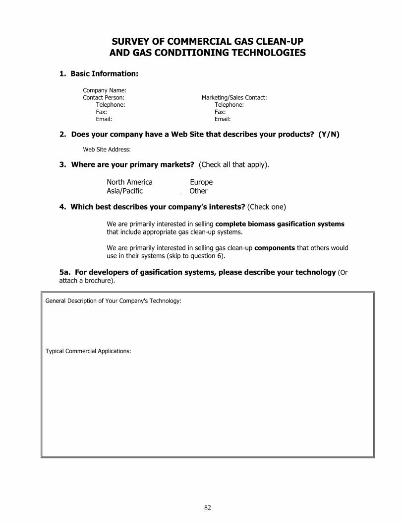
82
SURVEY OF COMMERCIAL GAS CLEAN-UPAND GAS CONDITIONING TECHNOLOGIES
1. Basic Information:
Company Name:Contact Person: Marketing/Sales Contact: Telephone: Telephone: Fax: Fax: Email: Email:
2. Does your company have a Web Site that describes your products? (Y/N)
Web Site Address:
3. Where are your primary markets? (Check all that apply).
� North America � Europe� Asia/Pacific � Other
4. Which best describes your company�s interests? (Check one)
� We are primarily interested in selling complete biomass gasification systemsthat include appropriate gas clean-up systems.
� We are primarily interested in selling gas clean-up components that others woulduse in their systems (skip to question 6).
5a. For developers of gasification systems, please describe your technology (Orattach a brochure).
General Description of Your Company's Technology:
Typical Commercial Applications:
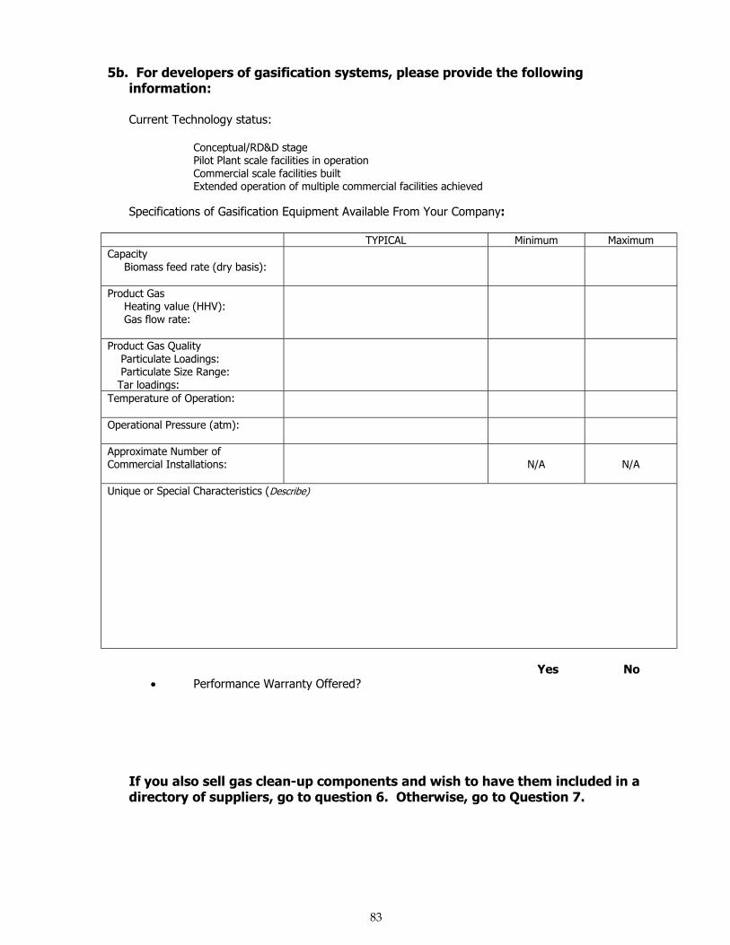
83
5b. For developers of gasification systems, please provide the followinginformation:
Current Technology status:
� Conceptual/RD&D stage� Pilot Plant scale facilities in operation� Commercial scale facilities built� Extended operation of multiple commercial facilities achieved
Specifications of Gasification Equipment Available From Your Company:
TYPICAL Minimum MaximumCapacity Biomass feed rate (dry basis):
Product Gas Heating value (HHV): Gas flow rate:
Product Gas Quality Particulate Loadings: Particulate Size Range: Tar loadings:Temperature of Operation:
Operational Pressure (atm):
Approximate Number ofCommercial Installations: N/A N/A
Unique or Special Characteristics (Describe)
Yes No• Performance Warranty Offered? � �
If you also sell gas clean-up components and wish to have them included in adirectory of suppliers, go to question 6. Otherwise, go to Question 7.
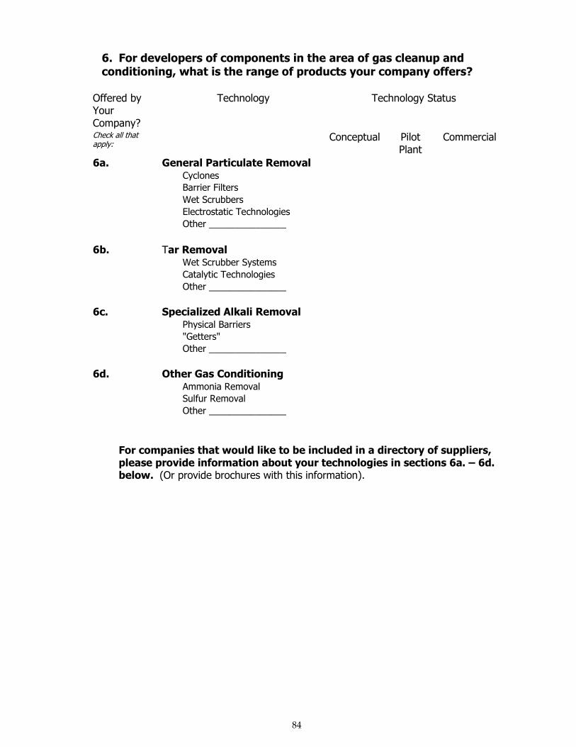
84
6. For developers of components in the area of gas cleanup andconditioning, what is the range of products your company offers?
Offered byYourCompany?
Technology Technology Status
Check all thatapply:
Conceptual PilotPlant
Commercial
6a. General Particulate Removal� Cyclones � � �
� Barrier Filters � � �
� Wet Scrubbers � � �
� Electrostatic Technologies � � �
� Other _______________ � � �
6b. Tar Removal� Wet Scrubber Systems � � �
� Catalytic Technologies � � �
� Other _______________ � � �
6c. Specialized Alkali Removal� Physical Barriers � � �
� "Getters" � � �
� Other _______________ � � �
6d. Other Gas Conditioning� Ammonia Removal � � �
� Sulfur Removal � � �
� Other _______________ � � �
For companies that would like to be included in a directory of suppliers,please provide information about your technologies in sections 6a. � 6d.below. (Or provide brochures with this information).
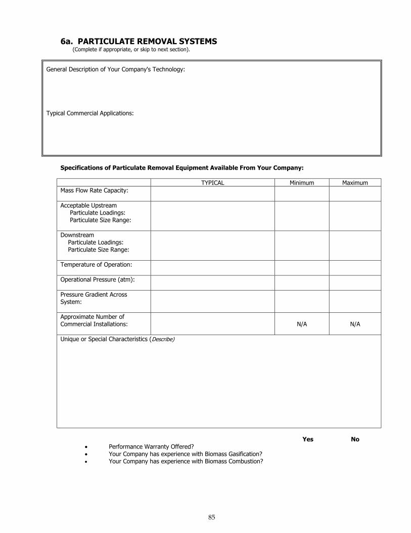
85
6a. PARTICULATE REMOVAL SYSTEMS(Complete if appropriate, or skip to next section).
General Description of Your Company's Technology:
Typical Commercial Applications:
Specifications of Particulate Removal Equipment Available From Your Company:
TYPICAL Minimum MaximumMass Flow Rate Capacity:
Acceptable Upstream Particulate Loadings: Particulate Size Range:
Downstream Particulate Loadings: Particulate Size Range:
Temperature of Operation:
Operational Pressure (atm):
Pressure Gradient AcrossSystem:
Approximate Number ofCommercial Installations: N/A N/A
Unique or Special Characteristics (Describe)
Yes No• Performance Warranty Offered? � �• Your Company has experience with Biomass Gasification? � �• Your Company has experience with Biomass Combustion? � �
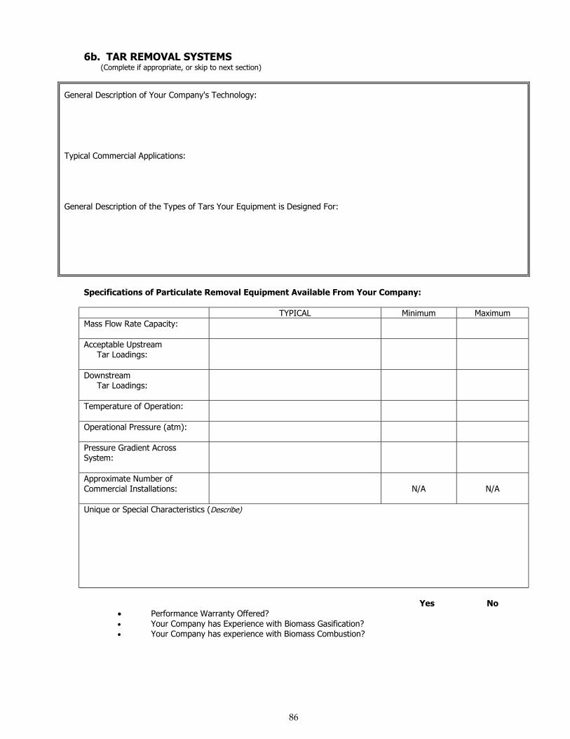
86
6b. TAR REMOVAL SYSTEMS(Complete if appropriate, or skip to next section)
General Description of Your Company's Technology:
Typical Commercial Applications:
General Description of the Types of Tars Your Equipment is Designed For:
Specifications of Particulate Removal Equipment Available From Your Company:
TYPICAL Minimum MaximumMass Flow Rate Capacity:
Acceptable Upstream Tar Loadings:
Downstream Tar Loadings:
Temperature of Operation:
Operational Pressure (atm):
Pressure Gradient AcrossSystem:
Approximate Number ofCommercial Installations: N/A N/A
Unique or Special Characteristics (Describe)
Yes No• Performance Warranty Offered? � �• Your Company has Experience with Biomass Gasification? � �• Your Company has experience with Biomass Combustion? � �
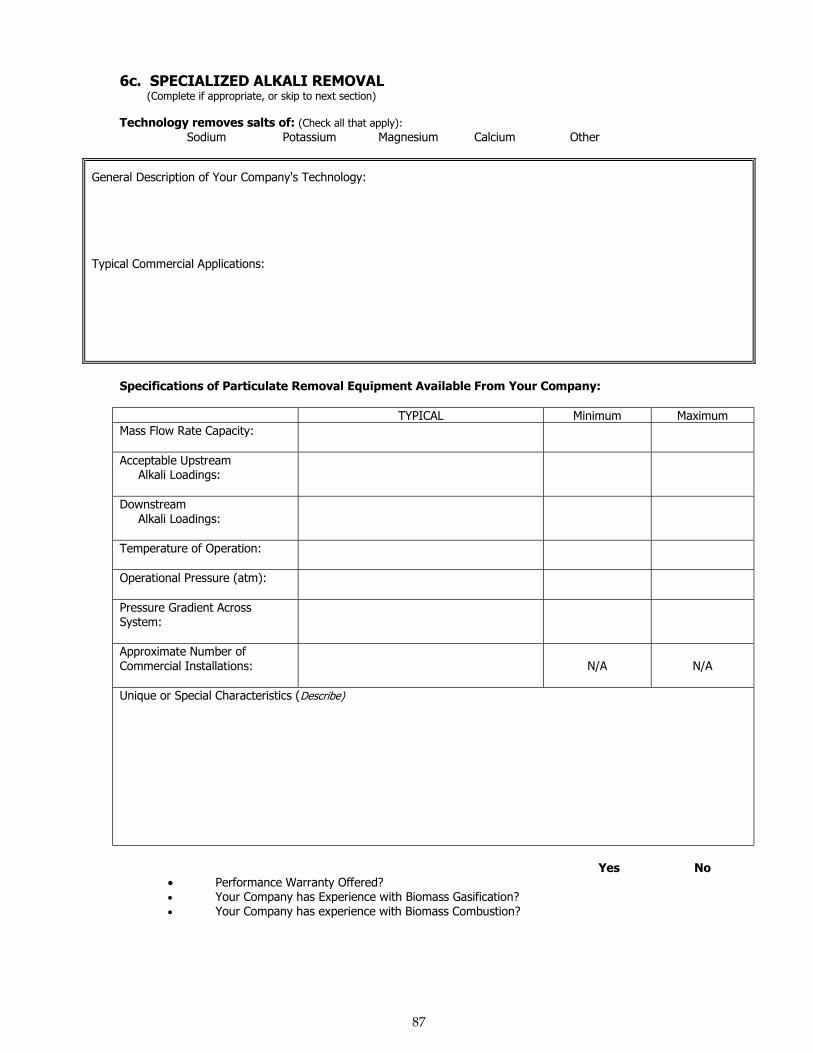
87
6c. SPECIALIZED ALKALI REMOVAL (Complete if appropriate, or skip to next section)
Technology removes salts of: (Check all that apply):� Sodium � Potassium � Magnesium � Calcium � Other
General Description of Your Company's Technology:
Typical Commercial Applications:
Specifications of Particulate Removal Equipment Available From Your Company:
TYPICAL Minimum MaximumMass Flow Rate Capacity:
Acceptable Upstream Alkali Loadings:
Downstream Alkali Loadings:
Temperature of Operation:
Operational Pressure (atm):
Pressure Gradient AcrossSystem:
Approximate Number ofCommercial Installations: N/A N/A
Unique or Special Characteristics (Describe)
Yes No• Performance Warranty Offered? � �• Your Company has Experience with Biomass Gasification? � �• Your Company has experience with Biomass Combustion? � �
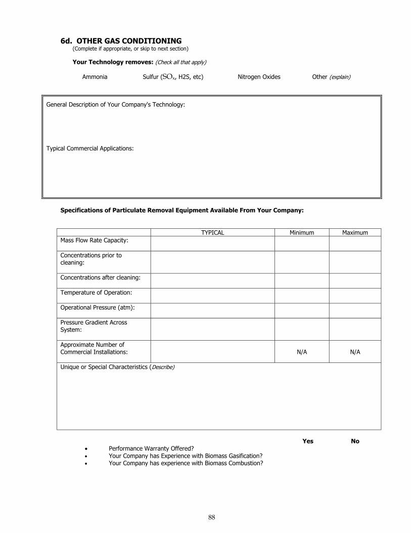
88
6d. OTHER GAS CONDITIONING(Complete if appropriate, or skip to next section)
Your Technology removes: (Check all that apply)
� Ammonia � Sulfur (SOx, H2S, etc) � Nitrogen Oxides � Other (explain)
General Description of Your Company's Technology:
Typical Commercial Applications:
Specifications of Particulate Removal Equipment Available From Your Company:
TYPICAL Minimum MaximumMass Flow Rate Capacity:
Concentrations prior tocleaning:
Concentrations after cleaning:
Temperature of Operation:
Operational Pressure (atm):
Pressure Gradient AcrossSystem:
Approximate Number ofCommercial Installations: N/A N/A
Unique or Special Characteristics (Describe)
Yes No• Performance Warranty Offered? � �• Your Company has Experience with Biomass Gasification? � �• Your Company has experience with Biomass Combustion? � �

89
7. OTHER GAS CLEAN-UP OR CONDITIONING CAPABILITIES:(Describe)
8. OTHER COMMENTS:
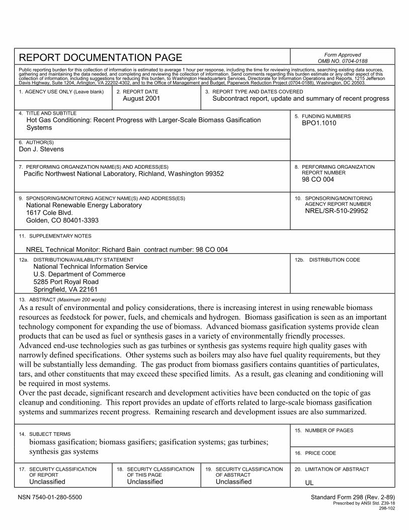
REPORT DOCUMENTATION PAGE Form ApprovedOMB NO. 0704-0188
Public reporting burden for this collection of information is estimated to average 1 hour per response, including the time for reviewing instructions, searching existing data sources,gathering and maintaining the data needed, and completing and reviewing the collection of information. Send comments regarding this burden estimate or any other aspect of thiscollection of information, including suggestions for reducing this burden, to Washington Headquarters Services, Directorate for Information Operations and Reports, 1215 JeffersonDavis Highway, Suite 1204, Arlington, VA 22202-4302, and to the Office of Management and Budget, Paperwork Reduction Project (0704-0188), Washington, DC 20503.
1. AGENCY USE ONLY (Leave blank) 2. REPORT DATEAugust 2001
3. REPORT TYPE AND DATES COVEREDSubcontract report, update and summary of recent progress
4. TITLE AND SUBTITLEHot Gas Conditioning: Recent Progress with Larger-Scale Biomass GasificationSystems
6. AUTHOR(S)Don J. Stevens
5. FUNDING NUMBERSBPO1.1010
7. PERFORMING ORGANIZATION NAME(S) AND ADDRESS(ES)Pacific Northwest National Laboratory, Richland, Washington 99352
8. PERFORMING ORGANIZATIONREPORT NUMBER98 CO 004
9. SPONSORING/MONITORING AGENCY NAME(S) AND ADDRESS(ES)National Renewable Energy Laboratory1617 Cole Blvd.Golden, CO 80401-3393
10. SPONSORING/MONITORINGAGENCY REPORT NUMBERNREL/SR-510-29952
11. SUPPLEMENTARY NOTES
NREL Technical Monitor: Richard Bain contract number: 98 CO 00412a. DISTRIBUTION/AVAILABILITY STATEMENT
National Technical Information ServiceU.S. Department of Commerce5285 Port Royal RoadSpringfield, VA 22161
12b. DISTRIBUTION CODE
13. ABSTRACT (Maximum 200 words)
As a result of environmental and policy considerations, there is increasing interest in using renewable biomassresources as feedstock for power, fuels, and chemicals and hydrogen. Biomass gasification is seen as an importanttechnology component for expanding the use of biomass. Advanced biomass gasification systems provide cleanproducts that can be used as fuel or synthesis gases in a variety of environmentally friendly processes.Advanced end-use technologies such as gas turbines or synthesis gas systems require high quality gases withnarrowly defined specifications. Other systems such as boilers may also have fuel quality requirements, but theywill be substantially less demanding. The gas product from biomass gasifiers contains quantities of particulates,tars, and other constituents that may exceed these specified limits. As a result, gas cleaning and conditioning willbe required in most systems.Over the past decade, significant research and development activities have been conducted on the topic of gascleanup and conditioning. This report provides an update of efforts related to large-scale biomass gasificationsystems and summarizes recent progress. Remaining research and development issues are also summarized.
15. NUMBER OF PAGES14. SUBJECT TERMS
biomass gasification; biomass gasifiers; gasification systems; gas turbines;synthesis gas systems 16. PRICE CODE
17. SECURITY CLASSIFICATIONOF REPORTUnclassified
18. SECURITY CLASSIFICATIONOF THIS PAGEUnclassified
19. SECURITY CLASSIFICATIONOF ABSTRACTUnclassified
20. LIMITATION OF ABSTRACT
UL
NSN 7540-01-280-5500 Standard Form 298 (Rev. 2-89)Prescribed by ANSI Std. Z39-18
298-102


![Cursus Digitale Elektronica en Processoren [Work in Progress]](https://static.fdocuments.nl/doc/165x107/55cf9c8c550346d033aa358b/cursus-digitale-elektronica-en-processoren-work-in-progress.jpg)