FARB-VIDEO-QUAD-PROZESSOR - monacor.dk · U vindt de nederlandstalige tekst op de pagina™s...
38
BEDIENUNGSANLEITUNG INSTRUCTION MANUAL MODE D’EMPLOI ISTRUZIONI PER L’USO GEBRUIKSAANWIJZING FARB-VIDEO-QUAD-PROZESSOR COLOUR VIDEO QUAD PROCESSOR TVSP-46 Best.-Nr. 19.7690 fi TVSP-46COL Best.-Nr. 19.7700
Transcript of FARB-VIDEO-QUAD-PROZESSOR - monacor.dk · U vindt de nederlandstalige tekst op de pagina™s...
BEDIENUNGSANLEITUNG
INSTRUCTION MANUAL
MODE D’EMPLOI
ISTRUZIONI PER L’USO
GEBRUIKSAANWIJZING
FARB-VIDEO-QUAD-PROZESSORCOLOUR VIDEO QUAD PROCESSOR
TVSP-46Best.-Nr. 19.7690
®
TVSP-46COLBest.-Nr. 19.7700

2
Voordat u inschakelt ...Wij wensen u veel plezier met uw nieuw toe-stel van MONACOR. Met behulp van bij-gaande gebruiksaanwijzing kunt u alle func-tiemogelijkheden leren kennen. Door dezeinstructies op te volgen zal een slechte wer-king vermeden worden, en zal een eventueelletsel aan uzelf en schade aan uw toesteltengevolge van onzorgvuldig gebruik wordenvoorkomen.
U vindt de nederlandstalige tekst op depaginas 32 38.
NL
B
Avant toute mise en service ...Nous vous remercions davoir choisi unappareil MONACOR et vous souhaitonsbeaucoup de plaisir à lutiliser. Cette notice apour objectif de vous aider à mieux connaîtreles multiples facettes de lappareil et à vouséviter toute mauvaise manipulation et deprotéger vous et lappareil de tout dommage.
La version française se trouve pages 18 24.
F
B
CH
Prima di accendere ...Vi auguriamo buon divertimento con il Vostronuovo apparecchio MONACOR. Le istruzioniper luso Vi possono aiutare a conosceretutte le possibili funzioni. E rispettandoquanto spiegato nelle istruzioni, evitate dicommettere degli errori, e così proteggeteVoi stessi, ma anche lapparecchio, da even-tuali rischi per uso improprio.
Il testo italiano lo potete trovare alle pagine 25 31.
I
Bevor Sie einschalten ...Wir wünschen Ihnen viel Spaß mit Ihremneuen Gerät von MONACOR. Dabei sollIhnen diese Bedienungsanleitung helfen alleFunktionsmöglichkeiten kennen zu lernen.Die Beachtung der Anleitung vermeidetaußerdem Fehlbedienungen und schützt Sieund Ihr Gerät vor eventuellen Schäden durchunsachgemäßen Gebrauch.Den deutschen Text finden Sie auf denSeite 4 10.
D
A
CH
Before you switch on ...We wish you much pleasure with your newunit by MONACOR. With these operatinginstructions you will be able to get to know allfunctions of the unit. By following theseinstructions false operations will be avoided,and possible damage to yourself and yourunit due to improper use will be prevented.
You will find the English text on the pages11 17.
GB

3
ENTER
MENU QUAD AUTOVCR PLAY
EXIT
FREEZE
COLOUR QUAD PROCESSOR
TVSP-46COL
➀5 6 7 8
1 2 3 4 VCRIN
MONITOROUT
QUADOUT
VIDEO INPUT
ALARMG1 G2 G3 G4
DC 12V1A
➁10 11 12 13 14 15
1 2 3 4
9
RXTXCH4 ALARM INCH3 ALARM INCH2 ALARM INCH1 ALARM INEXT ALARM (REL.) COMGNDEXT ALARM (REL.) N.O.
1 1
2
3
7
1325
14
5
6
9
2
3
4
7
8
1
5
6
9
1
5
6
9
2
3
RXTXCH4 ALARM INCH3 ALARM INCH2 ALARM INCH1 ALARM INEXT ALARM (REL.) COMGNDEXT ALARM (REL.) N.O.
25-PIN TVSP-46 /TVSP-46COL 9-PIN TVSP-46 /TVSP-46COLCOM PORT ALARM CONNECTOR COM PORT ALARM CONNECTOR
➂

Bitte klappen Sie die Seite 3 heraus. Sie sehendann immer die beschriebenen Bedienelementeund Anschlüsse.
Inhalt
1 Übersicht der Bedienelemente undAnschlüsse . . . . . . . . . . . . . . . . . . . . . . . . . . . 5
1.1 Frontseite . . . . . . . . . . . . . . . . . . . . . . . . . . . . . 5
1.2 Rückseite . . . . . . . . . . . . . . . . . . . . . . . . . . . . . 5
2 Hinweise für den sicheren Gebrauch . . . . . . 6
3 Anwendungsmöglichkeiten . . . . . . . . . . . . . . 6
4 Gerät anschließen . . . . . . . . . . . . . . . . . . . . . 6
4.1 Kameras . . . . . . . . . . . . . . . . . . . . . . . . . . . . . . 6
4.2 Monitor . . . . . . . . . . . . . . . . . . . . . . . . . . . . . . . 6
4.3 Videorecorder . . . . . . . . . . . . . . . . . . . . . . . . . . 6
4.4 Alarmverbindungen . . . . . . . . . . . . . . . . . . . . . 6
4.5 Fernbedienung . . . . . . . . . . . . . . . . . . . . . . . . . 6
4.6 Stromversorgung . . . . . . . . . . . . . . . . . . . . . . . 6
5 Bedienung . . . . . . . . . . . . . . . . . . . . . . . . . . . . 6
5.1 Betriebsarten . . . . . . . . . . . . . . . . . . . . . . . . . . 7
5.1.1 Normal . . . . . . . . . . . . . . . . . . . . . . . . . . . . . 7
5.1.2 Automatik (AUTO) . . . . . . . . . . . . . . . . . . . . . 7
5.1.3 Standbild (FREEZE) . . . . . . . . . . . . . . . . . . . 7
5.1.4 Wiedergabe (VCR PLAY) . . . . . . . . . . . . . . . 7
5.2 Änderungen der Geräteeinstellungen . . . . . . . 7
5.2.1 ALARM DURATION Alarmdauer . . . . . . . . 8
5.2.2 BAUD RATE Datenrate für die Fern-bedienung über RS-232 Schnittstelle . . . . . . 8
5.2.3 DWELL TIME Verweildauer für dieautomatische Bildweiterschaltung . . . . . . . . . 8
5.2.4 INT AUDIBLE ALARM Signalton für denAlarm . . . . . . . . . . . . . . . . . . . . . . . . . . . . . . . 8
5.2.5 EXT AUDIBLE ALARM Alarmrelais fürexternen Alarm . . . . . . . . . . . . . . . . . . . . . . . 8
5.2.6 SET TIME Einstellung der Zeitein-blendung . . . . . . . . . . . . . . . . . . . . . . . . . . . . 8
5.2.7 DWELL SETUP Einstellung der Bild-sequenz . . . . . . . . . . . . . . . . . . . . . . . . . . . . 8
5.2.8 ALARM POLARITY Konfiguration derAlarmeingänge . . . . . . . . . . . . . . . . . . . . . . . 8
5.2.9 CAMERA TITLE SETUP Einblendungvon Kameranamen . . . . . . . . . . . . . . . . . . . . 8
5.2.10 EVENT LIST Alarmprotokoll . . . . . . . . . . . . 8
5.2.11 VIDEO SET Anpassung des Video-signals (nur TVSP-46COL) . . . . . . . . . . . . . . 9
5.2.12 SYSTEM RESET Rücksetzensämtlicher Geräteeinstellungen . . . . . . . . . . 9
5.3 Fernbedienung . . . . . . . . . . . . . . . . . . . . . . . . . 9
5.4 Alarmfunktionen . . . . . . . . . . . . . . . . . . . . . . . 10
5.4.1 Alarmauslösung durch einenAlarmsensor . . . . . . . . . . . . . . . . . . . . . . . . 10
5.4.2 Alarmauslösung bei Videosignalverlust . . . 10
6 Technische Daten . . . . . . . . . . . . . . . . . . . . . 10
D
A
CH
4
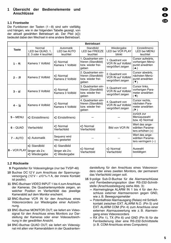
1 Übersicht der Bedienelemente undAnschlüsse
1.1 FrontseiteDie Funktionen der Tasten (1 8) sind sehr vielfältigund hängen, wie in der folgenden Tabelle gezeigt, vonder aktuell gewählten Betriebsart ab. Der Pfeil ( )bedeutet dabei den Wechsel in eine andere Betriebsart.
1.2 Rückseite9 Pegelsteller für Videoeingänge (nur bei TVSP-46)
10 Buchse DC 12 V zum Anschluss der Spannungs-versorgung (12 V ±10 % /1 A, der innere Kontaktist positiv).
11 BNC-Buchsen VIDEO INPUT 1 bis 4 zum Anschlussder Kameras. Die Quadrantensymbole zeigen, anwelcher Position im Vierfachbild das jeweiligeKamerabild auf dem Monitor erscheint.
12 BNC-Buchse VCR IN für den Anschluss einesVideorecorders zur Wiedergabe einer Aufzeich-nung.
13 BNC-Buchse MONITOR OUT; sie liefert ein Video-signal für den Anschluss eines Monitors zur Dar-stellung der Kameras oder einer Videoaufzeich-nung in der gewählten Ansicht.
14 BNC-Buchse QUAD OUT; sie liefert ein Videosig-nal mit allen vier Kamerabildern in der Quadranten-
darstellung für den Anschluss eines Videorecor-ders oder eines zweiten Monitors, der permanentdas Vierfachbild zeigen soll.
15 9-polige Sub-D-Buchse für die Alarmanschlüsseund Fernbedienungsoption über RS-232-Schnitt-stelle (Anschlussbelegung siehe Abb. 3):- Alarmeingänge ALARM IN 1 bis 4 für den An-
schluss externer Alarmsensoren gegen GND,wie z.B. Bewegungsmelder
- Potentialfreier Alarmausgang (Relais) mit Schließ-kontakt zwischen EXT. ALARM N.O. (Pin 5) undEXT. ALARM COM (Pin 4) zum Anschluss einerexternen Alarmauswertung wie z. B. Alarmein-gang eines Videorecorders
- RX (Pin 1), TX (Pin 6) und GND (Pin 9) für dieFernbedienung über eine RS-232-Schnittstelle(z.B. COM-Anschluss eines Computers)
D
A
CH
5
Betriebsart
Taste NormalLED bei QUAD, 1,2, 3 oder 4 leuchtet
AutomatikLED bei AUTO
leuchtet
StandbildLED bei FREEZE
leuchtet
WiedergabeLED bei VCR PLAY
blinkt
EinstellmenüLED bei MENU
leuchtet
1 Kamera 1 Vollbild NormalKamera 1 Vollbild
1. Quadranten ein-frieren (Standbild)bzw. wieder frei-geben
1. Quadrant vonVCR IN auf Vollbildvergrößert zeigen
Cursor aufwärts,vorherigen Menü-punkt anwählen( )
2 Kamera 2 Vollbild NormalKamera 2 Vollbild
2. Quadranten ein-frieren (Standbild)bzw. wieder frei-geben
2. Quadrant vonVCR IN auf Vollbildvergrößert zeigen
Cursor abwärts,nächsten Menü-punkt anwählen( )
3 Kamera 3 Vollbild NormalKamera 3 Vollbild
3. Quadranten ein-frieren (Standbild)bzw. wieder frei-geben
3. Quadrant vonVCR IN auf Vollbildvergrößert zeigen
Cursor links,vorherigen Para-meter anwählen( )
4 Kamera 4 Vollbild NormalKamera 4 Vollbild
4. Quadranten ein-frieren (Standbild)bzw. wieder frei-geben
4. Quadrant vonVCR IN auf Vollbildvergrößert zeigen
Cursor rechts,nächsten Para-meter anwählen( )
5 MENU Einstellmenü Einstellmenü zurück zurMenüauswahlbzw. Normal
6 QUAD Vierfachbild NormalVierfachbild
NormalVierfachbild
Bild von VCR INWert des ange-wählten Parame-ters erhöhen (+)
7 AUTO Automatik Sequenz wirdneu gestartet
Wert des ange-wählten Parame-ters verringern (-)
8 VCR PLAY
Standbild
länger als 2s: Wiedergabe
Standbild
länger als 2s: Wiedergabe
NormalVierfachbild
NormalVierfachbild
Auswahlbestätigen

2 Hinweise für den sicheren GebrauchDas Gerät entspricht der Richtlinie für elektromagne-tische Verträglichkeit 89/336/EWG.
Verwenden Sie das Gerät nur im Innenbereich.Schützen Sie es vor Feuchtigkeit und Hitze (zulässi-ger Einsatztemperaturbereich 0 40 °C).
Stellen Sie keine mit Flüssigkeit gefüllten Gefäße,z. B. Trinkgläser, auf das Gerät.
Verwenden Sie für die Reinigung nur ein trockenes,weiches Tuch, auf keinen Fall Wasser oder Chemi-kalien.
Wird das Gerät zweckentfremdet, falsch bedientoder nicht fachgerecht repariert, kann für eventuelleSchäden keine Haftung übernommen werden.
Soll das Gerät endgültig aus dem Betrieb genom-men werden, übergeben Sie es zur umweltgerech-ten Entsorgung einem örtlichen Recyclingbetrieb.
3 AnwendungsmöglichkeitenDie Video-Quad-Prozessoren TVSP-46 (schwarz-weiß) und TVSP-46COL (Farbe) sind für den Einsatzin Video-Überwachungsanlagen konzipiert. Die Geräteermöglichen bis zu vier Kamerabilder (S/W im EIA-oder CCIR-Standard oder Farbe im PAL- oder NTSC-Standard) einzeln oder als Vierfachbild (Quadranten-darstellung) zu zeigen und gleichzeitig mit einemVideorecorder aufzuzeichnen. Beim TVSP-46 erfolgtdie Quadrantendarstellung nur in schwarzweiß. Beider Recorderwiedergabe ist es möglich, ein Viertelbildals Vollbild vergrößert anzuzeigen. Ebenso ist es mög-lich, während einer Wiedergabe einer Vierfachbildauf-zeichnung über den TVSP-46 oder TVSP-46COL dieaktuellen vier Kamerasignale mit einem anderenVideorecorder aufzunehmen.
Die Videoprozessoren verfügen über zahlreicheAlarmfunktionen. So wird ein über die Alarman-schlüsse eingehender Alarm oder der Verlust einesVideosignals bei Ausfall einer Kamera im Bild ange-zeigt. Zusätzlich kann ein Signalton auf den Vorfall auf-merksam machen. Ein Relais mit Schließkontakt bietetdie Möglichkeit einen Alarm mit einem externen Gerätweiterzuverarbeiten. Alle Ereignisse werden protokol-liert und können über das Einstellungsmenü eingese-hen werden. Die Geräte verfügen über eine Echt-zeituhr, die auch bei Ausfall der Versorgungsspannungweiterläuft.
4 Gerät anschließen
4.1 KamerasBis zu vier Kameras an die Eingangsbuchsen VIDEOINPUT 1 bis 4 (11) anschließen.
4.2 MonitorDen Monitor an die Buchse MONITOR OUT (13) an-schließen.
4.3 VideorecorderZur Aufzeichnung der Kamerabilder als Vierfachbildden Video-Eingang des Videorecorders mit derBuchse QUAD OUT (14) verbinden. Für die Wieder-gabe der Aufzeichnung den Video-Ausgang desVideorecorders mit der Buchse VCR IN (12) ver-binden.
4.4 AlarmverbindungenAn die Alarmeingänge ALARM IN 1 bis 4 der BuchseALARM (15), Anschlussbelegung siehe Abb. 3, kön-nen externe Alarmgeber z. B. Sensoren wie Bewe-gungsmelder angeschlossen werden. Ein offener Ein-gang wird dabei als High-Pegel gelesen, ein mit GNDverbundener Eingang als Low-Pegel. Welcher Pegeleinen Alarm auslösen soll, kann im Einstellungsmenügewählt werden (siehe Kapitel 5.2.8).
Ein potentialfreier Alarmausgang (Relais) steht alsSchließkontakt zwischen den Anschlüssen EXT.ALARM N.O. (Pin 5) und EXT. ALARM COM (Pin 4)zur Verfügung. Hier kann z. B. der Alarmeingang einesVideorecorders angeschlossen werden, der dann imAlarmfall von Langzeit- auf Echtzeitaufzeichnung um-schaltet.
4.5 FernbedienungUm den Videoprozessor über eine RS-232-Schnitt-stelle (z. B. COM-Anschluss eines Computers in Ver-bindung mit einem Terminal-Programm) fernzusteuerndas steuernde Gerät mit den Anschlüssen TX, RX undGND der Buchse ALARM (15) verbinden. Die An-schlussbelegung und Verbindungsbeispiele mit einem25-poligen oder 9-poligen COM-Anschluss ist der Abb.3 zu entnehmen.
4.6 StromversorgungNach dem Anschluß aller übrigen Geräte ein Netzgerät12 V /1A an die Buchse DC IN (10) anschließen, z. B.PSS-1206 oder PS-1204ST von MONACOR. Es wirdein Kleinspannungsstecker 5,5/2,1 mm (Außen-/In-nendurchmesser) benötigt. Dabei ist auf die Polung zuachten: der innere Kontakt muss positiv sein.
5 Bedienung
Nach dem Anschließen der Versorgungsspannung istein kurzer Signalton ist zu hören. Nach ca. 2 s zeigt derProzessor das Vierfachbild der Betriebsart Normal.
Bei der ersten Inbetriebnahme sind die vom Her-steller vorprogrammierten Grundeinstellungen (sieheTabelle Voreinstellungen im Kapitel 5.2.12) wirksam.Zum Ändern der Geräteeinstellungen bitte Kapitel 5.2Änderung der Geräteeinstellungen lesen.
Wichtig! Damit sich das Gerät automatisch auf dieVideonorm des ersten Videoeingangs ein-stellen kann, muss das Signal dort an-liegen, bevor das Gerät mit Spannungversorgt wird.
D
A
CH
6
5.1 Betriebsarten
5.1.1 NormalDie Betriebsart Normal ist voreingestellt, sobald dieSpannungsversorgung hergestellt wird. Die am Gerätangeschlossenen Kameras werden als Vierfachbild(Quadrantendarstellung) angezeigt. Die LED bei derQUAD-Taste leuchtet. Ist an einem Kameraeingangkeine Kamera angeschlossen, so wird der zugeord-nete Quadrant dunkel dargestellt und das Symbol darin eingeblendet. Zudem blinkt bei nicht vorhande-nem Videosignal an einem Videoeingang die LED überder entsprechenden Vollbildtaste 1 bis 4.
Durch Drücken einer der Tasten 1 ( ) bis 4 ( )wird auf die Vollbild-Darstellung der entsprechendenKamera umgeschaltet.
Hinweis: Die Bedienung des Geräts in der BetriebsartNormal hat keinen Einfluss auf die Videoaufzeich-nung. Das Signal am Anschluss QUAD OUT (14) istunabhängig von der gewählten Monitordarstellungimmer ein Vierfachbild.
5.1.2 Automatik (AUTO)Diese Betriebsart wird durch Drücken der AUTO-Taste(7) gewählt und startet die automatische Weiterschal-tung (Sequenzschaltung) entsprechend der in denGeräteeinstellungen gewählten Bildfolge und Verweil-dauer. Näheres zu den Einstellungen der Sequenz istim Kapitel 5.2.3 und 5.2.7 beschrieben. Die LED überder AUTO-Taste leuchtet. Zusätzlich leuchtet jeweilsdie LED zu der momentan gezeigten Ansicht. Kamera-eingänge ohne gültiges Videosignal werden bei derWiedergabe der gewählten Bildsequenzschaltungautomatisch übersprungen.
5.1.3 Standbild (FREEZE)Diese Betriebsart wird durch Drücken der VCRPLAY/FREEZE-Taste (8) gewählt. Die LED über derTaste leuchtet. Standbilder sind nur in der Quadran-tendarstellung möglich, daher wird bei Aufruf dieserBetriebsart automatisch in die Quadrantenansichtgewechselt. Es können nun über die Tasten 1 bis 4 dieAnsichten der Quadranten als Standbild eingefrorenwerden. Die LED über der entsprechenden Tasteleuchtet während des Standbildes. Solange ein Bildsteht, blinkt in seinem Quadranten das Symbol Z. Einwiederholtes Drücken dieser Taste taut die Ansichtwieder auf, d. h. das aktuelle Kamerabild wird wiederangezeigt. Ein erneutes Drücken der VCR PLAY/FREEZE-Taste (8) führt zurück zur Betriebsart Nor-mal mit gewählter Quadrantenansicht.
5.1.4 Wiedergabe (VCR PLAY)Ein langes Drücken (> 2 s) der VCR PLAY/FREEZE-Taste (8) schaltet den Videoprozessor in die Wieder-gabe-Betriebsart. Die LED über der Taste blinkt in die-ser Betriebsart. Es können Bilder angezeigt werden,die gerade vom Videorecorder aufgezeichnet oderwiedergegeben werden. Wird nun eine der Tasten 1bis 4 gedrückt, so wird der entsprechende Quadrantzum Vollbild vergrößert. Dadurch können bei der Wie-dergabe einer Quadrantendarstellung einzelne Qua-
dranten genauer betrachtet werden. Die LED über derentsprechenden Taste leuchtet. Ein Drücken der TasteQUAD (6) zeigt das gesamte Bild. Um diese Betriebs-art wieder zu verlassen die VCR PLAY/FREEZE-Taste(8) erneut drücken. Das Gerät wechselt dann in dieBetriebsart Normal mit gewählter Quadrantenan-sicht.
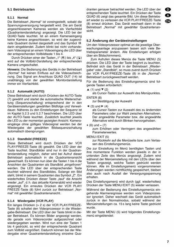
5.2 Änderung der GeräteeinstellungenUm den Videoprozessor optimal an die jeweilige Über-wachungsanlage anzupassen lassen sich viele Be-triebsparameter ändern. Alle Einstellungen erfolgenüber ein Bildschirmmenü.
Zum Aufrufen dieses Menüs die Taste MENU (5)drücken. Die LED über der Taste beginnt zu leuchten.Befindet sich das Gerät in der Betriebsart Wieder-gabe oder Standbild, so muss zuerst durch Drückender VCR PLAY/FREEZE-Taste (8) in die Normal-Betriebsart zurückgewechselt werden.
Für die Bedienung des Einstellungsmenüs sind fol-gende Tasten erforderlich:
(1) und (2)als Cursor-Tasten zur Auswahl des Menüpunktes.
ENTER (8)zur Bestätigung der Auswahl
(3) und (4)als Cursor-Tasten zur Auswahl des zu änderndenParameters oder zur Wahl zwischen Alternativen.Der angewählte Parameter bzw. die angewählteAlternative wird durch Blinken hervorgehoben.
+ (6) und - (7)zum Erhöhen oder Verringern des angewähltenParameterwertes.
MENU/EXIT (5)zur Rückkehr auf die Menüseite bzw. zum Verlas-sen des Einstellungsmenüs.
Die zur Einstellung im Menü benötigten Tasten undihre momentane Funktion werden jeweils in der inuntersten Zeile des Menüs angezeigt. Zudem wirdwährend der Menüeinstellung mit den LEDs über denTasten angezeigt, welche Tasten gedrückt werdenkönnen. Alle im Einstellungsmenü vorgenommenenÄnderungen werden nichtflüchtig gespeichert, bleibenalso auch nach Ausfall der Versorgungsspannungerhalten.
Das Einstellungsmenü wird durch (ggf. wiederholtes)Drücken der Taste MENU/EXIT (5) wieder verlassen.
Während der Bedienung des Einstellungsmenüs ein-gehende Alarmereignisse werden vom Videoprozes-sor ignoriert. Daher wechselt das Gerät automatischzurück in den Normalmodus, sobald während derMenüeinstellungen ca. 15 s lang keine Taste gedrücktwurde.
Mit der Taste MENU (5) wird folgendes Einstellungs-menü eingeblendet:
D
A
CH
7
Der aktuell gewählte Menüpunkt wird durch den Pfeilam linken Rand gekennzeichnet.Mit den Tasten (1) und (2) einen Menüpunktwählen und mit ENTER (8) bestätigen.Die Menüpunkte im Einzelnen:
5.2.1 ALARM DURATION – Alarmdauerermöglicht die Einstellung der Zeit, für die nach Auftre-ten eines Alarms der Relaiskontakt geschlossen wirdund der Alarmton ertönt im Bereich 1 s bis 99s (soweitdies über den Menüpunkt 5.2.5 EXT AUDIBLEALARM bzw. 5.2.4 INT AUDIBLE ALARM zugelas-sen wurde). Durch Drücken einer beliebigen Tastekann der Alarm vorzeitig beendet werden.
5.2.2 BAUD RATE – Datenrate für die Fernbedie-nung über RS-232-Schnittstelle
Für die Fernsteuerung über die serielle Schnittstellekann hier eine Datenrate von 1200, 2400, 3600, 4800,9600, 19 200, 57 600 oder 115 200 Bit/s gewählt wer-den.
5.2.3 DWELL TIME – Verweildauer für die automa-tische Bildweiterschaltung
gibt die Verweildauer pro Bild (1 s bis 30s) für denAutomatikmodus an.
5.2.4 INT AUDIBLE ALARM – Signalton für denAlarm
schaltet den Alarmton, der bei Bildsignalverlust oderAlarm über einen Alarmeingang ertönt, ein (ON) oderaus (OFF).
5.2.5 EXT AUDIBLE ALARM – Alarmrelais fürexternen Alarm
bestimmt, ob das Alarmausgangsrelais bei Bildsignal-verlust oder Alarm über einen Alarmeingang schaltensoll (ON) oder nicht (OFF).
5.2.6 SET TIME – Einstellung der Zeiteinblendungbestimmt, ob die aktuelle Uhrzeit und das Datum ein-geblendet werden und in welchem Format. Mit derTaste ENTER (8) wird zwischen den AnzeigeformatenJahr/Monat/Tag/Stunde/Minute/Sekunde(__y : __m : __d : __h : __m : __s),
Tag/Monat/Jahr/Stunde/Minute/Sekunde(__d : __m : __y : __h : __m : __s)
und keiner Zeiteinblendung (TIME DISPLAY OFF)gewählt. Die interne Uhr lässt sich mithilfe der Tasten
(3), (4), + (6) und – (7) einstellen.
5.2.7 DWELL SETUP – Einstellung der Bildse-quenz
bestimmt, welche Ansichten im Automatik-Modus ge-zeigt werden. Mit den Tasten (1) und (2) dieAnsicht wählen (CH1, CH2, CH3, CH4 oder QUAD)und mit den Tasten (3) und (4) einstellen, obdiese Ansicht in der Bildsequenz enthalten sein soll(ON) oder nicht (OFF).
5.2.8 ALARM POLARITY – Konfiguration derAlarmeingänge
bestimmt, welche Alarmeingänge aktiv sein sollen undob sie auf High-Pegel oder Low-Pegel ansprechen sol-len. Mit den Tasten (1) und (2) die Nummer desAlarmeingangs wählen (CH1, CH2, CH3 oder CH4)und mit den Tasten (3) und (4) einstellen, ob die-ser Alarmeingang auf HIGH-Pegel, LOW-Pegel odergar nicht (OFF) reagieren soll. Ein offener Eingang giltdabei als High-Pegel. Wird der Eingang mit Masse ver-bunden (GND) liegt er auf Low-Pegel.
5.2.9 CAMERA TITLE SETUP – Einblendung vonKameranamen
Hier kann in jedes der vier Kamerabilder ein bis zu zehnZeichen langer Name eingeblendet werden. Mit denTasten (1) und (2) die Nummer des Kameraein-gangs wählen (CH1, CH2, CH3 oder CH4), mit denTasten + (6) und – (7) ein Zeichen auswählen und mitden Tasten (3) und (4) die nächste oder vorherigeZeichenposition ansteuern. Mit der Taste ENTER (8)auswählen, ob der Name gezeigt werden soll oder aus-geblendet ist (UNSHOWN).Hinweis: Die Einblendungsmöglichkeiten von Kamera-titeln, Datum und Uhrzeit gelten nur für das Vierfachbild.In die Vollbilddarstellung werden keine Texte einge-blendet.
5.2.10 EVENT LIST – AlarmprotokollBei Aufruf dieses Menüpunktes wird die folgende Listeeingeblendet:
CH EVENT YY/MM/DD HH:MM:SS-----------------------------CH1 VLOSS 02/01/05 12:13:14CH2 ALARM 02/01/05 22:23:54--- ----- --/--/-- --:--:----- ----- --/--/-- --:--:----- ----- --/--/-- --:--:----- ----- --/--/-- --:--:----- ----- --/--/-- --:--:----- ----- --/--/-- --:--:----- ----- --/--/-- --:--:----- ----- --/--/-- --:--:--
ENTER:CLEAR,MENU:EXIT
(MENU)ALARM DURATION : 02 SECBAUD RATE : 1200 BPSDWELL TIME : 03 SECINT AUDIBLE ALARM : ON OFFEXT AUDIBLE ALARM : ON OFFSET TIME : 02y:02m:05d:11h:12m:13sDWELL SETUP (CH 01) : ON OFFALARM POLARITY (CH 01) : HIGH LOW OFFCAMERA TITLE SETUP (CH 01) : ABCDEFGHIJEVENT LISTVIDEO SETSYSTEM RESET
:SEL.ENTER:VERIFYCHOICE.MENU:EXIT
D
A
CH
8

D
A
CH
9
Hier sind, nach Zeitpunkt des Auftretens geordnet, diezehn letzten Alarm- und Videosignalverlust (VLOSS)-Ereignisse aufgeführt. Unter CH steht die Nummerdes Kameraeingangs (bei Videosignalverlust) bzw.des Alarmeingangs (bei Alarm). Das Datum ist hier,unabhängig von der Menüeinstellung unter SETTIME im Format Jahr / Monat / Tag ausgeführt. Ist dasListenende erreicht, werden die älteren Einträge vonder ersten Zeile herab wieder überschrieben. Um dieEinträge der Liste komplett zu löschen die TasteENTER (8) drücken.
5.2.11 VIDEO SET – Anpassung des Videosignals(nur TVSP-46COL)
Bei Aufruf dieses Menüpunktes wird folgendes Menüeingeblendet:
Hier können die Videosignale der vier Eingänge in Hel-ligkeit (BRIGHTNESS), Kontrast (CONTRAST) undFarbintensität (COLOR) angepasst werden. Mit denCursortasten (1), (2), (3) und (4) den einzu-stellenden Wert auswählen. Der Pfeil vor dem Para-meter zeigt die aktuelle Auswahl. Mit den Tasten + (6)und – (7) den Wert im Bereich 0 bis 9 anpassen.
Beim TVSP-46 können die Bildeigenschaften ggf.mithilfe der Regler für die Eingangspegel (9) korrigiertwerden.
5.2.12 SYSTEM RESET – Rücksetzen sämtlicherGeräteeinstellungen
Sämtliche Einstellungen des Videoprozessors mit Aus-nahme der Echtzeituhr lassen sich über diesen Menü-punkt gleichzeitig auf die vom Werk voreingestelltenWerte zurücksetzen. Die Funktion wird mit Drückender Taste ENTER (8) zur Bestätigung des Menüpunk-tes sofort ausgeführt. Es gibt keine Sicherheitsrück-frage.Achtung: Die Aktivierung dieser Option löscht, mit Aus-nahme der Echtzeituhr, alle vom Benutzer vorgenom-menen Einstellungen unwiederbringlich und ersetzt siedurch die im Werk festgelegten Voreinstellungen.Die vom Werk festgelegten Voreinstellungen sind infolgender Tabelle zusammengefasst:
5.3 FernbedienungÜber die Anschlüsse TX, RX und GND an der BuchseALARM (15) kann der Videoprozessor per seriellerDatenübertragung nach RS-232 komplett ferngesteuertwerden. Dabei werden die Funktionen der Bedientastendurch gesendete ASCII-Zeichen (z. B. über ein Termi-nal-Programm eines Computers) ausgelöst. Die Anzahlder übertragenen Datenbits ist acht, die Bitrate kann imEinstellungsmenü im Bereich 1200 bis 115 200 Bit/svariiert werden (siehe dazu Kapitel 5.2.2). Im Folgendensind die zulässigen ASCII-Codes und ihre Tastenent-sprechungen aufgeführt:
Hinweis: Die Anschlussbelegung beachten (sieheAbb. 3)! Die Sub-D-Buchse hat bei diesem Gerät meh-rere Funktionen, daher entspricht ihre Belegung nichtder eines Standardkabels für serielle Datenübertra-gung!
BRIGHTNESS 0 BRIGHTNESS 5CONTRAST 9 CONTRAST 5COLOR 3 COLOR 5
BRIGHTNESS 5 BRIGHTNESS 5CONTRAST 5 CONTRAST 5COLOR 5 COLOR 5
ASCII-Codefür Zeichen
Funktionwie Taste
Bezeichnungin Abb. 1
A AUTO/- 7
Q QUAD/+ 6
M MENU/EXIT 5
VVCR PLAY(entspricht
längerem Drücken)8
F FREEZE/ENTER 8
1 / (CH1) 1
2 / (CH2) 2
3 / (CH3) 3
4 / (CH4) 4
Voreinstellungen
ALARM DURATION 2 s
BAUD RATE 9600 Bit/s
DWELL TIME 2 s
EXT AUDIBLE ALARM ON
DWELL SETUP CH1 ... 4 = ON, QUAD = ON
ALARM POLARITY CH1 ... 4 = LOW
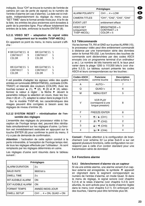
CAMERA TITLES CH1, CH2, CH3, CH4
EVENT LIST komplett gelöscht
VIDEO SET(nur TVSP-46COL)
BRIGHTNESS = 5CONTRAST = 5COLOR = 5
INT AUDIBLE ALARM ON
ZEIT FORMAT JAHR/MONAT/TAG

5.4 Alarmfunktionen
5.4.1 Alarmauslösung durch einen AlarmsensorWird über einen Alarmeingang ein von einem externenSensor kommender Alarm registriert, erscheint in derQuadrantenansicht in dem der Nummer des Alarmein-gangs entsprechenden Quadranten blinkend dasSymbol . Sind im Einstellungsmenü der Signalton(siehe Kap. 5.2.4) und das Alarmrelais (siehe Kap.5.2.5) eingeschaltet, werden sie für die im Menü ein-gestellte Alarmdauer (siehe Kap. 5.2.1) aktiviert. DurchDrücken einer beliebigen Taste kann der Alarm vorzei-tig beendet werden.
Das Symbol bleibt, unabhängig von der eingestell-ten Alarmdauer oder einem manuellen Abbruch desAlarms, solange auf dem Bildschirm, wie das Signalam Alarmeingang den im Einstellungsmenü vorge-gebenen Auslösebedingungen entspricht (siehe Kap.5.2.8).
5.4.2 Alarmauslösung bei VideosignalverlustFällt ein Videosignal aus (z. B. bei einem Kamera-defekt), wird in dem entsprechenden Quadranten dasSymbol eingeblendet. Zudem blinkt die LED überder entsprechenden Taste. Sind im Einstellungsmenüder Signalton (siehe Kap. 5.2.4) und das Alarmrelais(siehe Kap. 5.2.5) eingeschaltet, werden sie für die imMenü eingestellte Alarmdauer (siehe 5.2.1) aktiviert.Durch Drücken einer beliebigen Taste kann der Alarmvorzeitig beendet werden.
Das Symbol bleibt, unabhängig von der eingestell-ten Alarmdauer oder einem manuellen Abbruch desAlarms, solange auf dem Bildschirm, wie das Signalam Videoeingang fehlt.
Beide Alarmarten werden mit Datum und Uhrzeitdes Auftretens protokolliert. Die Auflistung der letztenzehn Ereignisse kann im Einstellungsmenü eingese-hen und gelöscht werden (siehe Kap. 5.2.10).
6 Technische Daten
VideoSignalformat: . . . . . . . . . . EIA, CCIRFarbnorm: . . . . . . . . . . . . NTSC, PAL
(nur TVSP-46COL)Bildfrequenz
NTSC/EIA: . . . . . . . . . 30 Bilder/sPAL /CCIR: . . . . . . . . . 25 Bilder/s
AuflösungNTSC/EIA: . . . . . . . . . 720 (h) x 480 (v)PAL /CCIR: . . . . . . . . . 720 (h) x 576 (v)
Farb- /GraustufenNTSC, PAL: . . . . . . . . . 16,7 Mio. FarbenEIA, CCIR: . . . . . . . . . . 256 Graustufen
Signalpegel: . . . . . . . . . . . 1Vss /75Ω
Alarm
Eingänge: . . . . . . . . . . . . 4 Alarmeingänge mitgemeinsamer Masse,wahlweise jeweils High-Pegelauslösung [für Öff-nungskontakt (N.C.)],Low-Pegelauslösung [fürSchließkontakt (N.C.)]oder deaktiviert
Ausgang: . . . . . . . . . . . . . Alarmrelais mit Schließ-kontakt (N.O.), max. 2 A / 24 V ,abschaltbar
Alarmsignalton: . . . . . . . . bei Signalverlust undAlarm über Alarmein-gänge, abschaltbar, Dauereinstellbar: 1 s bis 99s
Fernsteuerung: . . . . . . . . RS-232
Allgemein
Einsatztemperatur: . . . . . 0 40°CSpannungsversorgung: . . 12V ±10 %
(z. B. über PSS-1206 oderPS-1204ST vonMONACOR)
Leistungsaufnahme: . . . . 12W max., 1A bei 12VAbmessungen (B x H x T): 240 x 50 x 170mmGewicht: . . . . . . . . . . . . . . 1,1kg
Laut Angaben des Herstellers.Änderungen vorbehalten.
D
A
CH
10
Please unfold page 3. Then you can always see theoperating elements and connections described.
Contents
1 Operating Elements and Connections . . . . 12
1.1 Front panel . . . . . . . . . . . . . . . . . . . . . . . . . . . 12
1.2 Rear panel . . . . . . . . . . . . . . . . . . . . . . . . . . . 12
2 Safety Notes . . . . . . . . . . . . . . . . . . . . . . . . . 13
3 Applications . . . . . . . . . . . . . . . . . . . . . . . . . 13
4 Connecting the Unit . . . . . . . . . . . . . . . . . . . 13
4.1 Cameras . . . . . . . . . . . . . . . . . . . . . . . . . . . . . 13
4.2 Monitor . . . . . . . . . . . . . . . . . . . . . . . . . . . . . . 13
4.3 Video recorder . . . . . . . . . . . . . . . . . . . . . . . . 13
4.4 Alarm connections . . . . . . . . . . . . . . . . . . . . . 13
4.5 Remote control . . . . . . . . . . . . . . . . . . . . . . . . 13
4.6 Power supply . . . . . . . . . . . . . . . . . . . . . . . . . 13
5 Operation . . . . . . . . . . . . . . . . . . . . . . . . . . . 14
5.1 Operating modes . . . . . . . . . . . . . . . . . . . . . . 14
5.1.1 Normal . . . . . . . . . . . . . . . . . . . . . . . . . . . . 14
5.1.2 Automatic (AUTO) . . . . . . . . . . . . . . . . . . . . 14
5.1.3 Still picture (FREEZE) . . . . . . . . . . . . . . . . . 14
5.1.4 Reproduction (VCR PLAY) . . . . . . . . . . . . . 14
5.2 Changing the settings of the unit . . . . . . . . . . 14
5.2.1 ALARM DURATION . . . . . . . . . . . . . . . . . . 15
5.2.2 BAUD RATE data rate for remote control via RS-232 interface . . . . . . . . . . . . . . . . . . 15
5.2.3 DWELL TIME dwell time for automaticsequential switching . . . . . . . . . . . . . . . . . . 15
5.2.4 INT AUDIBLE ALARM acoustic alarm signal . . . . . . . . . . . . . . . . . . . . . . . . . 15
5.2.5 EXT AUDIBLE ALARM alarm relay for external alarm . . . . . . . . . . . . . . . . . . . . 15
5.2.6 SET TIME setting of the inserted time . . . 15
5.2.7 DWELL SETUP setting of picture sequence . . . . . . . . . . . . . . . . . . . . . 15
5.2.8 ALARM POLARITY configuration of the alarm inputs . . . . . . . . . . . . . . . . . . . . . 15
5.2.9 CAMERA TITLE SETUP insertion of camera titles . . . . . . . . . . . . . . . . . . . . . . . . 15
5.2.10 EVENT LIST alarm protocol . . . . . . . . . . . 15
5.2.11 VIDEO SET matching of the video signal (for TVSP-46COL only) . . . . . . . . . . . . . . . . 16
5.2.12 SYSTEM RESET total reset of the unit . . 16
5.3 Remote control . . . . . . . . . . . . . . . . . . . . . . . . 16
5.4 Alarm functions . . . . . . . . . . . . . . . . . . . . . . . . 17
5.4.1 Alarm triggering via an alarm sensor . . . . . 17
5.4.2 Alarm triggering in case of video signal loss . . . . . . . . . . . . . . . . . . . . . 17
6 Specifications . . . . . . . . . . . . . . . . . . . . . . . . 17
GB
11
GB
12
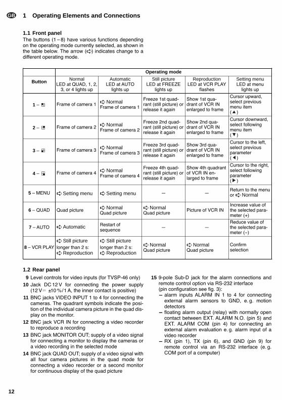
1 Operating Elements and Connections
1.1 Front panelThe buttons (1 8) have various functions dependingon the operating mode currently selected, as shown inthe table below. The arrow ( ) indicates change to adifferent operating mode.
1.2 Rear panel9 Level controls for video inputs (for TVSP-46 only)
10 Jack DC 12 V for connecting the power supply (12 V ±10 %/1 A, the inner contact is positive)
11 BNC jacks VIDEO INPUT 1 to 4 for connecting thecameras. The quadrant symbols indicate the posi-tion of the individual camera picture in the quad dis-play on the monitor.
12 BNC jack VCR IN for connecting a video recorderto reproduce a recording
13 BNC jack MONITOR OUT; supply of a video signalfor connecting a monitor to display the cameras ora video recording in the selected mode
14 BNC jack QUAD OUT; supply of a video signal withall four camera pictures in the quad mode forconnecting a video recorder or a second monitorfor continuous display of the quad picture
15 9-pole Sub-D jack for the alarm connections andremote control option via RS-232 interface (pin configuration see fig. 3):- alarm inputs ALARM IN 1 to 4 for connecting
external alarm sensors to GND, e. g. motiondetectors
- floating alarm output (relay) with normally opencontact between EXT. ALARM N.O. (pin 5) andEXT. ALARM COM (pin 4) for connecting anexternal alarm evaluation e. g. alarm input of avideo recorder
- RX (pin 1), TX (pin 6), and GND (pin 9) forremote control via an RS-232 interface (e. g.COM port of a computer)
Operating mode
Button NormalLED at QUAD, 1, 2,
3, or 4 lights up
AutomaticLED at AUTO
lights up
Still pictureLED at FREEZE
lights up
ReproductionLED at VCR PLAY
flashes
Setting menuLED at menu
lights up
1 Frame of camera 1 NormalFrame of camera 1
Freeze 1st quad-rant (still picture) orrelease it again
Show 1st qua-drant of VCR INenlarged to frame
Cursor upward,select previousmenu item ( )
2 Frame of camera 2 NormalFrame of camera 2
Freeze 2nd quad-rant (still picture) orrelease it again
Show 2nd qua-drant of VCR INenlarged to frame
Cursor downward,select followingmenu item( )
3 Frame of camera 3 NormalFrame of camera 3
Freeze 3rd quad-rant (still picture) orrelease it again
Show 3rd qua-drant of VCR INenlarged to frame
Cursor to the left,select previousparameter( )
4 Frame of camera 4 NormalFrame of camera 4
Freeze 4th quad-rant (still picture) orrelease it again
Show 4th quadrantof VCR IN en-larged to frame
Cursor to the right,select followingparameter ( )
5 MENU Setting menu Setting menu Return to the menuor Normal
6 QUAD Quad picture NormalQuad picture
NormalQuad picture
Picture of VCR INIncrease value ofthe selected para-meter (+)
7 AUTO Automatic Restart ofsequence
Reduce value ofthe selected para-meter (-)
8 VCR PLAY Still picturelonger than 2 s: Reproduction
Still picturelonger than 2 s: Reproduction
NormalQuad picture
NormalQuad picture
Confirm selection

2 Safety NotesThis unit corresponds to the directive for electromag-netic compatibility 89/336/EEC. The unit is suitable for indoor use only. Protect it
against humidity and heat (admissible ambient tem-perature range 0 40 °C).
Do not place any vessel filled with liquid on the unit,e. g. a drinking glass.
For cleaning only use a dry, soft cloth; never usechemicals or water.
No liability for any damage will be accepted if the unitis used for other purposes than originally intended, ifit is not correctly operated or not repaired in anexpert way.
If the unit is to be put out of operation definitively,take it to a local recycling plant for a disposal whichis not harmful to the environment.
3 ApplicationsThe video quad processors TVSP-46 (black-and-white) and TVSP-46COL (colour) are designed forapplications in video surveillance systems. The unitsallow display of up to four camera pictures (B/W in EIAor CCIR standard or colour in PAL or NTSC standard),individually or as quad picture (quadrant display), andsimultaneous recording with a video recorder. TheTVSP-46 displays the quadrants in black and whiteonly. During reproduction of the recording it is possibleto display a quadrant enlarged to frame. During repro-duction of a quad picture by the TVSP-46 or TVSP-46COL, it is also possible to record the current fourcamera signals with another video recorder.
The video processors are provided with variousalarm functions. The picture shows an incoming alarmvia the alarm connections or the loss of a video signalin case of failure of a camera. In addition, it is possibleto indicate the incident by an acoustic signal. A relaywith normally open contact allows further processing ofan alarm with an external unit. All incidents are record-ed and can be viewed via the setting menu. The unitsare provided with a real time clock which continues torun even after power failure.
4 Connecting the Unit
4.1 CamerasConnect up to four cameras to the input jacks VIDEOINPUT 1 to 4 (11).
4.2 MonitorConnect the monitor to the jack MONITOR OUT (13).
4.3 Video recorderTo record the camera pictures as quad picture,connect the video input of the video recorder to thejack QUAD OUT (14). To reproduce the recording,connect the video output of the video recorder to thejack VCR IN (12).
4.4 Alarm connectionsExternal alarm devices, e. g. sensors such as motiondetectors, can be connected to the alarm inputsALARM IN 1 to 4 of the jack ALARM (15), pin configu-ration see fig. 3. In this case, an open input is read ashigh level; an input connected to GND as low level.The level to trigger an alarm can be selected in the set-ting menu (see chapter 5.2.8).
A floating alarm output (relay) is available as nor-mally open contact between the connections EXT.ALARM N.O. (pin 5) and EXT. ALARM COM (pin 4).This output allows e. g. connection of the alarm input ofa video recorder which, in case of alarm, switches fromtime lapse recording to real time recording.
4.5 Remote controlFor remote control of the video processor via an RS-232 interface (e. g. COM port of a computer incombination with a terminal programme), connect thecontrolling unit to the terminals TX, RX, and GND ofthe jack ALARM (15). Fig. 3 shows the pin configura-tion and examples with a 25-pole or 9-pole COM port.
4.6 Power supplyAfter connecting all other units, connect a power sup-ply unit 12 V /1 A to the jack DC IN (10), e. g.MONACOR PSS-1206 or PS-1204ST. A low voltageplug 5.5/2.1 mm (outside/inside diameter) is required.Observe the correct polarity: the inner contact must bepositive.
GB
13
GB
14
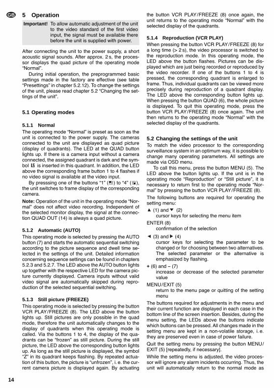
5 Operation
After connecting the unit to the power supply, a shortacoustic signal sounds. After approx. 2 s, the proces-sor displays the quad picture of the operating modeNormal.
During initial operation, the preprogrammed basicsettings made in the factory are effective (see tablePresettings in chapter 5.2.12). To change the settingsof the unit, please read chapter 5.2 Changing the set-tings of the unit.
5.1 Operating modes
5.1.1 NormalThe operating mode Normal is preset as soon as theunit is connected to the power supply. The camerasconnected to the unit are displayed as quad picture(display of quadrants). The LED at the QUAD buttonlights up. If there is a camera input without a cameraconnected, the assigned quadrant is dark and the sym-bol is inserted in this quadrant. In addition, the LEDabove the corresponding frame button 1 to 4 flashes ifno video signal is available at the video input.
By presssing one of the buttons 1 ( ) to 4 ( ),the unit switches to frame display of the correspondingcamera.
Note: Operation of the unit in the operating mode Nor-mal does not affect video recording. Independent ofthe selected monitor display, the signal at the connec-tion QUAD OUT (14) is always a quad picture.
5.1.2 Automatic (AUTO)This operating mode is selected by pressing the AUTObutton (7) and starts the automatic sequential switchingaccording to the picture sequence and dwell time se-lected in the settings of the unit. Detailed informationconcerning sequence settings can be found in chapters5.2.3 and 5.2.7. The LED above the AUTO button lightsup together with the respective LED for the camera pic-ture currently displayed. Camera inputs without validvideo signal are automatically skipped during repro-duction of the selected sequential switching.
5.1.3 Still picture (FREEZE)This operating mode is selected by pressing the buttonVCR PLAY/FREEZE (8). The LED above the buttonlights up. Still pictures are only possible in the quadmode, therefore the unit automatically changes to thedisplay of quadrants when this operating mode iscalled. Via the buttons 1 to 4, the display of the qua-drants can be frozen as still picture. During the stillpicture, the LED above the corresponding button lightsup. As long as the still picture is displayed, the symbolZ in its quadrant keeps flashing. By repeated actua-tion of this button, the picture is unfrozen, i. e. the cur-rent camera picture is displayed again. By actuating
the button VCR PLAY/FREEZE (8) once again, theunit returns to the operating mode Normal with theselected display of the quadrants.
5.1.4 Reproduction (VCR PLAY)When pressing the button VCR PLAY/FREEZE (8) fora long time (> 2 s), the video processor is switched tothe reproduction mode. In this operating mode, theLED above the button flashes. Pictures can be dis-played which are just being recorded or reproduced bythe video recorder. If one of the buttons 1 to 4 is pressed, the corresponding quadrant is enlarged toframe. Thus, individual quadrants can be viewed moreprecisely during reproduction of a quadrant display.The LED above the corresponding button lights up.When pressing the button QUAD (6), the whole pictureis displayed. To quit this operating mode, press thebutton VCR PLAY/FREEZE (8) once again. The unitthen returns to the operating mode Normal with theselected display of the quadrants.
5.2 Changing the settings of the unitTo match the video processor to the correspondingsurveillance system in an optimum way, it is possible tochange many operating parameters. All settings aremade via OSD menu.
To call this menu, press the button MENU (5). TheLED above the button lights up. If the unit is in theoperating mode Reproduction or Still picture, it isnecessary to return first to the operating mode Nor-mal by pressing the button VCR PLAY/FREEZE (8).
The following buttons are required for operating thesetting menu:
(1) and (2)cursor keys for selecting the menu item
ENTER (8)confirmation of the selection
(3) and (4)cursor keys for selecting the parameter to bechanged or for choosing between two alternatives.The selected parameter or the alternative isemphasized by flashing.
+ (6) and – (7)increase or decrease of the selected parametervalue
MENU/EXIT (5)return to the menu page or quitting of the settingmenu
The buttons required for adjustments in the menu andtheir current function are displayed in each case in thebottom line of the screen insertion. Besides, during themenu setting, the LEDs above the buttons indicatewhich buttons can be pressed. All changes made in thesetting menu are kept in a non-volatile storage, i. e.they are preserved even in case of power failure.
Quit the setting menu by pressing the button MENU/EXIT (5) [repeatedly, if necessary].
While the setting menu is adjusted, the video proces-sor will ignore any alarm incidents occurring. Thus, theunit will automatically return to the normal mode as
Important! To allow automatic adjustment of the unitto the video standard of the first videoinput, the signal must be available therebefore the unit is supplied with power.

soon as no button has been pressed for approx. 15 sduring the adjustments made in the menu.
With the button MENU (5), the following setting menuis inserted:
The currently selected menu item is indicated by thearrow on the left margin.
Select a menu item with the buttons (1) and (2)and confirm with ENTER (8).
The individual menu items are as follows:
5.2.1 ALARM DURATIONSetting of the time for which the relay contact is closedafter occurrence of an alarm and the acoustic signalsounds, in the range of 1 s to 99 s (as far as this was per-mitted via the menu item 5.2.5 EXT AUDIBLE ALARMor 5.2.4 INT AUDIBLE ALARM). The alarm can bestopped at any time by pressing an optional button.
5.2.2 BAUD RATE – data rate for remote controlvia RS-232 interface
For remote control via the serial interface, a data rateof 1200, 2400, 3600, 4800, 9600, 19 200, 57 600, or115 200 bits/s can be selected.
5.2.3 DWELL TIME – dwell time for automaticsequential switching
Indication of the dwell time of each picture (1 s to 30 s)in the automatic mode.
5.2.4 INT AUDIBLE ALARM – acoustic alarm signalSwitching ON or OFF of the acoustic signal whichsounds in case of video signal loss or alarm.
5.2.5 EXT AUDIBLE ALARM – alarm relay forexternal alarm
Definition if the alarm output relay responds in case ofvideo signal loss or alarm via an alarm input (ON) ornot (OFF).
5.2.6 SET TIME – setting of the inserted timeDefinition whether or not the current time and the dateare inserted and definition of their format. The buttonENTER (8) selects the following formats:
year/month/day/hour/minute/second(__y : __m : __d : __h : __m : __s),day/month/year/hour/minute/second(__d : __m : __y : __h : __m : __s)or TIME DISPLAY OFF. The internal clock can be setby means of the buttons (3), (4), + (6), and – (7).
5.2.7 DWELL SETUP – setting of the picturesequence
Definition of the displays in the automatic mode. Selectthe display (CH1, CH2, CH3, CH4, or QUAD) with thebuttons (1) and (2), then use the buttons (3)and (4) to define if this display is to be included inthe picture sequence (ON) or not (OFF).
5.2.8 ALARM POLARITY – configuration of thealarm inputs
Definition of the active alarm inputs and their responseeither to high level or low level. Select the number of thealarm input (CH1, CH2, CH3, or CH4) with the buttons
(1) and (2), then use the buttons (3) and (4)to define if this alarm input will respond to HIGH level,LOW level, or will not respond at all (OFF). An openinput is considered as high level. If the input is connec-ted to ground (GND), it is set to low level.
5.2.9 CAMERA TITLE SETUP – insertion ofcamera titles
For each of the four camera pictures a title of up to tencharacters can be inserted. Select the number of thecamera input (CH1, CH2, CH3, or CH4) with the but-tons (1) and (2), then use the buttons + (6) and – (7) to select a character and select the following orprevious character position with the buttons (3) and
(4). Use the button ENTER (8) to define if the title isshown or not (UNSHOWN).Note: Insertion of camera title, date, and time onlyapply to the quad picture. In the frame display, no textis inserted.
5.2.10 EVENT LIST – alarm protocolThe following list is inserted if this menu item is called:
It shows the last ten alarm incidents and video signalloss incidents (VLOSS), arranged according to thetime of their occurrence. Below CH, the number ofthe camera input (in case of video signal loss) or of thealarm input (in case of alarm) is listed. Independent of
CH EVENT YY/MM/DD HH:MM:SS-----------------------------CH1 VLOSS 02/01/05 12:13:14CH2 ALARM 02/01/05 22:23:54--- ----- --/--/-- --:--:----- ----- --/--/-- --:--:----- ----- --/--/-- --:--:----- ----- --/--/-- --:--:----- ----- --/--/-- --:--:----- ----- --/--/-- --:--:----- ----- --/--/-- --:--:----- ----- --/--/-- --:--:--
ENTER:CLEAR,MENU:EXIT
(MENU)ALARM DURATION : 02 SECBAUD RATE : 1200 BPSDWELL TIME : 03 SECINT AUDIBLE ALARM : ON OFFEXT AUDIBLE ALARM : ON OFFSET TIME : 02y:02m:05d:11h:12m:13sDWELL SETUP (CH 01) : ON OFFALARM POLARITY (CH 01) : HIGH LOW OFFCAMERA TITLE SETUP (CH 01) : ABCDEFGHIJEVENT LISTVIDEO SETSYSTEM RESET
:SEL.ENTER:VERIFYCHOICE.MENU:EXIT
GB
15
GB
16
the menu setting under SET TIME, the date is indi-cated here in the format year/month/day. At the end ofthe list, the older entries are overwritten starting fromthe first line. To delete all entries of the list, press thebutton ENTER (8).
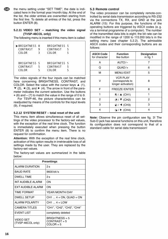
5.2.11 VIDEO SET – matching the video signal(TVSP-46COL only)
The following menu is inserted if this menu item is called:
The video signals of the four inputs can be matchedhere concerning BRIGHTNESS, CONTRAST, andCOLOR. Select the value with the cursor keys (1),
(2), (3), and (4). The arrow in front of the para-meter indicates the current selection. Use the buttons + (6) and – (7) to match the value in the range of 0 to 9.
For TSVP-46, the picture characteristics can bereadjusted by means of the controls for the input levels(9), if required.
5.2.12 SYSTEM RESET – total reset of the unitThis menu item allows simultaneous reset of all set-tings of the video processor to the factory-set values,with the exception of the real time clock. The functionis immediately executed when pressing the buttonENTER (8) to confirm the menu item. There is norequest for confirmation.Attention: With the exception of the real time clock,activation of this option results in irretrievable loss of allsettings made by the user. They are replaced by thefactory-set values.The factory-set values are summarized in the tablebelow:
5.3 Remote controlThe video processor can be completely remote-con-trolled by serial data transmission according to RS-232via the connections TX, RX, and GND at the jackALARM (15): For this purpose, the functions of theoperating buttons are triggered by ASCII codes (e. g.via a terminal programme of a computer). The numberof the transmitted data bits is eight; the bit rate can bemodified in the range of 1200 to 115 200 bits/s in thesetting menu (see chapter 5.2.2). The admissibleASCII codes and their corresponding buttons are asfollows:
Note: Observe the pin configuration see fig. 3! TheSub-D jack has several functions on this unit, thereforeits configuration does not correspond to that of astandard cable for serial data transmission!
BRIGHTNESS 0 BRIGHTNESS 5CONTRAST 9 CONTRAST 5COLOR 3 COLOR 5
BRIGHTNESS 5 BRIGHTNESS 5CONTRAST 5 CONTRAST 5COLOR 5 COLOR 5
Presettings
ALARM DURATION 2 s
BAUD RATE 9600 bit /s
DWELL TIME 2 s
EXT AUDIBLE ALARM ON
DWELL SETUP CH1 ... 4 = ON, QUAD = ON
ALARM POLARITY CH1 ... 4 = LOW
CAMERA TITLES CH1, CH2, CH3, CH4
EVENT LIST completely deleted
VIDEO SET(TVSP-46COL only)
BRIGHTNESS = 5CONTRAST = 5COLOR = 5
INT AUDIBLE ALARM ON
TIME FORMAT YEAR/MONTH/DAY
ASCII Codefor character
Functionlike button
Designationin fig. 1
A AUTO/- 7
Q QUAD/+ 6
M MENU/EXIT 5
VVCR PLAY
(corresponds to longer activation)
8
F FREEZE/ENTER 8
1 / (CH1) 1
2 / (CH2) 2
3 / (CH3) 3
4 / (CH4) 4
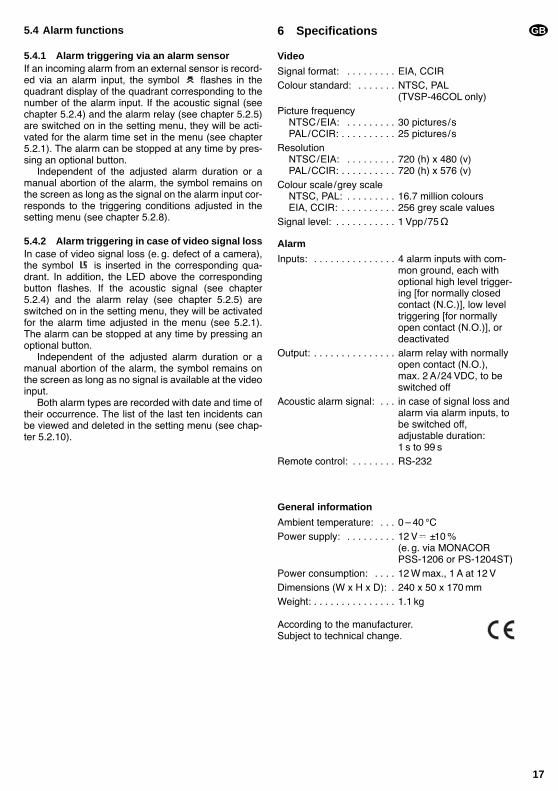
5.4 Alarm functions
5.4.1 Alarm triggering via an alarm sensorIf an incoming alarm from an external sensor is record-ed via an alarm input, the symbol flashes in thequadrant display of the quadrant corresponding to thenumber of the alarm input. If the acoustic signal (seechapter 5.2.4) and the alarm relay (see chapter 5.2.5)are switched on in the setting menu, they will be acti-vated for the alarm time set in the menu (see chapter5.2.1). The alarm can be stopped at any time by pres-sing an optional button.
Independent of the adjusted alarm duration or amanual abortion of the alarm, the symbol remains onthe screen as long as the signal on the alarm input cor-responds to the triggering conditions adjusted in thesetting menu (see chapter 5.2.8).
5.4.2 Alarm triggering in case of video signal lossIn case of video signal loss (e. g. defect of a camera),the symbol is inserted in the corresponding qua-drant. In addition, the LED above the correspondingbutton flashes. If the acoustic signal (see chapter5.2.4) and the alarm relay (see chapter 5.2.5) areswitched on in the setting menu, they will be activatedfor the alarm time adjusted in the menu (see 5.2.1).The alarm can be stopped at any time by pressing anoptional button.
Independent of the adjusted alarm duration or amanual abortion of the alarm, the symbol remains onthe screen as long as no signal is available at the videoinput.
Both alarm types are recorded with date and time oftheir occurrence. The list of the last ten incidents canbe viewed and deleted in the setting menu (see chap-ter 5.2.10).
6 Specifications
Video
Signal format: . . . . . . . . . EIA, CCIRColour standard: . . . . . . . NTSC, PAL
(TVSP-46COL only)Picture frequency
NTSC/EIA: . . . . . . . . . 30 pictures/sPAL/CCIR: . . . . . . . . . . 25 pictures/s
ResolutionNTSC/EIA: . . . . . . . . . 720 (h) x 480 (v)PAL/CCIR: . . . . . . . . . . 720 (h) x 576 (v)
Colour scale/grey scaleNTSC, PAL: . . . . . . . . . 16.7 million coloursEIA, CCIR: . . . . . . . . . . 256 grey scale values
Signal level: . . . . . . . . . . . 1 Vpp/75Ω
Alarm
Inputs: . . . . . . . . . . . . . . . 4 alarm inputs with com-mon ground, each withoptional high level trigger-ing [for normally closedcontact (N.C.)], low leveltriggering [for normallyopen contact (N.O.)], ordeactivated
Output: . . . . . . . . . . . . . . . alarm relay with normallyopen contact (N.O.), max. 2 A/24 VDC, to be switched off
Acoustic alarm signal: . . . in case of signal loss andalarm via alarm inputs, tobe switched off, adjustable duration: 1 s to 99 s
Remote control: . . . . . . . . RS-232
General information
Ambient temperature: . . . 0 40 °CPower supply: . . . . . . . . . 12 V ±10 %
(e. g. via MONACORPSS-1206 or PS-1204ST)
Power consumption: . . . . 12 W max., 1 A at 12 VDimensions (W x H x D): . 240 x 50 x 170 mmWeight: . . . . . . . . . . . . . . . 1.1 kg
According to the manufacturer.Subject to technical change.
GB
17
Ouvrez le présent livret page 3 de manière à visua-liser les éléments et branchements.
Table des matières
1 Eléments et branchements . . . . . . . . . . . . . 19
1.1 Face avant . . . . . . . . . . . . . . . . . . . . . . . . . . . 19
1.2 Face arrière . . . . . . . . . . . . . . . . . . . . . . . . . . 19
2 Conseils d’utilisation et de sécurité . . . . . . 20
3 Possibilités d’utilisation . . . . . . . . . . . . . . . 20
4 Branchements . . . . . . . . . . . . . . . . . . . . . . . 20
4.1 Caméras . . . . . . . . . . . . . . . . . . . . . . . . . . . . . 20
4.2 Moniteur . . . . . . . . . . . . . . . . . . . . . . . . . . . . . 20
4.3 Magnétoscope . . . . . . . . . . . . . . . . . . . . . . . . 20
4.4 Branchements dalarme . . . . . . . . . . . . . . . . . 20
4.5 Télécommande . . . . . . . . . . . . . . . . . . . . . . . . 20
4.6 Alimentation . . . . . . . . . . . . . . . . . . . . . . . . . . 20
5 Fonctionnement . . . . . . . . . . . . . . . . . . . . . . 20
5.1 Modes de fonctionnement . . . . . . . . . . . . . . . 21
5.1.1 Normal . . . . . . . . . . . . . . . . . . . . . . . . . . . . 21
5.1.2 Automatique (AUTO) . . . . . . . . . . . . . . . . . 21
5.1.3 Image fixe (FREEZE) . . . . . . . . . . . . . . . . . 21
5.1.4 Lecture (VCR PLAY) . . . . . . . . . . . . . . . . . . 21
5.2 Modification des réglages de lappareil . . . . . 21
5.2.1 ALARM DURATION durée de lalarme . . 22
5.2.2 BAUD RATE Taux de données pour la télécommande via linterface RS-232 . . . . . 22
5.2.3 DWELL TIME durée daffichage pour la commutation automatique des images . . . . 22
5.2.4 INT AUDIBLE ALARME signal sonore pour lalarme . . . . . . . . . . . . . . . . . . . . . . . . 22
5.2.5 EXT AUDIBLE ALARME relais dalarme pour une alarme externe . . . . . . . . . . . . . . . 22
5.2.6 SET TIME réglage de laffichage de lheure . . . . . . . . . . . . . . . . . . . . . . . . . . 22
5.2.7 DWELL SETUP réglage séquence des images . . . . . . . . . . . . . . . . . . . . . . . . . 22
5.2.8 ALARM POLARITY configuration des entrées dalarme . . . . . . . . . . . . . . . . . . . . . 22
5.2.9 CAMERA TITLE SETUP affichage des noms de caméra . . . . . . . . . . . . . . . . . . . . . 22
5.2.10 EVENT LIST protocole dalarme . . . . . . . 22
5.2.11 VIDEO SET adaptation du signal vidéo (uniquement sur le modèle TVSP-46COL) . 23
5.2.12 SYSTEM RESET réinitialisation de lensemble des réglages . . . . . . . . . . . . 23
5.3 Télécommande . . . . . . . . . . . . . . . . . . . . . . . . 23
5.4 Fonctions alarme . . . . . . . . . . . . . . . . . . . . . . 23
5.4.1 Déclenchement dalarme via un capteur . . . 23
5.4.2 Déclenchement dalarme en cas de perte de signal vidéo . . . . . . . . . . . . . . . 24
6 Caractéristiques techniques . . . . . . . . . . . . 24
F
B
CH
18
1 Eléments et branchements
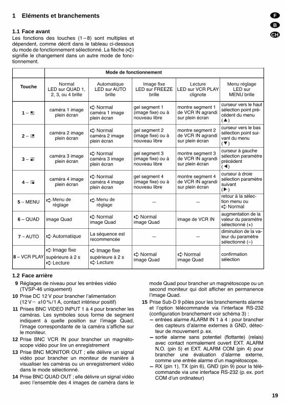
1.1 Face avantLes fonctions des touches (1 8) sont multiples etdépendent, comme décrit dans le tableau ci-dessousdu mode de fonctionnement sélectionné. La flèche ( )signifie le changement dans un autre mode de fonc-tionnement.
1.2 Face arrière9 Réglages de niveau pour les entrées vidéo
(TVSP-46 uniquement)10 Prise DC 12 V pour brancher lalimentation
(12 V ±10 %/1 A, contact intérieur positif)11 Prises BNC VIDEO INPUT 1 à 4 pour brancher les
caméras. Les symboles sous forme de segmentindiquent à quelle position sur limage Quad, limage correspondante de la caméra saffiche surle moniteur.
12 Prise BNC VCR IN pour brancher un magnéto-scope vidéo pour lire un enregistrement
13 Prise BNC MONITOR OUT ; elle délivre un signalvidéo pour brancher un moniteur de manière àvisualiser les caméras ou un enregistrement vidéodans le mode sélectionné.
14 Prise BNC QUAD OUT ; elle délivre un signal vidéoavec lensemble des 4 images de caméra dans le
mode Quad pour brancher un magnétoscope ou unsecond moniteur qui doit afficher en permanencelimage Quad.
15 Prise Sub-D 9 pôles pour les branchements alarmeet loption télécommande via linterface RS-232(configuration branchement voir schéma 3) :- entrées alarme ALARM IN 1 à 4 : pour brancher
des capteurs dalarme externes à GND, détec-teur de mouvement p. ex.
- sortie alarme sans potentiel (flottante) (relais)avec contact normalement ouvert EXT. ALARMN.O. (pin 5) et EXT. ALARM COM (pin 4) pourbrancher une évaluation dalarme externe,comme une entrée alarme dun magnétoscope.
- RX (pin 1), TX (pin 6), GND (pin 9) pour la télé-commande via une interface RS-232 (p. ex. portCOM dun ordinateur)
F
B
CH
19
Touche NormalLED sur QUAD 1,
2, 3, ou 4 brille
AutomatiqueLED sur AUTO
brille
Image fixeLED sur FREEZE
brille
LectureLED sur VCR PLAY
clignote
Menu réglageLED sur
MENU brille
1 caméra 1 image
plein écran
Normalcaméra 1 imageplein écran
gel segment 1(image fixe) ou ànouveau libre
montre segment 1de VCR IN agrandisur plein écran
curseur vers le hautsélection point pré-cédent du menu( )
2 caméra 2 image
plein écran
Normalcaméra 2 imageplein écran
gel segment 2(image fixe) ou ànouveau libre
montre segment 2de VCR IN agrandisur plein écran
curseur vers le bassélection point sui-vant du menu( )
3 caméra 3 image
plein écran
Normalcaméra 3 imageplein écran
gel segment 3(image fixe) ou ànouveau libre
montre segment 3de VCR IN agrandisur plein écran
curseur à gauchesélection paramètreprécédent( )
4 caméra 4 image
plein écran
Normalcaméra 4 imageplein écran
gel segment 4(image fixe) ou ànouveau libre
montre segment 4de VCR IN agrandisur plein écran
curseur à droiesélection paramètresuivant( )
5 MENU Menu de règlage
Menu de règlage
retour à la sélec-tion menu ou Normal
6 QUAD image Quad Normalimage Quad
Normalimage Quad
image de VCR INaugmentation de lavaleur du paramètresélectionné (+)
7 AUTO Automatique La séquence estrecommencée
diminution de la va-leur du paramètresélectionné (-)
8 VCR PLAY Image fixesupérieure à 2 s Lecture
Image fixesupérieure à 2 s Lecture
Normalimage Quad
Normalimage Quad
confirmation sélection
Mode de fonctionnement

2 Conseils d’utilisation et de sécuritéLappareil répond à la norme européenne 89/336/CEE relative à la compatibilité électromagnétique. Cet appareil nest conçu que pour une utilisation en
intérieur. Protégez-le de la chaleur et de lhumidité(température de fonctionnement autorisée : 0 °C 40 °C).
En aucun cas, vous ne devez poser dobjet conte-nant du liquide ou un verre sur lappareil.
Pour le nettoyer, utilisez uniquement un chiffon secet doux, en aucun cas de produits chimiques oudeau.
Nous déclinons toute responsabilité en cas de dom-mage si lappareil est utilisé dans un but autre quecelui pour lequel il a été conçu, sil nest pas correc-tement utilisé ou réparé par une personne habilitée.
Lorsque lappareil est définitivement retiré du mar-ché, vous devez le déposer dans une usine de recy-clage de proximité pour contribuer à son éliminationnon polluante.
3 Possibilités d’utilisationLes processeurs vidéo Quad TVSP-46 (noir & blanc) etTVSP-46COL (couleur) sont conçus pour une utilisa-tion dans des installations de surveillance vidéo. Lesappareils permettent dafficher jusquà 4 images decaméra (noir & blanc au standard EIA ou CCIR ou cou-leur au standard PAL ou NTSC) séparément ou en uneimage divisée en 4 segments (Quad : affichage en seg-ment) et denregistrer simultanément via un magnéto-scope. Sur le TVSP-46, laffichage en segments ne sefait quen noir et blanc. Lors de la lecture, il est possibledafficher un segment dimage comme image pleinécran agrandie. Il est également possible, pendant lalecture dun enregistrement dimage segmentée via leTVSP-46 ou TVSP-46COL, denregistrer les signauxactuels des 4 caméras avec un autre magnétoscope.
Les processeurs vidéo disposent de nombreusesfonctions dalarme. Limage montre ainsi une alarmedéclenchée via les connexions dalarme ou la perte dusignal vidéo en cas de problème de la caméra. De plus,un signal sonore peut attirer lattention sur lincident. Unrelais avec contact NO (normalement ouvert) proposede travailler une alarme avec un appareil externe. Tousles événements sont enregistrés et peuvent être visua-lisés via le menu de réglage. Les appareils disposentdune horloge temps réel, qui continue à fonctionnermême en cas de coupure de tension dalimentation.
4 Branchements
4.1 CamérasIl est possible de brancher jusquà 4 caméras aux pri-ses dentrée VIDEO INPUT 1 à 4 (11).
4.2 MoniteurReliez le moniteur à la prise MONITOR OUT (13).
4.3 MagnétoscopePour enregistrer les images de caméra, sous forme dimage Quad (divisée en 4), reliez lentrée vidéo dumagnétoscope à la prise QUAD OUT (14). Pour la lec-ture de lenregistrement, reliez la sortie vidéo dumagnétoscope à la prise VCR IN (12).
4.4 Branchements d’alarmeIl est possible de brancher des émetteurs dalarmeexternes, p. ex. des capteurs tels que des détecteursde mouvements aux entrées dalarme ALARM IN 1 à 4de la prise ALARM (15), voir configuration schéma 3.Dans ce cas, une entrée ouverte est lue comme HighLevel (niveau élevé), une entrée reliée à GND commeLow Level (bas niveau). On sélectionne dans lemenu de réglage quel niveau doit déclencher unealarme (voir chapitre 5.2.8).
Une sortie alarme flottante (relais) est disponiblecomme contact NO (normalement ouvert) entre lesconnexions EXT. ALARM N.O. (pin 5) et EXT. ALARMCOM (pin 4) ; cette sortie permet de brancher ici len-trée dalarme dun magnétoscope qui en cas dalarmecommute du mode enregistrement longue durée surlenregistrement temps réel.
4.5 TélécommandePour commander à distance le processeur vidéo viaune interface RS-232 (p. ex. port COM dun ordinateurrelié à un programme de terminal), il convient de relierlappareil de contrôle aux bornes TX, RX et GND de laprise ALARM (15). La configuration de branchement etles exemples de connexion avec le port COM 25 pôlesou 9 pôles sont précisés sur le schéma 3.
4.6 AlimentationUne fois les autres appareils branchés, reliez un blocsecteur 12 V /1 A à la prise DC IN (10), p. ex. PSS-1206 ou PS-1204ST de MONACOR. Un adaptateur5,5/2,1 mm (diamètre extérieur/diamètre intérieur) estnécessaire. Veillez à respecter la polarité : le contactintérieur doit être positif.
5 Fonctionnement
Après la connexion de la tension dalimentation, unbref signal sonore est audible. 2 secondes plus tardenviron, le processeur affiche limage Quad du modede fonctionnement Normal.
Lors de la première mise en service, les réglagesde base préprogrammés en usine (voir tableauPréréglages, chapitre 5.2.12), sont actifs. Pour modi-fier ces réglages de base, reportez-vous au chapitre5.2 Modification des réglages de lappareil.
Important ! Afin que lappareil puisse se régler auto-matiquement sur la norme vidéo de lapremière entrée vidéo, le signal doit êtredisponible avant que lappareil ne soitalimenté.
F
B
CH
20
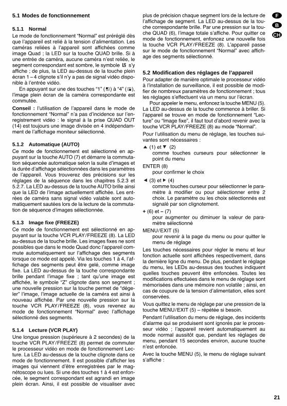
5.1 Modes de fonctionnement
5.1.1 NormalLe mode de fonctionnement Normal est préréglé dèsque lappareil est relié à la tension dalimentation. Lescaméras reliées à lappareil sont affichées commeimage Quad ; la LED sur la touche QUAD brille. Si àune entrée de caméra, aucune caméra nest reliée, lesegment correspondant est sombre, le symbole syaffiche ; de plus, la LED au-dessus de la touche pleinécran 1 4 clignote sil ny a pas de signal vidéo dispo-nible à lentrée vidéo.
En appuyant sur une des touches 1 ( ) à 4 ( ),limage plein écran de la caméra correspondante estcommutée.
Conseil : lutilisation de lappareil dans le mode defonctionnement Normal na pas dincidence sur len-registrement vidéo : le signal à la prise QUAD OUT(14) est toujours une image divisée en 4 indépendam-ment de laffichage moniteur sélectionné.
5.1.2 Automatique (AUTO)Ce mode de fonctionnement est sélectionné en ap-puyant sur la touche AUTO (7) et démarre la commuta-tion séquencée automatique selon la suite dimages etla durée daffichage sélectionnées dans les paramètresde lappareil. Vous trouverez des précisions sur lesréglages de la séquence dans les chapitres 5.2.3 et5.2.7. La LED au-dessus de la touche AUTO brille ainsique la LED de limage actuellement affichée. Les ent-rées de caméra sans signal vidéo valable sont auto-matiquement sautées lors de la lecture de la commuta-tion de séquence dimages sélectionnée.
5.1.3 Image fixe (FREEZE)Ce mode de fonctionnement est sélectionné en ap-puyant sur la touche VCR PLAY/FREEZE (8). La LEDau-dessus de la touche brille. Les images fixes ne sontpossibles que dans le mode Quad donc lappareil com-mute automatiquement sur laffichage des segmentslorsque ce mode est appelé. Via les touches 1 à 4, laf-fichage des segments peut être gelé, comme imagefixe. La LED au-dessus de la touche correspondantebrille pendant limage fixe ; tant quune image estaffichée, le symbole Z clignote dans son segment ;une nouvelle pression sur la touche permet de dége-ler limage, limage actuelle de la caméra est ainsi ànouveau affichée. Par une nouvelle pression sur latouche VCR PLAY/FREEZE (8), vous revenez aumode de fonctionnement Normal avec laffichagesélectionné des segments.
5.1.4 Lecture (VCR PLAY)Une longue pression (supérieure à 2 secondes) de latouche VCR PLAY/FREEZE (8) permet de commuterle processeur vidéo en mode de fonctionnement Lec-ture. La LED au-dessus de la touche clignote dans cemode de fonctionnement. Il est possible dafficher lesimages qui viennent dêtre enregistrées par le mag-nétoscope ou lues. Si une des touches 1 à 4 est enfon-cée, le segment correspondant est agrandi en imageplein écran. Ainsi, il est possible de visualiser avec
plus de précision chaque segment lors de la lecture delaffichage de segment. La LED au-dessus de la tou-che correspondante brille. Par une pression sur la tou-che QUAD (6), limage totale saffiche. Pour quitter cemode de fonctionnement, enfoncez une nouvelle foisla touche VCR PLAY/FREEZE (8). Lappareil passesur le mode de fonctionnement Normal avec affich-age des segments sélectionné.
5.2 Modification des réglages de l’appareilPour adapter de manière optimale le processeur vidéoà linstallation de surveillance, il est possible de modi-fier de nombreux paramètres de fonctionnement ; tousles réglages seffectuent via un menu sur lécran.
Pour appeler le menu, enfoncez la touche MENU (5).La LED au-dessus de la touche commence à briller. Silappareil se trouve en mode de fonctionnement Lec-ture ou Image fixe, il faut tout dabord revenir avec latouche VCR PLAY/FREEZE (8) au mode Normal.Pour lutilisation du menu de réglage, les touches sui-vantes sont nécessaires :
(1) et (2)comme touches curseurs pour sélectionner lepoint du menu
ENTER (8)pour confirmer le choix
(3) et (4)comme touches curseur pour sélectionner le para-mètre à modifier ou pour sélectionner entre 2choix. Le paramètre ou les choix sélectionnés estsignalé par son clignotement.
+ (6) et – (7)pour augmenter ou diminuer la valeur de para-mètre sélectionné
MENU/EXIT (5)pour revenir à la page du menu ou pour quitter lemenu de réglage
Les touches nécessaires pour régler le menu et leurfonction actuelle sont affichées respectivement, dansla dernière ligne du menu. De plus, pendant le réglagedu menu, les LEDs au-dessus des touches indiquentquelles touches peuvent être enfoncées. Toutes lesmodifications effectuées dans le menu de réglage sontmémorisées dans une mémoire non volatile ; ainsi, encas de coupure de la tension dalimentation, elles sontconservées.Vous quittez le menu de réglage par une pression de latouche MENU/EXIT (5) répétée si besoin.Pendant lutilisation du menu de réglage, des incidentsdalarme qui se produisent sont ignorés par le proces-seur vidéo ; lappareil revient automatiquement aumode normal aussitôt que, pendant les réglages demenu, pendant 15 secondes environ, aucune touchenest enfoncée.Avec la touche MENU (5), le menu de réglage suivantsaffiche :
F
B
CH
21
Le point du menu sélectionné est repéré par la flèchesituée dans la marge de gauche.
Avec les touches (1) et (2), sélectionnez un pointdu menu et confirmez avec ENTER (8).
Les différentes points du menu dans le détail :
5.2.1 ALARM DURATION – durée de l’alarmepermet de régler la durée pour laquelle le contactrelais après le déclenchement dune alarme est ferméet le buzzer dalarme émet un signal dalarme dans laplage 1 s à 99 s (dans la mesure où cela a été autorisévia le point 5.2.5 EXT AUDIBLE ALARME ou le point5.2.4 INT AUDIBLE ALARME). En enfonçant une destouches, lalarme peut être terminée plus tôt.
5.2.2 BAUD RATE – Taux de données pour la télé-commande via l’interface RS-232
Pour la commande à distance via linterface série, il estpossible de choisir ici un taux : 1200, 2400, 3600,4800, 9600, 19 200, 57 600 ou 115 200 bit/s.
5.2.3 DWELL TIME – durée d’affichage pour lacommutation automatique des images
indique la durée daffichage de chaque image (1 s à 30 s) en mode automatique
5.2.4 INT AUDIBLE ALARME – signal sonore pourl’alarme
commute [marche (ON) ou arrêt (OFF)] le signaldalarme qui retentit en cas de perte de signal dimageou dalarme, via une entrée dalarme
5.2.5 EXT AUDIBLE ALARME – relais d’alarmepour une alarme externe
détermine si le relais de sortie dalarme répond (ON)ou pas (OFF), en cas de perte de signaux dimages oudalarme, via une entrée dalarme.
5.2.6 SET TIME – réglage de l’affichage de l’heuredétermine si la durée actuelle et la date doivent êtreaffichées et sous quel format. Avec la touche ENTER(8), il est possible de choisir entre :
année/mois/jour/heure/minute/seconde(__y : __m : __d : __h : __m : __s),
jour/mois/année/heure/minute/seconde(__d : __m : __y : __h : __m : __s)
et aucun affichage de temps (TIME DISPLAY OFF) ;lhorloge interne peut être réglée avec les touches
(3), (4), + (6) et – (7).
5.2.7 DWELL SETUP – réglage séquence des ima-ges
détermine quelles images en mode automatique sontaffichées. Avec les touches (1), (2), sélectionnezlimage (CH1, CH2, CH3, CH4 ou QUAD) et avec lestouches (3) et (4), réglez si cette image doit êtrecomprise dans la séquence dimages ou non (ON ouOFF).
5.2.8 ALARM POLARITY – configuration des en-trées d’alarme
détermine quelles entrées dalarme doivent êtreactives et leur réponse sur High Level ou LowLevel. Avec les touches (1) et (2), sélectionnezle numéro de lentrée dalarme (CH1, CH2, CH3 ouCH4) et avec les touches (3) et (4), réglez si len-trée dalarme doit réagir sur HIGH level, LOW level oupas du tout (OFF). Une entrée ouverte sert de niveauHigh ; si lentrée est reliée à la masse (GND), elle estsur Low level.
5.2.9 CAMERA TITLE SETUP – affichage desnoms de caméra
Il est possible dafficher pour chacune des 4 images decaméras un titre de 10 signes de long au plus. Avec lestouches (1) et (2), sélectionnez le numéro de len-trée de caméra (CH1, CH2, CH3, CH4), avec les tou-ches + (6) et – (7), sélectionnez un signe puis avec lestouches (3) et (4), passez à la position suivanteou précédente. Avec la touche ENTER (8), sélec-tionnez si le nom doit être affiché ou non (UNSHOWN).Conseil : les possibilités daffichage de titre decaméra, date, heure ne sont valables que pour uneimage Quad. Dans laffichage plein écran, aucun textenest affiché.
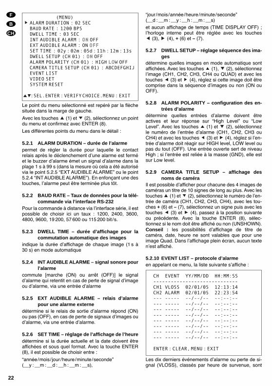
5.2.10 EVENT LIST – protocole d’alarmeen appelant ce menu, la liste suivante saffiche :
Les dix derniers événements dalarme ou perte de si-gnal (VLOSS), classés par heure de survenue, sont
CH EVENT YY/MM/DD HH:MM:SS-----------------------------CH1 VLOSS 02/01/05 12:13:14CH2 ALARM 02/01/05 22:23:54--- ----- --/--/-- --:--:----- ----- --/--/-- --:--:----- ----- --/--/-- --:--:----- ----- --/--/-- --:--:----- ----- --/--/-- --:--:----- ----- --/--/-- --:--:----- ----- --/--/-- --:--:----- ----- --/--/-- --:--:--
ENTER:CLEAR,MENU:EXIT
(MENU)ALARM DURATION : 02 SECBAUD RATE : 1200 BPSDWELL TIME : 03 SECINT AUDIBLE ALARM : ON OFFEXT AUDIBLE ALARM : ON OFFSET TIME : 02y:02m:05d:11h:12m:13sDWELL SETUP (CH 01) : ON OFFALARM POLARITY (CH 01) : HIGH LOW OFFCAMERA TITLE SETUP (CH 01) : ABCDEFGHIJEVENT LISTVIDEO SETSYSTEM RESET
:SEL.ENTER:VERIFYCHOICE.MENU:EXIT
F
B
CH
22
indiqués. Sous CH se trouve le numéro de lentrée decaméra (en cas de perte de signal) ou le numéro delentrée dalarme (en cas dalarme). La date est ici indi-quée, indépendamment du réglage du menu sousSET TIME dans le format année/mois jour. A la fin dela liste, les entrées les plus anciennes sont écrasées àpartir de la première ligne. Pour effacer totalement lesentrées de la liste, enfoncez la touche ENTER (8).
5.2.11 VIDEO SET – adaptation du signal vidéo(uniquement sur le modèle TVSP-46COL)
En appelant ce point du menu, le menu suivant saffi-che :
Il est possible dadapter les signaux vidéo des quatreentrées en luminosité (BRIGHTNESS), contraste (CON-TRAST) et intensité des couleurs (COLOR). Avec lestouches curseur (1), (2), (3) et (4), sélec-tionnez la valeur à régler ; la flèche devant leparamètre indique la sélection en cours. Avec les tou-ches + (6) et – (7), adaptez la valeur dans la plage 0 à 9.
Sur le modèle TVSP-46, les caractéristiques desimages peuvent être corrigées si besoin avec lesréglages de niveau dentrée (9).
5.2.12 SYSTEM RESET – réinitialisation de l’en-semble des réglages
Lensemble des réglages du processeur vidéo à lex-ception de lhorloge temps réel, peuvent être réinitia-lisés simultanément sur les réglages dusine. La fonc-tion est immédiatement exécutée en appuyant sur latouche ENTER (8) pour confirmer le point du menu. Ilny a pas de demande de confirmation.
Attention : lactivation de cette option conduit à laperte irréversible, à lexception de lhorloge temps réel,de tous les réglages effectués par lutilisateur ; ils sontremplacés par les réglages déterminés en usine.
Les réglages dusine sont résumés dans le tableausuivant :
5.3 TélécommandeVia les bornes TX, RX et GND sur la prise ALARM (15),le processeur vidéo peut être entièrement commandéà distance par une transmission série des donnéesselon le format RS-232. Les fonctions des touches decommande sont déclenchées par des codes ASCIIenvoyés (via un programme terminal dun ordinateurp. ex.). Le nombre de bits transmis est 8, le taux peutvarier dans la plage 1200 à 115 200 bits/s (voir cha-pitre 5.2.2). Le tableau suivant présente les codesASCII et leurs correspondances sur les touches :
Conseil : Faites attention à la configuration de bran-chement (voir schéma 3)! La prise Sub-D a sur cetappareil plusieurs fonctions, cette configuration ne cor-respond pas à celle dun cordon standard pour unetransmission série de données!
5.4 Fonctions alarme
5.4.1 Déclenchement d’alarme via un capteurSi via une entrée alarme, une alarme venant dun cap-teur externe est enregistrée, le symbole apparaîten clignotant dans le segment correspondant aunuméro de lentrée dalarme, en mode Quad. Si dansle menu de réglage, le signal sonore (voir chapitre5.2.4) et le relais dalarme (voir chapitre 5.2.5) sontallumés, ils sont activés pour la durée dalarme régléedans le menu (voir chapitre 5.2.1). En enfonçant unedes touches, lalarme peut être terminée plus tôt.
BRIGHTNESS 0 BRIGHTNESS 5CONTRAST 9 CONTRAST 5COLOR 3 COLOR 5
BRIGHTNESS 5 BRIGHTNESS 5CONTRAST 5 CONTRAST 5COLOR 5 COLOR 5
F
B
CH
23
Préréglages
ALARM DURATION 2 s
BAUD RATE 9600 bit /s
DWELL TIME 2 s
EXT AUDIBLE ALARM ON
DWELL SETUP CH1 ... 4 = ON, QUAD = ON
INT AUDIBLE ALARM ON
FORMAT TEMPS ANNEE/MOIS/JOUR
Préréglages
entièrement effacé
VIDEO SET(uniquementTVSP-46COL)
BRIGHTNESS = 5CONTRAST = 5COLOR = 5
CAMERA TITLES CH1, CH2, CH3, CH4
EVENT LIST
ALARM POLARITY CH1 ... 4 = LOW
Codes ASCIIpour symboles
Funcione comme touche
Descriptiondans schéma 1
A AUTO/- 7
Q QUAD/+ 6
M MENU/EXIT 5
VVCR PLAY
(correspond à unelongue pression)
8
F FREEZE/ENTER 8
1 / (CH1) 1
2 / (CH2) 2
3 / (CH3) 3
4 / (CH4) 4
Le symbole reste sur lécran, indépendamment dela durée dalarme réglée ou dun arrêt manuel delalarme, tant que le signal à lentrée dalarme corres-pond aux conditions de déclenchement indiquéesdans le menu (voir chapitre 5.2.8).
5.4.2 Déclenchement d’alarme en cas de perte designal vidéo
Si un signal vidéo disparaît (par exemple en cas dedéfaut dune caméra), le symbole saffiche dans lesegment correspondant. La LED au-dessus de la tou-che correspondante clignote. Si dans le menu deréglage, le signal sonore (voir chapitre 5.2.4) et lerelais dalarme (voir chapitre 5.2.5) sont allumés, ilssont activés pour la durée dalarme réglée dans lemenu (voir chapitre 5.2.1). En appuyant sur une destouches, lalarme peut être terminée plus tôt.
Le symbole reste sur lécran, indépendamment dela durée dalarme réglée ou dun arrêt manuel delalarme, tant que, le signal est manquant à lentréevidéo.
Les deux types dalarme sont mémorisés avec ladate et lheure de lincident. La liste des dix derniersévénements peut être affichée, et effacée dans lemenu de réglage (voir chapitre 5.2.10).
6 Caractéristiques techniques
Vidéo
Format du signal : . . . . EIA, CCIRNorme couleur : . . . . . . NTSC, PAL (uniquement
modèle TVSP-46COL)Fréquence imagesNTSC/EIA : . . . . . . . . . 30 images/sPAL/CCIR : . . . . . . . . . 25 images/s
RésolutionNTSC/EIA : . . . . . . . . . 720 (h) x 480 (v)PAL/CCIR : . . . . . . . . . 720 (h) x 576 (v)
Niveaux des couleurs/niveaux de grisNTSC, PAL : . . . . . . . . 16,7 millions de couleursEIA, CCIR : . . . . . . . . . 256 niveaux de gris
Niveau signaux : . . . . . . . 1 Vcc/75Ω
Alarme
Entrées : . . . . . . . . . . . . . 4 entrés alarme avecmasse commune, auchoix respectivement,déclenchement high level(pour contact N.C.),déclenchement low level(pour contact fermeture/N.O.) ou désactivé
Sortie : . . . . . . . . . . . . . . . relais alarme avec contactN.O.), 2 A/24 V max.déconnectable
Signal sonore dalarme : . en cas de perte de signalet dalarme, via les en-trées dalarme, déconnec-table, durée réglable : 1 sà 99 s
Télécommande : . . . . . . . RS-232
Généralités
Température defonctionnement : . . . . . . . 0 40 °CAlimentation : . . . . . . . . . . 12 V ±10%,
(PSS-1206 ou PS-1204STde MONACOR p. ex.)
Consommation : . . . . . . . 12 W max., 1 A à 12 VDimensions (L x H x P) : . 240 x 50 x 170 mmPoids : . . . . . . . . . . . . . . . 1,1 kg
Daprès les données du constructeur.Tout droit de modification réservé.
F
B
CH
24
Vi preghiamo di aprire completamente la pagina 3.Così vedrete sempre gli elementi di comando e icollegamenti descritti.
Indice
1 Elementi di comando e collegamenti . . . . . 26
1.1 Pannello frontale . . . . . . . . . . . . . . . . . . . . . . 26
1.2 Pannello posteriore . . . . . . . . . . . . . . . . . . . . 26
2 Avvertenze di sicurezza . . . . . . . . . . . . . . . . 27
3 Possibilità d’impiego . . . . . . . . . . . . . . . . . . 27
4 Collegamenti . . . . . . . . . . . . . . . . . . . . . . . . . 27
4.1 Telecamere . . . . . . . . . . . . . . . . . . . . . . . . . . . 27
4.2 Monitor . . . . . . . . . . . . . . . . . . . . . . . . . . . . . . 27
4.3 Videoregistratore . . . . . . . . . . . . . . . . . . . . . . 27
4.4 Contatti dallarme . . . . . . . . . . . . . . . . . . . . . . 27
4.5 Telecomando . . . . . . . . . . . . . . . . . . . . . . . . . 27
4.6 Alimentazione . . . . . . . . . . . . . . . . . . . . . . . . . 27
5 Funzionamento . . . . . . . . . . . . . . . . . . . . . . . 28
5.1 Modi di funzionamento . . . . . . . . . . . . . . . . . . 28
5.1.1 Normale . . . . . . . . . . . . . . . . . . . . . . . . . . . 28
5.1.2 Sequenza automatica (AUTO) . . . . . . . . . . 28
5.1.3 Immagine ferma (FREEZE) . . . . . . . . . . . . 28
5.1.4 Riproduzione (VCR PLAY) . . . . . . . . . . . . . 28
5.2 Modifica delle impostazioni . . . . . . . . . . . . . . 28
5.2.1 ALARM DURATION Durata dellallarme . 29
5.2.2 BAUD RATE per il telecomando via interfaccia RS-232 . . . . . . . . . . . . . . . . . 29
5.2.3 DWELL TIME Durata della permanenza dellimmagine durante la sequenza automatica . 29
5.2.4 INT AUDIBLE ALARM Segnale acustico di allarme . . . . . . . . . . . . . . . . . . . . . . . . . . 29
5.2.5 EXT AUDIBLE ALARM Relè dallarme per allarme esterno . . . . . . . . . . . . . . . . . . . 29
5.2.6 SET TIME Impostazione della visualizzazione di data e ora . . . . . . . . . . . . 29
5.2.7 DWELL SETUP Impostazione dellasequenze delle immagini . . . . . . . . . . . . . . 29
5.2.8 ALARM POLARITY Configurazione degliingressi dallarme . . . . . . . . . . . . . . . . . . . . 29
5.2.9 CAMERA TITLE SETUP Visualizzazionedei nomi delle telecamere . . . . . . . . . . . . . . 29
5.2.10 EVENT LIST Protocollo degli allarmi . . . . 29
5.2.11 VIDEO SET Adattamento del segnale video (solo TVSP-46COL) . . . . . . . . . . . . . 30
5.2.12 SYSTEM RESET Azzeramento di tutte le impostazioni . . . . . . . . . . . . . . . . . . . . . . 30
5.3 Telecomando . . . . . . . . . . . . . . . . . . . . . . . . . 30
5.4 Funzioni di allarme . . . . . . . . . . . . . . . . . . . . . 31
5.4.1 Allarme da sensore esterno . . . . . . . . . . . . 31
5.4.2 Allarme per perdita del segnale video . . . . . 31
6 Dati tecnici . . . . . . . . . . . . . . . . . . . . . . . . . . 31
I
25
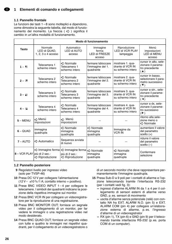
1 Elementi di comando e collegamenti
1.1 Pannello frontaleLe funzioni dei tasti 1 8 sono molteplici e dipendono,come dimostra la seguente tabella, dal modo di funzio-namento del momento. La freccia ( ) significa ilcambio in unaltra modalità di funzionamento.
1.2 Pannello posteriore9 Regolatori livello per ingresso video
(solo per TVSP-46)10 Presa DC 12 V per collegare lalimentazione
(12 V ±10 %/1 A; contatto interno = positivo).11 Prese BNC VIDEO INPUT 1 4 per collegare le
telecamere. I simboli dei quadranti indicano la posi-zione della rispettiva immagine sul monitor.
12 Presa BNC VCR IN per collegare un videoregistra-tore per la riproduzione di una registrazione.
13 Presa BNC MONITOR OUT; fornisce un segnalevideo per il collegamento di un monitor, per farvedere le immagini o una registrazione video nelmodo desiderato.
14 Presa BNC QUAD OUT; fornisce un segnale videocon tutte e quattro le immagini nei rispettivi qua-dranti, per il collegamento di un videoregistratore o
di un secondo monitor che deve rappresentare per-manentemente limmagine quadrupla.
15 Presa Sub-D a 9 poli per i contatti di allarme e lop-zione telecomando tramite linterfaccia RS-232(per i contatti vedi fig. 3):- ingressi dallarme ALARM IN da 1 a 4 per il col-
legamento di sensori esterni di allarme versoGND, p. es. sensori di movimento
- uscita dallarme senza potenziale (relè) con con-tatto NA fra EXT. ALARM N.O. (pin 5) e EXT.ALARM COM (pin 4) per collegare unelabora-zione esterna di allarme, p. es. lingressodallarme di un videoregistrator
- RX (pin 1), TX (pin 6) e GND (pin 9) per il teleco-mando tramite interfaccia RS-232 (p. es. portaCOM di un computer).
I
26
Tasto NormaleLED di QUAD,
1, 2, 3 o 4 acceso
AutomaticoLED di AUTO
acceso
Immagineferma
LED di FREEZEacceso
RiproduzioneLED di VCR PLAY
lampeggia
Menùimpostazioni
LED di MENUacceso
1 Telecamera 1
schermo intero
NormaleTelecamera 1schermo intero
fermare/sbloccarelimmagine del 1.quadrante
mostrare 1. qua-drante di VCR INsu schermo intero
cursor in alto, sele-zionare il parame-tro precedente ( )
2 Telecamera 2
schermo intero
NormaleTelecamera 2schermo intero
fermare/sbloccarelimmagine del 2.quadrante
mostrare 2. qua-drante di VCR INsu schermo intero
cursor in basso,selezionare il para-metro successivo( )
3 Telecamera 3
schermo intero
NormaleTelecamera 3schermo intero
fermare/sbloccarelimmagine del 3.quadrante
mostrare 3. qua-drante di VCR INsu schermo intero
cursor a sin., sele-zionare il parame-tro precedente ( )
4 Telecamera 4
schermo intero
NormaleTelecamera 4schermo intero
fermare/sbloccarelimmagine del 4.quadrante
mostrare 4. qua-drante di VCR INsu schermo intero
cursor a dx, sele-zionare il parame-tro successivo ( )
5 MENU Menùimpostazioni
Menùimpostazioni
ritorno alla sele-zione menù o Normale
6 QUAD immagina quadrupla
Normaleimmagina quadrupla
Normaleimmagina quadrupla
Immagine da VCR IN
aumentare il valoredel parametroscelto (+)
7 AUTO Automatico Sequenza avviatadi nuovo
ridurre il valore del parametroscelto (-)
8 VCR PLAY Immagine fermapiù di 2 sec.: Riproduzione
Immagine fermapiù di 2 sec.: Riproduzione
Normaleimmagina quadrupla
Normaleimmagina quadrupla
Confermare selezione
Modo di funzionamento

2 Avvertenze di sicurezzaQuestapparecchio corrisponde alla direttiva CE89/336/CEE sulla compatibilità elettromagnetica. Usare lo strumento solo allinterno di locali. Proteg-
gerlo dallumidità e dal calore (temperatura dim-piego ammessa fra 0 e 40 °C).
Non poggiare sullapparecchio dei contenitori pienidi liquidi, p. es. bicchieri.
Per la pulizia usare solo un panno asciutto; nonimpiegare in nessun caso prodotti chimici o acqua.
Nel caso di uso improprio, di collegamenti sbagliati odi riparazione scorretta non si assume nessuna re-sponsabilità per eventuali danni.
Se si desidera eliminare lapparecchio definitiva-mente, consegnarlo per lo smaltimento ad unistitu-zione locale per il riciclaggio.
3 Possibilità d’impiegoI processori video quad TVSP-46 (b/n) e TVSP-46COL (a colori) sono stati realizzati per limpiego inimpianti di sorveglianza video. È possibile rappresen-tare o registrare con un videoregistratore fino a quattroimmagini (b/n nei formati EIA o CCIR oppure a coloricon gli standard PAL o NTSC), singolarmente o tutteinsieme (a quadranti). Nel TVSP-46, la rappresenta-zione a quadranti è solo in b/n. Durante la riprodu-zione esiste la possibilità di ingrandire limmagine di unquadrante a schermo intero. Durante la riproduzione diuna registrazione quad con il TVSP-46 o con il TVSP-46COL è altresì possibile registrare i quattro segnalivideo con un altro videoregistratore.
I videoregistratori sono equipaggiati con numerosefunzioni d allarme. Un allarme scattato attraverso icontatti dallarme oppure dovuto alla perdita di un se-gnale video per disfunzione di una telecamera pos-sono essere segnalati da un segnale acustico. Un relècon contatto NA offre la possibilità di gestire lallarmecon un apparecchio esterno. Tutti gli eventi vengonoprotocollati e possono essere visualizzati per mezzodel menù di impostazione. Gli apparecchi dispongonodi un orologio a tempo reale che continua a funzionareanche se viene a cadere la tensione di alimentazione.
4 Collegamenti
4.1 TelecamereAlle prese dingresso VIDEO INPUT 1 a 4 (11) si pos-sono collegare fino a 4 telecamere.
4.2 MonitorCollegare il monitor con la presa MONITOR OUT (13).
4.3 VideoregistratorePer registrare le immagini delle telecamere comeimmagine quadrupla, collegare lingresso video delvideoregistratore con la presa QUAD OUT (14). Per lariproduzione della registrazione collegare luscitavideo del videoregistratore con la presa VCR IN (12).
4.4 Contatti d’allarmeAgli ingressi per allarmi ALARM IN 1 a 4 della presaALARM (15) [per i contatti vedere fig. 3] si possono col-legare dei segnalatori esterni, p. es. dei sensori di movi-mento. Un ingresso aperto viene letto come livello high,un ingresso collegato con GND come livello low. Illivello che deve fare scattare lallarme può essere sele-zionato con il menù delle impostazioni (vedi cap. 5.2.8).
Unuscita dallarme senza potenziale (relè) è dispo-nibile come contatto NA fra i contatti EXT. ALARM N.O.(pin 5) e EXT. ALARM COM (pin 4). Questuscita puòservire p. es. per collegare lingresso dallarme di unvideoregistratore il quale, nel caso di allarme, passada registrazione a lunga durata a registrazione atempo reale.
4.5 TelecomandoPer telecomandare il videoprocessore attraverso uninterfaccia RS-232 (p. es. tramite la porta COM di uncomputer in collegamento con un programma per ter-minali), collegare lapparecchio master con i contattiTX, RX e GND della presa ALARM (15). I contatti edegli esempi di collegamento con un connettore COMa 25 o 9 poli sono illustrati in fig. 3.
4.6 AlimentazioneDopo aver eseguito tutti i collegamenti dei vari appa-recchi, collegare un alimentatore 12 V /1 A (p. es.PSS-1206, o PS-1204ST della MONACOR) con lapresa DC IN (10). È richiesto un connettore per piccoletensioni 5,5/2,1 mm (diametro esterno/interno). Fareattenzione alla corretta polarità: il contatto interno deveessere positivo.
I
27
5 Funzionamento
Dopo aver applicato la tensione dalimentazione, sisente un breve segnale acustico. Dopo 2 sec. circa, ilprocessore mostra limmagine quadrupla nel modo difunzionamento Normale.
Alla prima messa in funzione sono attive leimpostazioni di default del costruttore (vedi tabellaPreimpostazioni del capitolo 5.2.12). Per cambiarleleggere il capitolo 5.2 Modifica delle impostazioni.
5.1 Modi di funzionamento
5.1.1 NormaleIl modo di funzionamento Normale è attivato nonappena si applica la tensione di esercizio. Le teleca-mere collegate vengono rappresentate con immaginidivisi fra i quattro quadranti. Il LED vicino al tasto QUADè acceso. Se un canale video è senza telecamera, ilrelativo quadrante rimane scuro e si vede il simbolo .Se manca il segnale video di un ingresso video, lam-peggia inoltre il LED sopra il relativo tasto 1 4.
Premendo uno dei tasto da 1 a 4 , si passaalla rappresentazione a schermo intero della relativatelecamera.
N.B.: Il funzionamento nella modalità Normale noninfluisce sulla registrazione video. Il segnale al con-tatto QUAD OUT (14) è sempre unimmagine quadru-pla, indipendentemente dalla rappresentazione sulmonitor.
5.1.2 Sequenza automatica (AUTO)Questa modalità viene selezionata premendo il tastoAUTO (7); la successione automatica parte secondo lasequenza e la durata previste dalle impostazioni. Perulteriori particolari leggere i capitoli 5.2.3 e 5.2.7. IlLED sopra il tasto AUTO rimane acceso insieme alLED dellimmagine attuale. I canali senza segnalevideo vengono automaticamente saltati durante la suc-cessione prescelta.
5.1.3 Immagine ferma (FREEZE)Per selezionare questa modalità premere il tasto VCRPLAY/FREEZE (8). Il LED sopra il tasto si accende. Leimmagini fermi sono possibili solo con la rappresenta-zione a quadranti; pertanto la scelta di questa modalitàdetermina automaticamente il passaggio alla rappre-sentazione quad. A questo punto, con i tasti 1 4 sipossono bloccare le immagini dei quadranti e il LEDsopra il relativo tasto si accende. Finché limmaginerimane ferma, nel suo quadrante lampeggia il simboloZ. Se si preme di nuovo questo tasto, limmagineviene sbloccata e si vede nuovamente limmagineattuale. Con una nuova pressione del tasto VCR
PLAY/FREEZE (8), lapparecchio ritorna alla modalitàNormale con la rappresentazione a quadranti.
5.1.4 Riproduzione (VCR PLAY)Premendo il tasto VCR PLAY/FREEZE (8) per un certotempo (> 2 sec.), il videoprocessore passa alla moda-lità di riproduzione. Lampeggia il LED sopra il tasto. Sipossono vedere le immagini che il videoregistratore staregistrando o riproducendo. Se si preme uno dei tasti1 4, il relativo quadrante diventa unimmagine aschermo intero. In questo modo è possibile osservaremeglio certi quadranti durante la rappresentazionequad. Il LED sopra il relativo tasto è acceso. Premendoil tasto QUAD (6) si vede limmagine intera. Per uscitada questa modalità premere di nuovo il tasto VCRPLAY/FREEZE (8). Lapparecchio torna alla modalitàNormale con la rappresentazione a quadranti.
5.2 Modifica delle impostazioniPer adattare il videoprocessore in maniera ottimaleallimpianto di sorveglianza si possono modificaremolti parametri. Tutte le impostazioni vengono ese-guite attraverso il menù sul monitor.
Per chiamare tale menù premere il tasto MENU (5).Il LED sopra il tasto si accende. Se lapparecchio sitrova nella modalità Riproduzione o Immagineferma, si deve prima tornare nella modalità Normalepremendo il tasto VCR PLAY/FREEZE (8).
Nel menù delle impostazioni ci si muove con i seguentitasti:
(1) e (2)tasti per selezionare la voce del menù.
ENTER (8)per confermare la selezione
(3) e (4)per selezionare il parametro da modificare o perscegliere unalternativa. Il parametro o lalternativaselezionati vengono segnalati lampeggiando.
+ (6) e – (7)per aumentare o ridurre il valore selezionato delparametro.
MENU/EXIT (5)per ritornare alla pagina del menù oppure perabbandonare il menù delle impostazioni.
I tasti necessari per le impostazioni nel menù nonchéla loro funziona momentanea vengono visualizzatisulla barra inferiore dello schermo. Durante limposta-zione, i LED sopra i tasti indicano quali tasti possonoessere premuti. Tutte le impostazioni effettuate nelmenù delle impostazioni vengono memorizzate inmodo non volatile e rimangono valide anche se la ten-sione di alimentazione viene a mancare.
Per lasciare il menù delle impostazioni premere (even-tualmente più volte) il tasto MENU/EXIT (5).
Gli allarmi che scattano durante limpostazione ven-gono ignorati dal videoprocessore. Perciò lappa-recchio torna automaticamente alla modalità normalese durante le impostazioni non si preme nessun tastoper 15 secondi ca.
Importante! Per permettere allapparecchio di adat-tarsi automaticamente alla norma videodel primo ingresso video, il segnaledeve essere presente a tale ingressoprima che venga fornita la tensione dialimentazione.
I
28
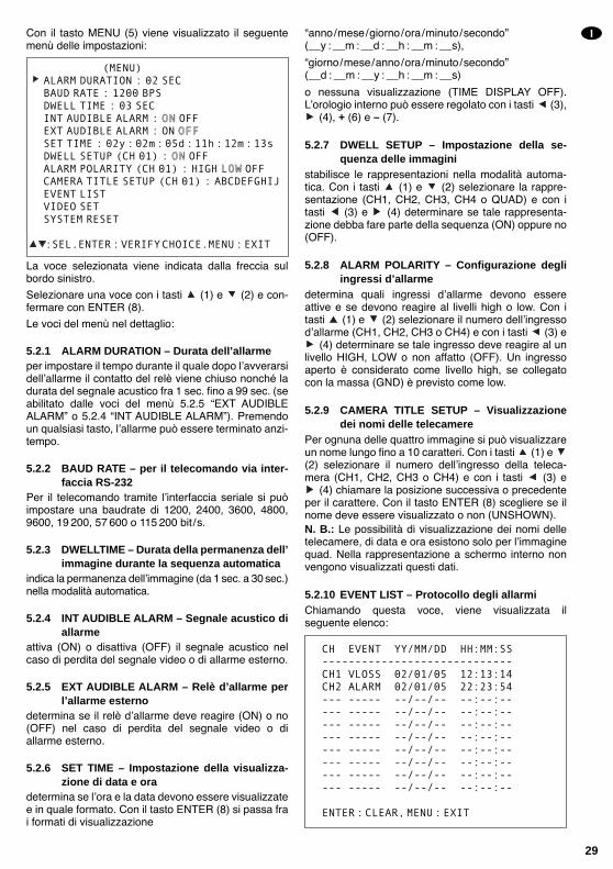
Con il tasto MENU (5) viene visualizzato il seguentemenù delle impostazioni:
La voce selezionata viene indicata dalla freccia sulbordo sinistro.
Selezionare una voce con i tasti (1) e (2) e con-fermare con ENTER (8).
Le voci del menù nel dettaglio:
5.2.1 ALARM DURATION – Durata dell’allarmeper impostare il tempo durante il quale dopo lavverarsidellallarme il contatto del relè viene chiuso nonché ladurata del segnale acustico fra 1 sec. fino a 99 sec. (seabilitato dalle voci del menù 5.2.5 EXT AUDIBLEALARM o 5.2.4 INT AUDIBLE ALARM). Premendoun qualsiasi tasto, lallarme può essere terminato anzi-tempo.
5.2.2 BAUD RATE – per il telecomando via inter-faccia RS-232
Per il telecomando tramite linterfaccia seriale si puòimpostare una baudrate di 1200, 2400, 3600, 4800,9600, 19 200, 57 600 o 115 200 bit/s.
5.2.3 DWELLTIME – Durata della permanenza dell’immagine durante la sequenza automatica
indica la permanenza dellimmagine (da 1 sec. a 30 sec.)nella modalità automatica.
5.2.4 INT AUDIBLE ALARM – Segnale acustico diallarme
attiva (ON) o disattiva (OFF) il segnale acustico nelcaso di perdita del segnale video o di allarme esterno.
5.2.5 EXT AUDIBLE ALARM – Relè d’allarme perl’allarme esterno
determina se il relè dallarme deve reagire (ON) o no(OFF) nel caso di perdita del segnale video o diallarme esterno.
5.2.6 SET TIME – Impostazione della visualizza-zione di data e ora
determina se lora e la data devono essere visualizzatee in quale formato. Con il tasto ENTER (8) si passa frai formati di visualizzazione
anno/mese/giorno/ora/minuto/secondo(__y : __m : __d : __h : __m : __s),
giorno/mese/anno/ora/minuto/secondo(__d : __m : __y : __h : __m : __s)
o nessuna visualizzazione (TIME DISPLAY OFF).Lorologio interno può essere regolato con i tasti (3),
(4), + (6) e – (7).
5.2.7 DWELL SETUP – Impostazione della se-quenza delle immagini
stabilisce le rappresentazioni nella modalità automa-tica. Con i tasti (1) e (2) selezionare la rappre-sentazione (CH1, CH2, CH3, CH4 o QUAD) e con itasti (3) e (4) determinare se tale rappresenta-zione debba fare parte della sequenza (ON) oppure no(OFF).
5.2.8 ALARM POLARITY – Configurazione degliingressi d’allarme
determina quali ingressi dallarme devono essereattive e se devono reagire al livelli high o low. Con itasti (1) e (2) selezionare il numero dellingressodallarme (CH1, CH2, CH3 o CH4) e con i tasti (3) e
(4) determinare se tale ingresso deve reagire al unlivello HIGH, LOW o non affatto (OFF). Un ingressoaperto è considerato come livello high, se collegatocon la massa (GND) è previsto come low.
5.2.9 CAMERA TITLE SETUP – Visualizzazionedei nomi delle telecamere
Per ognuna delle quattro immagine si può visualizzareun nome lungo fino a 10 caratteri. Con i tasti (1) e (2) selezionare il numero dellingresso della teleca-mera (CH1, CH2, CH3 o CH4) e con i tasti (3) e
(4) chiamare la posizione successiva o precedenteper il carattere. Con il tasto ENTER (8) scegliere se ilnome deve essere visualizzato o non (UNSHOWN).N. B.: Le possibilità di visualizzazione dei nomi delletelecamere, di data e ora esistono solo per limmaginequad. Nella rappresentazione a schermo interno nonvengono visualizzati questi dati.
5.2.10 EVENT LIST – Protocollo degli allarmiChiamando questa voce, viene visualizzata ilseguente elenco:
CH EVENT YY/MM/DD HH:MM:SS-----------------------------CH1 VLOSS 02/01/05 12:13:14CH2 ALARM 02/01/05 22:23:54--- ----- --/--/-- --:--:----- ----- --/--/-- --:--:----- ----- --/--/-- --:--:----- ----- --/--/-- --:--:----- ----- --/--/-- --:--:----- ----- --/--/-- --:--:----- ----- --/--/-- --:--:----- ----- --/--/-- --:--:--
ENTER:CLEAR,MENU:EXIT
(MENU)ALARM DURATION : 02 SECBAUD RATE : 1200 BPSDWELL TIME : 03 SECINT AUDIBLE ALARM : ON OFFEXT AUDIBLE ALARM : ON OFFSET TIME : 02y:02m:05d:11h:12m:13sDWELL SETUP (CH 01) : ON OFFALARM POLARITY (CH 01) : HIGH LOW OFFCAMERA TITLE SETUP (CH 01) : ABCDEFGHIJEVENT LISTVIDEO SETSYSTEM RESET
:SEL.ENTER:VERIFYCHOICE.MENU:EXIT
I
29
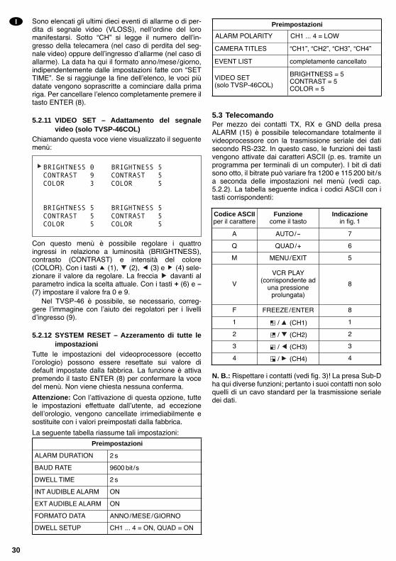
Sono elencati gli ultimi dieci eventi di allarme o di per-dita di segnale video (VLOSS), nellordine del loromanifestarsi. Sotto CH si legge il numero dellin-gresso della telecamera (nel caso di perdita del seg-nale video) oppure dellingresso dallarme (nel caso diallarme). La data ha qui il formato anno/mese/giorno,indipendentemente dalle impostazioni fatte con SETTIME. Se si raggiunge la fine dellelenco, le voci piùdatate vengono soprascritte a cominciare dalla primariga. Per cancellare lelenco completamente premere iltasto ENTER (8).
5.2.11 VIDEO SET – Adattamento del segnalevideo (solo TVSP-46COL)
Chiamando questa voce viene visualizzato il seguentemenù:
Con questo menù è possibile regolare i quattroingressi in relazione a luminosità (BRIGHTNESS),contrasto (CONTRAST) e intensità del colore(COLOR). Con i tasti (1), (2), (3) e (4) sele-zionare il valore da regolare. La freccia davanti alparametro indica la scelta attuale. Con i tasti + (6) e –(7) impostare il valore fra 0 e 9.
Nel TVSP-46 è possibile, se necessario, correg-gere limmagine con laiuto dei regolatori per i livellidingresso (9).
5.2.12 SYSTEM RESET – Azzeramento di tutte leimpostazioni
Tutte le impostazioni del videoprocessore (eccettolorologio) possono essere resettate sui valore didefault impostate dalla fabbrica. La funzione è attivapremendo il tasto ENTER (8) per confermare la vocedel menù. Non viene chiesta nessuna conferma.
Attenzione: Con lattivazione di questa opzione, tuttele impostazioni effettuate dallutente, ad eccezionedellorologio, vengono cancellate irrimediabilmente esostituite con i valori preimpostati dalla fabbrica.
La seguente tabella riassume tali impostazioni:
5.3 TelecomandoPer mezzo dei contatti TX, RX e GND della presaALARM (15) è possibile telecomandare totalmente ilvideoprocessore con la trasmissione seriale dei datisecondo RS-232. In questo caso, le funzioni dei tastivengono attivate dai caratteri ASCII (p. es. tramite unprogramma per terminali di un computer). I bit di datisono otto, il bitrate può variare fra 1200 e 115 200 bit/sa seconda delle impostazioni nel menù (vedi cap.5.2.2). La tabella seguente indica i codici ASCII con itasti corrispondenti:
N. B.: Rispettare i contatti (vedi fig. 3)! La presa Sub-Dha qui diverse funzioni; pertanto i suoi contatti non soloquelli di un cavo standard per la trasmissione serialedei dati.
BRIGHTNESS 0 BRIGHTNESS 5CONTRAST 9 CONTRAST 5COLOR 3 COLOR 5
BRIGHTNESS 5 BRIGHTNESS 5CONTRAST 5 CONTRAST 5COLOR 5 COLOR 5
I
30
Codice ASCIIper il carattere
Funzione come il tasto
Indicazionein fig. 1
A AUTO/- 7
Q QUAD/+ 6
M MENU/EXIT 5
V
VCR PLAY(corrispondente ad
una pressione prolungata)
8
F FREEZE/ENTER 8
1 / (CH1) 1
2 / (CH2) 2
3 / (CH3) 3
4 / (CH4) 4
Preimpostazioni
ALARM DURATION 2 s
BAUD RATE 9600 bit /s
DWELL TIME 2 s
EXT AUDIBLE ALARM ON
DWELL SETUP CH1 ... 4 = ON, QUAD = ON
INT AUDIBLE ALARM ON
FORMATO DATA ANNO/MESE/GIORNO
Preimpostazioni
completamente cancellato
VIDEO SET(solo TVSP-46COL)
BRIGHTNESS = 5CONTRAST = 5COLOR = 5
CAMERA TITLES CH1, CH2, CH3, CH4
EVENT LIST
ALARM POLARITY CH1 ... 4 = LOW

5.4 Funzioni d’allarme
5.4.1 Allarme da sensore esternoSe un ingresso dallarme registra un allarme esterno,nel quadrante corrispondente al numero del relativoingresso viene visualizzato il simbolo lampeggiante
. Se nel menù delle impostazioni sono abilitati ilsegnale acustico (vedi cap. 5.2.4) e il relè dallarme(vedi cap. 5.2.5), saranno attivati per la durata previstanel menù (vedi cap. 5.2.1). Premendo un qualsiasitasto, lallarme può essere terminato anzitempo.
Il simbolo di allarme, indipendentemente dalladurata impostata per lallarme o dallinterruzionemanuale dellallarme, rimane visibile sullo schermo fin-ché il segnale presente allingresso dallarme corri-sponde alle condizioni dallarme previste nel menùdelle impostazioni (vedi. cap. 5.2.8).
5.4.2 Allarme per perdita del segnale videoSe un segnale video viene a mancare (p. es. per unatelecamera difettosa), sul relativo quadrante vienevisualizzato il simbolo . Inoltre lampeggia il LEDsopra il relativo tasto. Se nel menù delle impostazionisono abilitati il segnale acustico (vedi cap. 5.2.4) e ilrelè dallarme (vedi cap. 5.2.5), saranno attivati per ladurata prevista nel menù (vedi cap. 5.2.1). Premendoun qualsiasi tasto, lallarme può essere terminato anzi-tempo.
Il simbolo di allarme, indipendentemente dalladurata impostata per lallarme o dallinterruzione ma-nuale dellallarme, rimane visibile sullo schermo finchéil segnale manca allingresso dallarme.
Entrambi i tipi di allarme vengono protocollati condata e ora del loro manifestarsi. Lelenco degli ultimidieci eventi può essere visionato e cancellato nelmenù delle impostazioni (vedi cap. 5.2.10).
6 Dati tecnici
Video
Formato segnale: . . . . . . . EIA, CCIRNorma colore: . . . . . . . . . NTSC, PAL
(solo TVSP-46COL)Frequenza immagine
NTSC/EIA: . . . . . . . . . 30 immagini/sec.PAL/CCIR: . . . . . . . . . . 25 immagini/sec.
Risoluzione:NTSC/EIA: . . . . . . . . . 720 (h) x 480 (v)PAL/CCIR: . . . . . . . . . . 720 (h) x 576 (v)
Livelli colore/del grigioNTSC, PAL: . . . . . . . . . 16,7 milioni di coloriEIA, CCIR: . . . . . . . . . . 256 livelli del grigio
Livello segnale: . . . . . . . . 1 Vpp/75Ω
Allarme
Ingressi: . . . . . . . . . . . . . . 4 ingressi dallarme conmassa comune, a sceltaper livelli high (per con-tatto NC), low (per con-tatto NA) oppure disattivati
Uscita: . . . . . . . . . . . . . . . relè dallarme con contattoNA, max. 2 A/24 V , disattivabile
Segnale acustico di allarme: . . . . . . . . . . . . in caso di perdita del se-
gnale video e di allarmeesterno tramite ingressidallarme, disattivabile,durata regolabile fra 1 sec.a 99 sec.
Telecomando: . . . . . . . . . RS-232
Dati generali
Temperatura dimpiego: . . 0 40°CAlimentazione: . . . . . . . . . 12V ±10 %
(p. es. con PSS-1206 oPS-1204ST dellaMONACOR)
Potenza assorbita: . . . . . . 12 Wmax., 1A a 12VDimensioni (l x h x p): . . . 240 x 50 x 170mmPeso: . . . . . . . . . . . . . . . . 1,1kg
Dati forniti dal costruttore.Con riserva di modifiche tecniche.
I
31
Vouw bladzijde 3 helemaal open, zodat u steedseen overzicht hebt van de bedieningselementen ende aansluitingen.
Inhoud
1 Bedieningselementen en aansluitingen . . . 33
1.1 Frontpaneel . . . . . . . . . . . . . . . . . . . . . . . . . . 33
1.2 Achterzijde van het toestel . . . . . . . . . . . . . . . 33
2 Veiligheidsvoorschriften . . . . . . . . . . . . . . . 34
3 Toepassingen . . . . . . . . . . . . . . . . . . . . . . . . 34
4 Het toestel aansluiten . . . . . . . . . . . . . . . . . 34
4.1 Cameras . . . . . . . . . . . . . . . . . . . . . . . . . . . . 34
4.2 Monitor . . . . . . . . . . . . . . . . . . . . . . . . . . . . . . 34
4.3 Videorecorder . . . . . . . . . . . . . . . . . . . . . . . . . 34
4.4 Alarmverbindingen . . . . . . . . . . . . . . . . . . . . . 34
4.5 Afstandsbediening . . . . . . . . . . . . . . . . . . . . . 34
4.6 Voedingsspanning . . . . . . . . . . . . . . . . . . . . . 34
5 Werking . . . . . . . . . . . . . . . . . . . . . . . . . . . . . 35
5.1 Functies . . . . . . . . . . . . . . . . . . . . . . . . . . . . . 35
5.1.1 Normaal . . . . . . . . . . . . . . . . . . . . . . . . . . . 35
5.1.2 Automatisch (AUTO) . . . . . . . . . . . . . . . . . . 35
5.1.3 Stilstaand beeld (FREEZE) . . . . . . . . . . . . . 35
5.1.4 Weergave (VCR PLAY) . . . . . . . . . . . . . . . . 35
5.2 De toestelinstellingen wijzigen . . . . . . . . . . . . 35
5.2.1 ALARM DURATION Alarmduur . . . . . . . . 36
5.2.2 BAUD RATE Doorvoercapaciteit voor deafstandsbediening via RS-232-interface . . . 36
5.2.3 DWELL TIME Verblijftijd voor de automatische beelddoorschakeling . . . . . . . 36
5.2.4 INT AUDIBLE ALARM Geluidssignaal voor het alarm . . . . . . . . . . . . . . . . . . . . . . . 36
5.2.5 EXT AUDIBLE ALARM Alarmrelais voorextern alarm . . . . . . . . . . . . . . . . . . . . . . . . 36
5.2.6 SET TIME Instelling van de tijdinvoeging . 36
5.2.7 DWELL SETUP Instelling van de beeldsequentie . . . . . . . . . . . . . . . . . . . . 36
5.2.8 ALARM POLARITY Configuratie van de alarmingangen . . . . . . . . . . . . . . . . . . . . 36
5.2.9 CAMERA TITLE SETUP Invoeging van cameranamen . . . . . . . . . . . . . . . . . . . 36
5.2.10 EVENT LIST Alarmprotocol . . . . . . . . . . . 37
5.2.11 VIDEO SET Aanpassing van het videosignaal (enkel TVSP-46COL) . . . . . . . 37
5.2.12 SYSTEM RESET Resetten van alle toestelinstellingen . . . . . . . . . . . . . . . . . 37
5.3 Afstandsbediening . . . . . . . . . . . . . . . . . . . . . 37
5.4 Alarmfuncties . . . . . . . . . . . . . . . . . . . . . . . . . 38
5.4.1 Activering van het alarm door een alarmsensor . . . . . . . . . . . . . . . . . . . . . 38
5.4.2 Activering van het alarm bij videoverlies . . . 38
6 Technische gegevens . . . . . . . . . . . . . . . . . 38
NL
B
32
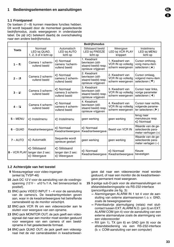
NL
B
33
1 Bedieningselementen en aansluitingen
1.1 FrontpaneelDe toetsen (1 8) kunnen meerdere functies hebben.Dit wordt bepaald door de momenteel geselecteerdebedrijfsmodus, zoals weergegeven in onderstaandetabel. De pijl ( ) betekent daarbij de overschakelingnaar een andere bedrijfsmodus.
1.2 Achterzijde van het toestel9 Niveauregelaar voor video-ingangen
(enkel bij TVSP-46)10 Jack DC 12 V voor de aansluiting van de voedings-
spanning (12 V ±10 %/1 A, het binnencontact ispositief).
11 BNC-jacks VIDEO INPUT 1 4 voor de aansluitingvan de cameras. De kwadrantsymbolen gevenaan, waar in de kwadrantweergave het betreffendecamerabeeld op de monitor verschijnt.
12 BNC-jack VCR IN om een videorecorder aan tesluiten voor weergave van een opname.
13 BNC-jack MONITOR OUT; de jack geeft een video-signaal dat naar een monitor moet worden gestuurdvoor weergave van een camera of een beeld-opname in het geselecteerde formaat.
14 BNC-jack QUAD OUT; de jack geeft een videosig-naal met de vier camerabeelden in kwadrantweer-
gave dat naar een videorecorder moet wordengestuurd, of naar een monitor die de kwadrantweer-gave permanent moet weergeven.
15 9-polige sub-D-jack voor de alarmaansluitingen enafstandsbedieningsoptie via RS-232-interface(penconfiguratie zie fig. 3):- Alarmingangen ALARM IN 1 tot 4 voor de aan-
sluiting van externe alarmsensoren t. o. v. GND,zoals de bewegingssensor
- Potentiaalvrije alarmuitgang (relais) met sluit-contact tussen EXT. ALARM N.O. (pin 5) en EXT.ALARM COM (pin 4) voor de aansluiting van eenexterne alarmanalyse zoals de alarmingang vaneen videorecorder
- RX (pin 1), TX (pin 6) en GND (pin 9) voor deafstandsbediening via een RS-232-interface(b. v. COM-aansluiting van een computer)
Bedrijfsmodus
Toets NormaalLED bij QUAD,
1, 2, 3 of 4 licht op
AutomatischLED bij AUTO
licht op
Stilstaand beeldLED bij FREEZE
licht op
WeergaveLED bij VCR PLAY
knippert
InstelmenuLED bij MENU
licht op
1 Camera 1 scherm-
vullend beeld
Normaalcamera 1scherm-vullend beeld
1. Kwadrantbevriezen (stil-staand beeld) resp.opnieuw vrijgeven
1. Kwadrant vanVCR IN op volledigscherm weergeven
Cursor omhoog, vorig menu-itemselecteren ( )
2 Camera 2 scherm-
vullend beeld
Normaalcamera 2 scherm-vullend beeld
2. Kwadrantbevriezen (stil-staand beeld) resp.opnieuw vrijgeven
2. Kwadrant vanVCR IN op volledigscherm weergeven
Cursor omlaag,volgend menu-itemselecteren ( )
3 Camera 3 scherm-
vullend beeld
Normaalcamera 3 scherm-vullend beeld
3. Kwadrantbevriezen (stil-staand beeld) resp.opnieuw vrijgeven
3. Kwadrant vanVCR IN op volledigscherm weergeven
Cursor naar links,vorige parameterselecteren ( )
4 Camera 4 scherm-
vullend beeld
Normaalcamera 4 scherm-vullend beeld
4. Kwadrantbevriezen (stil-staand beeld) resp.opnieuw vrijgeven
4. Kwadrant vanVCR IN op volledigscherm weergeven
Cursor naar rechts, volgende parame-ter selecteren ( )
5 MENU Instelmenu Instelmenu geen werking geen werkingterug naar menukeuze resp. Normaal
6 QUAD Kwadrantweergave NormaalKwadrantweergave
NormaalKwadrantweergave
Beeld van VCR INWaarde van de ge-selecteerde para-meter verhogen (+)
7 AUTO Automatik Sequentie wordtopnieuw gestart geen werking geen werking
Waarde van de ge-selecteerde para-meter verlagen (-)
8 VCR PLAY Stilstaandlanger dan 2 sec: Weergave
Stilstaandlanger dan 2 sec: Weergave
NormaalKwadrantweergave
NormaalKwadrantweergave
Keuze bevestigen

2 VeiligheidsvoorschriftenHet toestel is in overeenstemming met de EU-richtlijn89/336/EWG voor elektromagnetische compatibiliteit. Het toestel is enkel geschikt voor gebruik binnens-
huis. Vermijd uitzonderlijk warme plaatsen en plaat-sen met een hoge vochtigheid (toegestaan omge-vingstemperatuurbereik: 0 40 °C).
Plaats geen bekers met vloeistof zoals drinkglazenetc. op het toestel.
Gebruik voor de reiniging uitsluitend een droge,zachte doek. Gebruik in geen geval chemicaliën ofwater.
In geval van ongeoorloofd of verkeerd gebruik of vanherstelling door een niet-gekwalificeerd persoon ver-valt de garantie bij eventuele schade.
Wanneer het toestel definitief uit bedrijf genomenwordt, bezorg het dan voor milieuvriendelijke ver-werking aan een plaatselijk recyclagebedrijf.
3 ToepassingenDe video-quadprocessoren TVSP-46 (zwart/wit) enTVSP-46COL (kleur) zijn ontworpen voor gebruik invideobewakingssystemen. Met de toestellen kan u totvier camerabeelden (z/w in EIA- of CCIR-standaard ofkleur in PAL- of NTSC-standaard) afzonderlijk of alseen scherm met vier kwadranten weergeven (kwa-drantweergave) en tegelijk met een videorecorderopnemen. Bij de TVSP-46 gebeurt de kwadrantweer-gave enkel in zwart-wit. Bij de weergave met eenvideorecorder kan een kwadrantbeeld als schermvul-lend beeld uitvergroot worden weergegeven. Evenzokunnen de huidige vier camerasignalen tijdens eenweergave van een kwadrantopname via de TVSP-46of TVSP-46COL met een andere videorecorder wor-den opgenomen.
De videoprocessoren beschikken over talrijke alarm-functies. Zo wordt een via de alarmaansluitingen inko-mend alarm of het verlies van een videosignaal bij uit-vallen van een camera op het scherm weergegeven.Bovendien kan een geluidssignaal op het voorval wij-zen. Een relais met een sluitcontact biedt de mogelijk-heid om een alarm met een extern apparaat verder tebewerken. Alle gebeurtenissen worden geregistreerd enkunnen via het instelmenu worden ingezien. De appara-ten beschikken over een onvertraagde klok die ook bijonderbreking van de voedingsspanning blijft werken.
4 Het toestel aansluiten
4.1 Camera’sSluit maximaal vier cameras aan op de ingangsjacksVIDEO INPUT 1 tot 4 (11).
4.2 MonitorSluit de monitor aan op de jack MONITOR OUT (13).
4.3 VideorecorderVoor opname van de camerabeelden als kwadrant-weergave verbindt u de video-ingang van de video-recorder met de jack QUAD OUT (14). Voor de weer-gave van de opname verbindt u de video-uitgang vande videorecorder met de jack VCR IN (12).
4.4 AlarmverbindingenOp de alarmingangen ALARM IN 1 tot 4 van de jackALARM (15), penaansluiting zie figuur 3, kunnen ex-terne alarmsensoren, b. v. bewegingssensoren, wor-den aangesloten. Een open ingang wordt daarbij alsHIGH-niveau gelezen, een ingang met GND-verbin-ding als LOW-niveau. Het niveau dat een alarm moetactiveren kan in het instelmenu worden geselecteerd(zie hoofdstuk 5.2.8).
Een potentiaalvrije alarmuitgang (relais) is beschik-baar als sluitcontact tussen de aansluitingen EXT.ALARM N.O. (pin 5) en EXT. ALARM COM (pin 4). Hierkan u bijvoorbeeld de alarmingang van een videore-corder aansluiten die dan bij alarm van vertraagdenaar onvertraagde registratie omschakelt.
4.5 AfstandsbedieningOm de videoprocessor via een RS-232-interface (b. v.COM-aansluiting van een computer voor een terminal-programma) op afstand te bedienen, verbindt u hetsturende apparaat met de aansluitingen TX, RX enGND van de jack ALARM (15). De penaansluiting enverbindingsvoorbeelden met een 25-polige of 9-poligeCOM-aansluiting vindt u terug in figuur 3.
4.6 VoedingsspanningNa aansluiting van alle overige apparatuur sluit u eennetadapter 12 V/1A aan op de jack DC IN (10), bij-voorbeeld PSS-1206 of PS-1204ST van MONACOR.Hiervoor hebt u een laagspanningsstekker 5,5 /2,1 mm (buiten- / binnendiameter) nodig. Let hierbij opde polariteit: het binnencontact moet positief zijn.
NL
B
34
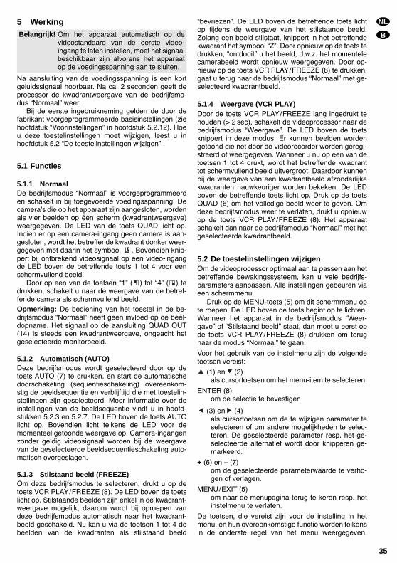
5 Werking
Na aansluiting van de voedingsspanning is een kortgeluidssignaal hoorbaar. Na ca. 2 seconden geeft deprocessor de kwadrantweergave van de bedrijfsmo-dus Normaal weer.
Bij de eerste ingebruikneming gelden de door defabrikant voorgeprogrammeerde basisinstellingen (ziehoofdstuk Voorinstellingen in hoofdstuk 5.2.12). Hoeu deze toestelinstellingen moet wijzigen, leest u inhoofdstuk 5.2 De toestelinstellingen wijzigen.
5.1 Functies
5.1.1 NormaalDe bedrijfsmodus Normaal is voorgeprogrammeerden schakelt in bij toegevoerde voedingsspanning. Decameras die op het apparaat zijn aangesloten, wordenals vier beelden op één scherm (kwadrantweergave)weergegeven. De LED van de toets QUAD licht op.Indien er op een camera-ingang geen camera is aan-gesloten, wordt het betreffende kwadrant donker weer-gegeven met daarin het symbool . Bovendien knip-pert bij ontbrekend videosignaal op een video-ingangde LED boven de betreffende toets 1 tot 4 voor eenschermvullend beeld.
Door op een van de toetsen 1 ( ) tot 4 ( ) tedrukken, schakelt u naar de weergave van de betref-fende camera als schermvullend beeld.Opmerking: De bediening van het toestel in de be-drijfsmodus Normaal heeft geen invloed op de beel-dopname. Het signaal op de aansluiting QUAD OUT(14) is steeds een kwadrantweergave, ongeacht hetgeselecteerde monitorbeeld.
5.1.2 Automatisch (AUTO)Deze bedrijfsmodus wordt geselecteerd door op detoets AUTO (7) te drukken, en start de automatischedoorschakeling (sequentieschakeling) overeenkom-stig de beeldsequentie en verblijftijd die met toestelin-stellingen zijn geselecteerd. Meer informatie over deinstellingen van de beeldsequentie vindt u in hoofd-stukken 5.2.3 en 5.2.7. De LED boven de toets AUTOlicht op. Bovendien licht telkens de LED voor demomenteel getoonde weergave op. Camera-ingangenzonder geldig videosignaal worden bij de weergavevan de geselecteerde beeldsequentieschakeling auto-matisch overgeslagen.
5.1.3 Stilstaand beeld (FREEZE)Om deze bedrijfsmodus te selecteren, drukt u op detoets VCR PLAY/FREEZE (8). De LED boven de toetslicht op. Stilstaande beelden zijn enkel in de kwadrant-weergave mogelijk, daarom wordt bij oproepen vandeze bedrijfsmodus automatisch naar het kwadrant-beeld geschakeld. Nu kan u via de toetsen 1 tot 4 debeelden van de kwadranten als stilstaand beeld
bevriezen. De LED boven de betreffende toets lichtop tijdens de weergave van het stilstaande beeld.Zolang een beeld stilstaat, knippert in het betreffendekwadrant het symbool Z. Door opnieuw op de toets tedrukken, ontdooit u het beeld, d.w.z. het momentelecamerabeeld wordt opnieuw weergegeven. Door op-nieuw op de toets VCR PLAY/FREEZE (8) te drukken,gaat u terug naar de bedrijfsmodus Normaal met ge-selecteerd kwadrantbeeld.
5.1.4 Weergave (VCR PLAY)Door de toets VCR PLAY/FREEZE lang ingedrukt tehouden (> 2 sec), schakelt de videoprocessor naar debedrijfsmodus Weergave. De LED boven de toetsknippert in deze modus. Er kunnen beelden wordengetoond die net door de videorecorder worden geregi-streerd of weergegeven. Wanneer u nu op een van detoetsen 1 tot 4 drukt, wordt het betreffende kwadranttot schermvullend beeld uitvergroot. Daardoor kunnenbij de weergave van een kwadrantbeeld afzonderlijkekwadranten nauwkeuriger worden bekeken. De LEDboven de betreffende toets licht op. Druk op de toetsQUAD (6) om het volledige beeld weer te geven. Omdeze bedrijfsmodus weer te verlaten, drukt u opnieuwop de toets VCR PLAY/FREEZE (8). Het apparaatschakelt dan naar de bedrijfsmodus Normaal met hetgeselecteerde kwadrantbeeld.
5.2 De toestelinstellingen wijzigenOm de videoprocessor optimaal aan te passen aan hetbetreffende bewakingssysteem, kan u vele bedrijfs-parameters aanpassen. Alle instellingen gebeuren viaeen schermmenu.
Druk op de MENU-toets (5) om dit schermmenu opte roepen. De LED boven de toets begint op te lichten.Wanneer het apparaat in de bedrijfsmodus Weer-gave of Stilstaand beeld staat, dan moet u eerst opde toets VCR PLAY/FREEZE (8) drukken om terugnaar de modus Normaal te gaan.
Voor het gebruik van de instelmenu zijn de volgendetoetsen vereist:
(1) en (2)als cursortoetsen om het menu-item te selecteren.
ENTER (8)om de selectie te bevestigen
(3) en (4)als cursortoetsen om de te wijzigen parameter teselecteren of om andere mogelijkheden te selec-teren. De geselecteerde parameter resp. het ge-selecteerde alternatief wordt door knipperen ge-markeerd.
+ (6) en – (7)om de geselecteerde parameterwaarde te verho-gen of verlagen.
MENU/EXIT (5)om naar de menupagina terug te keren resp. hetinstelmenu te verlaten.
De toetsen, die vereist zijn voor de instelling in hetmenu, en hun overeenkomstige functie worden telkensin de onderste regel van het menu weergegeven.
Belangrijk! Om het apparaat automatisch op devideostandaard van de eerste video-ingang te laten instellen, moet het signaalbeschikbaar zijn alvorens het apparaatop de voedingsspanning aan te sluiten.
NL
B
35

Bovendien wordt tijdens de menu-instelling met deLEDs boven de toetsen weergegeven, welke toetsenkunnen worden ingedrukt. Alle wijzigingen die in hetinstelmenu zijn doorgevoerd, worden duurzaamopgeslagen en blijven dus ook na uitvallen van de voe-dingsspanning behouden.
Om het instelmenu weer te verlaten, drukt u (evt. her-haald) op de toets MENU/EXIT (8).
Alarmmeldingen die tijdens de bediening van hetinstelmenu binnenkomen, worden door de videopro-cessor genegeerd. Daarom schakelt het apparaatautomatisch weer naar de normale modus van zodratijdens de menu-instellingen ca. 15 sec lang geen toetswerd ingedrukt.
Met de toets MENU (5) wordt volgend instelmenu inge-voegd:
Het momenteel geselecteerde menu-item wordt doorde pijl in de linker marge aangeduid.
Selecteer met de toetsen (1) en (2) een menu-item en bevestig met ENTER (8).
De afzonderlijke menu-items:
5.2.1 ALARM DURATION – AlarmduurHiermee kan u de sluitingstijd van het relaiscontactinstellen na activering van een alarm, en het alarmsig-naal weerklinkt gedurende 1 tot 99 sec (zover dit viahet menu-item 5.2.5 EXT AUDIBLE ALARM resp.5.2.4 INT AUDIBLE ALARM werd toegelaten). Doorop een willekeurige toets te drukken, kan het alarmvoortijdig worden afgebroken.
5.2.2 BAUD RATE – Doorvoercapaciteit voor deafstandsbediening via RS-232-interface
Voor de bediening op afstand via de seriële interfacekan u hier een kiezen uit een doorvoercapaciteit van1200, 2400, 3600, 4800, 9600, 19 200, 57 600 of115 200 bit/sec.
5.2.3 DWELL TIME – Verblijftijd voor de automati-sche beelddoorschakeling
Hier wordt de verblijftijd per beeld (1 tot 30 sec) voorde automatische modus weergegeven.
5.2.4 INT AUDIBLE ALARM – Geluidssignaal voorhet alarm
Hiermee schakelt u het alarmsignaal dat weerklinkt bijverlies van videosignaal of alarm via een alarmingang,in (ON) of uit (OFF).
5.2.5 EXT AUDIBLE ALARM – Alarmrelais voorextern alarm
Deze bepaalt of het alarmuitgangsrelais bij verlies vanvideosignaal of bij alarm via een alarmingang moet(ON) of niet moet (OFF) schakelen.
5.2.6 SET TIME – Instelling van de tijdinvoegingDeze instelling bepaalt of het momentele tijdstip en dedatum worden ingevoegd en in welke vorm. Met detoets ENTER (8) wordt gewisseld tussen de weerga-veformaten
Jaar/Maand/Dag/Uur/Minuut/Seconde(__y : __m : __d : __h : __m : __s),
Dag/Maand/Jaar/Uur/Minuut/Seconde(__d : __m : __y : __h : __m : __s)
en geen tijdweergave (TIME DISPLAY OFF). Deinterne klok kan met behulp van de toetsen (3), (4),+ (6) en – (7) worden ingesteld.
5.2.7 DWELL SETUP – Instelling van de beeldse-quentie
Deze instelling bepaalt welke beelden in de automati-sche modus worden getoond. Selecteer met de toet-sen (1) en (2) het beeld (CH1, CH2, CH3, CH4 ofQUAD) en stel met de toetsen (3) en (4) in, of ditbeeld in de beeldsequentie moet (ON) of niet moet(OFF) worden opgenomen.
5.2.8 ALARM POLARITY – Configuratie van dealarmingangen
De configuratie bepaalt welke alarmingangen actiefmoeten zijn en of ze op HIGH-niveau of LOW-niveau inwerking moeten treden. Selecteer met de toetsen (1)en ) het nummer van de alarmingang (CH1, CH2, CH3of CH4) en stel met de toetsen (3) en (4) in, of dezealarmingang op HIGH-niveau, LOW-niveau of helemaalniet (OFF) moet reageren. Een open ingang geldt daar-bij als HIGH-niveau. Bij verbinding van de ingang metmassa, ligt hij op LOW-niveau.
5.2.9 CAMERA TITLE SETUP – Invoeging vancamera-namen
Hier kan in elk van de vier camerabeelden een naamvan maximaal tien tekens worden ingevoegd. Selecteermet de toetsen (1) en (2) het nummer van decamera-ingang (CH1, CH2, CH3 of CH4), selecteer metde toetsen + (6) en – (7) een teken en ga met de toet-sen (3) en (4) naar de volgende of vorige teken-positie. Selecteer met de toets ENTER (8) of de naam aldan niet (UNSHOWN) moet worden weergegeven.Opmerking: De invoegmogelijkheden van camera-namen, datum en tijdstip gelden enkel voor de kwa-drantweergave. In de schermvullende weergave wor-den geen teksten ingevoegd.
(MENU)ALARM DURATION : 02 SECBAUD RATE : 1200 BPSDWELL TIME : 03 SECINT AUDIBLE ALARM : ON OFFEXT AUDIBLE ALARM : ON OFFSET TIME : 02y:02m:05d:11h:12m:13sDWELL SETUP (CH 01) : ON OFFALARM POLARITY (CH 01) : HIGH LOW OFFCAMERA TITLE SETUP (CH 01) : ABCDEFGHIJEVENT LISTVIDEO SETSYSTEM RESET
:SEL.ENTER:VERIFYCHOICE.MENU:EXIT
NL
B
36
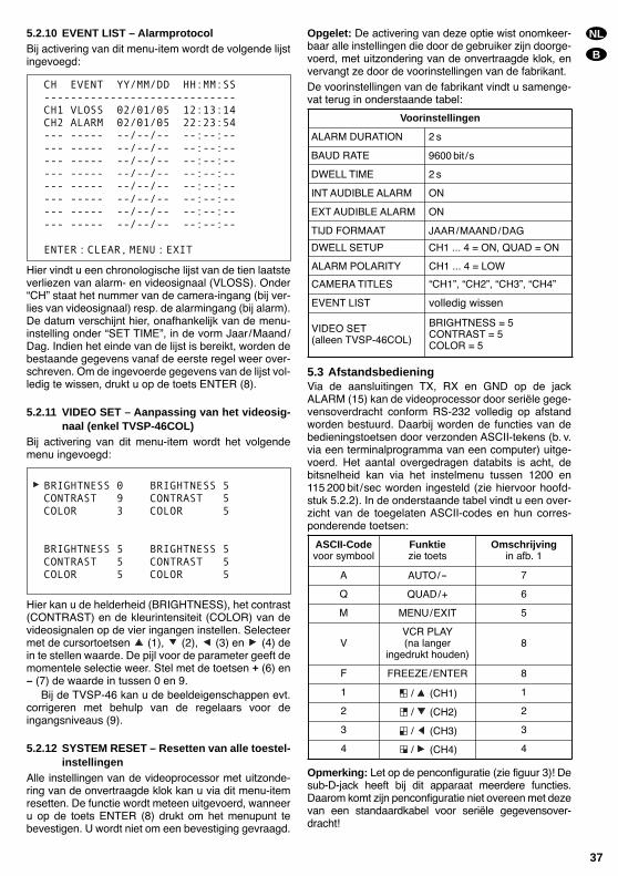
5.2.10 EVENT LIST – AlarmprotocolBij activering van dit menu-item wordt de volgende lijstingevoegd:
Hier vindt u een chronologische lijst van de tien laatsteverliezen van alarm- en videosignaal (VLOSS). OnderCH staat het nummer van de camera-ingang (bij ver-lies van videosignaal) resp. de alarmingang (bij alarm).De datum verschijnt hier, onafhankelijk van de menu-instelling onder SET TIME, in de vorm Jaar/Maand/Dag. Indien het einde van de lijst is bereikt, worden debestaande gegevens vanaf de eerste regel weer over-schreven. Om de ingevoerde gegevens van de lijst vol-ledig te wissen, drukt u op de toets ENTER (8).
5.2.11 VIDEO SET – Aanpassing van het videosig-naal (enkel TVSP-46COL)
Bij activering van dit menu-item wordt het volgendemenu ingevoegd:
Hier kan u de helderheid (BRIGHTNESS), het contrast(CONTRAST) en de kleurintensiteit (COLOR) van devideosignalen op de vier ingangen instellen. Selecteermet de cursortoetsen (1), (2), (3) en (4) dein te stellen waarde. De pijl voor de parameter geeft demomentele selectie weer. Stel met de toetsen + (6) en– (7) de waarde in tussen 0 en 9.
Bij de TVSP-46 kan u de beeldeigenschappen evt.corrigeren met behulp van de regelaars voor deingangsniveaus (9).
5.2.12 SYSTEM RESET – Resetten van alle toestel-instellingen
Alle instellingen van de videoprocessor met uitzonde-ring van de onvertraagde klok kan u via dit menu-itemresetten. De functie wordt meteen uitgevoerd, wanneeru op de toets ENTER (8) drukt om het menupunt tebevestigen. U wordt niet om een bevestiging gevraagd.
Opgelet: De activering van deze optie wist onomkeer-baar alle instellingen die door de gebruiker zijn doorge-voerd, met uitzondering van de onvertraagde klok, envervangt ze door de voorinstellingen van de fabrikant.De voorinstellingen van de fabrikant vindt u samenge-vat terug in onderstaande tabel:
5.3 AfstandsbedieningVia de aansluitingen TX, RX en GND op de jackALARM (15) kan de videoprocessor door seriële gege-vensoverdracht conform RS-232 volledig op afstandworden bestuurd. Daarbij worden de functies van debedieningstoetsen door verzonden ASCII-tekens (b. v.via een terminalprogramma van een computer) uitge-voerd. Het aantal overgedragen databits is acht, debitsnelheid kan via het instelmenu tussen 1200 en115 200 bit/sec worden ingesteld (zie hiervoor hoofd-stuk 5.2.2). In de onderstaande tabel vindt u een over-zicht van de toegelaten ASCII-codes en hun corres-ponderende toetsen:
Opmerking: Let op de penconfiguratie (zie figuur 3)! Desub-D-jack heeft bij dit apparaat meerdere functies.Daarom komt zijn penconfiguratie niet overeen met dezevan een standaardkabel voor seriële gegevensover-dracht!
BRIGHTNESS 0 BRIGHTNESS 5CONTRAST 9 CONTRAST 5COLOR 3 COLOR 5
BRIGHTNESS 5 BRIGHTNESS 5CONTRAST 5 CONTRAST 5COLOR 5 COLOR 5
CH EVENT YY/MM/DD HH:MM:SS-----------------------------CH1 VLOSS 02/01/05 12:13:14CH2 ALARM 02/01/05 22:23:54--- ----- --/--/-- --:--:----- ----- --/--/-- --:--:----- ----- --/--/-- --:--:----- ----- --/--/-- --:--:----- ----- --/--/-- --:--:----- ----- --/--/-- --:--:----- ----- --/--/-- --:--:----- ----- --/--/-- --:--:--
ENTER:CLEAR,MENU:EXIT
NL
B
37
Voorinstellingen
ALARM DURATION 2 s
BAUD RATE 9600 bit /s
DWELL TIME 2 s
EXT AUDIBLE ALARM ON
DWELL SETUP CH1 ... 4 = ON, QUAD = ON
INT AUDIBLE ALARM ON
TIJD FORMAAT JAAR/MAAND/DAG
ALARM POLARITY CH1 ... 4 = LOW
CAMERA TITLES CH1, CH2, CH3, CH4
EVENT LIST volledig wissen
VIDEO SET(alleen TVSP-46COL)
BRIGHTNESS = 5CONTRAST = 5COLOR = 5
ASCII-Codevoor symbool
Funktiezie toets
Omschrijvingin afb. 1
A AUTO/- 7
Q QUAD/+ 6
M MENU/EXIT 5
VVCR PLAY(na langer
ingedrukt houden)8
F FREEZE/ENTER 8
1 / (CH1) 1
2 / (CH2) 2
3 / (CH3) 3
4 / (CH4) 4
5.4 Alarmfunctie
5.4.1 Activering van het alarm door een alarm-sensor
Wanneer via een alarmingang een alarmsignaal af-komstig van een externe sensor wordt geregistreerd,begint in het kwadrantbeeld het symbool te knippe-ren in het kwadrant waarvan het nummer overeen-stemt met de alarmingang. Wanneer in het instelmenuhet geluidssignaal (zie hoofdstuk 5.2.4) en het alarm-relais (zie hoofdstuk 5.2.5) zijn ingeschakeld, dan tre-den ze in werking gedurende de alarmtijd die in hetmenu is ingesteld (zie hoofdstuk 5.2.1). Door op eenwillekeurige toets te drukken, kan het alarm voortijdigworden afgebroken.
Het symbool blijft, onafhankelijk van de ingesteldealarmduur of van een manuele onderbreking van hetalarm, op het beeldscherm staan zolang het signaalvan de alarmingang beantwoordt aan de voorwaardenvoor activering die in het instelmenu zijn vastgelegd(zie hoofdstuk 5.2.8).
5.4.2 Activering van het alarm bij verlies vanvideosignaal
Indien een videosignaal uitvalt (b. v. bij een camera-defect), verschijnt in de betreffende kwadrant het sym-bool . Bovendien knippert de LED boven de betref-fende toets. Wanneer in het instelmenu het geluidssig-naal (zie hoofdstuk 5.2.4) en het alarmrelais (ziehoofdstuk 5.2.5) zijn ingeschakeld, dan treden ze inwerking gedurende de alarmtijd die in het menu isingesteld (zie 5.2.1). Door op een willekeurige toets tedrukken, kan het alarm voortijdig worden afgebroken.
Het symbool blijft, onafhankelijk van de ingesteldealarmduur of van een manuele onderbreking van hetalarm, op het beeldscherm staan zolang het signaal opde video-ingang ontbreekt.
Beide alarmtypes worden met datum en tijdstip vanvoorval geregistreerd. De opsomming van de laatstetien gebeurtenissen kan in het instelmenu wordengeraadpleegd en gewist (zie hoofdstuk 5.2.10).
6 Technische gegevens
VideoSignaalformaat: . . . . . . . . EIA, CCIRKleurstandaard: . . . . . . . . NTSC, PAL
(enkel TVSP-46COL)Beeldfrequentie
NTSC/EIA: . . . . . . . . . 30 beelden/secPAL/CCIR: . . . . . . . . . . 25 beelden/sec
ResolutieNTSC/EIA: . . . . . . . . . 720 (h) x 480 (v)PAL/CCIR: . . . . . . . . . . 720 (h) x 576 (v)
Kleur-/grijstintenNTSC, PAL: . . . . . . . . . 16,7 miljoen kleurenEIA, CCIR: . . . . . . . . . . 256 grijstinten
Signaalniveau: . . . . . . . . . 1Vss/75Ω
Alarm
Ingangen: . . . . . . . . . . . . . 4 alarmingangen metgemeenschappelijkemassa, naar keuze telkensHIGH-niveau-activering[voor verbreekcontact(N.C.)], LOW-niveau-activering [voor sluitcontact(N.O.)] of gedeactiveerd
Uitgang: . . . . . . . . . . . . . . Alarmrelais met sluit-contact (N.O.), max. 2 A/24 V, uitschakelbaar
Alarmsignaal: . . . . . . . . . . bij signaalverlies en alarmvia alarmingangen, uit-schakelbaar, duur instel-baar: 1 tot 99 seconden
Afstandsbediening: . . . . . RS-232
Algemeen
Omgevings-temperatuurbereik: . . . . . 0 40 °CVoedingsspanning: . . . . . 12 V ±10 %
(b. v. via PSS-1206 of PS-1204ST vanMONACOR)
Vermogensverbruik: . . . . . 12 W max., 1 A bei 12 VAfmetingen (B x H x D): . . 240 x 50 x 170 mmGewicht: . . . . . . . . . . . . . . 1,1 kg
Opgemaakt volgens de gegevens van de fabrikant.Deze behoudt zich het recht voor de technische gege-vens te veranderen.
NL
B
Copyright© by MONACOR® INTERNATIONAL GmbH & Co. KG, Bremen, GermanyAll rights reserved. www.monacor.com 04.02.01
®