CONNECTORS FOR THE HIGHEST TEMPERATURE RANGE
52
CONNECTORS FOR THE HIGHEST TEMPERATURE RANGE STECKVERBIN- DUNGEN FÜR HÖCHSTE TEMPERATUR- MESSBEREICHE THERMO SERIES
Transcript of CONNECTORS FOR THE HIGHEST TEMPERATURE RANGE
CONNECTORS FOR THE HIGHESTTEMPERATURERANGE
STECKVERBIN-DUNGEN FÜRHÖCHSTETEMPERATUR-MESSBEREICHE
THERMOSERIES
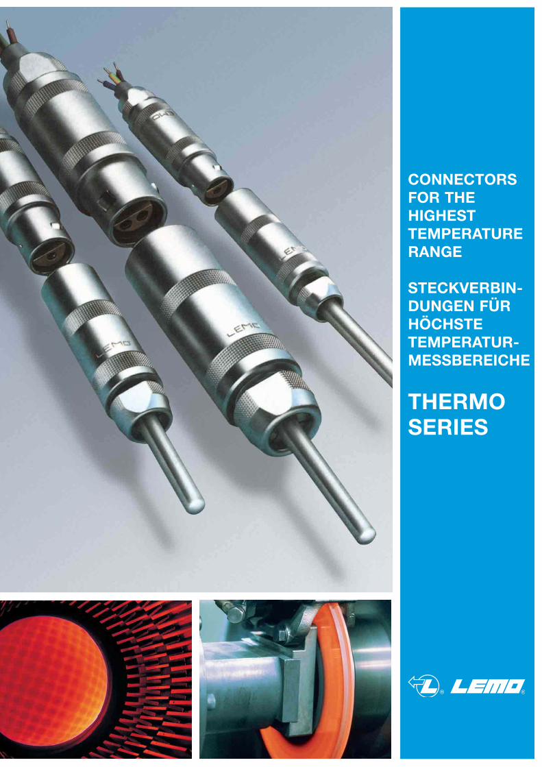
2Insight of our productionEinblicke in unsere Fertigung
Vacuumtest withleakdetector
Vakuumtest mitLeakdetektor
Cable assembling and system technology
Konfektionieren von Steckver-bindungen undSystemtechnologie
Vacuumtight sealedsockets with
Ni-Cr/Ni contacts
HochvakuumdichteApparatedosen mitNi-Cr/Ni-Kontakten
Cable overmold technology
Umspritzen fürKabelzug-entlastungen
Final inspectioncompletely PC-organized
Endkontrolle komplett PC-organisiert
Crimping: coaxial, biaxial,
triaxial, multipole
Crimpen:koaxial, biaxial,
triaxial, mehrpolig
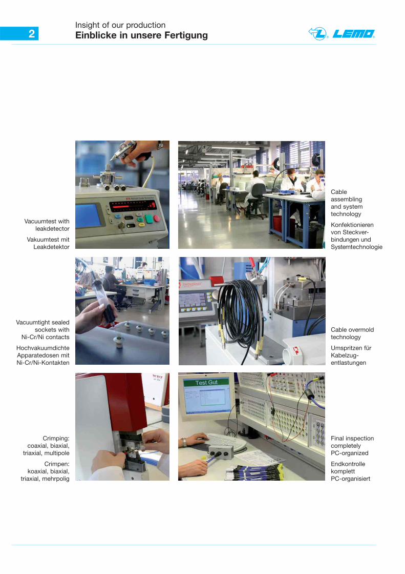
3ContentsInhaltsverzeichnis
Seite / Page
4 – 7
8 – 9
10
11 – 13
14 – 17
18
19 – 25
26
27
28 – 30
31
32
33
34 – 36
37
38 – 40
41
42 – 46
47 – 50
51
Technische Information / Technical information
Tabelle / Table / DIN-Information
Bestellinformation / Order information
Spannzangen-Übersicht / Collets table
Bauform / Model
TH-Kontaktfiguration / TH-Contact figuration
TH-Spannzangen u. ISO / TH-Collets and insulators
Bestellinformation / Order information
Spannzangen-Übersicht / Collets table
Bauform / Model
TH-Spannzangen u. ISO / TH-Collets and insulators
Bestellinformation / Order information
Spannzangen-Übersicht / Collets table
Bauform / Model
TH-Kontaktfiguration / TH-Contact figuration
TH-Spannzangen u. ISO / TH-Collets and insulators
Konfektionierungen / Cable assembly
Crimptechnik S/E Serie / Crimptechnique S/E Series
Crimptechnik B/K Serie / Crimptechnique B/K Series
Katalogübersicht / Catalog summary
Serie / Series
S
S
S
S + E
S
E
E
E
E
B
B
B
B
B
S + E
B + K
4Technical informationTechnische Information
Messwiderstande,Widerstandsther-mometer, Ausgleichsleitungen, Mantel-leitungen und vor allen Dingen Mantel-Thermoelemente müssen für den indus-triellen Einsatz mit einer geeignetenSteckverbindung versehen werden.
Das Messen der Thermospannung er-folgt in mV und μV. Für diesen Mess-bereich ist die LEMO-Steckverbindungdas ideale Bauteil.
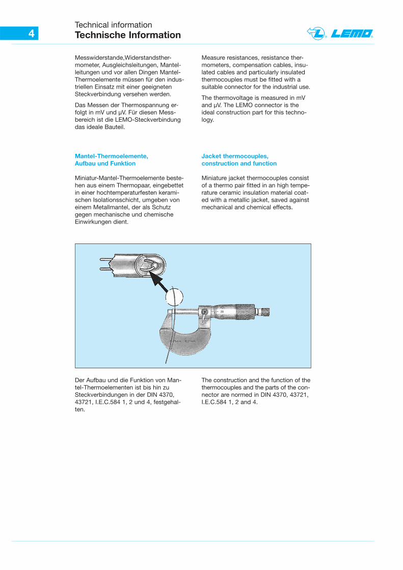
Mantel-Thermoelemente,Aufbau und Funktion
Miniatur-Mantel-Thermoelemente beste-hen aus einem Thermopaar, eingebettetin einer hochtemperaturfesten kerami-schen Isolationsschicht, umgeben voneinem Metallmantel, der als Schutzgegen mechanische und chemischeEinwirkungen dient.
Der Aufbau und die Funktion von Man-tel-Thermoelementen ist bis hin zuSteckverbindungen in der DIN 4370,43721, I.E.C.584 1, 2 und 4, festgehal-ten.
The construction and the function of thethermocouples and the parts of the con-nector are normed in DIN 4370, 43721,I.E.C.584 1, 2 and 4.
Measure resistances, resistance ther-mometers, compensation cables, insu-lated cables and particularly insulatedthermocouples must be fitted with asuitable connector for the industrial use.
The thermovoltage is measured in mVand μV. The LEMO connector is theideal construction part for this techno-logy.
Jacket thermocouples,construction and function
Miniature jacket thermocouples consistof a thermo pair fitted in an high tempe-rature ceramic insulation material coat-ed with a metallic jacket, saved againstmechanical and chemical effects.

5Technical informationTechnische Information
68.783 mV68 783 mV77 VVmm338866 VVmm888868.783 mV768.783 mV68 83 V68 83 VEEEEEE
42.283 mV2.283 mV42.283 mV42 283 mV2 283 mV42 283 mV42 283 mV2 283 mV42 283 mV JJJJJJ
47.502 mV247.502 mV47 502 mV247 502 mV47 502 mV247 502 mVNNNNNNNNNN
18.842 mV8.842 mV18.842 mV18 842 mV8 842 mV18 842 mV18 842 mV8 842 mV18 842 mVRRRRRR
48.828 mV48 828 mVmm44 888844 VVmm8822888848 828 mV48 828 m48 828 mVKKKKKKKK
12.426 mV12 426 mVVVmm22442211 VVmm6622.12 426 mV2 426 mV12 426 mVBBBBBBBBBBBB
16.771 mV6.771 mV 16.771 m16.771 mV6.771 mV16.771 m16 771 mV6 771 mV16 771 m16 771 V6 771 V16 771SSSSSS
35.932 mV35.932 m5.932 mV35 932 mV35 932 m5 932 mV35 932 mV35 932 m5 932 mVCCCCCCCC
Temperatur (Temperatur (ee ((uurrmmee rruuttaaaaeeppmmeeTTTTTemperatur (eratur (TemperaturT t (t (T t °°°°C)C)CC))CCC)C)C)C)
E.m.f. (mV).E.m.f. (mV)( )( )E m f (mV)E m f (mV)E m f (mV)E m f (mV)E f ( V)E f ( V)80800088008880808080
70700077007770707070
60600066006660606060
50500055005550505050
40400044004440404040
30300033003330303030
20200022002220202020
101000110010101010
0000000000
Die Auswahl des Adermaterialsbestimmt den Temperaturbereich.
Mit TH-Thermoelementen sind Messun-gen zwischen - 250 und + 2200 °Cmöglich. Die Entwicklung für neueWerkstoffe, seit der Einführung durchSEEBECK und PELTIR, ist noch immerin Bewegung.
Das gebräuchlichste Thermopaar ist dieAusführung Chromel-Alumel (Typ K).Der Einsatzbereich liegt bei - 200 bis1100 °C. In Verbindung mit unsererLEMO Steckverbindung erhält man hiergute thermoelektrische Eigenschaften,und der Thermo-Spannungsverlauf istfast linear.
Thermospannung (mV)
The part of the wire material will choosedthe temperature range.
The measurements of thermocouples isbetween - 250 and + 2200 °C.The development of new materials isstill moving since the introduction ofSEEBECK and PELTIR.
The most used thermocouple is the partof Chromel-Alumel (type K). The tempe-rature range is from - 200 to 1100 °C.With our LEMO connector we reachedgood thermoelectric characteristics. Thethermoelectric power curve is nearlylinear.
Thermoelectric power (mV)
Steckverbindung undThermoelement
Die Entfernung zwischen der Meßstelleund dem Messgerät beträgt in extre-men Fällen mehrere 100 m.
Connector and thermocouple
In extreme cases the distance betweenthe measuring point and the gauge canbe several hundred meters.
6Technical informationTechnische Information
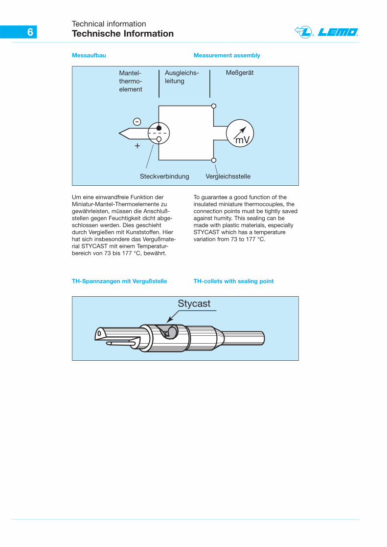
Messaufbau
Um eine einwandfreie Funktion derMiniatur-Mantel-Thermoelemente zugewährleisten, müssen die Anschluß-stellen gegen Feuchtigkeit dicht abge-schlossen werden. Dies geschiehtdurch Vergießen mit Kunststoffen. Hierhat sich insbesondere das Vergußmate-rial STYCAST mit einem Temperatur-bereich von 73 bis 177 °C, bewährt.
TH-Spannzangen mit Vergußstelle
To guarantee a good function of theinsulated miniature thermocouples, theconnection points must be tightly savedagainst humity. This sealing can bemade with plastic materials, especiallySTYCAST which has a temperaturevariation from 73 to 177 °C.
TH-collets with sealing point
Measurement assembly
Mantel-thermo-element
Ausgleichs-leitung
Meßgerät
Vergleichsstelle
mV
-
+
Steckverbindung
Stycast
7Technical informationTechnische Information
Aus langen Erfahrungswerten geht her-vor, daß bei den gebräuchlichstenThermopaaren, wie z. B. Chromel-Alumel, die hochwertigen LEMO-Kon-takte in der spezial vergoldeten Versioneingesetzt werden können. An derAnschlußstelle mit dem Thermoele-mentmaterial hebt sich die EMK (elek-tromagnetische Kraft) vollständig auf.Dies ist aber nur der Fall, wenn dieSteckverbindung als Zwischenstück inder Thermoleitung dient und diese sichwiederum auf einem gleichbleibendenTemperaturlevel befindet. Überall dort,wo ein thermisches Gleichgewicht derSteckverbindung nicht erreicht wird,muß der Steckkontakt aus demselbenMaterial, wie das der Thermoelemente,gewählt werden. Siehe Tabelle Thermo-elemente-Ausgleichskabel.
Bei der Verwendung von Steckverbin-dungen mit Thermokontakten ist aufden richtigen Anschluß nach DIN 43711,A.N.S.I. MC 96.1, zu achten.
Siehe Tabelle nach Farbcode und+/- Einteilung.
Wir empfehlen nachstehendesLötzinn:
Bei der Verwendung von Lötzinn, TypHMP07, und der richtigen Löttemperatur(380 °C), ist eine leichte Verarbeitungund ein homogener Anschluß gewähr-leistet. Entspricht laut Freistellung derISO 14001.
Das Mantel-Thermoelement wird in derRegel an der Kupplung, Typ PCA.- - -,oder an der Apparatedose mit Zugent-lastung, Typ PSA. - - -, angeschlossen.
Der Anschluß der Ausgleichsleitungerolgt somit am Slecker mit der Push-Pull-Verriegelung, Typ FFA. - - -.
During many years of experience, wecan assert that LEMO contacts of highquality in the special golden version canbe mounted on the most used thermo-couples, for example Chromel-Alumel.At the connection point with the thermo-couple material neutralizes the e.m.f.(electromagnetic force). This is only thecase, when the connector like an inter-mediate piece in the thermoelectric wireworks. The system must be on a con-stant temperature level. Wherever wedon’t reach a thermal balance of theconnector, the contact should be fromthe same material as the thermocouple.See table thermoelement compensationcable.
If you use connectors with thermo-contacts, you must pay attention to theassembly according to DIN 43711,A.N.S.I. MC 96.1.
See following table code coloursand +/- splitting.
We recommend following soldertin:
When you work with solder tin of typeHMP07 and the right soldering tempe-rature (380 °C), an easy working and ahomogeneous connection can beguaranteed. According to releaseof ISO 14001.
The jacket thermocouple will be usuallyconnected to the free socket of typePCA. - - - or to the receptacle withcable collet type PSA. - - -.
The compensation cable is conse-quently fitted at the connector withPush-Pull locking system, type FFA. - - -.
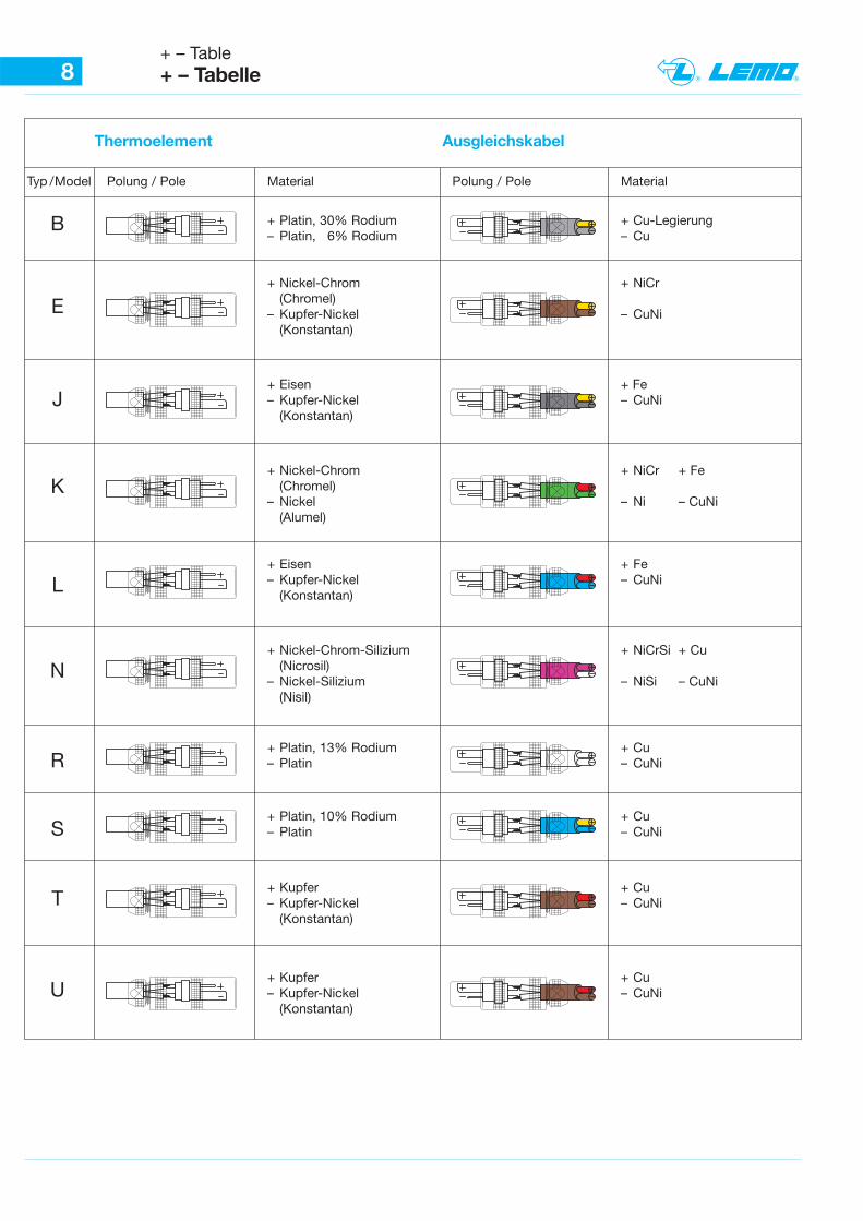
8+ – Table+ – Tabelle
Thermoelement Ausgleichskabel
Typ / Model Polung / Pole Material Polung / Pole Material
+ Platin, 30% Rodium + Cu-Legierung– Platin, 6% Rodium – Cu
+ Nickel-Chrom + NiCr(Chromel)
– Kupfer-Nickel – CuNi(Konstantan)
+ Eisen + Fe– Kupfer-Nickel – CuNi
(Konstantan)
+ Nickel-Chrom + NiCr + Fe(Chromel)
– Nickel – Ni – CuNi(Alumel)
+ Eisen + Fe– Kupfer-Nickel – CuNi
(Konstantan)
+ Nickel-Chrom-Silizium + NiCrSi + Cu(Nicrosil)
– Nickel-Silizium – NiSi – CuNi(Nisil)
+ Platin, 13% Rodium + Cu– Platin – CuNi
+ Platin, 10% Rodium + Cu– Platin – CuNi
+ Kupfer + Cu– Kupfer-Nickel – CuNi
(Konstantan)
+ Kupfer + Cu– Kupfer-Nickel – CuNi
(Konstantan)
B
E
J
K
L
N
R
S
T
U
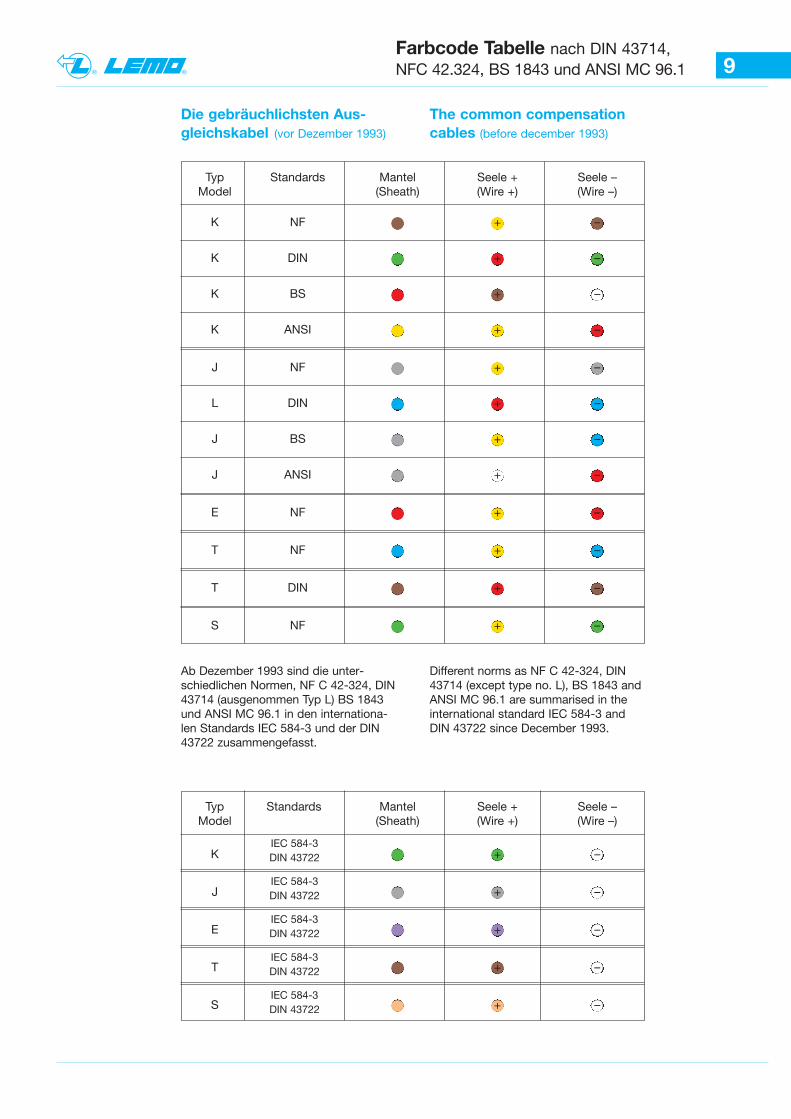
9Farbcode Tabelle nach DIN 43714,NFC 42.324, BS 1843 und ANSI MC 96.1
The common compensation cables (before december 1993)
Die gebräuchlichsten Aus-gleichskabel (vor Dezember 1993)
Ab Dezember 1993 sind die unter-schiedlichen Normen, NF C 42-324, DIN43714 (ausgenommen Typ L) BS 1843und ANSI MC 96.1 in den internationa-len Standards IEC 584-3 und der DIN43722 zusammengefasst.
Different norms as NF C 42-324, DIN43714 (except type no. L), BS 1843 andANSI MC 96.1 are summarised in theinternational standard IEC 584-3 andDIN 43722 since December 1993.
Typ Standards Mantel Seele + Seele – Model (Sheath) (Wire +) (Wire –)
K NF + –
K DIN + –
K BS + –
K ANSI + –
J NF + –
L DIN + –
J BS + –
J ANSI + –
E NF + –
T NF + –
T DIN + –
S NF + –
Typ Standards Mantel Seele + Seele – Model (Sheath) (Wire +) (Wire –)
K + –
J + –
E + –
T + –
S + –
IEC 584-3 DIN 43722
IEC 584-3 DIN 43722
IEC 584-3 DIN 43722
IEC 584-3 DIN 43722
IEC 584-3 DIN 43722
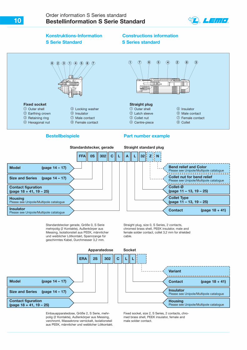
10Order information S Series standardBestellinformation S Serie Standard
Konstruktions-lnformation Constructions informationS Serie Standard S Series standard
Bestellbeispiele Part number example
6 2 3 1 4 5 8 1 7 6 5 2 8 347
Standardstecker gerade, Größe 0, S Seriemehrpolig (2 Kontakte), Außenkörper ausMessing, Isolationsteil aus PEEK, männlicherund weiblicher Lötkontakt, Spannzange fürgeschirmtes Kabel, Durchmesser 3,2 mm.
Straight plug, size 0, S Series, 2 contacts,chromed brass shell, PEEK insulator, male andfemale solder contact, collet 3,2 mm for shieldedcable.
Einbauapparatedose, Größe 2, S Serie, mehr-polig (2 Kontakte), Außenkörper aus Messing,verchromt, Massekrone vernickelt, Isolationsteilaus PEEK, männlicher und weiblicher Lötkontakt.
Fixed socket, size 2, S Series, 2 contacts, chro-med brass shell, PEEK insulator, female andmale solder contact.
Fixed socket1 Outer shell 5 Locking washer2 Earthing crown 6 Insulator3 Retaining ring 7 Male contact4 Hexagonal nut 8 Female contact
Straight plug1 Outer shell 5 Insulator2 Latch sleeve 6 Male contact3 Collet nut 7 Female contact4 Centre-piece 8 Collet
FFA 0S 302 C L A L 32 Z N
Standardstecker, gerade Straight standard plug
Model (page 14 – 17)
Size and Series (page 14 – 17)
Contact figuration (page 18 + 41, 19 – 25)
HousingPlease see Unipole/Multipole catalogue
InsulatorPlease see Unipole/Multipole catalogue
Bend relief and ColorPlease see Unipole/Multipole catalogue
Collet nut for bend relief Please see Unipole/Multipole catalogue
Collet-Ø(page 11 – 13, 19 – 25)
Collet Type(page 11 – 13, 19 – 25)
Contact (page 18 + 41)
ERA 2S 302 C L L
Apparatedose Socket
Model (page 14 – 17)
Size and Series (page 14 – 17)
Contact figuration (page 18 + 41, 19 – 25)
Variant
Contact (page 18 + 41)
Insulator Please see Unipole/Multipole catalogue
Housing Please see Unipole/Multipole catalogue
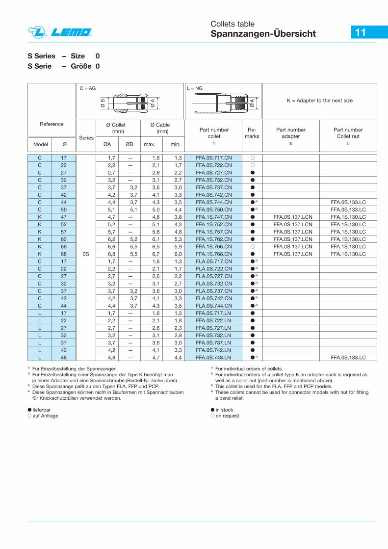
11Collets tableSpannzangen-Übersicht
S Series – Size 0S Serie – Größe 0
Reference
Model Ø
Ø Collet Ø Cable (mm) (mm)
SeriesØA ØB max. min.
Part number Re- Part number Part numbercollet marks adapter Collet nut
1) 2) 2)
Ø A
Ø B
C = AG
K = Adapter to the next size
L = NG
Ø A
C 17 1,7 — 1,6 1,3 FFA.0S.717.CN BC 22 2,2 — 2,1 1,7 FFA.0S.722.CN BC 27 2,7 — 2,6 2,2 FFA.0S.727.CN bC 32 3,2 — 3,1 2,7 FFA.0S.732.CN bC 37 3,7 3,2 3,6 3,0 FFA.0S.737.CN bC 42 4,2 3,7 4,1 3,3 FFA.0S.742.CN bC 44 4,4 3,7 4,3 3,5 FFA.0S.744.CN b 4) FFA.0S.133.LCC 50 5,1 5,1 5,0 4,4 FFA.0S.750.CN b 4) FFA.0S.133.LCK 47 4,7 — 4,6 3,8 FFA.1S.747.CN b FFA.0S.137.LCN FFA.1S.130.LCK 52 5,2 — 5,1 4,3 FFA.1S.752.CN b FFA.0S.137.LCN FFA.1S.130.LCK 57 5,7 — 5,6 4,8 FFA.1S.757.CN b FFA.0S.137.LCN FFA.1S.130.LCK 62 6,2 5,2 6,1 5,3 FFA.1S.762.CN b FFA.0S.137.LCN FFA.1S.130.LCK 66 6,6 5,5 6,5 5,9 FFA.1S.766.CN B FFA.0S.137.LCN FFA.1S.130.LCK 68 0S 6,8 5,5 6,7 6,0 FFA.1S.768.CN b FFA.0S.137.LCN FFA.1S.130.LCC 17 1,7 — 1,6 1,3 FLA.0S.717.CN b 3)
C 22 2,2 — 2,1 1,7 FLA.0S.722.CN b 3)
C 27 2,7 — 2,6 2,2 FLA.0S.727.CN b 3)
C 32 3,2 — 3,1 2,7 FLA.0S.732.CN b 3)
C 37 3,7 3,2 3,6 3,0 FLA.0S.737.CN b 3)
C 42 4,2 3,7 4,1 3,3 FLA.0S.742.CN b 3)
C 44 4,4 3,7 4,3 3,5 FLA.0S.744.CN b 3)
L 17 1,7 — 1,6 1,3 FFA.0S.717.LN bL 22 2,2 — 2,1 1,8 FFA.0S.722.LN bL 27 2,7 — 2,6 2,3 FFA.0S.727.LN bL 32 3,2 — 3,1 2,8 FFA.0S.732.LN bL 37 3,7 — 3,6 3,0 FFA.0S.737.LN bL 42 4,2 — 4,1 3,3 FFA.0S.742.LN bL 48 4,8 — 4,7 4,4 FFA.0S.748.LN b 4) FFA.0S.133.LC
1) Für Einzelbestellung der Spannzangen.2) Für Einzelbestellung einer Spannzange der Type K benötigt man
je einen Adapter und eine Spannschraube (Bestell-Nr. siehe oben).3) Diese Spannzange paßt zu den Typen FLA, FFP und PCP.4) Diese Spannzangen können nicht in Bauformen mit Spannschrauben
für Knickschutztüllen verwendet werden.
b lieferbarB auf Anfrage
1) For individual orders of collets. 2) For individual orders of a collet type K an adapter each is required as
well as a collet nut (part number is mentioned above). 3) This collet is used for the FLA, FFP and PCP models. 4) These collets cannot be used for connector models with nut for fitting
a bend relief.
b in stockB on request
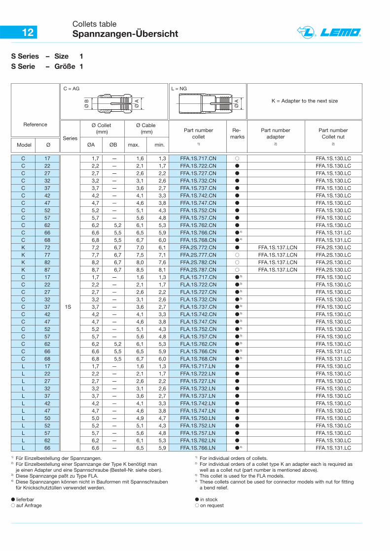
12Collets tableSpannzangen-Übersicht
S Series – Size 1S Serie – Größe 1
Reference
Model Ø
Ø Collet Ø Cable (mm) (mm)
SeriesØA ØB max. min.
Part number Re- Part number Part numbercollet marks adapter Collet nut
1) 2) 2)
Ø A
Ø B
C = AG
K = Adapter to the next size
L = NG
Ø A
C 17 1,7 — 1,6 1,3 FFA.1S.717.CN B FFA.1S.130.LCC 22 2,2 — 2,1 1,7 FFA.1S.722.CN b FFA.1S.130.LCC 27 2,7 — 2,6 2,2 FFA.1S.727.CN b FFA.1S.130.LCC 32 3,2 — 3,1 2,6 FFA.1S.732.CN b FFA.1S.130.LCC 37 3,7 — 3,6 2,7 FFA.1S.737.CN b FFA.1S.130.LCC 42 4,2 — 4,1 3,3 FFA.1S.742.CN b FFA.1S.130.LCC 47 4,7 — 4,6 3,8 FFA.1S.747.CN b FFA.1S.130.LCC 52 5,2 — 5,1 4,3 FFA.1S.752.CN b FFA.1S.130.LCC 57 5,7 — 5,6 4,8 FFA.1S.757.CN b FFA.1S.130.LCC 62 6,2 5,2 6,1 5,3 FFA.1S.762.CN b FFA.1S.130.LCC 66 6,6 5,5 6,5 5,9 FFA.1S.766.CN b 4) FFA.1S.131.LCC 68 6,8 5,5 6,7 6,0 FFA.1S.768.CN b 4) FFA.1S.131.LCK 72 7,2 6,7 7,0 6,1 FFA.2S.772.CN b FFA.1S.137.LCN FFA.2S.130.LCK 77 7,7 6,7 7,5 7,1 FFA.2S.777.CN B FFA.1S.137.LCN FFA.2S.130.LCK 82 8,2 6,7 8,0 7,6 FFA.2S.782.CN B FFA.1S.137.LCN FFA.2S.130.LCK 87 8,7 6,7 8,5 8,1 FFA.2S.787.CN B FFA.1S.137.LCN FFA.2S.130.LCC 17 1,7 — 1,6 1,3 FLA.1S.717.CN b 3) FFA.1S.130.LCC 22 2,2 — 2,1 1,7 FLA.1S.722.CN b 3) FFA.1S.130.LCC 27 2,7 — 2,6 2,2 FLA.1S.727.CN b 3) FFA.1S.130.LCC 32 3,2 — 3,1 2,6 FLA.1S.732.CN b 3) FFA.1S.130.LCC 37 1S 3,7 — 3,6 2,7 FLA.1S.737.CN b 3) FFA.1S.130.LCC 42 4,2 — 4,1 3,3 FLA.1S.742.CN b 3) FFA.1S.130.LCC 47 4,7 — 4,6 3,8 FLA.1S.747.CN b 3) FFA.1S.130.LCC 52 5,2 — 5,1 4,3 FLA.1S.752.CN b 3) FFA.1S.130.LCC 57 5,7 — 5,6 4,8 FLA.1S.757.CN b 3) FFA.1S.130.LCC 62 6,2 5,2 6,1 5,3 FLA.1S.762.CN b 3) FFA.1S.130.LCC 66 6,6 5,5 6,5 5,9 FLA.1S.766.CN b 3) FFA.1S.131.LCC 68 6,8 5,5 6,7 6,0 FLA.1S.768.CN b 3) FFA.1S.131.LCL 17 1,7 — 1,6 1,3 FFA.1S.717.LN b FFA.1S.130.LC L 22 2,2 — 2,1 1,7 FFA.1S.722.LN b FFA.1S.130.LCL 27 2,7 — 2,6 2,2 FFA.1S.727.LN b FFA.1S.130.LCL 32 3,2 — 3,1 2,6 FFA.1S.732.LN b FFA.1S.130.LCL 37 3,7 — 3,6 2,7 FFA.1S.737.LN b FFA.1S.130.LCL 42 4,2 — 4,1 3,3 FFA.1S.742.LN b FFA.1S.130.LCL 47 4,7 — 4,6 3,8 FFA.1S.747.LN b FFA.1S.130.LCL 50 5,0 — 4,9 4,7 FFA.1S.750.LN b FFA.1S.130.LCL 52 5,2 — 5,1 4,3 FFA.1S.752.LN b FFA.1S.130.LCL 57 5,7 — 5,6 4,8 FFA.1S.757.LN b FFA.1S.130.LCL 62 6,2 — 6,1 5,3 FFA.1S.762.LN b FFA.1S.130.LCL 66 6,6 — 6,5 5,9 FFA.1S.766.LN b 4) FFA.1S.131.LC
1) Für Einzelbestellung der Spannzangen.2) Für Einzelbestellung einer Spannzange der Type K benötigt man
je einen Adapter und eine Spannschraube (Bestell-Nr. siehe oben).3) Diese Spannzange paßt zu Type FLA.4) Diese Spannzangen können nicht in Bauformen mit Spannschrauben
für Knickschutztüllen verwendet werden.
b lieferbar B auf Anfrage
1) For individual orders of collets. 2) For individual orders of a collet type K an adapter each is required as
well as a collet nut (part number is mentioned above). 3) This collet is used for the FLA models. 4) These collets cannot be used for connector models with nut for fitting
a bend relief.
b in stockB on request
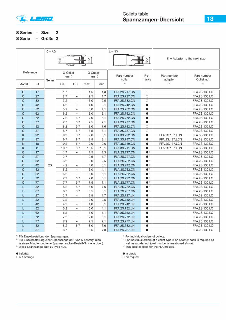
13Collets tableSpannzangen-Übersicht
S Series – Size 2S Serie – Größe 2
Reference
Model Ø
Ø Collet Ø Cable (mm) (mm)
SeriesØA ØB max. min.
Part number Re- Part number Part numbercollet marks adapter Collet nut
1) 2) 2)
Ø A
Ø B
C = AG
K = Adapter to the next size
L = NG
Ø A
C 17 1,7 – 1,5 1,3 FFA.2S.717.CN B FFA.2S.130.LCC 27 2,7 – 2,5 1,7 FFA.2S.727.CN B FFA.2S.130.LCC 32 3,2 – 3,0 2,5 FFA.2S.732.CN B FFA.2S.130.LCC 42 4,2 – 4,0 3,1 FFA.2S.742.CN b FFA.2S.130.LCC 52 5,2 – 5,0 4,1 FFA.2S.752.CN b FFA.2S.130.LCC 62 6,2 – 6,0 5,1 FFA.2S.762.CN b FFA.2S.130.LCC 72 7,2 6,7 7,0 6,1 FFA.2S.772.CN b FFA.2S.130.LCC 77 7,7 6,7 7,5 7,1 FFA.2S.777.CN b FFA.2S.130.LCC 82 8,2 6,7 8,0 7,6 FFA.2S.782.CN B FFA.2S.130.LCC 87 8,7 6,7 8,5 8,1 FFA.2S.787.CN B FFA.2S.130.LCK 92 9,2 8,7 9,0 8,1 FFA.3S.792.CN b FFA.2S.137.LCN FFA.3S.130.LCK 97 9,7 8,7 9,5 9,1 FFA.3S.797.CN b FFA.2S.137.LCN FFA.3S.130.LCK 10 10,2 8,7 10,0 9,6 FFA.3S.710.CN b FFA.2S.137.LCN FFA.3S.130.LCK 11 10,7 8,7 10,5 10,1 FFA.3S.711.CN b FFA.2S.137.LCN FFA.3S.130.LCC 17 1,7 – 1,5 1,3 FLA.2S.717.CN b 3) FFA.2S.130.LCC 27 2,7 – 2,5 1,7 FLA.2S.727.CN b 3) FFA.2S.130.LCC 32 3,2 – 3,0 2,5 FLA.2S.732.CN b 3) FFA.2S.130.LCC 42 2S 4,2 – 4,0 3,1 FLA.2S.742.CN b 3) FFA.2S.130.LCC 52 5,2 – 5,0 4,1 FLA.2S.752.CN b 3) FFA.2S.130.LCC 62 6,2 – 6,0 5,1 FLA.2S.762.CN b 3) FFA.2S.130.LCC 72 7,2 6,7 7,0 6,1 FLA.2S.772.CN b 3) FFA.2S.130.LCC 77 7,7 6,7 7,5 7,1 FLA.2S.777.CN b 3) FFA.2S.130.LCL 82 8,2 6,7 8,0 7,6 FLA.2S.782.CN b 3) FFA.2S.130.LCL 87 8,7 6,7 8,5 8,1 FLA.2S.787.CN b 3) FFA.2S.130.LCL 27 2,7 – 2,5 1,7 FFA.2S.727.LN b FFA.2S.130.LCL 32 3,2 – 3,0 2,5 FFA.2S.732.LN b FFA.2S.130.LCL 42 4,2 – 4,0 3,1 FFA.2S.742.LN b FFA.2S.130.LCL 52 5,2 – 5,0 4,1 FFA.2S.752.LN b FFA.2S.130.LCL 62 6,2 – 6,0 5,1 FFA.2S.762.LN b FFA.2S.130.LCL 72 7,2 – 7,0 6,1 FFA.2S.772.LN b FFA.2S.130.LCL 77 7,9 – 7,5 7,1 FFA.2S.777.LN b FFA.2S.130.LCL 82 8,2 6,7 8,0 7,6 FFA.2S.782.LN b FFA.2S.130.LCL 87 8,7 – 8,5 7,8 FFA.2S.787.LN b FFA.2S.130.LC
1) Für Einzelbestellung der Spannzangen.2) Für Einzelbestellung einer Spannzange der Type K benötigt man
je einen Adapter und eine Spannschraube (Bestell-Nr. siehe oben).3) Diese Spannzange paßt zu Type FLA.
b lieferbar B auf Anfrage
1) For individual orders of collets. 2) For individual orders of a collet type K an adapter each is required as
well as a collet nut (part number is mentioned above). 3) This collet is used for the FLA models.
b in stockB on request
Dimensions (mm)
A C L M S2
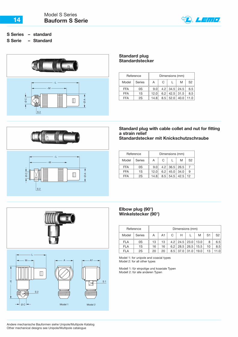
14Model S Series Bauform S Serie
S Series – standardS Serie – Standard
~L
~M
S 2
Ø AØ C
~L
~M
S 2
Ø A
Ø C
S 2
Ø C
L
M
~H
A
S 1
Model 1 Model 2
A1
Standard plugStandardstecker
Reference
Model Series
FFA 0S 9.0 4.2 34.5 24.5 6.5FFA 1S 12.0 6.2 42.5 31.5 8.5FFA 2S 14.8 8.5 52.0 40.0 11.0
Dimensions (mm)
A C L M S2
Standard plug with cable collet and nut for fittinga strain reliefStandardstecker mit Knickschutzschraube
Reference
Model Series
FFA 0S 9.0 4.2 36.5 26.5 7FFA 1S 12.0 6.2 45.0 34.0 9FFA 2S 14.8 8.5 54.5 42.5 12
Dimensions (mm)
A A1 C H L M S1 S2
Elbow plug (90°)Winkelstecker (90°)
Reference
Model Series
FLA 0S 13 13 4.2 24.5 23.0 13.0 8 6.5FLA 1S 16 16 6.2 28.5 26.5 15.5 10 8.5FLA 2S 20 20 8.5 37.0 31.0 19.0 13 11.0
Model 1: for unipole and coaxial types Model 2: for all other types
Modell 1: für einpolige und koaxiale TypenModell 2: für alle anderen Typen
Andere mechanische Bauformen siehe Unipole/Multipole KatalogOther mechanical designs see Unipole/Multipole catalogue
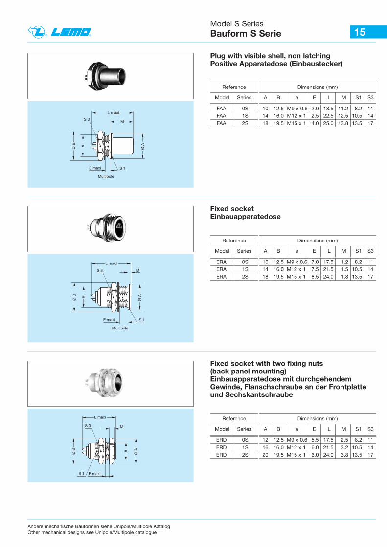
15Model S Series Bauform S Serie
L maxi
M
S 1
Ø A
S 3
Ø B e
E maxi
Multipole
Ø B e
S 1E maxi
Multipole
Ø A
L maxi
MS 3
Ø B
S 1 E maxi
Ø A
L maxi
MS 3
e
Plug with visible shell, non latchingPositive Apparatedose (Einbaustecker)
Fixed socketEinbauapparatedose
Fixed socket with two fixing nuts(back panel mounting)Einbauapparatedose mit durchgehendemGewinde, Flanschschraube an der Frontplatteund Sechskantschraube
Andere mechanische Bauformen siehe Unipole/Multipole KatalogOther mechanical designs see Unipole/Multipole catalogue
Dimensions (mm)
A B e E L M S1 S3
Reference
Model Series
FAA 0S 10 12.5 M9 x 0.6 2.0 18.5 11.2 8.2 11FAA 1S 14 16.0 M12 x 1 2.5 22.5 12.5 10.5 14FAA 2S 18 19.5 M15 x 1 4.0 25.0 13.8 13.5 17
Dimensions (mm)
A B e E L M S1 S3
Reference
Model Series
ERA 0S 10 12.5 M9 x 0.6 7.0 17.5 1.2 8.2 11ERA 1S 14 16.0 M12 x 1 7.5 21.5 1.5 10.5 14ERA 2S 18 19.5 M15 x 1 8.5 24.0 1.8 13.5 17
Dimensions (mm)
A B e E L M S1 S3
Reference
Model Series
ERD 0S 12 12.5 M9 x 0.6 5.5 17.5 2.5 8.2 11ERD 1S 16 16.0 M12 x 1 6.0 21.5 3.2 10.5 14ERD 2S 20 19.5 M15 x 1 6.0 24.0 3.8 13.5 17
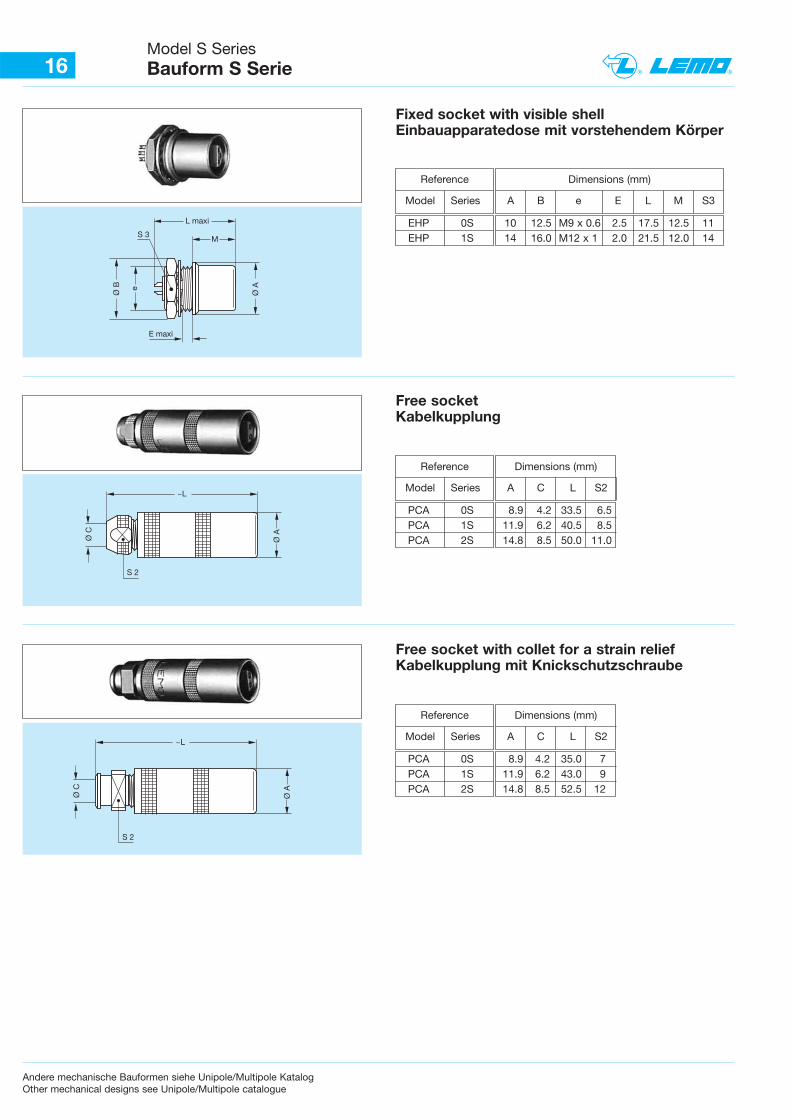
16Model S Series Bauform S Serie
L maxi
M
Ø A
S 3
Ø B e
E maxi
Fixed socket with visible shellEinbauapparatedose mit vorstehendem Körper
Dimensions (mm)
A B e E L M S3
Reference
Model Series
EHP 0S 10 12.5 M9 x 0.6 2.5 17.5 12.5 11EHP 1S 14 16.0 M12 x 1 2.0 21.5 12.0 14
Dimensions (mm)
A C L S2 ~L
S 2
Ø AØ C
Free socketKabelkupplung
Reference
Model Series
PCA 0S 8.9 4.2 33.5 6.5PCA 1S 11.9 6.2 40.5 8.5PCA 2S 14.8 8.5 50.0 11.0
Dimensions (mm)
A C L S2 ~L
S 2
Ø A
Ø C
Free socket with collet for a strain reliefKabelkupplung mit Knickschutzschraube
Reference
Model Series
PCA 0S 8.9 4.2 35.0 7PCA 1S 11.9 6.2 43.0 9PCA 2S 14.8 8.5 52.5 12
Andere mechanische Bauformen siehe Unipole/Multipole KatalogOther mechanical designs see Unipole/Multipole catalogue
17Model S Series Bauform S Serie
Andere mechanische Bauformen siehe Unipole/Multipole KatalogOther mechanical designs see Unipole/Multipole catalogue
S 1E maxi
Ø A
~L
MS 3
S 2
Ø C
Ø Be
~L
M
Ø A
N
S 2
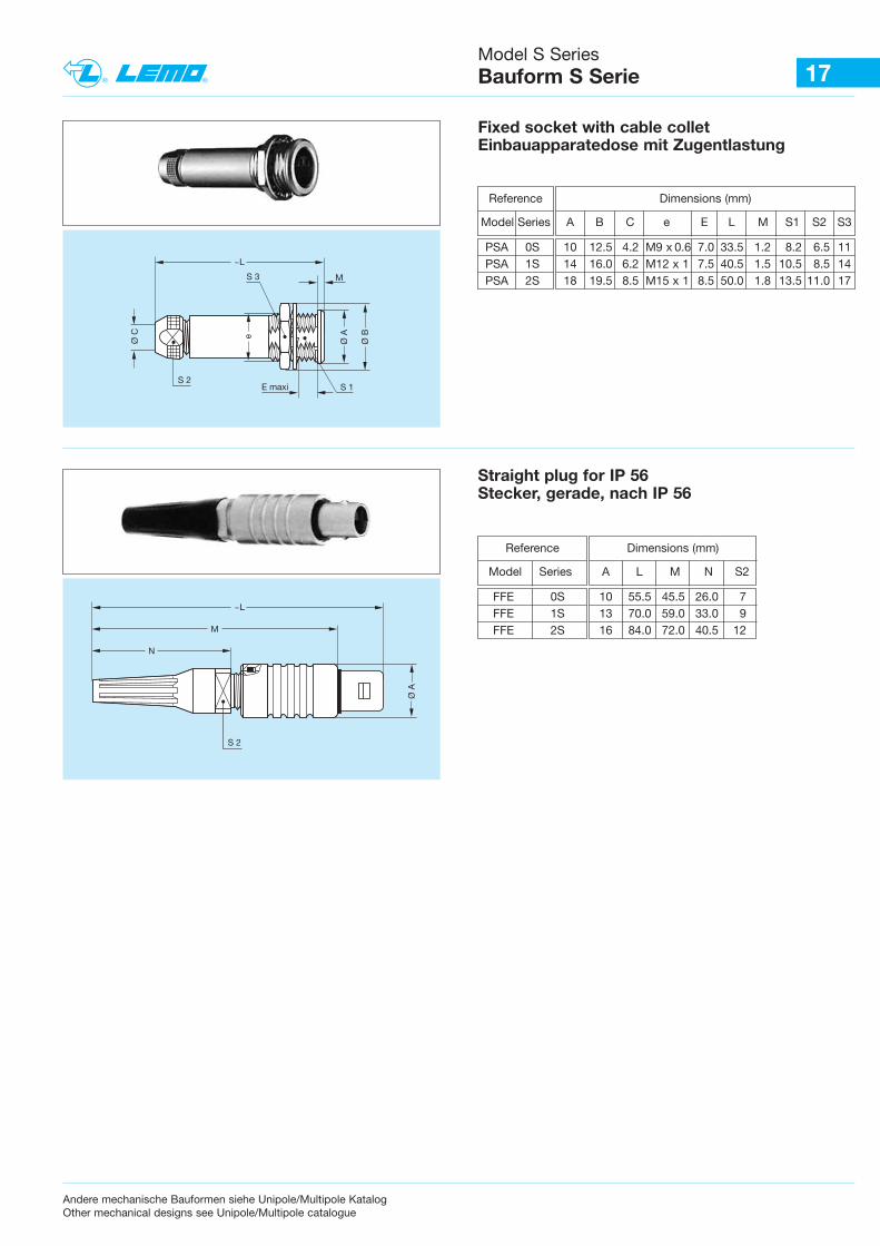
Fixed socket with cable colletEinbauapparatedose mit Zugentlastung
Straight plug for IP 56Stecker, gerade, nach IP 56
Dimensions (mm)
A B C e E L M S1 S2 S3
Reference
Model Series
PSA 0S 10 12.5 4.2 M9 x 0.6 7.0 33.5 1.2 8.2 6.5 11PSA 1S 14 16.0 6.2 M12 x 1 7.5 40.5 1.5 10.5 8.5 14PSA 2S 18 19.5 8.5 M15 x 1 8.5 50.0 1.8 13.5 11.0 17
Reference
Model Series
Dimensions (mm)
A L M N S2
FFE 0S 10 55.5 45.5 26.0 7FFE 1S 13 70.0 59.0 33.0 9FFE 2S 16 84.0 72.0 40.5 12
1
2
1
2
2
3
1 1
3
2
23
14
14
23
1
2
1
2
2
3
1 1
3
2
23
14
14
23
23 14 6
5
23146
5
1
2
1
2
2
3
1 1
3
2
23
14
14
23
23 14 6
5
2
3146
5
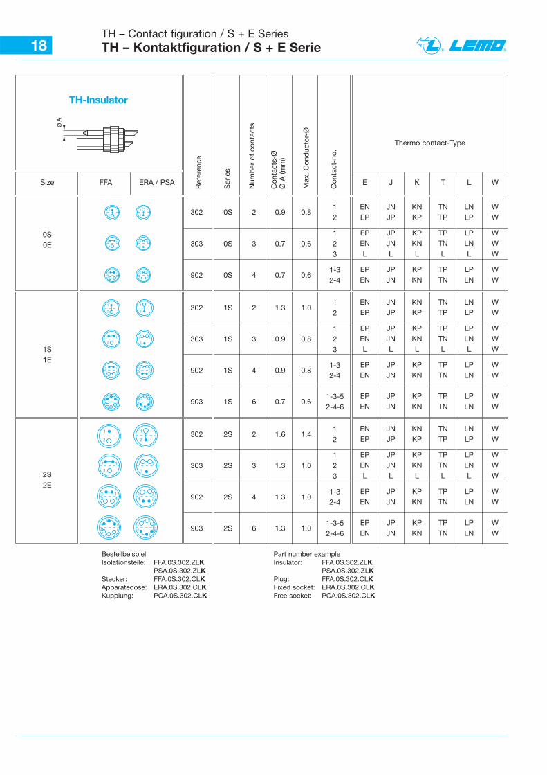
18TH – Contact figuration / S + E Series TH – Kontaktfiguration / S + E Serie
Ref
eren
ce
Ser
ies
Num
ber
of
cont
acts
Con
tact
s-Ø
Ø A
(mm
)
Max
. C
ond
ucto
r-Ø
Con
tact
-no.
Size FFA ERA / PSA
0S0E
1S1E
2S2E
E J K T L W
302 0S 2 0.9 0.812
1303 0S 3 0.7 0.6 2
3
902 0S 4 0.7 0.61-3 2-4
302 1S 2 1.3 1.012
1303 1S 3 0.9 0.8 2
3
902 1S 4 0.9 0.81-3 2-4
903 1S 6 0.7 0.61-3-5 2-4-6
302 2S 2 1.6 1.412
1303 2S 3 1.3 1.0 2
3
902 2S 4 1.3 1.01-3 2-4
903 2S 6 1.3 1.01-3-5 2-4-6
EN JN KN TN LN WEP JP KP TP LP W
EP JP KP TP LP WEN JN KN TN LN WL L L L L W
EP JP KP TP LP WEN JN KN TN LN W
EN JN KN TN LN WEP JP KP TP LP W
EP JP KP TP LP WEN JN KN TN LN WL L L L L W
EP JP KP TP LP WEN JN KN TN LN W
EP JP KP TP LP WEN JN KN TN LN W
EN JN KN TN LN WEP JP KP TP LP W
EP JP KP TP LP WEN JN KN TN LN WL L L L L W
EP JP KP TP LP WEN JN KN TN LN W
EP JP KP TP LP WEN JN KN TN LN W
Thermo contact-Type
TH-lnsulator
Bestellbeispiel Part number example Isolationsteile: FFA.0S.302.ZLK Insulator: FFA.0S.302.ZLK
PSA.0S.302.ZLK PSA.0S.302.ZLKStecker: FFA.0S.302.CLK Plug: FFA.0S.302.CLKApparatedose: ERA.0S.302.CLK Fixed socket: ERA.0S.302.CLKKupplung: PCA.0S.302.CLK Free socket: PCA.0S.302.CLK
Ø A
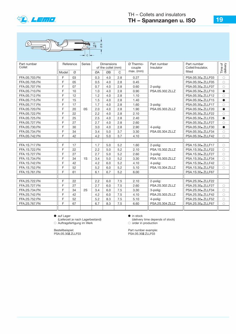
19TH – Collets and insulatorsTH – Spannzangen u. ISO
Ø BØ A
C
Tim
e of
deliv
eryPart number Reference Series Dimensions Ø Thermo- Part number Part number
Collet of the collet (mm) couple Insulator Collet/Insulator,
Model Ø ØA ØB C max. (mm) fitted
FFA.0S.703.FN F 03 0.3 4.0 2.8 0.27 PSA.0S.30•.ZLLF03 BFFA.0S.705.FN F 05 0.5 4.0 2.8 0.45 PSA.0S.30•.ZLLF05 BFFA.0S.707.FN F 07 0.7 4.0 2.8 0.60 2-polig: PSA.0S.30•.ZLLF07 BFFA.0S.710.FN F 10 1.0 4.0 2.8 0.90 PSA.0S.302.ZLLZ PSA.0S.30•.ZLLF10 bFFA.0S.712.FN F 12 1.2 4.0 2.8 1.10 PSA.0S.30•.ZLLF12 BFFA.0S.715.FN F 15 1.5 4.0 2.8 1.40 PSA.0S.30•.ZLLF15 bFFA.0S.717.FN F 17 1.7 4.0 2.8 1.60 3-polig: PSA.0S.30•.ZLLF17 BFFA.0S.720.FN F 20 0S 2.0 4.0 2.8 1.90 PSA.0S.303.ZLLZ PSA.0S.30•.ZLLF20 bFFA.0S.722.FN F 22 2.2 4.0 2.8 2.10 PSA.0S.30•.ZLLF22 BFFA.0S.725.FN F 25 2.5 4.0 2.8 2.40 PSA.0S.30•.ZLLF25 bFFA.0S.727.FN F 27 2.7 4.0 2.8 2.60 PSA.0S.30•.ZLLF27 BFFA.0S.730.FN F 30 3.0 4.0 2.8 2.90 4-polig: PSA.0S.30•.ZLLF30 bFFA.0S.734.FN F 34 3.4 5.0 3.7 3.30 PSA.0S.304.ZLLZ PSA.0S.30•.ZLLF34 BFFA.0S.742.FN F 42 4.2 5.0 3.7 4.10 PSA.0S.30•.ZLLF42 B
FFA.1S.717.FN F 17 1.7 5.0 5.2 1.60 2-polig: PSA.1S.30•.ZLLF17 BFFA.1S.722.FN F 22 2.2 5.0 5.2 2.10 PSA.1S.302.ZLLZ PSA.1S.30•.ZLLF22 BFFA.1S.727.FN F 27 2.7 5.0 5.2 2.60 3-polig: PSA.1S.30•.ZLLF27 BFFA.1S.734.FN F 34 1S 3.4 5.0 5.2 3.30 PSA.1S.303.ZLLZ PSA.1S.30•.ZLLF34 BFFA.1S.742.FN F 42 4.2 6.0 5.2 4.10 4-polig: PSA.1S.30•.ZLLF42 BFFA.1S.752.FN F 52 5.2 6.0 5.2 5.10 PSA.1S.304.ZLLZ PSA.1S.30•.ZLLF52 BFFA.1S.761.FN F 61 6.1 6.7 5.2 6.00 PSA.1S.30•.ZLLF67
FFA.2S.722.FN F 22 2.2 6.0 7.5 2.10 2-polig: PSA.2S.30•.ZLLF22FFA.2S.727.FN F 27 2.7 6.0 7.5 2.60 PSA.2S.302.ZLLZ PSA.2S.30•.ZLLF27 BFFA.2S.734.FN F 34 2S 3.4 6.0 7.5 3.30 3-polig: PSA.2S.30•.ZLLF34 BFFA.2S.742.FN F 42 4.2 6.0 7.5 4.10 PSA.2S.303.ZLLZ PSA.2S.30•.ZLLF42 BFFA.2S.752.FN F 52 5.2 8.3 7.5 5.10 4-polig: PSA.2S.30•.ZLLF52 BFFA.2S.767.FN F 67 6.7 8.3 7.5 6.60 PSA.2S.304.ZLLZ PSA.2S.30•.ZLLF67 B
b auf Lager(Lieferzeit je nach Lagerbestand)
B Auftragsfertigung im Werk
Bestellbeispiel:PSA.0S.302.ZLLF03
b in stock (delivery time depends of stock)
B order in production
Part number example:PSA.0S.302.ZLLF03
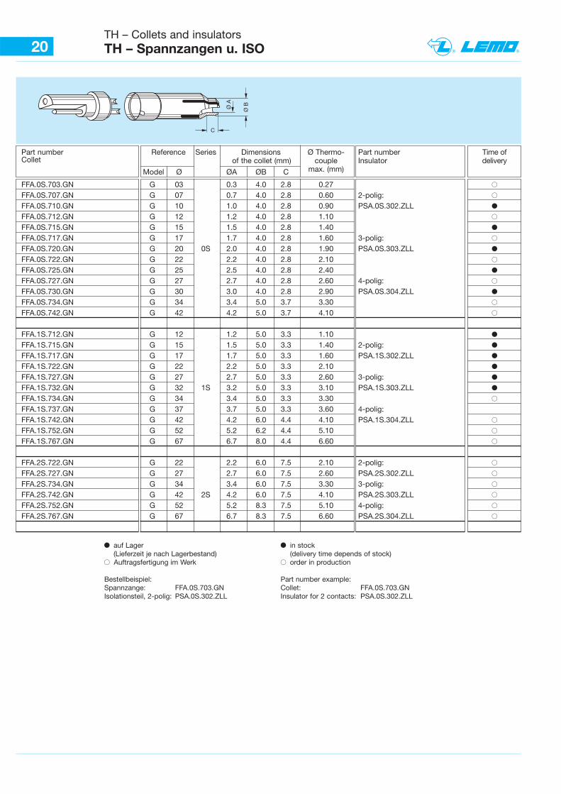
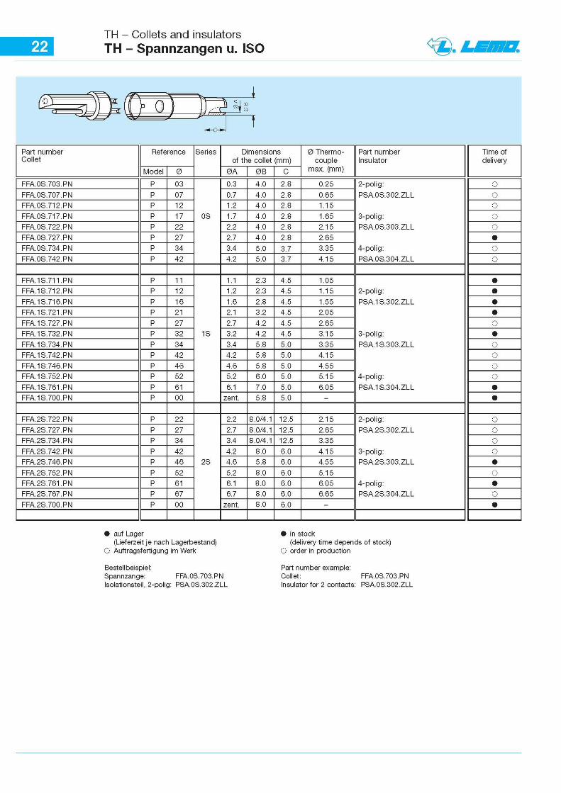
20TH – Collets and insulatorsTH – Spannzangen u. ISO
Ø BØ A
C
Part number Reference Series Dimensions Ø Thermo- Part number Time ofCollet of the collet (mm) couple Insulator delivery
Model Ø ØA ØB C max. (mm)
FFA.0S.703.GN G 03 0.3 4.0 2.8 0.27 BFFA.0S.707.GN G 07 0.7 4.0 2.8 0.60 2-polig: BFFA.0S.710.GN G 10 1.0 4.0 2.8 0.90 PSA.0S.302.ZLL bFFA.0S.712.GN G 12 1.2 4.0 2.8 1.10 BFFA.0S.715.GN G 15 1.5 4.0 2.8 1.40 bFFA.0S.717.GN G 17 1.7 4.0 2.8 1.60 3-polig: BFFA.0S.720.GN G 20 0S 2.0 4.0 2.8 1.90 PSA.0S.303.ZLL bFFA.0S.722.GN G 22 2.2 4.0 2.8 2.10 BFFA.0S.725.GN G 25 2.5 4.0 2.8 2.40 bFFA.0S.727.GN G 27 2.7 4.0 2.8 2.60 4-polig: BFFA.0S.730.GN G 30 3.0 4.0 2.8 2.90 PSA.0S.304.ZLL bFFA.0S.734.GN G 34 3.4 5.0 3.7 3.30 BFFA.0S.742.GN G 42 4.2 5.0 3.7 4.10 B
FFA.1S.712.GN G 12 1.2 5.0 3.3 1.10 bFFA.1S.715.GN G 15 1.5 5.0 3.3 1.40 2-polig: bFFA.1S.717.GN G 17 1.7 5.0 3.3 1.60 PSA.1S.302.ZLL bFFA.1S.722.GN G 22 2.2 5.0 3.3 2.10 bFFA.1S.727.GN G 27 2.7 5.0 3.3 2.60 3-polig: bFFA.1S.732.GN G 32 1S 3.2 5.0 3.3 3.10 PSA.1S.303.ZLL bFFA.1S.734.GN G 34 3.4 5.0 3.3 3.30 BFFA.1S.737.GN G 37 3.7 5.0 3.3 3.60 4-polig:FFA.1S.742.GN G 42 4.2 6.0 4.4 4.10 PSA.1S.304.ZLL BFFA.1S.752.GN G 52 5.2 6.2 4.4 5.10 BFFA.1S.767.GN G 67 6.7 8.0 4.4 6.60 B
FFA.2S.722.GN G 22 2.2 6.0 7.5 2.10 2-polig: BFFA.2S.727.GN G 27 2.7 6.0 7.5 2.60 PSA.2S.302.ZLL BFFA.2S.734.GN G 34 3.4 6.0 7.5 3.30 3-polig: BFFA.2S.742.GN G 42 2S 4.2 6.0 7.5 4.10 PSA.2S.303.ZLL BFFA.2S.752.GN G 52 5.2 8.3 7.5 5.10 4-polig: BFFA.2S.767.GN G 67 6.7 8.3 7.5 6.60 PSA.2S.304.ZLL B
b auf Lager(Lieferzeit je nach Lagerbestand)
B Auftragsfertigung im Werk
Bestellbeispiel:Spannzange: FFA.0S.703.GNIsolationsteil, 2-polig: PSA.0S.302.ZLL
b in stock (delivery time depends of stock)
B order in production
Part number example:Collet: FFA.0S.703.GNInsulator for 2 contacts: PSA.0S.302.ZLL
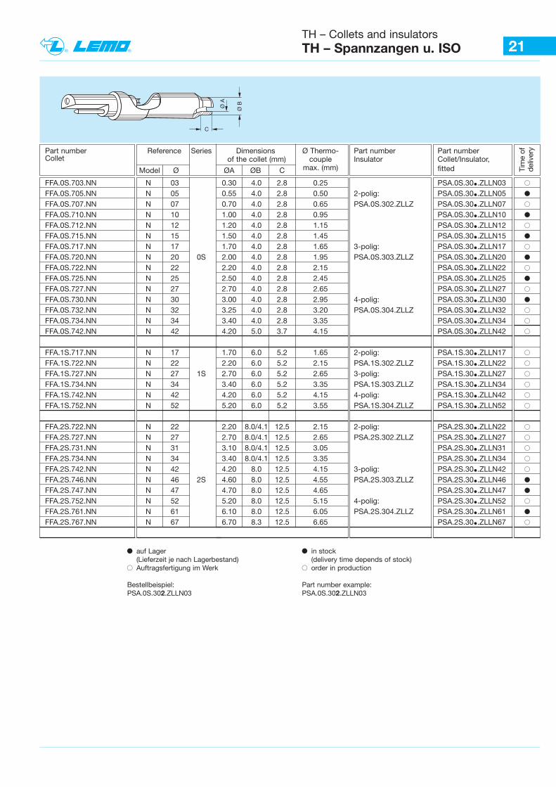
21TH – Collets and insulatorsTH – Spannzangen u. ISO
b auf Lager(Lieferzeit je nach Lagerbestand)
B Auftragsfertigung im Werk
Bestellbeispiel:PSA.0S.302.ZLLN03
b in stock (delivery time depends of stock)
B order in production
Part number example:PSA.0S.302.ZLLN03
Ø BØ A
C
Tim
e of
de
liver
yPart number Reference Series Dimensions Ø Thermo- Part number Part number Collet of the collet (mm) couple Insulator Collet/Insulator,
Model Ø ØA ØB C max. (mm) fitted
FFA.0S.703.NN N 03 0.30 4.0 2.8 0.25 PSA.0S.30•.ZLLN03 BFFA.0S.705.NN N 05 0.55 4.0 2.8 0.50 2-polig: PSA.0S.30•.ZLLN05 bFFA.0S.707.NN N 07 0.70 4.0 2.8 0.65 PSA.0S.302.ZLLZ PSA.0S.30•.ZLLN07 BFFA.0S.710.NN N 10 1.00 4.0 2.8 0.95 PSA.0S.30•.ZLLN10 bFFA.0S.712.NN N 12 1.20 4.0 2.8 1.15 PSA.0S.30•.ZLLN12 BFFA.0S.715.NN N 15 1.50 4.0 2.8 1.45 PSA.0S.30•.ZLLN15 bFFA.0S.717.NN N 17 1.70 4.0 2.8 1.65 3-polig: PSA.0S.30•.ZLLN17 BFFA.0S.720.NN N 20 0S 2.00 4.0 2.8 1.95 PSA.0S.303.ZLLZ PSA.0S.30•.ZLLN20 bFFA.0S.722.NN N 22 2.20 4.0 2.8 2.15 PSA.0S.30•.ZLLN22 BFFA.0S.725.NN N 25 2.50 4.0 2.8 2.45 PSA.0S.30•.ZLLN25 bFFA.0S.727.NN N 27 2.70 4.0 2.8 2.65 PSA.0S.30•.ZLLN27 BFFA.0S.730.NN N 30 3.00 4.0 2.8 2.95 4-polig: PSA.0S.30•.ZLLN30 bFFA.0S.732.NN N 32 3.25 4.0 2.8 3.20 PSA.0S.304.ZLLZ PSA.0S.30•.ZLLN32 BFFA.0S.734.NN N 34 3.40 4.0 2.8 3.35 PSA.0S.30•.ZLLN34 BFFA.0S.742.NN N 42 4.20 5.0 3.7 4.15 PSA.0S.30•.ZLLN42 B
FFA.1S.717.NN N 17 1.70 6.0 5.2 1.65 2-polig: PSA.1S.30•.ZLLN17 BFFA.1S.722.NN N 22 2.20 6.0 5.2 2.15 PSA.1S.302.ZLLZ PSA.1S.30•.ZLLN22 BFFA.1S.727.NN N 27 1S 2.70 6.0 5.2 2.65 3-polig: PSA.1S.30•.ZLLN27 BFFA.1S.734.NN N 34 3.40 6.0 5.2 3.35 PSA.1S.303.ZLLZ PSA.1S.30•.ZLLN34 BFFA.1S.742.NN N 42 4.20 6.0 5.2 4.15 4-polig: PSA.1S.30•.ZLLN42 BFFA.1S.752.NN N 52 5.20 6.0 5.2 3.55 PSA.1S.304.ZLLZ PSA.1S.30•.ZLLN52 B
FFA.2S.722.NN N 22 2.20 8.0/4.1 12.5 2.15 2-polig: PSA.2S.30•.ZLLN22 BFFA.2S.727.NN N 27 2.70 8.0/4.1 12.5 2.65 PSA.2S.302.ZLLZ PSA.2S.30•.ZLLN27 BFFA.2S.731.NN N 31 3.10 8.0/4.1 12.5 3.05 PSA.2S.30•.ZLLN31 BFFA.2S.734.NN N 34 3.40 8.0/4.1 12.5 3.35 PSA.2S.30•.ZLLN34 BFFA.2S.742.NN N 42 4.20 8.0 12.5 4.15 3-polig: PSA.2S.30•.ZLLN42 BFFA.2S.746.NN N 46 2S 4.60 8.0 12.5 4.55 PSA.2S.303.ZLLZ PSA.2S.30•.ZLLN46 bFFA.2S.747.NN N 47 4.70 8.0 12.5 4.65 PSA.2S.30•.ZLLN47 bFFA.2S.752.NN N 52 5.20 8.0 12.5 5.15 4-polig: PSA.2S.30•.ZLLN52 BFFA.2S.761.NN N 61 6.10 8.0 12.5 6.05 PSA.2S.304.ZLLZ PSA.2S.30•.ZLLN61 bFFA.2S.767.NN N 67 6.70 8.3 12.5 6.65 PSA.2S.30•.ZLLN67 B
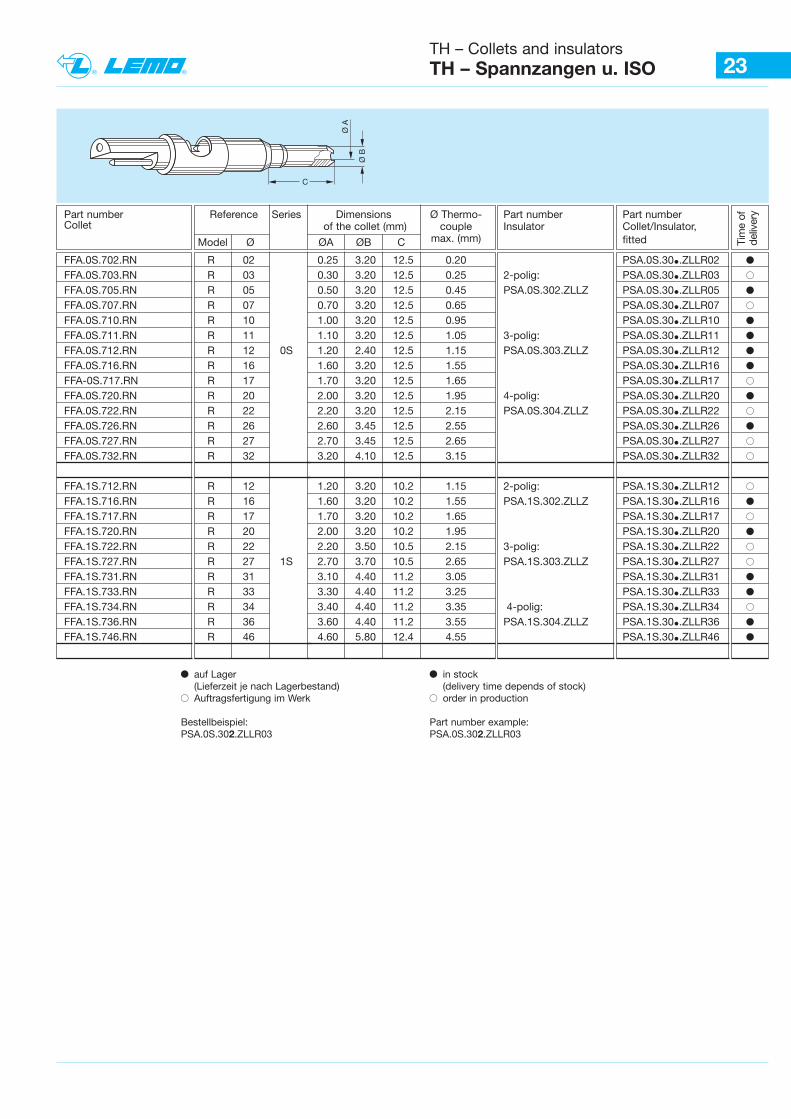
23TH – Collets and insulatorsTH – Spannzangen u. ISO
Ø B
Ø A
C
Tim
e of
de
liver
yPart number Reference Series Dimensions Ø Thermo- Part number Part number Collet of the collet (mm) couple Insulator Collet/Insulator,
Model Ø ØA ØB C max. (mm) fitted
FFA.0S.702.RN R 02 0.25 3.20 12.5 0.20 PSA.0S.30•.ZLLR02 bFFA.0S.703.RN R 03 0.30 3.20 12.5 0.25 2-polig: PSA.0S.30•.ZLLR03 BFFA.0S.705.RN R 05 0.50 3.20 12.5 0.45 PSA.0S.302.ZLLZ PSA.0S.30•.ZLLR05 bFFA.0S.707.RN R 07 0.70 3.20 12.5 0.65 PSA.0S.30•.ZLLR07 BFFA.0S.710.RN R 10 1.00 3.20 12.5 0.95 PSA.0S.30•.ZLLR10 bFFA.0S.711.RN R 11 1.10 3.20 12.5 1.05 3-polig: PSA.0S.30•.ZLLR11 bFFA.0S.712.RN R 12 0S 1.20 2.40 12.5 1.15 PSA.0S.303.ZLLZ PSA.0S.30•.ZLLR12 bFFA.0S.716.RN R 16 1.60 3.20 12.5 1.55 PSA.0S.30•.ZLLR16 bFFA-0S.717.RN R 17 1.70 3.20 12.5 1.65 PSA.0S.30•.ZLLR17 BFFA.0S.720.RN R 20 2.00 3.20 12.5 1.95 4-polig: PSA.0S.30•.ZLLR20 bFFA.0S.722.RN R 22 2.20 3.20 12.5 2.15 PSA.0S.304.ZLLZ PSA.0S.30•.ZLLR22 BFFA.0S.726.RN R 26 2.60 3.45 12.5 2.55 PSA.0S.30•.ZLLR26 bFFA.0S.727.RN R 27 2.70 3.45 12.5 2.65 PSA.0S.30•.ZLLR27 BFFA.0S.732.RN R 32 3.20 4.10 12.5 3.15 PSA.0S.30•.ZLLR32 B
FFA.1S.712.RN R 12 1.20 3.20 10.2 1.15 2-polig: PSA.1S.30•.ZLLR12 BFFA.1S.716.RN R 16 1.60 3.20 10.2 1.55 PSA.1S.302.ZLLZ PSA.1S.30•.ZLLR16 bFFA.1S.717.RN R 17 1.70 3.20 10.2 1.65 PSA.1S.30•.ZLLR17 BFFA.1S.720.RN R 20 2.00 3.20 10.2 1.95 PSA.1S.30•.ZLLR20 bFFA.1S.722.RN R 22 2.20 3.50 10.5 2.15 3-polig: PSA.1S.30•.ZLLR22 BFFA.1S.727.RN R 27 1S 2.70 3.70 10.5 2.65 PSA.1S.303.ZLLZ PSA.1S.30•.ZLLR27 BFFA.1S.731.RN R 31 3.10 4.40 11.2 3.05 PSA.1S.30•.ZLLR31 bFFA.1S.733.RN R 33 3.30 4.40 11.2 3.25 PSA.1S.30•.ZLLR33 bFFA.1S.734.RN R 34 3.40 4.40 11.2 3.35 4-polig: PSA.1S.30•.ZLLR34 BFFA.1S.736.RN R 36 3.60 4.40 11.2 3.55 PSA.1S.304.ZLLZ PSA.1S.30•.ZLLR36 bFFA.1S.746.RN R 46 4.60 5.80 12.4 4.55 PSA.1S.30•.ZLLR46 b
b auf Lager(Lieferzeit je nach Lagerbestand)
B Auftragsfertigung im Werk
Bestellbeispiel:PSA.0S.302.ZLLR03
b in stock (delivery time depends of stock)
B order in production
Part number example:PSA.0S.302.ZLLR03
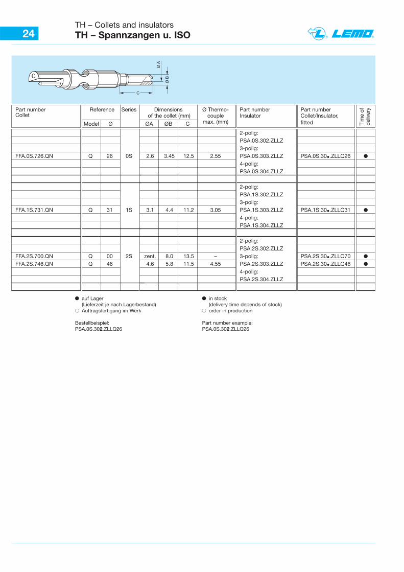
24TH – Collets and insulatorsTH – Spannzangen u. ISO
Ø B
Ø A
C
Tim
e of
deliv
eryPart number Reference Series Dimensions Ø Thermo- Part number Part number
Collet of the collet (mm) couple Insulator Collet/Insulator,
Model Ø ØA ØB C max. (mm) fitted
2-polig: PSA.0S.302.ZLLZ 3-polig:
FFA.0S.726.QN Q 26 0S 2.6 3.45 12.5 2.55 PSA.0S.303.ZLLZ PSA.0S.30•.ZLLQ26 b4-polig: PSA.0S.304.ZLLZ
2-polig: PSA.1S.302.ZLLZ 3-polig:
FFA.1S.731.QN Q 31 1S 3.1 4.4 11.2 3.05 PSA.1S.303.ZLLZ PSA.1S.30•.ZLLQ31 b4-polig: PSA.1S.304.ZLLZ
2-polig: PSA.2S.302.ZLLZ
FFA.2S.700.QN Q 00 2S zent. 8.0 13.5 – 3-polig: PSA.2S.30•.ZLLQ70 bFFA.2S.746.QN Q 46 4.6 5.8 11.5 4.55 PSA.2S.303.ZLLZ PSA.2S.30•.ZLLQ46 b
4-polig: PSA.2S.304.ZLLZ
b auf Lager(Lieferzeit je nach Lagerbestand)
B Auftragsfertigung im Werk
Bestellbeispiel:PSA.0S.302.ZLLQ26
b in stock (delivery time depends of stock)
B order in production
Part number example:PSA.0S.302.ZLLQ26
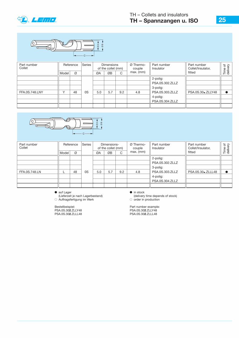
25TH – Collets and insulatorsTH – Spannzangen u. ISO
Ø B
C
Ø A
Tim
e of
deliv
eryPart number Reference Series Dimensions Ø Thermo- Part number Part number
Collet of the collet (mm) couple Insulator Collet/Insulator,
Model Ø ØA ØB C max. (mm) fitted
2-polig: PSA.0S.302.ZLLZ 3-polig:
FFA.0S.748.LNY Y 48 0S 5.0 5.7 9.2 4.8 PSA.0S.303.ZLLZ PSA.0S.30•.ZLLY48 b4-polig: PSA.0S.304.ZLLZ
b auf Lager(Lieferzeit je nach Lagerbestand)
B Auftragsfertigung im Werk
Bestellbeispiel:PSA.0S.302.ZLLY48PSA.0S.302.ZLLL48
b in stock (delivery time depends of stock)
B order in production
Part number example:PSA.0S.302.ZLLY48PSA.0S.302.ZLLL48
Ø B
C
Ø A
Part number Reference Series Dimensions- Ø Thermo- Part number Part number Collet of the collet (mm) couple Insulator Collet/Insulator,
Model Ø ØA ØB C max. (mm) fitted
2-polig: PSA.0S.302.ZLLZ 3-polig:
FFA.0S.748.LN L 48 0S 5.0 5.7 9.2 4.8 PSA.0S.303.ZLLZ PSA.0S.30•.ZLLL48 b4-polig: PSA.0S.304.ZLLZ
Tim
e of
deliv
ery
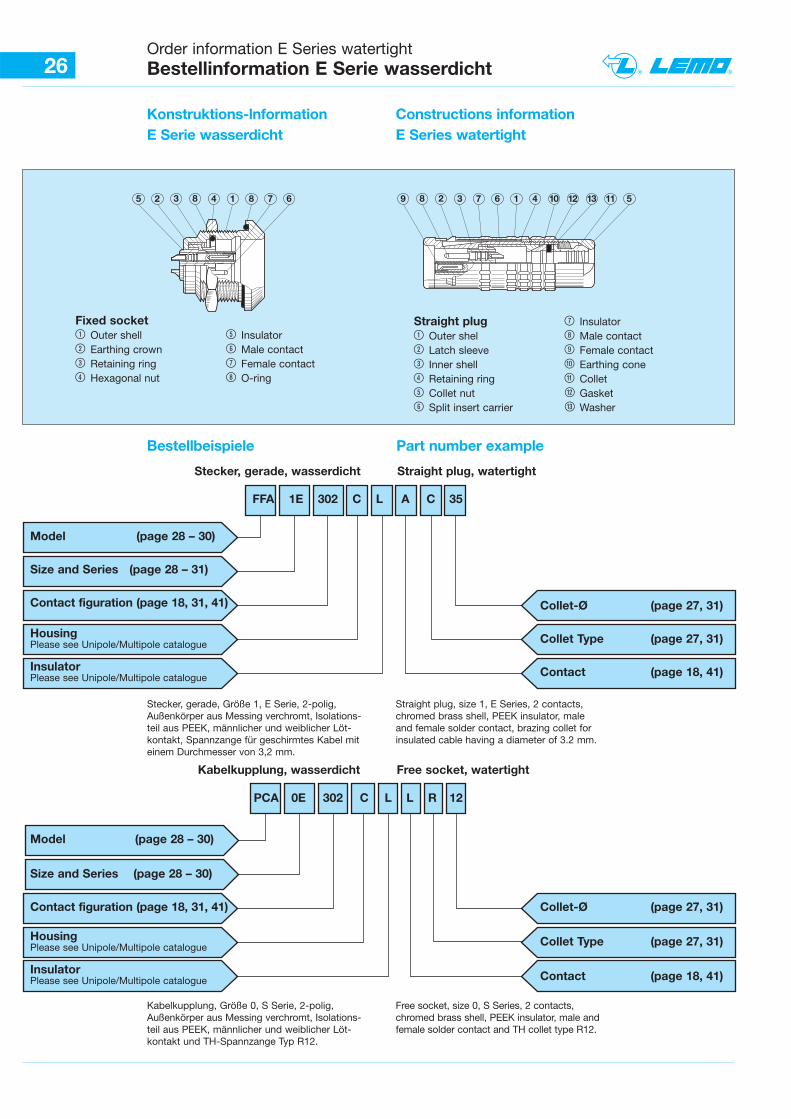
26Order information E Series watertightBestellinformation E Serie wasserdicht
Bestellbeispiele Part number example
5 2 3 8 4 1 8 7 6 9 8 2 3 7 6 1 4 10 12 13 11 5
Stecker, gerade, Größe 1, E Serie, 2-polig,Außenkörper aus Messing verchromt, Isolations-teil aus PEEK, männlicher und weiblicher Löt-kontakt, Spannzange für geschirmtes Kabel miteinem Durchmesser von 3,2 mm.
Straight plug, size 1, E Series, 2 contacts, chromed brass shell, PEEK insulator, male and female solder contact, brazing collet forinsulated cable having a diameter of 3.2 mm.
Kabelkupplung, Größe 0, S Serie, 2-polig,Außenkörper aus Messing verchromt, Isolations-teil aus PEEK, männlicher und weiblicher Löt-kontakt und TH-Spannzange Typ R12.
Free socket, size 0, S Series, 2 contacts, chromed brass shell, PEEK insulator, male andfemale solder contact and TH collet type R12.
Fixed socket1 Outer shell 5 Insulator2 Earthing crown 6 Male contact3 Retaining ring 7 Female contact4 Hexagonal nut 8 O-ring
Straight plug 7 Insulator1 Outer shel 8 Male contact2 Latch sleeve 9 Female contact3 Inner shell 0 Earthing cone4 Retaining ring ß Collet5 Collet nut “ Gasket6 Split insert carrier „ Washer
FFA 1E 302 C L A C 35
Stecker, gerade, wasserdicht Straight plug, watertight
Model (page 28 – 30)
Size and Series (page 28 – 31)
Contact figuration (page 18, 31, 41)
HousingPlease see Unipole/Multipole catalogue
InsulatorPlease see Unipole/Multipole catalogue
Collet-Ø (page 27, 31)
Collet Type (page 27, 31)
Contact (page 18, 41)
PCA 0E 302 C L L R 12
Kabelkupplung, wasserdicht Free socket, watertight
Model (page 28 – 30)
Size and Series (page 28 – 30)
Contact figuration (page 18, 31, 41)
HousingPlease see Unipole/Multipole catalogue
InsulatorPlease see Unipole/Multipole catalogue
Collet-Ø (page 27, 31)
Collet Type (page 27, 31)
Contact (page 18, 41)
Konstruktions-lnformationE Serie wasserdicht
Constructions informationE Series watertight
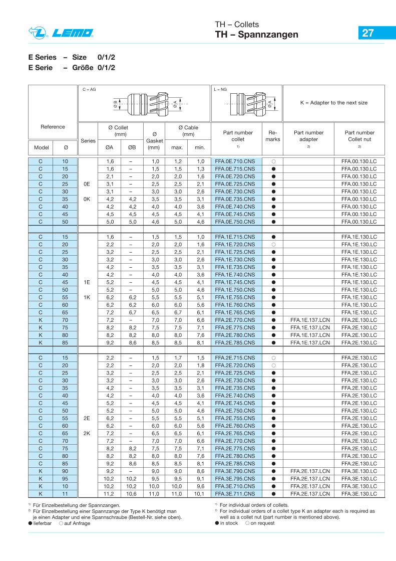
27
E Series – Size 0/1/2E Serie – Größe 0/1/2
Reference
Model Ø
Ø Collet Ø Cable (mm) Ø (mm)
Series GasketØA ØB (mm) max. min.
Part number Re- Part number Part numbercollet marks adapter Collet nut
1) 2) 2)
Ø A
Ø B
C = AG L = NG
Ø A K = Adapter to the next size
1) Für Einzelbestellung der Spannzangen.2) Für Einzelbestellung einer Spannzange der Type K benötigt man
je einen Adapter und eine Spannschraube (Bestell-Nr. siehe oben).b lieferbar B auf Anfrage
1) For individual orders of collets. 2) For individual orders of a collet type K an adapter each is required as
well as a collet nut (part number is mentioned above). b in stock B on request
TH – Collets TH – Spannzangen
C 10 1,6 – 1,0 1,2 1,0 FFA.0E.710.CNS B FFA.00.130.LCC 15 1,6 – 1,5 1,5 1,3 FFA.0E.715.CNS b FFA.00.130.LCC 20 2,1 – 2,0 2,0 1,6 FFA.0E.720.CNS b FFA.00.130.LCC 25 0E 3,1 – 2,5 2,5 2,1 FFA.0E.725.CNS b FFA.00.130.LCC 30 3,1 – 3,0 3,0 2,6 FFA.0E.730.CNS b FFA.00.130.LCC 35 0K 4,2 4,2 3,5 3,5 3,1 FFA.0E.735.CNS b FFA.00.130.LCC 40 4,2 4,2 4,0 4,0 3,6 FFA.0E.740.CNS b FFA.00.130.LCC 45 4,5 4,5 4,5 4,5 4,1 FFA.0E.745.CNS b FFA.00.130.LCC 50 5,0 5,0 4,6 5,0 4,6 FFA.0E.750.CNS b FFA.00.130.LC
C 15 1,6 – 1,5 1,5 1,0 FFA.1E.715.CNS b FFA.1E.130.LCC 20 2,2 – 2,0 2,0 1,6 FFA.1E.720.CNS B FFA.1E.130.LCC 25 3,2 – 2,5 2,5 2,1 FFA.1E.725.CNS b FFA.1E.130.LCC 30 3,2 – 3,0 3,0 2,6 FFA.1E.730.CNS b FFA.1E.130.LCC 35 4,2 – 3,5 3,5 3,1 FFA.1E.735.CNS b FFA.1E.130.LCC 40 4,2 – 4,0 4,0 3,6 FFA.1E.740.CNS b FFA.1E.130.LCC 45 1E 5,2 – 4,5 4,5 4,1 FFA.1E.745.CNS b FFA.1E.130.LCC 50 5,2 – 5,0 5,0 4,6 FFA.1E.750.CNS b FFA.1E.130.LCC 55 1K 6,2 6,2 5,5 5,5 5,1 FFA.1E.755.CNS b FFA.1E.130.LCC 60 6,2 6,2 6,0 6,0 5,6 FFA.1E.760.CNS b FFA.1E.130.LCC 65 7,2 6,7 6,5 6,7 6,1 FFA.1E.765.CNS b FFA.1E.130.LCK 70 7,2 – 7,0 7,0 6,6 FFA.2E.770.CNS b FFA.1E.137.LCN FFA.2E.130.LCK 75 8,2 8,2 7,5 7,5 7,1 FFA.2E.775.CNS b FFA.1E.137.LCN FFA.2E.130.LCK 80 8,2 8,2 8,0 8,0 7,6 FFA.2E.780.CNS b FFA.1E.137.LCN FFA.2E.130.LCK 85 9,2 8,6 8,5 8,5 8,1 FFA.2E.785.CNS b FFA.1E.137.LCN FFA.2E.130.LC
C 15 2,2 – 1,5 1,7 1,5 FFA.2E.715.CNS B FFA.2E.130.LCC 20 2,2 – 2,0 2,0 1,8 FFA.2E.720.CNS B FFA.2E.130.LCC 25 3,2 – 2,5 2,5 2,1 FFA.2E.725.CNS b FFA.2E.130.LCC 30 3,2 – 3,0 3,0 2,6 FFA.2E.730.CNS b FFA.2E.130.LCC 35 4,2 – 3,5 3,5 3,1 FFA.2E.735.CNS b FFA.2E.130.LCC 40 4,2 – 4,0 4,0 3,6 FFA.2E.740.CNS b FFA.2E.130.LCC 45 5,2 – 4,5 4,5 4,1 FFA.2E.745.CNS b FFA.2E.130.LCC 50 5,2 – 5,0 5,0 4,6 FFA.2E.750.CNS b FFA.2E.130.LCC 55 2E 6,2 – 5,5 5,5 5,1 FFA.2E.755.CNS b FFA.2E.130.LCC 60 6,2 – 6,0 6,0 5,6 FFA.2E.760.CNS b FFA.2E.130.LCC 65 2K 7,2 – 6,5 6,5 6,1 FFA.2E.765.CNS b FFA.2E.130.LCC 70 7,2 – 7,0 7,0 6,6 FFA.2E.770.CNS b FFA.2E.130.LCC 75 8,2 8,2 7,5 7,5 7,1 FFA.2E.775.CNS b FFA.2E.130.LCC 80 8,2 8,2 8,0 8,0 7,6 FFA.2E.780.CNS b FFA.2E.130.LCC 85 9,2 8,6 8,5 8,5 8,1 FFA.2E.785.CNS b FFA.2E.130.LCK 90 9,2 – 9,0 9,0 8,6 FFA.3E.790.CNS b FFA.2E.137.LCN FFA.3E.130.LCK 95 10,2 10,2 9,5 9,5 9,1 FFA.3E.795.CNS b FFA.2E.137.LCN FFA.3E.130.LCK 10 10,2 10,2 10,0 10,0 9,6 FFA.3E.710.CNS b FFA.2E.137.LCN FFA.3E.130.LCK 11 11,2 10,6 11,0 11,0 10,1 FFA.3E.711.CNS b FFA.2E.137.LCN FFA.3E.130.LC
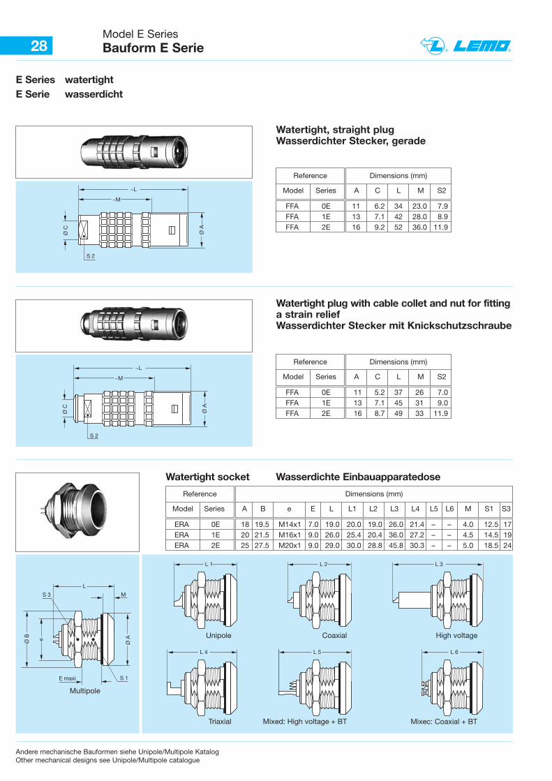
28Model E Series Bauform E Serie
Dimensions (mm)
A C L M S2
E Series watertightE Serie wasserdicht
S 2
Ø C
~L
Ø A
~M
S 2
Ø C
~L
Ø A
~M
S 1E maxi
Ø A
L
MS 3
Ø B e
Multipole
L 1
Unipole
L 2
Coaxial
L 3
High voltage
L 4
Triaxial
L 5
Mixed: High voltage + BT
L 6
Mixec: Coaxial + BT
Watertight, straight plugWasserdichter Stecker, gerade
Reference
Model Series
FFA 0E 11 6.2 34 23.0 7.9FFA 1E 13 7.1 42 28.0 8.9FFA 2E 16 9.2 52 36.0 11.9
Dimensions (mm)
A C L M S2
Watertight plug with cable collet and nut for fittinga strain relief Wasserdichter Stecker mit Knickschutzschraube
Reference
Model Series
FFA 0E 11 5.2 37 26 7.0FFA 1E 13 7.1 45 31 9.0FFA 2E 16 8.7 49 33 11.9
Dimensions (mm)
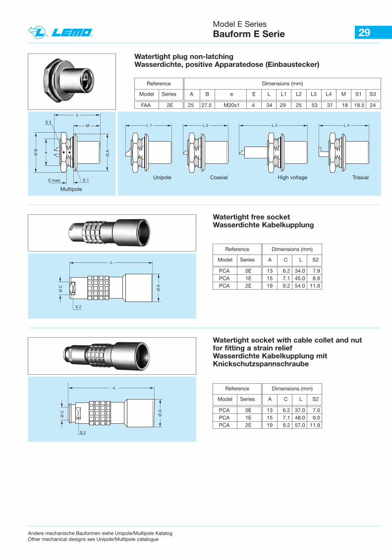
A B e E L L1 L2 L3 L4 L5 L6 M S1 S3
Watertight socket Wasserdichte Einbauapparatedose
Reference
Model Series
ERA 0E 18 19.5 M14x1 7.0 19.0 20.0 19.0 26.0 21.4 – – 4.0 12.5 17ERA 1E 20 21.5 M16x1 9.0 26.0 25.4 20.4 36.0 27.2 – – 4.5 14.5 19 ERA 2E 25 27.5 M20x1 9.0 29.0 30.0 28.8 45.8 30.3 – – 5.0 18.5 24
Andere mechanische Bauformen siehe Unipole/Multipole KatalogOther mechanical designs see Unipole/Multipole catalogue
29Model E Series Bauform E Serie
Andere mechanische Bauformen siehe Unipole/Multipole KatalogOther mechanical designs see Unipole/Multipole catalogue
S 1E maxi
Ø A
L
MS 3
Ø B e
Multipole
L 1
Unipole
L 2
Coaxial
L 3
High voltage
L 4
Triaxial
Dimensions (mm)
A B e E L L1 L2 L3 L4 M S1 S3
Watertight plug non-latching Wasserdichte, positive Apparatedose (Einbaustecker)
Reference
Model Series
FAA 2E 25 27.5 M20x1 4 34 29 25 53 37 18 18.5 24
S 2
Ø C
~L
Ø A
Dimensions (mm)
A C L S2
Watertight free socketWasserdichte Kabelkupplung
Reference
Model Series
PCA 0E 13 6.2 34.0 7.9PCA 1E 15 7.1 45.0 8.9PCA 2E 19 9.2 54.0 11.9
S 2
Ø C
~L
Ø A
Watertight socket with cable collet and nut for fitting a strain reliefWasserdichte Kabelkupplung mitKnickschutzspannschraube
Dimensions (mm)
A C L S2
Reference
Model Series
PCA 0E 13 6.2 37.0 7.0PCA 1E 15 7.1 48.0 9.0PCA 2E 19 9.2 57.0 11.9
30Model E Series Bauform E Serie
E maxi
Ø A
MS 3
Ø B e
Ø C
S 2
~L
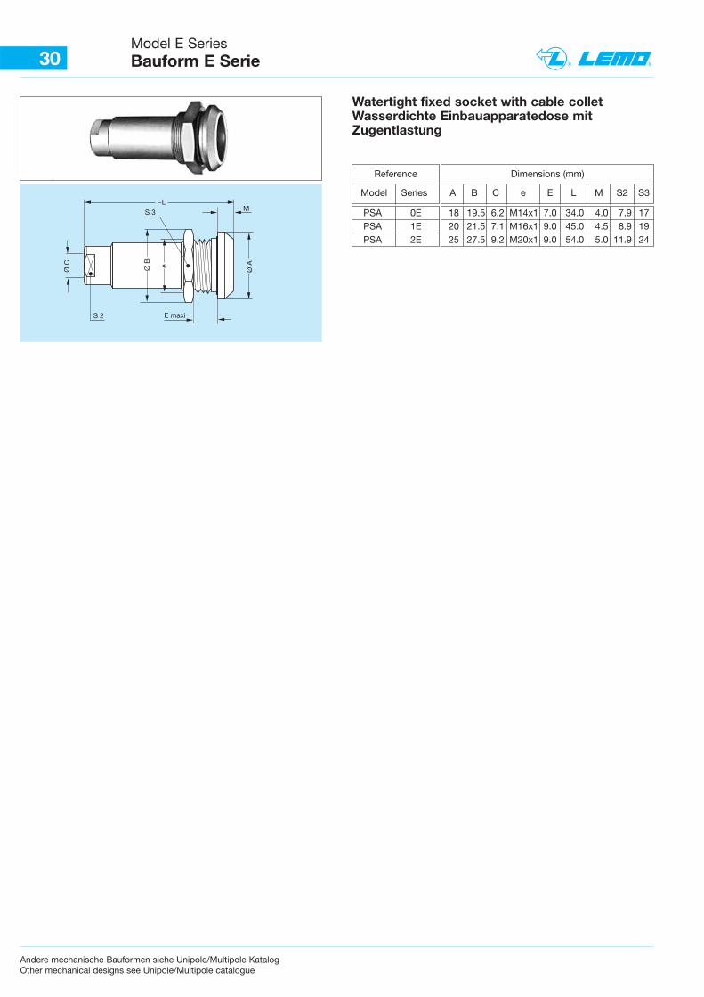
Watertight fixed socket with cable colletWasserdichte Einbauapparatedose mitZugentlastung
Dimensions (mm)
A B C e E L M S2 S3
Reference
Model Series
PSA 0E 18 19.5 6.2 M14x1 7.0 34.0 4.0 7.9 17PSA 1E 20 21.5 7.1 M16x1 9.0 45.0 4.5 8.9 19PSA 2E 25 27.5 9.2 M20x1 9.0 54.0 5.0 11.9 24
Andere mechanische Bauformen siehe Unipole/Multipole KatalogOther mechanical designs see Unipole/Multipole catalogue
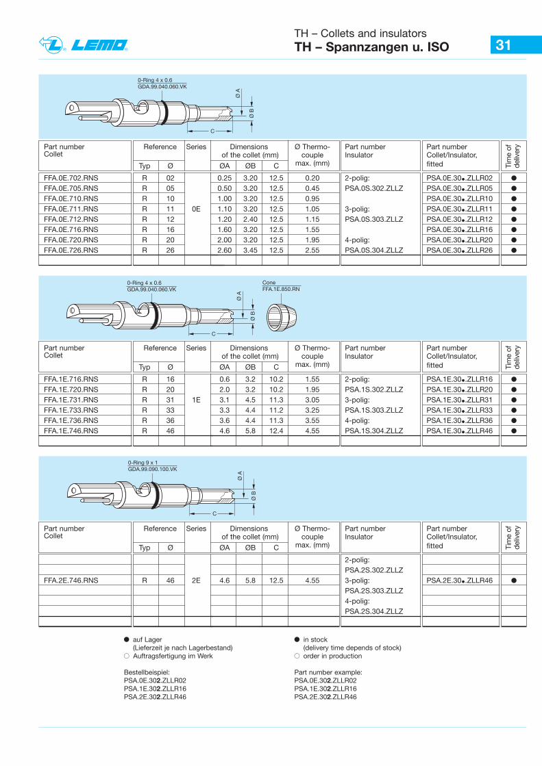
31TH – Collets and insulatorsTH – Spannzangen u. ISO
b auf Lager(Lieferzeit je nach Lagerbestand)
B Auftragsfertigung im Werk
Bestellbeispiel:PSA.0E.302.ZLLR02PSA.1E.302.ZLLR16PSA.2E.302.ZLLR46
b in stock (delivery time depends of stock)
B order in production
Part number example:PSA.0E.302.ZLLR02PSA.1E.302.ZLLR16PSA.2E.302.ZLLR46
Ø B
Ø A
C
0-Ring 4 x 0.6GDA.99.040.060.VK
Tim
e of
deliv
eryPart number Reference Series Dimensions Ø Thermo- Part number Part number
Collet of the collet (mm) couple Insulator Collet/Insulator,
Typ Ø ØA ØB C max. (mm) fitted
FFA.0E.702.RNS R 02 0.25 3.20 12.5 0.20 2-polig: PSA.0E.30•.ZLLR02 bFFA.0E.705.RNS R 05 0.50 3.20 12.5 0.45 PSA.0S.302.ZLLZ PSA.0E.30•.ZLLR05 bFFA.0E.710.RNS R 10 1.00 3.20 12.5 0.95 PSA.0E.30•.ZLLR10 bFFA.0E.711.RNS R 11 0E 1.10 3.20 12.5 1.05 3-polig: PSA.0E.30•.ZLLR11 bFFA.0E.712.RNS R 12 1.20 2.40 12.5 1.15 PSA.0S.303.ZLLZ PSA.0E.30•.ZLLR12 bFFA.0E.716.RNS R 16 1.60 3.20 12.5 1.55 PSA.0E.30•.ZLLR16 bFFA.0E.720.RNS R 20 2.00 3.20 12.5 1.95 4-polig: PSA.0E.30•.ZLLR20 bFFA.0E.726.RNS R 26 2.60 3.45 12.5 2.55 PSA.0S.304.ZLLZ PSA.0E.30•.ZLLR26 b
Ø B
Ø A
C
0-Ring 4 x 0.6GDA.99.040.060.VK
Cone FFA.1E.850.RN
Part number Reference Series Dimensions Ø Thermo- Part number Part numberCollet of the collet (mm) couple Insulator Collet/Insulator,
Typ Ø ØA ØB C max. (mm) fitted
FFA.1E.716.RNS R 16 0.6 3.2 10.2 1.55 2-polig: PSA.1E.30•.ZLLR16 bFFA.1E.720.RNS R 20 2.0 3.2 10.2 1.95 PSA.1S.302.ZLLZ PSA.1E.30•.ZLLR20 bFFA.1E.731.RNS R 31 1E 3.1 4.5 11.3 3.05 3-polig: PSA.1E.30•.ZLLR31 bFFA.1E.733.RNS R 33 3.3 4.4 11.2 3.25 PSA.1S.303.ZLLZ PSA.1E.30•.ZLLR33 bFFA.1E.736.RNS R 36 3.6 4.4 11.3 3.55 4-polig: PSA.1E.30•.ZLLR36 bFFA.1E.746.RNS R 46 4.6 5.8 12.4 4.55 PSA.1S.304.ZLLZ PSA.1E.30•.ZLLR46 b
Ø B
Ø A
C
0-Ring 9 x 1GDA.99.090.100.VK
Part number Reference Series Dimensions Ø Thermo- Part number Part numberCollet of the collet (mm) couple Insulator Collet/Insulator,
Typ Ø ØA ØB C max. (mm) fitted
2-polig: PSA.2S.302.ZLLZ
FFA.2E.746.RNS R 46 2E 4.6 5.8 12.5 4.55 3-polig: PSA.2E.30•.ZLLR46 bPSA.2S.303.ZLLZ 4-polig: PSA.2S.304.ZLLZ
Tim
e of
deliv
ery
Tim
e of
deliv
ery
32Order information B Series Bestellinformation B Serie
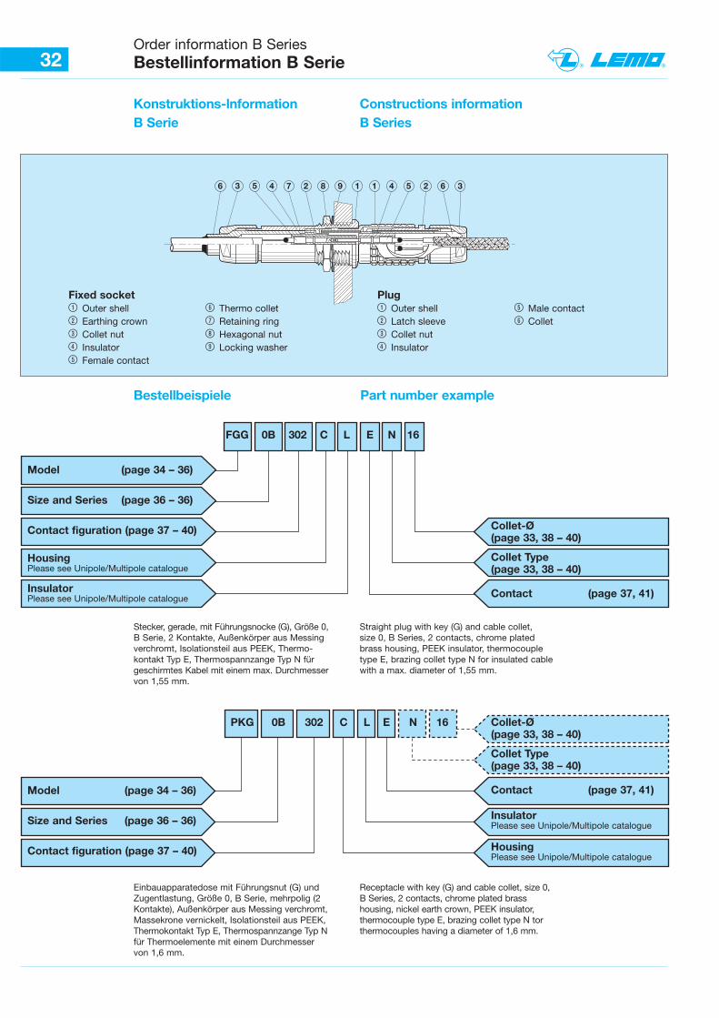
Konstruktions-lnformation B Serie
Constructions information B Series
Bestellbeispiele Part number example
2 6 36 3 5 4 7 2 8 9 1 1 4 5
Stecker, gerade, mit Führungsnocke (G), Größe 0,B Serie, 2 Kontakte, Außenkörper aus Messingverchromt, Isolationsteil aus PEEK, Thermo-kontakt Typ E, Thermospannzange Typ N fürgeschirmtes Kabel mit einem max. Durchmesservon 1,55 mm.
Straight plug with key (G) and cable collet, size 0, B Series, 2 contacts, chrome platedbrass housing, PEEK insulator, thermocoupletype E, brazing collet type N for insulated cablewith a max. diameter of 1,55 mm.
Einbauapparatedose mit Führungsnut (G) undZugentlastung, Größe 0, B Serie, mehrpolig (2Kontakte), Außenkörper aus Messing verchromt,Massekrone vernickelt, Isolationsteil aus PEEK,Thermokontakt Typ E, Thermospannzange Typ Nfür Thermoelemente mit einem Durchmesservon 1,6 mm.
Receptacle with key (G) and cable collet, size 0,B Series, 2 contacts, chrome plated brass housing, nickel earth crown, PEEK insulator,thermocouple type E, brazing collet type N torthermocouples having a diameter of 1,6 mm.
Fixed socket1 Outer shell 6 Thermo collet 2 Earthing crown 7 Retaining ring3 Collet nut 8 Hexagonal nut 4 Insulator 9 Locking washer 5 Female contact
Plug1 Outer shell 5 Male contact 2 Latch sleeve 6 Collet3 Collet nut4 Insulator
FGG 0B 302 C L E N 16
Model (page 34 – 36)
Size and Series (page 36 – 36)
Contact figuration (page 37 – 40)
HousingPlease see Unipole/Multipole catalogue
InsulatorPlease see Unipole/Multipole catalogue
Collet-Ø(page 33, 38 – 40)
Collet Type(page 33, 38 – 40)
Contact (page 37, 41)
PKG 0B 302 C L E N 16
Model (page 34 – 36)
Size and Series (page 36 – 36)
Contact figuration (page 37 – 40)
Collet-Ø(page 33, 38 – 40)
Collet Type(page 33, 38 – 40)
Contact (page 37, 41)
Insulator Please see Unipole/Multipole catalogue
Housing Please see Unipole/Multipole catalogue
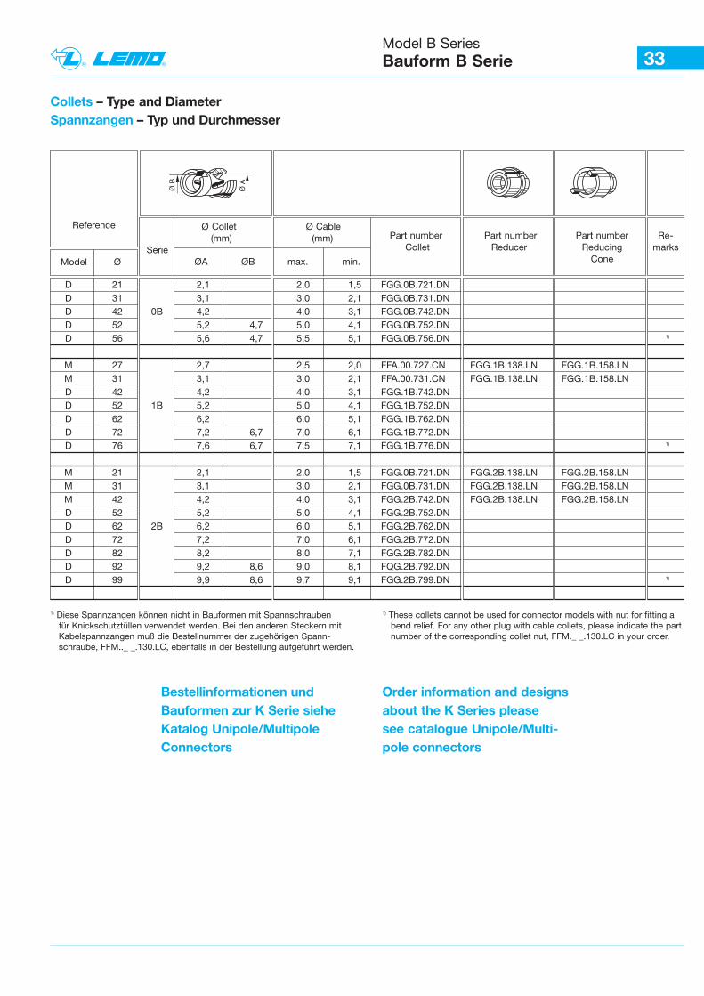
33Model B Series Bauform B Serie
Collets – Type and Diameter Spannzangen – Typ und Durchmesser
Reference
Model Ø
Ø Collet Ø Cable (mm) (mm)
SerieØA ØB max. min.
Ø A
Ø B
1) Diese Spannzangen können nicht in Bauformen mit Spannschraubenfür Knickschutztüllen verwendet werden. Bei den anderen Steckern mit Kabelspannzangen muß die Bestellnummer der zugehörigen Spann-schraube, FFM.._ _.130.LC, ebenfalls in der Bestellung aufgeführt werden.
1) These collets cannot be used for connector models with nut for fitting a bend relief. For any other plug with cable collets, please indicate the part number of the corresponding collet nut, FFM._ _.130.LC in your order.
Bestellinformationen undBauformen zur K Serie sieheKatalog Unipole/MultipoleConnectors
Order information and designsabout the K Series pleasesee catalogue Unipole/Multi-pole connectors
Part number Part number Part number Re-Collet Reducer Reducing marks
Cone
D 21 2,1 2,0 1,5 FGG.0B.721.DND 31 3,1 3,0 2,1 FGG.0B.731.DND 42 0B 4,2 4,0 3,1 FGG.0B.742.DND 52 5,2 4,7 5,0 4,1 FGG.0B.752.DND 56 5,6 4,7 5,5 5,1 FGG.0B.756.DN 1)
M 27 2,7 2,5 2,0 FFA.00.727.CN FGG.1B.138.LN FGG.1B.158.LNM 31 3,1 3,0 2,1 FFA.00.731.CN FGG.1B.138.LN FGG.1B.158.LND 42 4,2 4,0 3,1 FGG.1B.742.DND 52 1B 5,2 5,0 4,1 FGG.1B.752.DND 62 6,2 6,0 5,1 FGG.1B.762.DND 72 7,2 6,7 7,0 6,1 FGG.1B.772.DND 76 7,6 6,7 7,5 7,1 FGG.1B.776.DN 1)
M 21 2,1 2,0 1,5 FGG.0B.721.DN FGG.2B.138.LN FGG.2B.158.LNM 31 3,1 3,0 2,1 FGG.0B.731.DN FGG.2B.138.LN FGG.2B.158.LNM 42 4,2 4,0 3,1 FGG.2B.742.DN FGG.2B.138.LN FGG.2B.158.LND 52 5,2 5,0 4,1 FGG.2B.752.DND 62 2B 6,2 6,0 5,1 FGG.2B.762.DND 72 7,2 7,0 6,1 FGG.2B.772.DND 82 8,2 8,0 7,1 FGG.2B.782.DND 92 9,2 8,6 9,0 8,1 FQG.2B.792.DND 99 9,9 8,6 9,7 9,1 FGG.2B.799.DN 1)
34Model B Series Bauform B Serie
Dimensions (mm)
A L M S1 S2
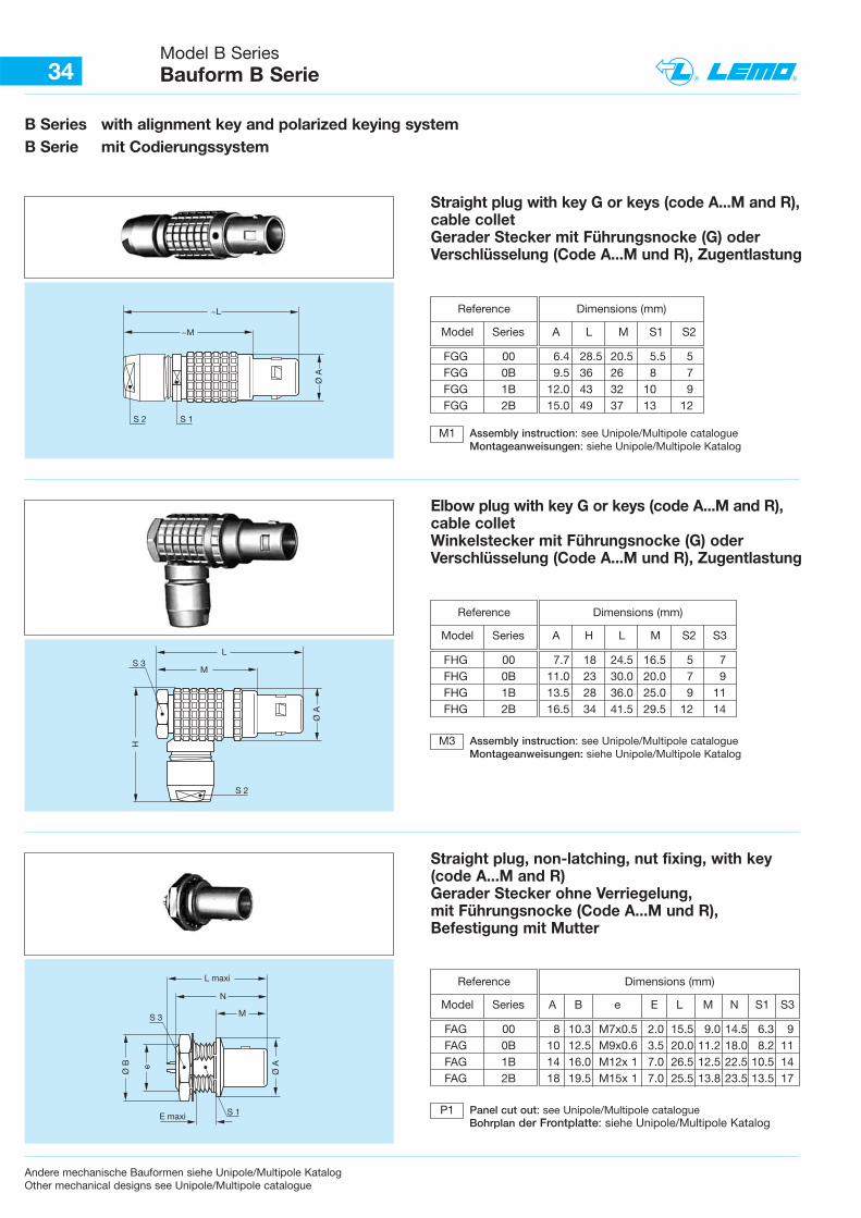
B Series with alignment key and polarized keying systemB Serie mit Codierungssystem
~LØ
A
~M
S 2 S 1
L
Ø A
MS 3
S 2
H
Straight plug with key G or keys (code A...M and R),cable colletGerader Stecker mit Führungsnocke (G) oderVerschlüsselung (Code A...M und R), Zugentlastung
Reference
Model Series
Dimensions (mm)
A H L M S2 S3
Elbow plug with key G or keys (code A...M and R),cable colletWinkelstecker mit Führungsnocke (G) oderVerschlüsselung (Code A...M und R), Zugentlastung
Reference
Model Series
FHG 00 7.7 18 24.5 16.5 5 7FHG 0B 11.0 23 30.0 20.0 7 9FHG 1B 13.5 28 36.0 25.0 9 11FHG 2B 16.5 34 41.5 29.5 12 14
Assembly instruction: see Unipole/Multipole catalogueMontageanweisungen: siehe Unipole/Multipole Katalog
Dimensions (mm)
A B e E L M N S1 S3N
M
Ø A
S 3
Ø B e
E maxi
L maxi
S 1
Straight plug, non-latching, nut fixing, with key(code A...M and R)Gerader Stecker ohne Verriegelung,mit Führungsnocke (Code A...M und R),Befestigung mit Mutter
Reference
Model Series
FAG 00 8 10.3 M7x0.5 2.0 15.5 9.0 14.5 6.3 9FAG 0B 10 12.5 M9x0.6 3.5 20.0 11.2 18.0 8.2 11FAG 1B 14 16.0 M12x 1 7.0 26.5 12.5 22.5 10.5 14FAG 2B 18 19.5 M15x 1 7.0 25.5 13.8 23.5 13.5 17
Panel cut out: see Unipole/Multipole catalogueBohrplan der Frontplatte: siehe Unipole/Multipole Katalog
Andere mechanische Bauformen siehe Unipole/Multipole KatalogOther mechanical designs see Unipole/Multipole catalogue
M3
FGG 00 6.4 28.5 20.5 5.5 5FGG 0B 9.5 36 26 8 7FGG 1B 12.0 43 32 10 9FGG 2B 15.0 49 37 13 12
Assembly instruction: see Unipole/Multipole catalogueMontageanweisungen: siehe Unipole/Multipole Katalog
M1
P1
35Model B Series Bauform B Serie
Andere mechanische Bauformen siehe Unipole/Multipole KatalogOther mechanical designs see Unipole/Multipole catalogue
Dimensions (mm)
A B e E L M N S1 S3N
M
Ø A
S 3
Ø B e
E maxi
L maxi
S 1
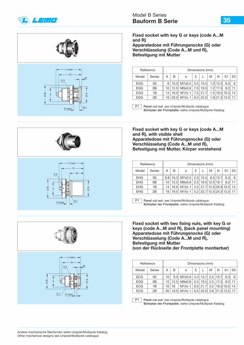
Fixed socket with key G or keys (code A...Mand R) Apparatedose mit Führungsnocke (G) oderVerschlüsselung (Code A...M und R),Befestigung mit Mutter
Reference
Model Series
EGG 00 8 10.3 M7x0.5 5.5 15.5 1.0 12.0 6.3 9EGG 0B 10 12.5 M9x0.6 7.0 19.5 1.2 17.5 8.2 11EGG 1B 14 16.0 M12x 1 7.5 21.7 1.5 19.5 10.5 14EGG 2B 18 20.0 M15x 1 8.5 25.0 1.8 21.5 13.5 17
Panel cut out: see Unipole/Multipole catalogueBohrplan der Frontplatte: siehe Unipole/Multipole Katalog
P1
Dimensions (mm)
A B e E L M N S1 S3N
M
Ø A
S 3
Ø B e
E maxi
L maxi
S 1
Fixed socket with key G or keys (code A...Mand R), with visible shellApparatedose mit Führungsnocke (G) oderVerschlüsselung (Code A...M und R),Befestigung mit Mutter, Körper vorstehend
Reference
Model Series
EHG 00 8.8 10.3 M7x0.5 2.0 15.5 8.5 13.7 6.3 9EHG 0B 10 12.5 M9x0.6 2.5 19.5 12.5 19.1 8.2 11EHG 1B 14 16.0 M12x 1 4.2 21.7 12.5 20.8 10.5 14EHG 2B 18 19.5 M15x 1 5.2 22.7 12.5 24.3 13.5 17
Panel cut out: see Unipole/Multipole catalogueBohrplan der Frontplatte: siehe Unipole/Multipole Katalog
P1
Dimensions (mm)
A B e E L M N S1 S3
NM
Ø A
S 3
Ø B e
E maxi
L maxi
S 1
Fixed socket with two fixing nuts, with key G orkeys (code A...M and R), (back panel mounting)Apparatedose mit Führungsnocke (G) oderVerschlüsselung (Code A...M und R),Befestigung mit Mutter(von der Rückseite der Frontplatte montierbar)
Reference
Model Series
ECG 00 10 9.5 M7x0.5 4.3 13.7 2.5 13.7 6.3 9EGG 0B 12 12.5 M9x0.6 5.5 19.5 2.5 17.5 8.2 11ECG 1B 16 16 M12x 1 6.0 21.7 3.2 19.5 10.5 14ECG 2B 20 19.5 M15x 1 6.5 25.0 3.8 21.5 13.5 17
Panel cut out: see Unipole/Multipole catalogueBohrplan der Frontplatte: siehe Unipole/Multipole Katalog
P1
36Model B Series Bauform B Serie
N
M
Ø A
S 1
Ø B e
E maxi
L maxi
S 2
P
Dimensions (mm)
A B e E L M N P S1 S3
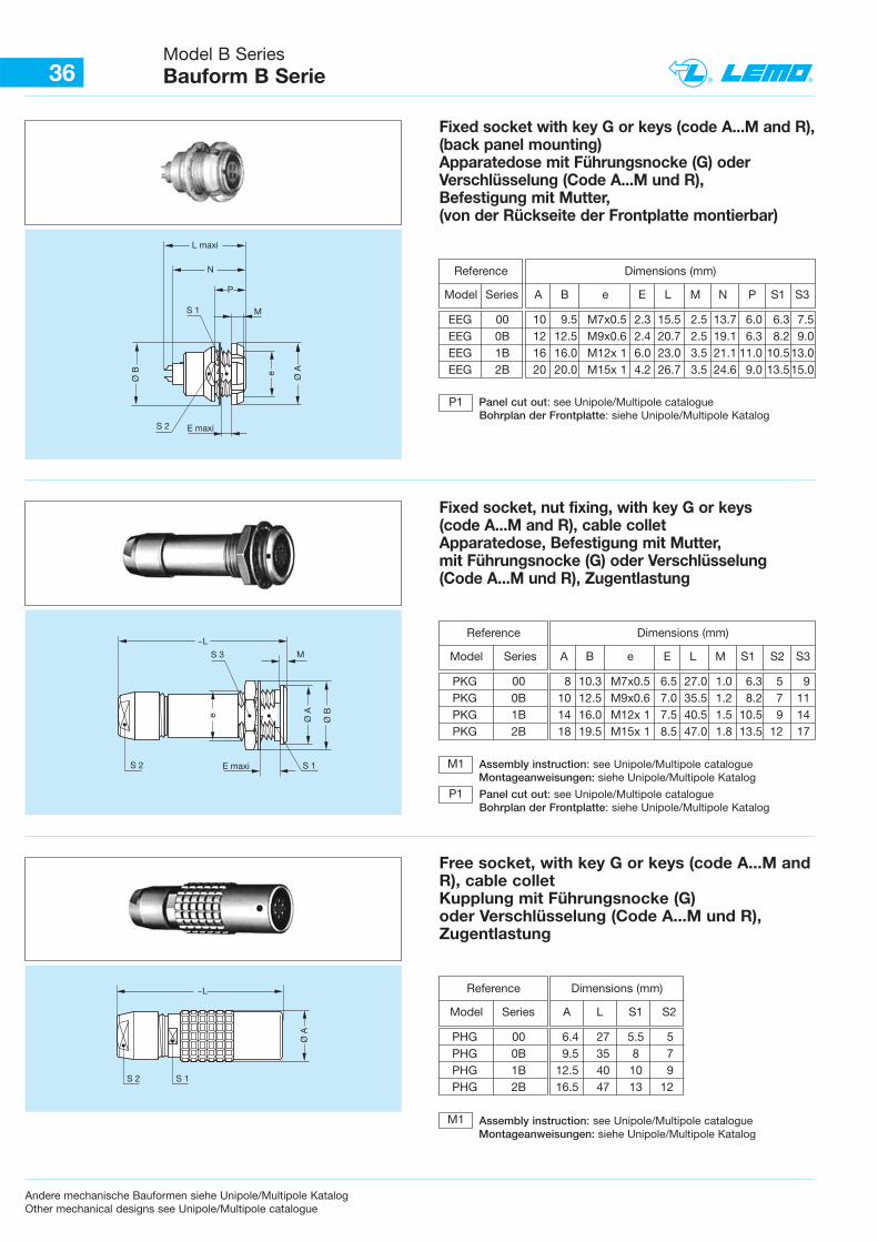
Fixed socket with key G or keys (code A...M and R),(back panel mounting)Apparatedose mit Führungsnocke (G) oderVerschlüsselung (Code A...M und R),Befestigung mit Mutter,(von der Rückseite der Frontplatte montierbar)
Reference
Model Series
EEG 00 10 9.5 M7x0.5 2.3 15.5 2.5 13.7 6.0 6.3 7.5EEG 0B 12 12.5 M9x0.6 2.4 20.7 2.5 19.1 6.3 8.2 9.0EEG 1B 16 16.0 M12x 1 6.0 23.0 3.5 21.1 11.0 10.513.0EEG 2B 20 20.0 M15x 1 4.2 26.7 3.5 24.6 9.0 13.515.0
Panel cut out: see Unipole/Multipole catalogueBohrplan der Frontplatte: siehe Unipole/Multipole Katalog
P1
Dimensions (mm)
A B e E L M S1 S2 S3
Ø A
S 1
Ø B
E maxiS 2
e
S 3 M
~L
Fixed socket, nut fixing, with key G or keys(code A...M and R), cable colletApparatedose, Befestigung mit Mutter,mit Führungsnocke (G) oder Verschlüsselung(Code A...M und R), Zugentlastung
Reference
Model Series
PKG 00 8 10.3 M7x0.5 6.5 27.0 1.0 6.3 5 9PKG 0B 10 12.5 M9x0.6 7.0 35.5 1.2 8.2 7 11PKG 1B 14 16.0 M12x 1 7.5 40.5 1.5 10.5 9 14PKG 2B 18 19.5 M15x 1 8.5 47.0 1.8 13.5 12 17
Assembly instruction: see Unipole/Multipole catalogueMontageanweisungen: siehe Unipole/Multipole Katalog
Panel cut out: see Unipole/Multipole catalogueBohrplan der Frontplatte: siehe Unipole/Multipole Katalog
P1
M1
M1
~L
Ø A
S 2 S 1
Dimensions (mm)
A L S1 S2
Free socket, with key G or keys (code A...M andR), cable colletKupplung mit Führungsnocke (G)oder Verschlüsselung (Code A...M und R),Zugentlastung
Reference
Model Series
PHG 00 6.4 27 5.5 5PHG 0B 9.5 35 8 7PHG 1B 12.5 40 10 9PHG 2B 16.5 47 13 12
Assembly instruction: see Unipole/Multipole catalogueMontageanweisungen: siehe Unipole/Multipole Katalog
Andere mechanische Bauformen siehe Unipole/Multipole KatalogOther mechanical designs see Unipole/Multipole catalogue
12
12
12 3
13 2
12
12
1
2 3
1
3 2
1
2
4
3
4
3
1
2
1
2
1
2
1
2 3
1
3 2
1
2
4
3
4
3
1
2
1
2
3
6
5
4
1
2
3
6
5
4
1
2
1
2
3
1
2 2
1
3
1
2
4
3
4
3
1
2
1
2
3
6
5
4
1
2
3
6
5
4
Size FGG EGG
00
0B
1B
2B
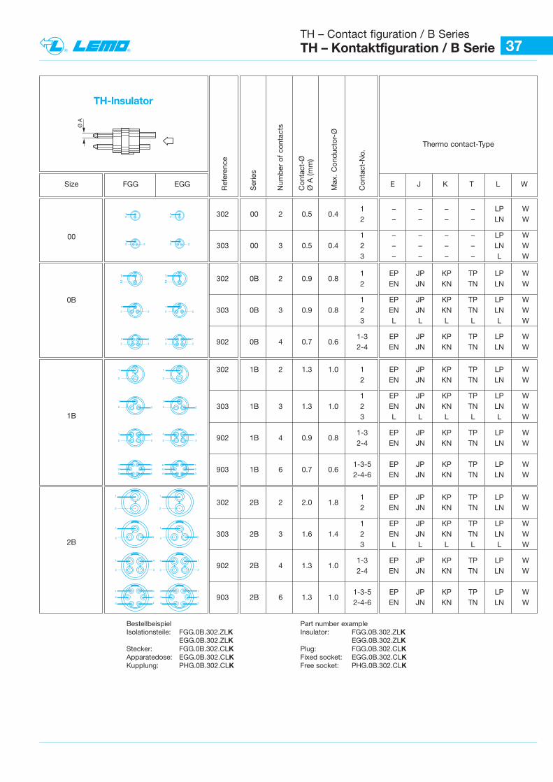
37TH – Contact figuration / B Series TH – Kontaktfiguration / B Serie
Ref
eren
ce
Ser
ies
Num
ber
of
cont
acts
Con
tact
-ØØ
A (m
m)
Max
. C
ond
ucto
r-Ø
Con
tact
-No.
E J K T L W
302 00 2 0.5 0.41 – – – – LP W2 – – – – LN W
1 – – – – LP W303 00 3 0.5 0.4 2 – – – – LN W
3 – – – – L W
302 0B 2 0.9 0.81 EP JP KP TP LP W2 EN JN KN TN LN W
1 EP JP KP TP LP W303 0B 3 0.9 0.8 2 EN JN KN TN LN W
3 L L L L L W
902 0B 4 0.7 0.61-3 EP JP KP TP LP W2-4 EN JN KN TN LN W
302 1B 2 1.3 1.0 1 EP JP KP TP LP W2 EN JN KN TN LN W
1 EP JP KP TP LP W303 1B 3 1.3 1.0 2 EN JN KN TN LN W
3 L L L L L W
902 1B 4 0.9 0.81-3 EP JP KP TP LP W2-4 EN JN KN TN LN W
903 1B 6 0.7 0.61-3-5 EP JP KP TP LP W2-4-6 EN JN KN TN LN W
302 2B 2 2.0 1.81 EP JP KP TP LP W2 EN JN KN TN LN W
1 EP JP KP TP LP W303 2B 3 1.6 1.4 2 EN JN KN TN LN W
3 L L L L L W
902 2B 4 1.3 1.01-3 EP JP KP TP LP W2-4 EN JN KN TN LN W
903 2B 6 1.3 1.01-3-5 EP JP KP TP LP W2-4-6 EN JN KN TN LN W
Thermo contact-Type
TH-lnsulator
Bestellbeispiel Part number example Isolationsteile: FGG.0B.302.ZLK Insulator: FGG.0B.302.ZLK
EGG.0B.302.ZLK EGG.0B.302.ZLKStecker: FGG.0B.302.CLK Plug: FGG.0B.302.CLKApparatedose: EGG.0B.302.CLK Fixed socket: EGG.0B.302.CLKKupplung: PHG.0B.302.CLK Free socket: PHG.0B.302.CLK
Ø A
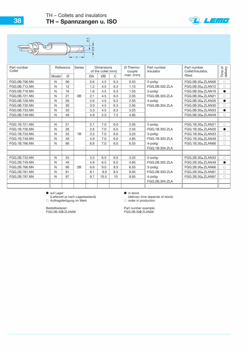
38TH – Collets and insulatorsTH – Spannzangen u. ISO
Ø B
Ø A
C
Tim
e of
deliv
eryPart number Reference Series Dimensions Ø Thermo- Part number Part number
Collet of the collet (mm) couple Insulator Collet/Insulator,
Model Ø ØA ØB C max. (mm) fitted
FGG.0B.706.NN N 06 0.6 4.5 6.3 0.55 2-polig: FGG.0B.30•.ZLAN06 BFGG.0B.712.NN N 12 1.2 4.5 6.3 1.15 FGG.0B.302.ZLA FGG.0B.30•.ZLAN12 BFGG.0B.716.NN N 16 1.6 4.5 6.3 1.55 3-polig: FGG.0B.30•.ZLAN16 bFGG.0B.721.NN N 21 0B 2.1 4.5 6.3 2.05 FGG.0B.303.ZLA FGG.0B.30•.ZLAN21 BFGG.0B.726.NN N 26 2.6 4.5 6.3 2.55 4-polig: FGG.0B.30•.ZLAN26 bFGG.0B.730.NN N 30 3.0 4.5 6.3 2.95 FGG.0B.304.ZLA FGG.0B.30•.ZLAN30 BFGG.0B.733.NN N 33 3.3 4.5 6.3 3.25 FGG.0B.30•.ZLAN33 bFGG.0B.749.NN N 49 4.9 5.5 7.5 4.85 FGG.0B.30•.ZLAN49 B
FGG.1B.721.NN N 21 2.1 7.0 6.0 2.05 2-polig: FGG.1B.30•.ZLAN21 BFGG.1B.726.NN N 26 2.6 7.0 6.0 2.55 FGG.1B.302.ZLA FGG.1B.30•.ZLAN26 bFGG.1B.733.NN N 33 1B 3.3 7.0 6.0 3.25 3-polig: FGG.1B.30•.ZLAN33 BFGG.1B.749.NN N 49 4.9 7.0 6.0 4.85 FGG.1B.303.ZLA FGG.1B.30•.ZLAN49 BFGG.1B.766.NN N 66 6.6 7.0 6.0 6.55 4-polig: FGG.1B.30•.ZLAN66 B
FGG.1B.304.ZLA
FGG.2B.733.NN N 33 3.3 6.5 6.0 3.25 2-polig: FGG.2B.30•.ZLAN33 BFGG.2B.749.NN N 49 4.9 6.5 6.0 4.85 FGG.2B.302.ZLA FGG.2B.30•.ZLAN49 bFGG.2B.766.NN N 66 2B 6.6 9.0 8.5 6.55 3-polig: FGG.2B.30•.ZLAN66 BFGG.2B.781.NN N 81 8.1 9.0 8.5 8.05 FGG.2B.303.ZLA FGG.2B.30•.ZLAN81 BFGG.2B.797.NN N 97 9.7 10.5 10 9.65 4-polig FGG.2B.30•.ZLAN97 B
FGG.2B.304.ZLA
b auf Lager(Lieferzeit je nach Lagerbestand)
B Auftragsfertigung im Werk
Bestellbeispiel:FGG.0B.302.ZLAN06
b in stock (delivery time depends of stock)
B order in production
Part number example:FGG.0B.302.ZLAN06
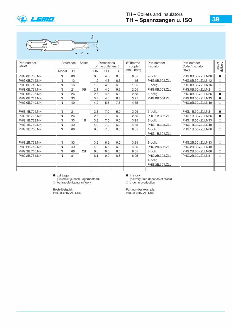
39TH – Collets and insulatorsTH – Spannzangen u. ISO
Ø B
Ø A
C
Tim
e of
deliv
eryPart number Reference Series Dimensions Ø Thermo- Part number Part number
Collet of the collet (mm) couple Insulator Collet/Insulator,
Model Ø ØA ØB C max. (mm) fitted
PHG.0B.706.NN N 06 0.6 4.5 6.3 0.55 2-polig: PHG.0B.30•.ZLLN06 bPHG.0B.712.NN N 12 1.2 4.5 6.3 1.15 PHG.0B.302.ZLL PHG.0B.30•.ZLLN12 BPHG.0B.716.NN N 16 1.6 4.5 6.3 1.55 3-polig: PHG.0B.30•.ZLLN16 BPHG.0B.721.NN N 21 0B 2.1 4.5 6.3 2.05 PHG.0B.303.ZLL PHG.0B.30•.ZLLN21 BPHG.0B.726.NN N 26 2.6 4.5 6.3 2.55 4-polig: PHG.0B.30•.ZLLN26 bPHG.0B.733.NN N 33 3.3 4.5 6.3 3.25 PHG.0B.304.ZLL PHG.0B.30•.ZLLN33 bPHG.0B.749.NN N 49 4.9 5.5 7.5 4.85 PHG.0B.30•.ZLLN49 B
PHG.1B.721.NN N 21 2.1 7.0 6.0 2.05 2-polig: PHG.1B.30•.ZLLN21 bPHG.1B.726.NN N 26 2.6 7.0 6.0 2.55 PHG.1B.302.ZLL PHG.1B.30•.ZLLN26 bPHG.1B.733.NN N 33 1B 3.3 7.0 6.0 3.25 3-polig: PHG.1B.30•.ZLLN33 BPHG.1B.749.NN N 49 4.9 7.0 6.0 4.85 PHG.1B.303.ZLL PHG.1B.30•.ZLLN49 BPHG.1B.766.NN N 66 6.6 7.0 6.0 6.55 4-polig: PHG.1B.30•.ZLLN66 B
PHG.1B.304.ZLL
PHG.2B.733.NN N 33 3.3 6.5 6.0 3.25 2-polig: PHG.2B.30•.ZLLN33 BPHG.2B.749.NN N 49 4.9 6.5 6.0 4.85 PHG.2B.302.ZLL PHG.2B.30•.ZLLN49 BPHG.2B.766.NN N 66 2B 6.6 9.0 8.5 6.55 3-polig: PHG.2B.30•.ZLLN66 BPHG.2B.781.NN N 81 8.1 9.0 8.5 8.05 PHG.2B.303.ZLL PHG.2B.30•.ZLLN81 B
4-polig:PHG.2B.304.ZLL
b auf Lager(Lieferzeit je nach Lagerbestand)
B Auftragsfertigung im Werk
Bestellbeispiel:PHG.0B.302.ZLLN06
b in stock (delivery time depends of stock)
B order in production
Part number example:PHG.0B.302.ZLLN06
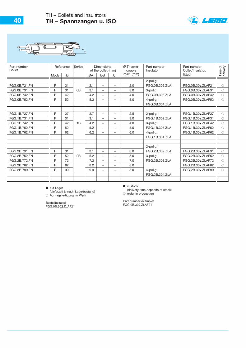
40TH – Collets and insulatorsTH – Spannzangen u. ISO
A
Tim
e of
deliv
eryPart number Reference Series Dimensions Ø Thermo- Part number Part number
Collet of the collet (mm) couple Insulator Collet/Insulator,
Model Ø ØA ØB C max. (mm) fitted
2-polig: FGG.0B.721.FN F 21 2.1 – – 2.0 FGG.0B.302.ZLA: FGG.0B.30•.ZLAF21 BFGG.0B.731.FN F 31 0B 3.1 – – 3.0 3-polig: FGG.0B.30•.ZLAF31 BFGG.0B.742.FN F 42 4.2 – – 4.0 FGG.0B.303.ZLA FGG.0B.30•.ZLAF42 BFGG.0B.752.FN F 52 5.2 – – 5.0 4-polig: FGG.0B.30•.ZLAF52 B
FGG.0B.304.ZLA
FGG.1B.727.FN F 27 2.7 – – 2.5 2-polig: FGG.1B.30•.ZLAF27 BFGG.1B.731.FN F 31 3.1 – – 3.0 FGG.1B.302.ZLA FGG.1B.30•.ZLAF31 BFGG.1B.742.FN F 42 1B 4.2 – – 4.0 3-polig: FGG.1B.30•.ZLAF42 BFGG.1B.752.FN F 52 5.2 – – 5.0 FGG.1B.303.ZLA FGG.1B.30•.ZLAF52 BFGG.1B.762.FN F 62 6.2 – – 6.0 4-polig: FGG.1B.30•.ZLAF62 B
FGG.1B.304.ZLA
2-polig: FGG.2B.731.FN F 31 3.1 – – 3.0 FGG.2B.302.ZLA FGG.2B.30•.ZLAF31 BFGG.2B.752.FN F 52 2B 5.2 – – 5.0 3-polig: FGG.2B.30•.ZLAF52 BFGG.2B.772.FN F 72 7.2 – – 7.0 FGG.2B.303.ZLA FGG.2B.30•.ZLAF72 BFGG.2B.782.FN F 82 8.2 – – 8.0 FGG.2B.30•.ZLAF82 BFGG.2B.799.FN F 99 9.9 – – 8.0 4-polig: FGG.2B.30•.ZLAF99 B
FGG.2B.304.ZLA
b auf Lager(Lieferzeit je nach Lagerbestand)
B Auftragsfertigung im Werk
Bestellbeispiel:FGG.0B.302.ZLAF21
b in stock (delivery time depends of stock)
B order in production
Part number example:FGG.0B.302.ZLAF21
12
FFA
ERA
PCA
PSA
12
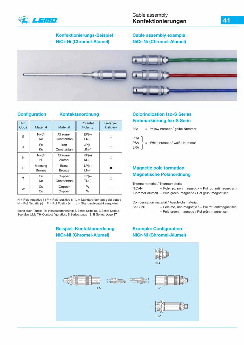
41Cable assemblyKonfektionierungen
Konfektionierungs-BeispielNiCr-Ni (Chromel-Alumel)
Cable assembly example NiCr-Ni (Chromel-Alumel)
Configuration Kontaktanordnung Colorindication Iso-S Series Farbmarkierung Iso-S Serie
Nr. Polarität Lieferzeit Code Material Material Polarity Delivery
ENi-Cr Chromel EP(+)
BKo Constantan EN(-)
JFe Iron JP(+)
BKo Constantan JN(-)
KNi-Cr Chromel KP(+)
BNi Alumel KN(-)
LMessing Brass LP(+)
bBronze Bronze LN(-)
TCu Copper TP(+)
BKo Constantan TN(-)
WCu Copper W
BCu Copper W
N = Pole negative (-) P = Pole positive (+) L = Standard contact gold platedN = Pol Negativ (-) P = Pol Positiv (+) L = Standardkontakt vergoldet
Siehe auch Tabelle TH-Kontaktanordnung: S Serie: Seite 18, B Serie: Seite 37See also table TH-Contact figuration: S Series: page 18, B Series: page 37
FFA = Yellow number / gelbe Nummer
PCAPSA = White number / weiße NummerERA {
Magnetic pole formationMagnetische Polanordnung
Beispiel: KontaktanordnungNiCr-Ni (Chromel-Alumel)
Example: ConfigurationNiCr-Ni (Chromel-Alumel)
Thermo meterial / Thermomaterial:NiCr-Ni + Pole red, non magnetic / + Pol rot, antimagnetisch (Chromel-Alumel) – Pole green, magnetic / Pol grün, magnetisch
Compensation material / Ausgleichsmaterial:Fe-CuNi + Pole red, non magnetic / + Pol rot, antimagnetisch
– Pole green, magnetic / Pol grün, magnetisch
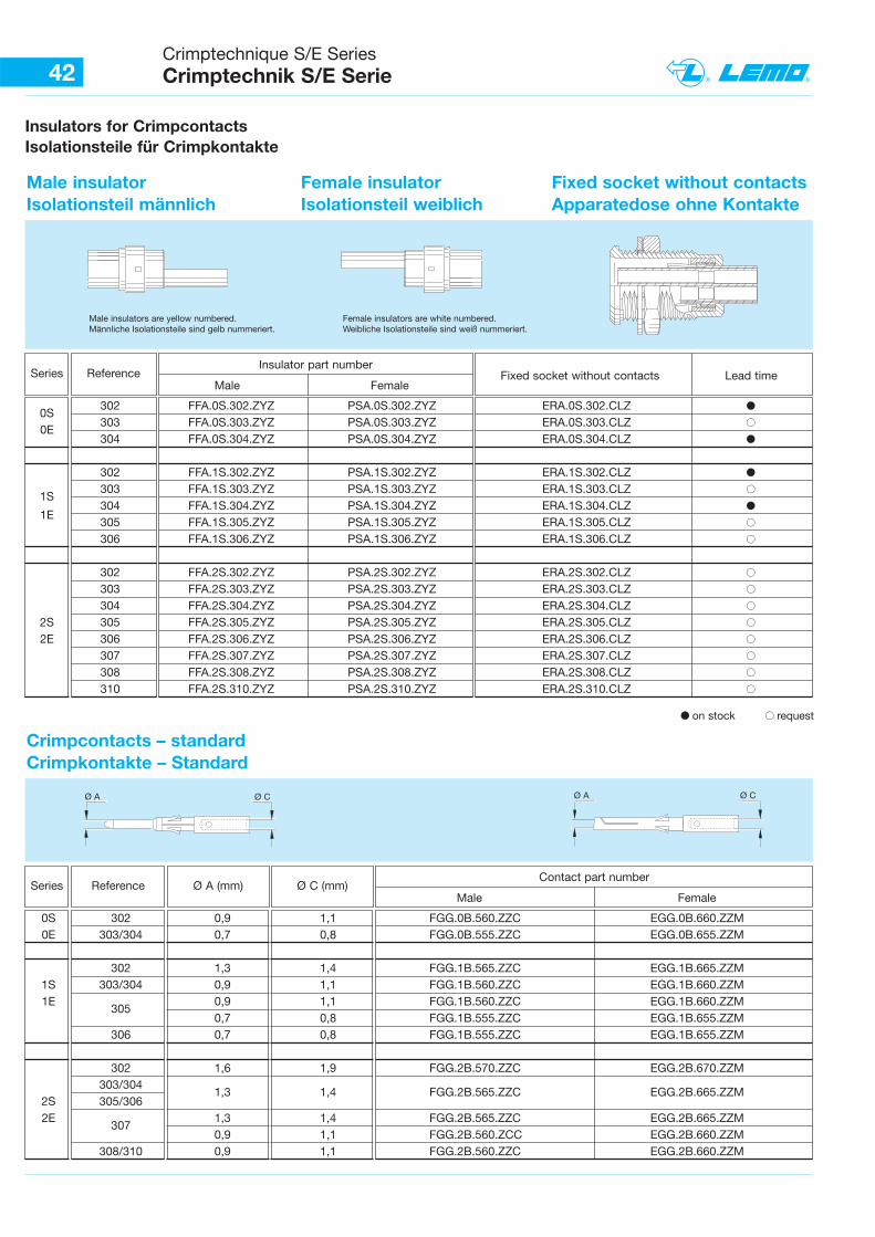
Crimptechnique S/E SeriesCrimptechnik S/E Serie42
Insulators for CrimpcontactsIsolationsteile für Crimpkontakte
Male insulatorIsolationsteil männlich
Female insulatorIsolationsteil weiblich
Male insulators are yellow numbered.Männliche Isolationsteile sind gelb nummeriert.
Female insulators are white numbered.Weibliche Isolationsteile sind weiß nummeriert.
ReferenceSeriesInsulator part number
Male FemaleFixed socket without contacts Lead time
Reference Ø A (mm) Ø C (mm)Contact part number
Male Female
0S 302 0,9 1,1 FGG.0B.560.ZZC EGG.0B.660.ZZM0E 303/304 0,7 0,8 FGG.0B.555.ZZC EGG.0B.655.ZZM
302 1,3 1,4 FGG.1B.565.ZZC EGG.1B.665.ZZM1S 303/304 0,9 1,1 FGG.1B.560.ZZC EGG.1B.660.ZZM1E
3050,9 1,1 FGG.1B.560.ZZC EGG.1B.660.ZZM0,7 0,8 FGG.1B.555.ZZC EGG.1B.655.ZZM
306 0,7 0,8 FGG.1B.555.ZZC EGG.1B.655.ZZM
302 1,6 1,9 FGG.2B.570.ZZC EGG.2B.670.ZZM303/304
1,3 1,4 FGG.2B.565.ZZC EGG.2B.665.ZZM2S 305/3062E
3071,3 1,4 FGG.2B.565.ZZC EGG.2B.665.ZZM0,9 1,1 FGG.2B.560.ZCC EGG.2B.660.ZZM
308/310 0,9 1,1 FGG.2B.560.ZZC EGG.2B.660.ZZM
b on stock B request
Ø A Ø C Ø A Ø C
Fixed socket without contactsApparatedose ohne Kontakte
Crimpcontacts – standardCrimpkontakte – Standard
0S302 FFA.0S.302.ZYZ PSA.0S.302.ZYZ ERA.0S.302.CLZ b
0E303 FFA.0S.303.ZYZ PSA.0S.303.ZYZ ERA.0S.303.CLZ B304 FFA.0S.304.ZYZ PSA.0S.304.ZYZ ERA.0S.304.CLZ b
302 FFA.1S.302.ZYZ PSA.1S.302.ZYZ ERA.1S.302.CLZ b
1S303 FFA.1S.303.ZYZ PSA.1S.303.ZYZ ERA.1S.303.CLZ B304 FFA.1S.304.ZYZ PSA.1S.304.ZYZ ERA.1S.304.CLZ b
1E305 FFA.1S.305.ZYZ PSA.1S.305.ZYZ ERA.1S.305.CLZ B306 FFA.1S.306.ZYZ PSA.1S.306.ZYZ ERA.1S.306.CLZ B
302 FFA.2S.302.ZYZ PSA.2S.302.ZYZ ERA.2S.302.CLZ B303 FFA.2S.303.ZYZ PSA.2S.303.ZYZ ERA.2S.303.CLZ B304 FFA.2S.304.ZYZ PSA.2S.304.ZYZ ERA.2S.304.CLZ B
2S 305 FFA.2S.305.ZYZ PSA.2S.305.ZYZ ERA.2S.305.CLZ B2E 306 FFA.2S.306.ZYZ PSA.2S.306.ZYZ ERA.2S.306.CLZ B
307 FFA.2S.307.ZYZ PSA.2S.307.ZYZ ERA.2S.307.CLZ B308 FFA.2S.308.ZYZ PSA.2S.308.ZYZ ERA.2S.308.CLZ B310 FFA.2S.310.ZYZ PSA.2S.310.ZYZ ERA.2S.310.CLZ B
Series
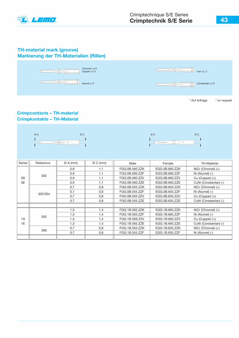
Crimptechnique S/E SeriesCrimptechnik S/E Serie 43
Crimpcontacts – TH-materialCrimpkontakte – TH-Material
Reference Male Female TH-Material
* Auf Anfrage * on request
Ø A (mm) Ø C (mm)
TH-material mark (groove)Markierung der TH-Materialien (Rillen)
Chromel (+) KCopper (+) V Iron (+) J*
Constantan (-) EAlumel (-) F
Ø A Ø CØ A Ø C
Series
0,9 1,1 FGG.0B.560.ZZK EGG.0B.660.ZZK NiCr (Chromel) (+)
3020,9 1,1 FGG.0B.560.ZZF EGG.0B.660.ZZF Ni (Alumel) (-)
0S 0,9 1,1 FGG.0B.560.ZZV EGG.0B.660.ZZV Cu (Copper) (+)0E 0,9 1,1 FGG.0B.560.ZZE EGG.0B.660.ZZE CuNi (Constantan) (-)
0,7 0,8 FGG.0B.555.ZZK EGG.0B.655.ZZK NiCr (Chromel) (+)
303/3040,7 0,8 FGG.0B.555.ZZF EGG.0B.655.ZZF Ni (Alumel) (-)0,7 0,8 FGG.0B.555.ZZV EGG.0B.655.ZZV Cu (Copper) (+)0,7 0,8 FGG.0B.555.ZZE EGG.0B.655.ZZE CuNi (Constantan) (-)
1,3 1,4 FGG.1B.565.ZZK EGG.1B.665.ZZK NiCr (Chromel) (+)
3021,3 1,4 FGG.1B.565.ZZF EGG.1B.665.ZZF Ni (Alumel) (-)
1S 1,3 1,4 FGG.1B.569.ZZV EGG.1B.665.ZZV Cu (Copper) (+)1E 1,3 1,4 FGG.1B.565.ZZE EGG.1B.665.ZZE CuNi (Constantan) (-)
3060,7 0,8 FGG.1B.555.ZZK EGG.1B.655.ZZK NiCr (Chromel) (+)0,7 0,8 FGG.1B.555.ZZF EGG.1B.655.ZZF Ni (Alumel) (-)
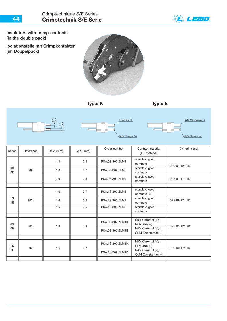
Insulators with crimp contacts(in the double pack)
Isolationsteile mit Crimpkontakten(im Doppelpack)
Ø A
44Crimptechnique S/E SeriesCrimptechnik S/E Serie
ReferenceSeriesOrder number Contact material Crimping tool
(TH-material)Ø A (mm) Ø C (mm)
Ø A
Ø C
Ø C Ni Alumel (-)
NiCr Chromel (+)
CuNi Constantan (-)
NiCr Chromel (+)
Type: K Type: E
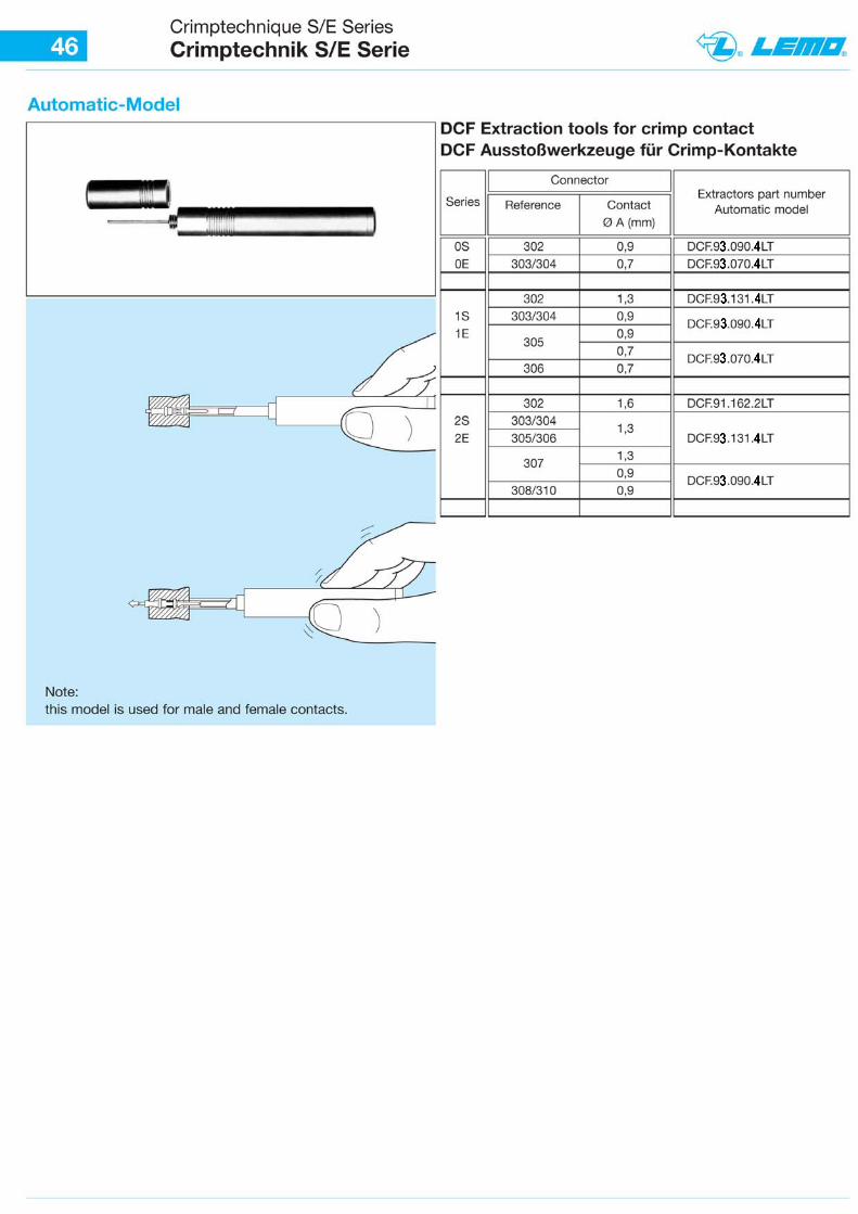
1,3 0,4 PSA.0S.302.ZLM1standard goldcontacts
DPE.91.121.2K0S
302 1,3 0,7 PSA.0S.302.ZLM2standard gold
0E contacts
0,9 0,3 PSA.0S.302.ZLM4standard gold
DPE.91.111.1Kcontacts
1,6 0,7 PSA.1S.302.ZLM1standard goldcontacts1S
1S302 1,6 0,4 PSA.1S.302.ZLM2
standard goldDPE.99.171.1K
1E contacts1,6 0,6 PSA.1S.302.ZLM3 standard gold
contacts
PSA.0S.302.ZLM1KNiCr Chromel (+);
0S302 1,3 0,4
Ni Alumel (-)DPE.91.121.2K
0EPSA.0S.302.ZLM1E
NiCr Chromel (+);CuNi Constantan (-)
PSA.1S.302.ZLM1KNiCr Chromel (+);
1S302 1,6 0,7
Ni Alumel (-)DPE.99.171.1K
1EPSA.1S.302.ZLM1E
NiCr Chromel (+);CuNi Constantan (-)
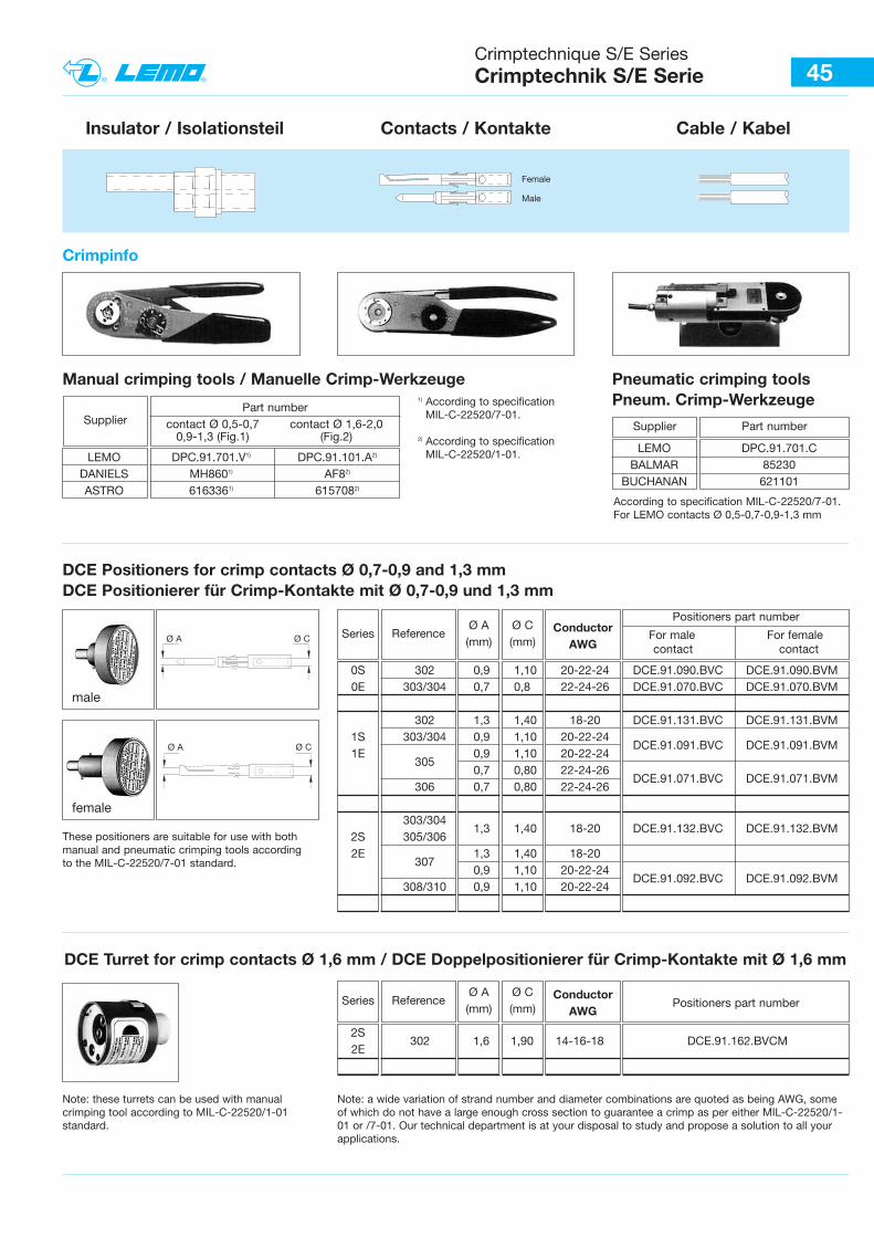
45
Part numbercontact Ø 0,5-0,7 contact Ø 1,6-2,0
0,9-1,3 (Fig.1) (Fig.2)Supplier
1) According to specification MIL-C-22520/7-01.
2) According to specification MIL-C-22520/1-01.
Insulator / Isolationsteil
Crimptechnique S/E SeriesCrimptechnik S/E Serie
Female
Male
Contacts / Kontakte Cable / Kabel
Crimpinfo
LEMO DPC.91.701.CBALMAR 85230
BUCHANAN 621101
Part numberSupplier
According to specification MIL-C-22520/7-01.For LEMO contacts Ø 0,5-0,7-0,9-1,3 mm
2S302 1,6 1,90 14-16-18 DCE.91.162.BVCM
2E
Ø A Ø C
Ø A Ø C
Manual crimping tools / Manuelle Crimp-Werkzeuge Pneumatic crimping toolsPneum. Crimp-Werkzeuge
DCE Positioners for crimp contacts Ø 0,7-0,9 and 1,3 mmDCE Positionierer für Crimp-Kontakte mit Ø 0,7-0,9 und 1,3 mm
Reference ConductorAWG
Positioners part number
For male For femalecontact contact
Ø A(mm)
Ø C(mm)
DCE Turret for crimp contacts Ø 1,6 mm / DCE Doppelpositionierer für Crimp-Kontakte mit Ø 1,6 mm
male
female
These positioners are suitable for use with bothmanual and pneumatic crimping tools according to the MIL-C-22520/7-01 standard.
Note: these turrets can be used with manualcrimping tool according to MIL-C-22520/1-01standard.
Note: a wide variation of strand number and diameter combinations are quoted as being AWG, someof which do not have a large enough cross section to guarantee a crimp as per either MIL-C-22520/1-01 or /7-01. Our technical department is at your disposal to study and propose a solution to all yourapplications.
LEMO DPC.91.701.V1) DPC.91.101.A2)
DANIELS MH8601) AF82)
ASTRO 6163361) 6157082)
Series
0S 302 0,9 1,10 20-22-24 DCE.91.090.BVC DCE.91.090.BVM0E 303/304 0,7 0,8 22-24-26 DCE.91.070.BVC DCE.91.070.BVM
302 1,3 1,40 18-20 DCE.91.131.BVC DCE.91.131.BVM1S 303/304 0,9 1,10 20-22-24
DCE.91.091.BVC DCE.91.091.BVM1E
3050,9 1,10 20-22-240,7 0,80 22-24-26
DCE.91.071.BVC DCE.91.071.BVM306 0,7 0,80 22-24-26
303/3041,3 1,40 18-20 DCE.91.132.BVC DCE.91.132.BVM
2S 305/3062E
3071,3 1,40 18-200,9 1,10 20-22-24
DCE.91.092.BVC DCE.91.092.BVM308/310 0,9 1,10 20-22-24
Reference ConductorAWG
Positioners part numberØ A(mm)
Ø C(mm)
Series
47
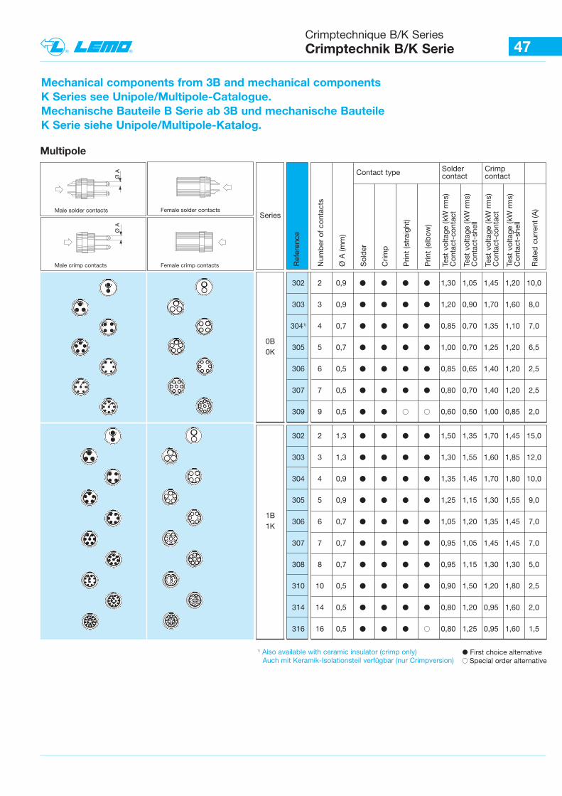
Mechanical components from 3B and mechanical componentsK Series see Unipole/Multipole-Catalogue.Mechanische Bauteile B Serie ab 3B und mechanische BauteileK Serie siehe Unipole/Multipole-Katalog.
Crimptechnique B/K SeriesCrimptechnik B/K Serie
Multipole
Male solder contacts Female solder contacts
Male crimp contacts Female crimp contacts Ref
eren
ce
Num
ber
of
cont
acts
Ø A
(mm
)
Sol
der
Crim
p
Prin
t (s
trai
ght)
Prin
t (e
lbow
)
Test
vol
tage
(kW
rm
s)C
onta
ct-c
onta
ct
Test
vol
tage
(kW
rm
s)C
onta
ct-s
hell
Test
vol
tage
(kW
rm
s)C
onta
ct-c
onta
ct
Test
vol
tage
(kW
rm
s)C
onta
ct-s
hell
Rat
ed c
urre
nt (A
)
Contact type Soldercontact
Crimpcontact
302 2 0,9 b b b b 1,30 1,05 1,45 1,20 10,0
303 3 0,9 b b b b 1,20 0,90 1,70 1,60 8,0
3041) 4 0,7 b b b b 0,85 0,70 1,35 1,10 7,0
305 5 0,7 b b b b 1,00 0,70 1,25 1,20 6,5
306 6 0,5 b b b b 0,85 0,65 1,40 1,20 2,5
307 7 0,5 b b b b 0,80 0,70 1,40 1,20 2,5
309 9 0,5 b b B B 0,60 0,50 1,00 0,85 2,0
302 2 1,3 b b b b 1,50 1,35 1,70 1,45 15,0
303 3 1,3 b b b b 1,30 1,55 1,60 1,85 12,0
304 4 0,9 b b b b 1,35 1,45 1,70 1,80 10,0
305 5 0,9 b b b b 1,25 1,15 1,30 1,55 9,0
306 6 0,7 b b b b 1,05 1,20 1,35 1,45 7,0
307 7 0,7 b b b b 0,95 1,05 1,45 1,45 7,0
308 8 0,7 b b b b 0,95 1,15 1,30 1,30 5,0
310 10 0,5 b b b b 0,90 1,50 1,20 1,80 2,5
314 14 0,5 b b b b 0,80 1,20 0,95 1,60 2,0
316 16 0,5 b b b B 0,80 1,25 0,95 1,60 1,5
� First choice alternativeB Special order alternative
1) Also available with ceramic insulator (crimp only)Auch mit Keramik-Isolationsteil verfügbar (nur Crimpversion)
Ø A
Ø A
Series
0B0K
1B1K
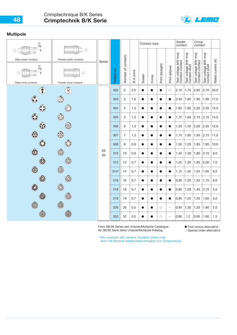
48Crimptechnique B/K SeriesCrimptechnik B/K Serie
Multipole
Ref
eren
ce
Num
ber
of
cont
acts
Ø A
(mm
)
Sol
der
Crim
p
Prin
t (s
trai
ght)
Prin
t (e
lbow
)
Test
vol
tage
(kW
rm
s)C
onta
ct-c
onta
ct
Test
vol
tage
(kW
rm
s)C
onta
ct-s
hell
Test
vol
tage
(kW
rm
s)C
onta
ct-c
onta
ct
Test
vol
tage
(kW
rm
s)C
onta
ct-s
hell
Rat
ed c
urre
nt (A
)
Contact type Soldercontact
Crimpcontact
302 2 2,0 � � � B 2,10 1,75 2,85 2,70 30,0
303 3 1,6 � � � � 2,40 1,85 1,90 1,90 17,0
304 4 1,3 � � � � 1,85 1,85 2,20 2,20 15,0
305 5 1,3 � � � � 1,75 1,60 2,15 2,15 14,0
306 6 1,3 � � � � 1,35 1,45 2,00 2,35 12,0
307 7 1,3 � � � � 1,75 1,60 1,95 2,15 11,0
308 8 0,9 � � � � 1,50 1,25 1,95 1,95 10,0
310 10 0,9 � � � � 1,45 1,30 1,80 2,10 8,0
312 12 0,7 � � � � 1,25 1,35 1,65 2,00 7,0
3141) 14 0,7 � � � � 1,15 1,35 1,55 1,95 6,5
316 16 0,7 � � � � 0,95 1,25 1,55 1,75 6,0
318 18 0,7 � � � � 0,85 1,20 1,45 2,10 5,5
319 19 0,7 � � � � 0,95 1,25 1,55 1,65 5,0
326 26 0,5 � � B - 0,95 1,30 1,20 1,80 2,0
332 32 0,5 � � B - 0,80 1,2 0,95 1,60 1,5
� First choice alternativeB Special order alternative
From 3B/3K Series see Unipole/Multipole-Catalogue.Ab 3B/3K Serie siehe Unipole/Multipole-Katalog.
1) Also available with ceramic insulator (crimp only)Auch mit Keramik-Isolationsteil verfügbar (nur Crimpversion)
Male solder contacts Female solder contacts
Male crimp contacts Female crimp contacts
Ø A
Ø A
Series
2B2K
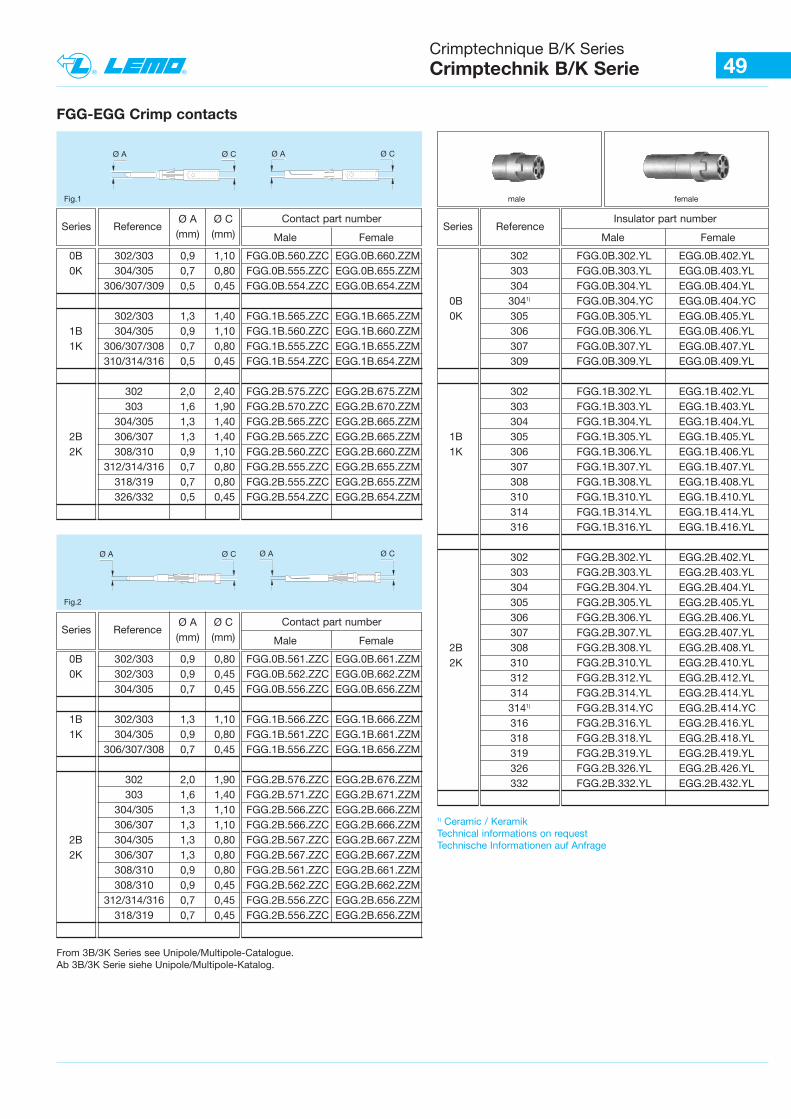
Crimptechnique B/K SeriesCrimptechnik B/K Serie 49
male femaleFig.1
302 FGG.0B.302.YL EGG.0B.402.YL303 FGG.0B.303.YL EGG.0B.403.YL304 FGG.0B.304.YL EGG.0B.404.YL
0B 3041) FGG.0B.304.YC EGG.0B.404.YC 0K 305 FGG.0B.305.YL EGG.0B.405.YL
306 FGG.0B.306.YL EGG.0B.406.YL307 FGG.0B.307.YL EGG.0B.407.YL309 FGG.0B.309.YL EGG.0B.409.YL
302 FGG.1B.302.YL EGG.1B.402.YL303 FGG.1B.303.YL EGG.1B.403.YL304 FGG.1B.304.YL EGG.1B.404.YL
1B 305 FGG.1B.305.YL EGG.1B.405.YL1K 306 FGG.1B.306.YL EGG.1B.406.YL
307 FGG.1B.307.YL EGG.1B.407.YL308 FGG.1B.308.YL EGG.1B.408.YL310 FGG.1B.310.YL EGG.1B.410.YL 314 FGG.1B.314.YL EGG.1B.414.YL316 FGG.1B.316.YL EGG.1B.416.YL
302 FGG.2B.302.YL EGG.2B.402.YL303 FGG.2B.303.YL EGG.2B.403.YL304 FGG.2B.304.YL EGG.2B.404.YL305 FGG.2B.305.YL EGG.2B.405.YL306 FGG.2B.306.YL EGG.2B.406.YL307 FGG.2B.307.YL EGG.2B.407.YL
2B 308 FGG.2B.308.YL EGG.2B.408.YL2K 310 FGG.2B.310.YL EGG.2B.410.YL
312 FGG.2B.312.YL EGG.2B.412.YL314 FGG.2B.314.YL EGG.2B.414.YL3141) FGG.2B.314.YC EGG.2B.414.YC316 FGG.2B.316.YL EGG.2B.416.YL318 FGG.2B.318.YL EGG.2B.418.YL319 FGG.2B.319.YL EGG.2B.419.YL326 FGG.2B.326.YL EGG.2B.426.YL332 FGG.2B.332.YL EGG.2B.432.YL
ReferenceInsulator part number
Male Female
FGG-EGG Crimp contacts
Ø A Ø C Ø A Ø C
0B 302/303 0,9 1,10 FGG.0B.560.ZZC EGG.0B.660.ZZM0K 304/305 0,7 0,80 FGG.0B.555.ZZC EGG.0B.655.ZZM
306/307/309 0,5 0,45 FGG.0B.554.ZZC EGG.0B.654.ZZM
302/303 1,3 1,40 FGG.1B.565.ZZC EGG.1B.665.ZZM1B 304/305 0,9 1,10 FGG.1B.560.ZZC EGG.1B.660.ZZM1K 306/307/308 0,7 0,80 FGG.1B.555.ZZC EGG.1B.655.ZZM
310/314/316 0,5 0,45 FGG.1B.554.ZZC EGG.1B.654.ZZM
302 2,0 2,40 FGG.2B.575.ZZC EGG.2B.675.ZZM303 1,6 1,90 FGG.2B.570.ZZC EGG.2B.670.ZZM
304/305 1,3 1,40 FGG.2B.565.ZZC EGG.2B.665.ZZM2B 306/307 1,3 1,40 FGG.2B.565.ZZC EGG.2B.665.ZZM2K 308/310 0,9 1,10 FGG.2B.560.ZZC EGG.2B.660.ZZM
312/314/316 0,7 0,80 FGG.2B.555.ZZC EGG.2B.655.ZZM318/319 0,7 0,80 FGG.2B.555.ZZC EGG.2B.655.ZZM326/332 0,5 0,45 FGG.2B.554.ZZC EGG.2B.654.ZZM
ReferenceØ A Ø C(mm) (mm)
Contact part number
Male Female
From 3B/3K Series see Unipole/Multipole-Catalogue.Ab 3B/3K Serie siehe Unipole/Multipole-Katalog.
1) Ceramic / KeramikTechnical informations on requestTechnische Informationen auf Anfrage
Fig.2
Ø A Ø C Ø A Ø C
SeriesSeries
0B 302/303 0,9 0,80 FGG.0B.561.ZZC EGG.0B.661.ZZM0K 302/303 0,9 0,45 FGG.0B.562.ZZC EGG.0B.662.ZZM
304/305 0,7 0,45 FGG.0B.556.ZZC EGG.0B.656.ZZM
1B 302/303 1,3 1,10 FGG.1B.566.ZZC EGG.1B.666.ZZM1K 304/305 0,9 0,80 FGG.1B.561.ZZC EGG.1B.661.ZZM
306/307/308 0,7 0,45 FGG.1B.556.ZZC EGG.1B.656.ZZM
302 2,0 1,90 FGG.2B.576.ZZC EGG.2B.676.ZZM303 1,6 1,40 FGG.2B.571.ZZC EGG.2B.671.ZZM
304/305 1,3 1,10 FGG.2B.566.ZZC EGG.2B.666.ZZM306/307 1,3 1,10 FGG.2B.566.ZZC EGG.2B.666.ZZM
2B 304/305 1,3 0,80 FGG.2B.567.ZZC EGG.2B.667.ZZM2K 306/307 1,3 0,80 FGG.2B.567.ZZC EGG.2B.667.ZZM
308/310 0,9 0,80 FGG.2B.561.ZZC EGG.2B.661.ZZM308/310 0,9 0,45 FGG.2B.562.ZZC EGG.2B.662.ZZM
312/314/316 0,7 0,45 FGG.2B.556.ZZC EGG.2B.656.ZZM318/319 0,7 0,45 FGG.2B.556.ZZC EGG.2B.656.ZZM
ReferenceØ A Ø C(mm) (mm)
Contact part number
Male FemaleSeries
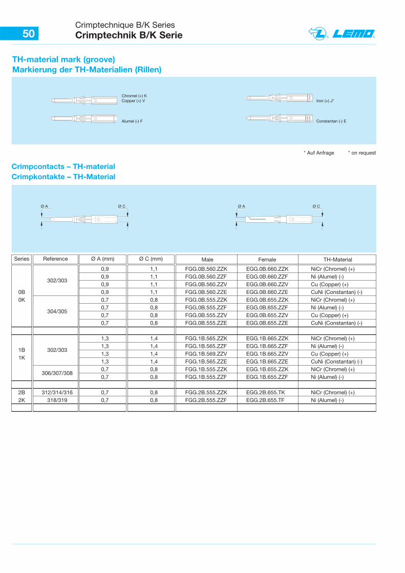
0,9 1,1 FGG.0B.560.ZZK EGG.0B.660.ZZK NiCr (Chromel) (+)
302/3030,9 1,1 FGG.0B.560.ZZF EGG.0B.660.ZZF Ni (Alumel) (-)0,9 1,1 FGG.0B.560.ZZV EGG.0B.660.ZZV Cu (Copper) (+)
0B 0,9 1,1 FGG.0B.560.ZZE EGG.0B.660.ZZE CuNi (Constantan) (-) 0K 0,7 0,8 FGG.0B.555.ZZK EGG.0B.655.ZZK NiCr (Chromel) (+)
304/3050,7 0,8 FGG.0B.555.ZZF EGG.0B.655.ZZF Ni (Alumel) (-)0,7 0,8 FGG.0B.555.ZZV EGG.0B.655.ZZV Cu (Copper) (+)0,7 0,8 FGG.0B.555.ZZE EGG.0B.655.ZZE CuNi (Constantan) (-)
1,3 1,4 FGG.1B.565.ZZK EGG.1B.665.ZZK NiCr (Chromel) (+)
1B 302/3031,3 1,4 FGG.1B.565.ZZF EGG.1B.665.ZZF Ni (Alumel) (-)
1K1,3 1,4 FGG.1B.569.ZZV EGG.1B.665.ZZV Cu (Copper) (+)1,3 1,4 FGG.1B.565.ZZE EGG.1B.665.ZZE CuNi (Constantan) (-)
306/307/3080,7 0,8 FGG.1B.555.ZZK EGG.1B.655.ZZK NiCr (Chromel) (+)0,7 0,8 FGG.1B.555.ZZF EGG.1B.655.ZZF Ni (Alumel) (-)
2B 312/314/316 0,7 0,8 FGG.2B.555.ZZK EGG.2B.655.TK NiCr (Chromel) (+)2K 318/319 0,7 0,8 FGG.2B.555.ZZF EGG.2B.655.TF Ni (Alumel) (-)
Crimptechnique B/K SeriesCrimptechnik B/K Serie50
Crimpcontacts – TH-materialCrimpkontakte – TH-Material
TH-material mark (groove)Markierung der TH-Materialien (Rillen)
Chromel (+) KCopper (+) V Iron (+) J*
Constantan (-) EAlumel (-) F
Ø A Ø CØ A Ø C
* Auf Anfrage * on request
Reference Male Female TH-MaterialØ A (mm) Ø C (mm)Series
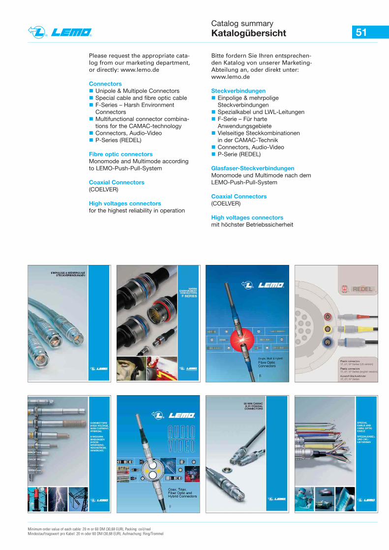
51Catalog summaryKatalogübersicht
Minimum order value of each cable: 20 m or 60 DM (30,68 EUR), Packing: coil/reelMindestauftragswert pro Kabel: 20 m oder 60 DM (30,68 EUR), Aufmachung: Ring/Trommel
Please request the appropriate cata-log from our marketing department,or directly: www.lemo.de
Connectors� Unipole & Multipole Connectors� Special cable and fibre optic cable� F-Series – Harsh Environment
Connectors� Multifunctional connector combina-
tions for the CAMAC-technology� Connectors, Audio-Video� P-Series (REDEL)
Fibre optic connectorsMonomode and Multimode accordingto LEMO-Push-Pull-System
Coaxial Connectors(COELVER)
High voltages connectorsfor the highest reliability in operation
Bitte fordern Sie Ihren entsprechen-den Katalog von unserer Marketing-Abteilung an, oder direkt unter:www.lemo.de
Steckverbindungen� Einpolige & mehrpolige
Steckverbindungen� Spezialkabel und LWL-Leitungen� F-Serie – Für harte
Anwendungsgebiete� Vielseitige Steckkombinationen
in der CAMAC-Technik� Connectors, Audio-Video� P-Serie (REDEL)
Glasfaser-SteckverbindungenMonomode und Multimode nach dem LEMO-Push-Pull-System
Coaxial Connectors(COELVER)
High voltages connectorsmit höchster Betriebssicherheit
![NEDERLANDS Conceptronic CM3H …download.conceptronic.net/Manuals/C08-137_CM3H_User...• Doe de audio-connectors van de composietkabel (rood en wit) in de tulpaansluitingen [12, 13]](https://static.fdocuments.nl/doc/165x107/5fe61a80e4714b32c7394c3d/nederlands-conceptronic-cm3h-a-doe-de-audio-connectors-van-de-composietkabel.jpg)