
CONCEPTUAL DATA MODEL A FOUNDATION FOR ......13th December 2017 Philipp Fischer, Meenakshi Deshmukh,...
20
13th December 2017 Philipp Fischer, Meenakshi Deshmukh, Volker Maiwald, Dominik Quantius, Antonio Martelo Gomez, Andreas Gerndt, Conceptual data model: A foundation for successful concurrent engineering, Concurrent Engineering Research and Application. Prepublished November 14, 2017, Copyright © 2017 DLR. Reprinted by permission of SAGE Publications. (https://doi.org/10.1177/1063293X17734592) CONCEPTUAL DATA MODEL – A FOUNDATION FOR SUCCESSFUL CONCURRENT ENGINEERING Philipp M. Fischer (1) , Meenakshi Deshmukh (1) , Volker Maiwald (2) , Dominik Quantius (2) , Antonio Martelo Gomez (2) , Andreas Gerndt (1) (1) DLR (German Aerospace Center), Software for Space Systems and Interactive Visualization Lilienthalplatz 7, 38108 Braunschweig, Germany Email: [email protected] Email: [email protected], Email: [email protected] (2) DLR (German Aerospace Center), Institute of Space Systems Robert-Hooke-Str. 7, 28359 Bremen, Germany Email: [email protected] Email: [email protected] Email: [email protected] ABSTRACT Today, phase A studies of future space systems are often conducted in special design facilities such as the Concurrent Engineering Facility (CEF) at the German Aerospace Center (DLR). Within these facilities the studies are performed following a defined process making use of a data model for information exchange. Quite often it remains unclear what exactly such a data model is and how it is implemented and applied. Nowadays, such a data model is usually a software using a formal specification describing its capabilities within a so called meta-model. This meta-model, often referred as Conceptual Data Model (CDM), is finally used and instantiated as system model during these CE studies. Such software also provides a user interface for instantiating and sharing the system model within the design team and it provides capabilities to analyze the system model on the fly. This is possible due to the semantics of the underlying CDM creating a common language used to exchange and process design information. This paper explains the implementation of the data model at DLR and shows information how it is applied in the concurrent engineering process of the CEF. It highlights important aspects concerning the modeling capabilities during a study and discusses how they can be implemented into a corresponding CDM. Accordingly, the paper presents important aspects such as rights management and data consistency and the implications of them to the software’s underlying technology. A special use case of the data model is depicted and shows the flexibility of the implementation proven by a study of a multi module space station. Extension of the original SECESA conference publication: P.M. Fischer, M. Deshmukh, V. Maiwald, D. Quantius, A. Martelo Gomez, A. Gerndt, “Conceptual Data Model: A foundation for successful concurrent engineering”. In: 7th International Systems & Concurrent Engineering for Space Applications Conference (SECESA), 5.-7. Oct. 2016, Madrid, Spain. INTRODUCTION The terms data base and system model and their various combinations are not far away when talking about Concurrent Engineering (CE) of spacecraft. Having some sort of data model as supporting tool when performing CE studies of new spacecraft is well accepted. Still, what such a data model should deliver to the study remains unclear. People have different understanding of this question depending on their tasks or the processes they are involved in. Gathering their ideas as a set of concepts though, allows creating common understanding of what such a data model should do in order to describe the spacecraft. These concepts are generally used to build a Conceptual Data Model (CDM) which is the basis to derive modeling languages to describe the studied system. Implementing such a CDM into a piece of computer software, e.g. an actual data-base and correctly embedding it into the CE process allows engineers to collaboratively merge their system knowledge into a common system model. This data-base providing a common modeling language helps the engineers focusing on their common tasks and thus allows successfully performing CE studies. The German Aerospace Center has developed such a CDM and has implemented it into the software called Virtual Satellite. It is used at DLR’s Concurrent Engineering Facility (CEF). The CDM has been built by capturing the demands from the CE process as it is applied in the CEF and the thereby arising needs of the individual engineers. Together with some guidelines and best practices learnt over the years, the engineers create a system model of the investigated system using the language of the CDM. The software takes care of further aspects such as sharing the designed system model with all involved engineers and permanently analyzing the designed system for feedback to the engineers. Accordingly, in order to implement such a software, it is necessary to first clearly define the terms such as
Transcript of CONCEPTUAL DATA MODEL A FOUNDATION FOR ......13th December 2017 Philipp Fischer, Meenakshi Deshmukh,...
13th December 2017
Philipp Fischer, Meenakshi Deshmukh, Volker Maiwald, Dominik Quantius, Antonio Martelo Gomez, Andreas Gerndt, Conceptual data model: A foundation for successful concurrent engineering, Concurrent Engineering Research and Application. Prepublished November 14, 2017, Copyright ©
2017 DLR. Reprinted by permission of SAGE Publications. (https://doi.org/10.1177/1063293X17734592)
CONCEPTUAL DATA MODEL – A FOUNDATION
FOR SUCCESSFUL CONCURRENT ENGINEERING
Philipp M. Fischer(1)
, Meenakshi Deshmukh(1)
, Volker Maiwald(2)
,
Dominik Quantius(2)
, Antonio Martelo Gomez(2)
, Andreas Gerndt(1)
(1)DLR (German Aerospace Center), Software for Space Systems and Interactive Visualization
Lilienthalplatz 7, 38108 Braunschweig, Germany
Email: [email protected]
Email: [email protected],
Email: [email protected]
(2)
DLR (German Aerospace Center), Institute of Space Systems
Robert-Hooke-Str. 7, 28359 Bremen, Germany
Email: [email protected]
Email: [email protected]
Email: [email protected]
ABSTRACT
Today, phase A studies of future space systems are often conducted in special design facilities such as the Concurrent
Engineering Facility (CEF) at the German Aerospace Center (DLR). Within these facilities the studies are performed
following a defined process making use of a data model for information exchange. Quite often it remains unclear what
exactly such a data model is and how it is implemented and applied. Nowadays, such a data model is usually a software
using a formal specification describing its capabilities within a so called meta-model. This meta-model, often referred
as Conceptual Data Model (CDM), is finally used and instantiated as system model during these CE studies. Such
software also provides a user interface for instantiating and sharing the system model within the design team and it
provides capabilities to analyze the system model on the fly. This is possible due to the semantics of the underlying
CDM creating a common language used to exchange and process design information. This paper explains the
implementation of the data model at DLR and shows information how it is applied in the concurrent engineering
process of the CEF. It highlights important aspects concerning the modeling capabilities during a study and discusses
how they can be implemented into a corresponding CDM. Accordingly, the paper presents important aspects such as
rights management and data consistency and the implications of them to the software’s underlying technology. A
special use case of the data model is depicted and shows the flexibility of the implementation proven by a study of a
multi module space station.
Extension of the original SECESA conference publication: P.M. Fischer, M. Deshmukh, V. Maiwald, D. Quantius, A. Martelo Gomez, A. Gerndt, “Conceptual Data Model: A foundation for successful concurrent engineering”. In: 7th International Systems & Concurrent Engineering for Space
Applications Conference (SECESA), 5.-7. Oct. 2016, Madrid, Spain.
INTRODUCTION
The terms data base and system model and their various combinations are not far away when talking about Concurrent
Engineering (CE) of spacecraft. Having some sort of data model as supporting tool when performing CE studies of new
spacecraft is well accepted. Still, what such a data model should deliver to the study remains unclear. People have
different understanding of this question depending on their tasks or the processes they are involved in. Gathering their
ideas as a set of concepts though, allows creating common understanding of what such a data model should do in order
to describe the spacecraft. These concepts are generally used to build a Conceptual Data Model (CDM) which is the
basis to derive modeling languages to describe the studied system. Implementing such a CDM into a piece of computer
software, e.g. an actual data-base and correctly embedding it into the CE process allows engineers to collaboratively
merge their system knowledge into a common system model. This data-base providing a common modeling language
helps the engineers focusing on their common tasks and thus allows successfully performing CE studies.
The German Aerospace Center has developed such a CDM and has implemented it into the software called Virtual
Satellite. It is used at DLR’s Concurrent Engineering Facility (CEF). The CDM has been built by capturing the
demands from the CE process as it is applied in the CEF and the thereby arising needs of the individual engineers.
Together with some guidelines and best practices learnt over the years, the engineers create a system model of the
investigated system using the language of the CDM. The software takes care of further aspects such as sharing the
designed system model with all involved engineers and permanently analyzing the designed system for feedback to the
engineers. Accordingly, in order to implement such a software, it is necessary to first clearly define the terms such as
13th December 2017
Philipp Fischer, Meenakshi Deshmukh, Volker Maiwald, Dominik Quantius, Antonio Martelo Gomez, Andreas Gerndt, Conceptual data model: A foundation for successful concurrent engineering, Concurrent Engineering Research and Application. Prepublished November 14, 2017, Copyright ©
2017 DLR. Reprinted by permission of SAGE Publications. (https://doi.org/10.1177/1063293X17734592)
data model, CDM and system model, and second to carefully understand the CE process and the engineer’s needs,
before defining a CDM and a software architecture.
This paper is about to give a definition on the aforementioned terms together with an analysis of the CEF process, the
resulting CDM and its implementation in the software Virtual Satellite. It starts by reflecting on the background to CE
as well as CDMs. It clarifies the definition of these terms and explains their origins. Furthermore, it elaborates on data
models as they are used in CE and in general, with a focus on spacecraft design within Europe. After bringing the
related work into context, the paper explains DLR’s CEF and the process applied during the studies, directly showing
the demand of a data model. The paper continues to define data model in the context of the CEF and explains how it is
used in Virtual Satellite from an engineer’s perspective. This includes full detail on how a system model actually looks
like during studies in the CEF and how this condensed into a best practice template for initial instantiation. The next
section provides detail on the definition of a corresponding CDM and how it has been implemented in Virtual Satellite
as software. Additionally the paper provides some information regarding extensibility and tailoring of the CDM as well
as DLR’s activities of embedding it in the whole lifecycle of a spacecraft. Before concluding, a small section will show
the real Virtual Satellite and how it was applied in some special use-cases.
BACKGROUND TO CONCURRENT ENGINEERING CENTERS AND CONCEPTUAL DATA MODELS
Concurrent Engineering (CE) is a philosophy of simultaneous design of a product along with all its related processes. It
intends to improve the design upfront of the production, thus reducing resulting costs later. The general idea of CE is
not totally new and can be tracked back to the early days in automotive line productions. From these days on, CE has
been researched and evolved into a team-based or computer based approach. The pure team-based approach is focusing
on people with appropriate knowledge of the product. Due to shortcomings in sharing their knowledge and emerging
computer tools it has been enhanced by the computer based approach. Computer Aided Design (CAD) tools, in general
and not only focusing on mechanical design, are expected to integrate into one design environment and interact and
cooperate with each other. This requires a single data base and a standard such as the International Organization for
Standardization (ISO) “Standard for the Exchange of Product Model Data” (STEP). (Jo, et al., 1993) In order to make
information management work in CE several aspects such as independence of parameters, functions, processes and
design consistency have to be considered. Frameworks to support on these information management aspects along the
whole product lifecycle have been described already in the nineties. They also address research issues regarding a
common schema and information model. (Prasad, et al., 1993) In terms of processes it is important to handle and
breaking down the complexity of the designed product. Starting from definitions such as hard and soft complexity it is
possible to use systemization to decompose the product into smaller logical parts. Such parts can be assigned to
individual experts. This approach is captured in an iterative process of planning, systemization, solution and unification,
where the later ones integrate individual design results back into the higher system level. (Prasad, 2001) A survey
across various different industries, including aerospace, proves the expected overall cost reduction. In addition it also
highlights the expectation of reducing costs already at design time. (Lawson & Karandikar, 1994). As one example
from space sector, the European Space Agency (ESA) has implemented CE for the early design of spacecraft. Here, a
reduction of design time from around six to nine months, down to three to six weeks was achieved. (Domizio &
Gaudenzi, 2008). Same as ESA with their Concurrent Design Facility (CDF), the German Aerospace Center (DLR) has
implemented CE for the early spacecraft design in their Concurrent Engineering Facility (CEF). Following a similar
approach both mention a set of key aspects for their actual implementations: a process, a multidisciplinary team, an
integrated design model, a facility as well as infrastructure. (Romberg, et al., 2008) (Bandechi, et al., 2000)
Considering the aforementioned facilities, the first Concurrent Engineering Centre (CEC) working in aerospace projects
was founded in 1995, when NASA’s Jet Propulsion Laboratory’s Team X was settled to address the need to create and
evaluate many concepts in a short period of time (Iwata, et al., 2015). Since then, the number of CEC’s has grown both
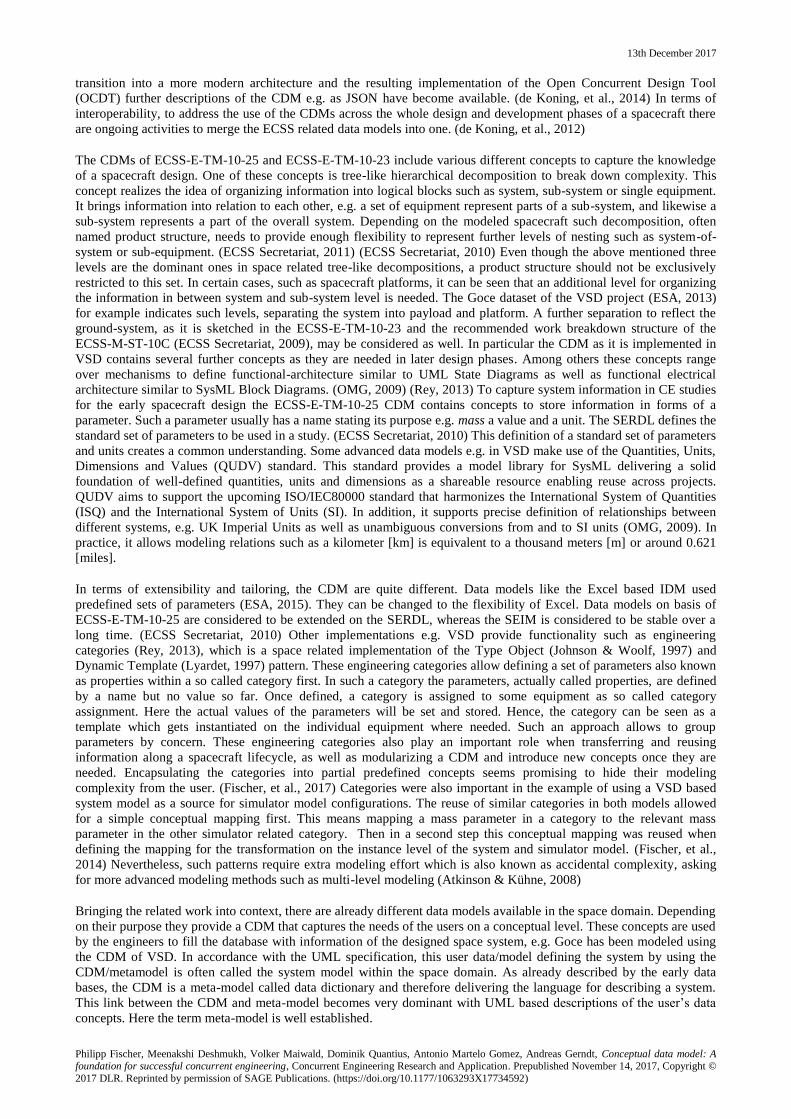
in the United States, and in the rest of the world. Table 1 provides a selection of CECs in the United States and their
applied data model / sharing tools. In Europe, the CDF established at ESA-ESTEC in 1998 has become a reference
point for other European CEC’s. Currently, a number of CEC’s are active in the European space industry environment
(ESA, 2015). A selection of these CECs is shown in Table 1 as well. For this selection of CECs, ESA’s Integrated
Design Model (IDM) has been the data sharing tool of choice. This Excel based tool, is composed of interconnected
spreadsheets representing the different subsystems. Today, some of these CEC’s continue to use the IDM in one form or
another, tuned to their specific requirements or with tools built on top of a modified IDM such as at DLR. (Romberg, et
al., 2008) Since then, ESA has developed in-house a new tool named Open Concurrent Design Tool (OCDT) to replace
the IDM, and has been using it exclusively in their studies since 2015. With an end-user tool based on an add-in that
works on top of Microsoft Excel, under the name of Concurrent Concepts, Options, Requirements and Design Editor
(ConCORDE), ESA promotes the use of their new open source software to other European CEC’s. (de Koning, et al.,
2014)
A modeling language is usually described by syntax, its semantics and a notation. The syntax describes the elements
and rules for creating a model, the semantics describe the meaning of the modeling language and finally the notation
13th December 2017
Philipp Fischer, Meenakshi Deshmukh, Volker Maiwald, Dominik Quantius, Antonio Martelo Gomez, Andreas Gerndt, Conceptual data model: A foundation for successful concurrent engineering, Concurrent Engineering Research and Application. Prepublished November 14, 2017, Copyright ©
2017 DLR. Reprinted by permission of SAGE Publications. (https://doi.org/10.1177/1063293X17734592)
describes the visualization. (Karagiannis & Kühn, 2002) The Unified Modeling Language (UML) for example is based
on a multi-layer architecture of three layers, the metamodel/language specification, the user specification/model and the
objects of the model. Hence, UML is a metamodel that can be used to define user models. The same applies for the
Meta Object Facility (MOF) representing a metamodel of which user models can be defined. These layers can be
interwoven, e.g. UML is actually a user model of MOF. (OMG, 2012) Therefore, the syntax of the UML is described in
the MOF framework, whereas the UML specific semantics are defined by the UML itself. (OMG, 2015)
Table 1: Overview of Concurrent Engineering Centers and used data models in the United States and Europe.
Agency Concurrent Engineering Centre Data model
The Aerospace Corporation Concept Design Center (CDC) interconnected Microsoft Excel
spreadsheets
NASA Jet Propulsion Laboratory
(JPL) Product Design Center (PDC) interconnected Microsoft Excel
spreadsheets
NASA Goddard Space Flight
Center (GSFC) Integrated Design Center (IDC) systems engineering integration
software
NASA Glenn Research Center
(GRC) COMPASS database and data transfer tool
known as GLIDE
Rutherford Appleton Laboratory
(RAL) Space Concurrent Design Facility (CDF) Custom macro-based software is
used with Microsoft Excel, Visio,
and Project
NASA Langley Research Center
(LaRC) Engineering Design Studio (EDS) Microsoft OneNote10 as the
working space for all disciplines
ESA-ESTEC Concurrent Design Facility (CDF) IDM and OCDT
Deutsches Zentrum für Luft- und
Raumfahrt
Concurrent Engineering Facility (CDF) Virtual Satellite
Centre national d'études spatiales
(CNES)
Centre d'Ingénierie Concourante (CIC) IDM
Agenzia Spaziale Italiana (ASI) Concurrent Engineering Facility
(ASI CEF)
-
École polytechnique fédérale de
Lausanne (EPFL) - -
Airbus Defence and Space Space Code -
OHB Systems - -
Thales Alenia Space - -
The term Conceptual Data Model (CDM) can be tracked back to early data base design. One of the first steps in data
base design is to create a conceptual schema from the user’s data requirements. During this conceptual design a high-
level CDM is used to describe entities and their relations, without implementation details. Accordingly it is used for
discussions with the users allowing them to understand what information they can store it in the database. Entity
Relational Diagrams (ERD) are one method to create such a model. From this conceptual schema two further artifacts
are usually derived. First the logical schema, sometimes called logical conceptual schema, with further implementation
details and finally the physical design, with internal storage structures, indexes, etc. (Elmasri & Navathe, 2004)
(Lockemann & Schmidt, 1987) The UML, and the class diagrams in particular, can be used as alternative to ERD for
describing the conceptual data model. (Elmasri & Navathe, 2004) These schemas fulfilling the transition from the user’s
data requirements down to their physical representation in a data base are a set of meta-data. They are also called the
data dictionary and they finally describe the user data in the data base. (Lockemann & Schmidt, 1987) It has to be
mentioned that the logical mapping from the conceptual schema to the logical schema is not unique and various
different mappings may exist.
Within the European space domain, the technical memorandum ECSS-E-TM-10-23 from the European Cooperation for
Space Standardization (ECSS) is describing a space system data repository. It establishes the formal specification of the
semantics of engineering data, and therefore enables standardized data exchange and interoperability across data
repositories. It defines the term CDM as the data model that captures the end-user needs in end-user terms. But it also
defines the term Global CDM describing a CDM for the complete lifecycle and all disciplines of a spacecraft system.
The Annex B of the standard provides an instantiation of the 10-23 for a system domain using UML. (ECSS Secretariat,
2011) An evolution of this CDM has been implemented in the project Virtual Spacecraft Design at ESA based on EMF
Ecore. (ESA, 2013) The technical memorandum ECSS-E-TM-10-25 focuses on data exchange for the CDF in the early
spacecraft design, called phase A. It does not explicitly define the terms CDM, but it still provides a UML description
of a so called System Engineering Information Model (SEIM). This memorandum also provides a System Engineering
Reference Data Library (SERDL) which describes the important information common to different concurrent design
studies in the CECs. The SEIM was described in the Annex A as UML model as well as ISO STEP EXPRESS schema.
(ECSS Secretariat, 2010) Initially the CDM was implemented in the Open Concurrent Design Server (OCDS). With the
13th December 2017
Philipp Fischer, Meenakshi Deshmukh, Volker Maiwald, Dominik Quantius, Antonio Martelo Gomez, Andreas Gerndt, Conceptual data model: A foundation for successful concurrent engineering, Concurrent Engineering Research and Application. Prepublished November 14, 2017, Copyright ©
2017 DLR. Reprinted by permission of SAGE Publications. (https://doi.org/10.1177/1063293X17734592)
transition into a more modern architecture and the resulting implementation of the Open Concurrent Design Tool
(OCDT) further descriptions of the CDM e.g. as JSON have become available. (de Koning, et al., 2014) In terms of
interoperability, to address the use of the CDMs across the whole design and development phases of a spacecraft there
are ongoing activities to merge the ECSS related data models into one. (de Koning, et al., 2012)
The CDMs of ECSS-E-TM-10-25 and ECSS-E-TM-10-23 include various different concepts to capture the knowledge
of a spacecraft design. One of these concepts is tree-like hierarchical decomposition to break down complexity. This
concept realizes the idea of organizing information into logical blocks such as system, sub-system or single equipment.
It brings information into relation to each other, e.g. a set of equipment represent parts of a sub-system, and likewise a
sub-system represents a part of the overall system. Depending on the modeled spacecraft such decomposition, often
named product structure, needs to provide enough flexibility to represent further levels of nesting such as system-of-
system or sub-equipment. (ECSS Secretariat, 2011) (ECSS Secretariat, 2010) Even though the above mentioned three
levels are the dominant ones in space related tree-like decompositions, a product structure should not be exclusively
restricted to this set. In certain cases, such as spacecraft platforms, it can be seen that an additional level for organizing
the information in between system and sub-system level is needed. The Goce dataset of the VSD project (ESA, 2013)
for example indicates such levels, separating the system into payload and platform. A further separation to reflect the
ground-system, as it is sketched in the ECSS-E-TM-10-23 and the recommended work breakdown structure of the
ECSS-M-ST-10C (ECSS Secretariat, 2009), may be considered as well. In particular the CDM as it is implemented in
VSD contains several further concepts as they are needed in later design phases. Among others these concepts range
over mechanisms to define functional-architecture similar to UML State Diagrams as well as functional electrical
architecture similar to SysML Block Diagrams. (OMG, 2009) (Rey, 2013) To capture system information in CE studies
for the early spacecraft design the ECSS-E-TM-10-25 CDM contains concepts to store information in forms of a
parameter. Such a parameter usually has a name stating its purpose e.g. mass a value and a unit. The SERDL defines the
standard set of parameters to be used in a study. (ECSS Secretariat, 2010) This definition of a standard set of parameters
and units creates a common understanding. Some advanced data models e.g. in VSD make use of the Quantities, Units,
Dimensions and Values (QUDV) standard. This standard provides a model library for SysML delivering a solid
foundation of well-defined quantities, units and dimensions as a shareable resource enabling reuse across projects.
QUDV aims to support the upcoming ISO/IEC80000 standard that harmonizes the International System of Quantities
(ISQ) and the International System of Units (SI). In addition, it supports precise definition of relationships between
different systems, e.g. UK Imperial Units as well as unambiguous conversions from and to SI units (OMG, 2009). In
practice, it allows modeling relations such as a kilometer [km] is equivalent to a thousand meters [m] or around 0.621
[miles].
In terms of extensibility and tailoring, the CDM are quite different. Data models like the Excel based IDM used
predefined sets of parameters (ESA, 2015). They can be changed to the flexibility of Excel. Data models on basis of
ECSS-E-TM-10-25 are considered to be extended on the SERDL, whereas the SEIM is considered to be stable over a
long time. (ECSS Secretariat, 2010) Other implementations e.g. VSD provide functionality such as engineering
categories (Rey, 2013), which is a space related implementation of the Type Object (Johnson & Woolf, 1997) and
Dynamic Template (Lyardet, 1997) pattern. These engineering categories allow defining a set of parameters also known
as properties within a so called category first. In such a category the parameters, actually called properties, are defined
by a name but no value so far. Once defined, a category is assigned to some equipment as so called category
assignment. Here the actual values of the parameters will be set and stored. Hence, the category can be seen as a
template which gets instantiated on the individual equipment where needed. Such an approach allows to group
parameters by concern. These engineering categories also play an important role when transferring and reusing
information along a spacecraft lifecycle, as well as modularizing a CDM and introduce new concepts once they are
needed. Encapsulating the categories into partial predefined concepts seems promising to hide their modeling
complexity from the user. (Fischer, et al., 2017) Categories were also important in the example of using a VSD based
system model as a source for simulator model configurations. The reuse of similar categories in both models allowed
for a simple conceptual mapping first. This means mapping a mass parameter in a category to the relevant mass
parameter in the other simulator related category. Then in a second step this conceptual mapping was reused when
defining the mapping for the transformation on the instance level of the system and simulator model. (Fischer, et al.,
2014) Nevertheless, such patterns require extra modeling effort which is also known as accidental complexity, asking
for more advanced modeling methods such as multi-level modeling (Atkinson & Kühne, 2008)
Bringing the related work into context, there are already different data models available in the space domain. Depending
on their purpose they provide a CDM that captures the needs of the users on a conceptual level. These concepts are used
by the engineers to fill the database with information of the designed space system, e.g. Goce has been modeled using
the CDM of VSD. In accordance with the UML specification, this user data/model defining the system by using the
CDM/metamodel is often called the system model within the space domain. As already described by the early data
bases, the CDM is a meta-model called data dictionary and therefore delivering the language for describing a system.
This link between the CDM and meta-model becomes very dominant with UML based descriptions of the user’s data
concepts. Here the term meta-model is well established.
13th December 2017
Philipp Fischer, Meenakshi Deshmukh, Volker Maiwald, Dominik Quantius, Antonio Martelo Gomez, Andreas Gerndt, Conceptual data model: A foundation for successful concurrent engineering, Concurrent Engineering Research and Application. Prepublished November 14, 2017, Copyright ©
2017 DLR. Reprinted by permission of SAGE Publications. (https://doi.org/10.1177/1063293X17734592)
INTERACTION WITH THE DATA MODEL IN THE CEF PROCESS
Space projects generally follow a lifecycle model of phases. The first phases are called 0 (Zero) and A, here the initial
design of the spacecraft is created. This design is detailed in phase B, before the actual system gets assembled and
tested in C and D. The phases E and F concern the operation and final disposal of the system. (ECSS Secretariat, 2009)
The Concurrent Engineering Facility (CEF) is used for the early phase A spacecraft design at DLR. The CEF is
specially designed with a focus on interpersonal communication; it provides a working environment in which several
engineers and customers can work together and discuss the initial design of a new mission or spacecraft. Every
workplace in the facility is equipped with a computer that can be used to research specifications, run simulations, write
down results, etc. The studies performed in the CEF follow a specific guided process to make them successful. This
process defines the tasks and issues to be addressed in the study in a way that will optimally fulfill previously defined
goals (e.g. define a mission, design a specific system, etc.).
A typical study in the CEF condenses a preliminary analysis phase A study into one, sometimes up to three weeks of
intensive group work. The duration depends on the complexity and objectives of the study as well as the availability of
the team members. Within this timeframe the team will create a preliminary design of a system (e.g. satellite, launcher,
lander, etc.), including 3D model configurations, as well as a parametric system model down to the elements of the
subsystem and equipment level.
For the design of a system such as a spacecraft, around 12 domain experts (i.e. multidisciplinary engineers, scientists,
etc.) are invited to the CEF. Starting off from a study scope document which includes the study goals, the system and
mission requirements, and a preliminary configuration as discussed and agreed upon with the customer, the CE process
kicks off in the CEF. The work performed in the CEF directs the approach to the design tasks, focusing on the key
performance indicators (KPI) of the studied system. These KPI reflect characteristics such as the decomposition of
needed equipment, the masses, power-consumptions, etc. The data model stores these KPI, shares them across the
whole team and accumulates them to some overall design metrics. Supported by these metrics, engineers judge on their
design and discuss the next changes for the upcoming iterations in the process.
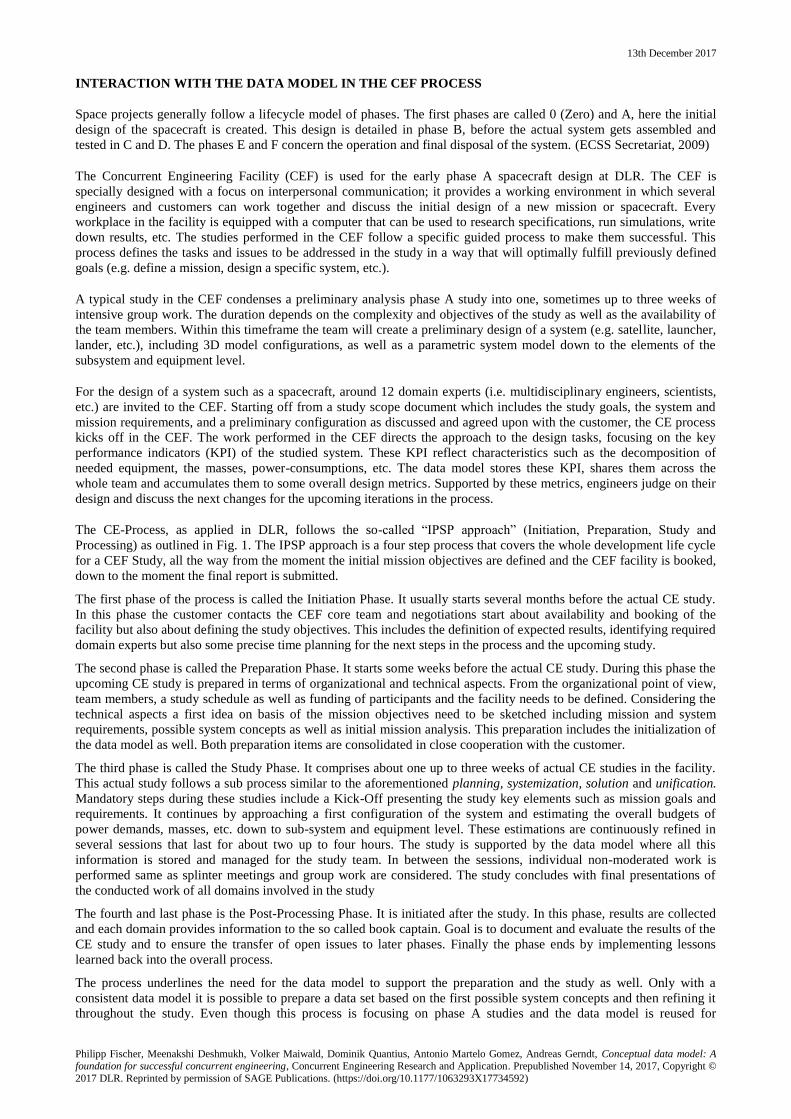
The CE-Process, as applied in DLR, follows the so-called “IPSP approach” (Initiation, Preparation, Study and
Processing) as outlined in Fig. 1. The IPSP approach is a four step process that covers the whole development life cycle
for a CEF Study, all the way from the moment the initial mission objectives are defined and the CEF facility is booked,
down to the moment the final report is submitted.
The first phase of the process is called the Initiation Phase. It usually starts several months before the actual CE study.
In this phase the customer contacts the CEF core team and negotiations start about availability and booking of the
facility but also about defining the study objectives. This includes the definition of expected results, identifying required
domain experts but also some precise time planning for the next steps in the process and the upcoming study.
The second phase is called the Preparation Phase. It starts some weeks before the actual CE study. During this phase the
upcoming CE study is prepared in terms of organizational and technical aspects. From the organizational point of view,
team members, a study schedule as well as funding of participants and the facility needs to be defined. Considering the
technical aspects a first idea on basis of the mission objectives need to be sketched including mission and system
requirements, possible system concepts as well as initial mission analysis. This preparation includes the initialization of
the data model as well. Both preparation items are consolidated in close cooperation with the customer.
The third phase is called the Study Phase. It comprises about one up to three weeks of actual CE studies in the facility.
This actual study follows a sub process similar to the aforementioned planning, systemization, solution and unification.
Mandatory steps during these studies include a Kick-Off presenting the study key elements such as mission goals and
requirements. It continues by approaching a first configuration of the system and estimating the overall budgets of
power demands, masses, etc. down to sub-system and equipment level. These estimations are continuously refined in
several sessions that last for about two up to four hours. The study is supported by the data model where all this
information is stored and managed for the study team. In between the sessions, individual non-moderated work is
performed same as splinter meetings and group work are considered. The study concludes with final presentations of
the conducted work of all domains involved in the study
The fourth and last phase is the Post-Processing Phase. It is initiated after the study. In this phase, results are collected
and each domain provides information to the so called book captain. Goal is to document and evaluate the results of the
CE study and to ensure the transfer of open issues to later phases. Finally the phase ends by implementing lessons
learned back into the overall process.
The process underlines the need for the data model to support the preparation and the study as well. Only with a
consistent data model it is possible to prepare a data set based on the first possible system concepts and then refining it
throughout the study. Even though this process is focusing on phase A studies and the data model is reused for
13th December 2017
Philipp Fischer, Meenakshi Deshmukh, Volker Maiwald, Dominik Quantius, Antonio Martelo Gomez, Andreas Gerndt, Conceptual data model: A foundation for successful concurrent engineering, Concurrent Engineering Research and Application. Prepublished November 14, 2017, Copyright ©
2017 DLR. Reprinted by permission of SAGE Publications. (https://doi.org/10.1177/1063293X17734592)
evaluation and documentation purposes only, the advantage of reusing the data model for phase B and continuing has to
be considered in the future as well.
Fig. 1: Overview to the IPSP – approach and its four phases.
REQUIRED CONCEPTS TO DEFINE A SYSTEM MODEL IN THE CEF
The data model which is used in CE studies within the CEF is intended to support the CE process. Accordingly it is
supposed to stay in the background, meaning it should not drag the attention of the engineers from their original design
and engineering tasks. The data model should provide an easy to use interface to the engineers to organize, store and
retrieve system relevant information. Therefore it needs to be implemented in some kind of software that takes care of
exchanging the information across all engineering domains while keeping it consistent. Additionally the software is
required to support the engineers with their design tasks by offering an instant analysis of the stored information in the
data model. These analyses help the engineers to base the design decisions for the next iterations of their overall system
design (Deshmukh, et al., 2013).
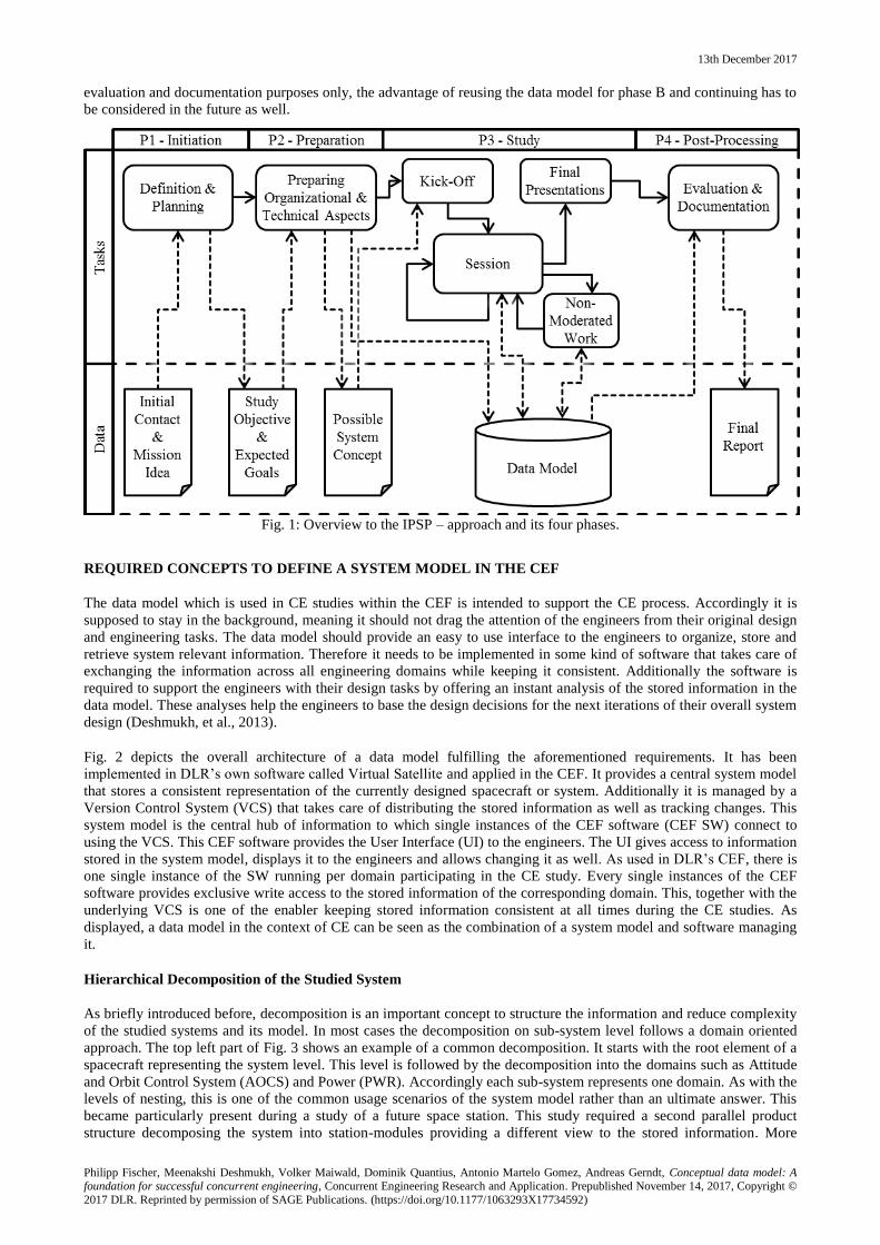
Fig. 2 depicts the overall architecture of a data model fulfilling the aforementioned requirements. It has been
implemented in DLR’s own software called Virtual Satellite and applied in the CEF. It provides a central system model
that stores a consistent representation of the currently designed spacecraft or system. Additionally it is managed by a
Version Control System (VCS) that takes care of distributing the stored information as well as tracking changes. This
system model is the central hub of information to which single instances of the CEF software (CEF SW) connect to
using the VCS. This CEF software provides the User Interface (UI) to the engineers. The UI gives access to information
stored in the system model, displays it to the engineers and allows changing it as well. As used in DLR’s CEF, there is
one single instance of the SW running per domain participating in the CE study. Every single instances of the CEF
software provides exclusive write access to the stored information of the corresponding domain. This, together with the
underlying VCS is one of the enabler keeping stored information consistent at all times during the CE studies. As
displayed, a data model in the context of CE can be seen as the combination of a system model and software managing
it.
Hierarchical Decomposition of the Studied System
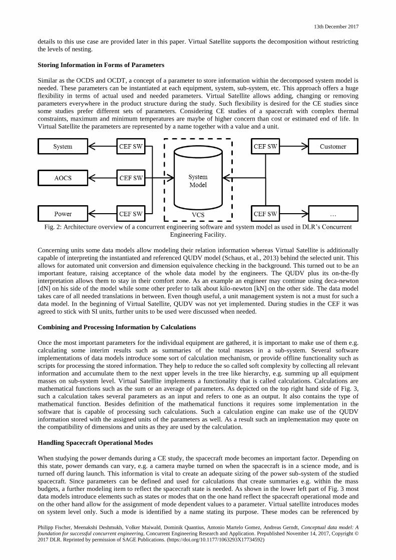
As briefly introduced before, decomposition is an important concept to structure the information and reduce complexity
of the studied systems and its model. In most cases the decomposition on sub-system level follows a domain oriented
approach. The top left part of Fig. 3 shows an example of a common decomposition. It starts with the root element of a
spacecraft representing the system level. This level is followed by the decomposition into the domains such as Attitude
and Orbit Control System (AOCS) and Power (PWR). Accordingly each sub-system represents one domain. As with the
levels of nesting, this is one of the common usage scenarios of the system model rather than an ultimate answer. This
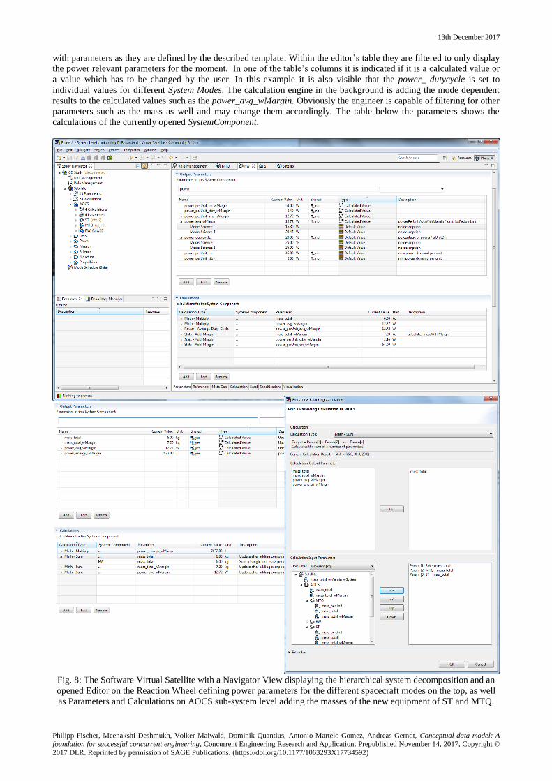
became particularly present during a study of a future space station. This study required a second parallel product
structure decomposing the system into station-modules providing a different view to the stored information. More
13th December 2017
Philipp Fischer, Meenakshi Deshmukh, Volker Maiwald, Dominik Quantius, Antonio Martelo Gomez, Andreas Gerndt, Conceptual data model: A foundation for successful concurrent engineering, Concurrent Engineering Research and Application. Prepublished November 14, 2017, Copyright ©
2017 DLR. Reprinted by permission of SAGE Publications. (https://doi.org/10.1177/1063293X17734592)
details to this use case are provided later in this paper. Virtual Satellite supports the decomposition without restricting
the levels of nesting.
Storing Information in Forms of Parameters
Similar as the OCDS and OCDT, a concept of a parameter to store information within the decomposed system model is
needed. These parameters can be instantiated at each equipment, system, sub-system, etc. This approach offers a huge
flexibility in terms of actual used and needed parameters. Virtual Satellite allows adding, changing or removing
parameters everywhere in the product structure during the study. Such flexibility is desired for the CE studies since
some studies prefer different sets of parameters. Considering CE studies of a spacecraft with complex thermal
constraints, maximum and minimum temperatures are maybe of higher concern than cost or estimated end of life. In
Virtual Satellite the parameters are represented by a name together with a value and a unit.
Fig. 2: Architecture overview of a concurrent engineering software and system model as used in DLR’s Concurrent
Engineering Facility.
Concerning units some data models allow modeling their relation information whereas Virtual Satellite is additionally
capable of interpreting the instantiated and referenced QUDV model (Schaus, et al., 2013) behind the selected unit. This
allows for automated unit conversion and dimension equivalence checking in the background. This turned out to be an
important feature, raising acceptance of the whole data model by the engineers. The QUDV plus its on-the-fly
interpretation allows them to stay in their comfort zone. As an example an engineer may continue using deca-newton
[dN] on his side of the model while some other prefer to talk about kilo-newton [kN] on the other side. The data model
takes care of all needed translations in between. Even though useful, a unit management system is not a must for such a
data model. In the beginning of Virtual Satellite, QUDV was not yet implemented. During studies in the CEF it was
agreed to stick with SI units, further units to be used were discussed when needed.
Combining and Processing Information by Calculations
Once the most important parameters for the individual equipment are gathered, it is important to make use of them e.g.
calculating some interim results such as summaries of the total masses in a sub-system. Several software
implementations of data models introduce some sort of calculation mechanism, or provide offline functionality such as
scripts for processing the stored information. They help to reduce the so called soft complexity by collecting all relevant
information and accumulate them to the next upper levels in the tree like hierarchy, e.g. summing up all equipment
masses on sub-system level. Virtual Satellite implements a functionality that is called calculations. Calculations are
mathematical functions such as the sum or an average of parameters. As depicted on the top right hand side of Fig. 3,
such a calculation takes several parameters as an input and refers to one as an output. It also contains the type of
mathematical function. Besides definition of the mathematical functions it requires some implementation in the
software that is capable of processing such calculations. Such a calculation engine can make use of the QUDV
information stored with the assigned units of the parameters as well. As a result such an implementation may quote on
the compatibility of dimensions and units as they are used by the calculation.
Handling Spacecraft Operational Modes
When studying the power demands during a CE study, the spacecraft mode becomes an important factor. Depending on
this state, power demands can vary, e.g. a camera maybe turned on when the spacecraft is in a science mode, and is
turned off during launch. This information is vital to create an adequate sizing of the power sub-system of the studied
spacecraft. Since parameters can be defined and used for calculations that create summaries e.g. within the mass
budgets, a further modeling item to reflect the spacecraft state is needed. As shown in the lower left part of Fig. 3 most
data models introduce elements such as states or modes that on the one hand reflect the spacecraft operational mode and
on the other hand allow for the assignment of mode dependent values to a parameter. Virtual satellite introduces modes
on system level only. Such a mode is identified by a name stating its purpose. These modes can be referenced by
13th December 2017
Philipp Fischer, Meenakshi Deshmukh, Volker Maiwald, Dominik Quantius, Antonio Martelo Gomez, Andreas Gerndt, Conceptual data model: A foundation for successful concurrent engineering, Concurrent Engineering Research and Application. Prepublished November 14, 2017, Copyright ©
2017 DLR. Reprinted by permission of SAGE Publications. (https://doi.org/10.1177/1063293X17734592)
corresponding mode dependent values of a parameter. The value associated with the parameter itself is considered as a
default value. That one accounts for all modes if no specific value is defined. The software part which is already
processing the calculations has to be aware of these modes. It needs to resolve the permutations of modes that are
relevant together with calculations. Actually the output parameter of a calculation has to depend on all modes where the
input parameters already depend on.
Fig. 3: Example of hierarchical decomposition of the spacecraft (Top Left) as well as storing parameters and
calculations with it (Top Right) and advanced modeling features introducing modes and integration of external
calculations such as Excel workbooks (Bottom).
Advanced Features such as Access Control and Excel Integration
Virtual Satellite provides some advanced functionality such as sharing of parameters. Per default a parameter is not
shared, which means that it cannot be referenced by another domain for its calculations. Since the parameter is still
visible for the other domain it enforces communication during the study. An engineer has to explicitly ask for it to be
able to use information of a colleague within a calculation. This guarantees that calculations are based on final results
and correct domain external input rather than some interim or guessed values.
A second important feature is the integration of Excel workbooks. A lot of engineers participating in the CE studies
make use of predefined Excel workbooks to size and layout their sub-system. Virtual Satellite allows to integrate such
workbooks into the data model and to connect it to input and output parameters similar to calculations as indicated by
Fig. 3Fehler! Verweisquelle konnte nicht gefunden werden.. When processing this special kind of calculation, the
values of input parameters need to be transferred into the Excel sheets and output parameters have to be read out again
to finally store them to the system model. Handling mode dependent values together with this Excel integration is of
13th December 2017
Philipp Fischer, Meenakshi Deshmukh, Volker Maiwald, Dominik Quantius, Antonio Martelo Gomez, Andreas Gerndt, Conceptual data model: A foundation for successful concurrent engineering, Concurrent Engineering Research and Application. Prepublished November 14, 2017, Copyright ©
2017 DLR. Reprinted by permission of SAGE Publications. (https://doi.org/10.1177/1063293X17734592)
concern as well. Additionally it is important to store the actual Excel Workbook to the system model, thus it gets
managed by the VCS as well.
DLR Template with Prepared Mass, Power Budgets and Included Margin Philosophy
With the described functionality of the data models it is also necessary to describe how it should be used. Similar to the
SERDL it means how it should be instantiated in detail. The pure flexibility of the data model actually allows each
engineer to decide by themselves on the levels of nesting, used parameters and their associated name. Nevertheless, this
does not make sense within a collaborative environment, since the information one engineer contributes to the data
model needs to be understood and correctly interpreted by another one. For Virtual Satellite a convention has been
developed over the last years that describe the instantiation of the data model in several areas. It covers the levels of
nesting, the parameters of major interest on each level in the hierarchy as well as the used calculations including a
margin philosophy.
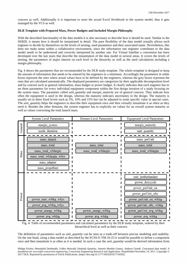
Fig. 4 shows the parameters that are recommended by the DLR study template. The whole template is designed to keep
the amount of information that needs to be entered by the engineers to a minimum. Accordingly the parameters in white
boxes represent the ones where actual values have to be defined by the engineers, whereas the grey boxes represent the
ones that are calculated automatically. The displayed parameters are categorizes by their applicable decomposition level
and by concern such as general information, mass budget or power budget. It clearly indicates that each engineer has to
set three parameters for every individual equipment component within the first design iteration of a study focusing on
the system mass. The parameter called unit_quantity and margin_maturity are of general concern. They indicate how
often the equipment is used in the design, whereas the maturity indicates uncertainty in the design. The maturity is
usually set to three fixed levels such as 5%, 10% and 15% but can be adjusted to some specific value in special cases.
The unit_quantity helps the engineers to describe their equipment once and then virtually instantiate it as often as they
need it. Besides the other domains, the system engineer has to explicitly set values for an overall system maturity as
well as values concerning the total launch mass.
Fig. 4: Table of recommended parameters and calculated parameters by the DLR study template, ordered by their
hierarchical level as well as their concern.
The definition of parameters such as unit_quantity can be seen as a trade-off between precise modeling and usability.
On the one hand, using a data model as described by the ECSS-E-TM-10-23 it would be possible to define a component
once and then instantiate it as often as it is needed. In such a case the unit_quantity would be derived information from
13th December 2017
Philipp Fischer, Meenakshi Deshmukh, Volker Maiwald, Dominik Quantius, Antonio Martelo Gomez, Andreas Gerndt, Conceptual data model: A foundation for successful concurrent engineering, Concurrent Engineering Research and Application. Prepublished November 14, 2017, Copyright ©
2017 DLR. Reprinted by permission of SAGE Publications. (https://doi.org/10.1177/1063293X17734592)
the amount of instantiations. On the other hand, experience in the CE studies showed that such patterns are not that
intuitive to the users. In return they asked for this quantity information as a parameter. Most likely this is also due to the
process applied in DLR’s CEF, with very short iterations and often unexperienced users. In total it reduces the modeling
effort by compromising the precision/quality of the model. Even though acceptable for the result of the CE study an
impact in later phases of the project should be considered.
Considering the power budget related parameters in the following design iterations, some more parameters need to be
set. The parameters and calculations implement a redundancy concept stating how many equipment are turned on in
parallel, hence the parameter unit_hotRedundant should not exceed the value of the unit_quantity. Other parameters
concern the consumed power when the equipment is turned on as well when it is turned off. Additionally a parameter
indicating the duty cycle of the equipment is defined. It represents a relative value reflecting how much of a certain
period of time the equipment is in it’s on and off state. The period of time are set with the mode_duration by the system
engineer.
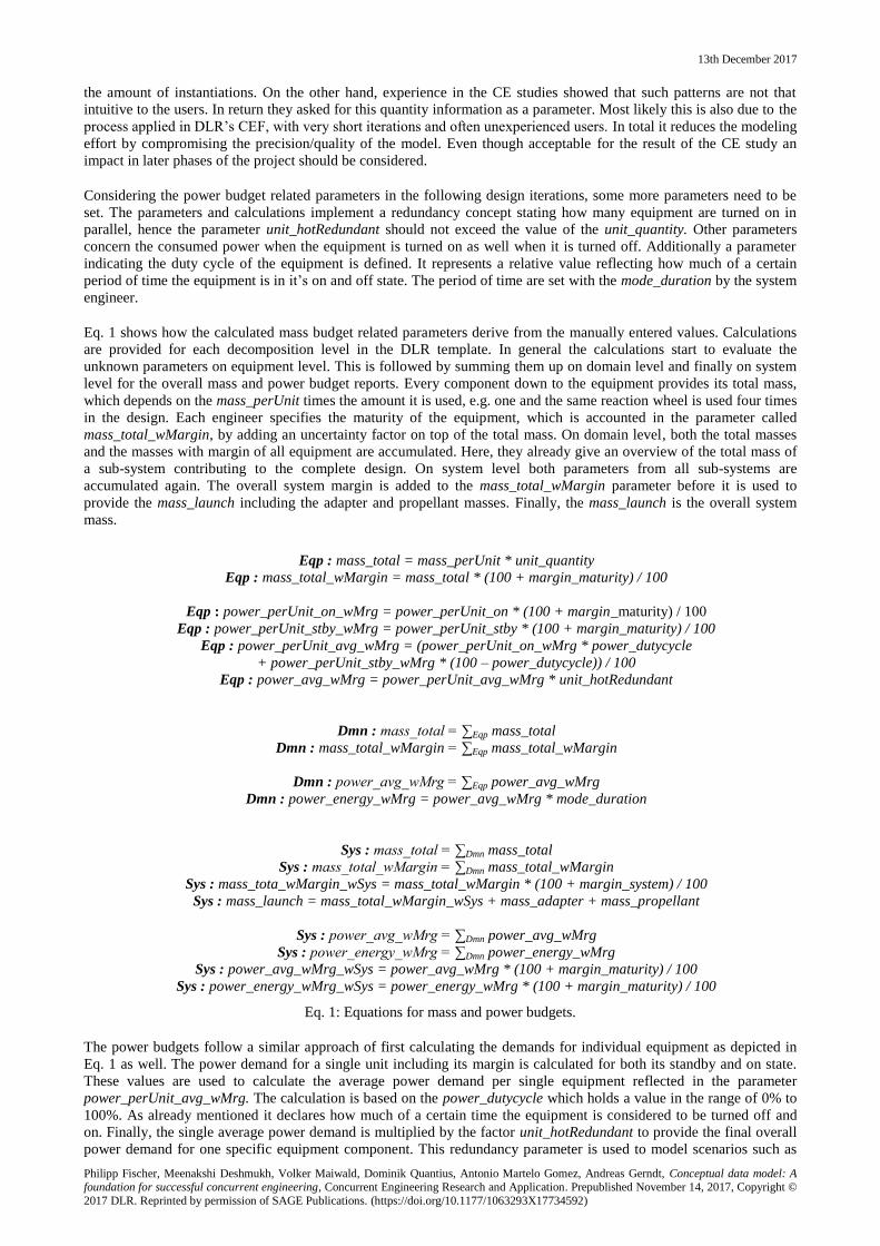
Eq. 1 shows how the calculated mass budget related parameters derive from the manually entered values. Calculations
are provided for each decomposition level in the DLR template. In general the calculations start to evaluate the
unknown parameters on equipment level. This is followed by summing them up on domain level and finally on system
level for the overall mass and power budget reports. Every component down to the equipment provides its total mass,
which depends on the mass_perUnit times the amount it is used, e.g. one and the same reaction wheel is used four times
in the design. Each engineer specifies the maturity of the equipment, which is accounted in the parameter called
mass_total_wMargin, by adding an uncertainty factor on top of the total mass. On domain level, both the total masses
and the masses with margin of all equipment are accumulated. Here, they already give an overview of the total mass of
a sub-system contributing to the complete design. On system level both parameters from all sub-systems are
accumulated again. The overall system margin is added to the mass_total_wMargin parameter before it is used to
provide the mass_launch including the adapter and propellant masses. Finally, the mass_launch is the overall system
mass.
Eq. 1: Equations for mass and power budgets.
The power budgets follow a similar approach of first calculating the demands for individual equipment as depicted in
Eq. 1 as well. The power demand for a single unit including its margin is calculated for both its standby and on state.
These values are used to calculate the average power demand per single equipment reflected in the parameter
power_perUnit_avg_wMrg. The calculation is based on the power_dutycycle which holds a value in the range of 0% to
100%. As already mentioned it declares how much of a certain time the equipment is considered to be turned off and
on. Finally, the single average power demand is multiplied by the factor unit_hotRedundant to provide the final overall
power demand for one specific equipment component. This redundancy parameter is used to model scenarios such as
Eqp : mass_total = mass_perUnit * unit_quantity
Eqp : mass_total_wMargin = mass_total * (100 + margin_maturity) / 100
Eqp : power_perUnit_on_wMrg = power_perUnit_on * (100 + margin_maturity) / 100
Eqp : power_perUnit_stby_wMrg = power_perUnit_stby * (100 + margin_maturity) / 100
Eqp : power_perUnit_avg_wMrg = (power_perUnit_on_wMrg * power_dutycycle
+ power_perUnit_stby_wMrg * (100 – power_dutycycle)) / 100
Eqp : power_avg_wMrg = power_perUnit_avg_wMrg * unit_hotRedundant
Dmn : mass_total = ∑Eqp mass_total
Dmn : mass_total_wMargin = ∑Eqp mass_total_wMargin
Dmn : power_avg_wMrg = ∑Eqp power_avg_wMrg
Dmn : power_energy_wMrg = power_avg_wMrg * mode_duration
Sys : mass_total = ∑Dmn mass_total
Sys : mass_total_wMargin = ∑Dmn mass_total_wMargin
Sys : mass_tota_wMargin_wSys = mass_total_wMargin * (100 + margin_system) / 100
Sys : mass_launch = mass_total_wMargin_wSys + mass_adapter + mass_propellant
Sys : power_avg_wMrg = ∑Dmn power_avg_wMrg
Sys : power_energy_wMrg = ∑Dmn power_energy_wMrg
Sys : power_avg_wMrg_wSys = power_avg_wMrg * (100 + margin_maturity) / 100
Sys : power_energy_wMrg_wSys = power_energy_wMrg * (100 + margin_maturity) / 100
13th December 2017
Philipp Fischer, Meenakshi Deshmukh, Volker Maiwald, Dominik Quantius, Antonio Martelo Gomez, Andreas Gerndt, Conceptual data model: A foundation for successful concurrent engineering, Concurrent Engineering Research and Application. Prepublished November 14, 2017, Copyright ©
2017 DLR. Reprinted by permission of SAGE Publications. (https://doi.org/10.1177/1063293X17734592)
using five redundant sensors which all stack up to the mass but only two of them are operating at the same time, thus
contributing to the power budget. On domain level the power demands of all equipment are accumulated and used to
additionally provide the energy demands of a complete sub-system. The energy demand is based on the mode duration.
Both the energy and the average power demands are accumulated on system level and finally raised by the system
margin to provide the absolute energy and power demand of the overall system.
Instantiating this DLR study template in Virtual Satellite, it automatically generates all parameters and calculations for
the system including one sub-system and one equipment level component. The engineers can use them as templates to
create copies for further sub-systems and equipment, but have to make sure they are correctly referenced in the
calculations in particular when accumulating interim summaries on system and sub-system level.
THE CONCEPTUAL DATA MODEL AND SOROUNDING SOFTWARE ARCHITCTURE
The previous chapter outlined some fundamental functionality that is needed in CE software such as Virtual Satellite. It
shows how a system model should be instantiated and how it is used in the CEF. Even though quite often stated as the
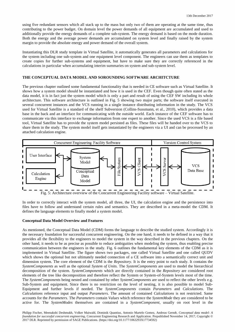
data model, it is in fact just the system model which is only a part and result of using the CEF SW including its whole
architecture. This software architecture is outlined in Fig. 5 showing two major parts; the software itself executed in
several concurrent instances and the VCS running in a single instance distributing information in the study. The VCS
used for Virtual Satellite is a standard of the shelf Subversion (Collins-Sussmann, et al., 2010), which provides a data
base in the back and an interface for communicating with the outside world. Each instance of the CEF software has to
communicate via this interface to exchange information from one expert to another. Since the used VCS is a file based
tool, Virtual Satellite has to provide the system model persisted as files. These files will be handed over to the VCS to
share them in the study. The system model itself gets instantiated by the engineers via a UI and can be processed by an
attached calculation engine.
Fig. 5: Architecture overview of the Concurrent Engineering Facility software – Virtual Satellite.
In order to correctly interact with the system model, all three, the UI, the calculation engine and the persistence into
files have to follow and understand certain rules and semantics. They are described in a meta-model the CDM. It
defines the language elements to finally model a system model.
Conceptual Data Model Overview and Features
As mentioned, the Conceptual Data Model (CDM) forms the language to describe the studied system. Accordingly it is
the necessary foundation for successful concurrent engineering. On the one hand, it needs to be defined in a way that it
provides all the flexibility to the engineers to model the system in the way described in the previous chapters. On the
other hand, it needs to be as precise as possible to reduce ambiguities when modeling the system, thus enabling precise
communication between the engineers in the study. Fig. 6 outlines the fundamental key elements of the CDM as it is
implemented in Virtual Satellite. The figure shows two packages, one called Virtual Satellite and one called QUDV
which shows the optional but not ultimately needed connection of a CE software into a semantically correct unit and
dimension system. The core element of the CDM is the Repository. It is the entry point to each study. It contains the
SystemComponents as well as the optional System of Units. The SystemComponents are used to model the hierarchical
decomposition of the system. SystemComponents which are directly contained in the Repository are considered root
elements of the tree like decomposition and therefore reflect the System or System-of-System levels most of the time.
The SystemComponents being nested and contained by other SystemComponents are used to reflect the other levels e.g.
Sub-System and equipment. Since there is no restriction on the level of nesting, it is also possible to model Sub-
Equipment and further levels if needed. The SystemComponents contain Parameters and Calculations. The
Calculations reference input and output Parameters. The amount of contained Calculations is not restricted. Same
accounts for the Parameters. The Parameters contain Values which reference the SystemMode they are considered to be
active for. The SystemModes themselves are contained in a SystemComponent, usually on root level in the
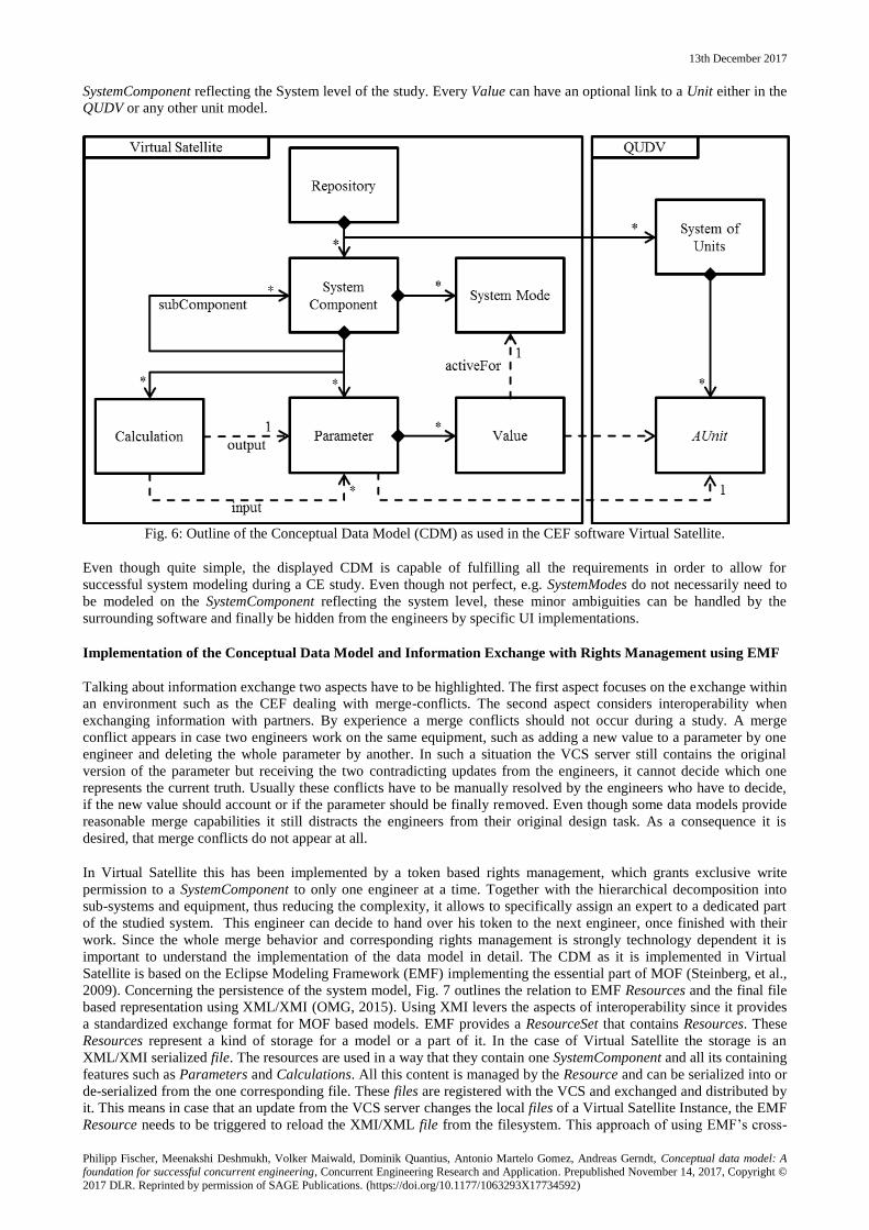
13th December 2017
Philipp Fischer, Meenakshi Deshmukh, Volker Maiwald, Dominik Quantius, Antonio Martelo Gomez, Andreas Gerndt, Conceptual data model: A foundation for successful concurrent engineering, Concurrent Engineering Research and Application. Prepublished November 14, 2017, Copyright ©
2017 DLR. Reprinted by permission of SAGE Publications. (https://doi.org/10.1177/1063293X17734592)
SystemComponent reflecting the System level of the study. Every Value can have an optional link to a Unit either in the
QUDV or any other unit model.
Fig. 6: Outline of the Conceptual Data Model (CDM) as used in the CEF software Virtual Satellite.
Even though quite simple, the displayed CDM is capable of fulfilling all the requirements in order to allow for
successful system modeling during a CE study. Even though not perfect, e.g. SystemModes do not necessarily need to
be modeled on the SystemComponent reflecting the system level, these minor ambiguities can be handled by the
surrounding software and finally be hidden from the engineers by specific UI implementations.
Implementation of the Conceptual Data Model and Information Exchange with Rights Management using EMF
Talking about information exchange two aspects have to be highlighted. The first aspect focuses on the exchange within
an environment such as the CEF dealing with merge-conflicts. The second aspect considers interoperability when
exchanging information with partners. By experience a merge conflicts should not occur during a study. A merge
conflict appears in case two engineers work on the same equipment, such as adding a new value to a parameter by one
engineer and deleting the whole parameter by another. In such a situation the VCS server still contains the original
version of the parameter but receiving the two contradicting updates from the engineers, it cannot decide which one
represents the current truth. Usually these conflicts have to be manually resolved by the engineers who have to decide,
if the new value should account or if the parameter should be finally removed. Even though some data models provide
reasonable merge capabilities it still distracts the engineers from their original design task. As a consequence it is
desired, that merge conflicts do not appear at all.
In Virtual Satellite this has been implemented by a token based rights management, which grants exclusive write
permission to a SystemComponent to only one engineer at a time. Together with the hierarchical decomposition into
sub-systems and equipment, thus reducing the complexity, it allows to specifically assign an expert to a dedicated part
of the studied system. This engineer can decide to hand over his token to the next engineer, once finished with their
work. Since the whole merge behavior and corresponding rights management is strongly technology dependent it is
important to understand the implementation of the data model in detail. The CDM as it is implemented in Virtual
Satellite is based on the Eclipse Modeling Framework (EMF) implementing the essential part of MOF (Steinberg, et al.,
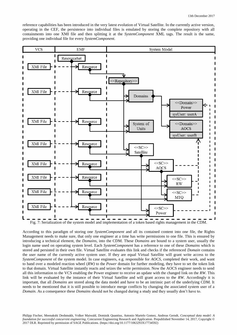
2009). Concerning the persistence of the system model, Fig. 7 outlines the relation to EMF Resources and the final file
based representation using XML/XMI (OMG, 2015). Using XMI levers the aspects of interoperability since it provides
a standardized exchange format for MOF based models. EMF provides a ResourceSet that contains Resources. These
Resources represent a kind of storage for a model or a part of it. In the case of Virtual Satellite the storage is an
XML/XMI serialized file. The resources are used in a way that they contain one SystemComponent and all its containing
features such as Parameters and Calculations. All this content is managed by the Resource and can be serialized into or
de-serialized from the one corresponding file. These files are registered with the VCS and exchanged and distributed by
it. This means in case that an update from the VCS server changes the local files of a Virtual Satellite Instance, the EMF
Resource needs to be triggered to reload the XMI/XML file from the filesystem. This approach of using EMF’s cross-
13th December 2017
Philipp Fischer, Meenakshi Deshmukh, Volker Maiwald, Dominik Quantius, Antonio Martelo Gomez, Andreas Gerndt, Conceptual data model: A foundation for successful concurrent engineering, Concurrent Engineering Research and Application. Prepublished November 14, 2017, Copyright ©
2017 DLR. Reprinted by permission of SAGE Publications. (https://doi.org/10.1177/1063293X17734592)
reference capabilities has been introduced in the very latest evolution of Virtual Satellite. In the currently active version,
operating in the CEF, the persistence into individual files is emulated by storing the complete repository with all
containments into one XMI file and then splitting it at the SystemComponent XML tags. The result is the same,
providing one individual file for every SystemComponent.
Fig. 7: Serialization of the system model and implementation of a token based rights management in the CDM.
According to this paradigm of storing one SystemComponent and all its contained content into one file, the Rights
Management needs to make sure, that only one engineer at a time has write permissions to one file. This is ensured by
introducing a technical element, the Domains, into the CDM. These Domains are bound to a system user, usually the
login name used on operating system level. Each SystemComponent has a reference to one of these Domains which is
stored and persisted in their own file. Virtual Satellite evaluates this link and checks if the referenced Domain contains
the user name of the currently active system user. If they are equal Virtual Satellite will grant write access to the
SystemComponent of the system model. In case engineers, e.g. responsible for AOCS, completed their work, and want
to hand over a modeled reaction wheel (RW) to the Power domain for further modeling, they have to set the token link
to that domain. Virtual Satellite instantly reacts and seizes the write permission. Now the AOCS engineer needs to send
all this information to the VCS enabling the Power engineer to receive an update with the changed link on the RW. This
link will be evaluated by the instance of their Virtual Satellite and will grant access to the RW. Accordingly it is
important, that all Domains are stored along the data model and have to be an intrinsic part of the underlying CDM. It
needs to be mentioned that it is still possible to introduce merge conflicts by changing the associated system user of a
Domain. As a consequence these Domains should not be changed during a study and they usually don’t have to.
13th December 2017
Philipp Fischer, Meenakshi Deshmukh, Volker Maiwald, Dominik Quantius, Antonio Martelo Gomez, Andreas Gerndt, Conceptual data model: A foundation for successful concurrent engineering, Concurrent Engineering Research and Application. Prepublished November 14, 2017, Copyright ©
2017 DLR. Reprinted by permission of SAGE Publications. (https://doi.org/10.1177/1063293X17734592)
Extensibility of the Data Model
Even though the CEF process dictates the kind and granularity of collected information during a study, there are cases
where this needs to be changed. Where usually the mass and power budgets of the spacecraft are of major interest, new
concerns such as data or cost budgets start playing a bigger role. Data models have to prepare for such changing
demands and allow for extending the system model if needed. The CDM of the here described data model can be
extended in such cases by adding new parameters and calculations. Obviously these parameters and calculations have to
be well discussed to create common understanding within the whole study team, similar to the presented template.
Therefore the names of the parameters to identify them, same as the calculations, need to be understood by all study
members. These new parameters and calculations have to be added to every subsystem and equipment of the system
model by all the study participants. Even though it is possible, it requires quite some extra effort during a study.
Accordingly, these changes should be finalized during the preparation of the data model upfront a study in the CEF. As
an example the data model has been extended to store structural configuration data in the past (Fischer, et al., 2012).
Therefore naming conventions for the parameters have been defined to indicate the position, orientation and shape of
structural elements. These parameters were added to all equipment relevant for the structural configuration.
Other approaches such as the engineering categories of VSD allow creating a definition of such parameters already in
the data model once. All other participants in the study can assign this engineering category to their equipment if
needed, and by this following the same convention due to this single definition. Even though these engineering
categories help to create a consistent understanding of the stored information, it is not as intuitive in its use that it fits
perfectly into the short CEF iterations. Accordingly it is not available for the CEF data model of Virtual Satellite.
Nevertheless, it is an important pattern to organize the information in the data model and should be considered when
progressing with the data model towards later phases. With a parameter based model, a conceptual mapping of
parameters to properties would be needed that relies on naming conventions of the parameters. In case it is possible to
hide the usage of engineering categories to the engineers by some well-designed user interface, it may provide the
benefit of a easy to use data model as well as improved conceptual mapping from phase A studies onwards.
Scalability of the data model across all phases of spacecraft projects
The here described data model has been really useful in early phase A spacecraft design. It has been developed with a
focus to perfectly fit to the CEF process. With some internal projects it became obvious that the system model of a
studied spacecraft contains a lot of information that could potentially been reused in lather phases. Unfortunately the
here described data model does not provide necessary concepts to support all relevant processes, tasks and data needs of
phase B and beyond. Still using this data model in these phases often feels like a hack and did not work out.
From this lesson learned DLR has gone into the development of a new version of Virtual Satellite (Version 4) with a
data model that can be extended when needed and customized to the individual processes in the various different
phases. By this Virtual Satellite can still be used early in the CEF and the modeled system can easily transit into the
next phases. Product structures and important parameters, such as the mass of individual parts, can be reused while at
the same time the data model can be extended to allow for modeling of functional electrical architecture as needed in
phase B. This data model is still under development and has been rolled out to the first project. (Fischer, et al., 2017)
USE CASES AND SUCCESSFUL APPLICATION IN THE CEF
The data model presented in this paper has been developed and applied to the CEF over the recent years. Its
implementation in the software Virtual Satellite has turned out to be a great success. Since 2011 it has been used in over
17 studies and has become the standard tool to run CE studies at DLR. The 17 studies range from a wide set of different
systems (Braukhane, et al., 2012). Surely spacecraft are of major concern, but also under water vehicles as well as
future space stations have been designed. Using the Virtual Satellite Software and the underlying CDM has increased
the overall performance in the studies. With direct feedback due to the calculations all design decisions and trades can
be discussed in more depth. Design iterations can be done faster since the software takes care of accumulating
information into one central source. Data ambiguities as they occurred with previous tools due to design issues on the
data model or incorrect access rights have become part of CEF history.
Using the Data Model implemented in the Software Virtual Satellite
Virtual Satellite implements the described data model. It is based on the Eclipse Rich Client Platform (RCP) and makes
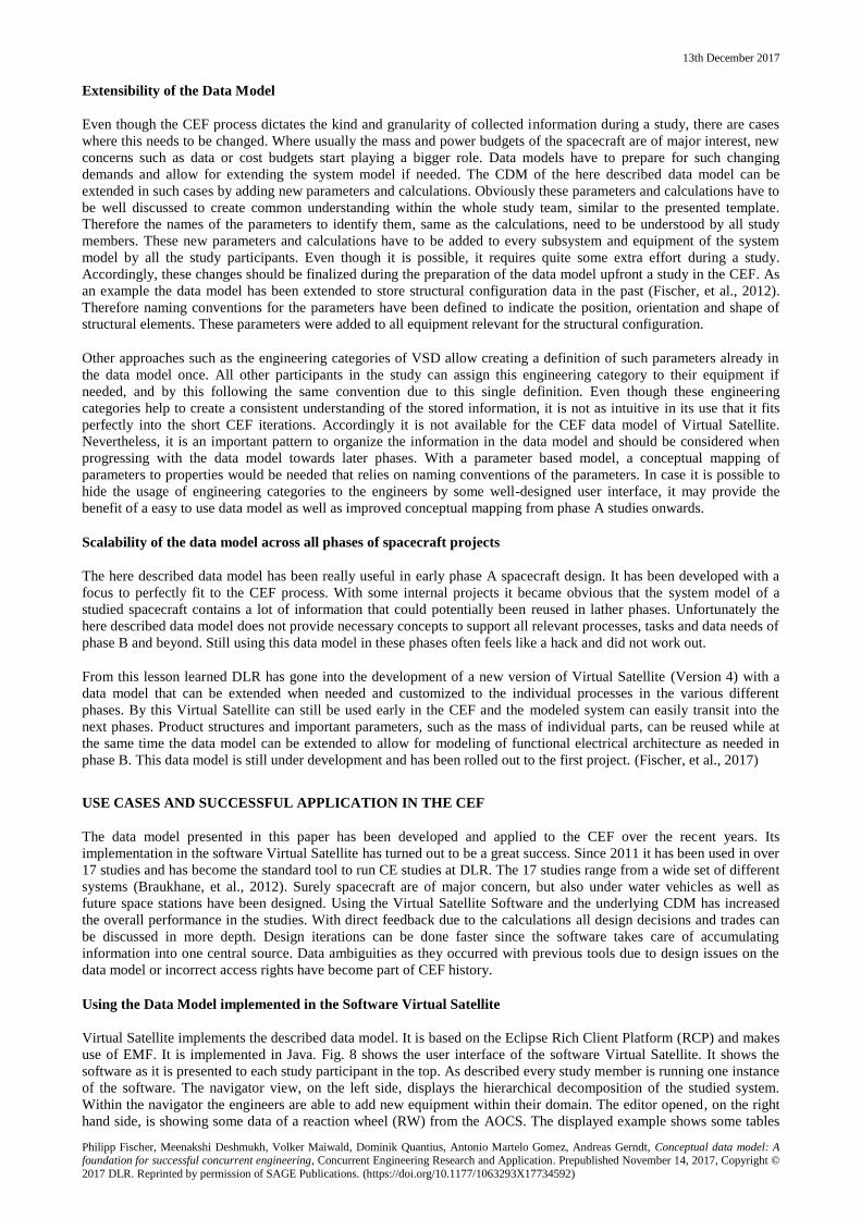
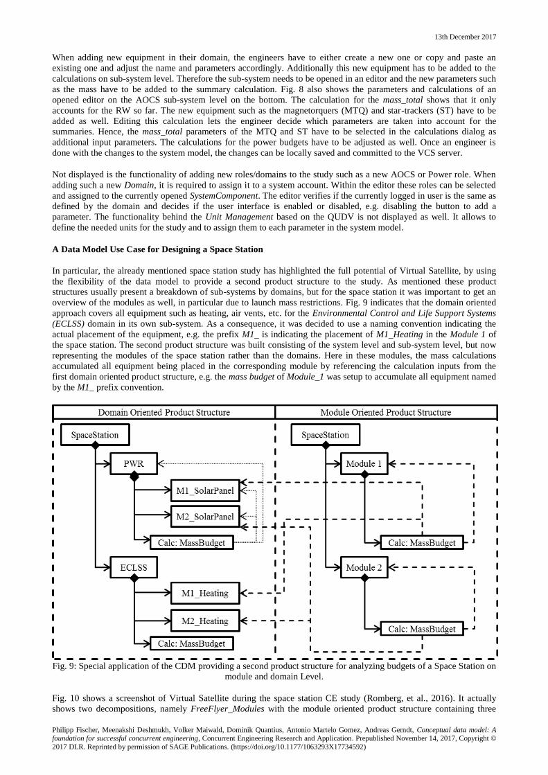
use of EMF. It is implemented in Java. Fig. 8 shows the user interface of the software Virtual Satellite. It shows the
software as it is presented to each study participant in the top. As described every study member is running one instance
of the software. The navigator view, on the left side, displays the hierarchical decomposition of the studied system.
Within the navigator the engineers are able to add new equipment within their domain. The editor opened, on the right
hand side, is showing some data of a reaction wheel (RW) from the AOCS. The displayed example shows some tables
13th December 2017
Philipp Fischer, Meenakshi Deshmukh, Volker Maiwald, Dominik Quantius, Antonio Martelo Gomez, Andreas Gerndt, Conceptual data model: A foundation for successful concurrent engineering, Concurrent Engineering Research and Application. Prepublished November 14, 2017, Copyright ©
2017 DLR. Reprinted by permission of SAGE Publications. (https://doi.org/10.1177/1063293X17734592)
with parameters as they are defined by the described template. Within the editor’s table they are filtered to only display
the power relevant parameters for the moment. In one of the table’s columns it is indicated if it is a calculated value or
a value which has to be changed by the user. In this example it is also visible that the power_ dutycycle is set to
individual values for different System Modes. The calculation engine in the background is adding the mode dependent
results to the calculated values such as the power_avg_wMargin. Obviously the engineer is capable of filtering for other
parameters such as the mass as well and may change them accordingly. The table below the parameters shows the
calculations of the currently opened SystemComponent.
Fig. 8: The Software Virtual Satellite with a Navigator View displaying the hierarchical system decomposition and an
opened Editor on the Reaction Wheel defining power parameters for the different spacecraft modes on the top, as well
as Parameters and Calculations on AOCS sub-system level adding the masses of the new equipment of ST and MTQ.
13th December 2017
Philipp Fischer, Meenakshi Deshmukh, Volker Maiwald, Dominik Quantius, Antonio Martelo Gomez, Andreas Gerndt, Conceptual data model: A foundation for successful concurrent engineering, Concurrent Engineering Research and Application. Prepublished November 14, 2017, Copyright ©
2017 DLR. Reprinted by permission of SAGE Publications. (https://doi.org/10.1177/1063293X17734592)
When adding new equipment in their domain, the engineers have to either create a new one or copy and paste an
existing one and adjust the name and parameters accordingly. Additionally this new equipment has to be added to the
calculations on sub-system level. Therefore the sub-system needs to be opened in an editor and the new parameters such
as the mass have to be added to the summary calculation. Fig. 8 also shows the parameters and calculations of an
opened editor on the AOCS sub-system level on the bottom. The calculation for the mass_total shows that it only
accounts for the RW so far. The new equipment such as the magnetorquers (MTQ) and star-trackers (ST) have to be
added as well. Editing this calculation lets the engineer decide which parameters are taken into account for the
summaries. Hence, the mass_total parameters of the MTQ and ST have to be selected in the calculations dialog as
additional input parameters. The calculations for the power budgets have to be adjusted as well. Once an engineer is
done with the changes to the system model, the changes can be locally saved and committed to the VCS server.
Not displayed is the functionality of adding new roles/domains to the study such as a new AOCS or Power role. When
adding such a new Domain, it is required to assign it to a system account. Within the editor these roles can be selected
and assigned to the currently opened SystemComponent. The editor verifies if the currently logged in user is the same as
defined by the domain and decides if the user interface is enabled or disabled, e.g. disabling the button to add a
parameter. The functionality behind the Unit Management based on the QUDV is not displayed as well. It allows to
define the needed units for the study and to assign them to each parameter in the system model.
A Data Model Use Case for Designing a Space Station
In particular, the already mentioned space station study has highlighted the full potential of Virtual Satellite, by using
the flexibility of the data model to provide a second product structure to the study. As mentioned these product
structures usually present a breakdown of sub-systems by domains, but for the space station it was important to get an
overview of the modules as well, in particular due to launch mass restrictions. Fig. 9 indicates that the domain oriented
approach covers all equipment such as heating, air vents, etc. for the Environmental Control and Life Support Systems
(ECLSS) domain in its own sub-system. As a consequence, it was decided to use a naming convention indicating the
actual placement of the equipment, e.g. the prefix M1_ is indicating the placement of M1_Heating in the Module 1 of
the space station. The second product structure was built consisting of the system level and sub-system level, but now
representing the modules of the space station rather than the domains. Here in these modules, the mass calculations
accumulated all equipment being placed in the corresponding module by referencing the calculation inputs from the
first domain oriented product structure, e.g. the mass budget of Module_1 was setup to accumulate all equipment named
by the M1_ prefix convention.
Fig. 9: Special application of the CDM providing a second product structure for analyzing budgets of a Space Station on
module and domain Level.
Fig. 10 shows a screenshot of Virtual Satellite during the space station CE study (Romberg, et al., 2016). It actually
shows two decompositions, namely FreeFlyer_Modules with the module oriented product structure containing three
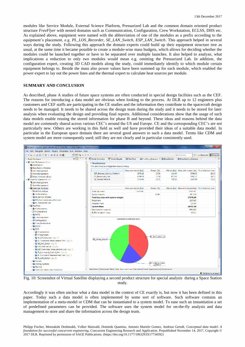
13th December 2017
Philipp Fischer, Meenakshi Deshmukh, Volker Maiwald, Dominik Quantius, Antonio Martelo Gomez, Andreas Gerndt, Conceptual data model: A foundation for successful concurrent engineering, Concurrent Engineering Research and Application. Prepublished November 14, 2017, Copyright ©
2017 DLR. Reprinted by permission of SAGE Publications. (https://doi.org/10.1177/1063293X17734592)
modules like Service Module, External Science Platform, Pressurized Lab and the common domain oriented product
structure FreeFlyer with nested domains such as Communication, Configuration, Crew Workstation, ECLSS, DHS etc.
As explained above, equipment were named with the abbreviation of one of the modules as a prefix according to the
equipment’s placement, e.g. PL_LOS_Recorder, SE_LAN_Switch, ESP_LAN_Switch. This approach helped in several
ways during the study. Following this approach the domain experts could build up their equipment structure tree as
usual, at the same time it became possible to create a module-wise mass budgets, which allows for deciding whether the
modules could be launched together or have to be separated over multiple launches. It also helped to analyze, what
implications a reduction to only two modules would mean e.g. omitting the Pressurized Lab. In addition, the
configuration expert, creating 3D CAD models along the study, could immediately identify to which module certain
equipment belongs to. Beside the mass also power values have been summed up for each module, which enabled the
power expert to lay out the power lines and the thermal expert to calculate heat sources per module.
SUMMARY AND CONCLUSION
As described, phase A studies of future space systems are often conducted in special design facilities such as the CEF.
The reasons for introducing a data model are obvious when looking to the process. At DLR up to 12 engineers plus
customers and CEF staffs are participating in the CE studies and the information they contribute to the spacecraft design
needs to be managed. It needs to be shared across the design team during the study and it needs to be stored for later
analysis when evaluating the design and providing final reports. Additional considerations show that the usage of such
data models enable reusing the stored information for phase B and beyond. These ideas and reasons behind the data
model are commonly shared across various CEC’s around the US and Europe. CE and the corresponding CEC’s are not
particularly new. Others are working in this field as well and have provided their ideas of a suitable data model. In
particular in the European space domain there are several good answers to such a data model. Terms like CDM and
system model are more consequently used; still they are not clearly and in particular consistently used.
Fig. 10: Screenshot of Virtual Satellite displaying a second product structure for special analysis during a Space Station
study.
Accordingly it was often unclear what a data model in the context of CE exactly is, but now it has been defined in this
paper. Today such a data model is often implemented by some sort of software. Such software contains an
implementation of a meta-model or CDM that can be instantiated to a system model. To ease such an instantiation a set
of predefined parameters can be provided. The software uses the system model for on-the-fly analysis and data
management to store and share the information across the design team.
13th December 2017
Philipp Fischer, Meenakshi Deshmukh, Volker Maiwald, Dominik Quantius, Antonio Martelo Gomez, Andreas Gerndt, Conceptual data model: A foundation for successful concurrent engineering, Concurrent Engineering Research and Application. Prepublished November 14, 2017, Copyright ©
2017 DLR. Reprinted by permission of SAGE Publications. (https://doi.org/10.1177/1063293X17734592)
DLR has implemented its own interpretation of such a data model in the software Virtual Satellite. It has been
successfully applied in several CE studies in the CEF and other places for a couple of years. Throughout this time the
software has constantly been developed and improved to perfectly fit to the described CEF process. Lessons learned
from the CE studies were fed back in the development of a DLR study template which actually created a common
understanding of how to use the Virtual Satellite data model. Major aspects in the development of the data model were
keeping it simple and flexible. The reasons are discussed. First, engineers should not be hindered in their actual work of
designing a spacecraft. Second, special use-cases such as the discussed second product structure for analyzing space
station modules have been a beneficial asset during CE studies.
Behind all these usability aspects of the data model, there has also been quite some effort to develop an adequate CDM
in the background to capture the needs imposed by the process and the engineers in their role as users. Actually, this
CDM is the foundation for successful concurrent engineering since it provides a common language and creates the
necessary common understanding for describing a system in the CE studies. This common understanding is a key
feature towards a technical implementation to instantiate, share and process information when the CDM is used to
model a system model. This technical discussion on implementation aspects needs to dive deep down to technical
details such as VCS and merge-conflict resolution for a correct implementation of the overall data model.
Comparing the here described data model to other ones, there is no clear answer which one is better or worth. The here
described work indicates that a data model is a tool that needs to fit to the process. On basis of these very intense studies
of sometimes just one week with untrained users, the CDM has to sacrifice on some concepts e.g. the unit_quantity
parameter but also provides some focused functionality on “no merge conflicts”. Other models may allow such conflicts
resolving them later or may create more precise models, but therefore compromising on quick iterations in the process.
The same applies for the presented engineering categories which are used in some other data models. In particular on
the topic of transferring data from the early design into later phases they become advantageous, but it will require some
further thoughts applying them into CE studies without introducing to much modeling effort.
Virtual Satellite is a success story for DLR and the CEF. With this paper we share this success and show our
developments that can help other facilities to implement a data model suiting their process. In the future, we plan to
continue on our work, now progressing in the spacecraft development phases. The first steps upgrading the CDM in
terms of extensibility have been taken and should enable reuse in phase B and beyond.
REFERENCES
Atkinson, C. & Kühne, T., 2008. Reducing accidential complexity in domain models. Software & Systems Modeling,
July, 7(3), pp. 345-359.
Bandechi, M., Melton, B., Gardini, B. & Ongaro, F., 2000. The ESA/ESTEC Concurrent Design Facility. Munich,
Germany, In proceedings of the 2nd European Systems Engineering Conference (EuSEC 2000).
Braukhane, A., Quantius, D., Maiwald, V. & Romberg, O., 2012. Statistics and Evaluation of 30+ Concurrent
Engineering Studies at DLR. Lisbon, Portugal, In proccedings of the 5th International Workshop on Systems and
Concurrent Engineering for Space Applications (SECESA 2012).
Collins-Sussmann, B., Fitzpatrick, B. W. & Pilato, C. M., 2010. Version Control with Subversion - For Subversion 1.7.
[Online]
Available at: http://svnbook.red-bean.com/en/1.7/svn-book.pdf
[Accessed 19 7 2016].
de Koning, H. P., Eisenmann, H. & Valera, S., 2012. Standardization of Semantic Data Models - Vision to Support
Interoperable Model Based System Engineering. Lisbon, Portugal, In procceedings of the 5th International Workshop
on Systems and Concurrent Engineering for Space Applications (SECESA 2012).
de Koning, H. P. et al., 2014. Open Concurrent Design Tool ESA Community Open Source Ready to Go!. [Online]
Available at: http://esaconferencebureau.com/docs/default-source/14c08_docs/open-concurrent-design-tool---esa-
community-open-source-ready-to-go!.pdf
[Accessed 27 01 2017].
Deshmukh, M. et al., 2013. Decision Support Tool for Concurrent Engineering in Space Mission Design. In:
Concurrent Engineering Approaches for Sustainable Product Development in a Multi-Disciplinary Environment:
Proceedings of the 19th ISPE International Conference on Concurrent Engineering. London, Great Britain: Springer
London, pp. 497-508.
Domizio, D. D. & Gaudenzi, P., 2008. A Model for Preliminary Design Procedures of Satellite Systems. Concurrent
Engineering: Research and Applications, June, 16(2), pp. 149-159.
13th December 2017
Philipp Fischer, Meenakshi Deshmukh, Volker Maiwald, Dominik Quantius, Antonio Martelo Gomez, Andreas Gerndt, Conceptual data model: A foundation for successful concurrent engineering, Concurrent Engineering Research and Application. Prepublished November 14, 2017, Copyright ©
2017 DLR. Reprinted by permission of SAGE Publications. (https://doi.org/10.1177/1063293X17734592)
ECSS Secretariat, 2009. ECSS-M-ST-10C Space project management - Project planning and implementation,
Noordwijk, Netherlands: ESA-ESTEC Requirements & Standards Division.
ECSS Secretariat, 2010. ECSS-E-TM-10-25A - Space engineering - Engineering design model data exchange (CDF),
Noordwijk, Netherlands: ESA-ESTEC Requirements & Standards Division.
ECSS Secretariat, 2011. ECSS-E-TM-10-23A - Space engineering - Space system data repository, Noordwijk,
Netherlands: ESA-ESTEC Requirements & Standards Devision.
Elmasri, R. & Navathe, S. B., 2004. Fundamentals of Database Systems. 4. ed. Boston, USA: Pearson Addison Wesley.
ESA, 2013. GOCE Validation Model. [Online]
Available at: http://www.vsd-project.org/download/example-models/VSD_DS_DataSet_V1_8.zip
[Accessed 19 7 2016].
ESA, 2013. Virtual Spacecraft Design. [Online]
Available at: http://www.vsd-project.org/
[Accessed 20 4 2016].
ESA, 2015. The ESA Concurrent Design Facility - Concurrent Engineering Applied to Space Mission Assessments.
[Online]
Available at: http://esamultimedia.esa.int/docs/cdf/CDF_infopack_2015.pdf
[Accessed 19 7 2016].
Fischer, P. M., Eisenmann, H. & Fuchs, J., 2014. Functional Verification by Simulation based on Preliminary System
Design Data. Stuttgart, Germany, s.n.
Fischer, P. M. et al., 2017. Implementing model-based system engineering for the whole lifecycle of a spacecraft. CEAS
Space Journal, 12 July.
Fischer, P. M., Wolff, R. & Gerndt, A., 2012. Collaborative Satellite Configuration Supported by Interactive
Visualization. Big Sky, Montana, USA, In proceedings of the IEEE 2012 Aerospace Conference.
Iwata, C. et al., 2015. Model-Based Systems Engineering in Concurrent Engineering Centers. Pasadena, USA, In
proceedings of the AIAA SPACE 2015 Conference and Exposition.
Jo, H. H., Parsaei, H. R. & Sullivan, W. G., 1993. Principles of concurrent engineering. Concurrent Engineering:
Contemporary issues and modern design tools, pp. 3-23.
Johnson, R. & Woolf, B., 1997. Type object. In: Pattern languages of program design 3. Bosten, MA, USA: Addison-
Wesley Longman Publishing Co., Inc., pp. 47-65.
Karagiannis, D. & Kühn, H., 2002. Metamodelling Platforms. Aix-en-Provence, France, Springer-Verlag, Berlin.
Lawson, M. & Karandikar, H. M., 1994. A Survey of Concurrent Engineering. Concurrent Engineering: Research and
Applications, Issue 2, pp. 1-6.
Lockemann, P. C. & Schmidt, J. W. eds., 1987. In: Datenbank-Handbuch. Heidelberg: Springer-Verlag Berlin, pp. 149-
151,482-486.
Lyardet, F. D., 1997. The Dynamic Template Pattern. Monticello, Illinois, USA, In proceedings of Patter Languages in
Programming (PLoP 1997).
OMG, 2009. SysML 1.2 RTF - ANNEX C.5 - Quantities, Units, Dimensions, Values (QUDV), Unknown: Object
Management Group OMG.
OMG, 2012. Unified Modelling Language (OMG UML), Infrastructure - ISO/IEC 19505-1:2012(E), s.l.: Object
Management Group OMG.
OMG, 2015. OMG Unified Modeling Language (OMG UML) - Version 2.5, s.l.: Object Management Group OMG.
OMG, 2015. XML Metadata Interchange (XMI) Specification - Version2.5.1, Unknown: Object Management Group
OMG.
Prasad, B., 2001. Product, process and methodology systematization to handle structural and computational complexity
in product realization. Systems Research and Behavioral Science, 6 11, 18(6), pp. 523-543.
Prasad, B., Morenc, R. S. & Rangan, R. M., 1993. Information Management for Concurrent Engineering. Concurrent
Engineering: Research and Applications, Issue 1, pp. 3-20.
Rey, J., 2013. Modeling with VSEE: Definition of Guidelines and Exploitation of the Models - YGT Final Report.
[Online]
Available at: http://www.vsd-project.org/download/documents/YGT%20final%20report%20Rey%20V2.pdf
[Accessed 19 7 2016].
13th December 2017
Philipp Fischer, Meenakshi Deshmukh, Volker Maiwald, Dominik Quantius, Antonio Martelo Gomez, Andreas Gerndt, Conceptual data model: A foundation for successful concurrent engineering, Concurrent Engineering Research and Application. Prepublished November 14, 2017, Copyright ©
2017 DLR. Reprinted by permission of SAGE Publications. (https://doi.org/10.1177/1063293X17734592)
Romberg, O., Braukhane, A. & Schumann, H., 2008. Status of the Concurrent Engineering Fa-cility at DLR Bremen.
Dresden, Germany, In proceedings of the Deutscher Luft- und Raumfahrtkongress (DLRK 2008).
Romberg, O. et al., 2016. Orbital-Hub DLR Vision 2025, Bremen, Germany: DLR Institute of Space Systems.
Schaus, V., Fischer, P. M. & Gerndt, A., 2013. Taking Advantage of the Model: Application of the Quantity, Units,
Dimension, and Values Standard in Concurrent Spacecraft Engineering. Philadelphia, USA, In proceedings of the 23rd
Annual International Symposium of the International Council of Systems Engineering (INCOSE 2013), pp. 24-27.
Steinberg, D., Budinsky, F., Paternostro, M. & Merks, E., 2009. EMF Eclipse Modeling Framework. Boston, USA :
Pearson Education, Inc.


![RATING 1:43 - LM24DATABASE · 2019. 12. 25. · CHASSIS: BODY: MOTOR: CLASS: DRIVERS: LOTUS Lotus T128 [001] GT Prototype Praga Judd HK 3.6 LMP2 Thomas Holzer Dominik Kraihamer Jan](https://static.fdocuments.nl/doc/165x107/60fa7a7ac442927e795824d6/rating-143-2019-12-25-chassis-body-motor-class-drivers-lotus-lotus.jpg)