
CENTRAN TMP - Lutz-JESCO America
20
A measured step forward Operations & Maintenance Manual CENTRAN TMP TM
Transcript of CENTRAN TMP - Lutz-JESCO America
A measured step forwardOperations & Maintenance Manual
CENTRAN TMP
TM
July 7, 2011P h o n e : ( 5 8 5 ) 4 2 6 - 0 9 9 0 www.jescoamerica.com Fax: (585) 426-40252 July 7, 2011
Ope
ratio
n &
Mai
nten
ance
Inst
ruct
ions
C
ENTR
AN T
MP
Table of Contents
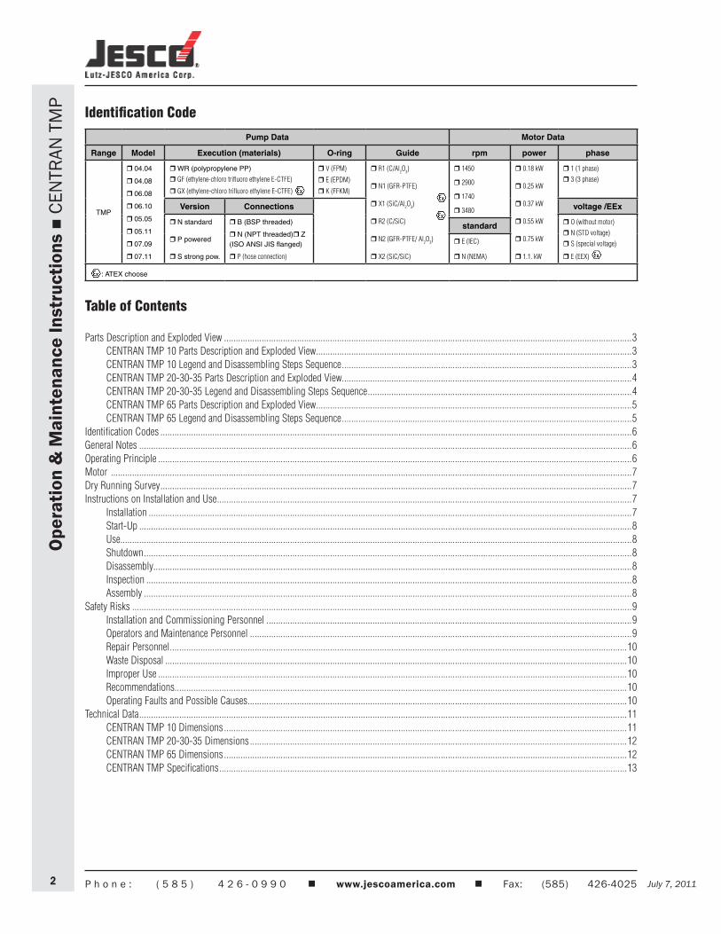
Parts Description and Exploded View .............................................................................................................................................................................3 CENTRAN TMP 10 Parts Description and Exploded View......................................................................................................................................3 CENTRAN TMP 10 Legend and Disassembling Steps Sequence ...........................................................................................................................3 CENTRAN TMP 20-30-35 Parts Description and Exploded View...........................................................................................................................4 CENTRAN TMP 20-30-35 Legend and Disassembling Steps Sequence ................................................................................................................4 CENTRAN TMP 65 Parts Description and Exploded View......................................................................................................................................5 CENTRAN TMP 65 Legend and Disassembling Steps Sequence ...........................................................................................................................5Identification Codes ........................................................................................................................................................................................................6General Notes .................................................................................................................................................................................................................6Operating Principle .........................................................................................................................................................................................................6Motor .............................................................................................................................................................................................................................7Dry Running Survey ........................................................................................................................................................................................................7Instructions on Installation and Use ................................................................................................................................................................................7 Installation .............................................................................................................................................................................................................7 Start-Up .................................................................................................................................................................................................................8 Use.........................................................................................................................................................................................................................8 Shutdown ...............................................................................................................................................................................................................8 Disassembly...........................................................................................................................................................................................................8 Inspection ..............................................................................................................................................................................................................8 Assembly ...............................................................................................................................................................................................................8Safety Risks ....................................................................................................................................................................................................................9 Installation and Commissioning Personnel ...........................................................................................................................................................9 Operators and Maintenance Personnel ..................................................................................................................................................................9 Repair Personnel ..................................................................................................................................................................................................10 Waste Disposal ....................................................................................................................................................................................................10 Improper Use .......................................................................................................................................................................................................10 Recommendations................................................................................................................................................................................................10 Operating Faults and Possible Causes .................................................................................................................................................................10Technical Data ...............................................................................................................................................................................................................11 CENTRAN TMP 10 Dimensions ...........................................................................................................................................................................11 CENTRAN TMP 20-30-35 Dimensions ................................................................................................................................................................12 CENTRAN TMP 65 Dimensions ...........................................................................................................................................................................12 CENTRAN TMP Specifications .............................................................................................................................................................................13
Pump Data Motor Data
Range Model Execution (materials) O-ring Guide rpm power phase
TMP
r 04.04
r 04.08
r 06.08
r 06.10
r 05.05
r 05.11
r 07.09
r 07.11
r WR (polypropylene PP)
r GF (ethylene-chloro trifluoro ethylene E-CTFE)
r GX (ethylene-chloro trifluoro ethylene E-CTFE)
r V (FPM)
r E (EPDM)
r K (FFKM)
r R1 (C/Al2O3)
r N1 (GFR-PTFE)
r X1 (SiC/Al2O3)
r R2 (C/SiC)
r N2 (GFR-PTFE/ Al2O3)
r X2 (SiC/SiC)
r 1450
r 2900
r 1740
r 3480
r 0.18 kW
r 0.25 kW
r 0.37 kW
r 0.55 kW
r 0.75 kW
r 1.1. kW
r 1 (1 phase)
r 3 (3 phase)
Version Connections voltage /EEx
r N standard
r P powered
r S strong pow.
r B (BSP threaded)
r N (NPT threaded)r Z (ISO ANSI JIS flanged)
r P (hose connection)
r O (without motor)
r N (STD voltage)
r S (special voltage)
r E (EEX)
standard
r E (IEC)
r N (NEMA)
: ATEX choose
Identification Code
July 7, 2011 July 7, 2011 P h o n e : ( 5 8 5 ) 4 2 6 - 0 9 9 0 www.jescoamerica.com Fax: (585) 426-4025 3
Ope
ratio
n &
Mai
nten
ance
Inst
ruct
ions
C
ENTR
AN T
MP
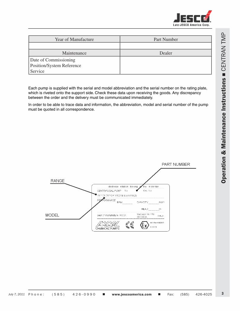
Each pump is supplied with the serial and model abbreviation and the serial number on the rating plate, which is riveted onto the support side. Check these data upon receiving the goods. Any discrepancy between the order and the delivery must be communicated immediately.
In order to be able to trace data and information, the abbreviation, model and serial number of the pump must be quoted in all correspondence.
Year of Manufacture Part Number
Maintenance Dealer
Date of CommissioningPosition/System ReferenceService
July 7, 2011P h o n e : ( 5 8 5 ) 4 2 6 - 0 9 9 0 www.jescoamerica.com Fax: (585) 426-40254 July 7, 2011
Ope
ratio
n &
Mai
nten
ance
Inst
ruct
ions
C
ENTR
AN T
MP
July 7, 2011 July 7, 2011 P h o n e : ( 5 8 5 ) 4 2 6 - 0 9 9 0 www.jescoamerica.com Fax: (585) 426-4025 5
Ope
ratio
n &
Mai
nten
ance
Inst
ruct
ions
C
ENTR
AN T
MP
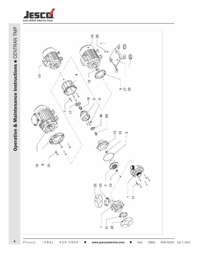
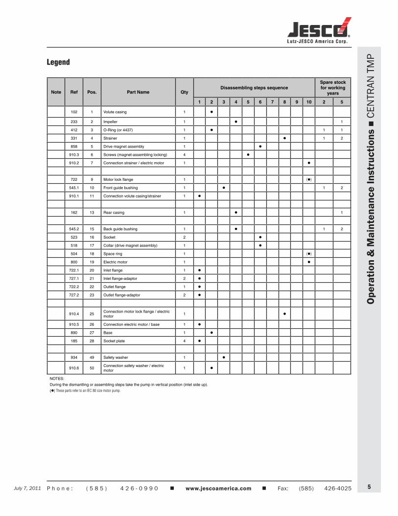
Note Ref Pos. Part Name QtyDisassembling steps sequence
Spare stock for working
years
1 2 3 4 5 6 7 8 9 10 2 5
102 1 Volute casing 1 l
233 2 Impeller 1 l 1
412 3 O-Ring (or 4437) 1 l 1 1
331 4 Strainer 1 l 1 2
858 5 Drive magnet assembly 1 l
910.3 6 Screws (magnet-assembling locking) 4 l
910.2 7 Connection strainer / electric motor 1 l
722 9 Motor lock flange 1 (l)
545.1 10 Front guide bushing 1 l 1 2
910.1 11 Connection volute casing/strainer 1 l
162 13 Rear casing 1 l 1
545.2 15 Back guide bushing 1 l 1 2
523 16 Socket 2 l
518 17 Collar (drive magnet assembly) 1 l
504 18 Space ring 1 (l)
800 19 Electric motor 1 l
722.1 20 Inlet flange 1 l
727.1 21 Inlet flange-adaptor 2 l
722.2 22 Outlet flange 1 l
727.2 23 Outlet flange-adaptor 2 l
910.4 25Connection motor lock flange / electric motor
1 l
910.5 26 Connection electric motor / base 1 l
890 27 Base 1 l
185 28 Socket plate 4 l
934 49 Safety washer 1 l
910.6 50Connection safety washer / electric motor
1 l
NOTES:
During the dismantling or assembling steps take the pump in vertical position (inlet side up).
(l) These parts refer to an IEC 80 size motor pump.
Legend
July 7, 2011P h o n e : ( 5 8 5 ) 4 2 6 - 0 9 9 0 www.jescoamerica.com Fax: (585) 426-40256 July 7, 2011
Ope
ratio
n &
Mai
nten
ance
Inst
ruct
ions
C
ENTR
AN T
MP
General NotesCENTRAN TMP pumps are designed and built for the transfer of liquid chemical products having a specific weight, viscosity, temperature. These criteria must be appropriate for use with centrifugal pumps in a fixed installation, from a tank at a lower level to a tank or a pipe to a higher level. The characteristics of the liquid (pressure, temperature, chemical reactivity, specific weight, viscosity, vapor tension) and the ambient atmosphere must be compatible with the characteristics of the pump and defined upon ordering.
The pump’s performance (capacity, head, rpm) is defined upon ordering and specified on the identification plate.
“TMP” and pumps are centrifugal, horizontal, single stage, coupled to a non-synchronous electric motor via a magnetic coupling, with axial inlet and radial outlet for connection to the hydraulic system. They are foot-mounted for floor fixing.
“TMP” pumps are not self priming.
R execution “TMP” pumps can occasionally run dry.
The liquid to be pumped must be clean for the R execution, the X execution may contain solid (%, dimension and solid part hardness must be agreed during the offer).
Clockwise rotation seen from the motor side.
Make sure that the chemical and physical characteristics of the liquid have been carefully evaluated for pump suitability.
The specific weight that can be pumped at a temperature of 25°C (both of the ambient and of the liquid) depends upon the impeller diameter (shown on the identification plate) and of the type of construction.
standard contruction N (stamped on the rating plate) 1,05 kg/dm3 powered construction P (stamped on the rating plate) 1,35 kg/dm3 strong-powered construction S (stamped on the rating plate) 1,80 kg/dm3
The specific weight that can be pumped at 70°C is 10% less than that at 25°C.
The level of kinematic viscosity must not exceed 40 cSt so as not to significantly modify the pump’s performance. Higher values up to a maximum of 100 cSt are possible provided that the pump is equipped with suitable impeller to be defined upon ordering.
The maximum continuous working temperature referred to water depends on the choice of materials (specified on the identification plate):
70 °C execution WR 110 °C execution GF
The ambient temperature interval is related to the choice of materials (specified on the identification plate):
0 - +40°C execution WR -20 - +40°C execution GF
The maximum pressure the pump may be subjected to is 1.5 times the head value developed with the outlet closed.
The vapour pressure value of the liquid to be pumped must exceed (by at least 1m w.c) to the difference between the absolute total head (suction side pressure added to the positive suction head, or subtracted by the suction lift) and the pressure drops in the suction side piping (including the inlet NPSHr drops shown on the specific tables).
The pump does not include any non return valve nor any liquid flow control or motor stop device.
July 7, 2011 July 7, 2011 P h o n e : ( 5 8 5 ) 4 2 6 - 0 9 9 0 www.jescoamerica.com Fax: (585) 426-4025 7
Ope
ratio
n &
Mai
nten
ance
Inst
ruct
ions
C
ENTR
AN T
MP
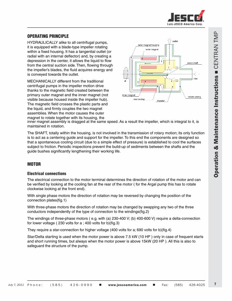
OPERATING PRINCIPLEHYDRAULICALLY alike to all centrifugal pumps, it is equipped with a blade-type impeller rotating within a fixed housing. It has a tangential outlet (or radial with an internal deflector) and, by creating a depression in the center, it allows the liquid to flow from the central suction side. Then, flowing through the impeller’s blades, the fluid acquires energy and is conveyed towards the outlet.
MECHANICALLY different from the traditional centrifugal pumps in the impeller motion drive thanks to the magnetic field created between the primary outer magnet and the inner magnet (not visible because housed inside the impeller hub). The magnetic field crosses the plastic parts and the liquid, and firmly couples the two magnet assemblies. When the motor causes the outer magnet to rotate together with its housing, the inner magnet assembly is dragged at the same speed. As a result the impeller, which is integral to it, is maintained in rotation.
The SHAFT, totally within the housing, is not involved in the transmission of rotary motion; its only function is to act as a centering guide and support for the impeller. To this end the components are designed so that a spontaneous cooling circuit (due to a simple effect of pressure) is established to cool the surfaces subject to friction. Periodic inspections prevent the build-up of sediments between the shafts and the guide bushes significantly lengthening their working life.
MOTOR
Electrical connectionsThe electrical connection to the motor terminal determines the direction of rotation of the motor and can be verified by looking at the cooling fan at the rear of the motor ( for the Argal pump this has to rotate clockwise looking at the front end).
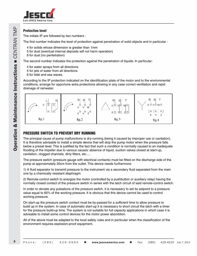
With single phase motors the direction of rotation may be reversed by changing the position of the connection plates(fig.1)
With three-phase motors the direction of rotation may be changed by swapping any two of the three conductors independently of the type of connection to the windings(fig.2)
The windings of three-phase motors ( e.g. with (a) 230-400 V; (b) 400-600 V) require a delta-connection for lower voltage ( 230 volts for a ; 400 volts for b)(fig.3)
They require a star-connection for higher voltage (400 volts for a; 690 volts for b)(fig.4)
Star/Delta starting is used when the motor power is above 7.5 kW (10 HP ) only in case of frequent starts and short running times, but always when the motor power is above 15kW (20 HP ). All this is also to safeguard the structure of the pump.
July 7, 2011P h o n e : ( 5 8 5 ) 4 2 6 - 0 9 9 0 www.jescoamerica.com Fax: (585) 426-40258 July 7, 2011
Ope
ratio
n &
Mai
nten
ance
Inst
ruct
ions
C
ENTR
AN T
MP
Protection levelThe initials IP are followed by two numbers :
The first number indicates the level of protection against penetration of solid objects and in particular :
4 for solids whose dimension is greater than 1mm 5 for dust (eventual internal deposits will not harm operation) 6 for dust (no pentetration)
The second number indicates the protection against the penetration of liquids. In particular:
4 for water sprays from all directions 5 for jets of water from all directions 6 for tidal and sea waves.
According to the IP protection indicated on the identification plate of the motor and to the environmental conditions, arrange for opportune extra protections allowing in any case correct ventilation and rapid drainage of rainwater.
PRESSURE SWITCH TO PREVENT DRY RUNNINGThe principal cause of pump malfunctions is dry-running (being it caused by improper use or cavitation). It is therefore advisable to install a simple device that will stop the pump motor when the pressure falls below a preset level. This is justified by the fact that such a condition is normally caused to an inadequate flooding of the impeller due to various causes: absence of liquid, suction valves closed at start-up, cavitation, clogged channels, dirty filters, etc.....
The pressure switch (pressure gauge with electrical contacts) must be fitted on the discharge side of the pump at approximately 20cm from the outlet. This device needs furthermore:
1) A fluid separator to transmit pressure to the instrument via a secondary fluid separated from the main one by a chemically resistant diaphragm.
2) Remote-control switch to energize the motor (controlled by a pushbutton or auxiliary relay) having the normally closed contact of the pressure switch in series with the latch circuit of said remote-control switch.
In order to obviate any pulsations of the pressure switch, it is necessary to set its setpoint to a pressure value equal to 65% of the working pressure. It is obvious that this device cannot be used to control working pressure.
On start-up the pressure switch contact must be by-passed for a sufficient time to allow pressure to build up in the system. In case of automatic start-up it is necessary to short circuit the latch with a timer for the pressure build-up time. The system is not suitable for full capacity applications in which case it is advisable to install some control devices for the motor power absorbtion.
All of the above must be adapted to the local safety rules and in particular when the classification of the environment requires explosion-proof equipment.
July 7, 2011 July 7, 2011 P h o n e : ( 5 8 5 ) 4 2 6 - 0 9 9 0 www.jescoamerica.com Fax: (585) 426-4025 9
Ope
ratio
n &
Mai
nten
ance
Inst
ruct
ions
C
ENTR
AN T
MP
INSTRUCTIONS ON INSTALLATION AND USE
TRANSPORTcover the hydraulic connections•when lifting the unit do not exert force on the plastic fittings•lay the pump on its base or fixing plate during transport•
if the road is particularly rough, protect the pump by means of adequate shock absorbing supports
bumps and shocks may damage important working parts vital for safety and functionality of the •machine
STORAGE INSTRUCTIONSWhen is necessary to store the pump bifore installation don’t remove it from the original packaged. •The packaged pump must be stored lifted from ground level, the ambient must be close, clean and dry.If at the receipt of the pump package seems damaged is necessary to free the pump in order to check •its integry and to store a new packageThe place where the pump is stored must be closed with an ambient temperature not lower than •–5°C and not higher than 40°C, the air humidity rate not higher than 80%, the package pump mustn’t received shock, vibrations and loads rising above.If the storing period is higher than 6 months, bifore installation check the condition of the grease in the •support, eventually provide to restore it.
INSTALLATIONclean the plant before connecting the pump•make sure that no foreign bodies are left in the pump. Remove safety caps on the hydraulic •connections.follow the instructions indicated in the following diagram:•
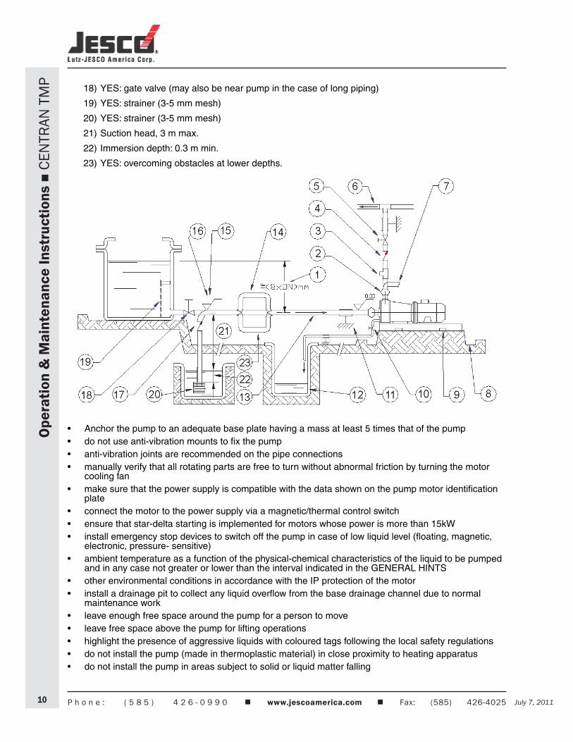
1) Suction head varies according to flow in order to prevent windage (min. 0.5 m, max. 15% of pump head)
2) YES: expansion joint (indispensable with long pipes or hot liquids) and/or anti-vibration facility during discharge and suction; anchored near to pump
3) YES: attachment for gauge or safety pressure switch
4) YES: check value (especially for long vertical or horizontal pipes; compulsory with parallel pumps).
5) YES: adjusting gate valve on outlet
6) speed of delivered fluid: 3.,5 m/s max. .
7) NO: elbow joints (and other parts) on the pump (discharge and suction lines)
8) YES: drainage channel around base
9) Fix the pump by the fixing holes provided: the supports must be level
10) YES: pipe discharge (completely sealed), discharge value shut during normal operations
11) YES: pipe fixing parts
12) YES: discharge collection well (does not leak)
13) Fluid speed suction: 2.5 m/s
14) NO: air pockets: the circuit must be short and straight
15) With positive head: tilt of piping towards pump
16) With negative suction lift: tilt of piping towards suction tank
17) YES: check vale (with negative suction lift)
July 7, 2011P h o n e : ( 5 8 5 ) 4 2 6 - 0 9 9 0 www.jescoamerica.com Fax: (585) 426-402510 July 7, 2011
Ope
ratio
n &
Mai
nten
ance
Inst
ruct
ions
C
ENTR
AN T
MP
18) YES: gate valve (may also be near pump in the case of long piping)
19) YES: strainer (3-5 mm mesh)
20) YES: strainer (3-5 mm mesh)
21) Suction head, 3 m max.
22) Immersion depth: 0.3 m min.
23) YES: overcoming obstacles at lower depths.
Anchor the pump to an adequate base plate having a mass at least 5 times that of the pump•do not use anti-vibration mounts to fix the pump•anti-vibration joints are recommended on the pipe connections•manually verify that all rotating parts are free to turn without abnormal friction by turning the motor •cooling fanmake sure that the power supply is compatible with the data shown on the pump motor identification •plateconnect the motor to the power supply via a magnetic/thermal control switch•ensure that star-delta starting is implemented for motors whose power is more than 15kW•install emergency stop devices to switch off the pump in case of low liquid level (floating, magnetic, •electronic, pressure- sensitive)ambient temperature as a function of the physical-chemical characteristics of the liquid to be pumped •and in any case not greater or lower than the interval indicated in the GENERAL HINTSother environmental conditions in accordance with the IP protection of the motor•install a drainage pit to collect any liquid overflow from the base drainage channel due to normal •maintenance workleave enough free space around the pump for a person to move•leave free space above the pump for lifting operations•highlight the presence of aggressive liquids with coloured tags following the local safety regulations•do not install the pump (made in thermoplastic material) in close proximity to heating apparatus•do not install the pump in areas subject to solid or liquid matter falling•
July 7, 2011 July 7, 2011 P h o n e : ( 5 8 5 ) 4 2 6 - 0 9 9 0 www.jescoamerica.com Fax: (585) 426-4025 11
Ope
ratio
n &
Mai
nten
ance
Inst
ruct
ions
C
ENTR
AN T
MP
do not install the pump in an explosive atmosphere unless the motor and its coupling have been •adequately pre-arrangeddo not install the pump in close proximity to workplaces or crowded areas•install extra protection guards for the pump or persons as the need arises•install a spare equivalent pump in parallel•
START-UPverify that the instructions outlined in the INSTALLATION have been followed•verify the correct direction of rotation (clockwise from the motor side) supplying the motor with short •impulsesensure that the NPSH available is greater than that required by the pump (in particular for hot liquids, •liquids with high vapour pressure, very long suction pipes or negative suction lift)close the discharge valve; completely cover the suction pipe and the pump. •close the outlet valve. Start up the motor two or three times with short supplies of current in order to •expel the air from the pump and the lubrication circuit between the guide shaft and bush.start the pump with the suction valve completely open and the outlet valve semi-closed.•slowly adjust the flow by adjusting the outlet valve (never adjust the suction valve) and making sure •that the motor absorption is does not exceed the nominal power rating shown on the platedo not operate at the extremes of the operating curve: maximum head (discharge valve shut too tight) •or maximum flow (total absence of loss and lift in discharge circuit).set the operating point for which the pump has been requested•check that there are no unusual vibrations or noises due to inadequate fixing or cavitation•avoid excessively short and/or frequent start-ups by adjusting the consent appliance•
Motor power; kW 0,75÷5,5 7,5÷30 37÷110 132÷200 250÷315 Max. no. starts/hour; 2-4 poles 20 - 40 10 - 20 6 - 12 2 - 4 1 - 2
check that temperature, pressure and characteristics of liquid match order specifications•Warning• !!! At the start-up be sure that all the internal hydraulic parts are not in CCW rotation (the cooling fan of the motor must stand or CW rotate), to prevent decoupling among magnetic driven parts of the pump;if the CCW rotation is due to the feed-back of the liquid in the discharge side, add a no-return valve in the plant.
USEswitch automatic control on•do not activate valves whilst the pump is in operation•risks of dangerous water hammer effects in case of sudden or improper valve actuation (only trained •personnel should operate valves)completely empty and wash the pump before using a different liquid•isolate or empty the pump if the crystallization temperature of the liquid is the same or lower than the •ambient temperaturestop the pump if the liquid temperature exceeds the maximum allowed temperature indicated in the •general notes; If the increase is of approximately 20%, check internal partsclose the valves in case of leaks•wash with water only if compatible from the chemical point of view. As alternative use an appropriate •solvent that will not generate dangerous exothermal reactionscontact the liquid supplier for information on the appropriate fire precautions•empty the pump in case of long periods of inactivity (in particular with liquids which would easily •crystallize)
SHUTDOWNdisconnect the motor•before starting maintenance, turn off the suction and discharge valves•
July 7, 2011P h o n e : ( 5 8 5 ) 4 2 6 - 0 9 9 0 www.jescoamerica.com Fax: (585) 426-402512 July 7, 2011
MAINTENANCEallthesemaintenanceoperationsmustbeperformedunderthesupervisionofqualifiedpersonnel••make periodic inspections (2 to 6 months depending on the type of liquid and the operating •conditions) on the rotating parts of the pump; clean or replace as necessarymake periodic inspections (3 to 5 months depending on the type of liquid and the operating •conditions) on the functionality of the motor control system; efficiency must be guaranteedmake periodic inspections (2 to 30 days depending on the type of liquid and the operating conditions) •of the in- line and foot filters as well as of the bottom valvethe presence of liquid below the pump could be a clue to pump problems•excessive current consumption could be an indication of impeller problems•unusual vibrations could be due to unbalanced impeller (due to damage or presence of foreign •material obstructing its blades)reduced pump performance could be due to an obstruction of the impeller or damages to the motor•motor damages could be due to abnormal friction within the pump•damaged parts must be replaced with new original parts•
DISASSEMBLYTools required: size 8 socket spanner, cross cogging screw driver, punch f < 4mm.
Bolts have right-hand thread
all these maintenance operations must be performed under supervision of qualified personnel•cut off the power supply from the motor and disconnect the electrical wiring; pull the wires out from •the terminal box and isolate their extremities accordinglyclose the suction and discharge valves and open the drain valve•use gloves, safety glasses and acid-proof overalls when disconnecting and washing the pump•disconnect the piping and leave enough time for the residual liquid to exit the pump body and •atmospheric air to fill the empty volumewash the pump before carrying out any maintenance work•do not scatter the liquid in the environment•before attempting to dismantle the pump ensure that its motor is disconnected and that it may not be •started accidentalllybefore the inspection, check that you have spare O-rings ready to hand for re-installing at the end of •operationswarning: operations near the magnet attract the tools. Proceed with caution to avoid damage. •during the dismantling take the pump in vertical position (inlet side up).•
Ope
ratio
n &
Mai
nten
ance
Inst
ruct
ions
C
ENTR
AN T
MP
July 7, 2011 July 7, 2011 P h o n e : ( 5 8 5 ) 4 2 6 - 0 9 9 0 www.jescoamerica.com Fax: (585) 426-4025 13
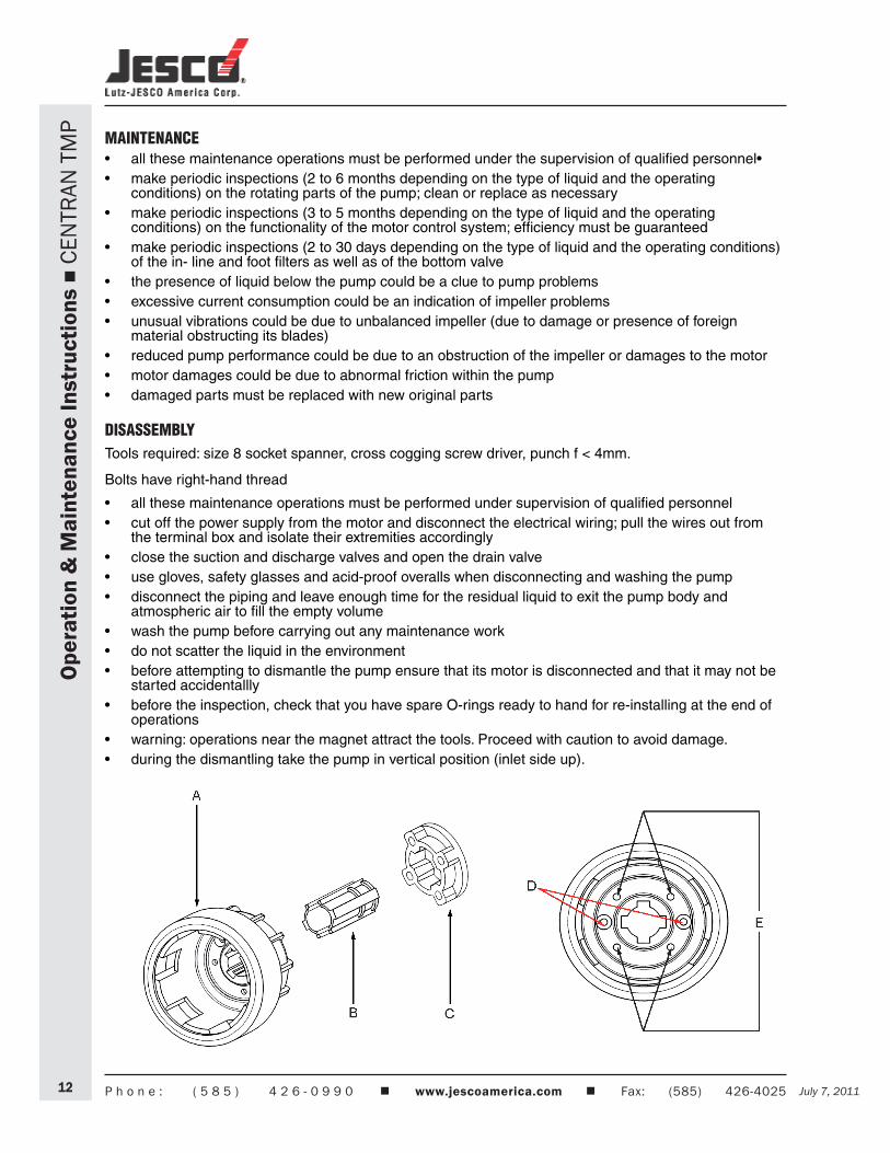
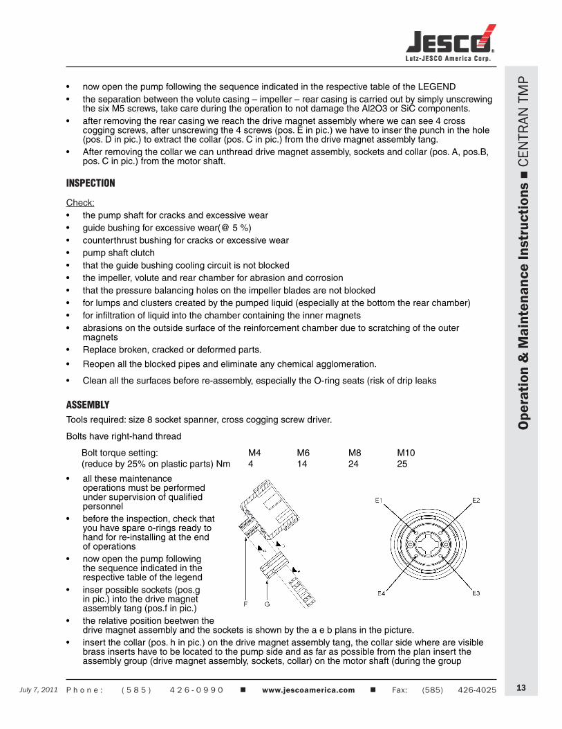
now open the pump following the sequence indicated in the respective table of the LEGEND•the separation between the volute casing – impeller – rear casing is carried out by simply unscrewing •the six M5 screws, take care during the operation to not damage the Al2O3 or SiC components.after removing the rear casing we reach the drive magnet assembly where we can see 4 cross •cogging screws, after unscrewing the 4 screws (pos. E in pic.) we have to inser the punch in the hole (pos. D in pic.) to extract the collar (pos. C in pic.) from the drive magnet assembly tang.After removing the collar we can unthread drive magnet assembly, sockets and collar (pos. A, pos.B, •pos. C in pic.) from the motor shaft.
INSPECTION
Check:the pump shaft for cracks and excessive wear•guide bushing for excessive wear(@ 5 %)•counterthrust bushing for cracks or excessive wear•pump shaft clutch•that the guide bushing cooling circuit is not blocked•the impeller, volute and rear chamber for abrasion and corrosion •that the pressure balancing holes on the impeller blades are not blocked •for lumps and clusters created by the pumped liquid (especially at the bottom the rear chamber)•for infiltration of liquid into the chamber containing the inner magnets•abrasions on the outside surface of the reinforcement chamber due to scratching of the outer •magnetsReplace broken, cracked or deformed parts.•
Reopen all the blocked pipes and eliminate any chemical agglomeration.•
Clean all the surfaces before re-assembly, especially the O-ring seats (risk of drip leaks•
ASSEMBLYTools required: size 8 socket spanner, cross cogging screw driver.
Bolts have right-hand thread
Bolt torque setting: M4 M6 M8 M10 (reduce by 25% on plastic parts) Nm 4 14 24 25
all these maintenance •operations must be performed under supervision of qualified personnelbefore the inspection, check that •you have spare o-rings ready to hand for re-installing at the end of operations now open the pump following •the sequence indicated in the respective table of the legendinser possible sockets (pos.g •in pic.) into the drive magnet assembly tang (pos.f in pic.)the relative position beetwen the •drive magnet assembly and the sockets is shown by the a e b plans in the picture.insert the collar (pos. h in pic.) on the drive magnet assembly tang, the collar side where are visible •brass inserts have to be located to the pump side and as far as possible from the plan insert the assembly group (drive magnet assembly, sockets, collar) on the motor shaft (during the group
Ope
ratio
n &
Mai
nten
ance
Inst
ruct
ions
C
ENTR
AN T
MP
July 7, 2011P h o n e : ( 5 8 5 ) 4 2 6 - 0 9 9 0 www.jescoamerica.com Fax: (585) 426-402514 July 7, 2011
Ope
ratio
n &
Mai
nten
ance
Inst
ruct
ions
C
ENTR
AN T
MP
insertion verify that the relative position between the sockets and the drive magnet assembly remain the same, the sockets (pos.g) and drive magnet assembly (pos.f) must be located as shown in the picturescrew the 4 cross cogging screws sharing the oparation in more than one phase, repeat the sequence •e1, e2 ,e3, e4 (torque@ 6 n m)don’t inser the impeller freely into the drive magnet assembly•during the impeller insertion take care not to damage the Al2O3- SiC-C HD components•
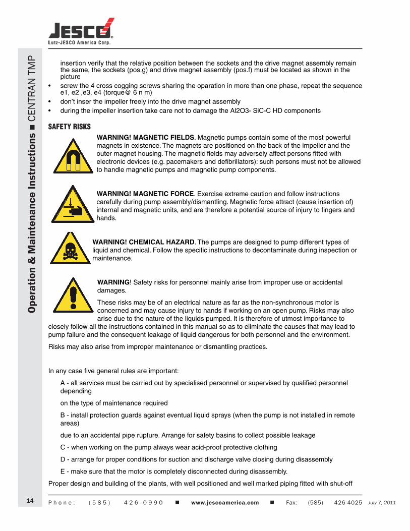
SAFETY RISKSWARNING! MAGNETIC FIELDS. Magnetic pumps contain some of the most powerful magnets in existence. The magnets are positioned on the back of the impeller and the outer magnet housing. The magnetic fields may adversely affect persons fitted with electronic devices (e.g. pacemakers and defibrillators): such persons must not be allowed to handle magnetic pumps and magnetic pump components.
WARNING! MAGNETIC FORCE. Exercise extreme caution and follow instructions carefully during pump assembly/dismantling. Magnetic force attract (cause insertion of) internal and magnetic units, and are therefore a potential source of injury to fingers and hands.
WARNING! CHEMICAL HAZARD. The pumps are designed to pump different types of liquid and chemical. Follow the specific instructions to decontaminate during inspection or maintenance.
WARNING! Safety risks for personnel mainly arise from improper use or accidental damages.
These risks may be of an electrical nature as far as the non-synchronous motor is concerned and may cause injury to hands if working on an open pump. Risks may also arise due to the nature of the liquids pumped. It is therefore of utmost importance to
closely follow all the instructions contained in this manual so as to eliminate the causes that may lead to pump failure and the consequent leakage of liquid dangerous for both personnel and the environment.
Risks may also arise from improper maintenance or dismantling practices.
In any case five general rules are important:
A - all services must be carried out by specialised personnel or supervised by qualified personnel depending
on the type of maintenance required
B - install protection guards against eventual liquid sprays (when the pump is not installed in remote areas)
due to an accidental pipe rupture. Arrange for safety basins to collect possible leakage
C - when working on the pump always wear acid-proof protective clothing
D - arrange for proper conditions for suction and discharge valve closing during disassembly
E - make sure that the motor is completely disconnected during disassembly.
Proper design and building of the plants, with well positioned and well marked piping fitted with shut-off
July 7, 2011 July 7, 2011 P h o n e : ( 5 8 5 ) 4 2 6 - 0 9 9 0 www.jescoamerica.com Fax: (585) 426-4025 15
Ope
ratio
n &
Mai
nten
ance
Inst
ruct
ions
C
ENTR
AN T
MP
valves, adequate passages and work areas for maintenance and inspections are extremely important (since the pressure developed by the pump could give some kind of damage to the plant in case this one should be faulty made or wear and tear-damaged).
It must be stressed that the major cause of pump failures leading to a consequent need to intervene is due to the pump running dry in manually operated plants. This is generally due to:
the suction valve being open at start-up or•the suction tank being emptied without stopping•
INSTALLATION AND START-UP PERSONNELInterventions allowed only to specialised personnel who may eventually delegate to others some operations depending on specific evaluations (technical capability required: specialisation in industrial plumbing or electric systems as needed).
MAINTENANCE AND OPERATIONAL PERSONNELInterventions allowed to general operators (after training on the correct use of the plant):
pump starting and stopping•opening and closing of valves with the pump at rest•emptying and washing of the pump body via special valves and piping•cleaning of filtering elements•
Interventions allowed to qualified personnel (technical capacities required: general knowledge of the mechanical, electrical and chemical features of the plant being fed by the pump and of the pump itself):
verification of environmental conditions•verification of the condition of the liquid being pumped•inspections of the control/stop devices of the pump•inspections of the rotating parts of the pump•trouble shooting•
PERSONNEL RESPONSIBLE FOR REPAIRSInterventions allowed to general operators under the supervision of qualified personnel:
stopping of the pump•closing of the valve•emptying of pump body•disconnection of piping from fittings•removal of anchoring bolts•washing with water or suitable solvent as needed•transport (after removal of electrical connections by qualified personnel)•Interventions by qualified personnel (technical capacities required: general knowledge of machining •operations, awareness
of possible damage to parts due to abrasion or shocks during handling, know-how of required bolt and screw tightening required on different materials such as plastics and metals, use of precision measuring instruments):
opening and closing of the pump body•removal and replacement of rotating parts•
WASTE DISPOSALMaterials:separateplasticfrommetalparts.Disposeofbyauthorizedcompanies.••
July 7, 2011P h o n e : ( 5 8 5 ) 4 2 6 - 0 9 9 0 www.jescoamerica.com Fax: (585) 426-402516 July 7, 2011
Ope
ratio
n &
Mai
nten
ance
Inst
ruct
ions
C
ENTR
AN T
MP
IMPROPER USEThe pump must not be used for purposes other than the transfer of liquids.
The pump cannot be used to generate isostatic or counter pressures.
The pump cannot be used to mix liquids generating an exothermal reaction
The pump must be installed horizontally on a firm base.
The pump must be installed on a suitable hydraulic plant with inlet and outlet connections to proper suction and discharge pipes.
The plant must be able to shut off the liquid flow independently from the pump.
Handling of aggressive liquids requires specific technical knowledge
OPERATING FAULTS AND POSSIBLE CAUSESPump does not deliver:
1. rotates in wrong direction
2. suction pipe is excessively long and tortuous
3. insufficient geodetic pump head or excessive suction geodetic lift
4. air infiltration into the suction pipe or branches
5. pump or suction pipe not completely covered by liquid
6. impeller channels blocked by impurities
7. check valve on discharge pipe jammed
8. geodetic system height is greater than maximum potential pump head
9. impeller jammed by considerable layer of crystals or by melting of materials for dry rotation.
10. bottom valve blocked by mud or other debris
11. bottom valve insufficiently immersed
12. bottom valve faulty, thereby causing suction valve to empty when pump stops
13. magnets release a much greater specific weight and flow rate of liquid than planned
14. the magnets release due start-up made while impeller is CCW moving (feed-back of the liquid in the discharge side)
Pump discharge rate or pressure insufficient: see. 01, 02, 03, 04, 05, 06, 10, 11, 12, 13
15. system’s resisting head is greater than expected
16. suction pipe, closing valve and other items have an insufficient nominal diameter
17. small geometric pump suction head
18. damaged or worn impeller
19. liquid viscosity greater than expected
20. excessive quantities of air or gas in liquid
21. elbow joints, check valves or other items on the outlet port
22. liquid (especially if hot) with tendency to change into gaseous state
July 7, 2011 July 7, 2011 P h o n e : ( 5 8 5 ) 4 2 6 - 0 9 9 0 www.jescoamerica.com Fax: (585) 426-4025 17
Ope
ratio
n &
Mai
nten
ance
Inst
ruct
ions
C
ENTR
AN T
MP
Pump absorbs too much power: see. 19
23. pump operates at greater capacity than expected
24. specific weight of liquid is greater than expected
25. impurities inside pump create abnormal wear
26. electric motor supply voltage is not rated voltage
Pump vibrates and is noisy see 25
27. operates at full capacity (no head)
28. pump or pipes inadequately fixed
29. eccentric impeller operation because of worn bushes
Pump’s internal parts wear out too quickly: see. 25
30. liquid excessively abrasive
31. recurring cavitation problems (see. 02, 15, 19, 17)
32. high tendency of liquid to crystallise or polymerise when pump is not operating.
33. pump made of materials that are unsuitable for pumped liquid
34. operation with capacity too reduced
July 7, 2011P h o n e : ( 5 8 5 ) 4 2 6 - 0 9 9 0 www.jescoamerica.com Fax: (585) 426-402518 July 7, 2011
Ope
ratio
n &
Mai
nten
ance
Inst
ruct
ions
C
ENTR
AN T
MP
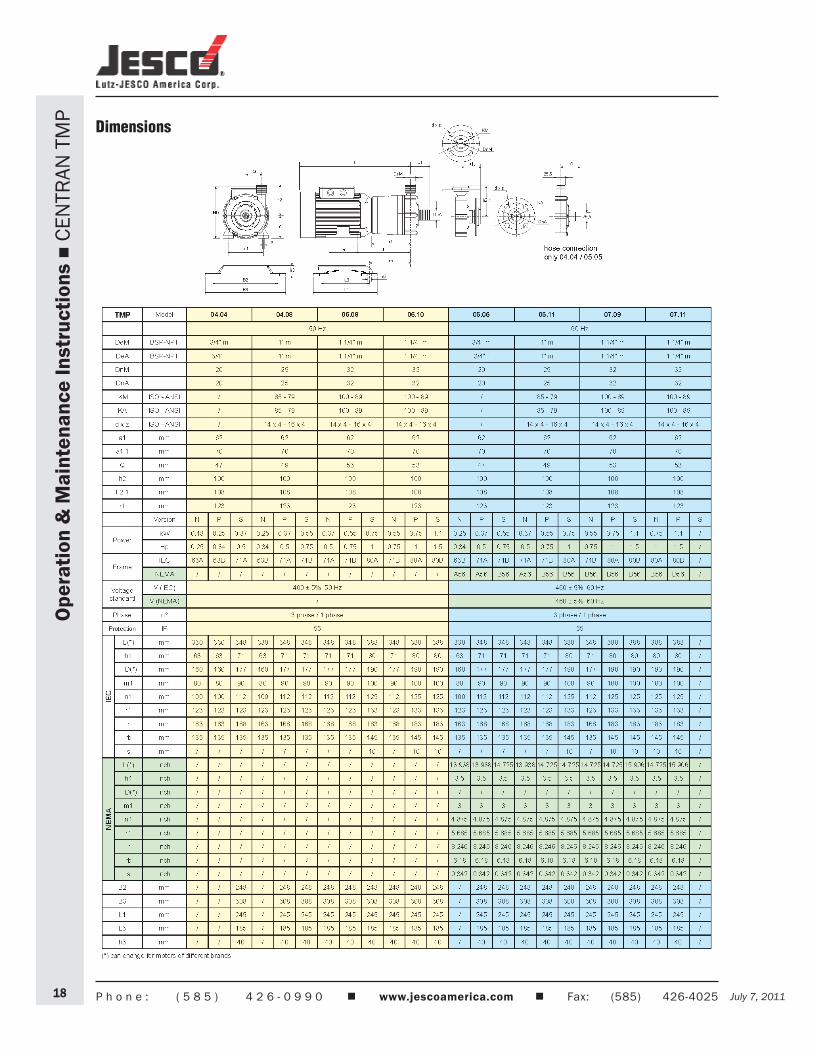
Dimensions
July 7, 2011 July 7, 2011 P h o n e : ( 5 8 5 ) 4 2 6 - 0 9 9 0 www.jescoamerica.com Fax: (585) 426-4025 19
Ope
ratio
n &
Mai
nten
ance
Inst
ruct
ions
C
ENTR
AN T
MP
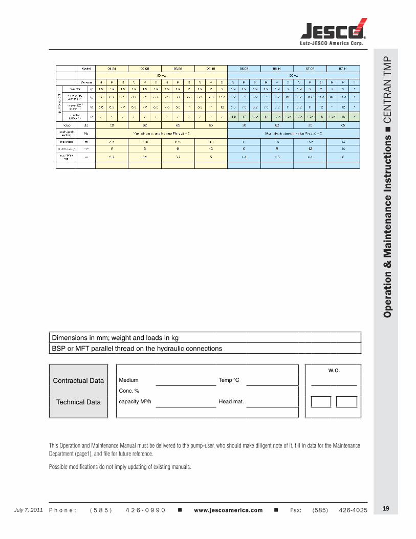
This Operation and Maintenance Manual must be delivered to the pump-user, who should make diligent note of it, fill in data for the Maintenance Department (page1), and file for future reference.
Possible modifications do not imply updating of existing manuals.
Dimensions in mm; weight and loads in kg
BSP or MFT parallel thread on the hydraulic connections
w.o.
Contractual Data Medium Temp oC
Conc. %
Technical Data capacity M3/h Head mat.
Lutz-JESCO America Corp. 55 Bermar Park Phone: +1-585-426-0990 E-Mail: [email protected] Toll Free: Rochester, NY 14624 USA Fax: +1-585-426-4025 Internet: www.jescoamerica.com 1-800-554-2762
Met
erin
g P
um
ps
T
ran
sfer
Pu
mp
s
Mea
suri
ng
an
d C
on
tro
l Tec
hn
olo
gy
C
hem
ical
Fee
d S
yste
ms
A
cces
sori
es