766e, Outdoor Switch-disconnector FLa 15/97 · 2 766 DRIESCHER - Outdoor Switch-Disconnector FLa...
20
766 DRIESCHER - Outdoor Switch-Disconnector Type FLa 15/97 • Rated voltage 12 kV, 24 kV, 36 kV and 38.5 kV • Rated current 400 A and 630 A • 1-pole and 3-pole design ELEKTROTECHNISCHE WERKE FRITZ DRIESCHER & SÖHNE GMBH D-85366 MOOSBURG • TEL. +49 87 61 6 81-0 • FAX +49 87 61 68 11 37 http://www.driescher.com [email protected] 15/97 http://www.driescher.de Für Sie im Internet FLa
Transcript of 766e, Outdoor Switch-disconnector FLa 15/97 · 2 766 DRIESCHER - Outdoor Switch-Disconnector FLa...
766
DRIESCHER -
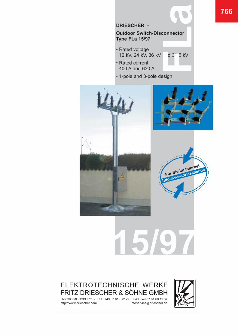
Outdoor Switch-Disconnector Type FLa 15/97
• Rated voltage 12 kV, 24 kV, 36 kV and 38.5 kV
• Rated current 400 A and 630 A
• 1-pole and 3-pole design
ELEKTROTECHNISCHE WERKEFRITZ DRIESCHER & SÖHNE GMBHD-85366 MOOSBURG • TEL. +49 87 61 6 81-0 • FAX +49 87 61 68 11 37http://www.driescher.com [email protected]
15/97
http://www.driescher.deFür Sie im Internet
FL
a
2
766
DRIESCHER - Outdoor Switch-Disconnector FLa 15/97according to EN 60265-1
content
• 3 Genaral, designs
• 4 Switching in a vaccum
• 5 Operation mode, technical data
Horizontal arrangement of the switch-disconnectors
• 6 FLa 15/97 mounted on wooden or concrete pole
• 7 Mouning supports, cu-tension straps
• 8 FLa 15/97 wide span system, coupling shafts for wide span system
• 9 Arrangement according to system “Tonnenbild“, arrangement for wide span system
• 10 Underframe, support bearing
• 11 Permissible tension angle, Tension units, Concrete cross-arm
• 12 FLa 15/97 - 64W
• 13 Accessories for tension units
Vertical arrangement of the switch-disconnectors
• 14 FLa 15/97 - 6400
• 15 FLa 15/97 - 6400 1-pole design
• 16 FLa 15/97 - 6410 - with fuse holders
• 17 FLa 15/97 - 6410 SA - with fuse holders and operating fuse
• 18 Arrangements of operators for Type FLa 15/97 - 6400, FLa 15/97 - 6410
• 19 Operation examples
• 20 Examples to use the switch-disconnectors
3
General
Contrary to former outdoor load-break switches inwhich it was common practice for the arc to be extin-guished in oil, with the new developed outdoorswitch-disconnector FLa 15/97 arc extinction takesplace in a vacuum interrupter.
Based on a patented insulating system there is alsono liquid or gaseous medium required for the exter-nal insulation strength of the vacuum interrupters.The vacuum quenching device is embedded in aweather-proof insulating housing.This switchgear is therefore also recommended forspecial applications (e.g. in water protection areas).
The outdoor switch-disconnector is capable of swit-ching on its rated current as well as its rated short-circuitmaking current via the main contact system. The disconnecting process is implemented via theshunt-connected vacuum interrupters, resulting in noexternal arcing phenomena.A fully developed eccentric make-and-break mecha-nism operates the vacuum interrupters and ensuresClass M2 with regard to the mechanical strength(corresponds to 5000 mechanical operating cycles).
The designs FLa 15/97 correspond in their maindimensions to the switches FLa 15/60, FLa 6400 andFLa 6410 (refer to brochure 762, 763), i.e. the fixingdimensions have remained unchanged.
Also the operating linkage (brochure 775) can beused in the common design.The switch frames and the operating shafts mountedin bronze bearings are hot-galvanized.
All insulators used in the design (brochure 712) are ofcycloaliphatic cast resin.The contacts with flanged ends in compliance withDIN 46206 as well as all other live components of thecontact system are of electrolytic copper and aresilver-plated in compliance with QTL 200.
Amply dimensioned cross-sections as well as theexternal spring mechanism at the contact jaw whichprovides constant contact pressure guarantee aneasy and satisfactory switching, even after manyyears of operation.
Connecting screws with nuts, washers and lockwashers are made of rustproof steel.
The outdoor switch-disconnector FLa 15/97 are avai-lable for rated voltages of 12 kV to 38.5 kV and ratedcurrents of 400 A and 630 A, and have been tested incompliance with the valid regulations.
By using adapters it is possible to retrofit alreadyinstalled equipment from the FLa 15/60 family (of themore recent design) with vacuum interrupters.
The attached earthing switches are, however, alwayswithout rapid breaking.
The external metal parts of the rapid make-and-breakmechanism (actuating fork) are made of rustproofsteel.
DRIESCHER - Outdoor Switch-Disconnector FLa 15/97
766
Designs
Vertical arrangement (switching angle 90°)
• FLa 15/97 - 6400
• FLa 15/97 - 6410; with fuses
• FLa 15/97 - 6410; with skew mounted fuses
• FLa 15/97 - 6410 SA; with fuse operates
• FLa 15/97 1-pole design
Horizontal arrangement
• FLa 15/97; for wodden- or concrete pole
• FLa 15/97; wide span system on concrete pole or steel cross arms
• FLa 15/97 - 64W; (switch angle 110°)
4
DRIESCHER - Outdoor Switch-Disconnector FLa 15/97
Switching in a vacuum
• The trend is to use a vacuum
During the Sixties basic research began on swit-ching in a vacuum. At this time low-oil switcheshad become firmly established in medium voltagenetworks, based on their reliable operation overdecades, and were accepted by users as reliabledevices. In laboratory tests it proved that the vacu-um switches were superior by far to the conventio-nally applied switching principles. The first experience with this vacuum technologywas gathered using our line sectionalizers inoverhead lines for railway operations, which havebeen successfully used since 1971. In principle, the proven arcing chamber methodhas been maintained in the new switchgears whichwere developed in 1997.
In distribution networks a reliable power supply isthe key criterion, wherein it is not the high numberof operating cycles which is so important, but ratherthe high degree of reliability. Even after many years of life the switchgear mustmake and break reliably.
All these requirements necessitate a switching unitwith electrical properties that preferably do notchange throughout its service life. The vacuum interrupter is hermetically sealed andthe purest materials ensure that the vacuum requiredfor reliable switching remains intact throughout theentire service life.
Also the contact resistances remain at very lowvalues as there is no oxidation process in a vacuum.
• Advantages of the switch-disconnector FLa 15/97over outdoor switch-disconnectors with conventionalextinguishing media:
• faster dielectric recoveryafter the breaking process
• high insulation resistance
• short total travel
• compact operating mechanism
• low contact wear and consequently
• high operating frequency
• very long service life
766
Description of operation:
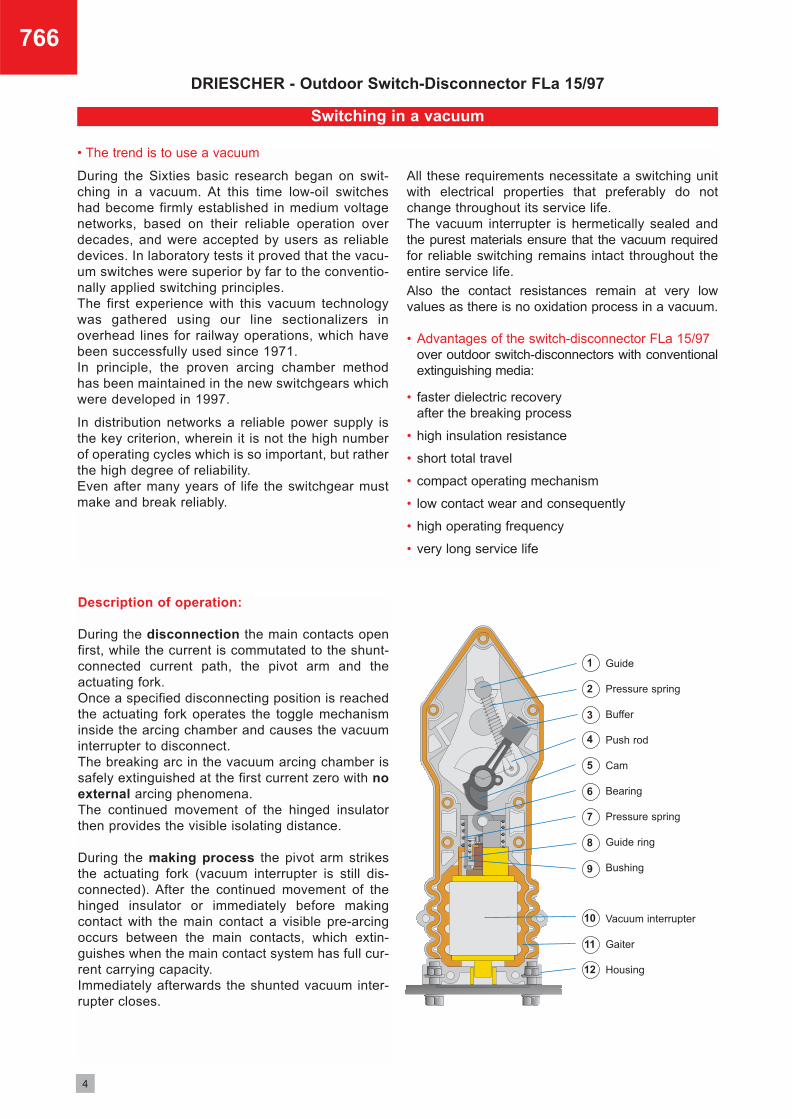
During the disconnection the main contacts openfirst, while the current is commutated to the shunt-connected current path, the pivot arm and theactuating fork. Once a specified disconnecting position is reachedthe actuating fork operates the toggle mechanisminside the arcing chamber and causes the vacuuminterrupter to disconnect. The breaking arc in the vacuum arcing chamber issafely extinguished at the first current zero with noexternal arcing phenomena.The continued movement of the hinged insulatorthen provides the visible isolating distance.
During the making process the pivot arm strikesthe actuating fork (vacuum interrupter is still dis-connected). After the continued movement of thehinged insulator or immediately before makingcontact with the main contact a visible pre-arcingoccurs between the main contacts, which extin-guishes when the main contact system has full cur-rent carrying capacity. Immediately afterwards the shunted vacuum inter-rupter closes.
Guide
Pressure spring
Buffer
Push rod
Cam
Bearing
Pressure spring
Guide ring
Bushing
Vacuum interrupter
Gaiter
Housing
1
2
3
4
5
6
7
8
9
10
11
12
5
Technical data
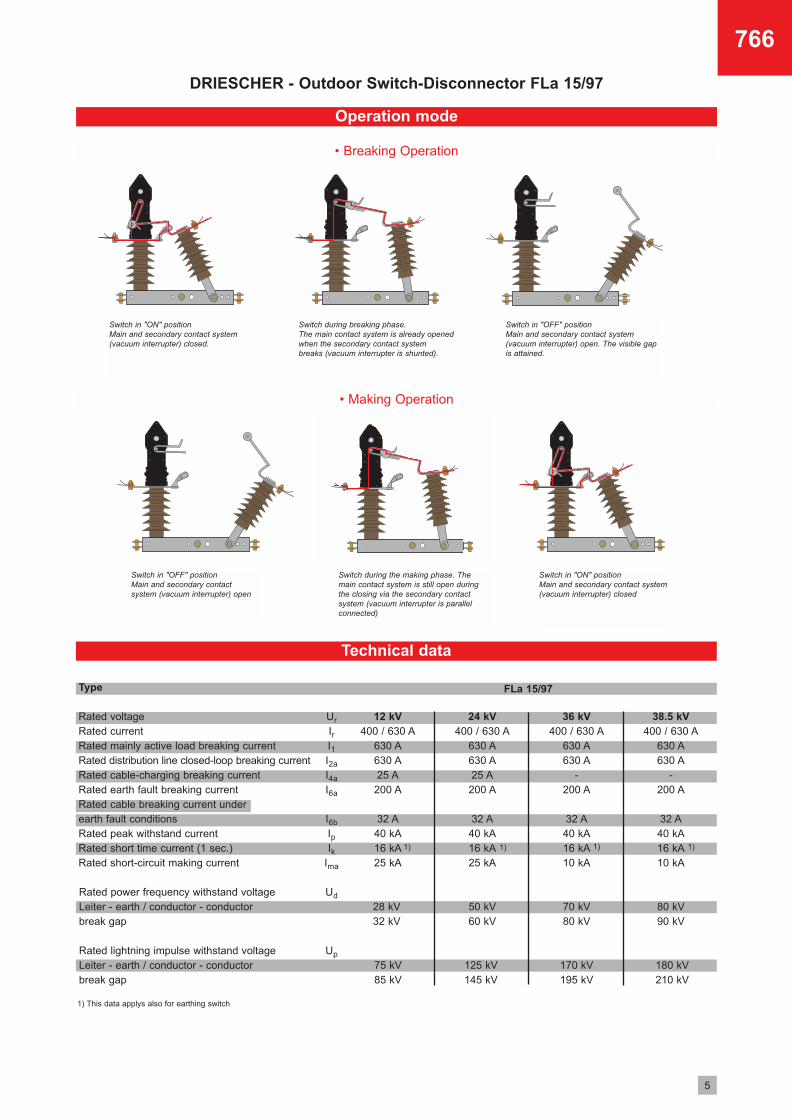
Operation mode
Type
Rated voltageRated currentRated mainly active load breaking currentRated distribution line closed-loop breaking currentRated cable-charging breaking currentRated earth fault breaking currentRated cable breaking current under earth fault conditionsRated peak withstand currentRated short time current (1 sec.)Rated short-circuit making current
12 kV400 / 630 A
630 A630 A25 A
200 A
32 A40 kA16 kA25 kA
24 kV400 / 630 A
630 A630 A25 A
200 A
32 A40 kA16 kA25 kA
50 kV60 kV
125 kV145 kV
38.5 kV400 / 630 A
630 A630 A
-200 A
32 A40 kA16 kA10 kA
80 kV90 kV
180 kV210 kV
36 kV400 / 630 A
630 A630 A
-200 A
32 A40 kA16 kA10 kA
70 kV80 kV
170 kV195 kV
Rated power frequency withstand voltageLeiter - earth / conductor - conductorbreak gap
28 kV32 kV
Rated lightning impulse withstand voltageLeiter - earth / conductor - conductorbreak gap
75 kV85 kV
DRIESCHER - Outdoor Switch-Disconnector FLa 15/97
• Making Operation
• Breaking Operation
1) This data applys also for earthing switch
1) 1)1) 1)
766
Ur
IrI1I2a
I4a
I6a
I6b
IpIk
Ima
Ud
Up
FLa 15/97
Switch in "ON" positionMain and secondary contact system(vacuum interrupter) closed.
Switch in "ON" positionMain and secondary contact system(vacuum interrupter) closed
Switch during breaking phase.The main contact system is already openedwhen the secondary contact system breaks (vacuum interrupter is shunted).
Switch during the making phase. Themain contact system is still open duringthe closing via the secondary contactsystem (vacuum interrupter is parallelconnected)
Switch in "OFF" positionMain and secondary contact system (vacuum interrupter) open. The visible gapis attained.
Switch in "OFF" positionMain and secondary contactsystem (vacuum interrupter) open
6
DRIESCHER - Outdoor Switch-Disconnector FLa 15/97
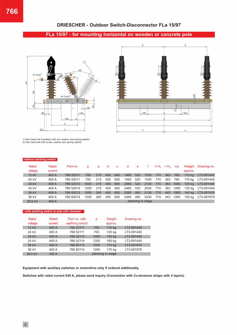
FLa 15/97 - for mounting horizontal on wooden or concrete pole
1) Hex head bolt (caulked) with nut, washer and spring washer 2) Hex head bolt with screw, washer and spring washer
Equipment with auxiliary switches or motordrive only if ordered additionally.
Switches with rated current 630 A, please send inquiry (Connection with Cu-tensions straps with 4 layers).
766
d
146514652065246520652465
e
520520520520460460
l
153015302130253021302530
Drawing-no.
LT3-091445LT3-091445LT3-091445LT3-091445LT3-091979LT3-091979
Weightapprox.110 kg110 kg125 kg135 kg140 kg150 kg
Rated current400 A400 A400 A400 A400 A400 A400 A
b
405405405405455455
c
600600600600650650
p
700700
1000120010001200
a
215215215215265265
x/y
765765
1065126510651265
Part-no.
766 52011766 52011766 52013766 52014766 82013766 82014
Ratedvoltage12 kV24 kV24 kV24 kV36 kV36 kV
38.5 kV
p
700700
1000120010001200
≈ H2≈ H1
363363363363443443
774774774774774774
Drawing-no.
LT3-091445LT3-091445LT3-091445LT3-091445LT3-091979LT3-091979
Weightapprox.115 kg 125 kg145 kg160 kg170 kg170 kg
Part-no. withearthing switch
766 22111766 52111766 52113766 52114766 82113766 82114
Ratedvoltage12 kV24 kV24 kV24 kV36 kV36 kV
38.5 kV
Rated current400 A400 A400 A400 A400 A400 A400 A
planning in stage
planning in stage
•without earthing switch
• with earthing switch at side with chamber
7
766
DRIESCHER - Outdoor Switch-Disconnector FLa 15/97
12243612243624362436
Part-no. 531 71004 531 71006 531 71009 531 71011
Lengths 1100 mm 1340 mm 1540 mm 1740 mm (special length)
1100110013401340134015401340134015401540
1340134015401340134016401540154015401540
1111111111
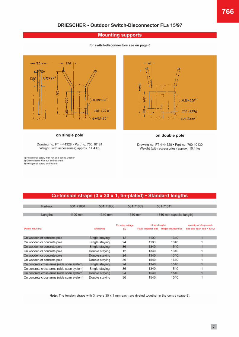
Mounting supports
for switch-disconnectors see on page 6
on single pole
Drawing no. FT 4-44328 • Part no. 760 10124Weight (with accessories) approx. 14.4 kg
on double pole
Drawing no. FT 4-44328 • Part no. 760 10130Weight (with accessories) approx. 15.4 kg
1) Hexagonal screw with nut and spring washer2) Gewindebolt with nut and washers3) Hexagonal screw and washer
On wooden or concrete poleOn wooden or concrete poleOn wooden or concrete poleOn wooden or concrete poleOn wooden or concrete poleOn wooden or concrete poleOn concrete cross-arms (wide span system)On concrete cross-arms (wide span system)On concrete cross-arms (wide span system)On concrete cross-arms (wide span system)
Single stayingSingle stayingSingle stayingDouble stayingDouble stayingDouble stayingSingle stayingSingle stayingDouble stayingDouble staying
Switch mountingFor rated voltage
kVAnchoring
quantity of straps each
side and each pole • 400 A
Straps lengths
Fixed insulator side Hinged insulator side
Note: The tension straps with 3 layers 30 x 1 mm each are riveted together in the centre (page 9).
Cu-tension straps (3 x 30 x 1, tin-plated) • Standard lengths
8
766
DRIESCHER - Outdoor Switch-Disconnector FLa 15/97
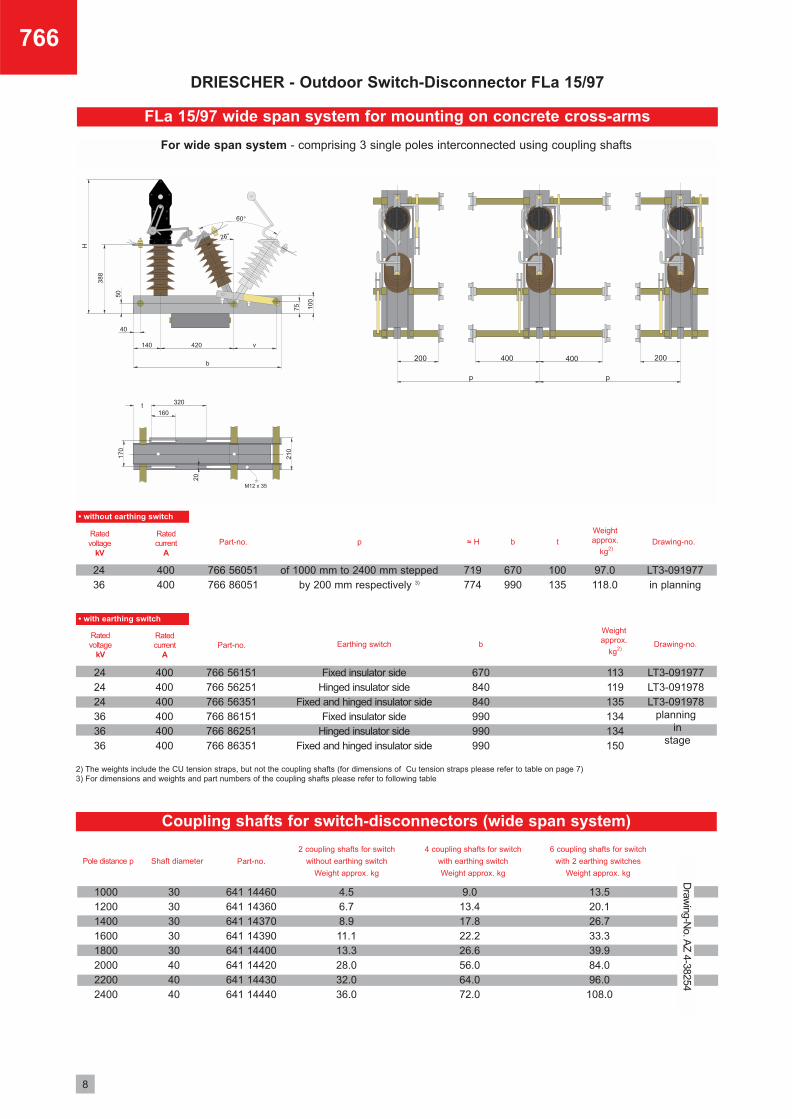
FLa 15/97 wide span system for mounting on concrete cross-arms
2436
400400
766 56051766 86051
670990
719774
100135
of 1000 mm to 2400 mm steppedby 200 mm respectively 3)
Ratedvoltage
kV
Ratedcurrent
A
242424363636
400400400400400400
Ratedvoltage
kV
Ratedcurrent
A
tp
Fixed insulator sideHinged insulator side
Fixed and hinged insulator sideFixed insulator side
Hinged insulator sideFixed and hinged insulator side
Earthing switch
b≈ H
97.0118.0
670840840990990990
b
Weightapprox.
kg2)Part-no.
766 56151766 56251766 56351766 86151766 86251766 86351
Part-no.
LT3-091977in planning
Drawing-no.
113119135134134150
Weightapprox.
kg2)
LT3-091977LT3-091978LT3-091978
planningin
stage
Drawing-no.
• without earthing switch
• with earthing switch
10001200140016001800200022002400
3030303030404040
4.56.78.911.113.328.032.036.0
641 14460641 14360641 14370641 14390641 14400641 14420641 14430641 14440
9.013.417.822.226.656.064.072.0
13.520.126.733.339.984.096.0
108.0
Pole distance p Shaft diameter Part-no.
2 coupling shafts for switch
without earthing switch
Weight approx. kg
6 coupling shafts for switch
with 2 earthing switches
Weight approx. kg
4 coupling shafts for switch
with earthing switch
Weight approx. kg
Draw
ing-No. A
Z 4-38254
Coupling shafts for switch-disconnectors (wide span system)
2) The weights include the CU tension straps, but not the coupling shafts (for dimensions of Cu tension straps please refer to table on page 7) 3) For dimensions and weights and part numbers of the coupling shafts please refer to following table
For wide span system - comprising 3 single poles interconnected using coupling shafts
9
DRIESCHER - Outdoor Switch-Disconnector FLa 15/97
766
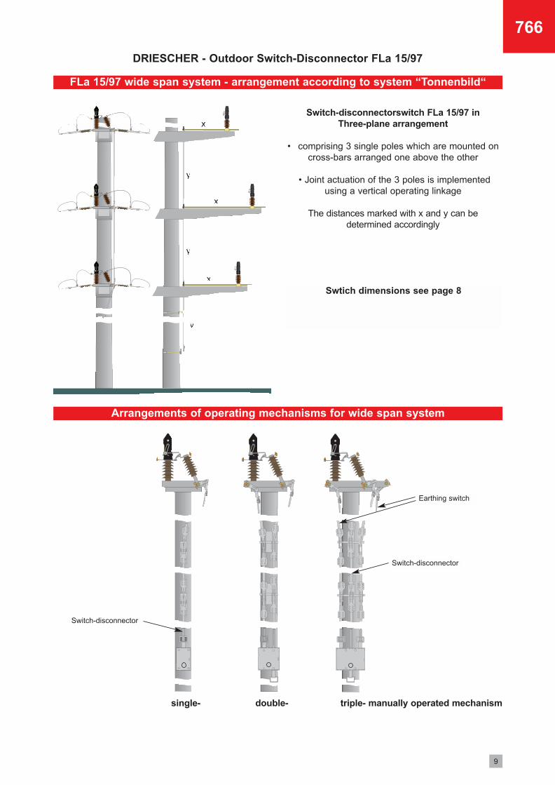
FLa 15/97 wide span system - arrangement according to system “Tonnenbild“
Arrangements of operating mechanisms for wide span system
Switch-disconnectorswitch FLa 15/97 in Three-plane arrangement
• comprising 3 single poles which are mounted oncross-bars arranged one above the other
• Joint actuation of the 3 poles is implementedusing a vertical operating linkage
The distances marked with x and y can be determined accordingly
single- double- triple- manually operated mechanism
Swtich dimensions see page 8
Earthing switch
Switch-disconnector
Switch-disconnector
DRIESCHER - Outdoor Switch-Disconnector FLa 15/97
10
766
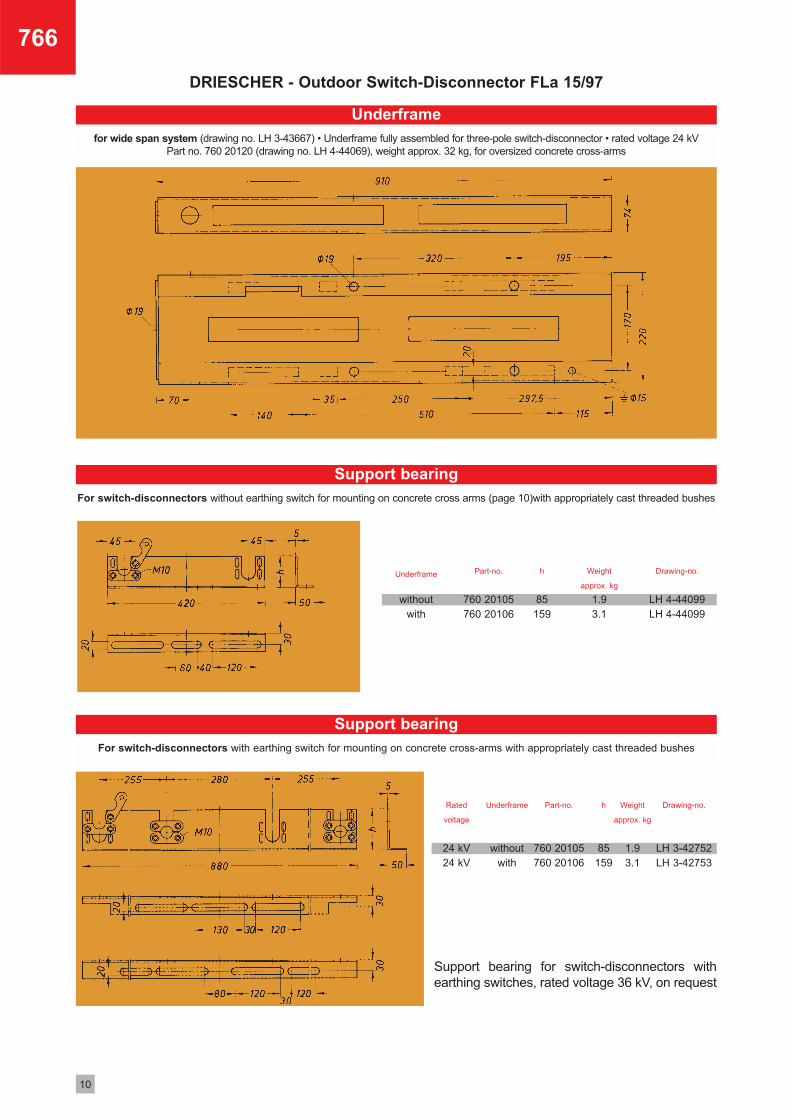
for wide span system (drawing no. LH 3-43667) • Underframe fully assembled for three-pole switch-disconnector • rated voltage 24 kVPart no. 760 20120 (drawing no. LH 4-44069), weight approx. 32 kg, for oversized concrete cross-arms
Underframe
withoutwith
Part-no.
760 20105760 20106
Weight
approx. kg
1.93.1
h
85159
Drawing-no.
LH 4-44099LH 4-44099
Rated
voltage
24 kV24 kV
Underframe
withoutwith
Part-no.
760 20105760 20106
Weight
approx. kg
1.93.1
h
85159
Drawing-no.
LH 3-42752LH 3-42753
Support bearing for switch-disconnectors withearthing switches, rated voltage 36 kV, on request
Underframe
For switch-disconnectors without earthing switch for mounting on concrete cross arms (page 10)with appropriately cast threaded bushes
Support bearing
For switch-disconnectors with earthing switch for mounting on concrete cross-arms with appropriately cast threaded bushes
Support bearing
11
766
DRIESCHER - Outdoor Switch-Disconnector FLa 15/97
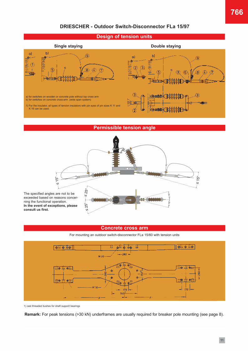
Permissible tension angle
Concrete cross arm
Design of tension units
a) for switches on wooden or concrete pole without top cross arm b) for switches on concrete cross-arm (wide span system)
1) For the insulator, all types of tension insulators with pin eyes of pin sizes K 11 and K 16 can be used.
Single staying Double staying
For mounting an outdoor switch-disconnector FLa 15/60 with tension units
The specified angles are not to beexceeded based on reasons concer-ning the functional operation. In the event of exceptions, pleaseconsult us first.
1) cast threaded bushes for shaft support bearings
Remark: For peak tensions (>30 kN) underframes are usually required for breaker pole mounting (see page 8).
DRIESCHER - Outdoor Switch-Disconnector FLa 15/97
12
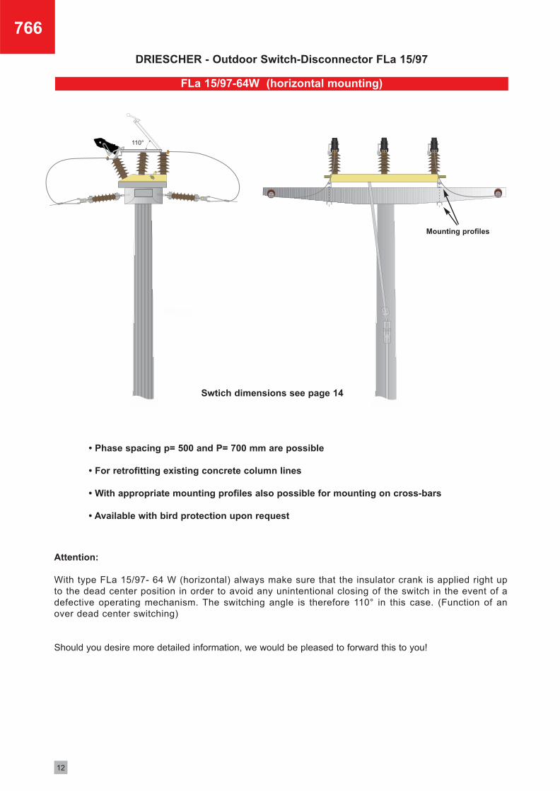
FLa 15/97-64W (horizontal mounting)
Swtich dimensions see page 14
Mounting profiles
Attention:
With type FLa 15/97- 64 W (horizontal) always make sure that the insulator crank is applied right upto the dead center position in order to avoid any unintentional closing of the switch in the event of adefective operating mechanism. The switching angle is therefore 110° in this case. (Function of anover dead center switching)
Should you desire more detailed information, we would be pleased to forward this to you!
• Phase spacing p= 500 and P= 700 mm are possible
• For retrofitting existing concrete column lines
• With appropriate mounting profiles also possible for mounting on cross-bars
• Available with bird protection upon request
766
DRIESCHER - Outdoor Switch-Disconnector FLa 15/97
13
766
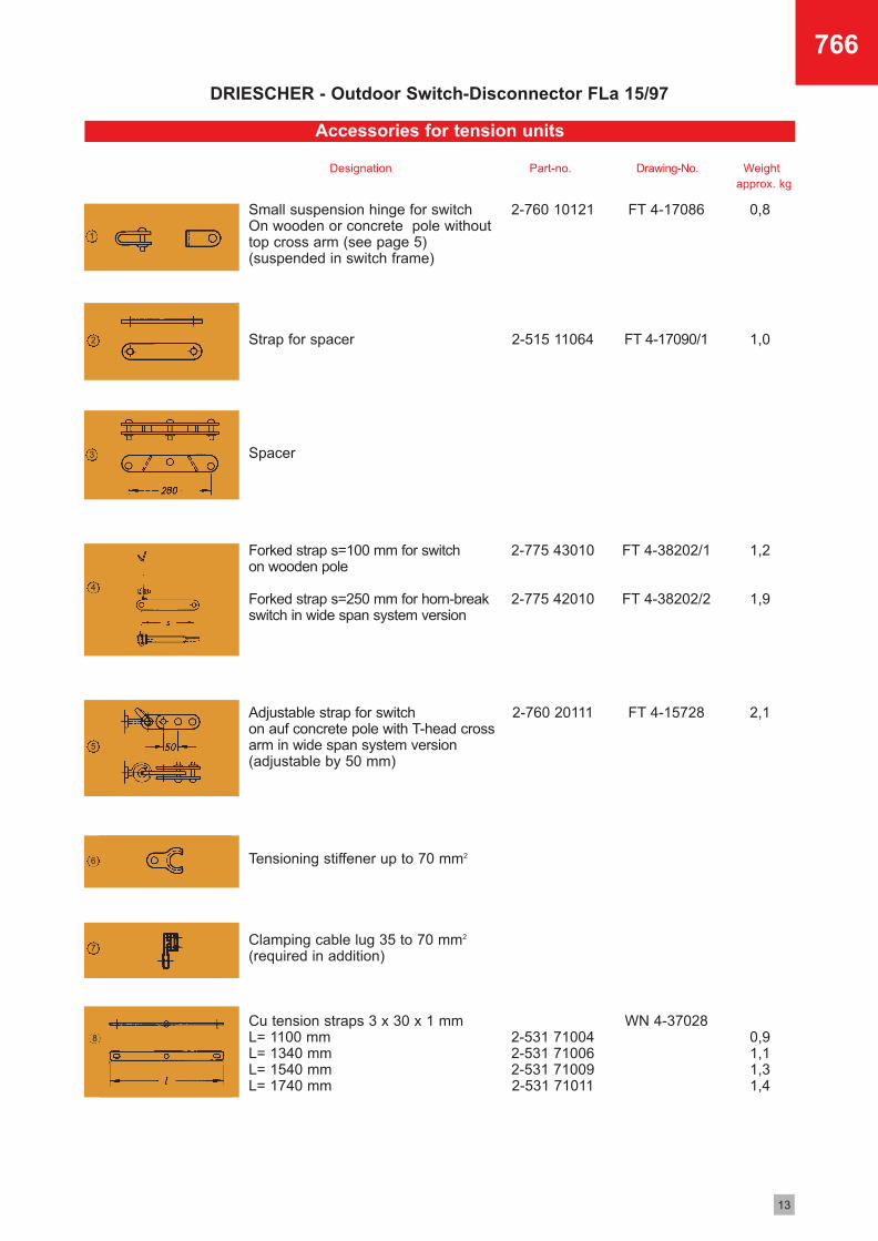
Small suspension hinge for switch On wooden or concrete pole withouttop cross arm (see page 5)(suspended in switch frame)
Strap for spacer
Spacer
Forked strap s=100 mm for switch on wooden pole
Forked strap s=250 mm for horn-breakswitch in wide span system version
Adjustable strap for switch on auf concrete pole with T-head crossarm in wide span system version(adjustable by 50 mm)
Tensioning stiffener up to 70 mm2
Clamping cable lug 35 to 70 mm2
(required in addition)
Cu tension straps 3 x 30 x 1 mmL= 1100 mmL= 1340 mmL= 1540 mmL= 1740 mm
2-760 10121
2-515 11064
2-775 43010
2-775 42010
2-760 20111
2-531 710042-531 710062-531 710092-531 71011
FT 4-17086
FT 4-17090/1
FT 4-38202/1
FT 4-38202/2
FT 4-15728
WN 4-37028
0,8
1,0
1,2
1,9
2,1
0,91,11,31,4
1
2
3
4
5
6
7
8
Designation Part-no. Drawing-No. Weight approx. kg
Accessories for tension units
14
766
DRIESCHER - Outdoor Switch-Disconnector FLa 15/97
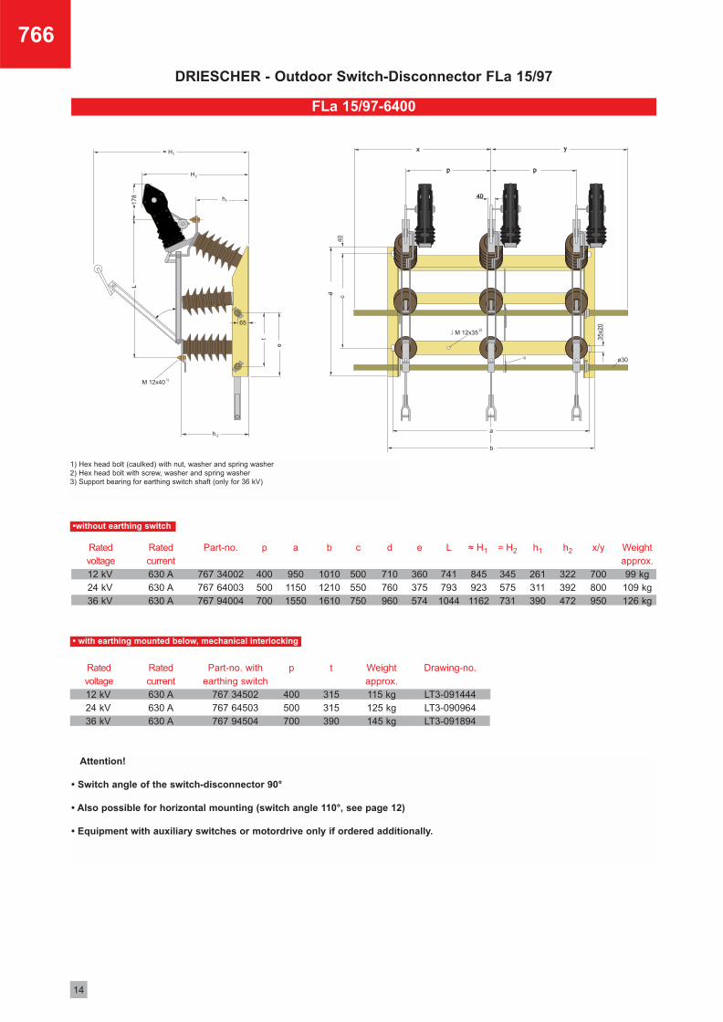
FLa 15/97-6400
Attention!
• Switch angle of the switch-disconnector 90°
• Also possible for horizontal mounting (switch angle 110°, see page 12)
• Equipment with auxiliary switches or motordrive only if ordered additionally.
d
710760960
e
360375574
h1
261311390
h2
322392472
L
741793
1044
Weightapprox.99 kg
109 kg126 kg
Rated current630 A630 A630 A
b
101012101610
c
500550750
p
400500700
a
95011501550
x/y
700800950
Part-no.
767 34002767 64003767 94004
Rated voltage12 kV24 kV36 kV
p
400500700
t
315315390
≈ H2≈ H1
345575731
8459231162
Drawing-no.
LT3-091444LT3-090964LT3-091894
Weightapprox. 115 kg125 kg145 kg
Part-no. withearthing switch
767 34502767 64503767 94504
Rated voltage12 kV24 kV36 kV
Rated current630 A630 A630 A
1) Hex head bolt (caulked) with nut, washer and spring washer 2) Hex head bolt with screw, washer and spring washer 3) Support bearing for earthing switch shaft (only for 36 kV)
•without earthing switch
• with earthing mounted below, mechanical interlocking
15
766
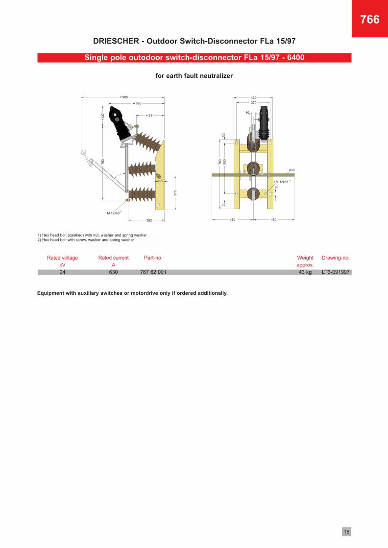
Rated voltagekV24
Rated currentA
630
Part-no.
767 62 001
Weightapprox.43 kg
Drawing-no.
LT3-091997
1) Hex head bolt (caulked) with nut, washer and spring washer 2) Hex head bolt with screw, washer and spring washer
for earth fault neutralizer
Equipment with auxiliary switches or motordrive only if ordered additionally.
Single pole outodoor switch-disconnector FLa 15/97 - 6400
DRIESCHER - Outdoor Switch-Disconnector FLa 15/97
16
766
DRIESCHER - Outdoor Switch-Disconnector FLa 15/97
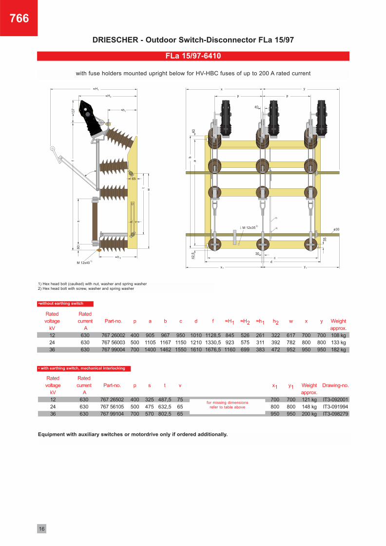
FLa 15/97-6410
Part-no.
767 26002767 56003767 99004
b
96711671462
f
1128,51330,51676,5
≈H1
8459231160
≈H2
526575699
≈h1
261311383
h2
322392472
w
617782952
x
700800950
y
700800950
a
90511051400
p
400500700
d
101012101610
c
95011501550
Weightapprox.108 kg133 kg182 kg
Part-no.
767 26502767 56105767 99104
t
487,5632,5802,5
x1
700800950
y1
700800950
s
325475570
p
400500700
v
756565
Weightapprox.121 kg148 kg200 kg
Drawing-no.
IT3-092001IT3-091994IT3-098279
•without earthing switch
• with earthing switch, mechanical interlocking
for missing dimensions refer to table above
1) Hex head bolt (caulked) with nut, washer and spring washer 2) Hex head bolt with screw, washer and spring washer
Equipment with auxiliary switches or motordrive only if ordered additionally.
Rated current
A630630630
Rated voltage
kV122436
Rated current
A630630630
Rated voltage
kV122436
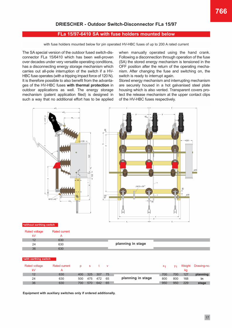
with fuse holders mounted upright below for HV-HBC fuses of up to 200 A rated current
17
766
The SA special version of the outdoor fused switch-dis-connector FLa 15/6410 which has been well-provenover decades under very versatile operating conditions,has a disconnecting energy storage mechanism whichcarries out all-pole interruption of the switch if a HV-HBC fuse operates (with a tripping impact force of 120 N).It is therefore possible to also benefit from the advanta-ges of the HV-HBC fuses with thermal protection inoutdoor applications as well. The energy storagemechanism (patent application filed) is designed insuch a way that no additional effort has to be applied
when manually operated using the hand crank.Following a disconnection through operation of the fuse(SA) the stored energy mechanism is tensioned in theOFF position after the return of the operating mecha-nism. After changing the fuse and switching on, theswitch is ready to interrupt again.Stored energy mechanism and interrupting mechanismare securely housed in a hot galvanised steel platehousing which is also vented. Transparent covers pro-tect the release mechanism at the upper contact clipsof the HV-HBC fuses respectively.
DRIESCHER - Outdoor Switch-Disconnector FLa 15/97
Rated voltage kV122436
Rated currentA
630630630
Drawing-no.
planningin
stage
Rated voltagekV122436
Rated currentA
630630630
t
307472642
x1
700800950
y1
700800950
s
325475570
p
400500700
v
756565
Weightkg
127168229
planning in stage
planning in stage
Equipment with auxiliary switches only if ordered additionally.
FLa 15/97-6410 SA with fuse holders mounted below
with fuse holders mounted below for pin operated HV-HBC fuses of up to 200 A rated current
•without earthing switch
•with earthing switch
18
766
DRIESCHER - Outdoor Switch-Disconnector FLa 15/97
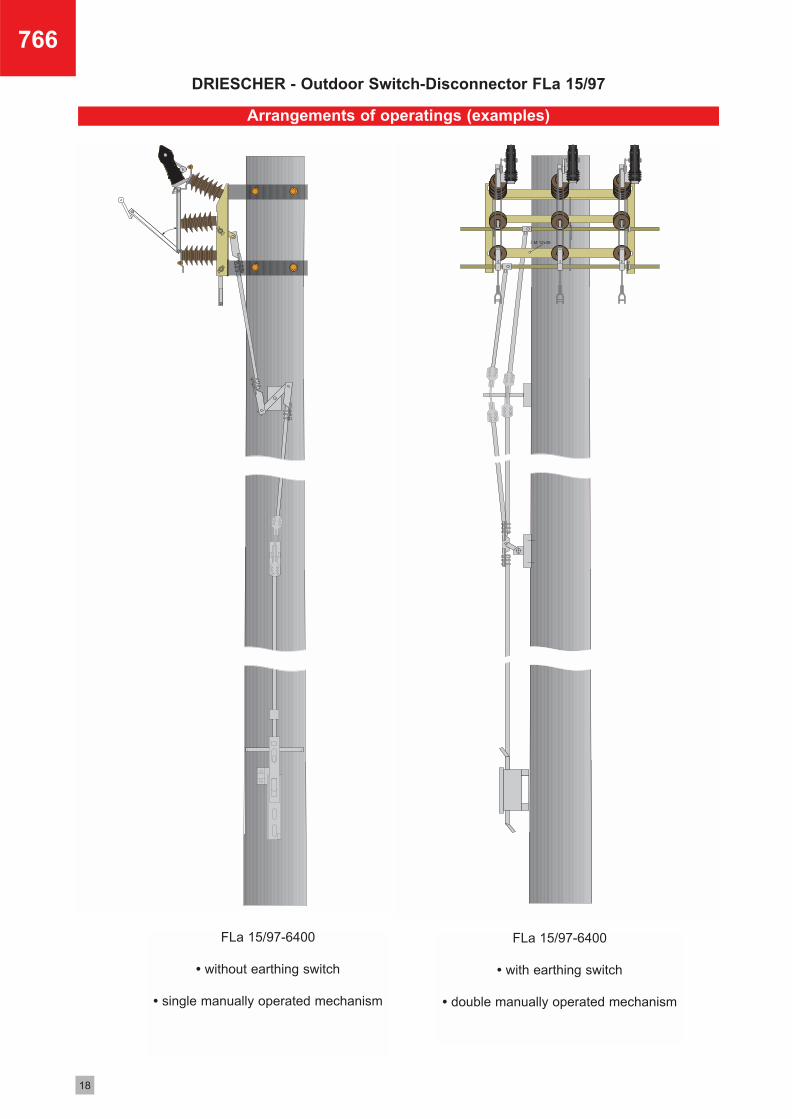
Arrangements of operatings (examples)
FLa 15/97-6400
• without earthing switch
• single manually operated mechanism
FLa 15/97-6400
• with earthing switch
• double manually operated mechanism
19
766
DRIESCHER - Outdoor Switch-Disconnector FLa 15/97
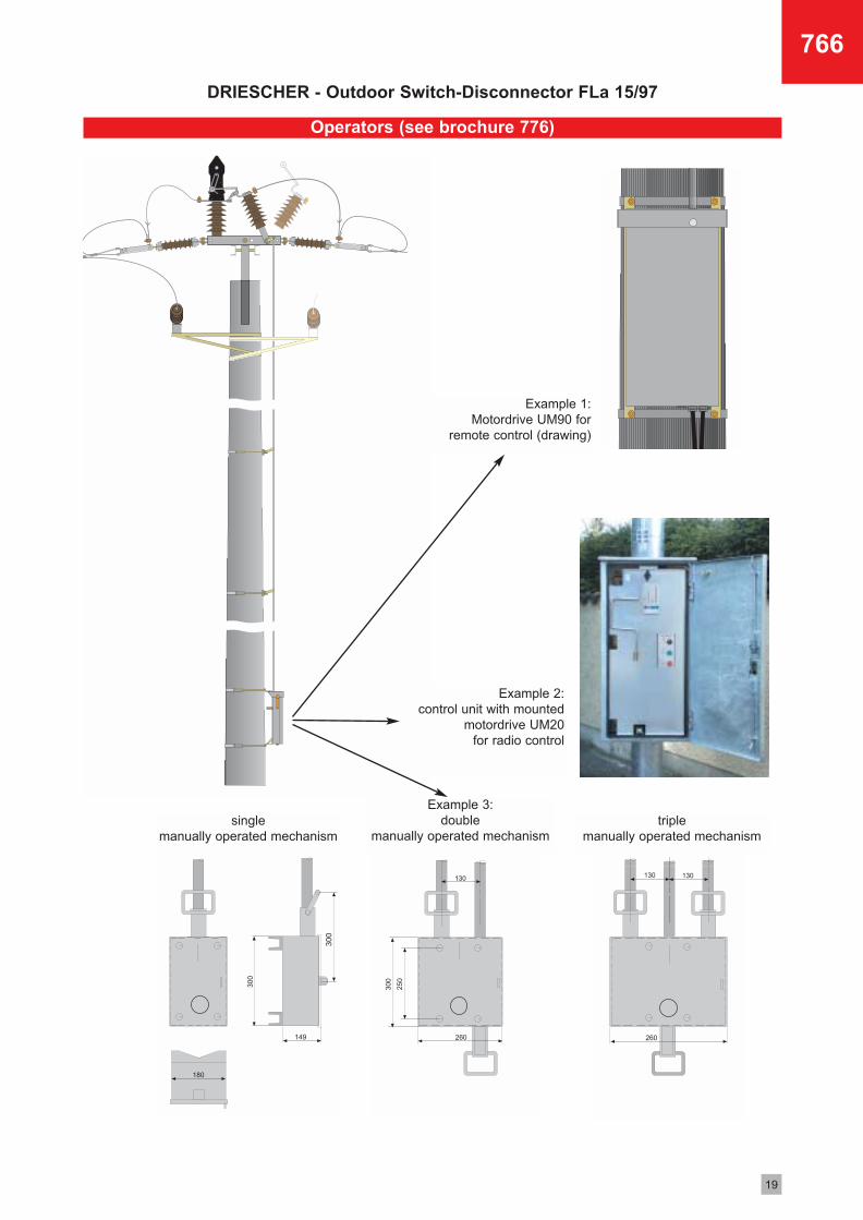
Operators (see brochure 776)
Example 2:control unit with mounted
motordrive UM20 for radio control
Example 1:Motordrive UM90 for
remote control (drawing)
triple manually operated mechanism
single manually operated mechanism
Example 3:double
manually operated mechanism
Bestellnr. 3-81707660 • 02-04
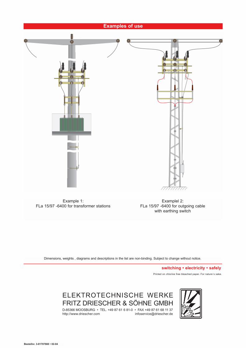
Examples of use
Examplel 2:FLa 15/97 -6400 for outgoing cable
with earthing switch
Example 1:FLa 15/97 -6400 for transformer stations
Dimensions, weights , diagrams and descriptions in the list are non-binding. Subject to change without notice.
Printed on chlorine free bleached paper. For nature´s sake.
switching • electricity • safely
ELEKTROTECHNISCHE WERKEFRITZ DRIESCHER & SÖHNE GMBHD-85366 MOOSBURG • TEL. +49 87 61 6 81-0 • FAX +49 87 61 68 11 37http://www.driescher.com [email protected]