2015 RAC LG
36
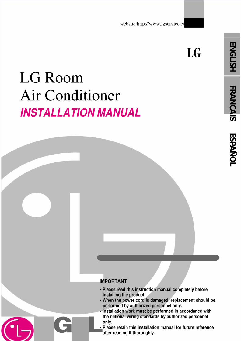
E G L I S LG Room Air Conditioner INSTALLATION MANUAL LG website http://www.lgservice.com IMPORTANT • Please read this instruction manual completely before installing the product. • When the power cord is damaged, replacement should be performed by authorized personnel only. • Installation work must be performed in accordance with the national wiring standards by authorized personnel only. • Please retain this installation manual for future reference after reading it thoroughly. F A Ç A I S E S A Ñ O L
Transcript of 2015 RAC LG
8/18/2019 2015 RAC LG
http://slidepdf.com/reader/full/2015-rac-lg 1/35
E N G
L I S H
LG Room
Air ConditionerINSTALLATION MANUAL
LG
website http://www.lgservice.com
IMPORTANT
• Please read this instruction manual completely beforeinstalling the product.
• When the power cord is damaged, replacement should beperformed by authorized personnel only.
• Installation work must be performed in accordance withthe national wiring standards by authorized personnelonly.
• Please retain this installation manual for future referenceafter reading it thoroughly.
F RAN Ç A
I S
E S PAÑ OL
8/18/2019 2015 RAC LG
http://slidepdf.com/reader/full/2015-rac-lg 2/35
2 Room Air Conditioner
Room Air Conditioner Installation Manual
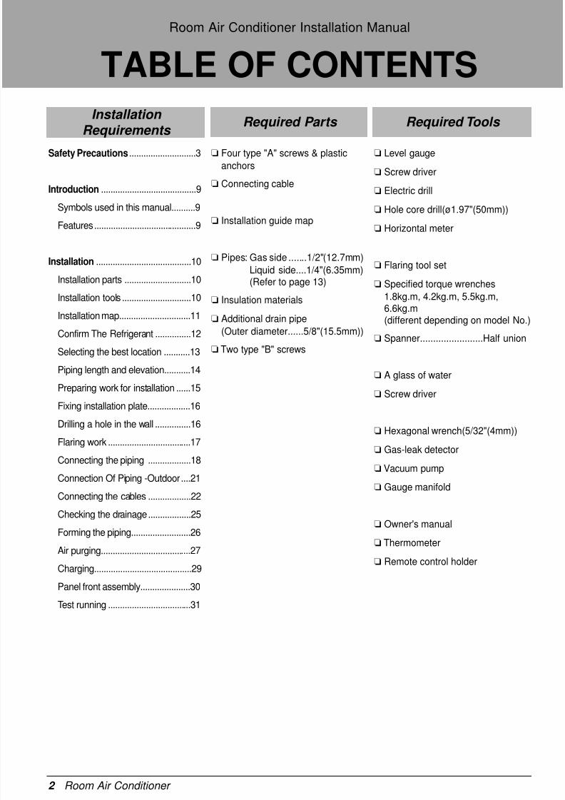
TABLE OF CONTENTS
Safety Precautions............................3
Introduction ........................................9
Symbols used in this manual..........9
Features...........................................9
Installation ........................................10
Installation parts ............................10
Installation tools .............................10
Installation map..............................11
Confirm The Refrigerant ...............12
Selecting the best location ...........13
Piping length and elevation...........14
Preparing work for installation ......15
Fixing installation plate..................16
Drilling a hole in the wall ...............16
Flaring work ...................................17
Connecting the piping ..................18
Connection Of Piping -Outdoor....21
Connecting the cables ..................22
Checking the drainage..................25
Forming the piping.........................26
Air purging......................................27
Charging.........................................29
Panel front assembly.....................30
Test running ...................................31
❏ Four type "A" screws & plastic
anchors
❏ Connecting cable
❏ Installation guide map
❏ Pipes: Gas side .......1/2"(12.7mm)
Liquid side....1/4"(6.35mm)
(Refer to page 13)
❏ Insulation materials
❏ Additional drain pipe
(Outer diameter......5/8"(15.5mm))
❏ Two type "B" screws
❏ Level gauge
❏ Screw driver
❏ Electric drill
❏ Hole core drill(ø1.97"(50mm))
❏ Horizontal meter
❏ Flaring tool set
❏ Specified torque wrenches1.8kg.m, 4.2kg.m, 5.5kg.m,6.6kg.m(different depending on model No.)
❏ Spanner........................Half union
❏ A glass of water
❏ Screw driver
❏ Hexagonal wrench(5/32"(4mm))
❏ Gas-leak detector
❏ Vacuum pump
❏ Gauge manifold
❏ Owner's manual
❏ Thermometer
❏ Remote control holder
Installation Requirements
Required Parts Required Tools
8/18/2019 2015 RAC LG
http://slidepdf.com/reader/full/2015-rac-lg 3/35
Installation Manual 3
E N G
L I S H
Safety Precautions
To prevent the injury of the user or other people and property damage, the following instructions
must be followed.
Be sure to read before installing the air conditioner.
Be sure to observe the cautions specified here as they include important items related to safety.
Incorrect operation due to ignoring instruction will cause harm or damage.The seriousness is
classified by the following indications.
The meanings of the symbols used in this manual are as shown below.
This symbol indicates the possibility of death or serious injury.
This symbol indicates the possibility of injury or damage to properties only.
Be sure not to do.
Be sure to follow the instruction.
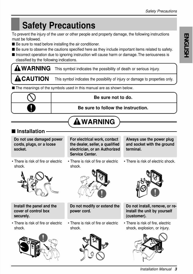
Safety Precautions
Installation
Do not use damaged power
cords, plugs, or a loosesocket.
• There is risk of fire or electric
shock.
For electrical work, contact
the dealer, seller, a qualifiedelectrician, or an AuthorizedService Center.
• There is risk of fire or electric
shock.
Always use the power plug
and socket with the groundterminal.
• There is risk of electric shock.
Install the panel and thecover of control boxsecurely.
• There is risk of fire or electric
shock.
Do not modify or extend thepower cord.
• There is risk of fire or electric
shock.
Do not install, remove, or re-install the unit by yourself(customer).
• There is risk of fire, electric
shock, explosion, or injury.
8/18/2019 2015 RAC LG
http://slidepdf.com/reader/full/2015-rac-lg 4/35
4 Room Air Conditioner
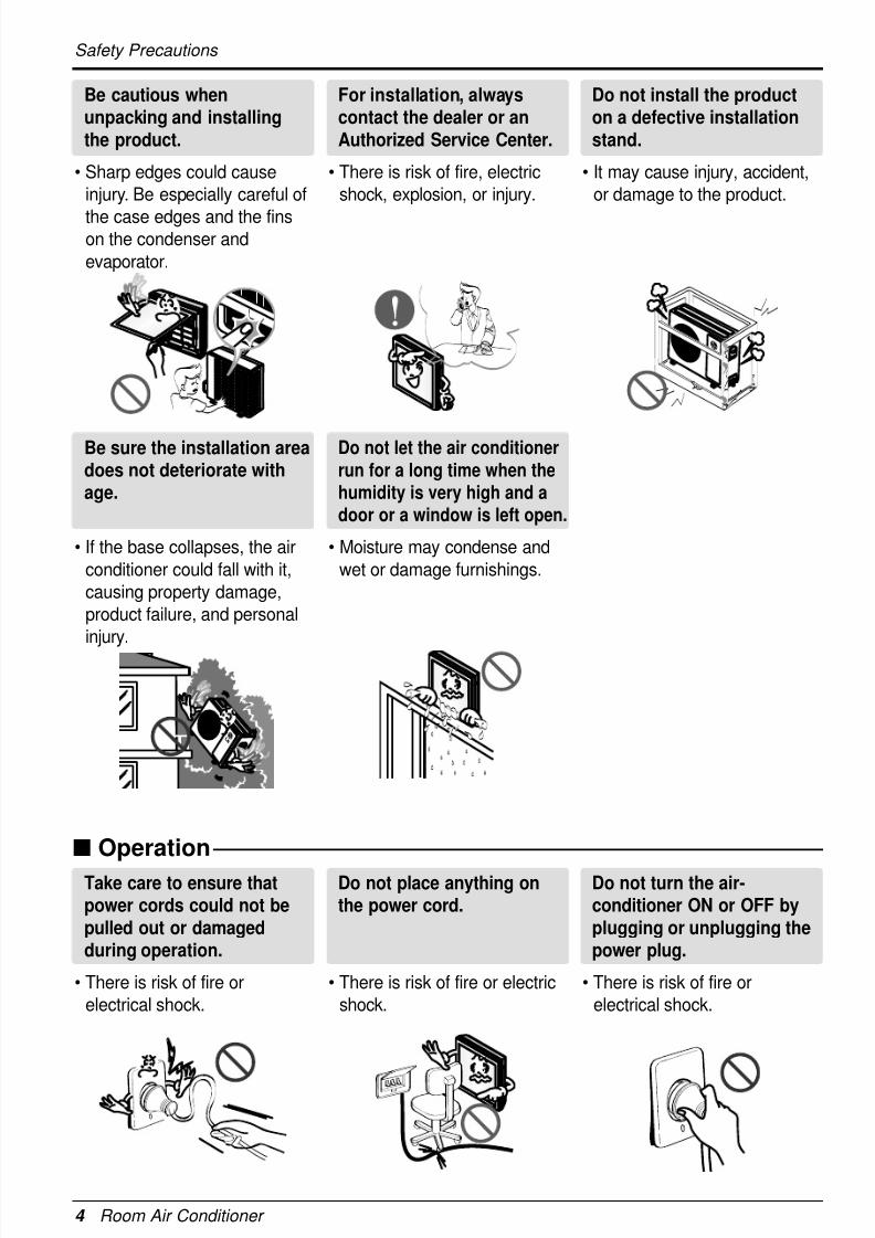
Safety Precautions
Operation
Be cautious whenunpacking and installingthe product.
• Sharp edges could cause
injury. Be especially careful of
the case edges and the finson the condenser and
evaporator.
For installation, alwayscontact the dealer or anAuthorized Service Center.
• There is risk of fire, electric
shock, explosion, or injury.
Do not install the producton a defective installationstand.
• It may cause injury, accident,
or damage to the product.
Be sure the installation areadoes not deteriorate withage.
• If the base collapses, the air
conditioner could fall with it,
causing property damage,
product failure, and personal
injury.
Do not let the air conditioner
run for a long time when thehumidity is very high and adoor or a window is left open.
• Moisture may condense and
wet or damage furnishings.
Take care to ensure thatpower cords could not bepulled out or damagedduring operation.
• There is risk of fire or
electrical shock.
Do not place anything onthe power cord.
• There is risk of fire or electric
shock.
Do not turn the air-conditioner ON or OFF byplugging or unplugging thepower plug.
• There is risk of fire or
electrical shock.
8/18/2019 2015 RAC LG
http://slidepdf.com/reader/full/2015-rac-lg 5/35
Installation Manual 5
E N G
L I S H
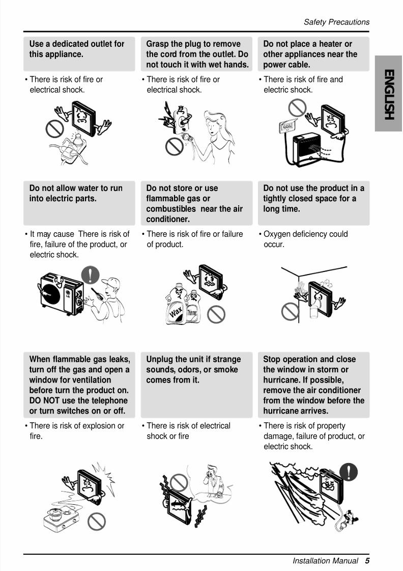
Safety Precautions
Use a dedicated outlet forthis appliance.
• There is risk of fire or
electrical shock.
Grasp the plug to removethe cord from the outlet. Donot touch it with wet hands.
• There is risk of fire or
electrical shock.
Do not place a heater orother appliances near thepower cable.
• There is risk of fire and
electric shock.
Do not allow water to run
into electric parts.
• It may cause There is risk of
fire, failure of the product, or
electric shock.
Do not store or use
flammable gas orcombustibles near the airconditioner.
• There is risk of fire or failure
of product.
Do not use the product in a
tightly closed space for along time.
• Oxygen deficiency could
occur.
W a x T hinner
When flammable gas leaks,turn off the gas and open awindow for ventilationbefore turn the product on.
DO NOT use the telephoneor turn switches on or off.
• There is risk of explosion or
fire.
Unplug the unit if strangesounds, odors, or smokecomes from it.
• There is risk of electrical
shock or fire
Stop operation and closethe window in storm orhurricane. If possible,remove the air conditioner
from the window before thehurricane arrives.
• There is risk of property
damage, failure of product, or
electric shock.
8/18/2019 2015 RAC LG
http://slidepdf.com/reader/full/2015-rac-lg 6/35
6 Room Air Conditioner
Safety Precautions
Installation
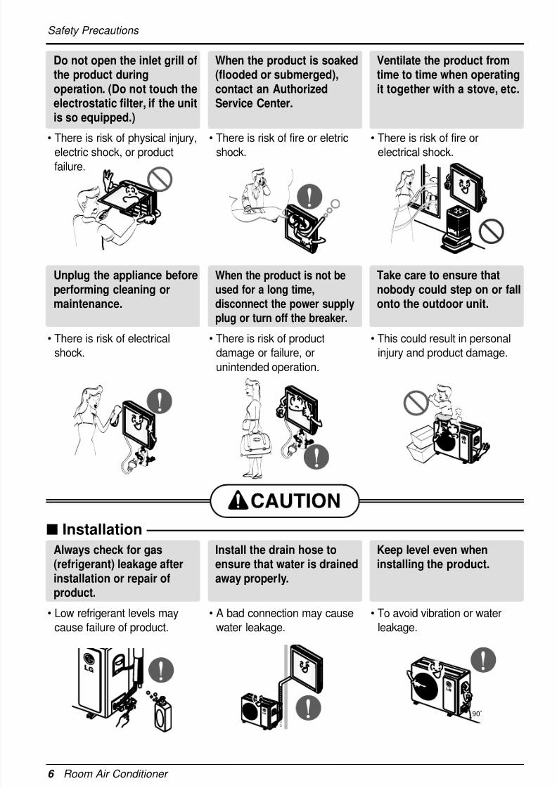
Do not open the inlet grill ofthe product duringoperation. (Do not touch theelectrostatic filter, if the unitis so equipped.)
• There is risk of physical injury,electric shock, or product
failure.
When the product is soaked(flooded or submerged),contact an AuthorizedService Center.
• There is risk of fire or eletricshock.
Ventilate the product fromtime to time when operatingit together with a stove, etc.
• There is risk of fire orelectrical shock.
Unplug the appliance beforeperforming cleaning ormaintenance.
• There is risk of electrical
shock.
When the product is not beused for a long time,
disconnect the power supply
plug or turn off the breaker.
• There is risk of product
damage or failure, or
unintended operation.
Take care to ensure thatnobody could step on or fallonto the outdoor unit.
• This could result in personal
injury and product damage.
Always check for gas(refrigerant) leakage afterinstallation or repair ofproduct.
• Low refrigerant levels may
cause failure of product.
Install the drain hose toensure that water is drainedaway properly.
• A bad connection may cause
water leakage.
Keep level even wheninstalling the product.
• To avoid vibration or water
leakage.
90˚
8/18/2019 2015 RAC LG
http://slidepdf.com/reader/full/2015-rac-lg 7/35
Safety Precautions
Installation Manual 7
E N G
L I S H
Operation
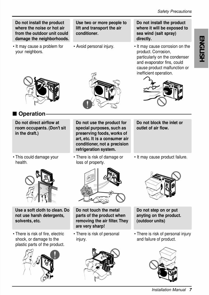
Do not install the productwhere the noise or hot airfrom the outdoor unit coulddamage the neighborhoods.
• It may cause a problem for
your neighbors.
Use two or more people tolift and transport the airconditioner.
• Avoid personal injury.
Do not install the productwhere it will be exposed tosea wind (salt spray)directly.
• It may cause corrosion on the
product. Corrosion,particularly on the condenserand evaporator fins, couldcause product malfunction orinefficient operation.
Do not direct airflow atroom occupants. (Don't sitin the draft.)
• This could damage yourhealth.
Do not use the product forspecial purposes, such aspreserving foods, works ofart, etc. It is a consumer airconditioner, not a precisionrefrigeration system.
• There is risk of damage orloss of property.
Do not block the inlet oroutlet of air flow.
• It may cause product failure.
Use a soft cloth to clean. Donot use harsh detergents,solvents, etc.
• There is risk of fire, electricshock, or damage to theplastic parts of the product.
Do not touch the metalparts of the product whenremoving the air filter. Theyare very sharp!
• There is risk of personalinjury.
Do not step on or putanyting on the product.(outdoor units)
• There is risk of personal injuryand failure of product.
8/18/2019 2015 RAC LG
http://slidepdf.com/reader/full/2015-rac-lg 8/35
8 Room Air Conditioner
Safety Precautions
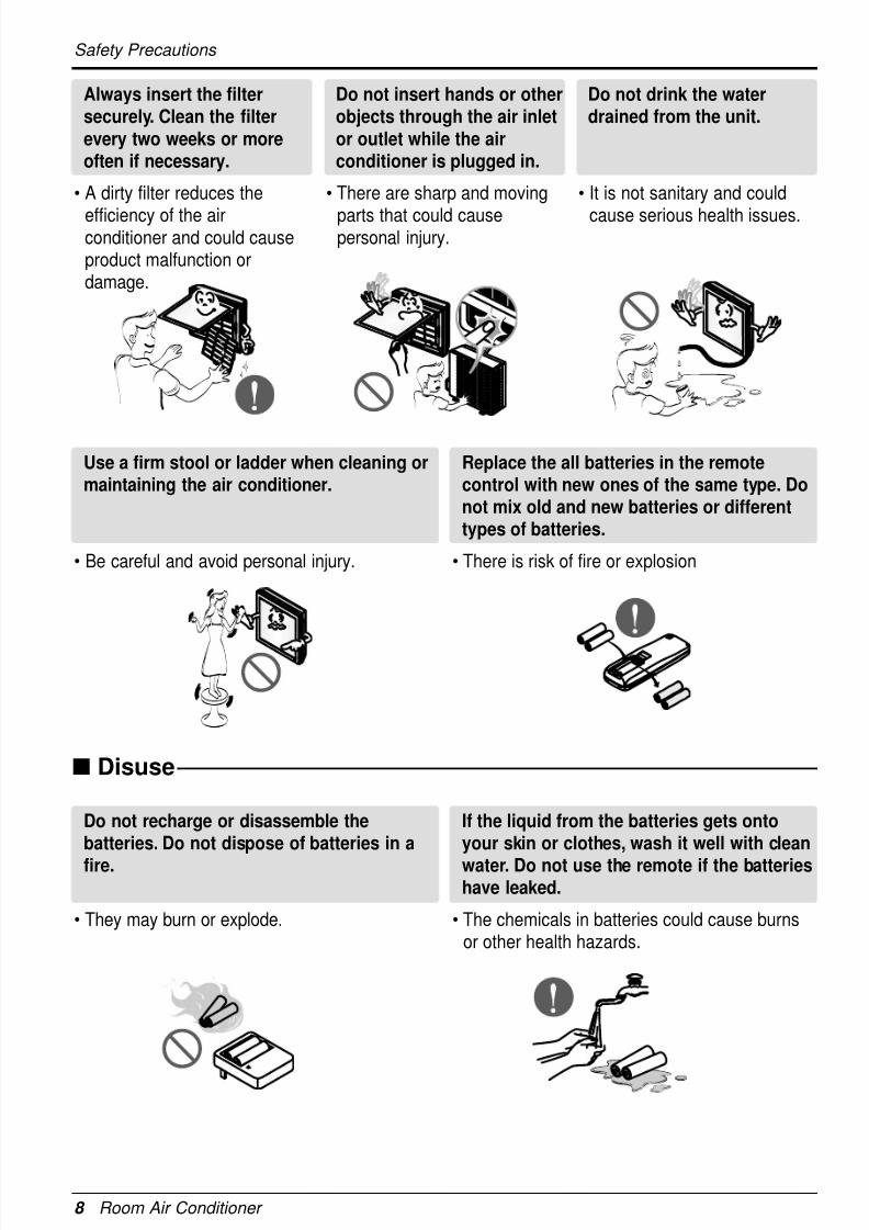
Always insert the filtersecurely. Clean the filterevery two weeks or moreoften if necessary.
• A dirty filter reduces the
efficiency of the airconditioner and could causeproduct malfunction ordamage.
Do not insert hands or otherobjects through the air inletor outlet while the airconditioner is plugged in.
• There are sharp and moving
parts that could causepersonal injury.
Do not drink the waterdrained from the unit.
• It is not sanitary and could
cause serious health issues.
Use a firm stool or ladder when cleaning ormaintaining the air conditioner.
• Be careful and avoid personal injury.
Replace the all batteries in the remotecontrol with new ones of the same type. Donot mix old and new batteries or differenttypes of batteries.
• There is risk of fire or explosion
Do not recharge or disassemble thebatteries. Do not dispose of batteries in a
fire.
• They may burn or explode.
If the liquid from the batteries gets ontoyour skin or clothes, wash it well with clean
water. Do not use the remote if the batterieshave leaked.
• The chemicals in batteries could cause burnsor other health hazards.
Disuse
8/18/2019 2015 RAC LG
http://slidepdf.com/reader/full/2015-rac-lg 9/35
Introduction
Installation Manual 9
E N G
L I S HThis symbol alerts you to the risk of electric shock.
This symbol alerts you to hazards that may cause harm to theair conditioner.
This symbol indicates special notes.NOTICE
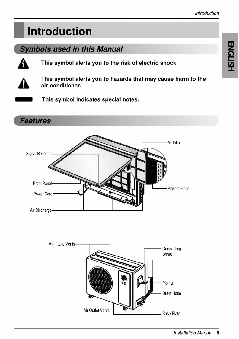
Introduction
Symbols used in this Manual
Features
Signal Receptor
Front Panel
Air Discharge
Air Intake Vents
Air Outlet Vents
Power Cord
ConnectingWires
Piping
Drain Hose
Base Plate
Air Filter
Plasma Filter
8/18/2019 2015 RAC LG
http://slidepdf.com/reader/full/2015-rac-lg 10/35
10 Room Air Conditioner
Installation
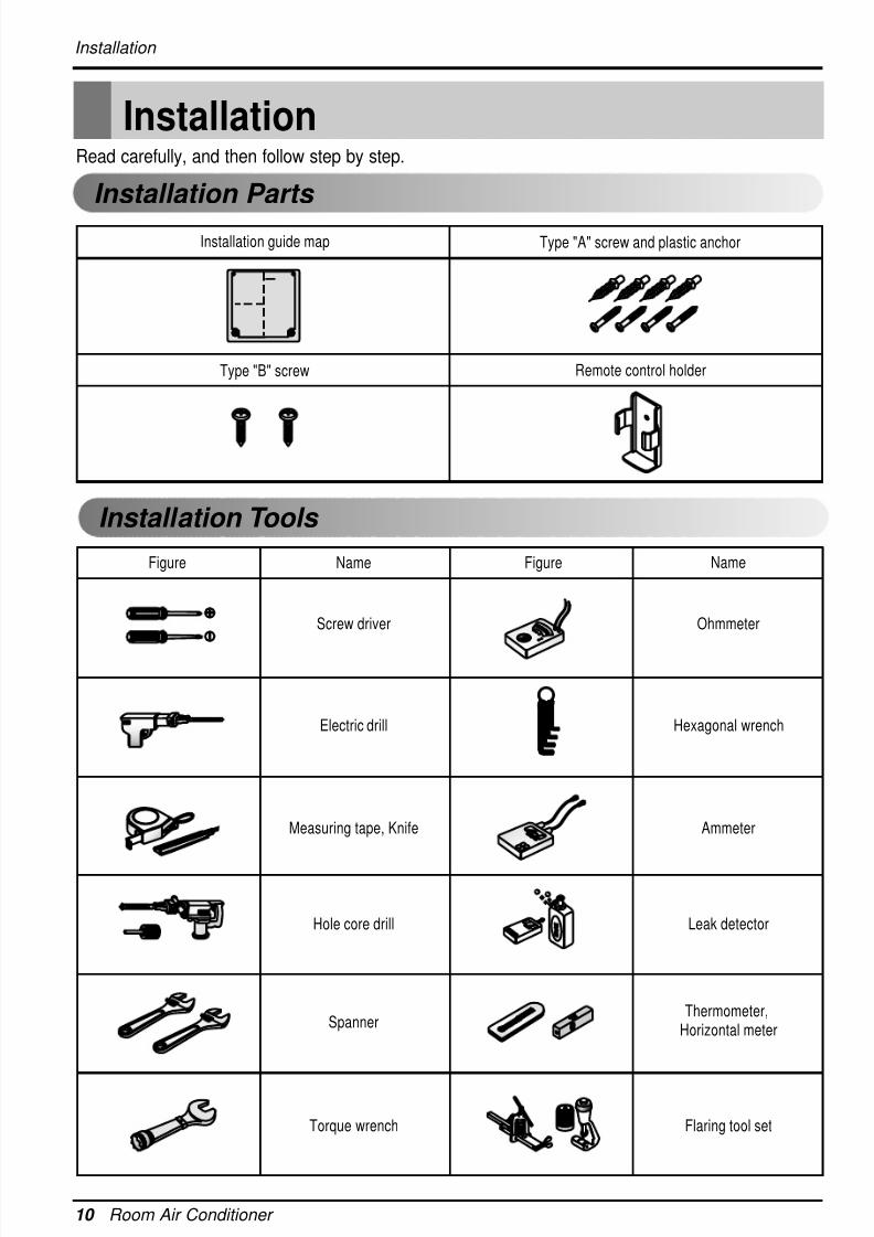
Type "A" screw and plastic anchor
Type "B" screw Remote control holder
Installation guide map
Figure FigureName
Screw driver
Electric drill
Measuring tape, Knife
Hole core drill
Spanner
Torque wrench
Ohmmeter
Hexagonal wrench
Ammeter
Leak detector
Thermometer,Horizontal meter
Flaring tool set
Name
Installation Parts
Installation Tools
InstallationRead carefully, and then follow step by step.
8/18/2019 2015 RAC LG
http://slidepdf.com/reader/full/2015-rac-lg 11/35
Installation
Installation Manual 11
E N G
L I S H
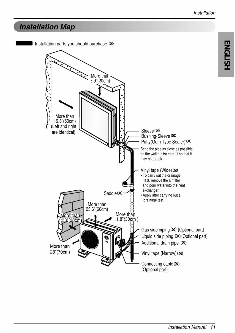
Installation Map
Installation parts you should purchase.NOTICE
(Left and rightare identical)
More than28"(70cm)
More than23.6"(60cm)
SleeveBushing-SleevePutty(Gum Type Sealer)
Vinyl tape (Wide)
• To carry out the drainagetest, remove the air filter
and pour water into the heatexchanger.
• Apply after carrying out a drainage test.
Saddle
More than19.6"(50cm)
Gas side piping (Optional part)
Liquid side piping (Optional part)
Additional drain pipe
Vinyl tape (Narrow)
Connecting cable(Optional part)
Bend the pipe as close as possibleon the wall but be careful so that itmay not break.
More than
11.8 (30cm )
More than11.8"(30cm )
More thanore than
11.8"(30cm)1.8 (30cm)
More than11.8"(30cm)
More thanore than
3.9"(10cm).9 (10cm)
More than7.9"(20cm)
8/18/2019 2015 RAC LG
http://slidepdf.com/reader/full/2015-rac-lg 12/35
12 Room Air Conditioner
Installation
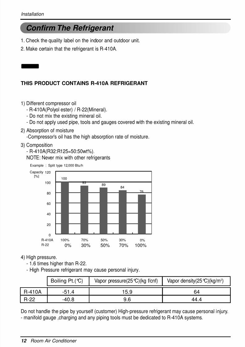
1. Check the quality label on the indoor and outdoor unit.
2. Make certain that the refrigerant is R-410A.
THIS PRODUCT CONTAINS R-410A REFRIGERANT
1) Different compressor oil- R-410A(Polyol ester) / R-22(Mineral).- Do not mix the existing mineral oil.
- Do not apply used pipe, tools and gauges covered with the existing mineral oil.
2) Absorption of moisture-Compressor’s oil has the high absorption rate of moisture.
3) Composition- R-410A(R32:R125=50:50wt%).NOTE: Never mix with other refrigerants
4) High pressure.- 1.6 times higher than R-22.- High Pressure refrigerant may cause personal injury.
Do not handle the pipe by yourself (customer) High-pressure refrigerant may cause personal injury.- manifold gauge ,charging and any piping tools must be dedicated to R-410A systems.
NOTICE
Confirm The Refrigerant
Boiling Pt.(°C) Vapor pressure(25°C)(kg f/cnf) Vapor density(25°C)(kg/m2)
R-410A -51.4 15.9 64
R-22 -40.8 9.6 44.4
Example : Split type 12,000 Btu/h
120Capacity[%]
100
100%
100%70%50%30%0%
70% 50% 30% 0%
100
93 8984
7680
60
40
20
0
R-410A
R-22
8/18/2019 2015 RAC LG
http://slidepdf.com/reader/full/2015-rac-lg 13/35
8/18/2019 2015 RAC LG
http://slidepdf.com/reader/full/2015-rac-lg 14/35
14 Room Air Conditioner
Installation
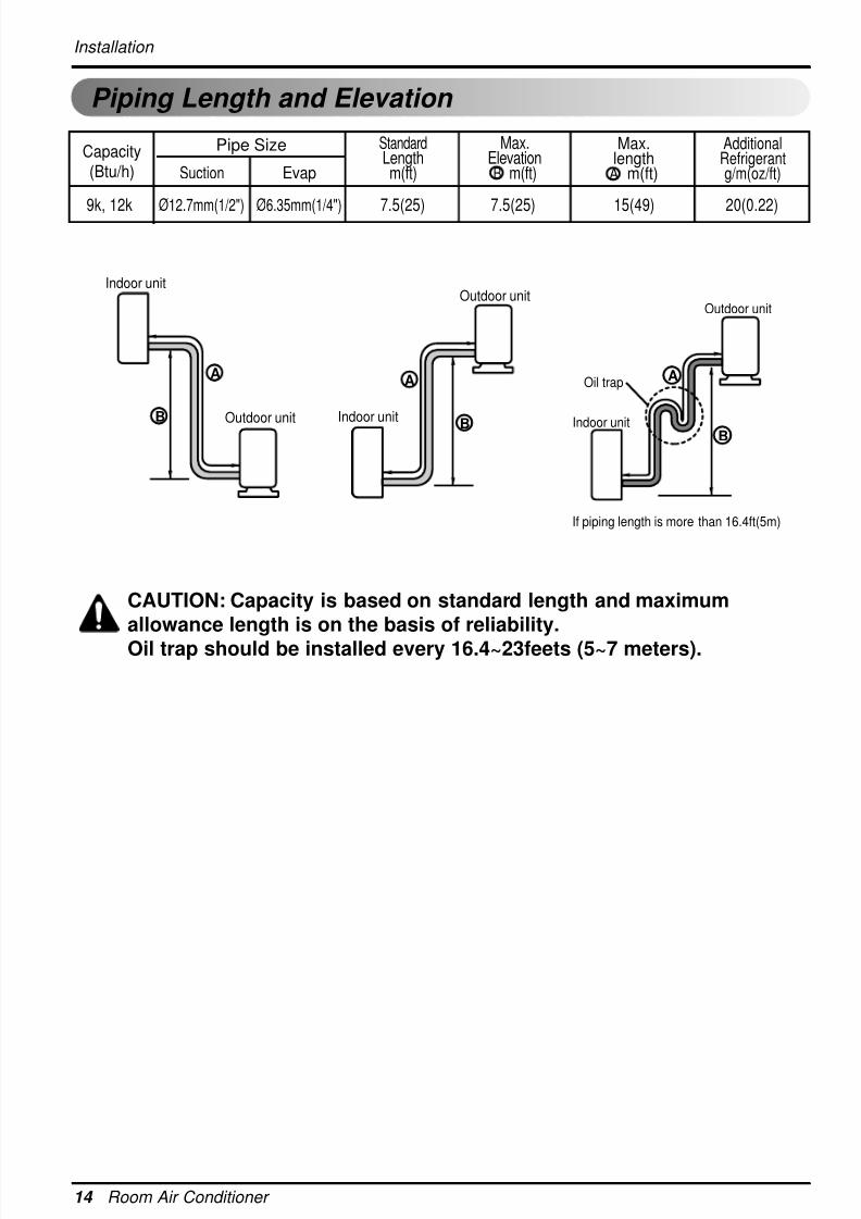
Piping Length and Elevation
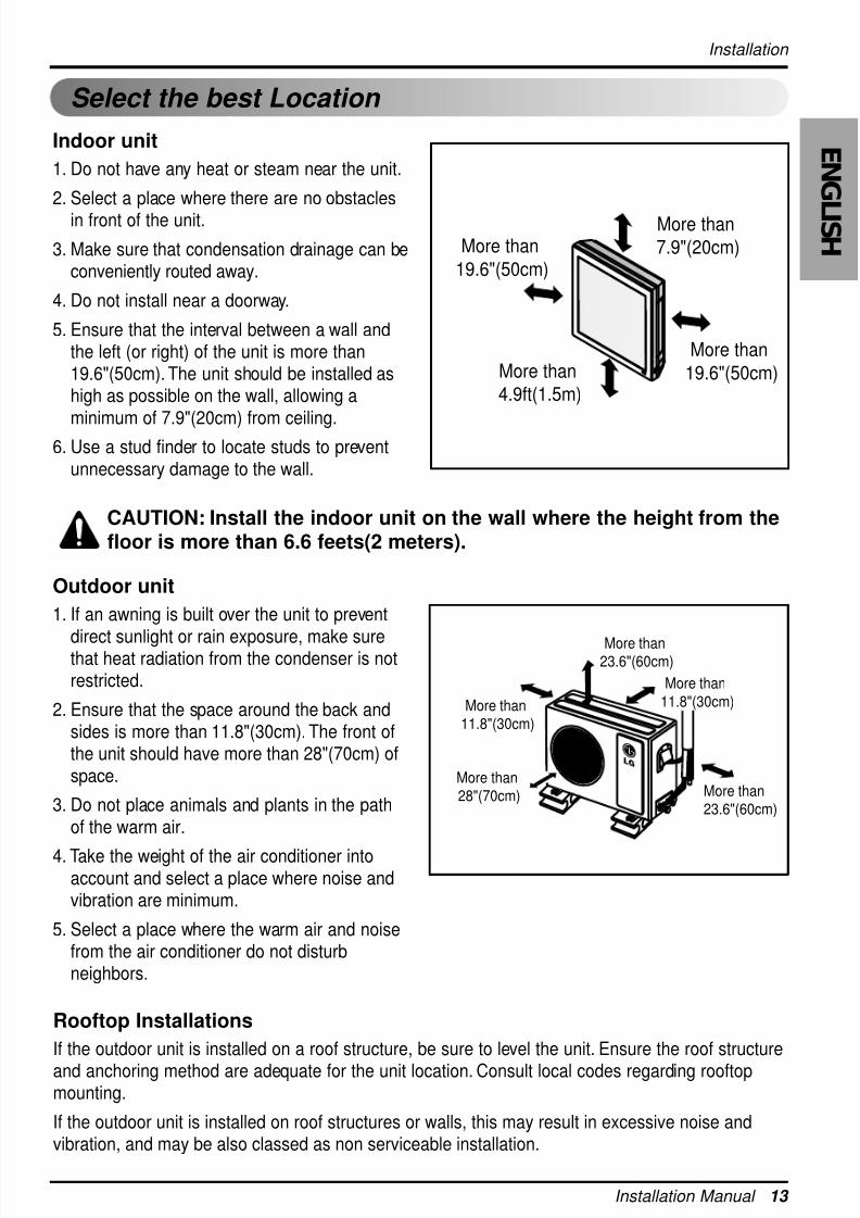
Outdoor unit
Indoor unit
A
B
Outdoor unit
Indoor unit
A
B
AOil trap
Outdoor unit
Indoor unit B
If piping length is more than 16.4ft(5m)
CAUTION: Capacity is based on standard length and maximumallowance length is on the basis of reliability.
Oil trap should be installed every 16.4~23feets (5~7 meters).
Pipe SizeCapacity(Btu/h) Suction Evap
Max.length
A m(ft)
AdditionalRefrigerantg/m(oz/ft)
Max.ElevationB m(ft)
StandardLengthm(ft)
9k, 12k Ø
12.7mm(1/2") Ø
6.35mm(1/4") 7.5(25) 7.5(25) 15(49) 20(0.22)
8/18/2019 2015 RAC LG
http://slidepdf.com/reader/full/2015-rac-lg 15/35
Installation Manual 15
E N G
L I S H
Installation
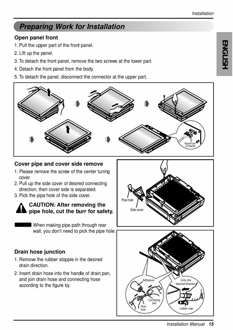
Preparing Work for Installation
Open panel front
1. Pull the upper part of the front panel.
2. Lift up the panel.
3. To detach the front panel, remove the two screws at the lower part.
4. Detach the front panel from the body.
5. To detach the panel, disconnect the connector at the upper part.
Cover pipe and cover side remove
1. Please remove the screw of the center tuningcover.2. Pull up the side cover of desired connecting
direction, then cover side is separated.3. Pick the pipe hole of the side cover.
CAUTION: After removing thepipe hole, cut the burr for safety.
When making pipe path through rear
wall, you don’t need to pick the pipe hole.
NOTICE
Drain hose junction
1. Remove the rubber stopple in the desireddrain direction.
2. Insert drain hose into the handle of drain pan,and join drain hose and connecting hoseaccording to the figure by.
Panel FrontConnector
Side cover
Pipe hole
Only thedesired direction
rubber cap
Only thedesired direction
Connectingpart
Adhesive
Drainhose
8/18/2019 2015 RAC LG
http://slidepdf.com/reader/full/2015-rac-lg 16/35
16 Room Air Conditioner
Installation
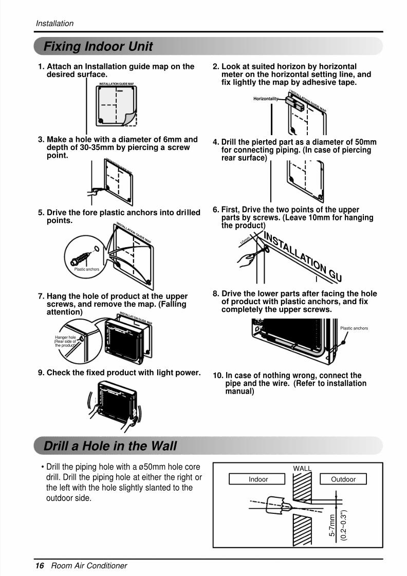
Fixing Indoor Unit
• Drill the piping hole with a ø50mm hole coredrill. Drill the piping hole at either the right orthe left with the hole slightly slanted to theoutdoor side.
Drill a Hole in the Wall
5 - 7 m m
( 0 . 2 ~ 0 . 3
" )
Indoor
WALL
Outdoor
Plastic anchors
INSTALLATION GUIDE MAP
1 0 m m
INSTALLATION GU
INSTAIIATION GUIDE MAP
Plastic anchors
INSTALLATION GUIDE MAP
INSTALLATION GUIDE MAP
Hanger hole(Rear side ofthe product)
3. Make a hole with a diameter of 6mm anddepth of 30-35mm by piercing a screwpoint.
5. Drive the fore plastic anchors into drilledpoints.
7. Hang the hole of product at the upper
screws, and remove the map. (Fallingattention)
9. Check the fixed product with light power.
1. Attach an Installation guide map on thedesired surface.
2. Look at suited horizon by horizontalmeter on the horizontal setting line, andfix lightly the map by adhesive tape.
4. Drill the pierted part as a diameter of 50mmfor connecting piping. (In case of piercingrear surface)
6. First, Drive the two points of the upperparts by screws. (Leave 10mm for hangingthe product)
8. Drive the lower parts after facing the hole
of product with plastic anchors, and fixcompletely the upper screws.
10. In case of nothing wrong, connect thepipe and the wire. (Refer to installationmanual)
Horizontality
NSTALLATION GUIDE MAP
8/18/2019 2015 RAC LG
http://slidepdf.com/reader/full/2015-rac-lg 17/35
Installation Manual 17
E N G
L I S H
Installation
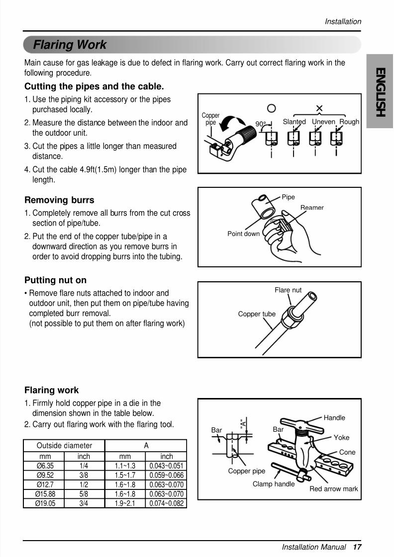
Flaring Work
Main cause for gas leakage is due to defect in flaring work. Carry out correct flaring work in thefollowing procedure.
Cutting the pipes and the cable.
1. Use the piping kit accessory or the pipespurchased locally.
2. Measure the distance between the indoor andthe outdoor unit.
3. Cut the pipes a little longer than measureddistance.
4. Cut the cable 4.9ft(1.5m) longer than the pipelength.
Removing burrs
1. Completely remove all burrs from the cut crosssection of pipe/tube.
2. Put the end of the copper tube/pipe in adownward direction as you remove burrs inorder to avoid dropping burrs into the tubing.
Putting nut on
• Remove flare nuts attached to indoor andoutdoor unit, then put them on pipe/tube havingcompleted burr removal.(not possible to put them on after flaring work)
Flaring work1. Firmly hold copper pipe in a die in the
dimension shown in the table below.
2. Carry out flaring work with the flaring tool.
Copperpipe 90° Slanted Uneven Rough
Pipe
Reamer
Point down
Flare nut
Copper tube
Bar
Copper pipe
Clamp handleRed arrow mark
Cone
Yoke
Handle
Bar " A "
mm inch mm inch
Ø6.35 1/4 1.1~1.3 0.043~0.051Ø9.52 3/8 1.5~1.7 0.059~0.066
Ø12.7 1/2 1.6~1.8 0.063~0.070Ø15.88 5/8 1.6~1.8 0.063~0.070Ø19.05 3/4 1.9~2.1 0.074~0.082
Outside diameter A
8/18/2019 2015 RAC LG
http://slidepdf.com/reader/full/2015-rac-lg 18/35
18 Room Air Conditioner
Installation
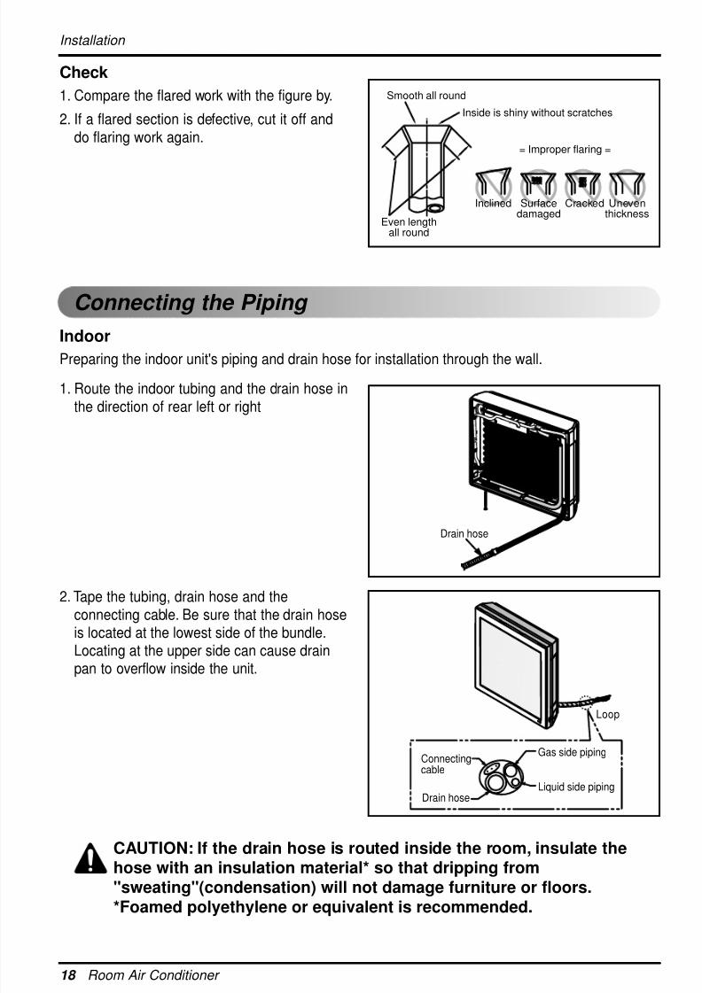
Check
1. Compare the flared work with the figure by.
2. If a flared section is defective, cut it off anddo flaring work again.
Indoor
Preparing the indoor unit's piping and drain hose for installation through the wall.
CAUTION: If the drain hose is routed inside the room, insulate the
hose with an insulation material* so that dripping from"sweating"(condensation) will not damage furniture or floors.*Foamed polyethylene or equivalent is recommended.
1. Route the indoor tubing and the drain hose inthe direction of rear left or right
2. Tape the tubing, drain hose and theconnecting cable. Be sure that the drain hoseis located at the lowest side of the bundle.Locating at the upper side can cause drainpan to overflow inside the unit.
Inclined
Inside is shiny without scratches
Smooth all round
Even lengthall round
Surfacedamaged
Cracked Uneventhickness
= Improper flaring =
Connecting the Piping
Drain hose
Connectingcable
Gas side piping
Liquid side pipingDrain hose
Loop
8/18/2019 2015 RAC LG
http://slidepdf.com/reader/full/2015-rac-lg 19/35
Installation Manual 19
E N G
L I S H
Installation
mm inch kgf.cmØ6.35 1/4 180~250Ø9.52 3/8 340~420Ø12.7 1/2 550~660
Outside diameter Torque
Wrap with vinyl tape
Drain hose
Pipe
Vinyl tape(wide)
Connecting the piping with the indoorunit and drain hose with drain pipe
1. Align the center of the pipings and sufficientlytighten the flare nut by hand.
2. Tighten the flare nut with a wrench.
3. When extending the drain hose at the indoor
unit, install the drain pipe.
Wrap the insulation material aroundthe connecting portion.
1. Overlap the connection pipe insulationmaterial and the indoor unit pipe insulationmaterial. Bind them together with vinyl tapeso that there may be no gap.
2. Wrap the area which accommodates the rearpiping housing section with vinyl tape.
3. Bundle the piping and drain hose together bywrapping them with vinyl tape over the rangewithin which they fit into the rear pipinghousing section.
Indoor unit tubing Flare nut Pipings
Torque wrench
Indoor unit tubing
Spanner (fixed)
Connection pipe
Flare nut
Vinyl tape(narrow)Adhesive
Drain pipe
Indoor unit drain hose
Plastic bandsInsulation material
Vinyl tape(narrow)
Connectionpipe
Connecting cable
Vinyl tape(wide)
Wrap with vinyl tape
Indoorunit pipe
Pipe
8/18/2019 2015 RAC LG
http://slidepdf.com/reader/full/2015-rac-lg 20/35
20 Room Air Conditioner
Installation
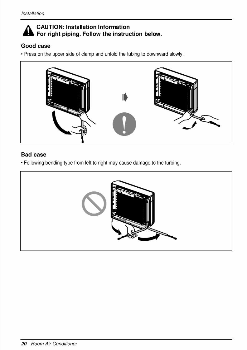
CAUTION: Installation InformationFor right piping. Follow the instruction below.
Good case
• Press on the upper side of clamp and unfold the tubing to downward slowly.
Bad case
• Following bending type from left to right may cause damage to the turbing.
8/18/2019 2015 RAC LG
http://slidepdf.com/reader/full/2015-rac-lg 21/35
Installation Manual 21
E N G
L I S H
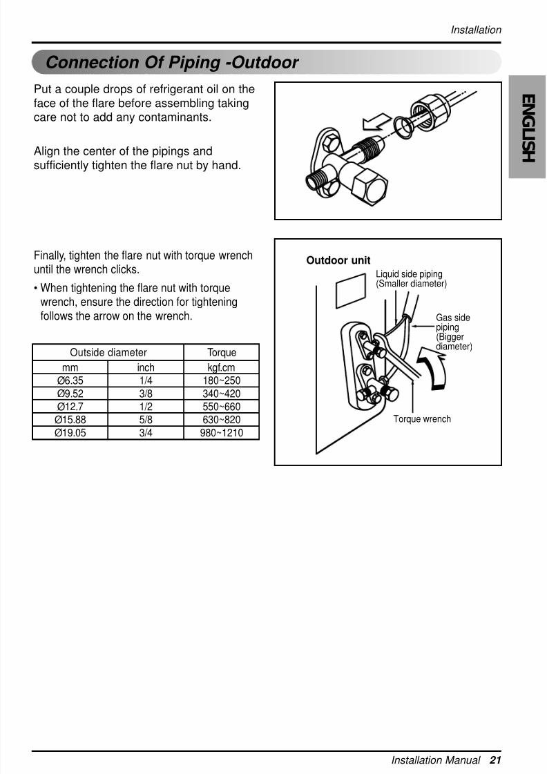
Put a couple drops of refrigerant oil on theface of the flare before assembling takingcare not to add any contaminants.
Align the center of the pipings andsufficiently tighten the flare nut by hand.
Finally, tighten the flare nut with torque wrench
until the wrench clicks.• When tightening the flare nut with torque
wrench, ensure the direction for tighteningfollows the arrow on the wrench.
mm inch kgf.cm
Ø6.35 1/4 180~250
Ø9.52 3/8 340~420
Ø12.7 1/2 550~660Ø15.88 5/8 630~820
Ø19.05 3/4 980~1210
Outside diameter Torque
Outdoor unit
Liquid side piping(Smaller diameter)
Gas sidepiping(Biggerdiameter)
Torque wrench
Installation
Connecting the Piping Connection Of Piping -Outdoor
8/18/2019 2015 RAC LG
http://slidepdf.com/reader/full/2015-rac-lg 22/35
22 Room Air Conditioner
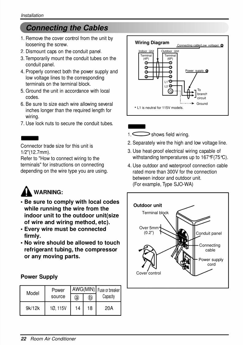
Connecting the Cables
1. Remove the cover control from the unit byloosening the screw.
2. Dismount caps on the conduit panel.
3. Temporarily mount the conduit tubes on theconduit panel.
4. Properly connect both the power supply andlow voltage lines to the correspondingterminals on the terminal block.
5. Ground the unit in accordance with localcodes.
6. Be sure to size each wire allowing severalinches longer than the required length forwiring.
7. Use lock nuts to secure the conduit tubes.
Connector trade size for this unit is1/2"(12.7mm).Refer to "How to connect wiring to theterminals" for instructions on connectingdepending on the wire type you are using.
WARNING:
• Be sure to comply with local codeswhile running the wire from theindoor unit to the outdoor unit(sizeof wire and wiring method, etc).
• Every wire must be connectedfirmly.
• No wire should be allowed to touchrefrigerant tubing, the compressoror any moving parts.
Power Supply
NOTICE
1
Indoor Unit Outdoor Unit
2
3
4
1
2
3
4
5
6
GTo
branch
circuit
Ground
Power supply a
L1*
L2
Connecting cable(Low voltage) b
Terminal(4P)
Terminal(6P)
Wiring Diagram
* L1 is neutral for 115V models.
Outdoor unit
Terminal block
Over 5mm(0.2")
Cover control
Conduit panel
Connectingcable
Power supplycord
1. shows field wiring.
2. Separately wire the high and low voltage line.
3. Use heat-proof electrical wiring capable ofwithstanding temperatures up to 167°F(75°C).
4. Use outdoor and waterproof connection cablerated more than 300V for the connectionbetween indoor and outdoor unit.(For example, Type SJO-WA)
NOTICE
Model
9k/12k 1Ø, 115V 14 18 20A
Powersource
Fuse or breakerCapacity
AWG(MIN)
Installation
8/18/2019 2015 RAC LG
http://slidepdf.com/reader/full/2015-rac-lg 23/35
Installation Manual 23
E N G
L I S H
Installation
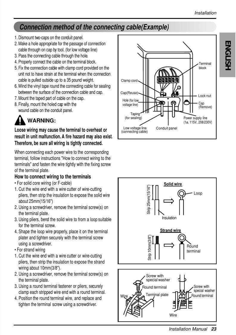
Connection method of the connecting cable(Example)
1. Dismount two-caps on the conduit panel.
2. Make a hole appropriate for the passage of connection
cable through on cap by tool. (for low voltage line)
3. Pass the connecting cable through the hole.
4. Properly connect the cable on the terminal block.
5. Fix the connection cable with clamp cord provided on the
unit not to have strain at the terminal when the connection
cable is pulled outside up to a 35 pound weight.
6. Wind the vinyl tape round the connecting cable for sealing
between the surface of the connection cable and cap.
7. Mount the taped part of cable on the cap.
8. Finally, mount the holed cap with the
wound cable on the conduit panel.
WARNING:
Loose wiring may cause the terminal to overheat or
result in unit malfunction. A fire hazard may also exist.
Therefore, be sure all wiring is tightly connected.
When connecting each power wire to the correspondingterminal, follow instructions "How to connect wiring to theterminals" and fasten the wire tightly with the fixing screwof the terminal plate.
How to connect wiring to the terminals• For solid core wiring (or F-cable)1. Cut the wire end with a wire cutter of wire-cutting
pliers, then strip the insulation to expose the solid wireabout 25mm(15/16")
2. Using a screwdriver, remove the terminal screw(s) onthe terminal plate.
3. Using pliers, bend the solid wire to from a loop suitablefor the terminal screw.
4. Shape the loop wire properly, place it on the terminalplater and tighten securely with the terminal screwusing a screwdriver.
• For strand wiring1. Cut the wire end with a wire cutter or wire-cutting
pliers, then strip the insulation to expose the strandwiring about 10mm(3/8").
2. Using a screwdriver, remove the terminal screw(s) onthe terminal plate.
3. Using a round terminal fastener or pliers, securely
clamp each stripped wire end with a round terminal.4. Position the round terminal wire, and replace and
tighten the terminal screw using a screwdriver.
G
Terminalblock
Cap(Remove)
Clamp cord
Lock nut
Conduit panel
Cap(Reuse)
Taping
(for sealing)
Low voltage line(connecting cable)
Power supply line(1ø, 115V, 208/230V)
Hole (for lowvoltage line)
Loop
Roundterminal
Insulation
S t r i p 2 5 m m ( 1 5 / 1 6 " )
S t r i p 1 0 m m ( 3 / 8 " )
Solid wire
Strand wire
Screw withspecial washer
Screw withspecial washer
Round terminal
Terminal plateWire
Wire
Round terminal
8/18/2019 2015 RAC LG
http://slidepdf.com/reader/full/2015-rac-lg 24/35
24 Room Air Conditioner
After the confirmation of the above conditions, prepare the wiring as follows:
1) Never fail to have an individual power circuit specifically for the air conditioner. As forthe method of wiring, be guided by the circuit diagram posted on the inside of controlcover.
2) The screw which fasten the wiring in the casing of electrical fittings are liable tocome loose from vibrations to which the unit is subjected during the course oftransportation. Check them and make sure that they are all tightly fastened. (If theyare loose, it could cause burn-out of the wires.)
3) Specification of power source.
4) Confirm that electrical capacity is sufficient.
5) Confirm that the starting voltage is maintained at more than 90 percent of the ratedvoltage marked on the name plate.
6) Confirm that the cable thickness is as specified in the power source specification.(Particularly note the relation between cable length and thickness.
7) Always install an GFCI circuit breaker in a wet or moist area.
8) The following would be caused by voltage drop.
• Vibration of a magnetic switch, which will damage the contact point, open fuse, disturbance of thenormal function of the overload.
9) The means for disconnection from a power supply shall be incorporated in the fixed
wiring and have an air gap contact separation of at least 3mm(0.12in) in each
active(phase) conductors.
CAUTION
Installation
8/18/2019 2015 RAC LG
http://slidepdf.com/reader/full/2015-rac-lg 25/35
Installation Manual 25
E N G
L I S H
Installation
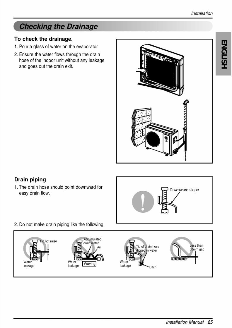
Checking the Drainage
To check the drainage.
1. Pour a glass of water on the evaporator.
2. Ensure the water flows through the drainhose of the indoor unit without any leakageand goes out the drain exit.
Drain piping
1. The drain hose should point downward foreasy drain flow.
2. Do not make drain piping like the following.
Downward slope
Do not raiseAccumulateddrain water
Tip of drain hosedipped in water
Air
WavingWaterleakage
Waterleakage Ditch
Less than50mm gap
Waterleakage
8/18/2019 2015 RAC LG
http://slidepdf.com/reader/full/2015-rac-lg 26/35
26 Room Air Conditioner
Installation
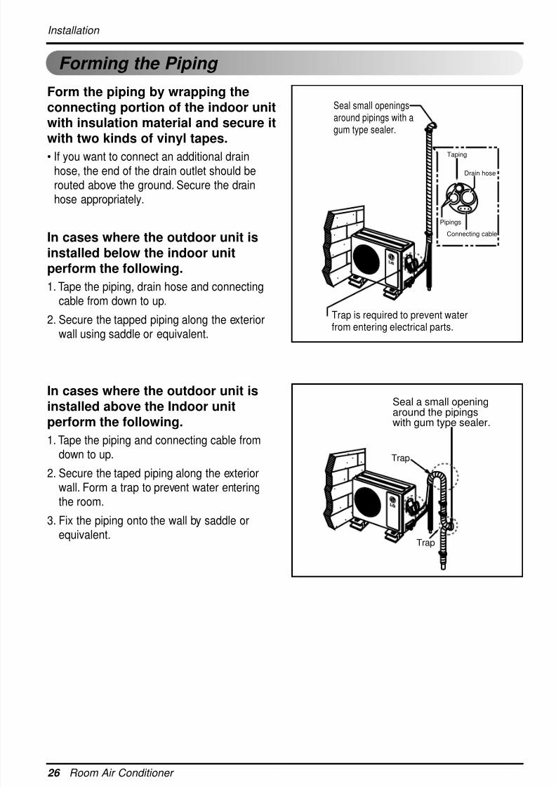
Forming the Piping
Form the piping by wrapping theconnecting portion of the indoor unitwith insulation material and secure it
with two kinds of vinyl tapes.• If you want to connect an additional drain
hose, the end of the drain outlet should berouted above the ground. Secure the drainhose appropriately.
In cases where the outdoor unit isinstalled below the indoor unitperform the following.
1. Tape the piping, drain hose and connectingcable from down to up.
2. Secure the tapped piping along the exteriorwall using saddle or equivalent.
In cases where the outdoor unit isinstalled above the Indoor unitperform the following.
1. Tape the piping and connecting cable fromdown to up.
2. Secure the taped piping along the exteriorwall. Form a trap to prevent water enteringthe room.
3. Fix the piping onto the wall by saddle orequivalent.
Taping
Drain hose
Pipings
Connecting cable
Trap is required to prevent waterfrom entering electrical parts.
Seal small openingsaround pipings with agum type sealer.
Seal a small opening
around the pipingswith gum type sealer.
Trap
Trap
8/18/2019 2015 RAC LG
http://slidepdf.com/reader/full/2015-rac-lg 27/35
Installation Manual 27
E N G
L I S H
Installation
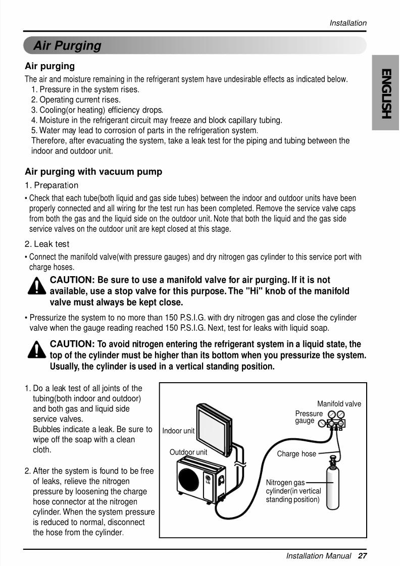
Air Purging
Air purging
The air and moisture remaining in the refrigerant system have undesirable effects as indicated below.1. Pressure in the system rises.
2. Operating current rises.3. Cooling(or heating) efficiency drops.4. Moisture in the refrigerant circuit may freeze and block capillary tubing.5. Water may lead to corrosion of parts in the refrigeration system.Therefore, after evacuating the system, take a leak test for the piping and tubing between theindoor and outdoor unit.
Air purging with vacuum pump
1. Preparation
• Check that each tube(both liquid and gas side tubes) between the indoor and outdoor units have beenproperly connected and all wiring for the test run has been completed. Remove the service valve capsfrom both the gas and the liquid side on the outdoor unit. Note that both the liquid and the gas sideservice valves on the outdoor unit are kept closed at this stage.
2. Leak test
• Connect the manifold valve(with pressure gauges) and dry nitrogen gas cylinder to this service port withcharge hoses.
CAUTION: Be sure to use a manifold valve for air purging. If it is notavailable, use a stop valve for this purpose. The "Hi" knob of the manifoldvalve must always be kept close.
• Pressurize the system to no more than 150 P.S.I.G. with dry nitrogen gas and close the cylindervalve when the gauge reading reached 150 P.S.I.G. Next, test for leaks with liquid soap.
CAUTION: To avoid nitrogen entering the refrigerant system in a liquid state, thetop of the cylinder must be higher than its bottom when you pressurize the system.
Usually, the cylinder is used in a vertical standing position.
1. Do a leak test of all joints of the
tubing(both indoor and outdoor)and both gas and liquid sideservice valves.Bubbles indicate a leak. Be sure towipe off the soap with a cleancloth.
2. After the system is found to be freeof leaks, relieve the nitrogen
pressure by loosening the chargehose connector at the nitrogencylinder. When the system pressureis reduced to normal, disconnectthe hose from the cylinder.
Lo Hi
Indoor unit
Outdoor unit
Manifold valve
Charge hose
Nitrogen gascylinder(in verticalstanding position)
Pressuregauge
8/18/2019 2015 RAC LG
http://slidepdf.com/reader/full/2015-rac-lg 28/35
28 Room Air Conditioner
Installation
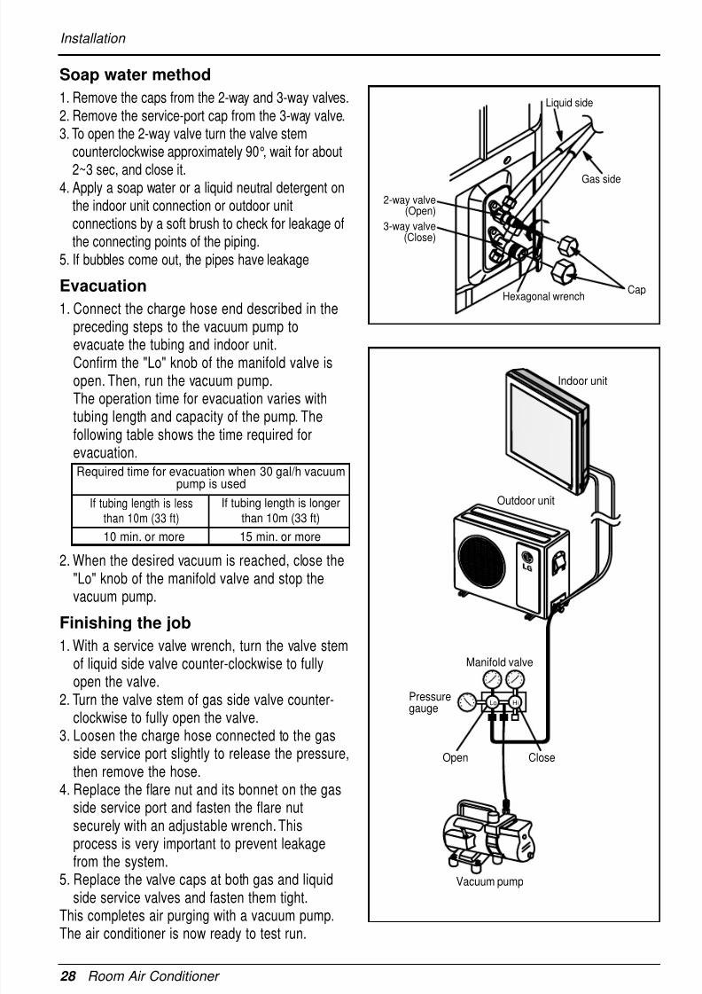
Soap water method
1. Remove the caps from the 2-way and 3-way valves.2. Remove the service-port cap from the 3-way valve.3. To open the 2-way valve turn the valve stem
counterclockwise approximately 90°, wait for about
2~3 sec, and close it.4. Apply a soap water or a liquid neutral detergent on
the indoor unit connection or outdoor unitconnections by a soft brush to check for leakage ofthe connecting points of the piping.
5. If bubbles come out, the pipes have leakage
Evacuation
1. Connect the charge hose end described in thepreceding steps to the vacuum pump to
evacuate the tubing and indoor unit.Confirm the "Lo" knob of the manifold valve isopen. Then, run the vacuum pump.The operation time for evacuation varies withtubing length and capacity of the pump. Thefollowing table shows the time required forevacuation.
2. When the desired vacuum is reached, close the"Lo" knob of the manifold valve and stop thevacuum pump.
Finishing the job
1. With a service valve wrench, turn the valve stemof liquid side valve counter-clockwise to fullyopen the valve.
2. Turn the valve stem of gas side valve counter-clockwise to fully open the valve.
3. Loosen the charge hose connected to the gasside service port slightly to release the pressure,then remove the hose.
4. Replace the flare nut and its bonnet on the gasside service port and fasten the flare nutsecurely with an adjustable wrench. Thisprocess is very important to prevent leakagefrom the system.
5. Replace the valve caps at both gas and liquidside service valves and fasten them tight.
This completes air purging with a vacuum pump.The air conditioner is now ready to test run.
Gas side
Liquid side
CapHexagonal wrench
2-way valve(Open)
3-way valve(Close)
Required time for evacuation when 30 gal/h vacuumpump is used
10 min. or more 15 min. or more
If tubing length is less
than 10m (33 ft)
If tubing length is longer
than 10m (33 ft)
Indoor unit
Outdoor unit
Lo Hi
Manifold valve
Vacuum pump
Pressuregauge
Open Close
8/18/2019 2015 RAC LG
http://slidepdf.com/reader/full/2015-rac-lg 29/35
Installation
Installation Manual 29
E N G
L I S H
Charging
Each outdoor unit is factory charged (nameplate charge) for the evaporator as well as a 7.5m(25ft) lineset. Any time a line set is used either shorter or longer then the nominal 7.5m(25ft) line set length therefrigerant charge has to be adjusted.
Whether the line set is made shorter or longer you must adjust the charge based on how many ft of tubingare either added or removed based on 20g(0.22oz) of R-410A per meter(foot).
Example: A 30ft line set is used
5 additional ft X 0.22 ounce per foot= add 1.1 ounces of R-410A
Important: If you are ever uncertain of the unit charge, reclaim, evacuate and weigh in the correct charge using the unitnameplate charge adjusting for line sets longer or shorter than 7.5m(25ft).
Confirm the refrigerant R-410A. Use manifold gauge and hose for R-410A.
Pipe SizeCapacity(Btu/h) Suction Evap
Max.lengthA m(ft)
AdditionalRefrigerantg/m(oz/ft)
Max.ElevationB m(ft)
StandardLengthm(ft)
9k, 12k Ø12.7mm(1/2") Ø6.35mm(1/4") 7.5(25) 7.5(25) 15(49) 20(0.22)
8/18/2019 2015 RAC LG
http://slidepdf.com/reader/full/2015-rac-lg 30/35
30 Room Air Conditioner
Installation
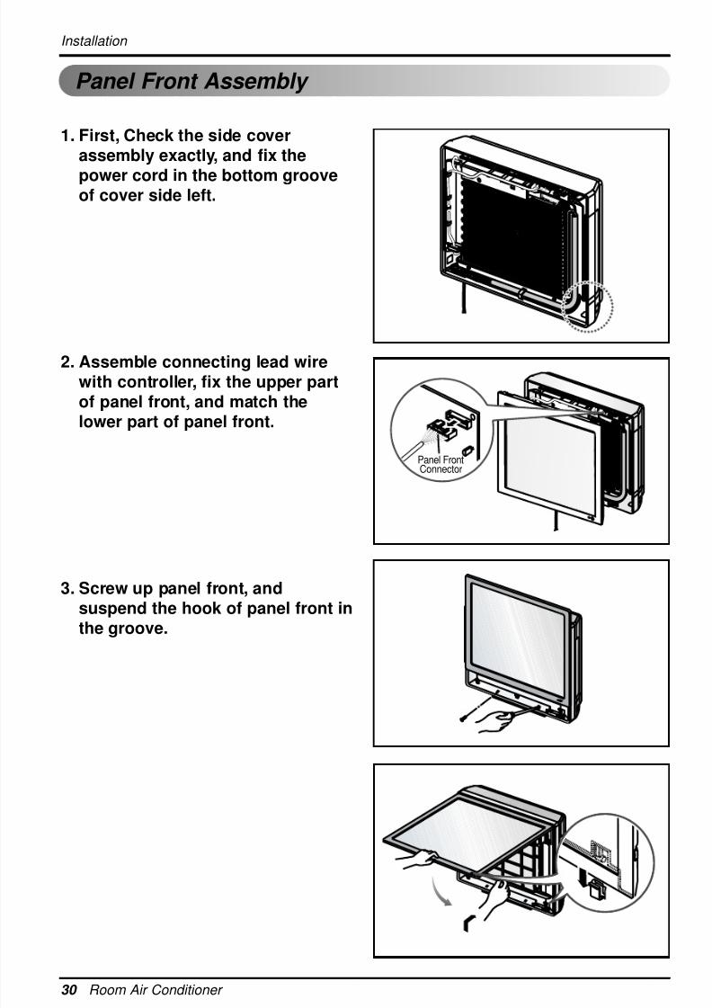
1. First, Check the side coverassembly exactly, and fix the
power cord in the bottom grooveof cover side left.
2. Assemble connecting lead wirewith controller, fix the upper partof panel front, and match thelower part of panel front.
3. Screw up panel front, andsuspend the hook of panel front inthe groove.
Panel FrontConnector
Panel Front Assembly
8/18/2019 2015 RAC LG
http://slidepdf.com/reader/full/2015-rac-lg 31/35
Installation Manual 31
E N G
L I S H
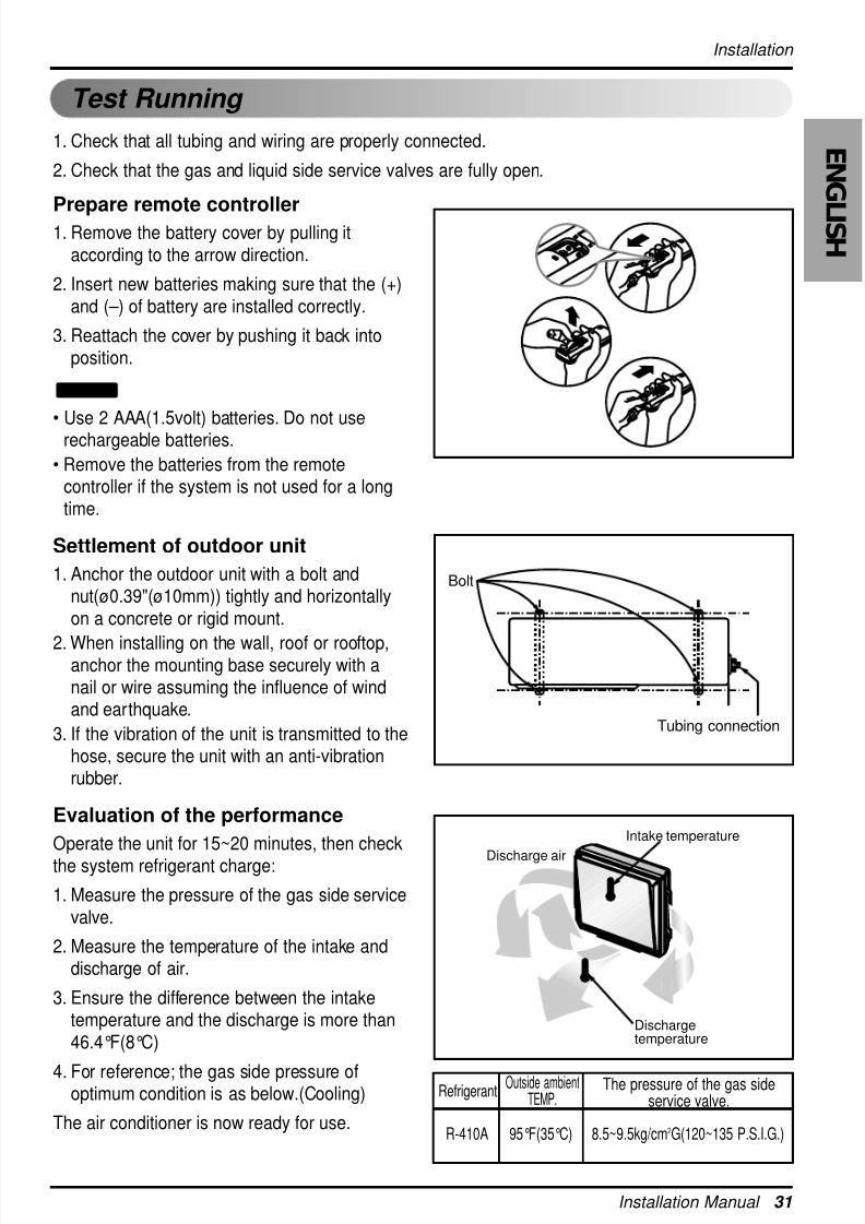
Installation
R-410A 95°F(35°C) 8.5~9.5kg/cm2G(120~135 P.S.I.G.)
Outside ambientTEMP.
Refrigerant The pressure of the gas sideservice valve.
1. Check that all tubing and wiring are properly connected.
2. Check that the gas and liquid side service valves are fully open.
Prepare remote controller1. Remove the battery cover by pulling it
according to the arrow direction.
2. Insert new batteries making sure that the (+)and ( – ) of battery are installed correctly.
3. Reattach the cover by pushing it back intoposition.
• Use 2 AAA(1.5volt) batteries. Do not userechargeable batteries.
• Remove the batteries from the remotecontroller if the system is not used for a longtime.
Settlement of outdoor unit
1. Anchor the outdoor unit with a bolt andnut(ø0.39"(ø10mm)) tightly and horizontallyon a concrete or rigid mount.
2. When installing on the wall, roof or rooftop,anchor the mounting base securely with anail or wire assuming the influence of windand earthquake.
3. If the vibration of the unit is transmitted to thehose, secure the unit with an anti-vibrationrubber.
Evaluation of the performance
Operate the unit for 15~20 minutes, then checkthe system refrigerant charge:
1. Measure the pressure of the gas side servicevalve.
2. Measure the temperature of the intake anddischarge of air.
3. Ensure the difference between the intaketemperature and the discharge is more than46.4°F(8°C)
4. For reference; the gas side pressure ofoptimum condition is as below.(Cooling)
The air conditioner is now ready for use.
NOTICE
Bolt
Tubing connection
Dischargetemperature
Discharge air
Intake temperature
Test Running
8/18/2019 2015 RAC LG
http://slidepdf.com/reader/full/2015-rac-lg 32/35
32 Room Air Conditioner
Installation
If the actual pressure is higher than shown, the system is most likely over-charged, andcharge should be removed. If the actual pressure are lower than shown, the system ismost likely undercharged, and charge should be added.
NOTICE
PUMP DOWN
This is performed when the unit is relocated or the refrigerant circuit is serviced.
Pump Down means collecting all refrigerant into the outdoor unit without the loss of refrigerant.
CAUTION: Be sure to perform Pump Down procedure in the coolingmode.
Pump Down Procedure
1. Connect a low-pressure gauge manifold hose to the charge port on the gas side service valve.
2. Open the gas side service valve halfway and purge the air in the manifold hose using therefrigerant.
3. Close the liquid side service valve(all the way).
4. Turn on the unit's operating switch and start the cooling operation.
5. When the low-pressure gauge reading becomes 1 to 0.5kg/cm2 G(14.2 to 7.1 P.S.I.G.), fully close
the gas side valve and then quickly turn off the unit. Now Pump Down procedure is completed,and all refrigerant is collected into the outdoor unit.
8/18/2019 2015 RAC LG
http://slidepdf.com/reader/full/2015-rac-lg 33/35
Installation Manual 33
E N G
L I S H
Installation guide at the seaside
1. Air conditioners should not be installed in areas where corrosive gases, such as acid or alkaline gas, are produced.2. Do not install the product where it could be exposed to sea wind (salty wind) directly. It can result corrosionon the product. Corrosion, particularly on the condenser and evaporator fins, could cause product malfunc-tion or inefficient performance.
3. If outdoor unit is installed close to the seaside, it should avoid direct exposure to the sea wind. Otherwise itneeds additional anticorrosion treatment on the heat exchanger.
1. If you can’t meet above guide line in the seaside installation, please contact LG Electronics for the additional anticorrosion treatment.
2. Periodic ( more than once/year ) cleaning of the dust or salt particles stuck on the heat exchanger by using water
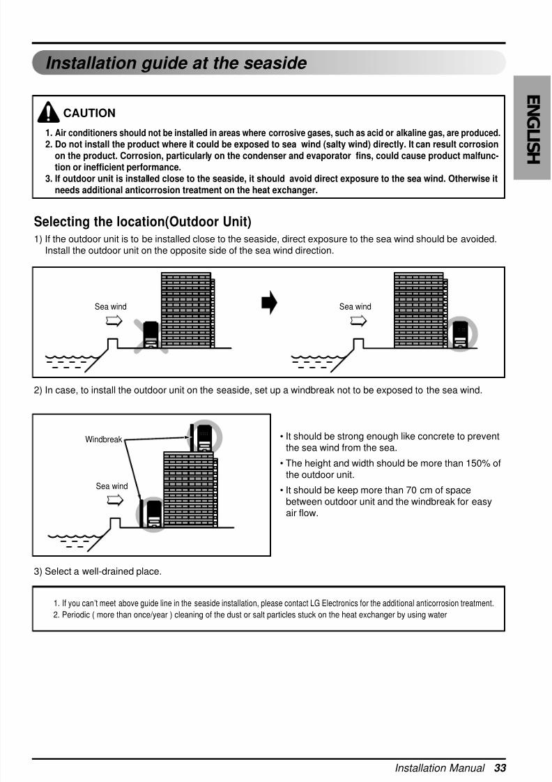
Selecting the location(Outdoor Unit)1) If the outdoor unit is to be installed close to the seaside, direct exposure to the sea wind should be avoided.
Install the outdoor unit on the opposite side of the sea wind direction.
2) In case, to install the outdoor unit on the seaside, set up a windbreak not to be exposed to the sea wind.
3) Select a well-drained place.
• It should be strong enough like concrete to preventthe sea wind from the sea.
• The height and width should be more than 150% ofthe outdoor unit.
• It should be keep more than 70 cm of spacebetween outdoor unit and the windbreak for easyair flow.
Sea wind Sea wind
Sea wind
Windbreak
CAUTION

8/18/2019 2015 RAC LG
http://slidepdf.com/reader/full/2015-rac-lg 34/35
34 Room Air Conditioner
Memo

8/18/2019 2015 RAC LG
http://slidepdf.com/reader/full/2015-rac-lg 35/35