18094043 LTE Protocol Overview
21
Document Number: LTEPTCLOVWWP Rev 0 10/2008 White Paper Long Term Evolution Protocol Overview
-
Upload
jordi-j-gimenez -
Category
Documents
-
view
222 -
download
0
Transcript of 18094043 LTE Protocol Overview
8/6/2019 18094043 LTE Protocol Overview
http://slidepdf.com/reader/full/18094043-lte-protocol-overview 1/21
Document Number: LTEPTCLOVWWPRev 010/2008
White Paper
Long Term Evolution ProtocolOverview
8/6/2019 18094043 LTE Protocol Overview
http://slidepdf.com/reader/full/18094043-lte-protocol-overview 2/21
OverviewLong term evolution (LTE) is the next step forward in cellular 3G services. LTE technology is a based on a 3GPPstandard that provides for a downlink speed of up to 150 megabits per second (Mbps) and an uplink speed of up to 50Mbps. Fixed wireless and wired standards are already approaching or achieving 100 Mbps or faster, and LTE is a wayfor cellular communications to operate at that high data rate.
This paper provides an introduction to how the LTE protocol stack operates. Because the final 3GPP specification willcover tens of thousands of pages, this paper touches only on the highest levels of protocol operation. The paper discusses the history and application requirements that determine the functions and priorities of LTE, examines theprotocol stack in terms of the time domain and in terms of information moving through the stack, and finally discussesmore specialized aspects of the standard such as scheduling and quality of service, management and control functions,handovers and power save operation.
Contents1 Introduction 1
1.1 Protocol Design 1
1.2 History and Scope of 3GPP Standards 1
2 LTE Architecture 2
2.1 How the MAC Sees the PHY 2
2.2 Frames and Packet Timelines:LTE Downlink 3
3 Life of an LTE Packet 4 3.1 Life of an LTE Packet: Downlink 4
3.1.1 MAC Layer 4
3.1.2 Hybrid ARQ 4
3.1.3 MAC Channels 5
3.1.4 MAC Downlink Mapping 5
3.1.5 MAC Format Selection andMeasurements 6
3.1.6 RLC Layer 6
3.1.7 PDCP Layer 7 3.2 Life of an LTE Packet: Uplink 8
3.2.1 PDCP Layer 9
3.2.2 RLC Layer 9
3.2.3 MAC Layer 9
3.3 Life of a Packet: Conclusion 11
4 LTE Protocol Operation 12
4.1 Scheduling 12
4.1.1 Downlink Scheduling 12
4.1.2 Downlink Schedulingwith HARQ 13
4.1.3 Uplink Schedulingwith HARQ 14
4.2 QoS Architecture 15
4.3 Management and Control Functions 15
4.4 Handover and Roaming 16
4.4.1 Handover Measurement 16
4.4.2 Handover: Neighbor Lists 17
4.5 Power Save Operation 17
4.5.1 DRX and DTX 17
4.5.2 Long and Short DRX 17
5 Conclusion 18
8/6/2019 18094043 LTE Protocol Overview
http://slidepdf.com/reader/full/18094043-lte-protocol-overview 3/21
Freescale Semiconductor, Inc. Long Term Evolution Protocol Overview 1
1 IntroductionLong Term Evolution (LTE) is important because it will bring up to a 50x performance improvement and much better spectral efficiency to cellular networks. LTE is different from other technologies that call themselves 4G because it iscompletely integrated into the existing cellular infrastructure for 2G and 3G. This allows seamless handoff and completeconnectivity between previous standards and LTE. LTE is in trials now and should see commercial deployment by2010.
This paper provides an overview of the MAC for 3GPP™ Long Term Evolution (LTE) also referred to as E-UTRAN, witha focus on the handset or User Equipment (UE). The protocol stack functions consist of the Medium Access Control(MAC), Radio Link Control (RLC), Packet Data Convergence Protocol (PDCP), and Radio Resource Control (RRC).
LTE is the latest generation of the 3GPP standards. The LTE standard specifies an IP-only network supporting datarates up to 150 Mbps. These high data rates will enables new applications and services such as voice over IP,streaming multimedia, videoconferencing or even a high-speed cellular modem.
1.1 Protocol DesignThe LTE standard grew out of the Global System for Mobile Communications (GSM) and Universal MobileTelecommunications System (UMTS) standards, commonly called 3G. Voice communication was primary application,
with data added recently. Mobility and seamless handoff were requirements from the start, as was a requirement for central management of all nodes.
LTE speeds will be equivalent to what today’s user might see at home on a fast cable modem. The LTE standard isdesigned to enable 150 Mbps downlink and 50 Mbps uplink over a wide area. While 150 Mbps is LTE’s theoretical topuplink speed, each user’s bandwidth will depend on how carriers deploy their network and available bandwidth.Supporting high rates while minimizing power is a key design challenge.
The LTE physical layer is unique because it has asymmetrical modulation and data rates for uplink and downlink. Thestandard is designed for full-duplex operation, with simultaneous transmission and reception. The radio is optimized for performance on the downlink, because the transmitter at the base station has plenty of power. On the uplink, the radiois optimized more for power consumption than efficiency, because while processing power has increased, mobiledevice battery power has stayed essentially constant.
1.2 History and Scope of 3GPP StandardsThe standardization process for LTE comes out of the Third Generation Partnership Project (3GPP), which wasdeveloped out of GSM cellular standards. Work on LTE has been going on since 2004, building on the GSM/UMTSfamily of standards that dates from 1990. Stage 2 of the standard, the functional descriptions, was completed in 2007.The standards bodies are currently finalizing Stage 3, which is the detailed specifications. Stage 3 is expected to becompleted by the end of 2008.
The LTE standard was designed as a completely new standard, with new numbering and new documents—it does notbuild on the previous series of UMTS standards. Earlier elements were only brought in if there was a compelling reasonfor them to exist in the new standard. There is no requirement for backward compatibility or error interoperability, for example, because LTE will operate in different spectrum using a different physical layer and different coding. However,The architecture may often appear similar because the standards were created by similar standards bodies.
The entire LTE system is specified by a large number of 3GPP working groups which oversee everything from the air interface to the protocol stack and the infrastructure network. This paper focuses on protocols specified by RAN2, a3GPP Radio Area Network working group 1. LTE is a departure from historical cellular and telecom operations, whichwere circuit switched. LTE is the first GSM/3GPP standard that is fully IP and packet-based. Much of the complexity of UMTS that deals with circuit switching is not carried into LTE; this has allowed some simplifications and optimizations of
1 For more information about RAN2, visit the 3GPP RAN2 web pages at http://www.3gpp.org/tb/ran/RAN2/RAN2.htm .
8/6/2019 18094043 LTE Protocol Overview
http://slidepdf.com/reader/full/18094043-lte-protocol-overview 4/21
2 Long Term Evolution Protocol Overview Freescale Semiconductor
the architecture. LTE provides a packet switched model at the SAP, but retains a circuit switched model at the PHY.The physical layer itself maintains the continuous connection model, especially on the downlink, where there iscontinuous transmission.
2 LTE Architecture
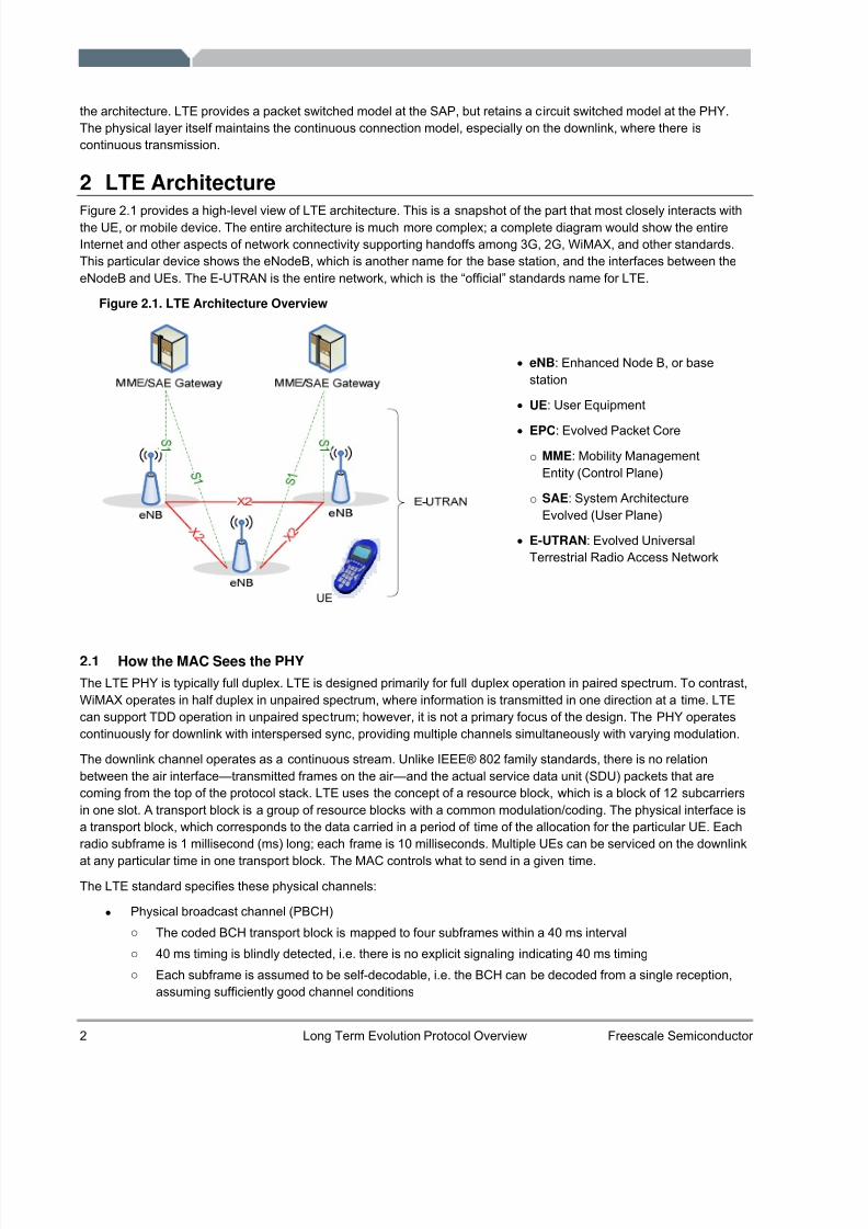
Figure 2.1 provides a high-level view of LTE architecture. This is a snapshot of the part that most closely interacts withthe UE, or mobile device. The entire architecture is much more complex; a complete diagram would show the entireInternet and other aspects of network connectivity supporting handoffs among 3G, 2G, WiMAX, and other standards.This particular device shows the eNodeB, which is another name for the base station, and the interfaces between theeNodeB and UEs. The E-UTRAN is the entire network, which is the “official” standards name for LTE.
Figure 2.1. LTE Architecture Overview
UE
2.1 How the MAC Sees the PHYThe LTE PHY is typically full duplex. LTE is designed primarily for full duplex operation in paired spectrum. To contrast,WiMAX operates in half duplex in unpaired spectrum, where information is transmitted in one direction at a time. LTEcan support TDD operation in unpaired spectrum; however, it is not a primary focus of the design. The PHY operatescontinuously for downlink with interspersed sync, providing multiple channels simultaneously with varying modulation.
The downlink channel operates as a continuous stream. Unlike IEEE® 802 family standards, there is no relationbetween the air interface—transmitted frames on the air—and the actual service data unit (SDU) packets that arecoming from the top of the protocol stack. LTE uses the concept of a resource block, which is a block of 12 subcarriersin one slot. A transport block is a group of resource blocks with a common modulation/coding. The physical interface isa transport block, which corresponds to the data carried in a period of time of the allocation for the particular UE. Eachradio subframe is 1 millisecond (ms) long; each frame is 10 milliseconds. Multiple UEs can be serviced on the downlink
at any particular time in one transport block. The MAC controls what to send in a given time.
The LTE standard specifies these physical channels:
• Physical broadcast channel (PBCH)o The coded BCH transport block is mapped to four subframes within a 40 ms intervalo 40 ms timing is blindly detected, i.e. there is no explicit signaling indicating 40 ms timingo Each subframe is assumed to be self-decodable, i.e. the BCH can be decoded from a single reception,
assuming sufficiently good channel conditions
• eNB : Enhanced Node B, or basestation
• UE : User Equipment
• EPC : Evolved Packet Coreo MME: Mobility Management
Entity (Control Plane)
o SAE : System ArchitectureEvolved (User Plane)
• E-UTRAN : Evolved UniversalTerrestrial Radio Access Network
8/6/2019 18094043 LTE Protocol Overview
http://slidepdf.com/reader/full/18094043-lte-protocol-overview 5/21
Freescale Semiconductor, Inc. Long Term Evolution Protocol Overview 3
• Physical control format indicator channel (PCFICH)o Informs the UE about the number of OFDM symbols used for the PDCCHso Transmitted in every subframe
• Physical downlink control channel (PDCCH)o Informs the UE about the resource allocation of PCH and DL-SCH, and Hybrid ARQ information related to
DL-SCHo Carries the uplink scheduling grant
• Physical Hybrid ARQ Indicator Channel (PHICH): Carries Hybrid ARQ ACK/NAKs in response to uplinktransmissions.
• Physical downlink shared channel (PDSCH): Carries the DL-SCH and PCH• Physical multicast channel (PMCH): Carries the MCH• Physical uplink control channel (PUCCH)
o Carries Hybrid ARQ ACK/NAKs in response to downlink transmissiono Carries Scheduling Request (SR)o Carries CQI reports
• Physical uplink shared channel (PUSCH): Carries the UL-SCH• Physical random access channel (PRACH): Carries the random access preamble
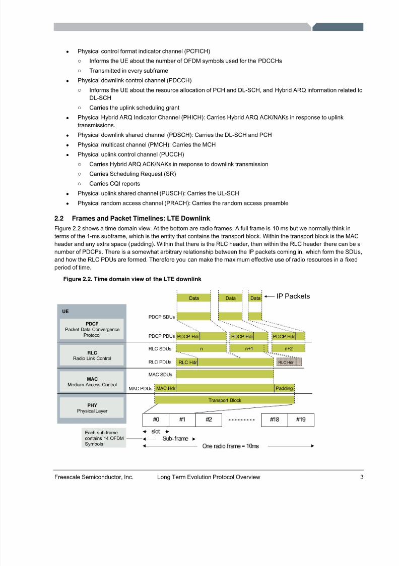
2.2 Frames and Packet Timelines: LTE DownlinkFigure 2.2 shows a time domain view. At the bottom are radio frames. A full frame is 10 ms but we normally think interms of the 1-ms subframe, which is the entity that contains the transport block. Within the transport block is the MACheader and any extra space (padding). Within that there is the RLC header, then within the RLC header there can be anumber of PDCPs. There is a somewhat arbitrary relationship between the IP packets coming in, which form the SDUs,and how the RLC PDUs are formed. Therefore you can make the maximum effective use of radio resources in a fixedperiod of time.
Figure 2.2. Time domain view of the LTE downlink
Each sub-framecontains 14 OFDMSymbols
PDCPPacket Data Convergence
Protocol
RLCRadio Link Control
MACMedium Access Control
PHYPhysical Layer
UEPDCP SDUs
RLC SDUs
MAC SDUs
PDCP PDUs
RLC PDUs
MAC PDUs
Data
PDCP Hdr
RLC Hdr
n
Data
PDCP Hdr PDCP Hdr
n+1 n+2
Data
RLC Hdr
Transport Block
Padding
IP Packets
MAC Hdr
8/6/2019 18094043 LTE Protocol Overview
http://slidepdf.com/reader/full/18094043-lte-protocol-overview 6/21
4 Long Term Evolution Protocol Overview Freescale Semiconductor
3 Life of an LTE PacketThis section traces the flow of a packet through the sub-layers of the LTE stack. The downlink direction (from networkto terminal) is covered first. An uplink packet is then described, highlighting any differences.
3.1 Life of an LTE Packet: Downlink
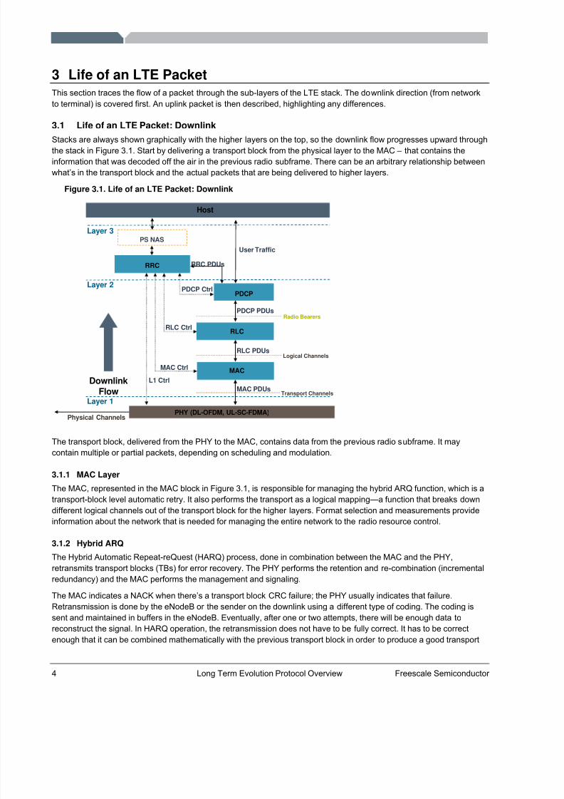
Stacks are always shown graphically with the higher layers on the top, so the downlink flow progresses upward throughthe stack in Figure 3.1. Start by delivering a transport block from the physical layer to the MAC – that contains theinformation that was decoded off the air in the previous radio subframe. There can be an arbitrary relationship betweenwhat’s in the transport block and the actual packets that are being delivered to higher layers.
Figure 3.1. Life of an LTE Packet: Downlink
RLC
RRC
MAC
PHY (DL-OFDM, UL-SC-FDMA)
Layer 1
Layer 3
PDCP
MAC PDUs
RLC PDUs
MAC Ctrl
L1 Ctrl
Layer 2
PDCP PDUs
RRC PDUs
Physical Channels
Host
PS NAS
RLC Ctrl
User Traffic
Radio Bearers
Logical Channels
Transport Channels
DownlinkFlow
PDCP Ctrl
The transport block, delivered from the PHY to the MAC, contains data from the previous radio subframe. It maycontain multiple or partial packets, depending on scheduling and modulation.
3.1.1 MAC Layer
The MAC, represented in the MAC block in Figure 3.1, is responsible for managing the hybrid ARQ function, which is atransport-block level automatic retry. It also performs the transport as a logical mapping—a function that breaks downdifferent logical channels out of the transport block for the higher layers. Format selection and measurements provideinformation about the network that is needed for managing the entire network to the radio resource control.
3.1.2 Hybrid ARQ
The Hybrid Automatic Repeat-reQuest (HARQ) process, done in combination between the MAC and the PHY,retransmits transport blocks (TBs) for error recovery. The PHY performs the retention and re-combination (incrementalredundancy) and the MAC performs the management and signaling.
The MAC indicates a NACK when there’s a transport block CRC failure; the PHY usually indicates that failure.Retransmission is done by the eNodeB or the sender on the downlink using a different type of coding. The coding issent and maintained in buffers in the eNodeB. Eventually, after one or two attempts, there will be enough data toreconstruct the signal. In HARQ operation, the retransmission does not have to be fully correct. It has to be correctenough that it can be combined mathematically with the previous transport block in order to produce a good transport
8/6/2019 18094043 LTE Protocol Overview
http://slidepdf.com/reader/full/18094043-lte-protocol-overview 7/21
Freescale Semiconductor, Inc. Long Term Evolution Protocol Overview 5
block. This is the most efficient way of providing this ARQ function. It does operate at the transport block level, there isanother ARQ process mechanism operating at the RLC.
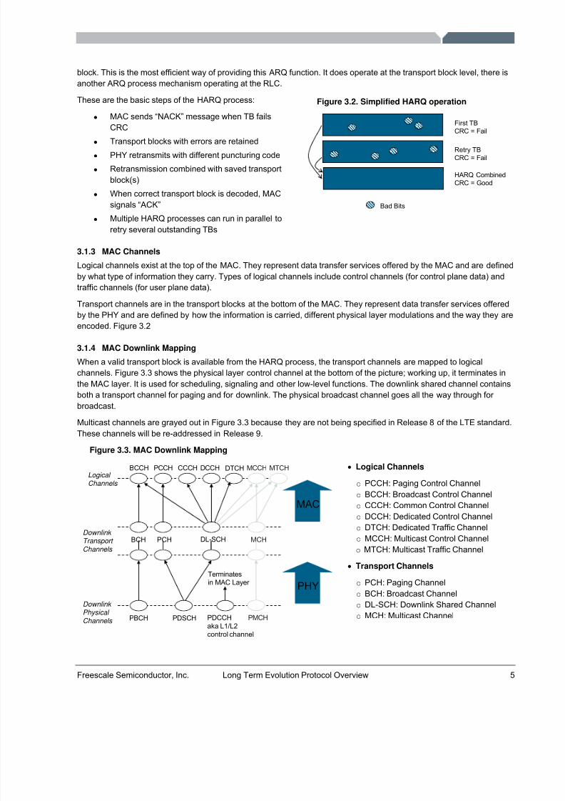
These are the basic steps of the HARQ process:
• MAC sends “NACK” message when TB failsCRC
• Transport blocks with errors are retained• PHY retransmits with different puncturing code• Retransmission combined with saved transport
block(s)• When correct transport block is decoded, MAC
signals “ACK”• Multiple HARQ processes can run in parallel to
retry several outstanding TBs
3.1.3 MAC Channels
Logical channels exist at the top of the MAC. They represent data transfer services offered by the MAC and are defined
by what type of information they carry. Types of logical channels include control channels (for control plane data) andtraffic channels (for user plane data).
Transport channels are in the transport blocks at the bottom of the MAC. They represent data transfer services offeredby the PHY and are defined by how the information is carried, different physical layer modulations and the way they areencoded. Figure 3.2
3.1.4 MAC Downlink Mapping
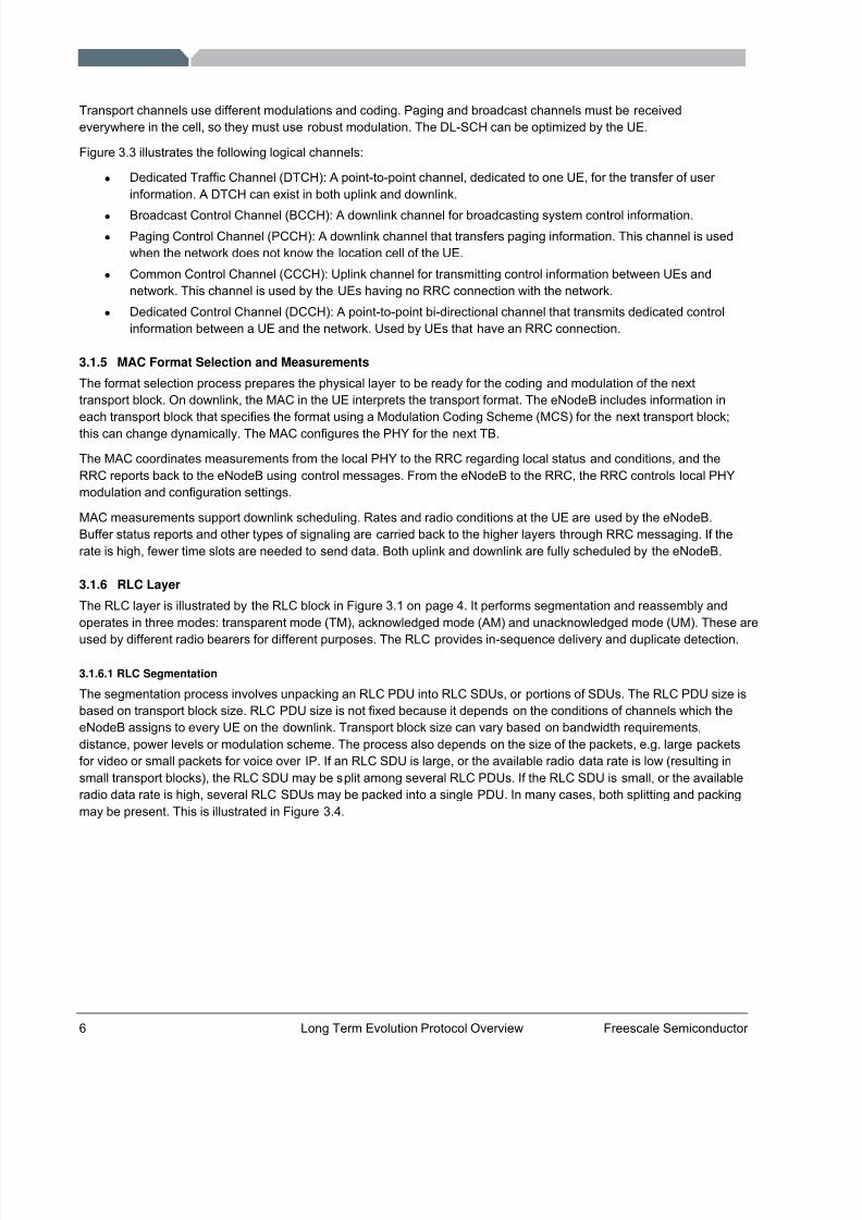
When a valid transport block is available from the HARQ process, the transport channels are mapped to logicalchannels. Figure 3.3 shows the physical layer control channel at the bottom of the picture; working up, it terminates inthe MAC layer. It is used for scheduling, signaling and other low-level functions. The downlink shared channel containsboth a transport channel for paging and for downlink. The physical broadcast channel goes all the way through for broadcast.
Multicast channels are grayed out in Figure 3.3 because they are not being specified in Release 8 of the LTE standard.These channels will be re-addressed in Release 9.
Figure 3.3. MAC Downlink Mapping
PHY
MAC
PCCHBCCH CCCH DCCH DTCH MCCH
PCHBCH DL-SCH MCH
PBCH PDSCH PDCCHaka L1/L2control channel
Logical Channels
Downlink Transport Channels
Downlink Physical Channels
Terminatesin MAC Layer
PMCH
MTCH
Figure 3.2. Simplified HARQ operation
Bad Bits
First TBCRC = Fail
Retry TBCRC = Fail
HARQ CombinedCRC = Good
• Logical Channels
o PCCH: Paging Control Channelo BCCH: Broadcast Control Channelo CCCH: Common Control Channelo DCCH: Dedicated Control Channelo DTCH: Dedicated Traffic Channelo MCCH: Multicast Control Channelo MTCH: Multicast Traffic Channel
• Transport Channels
o PCH: Paging Channelo BCH: Broadcast Channelo DL-SCH: Downlink Shared Channelo MCH: Multicast Channel
8/6/2019 18094043 LTE Protocol Overview
http://slidepdf.com/reader/full/18094043-lte-protocol-overview 8/21
6 Long Term Evolution Protocol Overview Freescale Semiconductor
Transport channels use different modulations and coding. Paging and broadcast channels must be receivedeverywhere in the cell, so they must use robust modulation. The DL-SCH can be optimized by the UE.
Figure 3.3 illustrates the following logical channels:
• Dedicated Traffic Channel (DTCH): A point-to-point channel, dedicated to one UE, for the transfer of user information. A DTCH can exist in both uplink and downlink.
• Broadcast Control Channel (BCCH): A downlink channel for broadcasting system control information.• Paging Control Channel (PCCH): A downlink channel that transfers paging information. This channel is used
when the network does not know the location cell of the UE.• Common Control Channel (CCCH): Uplink channel for transmitting control information between UEs and
network. This channel is used by the UEs having no RRC connection with the network.• Dedicated Control Channel (DCCH): A point-to-point bi-directional channel that transmits dedicated control
information between a UE and the network. Used by UEs that have an RRC connection.
3.1.5 MAC Format Selection and Measurements
The format selection process prepares the physical layer to be ready for the coding and modulation of the nexttransport block. On downlink, the MAC in the UE interprets the transport format. The eNodeB includes information ineach transport block that specifies the format using a Modulation Coding Scheme (MCS) for the next transport block;this can change dynamically. The MAC configures the PHY for the next TB.
The MAC coordinates measurements from the local PHY to the RRC regarding local status and conditions, and theRRC reports back to the eNodeB using control messages. From the eNodeB to the RRC, the RRC controls local PHYmodulation and configuration settings.
MAC measurements support downlink scheduling. Rates and radio conditions at the UE are used by the eNodeB.Buffer status reports and other types of signaling are carried back to the higher layers through RRC messaging. If therate is high, fewer time slots are needed to send data. Both uplink and downlink are fully scheduled by the eNodeB.
3.1.6 RLC Layer
The RLC layer is illustrated by the RLC block in Figure 3.1 on page 4. It performs segmentation and reassembly andoperates in three modes: transparent mode (TM), acknowledged mode (AM) and unacknowledged mode (UM). These are
used by different radio bearers for different purposes. The RLC provides in-sequence delivery and duplicate detection.
3.1.6.1 RLC Segmentation
The segmentation process involves unpacking an RLC PDU into RLC SDUs, or portions of SDUs. The RLC PDU size isbased on transport block size. RLC PDU size is not fixed because it depends on the conditions of channels which theeNodeB assigns to every UE on the downlink. Transport block size can vary based on bandwidth requirements,distance, power levels or modulation scheme. The process also depends on the size of the packets, e.g. large packetsfor video or small packets for voice over IP. If an RLC SDU is large, or the available radio data rate is low (resulting insmall transport blocks), the RLC SDU may be split among several RLC PDUs. If the RLC SDU is small, or the availableradio data rate is high, several RLC SDUs may be packed into a single PDU. In many cases, both splitting and packingmay be present. This is illustrated in Figure 3.4.
8/6/2019 18094043 LTE Protocol Overview
http://slidepdf.com/reader/full/18094043-lte-protocol-overview 9/21
Freescale Semiconductor, Inc. Long Term Evolution Protocol Overview 7
Figure 3.4. RLC Segmentation
Downlink
Flow
3.1.6.2 RLC In-order Delivery
The RLC ensures in-order delivery of SDUs. Out-of-order packets can be delivered during handover. The PDUsequence number carried by the RLC header is independent of the SDU sequence number (i.e. PDCP sequencenumber). An RLC SDU is built from (one or more) RLC PDUs for downlink. Packet order is corrected in the RLC usingsequence numbers in the RLC header.
3.1.6.3 RLC Modes
As mentioned above, the RLC operates in three modes. Transparent mode is used only for control plane signaling for afew RLC messages during the initial connection. There is effectively no header; it simply passes the message through.Unacknowledged and acknowledged modes use the RLC header and indicate whether or not the ARQ mechanism isinvolved.
ARQ applies to an RLC SDU, while HARQ applies to a transport block. These interactions may contain a partial SDU,one SDU, or multiple SDUs. ARQ can be used for TCP/IP or critical information; it also might use unacknowledgedmode for voice over IP or when there’s no time for a retry because of latency requirements; in voice over IP, for example, a packet that does not arrive the first time is useless, and the higher layers make up for the difference. ARQ,unlike the HARQ, applies to the SDU at the top of the RLC. If the HARQ transmitter detects a failed delivery of a TB—for example, maximum retransmission limit is reached—the relevant transmitting ARQ entities are notified and potentialretransmissions and re-segmentation can be initiated at the RLC layer for any number of affected PDUs.
3.1.7 PDCP Layer
The Packet Data Convergence Protocol (PDCP) layer is illustrated by the PDCP block in Figure 3.1 on page 4. Inearlier versions of GSM and 3GPP standards, the PDCP was only used for the packet data bearers, and the circuit-switched bearers connected directly from the host to the RLC layer. Because LTE is all-packet, this is now a place for higher-layer functions that sit above the packing and unpacking that goes on in the RLC.
PDCP functions in the user plane include decryption, ROHC header decompression, sequence numbering andduplicate removal. PDCP functions in the control plane include decryption, integrity protection, sequence numberingand duplicate removal. There is one PDCP instance per radio bearer. The radio bearer is similar to a logical channel for user control data.
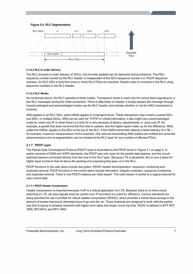
3.1.7.1 PDCP Header Compression
Header compression is important because VoIP is a critical application for LTE. Because there is no more circuitswitching in LTE, all voice signals must be carried over IP and there is a need for efficiency. Various standards arebeing specified for use in profiles for robust header compression (ROHC), which provides a tremendous savings in theamount of header that would otherwise have to go over the air. These protocols are designed to work with the packetloss that is typical in wireless networks with higher error rates and longer round trip time. ROHC is defined in IETF RFC3095, RFC4815, and RFC 3843.
8/6/2019 18094043 LTE Protocol Overview
http://slidepdf.com/reader/full/18094043-lte-protocol-overview 10/21
8 Long Term Evolution Protocol Overview Freescale Semiconductor
Figure 3.5. PDCP Header Compression
IP Header Payload
Token Payload
40 bytes
1 - 4 bytes
24 bytes
Payload size for VoIPe.g. G.723.1 codec
3.1.7.2 Ciphering and Integrity Protection
Ciphering, both encryption and decryption, also occurs in the PDCP. Security has to occur below the ROHC becausethe ROHC can only operate on unencrypted packets. It cannot understand an encrypted header. Ciphering protectsuser plane data, radio resource control (RRC) data and non access stratum (NAS) data. Processingorder in the PDCP is as follows: For the downlink, decryption occurs first, then ROHCdecompression. For the uplink, ROHC compression occurs first, then encryption.
Details of LTE security architecture are still being defined. The 3GPP System Architecture WorkingGroup 3 (SA3) is responsible for security and has decided to use either Advanced EncryptionStandard (AES) or SNOW 3G algorithms. Specific modes for AES are still being determined; AES isa block cipher and has to use specific operational modes to operate in a streaming mode.
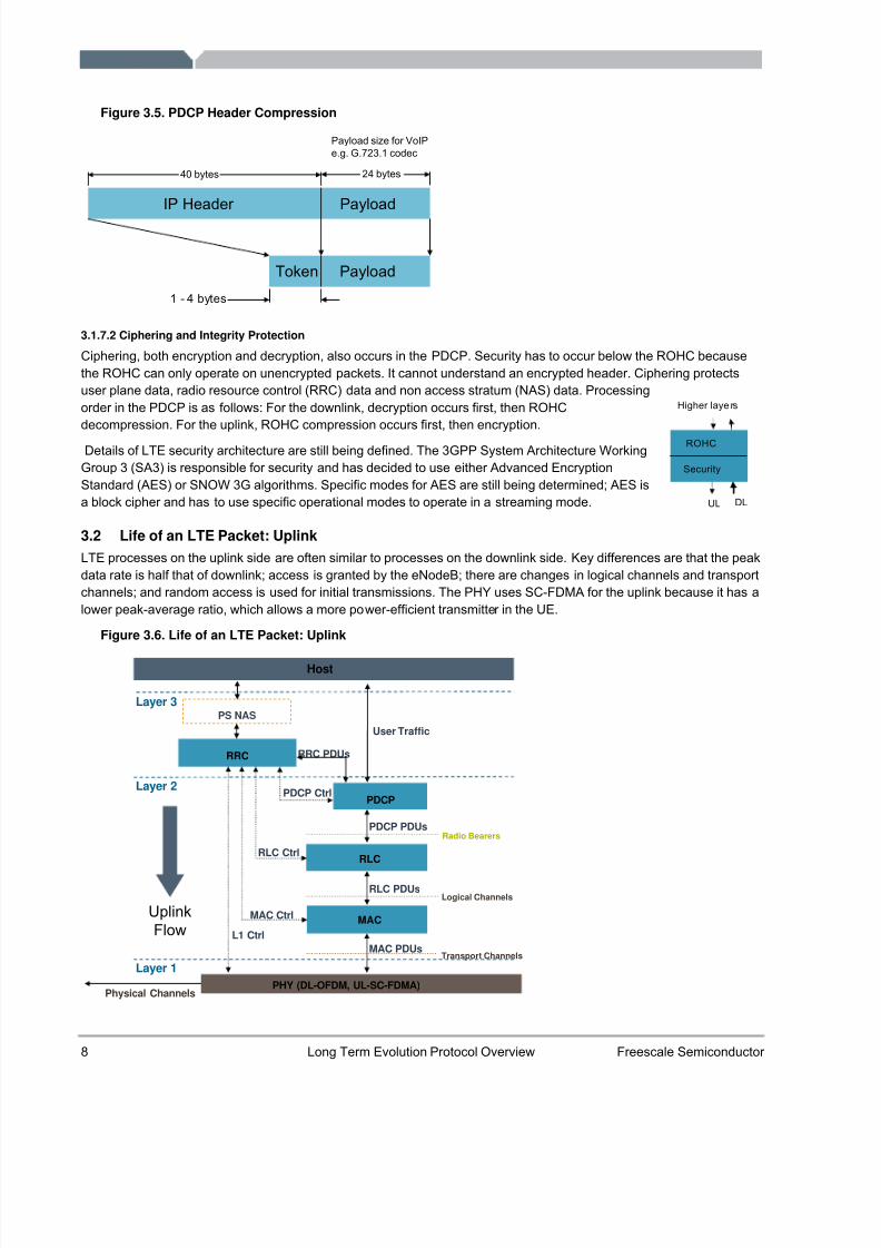
3.2 Life of an LTE Packet: UplinkLTE processes on the uplink side are often similar to processes on the downlink side. Key differences are that the peakdata rate is half that of downlink; access is granted by the eNodeB; there are changes in logical channels and transportchannels; and random access is used for initial transmissions. The PHY uses SC-FDMA for the uplink because it has alower peak-average ratio, which allows a more power-efficient transmitter in the UE.
Figure 3.6. Life of an LTE Packet: Uplink
RLC
RRC
MAC
PHY (DL-OFDM, UL-SC-FDMA)
Layer 1
Layer 3
PDCP
MAC PDUs
RLC PDUs
PDCP Ctrl
MAC Ctrl
L1 Ctrl
Layer 2
PDCP PDUs
Physical Channels
Host
PS NAS
RLC Ctrl
User Traffic
Radio Bearers
Logical Channels
Transport Channels
UplinkFlow
RRC PDUs
ROHC
Security
Higher laye rs
UL DL
8/6/2019 18094043 LTE Protocol Overview
http://slidepdf.com/reader/full/18094043-lte-protocol-overview 11/21
Freescale Semiconductor, Inc. Long Term Evolution Protocol Overview 9
3.2.1 PDCP Layer
PDCP functions are symmetrical for the uplink and the downlink. The PDCP block in Figure 3.6 illustrates the process.The functions are the same for the header compression and encryption, but they occur in reverse order. Uplinkprocessing includes header compression and encryption.
3.2.2 RLC Layer
The RLC functions, shown in the RLC block in Figure 3.6, are also symmetrical for the uplink and the downlink. Insteadof removing the headers, now headers are applied. There is still a need to support transparent mode, unacknowledgedmode and acknowledged mode. The uplink process concatenates rather than segments the SDUs into transport blocks.Segmentation is only done when it is needed to fit SDUs into a transport block.
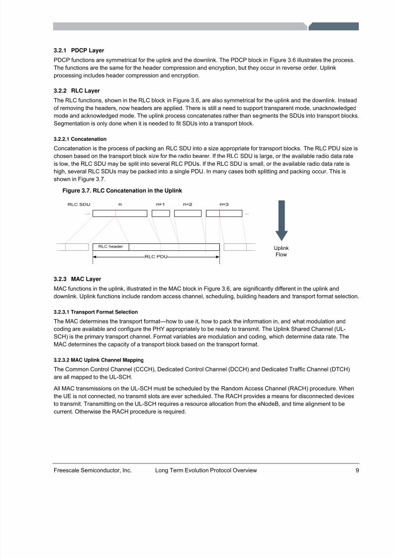
3.2.2.1 Concatenation
Concatenation is the process of packing an RLC SDU into a size appropriate for transport blocks. The RLC PDU size ischosen based on the transport block size for the radio bearer. If the RLC SDU is large, or the available radio data rateis low, the RLC SDU may be split into several RLC PDUs. If the RLC SDU is small, or the available radio data rate ishigh, several RLC SDUs may be packed into a single PDU. In many cases both splitting and packing occur. This isshown in Figure 3.7.
Figure 3.7. RLC Concatenation in the Uplink
UplinkFlow
3.2.3 MAC Layer
MAC functions in the uplink, illustrated in the MAC block in Figure 3.6, are significantly different in the uplink anddownlink. Uplink functions include random access channel, scheduling, building headers and transport format selection.
3.2.3.1 Transport Format Selection
The MAC determines the transport format—how to use it, how to pack the information in, and what modulation andcoding are available and configure the PHY appropriately to be ready to transmit. The Uplink Shared Channel (UL-SCH) is the primary transport channel. Format variables are modulation and coding, which determine data rate. TheMAC determines the capacity of a transport block based on the transport format.
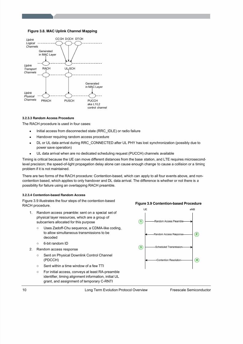
3.2.3.2 MAC Uplink Channel Mapping
The Common Control Channel (CCCH), Dedicated Control Channel (DCCH) and Dedicated Traffic Channel (DTCH)are all mapped to the UL-SCH.
All MAC transmissions on the UL-SCH must be scheduled by the Random Access Channel (RACH) procedure. Whenthe UE is not connected, no transmit slots are ever scheduled. The RACH provides a means for disconnected devicesto transmit. Transmitting on the UL-SCH requires a resource allocation from the eNodeB, and time alignment to becurrent. Otherwise the RACH procedure is required.
8/6/2019 18094043 LTE Protocol Overview
http://slidepdf.com/reader/full/18094043-lte-protocol-overview 12/21
10 Long Term Evolution Protocol Overview Freescale Semiconductor
Figure 3.8. MAC Uplink Channel Mapping
CCCH DCCH DTCH
RACH UL-SCH
PRACH PUSCH PUCCHaka L1/L2control channel
Uplink Logical Channels
Uplink Transport Channels
Uplink Physical Channels
Generatedin MAC Layer
Generatedin MAC Layer
3.2.3.3 Random Access Procedure
The RACH procedure is used in four cases:
• Initial access from disconnected state (RRC_IDLE) or radio failure• Handover requiring random access procedure• DL or UL data arrival during RRC_CONNECTED after UL PHY has lost synchronization (possibly due to
power save operation)• UL data arrival when are no dedicated scheduling request (PUCCH) channels available
Timing is critical because the UE can move different distances from the base station, and LTE requires microsecond-level precision; the speed-of-light propagation delay alone can cause enough change to cause a collision or a timingproblem if it is not maintained.
There are two forms of the RACH procedure: Contention-based, which can apply to all four events above, and non-
contention based, which applies to only handover and DL data arrival. The difference is whether or not there is apossibility for failure using an overlapping RACH preamble.
3.2.3.4 Contention-based Random Access
Figure 3.9 illustrates the four steps of the contention-basedRACH procedure.
1. Random access preamble: sent on a special set of physical layer resources, which are a group of subcarriers allocated for this purposeo Uses Zadoff-Chu sequence, a CDMA-like coding,
to allow simultaneous transmissions to bedecoded
o 6-bit random ID
2. Random access responseo Sent on Physical Downlink Control Channel
(PDCCH)o Sent within a time window of a few TTIo For initial access, conveys at least RA-preamble
identifier, timing alignment information, initial ULgrant, and assignment of temporary C-RNTI
Figure 3.9 Contention-based Procedure
8/6/2019 18094043 LTE Protocol Overview
http://slidepdf.com/reader/full/18094043-lte-protocol-overview 13/21
Freescale Semiconductor, Inc. Long Term Evolution Protocol Overview 11
o One or more UEs may be addressed in one response
3. Scheduled transmissiono Uses HARQ and RLC transparent mode on UL-SCHo Conveys UE identifier
4. Contention resolution: The eNodeB uses this optional step to end the RACH procedure
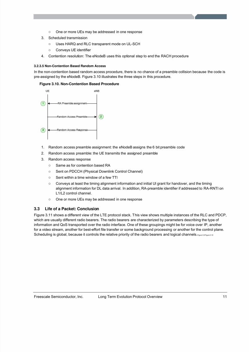
3.2.3.5 Non-Contention Based Random Access
In the non-contention based random access procedure, there is no chance of a preamble collision because the code ispre-assigned by the eNodeB. Figure 3.10 illustrates the three steps in this procedure.
Figure 3.10. Non-Contention Based Procedure
1. Random access preamble assignment: the eNodeB assigns the 6 bit preamble code
2. Random access preamble: the UE transmits the assigned preamble
3. Random access responseo Same as for contention based RAo Sent on PDCCH (Physical Downlink Control Channel)o Sent within a time window of a few TTIo
Conveys at least the timing alignment information and initial Ul grant for handover, and the timingalignment information for DL data arrival. In addition, RA-preamble identifier if addressed to RA-RNTI onL1/L2 control channel.
o One or more UEs may be addressed in one response
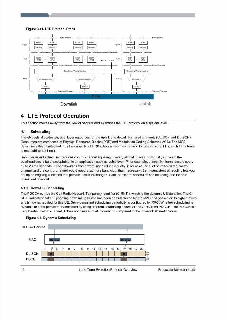
3.3 Life of a Packet: ConclusionFigure 3.11 shows a different view of the LTE protocol stack. This view shows multiple instances of the RLC and PDCP,which are usually different radio bearers. The radio bearers are characterized by parameters describing the type of information and QoS transported over the radio interface. One of these groupings might be for voice over IP, another for a video stream, another for best-effort file transfer or some background processing or another for the control plane.Scheduling is global, because it controls the relative priority of the radio bearers and logical channels. Figure 3.9 Figure 3.10
8/6/2019 18094043 LTE Protocol Overview
http://slidepdf.com/reader/full/18094043-lte-protocol-overview 14/21
12 Long Term Evolution Protocol Overview Freescale Semiconductor
Figure 3.11. LTE Protocol Stack
Downlink Uplink
PHY
4 LTE Protocol OperationThis section moves away from the flow of packets and examines the LTE protocol on a system level.
4.1 SchedulingThe eNodeB allocates physical layer resources for the uplink and downlink shared channels (UL-SCH and DL-SCH).Resources are composed of Physical Resource Blocks (PRB) and Modulation Coding Scheme (MCS). The MCSdetermines the bit rate, and thus the capacity, of PRBs. Allocations may be valid for one or more TTIs; each TTI intervalis one subframe (1 ms).
Semi-persistent scheduling reduces control channel signaling. If every allocation was individually signaled, theoverhead would be unacceptable. In an application such as voice over IP, for example, a downlink frame occurs every10 to 20 milliseconds. If each downlink frame were signaled individually, it would cause a lot of traffic on the controlchannel and the control channel would need a lot more bandwidth than necessary. Semi-persistent scheduling lets youset up an ongoing allocation that persists until it is changed. Semi-persistent schedules can be configured for bothuplink and downlink.
4.1.1 Downlink Scheduling
The PDCCH carries the Cell Radio Network Temporary Identifier (C-RNTI), which is the dynamic UE identifier. The C-RNTI indicates that an upcoming downlink resource has been demultiplexed by the MAC and passed on to higher layersand is now scheduled for this UE. Semi-persistent scheduling periodicity is configured by RRC. Whether scheduling isdynamic or semi-persistent is indicated by using different scrambling codes for the C-RNTI on PDCCH. The PDCCH is avery low-bandwidth channel; it does not carry a lot of information compared to the downlink shared channel.
Figure 4.1. Dynamic Scheduling
DL-SCH
PDCCH
RLC and PDCP
MAC
4 5 6 7 8 9 10 11 12 13 14 15 16 17 18 19 20
De-mux
D
De-mux
D
8/6/2019 18094043 LTE Protocol Overview
http://slidepdf.com/reader/full/18094043-lte-protocol-overview 15/21
Freescale Semiconductor, Inc. Long Term Evolution Protocol Overview 13
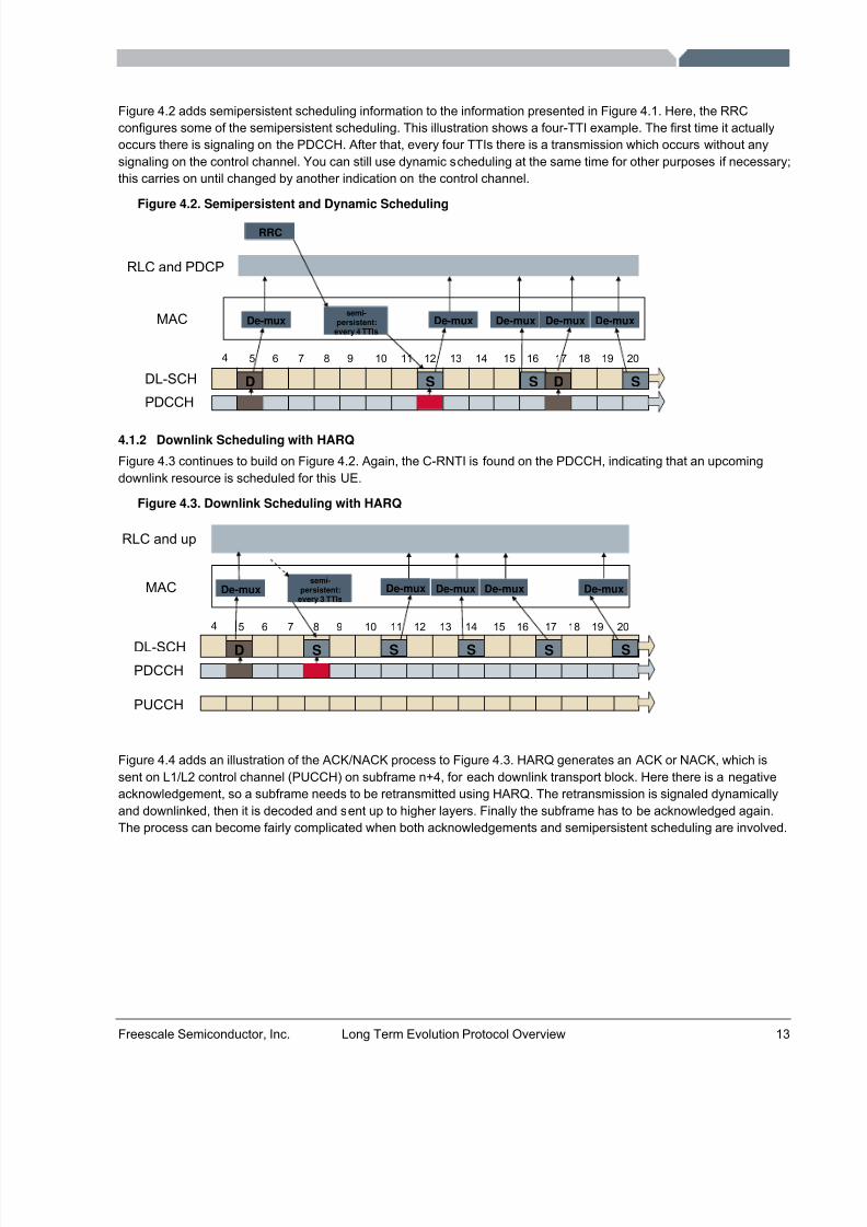
Figure 4.2 adds semipersistent scheduling information to the information presented in Figure 4.1. Here, the RRCconfigures some of the semipersistent scheduling. This illustration shows a four-TTI example. The first time it actuallyoccurs there is signaling on the PDCCH. After that, every four TTIs there is a transmission which occurs without anysignaling on the control channel. You can still use dynamic scheduling at the same time for other purposes if necessary;this carries on until changed by another indication on the control channel.
Figure 4.2. Semipersistent and Dynamic Scheduling
DL-SCH
PDCCH
RLC and PDCP
MAC
4 5 6 7 8 9 10 11 12 13 14 15 16 17 18 19 20
De-mux
D
De-mux
S S S
De-mux De-mux
RRC
semi-persistent:
every 4 TTIsDe-mux
D
4.1.2 Downlink Scheduling with HARQ
Figure 4.3 continues to build on Figure 4.2. Again, the C-RNTI is found on the PDCCH, indicating that an upcomingdownlink resource is scheduled for this UE.
Figure 4.3. Downlink Scheduling with HARQ
DL-SCHPDCCH
RLC and up
MAC
4 5 6 7 8 9 10 11 12 13 14 15 16 17 18 19 20
semi-persistent:
every 3 TTIsDe-mux
PUCCH
De-muxDe-mux De-mux
D S S S S S
De-mux
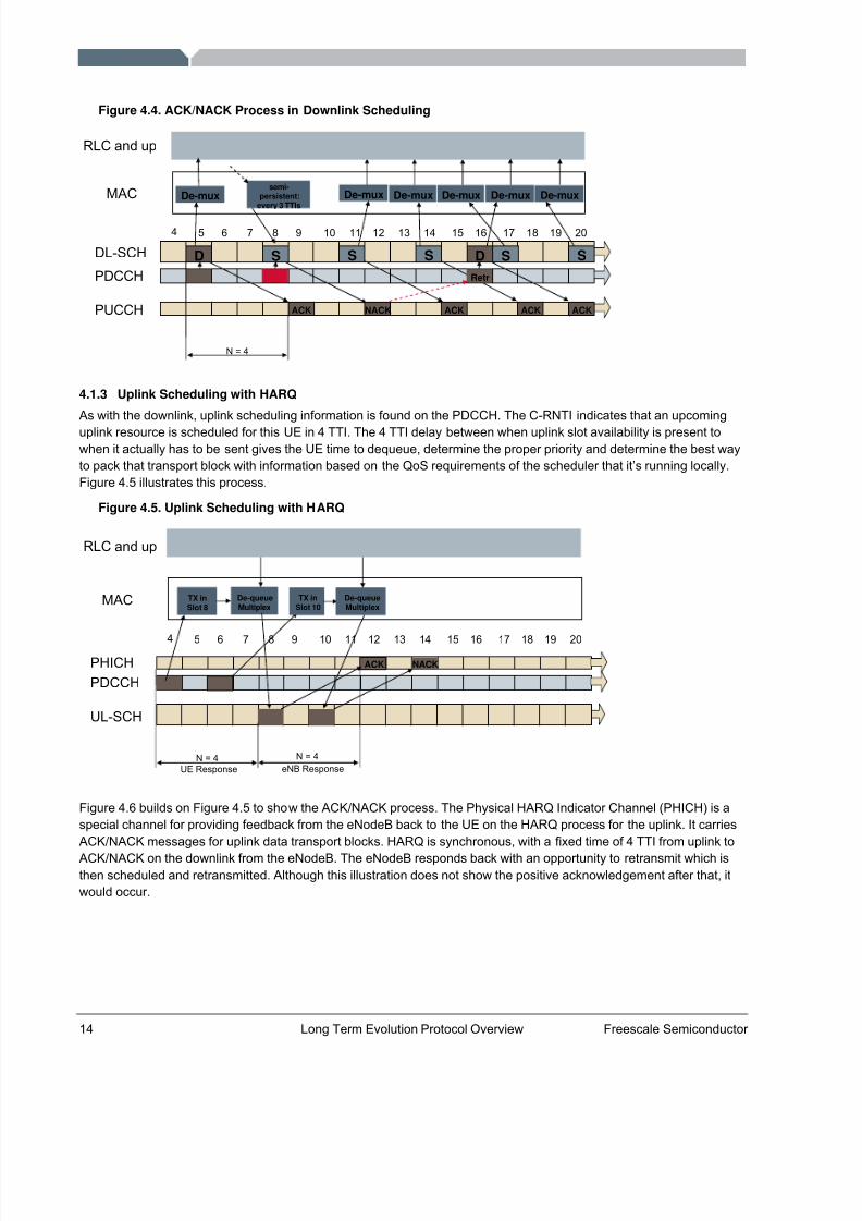
Figure 4.4 adds an illustration of the ACK/NACK process to Figure 4.3. HARQ generates an ACK or NACK, which issent on L1/L2 control channel (PUCCH) on subframe n+4, for each downlink transport block. Here there is a negativeacknowledgement, so a subframe needs to be retransmitted using HARQ. The retransmission is signaled dynamicallyand downlinked, then it is decoded and sent up to higher layers. Finally the subframe has to be acknowledged again.The process can become fairly complicated when both acknowledgements and semipersistent scheduling are involved.
8/6/2019 18094043 LTE Protocol Overview
http://slidepdf.com/reader/full/18094043-lte-protocol-overview 16/21
14 Long Term Evolution Protocol Overview Freescale Semiconductor
Figure 4.4. ACK/NACK Process in Downlink Scheduling
DL-SCH
PDCCH
RLC and up
MAC
4 5 6 7 8 9 10 11 12 13 14 15 16 17 18 19 20
semi-persistent:
every 3 TTIsDe-mux
PUCCH
De-mux
ACK ACKACK
N = 4
De-mux De-mux
D
ACK
De-mux
NACK
Retr
DS S S S S
De-mux
4.1.3 Uplink Scheduling with HARQ
As with the downlink, uplink scheduling information is found on the PDCCH. The C-RNTI indicates that an upcominguplink resource is scheduled for this UE in 4 TTI. The 4 TTI delay between when uplink slot availability is present towhen it actually has to be sent gives the UE time to dequeue, determine the proper priority and determine the best wayto pack that transport block with information based on the QoS requirements of the scheduler that it’s running locally.Figure 4.5 illustrates this process.
Figure 4.5. Uplink Scheduling with HARQ
4 5 6 7 8 9 10 11 12 13 14 15 16 17 18 19 20
PHICHPDCCH
RLC and up
MAC TX inSlot 8
De-queueMultiplex
UL-SCH
ACK
TX inSlot 10
De-queueMultiplex
NACK
N = 4 N = 4eNB ResponseUE Response
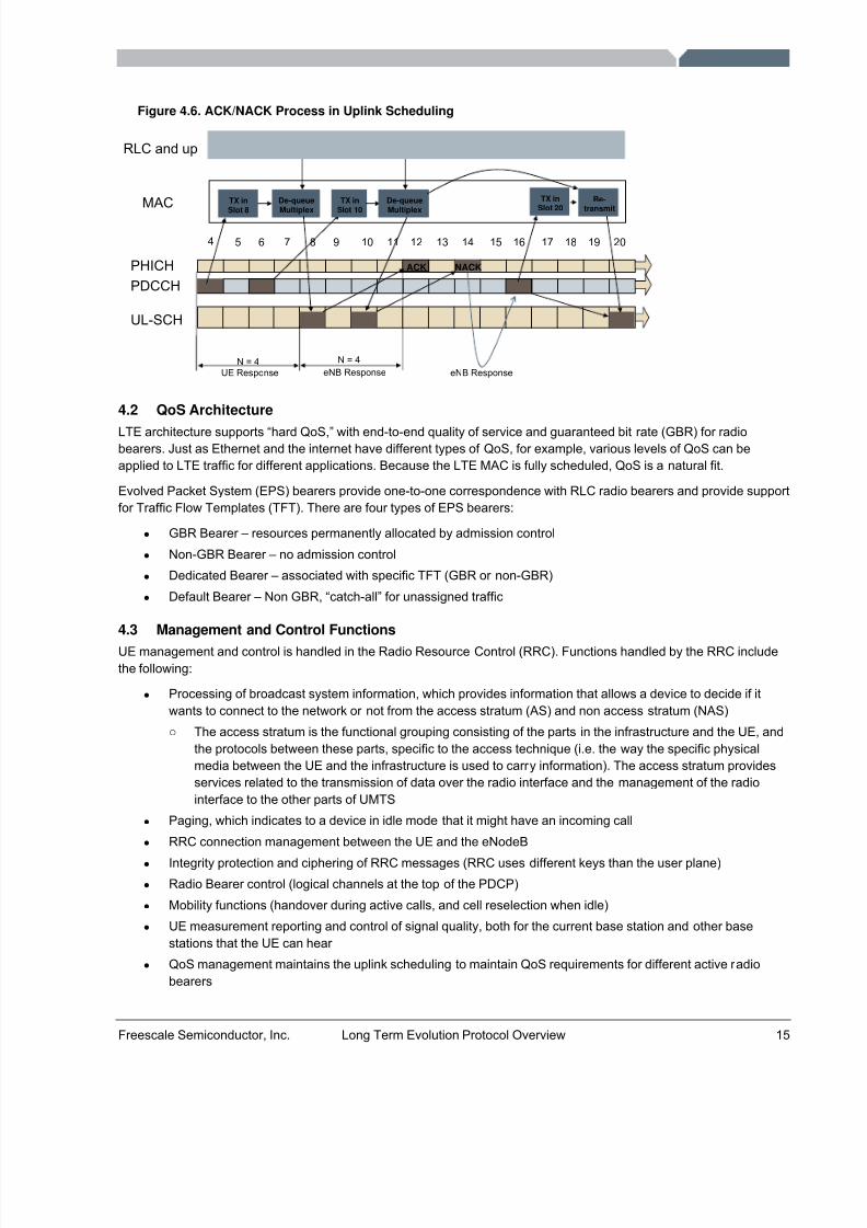
Figure 4.6 builds on Figure 4.5 to show the ACK/NACK process. The Physical HARQ Indicator Channel (PHICH) is aspecial channel for providing feedback from the eNodeB back to the UE on the HARQ process for the uplink. It carriesACK/NACK messages for uplink data transport blocks. HARQ is synchronous, with a fixed time of 4 TTI from uplink to
ACK/NACK on the downlink from the eNodeB. The eNodeB responds back with an opportunity to retransmit which isthen scheduled and retransmitted. Although this illustration does not show the positive acknowledgement after that, itwould occur.
8/6/2019 18094043 LTE Protocol Overview
http://slidepdf.com/reader/full/18094043-lte-protocol-overview 17/21
Freescale Semiconductor, Inc. Long Term Evolution Protocol Overview 15
Figure 4.6. ACK/NACK Process in Uplink Scheduling
4 5 6 7 8 9 10 11 12 13 14 15 16 17 18 19 20
PHICHPDCCH
RLC and up
MAC TX inSlot 8
De-queueMultiplex
UL-SCH
ACK
TX inSlot 10
De-queueMultiplex
NACK
N = 4 N = 4eNB ResponseUE Response eNB Response
TX inSlot 20
Re-transmit
4.2 QoS Architecture
LTE architecture supports “hard QoS,” with end-to-end quality of service and guaranteed bit rate (GBR) for radiobearers. Just as Ethernet and the internet have different types of QoS, for example, various levels of QoS can beapplied to LTE traffic for different applications. Because the LTE MAC is fully scheduled, QoS is a natural fit.
Evolved Packet System (EPS) bearers provide one-to-one correspondence with RLC radio bearers and provide supportfor Traffic Flow Templates (TFT). There are four types of EPS bearers:
• GBR Bearer – resources permanently allocated by admission control• Non-GBR Bearer – no admission control• Dedicated Bearer – associated with specific TFT (GBR or non-GBR)• Default Bearer – Non GBR, “catch-all” for unassigned traffic
4.3 Management and Control FunctionsUE management and control is handled in the Radio Resource Control (RRC). Functions handled by the RRC includethe following:
• Processing of broadcast system information, which provides information that allows a device to decide if itwants to connect to the network or not from the access stratum (AS) and non access stratum (NAS)o The access stratum is the functional grouping consisting of the parts in the infrastructure and the UE, and
the protocols between these parts, specific to the access technique (i.e. the way the specific physicalmedia between the UE and the infrastructure is used to carry information). The access stratum providesservices related to the transmission of data over the radio interface and the management of the radiointerface to the other parts of UMTS
• Paging, which indicates to a device in idle mode that it might have an incoming call• RRC connection management between the UE and the eNodeB• Integrity protection and ciphering of RRC messages (RRC uses different keys than the user plane)• Radio Bearer control (logical channels at the top of the PDCP)• Mobility functions (handover during active calls, and cell reselection when idle)• UE measurement reporting and control of signal quality, both for the current base station and other base
stations that the UE can hear • QoS management maintains the uplink scheduling to maintain QoS requirements for different active radio
bearers
8/6/2019 18094043 LTE Protocol Overview
http://slidepdf.com/reader/full/18094043-lte-protocol-overview 18/21
16 Long Term Evolution Protocol Overview Freescale Semiconductor
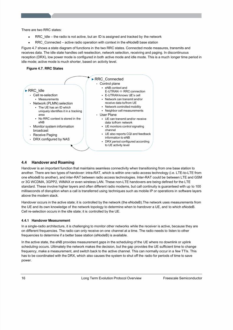
There are two RRC states:
• RRC_Idle – the radio is not active, but an ID is assigned and tracked by the network• RRC_Connected – active radio operation with context in the eNodeB base station
Figure 4.7 shows a state diagram of functions in the two RRC states. Connected mode measures, transmits andreceives data. The idle state handles cell reselection, network selection, receiving and paging. In discontinuous
reception (DRX), low power mode is configured in both active mode and idle mode. This is a much longer time period inidle mode; active mode is much shorter, based on activity level.
Figure 4.7. RRC States
► RRC_Idle• Cell re-selection
Measurements• Network (PLMN) selection
The UE has an ID whichuniquely identifies it in a tracking
areaNo RRC context is stored in theeNB
• Monitor system informationbroadcast
• Receive Paging• DRX configured by NAS
► RRC_Connected• Control plane
eNB context andE-UTRAN RRC connectionE-UTRAN knows UE’s cellNetwork can transmit and/or receive data to/from UENetwork controlled mobilityNeighbor cell measurements
• User PlaneUE can transmit and/or receivedata to/from networkUE monitors control signalingchannelUE also reports CQI and feedbackinformation to eNBDRX period configured accordingto UE activity level
4.4 Handover and RoamingHandover is an important function that maintains seamless connectivity when transitioning from one base station to
another. There are two types of handover: intra-RAT, which is within one radio access technology (i.e. LTE-to-LTE fromone eNodeB to another), and inter-RAT between radio access technologies. Inter-RAT could be between LTE and GSMor 3G WCDMA, 3GPP2, WiMAX or even wireless LAN. These non-LTE handovers are being defined for the LTEstandard. These involve higher layers and often different radio modems, but call continuity is guaranteed with up to 100milliseconds of disruption when a call is transferred using techniques such as mobile IP or operations in software layersabove the modem stack.
Handover occurs in the active state; it is controlled by the network (the eNodeB).The network uses measurements fromthe UE and its own knowledge of the network topology to determine when to handover a UE, and to which eNodeB.Cell re-selection occurs in the idle state; it is controlled by the UE.
4.4.1 Handover Measurement
In a single-radio architecture, it is challenging to monitor other networks while the receiver is active, because they are
on different frequencies. The radio can only receive on one channel at a time. The radio needs to listen to other frequencies to determine if a better base station (eNodeB) is available.
In the active state, the eNB provides measurement gaps in the scheduling of the UE where no downlink or uplinkscheduling occurs. Ultimately the network makes the decision, but the gap provides the UE sufficient time to changefrequency, make a measurement, and switch back to the active channel. This can normally occur in a few TTIs. Thishas to be coordinated with the DRX, which also causes the system to shut off the radio for periods of time to savepower.
8/6/2019 18094043 LTE Protocol Overview
http://slidepdf.com/reader/full/18094043-lte-protocol-overview 19/21
Freescale Semiconductor, Inc. Long Term Evolution Protocol Overview 17
4.4.2 Handover: Neighbor Lists
The LTE network provides the UE with neighbor lists. Based on the network knowledge configuration, the eNodeBprovides the UE with neighboring eNB’s identifiers and their frequency. During measurement gaps or idle periods, theUE measures the signal quality of the neighbors it can receive. The UE reports results back to the eNodeB and thenetwork decides the best handover (if any), based on signal quality, network utilization, etc.
4.5 Power Save OperationIn wireless data communication, the receiver uses significant power for the RF transceiver, fast A/D converters,wideband signal processing, etc. As LTE increases data rates by a factor of 50 over 3G, wireless device batteries arestill the same size, so substantial improvements in power use are necessary to operate at these very high rates andwide bandwidths. Some of that savings comes from hardware, some from system architecture and some from theprotocol.
Wireless standards employ power save mechanisms. The objective is to turn off the radio for the most time possiblewhile staying connected to the network. The radio modem can be turned off “most” of the time while the mobile devicestays connected to the network with reduced throughput. The receiver is turned on at specific times for updates.Devices can quickly transition to full power mode for full performance.
4.5.1 DRX and DTX
LTE power save protocols include Discontinuous Reception (DRX) and Discontinuous Transmission (DTX). Bothinvolve reducing transceiver duty cycle while in active operation. DRX also applies to the RRC_Idle state with a longer cycle time than active mode. However, DRX and DTX do not operate without a cost: the UE’s data throughput capacityis reduced in proportion to power savings.
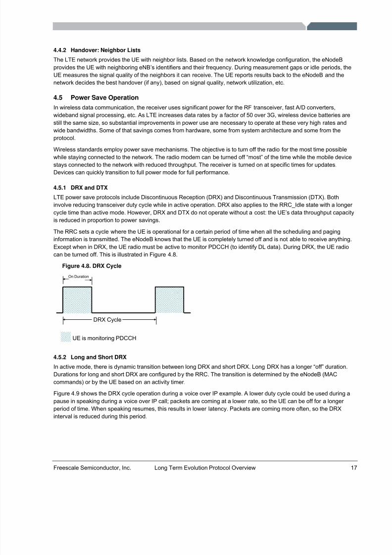
The RRC sets a cycle where the UE is operational for a certain period of time when all the scheduling and paginginformation is transmitted. The eNodeB knows that the UE is completely turned off and is not able to receive anything.Except when in DRX, the UE radio must be active to monitor PDCCH (to identify DL data). During DRX, the UE radiocan be turned off. This is illustrated in Figure 4.8.
Figure 4.8. DRX Cycle
DRX Cycle
On Duration
UE is monitoring PDCCH
4.5.2 Long and Short DRX
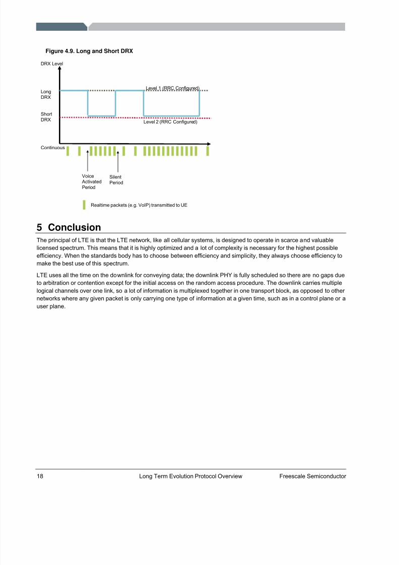
In active mode, there is dynamic transition between long DRX and short DRX. Long DRX has a longer “off” duration.Durations for long and short DRX are configured by the RRC. The transition is determined by the eNodeB (MACcommands) or by the UE based on an activity timer.
Figure 4.9 shows the DRX cycle operation during a voice over IP example. A lower duty cycle could be used during apause in speaking during a voice over IP call; packets are coming at a lower rate, so the UE can be off for a longer period of time. When speaking resumes, this results in lower latency. Packets are coming more often, so the DRXinterval is reduced during this period.
8/6/2019 18094043 LTE Protocol Overview
http://slidepdf.com/reader/full/18094043-lte-protocol-overview 20/21
18 Long Term Evolution Protocol Overview Freescale Semiconductor
Figure 4.9. Long and Short DRX
DRX Level
Long
DRX
ShortDRX
Continuous
Level 1 (RRC Configured)
Level 2 (RRC Configured)
Realtime packets (e.g. VoIP) transmitted to UE
VoiceActivatedPeriod
SilentPeriod
5 ConclusionThe principal of LTE is that the LTE network, like all cellular systems, is designed to operate in scarce and valuablelicensed spectrum. This means that it is highly optimized and a lot of complexity is necessary for the highest possibleefficiency. When the standards body has to choose between efficiency and simplicity, they always choose efficiency tomake the best use of this spectrum.
LTE uses all the time on the downlink for conveying data; the downlink PHY is fully scheduled so there are no gaps dueto arbitration or contention except for the initial access on the random access procedure. The downlink carries multiplelogical channels over one link, so a lot of information is multiplexed together in one transport block, as opposed to other networks where any given packet is only carrying one type of information at a given time, such as in a control plane or auser plane.
8/6/2019 18094043 LTE Protocol Overview
http://slidepdf.com/reader/full/18094043-lte-protocol-overview 21/21
Freescale and the Freescale logo are trademarks or registered trademarks of FreescaleSemiconductor, Inc. in the U.S. and other countries.All other product or service names are the property of their respective owners.© Freescale Semiconductor, Inc. 2008.
Document Number: LTEPTCLOVWWPREV 0
How to Reach Us:
Home Page:www.freescale.com
Web Support:
http://www.freescale.com/support
USA/Europe or Locations Not Listed:Freescale Semiconductor, Inc.Technical Information Center, EL5162100 East Elliot RoadTempe, Arizona 85284+1-800-521-6274 or +1-480-768-2130www.freescale.com/support
Europe, Middle East and Africa:Freescale Halbleiter Deutschland GmbHTechnical Information Center Schatzbogen 781829 Muenchen, Germany+44 1296 380 456 (English)+46 8 52200080 (English)
+49 89 92103 559 (German)+33 1 69 35 48 48 (French)www.freescale.com/support
Japan:Freescale Semiconductor Japan Ltd.HeadquartersARCO Tower 15F1-8-1, Shimo-Meguro, Meguro-ku,Tokyo 153-0064, Japan0120 191014 or +81 3 5437 [email protected]
Asia/Pacific:Freescale Semiconductor Hong Kong LtdTechnical Information Center 2 Dai King StreetTai Po Industrial EstateTai Po, N.T., Hong Kong+800 2666 [email protected]
For Literature Requests Only:Freescale Semiconductor Literature Distribution Center P.O. Box 5405Denver, Colorado 802171-800-441-2447 or 303-675-2140Fax: [email protected]
Information in this document is provided solely to enable system and software implementersto use Freescale Semiconductor products. There are no express or implied copyrightlicense granted hereunder to design or fabricate any integrated circuits or integrated circuitsbased on the information in this document.
Freescale Semiconductor reserves the right to make changes without further notice to anyproducts herein. Freescale Semiconductor makes no warranty, representation or guaranteeregarding the suitability of its products for any particular purpose, nor does FreescaleSemiconductor assume any liability arising out of the application or use of any product or circuit, and specifically disclaims any and all liability, including without limitationconsequential or incidental damages. “Typical” parameters which may be provided inFreescale Semiconductor data sheets and/or specifications can and do vary in differentapplications and actual performance may vary over t ime. All operating parameters,including “Typicals” must be validated for each customer application by customer’s technicalexperts. Freescale Semiconductor does not convey any license under its patent rights nor the rights of others. Freescale Semiconductor products are not designed, intended, or authorized for use as components in systems intended for surgical implant into the body, or other applications intended to support or sustain life, or for any other application in whichthe failure of the Freescale Semiconductor product could create a situation where personalinjury or death may occur. Should Buyer purchase or use Freescale Semiconductor products for any such unintended or unauthorized application, Buyer shall indemnify andhold Freescale Semiconductor and its officers, employees, subsidiaries, affiliates, anddistributors harmless against all claims, costs, damages, and expenses, and reasonableattorney fees arising out of, directly or indirectly, any claim of personal injury or deathassociated with such unintended or unauthorized use, even if such claim alleges thatFreescale Semiconductor was negligent regarding the design or manufacture of t he part.