


Talen
Pages
Wettelijk

VestigingMarkerkant 14561314AS AlmereThe Netherlands
PostadresP.O. Box 14301300BK AlmereThe Netherlands
Tel: +31 (0)36 750 53 72Fax: +31 (0)36 750 53 [email protected]
RetouradresAntwoordnummer 1521300VC AlmereThe Netherlands
VektoKVK 55974422BTW 851953931BANK 130952869
Maakt elektrotechniek betaalbaar
GD drive10 INVT inverters WWW.INVT.NL Content
2
Inhoud.Content................................................................................................................................................ 11 Safety Precautions ........................................................................................................................... 31.1 Safety definition ............................................................................................................................. 31.2 Warning symbols ........................................................................................................................... 31.3 Safety guidelines ........................................................................................................................... 32 Product overview.............................................................................................................................. 62.1 Quick start-up ................................................................................................................................ 62.2 Product specification...................................................................................................................... 72.3 Name plate .................................................................................................................................... 92.4 Type designation key..................................................................................................................... 92.5 Rated specifications....................................................................................................................... 92.6 Structure diagram ........................................................................................................................ 103 Installation Guidelines..................................................................................................................... 113.1 Mechanical installation................................................................................................................. 113.2 Standard wiring............................................................................................................................ 133.3 Layout protection ......................................................................................................................... 154 Keypad Operation Procedure ......................................................................................................... 174.1 Keypad displaying........................................................................................................................ 194.2 Keypad operation ........................................................................................................................ 205 Function Parameters ...................................................................................................................... 226 Fault tracking.................................................................................................................................. 686.1 Maintenance intervals.................................................................................................................. 686.2 Fault solution ............................................................................................................................... 717 Communication protocol ................................................................................................................. 757.1 Brief instruction to Modbus protocol............................................................................................. 757.2 Application of the inverter............................................................................................................. 757.3 RTU command code and communication data illustration............................................................ 798 Special functions for incense-making machines.............................................................................. 908.1 Function description..................................................................................................................... 908.2 Function operation....................................................................................................................... 90Appendix A Technical data................................................................................................................. 91A.1 Ratings........................................................................................................................................ 91A.2 CE............................................................................................................................................... 92A.3 EMC regulations.......................................................................................................................... 92Appendix B Dimension drawings ....................................................................................................... 94B.1 Keypad structure ......................................................................................................................... 94B.2 Inverter chart............................................................................................................................... 94Appendix C Peripherial options and parts.......................................................................................... 96C.1 Peripherial wiring ........................................................................................................................ 96C.2 Power supply .............................................................................................................................. 97C.3 Cables......................................................................................................................................... 97C.4 Breaker and electromagnetic contactor....................................................................................... 98C.5 Reactors ..................................................................................................................................... 99C.6 Filter............................................................................................................................................ 99C.7 Braking system ......................................................................................................................... 100Appendix D Further information ....................................................................................................... 102
VestigingMarkerkant 14561314AS AlmereThe Netherlands
PostadresP.O. Box 14301300BK AlmereThe Netherlands
Tel: +31 (0)36 750 53 72Fax: +31 (0)36 750 53 [email protected]
RetouradresAntwoordnummer 1521300VC AlmereThe Netherlands
VektoKVK 55974422BTW 851953931BANK 130952869
Maakt elektrotechniek betaalbaar
Goodrive10 inverters Safety precautions
3
1 Safety PrecautionsPlease read this manual carefully and follow all safety precautions before moving, installing, operating andservicing the inverter. If ignored, physical injury or death may occur, or damage may occur to the devices.If any physical injury or death or damage to the devices occurs for ignoring to the safety precautions in themanual, our company will not be responsible for any damages and we are not legally bound in any manner.
1.1 Safety definition
Danger: Serious physical injury or even death may occur if not follow relevantrequirements
Warning: Physical injury or damage to the devices may occur if not follow relevantrequirements
Note: Physical hurt may occur if not follow relevant requirementsQualified electricians: People working on the device should take part in professional electrical and
safety training, receive the certification and be familiar with all steps andrequirements of installing, commissioning, operating and maintaining thedevice to avoid any emergency.
1.2 Warning symbols
Warnings caution you about conditions which can result in serious injury or death and/or damage to theequipment, and advice on how to avoid the danger. Following warning symbols are used in this manual:
Symbols Name Instruction Abbreviation
Danger DangerSerious physical injury or even death mayoccur if not follow the relative requirements
Warning WarningPhysical injury or damage to the devices mayoccur if not follow the relative requirements
Do notElectrostaticdischarge
Damage to the PCBA board may occur if notfollow the relative requirements
Hot sides Hot sidesSides of the device may become hot. Do nottouch.
Note NotePhysical hurt may occur if not follow therelative requirements
Note
1.3 Safety guidelines
Only qualified electricians are allowed to operate on the inverter.Do not carry out any wiring and inspection or changing components when the power supplyis applied. Ensure all input power supply is disconnected before wiring and checking andalways wait for at least the time designated on the inverter or until the DC bus voltage isless than 36V. Below is the table of the waiting time:
Inverter module Minimum waiting time
Single-phase 220V 0.2kW-2.2kW 5 minutes
Three-phase 220V 0.2kW-2.2kW 5 minutes
VestigingMarkerkant 14561314AS AlmereThe Netherlands
PostadresP.O. Box 14301300BK AlmereThe Netherlands
Tel: +31 (0)36 750 53 72Fax: +31 (0)36 750 53 [email protected]
RetouradresAntwoordnummer 1521300VC AlmereThe Netherlands
VektoKVK 55974422BTW 851953931BANK 130952869
Maakt elektrotechniek betaalbaar
Goodrive10 inverters Safety precautions
4
Three-phase 380V 0.75kW-2.2kW 5 minutes
Do not refit the inverter unauthorizedly; otherwise fire, electric shock or other injury mayoccur.
The base of the radiator may become hot during running. Do not touch to avoid hurt.
The electrical parts and components inside the inverter are electrostatic. Takemeasurements to avoid electrostatic discharge during relevant operation.
1.3.1 Delivery and installation
Please install the inverter on fire-retardant material and keep the inverter away fromcombustible materials.Connect the braking optional parts (braking resistors or feedback units) according to thewiring diagram.Don’t operate on the inverter if there is any damage or components loss to the inverter.Don’t touch the inverter with wet items or body, otherwise electric shock may occur.
Note:Select appropriate moving and installing tools to ensure a safe and normal running of the inverterand avoid physical injury or death. For physical safety, the erector should take some mechanicalprotective measurements, such as wearing exposure shoes and working uniforms.Ensure to avoid physical shock or vibration during delivery and installation.Do not carry the inverter by its cover. The cover may fall off.Install away from children and other public places.The inverter cannot meet the requirements of low voltage protection in IEC61800-5-1 if the sea levelof installation site is above 2000m.The pick-up current of the inverter may be above 3.5mA during operation. Ground with propertechniques and ensure the grounding resistor is less than 10Ω . The conductivity of PE groundingconductor is the same as that of the phase conductor (with the same cross sectional area).R, S and T are the input terminals of the power supply, while U, V and W are the motor terminals.Please connect the input power cables and motor cables with proper techniques; otherwise thedamage to the inverter may occur.
1.3.2 Commissioning and running
Disconnect all power supplies applied to the inverter before the terminal wiring andwait for at least the designated time after disconnecting the power supply.High voltage is present inside the inverter during running. Do not carry out anyoperation except for the keypad setting.The inverter may start up by itself when P01.21=1. Do not get close to the inverterand motor.The inverter can not be used as “Emergency-stop device”.The inverter can not be used to break the motor suddenly. A mechanical brakingdevice should be provided.
Note:Do not switch on/off the input power supply of the inverter frequently.
VestigingMarkerkant 14561314AS AlmereThe Netherlands
PostadresP.O. Box 14301300BK AlmereThe Netherlands
Tel: +31 (0)36 750 53 72Fax: +31 (0)36 750 53 [email protected]
RetouradresAntwoordnummer 1521300VC AlmereThe Netherlands
VektoKVK 55974422BTW 851953931BANK 130952869
Maakt elektrotechniek betaalbaar
Goodrive10 inverters Safety precautions
5
For inverters that have been stored for a long time, check and fix the capacitance and try to run itagain before utilization (see Maintenance and Hardware Fault Diagnose).Cover the front board before running, otherwise electric shock may occur.
1.3.3 Maintenance and replacement of components
Only qualified electricians are allowed to perform the maintenance, inspection, andcomponents replacement of the inverter.Disconnect all power supplies to the inverter before the terminal wiring. Wait for atleast the time designated on the inverter after disconnection.Take measures to avoid screws, cables and other conductive matters to fall into theinverter during maintenance and component replacement.
Note:Please select proper torque to tighten screws.Keep the inverter, parts and components away from combustible materials during maintenance andcomponent replacement.Do not carry out any isolation and pressure test on the inverter and do not measure the controlcircuit of the inverter by megameter.
1.3.4 What to do after scrapping
There are heavy metals in the inverter. Deal with it as industrial effluent.
VestigingMarkerkant 14561314AS AlmereThe Netherlands
PostadresP.O. Box 14301300BK AlmereThe Netherlands
Tel: +31 (0)36 750 53 72Fax: +31 (0)36 750 53 [email protected]
RetouradresAntwoordnummer 1521300VC AlmereThe Netherlands
VektoKVK 55974422BTW 851953931BANK 130952869
Maakt elektrotechniek betaalbaar
Goodrive10 inverters Product overview
6
2 Product overview2.1 Quick start-up
2.1.1 Unpacking inspection
Check as followings after receiving products:
1. Check that there are no damage and humidification to the package. If not, please contact with localagents or INVT offices.
2. Check the information on the type designation label on the outside of the package to verify that the driveis of the correct type. If not, please contact with local dealers or INVT offices.
3. Check that there are no signs of water in the package and no signs of damage or breach to the inverter.If not, please contact with local dealers or INVT offices.
4. Check the information on the type designation label on the outside of the package to verify that the nameplate is of the correct type. If not, please contact with local dealers or INVT offices.
5. Check to ensure the accessories (including user’s manual and control keypad) inside the device iscomplete. If not, please contact with local dealers or INVT offices.
2.1.2 Application confirmation
Check the machine before beginning to use the inverter:
1. Check the load type to verify that there is no overload of the inverter during work and check that whetherthe drive needs to modify the power degree.
2. Check that the actual current of the motor is less than the rated current of the inverter.
3. Check that the control accuracy of the load is the same of the inverter.
4. Check that the incoming supply voltage is correspondent to the rated voltage of the inverter.
2.1.3 Environment
Check as followings before the actual installation and usage:
1. Check that the ambient temperature of the inverter is below 40 . If exceeds, derate 3% for everyadditional 1 . Additionally, the inverter can not be used if the ambient temperature is above 50 .Note: for the cabinet inverter, the ambient temperature means the air temperature inside the cabinet.
2. Check that the ambient temperature of the inverter in actual usage is above -10 . If not, add heatingfacilities.Note: for the cabinet inverter, the ambient temperature means the air temperature inside the cabinet.
3. Check that the altitude of the actual usage site is below 1000m. If exceeds, derate1% for everyadditional 100m.
4. Check that the humidity of the actual usage site is below 90% and condensation is not allowed. If not,add additional protection inverters.
5. Check that the actual usage site is away from direct sunlight and foreign objects can not enter theinverter. If not, add additional protective measures.
6. Check that there is no conductive dust or flammable gas in the actual usage site. If not, add additionalprotection to inverters.
VestigingMarkerkant 14561314AS AlmereThe Netherlands
PostadresP.O. Box 14301300BK AlmereThe Netherlands
Tel: +31 (0)36 750 53 72Fax: +31 (0)36 750 53 [email protected]
RetouradresAntwoordnummer 1521300VC AlmereThe Netherlands
VektoKVK 55974422BTW 851953931BANK 130952869
Maakt elektrotechniek betaalbaar
Goodrive10 inverters Product overview
7
2.1.4 Installation confirmation
Check as followings after the installation:
1. Check that the load range of the input and output cables meet the need of actual load.
2. Check that the accessories of the inverter are correctly and properly installed. The installation cablesshould meet the needs of every component (including reactors, input filters, output reactors, output filters,DC reactors and braking resistors).
3. Check that the inverter is installed on non-flammable materials and the calorific accessories (reactorsand brake resistors) are away from flammable materials.
4. Check that all control cables and power cables are run separately and the routation complies with EMCrequirement.
5. Check that all grounding systems are properly grounded according to the requirements of the inverter.
6. Check that the free space during installation is sufficient according to the instructions in user’s manual.
7. Check that the installation conforms to the instructions in user’s manual. The drive must be installed inan upright position.
8. Check that the external connection terminals are tightly fastened and the torque is appropriate.
9. Check that there are no screws, cables and other conductive items left in the inverter. If not, get themout.
2.1.5 Basic commissioning
Complete the basic commissioning as followings before actual utilization:
1. Autotune. If possible, de-coupled from the motor load to start dynamic autotune. Or if not, static autotuneis available.
2. Adjust the ACC/DEC time according to the actual running of the load.
3. Commission the device via jogging and check that the rotation direction is as required. If not, change therotation direction by changing the wiring of motor.
4. Set all control parameters and then operate.
2.2 Product specification
Function Specification
Power input
Input voltage (V)Single-phase 220(-15%)~240(+10%)Three-phase 220(-15%)~240(+10%)Three-phase 380(-15%)~440(+10%)
Input current (A) Refer to 2.5
Input frequency (Hz) 50Hz or 60Hz Allowed range: 47~63Hz
Poweroutput
Output voltage (V) =the input voltage (error 5%)
Output current (A) Refer to 2.5
Output power (kW) Refer to 2.5
Output frequency (Hz) 50Hz/60Hz, fluctuation:±5%
Technicalcontrol
Control mode V/F
Maximum outputfrequency
400Hz
VestigingMarkerkant 14561314AS AlmereThe Netherlands
PostadresP.O. Box 14301300BK AlmereThe Netherlands
Tel: +31 (0)36 750 53 72Fax: +31 (0)36 750 53 [email protected]
RetouradresAntwoordnummer 1521300VC AlmereThe Netherlands
VektoKVK 55974422BTW 851953931BANK 130952869
Maakt elektrotechniek betaalbaar
Goodrive10 inverters Product overview
8
Function Specification
Adjustable-speed ratio 1:100
Overload capability150% of rated current: 1 minute180% of rated current: 10 seconds200% of rated current: 1 second
Runningcontrol
Key functions Stop mode and anti-overtemperature of the bus
Temperaturemeasurement accuracy
Overtemperature point ±3
Terminal switch inputresolution
≤ 2ms
Terminal analog input
resolution≤ 20mV
Analog input 1 input 0~10V/0~20mA
Analog output 1 input 0~10V/0~20mA
Digital input 5 common input
Digital output1 Y output (commonly used with digital output) and 1rogrammable relay output
Communication 485 communication
Frequency setting
Digital setting, analog setting, multi-step speed setting,
PID setting, MODBUS communication setting and so on
Switch between different settings
Automatic voltage
adjustmentKeep output voltage stable when the grid voltage changes
Fault protection More than 10 fault protections
Others
Mountable method Wall mountable
Temperature of therunning environment
-10~50 , derate above 40
CoolingSingle/three-phase 220V 0.2-0.75kW natural coolingSingle/three-phase 220V 1.5-2.2kW, three-phase 380V0.75-2.2kW
Braking unit Embedded
DC reactor Not optional
Braking resistor Optional and external
EMC filter C2 filter
VestigingMarkerkant 14561314AS AlmereThe Netherlands
PostadresP.O. Box 14301300BK AlmereThe Netherlands
Tel: +31 (0)36 750 53 72Fax: +31 (0)36 750 53 [email protected]
RetouradresAntwoordnummer 1521300VC AlmereThe Netherlands
VektoKVK 55974422BTW 851953931BANK 130952869
Maakt elektrotechniek betaalbaar
Goodrive10 inverters Product overview
9
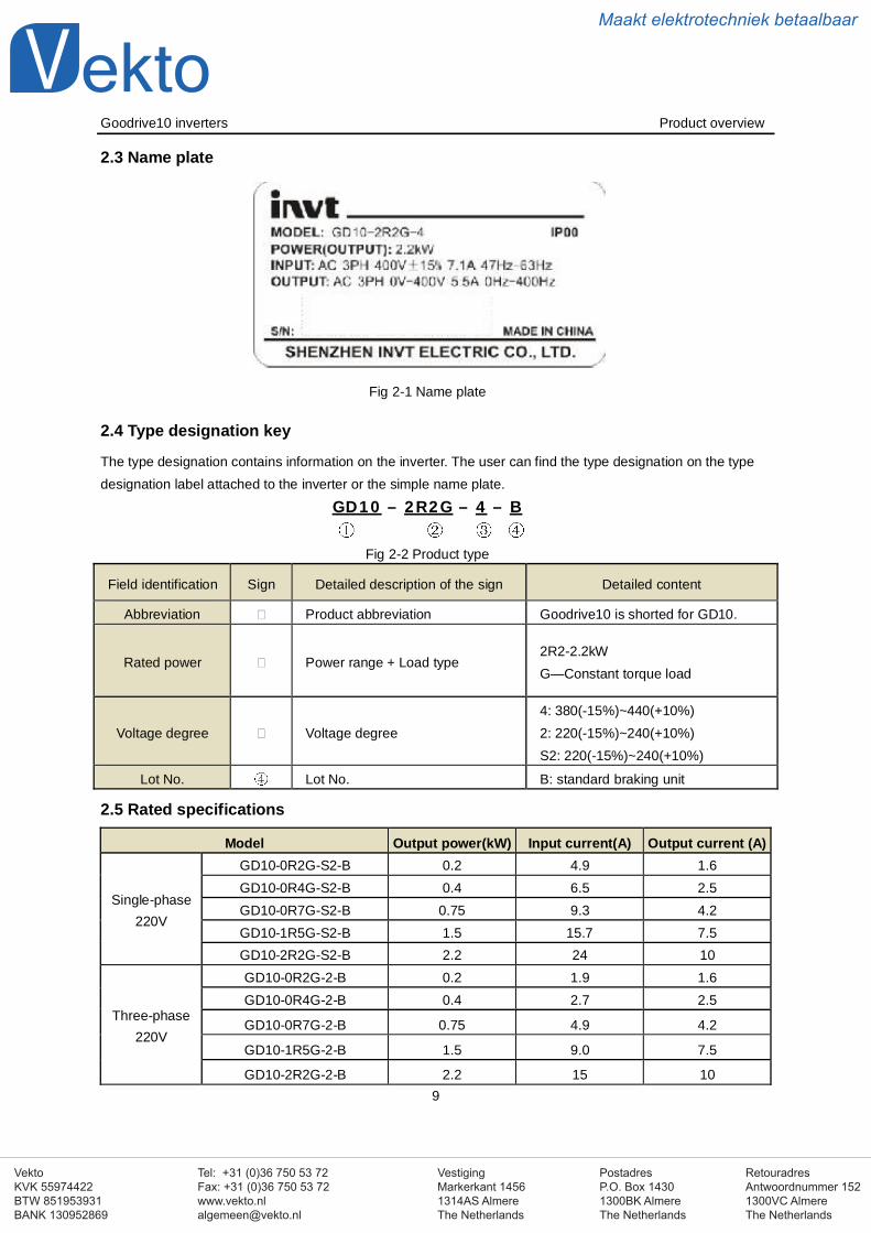
2.3 Name plate
Fig 2-1 Name plate
2.4 Type designation key
The type designation contains information on the inverter. The user can find the type designation on the typedesignation label attached to the inverter or the simple name plate.
GD10 – 2R2G – 4 – B
Fig 2-2 Product type
Field identification Sign Detailed description of the sign Detailed content
Abbreviation Product abbreviation Goodrive10 is shorted for GD10.
Rated power Power range + Load type2R2-2.2kWG—Constant torque load
Voltage degree Voltage degree4: 380(-15%)~440(+10%)2: 220(-15%)~240(+10%)S2: 220(-15%)~240(+10%)
Lot No. Lot No. B: standard braking unit
2.5 Rated specifications
Model Output power(kW) Input current(A) Output current (A)
Single-phase220V
GD10-0R2G-S2-B 0.2 4.9 1.6GD10-0R4G-S2-B 0.4 6.5 2.5GD10-0R7G-S2-B 0.75 9.3 4.2GD10-1R5G-S2-B 1.5 15.7 7.5GD10-2R2G-S2-B 2.2 24 10
Three-phase220V
GD10-0R2G-2-B 0.2 1.9 1.6GD10-0R4G-2-B 0.4 2.7 2.5
GD10-0R7G-2-B 0.75 4.9 4.2
GD10-1R5G-2-B 1.5 9.0 7.5
GD10-2R2G-2-B 2.2 15 10
VestigingMarkerkant 14561314AS AlmereThe Netherlands
PostadresP.O. Box 14301300BK AlmereThe Netherlands
Tel: +31 (0)36 750 53 72Fax: +31 (0)36 750 53 [email protected]
RetouradresAntwoordnummer 1521300VC AlmereThe Netherlands
VektoKVK 55974422BTW 851953931BANK 130952869
Maakt elektrotechniek betaalbaar
Goodrive10 inverters Product overview
10
Three-phase
380V
GD10-0R7G-4-B 0.75 3.2 2.5
GD10-1R5G-4-B 1.5 4.3 4.2
GD10-2R2G-4-B 2.2 7.1 5.5
2.6 Structure diagram
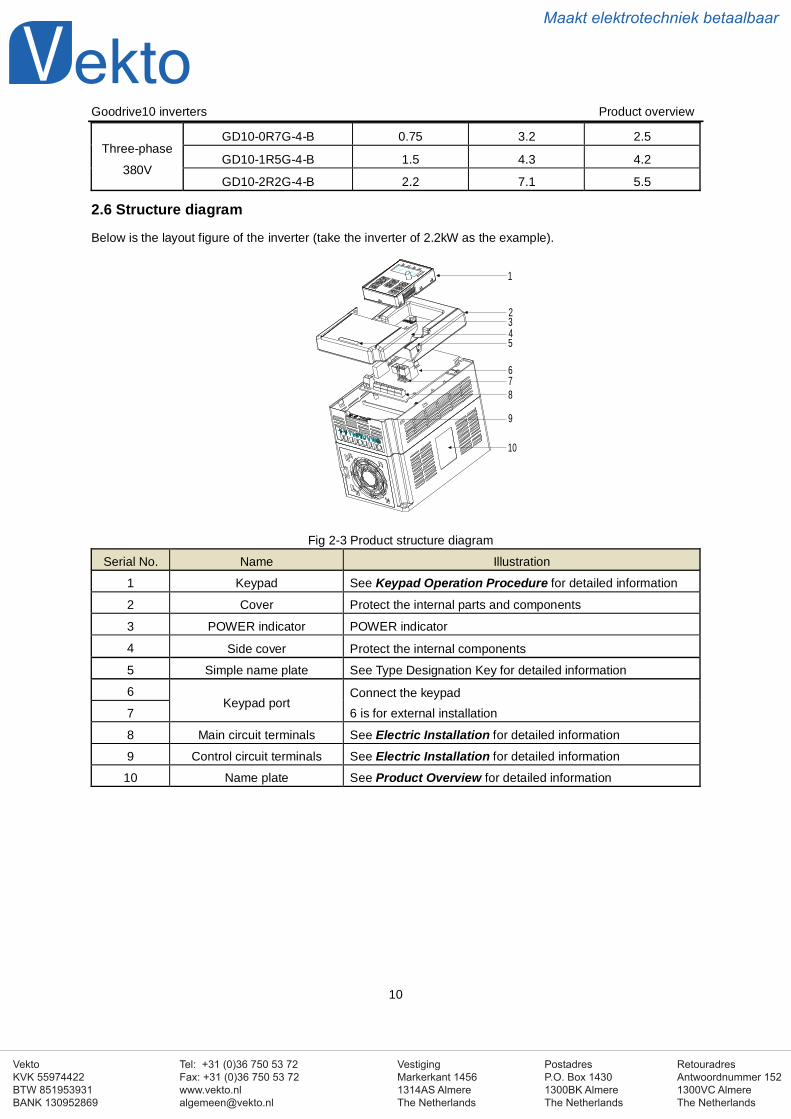
Below is the layout figure of the inverter (take the inverter of 2.2kW as the example).
1
234
678
9
5
10
Fig 2-3 Product structure diagram
Serial No. Name Illustration
1 Keypad See Keypad Operation Procedure for detailed information
2 Cover Protect the internal parts and components
3 POWER indicator POWER indicator
4 Side cover Protect the internal components
5 Simple name plate See Type Designation Key for detailed information
6Keypad port
Connect the keypad6 is for external installation7
8 Main circuit terminals See Electric Installation for detailed information
9 Control circuit terminals See Electric Installation for detailed information
10 Name plate See Product Overview for detailed information
VestigingMarkerkant 14561314AS AlmereThe Netherlands
PostadresP.O. Box 14301300BK AlmereThe Netherlands
Tel: +31 (0)36 750 53 72Fax: +31 (0)36 750 53 [email protected]
RetouradresAntwoordnummer 1521300VC AlmereThe Netherlands
VektoKVK 55974422BTW 851953931BANK 130952869
Maakt elektrotechniek betaalbaar
Goodrive10 inverters Installation guidelines
11
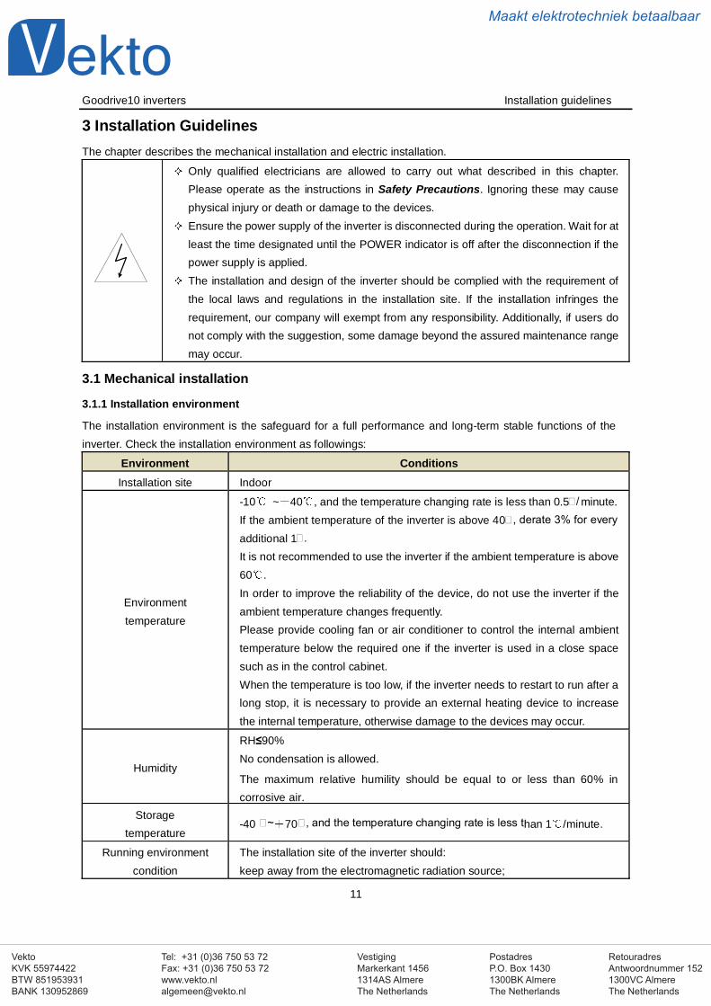
3 Installation GuidelinesThe chapter describes the mechanical installation and electric installation.
Only qualified electricians are allowed to carry out what described in this chapter.Please operate as the instructions in Safety Precautions. Ignoring these may causephysical injury or death or damage to the devices.Ensure the power supply of the inverter is disconnected during the operation. Wait for atleast the time designated until the POWER indicator is off after the disconnection if thepower supply is applied.The installation and design of the inverter should be complied with the requirement ofthe local laws and regulations in the installation site. If the installation infringes therequirement, our company will exempt from any responsibility. Additionally, if users donot comply with the suggestion, some damage beyond the assured maintenance rangemay occur.
3.1 Mechanical installation
3.1.1 Installation environment
The installation environment is the safeguard for a full performance and long-term stable functions of theinverter. Check the installation environment as followings:
Environment ConditionsInstallation site Indoor
Environmenttemperature
-10 ~ 40 , and the temperature changing rate is less than 0.5 / minute.If the ambient temperature of the inverter is above 40 , derate 3% for everyadditional 1 .It is not recommended to use the inverter if the ambient temperature is above60 .In order to improve the reliability of the device, do not use the inverter if theambient temperature changes frequently.Please provide cooling fan or air conditioner to control the internal ambienttemperature below the required one if the inverter is used in a close spacesuch as in the control cabinet.When the temperature is too low, if the inverter needs to restart to run after along stop, it is necessary to provide an external heating device to increasethe internal temperature, otherwise damage to the devices may occur.
Humidity
RH≤90%No condensation is allowed.
The maximum relative humility should be equal to or less than 60% incorrosive air.
Storagetemperature
-40 ~ 70 , and the temperature changing rate is less than 1 /minute.
Running environmentcondition
The installation site of the inverter should:keep away from the electromagnetic radiation source;
VestigingMarkerkant 14561314AS AlmereThe Netherlands
PostadresP.O. Box 14301300BK AlmereThe Netherlands
Tel: +31 (0)36 750 53 72Fax: +31 (0)36 750 53 [email protected]
RetouradresAntwoordnummer 1521300VC AlmereThe Netherlands
VektoKVK 55974422BTW 851953931BANK 130952869
Maakt elektrotechniek betaalbaar
Goodrive10 inverters Installation guidelines
12
Environment Conditionskeep away from contaminative air, such as corrosive gas, oil mist andflammable gas;ensure foreign objects, such as metal power, dust, oil, water can not enterinto the inverter(do not install the inverter on the flammable materials such aswood);keep away from direct sunlight, oil mist, steam and vibration environment.
AltitudeBelow 1000mIf the sea level is above 1000m, please derate 1% for every additional 100m.
Vibration ≤ 5.8m/s2(0.6g)
Installation directionThe inverter should be installed on an upright position to ensure sufficientcooling effect.
Note:Goodrive10 series inverters should be installed in a clean and ventilated environment accordingto enclosure classification.Cooling air must be clean, free from corrosive materials and electrically conductive dust.
3.1.2 Installation direction
The inverter may be installed on the wall or in a cabinet.The inverter must be installed in an upright position. Check the installation site according to the requirementsbelow. Refer to chapter Dimension Drawings in the appendix for frame details.
3.1.3 Installation manner
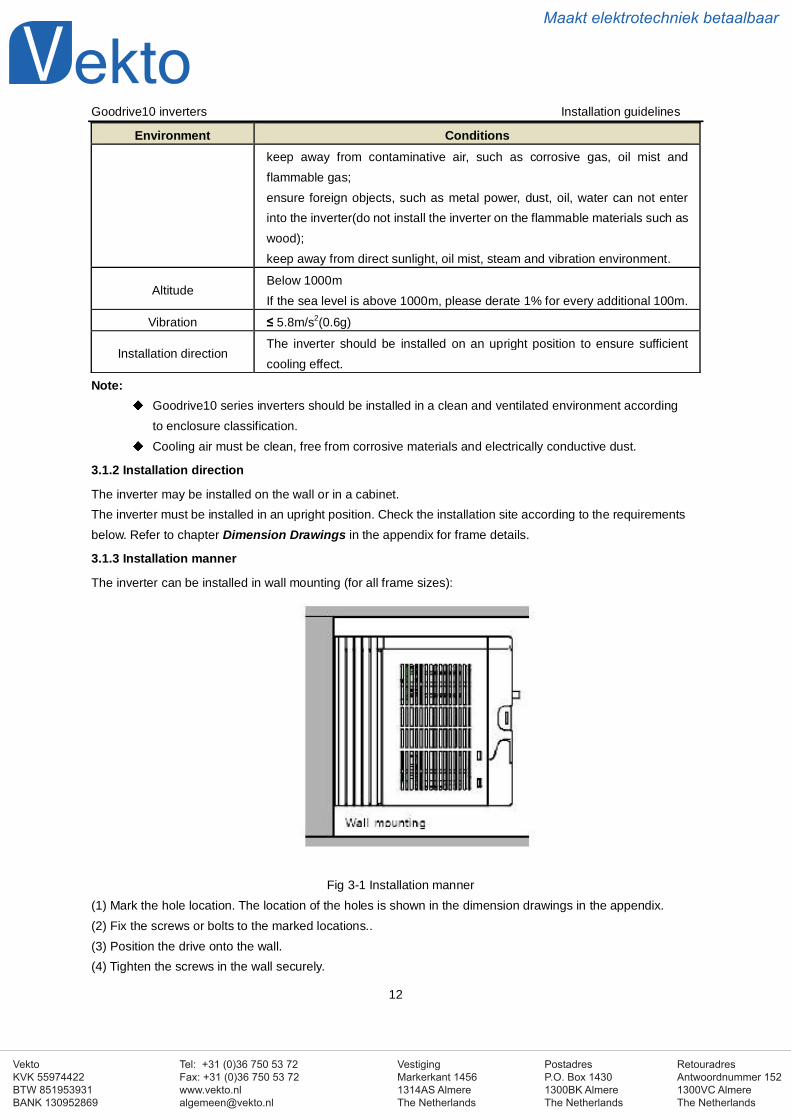
The inverter can be installed in wall mounting (for all frame sizes):
Fig 3-1 Installation manner(1) Mark the hole location. The location of the holes is shown in the dimension drawings in the appendix.(2) Fix the screws or bolts to the marked locations..(3) Position the drive onto the wall.(4) Tighten the screws in the wall securely.
VestigingMarkerkant 14561314AS AlmereThe Netherlands
PostadresP.O. Box 14301300BK AlmereThe Netherlands
Tel: +31 (0)36 750 53 72Fax: +31 (0)36 750 53 [email protected]
RetouradresAntwoordnummer 1521300VC AlmereThe Netherlands
VektoKVK 55974422BTW 851953931BANK 130952869
Maakt elektrotechniek betaalbaar
Goodrive10 inverters Installation guidelines
13
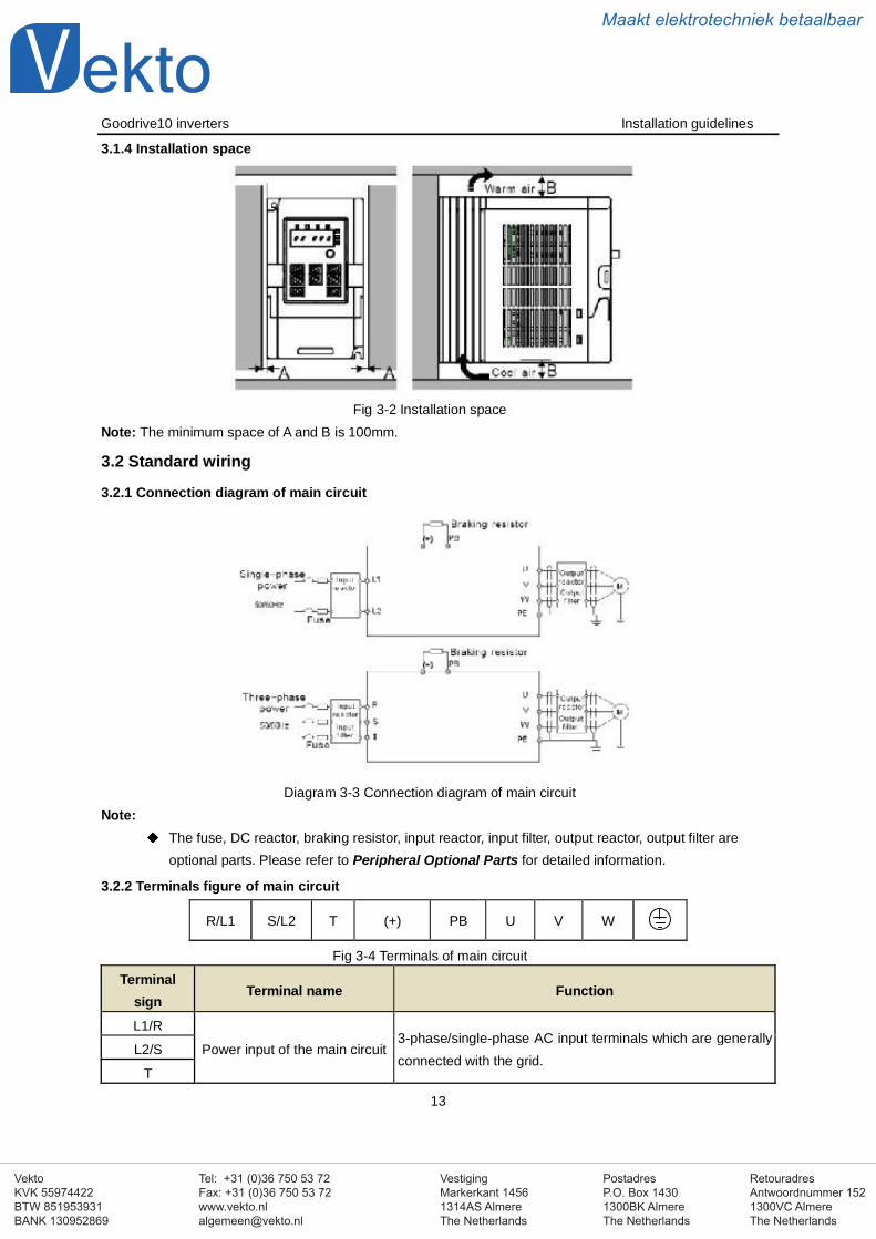
3.1.4 Installation space
Fig 3-2 Installation spaceNote: The minimum space of A and B is 100mm.
3.2 Standard wiring
3.2.1 Connection diagram of main circuit
Diagram 3-3 Connection diagram of main circuitNote:
The fuse, DC reactor, braking resistor, input reactor, input filter, output reactor, output filter areoptional parts. Please refer to Peripheral Optional Parts for detailed information.
3.2.2 Terminals figure of main circuit
R/L1 S/L2 T (+) PB U V W
Fig 3-4 Terminals of main circuit
Terminalsign
Terminal name Function
L1/R
Power input of the main circuit3-phase/single-phase AC input terminals which are generallyconnected with the grid.
L2/S
T
VestigingMarkerkant 14561314AS AlmereThe Netherlands
PostadresP.O. Box 14301300BK AlmereThe Netherlands
Tel: +31 (0)36 750 53 72Fax: +31 (0)36 750 53 [email protected]
RetouradresAntwoordnummer 1521300VC AlmereThe Netherlands
VektoKVK 55974422BTW 851953931BANK 130952869
Maakt elektrotechniek betaalbaar
Goodrive10 inverters Installation guidelines
14
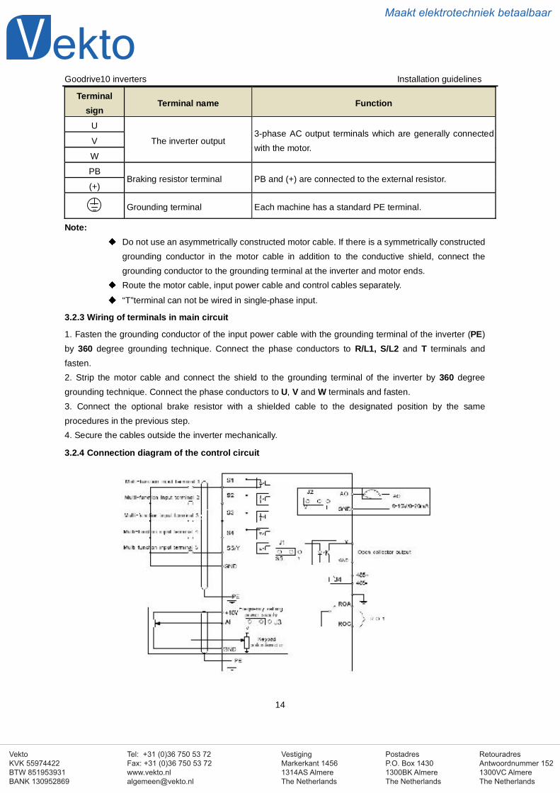
Terminalsign
Terminal name Function
U
The inverter output3-phase AC output terminals which are generally connectedwith the motor.
V
W
PBBraking resistor terminal PB and (+) are connected to the external resistor.
(+)
Grounding terminal Each machine has a standard PE terminal.
Note:Do not use an asymmetrically constructed motor cable. If there is a symmetrically constructedgrounding conductor in the motor cable in addition to the conductive shield, connect thegrounding conductor to the grounding terminal at the inverter and motor ends.Route the motor cable, input power cable and control cables separately.
“T”terminal can not be wired in single-phase input.
3.2.3 Wiring of terminals in main circuit
1. Fasten the grounding conductor of the input power cable with the grounding terminal of the inverter (PE)by 360 degree grounding technique. Connect the phase conductors to R/L1, S/L2 and T terminals andfasten.2. Strip the motor cable and connect the shield to the grounding terminal of the inverter by 360 degreegrounding technique. Connect the phase conductors to U, V and W terminals and fasten.3. Connect the optional brake resistor with a shielded cable to the designated position by the sameprocedures in the previous step.4. Secure the cables outside the inverter mechanically.
3.2.4 Connection diagram of the control circuit
VestigingMarkerkant 14561314AS AlmereThe Netherlands
PostadresP.O. Box 14301300BK AlmereThe Netherlands
Tel: +31 (0)36 750 53 72Fax: +31 (0)36 750 53 [email protected]
RetouradresAntwoordnummer 1521300VC AlmereThe Netherlands
VektoKVK 55974422BTW 851953931BANK 130952869
Maakt elektrotechniek betaalbaar
Goodrive10 inverters Installation guidelines
15
Figure 3-5 Connection diagram of the control circuit
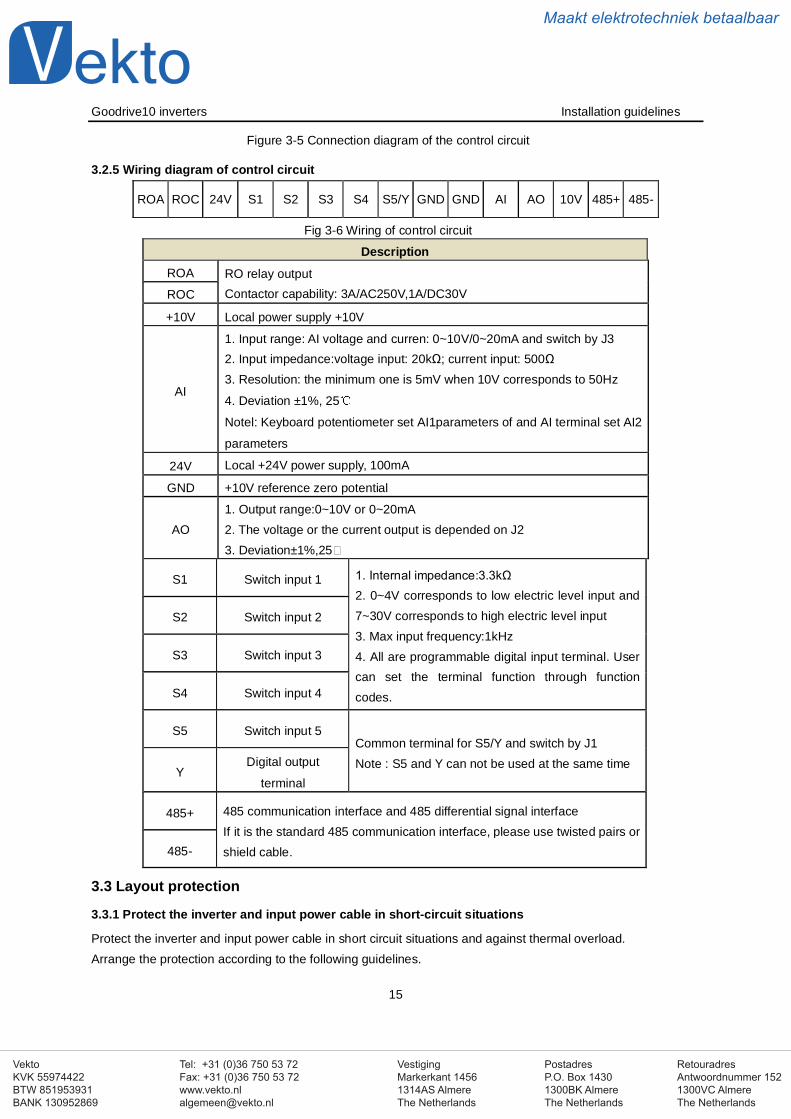
3.2.5 Wiring diagram of control circuit
ROA ROC 24V S1 S2 S3 S4 S5/Y GND GND AI AO 10V 485+ 485-
Fig 3-6 Wiring of control circuit
DescriptionROA RO relay output
Contactor capability: 3A/AC250V,1A/DC30VROC
+10V Local power supply +10V
AI
1. Input range: AI voltage and curren: 0~10V/0~20mA and switch by J32. Input impedance:voltage input: 20kΩ; current input: 500Ω3. Resolution: the minimum one is 5mV when 10V corresponds to 50Hz
4. Deviation ±1%, 25
Notel: Keyboard potentiometer set AI1parameters of and AI terminal set AI2
parameters
24V Local +24V power supply, 100mA
GND +10V reference zero potential
AO1. Output range:0~10V or 0~20mA2. The voltage or the current output is depended on J23. Deviation±1%,25
S1 Switch input 1 1. Internal impedance:3.3kΩ2. 0~4V corresponds to low electric level input and7~30V corresponds to high electric level input3. Max input frequency:1kHz4. All are programmable digital input terminal. Usercan set the terminal function through functioncodes.
S2 Switch input 2
S3 Switch input 3
S4 Switch input 4
S5 Switch input 5Common terminal for S5/Y and switch by J1Note : S5 and Y can not be used at the same time
YDigital output
terminal
485+ 485 communication interface and 485 differential signal interfaceIf it is the standard 485 communication interface, please use twisted pairs orshield cable.485-
3.3 Layout protection
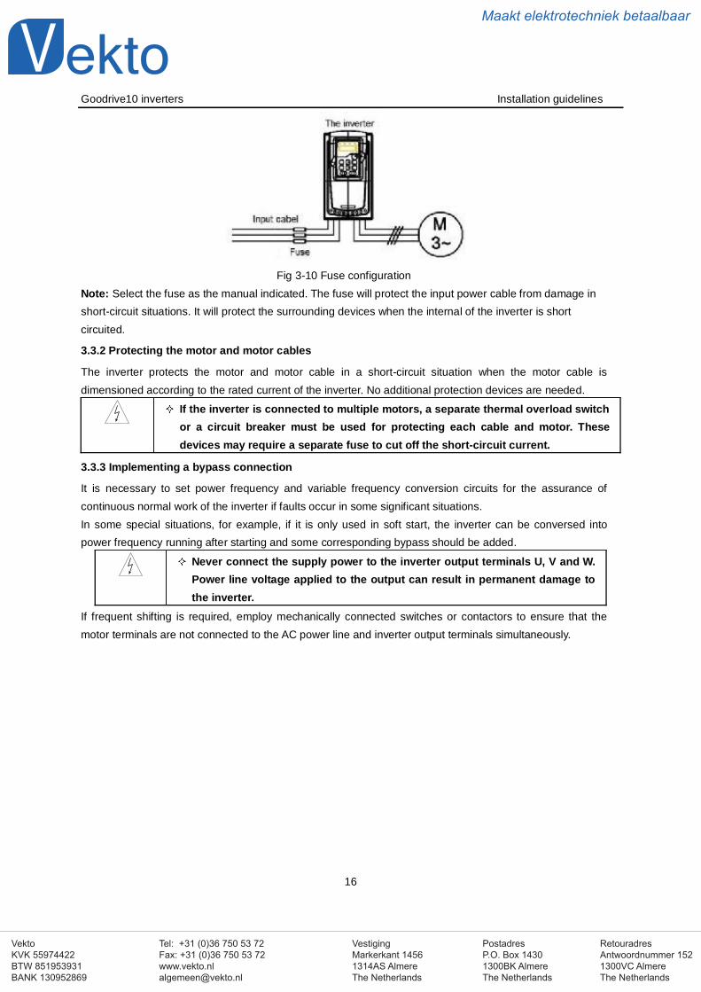
3.3.1 Protect the inverter and input power cable in short-circuit situations
Protect the inverter and input power cable in short circuit situations and against thermal overload.Arrange the protection according to the following guidelines.
VestigingMarkerkant 14561314AS AlmereThe Netherlands
PostadresP.O. Box 14301300BK AlmereThe Netherlands
Tel: +31 (0)36 750 53 72Fax: +31 (0)36 750 53 [email protected]
RetouradresAntwoordnummer 1521300VC AlmereThe Netherlands
VektoKVK 55974422BTW 851953931BANK 130952869
Maakt elektrotechniek betaalbaar
Goodrive10 inverters Installation guidelines
16
Fig 3-10 Fuse configurationNote: Select the fuse as the manual indicated. The fuse will protect the input power cable from damage inshort-circuit situations. It will protect the surrounding devices when the internal of the inverter is shortcircuited.
3.3.2 Protecting the motor and motor cables
The inverter protects the motor and motor cable in a short-circuit situation when the motor cable isdimensioned according to the rated current of the inverter. No additional protection devices are needed.
If the inverter is connected to multiple motors, a separate thermal overload switchor a circuit breaker must be used for protecting each cable and motor. Thesedevices may require a separate fuse to cut off the short-circuit current.
3.3.3 Implementing a bypass connection
It is necessary to set power frequency and variable frequency conversion circuits for the assurance ofcontinuous normal work of the inverter if faults occur in some significant situations.In some special situations, for example, if it is only used in soft start, the inverter can be conversed intopower frequency running after starting and some corresponding bypass should be added.
Never connect the supply power to the inverter output terminals U, V and W.Power line voltage applied to the output can result in permanent damage tothe inverter.
If frequent shifting is required, employ mechanically connected switches or contactors to ensure that themotor terminals are not connected to the AC power line and inverter output terminals simultaneously.
VestigingMarkerkant 14561314AS AlmereThe Netherlands
PostadresP.O. Box 14301300BK AlmereThe Netherlands
Tel: +31 (0)36 750 53 72Fax: +31 (0)36 750 53 [email protected]
RetouradresAntwoordnummer 1521300VC AlmereThe Netherlands
VektoKVK 55974422BTW 851953931BANK 130952869
Maakt elektrotechniek betaalbaar
Goodrive10 inverters Keypad operation procedure
17
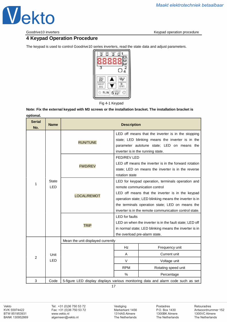
4 Keypad Operation ProcedureThe keypad is used to control Goodrive10 series inverters, read the state data and adjust parameters.
Fig 4-1 Keypad
Note: Fix the external keypad with M3 screws or the installation bracket. The installation bracket isoptional.
SerialNo.
Name Description
1StateLED
RUN/TUNE
LED off means that the inverter is in the stoppingstate; LED blinking means the inverter is in theparameter autotune state; LED on means theinverter is in the running state.
FWD/REV
FED/REV LEDLED off means the inverter is in the forward rotationstate; LED on means the inverter is in the reverserotation state
LOCAL/REMOT
LED for keypad operation, terminals operation andremote communication controlLED off means that the inverter is in the keypadoperation state; LED blinking means the inverter is inthe terminals operation state; LED on means theinverter is in the remote communication control state.
TRIP
LED for faultsLED on when the inverter is in the fault state; LED offin normal state; LED blinking means the inverter is inthe overload pre-alarm state.
2UnitLED
Mean the unit displayed currently
Hz Frequency unit
A Current unit
V Voltage unit
RPM Rotating speed unit
% Percentage
3 Code 5-figure LED display displays various monitoring data and alarm code such as set
VestigingMarkerkant 14561314AS AlmereThe Netherlands
PostadresP.O. Box 14301300BK AlmereThe Netherlands
Tel: +31 (0)36 750 53 72Fax: +31 (0)36 750 53 [email protected]
RetouradresAntwoordnummer 1521300VC AlmereThe Netherlands
VektoKVK 55974422BTW 851953931BANK 130952869
Maakt elektrotechniek betaalbaar
Goodrive10 inverters Keypad operation procedure
18
SerialNo.
Name Description
displaying
zone
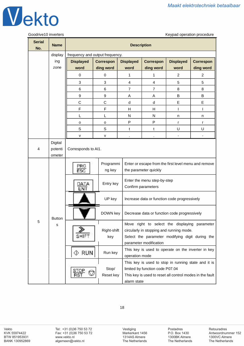
frequency and output frequency.
Displayedword
Corresponding word
Displayedword
Corresponding word
Displayedword
Corresponding word
0 0 1 1 2 2
3 3 4 4 5 5
6 6 7 7 8 8
9 9 A A B B
C C d d E E
F F H H I I
L L N N n n
o o P P r r
S S t t U U
v v . . - -
4Digitalpotentiometer
Corresponds to AI1.
5Button
s
Programming key
Enter or escape from the first level menu and removethe parameter quickly
Entry keyEnter the menu step-by-stepConfirm parameters
UP key Increase data or function code progressively
DOWN key Decrease data or function code progressively
Right-shiftkey
Move right to select the displaying parametercircularly in stopping and running mode.Select the parameter modifying digit during theparameter modification
Run keyThis key is used to operate on the inverter in keyoperation mode
Stop/Reset key
This key is used to stop in running state and it islimited by function code P07.04This key is used to reset all control modes in the faultalarm state
VestigingMarkerkant 14561314AS AlmereThe Netherlands
PostadresP.O. Box 14301300BK AlmereThe Netherlands
Tel: +31 (0)36 750 53 72Fax: +31 (0)36 750 53 [email protected]
RetouradresAntwoordnummer 1521300VC AlmereThe Netherlands
VektoKVK 55974422BTW 851953931BANK 130952869
Maakt elektrotechniek betaalbaar
Goodrive10 inverters Keypad operation procedure
19
SerialNo.
Name Description
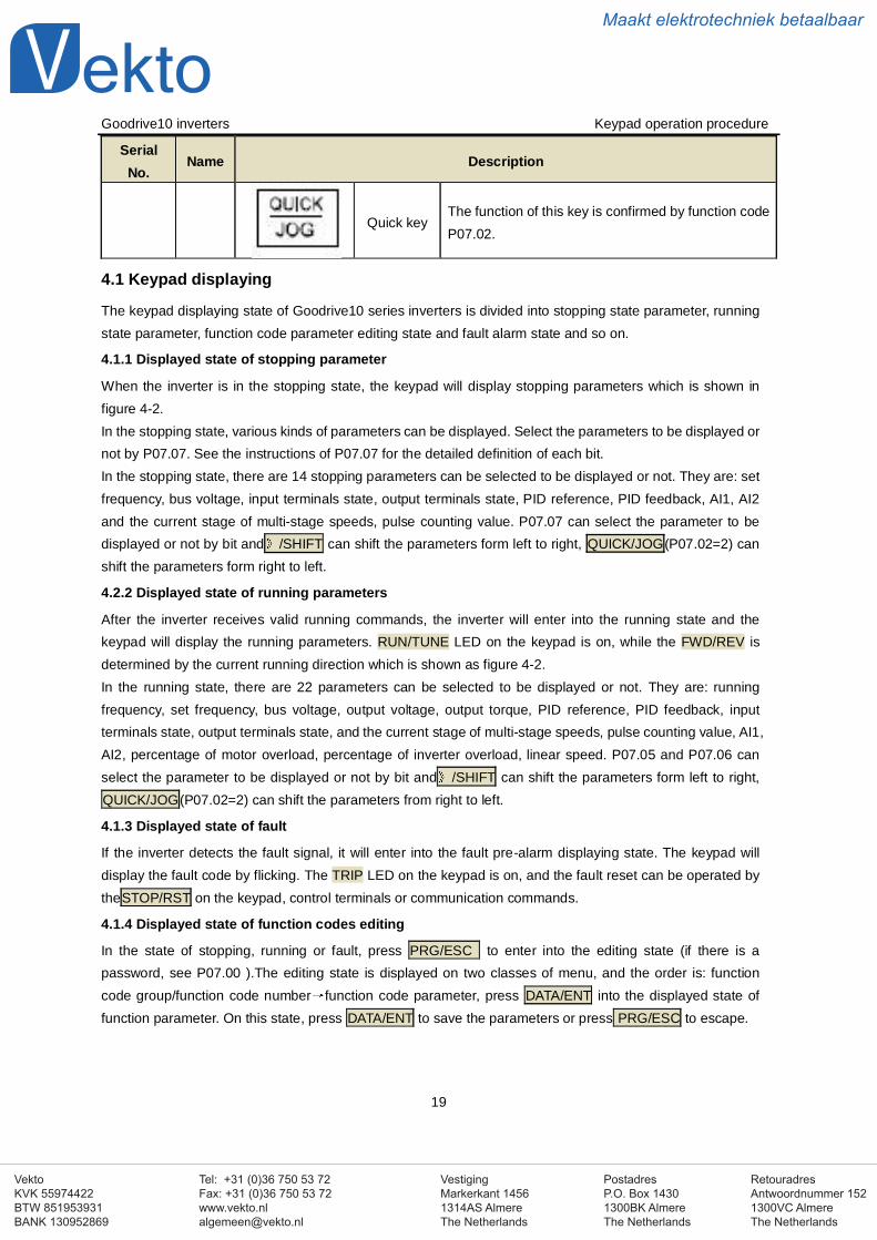
Quick keyThe function of this key is confirmed by function codeP07.02.
4.1 Keypad displaying
The keypad displaying state of Goodrive10 series inverters is divided into stopping state parameter, runningstate parameter, function code parameter editing state and fault alarm state and so on.
4.1.1 Displayed state of stopping parameter
When the inverter is in the stopping state, the keypad will display stopping parameters which is shown infigure 4-2.In the stopping state, various kinds of parameters can be displayed. Select the parameters to be displayed ornot by P07.07. See the instructions of P07.07 for the detailed definition of each bit.In the stopping state, there are 14 stopping parameters can be selected to be displayed or not. They are: setfrequency, bus voltage, input terminals state, output terminals state, PID reference, PID feedback, AI1, AI2and the current stage of multi-stage speeds, pulse counting value. P07.07 can select the parameter to bedisplayed or not by bit and /SHIFT can shift the parameters form left to right, QUICK/JOG(P07.02=2) canshift the parameters form right to left.
4.2.2 Displayed state of running parameters
After the inverter receives valid running commands, the inverter will enter into the running state and thekeypad will display the running parameters. RUN/TUNE LED on the keypad is on, while the FWD/REV isdetermined by the current running direction which is shown as figure 4-2.In the running state, there are 22 parameters can be selected to be displayed or not. They are: runningfrequency, set frequency, bus voltage, output voltage, output torque, PID reference, PID feedback, inputterminals state, output terminals state, and the current stage of multi-stage speeds, pulse counting value, AI1,AI2, percentage of motor overload, percentage of inverter overload, linear speed. P07.05 and P07.06 canselect the parameter to be displayed or not by bit and /SHIFT can shift the parameters form left to right,QUICK/JOG(P07.02=2) can shift the parameters from right to left.
4.1.3 Displayed state of fault
If the inverter detects the fault signal, it will enter into the fault pre-alarm displaying state. The keypad willdisplay the fault code by flicking. The TRIP LED on the keypad is on, and the fault reset can be operated bytheSTOP/RST on the keypad, control terminals or communication commands.
4.1.4 Displayed state of function codes editing
In the state of stopping, running or fault, press PRG/ESC to enter into the editing state (if there is apassword, see P07.00 ).The editing state is displayed on two classes of menu, and the order is: functioncode group/function code number function code parameter, press DATA/ENT into the displayed state offunction parameter. On this state, press DATA/ENT to save the parameters or press PRG/ESC to escape.
VestigingMarkerkant 14561314AS AlmereThe Netherlands
PostadresP.O. Box 14301300BK AlmereThe Netherlands
Tel: +31 (0)36 750 53 72Fax: +31 (0)36 750 53 [email protected]
RetouradresAntwoordnummer 1521300VC AlmereThe Netherlands
VektoKVK 55974422BTW 851953931BANK 130952869
Maakt elektrotechniek betaalbaar
Goodrive10 inverters Keypad operation procedure
20
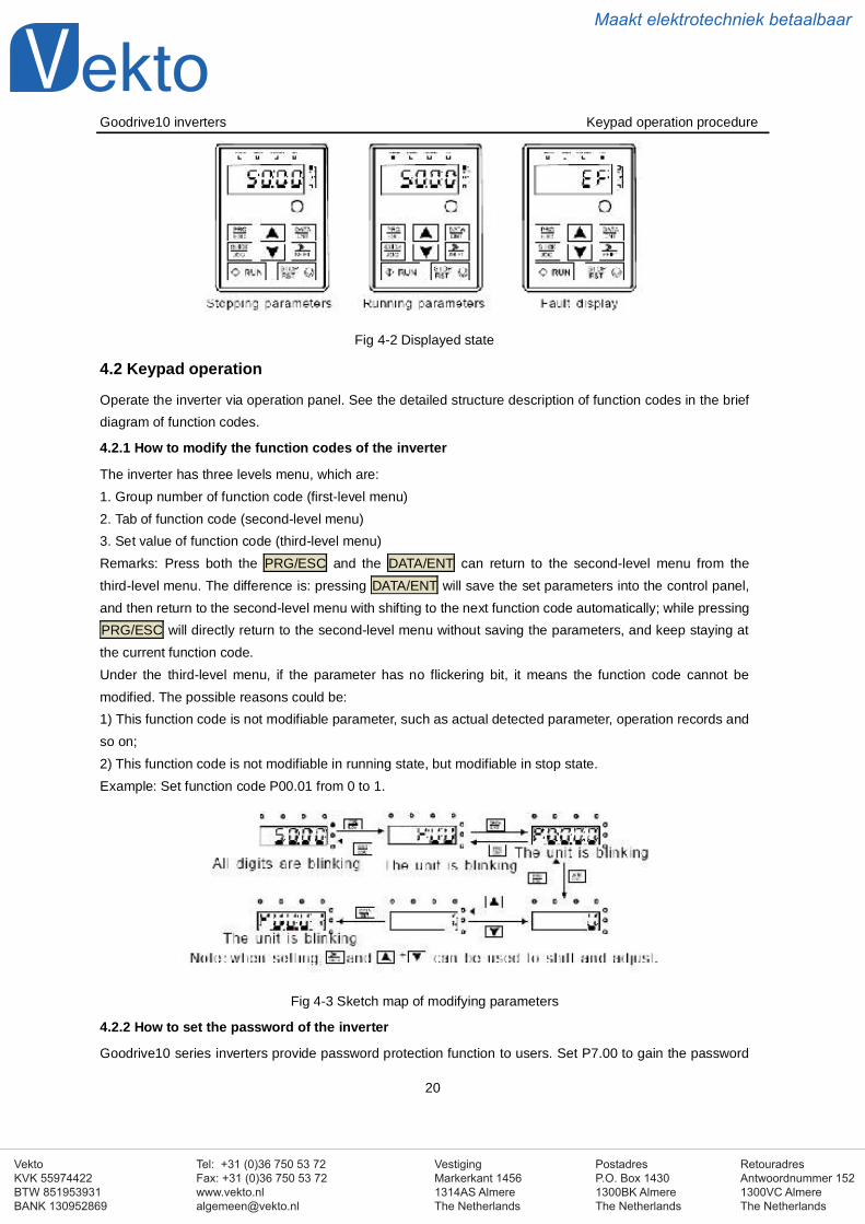
Fig 4-2 Displayed state
4.2 Keypad operation
Operate the inverter via operation panel. See the detailed structure description of function codes in the briefdiagram of function codes.
4.2.1 How to modify the function codes of the inverter
The inverter has three levels menu, which are:1. Group number of function code (first-level menu)2. Tab of function code (second-level menu)3. Set value of function code (third-level menu)Remarks: Press both the PRG/ESC and the DATA/ENT can return to the second-level menu from thethird-level menu. The difference is: pressing DATA/ENT will save the set parameters into the control panel,and then return to the second-level menu with shifting to the next function code automatically; while pressingPRG/ESC will directly return to the second-level menu without saving the parameters, and keep staying atthe current function code.Under the third-level menu, if the parameter has no flickering bit, it means the function code cannot bemodified. The possible reasons could be:1) This function code is not modifiable parameter, such as actual detected parameter, operation records andso on;2) This function code is not modifiable in running state, but modifiable in stop state.Example: Set function code P00.01 from 0 to 1.
Fig 4-3 Sketch map of modifying parameters
4.2.2 How to set the password of the inverter
Goodrive10 series inverters provide password protection function to users. Set P7.00 to gain the password
VestigingMarkerkant 14561314AS AlmereThe Netherlands
PostadresP.O. Box 14301300BK AlmereThe Netherlands
Tel: +31 (0)36 750 53 72Fax: +31 (0)36 750 53 [email protected]
RetouradresAntwoordnummer 1521300VC AlmereThe Netherlands
VektoKVK 55974422BTW 851953931BANK 130952869
Maakt elektrotechniek betaalbaar
Goodrive10 inverters Keypad operation procedure
21
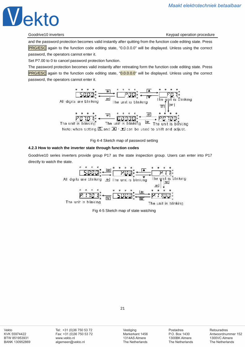
and the password protection becomes valid instantly after quitting from the function code editing state. PressPRG/ESC again to the function code editing state, “0.0.0.0.0” will be displayed. Unless using the correctpassword, the operators cannot enter it.Set P7.00 to 0 to cancel password protection function.The password protection becomes valid instantly after retreating form the function code editing state. PressPRG/ESC again to the function code editing state, “0.0.0.0.0” will be displayed. Unless using the correctpassword, the operators cannot enter it.
Fig 4-4 Sketch map of password setting
4.2.3 How to watch the inverter state through function codes
Goodrive10 series inverters provide group P17 as the state inspection group. Users can enter into P17directly to watch the state.
Fig 4-5 Sketch map of state watching
VestigingMarkerkant 14561314AS AlmereThe Netherlands
PostadresP.O. Box 14301300BK AlmereThe Netherlands
Tel: +31 (0)36 750 53 72Fax: +31 (0)36 750 53 [email protected]
RetouradresAntwoordnummer 1521300VC AlmereThe Netherlands
VektoKVK 55974422BTW 851953931BANK 130952869
Maakt elektrotechniek betaalbaar
Goodrive10 inverters Function codes
22
5 Function ParametersThe function parameters of Goodrive10 series inverters have been divided into 30 groups (P00~P29)according to the function, of which P18~P28 are reserved. Each function group contains certain functioncodes applying 3-level menus. For example, “P08.08” means the eighth function code in the P8 groupfunction, P29 group is factory reserved, and users are forbidden to access these parameters.For the convenience of function codes setting, the function group number corresponds to the first level menu,the function code corresponds to the second level menu and the function code corresponds to the third levelmenu.1. Below is the instruction of the function lists:The first column “Function code”:codes of function parameter group and parametersThe second column “Name”:full name of function parametersThe third column “Detailed illustration of parameters”:Detailed illustration of the function parametersThe fourth column “Default value”:the original factory set value of the function parameterThe fifth column “Modify”: the modifying character of function codes (the parameters can be modified or notand the modifying conditions), below is the instruction:
“ ”: means the set value of the parameter can be modified on stop and running state“ ”: means the set value of the parameter can not be modified on the running state“ ”: means the value of the parameter is the real detection value which can not be modified.
Functioncode
Name Detailed instruction of parametersDefaultvalue
Modify
P00 Group Basic function group
P00.00Speed
control mode
2:V/F control (suitable for AM)2 is suitable in cases where it does not need high controlaccuracy, such as the load of fan and pump. One invertercan drive multiple motors.
2
P00.01Run
commandchannel
Select the run command channel of the inverter.The control command of the inverter includes: start-up,stop, forward, reverse, jogging and fault reset.0:Keypad running command channel(“LOCAL/REMOT”light off)Carry out the command control by RUN, STOP/RST on thekeypad.Set the multi-function key QUICK/JOG to FWD/REVshifting function (P07.02=3) to change the running direction;press RUN and STOP/RST simultaneously in running stateto make the inverter coast to stop.1:Terminal running command channel (“LOCAL/REMOT”flickering)Carry out the running command control by the forward
0
VestigingMarkerkant 14561314AS AlmereThe Netherlands
PostadresP.O. Box 14301300BK AlmereThe Netherlands
Tel: +31 (0)36 750 53 72Fax: +31 (0)36 750 53 [email protected]
RetouradresAntwoordnummer 1521300VC AlmereThe Netherlands
VektoKVK 55974422BTW 851953931BANK 130952869
Maakt elektrotechniek betaalbaar
Goodrive10 inverters Function codes
23
Functioncode
Name Detailed instruction of parametersDefaultvalue
Modify
rotation, reverse rotation and forward jogging and reversejogging of the multi-function terminals2:Communication running command channel(“LOCAL/REMOT” on)The running command is controlled by the upper monitor viacommunication
P00.03Max. outputfrequency
This parameter is used to set the maximum outputfrequency of the inverter. Users should pay attention to thisparameter because it is the foundation of the frequencysetting and the speed of acceleration and deceleration.Setting range: P00.04~400.00Hz
50.00Hz
P00.04Upper limit ofthe runningfrequency
The upper limit of the running frequency is the upper limit ofthe output frequency of the inverter which is lower than orequal to the maximum frequency.Setting range:P00.05~P00.03 (Max. output frequency)
50.00Hz
P00.05Lower limit ofthe runningfrequency
The lower limit of the running frequency is that of the outputfrequency of the inverter.The inverter runs at the lower limit frequency if the setfrequency is lower than the lower limit one.Note: Max. output frequency ≥ Upper limit frequency ≥Lower limit frequencySetting range:0.00Hz~P00.04 (Upper limit of the runningfrequency)
0.00Hz
P00.06A frequencycommandselection
0:Keypad data settingModify the value of function code P00.10 (set the frequencyby keypad) to modify the frequency by the keypad.1:Analog AI1 setting2:Analog AI2 settingAnalog input terminal sets the frequency. There are 2standard analog input terminal, of which AI1 is adjustedthrough digital potentiometer, AI2 (0~10V/0~20mA)can beswitched by the jumper.Note: when AI2 selects 0~20mA input, 20mA corresponds to10V.100.0% of the analog input corresponds to P00.03, -100.0%of the analog input corresponds to the reverse P00.03.6: Multi-stage speed running setting
0
P00.07B frequencycommandselection
1
VestigingMarkerkant 14561314AS AlmereThe Netherlands
PostadresP.O. Box 14301300BK AlmereThe Netherlands
Tel: +31 (0)36 750 53 72Fax: +31 (0)36 750 53 [email protected]
RetouradresAntwoordnummer 1521300VC AlmereThe Netherlands
VektoKVK 55974422BTW 851953931BANK 130952869
Maakt elektrotechniek betaalbaar
Goodrive10 inverters Function codes
24
Functioncode
Name Detailed instruction of parametersDefaultvalue
Modify
The inverter runs at multi-stage speed mode whenP00.06=6 or P00.07=6. Set P05 to select the currentrunning stage, and set P10 to select the current runningfrequency.The multi-stage speed has the priority when P00.06 orP00.07 does not equal to 6, but the setting stage can onlybe the 1~15 stage. The setting stage is 1~15 if P00.06 orP00.07 equals to 6.7: PID control settingThe running mode of the inverter is process PID controlwhen P00.06=7 or P00.07=7. It is necessary to set P09.The running frequency of the inverter is the value after PIDeffect. See P09 for the detailed information of the presetsource, preset value, feedback source of PID.8:MODBUS communication settingThe frequency is set by MODBUS communication. See P14for detailed information.Note: A frequency and B frequency can not set as the samefrequency reference method.
P00.08B frequencycommandreference
0: Maximum output frequency, 100% of B frequencysetting corresponds to the maximum output frequency1: A frequency command, 100% of B frequency settingcorresponds to the maximum output frequency. Select thissetting if it needs to adjust on the base of A frequencycommand
0
P00.09
Combinationtype of the
settingsource
0: A, the current frequency setting is A freauency command1: B, the current frequency setting is B frequency command2: A+B, the current frequency setting is A frequencycommand + B frequency command3: A-B, the current frequency setting is A frequencycommand - B frequency command4: Max (A, B): The bigger one between A frequencycommand and B frequency is the set frequency.5: Min (A, B): The lower one between A frequency commandand B frequency is the set frequency.Note:The combination manner can be shifted byP05(terminal function)
0
P00.10Keypad setfrequency
When A and B frequency commands are selected as“keypad setting”, this parameter will be the initial value ofinverter reference frequencySetting range:0.00 Hz~P00.03(the Max. frequency)
50.00Hz
VestigingMarkerkant 14561314AS AlmereThe Netherlands
PostadresP.O. Box 14301300BK AlmereThe Netherlands
Tel: +31 (0)36 750 53 72Fax: +31 (0)36 750 53 [email protected]
RetouradresAntwoordnummer 1521300VC AlmereThe Netherlands
VektoKVK 55974422BTW 851953931BANK 130952869
Maakt elektrotechniek betaalbaar
Goodrive10 inverters Function codes
25
Functioncode
Name Detailed instruction of parametersDefaultvalue
Modify
P00.11 ACC time 1 ACC time means the time needed if the inverter speeds upfrom 0Hz to the Max. One (P00.03).DEC time means the time needed if the inverter speedsdown from the Max. Output frequency to 0Hz (P00.03).Goodrive10 series inverters define four groups of ACC/DECtime which can be selected by P05. The factory defaultACC/DEC time of the inverter is the first group.Setting range of P00.11 and P00.12:0.0~3600.0s
0.1
P00.12 DEC time 1 0.3
P00.13Runningdirectionselection
0: Runs at the default direction, the inverter runs in theforward direction. FWD/REV indicator is off.1: Runs at the opposite direction, the inverter runs in thereverse direction. FWD/REV indicator is on.Modify the function code to shift the rotation direction of themotor. This effect equals to the shifting the rotation directionby adjusting either two of the motor lines (U, V and W). Themotor rotation direction can be changed by QUICK/JOG onthe keypad. Refer to parameter P07.02.Note: When the function parameter comes back to thedefault value, the motor’s running direction will come backto the factory default state, too. In some cases it should beused with caution after commissioning if the change ofrotation direction is disabled.2: Forbid to run in reverse direction: It can be used in somespecial cases if the reverse running is disabled.
0
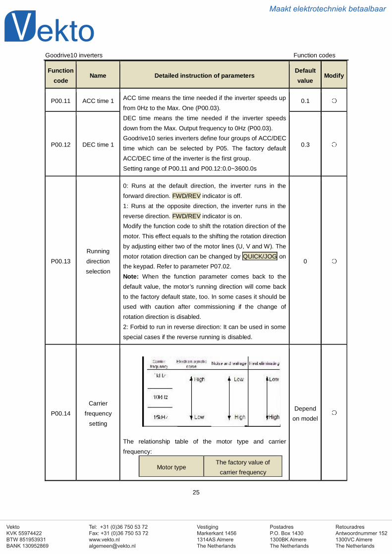
P00.14Carrier
frequencysetting
The relationship table of the motor type and carrierfrequency:
Motor typeThe factory value of
carrier frequency
Dependon model
VestigingMarkerkant 14561314AS AlmereThe Netherlands
PostadresP.O. Box 14301300BK AlmereThe Netherlands
Tel: +31 (0)36 750 53 72Fax: +31 (0)36 750 53 [email protected]
RetouradresAntwoordnummer 1521300VC AlmereThe Netherlands
VektoKVK 55974422BTW 851953931BANK 130952869
Maakt elektrotechniek betaalbaar
Goodrive10 inverters Function codes
26
Functioncode
Name Detailed instruction of parametersDefaultvalue
Modify
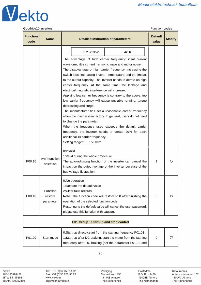
0.2~2.2kW 4kHz
The advantage of high carrier frequency: ideal currentwaveform, little current harmonic wave and motor noise.The disadvantage of high carrier frequency: increasing theswitch loss, increasing inverter temperature and the impactto the output capacity. The inverter needs to derate on highcarrier frequency. At the same time, the leakage andelectrical magnetic interference will increase.Applying low carrier frequency is contrary to the above, toolow carrier frequency will cause unstable running, torquedecreasing and surge.The manufacturer has set a reasonable carrier frequencywhen the inverter is in factory. In general, users do not needto change the parameter.When the frequency used exceeds the default carrierfrequency, the inverter needs to derate 20% for eachadditional 1k carrier frequency.Setting range:1.0~15.0kHz
P00.16AVR function
selection
0:Invalid1:Valid during the whole prodecureThe auto-adjusting function of the inverter can cancel theimpact on the output voltage of the inverter because of thebus voltage fluctuation.
1
P00.18Functionrestore
parameter
0:No operation1:Restore the default value2:Clear fault recordsNote: The function code will restore to 0 after finishing theoperation of the selected function code.Restoring to the default value will cancel the user password,please use this function with caution.
0
P01 Group Start-up and stop control
P01.00 Start mode0:Start-up directly:start from the starting frequency P01.011:Start-up after DC braking: start the motor from the startingfrequency after DC braking (set the parameter P01.03 and
0
VestigingMarkerkant 14561314AS AlmereThe Netherlands
PostadresP.O. Box 14301300BK AlmereThe Netherlands
Tel: +31 (0)36 750 53 72Fax: +31 (0)36 750 53 [email protected]
RetouradresAntwoordnummer 1521300VC AlmereThe Netherlands
VektoKVK 55974422BTW 851953931BANK 130952869
Maakt elektrotechniek betaalbaar
Goodrive10 inverters Function codes
27
Functioncode
Name Detailed instruction of parametersDefaultvalue
Modify
P01.04). It is suitable in the cases where reverse rotationmay occur to the low inertia load during starting.
P01.01
Startingfrequency of
directstart-up
Starting frequency of direct start-up means the originalfrequency during the inverter starting. See P01.02 fordetailed information.Setting range: 0.00~50.00Hz
1.50Hz
P01.02
Retentiontime of the
startingfrequency
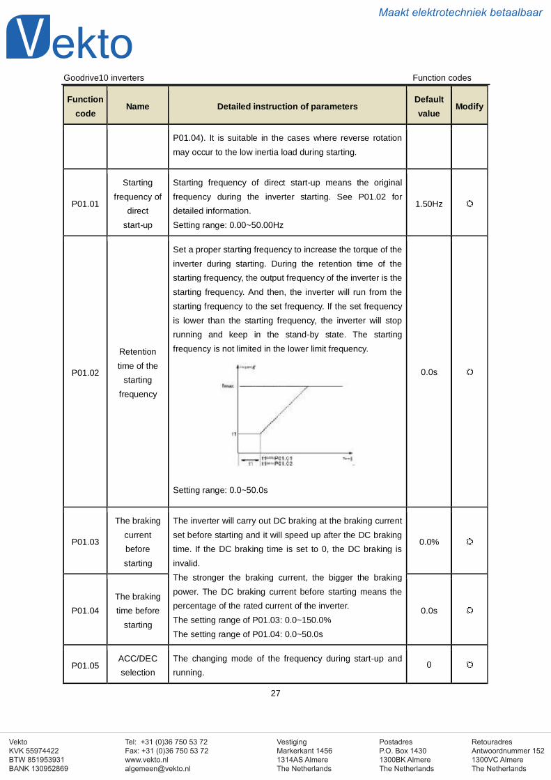
Set a proper starting frequency to increase the torque of theinverter during starting. During the retention time of thestarting frequency, the output frequency of the inverter is thestarting frequency. And then, the inverter will run from thestarting frequency to the set frequency. If the set frequencyis lower than the starting frequency, the inverter will stoprunning and keep in the stand-by state. The startingfrequency is not limited in the lower limit frequency.
Setting range: 0.0~50.0s
0.0s
P01.03
The brakingcurrentbeforestarting
The inverter will carry out DC braking at the braking currentset before starting and it will speed up after the DC brakingtime. If the DC braking time is set to 0, the DC braking isinvalid.The stronger the braking current, the bigger the brakingpower. The DC braking current before starting means thepercentage of the rated current of the inverter.The setting range of P01.03: 0.0~150.0%The setting range of P01.04: 0.0~50.0s
0.0%
P01.04The brakingtime before
starting0.0s
P01.05ACC/DECselection
The changing mode of the frequency during start-up andrunning.
0
VestigingMarkerkant 14561314AS AlmereThe Netherlands
PostadresP.O. Box 14301300BK AlmereThe Netherlands
Tel: +31 (0)36 750 53 72Fax: +31 (0)36 750 53 [email protected]
RetouradresAntwoordnummer 1521300VC AlmereThe Netherlands
VektoKVK 55974422BTW 851953931BANK 130952869
Maakt elektrotechniek betaalbaar
Goodrive10 inverters Function codes
28
Functioncode
Name Detailed instruction of parametersDefaultvalue
Modify
0:Linear typeThe output frequency increases or decreases linearly.
P01.08Stop
selection
0: Decelerate to stop: after the stop command becomesvalid, the inverter decelerates to decrease the outputfrequency during the set time. When the frequencydecreases to 0, the inverter stops.1: Coast to stop: after the stop command becomes valid, theinverter ceases the output immediately. And the load coaststo stop at the mechanical inertia.
0
P01.09Starting
frequency ofDC braking
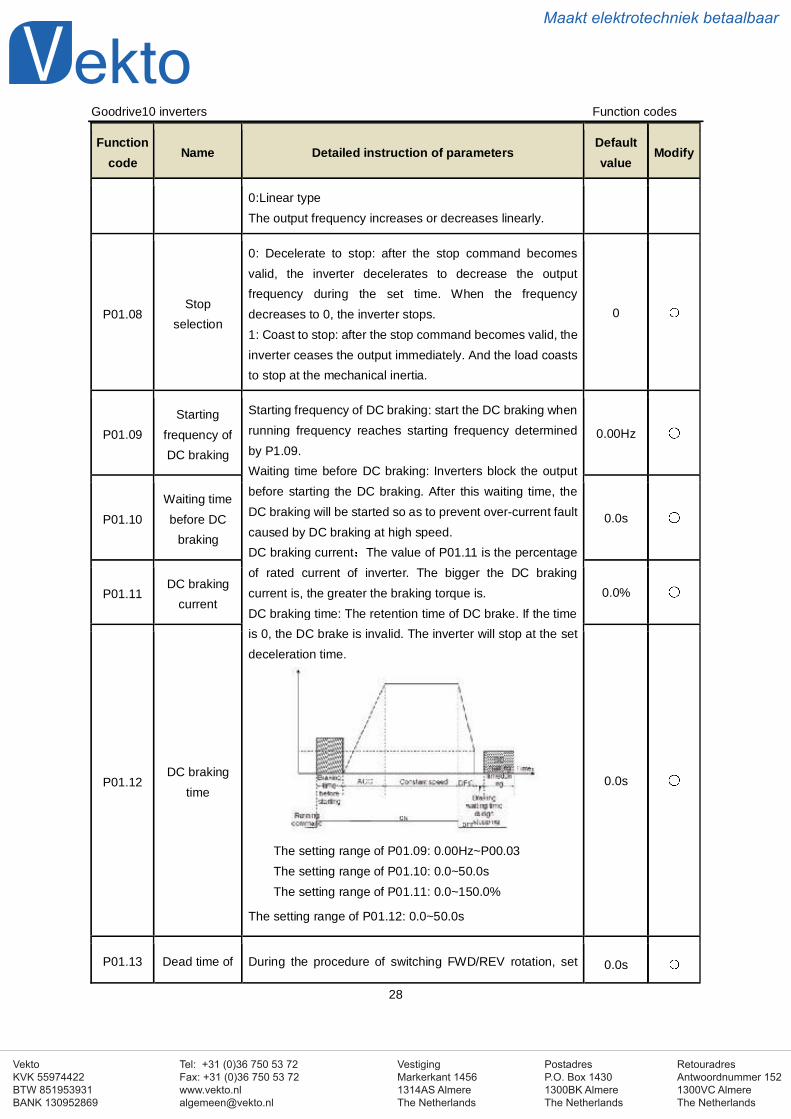
Starting frequency of DC braking: start the DC braking whenrunning frequency reaches starting frequency determinedby P1.09.Waiting time before DC braking: Inverters block the outputbefore starting the DC braking. After this waiting time, theDC braking will be started so as to prevent over-current faultcaused by DC braking at high speed.DC braking current The value of P01.11 is the percentageof rated current of inverter. The bigger the DC brakingcurrent is, the greater the braking torque is.DC braking time: The retention time of DC brake. If the timeis 0, the DC brake is invalid. The inverter will stop at the setdeceleration time.
The setting range of P01.09: 0.00Hz~P00.03The setting range of P01.10: 0.0~50.0sThe setting range of P01.11: 0.0~150.0%
The setting range of P01.12: 0.0~50.0s
0.00Hz
P01.10Waiting timebefore DC
braking
0.0s
P01.11DC braking
current0.0%
P01.12DC braking
time0.0s
P01.13 Dead time of During the procedure of switching FWD/REV rotation, set 0.0s
VestigingMarkerkant 14561314AS AlmereThe Netherlands
PostadresP.O. Box 14301300BK AlmereThe Netherlands
Tel: +31 (0)36 750 53 72Fax: +31 (0)36 750 53 [email protected]
RetouradresAntwoordnummer 1521300VC AlmereThe Netherlands
VektoKVK 55974422BTW 851953931BANK 130952869
Maakt elektrotechniek betaalbaar
Goodrive10 inverters Function codes
29
Functioncode
Name Detailed instruction of parametersDefaultvalue
Modify
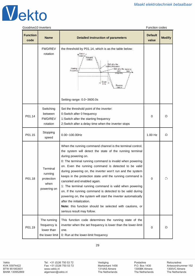
FWD/REVrotation
the threshold by P01.14, which is as the table below:
Setting range: 0.0~3600.0s
P01.14
Switchingbetween
FWD/REVrotation
Set the threshold point of the inverter:0:Switch after 0 frequency1:Switch after the starting frequency2:Switch after a delay time when the inverter stops
0
P01.15Stopping
speed0.00~100.00Hz 1.00 Hz
P01.18
Terminalrunning
protectionwhen
powering on
When the running command channel is the terminal control,the system will detect the state of the running terminalduring powering on.0: The terminal running command is invalid when poweringon. Even the running command is detected to be validduring powering on, the inverter won’t run and the systemkeeps in the protection state until the running command iscanceled and enabled again.1: The terminal running command is valid when poweringon. If the running command is detected to be valid duringpowering on, the system will start the inverter automaticallyafter the initialization.Note: this function should be selected with cautions, orserious result may follow.
0
P01.19
The runningfrequency islower than
the lower limit
This function code determines the running state of theinverter when the set frequency is lower than the lower-limitone.0: Run at the lower-limit frequency
0
VestigingMarkerkant 14561314AS AlmereThe Netherlands
PostadresP.O. Box 14301300BK AlmereThe Netherlands
Tel: +31 (0)36 750 53 72Fax: +31 (0)36 750 53 [email protected]
RetouradresAntwoordnummer 1521300VC AlmereThe Netherlands
VektoKVK 55974422BTW 851953931BANK 130952869
Maakt elektrotechniek betaalbaar
Goodrive10 inverters Function codes
30
Functioncode
Name Detailed instruction of parametersDefaultvalue
Modify
one (valid ifthe lower limitfrequency is
above 0)
1: Stop2: HibernationThe inverter will coast to stop when the set frequency islower than the lower-limit one.if the set frequency is abovethe lower limit one again and it lasts for the time set byP01.20, the inverter will come back to the running stateautomatically.
P01.20Hibernation
restore delaytime
This function code determines the hibernation delay time.When the running frequency of the inverter is lower than thelower limit one, the inverter will pause to stand by.When the set frequency is above the lower limit one againand it lasts for the time set by P01.20, the inverter will runautomatically.Note: The time is the total value when the set frequency isabove the lower limit one.Setting range: 0.0~3600.0s (valid when P01.19=2)
0.0s
P01.21Restart after
power off
This function can enable the inverter start or not after thepower off and then power on.0: Disabled1: Enabled, if the starting need is met, the inverter will runautomatically after waiting for the time defined by P01.22.
0
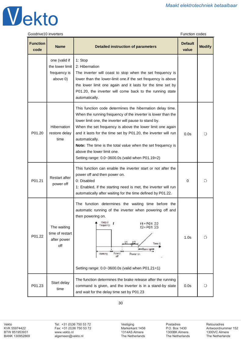
P01.22
The waitingtime of restartafter power
off
The function determines the waiting time before theautomatic running of the inverter when powering off andthen powering on.
Setting range: 0.0~3600.0s (valid when P01.21=1)
1.0s
P01.23Start delay
time
The function determines the brake release after the runningcommand is given, and the inverter is in a stand-by stateand wait for the delay time set by P01.23
0.0s
VestigingMarkerkant 14561314AS AlmereThe Netherlands
PostadresP.O. Box 14301300BK AlmereThe Netherlands
Tel: +31 (0)36 750 53 72Fax: +31 (0)36 750 53 [email protected]
RetouradresAntwoordnummer 1521300VC AlmereThe Netherlands
VektoKVK 55974422BTW 851953931BANK 130952869
Maakt elektrotechniek betaalbaar
Goodrive10 inverters Function codes
31
Functioncode
Name Detailed instruction of parametersDefaultvalue
Modify
Setting range: 0.0~60.0s
P01.24Delay of the
stoppingspeed
Setting range: 0.0~100.0 s 0.0s
P02 Group Motor 1
P02.01Asynchronous motor rated
power0.1~3000.0kW
Dependon model
P02.02Asynchronous motor rated
frequency0.01Hz~P00.03(the Max. frequency) 50.00Hz
P02.03Asynchronous motor rated
speed1~36000rpm
Dependon model
P02.04Asynchronous motor rated
voltage0~1200V
Dependon model
P02.05Asynchronous motor rated
current0.8~6000.0A
Dependon model
P02.06Asynchronous motor stator
resistor0.001~65.535Ω
Dependon model
P02.07Asynchronous motor rotor
resistor0.001~65.535Ω
Dependon model
P02.08
Asynchronous motorleakage
inductance
0.1~6553.5mHDepend
on model
VestigingMarkerkant 14561314AS AlmereThe Netherlands
PostadresP.O. Box 14301300BK AlmereThe Netherlands
Tel: +31 (0)36 750 53 72Fax: +31 (0)36 750 53 [email protected]
RetouradresAntwoordnummer 1521300VC AlmereThe Netherlands
VektoKVK 55974422BTW 851953931BANK 130952869
Maakt elektrotechniek betaalbaar
Goodrive10 inverters Function codes
32
Functioncode
Name Detailed instruction of parametersDefaultvalue
Modify
P02.09
Asynchronous motormutual
inductance
0.1~6553.5mHDepend
on model
P02.10
Asynchronous motor
non-loadcurrent
0.1~6553.5ADepend
on model
P02.26Motor
overloadprotection
0:No protection1: Common motor (with low speed compensation). Becausethe heat-releasing effect of the common motors will beweakened, the corresponding electric heat protection will beadjusted properly. The low speed compensationcharacteristic mentioned here means reducing the thresholdof the overload protection of the motor whose runningfrequency is below 30Hz.2: Frequency conversion motor (without low speedcompensation) Because the heat-releasing effect of thespecific motors won’t be impacted by the rotation speed, it isnot necessary to adjust the protection value duringlow-speed running.
2
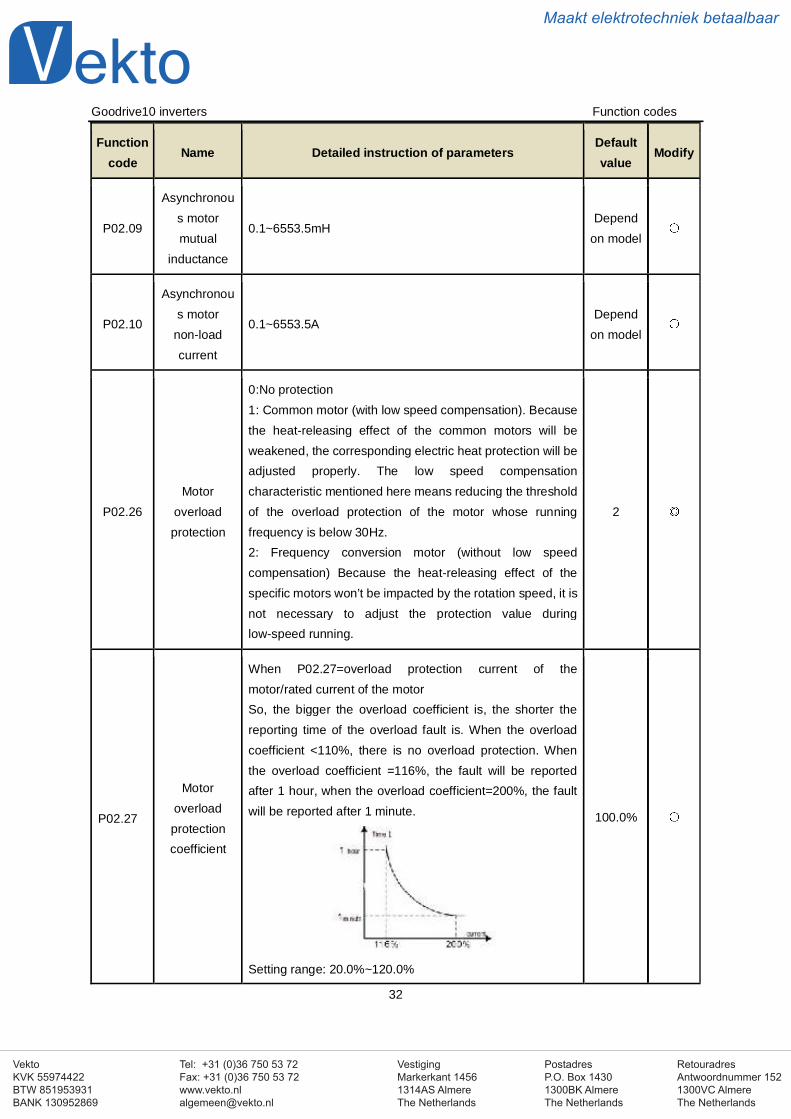
P02.27
Motoroverloadprotectioncoefficient
When P02.27=overload protection current of themotor/rated current of the motorSo, the bigger the overload coefficient is, the shorter thereporting time of the overload fault is. When the overloadcoefficient <110%, there is no overload protection. Whenthe overload coefficient =116%, the fault will be reportedafter 1 hour, when the overload coefficient=200%, the faultwill be reported after 1 minute.
Setting range: 20.0%~120.0%
100.0%
VestigingMarkerkant 14561314AS AlmereThe Netherlands
PostadresP.O. Box 14301300BK AlmereThe Netherlands
Tel: +31 (0)36 750 53 72Fax: +31 (0)36 750 53 [email protected]
RetouradresAntwoordnummer 1521300VC AlmereThe Netherlands
VektoKVK 55974422BTW 851953931BANK 130952869
Maakt elektrotechniek betaalbaar
Goodrive10 inverters Function codes
33
Functioncode
Name Detailed instruction of parametersDefaultvalue
Modify
P04 Group V/F control
P04.00 Motor V/Fcurve setting
These function codes define the V/F curve of Goodrive10motor to meet the need of different loads.0:Straight line V/F curve applying to the constant torqueload1:Multi-dots V/F curve
0
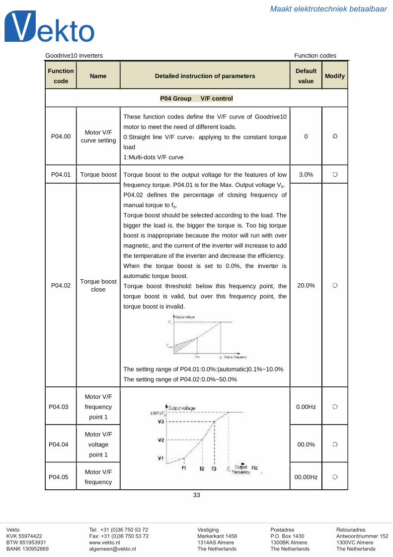
P04.01 Torque boost Torque boost to the output voltage for the features of lowfrequency torque. P04.01 is for the Max. Output voltage Vb.P04.02 defines the percentage of closing frequency ofmanual torque to fb.Torque boost should be selected according to the load. Thebigger the load is, the bigger the torque is. Too big torqueboost is inappropriate because the motor will run with overmagnetic, and the current of the inverter will increase to addthe temperature of the inverter and decrease the efficiency.When the torque boost is set to 0.0%, the inverter isautomatic torque boost.Torque boost threshold: below this frequency point, thetorque boost is valid, but over this frequency point, thetorque boost is invalid.
The setting range of P04.01:0.0%:(automatic)0.1%~10.0%The setting range of P04.02:0.0%~50.0%
3.0%
P04.02 Torque boostclose 20.0%
P04.03Motor V/Ffrequency
point 10.00Hz
P04.04Motor V/F
voltagepoint 1
00.0%
P04.05Motor V/Ffrequency
00.00Hz
VestigingMarkerkant 14561314AS AlmereThe Netherlands
PostadresP.O. Box 14301300BK AlmereThe Netherlands
Tel: +31 (0)36 750 53 72Fax: +31 (0)36 750 53 [email protected]
RetouradresAntwoordnummer 1521300VC AlmereThe Netherlands
VektoKVK 55974422BTW 851953931BANK 130952869
Maakt elektrotechniek betaalbaar
Goodrive10 inverters Function codes
34
Functioncode
Name Detailed instruction of parametersDefaultvalue
Modify
point 2 When P04.00 =1, the user can set V//F curve throughP04.03~P04.08.V/F is generally set according to the load of the motor.Note:V1 V2 V3,f1 f2 f3. Too high low frequencyvoltage will heat the motor excessively or damage. Theinverter may occur the overcurrent speed or overcurrentprotection.The setting range of P04.03: 0.00Hz~P04.05The setting range of P04.04, P04.06 and P04.08 :0.0%~110.0%The setting range of P04.05:P04.03~ P04.07The setting range of P04.07:P04.05~P02.02(the ratedfrequency of motor 1)
P04.06Motor V/F
voltage point2
00.0%
P04.07Motor V/Ffrequency
point 300.00Hz
P04.08Motor V/F
voltage point3
00.0%
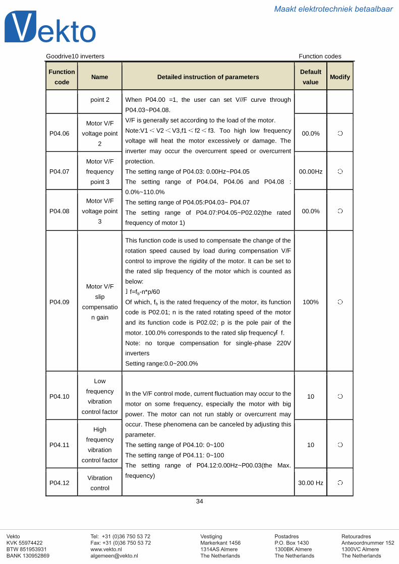
P04.09
Motor V/Fslip
compensation gain
This function code is used to compensate the change of therotation speed caused by load during compensation V/Fcontrol to improve the rigidity of the motor. It can be set tothe rated slip frequency of the motor which is counted asbelow:
f=fb-n*p/60Of which, fb is the rated frequency of the motor, its functioncode is P02.01; n is the rated rotating speed of the motorand its function code is P02.02; p is the pole pair of themotor. 100.0% corresponds to the rated slip frequency f.Note: no torque compensation for single-phase 220VinvertersSetting range:0.0~200.0%
100%
P04.10
Lowfrequencyvibration
control factor
In the V/F control mode, current fluctuation may occur to themotor on some frequency, especially the motor with bigpower. The motor can not run stably or overcurrent mayoccur. These phenomena can be canceled by adjusting thisparameter.The setting range of P04.10: 0~100The setting range of P04.11: 0~100The setting range of P04.12:0.00Hz~P00.03(the Max.frequency)
10
P04.11
Highfrequencyvibration
control factor
10
P04.12Vibrationcontrol
30.00 Hz
VestigingMarkerkant 14561314AS AlmereThe Netherlands
PostadresP.O. Box 14301300BK AlmereThe Netherlands
Tel: +31 (0)36 750 53 72Fax: +31 (0)36 750 53 [email protected]
RetouradresAntwoordnummer 1521300VC AlmereThe Netherlands
VektoKVK 55974422BTW 851953931BANK 130952869
Maakt elektrotechniek betaalbaar
Goodrive10 inverters Function codes
35
Functioncode
Name Detailed instruction of parametersDefaultvalue
Modify
threshold
P04.26Eneregy-saving operation
0: No operation
1: Automatic eneergy-savingThe motor adjust the output voltage in non-load stateautomatically.
0
P05 Group Input terminals
P05.01S1 terminals
functionselection
0: No function1: Forward rotation operation2: Reverse rotation operation3: 3-wire control operation4: Forward rotation jogging5: Reverse rotation jogging6: Coast to stop7: Fault reset8: Operation pause9: External fault input10:Increasing frequency setting(UP)11:Decreasing frequency setting(DOWN)12:Cancel the frequency change setting13:Shift between A setting and B setting14:Shift between combination setting and A setting15:Shift between combination setting and B setting16:Multi-stage speed terminal 117:Multi-stage speed terminal 218:Multi-stage speed terminal 319:Multi- stage speed terminal 420:Multi- stage speed pause21:ACC/DEC time option 125:PID control pause26:Traverse Pause(stop at the current frequency)27:Traverse reset(return to the center frequency)28:Counter reset30:ACC/DEC prohibition31:Counter trigger33:Cancel the frequency change setting temporarily
1
P05.02S2 terminals
functionselection
4
P05.03S3 terminals
functionselection
7
P05.04S4 terminals
functionselection
0
P05.05S5 terminals
functionselection
0
VestigingMarkerkant 14561314AS AlmereThe Netherlands
PostadresP.O. Box 14301300BK AlmereThe Netherlands
Tel: +31 (0)36 750 53 72Fax: +31 (0)36 750 53 [email protected]
RetouradresAntwoordnummer 1521300VC AlmereThe Netherlands
VektoKVK 55974422BTW 851953931BANK 130952869
Maakt elektrotechniek betaalbaar
Goodrive10 inverters Function codes
36
Functioncode
Name Detailed instruction of parametersDefaultvalue
Modify
34:DC brake36:Shift the command to the keypad37:Shift the command to the terminals38:Shift the command to the communication42: Stop at fixed time enabled (special for incense-makingmachine)43~63: Reserved
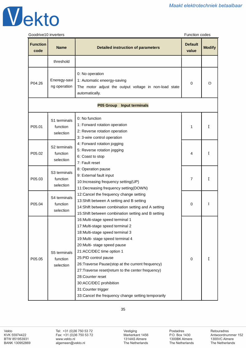
P05.10
Polarityselection of
the inputterminals
The function code is used to set the polarity of the inputterminals.Set the bit to 0, the input terminal is anode.Set the bit to 1, the input terminal is cathode.
BIT0 BIT1 BIT2 BIT3 BIT4
S1 S2 S3 S4 S5The setting range:0x000~0x1F
0x000
P05.11Switch filter
time
Set the sample filter time of S1~S5 and HDI terminals. If theinterference is strong, increase the parameter to avoid thedisoperation.0.000~1.000s
0.003s
P05.12Virtual
terminalssetting
Enable the input function of virtual terminals at thecommunication mode.0:Virtual terminals is invalid1:MODBUS communication virtual terminals are valid
0
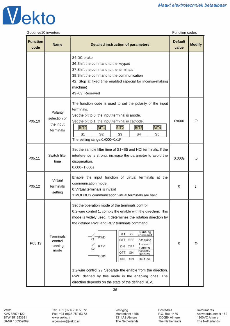
P05.13
Terminalscontrolrunningmode
Set the operation mode of the terminals control0:2-wire control 1, comply the enable with the direction. Thismode is widely used. It determines the rotation direction bythe defined FWD and REV terminals command.
1:2-wire control 2 Separate the enable from the direction.FWD defined by this mode is the enabling ones. Thedirection depends on the state of the defined REV.
0
VestigingMarkerkant 14561314AS AlmereThe Netherlands
PostadresP.O. Box 14301300BK AlmereThe Netherlands
Tel: +31 (0)36 750 53 72Fax: +31 (0)36 750 53 [email protected]
RetouradresAntwoordnummer 1521300VC AlmereThe Netherlands
VektoKVK 55974422BTW 851953931BANK 130952869
Maakt elektrotechniek betaalbaar
Goodrive10 inverters Function codes
37
Functioncode
Name Detailed instruction of parametersDefaultvalue
Modify
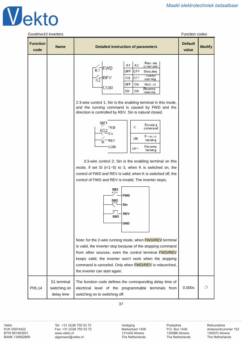
2:3-wire control 1; Sin is the enabling terminal in this mode,and the running command is caused by FWD and thedirection is controlled by REV. Sin is natural closed.
3:3-wire control 2; Sin is the enabling terminal on thismode, if set Si (i=1~5) to 3, when K is switched on, thecontrol of FWD and REV is valid; when K is switched off, thecontrol of FWD and REV is invalid. The inverter stops.
GND
SB2
SB1
FWD
REV
SIn
SB3
Note: for the 2-wire running mode, when FWD/REV terminalis valid, the inverter stop because of the stopping commandfrom other sources, even the control terminal FWD/REVkeeps valid; the inverter won’t work when the stoppingcommand is canceled. Only when FWD/REV is relaunched,the inverter can start again.
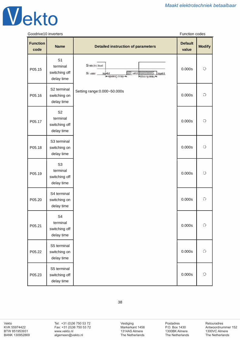
P05.14S1 terminalswitching ondelay time
The function code defines the corresponding delay time ofelectrical level of the programmable terminals fromswitching on to switching off.
0.000s
VestigingMarkerkant 14561314AS AlmereThe Netherlands
PostadresP.O. Box 14301300BK AlmereThe Netherlands
Tel: +31 (0)36 750 53 72Fax: +31 (0)36 750 53 [email protected]
RetouradresAntwoordnummer 1521300VC AlmereThe Netherlands
VektoKVK 55974422BTW 851953931BANK 130952869
Maakt elektrotechniek betaalbaar
Goodrive10 inverters Function codes
38
Functioncode
Name Detailed instruction of parametersDefaultvalue
Modify
P05.15
S1terminal
switching offdelay time
Setting range:0.000~50.000s
0.000s
P05.16S2 terminalswitching ondelay time
0.000s
P05.17
S2terminal
switching offdelay time
0.000s
P05.18S3 terminalswitching ondelay time
0.000s
P05.19
S3terminal
switching offdelay time
0.000s
P05.20S4 terminalswitching ondelay time
0.000s
P05.21
S4terminal
switching offdelay time
0.000s
P05.22S5 terminalswitching ondelay time
0.000s
P05.23S5 terminalswitching offdelay time
0.000s
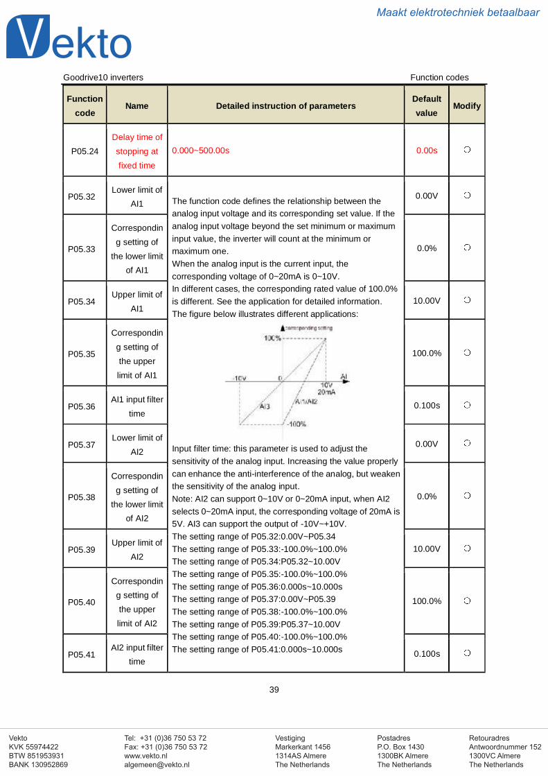
VestigingMarkerkant 14561314AS AlmereThe Netherlands
PostadresP.O. Box 14301300BK AlmereThe Netherlands
Tel: +31 (0)36 750 53 72Fax: +31 (0)36 750 53 [email protected]
RetouradresAntwoordnummer 1521300VC AlmereThe Netherlands
VektoKVK 55974422BTW 851953931BANK 130952869
Maakt elektrotechniek betaalbaar
Goodrive10 inverters Function codes
39
Functioncode
Name Detailed instruction of parametersDefaultvalue
Modify
P05.24Delay time ofstopping atfixed time
0.000~500.00s 0.00s
P05.32Lower limit of
AI1 The function code defines the relationship between theanalog input voltage and its corresponding set value. If theanalog input voltage beyond the set minimum or maximuminput value, the inverter will count at the minimum ormaximum one.When the analog input is the current input, thecorresponding voltage of 0~20mA is 0~10V.In different cases, the corresponding rated value of 100.0%is different. See the application for detailed information.The figure below illustrates different applications:
Input filter time: this parameter is used to adjust thesensitivity of the analog input. Increasing the value properlycan enhance the anti-interference of the analog, but weakenthe sensitivity of the analog input.Note: AI2 can support 0~10V or 0~20mA input, when AI2selects 0~20mA input, the corresponding voltage of 20mA is5V. AI3 can support the output of -10V~+10V.The setting range of P05.32:0.00V~P05.34The setting range of P05.33:-100.0%~100.0%The setting range of P05.34:P05.32~10.00VThe setting range of P05.35:-100.0%~100.0%The setting range of P05.36:0.000s~10.000sThe setting range of P05.37:0.00V~P05.39The setting range of P05.38:-100.0%~100.0%The setting range of P05.39:P05.37~10.00VThe setting range of P05.40:-100.0%~100.0%The setting range of P05.41:0.000s~10.000s
0.00V
P05.33
Corresponding setting of
the lower limitof AI1
0.0%
P05.34Upper limit of
AI110.00V
P05.35
Corresponding setting ofthe upperlimit of AI1
100.0%
P05.36AI1 input filter
time0.100s
P05.37Lower limit of
AI20.00V
P05.38
Corresponding setting of
the lower limitof AI2
0.0%
P05.39Upper limit of
AI210.00V
P05.40
Corresponding setting ofthe upperlimit of AI2
100.0%
P05.41AI2 input filter
time0.100s
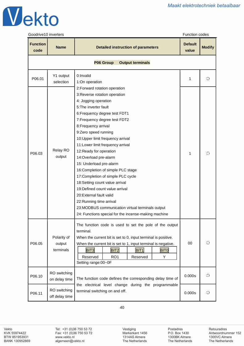
VestigingMarkerkant 14561314AS AlmereThe Netherlands
PostadresP.O. Box 14301300BK AlmereThe Netherlands
Tel: +31 (0)36 750 53 72Fax: +31 (0)36 750 53 [email protected]
RetouradresAntwoordnummer 1521300VC AlmereThe Netherlands
VektoKVK 55974422BTW 851953931BANK 130952869
Maakt elektrotechniek betaalbaar
Goodrive10 inverters Function codes
40
Functioncode
Name Detailed instruction of parametersDefaultvalue
Modify
P06 Group Output terminals
P06.01Y1 outputselection
0:Invalid1:On operation2:Forward rotation operation3:Reverse rotation operation4: Jogging operation5:The inverter fault6:Frequency degree test FDT17:Frequency degree test FDT28:Frequency arrival9:Zero speed running10:Upper limit frequency arrival11:Lower limit frequency arrival12:Ready for operation14:Overload pre-alarm15: Underload pre-alarm16:Completion of simple PLC stage17:Completion of simple PLC cycle18:Setting count value arrival19:Defined count value arrival20:External fault valid22:Running time arrival23:MODBUS communication virtual terminals output24: Functions special for the incense-making machine
1
P06.03Relay RO
output1
P06.05Polarity of
outputterminals
The function code is used to set the pole of the outputterminal.When the current bit is set to 0, input terminal is positive.When the current bit is set to 1, input terminal is negative.
BIT3 BIT2 BIT1 BIT0
Reserved RO1 Reserved YSetting range:00~0F
00
P06.10RO switchingon delay time The function code defines the corresponding delay time of
the electrical level change during the programmableterminal switching on and off.
0.000s
P06.11RO switchingoff delay time
0.000s
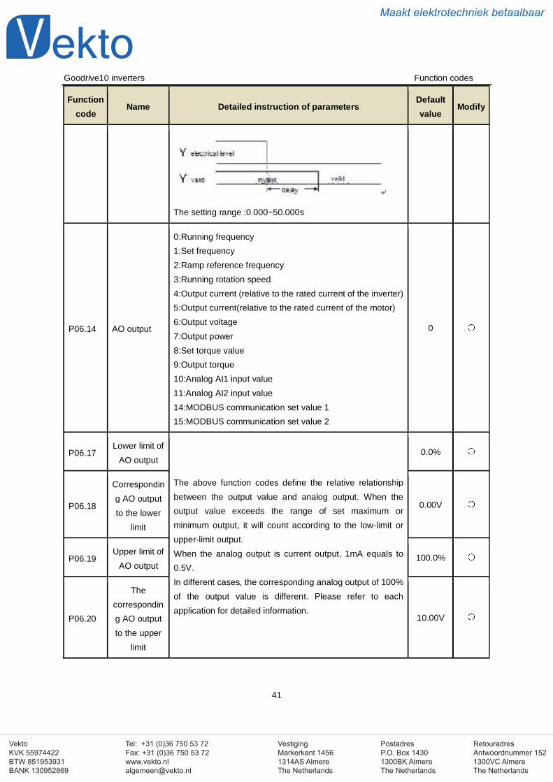
VestigingMarkerkant 14561314AS AlmereThe Netherlands
PostadresP.O. Box 14301300BK AlmereThe Netherlands
Tel: +31 (0)36 750 53 72Fax: +31 (0)36 750 53 [email protected]
RetouradresAntwoordnummer 1521300VC AlmereThe Netherlands
VektoKVK 55974422BTW 851953931BANK 130952869
Maakt elektrotechniek betaalbaar
Goodrive10 inverters Function codes
41
Functioncode
Name Detailed instruction of parametersDefaultvalue
Modify
The setting range :0.000~50.000s
P06.14 AO output
0:Running frequency1:Set frequency2:Ramp reference frequency3:Running rotation speed4:Output current (relative to the rated current of the inverter)5:Output current(relative to the rated current of the motor)6:Output voltage7:Output power8:Set torque value9:Output torque10:Analog AI1 input value11:Analog AI2 input value14:MODBUS communication set value 115:MODBUS communication set value 2
0
P06.17Lower limit of
AO output
The above function codes define the relative relationshipbetween the output value and analog output. When theoutput value exceeds the range of set maximum orminimum output, it will count according to the low-limit orupper-limit output.When the analog output is current output, 1mA equals to0.5V.In different cases, the corresponding analog output of 100%of the output value is different. Please refer to eachapplication for detailed information.
0.0%
P06.18
Corresponding AO outputto the lower
limit
0.00V
P06.19Upper limit of
AO output100.0%
P06.20
Thecorresponding AO outputto the upper
limit
10.00V
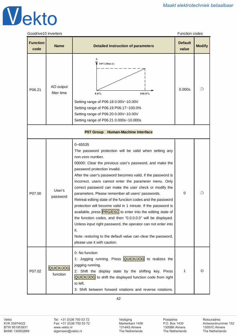
VestigingMarkerkant 14561314AS AlmereThe Netherlands
PostadresP.O. Box 14301300BK AlmereThe Netherlands
Tel: +31 (0)36 750 53 72Fax: +31 (0)36 750 53 [email protected]
RetouradresAntwoordnummer 1521300VC AlmereThe Netherlands
VektoKVK 55974422BTW 851953931BANK 130952869
Maakt elektrotechniek betaalbaar
Goodrive10 inverters Function codes
42
Functioncode
Name Detailed instruction of parametersDefaultvalue
Modify
P06.21AO outputfilter time
Setting range of P06.18 0.00V~10.00VSetting range of P06.19 P06.17~100.0%Setting range of P06.20 0.00V~10.00VSetting range of P06.21 0.000s~10.000s
0.000s
P07 Group Human-Machine Interface
P07.00User’s
password
0~65535The password protection will be valid when setting anynon-zero number.00000: Clear the previous user’s password, and make thepassword protection invalid.After the user’s password becomes valid, if the password isincorrect, users cannot enter the parameter menu. Onlycorrect password can make the user check or modify theparameters. Please remember all users’ passwords.Retreat editing state of the function codes and the passwordprotection will become valid in 1 minute. If the password isavailable, press PRG/ESC to enter into the editing state ofthe function codes, and then “0.0.0.0.0” will be displayed.Unless input right password, the operator can not enter intoit.Note: restoring to the default value can clear the password,please use it with caution.
0
P07.02QUICK/JOG
function
0: No function1: Jogging running. Press QUICK/JOG to realizes thejogging running.2: Shift the display state by the shifting key. PressQUICK/JOG to shift the displayed function code from rightto left.3: Shift between forward rotations and reverse rotations.
1
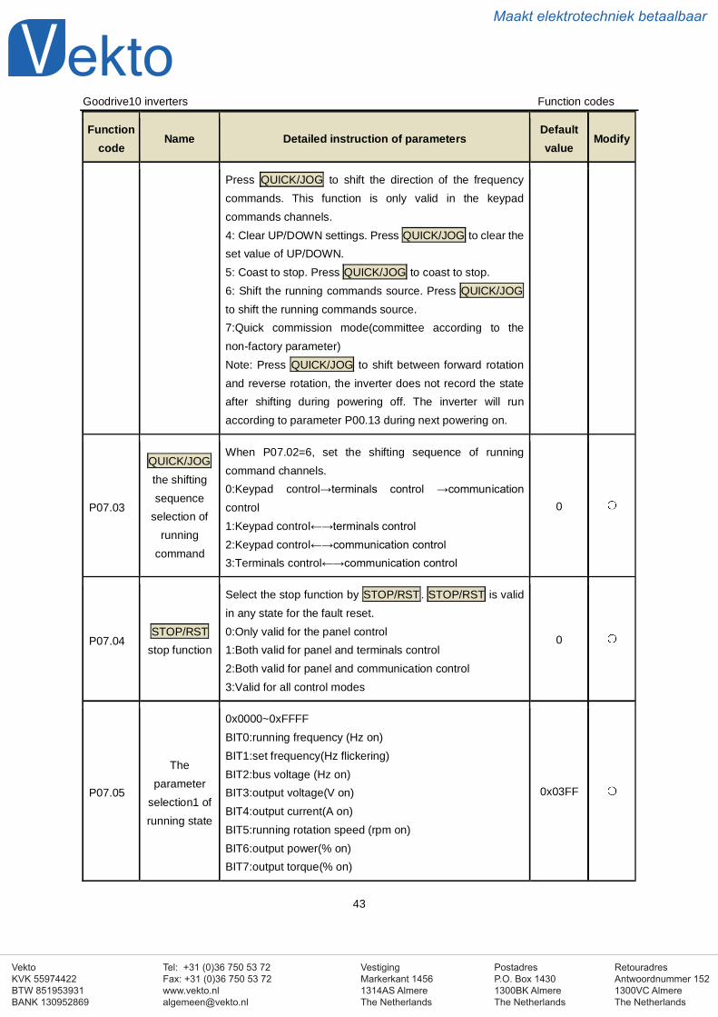
VestigingMarkerkant 14561314AS AlmereThe Netherlands
PostadresP.O. Box 14301300BK AlmereThe Netherlands
Tel: +31 (0)36 750 53 72Fax: +31 (0)36 750 53 [email protected]
RetouradresAntwoordnummer 1521300VC AlmereThe Netherlands
VektoKVK 55974422BTW 851953931BANK 130952869
Maakt elektrotechniek betaalbaar
Goodrive10 inverters Function codes
43
Functioncode
Name Detailed instruction of parametersDefaultvalue
Modify
Press QUICK/JOG to shift the direction of the frequencycommands. This function is only valid in the keypadcommands channels.4: Clear UP/DOWN settings. Press QUICK/JOG to clear theset value of UP/DOWN.5: Coast to stop. Press QUICK/JOG to coast to stop.6: Shift the running commands source. Press QUICK/JOGto shift the running commands source.7:Quick commission mode(committee according to thenon-factory parameter)Note: Press QUICK/JOG to shift between forward rotationand reverse rotation, the inverter does not record the stateafter shifting during powering off. The inverter will runaccording to parameter P00.13 during next powering on.
P07.03
QUICK/JOGthe shiftingsequence
selection ofrunning
command
When P07.02=6, set the shifting sequence of runningcommand channels.0:Keypad control→terminals control →communicationcontrol1:Keypad control←→terminals control2:Keypad control←→communication control3:Terminals control←→communication control
0
P07.04STOP/RST
stop function
Select the stop function by STOP/RST. STOP/RST is validin any state for the fault reset.0:Only valid for the panel control1:Both valid for panel and terminals control2:Both valid for panel and communication control3:Valid for all control modes
0
P07.05
Theparameter
selection1 ofrunning state
0x0000~0xFFFFBIT0:running frequency (Hz on)BIT1:set frequency(Hz flickering)BIT2:bus voltage (Hz on)BIT3:output voltage(V on)BIT4:output current(A on)BIT5:running rotation speed (rpm on)BIT6:output power(% on)BIT7:output torque(% on)
0x03FF
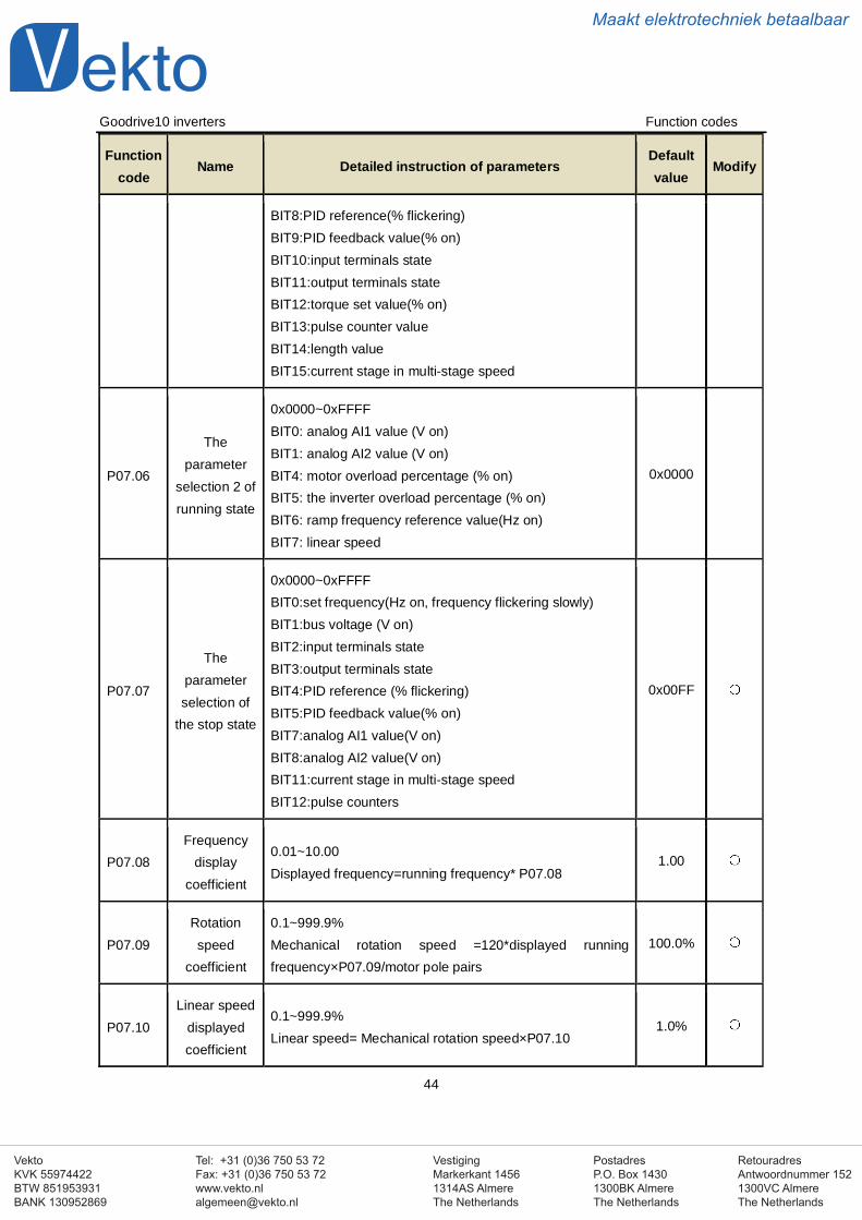
VestigingMarkerkant 14561314AS AlmereThe Netherlands
PostadresP.O. Box 14301300BK AlmereThe Netherlands
Tel: +31 (0)36 750 53 72Fax: +31 (0)36 750 53 [email protected]
RetouradresAntwoordnummer 1521300VC AlmereThe Netherlands
VektoKVK 55974422BTW 851953931BANK 130952869
Maakt elektrotechniek betaalbaar
Goodrive10 inverters Function codes
44
Functioncode
Name Detailed instruction of parametersDefaultvalue
Modify
BIT8:PID reference(% flickering)BIT9:PID feedback value(% on)BIT10:input terminals stateBIT11:output terminals stateBIT12:torque set value(% on)BIT13:pulse counter valueBIT14:length valueBIT15:current stage in multi-stage speed
P07.06
Theparameter
selection 2 ofrunning state
0x0000~0xFFFFBIT0: analog AI1 value (V on)BIT1: analog AI2 value (V on)BIT4: motor overload percentage (% on)BIT5: the inverter overload percentage (% on)BIT6: ramp frequency reference value(Hz on)BIT7: linear speed
0x0000
P07.07
Theparameterselection of
the stop state
0x0000~0xFFFFBIT0:set frequency(Hz on, frequency flickering slowly)BIT1:bus voltage (V on)BIT2:input terminals stateBIT3:output terminals stateBIT4:PID reference (% flickering)BIT5:PID feedback value(% on)BIT7:analog AI1 value(V on)BIT8:analog AI2 value(V on)BIT11:current stage in multi-stage speedBIT12:pulse counters
0x00FF
P07.08Frequency
displaycoefficient
0.01~10.00Displayed frequency=running frequency* P07.08
1.00
P07.09Rotationspeed
coefficient
0.1~999.9%Mechanical rotation speed =120*displayed runningfrequency×P07.09/motor pole pairs
100.0%
P07.10Linear speed
displayedcoefficient
0.1~999.9%Linear speed= Mechanical rotation speed×P07.10
1.0%
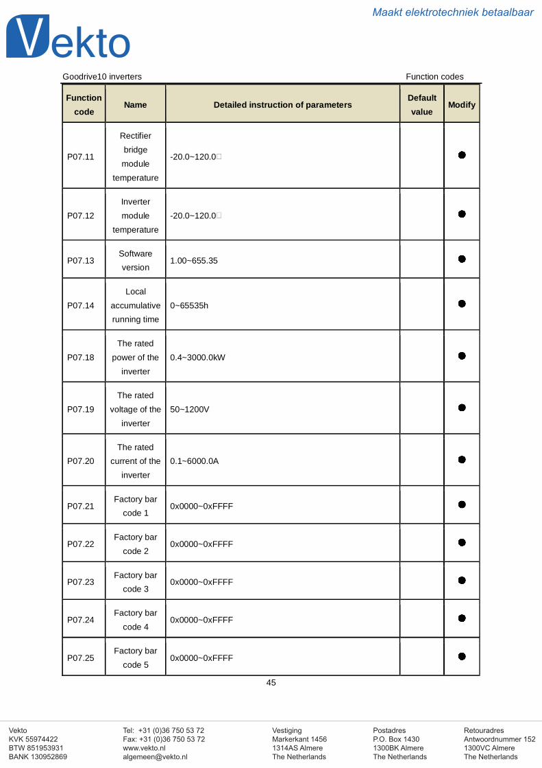
VestigingMarkerkant 14561314AS AlmereThe Netherlands
PostadresP.O. Box 14301300BK AlmereThe Netherlands
Tel: +31 (0)36 750 53 72Fax: +31 (0)36 750 53 [email protected]
RetouradresAntwoordnummer 1521300VC AlmereThe Netherlands
VektoKVK 55974422BTW 851953931BANK 130952869
Maakt elektrotechniek betaalbaar
Goodrive10 inverters Function codes
45
Functioncode
Name Detailed instruction of parametersDefaultvalue
Modify
P07.11
Rectifierbridgemodule
temperature
-20.0~120.0
P07.12Invertermodule
temperature-20.0~120.0
P07.13Softwareversion
1.00~655.35
P07.14Local
accumulativerunning time
0~65535h
P07.18The rated
power of theinverter
0.4~3000.0kW
P07.19The rated
voltage of theinverter
50~1200V
P07.20The rated
current of theinverter
0.1~6000.0A
P07.21Factory bar
code 10x0000~0xFFFF
P07.22Factory bar
code 20x0000~0xFFFF
P07.23Factory bar
code 30x0000~0xFFFF
P07.24Factory bar
code 40x0000~0xFFFF
P07.25Factory bar
code 50x0000~0xFFFF
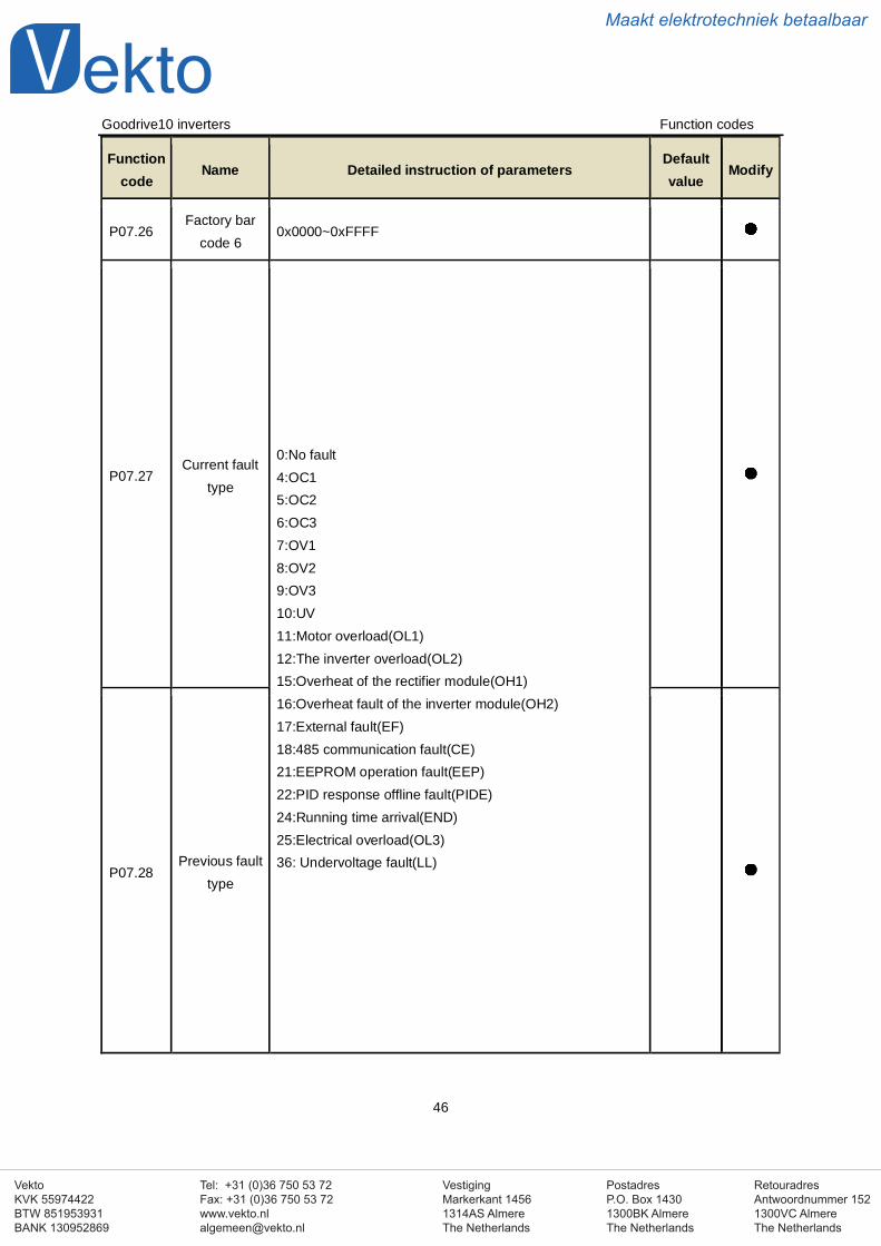
VestigingMarkerkant 14561314AS AlmereThe Netherlands
PostadresP.O. Box 14301300BK AlmereThe Netherlands
Tel: +31 (0)36 750 53 72Fax: +31 (0)36 750 53 [email protected]
RetouradresAntwoordnummer 1521300VC AlmereThe Netherlands
VektoKVK 55974422BTW 851953931BANK 130952869
Maakt elektrotechniek betaalbaar
Goodrive10 inverters Function codes
46
Functioncode
Name Detailed instruction of parametersDefaultvalue
Modify
P07.26Factory bar
code 60x0000~0xFFFF
P07.27Current fault
type
0:No fault4:OC15:OC26:OC37:OV18:OV29:OV310:UV11:Motor overload(OL1)12:The inverter overload(OL2)15:Overheat of the rectifier module(OH1)16:Overheat fault of the inverter module(OH2)17:External fault(EF)18:485 communication fault(CE)21:EEPROM operation fault(EEP)22:PID response offline fault(PIDE)24:Running time arrival(END)25:Electrical overload(OL3)36: Undervoltage fault(LL)
P07.28Previous fault
type
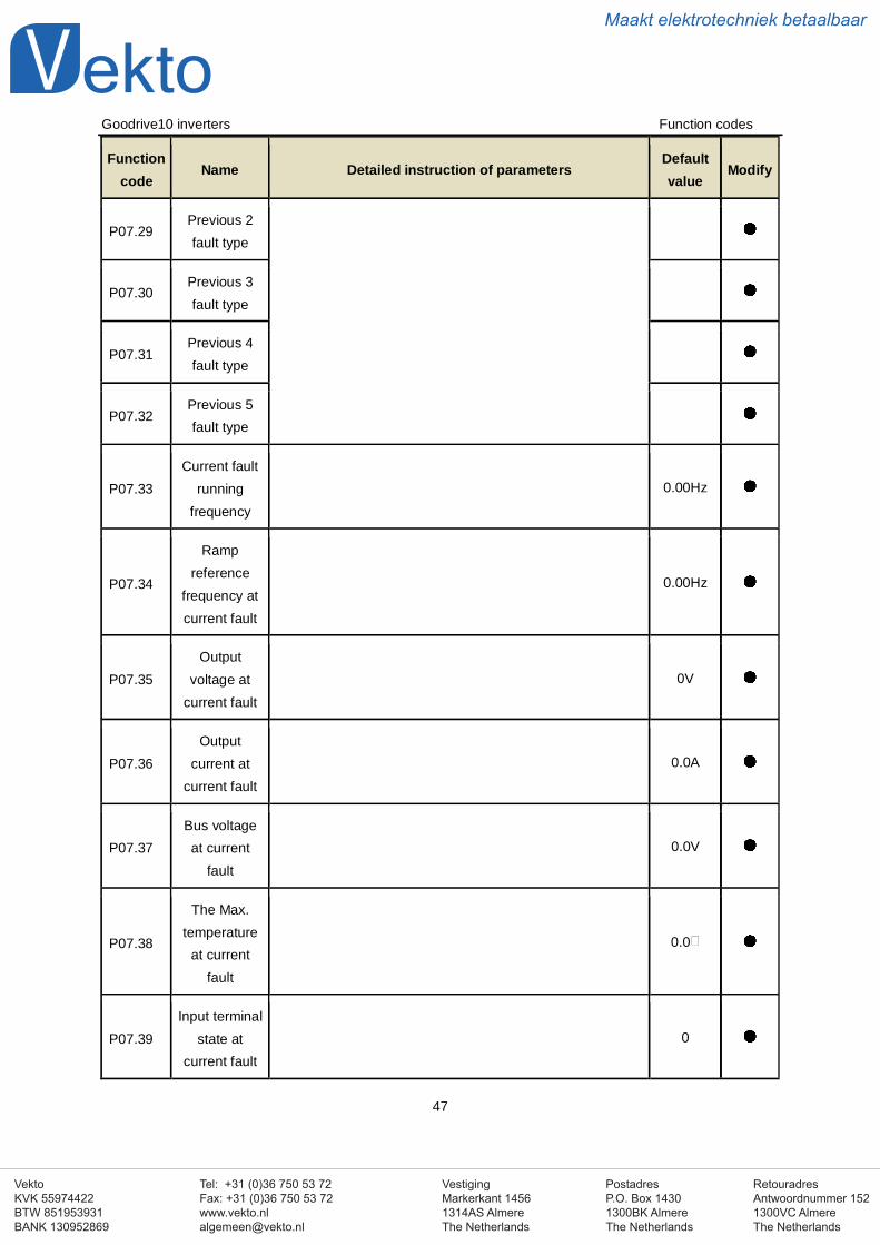
VestigingMarkerkant 14561314AS AlmereThe Netherlands
PostadresP.O. Box 14301300BK AlmereThe Netherlands
Tel: +31 (0)36 750 53 72Fax: +31 (0)36 750 53 [email protected]
RetouradresAntwoordnummer 1521300VC AlmereThe Netherlands
VektoKVK 55974422BTW 851953931BANK 130952869
Maakt elektrotechniek betaalbaar
Goodrive10 inverters Function codes
47
Functioncode
Name Detailed instruction of parametersDefaultvalue
Modify
P07.29Previous 2fault type
P07.30Previous 3fault type
P07.31Previous 4fault type
P07.32Previous 5fault type
P07.33Current fault
runningfrequency
0.00Hz
P07.34
Rampreference
frequency atcurrent fault
0.00Hz
P07.35Output
voltage atcurrent fault
0V
P07.36Output
current atcurrent fault
0.0A
P07.37Bus voltageat current
fault
0.0V
P07.38
The Max.temperature
at currentfault
0.0
P07.39Input terminal
state atcurrent fault
0
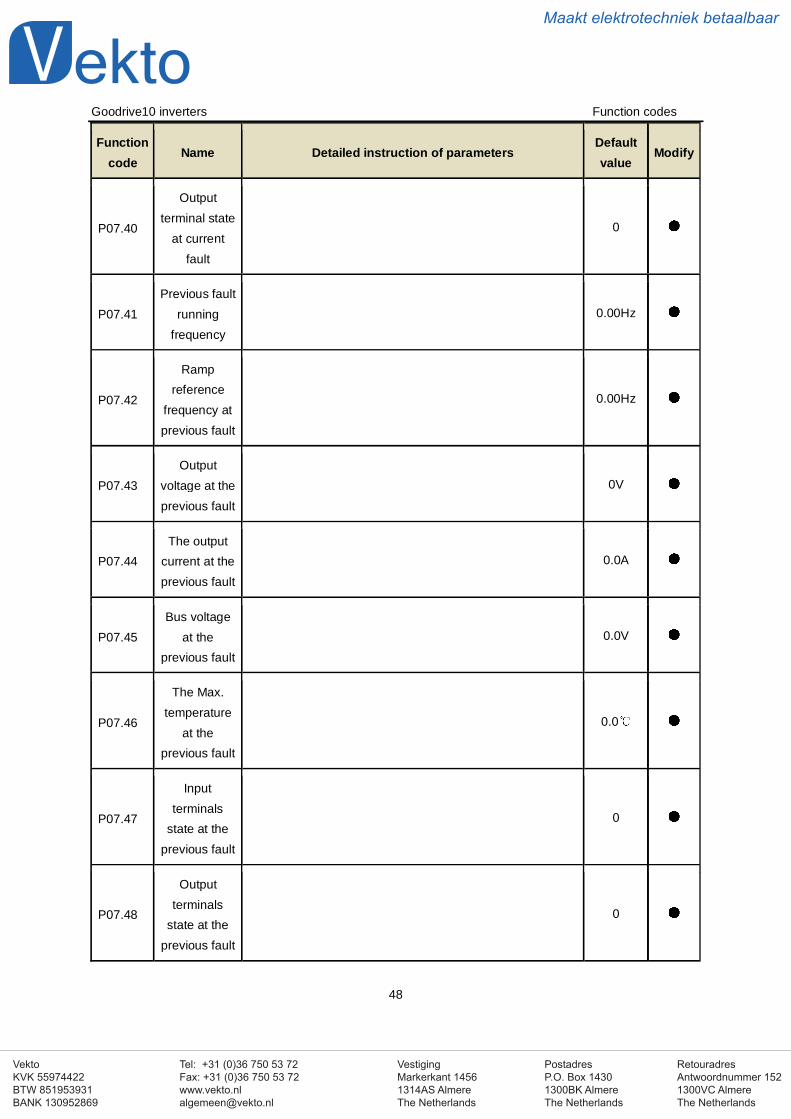
VestigingMarkerkant 14561314AS AlmereThe Netherlands
PostadresP.O. Box 14301300BK AlmereThe Netherlands
Tel: +31 (0)36 750 53 72Fax: +31 (0)36 750 53 [email protected]
RetouradresAntwoordnummer 1521300VC AlmereThe Netherlands
VektoKVK 55974422BTW 851953931BANK 130952869
Maakt elektrotechniek betaalbaar
Goodrive10 inverters Function codes
48
Functioncode
Name Detailed instruction of parametersDefaultvalue
Modify
P07.40
Outputterminal state
at currentfault
0
P07.41Previous fault
runningfrequency
0.00Hz
P07.42
Rampreference
frequency atprevious fault
0.00Hz
P07.43Output
voltage at theprevious fault
0V
P07.44The output
current at theprevious fault
0.0A
P07.45Bus voltage
at theprevious fault
0.0V
P07.46
The Max.temperature
at theprevious fault
0.0
P07.47
Inputterminals
state at theprevious fault
0
P07.48
Outputterminals
state at theprevious fault
0
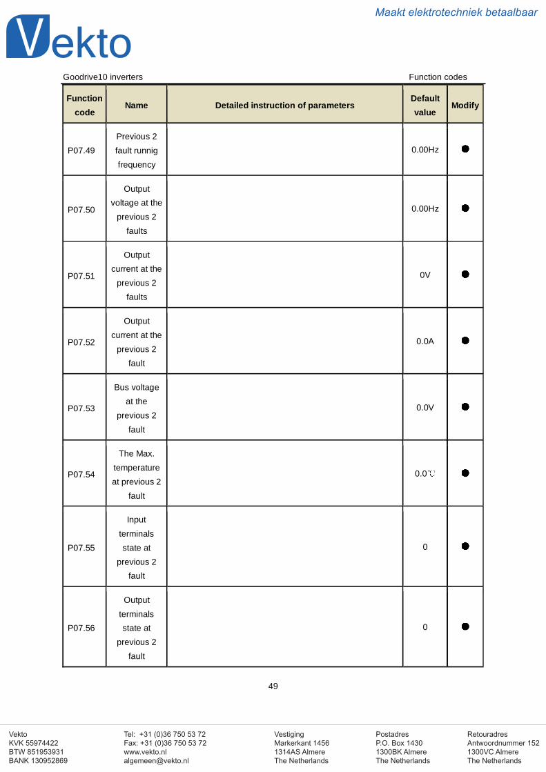
VestigingMarkerkant 14561314AS AlmereThe Netherlands
PostadresP.O. Box 14301300BK AlmereThe Netherlands
Tel: +31 (0)36 750 53 72Fax: +31 (0)36 750 53 [email protected]
RetouradresAntwoordnummer 1521300VC AlmereThe Netherlands
VektoKVK 55974422BTW 851953931BANK 130952869
Maakt elektrotechniek betaalbaar
Goodrive10 inverters Function codes
49
Functioncode
Name Detailed instruction of parametersDefaultvalue
Modify
P07.49Previous 2fault runnigfrequency
0.00Hz
P07.50
Outputvoltage at the
previous 2faults
0.00Hz
P07.51
Outputcurrent at the
previous 2faults
0V
P07.52
Outputcurrent at the
previous 2fault
0.0A
P07.53
Bus voltageat the
previous 2fault
0.0V
P07.54
The Max.temperatureat previous 2
fault
0.0
P07.55
Inputterminalsstate at
previous 2fault
0
P07.56
Outputterminalsstate at
previous 2fault
0
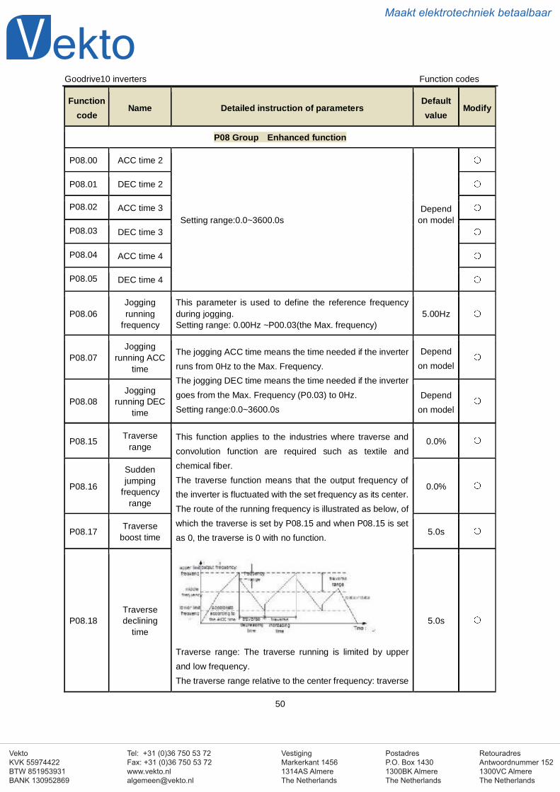
VestigingMarkerkant 14561314AS AlmereThe Netherlands
PostadresP.O. Box 14301300BK AlmereThe Netherlands
Tel: +31 (0)36 750 53 72Fax: +31 (0)36 750 53 [email protected]
RetouradresAntwoordnummer 1521300VC AlmereThe Netherlands
VektoKVK 55974422BTW 851953931BANK 130952869
Maakt elektrotechniek betaalbaar
Goodrive10 inverters Function codes
50
Functioncode
Name Detailed instruction of parametersDefaultvalue
Modify
P08 Group Enhanced function
P08.00 ACC time 2
Setting range:0.0~3600.0sDepend
on model
P08.01 DEC time 2
P08.02 ACC time 3
P08.03 DEC time 3
P08.04 ACC time 4
P08.05 DEC time 4
P08.06Joggingrunning
frequency
This parameter is used to define the reference frequencyduring jogging.Setting range: 0.00Hz ~P00.03(the Max. frequency)
5.00Hz
P08.07Jogging
running ACCtime
The jogging ACC time means the time needed if the inverterruns from 0Hz to the Max. Frequency.The jogging DEC time means the time needed if the invertergoes from the Max. Frequency (P0.03) to 0Hz.Setting range:0.0~3600.0s
Dependon model
P08.08Jogging
running DECtime
Dependon model
P08.15 Traverserange
This function applies to the industries where traverse andconvolution function are required such as textile andchemical fiber.The traverse function means that the output frequency ofthe inverter is fluctuated with the set frequency as its center.The route of the running frequency is illustrated as below, ofwhich the traverse is set by P08.15 and when P08.15 is setas 0, the traverse is 0 with no function.
Traverse range: The traverse running is limited by upperand low frequency.The traverse range relative to the center frequency: traverse
0.0%
P08.16
Suddenjumping
frequencyrange
0.0%
P08.17 Traverseboost time 5.0s
P08.18Traversedeclining
time5.0s
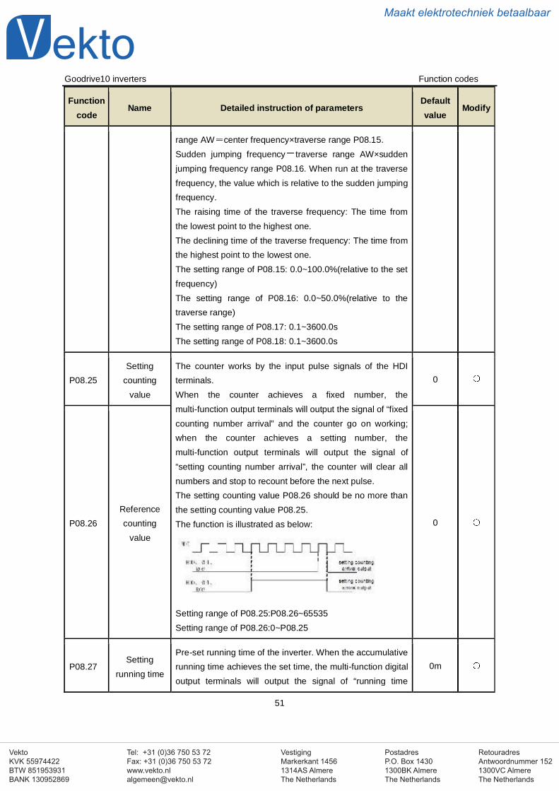
VestigingMarkerkant 14561314AS AlmereThe Netherlands
PostadresP.O. Box 14301300BK AlmereThe Netherlands
Tel: +31 (0)36 750 53 72Fax: +31 (0)36 750 53 [email protected]
RetouradresAntwoordnummer 1521300VC AlmereThe Netherlands
VektoKVK 55974422BTW 851953931BANK 130952869
Maakt elektrotechniek betaalbaar
Goodrive10 inverters Function codes
51
Functioncode
Name Detailed instruction of parametersDefaultvalue
Modify
range AW center frequency×traverse range P08.15.Sudden jumping frequency traverse range AW×suddenjumping frequency range P08.16. When run at the traversefrequency, the value which is relative to the sudden jumpingfrequency.The raising time of the traverse frequency: The time fromthe lowest point to the highest one.The declining time of the traverse frequency: The time fromthe highest point to the lowest one.The setting range of P08.15: 0.0~100.0%(relative to the setfrequency)The setting range of P08.16: 0.0~50.0%(relative to thetraverse range)The setting range of P08.17: 0.1~3600.0sThe setting range of P08.18: 0.1~3600.0s
P08.25Setting
countingvalue
The counter works by the input pulse signals of the HDIterminals.When the counter achieves a fixed number, themulti-function output terminals will output the signal of “fixedcounting number arrival” and the counter go on working;when the counter achieves a setting number, themulti-function output terminals will output the signal of“setting counting number arrival”, the counter will clear allnumbers and stop to recount before the next pulse.The setting counting value P08.26 should be no more thanthe setting counting value P08.25.The function is illustrated as below:
Setting range of P08.25:P08.26~65535Setting range of P08.26:0~P08.25
0
P08.26Referencecounting
value
0
P08.27Setting
running time
Pre-set running time of the inverter. When the accumulativerunning time achieves the set time, the multi-function digitaloutput terminals will output the signal of “running time
0m
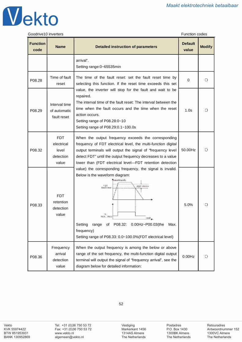
VestigingMarkerkant 14561314AS AlmereThe Netherlands
PostadresP.O. Box 14301300BK AlmereThe Netherlands
Tel: +31 (0)36 750 53 72Fax: +31 (0)36 750 53 [email protected]
RetouradresAntwoordnummer 1521300VC AlmereThe Netherlands
VektoKVK 55974422BTW 851953931BANK 130952869
Maakt elektrotechniek betaalbaar
Goodrive10 inverters Function codes
52
Functioncode
Name Detailed instruction of parametersDefaultvalue
Modify
arrival”.Setting range:0~65535min
P08.28Time of fault
resetThe time of the fault reset: set the fault reset time byselecting this function. If the reset time exceeds this setvalue, the inverter will stop for the fault and wait to berepaired.The interval time of the fault reset: The interval between thetime when the fault occurs and the time when the resetaction occurs.Setting range of P08.28:0~10Setting range of P08.29:0.1~100.0s
0
P08.29Interval timeof automaticfault reset
1.0s
P08.32
FDTelectrical
leveldetection
value
When the output frequency exceeds the correspondingfrequency of FDT electrical level, the multi-function digitaloutput terminals will output the signal of “frequency leveldetect FDT” until the output frequency decreases to a valuelower than (FDT electrical level—FDT retention detectionvalue) the corresponding frequency, the signal is invalid.Below is the waveform diagram:
Setting range of P08.32: 0.00Hz~P00.03(the Max.frequency)Setting range of P08.33: 0.0~100.0%(FDT electrical level)
50.00Hz
P08.33
FDTretentiondetection
value
5.0%
P08.36
Frequencyarrival
detectionvalue
When the output frequency is among the below or aboverange of the set frequency, the multi-function digital outputterminal will output the signal of “frequency arrival”, see thediagram below for detailed information:
0.00Hz
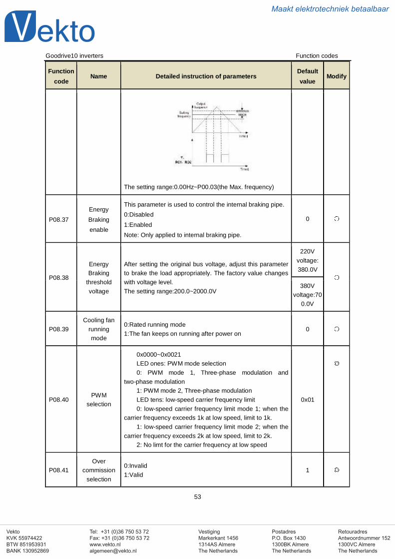
VestigingMarkerkant 14561314AS AlmereThe Netherlands
PostadresP.O. Box 14301300BK AlmereThe Netherlands
Tel: +31 (0)36 750 53 72Fax: +31 (0)36 750 53 [email protected]
RetouradresAntwoordnummer 1521300VC AlmereThe Netherlands
VektoKVK 55974422BTW 851953931BANK 130952869
Maakt elektrotechniek betaalbaar
Goodrive10 inverters Function codes
53
Functioncode
Name Detailed instruction of parametersDefaultvalue
Modify
The setting range:0.00Hz~P00.03(the Max. frequency)
P08.37EnergyBrakingenable
This parameter is used to control the internal braking pipe.0:Disabled1:EnabledNote: Only applied to internal braking pipe.
0
P08.38
EnergyBraking
thresholdvoltage
After setting the original bus voltage, adjust this parameterto brake the load appropriately. The factory value changeswith voltage level.The setting range:200.0~2000.0V
220Vvoltage:380.0V
380Vvoltage:70
0.0V
P08.39Cooling fan
runningmode
0:Rated running mode1:The fan keeps on running after power on
0
P08.40PWM
selection
0x0000~0x0021LED ones: PWM mode selection0: PWM mode 1, Three-phase modulation and
two-phase modulation1: PWM mode 2, Three-phase modulationLED tens: low-speed carrier frequency limit0: low-speed carrier frequency limit mode 1; when the
carrier frequency exceeds 1k at low speed, limit to 1k.1: low-speed carrier frequency limit mode 2; when the
carrier frequency exceeds 2k at low speed, limit to 2k.2: No limt for the carrier frequency at low speed
0x01
P08.41Over
commissionselection
0:Invalid1:Valid
1
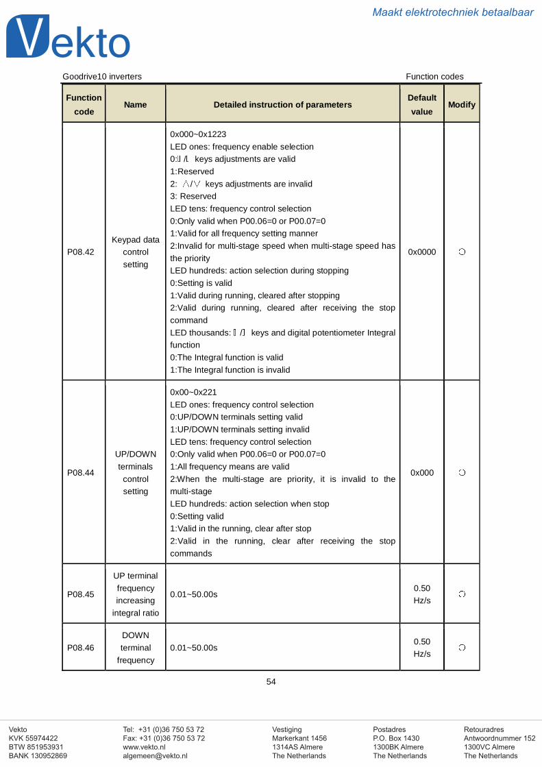
VestigingMarkerkant 14561314AS AlmereThe Netherlands
PostadresP.O. Box 14301300BK AlmereThe Netherlands
Tel: +31 (0)36 750 53 72Fax: +31 (0)36 750 53 [email protected]
RetouradresAntwoordnummer 1521300VC AlmereThe Netherlands
VektoKVK 55974422BTW 851953931BANK 130952869
Maakt elektrotechniek betaalbaar
Goodrive10 inverters Function codes
54
Functioncode
Name Detailed instruction of parametersDefaultvalue
Modify
P08.42Keypad data
controlsetting
0x000~0x1223LED ones: frequency enable selection0: / keys adjustments are valid1:Reserved2: / keys adjustments are invalid3: ReservedLED tens: frequency control selection0:Only valid when P00.06=0 or P00.07=01:Valid for all frequency setting manner2:Invalid for multi-stage speed when multi-stage speed hasthe priorityLED hundreds: action selection during stopping0:Setting is valid1:Valid during running, cleared after stopping2:Valid during running, cleared after receiving the stopcommandLED thousands: / keys and digital potentiometer Integralfunction0:The Integral function is valid1:The Integral function is invalid
0x0000
P08.44
UP/DOWNterminals
controlsetting
0x00~0x221LED ones: frequency control selection0:UP/DOWN terminals setting valid1:UP/DOWN terminals setting invalidLED tens: frequency control selection0:Only valid when P00.06=0 or P00.07=01:All frequency means are valid2:When the multi-stage are priority, it is invalid to themulti-stageLED hundreds: action selection when stop0:Setting valid1:Valid in the running, clear after stop2:Valid in the running, clear after receiving the stopcommands
0x000
P08.45
UP terminalfrequencyincreasing
integral ratio
0.01~50.00s0.50Hz/s
P08.46DOWNterminal
frequency0.01~50.00s
0.50Hz/s
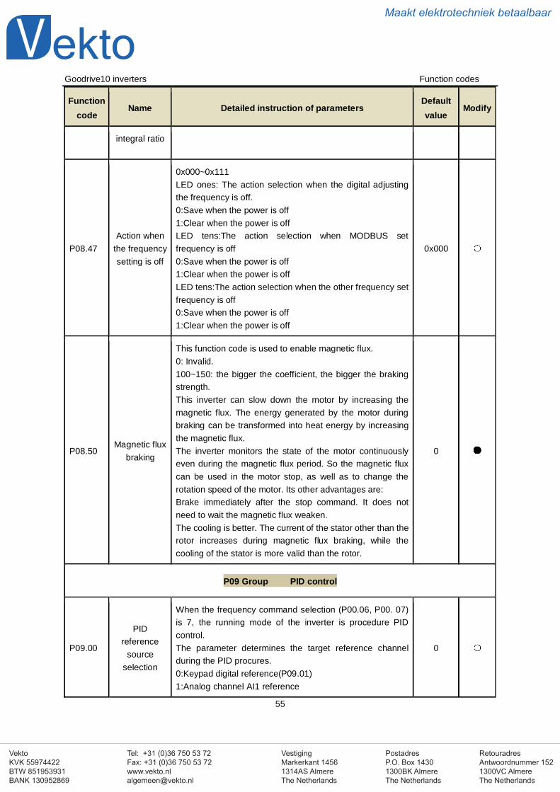
VestigingMarkerkant 14561314AS AlmereThe Netherlands
PostadresP.O. Box 14301300BK AlmereThe Netherlands
Tel: +31 (0)36 750 53 72Fax: +31 (0)36 750 53 [email protected]
RetouradresAntwoordnummer 1521300VC AlmereThe Netherlands
VektoKVK 55974422BTW 851953931BANK 130952869
Maakt elektrotechniek betaalbaar
Goodrive10 inverters Function codes
55
Functioncode
Name Detailed instruction of parametersDefaultvalue
Modify
integral ratio
P08.47Action when
the frequencysetting is off
0x000~0x111LED ones: The action selection when the digital adjustingthe frequency is off.0:Save when the power is off1:Clear when the power is offLED tens:The action selection when MODBUS setfrequency is off0:Save when the power is off1:Clear when the power is offLED tens:The action selection when the other frequency setfrequency is off0:Save when the power is off1:Clear when the power is off
0x000
P08.50Magnetic flux
braking
This function code is used to enable magnetic flux.0: Invalid.100~150: the bigger the coefficient, the bigger the brakingstrength.This inverter can slow down the motor by increasing themagnetic flux. The energy generated by the motor duringbraking can be transformed into heat energy by increasingthe magnetic flux.The inverter monitors the state of the motor continuouslyeven during the magnetic flux period. So the magnetic fluxcan be used in the motor stop, as well as to change therotation speed of the motor. Its other advantages are:Brake immediately after the stop command. It does notneed to wait the magnetic flux weaken.The cooling is better. The current of the stator other than therotor increases during magnetic flux braking, while thecooling of the stator is more valid than the rotor.
0
P09 Group PID control
P09.00
PIDreference
sourceselection
When the frequency command selection (P00.06, P00. 07)is 7, the running mode of the inverter is procedure PIDcontrol.The parameter determines the target reference channelduring the PID procures.0:Keypad digital reference(P09.01)1:Analog channel AI1 reference
0
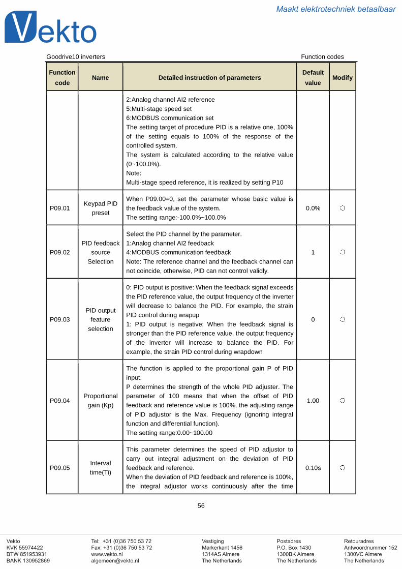
VestigingMarkerkant 14561314AS AlmereThe Netherlands
PostadresP.O. Box 14301300BK AlmereThe Netherlands
Tel: +31 (0)36 750 53 72Fax: +31 (0)36 750 53 [email protected]
RetouradresAntwoordnummer 1521300VC AlmereThe Netherlands
VektoKVK 55974422BTW 851953931BANK 130952869
Maakt elektrotechniek betaalbaar
Goodrive10 inverters Function codes
56
Functioncode
Name Detailed instruction of parametersDefaultvalue
Modify
2:Analog channel AI2 reference5:Multi-stage speed set6:MODBUS communication setThe setting target of procedure PID is a relative one, 100%of the setting equals to 100% of the response of thecontrolled system.The system is calculated according to the relative value(0~100.0%).Note:Multi-stage speed reference, it is realized by setting P10
P09.01Keypad PID
preset
When P09.00=0, set the parameter whose basic value isthe feedback value of the system.The setting range:-100.0%~100.0%
0.0%
P09.02PID feedback
sourceSelection
Select the PID channel by the parameter.1:Analog channel AI2 feedback4:MODBUS communication feedbackNote: The reference channel and the feedback channel cannot coincide, otherwise, PID can not control validly.
1
P09.03PID output
featureselection
0: PID output is positive: When the feedback signal exceedsthe PID reference value, the output frequency of the inverterwill decrease to balance the PID. For example, the strainPID control during wrapup1: PID output is negative: When the feedback signal isstronger than the PID reference value, the output frequencyof the inverter will increase to balance the PID. Forexample, the strain PID control during wrapdown
0
P09.04Proportional
gain (Kp)
The function is applied to the proportional gain P of PIDinput.P determines the strength of the whole PID adjuster. Theparameter of 100 means that when the offset of PIDfeedback and reference value is 100%, the adjusting rangeof PID adjustor is the Max. Frequency (ignoring integralfunction and differential function).The setting range:0.00~100.00
1.00
P09.05Intervaltime(Ti)
This parameter determines the speed of PID adjustor tocarry out integral adjustment on the deviation of PIDfeedback and reference.When the deviation of PID feedback and reference is 100%,the integral adjustor works continuously after the time
0.10s
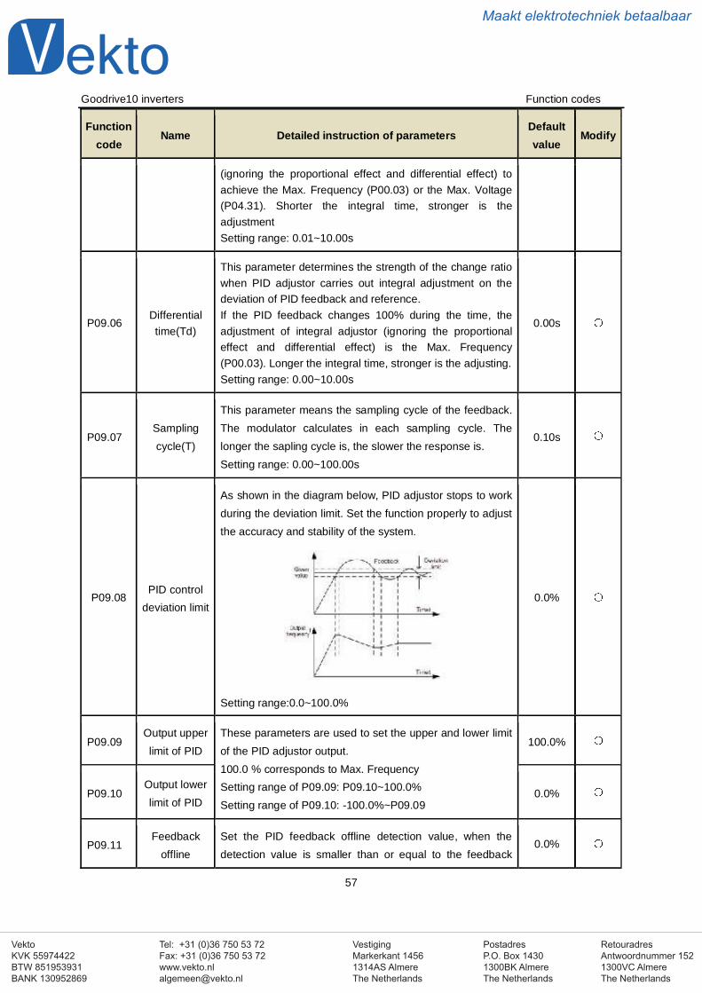
VestigingMarkerkant 14561314AS AlmereThe Netherlands
PostadresP.O. Box 14301300BK AlmereThe Netherlands
Tel: +31 (0)36 750 53 72Fax: +31 (0)36 750 53 [email protected]
RetouradresAntwoordnummer 1521300VC AlmereThe Netherlands
VektoKVK 55974422BTW 851953931BANK 130952869
Maakt elektrotechniek betaalbaar
Goodrive10 inverters Function codes
57
Functioncode
Name Detailed instruction of parametersDefaultvalue
Modify
(ignoring the proportional effect and differential effect) toachieve the Max. Frequency (P00.03) or the Max. Voltage(P04.31). Shorter the integral time, stronger is theadjustmentSetting range: 0.01~10.00s
P09.06Differentialtime(Td)
This parameter determines the strength of the change ratiowhen PID adjustor carries out integral adjustment on thedeviation of PID feedback and reference.If the PID feedback changes 100% during the time, theadjustment of integral adjustor (ignoring the proportionaleffect and differential effect) is the Max. Frequency(P00.03). Longer the integral time, stronger is the adjusting.Setting range: 0.00~10.00s
0.00s
P09.07Samplingcycle(T)
This parameter means the sampling cycle of the feedback.The modulator calculates in each sampling cycle. Thelonger the sapling cycle is, the slower the response is.Setting range: 0.00~100.00s
0.10s
P09.08PID control
deviation limit
As shown in the diagram below, PID adjustor stops to workduring the deviation limit. Set the function properly to adjustthe accuracy and stability of the system.
Setting range:0.0~100.0%
0.0%
P09.09Output upperlimit of PID
These parameters are used to set the upper and lower limitof the PID adjustor output.100.0 % corresponds to Max. FrequencySetting range of P09.09: P09.10~100.0%Setting range of P09.10: -100.0%~P09.09
100.0%
P09.10Output lowerlimit of PID
0.0%
P09.11Feedback
offlineSet the PID feedback offline detection value, when thedetection value is smaller than or equal to the feedback
0.0%
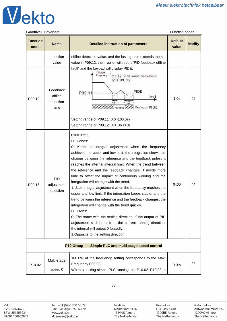
VestigingMarkerkant 14561314AS AlmereThe Netherlands
PostadresP.O. Box 14301300BK AlmereThe Netherlands
Tel: +31 (0)36 750 53 72Fax: +31 (0)36 750 53 [email protected]
RetouradresAntwoordnummer 1521300VC AlmereThe Netherlands
VektoKVK 55974422BTW 851953931BANK 130952869
Maakt elektrotechniek betaalbaar
Goodrive10 inverters Function codes
58
Functioncode
Name Detailed instruction of parametersDefaultvalue
Modify
detectionvalue
offline detection value, and the lasting time exceeds the setvalue in P09.12, the inverter will report “PID feedback offlinefault” and the keypad will display PIDE.
Setting range of P09.11: 0.0~100.0%Setting range of P09.12: 0.0~3600.0s
P09.12
Feedbackoffline
detectiontime
1.0s
P09.13PID
adjustmentselection
0x00~0x11LED ones:0: Keep on integral adjustment when the frequencyachieves the upper and low limit; the integration shows thechange between the reference and the feedback unless itreaches the internal integral limit. When the trend betweenthe reference and the feedback changes, it needs moretime to offset the impact of continuous working and theintegration will change with the trend.1: Stop integral adjustment when the frequency reaches theupper and low limit. If the integration keeps stable, and thetrend between the reference and the feedback changes, theintegration will change with the trend quickly.LED tens:0: The same with the setting direction; if the output of PIDadjustment is different from the current running direction,the internal will output 0 forcedly.1:Opposite to the setting direction
0x00
P10 Group Simple PLC and multi-stage speed control
P10.02Multi-stage
speed 0
100.0% of the frequency setting corresponds to the Max.Frequency P00.03.When selecting simple PLC running, set P10.02~P10.33 to
0.0%
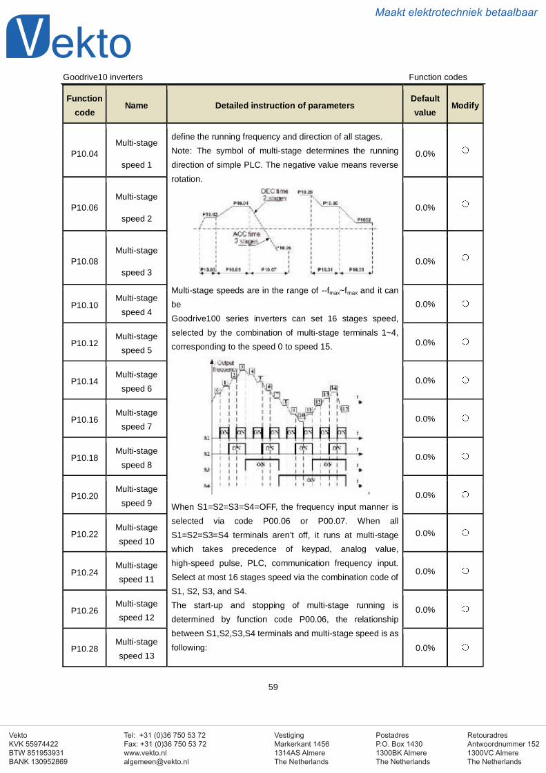
VestigingMarkerkant 14561314AS AlmereThe Netherlands
PostadresP.O. Box 14301300BK AlmereThe Netherlands
Tel: +31 (0)36 750 53 72Fax: +31 (0)36 750 53 [email protected]
RetouradresAntwoordnummer 1521300VC AlmereThe Netherlands
VektoKVK 55974422BTW 851953931BANK 130952869
Maakt elektrotechniek betaalbaar
Goodrive10 inverters Function codes
59
Functioncode
Name Detailed instruction of parametersDefaultvalue
Modify
P10.04Multi-stage
speed 1
define the running frequency and direction of all stages.Note: The symbol of multi-stage determines the runningdirection of simple PLC. The negative value means reverserotation.
Multi-stage speeds are in the range of --fmax~fmax and it canbeGoodrive100 series inverters can set 16 stages speed,selected by the combination of multi-stage terminals 1~4,corresponding to the speed 0 to speed 15.
When S1=S2=S3=S4=OFF, the frequency input manner isselected via code P00.06 or P00.07. When allS1=S2=S3=S4 terminals aren’t off, it runs at multi-stagewhich takes precedence of keypad, analog value,high-speed pulse, PLC, communication frequency input.Select at most 16 stages speed via the combination code ofS1, S2, S3, and S4.The start-up and stopping of multi-stage running isdetermined by function code P00.06, the relationshipbetween S1,S2,S3,S4 terminals and multi-stage speed is asfollowing:
0.0%
P10.06Multi-stage
speed 20.0%
P10.08Multi-stage
speed 30.0%
P10.10Multi-stage
speed 40.0%
P10.12Multi-stage
speed 50.0%
P10.14Multi-stage
speed 60.0%
P10.16Multi-stage
speed 70.0%
P10.18Multi-stage
speed 80.0%
P10.20Multi-stage
speed 90.0%
P10.22Multi-stagespeed 10
0.0%
P10.24Multi-stagespeed 11
0.0%
P10.26Multi-stagespeed 12
0.0%
P10.28Multi-stagespeed 13
0.0%
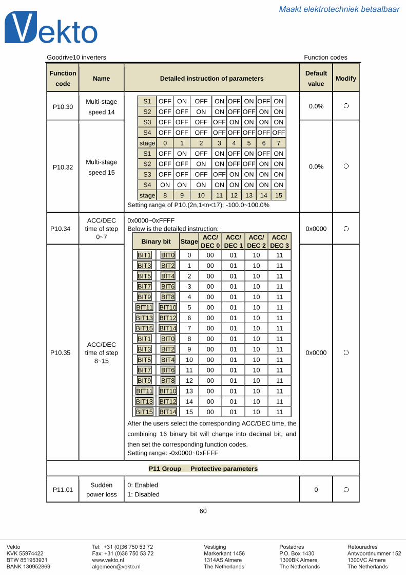
VestigingMarkerkant 14561314AS AlmereThe Netherlands
PostadresP.O. Box 14301300BK AlmereThe Netherlands
Tel: +31 (0)36 750 53 72Fax: +31 (0)36 750 53 [email protected]
RetouradresAntwoordnummer 1521300VC AlmereThe Netherlands
VektoKVK 55974422BTW 851953931BANK 130952869
Maakt elektrotechniek betaalbaar
Goodrive10 inverters Function codes
60
Functioncode
Name Detailed instruction of parametersDefaultvalue
Modify
P10.30Multi-stagespeed 14
S1 OFF ON OFF ON OFF ON OFF ONS2 OFF OFF ON ON OFF OFF ON ONS3 OFF OFF OFF OFF ON ON ON ONS4 OFF OFF OFF OFF OFF OFF OFF OFF
stage 0 1 2 3 4 5 6 7S1 OFF ON OFF ON OFF ON OFF ONS2 OFF OFF ON ON OFF OFF ON ONS3 OFF OFF OFF OFF ON ON ON ONS4 ON ON ON ON ON ON ON ON
stage 8 9 10 11 12 13 14 15Setting range of P10.(2n,1<n<17): -100.0~100.0%
0.0%
P10.32Multi-stagespeed 15
0.0%
P10.34ACC/DEC
time of step0~7
0x0000~0xFFFFBelow is the detailed instruction:
Binary bit Stage ACC/DEC 0
ACC/DEC 1
ACC/DEC 2
ACC/DEC 3
BIT1 BIT0 0 00 01 10 11BIT3 BIT2 1 00 01 10 11BIT5 BIT4 2 00 01 10 11BIT7 BIT6 3 00 01 10 11BIT9 BIT8 4 00 01 10 11BIT11 BIT10 5 00 01 10 11BIT13 BIT12 6 00 01 10 11BIT15 BIT14 7 00 01 10 11BIT1 BIT0 8 00 01 10 11BIT3 BIT2 9 00 01 10 11BIT5 BIT4 10 00 01 10 11BIT7 BIT6 11 00 01 10 11BIT9 BIT8 12 00 01 10 11BIT11 BIT10 13 00 01 10 11BIT13 BIT12 14 00 01 10 11BIT15 BIT14 15 00 01 10 11
After the users select the corresponding ACC/DEC time, thecombining 16 binary bit will change into decimal bit, andthen set the corresponding function codes.Setting range: -0x0000~0xFFFF
0x0000
P10.35ACC/DEC
time of step8~15
0x0000
P11 Group Protective parameters
P11.01Sudden
power loss0: Enabled1: Disabled
0
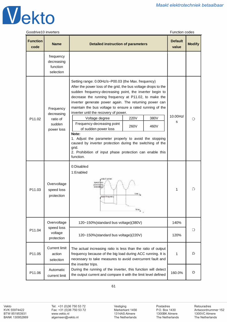
VestigingMarkerkant 14561314AS AlmereThe Netherlands
PostadresP.O. Box 14301300BK AlmereThe Netherlands
Tel: +31 (0)36 750 53 72Fax: +31 (0)36 750 53 [email protected]
RetouradresAntwoordnummer 1521300VC AlmereThe Netherlands
VektoKVK 55974422BTW 851953931BANK 130952869
Maakt elektrotechniek betaalbaar
Goodrive10 inverters Function codes
61
Functioncode
Name Detailed instruction of parametersDefaultvalue
Modify
frequencydecreasing
functionselection
P11.02
Frequencydecreasing
ratio ofsudden
power loss
Setting range: 0.00Hz/s~P00.03 (the Max. frequency)After the power loss of the grid, the bus voltage drops to thesudden frequency-decreasing point, the inverter begin todecrease the running frequency at P11.02, to make theinverter generate power again. The returning power canmaintain the bus voltage to ensure a rated running of theinverter until the recovery of power.
Voltage degree 220V 380VFrequency-decreasing point
of sudden power loss260V 460V
Note:1. Adjust the parameter properly to avoid the stoppingcaused by inverter protection during the switching of thegrid.2. Prohibition of input phase protection can enable thisfunction.
10.00Hz/s
P11.03Overvoltagespeed lossprotection
0:Disabled1:Enabled
1
P11.04
Overvoltagespeed loss
voltageprotection
120~150%(standard bus voltage)(380V) 140%
120~150%(standard bus voltage)(220V) 120%
P11.05Current limit
actionselection
The actual increasing ratio is less than the ratio of outputfrequency because of the big load during ACC running. It isnecessary to take measures to avoid overcurrent fault andthe inverter trips.During the running of the inverter, this function will detectthe output current and compare it with the limit level defined
1
P11.06Automatic
current limit160.0%
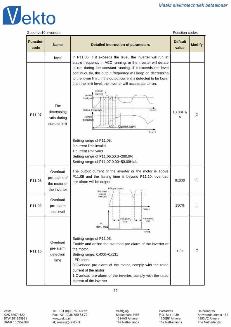
VestigingMarkerkant 14561314AS AlmereThe Netherlands
PostadresP.O. Box 14301300BK AlmereThe Netherlands
Tel: +31 (0)36 750 53 72Fax: +31 (0)36 750 53 [email protected]
RetouradresAntwoordnummer 1521300VC AlmereThe Netherlands
VektoKVK 55974422BTW 851953931BANK 130952869
Maakt elektrotechniek betaalbaar
Goodrive10 inverters Function codes
62
Functioncode
Name Detailed instruction of parametersDefaultvalue
Modify
level in P11.06. If it exceeds the level, the inverter will run atstable frequency in ACC running, or the inverter will derateto run during the constant running. If it exceeds the levelcontinuously, the output frequency will keep on decreasingto the lower limit. If the output current is detected to be lowerthan the limit level, the inverter will accelerate to run.
Setting range of P11.05:0:current limit invalid1:current limit validSetting range of P11.06:50.0~200.0%Setting range of P11.07:0.00~50.00Hz/s
P11.07
Thedecreasingratio duringcurrent limit
10.00Hz/s
P11.08
Overloadpre-alarm ofthe motor orthe inverter
The output current of the inverter or the motor is aboveP11.09 and the lasting time is beyond P11.10, overloadpre-alarm will be output.
Setting range of P11.08:Enable and define the overload pre-alarm of the inverter orthe motor.Setting range: 0x000~0x131LED ones:0:Overload pre-alarm of the motor, comply with the ratedcurrent of the motor1:Overload pre-alarm of the inverter, comply with the ratedcurrent of the inverter
0x000
P11.09Overloadpre-alarmtest level
150%
P11.10
Overloadpre-alarmdetection
time
1.0s
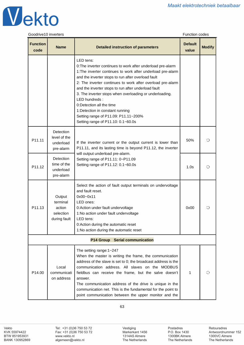
VestigingMarkerkant 14561314AS AlmereThe Netherlands
PostadresP.O. Box 14301300BK AlmereThe Netherlands
Tel: +31 (0)36 750 53 72Fax: +31 (0)36 750 53 [email protected]
RetouradresAntwoordnummer 1521300VC AlmereThe Netherlands
VektoKVK 55974422BTW 851953931BANK 130952869
Maakt elektrotechniek betaalbaar
Goodrive10 inverters Function codes
63
Functioncode
Name Detailed instruction of parametersDefaultvalue
Modify
LED tens:0:The inverter continues to work after underload pre-alarm1:The inverter continues to work after underload pre-alarmand the inverter stops to run after overload fault2: The inverter continues to work after overload pre-alarmand the inverter stops to run after underload fault3. The inverter stops when overloading or underloading.LED hundreds :0:Detection all the time1:Detection in constant runningSetting range of P11.09: P11.11~200%Setting range of P11.10: 0.1~60.0s
P11.11
Detectionlevel of theunderloadpre-alarm
If the inverter current or the output current is lower thanP11.11, and its lasting time is beyond P11.12, the inverterwill output underload pre-alarm.Setting range of P11.11: 0~P11.09Setting range of P11.12: 0.1~60.0s
50%
P11.12
Detectiontime of theunderloadpre-alarm
1.0s
P11.13
Outputterminalaction
selectionduring fault
Select the action of fault output terminals on undervoltageand fault reset.0x00~0x11LED ones:0:Action under fault undervoltage1:No action under fault undervoltageLED tens:0:Action during the automatic reset1:No action during the automatic reset
0x00
P14 Group Serial communication
P14.00Local
communication address
The setting range:1~247When the master is writing the frame, the communicationaddress of the slave is set to 0; the broadcast address is thecommunication address. All slaves on the MODBUSfieldbus can receive the frame, but the salve doesn’tanswer.The communication address of the drive is unique in thecommunication net. This is the fundamental for the point topoint communication between the upper monitor and the
1
VestigingMarkerkant 14561314AS AlmereThe Netherlands
PostadresP.O. Box 14301300BK AlmereThe Netherlands
Tel: +31 (0)36 750 53 72Fax: +31 (0)36 750 53 [email protected]
RetouradresAntwoordnummer 1521300VC AlmereThe Netherlands
VektoKVK 55974422BTW 851953931BANK 130952869
Maakt elektrotechniek betaalbaar
Goodrive10 inverters Function codes
64
Functioncode
Name Detailed instruction of parametersDefaultvalue
Modify
drive.Note: The address of the slave cannot set to 0.
P14.01 Baud rate
Set the digital transmission speed between the uppermonitor and the inverter.0:1200BPS1:2400BPS2:4800BPS3:9600BPS4:19200BPS5:38400BPSNote: The baud rate between the upper monitor and theinverter must be the same. Otherwise, the communication isnot applied. The bigger the baud rate, the quicker thecommunication speed.
4
P14.02Digital bitcheckoutsetting
The data format between the upper monitor and the invertermust be the same. Otherwise, the communication is notapplied.0: No check (N,8,1)for RTU1:Odd check (E,8,1)for RTU2:Even check (O,8,1)for RTU3:No check (N,8,2)for RTU4: Odd check (E,8,2)for RTU5:Even check(O,8,2)for RTU
1
P14.03Communication response
delay
0~200msIt means the interval time between the interval time whenthe drive receive the data and sent it to the upper monitor. Ifthe answer delay is shorter than the system processingtime, then the answer delay time is the system processingtime, if the answer delay is longer than the systemprocessing time, then after the system deal with the data,waits until achieving the answer delay time to send the datato the upper monitor.
5
P14.04Communication overtime
fault time
0.0(invalid),0.1~60.0sWhen the function code is set as 0.0, the communicationovertime parameter is invalid.When the function code is set as non-zero, if the intervaltime between two communications exceeds thecommunication overtime, the system will report “485communication faults” (CE).Generally, set it as invalid; setthe parameter in the continuous communication to monitor
0.0s
VestigingMarkerkant 14561314AS AlmereThe Netherlands
PostadresP.O. Box 14301300BK AlmereThe Netherlands
Tel: +31 (0)36 750 53 72Fax: +31 (0)36 750 53 [email protected]
RetouradresAntwoordnummer 1521300VC AlmereThe Netherlands
VektoKVK 55974422BTW 851953931BANK 130952869
Maakt elektrotechniek betaalbaar
Goodrive10 inverters Function codes
65
Functioncode
Name Detailed instruction of parametersDefaultvalue
Modify
the communication state.
P14.05Transmission
faultprocessing
0:Alarm and stop freely1:No alarm and continue to run2:No alarm and stop according to the stop means(onlyunder the communication control)3:No alarm and stop according to the stop means(under allcontrol modes)
0
P14.06
Communication
processingaction
selection
0x00~0x11LED ones:0: Operation with response: the drive will respond to allreading and writing commands of the upper monitor.1: Operation without response The drive only responds tothe reading command other than the writing command ofthe drive. The communication efficiency can be increasedby this method.LED tens:(reserved)
0x00
P17 Group Monitoring function
P17.00Set
frequencyDisplay current set frequency of the inverterRange: 0.00Hz~P00.03
0.00Hz
P17.01Output
frequencyDisplay current output frequency of the inverterRange: 0.00Hz~P00.03
0.00Hz
P17.02Ramp
referencefrequency
Display current ramp reference frequency of the inverterRange: 0.00Hz~P00.03
0.00Hz
P17.03Outputvoltage
Display current output voltage of the inverter
Range: 0~1200V0V
P17.04Outputcurrent
Display current output current of the inverter
Range: 0.0~5000.0A0.0A
P17.05 The rotationspeed of the
Display the rotation speed of the motor.
Range: 0~65535RPM0 RPM
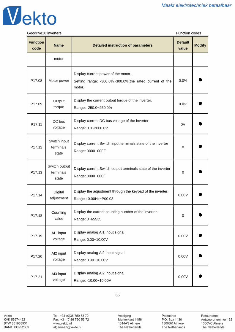
VestigingMarkerkant 14561314AS AlmereThe Netherlands
PostadresP.O. Box 14301300BK AlmereThe Netherlands
Tel: +31 (0)36 750 53 72Fax: +31 (0)36 750 53 [email protected]
RetouradresAntwoordnummer 1521300VC AlmereThe Netherlands
VektoKVK 55974422BTW 851953931BANK 130952869
Maakt elektrotechniek betaalbaar
Goodrive10 inverters Function codes
66
Functioncode
Name Detailed instruction of parametersDefaultvalue
Modify
motor
P17.08 Motor power
Display current power of the motor.
Setting range: -300.0%~300.0%(the rated current of themotor)
0.0%
P17.09Outputtorque
Display the current output torque of the inverter.
Range: -250.0~250.0%0.0%
P17.11DC busvoltage
Display current DC bus voltage of the inverter
Range: 0.0~2000.0V0V
P17.12Switch input
terminalsstate
Display current Switch input terminals state of the inverter
Range: 0000~00FF0
P17.13Switch output
terminalsstate
Display current Switch output terminals state of the inverter
Range: 0000~000F0
P17.14Digital
adjustment
Display the adjustment through the keypad of the inverter.
Range : 0.00Hz~P00.030.00V
P17.18Counting
value
Display the current counting number of the inverter.
Range: 0~655350
P17.19AI1 inputvoltage
Display analog AI1 input signal
Range: 0.00~10.00V0.00V
P17.20AI2 inputvoltage
Display analog AI2 input signal
Range: 0.00~10.00V0.00V
P17.21AI3 inputvoltage
Display analog AI2 input signal
Range: -10.00~10.00V0.00V
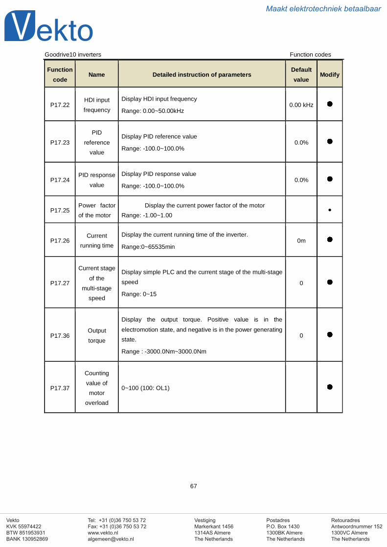
VestigingMarkerkant 14561314AS AlmereThe Netherlands
PostadresP.O. Box 14301300BK AlmereThe Netherlands
Tel: +31 (0)36 750 53 72Fax: +31 (0)36 750 53 [email protected]
RetouradresAntwoordnummer 1521300VC AlmereThe Netherlands
VektoKVK 55974422BTW 851953931BANK 130952869
Maakt elektrotechniek betaalbaar
Goodrive10 inverters Function codes
67
Functioncode
Name Detailed instruction of parametersDefaultvalue
Modify
P17.22HDI inputfrequency
Display HDI input frequency
Range: 0.00~50.00kHz0.00 kHz
P17.23PID
referencevalue
Display PID reference value
Range: -100.0~100.0%0.0%
P17.24PID response
value
Display PID response value
Range: -100.0~100.0%0.0%
P17.25Power factorof the motor
Display the current power factor of the motorRange: -1.00~1.00
P17.26Current
running time
Display the current running time of the inverter.
Range:0~65535min0m
P17.27
Current stageof the
multi-stagespeed
Display simple PLC and the current stage of the multi-stagespeed
Range: 0~15
0
P17.36Outputtorque
Display the output torque. Positive value is in theelectromotion state, and negative is in the power generatingstate.
Range : -3000.0Nm~3000.0Nm
0
P17.37
Countingvalue ofmotor
overload
0~100 (100: OL1)
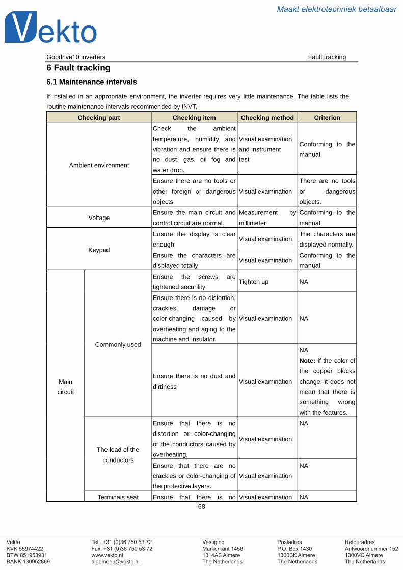
VestigingMarkerkant 14561314AS AlmereThe Netherlands
PostadresP.O. Box 14301300BK AlmereThe Netherlands
Tel: +31 (0)36 750 53 72Fax: +31 (0)36 750 53 [email protected]
RetouradresAntwoordnummer 1521300VC AlmereThe Netherlands
VektoKVK 55974422BTW 851953931BANK 130952869
Maakt elektrotechniek betaalbaar
Goodrive10 inverters Fault tracking
68
6 Fault tracking6.1 Maintenance intervals
If installed in an appropriate environment, the inverter requires very little maintenance. The table lists theroutine maintenance intervals recommended by INVT.
Checking part Checking item Checking method Criterion
Ambient environment
Check the ambienttemperature, humidity andvibration and ensure there isno dust, gas, oil fog andwater drop.
Visual examinationand instrumenttest
Conforming to themanual
Ensure there are no tools orother foreign or dangerousobjects
Visual examinationThere are no toolsor dangerousobjects.
VoltageEnsure the main circuit andcontrol circuit are normal.
Measurement bymillimeter
Conforming to themanual
Keypad
Ensure the display is clearenough
Visual examinationThe characters aredisplayed normally.
Ensure the characters aredisplayed totally
Visual examinationConforming to themanual
Maincircuit
Commonly used
Ensure the screws aretightened securility
Tighten up NA
Ensure there is no distortion,crackles, damage orcolor-changing caused byoverheating and aging to themachine and insulator.
Visual examination NA
Ensure there is no dust anddirtiness
Visual examination
NANote: if the color ofthe copper blockschange, it does notmean that there issomething wrongwith the features.
The lead of theconductors
Ensure that there is nodistortion or color-changingof the conductors caused byoverheating.
Visual examination
NA
Ensure that there are nocrackles or color-changing ofthe protective layers.
Visual examinationNA
Terminals seat Ensure that there is no Visual examination NA
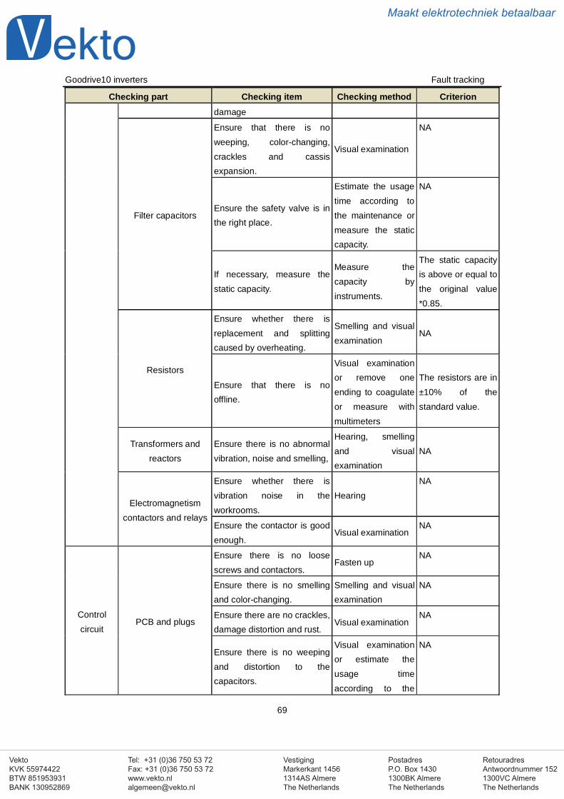
VestigingMarkerkant 14561314AS AlmereThe Netherlands
PostadresP.O. Box 14301300BK AlmereThe Netherlands
Tel: +31 (0)36 750 53 72Fax: +31 (0)36 750 53 [email protected]
RetouradresAntwoordnummer 1521300VC AlmereThe Netherlands
VektoKVK 55974422BTW 851953931BANK 130952869
Maakt elektrotechniek betaalbaar
Goodrive10 inverters Fault tracking
69
Checking part Checking item Checking method Criteriondamage
Filter capacitors
Ensure that there is noweeping, color-changing,crackles and cassisexpansion.
Visual examination
NA
Ensure the safety valve is inthe right place.
Estimate the usagetime according tothe maintenance ormeasure the staticcapacity.
NA
If necessary, measure thestatic capacity.
Measure thecapacity byinstruments.
The static capacityis above or equal tothe original value*0.85.
Resistors
Ensure whether there isreplacement and splittingcaused by overheating.
Smelling and visualexamination
NA
Ensure that there is nooffline.
Visual examinationor remove oneending to coagulateor measure withmultimeters
The resistors are in±10% of thestandard value.
Transformers andreactors
Ensure there is no abnormalvibration, noise and smelling,
Hearing, smellingand visualexamination
NA
Electromagnetismcontactors and relays
Ensure whether there isvibration noise in theworkrooms.
HearingNA
Ensure the contactor is goodenough.
Visual examinationNA
Controlcircuit
PCB and plugs
Ensure there is no loosescrews and contactors.
Fasten upNA
Ensure there is no smellingand color-changing.
Smelling and visualexamination
NA
Ensure there are no crackles,damage distortion and rust.
Visual examinationNA
Ensure there is no weepingand distortion to thecapacitors.
Visual examinationor estimate theusage timeaccording to the
NA
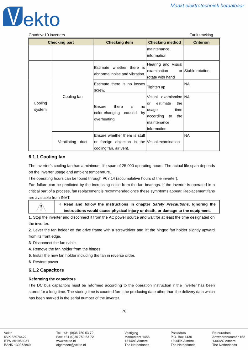
VestigingMarkerkant 14561314AS AlmereThe Netherlands
PostadresP.O. Box 14301300BK AlmereThe Netherlands
Tel: +31 (0)36 750 53 72Fax: +31 (0)36 750 53 [email protected]
RetouradresAntwoordnummer 1521300VC AlmereThe Netherlands
VektoKVK 55974422BTW 851953931BANK 130952869
Maakt elektrotechniek betaalbaar
Goodrive10 inverters Fault tracking
70
Checking part Checking item Checking method Criterionmaintenanceinformation
Coolingsystem
Cooling fan
Estimate whether there isabnormal noise and vibration.
Hearing and Visualexamination orrotate with hand
Stable rotation
Estimate there is no lossesscrew.
Tighten upNA
Ensure there is nocolor-changing caused byoverheating.
Visual examinationor estimate theusage timeaccording to themaintenanceinformation
NA
Ventilating ductEnsure whether there is stuffor foreign objection in thecooling fan, air vent.
Visual examinationNA
6.1.1 Cooling fan
The inverter’s cooling fan has a minimum life span of 25,000 operating hours. The actual life span dependson the inverter usage and ambient temperature.The operating hours can be found through P07.14 (accumulative hours of the inverter).Fan failure can be predicted by the increasing noise from the fan bearings. If the inverter is operated in acritical part of a process, fan replacement is recommended once these symptoms appear. Replacement fansare available from INVT.
Read and follow the instructions in chapter Safety Precautions. Ignoring theinstructions would cause physical injury or death, or damage to the equipment.
1. Stop the inverter and disconnect it from the AC power source and wait for at least the time designated onthe inverter.2. Lever the fan holder off the drive frame with a screwdriver and lift the hinged fan holder slightly upwardfrom its front edge.3. Disconnect the fan cable.4. Remove the fan holder from the hinges.5. Install the new fan holder including the fan in reverse order.6. Restore power.
6.1.2 Capacitors
Reforming the capacitorsThe DC bus capacitors must be reformed according to the operation instruction if the inverter has beenstored for a long time. The storing time is counted form the producing date other than the delivery data whichhas been marked in the serial number of the inverter.
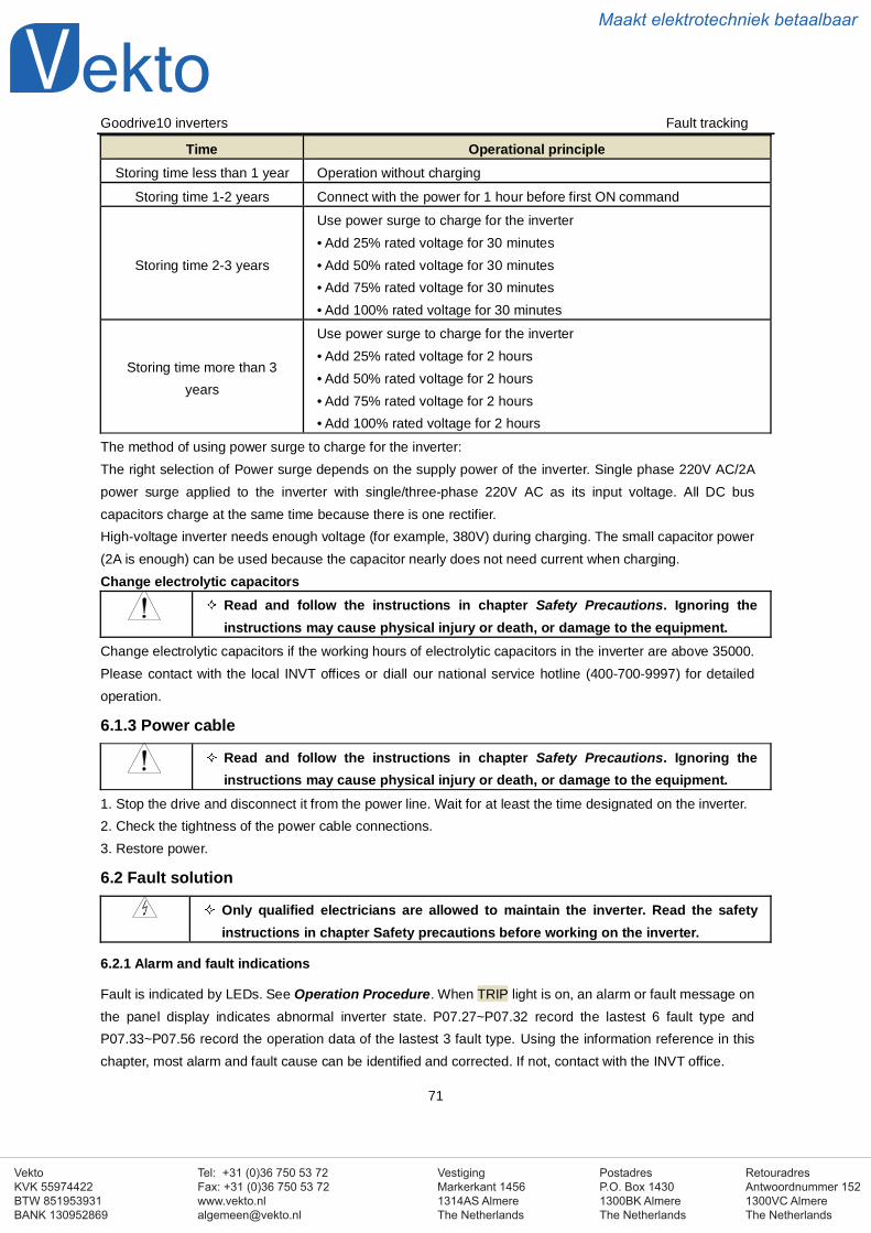
VestigingMarkerkant 14561314AS AlmereThe Netherlands
PostadresP.O. Box 14301300BK AlmereThe Netherlands
Tel: +31 (0)36 750 53 72Fax: +31 (0)36 750 53 [email protected]
RetouradresAntwoordnummer 1521300VC AlmereThe Netherlands
VektoKVK 55974422BTW 851953931BANK 130952869
Maakt elektrotechniek betaalbaar
Goodrive10 inverters Fault tracking
71
Time Operational principleStoring time less than 1 year Operation without charging
Storing time 1-2 years Connect with the power for 1 hour before first ON command
Storing time 2-3 years
Use power surge to charge for the inverter• Add 25% rated voltage for 30 minutes• Add 50% rated voltage for 30 minutes• Add 75% rated voltage for 30 minutes• Add 100% rated voltage for 30 minutes
Storing time more than 3years
Use power surge to charge for the inverter• Add 25% rated voltage for 2 hours• Add 50% rated voltage for 2 hours• Add 75% rated voltage for 2 hours• Add 100% rated voltage for 2 hours
The method of using power surge to charge for the inverter:The right selection of Power surge depends on the supply power of the inverter. Single phase 220V AC/2Apower surge applied to the inverter with single/three-phase 220V AC as its input voltage. All DC buscapacitors charge at the same time because there is one rectifier.High-voltage inverter needs enough voltage (for example, 380V) during charging. The small capacitor power(2A is enough) can be used because the capacitor nearly does not need current when charging.Change electrolytic capacitors
Read and follow the instructions in chapter Safety Precautions. Ignoring theinstructions may cause physical injury or death, or damage to the equipment.
Change electrolytic capacitors if the working hours of electrolytic capacitors in the inverter are above 35000.Please contact with the local INVT offices or diall our national service hotline (400-700-9997) for detailedoperation.
6.1.3 Power cable
Read and follow the instructions in chapter Safety Precautions. Ignoring theinstructions may cause physical injury or death, or damage to the equipment.
1. Stop the drive and disconnect it from the power line. Wait for at least the time designated on the inverter.2. Check the tightness of the power cable connections.3. Restore power.
6.2 Fault solution
Only qualified electricians are allowed to maintain the inverter. Read the safetyinstructions in chapter Safety precautions before working on the inverter.
6.2.1 Alarm and fault indications
Fault is indicated by LEDs. See Operation Procedure. When TRIP light is on, an alarm or fault message onthe panel display indicates abnormal inverter state. P07.27~P07.32 record the lastest 6 fault type andP07.33~P07.56 record the operation data of the lastest 3 fault type. Using the information reference in thischapter, most alarm and fault cause can be identified and corrected. If not, contact with the INVT office.
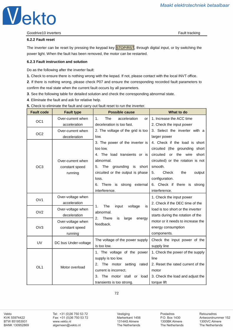
VestigingMarkerkant 14561314AS AlmereThe Netherlands
PostadresP.O. Box 14301300BK AlmereThe Netherlands
Tel: +31 (0)36 750 53 72Fax: +31 (0)36 750 53 [email protected]
RetouradresAntwoordnummer 1521300VC AlmereThe Netherlands
VektoKVK 55974422BTW 851953931BANK 130952869
Maakt elektrotechniek betaalbaar
Goodrive10 inverters Fault tracking
72
6.2.2 Fault reset
The inverter can be reset by pressing the keypad key STOP/RST, through digital input, or by switching thepower light. When the fault has been removed, the motor can be restarted.
6.2.3 Fault instruction and solution
Do as the following after the inverter fault:1. Check to ensure there is nothing wrong with the kepad. If not, please contact with the local INVT office.2. If there is nothing wrong, please check P07 and ensure the corresponding recorded fault parameters toconfirm the real state when the current fault occurs by all parameters.3. See the following table for detailed solution and check the corresponding abnormal state.4. Eliminate the fault and ask for relative help.5. Check to eliminate the fault and carry out fault reset to run the inverter.
Fault code Fault type Possible cause What to do
OC1Over-current when
acceleration1. The acceleration ordeceleration is too fast.2. The voltage of the grid is toolow.3. The power of the inverter istoo low.4. The load transients or isabnormal.5. The grounding is shortcircuited or the output is phaseloss.6. There is strong externalinterference.
1. Increase the ACC time2. Check the input power3. Select the inverter with alarger power4. Check if the load is shortcircuited (the grounding shortcircuited or the wire shortcircuited) or the rotation is notsmooth.5. Check the outputconfiguration.6. Check if there is stronginterference.
OC2Over-current when
deceleration
OC3Over-current when
constant speedrunning
OV1Over-voltage when
acceleration1. The input voltage isabnormal.2. There is large energyfeedback.
1. Check the input power2. Check if the DEC time of theload is too short or the inverterstarts during the rotation of themotor or it needs to increase theenergy consumptioncomponents.
OV2Over-voltage when
deceleration
OV3Over-voltage when
constant speedrunning
UV DC bus Under-voltageThe voltage of the power supplyis too low.
Check the input power of thesupply line
OL1 Motor overload
1. The voltage of the powersupply is too low.2. The motor setting ratedcurrent is incorrect.3. The motor stall or loadtransients is too strong.
1. Check the power of the supplyline2. Reset the rated current of themotor3. Check the load and adjust thetorque lift
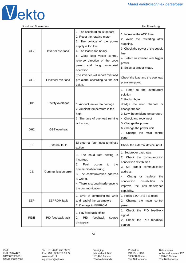
VestigingMarkerkant 14561314AS AlmereThe Netherlands
PostadresP.O. Box 14301300BK AlmereThe Netherlands
Tel: +31 (0)36 750 53 72Fax: +31 (0)36 750 53 [email protected]
RetouradresAntwoordnummer 1521300VC AlmereThe Netherlands
VektoKVK 55974422BTW 851953931BANK 130952869
Maakt elektrotechniek betaalbaar
Goodrive10 inverters Fault tracking
73
OL2 Inverter overload
1. The acceleration is too fast2. Reset the rotating motor3. The voltage of the powersupply is too low.4. The load is too heavy.5. Close loop vector control,reverse direction of the codepanel and long low-speedoperation
1. Increase the ACC time2. Avoid the restarting afterstopping.3. Check the power of the supplyline4. Select an inverter with biggerpower.5. Select a proper motor.
OL3 Electrical overloadThe inverter will report overloadpre-alarm according to the setvalue.
Check the load and the overloadpre-alarm point.
OH1 Rectify overheat 1. Air duct jam or fan damage2. Ambient temperature is toohigh.3. The time of overload runningis too long.
1. Refer to the overcurrentsolution2. Redistributedredge the wind channel orchange the fan3. Low the ambient temperature4. Check and reconnect5. Change the power6. Change the power unit7. Change the main controlpanel
OH2 IGBT overheat
EF External faultSI external fault input terminalsaction
Check the external device input
CE Communication error
1. The baud rate setting isincorrect.2. Fault occurs to thecommunication wiring.3. The communication addressis wrong.4. There is strong interference tothe communication.
1. Set proper baud rate2. Check the communicationconnection distribution3. Set proper communicationaddress.4. Chang or replace theconnection distribution orimprove the anti-interferencecapability.
EEP EEPROM fault1. Error of controlling the writeand read of the parameters2. Damage to EEPROM
1. Press STOP/RST to reset2. Change the main controlpanel
PIDE PID feedback fault1. PID feedback offline2. PID feedback sourcedisappear
1. Check the PID feedbacksignal2. Check the PID feedbacksource

VestigingMarkerkant 14561314AS AlmereThe Netherlands
PostadresP.O. Box 14301300BK AlmereThe Netherlands
Tel: +31 (0)36 750 53 72Fax: +31 (0)36 750 53 [email protected]
RetouradresAntwoordnummer 1521300VC AlmereThe Netherlands
VektoKVK 55974422BTW 851953931BANK 130952869
Maakt elektrotechniek betaalbaar
Goodrive10 inverters Fault tracking
74
ENDTime reach of factory
setting
The actual running time of theinverter is above the internalsetting running time.
Ask for the supplier and adjustthe setting running time.
LLElectronic underload
fault
The inverter will report theunderload pre-alarm accordingto the set value.
Check the load and theunderload pre-alarm point.
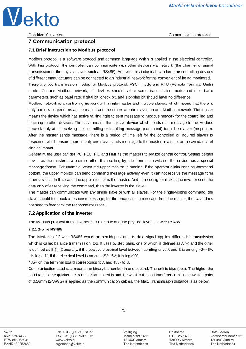
VestigingMarkerkant 14561314AS AlmereThe Netherlands
PostadresP.O. Box 14301300BK AlmereThe Netherlands
Tel: +31 (0)36 750 53 72Fax: +31 (0)36 750 53 [email protected]
RetouradresAntwoordnummer 1521300VC AlmereThe Netherlands
VektoKVK 55974422BTW 851953931BANK 130952869
Maakt elektrotechniek betaalbaar
Goodrive10 inverters Communication protocol
75
7 Communication protocol7.1 Brief instruction to Modbus protocol
Modbus protocol is a software protocol and common language which is applied in the electrical controller.With this protocol, the controller can communicate with other devices via network (the channel of signaltransmission or the physical layer, such as RS485). And with this industrial standard, the controlling devicesof different manufacturers can be connected to an industrial network for the convenient of being monitored.There are two transmission modes for Modbus protocol: ASCII mode and RTU (Remote Terminal Units)mode. On one Modbus network, all devices should select same transmission mode and their basicparameters, such as baud rate, digital bit, check bit, and stopping bit should have no difference.Modbus network is a controlling network with single-master and multiple slaves, which means that there isonly one device performs as the master and the others are the slaves on one Modbus network. The mastermeans the device which has active talking right to sent message to Modbus network for the controlling andinquiring to other devices. The slave means the passive device which sends data message to the Modbusnetwork only after receiving the controlling or inquiring message (command) form the master (response).After the master sends message, there is a period of time left for the controlled or inquired slaves toresponse, which ensure there is only one slave sends message to the master at a time for the avoidance ofsingles impact.Generally, the user can set PC, PLC, IPC and HMI as the masters to realize central control. Setting certaindevice as the master is a promise other than setting by a bottom or a switch or the device has a specialmessage format. For example, when the upper monitor is running, if the operator clicks sending commandbottom, the upper monitor can send command message actively even it can not receive the message formother devices. In this case, the upper monitor is the master. And if the designer makes the inverter send thedata only after receiving the command, then the inverter is the slave.The master can communicate with any single slave or with all slaves. For the single-visiting command, theslave should feedback a response message; for the broadcasting message from the master, the slave doesnot need to feedback the response message.
7.2 Application of the inverter
The Modbus protocol of the inverter is RTU mode and the physical layer is 2-wire RS485.
7.2.1 2-wire RS485
The interface of 2-wire RS485 works on semiduplex and its data signal applies differential transmissionwhich is called balance transmission, too. It uses twisted pairs, one of which is defined as A (+) and the otheris defined as B (-). Generally, if the positive electrical level between sending drive A and B is among +2~+6V,it is logic“1”, if the electrical level is among -2V~-6V; it is logic“0”.485+ on the terminal board corresponds to A and 485- to B.Communication baud rate means the binary bit number in one second. The unit is bit/s (bps). The higher thebaud rate is, the quicker the transmission speed is and the weaker the anti-interference is. If the twisted pairsof 0.56mm (24AWG) is applied as the communication cables, the Max. Transmission distance is as below:
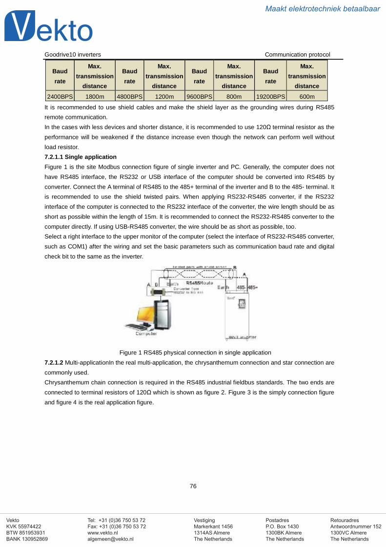
VestigingMarkerkant 14561314AS AlmereThe Netherlands
PostadresP.O. Box 14301300BK AlmereThe Netherlands
Tel: +31 (0)36 750 53 72Fax: +31 (0)36 750 53 [email protected]
RetouradresAntwoordnummer 1521300VC AlmereThe Netherlands
VektoKVK 55974422BTW 851953931BANK 130952869
Maakt elektrotechniek betaalbaar
Goodrive10 inverters Communication protocol
76
Baudrate
Max.transmission
distance
Baudrate
Max.transmission
distance
Baudrate
Max.transmission
distance
Baudrate
Max.transmission
distance2400BPS 1800m 4800BPS 1200m 9600BPS 800m 19200BPS 600m
It is recommended to use shield cables and make the shield layer as the grounding wires during RS485remote communication.In the cases with less devices and shorter distance, it is recommended to use 120Ω terminal resistor as theperformance will be weakened if the distance increase even though the network can perform well withoutload resistor.7.2.1.1 Single applicationFigure 1 is the site Modbus connection figure of single inverter and PC. Generally, the computer does nothave RS485 interface, the RS232 or USB interface of the computer should be converted into RS485 byconverter. Connect the A terminal of RS485 to the 485+ terminal of the inverter and B to the 485- terminal. Itis recommended to use the shield twisted pairs. When applying RS232-RS485 converter, if the RS232interface of the computer is connected to the RS232 interface of the converter, the wire length should be asshort as possible within the length of 15m. It is recommended to connect the RS232-RS485 converter to thecomputer directly. If using USB-RS485 converter, the wire should be as short as possible, too.Select a right interface to the upper monitor of the computer (select the interface of RS232-RS485 converter,such as COM1) after the wiring and set the basic parameters such as communication baud rate and digitalcheck bit to the same as the inverter.
Figure 1 RS485 physical connection in single application7.2.1.2 Multi-applicationIn the real multi-application, the chrysanthemum connection and star connection arecommonly used.Chrysanthemum chain connection is required in the RS485 industrial fieldbus standards. The two ends areconnected to terminal resistors of 120Ω which is shown as figure 2. Figure 3 is the simply connection figureand figure 4 is the real application figure.
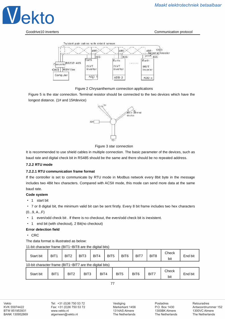
VestigingMarkerkant 14561314AS AlmereThe Netherlands
PostadresP.O. Box 14301300BK AlmereThe Netherlands
Tel: +31 (0)36 750 53 72Fax: +31 (0)36 750 53 [email protected]
RetouradresAntwoordnummer 1521300VC AlmereThe Netherlands
VektoKVK 55974422BTW 851953931BANK 130952869
Maakt elektrotechniek betaalbaar
Goodrive10 inverters Communication protocol
77
Figure 2 Chrysanthemum connection applicationsFigure 5 is the star connection. Terminal resistor should be connected to the two devices which have thelongest distance. (1# and 15#device)
Figure 3 star connectionIt is recommended to use shield cables in multiple connection. The basic parameter of the devices, such asbaud rate and digital check bit in RS485 should be the same and there should be no repeated address.
7.2.2 RTU mode
7.2.2.1 RTU communication frame formatIf the controller is set to communicate by RTU mode in Modbus network every 8bit byte in the messageincludes two 4Bit hex characters. Compared with ACSII mode, this mode can send more data at the samebaud rate.Code system
1 start bit7 or 8 digital bit, the minimum valid bit can be sent firstly. Every 8 bit frame includes two hex characters
(0...9, A...F)1 even/odd check bit . If there is no checkout, the even/odd check bit is inexistent.1 end bit (with checkout), 2 Bit(no checkout)
Error detection fieldCRC
The data format is illustrated as below:11-bit character frame (BIT1~BIT8 are the digital bits)
Start bit BIT1 BIT2 BIT3 BIT4 BIT5 BIT6 BIT7 BIT8Check
bitEnd bit
10-bit character frame (BIT1~BIT7 are the digital bits)
Start bit BIT1 BIT2 BIT3 BIT4 BIT5 BIT6 BIT7Check
bitEnd bit
VestigingMarkerkant 14561314AS AlmereThe Netherlands
PostadresP.O. Box 14301300BK AlmereThe Netherlands
Tel: +31 (0)36 750 53 72Fax: +31 (0)36 750 53 [email protected]
RetouradresAntwoordnummer 1521300VC AlmereThe Netherlands
VektoKVK 55974422BTW 851953931BANK 130952869
Maakt elektrotechniek betaalbaar
Goodrive10 inverters Communication protocol
78
In one character frame, the digital bit takes effect. The start bit, check bit and end bit is used to send thedigital bit right to the other device. The digital bit, even/odd checkout and end bit should be set as the samein real application.The Modbus minimum idle time between frames should be no less than 3.5 bytes. The network device isdetecting, even during the interval time, the network bus. When the first field (the address field) is received,the corresponding device decodes next transmitting character. When the interval time is at least 3.5 byte, themessage ends.The whole message frame in RTU mode is a continuous transmitting flow. If there is an interval time (morethan 1.5 bytes) before the completion of the frame, the receiving device will renew the uncompletedmessage and suppose the next byte as the address field of the new message. As such, if the new messagefollows the previous one within the interval time of 3.5 bytes, the receiving device will deal with it as the samewith the previous message. If these two phenomena all happen during the transmission, the CRC willgenerate a fault message to respond to the sending devices.The standard structure of RTU frame:
START T1-T2-T3-T4(transmission time of 3.5 bytes)
ADDR Communication address: 0~247(decimal system)(0 is the broadcast address)
CMD03H:read slave parameters06H:write slave parameters
DATA (N-1)
DATA (0)
The data of 2*N bytes are the main content of the communication as well asthe core of data exchanging
CRC CHK low bitDetection value:CRC (16BIT
CRC CHK high bit
END T1-T2-T3-T4(transmission time of 3.5 bytes)
7.2.2.2 RTU communication frame error checkoutVarious factors (such as electromagnetic interference) may cause error in the data transmission. Forexample, if the sending message is a logic “1”,A-B potential difference on RS485 should be 6V, but in reality,it may be -6V because of electromagnetic interference, and then the other devices take the sent message aslogic 0 . If there is no error checkout, the receiving devices will not find the message is wrong and they maygive incorrect response which cause serious result. So the checkout is essential to the message.The theme of checkout is that: the sender calculate the sending data according to a fixed formula, and thensend the result with the message. When the receiver gets this message, they will calculate anther resultaccording to the same method and compare it with the sending one. If two results are the same, themessage is correct. If not, the message is incorrect.The error checkout of the frame can be divided into two parts: the bit checkout of the byte and the whole datacheckout of the frame (CRC check).Bit checkout of the byteThe user can select different bit checkouts or non-checkout, which impacts the check bit setting of each byte.The definition of even checkout: add an even check bit before the data transmission to illustrate the number of“1” in the data transmission is odd number or even number. When it is even, the check byte is “0”, otherwise,the check byte is”1”. This method is used to stabilize the parity of the data.The definition of odd checkout: add an odd check bit before the data transmission to illustrate the number of “1”
VestigingMarkerkant 14561314AS AlmereThe Netherlands
PostadresP.O. Box 14301300BK AlmereThe Netherlands
Tel: +31 (0)36 750 53 72Fax: +31 (0)36 750 53 [email protected]
RetouradresAntwoordnummer 1521300VC AlmereThe Netherlands
VektoKVK 55974422BTW 851953931BANK 130952869
Maakt elektrotechniek betaalbaar
Goodrive10 inverters Communication protocol
79
in the data transmission is odd number or even number. When it is odd, the check byte is “0”, otherwise, thecheck byte is”1”. This method is used to stabilize the parity of the data.For example, when transmitting “11001110”, there are five “1” in the data. If the even checkout is applied, theeven check bit is “1”; if the odd checkout is applied; the odd check bit is “0”. The even and odd check bit iscalculated on the check bit position of the frame. And the receiving devices also carry out even and oddcheckout. If the parity of the receiving data is different from the setting value, there is an error in thecommunication.CRC checkThe checkout uses RTU frame format. The frame includes the frame error detection field which is based on theCRC calculation method. The CRC field is two bytes, including 16 figure binary values. It is added into theframe after calculated by transmitting device. The receiving device recalculates the CRC of the received frameand compares them with the value in the received CRC field. If the two CRC values are different, there is anerror in the communication.During CRC, 0*FFFF will be stored. And then, deal with the continuous 6-above bytes in the frame and thevalue in the register. Only the 8Bit data in every character is valid to CRC, while the start bit, the end and theodd and even check bit is invalid.The calculation of CRC applies the international standard CRC checkout principles. When the user is editingCRC calculation, he can refer to the relative standard CRC calculation to write the required CRC calculationprogram.
Here provided a simple function of CRC calculation for the reference (programmed with C language):unsigned int crc_cal_value(unsigned char *data_value,unsigned char data_length)int i;unsigned int crc_value=0xffff;while(data_length--) crc_value^=*data_value++;
for(i=0;i<8;i++)
if(crc_value&0x0001)crc_value=(crc_value>>1)^0xa001;else crc_value=crc_value>>1;
return(crc_value);In ladder logic, CKSM calculated the CRC value according to the frame with the table inquiry. The method isadvanced with easy program and quick calculation speed. But the ROM space the program occupied is huge.So use it with caution according to the program required space.
7.3 RTU command code and communication data illustration
7.3.1 Command code: 03H
03H correspond to binary 0000 0011 ,read N words Word (the Max. continuous reading is 16 words)Command code 03H means that if the master read data form the inverter, the reading number depends on
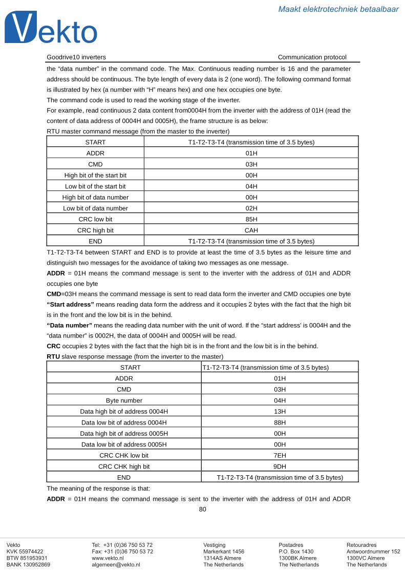
VestigingMarkerkant 14561314AS AlmereThe Netherlands
PostadresP.O. Box 14301300BK AlmereThe Netherlands
Tel: +31 (0)36 750 53 72Fax: +31 (0)36 750 53 [email protected]
RetouradresAntwoordnummer 1521300VC AlmereThe Netherlands
VektoKVK 55974422BTW 851953931BANK 130952869
Maakt elektrotechniek betaalbaar
Goodrive10 inverters Communication protocol
80
the “data number” in the command code. The Max. Continuous reading number is 16 and the parameteraddress should be continuous. The byte length of every data is 2 (one word). The following command formatis illustrated by hex (a number with “H” means hex) and one hex occupies one byte.The command code is used to read the working stage of the inverter.For example, read continuous 2 data content from0004H from the inverter with the address of 01H (read thecontent of data address of 0004H and 0005H), the frame structure is as below:RTU master command message (from the master to the inverter)
START T1-T2-T3-T4 (transmission time of 3.5 bytes)
ADDR 01H
CMD 03H
High bit of the start bit 00H
Low bit of the start bit 04H
High bit of data number 00H
Low bit of data number 02H
CRC low bit 85H
CRC high bit CAH
END T1-T2-T3-T4 (transmission time of 3.5 bytes)
T1-T2-T3-T4 between START and END is to provide at least the time of 3.5 bytes as the leisure time anddistinguish two messages for the avoidance of taking two messages as one message.ADDR = 01H means the command message is sent to the inverter with the address of 01H and ADDRoccupies one byteCMD=03H means the command message is sent to read data form the inverter and CMD occupies one byte“Start address” means reading data form the address and it occupies 2 bytes with the fact that the high bitis in the front and the low bit is in the behind.“Data number” means the reading data number with the unit of word. If the “start address’ is 0004H and the“data number” is 0002H, the data of 0004H and 0005H will be read.CRC occupies 2 bytes with the fact that the high bit is in the front and the low bit is in the behind.RTU slave response message (from the inverter to the master)
START T1-T2-T3-T4 (transmission time of 3.5 bytes)
ADDR 01H
CMD 03H
Byte number 04H
Data high bit of address 0004H 13H
Data low bit of address 0004H 88H
Data high bit of address 0005H 00H
Data low bit of address 0005H 00H
CRC CHK low bit 7EH
CRC CHK high bit 9DH
END T1-T2-T3-T4 (transmission time of 3.5 bytes)
The meaning of the response is that:ADDR = 01H means the command message is sent to the inverter with the address of 01H and ADDR
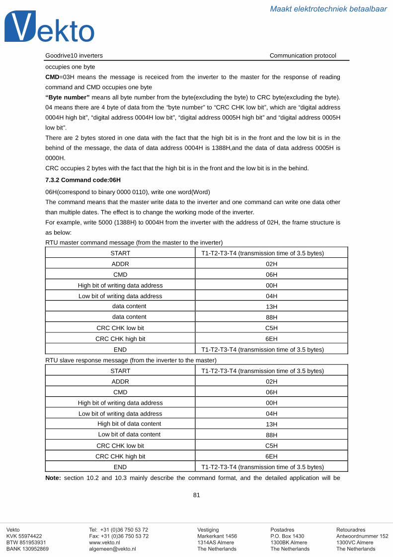
VestigingMarkerkant 14561314AS AlmereThe Netherlands
PostadresP.O. Box 14301300BK AlmereThe Netherlands
Tel: +31 (0)36 750 53 72Fax: +31 (0)36 750 53 [email protected]
RetouradresAntwoordnummer 1521300VC AlmereThe Netherlands
VektoKVK 55974422BTW 851953931BANK 130952869
Maakt elektrotechniek betaalbaar
Goodrive10 inverters Communication protocol
81
occupies one byteCMD=03H means the message is receiced from the inverter to the master for the response of readingcommand and CMD occupies one byte“Byte number” means all byte number from the byte(excluding the byte) to CRC byte(excluding the byte).04 means there are 4 byte of data from the “byte number” to “CRC CHK low bit”, which are “digital address0004H high bit”, “digital address 0004H low bit”, “digital address 0005H high bit” and “digital address 0005Hlow bit”.There are 2 bytes stored in one data with the fact that the high bit is in the front and the low bit is in thebehind of the message, the data of data address 0004H is 1388H,and the data of data address 0005H is0000H.CRC occupies 2 bytes with the fact that the high bit is in the front and the low bit is in the behind.
7.3.2 Command code:06H
06H(correspond to binary 0000 0110), write one word(Word)The command means that the master write data to the inverter and one command can write one data otherthan multiple dates. The effect is to change the working mode of the inverter.For example, write 5000 (1388H) to 0004H from the inverter with the address of 02H, the frame structure isas below:RTU master command message (from the master to the inverter)
START T1-T2-T3-T4 (transmission time of 3.5 bytes)
ADDR 02H
CMD 06H
High bit of writing data address 00H
Low bit of writing data address 04Hdata content 13Hdata content 88H
CRC CHK low bit C5H
CRC CHK high bit 6EH
END T1-T2-T3-T4 (transmission time of 3.5 bytes)
RTU slave response message (from the inverter to the master)
START T1-T2-T3-T4 (transmission time of 3.5 bytes)
ADDR 02H
CMD 06H
High bit of writing data address 00H
Low bit of writing data address 04HHigh bit of data content 13HLow bit of data content 88H
CRC CHK low bit C5H
CRC CHK high bit 6EH
END T1-T2-T3-T4 (transmission time of 3.5 bytes)
Note: section 10.2 and 10.3 mainly describe the command format, and the detailed application will be
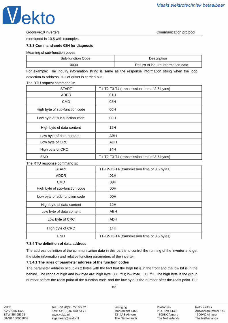
VestigingMarkerkant 14561314AS AlmereThe Netherlands
PostadresP.O. Box 14301300BK AlmereThe Netherlands
Tel: +31 (0)36 750 53 72Fax: +31 (0)36 750 53 [email protected]
RetouradresAntwoordnummer 1521300VC AlmereThe Netherlands
VektoKVK 55974422BTW 851953931BANK 130952869
Maakt elektrotechniek betaalbaar
Goodrive10 inverters Communication protocol
82
mentioned in 10.8 with examples.
7.3.3 Command code 08H for diagnosis
Meaning of sub-function codesSub-function Code Description
0000 Return to inquire information data
For example: The inquiry information string is same as the response information string when the loopdetection to address 01H of driver is carried out.The RTU request command is:
START T1-T2-T3-T4 (transmission time of 3.5 bytes)
ADDR 01H
CMD 08H
High byte of sub-function code 00H
Low byte of sub-function code 00H
High byte of data content 12H
Low byte of data content ABH
Low byte of CRC ADH
High byte of CRC 14H
END T1-T2-T3-T4 (transmission time of 3.5 bytes)
The RTU response command is:START T1-T2-T3-T4 (transmission time of 3.5 bytes)
ADDR 01H
CMD 08H
High byte of sub-function code 00H
Low byte of sub-function code 00H
High byte of data content 12H
Low byte of data content ABH
Low byte of CRC ADH
High byte of CRC 14H
END T1-T2-T3-T4 (transmission time of 3.5 bytes)
7.3.4 The definition of data address
The address definition of the communication data in this part is to control the running of the inverter and getthe state information and relative function parameters of the inverter.7.3.4.1 The rules of parameter address of the function codesThe parameter address occupies 2 bytes with the fact that the high bit is in the front and the low bit is in thebehind. The range of high and low byte are: high byte 00~ffH; low byte 00~ffH. The high byte is the groupnumber before the radix point of the function code and the low byte is the number after the radix point. But
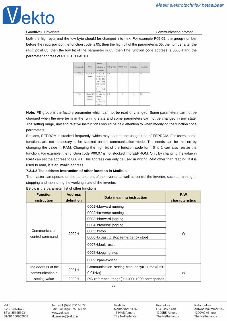
VestigingMarkerkant 14561314AS AlmereThe Netherlands
PostadresP.O. Box 14301300BK AlmereThe Netherlands
Tel: +31 (0)36 750 53 72Fax: +31 (0)36 750 53 [email protected]
RetouradresAntwoordnummer 1521300VC AlmereThe Netherlands
VektoKVK 55974422BTW 851953931BANK 130952869
Maakt elektrotechniek betaalbaar
Goodrive10 inverters Communication protocol
83
both the high byte and the low byte should be changed into hex. For example P05.05, the group numberbefore the radix point of the function code is 05, then the high bit of the parameter is 05, the number after theradix point 05, then the low bit of the parameter is 05, then t he function code address is 0505H and theparameter address of P10.01 is 0A01H.
Note: PE group is the factory parameter which can not be read or changed. Some parameters can not bechanged when the inverter is in the running state and some parameters can not be changed in any state.The setting range, unit and relative instructions should be paid attention to when modifying the function codeparameters.Besides, EEPROM is stocked frequently, which may shorten the usage time of EEPROM. For users, somefunctions are not necessary to be stocked on the communication mode. The needs can be met on bychanging the value in RAM. Changing the high bit of the function code form 0 to 1 can also realize thefunction. For example, the function code P00.07 is not stocked into EEPROM. Only by changing the value inRAM can set the address to 8007H. This address can only be used in writing RAM other than reading. If it isused to read, it is an invalid address.7.3.4.2 The address instruction of other function in ModbusThe master can operate on the parameters of the inverter as well as control the inverter, such as running orstopping and monitoring the working state of the inverter.Below is the parameter list of other functions
Functioninstruction
Addressdefinition
Data meaning instructionR/W
characteristics
Communicationcontrol command
2000H
0001H:forward running
W
0002H:reverse running
0003H:forward jogging
0004H:reverse jogging
0005H:stop
0006H:coast to stop (emergency stop)
0007H:fault reset
0008H:jogging stop
0009H:pre-exciting
The address of thecommunication n
setting value
2001HCommunication setting frequency(0~Fmax(unit:0.01Hz)) W
2002H PID reference, range(0~1000, 1000 corresponds
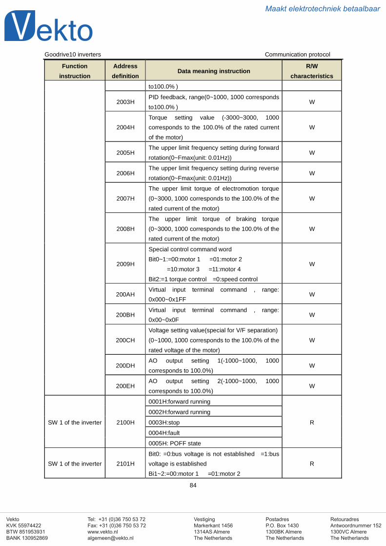
VestigingMarkerkant 14561314AS AlmereThe Netherlands
PostadresP.O. Box 14301300BK AlmereThe Netherlands
Tel: +31 (0)36 750 53 72Fax: +31 (0)36 750 53 [email protected]
RetouradresAntwoordnummer 1521300VC AlmereThe Netherlands
VektoKVK 55974422BTW 851953931BANK 130952869
Maakt elektrotechniek betaalbaar
Goodrive10 inverters Communication protocol
84
Functioninstruction
Addressdefinition
Data meaning instructionR/W
characteristicsto100.0% )
2003HPID feedback, range(0~1000, 1000 correspondsto100.0% )
W
2004HTorque setting value (-3000~3000, 1000corresponds to the 100.0% of the rated currentof the motor)
W
2005HThe upper limit frequency setting during forwardrotation(0~Fmax(unit: 0.01Hz))
W
2006HThe upper limit frequency setting during reverserotation(0~Fmax(unit: 0.01Hz))
W
2007HThe upper limit torque of electromotion torque(0~3000, 1000 corresponds to the 100.0% of therated current of the motor)
W
2008HThe upper limit torque of braking torque(0~3000, 1000 corresponds to the 100.0% of therated current of the motor)
W
2009H
Special control command wordBit0~1:=00:motor 1 =01:motor 2
=10:motor 3 =11:motor 4Bit2:=1 torque control =0:speed control
W
200AHVirtual input terminal command , range:0x000~0x1FF
W
200BHVirtual input terminal command , range:0x00~0x0F
W
200CHVoltage setting value(special for V/F separation)(0~1000, 1000 corresponds to the 100.0% of therated voltage of the motor)
W
200DHAO output setting 1(-1000~1000, 1000corresponds to 100.0%)
W
200EHAO output setting 2(-1000~1000, 1000corresponds to 100.0%)
W
SW 1 of the inverter 2100H
0001H:forward running
R
0002H:forward running
0003H:stop
0004H:fault
0005H: POFF state
SW 1 of the inverter 2101HBit0: =0:bus voltage is not established =1:busvoltage is establishedBi1~2:=00:motor 1 =01:motor 2
R
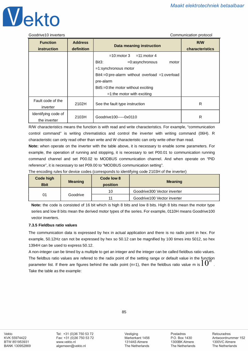
VestigingMarkerkant 14561314AS AlmereThe Netherlands
PostadresP.O. Box 14301300BK AlmereThe Netherlands
Tel: +31 (0)36 750 53 72Fax: +31 (0)36 750 53 [email protected]
RetouradresAntwoordnummer 1521300VC AlmereThe Netherlands
VektoKVK 55974422BTW 851953931BANK 130952869
Maakt elektrotechniek betaalbaar
Goodrive10 inverters Communication protocol
85
Functioninstruction
Addressdefinition
Data meaning instructionR/W
characteristics=10:motor 3 =11:motor 4
Bit3: =0:asynchronous motor=1:synchronous motorBit4:=0:pre-alarm without overload =1:overloadpre-alarmBit5:=0:the motor without exciting
=1:the motor with exciting
Fault code of theinverter
2102H See the fault type instruction R
Identifying code ofthe inverter
2103H Goodrive100-----0x0110 R
R/W characteristics means the function is with read and write characteristics. For example, “communicationcontrol command” is writing chrematistics and control the inverter with writing command (06H). Rcharacteristic can only read other than write and W characteristic can only write other than read.Note: when operate on the inverter with the table above, it is necessary to enable some parameters. Forexample, the operation of running and stopping, it is necessary to set P00.01 to communication runningcommand channel and set P00.02 to MODBUS communication channel. And when operate on “PIDreference”, it is necessary to set P09.00 to “MODBUS communication setting”.The encoding rules for device codes (corresponds to identifying code 2103H of the inverter)
Code high8bit
MeaningCode low 8
positionMeaning
01 Goodrive10 Goodrive300 Vector inverter
11 Goodrive100 Vector inverter
Note: the code is consisted of 16 bit which is high 8 bits and low 8 bits. High 8 bits mean the motor typeseries and low 8 bits mean the derived motor types of the series. For example, 0110H means Goodrive100vector inverters.
7.3.5 Fieldbus ratio values
The communication data is expressed by hex in actual application and there is no radix point in hex. Forexample, 50.12Hz can not be expressed by hex so 50.12 can be magnified by 100 times into 5012, so hex1394H can be used to express 50.12.A non-integer can be timed by a multiple to get an integer and the integer can be called fieldbus ratio values.The fieldbus ratio values are refered to the radix point of the setting range or default value in the functionparameter list. If there are figures behind the radix point (n=1), then the fieldbus ratio value m is .Take the table as the example:
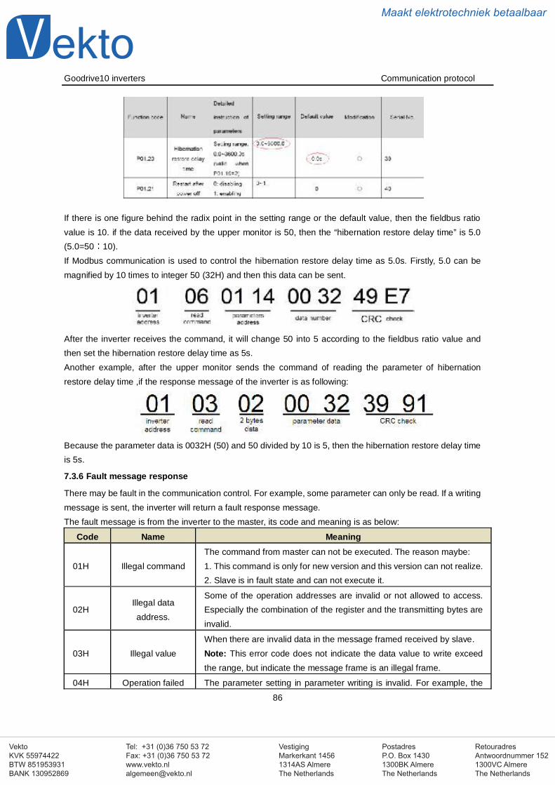
VestigingMarkerkant 14561314AS AlmereThe Netherlands
PostadresP.O. Box 14301300BK AlmereThe Netherlands
Tel: +31 (0)36 750 53 72Fax: +31 (0)36 750 53 [email protected]
RetouradresAntwoordnummer 1521300VC AlmereThe Netherlands
VektoKVK 55974422BTW 851953931BANK 130952869
Maakt elektrotechniek betaalbaar
Goodrive10 inverters Communication protocol
86
If there is one figure behind the radix point in the setting range or the default value, then the fieldbus ratiovalue is 10. if the data received by the upper monitor is 50, then the “hibernation restore delay time” is 5.0(5.0=50 10).If Modbus communication is used to control the hibernation restore delay time as 5.0s. Firstly, 5.0 can bemagnified by 10 times to integer 50 (32H) and then this data can be sent.
After the inverter receives the command, it will change 50 into 5 according to the fieldbus ratio value andthen set the hibernation restore delay time as 5s.Another example, after the upper monitor sends the command of reading the parameter of hibernationrestore delay time ,if the response message of the inverter is as following:
Because the parameter data is 0032H (50) and 50 divided by 10 is 5, then the hibernation restore delay timeis 5s.
7.3.6 Fault message response
There may be fault in the communication control. For example, some parameter can only be read. If a writingmessage is sent, the inverter will return a fault response message.The fault message is from the inverter to the master, its code and meaning is as below:
Code Name Meaning
01H Illegal commandThe command from master can not be executed. The reason maybe:1. This command is only for new version and this version can not realize.2. Slave is in fault state and can not execute it.
02HIllegal dataaddress.
Some of the operation addresses are invalid or not allowed to access.Especially the combination of the register and the transmitting bytes areinvalid.
03H Illegal valueWhen there are invalid data in the message framed received by slave.Note: This error code does not indicate the data value to write exceedthe range, but indicate the message frame is an illegal frame.
04H Operation failed The parameter setting in parameter writing is invalid. For example, the
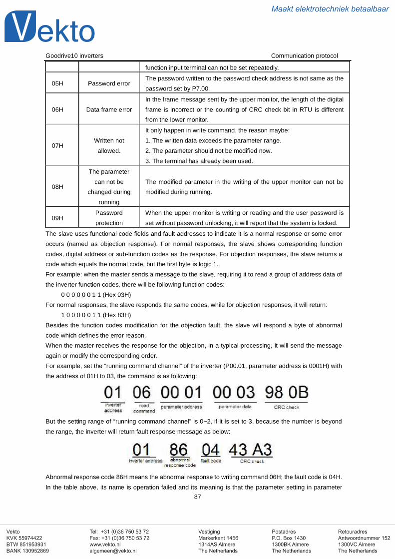
VestigingMarkerkant 14561314AS AlmereThe Netherlands
PostadresP.O. Box 14301300BK AlmereThe Netherlands
Tel: +31 (0)36 750 53 72Fax: +31 (0)36 750 53 [email protected]
RetouradresAntwoordnummer 1521300VC AlmereThe Netherlands
VektoKVK 55974422BTW 851953931BANK 130952869
Maakt elektrotechniek betaalbaar
Goodrive10 inverters Communication protocol
87
function input terminal can not be set repeatedly.
05H Password errorThe password written to the password check address is not same as thepassword set by P7.00.
06H Data frame errorIn the frame message sent by the upper monitor, the length of the digitalframe is incorrect or the counting of CRC check bit in RTU is differentfrom the lower monitor.
07HWritten not
allowed.
It only happen in write command, the reason maybe:1. The written data exceeds the parameter range.2. The parameter should not be modified now.3. The terminal has already been used.
08H
The parametercan not be
changed duringrunning
The modified parameter in the writing of the upper monitor can not bemodified during running.
09HPasswordprotection
When the upper monitor is writing or reading and the user password isset without password unlocking, it will report that the system is locked.
The slave uses functional code fields and fault addresses to indicate it is a normal response or some erroroccurs (named as objection response). For normal responses, the slave shows corresponding functioncodes, digital address or sub-function codes as the response. For objection responses, the slave returns acode which equals the normal code, but the first byte is logic 1.For example: when the master sends a message to the slave, requiring it to read a group of address data ofthe inverter function codes, there will be following function codes:
0 0 0 0 0 0 1 1 (Hex 03H)For normal responses, the slave responds the same codes, while for objection responses, it will return:
1 0 0 0 0 0 1 1 (Hex 83H)Besides the function codes modification for the objection fault, the slave will respond a byte of abnormalcode which defines the error reason.When the master receives the response for the objection, in a typical processing, it will send the messageagain or modify the corresponding order.For example, set the “running command channel” of the inverter (P00.01, parameter address is 0001H) withthe address of 01H to 03, the command is as following:
But the setting range of “running command channel” is 0~2, if it is set to 3, because the number is beyondthe range, the inverter will return fault response message as below:
Abnormal response code 86H means the abnormal response to writing command 06H; the fault code is 04H.In the table above, its name is operation failed and its meaning is that the parameter setting in parameter
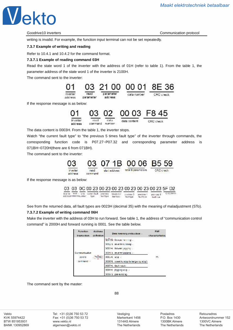
VestigingMarkerkant 14561314AS AlmereThe Netherlands
PostadresP.O. Box 14301300BK AlmereThe Netherlands
Tel: +31 (0)36 750 53 72Fax: +31 (0)36 750 53 [email protected]
RetouradresAntwoordnummer 1521300VC AlmereThe Netherlands
VektoKVK 55974422BTW 851953931BANK 130952869
Maakt elektrotechniek betaalbaar
Goodrive10 inverters Communication protocol
88
writing is invalid. For example, the function input terminal can not be set repeatedly.
7.3.7 Example of writing and reading
Refer to 10.4.1 and 10.4.2 for the command format.7.3.7.1 Example of reading command 03HRead the state word 1 of the inverter with the address of 01H (refer to table 1). From the table 1, theparameter address of the state word 1 of the inverter is 2100H.The command sent to the inverter:
If the response message is as below:
The data content is 0003H. From the table 1, the inverter stops.Watch “the current fault type” to “the previous 5 times fault type” of the inverter through commands, thecorresponding function code is P07.27~P07.32 and corresponding parameter address is071BH~0720H(there are 6 from 071BH).The command sent to the inverter:
If the response message is as below:
See from the returned data, all fault types are 0023H (decimal 35) with the meaning of maladjustment (STo).7.3.7.2 Example of writing command 06HMake the inverter with the address of 03H to run forward. See table 1, the address of “communication controlcommand” is 2000H and forward running is 0001. See the table below.
The command sent by the master:
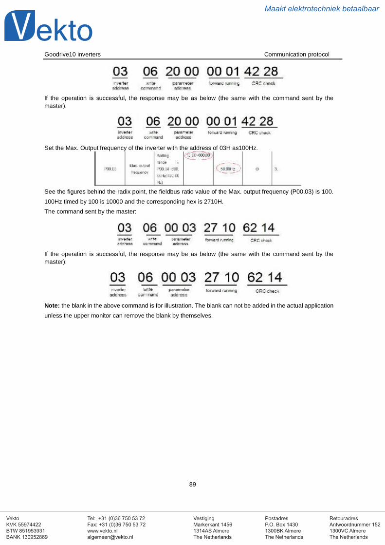
VestigingMarkerkant 14561314AS AlmereThe Netherlands
PostadresP.O. Box 14301300BK AlmereThe Netherlands
Tel: +31 (0)36 750 53 72Fax: +31 (0)36 750 53 [email protected]
RetouradresAntwoordnummer 1521300VC AlmereThe Netherlands
VektoKVK 55974422BTW 851953931BANK 130952869
Maakt elektrotechniek betaalbaar
Goodrive10 inverters Communication protocol
89
If the operation is successful, the response may be as below (the same with the command sent by themaster):
Set the Max. Output frequency of the inverter with the address of 03H as100Hz.
See the figures behind the radix point, the fieldbus ratio value of the Max. output frequency (P00.03) is 100.100Hz timed by 100 is 10000 and the corresponding hex is 2710H.The command sent by the master:
If the operation is successful, the response may be as below (the same with the command sent by themaster):
Note: the blank in the above command is for illustration. The blank can not be added in the actual applicationunless the upper monitor can remove the blank by themselves.
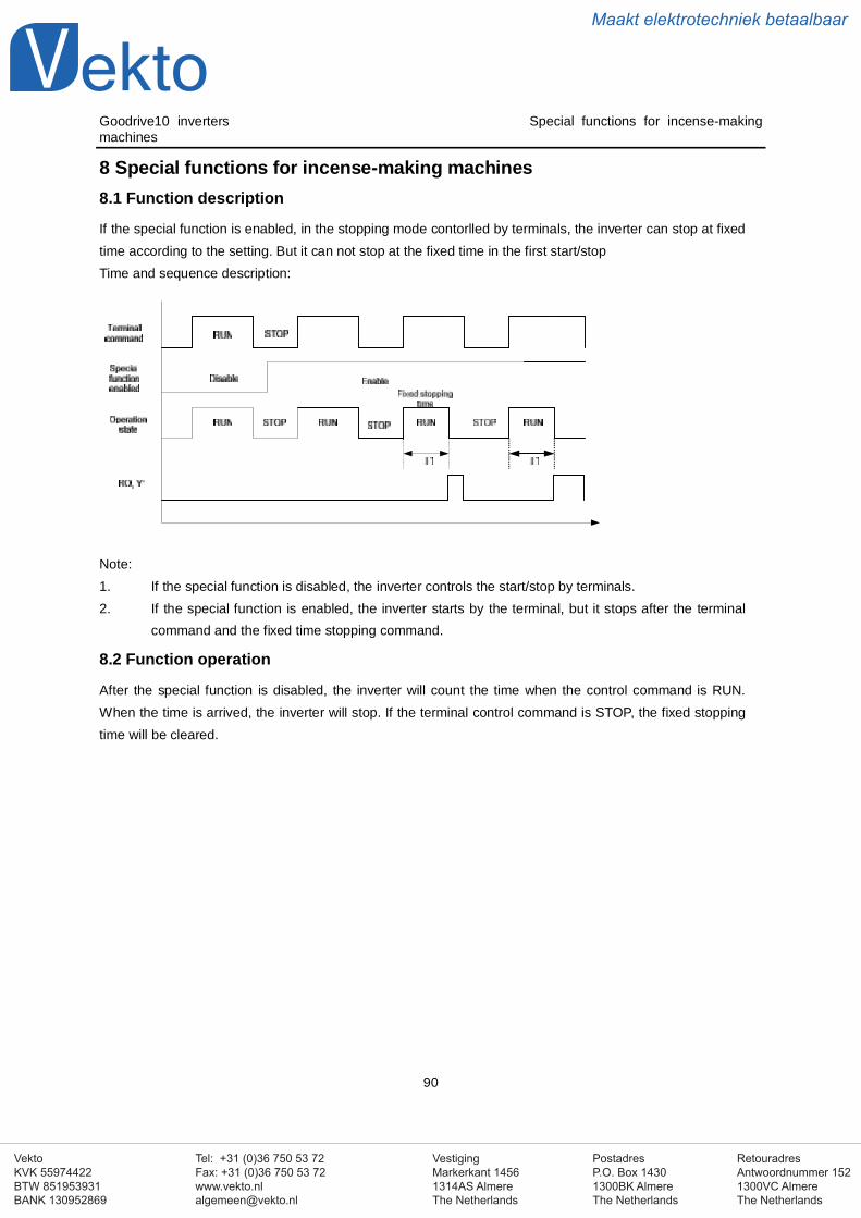
VestigingMarkerkant 14561314AS AlmereThe Netherlands
PostadresP.O. Box 14301300BK AlmereThe Netherlands
Tel: +31 (0)36 750 53 72Fax: +31 (0)36 750 53 [email protected]
RetouradresAntwoordnummer 1521300VC AlmereThe Netherlands
VektoKVK 55974422BTW 851953931BANK 130952869
Maakt elektrotechniek betaalbaar
Goodrive10 inverters Special functions for incense-makingmachines
90
8 Special functions for incense-making machines8.1 Function description
If the special function is enabled, in the stopping mode contorlled by terminals, the inverter can stop at fixedtime according to the setting. But it can not stop at the fixed time in the first start/stopTime and sequence description:
Note:1. If the special function is disabled, the inverter controls the start/stop by terminals.2. If the special function is enabled, the inverter starts by the terminal, but it stops after the terminal
command and the fixed time stopping command.
8.2 Function operation
After the special function is disabled, the inverter will count the time when the control command is RUN.When the time is arrived, the inverter will stop. If the terminal control command is STOP, the fixed stoppingtime will be cleared.
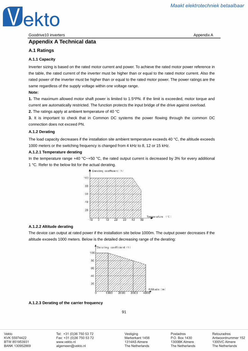
VestigingMarkerkant 14561314AS AlmereThe Netherlands
PostadresP.O. Box 14301300BK AlmereThe Netherlands
Tel: +31 (0)36 750 53 72Fax: +31 (0)36 750 53 [email protected]
RetouradresAntwoordnummer 1521300VC AlmereThe Netherlands
VektoKVK 55974422BTW 851953931BANK 130952869
Maakt elektrotechniek betaalbaar
Goodrive10 inverters Appendix A
91
Appendix A Technical dataA.1 Ratings
A.1.1 Capacity
Inverter sizing is based on the rated motor current and power. To achieve the rated motor power reference inthe table, the rated current of the inverter must be higher than or equal to the rated motor current. Also therated power of the inverter must be higher than or equal to the rated motor power. The power ratings are thesame regardless of the supply voltage within one voltage range.Note:1. The maximum allowed motor shaft power is limited to 1.5*PN. If the limit is exceeded, motor torque andcurrent are automatically restricted. The function protects the input bridge of the drive against overload.2. The ratings apply at ambient temperature of 40 °C3. It is important to check that in Common DC systems the power flowing through the common DCconnection does not exceed PN.
A.1.2 Derating
The load capacity decreases if the installation site ambient temperature exceeds 40 °C, the altitude exceeds1000 meters or the switching frequency is changed from 4 kHz to 8, 12 or 15 kHz.A.1.2.1 Temperature deratingIn the temperature range +40 °C~+50 °C, the rated output current is decreased by 3% for every additional1 °C. Refer to the below list for the actual derating.
A.1.2.2 Altitude deratingThe device can output at rated power if the installation site below 1000m. The output power decreases if thealtitude exceeds 1000 meters. Below is the detailed decreasing range of the derating:
A.1.2.3 Derating of the carrier frequency
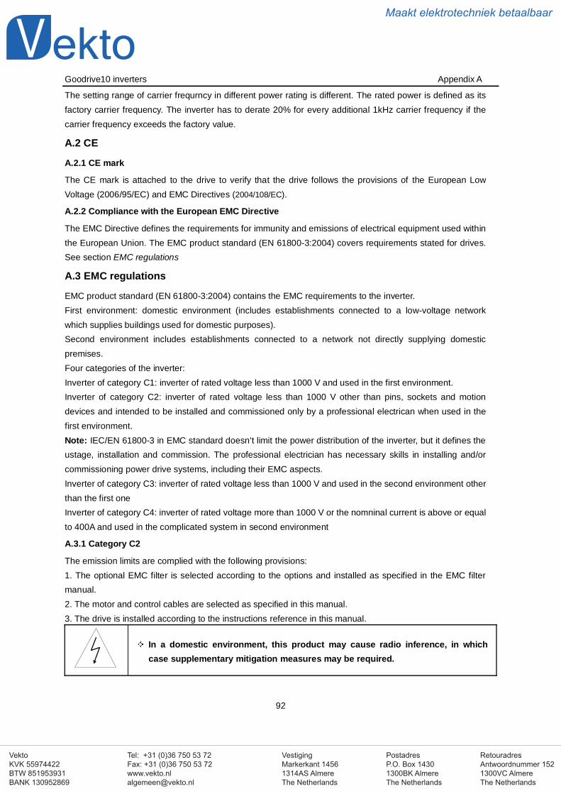
VestigingMarkerkant 14561314AS AlmereThe Netherlands
PostadresP.O. Box 14301300BK AlmereThe Netherlands
Tel: +31 (0)36 750 53 72Fax: +31 (0)36 750 53 [email protected]
RetouradresAntwoordnummer 1521300VC AlmereThe Netherlands
VektoKVK 55974422BTW 851953931BANK 130952869
Maakt elektrotechniek betaalbaar
Goodrive10 inverters Appendix A
92
The setting range of carrier frequrncy in different power rating is different. The rated power is defined as itsfactory carrier frequency. The inverter has to derate 20% for every additional 1kHz carrier frequency if thecarrier frequency exceeds the factory value.
A.2 CE
A.2.1 CE mark
The CE mark is attached to the drive to verify that the drive follows the provisions of the European LowVoltage (2006/95/EC) and EMC Directives (2004/108/EC).
A.2.2 Compliance with the European EMC Directive
The EMC Directive defines the requirements for immunity and emissions of electrical equipment used withinthe European Union. The EMC product standard (EN 61800-3:2004) covers requirements stated for drives.See section EMC regulations
A.3 EMC regulations
EMC product standard (EN 61800-3:2004) contains the EMC requirements to the inverter.First environment: domestic environment (includes establishments connected to a low-voltage networkwhich supplies buildings used for domestic purposes).Second environment includes establishments connected to a network not directly supplying domesticpremises.Four categories of the inverter:Inverter of category C1: inverter of rated voltage less than 1000 V and used in the first environment.Inverter of category C2: inverter of rated voltage less than 1000 V other than pins, sockets and motiondevices and intended to be installed and commissioned only by a professional electrican when used in thefirst environment.Note: IEC/EN 61800-3 in EMC standard doesn’t limit the power distribution of the inverter, but it defines theustage, installation and commission. The professional electrician has necessary skills in installing and/orcommissioning power drive systems, including their EMC aspects.Inverter of category C3: inverter of rated voltage less than 1000 V and used in the second environment otherthan the first oneInverter of category C4: inverter of rated voltage more than 1000 V or the nomninal current is above or equalto 400A and used in the complicated system in second environment
A.3.1 Category C2
The emission limits are complied with the following provisions:1. The optional EMC filter is selected according to the options and installed as specified in the EMC filtermanual.2. The motor and control cables are selected as specified in this manual.3. The drive is installed according to the instructions reference in this manual.
In a domestic environment, this product may cause radio inference, in whichcase supplementary mitigation measures may be required.
VestigingMarkerkant 14561314AS AlmereThe Netherlands
PostadresP.O. Box 14301300BK AlmereThe Netherlands
Tel: +31 (0)36 750 53 72Fax: +31 (0)36 750 53 [email protected]
RetouradresAntwoordnummer 1521300VC AlmereThe Netherlands
VektoKVK 55974422BTW 851953931BANK 130952869
Maakt elektrotechniek betaalbaar
Goodrive10 inverters Appendix A
93
A.3.2 Category C3
The immunity performance of the drive complies with the demands of IEC/EN 61800-3, second environment.The emission limits are complied with the following provisions:1. The optional EMC filter is selected according to the options and installed as specified in the EMC filtermanual.2. The motor and control cables are selected as specified in this manual.3. The drive is installed according to the instructions reference in this manual.
A drive of category C3 is not intended to be used on a low-voltage public networkwhich supplies domestic premises. Radio frequency interference is expected ifthe drive is used on such a network.
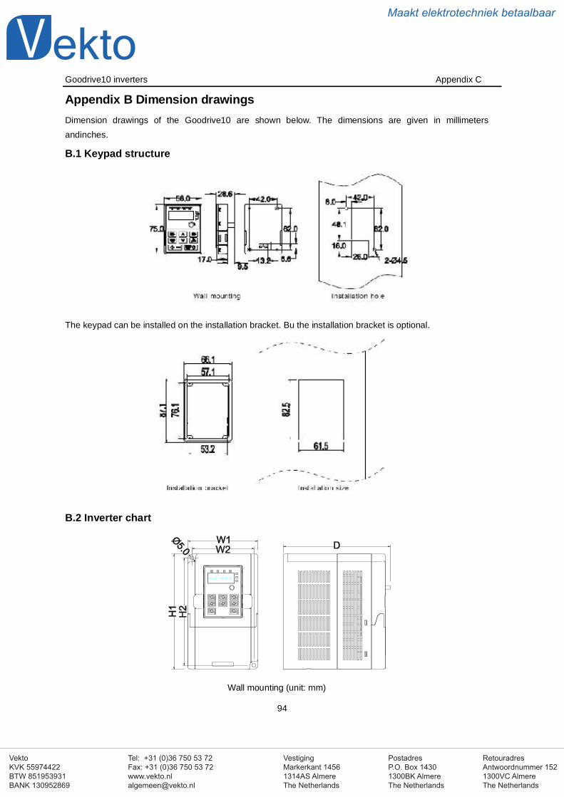
VestigingMarkerkant 14561314AS AlmereThe Netherlands
PostadresP.O. Box 14301300BK AlmereThe Netherlands
Tel: +31 (0)36 750 53 72Fax: +31 (0)36 750 53 [email protected]
RetouradresAntwoordnummer 1521300VC AlmereThe Netherlands
VektoKVK 55974422BTW 851953931BANK 130952869
Maakt elektrotechniek betaalbaar
Goodrive10 inverters Appendix C
94
Appendix B Dimension drawingsDimension drawings of the Goodrive10 are shown below. The dimensions are given in millimetersandinches.
B.1 Keypad structure
The keypad can be installed on the installation bracket. Bu the installation bracket is optional.
B.2 Inverter chart
Wall mounting (unit: mm)
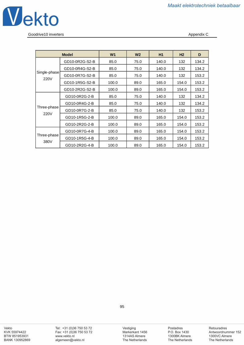
VestigingMarkerkant 14561314AS AlmereThe Netherlands
PostadresP.O. Box 14301300BK AlmereThe Netherlands
Tel: +31 (0)36 750 53 72Fax: +31 (0)36 750 53 [email protected]
RetouradresAntwoordnummer 1521300VC AlmereThe Netherlands
VektoKVK 55974422BTW 851953931BANK 130952869
Maakt elektrotechniek betaalbaar
Goodrive10 inverters Appendix C
95
Model W1 W2 H1 H2 D
Single-phase
220V
GD10-0R2G-S2-B 85.0 75.0 140.0 132 134.2
GD10-0R4G-S2-B 85.0 75.0 140.0 132 134.2
GD10-0R7G-S2-B 85.0 75.0 140.0 132 153.2
GD10-1R5G-S2-B 100.0 89.0 165.0 154.0 153.2
GD10-2R2G-S2-B 100.0 89.0 165.0 154.0 153.2
Three-phase
220V
GD10-0R2G-2-B 85.0 75.0 140.0 132 134.2
GD10-0R4G-2-B 85.0 75.0 140.0 132 134.2
GD10-0R7G-2-B 85.0 75.0 140.0 132 153.2
GD10-1R5G-2-B 100.0 89.0 165.0 154.0 153.2
GD10-2R2G-2-B 100.0 89.0 165.0 154.0 153.2
Three-phase
380V
GD10-0R7G-4-B 100.0 89.0 165.0 154.0 153.2
GD10-1R5G-4-B 100.0 89.0 165.0 154.0 153.2
GD10-2R2G-4-B 100.0 89.0 165.0 154.0 153.2
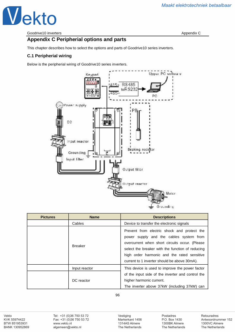
VestigingMarkerkant 14561314AS AlmereThe Netherlands
PostadresP.O. Box 14301300BK AlmereThe Netherlands
Tel: +31 (0)36 750 53 72Fax: +31 (0)36 750 53 [email protected]
RetouradresAntwoordnummer 1521300VC AlmereThe Netherlands
VektoKVK 55974422BTW 851953931BANK 130952869
Maakt elektrotechniek betaalbaar
Goodrive10 inverters Appendix C
96
Appendix C Peripherial options and partsThis chapter describes how to select the options and parts of Goodrive10 series inverters.
C.1 Peripherial wiring
Below is the peripherial wiring of Goodrive10 series inverters.
Pictures Name DescriptionsCables Device to transfer the electronic signals
Breaker
Prevent from electric shock and protect thepower supply and the cables system fromovercurrent when short circuits occur. (Pleaseselect the breaker with the function of reducinghigh order harmonic and the rated sensitivecurrent to 1 inverter should be above 30mA).
Input reactor This device is used to improve the power factorof the input side of the inverter and control thehigher harmonic current.The inverter above 37kW (including 37kW) can
DC reactor
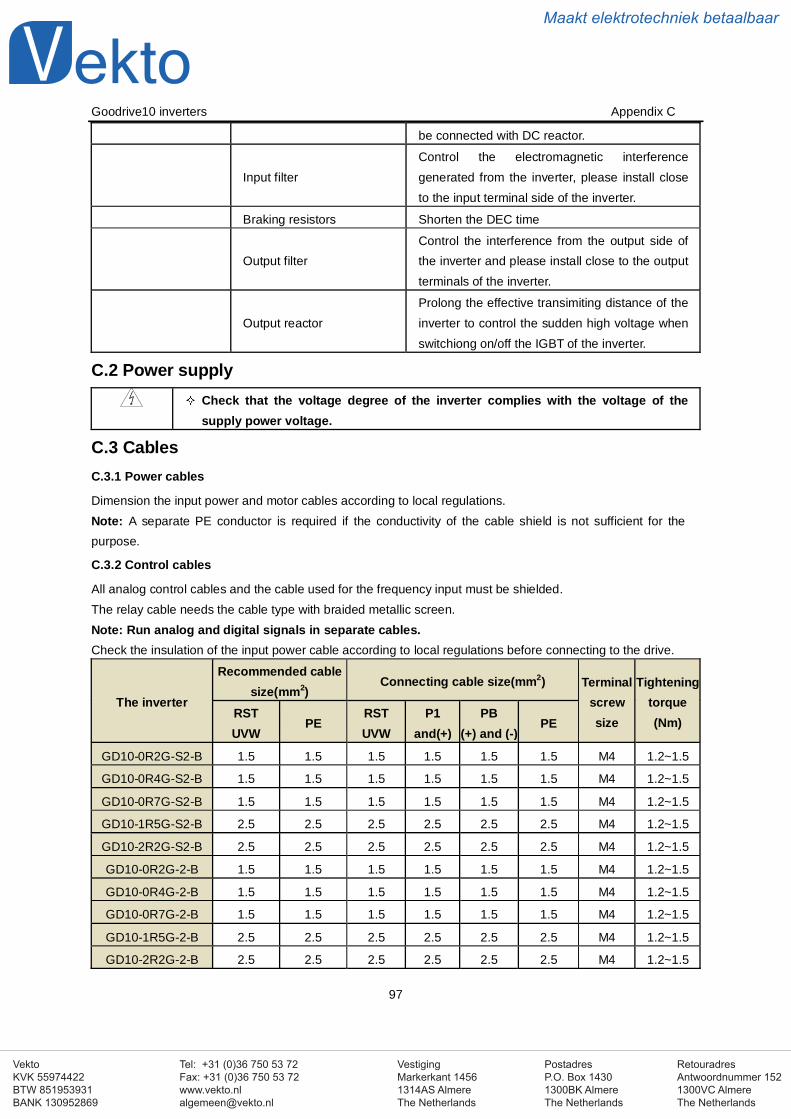
VestigingMarkerkant 14561314AS AlmereThe Netherlands
PostadresP.O. Box 14301300BK AlmereThe Netherlands
Tel: +31 (0)36 750 53 72Fax: +31 (0)36 750 53 [email protected]
RetouradresAntwoordnummer 1521300VC AlmereThe Netherlands
VektoKVK 55974422BTW 851953931BANK 130952869
Maakt elektrotechniek betaalbaar
Goodrive10 inverters Appendix C
97
be connected with DC reactor.
Input filterControl the electromagnetic interferencegenerated from the inverter, please install closeto the input terminal side of the inverter.
Braking resistors Shorten the DEC time
Output filterControl the interference from the output side ofthe inverter and please install close to the outputterminals of the inverter.
Output reactorProlong the effective transimiting distance of theinverter to control the sudden high voltage whenswitchiong on/off the IGBT of the inverter.
C.2 Power supplyCheck that the voltage degree of the inverter complies with the voltage of thesupply power voltage.
C.3 CablesC.3.1 Power cables
Dimension the input power and motor cables according to local regulations.Note: A separate PE conductor is required if the conductivity of the cable shield is not sufficient for thepurpose.
C.3.2 Control cables
All analog control cables and the cable used for the frequency input must be shielded.The relay cable needs the cable type with braided metallic screen.Note: Run analog and digital signals in separate cables.Check the insulation of the input power cable according to local regulations before connecting to the drive.
The inverter
Recommended cablesize(mm2)
Connecting cable size(mm2) Terminalscrewsize
Tighteningtorque(Nm)
RSTUVW
PERSTUVW
P1and(+)
PB(+) and (-)
PE
GD10-0R2G-S2-B 1.5 1.5 1.5 1.5 1.5 1.5 M4 1.2~1.5
GD10-0R4G-S2-B 1.5 1.5 1.5 1.5 1.5 1.5 M4 1.2~1.5
GD10-0R7G-S2-B 1.5 1.5 1.5 1.5 1.5 1.5 M4 1.2~1.5
GD10-1R5G-S2-B 2.5 2.5 2.5 2.5 2.5 2.5 M4 1.2~1.5
GD10-2R2G-S2-B 2.5 2.5 2.5 2.5 2.5 2.5 M4 1.2~1.5
GD10-0R2G-2-B 1.5 1.5 1.5 1.5 1.5 1.5 M4 1.2~1.5
GD10-0R4G-2-B 1.5 1.5 1.5 1.5 1.5 1.5 M4 1.2~1.5
GD10-0R7G-2-B 1.5 1.5 1.5 1.5 1.5 1.5 M4 1.2~1.5
GD10-1R5G-2-B 2.5 2.5 2.5 2.5 2.5 2.5 M4 1.2~1.5
GD10-2R2G-2-B 2.5 2.5 2.5 2.5 2.5 2.5 M4 1.2~1.5
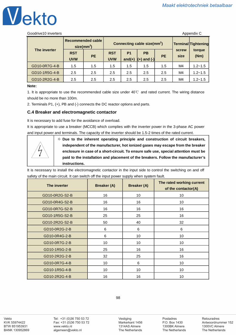
VestigingMarkerkant 14561314AS AlmereThe Netherlands
PostadresP.O. Box 14301300BK AlmereThe Netherlands
Tel: +31 (0)36 750 53 72Fax: +31 (0)36 750 53 [email protected]
RetouradresAntwoordnummer 1521300VC AlmereThe Netherlands
VektoKVK 55974422BTW 851953931BANK 130952869
Maakt elektrotechniek betaalbaar
Goodrive10 inverters Appendix C
98
The inverter
Recommended cablesize(mm2)
Connecting cable size(mm2) Terminalscrewsize
Tighteningtorque(Nm)
RSTUVW
PERSTUVW
P1and(+)
PB(+) and (-)
PE
GD10-0R7G-4-B 1.5 1.5 1.5 1.5 1.5 1.5 M4 1.2~1.5
GD10-1R5G-4-B 2.5 2.5 2.5 2.5 2.5 2.5 M4 1.2~1.5
GD10-2R2G-4-B 2.5 2.5 2.5 2.5 2.5 2.5 M4 1.2~1.5
Note:1. It is appropriate to use the recommended cable size under 40 and rated current. The wiring distanceshould be no more than 100m.2. Terminals P1, (+), PB and (-) connects the DC reactor options and parts.
C.4 Breaker and electromagnetic contactor
It is necessary to add fuse for the avoidance of overload.It is appropriate to use a breaker (MCCB) which complies with the inverter power in the 3-phase AC powerand input power and terminals. The capacity of the inverter should be 1.5-2 times of the rated current.
Due to the inherent operating principle and construction of circuit breakers,independent of the manufacturer, hot ionized gases may escape from the breakerenclosure in case of a short-circuit. To ensure safe use, special attention must bepaid to the installation and placement of the breakers. Follow the manufacturer’sinstructions.
It is necessary to install the electromagnetic contactor in the input side to control the switching on and offsafety of the main circuit. It can switch off the input power supply when syatem fault.
The inverter Breaker (A) Breaker (A)The rated working current
of the contactor(A)
GD10-0R2G-S2-B 16 10 10
GD10-0R4G-S2-B 16 16 10
GD10-0R7G-S2-B 16 16 16
GD10-1R5G-S2-B 25 25 16
GD10-2R2G-S2-B 50 40 32
GD10-0R2G-2-B 6 6 6
GD10-0R4G-2-B 6 10 10
GD10-0R7G-2-B 10 10 10
GD10-1R5G-2-B 25 16 16
GD10-2R2G-2-B 32 25 16
GD10-0R7G-4-B 10 6 10
GD10-1R5G-4-B 10 10 10
GD10-2R2G-4-B 16 16 10
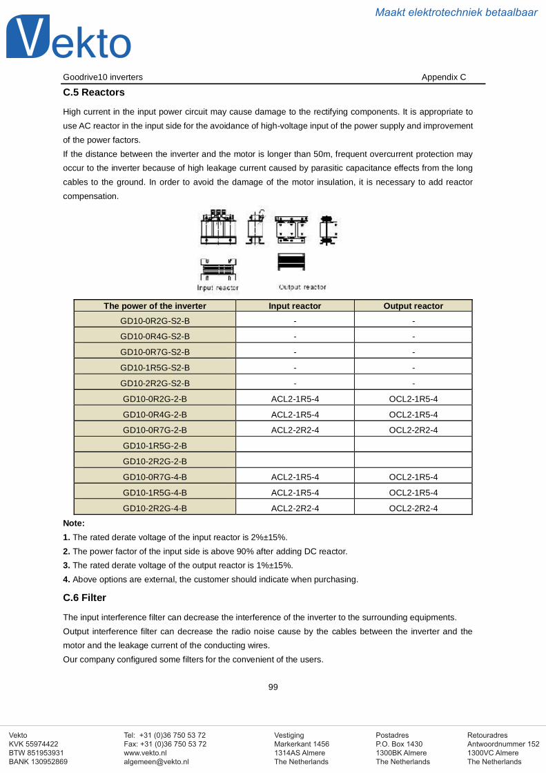
VestigingMarkerkant 14561314AS AlmereThe Netherlands
PostadresP.O. Box 14301300BK AlmereThe Netherlands
Tel: +31 (0)36 750 53 72Fax: +31 (0)36 750 53 [email protected]
RetouradresAntwoordnummer 1521300VC AlmereThe Netherlands
VektoKVK 55974422BTW 851953931BANK 130952869
Maakt elektrotechniek betaalbaar
Goodrive10 inverters Appendix C
99
C.5 Reactors
High current in the input power circuit may cause damage to the rectifying components. It is appropriate touse AC reactor in the input side for the avoidance of high-voltage input of the power supply and improvementof the power factors.If the distance between the inverter and the motor is longer than 50m, frequent overcurrent protection mayoccur to the inverter because of high leakage current caused by parasitic capacitance effects from the longcables to the ground. In order to avoid the damage of the motor insulation, it is necessary to add reactorcompensation.
The power of the inverter Input reactor Output reactorGD10-0R2G-S2-B - -
GD10-0R4G-S2-B - -
GD10-0R7G-S2-B - -
GD10-1R5G-S2-B - -
GD10-2R2G-S2-B - -
GD10-0R2G-2-B ACL2-1R5-4 OCL2-1R5-4
GD10-0R4G-2-B ACL2-1R5-4 OCL2-1R5-4
GD10-0R7G-2-B ACL2-2R2-4 OCL2-2R2-4
GD10-1R5G-2-B
GD10-2R2G-2-B
GD10-0R7G-4-B ACL2-1R5-4 OCL2-1R5-4
GD10-1R5G-4-B ACL2-1R5-4 OCL2-1R5-4
GD10-2R2G-4-B ACL2-2R2-4 OCL2-2R2-4
Note:1. The rated derate voltage of the input reactor is 2%±15%.2. The power factor of the input side is above 90% after adding DC reactor.3. The rated derate voltage of the output reactor is 1%±15%.4. Above options are external, the customer should indicate when purchasing.
C.6 Filter
The input interference filter can decrease the interference of the inverter to the surrounding equipments.Output interference filter can decrease the radio noise cause by the cables between the inverter and themotor and the leakage current of the conducting wires.Our company configured some filters for the convenient of the users.
VestigingMarkerkant 14561314AS AlmereThe Netherlands
PostadresP.O. Box 14301300BK AlmereThe Netherlands
Tel: +31 (0)36 750 53 72Fax: +31 (0)36 750 53 [email protected]
RetouradresAntwoordnummer 1521300VC AlmereThe Netherlands
VektoKVK 55974422BTW 851953931BANK 130952869
Maakt elektrotechniek betaalbaar
Goodrive10 inverters Appendix C
100
The inverter Input filter Output filter
GD10-0R2G-S2-B FLT-PS2010H-B FLT-LS2010H-B
GD10-0R4G-S2-B FLT-PS2010H-B FLT-LS2010H-B
GD10-0R7G-S2-B FLT-PS2010L-B FLT-LS2010L-B
GD10-1R5G-S2-B FLT-P04016L-B FLT-L04016L-B
GD10-2R2G-S2-B FLT-P04032L-B FLT-L04032L-B
GD10-0R2G-2-B FLT-P04006L-B FLT-L04006L-B
GD10-0R4G--B FLT-P04006L-B FLT-L04006L-B
GD10-0R7G-2-B FLT-P04006L-B FLT-L04006L-B
GD10-1R5G-2-B FLT-P04010L-B FLT-L04010L-B
GD10-2R2G-2-B FLT-P04016L-B FLT-L04016L-B
GD10-0R7G-4-B FLT-P04006L-B FLT-L04006L-B
GD10-1R5G-4-B FLT-P04006L-B FLT-L04006L-B
GD10-2R2G-4-B FLT-P04010L-B FLT-L04010L-B
Note:1. The input EMI meet the requirement of C2 after adding input filters.2. Above options are external, the customer should indicate when purchasing.
C.7 Braking system
C.7.1 Select the braking components
The motor will become a generator if its actual rotating speed is higher than the corresponding speed of thereference frequency. As a result, the inertial energy of the motor and load return to the inverter to charge thecapacitors in the main DC circuit. When the voltage increases to the limit, damage may occur to the inverter.It is necessary to apply braking resistor to avoid this accident happens.
Only qualified electricians are allowed to design, install, commission and operateon the inverter.Follow the instructions in “warning” during working. Physical injury or death orserious property may occur.Only qualified electricians are allowed to wire. Damage to the inverter or brakingoptions and part may occur. Read carefully the instructions of braking resistorsor units before connecting them with the inverter.Do not connect the braking resistor with other terminals except for PB and (-).Damage to the inverter or braking circuit or fire may occur.Connect the braking device with the inverter according to the diagram. Incorrectwiring may cause damage to the inverter or other devices.
Model
Braking resistorat 100% of the
brakigntorque(Ω)
Dissipationpower (kW)
Dissipationpower (kW)
Dissipationpower (kW) Mini braking
resistor (Ω)10% braking 50% braking 80% braking
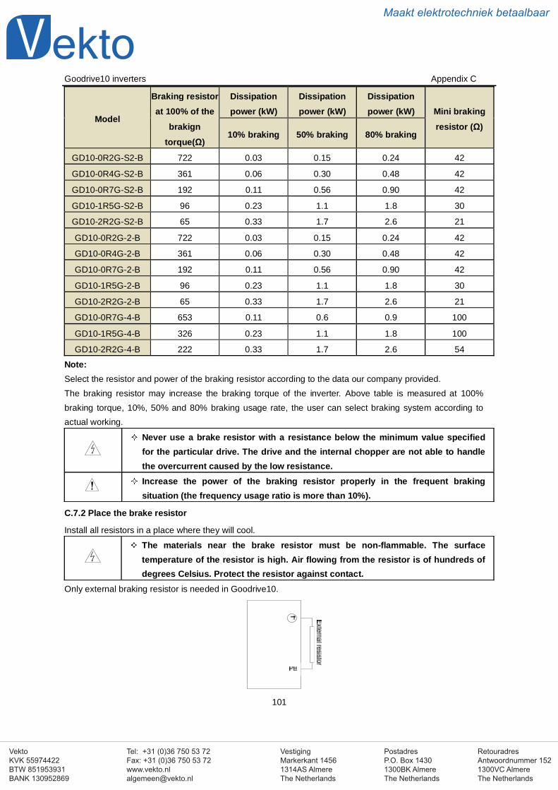
VestigingMarkerkant 14561314AS AlmereThe Netherlands
PostadresP.O. Box 14301300BK AlmereThe Netherlands
Tel: +31 (0)36 750 53 72Fax: +31 (0)36 750 53 [email protected]
RetouradresAntwoordnummer 1521300VC AlmereThe Netherlands
VektoKVK 55974422BTW 851953931BANK 130952869
Maakt elektrotechniek betaalbaar
Goodrive10 inverters Appendix C
101
Model
Braking resistorat 100% of the
brakigntorque(Ω)
Dissipationpower (kW)
Dissipationpower (kW)
Dissipationpower (kW) Mini braking
resistor (Ω)10% braking 50% braking 80% braking
GD10-0R2G-S2-B 722 0.03 0.15 0.24 42
GD10-0R4G-S2-B 361 0.06 0.30 0.48 42
GD10-0R7G-S2-B 192 0.11 0.56 0.90 42
GD10-1R5G-S2-B 96 0.23 1.1 1.8 30
GD10-2R2G-S2-B 65 0.33 1.7 2.6 21
GD10-0R2G-2-B 722 0.03 0.15 0.24 42
GD10-0R4G-2-B 361 0.06 0.30 0.48 42
GD10-0R7G-2-B 192 0.11 0.56 0.90 42
GD10-1R5G-2-B 96 0.23 1.1 1.8 30
GD10-2R2G-2-B 65 0.33 1.7 2.6 21
GD10-0R7G-4-B 653 0.11 0.6 0.9 100
GD10-1R5G-4-B 326 0.23 1.1 1.8 100
GD10-2R2G-4-B 222 0.33 1.7 2.6 54
Note:Select the resistor and power of the braking resistor according to the data our company provided.The braking resistor may increase the braking torque of the inverter. Above table is measured at 100%braking torque, 10%, 50% and 80% braking usage rate, the user can select braking system according toactual working.
Never use a brake resistor with a resistance below the minimum value specifiedfor the particular drive. The drive and the internal chopper are not able to handlethe overcurrent caused by the low resistance.Increase the power of the braking resistor properly in the frequent brakingsituation (the frequency usage ratio is more than 10%).
C.7.2 Place the brake resistor
Install all resistors in a place where they will cool.
The materials near the brake resistor must be non-flammable. The surfacetemperature of the resistor is high. Air flowing from the resistor is of hundreds ofdegrees Celsius. Protect the resistor against contact.
Only external braking resistor is needed in Goodrive10.

VestigingMarkerkant 14561314AS AlmereThe Netherlands
PostadresP.O. Box 14301300BK AlmereThe Netherlands
Tel: +31 (0)36 750 53 72Fax: +31 (0)36 750 53 [email protected]
RetouradresAntwoordnummer 1521300VC AlmereThe Netherlands
VektoKVK 55974422BTW 851953931BANK 130952869
Maakt elektrotechniek betaalbaar
Goodrive10 inverters Appendix D
102
Appendix D Further informationD.1 Product and service inquirieAddress any inquiries about the product to your local INVT offices, quoting the type designation and serialnumber of the unit in question. A listing of INVT sales, support and service contacts can be found bynavigating to www.invt.com.cn.
D.1 Provide feedback on INVT Inverters manualsYour comments on our manuals are welcome. Go to www.invt.com.cn and select Online Feedback ofContact Us.
D.1 Document library on the InternetYou can find manuals and other product documents in PDF format on the Internet. Go to www.invt.com.cnand select Service and Support of Document Download.
Top Related