D81-1 N en U1 U4xspace.talaweb.com/siemens-daihongphat/home/Motor... · MICROMASTER MICROMASTER...
117
© Siemens AG 2007
Transcript of D81-1 N en U1 U4xspace.talaweb.com/siemens-daihongphat/home/Motor... · MICROMASTER MICROMASTER...
���������
�� ����������������
���
��������� ��������������������������������������������������������� !"�#$����%%�#$
��������������� ���!������ ���!������ ���!�
© Siemens AG 2007
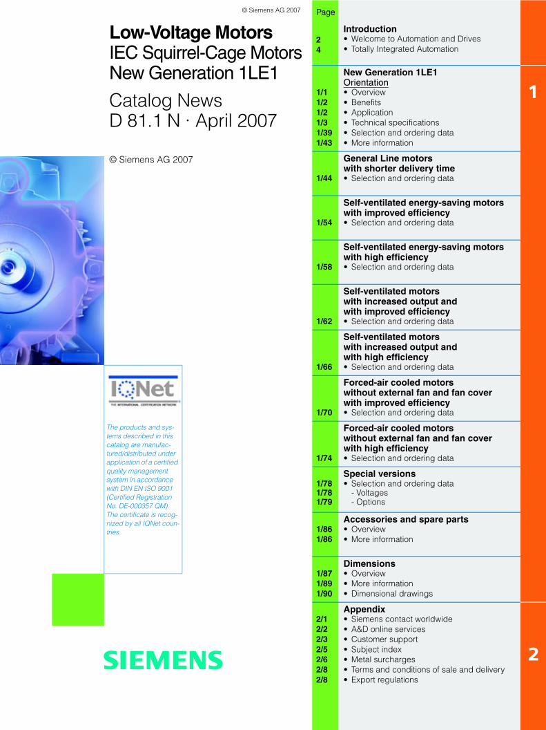
Related catalogs
Additional documentation
You will find all information material, such as brochures, cata-logs, manuals and operating instructions for standard drive sys-tems up-to-date on the Internet at the address
http://www.siemens.com/motors/printmaterial
You can order the listed documentation or download it in com-mon file formats (PDF, ZIP).
Catalog CA 01 – Selection tool SD configurator
The selection tool SD configurator is available in combination with the electronic catalog CA 01.
On CD 2 for the selection and configuring tools, you will find the SD configurators for low-voltage motors, MICROMASTER 4 invert-ers, SINAMICS G110 and SINAMICS G120 inverter chassis units and SIMATIC ET 200S FC frequency converters for distributed I/O, complete with:• Dimension drawing generator for motors• Data sheet generator for motors and inverters• Starting calculation• 3D models in STP format• Extensive documentation
Hardware and software requirements• PC with 500 MHz CPU or faster• Operating systems
– Windows 98/ME– Windows 2000– Windows XP– Windows NT
(Service Pack 6 or higher)• 256 MB work memory (minimum)• Screen resolution 1024 x 768, graphic with more than
256 colors, small fonts• 150 MB spare hard disk space (after installation)• CD-ROM drive• Windows-compatible sound card• Windows-compatible mouse
Installation
You can install this catalog directly from the CD-ROM as a partial version or full version on your hard disk or in the network.
Low-Voltage Motors D 81.1IEC Squirrel-Cage MotorsFrame sizes 56 to 450
Order No.:E86060-K5581-A111-A1-7600
SINAMICS G130 D 11Drive Converter Chassis UnitsSINAMICS G150Drive Converter Cabinet UnitsOrder No.:E86060-K5511-A101-A3-7600
SINAMICS G110/SINAMICS G120 D 11.1Inverter Chassis UnitsSINAMICS G120DDistributed Frequency InvertersOrder No.:E86060-K5511-A111-A4-7600
MICROMASTERMICROMASTER 410/420/430/440Inverters0.12 kW to 250 kWOrder No.:E86060-K5151-A121-A5-7600
DA 51.2
MICROMASTER/COMBIMASTERMICROMASTER 411 InvertersCOMBIMASTER 411 Distributed Drive SolutionsOrder No.:E86060-K5251-A131-A2-7600
DA 51.3
Industrial Communication IK PIfor Automation and DrivesPart 6: ET 200 Distributed I/OET 200S FC Frequency ConverterOrder No.:E86060-K6710-A101-B4-7600
AC NEMA & IEC Motors D 81.2Further details available on the U.S./Internet at: Canada
http://www.sea.siemens.com/motors
Catalog CA 01 CA 01The Offline Mall of Automationand DrivesOrder No.:CD: E86060-D4001-A110-C5-7600DVD: E86060-D4001-A510-C5-7600
A&D Mall
Internet:http://www.siemens.com/automation/mall
© Siemens AG 2007
s
© Siemens AG 2007
Low-Voltage MotorsIEC Squirrel-Cage MotorsNew Generation 1LE1
Catalog NewsD 81.1 N · April 2007
Page
24
Introduction• Welcome to Automation and Drives• Totally Integrated Automation
1/11/21/21/31/391/43
New Generation 1LE1Orientation• Overview• Benefits• Application• Technical specifications• Selection and ordering data• More information
1
1/44
General Line motors with shorter delivery time• Selection and ordering data
1/54
Self-ventilated energy-saving motorswith improved efficiency• Selection and ordering data
1/58
Self-ventilated energy-saving motorswith high efficiency• Selection and ordering data
1/62
Self-ventilated motors with increased output and with improved efficiency• Selection and ordering data
1/66
Self-ventilated motors with increased output and with high efficiency• Selection and ordering data
1/70
Forced-air cooled motors without external fan and fan cover with improved efficiency• Selection and ordering data
1/74
Forced-air cooled motors without external fan and fan cover with high efficiency• Selection and ordering data
1/781/781/79
Special versions• Selection and ordering data
- Voltages- Options
1/861/86
Accessories and spare parts• Overview• More information
1/871/891/90
Dimensions• Overview• More information• Dimensional drawings
2/12/22/32/52/62/82/8
Appendix• Siemens contact worldwide• A&D online services• Customer support• Subject index• Metal surcharges• Terms and conditions of sale and delivery • Export regulations
2
The products and sys-tems described in this catalog are manufac-tured/distributed under application of a certified quality management system in accordance with DIN EN ISO 9001 (Certified Registration No. DE-000357 QM). The certificate is recog-nized by all IQNet coun-tries.
© Siemens AG 2007
2 Siemens D 81.1 N · April 2007
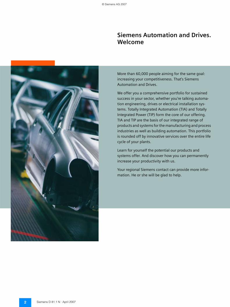
Siemens Automation and Drives.Welcome
More than 60,000 people aiming for the same goal: increasing your competitiveness. That's Siemens Automation and Drives.
We offer you a comprehensive portfolio for sustained success in your sector, whether you're talking automa-tion engineering, drives or electrical installation sys-tems. Totally Integrated Automation (TIA) and Totally Integrated Power (TIP) form the core of our offering. TIA and TIP are the basis of our integrated range of products and systems for the manufacturing and process industries as well as building automation. This portfolio is rounded off by innovative services over the entire life cycle of your plants.
Learn for yourself the potential our products and systems offer. And discover how you can permanently increase your productivity with us.
Your regional Siemens contact can provide more infor-mation. He or she will be glad to help.
© Siemens AG 2007
3Siemens D 81.1 N · April 2007
© Siemens AG 2007
���������������� ���������
��������� ��������� ����������
�����
�����
� �� �� � ����
���� ���� � ����
���������!�
� � ����
���������! ����"�������
��������)������"�� ��������� ����
��!�������./��"��%�������� ������#"��
����&����� ����� ������&��"������ ��$+�
� ��#����� ��
������ ��)�-�����������#"��
������������
���������"�"
��&% "������� ����
,���������������#
���������������"'����� ������#"��
��!��)��
��!��,-�
��&���� �
0)2'��,
4�������������
����"�� ������
4 Siemens D 81.1 N · April 2007
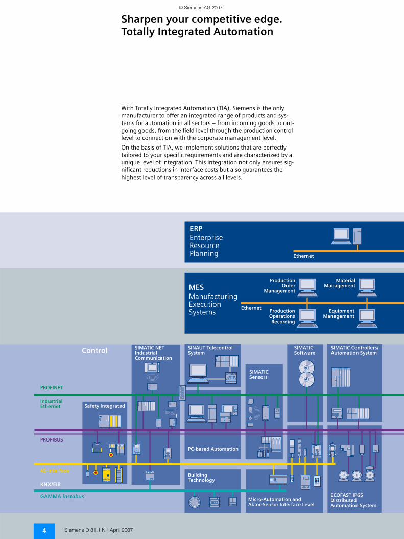
Sharpen your competitive edge. Totally Integrated Automation
With Totally Integrated Automation (TIA), Siemens is the only manufacturer to offer an integrated range of products and sys-tems for automation in all sectors – from incoming goods to out-going goods, from the field level through the production control level to connection with the corporate management level.
On the basis of TIA, we implement solutions that are perfectly tailored to your specific requirements and are characterized by a unique level of integration. This integration not only ensures sig-nificant reductions in interface costs but also guarantees the highest level of transparency across all levels.
© Siemens AG 2007
�� ������� ����� � ����
�� ���������������������
������������ ������������������
�������� ����� ����� � ������#"��
$ %� ��#������ ����� � ������#"��
�������"��&��� ����'�� �#���"
������������(���""���������#"�� ��������*��
*�� ��� �������� �
��+��#"��"'��)�����
��!��,-����
��)��!)������, �"
���������"��%���� '!
���!��!)��������������#"��
��)-����0��� ��)�����������
���!�!��� ������� � �&�����#"��
*���
��1���21��������������#
��)��������!���3���)�����
����-�������� �
5Siemens D 81.1 N · April 2007
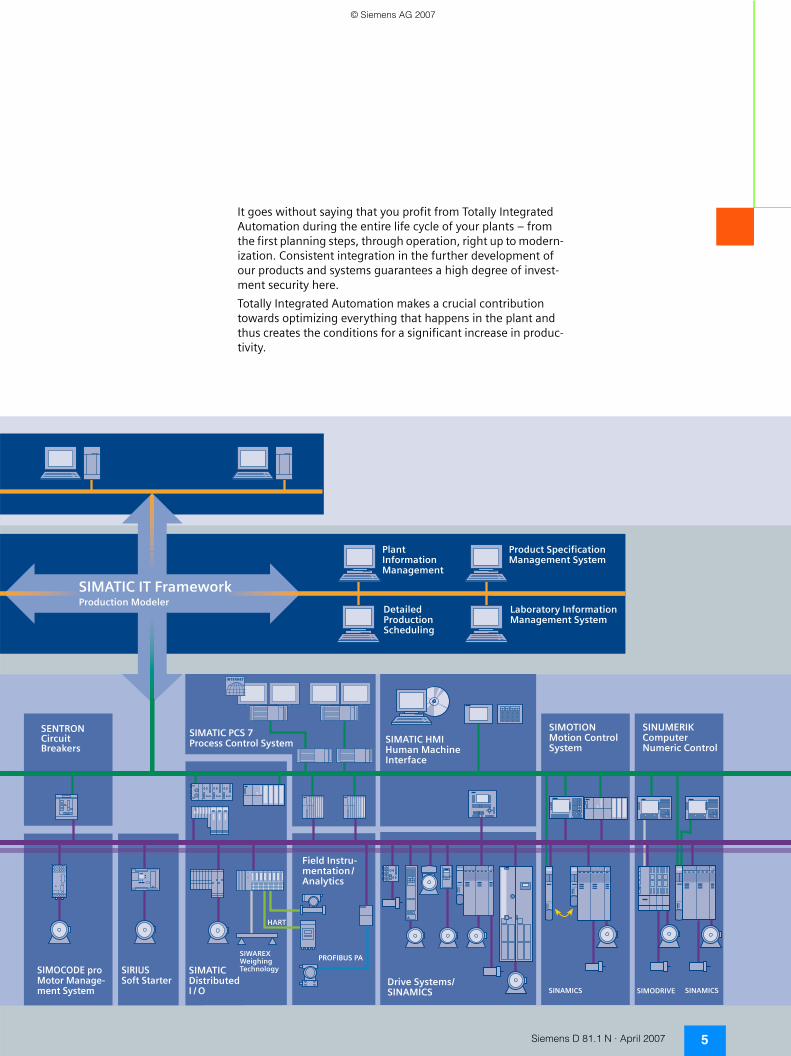
It goes without saying that you profit from Totally Integrated Automation during the entire life cycle of your plants – from the first planning steps, through operation, right up to modern-ization. Consistent integration in the further development of our products and systems guarantees a high degree of invest-ment security here.
Totally Integrated Automation makes a crucial contribution towards optimizing everything that happens in the plant and thus creates the conditions for a significant increase in produc-tivity.
© Siemens AG 2007
IEC Squirrel-Cage MotorsIntroduction
Notes
6 Siemens D 81.1 N · April 2007
© Siemens AG 2007
IEC Squirrel-Cage MotorsNew Generation 1LE1
Orientation
1/1Siemens D 81.1 N · April 2007
1■ Overview
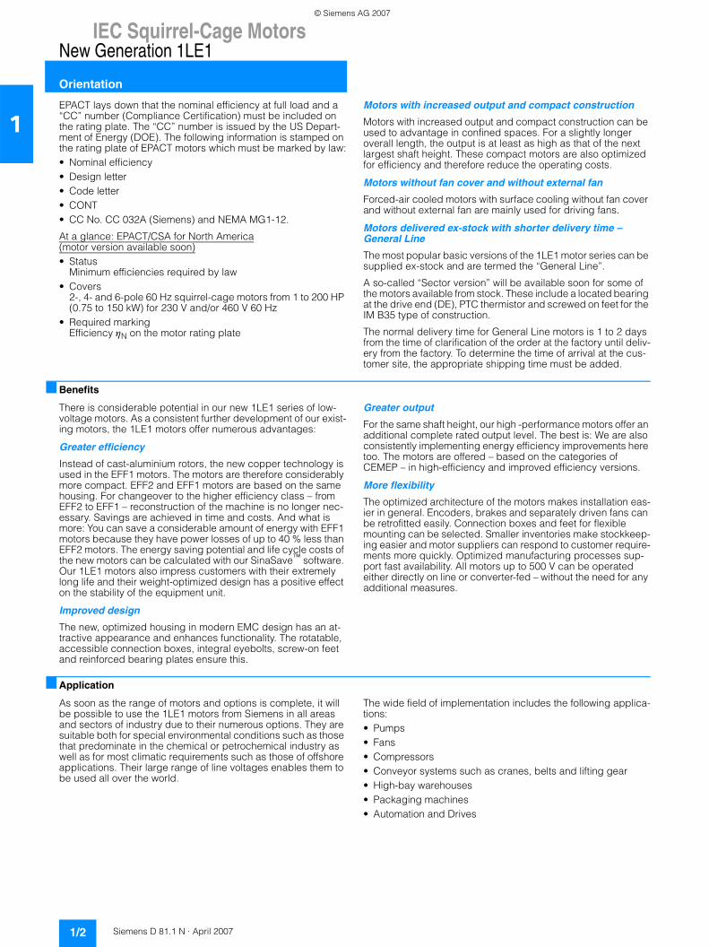
Increasing energy costs have resulted in greater emphasis on the power consumption of drive systems. It is extremely impor-tant to utilize the full potential for minimization here to secure competitiveness today and in the future. The environment will also profit from reduced energy consumption.
With this in mind, we have already developed a new generation of low-voltage motors that you can use in drives to move even more than before. Innovative copper rotors that we develop and manufacture entirely in-house create the perfect conditions for motors with a high degree of efficiency. The new motors for EFF1 (High Efficiency) offer considerable energy savings and protect our environment.
The modular mounting concept also provides total flexibility: Each motor is based on a uniform concept for all markets world-wide. Our motors are manufactured in accordance with modern ecological principles and give machines and plants more drive. Worldwide and for every application. Efficiency over the com-plete life cycle is a clear benefit of our motors especially for the use of 1LE1 designed to EFF1. All machine builders and plant operators can profit from this – not to mention the environment. We will be launching our new 1LE1 motors onto the market step by step.
Classified energy-saving motors for an efficient energy balance
Depending on requirements, energy-saving motors are avail-able for an efficient energy balance for the EU in accordance with CEMEP (European Committee of Manufacturers of Electrical Machines and Power Electronics) and will be available soon for the North American market in accordance with EPACT (US En-ergy Policy Act).
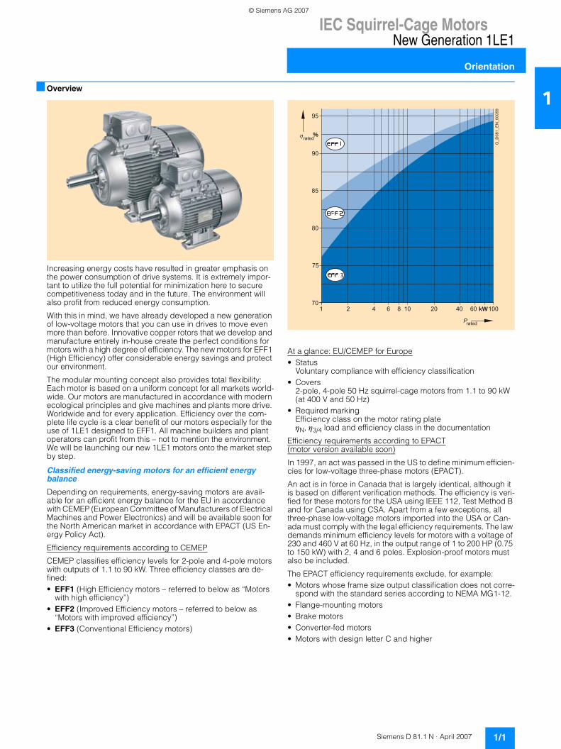
Efficiency requirements according to CEMEP
CEMEP classifies efficiency levels for 2-pole and 4-pole motors with outputs of 1.1 to 90 kW. Three efficiency classes are de-fined:• EFF1 (High Efficiency motors – referred to below as “Motors
with high efficiency”) • EFF2 (Improved Efficiency motors – referred to below as
“Motors with improved efficiency”) • EFF3 (Conventional Efficiency motors)
At a glance: EU/CEMEP for Europe• Status
Voluntary compliance with efficiency classification • Covers
2-pole, 4-pole 50 Hz squirrel-cage motors from 1.1 to 90 kW (at 400 V and 50 Hz)
• Required markingEfficiency class on the motor rating plateηN, η3/4 load and efficiency class in the documentation
Efficiency requirements according to EPACT(motor version available soon)
In 1997, an act was passed in the US to define minimum efficien-cies for low-voltage three-phase motors (EPACT).
An act is in force in Canada that is largely identical, although it is based on different verification methods. The efficiency is veri-fied for these motors for the USA using IEEE 112, Test Method B and for Canada using CSA. Apart from a few exceptions, all three-phase low-voltage motors imported into the USA or Can-ada must comply with the legal efficiency requirements. The law demands minimum efficiency levels for motors with a voltage of 230 and 460 V at 60 Hz, in the output range of 1 to 200 HP (0.75 to 150 kW) with 2, 4 and 6 poles. Explosion-proof motors must also be included.
The EPACT efficiency requirements exclude, for example:• Motors whose frame size output classification does not corre-
spond with the standard series according to NEMA MG1-12. • Flange-mounting motors • Brake motors • Converter-fed motors • Motors with design letter C and higher
%
70
75
1 10 20 40
G_D
081_
EN
_000
59
100
P rated
kW 2 4 6 8 60
80
85
90
95
rated
© Siemens AG 2007
IEC Squirrel-Cage MotorsNew Generation 1LE1
Orientation
1/2 Siemens D 81.1 N · April 2007
1EPACT lays down that the nominal efficiency at full load and a “CC” number (Compliance Certification) must be included on the rating plate. The “CC” number is issued by the US Depart-ment of Energy (DOE). The following information is stamped on the rating plate of EPACT motors which must be marked by law:• Nominal efficiency • Design letter • Code letter • CONT • CC No. CC 032A (Siemens) and NEMA MG1-12.
At a glance: EPACT/CSA for North America(motor version available soon)• Status
Minimum efficiencies required by law • Covers
2-, 4- and 6-pole 60 Hz squirrel-cage motors from 1 to 200 HP (0.75 to 150 kW) for 230 V and/or 460 V 60 Hz
• Required marking Efficiency ηN on the motor rating plate
Motors with increased output and compact construction
Motors with increased output and compact construction can be used to advantage in confined spaces. For a slightly longer overall length, the output is at least as high as that of the next largest shaft height. These compact motors are also optimized for efficiency and therefore reduce the operating costs.
Motors without fan cover and without external fan
Forced-air cooled motors with surface cooling without fan cover and without external fan are mainly used for driving fans.
Motors delivered ex-stock with shorter delivery time – General Line
The most popular basic versions of the 1LE1 motor series can be supplied ex-stock and are termed the “General Line”.
A so-called “Sector version” will be available soon for some of the motors available from stock. These include a located bearing at the drive end (DE), PTC thermistor and screwed on feet for the IM B35 type of construction.
The normal delivery time for General Line motors is 1 to 2 days from the time of clarification of the order at the factory until deliv-ery from the factory. To determine the time of arrival at the cus-tomer site, the appropriate shipping time must be added.
■ Benefits
There is considerable potential in our new 1LE1 series of low-voltage motors. As a consistent further development of our exist-ing motors, the 1LE1 motors offer numerous advantages:
Greater efficiency
Instead of cast-aluminium rotors, the new copper technology is used in the EFF1 motors. The motors are therefore considerably more compact. EFF2 and EFF1 motors are based on the same housing. For changeover to the higher efficiency class – from EFF2 to EFF1 – reconstruction of the machine is no longer nec-essary. Savings are achieved in time and costs. And what is more: You can save a considerable amount of energy with EFF1 motors because they have power losses of up to 40 % less than EFF2 motors. The energy saving potential and life cycle costs of the new motors can be calculated with our SinaSave™ software. Our 1LE1 motors also impress customers with their extremely long life and their weight-optimized design has a positive effect on the stability of the equipment unit.
Improved design
The new, optimized housing in modern EMC design has an at-tractive appearance and enhances functionality. The rotatable, accessible connection boxes, integral eyebolts, screw-on feet and reinforced bearing plates ensure this.
Greater output
For the same shaft height, our high -performance motors offer an additional complete rated output level. The best is: We are also consistently implementing energy efficiency improvements here too. The motors are offered – based on the categories of CEMEP – in high-efficiency and improved efficiency versions.
More flexibility
The optimized architecture of the motors makes installation eas-ier in general. Encoders, brakes and separately driven fans can be retrofitted easily. Connection boxes and feet for flexible mounting can be selected. Smaller inventories make stockkeep-ing easier and motor suppliers can respond to customer require-ments more quickly. Optimized manufacturing processes sup-port fast availability. All motors up to 500 V can be operated either directly on line or converter-fed – without the need for any additional measures.
■ Application
As soon as the range of motors and options is complete, it will be possible to use the 1LE1 motors from Siemens in all areas and sectors of industry due to their numerous options. They are suitable both for special environmental conditions such as those that predominate in the chemical or petrochemical industry as well as for most climatic requirements such as those of offshore applications. Their large range of line voltages enables them to be used all over the world.
The wide field of implementation includes the following applica-tions:• Pumps • Fans • Compressors • Conveyor systems such as cranes, belts and lifting gear • High-bay warehouses • Packaging machines • Automation and Drives
© Siemens AG 2007
IEC Squirrel-Cage MotorsNew Generation 1LE1
Orientation
1/3Siemens D 81.1 N · April 2007
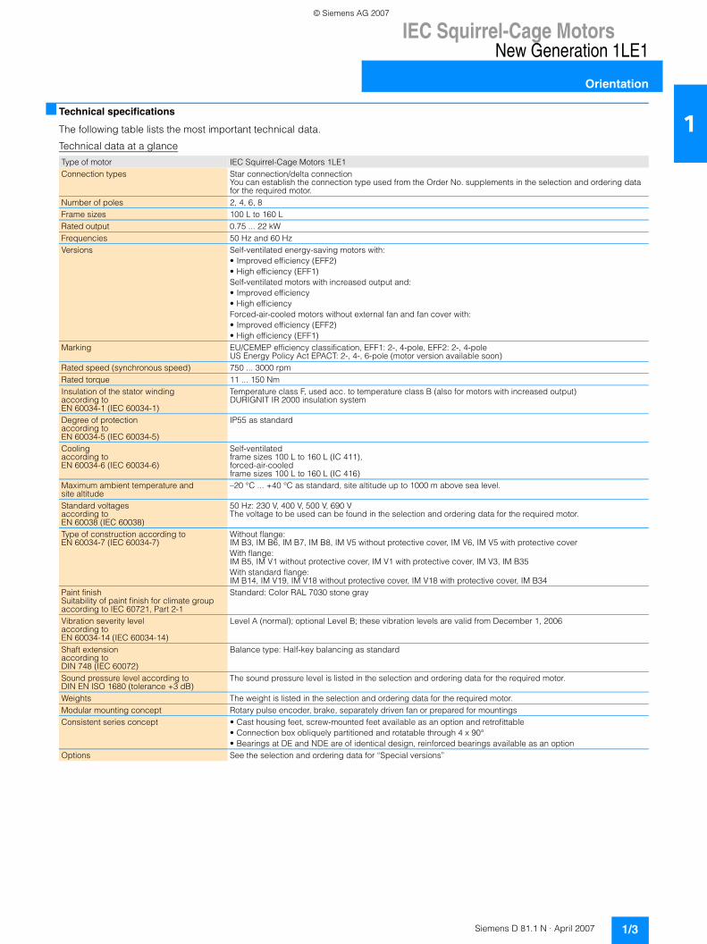
1■ Technical specifications
The following table lists the most important technical data.
Technical data at a glance
Type of motor IEC Squirrel-Cage Motors 1LE1Connection types Star connection/delta connection
You can establish the connection type used from the Order No. supplements in the selection and ordering data for the required motor.
Number of poles 2, 4, 6, 8Frame sizes 100 L to 160 LRated output 0.75 ... 22 kWFrequencies 50 Hz and 60 HzVersions Self-ventilated energy-saving motors with:
• Improved efficiency (EFF2)• High efficiency (EFF1)Self-ventilated motors with increased output and:• Improved efficiency• High efficiencyForced-air-cooled motors without external fan and fan cover with: • Improved efficiency (EFF2)• High efficiency (EFF1)
Marking EU/CEMEP efficiency classification, EFF1: 2-, 4-pole, EFF2: 2-, 4-poleUS Energy Policy Act EPACT: 2-, 4-, 6-pole (motor version available soon)
Rated speed (synchronous speed) 750 ... 3000 rpmRated torque 11 ... 150 NmInsulation of the stator winding according toEN 60034-1 (IEC 60034-1)
Temperature class F, used acc. to temperature class B (also for motors with increased output)DURIGNIT IR 2000 insulation system
Degree of protectionaccording toEN 60034-5 (IEC 60034-5)
IP55 as standard
Coolingaccording to EN 60034-6 (IEC 60034-6)
Self-ventilated frame sizes 100 L to 160 L (IC 411), forced-air-cooled frame sizes 100 L to 160 L (IC 416)
Maximum ambient temperature and site altitude
–20 °C ... +40 °C as standard, site altitude up to 1000 m above sea level.
Standard voltages according to EN 60038 (IEC 60038)
50 Hz: 230 V, 400 V, 500 V, 690 VThe voltage to be used can be found in the selection and ordering data for the required motor.
Type of construction according to EN 60034-7 (IEC 60034-7)
Without flange: IM B3, IM B6, IM B7, IM B8, IM V5 without protective cover, IM V6, IM V5 with protective coverWith flange: IM B5, IM V1 without protective cover, IM V1 with protective cover, IM V3, IM B35With standard flange: IM B14, IM V19, IM V18 without protective cover, IM V18 with protective cover, IM B34
Paint finish Suitability of paint finish for climate group according to IEC 60721, Part 2-1
Standard: Color RAL 7030 stone gray
Vibration severity level according to EN 60034-14 (IEC 60034-14)
Level A (normal); optional Level B; these vibration levels are valid from December 1, 2006
Shaft extension according to DIN 748 (IEC 60072)
Balance type: Half-key balancing as standard
Sound pressure level according to DIN EN ISO 1680 (tolerance +3 dB)
The sound pressure level is listed in the selection and ordering data for the required motor.
Weights The weight is listed in the selection and ordering data for the required motor.Modular mounting concept Rotary pulse encoder, brake, separately driven fan or prepared for mountingsConsistent series concept • Cast housing feet, screw-mounted feet available as an option and retrofittable
• Connection box obliquely partitioned and rotatable through 4 x 90°• Bearings at DE and NDE are of identical design, reinforced bearings available as an option
Options See the selection and ordering data for “Special versions”
© Siemens AG 2007
IEC Squirrel-Cage MotorsNew Generation 1LE1
Orientation
1/4 Siemens D 81.1 N · April 2007
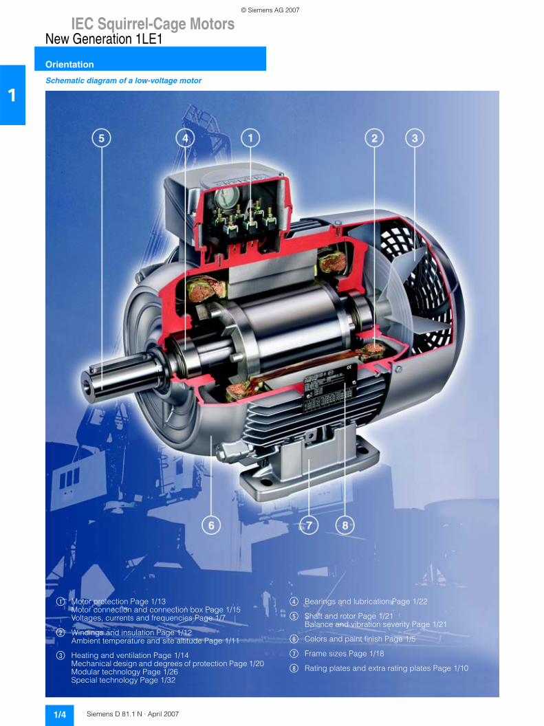
1Schematic diagram of a low-voltage motor
$ Motor protection Page 1/13 Motor connection and connection box Page 1/15 Voltages, currents and frequencies Page 1/7
% Windings and insulation Page 1/12 Ambient temperature and site altitude Page 1/11
& Heating and ventilation Page 1/14 Mechanical design and degrees of protection Page 1/20 Modular technology Page 1/26 Special technology Page 1/32
( Bearings and lubrication Page 1/22
) Shaft and rotor Page 1/21Balance and vibration severity Page 1/21
* Colors and paint finish Page 1/5
+ Frame sizes Page 1/18
, Rating plates and extra rating plates Page 1/10
© Siemens AG 2007
IEC Squirrel-Cage MotorsNew Generation 1LE1
Orientation
1/5Siemens D 81.1 N · April 2007
1Designs in accordance with standards and specifications
Applicable standards and specifications
The motors comply with the appropriate standards and regula-tions, especially those listed in the table below.
National standards
The motors comply with the IEC or European standards listed above. The European standards replace the national standards in the following EU member states: Germany (VDE), France (NF C), Belgium (NBNC), Great Britain (BS), Italy (CEI), Netherlands (NEN), Sweden (SS), Switzerland (SEV) etc.
The motors also comply with various national standards. The fol-lowing standards have been harmonized with IEC publication 60034-1 or replaced with DIN EN 60034-1 so that the motors can be operated at standard rated output.
Tolerances for electrical data
According to DIN EN 60034, the following tolerances are permit-ted:Motors which comply with DIN EN 60034-1 must have a voltage tolerance of ±5% / frequency tolerance of ±2% (Design A). If uti-lized, the permitted limit temperature of the temperature class may be exceeded by 10 K.
A tolerance of ±5% also applies to the rated voltage range in accordance with DIN EN 60034-1.
Efficiency η atPrated ≤150 kW: –0.15 ⋅ (1 –η)Prated >150 kW: –0.1 ⋅ (1 –η)
With η being a decimal number.
• Minimum absolute value: 0.02• Maximum absolute value: 0.07
Slip ±20% (for motors <1 kW ±30% is permissible)Locked-rotor current +20% Locked-rotor torque –15% to +25%Breakdown torque –10%Moment of inertia ±10%
Colors and paint finish
All motors are painted with RAL 7030 (stone gray) if the color is not specified.
Other colors in special finish must be ordered with defined order codes (e.g. S24) or order code Y51/Y54 and the RAL number in plain text.
For very corrosive environments, motors can be painted with off-shore paint CERAM-KOTE 54 (only on request).
All paint finishes can be painted over with commercially avail-able paints. Special paint with increased layer thickness avail-able on request.
If required, the motors can also be supplied coated in primer, order code S01, or unpainted (cast-iron parts in primer) using order code S00.
Titel IEC DIN/ENGeneral specifications for rotating electrical machines
IEC 60034-1, IEC 60085
DIN EN 60034-1
Specification of the losses and effi-ciency of rotating electrical machines
IEC 60034-2 DIN EN 60034-2
Asynchronous AC motors for general use with standardized dimensions and outputs
IEC 60072 mounting dimensions only
DIN EN 50347
Restart characteristics for rotating electrical machines
IEC 60034-12 DIN EN 60034-12
Terminal designations and direction of rotation for electrical machines
IEC 60034-8 DIN EN 60034-8
Designation for type of construction, installation and terminal box position
IEC 60034-7 DIN EN 60034-7
Entry to terminal box – DIN 42925Built-in thermal protection IEC 60034-11 DIN EN 60034-11Noise limit values for rotating electri-cal machines
IEC 60034-9 DIN EN 60034-9
IEC standard voltages IEC 60038 DIN IEC 60038Cooling methods for rotating electrical machines
IEC 60034-6 DIN EN 60034-6
Vibration severity of rotating electrical machines
IEC 60034-14 DIN EN 60034-14
Vibration limits – DIN ISO 10816Degrees of protection of rotating electrical machines
IEC 60034-5 DIN EN 60034-5
Titel CountryIS 325 IS 4722
India
NEK – IEC 60034-1 Norway
–6
1 – cosPower factor
Type Suitability of paint finish for climate group in accordance with DIN IEC 60721, Part 2-1Special finish Worldwide (global)
for outdoor use in direct sunlight and/or weather condi-tions. Suitable for use in the tropics for <60% relative humidity at 40 °C
Briefly: Up to 140 °CContin.: Up to 120 °CAlso: for aggressive atmospheres up to 1% acid and alkali concentration or permanent dampness in sheltered rooms
© Siemens AG 2007
IEC Squirrel-Cage MotorsNew Generation 1LE1
Orientation
1/6 Siemens D 81.1 N · April 2007
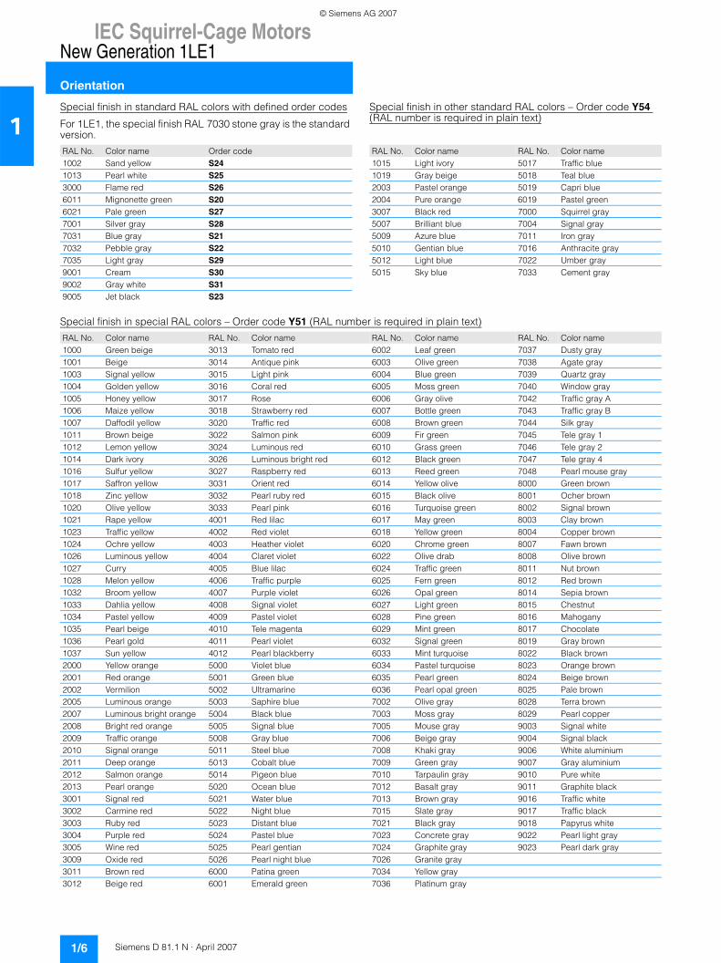
1Special finish in standard RAL colors with defined order codes
For 1LE1, the special finish RAL 7030 stone gray is the standard version.
Special finish in other standard RAL colors – Order code Y54 (RAL number is required in plain text)
Special finish in special RAL colors – Order code Y51 (RAL number is required in plain text)
RAL No. Color name Order code1002 Sand yellow S241013 Pearl white S253000 Flame red S266011 Mignonette green S206021 Pale green S277001 Silver gray S287031 Blue gray S217032 Pebble gray S227035 Light gray S299001 Cream S309002 Gray white S319005 Jet black S23
RAL No. Color name RAL No. Color name1015 Light ivory 5017 Traffic blue1019 Gray beige 5018 Teal blue2003 Pastel orange 5019 Capri blue2004 Pure orange 6019 Pastel green3007 Black red 7000 Squirrel gray5007 Brilliant blue 7004 Signal gray5009 Azure blue 7011 Iron gray5010 Gentian blue 7016 Anthracite gray5012 Light blue 7022 Umber gray5015 Sky blue 7033 Cement gray
RAL No. Color name RAL No. Color name RAL No. Color name RAL No. Color name1000 Green beige 3013 Tomato red 6002 Leaf green 7037 Dusty gray1001 Beige 3014 Antique pink 6003 Olive green 7038 Agate gray1003 Signal yellow 3015 Light pink 6004 Blue green 7039 Quartz gray1004 Golden yellow 3016 Coral red 6005 Moss green 7040 Window gray1005 Honey yellow 3017 Rose 6006 Gray olive 7042 Traffic gray A1006 Maize yellow 3018 Strawberry red 6007 Bottle green 7043 Traffic gray B1007 Daffodil yellow 3020 Traffic red 6008 Brown green 7044 Silk gray1011 Brown beige 3022 Salmon pink 6009 Fir green 7045 Tele gray 11012 Lemon yellow 3024 Luminous red 6010 Grass green 7046 Tele gray 21014 Dark ivory 3026 Luminous bright red 6012 Black green 7047 Tele gray 41016 Sulfur yellow 3027 Raspberry red 6013 Reed green 7048 Pearl mouse gray1017 Saffron yellow 3031 Orient red 6014 Yellow olive 8000 Green brown1018 Zinc yellow 3032 Pearl ruby red 6015 Black olive 8001 Ocher brown1020 Olive yellow 3033 Pearl pink 6016 Turquoise green 8002 Signal brown1021 Rape yellow 4001 Red lilac 6017 May green 8003 Clay brown1023 Traffic yellow 4002 Red violet 6018 Yellow green 8004 Copper brown1024 Ochre yellow 4003 Heather violet 6020 Chrome green 8007 Fawn brown1026 Luminous yellow 4004 Claret violet 6022 Olive drab 8008 Olive brown1027 Curry 4005 Blue lilac 6024 Traffic green 8011 Nut brown1028 Melon yellow 4006 Traffic purple 6025 Fern green 8012 Red brown1032 Broom yellow 4007 Purple violet 6026 Opal green 8014 Sepia brown1033 Dahlia yellow 4008 Signal violet 6027 Light green 8015 Chestnut1034 Pastel yellow 4009 Pastel violet 6028 Pine green 8016 Mahogany1035 Pearl beige 4010 Tele magenta 6029 Mint green 8017 Chocolate1036 Pearl gold 4011 Pearl violet 6032 Signal green 8019 Gray brown1037 Sun yellow 4012 Pearl blackberry 6033 Mint turquoise 8022 Black brown2000 Yellow orange 5000 Violet blue 6034 Pastel turquoise 8023 Orange brown2001 Red orange 5001 Green blue 6035 Pearl green 8024 Beige brown2002 Vermilion 5002 Ultramarine 6036 Pearl opal green 8025 Pale brown2005 Luminous orange 5003 Saphire blue 7002 Olive gray 8028 Terra brown2007 Luminous bright orange 5004 Black blue 7003 Moss gray 8029 Pearl copper2008 Bright red orange 5005 Signal blue 7005 Mouse gray 9003 Signal white2009 Traffic orange 5008 Gray blue 7006 Beige gray 9004 Signal black2010 Signal orange 5011 Steel blue 7008 Khaki gray 9006 White aluminium2011 Deep orange 5013 Cobalt blue 7009 Green gray 9007 Gray aluminium2012 Salmon orange 5014 Pigeon blue 7010 Tarpaulin gray 9010 Pure white2013 Pearl orange 5020 Ocean blue 7012 Basalt gray 9011 Graphite black3001 Signal red 5021 Water blue 7013 Brown gray 9016 Traffic white3002 Carmine red 5022 Night blue 7015 Slate gray 9017 Traffic black3003 Ruby red 5023 Distant blue 7021 Black gray 9018 Papyrus white3004 Purple red 5024 Pastel blue 7023 Concrete gray 9022 Pearl light gray3005 Wine red 5025 Pearl gentian 7024 Graphite gray 9023 Pearl dark gray3009 Oxide red 5026 Pearl night blue 7026 Granite gray3011 Brown red 6000 Patina green 7034 Yellow gray3012 Beige red 6001 Emerald green 7036 Platinum gray
© Siemens AG 2007
IEC Squirrel-Cage MotorsNew Generation 1LE1
Orientation
1/7Siemens D 81.1 N · April 2007
1Packaging, safety notes, documentation and test certificates
Connected in star for dispatch – Order code M01The terminal board of the motor is connected in star for dispatch.
Connected in delta for dispatch – Order code M02The terminal board of the motor is connected in delta for dis-patch.
Packing weights and packing dimensions
a. s. Available soon
Data apply for individual packaging. Packing in wire-lattice pal-lets can be used, order code B99.
Safety notes
If the motors are to be delivered without safety and commission-ing notes, a customer’s declaration of renouncement is required.
Without safety and commissioning note – Order code B00
The motors are supplied with only one set of safety and commis-sioning notes per wire-lattice pallet for most motor types and frame sizes.
Complete with one safety and commissioning notes per wire-lattice pallet – Order code B01
Documentation
The following documents are optionally available:• Operating instructions on CD enclosed – Order code B03 • Printed operating instructions German/English enclosed –
Order code B04
Test certificates
Acceptance test certificate 3.1 according to EN 10204 – Order code B02
An acceptance test certificate 3.1 according to EN 10204 can be supplied for most motors.
Voltages, currents and frequencies
Standard voltages
EN 60034-1 differentiates between Category A (combination of voltage deviation ±5% and frequency deviation ±2%) and Cate-gory B (combination of voltage deviation ±10% and frequency deviation +3/–5%) for voltage and frequency fluctuations. The motors can supply their rated torque in both Category A and Category B. In Category A, the temperature rise is approx. 10 K higher than during rated duty.
According to the standard, longer duty is not recommended for Category B. See “Rating plates and extra rating plates” for de-tails of the rating plate inscriptions and corresponding exam-ples. The selection and ordering data state the rated current at 400 V and where applicable 690 V. The DIN IEC 60038 standard specifies a tolerance of ±10% for line voltages of 230 V, 400 V and 690 V. The rating plates of motors with voltage code 22 or 34 specify a rated voltage range in addition to the rated voltage (see table below).
The rated currents at 380/420 V are specified in the table “Rated currents for rated voltage range 380 V to 420 V at 50 Hz” and on the rating plate.
Packing weightsFor motors For land transportFrame size Type Type of construction IM B3 Types of construction IM B5, IM V1
In box Tare
On battens Tare
In crate Tare
In box Tare
On battens Tare
In crate Tare
kg kg kg kg kg kg100 L 1LE1 ... -1A.4 a. s. – – a. s. – –
1LE1 ... -1A.5 a. s. – – a. s. – –1LE1 ... -1A.6 a. s. – – a. s. – –
112 M 1LE1 ... -1B.2 a. s. – – a. s. – –1LE1 ... -1B.6 a. s. – – a. s. – –
132 S 1LE1 ... -1C.0 4.7 – – 5.2 – –1LE1 ... -1C.1 4.7 – – 5.2 – –
132 M 1LE1 ... -1C.2 4.7 – – 5.2 – –1LE1 ... -1C.3 4.7 – – 5.2 – –1LE1 ... -1C.6 8.7 – – 9.2 – –
160 M 1LE1 ... -1D.2 4.8 – – 5.7 – –1LE1 ... -1D.3 4.8 – – 5.7 – –
160 L 1LE1 ... -1D.4 4.8 – – 5.7 – –1LE1 ... -1D.6 8.8 – – 9.7 – –
Line voltages Rated voltage range Voltage code1LE1 motors230 V∆/400 VY, 50 Hz 220 ... 240 V∆/380 ... 420 VY, 50 Hz 22400 V∆/690 VY, 50 Hz 380 ... 420 V∆/660 ... 725 VY, 50 Hz 34500 VY, 50 Hz – 27500 V∆, 50 Hz – 40
© Siemens AG 2007
IEC Squirrel-Cage MotorsNew Generation 1LE1
Orientation
1/8 Siemens D 81.1 N · April 2007
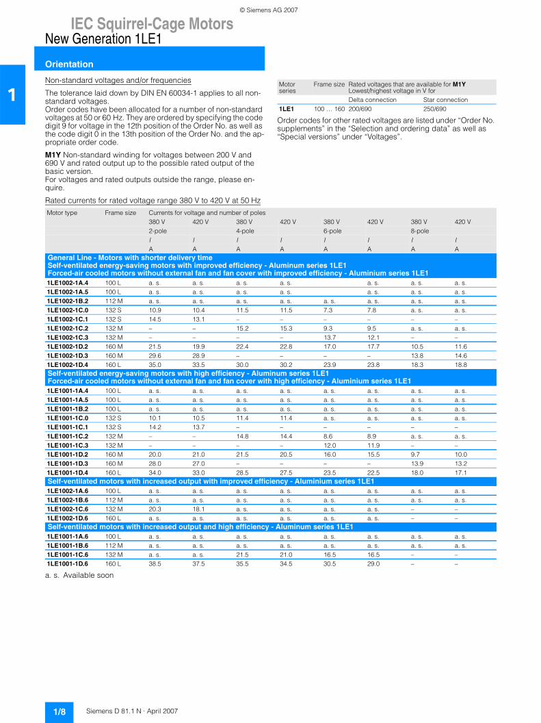
1Non-standard voltages and/or frequencies
The tolerance laid down by DIN EN 60034-1 applies to all non-standard voltages.Order codes have been allocated for a number of non-standard voltages at 50 or 60 Hz. They are ordered by specifying the code digit 9 for voltage in the 12th position of the Order No. as well as the code digit 0 in the 13th position of the Order No. and the ap-propriate order code.
M1Y Non-standard winding for voltages between 200 V and 690 V and rated output up to the possible rated output of the basic version. For voltages and rated outputs outside the range, please en-quire.
Order codes for other rated voltages are listed under “Order No. supplements” in the “Selection and ordering data” as well as “Special versions” under “Voltages”.
Rated currents for rated voltage range 380 V to 420 V at 50 Hz
a. s. Available soon
Motor series
Frame size Rated voltages that are available for M1YLowest/highest voltage in V forDelta connection Star connection
1LE1 100 … 160 200/690 250/690
Motor type Frame size Currents for voltage and number of poles380 V 420 V 380 V 420 V 380 V 420 V 380 V 420 V2-pole 4-pole 6-pole 8-poleI I I I I I I IA A A A A A A A
General Line - Motors with shorter delivery timeSelf-ventilated energy-saving motors with improved efficiency - Aluminum series 1LE1 Forced-air cooled motors without external fan and fan cover with improved efficiency - Aluminium series 1LE11LE1002-1A.4 100 L a. s. a. s. a. s. a. s. a. s. a. s. a. s.1LE1002-1A.5 100 L a. s. a. s. a. s. a. s. a. s. a. s. a. s.1LE1002-1B.2 112 M a. s. a. s. a. s. a. s. a. s. a. s. a. s. a. s.1LE1002-1C.0 132 S 10.9 10.4 11.5 11.5 7.3 7.8 a. s. a. s.1LE1002-1C.1 132 S 14.5 13.1 – – – – – –1LE1002-1C.2 132 M – – 15.2 15.3 9.3 9.5 a. s. a. s.1LE1002-1C.3 132 M – – – – 13.7 12.1 – –1LE1002-1D.2 160 M 21.5 19.9 22.4 22.8 17.0 17.7 10.5 11.61LE1002-1D.3 160 M 29.6 28.9 – – – – 13.8 14.61LE1002-1D.4 160 L 35.0 33.5 30.0 30.2 23.9 23.8 18.3 18.8Self-ventilated energy-saving motors with high efficiency - Aluminum series 1LE1 Forced-air cooled motors without external fan and fan cover with high efficiency - Aluminium series 1LE11LE1001-1A.4 100 L a. s. a. s. a. s. a. s. a. s. a. s. a. s. a. s.1LE1001-1A.5 100 L a. s. a. s. a. s. a. s. a. s. a. s. a. s. a. s.1LE1001-1B.2 100 L a. s. a. s. a. s. a. s. a. s. a. s. a. s. a. s.1LE1001-1C.0 132 S 10.1 10.5 11.4 11.4 a. s. a. s. a. s. a. s.1LE1001-1C.1 132 S 14.2 13.7 – – – – – –1LE1001-1C.2 132 M – – 14.8 14.4 8.6 8.9 a. s. a. s.1LE1001-1C.3 132 M – – – – 12.0 11.9 – –1LE1001-1D.2 160 M 20.0 21.0 21.5 20.5 16.0 15.5 9.7 10.01LE1001-1D.3 160 M 28.0 27.0 – – – – 13.9 13.21LE1001-1D.4 160 L 34.0 33.0 28.5 27.5 23.5 22.5 18.0 17.1Self-ventilated motors with increased output with improved efficiency - Aluminium series 1LE11LE1002-1A.6 100 L a. s. a. s. a. s. a. s. a. s. a. s. a. s. a. s.1LE1002-1B.6 112 M a. s. a. s. a. s. a. s. a. s. a. s. a. s. a. s.1LE1002-1C.6 132 M 20.3 18.1 a. s. a. s. a. s. a. s. – –1LE1002-1D.6 160 L a. s. a. s. a. s. a. s. a. s. a. s. – –Self-ventilated motors with increased output and high efficiency - Aluminum series 1LE11LE1001-1A.6 100 L a. s. a. s. a. s. a. s. a. s. a. s. a. s. a. s.1LE1001-1B.6 112 M a. s. a. s. a. s. a. s. a. s. a. s. a. s. a. s.1LE1001-1C.6 132 M a. s. a. s. 21.5 21.0 16.5 16.5 – –1LE1001-1D.6 160 L 38.5 37.5 35.5 34.5 30.5 29.0 – –
© Siemens AG 2007
IEC Squirrel-Cage MotorsNew Generation 1LE1
Orientation
1/9Siemens D 81.1 N · April 2007
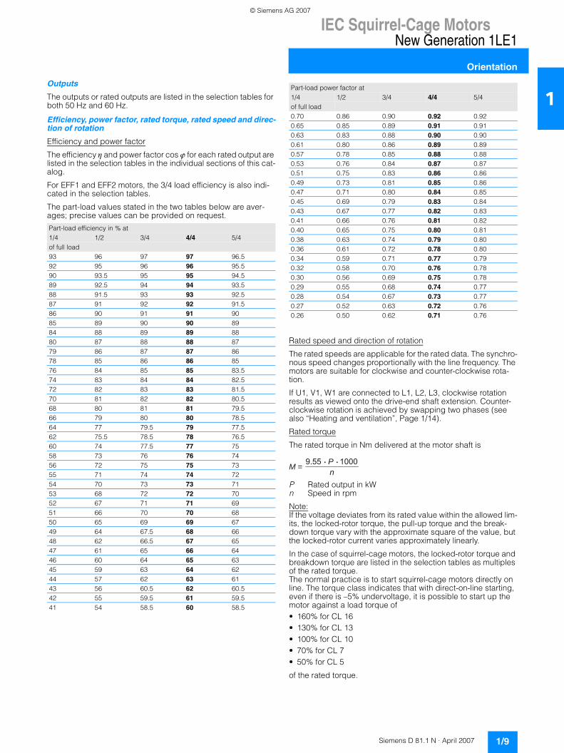
1Outputs
The outputs or rated outputs are listed in the selection tables for both 50 Hz and 60 Hz.
Efficiency, power factor, rated torque, rated speed and direc-tion of rotation
Efficiency and power factor
The efficiency η and power factor cos ϕ for each rated output are listed in the selection tables in the individual sections of this cat-alog.
For EFF1 and EFF2 motors, the 3/4 load efficiency is also indi-cated in the selection tables.
The part-load values stated in the two tables below are aver-ages; precise values can be provided on request.
Rated speed and direction of rotation
The rated speeds are applicable for the rated data. The synchro-nous speed changes proportionally with the line frequency. The motors are suitable for clockwise and counter-clockwise rota-tion.
If U1, V1, W1 are connected to L1, L2, L3, clockwise rotation results as viewed onto the drive-end shaft extension. Counter-clockwise rotation is achieved by swapping two phases (see also “Heating and ventilation”, Page 1/14).
Rated torque
The rated torque in Nm delivered at the motor shaft is
P Rated output in kWn Speed in rpm
Note:If the voltage deviates from its rated value within the allowed lim-its, the locked-rotor torque, the pull-up torque and the break-down torque vary with the approximate square of the value, but the locked-rotor current varies approximately linearly.
In the case of squirrel-cage motors, the locked-rotor torque and breakdown torque are listed in the selection tables as multiples of the rated torque. The normal practice is to start squirrel-cage motors directly on line. The torque class indicates that with direct-on-line starting, even if there is –5% undervoltage, it is possible to start up the motor against a load torque of• 160% for CL 16• 130% for CL 13• 100% for CL 10• 70% for CL 7• 50% for CL 5
of the rated torque.
Part-load efficiency in % at1/4 1/2 3/4 4/4 5/4of full load93 96 97 97 96.592 95 96 96 95.590 93.5 95 95 94.589 92.5 94 94 93.588 91.5 93 93 92.587 91 92 92 91.586 90 91 91 9085 89 90 90 8984 88 89 89 8880 87 88 88 8779 86 87 87 8678 85 86 86 8576 84 85 85 83.574 83 84 84 82.572 82 83 83 81.570 81 82 82 80.568 80 81 81 79.566 79 80 80 78.564 77 79.5 79 77.562 75.5 78.5 78 76.560 74 77.5 77 7558 73 76 76 7456 72 75 75 7355 71 74 74 7254 70 73 73 7153 68 72 72 7052 67 71 71 6951 66 70 70 6850 65 69 69 6749 64 67.5 68 6648 62 66.5 67 6547 61 65 66 6446 60 64 65 6345 59 63 64 6244 57 62 63 6143 56 60.5 62 60.542 55 59.5 61 59.541 54 58.5 60 58.5
Part-load power factor at1/4 1/2 3/4 4/4 5/4of full load0.70 0.86 0.90 0.92 0.920.65 0.85 0.89 0.91 0.910.63 0.83 0.88 0.90 0.900.61 0.80 0.86 0.89 0.890.57 0.78 0.85 0.88 0.880.53 0.76 0.84 0.87 0.870.51 0.75 0.83 0.86 0.860.49 0.73 0.81 0.85 0.860.47 0.71 0.80 0.84 0.850.45 0.69 0.79 0.83 0.840.43 0.67 0.77 0.82 0.830.41 0.66 0.76 0.81 0.820.40 0.65 0.75 0.80 0.810.38 0.63 0.74 0.79 0.800.36 0.61 0.72 0.78 0.800.34 0.59 0.71 0.77 0.790.32 0.58 0.70 0.76 0.780.30 0.56 0.69 0.75 0.780.29 0.55 0.68 0.74 0.770.28 0.54 0.67 0.73 0.770.27 0.52 0.63 0.72 0.760.26 0.50 0.62 0.71 0.76
M = P 1000n
9.55
© Siemens AG 2007
IEC Squirrel-Cage MotorsNew Generation 1LE1
Orientation
1/10 Siemens D 81.1 N · April 2007
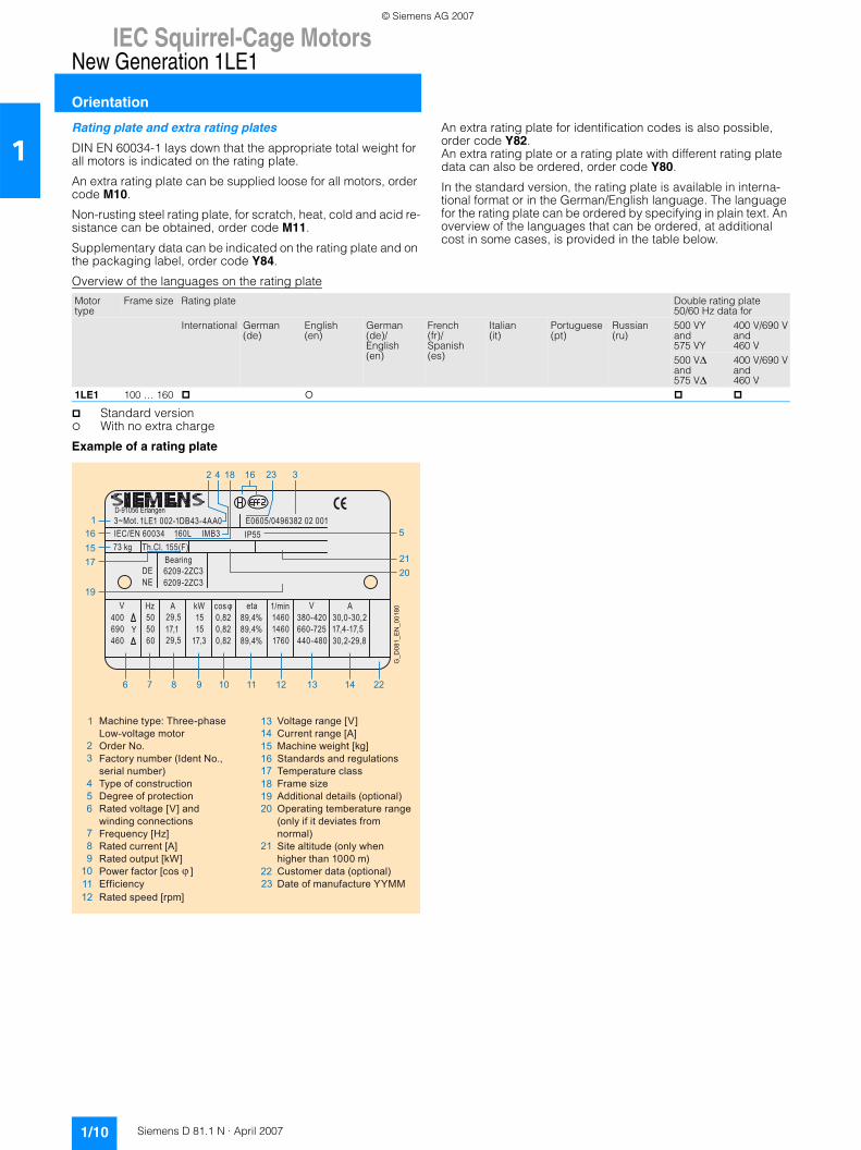
1Rating plate and extra rating plates
DIN EN 60034-1 lays down that the appropriate total weight for all motors is indicated on the rating plate.
An extra rating plate can be supplied loose for all motors, order code M10.
Non-rusting steel rating plate, for scratch, heat, cold and acid re-sistance can be obtained, order code M11.
Supplementary data can be indicated on the rating plate and on the packaging label, order code Y84.
An extra rating plate for identification codes is also possible, order code Y82. An extra rating plate or a rating plate with different rating plate data can also be ordered, order code Y80.
In the standard version, the rating plate is available in interna-tional format or in the German/English language. The language for the rating plate can be ordered by specifying in plain text. An overview of the languages that can be ordered, at additional cost in some cases, is provided in the table below.
Overview of the languages on the rating plate
Standard versionWith no extra charge
Example of a rating plate
Motor type
Frame size Rating plate Double rating plate50/60 Hz data for
International German (de)
English (en)
German (de)/English (en)
French (fr)/Spanish (es)
Italian (it)
Portuguese (pt)
Russian (ru)
500 VY and575 VY
400 V/690 V and460 V
500 V∆ and575 V∆
400 V/690 V and460 V
1LE1 100 … 160
E0605/0496382 02 001
660-725440-480
380-420
1LE1 002-1DB43-4AA0
kW15
AHzV
690 400
Y605050
17,129,5
D-91056 Erlangen3~Mot.
1/mincos φ eta
89,4%
89,4%
0,820,820,82
17,3 1760
1460AV
30,0-30,2
IEC/EN 60034 160L IMB3 IP55 73 kg Th.Cl. 155(F)
29,515 89,4% 1460
BearingDENE 6209-2ZC3
6209-2ZC3
46017,4-17,530,2-29,8
21
5
20
6
19
171516
1
7 8 9 10 11 12 13 14 22
23 316182 4
G_D
081_
EN
_001
80
1
23
456
789
101112
1314151617181920
21
2223
Machine type: Three-phaseLow-voltage motorOrder No.Factory number (Ident No.,serial number)Type of constructionDegree of protectionRated voltage [V] andwinding connectionsFrequency [Hz]Rated current [A]Rated output [kW]Power factor [cos ]EfficiencyRated speed [rpm]
Voltage range [V]Current range [A]Machine weight [kg]Standards and regulationsTemperature classFrame sizeAdditional details (optional)Operating temberature range(only if it deviates fromnormal)Site altitude (only whenhigher than 1000 m)Customer data (optional)Date of manufacture YYMM
© Siemens AG 2007
IEC Squirrel-Cage MotorsNew Generation 1LE1
Orientation
1/11Siemens D 81.1 N · April 2007
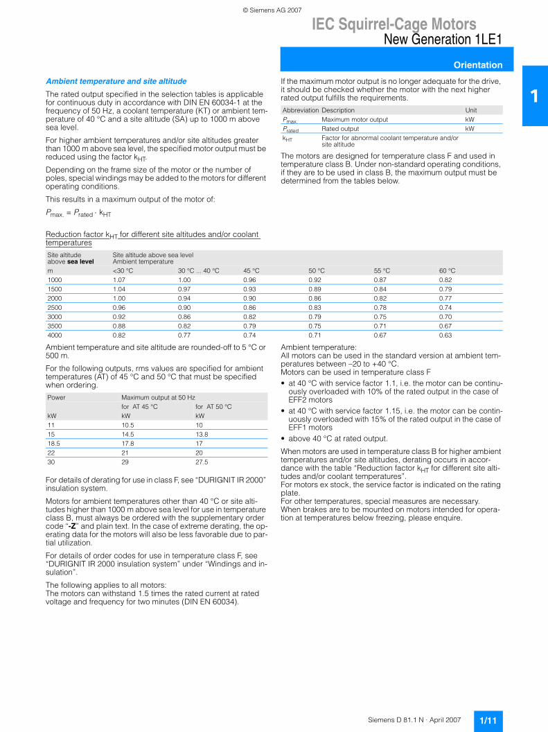
1Ambient temperature and site altitude
The rated output specified in the selection tables is applicable for continuous duty in accordance with DIN EN 60034-1 at the frequency of 50 Hz, a coolant temperature (KT) or ambient tem-perature of 40 °C and a site altitude (SA) up to 1000 m above sea level.
For higher ambient temperatures and/or site altitudes greater than 1000 m above sea level, the specified motor output must be reduced using the factor kHT.
Depending on the frame size of the motor or the number of poles, special windings may be added to the motors for different operating conditions.
This results in a maximum output of the motor of:
Pmax. = Prated ⋅ kHT
If the maximum motor output is no longer adequate for the drive, it should be checked whether the motor with the next higher rated output fulfills the requirements.
The motors are designed for temperature class F and used in temperature class B. Under non-standard operating conditions, if they are to be used in class B, the maximum output must be determined from the tables below.
Reduction factor kHT for different site altitudes and/or coolant temperatures
Ambient temperature and site altitude are rounded-off to 5 °C or 500 m.
For the following outputs, rms values are specified for ambient temperatures (AT) of 45 °C and 50 °C that must be specified when ordering.
For details of derating for use in class F, see “DURIGNIT IR 2000” insulation system.
Motors for ambient temperatures other than 40 °C or site alti-tudes higher than 1000 m above sea level for use in temperature class B, must always be ordered with the supplementary order code “-Z” and plain text. In the case of extreme derating, the op-erating data for the motors will also be less favorable due to par-tial utilization.
For details of order codes for use in temperature class F, see “DURIGNIT IR 2000 insulation system” under “Windings and in-sulation”.
The following applies to all motors: The motors can withstand 1.5 times the rated current at rated voltage and frequency for two minutes (DIN EN 60034).
Ambient temperature: All motors can be used in the standard version at ambient tem-peratures between –20 to +40 °C. Motors can be used in temperature class F • at 40 °C with service factor 1.1, i.e. the motor can be continu-
ously overloaded with 10% of the rated output in the case of EFF2 motors
• at 40 °C with service factor 1.15, i.e. the motor can be contin-uously overloaded with 15% of the rated output in the case of EFF1 motors
• above 40 °C at rated output.
When motors are used in temperature class B for higher ambient temperatures and/or site altitudes, derating occurs in accor-dance with the table “Reduction factor kHT for different site alti-tudes and/or coolant temperatures”. For motors ex stock, the service factor is indicated on the rating plate. For other temperatures, special measures are necessary. When brakes are to be mounted on motors intended for opera-tion at temperatures below freezing, please enquire.
Abbreviation Description UnitPmax. Maximum motor output kWPrated Rated output kWkHT Factor for abnormal coolant temperature and/or
site altitude
Site altitude above sea level
Site altitude above sea level Ambient temperature
m <30 °C 30 °C ... 40 °C 45 °C 50 °C 55 °C 60 °C1000 1.07 1.00 0.96 0.92 0.87 0.821500 1.04 0.97 0.93 0.89 0.84 0.792000 1.00 0.94 0.90 0.86 0.82 0.772500 0.96 0.90 0.86 0.83 0.78 0.743000 0.92 0.86 0.82 0.79 0.75 0.703500 0.88 0.82 0.79 0.75 0.71 0.674000 0.82 0.77 0.74 0.71 0.67 0.63
Power Maximum output at 50 Hzfor AT 45 °C for AT 50 °C
kW kW kW11 10.5 1015 14.5 13.818.5 17.8 1722 21 2030 29 27.5
© Siemens AG 2007
IEC Squirrel-Cage MotorsNew Generation 1LE1
Orientation
1/12 Siemens D 81.1 N · April 2007
1Windings and insulation
DURIGNIT IR 2000 insulation system
The DURIGNIT IR 2000 insulation system comprises high-grade enameled wires and insulating sheet materials combined with solvent-free impregnating resin. The system ensures a high level of mechanical and electrical strength as well as good serviceability and a long motor life. The insulation system protects the winding against aggressive gases, vapors, dust, oil and increased air humidity. It can with-stand the usual vibration stressing. The insulation is suitable up to an absolute air humidity of 30 g water per m3 of air. Moisture condensation should be prevented from forming on the winding. Please enquire if higher values are required.
Please enquire about extreme applications.
Restarting against residual field and opposite phase
All motors can be reclosed against 100% residual field after a line voltage failure.
Winding and insulation design with regard to temperature class and air humidity
All motors are designed for temperature class F.At rated output with line-fed operation, the motors can be used in temperature class B.
Temperature class F, used in accordance with F, with serviceFor all 1LE1 motors for line-fed operation for the rated output given in the selection table and rated voltage, a service factor of 1.1 can be specified for EFF2 motors (SF = 1.15 for EFF1 motors) also for motors with increased output. Order code N01
Temperature class F, used in accordance with F, for increased outputWhen used according to temperature class F, the rated output as specified in the selection and ordering data can be increased by 10% for EFF2 motors (15 % for EFF1 motors) also for motors with increased output.Order code N02
Temperature class F, used in accordance with F, with in-creased coolant temperatureFor line-fed motors at outputs in accordance with the catalog, the coolant temperature can be raised to 55 °C. Order code N03
The service factor (SF) is not indicated on the rating plate for or-der codes N02 and N03. For converter-fed operation at the output specified in the cata-log, the motors are used in accordance with temperature class F. Order codes N01, N02 and N03 are not possible. This applies to motors up to 500 V.
Temperature class F, used in accordance with F, other re-quirementsThe motors can be ordered according to temperature class F for use according to temperature class F with other customized re-quirements if they are specified in plain text in the order. Order code Y52
Temperature class F, used in accordance with B, coolant temperature 45 °C, approx. 4% deratingFor the 1LE1 motor series, a version for temperature class F can be used according to temperature class B at a maximum coolant temperature of 45 °C with a 4% reduction in rated output. Order code N05
Temperature class F, used in accordance with B, coolant temperature 50 °C, approx. 8% deratingFor the 1LE1 motor series, a version for temperature class F can be used according to temperature class B at a maximum coolant temperature of 50 °C with a 8% reduction in rated output. Order code N06
Temperature class F, used in accordance with B, coolant temperature 55 °C, approx. 13% deratingFor the 1LE1 motor series, a version for temperature class F can be used according to temperature class B at a maximum coolant temperature of 55 °C with a 13% reduction in rated output. Order code N07
Temperature class F, used in accordance with B, coolant temperature 60 °C, approx. 18% deratingFor the 1LE1 motor series, a version for temperature class F can be used according to temperature class B at a maximum coolant temperature of 60 °C with a 18% reduction in rated output. Order code N08
© Siemens AG 2007
IEC Squirrel-Cage MotorsNew Generation 1LE1
Orientation
1/13Siemens D 81.1 N · April 2007
1Motor protection
The order variants for motor protection are coded with letters in the 15th position of the order number and, if necessary, using order codes.
In the standard version, the motor is designed without motor pro-tection. 15th position in Order No. letter A
A distinction is made between current-dependent and motor-temperature-dependent protection devices.
Current-dependent protection devices
Fuses are only used to protect mains cables in the event of a short-circuit. They are not suitable for overload protection of the motor.
The motors are usually protected by delayed overload protection devices (circuit breakers for motor protection or overload re-lays).
This protection is current-dependent and is particularly effective in the case of a locked rotor.
For standard duty with short start-up times and starting currents that are not excessive and for low numbers of switching opera-tions, motor protection switches provide adequate protection. Motor protection switches are not suitable for heavy starting duty or large numbers of switching operations. Differences in the ther-mal time constants for the protection equipment and the motor results in unnecessary early tripping when the protection switch is set to rated current.
Protection devices that are motor temperature sensitive
Temperature monitors installed in the motor winding are suit-able protection devices in the case of slowly rising motor tem-perature.
When a limit temperature is reached, these bimetal switches (NC contacts) can deactivate an auxiliary circuit. The circuit can only be reclosed following a considerable fall in temperature. When the motor current rises quickly (e.g. with a locked rotor), these switches are not suitable due to their large thermal time constants. 3 temperature detectors for tripping 15th position of Order No. letter Z and order code Q3A
The most comprehensive protection against thermal overload-ing of the motor is provided by PTC thermistors (thermistor motor protection) installed in the motor winding. The tempera-ture of the winding can be accurately monitored thanks to its low heating capacity and the excellent heat contact with the wind-ing. When a limit temperature is reached (rated tripping temper-ature), the PTC thermistors undergo a step change in resistance. This is evaluated by a tripping unit and can be used to open auxiliary circuits. The PTC thermistors themselves cannot be subjected to high currents and voltages. This would result in destruction of the semiconductor. The switching hysteresis of the PTC thermistor and tripping unit is low, which supports fast re-starting of the drive. Motors with this type of protection are rec-ommended for heavy duty starting, switching duty, extreme changes in load, high ambient temperatures or fluctuating sup-ply systems.
Motor protection with PTC thermistor with 3 embedded temper-ature sensors for tripping. In the connection box, 2 auxiliary ter-minals are required. 15th position in Order No. letter B
Two sets of three temperature sensors are used if a warning is required before the motor is shut down (tripped). The warning is normally set to 10 K below the tripping temperature.
Motor protection with PTC thermistors with 6 embedded temper-ature sensors for alarm and tripping. In the connection box, 4 auxiliary terminals are required. 15th position in Order No. letter C
In order to achieve full thermal protection it is necessary to combine a thermally delayed overcurrent release and a PTC thermistor. For full motor protection implemented only with PTC thermistors, please enquire.
Motor temperature detection with converter-fed operation
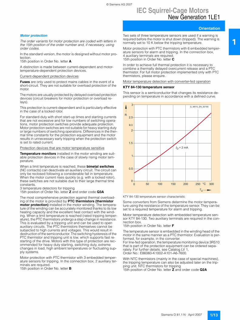
KTY 84-130 temperature sensor
This sensor is a semiconductor that changes its resistance de-pending on temperature in accordance with a defined curve.
KTY 84-130 temperature sensor characteristic
Some converters from Siemens determine the motor tempera-ture using the resistance of the temperature sensor. They can be set to a required temperature for alarm and tripping.
Motor temperature detection with embedded temperature sen-sor KTY 84-130. Two auxiliary terminals are required in the con-nection box. 15th position in Order No. letter F
The temperature sensor is embedded in the winding head of the motor in the same manner as a PTC thermistor. Evaluation is per-formed, for example, in the converter. For line-fed operation, the temperature monitoring device 3RS10 that is part of the protection equipment can be ordered sepa-rately. For further details, see Catalog LV 1, Order No.: E86060-K1002-A101-A6-7600.
With NTC thermistors (mainly in the case of special machines), the tripping temperature can also be adjusted later on the trip-ping unit. NTC thermistors for tripping 15th position of Order No. letter Z and order code Q2A
R
k
= 2 mAD
U
3
2.5
2
1.5
1
0.5
050 100 150 200 250 300°C0
G_M015_EN_00190
© Siemens AG 2007
IEC Squirrel-Cage MotorsNew Generation 1LE1
Orientation
1/14 Siemens D 81.1 N · April 2007
1Heating and ventilation
Anti-condensation heaters
Line voltage 230 V (1~)Order code Q02
Line voltage 115 V (1~)Order code Q03
Motors whose windings are at risk of condensation due to the climatic conditions, e.g. inactive motors in humid atmospheres or motors that are subjected to widely fluctuating temperatures, can be equipped with anti-condensation heaters. An additional M16 x 1.5 cable entry is provided for the connect-ing cable in the connection box. Anti-condensation heaters must not be switched on during oper-ation.
Instead of an anti-condensation heater, another possibility (at no extra cost) is connection of a voltage that is approximately 4 to 10% of the rated motor voltage to stator terminals U1 and V1; 20 to 30% of rated motor current is sufficient to heat the motor.
a. s. Available soon
Fans/Separately driven fans
Motors of frame sizes 100 to 160 have radial-flow fans in the standard version that cool regardless of the direction of rotation of the motor (cooling method IC 411 acc. to DIN EN 60034-6). The air flow is forced from the non-drive-end (NDE) to the drive end (DE). For details of separately-driven fans for frame sizes 100 to 160, see Page 1/27.
Line voltage of separately driven fan for 1LE1 motors: The line voltage tolerance of the separately driven fan is ±5%; voltage range, Page 1/27.
When the motor is mounted and the air intake is restricted, then it must be ensured that a minimum clearance is maintained be-tween the fan cover and the wall. This clearance is calculated from the difference between the protective cover and the fan cover (differential dimension LM - L) or is specified in the detail dimension drawing.
For design of the fan/separately driven fan and the fan cover, see the table below.
Sheet metal fan cover
For 1LE1 motor series, the fan cover can be supplied in sheet metal instead of plastic. Order code F74
Necessary minimum cooling air flow for forced-air-cooled motors in standard duty
The required cooling air flow indicated in the selection table ap-plies to continuous duty according to DIN EN 60034-1 at a cool-ant temperature (KT) and ambient temperature, respectively, of 40 °C and a site altitude (SA) of up to 1000 m above sea level.
In the motor version without an external fan and without a fan cover, order code F90, the motor is located in the air flow of the
fan to be driven which must drive the minimum cooling air flow over the motor housing. The minimum air flow must pass closely over the housing (comparable to self-ventilation of the motor). Otherwise higher air flows are required to comply with maximum motor heating levels. For a higher cooling air flow, the operating temperature of the motor can be reduced.
a. s. Available soon
Motor series Frame size Heater output in Watt (W)Line voltage at230 V 115 VOrder code Order codeQ02 Q03
1LE1 100 a. s. a. s.1LE1 112 a. s. a. s.1LE1 132 … 160 100 100
Motor series Frame size Fan material Fan cover material
1LE1 100 … 160 plastic plastic1)
Frame size Required cooling air flow for number of poles2 4 6 8EFF1/EFF2 EFF1 EFF2 EFF1/EFF2 EFF1/EFF250 Hz 60 Hz 50 Hz 60 Hz 50 Hz 60 Hz 50 Hz 60 Hz 50 Hz 60 Hzm3/min m3/min m3/min m3/min m3/min m3/min m3/min m3/min m3/min m3/min
100 a. s. a. s. a. s. a. s. a. s. a. s. a. s. a. s. a. s. a. s.112 a. s. a. s. a. s. a. s. a. s. a. s. a. s. a. s. a. s. a. s.132 6.3 7.3 4.6 5.7 4.6 5.7 3.1 3.7 2.4 2.8160 10. 4 12.6 6.3 7.5 7 8.5 4.5 5.5 3.3 4.0
1) The external fan cover is supplied in metal.
© Siemens AG 2007
IEC Squirrel-Cage MotorsNew Generation 1LE1
Orientation
1/15Siemens D 81.1 N · April 2007
1Motor connection and connection boxes
Connection, circuit and connection boxes
Location of the connection box
The order variants for motor connection are coded with digits in the 16th position of the order number.
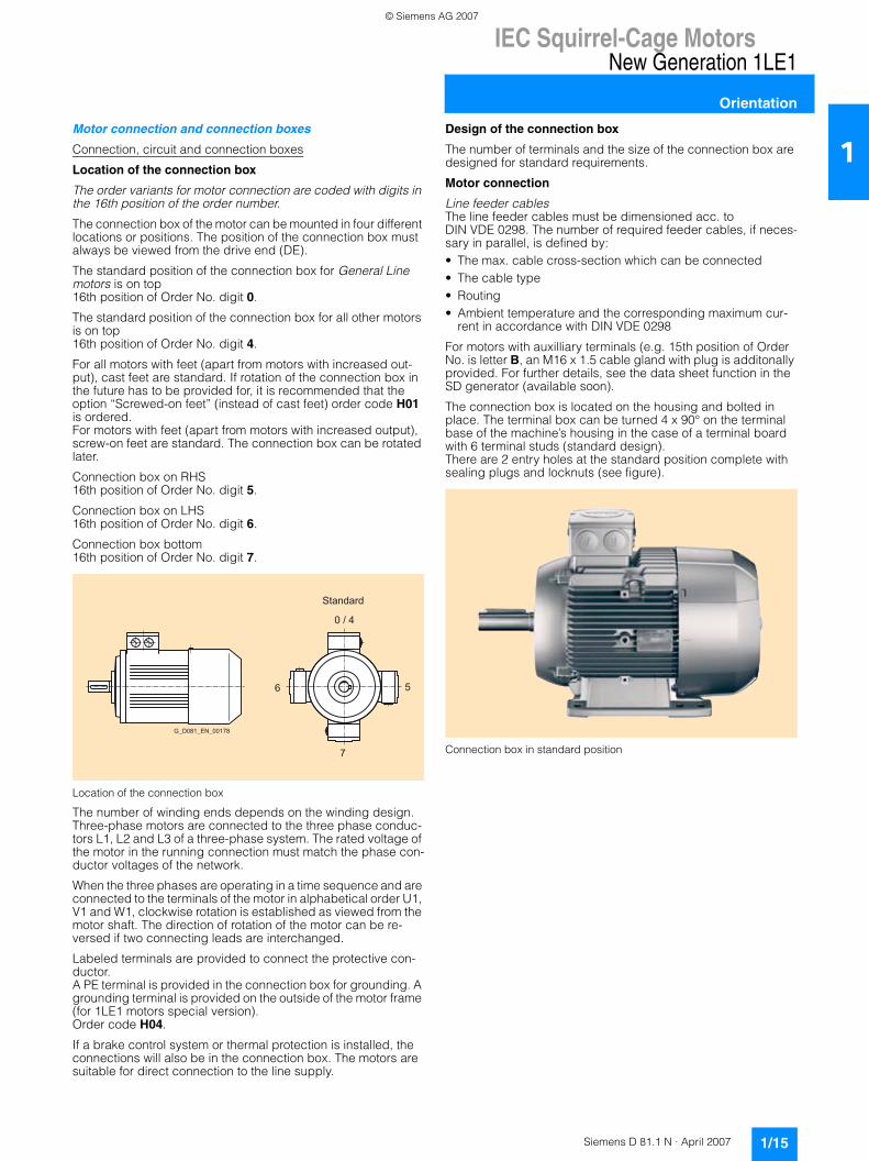
The connection box of the motor can be mounted in four different locations or positions. The position of the connection box must always be viewed from the drive end (DE).
The standard position of the connection box for General Line motors is on top16th position of Order No. digit 0.
The standard position of the connection box for all other motors is on top16th position of Order No. digit 4.
For all motors with feet (apart from motors with increased out-put), cast feet are standard. If rotation of the connection box in the future has to be provided for, it is recommended that the option “Screwed-on feet” (instead of cast feet) order code H01 is ordered. For motors with feet (apart from motors with increased output), screw-on feet are standard. The connection box can be rotated later.
Connection box on RHS 16th position of Order No. digit 5.
Connection box on LHS 16th position of Order No. digit 6.
Connection box bottom 16th position of Order No. digit 7.
Location of the connection box
The number of winding ends depends on the winding design. Three-phase motors are connected to the three phase conduc-tors L1, L2 and L3 of a three-phase system. The rated voltage of the motor in the running connection must match the phase con-ductor voltages of the network.
When the three phases are operating in a time sequence and are connected to the terminals of the motor in alphabetical order U1, V1 and W1, clockwise rotation is established as viewed from the motor shaft. The direction of rotation of the motor can be re-versed if two connecting leads are interchanged.
Labeled terminals are provided to connect the protective con-ductor. A PE terminal is provided in the connection box for grounding. A grounding terminal is provided on the outside of the motor frame (for 1LE1 motors special version). Order code H04.
If a brake control system or thermal protection is installed, the connections will also be in the connection box. The motors are suitable for direct connection to the line supply.
Design of the connection box
The number of terminals and the size of the connection box are designed for standard requirements.
Motor connection
Line feeder cablesThe line feeder cables must be dimensioned acc. to DIN VDE 0298. The number of required feeder cables, if neces-sary in parallel, is defined by:• The max. cable cross-section which can be connected • The cable type • Routing • Ambient temperature and the corresponding maximum cur-
rent in accordance with DIN VDE 0298
For motors with auxilliary terminals (e.g. 15th position of Order No. is letter B, an M16 x 1.5 cable gland with plug is additonally provided. For further details, see the data sheet function in the SD generator (available soon).
The connection box is located on the housing and bolted in place. The terminal box can be turned 4 x 90° on the terminal base of the machine’s housing in the case of a terminal board with 6 terminal studs (standard design). There are 2 entry holes at the standard position complete with sealing plugs and locknuts (see figure).
Connection box in standard position
Standard
0 / 4
5
7
6
G_D081_EN_00178
© Siemens AG 2007
IEC Squirrel-Cage MotorsNew Generation 1LE1
Orientation
1/16 Siemens D 81.1 N · April 2007
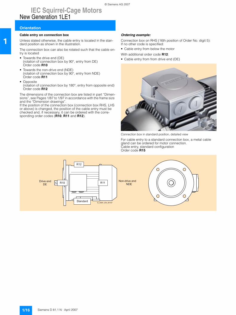
1Cable entry on connection box
Unless stated otherwise, the cable entry is located in the stan-dard position as shown in the illustration.
The connection box can also be rotated such that the cable en-try is located • Towards the drive end (DE)
(rotation of connection box by 90°, entry from DE) Order code R10
• Towards the non-drive end (NDE) (rotation of connection box by 90°, entry from NDE) Order code R11
• Opposite (rotation of connection box by 180°, entry from opposite end) Order code R12
The dimensions of the connection box are listed in part “Dimen-sions”, see Pages 1/87 to 1/97 in accordance with the frame size and the “Dimension drawings”. If the position of the connection box (connection box RHS, LHS or above) is changed, the position of the cable entry must be checked and, if necessary, it can be ordered with the corre-sponding order codes (R10, R11 and R12).
Ordering example:
Connection box on RHS (16th position of Order No. digit 5):If no other code is specified:• Cable entry from below the motor
With additional order code R12:• Cable entry from from drive end (DE)
Connection box in standard position, detailed view
For cable entry to a standard connection box, a metal cable gland can be ordered for motor connection. Cable entry, standard configuration Order code R15
R10
R12
R11Drive endDE
Non-drive endNDE
StandardG_D081_EN_00157
© Siemens AG 2007
IEC Squirrel-Cage MotorsNew Generation 1LE1
Orientation
1/17Siemens D 81.1 N · April 2007
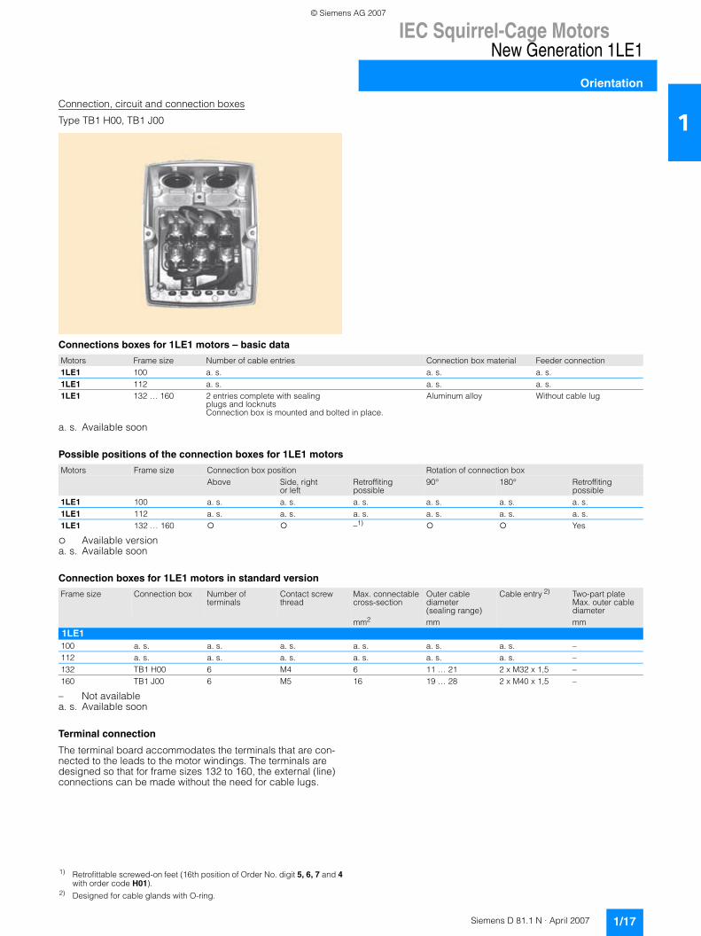
1Connection, circuit and connection boxes
Type TB1 H00, TB1 J00
Connections boxes for 1LE1 motors – basic data
a. s. Available soon
Possible positions of the connection boxes for 1LE1 motors
Available versiona. s. Available soon
Connection boxes for 1LE1 motors in standard version
– Not available a. s. Available soon
Terminal connection
The terminal board accommodates the terminals that are con-nected to the leads to the motor windings. The terminals are designed so that for frame sizes 132 to 160, the external (line) connections can be made without the need for cable lugs.
Motors Frame size Number of cable entries Connection box material Feeder connection1LE1 100 a. s. a. s. a. s.1LE1 112 a. s. a. s. a. s.1LE1 132 … 160 2 entries complete with sealing
plugs and locknuts Connection box is mounted and bolted in place.
Aluminum alloy Without cable lug
Motors Frame size Connection box position Rotation of connection boxAbove Side, right
or leftRetroffiting possible
90° 180° Retroffiting possible
1LE1 100 a. s. a. s. a. s. a. s. a. s. a. s.1LE1 112 a. s. a. s. a. s. a. s. a. s. a. s.1LE1 132 … 160 –1) Yes
Frame size Connection box Number of terminals
Contact screw thread
Max. connectable cross-section
Outer cable diameter (sealing range)
Cable entry 2) Two-part plate Max. outer cable diameter
mm2 mm mm1LE1100 a. s. a. s. a. s. a. s. a. s. a. s. –112 a. s. a. s. a. s. a. s. a. s. a. s. –132 TB1 H00 6 M4 6 11 … 21 2 x M32 x 1,5 –160 TB1 J00 6 M5 16 19 … 28 2 x M40 x 1,5 –
1) Retrofittable screwed-on feet (16th position of Order No. digit 5, 6, 7 and 4 with order code H01).
2) Designed for cable glands with O-ring.
© Siemens AG 2007
IEC Squirrel-Cage MotorsNew Generation 1LE1
Orientation
1/18 Siemens D 81.1 N · April 2007
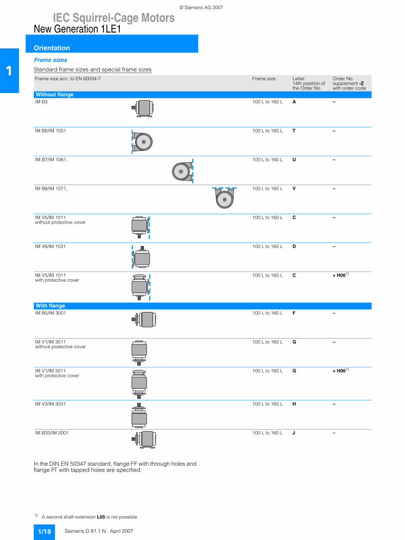
1Frame sizes
Standard frame sizes and special frame sizes
In the DIN EN 50347 standard, flange FF with through holes and flange FT with tapped holes are specified.
Frame size acc. to EN 60034-7 Frame size Letter 14th position of the Order No.
Order No. supplement -Z with order code
Without flangeIM B3 100 L to 160 L A –
IM B6/IM 1051 100 L to 160 L T –
IM B7/IM 1061, 100 L to 160 L U –
IM B8/IM 1071, 100 L to 160 L V –
IM V5/IM 1011 without protective cover
100 L to 160 L C –
IM V6/IM 1031 100 L to 160 L D –
IM V5/IM 1011with protective cover
100 L to 160 L C + H001)
With flangeIM B5/IM 3001 100 L to 160 L F –
IM V1/IM 3011without protective cover
100 L to 160 L G –
IM V1/IM 3011with protective cover
100 L to 160 L G + H001)
IM V3/IM 3031 100 L to 160 L H –
IM B35/IM 2001 100 L to 160 L J –
1) A second shaft extension L05 is not possible.
© Siemens AG 2007
IEC Squirrel-Cage MotorsNew Generation 1LE1
Orientation
1/19Siemens D 81.1 N · April 2007
1
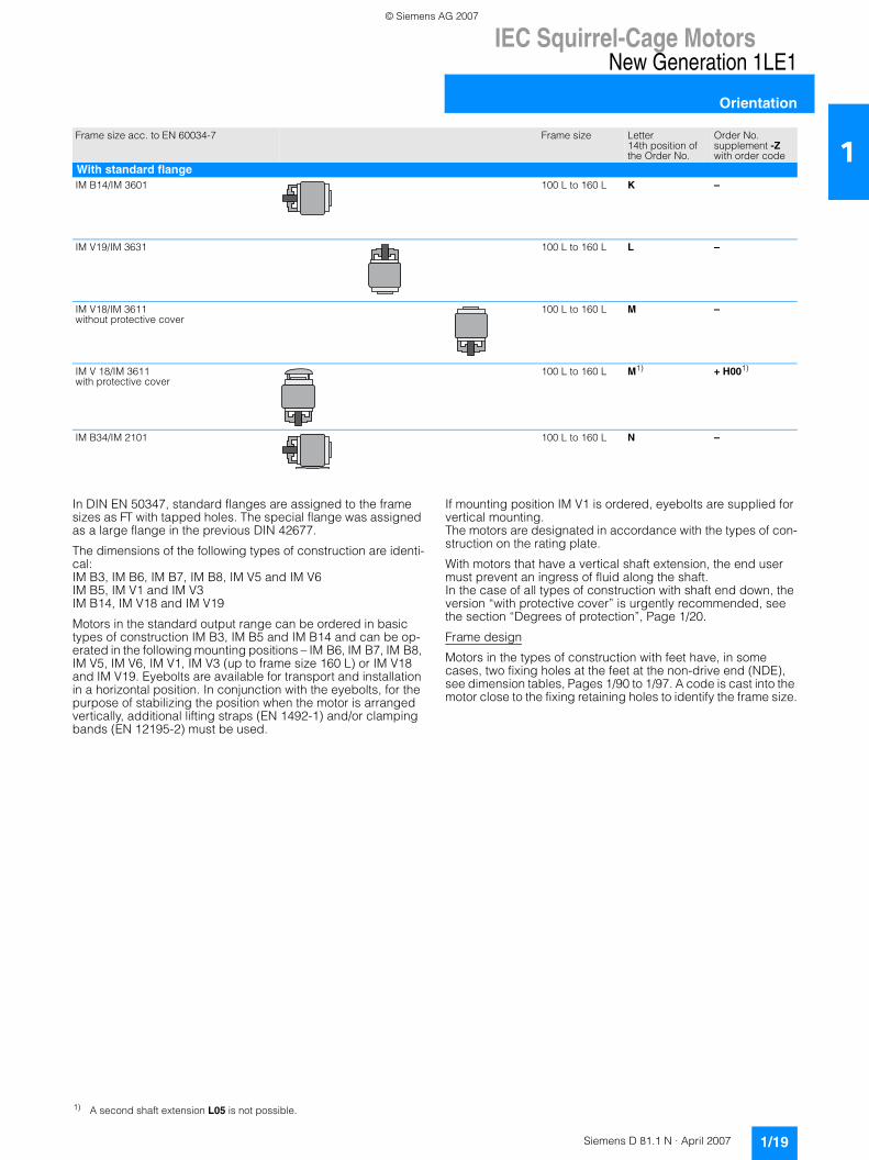
In DIN EN 50347, standard flanges are assigned to the frame sizes as FT with tapped holes. The special flange was assigned as a large flange in the previous DIN 42677.
The dimensions of the following types of construction are identi-cal:IM B3, IM B6, IM B7, IM B8, IM V5 and IM V6IM B5, IM V1 and IM V3IM B14, IM V18 and IM V19
Motors in the standard output range can be ordered in basic types of construction IM B3, IM B5 and IM B14 and can be op-erated in the following mounting positions – IM B6, IM B7, IM B8, IM V5, IM V6, IM V1, IM V3 (up to frame size 160 L) or IM V18 and IM V19. Eyebolts are available for transport and installation in a horizontal position. In conjunction with the eyebolts, for the purpose of stabilizing the position when the motor is arranged vertically, additional lifting straps (EN 1492-1) and/or clamping bands (EN 12195-2) must be used.
If mounting position IM V1 is ordered, eyebolts are supplied for vertical mounting. The motors are designated in accordance with the types of con-struction on the rating plate.
With motors that have a vertical shaft extension, the end user must prevent an ingress of fluid along the shaft. In the case of all types of construction with shaft end down, the version “with protective cover” is urgently recommended, see the section “Degrees of protection”, Page 1/20.
Frame design
Motors in the types of construction with feet have, in some cases, two fixing holes at the feet at the non-drive end (NDE), see dimension tables, Pages 1/90 to 1/97. A code is cast into the motor close to the fixing retaining holes to identify the frame size.
Frame size acc. to EN 60034-7 Frame size Letter 14th position of the Order No.
Order No. supplement -Z with order code
With standard flangeIM B14/IM 3601 100 L to 160 L K –
IM V19/IM 3631 100 L to 160 L L –
IM V18/IM 3611without protective cover
100 L to 160 L M –
IM V 18/IM 3611with protective cover
100 L to 160 L M1) + H001)
IM B34/IM 2101 100 L to 160 L N –
1) A second shaft extension L05 is not possible.
© Siemens AG 2007
IEC Squirrel-Cage MotorsNew Generation 1LE1
Orientation
1/20 Siemens D 81.1 N · April 2007
1Mechanical design and degrees of protection
Eyebolts and transport
1LE1 motors without feet have four cast eyebolts as standard, each offset by 90°; in the case of screw-on feet, two eyebolts are covered by the feet, so in this case only two eyebolts are avail-able for use.
Preparation for mountings
The encoders of the “modular and special technology” can be fitted at a later time. The motor must be prepared for this.
For the brake with order code F01 and for all encoders from the “modular and special technology” this preparation of the shaft extension on NDE can be ordered with the option “Prepared for mounting, only center hole”. Order code G40The length of the motor does not change because the shaft ex-tension is still under the fan cover.
For the encoders• 1XP8 012-10 order code G01• 1XP8 012-20 order code G02
from the “modular technology”, this preparation of the shaft extension on NDE can be ordered with the option “Prepared for mounting with shaft D12”. Order code G41The motor is at frame size 132 approx. 11 mm longer and at frame size 160 approx. 6 mm longer, see also “Dimensions and weights”, Pages 1/35 to 1/38.
For the encoders• LL 861 900 220 order code G04• HOG 9 D 1024 l order code G05• HOG 10 D 1024 l order code G06
from the “special technology”, this preparation of the shaft extension on NDE can be ordered with the option “Prepared for mounting with shaft D16”. Order code G42The motor is at frame size 132 approx. 51 mm longer and at frame size 160 approx. 46 mm longer, see also “Dimensions and weights”, Pages 1/35 to 1/38.
Degrees of protection
All motors are designed to IP55 degree of protection. They can be installed in dusty or humid environments. The motors are suit-able for operation in tropical climates. Guide value <60% relative air humidity at KT 40 °C. Other requirements are available on re-quest.
Brief explanation of the degree of protection
IP55: Protection against harmful dust deposits, protection against water jets from any direction.
DIN EN 60529 contains a comprehensive description of this de-gree of protection as well as test conditions.
With motors that have a vertical shaft extension, the end user must prevent an ingress of fluid along the shaft.
For motors with shaft extension pointing downwards, the version “with protective cover” order code H00 is urgently recom-mended, see also “Frame sizes”, Page 1/18.
With flange-mounting motors, for IM V3 type of construction, col-lection of fluid in the flange basin can be prevented by drainage holes (on request).
The condensation drainage holes at the drive end (DE) and non-drive end (NDE) are sealed (IP55) on delivery. If the condensa-tion drainage holes are ordered for motors fo the IM B6, IM B7 or IM B8 type of construction (feet located on side or top), the po-sition of the drainage holes will be in the correct position for the type of construction. Order code H03
When the motors are used or stored outdoors we reccommend that they are kept under some sort of cover so that they are not subjected to direct intensive solar radiation, rain, snow, ice or dust over a long period of time. In such cases, technical consul-tation may be appropriate.
Noise levels for line-fed operation
The noise levels are measured in accordance with DIN EN ISO 1680 in a dead room. It is specified as the reduced measuring-surface sound pressure level LpfA in dB (A).This is the spatial mean value of the sound pressure levels mea-sured on the measuring surface. The measuring surface is a cube 1 m away from the surface of the motor. The sound power level is also specified as LWA in dB (A). The specified values are valid at 50 Hz (see the selection and or-dering data). The tolerance is +3 dB. At 60 Hz, the values are approximately 4 dB (A) higher. Please enquire about the noise levels for motors with increased output or converter-fed motors.
Frame materialType series Frame size Frame material Frame feet1LE1 100 … 160 Aluminium alloy Cast 1)
© Siemens AG 2007
IEC Squirrel-Cage MotorsNew Generation 1LE1
Orientation
1/21Siemens D 81.1 N · April 2007
1Balance and vibration severity
All of the rotors are dynamically balanced with half key. This cor-responds to vibration severity level A. The vibrational character-istics and behavior of electrical machinery is specified in DIN EN 60034-14 Sept. 2004. “Half key balancing” is specified here based on DIN ISO 8821.
The balancing type is stamped on the face of the drive-end (DE) shaft extension.
F = Balancing with full keyH = Balancing with half key (standard)N = Balancing without key
This is indicated on the rating plate of the motors.Full-key balancing (F) is possible on request with order code L02 (extra charge).
Balancing without featherkey (N) is possible, on request, by specifying code L01 (extra charge).
Low-vibration versions can be supplied to fulfill stricter require-ments on smooth running (extra charge).
Vibration severity level A is the standard version.
Vibration severity level B Not possible with parallel roller bearings. Order code L00
The limits stated in the table are applicable for uncoupled, idling motors.
For converter-fed operation with frequencies greater than 60 Hz, special balancing is required for compliance with the specified limit values (plain text: Max. speed).
For further details, see the online help in SD configurator (avail-able soon).
For details, see standard DIN EN 60034-14, Sept. 2004.
Shaft and rotor
Shaft extension
60° center hole to DIN 332, Part 2 with M3 to M24 tapped hole depending on the shaft diameter (see dimension tables, Pages 1/90 to 1/97.)
Second standard shaft extension.Order code L05.
The second shaft extension can transmitt the full rated output via an output coupling.
Please also enquire about the transmitted power and maximum cantilever force if belt pulleys, chains or gear pinions are used on the second shaft extension.
A second shaft extension is not available if a rotary pulse en-coder and/or separately-driven fan is mounted. Please enquire if a brake is mounted.
Dimensions and tolerances for keyways and keys are designed to DIN EN 50347. The motors are always supplied with a key in-serted in the shaft.
Standard shaft made of non-rusting steel
For motor series 1LE1, a standard shaft made of non-rusting steel can be ordered. This is only possible for shaft extensions of standard dimensions. For non-standard shaft dimensions, there will be an additional charge! Order code L06
Please enquire about other non-rusting materials.
Concentricity of shaft extension, coaxiality and linear movement in accordance with DIN 42955 Tolerance R for flange-mounting motors
The following are specified in DIN 42955 with Tolerance N (normal) and Tolerance R (reduced):
1. Concentricity tolerances for the shaft extension
2. Coaxiality tolerances for the shaft extension and flange centering
3. Linear movement tolerances for the shaft extension and flange surface
The concentricity of the shaft extension, coaxiality and linear movement according to DIN 42955 Tolerance R for flange-mounting motors can be ordered using order code L08.This order code can be combined for motors with deep-groove bearings of series 60.., 62.. and 63… This cannot be supplied in combination with parallel roller bearings (e.g. bearings for in-creased cantilever forces, order code L22), brake or encoder mounting.
Concentricity of the shaft extension can be ordered according to DIN 42955 Tolerance R for types of construction without a flange with order code L07.
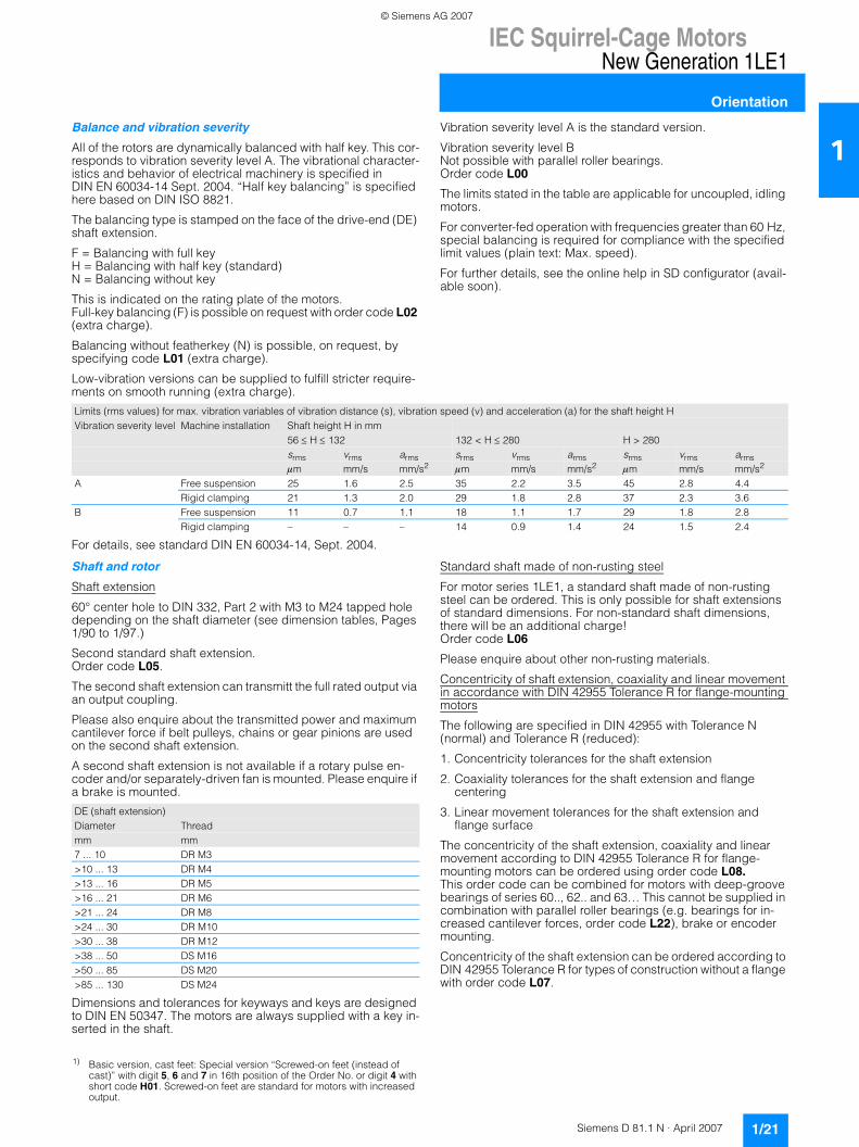
Limits (rms values) for max. vibration variables of vibration distance (s), vibration speed (v) and acceleration (a) for the shaft height HVibration severity level Machine installation Shaft height H in mm
56 ≤ H ≤ 132 132 < H ≤ 280 H > 280srms vrms arms srms vrms arms srms vrms armsμm mm/s mm/s2 μm mm/s mm/s2 μm mm/s mm/s2
A Free suspension 25 1.6 2.5 35 2.2 3.5 45 2.8 4.4Rigid clamping 21 1.3 2.0 29 1.8 2.8 37 2.3 3.6
B Free suspension 11 0.7 1.1 18 1.1 1.7 29 1.8 2.8Rigid clamping – – – 14 0.9 1.4 24 1.5 2.4
1) Basic version, cast feet: Special version “Screwed-on feet (instead of cast)” with digit 5, 6 and 7 in 16th position of the Order No. or digit 4 with short code H01. Screwed-on feet are standard for motors with increased output.
DE (shaft extension)Diameter Threadmm mm7 ... 10 DR M3>10 ... 13 DR M4>13 ... 16 DR M5>16 ... 21 DR M6>21 ... 24 DR M8>24 ... 30 DR M10>30 ... 38 DR M12>38 ... 50 DS M16>50 ... 85 DS M20>85 ... 130 DS M24
© Siemens AG 2007
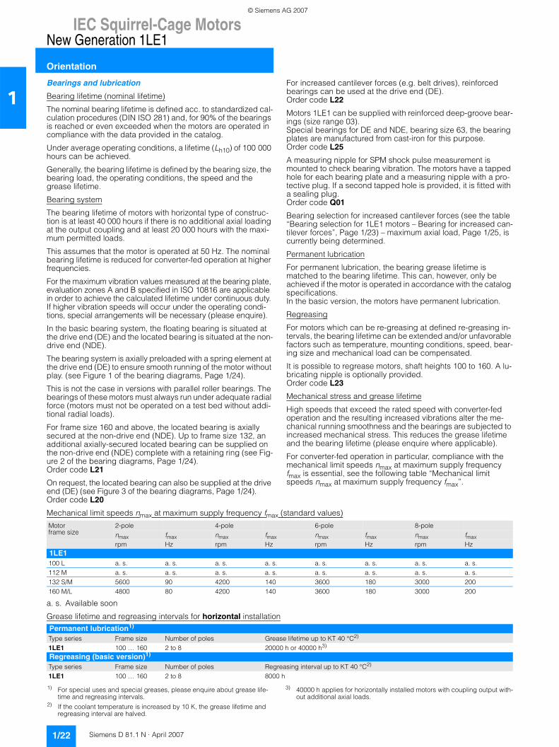
IEC Squirrel-Cage MotorsNew Generation 1LE1
Orientation
1/22 Siemens D 81.1 N · April 2007
1Bearings and lubrication
Bearing lifetime (nominal lifetime)
The nominal bearing lifetime is defined acc. to standardized cal-culation procedures (DIN ISO 281) and, for 90% of the bearings is reached or even exceeded when the motors are operated in compliance with the data provided in the catalog.
Under average operating conditions, a lifetime (Lh10) of 100 000 hours can be achieved.
Generally, the bearing lifetime is defined by the bearing size, the bearing load, the operating conditions, the speed and the grease lifetime.
Bearing system
The bearing lifetime of motors with horizontal type of construc-tion is at least 40 000 hours if there is no additional axial loading at the output coupling and at least 20 000 hours with the maxi-mum permitted loads.
This assumes that the motor is operated at 50 Hz. The nominal bearing lifetime is reduced for converter-fed operation at higher frequencies.
For the maximum vibration values measured at the bearing plate, evaluation zones A and B specified in ISO 10816 are applicable in order to achieve the calculated lifetime under continuous duty. If higher vibration speeds will occur under the operating condi-tions, special arrangements will be necessary (please enquire).
In the basic bearing system, the floating bearing is situated at the drive end (DE) and the located bearing is situated at the non-drive end (NDE).
The bearing system is axially preloaded with a spring element at the drive end (DE) to ensure smooth running of the motor without play. (see Figure 1 of the bearing diagrams, Page 1/24).
This is not the case in versions with parallel roller bearings. The bearings of these motors must always run under adequate radial force (motors must not be operated on a test bed without addi-tional radial loads).
For frame size 160 and above, the located bearing is axially secured at the non-drive end (NDE). Up to frame size 132, an additional axially-secured located bearing can be supplied on the non-drive end (NDE) complete with a retaining ring (see Fig-ure 2 of the bearing diagrams, Page 1/24). Order code L21
On request, the located bearing can also be supplied at the drive end (DE) (see Figure 3 of the bearing diagrams, Page 1/24).Order code L20
For increased cantilever forces (e.g. belt drives), reinforced bearings can be used at the drive end (DE). Order code L22
Motors 1LE1 can be supplied with reinforced deep-groove bear-ings (size range 03).Special bearings for DE and NDE, bearing size 63, the bearing plates are manufactured from cast-iron for this purpose.Order code L25
A measuring nipple for SPM shock pulse measurement is mounted to check bearing vibration. The motors have a tapped hole for each bearing plate and a measuring nipple with a pro-tective plug. If a second tapped hole is provided, it is fitted with a sealing plug.Order code Q01
Bearing selection for increased cantilever forces (see the table “Bearing selection for 1LE1 motors – Bearing for increased can-tilever forces”, Page 1/23) – maximum axial load, Page 1/25, is currently being determined.
Permanent lubrication
For permanent lubrication, the bearing grease lifetime is matched to the bearing lifetime. This can, however, only be achieved if the motor is operated in accordance with the catalog specifications. In the basic version, the motors have permanent lubrication.
Regreasing
For motors which can be re-greasing at defined re-greasing in-tervals, the bearing lifetime can be extended and/or unfavorable factors such as temperature, mounting conditions, speed, bear-ing size and mechanical load can be compensated.
It is possible to regrease motors, shaft heights 100 to 160. A lu-bricating nipple is optionally provided. Order code L23
Mechanical stress and grease lifetime
High speeds that exceed the rated speed with converter-fed operation and the resulting increased vibrations alter the me-chanical running smoothness and the bearings are subjected to increased mechanical stress. This reduces the grease lifetime and the bearing lifetime (please enquire where applicable).
For converter-fed operation in particular, compliance with the mechanical limit speeds nmax at maximum supply frequency fmax is essential, see the following table “Mechanical limit speeds nmax at maximum supply frequency fmax”.
Mechanical limit speeds nmax at maximum supply frequency fmax (standard values)
a. s. Available soon
Grease lifetime and regreasing intervals for horizontal installation
Motor frame size
2-pole 4-pole 6-pole 8-polenmax fmax nmax fmax nmax fmax nmax fmaxrpm Hz rpm Hz rpm Hz rpm Hz
1LE1100 L a. s. a. s. a. s. a. s. a. s. a. s. a. s. a. s.112 M a. s. a. s. a. s. a. s. a. s. a. s. a. s. a. s.132 S/M 5600 90 4200 140 3600 180 3000 200160 M/L 4800 80 4200 140 3600 180 3000 200
Permanent lubrication1)
Type series Frame size Number of poles Grease lifetime up to KT 40 °C2)
1LE1 100 … 160 2 to 8 20000 h or 40000 h3)
Regreasing (basic version)1)
Type series Frame size Number of poles Regreasing interval up to KT 40 °C2)
1LE1 100 … 160 2 to 8 8000 h
1) For special uses and special greases, please enquire about grease life-time and regreasing intervals.
2) If the coolant temperature is increased by 10 K, the grease lifetime and regreasing interval are halved.
3) 40000 h applies for horizontally installed motors with coupling output with-out additional axial loads.
© Siemens AG 2007
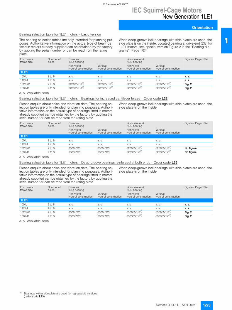
IEC Squirrel-Cage MotorsNew Generation 1LE1
Orientation
1/23Siemens D 81.1 N · April 2007
1Bearing selection table for 1LE1 motors – basic version
The bearing selection tables are only intended for planning pur-poses. Authoritative information on the actual type of bearings fitted in motors already supplied can be obtained by the factory by quoting the serial number or can be read from the rating plate.
When deep-groove ball bearings with side plates are used, the side plate is on the inside. Located bearing at drive end (DE) for 1LE1 motors, see special version Figure 2 in the “Bearing dia-grams”, Page 1/24.
a. s. Available soon
Bearing selection table for 1LE1 motors – Bearings for increased cantilever forces – Order code L22
Please enquire about noise and vibration data. The bearing se-lection tables are only intended for planning purposes. Authori-tative information on the actual type of bearings fitted in motors already supplied can be obtained by the factory by quoting the serial number or can be read from the rating plate.
When deep-groove ball bearings with side plates are used, the side plate is on the inside.
a. s. Available soon
Bearing selection table for 1LE1 motors – Deep-groove bearings reinforced at both ends – Order code L25
Please enquire about noise and vibration data. The bearing se-lection tables are only intended for planning purposes. Authori-tative information on the actual type of bearings fitted in motors already supplied can be obtained by the factory by quoting the serial number or can be read from the rating plate.
When deep-groove ball bearings with side plates are used, the side plate is on the inside.
a. s. Available soon
For motors frame size
Number of poles
Drive end (DE) bearing
Non-drive end NDE bearing
Figures, Page 1/24
Horizontal type of construction
Vertical type of construction
Horizontal type of construction
Vertical type of construction
1LE1100 L 2 to 8 a. s. a. s. a. s. a. s. a. s.112 M 2 to 8 a. s. a. s. a. s. a. s. a. s.132 S/M 2 to 8 6208 2ZC31) 6208 2ZC31) 6208 2ZC31) 6208 2ZC31) Fig. 2160 M/L 2 to 8 6209 2ZC31) 6209 2ZC31) 6209 2ZC31) 6209 2ZC31) Fig. 2
For motorsframe size
Number of poles
Drive end (DE) bearing
Non-drive end NDE bearing
Figures, Page 1/24
Horizontal type of construction
Vertical type of construction
Horizontal type of construction
Vertical type of construction
1LE1100 L 2 to 8 a. s. a. s. a. s. a. s.112 M 2 to 8 a. s. a. s. a. s. a. s.132 S/M 2 to 8 6308 ZC3 6308 ZC3 6208 2ZC31) 6208 2ZC31) No figure160 M/L 2 to 8 6309 ZC3 6309 ZC3 6209 2ZC31) 6209 2ZC31) No figure
For motorsframe size
Number of poles
Drive end (DE) bearing
Non-drive end NDE bearing
Figures, Page 1/24
Horizontal type of construction
Vertical type of construction
Horizontal type of construction
Vertical type of construction
1LE1100 L 2 to 8 a. s. a. s. a. s. a. s. a. s.112 M 2 to 8 a. s. a. s. a. s. a. s. a. s.132 S/M 2 to 8 6308 ZC3 6308 ZC3 6308 2ZC31) 6308 2ZC31) Fig. 2160 M/L 2 to 8 6309 ZC3 6309 ZC3 6309 2ZC31) 6309 2ZC31) Fig. 2
1) Bearings with a side plate are used for regreasable versions (order code L23).
© Siemens AG 2007
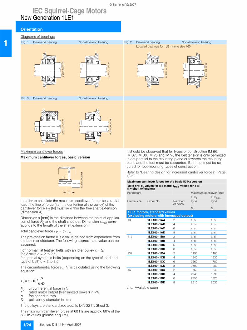
IEC Squirrel-Cage MotorsNew Generation 1LE1
Orientation
1/24 Siemens D 81.1 N · April 2007
1Diagrams of bearings
Maximum cantilever forces
Maximum cantilever forces, basic version
In order to calculate the maximum cantilever forces for a radial load, the line of force (i.e. the centerline of the pulley) of the cantilever force FQ (N) must lie within the free shaft extension (dimension X).
Dimension x [mm] is the distance between the point of applica-tion of force FQ and the shaft shoulder. Dimension xmax corre-sponds to the length of the shaft extension.
Total cantilever force FQ = c ⋅ Fu
The pre-tension factor c is a value gained from experience from the belt manufacturer. The following approximate value can be assumed:
For normal flat leather belts with an idler pulley c = 2;for V-belts c = 2 to 2.5;for special synthetic belts (depending on the type of load and type of belt) c = 2 to 2.5.
The circumferential force Fu (N) is calculated using the following equation
Fu circumferential force in NP rated motor output (transmitted power) in kWn fan speed in rpm D belt pulley diameter in mm
The pulleys are standardized acc. to DIN 2211, Sheet 3.
The maximum cantilever forces at 60 Hz are approx. 80% of the 50 Hz values (please enquire).
It should be observed that for types of construction IM B6, IM B7, IM B8, IM V5 and IM V6 the belt tension is only permitted to act parallel to the mounting plane or towards the mounting plane and the feet must be supported. Both feet must be se-cured for foot-mounting types of construction.
Refer to “Bearing design for increased cantilever forces”, Page 1/25.
a. s. Available soon
Fig. 1: Drive-end bearing Non-drive end bearing Fig. 2: Drive-end bearing Non-drive end bearingLocated bearings for 1LE1 frame size 160
Fig. 3: Drive-end bearing Non-drive end bearing
G_D
081_
XX
_001
01
G_D
081_
XX
_001
02
G_D
081_
XX
_001
03
G_D
081_
XX
_001
04
G_D
081_
XX
_001
05
G_D
081_
XX_0
0106
x
QF
G_D
081_
XX
_001
28
F 2 10 = u 7 P n D
Maximum cantilever forces for the basic 50 Hz versionValid are: x0 values for x = 0 and xmax. values for x = l (l = shaft extension)For motors Maximum cantilever force
at x0 at xmax.Frame size Order No. Number
of polesType Type
N N1LE1 motors, standard values (excluding motors with increased output) 100 1LE100.-1AA 2 a. s. a. s.
1LE100.-1AB 4 a. s. a. s.1LE100.-1AC 6 a. s. a. s.1LE100.-1AD 8 a. s. a. s.
112 1LE100.-1BA 2 a. s. a. s.1LE100.-1BB 4 a. s. a. s.1LE100.-1BC 6 a. s. a. s.1LE100.-1BD 8 a. s. a. s.
132 1LE100.-1CA 2 1490 11801LE100.-1CB 4 1940 15301LE100.-1CC 6 2260 17801LE100.-1CD 8 2500 1980
160 1LE100.-1DA 2 1560 12401LE100.-1DB 4 2040 15901LE100.-1DC 6 2350 18201LE100.-1DD 8 2610 2030
© Siemens AG 2007
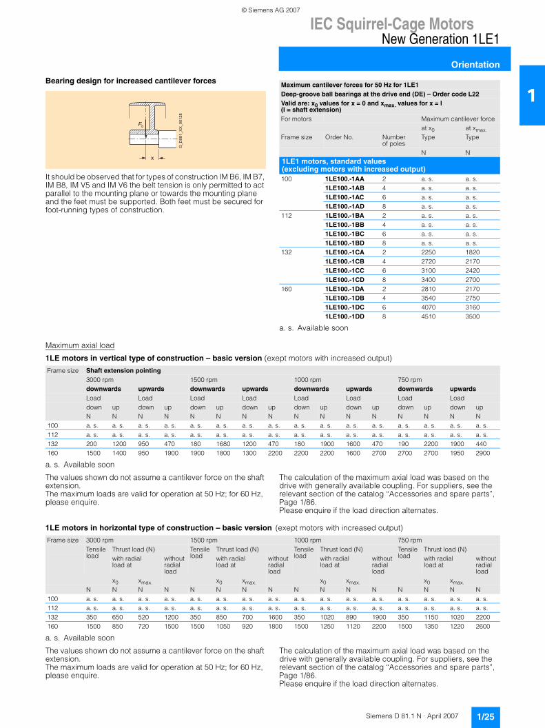
IEC Squirrel-Cage MotorsNew Generation 1LE1
Orientation
1/25Siemens D 81.1 N · April 2007
1Bearing design for increased cantilever forces
It should be observed that for types of construction IM B6, IM B7, IM B8, IM V5 and IM V6 the belt tension is only permitted to act parallel to the mounting plane or towards the mounting plane and the feet must be supported. Both feet must be secured for foot-running types of construction.
a. s. Available soon
Maximum axial load
1LE motors in vertical type of construction – basic version (exept motors with increased output)
a. s. Available soon
The values shown do not assume a cantilever force on the shaft extension. The maximum loads are valid for operation at 50 Hz; for 60 Hz, please enquire.
The calculation of the maximum axial load was based on the drive with generally available coupling. For suppliers, see the relevant section of the catalog “Accessories and spare parts”, Page 1/86.Please enquire if the load direction alternates.
1LE motors in horizontal type of construction – basic version (exept motors with increased output)
a. s. Available soon
The values shown do not assume a cantilever force on the shaft extension. The maximum loads are valid for operation at 50 Hz; for 60 Hz, please enquire.
The calculation of the maximum axial load was based on the drive with generally available coupling. For suppliers, see the relevant section of the catalog “Accessories and spare parts”, Page 1/86.Please enquire if the load direction alternates.
x
QF
G_D
081_
XX
_001
28
Maximum cantilever forces for 50 Hz for 1LE1 Deep-groove ball bearings at the drive end (DE) – Order code L22Valid are: x0 values for x = 0 and xmax. values for x = l (l = shaft extension)For motors Maximum cantilever force
at x0 at xmax.Frame size Order No. Number
of polesType Type
N N1LE1 motors, standard values (excluding motors with increased output) 100 1LE100.-1AA 2 a. s. a. s.
1LE100.-1AB 4 a. s. a. s.1LE100.-1AC 6 a. s. a. s.1LE100.-1AD 8 a. s. a. s.
112 1LE100.-1BA 2 a. s. a. s.1LE100.-1BB 4 a. s. a. s.1LE100.-1BC 6 a. s. a. s.1LE100.-1BD 8 a. s. a. s.
132 1LE100.-1CA 2 2250 18201LE100.-1CB 4 2720 21701LE100.-1CC 6 3100 24201LE100.-1CD 8 3400 2700
160 1LE100.-1DA 2 2810 21701LE100.-1DB 4 3540 27501LE100.-1DC 6 4070 31601LE100.-1DD 8 4510 3500
Frame size Shaft extension pointing3000 rpm 1500 rpm 1000 rpm 750 rpmdownwards upwards downwards upwards downwards upwards downwards upwardsLoad Load Load Load Load Load Load Loaddown up down up down up down up down up down up down up down upN N N N N N N N N N N N N N N N
100 a. s. a. s. a. s. a. s. a. s. a. s. a. s. a. s. a. s. a. s. a. s. a. s. a. s. a. s. a. s. a. s.112 a. s. a. s. a. s. a. s. a. s. a. s. a. s. a. s. a. s. a. s. a. s. a. s. a. s. a. s. a. s. a. s.132 200 1200 950 470 180 1680 1200 470 180 1900 1600 470 190 2200 1900 440160 1500 1400 950 1900 1900 1800 1300 2200 2200 2200 1600 2700 2700 2700 1950 2900
Frame size 3000 rpm 1500 rpm 1000 rpm 750 rpmTensile load
Thrust load (N) Tensile load
Thrust load (N) Tensile load
Thrust load (N) Tensile load
Thrust load (N)with radial load at
without radial load
with radial load at
without radial load
with radial load at
without radial load
with radial load at
without radial load
x0 xmax. x0 xmax. x0 xmax. x0 xmax.N N N N N N N N N N N N N N N N
100 a. s. a. s. a. s. a. s. a. s. a. s. a. s. a. s. a. s. a. s. a. s. a. s. a. s. a. s. a. s. a. s.112 a. s. a. s. a. s. a. s. a. s. a. s. a. s. a. s. a. s. a. s. a. s. a. s. a. s. a. s. a. s. a. s.132 350 650 520 1200 350 850 700 1600 350 1020 890 1900 350 1150 1020 2200160 1500 850 720 1500 1500 1050 920 1800 1500 1250 1120 2200 1500 1350 1220 2600
© Siemens AG 2007
IEC Squirrel-Cage MotorsNew Generation 1LE1
Orientation
1/26 Siemens D 81.1 N · April 2007
1Modular technology
Basic versions
The range of potential applications for the 1LE1 motors can be broadened considerably by mounting the following modules (e.g. the motors can be used as brake motors).• 1XP8 012 rotary pulse encoder• Separately driven fan • Brake
The brake must always be mounted in the factory for safety rea-sons. The rotary pulse encoder and/or the separately driven fan can also be retrofitted.
The degree of protection of the motors with modular technology is IP55. Higher degrees of protection on request.
When a rotary pulse encoder, brake or separately driven fan is mounted, the length of the motor increases by ∆ I. For an expla-nation of the additional dimensions and weights, see “Modular technology” “Dimensions and weights”.
1XP8 012 rotary pulse encoder
The rotary pulse encoder can be supplied already mounted in an HTL version as 1XP8 012-10 with order code G01 or in a TTL version as 1XP8 012-20 with order code G02. The rotary pulse encoder can only be mounted on a standard non-drive end (NDE), i.e. a second shaft extension cannot be supplied.
The encoder can be retrofitted. The motor must be prepared for this. When the motor is ordered, the option “Prepared for mount-ings, center hole only” order code G40 or the option “Prepared for mountings with shaft D12” order code G41 must be specified (see “Mechanical design and degrees of protection”, Page 1/20).
The 1XP8 012 rotary pulse encoder is suitable for standard ap-plications. For further encoders, see “Special technology”, Page 1/32.
When the rotary pulse encoder is mounted, the length of the mo-tor increases by ∆ I. For an explanation of the additional dimen-sions and weights, see “Modular technology” “Dimensions and weights”, Pages 1/35 to 1/38. The rotary pulse encoders of “Modular technology” and “Special technology” are fitted as standard with a protective cover made of non-corrosive sheet steel.
Technical data of rotary pulse encodersSupply voltage UB 1XP8 012-10 (HTL version)
+10 V to +30 V1XP8 012-20 (TTL version)5V ±10%
Current input without load 200 mA 150 mAMaximum load current per output max. 100 mA max. 20 mAPulses per revolution 1024 1024Outputs 2 square-wave pulses A, B – 2 inverted square-wave pulses A, B
Zero pulse and inverted zero pulse Pulse offset between the two outputs 90° ±20% 90° ±20%Output amplitude UHigh > UB – 3.5 V
ULow < 3 V UHigh > 2.5 VULow < 0.5 V
Minimum edge interval 0.8 µs at 160 kHz 0.45 µs at 300 kHzEdge steepness (without load or cable) t+, t– ≤200 ns t+, t– ≤100 nsMaximum frequency 160 kHz 300 kHzMaximum speed 9000 rpm 12000 rpmTemperature range –20 to +80 °C –20 to +100 °CDegree of protection IP66 IP66Maximum radial cantilever force 60 N 60 NMaximum axial force 40 N 40 NConnection system 12-pin connector (mating connector is supplied)Certification CSA, UL CSA, UL Weight 0.3 kg 0.3 kg
© Siemens AG 2007
IEC Squirrel-Cage MotorsNew Generation 1LE1
Orientation
1/27Siemens D 81.1 N · April 2007
1Separately driven fan
The use of a separately driven fan is recommended to increase motor utilization at low speeds and to limit noise generation at speeds significantly higher than the synchronous speed. Both of these results can only be achieved with converter-fed operation. Please enquire about traction and vibratory operation.
The separately driven fan can be supplied already fitted, order code F70.
It can also be ordered separately and retrofitted. For selection information and order numbers, see the section “Accessories and spare parts” (available soon). A rating plate listing all the important data is fitted to the separately driven fan. Please note the direction of rotation of the separately driven fan (axial-flow fan) when connecting it. Ambient temperature ATmax. 50 °C, please enquire for higher ambient temperatures. When the separately driven fan is mounted, the length of the mo-tor increases by ∆ I. For an explanation of the additional dimen-sions and weights, see “Modular technology” “Dimensions and weights”, Pages 1/35 to 1/38.
Technical data of the separately driven fanFrame size Rated voltage range Frequency Rated speed Power consumption Rated current
V Hz rpm kW A100 1 AC 200 to 277 50 2790 0.070 0.25
3 AC 200 to 290 ∆ 50 2830 0.086 0.2673 AC 346 to 500 Y 50 2830 0.083 0.1561 AC 200 to 277 50 3280 0.088 0.253 AC 200 to 332 ∆ 60 3490 0.093 0.2713 AC 346 to 575 Y 60 3490 0.093 0.157
112 1 AC 200 to 277 50 2720 0.073 0.263 AC 200 to 290 ∆ 50 2770 0.085 0.2693 AC 346 to 500 Y 50 2770 0.082 0.1511 AC 200 to 277 50 3000 0.107 0.313 AC 200 to 332 ∆ 60 3280 0.094 0.2733 AC 346 to 575 Y 60 3280 0.094 0.158
132 1 AC 200 to 277 50 2860 0.115 0.393 AC 200 to 290 ∆ 50 2880 0.130 0.4423 AC 346 to 500 Y 50 2880 0.138 0.241 AC 200 to 277 50 3380 0.185 0.523 AC 200 to 332 ∆ 60 3470 0.148 0.4073 AC 346 to 575 Y 60 3470 0.148 0.235
160 1 AC 200 to 277 50 2780 0.225 0.843 AC 200 to 290 ∆ 50 2840 0.218 0.7133 AC 346 to 500 Y 50 2830 0.220 0.4013 AC 200 to 332 ∆ 60 3400 0.280 0.7983 AC 346 to 575 Y 60 3400 0.280 0.461
© Siemens AG 2007
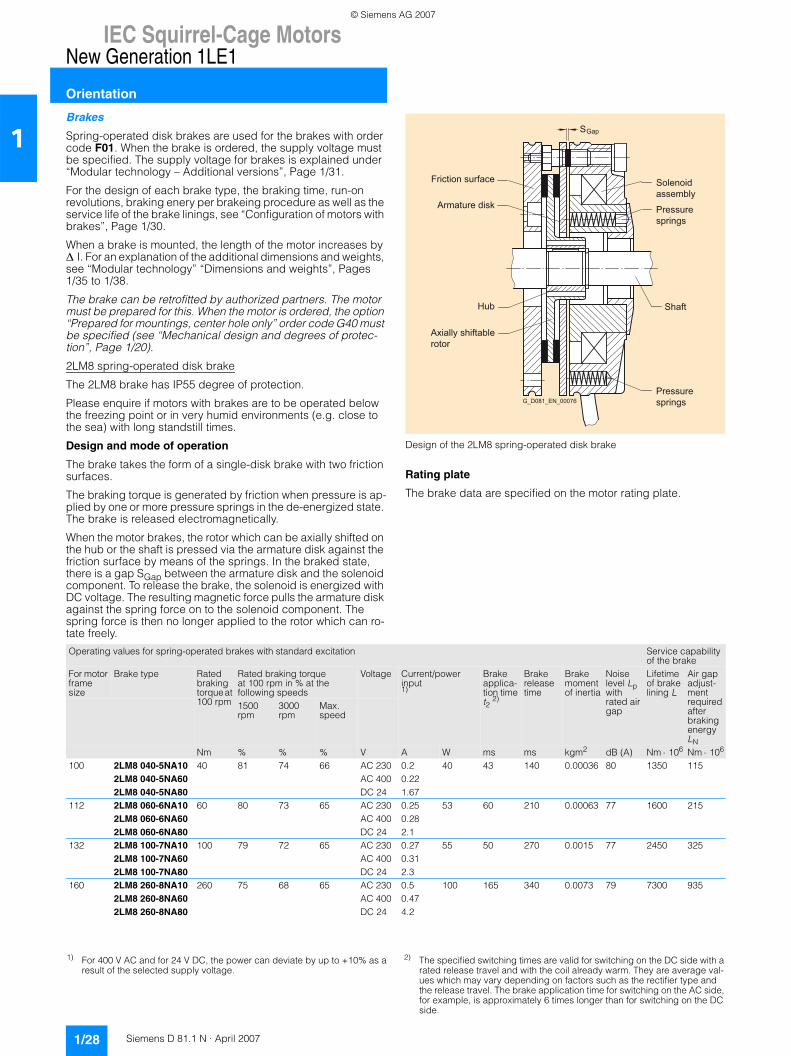
IEC Squirrel-Cage MotorsNew Generation 1LE1
Orientation
1/28 Siemens D 81.1 N · April 2007
1Brakes
Spring-operated disk brakes are used for the brakes with order code F01. When the brake is ordered, the supply voltage must be specified. The supply voltage for brakes is explained under “Modular technology – Additional versions”, Page 1/31.
For the design of each brake type, the braking time, run-on revolutions, braking enery per brakeing procedure as well as the service life of the brake linings, see “Configuration of motors with brakes”, Page 1/30.
When a brake is mounted, the length of the motor increases by ∆ I. For an explanation of the additional dimensions and weights, see “Modular technology” “Dimensions and weights”, Pages 1/35 to 1/38.
The brake can be retrofitted by authorized partners. The motor must be prepared for this. When the motor is ordered, the option “Prepared for mountings, center hole only” order code G40 must be specified (see “Mechanical design and degrees of protec-tion”, Page 1/20).
2LM8 spring-operated disk brake
The 2LM8 brake has IP55 degree of protection.
Please enquire if motors with brakes are to be operated below the freezing point or in very humid environments (e.g. close to the sea) with long standstill times.
Design and mode of operation
The brake takes the form of a single-disk brake with two friction surfaces.
The braking torque is generated by friction when pressure is ap-plied by one or more pressure springs in the de-energized state. The brake is released electromagnetically.
When the motor brakes, the rotor which can be axially shifted on the hub or the shaft is pressed via the armature disk against the friction surface by means of the springs. In the braked state, there is a gap SGap between the armature disk and the solenoid component. To release the brake, the solenoid is energized with DC voltage. The resulting magnetic force pulls the armature disk against the spring force on to the solenoid component. The spring force is then no longer applied to the rotor which can ro-tate freely.
Design of the 2LM8 spring-operated disk brake
Rating plate
The brake data are specified on the motor rating plate.
S
G_D081_EN_00076
Pressuresprings
Friction surface
Armature disk
Hub
Axially shiftable rotor
Pressuresprings
Shaft
Solenoidassembly
Gap
Operating values for spring-operated brakes with standard excitation Service capability of the brake
For motor frame size
Brake type Rated braking torque at 100 rpm
Rated braking torque at 100 rpm in % at the following speeds
Voltage Current/power input 1)
Brake applica-tion time t2 2)
Brake release time
Brake moment of inertia
Noise level Lp with rated air gap
Lifetime of brake lining L
Air gap adjust-ment required after braking energy LN
1500rpm
3000rpm
Max. speed
Nm % % % V A W ms ms kgm2 dB (A) Nm ⋅ 106 Nm ⋅ 106
100 2LM8 040-5NA10 40 81 74 66 AC 230 0.2 40 43 140 0.00036 80 1350 1152LM8 040-5NA60 AC 400 0.222LM8 040-5NA80 DC 24 1.67
112 2LM8 060-6NA10 60 80 73 65 AC 230 0.25 53 60 210 0.00063 77 1600 2152LM8 060-6NA60 AC 400 0.282LM8 060-6NA80 DC 24 2.1
132 2LM8 100-7NA10 100 79 72 65 AC 230 0.27 55 50 270 0.0015 77 2450 3252LM8 100-7NA60 AC 400 0.312LM8 100-7NA80 DC 24 2.3
160 2LM8 260-8NA10 260 75 68 65 AC 230 0.5 100 165 340 0.0073 79 7300 9352LM8 260-8NA60 AC 400 0.472LM8 260-8NA80 DC 24 4.2
1) For 400 V AC and for 24 V DC, the power can deviate by up to +10% as a result of the selected supply voltage.
2) The specified switching times are valid for switching on the DC side with a rated release travel and with the coil already warm. They are average val-ues which may vary depending on factors such as the rectifier type and the release travel. The brake application time for switching on the AC side, for example, is approximately 6 times longer than for switching on the DC side.
© Siemens AG 2007
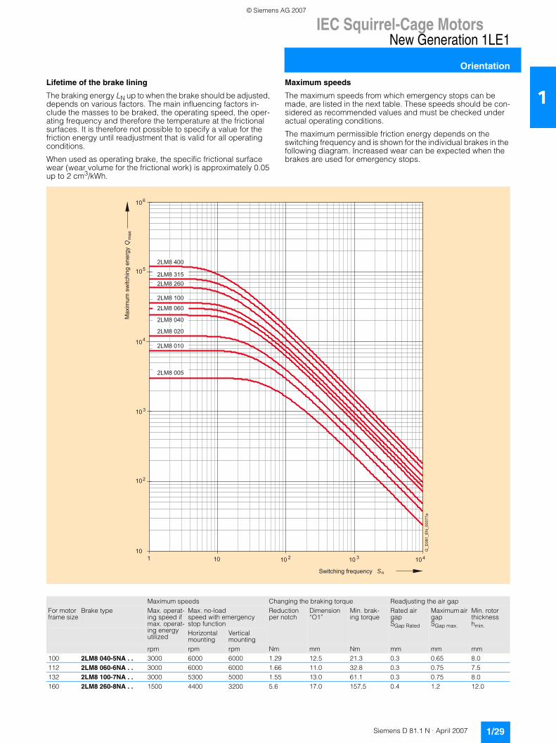
IEC Squirrel-Cage MotorsNew Generation 1LE1
Orientation
1/29Siemens D 81.1 N · April 2007
1Lifetime of the brake lining
The braking energy LN up to when the brake should be adjusted, depends on various factors. The main influencing factors in-clude the masses to be braked, the operating speed, the oper-ating frequency and therefore the temperature at the frictional surfaces. It is therefore not possible to specify a value for the friction energy until readjustment that is valid for all operating conditions.
When used as operating brake, the specific frictional surface wear (wear volume for the frictional work) is approximately 0.05 up to 2 cm3/kWh.
Maximum speeds
The maximum speeds from which emergency stops can be made, are listed in the next table. These speeds should be con-sidered as recommended values and must be checked under actual operating conditions.
The maximum permissible friction energy depends on the switching frequency and is shown for the individual brakes in the following diagram. Increased wear can be expected when the brakes are used for emergency stops.
Maximum speeds Changing the braking torque Readjusting the air gap For motor frame size
Brake type Max. operat-ing speed if max. operat-ing energy utilized
Max. no-load speed with emergency stop function
Reduction per notch
Dimension “O1”
Min. brak-ing torque
Rated air gap SGap Rated
Maximum air gapSGap max.
Min. rotor thickness hmin.
Horizontal mounting
Vertical mounting
rpm rpm rpm Nm mm Nm mm mm mm100 2LM8 040-5NA . . 3000 6000 6000 1.29 12.5 21.3 0.3 0.65 8.0112 2LM8 060-6NA . . 3000 6000 6000 1.66 11.0 32.8 0.3 0.75 7.5132 2LM8 100-7NA . . 3000 5300 5000 1.55 13.0 61.1 0.3 0.75 8.0160 2LM8 260-8NA . . 1500 4400 3200 5.6 17.0 157.5 0.4 1.2 12.0
10 2 10 1 10 3 10 4
10 4
10 5
10 6
10 2
10
10 3
2LM8 400
2LM8 315 2LM8 260
2LM8 100
2LM8 060
2LM8 040
2LM8 020
2LM8 010
2LM8 005
n S
G_D
081_
EN
_000
77a
Max
imum
sw
itchi
ng e
nerg
y m
axQ
Switching frequency
© Siemens AG 2007
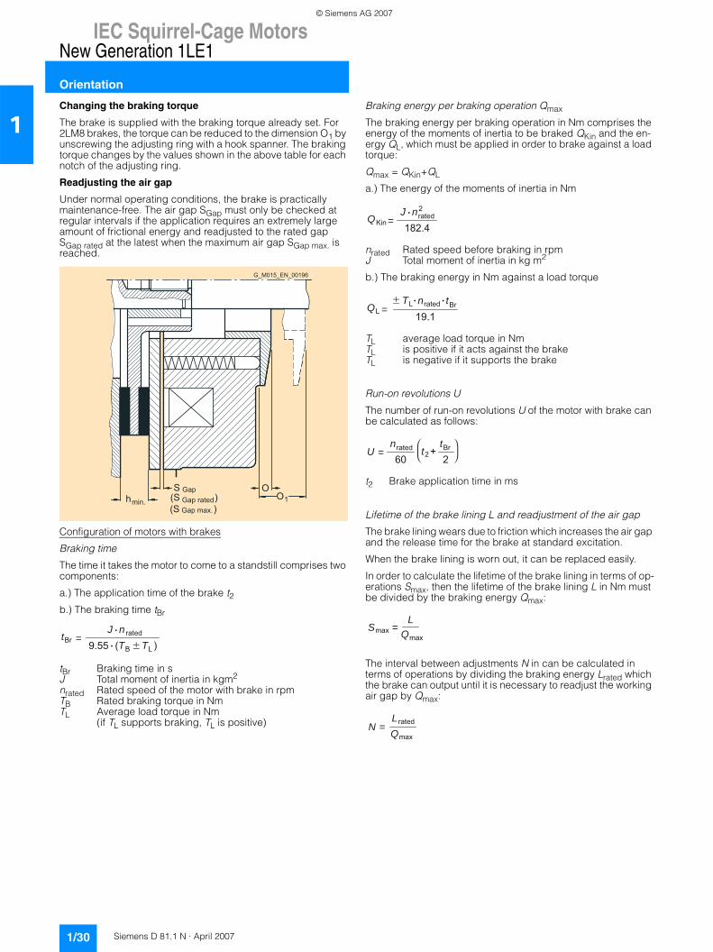
IEC Squirrel-Cage MotorsNew Generation 1LE1
Orientation
1/30 Siemens D 81.1 N · April 2007
1Changing the braking torque
The brake is supplied with the braking torque already set. For 2LM8 brakes, the torque can be reduced to the dimension O1 by unscrewing the adjusting ring with a hook spanner. The braking torque changes by the values shown in the above table for each notch of the adjusting ring.
Readjusting the air gap
Under normal operating conditions, the brake is practically maintenance-free. The air gap SGap must only be checked at regular intervals if the application requires an extremely large amount of frictional energy and readjusted to the rated gap SGap rated at the latest when the maximum air gap SGap max. is reached.
Configuration of motors with brakes
Braking time
The time it takes the motor to come to a standstill comprises two components:
a.) The application time of the brake t2b.) The braking time tBr
tBr Braking time in sJ Total moment of inertia in kgm2
nrated Rated speed of the motor with brake in rpmTB Rated braking torque in NmTL Average load torque in Nm
(if TL supports braking, TL is positive)
Braking energy per braking operation Qmax
The braking energy per braking operation in Nm comprises the energy of the moments of inertia to be braked QKin and the en-ergy QL, which must be applied in order to brake against a load torque:
Qmax = QKin+QL
a.) The energy of the moments of inertia in Nm
nrated Rated speed before braking in rpmJ Total moment of inertia in kg m2
b.) The braking energy in Nm against a load torque
TL average load torque in NmTL is positive if it acts against the brakeTL is negative if it supports the brake
Run-on revolutions U
The number of run-on revolutions U of the motor with brake can be calculated as follows:
t2 Brake application time in ms
Lifetime of the brake lining L and readjustment of the air gap
The brake lining wears due to friction which increases the air gap and the release time for the brake at standard excitation.
When the brake lining is worn out, it can be replaced easily.
In order to calculate the lifetime of the brake lining in terms of op-erations Smax, then the lifetime of the brake lining L in Nm must be divided by the braking energy Qmax:
The interval between adjustments N in can be calculated in terms of operations by dividing the braking energy Lrated which the brake can output until it is necessary to readjust the working air gap by Qmax:
(S ) h
S (S )
O O
G_M015_EN_00196
min.
Gap Gap rated Gap max.
1
t =BrJ
B(T LT )9.55n rated
Q =KinJ182.4
nrated2
Q =LT
19.1nratedL tBr
U = t +260 2nrated tBr
S = max L
Q max
N = Q max
L rated
© Siemens AG 2007
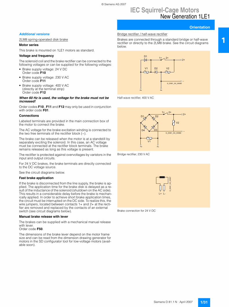
IEC Squirrel-Cage MotorsNew Generation 1LE1
Orientation
1/31Siemens D 81.1 N · April 2007
1Additional versions
2LM8 spring-operated disk brake
Motor series
This brake is mounted on 1LE1 motors as standard.
Voltage and frequency
The solenoid coil and the brake rectifier can be connected to the following voltages or can be supplied for the following voltages:• Brake supply voltage: 24 V DC
Order code F10• Brake supply voltage: 230 V AC
Order code F11• Brake supply voltage: 400 V AC
(directly at the terminal strip)Order code F12
When 60 Hz is used, the voltage for the brake must not be increased!
Order codes F10 , F11 and F12 may only be used in conjunction with order code F01.
Connections
Labeled terminals are provided in the main connection box of the motor to connect the brake.
The AC voltage for the brake excitation winding is connected to the two free terminals of the rectifier block (~).
The brake can be released when the motor is at a standstill by separately exciting the solenoid. In this case, an AC voltage must be connected at the rectifier block terminals. The brake remains released as long as this voltage is present.
The rectifier is protected against overvoltages by varistors in the input and output circuits.
For 24 V DC brakes, the brake terminals are directly connected to the DC voltage source.
See the circuit diagrams below.
Fast brake application
If the brake is disconnected from the line supply, the brake is ap-plied. The application time for the brake disk is delayed as a re-sult of the inductance of the solenoid (shutdown on the AC side). This results in a considerable delay before the brake is mechan-ically applied. In order to achieve short brake application times, the circuit must be interrupted on the DC side. To realize this, the wire jumpers, located between contacts 1+ and 2+ at the recti-fier are removed and replaced by the contacts of an external switch (see circuit diagrams below).
Manual brake release with lever
The brakes can be supplied with a mechanical manual release with lever. Order code F50.
The dimensions of the brake lever depend on the motor frame size and can be read from the dimension drawing generator for motors in the SD configurator tool for low-voltage motors (avail-able soon).
Bridge rectifier / half-wave rectifier
Brakes are connected through a standard bridge or half-wave rectifier or directly to the 2LM8 brake. See the circuit diagrams below.
Half-wave rectifier, 400 V AC
Bridge rectifier, 230 V AC
Brake connection for 24 V DC
G_D081_XX_00085
1+D12+
_
V1 D2 V2
2+
G_D081_XX_00086
1+ 2+2+
_
V1
V2
D1 D2
D3D4
L+ L-
G_D
081_
XX
_000
87
© Siemens AG 2007
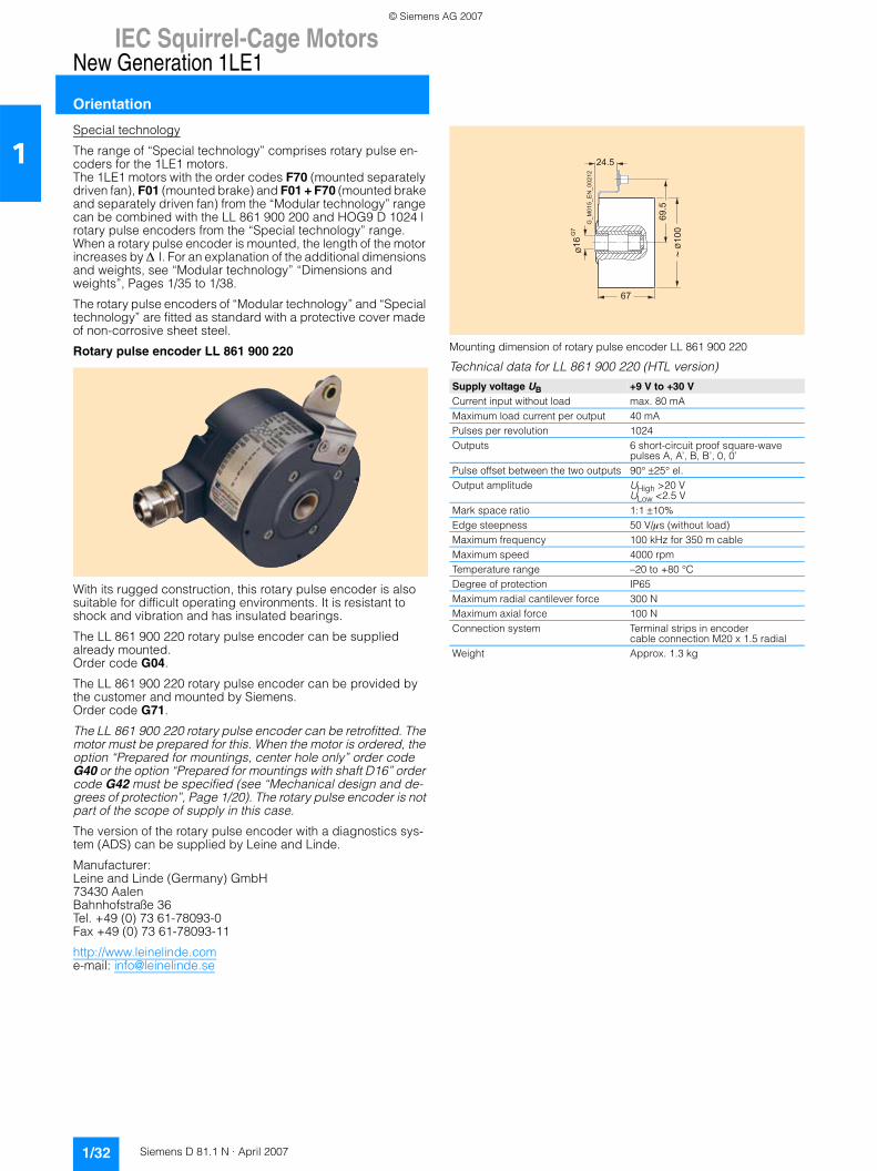
IEC Squirrel-Cage MotorsNew Generation 1LE1
Orientation
1/32 Siemens D 81.1 N · April 2007
1Special technology
The range of “Special technology” comprises rotary pulse en-coders for the 1LE1 motors.The 1LE1 motors with the order codes F70 (mounted separately driven fan), F01 (mounted brake) and F01 + F70 (mounted brake and separately driven fan) from the “Modular technology” range can be combined with the LL 861 900 200 and HOG9 D 1024 l rotary pulse encoders from the “Special technology” range.When a rotary pulse encoder is mounted, the length of the motor increases by ∆ I. For an explanation of the additional dimensions and weights, see “Modular technology” “Dimensions and weights”, Pages 1/35 to 1/38.
The rotary pulse encoders of “Modular technology” and “Special technology” are fitted as standard with a protective cover made of non-corrosive sheet steel.
Rotary pulse encoder LL 861 900 220
With its rugged construction, this rotary pulse encoder is also suitable for difficult operating environments. It is resistant to shock and vibration and has insulated bearings.
The LL 861 900 220 rotary pulse encoder can be supplied already mounted. Order code G04.
The LL 861 900 220 rotary pulse encoder can be provided by the customer and mounted by Siemens. Order code G71.
The LL 861 900 220 rotary pulse encoder can be retrofitted. The motor must be prepared for this. When the motor is ordered, the option “Prepared for mountings, center hole only” order code G40 or the option “Prepared for mountings with shaft D16” order code G42 must be specified (see “Mechanical design and de-grees of protection”, Page 1/20). The rotary pulse encoder is not part of the scope of supply in this case.
The version of the rotary pulse encoder with a diagnostics sys-tem (ADS) can be supplied by Leine and Linde.
Manufacturer:Leine and Linde (Germany) GmbH73430 AalenBahnhofstraße 36Tel. +49 (0) 73 61-78093-0Fax +49 (0) 73 61-78093-11
http://www.leinelinde.come-mail: [email protected]
Mounting dimension of rotary pulse encoder LL 861 900 220
Technical data for LL 861 900 220 (HTL version)
Supply voltage UB +9 V to +30 VCurrent input without load max. 80 mAMaximum load current per output 40 mAPulses per revolution 1024Outputs 6 short-circuit proof square-wave
pulses A, A’, B, B’, 0, 0’Pulse offset between the two outputs 90° ±25° el.Output amplitude UHigh >20 V
ULow <2.5 VMark space ratio 1:1 ±10%Edge steepness 50 V/μs (without load)Maximum frequency 100 kHz for 350 m cableMaximum speed 4000 rpmTemperature range –20 to +80 °CDegree of protection IP65Maximum radial cantilever force 300 NMaximum axial force 100 NConnection system Terminal strips in encoder
cable connection M20 x 1.5 radialWeight Approx. 1.3 kg
67
16
G7
100
69.5
24.5
G_M
015_
EN
_002
12
© Siemens AG 2007
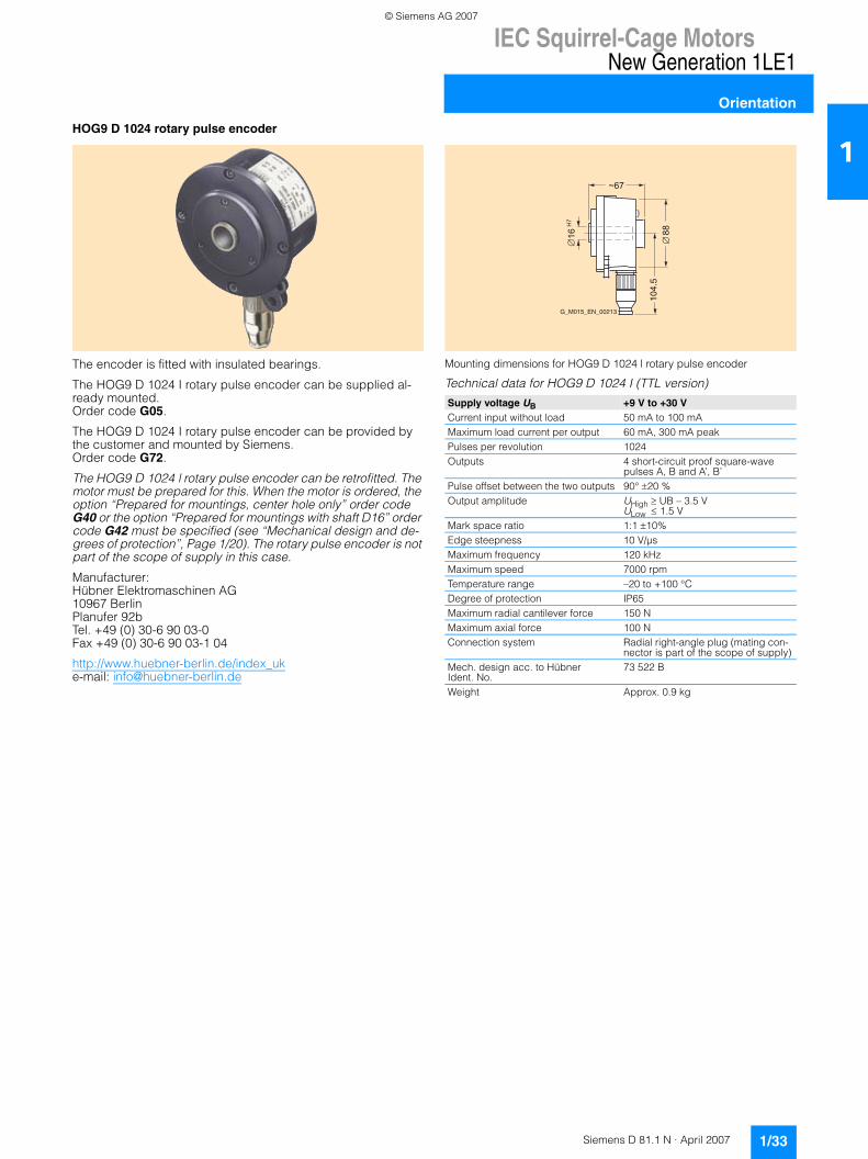
IEC Squirrel-Cage MotorsNew Generation 1LE1
Orientation
1/33Siemens D 81.1 N · April 2007
1HOG9 D 1024 rotary pulse encoder
The encoder is fitted with insulated bearings.
The HOG9 D 1024 I rotary pulse encoder can be supplied al-ready mounted.Order code G05.
The HOG9 D 1024 I rotary pulse encoder can be provided by the customer and mounted by Siemens.Order code G72.
The HOG9 D 1024 l rotary pulse encoder can be retrofitted. The motor must be prepared for this. When the motor is ordered, the option “Prepared for mountings, center hole only” order code G40 or the option “Prepared for mountings with shaft D16” order code G42 must be specified (see “Mechanical design and de-grees of protection”, Page 1/20). The rotary pulse encoder is not part of the scope of supply in this case.
Manufacturer:Hübner Elektromaschinen AG10967 BerlinPlanufer 92bTel. +49 (0) 30-6 90 03-0Fax +49 (0) 30-6 90 03-1 04
http://www.huebner-berlin.de/index_uke-mail: [email protected]
Mounting dimensions for HOG9 D 1024 l rotary pulse encoder
Technical data for HOG9 D 1024 I (TTL version)
Supply voltage UB +9 V to +30 VCurrent input without load 50 mA to 100 mAMaximum load current per output 60 mA, 300 mA peakPulses per revolution 1024Outputs 4 short-circuit proof square-wave
pulses A, B and A’, B’Pulse offset between the two outputs 90° ±20 %Output amplitude UHigh ≥ UB – 3.5 V
ULow ≤ 1.5 VMark space ratio 1:1 ±10%Edge steepness 10 V/µs Maximum frequency 120 kHzMaximum speed 7000 rpmTemperature range –20 to +100 °CDegree of protection IP65Maximum radial cantilever force 150 NMaximum axial force 100 NConnection system Radial right-angle plug (mating con-
nector is part of the scope of supply)Mech. design acc. to Hübner Ident. No.
73 522 B
Weight Approx. 0.9 kg
~67
88
16
H
7
104.
5
G_M015_EN_00213
© Siemens AG 2007
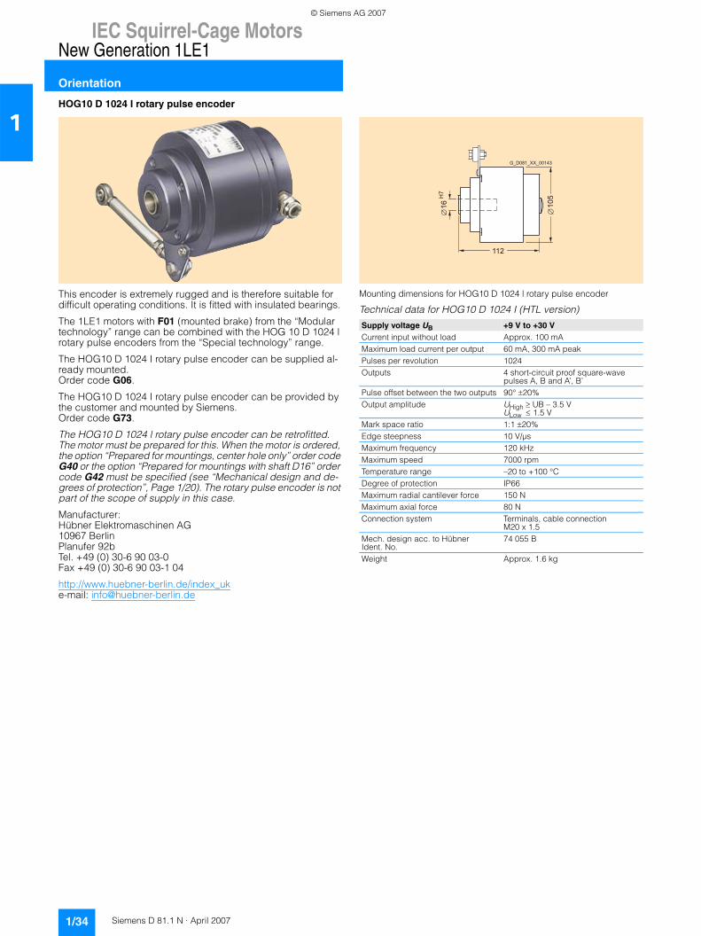
IEC Squirrel-Cage MotorsNew Generation 1LE1
Orientation
1/34 Siemens D 81.1 N · April 2007
1HOG10 D 1024 I rotary pulse encoder
This encoder is extremely rugged and is therefore suitable for difficult operating conditions. It is fitted with insulated bearings.
The 1LE1 motors with F01 (mounted brake) from the “Modular technology” range can be combined with the HOG 10 D 1024 l rotary pulse encoders from the “Special technology” range.
The HOG10 D 1024 I rotary pulse encoder can be supplied al-ready mounted.Order code G06.
The HOG10 D 1024 I rotary pulse encoder can be provided by the customer and mounted by Siemens.Order code G73.
The HOG10 D 1024 l rotary pulse encoder can be retrofitted. The motor must be prepared for this. When the motor is ordered, the option “Prepared for mountings, center hole only” order code G40 or the option “Prepared for mountings with shaft D16” order code G42 must be specified (see “Mechanical design and de-grees of protection”, Page 1/20). The rotary pulse encoder is not part of the scope of supply in this case.
Manufacturer:Hübner Elektromaschinen AG10967 BerlinPlanufer 92bTel. +49 (0) 30-6 90 03-0Fax +49 (0) 30-6 90 03-1 04
http://www.huebner-berlin.de/index_uke-mail: [email protected]
Mounting dimensions for HOG10 D 1024 l rotary pulse encoder
Technical data for HOG10 D 1024 I (HTL version)
Supply voltage UB +9 V to +30 VCurrent input without load Approx. 100 mAMaximum load current per output 60 mA, 300 mA peakPulses per revolution 1024Outputs 4 short-circuit proof square-wave
pulses A, B and A’, B’Pulse offset between the two outputs 90° ±20%Output amplitude UHigh ≥ UB – 3.5 V
ULow ≤ 1.5 VMark space ratio 1:1 ±20%Edge steepness 10 V/µsMaximum frequency 120 kHzMaximum speed 7000 rpmTemperature range –20 to +100 °CDegree of protection IP66Maximum radial cantilever force 150 NMaximum axial force 80 NConnection system Terminals, cable connection
M20 x 1.5Mech. design acc. to Hübner Ident. No.
74 055 B
Weight Approx. 1.6 kg
112
105
G_D081_XX_00143
16 H
7
© Siemens AG 2007
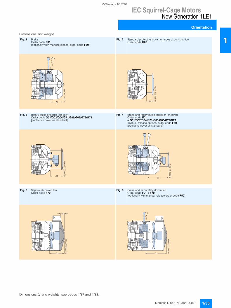
IEC Squirrel-Cage MotorsNew Generation 1LE1
Orientation
1/35Siemens D 81.1 N · April 2007
1Dimensions and weight
Fig. 1 BrakeOrder code F01[optionally with manual release, order code F50]
Fig. 2 Standard protective cover for types of constructionOrder code H00
Fig. 3 Rotary pulse encoder (on cowl)Order code G01/G02/G04/G71/G05/G06/G72/G73[protective cover as standard]
Fig. 4 Brake and rotary pulse encoder (on cowl)Order code F01+ G01/G02/G04/G71/G05/G06/G72/G73 [manual release optional order code F50; protective cover as standard]
Fig. 5 Separately driven fanOrder code F70
Fig. 6 Brake and separately driven fanOrder code F01 + F70[optionally with manual release order code F50]
G_D
081_
XX
_001
67
l G_D
081_
XX
_001
72a
l
G_D
081_
XX
_001
68a
ll G
_D08
1_X
X_0
0186
G_D
081_
XX
_000
92
l
M
G_D
081_
XX
_000
94
l
Dimensions �l and weights, see pages 1/37 and 1/38.
© Siemens AG 2007
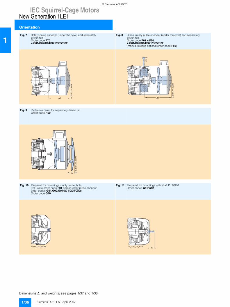
IEC Squirrel-Cage MotorsNew Generation 1LE1
Orientation
1/36 Siemens D 81.1 N · April 2007
1Fig. 7 Rotary pulse encoder (under the cowl) and separately
driven fan Order code F70+ G01/G02/G04/G71/G05/G72
Fig. 8 Brake, rotary pulse encoder (under the cowl) and separately driven fan Order code F01 + F70+ G01/G02/G04/G71/G05/G72[manual release optional order code F50]
Fig. 9 Protective cover for separately driven fan Order code H00
Fig. 10 Prepared for mountings – only center hole (for Brake order code F01 and/or rotary pulse encoder order codes G01/G02/G04/G71/G05/G72) Order code G40
Fig. 11 Prepared for mountings with shaft D12/D16 Order codes G41/G42
G_D
081_
XX
_000
96
l G_D
081_
XX
_000
98
l
l
G_D
081_
XX
_001
79
G_D081_XX_00187 G_D081_XX_00188l
Dimensions �l and weights, see pages 1/37 and 1/38.
© Siemens AG 2007
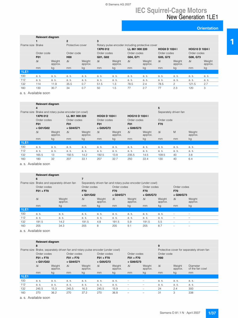
IEC Squirrel-Cage MotorsNew Generation 1LE1
Orientation
1/37Siemens D 81.1 N · April 2007
1
a. s. Available soon
a. s. Available soon
a. s. Available soon
a. s. Available soon
Relevant diagram1 2 3
Frame size Brake Protective cover Rotary pulse encoder including protective cover1XP8 012 LL 861 900 220 HOG9 D 1024 I HOG10 D 1024 I
Order code Order code Order codes Order codes Order codes Order codesF01 H00 G01, G02 G04, G71 G05, G72 G06, G73∆l Weight
approx.∆l Weight
approx.∆l Weight
approx.∆l Weight
approx.∆l Weight
approx.∆l Weight
approx.mm kg mm kg mm kg mm kg mm kg mm kg
1LE1100 a. s. a. s. a. s. a. s. a. s. a. s. a. s. a. s. a. s. a. s. a. s. a. s.112 a. s. a. s. a. s. a. s. a. s. a. s. a. s. a. s. a. s. a. s. a. s. a. s.132 114 11.9 35.5 0.7 51.5 1.3 78.5 2.4 78.5 2 121.5 2.7160 130 30.7 34 0.7 50 1.5 77 2.7 77 2.3 120 3
Relevant diagram4 5
Frame size Brake and rotary pulse encoder (on cowl) Separately driven fan1XP8 012 LL 861 900 220 HOG9 D 1024 I HOG10 D 1024 IOrder codes Order codes Order codes Order codes Order codeF01 F01 F01 F01 F70+ G01/G02 + G04/G71 + G05/G72 + G06/G73∆l Weight
approx.∆l Weight
approx.∆l Weight
approx.∆l Weight
approx.∆l M Weight
approx.mm kg mm kg mm kg mm kg mm mm kg
1LE1100 a. s. a. s. a. s. a. s. a. s. a. s. a. s. a. s. a. s. a. s. a. s.112 a. s. a. s. a. s. a. s. a. s. a. s. a. s. a. s. a. s. a. s. a. s.132 165.5 13 192.5 14.2 192.5 13.8 235.5 14.5 109.5 40 3.8160 180 32 207 33.1 207 32.7 250 33.4 130 40 6.4
Relevant diagram6 7
Frame size Brake and separately driven fan Separately driven fan and rotary pulse encoder (under cowl)Order codes Order codes Order codes Order codes Order codesF01 + F70 F70 F70 F70 F70
+ G01/G02 + G04/G71 + G05/G72 + G06/G73∆l Weight
approx.∆l Weight
approx.∆l Weight
approx.∆l Weight
approx.∆l Weight
approx.mm kg mm kg mm kg mm kg mm kg
1LE1100 a. s. a. s. a. s. a. s. a. s. a. s. a. s. a. s. – –112 a. s. a. s. a. s. a. s. a. s. a. s. a. s. a. s. – –132 191.5 14.2 191.5 4.8 191.5 5.9 191.5 5.5 – –160 205 34.3 205 8 205 9.1 205 8.7 – –
Relevant diagram8 9
Frame size Brake, separately driven fan and rotary pulse encoder (under cowl) Protective cover for separately driven fanOrder codes Order codes Order codes Order codes Order codeF01 + F70 F01 + F70 F01 + F70 F01 + F70 H00+ G01/G02 + G04/G71 + G05/G72 + G06/G73∆l Weight
approx.∆l Weight
approx.∆l Weight
approx.∆l Weight
approx.∆l Weight
approx.Diameter of the fan cowl
mm kg mm kg mm kg mm kg mm kg mm1LE1100 a. s. a. s. a. s. a. s. a. s. a. s. – – a. s. a. s. a. s.112 a. s. a. s. a. s. a. s. a. s. a. s. – – a. s. a. s. a. s.132 245.5 15.3 245.5 16.3 245.5 15.9 – – 24 2.4 300160 270 36.2 270 37.2 270 36.8 – – 31 3 338
© Siemens AG 2007
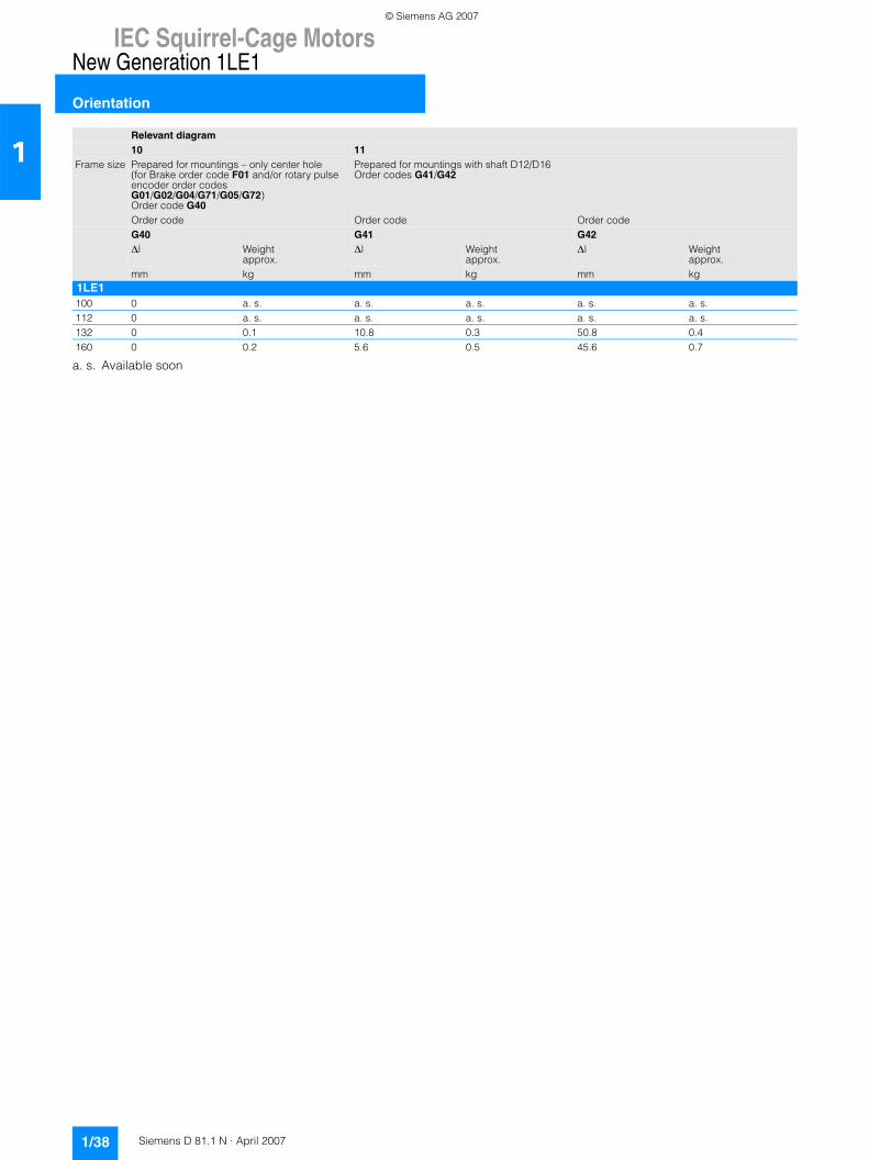
IEC Squirrel-Cage MotorsNew Generation 1LE1
Orientation
1/38 Siemens D 81.1 N · April 2007
1
a. s. Available soon
Relevant diagram10 11
Frame size Prepared for mountings – only center hole (for Brake order code F01 and/or rotary pulse encoder order codes G01/G02/G04/G71/G05/G72) Order code G40
Prepared for mountings with shaft D12/D16 Order codes G41/G42
Order code Order code Order codeG40 G41 G42∆l Weight
approx.∆l Weight
approx.∆l Weight
approx.mm kg mm kg mm kg
1LE1100 0 a. s. a. s. a. s. a. s. a. s.112 0 a. s. a. s. a. s. a. s. a. s.132 0 0.1 10.8 0.3 50.8 0.4160 0 0.2 5.6 0.5 45.6 0.7
© Siemens AG 2007
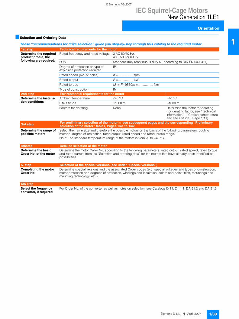
IEC Squirrel-Cage MotorsNew Generation 1LE1
Orientation
1/39Siemens D 81.1 N · April 2007
1■ Selection and Ordering Data
These “recommendations for drive selection” guide you step-by-step through this catalog to the required motor.
1st step Technical requirements for the motorDetermine the required product profile, the following are required:
Rated frequency and rated voltage 3 AC 50/60 Hz,400, 500 or 690 V
Duty Standard duty (continuous duty S1 according to DIN EN 60034-1)
Degree of protection or type of explosion protection required
IP..
Rated speed (No. of poles) n =................. rpm
Rated output P =................. kW
Rated torque M = P ⋅ 9550/n =................. Nm
Type of construction IM..2nd step Environmental requirements for the motorDetermine the installa-tion conditions
Ambient temperature ≤40 °C >40 °C
Site altitude ≤1000 m >1000 m
Factors for derating None Determine the factor for derating (for derating factor, see “Technical information” – “Coolant temperature and site altitude”, Page 1/11)
3rd step For preliminary selection of the motor ⇒ see subsequent pages and the corresponding “Preliminary selection of the motor” tables, Pages 1/41 to 1/42
Determine the range of possible motors
Select the frame size and therefore the possible motors on the basis of the following parameters: cooling method, degree of protection, rated output, rated speed and rated torque range. Note: The standard temperature range of the motors is from 20 to +40 °C.
4thstep Detailed selection of the motorDetermine the basic Order No. of the motor
Determine the motor Order No. according to the following parameters: rated output, rated speed, rated torque and rated current from the “Selection and ordering data” for the motors that have already been identified as possibilities.
5. step Selection of the special versions (see under “Special versions”)Completing the motor Order No.
Determine special versions and the associated Order codes (e.g. special voltages and types of construction, motor protection and degrees of protection, windings and insulation, colors and paint finish, mountings and mounting technology, etc.).
6th stepSelect the frequency converter, if required
For Order No. of the converter as well as notes on selection, see Catalogs D 11, D 11.1, DA 51.2 and DA 51.3.
© Siemens AG 2007
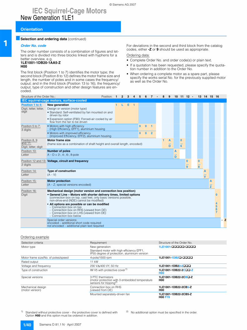
IEC Squirrel-Cage MotorsNew Generation 1LE1
Orientation
1/40 Siemens D 81.1 N · April 2007
1■ Selection and ordering data (continued)
Order No. code
The order number consists of a combination of figures and let-ters and is divided into three blocks linked with hyphens for a better overview, e.g. 1LE1001-1DB20-1AA5-ZH00
The first block (Position 1 to 7) identifies the motor type; the second block (Position 8 to 12) defines the motor frame size and length, the number of poles and in some cases the frequency/output; and in the third block (Position 13 to 16), the frequency/output, type of construction and other design features are en-coded.
For deviations in the second and third block from the catalog codes, either -Z or 9 should be used as appropriate.
Ordering data:• Complete Order No. and order code(s) or plain text.• If a quotation has been requested, please specify the quota-
tion number in addition to the Order No.• When ordering a complete motor as a spare part, please
specify the works serial No. for the previously supplied motor as well as the Order No.
Ordering example
Structure of the Order No.: Position: 1 2 3 4 5 6 7 - 8 9 10 11 12 - 13 14 15 16IEC squirrel-cage motors, surface-cooled Position 1 to 4:Digit, letter, letter, digit
New generationDesign or version (motor type)• Standard: Self-ventilated by fan mounted on and
driven by rotor• Expansion option (F90): Forced-air cooled by air
flow from the fan to be driven
1 L E 1
Position 5 to 7:3 digits
• Motors with high efficiency(High Efficiency, EFF1), aluminium housing
0 0 1
• Motors with improved efficiency(Improved Efficiency, EFF2), aluminium housing
0 0 2
Position 8, 9 and 11:Digit, letter, digit
Motor frame size (frame size as a combination of shaft height and overall length, encoded)
1 A...D
0...6
Position 10:Letter
Number of polesA – D = 2-, 4-, 6-, 8-pole
A...D
Position 12 and 13:2 digits
Voltage, circuit and frequency 0...9
0...8
Position 14:Letter
Type of construction(A – V)
A...V
Position 15:Letter
Motor protection(A – Z; special versions encoded)
A...Z
Position 16:Digit
Mechanical design (motor version and connection box position)• General Line – Motors with shorter delivery times, limited options
(connection box on top, cast feet, only basic versions possible, non-drive-end (NDE) cannot be modified)
• All options are possible or can be modified - Connection box on top- Connection box on RHS (viewed from DE)- Connection box on LHS (viewed from DE)- Connection box below
0
4567
Special order versions:encoded – additional short code requirednot encoded – additional plain text required
- Z
Selection criteria Requirement Structure of the Order No.Motor type New generation
Standard motor with high efficiency EFF1, IP55 degree of protection, aluminium version
1LE1001- -
Motor frame size/No. of poles/speed 4-pole/1500 rpm 1LE1001-1DB2 -Rated output 11 kWVoltage and frequency 230 V∆/400 VY, 50 Hz 1LE1001-1DB22-2Type of construction IM V5 with protective cover1) 1LE1001-1DB22-2C -Z
H00Special versions 3 PTC thermistors
(motor protection with 3 embedded temperature sensors for tripping2)
1LE1001-1DB22-2CB -ZH00
Mechanical design(motor version)
Connection box on RHS(viewed from DE)
1LE1001-1DB22-2CB5-ZH00
Mounted separately-driven fan 1LE1001-1DB22-2CB5-ZH00 F70
1) Standard without protective cover – the protective cover is defined with Option H00 and this option must be ordered in addition.
2) No additional option must be specified in the order.
© Siemens AG 2007
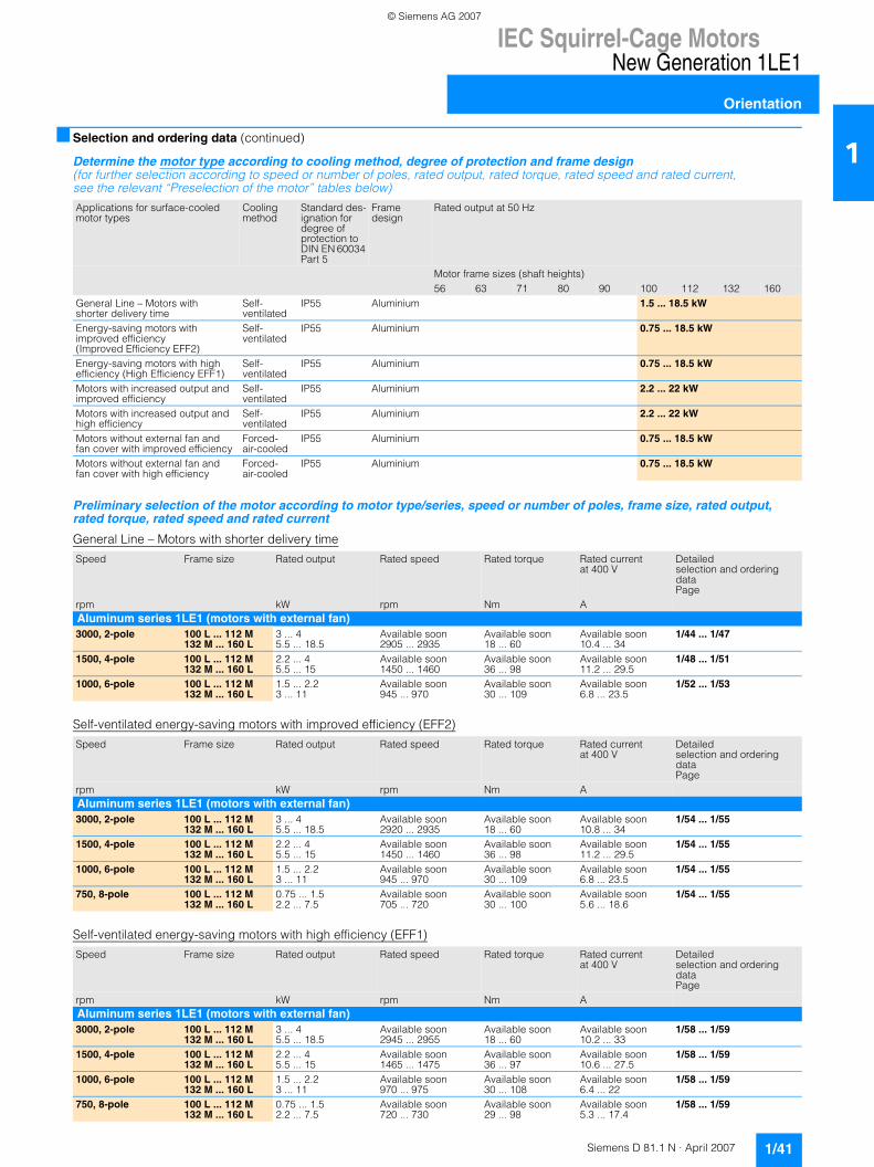
IEC Squirrel-Cage MotorsNew Generation 1LE1
Orientation
1/41Siemens D 81.1 N · April 2007
1■ Selection and ordering data (continued)
Determine the motor type according to cooling method, degree of protection and frame design (for further selection according to speed or number of poles, rated output, rated torque, rated speed and rated current, see the relevant “Preselection of the motor” tables below)
Preliminary selection of the motor according to motor type/series, speed or number of poles, frame size, rated output, rated torque, rated speed and rated current
General Line – Motors with shorter delivery time
Self-ventilated energy-saving motors with improved efficiency (EFF2)
Self-ventilated energy-saving motors with high efficiency (EFF1)
Applications for surface-cooled motor types
Cooling method
Standard des-ignation for degree of protection to DIN EN 60034 Part 5
Frame design
Rated output at 50 Hz
Motor frame sizes (shaft heights)56 63 71 80 90 100 112 132 160
General Line – Motors with shorter delivery time
Self-ventilated
IP55 Aluminium 1.5 ... 18.5 kW
Energy-saving motors with improved efficiency (Improved Efficiency EFF2)
Self-ventilated
IP55 Aluminium 0.75 ... 18.5 kW
Energy-saving motors with high efficiency (High Efficiency EFF1)
Self-ventilated
IP55 Aluminium 0.75 ... 18.5 kW
Motors with increased output and improved efficiency
Self-ventilated
IP55 Aluminium 2.2 ... 22 kW
Motors with increased output and high efficiency
Self-ventilated
IP55 Aluminium 2.2 ... 22 kW
Motors without external fan and fan cover with improved efficiency
Forced-air-cooled
IP55 Aluminium 0.75 ... 18.5 kW
Motors without external fan and fan cover with high efficiency
Forced-air-cooled
IP55 Aluminium 0.75 ... 18.5 kW
Speed Frame size Rated output Rated speed Rated torque Rated current at 400 V
Detailed selection and ordering data Page
rpm kW rpm Nm AAluminum series 1LE1 (motors with external fan)3000, 2-pole 100 L ... 112 M
132 M ... 160 L3 ... 45.5 ... 18.5
Available soon2905 ... 2935
Available soon18 ... 60
Available soon10.4 ... 34
1/44 ... 1/47
1500, 4-pole 100 L ... 112 M132 M ... 160 L
2.2 ... 45.5 ... 15
Available soon1450 ... 1460
Available soon36 ... 98
Available soon11.2 ... 29.5
1/48 ... 1/51
1000, 6-pole 100 L ... 112 M132 M ... 160 L
1.5 ... 2.23 ... 11
Available soon945 ... 970
Available soon30 ... 109
Available soon6.8 ... 23.5
1/52 ... 1/53
Speed Frame size Rated output Rated speed Rated torque Rated current at 400 V
Detailed selection and ordering data Page
rpm kW rpm Nm AAluminum series 1LE1 (motors with external fan)3000, 2-pole 100 L ... 112 M
132 M ... 160 L3 ... 45.5 ... 18.5
Available soon2920 ... 2935
Available soon18 ... 60
Available soon10.8 ... 34
1/54 ... 1/55
1500, 4-pole 100 L ... 112 M132 M ... 160 L
2.2 ... 45.5 ... 15
Available soon1450 ... 1460
Available soon36 ... 98
Available soon11.2 ... 29.5
1/54 ... 1/55
1000, 6-pole 100 L ... 112 M132 M ... 160 L
1.5 ... 2.23 ... 11
Available soon945 ... 970
Available soon30 ... 109
Available soon6.8 ... 23.5
1/54 ... 1/55
750, 8-pole 100 L ... 112 M132 M ... 160 L
0.75 ... 1.52.2 ... 7.5
Available soon705 ... 720
Available soon30 ... 100
Available soon5.6 ... 18.6
1/54 ... 1/55
Speed Frame size Rated output Rated speed Rated torque Rated current at 400 V
Detailed selection and ordering data Page
rpm kW rpm Nm AAluminum series 1LE1 (motors with external fan)3000, 2-pole 100 L ... 112 M
132 M ... 160 L3 ... 45.5 ... 18.5
Available soon2945 ... 2955
Available soon18 ... 60
Available soon10.2 ... 33
1/58 ... 1/59
1500, 4-pole 100 L ... 112 M132 M ... 160 L
2.2 ... 45.5 ... 15
Available soon1465 ... 1475
Available soon36 ... 97
Available soon10.6 ... 27.5
1/58 ... 1/59
1000, 6-pole 100 L ... 112 M132 M ... 160 L
1.5 ... 2.23 ... 11
Available soon970 ... 975
Available soon30 ... 108
Available soon6.4 ... 22
1/58 ... 1/59
750, 8-pole 100 L ... 112 M132 M ... 160 L
0.75 ... 1.52.2 ... 7.5
Available soon720 ... 730
Available soon29 ... 98
Available soon5.3 ... 17.4
1/58 ... 1/59
© Siemens AG 2007
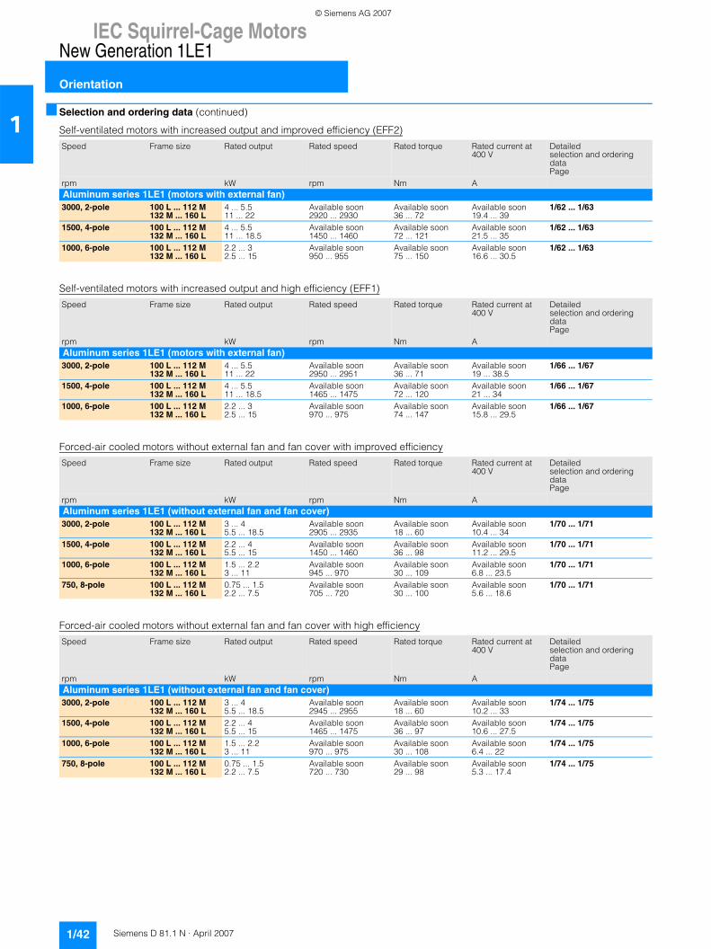
IEC Squirrel-Cage MotorsNew Generation 1LE1
Orientation
1/42 Siemens D 81.1 N · April 2007
1■ Selection and ordering data (continued)
Self-ventilated motors with increased output and improved efficiency (EFF2)
Self-ventilated motors with increased output and high efficiency (EFF1)
Forced-air cooled motors without external fan and fan cover with improved efficiency
Forced-air cooled motors without external fan and fan cover with high efficiency
Speed Frame size Rated output Rated speed Rated torque Rated current at 400 V
Detailed selection and ordering data Page
rpm kW rpm Nm AAluminum series 1LE1 (motors with external fan)3000, 2-pole 100 L ... 112 M
132 M ... 160 L4 ... 5.511 ... 22
Available soon2920 ... 2930
Available soon36 ... 72
Available soon19.4 ... 39
1/62 ... 1/63
1500, 4-pole 100 L ... 112 M132 M ... 160 L
4 ... 5.511 ... 18.5
Available soon1450 ... 1460
Available soon72 ... 121
Available soon21.5 ... 35
1/62 ... 1/63
1000, 6-pole 100 L ... 112 M132 M ... 160 L
2.2 ... 32.5 ... 15
Available soon950 ... 955
Available soon75 ... 150
Available soon16.6 ... 30.5
1/62 ... 1/63
Speed Frame size Rated output Rated speed Rated torque Rated current at 400 V
Detailed selection and ordering data Page
rpm kW rpm Nm AAluminum series 1LE1 (motors with external fan)3000, 2-pole 100 L ... 112 M
132 M ... 160 L4 ... 5.511 ... 22
Available soon2950 ... 2951
Available soon36 ... 71
Available soon19 ... 38.5
1/66 ... 1/67
1500, 4-pole 100 L ... 112 M132 M ... 160 L
4 ... 5.511 ... 18.5
Available soon1465 ... 1475
Available soon72 ... 120
Available soon21 ... 34
1/66 ... 1/67
1000, 6-pole 100 L ... 112 M132 M ... 160 L
2.2 ... 32.5 ... 15
Available soon970 ... 975
Available soon74 ... 147
Available soon15.8 ... 29.5
1/66 ... 1/67
Speed Frame size Rated output Rated speed Rated torque Rated current at 400 V
Detailed selection and ordering data Page
rpm kW rpm Nm AAluminum series 1LE1 (without external fan and fan cover)3000, 2-pole 100 L ... 112 M
132 M ... 160 L3 ... 45.5 ... 18.5
Available soon2905 ... 2935
Available soon18 ... 60
Available soon10.4 ... 34
1/70 ... 1/71
1500, 4-pole 100 L ... 112 M132 M ... 160 L
2.2 ... 45.5 ... 15
Available soon1450 ... 1460
Available soon36 ... 98
Available soon11.2 ... 29.5
1/70 ... 1/71
1000, 6-pole 100 L ... 112 M132 M ... 160 L
1.5 ... 2.23 ... 11
Available soon945 ... 970
Available soon30 ... 109
Available soon6.8 ... 23.5
1/70 ... 1/71
750, 8-pole 100 L ... 112 M132 M ... 160 L
0.75 ... 1.52.2 ... 7.5
Available soon705 ... 720
Available soon30 ... 100
Available soon5.6 ... 18.6
1/70 ... 1/71
Speed Frame size Rated output Rated speed Rated torque Rated current at 400 V
Detailed selection and ordering data Page
rpm kW rpm Nm AAluminum series 1LE1 (without external fan and fan cover)3000, 2-pole 100 L ... 112 M
132 M ... 160 L3 ... 45.5 ... 18.5
Available soon2945 ... 2955
Available soon18 ... 60
Available soon10.2 ... 33
1/74 ... 1/75
1500, 4-pole 100 L ... 112 M132 M ... 160 L
2.2 ... 45.5 ... 15
Available soon1465 ... 1475
Available soon36 ... 97
Available soon10.6 ... 27.5
1/74 ... 1/75
1000, 6-pole 100 L ... 112 M132 M ... 160 L
1.5 ... 2.23 ... 11
Available soon970 ... 975
Available soon30 ... 108
Available soon6.4 ... 22
1/74 ... 1/75
750, 8-pole 100 L ... 112 M132 M ... 160 L
0.75 ... 1.52.2 ... 7.5
Available soon720 ... 730
Available soon29 ... 98
Available soon5.3 ... 17.4
1/74 ... 1/75
© Siemens AG 2007
IEC Squirrel-Cage MotorsNew Generation 1LE1
Orientation
1/43Siemens D 81.1 N · April 2007
1■ More information
For further information, please get in touch with your local Siemens contact.
At http://www.siemens.com/automation/partneryou can find details of Siemens contact partners worldwide re-sponsible for particular technologies.
You can obtain in most cases a contact partner for• technical support• spare parts/repairs• service• training• sales or• technical support/engineering
The selection procedure starts with:• a country• a product or• a sector.
By further specifying the remaining criteria you will find exactly the right contact partner with his/her respective expertise.
© Siemens AG 2007
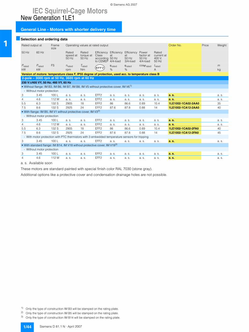
IEC Squirrel-Cage MotorsNew Generation 1LE1
General Line - Motors with shorter delivery time
1/44 Siemens D 81.1 N · April 2007
1■ Selection and ordering data
a. s. Available soon
These motors are standard painted with special finish color RAL 7030 (stone gray).
Additional options like a protective cover and condensation drainage holes are not possible.
Rated output at Frame size
Operating values at rated output Order No. Price Weight
50 Hz 60 Hz Ratedspeed at 50 Hz
Ratedtorque at 50 Hz
Efficiency Classaccordingto CEMEP
Efficiencyat50 Hz4/4-load
Efficiencyat50 Hz3/4-load
Powerfactor at50 Hz4/4-load
Ratedcurrent at400 V,50 Hz
Prated Prated FS nrated Trated ηrated ηrated cosϕrated Irated mkW kW rpm Nm % % A kg
Version of motors: temperature class F, IP55 degree of protection, used acc. to temperature class B2-pole – 3000 rpm at 50 Hz, 3600 rpm at 60 Hz230 V∆/400 VY, 50 Hz; 460 VY, 60 Hz• Without flange: IM B3, IM B6, IM B7, IM B8, IM V5 without protective cover, IM V61)
- Without motor protection3 3.45 100 L a. s. a. s. EFF2 a. s. a. s. a. s. a. s. a. s. a. s.4 4.6 112 M a. s. a. s. EFF2 a. s. a. s. a. s. a. s. a. s. a. s.5.5 6.3 132 S 2905 18 EFF2 86 86.6 0.89 10.4 1LE1002-1CA02-2AA0 357.5 8.6 132 S 2925 24 EFF2 87.6 87.8 0.88 14 1LE1002-1CA12-2AA0 40• With flange: IM B5, IM V1 without protective cover, IM V32)
- Without motor protection3 3.45 100 L a. s. a. s. EFF2 a. s. a. s. a. s. a. s. a. s. a. s.4 4.6 112 M a. s. a. s. EFF2 a. s. a. s. a. s. a. s. a. s. a. s.5.5 6.3 132 S 2905 18 EFF2 86 86.6 0.89 10.4 1LE1002-1CA02-2FA0 407.5 8.6 132 S 2925 24 EFF2 87.6 87.8 0.88 14 1LE1002-1CA12-2FA0 45
- With motor protection with PTC thermistors with 3 embedded temperature sensors for tripping3 3.45 100 L a. s. a. s. EFF2 a. s. a. s. a. s. a. s. a. s. a. s.• With standard flange: IM B14, IM V18 without protective cover, IM V193)
- Without motor protection3 3.45 100 L a. s. a. s. EFF2 a. s. a. s. a. s. a. s. a. s. a. s.4 4.6 112 M a. s. a. s. EFF2 a. s. a. s. a. s. a. s. a. s. a. s.
1) Only the type of construction IM B3 will be stamped on the rating plate.2) Only the type of construction IM B5 will be stamped on the rating plate.3) Only the type of construction IM B14 will be stamped on the rating plate.
© Siemens AG 2007
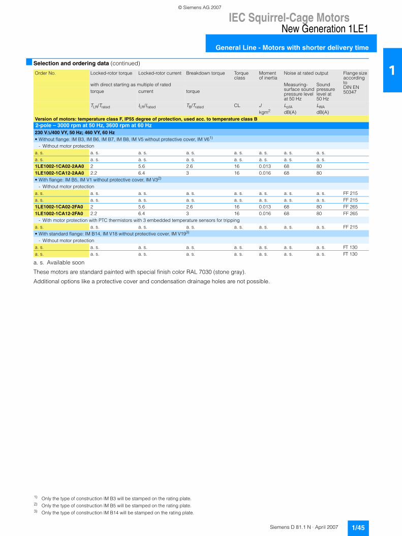
IEC Squirrel-Cage MotorsNew Generation 1LE1
General Line - Motors with shorter delivery time
1/45Siemens D 81.1 N · April 2007
1■ Selection and ordering data (continued)
a. s. Available soon
These motors are standard painted with special finish color RAL 7030 (stone gray).
Additional options like a protective cover and condensation drainage holes are not possible.
Order No. Locked-rotor torque Locked-rotor current Breakdown torque Torque class
Moment of inertia
Noise at rated output Flange size according toDIN EN 50347
with direct starting as multiple of rated Measuring-surface soundpressure levelat 50 Hz
Sound pressurelevel at 50 Hz
torque current torque
TLR/Trated ILR/Irated TB/Trated CL J LpfA LWAkgm2 dB(A) dB(A)
Version of motors: temperature class F, IP55 degree of protection, used acc. to temperature class B2-pole – 3000 rpm at 50 Hz, 3600 rpm at 60 Hz230 V∆/400 VY, 50 Hz; 460 VY, 60 Hz• Without flange: IM B3, IM B6, IM B7, IM B8, IM V5 without protective cover, IM V61)
- Without motor protectiona. s. a. s. a. s. a. s. a. s. a. s. a. s. a. s.a. s. a. s. a. s. a. s. a. s. a. s. a. s. a. s.1LE1002-1CA02-2AA0 2 5.6 2.6 16 0.013 68 801LE1002-1CA12-2AA0 2.2 6.4 3 16 0.016 68 80• With flange: IM B5, IM V1 without protective cover, IM V32)
- Without motor protectiona. s. a. s. a. s. a. s. a. s. a. s. a. s. a. s. FF 215a. s. a. s. a. s. a. s. a. s. a. s. a. s. a. s. FF 2151LE1002-1CA02-2FA0 2 5.6 2.6 16 0.013 68 80 FF 2651LE1002-1CA12-2FA0 2.2 6.4 3 16 0.016 68 80 FF 265
- With motor protection with PTC thermistors with 3 embedded temperature sensors for trippinga. s. a. s. a. s. a. s. a. s. a. s. a. s. a. s. FF 215• With standard flange: IM B14, IM V18 without protective cover, IM V193)
- Without motor protectiona. s. a. s. a. s. a. s. a. s. a. s. a. s. a. s. FT 130a. s. a. s. a. s. a. s. a. s. a. s. a. s. a. s. FT 130
1) Only the type of construction IM B3 will be stamped on the rating plate.2) Only the type of construction IM B5 will be stamped on the rating plate.3) Only the type of construction IM B14 will be stamped on the rating plate.
© Siemens AG 2007
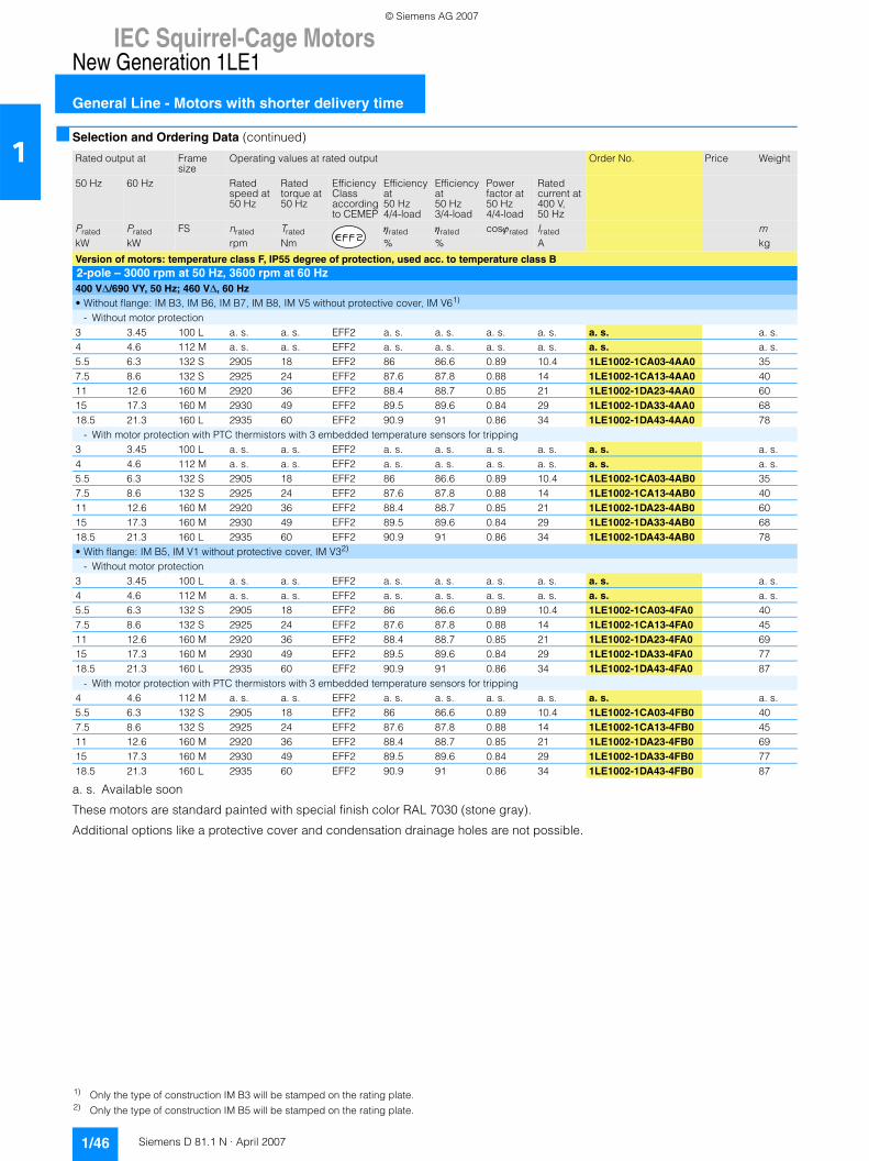
IEC Squirrel-Cage MotorsNew Generation 1LE1
General Line - Motors with shorter delivery time
1/46 Siemens D 81.1 N · April 2007
1■ Selection and Ordering Data (continued)
a. s. Available soon
These motors are standard painted with special finish color RAL 7030 (stone gray).
Additional options like a protective cover and condensation drainage holes are not possible.
Rated output at Frame size
Operating values at rated output Order No. Price Weight
50 Hz 60 Hz Ratedspeed at 50 Hz
Ratedtorque at 50 Hz
Efficiency Classaccordingto CEMEP
Efficiencyat50 Hz4/4-load
Efficiencyat50 Hz3/4-load
Powerfactor at50 Hz4/4-load
Ratedcurrent at400 V,50 Hz
Prated Prated FS nrated Trated ηrated ηrated cosϕrated Irated mkW kW rpm Nm % % A kg
Version of motors: temperature class F, IP55 degree of protection, used acc. to temperature class B2-pole – 3000 rpm at 50 Hz, 3600 rpm at 60 Hz400 V∆/690 VY, 50 Hz; 460 V∆, 60 Hz• Without flange: IM B3, IM B6, IM B7, IM B8, IM V5 without protective cover, IM V61)
- Without motor protection3 3.45 100 L a. s. a. s. EFF2 a. s. a. s. a. s. a. s. a. s. a. s.4 4.6 112 M a. s. a. s. EFF2 a. s. a. s. a. s. a. s. a. s. a. s.5.5 6.3 132 S 2905 18 EFF2 86 86.6 0.89 10.4 1LE1002-1CA03-4AA0 357.5 8.6 132 S 2925 24 EFF2 87.6 87.8 0.88 14 1LE1002-1CA13-4AA0 4011 12.6 160 M 2920 36 EFF2 88.4 88.7 0.85 21 1LE1002-1DA23-4AA0 6015 17.3 160 M 2930 49 EFF2 89.5 89.6 0.84 29 1LE1002-1DA33-4AA0 6818.5 21.3 160 L 2935 60 EFF2 90.9 91 0.86 34 1LE1002-1DA43-4AA0 78
- With motor protection with PTC thermistors with 3 embedded temperature sensors for tripping3 3.45 100 L a. s. a. s. EFF2 a. s. a. s. a. s. a. s. a. s. a. s.4 4.6 112 M a. s. a. s. EFF2 a. s. a. s. a. s. a. s. a. s. a. s.5.5 6.3 132 S 2905 18 EFF2 86 86.6 0.89 10.4 1LE1002-1CA03-4AB0 357.5 8.6 132 S 2925 24 EFF2 87.6 87.8 0.88 14 1LE1002-1CA13-4AB0 4011 12.6 160 M 2920 36 EFF2 88.4 88.7 0.85 21 1LE1002-1DA23-4AB0 6015 17.3 160 M 2930 49 EFF2 89.5 89.6 0.84 29 1LE1002-1DA33-4AB0 6818.5 21.3 160 L 2935 60 EFF2 90.9 91 0.86 34 1LE1002-1DA43-4AB0 78• With flange: IM B5, IM V1 without protective cover, IM V32)
- Without motor protection3 3.45 100 L a. s. a. s. EFF2 a. s. a. s. a. s. a. s. a. s. a. s.4 4.6 112 M a. s. a. s. EFF2 a. s. a. s. a. s. a. s. a. s. a. s.5.5 6.3 132 S 2905 18 EFF2 86 86.6 0.89 10.4 1LE1002-1CA03-4FA0 407.5 8.6 132 S 2925 24 EFF2 87.6 87.8 0.88 14 1LE1002-1CA13-4FA0 4511 12.6 160 M 2920 36 EFF2 88.4 88.7 0.85 21 1LE1002-1DA23-4FA0 6915 17.3 160 M 2930 49 EFF2 89.5 89.6 0.84 29 1LE1002-1DA33-4FA0 7718.5 21.3 160 L 2935 60 EFF2 90.9 91 0.86 34 1LE1002-1DA43-4FA0 87
- With motor protection with PTC thermistors with 3 embedded temperature sensors for tripping4 4.6 112 M a. s. a. s. EFF2 a. s. a. s. a. s. a. s. a. s. a. s.5.5 6.3 132 S 2905 18 EFF2 86 86.6 0.89 10.4 1LE1002-1CA03-4FB0 407.5 8.6 132 S 2925 24 EFF2 87.6 87.8 0.88 14 1LE1002-1CA13-4FB0 4511 12.6 160 M 2920 36 EFF2 88.4 88.7 0.85 21 1LE1002-1DA23-4FB0 6915 17.3 160 M 2930 49 EFF2 89.5 89.6 0.84 29 1LE1002-1DA33-4FB0 7718.5 21.3 160 L 2935 60 EFF2 90.9 91 0.86 34 1LE1002-1DA43-4FB0 87
1) Only the type of construction IM B3 will be stamped on the rating plate.2) Only the type of construction IM B5 will be stamped on the rating plate.
© Siemens AG 2007
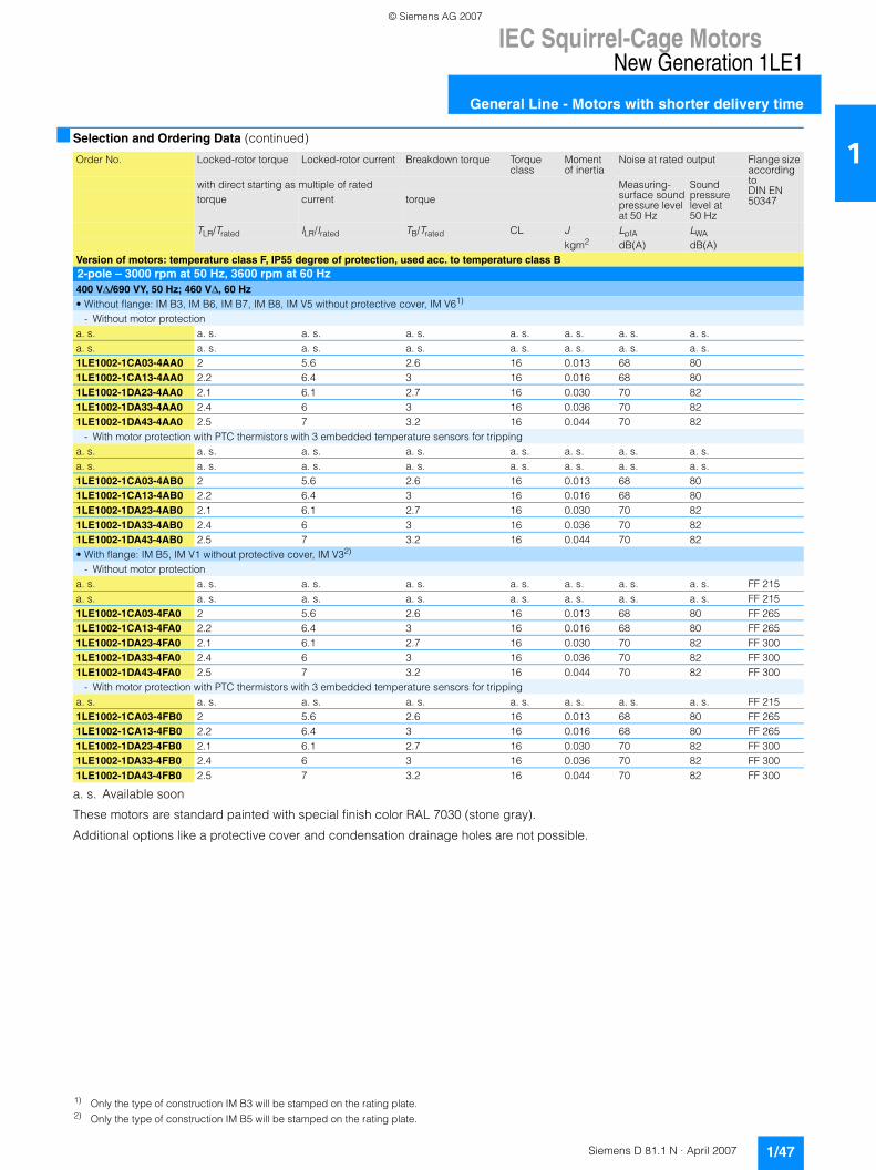
IEC Squirrel-Cage MotorsNew Generation 1LE1
General Line - Motors with shorter delivery time
1/47Siemens D 81.1 N · April 2007
1■ Selection and Ordering Data (continued)
a. s. Available soon
These motors are standard painted with special finish color RAL 7030 (stone gray).
Additional options like a protective cover and condensation drainage holes are not possible.
Order No. Locked-rotor torque Locked-rotor current Breakdown torque Torque class
Moment of inertia
Noise at rated output Flange size according toDIN EN 50347
with direct starting as multiple of rated Measuring-surface soundpressure levelat 50 Hz
Sound pressurelevel at 50 Hz
torque current torque
TLR/Trated ILR/Irated TB/Trated CL J LpfA LWAkgm2 dB(A) dB(A)
Version of motors: temperature class F, IP55 degree of protection, used acc. to temperature class B2-pole – 3000 rpm at 50 Hz, 3600 rpm at 60 Hz400 V∆/690 VY, 50 Hz; 460 V∆, 60 Hz• Without flange: IM B3, IM B6, IM B7, IM B8, IM V5 without protective cover, IM V61)
- Without motor protectiona. s. a. s. a. s. a. s. a. s. a. s. a. s. a. s.a. s. a. s. a. s. a. s. a. s. a. s. a. s. a. s.1LE1002-1CA03-4AA0 2 5.6 2.6 16 0.013 68 801LE1002-1CA13-4AA0 2.2 6.4 3 16 0.016 68 801LE1002-1DA23-4AA0 2.1 6.1 2.7 16 0.030 70 821LE1002-1DA33-4AA0 2.4 6 3 16 0.036 70 821LE1002-1DA43-4AA0 2.5 7 3.2 16 0.044 70 82
- With motor protection with PTC thermistors with 3 embedded temperature sensors for trippinga. s. a. s. a. s. a. s. a. s. a. s. a. s. a. s.a. s. a. s. a. s. a. s. a. s. a. s. a. s. a. s.1LE1002-1CA03-4AB0 2 5.6 2.6 16 0.013 68 801LE1002-1CA13-4AB0 2.2 6.4 3 16 0.016 68 801LE1002-1DA23-4AB0 2.1 6.1 2.7 16 0.030 70 821LE1002-1DA33-4AB0 2.4 6 3 16 0.036 70 821LE1002-1DA43-4AB0 2.5 7 3.2 16 0.044 70 82• With flange: IM B5, IM V1 without protective cover, IM V32)
- Without motor protectiona. s. a. s. a. s. a. s. a. s. a. s. a. s. a. s. FF 215a. s. a. s. a. s. a. s. a. s. a. s. a. s. a. s. FF 2151LE1002-1CA03-4FA0 2 5.6 2.6 16 0.013 68 80 FF 2651LE1002-1CA13-4FA0 2.2 6.4 3 16 0.016 68 80 FF 2651LE1002-1DA23-4FA0 2.1 6.1 2.7 16 0.030 70 82 FF 3001LE1002-1DA33-4FA0 2.4 6 3 16 0.036 70 82 FF 3001LE1002-1DA43-4FA0 2.5 7 3.2 16 0.044 70 82 FF 300
- With motor protection with PTC thermistors with 3 embedded temperature sensors for trippinga. s. a. s. a. s. a. s. a. s. a. s. a. s. a. s. FF 2151LE1002-1CA03-4FB0 2 5.6 2.6 16 0.013 68 80 FF 2651LE1002-1CA13-4FB0 2.2 6.4 3 16 0.016 68 80 FF 2651LE1002-1DA23-4FB0 2.1 6.1 2.7 16 0.030 70 82 FF 3001LE1002-1DA33-4FB0 2.4 6 3 16 0.036 70 82 FF 3001LE1002-1DA43-4FB0 2.5 7 3.2 16 0.044 70 82 FF 300
1) Only the type of construction IM B3 will be stamped on the rating plate.2) Only the type of construction IM B5 will be stamped on the rating plate.
© Siemens AG 2007
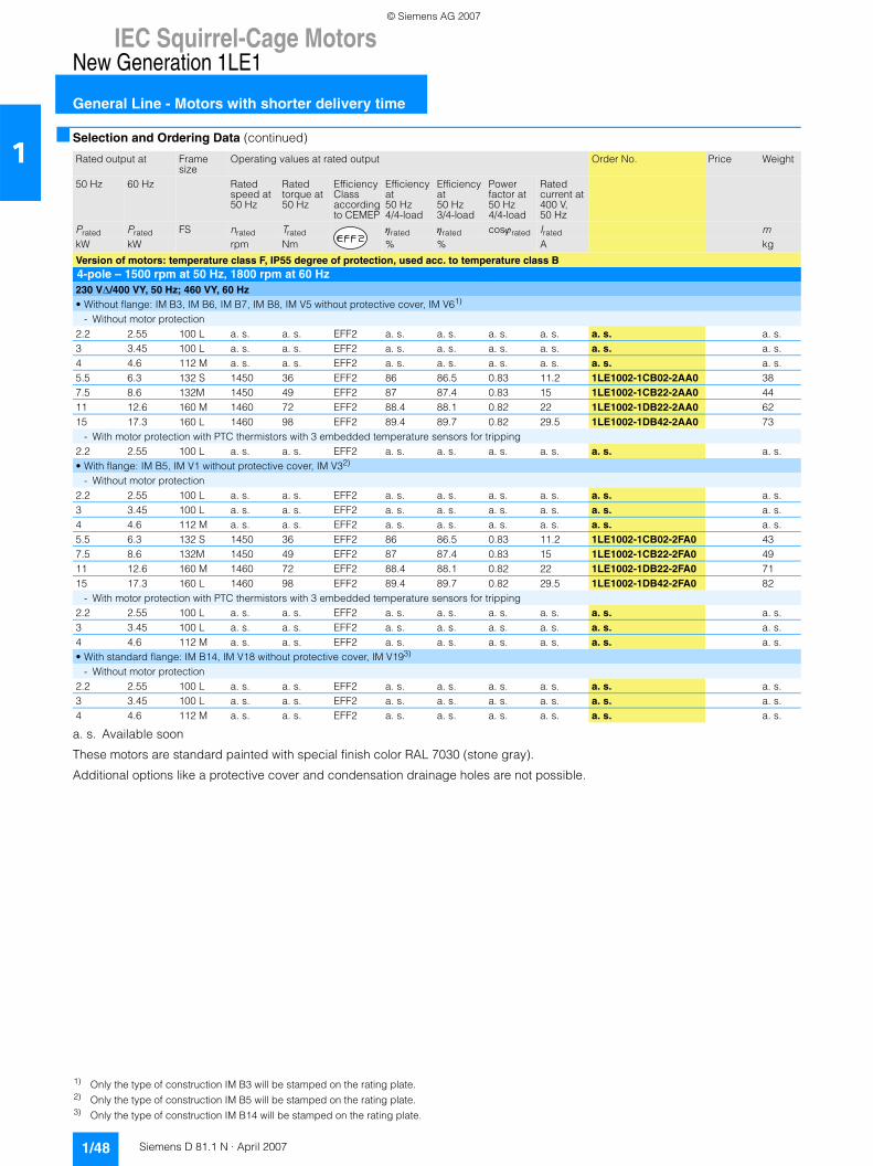
IEC Squirrel-Cage MotorsNew Generation 1LE1
General Line - Motors with shorter delivery time
1/48 Siemens D 81.1 N · April 2007
1■ Selection and Ordering Data (continued)
a. s. Available soon
These motors are standard painted with special finish color RAL 7030 (stone gray).
Additional options like a protective cover and condensation drainage holes are not possible.
Rated output at Frame size
Operating values at rated output Order No. Price Weight
50 Hz 60 Hz Ratedspeed at 50 Hz
Ratedtorque at 50 Hz
Efficiency Classaccordingto CEMEP
Efficiencyat50 Hz4/4-load
Efficiencyat50 Hz3/4-load
Powerfactor at50 Hz4/4-load
Ratedcurrent at400 V,50 Hz
Prated Prated FS nrated Trated ηrated ηrated cosϕrated Irated mkW kW rpm Nm % % A kg
Version of motors: temperature class F, IP55 degree of protection, used acc. to temperature class B4-pole – 1500 rpm at 50 Hz, 1800 rpm at 60 Hz230 V∆/400 VY, 50 Hz; 460 VY, 60 Hz• Without flange: IM B3, IM B6, IM B7, IM B8, IM V5 without protective cover, IM V61)
- Without motor protection2.2 2.55 100 L a. s. a. s. EFF2 a. s. a. s. a. s. a. s. a. s. a. s.3 3.45 100 L a. s. a. s. EFF2 a. s. a. s. a. s. a. s. a. s. a. s.4 4.6 112 M a. s. a. s. EFF2 a. s. a. s. a. s. a. s. a. s. a. s.5.5 6.3 132 S 1450 36 EFF2 86 86.5 0.83 11.2 1LE1002-1CB02-2AA0 387.5 8.6 132M 1450 49 EFF2 87 87.4 0.83 15 1LE1002-1CB22-2AA0 4411 12.6 160 M 1460 72 EFF2 88.4 88.1 0.82 22 1LE1002-1DB22-2AA0 6215 17.3 160 L 1460 98 EFF2 89.4 89.7 0.82 29.5 1LE1002-1DB42-2AA0 73
- With motor protection with PTC thermistors with 3 embedded temperature sensors for tripping2.2 2.55 100 L a. s. a. s. EFF2 a. s. a. s. a. s. a. s. a. s. a. s.• With flange: IM B5, IM V1 without protective cover, IM V32)
- Without motor protection2.2 2.55 100 L a. s. a. s. EFF2 a. s. a. s. a. s. a. s. a. s. a. s.3 3.45 100 L a. s. a. s. EFF2 a. s. a. s. a. s. a. s. a. s. a. s.4 4.6 112 M a. s. a. s. EFF2 a. s. a. s. a. s. a. s. a. s. a. s.5.5 6.3 132 S 1450 36 EFF2 86 86.5 0.83 11.2 1LE1002-1CB02-2FA0 437.5 8.6 132M 1450 49 EFF2 87 87.4 0.83 15 1LE1002-1CB22-2FA0 4911 12.6 160 M 1460 72 EFF2 88.4 88.1 0.82 22 1LE1002-1DB22-2FA0 7115 17.3 160 L 1460 98 EFF2 89.4 89.7 0.82 29.5 1LE1002-1DB42-2FA0 82
- With motor protection with PTC thermistors with 3 embedded temperature sensors for tripping2.2 2.55 100 L a. s. a. s. EFF2 a. s. a. s. a. s. a. s. a. s. a. s.3 3.45 100 L a. s. a. s. EFF2 a. s. a. s. a. s. a. s. a. s. a. s.4 4.6 112 M a. s. a. s. EFF2 a. s. a. s. a. s. a. s. a. s. a. s.• With standard flange: IM B14, IM V18 without protective cover, IM V193)
- Without motor protection2.2 2.55 100 L a. s. a. s. EFF2 a. s. a. s. a. s. a. s. a. s. a. s.3 3.45 100 L a. s. a. s. EFF2 a. s. a. s. a. s. a. s. a. s. a. s.4 4.6 112 M a. s. a. s. EFF2 a. s. a. s. a. s. a. s. a. s. a. s.
1) Only the type of construction IM B3 will be stamped on the rating plate.2) Only the type of construction IM B5 will be stamped on the rating plate.3) Only the type of construction IM B14 will be stamped on the rating plate.
© Siemens AG 2007
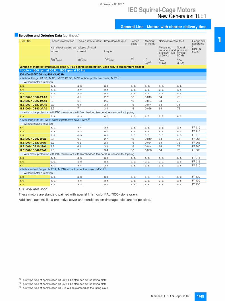
IEC Squirrel-Cage MotorsNew Generation 1LE1
General Line - Motors with shorter delivery time
1/49Siemens D 81.1 N · April 2007
1■ Selection and Ordering Data (continued)
a. s. Available soon
These motors are standard painted with special finish color RAL 7030 (stone gray).
Additional options like a protective cover and condensation drainage holes are not possible.
Order No. Locked-rotor torque Locked-rotor current Breakdown torque Torque class
Moment of inertia
Noise at rated output Flange size according toDIN EN 50347
with direct starting as multiple of rated Measuring-surface soundpressure levelat 50 Hz
Sound pressurelevel at 50 Hz
torque current torque
TLR/Trated ILR/Irated TB/Trated CL J LpfA LWAkgm2 dB(A) dB(A)
Version of motors: temperature class F, IP55 degree of protection, used acc. to temperature class B4-pole – 1500 rpm at 50 Hz, 1800 rpm at 60 Hz230 VD/400 VY, 50 Hz; 460 VY, 60 Hz• Without flange: IM B3, IM B6, IM B7, IM B8, IM V5 without protective cover, IM V61)
- Without motor protectiona. s. a. s. a. s. a. s. a. s. a. s. a. s. a. s.a. s. a. s. a. s. a. s. a. s. a. s. a. s. a. s.a. s. a. s. a. s. a. s. a. s. a. s. a. s. a. s.1LE1002-1CB02-2AA0 2.3 6.2 2.7 16 0.019 64 761LE1002-1CB22-2AA0 2.9 6.6 2.5 16 0.024 64 761LE1002-1DB22-2AA0 2.3 6.4 3.1 16 0.044 64 761LE1002-1DB42-2AA0 2.5 7 3.4 16 0.056 64 76
- With motor protection with PTC thermistors with 3 embedded temperature sensors for trippinga. s. a. s. a. s. a. s. a. s. a. s. a. s. a. s.• With flange: IM B5, IM V1 without protective cover, IM V32)
- Without motor protectiona. s. a. s. a. s. a. s. a. s. a. s. a. s. a. s. FF 215a. s. a. s. a. s. a. s. a. s. a. s. a. s. a. s. FF 215a. s. a. s. a. s. a. s. a. s. a. s. a. s. a. s. FF 2151LE1002-1CB02-2FA0 2.3 6.2 2.7 16 0.019 64 76 FF 2651LE1002-1CB22-2FA0 2.9 6.6 2.5 16 0.024 64 76 FF 2651LE1002-1DB22-2FA0 2.3 6.4 3.1 16 0.044 64 76 FF 3001LE1002-1DB42-2FA0 2.5 7 3.4 16 0.056 64 76 FF 300
- With motor protection with PTC thermistors with 3 embedded temperature sensors for trippinga. s. a. s. a. s. a. s. a. s. a. s. a. s. a. s. FF 215a. s. a. s. a. s. a. s. a. s. a. s. a. s. a. s. FF 215a. s. a. s. a. s. a. s. a. s. a. s. a. s. a. s. FF 215• With standard flange: IM B14, IM V18 without protective cover, IM V193)
- Without motor protectiona. s. a. s. a. s. a. s. a. s. a. s. a. s. a. s. FT 130a. s. a. s. a. s. a. s. a. s. a. s. a. s. a. s. FT 130a. s. a. s. a. s. a. s. a. s. a. s. a. s. a. s. FT 130
1) Only the type of construction IM B3 will be stamped on the rating plate.2) Only the type of construction IM B5 will be stamped on the rating plate.3) Only the type of construction IM B14 will be stamped on the rating plate.
© Siemens AG 2007
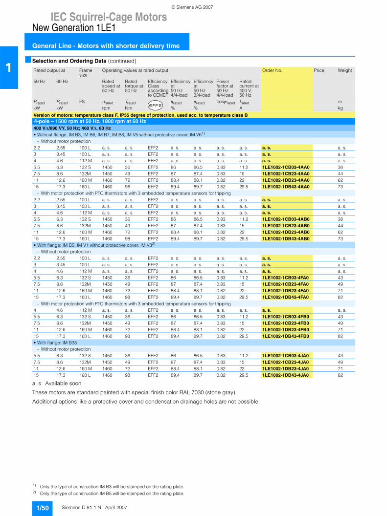
IEC Squirrel-Cage MotorsNew Generation 1LE1
General Line - Motors with shorter delivery time
1/50 Siemens D 81.1 N · April 2007
1■ Selection and Ordering Data (continued)
a. s. Available soon
These motors are standard painted with special finish color RAL 7030 (stone gray).
Additional options like a protective cover and condensation drainage holes are not possible.
Rated output at Frame size
Operating values at rated output Order No. Price Weight
50 Hz 60 Hz Ratedspeed at 50 Hz
Ratedtorque at 50 Hz
Efficiency Classaccordingto CEMEP
Efficiencyat50 Hz4/4-load
Efficiencyat50 Hz3/4-load
Powerfactor at50 Hz4/4-load
Ratedcurrent at400 V,50 Hz
Prated Prated FS nrated Trated ηrated ηrated cosϕrated Irated mkW kW rpm Nm % % A kg
Version of motors: temperature class F, IP55 degree of protection, used acc. to temperature class B4-pole – 1500 rpm at 50 Hz, 1800 rpm at 60 Hz400 V∆/690 VY, 50 Hz; 460 V∆, 60 Hz• Without flange: IM B3, IM B6, IM B7, IM B8, IM V5 without protective cover, IM V61)
- Without motor protection2.2 2.55 100 L a. s. a. s. EFF2 a. s. a. s. a. s. a. s. a. s. a. s.3 3.45 100 L a. s. a. s. EFF2 a. s. a. s. a. s. a. s. a. s. a. s.4 4.6 112 M a. s. a. s. EFF2 a. s. a. s. a. s. a. s. a. s. a. s.5.5 6.3 132 S 1450 36 EFF2 86 86.5 0.83 11.2 1LE1002-1CB03-4AA0 387.5 8.6 132M 1450 49 EFF2 87 87.4 0.83 15 1LE1002-1CB23-4AA0 4411 12.6 160 M 1460 72 EFF2 88.4 88.1 0.82 22 1LE1002-1DB23-4AA0 6215 17.3 160 L 1460 98 EFF2 89.4 89.7 0.82 29.5 1LE1002-1DB43-4AA0 73
- With motor protection with PTC thermistors with 3 embedded temperature sensors for tripping2.2 2.55 100 L a. s. a. s. EFF2 a. s. a. s. a. s. a. s. a. s. a. s.3 3.45 100 L a. s. a. s. EFF2 a. s. a. s. a. s. a. s. a. s. a. s.4 4.6 112 M a. s. a. s. EFF2 a. s. a. s. a. s. a. s. a. s. a. s.5.5 6.3 132 S 1450 36 EFF2 86 86.5 0.83 11.2 1LE1002-1CB03-4AB0 387.5 8.6 132M 1450 49 EFF2 87 87.4 0.83 15 1LE1002-1CB23-4AB0 4411 12.6 160 M 1460 72 EFF2 88.4 88.1 0.82 22 1LE1002-1DB23-4AB0 6215 17.3 160 L 1460 98 EFF2 89.4 89.7 0.82 29.5 1LE1002-1DB43-4AB0 73• With flange: IM B5, IM V1 without protective cover, IM V32)
- Without motor protection2.2 2.55 100 L a. s. a. s. EFF2 a. s. a. s. a. s. a. s. a. s. a. s.3 3.45 100 L a. s. a. s. EFF2 a. s. a. s. a. s. a. s. a. s. a. s.4 4.6 112 M a. s. a. s. EFF2 a. s. a. s. a. s. a. s. a. s. a. s.5.5 6.3 132 S 1450 36 EFF2 86 86.5 0.83 11.2 1LE1002-1CB03-4FA0 437.5 8.6 132M 1450 49 EFF2 87 87.4 0.83 15 1LE1002-1CB23-4FA0 4911 12.6 160 M 1460 72 EFF2 88.4 88.1 0.82 22 1LE1002-1DB23-4FA0 7115 17.3 160 L 1460 98 EFF2 89.4 89.7 0.82 29.5 1LE1002-1DB43-4FA0 82
- With motor protection with PTC thermistors with 3 embedded temperature sensors for tripping4 4.6 112 M a. s. a. s. EFF2 a. s. a. s. a. s. a. s. a. s. a. s.5.5 6.3 132 S 1450 36 EFF2 86 86.5 0.83 11.2 1LE1002-1CB03-4FB0 437.5 8.6 132M 1450 49 EFF2 87 87.4 0.83 15 1LE1002-1CB23-4FB0 4911 12.6 160 M 1460 72 EFF2 88.4 88.1 0.82 22 1LE1002-1DB23-4FB0 7115 17.3 160 L 1460 98 EFF2 89.4 89.7 0.82 29.5 1LE1002-1DB43-4FB0 82• With flange: IM B35
- Without motor protection5.5 6.3 132 S 1450 36 EFF2 86 86.5 0.83 11.2 1LE1002-1CB03-4JA0 437.5 8.6 132M 1450 49 EFF2 87 87.4 0.83 15 1LE1002-1CB23-4JA0 4911 12.6 160 M 1460 72 EFF2 88.4 88.1 0.82 22 1LE1002-1DB23-4JA0 7115 17.3 160 L 1460 98 EFF2 89.4 89.7 0.82 29.5 1LE1002-1DB43-4JA0 82
1) Only the type of construction IM B3 will be stamped on the rating plate.2) Only the type of construction IM B5 will be stamped on the rating plate.
© Siemens AG 2007
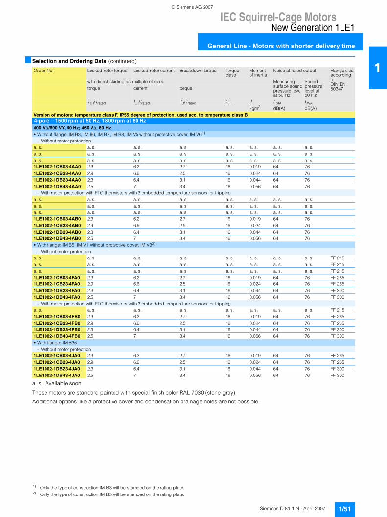
IEC Squirrel-Cage MotorsNew Generation 1LE1
General Line - Motors with shorter delivery time
1/51Siemens D 81.1 N · April 2007
1■ Selection and Ordering Data (continued)
a. s. Available soon
These motors are standard painted with special finish color RAL 7030 (stone gray).
Additional options like a protective cover and condensation drainage holes are not possible.
Order No. Locked-rotor torque Locked-rotor current Breakdown torque Torque class
Moment of inertia
Noise at rated output Flange size according toDIN EN 50347
with direct starting as multiple of rated Measuring-surface soundpressure levelat 50 Hz
Sound pressurelevel at 50 Hz
torque current torque
TLR/Trated ILR/Irated TB/Trated CL J LpfA LWAkgm2 dB(A) dB(A)
Version of motors: temperature class F, IP55 degree of protection, used acc. to temperature class B4-pole – 1500 rpm at 50 Hz, 1800 rpm at 60 Hz400 V∆/690 VY, 50 Hz; 460 V∆, 60 Hz• Without flange: IM B3, IM B6, IM B7, IM B8, IM V5 without protective cover, IM V61)
- Without motor protectiona. s. a. s. a. s. a. s. a. s. a. s. a. s. a. s.a. s. a. s. a. s. a. s. a. s. a. s. a. s. a. s.a. s. a. s. a. s. a. s. a. s. a. s. a. s. a. s.1LE1002-1CB03-4AA0 2.3 6.2 2.7 16 0.019 64 761LE1002-1CB23-4AA0 2.9 6.6 2.5 16 0.024 64 761LE1002-1DB23-4AA0 2.3 6.4 3.1 16 0.044 64 761LE1002-1DB43-4AA0 2.5 7 3.4 16 0.056 64 76
- With motor protection with PTC thermistors with 3 embedded temperature sensors for trippinga. s. a. s. a. s. a. s. a. s. a. s. a. s. a. s.a. s. a. s. a. s. a. s. a. s. a. s. a. s. a. s.a. s. a. s. a. s. a. s. a. s. a. s. a. s. a. s.1LE1002-1CB03-4AB0 2.3 6.2 2.7 16 0.019 64 761LE1002-1CB23-4AB0 2.9 6.6 2.5 16 0.024 64 761LE1002-1DB23-4AB0 2.3 6.4 3.1 16 0.044 64 761LE1002-1DB43-4AB0 2.5 7 3.4 16 0.056 64 76• With flange: IM B5, IM V1 without protective cover, IM V32)
- Without motor protectiona. s. a. s. a. s. a. s. a. s. a. s. a. s. a. s. FF 215a. s. a. s. a. s. a. s. a. s. a. s. a. s. a. s. FF 215a. s. a. s. a. s. a. s. a. s. a. s. a. s. a. s. FF 2151LE1002-1CB03-4FA0 2.3 6.2 2.7 16 0.019 64 76 FF 2651LE1002-1CB23-4FA0 2.9 6.6 2.5 16 0.024 64 76 FF 2651LE1002-1DB23-4FA0 2.3 6.4 3.1 16 0.044 64 76 FF 3001LE1002-1DB43-4FA0 2.5 7 3.4 16 0.056 64 76 FF 300
- With motor protection with PTC thermistors with 3 embedded temperature sensors for trippinga. s. a. s. a. s. a. s. a. s. a. s. a. s. a. s. FF 2151LE1002-1CB03-4FB0 2.3 6.2 2.7 16 0.019 64 76 FF 2651LE1002-1CB23-4FB0 2.9 6.6 2.5 16 0.024 64 76 FF 2651LE1002-1DB23-4FB0 2.3 6.4 3.1 16 0.044 64 76 FF 3001LE1002-1DB43-4FB0 2.5 7 3.4 16 0.056 64 76 FF 300• With flange: IM B35
- Without motor protection1LE1002-1CB03-4JA0 2.3 6.2 2.7 16 0.019 64 76 FF 2651LE1002-1CB23-4JA0 2.9 6.6 2.5 16 0.024 64 76 FF 2651LE1002-1DB23-4JA0 2.3 6.4 3.1 16 0.044 64 76 FF 3001LE1002-1DB43-4JA0 2.5 7 3.4 16 0.056 64 76 FF 300
1) Only the type of construction IM B3 will be stamped on the rating plate.2) Only the type of construction IM B5 will be stamped on the rating plate.
© Siemens AG 2007
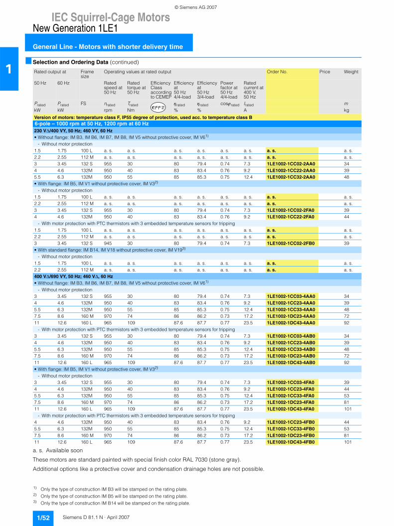
IEC Squirrel-Cage MotorsNew Generation 1LE1
General Line - Motors with shorter delivery time
1/52 Siemens D 81.1 N · April 2007
1■ Selection and Ordering Data (continued)
a. s. Available soon
These motors are standard painted with special finish color RAL 7030 (stone gray).
Additional options like a protective cover and condensation drainage holes are not possible.
Rated output at Frame size
Operating values at rated output Order No. Price Weight
50 Hz 60 Hz Ratedspeed at 50 Hz
Ratedtorque at 50 Hz
Efficiency Classaccordingto CEMEP
Efficiencyat50 Hz4/4-load
Efficiencyat50 Hz3/4-load
Powerfactor at50 Hz4/4-load
Ratedcurrent at400 V,50 Hz
Prated Prated FS nrated Trated ηrated ηrated cosϕrated Irated mkW kW rpm Nm % % A kg
Version of motors: temperature class F, IP55 degree of protection, used acc. to temperature class B6-pole – 1000 rpm at 50 Hz, 1200 rpm at 60 Hz230 V∆/400 VY, 50 Hz; 460 VY, 60 Hz• Without flange: IM B3, IM B6, IM B7, IM B8, IM V5 without protective cover, IM V61)
- Without motor protection1.5 1.75 100 L a. s. a. s. a. s. a. s. a. s. a. s. a. s. a. s.2.2 2.55 112 M a. s. a. s. a. s. a. s. a. s. a. s. a. s. a. s.3 3.45 132 S 955 30 80 79.4 0.74 7.3 1LE1002-1CC02-2AA0 344 4.6 132M 950 40 83 83.4 0.76 9.2 1LE1002-1CC22-2AA0 395.5 6.3 132M 950 55 85 85.3 0.75 12.4 1LE1002-1CC32-2AA0 48• With flange: IM B5, IM V1 without protective cover, IM V32)
- Without motor protection1.5 1.75 100 L a. s. a. s. a. s. a. s. a. s. a. s. a. s. a. s.2.2 2.55 112 M a. s. a. s. a. s. a. s. a. s. a. s. a. s. a. s.3 3.45 132 S 955 30 80 79.4 0.74 7.3 1LE1002-1CC02-2FA0 394 4.6 132M 950 40 83 83.4 0.76 9.2 1LE1002-1CC22-2FA0 44
- With motor protection with PTC thermistors with 3 embedded temperature sensors for tripping1.5 1.75 100 L a. s. a. s. a. s. a. s. a. s. a. s. a. s. a. s.2.2 2.55 112 M a. s. a. s. a. s. a. s. a. s. a. s. a. s. a. s.3 3.45 132 S 945 30 80 79.4 0.74 7.3 1LE1002-1CC02-2FB0 39• With standard flange: IM B14, IM V18 without protective cover, IM V193)
- Without motor protection1.5 1.75 100 L a. s. a. s. a. s. a. s. a. s. a. s. a. s. a. s.2.2 2.55 112 M a. s. a. s. a. s. a. s. a. s. a. s. a. s. a. s.400 V∆/690 VY, 50 Hz; 460 V∆, 60 Hz• Without flange: IM B3, IM B6, IM B7, IM B8, IM V5 without protective cover, IM V61)
- Without motor protection3 3.45 132 S 955 30 80 79.4 0.74 7.3 1LE1002-1CC03-4AA0 344 4.6 132M 950 40 83 83.4 0.76 9.2 1LE1002-1CC23-4AA0 395.5 6.3 132M 950 55 85 85.3 0.75 12.4 1LE1002-1CC33-4AA0 487.5 8.6 160 M 970 74 86 86.2 0.73 17.2 1LE1002-1DC23-4AA0 7211 12.6 160 L 965 109 87.6 87.7 0.77 23.5 1LE1002-1DC43-4AA0 92
- With motor protection with PTC thermistors with 3 embedded temperature sensors for tripping3 3.45 132 S 955 30 80 79.4 0.74 7.3 1LE1002-1CC03-4AB0 344 4.6 132M 950 40 83 83.4 0.76 9.2 1LE1002-1CC23-4AB0 395.5 6.3 132M 950 55 85 85.3 0.75 12.4 1LE1002-1CC33-4AB0 487.5 8.6 160 M 970 74 86 86.2 0.73 17.2 1LE1002-1DC23-4AB0 7211 12.6 160 L 965 109 87.6 87.7 0.77 23.5 1LE1002-1DC43-4AB0 92• With flange: IM B5, IM V1 without protective cover, IM V32)
- Without motor protection3 3.45 132 S 955 30 80 79.4 0.74 7.3 1LE1002-1CC03-4FA0 394 4.6 132M 950 40 83 83.4 0.76 9.2 1LE1002-1CC23-4FA0 445.5 6.3 132M 950 55 85 85.3 0.75 12.4 1LE1002-1CC33-4FA0 537.5 8.6 160 M 970 74 86 86.2 0.73 17.2 1LE1002-1DC23-4FA0 8111 12.6 160 L 965 109 87.6 87.7 0.77 23.5 1LE1002-1DC43-4FA0 101
- With motor protection with PTC thermistors with 3 embedded temperature sensors for tripping4 4.6 132M 950 40 83 83.4 0.76 9.2 1LE1002-1CC23-4FB0 445.5 6.3 132M 950 55 85 85.3 0.75 12.4 1LE1002-1CC33-4FB0 537.5 8.6 160 M 970 74 86 86.2 0.73 17.2 1LE1002-1DC23-4FB0 8111 12.6 160 L 965 109 87.6 87.7 0.77 23.5 1LE1002-1DC43-4FB0 101
1) Only the type of construction IM B3 will be stamped on the rating plate.2) Only the type of construction IM B5 will be stamped on the rating plate.3) Only the type of construction IM B14 will be stamped on the rating plate.
© Siemens AG 2007
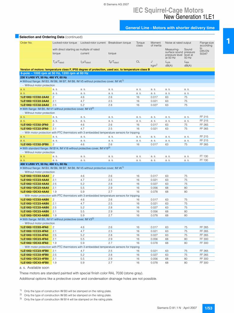
IEC Squirrel-Cage MotorsNew Generation 1LE1
General Line - Motors with shorter delivery time
1/53Siemens D 81.1 N · April 2007
1■ Selection and Ordering Data (continued)
a. s. Available soon
These motors are standard painted with special finish color RAL 7030 (stone gray).
Additional options like a protective cover and condensation drainage holes are not possible.
Order No. Locked-rotor torque Locked-rotor current Breakdown torque Torque class
Moment of inertia
Noise at rated output Flange size according toDIN EN 50347
with direct starting as multiple of rated Measuring-surface soundpressure levelat 50 Hz
Sound pressurelevel at 50 Hz
torque current torque
TLR/Trated ILR/Irated TB/Trated CL J LpfA LWAkgm2 dB(A) dB(A)
Version of motors: temperature class F, IP55 degree of protection, used acc. to temperature class B6-pole – 1000 rpm at 50 Hz, 1200 rpm at 60 Hz230 V∆/400 VY, 50 Hz; 460 VY, 60 Hz• Without flange: IM B3, IM B6, IM B7, IM B8, IM V5 without protective cover, IM V61)
- Without motor protectiona. s. a. s. a. s. a. s. a. s. a. s. a. s. a. s.a. s. a. s. a. s. a. s. a. s. a. s. a. s. a. s.1LE1002-1CC02-2AA0 2 4.6 2.6 16 0.017 63 751LE1002-1CC22-2AA0 2.1 4.7 2.5 16 0.021 63 751LE1002-1CC32-2AA0 2.5 5.2 2.8 16 0.027 63 75• With flange: IM B5, IM V1 without protective cover, IM V32)
- Without motor protectiona. s. a. s. a. s. a. s. a. s. a. s. a. s. a. s. FF 215a. s. a. s. a. s. a. s. a. s. a. s. a. s. a. s. FF 2151LE1002-1CC02-2FA0 2 4.6 2.6 16 0.017 63 75 FF 2651LE1002-1CC22-2FA0 2.1 4.7 2.5 16 0.021 63 75 FF 265
- With motor protection with PTC thermistors with 3 embedded temperature sensors for trippinga. s. a. s. a. s. a. s. a. s. a. s. a. s. a. s. FF 215a. s. a. s. a. s. a. s. a. s. a. s. a. s. a. s. FF 2151LE1002-1CC02-2FB0 2 4.6 2.6 16 0.017 63 75 FF 265• With standard flange: IM B14, IM V18 without protective cover, IM V193)
- Without motor protectiona. s. a. s. a. s. a. s. a. s. a. s. a. s. a. s. FT 130a. s. a. s. a. s. a. s. a. s. a. s. a. s. a. s. FT 130400 V∆/690 VY, 50 Hz; 460 V∆, 60 Hz• Without flange: IM B3, IM B6, IM B7, IM B8, IM V5 without protective cover, IM V61)
- Without motor protection1LE1002-1CC03-4AA0 2 4.6 2.6 16 0.017 63 751LE1002-1CC23-4AA0 2.1 4.7 2.5 16 0.021 63 751LE1002-1CC33-4AA0 2.5 5.2 2.8 16 0.027 63 751LE1002-1DC23-4AA0 2.1 5.5 2.9 16 0.056 68 801LE1002-1DC43-4AA0 1.9 5.9 2.7 16 0.078 68 80
- With motor protection with PTC thermistors with 3 embedded temperature sensors for tripping1LE1002-1CC03-4AB0 2 4.6 2.6 16 0.017 63 751LE1002-1CC23-4AB0 2.1 4.7 2.5 16 0.021 63 751LE1002-1CC33-4AB0 2.5 5.2 2.8 16 0.027 63 751LE1002-1DC23-4AB0 2.1 5.5 2.9 16 0.056 68 801LE1002-1DC43-4AB0 1.9 5.9 2.7 16 0.078 68 80• With flange: IM B5, IM V1 without protective cover, IM V32)
- Without motor protection1LE1002-1CC03-4FA0 2 4.6 2.6 16 0.017 63 75 FF 2651LE1002-1CC23-4FA0 2.1 4.7 2.5 16 0.021 63 75 FF 2651LE1002-1CC33-4FA0 2.5 5.2 2.8 16 0.027 63 75 FF 2651LE1002-1DC23-4FA0 2.1 5.5 2.9 16 0.056 68 80 FF 3001LE1002-1DC43-4FA0 1.9 5.9 2.7 16 0.078 68 80 FF 300
- With motor protection with PTC thermistors with 3 embedded temperature sensors for tripping1LE1002-1CC23-4FB0 2.1 4.7 2.5 16 0.021 63 75 FF 2651LE1002-1CC33-4FB0 2.5 5.2 2.8 16 0.027 63 75 FF 2651LE1002-1DC23-4FB0 2.1 5.5 2.9 16 0.056 68 80 FF 3001LE1002-1DC43-4FB0 1.9 5.9 2.7 16 0.078 68 80 FF 300
1) Only the type of construction IM B3 will be stamped on the rating plate.2) Only the type of construction IM B5 will be stamped on the rating plate.3) Only the type of construction IM B14 will be stamped on the rating plate.
© Siemens AG 2007
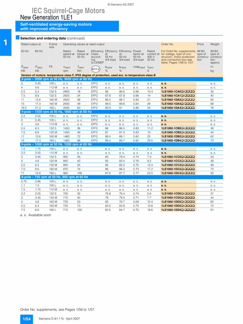
IEC Squirrel-Cage MotorsNew Generation 1LE1Self-ventilated energy-saving motorswith improved efficiency
1/54 Siemens D 81.1 N · April 2007
1■ Selection and ordering data (continued)
a. s. Available soon
Rated output at Frame size
Operating values at rated output Order No. Price Weight
50 Hz 60 Hz Ratedspeed at 50 Hz
Ratedtorque at 50 Hz
Efficiency Classaccord-ingto CEMEP
Efficiencyat50 Hz4/4-load
Efficiencyat50 Hz3/4-load
Powerfactor at50 Hz4/4-load
Ratedcurrent at400 V,50 Hz
For Order No. supplements for voltage, type of con-struction, motor protection and connection box see table, Pages 1/56 to 1/57.
IM B3 type of construc-tion
IM B3 type of construc-tion approx.
Prated Prated FS nrated Trated ηrated ηrated cosϕrated Irated mkW kW rpm Nm % % A kg
Version of motors: temperature class F, IP55 degree of protection, used acc. to temperature class B2-pole – 3000 rpm at 50 Hz, 3600 rpm at 60 Hz3 3.45 100 L a. s. a. s. EFF2 a. s. a. s. a. s. a. s. a. s. a. s.4 4.6 112 M a. s. a. s. EFF2 a. s. a. s. a. s. a. s. a. s. a. s.5.5 6.3 132 S 2905 18 EFF2 86 86.6 0.89 10.4 1LE1002-1CA0 - 357.5 8.6 132 S 2925 24 EFF2 87.6 87.8 0.88 14 1LE1002-1CA1 - 4011 12.6 160 M 2920 36 EFF2 88.4 88.7 0.85 21 1LE1002-1DA2 - 6015 17.3 160 M 2930 49 EFF2 89.5 89.6 0.84 29 1LE1002-1DA3 - 6818.5 21.3 160 L 2935 60 EFF2 90.9 91 0.86 34 1LE1002-1DA4 - 784-pole – 1500 rpm at 50 Hz, 1800 rpm at 60 Hz2.2 2.55 100 L a. s. a. s. EFF2 a. s. a. s. a. s. a. s. a. s. a. s.3 3.45 100 L a. s. a. s. EFF2 a. s. a. s. a. s. a. s. a. s. a. s.4 4.6 112 M a. s. a. s. EFF2 a. s. a. s. a. s. a. s. a. s. a. s.5.5 6.3 132 S 1450 36 EFF2 86 86.5 0.83 11.2 1LE1002-1CB0 - 387.5 8.6 132 M 1450 49 EFF2 87 87.4 0.83 15 1LE1002-1CB2 - 4411 12.6 160 M 1460 72 EFF2 88.4 88.1 0.82 22 1LE1002-1DB2 - 6215 17.3 160 L 1460 98 EFF2 89.4 89.7 0.82 29.5 1LE1002-1DB4 - 736-pole – 1000 rpm at 50 Hz, 1200 rpm at 60 Hz1.5 1.75 100 L a. s. a. s. a. s. a. s. a. s. a. s. a. s. a. s.2.2 2.55 112 M a. s. a. s. a. s. a. s. a. s. a. s. a. s. a. s.3 3.45 132 S 955 30 80 79.4 0.74 7.3 1LE1002-1CC0 - 344 4.6 132 M 950 40 83 83.4 0.76 9.2 1LE1002-1CC2 - 395.5 6.3 132 M 950 55 85 85.3 0.75 12.4 1LE1002-1CC3 - 487.5 8.6 160 M 970 74 86 86.2 0.73 17.2 1LE1002-1DC2 - 7211 12.6 160 L 965 109 87.6 87.7 0.77 23.5 1LE1002-1DC4 - 928-pole – 750 rpm at 50 Hz, 900 rpm at 60 Hz0.75 0.86 100 L a. s. a. s. a. s. a. s. a. s. a. s. a. s. a. s.1.1 1.3 100 L a. s. a. s. a. s. a. s. a. s. a. s. a. s. a. s.1.5 1.75 112 M a. s. a. s. a. s. a. s. a. s. a. s. a. s. a. s.2.2 2.55 132 S 705 30 76.6 76.4 0.74 5.6 1LE1002-1CD0 - 373 3.45 132 M 710 40 79 78.5 0.71 7.7 1LE1002-1CD2 - 444 4.6 160 M 720 53 80 78.7 0.69 10.4 1LE1002-1DD2 - 605.5 6.3 160 M 720 73 83.5 83.9 0.70 13.6 1LE1002-1DD3 - 727.5 8.6 160 L 715 100 83.5 84.7 0.70 18.6 1LE1002-1DD4 - 91
Order No. supplements, see Pages 1/56 to 1/57.
© Siemens AG 2007
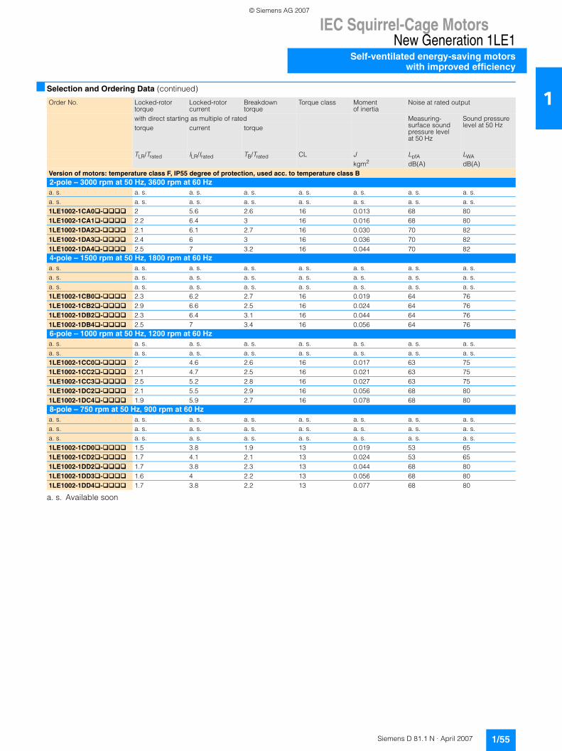
IEC Squirrel-Cage MotorsNew Generation 1LE1
Self-ventilated energy-saving motorswith improved efficiency
1/55Siemens D 81.1 N · April 2007
1■ Selection and Ordering Data (continued)
a. s. Available soon
Order No. Locked-rotor torque
Locked-rotor current
Breakdown torque
Torque class Momentof inertia
Noise at rated output
with direct starting as multiple of rated Measuring-surface soundpressure levelat 50 Hz
Sound pressurelevel at 50 Hztorque current torque
TLR/Trated ILR/Irated TB/Trated CL J LpfA LWAkgm2 dB(A) dB(A)
Version of motors: temperature class F, IP55 degree of protection, used acc. to temperature class B2-pole – 3000 rpm at 50 Hz, 3600 rpm at 60 Hza. s. a. s. a. s. a. s. a. s. a. s. a. s. a. s.a. s. a. s. a. s. a. s. a. s. a. s. a. s. a. s.1LE1002-1CA0�-���� 2 5.6 2.6 16 0.013 68 801LE1002-1CA1�-���� 2.2 6.4 3 16 0.016 68 801LE1002-1DA2�-���� 2.1 6.1 2.7 16 0.030 70 821LE1002-1DA3�-���� 2.4 6 3 16 0.036 70 821LE1002-1DA4�-���� 2.5 7 3.2 16 0.044 70 824-pole – 1500 rpm at 50 Hz, 1800 rpm at 60 Hza. s. a. s. a. s. a. s. a. s. a. s. a. s. a. s.a. s. a. s. a. s. a. s. a. s. a. s. a. s. a. s.a. s. a. s. a. s. a. s. a. s. a. s. a. s. a. s.1LE1002-1CB0�-���� 2.3 6.2 2.7 16 0.019 64 761LE1002-1CB2�-���� 2.9 6.6 2.5 16 0.024 64 761LE1002-1DB2�-���� 2.3 6.4 3.1 16 0.044 64 761LE1002-1DB4�-���� 2.5 7 3.4 16 0.056 64 766-pole – 1000 rpm at 50 Hz, 1200 rpm at 60 Hza. s. a. s. a. s. a. s. a. s. a. s. a. s. a. s.a. s. a. s. a. s. a. s. a. s. a. s. a. s. a. s.1LE1002-1CC0�-���� 2 4.6 2.6 16 0.017 63 751LE1002-1CC2�-���� 2.1 4.7 2.5 16 0.021 63 751LE1002-1CC3�-���� 2.5 5.2 2.8 16 0.027 63 751LE1002-1DC2�-���� 2.1 5.5 2.9 16 0.056 68 801LE1002-1DC4�-���� 1.9 5.9 2.7 16 0.078 68 808-pole – 750 rpm at 50 Hz, 900 rpm at 60 Hza. s. a. s. a. s. a. s. a. s. a. s. a. s. a. s.a. s. a. s. a. s. a. s. a. s. a. s. a. s. a. s.a. s. a. s. a. s. a. s. a. s. a. s. a. s. a. s.1LE1002-1CD0�-���� 1.5 3.8 1.9 13 0.019 53 651LE1002-1CD2�-���� 1.7 4.1 2.1 13 0.024 53 651LE1002-1DD2�-���� 1.7 3.8 2.3 13 0.044 68 801LE1002-1DD3�-���� 1.6 4 2.2 13 0.056 68 801LE1002-1DD4�-���� 1.7 3.8 2.2 13 0.077 68 80
© Siemens AG 2007
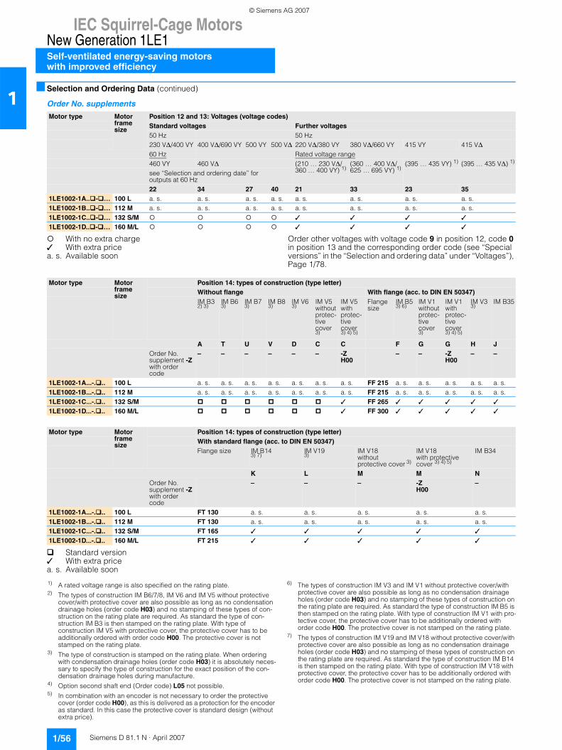
IEC Squirrel-Cage MotorsNew Generation 1LE1Self-ventilated energy-saving motorswith improved efficiency
1/56 Siemens D 81.1 N · April 2007
1■ Selection and Ordering Data (continued)
Order No. supplements
With no extra charge✓ With extra pricea. s. Available soon
Order other voltages with voltage code 9 in position 12, code 0 in position 13 and the corresponding order code (see “Special versions” in the “Selection and ordering data” under “Voltages”), Page 1/78.
Standard version✓ With extra pricea. s. Available soon
Motor type Motor frame size
Position 12 and 13: Voltages (voltage codes)Standard voltages Further voltages50 Hz 50 Hz230 V∆/400 VY 400 V∆/690 VY 500 VY 500 V∆ 220 V∆/380 VY 380 V∆/660 VY 415 VY 415 V∆60 Hz Rated voltage range460 VY 460 V∆ (210 … 230 V∆/
360 … 400 VY) 1)(360 … 400 V∆/625 … 695 VY) 1)
(395 … 435 VY) 1) (395 … 435 V∆) 1)
see “Selection and ordering date” for outputs at 60 Hz22 34 27 40 21 33 23 35
1LE1002-1A.. - … 100 L a. s. a. s. a. s. a. s. a. s. a. s. a. s. a. s.1LE1002-1B.. - … 112 M a. s. a. s. a. s. a. s. a. s. a. s. a. s. a. s.1LE1002-1C.. - … 132 S/M ✓ ✓ ✓ ✓
1LE1002-1D.. - … 160 M/L ✓ ✓ ✓ ✓
Motor type Motor frame size
Position 14: types of construction (type letter)Without flange With flange (acc. to DIN EN 50347)IM B32) 3)
IM B63)
IM B73)
IM B83)
IM V63)
IM V5withoutprotec-tive cover3)
IM V5withprotec-tive cover3) 4) 5)
Flange size
IM B53) 6)
IM V1withoutprotec-tive cover3)
IM V1withprotec-tive cover3) 4) 5)
IM V33)
IM B35
A T U V D C C F G G H JOrder No. supplement -Zwith order code
– – – – – – -ZH00
– – -ZH00
– –
1LE1002-1A...-. .. 100 L a. s. a. s. a. s. a. s. a. s. a. s. a. s. FF 215 a. s. a. s. a. s. a. s. a. s.1LE1002-1B...-. .. 112 M a. s. a. s. a. s. a. s. a. s. a. s. a. s. FF 215 a. s. a. s. a. s. a. s. a. s.1LE1002-1C...-. .. 132 S/M ✓ FF 265 ✓ ✓ ✓ ✓ ✓
1LE1002-1D...-. .. 160 M/L ✓ FF 300 ✓ ✓ ✓ ✓ ✓
Motor type Motor frame size
Position 14: types of construction (type letter)With standard flange (acc. to DIN EN 50347)Flange size IM B14
3) 7)IM V193)
IM V18withoutprotective cover 3)
IM V18with protective cover 3) 4) 5)
IM B34
K L M M NOrder No. supplement -Zwith order code
– – – -Z H00
–
1LE1002-1A...-. .. 100 L FT 130 a. s. a. s. a. s. a. s. a. s.1LE1002-1B...-. .. 112 M FT 130 a. s. a. s. a. s. a. s. a. s.1LE1002-1C...-. .. 132 S/M FT 165 ✓ ✓ ✓ ✓ ✓
1LE1002-1D...-. .. 160 M/L FT 215 ✓ ✓ ✓ ✓ ✓
1) A rated voltage range is also specified on the rating plate.2) The types of construction IM B6/7/8, IM V6 and IM V5 without protective
cover/with protective cover are also possible as long as no condensation drainage holes (order code H03) and no stamping of these types of con-struction on the rating plate are required. As standard the type of con-struction IM B3 is then stamped on the rating plate. With type of construction IM V5 with protective cover, the protective cover has to be additionally ordered with order code H00. The protective cover is not stamped on the rating plate.
3) The type of construction is stamped on the rating plate. When ordering with condensation drainage holes (order code H03) it is absolutely neces-sary to specify the type of construction for the exact position of the con-densation drainage holes during manufacture.
4) Option second shaft end (Order code) L05 not possible.5) In combination with an encoder is not necessary to order the protective
cover (order code H00), as this is delivered as a protection for the encoder as standard. In this case the protective cover is standard design (without extra price).
6) The types of construction IM V3 and IM V1 without protective cover/with protective cover are also possible as long as no condensation drainage holes (order code H03) and no stamping of these types of construction on the rating plate are required. As standard the type of construction IM B5 is then stamped on the rating plate. With type of construction IM V1 with pro-tective cover, the protective cover has to be additionally ordered with order code H00. The protective cover is not stamped on the rating plate.
7) The types of construction IM V19 and IM V18 without protective cover/with protective cover are also possible as long as no condensation drainage holes (order code H03) and no stamping of these types of construction on the rating plate are required. As standard the type of construction IM B14 is then stamped on the rating plate. With type of construction IM V18 with protective cover, the protective cover has to be additionally ordered with order code H00. The protective cover is not stamped on the rating plate.
© Siemens AG 2007
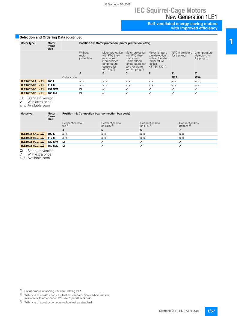
IEC Squirrel-Cage MotorsNew Generation 1LE1
Self-ventilated energy-saving motorswith improved efficiency
1/57Siemens D 81.1 N · April 2007
1■ Selection and Ordering Data (continued)
Standard version✓ With extra pricea. s. Available soon
Standard version✓ With extra pricea. s. Available soon
Motor type Motor frame size
Position 15: Motor protection (motor protection letter)
Without motor protection
Motor protection with PTC ther-mistors with 3 embedded temperature sensors for tripping 1)
Motor protection with PTC ther-mistors with 6 embedded temperature sen-sors for alarm and tripping 1)
Motor tempera-ture detection with embedded temperature sensor KTY 84-130 1)
NTC thermistors for tripping
3 temperature detectors for tripping 1))
A B C F Z ZOrder code Q2A Q3A
1LE1002-1A...-.. . 100 L a. s. a. s. a. s. a. s. a. s. a. s.1LE1002-1B...-.. . 112 M a. s. a. s. a. s. a. s. a. s. a. s.1LE1002-1C...-.. . 132 S/M ✓ ✓ ✓ ✓ ✓
1LE1002-1D...-.. . 160 M/L ✓ ✓ ✓ ✓ ✓
Motortyp Motor frame size
Position 16: Connection box (connection box code)
Connection box top 2)
Connection box on RHS 3)
Connection box on LHS 3)
Connection box bottom 3)
4 5 6 71LE1002-1A...-... 100 L a. s. a. s. a. s. a. s.1LE1002-1B...-... 112 M a. s. a. s. a. s. a. s.1LE1002-1C...-... 132 S/M ✓ ✓ ✓
1LE1002-1D...-... 160 M/L ✓ ✓ ✓
1) For appropriate tripping unit see Catalog LV 1.2) With type of construction cast feet as standard. Screwed-on feet are
available with order code H01, see “Special versions”.3) With type of construction screwed-on feet as standard.
© Siemens AG 2007

IEC Squirrel-Cage MotorsNew Generation 1LE1Self-ventilated energy-saving motorswith high efficiency
1/58 Siemens D 81.1 N · April 2007
1■ Selection and Ordering Data (continued)
a. s. Available soon
Rated output at Frame size
Operating values at rated output Order No. Price Weight
50 Hz 60 Hz Ratedspeed at 50 Hz
Ratedtorque at 50 Hz
Efficiency Classaccord-ingto CEMEP
Efficiencyat50 Hz4/4-load
Efficiencyat50 Hz3/4-load
Powerfactor at50 Hz4/4-load
Ratedcurrent at400 V,50 Hz
For Order No. supplements for voltage, type of con-struction, motor protection and connection box see table, Pages 1/60 to 1/61.
IM B3 type of construc-tion
IM B3 type of construc-tion approx.
Prated Prated FS nrated Trated ηrated ηrated cosϕrated Irated mkW kW rpm Nm % % A kg
Version of motors: temperature class F, IP55 degree of protection, used acc. to temperature class B2-pole – 3000 rpm at 50 Hz, 3600 rpm at 60 Hz3 3.45 100 L a. s. a. s. EFF1 a. s. a. s. a. s. a. s. a. s. a. s.4 4.6 112 M a. s. a. s. EFF1 a. s. a. s. a. s. a. s. a. s. a. s.5.5 6.3 132 S 2950 18 EFF1 89.5 90.6 0.87 10.2 1LE1001-1CA0 - 397.5 8.6 132 S 2950 24 EFF1 90 91 0.88 13.8 1LE1001-1CA1 - 4311 12.6 160 M 2955 36 EFF1 90.8 91 0.87 20 1LE1001-1DA2 - 6715 17.3 160 M 2955 48 EFF1 91.4 91.5 0.88 27 1LE1001-1DA3 - 7518.5 21.3 160 L 2955 60 EFF1 92 92.5 0.88 33 1LE1001-1DA4 - 844-pole – 1500 rpm at 50 Hz, 1800 rpm at 60 Hz2.2 2.55 100 L a. s. a. s. EFF1 a. s. a. s. a. s. a. s. a. s. a. s.3 3.45 100 L a. s. a. s. EFF1 a. s. a. s. a. s. a. s. a. s. a. s.4 4.6 112 M a. s. a. s. EFF1 a. s. a. s. a. s. a. s. a. s. a. s.5.5 6.3 132 S 1465 36 EFF1 89.2 89.5 0.80 11.2 1LE1001-1CB0 - 427.5 8.6 132 M 1465 49 EFF1 90.1 91 0.83 14.4 1LE1001-1CB2 - 4911 12.6 160 M 1470 71 EFF1 91.2 91.8 0.85 20.5 1LE1001-1DB2 - 7115 17.3 160 L 1475 97 EFF1 92 92.4 0.85 27.5 1LE1001-1DB4 - 836-pole – 1000 rpm at 50 Hz, 1200 rpm at 60 Hz1.5 1.75 100 L a. s. a. s. a. s. a. s. a. s. a. s. a. s. a. s.2.2 2.55 112 M a. s. a. s. a. s. a. s. a. s. a. s. a. s. a. s.3 3.45 132 S 970 30 86 85.9 0.73 6.9 1LE1001-1CC0 - 384 4.6 132 M 970 39 86 86.5 0.78 8.6 1LE1001-1CC2 - 435.5 6.3 132 M 970 54 88 89 0.77 11.8 1LE1001-1CC3 - 527.5 8.6 160 M 975 73 89 89.6 0.77 15.8 1LE1001-1DC2 - 7711 12.6 160 L 975 108 89.5 90.5 0.80 22 1LE1001-1DC4 - 938-pole – 750 rpm at 50 Hz, 900 rpm at 60 Hz0.75 0.86 100 L a. s. a. s. a. s. a. s. a. s. a. s. a. s. a. s.1.1 1.3 100 L a. s. a. s. a. s. a. s. a. s. a. s. a. s. a. s.1.5 1.75 112 M a. s. a. s. a. s. a. s. a. s. a. s. a. s. a. s.2.2 2.55 132 S 725 29 77.5 76.7 0.63 6.5 1LE1001-1CD0 - 413 3.45 132 M 720 40 77.5 76.5 0.61 9.2 1LE1001-1CD2 - 494 4.6 160 M 730 52 87 88 0.69 9.6 1LE1001-1DD2 - 695.5 6.3 160 M 730 72 87.5 89 0.69 13.2 1LE1001-1DD3 - 827.5 8.6 160 L 730 98 88 89 0.72 17 1LE1001-1DD4 - 94
Order No. supplements, see Pages 1/60 to 1/61.
© Siemens AG 2007
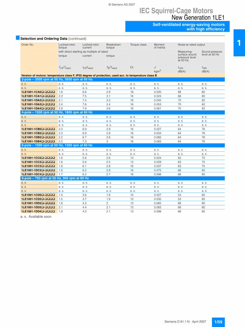
IEC Squirrel-Cage MotorsNew Generation 1LE1
Self-ventilated energy-saving motorswith high efficiency
1/59Siemens D 81.1 N · April 2007
1■ Selection and Ordering Data (continued)
a. s. Available soon
Order No. Locked-rotor torque
Locked-rotor current
Breakdown torque
Torque class Momentof inertia
Noise at rated output
with direct starting as multiple of rated Measuring-surface soundpressure levelat 50 Hz
Sound pressurelevel at 50 Hztorque current torque
TLR/Trated ILR/Irated TB/Trated CL J LpfA LWAkgm2 dB(A) dB(A)
Version of motors: temperature class F, IP55 degree of protection, used acc. to temperature class B2-pole – 3000 rpm at 50 Hz, 3600 rpm at 60 Hza. s. a. s. a. s. a. s. a. s. a. s. a. s. a. s.a. s. a. s. a. s. a. s. a. s. a. s. a. s. a. s.1LE1001-1CA0�-���� 1.8 6.6 2.9 16 0.020 68 801LE1001-1CA1�-���� 2.2 7.5 3.1 16 0.024 68 801LE1001-1DA2�-���� 2.1 7.4 3.2 16 0.045 70 821LE1001-1DA3�-���� 2.4 7.6 3.4 16 0.053 70 821LE1001-1DA4�-���� 2.9 7.9 3.6 16 0.061 70 824-pole – 1500 rpm at 50 Hz, 1800 rpm at 60 Hza. s. a. s. a. s. a. s. a. s. a. s. a. s. a. s.a. s. a. s. a. s. a. s. a. s. a. s. a. s. a. s.a. s. a. s. a. s. a. s. a. s. a. s. a. s. a. s.1LE1001-1CB0�-���� 2.3 6.9 2.9 16 0.027 64 761LE1001-1CB2�-���� 2.3 6.9 2.9 16 0.034 64 761LE1001-1DB2�-���� 2.2 6.7 2.8 16 0.065 64 761LE1001-1DB4�-���� 2.5 7.3 3 16 0.083 64 766-pole – 1000 rpm at 50 Hz, 1200 rpm at 60 Hza. s. a. s. a. s. a. s. a. s. a. s. a. s. a. s.a. s. a. s. a. s. a. s. a. s. a. s. a. s. a. s.1LE1001-1CC0�-���� 1.6 5.6 2.6 13 0.024 63 751LE1001-1CC2�-���� 1.6 5.6 2.5 13 0.029 63 751LE1001-1CC3�-���� 1.9 6.1 2.8 16 0.037 63 751LE1001-1DC2�-���� 1.8 6.3 2.8 16 0.075 68 801LE1001-1DC4�-���� 1.7 6.2 2.7 16 0.098 68 808-pole – 750 rpm at 50 Hz, 900 rpm at 60 Hza. s. a. s. a. s. a. s. a. s. a. s. a. s. a. s.a. s. a. s. a. s. a. s. a. s. a. s. a. s. a. s.a. s. a. s. a. s. a. s. a. s. a. s. a. s. a. s.1LE1001-1CD0�-���� 1.4 3.6 1.8 10 0.027 53 651LE1001-1CD2�-���� 1.5 3.7 1.9 10 0.035 53 651LE1001-1DD2�-���� 1.8 4.3 2 13 0.065 68 801LE1001-1DD3�-���� 2.1 4.4 2.1 13 0.083 68 801LE1001-1DD4�-���� 1.9 4.5 2.1 13 0.098 68 80
© Siemens AG 2007
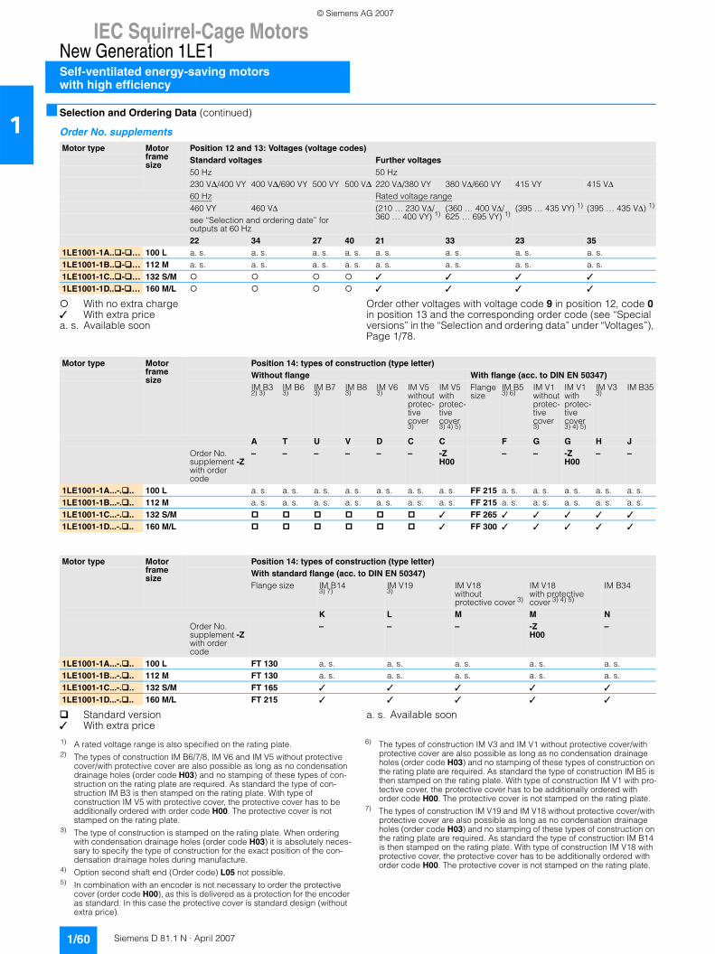
IEC Squirrel-Cage MotorsNew Generation 1LE1Self-ventilated energy-saving motorswith high efficiency
1/60 Siemens D 81.1 N · April 2007
1■ Selection and Ordering Data (continued)
Order No. supplements
With no extra charge✓ With extra pricea. s. Available soon
Order other voltages with voltage code 9 in position 12, code 0 in position 13 and the corresponding order code (see “Special versions” in the “Selection and ordering data” under “Voltages”), Page 1/78.
Standard version✓ With extra price
a. s. Available soon
Motor type Motor frame size
Position 12 and 13: Voltages (voltage codes)Standard voltages Further voltages50 Hz 50 Hz230 V∆/400 VY 400 V∆/690 VY 500 VY 500 V∆ 220 VΔ/380 VY 380 VΔ/660 VY 415 VY 415 VΔ60 Hz Rated voltage range460 VY 460 VΔ (210 … 230 VΔ/
360 … 400 VY) 1)(360 … 400 VΔ/625 … 695 VY) 1)
(395 … 435 VY) 1) (395 … 435 VΔ) 1)
see “Selection and ordering date” for outputs at 60 Hz22 34 27 40 21 33 23 35
1LE1001-1A.. - … 100 L a. s. a. s. a. s. a. s. a. s. a. s. a. s. a. s.1LE1001-1B.. - … 112 M a. s. a. s. a. s. a. s. a. s. a. s. a. s. a. s.1LE1001-1C.. - … 132 S/M ✓ ✓ ✓ ✓
1LE1001-1D.. - … 160 M/L ✓ ✓ ✓ ✓
Motor type Motor frame size
Position 14: types of construction (type letter)Without flange With flange (acc. to DIN EN 50347)IM B32) 3)
IM B63)
IM B73)
IM B83)
IM V63)
IM V5withoutprotec-tive cover3)
IM V5withprotec-tive cover3) 4) 5)
Flange size
IM B53) 6)
IM V1withoutprotec-tive cover3)
IM V1withprotec-tive cover3) 4) 5)
IM V33)
IM B35
A T U V D C C F G G H JOrder No. supplement -Zwith order code
– – – – – – -ZH00
– – -ZH00
– –
1LE1001-1A...-. .. 100 L a. s. a. s. a. s. a. s. a. s. a. s. a. s. FF 215 a. s. a. s. a. s. a. s. a. s.1LE1001-1B...-. .. 112 M a. s. a. s. a. s. a. s. a. s. a. s. a. s. FF 215 a. s. a. s. a. s. a. s. a. s.1LE1001-1C...-. .. 132 S/M ✓ FF 265 ✓ ✓ ✓ ✓ ✓
1LE1001-1D...-. .. 160 M/L ✓ FF 300 ✓ ✓ ✓ ✓ ✓
Motor type Motor frame size
Position 14: types of construction (type letter)With standard flange (acc. to DIN EN 50347)Flange size IM B14
3) 7)IM V193)
IM V18withoutprotective cover 3)
IM V18with protective cover 3) 4) 5)
IM B34
K L M M NOrder No. supplement -Zwith order code
– – – -Z H00
–
1LE1001-1A...-. .. 100 L FT 130 a. s. a. s. a. s. a. s. a. s.1LE1001-1B...-. .. 112 M FT 130 a. s. a. s. a. s. a. s. a. s.1LE1001-1C...-. .. 132 S/M FT 165 ✓ ✓ ✓ ✓ ✓
1LE1001-1D...-. .. 160 M/L FT 215 ✓ ✓ ✓ ✓ ✓
1) A rated voltage range is also specified on the rating plate.2) The types of construction IM B6/7/8, IM V6 and IM V5 without protective
cover/with protective cover are also possible as long as no condensation drainage holes (order code H03) and no stamping of these types of con-struction on the rating plate are required. As standard the type of con-struction IM B3 is then stamped on the rating plate. With type of construction IM V5 with protective cover, the protective cover has to be additionally ordered with order code H00. The protective cover is not stamped on the rating plate.
3) The type of construction is stamped on the rating plate. When ordering with condensation drainage holes (order code H03) it is absolutely neces-sary to specify the type of construction for the exact position of the con-densation drainage holes during manufacture.
4) Option second shaft end (Order code) L05 not possible.5) In combination with an encoder is not necessary to order the protective
cover (order code H00), as this is delivered as a protection for the encoder as standard. In this case the protective cover is standard design (without extra price).
6) The types of construction IM V3 and IM V1 without protective cover/with protective cover are also possible as long as no condensation drainage holes (order code H03) and no stamping of these types of construction on the rating plate are required. As standard the type of construction IM B5 is then stamped on the rating plate. With type of construction IM V1 with pro-tective cover, the protective cover has to be additionally ordered with order code H00. The protective cover is not stamped on the rating plate.
7) The types of construction IM V19 and IM V18 without protective cover/with protective cover are also possible as long as no condensation drainage holes (order code H03) and no stamping of these types of construction on the rating plate are required. As standard the type of construction IM B14 is then stamped on the rating plate. With type of construction IM V18 with protective cover, the protective cover has to be additionally ordered with order code H00. The protective cover is not stamped on the rating plate.
© Siemens AG 2007
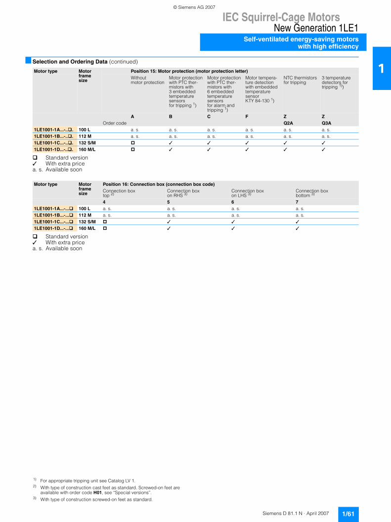
IEC Squirrel-Cage MotorsNew Generation 1LE1
Self-ventilated energy-saving motorswith high efficiency
1/61Siemens D 81.1 N · April 2007
1■ Selection and Ordering Data (continued)
Standard version✓ With extra pricea. s. Available soon
Standard version✓ With extra pricea. s. Available soon
Motor type Motor frame size
Position 15: Motor protection (motor protection letter)Without motor protection
Motor protection with PTC ther-mistors with 3 embedded temperature sensorsfor tripping 1)
Motor protection with PTC ther-mistors with 6 embedded temperature sensorsfor alarm and tripping 1)
Motor tempera-ture detection with embedded temperature sensor KTY 84-130 1)
NTC thermistors for tripping
3 temperature detectors for tripping 1))
A B C F Z ZOrder code Q2A Q3A
1LE1001-1A...-.. . 100 L a. s. a. s. a. s. a. s. a. s. a. s.1LE1001-1B...-.. . 112 M a. s. a. s. a. s. a. s. a. s. a. s.1LE1001-1C...-.. . 132 S/M ✓ ✓ ✓ ✓ ✓
1LE1001-1D...-.. . 160 M/L ✓ ✓ ✓ ✓ ✓
Motor type Motor frame size
Position 16: Connection box (connection box code)Connection box top 2)
Connection box on RHS 3)
Connection box on LHS 3)
Connection box bottom 3)
4 5 6 71LE1001-1A...-... 100 L a. s. a. s. a. s. a. s.1LE1001-1B...-... 112 M a. s. a. s. a. s. a. s.1LE1001-1C...-... 132 S/M ✓ ✓ ✓
1LE1001-1D...-... 160 M/L ✓ ✓ ✓
1) For appropriate tripping unit see Catalog LV 1.2) With type of construction cast feet as standard. Screwed-on feet are
available with order code H01, see “Special versions”.3) With type of construction screwed-on feet as standard.
© Siemens AG 2007
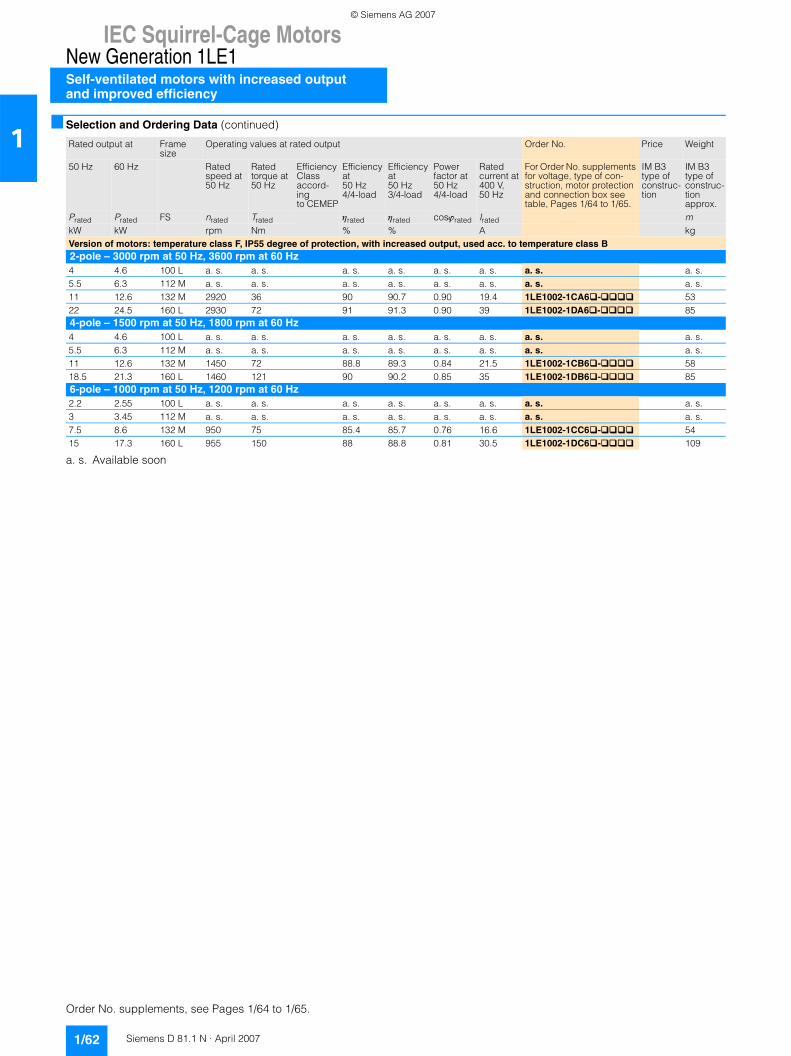
IEC Squirrel-Cage MotorsNew Generation 1LE1Self-ventilated motors with increased outputand improved efficiency
1/62 Siemens D 81.1 N · April 2007
1■ Selection and Ordering Data (continued)
a. s. Available soon
Rated output at Frame size
Operating values at rated output Order No. Price Weight
50 Hz 60 Hz Ratedspeed at 50 Hz
Ratedtorque at 50 Hz
Efficiency Classaccord-ingto CEMEP
Efficiencyat50 Hz4/4-load
Efficiencyat50 Hz3/4-load
Powerfactor at50 Hz4/4-load
Ratedcurrent at400 V,50 Hz
For Order No. supplements for voltage, type of con-struction, motor protection and connection box see table, Pages 1/64 to 1/65.
IM B3 type of construc-tion
IM B3 type of construc-tion approx.
Prated Prated FS nrated Trated ηrated ηrated cosϕrated Irated mkW kW rpm Nm % % A kgVersion of motors: temperature class F, IP55 degree of protection, with increased output, used acc. to temperature class B2-pole – 3000 rpm at 50 Hz, 3600 rpm at 60 Hz4 4.6 100 L a. s. a. s. a. s. a. s. a. s. a. s. a. s. a. s.5.5 6.3 112 M a. s. a. s. a. s. a. s. a. s. a. s. a. s. a. s.11 12.6 132 M 2920 36 90 90.7 0.90 19.4 1LE1002-1CA6 - 5322 24.5 160 L 2930 72 91 91.3 0.90 39 1LE1002-1DA6 - 854-pole – 1500 rpm at 50 Hz, 1800 rpm at 60 Hz4 4.6 100 L a. s. a. s. a. s. a. s. a. s. a. s. a. s. a. s.5.5 6.3 112 M a. s. a. s. a. s. a. s. a. s. a. s. a. s. a. s.11 12.6 132 M 1450 72 88.8 89.3 0.84 21.5 1LE1002-1CB6 - 5818.5 21.3 160 L 1460 121 90 90.2 0.85 35 1LE1002-1DB6 - 856-pole – 1000 rpm at 50 Hz, 1200 rpm at 60 Hz2.2 2.55 100 L a. s. a. s. a. s. a. s. a. s. a. s. a. s. a. s.3 3.45 112 M a. s. a. s. a. s. a. s. a. s. a. s. a. s. a. s.7.5 8.6 132 M 950 75 85.4 85.7 0.76 16.6 1LE1002-1CC6 - 5415 17.3 160 L 955 150 88 88.8 0.81 30.5 1LE1002-1DC6 - 109
Order No. supplements, see Pages 1/64 to 1/65.
© Siemens AG 2007
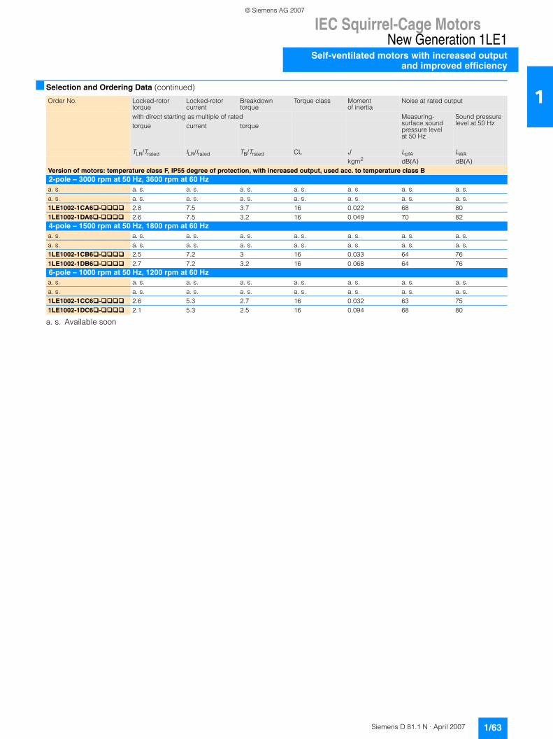
IEC Squirrel-Cage MotorsNew Generation 1LE1
Self-ventilated motors with increased outputand improved efficiency
1/63Siemens D 81.1 N · April 2007
1■ Selection and Ordering Data (continued)
a. s. Available soon
Order No. Locked-rotor torque
Locked-rotor current
Breakdown torque
Torque class Momentof inertia
Noise at rated output
with direct starting as multiple of rated Measuring-surface soundpressure levelat 50 Hz
Sound pressurelevel at 50 Hztorque current torque
TLR/Trated ILR/Irated TB/Trated CL J LpfA LWAkgm2 dB(A) dB(A)
Version of motors: temperature class F, IP55 degree of protection, with increased output, used acc. to temperature class B2-pole – 3000 rpm at 50 Hz, 3600 rpm at 60 Hza. s. a. s. a. s. a. s. a. s. a. s. a. s. a. s.a. s. a. s. a. s. a. s. a. s. a. s. a. s. a. s.1LE1002-1CA6�-���� 2.8 7.5 3.7 16 0.022 68 801LE1002-1DA6�-���� 2.6 7.5 3.2 16 0.049 70 824-pole – 1500 rpm at 50 Hz, 1800 rpm at 60 Hza. s. a. s. a. s. a. s. a. s. a. s. a. s. a. s.a. s. a. s. a. s. a. s. a. s. a. s. a. s. a. s.1LE1002-1CB6�-���� 2.5 7.2 3 16 0.033 64 761LE1002-1DB6�-���� 2.7 7.2 3.2 16 0.068 64 766-pole – 1000 rpm at 50 Hz, 1200 rpm at 60 Hza. s. a. s. a. s. a. s. a. s. a. s. a. s. a. s.a. s. a. s. a. s. a. s. a. s. a. s. a. s. a. s.1LE1002-1CC6�-���� 2.6 5.3 2.7 16 0.032 63 751LE1002-1DC6�-���� 2.1 5.3 2.5 16 0.094 68 80
© Siemens AG 2007

IEC Squirrel-Cage MotorsNew Generation 1LE1Self-ventilated motors with increased outputand improved efficiency
1/64 Siemens D 81.1 N · April 2007
1■ Selection and Ordering Data (continued)
Order No. supplements
With no extra charge✓ With extra pricea. s. Available soon
Order other voltages with voltage code 9 in position 12, code 0 in position 13 and the corresponding order code (see “Special versions” in the “Selection and ordering data” under “Voltages”), Page 1/78.
Standard version✓ With extra price
a. s. Available soon
Motor type Motor frame size
Position 12 and 13: Voltages (voltage codes)Standard voltages Further voltages50 Hz 50 Hz230 VΔ/400 VY 400 VΔ/690 VY 500 VY 500 VΔ 220 VΔ/380 VY 380 VΔ/660 VY 415 VY 415 VΔ60 Hz Rated voltage range460 VY 460 VΔ (210 … 230 VΔ/
360 … 400 VY) 1)(360 … 400 VΔ/625 … 695 VY) 1)
(395 … 435 VY) 1) (395 … 435 VΔ) 1)
see “Selection and ordering date” for outputs at 60 Hz22 34 27 40 21 33 23 35
1LE1002-1A.. - … 100 L a. s. a. s. a. s. a. s. a. s. a. s. a. s. a. s.1LE1002-1B.. - … 112 M a. s. a. s. a. s. a. s. a. s. a. s. a. s. a. s.1LE1002-1C.. - … 132 M ✓ ✓ ✓ ✓
1LE1002-1D.. - … 160 L ✓ ✓ ✓ ✓
Motor type Motor frame size
Position 14: types of construction (type letter)Without flange With flange (acc. to DIN EN 50347)IM B32) 3)
IM B63)
IM B73)
IM B83)
IM V63)
IM V5withoutprotec-tive cover3)
IM V5withprotec-tive cover3) 4) 5)
Flange size
IM B53) 6)
IM V1withoutprotec-tive cover3)
IM V1withprotec-tive cover3) 4) 5)
IM V33)
IM B35
A T U V D C C F G G H JOrder No. supplement -Zwith order code
– – – – – – -ZH00
– – -ZH00
– –
1LE1002-1A...-. .. 100 L a. s. a. s. a. s. a. s. a. s. a. s. a. s. FF 215 a. s. a. s. a. s. a. s. a. s.1LE1002-1B...-. .. 112 M a. s. a. s. a. s. a. s. a. s. a. s. a. s. FF 215 a. s. a. s. a. s. a. s. a. s.1LE1002-1C...-. .. 132 M ✓ FF 265 ✓ ✓ ✓ ✓ ✓
1LE1002-1D...-. .. 160 L ✓ FF 300 ✓ ✓ ✓ ✓ ✓
Motor type Motor frame size
Position 14: types of construction (type letter)With standard flange (acc. to DIN EN 50347)Flange size IM B14
3) 7)IM V193)
IM V18withoutprotective cover 3)
IM V18with protective cover 3) 4) 5)
IM B34
K L M M NOrder No. supplement -Zwith order code
– – – -Z H00
–
1LE1002-1A...-. .. 100 L FT 130 a. s. a. s. a. s. a. s. a. s.1LE1002-1B...-. .. 112 M FT 130 a. s. a. s. a. s. a. s. a. s.1LE1002-1C...-. .. 132 M FT 165 ✓ ✓ ✓ ✓ ✓
1LE1002-1D...-. .. 160 L FT 215 ✓ ✓ ✓ ✓ ✓
1) A rated voltage range is also specified on the rating plate.2) The types of construction IM B6/7/8, IM V6 and IM V5 without protective
cover/with protective cover are also possible as long as no condensation drainage holes (order code H03) and no stamping of these types of con-struction on the rating plate are required. As standard the type of con-struction IM B3 is then stamped on the rating plate. With type of construction IM V5 with protective cover, the protective cover has to be additionally ordered with order code H00. The protective cover is not stamped on the rating plate.
3) The type of construction is stamped on the rating plate. When ordering with condensation drainage holes (order code H03) it is absolutely neces-sary to specify the type of construction for the exact position of the con-densation drainage holes during manufacture.
4) Option second shaft end (Order code) L05 not possible.5) In combination with an encoder is not necessary to order the protective
cover (order code H00), as this is delivered as a protection for the encoder as standard. In this case the protective cover is standard design (without extra price).
6) The types of construction IM V3 and IM V1 without protective cover/with protective cover are also possible as long as no condensation drainage holes (order code H03) and no stamping of these types of construction on the rating plate are required. As standard the type of construction IM B5 is then stamped on the rating plate. With type of construction IM V1 with pro-tective cover, the protective cover has to be additionally ordered with order code H00. The protective cover is not stamped on the rating plate.
7) The types of construction IM V19 and IM V18 without protective cover/with protective cover are also possible as long as no condensation drainage holes (order code H03) and no stamping of these types of construction on the rating plate are required. As standard the type of construction IM B14 is then stamped on the rating plate. With type of construction IM V18 with protective cover, the protective cover has to be additionally ordered with order code H00. The protective cover is not stamped on the rating plate.
© Siemens AG 2007

IEC Squirrel-Cage MotorsNew Generation 1LE1
Self-ventilated motors with increased outputand improved efficiency
1/65Siemens D 81.1 N · April 2007
1■ Selection and Ordering Data (continued)
Standard version✓ With extra pricea. s. Available soon
Standard version✓ With extra pricea. s. Available soon
Motor type Motor frame size
Position 15: Motor protection (motor protection letter)Without motor protection
Motor protection with PTC ther-mistors with 3 embedded temperature sensorsfor tripping 1)
Motor protection with PTC ther-mistors with 6 embedded temperature sensorsfor alarm and tripping 1)
Motor tempera-ture detection with embedded temperature sensor KTY 84-130 1)
NTC thermistors for tripping
3 temperature detectors for tripping 1))
A B C F Z ZOrder code Q2A Q3A
1LE1002-1A...-.. . 100 L a. s. a. s. a. s. a. s. a. s. a. s.1LE1002-1B...-.. . 112 M a. s. a. s. a. s. a. s. a. s. a. s.1LE1002-1C...-.. . 132 M ✓ ✓ ✓ ✓ ✓
1LE1002-1D...-.. . 160 L ✓ ✓ ✓ ✓ ✓
Motor type Motor frame size
Position 16: Connection box (connection box code)Connection box top 2)
Connection box on RHS 2)
Connection box on LHS 2)
Connection box bottom 2)
4 5 6 71LE1002-1A...-... 100 L a. s. a. s. a. s. a. s.1LE1002-1B...-... 112 M a. s. a. s. a. s. a. s.1LE1002-1C...-... 132 M ✓ ✓ ✓
1LE1002-1D...-... 160 L ✓ ✓ ✓
1) For appropriate tripping unit see Catalog LV 1.2) With type of construction screwed-on feet as standard.
© Siemens AG 2007
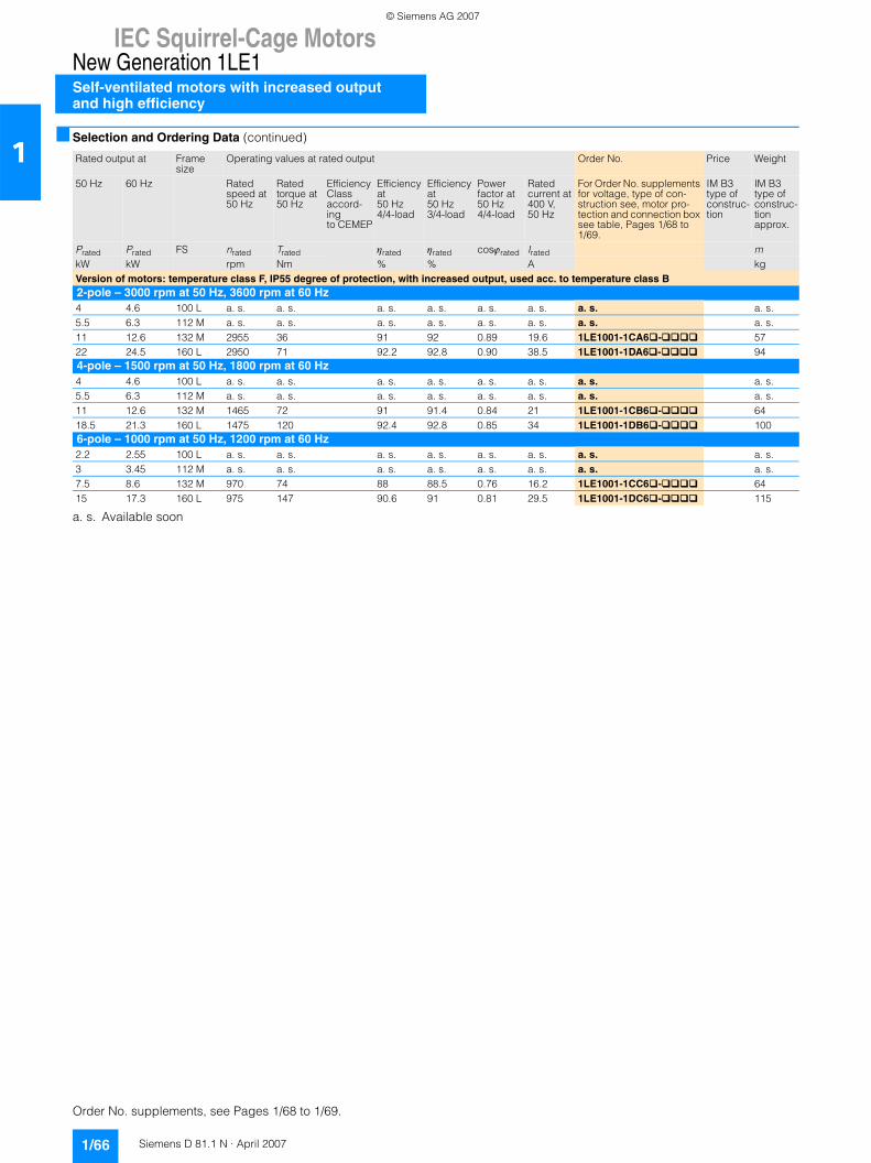
IEC Squirrel-Cage MotorsNew Generation 1LE1Self-ventilated motors with increased outputand high efficiency
1/66 Siemens D 81.1 N · April 2007
1■ Selection and Ordering Data (continued)
a. s. Available soon
Rated output at Frame size
Operating values at rated output Order No. Price Weight
50 Hz 60 Hz Ratedspeed at 50 Hz
Ratedtorque at 50 Hz
Efficiency Classaccord-ingto CEMEP
Efficiencyat50 Hz4/4-load
Efficiencyat50 Hz3/4-load
Powerfactor at50 Hz4/4-load
Ratedcurrent at400 V,50 Hz
For Order No. supplements for voltage, type of con-struction see, motor pro-tection and connection box see table, Pages 1/68 to 1/69.
IM B3 type of construc-tion
IM B3 type of construc-tion approx.
Prated Prated FS nrated Trated ηrated ηrated cosϕrated Irated mkW kW rpm Nm % % A kgVersion of motors: temperature class F, IP55 degree of protection, with increased output, used acc. to temperature class B2-pole – 3000 rpm at 50 Hz, 3600 rpm at 60 Hz4 4.6 100 L a. s. a. s. a. s. a. s. a. s. a. s. a. s. a. s.5.5 6.3 112 M a. s. a. s. a. s. a. s. a. s. a. s. a. s. a. s.11 12.6 132 M 2955 36 91 92 0.89 19.6 1LE1001-1CA6 - 5722 24.5 160 L 2950 71 92.2 92.8 0.90 38.5 1LE1001-1DA6 - 944-pole – 1500 rpm at 50 Hz, 1800 rpm at 60 Hz4 4.6 100 L a. s. a. s. a. s. a. s. a. s. a. s. a. s. a. s.5.5 6.3 112 M a. s. a. s. a. s. a. s. a. s. a. s. a. s. a. s.11 12.6 132 M 1465 72 91 91.4 0.84 21 1LE1001-1CB6 - 6418.5 21.3 160 L 1475 120 92.4 92.8 0.85 34 1LE1001-1DB6 - 1006-pole – 1000 rpm at 50 Hz, 1200 rpm at 60 Hz2.2 2.55 100 L a. s. a. s. a. s. a. s. a. s. a. s. a. s. a. s.3 3.45 112 M a. s. a. s. a. s. a. s. a. s. a. s. a. s. a. s.7.5 8.6 132 M 970 74 88 88.5 0.76 16.2 1LE1001-1CC6 - 6415 17.3 160 L 975 147 90.6 91 0.81 29.5 1LE1001-1DC6 - 115
Order No. supplements, see Pages 1/68 to 1/69.
© Siemens AG 2007

IEC Squirrel-Cage MotorsNew Generation 1LE1
Self-ventilated motors with increased outputand high efficiency
1/67Siemens D 81.1 N · April 2007
1■ Selection and Ordering Data (continued)
a. s. Available soon
Order No. Locked-rotor torque
Locked-rotor current
Breakdown torque
Torque class Momentof inertia
Noise at rated output
with direct starting as multiple of rated Measuring-surface soundpressure levelat 50 Hz
Sound pressurelevel at 50 Hztorque current torque
TLR/Trated ILR/Irated TB/Trated CL J LpfA LWAkgm2 dB(A) dB(A)
Version of motors: temperature class F, IP55 degree of protection, with increased output, used acc. to temperature class B2-pole – 3000 rpm at 50 Hz, 3600 rpm at 60 Hza. s. a. s. a. s. a. s. a. s. a. s. a. s. a. s.a. s. a. s. a. s. a. s. a. s. a. s. a. s. a. s.1LE1001-1CA6�-���� 2.5 7.9 3.2 16 0.031 68 801LE1001-1DA6�-���� 2.7 7.7 3.3 16 0.068 70 824-pole – 1500 rpm at 50 Hz, 1800 rpm at 60 Hza. s. a. s. a. s. a. s. a. s. a. s. a. s. a. s.a. s. a. s. a. s. a. s. a. s. a. s. a. s. a. s.1LE1001-1CB6�-���� 2.9 7.7 3.1 16 0.046 64 761LE1001-1DB6�-���� 2.8 7.7 3.3 16 0.099 64 766-pole – 1000 rpm at 50 Hz, 1200 rpm at 60 Hza. s. a. s. a. s. a. s. a. s. a. s. a. s. a. s.a. s. a. s. a. s. a. s. a. s. a. s. a. s. a. s.1LE1001-1CC6�-���� 2.1 6.5 3 16 0.046 63 751LE1001-1DC6�-���� 1.9 6.5 2.9 16 0.12 68 80
© Siemens AG 2007
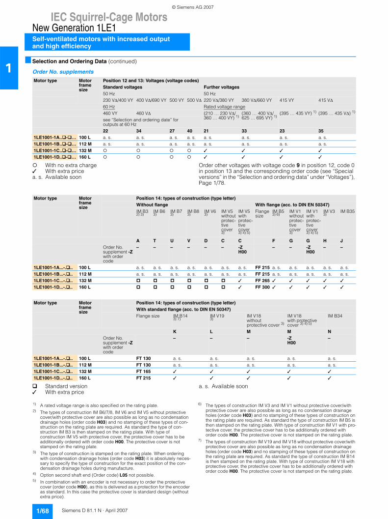
IEC Squirrel-Cage MotorsNew Generation 1LE1Self-ventilated motors with increased outputand high efficiency
1/68 Siemens D 81.1 N · April 2007
1■ Selection and Ordering Data (continued)
Order No. supplements
With no extra charge✓ With extra pricea. s. Available soon
Order other voltages with voltage code 9 in position 12, code 0 in position 13 and the corresponding order code (see “Special versions” in the “Selection and ordering data” under “Voltages”), Page 1/78.
Standard version✓ With extra price
a. s. Available soon
Motor type Motor frame size
Position 12 and 13: Voltages (voltage codes)Standard voltages Further voltages50 Hz 50 Hz230 VΔ/400 VY 400 VΔ/690 VY 500 VY 500 VΔ 220 VΔ/380 VY 380 VΔ/660 VY 415 VY 415 VΔ60 Hz Rated voltage range460 VY 460 VΔ (210 … 230 VΔ/
360 … 400 VY) 1)(360 … 400 VΔ/625 … 695 VY) 1)
(395 … 435 VY) 1) (395 … 435 VΔ) 1)
see “Selection and ordering date” for outputs at 60 Hz22 34 27 40 21 33 23 35
1LE1001-1A.. - … 100 L a. s. a. s. a. s. a. s. a. s. a. s. a. s. a. s.1LE1001-1B.. - … 112 M a. s. a. s. a. s. a. s. a. s. a. s. a. s. a. s.1LE1001-1C.. - … 132 M ✓ ✓ ✓ ✓
1LE1001-1D.. - … 160 L ✓ ✓ ✓ ✓
Motor type Motor frame size
Position 14: types of construction (type letter)Without flange With flange (acc. to DIN EN 50347)IM B32) 3)
IM B63)
IM B73)
IM B83)
IM V63)
IM V5withoutprotec-tive cover3)
IM V5withprotec-tive cover3) 4) 5)
Flange size
IM B53) 6)
IM V1withoutprotec-tive cover3)
IM V1withprotec-tive cover3) 4) 5)
IM V33)
IM B35
A T U V D C C F G G H JOrder No. supplement -Zwith order code
– – – – – – -ZH00
– – -ZH00
– –
1LE1001-1A...-. .. 100 L a. s. a. s. a. s. a. s. a. s. a. s. a. s. FF 215 a. s. a. s. a. s. a. s. a. s.1LE1001-1B...-. .. 112 M a. s. a. s. a. s. a. s. a. s. a. s. a. s. FF 215 a. s. a. s. a. s. a. s. a. s.1LE1001-1C...-. .. 132 M ✓ FF 265 ✓ ✓ ✓ ✓ ✓
1LE1001-1D...-. .. 160 L ✓ FF 300 ✓ ✓ ✓ ✓ ✓
Motor type Motor frame size
Position 14: types of construction (type letter)With standard flange (acc. to DIN EN 50347)Flange size IM B14
3) 7)IM V193)
IM V18withoutprotective cover 3)
IM V18with protective cover 3) 4) 5)
IM B34
K L M M NOrder No. supplement -Zwith order code
– – – -Z H00
–
1LE1001-1A...-. .. 100 L FT 130 a. s. a. s. a. s. a. s. a. s.1LE1001-1B...-. .. 112 M FT 130 a. s. a. s. a. s. a. s. a. s.1LE1001-1C...-. .. 132 M FT 165 ✓ ✓ ✓ ✓ ✓
1LE1001-1D...-. .. 160 L FT 215 ✓ ✓ ✓ ✓ ✓
1) A rated voltage range is also specified on the rating plate.2) The types of construction IM B6/7/8, IM V6 and IM V5 without protective
cover/with protective cover are also possible as long as no condensation drainage holes (order code H03) and no stamping of these types of con-struction on the rating plate are required. As standard the type of con-struction IM B3 is then stamped on the rating plate. With type of construction IM V5 with protective cover, the protective cover has to be additionally ordered with order code H00. The protective cover is not stamped on the rating plate.
3) The type of construction is stamped on the rating plate. When ordering with condensation drainage holes (order code H03) it is absolutely neces-sary to specify the type of construction for the exact position of the con-densation drainage holes during manufacture.
4) Option second shaft end (Order code) L05 not possible.5) In combination with an encoder is not necessary to order the protective
cover (order code H00), as this is delivered as a protection for the encoder as standard. In this case the protective cover is standard design (without extra price).
6) The types of construction IM V3 and IM V1 without protective cover/with protective cover are also possible as long as no condensation drainage holes (order code H03) and no stamping of these types of construction on the rating plate are required. As standard the type of construction IM B5 is then stamped on the rating plate. With type of construction IM V1 with pro-tective cover, the protective cover has to be additionally ordered with order code H00. The protective cover is not stamped on the rating plate.
7) The types of construction IM V19 and IM V18 without protective cover/with protective cover are also possible as long as no condensation drainage holes (order code H03) and no stamping of these types of construction on the rating plate are required. As standard the type of construction IM B14 is then stamped on the rating plate. With type of construction IM V18 with protective cover, the protective cover has to be additionally ordered with order code H00. The protective cover is not stamped on the rating plate.
© Siemens AG 2007

IEC Squirrel-Cage MotorsNew Generation 1LE1
Self-ventilated motors with increased outputand high efficiency
1/69Siemens D 81.1 N · April 2007
1■ Selection and Ordering Data (continued)
Standard version✓ With extra pricea. s. Available soon
Standard version✓ With extra pricea. s. Available soon
Motor type Motor frame size
Position 15: Motor protection (motor protection letter)Without motor protection
Motor protection with PTC ther-mistors with 3 embedded temperature sensorsfor tripping 1)
Motor protection with PTC ther-mistors with 6 embedded temperature sensorsfor alarm and tripping 1)
Motor tempera-ture detection with embedded temperature sensor KTY 84-130 1)
NTC thermistors for tripping
3 temperature detectors for tripping 1))
A B C F Z ZOrder code Q2A Q3A
1LE1001-1A...-.. . 100 L a. s. a. s. a. s. a. s. a. s. a. s.1LE1001-1B...-.. . 112 M a. s. a. s. a. s. a. s. a. s. a. s.1LE1001-1C...-.. . 132 M ✓ ✓ ✓ ✓ ✓
1LE1001-1D...-.. . 160 L ✓ ✓ ✓ ✓ ✓
Motor type Motor frame size
Position 16: Connection box (connection box code)Connection box top 2)
Connection box on RHS 2)
Connection box on LHS 2)
Connection box bottom 2)
4 5 6 71LE1001-1A...-... 100 L a. s. a. s. a. s. a. s.1LE1001-1B...-... 112 M a. s. a. s. a. s. a. s.1LE1001-1C...-… 132 M ✓ ✓ ✓
1LE1001-1D...-... 160 L ✓ ✓ ✓
1) For appropriate tripping unit see Catalog LV 1.2) With type of construction screwed-on feet as standard.
© Siemens AG 2007
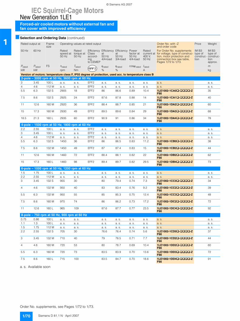
IEC Squirrel-Cage MotorsNew Generation 1LE1Forced-air cooled motors without external fan and fan cover with improved efficiency
1/70 Siemens D 81.1 N · April 2007
1■ Selection and Ordering Data (continued)
a. s. Available soon
Rated output at Frame size
Operating values at rated output Order No. with -Zand order code
Price Weight
50 Hz 60 Hz Ratedspeed at 50 Hz
Ratedtorque at 50 Hz
Efficiency Classaccord-ingto CEMEP
Efficiencyat50 Hz4/4-load
Efficiencyat50 Hz3/4-load
Powerfactor at50 Hz4/4-load
Ratedcurrent at400 V,50 Hz
For Order No. supplements for voltage, type of construc-tion, motor protection and connection box see table, Pages 1/72 to 1/73.
IM B3 type of construc-tion
IM B3 type of construc-tion approx.
Prated Prated FS nrated Trated ηrated ηrated cosϕrated Irated mkW kW rpm Nm % % A kg
Version of motors: temperature class F, IP55 degree of protection, used acc. to temperature class B2-pole – 3000 rpm at 50 Hz, 3600 rpm at 60 Hz3 3.45 100 L a. s. a. s. EFF2 a. s. a. s. a. s. a. s. a. s. a. s.4 4.6 112 M a. s. a. s. EFF2 a. s. a. s. a. s. a. s. a. s. a. s.5.5 6.3 132 S 2905 18 EFF2 86 86.6 0.89 10.4 1LE1002-1CA0 - -Z
F9035
7.5 8.6 132 S 2925 24 EFF2 87.6 87.8 0.88 14 1LE1002-1CA1 - -ZF90
40
11 12.6 160 M 2920 36 EFF2 88.4 88.7 0.85 21 1LE1002-1DA2 - -ZF90
60
15 17.3 160 M 2930 49 EFF2 89.5 89.6 0.84 29 1LE1002-1DA3 - -ZF90
68
18.5 21.3 160 L 2935 60 EFF2 90.9 91 0.86 34 1LE1002-1DA4 - -ZF90
78
4-pole – 1500 rpm at 50 Hz, 1800 rpm at 60 Hz2.2 2.55 100 L a. s. a. s. EFF2 a. s. a. s. a. s. a. s. a. s. a. s.3 3.45 100 L a. s. a. s. EFF2 a. s. a. s. a. s. a. s. a. s. a. s.4 4.6 112 M a. s. a. s. EFF2 a. s. a. s. a. s. a. s. a. s. a. s.5.5 6.3 132 S 1450 36 EFF2 86 86.5 0.83 11.2 1LE1002-1CB0 - -Z
F9038
7.5 8.6 132 M 1450 49 EFF2 87 87.4 0.83 15 1LE1002-1CB2 - -ZF90
44
11 12.6 160 M 1460 72 EFF2 88.4 88.1 0.82 22 1LE1002-1DB2 - -ZF90
62
15 17.3 160 L 1460 98 EFF2 89.4 89.7 0.82 29.5 1LE1002-1DB4 - -ZF90
73
6-pole – 1000 rpm at 50 Hz, 1200 rpm at 60 Hz1.5 1.75 100 L a. s. a. s. a. s. a. s. a. s. a. s. a. s. a. s.2.2 2.55 112 M a. s. a. s. a. s. a. s. a. s. a. s. a. s. a. s.3 3.45 132 S 955 30 80 79.4 0.74 7.3 1LE1002-1CC0 - -Z
F9034
4 4.6 132 M 950 40 83 83.4 0.76 9.2 1LE1002-1CC2 - -ZF90
39
5.5 6.3 132 M 950 55 85 85.3 0.75 12.4 1LE1002-1CC3 - -ZF90
48
7.5 8.6 160 M 970 74 86 86.2 0.73 17.2 1LE1002-1DC2 - -ZF90
72
11 12.6 160 L 965 109 87.6 87.7 0.77 23.5 1LE1002-1DC4 - -ZF90
92
8-pole – 750 rpm at 50 Hz, 900 rpm at 60 Hz0.75 0.86 100 L a. s. a. s. a. s. a. s. a. s. a. s. a. s. a. s.1.1 1.3 100 L a. s. a. s. a. s. a. s. a. s. a. s. a. s. a. s.1.5 1.75 112 M a. s. a. s. a. s. a. s. a. s. a. s. a. s. a. s.2.2 2.55 132 S 705 30 76.6 76.4 0.74 5.6 1LE1002-1CD0 - -Z
F9037
3 3.45 132 M 710 40 79 78.5 0.71 7.7 1LE1002-1CD2 - -ZF90
44
4 4.6 160 M 720 53 80 78.7 0.69 10.4 1LE1002-1DD2 - -ZF90
60
5.5 6.3 160 M 720 73 83.5 83.9 0.70 13.6 1LE1002-1DD3 - -ZF90
72
7.5 8.6 160 L 715 100 83.5 84.7 0.70 18.6 1LE1002-1DD4 - -ZF90
91
Order No. supplements, see Pages 1/72 to 1/73.
© Siemens AG 2007

IEC Squirrel-Cage MotorsNew Generation 1LE1
Forced-air cooled motors without external fan andfan cover with improved efficiency
1/71Siemens D 81.1 N · April 2007
1■ Selection and Ordering Data (continued)
a. s. Available soon
Order No. with -Zand order code
Locked-rotor torque
Locked-rotor current
Breakdown torque
Torque class Momentof inertia
Noise at rated output
with direct starting as multiple of rated Measuring-surface soundpressure levelat 50 Hz
Sound pressurelevel at 50 Hztorque current torque
TLR/Trated ILR/Irated TB/Trated CL J LpfA LWAkgm2 dB(A) dB(A)
Version of motors: temperature class F, IP55 degree of protection, used acc. to temperature class B2-pole – 3000 rpm at 50 Hz, 3600 rpm at 60 Hza. s. a. s. a. s. a. s. a. s. a. s. a. s. a. s.a. s. a. s. a. s. a. s. a. s. a. s. a. s. a. s.1LE1002-1CA0�-����-ZF90
2 5.6 2.6 16 0.013 68 80
1LE1002-1CA1�-����-ZF90
2.2 6.4 3 16 0.016 68 80
1LE1002-1DA2�-����-ZF90
2.1 6.1 2.7 16 0.030 70 82
1LE1002-1DA3�-����-ZF90
2.4 6 3 16 0.036 70 82
1LE1002-1DA4�-����-ZF90
2.5 7 3.2 16 0.044 70 82
4-pole – 1500 rpm at 50 Hz, 1800 rpm at 60 Hza. s. a. s. a. s. a. s. a. s. a. s. a. s. a. s.a. s. a. s. a. s. a. s. a. s. a. s. a. s. a. s.a. s. a. s. a. s. a. s. a. s. a. s. a. s. a. s.1LE1002-1CB0�-����-ZF90
2.3 6.2 2.7 16 0.019 64 76
1LE1002-1CB2�-����-ZF90
2.9 6.6 2.5 16 0.024 64 76
1LE1002-1DB2�-����-ZF90
2.3 6.4 3.1 16 0.044 64 76
1LE1002-1DB4�-����-ZF90
2.5 7 3.4 16 0.056 64 76
6-pole – 1000 rpm at 50 Hz, 1200 rpm at 60 Hza. s. a. s. a. s. a. s. a. s. a. s. a. s. a. s.a. s. a. s. a. s. a. s. a. s. a. s. a. s. a. s.1LE1002-1CC0�-����-ZF90
2 4.6 2.6 16 0.017 63 75
1LE1002-1CC2�-����-ZF90
2.1 4.7 2.5 16 0.021 63 75
1LE1002-1CC3�-����-ZF90
2.5 5.2 2.8 16 0.027 63 75
1LE1002-1DC2�-����-ZF90
2.1 5.5 2.9 16 0.056 68 80
1LE1002-1DC4�-����-ZF90
1.9 5.9 2.7 16 0.078 68 80
8-pole – 750 rpm at 50 Hz, 900 rpm at 60 Hza. s. a. s. a. s. a. s. a. s. a. s. a. s. a. s.a. s. a. s. a. s. a. s. a. s. a. s. a. s. a. s.a. s. a. s. a. s. a. s. a. s. a. s. a. s. a. s.1LE1002-1CD0�-����-ZF90
1.5 3.8 1.9 13 0.019 53 65
1LE1002-1CD2�-����-ZF90
1.7 4.1 2.1 13 0.024 53 65
1LE1002-1DD2�-����-ZF90
1.7 3.8 2.3 13 0.044 68 80
1LE1002-1DD3�-����-ZF90
1.6 4 2.2 13 0.056 68 80
1LE1002-1DD4�-����-ZF90
1.7 3.8 2.2 13 0.077 68 80
© Siemens AG 2007
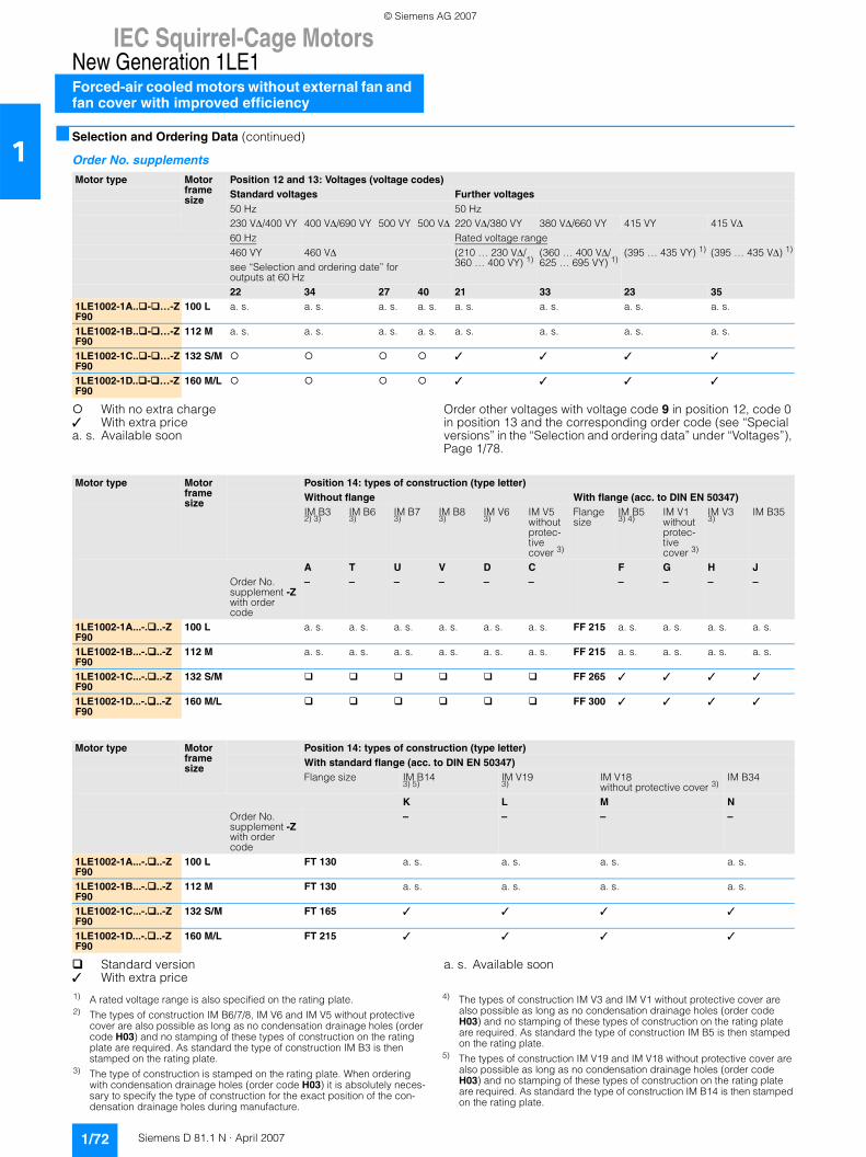
IEC Squirrel-Cage MotorsNew Generation 1LE1Forced-air cooled motors without external fan and fan cover with improved efficiency
1/72 Siemens D 81.1 N · April 2007
1■ Selection and Ordering Data (continued)
Order No. supplements
With no extra charge✓ With extra pricea. s. Available soon
Order other voltages with voltage code 9 in position 12, code 0 in position 13 and the corresponding order code (see “Special versions” in the “Selection and ordering data” under “Voltages”), Page 1/78.
Standard version✓ With extra price
a. s. Available soon
Motor type Motor frame size
Position 12 and 13: Voltages (voltage codes)Standard voltages Further voltages50 Hz 50 Hz230 VΔ/400 VY 400 VΔ/690 VY 500 VY 500 VΔ 220 VΔ/380 VY 380 VΔ/660 VY 415 VY 415 VΔ60 Hz Rated voltage range460 VY 460 VΔ (210 … 230 VΔ/
360 … 400 VY) 1)(360 … 400 VΔ/625 … 695 VY) 1)
(395 … 435 VY) 1) (395 … 435 VΔ) 1)
see “Selection and ordering date” for outputs at 60 Hz22 34 27 40 21 33 23 35
1LE1002-1A.. - …-ZF90
100 L a. s. a. s. a. s. a. s. a. s. a. s. a. s. a. s.
1LE1002-1B.. - …-ZF90
112 M a. s. a. s. a. s. a. s. a. s. a. s. a. s. a. s.
1LE1002-1C.. - …-ZF90
132 S/M ✓ ✓ ✓ ✓
1LE1002-1D.. - …-ZF90
160 M/L ✓ ✓ ✓ ✓
Motor type Motor frame size
Position 14: types of construction (type letter)Without flange With flange (acc. to DIN EN 50347)IM B32) 3)
IM B63)
IM B73)
IM B83)
IM V63)
IM V5withoutprotec-tive cover 3)
Flange size
IM B53) 4)
IM V1withoutprotec-tive cover 3)
IM V33)
IM B35
A T U V D C F G H JOrder No. supplement -Zwith order code
– – – – – – – – – –
1LE1002-1A...-. ..-ZF90
100 L a. s. a. s. a. s. a. s. a. s. a. s. FF 215 a. s. a. s. a. s. a. s.
1LE1002-1B...-. ..-ZF90
112 M a. s. a. s. a. s. a. s. a. s. a. s. FF 215 a. s. a. s. a. s. a. s.
1LE1002-1C...-. ..-ZF90
132 S/M FF 265 ✓ ✓ ✓ ✓
1LE1002-1D...-. ..-ZF90
160 M/L FF 300 ✓ ✓ ✓ ✓
Motor type Motor frame size
Position 14: types of construction (type letter)With standard flange (acc. to DIN EN 50347)Flange size IM B14
3) 5)IM V193)
IM V18without protective cover 3)
IM B34
K L M NOrder No. supplement -Zwith order code
– – – –
1LE1002-1A...-. ..-ZF90
100 L FT 130 a. s. a. s. a. s. a. s.
1LE1002-1B...-. ..-ZF90
112 M FT 130 a. s. a. s. a. s. a. s.
1LE1002-1C...-. ..-ZF90
132 S/M FT 165 ✓ ✓ ✓ ✓
1LE1002-1D...-. ..-ZF90
160 M/L FT 215 ✓ ✓ ✓ ✓
1) A rated voltage range is also specified on the rating plate.2) The types of construction IM B6/7/8, IM V6 and IM V5 without protective
cover are also possible as long as no condensation drainage holes (order code H03) and no stamping of these types of construction on the rating plate are required. As standard the type of construction IM B3 is then stamped on the rating plate.
3) The type of construction is stamped on the rating plate. When ordering with condensation drainage holes (order code H03) it is absolutely neces-sary to specify the type of construction for the exact position of the con-densation drainage holes during manufacture.
4) The types of construction IM V3 and IM V1 without protective cover are also possible as long as no condensation drainage holes (order code H03) and no stamping of these types of construction on the rating plate are required. As standard the type of construction IM B5 is then stamped on the rating plate.
5) The types of construction IM V19 and IM V18 without protective cover are also possible as long as no condensation drainage holes (order code H03) and no stamping of these types of construction on the rating plate are required. As standard the type of construction IM B14 is then stamped on the rating plate.
© Siemens AG 2007
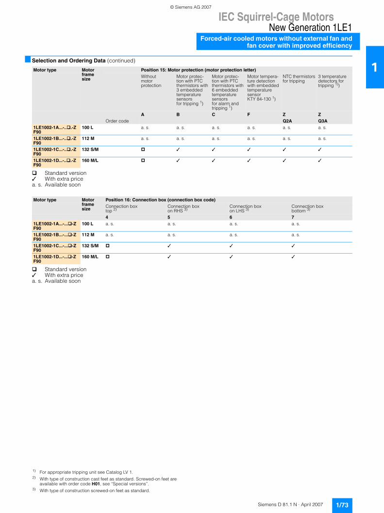
IEC Squirrel-Cage MotorsNew Generation 1LE1
Forced-air cooled motors without external fan andfan cover with improved efficiency
1/73Siemens D 81.1 N · April 2007
1■ Selection and Ordering Data (continued)
Standard version✓ With extra pricea. s. Available soon
Standard version✓ With extra pricea. s. Available soon
Motor type Motor frame size
Position 15: Motor protection (motor protection letter)Without motor protection
Motor protec-tion with PTC thermistors with 3 embedded temperature sensorsfor tripping 1)
Motor protec-tion with PTC thermistors with 6 embedded temperature sensorsfor alarm and tripping 1)
Motor tempera-ture detection with embedded temperature sensor KTY 84-130 1)
NTC thermistors for tripping
3 temperature detectors for tripping 1))
A B C F Z ZOrder code Q2A Q3A
1LE1002-1A...-.. .-ZF90
100 L a. s. a. s. a. s. a. s. a. s. a. s.
1LE1002-1B...-.. .-ZF90
112 M a. s. a. s. a. s. a. s. a. s. a. s.
1LE1002-1C...-.. .-ZF90
132 S/M ✓ ✓ ✓ ✓ ✓
1LE1002-1D...-.. .-ZF90
160 M/L ✓ ✓ ✓ ✓ ✓
Motor type Motor frame size
Position 16: Connection box (connection box code)Connection box top 2)
Connection box on RHS 3)
Connection box on LHS 3)
Connection box bottom 3)
4 5 6 71LE1002-1A...-... -ZF90
100 L a. s. a. s. a. s. a. s.
1LE1002-1B...-... -ZF90
112 M a. s. a. s. a. s. a. s.
1LE1002-1C...-... -ZF90
132 S/M ✓ ✓ ✓
1LE1002-1D...-... -ZF90
160 M/L ✓ ✓ ✓
1) For appropriate tripping unit see Catalog LV 1.2) With type of construction cast feet as standard. Screwed-on feet are
available with order code H01, see “Special versions”.3) With type of construction screwed-on feet as standard.
© Siemens AG 2007

IEC Squirrel-Cage MotorsNew Generation 1LE1Forced-air cooled motors without external fan and fan cover with high efficiency
1/74 Siemens D 81.1 N · April 2007
1■ Selection and Ordering Data (continued)
a. s. Available soon
Rated output at Frame size
Operating values at rated output Order No. with -Zand order code
Price Weight
50 Hz 60 Hz Ratedspeed at 50 Hz
Ratedtorque at 50 Hz
Efficiency Classaccord-ingto CEMEP
Efficiencyat50 Hz4/4-load
Efficiencyat50 Hz3/4-load
Powerfactor at50 Hz4/4-load
Ratedcurrent at400 V,50 Hz
For Order No. supplements for voltage, type of construc-tion, motor protection and connection box see table, Pages 1/76 to 1/77.
IM B3 type of construc-tion
IM B3 type of construc-tion approx.
Prated Prated FS nrated Trated ηrated ηrated cosϕrated Irated mkW kW rpm Nm % % A kg
Version of motors: temperature class F, IP55 degree of protection, used acc. to temperature class B2-pole – 3000 rpm at 50 Hz, 3600 rpm at 60 Hz3 3.45 100 L a. s. a. s. EFF1 a. s. a. s. a. s. a. s. a. s. a. s.4 4.6 112 M a. s. a. s. EFF1 a. s. a. s. a. s. a. s. a. s. a. s.5.5 6.3 132 S 2950 18 EFF1 89.5 90.6 0.87 10.2 1LE1001-1CA0 - -Z
F9039
7.5 8.6 132 S 2950 24 EFF1 90 91 0.87 13.8 1LE1001-1CA1 - -ZF90
43
11 12.6 160 M 2955 36 EFF1 90.8 91 0.87 20 1LE1001-1DA2 - -ZF90
67
15 17.3 160 M 2955 48 EFF1 91.4 91.5 0.88 27 1LE1001-1DA3 - -ZF90
75
18.5 21.3 160 L 2955 60 EFF1 92 92.5 0.88 33 1LE1001-1DA4 - -ZF90
84
4-pole – 1500 rpm at 50 Hz, 1800 rpm at 60 Hz2.2 2.55 100 L a. s. a. s. EFF1 a. s. a. s. a. s. a. s. a. s. a. s.3 3.45 100 L a. s. a. s. EFF1 a. s. a. s. a. s. a. s. a. s. a. s.4 4.6 112 M a. s. a. s. EFF1 a. s. a. s. a. s. a. s. a. s. a. s.5.5 6.3 132 S 1465 36 EFF1 89.2 89.5 0.80 11.2 1LE1001-1CB0 - -Z
F9042
7.5 8.6 132 M 1465 49 EFF1 90.1 91 0.83 14.4 1LE1001-1CB2 - -ZF90
49
11 12.6 160 M 1470 71 EFF1 91.2 91.8 0.85 20.5 1LE1001-1DB2 - -ZF90
71
15 17.3 160 L 1475 97 EFF1 92 92.4 0.85 27.5 1LE1001-1DB4 - -ZF90
83
6-pole – 1000 rpm at 50 Hz, 1200 rpm at 60 Hz1.5 1.75 100 L a. s. a. s. a. s. a. s. a. s. a. s. a. s. a. s.2.2 2.55 112 M a. s. a. s. a. s. a. s. a. s. a. s. a. s. a. s.3 3.45 132 S 970 30 86 85.9 0.73 6.9 1LE1001-1CC0 - -Z
F9038
4 4.6 132 M 970 39 86 86.5 0.78 8.6 1LE1001-1CC2 - -ZF90
43
5.5 6.3 132 M 970 54 88 89 0.77 11.8 1LE1001-1CC3 - -ZF90
52
7.5 8.6 160 M 975 73 89 89.6 0.77 15.8 1LE1001-1DC2 - -ZF90
77
11 12.6 160 L 975 108 89.5 90.5 0.80 22 1LE1001-1DC4 - -ZF90
93
8-pole – 750 rpm at 50 Hz, 900 rpm at 60 Hz0.75 0.86 100 L a. s. a. s. a. s. a. s. a. s. a. s. a. s. a. s.1.1 1.3 110 L a. s. a. s. a. s. a. s. a. s. a. s. a. s. a. s.1.5 1.75 112 M a. s. a. s. a. s. a. s. a. s. a. s. a. s. a. s.2.2 2.55 132 S 725 29 77.5 76.7 0.63 6.5 1LE1001-1CD0 - -Z
F9041
3 3.45 132 M 720 40 77.5 76.5 0.61 9.2 1LE1001-1CD2 - -ZF90
49
4 4.6 160 M 730 52 87 88 0.69 9.6 1LE1001-1DD2 - -ZF90
69
5.5 6.3 160 M 730 72 87.5 89 0.69 13.2 1LE1001-1DD3 - -ZF90
82
7.5 8.6 160 L 730 98 88 89 0.72 17 1LE1001-1DD4 - -ZF90
94
Order No. supplements, see Pages 1/76 to 1/77.
© Siemens AG 2007
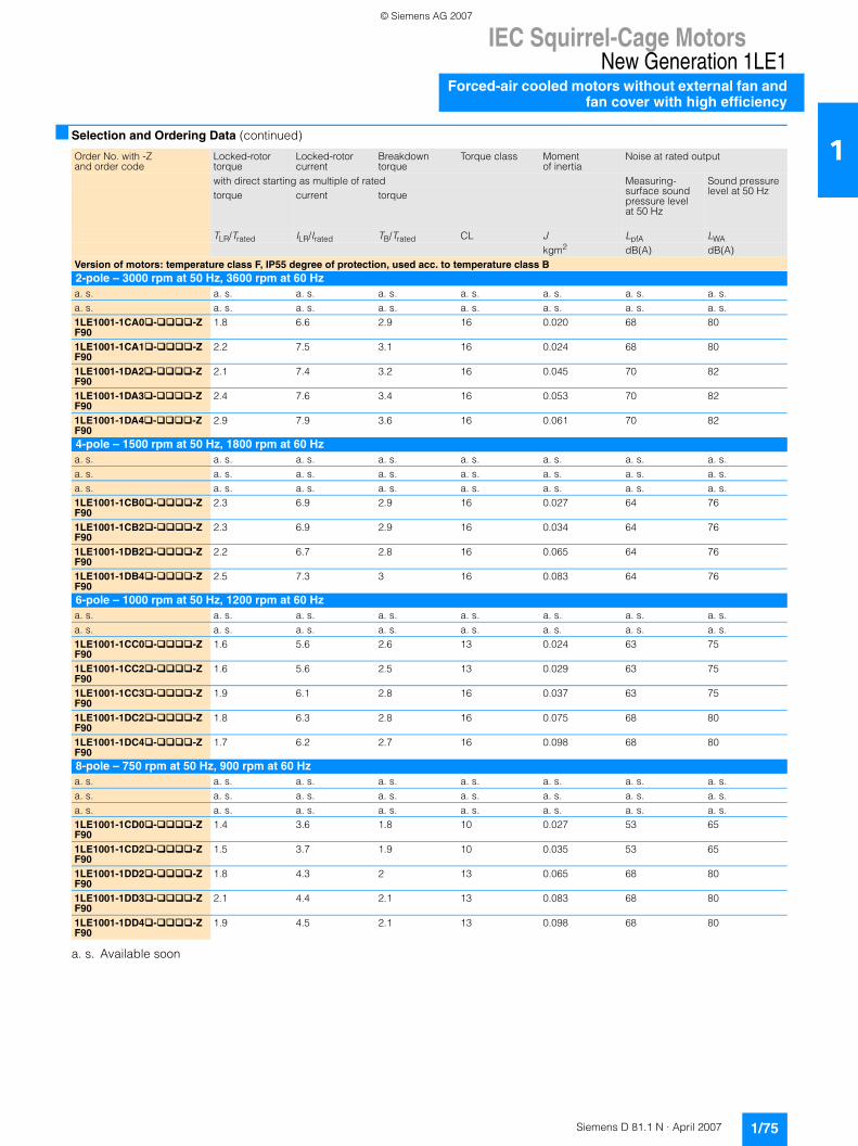
IEC Squirrel-Cage MotorsNew Generation 1LE1
Forced-air cooled motors without external fan andfan cover with high efficiency
1/75Siemens D 81.1 N · April 2007
1■ Selection and Ordering Data (continued)
a. s. Available soon
Order No. with -Zand order code
Locked-rotor torque
Locked-rotor current
Breakdown torque
Torque class Momentof inertia
Noise at rated output
with direct starting as multiple of rated Measuring-surface soundpressure levelat 50 Hz
Sound pressurelevel at 50 Hztorque current torque
TLR/Trated ILR/Irated TB/Trated CL J LpfA LWAkgm2 dB(A) dB(A)
Version of motors: temperature class F, IP55 degree of protection, used acc. to temperature class B2-pole – 3000 rpm at 50 Hz, 3600 rpm at 60 Hza. s. a. s. a. s. a. s. a. s. a. s. a. s. a. s.a. s. a. s. a. s. a. s. a. s. a. s. a. s. a. s.1LE1001-1CA0�-����-ZF90
1.8 6.6 2.9 16 0.020 68 80
1LE1001-1CA1�-����-ZF90
2.2 7.5 3.1 16 0.024 68 80
1LE1001-1DA2�-����-ZF90
2.1 7.4 3.2 16 0.045 70 82
1LE1001-1DA3�-����-ZF90
2.4 7.6 3.4 16 0.053 70 82
1LE1001-1DA4�-����-ZF90
2.9 7.9 3.6 16 0.061 70 82
4-pole – 1500 rpm at 50 Hz, 1800 rpm at 60 Hza. s. a. s. a. s. a. s. a. s. a. s. a. s. a. s.a. s. a. s. a. s. a. s. a. s. a. s. a. s. a. s.a. s. a. s. a. s. a. s. a. s. a. s. a. s. a. s.1LE1001-1CB0�-����-ZF90
2.3 6.9 2.9 16 0.027 64 76
1LE1001-1CB2�-����-ZF90
2.3 6.9 2.9 16 0.034 64 76
1LE1001-1DB2�-����-ZF90
2.2 6.7 2.8 16 0.065 64 76
1LE1001-1DB4�-����-ZF90
2.5 7.3 3 16 0.083 64 76
6-pole – 1000 rpm at 50 Hz, 1200 rpm at 60 Hza. s. a. s. a. s. a. s. a. s. a. s. a. s. a. s.a. s. a. s. a. s. a. s. a. s. a. s. a. s. a. s.1LE1001-1CC0�-����-ZF90
1.6 5.6 2.6 13 0.024 63 75
1LE1001-1CC2�-����-ZF90
1.6 5.6 2.5 13 0.029 63 75
1LE1001-1CC3�-����-ZF90
1.9 6.1 2.8 16 0.037 63 75
1LE1001-1DC2�-����-ZF90
1.8 6.3 2.8 16 0.075 68 80
1LE1001-1DC4�-����-ZF90
1.7 6.2 2.7 16 0.098 68 80
8-pole – 750 rpm at 50 Hz, 900 rpm at 60 Hza. s. a. s. a. s. a. s. a. s. a. s. a. s. a. s.a. s. a. s. a. s. a. s. a. s. a. s. a. s. a. s.a. s. a. s. a. s. a. s. a. s. a. s. a. s. a. s.1LE1001-1CD0�-����-ZF90
1.4 3.6 1.8 10 0.027 53 65
1LE1001-1CD2�-����-ZF90
1.5 3.7 1.9 10 0.035 53 65
1LE1001-1DD2�-����-ZF90
1.8 4.3 2 13 0.065 68 80
1LE1001-1DD3�-����-ZF90
2.1 4.4 2.1 13 0.083 68 80
1LE1001-1DD4�-����-ZF90
1.9 4.5 2.1 13 0.098 68 80
© Siemens AG 2007
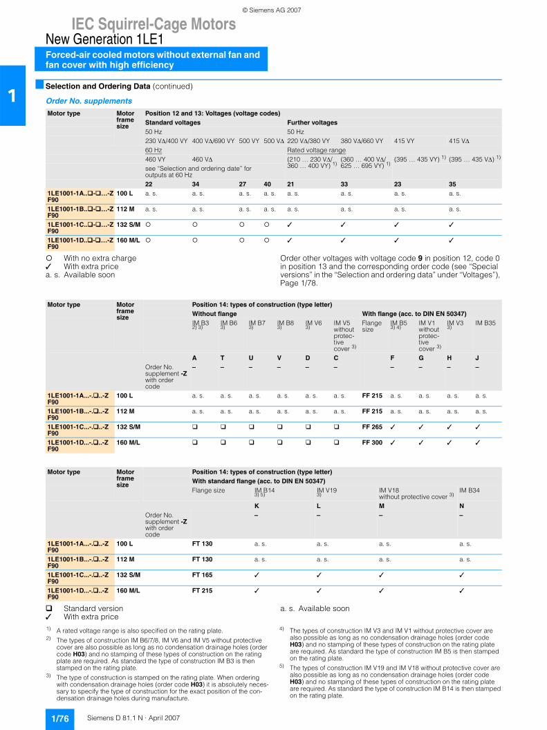
IEC Squirrel-Cage MotorsNew Generation 1LE1Forced-air cooled motors without external fan and fan cover with high efficiency
1/76 Siemens D 81.1 N · April 2007
1■ Selection and Ordering Data (continued)
Order No. supplements
With no extra charge✓ With extra pricea. s. Available soon
Order other voltages with voltage code 9 in position 12, code 0 in position 13 and the corresponding order code (see “Special versions” in the “Selection and ordering data” under “Voltages”), Page 1/78.
Standard version✓ With extra price
a. s. Available soon
Motor type Motor frame size
Position 12 and 13: Voltages (voltage codes)Standard voltages Further voltages50 Hz 50 Hz230 VΔ/400 VY 400 VΔ/690 VY 500 VY 500 VΔ 220 VΔ/380 VY 380 VΔ/660 VY 415 VY 415 VΔ60 Hz Rated voltage range460 VY 460 VΔ (210 … 230 VΔ/
360 … 400 VY) 1)(360 … 400 VΔ/625 … 695 VY) 1)
(395 … 435 VY) 1) (395 … 435 VΔ) 1)
see “Selection and ordering date” for outputs at 60 Hz22 34 27 40 21 33 23 35
1LE1001-1A.. - …-ZF90
100 L a. s. a. s. a. s. a. s. a. s. a. s. a. s. a. s.
1LE1001-1B.. - …-ZF90
112 M a. s. a. s. a. s. a. s. a. s. a. s. a. s. a. s.
1LE1001-1C.. - …-ZF90
132 S/M ✓ ✓ ✓ ✓
1LE1001-1D.. - …-ZF90
160 M/L ✓ ✓ ✓ ✓
Motor type Motor frame size
Position 14: types of construction (type letter)Without flange With flange (acc. to DIN EN 50347)IM B32) 3)
IM B63)
IM B73)
IM B83)
IM V63)
IM V5withoutprotec-tive cover 3)
Flange size
IM B53) 4)
IM V1withoutprotec-tive cover 3)
IM V33)
IM B35
A T U V D C F G H JOrder No. supplement -Zwith order code
– – – – – – – – – –
1LE1001-1A...-. ..-ZF90
100 L a. s. a. s. a. s. a. s. a. s. a. s. FF 215 a. s. a. s. a. s. a. s.
1LE1001-1B...-. ..-ZF90
112 M a. s. a. s. a. s. a. s. a. s. a. s. FF 215 a. s. a. s. a. s. a. s.
1LE1001-1C...-. ..-ZF90
132 S/M FF 265 ✓ ✓ ✓ ✓
1LE1001-1D...-. ..-ZF90
160 M/L FF 300 ✓ ✓ ✓ ✓
Motor type Motor frame size
Position 14: types of construction (type letter)With standard flange (acc. to DIN EN 50347)Flange size IM B14
3) 5)IM V193)
IM V18without protective cover 3)
IM B34
K L M NOrder No. supplement -Zwith order code
– – – –
1LE1001-1A...-. ..-ZF90
100 L FT 130 a. s. a. s. a. s. a. s.
1LE1001-1B...-. ..-ZF90
112 M FT 130 a. s. a. s. a. s. a. s.
1LE1001-1C...-. ..-ZF90
132 S/M FT 165 ✓ ✓ ✓ ✓
1LE1001-1D...-. ..-ZF90
160 M/L FT 215 ✓ ✓ ✓ ✓
1) A rated voltage range is also specified on the rating plate.2) The types of construction IM B6/7/8, IM V6 and IM V5 without protective
cover are also possible as long as no condensation drainage holes (order code H03) and no stamping of these types of construction on the rating plate are required. As standard the type of construction IM B3 is then stamped on the rating plate.
3) The type of construction is stamped on the rating plate. When ordering with condensation drainage holes (order code H03) it is absolutely neces-sary to specify the type of construction for the exact position of the con-densation drainage holes during manufacture.
4) The types of construction IM V3 and IM V1 without protective cover are also possible as long as no condensation drainage holes (order code H03) and no stamping of these types of construction on the rating plate are required. As standard the type of construction IM B5 is then stamped on the rating plate.
5) The types of construction IM V19 and IM V18 without protective cover are also possible as long as no condensation drainage holes (order code H03) and no stamping of these types of construction on the rating plate are required. As standard the type of construction IM B14 is then stamped on the rating plate.
© Siemens AG 2007

IEC Squirrel-Cage MotorsNew Generation 1LE1
Forced-air cooled motors without external fan andfan cover with high efficiency
1/77Siemens D 81.1 N · April 2007
1■ Selection and Ordering Data (continued)
Standard version✓ With extra price
a. s. Available soon
Standard version✓ With extra pricea. s. Available soon
Motor type Motor frame size
Position 15: Motor protection (motor protection letter)Without motor protection
Motor protec-tion with PTC thermistors with 3 embedded temperature sensorsfor tripping 1)
Motor protec-tion with PTC thermistors with 6 embedded temperature sensorsfor alarm and tripping 1)
Motor tempera-ture detection with embedded temperature sensor KTY 84-130 1)
NTC ther-mistors for trip-ping
3 temperature detectors for tripping 1))
A B C F Z ZOrder code Q2A Q3A
1LE1001-1A...-.. .-ZF90
100 L a. s. a. s. a. s. a. s. a. s. a. s.
1LE1001-1B...-.. .-ZF90
112 M a. s. a. s. a. s. a. s. a. s. a. s.
1LE1001-1C...-.. .-ZF90
132 S/M ✓ ✓ ✓ ✓ ✓
1LE1001-1D...-.. .-ZF90
160 M/L ✓ ✓ ✓ ✓ ✓
Motor type Motor frame size
Position 16: Connection box (connection box code)Connection box top 2)
Connection box on RHS 3)
Connection box on LHS 3)
Connection box bottom 3)
4 5 6 71LE1001-1A ...-... -ZF90
100 L a. s. a. s. a. s. a. s.
1LE1001-1B ...-... -ZF90
112 M a. s. a. s. a. s. a. s.
1LE1001-1C ...-... -ZF90
132 S/M ✓ ✓ ✓
1LE1001-1D ...-... -ZF90
160 M/L ✓ ✓ ✓
1) For appropriate tripping unit see Catalog LV 1.2) With type of construction cast feet as standard. Screwed-on feet are
available with order code H01, see “Special versions”.3) With type of construction screwed-on feet as standard.
© Siemens AG 2007
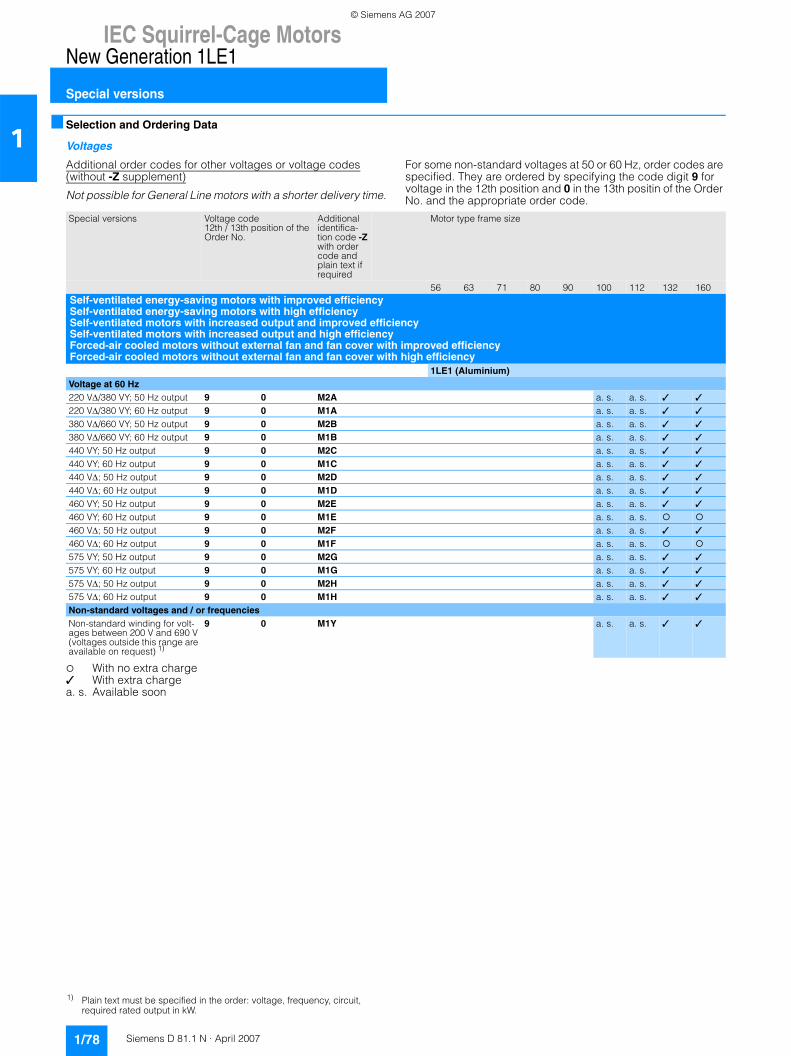
IEC Squirrel-Cage MotorsNew Generation 1LE1
Special versions
1/78 Siemens D 81.1 N · April 2007
1■ Selection and Ordering Data
Voltages
Additional order codes for other voltages or voltage codes (without -Z supplement)
Not possible for General Line motors with a shorter delivery time.
For some non-standard voltages at 50 or 60 Hz, order codes are specified. They are ordered by specifying the code digit 9 for voltage in the 12th position and 0 in the 13th positin of the Order No. and the appropriate order code.
With no extra charge✓ With extra chargea. s. Available soon
Special versions Voltage code 12th / 13th position of the Order No.
Additional identifica-tion code -Z with order code and plain text if required
Motor type frame size
56 63 71 80 90 100 112 132 160Self-ventilated energy-saving motors with improved efficiencySelf-ventilated energy-saving motors with high efficiencySelf-ventilated motors with increased output and improved efficiencySelf-ventilated motors with increased output and high efficiencyForced-air cooled motors without external fan and fan cover with improved efficiencyForced-air cooled motors without external fan and fan cover with high efficiency
1LE1 (Aluminium)Voltage at 60 Hz 220 VΔ/380 VY; 50 Hz output 9 0 M2A a. s. a. s. ✓ ✓
220 VΔ/380 VY; 60 Hz output 9 0 M1A a. s. a. s. ✓ ✓
380 VΔ/660 VY; 50 Hz output 9 0 M2B a. s. a. s. ✓ ✓
380 VΔ/660 VY; 60 Hz output 9 0 M1B a. s. a. s. ✓ ✓
440 VY; 50 Hz output 9 0 M2C a. s. a. s. ✓ ✓
440 VY; 60 Hz output 9 0 M1C a. s. a. s. ✓ ✓
440 VΔ; 50 Hz output 9 0 M2D a. s. a. s. ✓ ✓
440 VΔ; 60 Hz output 9 0 M1D a. s. a. s. ✓ ✓
460 VY; 50 Hz output 9 0 M2E a. s. a. s. ✓ ✓
460 VY; 60 Hz output 9 0 M1E a. s. a. s.460 VΔ; 50 Hz output 9 0 M2F a. s. a. s. ✓ ✓
460 VΔ; 60 Hz output 9 0 M1F a. s. a. s.575 VY; 50 Hz output 9 0 M2G a. s. a. s. ✓ ✓
575 VY; 60 Hz output 9 0 M1G a. s. a. s. ✓ ✓
575 VΔ; 50 Hz output 9 0 M2H a. s. a. s. ✓ ✓
575 VΔ; 60 Hz output 9 0 M1H a. s. a. s. ✓ ✓
Non-standard voltages and / or frequenciesNon-standard winding for volt-ages between 200 V and 690 V (voltages outside this range are available on request) 1)
9 0 M1Y a. s. a. s. ✓ ✓
1) Plain text must be specified in the order: voltage, frequency, circuit, required rated output in kW.
© Siemens AG 2007

IEC Squirrel-Cage MotorsNew Generation 1LE1
Special versions
1/79Siemens D 81.1 N · April 2007
1Options
Options or order codes (supplement -Z is required)
Not possible for General Line motors with a shorter delivery time.
Special versions Additional identifica-tion code -Z with order code and plain text if required
Motor type frame size
56 63 71 80 90 100 112 132 160Self-ventilated energy-saving motors with improved efficiencySelf-ventilated energy-saving motors with high efficiencySelf-ventilated motors with increased output and improved efficiencySelf-ventilated motors with increased output and high efficiency
1LE1 (Aluminium)Motor connection and connection boxes Cable entry, standard configuration
R15 a. s. a. s. ✓ ✓
Rotation of the connection box through 90°, entry from DE
R10 a. s. a. s.
Rotation of the connection box through 90°, entry from NDE
R11 a. s. a. s.
Rotation of the connection box through 180°
R12 a. s. a. s.
External earthing H04 a. s. a. s. ✓ ✓
Windings and insulationTemperature class F, used acc. to F, with service factor (SF)
N01 a. s. a. s. ✓ ✓
Temperature class F, used acc. to F, with increased output
N02 a. s. a. s. ✓ ✓
Temperature class F, used acc. to F, with increased ambient temperature
N03 a. s. a. s. ✓ ✓
Temperature class F, used acc. to B, ambient temperature 45 °C, derating approx. 4%
N05 a. s. a. s. ✓ ✓
Temperature class F, used acc. to B, ambient temperature 50 °C, derating approx. 8%
N06 a. s. a. s. ✓ ✓
Temperature class F, used acc. to B, ambient temperature 55 °C, derating approx. 13%
N07 a. s. a. s. ✓ ✓
Temperature class F, used acc. to B, ambient temperature 60 °C, derating approx. 18%
N08 a. s. a. s. ✓ ✓
Temperature class F, used acc. to F, other requirements
Y52 • and identifica-tion code
a. s. a. s. ✓ ✓
Colors and paint finishSpecial finish in RAL 7030 stone gray
a. s. a. s.
Special finish in RAL 1002 sand yellow
S24 a. s. a. s. ✓ ✓
Special finish in RAL 1013 pearl white
S25 a. s. a. s. ✓ ✓
Special finish in RAL 3000 flame red
S26 a. s. a. s. ✓ ✓
Special finish in RAL 6011 reseda green
S20 a. s. a. s. ✓ ✓
Special finish in RAL 6021 pale green
S27 a. s. a. s. ✓ ✓
Special finish in RAL 7001 silver gray
S28 a. s. a. s. ✓ ✓
Special finish in RAL 7031 blue gray
S21 a. s. a. s. ✓ ✓
Special finish in RAL 7032 pebble gray
S22 a. s. a. s. ✓ ✓
Special finish in RAL 7035 light gray
S29 a. s. a. s. ✓ ✓
Special finish in RAL 9001 cream
S30 a. s. a. s. ✓ ✓
For legend and footnotes, see Page 1/82.
© Siemens AG 2007
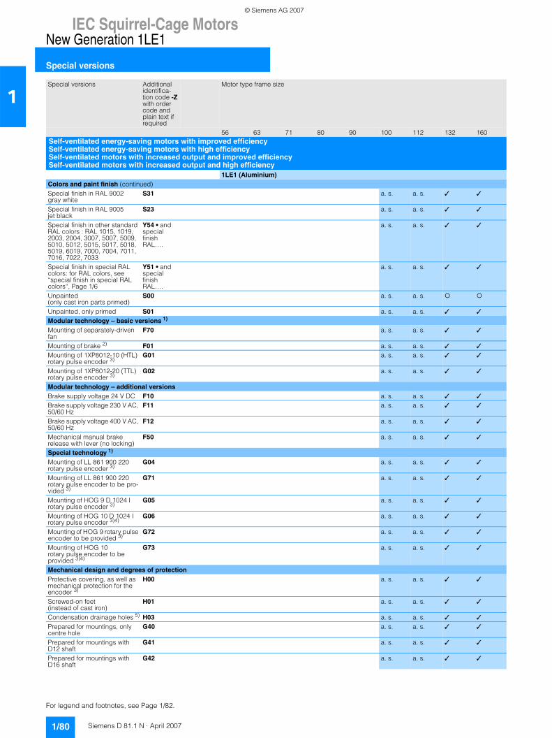
IEC Squirrel-Cage MotorsNew Generation 1LE1
Special versions
1/80 Siemens D 81.1 N · April 2007
1
Colors and paint finish (continued)Special finish in RAL 9002 gray white
S31 a. s. a. s. ✓ ✓
Special finish in RAL 9005 jet black
S23 a. s. a. s. ✓ ✓
Special finish in other standard RAL colors : RAL 1015, 1019, 2003, 2004, 3007, 5007, 5009, 5010, 5012, 5015, 5017, 5018, 5019, 6019, 7000, 7004, 7011, 7016, 7022, 7033
Y54 • and special finish RAL….
a. s. a. s. ✓ ✓
Special finish in special RAL colors: for RAL colors, see “special finish in special RAL colors“, Page 1/6
Y51 • and special finish RAL….
a. s. a. s. ✓ ✓
Unpainted (only cast iron parts primed)
S00 a. s. a. s.
Unpainted, only primed S01 a. s. a. s. ✓ ✓
Modular technology – basic versions 1)
Mounting of separately-driven fan
F70 a. s. a. s. ✓ ✓
Mounting of brake 2) F01 a. s. a. s. ✓ ✓
Mounting of 1XP8012-10 (HTL) rotary pulse encoder 3)
G01 a. s. a. s. ✓ ✓
Mounting of 1XP8012-20 (TTL) rotary pulse encoder 3)
G02 a. s. a. s. ✓ ✓
Modular technology – additional versions Brake supply voltage 24 V DC F10 a. s. a. s. ✓ ✓
Brake supply voltage 230 V AC, 50/60 Hz
F11 a. s. a. s. ✓ ✓
Brake supply voltage 400 V AC, 50/60 Hz
F12 a. s. a. s. ✓ ✓
Mechanical manual brake release with lever (no locking)
F50 a. s. a. s. ✓ ✓
Special technology 1)
Mounting of LL 861 900 220 rotary pulse encoder 3)
G04 a. s. a. s. ✓ ✓
Mounting of LL 861 900 220 rotary pulse encoder to be pro-vided 3)
G71 a. s. a. s. ✓ ✓
Mounting of HOG 9 D 1024 I rotary pulse encoder 3)
G05 a. s. a. s. ✓ ✓
Mounting of HOG 10 D 1024 Irotary pulse encoder 3)4)
G06 a. s. a. s. ✓ ✓
Mounting of HOG 9 rotary pulse encoder to be provided 3)
G72 a. s. a. s. ✓ ✓
Mounting of HOG 10
rotary pulse encoder to be provided 3)4)
G73 a. s. a. s. ✓ ✓
Mechanical design and degrees of protectionProtective covering, as well as mechanical protection for the encoder 3)
H00 a. s. a. s. ✓ ✓
Screwed-on feet (instead of cast iron)
H01 a. s. a. s. ✓ ✓
Condensation drainage holes 5) H03 a. s. a. s. ✓ ✓
Prepared for mountings, only centre hole
G40 a. s. a. s. ✓ ✓
Prepared for mountings with D12 shaft
G41 a. s. a. s. ✓ ✓
Prepared for mountings with D16 shaft
G42 a. s. a. s. ✓ ✓
Special versions Additional identifica-tion code -Z with order code and plain text if required
Motor type frame size
56 63 71 80 90 100 112 132 160Self-ventilated energy-saving motors with improved efficiencySelf-ventilated energy-saving motors with high efficiencySelf-ventilated motors with increased output and improved efficiencySelf-ventilated motors with increased output and high efficiency
1LE1 (Aluminium)
For legend and footnotes, see Page 1/82.
© Siemens AG 2007
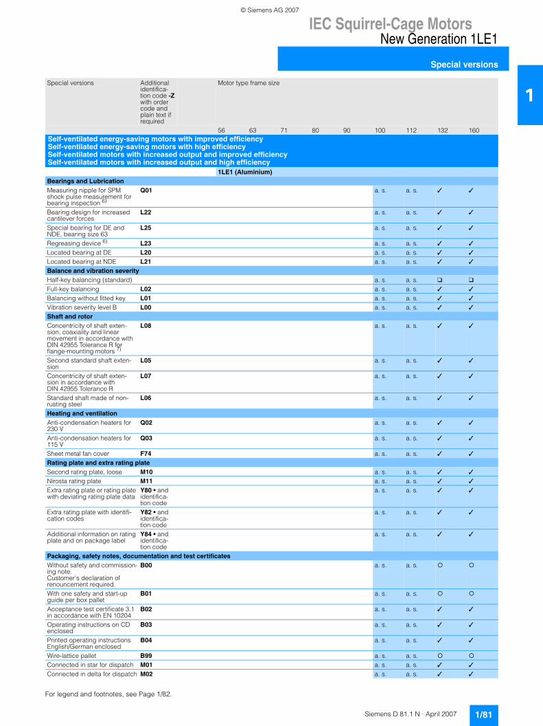
IEC Squirrel-Cage MotorsNew Generation 1LE1
Special versions
1/81Siemens D 81.1 N · April 2007
1
Bearings and LubricationMeasuring nipple for SPM shock pulse measurement for bearing inspection 6)
Q01 a. s. a. s. ✓ ✓
Bearing design for increased cantilever forces
L22 a. s. a. s. ✓ ✓
Special bearing for DE and NDE, bearing size 63
L25 a. s. a. s. ✓ ✓
Regreasing device 6) L23 a. s. a. s. ✓ ✓
Located bearing at DE L20 a. s. a. s. ✓ ✓
Located bearing at NDE L21 a. s. a. s. ✓ ✓
Balance and vibration severityHalf-key balancing (standard) a. s. a. s. ❑ ❑
Full-key balancing L02 a. s. a. s. ✓ ✓
Balancing without fitted key L01 a. s. a. s. ✓ ✓
Vibration severity level B L00 a. s. a. s. ✓ ✓
Shaft and rotorConcentricity of shaft exten-sion, coaxiality and linear movement in accordance with DIN 42955 Tolerance R for flange-mounting motors 7)
L08 a. s. a. s. ✓ ✓
Second standard shaft exten-sion
L05 a. s. a. s. ✓ ✓
Concentricity of shaft exten-sion in accordance with DIN 42955 Tolerance R
L07 a. s. a. s. ✓ ✓
Standard shaft made of non-rusting steel
L06 a. s. a. s. ✓ ✓
Heating and ventilationAnti-condensation heaters for 230 V
Q02 a. s. a. s. ✓ ✓
Anti-condensation heaters for 115 V
Q03 a. s. a. s. ✓ ✓
Sheet metal fan cover F74 a. s. a. s. ✓ ✓
Rating plate and extra rating plateSecond rating plate, loose M10 a. s. a. s. ✓ ✓
Nirosta rating plate M11 a. s. a. s. ✓ ✓
Extra rating plate or rating plate with deviating rating plate data
Y80 • and identifica-tion code
a. s. a. s. ✓ ✓
Extra rating plate with identifi-cation codes
Y82 • and identifica-tion code
a. s. a. s. ✓ ✓
Additional information on rating plate and on package label
Y84 • and identifica-tion code
a. s. a. s. ✓ ✓
Packaging, safety notes, documentation and test certificatesWithout safety and commission-ing note. Customer's declaration of renouncement required.
B00 a. s. a. s.
With one safety and start-up guide per box pallet
B01 a. s. a. s.
Acceptance test certificate 3.1 in accordance with EN 10204
B02 a. s. a. s. ✓ ✓
Operating instructions on CD enclosed
B03 a. s. a. s. ✓ ✓
Printed operating instructions English/German enclosed
B04 a. s. a. s. ✓ ✓
Wire-lattice pallet B99 a. s. a. s.Connected in star for dispatch M01 a. s. a. s. ✓ ✓
Connected in delta for dispatch M02 a. s. a. s. ✓ ✓
Special versions Additional identifica-tion code -Z with order code and plain text if required
Motor type frame size
56 63 71 80 90 100 112 132 160Self-ventilated energy-saving motors with improved efficiencySelf-ventilated energy-saving motors with high efficiencySelf-ventilated motors with increased output and improved efficiencySelf-ventilated motors with increased output and high efficiency
1LE1 (Aluminium)
For legend and footnotes, see Page 1/82.
© Siemens AG 2007
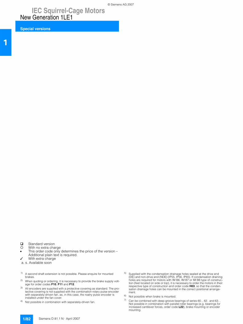
IEC Squirrel-Cage MotorsNew Generation 1LE1
Special versions
1/82 Siemens D 81.1 N · April 2007
1
1) A second shaft extension is not possible. Please enquire for mounted brakes.
2) When quoting or ordering, it is necessary to provide the brake supply volt-age for order codes F10, F11 and F12.
3) All encoders are supplied with a protective covering as standard. The pro-tective covering is not supplied with the combination rotary pulse encoder with separately-driven fan, as, in this case, the roatry pulse encoder is installed under the fan cover.
4) Not possible in combination with separately-driven fan.
5) Supplied with the condensation drainage holes sealed at the drive end (DE) and non-drive end (NDE) (IP55, IP56, IP65). If condensation draining holes are required for motors with IM B6, IM B7 or IM B8 type of construc-tion (feet located on side or top), it is necessary to order the motors in their respective type of construction and order code H03, so that the conden-sation drainage holes can be mounted in the correct positional arrange-ment.
6) Not possible when brake is mounted.7) Can be combined with deep-groove bearings of series 60.., 62.. and 63…
Not possible in combination with parallel roller bearings (e.g. bearings for increased cantilever forces, order code L22), brake mounting or encoder mounting.
Standard versionWith no extra charge
• This order code only determines the price of the version – Additional plain text is required.
✓ With extra charge a. s. Available soon
© Siemens AG 2007
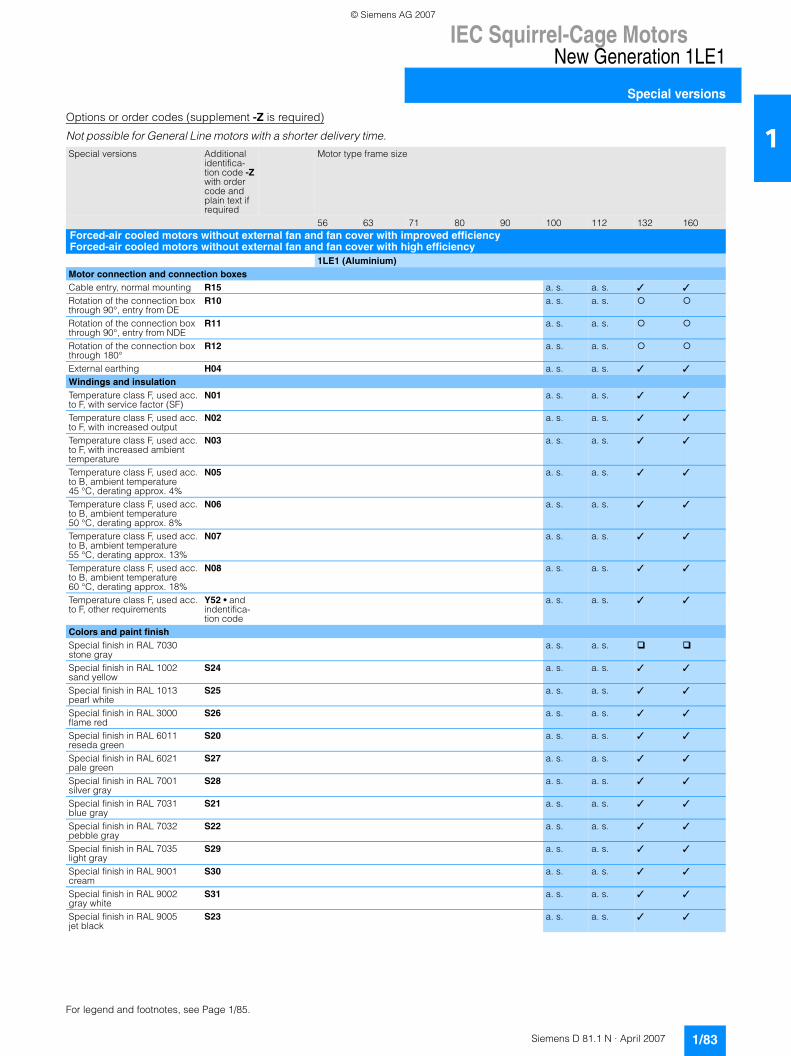
IEC Squirrel-Cage MotorsNew Generation 1LE1
Special versions
1/83Siemens D 81.1 N · April 2007
1Options or order codes (supplement -Z is required)
Not possible for General Line motors with a shorter delivery time.
Special versions Additional identifica-tion code -Z with order code and plain text if required
Motor type frame size
56 63 71 80 90 100 112 132 160Forced-air cooled motors without external fan and fan cover with improved efficiencyForced-air cooled motors without external fan and fan cover with high efficiency
1LE1 (Aluminium)Motor connection and connection boxesCable entry, normal mounting R15 a. s. a. s. ✓ ✓
Rotation of the connection box through 90°, entry from DE
R10 a. s. a. s.
Rotation of the connection box through 90°, entry from NDE
R11 a. s. a. s.
Rotation of the connection box through 180°
R12 a. s. a. s.
External earthing H04 a. s. a. s. ✓ ✓
Windings and insulationTemperature class F, used acc. to F, with service factor (SF)
N01 a. s. a. s. ✓ ✓
Temperature class F, used acc. to F, with increased output
N02 a. s. a. s. ✓ ✓
Temperature class F, used acc. to F, with increased ambient temperature
N03 a. s. a. s. ✓ ✓
Temperature class F, used acc. to B, ambient temperature 45 °C, derating approx. 4%
N05 a. s. a. s. ✓ ✓
Temperature class F, used acc. to B, ambient temperature 50 °C, derating approx. 8%
N06 a. s. a. s. ✓ ✓
Temperature class F, used acc. to B, ambient temperature 55 °C, derating approx. 13%
N07 a. s. a. s. ✓ ✓
Temperature class F, used acc. to B, ambient temperature 60 °C, derating approx. 18%
N08 a. s. a. s. ✓ ✓
Temperature class F, used acc. to F, other requirements
Y52 • and indentifica-tion code
a. s. a. s. ✓ ✓
Colors and paint finishSpecial finish in RAL 7030 stone gray
a. s. a. s.
Special finish in RAL 1002 sand yellow
S24 a. s. a. s. ✓ ✓
Special finish in RAL 1013 pearl white
S25 a. s. a. s. ✓ ✓
Special finish in RAL 3000 flame red
S26 a. s. a. s. ✓ ✓
Special finish in RAL 6011 reseda green
S20 a. s. a. s. ✓ ✓
Special finish in RAL 6021 pale green
S27 a. s. a. s. ✓ ✓
Special finish in RAL 7001 silver gray
S28 a. s. a. s. ✓ ✓
Special finish in RAL 7031 blue gray
S21 a. s. a. s. ✓ ✓
Special finish in RAL 7032 pebble gray
S22 a. s. a. s. ✓ ✓
Special finish in RAL 7035 light gray
S29 a. s. a. s. ✓ ✓
Special finish in RAL 9001 cream
S30 a. s. a. s. ✓ ✓
Special finish in RAL 9002 gray white
S31 a. s. a. s. ✓ ✓
Special finish in RAL 9005 jet black
S23 a. s. a. s. ✓ ✓
For legend and footnotes, see Page 1/85.
© Siemens AG 2007
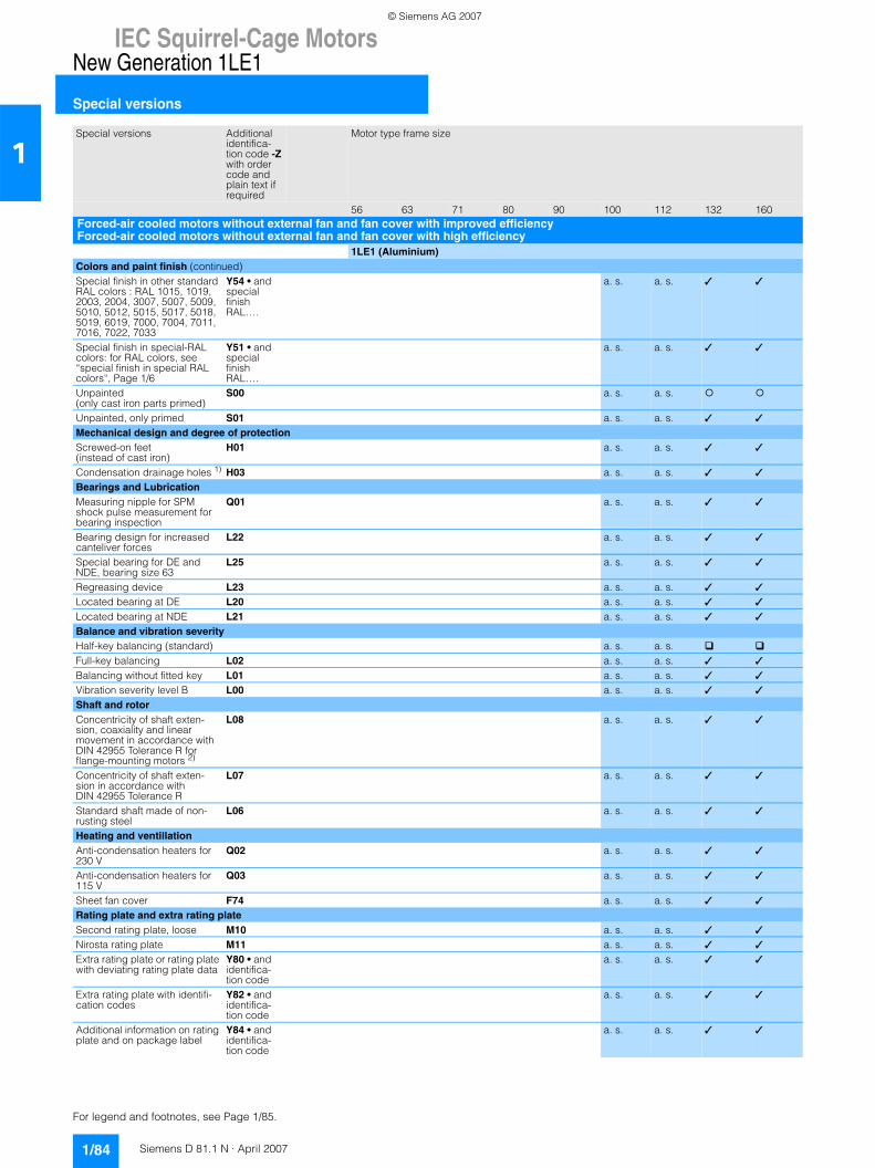
IEC Squirrel-Cage MotorsNew Generation 1LE1
Special versions
1/84 Siemens D 81.1 N · April 2007
1
Colors and paint finish (continued)Special finish in other standard RAL colors : RAL 1015, 1019, 2003, 2004, 3007, 5007, 5009, 5010, 5012, 5015, 5017, 5018, 5019, 6019, 7000, 7004, 7011, 7016, 7022, 7033
Y54 • and special finish RAL….
a. s. a. s. ✓ ✓
Special finish in special-RAL colors: for RAL colors, see “special finish in special RAL colors“, Page 1/6
Y51 • and special finish RAL….
a. s. a. s. ✓ ✓
Unpainted (only cast iron parts primed)
S00 a. s. a. s.
Unpainted, only primed S01 a. s. a. s. ✓ ✓
Mechanical design and degree of protectionScrewed-on feet (instead of cast iron)
H01 a. s. a. s. ✓ ✓
Condensation drainage holes 1) H03 a. s. a. s. ✓ ✓
Bearings and LubricationMeasuring nipple for SPM shock pulse measurement for bearing inspection
Q01 a. s. a. s. ✓ ✓
Bearing design for increased canteliver forces
L22 a. s. a. s. ✓ ✓
Special bearing for DE and NDE, bearing size 63
L25 a. s. a. s. ✓ ✓
Regreasing device L23 a. s. a. s. ✓ ✓
Located bearing at DE L20 a. s. a. s. ✓ ✓
Located bearing at NDE L21 a. s. a. s. ✓ ✓
Balance and vibration severityHalf-key balancing (standard) a. s. a. s.Full-key balancing L02 a. s. a. s. ✓ ✓
Balancing without fitted key L01 a. s. a. s. ✓ ✓
Vibration severity level B L00 a. s. a. s. ✓ ✓
Shaft and rotorConcentricity of shaft exten-sion, coaxiality and linear movement in accordance with DIN 42955 Tolerance R for flange-mounting motors 2)
L08 a. s. a. s. ✓ ✓
Concentricity of shaft exten-sion in accordance with DIN 42955 Tolerance R
L07 a. s. a. s. ✓ ✓
Standard shaft made of non-rusting steel
L06 a. s. a. s. ✓ ✓
Heating and ventillationAnti-condensation heaters for 230 V
Q02 a. s. a. s. ✓ ✓
Anti-condensation heaters for 115 V
Q03 a. s. a. s. ✓ ✓
Sheet fan cover F74 a. s. a. s. ✓ ✓
Rating plate and extra rating plateSecond rating plate, loose M10 a. s. a. s. ✓ ✓
Nirosta rating plate M11 a. s. a. s. ✓ ✓
Extra rating plate or rating plate with deviating rating plate data
Y80 • and identifica-tion code
a. s. a. s. ✓ ✓
Extra rating plate with identifi-cation codes
Y82 • and identifica-tion code
a. s. a. s. ✓ ✓
Additional information on rating plate and on package label
Y84 • and identifica-tion code
a. s. a. s. ✓ ✓
Special versions Additional identifica-tion code -Z with order code and plain text if required
Motor type frame size
56 63 71 80 90 100 112 132 160Forced-air cooled motors without external fan and fan cover with improved efficiencyForced-air cooled motors without external fan and fan cover with high efficiency
1LE1 (Aluminium)
For legend and footnotes, see Page 1/85.
© Siemens AG 2007
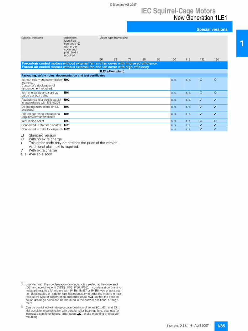
IEC Squirrel-Cage MotorsNew Generation 1LE1
Special versions
1/85Siemens D 81.1 N · April 2007
1
Standard versionWith no extra charge
• This order code only determines the price of the version –Additional plain text is required.
✓ With extra charge a. s. Available soon
Packaging, safety notes, documentation and test certificatesWithout safety and commission-ing note. Customer's declaration of renouncement required.
B00 a. s. a. s.
With one safety and start-up guide per box pallet
B01 a. s. a. s.
Acceptance test certificate 3.1 in accordance with EN 10204
B02 a. s. a. s. ✓ ✓
Operating instructions on CD enclosed
B03 a. s. a. s. ✓ ✓
Printed operating instructions English/German enclosed
B04 a. s. a. s. ✓ ✓
Wire-lattice pallet B99 a. s. a. s.Connected in star for dispatch M01 a. s. a. s. ✓ ✓
Connected in delta for dispatch M02 a. s. a. s. ✓ ✓
Special versions Additional identifica-tion code -Z with order code and plain text if required
Motor type frame size
56 63 71 80 90 100 112 132 160Forced-air cooled motors without external fan and fan cover with improved efficiencyForced-air cooled motors without external fan and fan cover with high efficiency
1LE1 (Aluminium)
1) Supplied with the condensation drainage holes sealed at the drive end (DE) and non-drive end (NDE) (IP55, IP56, IP65). If condensation draining holes are required for motors with IM B6, IM B7 or IM B8 type of construc-tion (feet located on side or top), it is necessary to order the motors in their respective type of construction and order code H03, so that the conden-sation drainage holes can be mounted in the correct positional arrange-ment.
2) Can be combined with deep-groove bearings of series 60.., 62.. and 63… Not possible in combination with parallel roller bearings (e.g. bearings for increased cantilever forces, order code L22), brakd mounting or encoder mounting.
© Siemens AG 2007
IEC Squirrel-Cage MotorsNew Generation 1LE1
Accessories and spare parts
1/86 Siemens D 81.1 N · April 2007
1■ Overview
Couplings
The motor from Siemens is connected to the machine or gear unit through a coupling. Flender is an important coupling manu-facturer with a wide range of products. For standard applica-tions, Siemens recommends that elastic couplings of Flender types N-Eupex and Rupex or torsionally rigid couplings of types Arpex and Zapex are used. For special applications, Fludex and Elpex couplings are recommended.
Available from:A. Friedr. Flender AGKupplungswerk MussumIndustriepark BocholtSchlavenhorst 10046395 BocholtTel. +49 (0) 2871-92 2185Fax +49 (0) 2871-92 2579
http://www.flender.com e-mail: [email protected]
Mounting of encoder
In the case of supply or mounting by the customer.
Options G72, G73
Hübner Elektromaschinen AG 10967 Berlin Planufer 92b Tel. +49 (0) 30-690 03-0 Fax +49 (0) 30-690 03-104
http://www.huebner-berlin.de/index_uk e-mail: [email protected]
Option G71
Leine & Linde (Deutschland) GmbH 73430 Aalen Bahnhofstraße 36 Tel. +49 (0) 7361-78 093-0 Fax +49 (0) 7361-78 093-11
http://www.leinelinde.come-mail: [email protected]
■ More information
Spare motors and repair parts• Supply commitment for spare motors and repair parts follow-
ing delivery of the motor - For up to 5 years, in the event of total motor failure, Siemens
will supply a comparable motor with regard to the mounting dimensions and functions (the type series may vary).
- Repair parts will be supplied for up to 5 years.- For up to 10 years, Siemens will provide information and will,
if necessary, supply documentation for repair parts.• When repair parts are ordered, the following details must be
provided: - Designation and part number- Order No. and factory number of the motor
• For bearing types, see the „Orientation” article “Technical data”, Page 1/23.
• For standard components, a supply commitment does not ap-ply.
• Support – Hotline In GermanyTel.: 01 80/5 05 04 48
You will find telephone numbers for other countries on our Internet site: http://www.siemens.com/automation/service&support
© Siemens AG 2007
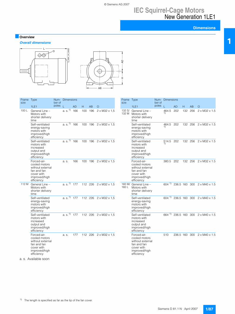
IEC Squirrel-Cage MotorsNew Generation 1LE1
Dimensions
1/87Siemens D 81.1 N · April 2007
1■ Overview
Overall dimensions
AB
AD
LO
H
G_D
081_XX_00033
Frame size
Type Num-ber of poles
Dimensions
1LE1 L AD H AB O100 L General Line –
Motors with shorter delivery time
a. s.1) 166 100 196 2 x M32 x 1,5
Self-ventilated energy-saving motors with improved/high efficiency
a. s.1) 166 100 196 2 x M32 x 1,5
Self-ventilated motors with increased output and improved/high efficiency
a. s.1) 166 100 196 2 x M32 x 1,5
Forced-air-cooled motors without external fan and fan cover with improved/high efficiency
a. s. 166 100 196 2 x M32 x 1,5
112 M General Line – Motors with shorter delivery time
a. s.1) 177 112 226 2 x M32 x 1,5
Self-ventilated energy-saving motors with improved/high efficiency
a. s.1) 177 112 226 2 x M32 x 1,5
Self-ventilated motors with increased output and improved/high efficiency
a. s.1) 177 112 226 2 x M32 x 1,5
Forced-air-cooled motors without external fan and fan cover with improved/high efficiency
a. s. 177 112 226 2 x M32 x 1,5
a. s. Available soon
132 S/132 M
General Line – Motors with shorter delivery time
464.51)
202 132 256 2 x M32 x 1.5
Self-ventilated energy-saving motors with improved/high efficiency
464.51)
202 132 256 2 x M32 x 1.5
Self-ventilated motors with increased output and improved/high efficiency
514.51)
202 132 256 2 x M32 x 1.5
Forced-air-cooled motors without external fan and fan cover with improved/high efficiency
380.5 202 132 256 2 x M32 x 1.5
160 M/160 L
General Line – Motors with shorter delivery time
604 1) 236.5 160 300 2 x M40 x 1.5
Self-ventilated energy-saving motors with improved/high efficiency
604 1) 236.5 160 300 2 x M40 x 1.5
Self-ventilated motors with increased output and improved/high efficiency
664 1) 236.5 160 300 2 x M40 x 1.5
Forced-air-cooled motors without external fan and fan cover with improved/high efficiency
510 236.5 160 300 2 x M40 x 1.5
Frame size
Type Num-ber of poles
Dimensions
1LE1 L AD H AB O
1) The length is specified as far as the tip of the fan cover.
© Siemens AG 2007
IEC Squirrel-Cage MotorsNew Generation 1LE1
Dimensions
1/88 Siemens D 81.1 N · April 2007
1■ Overview (continued)
Notes on the dimensions7 Dimension drawings according to DIN EN 50347 and
IEC 60072.7 FitsThe shaft extensions specified in the dimension tables (DIN 748) and centering spigot diameters (DIN EN 50347) are machined with the following fits:
Dimension ISO fit DIN ISO 286-2designation
D, DA to 30 j6over 30 to 50 k6over 50 m6
N to 250 j6over 250 h6
F, FA h9
The drilled holes of couplings and belt pulleys should have an ISO fit of at least H7.
7 Dimension tolerancesFor the following dimensions, the permissible deviations are given below:
Dimension Dimensions Permitted designation deviation
A, B to 250 ±0.75over 250 to 500 ±1.0over 500 to 750 ±1.5over 750 to 1000 ±2.0over 1000 ±2.5
H to 250 –0.5over 250 –1.0
E, EA –0.5
Keyways and feather keyways (dimensions GA, GC, F and FA) are made in compliance with DIN 6885 Part 1. 7 All dimensions are specified in mm.
© Siemens AG 2007
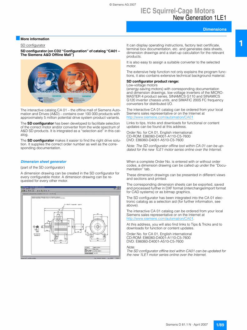
IEC Squirrel-Cage MotorsNew Generation 1LE1
Dimensions
1/89Siemens D 81.1 N · April 2007
1■ More information
SD configurator
SD configurator (on CD2 “Configuration” of catalog “CA01 – The Siemens A&D Offline Mall”)
The interactive catalog CA 01 – the offline mall of Siemens Auto-mation and Drives (A&D) – contains over 100 000 products with approximately 5 million potential drive system product variants.
The SD configurator has been developed to facilitate selection of the correct motor and/or converter from the wide spectrum of A&D SD products. It is integrated as a “selection aid” in this cat-alog.
The SD configurator makes it easier to find the right drive solu-tion. It supplies the correct order number as well as the corre-sponding documentation.
It can display operating instructions, factory test certificate, terminal box documentation, etc. and generates data sheets, dimension drawings and a start-up calculation for the relevant products.
It is also easy to assign a suitable converter to the selected motor.
The extensive help function not only explains the program func-tions, it also contains extensive technical background material.
SD configurator product range: Low-voltage motors (energy-saving motors) with corresponding documentation and dimension drawings, low-voltage inverters of the MICRO-MASTER 4 product series, SINAMICS G110 and SINAMICS G120 inverter chassis units, and SIMATIC 200S FC frequency converters for distributed I/O.
The interactive CA 01 catalog can be ordered from your local Siemens sales representative or on the Internet athttp://www.siemens.com/automation/CA01
Links to tips, tricks and downloads for functional or content updates can be found at this address.
Order No. for CA 01, English international:CD-ROM: E86060-D4001-A110-C5-7600 DVD: E86060-D4001-A510-C5-7600
Note: The SD configurator offline tool within CA 01 can be up-dated for the new 1LE1 motor series online over the Internet.
Dimension sheet generator
(part of the SD configurator)
A dimension drawing can be created in the SD configurator for every configurable motor. A dimension drawing can be re-quested for every other motor.
When a complete Order No. is entered with or without order codes, a dimension drawing can be called up under the “Docu-mentation” tab.
These dimension drawings can be presented in different views and sections and printed.
The corresponding dimension sheets can be exported, saved and processed further in DXF format (interchange/import format for CAD systems) or as bitmap graphics.
The SD configurator has been integrated into the CA 01 elec-tronic catalog as a selection aid (for further information, see above).
The interactive CA 01 catalog can be ordered from your local Siemens sales representative or on the Internet at http://www.siemens.com/automation/CA01.
At this address, you will also find links to Tips & Tricks and to downloads for function or content updates.
Order No. for CA 01, English internationalCD-ROM: E86060-D4001-A110-C5-7600 DVD: E86060-D4001-A510-C5-7600
Note:The SD configurator offline tool within CA01 can be updated for the new 1LE1 motor series online over the Internet.
© Siemens AG 2007
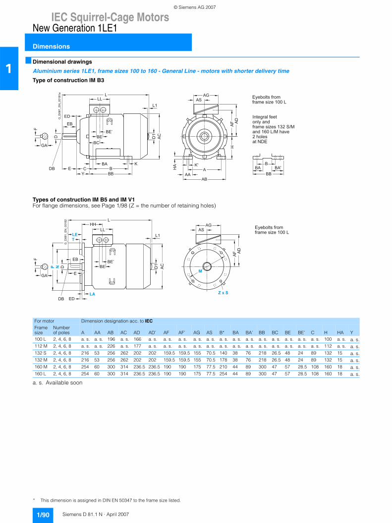
IEC Squirrel-Cage MotorsNew Generation 1LE1
Dimensions
1/90 Siemens D 81.1 N · April 2007
1■ Dimensional drawings
Aluminium series 1LE1, frame sizes 100 to 160 - General Line - motors with shorter delivery time
Type of construction IM B3
Types of construction IM B5 and IM V1For flange dimensions, see Page 1/98 (Z = the number of retaining holes)
a. s. Available soon
ACD1
L1
KBCE
BA
BBY
D
DB
F
GA
AGAS
HA
AF A
D
K'A
AAAB
BE’
BCBE
H
LLL
ED
EB
BBA
BBBA'
G_D
081_
EN
_001
81a
Eyebolts fromframe size 100 L
Integral feet only andframe sizes 132 S/Mand 160 L/M have2 holesat NDE
For motor Dimension designation acc. to IECFrame size
Number of poles A AA AB AC AD AD’ AF AF’ AG AS B* BA BA’ BB BC BE BE’ C H HA Y
100 L 2, 4, 6, 8 a. s. a. s. 196 a. s. 166 a. s. a. s. a. s. a. s. a. s. a. s. a. s. a. s. a. s. a. s. a. s. a. s. a. s. 100 a. s. a. s.112 M 2, 4, 6, 8 a. s. a. s. 226 a. s. 177 a. s. a. s. a. s. a. s. a. s. a. s. a. s. a. s. a. s. a. s. a. s. a. s. a. s. 112 a. s. a. s.132 S 2, 4, 6, 8 216 53 256 262 202 202 159.5 159.5 155 70.5 140 38 76 218 26.5 48 24 89 132 15 a. s.132 M 2, 4, 6, 8 216 53 256 262 202 202 159.5 159.5 155 70.5 178 38 76 218 26.5 48 24 89 132 15 a. s.160 M 2, 4, 6, 8 254 60 300 314 236.5 236.5 190 190 175 77.5 210 44 89 300 47 57 28.5 108 160 18 a. s.160 L 2, 4, 6, 8 254 60 300 314 236.5 236.5 190 190 175 77.5 254 44 89 300 47 57 28.5 108 160 18 a. s.
AC
AF A
D
BE’BE
HHL
LL
D
DB
E
F
GA
EB
ED
D1
L1
AGAS
G_D
081_
EN
_001
82
Eyebolts fromframe size 100 L
* This dimension is assigned in DIN EN 50347 to the frame size listed.
© Siemens AG 2007
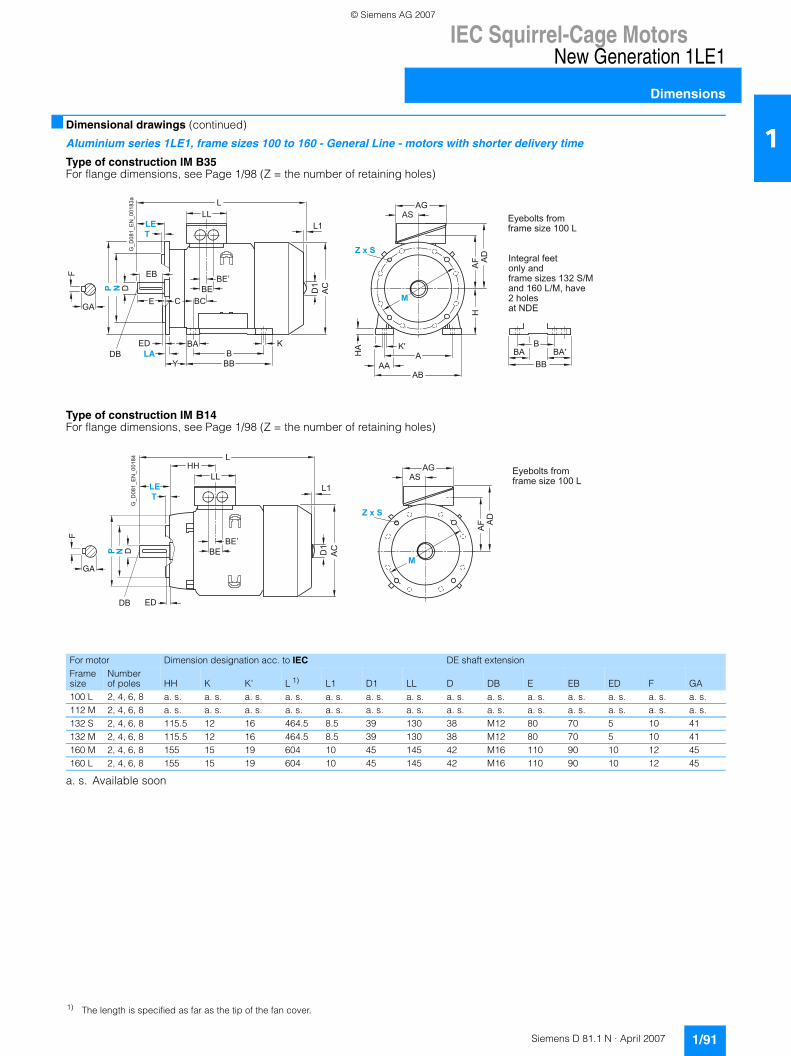
IEC Squirrel-Cage MotorsNew Generation 1LE1
Dimensions
1/91Siemens D 81.1 N · April 2007
1■ Dimensional drawings (continued)
Aluminium series 1LE1, frame sizes 100 to 160 - General Line - motors with shorter delivery time
Type of construction IM B35For flange dimensions, see Page 1/98 (Z = the number of retaining holes)
Type of construction IM B14For flange dimensions, see Page 1/98 (Z = the number of retaining holes)
a. s. Available soon
HA K'
AAA
AB
AC
AGAS
AF
HA
D
LLL
D
DB
E
F
GA
EB
ED KB
BA
BBY
BE’
BCCBE D
1
L1
BBA
BBBA'
G_D
081_
EN
_001
83a
Eyebolts fromframe size 100 L
Integral feetonly andframe sizes 132 S/Mand 160 L/M, have2 holesat NDE
For motor Dimension designation acc. to IEC DE shaft extensionFrame size
Number of poles HH K K' L 1) L1 D1 LL D DB E EB ED F GA
100 L 2, 4, 6, 8 a. s. a. s. a. s. a. s. a. s. a. s. a. s. a. s. a. s. a. s. a. s. a. s. a. s. a. s.112 M 2, 4, 6, 8 a. s. a. s. a. s. a. s. a. s. a. s. a. s. a. s. a. s. a. s. a. s. a. s. a. s. a. s.132 S 2, 4, 6, 8 115.5 12 16 464.5 8.5 39 130 38 M12 80 70 5 10 41132 M 2, 4, 6, 8 115.5 12 16 464.5 8.5 39 130 38 M12 80 70 5 10 41160 M 2, 4, 6, 8 155 15 19 604 10 45 145 42 M16 110 90 10 12 45160 L 2, 4, 6, 8 155 15 19 604 10 45 145 42 M16 110 90 10 12 45
DB
D
F
GA
ED
AC
AGAS
AF A
D
BE’BE
HHL
LL
D1
L1
G_D
081_
EN
_001
84
Eyebolts fromframe size 100 L
1) The length is specified as far as the tip of the fan cover.
© Siemens AG 2007

IEC Squirrel-Cage MotorsNew Generation 1LE1
Dimensions
1/92 Siemens D 81.1 N · April 2007
1■ Dimensional drawings (continued)
Aluminium series 1LE1, frame sizes 100 to 160 - self-ventilated energy-saving motors with improved/high efficiency
Type of construction IM B3
Types of construction IM B5 and IM V1 For flange dimensions, see Page 1/98 (Z = the number of retaining holes)
a. s. Available soon
AC
D
A D1
EA
GC
FA
EC
L1
EE K B C E CA
BA
BB
D
DB DC
F
GA
AG AS
HA
AF A
D
K'
AF' A
AA AB
AD'
BE’
BC BE A
Q
LM
H
LC L
LL
ED
EB
Y
B BA
BB BA'
CA
G_D
081_
EN
_001
63b
Eyebolts fromframe size 100 L
Integral feet only andframe sizes 132 S/Mand 160 L/M have2 holesat NDE
For motor Dimension designation acc. to IECFrame size
Number of poles A AA AB AC AD AD’ AF AF’ AG AQ AS B* BA BA’ BB BC BE BE’ C CA* H HA Y
100 L 2, 4, 6, 8 a. s. a. s. 196 a. s. 166 a. s. a. s. a. s. a. s. a. s. a. s. a. s. a. s. a. s. a. s. a. s. a. s. a. s. a. s. a. s. 100 a. s. a. s.112 M 2, 4, 6, 8 a. s. a. s. 226 a. s. 177 a. s. a. s. a. s. a. s. a. s. a. s. a. s. a. s. a. s. a. s. a. s. a. s. a. s. a. s. a. s. 112 a. s. a. s.132 S 2, 4, 6, 8 216 53 256 262 202 202 159.5 159.5 155 260 70.5 140 38 76 1) 218 2) 26.5 48 24 89 128.5 3) 132 15 a. s.132 M 2, 4, 6, 8 216 53 256 262 202 202 159.5 159.5 155 260 70.5 178 38 76 218 26.5 48 24 89 128.5 3) 132 15 a. s.160 M 2, 4, 6, 8 254 60 300 314 236.5 236.5 190 190 175 260 77.5 210 44 89 4) 300 5) 47 57 28.5 108 148 6) 160 18 a. s.160 L 2, 4, 6, 8 254 60 300 314 236.5 236.5 190 190 175 260 77.5 254 44 89 300 47 57 28.5 108 148 6) 160 18 a. s.
AC
D
A
EA
EC
DC EE
AF A
D
BE’ BE A
Q
LM
LC
HH L
LL
D
DB
E
F
GA
EB
ED
GC
FA
D1
L1
AG AS
G_D
081_
EN
_001
64
Eyebolts fromframe size 100 L
* This dimension is assigned in DIN EN 50347 to the frame size listed.1) With screwed-on feet, dimension BA' is 38 mm.2) With screwed-on feet, dimension BB is 180 mm.3) With screwed-on feet, dimension CA is 166.5 mm.
4) With screwed-on feet, dimension BA' is 44 mm.5) With screwed-on feet, dimension BB is 256 mm.6) With screwed-on feet, dimension CA is 192 mm.
© Siemens AG 2007
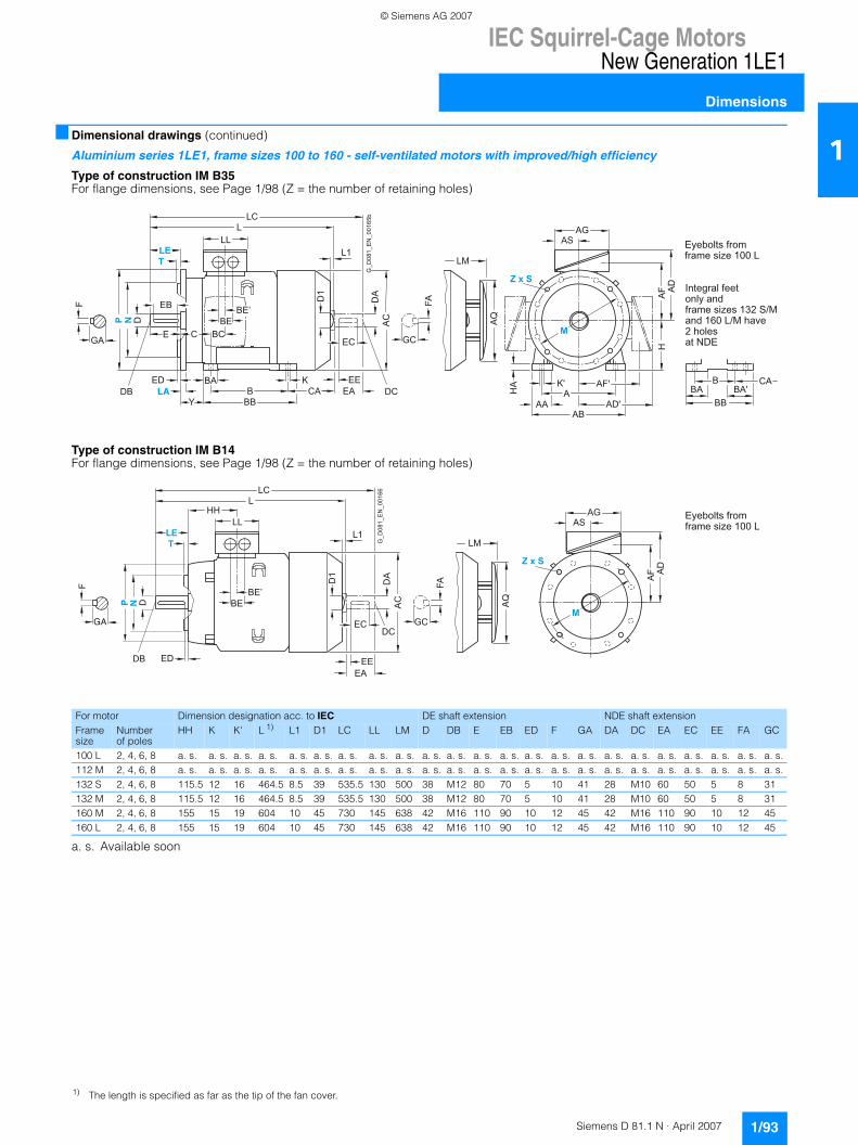
IEC Squirrel-Cage MotorsNew Generation 1LE1
Dimensions
1/93Siemens D 81.1 N · April 2007
1■ Dimensional drawings (continued)
Aluminium series 1LE1, frame sizes 100 to 160 - self-ventilated motors with improved/high efficiency
Type of construction IM B35 For flange dimensions, see Page 1/98 (Z = the number of retaining holes)
Type of construction IM B14For flange dimensions, see Page 1/98 (Z = the number of retaining holes)
a. s. Available soon
HA K'
AF'
A AA
AB AD'
AC
D
A
EA
EC
DC EE
AG AS
AF
H
AD
AQ
LM
LC L
LL
D
DB
E
F
GA
EB
ED
GC
FA
K B CA
BA
BB Y
BE’
BC C BE
D1
L1
B BA
BB BA'
CA G
_D08
1_E
N_0
0165
b
Eyebolts fromframe size 100 L
Integral feet only andframe sizes 132 S/Mand 160 L/M have2 holesat NDE
For motor Dimension designation acc. to IEC DE shaft extension NDE shaft extensionFrame size
Number of poles
HH K K' L 1) L1 D1 LC LL LM D DB E EB ED F GA DA DC EA EC EE FA GC
100 L 2, 4, 6, 8 a. s. a. s. a. s. a. s. a. s. a. s. a. s. a. s. a. s. a. s. a. s. a. s. a. s. a. s. a. s. a. s. a. s. a. s. a. s. a. s. a. s. a. s. a. s.112 M 2, 4, 6, 8 a. s. a. s. a. s. a. s. a. s. a. s. a. s. a. s. a. s. a. s. a. s. a. s. a. s. a. s. a. s. a. s. a. s. a. s. a. s. a. s. a. s. a. s. a. s.132 S 2, 4, 6, 8 115.5 12 16 464.5 8.5 39 535.5 130 500 38 M12 80 70 5 10 41 28 M10 60 50 5 8 31132 M 2, 4, 6, 8 115.5 12 16 464.5 8.5 39 535.5 130 500 38 M12 80 70 5 10 41 28 M10 60 50 5 8 31160 M 2, 4, 6, 8 155 15 19 604 10 45 730 145 638 42 M16 110 90 10 12 45 42 M16 110 90 10 12 45160 L 2, 4, 6, 8 155 15 19 604 10 45 730 145 638 42 M16 110 90 10 12 45 42 M16 110 90 10 12 45
DB
D
F
GA
ED
AC
D
A
EA
EC DC
EE
AG AS
AF A
D
BE’ BE A
Q
LM
LC
HH L
LL
GC
FA
D1
L1
G_D
081_
EN
_001
66
Eyebolts fromframe size 100 L
1) The length is specified as far as the tip of the fan cover.
© Siemens AG 2007
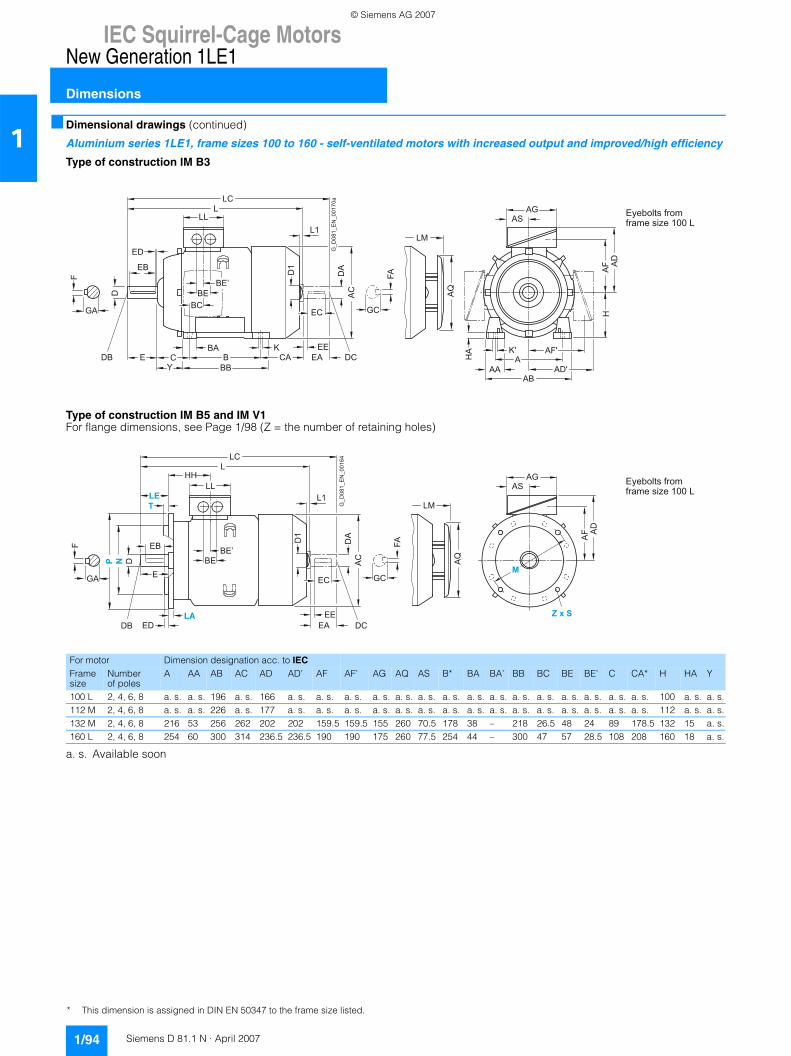
IEC Squirrel-Cage MotorsNew Generation 1LE1
Dimensions
1/94 Siemens D 81.1 N · April 2007
1■ Dimensional drawings (continued)
Aluminium series 1LE1, frame sizes 100 to 160 - self-ventilated motors with increased output and improved/high efficiency
Type of construction IM B3
Type of construction IM B5 and IM V1For flange dimensions, see Page 1/98 (Z = the number of retaining holes)
a. s. Available soon
AC
D
A D1
EA
GC
FA
EC
L1
EE K B C E CA
BA
BB Y
D
DB DC
F
GA
AG AS
HA
AF A
D
K'
AF' A
AA AB
AD'
BE’
BC BE A
Q
LM
H
LC L
LL
ED
EB
G_D
081_
EN
_001
70a
Eyebolts fromframe size 100 L
For motor Dimension designation acc. to IECFrame size
Number of poles
A AA AB AC AD AD’ AF AF’ AG AQ AS B* BA BA’ BB BC BE BE’ C CA* H HA Y
100 L 2, 4, 6, 8 a. s. a. s. 196 a. s. 166 a. s. a. s. a. s. a. s. a. s. a. s. a. s. a. s. a. s. a. s. a. s. a. s. a. s. a. s. a. s. 100 a. s. a. s.112 M 2, 4, 6, 8 a. s. a. s. 226 a. s. 177 a. s. a. s. a. s. a. s. a. s. a. s. a. s. a. s. a. s. a. s. a. s. a. s. a. s. a. s. a. s. 112 a. s. a. s.132 M 2, 4, 6, 8 216 53 256 262 202 202 159.5 159.5 155 260 70.5 178 38 – 218 26.5 48 24 89 178.5 132 15 a. s.160 L 2, 4, 6, 8 254 60 300 314 236.5 236.5 190 190 175 260 77.5 254 44 – 300 47 57 28.5 108 208 160 18 a. s.
AC
D
A
EA
EC
DC EE
AF A
D
BE’ BE A
Q
LM
LC
HH L
LL
D
DB
E
F
GA
EB
ED
GC
FA
D1
L1
AG AS
G_D
081_
EN
_001
64
Eyebolts fromframe size 100 L
* This dimension is assigned in DIN EN 50347 to the frame size listed.
© Siemens AG 2007
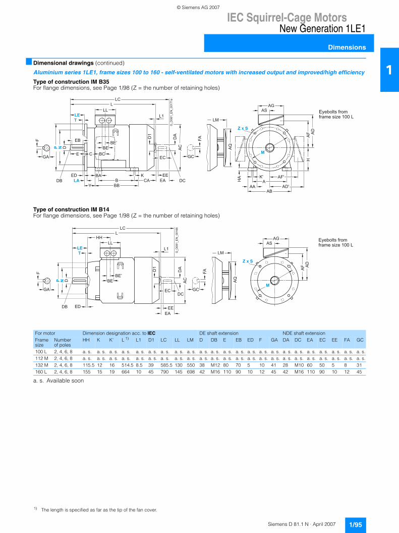
IEC Squirrel-Cage MotorsNew Generation 1LE1
Dimensions
1/95Siemens D 81.1 N · April 2007
1■ Dimensional drawings (continued)
Aluminium series 1LE1, frame sizes 100 to 160 - self-ventilated motors with increased output and improved/high efficiency
Type of construction IM B35For flange dimensions, see Page 1/98 (Z = the number of retaining holes)
Type of construction IM B14For flange dimensions, see Page 1/98 (Z = the number of retaining holes)
a. s. Available soon
HA K'
AF'
A AA
AB AD'
AC
D
A EA
EC
DC EE
AG AS
AF
H
AD
AQ
LM
LC L
LL
D
DB
E
F
GA
EB
ED
GC
FA
K B CA
BA
BB Y
BE’
BC C BE
D1
L1
G_D
081_
EN
_001
71a
Eyebolts fromframe size 100 L
For motor Dimension designation acc. to IEC DE shaft extension NDE shaft extensionFrame size
Number of poles
HH K K' L 1) L1 D1 LC LL LM D DB E EB ED F GA DA DC EA EC EE FA GC
100 L 2, 4, 6, 8 a. s. a. s. a. s. a. s. a. s. a. s. a. s. a. s. a. s. a. s. a. s. a. s. a. s. a. s. a. s. a. s. a. s. a. s. a. s. a. s. a. s. a. s. a. s.112 M 2, 4, 6, 8 a. s. a. s. a. s. a. s. a. s. a. s. a. s. a. s. a. s. a. s. a. s. a. s. a. s. a. s. a. s. a. s. a. s. a. s. a. s. a. s. a. s. a. s. a. s.132 M 2, 4, 6, 8 115.5 12 16 514.5 8.5 39 585.5 130 550 38 M12 80 70 5 10 41 28 M10 60 50 5 8 31160 L 2, 4, 6, 8 155 15 19 664 10 45 790 145 698 42 M16 110 90 10 12 45 42 M16 110 90 10 12 45
DB
D
F
GA
ED
AC
D
A
EA
EC DC
EE
AG AS
AF A
D
BE’ BE A
Q
LM
LC
HH L
LL
GC
FA
D1
L1
G_D
081_
EN
_001
66
Eyebolts fromframe size 100 L
1) The length is specified as far as the tip of the fan cover.
© Siemens AG 2007
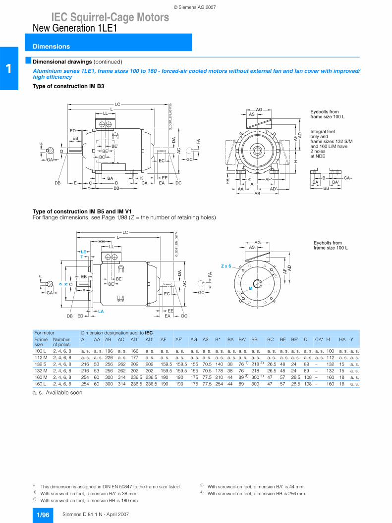
IEC Squirrel-Cage MotorsNew Generation 1LE1
Dimensions
1/96 Siemens D 81.1 N · April 2007
1■ Dimensional drawings (continued)
Aluminium series 1LE1, frame sizes 100 to 160 - forced-air cooled motors without external fan and fan cover with improved/high efficiency
Type of construction IM B3
Type of construction IM B5 and IM V1For flange dimensions, see Page 1/98 (Z = the number of retaining holes)
a. s. Available soon
AC
DA
EA
GC
FA
EC
EEKBCE CA
BA
BBY
D
DB DC
F
GA
AGAS
HA
AF A
D
K' AF'A
AAAB
AD'
BE’
BCBE
H
LCL
LL
ED
EB
B BA
BB BA'
CA
G_D
081_
EN
_001
73b
Eyebolts fromframe size 100 L
Integral feet only andframe sizes 132 S/Mand 160 L/M have2 holesat NDE
For motor Dimension designation acc. to IECFrame size
Number of poles
A AA AB AC AD AD’ AF AF’ AG AS B* BA BA’ BB BC BE BE’ C CA* H HA Y
100 L 2, 4, 6, 8 a. s. a. s. 196 a. s. 166 a. s. a. s. a. s. a. s. a. s. a. s. a. s. a. s. a. s. a. s. a. s. a. s. a. s. a. s. 100 a. s. a. s.112 M 2, 4, 6, 8 a. s. a. s. 226 a. s. 177 a. s. a. s. a. s. a. s. a. s. a. s. a. s. a. s. a. s. a. s. a. s. a. s. a. s. a. s. 112 a. s. a. s.132 S 2, 4, 6, 8 216 53 256 262 202 202 159.5 159.5 155 70.5 140 38 76 1) 218 2) 26.5 48 24 89 – 132 15 a. s.132 M 2, 4, 6, 8 216 53 256 262 202 202 159.5 159.5 155 70.5 178 38 76 218 26.5 48 24 89 – 132 15 a. s.160 M 2, 4, 6, 8 254 60 300 314 236.5 236.5 190 190 175 77.5 210 44 89 3) 300 4) 47 57 28.5 108 – 160 18 a. s.160 L 2, 4, 6, 8 254 60 300 314 236.5 236.5 190 190 175 77.5 254 44 89 300 47 57 28.5 108 – 160 18 a. s.
AGAS
AF A
D
BE’BE
LC
HHL
LL
D
DB
E
F
GA
EB
ED
AC
DA
EA
GC
FA
EC
EEDC
G_D
081_
EN
_001
74
Eyebolts fromframe size 100 L
* This dimension is assigned in DIN EN 50347 to the frame size listed.1) With screwed-on feet, dimension BA' is 38 mm.2) With screwed-on feet, dimension BB is 180 mm.
3) With screwed-on feet, dimension BA' is 44 mm.4) With screwed-on feet, dimension BB is 256 mm.
© Siemens AG 2007
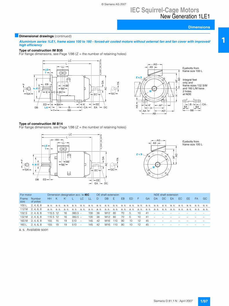
IEC Squirrel-Cage MotorsNew Generation 1LE1
Dimensions
1/97Siemens D 81.1 N · April 2007
1■ Dimensional drawings (continued)
Aluminium series 1LE1, frame sizes 100 to 160 - forced-air cooled motors without external fan and fan cover with improved/high efficiency
Type of construction IM B35 For flange dimensions, see Page 1/98 (Z = the number of retaining holes)
Type of construction IM B14 For flange dimensions, see Page 1/98 (Z = the number of retaining holes)
a. s. Available soon
HA K'
AF'
A AA
AB AD'
AG AS
AF
H
AD
LCL
LL
D
DB
E
F
GA
EB
KB
BA
BB
BE’
BCCBE A
CD
A
EA
GC
FA
EC
EECA DC
Y
ED B BA
BB BA'
CA
Eyebolts fromframe size 100 L
Integral feet only andframe sizes 132 S/Mand 160 L/M have2 holesat NDE
G_D
081_
EN
_001
75b
For motor Dimension designation acc. to IEC DE shaft extension NDE shaft extensionFrame size
Number of poles
HH K K' L LC LL D DB E EB ED F GA DA DC EA EC EE FA GC
100 L 2, 4, 6, 8 a. s. a. s. a. s. a. s. a. s. a. s. a. s. a. s. a. s. a. s. a. s. a. s. a. s. a. s. a. s. a. s. a. s. a. s. a. s. a. s.112 M 2, 4, 6, 8 a. s. a. s. a. s. a. s. a. s. a. s. a. s. a. s. a. s. a. s. a. s. a. s. a. s. a. s. a. s. a. s. a. s. a. s. a. s. a. s.132 S 2, 4, 6, 8 115.5 12 16 380.5 – 130 38 M12 80 70 5 10 41 – – – – – – –132 M 2, 4, 6, 8 115.5 12 16 380.5 – 130 38 M12 80 70 5 10 41 – – – – – – –160 M 2, 4, 6, 8 155 15 19 510 – 145 42 M16 110 90 10 12 45 – – – – – – –160 L 2, 4, 6, 8 155 15 19 510 – 145 42 M16 110 90 10 12 45 – – – – – – –
DB
D
F
GA
ED
AG AS
AF A
D
BE’ BE
LC
HH L
LL
AC
DA
EA
GC
FA
EC
EEDC
G_D
081_
EN
_001
76
Eyebolts fromframe size 100 L
© Siemens AG 2007
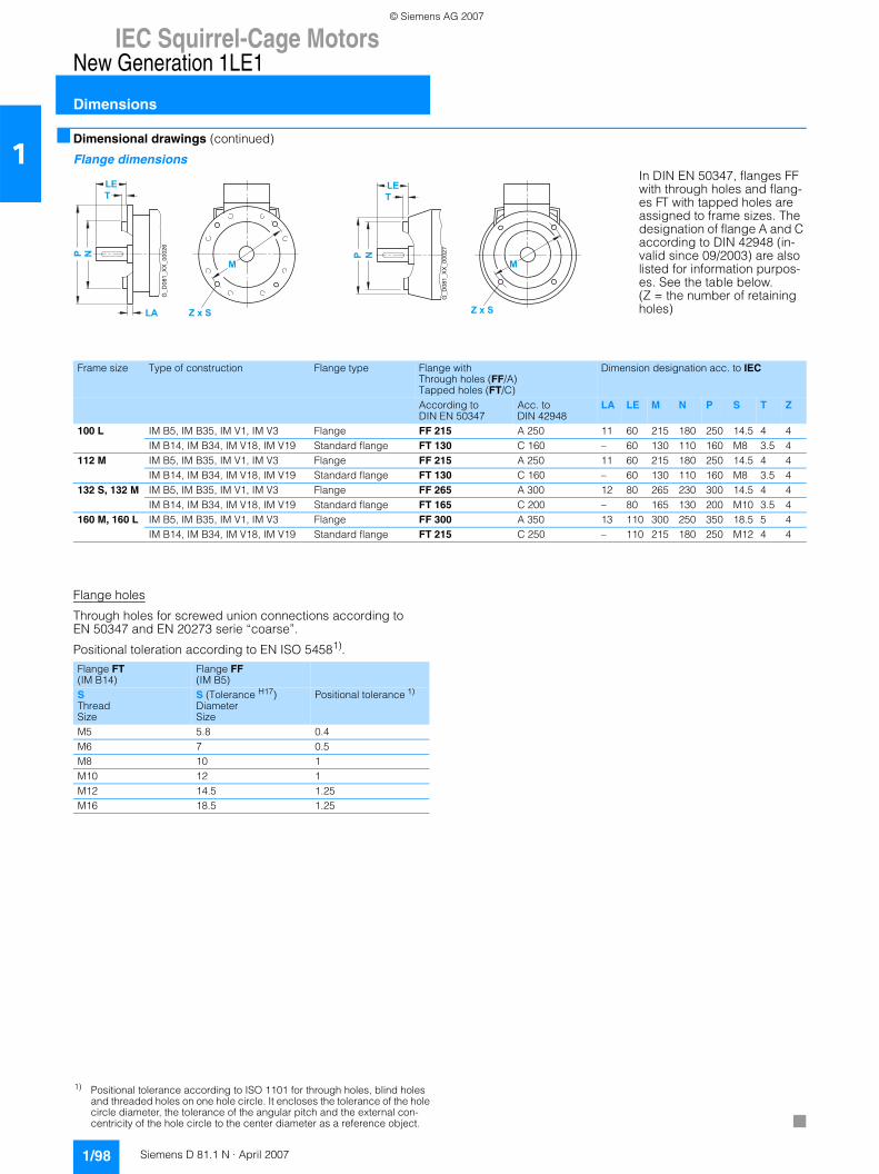
IEC Squirrel-Cage MotorsNew Generation 1LE1
Dimensions
1/98 Siemens D 81.1 N · April 2007
1■ Dimensional drawings (continued)
Flange dimensions
Flange holes
Through holes for screwed union connections according to EN 50347 and EN 20273 serie “coarse”.
Positional toleration according to EN ISO 54581).
In DIN EN 50347, flanges FF with through holes and flang-es FT with tapped holes are assigned to frame sizes. The designation of flange A and C according to DIN 42948 (in-valid since 09/2003) are also listed for information purpos-es. See the table below. (Z = the number of retaining holes)
G_D
081_
XX
_000
26
G_D
081_
XX
_000
27
Frame size Type of construction Flange type Flange withThrough holes (FF/A)Tapped holes (FT/C)
Dimension designation acc. to IEC
According to DIN EN 50347
Acc. to DIN 42948
LA LE M N P S T Z
100 L IM B5, IM B35, IM V1, IM V3 Flange FF 215 A 250 11 60 215 180 250 14.5 4 4IM B14, IM B34, IM V18, IM V19 Standard flange FT 130 C 160 – 60 130 110 160 M8 3.5 4
112 M IM B5, IM B35, IM V1, IM V3 Flange FF 215 A 250 11 60 215 180 250 14.5 4 4IM B14, IM B34, IM V18, IM V19 Standard flange FT 130 C 160 – 60 130 110 160 M8 3.5 4
132 S, 132 M IM B5, IM B35, IM V1, IM V3 Flange FF 265 A 300 12 80 265 230 300 14.5 4 4IM B14, IM B34, IM V18, IM V19 Standard flange FT 165 C 200 – 80 165 130 200 M10 3.5 4
160 M, 160 L IM B5, IM B35, IM V1, IM V3 Flange FF 300 A 350 13 110 300 250 350 18.5 5 4IM B14, IM B34, IM V18, IM V19 Standard flange FT 215 C 250 – 110 215 180 250 M12 4 4
Flange FT(IM B14)
Flange FF(IM B5)
SThreadSize
S (Tolerance H17)DiameterSize
Positional tolerance 1)
M5 5.8 0.4M6 7 0.5M8 10 1M10 12 1M12 14.5 1.25M16 18.5 1.25
1) Positional tolerance according to ISO 1101 for through holes, blind holes and threaded holes on one hole circle. It encloses the tolerance of the hole circle diameter, the tolerance of the angular pitch and the external con-centricity of the hole circle to the center diameter as a reference object.
© Siemens AG 2007
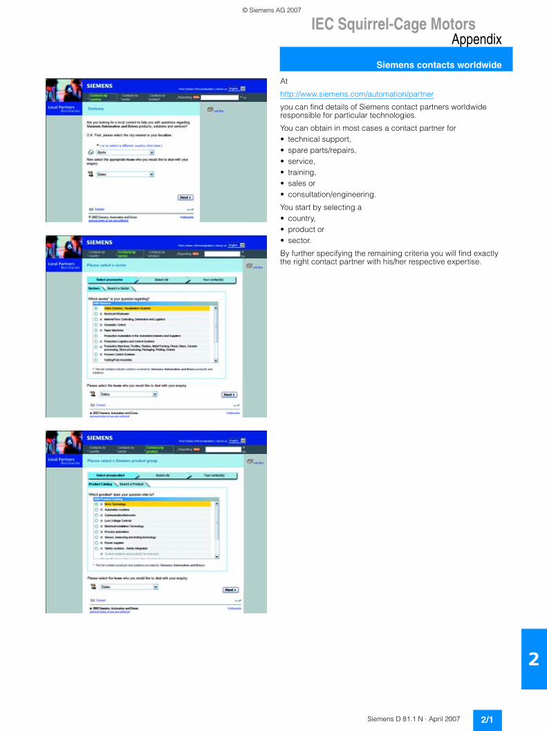
IEC Squirrel-Cage MotorsAppendix
Siemens contacts worldwide
2/1Siemens D 81.1 N · April 2007
2
At
http://www.siemens.com/automation/partner
you can find details of Siemens contact partners worldwide responsible for particular technologies.
You can obtain in most cases a contact partner for• technical support,• spare parts/repairs,• service,• training,• sales or• consultation/engineering.
You start by selecting a• country,• product or• sector.
By further specifying the remaining criteria you will find exactly the right contact partner with his/her respective expertise.
© Siemens AG 2007
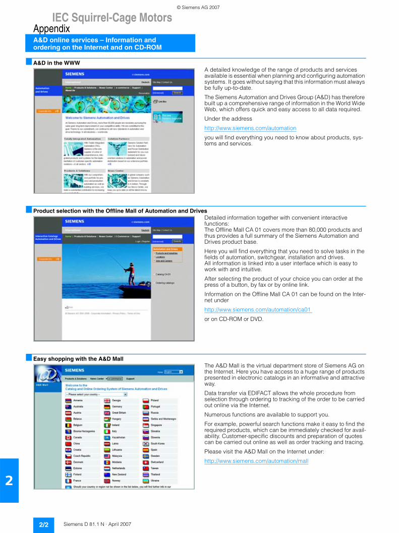
IEC Squirrel-Cage MotorsAppendixA&D online services – Information and ordering on the Internet and on CD-ROM
2/2 Siemens D 81.1 N · April 2007
2
■ A&D in the WWWA detailed knowledge of the range of products and services available is essential when planning and configuring automation systems. It goes without saying that this information must always be fully up-to-date.
The Siemens Automation and Drives Group (A&D) has therefore built up a comprehensive range of information in the World Wide Web, which offers quick and easy access to all data required.
Under the address
http://www.siemens.com/automation
you will find everything you need to know about products, sys-tems and services.
■ Product selection with the Offline Mall of Automation and DrivesDetailed information together with convenient interactive functions: The Offline Mall CA 01 covers more than 80,000 products and thus provides a full summary of the Siemens Automation and Drives product base.
Here you will find everything that you need to solve tasks in the fields of automation, switchgear, installation and drives. All information is linked into a user interface which is easy to work with and intuitive.
After selecting the product of your choice you can order at the press of a button, by fax or by online link.
Information on the Offline Mall CA 01 can be found on the Inter-net under
http://www.siemens.com/automation/ca01
or on CD-ROM or DVD.
■ Easy shopping with the A&D Mall The A&D Mall is the virtual department store of Siemens AG on the Internet. Here you have access to a huge range of products presented in electronic catalogs in an informative and attractive way.
Data transfer via EDIFACT allows the whole procedure from selection through ordering to tracking of the order to be carried out online via the Internet.
Numerous functions are available to support you.
For example, powerful search functions make it easy to find the required products, which can be immediately checked for avail-ability. Customer-specific discounts and preparation of quotes can be carried out online as well as order tracking and tracing.
Please visit the A&D Mall on the Internet under:
http://www.siemens.com/automation/mall
© Siemens AG 2007
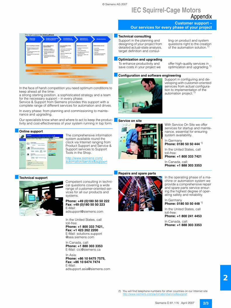
IEC Squirrel-Cage MotorsAppendix
Customer support –Our services for every phase of your project
2/3Siemens D 81.1 N · April 2007
2
I
In the face of harsh competition you need optimum conditions to keep ahead all the time: a strong starting position, a sophisticated strategy and a team for the necessary support – in every phase. Service & Support from Siemens provides this support with a complete range of different services for automation and drives.
In every phase: from planning and commissioning to mainte-nance and upgrading.
Our specialists know when and where to act to keep the produc-tivity and cost-effectiveness of your system running in top form.
■ Online supportThe comprehensive information system available round the clock via Internet ranging from Product Support and Service & Support services to Support Tools in the Shop.
http://www.siemens.com/automation/service&support
■ Technical supportCompetent consulting in techni-cal questions covering a wide range of customer-oriented ser-vices for all our products and systems.
Phone: +49 (0)180 50 50 222Fax: +49 (0)180 50 50 223E-Mail:[email protected]
In the United States, call toll-free:Phone: +1 800 333 7421, Fax: +1 423 262 2200E-Mail: solutions.support @sea.siemens.com
In Canada, call:Phone: +1 888 303 3353E-Mail: [email protected]
In Asia:Phone: +86 10 6475 7575, Fax: +86 10 6474 7474E-Mail: [email protected]
■ Technical consulting
■ Optimization and upgrading
■ Configuration and software engineeringSupport in configuring and de-veloping with customer-oriented services from actual configura-tion to implementation of the automation project.1)
■ Service on siteWith Service On Site we offer services for startup and mainte-nance, essential for ensuring system availability.
In Germany Phone: 0180 50 50 444 1)
In the United States, call toll-free:Phone: +1 800 333 7421
In Canada, call:Phone: +1 888 303 3353
■ Repairs and spare partsIn the operating phase of a ma-chine or automation system we provide a comprehensive repair and spare parts service ensur-ing the highest degree of oper-ating safety and reliability.
In Germany Phone: 0180 50 50 448 1)
In the United States, call toll-free:Phone: +1 800 241 4453
In Canada, call:Phone: +1 888 303 3353
2) You will find telephone numbers for other countries on our Internet site http://www.siemens.com/automation/service&support
Support in the planning and designing of your project from detailed actual-state analysis, target definition and consul-
ting on product and system questions right to the creation of the automation solution.1)
To enhance productivity and save costs in your project we
offer high-quality services in optimization and upgrading.1)
© Siemens AG 2007
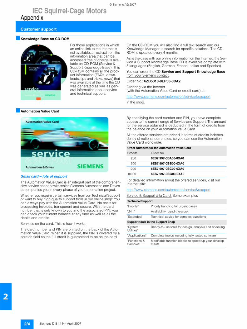
IEC Squirrel-Cage MotorsAppendix
Customer support
2/4 Siemens D 81.1 N · April 2007
2
■ Knowledge Base on CD-ROM
For those applications in which an online link to the Internet is not available, an extract from the information area that can be accessed free of charge is avai-lable on CD-ROM (Service & Support Knowledge Base). This CD-ROM contains all the prod-uct information (FAQs, down-loads, tips and tricks, news) that was available at the time the CD was generated as well as gen-eral information about service and technical support.
On the CD-ROM you will also find a full text search and our Knowledge Manager to search for specific solutions. The CD-ROM is updated every 4 months.
As is the case with our online information on the Internet, the Ser-vice & Support Knowledge Base CD is available complete with 5 languages (English, German, French, Italian and Spanish).
You can order the CD Service and Support Knowledge Base from your Siemens contact.
Order No.: 6ZB5310-0EP30-0BA2
Ordering via the Internet (with the Automation Value Card or credit card) at:
http://www.siemens.com/automation/service&support
in the shop.
■ Automation Value Card
Small card – lots of support
The Automation Value Card is an integral part of the comprehen-sive service concept with which Siemens Automation and Drives accompanies you in every phase of your automation project.
Whether you require certain services from our Technical Support or want to buy high-quality support tools in our online shop: You can always pay with the Automation Value Card. No costs for processing invoices, transparent and secure. With the card number that is only known to you and the associated PIN, you can check your current balance at any time as well as all the debits and credits.
Services on the card. This is how it works.
The card number and PIN are printed on the back of the Auto-mation Value Card. When it is supplied, the PIN is covered by a scratch field so the full credit is guaranteed to be on the card.
By specifying the card number and PIN, you have complete access to the current range of Service and Support. The amount for the service obtained is deducted in the form of credits from the balance on your Automation Value Card.
All the offered services are priced in terms of credits indepen-dently of national currencies, so you can use the Automation Value Card worldwide.
For detailed information about the offered services, visit our Internet site:
http://www.siemens.com/automation/service&support
Service & Support à la Card: Some examples
Order Numbers for the Automation Value Card
Credits Order No.
200 6ES7 997-0BA00-0XA0
500 6ES7 997-0BB00-0XA0
1000 6ES7 997-0BC00-0XA0
10000 6ES7 997-0BG00-0XA0
Technical Support
"Priority" Priority handling for urgent cases
"24 h" Availability round-the-clock
"Extended" Technical advice for complex questions
Support tools in the Support Shop
"System Utilities"
Ready-to-use tools for design, analysis and checking
"Applications" Complete topics including fully tested software
"Functions & Samples"
Modifiable function blocks to speed up your develop-ments
© Siemens AG 2007
IEC Squirrel-Cage MotorsAppendix
Subject index
2/5Siemens D 81.1 N · April 2007
2
■ Subject index
Page
AA&D online services 2/2Accessories 1/86Additional versions 1/31Application 1/2
BBalance 1/21Bearing selection table 1/23Bearings 1/22Benefits 1/2Brakes 1/28, 1/31
CCEMEP 1/1Colors 1/5Conditions of sale and delivery 2/8Connection box 1/15Coolant temperature 1/11Current-dependent protection devices 1/13Currents 1/7Customer support 2/3
DDegrees of protection 1/20Diagrams of bearings 1/24Dimension sheet generator 1/89Dimensional drawings 1/90 … 1/98Dimensions 1/87 … 1/98Direction of rotation 1/9Documentation 1/7
EEfficiency 1/1, 1/9Energy balance 1/1EPACT 1/1Export regulations 2/8Extra rating plates 1/10
FFlange dimensions 1/98Frame sizes 1/18Frequencies 1/7
HHeating 1/14
IInsulation 1/12
LLubrication 1/22
MMaximum axial load 1/25Maximum cantilever forces 1/24 ... 1/25Mechanical design 1/20Metal surcharges 2/6Modular technology 1/26Motor connection 1/15Motor protection 1/13
Page
NNational standards 1/5Non-standard voltages 1/8
OOptions 1/79 ... 1/85Order No. code 1/40Ordering data 1/44 … 1/77Ordering example 1/40Outputs 1/9Overall dimensions 1/87Overview 1/1
PPackaging 1/7Paint finish 1/5Power factor 1/9Preliminary selection of the motor 1/41Protection devices that are motor temperature
sensitive 1/13Rated currents 1/8Rated speed 1/9Rated torque 1/9Rating plates 1/10Recommendations for drive selection 1/39Rotary pulse encoder 1/26,
1/32 … 1/34Rotor 1/21
SSafety notes 1/7Schematic diagram 1/4SD configurator 1/89Selection and ordering data 1/44 … 1/77Separately driven fan 1/27Shaft 1/21Siemens contact worldwide 2/1Site altitude 1/11Spare parts 1/86Special versions 1/78 ... 1/85Standard voltages 1/7Standards 1/5
TTechnical specifications 1/3Test certificates 1/7Totally Integrated Automation 4
VVentilation 1/14Vibration severity 1/21Voltages 1/7, 1/78
WWelcome to Automation and Drives 2Windings 1/12
© Siemens AG 2007
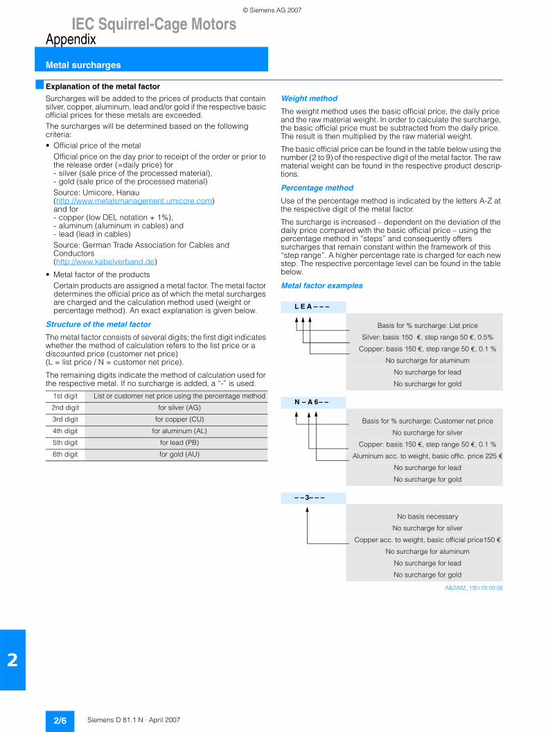
IEC Squirrel-Cage MotorsAppendix
Metal surcharges
2/6 Siemens D 81.1 N · April 2007
2
■ Explanation of the metal factor
Surcharges will be added to the prices of products that contain silver, copper, aluminum, lead and/or gold if the respective basic official prices for these metals are exceeded.The surcharges will be determined based on the following criteria:• Official price of the metal
Official price on the day prior to receipt of the order or prior to the release order (=daily price) for- silver (sale price of the processed material), - gold (sale price of the processed material)Source: Umicore, Hanau (http://www.metalsmanagement.umicore.com)and for- copper (low DEL notation + 1%),- aluminum (aluminum in cables) and - lead (lead in cables)Source: German Trade Association for Cables and Conductors(http://www.kabelverband.de)
• Metal factor of the productsCertain products are assigned a metal factor. The metal factor determines the official price as of which the metal surcharges are charged and the calculation method used (weight or percentage method). An exact explanation is given below.
Structure of the metal factor
The metal factor consists of several digits; the first digit indicates whether the method of calculation refers to the list price or a discounted price (customer net price) (L = list price / N = customer net price).
The remaining digits indicate the method of calculation used for the respective metal. If no surcharge is added, a “-” is used.
Weight method
The weight method uses the basic official price, the daily price and the raw material weight. In order to calculate the surcharge, the basic official price must be subtracted from the daily price. The result is then multiplied by the raw material weight.
The basic official price can be found in the table below using the number (2 to 9) of the respective digit of the metal factor. The raw material weight can be found in the respective product descrip-tions.
Percentage method
Use of the percentage method is indicated by the letters A-Z at the respective digit of the metal factor.
The surcharge is increased – dependent on the deviation of the daily price compared with the basic official price – using the percentage method in “steps” and consequently offers surcharges that remain constant within the framework of this “step range”. A higher percentage rate is charged for each new step. The respective percentage level can be found in the table below.
Metal factor examples
A&D/MZ_1/En 05.09.06
1st digit List or customer net price using the percentage method
2nd digit for silver (AG)
3rd digit for copper (CU)
4th digit for aluminum (AL)
5th digit for lead (PB)
6th digit for gold (AU)
L E A – – –
Basis for % surcharge: List price
Silver: basis 150 €, step range 50 €, 0.5%
Copper: basis 150 €, step range 50 €, 0.1 %
No surcharge for aluminum
No surcharge for lead
No surcharge for gold
N – A 6– –
Basis for % surcharge: Customer net price
No surcharge for silver
Copper: basis 150 €, step range 50 €, 0.1 %
Aluminum acc. to weight, basic offic. price 225 €
No surcharge for lead
No surcharge for gold
– – 3– – –
No basis necessary
No surcharge for silver
Copper acc. to weight, basic official price150 €
No surcharge for aluminum
No surcharge for lead
No surcharge for gold
© Siemens AG 2007
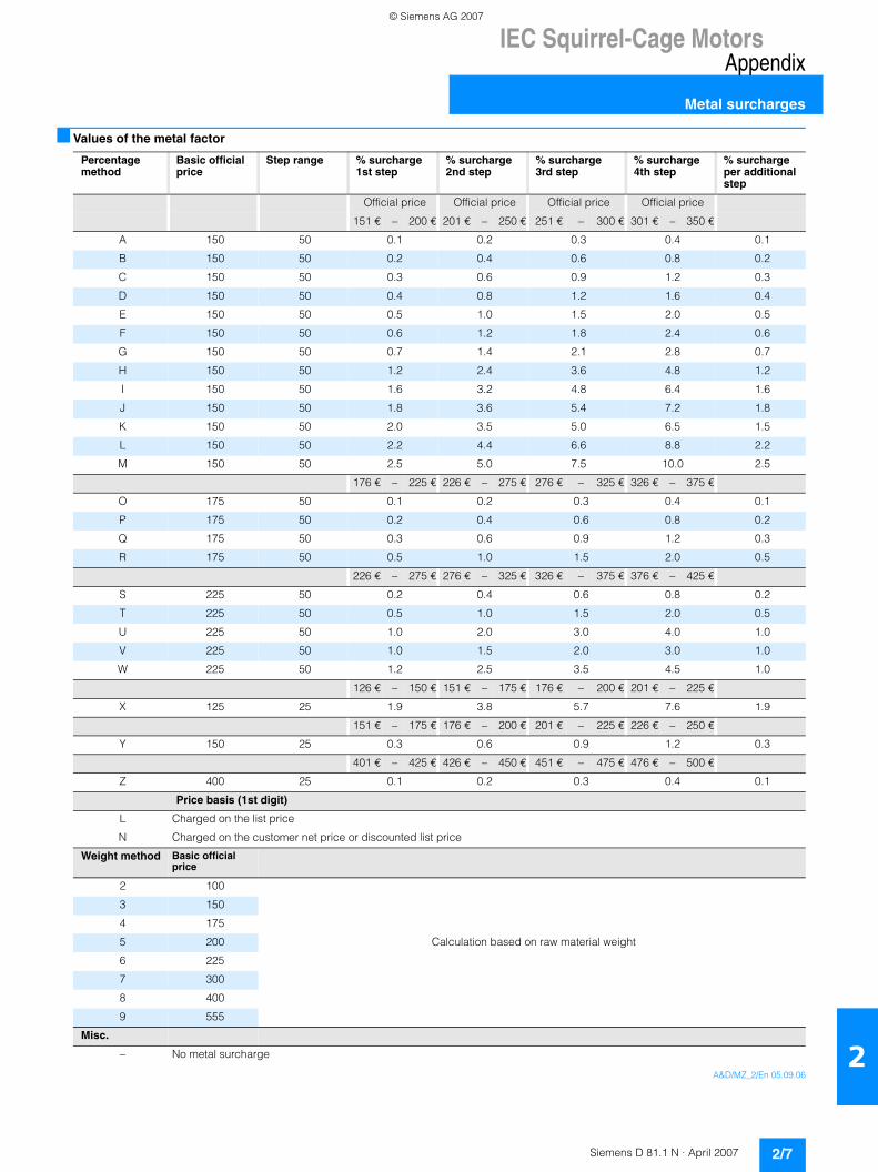
IEC Squirrel-Cage MotorsAppendix
Metal surcharges
2/7Siemens D 81.1 N · April 2007
2
■ Values of the metal factor
A&D/MZ_2/En 05.09.06
Percentage method
Basic official price
Step range % surcharge1st step
% surcharge2nd step
% surcharge3rd step
% surcharge4th step
% surcharge per additional step
Official price Official price Official price Official price
151 € − 200 € 201 € − 250 € 251 € − 300 € 301 € − 350 €
A 150 50 0.1 0.2 0.3 0.4 0.1
B 150 50 0.2 0.4 0.6 0.8 0.2
C 150 50 0.3 0.6 0.9 1.2 0.3
D 150 50 0.4 0.8 1.2 1.6 0.4
E 150 50 0.5 1.0 1.5 2.0 0.5
F 150 50 0.6 1.2 1.8 2.4 0.6
G 150 50 0.7 1.4 2.1 2.8 0.7
H 150 50 1.2 2.4 3.6 4.8 1.2
I 150 50 1.6 3.2 4.8 6.4 1.6
J 150 50 1.8 3.6 5.4 7.2 1.8
K 150 50 2.0 3.5 5.0 6.5 1.5
L 150 50 2.2 4.4 6.6 8.8 2.2
M 150 50 2.5 5.0 7.5 10.0 2.5
176 € − 225 € 226 € − 275 € 276 € − 325 € 326 € − 375 €
O 175 50 0.1 0.2 0.3 0.4 0.1
P 175 50 0.2 0.4 0.6 0.8 0.2
Q 175 50 0.3 0.6 0.9 1.2 0.3
R 175 50 0.5 1.0 1.5 2.0 0.5
226 € − 275 € 276 € − 325 € 326 € − 375 € 376 € − 425 €
S 225 50 0.2 0.4 0.6 0.8 0.2
T 225 50 0.5 1.0 1.5 2.0 0.5
U 225 50 1.0 2.0 3.0 4.0 1.0
V 225 50 1.0 1.5 2.0 3.0 1.0
W 225 50 1.2 2.5 3.5 4.5 1.0
126 € − 150 € 151 € − 175 € 176 € − 200 € 201 € − 225 €
X 125 25 1.9 3.8 5.7 7.6 1.9
151 € − 175 € 176 € − 200 € 201 € − 225 € 226 € − 250 €
Y 150 25 0.3 0.6 0.9 1.2 0.3
401 € − 425 € 426 € − 450 € 451 € − 475 € 476 € − 500 €
Z 400 25 0.1 0.2 0.3 0.4 0.1
Price basis (1st digit)
L Charged on the list price
N Charged on the customer net price or discounted list price
Weight method Basic official price
2 100
3 150
4 175
5 200 Calculation based on raw material weight
6 225
7 300
8 400
9 555
Misc.
− No metal surcharge
© Siemens AG 2007
IEC Squirrel-Cage MotorsAppendix
Conditions of sale and delivery
2/8 Siemens D 81.1 N · April 2007
2
■ Terms and Conditions of Sale and Delivery
By using this catalog you can acquire hardware and software products described therein from Siemens AG subject to the fol-lowing terms. Please note! The scope, the quality and the condi-tions for supplies and services, including software products, by any Siemens entity having a registered office outside of Ger-many, shall be subject exclusively to the General Terms and Conditions of the respective Siemens entity. The following terms apply exclusivelyfor orders placed with Siemens AG.
For customers with a seat or registered office in GermanyThe “General Terms of Payment” as well as the “General Condi-tions for the Supply of Products and Services of the Electrical and Electronics Industry” shall apply.For software products, the “General License Conditions for Software Products for Automation and Drives for Customers with a Seat or registered Office in Germany” shall apply.
For customers with a seat or registered office outside of GermanyThe “General Terms of Payment” as well as the “General Condi-tions for Supplies of Siemens, Automation and Drives for Cus-tomers with a Seat or registered Office outside of Germany” shall apply.For software products, the “General License Conditions for Soft-ware Products for Automation and Drives for Customers with a Seat or registered Office outside of Germany” shall apply.
GeneralThe dimensions are in mm. In Germany, according to the Ger-man law on units in measuring technology, data in inches only apply to devices for export. Illustrations are not binding.Insofar as there are no remarks on the corresponding pages, - especially with regard to data, dimensions and weights given -these are subject to change without prior notice.The prices are in € (Euro) ex works, exclusive packaging.The sales tax (value added tax) is not included in the prices. It shall be debited separately at the respective rate according to the applicable legal regulations.Prices are subject to change without prior notice. We will debit the prices valid at the time of delivery.Surcharges will be added to the prices of products that contain silver, copper, aluminum, lead and/or gold, if the respective ba-sic official prices for these metals are exceeded. These sur-charges will be determined based on the official price and the metal factor of the respective product.The surcharge will be calculated on the basis of the official price on the day prior to receipt of the order or prior to the release or-der. The metal factor determines the official price as of which the metal surcharges are charged and the calculation method used. The metal factor, provided it is relevant, is included with the price information of the respective products. An exact explanation of the metal factor can be found on the page entitled “Metal surcharges”.
The texts of the Comprehensive Terms and Conditions of Sale and Delivery are available free of charge from your local Siemens business office under the following Order Nos.:• 6ZB5310-0KR30-0BA1
(for customers based in Germany)• 6ZB5310-0KS53-0BA1
(for customers based outside of Germany)or download them from the Internethttp://www.siemens.com/automation/mall (Germany: A&D Mall Online-Help System)
■ Export regulations
The products listed in this catalog / price list may be subject to European / German and/or US export regulations.Therefore, any export requiring a license is subject to approval by the competent authorities.According to current provisions, the following export regulations must be observed with respect to the products featured in this catalog / price list:
Even without a label or with an “AL: N” or “ECCN: N”, authoriza-tion may be required due to the final destination and purpose for which the goods are to be used. The deciding factors are the AL or ECCN export authorization indicated on order confirmations, delivery notes and invoices.Errors excepted and subject to change without prior notice.
A&D/VuL_mit MZ/En 05.09.06
AL Number of the German Export ListProducts marked other than “N” require an export license. In the case of software products, the export des-ignations of the relevant data medium must also be generally adhered to.Goods labeled with an “AL” not equal to “N” are subject to a European or German export authori-zation when being exported out of the EU.
ECCN Export Control Classification Number.Products marked other than “N” are subject to a reexport license to specific countries.In the case of software products, the exportdesignations of the relevant data medium must also be generally adhered to.Goods labeled with an “ECCN” not equal to “N” are subject to a US re-export authorization.
© Siemens AG 2007
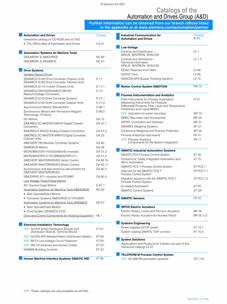
Catalogs of theAutomation and Drives Group (A&D)
Further information can be obtained from our branch offices listedin the appendix or at www.siemens.com/automation/partner
A&D/3U/En 13.12.06
Automation and Drives CatalogInteractive catalog on CD-ROM and on DVD
• The Offline Mall of Automation and Drives CA 01
Automation Systems for Machine ToolsSINUMERIK & SIMODRIVE NC 60
SINUMERIK & SINAMICS NC 61
Drive SystemsVariable-Speed Drives
SINAMICS G130 Drive Converter Chassis Units, SINAMICS G150 Drive Converter Cabinet Units
D 11
SINAMICS G110 Inverter Chassis Units D 11.1
SINAMICS GM150/SINAMICS SM150 Medium-Voltage Converters
D 12
SINAMICS S120 Drive Converter Systems D 21.1
SINAMICS S150 Drive Converter Cabinet Units D 21.3
Asynchronous Motors Standardline D 86.1
Synchronous Motors with Permanent-Magnet Technology, HT-direct
D 86.2
DC Motors DA 12
SIMOREG DC MASTER 6RA70 Digital Chassis Converters
DA 21.1
SIMOREG K 6RA22 Analog Chassis Converters DA 21.2
SIMOREG DC MASTER 6RM70 Digital Converter Cabinet Units
DA 22
SIMOVERT PM Modular Converter Systems DA 45
SIEMOSYN Motors DA 48
MICROMASTER 410/420/430/440 Inverters DA 51.2
MICROMASTER 411/COMBIMASTER 411 DA 51.3
SIMOVERT MASTERDRIVES Vector Control DA 65.10
SIMOVERT MASTERDRIVES Motion Control DA 65.11
Synchronous and asynchronous servomotors for SIMOVERT MASTERDRIVES
DA 65.3
SIMODRIVE 611 universal and POSMO DA 65.4
Low-Voltage Three-Phase-Motors
IEC Squirrel-Cage Motors D 81.1
Automation Systems for Machine Tools SIMODRIVE NC 60
• Main Spindle/Feed Motors
• Converter Systems SIMODRIVE 611/POSMO
Automation Systems for Machine Tools SINAMICS NC 61
• Main Spindle/Feed Motors
• Drive System SINAMICS S120
Drive and Control Components for Hoisting Equipment HE 1
Electrical Installation TechnologyPDF: ALPHA Small Distribution Boards and
Distribution Boards, Terminal BlocksET A1
PDF: ALPHA 8HP Molded-Plastic Distribution System ET A3
PDF: BETA Low-Voltage Circuit Protection ET B1
PDF: DELTA Switches and Socket Outlets ET D1
GAMMA Building Controls ET G1
Human Machine Interface Systems SIMATIC HMI ST 80
PDF: These catalogs are only available as pdf files.
Industrial Communication for Automation and Drives
CatalogIK PI
Low-VoltageControls and Distribution – SIRIUS, SENTRON, SIVACON
LV 1
Controls and Distribution – Technical InformationSIRIUS, SENTRON, SIVACON
LV 1 T
SIDAC Reactors and Filters LV 60
SIVENT Fans LV 65
SIVACON 8PS Busbar Trunking Systems LV 70
Motion Control System SIMOTION PM 10
Process Instrumentation and AnalyticsField Instruments for Process AutomationMeasuring Instruments for Pressure, Differential Pressure, Flow, Level and Temperature, Positioners and Liquid Meters
FI 01
PDF: Indicators for panel mounting MP 12
SIREC Recorders and Accessories MP 20
SIPART, Controllers and Software MP 31
SIWAREX Weighing Systems WT 01
Continuous Weighing and Process Protection WT 02
Process Analytical Instruments PA 01
PDF: Process Analytics, Components for the System Integration
PA 11
SIMATIC Industrial Automation SystemsSIMATIC PCS Process Control System ST 45
Products for Totally Integrated Automation and Micro Automation
ST 70
SIMATIC PCS 7 Process Control System ST PCS 7
Add-ons for the SIMATIC PCS 7 Process Control System
ST PCS 7.1
Migration solutions with the SIMATIC PCS 7 Process Control System
ST PCS 7.2
pc-based Automation ST PC
SIMATIC Control Systems ST DA
SIMATIC Sensors FS 10
SIPOS Electric ActuatorsElectric Rotary, Linear and Part-turn Actuators MP 35
Electric Rotary Actuators for Nuclear Plants MP 35.1/.2
Systems EngineeringPower supplies SITOP power KT 10.1
System cabling SIMATIC TOP connect KT 10.2
System SolutionsApplications and Products for Industry are part of the interactive catalog CA 01
TELEPERM M Process Control SystemPDF: AS 488/TM automation systems PLT 112
© Siemens AG 2007
��"�����!�#�#��$%%������������#��
��������� ������������� ������ ������ ����������� ��������� ��� ��������������������������������� ����������� ���������������������������������������������������� ����� ������������ �� ������� ����������� ��� ������� �������� ��������� ��� ����������������� ���������������������� ��� �������� �� ������������ ����� ������������������ ������������� � ���������� �� �� ����
�������� �������� ����������� ������������� ������������������������������������������������� ������ ������ ���������������������� �� ������ ���� ��������
��&'
�(���
��()
����
���)
����*
�
����
(��
��+���
,�
*���
-.�.
���+��
�/�
��.�
!�.
����
��%�
���0�
!%%%
-����
+����
��
�1��
���
���
2���+
���3
���
���
��4
��%
��!
�&'���(
4�����������1�,5������1�1�,5������6�()�7��-�8��"���9�4������9�4�:
��� ������ (��0���������
������&'��)�&*&�����
© Siemens AG 2007

���������
�� �������� ��������
���
���
;��
����
����
������
����
��
�� �
����
���
��
© Siemens AG 2007


![HEYTEC Klimaat2019 Boek...MHI PACPAC MHI[] Cassettes | FDTC | 230V R410A Cassettes | FDTC | 230V SINGLE SPLIT MONO SPLIT 4.0 kW 4.0 kW 5.0 kW 5.0 kW 5.6 kW 5.6 kW BINNENUNIT UNIT INT](https://static.fdocuments.nl/doc/165x107/5fd707e2efa3400b7e7a0212/heytec-klimaat2019-boek-mhi-pacpac-mhi-cassettes-fdtc-230v-r410a-cassettes.jpg)