Wir schaffen Wissen heute für morgen - CERN
51
Wir schaffen Wissen – heute für morgen Paul Scherrer Institut Swiss FEL, the X-Ray Free Electron Laser at PSI CAS Baden, 10.5.2014 Hans Braun
Transcript of Wir schaffen Wissen heute für morgen - CERN
Wir schaffen Wissen – heute für morgen
Paul Scherrer Institut
Swiss FEL, the X-Ray Free Electron Laser at PSI
CAS Baden, 10.5.2014
Hans Braun
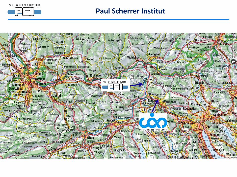
Paul Scherrer Institut
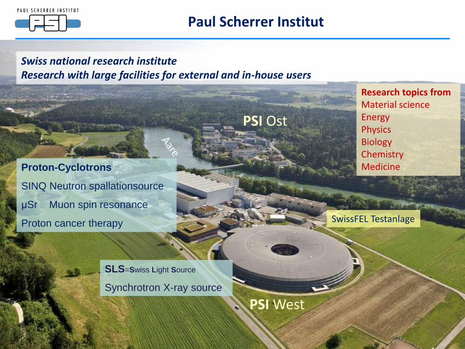
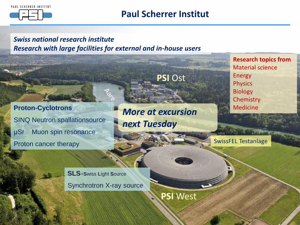
SLS=Swiss Light Source
Synchrotron X-ray source
Proton-Cyclotrons
SINQ Neutron spallationsource
μSr Muon spin resonance
Proton cancer therapy
Paul Scherrer Institut
SwissFEL Testanlage
Swiss national research institute Research with large facilities for external and in-house users
PSI West
PSI Ost
Research topics from Material science Energy Physics Biology Chemistry Medicine
More at excursion next Tuesday
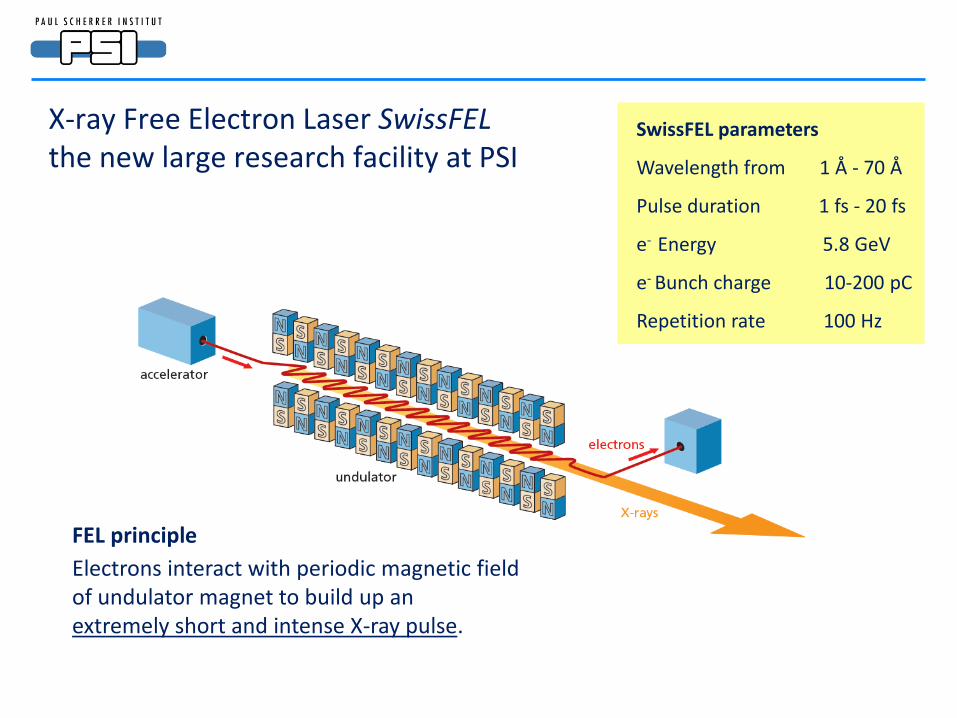
FEL principle
Electrons interact with periodic magnetic field of undulator magnet to build up an extremely short and intense X-ray pulse.
SwissFEL parameters
Wavelength from 1 Å - 70 Å
Pulse duration 1 fs - 20 fs
e- Energy 5.8 GeV
e- Bunch charge 10-200 pC
Repetition rate 100 Hz
X-ray Free Electron Laser SwissFEL the new large research facility at PSI
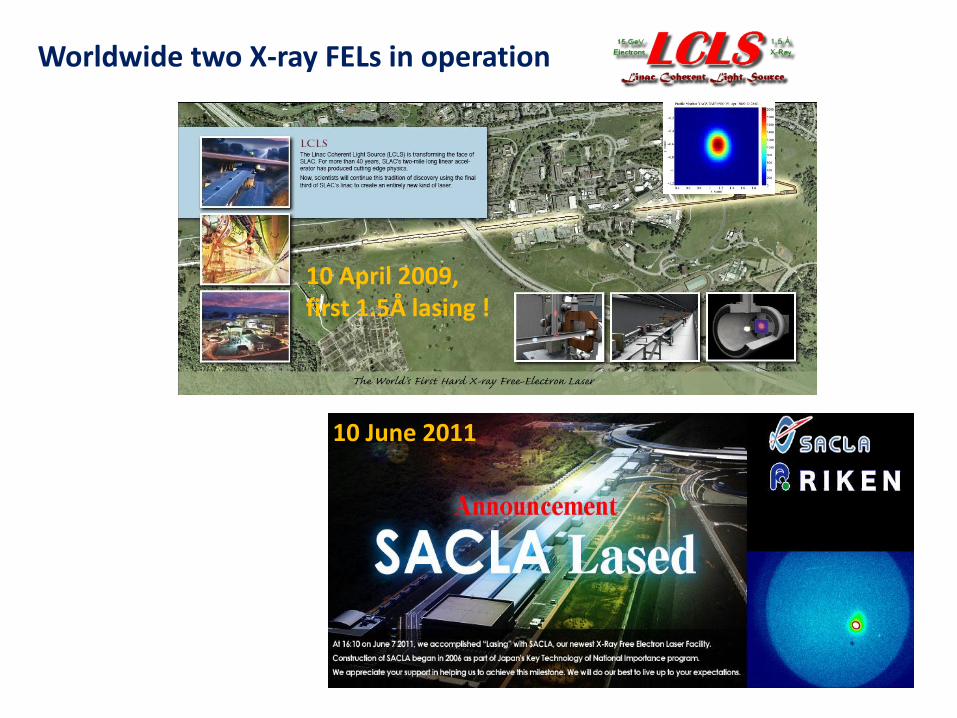
10 April 2009, first 1.5Å lasing !
10 June 2011
Worldwide two X-ray FELs in operation
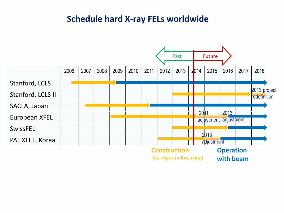
Schedule hard X-ray FELs worldwide
2006 2007 2008 2009 2010 2011 2012 2013 2014 2015 2016 2017 2018
Stanford, LCLS
Stanford, LCLS II
SACLA, Japan
European XFEL
SwissFEL
PAL XFEL, Korea
Construction (start=groundbreaking)
Operation with beam
2011
adjustment
Past Future
2013
adjustment
2013
adjustment
2013 project
redefinition
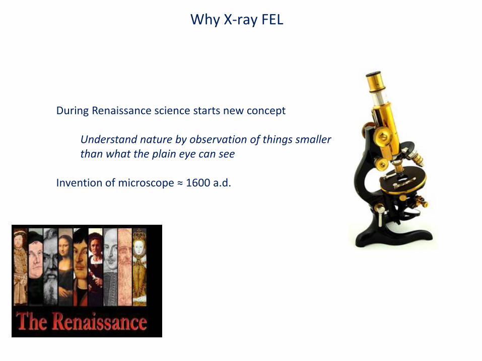
Why X-ray FEL
During Renaissance science starts new concept
Understand nature by observation of things smaller than what the plain eye can see
Invention of microscope ≈ 1600 a.d.
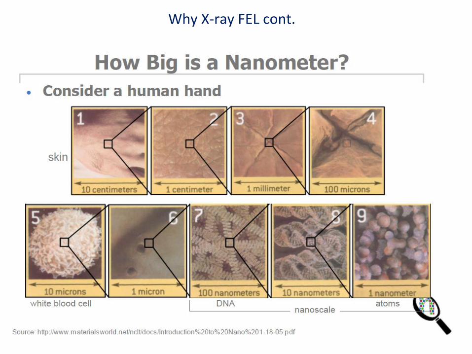
Why X-ray FEL cont.
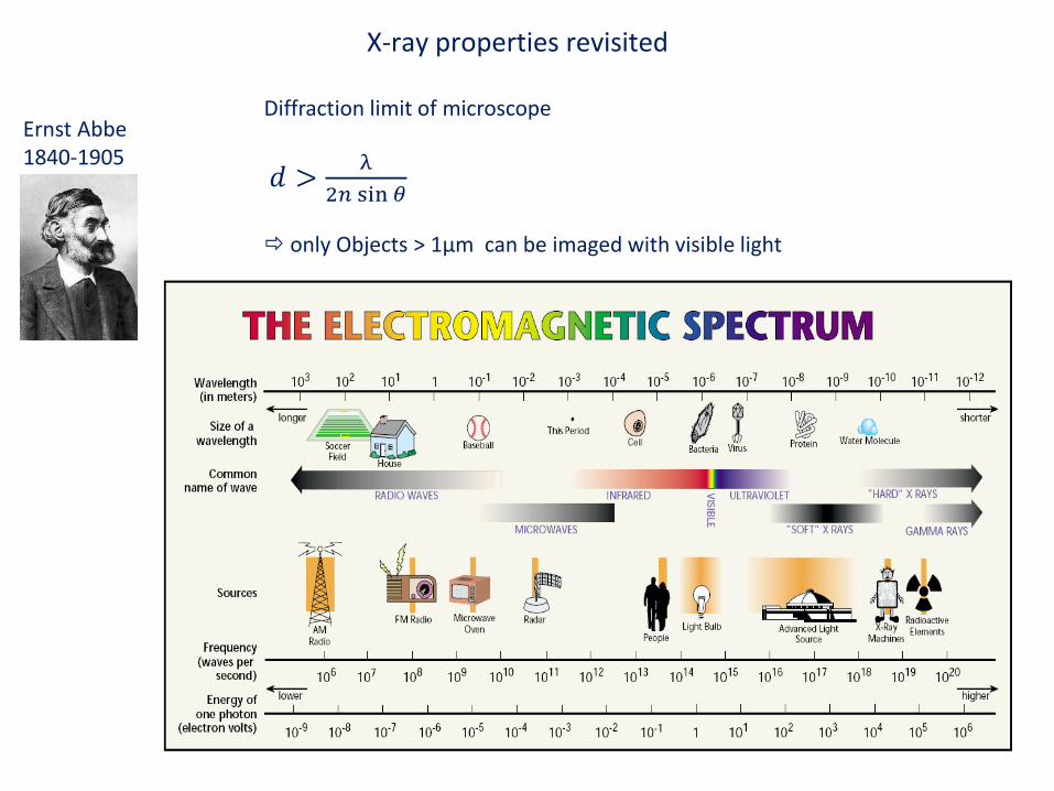
X-ray properties revisited
Ernst Abbe 1840-1905
Diffraction limit of microscope
𝑑 >λ
2𝑛 sin 𝜃
only Objects > 1μm can be imaged with visible light
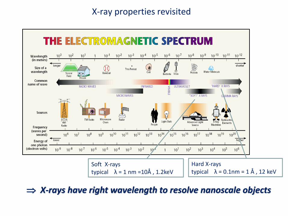
X-ray properties revisited
Soft X-rays typical λ = 1 nm =10Å , 1.2keV
Hard X-rays typical λ = 0.1nm = 1 Å , 12 keV
X-rays have right wavelength to resolve nanoscale objects

X-ray properties revisited, cont.
Sylvester Stallone imaged with visible light
Sylvester Stallone imaged with X-rays
X-ray attenuation is weak extended objects can be imaged in transmission
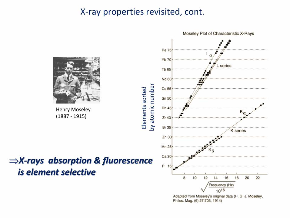
X-ray properties revisited, cont.
Henry Moseley (1887 - 1915)
Elem
ents
so
rted
b
y at
om
ic n
um
ber
X-rays absorption & fluorescence is element selective
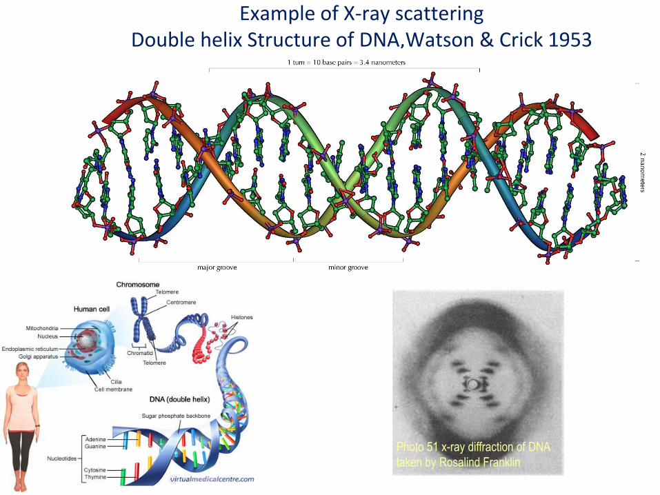
Example of X-ray scattering Double helix Structure of DNA,Watson & Crick 1953
Photo 51 x-ray diffraction of DNA
taken by Rosalind Franklin
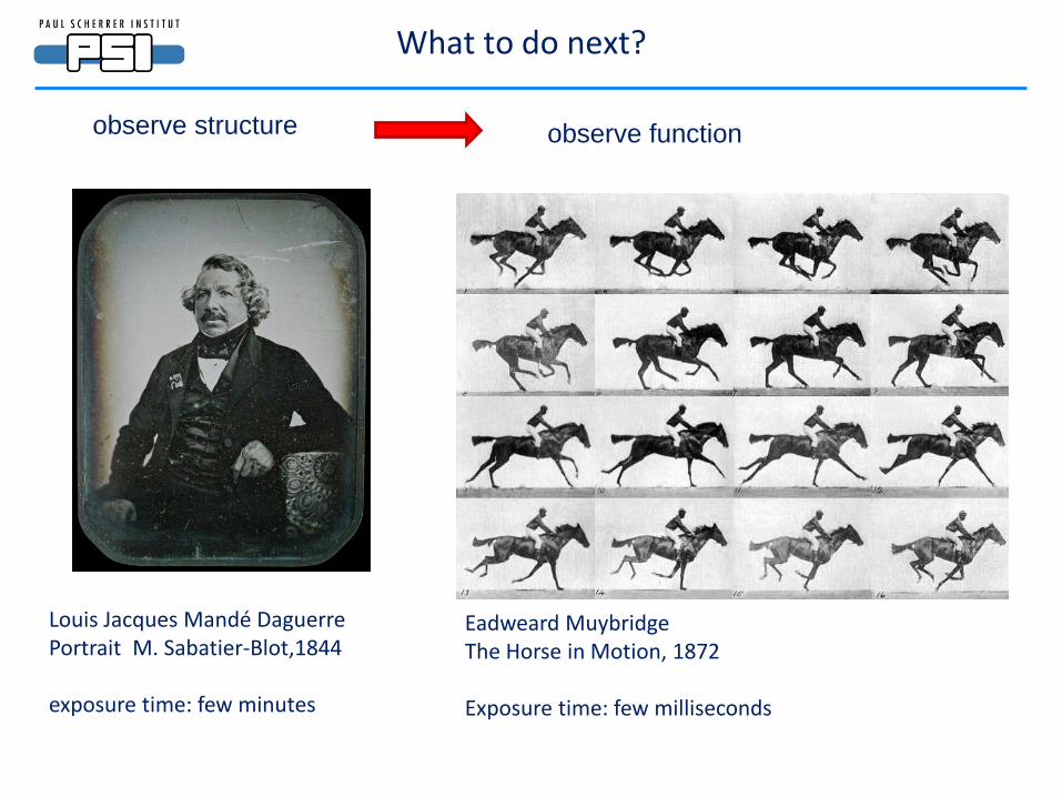
Eadweard Muybridge The Horse in Motion, 1872 Exposure time: few milliseconds
Louis Jacques Mandé Daguerre Portrait M. Sabatier-Blot,1844 exposure time: few minutes
observe structure observe function
What to do next?
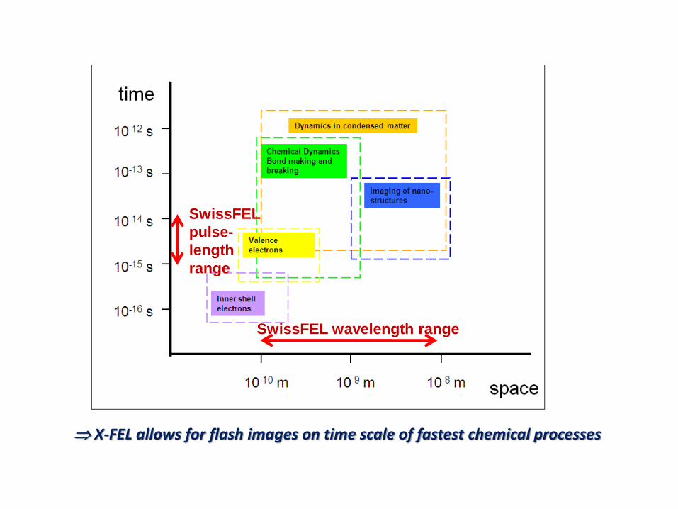
SwissFEL wavelength range
SwissFEL
pulse-
length
range
X-FEL allows for flash images on time scale of fastest chemical processes
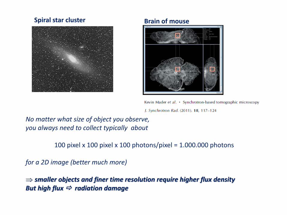
No matter what size of object you observe, you always need to collect typically about 100 pixel x 100 pixel x 100 photons/pixel = 1.000.000 photons for a 2D image (better much more) smaller objects and finer time resolution require higher flux density But high flux radiation damage
Spiral star cluster Brain of mouse
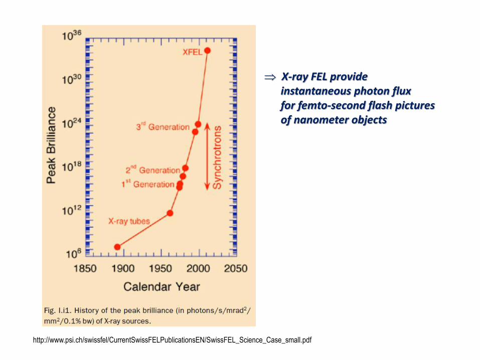
http://www.psi.ch/swissfel/CurrentSwissFELPublicationsEN/SwissFEL_Science_Case_small.pdf
X-ray FEL provide instantaneous photon flux for femto-second flash pictures of nanometer objects
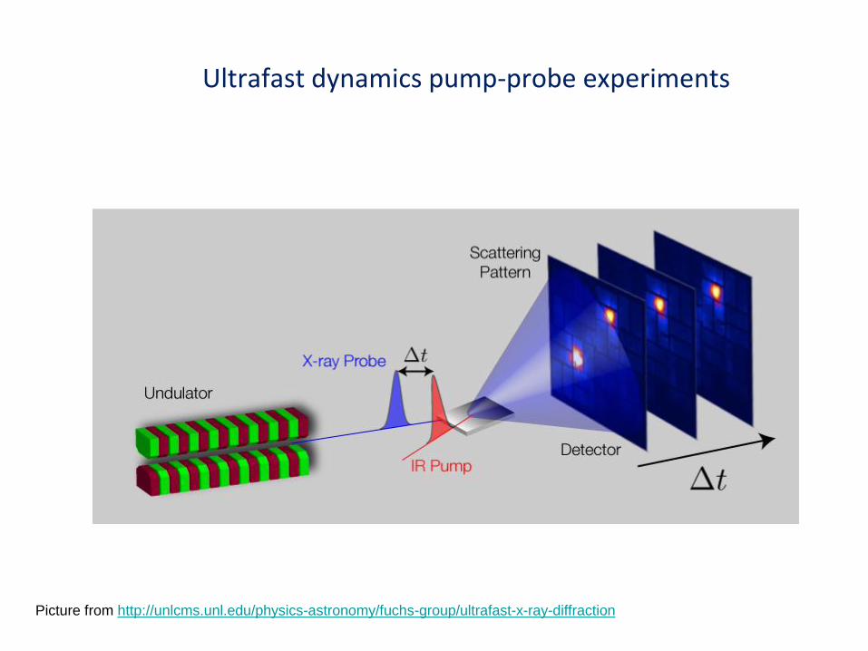
Ultrafast dynamics pump-probe experiments
Picture from http://unlcms.unl.edu/physics-astronomy/fuchs-group/ultrafast-x-ray-diffraction
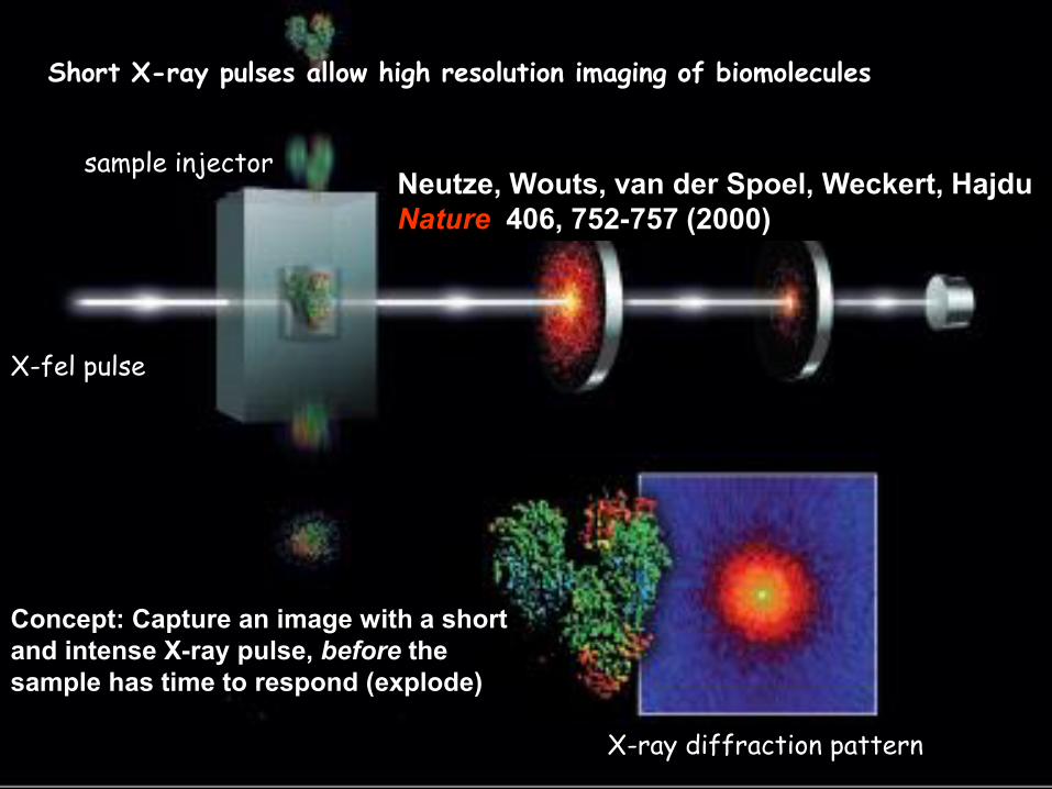
detectors sample injector
X-fel pulse
X-ray diffraction pattern
Short X-ray pulses allow high resolution imaging of biomolecules
Neutze, Wouts, van der Spoel, Weckert, Hajdu
Nature 406, 752-757 (2000)
Concept: Capture an image with a short
and intense X-ray pulse, before the
sample has time to respond (explode)
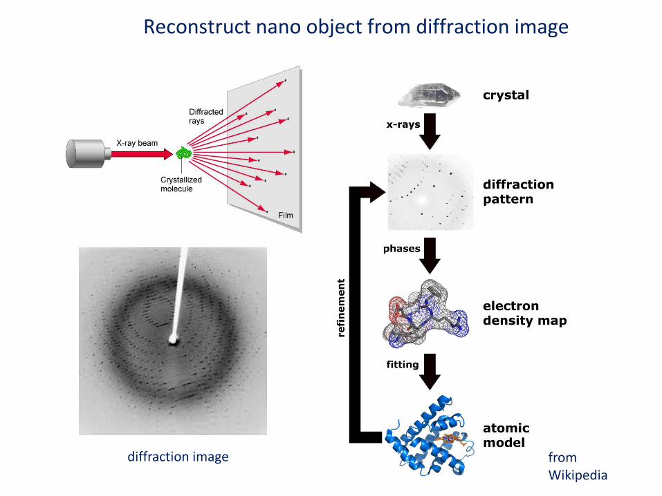
Reconstruct nano object from diffraction image
from Wikipedia
diffraction image
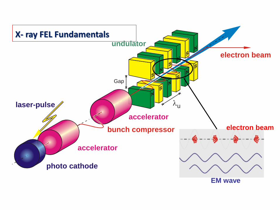
X- ray FEL Fundamentals
Gap
u
undulator
electron beam
photo cathode
accelerator
bunch compressor
accelerator
laser-pulse
EM wave
electron beam
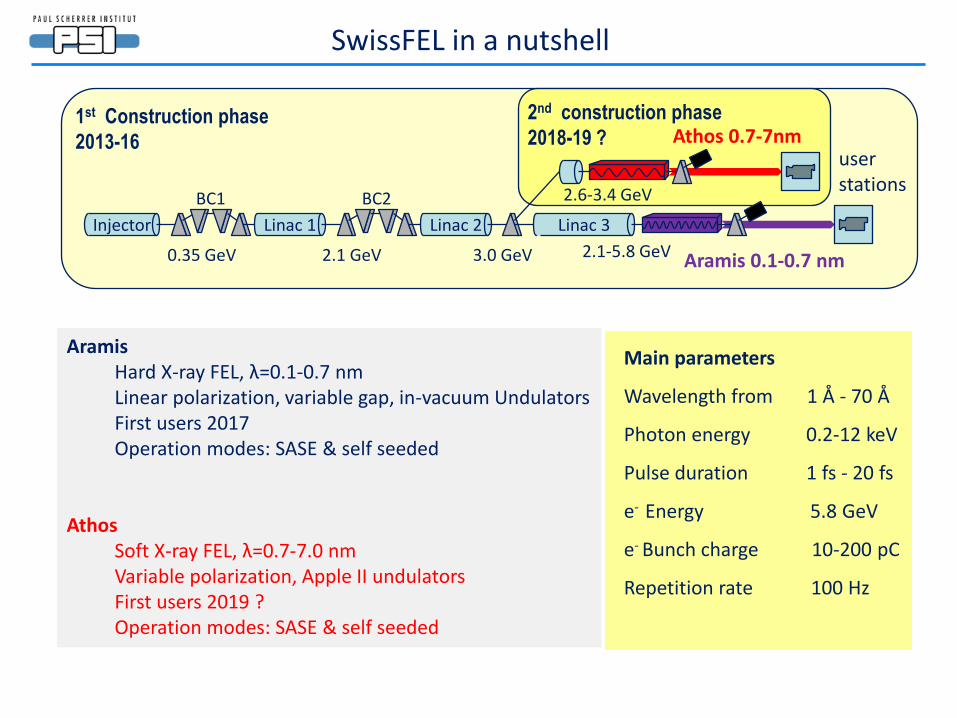
SwissFEL in a nutshell
Aramis Hard X-ray FEL, λ=0.1-0.7 nm Linear polarization, variable gap, in-vacuum Undulators First users 2017 Operation modes: SASE & self seeded
Athos Soft X-ray FEL, λ=0.7-7.0 nm Variable polarization, Apple II undulators First users 2019 ? Operation modes: SASE & self seeded
1st Construction phase
2013-16
2nd construction phase
2018-19 ?
Linac 3 Linac 1 Injector Linac 2
Athos 0.7-7nm
Aramis 0.1-0.7 nm 0.35 GeV 2.1 GeV 3.0 GeV 2.1-5.8 GeV
user stations
2.6-3.4 GeV BC1 BC2
Main parameters
Wavelength from 1 Å - 70 Å
Photon energy 0.2-12 keV
Pulse duration 1 fs - 20 fs
e- Energy 5.8 GeV
e- Bunch charge 10-200 pC
Repetition rate 100 Hz
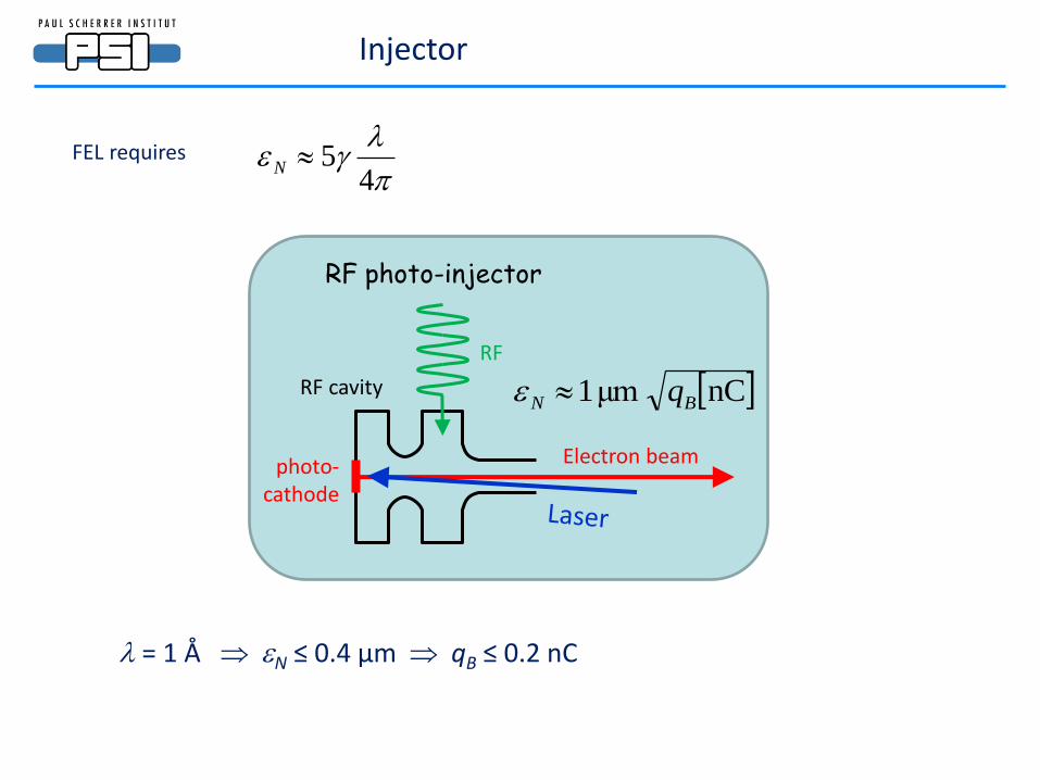
Injector
FEL requires
45N
RF photo-injector
RF
Electron beam photo- cathode
RF cavity nCμm1 BN q
= 1 Å N ≤ 0.4 μm qB ≤ 0.2 nC
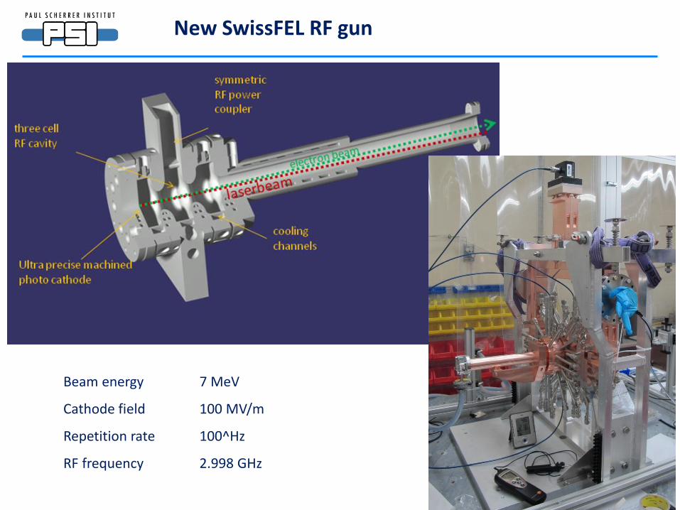
New SwissFEL RF gun
Beam energy 7 MeV
Cathode field 100 MV/m
Repetition rate 100^Hz
RF frequency 2.998 GHz
RF
Power
source
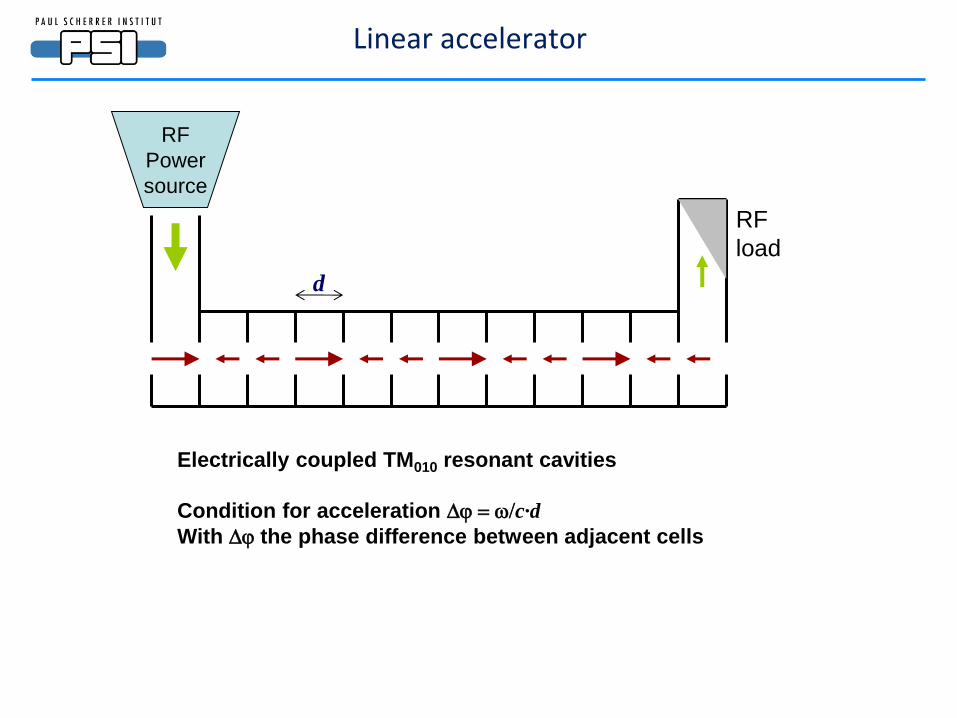
Electrically coupled TM010 resonant cavities
Condition for acceleration Dj = w/c·d
With Dj the phase difference between adjacent cells
d
RF
load
Linear accelerator
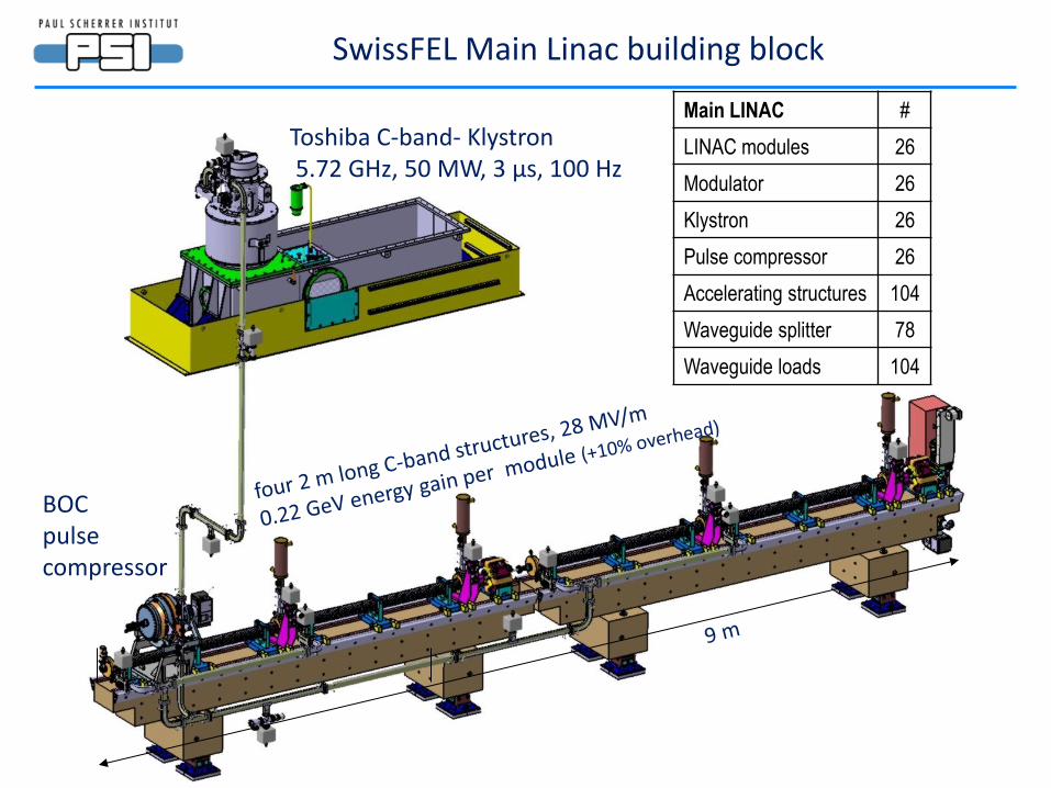
Toshiba C-band- Klystron 5.72 GHz, 50 MW, 3 μs, 100 Hz
BOC pulse compressor
SwissFEL Main Linac building block
Main LINAC #
LINAC modules 26
Modulator 26
Klystron 26
Pulse compressor 26
Accelerating structures 104
Waveguide splitter 78
Waveguide loads 104
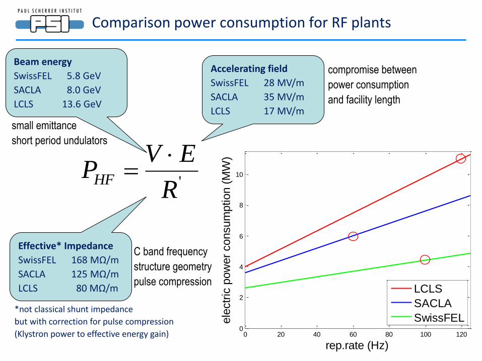
Comparison power consumption for RF plants
0 20 40 60 80 100 1200
2
4
6
8
10
rep.rate (Hz)
ele
ctr
ic p
ow
er
consum
ption (
MW
)
LCLS
SACLA
SwissFEL
'R
EVPHF
=
*not classical shunt impedance
but with correction for pulse compression
(Klystron power to effective energy gain)
Beam energy
SwissFEL 5.8 GeV
SACLA 8.0 GeV
LCLS 13.6 GeV
Accelerating field
SwissFEL 28 MV/m
SACLA 35 MV/m
LCLS 17 MV/m
Effective* Impedance
SwissFEL 168 MΩ/m
SACLA 125 MΩ/m
LCLS 80 MΩ/m
small emittance
short period undulators
compromise between
power consumption
and facility length
C band frequency
structure geometry
pulse compression
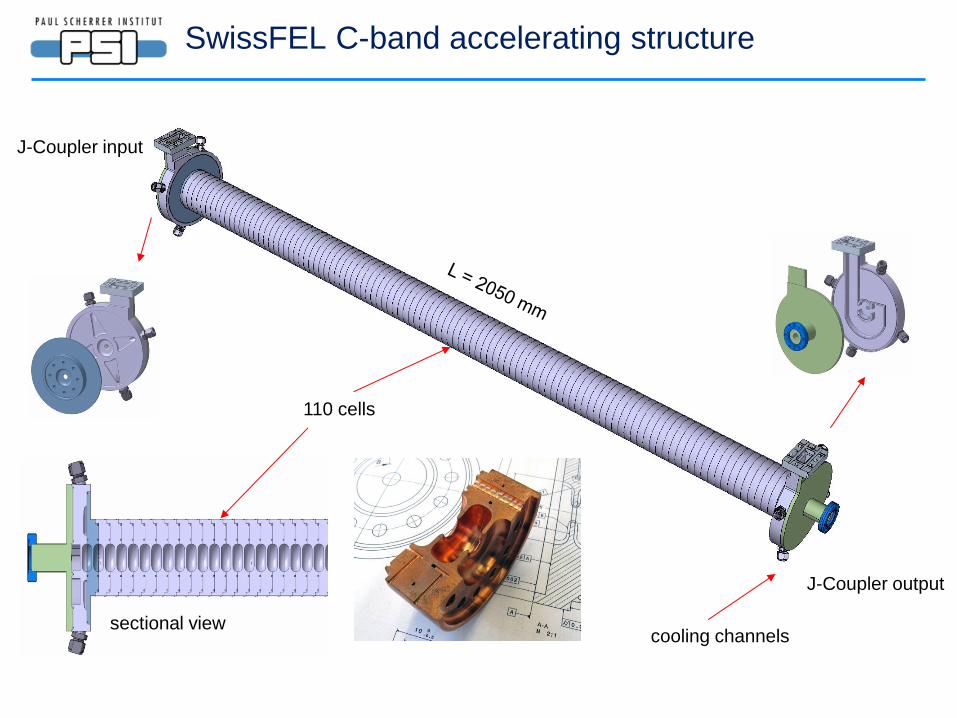
J-Coupler input
J-Coupler output
110 cells
cooling channels
sectional view
SwissFEL C-band accelerating structure
Leak check
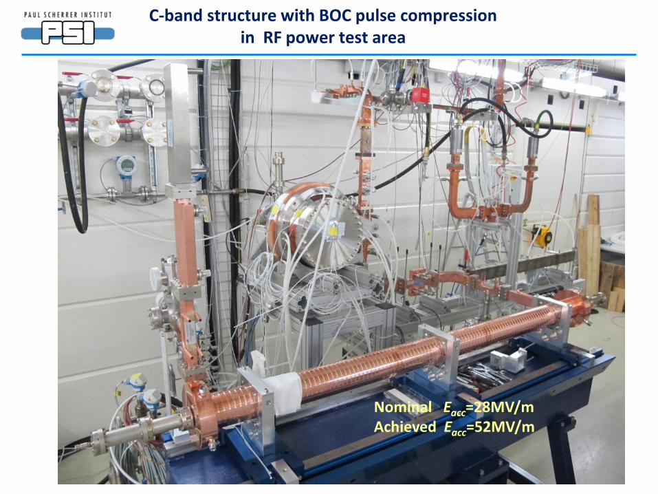
C-band structure with BOC pulse compression in RF power test area
Nominal Eacc=28MV/m Achieved Eacc=52MV/m
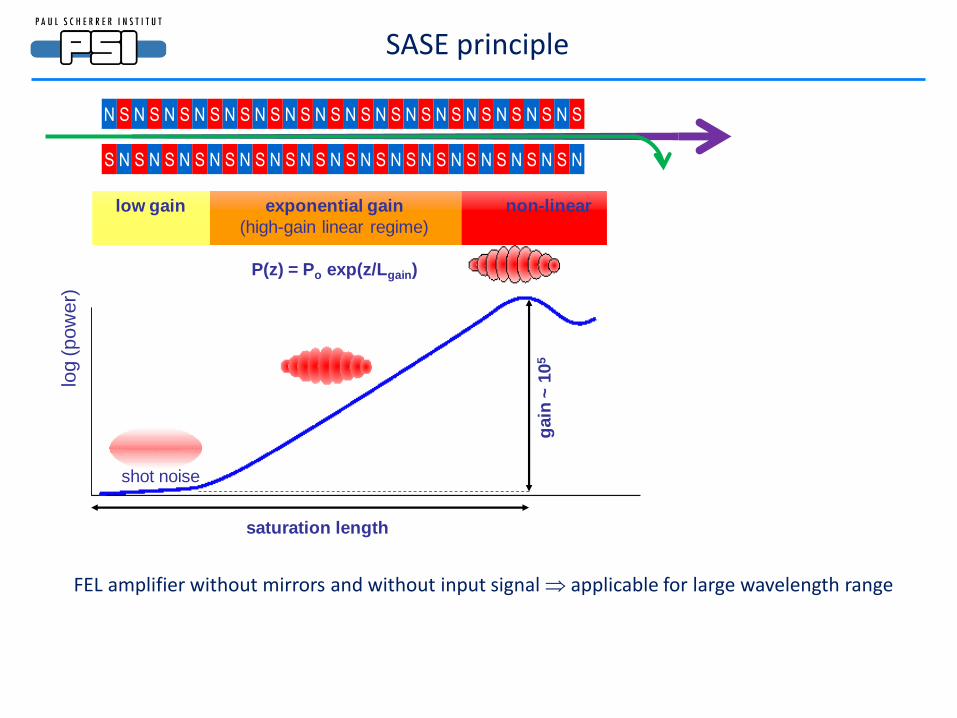
log (p
ow
er)
saturation length
shot noise
gain
~ 1
05
low gain exponential gain
(high-gain linear regime)
P(z) = Po exp(z/Lgain)
non-linear
N S N S N S N S N S N S N S N S N S N S
N S N S N S N S N S N S N S N S N S N S
N S N S N S N S N S N S
N S N S N S N S S N S N
SASE principle
FEL amplifier without mirrors and without input signal applicable for large wavelength range
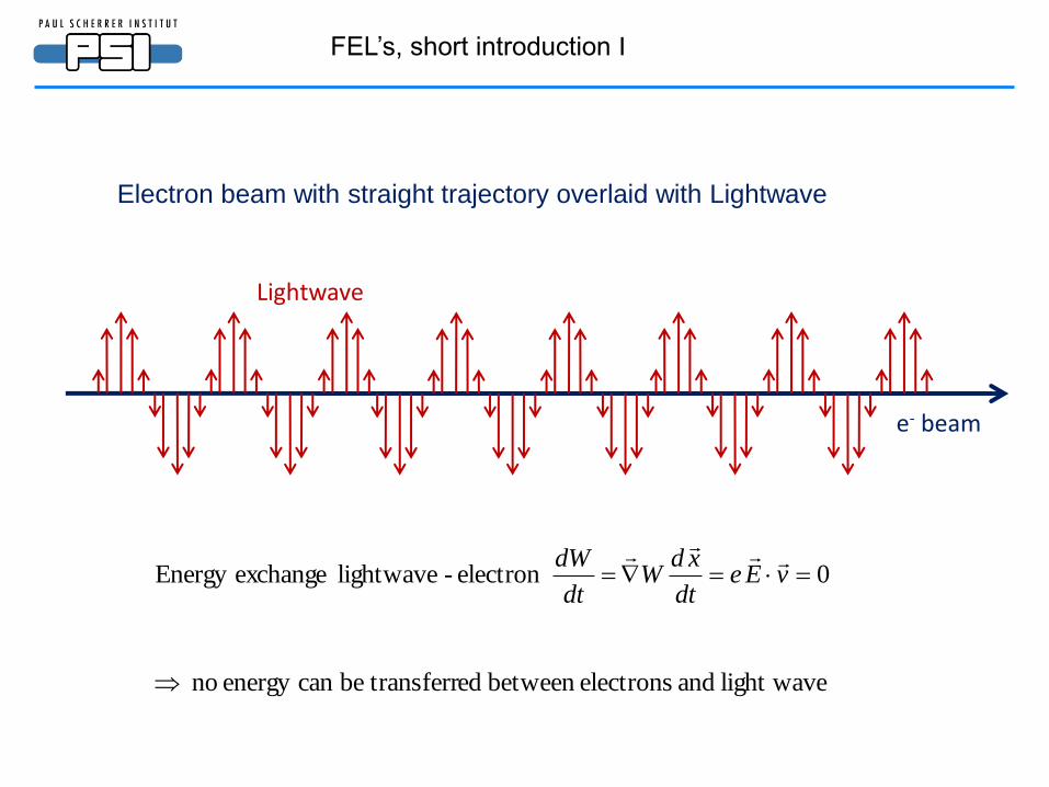
Lightwave
e- beam
light wave and electronsbetween ed transferrbecan energy no
0electron - lightwave exchangeEnergy
=== vEedt
xdW
dt
dW
Electron beam with straight trajectory overlaid with Lightwave
FEL’s, short introduction I
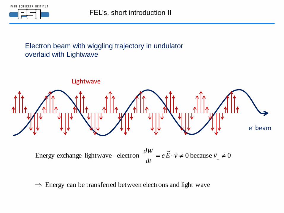
light wave and electronsbetween ed transferrbecan Energy
0 because 0electron - lightwave exchangeEnergy
= vvEedt
dW
Lightwave
e- beam
Electron beam with wiggling trajectory in undulator
overlaid with Lightwave
FEL’s, short introduction II
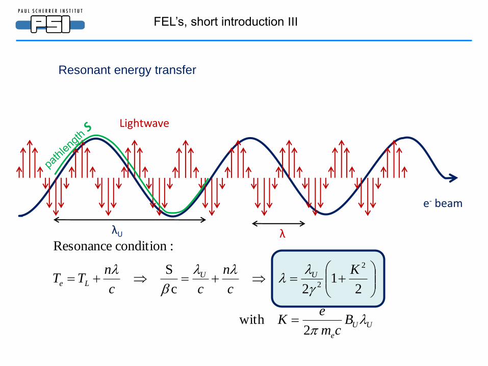
UU
e
UULe
Bcm
eK
K
c
n
cc
nTT
2 with
21
2c
S
:condition Resonance
2
2
=
===
Lightwave
e- beam
Resonant energy transfer
λU λ
FEL’s, short introduction III
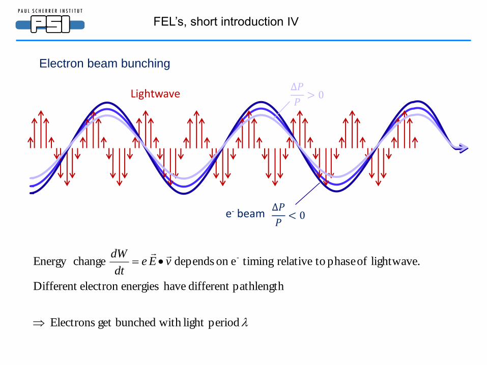
periodlight with bunchedget Electrons
pathlengthdifferent have energieselectron Different
lightwave. of phase torelative timingeon depends changeEnergy -
= vEedt
dW
Lightwave
e- beam
Electron beam bunching
FEL’s, short introduction IV
∆𝑃
𝑃< 0
∆𝑃
𝑃> 0
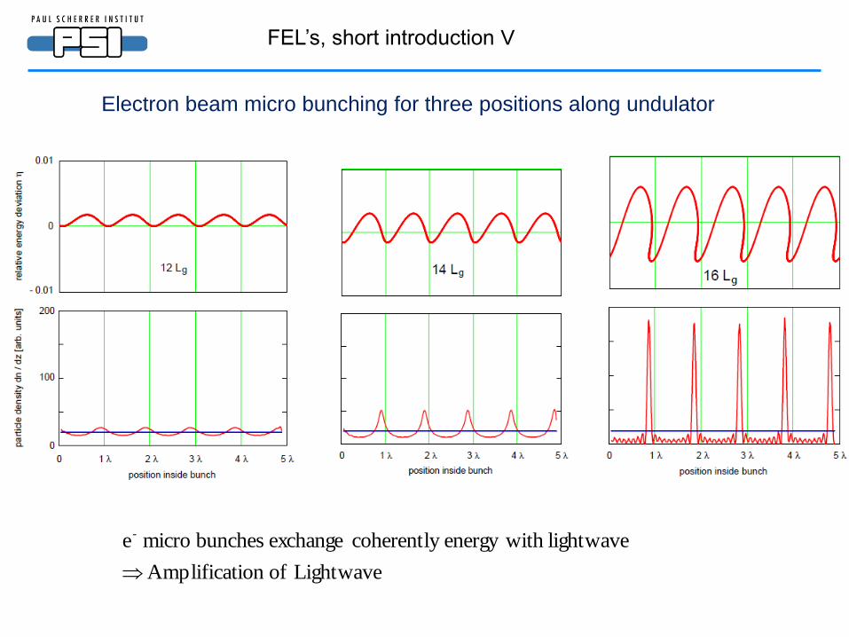
Electron beam micro bunching for three positions along undulator
Lightwave ofion Amplificat
lightwaveh energy wit coherently exchange bunches micro e-
FEL’s, short introduction V
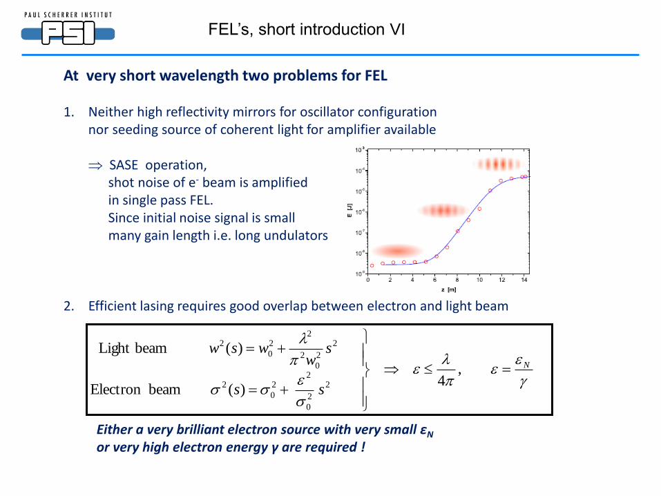
At very short wavelength two problems for FEL 1. Neither high reflectivity mirrors for oscillator configuration
nor seeding source of coherent light for amplifier available
SASE operation, shot noise of e- beam is amplified in single pass FEL.
Since initial noise signal is small many gain length i.e. long undulators
2. Efficient lasing requires good overlap between electron and light beam
Either a very brilliant electron source with very small εN or very high electron energy γ are required !
N
ss
sw
wsw
=
=
=
,4
)( beamElectron
)( beamLight
2
2
0
22
0
2
2
2
0
2
22
0
2
FEL’s, short introduction VI
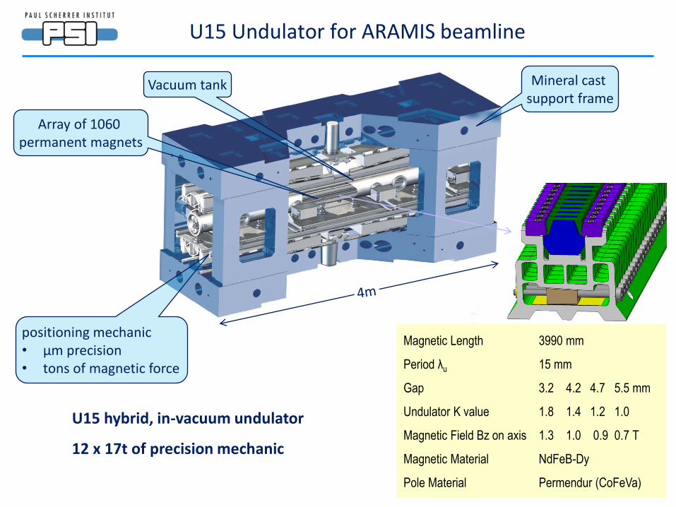
U15 Undulator for ARAMIS beamline
U15 hybrid, in-vacuum undulator
12 x 17t of precision mechanic
Mineral cast support frame
Vacuum tank
positioning mechanic • μm precision • tons of magnetic force
Array of 1060 permanent magnets
Magnetic Length 3990 mm
Period λu 15 mm
Gap 3.2 4.2 4.7 5.5 mm
Undulator K value 1.8 1.4 1.2 1.0
Magnetic Field Bz on axis 1.3 1.0 0.9 0.7 T
Magnetic Material NdFeB-Dy
Pole Material Permendur (CoFeVa)

SwissFEL injector Tesf facility
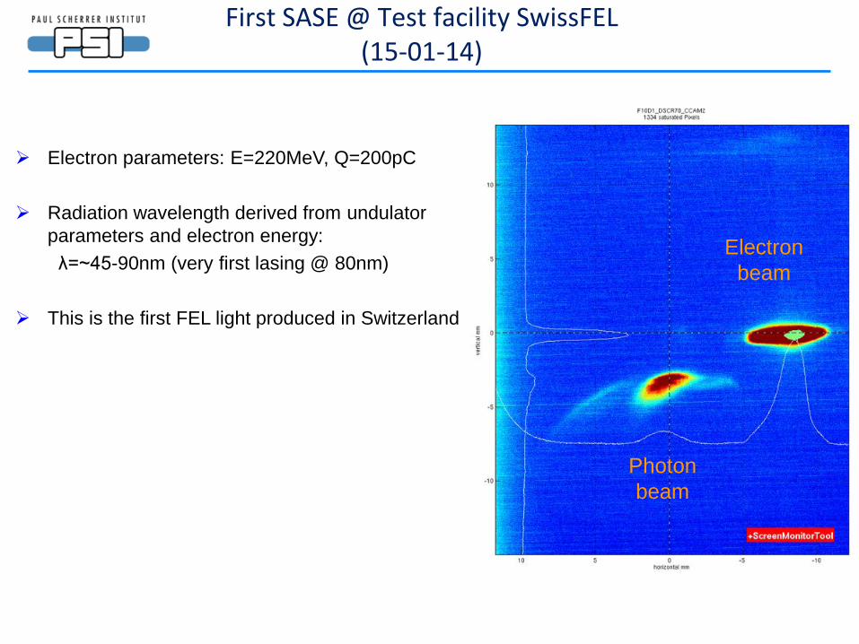
First SASE @ Test facility SwissFEL (15-01-14)
Electron parameters: E=220MeV, Q=200pC
Radiation wavelength derived from undulator
parameters and electron energy:
λ=~45-90nm (very first lasing @ 80nm)
This is the first FEL light produced in Switzerland
Electron
beam
Photon
beam
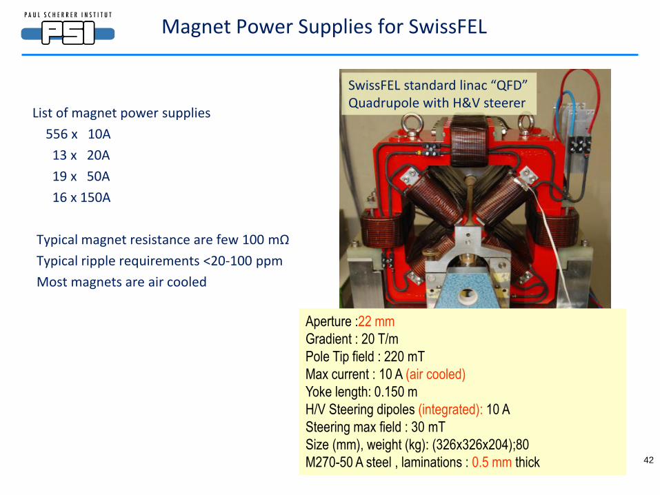
Magnet Power Supplies for SwissFEL
42
List of magnet power supplies
556 x 10A
13 x 20A
19 x 50A
16 x 150A
Typical magnet resistance are few 100 mΩ
Typical ripple requirements <20-100 ppm
Most magnets are air cooled
SwissFEL standard linac “QFD” Quadrupole with H&V steerer
Aperture :22 mm
Gradient : 20 T/m
Pole Tip field : 220 mT
Max current : 10 A (air cooled)
Yoke length: 0.150 m
H/V Steering dipoles (integrated): 10 A
Steering max field : 30 mT
Size (mm), weight (kg): (326x326x204);80
M270-50 A steel , laminations : 0.5 mm thick
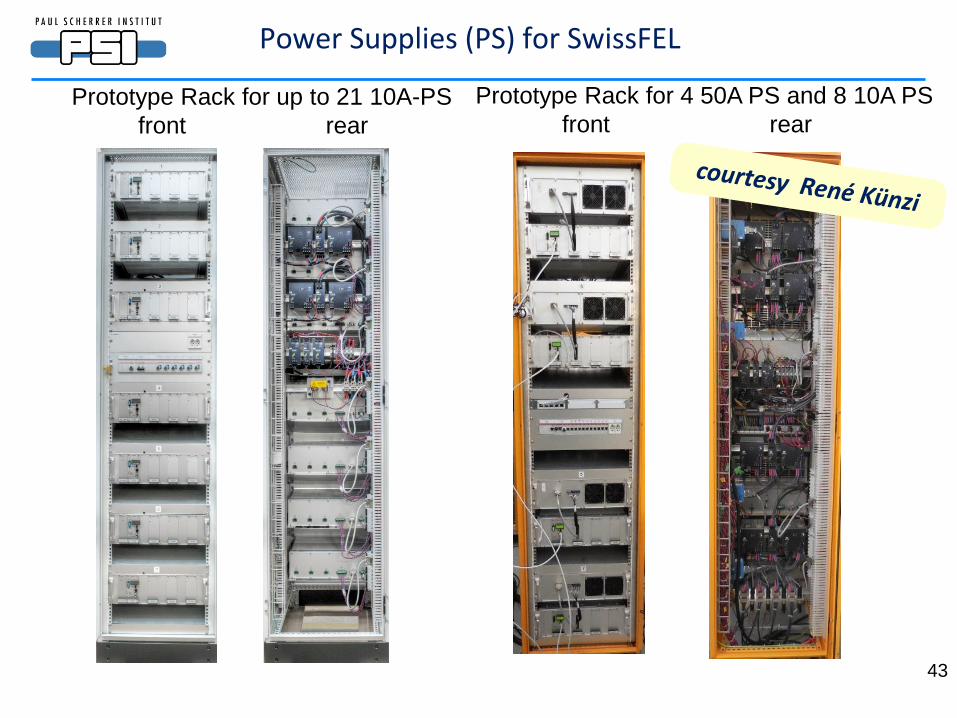
Power Supplies (PS) for SwissFEL
43
Prototype Rack for up to 21 10A-PS
front rear
Prototype Rack for 4 50A PS and 8 10A PS
front rear
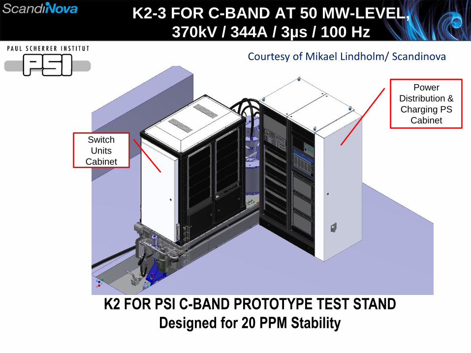
K2-3 FOR C-BAND AT 50 MW-LEVEL,
370kV / 344A / 3µs / 100 Hz
K2 FOR PSI C-BAND PROTOTYPE TEST STAND
Designed for 20 PPM Stability
Switch
Units
Cabinet
Power
Distribution &
Charging PS
Cabinet
Courtesy of Mikael Lindholm/ Scandinova
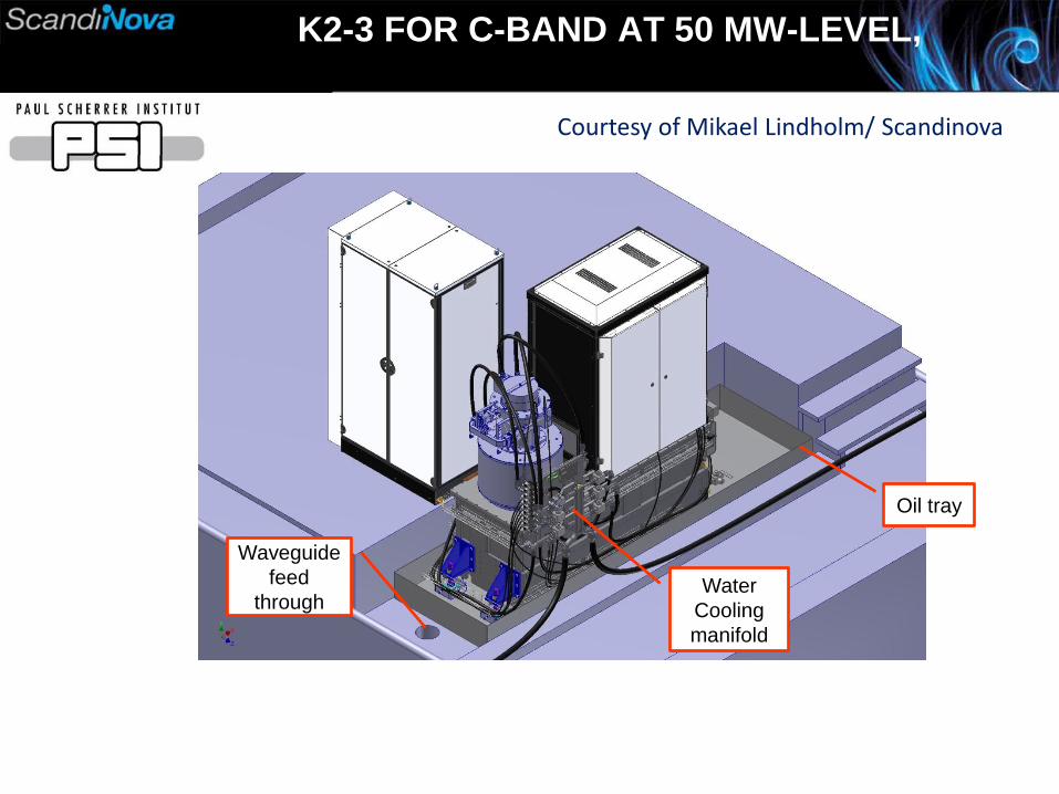
K2-3 FOR C-BAND AT 50 MW-LEVEL,
Water
Cooling
manifold
Oil tray
Waveguide
feed
through
Courtesy of Mikael Lindholm/ Scandinova
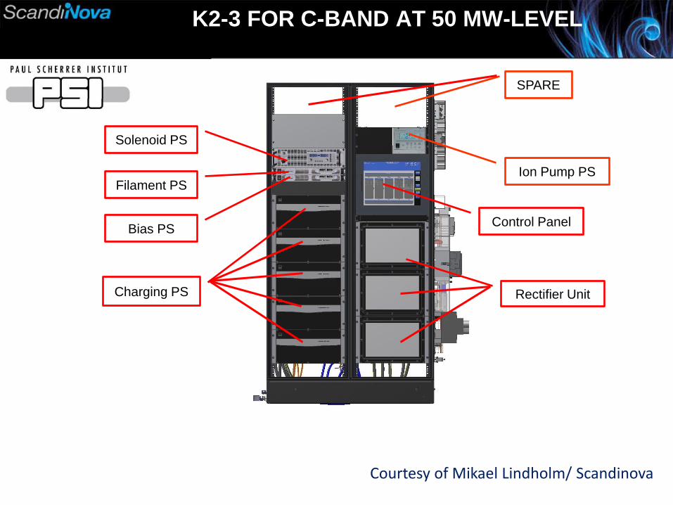
K2-3 FOR C-BAND AT 50 MW-LEVEL
Charging PS
Control Panel
Ion Pump PS
Solenoid PS
Filament PS
Rectifier Unit
Bias PS
SPARE
Courtesy of Mikael Lindholm/ Scandinova
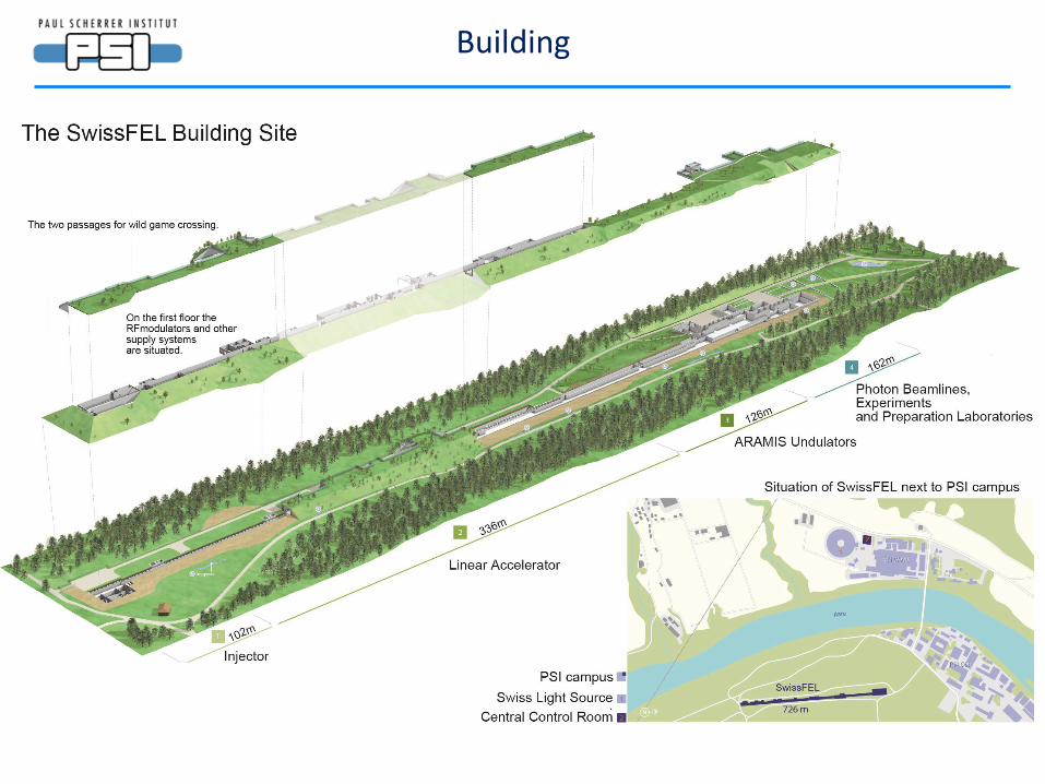
Building
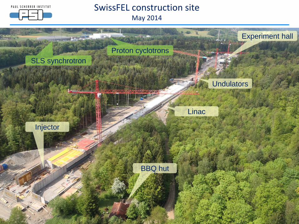
SwissFEL construction site May 2014
Injector
Linac
BBQ hut
Undulators
Experiment hall
SLS synchrotron
Proton cyclotrons
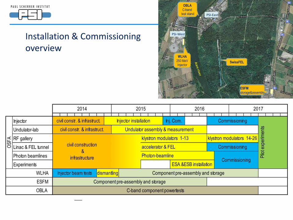
WLHA
250 MeVInjector
SwissFEL
ESFM
storage&assembly
OBLA
C-bandtest stand
PSI-West
PSI-East
Injector
Undulator-lab
RF gallery
Linac & FEL tunnel
Photon beamlines
Experiments
civil construction
&
infrastructure
ESFM Component pre-assembly and storage
OBLA C-band component powertests
CommissioningESA &ESB installation
WLHA Injector beam tests dismantling Component pre-assembly and storage
Pilo
t exp
erim
en
tscivil constr. & infrastruct. Undulator assembly & measurement
klystron modulators 1-13 klystron modulators 14-26
accelerator & FEL Commissioning
Photon-beamline
2014 2015 2016 2017
OS
FA
civil constr. & infrastruct. Injector installation Inj. Com. Commissioning
Installation & Commissioning overview
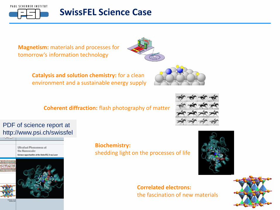
SwissFEL Science Case
Magnetism: materials and processes for tomorrow‘s information technology
Catalysis and solution chemistry: for a clean environment and a sustainable energy supply
Coherent diffraction: flash photography of matter
Biochemistry: shedding light on the processes of life
Correlated electrons: the fascination of new materials
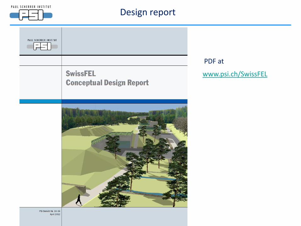
PDF of science report at
http://www.psi.ch/swissfel