
qform3d.com · Web viewSuch parts like turbine and generator rotors, pieces of nuclear and chemical...
9
Experience of Simulation Implementation to Development of Technological Processes for Production of Large Forged Products at Energomashspetsstal (Kramatorsk) Maksim Efimov 1 , Aleksandr Selutin 1 , Andrey Kolomoyets 1 , Anatoly Ryabcev 2 , Vladimir Pashinsky 2 , Sergey Stebunov 3 1 PJSC "EMSS", Kramatorsk, Ukraine 2 Donetsk National Technical University, Donetsk, Ukraine 3 QuantorForm Ltd., Moscow, Russia Abstract There is a worldwide trend to produce larger single-piece heavy duty forged parts due to the demand of the heavy engineering industry and energy industry. Such parts like turbine and generator rotors, pieces of nuclear and chemical reactors, drive shafts, heavy rolls of rolling mills and other similar items may have finish unit mass about 120-250 tons. In turn the initial weight of a steel forging ingot for such products may reach up to 350-600 tons and even more. Manufacturing of heavy forgings have certain technological difficulties that should be resolved to provide required high quality of finished parts that should be proved by an ultrasonic inspection and mechanical testing. That is why when designing the forging ingot having the weight 350 tons and developing the forging technology for subsequent manufacturing of heavy rolls with the weight 165 tons we have carried out computer simulation of all main stages of technology including casting (solidification) and further forging by means of the programs MAGMA and QFORM. The results of casting simulation have been transferred to be used for subsequent simulation of heating and forging. 1. INTRODUCTION The decision regarding building of the "Castings and Forgings" plant as the fundamental plant to supply heavy machining industry plants with large- sized castings, forgings and welded parts was made by the Cabinet of Ministers of Soviet Union on 17 December 1960. In 1979 the Ministry of power engineering renamed the plant "Castings and Forgings" as the Kramatorsk plant "Energomashspetsstal" ("EMSS"). On September 2014 "EMSS" have celebrated its 50th anniversary. "EMSS" now is one of the leading Ukrainian enterprises producing castings and forgings of individual and small lot production. It is producing Casting and forging for Power generating industry; Metallurgical industry; Shipbuilding and General machine building. Figure 1 The ingot №1 weighing 355 tons In 2010 "EMSS" successfully completed pouring an ingot weighting 355 ton (figure 1) and made the backup
Transcript of qform3d.com · Web viewSuch parts like turbine and generator rotors, pieces of nuclear and chemical...
Experience of Simulation Implementation to Development of Technological Processes for Production of Large Forged Products at
Energomashspetsstal (Kramatorsk)
Maksim Efimov1, Aleksandr Selutin1, Andrey Kolomoyets1, Anatoly Ryabcev2, Vladimir Pashinsky2, Sergey Stebunov3
1 PJSC "EMSS", Kramatorsk, Ukraine 2 Donetsk National Technical University, Donetsk, Ukraine
3QuantorForm Ltd., Moscow, Russia
Abstract There is a worldwide trend to produce larger single-piece heavy duty forged parts due to the demand of the heavy
engineering industry and energy industry. Such parts like turbine and generator rotors, pieces of nuclear and chemical reactors, drive shafts, heavy rolls of rolling mills and other similar items may have finish unit mass about 120-250 tons. In turn the initial weight of a steel forging ingot for such products may reach up to 350-600 tons and even more.
Manufacturing of heavy forgings have certain technological difficulties that should be resolved to provide required high quality of finished parts that should be proved by an ultrasonic inspection and mechanical testing. That is why when designing the forging ingot having the weight 350 tons and developing the forging technology for subsequent manufacturing of heavy rolls with the weight 165 tons we have carried out computer simulation of all main stages of technology including casting (solidification) and further forging by means of the programs MAGMA and QFORM. The results of casting simulation have been transferred to be used for subsequent simulation of heating and forging.
1. INTRODUCTIONThe decision regarding building of the "Castings and
Forgings" plant as the fundamental plant to supply heavy machining industry plants with large- sized castings, forgings and welded parts was made by the Cabinet of Ministers of Soviet Union on 17 December 1960. In 1979 the Ministry of power engineering renamed the plant "Castings and Forgings" as the Kramatorsk plant "Energomashspetsstal" ("EMSS"). On September 2014 "EMSS" have celebrated its 50th anniversary. "EMSS" now is one of the leading Ukrainian enterprises producing castings and forgings of individual and small lot production. It is producing Casting and forging for Power generating industry; Metallurgical industry; Shipbuilding and General machine building.
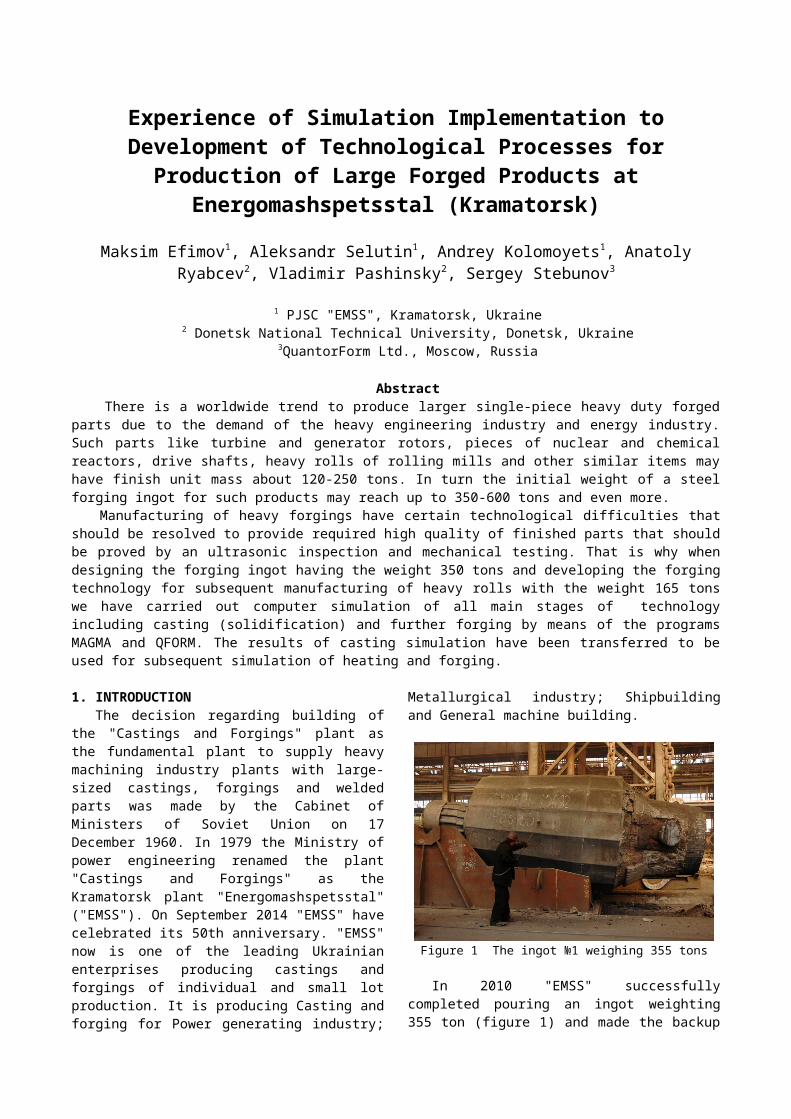
Figure 1 The ingot №1 weighing 355 tons
In 2010 "EMSS" successfully completed pouring an ingot weighting 355 ton (figure 1) and made the backup roll for “Thyssen Krupp Materials France” (Versailles, France) (figure 2). This backup roll for rolling mill is the
unique thing: its length is more than 10 m and body diameter is more than 2 m. The backup roll net weight is more than 165 t.
"EMSS" employees developed and carried out a new technology for heavy ingots casting with using new materials that ensure high steel purity on nonmetallic. In order to get the necessary quantity of metal, six meltings were required. After melting, the material was treated on LF, vacuum degassed and poured into a mold within a vacuum chamber under 0.5 mBar of pressure.
The ingot stripping was carried out by two cranes with a hoisting capacity of 275 t each.
Figure 2 The backup roll weight of 165 tons after machining
In 2013 another large-scale project for production of a backup roll of a plate mill "5000" from a 412 ton ingot was realized. The support roll was produced for metallurgical plant "Severstal" from this ingot. Its weight is 255 tons and is also unique. Successful realization of this project enabled "EMSS" to enter into the top five of
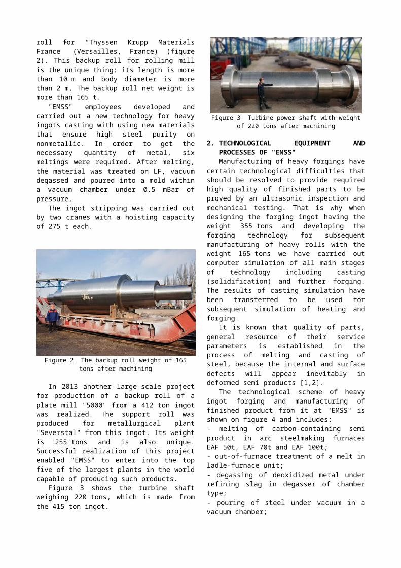
the largest plants in the world capable of producing such products.
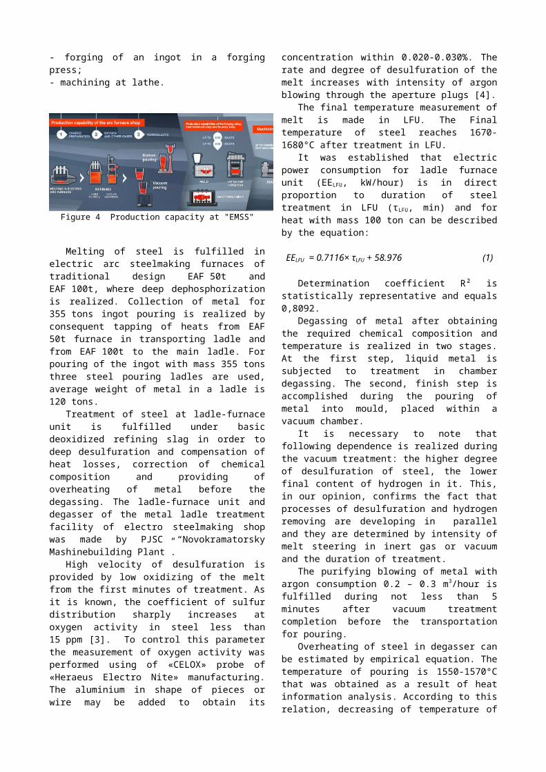
Figure 3 shows the turbine shaft weighing 220 tons, which is made from the 415 ton ingot.
Figure 3 Turbine power shaft with weight of 220 tons after machining
2. TECHNOLOGICAL EQUIPMENT AND PROCESSES OF "EMSS"Manufacturing of heavy forgings have certain
technological difficulties that should be resolved to provide required high quality of finished parts to be proved by an ultrasonic inspection and mechanical testing. That is why when designing the forging ingot having the weight 355 tons and developing the forging technology for subsequent manufacturing of heavy rolls with the weight 165 tons we have carried out computer simulation of all main stages of technology including casting (solidification) and further forging. The results of casting simulation have been transferred to be used for subsequent simulation of heating and forging.
It is known that quality of parts, general resource of their service parameters is established in the process of melting and casting of steel, because the internal and surface defects will appear inevitably in deformed semi products [1,2].
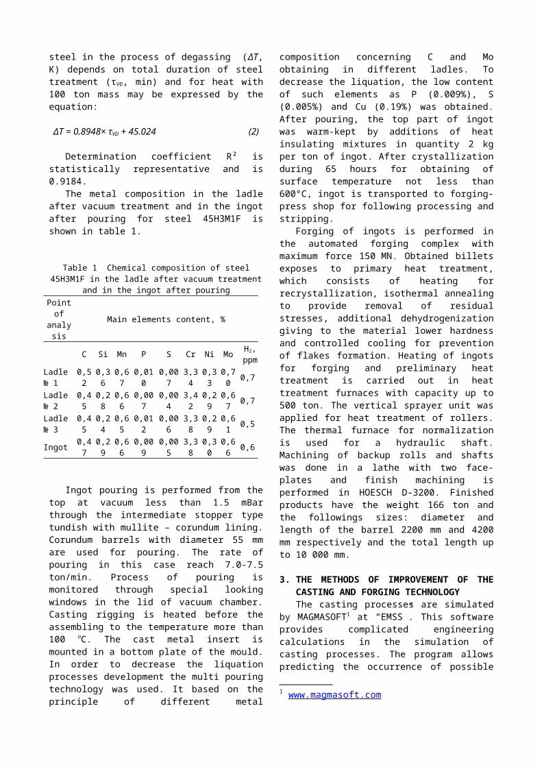
The technological scheme of heavy ingot forging and manufacturing of finished product from it at "EMSS" is shown on figure 4 and includes: - melting of carbon-containing semi product in arc steelmaking furnaces EAF 50t, EAF 70t and EAF 100t; - out-of-furnace treatment of a melt in ladle-furnace unit;- degassing of deoxidized metal under refining slag in degasser of chamber type; - pouring of steel under vacuum in a vacuum chamber; - forging of an ingot in a forging press; - machining at lathe.
Figure 4 Production capacity at "EMSS"
Melting of steel is fulfilled in electric arc steelmaking furnaces of traditional design EAF 50t and EAF 100t, where deep dephosphorization is realized. Collection of metal for 355 tons ingot pouring is realized by consequent tapping of heats from EAF 50t furnace in transporting ladle and from EAF 100t to the main ladle. For pouring of the ingot with mass 355 tons three steel pouring ladles are used, average weight of metal in a ladle is 120 tons.
Treatment of steel at ladle-furnace unit is fulfilled under basic deoxidized refining slag in order to deep desulfuration and compensation of heat losses, correction of chemical composition and providing of overheating of metal before the degassing. The ladle-furnace unit and degasser of the metal ladle treatment facility of electro steelmaking shop was made by PJSC “Novokramatorsky Mashinebuilding Plant”.
High velocity of desulfuration is provided by low oxidizing of the melt from the first minutes of treatment. As it is known, the coefficient of sulfur distribution sharply increases at oxygen activity in steel less than 15 ppm [3]. To control this parameter the measurement of oxygen activity was performed using of «СЕLOX» probe of «Heraeus Electro Nite» manufacturing. The aluminium in shape of pieces or wire may be added to obtain its concentration within 0.020-0.030%. The rate and degree of desulfuration of the melt increases with intensity of argon blowing through the aperture plugs [4].
The final temperature measurement of melt is made in LFU. The Final temperature of steel reaches 1670-1680°С after treatment in LFU.
It was established that electric power consumption for ladle furnace unit (EELFU, kW/hour) is in direct proportion to duration of steel treatment in LFU (τLFU, min) and for heat with mass 100 ton can be described by the equation:
EELFU = 0.7116× τLFU + 58.976 (1)
Determination coefficient R² is statistically representative and equals 0,8092.
Degassing of metal after obtaining the required chemical composition and temperature is realized in two stages. At the first step, liquid metal is subjected to treatment in chamber degassing. The second, finish step is accomplished during the pouring of metal into mould, placed within a vacuum chamber.
It is necessary to note that following dependence is realized during the vacuum treatment: the higher degree of desulfuration of steel, the lower final content of hydrogen in it. This, in our opinion, confirms the fact that processes of desulfuration and hydrogen removing are developing in parallel and they are determined by intensity of melt steering in inert gas or vacuum and the duration of treatment.
The purifying blowing of metal with argon consumption 0.2 – 0.3 m3/hour is fulfilled during not less than 5 minutes after vacuum treatment completion before the transportation for pouring.
Overheating of steel in degasser can be estimated by empirical equation. The temperature of pouring is 1550-1570°С that was obtained as a result of heat information analysis. According to this relation, decreasing of temperature of steel in the process of degassing (ΔT, K) depends on total duration of steel treatment (τVD, min) and
for heat with 100 ton mass may be expressed by the equation:
ΔT = 0.8948× τVD + 45.024 (2)
Determination coefficient R² is statistically representative and is 0.9184.
The metal composition in the ladle after vacuum treatment and in the ingot after pouring for steel 45H3M1F is shown in table 1.
Table 1 Chemical composition of steel 45H3M1F in the ladle after vacuum treatment and in the ingot after pouring
Point of analysis Main elements content, %
C Si Mn P S Cr Ni Mo Н2, ppm
Ladle№ 1 0,52 0,36 0,67 0,010 0,007 3,34 0,33 0,70 0,7
Ladle№ 2 0,45 0,28 0,66 0,007 0,004 3,42 0,29 0,67 0,7
Ladle№ 3 0,45 0,24 0,65 0,012 0,006 3,38 0,29 0,61 0,5
Ingot 0,47 0,29 0,66 0,009 0,005 3,38 0,30 0,66 0,6
Ingot pouring is performed from the top at vacuum less than 1.5 mBar through the intermediate stopper type tundish with mullite – corundum lining. Corundum barrels with diameter 55 mm are used for pouring. The rate of pouring in this case reach 7.0-7.5 ton/min. Process of pouring is monitored through special looking windows in the lid of vacuum chamber. Casting rigging is heated before the assembling to the temperature more than 100 oC. The cast metal insert is mounted in a bottom plate of the mould. In order to decrease the liquation processes development the multi pouring technology was used. It based on the principle of different metal composition concerning C and Mo obtaining in different ladles. To decrease the liquation, the low content of such elements as P (0.009%), S (0.005%) and Cu (0.19%) was obtained. After pouring, the top part of ingot was warm-kept by additions of heat insulating mixtures in quantity 2 kg per ton of ingot. After crystallization during 65 hours for obtaining of surface temperature not less than 600°С, ingot is transported to forging-press shop for following processing and stripping.
Forging of ingots is performed in the automated forging complex with maximum force 150 MN. Obtained billets exposes to primary heat treatment, which consists of heating for recrystallization, isothermal annealing to provide removal of residual stresses, additional dehydrogenization giving to the material lower hardness and controlled cooling for prevention of flakes formation. Heating of ingots for forging and preliminary heat treatment is carried out in heat treatment furnaces with capacity up to 500 ton. The vertical sprayer unit was applied for heat treatment of rollers. The thermal furnace for normalization is used for a hydraulic shaft. Machining of backup rolls and shafts was done in a lathe with two face-plates and finish machining is performed in HOESCH D-3200. Finished products have the weight 166
ton and the followings sizes: diameter and length of the barrel 2200 mm and 4200 mm respectively and the total length up to 10 000 mm.
3. THE METHODS OF IMPROVEMENT OF THE CASTING AND FORGING TECHNOLOGY The casting processes are simulated by
MAGMASOFT1 at “EMSS”. This software provides complicated engineering calculations in the simulation of casting processes. The program allows predicting the occurrence of possible defects and greatly facilitates the work of the founders connected with the assessment of the technological details.
For the development of technological processes of forging “EMSS” applied software product QForm2. Peculiarities of numerical implementation metal forming simulation by QForm described in [5]. The program QForm is very convenient for the development of open die forging, checking plastic deformation distribution inside the ingots, evaluation the heating and cooling of the billet during the whole technological chain and technology optimization.
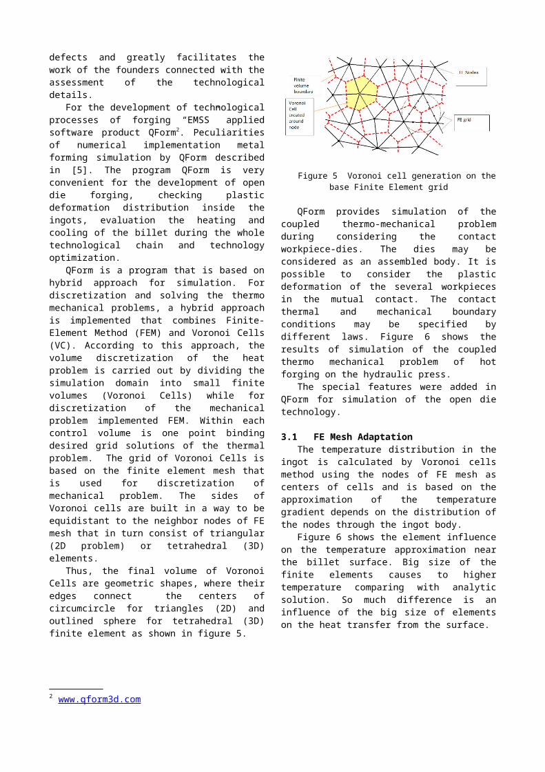
QForm is a program that is based on hybrid approach for simulation. For discretization and solving the thermo mechanical problems, a hybrid approach is implemented that combines Finite-Element Method (FEM) and Voronoi Cells (VC). According to this approach, the volume discretization of the heat problem is carried out by dividing the simulation domain into small finite volumes (Voronoi Cells) while for discretization of the mechanical problem implemented FEM. Within each control volume is one point binding desired grid solutions of the thermal problem. The grid of Voronoi Cells is based on the finite element mesh that is used for discretization of mechanical problem. The sides of Voronoi cells are built in a way to be equidistant to the neighbor nodes of FE mesh that in turn consist of triangular (2D problem) or tetrahedral (3D) elements.
Thus, the final volume of Voronoi Cells are geometric shapes, where their edges connect the centers of circumcircle for triangles (2D) and outlined sphere for tetrahedral (3D) finite element as shown in figure 5.
Figure 5 Voronoi cell generation on the base Finite Element grid
1 www. magmasoft .com
2 www.qform3d.com
a.
b.
QForm provides simulation of the coupled thermo-mechanical problem during considering the contact workpiece-dies. The dies may be considered as an assembled body. It is possible to consider the plastic deformation of the several workpieces in the mutual contact. The contact thermal and mechanical boundary conditions may be specified by different laws. Figure 6 shows the results of simulation of the coupled thermo mechanical problem of hot forging on the hydraulic press.
The special features were added in QForm for simulation of the open die technology.
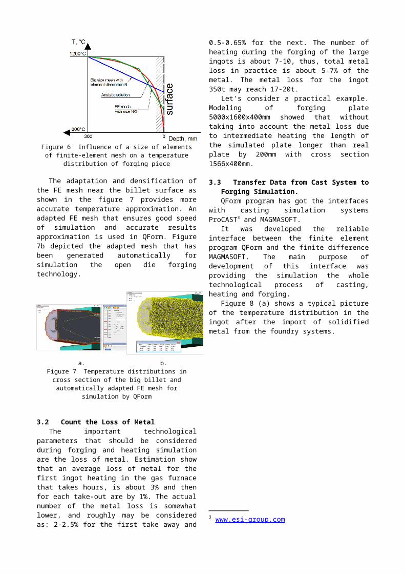
3.1 FE Mesh AdaptationThe temperature distribution in the ingot is calculated
by Voronoi cells method using the nodes of FE mesh as centers of cells and is based on the approximation of the temperature gradient depends on the distribution of the nodes through the ingot body.
Figure 6 shows the element influence on the temperature approximation near the billet surface. Big size of the finite elements causes to higher temperature comparing with analytic solution. So much difference is an influence of the big size of elements on the heat transfer from the surface.
Figure 6 Influence of a size of elements of finite-element mesh on a temperature distribution of forging piece
The adaptation and densification of the FE mesh near the billet surface as shown in the figure 7 provides more accurate temperature approximation. An adapted FE mesh that ensures good speed of simulation and accurate results approximation is used in QForm. Figure 7b depicted the adapted mesh that has been generated automatically for simulation the open die forging technology.
a. b.Figure 7 Temperature distributions in cross section of the big
billet and automatically adapted FE mesh for simulation by QForm
3.2 Count the Loss of MetalThe important technological parameters that should
be considered during forging and heating simulation are the loss of metal. Estimation show that an average loss of metal for the first ingot heating in the gas furnace that takes hours, is about 3% and then for each take-out are by 1%. The actual number of the metal loss is somewhat lower, and roughly may be considered as: 2-2.5% for the first take away and 0.5-0.65% for the next. The number of heating during the forging of the large ingots is about 7-10, thus, total metal loss in practice is about 5-7% of the metal. The metal loss for the ingot 350t may reach 17-20t.
Let's consider a practical example. Modeling of forging plate 5000x1600x400mm showed that without taking into account the metal loss due to intermediate heating the length of the simulated plate longer than real plate by 200mm with cross section 1566х400mm.
3.3 Transfer Data from Cast System to Forging Simulation.QForm program has got the interfaces with casting
simulation systems ProCAST3 and MAGMASOFT. It was developed the reliable interface between the
finite element program QForm and the finite difference MAGMASOFT. The main purpose of development of this interface was providing the simulation the whole technological process of casting, heating and forging.
Figure 8 (a) shows a typical picture of the temperature distribution in the ingot after the import of solidified metal from the foundry systems.
Figure 8 Temperature (a) and a relative density (b) in the ingot 12 ton after import data from MAGMASOFT in QForm
3 www.esi-group.com
a.
b.
One of the problems of import was the solution of the transfer and use of information about shrinkage cavities and hollows formed in the ingot during solidification. There are characteristic zones with zero temperature that identifies zones of shrinkage in ingot.
The same fields with zero values are arisen during the transfer information about the porosity of the ingot. The shrinkage zones have got the zero relative density as depicted in the figure 8 (b).
In the figure 9 depicted the billet with automatically trimmed sink head and void inside the ingot.
Figure 9 The ingot after import in QForm from MAGMASOFT with trimmed sink head and void
As the next step we can simulate the forging operations using this ingot with trimmed sink head and voids. This approach for simulation of the whole technology beginning from casting simulation increase the accuracy of the results and provides more accurately develop the casting–forging technological chain. Particularly the most important information from casting simulation is the shape of the voids that only partially can be deleted by trimming while the rest of them can be tracked through cogging by means of metal forming simulation.
Figure 10 Cogging of the head part of ingot in the rolling-
impression dies with diameter reduction by twice
The initial and final dimensions of the head of the ingot are shown in the figure 10a. The cogging is performed in the hydraulic press 60MN by rolling-
impression dies 600 mm width with standard feed. The closing of the void in the central area of the ingot head is shown in the figure 10b.
The closing of the void that is depicted in the figure 10b agrees with results shown in the work [6]. At the same time, the authors of [6] have used the artificial generation of the voids in the ingot for investigation of their closing versus the forging ratio.
4. RESULTS OF DEVELOPMENT OF FORGING
TECHNOLOGY OF THE BACKUP ROLL FROM 355T INGOTThe backup roll (see figure 2) is produced from the
ingot 355t (figure 1) from steel X40CrMoV5-1-1 (DIN). The part of forging operations on 150 MN hydraulic
press and intermediate heating for obtaining support mill roll weight 165t are shown in the table 2. Because this is draft of the technology it is validated by simulation using QForm. Simulation of the forging operations and intermediate heating takes into account the metal loss. The simulation gives the information that is necessary for modifications and changing of technological instructions for operators.
The forging operations is simulated automatically due the Table 2 where are shown the primary operations from full sequence.
Table 2 Sequence of forging technology of backup roll (primary operations)
Operation DrawingHeating #1Forging
Head forging Cogging
Sawing of head
Heating #2
Forging: Roughing-up Cogging by
3000mm Diameter
Straightening
Heating #3
Forging Cogging by 2700
mm diameter
And other forging operations
a.
b.
a.
b.
a
Let us consider the first sequence of the blows of the head part of the ingot 355t forging. This sequence includes short cogging of the head (8 strokes) with final distance between dies 1550 mm. The upper die is flat and lower is rolling impressed die with width 1200mm. The followed sequence of the blows is 32 strokes with final distance 1200mm and then the next forging with final distance 550mm (32 strokes) and sawing of head.
In the figure 11 depicted the table of strokes for the first group of forging - cogging of the head (12 strokes) with final distance between dies 1550 mm.
Figure 11 The table of head cogging by 12 blows of 355t ingot up to final distance 1550 mm between rolling-impression die.
The forging in the hydraulic press 150MN
Similar tables have been prepared for all forging operations. The number of the blows in one forging sequence can be up to 144 strokes. Simulation provides the verification of forging operations from the point of view of performing them within material process window regarding the temperature range and proper distribution of the plastic deformation inside the billet body to get guaranteed material deformation. Simulation also provides evaluation of the forging force that is very important for such large ingots because the process is always at the limit of press capacity.
Figure 12 The shape, temperature distribution (a) and plastic strain distribution in the forged part after cogging 2700 mm (see
table 2)
The realistic shape of the billet (see figure 12) as the result of simulation of the forging sequence will help to improve the sequence of the forging. Adjusting the sequence of the forging blows provides the proper size of the forged billet. The biggest effect from simulation implementation has been achieved for large ingots.
The result of such simulation allowed us to estimate the real shape of the ingot after implementation of the designed technology. Using the simulation results it is possible to modify the forging parameters to achieve further improvement of the forging technology.
5. CONCLUSIONThe development of forging technology for big ingots
with weights up to 415 ton requires the implementation of the simulation of the full technological chain that includes casting, solidification, heating, forging and cooling. The first experience of production of the backup rolls weighing 165 and 255 tons from ingots of 355 and 400 ton respectively based on simulation results has confirmed its practical efficiency. Implementation of the simulation software MAGMASOFT and QForm have successfully solved the problem of production in “EMSS” of the big and heavy parts.
6. REFERENCES[1] Efimov V.A., Eldarkhanov A.S. Modern technologies of pouring and crystallization of alloys, Mashinebuilding, Moscow, Russia, 1998, 359 p.[2] Smirnov A.N., Makurov S.L., Safonov V.M., Tsuprun A.Yu. Large size ingot, DonNTU, Veber, Donetsk, Ukrain, 2009, 279 p.[3] Dudkin D.A., Bat S.Yu., Grinberg S.E., Marintsev S.N. Producing of steel at ladle furnace unit, South-East, Donetsk, Ukrain, 2003, 62 p.[4] Farouk Siddiki, Kodak A.V., Kasyan G.I., Yavtushenko P.M., Popik N.I. Metal and casting of Ukraine, 2006, No. 1, pp.19-21[5] S. Stebunov, N. Biba, A. Vlasov, A. Maximov, 10th International Conference on Technology of Plasticity, Aachen, Germany, 2011[6] Min-Churl Song, Il-Keun Kwon, Tae-Young Heo and Byung-Hwa Kim, IFM 2008, Santande, Spain, paper 7.4.