DiskShelf14mk2 FC and DiskShelf14mk4 FC Hardware and ...
90
DiskShelf14mk2 FC and DiskShelf14mk4 FC Hardware and Service Guide NetApp, Inc. 495 East Java Drive Sunnyvale, CA 94089 U.S.A. Telephone: +1 (408) 822-6000 Fax: +1 (408) 822-4501 Support telephone: +1 (888) 4-NETAPP Documentation comments: [email protected] Information Web: www.netapp.com Part number 210-01431_D0 April 2011
Transcript of DiskShelf14mk2 FC and DiskShelf14mk4 FC Hardware and ...
DiskShelf14mk2 FC and DiskShelf14mk4 FCHardware and Service Guide
NetApp, Inc.495 East Java DriveSunnyvale, CA 94089 U.S.A.Telephone: +1 (408) 822-6000Fax: +1 (408) 822-4501Support telephone: +1 (888) 4-NETAPPDocumentation comments: [email protected] Web: www.netapp.com
Part number 210-01431_D0April 2011

Copyright and trademark information
Copyright information
Copyright © 1994–2011 NetApp, Inc. All rights reserved. Printed in the U.S.A.
No part of this document covered by copyright may be reproduced in any form or by any means—graphic, electronic, or mechanical, including photocopying, recording, taping, or storage in an electronic retrieval system—without prior written permission of the copyright owner.
NetApp reserves the right to change any products described herein at any time, and without notice. NetApp assumes no responsibility or liability arising from the use of products described herein, except as expressly agreed to in writing by NetApp. The use or purchase of this product does not convey a license under any patent rights, trademark rights, or any other intellectual property rights of NetApp. The product described in this manual may be protected by one or more U.S.A. patents, foreign patents, or pending applications.
RESTRICTED RIGHTS LEGEND: Use, duplication, or disclosure by the government is subject to restrictions as set forth in subparagraph (c)(1)(ii) of the Rights in Technical Data and Computer Software clause at DFARS 252.277-7103 (October 1988) and FAR 52-227-19 (June 1987).
Trademark information
NetApp, the NetApp logo, Network Appliance, the Network Appliance logo, Akorri, ApplianceWatch, ASUP, AutoSupport, BalancePoint, BalancePoint Predictor, Bycast, Campaign Express, ComplianceClock, Cryptainer, CryptoShred, Data ONTAP, DataFabric, DataFort, Decru, Decru DataFort, FAServer, FilerView, FlexCache, FlexClone, FlexScale, FlexShare, FlexSuite, FlexVol, FPolicy, GetSuccessful, gFiler, Go further, faster, Imagine Virtually Anything, Lifetime Key Management, LockVault, Manage ONTAP, MetroCluster, MultiStore, NearStore, NetCache, NOW (NetApp on the Web), ONTAPI, OpenKey, RAID-DP, ReplicatorX, SANscreen, SecureAdmin, SecureShare, Select, Shadow Tape, Simulate ONTAP, SnapCopy, SnapDirector, SnapDrive, SnapFilter, SnapLock, SnapManager, SnapMigrator, SnapMirror, SnapMover, SnapRestore, Snapshot, SnapSuite, SnapValidator, SnapVault, StorageGRID, StoreVault, the StoreVault logo, SyncMirror, Tech OnTap, The evolution of storage, Topio, vFiler, VFM, Virtual File Manager, VPolicy, WAFL, and Web Filer are trademarks or registered trademarks of NetApp, Inc. in the United States, other countries, or both.
IBM, the IBM logo, and ibm.com are trademarks or registered trademarks of International Business Machines Corporation in the United States, other countries, or both. A complete and current list of other IBM trademarks is available on the Web at www.ibm.com/legal/copytrade.shtml.
Apple is a registered trademark and QuickTime is a trademark of Apple, Inc. in the U.S.A. and/or other countries. Microsoft is a registered trademark and Windows Media is a trademark of Microsoft Corporation in the U.S.A. and/or other countries. RealAudio, RealNetworks, RealPlayer, RealSystem, RealText, and RealVideo are registered trademarks and RealMedia, RealProxy, and SureStream are trademarks of RealNetworks, Inc. in the U.S.A. and/or other countries.
All other brands or products are trademarks or registered trademarks of their respective holders and should be treated as such.
NetApp, Inc. is a licensee of the CompactFlash and CF Logo trademarks. NetApp, Inc. NetCache is certified RealSystem compatible.
ii Copyright and trademark information
Table of Contents
Safety Information (Sicherheitshinweise) . . . . . . . . . . . . . . . . . . . v
Chapter 1 Installation Roadmap for the Disk Shelf. . . . . . . . . . . . . . . . . . . . 1
Differences between the various disk shelf models . . . . . . . . . . . . . . . 2
Before you begin your installation . . . . . . . . . . . . . . . . . . . . . . . . 4
The installation process . . . . . . . . . . . . . . . . . . . . . . . . . . . . . . 9
Chapter 2 Monitoring the Disk Shelf. . . . . . . . . . . . . . . . . . . . . . . . . . . 11
Monitoring the front operation panel . . . . . . . . . . . . . . . . . . . . . . 12
Monitoring the ESH2 or ESH4 modules . . . . . . . . . . . . . . . . . . . . 15
Monitoring the power supply . . . . . . . . . . . . . . . . . . . . . . . . . . 26
Monitoring the Fibre Channel disk . . . . . . . . . . . . . . . . . . . . . . . 28
Chapter 3 Replacing Disk Shelf Devices . . . . . . . . . . . . . . . . . . . . . . . . . 31
Replacing a disk shelf . . . . . . . . . . . . . . . . . . . . . . . . . . . . . 32Removing a disk shelf from a single disk shelf configuration . . . . . . 34Removing a disk shelf from a loop. . . . . . . . . . . . . . . . . . . . 36Installing a disk shelf in a rack . . . . . . . . . . . . . . . . . . . . . . 38
Replacing a disk in a disk shelf . . . . . . . . . . . . . . . . . . . . . . . . . 40
Replacing a power supply in a disk shelf . . . . . . . . . . . . . . . . . . . . 44
Replacing an ESH2/ESH4 module . . . . . . . . . . . . . . . . . . . . . . . 48Removing a module . . . . . . . . . . . . . . . . . . . . . . . . . . . 49Installing a module . . . . . . . . . . . . . . . . . . . . . . . . . . . . 51Hot-swapping a module . . . . . . . . . . . . . . . . . . . . . . . . . 52
Appendix A Hot-adding a Disk Shelf to an Existing System . . . . . . . . . . . . . . . 55
Hot-adding a disk shelf to an existing loop. . . . . . . . . . . . . . . . . . . 57
Hot-adding a disk shelf to an existing adapter in your system . . . . . . . . . 62
Appendix B Recommended Power Line Sizes . . . . . . . . . . . . . . . . . . . . . . . 67
Table of Contents iii
Recommended AC power line sizes . . . . . . . . . . . . . . . . . . . . . . 68
Calculating the length of DC wires . . . . . . . . . . . . . . . . . . . . . . . 69
Appendix C Feature Update Record . . . . . . . . . . . . . . . . . . . . . . . . . . . . 75
Appendix D Communications Regulations. . . . . . . . . . . . . . . . . . . . . . . . . 77
Regulatory notices . . . . . . . . . . . . . . . . . . . . . . . . . . . . . . . 78
Declaration of Conformity . . . . . . . . . . . . . . . . . . . . . . . . . . . 80
Index . . . . . . . . . . . . . . . . . . . . . . . . . . . . . . . . . . . . . . 81
iv Table of Contents
Safety Information (Sicherheitshinweise)
Safety rules All products are Class 1 laser devices, except the NVRAM5 cluster media converter, which is Class 1M. You must follow these safety rules when working with this equipment:
DANGERFailure to follow these directions could result in bodily harm or death.
◆ When using an NVRAM5 cluster media converter, the system must be installed in a restricted access location.
◆ Switzerland only—for FAS900, GF900, R200, and C6200 systems: This equipment relies on fuses/circuit breakers in the building installation for overcurrent protection. Each power supply must receive power from a separately dedicated outlet with a 10A fuse/circuit breaker.
◆ When installing disk shelves and a system into a movable cabinet or rack, install from the bottom up for best stability.
◆ DC-based systems must be installed in a restricted access location and the two input power terminals for the DC power supply must be connected to separate isolated branch circuits.
◆ To reduce the risk of personal injury or equipment damage, allow internal components time to cool before touching them and ensure that the equipment is properly supported or braced when installing options.
◆ This equipment is designed for connection to a grounded outlet. The grounding type plug is an important safety feature. To avoid the risk of electrical shock or damage to the equipment, do not disable this feature.
◆ This equipment has one or more replaceable batteries. There is danger of explosion if the battery is incorrectly replaced. Replace the battery only with the same or equivalent type recommended by the manufacturer. Dispose of used batteries according to the manufacturer’s instructions.
For units with multiple power cords
If your system or disk shelf has multiple power cords and you need to turn the unit off, heed the following warning:
DANGERThis unit has more than one power supply cord. To reduce the risk of electrical shock, disconnect all power supply cords before servicing.
Safety Information (Sicherheitshinweise) v

Sicherheitsvorgaben Alle Produkte sind Lasergeräte der Klasse 1, mit Ausnahme des NVRAM5 Cluster-Medienkonverters, der in Klasse 1M fällt. Beim Einsatz dieser Geräte sind die Sicherheitsvorschriften zu beachten:
VorsichtNichtbeachtung dieser Vorschriften kann zu Verletzungen oder Tod führen.
◆ Bei der Verwendung eines NVRAM5 Cluster-Medienkonverters muss das Speichersystem an einem Standort mit beschränktem Zugriff installiert werden.
◆ Nur für die Schweiz - Systeme FAS900, GF900, R200 und C6200: Diese Geräte erfordern den Festeinbau von Sicherungen zum Überstromschutz. Jeder Netzanschluss muss mit Strom aus getrennten, speziell für diesen Zweck vorgesehenen Steckdosen versorgt werden, die jeweils mit einer 10A-Sicherung geschützt sind.
◆ Werden die Plattenregale und das Speichersystem in einen beweglichen Schrank oder Turm eingebaut, ist wegen der höheren Stabilität der Einbau von unten nach oben vorzunehmen.
◆ Gleichstrom-Systeme müssen an Betriebsstaette mit beschraenktem Zutritt installiert sein und die beiden Eingangsstromklemmen für das Gleichstrom-Netzteil müssen an separate und isolierte Abzweigleitungen angeschlossen sein.
◆ Zum Schutz vor Körperverletzung oder Sachschäden am Gerät lassen Sie die inneren Bauteile stets vor dem Berühren abkühlen. Sorgen Sie dafür, dass das Gerät richtig abgestützt ist oder fest aufrecht steht, bevor Sie neues Zubehör einbauen.
◆ Dieses Gerät ist für die Einspeisung aus einer geerdeten Netzverbindung ausgelegt. Der Netzstecker mit Erdungsvorrichtung ist ein wichtiger Sicherheitsschutz. Zum Schutz vor elektrischem Schlag oder Sachschäden am Gerät die Erdung nicht abschalten.
◆ Das Gerät ist mit einer oder mehreren auswechselbaren Batterien ausgestattet. Bei unsachgemäßem Auswechseln der Batterie besteht Explosionsgefahr. Batterien nur mit dem vom Hersteller empfohlenen Typ oder entsprechenden Typen ersetzen. Gebrauchte Batterien sind gemäß den Anweisungen des Herstellers zu entsorgen.
Für Geräte mit mehr-fachen Netzan-schlussleitungen
Wenn Ihr Speichersystem oder Plattenregal über mehrere Stromkabel verfügt und Sie die Einheit ausschalten müssen, folgenden Warnhinweis beachten:
ACHTUNGGerät besitzt zwei Netzanschlussleitungen. Vor Wartung alle Anschlüsse vom Netz trennen.
vi Safety Information (Sicherheitshinweise)
Chapter 1: Installation Roadmap for the Disk Shelf
1
Installation Roadmap for the Disk ShelfAbout this chapter This chapter provides a roadmap for installing the DS14mk2 FC and DS14mk4 FC disk shelf.
Topics in this chapter
This chapter discusses the following topics:
◆ “Differences between the various disk shelf models” on page 2
◆ “Before you begin your installation” on page 4
◆ “The installation process” on page 9
1
Differences between the various disk shelf models
Differences between the disk shelves
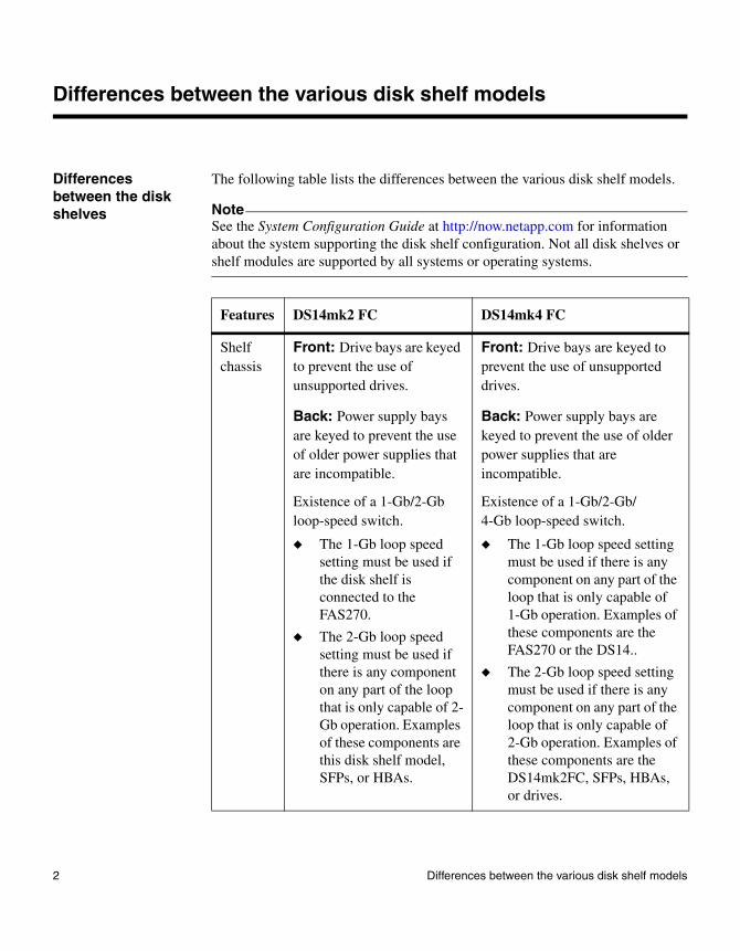
The following table lists the differences between the various disk shelf models.
NoteSee the System Configuration Guide at http://now.netapp.com for information about the system supporting the disk shelf configuration. Not all disk shelves or shelf modules are supported by all systems or operating systems.
Features DS14mk2 FC DS14mk4 FC
Shelf chassis
Front: Drive bays are keyed to prevent the use of unsupported drives.
Back: Power supply bays are keyed to prevent the use of older power supplies that are incompatible.
Existence of a 1-Gb/2-Gb loop-speed switch.
◆ The 1-Gb loop speed setting must be used if the disk shelf is connected to the FAS270.
◆ The 2-Gb loop speed setting must be used if there is any component on any part of the loop that is only capable of 2-Gb operation. Examples of these components are this disk shelf model, SFPs, or HBAs.
Front: Drive bays are keyed to prevent the use of unsupported drives.
Back: Power supply bays are keyed to prevent the use of older power supplies that are incompatible.
Existence of a 1-Gb/2-Gb/4-Gb loop-speed switch.
◆ The 1-Gb loop speed setting must be used if there is any component on any part of the loop that is only capable of 1-Gb operation. Examples of these components are the FAS270 or the DS14..
◆ The 2-Gb loop speed setting must be used if there is any component on any part of the loop that is only capable of 2-Gb operation. Examples of these components are the DS14mk2FC, SFPs, HBAs, or drives.
2 Differences between the various disk shelf models
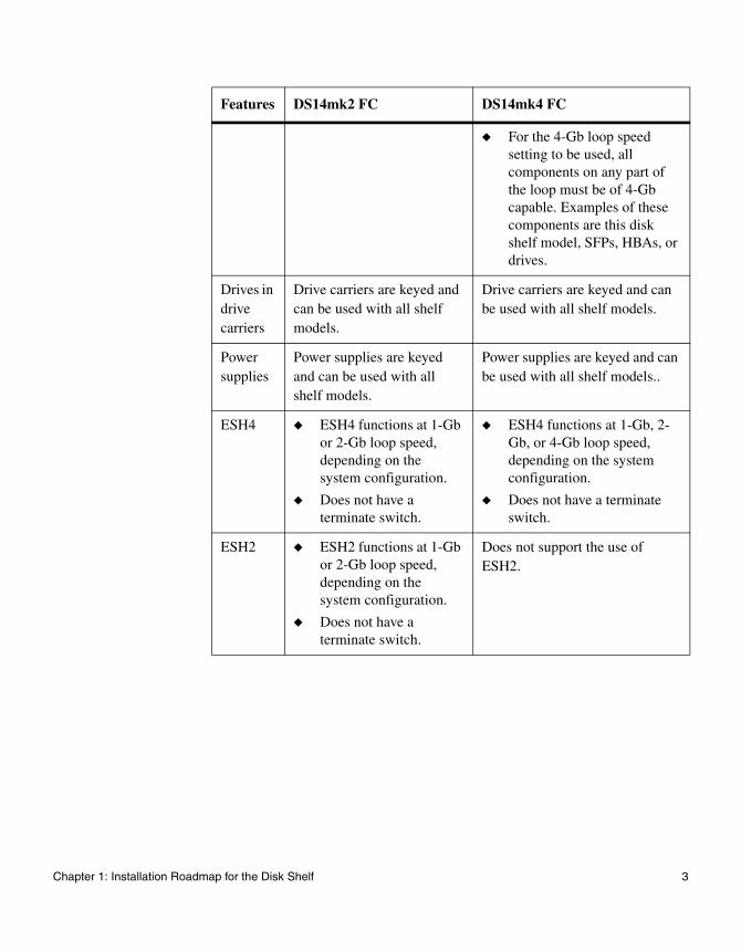
◆ For the 4-Gb loop speed setting to be used, all components on any part of the loop must be of 4-Gb capable. Examples of these components are this disk shelf model, SFPs, HBAs, or drives.
Drives in drive carriers
Drive carriers are keyed and can be used with all shelf models.
Drive carriers are keyed and can be used with all shelf models.
Power supplies
Power supplies are keyed and can be used with all shelf models.
Power supplies are keyed and can be used with all shelf models..
ESH4 ◆ ESH4 functions at 1-Gb or 2-Gb loop speed, depending on the system configuration.
◆ Does not have a terminate switch.
◆ ESH4 functions at 1-Gb, 2-Gb, or 4-Gb loop speed, depending on the system configuration.
◆ Does not have a terminate switch.
ESH2 ◆ ESH2 functions at 1-Gb or 2-Gb loop speed, depending on the system configuration.
◆ Does not have a terminate switch.
Does not support the use of ESH2.
Features DS14mk2 FC DS14mk4 FC
Chapter 1: Installation Roadmap for the Disk Shelf 3
Before you begin your installation
About disk shelf installation
Before you install one or more disk shelves in a rack, you need to understand the following information:
◆ Disk shelf numbering
◆ Loop IDs
◆ Supported disk drives
◆ Drive bay requirements
Disk shelf numbering
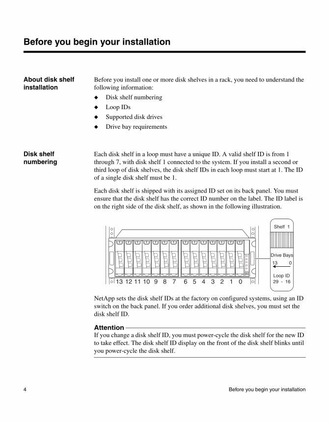
Each disk shelf in a loop must have a unique ID. A valid shelf ID is from 1 through 7, with disk shelf 1 connected to the system. If you install a second or third loop of disk shelves, the disk shelf IDs in each loop must start at 1. The ID of a single disk shelf must be 1.
Each disk shelf is shipped with its assigned ID set on its back panel. You must ensure that the disk shelf has the correct ID number on the label. The ID label is on the right side of the disk shelf, as shown in the following illustration.
NetApp sets the disk shelf IDs at the factory on configured systems, using an ID switch on the back panel. If you order additional disk shelves, you must set the disk shelf ID.
AttentionIf you change a disk shelf ID, you must power-cycle the disk shelf for the new ID to take effect. The disk shelf ID display on the front of the disk shelf blinks until you power-cycle the disk shelf.
45678910111213 3 2 1 0
0
Drive Bays
Shelf 1
013
Loop ID29 - 16
4 Before you begin your installation
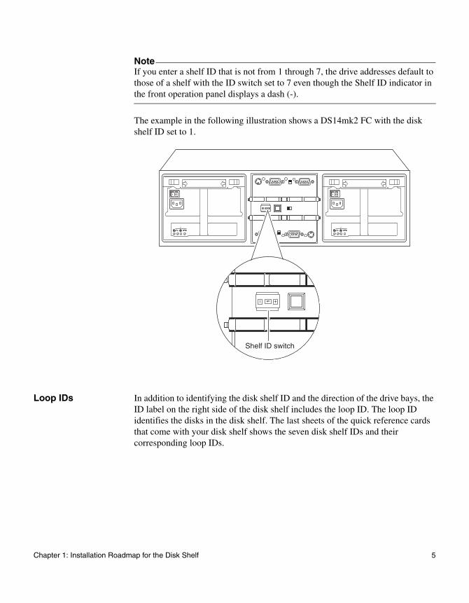
NoteIf you enter a shelf ID that is not from 1 through 7, the drive addresses default to those of a shelf with the ID switch set to 7 even though the Shelf ID indicator in the front operation panel displays a dash (-).
The example in the following illustration shows a DS14mk2 FC with the disk shelf ID set to 1.
Loop IDs In addition to identifying the disk shelf ID and the direction of the drive bays, the ID label on the right side of the disk shelf includes the loop ID. The loop ID identifies the disks in the disk shelf. The last sheets of the quick reference cards that come with your disk shelf shows the seven disk shelf IDs and their corresponding loop IDs.
1
1
Shelf ID switch
Chapter 1: Installation Roadmap for the Disk Shelf 5
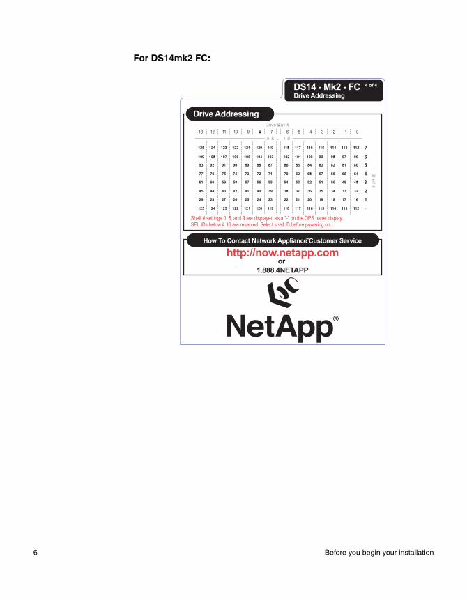
For DS14mk2 FC:
6 Before you begin your installation
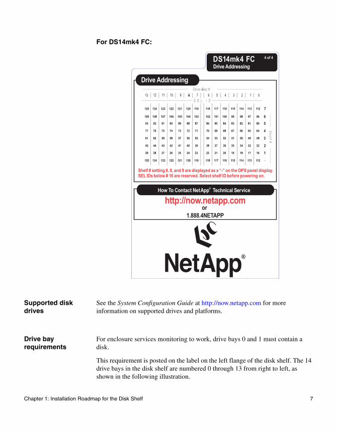
For DS14mk4 FC:
Supported disk drives
See the System Configuration Guide at http://now.netapp.com for more information on supported drives and platforms.
Drive bay requirements
For enclosure services monitoring to work, drive bays 0 and 1 must contain a disk.
This requirement is posted on the label on the left flange of the disk shelf. The 14 drive bays in the disk shelf are numbered 0 through 13 from right to left, as shown in the following illustration.
Chapter 1: Installation Roadmap for the Disk Shelf 7
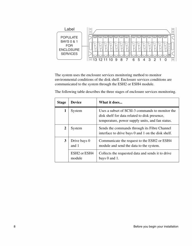
The system uses the enclosure services monitoring method to monitor environmental conditions of the disk shelf. Enclosure services conditions are communicated to the system through the ESH2 or ESH4 module.
The following table describes the three stages of enclosure services monitoring.
Stage Device What it does...
1 System Uses a subset of SCSI-3 commands to monitor the disk shelf for data related to disk presence, temperature, power supply units, and fan status.
2 System Sends the commands through its Fibre Channel interface to drive bays 0 and 1 on the disk shelf.
3 Drive bays 0 and 1
Communicate the request to the ESH2 or ESH4 module and send the data to the system.
ESH2 or ESH4 module
Collects the requested data and sends it to drive bays 0 and 1.
45678910111213 3 2 1 0
0
POPULATEBAYS 0 & 1
FORENCLOSURE
SERVICES
Label
8 Before you begin your installation
The installation process
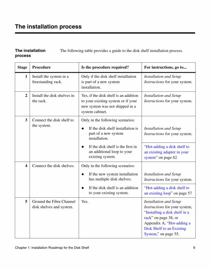
The installation process
The following table provides a guide to the disk shelf installation process.
Stage Procedure Is the procedure required? For instructions, go to...
1 Install the system in a freestanding rack.
Only if the disk shelf installation is part of a new system installation.
Installation and Setup Instructions for your system.
2 Install the disk shelves in the rack.
Yes, if the disk shelf is an addition to your existing system or if your new system was not shipped in a system cabinet.
Installation and Setup Instructions for your system.
3 Connect the disk shelf to the system.
Only in the following scenarios:
◆ If the disk shelf installation is part of a new system installation.
Installation and Setup Instructions for your system.
◆ If the disk shelf is the first in an additional loop to your existing system.
“Hot-adding a disk shelf to an existing adapter in your system” on page 62
4 Connect the disk shelves. Only in the following scenarios:
◆ If the new system installation has multiple disk shelves.
Installation and Setup Instructions for your system.
◆ If the disk shelf is an addition to your existing system.
“Hot-adding a disk shelf to an existing loop” on page 57
5 Ground the Fibre Channel disk shelves and system.
Yes. Installation and Setup Instructions for your system, “Installing a disk shelf in a rack” on page 38, or Appendix A, “Hot-adding a Disk Shelf to an Existing System,” on page 55.
Chapter 1: Installation Roadmap for the Disk Shelf 9
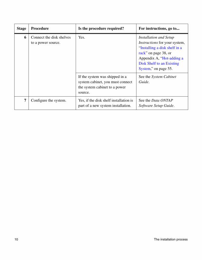
6 Connect the disk shelves to a power source.
Yes. Installation and Setup Instructions for your system, “Installing a disk shelf in a rack” on page 38, or Appendix A, “Hot-adding a Disk Shelf to an Existing System,” on page 55.
If the system was shipped in a system cabinet, you must connect the system cabinet to a power source.
See the System Cabinet Guide.
7 Configure the system. Yes, if the disk shelf installation is part of a new system installation.
See the Data ONTAP Software Setup Guide.
Stage Procedure Is the procedure required? For instructions, go to...
10 The installation process

Chapter 2: Monitoring the Disk Shelf
2
Monitoring the Disk ShelfAbout this chapter This chapter describes how to monitor the disk shelf from the error messages displayed on the console that is connected to the system and identifies the location of the various LEDs on the disk shelf.
NoteThe quick reference cards in the slide-out tray at the base of the disk shelf describe the functions of each LED on the disk shelf and the suggested course of action.
Topics in this chapter
This chapter discusses the following topics:
◆ “Monitoring the front operation panel” on page 12
◆ “Monitoring the ESH2 or ESH4 modules” on page 15
◆ “Monitoring the ESH2/ESH4” on page 20
◆ “Monitoring the Fibre Channel disk” on page 28
11
Monitoring the front operation panel
About monitoring the front operation panel
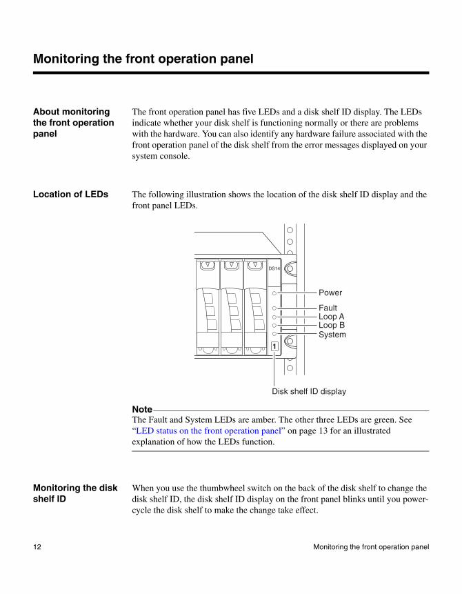
The front operation panel has five LEDs and a disk shelf ID display. The LEDs indicate whether your disk shelf is functioning normally or there are problems with the hardware. You can also identify any hardware failure associated with the front operation panel of the disk shelf from the error messages displayed on your system console.
Location of LEDs The following illustration shows the location of the disk shelf ID display and the front panel LEDs.
NoteThe Fault and System LEDs are amber. The other three LEDs are green. See “LED status on the front operation panel” on page 13 for an illustrated explanation of how the LEDs function.
Monitoring the disk shelf ID
When you use the thumbwheel switch on the back of the disk shelf to change the disk shelf ID, the disk shelf ID display on the front panel blinks until you power-cycle the disk shelf to make the change take effect.
Power
DS14
FaultLoop ALoop BSystem
Disk shelf ID display
1
12 Monitoring the front operation panel
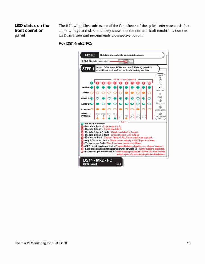
LED status on the front operation panel
The following illustrations are of the first sheets of the quick reference cards that come with your disk shelf. They shows the normal and fault conditions that the LEDs indicate and recommends a corrective action.
For DS14mk2 FC:
Chapter 2: Monitoring the Disk Shelf 13
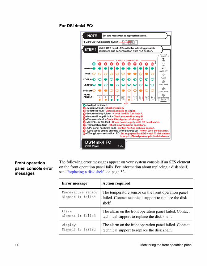
For DS14mk4 FC:
Front operation panel console error messages
The following error messages appear on your system console if an SES element on the front operation panel fails. For information about replacing a disk shelf, see “Replacing a disk shelf” on page 32.
Error message Action required
Temperature sensorElement 1: failed
The temperature sensor on the front operation panel failed. Contact technical support to replace the disk shelf.
AlarmElement 1: failed
The alarm on the front operation panel failed. Contact technical support to replace the disk shelf.
DisplayElement 1: failed
The alarm on the front operation panel failed. Contact technical support to replace the disk shelf.
14 Monitoring the front operation panel
Monitoring the ESH2 or ESH4 modules
About monitoring the modules
All the modules have LEDs that indicate whether it is functioning normally or if there are any problems with the hardware. The following table identifies the type of LED that is available for each type of module.
NoteThe Fault LED is amber. The input and output LEDs are green. See “LED status on the modules” on page 16 for an illustrated explanation of the LED functions. On ESH4, the appropriate loop speed LED lights up to indicate the speed of operation.
You can also identify any hardware failure associated with the module from the error messages displayed on your system console.
This section also describes the different types of messages that appear on the system console in response to a command monitoring the ESH2 or ESH4.
Location of the module LEDs
The modules are in the middle of the back of the disk shelf. Because module A is inverted, the location of the module A LEDs is the inverse of what is shown in some of the illustrations.
LED indicating... ESH2 ESH4
Input X X
Output X X
Fault X X
1-Gb operation - X
2-Gb operation X X
4-Gb operation - X
ELP (future functionality) - X
Chapter 2: Monitoring the Disk Shelf 15
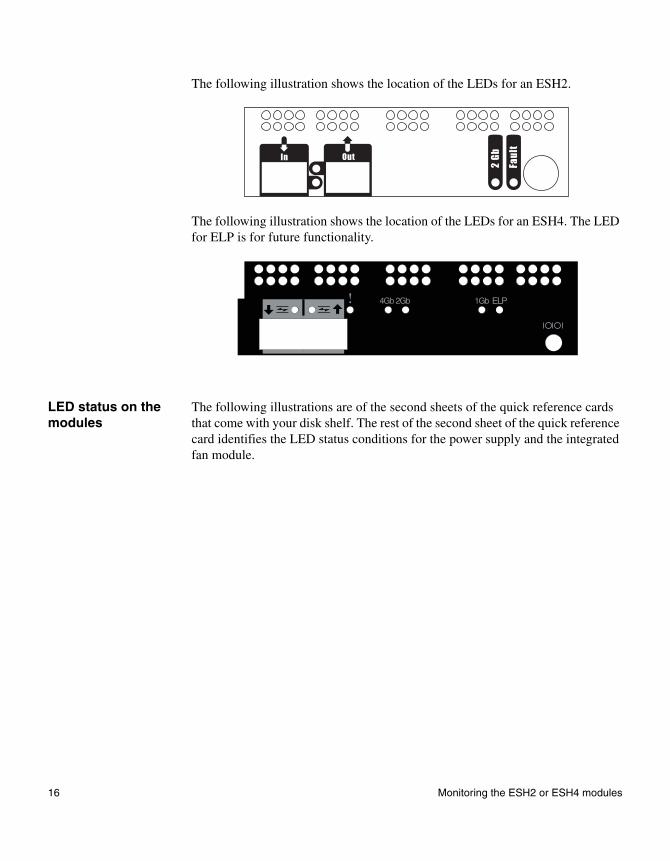
The following illustration shows the location of the LEDs for an ESH2.
The following illustration shows the location of the LEDs for an ESH4. The LED for ELP is for future functionality.
LED status on the modules
The following illustrations are of the second sheets of the quick reference cards that come with your disk shelf. The rest of the second sheet of the quick reference card identifies the LED status conditions for the power supply and the integrated fan module.
ELP
16 Monitoring the ESH2 or ESH4 modules
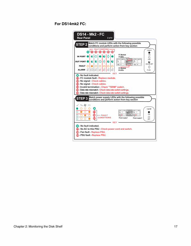
For DS14mk2 FC:
Chapter 2: Monitoring the Disk Shelf 17
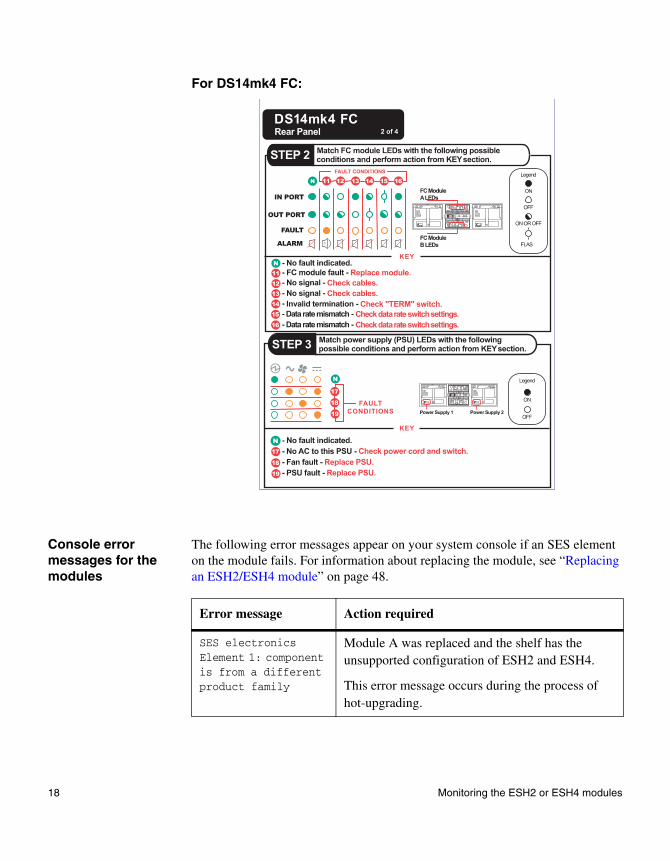
For DS14mk4 FC:
Console error messages for the modules
The following error messages appear on your system console if an SES element on the module fails. For information about replacing the module, see “Replacing an ESH2/ESH4 module” on page 48.
Error message Action required
SES electronicsElement 1: component is from a different product family
Module A was replaced and the shelf has the unsupported configuration of ESH2 and ESH4.
This error message occurs during the process of hot-upgrading.
18 Monitoring the ESH2 or ESH4 modules
SES electronicsElement 2: component is from a different product family
Module B was replaced and the shelf has the unsupported configuration of ESH2 and ESH4.
This error message occurs during the process of hot-upgrading.
SES electronicsElement 1: failed
Module A on the top back of the disk shelf failed. Contact technical support to replace the module.
SES electronicsElement 2: failed
Module B on the bottom back of the disk shelf failed. Contact technical support to replace the module.
Temperature sensorElement 2: not installed or failed
Communication was possible with the temperature sensor on ESH2/ESH4 module A at one point, but it is not possible now. Even if traffic is flowing through the Fibre Channel loop, contact technical support to replace the ESH2/ESH4.
Temperature sensorElement 3: not installed or failed
Communication was possible with the temperature sensor on ESH2/ESH4 module B at one point, but it is not possible now. Even if traffic is flowing through the Fibre Channel loop, contact technical support to replace the ESH2/ESH4.
SES electronicsElement 1: not installed or failed
Communication was possible with ESH2/ESH4 module A at one point, but it is not possible now. Even if traffic is flowing through the Fibre Channel loop, contact technical support to replace the ESH2/ESH4.
Vendor-specificElement 1: not installed or failed
SES electronicsElement 2: not installed or failed
Communication was possible with ESH2/ESH4 module B at one point, but it is not possible now. Even if traffic is flowing through the Fibre Channel loop, contact technical support to replace the ESH2/ESH4.
Vendor-specificElement 2: not installed or failed
Error message Action required
Chapter 2: Monitoring the Disk Shelf 19
Monitoring the ESH2/ESH4
Command to use: Use the following commands to enable you to monitor the ESH2/ESH4.
Sample output: The following is an example of the output from the storage show hub command. The exact messages that appear on your system console depend on your system configuration.
NoteFor the ESH2/ESH4, the following output shows the Term switch status as N/A or not applicable because the ESH2/ESH4 does not have a terminate switch.
If the disk shelf connects to a... Use the commands...
System with Data ONTAP 7.x or earlier installed
◆ storage show hub
◆ environ shelf
System with Data ONTAP 10.x installed
◆ storage show hub
◆ environ shelf
But you must do the following before you can use the above commands:
1. Log into the system and enter the following command at the console to go to the shell command mode:
ngsh
2. Enter the following command at the console to go to the command line interface:
dbladecli
Hub name: 9.shelf2Channel: 9Loop: BShelf id: 2Shelf UID: 50:05:0c:c0:02:00:24:02Term switch: ONShelf state: ONLINEESH state: OK
20 Monitoring the ESH2 or ESH4 modules
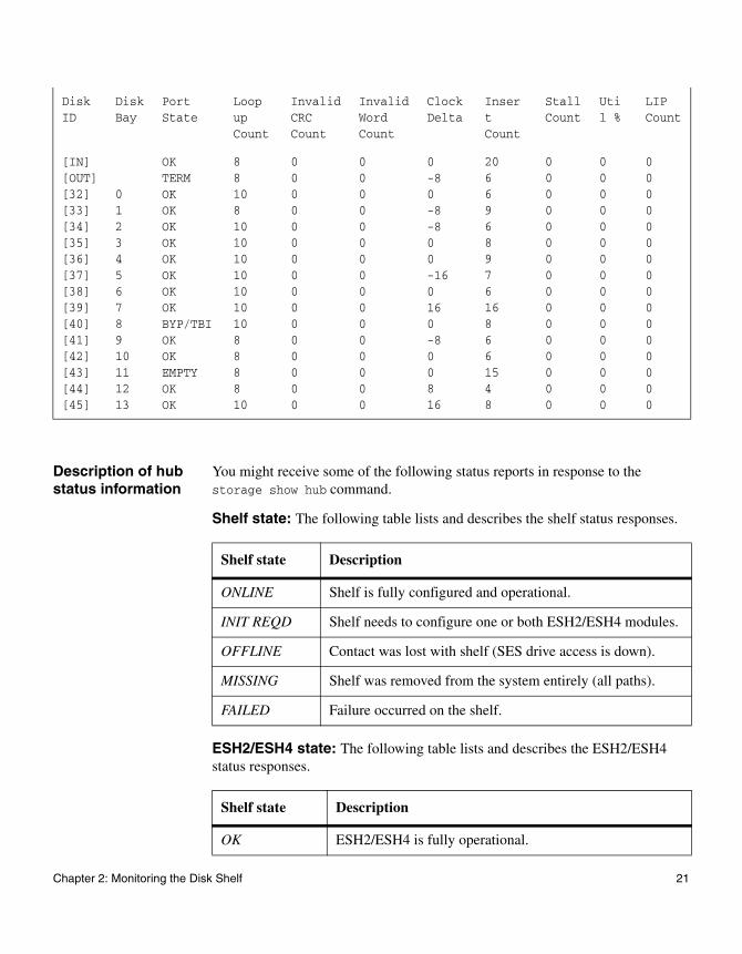
Description of hub status information
You might receive some of the following status reports in response to the storage show hub command.
Shelf state: The following table lists and describes the shelf status responses.
ESH2/ESH4 state: The following table lists and describes the ESH2/ESH4 status responses.
Disk ID
Disk Bay
Port State
Loop up Count
Invalid CRC Count
Invalid Word Count
Clock Delta
Insert Count
Stall Count
Util %
LIP Count
[IN][OUT][32][33][34][35][36][37][38][39][40][41][42][43][44][45]
012345678910111213
OKTERMOKOKOKOKOKOKOKOKBYP/TBIOKOKEMPTYOKOK
8810810101010101010888810
0000000000000000
0000000000000000
0-80-8-800-160160-800816
2066968976168661548
0000000000000000
0000000000000000
0000000000000000
Shelf state Description
ONLINE Shelf is fully configured and operational.
INIT REQD Shelf needs to configure one or both ESH2/ESH4 modules.
OFFLINE Contact was lost with shelf (SES drive access is down).
MISSING Shelf was removed from the system entirely (all paths).
FAILED Failure occurred on the shelf.
Shelf state Description
OK ESH2/ESH4 is fully operational.
Chapter 2: Monitoring the Disk Shelf 21
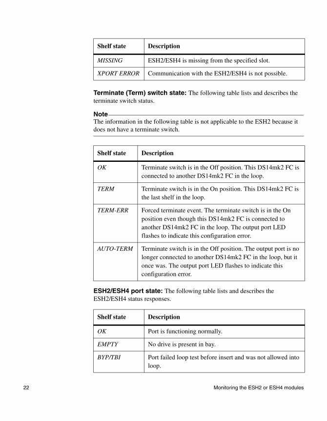
Terminate (Term) switch state: The following table lists and describes the terminate switch status.
NoteThe information in the following table is not applicable to the ESH2 because it does not have a terminate switch.
ESH2/ESH4 port state: The following table lists and describes the ESH2/ESH4 status responses.
MISSING ESH2/ESH4 is missing from the specified slot.
XPORT ERROR Communication with the ESH2/ESH4 is not possible.
Shelf state Description
OK Terminate switch is in the Off position. This DS14mk2 FC is connected to another DS14mk2 FC in the loop.
TERM Terminate switch is in the On position. This DS14mk2 FC is the last shelf in the loop.
TERM-ERR Forced terminate event. The terminate switch is in the On position even though this DS14mk2 FC is connected to another DS14mk2 FC in the loop. The output port LED flashes to indicate this configuration error.
AUTO-TERM Terminate switch is in the Off position. The output port is no longer connected to another DS14mk2 FC in the loop, but it once was. The output port LED flashes to indicate this configuration error.
Shelf state Description
OK Port is functioning normally.
EMPTY No drive is present in bay.
BYP/TBI Port failed loop test before insert and was not allowed into loop.
Shelf state Description
22 Monitoring the ESH2 or ESH4 modules
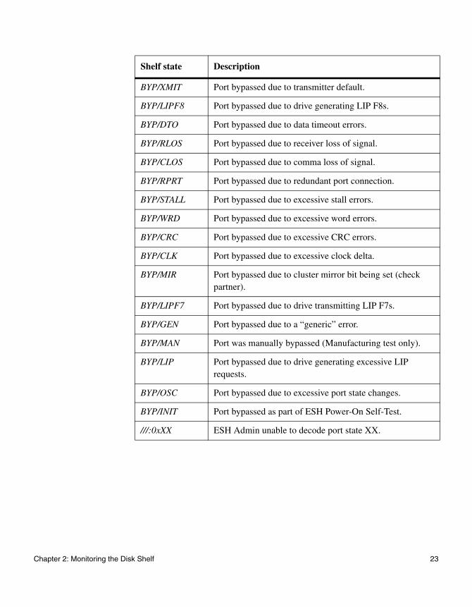
BYP/XMIT Port bypassed due to transmitter default.
BYP/LIPF8 Port bypassed due to drive generating LIP F8s.
BYP/DTO Port bypassed due to data timeout errors.
BYP/RLOS Port bypassed due to receiver loss of signal.
BYP/CLOS Port bypassed due to comma loss of signal.
BYP/RPRT Port bypassed due to redundant port connection.
BYP/STALL Port bypassed due to excessive stall errors.
BYP/WRD Port bypassed due to excessive word errors.
BYP/CRC Port bypassed due to excessive CRC errors.
BYP/CLK Port bypassed due to excessive clock delta.
BYP/MIR Port bypassed due to cluster mirror bit being set (check partner).
BYP/LIPF7 Port bypassed due to drive transmitting LIP F7s.
BYP/GEN Port bypassed due to a “generic” error.
BYP/MAN Port was manually bypassed (Manufacturing test only).
BYP/LIP Port bypassed due to drive generating excessive LIP requests.
BYP/OSC Port bypassed due to excessive port state changes.
BYP/INIT Port bypassed as part of ESH Power-On Self-Test.
///:0xXX ESH Admin unable to decode port state XX.
Shelf state Description
Chapter 2: Monitoring the Disk Shelf 23
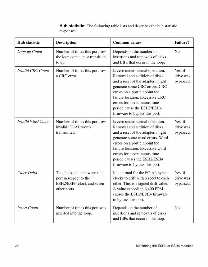
Hub statistic: The following table lists and describes the hub statistic responses.
Hub statistic Description Common values Failure?
Loop up Count Number of times this port saw the loop come up or transition to up.
Depends on the number of insertions and removals of disks and LIPs that occur in the loop.
No
Invalid CRC Count Number of times this port saw a CRC error.
Is zero under normal operation. Removal and addition of disks, and a reset of the adapter, might generate some CRC errors. CRC errors on a port pinpoint the failure location. Excessive CRC errors for a continuous time period cause the ESH2/ESH4 firmware to bypass this port.
Yes, if drive was bypassed.
Invalid Word Count Number of times this port saw invalid FC-AL words transmitted.
Is zero under normal operation. Removal and addition of disks, and a reset of the adapter, might generate some word errors. Word errors on a port pinpoint the failure location. Excessive word errors for a continuous time period causes the ESH2/ESH4 firmware to bypass this port.
Yes, if drive was bypassed.
Clock Delta The clock delta between this port in respect to the ESH2/ESH4 clock and seven other ports.
It is normal for the FC-AL sync clocks to drift with respect to each other. This is a signed drift value. A value exceeding 6,400 PPM causes the ESH2/ESH4 firmware to bypass this port.
Yes, if drive was bypassed.
Insert Count Number of times this port was inserted into the loop.
Depends on the number of insertions and removals of disks and LIPs that occur in the loop.
No
24 Monitoring the ESH2 or ESH4 modules
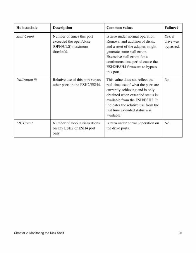
Stall Count Number of times this port exceeded the open/close (OPN/CLS) maximum threshold.
Is zero under normal operation. Removal and addition of disks, and a reset of the adapter, might generate some stall errors. Excessive stall errors for a continuous time period cause the ESH2/ESH4 firmware to bypass this port.
Yes, if drive was bypassed.
Utilization % Relative use of this port versus other ports in the ESH2/ESH4.
This value does not reflect the real-time use of what the ports are currently achieving and is only obtained when extended status is available from the ESH/ESH2. It indicates the relative use from the last time extended status was available.
No
LIP Count Number of loop initializations on any ESH2 or ESH4 port only.
Is zero under normal operation on the drive ports.
No
Hub statistic Description Common values Failure?
Chapter 2: Monitoring the Disk Shelf 25
Monitoring the power supply
LEDs on the power supply
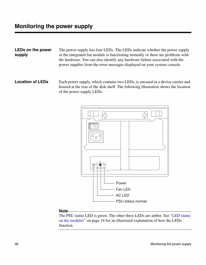
The power supply has four LEDs. The LEDs indicate whether the power supply or the integrated fan module is functioning normally or there are problems with the hardware. You can also identify any hardware failure associated with the power supplies from the error messages displayed on your system console.
Location of LEDs Each power supply, which contains two LEDs, is encased in a device carrier and housed at the rear of the disk shelf. The following illustration shows the location of the power supply LEDs.
NoteThe PSU status LED is green. The other three LEDs are amber. See “LED status on the modules” on page 16 for an illustrated explanation of how the LEDs function.
PSU status normal
Power
Fan LED
AC LED
26 Monitoring the power supply
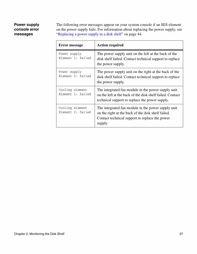
Power supply console error messages
The following error messages appear on your system console if an SES element on the power supply fails. For information about replacing the power supply, see “Replacing a power supply in a disk shelf” on page 44.
Error message Action required
Power supplyElement 1: failed
The power supply unit on the left at the back of the disk shelf failed. Contact technical support to replace the power supply.
Power supplyElement 2: failed
The power supply unit on the right at the back of the disk shelf failed. Contact technical support to replace the power supply.
Cooling elementElement 1: failed
The integrated fan module in the power supply unit on the left at the back of the disk shelf failed. Contact technical support to replace the power supply.
Cooling elementElement 2: failed
The integrated fan module in the power supply unit on the right at the back of the disk shelf failed. Contact technical support to replace the power supply.
Chapter 2: Monitoring the Disk Shelf 27
Monitoring the Fibre Channel disk
About monitoring the Fibre Channel disk
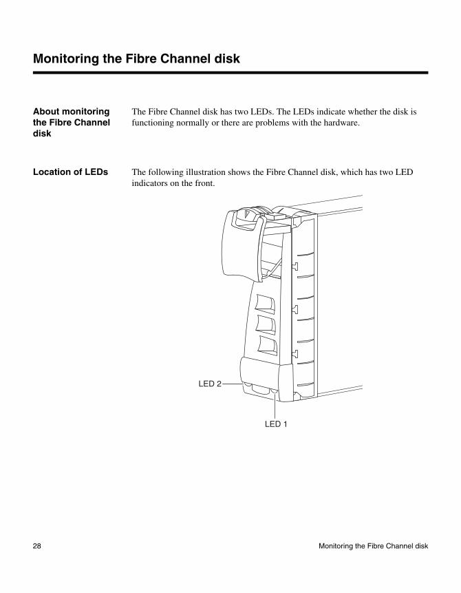
The Fibre Channel disk has two LEDs. The LEDs indicate whether the disk is functioning normally or there are problems with the hardware.
Location of LEDs The following illustration shows the Fibre Channel disk, which has two LED indicators on the front.
LED 1
LED 2
28 Monitoring the Fibre Channel disk
LED status on the Fibre Channel disks
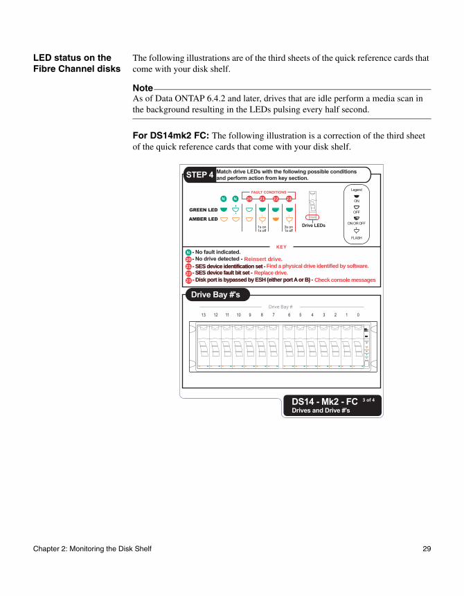
The following illustrations are of the third sheets of the quick reference cards that come with your disk shelf.
NoteAs of Data ONTAP 6.4.2 and later, drives that are idle perform a media scan in the background resulting in the LEDs pulsing every half second.
For DS14mk2 FC: The following illustration is a correction of the third sheet of the quick reference cards that come with your disk shelf.
Reinsert drive.
Replace drive.Check console messages
- SES device fault bit set - - SES device fault bit set - Find a physical drive identified by software.- SES device identification set - - SES device identification set -
- Disk port is bypassed by ESH (either port A or B) - - Disk port is bypassed by ESH (either port A or B) -
20212223
20N
N
N 21 22 23
3
Chapter 2: Monitoring the Disk Shelf 29
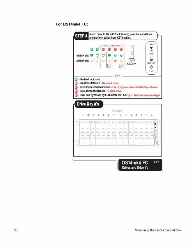
For DS14mk4 FC:
30 Monitoring the Fibre Channel disk

Chapter 3: Replacing Disk Shelf Devices
3
Replacing Disk Shelf DevicesAbout this chapter This chapter describes how to replace disk shelves in a rack, disks in a disk shelf, and other devices.
Topics in this chapter
This chapter discusses the following topics:
◆ “Replacing a disk shelf” on page 32
◆ “Replacing a disk in a disk shelf” on page 40
◆ “Replacing a power supply in a disk shelf” on page 44
◆ “Replacing an ESH2/ESH4 module” on page 48
31
Replacing a disk shelf
About this section This section discusses how to disconnect a disk shelf from a system, how to remove a disk shelf from a loop, and how to install a disk shelf. It does not discuss how to hot-add a disk shelf to a system. For information about hot-adding a disk-shelf, see Appendix A, “Hot-adding a Disk Shelf to an Existing System,” on page 55.
AttentionHot removal of disk shelves is not supported. Shutdown of system is required to remove shelves from system.
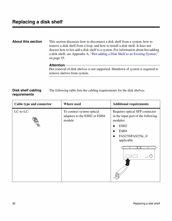
Disk shelf cabling requirements
The following table lists the cabling requirements for the disk shelves.
Cable type and connector Where used Additional requirements
LC-to-LC: To connect system optical adapters to the ESH2 or ESH4 module
Requires optical SFP connector in the input port of the following modules:
◆ ESH2
◆ ESH4
◆ FAS270/FAS270c, if applicable
32 Replacing a disk shelf
For detailed information
For detailed information about removing a disk shelf from a rack, see the following topics:
◆ “Removing a disk shelf from a single disk shelf configuration” on page 34
◆ “Removing a disk shelf from a loop” on page 36
◆ “Installing a disk shelf in a rack” on page 38
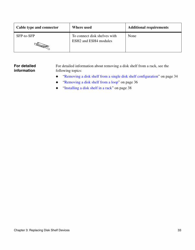
SFP-to-SFP To connect disk shelves with ESH2 and ESH4 modules
None
Cable type and connector Where used Additional requirements
Chapter 3: Replacing Disk Shelf Devices 33
Replacing a disk shelf in a rack
Removing a disk shelf from a single disk shelf configuration
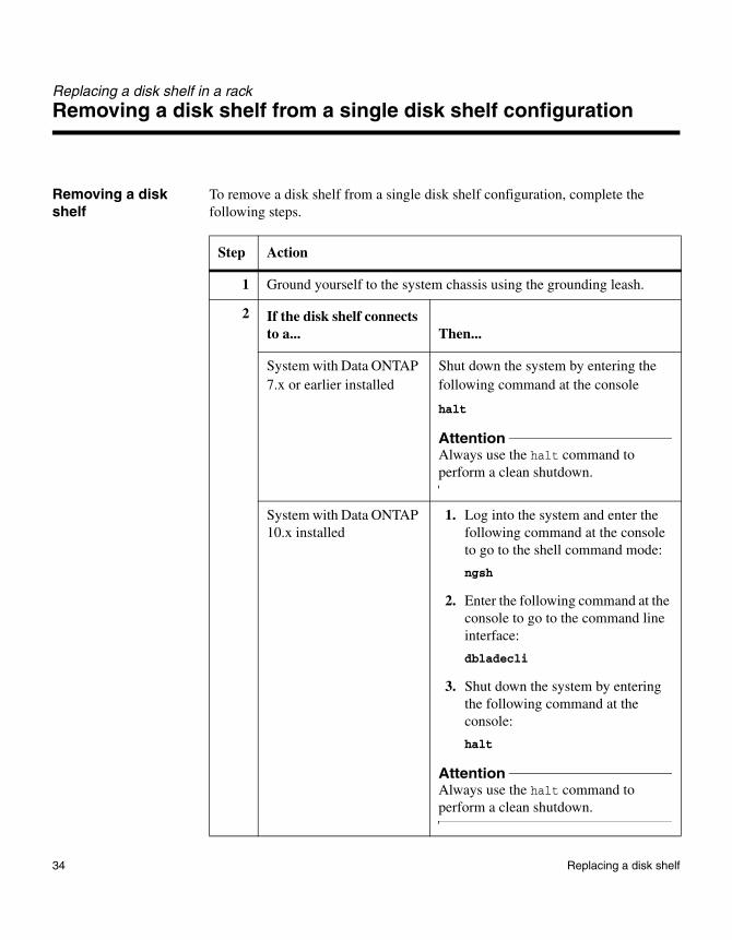
Removing a disk shelf
To remove a disk shelf from a single disk shelf configuration, complete the following steps.
Step Action
1 Ground yourself to the system chassis using the grounding leash.
2 If the disk shelf connects to a... Then...
System with Data ONTAP 7.x or earlier installed
Shut down the system by entering the following command at the console
halt
AttentionAlways use the halt command to perform a clean shutdown.
System with Data ONTAP 10.x installed
1. Log into the system and enter the following command at the console to go to the shell command mode:
ngsh
2. Enter the following command at the console to go to the command line interface:
dbladecli
3. Shut down the system by entering the following command at the console:
halt
AttentionAlways use the halt command to perform a clean shutdown.
34 Replacing a disk shelf
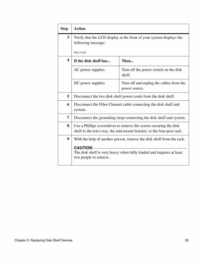
3 Verify that the LCD display at the front of your system displays the following message:
Halted
4 If the disk shelf has... Then...
AC power supplies Turn off the power switch on the disk shelf.
DC power supplies Turn off and unplug the cables from the power source.
5 Disconnect the two disk shelf power cords from the disk shelf.
6 Disconnect the Fibre Channel cable connecting the disk shelf and system.
7 Disconnect the grounding strap connecting the disk shelf and system.
8 Use a Phillips screwdriver to remove the screws securing the disk shelf to the telco tray, the mid-mount bracket, or the four-post rack.
9 With the help of another person, remove the disk shelf from the rack.
CAUTIONThe disk shelf is very heavy when fully loaded and requires at least two people to remove.
Step Action
Chapter 3: Replacing Disk Shelf Devices 35
Replacing a disk shelf in a rack
Removing a disk shelf from a loop
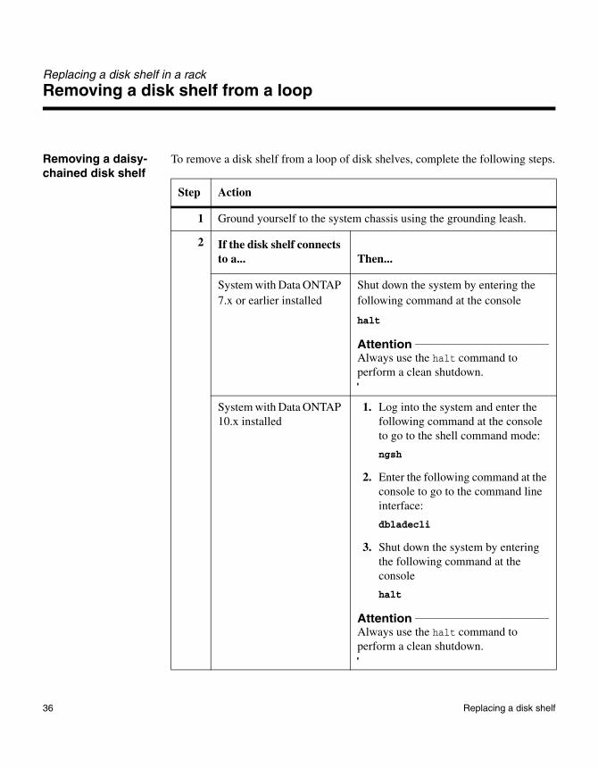
Removing a daisy-chained disk shelf
To remove a disk shelf from a loop of disk shelves, complete the following steps.
Step Action
1 Ground yourself to the system chassis using the grounding leash.
2 If the disk shelf connects to a... Then...
System with Data ONTAP 7.x or earlier installed
Shut down the system by entering the following command at the console
halt
AttentionAlways use the halt command to perform a clean shutdown.
System with Data ONTAP 10.x installed
1. Log into the system and enter the following command at the console to go to the shell command mode:
ngsh
2. Enter the following command at the console to go to the command line interface:
dbladecli
3. Shut down the system by entering the following command at the console
halt
AttentionAlways use the halt command to perform a clean shutdown.
36 Replacing a disk shelf
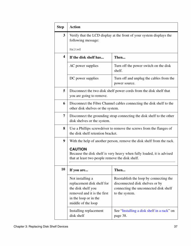
3 Verify that the LCD display at the front of your system displays the following message:
Halted
4 If the disk shelf has... Then...
AC power supplies Turn off the power switch on the disk shelf.
DC power supplies Turn off and unplug the cables from the power source.
5 Disconnect the two disk shelf power cords from the disk shelf that you are going to remove.
6 Disconnect the Fibre Channel cables connecting the disk shelf to the other disk shelves or the system.
7 Disconnect the grounding strap connecting the disk shelf to the other disk shelves or the system.
8 Use a Phillips screwdriver to remove the screws from the flanges of the disk shelf retention bracket.
9 With the help of another person, remove the disk shelf from the rack.
CAUTIONBecause the disk shelf is very heavy when fully loaded, it is advised that at least two people remove the disk shelf.
10 If you are... Then...
Not installing a replacement disk shelf for the disk shelf you removed and it is the first in the loop or in the middle of the loop
Reestablish the loop by connecting the disconnected disk shelves or by connecting the unconnected disk shelf to the system.
Installing replacement disk shelf
See “Installing a disk shelf in a rack” on page 38.
Step Action
Chapter 3: Replacing Disk Shelf Devices 37
Replacing a disk shelf in a rack
Installing a disk shelf in a rack
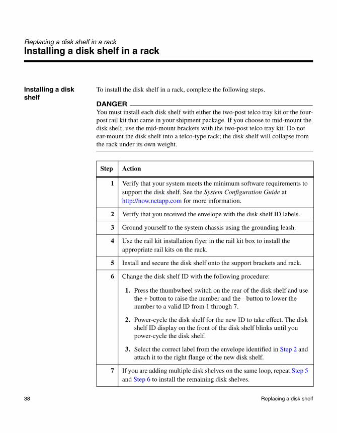
Installing a disk shelf
To install the disk shelf in a rack, complete the following steps.
DANGERYou must install each disk shelf with either the two-post telco tray kit or the four-post rail kit that came in your shipment package. If you choose to mid-mount the disk shelf, use the mid-mount brackets with the two-post telco tray kit. Do not ear-mount the disk shelf into a telco-type rack; the disk shelf will collapse from the rack under its own weight.
Step Action
1 Verify that your system meets the minimum software requirements to support the disk shelf. See the System Configuration Guide at http://now.netapp.com for more information.
2 Verify that you received the envelope with the disk shelf ID labels.
3 Ground yourself to the system chassis using the grounding leash.
4 Use the rail kit installation flyer in the rail kit box to install the appropriate rail kits on the rack.
5 Install and secure the disk shelf onto the support brackets and rack.
6 Change the disk shelf ID with the following procedure:
1. Press the thumbwheel switch on the rear of the disk shelf and use the + button to raise the number and the - button to lower the number to a valid ID from 1 through 7.
2. Power-cycle the disk shelf for the new ID to take effect. The disk shelf ID display on the front of the disk shelf blinks until you power-cycle the disk shelf.
3. Select the correct label from the envelope identified in Step 2 and attach it to the right flange of the new disk shelf.
7 If you are adding multiple disk shelves on the same loop, repeat Step 5 and Step 6 to install the remaining disk shelves.
38 Replacing a disk shelf
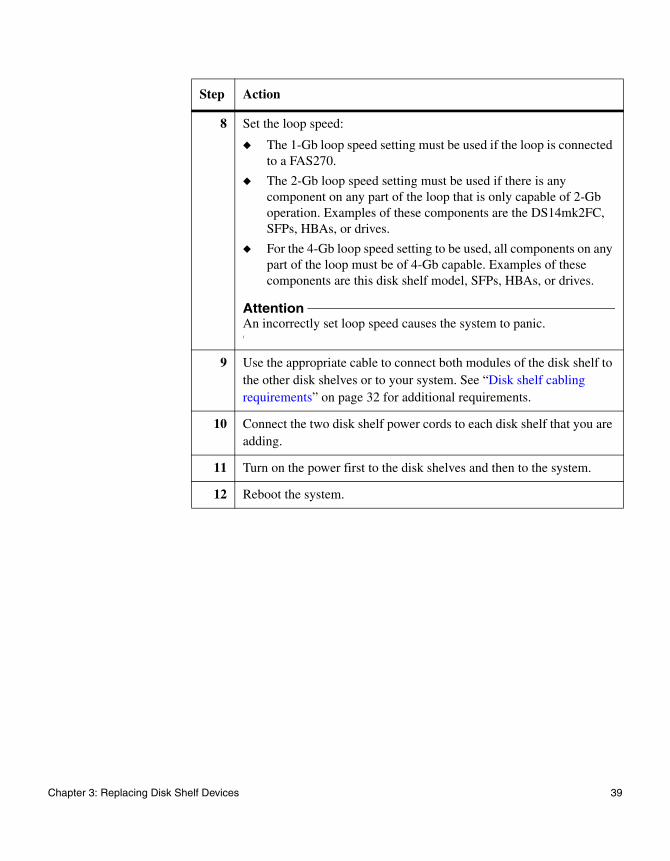
8 Set the loop speed:
◆ The 1-Gb loop speed setting must be used if the loop is connected to a FAS270.
◆ The 2-Gb loop speed setting must be used if there is any component on any part of the loop that is only capable of 2-Gb operation. Examples of these components are the DS14mk2FC, SFPs, HBAs, or drives.
◆ For the 4-Gb loop speed setting to be used, all components on any part of the loop must be of 4-Gb capable. Examples of these components are this disk shelf model, SFPs, HBAs, or drives.
AttentionAn incorrectly set loop speed causes the system to panic.
9 Use the appropriate cable to connect both modules of the disk shelf to the other disk shelves or to your system. See “Disk shelf cabling requirements” on page 32 for additional requirements.
10 Connect the two disk shelf power cords to each disk shelf that you are adding.
11 Turn on the power first to the disk shelves and then to the system.
12 Reboot the system.
Step Action
Chapter 3: Replacing Disk Shelf Devices 39
Replacing a disk in a disk shelf
Reasons to replace a disk
You can replace a disk in a disk shelf for any reason. However, the most common reason is disk failure. If a disk fails, the system logs a warning message to the system console indicating which disk on which loop failed.
In addition, a disk shelf with an ESH2/ESH4 module identifies any one of the following situations as disk failure:
◆ A disk is bypassed.
◆ The system boots with the presence of bypassed disks.
◆ The system detects an eminent threshold bypass.
The following autosupport warning message is then sent:
DISK FAIL!! - Bypassed by ESH
Preparing to replace a disk
Before you replace a disk in a disk shelf, you must first check the disk shelf to ensure that after you remove the disk you still have enough disks installed to meet the enclosure services requirements. For information about these requirements, see “Drive bay requirements” on page 7.
About replacing a disk in a disk shelf
Replacing a disk in a disk shelf consists of the following procedures:
◆ “Removing a disk” on page 41
◆ “Installing a disk” on page 43
NoteIf you are replacing several disks in a disk shelf or if you are installing several disks into a half-empty disk shelf, replace or install the disks one at a time to allow your system to recognize the existence of each new disk.
40 Replacing a disk in a disk shelf
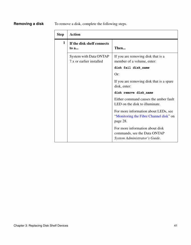
Removing a disk To remove a disk, complete the following steps.
Step Action
1 If the disk shelf connects to a... Then...
System with Data ONTAP 7.x or earlier installed
If you are removing disk that is a member of a volume, enter:
disk fail disk_name
Or:
If you are removing disk that is a spare disk, enter:
disk remove disk_name
Either command causes the amber fault LED on the disk to illuminate.
For more information about LEDs, see “Monitoring the Fibre Channel disk” on page 28.
For more information about disk commands, see the Data ONTAP System Administrator’s Guide.
Chapter 3: Replacing Disk Shelf Devices 41
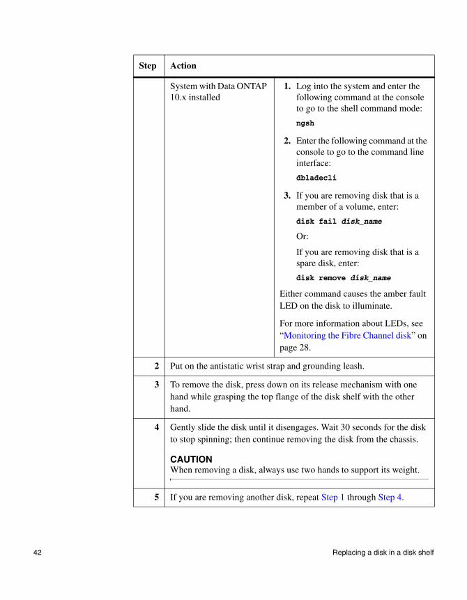
System with Data ONTAP 10.x installed
1. Log into the system and enter the following command at the console to go to the shell command mode:
ngsh
2. Enter the following command at the console to go to the command line interface:
dbladecli
3. If you are removing disk that is a member of a volume, enter:
disk fail disk_name
Or:
If you are removing disk that is a spare disk, enter:
disk remove disk_name
Either command causes the amber fault LED on the disk to illuminate.
For more information about LEDs, see “Monitoring the Fibre Channel disk” on page 28.
2 Put on the antistatic wrist strap and grounding leash.
3 To remove the disk, press down on its release mechanism with one hand while grasping the top flange of the disk shelf with the other hand.
4 Gently slide the disk until it disengages. Wait 30 seconds for the disk to stop spinning; then continue removing the disk from the chassis.
CAUTIONWhen removing a disk, always use two hands to support its weight.
5 If you are removing another disk, repeat Step 1 through Step 4.
Step Action
42 Replacing a disk in a disk shelf
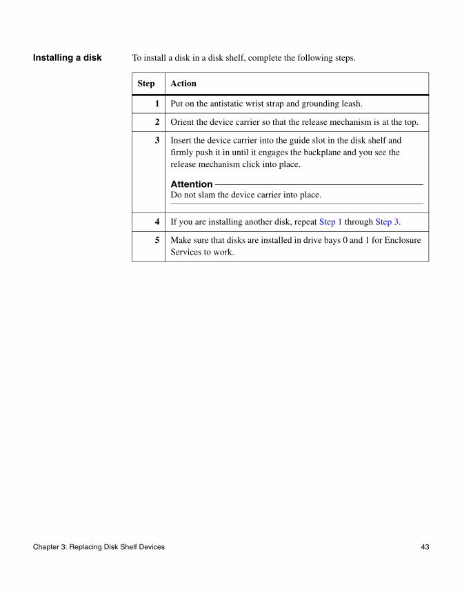
Installing a disk To install a disk in a disk shelf, complete the following steps.
Step Action
1 Put on the antistatic wrist strap and grounding leash.
2 Orient the device carrier so that the release mechanism is at the top.
3 Insert the device carrier into the guide slot in the disk shelf and firmly push it in until it engages the backplane and you see the release mechanism click into place.
AttentionDo not slam the device carrier into place.
4 If you are installing another disk, repeat Step 1 through Step 3.
5 Make sure that disks are installed in drive bays 0 and 1 for Enclosure Services to work.
Chapter 3: Replacing Disk Shelf Devices 43
Replacing a power supply in a disk shelf
About this section Replacing a power supply in a disk shelf consists of the following procedures:
◆ “Removing a power supply” on page 44
◆ “Installing a power supply” on page 46
Rules for replacing power supplies
When replacing the power supply on your disk shelf, observe the following rules:
◆ You do not need to turn off the power when you replace one power supply.
◆ If you are replacing both power supplies in the same disk shelf, replace them one at a time to avoid powering down the disk shelf.
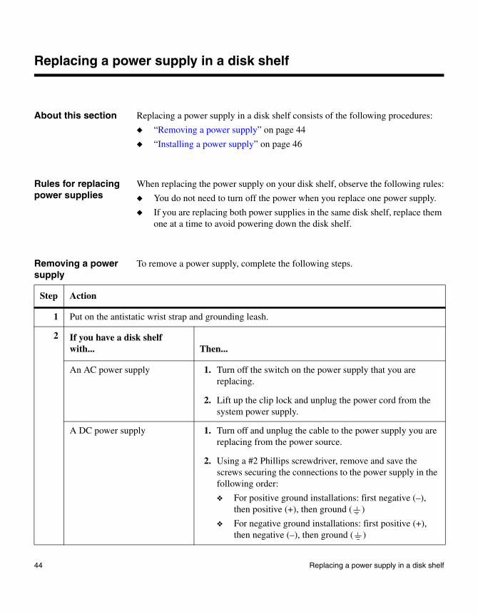
Removing a power supply
To remove a power supply, complete the following steps.
Step Action
1 Put on the antistatic wrist strap and grounding leash.
2 If you have a disk shelf with... Then...
An AC power supply 1. Turn off the switch on the power supply that you are replacing.
2. Lift up the clip lock and unplug the power cord from the system power supply.
A DC power supply 1. Turn off and unplug the cable to the power supply you are replacing from the power source.
2. Using a #2 Phillips screwdriver, remove and save the screws securing the connections to the power supply in the following order:
❖ For positive ground installations: first negative (–), then positive (+), then ground ( )
❖ For negative ground installations: first positive (+), then negative (–), then ground ( )
44 Replacing a power supply in a disk shelf
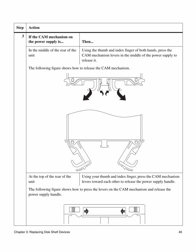
3 If the CAM mechanism on the power supply is... Then...
In the middle of the rear of the unit
Using the thumb and index finger of both hands, press the CAM mechanism levers in the middle of the power supply to release it.
The following figure shows how to release the CAM mechanism.
At the top of the rear of the unit
Using your thumb and index finger, press the CAM mechanism levers toward each other to release the power supply handle.
The following figure shows how to press the levers on the CAM mechanism and release the power supply handle.
Step Action
OPEN OPEN
Chapter 3: Replacing Disk Shelf Devices 45
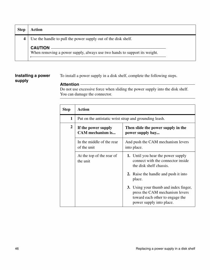
Installing a power supply
To install a power supply in a disk shelf, complete the following steps.
AttentionDo not use excessive force when sliding the power supply into the disk shelf. You can damage the connector.
4 Use the handle to pull the power supply out of the disk shelf.
CAUTIONWhen removing a power supply, always use two hands to support its weight.
Step Action
Step Action
1 Put on the antistatic wrist strap and grounding leash.
2 If the power supply CAM mechanism is...
Then slide the power supply in the power supply bay...
In the middle of the rear of the unit
And push the CAM mechanism levers into place.
At the top of the rear of the unit
1. Until you hear the power supply connect with the connector inside the disk shelf chassis.
2. Raise the handle and push it into place.
3. Using your thumb and index finger, press the CAM mechanism levers toward each other to engage the power supply into place.
46 Replacing a power supply in a disk shelf
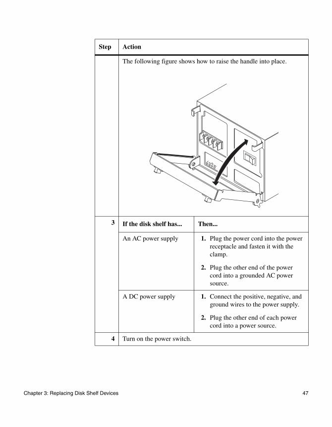
The following figure shows how to raise the handle into place.
3 If the disk shelf has... Then...
An AC power supply 1. Plug the power cord into the power receptacle and fasten it with the clamp.
2. Plug the other end of the power cord into a grounded AC power source.
A DC power supply 1. Connect the positive, negative, and ground wires to the power supply.
2. Plug the other end of each power cord into a power source.
4 Turn on the power switch.
Step Action
Chapter 3: Replacing Disk Shelf Devices 47
Replacing an ESH2/ESH4 module
About a module The ESH2/ESH4 module in a DS14mk2 FC or DS14mk4 FC includes a SCSI-3 Enclosure Services Processor. It maintains the integrity of the loop when disks are swapped and provides signal retiming for enhanced loop stability. There are two modules in the middle of the rear of the disk shelf, one for Channel A and one for Channel B.
NoteThe Input and Output ports on module A on the disk shelves are inverted from module B.
Connectors in a module: The modules have the following connectors.
For detailed information
This section provides information about the following topics:
◆ “Removing a module” on page 49
◆ “Installing a module” on page 51
◆ “Hot-swapping a module” on page 52
◆ “Hot-adding a Disk Shelf to an Existing System” on page 55
Module connector Function
Input Provides the interface between the disk shelf and the system.
Output Provides the interface between two disk shelves to create a loop of daisy-chained disk shelves.
48 Replacing an ESH2/ESH4 module
Replacing an ESH2/ESH4 module
Removing a module
Assumption about this procedure
This procedure is based on the assumption that the disk shelf is in a configuration which fulfils one or all of the following requirements:
◆ It has a single path connection
◆ It is not in a cluster
◆ It does not use synchronous mirroring
Removing a module To remove a module that is connected to the Fibre Channel loop, complete the following steps.
Step Action
1 Put on the antistatic wrist strap and grounding leash.
2 If the disk shelf connects to a... Then...
System with Data ONTAP 7.x or earlier installed
Shut down the system by entering the following command at the console
halt
AttentionAlways use the halt command to perform a clean shutdown.
Chapter 3: Replacing Disk Shelf Devices 49
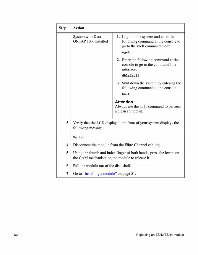
System with Data ONTAP 10.x installed
1. Log into the system and enter the following command at the console to go to the shell command mode:
ngsh
2. Enter the following command at the console to go to the command line interface:
dbladecli
3. Shut down the system by entering the following command at the console
halt
AttentionAlways use the halt command to perform a clean shutdown.
3 Verify that the LCD display at the front of your system displays the following message:
Halted
4 Disconnect the module from the Fibre Channel cabling.
5 Using the thumb and index finger of both hands, press the levers on the CAM mechanism on the module to release it.
6 Pull the module out of the disk shelf.
7 Go to “Installing a module” on page 51.
Step Action
50 Replacing an ESH2/ESH4 module
Replacing an ESH2/ESH4 module
Installing a module
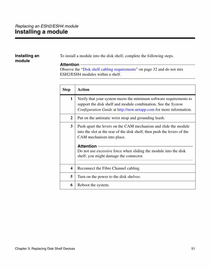
Installing an module
To install a module into the disk shelf, complete the following steps.
AttentionObserve the “Disk shelf cabling requirements” on page 32 and do not mix ESH2/ESH4 modules within a shelf.
Step Action
1 Verify that your system meets the minimum software requirements to support the disk shelf and module combination. See the System Configuration Guide at http://now.netapp.com for more information.
2 Put on the antistatic wrist strap and grounding leash.
3 Push apart the levers on the CAM mechanism and slide the module into the slot at the rear of the disk shelf, then push the levers of the CAM mechanism into place.
AttentionDo not use excessive force when sliding the module into the disk shelf; you might damage the connector.
4 Reconnect the Fibre Channel cabling.
5 Turn on the power to the disk shelves.
6 Reboot the system.
Chapter 3: Replacing Disk Shelf Devices 51
Replacing an ESH2/ESH4 module
Hot-swapping a module
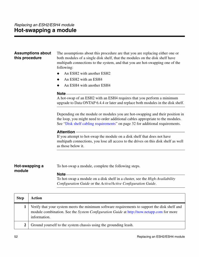
Assumptions about this procedure
The assumptions about this procedure are that you are replacing either one or both modules of a single disk shelf, that the modules on the disk shelf have multipath connections to the system, and that you are hot-swapping one of the following:
◆ An ESH2 with another ESH2
◆ An ESH2 with an ESH4
◆ An ESH4 with another ESH4
NoteA hot-swap of an ESH2 with an ESH4 requires that you perform a minimum upgrade to Data ONTAP 6.4.4 or later and replace both modules in the disk shelf.
Depending on the module or modules you are hot-swapping and their position in the loop, you might need to order additional cables appropriate to the modules. See “Disk shelf cabling requirements” on page 32 for additional requirements.
AttentionIf you attempt to hot-swap the module on a disk shelf that does not have multipath connections, you lose all access to the drives on this disk shelf as well as those below it.
Hot-swapping a module
To hot-swap a module, complete the following steps.
NoteTo hot-swap a module on a disk shelf in a cluster, see the High-Availability Configuration Guide or the Active/Active Configuration Guide.
Step Action
1 Verify that your system meets the minimum software requirements to support the disk shelf and module combination. See the System Configuration Guide at http://now.netapp.com for more information.
2 Ground yourself to the system chassis using the grounding leash.
52 Replacing an ESH2/ESH4 module
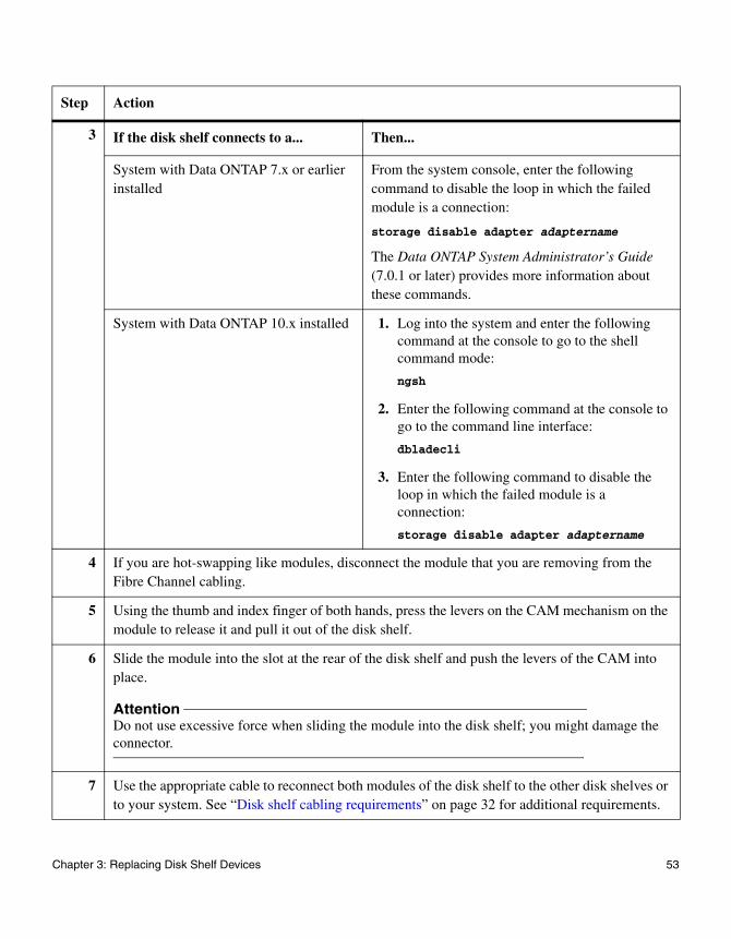
3 If the disk shelf connects to a... Then...
System with Data ONTAP 7.x or earlier installed
From the system console, enter the following command to disable the loop in which the failed module is a connection:
storage disable adapter adaptername
The Data ONTAP System Administrator’s Guide (7.0.1 or later) provides more information about these commands.
System with Data ONTAP 10.x installed 1. Log into the system and enter the following command at the console to go to the shell command mode:
ngsh
2. Enter the following command at the console to go to the command line interface:
dbladecli
3. Enter the following command to disable the loop in which the failed module is a connection:
storage disable adapter adaptername
4 If you are hot-swapping like modules, disconnect the module that you are removing from the Fibre Channel cabling.
5 Using the thumb and index finger of both hands, press the levers on the CAM mechanism on the module to release it and pull it out of the disk shelf.
6 Slide the module into the slot at the rear of the disk shelf and push the levers of the CAM into place.
AttentionDo not use excessive force when sliding the module into the disk shelf; you might damage the connector.
7 Use the appropriate cable to reconnect both modules of the disk shelf to the other disk shelves or to your system. See “Disk shelf cabling requirements” on page 32 for additional requirements.
Step Action
Chapter 3: Replacing Disk Shelf Devices 53
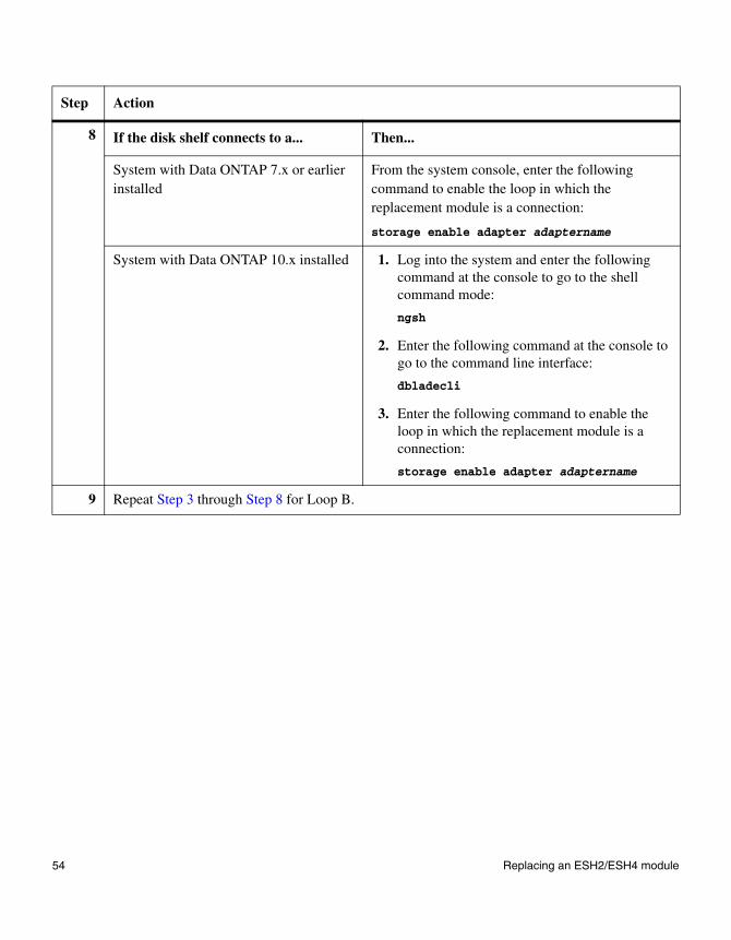
8 If the disk shelf connects to a... Then...
System with Data ONTAP 7.x or earlier installed
From the system console, enter the following command to enable the loop in which the replacement module is a connection:
storage enable adapter adaptername
System with Data ONTAP 10.x installed 1. Log into the system and enter the following command at the console to go to the shell command mode:
ngsh
2. Enter the following command at the console to go to the command line interface:
dbladecli
3. Enter the following command to enable the loop in which the replacement module is a connection:
storage enable adapter adaptername
9 Repeat Step 3 through Step 8 for Loop B.
Step Action
54 Replacing an ESH2/ESH4 module
Appendix A: Hot-adding a Disk Shelf to an Existing System
A
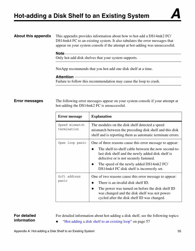
Hot-adding a Disk Shelf to an Existing SystemAbout this appendix This appendix provides information about how to hot-add a DS14mk2 FC/DS14mk4 FC to an existing system. It also tabulates the error messages that appear on your system console if the attempt at hot-adding was unsuccessful.
NoteOnly hot-add disk shelves that your system supports.
NetApp recommends that you hot-add one disk shelf at a time.
AttentionFailure to follow this recommendation may cause the loop to crash.
Error messages The following error messages appear on your system console if your attempt at hot-adding the DS14mk2 FC is unsuccessful.
For detailed information
For detailed information about hot-adding a disk shelf, see the following topics:
◆ “Hot-adding a disk shelf to an existing loop” on page 57
Error message Explanation
Speed mismatch termination
The modules on the disk shelf detected a speed mismatch between the preceding disk shelf and this disk shelf and is reporting them as automatic terminate errors.
Open loop panic One of three reasons cause this error message to appear:
◆ The shelf-to-shelf cable between the now second-to-last disk shelf and the newly added disk shelf is defective or is not securely fastened.
◆ The speed of the newly added DS14mk2 FC/DS14mk4 FC disk shelf is incorrectly set.
Soft address panic
One of two reasons cause this error message to appear:
◆ There is an invalid disk shelf ID.
◆ The power was turned on before the disk shelf ID was changed and the disk shelf was not power-cycled after the disk shelf ID was changed.
55
◆ “Hot-adding a disk shelf to an existing adapter in your system” on page 62
56 Hot-adding a Disk Shelf to an Existing System
Hot-adding a disk shelf to an existing loop
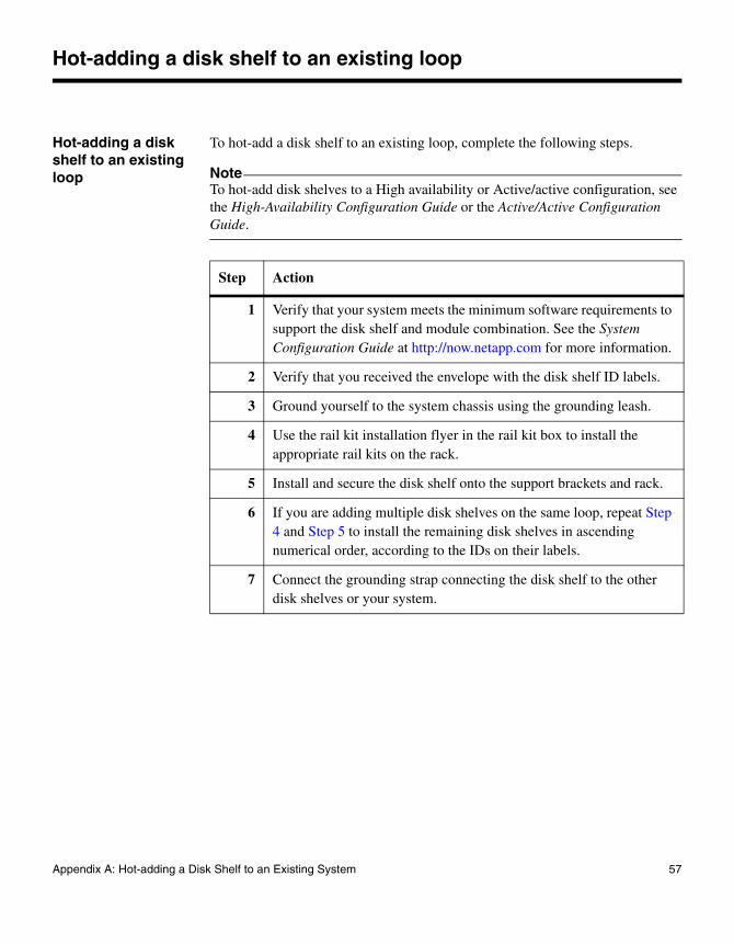
Hot-adding a disk shelf to an existing loop
To hot-add a disk shelf to an existing loop, complete the following steps.
NoteTo hot-add disk shelves to a High availability or Active/active configuration, see the High-Availability Configuration Guide or the Active/Active Configuration Guide.
Step Action
1 Verify that your system meets the minimum software requirements to support the disk shelf and module combination. See the System Configuration Guide at http://now.netapp.com for more information.
2 Verify that you received the envelope with the disk shelf ID labels.
3 Ground yourself to the system chassis using the grounding leash.
4 Use the rail kit installation flyer in the rail kit box to install the appropriate rail kits on the rack.
5 Install and secure the disk shelf onto the support brackets and rack.
6 If you are adding multiple disk shelves on the same loop, repeat Step 4 and Step 5 to install the remaining disk shelves in ascending numerical order, according to the IDs on their labels.
7 Connect the grounding strap connecting the disk shelf to the other disk shelves or your system.
Appendix A: Hot-adding a Disk Shelf to an Existing System 57
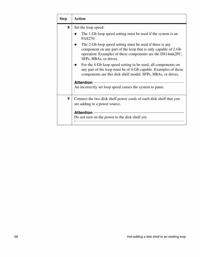
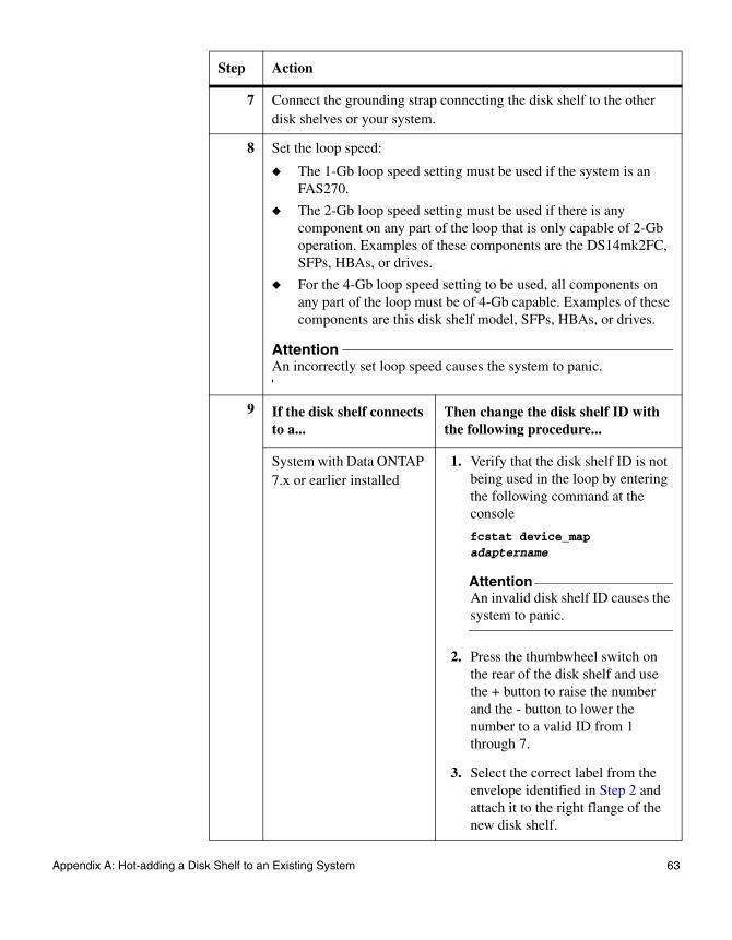
8 Set the loop speed:
◆ The 1-Gb loop speed setting must be used if the system is an FAS270.
◆ The 2-Gb loop speed setting must be used if there is any component on any part of the loop that is only capable of 2-Gb operation. Examples of these components are the DS14mk2FC, SFPs, HBAs, or drives.
◆ For the 4-Gb loop speed setting to be used, all components on any part of the loop must be of 4-Gb capable. Examples of these components are this disk shelf model, SFPs, HBAs, or drives.
AttentionAn incorrectly set loop speed causes the system to panic.
9 Connect the two disk shelf power cords of each disk shelf that you are adding to a power source.
AttentionDo not turn on the power to the disk shelf yet.
Step Action
58 Hot-adding a disk shelf to an existing loop
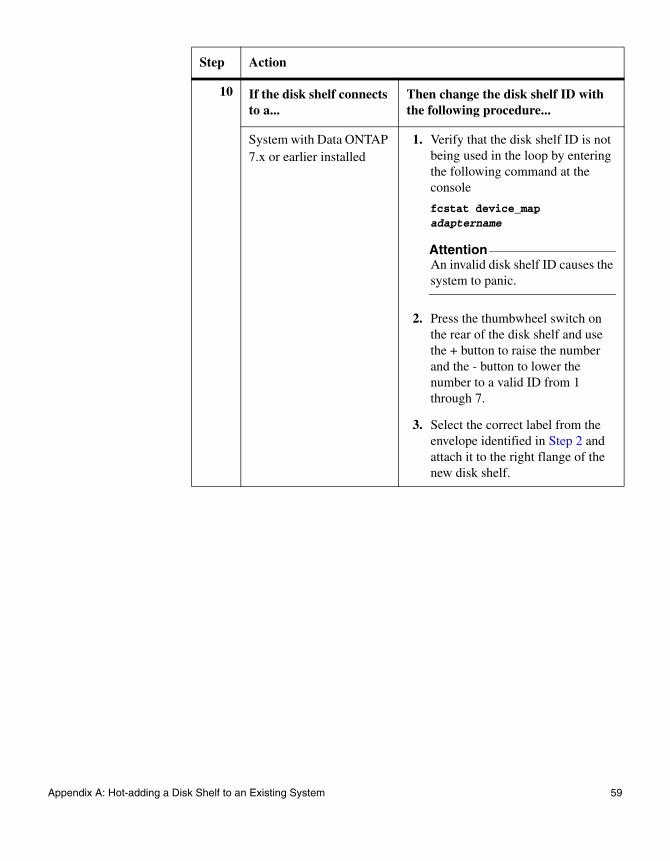
10 If the disk shelf connects to a...
Then change the disk shelf ID with the following procedure...
System with Data ONTAP 7.x or earlier installed
1. Verify that the disk shelf ID is not being used in the loop by entering the following command at the console
fcstat device_map adaptername
AttentionAn invalid disk shelf ID causes the system to panic.
2. Press the thumbwheel switch on the rear of the disk shelf and use the + button to raise the number and the - button to lower the number to a valid ID from 1 through 7.
3. Select the correct label from the envelope identified in Step 2 and attach it to the right flange of the new disk shelf.
Step Action
Appendix A: Hot-adding a Disk Shelf to an Existing System 59
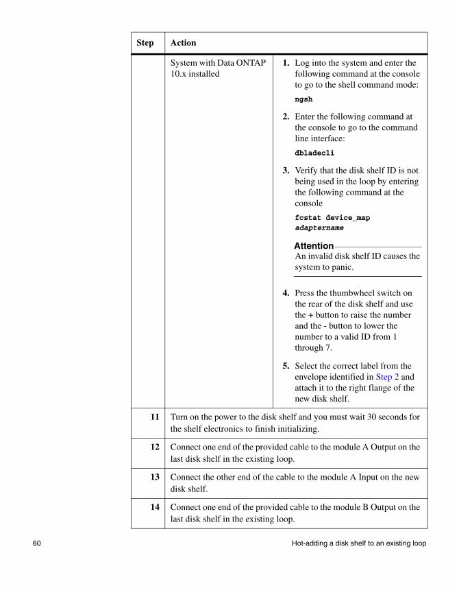
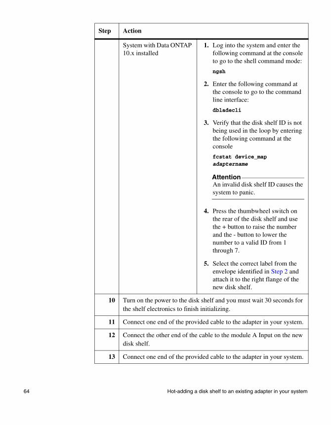
System with Data ONTAP 10.x installed
1. Log into the system and enter the following command at the console to go to the shell command mode:
ngsh
2. Enter the following command at the console to go to the command line interface:
dbladecli
3. Verify that the disk shelf ID is not being used in the loop by entering the following command at the console
fcstat device_map adaptername
AttentionAn invalid disk shelf ID causes the system to panic.
4. Press the thumbwheel switch on the rear of the disk shelf and use the + button to raise the number and the - button to lower the number to a valid ID from 1 through 7.
5. Select the correct label from the envelope identified in Step 2 and attach it to the right flange of the new disk shelf.
11 Turn on the power to the disk shelf and you must wait 30 seconds for the shelf electronics to finish initializing.
12 Connect one end of the provided cable to the module A Output on the last disk shelf in the existing loop.
13 Connect the other end of the cable to the module A Input on the new disk shelf.
14 Connect one end of the provided cable to the module B Output on the last disk shelf in the existing loop.
Step Action
60 Hot-adding a disk shelf to an existing loop

15 Connect the other end of the cable to the module B Input on the new disk shelf.
16 Verify that all the cables are securely fastened.
AttentionPoorly secured cables cause the system to panic over an open loop.
Result: In 60 seconds, the system recognizes the hot-added disk shelf.
Step Action
Appendix A: Hot-adding a Disk Shelf to an Existing System 61
Hot-adding a disk shelf to an existing adapter in your system
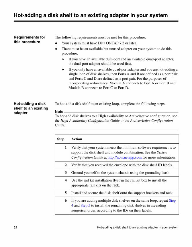
Requirements for this procedure
The following requirements must be met for this procedure:
◆ Your system must have Data ONTAP 7.2 or later.
◆ There must be an available but unused adapter on your system to do this procedure.
❖ If you have an available dual-port and an available quad-port adapter, the dual-port adapter should be used first.
❖ If you only have an available quad-port adapter and you are hot-adding a single loop of disk shelves, then Ports A and B are defined as a port pair and Ports C and D are defined as a port pair. For the purposes of incorporating redundancy, Module A connects to Port A or Port B and Module B connects to Port C or Port D.
Hot-adding a disk shelf to an existing adapter
To hot-add a disk shelf to an existing loop, complete the following steps.
NoteTo hot-add disk shelves to a High availability or Active/active configuration, see the High-Availability Configuration Guide or the Active/Active Configuration Guide.
Step Action
1 Verify that your system meets the minimum software requirements to support the disk shelf and module combination. See the System Configuration Guide at http://now.netapp.com for more information.
2 Verify that you received the envelope with the disk shelf ID labels.
3 Ground yourself to the system chassis using the grounding leash.
4 Use the rail kit installation flyer in the rail kit box to install the appropriate rail kits on the rack.
5 Install and secure the disk shelf onto the support brackets and rack.
6 If you are adding multiple disk shelves on the same loop, repeat Step 4 and Step 5 to install the remaining disk shelves in ascending numerical order, according to the IDs on their labels.
62 Hot-adding a disk shelf to an existing adapter in your system
7 Connect the grounding strap connecting the disk shelf to the other disk shelves or your system.
8 Set the loop speed:
◆ The 1-Gb loop speed setting must be used if the system is an FAS270.
◆ The 2-Gb loop speed setting must be used if there is any component on any part of the loop that is only capable of 2-Gb operation. Examples of these components are the DS14mk2FC, SFPs, HBAs, or drives.
◆ For the 4-Gb loop speed setting to be used, all components on any part of the loop must be of 4-Gb capable. Examples of these components are this disk shelf model, SFPs, HBAs, or drives.
AttentionAn incorrectly set loop speed causes the system to panic.
9 If the disk shelf connects to a...
Then change the disk shelf ID with the following procedure...
System with Data ONTAP 7.x or earlier installed
1. Verify that the disk shelf ID is not being used in the loop by entering the following command at the console
fcstat device_map adaptername
AttentionAn invalid disk shelf ID causes the system to panic.
2. Press the thumbwheel switch on the rear of the disk shelf and use the + button to raise the number and the - button to lower the number to a valid ID from 1 through 7.
3. Select the correct label from the envelope identified in Step 2 and attach it to the right flange of the new disk shelf.
Step Action
Appendix A: Hot-adding a Disk Shelf to an Existing System 63
System with Data ONTAP 10.x installed
1. Log into the system and enter the following command at the console to go to the shell command mode:
ngsh
2. Enter the following command at the console to go to the command line interface:
dbladecli
3. Verify that the disk shelf ID is not being used in the loop by entering the following command at the console
fcstat device_map adaptername
AttentionAn invalid disk shelf ID causes the system to panic.
4. Press the thumbwheel switch on the rear of the disk shelf and use the + button to raise the number and the - button to lower the number to a valid ID from 1 through 7.
5. Select the correct label from the envelope identified in Step 2 and attach it to the right flange of the new disk shelf.
10 Turn on the power to the disk shelf and you must wait 30 seconds for the shelf electronics to finish initializing.
11 Connect one end of the provided cable to the adapter in your system.
12 Connect the other end of the cable to the module A Input on the new disk shelf.
13 Connect one end of the provided cable to the adapter in your system.
Step Action
64 Hot-adding a disk shelf to an existing adapter in your system
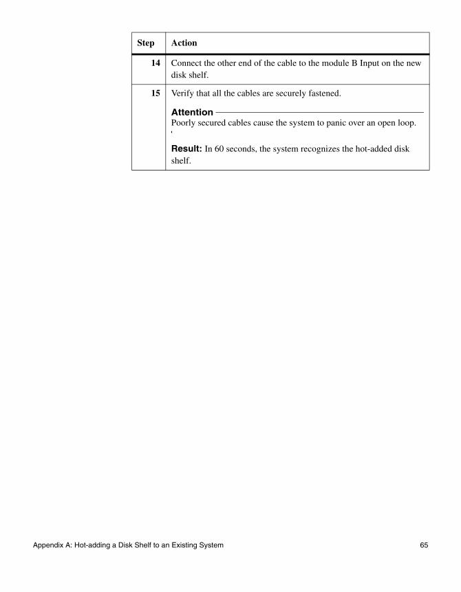
14 Connect the other end of the cable to the module B Input on the new disk shelf.
15 Verify that all the cables are securely fastened.
AttentionPoorly secured cables cause the system to panic over an open loop.
Result: In 60 seconds, the system recognizes the hot-added disk shelf.
Step Action
Appendix A: Hot-adding a Disk Shelf to an Existing System 65

66 Hot-adding a disk shelf to an existing adapter in your system
Appendix B: Recommended Power Line Sizes
B
Recommended Power Line SizesAbout this appendix This appendix describes how to determine the power line lengths running from the system to the power source.
Topics in this appendix
This appendix discusses the following information:
◆ “Recommended AC power line sizes” on page 68
◆ “Calculating the length of DC wires” on page 69
67
Recommended AC power line sizes
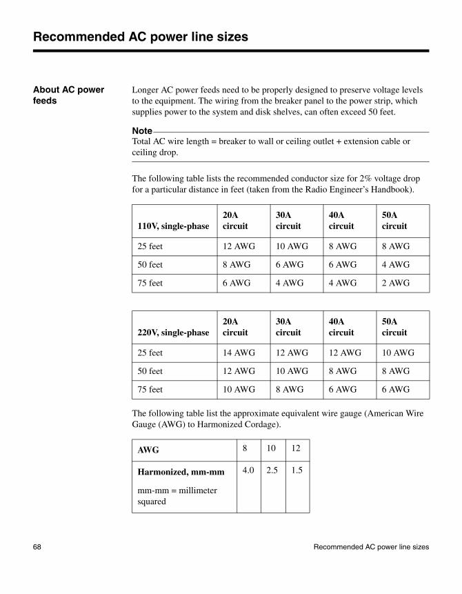
About AC power feeds
Longer AC power feeds need to be properly designed to preserve voltage levels to the equipment. The wiring from the breaker panel to the power strip, which supplies power to the system and disk shelves, can often exceed 50 feet.
NoteTotal AC wire length = breaker to wall or ceiling outlet + extension cable or ceiling drop.
The following table lists the recommended conductor size for 2% voltage drop for a particular distance in feet (taken from the Radio Engineer’s Handbook).
The following table list the approximate equivalent wire gauge (American Wire Gauge (AWG) to Harmonized Cordage).
110V, single-phase20A circuit
30A circuit
40A circuit
50A circuit
25 feet 12 AWG 10 AWG 8 AWG 8 AWG
50 feet 8 AWG 6 AWG 6 AWG 4 AWG
75 feet 6 AWG 4 AWG 4 AWG 2 AWG
220V, single-phase20A circuit
30A circuit
40A circuit
50A circuit
25 feet 14 AWG 12 AWG 12 AWG 10 AWG
50 feet 12 AWG 10 AWG 8 AWG 8 AWG
75 feet 10 AWG 8 AWG 6 AWG 6 AWG
AWG 8 10 12
Harmonized, mm-mm
mm-mm = millimeter squared
4.0 2.5 1.5
68 Recommended AC power line sizes
Calculating the length of DC wires
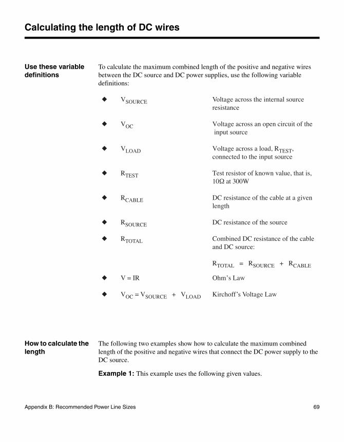
Use these variable definitions
To calculate the maximum combined length of the positive and negative wires between the DC source and DC power supplies, use the following variable definitions:
How to calculate the length
The following two examples show how to calculate the maximum combined length of the positive and negative wires that connect the DC power supply to the DC source.
Example 1: This example uses the following given values.
◆ VSOURCE Voltage across the internal source resistance
◆ VOC Voltage across an open circuit of the input source
◆ VLOAD Voltage across a load, RTEST, connected to the input source
◆ RTEST Test resistor of known value, that is, 10Ω at 300W
◆ RCABLE DC resistance of the cable at a given length
◆ RSOURCE DC resistance of the source
◆ RTOTAL Combined DC resistance of the cable and DC source:
RTOTAL = RSOURCE + RCABLE
◆ V = IR Ohm’s Law
◆ VOC = VSOURCE + VLOAD Kirchoff’s Voltage Law
Appendix B: Recommended Power Line Sizes 69
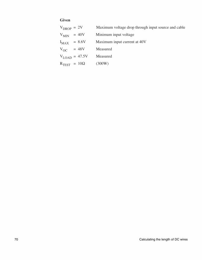
Given
VDROP = 2V Maximum voltage drop through input source and cable
VMIN = 40V Minimum input voltage
IMAX = 8.6V Maximum input current at 40V
VOC = 48V Measured
VLOAD = 47.5V Measured
RTEST = 10Ω (300W)
70 Calculating the length of DC wires
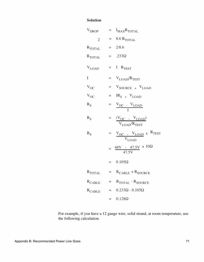
For example, if you have a 12 gauge wire, solid strand, at room temperature, use the following calculation.
VLOAD = I RTEST
I = VLOAD/RTEST
VOC = VSOURCE + VLOAD
VOC = IRS + VLOAD
RS = VOC - VLOAD
I
RS = (VOC - VLOAD)
VLOAD/RTEST
RS = VOC - VLOAD
VLOAD
= 48V - 47.5V 47.5V
= 0.105Ω
RTOTAL = RCABLE + RSOURCE
RCABLE = RTOTAL - RSOURCE
RCABLE = 0.233Ω - 0.105Ω
= 0.128Ω
Solution
VDROP = IMAXRTOTAL
2 = 8.6 RTOTAL
RTOTAL = 2/8.6
RTOTAL = .233Ω
x RTEST
x 10Ω
Appendix B: Recommended Power Line Sizes 71
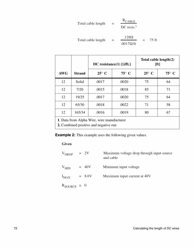
Example 2: This example uses the following given values.
AWG Strand
DC resistance(1) [Ω/ft.]Total cable length(2)
[ft]
25° C 75° C 25° C 75° C
12 Solid .0017 .0020 75 64
12 7/20 .0015 .0018 85 71
12 19/25 .0017 .0020 75 64
12 65/30 .0018 .0022 71 58
12 165/34 .0016 .0019 80 67
1. Data from Alpha Wire, wire manufacturer2. Combined positive and negative run
Total cable length =
Total cable length = = 75 ft
RCABLE
DC resis.1
.128Ω
.0017Ω/ft
Given
VDROP = 2V Maximum voltage drop through input source and cable
VMIN = 40V Minimum input voltage
IMAX = 8.6V Maximum input current at 40V
RSOURCE ≅ 0
72 Calculating the length of DC wires
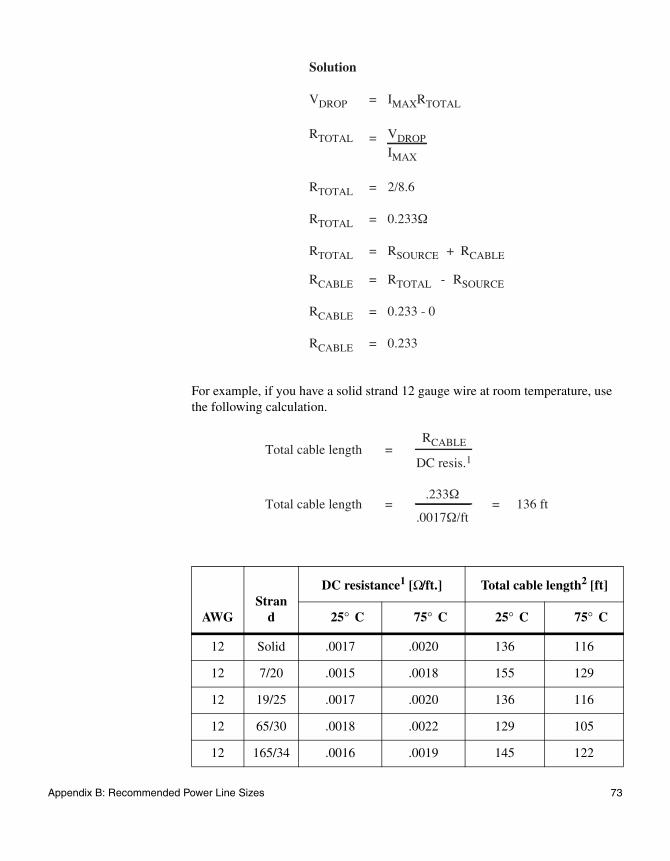
For example, if you have a solid strand 12 gauge wire at room temperature, use the following calculation.
AWGStran
d
DC resistance1 [Ω/ft.] Total cable length2 [ft]
25° C 75° C 25° C 75° C
12 Solid .0017 .0020 136 116
12 7/20 .0015 .0018 155 129
12 19/25 .0017 .0020 136 116
12 65/30 .0018 .0022 129 105
12 165/34 .0016 .0019 145 122
Solution
VDROP = IMAXRTOTAL
RTOTAL = VDROP
IMAX
RTOTAL = 2/8.6
RTOTAL = 0.233Ω
RTOTAL = RSOURCE + RCABLE
RCABLE = RTOTAL - RSOURCE
RCABLE = 0.233 - 0
RCABLE = 0.233
Total cable length =
Total cable length = = 136 ft
RCABLE
DC resis.1
.233Ω
.0017Ω/ft
Appendix B: Recommended Power Line Sizes 73
About using other wire sizes
If you need a longer run for your combined positive and negative DC wires, choose a wire with a lower resistance and calculate the total cable length. For example, a solid #10 AWG has a lower DC resistance than a solid #12 AWG.
1. Data from Alpha Wire, wire manufacturer. 2. Combined positive and negative run
74 Calculating the length of DC wires
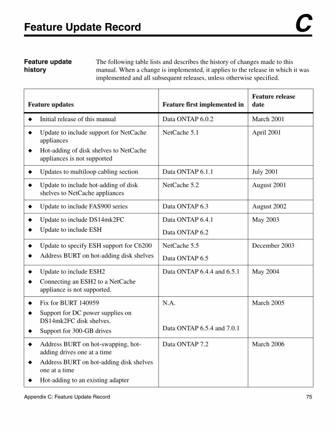
Appendix C: Feature Update Record
C
Feature Update RecordFeature update history
The following table lists and describes the history of changes made to this manual. When a change is implemented, it applies to the release in which it was implemented and all subsequent releases, unless otherwise specified.
Feature updates Feature first implemented inFeature release date
◆ Initial release of this manual Data ONTAP 6.0.2 March 2001
◆ Update to include support for NetCache appliances
◆ Hot-adding of disk shelves to NetCache appliances is not supported
NetCache 5.1 April 2001
◆ Updates to multiloop cabling section Data ONTAP 6.1.1 July 2001
◆ Update to include hot-adding of disk shelves to NetCache appliances
NetCache 5.2 August 2001
◆ Update to include FAS900 series Data ONTAP 6.3 August 2002
◆ Update to include DS14mk2FC
◆ Update to include ESH
Data ONTAP 6.4.1
Data ONTAP 6.2
May 2003
◆ Update to specify ESH support for C6200
◆ Address BURT on hot-adding disk shelves
NetCache 5.5
Data ONTAP 6.5
December 2003
◆ Update to include ESH2
◆ Connecting an ESH2 to a NetCache appliance is not supported.
Data ONTAP 6.4.4 and 6.5.1 May 2004
◆ Fix for BURT 140959
◆ Support for DC power supplies on DS14mk2FC disk shelves.
◆ Support for 300-GB drives
N.A.
Data ONTAP 6.5.4 and 7.0.1
March 2005
◆ Address BURT on hot-swapping, hot-adding drives one at a time
◆ Address BURT on hot-adding disk shelves one at a time
◆ Hot-adding to an existing adapter
Data ONTAP 7.2 March 2006
75
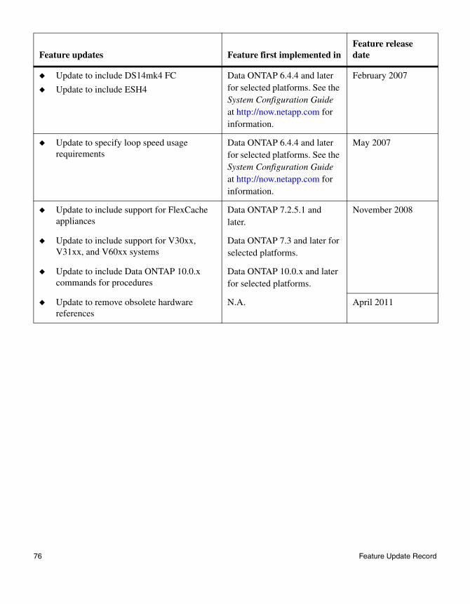
◆ Update to include DS14mk4 FC
◆ Update to include ESH4
Data ONTAP 6.4.4 and later for selected platforms. See the System Configuration Guide at http://now.netapp.com for information.
February 2007
◆ Update to specify loop speed usage requirements
Data ONTAP 6.4.4 and later for selected platforms. See the System Configuration Guide at http://now.netapp.com for information.
May 2007
◆ Update to include support for FlexCache appliances
Data ONTAP 7.2.5.1 and later.
November 2008
◆ Update to include support for V30xx, V31xx, and V60xx systems
Data ONTAP 7.3 and later for selected platforms.
◆ Update to include Data ONTAP 10.0.x commands for procedures
Data ONTAP 10.0.x and later for selected platforms.
◆ Update to remove obsolete hardware references
N.A. April 2011
Feature updates Feature first implemented inFeature release date
76 Feature Update Record
Appendix D: Communications Regulations
D
Communications RegulationsAbout this appendix This appendix lists the regulatory notices you need to be aware of when installing and operating your NetApp equipment.
77
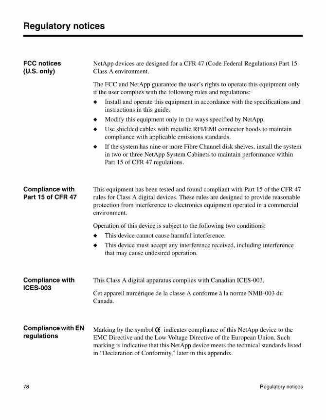
Regulatory notices
FCC notices (U.S. only)
NetApp devices are designed for a CFR 47 (Code Federal Regulations) Part 15 Class A environment.
The FCC and NetApp guarantee the user’s rights to operate this equipment only if the user complies with the following rules and regulations:
◆ Install and operate this equipment in accordance with the specifications and instructions in this guide.
◆ Modify this equipment only in the ways specified by NetApp.
◆ Use shielded cables with metallic RFI/EMI connector hoods to maintain compliance with applicable emissions standards.
◆ If the system has nine or more Fibre Channel disk shelves, install the system in two or three NetApp System Cabinets to maintain performance within Part 15 of CFR 47 regulations.
Compliance with Part 15 of CFR 47
This equipment has been tested and found compliant with Part 15 of the CFR 47 rules for Class A digital devices. These rules are designed to provide reasonable protection from interference to electronics equipment operated in a commercial environment.
Operation of this device is subject to the following two conditions:
◆ This device cannot cause harmful interference.
◆ This device must accept any interference received, including interference that may cause undesired operation.
Compliance with ICES-003
This Class A digital apparatus complies with Canadian ICES-003.
Cet appareil numérique de la classe A conforme à la norme NMB-003 du Canada.
Compliance with EN regulations
Marking by the symbol indicates compliance of this NetApp device to the EMC Directive and the Low Voltage Directive of the European Union. Such marking is indicative that this NetApp device meets the technical standards listed in “Declaration of Conformity,” later in this appendix.
78 Regulatory notices
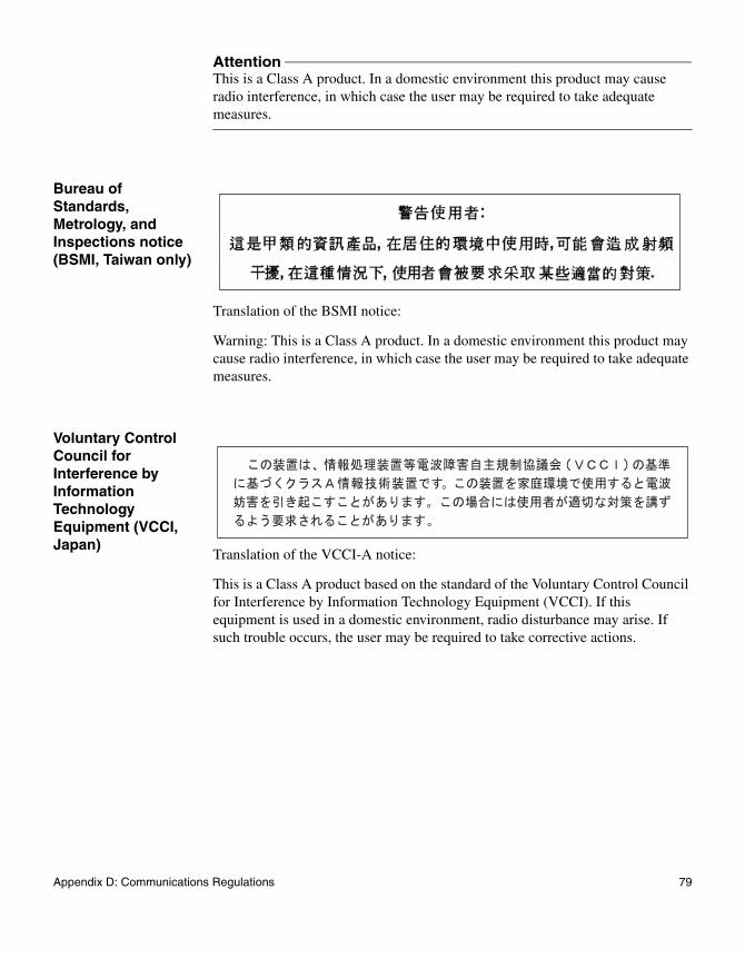
AttentionThis is a Class A product. In a domestic environment this product may cause radio interference, in which case the user may be required to take adequate measures.
Bureau of Standards, Metrology, and Inspections notice (BSMI, Taiwan only)
Translation of the BSMI notice:
Warning: This is a Class A product. In a domestic environment this product may cause radio interference, in which case the user may be required to take adequate measures.
Voluntary Control Council for Interference by Information Technology Equipment (VCCI, Japan)
Translation of the VCCI-A notice:
This is a Class A product based on the standard of the Voluntary Control Council for Interference by Information Technology Equipment (VCCI). If this equipment is used in a domestic environment, radio disturbance may arise. If such trouble occurs, the user may be required to take corrective actions.
Appendix D: Communications Regulations 79
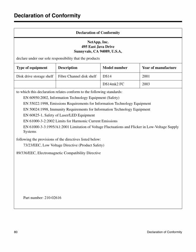
Declaration of Conformity
Declaration of Conformity
NetApp, Inc.495 East Java Drive
Sunnyvale, CA 94089, U.S.A,
declare under our sole responsibility that the products
Type of equipment Description Model number Year of manufacture
Disk drive storage shelf Fibre Channel disk shelf DS14 2001
DS14mk2 FC 2003
to which this declaration relates conform to the following standards:
EN 60950:2002, Information Technology Equipment (Safety)
EN 55022:1998, Emissions Requirements for Information Technology Equipment
EN 50024:1998, Immunity Requirements for Information Technology Equipment
EN 60825-1, Safety of Laser/LED Equipment
EN 61000-3-2:2002 Limits for Harmonic Current Emissions
EN 61000-3-3:1995/A1:2001 Limitation of Voltage Fluctuations and Flicker in Low-Voltage Supply Systems
following the provisions of the directives listed below:
73/23/EEC, Low Voltage Directive (Product Safety)
89/336/EEC, Electromagnetic Compatibility Directive
Part number: 210-02616
80 Declaration of Conformity
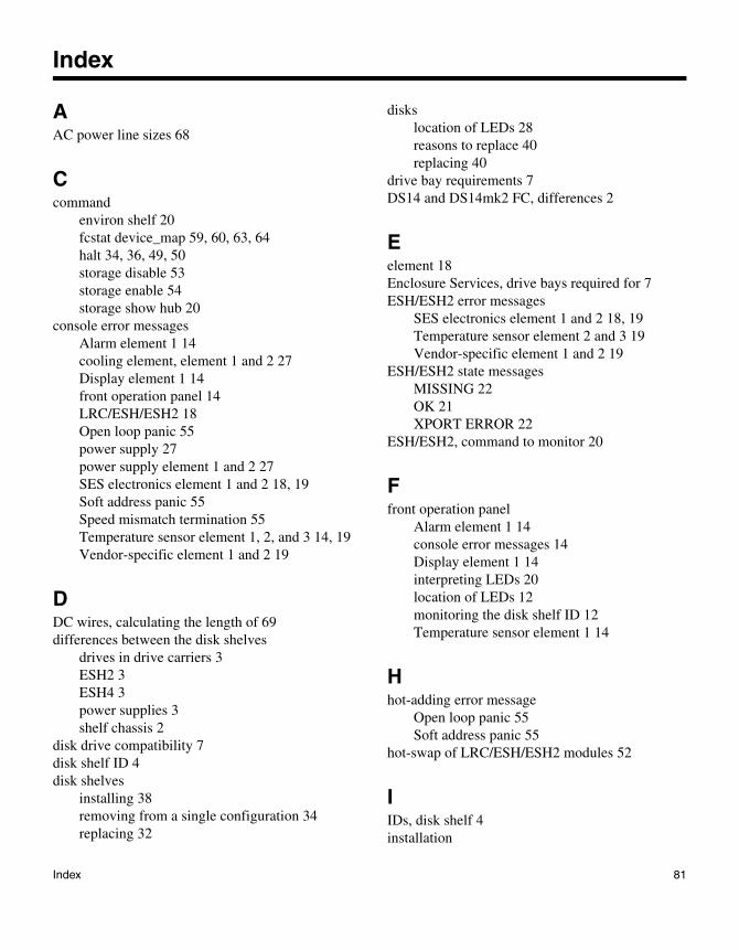
Index
AAC power line sizes 68
Ccommand
environ shelf 20fcstat device_map 59, 60, 63, 64halt 34, 36, 49, 50storage disable 53storage enable 54storage show hub 20
console error messagesAlarm element 1 14cooling element, element 1 and 2 27Display element 1 14front operation panel 14LRC/ESH/ESH2 18Open loop panic 55power supply 27power supply element 1 and 2 27SES electronics element 1 and 2 18, 19Soft address panic 55Speed mismatch termination 55Temperature sensor element 1, 2, and 3 14, 19Vendor-specific element 1 and 2 19
DDC wires, calculating the length of 69differences between the disk shelves
drives in drive carriers 3ESH2 3ESH4 3power supplies 3shelf chassis 2
disk drive compatibility 7disk shelf ID 4disk shelves
installing 38removing from a single configuration 34replacing 32
diskslocation of LEDs 28reasons to replace 40replacing 40
drive bay requirements 7DS14 and DS14mk2 FC, differences 2
Eelement 18Enclosure Services, drive bays required for 7ESH/ESH2 error messages
SES electronics element 1 and 2 18, 19Temperature sensor element 2 and 3 19Vendor-specific element 1 and 2 19
ESH/ESH2 state messagesMISSING 22OK 21XPORT ERROR 22
ESH/ESH2, command to monitor 20
Ffront operation panel
Alarm element 1 14console error messages 14Display element 1 14interpreting LEDs 20location of LEDs 12monitoring the disk shelf ID 12Temperature sensor element 1 14
Hhot-adding error message
Open loop panic 55Soft address panic 55
hot-swap of LRC/ESH/ESH2 modules 52
IIDs, disk shelf 4installation
Index 81
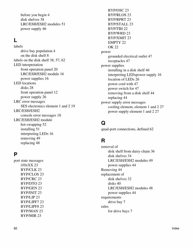
before you begin 4disk shelves 38LRC/ESH/ESH2 modules 51power supply 46
Llabels
drive bay population 4on the disk shelf 8
labels on the disk shelf 38, 57, 62LED interpretation
front operation panel 20LRC/ESH/ESH2 module 16power supplies 16
LED locationsdisks 28front operation panel 12power supply 26
LRC error messagesSES electronics element 1 and 2 19
LRC/ESH/ESH2console error messages 18
LRC/ESH/ESH2 modulehot-swapping 52installing 51interpreting LEDs 16removing 49replacing 48
Pport state messages
///0xXX 23BYP/CLK 23BYP/CLOS 23BYP/CRC 23BYP/DTO 23BYP/GEN 23BYP/INIT 23BYP/LIP 23BYP/LIPF7 23BYP/LIPF8 23BYP/MAN 23BYP/MIR 23
BYP/OSC 23BYP/RLOS 23BYP/RPRT 23BYP/STALL 23BYP/TBI 22BYP/WRD 23BYP/XMIT 23EMPTY 22OK 22
powergrounded electrical outlet 47receptacles 47
power suppliesinstalling in a disk shelf 46interpreting LEDspower supply 16location of LEDs 26power cord with 47power switch for 47removing from a disk shelf 44replacing 44
power supply error messagescooling element, element 1 and 2 27power supply element 1 and 2 27
Qquad-port connections, defined 62
Rremoval of
disk shelf from daisy-chain 36disk shelves 34LRC/ESH/ESH2 modules 49power supplies 44
Removing 44replacement of
disk shelves 32disks 40LRC/ESH/ESH2 modules 48power supplies 44
requirementsdrive bay 7
rulesfor drive bays 7
82 Index
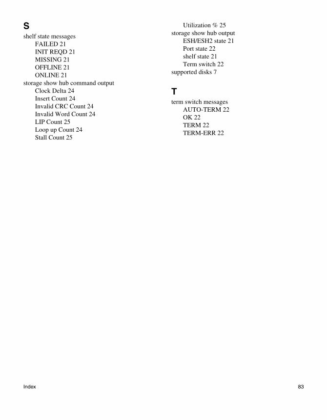
Sshelf state messages
FAILED 21INIT REQD 21MISSING 21OFFLINE 21ONLINE 21
storage show hub command outputClock Delta 24Insert Count 24Invalid CRC Count 24Invalid Word Count 24LIP Count 25Loop up Count 24Stall Count 25
Utilization % 25storage show hub output
ESH/ESH2 state 21Port state 22shelf state 21Term switch 22
supported disks 7
Tterm switch messages
AUTO-TERM 22OK 22TERM 22TERM-ERR 22
Index 83

84 Index