Water Treeing
197
WATER TREEING the behaviour of water trees in extruded cable insulation TR. diss 1735 Evert Frederik Steennis
Transcript of Water Treeing
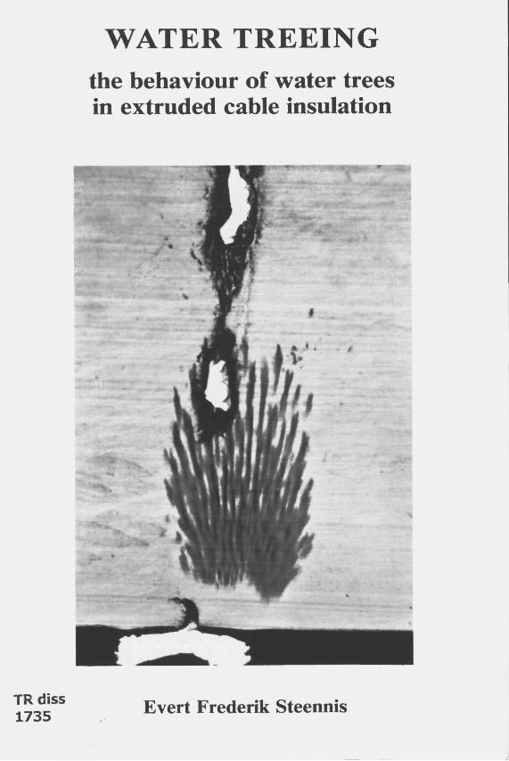
WATER TREEING the behaviour of water trees in extruded cable insulation
TR. diss 1735 Evert Frederik Steennis
PROEFSCHRIFT
Ter verkrijging van de graad van doctor aan de Technische Universiteit Delft, op gezag van de Rector Magnificus, prof. drs. P.A. Schenck, in het openbaar te verdedigen ten overstaan van een
commissie door het College van Dekanen daartoe aangewezen, op donderdag
8 juni 1989, te 14.00 uur.
Door
Evert Frederik Steennis
elektrotechnisch ingenieur
geboren te Ede
TR diss 1735
STELLINGEN
behorende bij het proefschrift van Evert Frederik Steennis
1. Het verdient aanbeveling de storingsstatistiek voor middenspannings kunststof kabels niet slechts te baseren op het aantal fouten per kilometer geïnstalleerde kabel per jaar, maar eveneens op de vervangen kabellengte per geïnstalleerde kilometer per jaar.
2. De dielectrische eigenschappen van een waterboom komen overeen met die van een isolator. De waterboom als isolator is evenwel inferieur aan de in de elektrische energie techniek gebruikelijke isolatie materialen.
3. Het is zeer riskant te veronderstellen dat de groeisnelheid van "vented trees" vlak na kunstmatige initiatie door middel van waternaalden maatgevend is voor de groeisnelheid van deze waterbomen onder praktijk condities.
4. Het is niet aangetoond dat de groeisnelheid van "bow-tie trees" uitsluitsel geeft over de groeisnelheid van de veel gevaarlijker "vented trees". Uitspraken over de waterboom gevoeligheid van een isolatie materiaal welke gebaseerd zijn op de "bow-tie tree" groei zijn daarom aanvechtbaar.
5. Bij de vorming van "vented trees" in een kabel is niet het vochtgehalte in de isolatie, maar het vochtgehalte buiten deze isolatie is van wezenlijke betekenis.
6. Het komt de electriciteilssector ten goede indien de test- en keuringsinstituten in deze sector in hun programma van onderzoek bedrijfsmiddelen opnemen en dit onderzoek niet uitsluitend aan de desbetreffende leveranciers overlaten.
7. Men aanvaardt een feitelijke machteloosheid indien men een uitgesproken mening heeft over zaken als apartheid, bewapening en/of aantasting van het milieu en men tegelijk voor zijn spaartegoed slechts is geïnteresseerd in de hoogte van de rente, en men buiten beschouwing Iaat hoe deze rente door de betrokken instelling wordt gerealiseerd.
8. Een weinig polulaire maar effectieve methode om de druk op het milieu te verminderen wordt verkregen indien bedrijven en instellingen voor zakenreizen niet de autokosten maar de kosten van het openbaar vervoer vergoeden. De veelal ingebrachte tegenwerping dat het gebruik van het openbaar vervoer tijdrovend en dus weinig effectief is, is aanvechtbaar indien de reistijd wordt benut voor overleg, voorbereiding, verslaggeving en/of studie.
9. Het berust op een misverstand dat een paspoort of een waardepapier fraudebestendig kan worden gemaakt.
10. Een uniforme richtlijn is gewenst, die vastlegt dat het tikpunt van de dirigeerslag en de tactus van de muziek samenvallen.
11. Daar waar het in de sport gaat om te winnen, prefereert men in de muziek een gelijk spel.
CONTENT
i
SUMMARY 7
CHAPTER 1 GENERAL INTRODUCTION
1.1 General aspects 9 1.2 Water treeing 10 1.3 Object of study 13
CHAPTER 2 POLYETHYLENE INSULATION
2.1 Polyclhylene structure 15 2.2 Mechanical properties 19 2.3 Fracture in polymers 22 2.4 Extruded cable insulation 24
2.4.1 Extrusion 24 2.4.2 Cross-linking 26 2.4.3 Voids 26
2.5 Water in polyethylene 29
2.5.1 General aspects 29 2.5.2 Water in voids with pure polyethylene walls 30 2.5.3 Capillary action 31 2.5.4 Osmosis 34
CHAPTER 3 PHENOMENOLOGY
3.1 Introduction 37 3.2 Morphoiogy of water trees 39
3.2.1 Shape 39 3.2.2 Voids and channels 42
2
3.2.3 Water content 43
3.2.4 Typical growth behaviour of water trees 43
3.3 Dielectrical propcrties (local) 45
3.3.1 Definitions 45 3.3.2 The vented tree: an insulating material 45 3.3.3 Conclusion 47
3.4 Physical/Chemical propcrties (local) 48 3.5 Electrical propcrties (bulk) 51 3.6 Effect of electric stress intensity 57 3.7 Effect of frequency 59 3.8 Effect of temperature 62 3.9 Effect of mechanical stress 64 3.10 Effect of relative humidity 65 3.11 Effect of the chemical nature of the fluid 66 3.12 Effect of insulating material and additives 69 3.13 Effect of morphology of the insulating material 73
CHAPTER 4 PHENOMENOLOGY, A SUMMARY 75
CHAPTER 5 POSSIBLE MECHANISMS OF VENTED TREE GROWTH
5.1 Introduction 77 5.2 Ageing conditions 77 5.3 Possible mechanisms 80
5.3.1 Introduction 80 5.3.2 Osmosis and capillary action 80 5.3.3 Coulomb forces 81 5.3.4 Dielectrophoresis 84 5.3.5 Thermal degradation 87 5.3.6 Partial discharges 90 5.3.7 Electrochemical degradation 91
5.4 Conclusions 92
CHAPTER 6 ELECTROCHEMICAL DEGRADATION
3
6.1 Introduction 93 6.2 Initiation 93
6.2.1 Creation of polar amorphous regions 93
6.2.2 Water intake 96
6.3 Growth 97
6.3.1 Introduction 97 6.3.2 Further degradation within the tree 98 6.3.3 Electrolysis 99 6.3.4 Electrochemical degradation 101
6.4 Propagation rate 102 6.5 Theory and phenomenology 106
6.5.1 Agreements 106 6.5.2 Remaining aspects 110 6.5.3 Bow-tie trees 111
6.6 Measures to suppress vented treeing 112
6.6.1 Suppression of initiation 112 6.6.2 Water-blockings 112 6.6.3 Suppression of propagation 113
6.7 Conclusions 115 6.8 Further study 116
CHAPTER 7 CHARACTERIZATION TEST
7.1 Introduction 117 7.2 Description of the characterization test 119
7.2.1 Introduction 119 7.2.2 Method of sampling 121 7.2.3 Pre-conditioning 122 7.2.4 Breakdown tests 122 7.2.5 Observed causcs of breakdown 123
4
7.2.6 General visual inspection 127
7.3 Typical results 129 7.4 Classification procedure 135 7.5 Conclusions 136
CHAPTER 8 INVESTIGATION OF A CABLE NETWORK
8.1 Introduction 137 8.2 Cable characteristics 137 8.3 Rate of degradation 138 8.4 Degradation versus cable characteristics 140
8.4.1 Soil conditions 140 8.4.2 Type of semiconducting outer screen 141 8.4.3 Method of cross-linking 142 8.4.4 Outer shcath malcrial 142 8.4.5 Manufacturer 143 8.4.6 Mean ageing stress level, ageing time and year of cable
production 147
8.5 Conclusions 148
CHAPTER 9 ACCELERATED AGEING PROCEDURES
9.1 Introduction 149 9.2 Experiment 149 9.3 Rate of degradation 153 9.4 Conclusions 156 9.5 Further study and recommendations 157
5
APPENDICES
Appendix 1 methylene blue dyeing procedure 159
I. Preparation of a methylene blue dye solution 159 II. Use of the methylene blue dye solution 159 UI. Hints for handling methylene blue 160
Appendix 2 electric stresses at the vented tree tip 161
I. Axial and radial electric stresses in the polyethylene at the tree tip 162 II. Ratios of the radial and axial electric stresses in the polyethylene at
the tree tip 163 UI. Axial electric stress on the axis of symmetry 164 IV. Axial electric stress in the tree at the tree tip 165
Appendix 3 cable properties 166
Appendix 4 vented tree initiation site, cxample 167
REFERENCES: 169
LIST OF SYMBOLS 181
LIST OF FIGURES 185
LIST OF TABLES 189
AUTHOR INDEX 191
SUBJECT INDEX 193
SAMENVATTING 199
NAWOORD 201
CURRICULUM VITAE 202

WATER TREEING 7
SUMMARY
This study deals with the behaviour of water trees in extruded cabies, especially in medium-voltage cabies. It is the aim of the study to review the phenomenology of water treeing, to study the mechanisms of vented tree growth, to fmd methods to evaluate the rate of cable degradation by water treeing and to develop an accelerated ageing procedure necessary to arrive at a discrimination between cable insulation with a low or a high water tree susceptibility.
In Chapter 1 a general introduction is given.
A study of the various aspects of water treeing is possible only if it is based on general knowledge of the structure of polyethylenc insulation and the behaviour of water in this material. Information is given in Chapter 2.
Phenomenological data are given in Chapter 3 and summarized in Chapter 4. Morphological aspects of water trees and their impact on the insulating material properties are studied. Moreover, the effects are studied of electric stress, voltage frequency, temperature, mechanical stress, relative humidity, chemistry and morphological parameters of the insulation on water tree growth. One of the main conclusions is that a vented tree can be considered as an insulating material.
Possible mechanisms of vented tree growth are studied in Chapter 5. The conclusion is that osmosis, capillary action, Coulomb forces, thermal degradation, partial discharges and dielectrophoresis are not the cause of vented tree growth, although in a few cases they may play a secondary role. Electrochemical degradation as the cause of vented tree growth is studied in Chapter 6. It is found that the effects of electrochemical degradation agree with the phenomenology as presented in previous Chapters. Measures to suppress water tree growth are discussed.
A test procedure to establish the level of degradation of a cable is developed and is presented in Chapter 7. On the basis of this test procedure an investigalion of a medium-voltage extruded cable network was carried out. The rate of degradation and its relation to construction and ageing parameters are discussed and presented in Chapter 8.
The development of an accelerated ageing procedure is described in Chapter 9. The choice of the ageing parameters based on phenomenological experience appears to be successful. The most effective ageing parameters are related to solutes in the water and the voltage frequency.
WATER TREEING CHAPTER 1 9
1 GENERALINTRODUCTION
1.1 General aspects
Underground cables are essential for the transmission of electric power, particuiarly in The Netherlands, where nearly 100 % of the total low-voltage (< 1 kV) and medium-voltage (10 to 30 kV) distribution network is buried in the ground. This percentage is high in comparison with other countries (Boone et al, 1987).
Medium-voltage cable
The total circuit length of medium-voltage cable buried in Dutch soil amounts about 90,000 km. The network represents a value of approximately NLG 6.510 , calculatcd for ncw cable including costs of assembling and laying.
The first medium-voltage cables werc installed in London in 1890 (Allister, 1982). Traditionally most of the medium-voltage cables have a mass-impregnated paper insulation. Since the Second World-War, however, polycthylene (PE) insulation is an interesting alternative. This is because of its favourable dielectric characteristics such as low loss angle and low relative permittivity, expected longevity, simple handling, a potcntially lower price and especially if the polyethylene is cross-linked (XLPE) a highcr maximum operating temperature. Installation of polycthylene cables in the United States eind Japan commcnced in the sixties, in Europc in the seventies. Nowadays, when there is an extension of the distribution network or a replacement of a part of this network, polymer insulatcd cable is often chosen, with an exception for the 10 kV voltage range. This exception is mainly due to the fact that, because of its sophisticated concept, the 10 kV mass-impregnated cable is economically still more attractive than the polymer insulated alternative. Only for heavily loaded circuits in this voltage range extruded cable is to be preferred from a technical and economical point of view.
The above mentioned facts form the cause why the total circuit length of medium-voltage cross-linked polyethylene insulatcd cables in The Netherlands, where the principal distribution voltage is 10 kV, is restricted to about 1800 km, while in many other industrialized countries, where a higher distribution voltage is used, the rate of penetration is much higher.
High-voltage cable
Extruded high-voltage cable (50 kV to 380 kV) is economically competitive with conventional high-voltage cable types such as the oil-pressure cable. In the voltage range of 50 kV up to 150 kV the extruded cable is a highly interesting alternative. In
10 GENERAL INTRODUCTION
addition to the advantages mentioned above, the extruded cable is attractive from an environmental poinl of view; it may bc chosen as an alternativc for oil-fillcd cable, where leakage of oil cannot fully be prevcnted. In the voltage range over 150 kV the devclopment of extruded cable is still going on. Here progrcss is also determincd by the devclopment of the accessories.
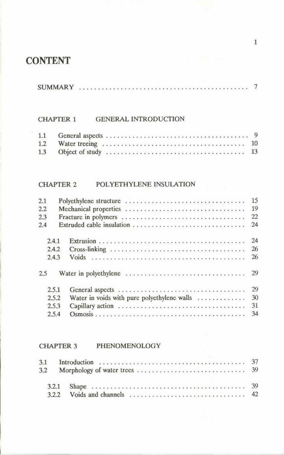
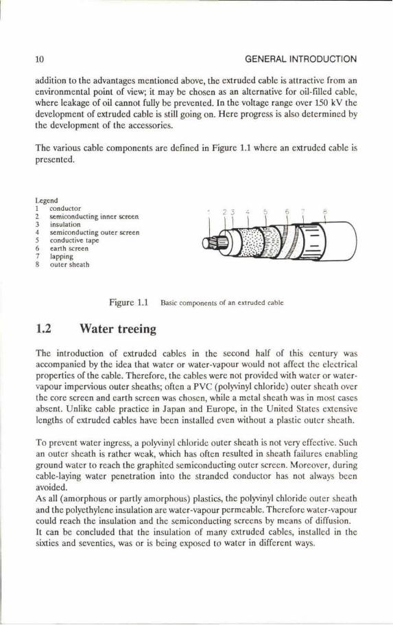
The various cable components are defined in Figurc 1.1 where an extruded cable is presentcd.
Ixgend 1 conductor 2 semiconducting inner screen 3 insulaiion 4 semiconducting outer screen 5 conductive tape 6 carth screen 7 lapping 8 outer shcath
Figure 1.1 Basic components of an extruded cable
1.2 Water treeing
The introduction of extruded cables in the second half of this century was accompanicd by the idea that water or water-vapour would not affect the electrical properties of the cable. Therefore, the cables were not providcd with water or water-vapour impervious outer sheaths; often a PVC (polyvinyl chloride) outer shealh over the core screen and earth screen was chosen, while a metal shealh was in most cases absent. Unlike cable practice in Japan and Europe, in the Uniicd Statcs extensive lengths of extruded cables have been installcd even without a plastic outer sheath.
To prevent water ingress, a polyvinyl chloride outer sheath is not very effective. Such an outer shealh is rather weak, which has often resulted in shcath failures enabling ground water to rcach the graphited semiconducting outer screen. Moreovcr, during cable-laying water penetration into the stranded conductor has not always been avoided. As all (amorphous or partly amorphous) plastics, the polyvinyl chloride outer shcath and the polyethylcne insulation are water-vapour permeable. Therefore water-vapour could rcach the insulation and the semiconducting sereens by means of diffusion. It can bc concludcd that the insulation of many extruded cables, installcd in the sixlies and seventies, was or is bcing exposed to water in different ways.
WATER TREEING CHAPTER 1 11
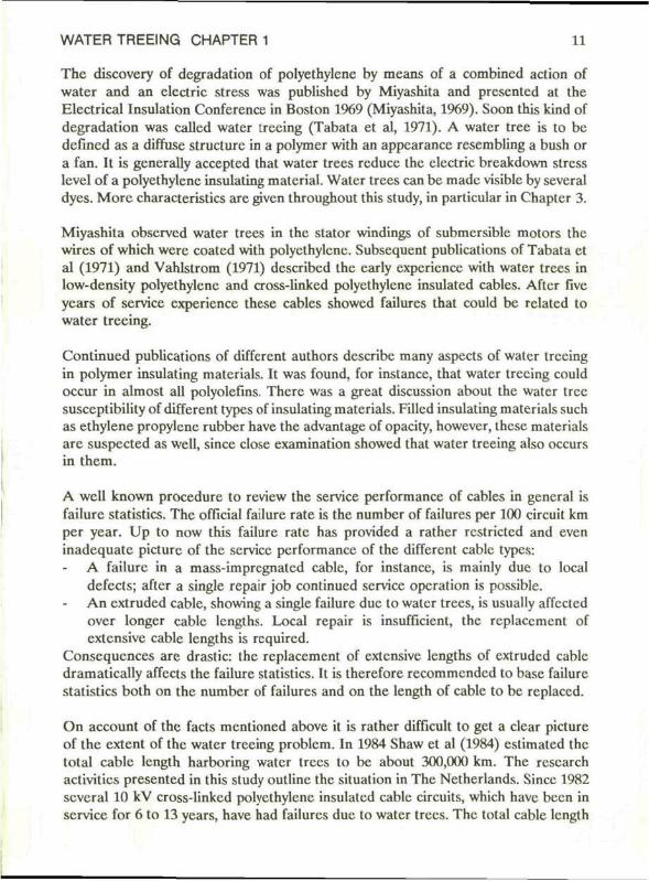
The discovery of dcgradation of polyethylene by means of a combined action of water and an clcctric stress was publishcd by Miyashita and presented at the Electrical I n sul ai ion Conference in Boston 1969 (Miyashita, 1969). Soon this kind of degradation was called water treeing (Tabata et al, 1971). A water tree is to bc defined as a diffuse structurc in a polymer with an appcarance resembling a bush or a fan. It is generally acceptcd that water trees reduce the clcctric breakdown stress level of a polyethylene insulating material. Water trees can be made visible by several dyes. More characteristics are given throughout this study, in particular in Chapter 3.
Miyashita observed water trees in the stator windings of submersible motors the wires of which were coated with polyethylene. Subsequent publications of Tabata et al (1971) and Vahlstrom (1971) described the early experience with water trees in low-density polyethylene and cross-linked polyethylene insulated cables. After five years of service experience these cables showed failures that could be rclated to water treeing.
Continued publications of different authors describe many aspects of water treeing in polymer insulating materials. It was found, for instance, that water treeing could occur in almost all polyolefins. Thcre was a great discussion about the water tree susccptibility of different types of insulating materials. Filled insulating materials such as ethylene propylene rubber have the advantage of opacity, howevcr, these materials are suspected as well, sincc close examination showed that water treeing also occurs in them.
A wcll known procedure to review the service performance of cables in gencral is failure statistics. The official failure rate is the numbcr of failures per 100 circuit km per year. Up to now this failure ratc has provided a rather restricted and even inadequate picture of the service performance of the different cablc types:
A failure in a mass-impregnated cable, for instance, is mainly due to local defects; after a single repair job continued service operation is possible. An extruded cable, showing a single failure due to water trees, is usually affected over longer cablc lengths. Local repair is insufficiënt, the replaccmcnt of extensive cable lengths is required.
Conscqucnces are drastic: the rcplacement of extensive lengths of extruded cable dramatically affects the failure statistics. It is therefore recommended to base failure statistics both on the number of failures and on the length of cable to be replaccd.
On account of the facts mentioned above it is rather difficult to get a clcar picture of the extent of the water treeing problcm. In 1984 Shaw et al (1984) eslimated the total cablc length harboring water trees to be about 300,000 km. The research activitics presented in this study outline the situation in The Netherlands. Sincc 1982 several 10 kV cross-linked polyethylene insulated cable circuits, which have been in service for 6 to 13 years, have had failures due to water trees. The total cable length

12 GENERAL INTRODUCTION
involved is about 50 km or 3 % of the extruded cable network. These lengths have been replaccd and more cablc lengths will have to be replaced because of expected bad service performance.
WATER TREEING CHAPTER 1 13
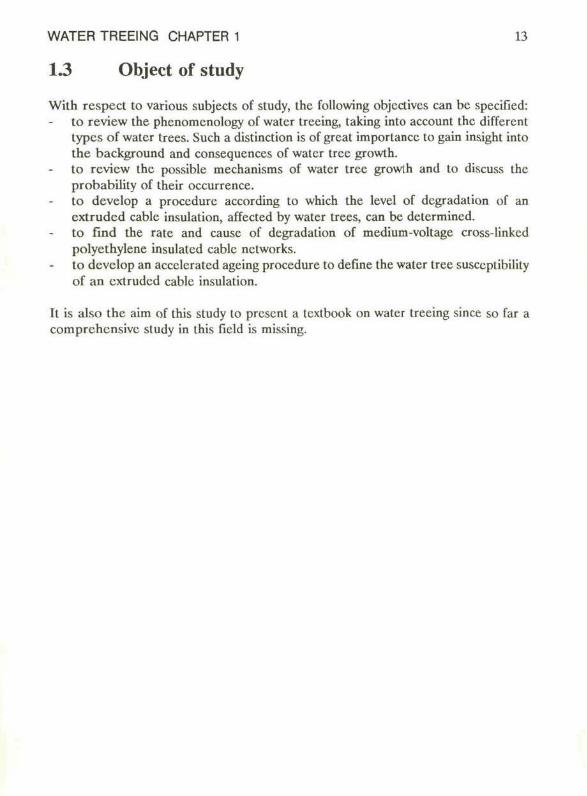
1.3 Object of study
With respect to various subjects of study, the following objcdivcs can be specified: to review the phenomcnology of water trecing, taking into account the different types of water trees. Such a distinction is of great importancc lo gain insight into the background and consequences of water tree growth. to review the possible mechanisms of water tree growth and to discuss the probability of their occurrence. to develop a procedure according to which the level of degradation of an extrudcd cable insulation, affected by water trees, can be determincd. to find the rate and causc of degradation of medium-voltage cross-linkcd polyethylene insulatcd cablc nctworks. to develop an accelerated ageing procedure to define the water tree susccplibilily of an extrudcd cable insulation.
It is also the aim of this study to present a tcxlbook on water treeing since so far a comprehensivc study in this field is missing.
WATER TREEING CHAPTER 2 15
2 POLYETHYLENEINSULATION
2.1 Polyethylene structure
General information on polymers is provided for instance by Sauer and Pae (1977). In this study the main focus is on low-density polyethylene (LDPE). This material is commonly used as an insulating material for extruded cables. Other types of polyethylenes are medium-density polyethylene (MDPE) and high-dcnsity polyethylene (HDPE) used for sheath production in modern cable technology.
Polyethylenes, (CH2-CH2)n, are very long macro moleculcs, each containing up to 100,000 or even more monomcrs of the CH2 = CH2 type. The CH2 groups are strongly joined by bonds of the shared clectron valence type. The ends of the different chains contain methyl (-CH3) or vinyl (-CH = CH2) groups.
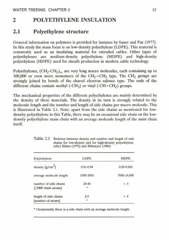
The mechanical properties of the different polyethylenes are mainly dclermincd by the density of these materials. The density in its turn is strongly related to the molecule length and the number and length of side chains per macro molecule. This is illustrated in Table 2.1. Note: apart from the side chains as mentioncd for low-density polyethylene in this Table, there may be an occasional side chain on the low-density polyethylene main chain with an average molecule length of the main chain itself.
T a b l e 2.1 Relalion belwecn density and number and length of side chains for low-density and for high-density polyethylene. Aftcr Sillars (1973) and Billmcyer (1984)
Polyethylene
density [g/cm ]
average molecule length
number of side chains [/1000 chain atoms]
length of side chains [number of atoms]
I.DPE
0.91-0.94
1500-3500
20-40 •
2-5 •
HDPE
0.95-0.965
7000-14,000
< 5
< 4
• Occasionally there is a side chain with an average molecule length
16 POLYETHYLENE INSULATION
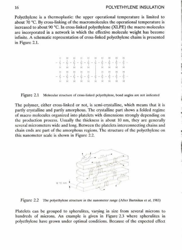
Polyethylenc is a thermoplastic: the upper operational temperature is limited to about 70 °C. By cross-linking of the macromolecules the operational temperature is incrcased to about 90 °C. In cross-linked polyethylene (XLPE) the macro molecules are incorporated in a network in which the effective molecule weight has become infinite. A schematic representation of cross-linked polyethylene chains is presentcd in Figure 2.1.
H H H H H H H H H H I i I I l i I i l i
- c - c - c - c - c - c - c - c - c - c -I I I M il H H H H H H H H i i i i i
- c - c - c - c - c - c - c - c - c - c -I I I I I I I I I I H H H H H H H H H H
F i g u r e 2.1 Molecular struclure of cross-linked polyethylene, bond angles are nol indicaled
The polymer, cithcr cross-linked or not, is semi-crystalline, which means that it is partly cryslalline and partly amorphous. The crystalline part shows a folded regime of macro molecules organized into platelets with dimensions strongly depending on the production process. Usually the thickness is about 10 nm, thcy are generally several micrometers wide and long. Between the platelets interconnecting chains and chain ends are part of the amorphous regions. The struclure of the polyethylene on this nanometer scalc is shown in Figure 2.2.
F i g u r e 2 .2 The polyethylene struclure in the nanometer range (Aftcr Rartnikas et al. 1983)
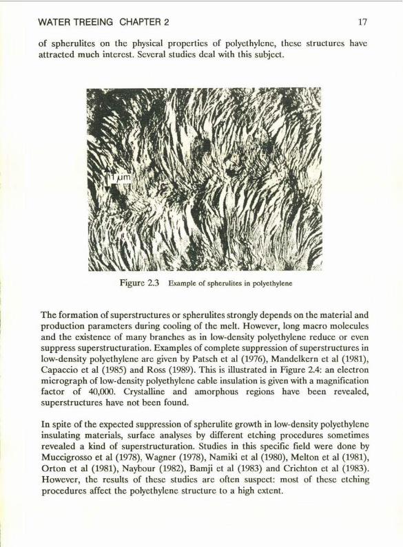
Platelets can be grouped to spherulites, varying in size from several microns to hundreds of microns. An cxamplc is given in Figure 2.3 wherc spherulites in polyethylene have grown under optimal condilions. Because of the expected effect
WATER TREEING CHAPTER 2 17
of spherulites on the physical propcrties of polyethylcnc, these structures have attractcd much interest. Scveral studies deal wilh this subject.
F l g u r e 2.3 Example of spherulites in polyethylene
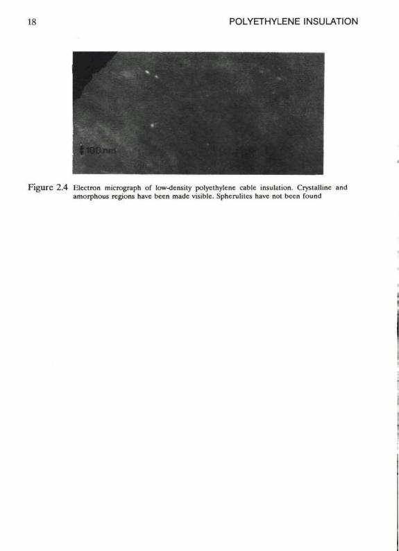
The formation of superstructures or spherulites strongly depends on the material and production parameters during cooling of the mcll. Howcvcr, long macro molcculcs and the existence of many branches as in low-density polyethylcnc rcducc or even suppress superstructuration. Examples of complete suppression of superstructures in low-density polyethylcnc are givcn by Patsch et al (1976), Mandclkcrn et al (1981), Capaccio et al (1985) and Ross (1989). This is Ulustrated in Figure 2.4: an electron micrograph of low-density polyethylene cable insulation is given with a magnification factor of 40,000. Crystalline and amorphous regions have been revealed, superstructures have not been found.
In spite of the expected suppression of spherulite growth in low-density polyethylene insulating matcrials, surface analyses by different etching procedures sometimes revealed a kind of superstructuration. Studies in this specifie field were done by Muccigrosso et al (1978), Wagner (1978), Namiki et al (1980), Melton et al (1981), Orton et al (1981), Naybour (1982), Bamji et al (1983) and Crichton et al (1983). However, the results of these studies are oftcn suspect: most of these etching procedures affect the polyethylcnc structure to a high extent.
POLYETHYLENE INSULATION
F i g u r c 2.4 niectron micrograph of low-density polyclhylene cablc insulation. Crystallinc and amorphous regions have been made visiblc. Sphcruliics have nol been found
WATER TREEING CHAPTER 2 1-)
2.2 Mechanical properties
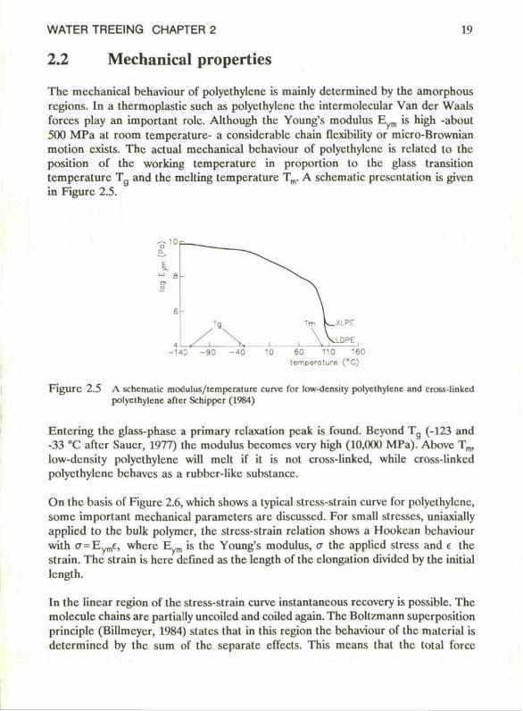
The mechanical behaviour of polyethylcne is mainly determined by the amorphous regions. In a thermoplastic such as polyethylcne the intermolecular Van der Waals forces play an important role. Although the Young's modulus E is high -about 500 MPa at room temperature- a considerable chain flexibility or micro-Brownian motion exists. The actual mechanical behaviour of polyethylcne is rclated to the position of the working temperature in proportion to the glass transition temperature Tg and the melting temperature Tm. A schematic presentation is given in Figure 2.5.
a. I ui g o-o
6
4 -140 - 9 0 - 4 0 10 60 110 160
temperature (°C)
F i g u r e 2.5 A schematic modulus/tcmpcraturc curve for low-density polycthylenc and cross-linked polyethylene aftcr Schipper (1984)
Entering the glass-phase a primary rclaxation peak is found. Beyond T g (-123 and -33 °C aftcr Saucr, 1977) the modulus becomes very high (10,000 MPa). Above Tm, low-density polyethylene will melt if it is not cross-linkcd, while cross-linkcd polyethylene bchavcs as a rubber-like substance.
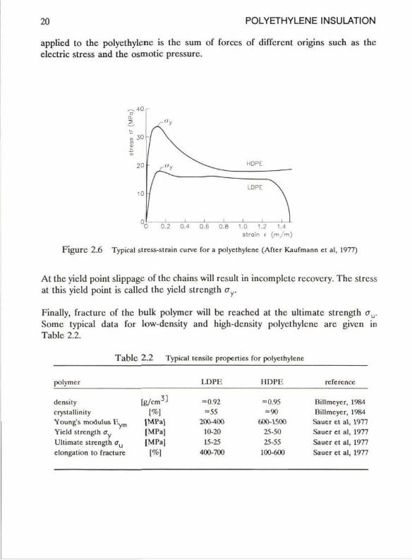
On the basis of Figure 2.6, which shows a typical stress-strain curve for polyethylene, somc important mechanical parameters are discussed. For small stresses, uniaxially applied to the bulk polymcr, the stress-strain relation shows a Hookcan behaviour with CT = Eyrne, where E m is the Young's modulus, o the applied stress and e the strain. The strain is hcre defined as the length of the clongalion divided by the initial length.
In the linear region of the stress-strain curve instantancous recovery is possible. The molecule chains are partially uncoiled and coiled again. The Boltzmann superposition principle (Billmeyer, 1984) statcs that in this region the behaviour of the matcrial is determined by the sum of the separate effects. This means that the total forcc
20 POLYETHYLENE INSULATION
applicd to the polyethylene is the sum of forces of different origins such as the electric stress and the osmotic pressure.
0.2 0.4 0.6 0.8 1.0 1.2 1.4 slrain ( (m/m)
Figure 2.6 Typical slrcss-slrain curve for a polyethylene (Aflcr Kaufmann cl al. 1977)
At the yield point slippage of the chains will result in incomplete recovcry. The stress at this yield point is called the yield strength o
Finally, fracturc of the bulk polymcr will bc rcached at the ultimatc strength CTU. Some typical data for low-density and high-density polyethylene are given in Table 2.2.
Table 2.2 Typical tensile propertics for polyethylene
polymcr
density crystallinity Young's modulus Eym
Yield strength o Ultimatc strength o clongation to fracturc
[g /cm 3 ]
[%] |MPa) [MPa] |MPa|
|%]
LDPE
= 0.92 =55
200-100 10-20 15-25
400-700
HDPE
= 0.95 =90
600-1500 25-50 25-55
100-600
rcfercncc
Billmcycr, 1984 Billmcycr, 1984
Saucr et al, 1977 Sauer et al. 1977 Saucr et al, 1977 Saucr et al, 1977
WATER TREEING CHAPTER 2 21
As all polymers, polyethylene is rather susccptible to effects of time.
Important time effects are
creep: at a constant stress the deformation or strain slowly inercases relaxation: at constant strain the required stress slowly decreases internal friction: at dynamic load mechanical energy is converted into heat.
Time effects are of importance at moderate or high stress lcvcls. At lowcr stress levels these effects are hardly found and therefore complete recovcry is possible at lower stresses.
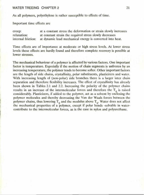
The mechanical behaviour of a polymer is affected by various factors. One important factor is temperature. Especially if the motion of chain segments is unfrozen by an increasing temperature, the polymer tends to become softcr. Other important factors are the length of sidc chains, crystallinity, polar substituents, plasticizcrs and water. With increasing length of (non-polar) side branches there is a larger inter chain separation and therefore flexibility inercases. The effect of crystallinity has alrcady been shown in Tables 2.1 and 2.2. Increasing the polarity of the polymer chains rcsults in an increase of the intermolecular forces and therefore the T g is raiscd considerably. Plasticizers, if added to the polymer, act as a solvent by enclosing (hc polymer molecules and thereby decreasing the Van der Waals forces betwecn the polymer chains, thus lowering T and the modulus above T Water does not affect the mechanical properties of a polymer, except if polar bonds -solvable in watcr-contribute to the intermolecular forces, as is the case in nylon and polyurcthane.
21 POLYETHYLENE INSULATION
23 Fracture in polymers
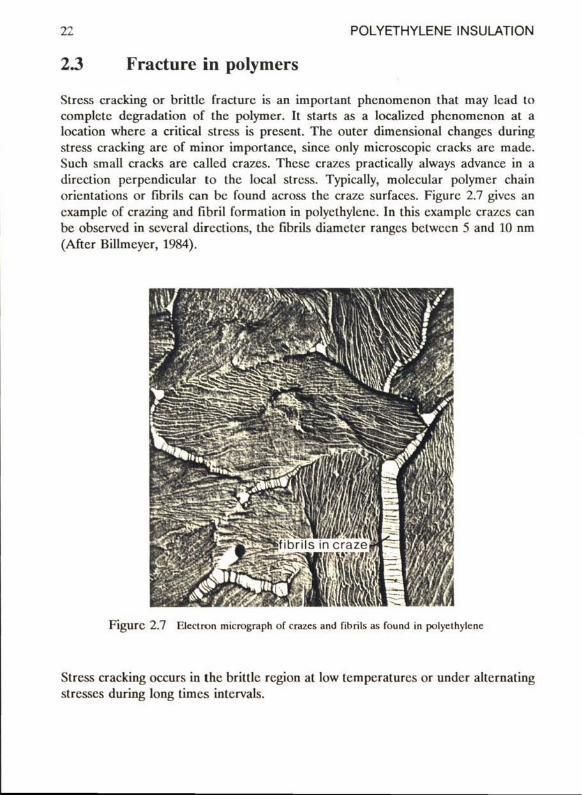
Stress cracking or brittle fracturc is an important phenomenon that may lead to complete dcgradation of the polymer. It starts as a localizcd phenomenon at a location wherc a crilical stress is present. The outer dimensional changes during stress cracking are of minor importance, since only microscopic cracks are made. Such small cracks are called crazes. These crazcs practically always advance in a direction perpendicular to the local stress. Typically, molecular polymer chain orientations or fibrils can bc found across the craze surfaces. Figurc 2.7 givcs an example of crazing and fibril formation in polyethylene. In this examplc crazcs can be observed in scvcral directions, the fibrils diameter ranges bctween 5 and 10 nm (After Bilimcycr, 1984).
F i g u r c 2.7 F.lcctron micrograph of crazcs and fibrils as found in polyethylene
Stress cracking occurs in the brittle rcgion at low tcmpcraturcs or under alternating stresses during long times intervals.
WATER TREEING CHAPTER 2 23
A model dcscribing the propagation of crazes was proposed by Griffith (1921,1924). According to Griffith stresses are concentrated in the region of crazes. A micro-crack with a tip curvature of atomic dimensions may have stress concentrations comparable with stresses of interatomic forces. The cncrgy for propagation of the crack comes from the elastic energy which is stored at the crack tip. Propagation of these crazes may continue at imposed stresses which are much lower than the static yield strength.
Fracture is not found under repeatcd loading conditions as long as the imposed stress remains below a certain endurance limit. This limit is about 1/5 of the static ultimate strength.
There are methods to enhance or reduce stress cracking. A liquid which is capable of solvating the polymer promotes cracking. Measures to reduce stress cracking are:
increasing the molecular weight (fewer chain ends and thereforc fewer micro-cracks) annealing (by reducing the internal stress concentrations) molding and cooling carefully the use of copolymers (the mechanical properties are improved by the combined effects of the various polymers).
24 POLYETHYLENE INSULATION
2.4 Extruded cable insulation
The extrusion and cross-linking of polyethylene cable insulation is a subject of study in this Section. During the extrusion and cross-linking process, voids and internal stresses may be created. Both phcnomena are assumed to affect the ageing performance of the polymer.
2.4.1 Extrusion
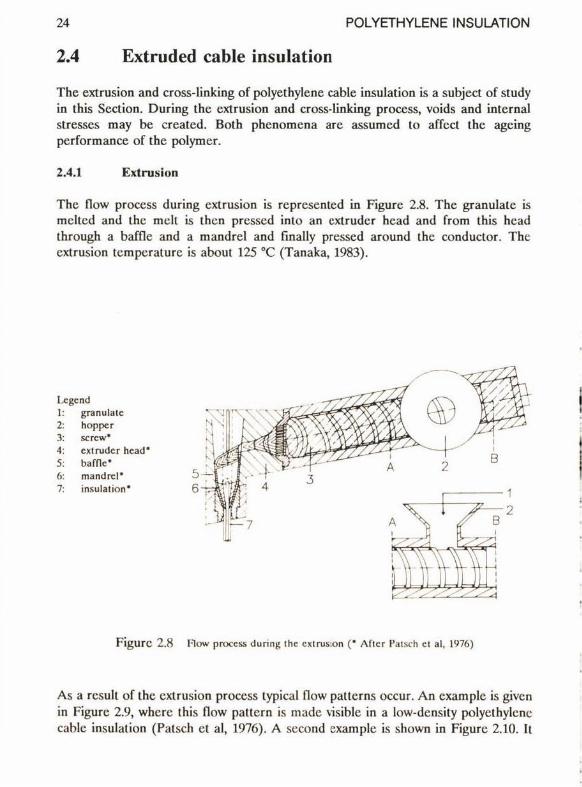
The flow process during extrusion is represented in Figure 2.8. The granulate is meltcd and the melt is then presscd into an extruder hcad and from this hcad through a baffle and a mandrei and finally pressed around the conductor. The extrusion temperature is about 125 °C (Tanaka, 1983).
Ixgcnd granulate hopper screw* extruder hcad* balTIc* mand rel* insulation*
F i g u r e 2.8 Flow process during the extrusion (* Af tc r Patsch et al, 1976)
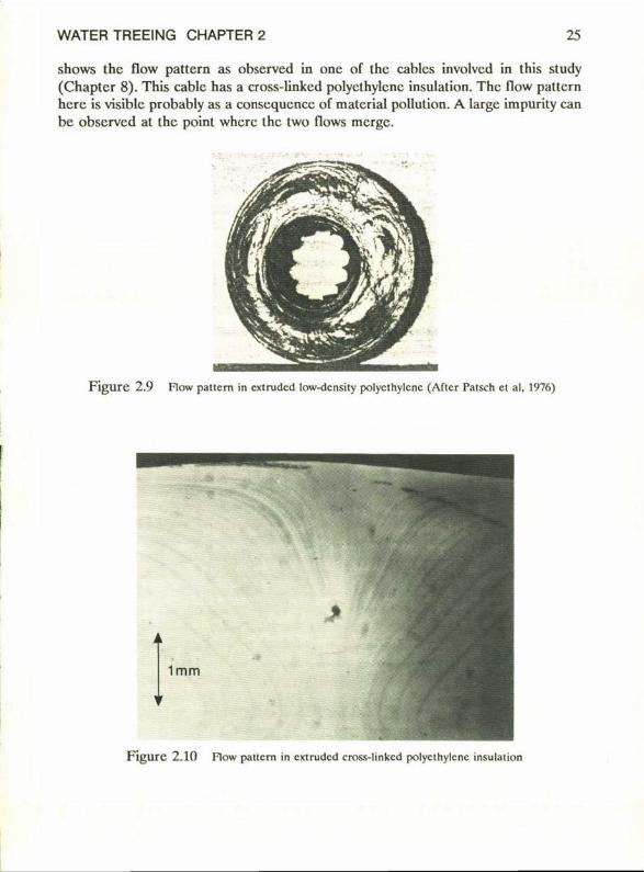
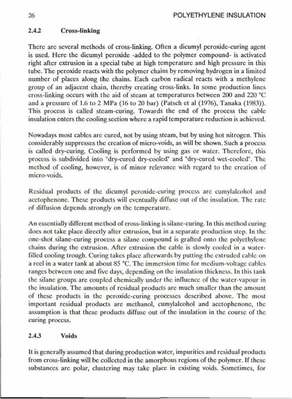
As a result of the extrusion process typical flow patterns occur. An example is givcn in Figure 2.9, where this flow pattern is made visible in a low-density polyethylene cable insulation (Patsch et al, 1976). A second example is shown in Figure 2.10. It
WATER TREEING CHAPTER 2 25
shows the flow pattera as observed in one of the cabics involved in this study (Chapter 8). This cable has a cross-linked polyethyicnc insulation. The flow patlcrn here is visible probably as a conscqucncc of material pollution. A large impurity can be observed at the point where the two flows merge.
F i g u r e 2.9 Flow pattern in extnidcd low-density polyethyicnc (Aflcr Patsch el al, 1976)
F l g u r e 2.10 Flow pattern in extrudcd cross-linkcd polyethyicnc insulation
26 POLYETHYLENE INSULATION
2.42 Cross-linking
Thcrc are several methods of cross-linking. Often a dicumyl peroxidc-curing agent is used. Hcre the dicumyl peroxide -added to the polymer compound- is activated right after extrusion in a special tube at high tempcrature and high pressurc in this tube. The peroxide reacts with the polymer chains by removing hydrogen in a limited numbcr of places along the chains. Each carbon radical reacts with a methylcne group of an adjacent chain, thereby creating cross-links. In somc production lincs cross-linking occurs with the aid of stcam at tempcratures bctween 200 and 220 °C and a pressurc of 1.6 to 2 MPa (16 to 20 bar) (Patsch et al (1976), Tanaka (1983)). This process is called steam-curing. Towards the end of the process the cable insulation enters the cooling section where a rapid tempcrature reduction is achievcd.
Nowadays most cablcs are cured, not by using steam, but by using hot nitrogen. This considerably suppresses the creation of micro-voids, as will be shown. Such a process is called dry-curing. Cooling is performed by using gas or water. Thereforc, this process is subdivided into "dry-cured dry-cooled" and "dry-cured wct-coolcd". The mcthod of cooling, however, is of minor relevance with regard to the creation of micro-voids.
Residual products of the dicumyl peroxidc-curing process are cumylalcohol and acetophenonc. These products will cvcntually diffuse out of the insulation. The rate of diffusion depends strongly on the tempcrature.
An csscntially different mcthod of cross-linking is silane-curing. In this mcthod curing does not take place directly after extrusion, but in a separate produclion step. In the one-shot silane-curing process a silane compound is grafted onlo the polycthylene chains during the extrusion. After extrusion the cable is slowly coolcd in a watcr-filled cooling trough. Curing takes place aftcrwards by putting the extruded cable on a reel in a water tank at aboul 85 °C. The immersion time for medium-voltage cables ranges bctween onc and fivc days, depending on the insulation thickness. In this tank the silane groups are coupled chcmically under the influence of the watcr-vapour in the insulation. The amounts of residual products are much smaller than the amount of these products in the peroxidc-curing processes describcd above. The most important residual products are methanol, cumylalcohol and acetophenonc, the assumption is that these products diffuse out of the insulation in the coursc of the curing process.
2.43 Voids
It is gcncrally assumed that during production water, impuritics and residual products from cross-linking will be collected in the amorphous regions of the polymer. If these substanecs are polar, clustering may take place in existing voids. Somctimcs, for
WATER TREEING CHAPTER 2 27
instance if supersaturation occurs, voids will be created. Smaller voids have dimensions comparable to the dimcnsions of the interlamellar regions, the largest voids have diameters of sevcral micrometers.
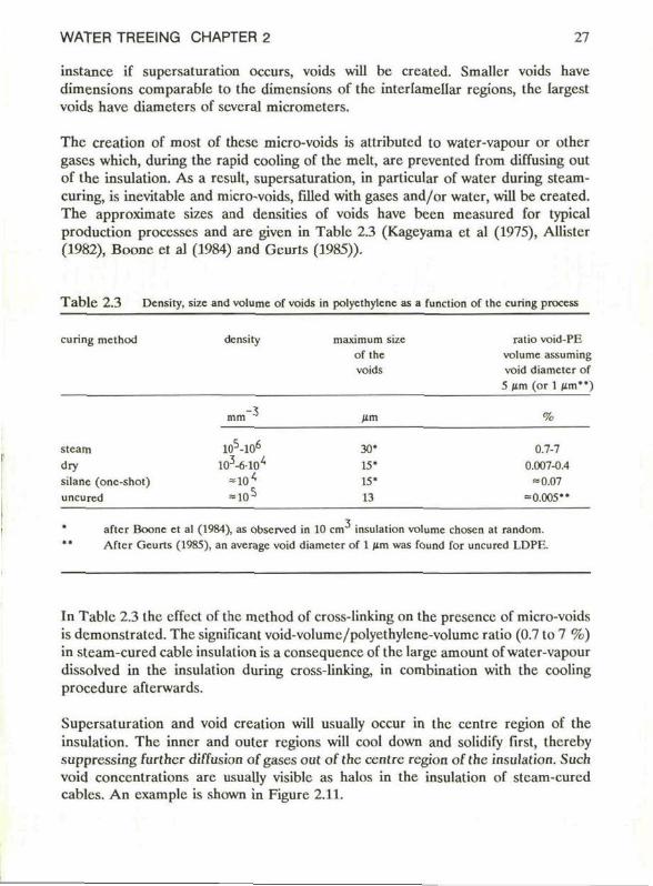
The creation of most of these micro-voids is attributed to water-vapour or other gases which, during the rapid cooling of the melt, are preventcd from diffusing out of the insulation. As a rcsult, supersaturation, in particular of water during steam-curing, is inevitable and micro-voids, füled with gases and/or water, will be created. The approximate sizes and densities of voids have been measured for typical production processcs and are given in Tablc 2.3 (Kageyama et al (1975), Allister (1982), Boone et al (1984) and Gcurts (1985)).
T a b l e 2 .3 Density, size and volume of voids in polyethylcne as a funclion of the curing process
curing method density maximum size of the voids
ratio void-PE volume assuming void diameter of 5 lim (or 1 lim")
-3 j i m
stcam dry silane (onc-shot) uncured
105-106
lfAóir/ -10< «10*
30' 15' 15' 13
%
0.7-7 0.007-0.4
= 0.07 = 0.005"
aftcr Boone et al (1984), as observcd in 10 cm insulation volume chosen al random. Aftcr Geurts (1985), an average void diameter of 1 /im was found for uncured LDPK.
In Tablc 2.3 the effect of the method of cross-linking on the presencc of micro-voids is demonstratcd. The significant void-volumc/polyethylene-volumc ratio (0.7 to 7 %) in steam-cured cable insulation is a consequence of the large amount of water-vapour dissolved in the insulation during cross-linking, in combination with the cooling procedure aftcrwards.
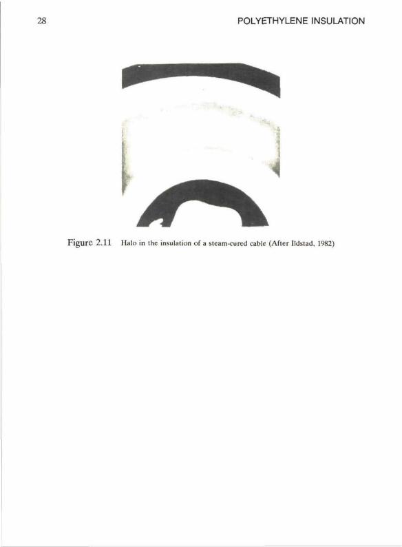
Supersaturation and void creation will usually occur in the centre region of the insulation. The inner and outer regions will cool down and solidify first, thereby suppressing further diffusion of gases out of the centre region of the insulation. Such void concentrations are usually visiblc as halos in the insulation of steam-cured cables. An example is shown in Figure 2.11.
2,S POLYETHYLENE INSULATION
F i g u r e 2 .11 Halo in the insulation of a stcam-curcd cablc (A f l c r Ildsiad. 1982)
WATER TREEING CHAPTER 2 29
2.5 Water in polyethylene
Water is an important substance with respect to water treeing. Therefore, the bchaviour of water in polyethylene will be discussed. The effect of the presence of an electric stress on the behaviour of water in the polyethylene will not be dealt with in this Scction, however, will bc subject of discussion in Chapter 5 and Chapter 6.
2.5.1 General aspects
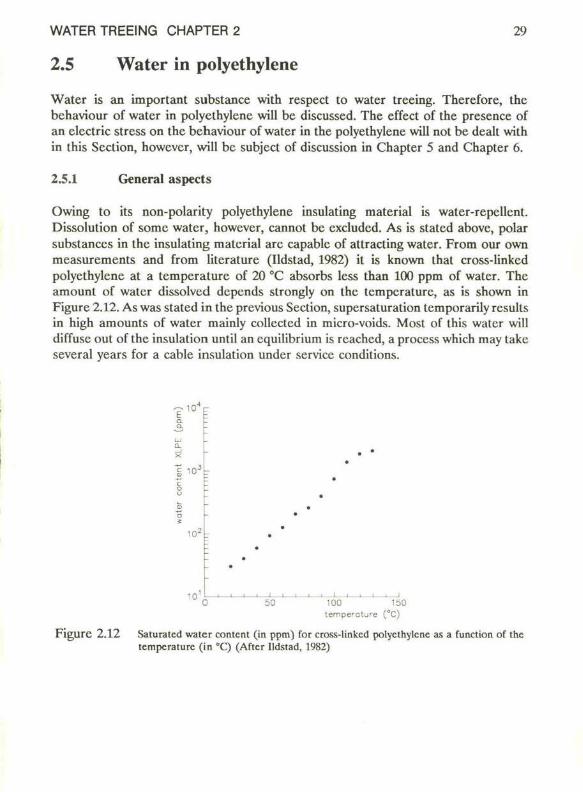
Owing to its non-polarity polyethylene insulating material is water-repellent. Dissolution of somc water, however, cannot be excluded. As is stated above, polar substanecs in the insulating material are capable of attracting water. From our own measurements and from literature (Ildstad, 1982) it is known that cross-linkcd polyethylene at a temperature of 20 °C absorbs less than 100 ppm of water. The amount of water dissolvcd depends strongly on the temperature, as is shown in Figure 2.12. As was stated in the previous Section, supersaturation temporarily results in high amounts of water mainly collected in micro-voids. Most of this water will diffuse out of the insulation until an equilibrium is reached, a process which may take several years for a cable insulation under service conditions.
10 —'—'—'—'—'—'—'—'—'—'—'—'—'—'—' 0 50 100 150
temperature (°C)
F i g u r e 2 .12 Saturatcd water content (in ppm) for cross-linkcd polyethylene as a function of the temperature (in °C) (After Ildstad. 1982)
30 POLYETHYLENE INSULATION
The following three Sections discuss the behaviour of water in
voids whose walls consist of pure polyethylene (2.5.2) capillary channels with walls of pure polyethylene or with walls being modified. This modification means that the polyethylene walls have bccomc polar (2.5.3) voids fillcd with water solublc substanecs (2.5.4)
The smallest dimensions of these voids and channels are comparable with the dimensions of the interlamellar arcas, i.c. in the order of 10 nm.
2.5.2 Water in voids with pure polyethylene walls
Il will bc shown that water in micro-voids with pure polyethylene walls diffuses out of the cablc insulation. A comparison is made between the potential cnergy of water in two different systems. Assuming a connection by diffusion between both systems, water will enter the systcm where it has the lowcst potential cnergy. The discussion will start with a description of two systems, both present in the polyethylene.
The first systcm is a collection of many micro-voids in polyethylene, the sccond is one large void in this matcrial. The voids in both systems may contain water or air. Van der Waals demonstrated ihat a force is exerted on the molcculcs of a surface laycr which is directed inward. The relatcd surface cnergy can bc written as rA, in which r is surface tension and A is surface. This surface cnergy is a representation of the potential energy of the molecules in the surface layer. Enlarging this surface requires energy.
Throughout this and the following Sections thrce surface tension indices will bc uscd to idcnlify the matcrials that are active:
1 = liquid (usually the water) s = solid (usually the polyethylene) g = gas
In the first systcm the surface energy U s n for a collection of n, watcr-filled spherical voids in polyethylene with radius rt is
U s n = r . , * , * * , 2 (2-1)
In rclalion (2-1) the surface tension Ts^ refers to the polycthylcne/watcr interface.
The water collcctcd in the sccond systcm (one spherical water drop with radius r0), will have a surface energy U s with
WATER TREEING CHAPTER 2 31
U s = r s l 4 * r 02 (2-2)
If the same water volume occurs in both systems:
"i = ( r 0 / r , ) 3 (2-3)
Combining the relations (2-1) to (2-3), the ratio between the surfacc cncrgy in systems 1 and 2 becomes r 0 / r ; which is larger than 1. A reduclion of potcntial energy is realized by a reduction of the numbcr of small water drops in favour of the enlargement of one large water drop.
The conclusion reached above can also be derived in the following manner. The vapour pressure of the water in the void is inversely proportional to the void radius. Moreover, the concentration of the water in the polyethylene ncar the void surfacc is relatcd to this vapour pressure (Ildstad, 1982). Consequently, the water concentration in the polyethylene near a small void is highcr than that ncar a large void. Diffusion will takc place until cquilibrium is reached. Water will be expelled from the smaller voids and will enter the larger voids in the polyethylene.
The following step is that system 1 can be chosen insidc the polyethylene, while for system 2 a spherical water drop outside the polyethylene can bc taken. The intcraction between water and pure polyethylene is about the same as between water and gas. This was found by Ildstad (1982) and it means that Tsl ~ T t .
Now the water will collect in a place where it can create the largest water drop, which is outside the insulation.
Consequently, water in micro-voids with pure polyethylene walls will be cxpcllcd from the polyethylene, where the expelling force inercases as the voids become smaller. The diffusion coëfficiënt of water in polyethylene is low; in Section 2.5.1 it has alrcady been mentioned that equilibrium is reached aftcr sevcral ycars for stcam-cured cablc insulation.
2.53 Capillary action
In this Section the effect of pressure by capillary action on the polyethylene surrounding a narrow channel will be sludicd.
Water will not enter a narrow channel as long as the walls of these channels consist of pure polyethylene. Howcver, if the walls of these channels become polar, their surfacc tension will change. Water will enter the channel if the surfacc tension of the polyethylenc/water interface r s^ is smaller than the surface tension of the

32 POLYETHYLENE INSULANON
polyethylene/gas interface r s_. Then the absorption of water into the system will cause the surface cncrgy to deercase.
Water may be supplied in two different ways. lt can enter the channel by diffusion through the polyethylene walls. It could also enter the channel through an open connection with a water reservoir.
The rcduction of the surface energy and, thus, the supply of water will stop as soon as the water has reached the unmodificd arca in the channel.
To show the effect of the hydrostatic pressure inside a capillary channel, a calculation is made for a hypolhctic capillary cylinder with radius r. A pressure drop over the water/gas interface or water meniscus can be calculated from the rcduction of frec energy dF, by raising the water lcvel in the capillary channel over a length dh. The changc in free energy in spreading the water over the surface of the capillary channcl with length dh is
dF s = 2 * r ( r s l - r s g ) . d h (2-4)
Undcr isothermal conditions the change in free energy by changing the volume is
dFv = -po u l-dVo u l - P i n -dV i n (2-5)
In relation (2-5) the pressure undcr the curvcd surface is p j n , the pressure abovc this surface is p o u t , the water volume inside the capillary system is V j n and the water volume outsidc the channcl is V o u t .
The changc in volume as water enters the cylinder is
dV i n= *r2dh (2-6)
For the total system the following equation applies
dVo u l = -dVm (2-7)
The free cncrgy of the system has a minimum for
dF s + dFv = 0 (2-8)
With relations (2-4) to (2-8) a pressure diffcrence across the meniscus can be calculated
Pin "Pout " 2 ( T s r r s g ) / r (2-9)
WATER TREEING CHAPTER 2 33
dh
h
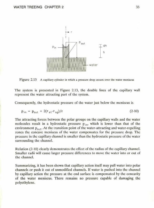
F i g u r e 2 .13 A capillary cylinder in which a pressure drop occurs over Ihe walcr meniscus
The system is presented in Figure 2.13, the doublé lines of the capillary wall represent the water attracting part of the system.
Conscqucntly, ihe hydrostatic pressure of the water just below the meniscus is
Pin = Poui + 2( r s l -T s g ) / r (2-10)
The attracting forces between the polar groups on the capillary walls and the water molecules result in a hydrostatic pressure Pin, which is lower than that of the environment p o u l . At the Iransition point of the water-attracting and water-repelling zones the concave meniscus of the water compensates for the pressure drop. The pressure in the capillary channel is smaller than the hydrostatic pressure of the water surrounding the channel.
Rclation (2-10) clcarly demonstrates the effect of the radius of the capillary channel. Smaller radii will cause larger pressure differences to move the water into or out of the channel.
Summarizing, it has been shown that capillary action itself may pull water into polar channels or push it out of unmodified channels. If water is pushed into the channel by capillary action the pressure al the end surfacc is compensated by the concavity of the water meniscus. There remains no pressure capablc of damaging the polyethylene.
=====;« water
34 POLYETHYLENE INSULATION
2.5.4 Osmosis
In this Section the effect is described of the osmotic pressure in a void in the polyethylene. A general thermodynamic approach is prescnlcd and an cxample is given of the pressure in a void which is the rcsult of a sat urated NaCl solution. It will bc shown that this pressure may increase beyond the yield strength of polyethylene. In such a situation the polyethylene will stretch.
Finally, the effect of the surfacc lension will bc discussed. For voids with small radii this surfacc tension may compensate for the osmotic pressure.
Derivation of the pressure increase
Watcr-soluble substanecs that are present in micro-voids attract water from the environment and osmotic pressure may occur. In literature (for instance Moorc, 1972, pg 252) such an osmotic pressure is often derived by means of a thermodynamic approach foliowed hcre. It is stated that the chcmical potential of the water in the void and outsidc the polyethylene are equal if an equilibrium is reached. Therefore, a decrease of the chemical potential of the water in a void due to a solutc must bc compensated by the increase of the hydrostatic pressure. This decrease of the chcmical potential of the water for a dilutcd solution (X « 1) is represented by NkTln(l-X) with
N = Avogadro constant k = Boltzmann constant T = tempcrature X = molc fraction of the solutc
The increase of the chemical potential of the water by an imposed pressure is given by
rn
vdp . 0
in which
IT = osmotic pressure v = specifie molar volume
Assuming the water incomprcssible cquation (2-11) applies in an equilibrium
vfl + NkTln(l-X) = 0 (2-11)
WATER TREEING CHAPTER 2 35
With X « 1, the osmotic pressure becomes
n - NkTX/v (2-12)
The molc fraction X of the solute is relatcd to the quanlitics of the solute and the solvent water (both measured in molcs) by the following rclation
X = m s o l u / ( m s o l u + m so lv ) ( 2 ' 1 3 )
in which
m s o l u = quantity of the solute msolv = quantity of the solvent
With X « 1 this mole fraction is
X " m s o l u / m s o l v ( 2 " 1 4 )
On the samc condition the specific volume v can be written as
v « V / m s o l v (2-15)
in which V is the volume of the void.
By taking the concentration c as
c = m s o l u / V (2-16)
the osmotic pressure becomes
n » RTc (2-17)
In rclation (2-17) Nk has been replaced by R, the gas constant, being 8.31 J/Kmole. For a saturated solution the condition X « 1 is not usually truc, so cqualion (2-17) is an approximation. For bctter rcsults the concentration c has to be replaced by a practical parameter, c' being the osmolarity. Therefore,
f! = RTc' (2-18)
This osmolarity has been measurcd for many solulions and can be derived from data given in the Handbook of Chcmistry and Physics (Weast, 1980, pg.:D-262).
36 POLYETHYLENE INSULATION
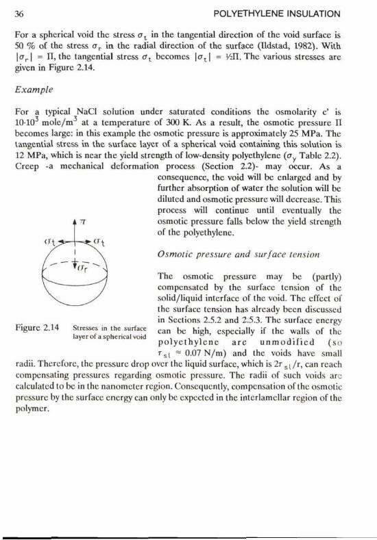
For a spherical void the stress a t in the tangential direction of the void surface is 50 % of the stress ar in the radial direction of the surface (Ildstad, 1982). With | a r | = II, the tangential stress ot bccomcs |(7 t | = VJl. The various stresses are given in Figurc 2.14.
Example
For a typical NaCI solution undcr saturatcd conditions the osmolarity c' is 10-10 mole/m at a temperature of 300 K. As a result, the osmotic pressure II bccomcs large: in this cxamplc the osmotic prcssure is approximatcly 25 MPa. The tangential stress in the surface layer of a spherical void containing this solution is 12 MPa, which is near the yield strength of low-density polyethylenc (p Table 2.2). Crccp -a mechanical dcformation process (Section 2.2)- may occur. As a
conscqucnce, the void will bc cnlargcd and by further absorption of water the solution will bc diluted and osmotic pressure will decrease. This process will continue until eventually the osmotic pressure falls bclow the yield strength of the polyethylenc.
Osmotic pressure and surface tension
The osmotic pressure may be (partly) compensated by the surface tension of the solid/liquid interface of the void. The effect of the surface tension has alrcady been discusscd in Scctions 2.5.2 and 2.5.3. The surface energy
Figurc 2.14 Stresses in the surface c a n b c h i h c s p c c i a l | y jf t h c wal ls of ihc laycrofa spherical void . . , . . . . , ,
polye thy lenc a re u n m o d i h e d ( so r s l " 0.07 N/m) and the voids have small
radii. Thcrcforc, the prcssure drop over the liquid surface, which is 2r s | / r , can rcach compensating pressures regarding osmotic prcssure. The radii of such voids are calculatcd lo bc in thc nanometer rcgion. Conscqucntly, compensation of thc osmotic prcssure by thc surface energy can only bc cxpcctcd in thc intcrlamcllar rcgion of thc polymcr.
WATER TREEING CHAPTER 3 37
3 PHENOMENOLOGY
3.1 Introduction
Much research work has been carried out in order to gain a bcttcr understanding of water treeing. Not only the mechanism of growth, but also the actual phenomenology of these trees have been studicd since their discovery in 1969. Many details were not clear. This is mainly duc to the fact that water trees produce only a minor changc of the physical insulation properties, making research work rathcr difficult.
The scope of this Chapter is to review different aspects of the phenomcnology of water trees. Data have been obtained from literature, in certain cases the results of our own research work will bc presentcd. The conclusions will bc summarized in Chapter 4.
A distinction must be made between two different types of water trees. These types are the "bow-tie tree" and the "vented tree". This distinction is based on the localion wherc these trees start growing: vented trees are initiated at the insulation surfaces, bow-lic trees are initiated in the insulation volume. Such a distinction is important since both types show a completely different behaviour of iniliation and growth. In Section 3.2 both types will be discussed in detail.
This review is mainly directed towards the phenomcnology of vented trees. This is bccausc vented trees under service ageing conditions often appear to bc much more dangerous than bow-tie trees.
For several reasons the study of vented trees is more difficult than that of bow-tie trees:
the density of vented trees is often low compared to the density of bow-tie trees. as will be shown in Section 3.2.4, at the bcginning of growth the propagation rate of vented trees is lower than that of bow-lic trees; in a later stage of growth the oppositc is truc.
Consequently, the study of vented trees is more timc-consuming than the study of bow-tie trees. For these reasons many publications contain information on bow-tie trees only. In somc othcr cases a distinction between both types of water trees has not even been made: only the description "water tree" has been used.
One of the best among recent reviews is from Shaw and Shaw (1984) with over 2(X) referenecs. Although this review is of great value, it has the disadvantage that even here no consistent distinction between vented trees and bow-tie trees has been made.

38 PHENOMENOLOGY
In this study the description "water tree" will be used only if bow-tie trees as well as vented trees are under consideration.
In Section 3.2 the following morphological aspccts will bc discusscd: shapc of water trees voids and channcls in vented trees water content of vented trees typical growth bchaviour of water trees
The impact of water trees on material propertics is givcn in the Sections 3.3 to 3.5.
Sections 3.6 to 3.13 will describe the effect of various agcing parameters on water tree growth such as tempcrature, voltage and frequency.
WATER TREEING CHAPTER 3 39
3.2 Morphology of water trees
3.2.1 Shape
In general water trees are diffuse structurcs in an insulating material resembling a bush or a fan, growing in many different kinds of polymers. The amount of water in water trees is higher than the amount of water in the unaffeclcd surrounding insulation.
Trees can be made permanently visible using different dycs, a wcll known and gcncrally acccpted dycing procedure is givcn by Larsen (1983) and Shaw and Shaw (1984). This procedure is described in Appendix 1.
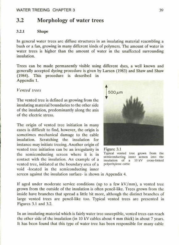
Vented trees
The vented tree is defined as growing from the insulating material boundaries to the other side of the insulation, predominantly along the axis of the electric stress.
The origin of vented tree initiation in many cases is difficult to find, however, the origin is sometimes mechanical damage to the cable insulation. Scratching the insulation for instance may initiate treeing. Another origin of vented tree initiation can be an irregularity in the semiconducting screen where il is in contact with the insulation. An example of a vented tree, initiated at the boundary area of a void -located in the semiconducting inner screen against the insulation surface- is shown in Appendix 4.
Figurc 3.1 Typical vented scmiconducling insulation of polycthylcnc cable
tree grown from the inner screen into the a 10 kV cross-linkcd
If aged undcr moderate service conditions (up to a few kV/mm), a vented tree grown from the outside of the insulation is often pencil-like. Trees grown from the inside have branches that spread a little bit more, although the distinct branches of large venled trees are pencil-like too. Typical vented trees are presented in Figurcs 3.1 and 3.2.
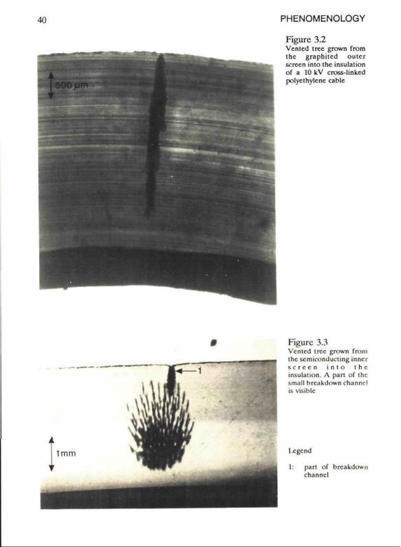
In an insulating material which is fairly water tree susceptible, vented trees can reach the other side of the insulation (in 10 kV cablcs about 4 mm thick) in about 7 years. It has been found that this type of water tree has been responsible for many cable
41) PHENOMENOLOGY
Figure 3.2 Vented tree grown from the graphiicd oulcr screen into the insulation of a 10 kV cross-linked polycthylcne cable
Figure 3.3 Vented tree grown from the scmiconducting inner s c r e e n i n t o t h e insulation. A part of the small breakdown channcl is visiblc
I-cgcnd
1: part of breakdown channcl
WATER TREEING CHAPTER 3 41
failures. In Figure 3.3 a vcnted tree is prcsented; here also a part of a breakdown channcl is visiblc. Small breakdown channeis as shown in this Figure have been obtained in the laboratory using special techniques as will bc discusscd in Chapter 7.
Bow-tie tree
The other type of water tree is the bow-tie tree. Bow-tie trees are defined as initiating in the insulation volume. These trees grow in opposite directions, along the clcctric field lincs.
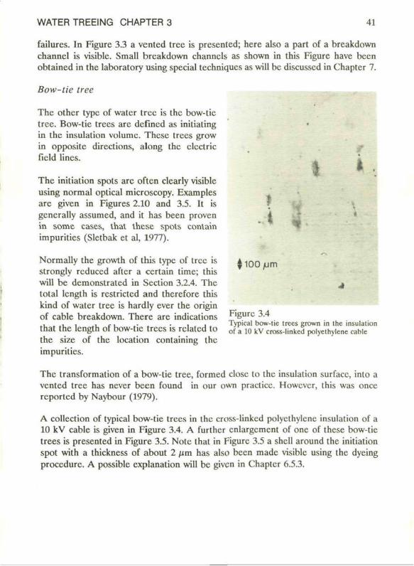
The initiation spots are oftcn clearly visible using normal optical microscopy. Examples are given in Figures 2.10 and 3.5. It is gcncrally assumed, and it has been proven in some cases, thal these spots conlain impurities (Sletbak et al, 1977).
Normally the growth of this type of tree is strongly rcduccd aftcr a certain time; this will be demonstrated in Section 3.2.4. The total lengt h is restrictcd and therefore this kind of water tree is hardly ever the origin of cable breakdown. There are indications that the length of bow-tie trees is rclatcd to the size of the location containing the impurities.
The transformation of a bow-tie tree, formed close to the insulation surface, into a vented tree has never been found in our own practicc. Howcvcr, this was once reporled by Naybour (1979).
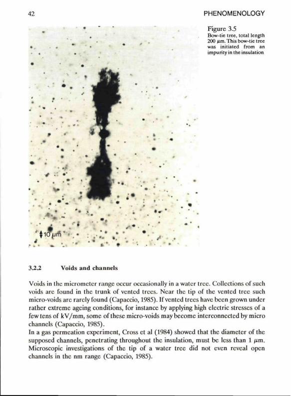
A collcction of typical bow-tie trees in the cross-linked polycthylcnc insulation of a 10 kV cable is given in Figure 3.4. A further cnlargcment of one of these bow-tie trees is presented in Figure 3.5. Nole that in Figure 3.5 a shcll around the initiation spot with a thickness of about 2 nm has also been made visiblc using the dyeing procedure. A possible explanation will bc given in Chapter 6.5.3.
Figurc 3.4 Typical bow-lic trees grown in the insulation of a 10 kV cross-linked polyethylene cable
42 PHENOMENOLOGY
Figure 3.5 Bow-tie tree, total lcngth 200 /im.This bow-tie tree was initiated from an impurity in the insulation
»
■4 4 - •'
• ■ * ■ • ,
• • . • » *
3.2.2 Voids and channels
Voids in the micrometer range occur occasionally in a water tree. Collcctions of such voids are found in the trunk of vented trees. Near the tip of the vented tree such micro-voids are rarcly found (Capaccio, 1985). If vented trees have been grown undcr rather extreme agcing conditions, for instance by applying high clcctric stresses of a few tens of k V/mm, somc of these micro-voids may bccomc interconnected by micro channels (Capaccio, 1985). In a gas permcation experiment, Cross et al (1984) showcd that the diameter of the supposed channels, penctrating throughout the insulation, must bc less than 1 ^m. Microscopic investigations of the tip of a water tree did nol even reveal open channels in the nm range (Capaccio, 1985).
WATER TREEING CHAPTER 3 43
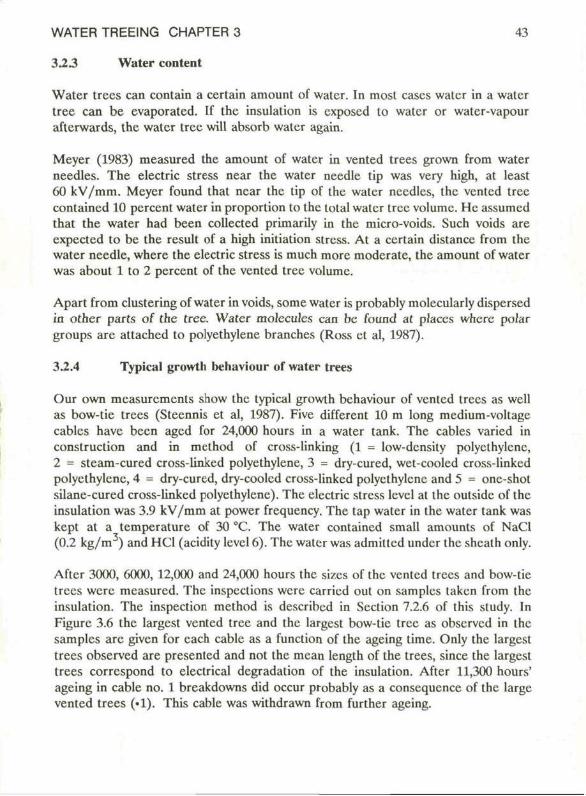
3 2 3 Water content
Water trees can contain a certain amount of water. In most cases water in a water tree can be evaporated. If the insulation is cxposcd to water or water-vapour afterwards, the water tree will absorb water again.
Meyer (1983) measured the amount of water in vented trees grown from water needies. The electric stress near the water needie tip was very high, at least 60 kV/mm. Meycr found that near the tip of the water nccdlcs, the vented tree containcd 10 percent water in proportion to the total water Ircc volume. He assumed that the water had been collected primarily in the micro-voids. Such voids are expected to be the result of a high initiation stress. At a ccrtain distancc from ihc water needie, where the electric stress is much more moderate, the amount of water was about 1 to 2 percent of the vented tree volume.
Apart from clustering of water in voids, some water is probably molecularly dispersed in other parts of the tree. Water molcculcs can bc found at places where polar groups are attached to polyethylene branches (Ross et al, 1987).
32.4 Typical growth behaviour of water trees
Our own measurements show the typical growth behaviour of vented trees as wcll as bow-tie trees (Steennis et al, 1987). Five different 10 m long medium-voltage cables have been aged for 24,000 hours in a water tank. The cables varied in construction and in method of cross-linking (1 = low-density polyethylene, 2 = steam-cured cross-linked polyethylene, 3 = dry-cured, wet-cooled cross-linked polyethylene, 4 = dry-curcd, dry-coolcd cross-linked polyethylene and 5 = one-shot silane-cured cross-linked polyethylene). The electric stress lcvcl at the outsidc of the insulation was 3.9 kV/mm at power frequency. The tap water in the water tank was kept at a temperature of 30 °C. The water contained small amounts of NaCl (0.2 kg/m ) and HC1 (acidily levcl 6). The water was admitlcd undcr the shcath only.
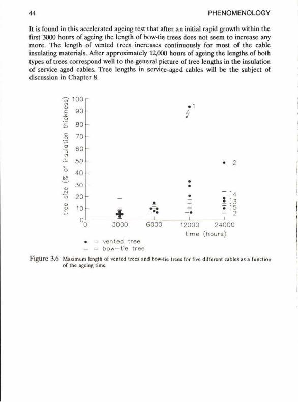
Aftcr 3000, 6000, 12,000 and 24,000 hours the sizes of the vented trees and bow-tie trees wcre measured. The inspections wcre carricd out on samples taken from the insulation. The inspection method is described in Section 7.2.6 of this study. In Figure 3.6 the largest vented tree and the largest bow-tie tree as observed in the samples are given for each cable as a function of the ageing time. Only the largest trees observed are presented and not the mean length of the trees, since the largest trees correspond to electrical degradation of the insulation. After 11,300 hours' ageing in cable no. 1 breakdowns did occur probably as a conscqucnce of the large vented trees (•!). This cable was withdrawn from further ageing.
44 PHENOMENOLOGY
It is found in this acceleratcd agcing test that after an initial rapid growth within the first 3000 hours of agcing the length of bow-tie trees does not seem to increase any more. The length of vented trees increases continuously for most of the cable insulating materials. After approximately 12,000 hours of agcing the lengths of both types of trees correspond well to the general picture of tree lengths in the insulation of service-aged cabics. Tree lengths in service-agcd cabics will bc the subject of discussion in Chapter 8.
V 100 <o c 90 o £ 80
§ 70 U-* | 60 o •5 50 •«_ ° 40 fc? ^ 30 <D N "5 20 <p <u 1 0 i_ v
0 (
r
-
-
-
-
•1 ) 3000
- • • i
6000
• 1
t
• • •
—• i
12000
• 2
~ l 4
ï 15 - 2 i
24000 time (hours)
• = vented tree — = bow-tie tree
F i g u r e 3.6 Maximum length of vented trees and bow-tje trees for fivc different cabics as a function of the agcing time
WATER TREEING CHAPTER 3 45
3 3 Dielectrical properties (local)
33.1 Definitions
Before starting the discussion of dielectrical properties, definitions should bc given of "vented tree" and "vented tree path".
The "vented tree" represcnts the total area within which the tree can bc obscrved (/im to mm scalc), using the dyeing procedure described in Appendix 1.
The "vented tree path" or "path" rclates to the attackcd polyethylenc only (the nm scale).
The ratio of the volume of the vcntcd tree paths to the vented tree certainly is much smaller than 100 %, howcver, an upper limit cannot be given.
332 The vented tree: an insulating material
Therc are scveral indications that bolh the vented tree and the vented tree paths can be considcred as an insulating material.
Koo et al (1983) and Cross et al (1984) studied the dielectrical properties of a vented tree in a water needlc experiment. The change in capacitance between the water needie and the opposite electrode was mcasured during the growth of the vented tree at a frequency of 1500 Hz. The capacitance variations were derived from a voltage change in a resistor placed in series with the electrode. Afterwards, in a model, the vented tree was rcplaccd by metal or by dielcctrics with different permittivities. The rcsulting capacitance variations showed that the dielectrical behaviour of a real vented tree differs strongly from that of a conductor. Moreover, it was found that comparable voltage variations in this model could bc obtained if the water tree was replaced by an actual material with a diclectric constant of about 6. To explain the measurcd diclectric constant, Cross assumed that water was collccted in the many micro-voids distributed over the vented tree volume. Cross pointed out that in such a situation the observed inercase in the dielectric constant of the vented tree volume might be explaincd by using the multiphase dielectric mixture theory (e.g. Tinga, 1973).
Boggs et al (1986) studied the micro-movement of vented trees in a water needie experiment. The trees were grown in silicone rubber at different frequencies. Tree movement has been observed by applying interferometrie holography. Boggs found that the movement of the trees was related to E and therefore probably related to Maxwell stresses. He also concludcd that certain out-of-phase movcments of the tree
46 PHENOMENOLOGY
in rclation lo ihe movement of the needie tip would provide cvidcncc that the vented tree is not conductive.
Recently Ross et al (to be published, preliminary results) measurcd the dielectrical properties of a vented tree which had been grown under normal ageing condilions in a full-scale cross-linkcd polycthylcnc insulated cable. The dieleclric constant and loss-factor were measured on slices wilh a thickness of about 150 /im. The slices were saturaled with water preceding lo the mcasurcmcnts. The vcntcd tree penetrated the slices complctely. He found that the vcntcd tree has the properties of an insulaling material with a dieleclric constant of 2.26 and a loss-factor of about 2010_ i at 50 Hz.
There are more observations confirming that a vcntcd tree is an insulating material:
Breakdown characteristics
If a vcntcd tree path were a conductor, then such a path, grown through to the othcr sidc of the insulation, would initiale thermal breakdown or initiale an clectrical tree followcd by breakdown. However, it was found that in most cases such long vcntcd Irces do not cause breakdown al stresses of 2 kV/mm or even highcr (sec Seclion 3.5, Figurc 3.8).
In an experiment by Densley (1974) clectrical trees were iniliated in vcnlcd trees by inserting a ncedlc. It was found thal ihc vcnlcd Irccs did not provide a more convenient path to ihc clectrical Irccs or the breakdown channcls than unaffected polycthylcnc.
Direction of vented tree propagalion
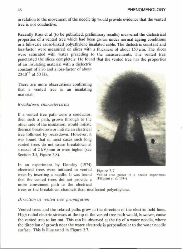
Vcntcd trees and the rclated paths grow in the direction of the clcctric field lines. High radial clcctric stresses at the tip of the vcntcd tree path would, however, cause the vcntcd tree to fan out. This can be observcd at the lip of a water needie, where the direction of growth ncar the water electrode is perpendicular to the water ncedlc surfacc. This is illuslratcd in Figurc 3.7.
Figurc 3.7 Vcntcd tree grown in ( l ï l ipp in i et al, 1984)
a ncedlc experiment
WATER TREEING CHAPTER 3 •17
In Appendix 2 various electric stresscs near the tree tip are calculated for different vented tree tip radii. The electric stresscs have been calculated for a range of diclcctric constants and conductivilies of the vented tree path. High radial electric stresses of 30 % of the axial electric stress at the tip of the vented tree path (E p d /E t = 0.3) can bc expected for vented tree paths with a dielectric constant of20 or higher, or a conductivity of 2.5-10"8 (firn)-1 or highcr. In such a situation it is expected that the tree would fan out. It is also shown in Appendix 2.II that for a dielectric constant of less than 10 and a conductivity of less than 1.310 (flm)" this ratio E d / E p t is small. In that case vented tree growth can be expected mainly in the direction of the axial electric stress at the tree tip. This conforms with the phenomenology where it is found that the direction of propagation of vented trees is mainly determined by the local electric field lines of the original unaffected polyethylene.
It appears that for moderate permittivities and conductivitics the electric stresses become independent of the length of the vented tree path: the influence is confïned to a local area. This is illuslrated in Appendix 2.III, where the electric stress is shown in the axial direction along the axis of symmetry through the tree path bctween the electrodes.
3 3 3 Conclusion
The vented tree and the vented tree paths may be considered as insulating materials. The electric stress enhanecment near the tip of a vented tree or a vented tree path is moderate or possibly even minutc.
For the complete vented tree a diclcctric constant ranging from 2.3 to 6 and a loss-factor of 2010 - 4 at 50 Hz was found. These values are higher than for the unaffected polyethylene having a dielectric constant of 2.26 and a loss-factor of approximately 410 . The slight increase of the diclcctric constant and loss-factor is in all probability caused by the clustering of water in voids.
Accurate values for the dielectrical properties of the distinct paths of the vented tree cannot be given. Howevcr, moderate stress enhanecment al the tip of a path can be expected for a dielectric constant smaller than about 10 and a conductivity smaller than about 1.310" (firn)" . Such dielectrical properties are in line with the assumption that water in these regions is molecularly dispersed.
4S PHENOMENOLOGY
3.4 Physical/Chemical properties (local)
Introduction
This Scction discusses chemical and physical obscrvations in a water tree compared to observations outside a water tree. Studies are mainly carricd out on vented trees from nccdle tests; sometimes scratchcd insulalion slabs or full-scale cables have been uscd.
Infra-red
Infra-red mcasurcmcnts have been carried out by sevcral authors.
Bernstein et al (1975) pcrformed measurements on miniaturc cables aged for 60 days at 4.6 kHz. After drying the samples, mctal ions from the solution were detectcd at 1130 cm"'.
Garton et al (1980) tricd to find cvidcncc for oxidation in a water tree with FTIR. The insulation of miniaturc cable has been studied, aged at a moderate clcctric stress level at 1 kHz for 320 hours at 70 °C. Garton was not able to find a typical oxidation product such as carbonyl. However, he did found absorptions al 600, 1100, 1160,3550 and 3600 cm assigncd to ether and alcohol groups.
Abdolall et al (1982) were able to distinguish differenecs bctwccn affected and unaffected polycthylcne in a range bctwccn 20 and 350 cm"1 at a tempcrature of 4.2 K. Samples were taken from a full-scalc cross-linkcd polycthylcne insulated cablc The differenecs were attributcd to various possiblc effects such as hydrogen bonding. strain or inhomogencous broadening, brcakage of polymcr chains or effects duc t> cross-linking residual producls.
Differenecs in a range bctwccn 500 and 2000 cm have been found by Yoshimitsu et al (1983-b) with FTIR. These invcstigalors studied cross-linkcd polyethylent malcrial with an imbedded copper wirc aged for up to 10 days at 1 kHz. Thcy found that in the tree affected regions the CH2 groups losc thcir absorbancc, bul chemical species such as hydroxyl groups and carbonyl groups gain strength compared with the undegraded arca.
Bamji et al (1984) also cxamined regions with and without water trees using FTIR Different kinds of test specimen were studied. Absorption was found at 1160 (and 600) cm" . Bamji did not atlribute these absorplions to ether groups (Garton et al, 1980) but lo sulphatc anions. The absorptions at 1600 cm"1 are consistent with the
WATER TREEING CHAPTER 3 49
prescncc of carboxylate anions. Also in this particular experiment the absence of carbonyl absorption is noticcable.
Recently Garton et al (1987) found traces of oxidation. Trees have been taken from service-aged steam-cured cross-linked polycthylcnc insulatcd cablcs. The diffcrcncc in the carbonyl concentrations at 1720 cm" was about 15 % of the overall level of oxidation in the insulation. The results have been confirmcd by oxidalivc stability tests where it was found that the tree affectcd arcas werc much less stablc ihan the arcas not affectcd by water trees.
Ross et al (1988) were also able to observe traces of oxidation in the ventcd trees of an accelerated-aged cross-linked polyethylene cable insulation. The cable was aged for 24,000 hours, the mean electric stress applied during ageing was approximately 4 kV/mm, the voltage frequency during ageing was 50 Hz. Differences between the material inside and outside vented trees were found at 1150 cm , 1710 cm" and 1720 cm and assigned to hydroxyl groups and carbonyl groups rcspcclivcly.
Electron Spin Resonance
Electron Spin Resonance was applied by Dorlannc et al (1980) and Crichton et al (1983). They studicd low-density polycthylcnc samples from water needie experiments as well as cross-linked polyethylene samples from full-scalc cablcs. All samples were aged for up to 90 days at frequency levels of up to 4 kHz. Both investigators detected metal ions from the solution in the water trees, even beyond the visible part of the water tree (Crichton).
Differential Scanning Calorimetry
Diffcrcnlial Scanning Calorimetry was applied by Bamji et al (1984). Trees have been studicd in samples taken from scrvicc-agcd cross-linked polyethylene insulatcd cable. It was not possible to find a difference in melting endotherms between regions containing water trees and regions without these trees. This indicatcs that heating during or aftcr water tree growth is of minor importance.
X-ray analyses
Sletbak et al (1977) detected metal ions and sulphur in the branches of strongly coloured bow-tie trees. These elements could also bc detected as a fraction of the impuritics locatcd at the initiation site. The bow-tie trees were grown in a cross-linked polycthylcnc slab for up to 790 hours at a frequency level of 50 Hz.
50 PHENOMENOLOGY
Bamji et al (1984) detectcd mctal ions in a vented tree using X-ray techniques. The vented trees were taken from a full-scale cross-linked polyethylene insulated cable, aged under service conditions.
DC Are measurements
DC Are measurements, performed by Bamji cl al (1984), again show mctal ions in vented trees. Moreovcr, Garton et al (1987) clearly demonstrated the existence of apprcciablc amounts of sodium, calcium, aluminium and silicon in the tree affected regions of the insulation of scrvicc-agcd cross-linked polyethylene insulated cablcs.
Heat-lreatment
Muller et al (1985) carried out some unusual experiments with low-density polyethylene sliecs in which vented trees were present. In an initial experiment slices were hcated for 160 hours at 135 °C and 20 hours at 190 °C. In both cases il was found that the optical structure of the water tree was unchangcd. Even after rccrystallisation of the matcrial by cooling the mclt the structure was not changcd. Chcmical changes in a water tree are assumcd, stabili/.ing the structure. In a second experiment untreated slices were dissolved in xylol. It appcarcd that not only the polyethylene but also the water trees thcmselvcs had been complctely dissolved. This experiment shows that the chemical changes assumcd abovc do not rcsult in cross-linking of the tree affected material.
Staining
Abdolall cl al (1982) coloured (most probably) vented trees from a full-scale cross-linked polyethylene insulated cable after drying of the insulation for 12 hours at 95 °C. For the staining experiment many different solvcnts were uscd. The rcvisibility rcsults show that, with a few exceptions, only solvcnts with an OH-group at the end of a molecule made the trees strongly visiblc again, only after a few days.
Conclusion
It can bc concludcd that most of the chcmical or physical detection methods reveal a certain changc of the composition and propertics of the polyethylene in the tree affected matcrial. These changes probably can bc attributed to oxidation of polyethylene. Various species from outside the polyethylene have been found in the trees, such as mctal ions or salts from the solution.
WATER TREEING CHAPTER 3 51
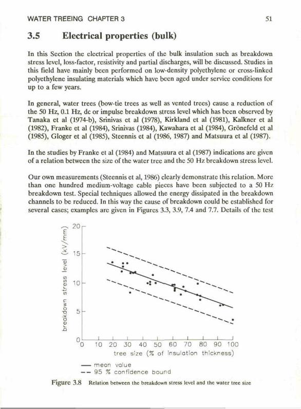
3.5 Electrical properties (bulk)
In this Section the electrical properties of the bulk insulation such as breakdown stress lcvcl, loss-factor, resistivity and partial discharges, will be discussed. Studies in this field have mainly been performed on low-density polyethylenc or cross-linkcd polyethylene insulating materials which have been aged under service conditions for up to a few years.
In genera!, water trees (bow-tie trees as well as vented trees) cause a reduction of the 50 Hz, 0.1 Hz, de or impulse breakdown stress level which has been observcd by Tanaka et al (1974-b), Srinivas et al (1978), Kirkland et al (1981), Kalkner et al (1982), Franke et al (1984), Srinivas (1984), Kawahara et al (1984), Grönefeld et al (1985), Gloger et al (1985), Steennis et al (1986, 1987) and Matsuura et al (1987).
In the studies by Franke et al (1984) and Matsuura et al (1987) indications are givcn of a relation between the si/c of the water tree and the 50 Hz breakdown stress level.
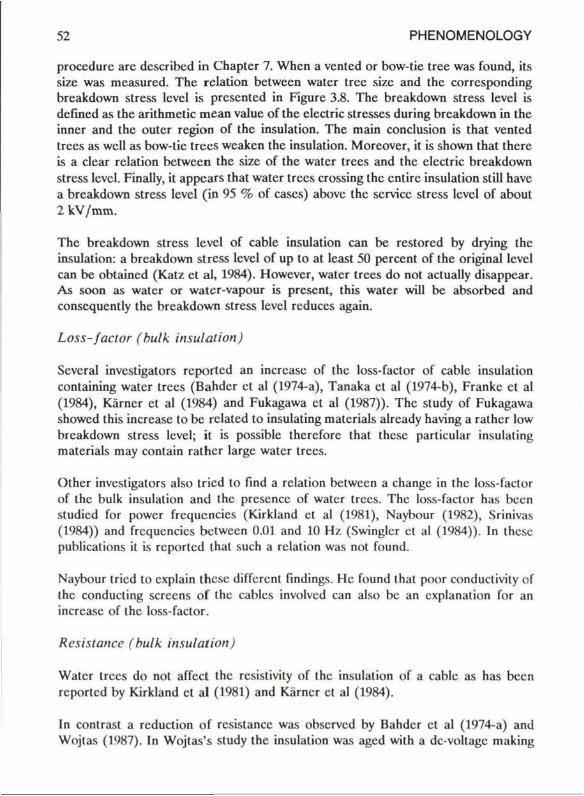
Our own measurements (Steennis et al, 1986) clearly demonstrate this relation. More than onc hundred medium-voltage cable pieces have been subjected to a 50 Hz breakdown test. Special techniques allowed the energy dissipated in the breakdown channels to be reduced. In this way the cause of breakdown could bc cstablishcd for several cases; cxamplcs are givcn in Figurcs 3.3, 3.9, 7.4 and 7.7. Details of the test
E i >
> 91 co m
c S o
ü o
20 r
' 5
10 -
__ j _ i
0 10 20 30 40 50 60 70 80 90 100 tree size (% of insulotion thickness)
mean value 95 % confidence bound
FigUre 3.8 Relation bclween Ihc breakdown stress level and the water tree size
52 PHENOMENOLOGY
procedure are describcd in Chapter 7. Whcn a vented or bow-tie tree was found, its size was measured. The relation between water tree size and the corresponding breakdown stress lcvcl is presented in Figure 3.8. The breakdown stress level is defined as the arithmetic mean value of the electric stresses during breakdown in the inner and the outer region of the insulation. The main conclusion is that vented trees as wcll as bow-tie trees wcaken the insulation. Moreover, it is shown that there is a clear relation between the size of the water trees and the electric breakdown stress level. Finally, it appears that water trees crossing the entire insulation still have a breakdown stress level (in 95 % of cases) above the service stress level of about 2 W / m m .
The breakdown stress level of cable insulation can be restored by drying the insulation: a breakdown stress lcvcl of up to at least 50 percent of the original level can be obtaincd (Katz et al, 1984). However, water trees do not actually disappear. As soon as water or watcr-vapour is present, this water will be absorbed and conscquently the breakdown stress level reduces again.
Loss-factor (bulk insulation)
Scveral investigators reportcd an increase of the loss-factor of cable insulation containing water trees (Bahder et al (1974-a), Tanaka et al (1974-b), Franke et al (1984), Karner et al (1984) and Fukagawa et al (1987)). The study of Fukagawa showed this increase to be related to insulating matcrials alrcady having a rathcr low breakdown stress level; it is possiblc therefore that these parlicular insulating materials may contain rathcr largc water trees.
Other investigators also tricd to find a relation between a change in the loss-factor of the bulk insulation and the prcscncc of water trees. The loss-factor has been studicd for power frequencies (Kirkland et al (1981), Naybour (1982), Srinivas (1984)) and frequencies between 0.01 and 10 Hz (Swinglcr cl al (1984)). In these publications it is reportcd that such a relation was not found.
Naybour tricd to cxplain these different findings. He found that poor conductivity of the conducting sereens of the cablcs involved can also bc an cxplanation for an increase of the loss-factor.
Resistance (bulk insulation)
Water trees do not affect the resistivity of the insulation of a cable as has been reportcd by Kirkland et al (1981) and Karner et al (1984).
In contrast a rcduction of resistance was observed by Bahder et al (1974-a) and Wojlas (1987). In Wojtas's study the insulation was aged with a dc-voltage making
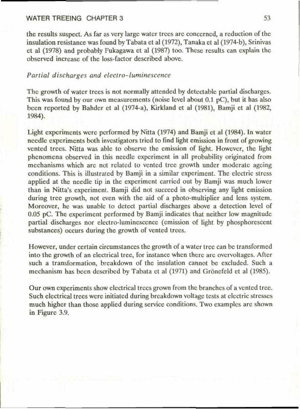
WATER TREEING CHAPTER 3 53
the results suspect. As far as very large water trees are concerned, a reduction of the insulation resistance was found by Tabata et al (1972), Tanaka et al (1974-b), Srinivas et al (1978) and probably Fukagawa et al (1987) too. These results can cxplain the observed increase of the loss-factor described above.
Partial discharges and eleclro-luminescence
The growth of water trees is not normally attended by detectable partial discharges. This was found by our own measurements (noise level about 0.1 pC), but it has also been reported by Bahder et al (1974-a), Kirkland et al (1981), Bamji et al (1982, 1984).
Light experiments were performed by Nitta (1974) and Bamji et al (1984). In water needie experiments both investigators tried to find light emission in front of growing vented trees. Nitta was able to observe the emission of light. Howcvcr, the light phenomena observed in this needie experiment in all probability originated from mechanisms which are not rclatcd to vented tree growth under moderate ageing conditions. This is illustrated by Bamji in a similar experiment. The electric stress applied at the needie tip in the experiment carricd out by Bamji was much lower than in Nitta's experiment. Bamji did not succeed in observing any light emission during tree growth, not even with the aid of a photo-multiplier and lens systcm. Moreover, he was unabic to detect partial discharges above a detection level of 0.05 pC. The experiment performed by Bamji indicates that neither low magnitude partial discharges nor electro-lumincscence (emission of light by phosphorescent substances) occurs during the growth of vented trees.
However, under certain circumstances the growth of a water tree can be transformed into the growth of an electrical tree, for instance when there are ovcrvoltages. Aftcr such a transformation, breakdown of the insulation cannot be excluded. Such a mechanism has been described by Tabata el al (1971) and Grönefeld et al (1985).
Our own experiments show electrical trees grown from the branches of a vented tree. Such electrical trees were initiated during breakdown voltage tests at electric stresses much higher than those applied during service conditions. Two examplcs are shown in Figure 3.9.
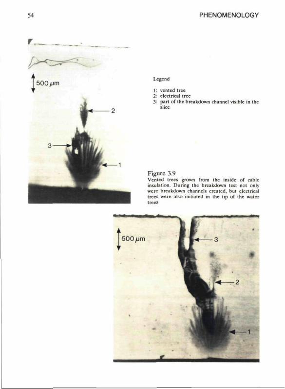
54 PHENOMENOLOGY
Legend
venled tree eleclrical tree part of the breakdown channel visible in the slice
Figurc 3.9 Vented trees grown from the inside of cablc insulation. During the breakdown test not only were breakdown channels crcatcd, but clcctrical trees were also iniliatcd in the tip of the water trees
500/Lim
| •
" ■
*
T*—3
t • • ^ M — 2
kl^l n k
w*—1
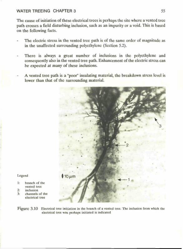
WATER TREEING CHAPTER 3 55
The cause of initiation of these elcctrical trees is pcrhaps the site wherc a vcnted tree path crosses a field disturbing inclusion, such as an impurity or a void. This is based on the following facts.
The electric stress in the vented tree path is of the same order of magnitude as in the unaffected surrounding polyethylcnc (Scction 5.2).
There is always a great number of inclusions in the polycthylene and consequently also in the vented tree path. Enhancement of the electric stress can be expected at many of these inclusions.
A vented tree path is a "poor" insulating material, the breakdown stress levcl is lower than that of the surrounding material.
legend
1:
2: 3:
braneh of the vented tree inclusion channels of the elcctrical tree
F i g u r e 3.10 Eleclrical tree initiation in the braneh of a vcnted tree. The inclusion from which the elcctrical tree was pcrhaps initiatcd is indicatcd
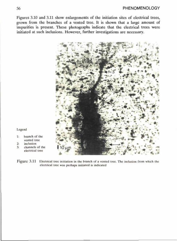
56 PHENOMENOLOGY
Figurcs 3.10 and 3.11 show enlargements of the initiation sites of electrical trees, grown from the branches of a vented tree. It is shown that a large amount of impurities is present. These photographs indicatc that the electrical trees were initiated at such inclusions. Howevcr, further investigations are necessary.
I.cgcnd
1: branch o f i h c ven led tree
2: inclusion 3: channcls of Ihc
electrical tree
»W - . ■ '
h > . < <
L#- *
*»*» • - i r . • * • . ^ t t »
F i g u r c 3.11 li lcctrical (ree init iation in the branch of a vented tree. The inclusion from which the electrical tree was perhaps initiated is indicatcd
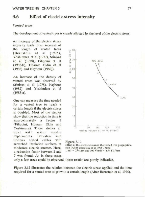
WATER TREEING CHAPTER 3 59
3.6 Effect of electric stress intensity
Vented trees
The dcvelopmcnt of vented trees is clcarly affected by the lcvel of the electric slrcss.
An increase of the electric stress intensity leads to an increase of the length of vented trees (Bcrns te in et al (1975), Yoshimura et al (1977), Srinivas et al (1978), Filippini et al (1982-b), Hossam Eldin et al (1982) and Naybour (1982)).
.- 80 E
'0
s.6 0
50
40
30
20
10
An increase of the density of vented trees was observed by Srinivas et al (1978), Naybour (1982) and Yoshimitsu et al (1983-a).
One can mcasurc the time needed for a vented tree to reach a certain length if the electric stress is doubled. Most of the studies show that the reduction in time is approximately a factor 2 (Filippini, Hossam Eldin and Yoshimura). These studies all deal with water needie experiments. Bcrnstein and Srinivas tcsted cables with scratched insulation surfaces at moderate electric stresses. Herc, a reduction factor between 2 and 7 was found. As in these cases only a few trees could be observed, these rcsults are purely indicativc.
XLPE
50 85 ooplied voltage at
125 170 /O "C (V/mil)
Figure 3.12 liffect of the elcclric stress on the vented tree propagation rate (After Bernstcin et al, 1975). Notc: 1 mil = 25.4 (im and 100 V/mil = 3.94 kV/mm
Figure 3.12 illustrates the rclation bctween the electric stress applicd and the time required for a vented tree to grow to a certain length (After Bernstcin et al, 1975).

58 PHENOMENOLOGY
Bow-lie trees
Thcrc are conflicting results concerning the rclation between the propagation rate of bow-tic trees and the eicctric stress intensity. Enhancement of the electric stress was found to increase the rate of propagation in experiments carricd out by Buünski et al (1981) and Yoshimura et al (1982). The reverse effect was observed by Sletbak et al (1977).
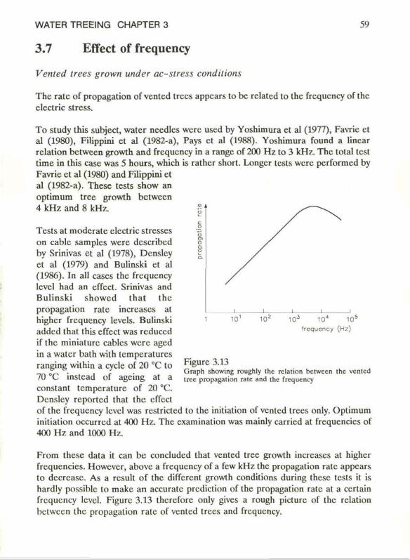
WATER TREEING CHARTER 3 59
3.7 Effect of frequency
Vented trees grown under ac-stress conditions
The rate of propagation of vented trees appears to be related to the frequency of the clectric stress.
To study this subject, water needics were used by Yoshimura et al (1977), Favric et al (1980), Filippini et al (1982-a), Pays et al (1988). Yoshimura found a linear relation between growth and frequency in a range of 200 Hz to 3 kHz. The total test time in this case was 5 hours, which is rather short. Longcr tests were performed by Favrie et al (1980) and Filippini et al (1982-a). These tests show an optimum tree growth between 4 kHz and 8 kHz.
Tests at moderate electric stresses on cablc samples were describcd by Srinivas et al (1978), Dcnsley et al (1979) and Bulinski et al (1986). In all cases the frequency level had an effect. Srinivas and Bulinski showed that the propagation rate inercases at highcr frequency levels. Bulinski added that this effect was rcduccd if the miniaturc cables were aged in a water bath with temperatures ranging within a cycle of 20 °C to 70 °C instcad of ageing at a constant temperature of 20 CC. Dcnsley reported that the effect of the frequency lcvcl was restricted to the initiation of vented trees only. Optimum initialion occurrcd at 400 Hz. The examination was mainly carried at frequencics of 400 Hz and 1000 Hz.
From these data it can be concluded that vented tree growth inercases at higher frcquencies. However, abovc a frequency of a few kHz the propagation rate appears to deercase. As a rcsult of the different growth conditions during these tests it is hardly possible to make an accurate prediction of the propagation rate at a certain frequency lcvcl. Figure 3.13 therefore only gives a rough picture of the relation between the propagation rate of vented trees and frequency.
10 10* 10 J 10* 10q
frequency (Hz)
Figure 3.13 Graph showing roughly the relation between the vented tree propagation rate and the frequency
60 PHENOMENOLOGY
Bow-lie trees grown under ac-stress condilions
Bow-tie tree growth in different types of polyethylene was studicd by Bahder et al (1974-b), Sletbak et al (1977) and Yoshimura et al (1982). Bahder used miniature cablcs and Sletbak full-scale cables; in the experiment carricd out by Yoshimura a blunt ncedle has been applied. The electric stress in all experiments was moderate. At higher frequencics accclcration of initiation and growth was found. An optimum frequency was not givcn.
Water trees grown under simullaneous application of ac-stress and dc-stress
Pays et al (1988) studied the tree propagation rate in a frequency range of approximatcly 20 Hz to 10 kHz. In this experiment water treeing was studied under ac-stress as wcll as undcr simultaneous ac-stress and dc-strcss condilions. The results of ac-stress plus dc-strcss were the same as if only ac-stress had been applied. The type of water trees found in these experiments has not been describcd. However, in gencral these results confirm the results presentcd by othcr investigators: in this frequency range an inercase of the propagation rate is found at inercasing frequency. Different types of polyethylene were studied. The agcing time of this experiment was not givcn.
Water trees grown under dc-stress condilions
If the results describcd abovc for moderate electric stresses are extrapolatcd to very low frequencics, hardly any tree growth is to be expectcd. This is confirmcd in litcraturc. Water tree growth at dc-voltagcs has been studied by Franke et al (1977), Yamada et al (1979) and Pays et al (1988). The results were obtaincd from tests on miniature low-density polyethylene insulatcd cablcs (Franke et al, 1977) or full-scalc cross-linkcd polyethylene insulatcd cables (Yamada et al, 1979) under the application of high electric stresses. Pays et al (1988) studicd trees in low-density polyethylene plates and vented trees in a needie experiment. The electric stresses varied from 10 to 100 kV/mm for the cablc and platc experiments. In the needie test the electric stresses were much higher than thal.
The shape of water trees grown undcr dc-stress condilions differs from ihat of common water trees grown under ac-stress condilions. Il was reported that water trees grown under the application of a dc-strcss have a remarkably narrow struclure, whilc venled Irccs as well as bow-tie trees only grow in onc direction. Consequcnlly Ihe bow-tie trees have only onc plume. Franke observed that during the growth of ihe water trees undcr the application of a dc-strcss the ncgativc coppcr clectrodc becamc black. It is assumcd that this is an indication of the presence of an clcctrochemical proecss. Pays did not find any tree growth, with onc cxceplion: in the platc experiment once a tree-like structurc was observed.

WATER TREEING CHAPTER 3 oi
There are reasons to suspect results of tests with dc-stresses: very high electric strcsscs have been applicd in order to initiate and grow these trees the shape of the trees is different from that of water trees grown under ac-stress conditions.
Perhaps there are different mechanisms of (initiation and) growth for trees grown under the application of high dc-stresses and those trees grown under the applicalion of ac-stresses.
62 PHENOMENOLOGY
3.8 Effect of temperature
Vented treeing at constant temperature level
Scveral publicalions discuss vented tree growth at constant temperature levels, without a temperature gradiënt over the insulation. Most of the tests were carried out in water baths on low-density polycthylene or cross-linked polycthylene insulation. The test models applied are nccdie samples by Fournié et al (1978), sandwich models with inserted wire by Yoshimitsu et al (1983-a, 1983-b) or more or less full-scale cablcs by Tabata et al (1972) and Srinivas et al (1978). From these studies it can bc concluded thal the density of vented trees increases and the length of vented trees decreases if the temperature of the insulation is increased to abovc about 50 °C. Bctwccn 20 °C and 50 °C there are conflicting views. Excluding the results of the nccdie tests (Fournié et al, 1978), the most favourable temperature range for water tree growth seems to bc 30 °C to 50 °C (Tabata et al, 1972 and Srinivas et al, 1978).
Venled treeing at cycling temperalures
Slctbak et al (1983), Bulinski cl al (1986) and Marsh et al (1987) studicd ihc effcel of cycling the tcmperalurc of ihe conduclor and ihe oulcr screen. In most cases ihcrc was a tcmperalurc gradiënt over the insulation during Ihe experiment. Slclbak and Marsh uscd full-scale cablc and Bulinski minialurc cablcs. The duration of the different tests was al least a few hundred hours. The outlincs of ihe different experimenls are summarized in Table 3.1.
In general, onc can concludc from ihese experimenls thal ihe growlh of venled trees from the oulcr screen is hardly affccled by these varialions in test condilions. Wiih respect lo the density of these trees, Bulinski remarked thal temperature cycles rcduccd il strongly.
Bow-tie trees
The developmcnt of bow-lie Irees has been sludied by Naybour (1979), Slclbak cl al (1983), Bulinski cl al (1986), Frcdrich et al (1987) and Marsh cl al (1987).
Frcdrich showed ihat bow-lie tree growth is enhanccd at highcr (empcratures. In his experiment the lemperalure of the water outside the insulation of the full-scale cablc was fixcd at 40 °C or 90 °C or varicd within cycles of 5 °C to 90 °C. The conductor containcd water, bul was unheated. In this particular study ihe water at high
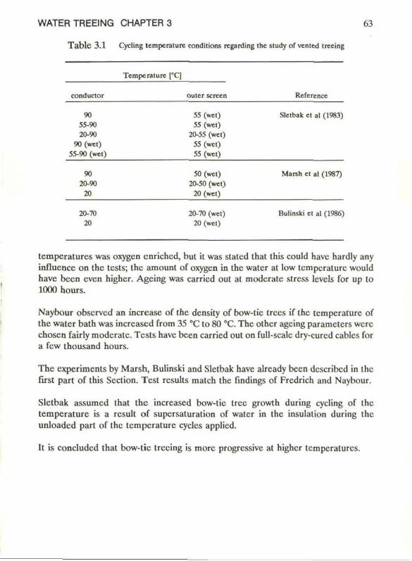
WATER TREEING CHAPTER 3 63
Table 3.1 Cycling lemperature conditions regarding the study of venled trecing
conductor
90 55-90 20-90
90 (wet) 55-90 (wel)
90 20-90
20
20-70 20
Tempcralurc ra outcr screen
55 (wet) 55 (wet)
20-55 (wet) S5 (wet) 55 (wet)
50 (wet) 20-50 (wet)
20 (wet)
20-70 (wet) 20 (wet)
Reference
Sletbak et al (1983)
Marsh et al (1987)
Bulinski et al (1986)
temperatures was oxygen enrichcd, but it was stated that this could have hardly any influence on the tests; the amount of oxygen in the water at low tempcralurc would have been even higher. Ageing was carried out at moderate stress levels for up to 1000 hours.
Naybour observed an increase of the densily of bow-tic trees if the temperature of the water bath was increased from 35 °C to 80 °C. The other ageing parameters wcrc chosen fairly moderate. Tests have been carried out on full-scale dry-curcd cablcs for a few thousand hours.
The experiments by Marsh, Bulinski and Sletbak have already been dcscribcd in the first part of this Section. Test rcsults match the findings of Fredrich and Naybour.
Sletbak assumed that the increased bow-tic tree growth during cycling of the temperature is a result of supersaturation of water in the insulation during the unloadcd part of the temperature cycles applied.
It is concluded that bow-tie treeing is more progressive at higher temperatures.
64 PHENOMENOLOGY
3.9 Effect of mechanical stress
A mechanical stress can bc imposcd on an insulation. It can also bc present in the insulation after cooling from the cxtruded melt.
Tanaka et al (1974-a) studied the rciation bctwecn internal mechanical strcsses and water trecing. Slices were taken from scvcral full-scalc (cross-linked) low-density polyethylenc insulated cables aged in different ways. By counting the numbcr of isochromatic lines on a polarization photograph in a cross-scclion of the insulation, ihe mechanical stresses were cstimated. It was found by Tanaka that bow-tie trees and vented trees are concentrated in regions undcr higher mechanical stresses. Mechanical stresses between 1 to 8 MPa (10 to 80 bar) were observed in the insulation. This is high, but not destructivc as is shown in Section 2.2. Such mechanical stresses may rcsult from the production process or from cable installation.
Onc vear later Prigent et al (1975) found water trees in low-density polyethylenc samples concentrated at locations with high mechanical stresses. However, Prigent's cvaluation is purcly qualitativc.
More recently, results were published by Tu and Kao (1983). They exposed a polycthylene sample with a water needie to a pressuri/.ed atmospherc. The pressure on all sides of the sample was varied over a range between 0.1 and 3 MPa (1 to 30 bar). The test time was short, only 15 hours. Tu and Kao found that the inilialion was faster, but growth of the vented trees was slowcr if the pressure was increascd.
Il can be concludcd that thcre are only a few indications that water trecing is rclatcd to mechanical stresses. A widcly acceptcd measurement tcchnique for determining mechanical stresses in insulation is not yet availablc or applicable.
WATER TREEING CHAPTER 3 65
3.10 Effect of relative humidity
There are a few studies dealing with the subject of water treeing under different water-vapour conditions. Sletbak et al (1977, 1983) and Yoshimitsu et al (1983-a) showed that the relative humidity of the air surrounding the specimen and in the specimen is relevant to water treeing. Both found that water treeing becomes rare at a relative humidity of 65 % to 70 % or less. Above this level the density of bow-tie trees (Sletbak) or vented trees (Yoshimitsu) increases if the relativc humidity level is inercased. The studies do not give a relation bctween water tree length and relativc humidity. Also, the effect of liquid water around the specimen compared to water-vapour with a relative humidity of 100 % around the specimen has not been studied.
The experiments were carried out on cross-linked polyethylenc samples or cables with elcctric stresses ranging between 4 kV/mm and 20 kV/mm.
66 PHENOMENOLOGY
3.11 Effect of the chemical nature of the fluid
Non-watery solulions
Bahdcr et al (1974-b) studicd the growth of vented trees and bow-tie trees in normal cables with a low-density polyethylenc or cross-linkcd polyethylene insulation. The tests were carried out at a frequency level of 7.3 kHz and for a duration of 274 days. Fluids surrounding the insulation were water and water with C11SO4. Moreover, hostopal and cthylene glycol, bolh easily penctrating the polymers, were used. In all cases treeing in the insulation had the same appearance. From this it can bc concludcd that water treeing is probably a special case in a broader field of insulation degradation. Treeing has also been studicd in a liquid paraffin solution, which was chosen bccause of its extreme small dipolc moment. No trees could bc observed but it must bc mentioned that the test duration was only 12 days.
All othcr studies mentioncd below deal with water solutions. The following subjects will bc reviewcd: type of salts, salt quantity, elcctrode materials, acidity and solubility.
Type of salts
An indication that vented tree length is affected by the type of salts dissolvcd in the water is given by Bamji et al (1984). Bamji uscd cross-linkcd polyethylenc samples in which water needies were made. A C11SO4 solution produced the greatest tree growth, foliowed by a NaCl solution and finally by a CaClj solution. No trees were observed in distilled water. The test duration was 90 hours, the test frequency was 1 kHz.
Salt quantity
Many investigators studicd the growth of vented trees in rclation to the quantity of certain salt ions dissolvcd in water. The salt quantity can of course bc translatcd into the conductivity of the fluid. In most cases NaCl and CuSO^ solutions were applied. It was found that higher salt quantitics enhanecs the vented tree propagation ralc.
Most of these investigators used water nccdles in order to study vented trees: Ashcraft (1977-a, 1977-b), Yoshimura et al (1977), Filippini et al (1982-a, 1982-b), Hossam Eldin et al (1982). Test durations of up to 120 hours were uscd at frequencics of up to 20 kHz.
The effect was confirmed for vented trees in miniature or full-scale cables (Tabata el al (1972), Katz et al (1974) and Srinivas et al (1978)). Test durations in the related studies were much longcr, up to one year, while the frequency level was 50 Hz in the
WATER TREEING CHAPTER 3 (.7
study by Tabata et al (1972) or a few kHz in (Tabata et al, 1972) and (Katz et al, 1974).
Fournié et al (1978) found the opposite effect in a 50 Hz low-density polyethylcne needie test. Rye et al (1975) tried to cxplain Fournié's findings. They proposed that oxygen promotes vented tree growth; moreover, it is known that the solubility lcvcl of oxygen is lower in a very strong solution of salts. A combination of these facts could explain the reduced growth of vented trees.
Electrode material
Fournié cxamined the effect of the electrode material on vented tree growth. The fastest vented tree growth was found if Pt or Cu electrodes were used, followcd by Al and finally Fe and Pb. It is again suggested by Rye that the amount of oxygen in the fluid affects the growth of water trees. The amount of oxygen is lower with Fe or Pb electrodes, than when using Pt and Cu electrodes.
Acidily
The effect of the acidity level has been studied by Ashcraft (1977-a, 1977-b). A deercase in acidity level rcsulted in progressive vented tree growth. In this experiment a water nccdlc in polyethylene was used. The test duralion was 24 hours at a frequency level of 8.5 kHz.
Morita et al (1980) examined the density of vented trees for a great variety of solutions. Scratched low-density polyethylcne films were tested for 7 days at a frequency of 3 kHz. Morita could not find a relation between the density and the acidity lcvcl of the water. However, a slight relation between the density and the Standard entropy of hydrated ions was found.
Solubility
A relation between solubility and initiation of water trecing was found by Katz et al (1974). Vented trees have been studied, which start at the surface of scratched (cross-linkcd) low-density polyethylene cable insulation in a test with a duralion of 13 days at a frequency level of 7.8 kHz.
Conclusions
It seems to be clear that the amount of dissolved ions in water positivcly affects water tree growth and that the effect is related to individual ion types. Thcre are a few studies dealing with acidity, type of salts and solubility level of the salt. The results have not ycl been confirmed and are purely indicative.
68 PHENOMENOLOGY
Apart from the water, the semicondiicting sereens around the insulation normally contain high amounts of different impurities, as has been shown by Crine et al (1987). It might therefore be of interest to take the role of the semiconducting sereens into account.
WATER TREEING CHAPTER 3 69
3.12 Effect of insulating material and additives
Vented treeing in needie tests
The water tree susccptibility of different types of insulating material has often been studicd in water necdle cxpcriments. Studies wilh water needies in this spccific field have been carried out by Ashcraft (1977-a, 1977-b), Isshiki et al (1974), Kato et al (1974), Braun (1980), McMahon (1981) and Saure et al (1985).
Ashcraft examined the growth rate of trees at 8.5 kHz for 24 hours in polybutene, polystyrene, ethylcne propylene dicne terpolymer rubber (EPDM), low-density polycthylene and in cross-linked polyethylenc. Tree growth in polybutene was extreme. The slowest tree growth was found in frcshly cured cross-linkcd polycthylene. This was altributed to cross-link residual products (mainly acetophenonc). It was shown that acetophenone added to polyethylene is able to suppress water treeing in this material.
The retardant effect of cross-link residual products was confirmed by Saurc in a similar test, but at a frcqucncy of 50 Hz. It is remarkable that an antioxidant, used for the stabilization of polycthylene, in this test had the opposite effect. Saurc also found that silane-cured cross-linked polycthylene was less water tree susceptible than pcroxide-cured cross-linked polyethylenc, which matches the findings of Laar, van de (1982) and Kreuger et al (1983). Recently Dissado et al (1987) examined vented tree growth under moderate ageing conditions (6 kV/mm, 50 Hz, 30 °C) in silanc-cured and pcroxide-cured (degasscd) cross-linked polyethylenc slabs for a few thousand hours. In both matcrials vented trees with a comparable average length could be observcd. In the peroxidc-cured cross-linked polyethylenc, however, the scattcr was much higher. These rcsults give the impression that silane-cured polycthylene is less susceptible to vented tree devclopmcnt than peroxide-curcd polycthylene. However, none of the investigators tricd or were able to cxplain these findings.
Braun studicd the growth of vented trees in dry-cured cross-linkcd polyethylenc, steam-curcd cross-linked polyethylene, polystyrene and cpoxy resin at 60 Hz for 100 days. No treeing was observcd in cpoxy resin, the othcr materials showcd aboul cqual vented tree development. It cannot be concludcd that epoxy resin is water tree resistant: other investigators observed water tree development in this material too, for instance Yoshimitsu et al (1978).
Isshiki et al (1974) carried out research work which was mainly intended to find the electric stress level at which various materials initiale water trees. The rate of propagation was also studied. The total ageing time for this experiment was 12 days;
70 PHENOMENOLOGY
the frcqucncy of the electric stress was 2 kHz. It was found that the growth of vcnted trees is fastcr in soft materials:
the materials polyvinyl chloride, low-density polyethylcnc, cross-linked polyethylene, ethylene vinyl acetate copolymcr, high-density polyethylene and polypropylene all showed water trecing in the materials polystyrcne, polycarbonate and nylon a kind of vented treeing was only observed when high initiation stresses were used. In these cases the trees observed are suspect since othcr ageing mechanisms may have been inlroduced.
Kato et al (1974) suppressed the initiation of vcnted trees in vcry short term needlc tests on cross-linked polyethylene samples at 1.2 kHz. He uscd a mix of different additivcs: fcrroccnc, siloxane oligomcr and 8-hydroxy quinoline. The initiation resistancc observed was attributed to the combined action of a migration of these additives to irregularitics and a deactivation of electrons and metal ions through traps.
Another water tree inhibitant additivc was prescnted by McMahon (1981). This additive, dodccanol, has been tested with water needies at different frequencics in polyethylene samples for 28 days. Moreovcr, the additivc was uscd in full-scalc cablcs, lested for 220 days with a 90 °C conductor temperalure. It was found that the dodccanol concentration stabilizcs; this indicates that the water tree inhibiting effect observed might bc cffcctivc over longer pcriods.
Vented treeing in (model) cables
The dcvclopmenl of vcnted trees in cablcs or model cablcs has been studied by scvcral investigators: Katz et al (1974), Bahdcr et al (1974-b), Srinivas et al (1976, 1978), Henkcl et al (1981), Kalkner et al (1982), Marsh et al (1987) and Faremo (1987).
Bahdcr investigated the diffcrcncc in vcnted tree growth bctwecn low-density polyethylene and cross-linked polyethylene insulatcd cablcs. He found that low-density polyethylene insulatcd cablcs were more susccptiblc to vcnted trees than cross-linked polyethylcnc insulatcd cablcs. The investigations were carricd out on full-scalc cablcs agcd for 8 ycars undcr service conditions. The diffcrcncc observed can bc attributed, for instance, to the water tree rctardant effect of cross-link rcsidual products in the cross-linked polyethylcnc cable insulation.
Henkcl and Kalkner tested full-scalc low-density polyethylcnc and cross-linked polyethylcnc insulatcd cables for 250 days at 50 Hz. The cablcs were pre-conditioned, causing cvaporation of these rcsidual products. This evaporation rcsultcd in even
WATER TREEING CHAPTER 3 71
more progressive vented tree growth in the cross-linked polyethylcnc insulated cables than in the low-density polyethylcnc insulated cables.
Katz tested pre-conditioncd miniature cables with a scratchcd inner surfacc for 15 days at 7.8 kHz. He found only a small difference in the growth behaviour of vented trees in low-density polyethylene and cross-linkcd polyethylene insulated cables.
The effect of cross-link residual products is also confirmed by Srinivas. In his experiments, miniature low-density polyethylene and cross-linkcd polyethylene insulated cables with a scratched inner insulation surface were tested for 20 to 150 days at a frequency of a few kHz.
Faremo studied vented tree growth in cross-linked polyethylene and somc filled ethylene propylene rubbers. The materials were pre-conditioned prior to testing. The experiments were carried out under rather extreme temperature conditions and at high electric stresses on press mouldcd cups, including plastic semiconducling sereens. Faremo concluded that the growth rate of vented trees was about the same in the different materials. These results are all the more important since it has oftcn been suggested that water trees would not exist in ethylene propylene rubber.
Bow-tie trees
Bow-tie tree growth has been studied by Katz et al (1973), Yoshimitsu et al (1978), Kalkner et al (1982), Marsh et al (1987) and Faremo (1987).
Katz and Faremo did not find any difference in the growth of bow-tie trees between pre-conditioned low-density polyethylene and cross-linkcd polyethylene insulated cables (Katz) or between cross-linked polyethylene and ethylene propylene rubber press mouldcd cups (Faremo). The experiments are described above under "Vented treeing in (model) cables".
Marsh et al (1987) observed bow-tie trees in silanc-curcd and in steam-cured polyethylene insulated cablcs. In both types of insulation bow-tie trees were observed. The density and growth of bow-tie trees in the peroxidc-curcd cables was shown to bc more progressive than in silane-cured cables. Marsh tested the full-scale cablcs for many years under moderate ageing conditions. In his experiments different temperature conditions were applied.
Yoshimitsu and Kalkner both confirmed that bow-tie tree growth is reduced if certain additives are used. The experiments by Yoshimitsu were carried out on cross-linked polyethylene or epoxy resin films. A rather high electric stress level of 40 kV/mm at
72 PHENOMENOLOGY
1 kHz for 63 hours was applied. Kalkner tested polyethylene films at 50 Hz for 130 days.
Conclusion
Water treeing nas been found in polyolefins, it also occurs in epoxy resins.
The growth of water trees is clearly affectcd by cross-link residual products and additivcs. Cross-link residual products and some of these additivcs reduce water treeing. Howcver, they are usually able to evaporate (mainly at highcr tcmperature) aftcr which the retardant effect is lost.
WATER TREEING CHAPTER 3 73
3.13 Effect of morphology of the insulating material
Only a few publications discuss the growth of water trees with respect to morphology-related parameters of the insulation.
Morita et al (1973) varied the melt index (0.3 to 2 g/10 min), density (0.920 to 0.927 g/cm3) and related crystallinity (72 to 76 % from density) of low-density polyethylene and some other materials. He was not able to find a relation between the growth of the water trees and these morphological parameters. No information is given as to whether bow-tic trees or vented trees were observed. The insulation was tested in a sandwich construction at a frequency of 50 Hz for 42 days.
Saure and Gölz (1985) studied vented tree growth in a 50 Hz water ncedle experiment. The melt index of the low-density polyethylene and cross-linked polyethylene samples was varied over a wide range (0.2 to 10 g/10 min). Also no relation could bc observed in this study.
In the same kind of test Gölz (1985) concludcd that annealing the insulation resulted in extra vented tree growth. The total effect, however, is small. The annealing was carried out in different ways, often at temperatures above 100 °C for 15 hours. Crosslink rcsidual products had been removcd by pre-conditioning from the polyethylene samples. Gölz attributcd the effect observed to the increase of crystallinity and thercfore of free spaces in the insulation after annealing.
Namiki et al (1980) also concluded that heat-treatment of the material produccd extra water tree growth. The author studied the developmcnt of bow-tic trees in cross-linked polyethylene sheets aged for 40 hours at a frequency of 50 Hz. Namiki ascribed this effect to an enhanecment of the brittleness of the insulation due to higher crystallization.
An explanation for the enhanced water tree growth aftcr heat-treatment (Namiki el al, 1980 and Gölz, 1985) could be the effect of the (furlher) evaporation of crosslink residual products.
Most results indicate that there is no distinct relation between the morphological parameters of the insulation such as melt index, density or crystallinity and the growth of water trees. Only a few studies are informative in this particular field and unfortunatcly none of these studies deals with vented trees in full-scale cables.
WATER TREEING CHAPTER 4 75
4 PHENOMENOLOGY, A SUMMARY In summarizing the main items of the previous Chapter rcgarding the phenomenology on vented tree growth, the following can bc concludcd.
Vented trees are more dangcrous than bow-tie trees as a result of the diffcrence in growth behaviour. Vented trees are diffuse structurcs, growing in many kinds of polymers. The vented tree probably contains about 1 percent water, being about 3 times the amount of water in freshly steam-cured cross-linkcd polyethylene insulations and about 100 times the saturation level of water in polyethylene without vented trees. This water is mainly concentrated in micro-voids and channels. Apart from clustering of water in voids, water is probably molecularly dispersed in the path of the vented tree. Here water moleculcs can be found at places with polar groups attached to polyethylene branches. The vented tree and the vented tree paths can be considercd as insulating materials. Vented tree and vented tree path are dcfincd in Section 3.3.1.
A vented tree can be dried and rewcttcd. To make the tree clearly visiblc different water-soluble dycs can bc used; dccoulorization of vented trees after dycing has never been reportcd. A high density of micro-voids is mainly found in the trunk of vented trees grown at high electric stresses. The branches of such vented trees also become more pronounced. A vented tree grows mainly in the direction of the original electric field. The growth ratc under service ageing conditions ranges from about 20 to about 500 /im per year.
Local measurements on tree affected parts of the insulation with different chemical and physical detection methods show evidence of oxidation. The presence of different species like sulphate, carboxylate anions and metals in the tree affected regions has been establishcd.
Bulk measurements on insulating materials with and without vented trees show:
Thcrc is a rclation between the size of vented trees and the breakdown stress level. Onc cannol exclude an increasc of the loss-factor and a decreasc of the dc-resistance of insulating material containing vented trees. Howevcr, rcsults from different investigators were found to be not rcproducible. At normal electric stresses the growth of vented trees is not accompanied by measurable partial discharges. At higher electric stresses elcctrical treeing may be initiated from the tip of the vented tree, eventually resulting in a breakdown.
76 PHENOMENOLOGY, A SUMMARY
There are no fundamcntal contradictions bctwccn the results of tests where vented trees have been initiatcd in a water needie experiment and vented trees initiated on the surfaces of scratched or even unscratched insulations.
Most of the informalion justifies the conclusion that the rate of propagation of vented trees is proportional to the electric stress.
Thcre is hardiy any vented tree growth under the application of a dc-strcss. In the range of a few Hz up to a few kHz the vented tree propagation rate inercases at increasing frequency. Above a few kHz. the tree propagation rate dccrcascs wilh inercasing frequency.
Vented tree growth is not rcally affectcd by temperature cycling with or without a temperature gradiënt over the insulation. At constant temperature level the most favourable temperature region for vented tree growth appcars to bc 30 °C to 50 °C.
Until now the rclation bctween vented treeing and mechanical stresses has been unclcar.
At a relative humidity of the air surrounding the insulation of 70 % or Icss, vented treeing becomes rare.
The chemical nature of the (luid surrounding the polymer affects vented tree growth. Thcre are scveral indications that ihc type of salts is relatcd to vented tree growth; NaCI and CuS04 solutions are often used to speed up agcing proccsses. Highcr salts quantities will usually producc more progressive growth. Onc test was made with fluids othcr than water. This also rcsultcd in a kind of treeing, showing that water treeing is probably a special case of chemical treeing in gencral.
Vented tree growth is not only relatcd to polycthylcne but can be found in many different materials: polyolefins and cpoxy resins. The growth of these trees is clcarly affectcd by additives and cross-link residual products. Additivcs and residual products are ablc to cvaporatc in most cases, resulting in a reduction of this protective effect.
Morphological parameters such as melt index, crystallinity and density probably do not affect the growth of vented trees.
WATER TREEING CHARTER 5 77
5 POSSIBLE MECHANISMS OF VENTED TREE GROWTH
5.1 Introduction
A variety of mechanisms of bow-tie tree and vented tree growth has been prcscntcd in Htcrature since water trees were discovered. The most important mechanisms will be discussed in the course of this Chapter. The main focus will be on the growth of vented trees, because this type of water tree appears to be the most dangcrous onc for medium-voltage extruded cable insulations, as was stated beforc.
The discussion of the mechanisms of vented tree growth is, in Section 5.2, preceded by the definition of ageing conditions. As will be shown these agcing conditions are chosen to be rather moderate.
5.2 Ageing conditions
In literature degradation is usually presented under extreme ageing conditions. It is obvious to expect a certain dcgradation if, for instance, very high electric stresses are applied. Moreover, it is not difficult to show this degradation in experiments with water nccdlcs, in which high stresses are used. These experiments show that high electric stresses should be avoided; however, such experiments are not conclusivc on the cause of vented tree propagation at moderate electric stresses of a few kV/mm.
It is therefore necessary to define in this Chapter the assumptions with respect to ageing conditions which will serve as the basis for discussion. These conditions are chosen to comply with the practical use of medium-voltage cables.
These conditions are:
1. E 0 = 2-106 V/m or 2 kV/mm
In the virgin insulating matcrial a homogeneous electric field is present. The chosen electric stress E 0 agrees with the maximum electric stress found in the insulation of 10 kV cables during normal service operation. The various electric stresses are shown in Figure 5.1.
2. 2.26 < e v < 10
The dielectric constant of the vented tree (path) is smaller than 10 according to the observations in Section 3.3.
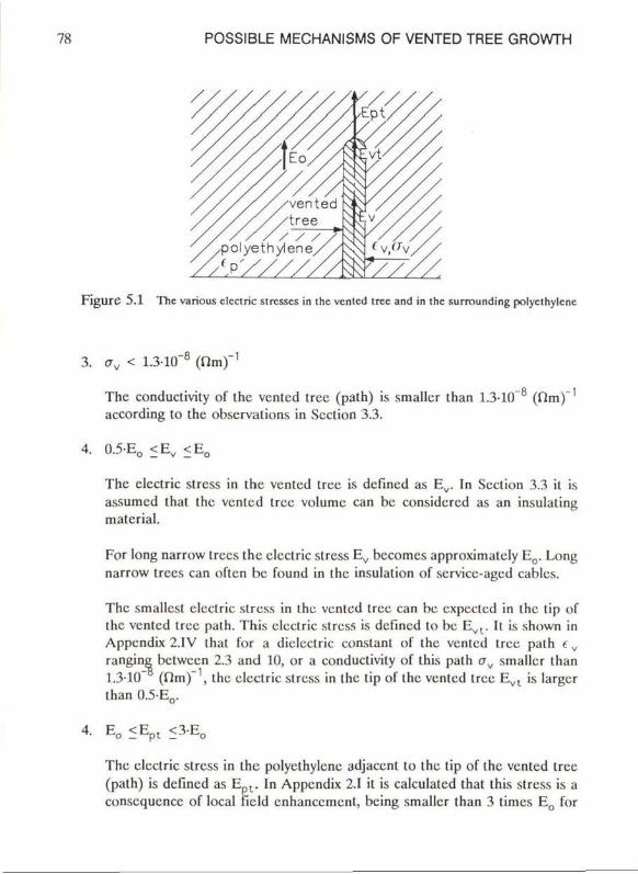
78 POSSIBLE MECHANISMS OF VENTED TREE GROWTH
FigurC 5.1 The various clectric stresses in Ihe venicd tree and in the surrounding polycihylenc
3 . <7V < 1.3-10"0 ( f i rn ) " '
The conduclivity of the vented tree (path) is smaller than 1.3-10"8 (Om)"1
according to the observalions in Scction 3.3.
4. 0.5-Eo <E t f < E 0
The clectric stress in the vented tree is defincd as E v . In Scction 3.3 it is assumcd thal the vented tree volume can bc considcred as an insulating material.
For long narrow trees the clectric stress E v bccomes approximatcly E 0 . Long narrow trees can oftcn bc found in the insulation of servicc-aged cablcs.
The smalicst clectric stress in the vented tree can bc cxpcctcd in the tip of the vented tree path. This clectric stress is defincd to bc E v l . K is shown in Appendix 2.IV thal for a diclectric constant of the vented tree path c v
ranging between 2.3 and 10, or a conduclivity of this path C7V smaller ihan 1.3-10" (firn)" , the clectric stress in the tip of the vented tree E v l is largcr Ihan 0 .5E o .
4. E 0 < E p l < 3 E 0
The clectric stress in the polycihylenc adjacenl lo the tip of the vented tree (path) is defincd as E p l . In Appendix 2.1 il is calculatcd that this stress is a conscqucncc of local field cnhanccmcnt, being smaller than 3 times E 0 for
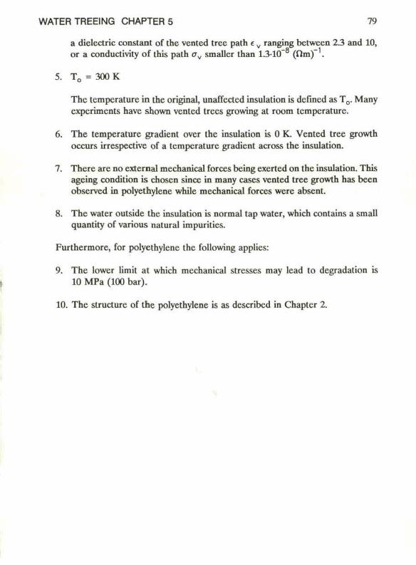
WATER TREEING CHAPTER 5 79
a dielectric constant of the vented tree path e v ranging between 2.3 and 10, or a conductivity of this path av smaller than 1.3-10" (flm) .
5. T 0 = 300 K
The temperature in the original, unaffected insulation is defined as T0. Many experiments have shown vented trees growing at room temperature.
6. The temperature gradiënt over the insulation is 0 K. Vented tree growth occurs irrespective of a temperature gradiënt across the insulation.
7. There are no external mechanica] forces being exerted on the insulation. This ageing condition is chosen since in many cases vented tree growth has been observed in polyethylene while mechanical forces were absent.
8. The water outside the insulation is normal tap water, which contains a small quantity of various natural impurities.
Furthermore, for polyethylene the following applies:
9. The lower limit at which mechanical stresses may lead to degradalion is 10 MPa (100 bar).
10. The structure of the polyethylene is as described in Chapter 2.
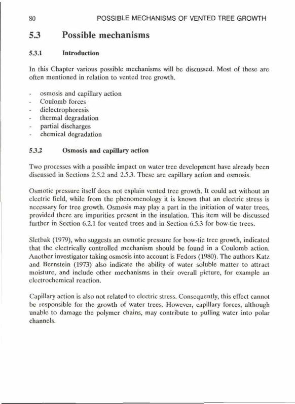
80 POSSIBLE MECHANISMS OF VENTED TREE GROWTH
53 Possible mechanisms
5.3.1 Introduction
In this Chapter various possible mechanisms will be discussed. Most of these are often mentioned in relation to vented tree growth.
osmosis and capillary action Coulomb forces dielectrophoresis thermal degradation partial discharges chemical degradation
5.3J Osmosis and capillary action
Two processes with a possiblc impact on water tree development have alrcady been discussed in Sections 2.5.2 and 2.5.3. These are capillary action and osmosis.
Osmotic pressure itself does not explain vented tree growth. It could act without an electric field, while from the phenomcnology it is known that an electric stress is neecssary for tree growth. Osmosis may play a part in the initiation of water trees, providcd therc are impuritics present in the insulation. This item will bc discussed further in Scclion 6.2.1 for vented trees and in Section 6.5.3 for bow-tic trees.
Slelbak (1979), who suggests an osmotic pressure for bow-tic tree growth, indicated that the elcctrically controllcd mechanism should bc found in a Coulomb action. Anothcr invcstigalor taking osmosis into account is Fedors (1980). The authors Kat/. and Bcrnstcin (1973) also indicatc the ability of water solublc matter to attract moisturc, and includc other mechanisms in their overall picture, for cxamplc an electrochcmical reaction.
Capillary action is also not rclated to electric stress. Consequcntly, this effect cannot be rcsponsible for the growth of water trees. However, capillary forces, although unable to damagc the polymcr chains, may contributc to puiling water into polar channels.
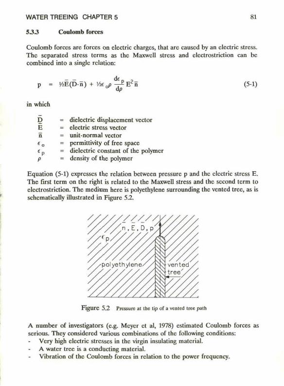
WATER TREEING CHAPTER 5 81
533 Coulomb forces
Coulomb forces are forces on electric charges, that are causcd by an electric stress. The separated stress terms as the Maxwell stress and clectrostriction can be combined into a single relation:
p = KE(D-n) + V*j ■^ £ E 2 n (5-1)
in which
D E n «o
dielectric displacement vector electric stress vector unit-normal vector permittivity of free space dielectric constant of the polymer density of the polymer
Equation (5-1) expresses the relation between pressure p and the electric stress E. The first term on the right is related to the Maxwell stress and the second term to clectrostriction. The medium here is polyethylene surrounding the vented tree, as is schematically illustrated in Figure 5.2.
F i g u r e 5.2 Pressure at the tip of a vented tree palh
A number of investigators (e.g. Meyer et al, 1978) estimated Coulomb forces as serious. They considered various combinations of the following conditions:
Very high electric stresses in the virgin insulating material. A water tree is a conducting material. Vibration of the Coulomb forces in relation to the power frequency.
82 POSSIBLE MECHANISMS OF VENTED TREE GROWTH
In certain cases Coulomb forces are assumcd to act in combination with another force. With regard to the growth of bow-tie trees, including the effect of osmotic pressure Slctbak (1979) and Sletbak et al (1984) should bc mentioned here. A high surface tension of the polyethylene-water interface may counteract the effect of Coulomb forces, cspecially for voids with small radii (Section 2.5). A reduction of this surface tension is assumed by Tanaka et al (1976) and Minnema et al (1980). The effect of vibrations is emphasized by Chcrncy (1973), Isshiki et al (1974), Minnema et al (1980) and Morita et al (1980).
Minnema et al concluded that the vibraling clastic stresses as a rcsult of the Coulomb forces are csscntial. They also found a reduction of the surface tension of the polyethylenc surface through the action of an electric stress. On ihe basis of these two facts it was concluded that the propagation of a ventcd tree is relatcd to a process which is called "environmental fatigue failurc".
Cherney (1973) starts his calculations with the assumption that the pressure can be derived from the relation Fn = QE. In this relation the parameter Fn represents ihe force on the medium. The electric stress is E and O represents all the electric charges present in the water of a cavily. This derivation, howcver, is incorrect because by no means all charges in the water contributc to the force on the medium.
Howcver, under the limiling agcing conditions given in Section 5.2, namely:
a. The electric stress E0 is moderate (2 kV/mm) b. A water tree can bc represented by an insulating material,
the following calculation shows that it is highly improbablc that ventcd tree growth is relatcd to Coulomb forces.
In a worst case approximation it is assumed that the maximum axial electric stress in the polyethylenc is found ncar the tree tip (dcfincd as Ept), and that the axial electric stress in the ventcd tree path ncar the tree tip (Evt) is zero. Assuming further that the unit-normal vector, the dieleclric displacement and the electric stress in the polyethylenc ncar the (ree tip all act in the samc direction, the maximum pressure in the polyethylenc can bc writtcn as
p = ' / * 0 (£ p + p - ^ - ) E p l2 (5-2)
In Figurc 5.2 the tip of the ventcd tree path and the electric stresses are shown.
WATER TREEINQ CHARTER 5 83
From literature (Blythe, 1979) it can be derived for polyethylene that
de. dp P-T^^'p (5"3>
Therefore, the maximum pressure on the polyethylene adjacent to the tip of the vented tree path is
P " <o<pEp t2 (5-4)
Assuming the vented tree path an msulating material it has been shown in Section 5.2 that:
Ept <3E0
WithEo = 2-106 V/m and € p = 2.26 the pressure can amount to 720 Pa at the most. This is far below the limit of 10 MPa for damaging to the polyethylene.
The hypothesis of Coulomb forces damaging the polyethylene is therefore very improbable.
Recently Zeiler (1987) also calculated that the Coulomb forces are unable to degrade the polymer. In this case the electric stress E0 has been chosen rather moderate, according to service ageing conditions.
There are several results from the phenomenological experience supporting this conclusion:
If vented tree growth wcre related to Coulomb forces, the propagation of the tree would be proportional to E . However, the results of the phcnomenology seem to indicate that its propagation is proportional to E. Cracking of a polymer is normally rcduced by the increase of the molecular weight of the polyethylene (Section 2.3). Such an effect has not been observed in relat ion to the propagation of vented trees. Even electron micrographs did not reveal cracking in the tips of vented tree channels (Capaccio et al, 1985). The fraction of voids sometimes observed in the polyethylene at a certain distance from the channcl tip is probably related to secondary degradation.
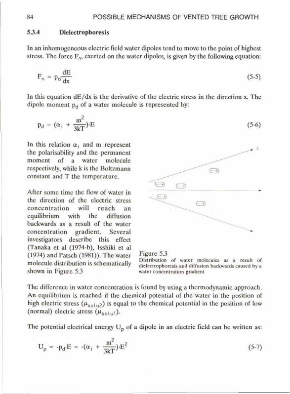
84 POSSIBLE MECHANISMS OF VENTED TREE GROWTH
53.4 Dielectrophoresis
In an inhomogeneous electric field water dipoles tend to move to the point of highest stress. The force Fn, exerted on the water dipoles, is givcn by the following equation:
Fn = Pd dE dx
(5-5)
In this equation dE/dx is the derivativc of the electric sircss in the direction x. The dipolc moment pd of a water molecule is represented by:
Pd = («i + W)X (5-6)
In this relation ax and m represent the polarisability and the permanent moment of a water molecule respcctively, while k is the Boltzmann constant and T the temperaturc.
Aftcr somc time the flow of water in the direction of the electric stress concentration will reach an equilibrium with the diffusion backwards as a rcsult of the water concentration gradiënt. Scveral investigators describe this effect (Tanaka et al (1974-b), Isshiki et al (1974) and Patsch (1981)). The water molecule distribution is schematically shown in Figurc 5.3
Figure 5.3 Distribution of water molcculcs as a rcsult of dielectrophoresis and diffusion backwards causcd by a water concentration gradiënt
The diffcrencc in water concentration is found by using a thermodynamie approach. An equilibrium is rcachcd if the chcmical potential of the water in the posilion of high electric stress (/isoiu2) is equal to the chcmical potcnlial in the position of low (normal) electric stress (/*soiui).
The potcnlial electrical cnergy Up of a dipolc in an electric field can bc wrillen as:
Up = -pd-E = -(al+ — ) - E (5-7)
WATER TREEING CHAPTER 5 85
The potential energy concerning the interaction between the water molecules is Hr + NkTlnc, in which c stands for the conccntration of the water, nr is the energy for unit concentration and N the Avogadro constant.
The chemical potential of the water in the positions of the low and high electric stresses are
m2 , Msolul = /V + NkTlnc, - N(o, + g f f W (5-8)
and
m2 , Msolu2 = Mr + NkTlnc2 - N(a, + - ^ T " - ) E 2 (5-9)
respectively, in which
c, = concentration of water molecules at normal electric stress E0 Cj = concentration of water molecules in the position of a high electric
stress E
Combining equation (5-8) and (5-9) with / i s o iu] = /*Solu2 giv c s t n e following relation between cl and c2:
c? a, + m2/(3kT) , , q = C X P { ( kT ) ( E - E o ) } (5"10)
The electric stresses E and the tempcrature T can be chosen according to the agcing conditions as stated in Section 5.2.
With:
E = Ept <3 -E 0 E 0 = 2-106 V/m T = 300K o-, = 1.6210"'10 Asm2/V m = 6.14-10"30 Asm N = 610 2 3mole _ 1
k = 1.38-10"23 J /K
the ratio between the water concentrations becomes:
c2 /c, < 1.000025 (5-11)
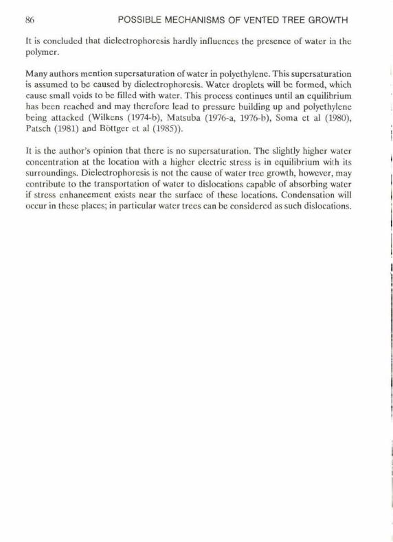
86 POSSIBLE MECHANISMS OF VENTED TREE GROWTH
It is concludcd thal dielectrophoresis hardly influcnccs the presence of water in the polymer.
Many authors mcntion supcrsaturation of water in polyethylcnc. This supersaturation is assumed to bc caused by dielectrophoresis. Water droplets will be formcd, which cause small voids to be filled with water. This proccss continues until an equilibrium has been reached and may thcrcfore lcad to pressure building up and polyelhyiene being attacked (Wilkcns (1974-b), Matsuba (1976-a, 1976-b), Soma el al (1980), Patsch (1981) and Böttger et al (1985)).
It is the aulhor's opinion thal there is no supersaturation. The slightly higher water concentration at the location with a higher electric stress is in equilibrium wilh its surroundings. Dielectrophoresis is not the cause of water tree growth, however, may contribute to the transporlation of water to dislocations capable of absorbing water if stress cnhancement exists near the surfacc of these locations. Condensation will occur in these places; in particular water trees can be considcred as such dislocations.
WATER TREEING CHAPTER 5 87
5 3 5 Thermal degradation
This Chapter considers thermal degradation of the polyethyicnc as a possible mechanism of vented tree growth. The maximum possible temperature in a vented tree or the branches of the vented tree is calculated.
Consider a certain volume V in the polyethylene, cylindrically shaped, as is shown in Figure 5.4, with a length h, radius r and with one of its extreme surfaces A on the outer surface of the insulation. The properties of the vented tree or the vented tree paths are attributed to the whole cylinder.
w v j-»r ^ c o n d u c t o r
cable insulation
F i g u r e 5.4 Cylindrically shaped volume V surrounded by the unaffectcd polyethylene. The volume V has the elcctrical properties of a vented tree path
The thermal behaviour of any arbitrary volume is given by the relation
P C V - ^ + div(k'gradT) = qh (5-12)
With
p = density of the material O, = specific heat k' = thermal conductivity qh = heat dissipation
Assuming thermal equilibrium: dT/dt = 0.
If the heat flow through the extreme surface A is neglected, then, for the configuration considered, the solution of the remaining cquation is, according to Wong (1977):
88 POSSIBLE MECHANISMS OF VENTED TREE GROWTH
Tv = T0 + qh-^rln(2h/r) (5-13)
in which
Tv = temperature of ihc vented tree r = radius of the cylindcr h = length of the cylinder
The valuc of qh is given by the following equation:
% - ^ E , 2 (5-14)
in which av and Ev are the conductivity and the electric stress in the vented tree rcspcctively.
The temperature in the water tree has a maximum for r = 2h/\/e, so
Tv < T0 + ffvE/tf/Cdf) (5-15)
Assuming
Ev < E E0 = 2-106 V/m av = 1.310"8 (Om)"1
k' = 0.25J/Ksm h < 1 mm c = 2.72
The conductivity av and the electric stress Ev have been choscn according to the assumptions presented in Scction 5.2.
These assumptions result in
Tv < T0 + 0.08 K (5-16)
Discussion
It has been shown that the temperature increase in a vented tree volume under moderate ageing conditions is negligiblc. It is too small to lead to destruction of the polymcr or even to acccleration of othcr ageing processes.
WATER TREEING CHAPTER 5 89
In agreement with these findings microscopic examinations of vented trees do not reveal any thermal degradation. Moreover, Bamji et al (1984) using Differential Scanning Calorimetry were not able to detect any differencc between the thermal history within polyethylene affected by a tree and the polyethylcne free from attack.
The investigators Isshiki et al (1974), Tanaka et al (1976), Yoshimura et al (1977) and Meycr et al (1978) state that an increase of temperaturc may play an essential role. On the basis of the findings of Yoshimura (1977) the water in the tree would even evaporate, with obvious consequences for the polymer. Their results were obtained by selecting a vcry high electric stress; moreover, the vented tree (path) was considered to be a conductor.
90 POSSIBLE MECHANISMS OF VENTED TREE GROWTH
5-5.6 Partial discharges
Partial discharges occur in gas-fillcd cavities. Under the application of an ac-fïeld a continuous repetition of the process causes degradation of the surrounding insulaling material, so that electrical treeing may occur eventually.
Partial discharges have been studicd for many years (Mason, 1951,1953 and Kreuger, 1960,1989). Equipment to deteel these discharges is available and is currcntly in use.
In Section 3.5 it was concluded that vented tree growth at moderate stress levels is in all likelihood not accompanicd by such discharges. The author's experience with partial discharge measurements on medium-voltage cables confirm this, even if these cablcs contained large vented trees. The noise level during this experiment was about 0.1 pC, the mean electric stress level in the insulation was less than 5 kV/mm.
However, there are two different situations in which partial discharges can be related to vented treeing. In the first situation partial discharges may occur during initiation. If water needies are applied, the very high initiation stress level at the tip of the water nccdlc may cause partial discharges. This accounts for the light cmission from the water nccdlc clectrodes in a test by Nitta (1974). Sccondly it is possiblc for electrical treeing to originatc from vented trees, for example during ovcrvoltages. These electrical trees cause partial discharges. Exampics have already been presented in Section 3.5.
WATER TREEING CHAPTER 5 91
53.7 Electrochemical degradation
The concept of chemical action in relation to water tree growth in polyethylene has been mentioned by several authors. Rye et al (1975) showed that warm solutions of some salts attack the interface of polyethylene chemically, possibly oxidizing it. They think that it is possible that such a process increases the tendency to water tree growth in polyethylene. It has still to be explained why a tree structure arises.
Tabata et al (1972) found tree structures in voltage energizcd cable insulation which had been in a solution of H2S and water. The trees had grown from a copper conductor, and contained Cu2S and Cu 2 0. This makes the contribution of a chemical action to water treeing probable. Yoshimitsu et al (1978) suppose water tree formation in epoxy resins to be accompanied by chemical reactions.
However, none of the investigations mentioned have resulted in unambiguous proof.
Henkei et al (1985) supposed an electrochemical process at the polyethylene interface, in which H 2 0 2 is generated in water, successively attacking the polyethylene. The fact that agents which are known to either interrupt the electrochemical process or stabilize H 2 0 2 , strongly diminish the formation of water trees supports this supposition.
In Chapter 6 our own hypothesis of electrochemical degradation will be presented.
92 POSSIBLE MECHANISMS OF VENTED TREE GROWTH
5.4 Conclusions
The discussions in this Chapter have been carried out on the basis of the assumption that a vented tree is an insulating material. Arguments for this have been given in Chapter 3. All parameters with a possibic effect on water tree growth -such as clectric stress and temperature- have been choscn to comply with the actual use of medium-vollagc cablcs. Under these conditions the following conclusions apply:
Osmosis and capillary action are not relatcd to clectric stress, which is the reason why they cannot bc considcred as the cause of water tree growth. However, both proecsses may play a secondary role, for instancc during the initiation of a water tree or by pushing water into a polarized channel.
Coulomb forces at the vented tree tip are too small to explain mechanical degradation of the polyethylene.
Thermal degradation of the polyethylene is not expectcd, sincc ihc inercase of the temperature in a vented tree is negligible.
Partial discharges have never been dctcctcd during the growth of a vented tree undcr moderate agcing conditions and are thus not considcred as the background of water tree growth.
Diclcctrophorcsis cannot explain vented tree growth. In an electric field dielectrophoresis might be of assistance by carrying watcr-vapour to the tip of a vented tree. However, the effect of this latler process will bc slighl, sincc field concentrations at the tree tip are limilcd.
Electrochcmical degradation is an interesting mechanism. In Chapter 6 a hypothesis of vented tree initialion and growth by electrochcmical action will bc presentcd.
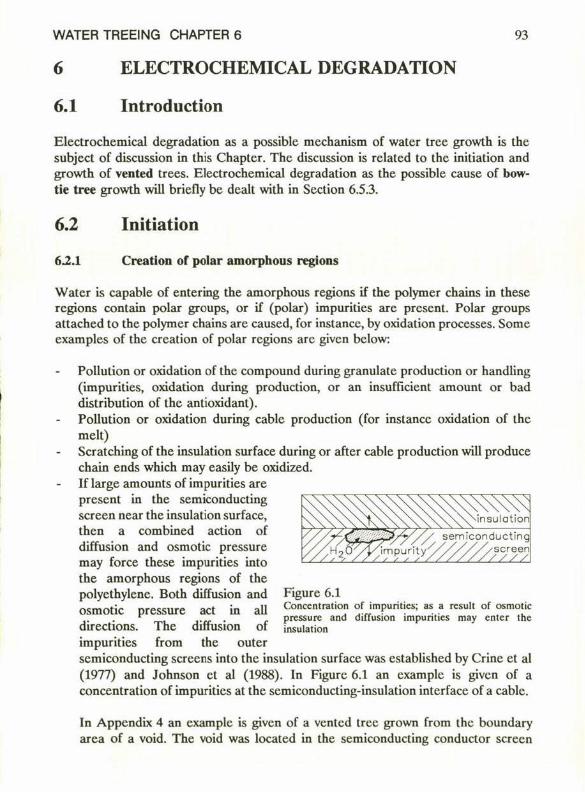
WATER TREEING CHAPTER 6 93
ELECTROCHEMICAL DEGRADATION
6.1 Introduction
Electrochemical degradation as a possible mechanism of water tree growth is the subject of discussion in this Chapter. The discussion is related to the initiation and growth of vented trees. Electrochemical degradation as the possible cause of bow-tie tree growth will briefly be dealt with in Section 6.5.3.
6.2 Initiation
62.1 Creation of polar amorphous regions
Water is capable of entering the amorphous regions if the polymer chains in these regions contain polar groups, or if (polar) impurities are present. Polar groups attached to the polymer chains are caused, for instancc, by oxidation processes. Some examples of the creation of polar regions are given below:
Pollution or oxidation of the compound during granulate production or handling (impurities, oxidation during production, or an insufficiënt amount or bad distribution of the antioxidant). Pollution or oxidation during cablc production (for instancc oxidation of the melt) Scratching of the insulation surface during or after cable production will produce chain ends which may easily be oxidized. If large amounts of impurities are present in the semiconducting screen near the insulation surface, then a combined action of diffusion and osmotic pressure may force these impurities into the amorphous regions of the polycthylene. Both diffusion and osmotic pressure act in all directions. The diffusion of impurities from the outer semiconducting sereens into the insulation surface was established by Crine et al (1977) and Johnson et al (1988). In Figure 6.1 an cxamplc is given of a concentration of impurities at the semiconducting-insulation interface of a cable.
'ï/y'// semiconducting
h^y/////A screen / / / /
Figure 6.1 Concentration of impurities; as a rcsult of osmotic pressure and diffusion impurities may enter the insulation
In Appendix 4 an examplc is given of a vented tree grown from the boundary area of a void. The void was located in the semiconducting conductor screen

94 ELECTROCHEMICAL DEGRADATION
T 10 riTi " c *ea'or
Figure 6.2 Model of a cross scction of a scratched polycihylcnc surface
against the surface of the insulation of a 10 kV cable which was agcd for 8 years undcr service ageing conditions (cable Al in Chapter 8). Indeed the void still contained significant amounts of various species, such as silicon, sulphur and calcium. Partial discharges may attack the polyethylenc and will oxidi/c it. Water may then enter the polar regions. Locations al the insulation surface, which can produce partial discharges undcr normal clcctric stress conditions are thcreforc a potential source of risk for the initiation of vented trees.
Figure 6.2 shows a microscopic detail of a cross section of a scratched insulation surface. Scratching is choscn as an example of surface attack in genend. The
Figure 6.3 Polar groups (•) fixcd on Ihc polymcr chains al a scratched polyethylenc surface
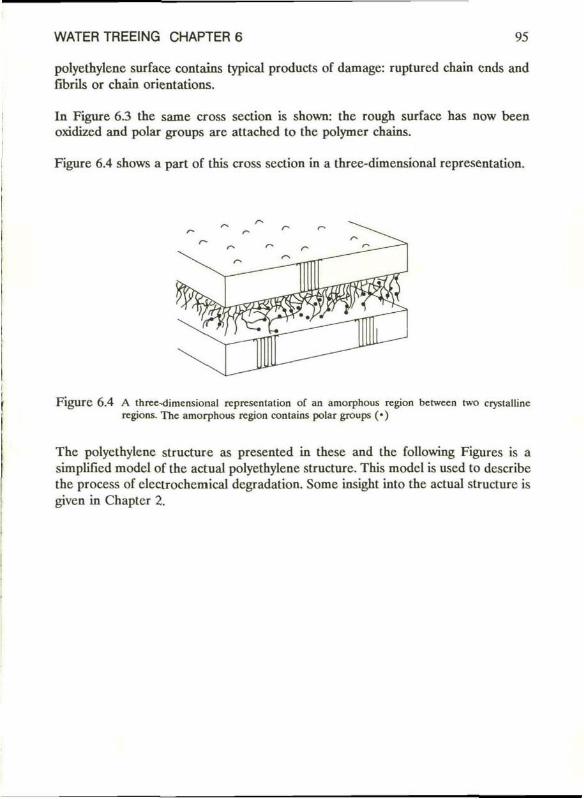
WATER TREEING CHAPTER 6 95
polyethylene surface contains typical products of damagc: rupturcd chain ends and fibrils or chain orientations.
In Figure 6.3 the same cross section is shown: the rough surface has now been oxidized and polar groups are attached to the polymer chains.
Figure 6.4 shows a part of this cross section in a three-dimensional representation.
F i g u r e 6.4 A three-dimcnsional representation of an amorphous region betwecn two crystallinc regions. The amorphous region contains polar groups (•)
The polyethylene structure as presented in these and the following Figures is a simplified model of the actual polyethylene structure. This model is used to describe the process of elcctrochemical degradation. Some insight into the actual structure is given in Chaptcr 2.
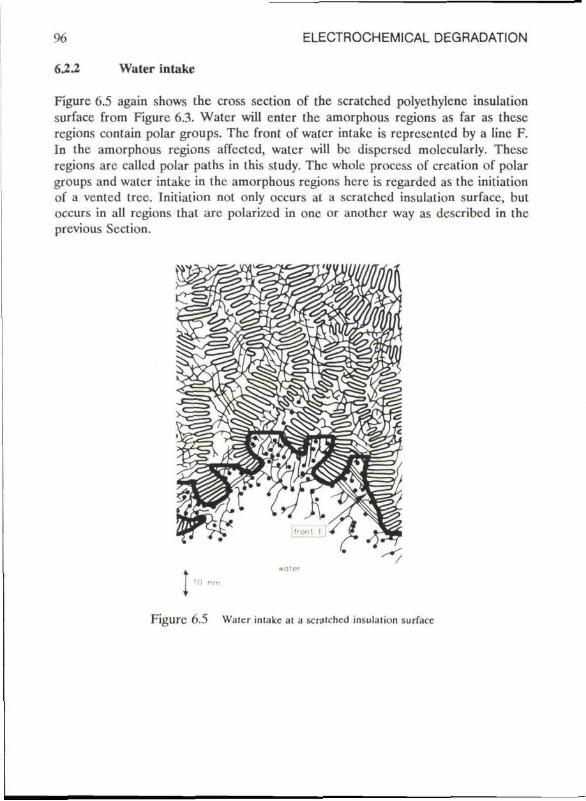
96 ELECTROCHEMICAL DEGRADATION
622 Water intake
Figurc 6.5 again shows the cross section of the scratched polyethylcnc insulation surface from Figurc 6.3. Water will enter the amorphous regions as far as these regions contain polar groups. The front of water intake is represcntcd by a line F. In the amorphous regions affcctcd, water will bc dispersed molccularly. These regions are callcd polar paths in this study. The whole process of creation of polar groups and water intake in the amorphous regions here is regarded as the initiation of a vented tree. Initiation not only occurs at a scratched insulation surface, but occurs in all regions that are polarizcd in one or another way as described in the previous Section.
I n
' ■ ■ ■
Figurc 6.5 Water inlakc al a scralchcd insulation surface
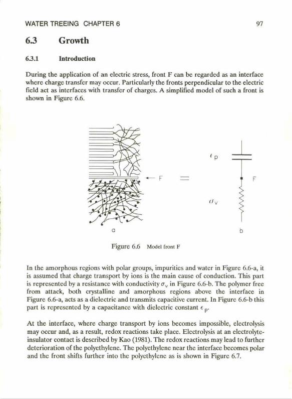
WATER TREEING CHAPTER 6 97
63 Growth
6.3.1 Introduction
During the application of an electric stress, front F can be regarded as an interface whcrc charge transfer may occur. Particularly the fronts perpendicular to the electric field act as interfaces with transfer of charges. A simplified model of such a front is shown in Figurc 6.6.
ffy
Figure 6.6 Model front F
In the amorphous regions with polar groups, impuritics and water in Figure 6.6-a, it is assumed that charge transport by ions is the main cause of conduction. This part is represented by a resistance with conductivity av in Figure 6.6-b. The polymer free from attack, both crystallinc and amorphous regions above the interface in Figure 6.6-a, acts as a dielectric and transmits capacitive current. In Figure 6.6-b this part is represented by a capacitancc with dielectric constant e _.
At the interface, where charge transport by ions becomes impossible, electrolysis may occur and, as a result, redox reactions takc place. Electrolysis at an elcctrolyte-insulator contact is describcd by Kao (1981). The redox reactions may lead to furthcr deterioration of the polyethylene. The polyethylene near the interface becomes polar and the front shifts furthcr into the polyethylene as is shown in Figure 6.7.
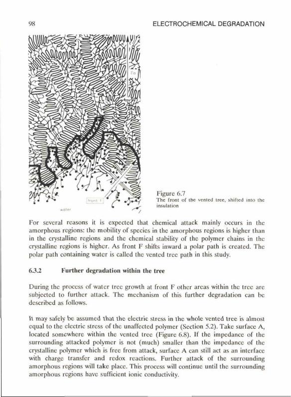
98 ELECTROCHEMICAL DEGRADATION
Figure 6.7 The fronl of Ihc vcnlcd tree, shifled inio ihc insulalion
For scvcral rcasons it is expected thal chemical altack mainly occurs in the amorphous regions: the mobility of species in the amorphous regions is higher than in the crystallinc regions and the chemical stability of the polymcr chains in the crystalline regions is higher. As front F shifls inward a polar palh is created. The polar path containing water is called the vented tree path in this study.
632 Further degradation within the tree
During the process of water tree growth at front F other areas within the tree are subjecled to further atlack. The mechanism of this further degradation can be describcd as follows.
It may safely bc assumcd that the clectric stress in the whole vented t ree is almost cqual to the clectric stress of the unaffectcd polymcr (Scction 5.2). Takc surface A, locatcd somewhere within the vented tree (Figure 6.8). If the impcdancc of the surrounding allackcd polymcr is not (much) smaller than the impcdancc of the crystallinc polymcr which is free from attack, surface A can still act as an interface with charge transfer and redox reactions. Further attack of the surrounding amorphous regions will take place. This process will continue until the surrounding amorphous regions have sufficiënt ionic conductivity.
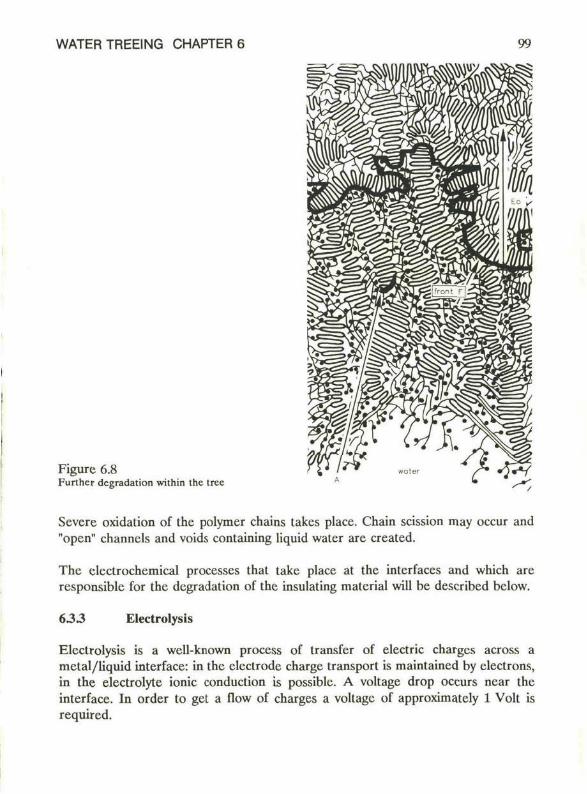
WATER TREEING CHAPTER 6 99
Figure 6.8 Further degradation within ihc iree
Severe oxidation of the polymer chains takes place. Chain scission may occur and "open" channels and voids containing liquid water are created.
The electrochemical processes that take place at the interfaces and which are responsible for the degradation of the insulating matcrial will be described below.
6 3 3 Electrolysis
Electrolysis is a well-known process of transfer of electric charges across a mctal/liquid interface: in the electrode charge transport is maintained by electrons, in the electrolyte ionic conduction is possible. A voltage drop occurs ncar the interface. In order to get a flow of charges a voltage of approximately 1 Volt is required.
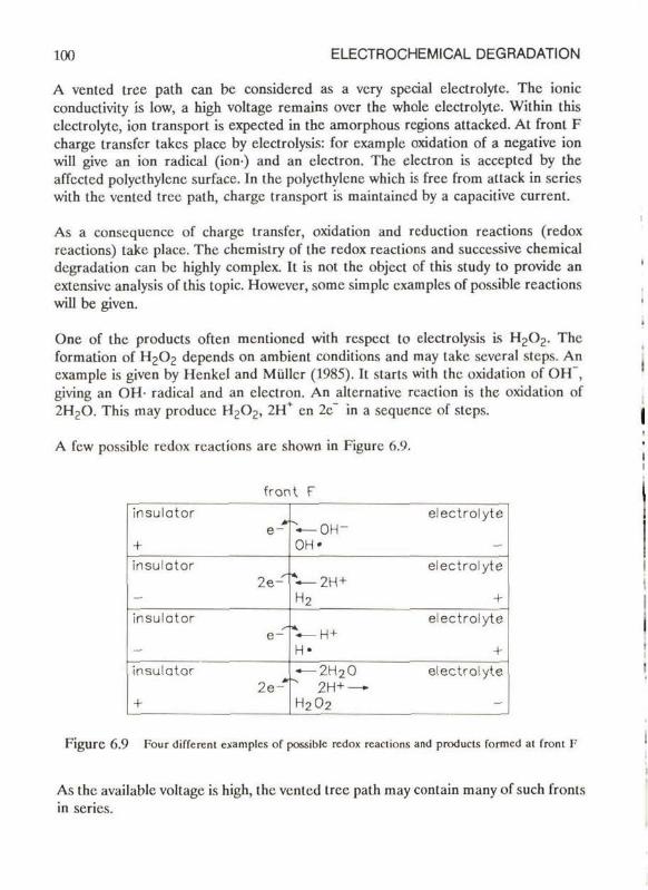
100 ELECTROCHEMICAL DEGRADATION
A ventcd tree path can be considered as a vcry special electrolyte. The ionic conductivity is Iow, a high voltage remains over the whole electrolyte. Within this electrolyte, ion transport is expected in the amorphous regions attacked. At front F charge transfer takes place by electrolysis: for cxamplc oxidation of a negative ion will give an ion radical (ion) and an clcctron. The electron is acccpted by the affectcd polyethylene surface. In the polycthylcne which is free from attack in series with the vented tree path, charge transport is maintained by a capacitive current.
As a consequence of charge transfer, oxidation and rcduction reactions (redox reactions) take place. The chcmistry of the redox reactions and succcssive chemical degradation can be highly complex. It is nol the object of this study to providc an extensivc analysis of this topic. However, somc simplc cxamples of possible reactions will be given.
One of the products often mentioned with respect to electrolysis is H 2 0 2 . The formation of H J O J depends on ambient conditions and may take several steps. An cxample is given by Henkei and Muller (1985). It starts wilh the oxidation of OH , giving an OH- radical and an clcctron. An altcrnativc rcaction is the oxidation of 2H 2 0. This may produce H J O J , 2H en 2c in a sequencc of steps.
A few possible redox reactions are shown in Figure 6.9.
front F insulator
e~ + insulator
2e-
insulator e -
insulator 2e-*
+
electrolyte V - O H -OH"
electrolyte *—2H + H2 +
electrolyte V - H + H- + — 2H 20 electrolyte " 2H+ — H202
Figure 6.9 Pour different cxamples of possible redox rcaclions and products formcd al fronl F;
As the available voltage is high, the venled tree path may contain many of such fronts in series.
WATER TREEING CHAPTER 6 101
63.4 Electrochemical degradation
The prescncc of H 2 0 2 as mentioned in the previous Section may rcsult in further proecsses:
Many carbon-to-carbon doublé bonds are present in the polyethylenc, prefercntially in the interlamellar spaces. These bonds are relatively casily oxidi/cd with H 2 0 2 to a glycol:
I I > C = C < + H 2 0 2 — —C—C— (6-1)
I I O O H H
Such glycols are able to undergo a rearrangcmcnl according to:
I I I —C—C ► —C—C— + H 2 0 (6-2)
II II I O O O H H
It is also possible that metal ions act as a catalyst to form poiymcr radicals with H 2 0 2 . In a sequence of steps such poiymcr radicals may oxidize the polyethylene during the formation of carbonyles and ketones. This part of the electrochemical degradation was suggested by Henkei and Muller (1985). The presence of metal ions of different kinds cannot bc ignorcd, since the vented tree paths are connected to the environment, via diffusion through the polar amorphous regions. Indeed, metal ions have been detected using various techniques which is described in Chapter 3 and Chapter 4.
102 ELECTROCHEMICAL DEGRADATION
6.4 Propagation rate
In this Section the number of polar groups produccd will be compared with the total CH2 groups available in the amorphous region. It will be shown that according to the proposcd assumptions a vented tree propagation rate of 20 firn to 500 /im per ycar is possible.
The number of rcdox reactions near the lip of the vented tree path will be related to the vented tree propagation rate. The number of charges 0 passing the interface per unit area and time is:
0 = « r ^ t / q (6-3)
In this rclation E ^ is the local clcctric stress insidc the tip of the vented tree path, q is the unit charge and av the conductivity of the path.
In Section 5.2 the diclcctrical propcrties of a vented tree path were summari/.cd, the conductivity ov in the vented tree path is low, smaller than 1.3-10" (firn)" so
CTV = g-1.3-10"8 (firn)"1 (6-4)
in which g ranges from 0 to 1.
In Section 5.2 the clcctric stress in the tip of the vented tree path is cstimated. In a worst case approximation it follows:
E v l = m0 (6-5)
The number of charges passing the interface in the vented tree tip per unit time and unit area is
9 = g-0.7-10"8Eo/q (6-6)
With
E0 = 2-106 V/m
the number of charges is
6 = g-8.1-1016 m ~ V 1 (6-7)
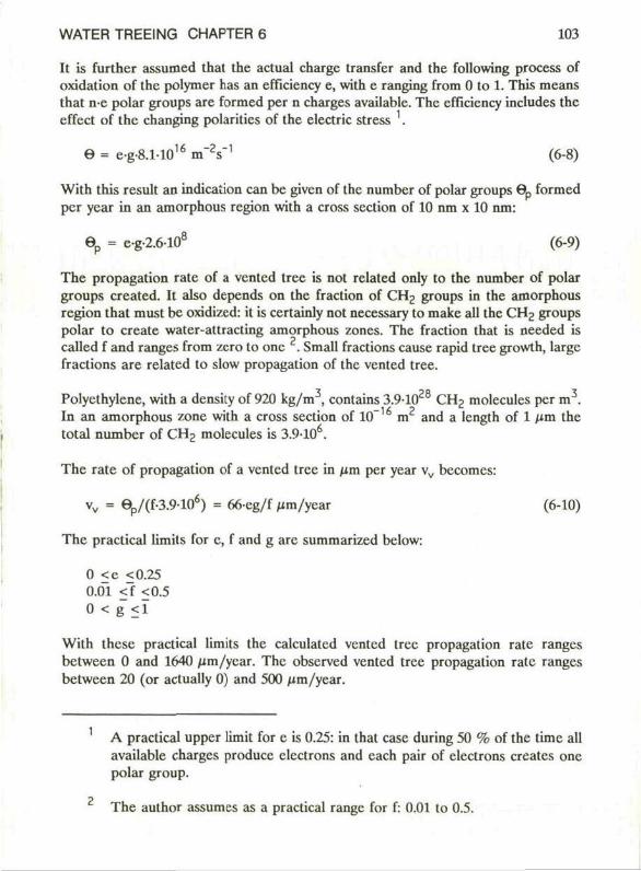
WATER TREEING CHAPTER 6 103
It is further assumed that the actual charge transfer and the following process of oxidation of the polymer has an efficiency e, with e ranging from 0 to 1. This means that n e polar groups are formed per n charges availablc. The efficiency includes the effect of the changing polaritics of the electric stress .
6 = e-g-8.1-1016 m ' V 1 (6-8)
With this result an indication can be given of the number of polar groups 6 p formed per year in an amorphous region with a cross section of 10 nm x 10 nm:
6 p = eg-2.6108 (6-9)
The propagation rate of a vented tree is not related only to the number of polar groups created. It also depends on the fraction of CH2 groups in the amorphous region that must be oxidizcd: it is certainly not necessary to make all the CH2 groups polar to create water-attracting amorphous zones. The fraction that is needed is called f and ranges from zero to one . Small fractions cause rapid tree growth, largc fractions are related to slow propagation of the vented tree.
Polyethylene, with a density of 920 kg/m3, contains 3.91028 CH2 molecules per m3. In an amorphous zone with a cross section of 10" m and a length of 1 /*m the total number of CH2 molecules is 3.910 .
The rate of propagation of a vented tree in nm per year vv becomes:
vv = 6p/(f-3.9106) = 66-eg/f Mm/year (6-10)
The practical limits for e, f and g are summarized below:
0 <e <0.25 0.01 <f <0.5 0 < g <1
With these practical limits the calculatcd vented tree propagation rate ranges between 0 and 1640 /im/year. The observed vented tree propagation rate ranges between 20 (or actually 0) and 500 /im/year.
A practical upper limit for e is 0.25: in that case during 50 % of the time all available charges produce clectrons and each pair of electrons creates one polar group.
The author assumes as a practical range for f: 0.01 to 0.5.
104 ELECTROCHEMICAL DEGRADATION
In Figurc 6.10 the calculalcd vcnted tree propagation ratc vv is given in a graph for the practical values of e, f and g. Added to this graph is a shaded arca which represcnts the vented tree propagation rate as obscrvcd in servicc-aged mediumvoltage cable insulations. The observed propagation ratc ranges between 20 firn and 500 /xm per ycar. Note: only the calculatcd propagation rate is given as a function of the parameters e, f or g.
0 5 10 15 20 25 e f f i c i ency e (%)
F i g u r c 6.10 Vcnted Ircc propagation ratc in (im/ycar
It can be concluded that the observed vcnted tree propagation rate can bc cxplained according to a set of assumptions. A summary of these assumptions is given bclow:
1. the vcnted tree path (attackcd amorphous region) is an insulating material with a diclcctric constant t v smaller than 10, and a conductivity crv smaller than 13-10"8 (Om)"1.
2. the current through the vented tree path is caused by ionic conduction. 3. at the tip of the vcnted tree charge transfer occurs and there are rcdox rcaclions. 4. Thcrc is formation of polar groups near the tip. 5. The total efficiency e for items 3. and 4. is smaller than 0.25, so c < 0.25. 6. The fraction f of polari/.cd CH2 groups, which is necessary to attracl water,
ranges between 0.01 and 0.5. 7. The interface shifts further into the insulation as a consequence of the formation
of polar groups. 8. The density of the insulation, low-density polycthylene, is 920 kg/m . 9. The clcctric stress in the unaffectcd polycthylene E0 is 2-106 V/m; the clectric
stress within the tip of the vcnted tree path is chosen to bc '/:E0. 10. The observed vcnted tree propagation ratc ranges from 20 to 500 nm per ycar.
WATER TREEING CHAPTER 6 105
The vcntcd tree propagation rate is mainly determined by
the conductivity of the vented tree path the local elcctric stress the efficiency of the production of polar groups from charges transferred
In the process described above, it is interesting to see that the propagation is mainly related to the properties of the degraded part of the polymcr. The numbcr of charges transferred, for instance, is a result of the conductivities of the affected part of the polymcr. Moreover, the efficiency of the process is influenced by the migration of products through the attackcd amorphous regions. It mcans that the vented tree propagation ratc does not only -perhaps hardly at all- depend on the properties of the unaffected polymer.
106 ELECTROCHEMICAL DEGRADATION
6.5 Theory and phenomenology
In this Section the results of the hypothesis of electrochemical degradation will be compared with the phenomenology of water trees as is known from our own research work and from literature. In Section 6.5.1 those aspects will be treated that show general agrcement betwcen the theory and the phenomenology. In Section 6.5.2 the remaining aspects are topics for discussion. Finally, in Section 6.5.3 bow-tie tree growth in relation to the presented hypothesis will bc discussed.
6.5.1 Agreements
Morphological aspects
Assumcd:
The growth of the vented tree takes place in the amorphous regions. lts appcarance is cxpcctcd to bc rathcr diffuse since there are no clearly visiblc open channels. Chemical reactions take place near the interfaces. Especially those interfaces perpendicular to the electric field lines will show this process. The growth of vented trees is thercfore mainly in the direction of the electric field lines.
Obscrvcd:
The phenomenology indeed shows diffuse structures with a propagation mainly in the direction of the voltage gradiënt.
Assumcd:
As a rcsult of electrochemical proecsses within the vcnlcd tree path furthcr degradation will occur. Finally, oxidation proecsses may rcsult in chain scission: channels and voids are created.
Obscrved:
Visible degradation has occasionally been obscrvcd: voids and channels have been found, parlicularly in the oldcr rcgions of the tree.
WATER TREEING CHAPTER 6 107
Physical properlies (local)
Assumcd:
The proposed degradation will give a significant enhancement of various impuritics and oxidation products. The incrcasc, however, is restricted to the attacked amorphous regions. The volume percentage of such attacked regions (vented tree paths) is probably small in relation to the total vented tree volume. Oxidation products can therefore only be found using very sensitive equipment.
Observed:
Using Infra-red techniques, Garton et al (1987) and Ross et al (1988) were able recently to observe a carbonyl (C = O) concentration that was higher in tree affected regions than in regions not affected by vented trees. An increase of the impurity level such as through metal ions, has been observed using various techniques.
Heat-treatment experiments executed by Muller et al (1985) support the idea that the tree affected part of the polymer has been chemically affected.
Electrical properties (bulk)
Assumed:
If large vented trees bridge the insulation, a significant increase of the cablc dc-current and loss-factor is possible. In that case it is assumed that the sum of ihc Joule losses and the dielcctric losses in the vented tree is much higher than the dielectric losses of the surrounding polymer.
Observed:
The increase of cable dc-current and loss-factor was reported on several occasions. In these cases very large vented trees were reported as wcll.
Effect of electric stress intensity
Assumed:
The proposed mechanism of vented tree growth assumes a linear relation between electric stress level and vented tree propagation. This is a resuit of the amount of charge transfers, which is proportional to the local electric stress in the vented tree.

108 ELECTROCHEMICAL DEGRADATION
Observed:
Such a relation is often prcscnled in literature.
Effect of frequency
Assumed:
Capacitivc currcnt through the insulation is proportional to frequency. The maximum possible charge transfer is limited by the total current through the insulation. Consequently, the vented tree propagation rate is proportional to the frequency as long as there are no other limiting factors. For instance:
At high frequency the efficiency of electrolysis at the transition plancs or interfaces decreases, the time to create charge transfer becomes too short.
The efficiency of electrolysis is expected to reach a peak at a certain frequency. It is impossible to calculate this frequency level or the efficiency at this point, since precise data about capacities, resistivities and diffusion ratcs are not available.
Observed:
The resulls of the phenomenology indeed show that thcrc is a frequency (range), at which the vented tree propagation ratc reaches its peak.
Effect of the chemical nature of the f luid
Assumed:
It is expected that scvcral solutes clearly affect the overall efficiency. Howevcr, the actual rolc of a solute is difficult to predict, the various steps in the chemical process are not yet known. Moreover, the solutes may affect the conductivities in the amorphous regions.
Observed:
Much research work has been carricd out to find the relation bctwecn vented tree propagation ratc and solutes. Indeed it has been found that types and amounts of solutes significantly affect the vented tree growth. A further cxamination of the rcsults of these experiments may give valuablc information.
WATER TREEING CHAPTER 6 109
Effect of insulation material and additives
Assumcd:
The electrochemical process and resulling vented tree propagation is mainly relatcd to the characteristics of the already affected insulation and not to the pure material.
Observed:
Vented tree growth is reported to occur in many different kinds of polymer insulation matcrials. These findings correspond to the process of electrochemical dcgradation.
Assumcd:
Additives such as cumylalcohol and acetophenone are assumcd to givc the insulation a vented tree retardant behaviour. Sincc these products are polar and mobile, they are cxpcctcd to bc able to reduce the interfacial energy of polar interfaces. As a consequence, the absorption of water in amorphous regions and the vented tree propagation rate will bc reduced. The additives mentioned here will normally evaporate out of the insulation. The retardant affect therefore is limited in time.
Observed:
Polar additivcs are able to reduce vented tree propagation rate for a limited period of time.
Effect of the morphology of the insulating material
Assumed:
The process of electrochemical dcgradation is hardiy affcctcd by morphological parameters such as mclt index and dcnsily.
Observed:
In the literature such relations have not been found either.
110 ELECTROCHEMICAL DEGRADATION
6.5.2 Remaining aspects
Effect of temperature
Assumed:
Chemical processes will accclerate at higher tcmpcraturcs. Moreover, the rate of diffusion of various products, includingelectrolysis products but also of tree rctardant residual products, is fastcr. It is not clear if a higher mobility of these products contributes to or countcracts the vcnted tree propagation. Howcver, in gcncral a highcr vcnted tree propagation rate is expected at higher temperatures.
Observed:
An incrcasc of the vcnted tree propagation ratc at highcr temperatures is observed in a limitcd temperature range only. The most favourablc temperature secms to bc about 30 to 50 °C.
Effect of mechanical stress
Assumed:
A rclalion between the clectrochemical process and mechanical stresses in the insulation is not expected. The propagation of vented trees is thercfore assumed not to be affected by these stresses. In a later stage of the degradation, when many polymer chains have been oxidizcd, chain scission and formation of voids and cracks is probably promotcd by these mechanical stresses.
Observed:
Voids and cracks have occasionally been observed in vcnted trees, mainly at a certain distance from the tip of the vcnicd tree. Sincc litcraturc is nol vcry informalivc about vcnted tree propagation and void creation in rclation to mechanical stresses, a more dctailed discussion is not yet possible.
Effect of relative humidity
The mechanism of clectrochemical degradation requires water. Tree devclopmcnt can be expected at a relative humidity Icvcl bclow 100 percent. However, such a rcsult also applies for othcr (assumed) mechanisms of vcnted tree growth. Practical rcsults are therefore not very informative, but thcy do not contradict the aulhor's hypothesis cithcr.
WATER TREEING CHAPTER 6 111
6.5.3 Bow-tie trees
The process of electrochcmical degradation described can also be applied to bow-tie treeing.
Initiation
It is known from the phcnomcnology that bow-tie trees are initiated mainly from voids filled with impurities. Voids that are fdled with water do not usually give initiation.
Initiation of bow-tie trees can be explained by a process mentioned before: a combined action of diffusion and osmotic pressure. Once water and impurities have entered these regions, the growth of a water tree can start.
Assuming such a mechanism of initiation for bow-tie trees, it is expected that the amorphous regions around the void will contain impurities, since diffusion and osmotic pressure act in all dircctions. Indeed there are indications. Stained bow-tie trees (with methylene blue) often show that not only the bow-tie tree has been colourcd, but also a shell around these voids. An cxamplc is given in Figure 3.5. This shell has a thickness of several micrometers. This indicates that in the shell around the void polar groups, for instance from dissolved impurities, are present.
Diffusion as well as osmotic pressure will inercase if the tempcrature is raised. It is expected, thercforc, that initiation will increase at higher temperatures. Indeed this effect was observed by Naybour (1979).
Propagation
Finally, onc may wonder why bow-tie trees often stop growing after a certain time. A possible explanation is given. It is assumcd in the process described that the efficiency of electrochcmical degradation is related to the transformation of redox reaction products into polar groups. This transformation may bc stimulatcd by the prcscncc of certain species, such as metal ions. For vented trees the supply of these species from the outer regions of the insulation is guaranteed by the polar amorphous zones. As bow-tie trees are not in open connection with the environment, stagnation of the growth process might be explained by this assumption.
112 ELECTROCHEMICAL DEGRADATION
6.6 Measures to suppress vented treeing
In this Section some general remarks are made in order to come to a suppression of vented tree initiation and growth regarding the proposed mechanism of electrochemical degradation. Further study of the process may rcsult in more detailcd knowledge, which is needed to devclop effective measures.
6.6.1 Suppression of initiation
For the proccss of electrochemical degradation there are two main causcs of initiation:
oxidized amorphous regions and clusters of water soluble matter or impuritics
The deercase of the number and size of impuritics and the prevention of oxidized amorphous zones in the outer regions of the insulation will certainly rcducc the number of initiation spots. This requires extremely pure insulation compounds and a production proccss in which the hot compound or insulation cannot come into contact with oxygen. Moreover, the produced core must be handled with care to avoid scratching of the insulation surface.
Concerning initiation only, the risk of cable failurc due to water trees will bc climinatcd if the number of initiation spots in a whole cable core is zero. Howcver, it is impossible to produce a cable core without any initiation spot. Such a production would requirc extreme purification of the compounds and extreme caution in cable handling during and after cable manufacturing.
Efforts to climinatc the risk of cable failure are more effective if thcy are directed towards:
an exclusion of water or a high water-vapour level near the insulation using water-blockings (Section 6.6.2) or if water is admiltcd near the insulation, a rcduction of the vented tree
propagation rate (Section 6.6.3).
6.6.2 Water-blockings
Two principal cable constructions are uscd to cxcludc water undcr the shcath.
Longiludinal water-blocking Swclling tapes or swclling powders undcr the plastic shcath can be applied in order to avoid axial ingress of liquid water, for instancc after shcath damagc. Howcver,
WATER TREEING CHAPTER 6 113
water-vapour can still enter the cable through the plastic sheath. The swelling tapes or powders can absorb this water; but aftcr a limitcd period of time the rclative humidity level under the sheath becomes high.
Radial water-blocking
A metal sheath or a mctal foil in a plastic-mctal sandwich construction is uscd to obtain radial water-vapour tightness. Usually, such a construction is also provided with a longitudinal water-blocking. It is necessary that the metal sheath is applied only if the cable core is dry, especially if the cable is steam-cured. See also Chapter 8.4
6.63 Suppression of propagation
The suppression of vcnted tree growth can be directcd towards sevcral stages of the electrochemical degradation process. Measures are effective only if the related stage plays a dominant role in the total process of degradation.
A reduclion of the ionic conductivity in the vcnted tree palh.
A reduction of the amount of impurities in the vented tree path can be obtained by an overall reduction of the impurity level in and around the insulation. As a result of the dissociation of water into H and OH ' it is impossiblc to makc the ionic conductivity in the tree cxtremcly low. (An examplc: distilled water, with a normal mobility of the ions, still has a conductivity of about 510 (fim) at 300 K.). Impurities are expected to originate from the water outside the insulation and from the semiconducting sereens. The prcscncc of significant amounts of impurities in these sereens was confirmed by Crine et al (1987) and Johnson et al (1988).
A reduction of the efficiency of the conversion of redox products to oxidized polymer molecules.
This specific point requires a great deal more knowlcdgc of the electrochemical process. In general a reduction of the catalytic action, if such an action exists, will result in decreased vented tree propagation. Henkei and Muller (1985) assume that metal ions are essential in producing radicals from hydrogen peroxide. A reduction or stabilization of these metals is therefore expected to reduce vcnted tree propagation. Antioxidants may also limit the formation of oxidized polymer molecules. However, antioxidant is applied in quantities in the order of 1 percent by weight (Lichtenthaler et al, 1978). Generally speaking, this comes down to about 1 molecule of antioxidant per 1000 methylene groups. Depending on the
114 ELECTROCHEMICAL DEGRADATION
type of antioxidant, the number of active groups is a few per thousand. The active period of the antioxidant may therefore be rather limited.
Polar additives
Mobile polar additives, such as cumylalcohol and acetophcnonc, are capablc of diffusing into the regions where electrochemical processes occur. These polar additives are in competition wilh water and may therefore rcducc water ingress. Mobile additives have the disadvantage of evaporation. This means that the reduction of vented tree growth is only active for a limited period of time.
WATER TREEING CHAPTER 6 115
6.7 Conclusions
Oxidation processes, caused for instance by mechanical damage of the insulation surface, may result in polar groups, attached to the polymer chains. These polar regions in the polycthylenc will atlract water. This process reprcscnts the initiation of the vented tree.
In the polyethylene two different regions can be distinguished
the polarized area containing water, clusters of water, or water-vapour the regions free from attack
Undcr the action of an clcctric stress clcctric charges will be transported in both regions; in the attackcd regions by ions and in the regions frec from attack by capacitive currents. At the interface of both regions electrolysis occurs. Redox products are created causing further oxidation of the surrounding polyethylene; the interface shifts further into the insulation. This process causes the growth of a vented tree.
The propagation rate of a vented tree, calculated on the basis of the proposed mechanism, is of the same magnitude as observed in the insulation of service-aged cables.
The rcsults of the hypothesis of electrochemical degradation outline the results of the phenomenology.
Suppression of tree growth should be aimed at
1) a reduction of the overall impurity level in the insulation and its semiconducting sereens
2) a reduction of the formation of rcdox-products and the creation of oxidized polymer molecules
3) the use of additives.
The lattcr two items require more knowledge into the chemistry of vented tree growth.
116 ELECTROCHEMICAL DEGRADATION
6.8 Further study
The mcchanism of electrochcmical dcgradalion presented is not yet complete. The various steps in the process of oxidation of the polymer, as well as the efficiency in the occurrcnce of the process, are not known. More experiments are needed to obtain insight into the actual processes.
It is not the object of this study to specify new research work, but some gencral statcmcnls can be made:
charactcrization of the products involved in the process with sensitive and local measurement techniques (redox reaction, impurities, oxidation products and species related to catalytic action). verification of the effect of several solutes in relation to vented tree development (salts, 0 2 , H 2 0 2 ) . measurement of local electrical properties, cspccially of vented trees bridging the whole insulation thickness. further development of the model presented in Section 6.3, including electric stresses, ionic conductivitics, diclectric permittivitics, charge transfer and redox rcactions at the clectrolytc-insulator interface, diffusion rates and mobilities of ions and radicals.
WATER TREEING CHAPTER 7 117
7 CHARACTERIZATION TEST
7.1 Introduction
History
For many years water treeing has been recognized as a degradation proccss of extrudcd cable insulation. Consequently thcrc is a nced for a test procedure which gives an answer to the following question:
-what is the rate of degradation of an aged medium-voltage extruded cable-
A reliable test procedure was not available; as f ar as possible the cable degradation was establishcd by breakdown tests and/or visual inspections of randomly chosen insulation volumes. A few breakdown tests were applied to measure the electrical degradation of a certain cable length. Data concerning water tree types, densities and sizes were collected by means of visual inspections of randomly chosen insulation volumes. For this purpose a part of the insulation was sliccd, the water trees were made visible by means of a staining procedure.
Gcncral cxpcricncc showed that it was not possible to obtain a convincing relationship belween the results of the breakdown tests and the visual inspections. However, such a relation is neecssary for two reasons:
1. The breakdown tests givc insight into the electrical properties of the cable insulation. But, without knowledge of the background of degradation gaincd by visual inspection these results are of limited valuc: degradation caused by (growing) water trees must be taken much more seriously than that caused by (non growing) irregularities.
2. An evaluation, bascd only on a visual inspection of a randomly chosen insulation volume is misleading in many cases. The observed water trees in the inspected insulation volume will not give sufficiënt information on the important largest water trees, which are certainly present elsewhere.
Improved test method
A significant improvcmcnl in the accuracy of cable testing can be obtained in two ways:
1. by inercasing of the numbcr of cable picecs subjected to the breakdown tests 2. by adding a local visual inspection for the causes of breakdown
118 CHARACTERIZATION TEST
The test procedure which is based on these improvements will be presented in Chapter 7.2. The test is callcd: "Characterization Test".
So far over 40 different cables or cable circuits have been subjected to the characterization test. Each test represents several hundred items, tOO much data to be presented in this study. In order to manage all this information a computerized data management system has been developed and is currcnlly in usc. A summary of some typical rcsults -produced by means of this data management system- will bc givcn in Scction 7.3. Finally, a classification procedure based on the rcsults of the characterization test is given in Scction 7.4.
WATER TREEING CHAPTER 7 119
7.2 Description of the characterization test
72.1 Introduction
The characterization test compriscs thrcc important parts:
breakdown tests local visual inspections at the breakdown sites in order to determine the causes of breakdown generaI visual inspections of a number of cable samples chosen at random
The procedure starts by taking about 12 randomly chosen cable pieces from the total cable length. Each of these cable pieces should be approximately 5 meters in length. The cables are prc-conditioned in the laboratory by putting water in the conductor and under the sheath.
Then tcrminations are prcpared and each of the cable samples is voltage energized with a step-test until breakdown. Weibull-statistics are applied to evaluatc the breakdown stress levels.
The equipment for the breakdown tests has been adjusted in such a way that the energy dissipated during breakdown is minimized. The usc of this equipment will in many cases avoid complete destruction of the cause of breakdown. In this way in many cases it was possible to find the cause of breakdown by inspection of the breakdown site. This inspection is called local visual inspection.
In addition, a general visual inspection can give an idea of the types, sizes and densities of water trees and other irrcgularities. This inspection is carried out on at least 10 cm insulation volume, chosen at random from the cable pieces.
The test procedure produces a large collection of data. The most important parameters obtained appeared to be:
the 63 % breakdown stress level the size of the Iargest water tree
These two parameters can be represented in graph. In this graph each cable (circuit) being testcd is represented by one dot. As wil! be shown, the combination of both parameters in this graph gives a useful indication of the insulation degradation. This graph will thcrefore be used to classify the cable (circuit) with respect to the degradation of the insulation.
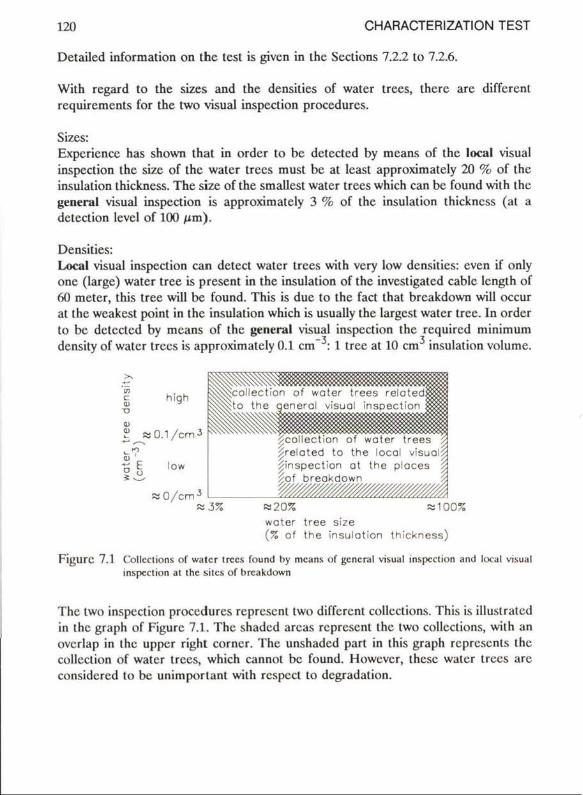
120 CHARACTERIZATION TEST
Detailed information on the test is givcn in the Sections 7.2.2 to 7.2.6.
With regard to the sizes and the densities of water trees, there are different requirements for the two visual inspection procedures.
Sizes: Expcricncc has shown that in order to be detected by means of the local visual inspection the size of the water trees must be at least approximately 20 % of the insulation thickness. The size of the smallest water trees which can be found with the general visual inspection is approximately 3 % of the insulation thickness (at a detection lcvcl of 100 /im).
Densities: Local visual inspection can detect water trees with very low densities: even if only onc (large) water tree is present in the insulation of the investigated cablc length of 60 meter, this tree will be found. This is due to the fact that breakdown will occur at the weakest point in the insulation which is usually the largest water tree. In order to be detected by means of the general visual inspection the required minimum density of water trees is approximately 0.1 cm" : 1 tree at 10 cm insulation volume.
x ai •o
high
? «0.1 /cm *
low
« O / c m 3
«J5%
^re loted to the local visual^ ^inspect ion ot the ploces ^ ^of breakdown
« 2 0 % «100% water tree size (% of the insulation thickness)
FigUre 7.1 Collcclions of water trees found by means of general visual inspection and local visual inspection at the sites of breakdown
The two inspection procedures represent two different collections. This is illustratcd in the graph of Figurc 7.1. The shadcd areas represent the two collections, with an overlap in the upper right corner. The unshadcd part in this graph represents the collection of water trees, which cannol bc found. Howevcr, these water trees are considcred to be unimportant with respect to degradation.
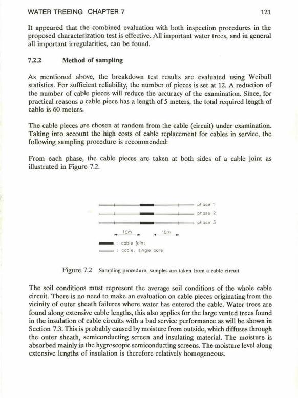
WATER TREEING CHAPTER 7 121
It appcarcd that the combincd evaluation with both inspection procedures in the proposed characterization test is effectivc. All important water trees, and in gcneral all important irregularities, can be found.
122 Method of sampling
As mentioned above, the breakdown test rcsults are evaluated using Weibull statistics. For sufficiënt reliability, the numbcr of pieces is set at 12. A reduction of the numbcr of cable pieces will reduce the accuracy of the cxamination. Since, for practical reasons a cable picce has a length of 5 meters, the total rcquired length of cablc is 60 meters.
The cablc pieces are chosen at random from the cable (circuit) under cxamination. Taking into account the high costs of cablc replacement for cablcs in service, the following sampling procedure is recommended:
From each phase, the cable pieces are taken at both sides of a cablc joint as illustrated in Figurc 7.2.
■ ^ | — i phase 1
I ^ | -■ pnosc 2
i I ^ ^ ^ i i onose 3
10m lOm M »• >* mt
^ ^ ^ H : cable Joint i i : cable, single core
F i g u r c 7.2 Sampling procedure, samples are laken from a cable circuit
The soil conditions must represent the average soil conditions of the whole cable circuit. There is no need to make an evaluation on cable pieces originating from the vicinity of outer sheath failurcs where water has entered the cablc. Water trees are found along extensivc cable lengths, this also applies for the large vented trees found in the insulation of cable circuits with a bad service performance as will be shown in Scction 7.3. This is probably caused by moisturc from outside, which diffuses through the outer sheath, semiconducting screen and insulating material. The moisture is absorbed mainly in the hygroscopic semiconducting sereens. The moisture lcvel along exlensive lengths of insulation is therefore relatively homogencous.
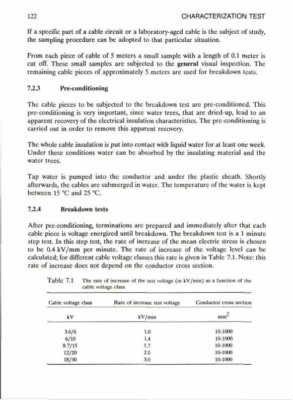
122 CHARACTERIZATION TEST
If a spccific part of a cable circuit or a laboratory-aged cabic is the subject of study, the sampling procedure can bc adopted to that particular situation.
From each piece of cable of 5 meters a small sample with a length of 0.1 meter is cut off. These small samples are subjected to the general visual inspcclion. The remaining cable pieces of approximately 5 meters are used for breakdown tests.
723 Pre-conditioning
The cable pieces to be subjected to the breakdown test are pre-conditioned. This pre-conditioning is very important, sincc water trees, that are dricd-up, lead to an apparent recovcry of the clectrical insulation characteristics. The pre-conditioning is carricd out in order to remove this apparent recovcry.
The whole cable insulation is put into contact with liquid water for at least one week. Under these conditions water can be absorbed by the insulating material and the water trees.
Tap water is pumped into the conductor and under the plastic sheath. Shortly afterwards, the cables are submerged in water. The temperaturc of the water is kept bctween 15 °C and 25 °C.
72.4 Breakdown tests
After pre-conditioning, terminations are prepared and immediately aftcr that each cable piece is voltage energizcd until breakdown. The breakdown test is a 1 minute step test. In this step test, the rate of increase of the mcan clcctric stress is chosen to bc 0.4 kV/mm per minute. The rate of increase of the voltage levcl can be calculatcd; for different cable voltage classes this rate is givcn in Table 7.1. Notc: this rate of increase does not depend on the conductor cross section.
T a b l e 7.1 The rate of increase of the test voltage (in kV/min) as a function of the cable voltage class
Cable voltage class Rate of increase test voltage Conductor cross section
kV kV/min mm2
3.6/6 1.0 10-1000 6/10 1.4 10-1000
8.7/15 1.7 10-1000 12/20 2.0 10-1000 18/30 3.0 10-1000
WATER TREEING CHAPTER 7 123
Weibull statistics are used to evaluate the breakdown results. General information about Weibull statistics is given, for instance, by Stone and van Heeswijk (1977). The two parameter Weibull distribution function presented in relation (7-1) is well suitcd for the cvaluation of these results.
P(Eb d) = 1 - exp{ -(Ebd/Ebd^e.))*} (7-1)
In which
P(Ebd) = the fraction of breakdown results with a mean breakdown stress level in the interval [0,Ebd]
Ebd = breakdown stress level, being the arithmetic mean value of the electric stresses in the inner and outer part of the insulation during breakdown
Ebd(63%) = the scalc parameter: the breakdown stress level at P(Ebd) = 0.63 B = the shape parameter: this parameter gives information about the
scatter of the breakdown values
Curve fitting is performcd with the maximum likelihood method. This gives an estimation of the scale parameter Ebd(63%) and the shape parameter B. For the small number of cable pieces in the characterization test (which is 12) the shape parameter has to be corrected into B c o r in a way proposed by Thoman, Bain and Antle (1969).
The confidence boundaries for B c o r and Ebd(63%) can be found in literature (Lawless, 1975,1978). The confidence intervals for Ebd(x%) are calculated by means of a computer program developed by Lawless (Lawless, 1975).
72.5 Observed causes of breakdown
In the characterization test presented in this study, the cnergy dissipated during breakdown has been reduced, which is one of the main advantagcs of this test procedure. In this way it is possiblc to find the causes of breakdown by local visual inspection. The inspection procedure and the test circuit will bc described in succession.
Local visual inspection
After the breakdown test the outer sheath, the earth screen and tapes are removed. The site of breakdown in the cable core can in many cases be found without any problem. Sometimes the breakdown channcl is vcry small and removal of the graphited semiconducting screen and careful investigation are necessary. In extreme cases the "trick of the punctured tire" can be applied: compressed air is entcred in
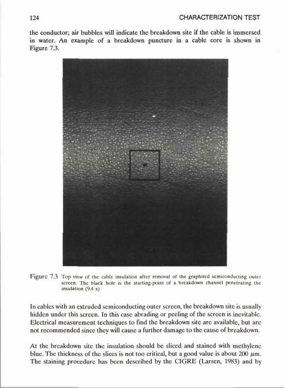
124 CHARACTERIZATION TEST
the conductor; air bubbles will indicatc the breakdown site if the cable is immersed in water. An example of a breakdown puncture in a cable core is shown in Figure 13.
Figurc 7.3 Top view of the cable insulalion aflcr removal of lhc graphitcd scmiconducling oulcr screen, 'llic black hole is the starting-point of a breakdown channcl pcnclraling lhc insulalion (9.4 x)
In cables with an extrudcd semiconducting outer screen, the breakdown site is usually hidden under this screen. In this case abrading or peeling of the screen is inevitablc. Electrical measurement techniques to find the breakdown site are available, but are not recommended sincc thcy will cause a further damagc to the causc of breakdown.
At the breakdown site the insulation should bc sliced and staincd with methylenc blue. The thickness of the slices is not too critical, but a good value is about 200 firn. The staining procedure has been described by the CIGRE (Larscn, 1983) and by
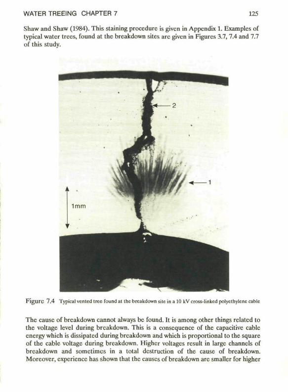
WATER TREEING CHAPTER 7 125
Shaw and Shaw (1984). This staining procedure is givcn in Appendix 1. Exampics of typical water trees, found at the breakdown sites are given in Figures 3.7, 7.4 and 7.7 of this study.
F i g u r e 7.4 Typical ventcd tree found at the breakdown site in a 10 kV cross-linked polyethylcnc cablc
The causc of breakdown cannot always be found. It is among other things related to the voltage level during breakdown. This is a conscqucnce of the capacitive cable energy which is dissipatcd during breakdown and which is proportional to the square of the cable voltage during breakdown. Highcr voltages result in large channels of breakdown and sometimes in a total destruction of the cause of breakdown. Moreover, experience has shown that the causes of breakdown are smaller for higher
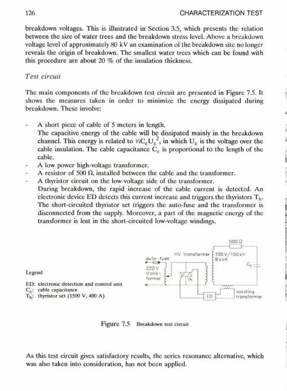
126 CHARACTERIZATION TEST
breakdown voltages. This is illustrated in Section 3.5, which presents the rclalion between the size of water trees and the breakdown stress level. Above a breakdown voltage level of approxhnalely 80 kV an cxamination of the breakdown site no longer reveals the origin of breakdown. The smallcst water trees which can be found with this procedure are about 20 % of the insulation thickness.
Test circuit
The main components of the breakdown test circuit are presented in Figure 7.5. It shows the measures taken in order to minimi/c the cnergy dissipatcd during breakdown. These involve:
A short picee of cablc of 5 meters in length. The capacitive cnergy of the cablc will be dissipatcd mainly in the breakdown channcl. This cnergy is relatcd to '/2CCUC , in which U c is the voltage over the cable insulation. The cablc capacitance Cc is proportional to the length of the cable. A low power high-voltage transformer. A resistor of 500 n , installed between the cable and the transformer. A thyrislor circuit on the low-voltage sidc of the transformer. During breakdown, the rapid increase of the cablc current is detected. An clectronic device ED detects this current increase and triggers the thyristors Th. The short-circuited thyristor set triggers the auto-fusc and the transformer is disconncctcd from the supply. Moreover, a part of the magnetic cnergy of the transformer is lost in the short-circuited low-voltage windings.
500 Q
outo-fuse
Legend
ED: clcclronic detection and conlrol unil C c : cable capacitance T n : lhyristor set (1500 V, 400 A )
i3Ol0ting transformer
F i g u r e 7.5 Urcakdown test circuit
As this test circuit gives satisfactory rcsults, the series resonance allcrnativc, which was also taken into considcration, has not been applied.
WATER TREEING CHAPTER 7 127
7.2.6 General visual inspection
Information on the types, sizes and dcnsitics of the various irregularities (impurities, water trees etc.) in the insulation volume is obtained by means of general visual inspection.
From the 12 small cable samples of about 10 cm in length, 3 samples are chosen randomly for inspection. In case of the cxamination of a 3-phase cable, it is recommended that the samples are taken from the 3 different phases.
The inspection of an insulation volume of approximately 10 cm is adequate: the inspection of larger volumes usually does not reveal more significant information.
Alter removal of the outer screen, tapes, copper screen and conductor, sliccs are cut with a microtome. A slice thickness of 200 firn is recommended. Larger thicknesses givc a rcduccd transparency, thinner slices may lead to doublé counting of separate parts of the same irregularity. Slices are stained according to the procedure described in Appendix 1.
The inspection is carried out by using a simple stcrcoscopic microscope with a magnification factor ranging between 5 and 50 times. All irregularities such as impurities and water trees larger than 100 /im are registered.
The presentation of data is important. In this test the following method is uscd:
Impurities and bow-tie trees which are present in the insulation volume are measured in "number per unit volume". Vcnted trees and irregularities such as impcrfcclions of the semiconducting sereens which are present at the insulation surface are given in "number per unit surface". If no irregularities have been observed similar units for the sizes and densities are given: * the minimum detectablc sizc (herc 100 /im). * the minimum detectablc density, that is the reciprocal value of the inspected
volume or surface (here about 1/10 cm which corresponds with about 1/0.3 dm respectively).
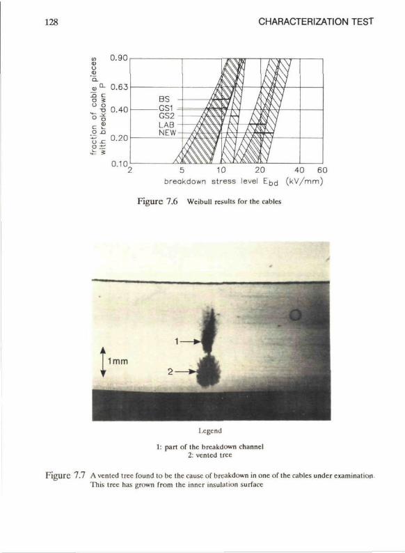
128 CHARACTERIZATION TEST
0.90
5 10 20 40 60 breakdown stress level ED( j ( k V / m m )
Figure 7.6 Wcibull results for the cablcs
Legend
1: part of the breakdown channcl 2: vented tree
F i g u r e 7.7 A vented tree found to bc the causc of breakdown in one of the cablcs undcr cxamination This tree has grnwn from the inner insulation surfacc
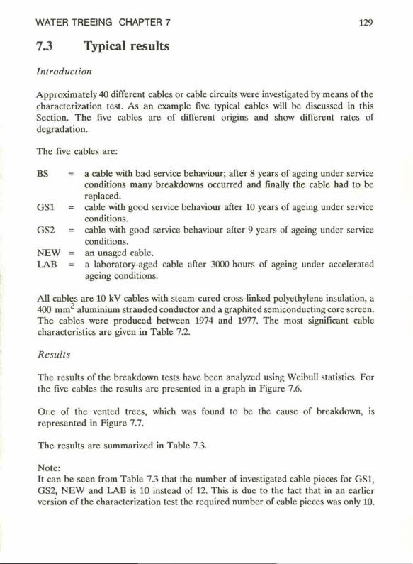
WATER TREEING CHAPTER 7 129
13 Typical results
Introduction
Approximately 40 different cablcs or cable circuits were investigated by means of the characterization test. As an cxamplc fivc typical cables will be discussed in this Section. The fivc cables are of different origins and show different rates of degradation.
The fivc cables are:
BS = a cable with bad service behaviour; aftcr 8 ycars of agcing undcr service conditions many breakdowns occurred and finally the cable had to bc replaced.
GS1 = cable with good service behaviour after 10 years of ageing undcr service conditions.
GS2 = cable with good service behaviour aftcr 9 ycars of agcing undcr service conditions.
NEW = an unaged cable. LAB = a laboratory-aged cable aflcr 3000 hours of ageing under accelerated
ageing conditions.
All cables are 10 kV cablcs with steam-curcd cross-linkcd polyelhylene insulation, a 400 mm aluminium stranded conductor and a graphited semiconducting corc screen. The cablcs were produced between 1974 and 1977. The most significant cable charactcristics are given in Table 7.2.
Results
The results of the breakdown tests have been analy/cd using Weibull statistics. For the five cables the results are prcscnlcd in a graph in Figure 7.6.
Oi.e of the vented trees, which was found to be the causc of breakdown, is represented in Figure 7.7.
The results are summarized in Table 7.3.
Note: It can be seen from Table 7.3 that the numbcr of investigated cable pieces for GS1, GS2, NEW and LAB is 10 instcad of 12. This is due to the fact that in an earlicr version of the characterization test the required numbcr of cable pieces was only 10.
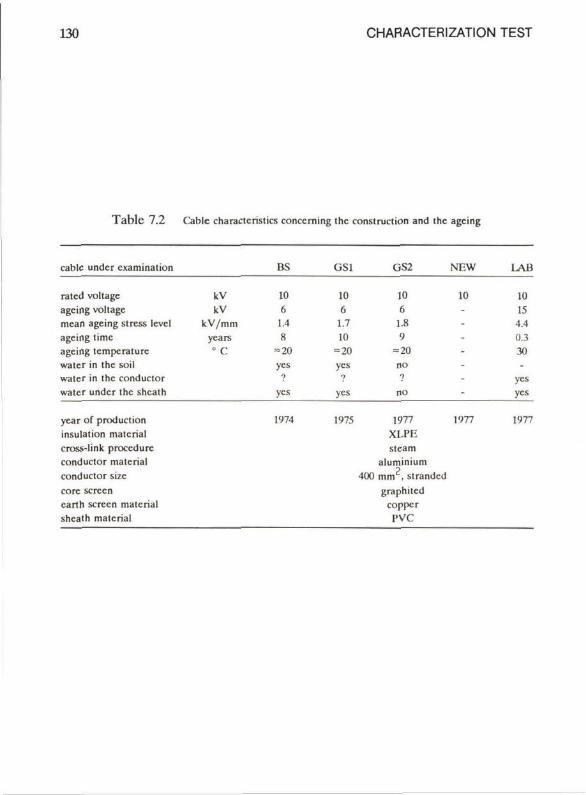
130 CHARACTERIZATION TEST
T a b l e 7.2 Cablc charactcristics conccming Ihc constniclion and ihc agcing
cablc undcr cxamination BS USl GS2 NEW L A B
rated voltage agcing voltage mcan ageing stress levcl agcing time agcing tempcraturc water in the soil water in the conductor water undcr the sheath
kV kV
kV/mm ycars
•c
10 6 1.4 8
=20 ycs
10 6 1.7 10
=20 ycs
in 6 1.8 9
= 20 no
10
ycs ycs no
10 15 •1,1 0.3 30
yes ycs
ycar of production insulation matcrial cross-link procedure conductor matcrial conductor sizc corc screen carth screen matcrial sheath matcrial
1974 1975 1977 XI.PF. stcam
aluminium 400 m m 2 , strandcd
graphilcd coppcr PVC
1977 1977
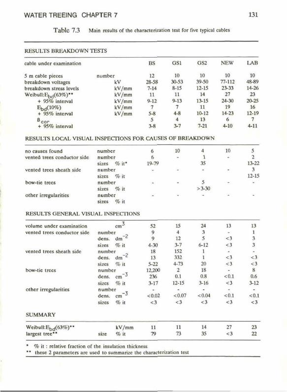
WATER TREEING CHAPTER 7
T a b l e 7.3 Main rcsulis of ihc characterization test for five typical cables
131
RESULTS BREAKDOWN TESTS
cable under examination
5 m cable picces breakdown voltages breakdown stress levels Wcibull :Eb d(63%)"
+ 95% interval Efad(10%) + 95% interval B c o r + 95% interval
numbcr kV kV/mm kV/mm kV/mm kV/mm kV/mm
BS
12 28-58 7-14 11
9-12 7
5-8 5
3-8
GS1
10 30-53 8-15
11 9-13
7 4-8 4
3-7
GS2
10 39-50 12-15
14 13-15
11 10-12
13 7-21
RESULTS LOCAL VISUAL INSPECTIONS FOR CAUSES OF BREAKDOWN
NEW
10 77-112 23-33
27 24-30
19 14-23
6 4-10
LAB
10 48-89 14-26
23 20-25
16 12-19
7 4-11
no causes found number vented trees conductor sidc numbcr
sizes % it* vented trees shcath sidc numbcr
sizes % it bow-tie trees number
sizes % it other irregularities number
sizes % it
RESULTS GENERAL VISUAL INSPECTIONS
6 6
19-79
10 4 1
35
5 >3-30
Ki 5 2
13-22 3
12-15
volume under examination vented trees conductor side
vented trees shcath sidc
bow-tic trees
other irregularities
SUMMARY
cm number dens. dm sizes % it number dens. dm sizes % it numbcr dens. cm sizes % it numbcr
3
-2
-2
-3
dens. sizes
cm -3
52 9 9
4-30 18 13
5-22 12,200 236 3-17
<0.02 <3
15 4 12 3-7 152 332 4-73
2 0.1
12-15
<0.07 <3
24 3 5
6-12 1 1
2(1 18 0.8 3-16
<0.04 <3
13 -
<3 <3 -
<3 <3 -
<0.1 <3
<0.1 <3
13 1 3 3 -
<3 <3 8
0.6 3-12
<0.1 <3
Wcibull :Eb d(63%)" largest tree""
kV/mm % i t
11 79
11 73
14 35
27 <3
23 22
% it : rclative fraction of the insulation thickness these 2 parameters are uscd to summarizc the characterization test
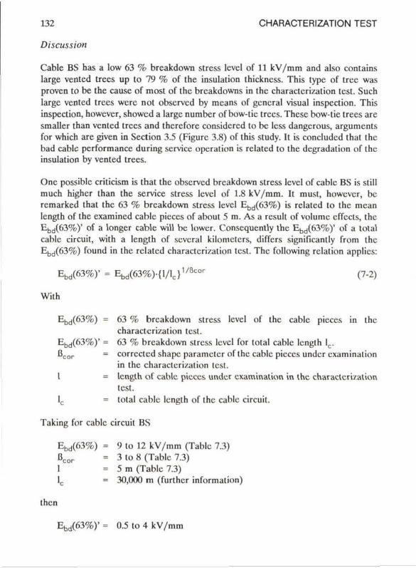
132 CHARACTERIZATION TEST
Discussion
Cable BS has a low 63 % breakdown stress level of 11 kV/mm and also contains large vented trees up to 79 % of the insulation thickncss. This type of tree was proven to be the cause of most of the breakdowns in the characterization test. Such large vented trees wcrc not observed by means of general visual inspection. This inspection, however, showed a large numbcr of bow-tie trees. These bow-tie trees are smaller than vented trees and thcrefore considered to bc less dangerous, arguments for which are given in Section 3.5 (Figure 3.8) of this study. It is concluded that the bad cable performance during service operation is rclatcd to the degradation of the insulation by vented trees.
Onc possible criticism is that the observed breakdown stress level of cable BS is still much highcr than the service stress level of 1.8 kV/mm. It must, however, bc remarked that the 63 % breakdown stress level Ebd(63%) is related to the mean length of the examincd cable pieecs of about 5 m. As a rcsult of volume cffects, the Ebd(63%)' of a longer cable will be lowcr. Conscquently the Ebd(63%)' of a total cable circuit, with a length of scvcral kilometers, differs significantly from the Ebd(63%) found in the related characterization test. The following relation applies:
Ebd(63%)' = E b d ( 6 3 % ) - { l / l c } , / I W (7-2)
With
Ebd(63%) = 63 % breakdown stress level of the cable pieces in the characterization test.
Ebd(63%)' = 63 % breakdown stress level for total cable length lc. B c o r = corrected shape parameter of the cable pieces under examinalion
in the characterization test. 1 = length of cable pieces under examinalion in the characterization
test. lc = total cable length of the cable circuit.
Taking for cable circuit BS
Ebd(63%) = 9 to 12 kV/mm (Table 7.3) B c o r = 3 to 8 (Table 7.3) 1 = 5 m (Table 7.3) lc = 30,000 m (further information)
then
Ebd(63%)' = 0.5 to 4 kV/mm

WATER TREEING CHAPTER 7 133
The calculated breakdown stress lcvel of the cable circuit is of the same order of magnitude as the service stress levcl of cable BS which was 1.8 kV/mm. It shows that Weibull statistics are an adequate tooi to investigate the clcctrical degradation of a cable.
Cable GS1 also has a low 63 % breakdown stress level of 11 kV/mm. No impurities have been found at the breakdown sites. As a rcsult of the general visual inspection many largc pencil-Iikc vented trees were found of up to 73 % of the insulation thickness. These trees have also been found close to the breakdown sites. As the observed trees are pencil-like it is probable that these trees wcrc completely destroyed during breakdown. The large number and sizes of the vented trees found during the general visual inspection substantiate the conclusion that these trees are related to the low breakdown stress level of the cable. The conclusion is that the level of degradation of this cable is comparable to that of cable BS. Although this cable showcd a good service performance, the cable insulation can be considcred unreliable. In such a situation the involvcd cable user is recommendcd to replace the cable.
Cable GS2 has a 63 % breakdown stress level of 14 kV/mm. Venlcd trees and bow-tie trees have been found at the breakdown sites and by mcans of general visual inspection, with sizes up to 35 % of the insulation thickness. These results show that there is significant insulation degradation. The cable has a good service performance, however, further degradation can bc expectcd. In this situation the cable user is recommendcd to repeat the characterization test on this cable circuit wilhin a few years.
Cable NEW has a high 63 % breakdown stress level of 27 kV/mm and, as expected, no impurities larger than 100 /im (about 3 % of the insulation thickness) were found.
The last cable involvcd in the cxamination was cable LAB. In this case too, the 63 % breakdown stress lcvel is high, about 23 kV/mm. At the breakdown sites and by means of general visual inspection a first treeing has been observed; trees of up to 22 % of the insulation thickness were found. The conclusion is that this laboratory-agcd cable shows first indicalions of insulation degradation.
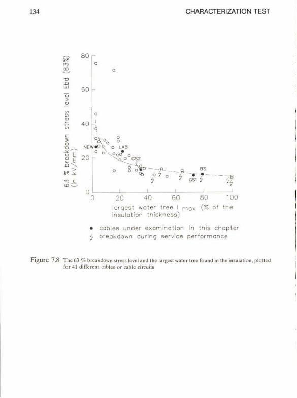
134 CHARACTERIZATION TEST
CD
O '.1
>
01 (0
c ï
o
□ 0)
80 r
60 -
40 -
ro C lO -O
0 , ° 0 NEW«O0 o LAB
--■Ck? G S 2
7 - 8 . BS
GS1 $ ■ :
20 40 60 80 100 largest water tree I max (% of the insulation thickness)
• cables under examinotion in this chapter 7 breakdown during service performance
Figurc 7.8 The 63 % breakdown stress Icvcl and the largest water tree Ibund in the insulation, plotled for 41 different Cablcs or cablc circuits
WATER TREEING CHAPTER 7 135
7.4 Classification procedure
From the tests performed it appeared that the following two parameters are the most significant:
the 63 % breakdown stress level: Ebd(63%) the largest water tree lmax found eithcr by mcans of local visual inspection at the breakdown sites or by means of general visual inspection
Both parameters summarize the results of the charactcrization test. In Figure 7.8 the results of 41 different cablcs or cable circuits are represented.
Each of the 41 cables or cable circuits is represented by onc dot on the graph; the typical examples BS, GS1, GS2, NEW and LAB have been markcd. The broken line represents a power curve, it is the best fit power curve for the 41 data points involved.
With this method of presentation it is possible to classify the ratc of cable degradation. "Good" cables with a low rate of degradation are situated in the upper left corner. "Bad" cablcs with a high rate of degradation are in the bottom right corner; cable circuits which showed bad service performance can also bc found in this corner.
The conclusion is that this method of presentation gives a good picture of the insulation degradation by water trees.
136 CHARACTERIZATION TEST
7.5 Conclusions
The "characterization test" yields information of a cablc circuit on the clectrical properties as well as on the background of electrical degradation. The electrical properties are studied with breakdown tests on a set of cablc picecs taken from the cable circuit. Insight into the background of degradation is oblaincd by analysis for the causes of breakdown. Techniques have been developed to find these causes.
Over 40 different cablc circuits were investigated by means of the characterization test. A suitable method -the classification procedure- was found to summarize the results of the test. In this procedure the following information for each cable circuit is presented in one graph:
63 % breakdown stress levcl the size of the largest water tree, found by means of a set of special techniques.
Each cable circuit can bc representcd by onc dot in this graph; the position of this dot in relation to the position of the dots of the olher cablc circuits yields significant information about the rate of degradation of the cablc circuit under investigation.
WATER TREEING CHAPTER 8 137
8 INVESTIGATION OF A CABLE NETWORK
8.1 Introduction
From the 41 cables which have been mentioned in the previous Chaplcr a sclection is taken for further investigation. Those cable circuits which have similar ageing and cable construction charactcristics were selected.
The degradation and the background of this degradation is studied for 24 different cable circuits from a specific cable network (Steennis et al, 1989). The cables were aged under service conditions, the rate of degradation was determined by applying the characterization test.
8.2 Cable characteristics
Important cable characteristics such as construction, hislorical data and ageing conditions are given in Appendix 3. Most cables are 10 kV cross-linkcd polycthylene insulated cables with an aluminium stranded conductor of 4(K) mm . The inner semiconducting screen is extruded, the insulating material is cross-linked according to the steam-curing or the onc-shot silane-curing process. The semiconducting outcr screen is graphited or extruded. All cables have a polyvinyl chloride outer sheath, in onc case an extruded lead sheath over the core has been applied as wcll. The cables originate from 7 different manufacturers and have been aged in service for about 7 to 10 years. In most cases the cable circuits were installed in wet soil. Of the cable circuits under examination 18 showed an excellent service performance (up till now) and 6 cable circuits have been replaced as a consequence of repeated breakdown during service. In Appendix 3 the replaced cable circuits are marked with "b.down" in the column "service performance". The basic design of the cables under investigation is given in Figure 1.1 of this study.
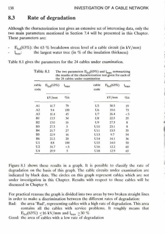
138 INVESTIGATION OF A CABLE NETWORK
8.3 Rate of degradation
Although the characterization test gives an extensive set of intercsiing data, only the two main parameters mentioned in Scction 7.4 will bc presented in this Chapter. These parameters are:
Ebd(63%): the 63 % breakdown stress level of a cable circuit (in kV/mm) Lax: t n c 'argcst water tree (in % of the insulation thickness)
Tablc 8.1 gives the parameters for the 24 cables under examination.
T a b l e 8.1 The two parameters £^^(63%) and l m a x summarizing the rcsults of the characterization lest givcn for cach of the 24 cables under examination
cablc Ebd(63%) lm a x cablc 1-^(63%) 1 ^ code code
Al A2 A3 BI B2 B3 B4 B5 U(, UI U2 U4
kV/mm
10.7 9.4 10.4 13.5 13.0 27.3 21.7 22.9 22.2 8.8 31.7 29.9
%it
79 100 45 34 16 5 27 16 20 100 <3 s
U5 U6 U7 U8 U9 U10 Ui l U13 U14 U15 U16 U18
kV/mm
30.5 10.6 26.4 22.5 27.3 23.1 13.5 9.7 14.1 14.0 12.2 12.9
%it
19 73 <3 20 8 8 35 54 36 50 65 65
Figurc 8.1 shows these rcsults in a graph. It is possibic to dassify the rate of degradation on the basis of this graph. The cablc circuits under examination are indicatcd by black dols. The circles on this graph represent cables which are nol under invesligation in this Chapter. Rcsults wilh respcel lo Ihose cables will be discusscd in Chapter 9.
For practical rcasons the graph is divided into two arcas by two broken straight lincs in order to makc a discrimination between the different rales of degradation: Bad: the area "Bad", rcprescnling cables with a high rate of degradation. This area
contains all the cables with service problems. Il roughly means thal Ebd(63%) <16 kV/mm and ^ >30 %
(Jood: the area of cables with a low rate of degradation
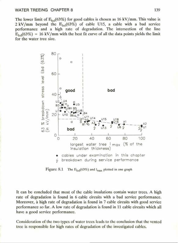
WATER TREEING CHAPTER 8 139
The lowcr limit of Ebd(63%) for good cables is chosen as 16 kV/mm. This value is 2 kV/mm beyond the Ebd(63%) of cable U15, a cable with a bad service performance and a high rate of degradation. The intersection of the line Ebd(63%) = 16 kV/mm with the best fit curve of all the data points yields the limit for the water tree size.
6° ■O
-O ÜJ
> o
(0 H 9> L_ 05
i S o "O _
S E
80 r
60 -
40 good
| O» »U90 B5
20 h U10 B6o°
bod
B4 U11
B1
bod
Q _ y * U15 U18 f A Ï r - - | i " 6 AI t> «7 . f—r-f——
7 U13 7 U 6 7 • '
A2 U1
20 40 60 80 100 largest water tree I mox (% of the insulation thickness)
• cobles under examination in this chapter 4 breakdown during service performance
F i g u r c 8 . 1 The Rb t j (63%) and l m a x plotled in onc graph
It can be concludcd that most of the cable insulations contain water trees. A high rate of degradation is found in 6 cable circuits with a bad service performance. Moreover, a high rate of degradation is found in 7 cable circuits with good service performance so far. A low rate of degradation is found in 11 cable circuits which all have a good service performance.
Consideration of the two types of water trees leads lo the conclusion that the vented tree is responsible for high ratcs of degradation of the investigated cables.
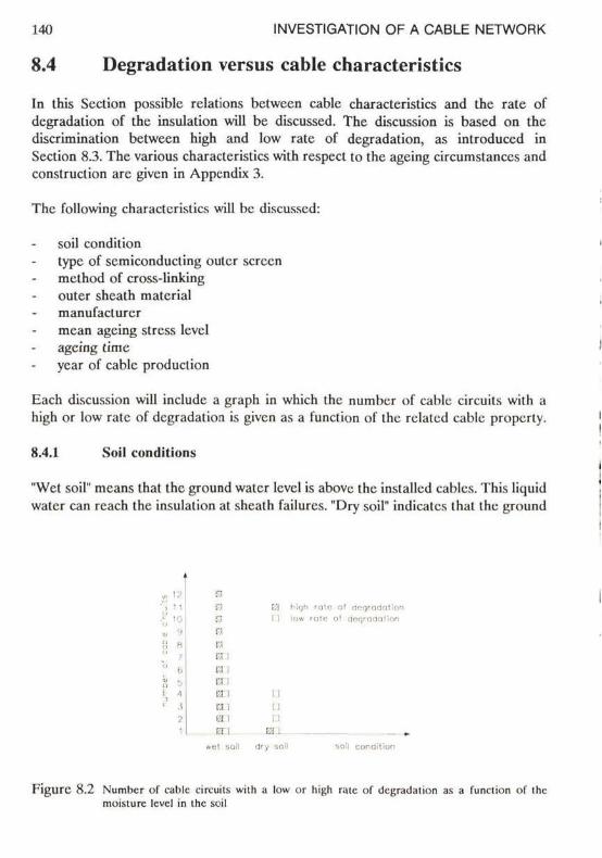
140 INVESTIGATION OF A CABLE NETWORK
8.4 Degradation versus cable characteristics
In this Scction possible relations between cable characteristics and the rate of degradation of the insulation will be discussed. The discussion is based on the discrimination between high and low rate of degradation, as introduccd in Section 8.3. The various characteristics with respect to the ageing circumstances and construction are given in Appendix 3.
The following characteristics will bc discussed:
soil condition type of semiconducting ouler screen method of cross-linking outer sheath material manufaclurer mean ageing stress level ageing time ycar of cablc produclion
Each discussion will include a graph in which the number of cablc circuits with a high or low rate of degradation is given as a function of the rclatcd cable property.
8.4.1 Soil conditions
"Wet soil" mcans that the ground water level is abovc the installed cables. This liquid water can rcach the insulation at sheath failurcs. "Dry soil" indicatcs that the ground
ito ' logrodatlon I ItC al cteqrodalion
I i I I I I
■:i . .
dry soil soil condil
Flgure 8.2 Number of cablc circuits with a low or high rate of tlcgradalion as a function of the moisturc level in the soil
' ■ • ■
'" '
• ■
' • ', •1 ) 2 1
E3 m ■■■
■■■
: ■
:': EU 0 rai ■ : ;
m\ :/!
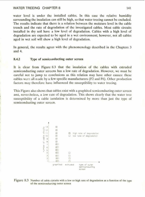
WATER TREEING CHAPTER 8 141
water level is under the installed cabies. In this case the rclative humidity surrounding the insulation can still be high, so that water trccing cannot bc excludcd. The results indicate that there is a relation bctween the moisture level in the cable trench and the rate of degradation of the investigatcd cabies. Most cable circuits installed in dry soil have a low level of dcgradation. Cabies with a high Icvcl of degradation are expected to be aged in a wet environment; however, not all cabies aged in wet soil will show a high level of degradation.
In general, the results agree with the phenomcnology dcscribed in the Chapters 3 and 4.
8.42 Type of semiconducting outer screen
It is clear from Figure 8.3 that the insulation of the cabies with extruded semiconducting outer sereens has a low rate of degradation. However, we must be careful not to jump to conclusions as this relation may have other causes: these cabies were all made by a few specifie manufacturers (F2 and F6). Othcr production factors may therefore have influenccd the susceplibility to water treeing.
This Figure also shows that cabies exist with a graphited semiconducting outer screen ana, nevenheless, a low rate of degradation. This shows clearly that the water tree susceplibility of a cable insulation is determined by more than just the type of semiconducting outer screen.
. 1 3
i« b n s 10
8 9 o 8
l| 1
O
ra ■::■
;:■
■::■
ra
03 ran En en
■-■
□
D -□ n
hlgn rote o* degradation low rate of degradation
graphitefl exiruded type o' outer sem Icon auct ing screen
F i g u r e 8.3 Numbcr of cable circuits with a low or high rate of degradation as a function of the type of the semiconducting outer screen
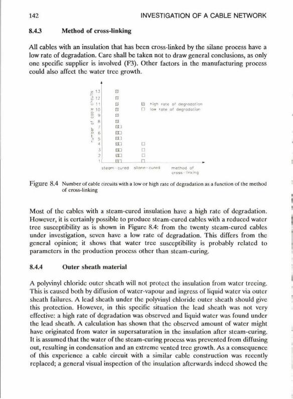
142 INVESTIGATION OF A CABLE NETWORK
8.43 Method of cross-Iinking
All cables with an insulation that has been cross-linked by the silane process have a low rate of dcgradation. Care shall be taken not to draw general conclusions, as only onc spccific supplier is involved (F3). Other factors in the manufacturing process could also affect the water tree growth.
: " ■
£3 E2 hiqh rolc ot dcgradation P3 n low rate o* degradolion 0 *;:■
:'.! f.-H l en a ED D
■:■. n _ _
sleam curod si lonc-cured method of cross Mnking
F i g u r e 8.4 Numbcr of cablc circuits wilha low or high ralc of dcgradation as a function of the method of cross-Iinking
Most of the cables with a steam-cured insulation have a high rate of dcgradation. Howcver, il is certainly possiblc to produce steam-curcd cables with a rcduced water tree susceplibility as is shown in Figure 8.4: from the twenty steam-cured cables undcr investigation, scven have a low rate of dcgradation. This differs from the general opinion; it shows that water tree susceplibility is probably relatcd to parameters in the production process other than steam-curing.
8.4.4 Outer sheath mateiïal
A polyvinyl chloride outcr sheath will nol prolecl the insulation from water ireeing. This is caused bolh by diffusion of water-vapour and ingress of liquid water via outer sheath failures. A lead sheath under the polyvinyl chloride outer sheath should givc this protcclion. However, in this spccific situation the lead sheath was not very cffcctivc: a high rate of dcgradation was observed and liquid water was found under the lead sheath. A calculalion has shown that the observed amount of water might have originated from water in supersaturation in the insulation aftcr steam-curing. It is assumcd that the water of the steam-curing process was prevented from diffusing out, rcsulling in condensation and an extreme vented tree growth. As a consequcnce of this experience a cable circuit with a similar cablc construction was reccntly replaced; a general visual inspection of the insulation aftcrwards indeed showcd the
m — -8 • u S
8 • o ■ : .
i ï
13
•:• • ■
•u ■>
-' • ■••
3 2 '
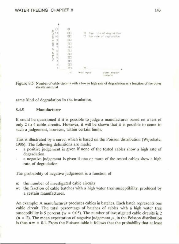
WATER TREEING CHAPTER 8 143
E» ü ] fa High rote of aegroaotion d j D low rote of aegradation
■ ■
: ' - ■
■ :
:'.T ■ : : ■ -
r.i ETI -Hn 0 » pvc lead -fpvc outer r,ncotn
F i g u r e 8.5 Number of cablc circuits with a low or high rate of degradation as a function of the outer shcath matcrial
same kind of degradation in the insulation.
8.4.5 Manuracturer
It could be questioned if it is possible to judge a manufacturer based on a test of only 2 to 4 cable circuits. However, it will be shown that it is possible to come to such a judgemcnt, however, within ccrlain limits.
This is illustratcd by a curve, which is based on the Poisson distribution (Wijvckate, 1986). The following definitions are made:
a positivc judgemcnt is given if none of the tested cables show a high rate of degradation a ncgativc judgemcnt is given if one or more of the tested cables show a high rate of degradation
The probability of ncgativc judgemcnt is a function of
n: the number of investigated cable circuits w: the fraction of cablc batches with a high water tree susceptibility, produced by
a certain manufacturer.
An example: A manufacturcr produces cables in batches. Each batch represents one cable circuit. The total percentage of batches of cables with a high water tree susceptibility is 5 percent (w = 0.05). The number of investigated cable circuits is 2 (n = 2). The mean expectation of negative judgement fin in the Poisson distribution is thus n-w = 0.1. From the Poisson tablc it follows that the probability that at least
M o „
Ij
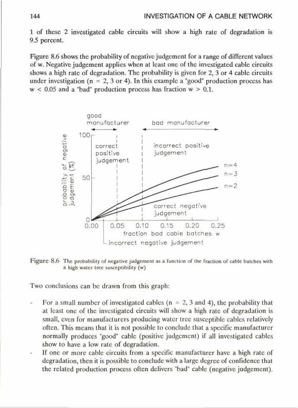
144 INVESTIGATION OF A CABLE NETWORK
1 of these 2 investigated cable circuits will show a high rate of degradation is 9.5 percent.
Figure 8.6 shows the probability of negative judgement for a range of different values of w. Negative judgement applies whcn at least onc of the investigated cable circuits shows a high rate of degradation. The probability is given for 2, 3 or 4 cable circuits under invcstigation (n = 2, 3 or 4). In this examplc a "good" production process has w < 0.05 and a "bad" production process has fraction w > 0.1.
o
o O ' Q> t
i.K
good monufacturer
100 r
S E
O CD
C L . 3 ,
50
correct positive judgement
0.00
bad monufacturer ■« ►■
incorrect positive I judgement
correct negative judgement
i L 0.05 0.10 0.15 0.20 0.25
fraction bad cable batches w L incorrect negative judgement
Figure 8.6 The probability of negative judgement as a function of the fraction of cable batches with a high water tree susccptibility (w)
Two conclusions can bc drawn from this graph:
For a small numbcr of investigated cablcs (n = 2, 3 and 4), the probability that al least onc of the investigated circuits will show a high rate of degradation is small, even for manufacturers producing water tree susccptible cablcs rclalivcly oftcn. This means that il is nol possible to concludc that a specifie manufacturcr normally produces "good" cable (positive judgement) if all investigated cablcs show to have a low rate of degradation. If onc or more cable circuits from a specifie manufacturcr have a high rate of degradation, then it is possible to concludc with a large degree of confidence that the rclated production process oftcn dclivcrs "bad" cable (negative judgement).
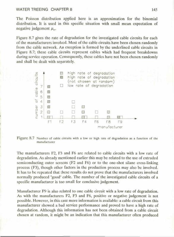
WATER TREEING CHAPTER 8 145
The Poisson distribution applicd here is an approximation for the binomial distribution. It is used in this specific situation with small mean expectation of negative judgement /Jn.
Figure 8.7 gives the rate of degradation for the investigated cable circuits for each of the manufacturers involved. Most of the cable circuits have been chosen randomly from the cable network. An cxception is formed by the undcrlincd cable circuits in Figure 8.7; these cable circuits represent cables which had frequent breakdowns during service operation. Consequently, these cables have nol been chosen randomly and shall bc dealt with separately.
3 U
i
BES
0 B3 E ;.-; :
■■:■
■■■:
D
D n
high rate of degradation high rate of degradation (not chosen at random) low rate of degradation
D D 0 O 0 D 0 n m n es isn
F1 F2 F3 F4 F6 F8 r 9 manufacturer
F i g u r e 8.7 Numbcr of cable circuils wi ih a low or high rate of degradation as a function of the manufacturer
The manufacturers F2, F3 and F6 are relatcd to cable circuits with a low rate of degradation. As already mentioncd earlier this may be related to the use of extrudcd semiconducting outer sereens (F2 and F6) or to the one-shot silane cross-linking process (F3), though othcr factors in the production process may also be involved. It has to bc repeated that ihcsc resulls do not prove that the manufacturers involved normally produced "good" cable. The numbcr of the investigated cable circuits of a specific manufacturer is too small for conclusive judgement.
Manufacturer F9 is also related to one cable circuit with a low rate of degradation. As with the manufacturers F2, F3 and F6, positive or negative judgement is not possible. However, in this case more information is available: a cable circuit from this manufacturer showed a bad service performance and proved to have a high rate of degradation. Although this information has not been obtained from a cable circuit chosen at random, it might be an indication that this manufacturer often produced
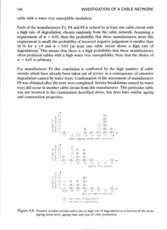
146 INVESTIGATION OF A CABLE NETWORK
cablc with a water tree susceptible insulation.
Each of the manufacturcrs Fl, F4 and F8 is rclated to at least one cable circuit with a high rate of degradation, chosen randomly from the cable network. Assuming a requirement of w < 0.05, then the probability that these manufacturcrs meet this requirement is small; the probability of incorrect negative judgement is smaller than 18 % for n <4 and w < 0.05 (at least one cable circuit shows a high rate of degradation). This means that there is a high probability that these manufacturers often produced cables with a high water tree susceptibility. Note that the choice of w < 0.05 is arbitrary.
For manufacturer Fl this conclusion is confirmcd by the high number of cable circuits which have already been taken out of service as a conscqucncc of extensive degradation causcd by water trees. Confirmation of the assessment of manufacturer F8 was obtaincd aftcr the tests werc completed. Service breakdowns causcd by water trees did occur in another cable circuit from this manufacturer. This particular cablc was not involvcd in the cxamination described above, but does have similar agcing and construction propertics.
1.1
t l :': K i l
D ED
D en B3 a : t l : 1.5 1.6 1.7
•■:>.
t l . 1.2 1.3 1.4 1.5 1.6 1.7 1.8
rneon ageing stress level ( k V / m m )
■:-.
;:■
(i
: i
u n
D I ! D i l
En 7
Kf t l Rn
Bi El H ETI 8
EJ ED a
El Ei t l 1 En 9
t l r.'I t l 171
En 10
oqcing
ra
El ■ 11 1? 13 l lmc
KI . 19 /9 / 8 7? / 6 /i> /4 /-S 72
year o ' cable producl ion
E3 high rotc o l degradation G low 'Otc ot degrodotion
F i g u r c 8.8 Number of cablc circuits wilh a low or high ralc of dcgradalion as a funclion of ihc mcan agcing stress leve!, agcing time and ycar of cablc produclion
WATER TREEING CHAPTER 8 147
As a rcsult of the investigations all steam-cured cables from the manufacturers Fl, F4 and F8 are bcing replaced.
8.4.6 Mean ageing stress level, ageing time and year of cable production
Within the limited variables sludicd hcrc there appcars lo bc no indicalion of relations between the rate of degradation and the mean electric stress level, the ageing time or the year of cable production. Such a relation was also not found for the cables of the individual supplicrs. Any effect is probably overruled by the effcel of the individual cable suppliers.
148 INVESTIGATION OF A CABLE NETWORK
8.5 Conclusions
Cables, installed above the ground water level (dry soil), may still be affected by water trees since the relativc humidity of this soil can be high at cable depth.
A polyvinyl chloride outer sheath is not effective to obtain a low ratc of insulation degradation by water trees.
A lead sheath applicd over a cable core can be uscd to exclude water from the soil. Howcvcr, if water is cnclosed during production (steam-curing) the remedy may bc worse than the disease.
The characterization test can single out manufacturcrs, who at that time frcqucntly produced cables with a high water tree susceptibility. The water tree susceptibility of cables from 7 manufacturcrs was investigatcd. There is a high probability that 3 manufacturers often produced "bad" cables. It cannot bc concluded that this is rclatcd to the usc of steam-curing or graphited semiconducting outer sereens; othcr manufacturcrs are able to produce such cables without a high water tree susceptibility.
One-shot silane-curing and extrudcd semiconducting oulcr sereens are rclatcd to certain manufacturcrs. There are indications that these measures are effective, sincc in all investigated cables the rate of degradation is low. Howcvcr, specific manufacturcrs are involved, which indicates that also other factors in ihc production process may affect the water tree susceptibility. An accurate judgement of these manufacturers and the effectiveness of silane-curing or extrudcd semiconducting outer sereens can bc givcn only aftcr conlinucd investigation of similar cables from the same and othcr manufacturcrs.
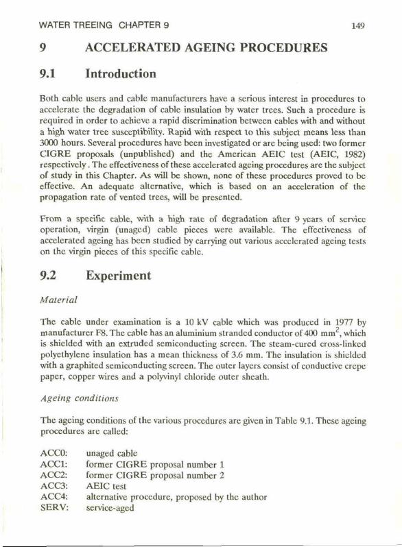
WATER TREEING CHAPTER 9 149
9 ACCELERATED AGEING PROCEDURES 9.1 Introduction
Both cablc uscrs and cablc manufacturers have a scrious interest in procedures to acceleratc the degradation of cable insulation by water trees. Such a procedure is required in order to achieve a rapid discrimination betwecn cablcs with and without a high water tree susceptibility. Rapid with respect to this subject means less than 3000 hours. Several procedures have been investigated or are bcing uscd: two former CIGRE proposals (unpublishcd) and the American AEIC test (AEIC, 1982) respcctivcly. The effectiveness of these acceleratcd agcing procedures are the subject of study in this Chapter. As will bc shown, none of these procedures provcd to bc effective. An adequate allcrnativc, which is based on an accclcration of the propagation ratc of vented trees, will be presentcd.
From a specifie cable, with a high ratc of degradation after 9 years of service operation, virgin (unagcd) cablc pieces were availablc. The effectiveness of accelerated ageing has been studicd by carrying out various acceleratcd agcing tests on the virgin pieces of this specifie cable.
9.2 Experiment
Material
The cable under examination is a 10 kV cable which was produccd in 1977 by manufacturcr F8. The cable has an aluminium strandcd conductor of 400 mm2, which is shieldcd with an extruded semiconducting screen. The steam-cured cross-linkcd polycthylcne insulation has a mean thickness of 3.6 mm. The insulation is shiclded with a graphited semiconducting screen. The outer layers consist of conductive crepe paper, copper wires and a polyvinyl chloride outcr sheath.
Ageing conditions
The agcing conditions of the various procedures are given in Tablc 9.1. These ageing procedures are callcd:
ACC0 ACC1 ACC2 ACC3 ACC4 SERV
unaged cable former CIGRE proposal number 1 former CIGRE proposal number 2 AEIC test allcrnativc procedure, proposed by the author service-aged
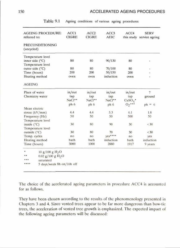
150 ACCELERATED AGEING PROCEDURES
Tablc 9.1 Ageing conditions of va nous agcing procedures
AGF.ING PROCEDURE: ACC1 ACC2 ACC3 ACC4 SERV referrcd to: CIGRE CIGRE AEIC Ihis study service agcing
PRECONDITIONING (uncyclcd)
Tcmpcrature levcl inner side (°C) 'rcmpcralurc levcl oulcr side (°C) Time (hours) Ilcaling method
AGEING
Place of water Chemistry waler
Mcan clcclric stress (kV/mm) Frcqucncy (Hz) 'I'cmpcraturc levcl inside (°C) Tempcraturc levcl oulside (°C) Temp. cyclcs llcating method Time (hours)
10 g/100 g l l 2 0 0.02 g/100 g H2(> saturatcd 5 days/weck 8h on/lfih off
The choice of the acceleratcd ageing parameters in procedure ACC4 is accounlcd for as follows.
Thcy have been choscn according to the rcsulls of the phenomenology presented in Chapters 3 and 4. Since ventcd trees appear to bc far more dangerous than bow-tie Irccs, the accclcralion of vented tree growth is emphasi/cd. The expected impact of the following ageing parameters will bc discussed:
80 80
80 80 200 200
oven oven
90/130 80
70/100 80 50/150 200
induction oven
in/out tap
N a C l " ph 6
4.4 50
in/out tap
N a C l " p h 6
4.4 50
in/out tap
N a C l " p h 6
5.3 50
in /ou l tap
C u S C V o 2 " '
6.1 500
ground
ph - 6
1.8 50
30 80 90 30 < 30
30 no
bath 3000
BC no
bath 1000
70
ycs.... induction
2880
30 no
bath 1917
<30 yes
induction 9 ycars
WATER TREEING CHAPTER 9 151
- electric stress level - frequency of the electric stress - tempcraturc - mechanical stress level - place of the liquid - chemical nature of the liquid - time - pre-conditioning
Electric stress level
An increase of the electric stress will lead to an increase of the size of ventcd trees. In order to avoid undcsirable ageing mechanisms such as partial discharges, the highcst acccptable ageing stress level is about three times the design stress level of a cable. A mcan electric stress of 6.1 kV/mm has been chosen.
Frequency of the electric stress
The highcst growth efficiency per unit time is reached at a few kHz; abovc this level the efficiency dccrcascs. For practical reasons (capacitivc current of the cable picecs) a frequency of 500 Hz has been chosen.
Temperature
Ventcd tree growth is not really affected by temperature cycling with or without a temperature gradiënt over the insulation. At a constant temperature level the most favourablc temperature region is 30 to 50 °C. A temperature of 30 °C, uncycled and without a gradiënt over the insulation, has been chosen.
Mechanical stress level
At present a recommendation for an artificially imposcd mechanical stress cannol bc given on the basis of the phcnomenology.
Place of the water
Water present in the stranded conductor and under the plastic outer shcath.
Chemical addilives
Many authors found a positive correlation bctween the ventcd tree propagalion rate and the amount of a certain salt dissolved in water, mostly NaCI and CuSO^. Moreovcr, recent literalurc and the proposcd process of electrochcmical degradation
152 ACCELERATED AGEING PROCEDURES
(Chapter 6) cmphasize that the growth of vcntcd trees is related to the oxidation of the polycthylene. The following liquid has thercfore been chosen: tap water wilh 10 gram CuSO^ per 100 gram water and the water is saturated wilh oxygen.
Time
It is the purpose of this investigation lo develop an ageing procedure which is effective within a few thousand hours. In Figure 9.1 the ageing time of the various accelerated ageing procedures is given.
Pre-conditioning
Pre-conditioning of the cables is nccessary in order to evaporate water tree retardant residual products. A well-known water tree retardant residual product is acetophenone from the cross-linking process of pcroxidc-cured cables. Pre-conditioning is carried out according to procedures ACC1 and ACC2 in a ventilatcd oven at 80 °C for 200 hours prior to ageing.
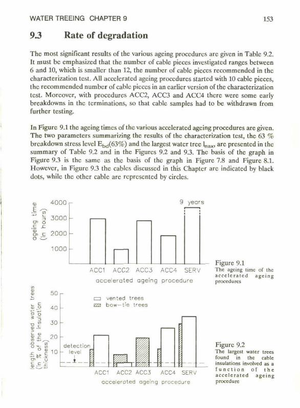
WATER TREEING CHAPTER 9 153
93 Rate of degradation
The most significant results of the various ageing procedures are given in Table 9.2. It must bc emphasized that the numbcr of cable pieces investigatcd ranges between 6 and 10, which is smaller than 12, the number of cable pieces recommended in the characterization test. All accclcrated ageing procedures started with 10 cable pieces, the recommended number of cable pieces in an earlier version of the characterization test. Moreover, with procedures ACC2, ACC3 and ACC4 thcre were some early breakdowns in the terminations, so that cable samples had to be withdrawn from further testing.
In Figure 9.1 the ageing times of the various accelerated ageing procedures are given. The two parameters summarizing the results of the characterization test, the 63 % breakdown stress level Ebd(63%) and the largest water tree l^*, are presented in the summary of Table 9.2 and in the Figurcs 9.2 and 9.3. The basis of the graph in Figure 9.3 is the samc as the basis of the graph in Figure 7.8 and Figure 8.1. Howevcr, in Figure 9.3 the cablcs discussed in this Chapter are indicated by black dots, while the other cable are represented by circles.
I-e-en o u
4000
3000
2000 h
1000
-
9 yeors
i
in U O
. c
0) O
II si > <n £ ^ •9 w O t ; (O
O tü
£**
50 r-
40 -
30 -
20 -detection
10 - level
ACC1 ACC2 ACC3 ACC4 SERV accelerated ageing procedure
nn vented trees Eza bow- t ' e trees
ACC1 ACC2 ACC3 ACC4 SERV accelerated ageing procedure
Figure 9.1 'ITic ageing limc of the a c c e l e r a t e d age ing procedures
Figure 9.2 The largest water trees found in the cable insulations involvcd as a f u n c t i o n of t h e a c c e l e r a t e d age ing procedure
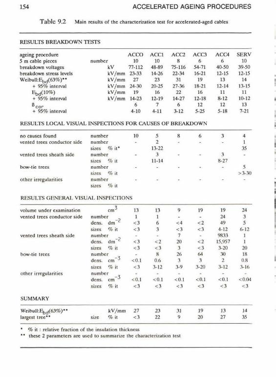
154 A C C E L E R A T E D A G E I N G P R O C E D U R E S
T a b l e 9 .2 Main results of the characterization test for accelerated-aged cables
RESULTS BREAKDOWN TESTS
agcing procedure 5 m cablc picccs breakdown voltages breakdown stress lcvels WeibulfcE^fö^)**
+ 95% interval Efed(10%) + 95% interval »cor + 95% interval
RESULTS I.OCAI. VISUAL
numbcr kV kV/mm kV/mm kV/mm kV/mm kV/mm
ACCO 10
77-112 23-33
27 24-30
19 14-23
6 4-10
ACC1 10
48-89 14-26
23 20-25
16 12-19
7 4-11
ACC2 8
75-116 22-34
31 27-36
22 14-27
6 3-12
ACC3 6
54-71 16-21
19 18-21
16 12-18
12 5-25
INSPECTIONS FOR CAUSES OF BREAKDOWN
ACC4 6
40-50 12-15
13 12-14
11 8-12
12 5-18
SERV 10
39-50 12-15
14 13-15
11 10-12
13 7-21
no causes found numbcr 10 vented trees conductor sidc numbcr
sizes % i t* vented trees shcath sidc numbcr
sizes % it bow-tie trees numbcr
sizes % it othcr irrcgularitics numbcr
sizes % it
RESULTS GENERAL VISUAL INSPECTIONS
5 2
13-22 3
11-14
3 -
3 8-27
-
■1
1 35 -
5 >3-30
volume undcr cxamination vented trees conductor sidc
vented trees shcath sidc
bow-tic trees
othcr irrcgularitics
cm J
number dens. dm sizes % il numbcr dens. dm sizes % it numbcr dens. cm" 5
sizes % it numbcr dens. cm sizes % it
13 1
<3 <3 -
<3 <3 -
<0.1 <3 -
<().! <3
1.1 1 6 3 -
<2 <3 8
0.6 3-12
-<0.1 <3
9 -
<4 <3 7 20 3 26 3
3-9 -
<0.1 <3
19 -
<2 <3 -
<2 <3 64 3
3-20 -
<0.1 <3
19 24 49
4-12 9833 15.957 3-20 30 2
3-12 -
<0.1 <3
24 3 5
6-12 1 1
20 18 0.8 3-16
<0.04 <3
SUMMARY
Weibull:Ebd(63%)" largest tree**
k V / m m 27 sizc % i l < 3
23 22
31 9
19 20
13 27
11 35
• % it : rclativc fraction of the insulation Ihickncss " • these 2 parameters are uscd to summarizc the characterization lest
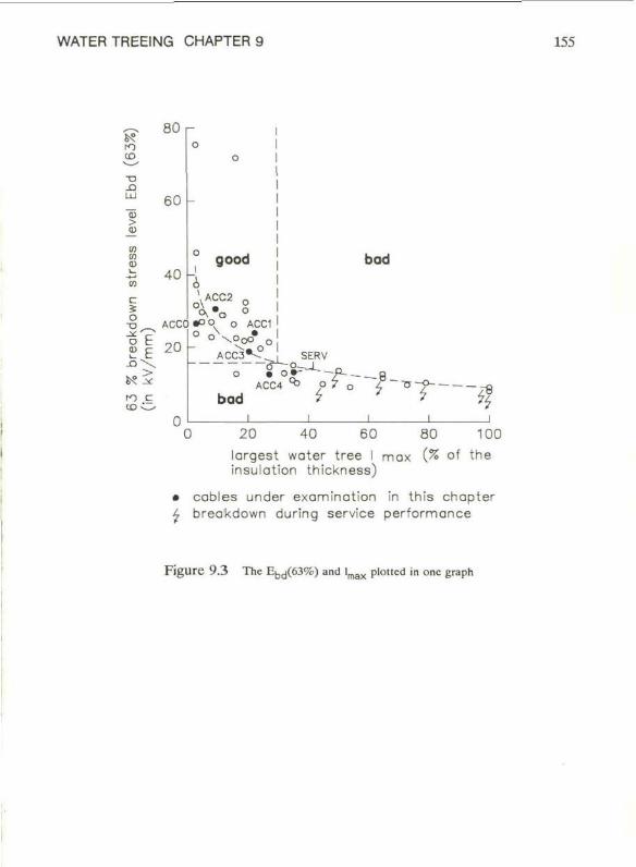
WATER TREEING CHAPTER 9 155
tn «O
"O -O
S o n n
80 r
60
40
c ï o -*• o e £ E - o \
fO C CO C
good
ACCÓ «O O. o ACC1
20 l° °V o<o° ACC3*--
bod
SERV
bod
6 "2-r.
ACC4 ^ -P--
i r* f '%
20 40 60 80 100 largest water tree I max (% of the insulation thickness)
• cables under examination in this chapter £ breakdown during service performance
F i g u r e 9 .3 The Ebd(63%) and lm a x plotled in onc graph
156 ACCELERATED AGEING PROCEDURES
9.4 Conclusions
1. A significant reduction of the Ebd(63%) has not been found in tests based on the formal CIGRE proposals: ACC1 and ACC2.
2. A significant, however limited, reduction of Ebd(63%) has been obtained with the AEIC test ACC3. This reduction is probably rclated to the growth of bow-tie trees (Figure 9.2). Since bow-tic trees are nol rcsponsible for the insulation degradation of the rclated service-aged cable (SERV) it is concluded that procedure ACC3 is probably nol cffcctivc.
3. In test ACC4, proposed by the author, the Ebd(63%) rcachcs a significant reduction in only 1917 hours. This reduction is well reiated to the growth of vcnted trees. Figure 9.1 shows that the result of procedure ACC4 is very close to the result of the service-aged cablc SERV.
4. The most cffcctivc dcvelopmcnt of vcnted trees has been found in the insulation of cablcs aged at moderate temperature level, i.e. ACC1 and ACC4. The most progressive growth of bow-tic trees, combincd with reduccd vented tree propagation, is observed in the insulation of cablcs aged at higher temperatures: ACC2 and ACC3. These results are in agreement with the phcnomenology presented in Scction 3.7.
5. A gencral conclusion can be drawn: procedure ACC4 is more cffcctivc than the procedures ACC1, ACC2 and ACC3. The choicc of the accclcraled agcing parameters in procedure ACC4, bascd on the availablc information of the phcnomenology and emphasizing vcnted tree devclopment, appears to bc succcssful. The main differenecs between procedure ACC4 and the olhcr procedures concern the temperature, the agcing frequency and the chemical nature of the water.
WATER TREEING CHAPTER 9 157
9.5 Further study and recommendations
The following supplementary studies are recommcnded
1. Sincc all measures taken to acceleratc ageing have been combined in onc procedure ACC4, it is not possible to draw conclusions about the actual cffcctivcness of onc of these measures in itself (tempcrature, frequcncy or chcmistry). High frequcncy and a corrosive liquid solution require special equipment. It is thcrefore recommcnded to study the cffectiveness of the various accelerated ageing parameters in separate tests. The rcsults of these tests might be uscd to optimize the accelerated ageing procedure.
A disadvantage of the use of a high conccntration of CuS04 in the water is its capability to dissolve the copper earth screen of the cablc. Breakdowns may then occur as a consequence of a bad earth connection. Morcovcr, handling the solution and the cables aged in this solution requires special measures since CuSO^ in such high concentrations can bc considered as poisonous. An alternativc salt might be NaCl, from which it has also been found to accelerate the ventcd tree propagation rate (phenomenology, Chaptcr 3).
2. Procedure ACC4 should bc repeated on cables with various rates of degradation after extensivc service performance. It must further be proven that the accelerated ageing procedure is ablc to discriminate between cable insulations having a high and having a low water tree susceptibility. As long as this result is not availablc it is recommcnded to use procedure ACC1, not with a test duration of 3000 hours (which is not effectivc), but with a test duration of 17,000 hours (2 ycars). It has already been shown in Scction 3.2.4 that with the extendcd version of ACC1 it is possible to discriminate between cables with high and with low water tree susceptibility.
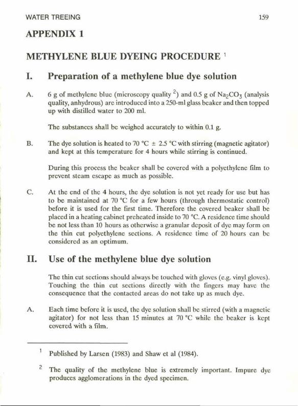
WATER TREEING 159
APPENDIX 1
METHYLENE BLUE DYEING PROCEDURE '
I. Preparation of a methylene blue dye solution
A. 6 g of methylene blue (microscopy quality ) and 0.5 g of NagCG^ (analysis quality, anhydrous) are introduced into a 250-ml glass bcakcr and then toppcd up with distilled water to 200 ml.
The substanccs shall be weighed accurately to within 0.1 g.
B. The dye solution is heated to 70 °C ± 2.5 °C with stirring (magnetic agitator) and kcpt at this tcmperaturc for 4 hours while stirring is continued.
During this process the bcakcr shall bc covcrcd with a polycthylcnc film lo prevent steam escape as much as possible.
C. At the end of the 4 hours, the dye solution is not yet ready for use but has to bc maintaincd at 70 °C for a few hours (through thermostatic control) before it is used for the first time. Therefore the covered beaker shall be placed in a heating cabinet preheated inside to 70 °C. A residence time should be not less than 10 hours as olherwisc a granular deposit of dyc may form on the thin cut polyethylene sections. A rcsidcncc limc of 20 hours can bc considcred as an optimum.
II. Use of the methylene blue dye solution
The thin cul scctions should always bc louchcd with glovcs (e.g. vinyl gloves). Touching the thin cut scctions directly with the fingers may have the consequencc that the contacted areas do not take up as much dye.
A. Each time bcforc il is used, the dyc solution shall bc stirred (with a magnetic agitator) for nol less than 15 minutcs at 70 °C while the bcakcr is kcpt covered with a film.
Published by Larsen (1983) and Shaw et al (1984).
The quality of the methylene blue is extremely important. Impure dye produecs agglomeralions in the dycd specimen.
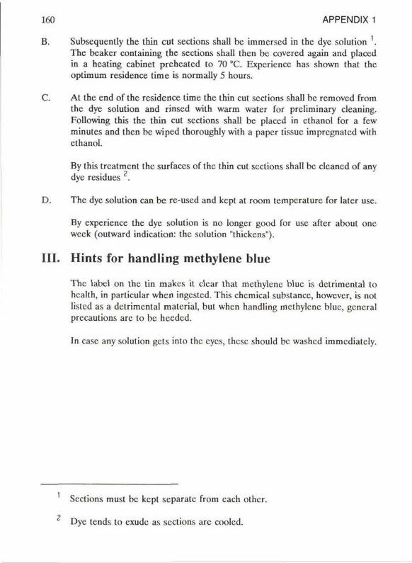
160 APPENDIX 1
B. Subscquently the thin cut sections shall bc immersed in the dyc solution . The bcaker containing the sections shall then be covered again and placed in a heating cabinet prehcatcd to 70 °C. Experience has shown that the optimum residence time is normally 5 hours.
C. At the end of the rcsidence time the thin cut sections shall be removcd from the dye solution and rinscd with warm water for prcliminary cleaning. Following this the thin cut sections shall be placed in ethanol for a few minutcs and then be wiped thoroughly with a paper tissue impregnated with ethanol.
By this treatment the surfaces of the thin cut sections shall be cleaned of any dye residues .
D. The dyc solution can be re-used and kept at room temperaturc for later use.
By experience the dye solution is no longer good for use after about one week (outward indication: the solution "thickens").
III. Hints for handling methylene blue
The label on the tin makes it clcar that methylene blue is dctrimental to health, in particular when ingestcd. This chemical substance, howcver, is nol listcd as a dctrimental material, but when handling methylene blue, gencral precautions are to bc heedcd.
In case any solution gets into the cycs, these should bc washed immediatcly.
Sections must bc kept separate from each other.
Dyc tends to exude as sections are coolcd.
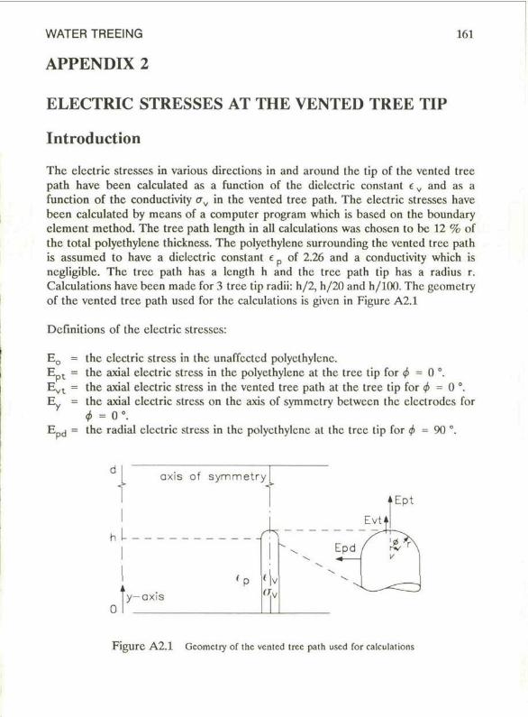
WATER TREEING 161
APPENDIX 2
ELECTRIC STRESSES AT THE VENTED TREE TIP
Introduction
The clcctric strcsses in various dircclions in and around Ihc tip of the ventcd tree path have been calculated as a function of the diclcctric constant e v and as a function of the conductivity CTV in the vented tree path. The electric stresses have been calculatcd by mcans of a computer program which is based on the boundary element method. The tree path length in all calculations was chosen to bc 12 % of the total polyethylene thickness. The polyethylene surrounding the vented tree path is assumed to have a diclcctric constant e p of 2.26 and a conductivity which is ncgligiblc. The tree path has a length h and the tree path tip has a radius r. Calculations have been made for 3 tree tip radii: h/2, h/20 and h/100. The geometry of the vented tree path used for the calculations is givcn in Figure A2.1
Definilions of the clcctric strcsses:
E0 = E pt = Evt = Ey =
ERd =
the clcctric stress in the unaffected polyethylene. the axial electric stress in the polyethylene at the tree tip for <f> = 0 °. the axial electric stress in the vented tree path at the tree tip for <f> = 0 c. the axial electric stress on the axis of symmclry between the clcclrodes for <t> = 0 ° . the radial clcctric stress in the polyethylene at the tree tip for 0 = 9 0 °.
axis of symmet ry
y—axis
Figure A2.1 ücometry of the vented tree path used for calculations
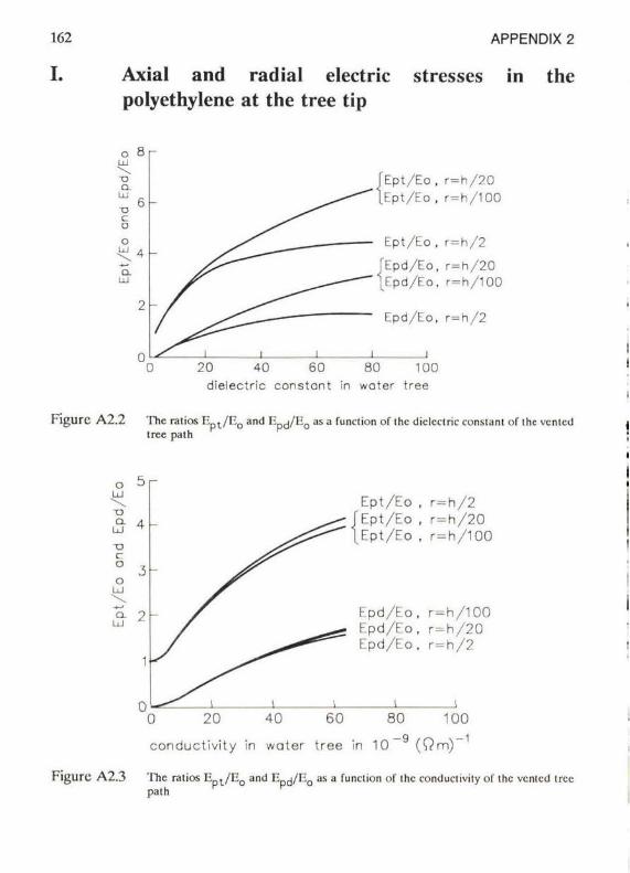
162 APPENDIX 2
I. Axial and radial electric stresses in the polyethylene at the tree tip
Ept /Eo , r = h / 2 0 Ept/Eo , r=h /100
Ept/Eo , r = h / 2
Epd/Eo, r = h / 2 0 Epd/Eo, r=h /100
Epd/Eo, r = h / 2
20 40 60 80 100 dielectric constant in water tree
Figure A2.2 The ratios K p l / i ; o and Hpcj/K0 as a funclion of Ihc dieleclrie conslanl of Ihc vcnlcd tree palh
Ept/Eo . r = h / 2 Ept/Eo , r =h /20 Ept/Eo , r=h/100
Epd/Eo. r=h/100 Epd/Eo, r = h / 2 0 Epd/Eo. r = h / 2
• i
0 20 40 60 80 100
conductivity in water tree in 10 ~ (Qm)~
Figure A2.3 'I"hc raiios EDl/I20 and V. J/V. as a funclion of ihc conductivity of ihc vcnlcd tree path
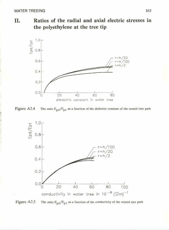
WATER TREEING 163
II. Ratios of the radial and axial electric stresses in the polyethylene at the tree tip
1.0 r
20 40 60 80 dielectric constant in water tree
Figure A2.4 The ratio np (j/np l as a function of the dielectric constant of the vcnted tree path
I.Or
r=h/100 r=h/20 r=h/2
conductivity in water tree in 10 (Om)'
Figure A2.5 The ratio E <j/E t as a function of the conductivity of the vcnted tree path
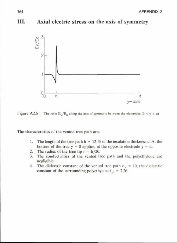
164 APPENDIX 2
III. Axial electric stress on the axis of symmetry
2 -
^
L
d y - a x i s
Figurc A2.6 The ralio E y /E 0 along ihc axis of syttimclry bclwccn Ihc clcclrodcs (0 < y < d)
The charactcristics of the vented tree path are:
1. The Icngth of the tree path h = 12 %of the insulation thickness d. At the bottom of the tree y = 0 applies, at the opposite electrode y = d.
2. The radius of the tree tip r = h/20. 3. The conductivities of the vented tree path and the polyethylene are
negligiblc. 4. The diclcctric constant of the vented tree path e v = 10, the diclcctric
constant of the surrounding polyethylene e = 2.26.
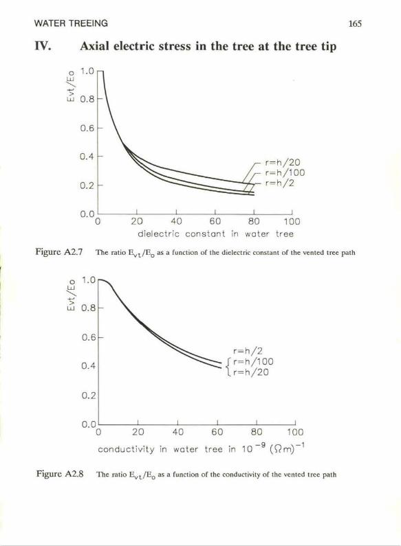
WATER TREEING 165
IV. Axial electric stress in the tree at the tree tip
r = h / 2 0 r=h /100 r = h / 2
0.0 20 40 60 80 100
dielectric constant in water tree
Flgure A2 .7 The ratio E ^ / E Q as a funclion of the dielectric constant of the vented tree palh
r = h / 2 r = h / l 0 0 r = h / 2 0
0.0 0 20 40 60 80 100
conductivity in water tree in 10 (Om)
Figure A2.8 The ratio E ^ / E g as a function of ihe conductivity of the vcnlcd tree palh
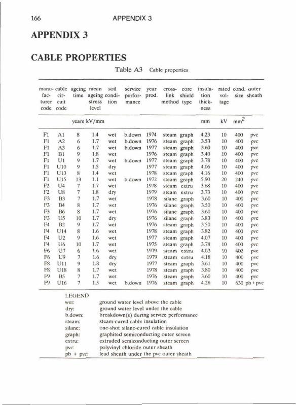
166
APPENDIX 3
APPENDIX 3
CABLE PROPERTIES Table A3 Cablc properties
manu-fac-
lurcr code
Fl l'l Fl Fl l'l 11 Fl Fl F2 F2 F3 F 3 F3 !"3 F4 F4 l ' l F4 F 6 F6 F8
ra F9 F9
cablc circuit
code
A l A 2 A3 BI UI
U10 U13 U15 U4 U8 B3 B4 B6 US B2
U14 U2 U 6 U 7 U9
U i l U18 B5
U16
ageing time
ycars
8 6 6 9 9 9 8 13 7 7 7 8 8 1U 9 8 9 Ui 6 7 9 8 7 7
mcan agcing stress level
k V / m m
1.4 1.7 1.7 i s 1.7 IS 1.4 1.1 1.7 I S 1.7 1.7 1.7 1.7 1.7 1.6 1.6 1.7 1.6 1.6 1.8 1.7 1.7 1.5
soil condi-
tion
wet wet wet wet wet dry wel wet wet dry wet wel wel dry wet wet wet wet wet dry dry wet wet wet
service performance
b.down b.down b.down
b.down
b.down
b.down
year prod.
1974 1976 1977 1976 1977 1977 1978 1972 1978 1979 1978 1976 1976 1976 1976 1978 1977 1975 1979 1979 1977 1978 1976 1976
crosslink
method
steam steam steam steam steam steam steam steam steam steam silanc silanc silanc silane steam steam steam steam steam steam slcam steam steam steam
corc shicid type
graph graph graph graph graph graph graph graph extru extru graph graph graph graph graph graph graph graph extru extru graph graph graph graph
insula-tion
thick-ncss
mm
4.23 3.53 3.60 3.40 3.78 4.06 4.16 5.90 3.68 3.73 3.60 3.50 3.60 3.83 3.50 3.82 4.07 3.78 4.03 4.18 3.61 3.80 3.60 4.26
rated voltage
kV
10 10 10 10 in 10 10 20 10 lil 10 10 10 10 lil 10 10 II) 10 10 10 10 10 10
cond. size
mm
400 400 400 400 400 400 400 240 400 400 400 400 400 400 100 400 400 400 400 400 400 400 400 630
ou l c r shcath
pvc pvc pvc pvc pvc pvc pvc pvc pvc pvc pvc pvc pvc pvc pvc pvc pvc pvc pvc pvc pvc pvc pvc
nb + pvc
I.IXiKND wel: ground water levcl abovc the cablc dry ground water levcl undcr the cablc b.down: brcakdown(s) during service performance steam: stcam-curcd cablc insulation silanc: onc-shot silanc-curcd cablc insulation graph: graphitcd scmiconducling oulcr screen extru: extrudcd scmiconducling oulcr screen pvc: polyvinyl chloride oulcr shcath pb t pvc: lead shealh undcr Ihc pvc oulcr shcaih
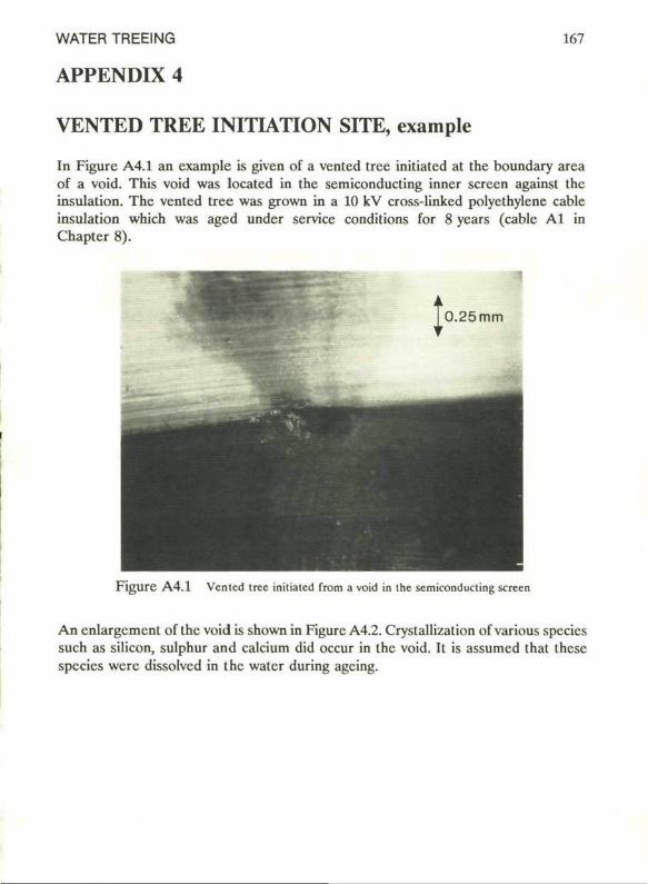
WATER TREEING 167
APPENDIX 4
VENTED TREE INITIATION SITE, example
In Figure A4.1 an example is given of a vented tree initiated at the boundary area of a void. This void was located in the semiconducting inner screen against the insulation. The vented tree was grown in a 10 kV cross-linked polyethylene cable insulation which was aged under service conditions for 8 years (cable Al in Chapter 8).
F i g u r e A 4 . 1 Vented tree initiated from a void in the semiconducting screen
An enlargement of the void is shown in Figure A4.2. Crystallization of various species such as silicon, sulphur and calcium did occur in the void. It is assumed that these species were dissolved in the water during agcing.
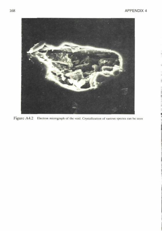
168 APPENDIX 4
F i g u r c A 4 . 2 l-lcctron micrograph of ihc void. Crystalllzation of vanous species can bc sccn
WATER TREEING 169
REFERENCES:
ABDOLALL, K. ORTON, H.E.. REYNOLDS, M.W.. ROBERT, B.D.. KENNEDY, R. and CLAYMAN, B.P., 1982. Somc physicochemical aspects of walcr trees. 1982 Annual Report Conference on Elcctrical Insulation and Diclcctric Phcnomcna: 604-614.
AE1C, 1982. Spccifications for thermoplastic and crosslinked polyethyicnc insulatcd shicidcd power cablcs ratcd 5 through 46 kV, 8th cdition. AEIC CS5-82. Association of Edison Illuminating Companies (AEIC), 51 East 42nd street, New York, N.Y. 10017, June 1982: 34 pp.
ALLISTER, D. MC. (ed), 1982. Electric Cables Handbook. Granada; I-ondon, Toronto, Sydney, New York, 1982: 880 pp.
ASHCRAFT, A.C., 1977-a. Trccing Update Part III: water trees." Kabclitcms 152, Union Carbidc Corporation. Bascd on "Water trccing in polymcr diclcctrics", presented at World Elcclrotechnical Congress in Moscow, June 1977: 11 pp.
ASHCRAFT, A.C., 1977-b. Factors influencing treeing idcniificd. Elcctrical World, December 1: 38^0.
BAHDER, G., EAGER, G.S. and LUKAC, R.G., 1974-a. Influence of electrochemical trees on the electrical properties of extrudcd polymcric insulation. 1974 Annual Report Conference on Electrical Insulation and Diclcctric Phcnomcna: 289-301.
BAHDER, G., KATZ, C, LAWSON, J. and VAHLSTROM, W., 1974-b. Elcctrical and electrochemical trccing effect in polyethyicnc and cross linkcd polyethyicnc cables. IEEE Trans. PAS-93: 977-990.
BAMJI. S., BULINSKI, A. DENSLEY, J., and GARTON A., 1983. Etching and the morphology of cross-linked polyethyicnc cable insulation. IEEE Trans. EI-19 No. 1. Feb. 1983: 32-41.
BAMJI, S., BULINSKI, A, DENSLEY, J. and SHIMIZU, N.. 1982. Light emission from polyethyicnc subjected to highly divergent ficlds. 1982 Annual Report Conference on Elcctrical Insulation and Dielectric Phcnomcna: 592-597.
BAMJI, S., BULINSKI, A, DENSLEY, J., GARTON A. and SHIMIZU, N.. 1984. Walcr trccing in polymeric insulation. Conférence Internationale des Grandcs Rcseaux Elcctriques a Haute Tcnsion (CIGRE), session September 1984. Paper 15-07: 7 pp.
BARTNIKAS, R. and EICHHORN, R.M. (ed), 1983. Engineering dielectrics volume IIA. Electrical properties of solid insulatingmatcrials: molecularstructurc and electrical behavior. ASTM Special Technical Publications 783. ASTM Publication Philadclphia, March 1983: 721 pp.

170 REFERENCES
BERNSTEIN, B.S., SRINIVAS, N. and LEE, P.N., 1975. Electrochemical trceing studies: voltage stress, lemperaturc, and solulion penetration effects undcr accclcrated test conditions. 1975 Annual Report Conference on Electrical Insulation and Diclcctric Phcnomena: 296-302.
BILLMEYER, F.W. jr., 1984. Textbook of polymer science, 3th cdition. Wiley-Interscience Publication. John Wiley & Sons. New York, Chichcstcr, Brisbanc, Toronto, Singapore, 1984: 578 pp.
BLYTHE, AR., 1979. Electrical propertics of polymers. Cambridgc Univcrsity Prcss, Cambridge 1979. ISBN 0521.21902.7.
BOGGS, SA., and RIZZETTO, S.,1986. The application of interfcrometrie holography lo the study of watertreeing. Conference Record of 1986 IEEE International Symposium on Electrical Insulation, Washington. DC. June9- l l , 1986: 140-143.
BOONE, W., GEURTS, W.S.M., STEENNIS, E.F. and TEMPEIAAR, HG. . 1987. XLPE- and PE-insulated cablcs in The Ncthcrlands. Kcma Scientific Technical Rcports. Volume 5. Numbcr 3, 1987: 57-71.
BOONE, W., STEENNIS, E.F., BENTVELZEN, P.A.C. and LAAR, A.M.EJ. van de, 1984. Dcvclopmcnl and trial of EHV XI.PE cablcs in The Nclherlands. Conférence Internationale des Grandcs Réscaux Elcctriqucs a Haute Tension (CIGRE), scssion September 1984. Paper 21-02: 7 pp.
BÖTTGER, O., NIEDERHAGEN, R and SCIIUCHARD, W., 1985. Hypothese 7.ur Water-Tree Entstehung und deren Übcrprüfung. Ix>ng-tcrm performance of high-voltagc insulations, Daucrvcrhaltcn von Hochspannungsisolierungcn. Elcctrotechnische Gescllschaft I'achbcrichte 16, Long-term performance of high voltage insulation. VDE-Vcrlag Gmbll, Bcrlin. 1985: 109-113.
BRAUN, J.M., 1980. Comparison of water trceing ratcs in stcam and nitrogen trcalcd polyclhylcncs. IEEE Trans. EI-15 No. 2, April 1980: 120-123.
BUI.INSKI, A. and DENSLEY. R.J., 1981. 'ITic voltage breakdown charactcristics of miniaturc XLPE cahlcs containing water trees. IEEE Trans. EI-16, August 1981: 319-326.
BULINSKI, A T . BAMJI, S.S. and DENSLEY, R.J., 1986. The effect of frequency and lemperaturc on water tree degradation of miniaturc XLPE cablcs. IEEE Trans. EI-21 No. 4, August 1986: 645-650.
CAPACCIO, O , GöLZ, W. and ROSÉ, L.J., 1985. The influencc of morphology and polymer struclurc on the watcr-treeing resistance of crosslinkcd polycthylenc. Elektrotechnische Gescllschaft Fachbcrichlc 16, Ix>ng-tcrm performance of high-voltagc insulation. VDE-VerlagGmblI, Bcrlin, 1985: 123-126.
WATER TREEING 171
CHERNEY, E.A., 1973. Water trees in clectrical insulation. Ontario Hydro Research Quarterly, third quarter, 1973: 7-12.
CRICirrON, B.H., GIVEN, MJ. , FAR1SII, O. and BAMFORD, H.M.. 1983. Mcasurement of water tree growth by instrumental neutron activation analysis. Journal of Physics, Part D: Applied Physics, 16, 1983: L223-L226.
CRINE, W.P., PELISSOU, S., ST-ONGE, H., ST-PIERE, J., KENNEDY, G., HOUDAYER, A. AND HINRICIISEN, P.,1987. Elemental and ionic impuritics in cablc insulation and shields. Jicablc 87, International Conference on Polymer Insulated Power Cablcs, Paris, 1987: 206-213.
CROSS, J.D. and KOO, J.Y., 1984. Somc observations on the structure of water trees. IEEE Trans. EI-19 No. 4, August 1984: 303-306.
DENSLEY, J., 1974. Water trecing in high voltage cable insulation. IEEE Canadian Communications and Power Conference, 1974: 269-270.
DENSLEY, J., BULINSKI. A. and SUDARSHAN, T., 1979. Theeffectsof water immersion, voltage and frcqucncyon the clcctricstrength of miniature XLPE cablcs. 1979 Annual Report Conference on Eleclrical Insulation and Diclcctric Phcnomcna: 469-479.
DISSADO, LA., WOLFE, S.V., FOTHERGILL, J.C, JONES, T. and ROWLAND, S.M.. 1986. The distribution in lenglh of vented water trees. IEEE Trans. EI-21 No. 4, August 1986: 651-655.
DORLANNE, 0 „ WERTHEIMER, M.R., YELON, A. and DENSLEY, J.R.. 1980. ESR study of Cu in polycthylene containing eleclrical and water trees. 1980 Annual Report Conference on Eleclrical Insulation and Diclcctric Phcnomcna: 136-143.
FAREMO, II., 1987. Growth of watertrees and thcir influcncc upon the breakdown strength of EPR matcrials. Jicablc 87, International Conference on Polymer Insulated Power Cablcs, Paris, 1987: 193-198.
FAVRIE, E. and AUCLAIR, II.. 1980. Effect of water on clectrical properlies of extrudcd synthelical insulations applicalion on cablcs. IEEE Trans. PAS-99, No. 3 May/Junc 1980: 1225-1234.
FEDORS, R.F.. 1980. Walcr-trecing as an osmotic phenomenon. Polymer, 1980, Vol. 21, August: 863-865.
F1LIPPINI, J.C. and MEYER, C.T., 1982-a. Effect of frequency on the growth of walcr Irces in polyelhylenc. IEEE Trans. EI-17 No. 6, Dcc. 1982: 554-559.
HLIPP1NI, J.C., MEYER, C.T. and EL KAHEL, M., 1982-b. Some mechanical aspects of the propagation of water trees in polyelhylenc. 1982 Annual Report Conference on Eleclrical Insulation and Diclcctric Phcnomcna: 629-637.
172 REFERENCES
F1LIPPINI, J.C., KOO. J.Y., POGGI, Y., I.AURENT C, MAYOUX C. and NOEL, S., 1984. Aborescences d'eau et aborescenccs élcctriques (Watertreeing and electrical trccing). Jicable 84, International Conference on Polymer Insulated Power Cables, Paris, March 1984: 87-92.
FOURNIé, R , PERRET, J., RECOUPé, P. and I.E GALL, Y., 1978. Water trccing in poiyethylene for high voltage cables. Conference Record of 1978 IEEE International Symposium on Electrical Insulation: 110-115.
FRANKE, E.A., STAUFFER J.R and CZEKAJ, E., 1977. Water tree growth in poiyethylene under DC voltage stress. IEEE Trans. 1:1-12 No. 3, June 1977: 218-223.
FRANKE, II., HEUMANN, H. and KAUBISCH, D., 1984. Testing possibilitics and rcsults regarding water agcing of PE/XLPE insulaled medium voltage cables. Jicable 84, International Conference on Polymer Insulated Power Cables, Paris, March 1984: 113-118.
FREDR1CH, D and KALKNER W., 1987. On the examination of the watertreeing bchaviour of XLPE-insulatcd cables. Conference report of the Fifth International Symposium on High Voltage Engineering. Paper no. 21-04. Braunschweig, Fcdcral Rcpublic of Germany, August 24-28 1987: 4 pp.
FUKAGAWA, ft, OKAMOTO, T , HOZUMI, N. and SHIBATA, T , 1987. Dcvclopmcnts of methods to cstimate Ihe residual life of Xl.PE cables detcriorated by watertrecs. Jicable 87, International Conference on Polymer Insulated Power Cables, Paris, 1987: 457-462.
GARTON, A. BAMJI, S., BUI.INSKI, A. and DENSI.EY, J., 1987. Oxidation and water tree formation in service-aged Xl.PE cablc insulation. IEEE Trans. EI-22 No. 4, August 1987: 405-412.
GARTON, A., DENSI.EY, RJ . and BULINSKI, A., 1980. Initial rcsults of a study of water trees in XLPE by infrared speetroscopy. IEEE Trans. EI-15 No. 6, Dcc 1980: 500-501.
GEURTS, W.S.M., 1985. Veroudering van kabels met isolatie van lagedichthcids polythecn. Research report. Rcf. III 7722/85, N.V. KEMA. Arnhem, The Ncthcrlands. 1985 (In Dutch): 42 pp.
GLOGER T , OLSHAUSEN, Rv., 1985. Die Auswirkungen von Water Trees auf dic Glcich- und Stossspannungsfcstigkcit von Polycthylcn-Modclpriifkörpcrn. EIcctrotcchnischcGcsellschaft Fachbcrichlc 16, Ixing-tcrm performance of high voltage insulation. VDE-Vcrlag Gmbll, Bcrlin, 1985: 135-139.
GöLZ, W„ 1985. Watcr-lrcc growth in low density poiyethylene. Colloid and Polymer Sci, 1985, 263: 286-292.
GRIITTTH, A.A., 1921. The phenomena of rupturc and flow in solids. Phil. Trans. Roy. Soc. A 221, 1921: 163
GRIITTTH, A.A., 1924. The thcory of rupturc. Procccdings lst International Congrcss, Applied Mcchanics, Delft, 1924.
WATER TREEING 173
GRöNEFELD, P., OLSHAUSEN, R- von and SELLE, F., 1985. Fchlererkennung und Isolationsgcfahrdung bei der Priifung water tree-haltigcr VPE-Kabcl mit Spannungcn untcrschiediicher Form. Elektrizitatswirtschaft, Jg. 84 (1985), Heft 13 : 501-506.
HENKEL, H J . and MüLLER N., 1985. Addilive zur Inhibiemng von Wasscrbaumchen in Polyolcfincn für Kabclisolicrungen. Electrotechnische Gesellschaft Fachbcrichtc 16, I-ong-term performance of high voltage insulation. VDF-Vcrlag GmbH, Berlin, 1985: 132-134.
HENKEL, HJ. , KALKNER W. and MüLLER, N., 1981. Elcctrochcmical trecing-Strukturen in Modellkabclisolicrungcn ausThcrmoplastischcm oderVemetztem Polyethylen. Siemens Forschungs und Entwicklungs Bericht, Bd. 10 (1981) Nr. 4, Springer Verlag 1981: 205-214.
HOSSAM ELDIN, AA. and EL SHAZLI, Z., 1982. A study of water tree frequency depcndcncc and growth ratc in polymer. 1982 Annual Report Conference on Elcctrical Insulation and Dielectric Phenomena: 638-643.
ILDSTAD, E., 1982. Water migration and watcrtrccing in cross-linked polyethylcnc cables. Dissertation. University of Trondhcim, Norway 1982: 145 pp.
ISSHIKI, S., YAMAMOÏO, M., CHABATA, S., M1ZOGUCHI, T. and ONO, M., 1974. Water tree in cross-linked polyethylcnc power cables. IEEE Trans. PAS-93: 1419-1429.
JOHNSON, J.F., GROEGER, J.H., MASHIKIAN, M.S., BERNSTEIN, B.S. and COOPER A.R., 1988. Sensitive analytical methods for carly diagnosis of ageing in solid insulation undcr voltage stress. Conférence Internationale des Grandcs Reseaux Electriques a Haute Tcnsion (CIGRE), session August/September 1988. Paper 15-01: 7 pp.
KAGEYAMA, S., ONO, M. and CHABATA, S., 1975. Microvoids in crosslinked polyethylcnc insulatcd cables. IEEE Trans. PAS-94, No. 4, July/August 1975: 1258-1263.
KALKNER W., MüLLER U., PESCHKE, E., HENKEL, H J . and OLSHAUSEN, R von, 1982. Watertreeing in PE and XLPE insulatcd high voltage cables. International Conference on I.argc High Voltage Elcctric Systcms (CIGRE). Paper No. 21-07, 12 pp.
KAO, KC. and HWANG, W., 1981. Elcctrical transport in solids (with particular refcrencc lo organic semiconductors) International Series in the Scicnce of the Solid State, Volume 14, Pcrgamon Prcss, 1981: 663 pp.
KaRNER II., STIETZEL, U., SAURE, M. and GöLZ, W., 1984. Determination ofsmall water contents in solid organic insulating materials and the influence of moisture on the dielectric propertics. Conférence Internationale des Grandcs Reseaux Electriques a Haute Tcnsion, CIGRE, session September 1984. Paper 15-02: 10 pp.
KATO, H., MAEKAWA, N., INOUE, S. and FUJITA, H., 1974. Effect and mechanism of some new voltage stabilizers for cross-linked polyethylcnc insulation. 1974 Annual Report Conference on Electrical Insulation and Dielectric Phenomena: 229-238.
174 REFERENCES
KATZ, C. and BERNSTEIN, B.S., 1973. Electrochcmical Ireeing at contaminants in polycthylenc and cross-linkcd polycthylcnc insulation. 1973 Annual Report Conference on Electrical Insulation and Diclcctric Phenomena: 307-316.
KATZ, C, EAGER Jr G.S., LEBER, E.R and FISCHER, F.E., 1984. Influcncc of water on dielectric strength and rcjuvenation of in-service agcd URD cablcs. Jicablc 84, International Conference on Polymcr Insulated Power Cablcs, Paris. March 1984: 127-134.
KATZ, C, SRINIVAS, N. and BERNSTEIN, B.S., 1974. Growth rate of electrochcmical trees in PE and XI.PE insulation systems: effect of water nature. 1974 Annual Report Conference on Electrical Insulation and Dielectric Phenomena: 279-288.
KAUFMANN, H.S., FALCETTA. HJ . (cd), 1977. Introduction to polymcr science and technology. An SPE Tcxtbook. LC 76-16838. Society of Plastics Engineering Monographs. Wiley, New York, 1977: 613 pp.
KAWAHARA. K, YOSHIMITSU, T . ISHIKAWA, Y., AKAIIORI, H. and YOSIIIDA, H., 1984. The effect of tempcrature on the electrical breakdown voltage of XLPE in the presence of water trees. Conference record of 1984IEEE International Symposium on Electrical Insulation, Montrcal, Junc 11-13. 1984 : 33-36.
KIRKIAND, J.W., THIEDE, RS . and REITZ, RA.. 1981. Evüluating the service degradation of insulated power cablcs. Conference paper (81TD645-1) of the IEEE PES 1981, Transmission & Distribution Conference and Exposition, Minncapolis, Minncsota, Scpt. 20-25 1981: 2128-2136.
KOO, J.Y., CROSS, J.D., EL-KAHEL, M., MEYER, C.T. and FILIPPINI, J .C, 1983. Electrical bchaviour and structurc of watertrecs in rclation to thcir propagation. 1983 Annual Report Conference on Electrical Insulation and Dielectric Phenomena: 301-306.
KREUGER F.H., 1960. Dctcction and localion of discharges: in particular in plastic-insulatcd high-voltagc cablcs. 'ITicsis Delft University, 1960: 161 pp.
KREUGER F.H., 1989. Partial discharge dctcction in high voltage equipment. Tcmplc Prcss, I.ondon, 1964 & Buttcrworths. l-ondon, 1989.
KREUGER F.H. and IAAR, A.M.F.J. van de, 1985. Silanc crosslinkcd medium voltage cable. Circd 85, International conference on clcctricity distribution, Part I. IEE Conference Publicalion Nr. Z50. IEE, l-ondon, 1985: 231-233.
I A A R A.M.F.J. van de, 1982. Silanc crosslinkcd power cablc: an invcstigation of cablc propcrlics. 1982 International Conference on I-argc High Voltage Elcctric Systems, CICiRE. Paper no. 21-2: 7 pp.
I.ARSEN, P.B., 1983. Methodes de coloration d'ulilisCcs des arborescences d'cau dans les isolation extrudecs de cablcs. Electra Nr. 86, 1983: 53-59.
WATER TREEING 175
LAWLESS, J.F., 1975. Construction of tolcrancc bounds for the Extrcme-value and Weibull distributions. Tcchnometrics, Vol. 17, No. 2, May 1975: 255-261.
LAWLESS, J.F., 1978. Confidencc interval estimation for the Weibull and Extreme valuc distributions. Technomctrics, Vol. 20, No. 4, November 1978: 355-364.
LICUTENTHALER, R.G. and RANFELT, F., 1978. Determination of antioxidants and thcir transformation producls in polyclhylcnc by high-performance liquid chromatography. Journal of chromatography, 149, 1978: 553-560.
MANDELKERN, L., GLOTIN, M. and BENSON, RA., 1981. Supermolecular structure and thermodynamie propertics of lincar and branched polyethylcncs undcr rapid crystallization conditions. Macromoleculcs, 1981, 14: 22-33.
MARSH, T.G., SMITIl, A.P. and DRYSALE, J., 1987. Long term agcing of water immerscd XLPE insulations. Jicablc 87, International Conference on Polymer Insulatcd Power Cablcs, Paris, 1987: 181-186.
MASON, J.H., 1951. The deterioration and breakdown of diclcctrics rcsulting from intemal discharges. Proc. Instn. Electr. Eng., Part I, 98, 1951: 44-59.
MASON, J.H., 1953. Breakdown of insulation by discharges. Proc. Instn. Electr. Eng.. Part Ha, 100, Nr. 3, 1953: 149.
MATSUBA, H. and KAWAI, E., 1976-a. Water tree mechanism in electrical insulation. IEEE Trans. PAS-95 No. 2, March/April 1976: 660-670.
MATSUBA, H., KAWAI, E. and SATO, K-, 1976-b. Water tree mechanism and its suppression. Conference Records (CII 1496- 9/80) International Symposium on Electrical Insulation 1976: 224-227.
MATSUURA, K. OHNO. H. 1SHIBASIII, A., YATSUKA. K.. IIIROTSU. K.. KAJIKl, I. AND SHINAGAWA, J., 1987. Invcstigation on deterioration of 22 to 66 kV Xl-PE cables removed from actual service Unes. Jicable 87, International Conference on Polymer Insulatcd Power Cablcs. Paris, 1987: 47M76.
MCMAHON, EJ. , 1981. A tree growth inhibiting insulation for power cablc. IEEE Trans. EI-16 No. 4, August 1981: 304-318.
MELTON, C.W., MANGARAJ, D. and EPSTEIN, M., 1981. Morphology of thermoplastic and cross-linkcd polyethylcnc cablc insulation. 1981 Annual Report Conference on Electrical Insulation and Diclcctric Phcnomena: 299-305.
MEYER, C.T., FILIPPINI, J.C. and FELICI, N., 1978. Water tree propagation in relation to mechanical properties of polycthylene. 1978 Annual Report Conference on Electrical Insulation and Dielectric Phcnomena: 374-381.
176 REFERENCES
MEYER, C.T., 1983. Water absorption during water treeing. IEEE Trans. EI-18 No. 1, Feb. 1983: 28-31.
MINNEMA, L., BARNEVELD, HA. and RINKEL, P.D., 1980. A n investigation into the mechanism of water treeing in polyethylene high-voltagc cablcs. IEEE Trans. EI-15 No. 6, Dec. 1980: 461-471.
M I Y A S H I T A , T., 1969, Dcterioration of water-immersed polyethylene coatcd wire by treeing. Proceedings 1969 IEEE-NEMA Elcctrical Insulation Conference. Boston, Sept. 1969: 131-135.
MOORE, WJ . , 1972. Physical Chemistry, fourth edition. Prentice-Hall, Ine, Englewood Qif fs, New Jersey, 1972: 977 pp.
M O R I T A , M., I I A N A I , M. and S H I M A N U K I , H., 1973. Some prevenlive methods for water treeing in PE and XLP insulation. 1973 Annual Report Conference on Elcctrical Insulation and Diclcctric Phcnomcna: 303-312.
MORITA, M., I I A N A I M., S H I M A N U K I , H., A I D A , F. and SHIONO, T-, 1980. Effects of hydrated ions on watertrees in polyethylene. 1980 Annual Report Conference on Electrical Insulation and Diclcctric Phcnomcna: 195-202.
MUCCIGROSSO, J. and PHILI.IPS, P.J., 1978. The morphology o f cross-linked polyethylene insulation. IEEE Trans. EI-13 No. 3, Junc 1978: 172-178.
M ü L L E R N. and H E N K E I . , H J . . 1985. Phanomcnologische Aspckte der Wasserbaümchcm in Polyolcfincn für Kabclisolicrungcn. Electrotechnischc Gcscllschaft Fachberichtc 16, Long-term performance of high voltage insulation. V D E -Verlag C.mbll, Berlin, 1985: 119-122.
NAM1KI , Y „ S H I M A N U K I , H., A I D A . F. and M O R I T A , M., 1980. A study on microvoids and thcir f i l l ing in crosslinkcd polyethylene insulatcd cablcs. IEEE Trans. EI-15 No. 6, Dcc. 1980: 473-480.
NAYBOUR. R.D., 1979. The growth of water trees in cross linkcd polyethylene at opcraling sircsscs and Ihcir influcnce on cablc life. IEE Conference Publicalion nr. 177, 1979: 238-241.
N A Y B O U R , R D . , 1982. 'I"hc growth of water trees in dry and stcam curcd polyethylene al 1.9 M V / m , 50 Hz and ihcir influcnce on cablc lifc in the stress range 15 to 4 M V / m . 1982 Annual Report Conference on Elcctrical Insulation and Diclcclric Phcnomcna: 620-628.
N ITTA, Y., 1974. A possiblc mechanism for propagation on walcr Irces from water clcclrodcs. IEEE Trans. F.I-9, No. 3, Scpt. 1974: 109 - 112.
WATER TREEING 177
ORTON, H. and ABDOLALL, K..1981. An investigation into the morphology of XLPE cable insulation. 1981 Annual Report Conference on Electrical Insulation and Dielectric Phcnomena: 306-313.
PATSCH, R , WAGNER H. and HEUMANN, H., 1976. Imhomogcncities and their significancc in singlc-laycr extruded polyolefinc insulations for cables. 1976 International Conference on Large High Voltage Elcctric Systems. CIGRE. Paper 15-11: 16 pp.
PATSCH, R., 1981. Effccts of moisture and electrical field strength on polymcr insulations. Colloid Polym. Sci. 259.: 885-893.
PAYS, M., LOUIS, M., PERRET, J., ALOUIE, C. and I.EWINER J., 1988. Bchaviour of extruded HVDC power transmission cables: tests on materials and cables. 1988 International Conference on I-arge High Voltage Elcctric Systems, CIGRE. Paper 21-07: 11 pp.
PRIGENT, M., BOBO, J and EYRAUD, I., 1975. Agcing of polyethylcnc in water under electrical stress. Conference Record on Dielectric Materials, Mcasurementsand Applicalions. July 21-25 1975, Cambridge: 32-35.
ROSS, R , GEURTS, W.S.M, and SMIT, JJ. , 1988. FTIR Microspcctroscopy and dielectric analysis of watertrecs in XLPE. IEE Conference publication numbcr 289, Dielectric Materials, Mcasurcmcnts and Applicalions. 1988:313-317.
ROSS, R , 1989. Kema Scientific Tcchnical Repons, 1989. To be published.
RYE, J., BROWN, P.M., POIDEVIN, G.L. LE and EELES, W.T., 1975. Oxidation of polyethylenc as a possible prelude lo water trecing. IEE Conference Record on Dielectric Materials, Measurcments and Applicalions. July 21-25 1975. Cambridge: 36-39.
SAUER J A . and PAE, K.D., 1977. Mcchanical properties of high polymers. In: Kaufmann, H.S. and I-alcetta, J J : 30M23. Introduction to polymeric scicncc and lechnology, An SPE Textbook. LC 76-16838. Society of Plaslic Engineering Monographs. Wilcy, Ncw-York, 1977, New York: 613 pp.
SAURE, M. and GöLZ, W., 1985. Über den Eiinfluss von Mischungskomponcnlcn auf das Water-Tree Wachstum in Polyolcfin-Matcrialcn und Prüfverfahrcn zur Bewertur.g des Water-Tree Wachstums. Elcctrotcchnischc Gescllschaft Fachberichte 16, Long-term performance of high voltage insulation. VDE-Verlag GmbH, Bcrlin, 1985: 127-131.
SCHIPPER, BA., 1984. Dynamic mechanical thermal analysis van kunststoffen. Research report. Ref. III 9168/84, N.V. KEMA, Arnhem, The Ncthcrlands, 1984 (In Dutch): 40 pp.
SHAW, M.T. and SHAW, S.H., 1984. Water Treeing in Solid Dielectrics. IEEE Trans, on Electrical Insulation Vol. EI-19 No. 5, Oct. 1984: 419^152.
178 REFERENCES
SILLARS, RW., 1973. Elcctrical insulating materials (and thcir application). Peter Peregrinus Ltd. England, 1973: 287 pp.
SLETBAK, J. and BOTNE, A., 1977. A study of inccption and growth of water trees and electrochemical trees in polycthylcnc and crosslinked polycihylene insulations. IEEE Trans. EI-12 No. 6, Dec. 1977: 383-388.
SLETBAK, J„ 1979. A thcory of water tree initiation and growth. IEEE Trans. PAS-98 No. 4, July/August 1979: 1358-1365.
SLETBAK, J. and 1LDSTAD, E.. 1983. The effect of service and test conditions on water tree growth in XLPE cables. IEEE Trans. PAS-102 No. 7. July 1983: 2069-2076.
SLETBAK J- and ILDSTAD, E., 1984. The validity of the mechanical damage thcory of water treeing tcstcd against experimental results. Conference Record of the 1984 IEEE International Symposium on Elcctrical Insulation, Montrcal, Junc 11-13. 1984: 29-32.
SOMA, K. and KUMA, S., 1980. Devclopmcnt of bow-tic tree inhibitors. Conference Record of the 1980 IEEE International Symposium on Elcctrical Insulation: 212-215.
SRIN1VAS, N.N., ALI.AM, S.M., DOEPKEN, H.C. Jr., 1976. The effect of cross-linking and cross-linking agent by products on tree growlh in polycthylcnc. 1976 Annual Report Conference on Elcctrical Insulation and Diclcctric Phcnomcna: 380-385.
SRINIVAS, N.N., DOEPKEN, H.C., MCKEAN, A.L. and BISKEBORN, M.C., 1978. Electrochemical treeing in cablc. EPRI Final Report EL-647: 230 pp.
SRINIVAS, N.N., 1984. listimation of life expectancy of polyethylcnc-insulatcd cables. EPRI Final Report EL-3154: 138 pp.
STEENNIS, E.F. and BOONE, W., 1986. Watcrtrccing in service agcd and accelcratcd agcd XI.PE cables. Institutc of Elcctrical Enginecrs (IEE). Conference Power Cables and Acccssorics 10 to 180 kV, Ix>ndon, 1986: 162-166.
STEENNIS, E.F., HEUVEL, C.C. van den and BOONE, W., 1987. Accelcratcd agcing to predict watertree behaviour in extrudcd cables. Jicable 87, International Conference on Polymcr Insulatcd Power Cables, Paris, 1987: 161-167.
STEENNIS, E.F., BOONE, W. and MONITOORT, A., 1989. Water treeing in service agcd cables, cxpcricncc and cvaluation procedure. IEEE Power Engineering Society 1989 Summer Meeting, July 9-14, Ix>ng Bcach, California. To bc published.
WATER TREEING 179
STONE, G.C. and VAN IIEESWUK, RG.,1977. Parameter estimation for the Wcibull distribution. IEEE Trans. Electr. Insul. Vol. EI-12, No. 4, August 1977: 253-260.
SWINGLER S.G., JACKSON, R J . and DRYSDALE, J., 1984. The dielectric response of polyelhylene cable containing water trees. Conference Univcrsity of Lancaster, 10-13 September 1984 : 183-186.
TABATA, T., FUKUDA, T. and IWATA, Z . 1971. Investigations of water effects on degradation of crosslinkcd polycthylenc insulated conductors. Paper 71TP545-PWR, IEEE Summer Meeting and International Symposium on High Power Testing. Portland, Ore., July 18-23, 1971: 1361-1370.
TABATA, T., NAGAI, H., FUKUDA, T. and IWATA, Z , 1972. Sulfide attack and trecing of polycthylene insulated cables - cause and prevention. IEEE Trans. PAS-91, Nr. 4, 1972: 1354-1360.
TANAKA, T. and FUKUDA, T., 1974-a. Rcsidual strain and water trees in XI.PE and PE cables. 1974 Annual Report Conference on Elcctrical Insulation and Dielectric Phenomena: 239-249.
TANAKA, T., FUKUDA, T. and SUZUKI, S., NI'ITA, Y., GOTO, H. and KUBOTA, K, 1974-b. Water trees in cross-linkcd polycthylenc power cables. Paper T73497-5. IEEE PES Summcr Meeting & EHV/UHV Conference, Vancouver, BC Canada. July 15-20, 1973: 693-702.
TANAKA, T., FUKUDA, T. and SUZUKI, S., 1976. Water tree formation and lifetime estimation in 3.3 kV and 6.6 kV XI.PE and PE power cables. IEEE Trans. PAS-95 No. 6, Nov/Dec 1976: 1892-1900.
TANAKA, T. and GREENWOOD, A , 1983. Advanccd power cable tcchnology, volume II, present and future. CRC Press, Ine. Boca Raton, Florida, 1983: 282 pp.
THOMAN, D.R, BAIN, L.J. and ANTLE, CE., 1969. Infcrcnces on the parameters of the Wcibull distribution. Technometrics, Vol. 11, No. 3, August 1969: 445-460.
T1NGA, W.R., VOSS. WA.G. and BLOSSEY, D.F., 1973. Generalized approach to multiphase dielectric mixture thcory. Joumal of Applied Physics, Vol. 44, No. 9, Scpt. 1973: 3897-3902.
TU, D.M. and KAO, K.C., 1983. Effects of hydrostatic pressure on water treeing properties of polyelhylene. 1983 Annual Report Conference on Elcctrical Insulation and Dielectric Phenomena: 307-311.
VAHLSTROM, W. Jr., 1971. Invcstigation of insulation deterioration in 15 kV and 22 kV polyelhylene cables removcd from service. Paper 71C42-PWR, IEEE PES Underground Distribution Conference, Detroit, -Mich., Scpt 27-30, 1971: 1023-1035.
WAGNER, H., 1978. Pseudo-sphcrulitc structures in cross-linked low-density polycthylenc. IEEE Trans. EI-13 No. 2, April 1978: 81-86.
180 REFERENCES
WEAST, R.C. (cd), 1980. Handbook of chemistry and physics, 61st cdilion 1980-1981. CRC Prcss. Ine. Boca Ralon, Florida 33431, 1980.
WUVEKATE, M.L., 1986. Verklarende statistiek, 19nd edition. AULA Pocket 39, Uitgeverij Het Spectrum, Utrecht/Antwerpen, 1986 (In Dutch): 251 pp.
WILKENS, W.D.. 1974-a. A study of treeing in medium voltage power cables. Paper T73498-3, IEEE Winter Meeting, Jan. 27-Feb. 1: 1201-1207.
WILKENS, W.D.. 1974-b. Thermal gradiënt effects in power cable insulation in wet environments. 1974 Annual Report Conference on Elcctrical Insulation and Dieleetric Phenomena: 260-269.
WOJTAS, S., 1987. Investigations of polyelhylcne insulation resistivity of power cables. Jicablc 87, International Conference on Polymer Insulatcd Power Cables, Paris, 1987: 436-440.
WONG, H.Y., 1977. Heat transfer for engineers. longman Group Limitcd. longman Ine, New York, 1977: 236 pp.
YAMADA, Y., YAMANOUCHI, S. and MIYAMOTO, S., 1979. Treeing phenomena in XLPE insulation under DC voltage. 1979 Annual Report Conference on Elcctrical Insulation and Dieleetric Phenomena: 500-510.
YOSHIMITSU, T. and NAKAKTTA, T.. 1978. New findings on water tree in high polymer insulating materials. Conference Record, 1978 IEEE International Symposium on Elcctrical Insulation: 116-121.
YOSHIMITSU, T., MITSUI, H., HISHIDA, K. and YOSH1DA, HL, 1983-a. Water treeing phenomena in humid air. IEEE Trans. EI-18 No. 4, August 1983: 396401.
YOSHIMITSU, T , MITSUI, H., KENJO. S. and NAKAKTTA, T . 1983-b. Some considcrations on AC watertrecs in crosslinkcd polycthylcnc. IEEE Trans. EI-18 No. 1, Fcb. 1983: 23-27.
YOSHIMURA, N., NOTO, P. and KIKUCHI, K, 1977. Growth of watertrecs in polycthylcnc and silicone rubber by water clcctrodcs. IEEE Trans. EI-12 No. 6, Dcc. 1977: 411-416.
YOSHIMURA, N. and NOTO, E, 1982. Voltage and frequency dcpcndcncc of bow-tic trees in crosslinkcd polycthylcnc. IEEE Trans. EI-17 No. 4, August 1982: 363-367.
ZELLER. II. R., 1987. Thcrmodynamics of watertrecing. IEEE Trans. EI-22 No. 6, Dcc. 1977: 677-681.
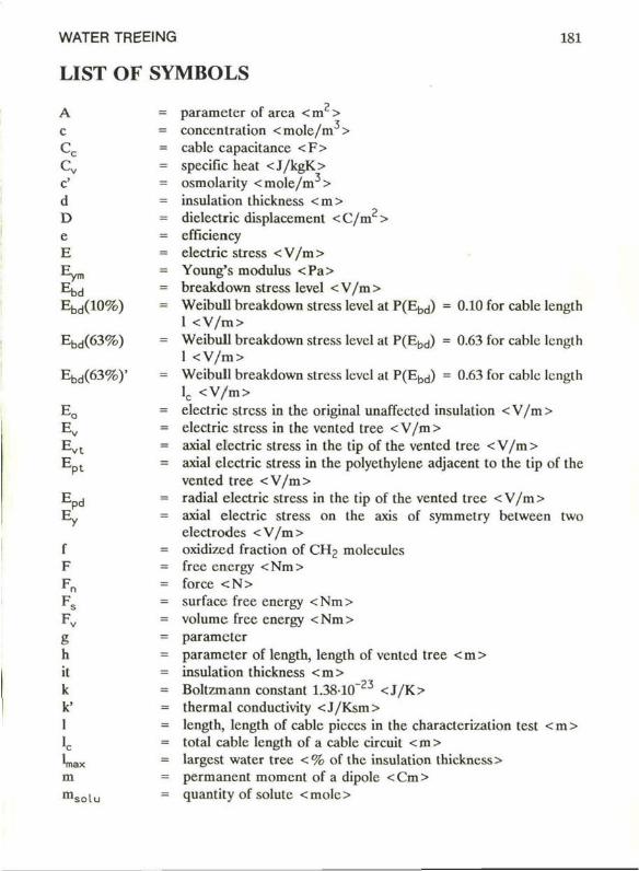
WATER TRËEING 181
LIST OF SYMBOLS A c
C c Cv c' d D e B
k Ebd(10%)
Ebd(63%)
Ebd(63%)' E 0
Ev
Evt
E<
I F
g h it k k' 1 Ie •max m msolu
= parameter of area < m > = concentration <molc/m > = cable capacitance <F> = specific heat <J/kgK> = osmolarity <mole/m > = insulation thickness <m> = dielectric displacement <C/m > = efficiency = electric stress < V/m > = Young's modulus <Pa> = breakdown stress level <V/m> = Weibull breakdown stress level at P(Ebd) = 0.10 for cable length
1 <V/m> = Weibull breakdown stress level at P(Ebtj) = 0.63 for cable length
1 <V/m> = Weibull breakdown stress level at P(Ebtj) = 0.63 for cable length
lc <V/m> = electric stress in the original unaffected insulation <V/m> = electric stress in the ventcd tree <V/m> = axial electric stress in the tip of the vented tree < V/m > = axial electric stress in the polycthylene adjacent to the tip of the
vented tree <V/m> = radial electric stress in the tip of the vented tree < V/m> = axial electric stress on the axis of symmetry betwecn two
electrodes <V/m> = oxidizcd fraction of CHj moleculcs = free cnergy <Nm> = force <N> = surfacc free energy <Nm> = volume free energy <Nm> = parameter = parameter of length, length of vented tree < m > = insulation thickness <m> = Boltzmann constant 1.38-10"23 <J /K> = thermal conductivity <J/Ksm> = length, length of cable pieces in the characterization test < m > = total cable length of a cable circuit < m > = largest water tree < % of the insulation thickness > = permanent moment of a dipole < Cm > = quantity of solute <mole>
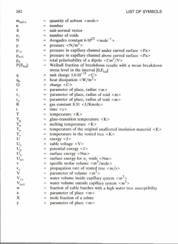
LIST OF SYMBOLS
quantity of solvent < molc > number unit-normal vector number of voids Avogadro constant 610 <mole~ > pressurc <N/m > prcssurc in capillary channel under curved surface < Pa > pressurc in capillary channel above curved surface <Pa> total polarisability of a dipole <Cm /V> Weibull fraction of breakdown rcsults with a mcan breakdown stress level in the interval [0,Ebd] unit charge 1.6-10"19 <C> heat dissipation <W/m > charge <C> parameter of place, radius < m > parameter of place, radius of void < m > parameter of place, radius of void < m > gas constant 8.31 <J/Kmolc> time <s> tempcraturc <K> glass-transition temperaturc <K> mclting temperaturc <K> lempcrature of the original unaffcclcd insulation material <K> tempcraturc in the vented tree <K> encrgy <J> cable voltage <V> potential encrgy <J> surfacc encrgy <Nm> surfacc encrgy for nt voids <Nm> specifie molar volume <m /mole> propagation rate of vented tree <m/s> parameter of volume <m > water volume insidc capillary system <m > water volume outside capillary system <m > fraction of cable batchcs with a high water tree susccplibilily parameter of place < m > mole fraction of a solutc parameter of place <m>
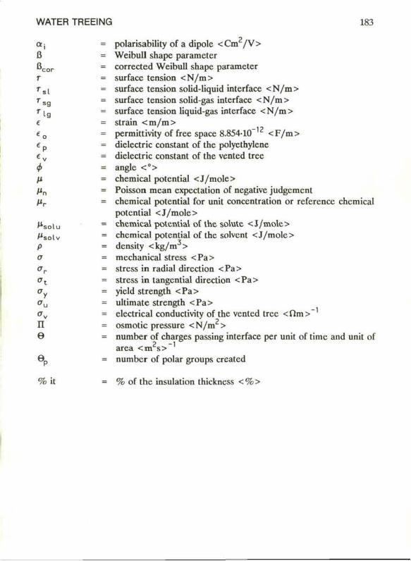
WATER TREEING 183
Oj = polarisability of a dipole < Cm / V > 8 = Weibull shape parameter B c o r = corrected Weibull shape parameter
= surface tension <N/m> ■ s ( = surface tension solid-liquid interface < N/m > " s g = surface tension solid-gas interface < N/m > ' lg = surface tension liquid-gas interface <N/m>
= strain < m / m > = permittivity of free space 8.854-10~'2 <F /m>
e p = dielectric constant of the polyethylene e v = dielectric constant of the vented tree <f> = angle <°> H = chemical potential <J/mole> fin = Poisson mean expectation of negative judgcment Hr = chemical potential for unit concentration or reference chemical
potential <J/mole> Hso[u = chemical potential of the solute <J/mole> Msotv = chcmical potential of the solvent <J/mole> p = density <kg/m3> o = mechanical stress <Pa> ar = stress in radial direction <Pa> ot = stress in tangential direction <Pa> o = yield strength <Pa> ou = ultimate strength <Pa> av = electrical conductivity of the vented tree <fïm>~ Il = osmotic pressure <N/m > © = number of charges passing interface per unit of time and unit of
area <m s>~' öp = number of polar groups created
% it = % of the insulation thickncss <%>
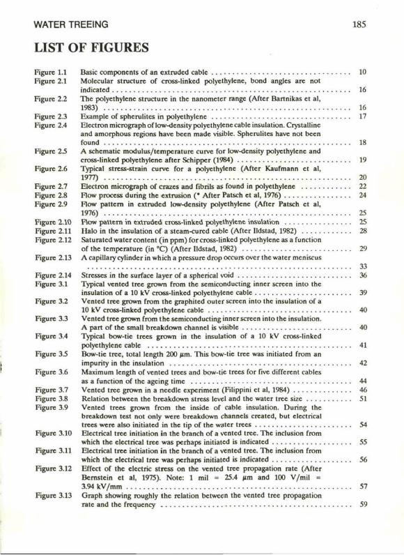
WATER TREEING 185
LIST OF FIGURES Figure 1.1 Basic components of an extrudcd cablc 10 Figure 2.1 Molecular struclure of cross-linked polyethylene, bond angles are not
indicaled 16 Figure 2.2 The polyethylene structurc in the nanometer range (Aftcr Bartnikas et al,
1983) 16 Figure 2.3 Example of spherulites in polyethylene 17 Figure 2.4 niectronmicrographoflow-densitypolyethylenecableinsulation. Crystalline
and amorphous regions have been made visible. Spherulites have not been found 18
Figure 25 A schematic modulus/tempcrature curve for low-density polyethylene and cross-linked polyethylene after Schipper (1984) 19
Figure 2.6 Typical stress-strain curve for a polyethylene (After Kaufmann et al, 1977) 20
Figure 2.7 Electron micrograph of crazes and fibrils as found in polyethylene 22 Figure 2.8 Flow process during the extrusion (• After Patsch et al, 1976) 24 Figure 2.9 Flow pattem in extrudcd low-density polyethylene (After Patsch et al,
1976) 25 Figure 2.10 Flow pattem in extrudcd cross-linked polyethylene insulation 25 Figure 2.11 Halo in the insulation of a stcam-curcd cablc (Aftcr lldstad, 1982) 28 Figure 2.12 Saturated water content (in ppm) for cross-linked polyethylene as a function
of the temperaturc (in °C) (Aftcr lldstad, 1982) 29 Figure 2.13 Acapillarycylindcr in which a pressure drop occurs over the water meniscus
33 Figure 2.14 Stresses in the surf ace layer of a spherical void 36 Figure 3.1 Typical vented tree grown from the semiconducting inner screen into the
insulation of a 10 kV cross-linked polyethylene cable 39 Figure 3.2 Vented tree grown from the graphited outer screen into the insulation of a
10 kV cross-linked polyethylene cable 40 Figure 3.3 Vented tree grown from t he semiconducting inner screen into the insulation.
A part of the small breakdown channcl is visible 40 Figure 3.4 Typical bow-tic trees grown in the insulation of a 10 kV cross-linked
polyethylene cable 41 Figure 3.5 Bow-tie tree, total length 200 Mm. This bow-tie tree was initiated from an
impurity in the insulation 42 Figure 3.6 Maximum length of vented trees and bow-tie trees for five different cables
as a function of the agcing time 44 Figure 3.7 Vented tree grown in a ncedlc experiment (Filippini et al, 1984) 46 Figure 3.8 Relation between the breakdown stress level and the water tree size 51 Figure 3.9 Vented trees grown from the inside of cable insulation. During the
breakdown test not only were breakdown channels created, but clectrical trees were also initiated in the tip of the water trees 54
Figure 3.10 Electrical tree initiation in the branch of a vented tree. The inclusion from which the clectrical tree was perhaps initiated is indicaled 55
Figure 3.11 Electrical tree initiation in the branch of a vented tree. The inclusion from which Ihc electrical tree was perhaps initiated is indicaled 56
Figure 3.12 Effect of the electric stress on the vcnlcd tree propagalion rate (After Bemstein el al, 1975). Note: 1 mil = 25.4 iim and 100 V/mil = 3.94 kV/mm 57
Figure 3.13 Graph showing roughly the relation between the vented tree propagation rate and the frequency 59
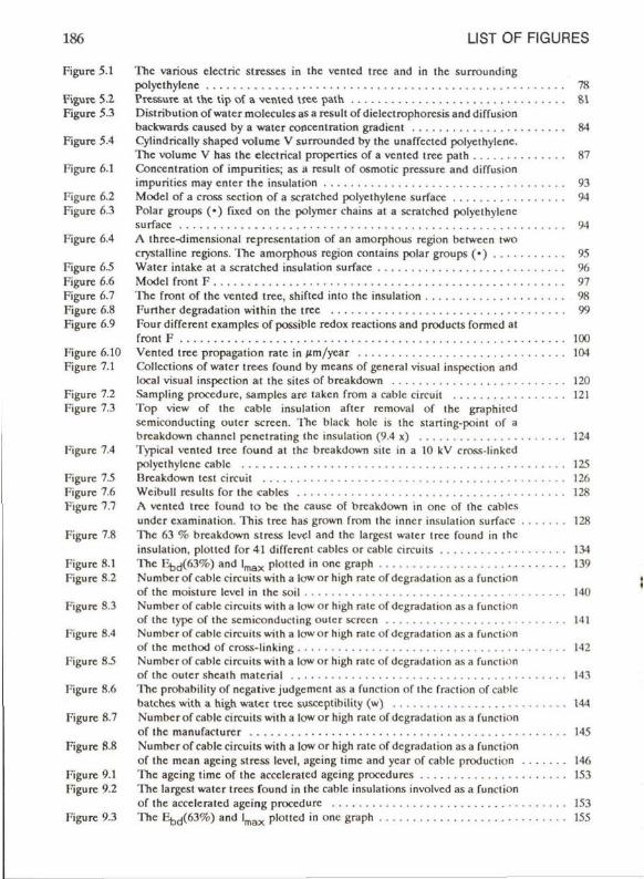
186 LIST OF FIGURES
Figurc 5.1 The various clcclric slrcsses in the venled tree and in Ihc surrounding polyethylene 78
Figurc 5.2 Pressure at the t ip o f a vcnlcd irec path 81 Figurc 5.3 Distr ibution of water molcculcs as a rcsult o f diclcclrophorcsis and diffusion
backwards causcd by a water concenlration gradient 84 Figurc 5.4 Cyiindrically shapcd volume V surrounded by the unaffected polyethylene.
The volume V has the electrical propertics of a vented tree path 87 Figurc 6.1 Concenlration of impuri l ies; as a rcsult of osmotic prcssurc and diffusion
impurities may enter Ihe insulation 93 Figurc 6.2 Model of a cross section of a scratchcd polyethylene surfacc 94 Figure 6.3 Polar groups (• ) fixcd on the polymer chains at a scratchcd polyethylene
surfacc 94 Figurc 6.4 A threc-dimensional representation of an amorphous rcgion herween two
crystallinc regions. The amorphous rcgion contains polar groups ( • ) 95 Figurc 6.5 Water intake at a scratchcd insulation surfacc 96 Figurc 6.6 Model front F 97 Figure 6.7 The front o f the vented tree, shifted into the insulation 98 Figurc 6.8 Furthcr degradation wi lh in the tree 99 Figure 6.9 Four different cxamplcs of possible rcdox rcactions and products formcd at
front F 100 Figurc 6.10 Vented tree propagation rate in ( im/ycar 104 Figure 7.1 Collcctions of water trees found by mcans of general visual inspcclion and
local visual inspcclion al Ihc siles of breakdown 120 Figurc 7.2 .Sampling procedure, samples are laken from a cablc circuit 121 Figure 7.3 Top view of the cablc insulation aftcr removal of the graphitcd
semiconducting ouler screen. 'ITic black hole is the starting-poinl of a breakdown channcl penctrating the insulation (9.4 x) 124
Figurc 7.4 Typical venled tree found at the breakdown silc in a 10 kV cro&s-linkcd polyethylene cablc 125
Figurc 7.5 Breakdown lest circuit 126 Figurc 7.6 Wcibull rcsulis for Ihc cablcs 128 Figure 7.7 A venled tree found t o bc Ihc causc of breakdown in onc of Ihe cablcs
undcr cxamination. This tree has grown from ihc inner insulalion surfacc 128 Figure 7.8 The 63 % breakdown stress Icvcl and ihc largcsi water tree found in the
insulalion. plotled for 41 different cablcs or cablc circuits 134 Figurc 8.1 The F^d(63%) and l m a x plotled in onc graph 139 Figure 8.2 Numbcrof cablc circuits wi lh a lowor high ralc of degradation as a funclion
of the moisturc Icvcl in Ihc soil 140 Figure 8,3 Numbcro f cablc circuits wilh a lowor high ralc of degradation asa funclion
of the type of the semiconducting ouler screen 141 Figure 8.4 Numbcro f cablc circuits wi lh a lowor high rate of degradation asa funclion
of the mclhod of cross-linking 142 Figurc 8.5 Numbcr of cablc circuits wilh a low or high ralc of degradation as a funclion
of Ihe ouler shcalh ni.iicn.il 143 Figurc 8.6 The probabilily of ncgalive judgcmcnl as a funclion of Ihc fraclion of cablc
balches wi th a high water tree susccptibilily (w) 144 Figurc 8.7 Numbcrof cablc circuits with a lowor high rate of degradation as a funclion
of the manufacturcr 145 Figure 8.8 Numbcro f cablc circuits wi lh a lowor high ralc of degradation asa function
of the mean agcing stress Icvcl. agcing time and ycar of cablc production 146 FiguR 9.1 The agcing time of the accclcratcd agcing procedures 153 Figurc 9.2 The largest water trees found in the cablc insulations involvcd as a function
of the accelcraled agcing procedure 153 Figure 9.3 The 1 ^ ( 6 3 % ) and l m a x plottcd in one graph 155
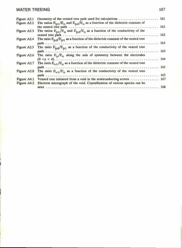
WATER TREEING 187
Figure A2.1 Geometry of the vcnted tree path used for calculations 161 Figure A2.2 The ratios E _ t / E 0 and E - J / E Q as a funclion of the diclcctric constant of
ihe vented tree path 162 Figure A2.3 The ratios E _ t / E 0 and E - J / E Q as a function of the conductivity of the
venled tree path 162 Figure A2.4 The ratio ED J / E _ , as a function of the diclcctric constant of ihe vented tree
path . . . . . . . . 163 Figure A2.5 The ratio E-jj/E t as a function of the conduclivily of Ihe venled tree
path VT.TV 163 Figure A2.6 The ratio E y / E 0 along the axis of symmetry between Ihe elcctrodes
(0 <y < d) . 164 Figure A2.7 The ralio Eyj/E, , as a function of the dieleciric consiani of the venled Iree
path 165 Figure A2.8 The ralio E y t / E 0 as a function of Ihe conductivity of the venled Iree
path 165 Figure A4.1 Vented tree initiated from a void in Ihc semiconducting screen 167 Figure A4.2 Electron micrograph of Ihc void. Crystallizalion of various species can bc
seen 168
WATER TREEING 189
LIST OF TABLES Table 2.1 Relation belween dcnsity and numbcr and length of sidc chains for
low-dcnsity and for high-densiiy polyelhylcne. Afler Sillars (1973) and Billmeyer (1984) 15
Table 2.2 Typical tensilc properties for polyelhylcne 20 Table 2.3 Density, size and volume of voids in polyelhylcne as a funclion of the curing
process 27 Table 3.1 Cycling temperature condilions regarding Ihc sludy of vented treeing 63 Table 7.1 The ratc of inercase of the test voltage (in kV/min) as a function of the
cable voltage class 122 Table 7.2 Cable characterislics conecming the construction and the agcing 130 Table 7.3 Main results of the characlerization test for fivc typical cables 131 Table 8.1 The two parameters 12^(63%) and l m a x summarizing the results of the
charactcrization test givcn for each of the 24 cables undcr cxamination 138 Table 9.1 Agcing conditions of various agcing procedures 150 Table 9.2 Main results of Ihc characlerization lest for accelcralcd-agcd cables 154 Table A3 Cable properlies 166
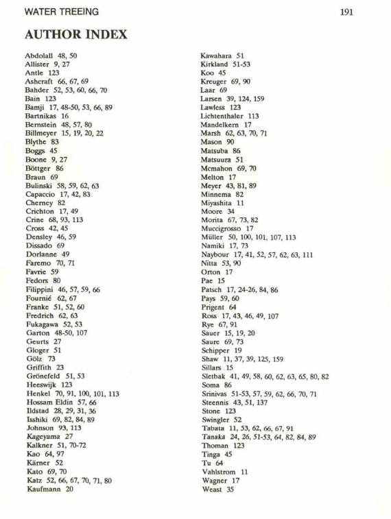
WATER TREEING
AUTHOR INDEX Abdolall 48, 50 Allister 9, 27 Antle 123 Ashcraft 66, 67, 69 Bahder 52, 53, 60, 66, 70 Bain 123 Bamji 17,48-50,53,66,89 Bartnikas 16 Bcmstein 48, 57, 80 Billmeyer 15, 19, 20, 22 Blylhc 83 Boggs 45 Boone 9,27 Böttger 86 Draun 69 Bulinski 58, 59, 62, 63 Capaccio 17, 42, 83 Cherncy 82 Crichton 17, 49 Crinc 68, 93, 113 Cross 42,45 Dcnslcy 46, 59 Dissado 69 Dorlanne 49 Faremo 70, 71 Favric 59 Fedors 80 Filippini 46,57,59,66 Fournié 62,67 Franke 51,52,60 Fredrich 62,63 Fukagawa 52, 53 Garton 48-50, 107 Gcurts 27 Gloger 51 Gölz 73 Griffïth 23 Gröncfcld 51,53 Heeswijk 123 Hcnkel 70, 91, 100, 101, 113 Hossam Eldin 57, 66 Ildstad 28, 29, 31, 36 Isshiki 69,82,84,89 Johnson 93, 113 Kageyama 27 Kalkncr 51,70-72 Kao 64,97 Kamer 52 Kalo 69,70 Katz 52, 66, 67, 70, 71, 80 Kaufmann 20
Kawahara 51 Kirkland 51-53 Koo 45 Kreuger 69,90 Laar 69 Larsen 39, 124, 159 l-awless 123 Lichtenlhaler 113 Mandelkern 17 Marsh 62, 63, 70, 71 Mason 90 Matsuba 86 Matsuura 51 Mcmahon 69, 70 Melton 17 Meyer 43,81,89 Minnema 82 Miyashita 11 Moore 34 Morita 67, 73, 82 Muccigrosso 17 Muller 50, 100, 101, 107, 113 Namiki 17, 73 Naybour 17, 41, 52, 57, 62, 63, 111 Nitta 53,90 Orton 17 Pae 15 Patsch 17, 24-26, 84, 86 Pays 59,60 Prigenl 64 Ross 17, 43, 46, 49, 107 Rye 67,91 Saucr 15, 19, 20 Saure 69, 73 Schipper 19 Shaw 11,37,39, 125, 159 Sillars 15 Sletbak 41, 49, 58, 60, 62, 63, 65, 80, 82 Soma 86 Srinivas 51-53, 57, 59, 62, 66, 70, 71 Sceennis 43, 51, 137 Stone 123 Swingler 52 Tabata 11, 53, 62, 66, 67, 91 Tanaka 24, 26, 51-53, 64, 82, 84, 89 Thoman 123 Tinga 45 Tu 64 Vahlstrom 11 Wagner 17 Weast 35

192 AUTHOR INDEX
Wijvckate 143 Wilkens 86 Wojlas 52 Wong 87 Yamada 60 Yoshimitsu 48, 57, 62, 65, 69, 71, 91 Yoshimura 57-60, 66, 89 Zeiler 83
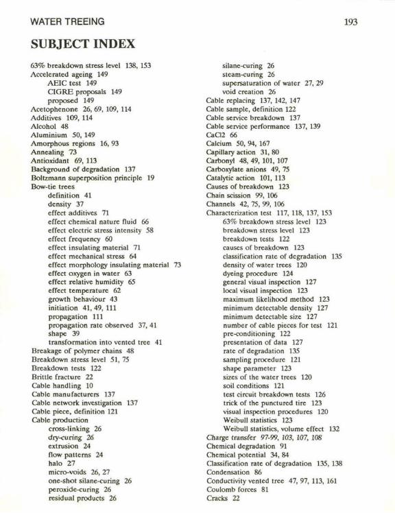
WATER TREEING
SUBJECT INDEX 63% breakdown stress level 138, 153 Accelcratcd ageing 149
AEICtest 149 CIGRE proposals 149 proposcd 149
Acetophcnone 26, 69, 109, 114 Additives 109, 114 Alcohol 48 Aluminium 50, 149 Amorphous regions 16, 93 Annealing 73 Antioxidant 69, 113 Background of degradation 137 Boltzmann supcrposition principlc 19 Bow-tie trees
dennition 41 density 37 effect additives 71 effect chemical nature fluid 66 effect clcctric stress intensity 58 effect frequency 60 effect insulating material 71 effect mechanical stress 64 effect morphology insulating material 73 effect oxygen in water 63 effect relative humidity 65 effect temperaturc 62 growth behaviour 43 initiation 41,49, 111 propagation 111 propagation ratc observed 37, 41 shape 39 transformation into vented tree 41
Brcakage of polymer chains 48 Breakdown stress level 51, 75 Breakdown tests 122 Brittle fracturc 22 Cable handling 10 Cable manufacturers 137 Cable nctwork investigation 137 Cable picce, dcfinition 121 Cable production
cross-linking 26 dry-curing 26 extrusion 24 flow patterns 24 halo 27 micro-voids 26, 27 one-shot silane-curing 26 peroxidc-curing 26 residual products 26
silane-curing 26 stcam-curing 26 supersaturation of water 27, 29 void creation 26
Cable rcplacing 137, 142, 147 Cable sample, dcfinition 122 Cable service breakdown 137 Cable service performance 137, 139 CaC12 66 Calcium 50, 94, 167 Capillary action 31, 80 Carbonyl 48, 49, 101, 107 Carboxyiate anions 49, 75 Catalytic action 101, 113 Causes of breakdown 123 Chain scission 99, 106 Channels 42. 75, 99, 106 Charactcrization test 117, 118, 137, 153
63% breakdown stress level 123 breakdown stress level 123 breakdown tests 122 causes of breakdown 123 classificalion rate of degradation 135 density of water trees 120 dyeing procedure 124 general visual inspection 127 local visual inspection 123 maximum likclihood method 123 minimum detectable density 127 minimum detectable size 127 numbcr of cable picecs for lest 121 pre-conditioning 122 presentation of data 127 ratc of degradation 135 sampling procedure 121 shape parameter 123 sizes of the water trees 120 soil conditions 121 test circuit breakdown tests 126 trick of the punctured tire 123 visual inspection procedures 120 Weibull statistics 123 Wcibull statistics, volume effect 132
Charge transfer 97-99, 103, 107, 108 Chemical degradation 91 Chemical potential 34, 84 Classificalion rate of degradation 135, 138 Condensation 86 Conductivity vented tree 47, 97, 113, 161 Coulomb forces 81 Cracks 22
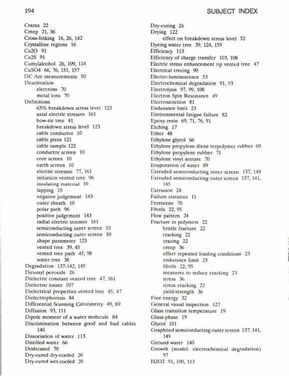
194 SUBJECT INDEX
Crazcs 22 Creep 21, 36 Cross-linking 16, 26, 142 Crystalline regions 16 Cu20 91 Cu2S 91
Cumylalcohol 26, 109, 114 CuSCM 66, 76, 151, 157 DC" Are mcasurcmcnis 50 Dcactivalion
eleclrons 70 mctal ions 70
Dcfinil ions 63% breakdown siress Icvcl 123 axial electric stresses 161 bow-lie tree 41 breakdown stress Icvcl 123 cablc conductor 10 cablc picce 121 cablc sample 122 conductor screen 10 corc screen 10 carth screen 10 electric stresses 77, 161 initiation vented tree 96 insulating material 10 lapping 10 ncgativc judgement 143 outcrshcalh 10 polar path % positivc judgement 143 radial electric stresses 161 semiconducling inner screen 10 semiconducling outcr screen 10 shapc parameter 123 vented tree 39, 45 vented tree path 45, 98 walcr tree 38
Dcgradation 137-142, 145 Dicumyl peroxide 26 Diclcctric constant vented tree 47, 161 Diclcctric losses 107 Diclcctrical propertics vented tree 45, 47 Diclcctrophorcsis 84 Diffcrcntial Scanning Calorimclry 49, 89 Diffusion 93, 111
Dipolc moment of a water molecule 84 Discnminalion betwecn good and bad cables
140 Dissociation of water 113 Distil lcd water 66 Dodccanol 70 Ory-curcd dry-cooled 26 Dry-curcd wct-cooled 26
Dry-curing 26 Drying 122
effect on breakdown stress level 52 Dyeing water tree 39, 124, 159 Efficiency 113 Efficiency of charge transfer 103, 108 Electric stress enhanecment tip vented tree 47 Elcctrical trecing 90 Elcctro-lumincscencc 53 Electrochcmical dcgradation 91, 93 Elcctrolysis 97, 99, 108 Hlcctron Spin Rcsonancc 49 Elcctrostriction 81 Endurancc limit 23 Environmental fatigue failurc 82 Epoxy resin 69, 71, 76, 91 Etching 17 Ether 48 Ethylene glycol 66
Ethylcnc propyicne dienc Icrpolymcr rubber 69 Ethylene propyicne rubber 71 Ethylcnc vinyl acetate 70 Evaporation of water 89 Extrudcd semiconducling inner screen 137, 149 Extrudcd semiconducling oulcr screen 137. 141,
145 Ext rusion 24 Failurc statistics 11 Fcrroccnc 70 Fibrils 22, 95 Flow patlcm 24 Fracture in polymcrs 22
bri l i lc fracture 22 cracking 22 cra/.ing 22 creep 36 effect rcpcaicd loading conditions 23 endurancc limit 23 fibrils 22. 95 measures lo rcducc cracking 23 slrcss 36 stress cracking 22 yicld-strcngth 36
Frce cnergy 32 Gcncral visual inspcclion 127 ülass iransilion tempcrature 19 Glass-phasc 19 Glycol 101 Graphilcd semiconducling oulcr screen 137, 141,
149 Ground walcr 140 Growth (model: electrochcmical dcgradation)
97 11202 91, 100. 113
WATER TREEING 195
H2S 91 Halo 27 Heat-treatmcnt 50, 107 High-density polycthylcne 15 Hookcan behaviour 19 Hoslopal 66 Hydrogcn bonding 48 Hydrostatic pressure 32 Hydroxyl 48,49 Impurities 41, 80, 93, 107, 113 Impurities in scmiconducting screen 93, 167 Infra-red 48, 107 Inhomogeneous broadening 48 Initiation 93 Iniliation of elcetrical irec 46 Interfcrometric holography 45 Inlernal friction 21 Joule losses 107 Kctone 101 I.argcst water tree 138, 153 Lcad shcath 137, 142 Light cmission 53, 90 Liquid paraffin 66 Local visual inspection 123 Longitudinal water-blocking 112 Loss-factor 52, 75, 107 Low-dcnsity polyethylcnc 15 Manufacturere 137 Maximum likclihood method 123 Maxwell stress 45, 81 Mean expectation of negative judgement 143 Mcchanical properties polycthylene 15, 19
Boltzmann superposition principle 19 creep 21 effect cross-linking 19 effect crystallinity 21 effect density 15 effect glass transition temperature 19 effect mcchanical stress 19 effect mclting temperature 19 effect molecule length 15 effect plasticizers 21 effect sidc chains 15, 21 effect sphcrulites 16 effect strain 19 effect temperature 21 effect water 21 effects of time 21 glass-phase 19 Hookean behaviour 19 internal friction 21 polarity polymer chains 21 rclaxation 21 stress-strain curve 19
tensile properties 20 ultimatc strength 20 yicld point 20 yield strength 20 Young's modulus 19
Mechanical stress by osmosis 36 Mechanisms of ventcd tree growth 80
capillair action 80 chemical degradation 91 chemical potential 84 condensation 86 Coulomb forces 81 cracking 83 dielectrophoresis 84 effect of vibrations 82 elcetrical treeing 90 electrochemical degradation 91, 93 clectrostriction 81 environmental fatigue failure 82 evaporation of water 89 Maxwell stress 81 osmosis 80 overvoltagcs 90 oxidation 91 partial discharges 90 supersaturation of water 86 surface tension 82 thermal degradation 87 voids 83, 86
Mcdium-density polyethylcnc 15 Melt index 73 Melting endotherms 49 Mclting temperature 19 Metal ions 48-SO, 75, 101, 107, 113 Methanol 26 Methylcne blue 159 Micro-voids 27, 30, 34, 42, 75 Migration of additives 70 Multiphase diclcctric mixture theory 45 Na2C03 159 NaCI 66. 76, 151, 157 Nccdle experiment 76 Nylon 70
One-shot silane-curing 26, 137, 145 Osmolarity 35 Osmosis 34, 80, 93, 111 Outcr sheath failures 10, 142 Ovcrvoltages 90 Oxidation 48, 49, 75, 91, 93, 99, 100, 107 Oxidative stability test 49 Oxygen in water 63, 67 Partial discharges 53, 75, 90, 94 Pencil-likc vented trees 133 Permanent moment of a water molecule 84
1% SUBJECT INDEX
Phenomenology and model of electrochcmical degradation 106
bow-tie tree dcvclopment 111 effect of electric stress intensity 107 effect of frequency 108 effect of insulation material and addilivcs
109 effect of mechanica! stress 110 effect of relative humidity 110 effect of tempcrature 110 effect of the morphology of the insulaling
material 109 clcctrical properties (bulk) 107 morphological aspects 106 physical propenies (local) 107
Phenomenology of water trees 37 Poisson distribution 143 Polar groups 93, 103 Polarpaths 96 Pollulion 93 Polybutene 69 Polycarbonatc 70 Polypropylene 70 Polystyrene 69, 70 Polyvinyl chloride 70, 137. 142, 149 Potcntial energy of a dipole 84 Prc-conditioning 122 Propagation rate calculatcd 102, 104 Propagation rate observed 37, 104 Ouinolinc 70 Radial water-blocking 113 Rate of degradation 135, 137-142, 145 Rccrystallisation 50 Rcdox rcactions 97, 98, 100, 102 Reduction rcactions 100 Rclaxation 21
Rcplacing cablcs 137, 142, 147 Residual products 26, 69, 70, 76 Rcsistancc bulk insulation 52, 75 Service breakdown cablcs 137 Service performance cablcs 137, 139 Service-agcd cablcs 137 Shcath failurcs 140 Silanc-curing 26, 137, 142, 145 Silicon 50, 94, 167 Siloxanc oligomcr 70 Sodium 50
Soil condition 121, 140 Spherulitcs 17 Stcam-curing 26, 137, 142, 147, 149 Step test 122 Strain 48 Stress cracking 22 Stress-strain curve 19
Structure polyethylenc 15 amorphous parts 16 crystalline parts 16 effect cross-linking 16 effect etching procedures 17 .spherulitcs 17 superstructures 17
Sulphate 75 Sulphatc anions 48 Sulphur 49, 94, 167 Supersaturation 86 Supcrsaturation of water 27, 29, 63 Superstructures 17 Suppression of vented trecing 112 Surfacc energy 30 Surf ace tension 30, 31, 36, 82 Swclling powders 112 Swclling tapes 112 Tcmperaturc
glass transition tcmperaturc 19 melting tempcrature 19 operational tempcrature polyethylenc
insulation 16 Test circuit breakdown tests 126 lTicrmal breakdown 46 'ITicrmal degradation 87 Transformation bow-lic tree inlo vcnlcd tree 41 Traps 70 Trick of the puncturcd lire 123 Ullimate strength 20 Vcntcd tree path
dcfinition 45 Vcntcd trees
channels 42, 75, 99 chemical propertics 48, 75 conductivity 47, 113 definition 39, 45 density 37 diclcctric constant 47 dtclcctrical propertics 45, 75 direction of propagation 46 dycing using different solvcnts 50 effect acidity Icvcl 67 effect addilivcs 69, 76 effect anncaling 73 effect chemical nature fluid 66, 76 effect cross-link by-products 76 effcel clcclric stress intensity 57, 76 effect elcctrodc material 67 effect frequency 59, 76 effect insulaling material 69, 76 effcel mechanical stress 64, 76 effect morphology insulaling material 73,
76
WATER TREEING 197
effect overvoltagcs 90 effect oxygen in water 67 effect rclative humidity 65, 76 effect residual products cross-linking 69 effect salt quantity 66 effect solubility 67 effect temperature 62, 76 effect type of salts 66 clcctric stress enhancement 47 clcctro-luminescence 53 growth bchaviour 43 impurities 113 initiation 39, 93, 167 initiation of electrical tree 55 light emission 53 micro-voids 42, 75, 99 needie experiment 76 oxidation 49, 75, 93, 99 partial discharges 53, 75 pencil-like 133 physical properties 48, 75 pollution 93 propagaiion ratc calculated 104 propagation ratc observed 37, 39, 75, 104 recrystallisation 50 retardants 69, 109, 112, 113 shape 39 suppression 112 water content 43, 75 water necdlc experiment 76
Vibrations 82 Void creation during production 26 Voids 42, 86, 99, 106, 167 Water
absorption by osmosis 34 capillary action 31 concentration by diclcctrophoresis 84 content in polycthylcnc 29, 75 content in vented tree 43, 75 diffusion through outer sheath 142 in polycthylcnc 29 in voids 30 penctration in cablc 10 supersaturation 27, 29, 63
Water nccdle experiment 76 Water tree
chemical properties 48 conductivity 47 dielcctric constant 47 diclcctrical properties 45 direction of propagation 46 dyeing using different solvcnts 50 effect acidity level 67 effect additives 69
effect annealing 73 effect chemical nature fluid 66 effect crystallinity 73 effect density 73 effect electric stress intensity 57 effect elcctrodc material 67 effect frequency 59 effect insulating matcrial 69 effect mechanical stress 64 effect mclt index 73 effect morphology insulating matcrial 73 effect oxygen in water 63, 67 effect rclative humidity 65 effect residual products cross-linking 69 effect salt quantity 66 effect solubility 67 effect temperature 62 effect type of salts 66 electric stress enhancement 47 electro-lumincscence 53 growth bchaviour 43 initiation 49 initiation of electrical tree 55 light emission 53 micro-voids 42 partial discharges 53 recrystallisation 50 retardants 69, 112, 113 types 37, 139
Water tree susccptibility cable insulation effect ageing time 147 effect mean ageing stress Icvcl 147 effect method of cross-linking 142 effect outcr sheath material 142 effect soil condition 140 effect type semiconducting outcr screen 141 effect year of cablc production 147
Watcr-blocking 112, 113 Wcibull statistics 123 Wcibull statistics, volume effect 132 X-ray analyses 49 Xylol 50 Yicld point 20 Yield strength 20, 36 Young's modulus 19
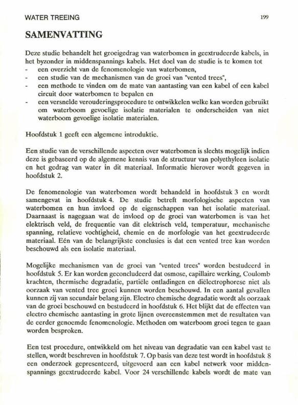
WATER TREEING 199
SAMENVATTING Deze studie behandelt het groeigedrag van waterbomcn in gccxtrudccrde kabels, in het byzonder in middenspannings kabels. Het doel van de studie is te komen tot
een overzicht van de fenomenologie van waterbomcn, een studie van de mechanismen van de groei van "vcnted trees", een methode te vinden om de mate van aantasting van een kabel of een kabel circuit door waterbomcn te bepalen en een versnelde verouderingsprocedure te ontwikkelen welke kan worden gebruikt om waterboom gevoelige isolatie materialen te onderscheiden van niet waterboom gevoelige isolatie materialen.
Hoofdstuk 1 geeft een algemene introduktie.
Een studie van de verschillende aspecten over waterbomen is slechts mogelijk indien deze is gebaseerd op de algemene kennis van de structuur van polyethyleen isolatie en het gedrag van water in dit materiaal. Informatie hierover wordt gegeven in hoofdstuk 2.
De fenomenologie van waterbomen wordt behandeld in hoofdstuk 3 en wordt samengevat in hoofdstuk 4. De studie betreft morfologische aspecten van waterbomen en hun invloed op de eigenschappen van het isolatie materiaal. Daarnaast is nagegaan wat de invloed op de groei van waterbomen is van het elektrisch veld, de frequentie van dit elektrisch veld, temperatuur, mechanische spanning, relatieve vochtigheid, chemie en de morfologie van het geextrudeerde materiaal. Eén van de belangrijkste conclusies is dat een vcnted tree kan worden beschouwd als een isolatie materiaal.
Mogelijke mechanismen van de groei van "vented trees" worden bestudeerd in hoofdstuk 5. Er kan worden geconcludeerd dat osmose, capillaire werking, Coulomb krachten, thermische degradatie, partiele ontladingen en diëlcctrophorese niet als oorzaak van vented tree groei kunnen worden beschouwd. In een aantal gevallen kunnen zij van secundair belang zijn. Electro chemische degradatie wordt als oorzaak van de groei beschouwd en bestudeerd in hoofdstuk 6. Het blijkt dat de effecten van electro chemische aantasting in grote lijnen overeenstemmen met de resultaten van de eerder genoemde fenomenologie. Methoden om waterboom groei tegen te gaan worden besproken.
Een test procedure, ontwikkeld om het niveau van degradatie van een kabel vast te stellen, wordt beschreven in hoofdstuk 7. Op basis van deze test wordt in hoofdstuk 8 een onderzoek gepresenteerd, uitgevoerd aan een kabel netwerk voor middenspannings geextrudeerde kabel. Voor 24 verschillende kabels wordt de mate van
200 SAMENVATTING
degradatie en de achtergrond van deze degradatie besproken in relatie tot zowel constructie als verouderings parameters.
In hoofdstuk 9 wordt de ontwikkeling van een versnelde verouderingsproccdure beschreven. De keuze van de verouderings parameters, gebaseerd op de resultaten van de fenomenologie, blijkt succesvol te zijn. De meest effectieve verouderings parameters zijn gerelateerd aan de chemische huishouding van het water en de frequentie van de clectrische spanning.
201
NAWOORD Het onderzoek heeft plaatsgevonden bij de N.V. KEMA te Arnhem. Ik ben de KEMA zeer erkentelijk voor de geboden gelegenheid het onderzoek in interdisciplinair verband te verrichten en erkentelijk voor de medewerking bij de afronding van het proefschrift.
Mijn promotor, prof. dr. ir. F.H. Kreuger ben ik byzondere dank verschuldigd voor zijn kritische begeleiding met name met betrekking tot de uitwerking en de presentatie van de resultaten.
Mijn begeleider bij de N.V. KEMA, Wim Boone, ben ik zeer veel dank verschuldigd voor een uitstekende werksfeer, voor de vele stimulerende discussies en voor de grote mate van vrijheid die hij mij heeft gelaten bij het uitvoeren van het onderzoek.
Ik spreek grote waardering uit voor de plezierige manier waarop ik met Wim Gcurts van de afdeling Natuurkundig Onderzoek van de N.V. KEMA heb kunnen discussiëren over het mechanisme van waterboom groei. De discussies en zijn adviezen hebben mede de uiteindeüjk resultaten bepaald.
Veel dank ben ik verschuldigd aan het Hoogspanningslaboratorium van de N.V. KEMA alwaar vele beproevingen zijn uitgevoerd. In het byzonder wil ik graag noemen Leo Scheltinga voor zijn belangrijke bijdrage aan de totstandkoming van de testapparatuur. Ook wil ik graag noemen Paul van Nes voor zijn bijdrage aan de analyses van de vele kabels die werden onderzocht op hun mate van aantasting door waterbomen en hem danken voor de zeer plezierige samenwerking.
Grote waardering heb ik voor het computer werk en experimentele werk dat is voortgekomen uit de deskundige handen van Chris van den Heuvel. In deze waardering wil ik gaarne betrekken Alex Geurtsen en Peter Willemsen die een belangrijke bijdrage hebben geleverd aan het opzetten van de experimenten.
Bij een deel van het onderzoek was één van de Elcctriciteitsbedrijven in ons land nauw betrokken, de N.V. PNEM in 's-Hertogenbosch. De medewerking van velen en met name van ing. A. Montfoorl en ing. C.W.J. Verhoeven is van grote waarde geweest. Ik ben de PNEM hiervoor zeer erkentelijk.
Voor de niet aflatende morele steun ben ik jou, Annelies, in het byzonder heel dankbaar.
Arnhem. 1 mei 1989
202
CURRICULUM VITAE Evert Fredcrik Stccnnis was born on November 16, 1954, at Ede.
He graduated at the Arnhem Technical College, Electrotechnical Dcpartmcnt in 1976.
From 1976 to 1981 he studied at the Eindhoven University of Tcchnology. Graduale work was performcd in the High-Voltage Group, undcr the guidancc of prof. dr. ir. P.C.T. van der Laan. The degrce of Electrotechnical Engineer was grantcd in 1981.
Aftcr hc finishcd his study, he joined the central research laboratories of the Dutch elcctric ulilitics, N.V. KEMA. Hc performcd technological research in the field of power cablcs and superconductors.