
The Professional Choice FAWCETT CHRISTIE …...Charging kit with hose burst...
4
Olaer Fawcett Christie Ltd. | Glendale Avenue | Sandycroft Industrial Estate | Sandycroft | Deeside | Flintshire | CH5 2QP | UK | Tel: +44 (0)1244 535515 www.olaerfawcettchristie.co.uk The Professional Choice Charging kit with hose burst valve_Version2_21/04/2010 FAWCETT CHRISTIE 3 5 1 4 6 2 Charging Kit with hose burst valve Specification A microbore hose with hose burst valve has been incorporated within the kit to prevent injury occurring as a result of hose whip. Hose whip can occur due to the sudden release of energy. When a hose fails it could cause serious harm to personnel in the vicinity. Benefits Each kit comes with a Microbore Hose which is offers greater flexibility and is easier to use than a standard hose. Other key benefits of the Microbore hose design are: ♦ Reduced flow rate to minimize the possibility of a bursting bladder during precharging. ♦ Detachable gas bottle adaptor that can be changed without replacing whole assembly. ♦ Olaer specially designed flow restriction hose burst valve that prevents hose whip and potential injury in the case of hose failure. ♦ The hose burst valve will close if the nitrogen supply is too high or if the supply valve was opened too fast. ♦ After closing the nitrogen supply valve there will be a short delay before the safety valve automatically opens again. Other benefits of this kit include: ♦ The charging body can be used as a stand alone device which permits precharge checking. ♦ Maximum working pressure: 350 bar. ♦ A wide selection of gauges are available for inclusion in this kit. ♦ Each kit contains 3 different charging adaptors which will accommodate the majority of European bladder and piston accumulators. ♦ Spare seals included. ♦ All parts in the kit are contained within a foam filled damage resistant, polypropylene case. Contents Each Charging Kit contains: 1. Hose burst valve 2. Microbore hose 3. Safety pattern pressure gauges 4. Charging adaptors 5. Spare seals 6. Charging set body 7. Protective Case (Not labelled, see picture above) The information in this datasheet is subject to change without prior notice.
Transcript of The Professional Choice FAWCETT CHRISTIE …...Charging kit with hose burst...
Olaer Fawcett Christie Ltd. | Glendale Avenue | Sandycroft Industrial Estate | Sandycroft | Deeside | Flintshire | CH5 2QP | UK | Tel: +44 (0)1244 535515
www.olaerfawcettchristie.co.uk
The Professional Choice
Charging kit with hose burst valve_Version2_21/04/2010
FAWCETT CHRISTIE
3
5
14
6
2
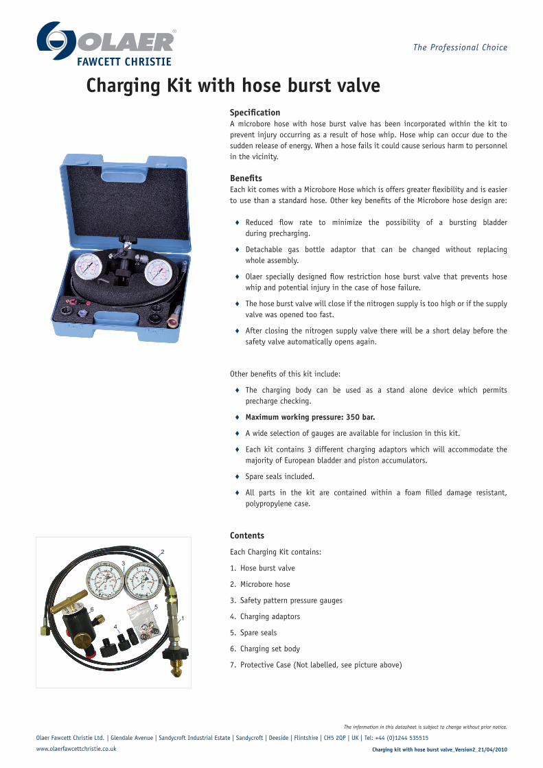
Charging Kit with hose burst valveSpecificationA microbore hose with hose burst valve has been incorporated within the kit to prevent injury occurring as a result of hose whip. Hose whip can occur due to the sudden release of energy. When a hose fails it could cause serious harm to personnel in the vicinity.
BenefitsEach kit comes with a Microbore Hose which is offers greater flexibility and is easier to use than a standard hose. Other key benefits of the Microbore hose design are:
♦ Reduced flow rate to minimize the possibility of a bursting bladder during precharging.
♦ Detachable gas bottle adaptor that can be changed without replacing whole assembly.
♦ Olaer specially designed flow restriction hose burst valve that prevents hose whip and potential injury in the case of hose failure.
♦ The hose burst valve will close if the nitrogen supply is too high or if the supply valve was opened too fast.
♦ After closing the nitrogen supply valve there will be a short delay before the safety valve automatically opens again.
Other benefits of this kit include:
♦ The charging body can be used as a stand alone device which permits precharge checking.
♦ Maximum working pressure: 350 bar.
♦ A wide selection of gauges are available for inclusion in this kit.
♦ Each kit contains 3 different charging adaptors which will accommodate the majority of European bladder and piston accumulators.
♦ Spare seals included.
♦ All parts in the kit are contained within a foam filled damage resistant, polypropylene case.
Contents
Each Charging Kit contains:
1. Hose burst valve
2. Microbore hose
3. Safety pattern pressure gauges
4. Charging adaptors
5. Spare seals
6. Charging set body
7. Protective Case (Not labelled, see picture above)
The information in this datasheet is subject to change without prior notice.
Olaer Fawcett Christie Ltd. | Glendale Avenue | Sandycroft Industrial Estate | Sandycroft | Deeside | Flintshire | CH5 2QP | UK | Tel: +44 (0)1244 535515
www.olaerfawcettchristie.co.uk
The Professional Choice
Charging kit with hose burst valve_Version2_21/04/2010
FAWCETT CHRISTIE
Assembly Part Number Component Part
10607-01 10607-02 10607-03 10607-04 10607-05 10607-06 Charging Kit Assembly Part No.
1 1 1 1 1 1 Olaer charging set 10608
1 1 1 1 1 1 Charging hose assembly 10609
1 1 Pressure gauge 0 - 25 bar 45083-099
1 1 1 Pressure gauge 0 - 250 bar 45086-099
1 1 Pressure gauge 0 - 60 bar 45084-099
1 Pressure gauge 0 - 400 bar 45087-099
1 Pressure gauge 0 - 10 bar 45117-099
1 1 1 Pressure gauge 0 - 160 bar 45085-099
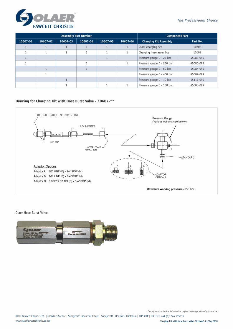
Olaer Hose Burst Valve
Maximum working pressure - 400 bar
Pressure Gauge(Various options, see below)
A B CAdaptor OptionsAdaptor A: 5/8" UNF (F) x 1/4" BSP (M)
Adaptor B: 7/8" UNF (F) x 1/4" BSP (M)
Adaptor C: 0.302" X 32 TPI (F) x 1/4" BSP (M)
350 bar
Drawing for Charging Kit with Host Burst Valve - 10607-**
The information in this datasheet is subject to change without prior notice.
Olaer Fawcett Christie Ltd. | Glendale Avenue | Sandycroft Industrial Estate | Sandycroft | Deeside | Flintshire | CH5 2QP | UK | Tel: +44 (0)1244 535515
www.olaerfawcettchristie.co.uk
The Professional Choice
Charging kit with hose burst valve_Version2_21/04/2010
FAWCETT CHRISTIE
Nitrogen Precharging
PrechargingUSE ONLY oxygen-free DRY NITROGEN GAS.
1. All accumulators are supplied without precharge unless a precharge pressure is specified when ordering. Prior to applying hydraulic pressure to the system all accumulators must be precharged with nitrogen.
2. Check details of accumulator on label and shell for maximum working pressure. The maximum hydraulic system pressure must not exceed the MWP of the accumulator.
3. Always use a nitrogen pressure regulator valve when the accumulator shell pressure rating is lower than gas pressure in nitrogen cylinder.
4. Precharge pressures vary with operating conditions. CONSULT OLAER Fawcett Christie if no precharge has been previously recommended. For a guide the following values can be used; - Storage application: 90% of minimum allowable system pressure, Shock application: 90% of flow pressure at accu- mulator position, Pulsation application: 70% of mean pump-ing pressure, NB. Allowing precharge to fall below 20% of maximum system pressure in a bladder accumulator may cause premature failure of the bladder. Excessive precharge pressures in relation to minimum system pressure may cause failures of the bladder and/or poppet valve and in piston accumulators, may cause excessive stresses due to the piston frequently contacting the end cap.
5. Ensure that moving parts such as bladders and pistons are adequately lubricated with system fluid before commencing precharging. This is especially important where the system fluid is of low viscosity e.g. water based.
CONSULT OLAER Fawcett Christie FOR FURTHER INFORMATION.
Precharging ProcedureThe following procedures should be adopted for safe precharging of accumulators.
For accumulators having a working pressure less than the nitrogen source refer to fig.2.
For accumulators having a working pressure equal to or greater than the nitrogen source refer to fig.3. see note 4.
For accumulators fitted with a permanent charging set refer to fig.4.
Procedure 1. Using a Nitrogen Pressure Regulatoe Valve (NPRV) fig.2
•Remove protective cap (1) if fitted and sealing cap (2).
•Attach NPRV (3) to nitrogen cylinder (4). Ensure centre spindle (10) is fully unwound.
•Attach charging set (5) to accumulator gas valve assembly (6) and connect charging hose (7) between NPRV (3) and charging set connection.
•Back off handle (8) anti-clockwise until loose, check gas bleed valve (9) on charging set is closed and screw handwheel (10) clockwise to open gas valve. Do not screw knob down tight.
•Open nitrogen cylinder valve by turning key (11), cylinder pressure will register on right-hand gauge (12). This pressure should be checked against the required precharge pressure.
•Turn handle (8) clockwise until outlet pressure on left-hand gauge (13) registers 10% higher than required precharge pressure. When pressure on the charging set and outlet gauges are equal, close nitrogen cylinder valve.
•Turn handwheel (10) anti-clockwise to seal gas valve.
•Crack bleed valve (9) to exhaust gas from charging hose and remove hose from charging set and replace hose connection sealing cap.
•Close bleed valve, turn handwheel (10) clockwise to open gas valve. Do not screw knob down tight. Crack bleed valve (9) to vent down to required precharge pressure. Close bleed valve.
•Turn handwheel (10) anti-clockwise to reseal gas valve, crack bleed valve and remove charging set from accumulator.
•Test gas valve for leaks using a leak detection spray or a soapy water solution.
•Replace sealing cap (2), tighten with pliers, and protective cap (1) if fitted.
The information in this datasheet is subject to change without prior notice.
Olaer Fawcett Christie Ltd. | Glendale Avenue | Sandycroft Industrial Estate | Sandycroft | Deeside | Flintshire | CH5 2QP | UK | Tel: +44 (0)1244 535515
www.olaerfawcettchristie.co.uk
The Professional Choice
Charging kit with hose burst valve_Version2_21/04/2010
FAWCETT CHRISTIE
Procedure 2. Nitrogen Pressure Regulator Valve (NPRV) not required fig.2• Remove protective cap (1) if fitted and sealing cap (2).
• Attach charging set (5) to accumulator gas valve assembly (6). Ensure centre spindle (10) is fully unwound.
• Connect charging hose (7) to nitrogen cylinder (4) using the appropriate adaptor, and attach the free end to the charging set.
• Turn handwheel (10) clockwise to open gas valve. Do not screw knob down tight. Slowly open nitrogen cylinder by turning key (11).
• Allow pressure on the gauge (14) to read slightly in excess of required precharge and then close nitrogen cylinder valve.
• Turn handwheel (10) anti-clockwise to seal gas valve.
• Crack bleed valve (9) to exhaust gas from charging hose and remove hose from charging set and replace hose connection sealing cap.
Procedure 3. Permanent Charging Set fitted fig. 4Follow steps of Procedures 1 or 2 as appropriate but connect to the permanent charging set as shown in fig.4.
The information in this datasheet is subject to change without prior notice.


![Agatha Christie - 4.50 Din Paddington [ibuc.info]-1.pdf](https://static.fdocuments.nl/doc/165x107/55cf9803550346d033950319/agatha-christie-450-din-paddington-ibucinfo-1pdf.jpg)