Telecomandi meccanici per motori RCTOPB RCTOPTB · PDF fileMando a distancia mecánico...
16
Copyright © 1995, 1999, 2001, 2003 Vetus den Ouden n.v. Schiedam Holland RCTOPB RCTOPTB SICO SISCO Installatie instructies Installation instructions Installationsvorschriften Instructions d’installation Instrucciones de instalación Istruzioni per l’installazione NEDERLANDS 2 ENGLISH 4 DEUTSCH 6 FRANÇAIS 8 ESPAÑOL 10 ITALIANO 12 Mechanische motorafstandsbediening Mechanical remote engine control Mechanische Motor-Fernbedienung Télécommande mécanique pour moteur Mando a distancia mecánico para motores Telecomandi meccanici per motori
Transcript of Telecomandi meccanici per motori RCTOPB RCTOPTB · PDF fileMando a distancia mecánico...
Copyr ight © 1995, 1999, 2001, 2003 Vetus den Ouden n.v. Schiedam Hol land
RCTOPBRCTOPTB
SICOSISCO
Installatie instructies
Installation instructions
Installationsvorschriften
Instructions d’installation
Instrucciones de instalación
Istruzioni per l’installazione
NEDERLANDS 2ENGLISH 4DEUTSCH 6FRANÇAIS 8ESPAÑOL 10ITALIANO 12
Mechanische motorafstandsbediening
Mechanical remote engine control
Mechanische Motor-Fernbedienung
Télécommande mécanique pour moteur
Mando a distancia mecánico para motores
Telecomandi meccanici per motori
InleidingMet de Vetus mechanische motorafstandsbedieningenRCTOPB, RCTOPTB, SICO en SISCO worden zowel de koppe-ling als de brandstofpomp door middel van één handelbediend.
Installatie
Trek-drukkabels aan het mechanismeHet mechanisme is direct geschikt voor het bedienen van de:• brandstofpomp (gas geven) - ‘duwend’
- ‘trekkend’• keerkoppeling (schakelen)
- ‘duwend-vooruit’ en ‘trekkend-achteruit’- ‘duwend-achteruit’ en ‘trekkend-vooruit’
Raadpleeg bij twijfel de motorleverancier wanneer niet duidelijkis hoe de bediening van de motor is wat betreft gas geven enschakelen (‘duwend’ of ‘trekkend’).
Let op!Verbind altijd eerst de kabels met het mechanisme. Het ver-binden van de kabels met de keerkoppeling en de brand-stofpomp dient pas te gebeuren wanneer de completeafstandsbediening geïnstalleerd is.
Verwijder altijd eerst de handel en het zwarte gedeelte van hethuis (bij RCTOPB en RCTOPBT) of de handel en de kunststofplaat (bij SICO) van het mechanisme, voordat de kabels aanhet mechanisme verbonden gaan worden (zie tekeningen rech-ter pagina).
Naast het door Vetus en Morse geleverde kabeltype 33C, is hetmechanisme ook geschikt voor kabeltype OS van OMC enkabeltype KM van Mercury.
De bevestigingsgaten in het mechanisme zijn genummerd.Deze nummers corresponderen met het type kabel:
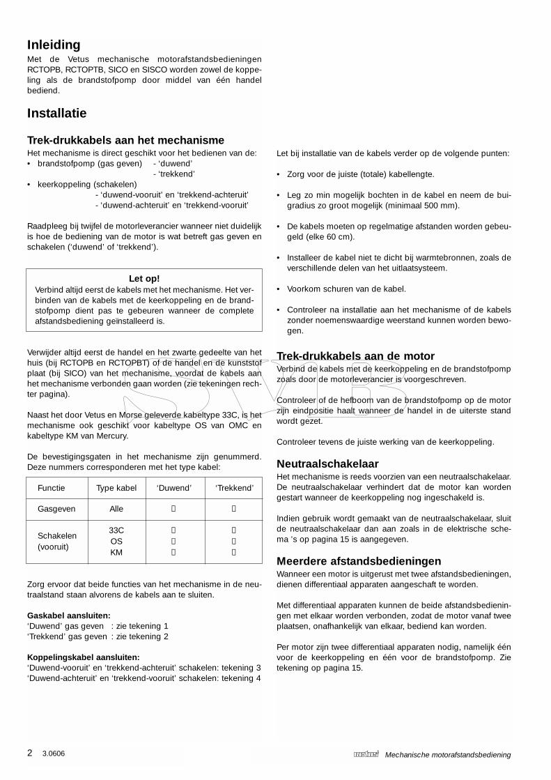
Functie Type kabel ‘Duwend’ ‘Trekkend’
Gasgeven Alle ➀ ➁
33C ➂ ➃Schakelen
OS ➄ ➇(vooruit)
KM ➅ ➆
Zorg ervoor dat beide functies van het mechanisme in de neu-traalstand staan alvorens de kabels aan te sluiten.
Gaskabel aansluiten:‘Duwend’ gas geven : zie tekening 1‘Trekkend’ gas geven : zie tekening 2
Koppelingskabel aansluiten:‘Duwend-vooruit’ en ‘trekkend-achteruit’ schakelen: tekening 3‘Duwend-achteruit’ en ‘trekkend-vooruit’ schakelen: tekening 4
2 3.0606 Mechanische motorafstandsbediening
Let bij installatie van de kabels verder op de volgende punten:
• Zorg voor de juiste (totale) kabellengte.
• Leg zo min mogelijk bochten in de kabel en neem de bui-gradius zo groot mogelijk (minimaal 500 mm).
• De kabels moeten op regelmatige afstanden worden gebeu-geld (elke 60 cm).
• Installeer de kabel niet te dicht bij warmtebronnen, zoals deverschillende delen van het uitlaatsysteem.
• Voorkom schuren van de kabel.
• Controleer na installatie aan het mechanisme of de kabelszonder noemenswaardige weerstand kunnen worden bewo-gen.
Trek-drukkabels aan de motorVerbind de kabels met de keerkoppeling en de brandstofpompzoals door de motorleverancier is voorgeschreven.
Controleer of de hefboom van de brandstofpomp op de motorzijn eindpositie haalt wanneer de handel in de uiterste standwordt gezet.
Controleer tevens de juiste werking van de keerkoppeling.
NeutraalschakelaarHet mechanisme is reeds voorzien van een neutraalschakelaar.De neutraalschakelaar verhindert dat de motor kan wordengestart wanneer de keerkoppeling nog ingeschakeld is.
Indien gebruik wordt gemaakt van de neutraalschakelaar, sluitde neutraalschakelaar dan aan zoals in de elektrische sche-ma ’s op pagina 15 is aangegeven.
Meerdere afstandsbedieningenWanneer een motor is uitgerust met twee afstandsbedieningen,dienen differentiaal apparaten aangeschaft te worden.
Met differentiaal apparaten kunnen de beide afstandsbedienin-gen met elkaar worden verbonden, zodat de motor vanaf tweeplaatsen, onafhankelijk van elkaar, bediend kan worden.
Per motor zijn twee differentiaal apparaten nodig, namelijk éénvoor de keerkoppeling en één voor de brandstofpomp. Zietekening op pagina 15.
3.0606 3Mechanische motorafstandsbediening
NEDERLANDS
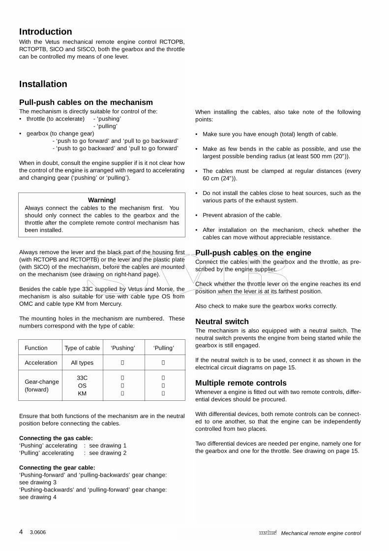
AfstellingMet schroef 1 kan de frictie voor het gas-mechanisme worden ingesteld, afhankelijkvan de tegendruk van de brandstofpomp.
BedieningMet drukknop 2 kan de bediening van dekeerkoppeling worden uitgeschakeld,zodat alleen gas gegeven kan worden, bij-voorbeeld voor het starten en opwarmenvan de motor.
Wanneer de handel weer in de neutraalstand wordt gezet, zalde drukknop terugspringen en is de afstandsbediening gereedvoor normaal gebruik.
OnderhoudReinig, indien noodzakelijk, de handel en het huis met zoetwater.
Controleer regelmatig het mechanisme op los zittende onder-delen en op slijtage van de bewegende delen. Smeer regelmatig de bewegende delen met een vochtverdrij-vende smeerolie.
Controleer regelmatig de kabels en de kabelverbindingen opslijtage en corrosie.
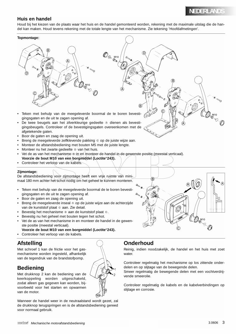
Huis en handelHoud bij het kiezen van de plaats waar het huis en de handel gemonteerd worden, rekening met de maximale uitslag die de han-del kan maken. Houd tevens rekening met de totale lengte van het mechanisme. Zie tekening ‘Hoofdafmetingen’.
Topmontage:
• Teken met behulp van de meegeleverde boormal de te boren bevesti-gingsgaten en de uit te zagen opening af.
• De twee beugels aan het zilverkleurige gedeelte dienen als bevesti-gingsbeugels. Controleer of de bevestigingsgaten overeenkomen met deafgetekende gaten.
• Boor de gaten en zaag de opening uit.• Breng de meegeleverde zelfklevende pakking op de juiste wijze aan.• Monteer de afstandsbediening met bouten M5 met de juiste lengte.• Monteer nu het zwarte gedeelte van het huis.• Vet de as van het mechanisme in en monteer de handel in de gewenste positie (meestal verticaal).
Voorzie de bout M10 van een borgmiddel (Loctite®243).• Controleer het verloop van de kabels.
Zijmontage:De afstandsbediening voor zijmontage heeft een vrije ruimte van mini-maal 180 mm achter het schot nodig om het geheel te kunnen monteren.
• Teken met behulp van de meegeleverde boormal de te boren bevesti-gingsgaten en de uit te zagen opening af.
• Boor de gaten en zaag de opening uit.• Breng de meegeleverde inseal op de juiste wijze aan de achterzijde
van de kunststof plaat aan. Zie detail.• Bevestig het mechanisme aan de kunststof plaat .• Bevestig nu het geheel met bouten tegen het schot.• Vet de as van het mechanisme in en monteer de handel in de gewen-
ste positie (meestal verticaal). Voorzie de bout M10 van een borgmiddel (Loctite®243).
• Controleer het verloop van de kabels.
IntroductionWith the Vetus mechanical remote engine control RCTOPB,RCTOPTB, SICO and SISCO, both the gearbox and the throttlecan be controlled my means of one lever.
Installation
Pull-push cables on the mechanismThe mechanism is directly suitable for control of the:• throttle (to accelerate) - ‘pushing’
- ‘pulling’• gearbox (to change gear)
- ‘push to go forward’ and ‘pull to go backward’- ‘push to go backward’ and ‘pull to go forward’
When in doubt, consult the engine supplier if is it not clear howthe control of the engine is arranged with regard to acceleratingand changing gear (‘pushing’ or ‘pulling’).
Warning!Always connect the cables to the mechanism first. Youshould only connect the cables to the gearbox and thethrottle after the complete remote control mechanism hasbeen installed.
Always remove the lever and the black part of the housing first(with RCTOPB and RCTOPTB) or the lever and the plastic plate(with SICO) of the mechanism, before the cables are mountedon the mechanism (see drawing on right-hand page).
Besides the cable type 33C supplied by Vetus and Morse, themechanism is also suitable for use with cable type OS fromOMC and cable type KM from Mercury.
The mounting holes in the mechanism are numbered. Thesenumbers correspond with the type of cable:
Function Type of cable ‘Pushing’ ‘Pulling’
Acceleration All types ➀ ➁
33C ➂ ➃Gear-change
OS ➄ ➇(forward)
KM ➅ ➆
Ensure that both functions of the mechanism are in the neutralposition before connecting the cables.
Connecting the gas cable:‘Pushing’ accelerating : see drawing 1‘Pulling’ accelerating : see drawing 2
Connecting the gear cable:‘Pushing-forward’ and ‘pulling-backwards’ gear change: see drawing 3‘Pushing-backwards’ and ‘pulling-forward’ gear change:see drawing 4
4 3.0606 Mechanical remote engine control
When installing the cables, also take note of the followingpoints:
• Make sure you have enough (total) length of cable.
• Make as few bends in the cable as possible, and use thelargest possible bending radius (at least 500 mm (20”)).
• The cables must be clamped at regular distances (every60 cm (24”)).
• Do not install the cables close to heat sources, such as thevarious parts of the exhaust system.
• Prevent abrasion of the cable.
• After installation on the mechanism, check whether thecables can move without appreciable resistance.
Pull-push cables on the engineConnect the cables with the gearbox and the throttle, as pre-scribed by the engine supplier.
Check whether the throttle lever on the engine reaches its endposition when the lever is at its farthest position.
Also check to make sure the gearbox works correctly.
Neutral switchThe mechanism is also equipped with a neutral switch. Theneutral switch prevents the engine from being started while thegearbox is still engaged.
If the neutral switch is to be used, connect it as shown in theelectrical circuit diagrams on page 15.
Multiple remote controlsWhenever a engine is fitted out with two remote controls, differ-ential devices should be procured.
With differential devices, both remote controls can be connect-ed to one another, so that the engine can be independentlycontrolled from two places.
Two differential devices are needed per engine, namely one forthe gearbox and one for the throttle. See drawing on page 15.
3.0606 5Mechanical remote engine control
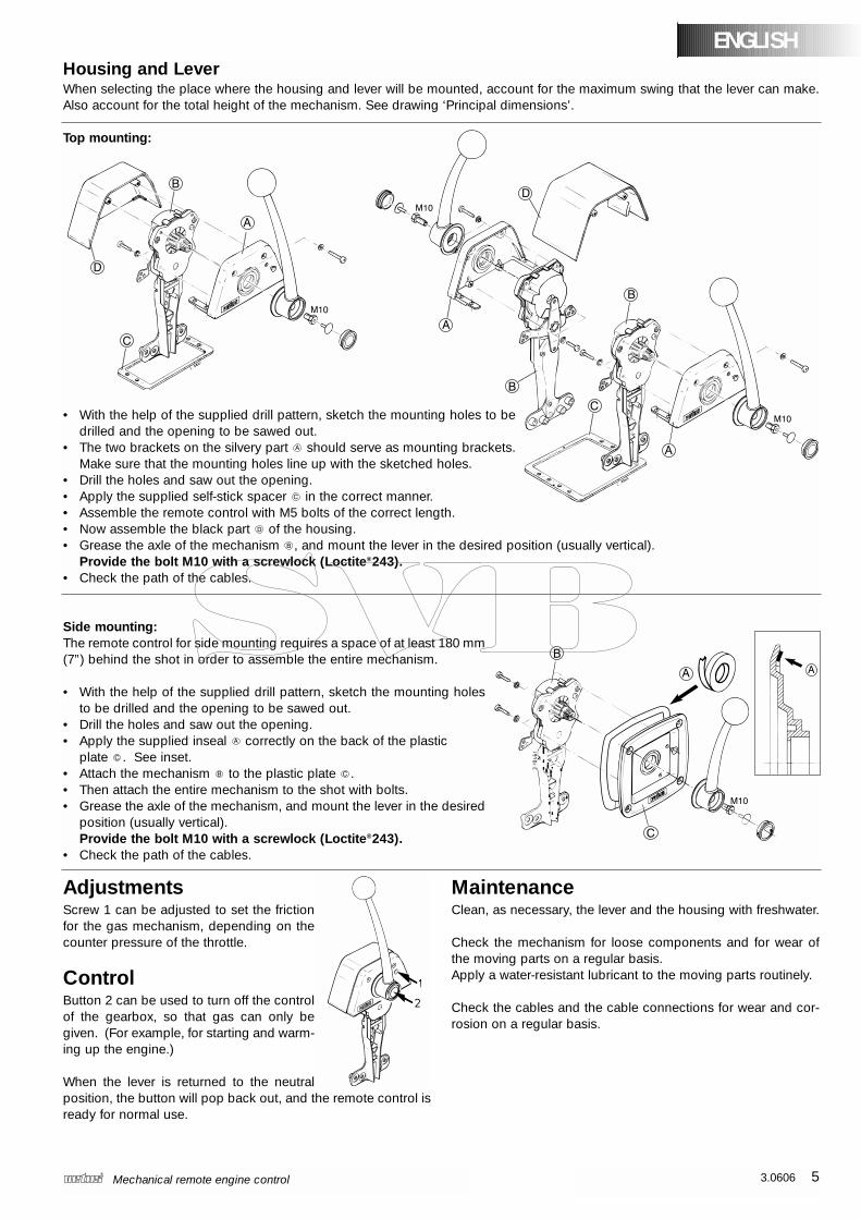
ENGLISHHousing and LeverWhen selecting the place where the housing and lever will be mounted, account for the maximum swing that the lever can make.Also account for the total height of the mechanism. See drawing ‘Principal dimensions’.
Top mounting:
• With the help of the supplied drill pattern, sketch the mounting holes to bedrilled and the opening to be sawed out.
• The two brackets on the silvery part should serve as mounting brackets.Make sure that the mounting holes line up with the sketched holes.
• Drill the holes and saw out the opening.• Apply the supplied self-stick spacer in the correct manner.• Assemble the remote control with M5 bolts of the correct length.• Now assemble the black part of the housing.• Grease the axle of the mechanism , and mount the lever in the desired position (usually vertical).
Provide the bolt M10 with a screwlock (Loctite®243).• Check the path of the cables.
Side mounting:The remote control for side mounting requires a space of at least 180 mm (7”) behind the shot in order to assemble the entire mechanism.
• With the help of the supplied drill pattern, sketch the mounting holesto be drilled and the opening to be sawed out.
• Drill the holes and saw out the opening.• Apply the supplied inseal correctly on the back of the plastic
plate . See inset.• Attach the mechanism to the plastic plate .• Then attach the entire mechanism to the shot with bolts.• Grease the axle of the mechanism, and mount the lever in the desired
position (usually vertical).Provide the bolt M10 with a screwlock (Loctite®243).
• Check the path of the cables.
AdjustmentsScrew 1 can be adjusted to set the frictionfor the gas mechanism, depending on thecounter pressure of the throttle.
ControlButton 2 can be used to turn off the controlof the gearbox, so that gas can only begiven. (For example, for starting and warm-ing up the engine.)
When the lever is returned to the neutralposition, the button will pop back out, and the remote control isready for normal use.
MaintenanceClean, as necessary, the lever and the housing with freshwater.
Check the mechanism for loose components and for wear ofthe moving parts on a regular basis.Apply a water-resistant lubricant to the moving parts routinely.
Check the cables and the cable connections for wear and cor-rosion on a regular basis.
EinleitungMit den mechanischen Vetus-Motor-FernbedienungenRCTOPB, RCTOPTB, SICO und SISCO wird sowohl dieKupplung als die Treibstoffpumpe mit Hilfe eines Hebelsbedient.
Installation
Zug-Druck-Kabel an den MechanismusDer Mechanismus eignet sich sofort zur Bedienung:• der Treibstoffpumpe (Gas geben) - ‘durch Druck’
- ‘durch Zug’• des Wendegetriebes (schalten)
- ‘durch Druck vorwärts’ und ‘durch Zug rückwärts’- ‘durch Druck rückwärts’ und ‘durch Zug vorwärts’
Falls nicht klar ist, wie die Bedienung des Motors in Bezug aufdas Gas geben und Schalten (‘Druck’ oder ‘Zug’) funktioniert,den Motorlieferanten zu Rate ziehen.
Achtung!Erst alle Kabel mit dem Mechanismus verbinden. DasVerbinden der Kabel mit dem Wendegetriebe und derTreibstoffpumpe hat erst zu erfolgen, nachdem die gesam-te Fernbedienung installiert worden ist.
Ehe die Kabel beim Mechanismus verbunden werden, erst denHebel und das schwarze Element des Gehäuses (bei RCTOPBund RCTOPTB) beziehungsweise den Hebel und dieKunststoffscheibe (bei SICO) vom Mechanismus entfernen(siehe Zeichnung auf der rechten Seite).
Außer für den von Vetus und Morse gelieferten 33C-Kabeltypeignet sich der Mechanismus für den OS-Kabeltyp von OMVund den KM-Kabeltyp von Mercury.
Die Befestigungslöcher im Mechanismus sind nummeriert.Diese Nummern entsprechen dem Kabeltyp:
Funktion Kabeltyp ‘durch Druck’ ‘durch Zug’
Gas geben alle ➀ ➁
33C ➂ ➃Schalten
OS ➄ ➇(vorwärts)
KM ➅ ➆
Darauf achten, dass sich beide Funktionen des Mechanismusim Leerlaufstand befinden, bevor die Kabel angeschlossen wer-den.
Gaskabel anschließen:‘Durch Druck’ Gas geben : siehe Zeichnung 1‘Durch Zug’ Gas geben : siehe Zeichnung 2
Kupplungskabel anschließen:‘Durch Druck vorwärts’ und
‘durch Zug rückwärts’ schalten : Zeichnung 3‘Durch Druck rückwärts’ und
‘durch Zug vorwärts’ schalten : Zeichnung 4
6 3.0606 Mechanische Motor-Fernbedienung
Bei der Installation der Kabel ferner folgende Punkte beachten:
• Für eine entsprechende (Gesamt)kabellänge sorgen
• Möglichst wenig Kurven in das Kabel legen und denBiegeradius möglichst groß halten (mindestens 500 mm).
• Die Kabel sind in regelmäßigen Abständen mitKabelschellen zu befestigen (alle 60 cm).
• Die Kabel nicht zu nahe bei Hitzequellen (wie den diversenTeilen des Auspuffsystems) installieren.
• Scheuern des Kabels verhüten.
• Nach der Installation des Mechanismus prüfen, ob die Kabelohne nennenswerten Widerstand bewegt werden können.
Zug-Druck-Kabel am MotorDie Kabel gemäß den Angaben des Motorlieferanten mit demWendegetriebe und der Treibstoffpumpe verbinden.
Prüfen, ob der Hebelarm der Treibstoffpumpe am Motor seineEndposition erreicht, wenn der Hebel in den äußersten Standgeschaltet wird.
Prüfen, ob das Wendegetriebe ordnungsgemäß funktioniert.
LeerlaufschalterDer Mechanismus ist bereits mit einem Leerlaufschalter ausge-stattet. Der Leerlaufschalter verhindert, dass der Motor gestar-tet werden kann, wenn das Wendegetriebe noch nicht einge-schaltet ist.
Falls der Leerlaufschalter benutzt werden soll, denLeerlaufschalter gemäß dem auf Seite 15 angegebenen elektri-schen Schaltplan anschließen.
Mehrere Hebel-FernbedienungenWenn ein Motor mit zwei Hebel-Fernbedienungen ausgestattetist, sind Differenzialschalter hinzuzufügen.
Mit Differenzialschaltern lassen sich die beiden Hebel-Fernbedienungen miteinander verbinden, sodass sich derMotor von zwei Stellen aus, unabhängig voneinander, bedienenlässt.
Pro Motor sind zwei Differenzialschalter erforderlich, und zwareiner für das Wendegetriebe und einer für die Treibstoffpumpe.Siehe die Zeichnung auf Seite 15.
3.0606 7Mechanische Motor-Fernbedienung
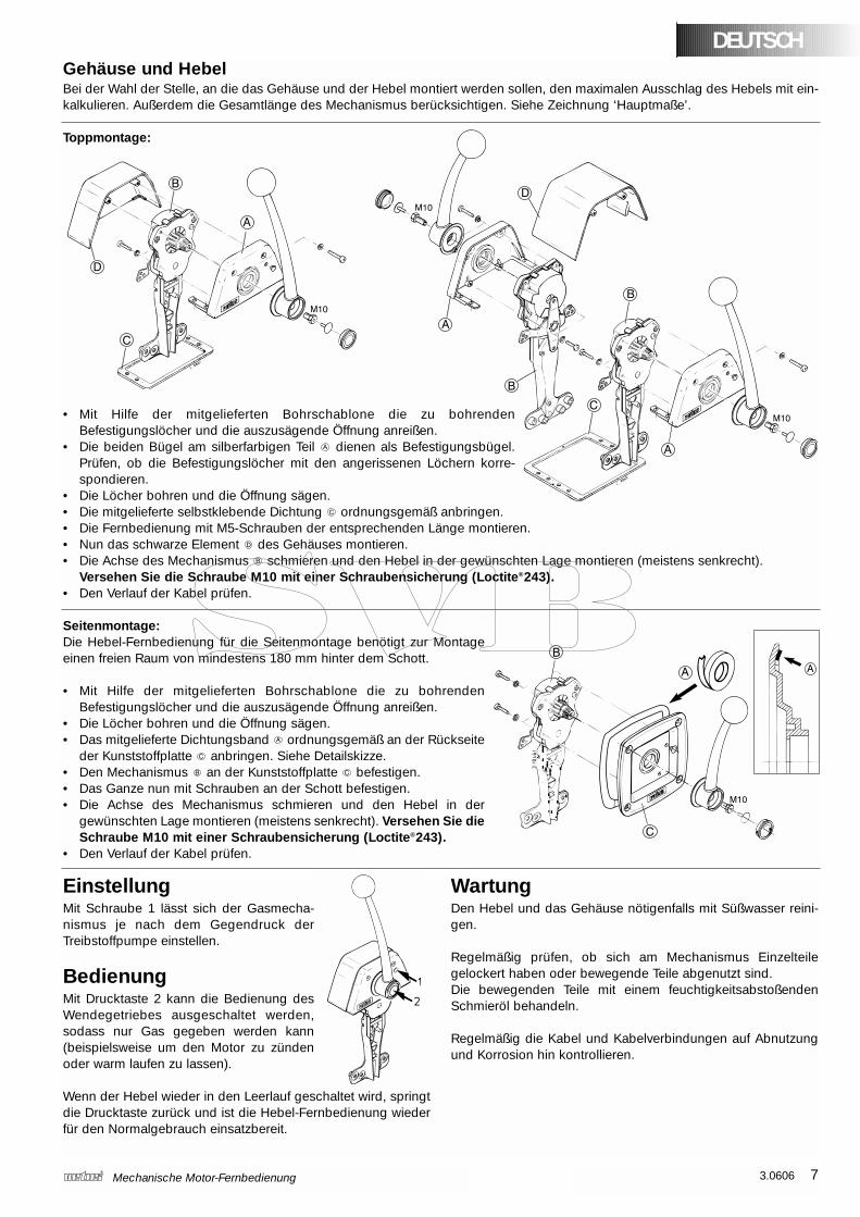
Gehäuse und HebelBei der Wahl der Stelle, an die das Gehäuse und der Hebel montiert werden sollen, den maximalen Ausschlag des Hebels mit ein-kalkulieren. Außerdem die Gesamtlänge des Mechanismus berücksichtigen. Siehe Zeichnung ‘Hauptmaße’.
Toppmontage:
• Mit Hilfe der mitgelieferten Bohrschablone die zu bohrendenBefestigungslöcher und die auszusägende Öffnung anreißen.
• Die beiden Bügel am silberfarbigen Teil dienen als Befestigungsbügel.Prüfen, ob die Befestigungslöcher mit den angerissenen Löchern korre-spondieren.
• Die Löcher bohren und die Öffnung sägen.• Die mitgelieferte selbstklebende Dichtung ordnungsgemäß anbringen.• Die Fernbedienung mit M5-Schrauben der entsprechenden Länge montieren.• Nun das schwarze Element des Gehäuses montieren.• Die Achse des Mechanismus schmieren und den Hebel in der gewünschten Lage montieren (meistens senkrecht).
Versehen Sie die Schraube M10 mit einer Schraubensicherung (Loctite®243).• Den Verlauf der Kabel prüfen.
Seitenmontage:Die Hebel-Fernbedienung für die Seitenmontage benötigt zur Montageeinen freien Raum von mindestens 180 mm hinter dem Schott.
• Mit Hilfe der mitgelieferten Bohrschablone die zu bohrendenBefestigungslöcher und die auszusägende Öffnung anreißen.
• Die Löcher bohren und die Öffnung sägen.• Das mitgelieferte Dichtungsband ordnungsgemäß an der Rückseite
der Kunststoffplatte anbringen. Siehe Detailskizze.• Den Mechanismus an der Kunststoffplatte befestigen.• Das Ganze nun mit Schrauben an der Schott befestigen.• Die Achse des Mechanismus schmieren und den Hebel in der
gewünschten Lage montieren (meistens senkrecht). Versehen Sie dieSchraube M10 mit einer Schraubensicherung (Loctite®243).
• Den Verlauf der Kabel prüfen.
DEUTSCH
EinstellungMit Schraube 1 lässt sich der Gasmecha-nismus je nach dem Gegendruck derTreibstoffpumpe einstellen.
BedienungMit Drucktaste 2 kann die Bedienung desWendegetriebes ausgeschaltet werden,sodass nur Gas gegeben werden kann(beispielsweise um den Motor zu zündenoder warm laufen zu lassen).
Wenn der Hebel wieder in den Leerlauf geschaltet wird, springtdie Drucktaste zurück und ist die Hebel-Fernbedienung wiederfür den Normalgebrauch einsatzbereit.
WartungDen Hebel und das Gehäuse nötigenfalls mit Süßwasser reini-gen.
Regelmäßig prüfen, ob sich am Mechanismus Einzelteilegelockert haben oder bewegende Teile abgenutzt sind.Die bewegenden Teile mit einem feuchtigkeitsabstoßendenSchmieröl behandeln.
Regelmäßig die Kabel und Kabelverbindungen auf Abnutzungund Korrosion hin kontrollieren.
IntroductionLes télécommandes mécaniques Vetus pour les moteursRCTOPB, RCTOPTB, SICO et SISCO permettent de comman-der aussi bien l’inverseur que l’accélérateur à l’aide d’un seullevier.
Installation
Câbles ‘push-pull’ sur le mécanismeLe mécanisme est prévu pour commander directement :• l’accélérateur (admission du carburant ) - ‘pousser’
- ‘tirer’• l’inverseur (embrayer)
- ‘pousser - en avant’ et ‘tirer - en arrière’- ‘pousser - en arrière’ et ‘tirer en avant’
En cas de doute, si vous ne savez pas comment fonctionnevotre moteur pour accélérer et inverser (‘pousser” ou “tirer’),consulter le fournisseur de votre moteur.
Attention!Connecter toujours d’abord les câbles au mécanisme. Leraccordement des câbles à l’inverseur et à l’accélérateurne doit se faire qu’une fois la télécommande complètementinstallée.
Retirer toujours d’abord le levier et la partie noire du boîtier (surles RCTOPB et RCTOPTB) ou le levier et la plaquette plastique(sur le SICO) du mécanisme avant de relier les câbles au méca-nisme (voir les dessins sur la page de droite).
Le dispositif convient pour le type de câble 33C fourni par Vetuset Morse mais aussi pour le type de câble OS d’OMC et le typede câble KM de Mercury.
Les trous de fixation dans le dispositif sont numérotés. Cesnuméros correspondent au type de câble:
Fonction Type de câble ‘Pousser’ ‘Tirer’
Accélérer Tous les types ➀ ➁
33C ➂ ➃Inverser
OS ➄ ➇(en avant)
KM ➅ ➆
Veiller à ce que les deux fonctions du dispositif soit au pointmort avant de raccorder les câbles.
Raccordement du câble de l’accélérateur:‘Pousser’ accélérer : voir plan 1‘Tirer’ accélérer : voir plan 2
Raccordement du câble de l’inverseur:Inverser ‘pousser - en avant’ et ‘tirer - en arrière’ : voir plan 3Inverser ‘pousser - en arrière’ et ‘tirer - en avant’ : voir plan 4
8 3.0606 Télécommande mécanique pour moteur
Lors de la pose des câbles, veiller aux points suivants:
• S’assurer que l’on dispose de la longueur (totale) de câbleexacte.
• Limiter au minimum le nombre de coudes pratiqués sur lecâble et observer un rayon de cintrage le plus grand pos-sible (500 mm minimum).
• Fixer les câbles à intervalles réguliers (tous les 60 cm).
• Ne pas poser le câble trop près de sources de chaleur tellesque les éléments du système d’échappement.
• Veiller à ce que le câble ne soit pas fendu.
• Après la pose, vérifier que les câbles puissent être déplacéssans présenter de grande résistance.
Câbles ‘push-pull’ sur le moteurRelier les câbles à l’inverseur et à l’accélérateur conformémentaux prescriptions du fournisseur du moteur.
Vérifier que le levier de l’accélérateur atteint sa position extrêmesur le moteur lorsque le levier est sur la position extrême sur leboîtier.
Vérifier également le bon fonctionnement de l’inverseur.
Sécurité point mortLe dispositif est équipé d’une sécurité point mort qui empêchede démarrer le moteur si l’inverseur n’est pas au point mort.
Si l’on souhaite utiliser le dispositif de sécurité point mort, il fau-dra le raccorder comme indiqué sur les schémas électriques àla page 15.
Deux télécommandesSi le moteur est équipé de deux télécommandes, il faudra utili-ser des différentiels. Les différentiels permettent de brancherensemble les deux télécommandes afin de pouvoir comman-der le moteur depuis deux endroits différents indépendants l’unde l’autre.
Pour chaque moteur il faut deux différentiels, un pour l’inver-seur et un pour l’accélérateur. Voir le plan à la page 15.
3.0606 9Télécommande mécanique pour moteur
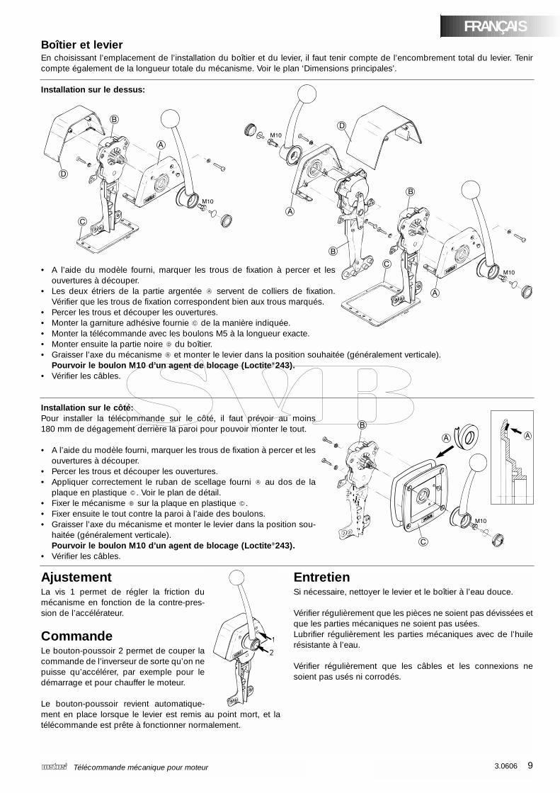
Boîtier et levierEn choisissant l’emplacement de l’installation du boîtier et du levier, il faut tenir compte de l’encombrement total du levier. Tenircompte également de la longueur totale du mécanisme. Voir le plan ‘Dimensions principales’.
Installation sur le dessus:
• A l’aide du modèle fourni, marquer les trous de fixation à percer et lesouvertures à découper.
• Les deux étriers de la partie argentée servent de colliers de fixation.Vérifier que les trous de fixation correspondent bien aux trous marqués.
• Percer les trous et découper les ouvertures.• Monter la garniture adhésive fournie de la manière indiquée.• Monter la télécommande avec les boulons M5 à la longueur exacte.• Monter ensuite la partie noire du boîtier.• Graisser l’axe du mécanisme et monter le levier dans la position souhaitée (généralement verticale).
Pourvoir le boulon M10 d’un agent de blocage (Loctite®243).• Vérifier les câbles.
Installation sur le côté:Pour installer la télécommande sur le côté, il faut prévoir au moins180 mm de dégagement derrière la paroi pour pouvoir monter le tout.
• A l’aide du modèle fourni, marquer les trous de fixation à percer et lesouvertures à découper.
• Percer les trous et découper les ouvertures.• Appliquer correctement le ruban de scellage fourni au dos de la
plaque en plastique . Voir le plan de détail.• Fixer le mécanisme sur la plaque en plastique .• Fixer ensuite le tout contre la paroi à l’aide des boulons.• Graisser l’axe du mécanisme et monter le levier dans la position sou-
haitée (généralement verticale).Pourvoir le boulon M10 d’un agent de blocage (Loctite®243).
• Vérifier les câbles.
FRANÇAIS
AjustementLa vis 1 permet de régler la friction dumécanisme en fonction de la contre-pres-sion de l’accélérateur.
CommandeLe bouton-poussoir 2 permet de couper lacommande de l’inverseur de sorte qu’on nepuisse qu’accélérer, par exemple pour ledémarrage et pour chauffer le moteur.
Le bouton-poussoir revient automatique-ment en place lorsque le levier est remis au point mort, et latélécommande est prête à fonctionner normalement.
EntretienSi nécessaire, nettoyer le levier et le boîtier à l’eau douce.
Vérifier régulièrement que les pièces ne soient pas dévissées etque les parties mécaniques ne soient pas usées. Lubrifier régulièrement les parties mécaniques avec de l’huilerésistante à l’eau.
Vérifier régulièrement que les câbles et les connexions nesoient pas usés ni corrodés.
10 3.0606 Mando a distancia mecánico para motores
IntroducciónCon los mandos a distancia mecánicos para motores RCTOPB,RCTOPTB, SICO y SISCO de Vetus, tanto el inversor como labomba de carburante se activan por medio de una sola palan-ca.
Instalación
Cables de empuje-tracción en el mecanismoEl mecanismo es adecuado directamente para la activación de:• la bomba de carburante (dar gas) - ‘empujando’
- ‘tirando’• el inversor (cambiar de marcha)
- ‘empujando hacia delante’ y ‘tirando hacia atrás’- ‘empujando hacia atrás’ y ‘tirando hacia delante’
Consulte al suministrador del motor en caso de duda, cuandono esté claro cómo se activa el motor para dar gas y cambiarde marcha (‘empujando’ o ‘tirando’).
¡Atención!Conecte siempre en primer lugar los cables con el meca-nismo. La conexión de los cables con el inversor y con labomba de carburante sólo debe realizarse cuando elmando a distancia completo esté instalado.
Retire siempre primero la palanca y la parte negra de la caja (enRCTOPB y RCTOPTB) o la palanca y la chapa de material sin-tético (en SICO) del mecanismo, antes de conectar los cablesal mecanismo (véanse los dibujos en la página de la derecha).
Además del tipo de cable 33C suministrado por Vetus y Morse,el mecanismo también es adecuado para el tipo de cable OSde OMC y el tipo de cable KM de Mercury.
Los agujeros de fijación en el mecanismo están numerados.Estos números corresponden con el tipo de cable:
Función Tipo de cable ‘Empujando’ ‘Tirando’
Dar gas Todos ➀ ➁
Cambiar 33C ➂ ➃
de marcha OS ➄ ➇
(hacia delante) KM ➅ ➆
Procure que ambas funciones del mecanismo estén en la posi-ción neutral antes de conectar los cables.
Conexión del cable del gas:Dar gas ‘empujando’ : véase el dibujo 1Dar gas ‘tirando’ : véase el dibujo 2
Conexión del cable del inversor:Cambiar de marcha ‘empujando hacia delante’ y ‘tirando hacia atrás’: dibujo 3Cambiar de marcha ‘empujando hacia atrás’ y‘tirando hacia delante’: dibujo 4
Al instalar los cables fíjese además en los siguientes puntos:
• Procure que la longitud (total) del cable sea adecuada.
• Instale el cable con un número de curvas tan pequeño comosea posible y un radio de flexión tan grande como sea posi-ble (como mínimo 500 mm).
• Los cables deben fijarse con abrazaderas a distancias regu-lares (cada 60 cm).
• No instale el cable demasiado cerca de fuentes de calor,como las diferentes partes del sistema de escape.
• Evite el roce del cable.
• Después de la instalación, controle en el mecanismo si loscables se pueden mover sin ofrecer resistencia considera-ble.
Cables de empuje-tracción en el motorConecte los cables con el inversor y la bomba de carburante taly como ha sido prescrito por el suministrador del motor.
Controle si la palanca de la bomba de carburante en el motoralcanza su posición final, cuando la palanca del mando a dis-tancia se pone en la posición límite.
Controle asimismo el funcionamiento adecuado del inversor.
Interruptor neutralEl mecanismo ya está provisto de un interruptor neutral. Esteinterruptor neutral impide que el motor se pueda arrancar cuan-do el inversor todavía está conectado.
Si hace uso del interruptor neutral, éste debe conectarse tal ycomo se indica en los esquemas eléctricos de la página 15.
Varios mandos a distanciaCuando un motor está equipado con dos mandos a distancia,hay que adquirir diferenciales.
Con diferenciales los dos mandos a distancia pueden serconectados entre sí, de modo que el motor pueda activarsedesde dos lugares independientes uno del otro.
Por motor hacen falta dos diferenciales: uno para el inversor yotro para la bomba de carburante. Véase el dibujo de la pági-na 15.
3.0606 11Mando a distancia mecánico para motores
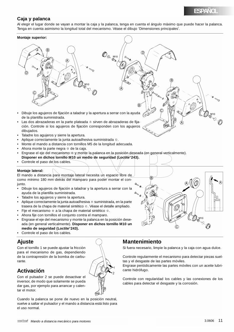
ESPAÑOLCaja y palancaAl elegir el lugar donde se vayan a montar la caja y la palanca, tenga en cuenta el ángulo máximo que puede hacer la palanca.Tenga en cuenta asimismo la longitud total del mecanismo. Véase el dibujo ‘Dimensiones principales’.
Montaje superior:
• Dibuje los agujeros de fijación a taladrar y la apertura a serrar con la ayudade la plantilla suministrada.
• Las dos abrazaderas en la parte plateada sirven de abrazaderas de fija-ción. Controle si los agujeros de fijación corresponden con los agujerosdibujados.
• Taladre los agujeros y sierre la apertura.• Aplique correctamente la junta autoadhesiva suministrada .• Monte el mando a distancia con tornillos M5 de la longitud adecuada.• Ahora monte la parte negra de la caja.• Engrase el eje del mecanismo y monte la palanca en la posición deseada (en general verticalmente).
Disponer en dichos tornillo M10 un medio de seguridad (Loctite®243).• Controle el paso de los cables.
Montaje lateral:El mando a distancia para montaje lateral necesita un espacio libre decomo mínimo 180 mm detrás del mamparo para poder montar el con-junto.• Dibuje los agujeros de fijación a taladrar y la apertura a serrar con la
ayuda de la plantilla suministrada.• Taladre los agujeros y sierre la apertura.• Aplique correctamente la junta autoadhesiva suministrada, en la parte
trasera de la chapa de material sintético . Véase el detalle ampliado.• Fije el mecanismo a la chapa de material sintético .• Ahora fije con tornillos el conjunto contra el mamparo.• Engrase el eje del mecanismo y monte la palanca en la posición dese-
ada (en general verticalmente). Disponer en dichos tornillo M10 unmedio de seguridad (Loctite®243).
• Controle el paso de los cables.
AjusteCon el tornillo 1 se puede ajustar la fricciónpara el mecanismo de gas, dependiendode la contrapresión de la bomba de carbu-rante.
ActivaciónCon el pulsador 2 se puede desactivar elinversor, de modo que solamente se puedadar gas, por ejemplo para arrancar y calen-tar el motor.
Cuando la palanca se pone de nuevo en la posición neutral,vuelve a saltar el pulsador y el mando a distancia está listo parael uso normal.
MantenimientoSi fuera necesario, limpie la palanca y la caja con agua dulce.
Controle regularmente el mecanismo para detectar piezas suel-tas y el desgaste de las partes móviles.Engrase periódicamente las partes móviles con un aceite lubri-cante hidrófugo.
Controle con regularidad los cables y las conexiones de loscables para detectar el desgaste y la corrosión.
12 3.0606 Telecomandi meccanici per motori
IntroduzioneCon i telecomandi meccanici per motori Vetus RCTOPB,RCTOPTB, SICO e SISCO è possibile comandare con un’unicaleva sia la frizione che la pompa del combustibile.
Installazione
Collegamento dei cavi di trazione/spinta almeccanismoIl meccanismo permette di comandare:• La pompa del combustibile (acceleratore) - a ‘spinta’
- a ‘trazione’• La frizione (cambio)
- a ‘spinta per marcia avanti’ ed a ‘trazione per marcia indietro’- a ‘spinta per marcia indietro’ ed a ‘trazione per marcia avanti’
Contattate il fornitore del motore in caso di dubbi circa il tipo dicomando dell’acceleratore e del cambio del motore (a ‘spinta’oa ‘trazione’).
Attenzione!Collegare sempre prima i cavi al meccanismo. I collega-menti con la frizione e la pompa del combustibile vannoeffettuati solo dopo aver installato completamente il mec-canismo.
Rimuovere sempre prima la leva e la parte nera della scatola(per i modelli RCTOPB ed RCTOPTB), o la leva ed il pannello inplastica (per il modello SICO), del meccanismo, prima di colle-gare i cavi al meccanismo stesso (vedi disegno nella paginasuccessiva).
Oltre ai cavi tipo 33C, forniti dalla Vetus e dalla Morse, possonoessere impiegati anche cavi tipo OS della OMC e KM dellaMercury.
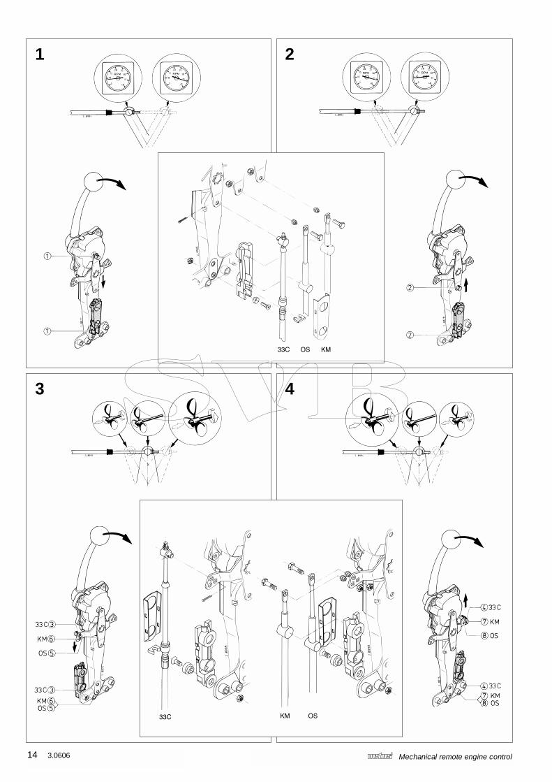
I fori di innesto sul meccanismo sono numerati. La seguentetabella riporta la corrispondenza tra il tipo di cavo ed il numerodel foro.
Funzione Tipo di cavo a ‘spinta’ a ‘trazione’
Accelerazione Tutti ➀ ➁
33C ➂ ➃Cambio
OS ➄ ➇(marcia avanti)
KM ➅ ➆
Assicurarsi che entrambe le funzioni del meccanismo siano infolle (posizione neutrale) prima di collegare i cavi.
Collegamento del cavo dell’acceleratore: Acceleratore a ‘spinta’ : vedi figura 1Acceleratore a ‘trazione’ : vedi figura 2
Collegamento del cavo della frizione:Cambio a ‘spinta per marcia avanti’ e
‘trazione per marcia indietro’ : vedi figura 3Cambio a ‘spinta per marcia indietro’ e
‘trazione per marcia avant’ : vedi figura 4
Al fine di una corretta installazione è necessario che:
• la lunghezza (totale) dei cavi sia esatta;
• i cavi presentino meno curve possibile ed il raggio di curva-tura sia più ampio possibile (minimo 500 mm);
• i cavi siano sostenuti a distanza regolare (un sostegno ogni60 cm);
• i cavi non vengano installati troppo vicino a fonti di calore,come alle diverse parti del sistema di scarico;
• i cavi siano integri;
• dopo il collegamento al meccanismo, i cavi non opponganotroppa resistenza al movimento.
Collegamento dei cavi di trazione/ spinta almotoreCollegare i cavi alla frizione ed alla pompa del combustibilesecondo le modalità indicate dal fornitore del motore.
Controllare che la leva della pompa del combustibile sul moto-re possa raggiungere la sua posizione limite, quando la levadell’acceleratore è completamente aperta.
Verificare, inoltre, il corretto funzionamento della frizione.
Dispositivo di protezione Il meccanismo è dotato di un dispositivo di protezione, cheimpedisce che il motore possa essere avviato con la marciainnestata.
Qualora venga fatto uso di un dispositivo di protezione, colle-gare il dispositivo secondo le indicazioni riportate nello schemaelettrico a pagina 15.
Installazione di più telecomandiSe il motore è dotato di due telecomandi, devono essere instal-lati dei dispositivi differenziali.
I dispositivi differenziali permettono di collegare tra di loro i duetelecomandi, in modo che il motore possa essere governato dadue postazioni diverse.
Per ciascun motore sono necessari due dispositivi differenziali,uno per la frizione ed uno per la pompa del combustibile. Vedifigura a pagina 15.
3.0606 13Telecomandi meccanici per motori
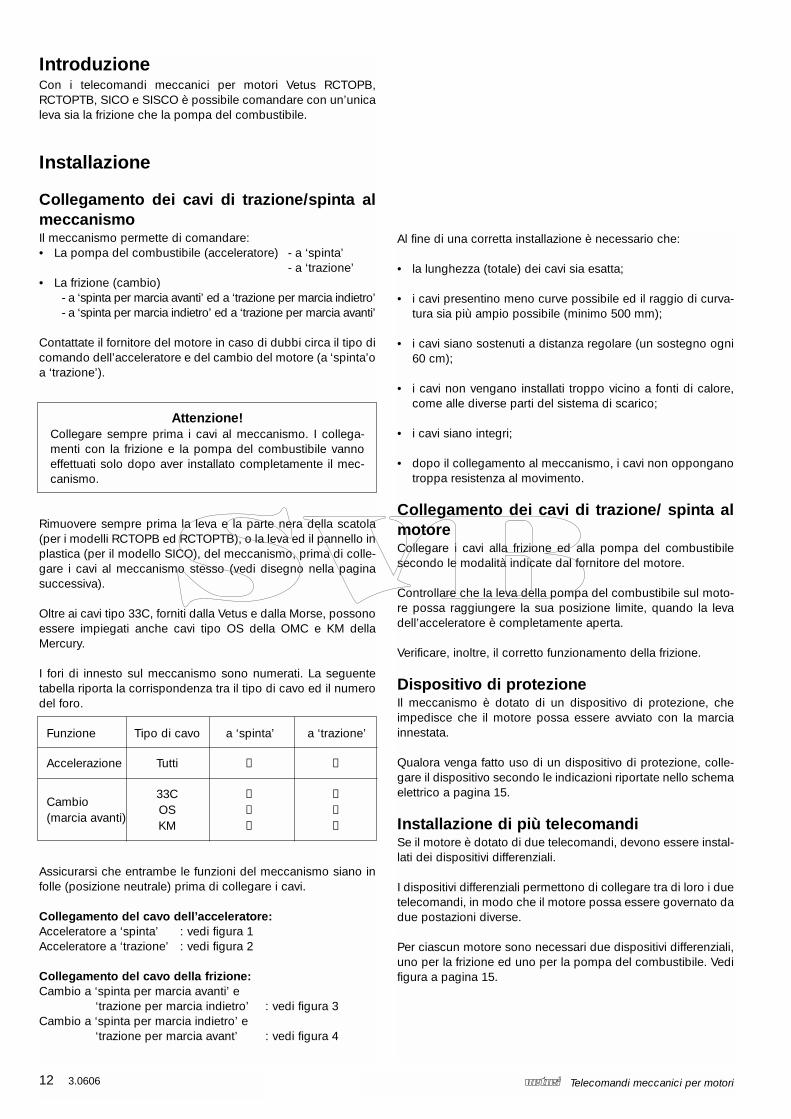
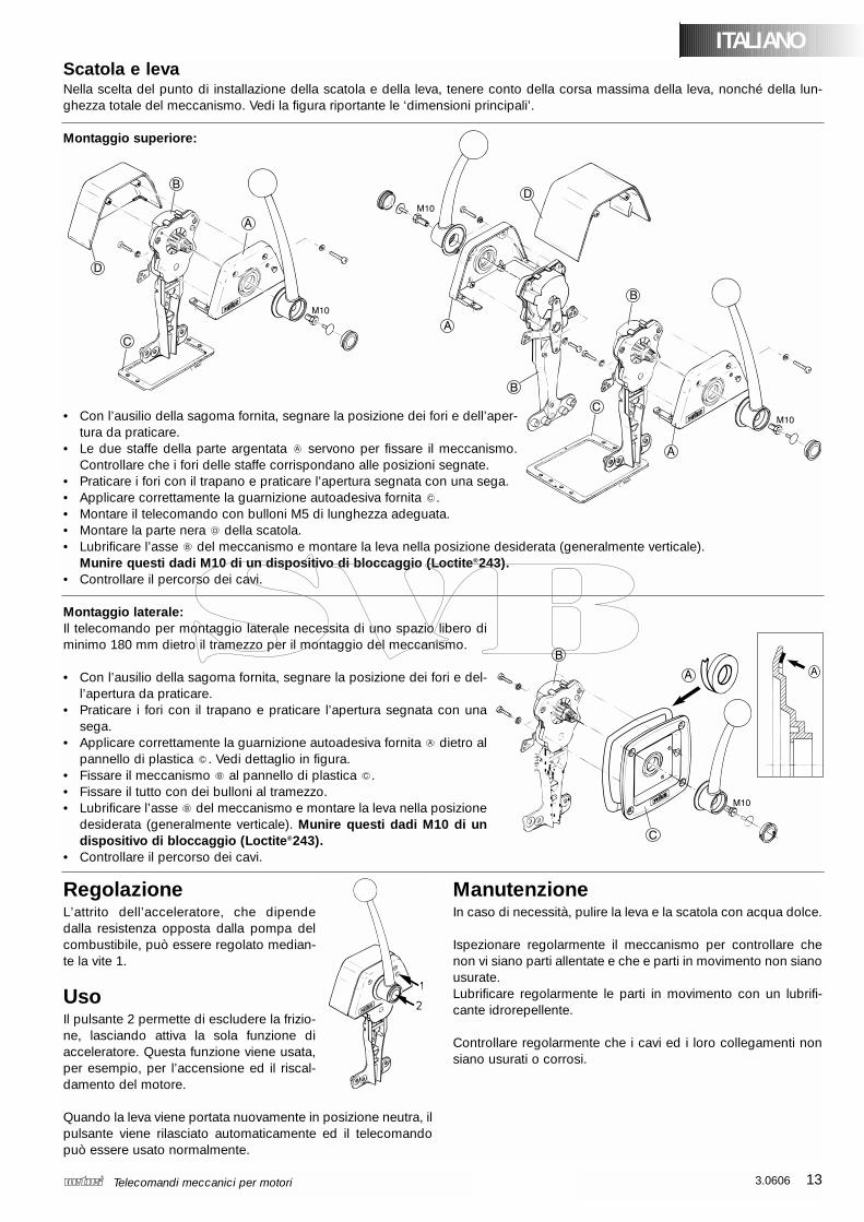
Scatola e levaNella scelta del punto di installazione della scatola e della leva, tenere conto della corsa massima della leva, nonché della lun-ghezza totale del meccanismo. Vedi la figura riportante le ‘dimensioni principali’.
Montaggio superiore:
• Con l’ausilio della sagoma fornita, segnare la posizione dei fori e dell’aper-tura da praticare.
• Le due staffe della parte argentata servono per fissare il meccanismo.Controllare che i fori delle staffe corrispondano alle posizioni segnate.
• Praticare i fori con il trapano e praticare l’apertura segnata con una sega.• Applicare correttamente la guarnizione autoadesiva fornita .• Montare il telecomando con bulloni M5 di lunghezza adeguata.• Montare la parte nera della scatola.• Lubrificare l’asse del meccanismo e montare la leva nella posizione desiderata (generalmente verticale).
Munire questi dadi M10 di un dispositivo di bloccaggio (Loctite®243).• Controllare il percorso dei cavi.
Montaggio laterale:Il telecomando per montaggio laterale necessita di uno spazio libero diminimo 180 mm dietro il tramezzo per il montaggio del meccanismo.
• Con l’ausilio della sagoma fornita, segnare la posizione dei fori e del-l’apertura da praticare.
• Praticare i fori con il trapano e praticare l’apertura segnata con unasega.
• Applicare correttamente la guarnizione autoadesiva fornita dietro alpannello di plastica . Vedi dettaglio in figura.
• Fissare il meccanismo al pannello di plastica . • Fissare il tutto con dei bulloni al tramezzo.• Lubrificare l’asse del meccanismo e montare la leva nella posizione
desiderata (generalmente verticale). Munire questi dadi M10 di undispositivo di bloccaggio (Loctite®243).
• Controllare il percorso dei cavi.
ITALIANO
RegolazioneL’attrito dell’acceleratore, che dipendedalla resistenza opposta dalla pompa delcombustibile, può essere regolato median-te la vite 1.
UsoIl pulsante 2 permette di escludere la frizio-ne, lasciando attiva la sola funzione diacceleratore. Questa funzione viene usata,per esempio, per l’accensione ed il riscal-damento del motore.
Quando la leva viene portata nuovamente in posizione neutra, ilpulsante viene rilasciato automaticamente ed il telecomandopuò essere usato normalmente.
ManutenzioneIn caso di necessità, pulire la leva e la scatola con acqua dolce.
Ispezionare regolarmente il meccanismo per controllare chenon vi siano parti allentate e che e parti in movimento non sianousurate.Lubrificare regolarmente le parti in movimento con un lubrifi-cante idrorepellente.
Controllare regolarmente che i cavi ed i loro collegamenti nonsiano usurati o corrosi.
14 3.0606 Mechanical remote engine control
1 2
3 4
3.0606 15Mechanical remote engine control
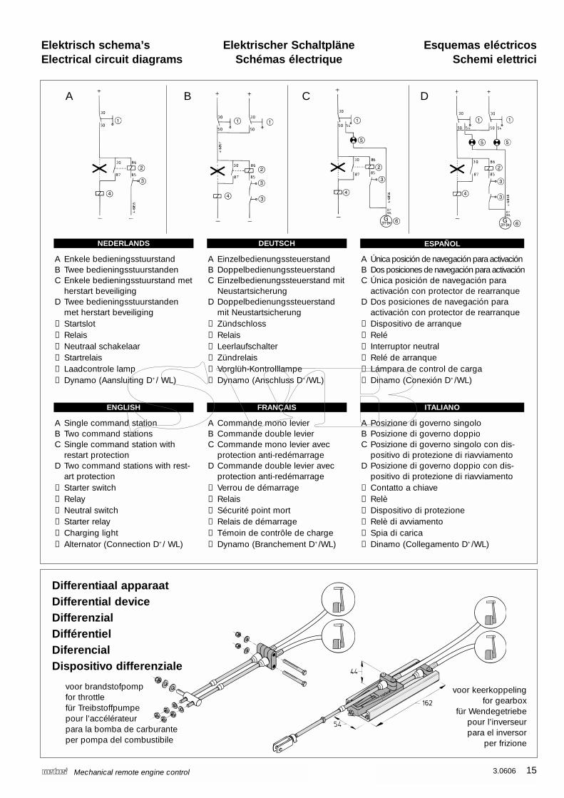
Elektrisch schema’sElectrical circuit diagrams
Elektrischer SchaltpläneSchémas électrique
Esquemas eléctricosSchemi elettrici
NEDERLANDS
ENGLISH FRANÇAIS ITALIANO
DEUTSCH ESPAÑOL
A Enkele bedieningsstuurstandB Twee bedieningsstuurstandenC Enkele bedieningsstuurstand met
herstart beveiligingD Twee bedieningsstuurstanden
met herstart beveiliging➀ Startslot➁ Relais➂ Neutraal schakelaar➃ Startrelais➄ Laadcontrole lamp➅ Dynamo (Aansluiting D+/ WL)
Differentiaal apparaatDifferential deviceDifferenzialDifférentielDiferencialDispositivo differenziale
A Commande mono levierB Commande double levierC Commande mono levier avec
protection anti-redémarrageD Commande double levier avec
protection anti-redémarrage➀ Verrou de démarrage➁ Relais➂ Sécurité point mort➃ Relais de démarrage➄ Témoin de contrôle de charge➅ Dynamo (Branchement D+/WL)
A B C D
voor brandstofpompfor throttlefür Treibstoffpumpepour l’accélérateurpara la bomba de carburanteper pompa del combustibile
voor keerkoppelingfor gearbox
für Wendegetriebepour l’inverseurpara el inversor
per frizione
A Single command stationB Two command stationsC Single command station with
restart protectionD Two command stations with rest-
art protection➀ Starter switch➁ Relay➂ Neutral switch➃ Starter relay➄ Charging light➅ Alternator (Connection D+/ WL)
A EinzelbedienungssteuerstandB DoppelbedienungssteuerstandC Einzelbedienungssteuerstand mit
NeustartsicherungD Doppelbedienungssteuerstand
mit Neustartsicherung➀ Zündschloss➁ Relais➂ Leerlaufschalter➃ Zündrelais➄ Vorglüh-Kontrolllampe➅ Dynamo (Anschluss D+/WL)
A Única posición de navegación para activaciónB Dos posiciones de navegación para activaciónC Única posición de navegación para
activación con protector de rearranqueD Dos posiciones de navegación para
activación con protector de rearranque➀ Dispositivo de arranque➁ Relé➂ Interruptor neutral➃ Relé de arranque➄ Lámpara de control de carga➅ Dinamo (Conexión D+/WL)
A Posizione di governo singoloB Posizione di governo doppioC Posizione di governo singolo con dis-
positivo di protezione di riavviamentoD Posizione di governo doppio con dis-
positivo di protezione di riavviamento➀ Contatto a chiave➁ Relè➂ Dispositivo di protezione➃ Relè di avviamento➄ Spia di carica➅ Dinamo (Collegamento D+/WL)
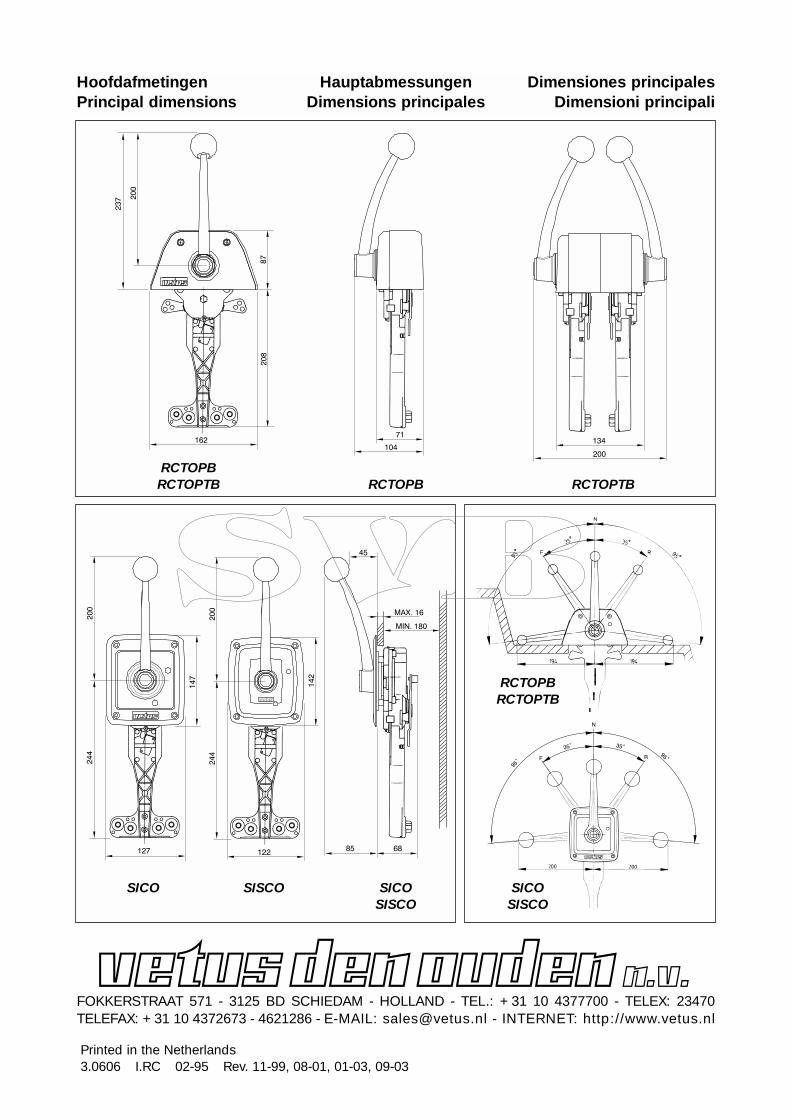
HoofdafmetingenPrincipal dimensions
HauptabmessungenDimensions principales
Dimensiones principalesDimensioni principali
RCTOPBRCTOPTB RCTOPB RCTOPTB
SICO
RCTOPBRCTOPTB
FOKKERSTRAAT 571 - 3125 BD SCHIEDAM - HOLLAND - TEL.: +31 10 4377700 - TELEX: 23470TELEFAX: +31 10 4372673 - 4621286 - E-MAIL: [email protected] - INTERNET: http://www.vetus.nl
Printed in the Netherlands3.0606 I.RC 02-95 Rev. 11-99, 08-01, 01-03, 09-03
SISCO SICOSISCO
SICOSISCO