
Studieopdracht: Optische communicatie in ruggengraatnetwerken
13
Katholieke Universiteit Leuven Departement Elektrotechniek – ESAT Studieopdracht: Optische communicatie in ruggengraatnetwerken H05H6a: Optische Communicatie Stijn Van Caekenberghe December 2009
Transcript of Studieopdracht: Optische communicatie in ruggengraatnetwerken

Katholieke Universiteit LeuvenDepartement Elektrotechniek – ESAT
Studieopdracht:Optische communicatie in ruggengraatnetwerken
H05H6a: Optische Communicatie Stijn Van Caekenberghe
December 2009
Contents
1 Inleiding 1
2 Translucent Networks 3
3 WDM-Netwerkelementen 53.1 Optical Line Terminals . . . . . . . . . . . . . . . . . . . . . . 53.2 Optical Add/Drop Multiplexers . . . . . . . . . . . . . . . . . 63.3 Optical Crossconnects . . . . . . . . . . . . . . . . . . . . . . 73.4 Fiber Amplifiers . . . . . . . . . . . . . . . . . . . . . . . . . 8
4 Degradatie van het optisch signaal 94.1 Verzwakking . . . . . . . . . . . . . . . . . . . . . . . . . . . . 94.2 Spontane emissie in versterkers . . . . . . . . . . . . . . . . . 104.3 Chromatische dispersie . . . . . . . . . . . . . . . . . . . . . . 114.4 Polarisatiedispersie . . . . . . . . . . . . . . . . . . . . . . . . 11
5 Huidig onderzoek 12
1 Inleiding
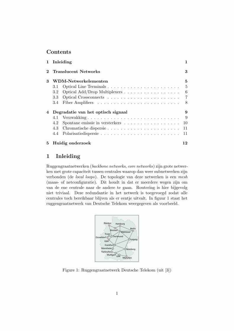
Ruggengraatnetwerken (backbone networks, core networks) zijn grote netwer-ken met grote capaciteit tussen centrales waarop dan weer subnetwerken zijnverbonden (de local loops). De topologie van deze netwerken is een mesh(maas- of netconfiguratie). Dit houdt in dat er meerdere wegen zijn omvan de ene centrale naar de andere te gaan. Routering is hier bijgevolgniet triviaal. Deze redundantie in het netwerk is toegevoegd zodat allecentrales toch bereikbaar blijven als er eentje uitvalt. In figuur 1 staat hetruggengraatnetwerk van Deutsche Telekom weergegeven als voorbeeld.
IEEE Communications Magazine • February 2007 41
physical layer design (i.e., selection of an ade-quate technology from several options), andpath computation algorithms to be used on dif-ferent timescales in planning tools, managementsystems, and control plane units.
NETWORK DESIGNAPPROACH OUTLINE
To evaluate the planning procedure for an opti-cal network, the criteria we use are the follow-ing:• Performance: The resulting network must
be able to support optical transparency,implying that wavelengths should be able tobe transmitted across all requested paths.
• Economics: The proposed network shouldbe cost efficient, and optical transparency isexpected to contribute to cost reduction.
• Availability: Protection on the physical layeris mandatory for quality of service (QoS) ofhigh-capacity data streams.
• Scalability/flexibility: The network architec-ture needs to cope efficiently with trafficgrowth, as well as changes in traffic pat-terns.
• Stability: In case of failure of a single ele-ment, it must be ensured that the rest ofthe network shows stable transmission per-formance.The iteration procedure for planning a net-
work looking toward a reconfigurable networkhas several steps:
•Different sizes of networks are assumed toutilize different technologies; hence, the size andtraffic matrix of the network under investigationare the first input parameters. For the scope ofthe project, the development of common refer-ence networks was arranged (reference networksexercise). Therefore, three types of networks aredistinguished: metro, national, and international.
•Define and model the network elementsfor the physical layer, perform simulations todesign the critical paths, and set optimizationcriteria as input for network simulations (physi-cal layer design and modeling). It is convenientto distinguish between the two phases of net-work planning and deployment and networkoperation. Here we start by modeling numeri-cally the performance of critical paths. Indynamic networks the procedure is different, aspaths longer than the ones emerging from astatic planning (e.g., the shortest path) may berequired to avoid blocking or serve dynamicrestoration. We then summarize some calibrat-ed physical constraints modeling for use in pathcomputation algorithms (e.g., rapid Q-factorassessment for integrating the physical layerconstraints into planning and path computationalgorithms).
•Develop network planning tools to set thenetwork dimensions and investigate transparencybenefits while considering physical or cost con-straints (network planning and static network sim-ulations). Network planning involves complexcalculations, since many parameters and con-straints contribute to the problem of designing acost-efficient and physically stable network. Cal-culation time is relaxed since planning is per-
formed before initial commissioning of the net-work. Because of the complexity, different meth-ods corresponding to different modeling andalgorithmic approaches were proposed; in thisarticle we elaborate on one.
•To ensure cost efficiency of the designednetworks, cost assumptions have been assignedto the network elements [1] so that accurate net-work cost (capital expenditure, CAPEX) isobtained and the most efficient solution can beselected (technology selection). In this article thethird and fourth steps are performed simultane-ously.
•Develop simulations to investigate thedynamic behavior of these networks (dynamicnetwork simulations). Once equipment placementis arranged, changes in traffic demand willrequire dynamic path computation and physical-constraint-based routing in order to allow thenetwork to efficiently and robustly add andremove connections on demand. In this step dif-ferent algorithms that solve the path computa-tion problem at various levels of detail should beassessed through planned network case studies.
•Refine the architectural concepts of such atransparent optical network.
The rest of the article exemplifies some ofthe steps, elaborating on the integration of spe-cific design constraints.
REFERENCE NETWORK EXAMPLEWhen planning a network, the technology choiceis related to the size of the network. Here, as acore network example the Deutsche Telekom(DT) network is considered [2], as illustrated inFig 1a. The reference network exercise dealswith issues like future traffic demands and trafficmatrices to be utilized in other steps.
In order to work out the size of any dynamic
n Figure 1. a) The DT core network [2]; b) a table showing the indicative sizeof the network.
k Maxno. ofhops
90%length(km)
Ratio(%)
Longest ofthe k
lightpaths (km)
< 5 13 1254 73.91698
< 4 13 1192 70.21698
Norden Hamburg
Berlin
HannoverBremen
Essen
Düsseldorf Dortmund
Köln
Frankfurt
Mannheim
KarlsruheStuttgart
UlmMünchen
Nümberg
Leipzig
(a)
(b)
POLITI LAYOUT 1/22/07 12:09 PM Page 41
Authorized licensed use limited to: Katholieke Universiteit Leuven. Downloaded on November 20, 2009 at 10:34 from IEEE Xplore. Restrictions apply.
Figure 1: Ruggengraatnetwerk Deutsche Telekom (uit [3])
1
Huidige ruggengraatnetwerken bestaan uit punt-tot-punt WDM linksgebaseerd op SDH-technologie. Het zijn zogenaamde doorschijnende op-tische netwerken. We kunnen optische netwerken namelijk opdelen indrie soorten. In transparante1 netwerken (transparent networks, all-opticalnetworks, AON ), zijn alle nodes optisch. Data worden op hun weg vanzender naar ontvanger nooit geconverteerd van optisch naar elektrisch (enterug omgekeerd). Er vindt geen regeneratie in het elektrische domeinplaats. Bij ondoorzichtige netwerken (opaque networks) gebeurt bij elkenode een conversie. Een tussenvorm zijn de doorschijnende netwerken(translucent networks). Deze tussenvorm probeert de voordelen van beidete combineren.
IEEE Communications Magazine • May 200958
FLAT VS. NON-FLAT BEHAVIOR ASSUMPTION
In most studies optical fibers’ CD and EDFA’spenalty on OSNR are assumed to be flat, that is,independent of the wavelength used by the con-sidered lightpath. In practice, this assumption isnot valid. Hence, CD is wavelength-dependent.Similarly, the gain of an EDFA is not flat in theC-band. Wavelength allocation strategies maythen have a strong impact on system perfor-mance [2]. Dynamic gain equalization (DGE)enables compensation for non-flat gain andwavelength-dependent NF of EDFAs.
TRANSLUCENT OPTICAL NETWORKSThe amount and complexity of the equipmentrequired in the network to compensate for QoTdegradation increases with distance and bit rate.Thus, ultra long haul (ULH) equipment coveringranges from 880 mi (1500 km) to 1800 mi (3000km) are much more costly than long haul (LH)transmission equipment operating from 90 mi (90km) to 430 mi (700 km). The STM-16 and STM-64 standardized data rates at 2.5 Gb/s and 10Gb/s, respectively, are currently widely deployedin LH systems. The first STM-256 equipmentoperating at 40 Gb/s more specifically dedicatedto ULH systems are complex to design, mainlybecause of their sensitivity to nonlinear impair-ments. CD compensation and DGE are morecomplex and costly to deploy in ULH systemsthan in LH systems. In general, FEC techniquesare strongly recommended in ULH or with STM-256 to prevent excessive BER at the destination.As an indication, current FEC enables BER tobe reduced from 10–5 to 10–12.
Figure 3 illustrates the principle of the neces-sary trade-off for a carrier between full opacityand full transparency. The horizontal axis refersto the average range L of the lightpaths on theconsidered network. The left side vertical axiscorresponds to the cost C1 of the required opti-cal and electrical ports provided by a solution ofthe RWA problem for a given set of trafficdemands and a given physical infrastructure. Theright side vertical axis corresponds to the cost C2
of the equipment to be used in the network tocompensate for QoT degradation of the obtainedlightpaths in order to get an admissible BER atthe destination. In the case of a fully opaquenetwork, electrical regeneration is systematicallyapplied at intermediate nodes. Opaque networkscorrespond to current networks made of EXCs(e.g., a synchronous digital hierarchy [SDH]cross-connect) or electrical switches (asyn-chronous transfer mode [ATM], Ethernet, framerelay switches). Let us recall that in existing corenetworks, IP routers are interfaced with layer 2switches in order to benefit from multiprotocollabel switching (MPLS) constraint-based routingand traffic engineering. As mentioned in ourintroduction, the cost of an RWA solution isexpressed as the cumulated cost of electrical andoptical ports required in the network, the cost ofan electrical port being around five times higherthan the cost of an optical port. If the averagerange of the lightpaths is extended in order tooverlap at least two hops, a fraction of the elec-trical ports initially required by the opaquearchitecture is replaced by optical ports, leadingto a reduction of C1. On one hand, we can saythat the higher the lightpath range, the lower C1.At the limit, full transparency reduces the num-ber of electrical ports to a minimum correspond-ing to the transceivers used at the source anddestination nodes. On the other hand, the largerthe range of a lightpath, the higher the cost ofthe compensation techniques necessary to guar-antee an admissible Q-factor at the destination.We see from Fig. 3 that for any network configu-ration there is a maximum distance Lmax for alightpath to operate without QoT compensationtechniques. We can assume that QoT is at leastacceptable on any single hop of the physicaltopology. Beyond Lmax, C2 increases progressive-ly. In practice, in wide transport networks suchas the North American backbone, full trans-parency is not achievable. As described later,various configurations are considered in the lit-erature for translucent networks. In this sectionwe consider the case for which all the nodes aretransparent (e.g., OXCs or OCSs) and equippedwith a pool of electrical regenerators. Figure 4illustrates the architecture of a translucent node.The main problem of IA-RWA is then to deter-mine the ideal sites where electrical regenerationis necessary in order to minimize the global costC1 + C2. It has to be noted that electrical regen-eration indirectly relaxes the wavelength conti-nuity constraint, which then impacts on networkcongestion.
The right side of Fig. 3 corresponds to trans-parent networks. In existing LH networks, trans-parency may not be achievable for all trafficrequests, as some demands are rejected by themanagement/control plane. We can concludefrom Fig. 3 that theoretically, assuming translu-cent nodes, there is a critical length Lcrit forwhich (C1 + C2) is minimal. As long as Lremains under Lcrit, transparency is cost effec-tive. Beyond this value, transparency is economi-cally not viable. The next sections show thatdetermining the ideal location of electricalregenerator placement to reach this minimum isa complex objective because of the amount andnature of the parameters to take into account.
� Figure 3. Opaque, translucent, and transparent networks.
Ideal translucent network
Transparencyis cost effective
Transparencyis not economicallyviable
C1 = cost inducedby the number ofelectrical/optical ports
C1+C2
C1C2
C2 = cost induced byphysical impairmentcompensation
Opaque Transparent
Average rangeL of a lightpath
Lmax Lcrit
Previous Page | Contents | Zoom in | Zoom out | Front Cover | Search Issue | Next PageIEEE
Communications BA
M SaGEF
Previous Page | Contents | Zoom in | Zoom out | Front Cover | Search Issue | Next PageIEEE
Communications BA
M SaGEF
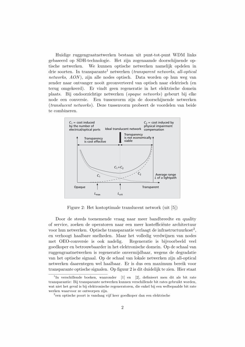
Figure 2: Het kostoptimale translucent network (uit [5])
Door de steeds toenemende vraag naar meer bandbreedte en qualityof service, zoeken de operatoren naar een meer kostefficiente architectuurvoor hun netwerken. Optische transparantie verlaagt de infrastructuurkost2,en verhoogt haalbare snelheden. Maar het volledig verdwijnen van nodesmet OEO-conversie is ook nadelig. Regeneratie is bijvoorbeeld veelgoedkoper en betrouwbaarder in het elektronische domein. Op de schaal vanruggengraatnetwerken is regeneratie onvermijdbaar, wegens de degradatievan het optische signaal. Op de schaal van lokale netwerken zijn all-opticalnetwerken daarentegen wel haalbaar. Er is dus een maximum bereik voortransparante optische signalen. Op figuur 2 is dit duidelijk te zien. Hier staat
1In verschillende boeken, waaronder [1] en [2], definieert men dit als bit ratetransparantie: Bij transparante netwerken kunnen verschillende bit rates gebruikt worden,wat niet het geval is bij elektronische regeneratoren, die enkel bij een welbepaalde bit ratewerken waarvoor ze ontworpen zijn.
2een optische poort is vandaag vijf keer goedkoper dan een elektrische
2
zowel de kost van de elektrische en/of optische poorten geplot als de kostvoor het opkrikken van een gedegradeerd signaal in functie van de afstanddat het signaal aflegt. Men definieert Lmax wanneer geen kosten toegelatenzijn om de degradatie te verbeteren, en Lcrit wanneer men het minimum wiltvan de totale kost. Om verder dan deze laatste te gaan, is er reamplifying,reshaping en retiming nodig3. In de praktijk zal men dus trachten om deLmax dat het signaal loopt, te regenereren.
2 Translucent Networks
Uit figuur 2 is duidelijk dat translucent networks de gulden middenwegzijn tussen all-electronic switching en all-optical switching. Deze netwerkenhebben nog meer voordelen dan uit deze afweging blijkt. Nodes metOEO-conversie hebben inherent de mogelijkheid om signalen op een anderegolflengte te plaatsen. Optisch is zo’n golflengteconversie veel moeilijkerte realiseren. Dit is belangrijk voor routering. Een ander voordeel is datmulticasting veel gemakkelijker uitvoerbaar is. Bij multicasting moet eennode een ontvangen signaal naar meerdere nodes doorsturen. Dit wordtmeer en meer belangrijk met de opkomst van IPTV. Het televisiesignaalreist eerst op 1 lichtpad4 tot het bij een bepaalde node gesplitst wordt overmeerdere lichtpaden naar hun bestemming. Optisch geeft dit problemendoordat de signaalsterkte over de verschillende lichtpaden verdeeld wordt.Nodes met OEO-conversie ondervinden dit probleem niet.
IEEE Communications Magazine • February 2007 49
article concludes with final remarks.
TRANSLUCENT OPTICAL NETWORKSWe can broadly classify translucent optical net-works into three categories, namely• Translucent networks made up of transpar-
ent islands [2, 6]• Translucent networks with sparsely placed
opaque nodes [3, 4]• Translucent networks made up of translu-
cent nodes [6]A translucent network can be made up of
several subdomains (termed islands) of opticaltransparency [2, 6]. Here, “optical transparency”means that all nodes in an island are transpar-ent; no nodes in the island have regenerationcapability. Regeneration OXC nodes are locatedonly on the island boundary. Therefore, withineach island, lightpaths sourced from a node cantransparently reach any other node without anysignal regeneration; whereas between differentislands, it is necessary for the lightpaths to passisland boundaries and traverse regenerationOXC nodes on the boundaries. Figure 1 illus-trates a translucent network made up of threetransparent islands, in which nodes 4, 7, 8, and 9are boundary regeneration nodes to relay light-paths crossing neighboring transparent islands.
A translucent optical network can be moregeneral than one with regeneration nodes onlyat island boundaries. We may also strategicallydistribute regeneration capability around anentire network. Instead of being dedicated torouting lightpaths only in and out of transparentislands, switches that have an electronic regener-ation function can be shared by all lightpaths inthe network as a whole. One such a type ofimplementation is based on sparse placement ofopaque switches [3, 4]. Here, one deploys a rela-tively small number of strategically chosenopaque (i.e., electronic) nodes, at which wave-length conversion and regeneration is possible.All other nodes are lower-cost optically transpar-ent OXCs. Figure 2 depicts an example of such atype of translucent network, where nodes 1 and3 are opaque, whereas the rest of the nodes aretransparent. Opaque nodes can regenerate opti-cal signals and convert wavelengths electronical-ly, while transparent ones have the opticalswitching function only.
Another distributed regeneration approach isto deploy hybrid optical switches (termed translu-cent switches) at some or all of the nodes in anoptical network [5]. Each of these switches con-tains an optical switching core and an electronicswitching core [including a bank of regeneratingOEO transponders (typically 2R) and an elec-tronic cross-connect] as depicted in Fig. 3. Eachlightpath through a translucent node can beswitched either all-optically (via the optical mod-ule) or through the electronic core module,which regenerates its payload and assigns it anew wavelength as desired (if available). Thedecision between optical or electronic switchingis based on the signal quality (e.g., BER) of thelightpath, i.e., whether regeneration is requiredbefore further transmission.
Associated with the concept of translucentnetwork, there are two types of lightpaths:
translucent and transparent [3, 4]. A lightpath iscalled translucent if there are some opaque orregeneration nodes en route for signal regenera-tion (and wavelength conversion); a lightpath iscalled transparent if there are no opaque orregeneration nodes en route. We also refer tothe lightpath segment between two neighboring
n Figure 1. Example of a translucent network withmultiple transparent islands.
1
12
10
116
5
3
2 4
Border regeneration nodes
Transparent islands
9 8
7
n Figure 2. Example of a translucent network withsparsely placed opaque nodes (adapted from [4]).
Translucent lightpath
Transparentsegment
Transparent lightpath 12
11
10
9
87
6
54
3
210
n Figure 3. Architecture of a translucent OXC node.
Optical core
Electronic core
2R/3Rregeneratingtransponders
SHEN LAYOUT 1/22/07 12:14 PM Page 49
Authorized licensed use limited to: Katholieke Universiteit Leuven. Downloaded on November 20, 2009 at 10:34 from IEEE Xplore. Restrictions apply.
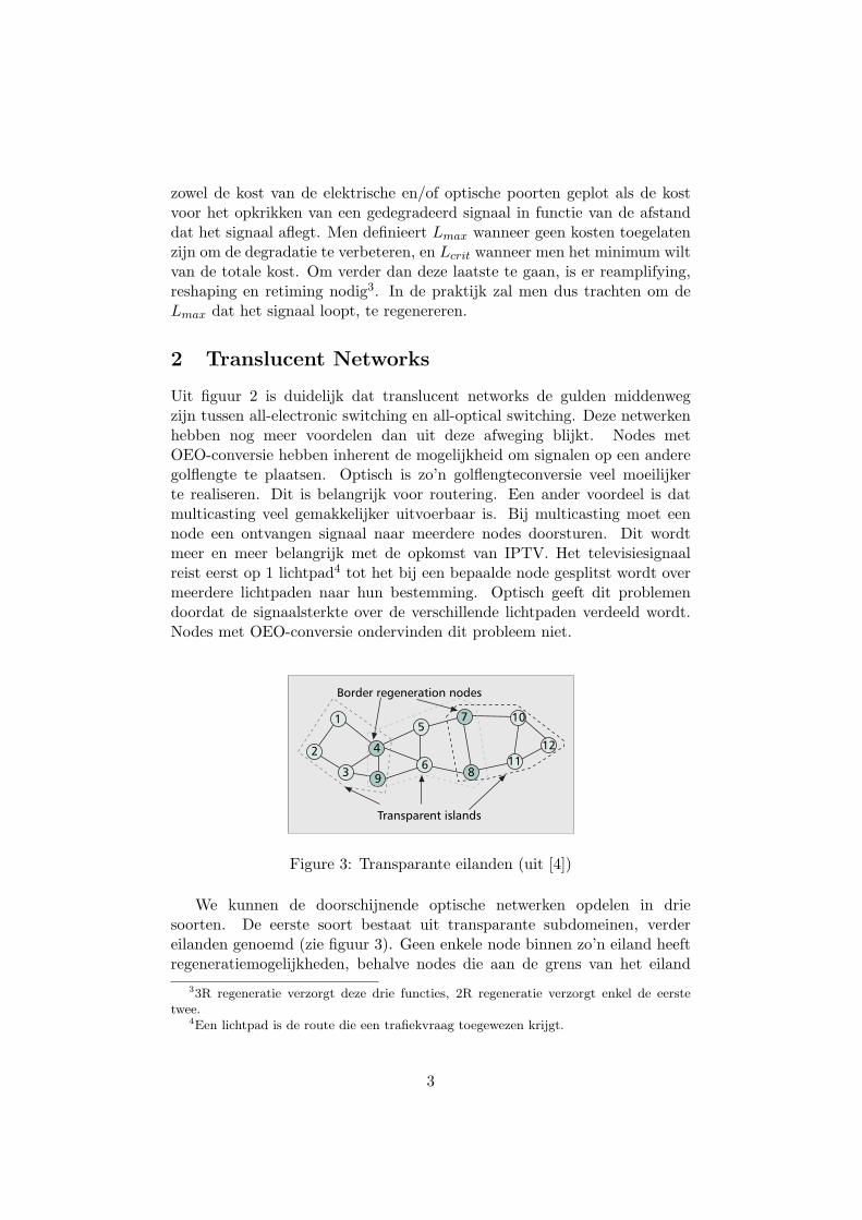
Figure 3: Transparante eilanden (uit [4])
We kunnen de doorschijnende optische netwerken opdelen in driesoorten. De eerste soort bestaat uit transparante subdomeinen, verdereilanden genoemd (zie figuur 3). Geen enkele node binnen zo’n eiland heeftregeneratiemogelijkheden, behalve nodes die aan de grens van het eiland
33R regeneratie verzorgt deze drie functies, 2R regeneratie verzorgt enkel de eerstetwee.
4Een lichtpad is de route die een trafiekvraag toegewezen krijgt.
3
gelegen zijn. Een lichtpad tussen twee nodes binnen een eiland ondergaatdus geen conversie. (bijvoorbeeld van node 1 naar node 3 in de figuur)Wanneer deze nodes in verschillende eilanden liggen, zal het lichtpad viaeen regenererende node moeten passeren (bijvoorbeeld 1 naar 6 in de figuur).
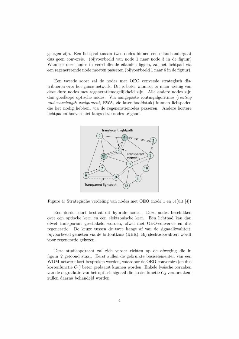
Een tweede soort zal de nodes met OEO conversie strategisch dis-tribueren over het ganse netwerk. Dit is beter wanneer er maar weinig vandeze dure nodes met regeneratiemogelijkheid zijn. Alle andere nodes zijndan goedkope optische nodes. Via aangepaste routingalgoritmes (routingand wavelength assignment, RWA, zie later hoofdstuk) kunnen lichtpadendie het nodig hebben, via de regeneratienodes passeren. Andere korterelichtpaden hoeven niet langs deze nodes te gaan.
IEEE Communications Magazine • February 2007 49
article concludes with final remarks.
TRANSLUCENT OPTICAL NETWORKSWe can broadly classify translucent optical net-works into three categories, namely• Translucent networks made up of transpar-
ent islands [2, 6]• Translucent networks with sparsely placed
opaque nodes [3, 4]• Translucent networks made up of translu-
cent nodes [6]A translucent network can be made up of
several subdomains (termed islands) of opticaltransparency [2, 6]. Here, “optical transparency”means that all nodes in an island are transpar-ent; no nodes in the island have regenerationcapability. Regeneration OXC nodes are locatedonly on the island boundary. Therefore, withineach island, lightpaths sourced from a node cantransparently reach any other node without anysignal regeneration; whereas between differentislands, it is necessary for the lightpaths to passisland boundaries and traverse regenerationOXC nodes on the boundaries. Figure 1 illus-trates a translucent network made up of threetransparent islands, in which nodes 4, 7, 8, and 9are boundary regeneration nodes to relay light-paths crossing neighboring transparent islands.
A translucent optical network can be moregeneral than one with regeneration nodes onlyat island boundaries. We may also strategicallydistribute regeneration capability around anentire network. Instead of being dedicated torouting lightpaths only in and out of transparentislands, switches that have an electronic regener-ation function can be shared by all lightpaths inthe network as a whole. One such a type ofimplementation is based on sparse placement ofopaque switches [3, 4]. Here, one deploys a rela-tively small number of strategically chosenopaque (i.e., electronic) nodes, at which wave-length conversion and regeneration is possible.All other nodes are lower-cost optically transpar-ent OXCs. Figure 2 depicts an example of such atype of translucent network, where nodes 1 and3 are opaque, whereas the rest of the nodes aretransparent. Opaque nodes can regenerate opti-cal signals and convert wavelengths electronical-ly, while transparent ones have the opticalswitching function only.
Another distributed regeneration approach isto deploy hybrid optical switches (termed translu-cent switches) at some or all of the nodes in anoptical network [5]. Each of these switches con-tains an optical switching core and an electronicswitching core [including a bank of regeneratingOEO transponders (typically 2R) and an elec-tronic cross-connect] as depicted in Fig. 3. Eachlightpath through a translucent node can beswitched either all-optically (via the optical mod-ule) or through the electronic core module,which regenerates its payload and assigns it anew wavelength as desired (if available). Thedecision between optical or electronic switchingis based on the signal quality (e.g., BER) of thelightpath, i.e., whether regeneration is requiredbefore further transmission.
Associated with the concept of translucentnetwork, there are two types of lightpaths:
translucent and transparent [3, 4]. A lightpath iscalled translucent if there are some opaque orregeneration nodes en route for signal regenera-tion (and wavelength conversion); a lightpath iscalled transparent if there are no opaque orregeneration nodes en route. We also refer tothe lightpath segment between two neighboring
n Figure 1. Example of a translucent network withmultiple transparent islands.
1
12
10
116
5
3
2 4
Border regeneration nodes
Transparent islands
9 8
7
n Figure 2. Example of a translucent network withsparsely placed opaque nodes (adapted from [4]).
Translucent lightpath
Transparentsegment
Transparent lightpath 12
11
10
9
87
6
54
3
210
n Figure 3. Architecture of a translucent OXC node.
Optical core
Electronic core
2R/3Rregeneratingtransponders
SHEN LAYOUT 1/22/07 12:14 PM Page 49
Authorized licensed use limited to: Katholieke Universiteit Leuven. Downloaded on November 20, 2009 at 10:34 from IEEE Xplore. Restrictions apply.
Figure 4: Strategische verdeling van nodes met OEO (node 1 en 3)(uit [4])
Een derde soort bestaat uit hybride nodes. Deze nodes beschikkenover een optische kern en een elektronische kern. Een lichtpad kan danofwel transparant geschakeld worden, ofwel met OEO-conversie en dusregeneratie. De keuze tussen de twee hangt af van de signaalkwaliteit,bijvoorbeeld gemeten via de bitfoutkans (BER). Bij slechte kwaliteit wordtvoor regeneratie gekozen.
Deze studieopdracht zal zich verder richten op de afweging die infiguur 2 getoond staat. Eerst zullen de gebruikte basiselementen van eenWDM-netwerk kort besproken worden, waardoor de OEO-conversies (en duskostenfunctie C1) beter geplaatst kunnen worden. Enkele fysische oorzakenvan de degradatie van het optisch signaal die kostenfunctie C2 veroorzaken,zullen daarna behandeld worden.
4

3 WDM-Netwerkelementen
De architectuur van een WDM-netwerk is in figuur 5 te zien. Het netwerkbestaat uit optical line terminals (OLTs), optical add/drop multiplexers(OADMs) en optical crossconnects (OXCs) die via optische vezel verbondenzijn. Dit is een vereenvoudigde weergave, onder andere versterkers wordenniet getoond. Het ruggengraatnetwerk bestaat uit OXCs als centrales en iszoals eerder vermeld een mesh-topologie. Op deze centrales zijn de local loopsaangesloten, deze hebben een ringtopologie en gebruiken OADMs. Om hetplaatje volledig te maken, zou men hier nog het access network aan kunnentoevoegen, maar aangezien deze uit twisted pair bestaat, valt deze wat uitde boot.404 WDM NETWORK ELEMENTS
Figure 7.1 A wavelength-routing mesh network showing optical line terminals (OLTs), optical add/drop multiplexers (OADMs), and optical crossconnects (OXCs). The network provides lightpaths to its users, such as SONET boxes and IP routers. A lightpath is carried on a wavelength between its source and destination but may get converted from one wavelength to another along the way.
destinations. They are typically deployed in linear or ring topologies. OXCs perform a similar function but on a much larger scale in terms of number of ports and wave- lengths involved, and are deployed in mesh topologies or in order to interconnect multiple rings. We will study these network elements in detail later in this chapter. The users (or clients) of this network are connected to the OLTs, OADMs, or OXCs. The network supports a variety of client types, such as IP routers, ATM switches, and SONET terminals and ADMs.
Each link can support a certain number of wavelengths. The number of wave- lengths that can be supported depends on the component- and transmission-imposed limitations that we studied in Chapters 2, 3, and 5.
We next describe several noteworthy features of this architecture:
Figure 5: WDM-netwerk (uit [2])
3.1 Optical Line Terminals
OLTs zijn redelijk eenvoudige netwerkelementen. Ze worden ingezet aande uiteinden van een punt-tot-punt link om verschillende golflengten te(de-)multiplexen. Ze bestaan uit drie functionele delen (zie figuur 6):transponders, golflengtemultiplexers en optische versterkers (weer niet inde figuur getoond). De transponder zet het signaal dat van de client komtom in een signaal dat geschikt is voor het optische netwerk, en omgekeerd.De transponder kan ook extra overhead toevoegen voor networkmanagementen/of voor foutcorrectie. Ze monitort meestal ook de bitfoutkans van hetbinnenkomend signaal. Al deze taken worden typisch gedaan door een OEO-conversie. Het signaal uit de transponder wordt daarna gemultiplext met
5
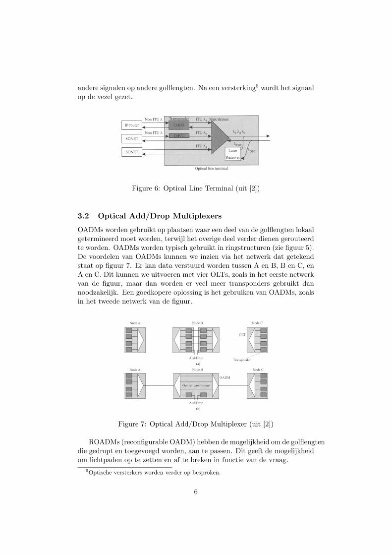
andere signalen op andere golflengten. Na een versterking5 wordt het signaalop de vezel gezet.406 WDM NETWORK ELEMENTS
Figure 7.2 Block diagram of an optical line terminal. The OLT has wavelength multi- plexers and demultiplexers and adaptation devices called transponders. The transponders convert the incoming signal from the client to a signal suitable for transmission over the WDM link and an incoming signal from the WDM link to a suitable signal toward the client. Transponders are not needed if the client equipment can directly send and re- ceive signals compatible with the WDM link. The OLT also terminates a separate optical supervisory channel (OSC) used on the fiber link.
optical layer. To an IP network residing above the optical layer, the lightpaths look like links between IP routers. The set of lightpaths can be tailored to meet the traffic requirements of the higher layers. This topic will be explored further in Chapter 8.
7.1 Optical Line Terminals OLTs are relatively simple network elements from an architectural perspective. They are used at either end of a point-to-point link to multiplex and demultiplex wave- lengths. Figure 7.2 shows the three functional elements inside an OLT: transponders, wavelength multiplexers, and optionally, optical amplifiers (not shown in the figure). A transponder adapts the signal coming in from a client of the optical network into a signal suitable for use inside the optical network. Likewise, in the reverse direction, it adapts the signal from the optical network into a signal suitable for the client. The interface between the client and the transponder may vary depending on the client, bit rate, and the distance and/or loss between the client and the transponder. The most common interface is the SONET/SDH short-reach (SR) interface described in Section 6.1.4. We are also seeing the emergence of cheaper very short reach (VSR) interfaces at bit rates of 10 Gb/s and higher.
Figure 6: Optical Line Terminal (uit [2])
3.2 Optical Add/Drop Multiplexers
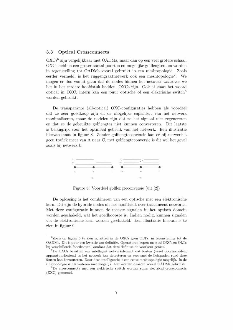
OADMs worden gebruikt op plaatsen waar een deel van de golflengten lokaalgetermineerd moet worden, terwijl het overige deel verder dienen gerouteerdte worden. OADMs worden typisch gebruikt in ringstructuren (zie figuur 5).De voordelen van OADMs kunnen we inzien via het netwerk dat getekendstaat op figuur 7. Er kan data verstuurd worden tussen A en B, B en C, enA en C. Dit kunnen we uitvoeren met vier OLTs, zoals in het eerste netwerkvan de figuur, maar dan worden er veel meer transponders gebruikt dannoodzakelijk. Een goedkopere oplossing is het gebruiken van OADMs, zoalsin het tweede netwerk van de figuur.
7.3 Optical Add/Drop Multiplexers 409
Figure 7.4 A three-node linear network example to illustrate the role of optical add/drop multi- plexers. Three wavelengths are needed between nodes A and C, and one wavelength each between nodes A and B and between nodes B and C. (a) A solution using point-to-point WDM systems. (b) A solution using an optical add/drop multiplexer at node B.
amplifier sites in long-haul networks but can also be used as stand-alone network elements, particularly in metro networks. To understand the benefits of OADMs, consider a network between three nodes, say, A, B, and C, shown in Figure 7.4, with IP routers located at nodes A, B, and C. This network supports traffic between A and B, B and C, and A and C. Based on the network topology, traffic between A and C passes through node B. For simplicity, we will assume full-duplex links and full-duplex connections. This is the case for most networks today. Thus the network in Figure 7.4 actually consists of a pair of fibers carrying traffic in opposite directions.
Suppose the traffic requirement is as follows: one wavelength between A and B, one wavelength between B and C, and three wavelengths between A and C. Now suppose we deploy point-to-point WDM systems to support this traffic demand. The resulting solution is shown in Figure 7.4(a). Two point-to-point systems are deployed, one between A and B and the other between B and C. As we saw earlier in Section 7.1, each point-to-point system uses an OLT at each end of the link. The
Figure 7: Optical Add/Drop Multiplexer (uit [2])
ROADMs (reconfigurable OADM) hebben de mogelijkheid om de golflengtendie gedropt en toegevoegd worden, aan te passen. Dit geeft de mogelijkheidom lichtpaden op te zetten en af te breken in functie van de vraag.
5Optische versterkers worden verder op besproken.
6
3.3 Optical Crossconnects
OXCs6 zijn vergelijkbaar met OADMs, maar dan op een veel grotere schaal.OXCs hebben een groter aantal poorten en mogelijke golflengten, en wordenin tegenstelling tot OADMs vooral gebruikt in een meshtopologie. Zoalseerder vermeld, is het ruggengraatnetwerk ook een meshtopologie7. Wemogen er dus vanuit gaan dat de nodes binnen het netwerk waarover wehet in het eerdere hoofdstuk hadden, OXCs zijn. Ook al staat het woordoptical in OXC, intern kan een puur optische of een elektrische switch8
worden gebruikt.
De transparante (all-optical) OXC-configuraties hebben als voordeeldat ze zeer goedkoop zijn en de mogelijke capaciteit van het netwerkmaximaliseren, maar de nadelen zijn dat ze het signaal niet regenererenen dat ze de gebruikte golflengtes niet kunnen converteren. Dit laatsteis belangrijk voor het optimaal gebruik van het netwerk. Een illustratiehiervan staat in figuur 8. Zonder golflengteconversie kan er bij netwerk ageen trafiek meer van A naar C, met golflengteconversie is dit wel het gevalzoals bij netwerk b.426 WDM NETWORK ELEMENTS
Figure 7.10 Illustrating the need for wavelength conversion. (a) Node B does not con- vert wavelengths. (b) Node B can convert wavelengths.
Figure 7.11 A realistic "all-optical" network node combining optical core crosscon- nects with electrical core crossconnects. Signals are switched in the optical domain when- ever possible but routed down to the electrical domain whenever they need to be groomed, regenerated, or converted from one wavelength to another.
Figure 8: Voordeel golflengteconversie (uit [2])
De oplossing is het combineren van een optische met een elektronischekern. Dit zijn de hybride nodes uit het hoofdstuk over translucent networks.Met deze configuratie kunnen de meeste signalen in het optisch domeinworden geschakeld, wat het goedkoopste is. Indien nodig, kunnen signalenvia de elektronische kern worden geschakeld. Een illustratie hiervan is tezien in figuur 9.
6Zoals op figuur 5 te zien is, zitten in de OXCs geen OLTs, in tegenstelling tot deOADMs. Dit is puur een kwestie van definitie. Operatoren kopen meestal OXCs en OLTsbij verschillende fabrikanten, vandaar dat deze definitie de voorkeur geniet.
7De OXCs bevatten een intelligent netwerkelement dat fouten (vezel doorgesneden,apparatuurfouten,) in het netwerk kan detecteren en zeer snel de lichtpaden rond dezefouten kan herrouteren. Door deze intelligentie is een echte meshtopologie mogelijk. In deringtopologie is herrouteren niet mogelijk, hier worden daarom vooral OADMs gebruikt.
8De crossconnects met een elektrische switch worden soms electrical crossconnects(EXC) genoemd.
7
IEEE Communications Magazine • February 2007 49
article concludes with final remarks.
TRANSLUCENT OPTICAL NETWORKSWe can broadly classify translucent optical net-works into three categories, namely• Translucent networks made up of transpar-
ent islands [2, 6]• Translucent networks with sparsely placed
opaque nodes [3, 4]• Translucent networks made up of translu-
cent nodes [6]A translucent network can be made up of
several subdomains (termed islands) of opticaltransparency [2, 6]. Here, “optical transparency”means that all nodes in an island are transpar-ent; no nodes in the island have regenerationcapability. Regeneration OXC nodes are locatedonly on the island boundary. Therefore, withineach island, lightpaths sourced from a node cantransparently reach any other node without anysignal regeneration; whereas between differentislands, it is necessary for the lightpaths to passisland boundaries and traverse regenerationOXC nodes on the boundaries. Figure 1 illus-trates a translucent network made up of threetransparent islands, in which nodes 4, 7, 8, and 9are boundary regeneration nodes to relay light-paths crossing neighboring transparent islands.
A translucent optical network can be moregeneral than one with regeneration nodes onlyat island boundaries. We may also strategicallydistribute regeneration capability around anentire network. Instead of being dedicated torouting lightpaths only in and out of transparentislands, switches that have an electronic regener-ation function can be shared by all lightpaths inthe network as a whole. One such a type ofimplementation is based on sparse placement ofopaque switches [3, 4]. Here, one deploys a rela-tively small number of strategically chosenopaque (i.e., electronic) nodes, at which wave-length conversion and regeneration is possible.All other nodes are lower-cost optically transpar-ent OXCs. Figure 2 depicts an example of such atype of translucent network, where nodes 1 and3 are opaque, whereas the rest of the nodes aretransparent. Opaque nodes can regenerate opti-cal signals and convert wavelengths electronical-ly, while transparent ones have the opticalswitching function only.
Another distributed regeneration approach isto deploy hybrid optical switches (termed translu-cent switches) at some or all of the nodes in anoptical network [5]. Each of these switches con-tains an optical switching core and an electronicswitching core [including a bank of regeneratingOEO transponders (typically 2R) and an elec-tronic cross-connect] as depicted in Fig. 3. Eachlightpath through a translucent node can beswitched either all-optically (via the optical mod-ule) or through the electronic core module,which regenerates its payload and assigns it anew wavelength as desired (if available). Thedecision between optical or electronic switchingis based on the signal quality (e.g., BER) of thelightpath, i.e., whether regeneration is requiredbefore further transmission.
Associated with the concept of translucentnetwork, there are two types of lightpaths:
translucent and transparent [3, 4]. A lightpath iscalled translucent if there are some opaque orregeneration nodes en route for signal regenera-tion (and wavelength conversion); a lightpath iscalled transparent if there are no opaque orregeneration nodes en route. We also refer tothe lightpath segment between two neighboring
n Figure 1. Example of a translucent network withmultiple transparent islands.
1
12
10
116
5
3
2 4
Border regeneration nodes
Transparent islands
9 8
7
n Figure 2. Example of a translucent network withsparsely placed opaque nodes (adapted from [4]).
Translucent lightpath
Transparentsegment
Transparent lightpath 12
11
10
9
87
6
54
3
210
n Figure 3. Architecture of a translucent OXC node.
Optical core
Electronic core
2R/3Rregeneratingtransponders
SHEN LAYOUT 1/22/07 12:14 PM Page 49
Authorized licensed use limited to: Katholieke Universiteit Leuven. Downloaded on November 20, 2009 at 10:34 from IEEE Xplore. Restrictions apply.
Figure 9: Hybride nodes (uit [4])
3.4 Fiber Amplifiers
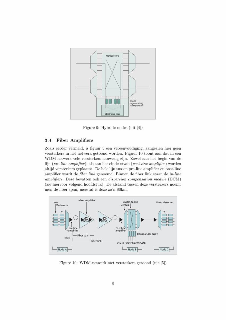
Zoals eerder vermeld, is figuur 5 een vereenvoudiging, aangezien hier geenversterkers in het netwerk getoond worden. Figuur 10 toont aan dat in eenWDM-netwerk vele versterkers aanwezig zijn. Zowel aan het begin van delijn (pre-line amplifier), als aan het einde ervan (post-line amplifier) wordenaltijd versterkers geplaatst. De hele lijn tussen pre-line amplifier en post-lineamplifier wordt de fiber link genoemd. Binnen de fiber link staan de in-lineamplifiers. Deze bevatten ook een dispersion compensation module (DCM)(zie hiervoor volgend hoofdstuk). De afstand tussen deze versterkers noemtmen de fiber span, meestal is deze zo’n 80km.
IEEE Communications Magazine • May 200956
the whole set of traffic demands. A solution’scost is expressed in terms of required optical andelectrical ports. Dynamic and stochastic trafficdemands are characterized by an unknownarrival time and a random lifetime. This unpre-dictability of the traffic imposes on-the-fly RWAapplied to individual demands. This task must bedone in real time and is the main functionalityof the control plane. Although all-optical wave-length converters are technically feasible, theircost remains prohibitive for carriers. This is thereason two main constraints must be consideredwhen solving the RWA problem: wavelengthcontinuity and the limited number of opticalchannels that may be multiplexed onto the samefiber.
Only since 2000 has real attention been paidto the impact of transmission impairments onthe feasibility of solutions provided by RWA[1]. According to the state of the technology,various factors degrade the quality of an analogoptical signal along its route due to propaga-tion itself, multiplexing, amplification, andswitching. Many investigations have tried toinclude QoT constraints in RWA strategies;these constraints may be classified into linearand nonlinear impairments. Linear impairmentsare such that their impact on QoT is indepen-dent of the power of each of the optical chan-nels transported on the same fiber. At theopposite, nonlinear impairments are stronglydependent on the accumulated power and onthe individual power of the optical channelstransported in parallel on the same fiber. Thehigher the bit rate of the data transported by alightpath or the larger the length of the routeadopted for a lightpath, the higher the requiredoptical power at the transmitter. In other terms,under linear impairments QoT can be evaluat-ed individually for the different optical chan-nels sharing the same fiber. This is not the caseunder nonlinear impairments, wherein the QoTof each optical channel transported on a fiberdepends on the number, value, and power ofthe other channels transported simultaneouslyon the same fiber. Impairment-aware RWA(IA-RWA) consists of solving the RWA prob-lem while taking into account QoT constraints.Today, the great majority of the investigations
on IA-RWA are dedicated to static traffic. Thecase of IA-RWA with dynamic traffic remainswidely open to further study; it is a key objec-tive of the DICONET project.
The aim of this article is to provide anoverview of the state of the art of IA-RWA. Werecall the main physical layer impairments to beconsidered for QoT evaluation. As mentioned inthe abstract, full optical transparency is in prac-tice not achievable with the state of the technol-ogy. This is why the concept of a translucentnetwork has been introduced. We discuss thenecessary economical trade-off for carriersbetween opacity and transparency. Numeroustechnologies enable the impact of physical layerimpairments on QoT to be reduced. Meanwhile,beyond a certain distance, electrical regenerationbecomes mandatory if QoT at intermediatenodes degrades beyond an admissible limit. Thislimit is referred to as the Q-factor threshold. Wealso dedicate a section to static IA-RWA. Themain task of static IA-RWA is to determine themost judicious locations for electrical regenera-tion in the network. We then deal with the moreprospective problem of dynamic IA-RWA. Wepropose an introductory analysis of IA-RWA inthe context of multidomain lightpath establish-ment. We then conclude this article.
PHYSICAL LAYER IMPAIRMENTSFigure 1 recalls the typical configuration of apoint-to-point WDM transmission system. Incarriers’ networks optical fibers are set in pairsbetween adjacent nodes, a fiber for each direc-tion of transmission. At the source node, paralleloptical channels generated by fixed transceiversare multiplexed onto a standard single-modefiber (SMF). An optical pre-amplifier (post-amplifier) is used at the input (output) of eachswitching node. The WDM multiplex is regularlyre-amplified at amplification sites spaced onaverage 80 km apart. A span corresponds to thesection of fiber separating two adjacent amplifi-cation sites. An optical link is the set of spansused between two adjacent switching nodes. Alightpath generally overlaps several links; inter-mediate nodes (electrical cross-connects [EXCs]or OCSs) are in charge of lightpath routing.
� Figure 1. Configuration of a WDM transmission system.
Client (SONET/ATM/SAN)
Transponder arrayMux
Node A Node B Node C
Fiber span
DCM
Laser
Pre-lineamplifier
Post-lineamplifier
Photo detectorModulator
Inline amplifier
DemuxSwitch fabric
DCM
Fiber link
The analog optical
signal is subject to
two main types of
attenuation:
intrinsic and extrinsic.
Intrinsic attenuation
is due to the
absorption of the
optical power in
silica. Extrinsic
attenuation is due to
irregularities in the
section of the
cylindrical geometry
of the fiber.
Previous Page | Contents | Zoom in | Zoom out | Front Cover | Search Issue | Next PageIEEE
Communications BA
M SaGEF
Previous Page | Contents | Zoom in | Zoom out | Front Cover | Search Issue | Next PageIEEE
Communications BA
M SaGEF
Figure 10: WDM-netwerk met versterkers getoond (uit [5])
8
4 Degradatie van het optisch signaal
Om de werkbaarheid van een lichtpad aan te geven, wordt de term Qualityof Transmission (QoT) gebruikt. Deze QoT wordt geevalueerd door inde ontvanger de Q-factor te berekenen, die gelinkt is met de bitfoutkansen de optische signaal-ruisverhouding (OSNR). Lineaire degradatie (linearimpairment) is onafhankelijk van het vermogen9 op de verschillende optischekanalen die zich op een vezel bevinden. Niet-lineaire degradatie is daar-entegen sterk afhankelijk van het totaal vermogen op de vezel en van hetindividueel vermogen van 1 kanaal. Bij lineaire degradatie kan de QoT van1 kanaal dus individueel bepaald worden, terwijl bij niet-lineaire degradatieer rekening zal moeten gehouden worden met invloeden van andere kanalen.Dit hoofdstuk zal vooral ingaan op enkele lineaire degradatiemechanismen.
4.1 Verzwakking
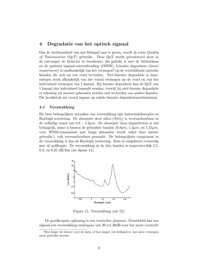
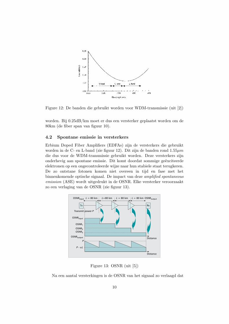
De twee belangrijkste oorzaken van verzwakking zijn materiaalabsorptie enRayleigh scattering. De absorptie door silica (SiO2) is verwaarloosbaar inde volledige band van 0.8 − 1.6µm. De absorptie door impuriteiten is welbelangrijk, maar is binnen de gebruikte banden (0.8µm, 1.3µm, en 1.55µm,voor WDM-transmissie met lange afstanden wordt enkel deze laatstegebruikt.) ook verwaarloosbaar gemaakt. De belangrijkste component inde verzwakking is dus de Rayleigh scattering. Deze is omgekeerd evenredigmet de golflengte. De verzwakking in de drie banden is respectievelijk 2.5,0.4, en 0.25 dB/km (zie figuur 11).66 PROPAGATION OF SIGNALS IN OPTICAL FIBER
r ~
0
20
1~ f 5
2
1
0.5
0.2
�9 , i . . . . i . . . . i . . . . . . . . i �9 �9 �9
08 1 12 14 16
Wavelength, )~ (~tm)
Figure 2.6 Attenuation loss in silica as a function of wavelength. (After [Agr97].)
these bands, which we can take as the bandwidth over which the loss in decibels per kilometer is within a factor of 2 of its minimum, is approximately 80 nm at 1.3/~m and 180 nm at 1.55 ~m. In terms of optical frequency, these bandwidths correspond to about 35,000 GHz! This is an enormous amount of bandwidth indeed, considering that the bit rate needed for most user applications today is no more than a few tens of megabits per second.
The usable bandwidth of fiber in most of today's long-distance networks is limited by the bandwidth of the erbium-doped fiber amplifiers (see Section 3.4) that are widely deployed, rather than by the bandwidth of the silica fiber. Based on the availability of amplifiers, the low-loss band at 1.55 ~m is divided into three regions, as shown in Figure 2.7. The middle band from 1530 to 1565 nm is the conventional or C-band where WDM systems have operated using conventional erbium-doped fiber amplifiers. The band from 1565 to 1625 nm, which consists of wavelengths longer than those in the C-band, is called the L-band and is today being used in high-capacity WDM systems, with the development of gain-shifted erbium-doped amplifiers (see Section 3.4) that provide amplification in this band. The band below 1530 nm, consisting of wavelengths shorter than those in the C-band, is called the S-band. Fiber Raman amplifiers (Section 3.4.4) provide amplification in this band.
Lucent introduced a new kind of single-mode optical fiber, called AllWave fiber, in 1998, which virtually eliminates the absorption peaks due to water vapor. This fiber has an even larger bandwidth and is expected to be deployed in metropolitan-area networks that do not use erbium-doped fiber amplifiers.
Figure 11: Verzwakking (uit [2])
De goedkoopste oplossing is een versterker plaatsen. Gemiddeld kan eensignaal een verzwakking ondergaan van 20 tot 30dB voor het moet versterkt
9Hoe hoger de bitrate voor de data, of hoe langer een lichtpad is, hoe meer vermogenmoet gebruikt worden.
9
2.2 Loss and Bandwidth 67
0.30
0.28
0.26
r ~
e 0.24
0.22 S-band C-band
0.20 ' ' ' ' ' ' ' ' ' ' ' '
1450 1500 1550
Wavelength (nm)
L-band v
, l , , ~ ~ i
1600 1650
Figure 2.7 The three bands, S-band, C-band, and L-band, based on amplifier availabil- ity, within the low-loss region around 1.55 #m in silica fiber. (After [Kan99].)
2.2.1
As we saw earlier in this section, the dominant loss mechanism in optical fiber is Rayleigh scattering. Rayleigh scattering arises because of fluctuations in the density of the medium (silica) at the microscopic level. We refer to [BW99] for a detailed description of the scattering mechanism. The loss due to Rayleigh scattering is a fundamental one and decreases with increasing wavelength. The loss coefficient dR due to Rayleigh scattering at a wavelength Z can be written as dR = A/Z 4, where A is called the Rayleigh scattering coefficient. Note that the Rayleigh scattering loss decreases rapidly with increasing wavelength due to the Z -4 dependence. Glasses with substantially lower Rayleigh attenuation coefficients at 1.55 #m are not known. In order to reduce the fiber loss below the current best value of about 0.2 dB/km, one possibility is to operate at higher wavelengths, so as to reduce the loss due to Rayleigh scattering. However, at such higher wavelengths, the material absorption of silica is quite significant. It may be possible to use other materials such as fluorozirconate (ZiFr4) in order to realize the low loss that is potentially possible by operating at these wavelengths [KK97, p. 69].
Bending Loss Optical fibers need to be bent for various reasons both when deployed in the field and particularly within equipment. Bending leads to "leakage" of power out of the
Figure 12: De banden die gebruikt worden voor WDM-transmissie (uit [2])
worden. Bij 0.25dB/km moet er dus een versterker geplaatst worden om de80km (de fiber span van figuur 10).
4.2 Spontane emissie in versterkers
Erbium Doped Fiber Amplifiers (EDFAs) zijn de versterkers die gebruiktworden in de C- en L-band (zie figuur 12). Dit zijn de banden rond 1.55µmdie dus voor de WDM-transmissie gebruikt worden. Deze versterkers zijnonderhevig aan spontane emissie. Dit komt doordat sommige geexciteerdeelektronen op een ongecontroleerde wijze naar hun stabiele staat terugkeren.De zo ontstane fotonen komen niet overeen in tijd en fase met hetbinnenkomende optische signaal. De impact van deze amplified spontaneousemission (ASE) wordt uitgedrukt in de OSNR. Elke versterker veroorzaaktzo een verlaging van de OSNR (zie figuur 13).
IEEE Communications Magazine • May 2009 57
QoT is evaluated at the destination node of alightpath by computing the Q-factor, which isdirectly linked to the bit error rate (BER) andoptical signal-to-noise ratio (OSNR). As an indi-cation, a Q-factor of 12.5 dB corresponding to aBER of 10–5 is frequently considered the Q-fac-tor admissibility threshold when forward errorcorrection (FEC) is applied.
LINEAR IMPAIRMENTSAttenuation ( ): The analog optical signal issubject to two main types of attenuation: intrin-sic and extrinsic. Intrinsic attenuation is due tothe absorption of the optical power in silica.Raleigh scattering due to the interaction betweenphotons and silica molecules causes scattering inmultiple directions. Attenuation due to Rayleighscattering is more sensitive for short wavelengths(in nanometers) than longer ones. Extrinsicattenuation is due to irregularities in the sectionof the cylindrical geometry of the fiber. Bothattenuations are expressed in dB per kilometer.Global attenuation of SMF fibers (other typesof fiber can be used for very long-haul transmis-sion systems) is about 0.2 dB/km
Amplified spontaneous emission: Erbiumdoped fiber amplifiers (EDFAs) are subject tospontaneous emission that corresponds to pho-tons generated by the non-controlled return ofexcited electrons in Erbium ions to their stablestate. Such photons do not coincide in time andphase with those belonging to the incoming opti-cal signal. The impact of amplified spontaneousemission (ASE) is expressed in terms of OSNR.Even if one assumes perfect compensation forthe attenuation of a span by an EDFA, theinverse of OSNR at the output of an EDFA isequal to the summation of the inverse of OSNRat its input and the ratio of the ASE power tothe input power. ASE is related to the noise fig-ure (NF) of the amplifier. Figure 2 illustrates thetypical evolution of OSNR over multiple spans.
Chromatic dispersion: CD is due to the factthe various spectral components of a modulatedanalog optical signal do not propagate with thesame speed in the fiber. This propagation speeddisparity induces intersymbol interference (ISI)at destination. CD depends on wavelength andincreases with distance. It is expressed in picosec-onds per nanometer or kilometer. CD is consid-ered as one of the most penalizing linearimpairments on QoT. CD of SMF fibers is about+17 ps/nm.km.
Polarization mode dispersion: PMD is due tounpredictable birefringence in the fiber, thisbirefringence being due itself to the non-circu-larity of the core of the fiber. The fact the twoorthogonal polarization directivities of the elec-tro-magnetic field do not propagate at the samespeed induces a phenomenon similar to ISI atthe destination. Being expressed in ps per squareroot of km, the square of PMD value is additivewith distance. As an indication, the InternationalTelecommunication Union — Telecommunica-tion Standardization Sector (ITU-T) recom-mends, for a 2 Gb/s (10 Gb/s) channel, a limitedcumulated PMD of 40 ps (10 ps) after 400 km ofpropagation. Unlike CD, PMD is wavelengthpin-dependent. PMD of SMF fibers is about 0.1 psper square root of km.
Insertion loss: IL corresponds to the differ-ence between the power of the optical signal atthe input and output of an opto-electronicdevice. IL expressed in dB is considered in thecalculation of the power budget (OSNR) of alightpath. The penalty induced by the transitthrough an OXC or OCS strongly depends onthe hardware architecture of the switching fab-ric; it is evaluated in terms of IL.
NONLINEAR IMPAIRMENTSNonlinear impairments may be classified intotwo categories. The first category refers to theimpact of optical power on the fiber’s refractiveindex. Such an impact is known as a Kerr effect.Three Kerr effects are distinguished: self-phasemodulation (SPM), cross-phase modulation(XPM), and four-wave mixing (FWM). SPMinduces a phase shift of the optical pulses. Theother category refers to scattering effectsbetween silica and optical signal. StimulatedRaman scattering (SRS) and stimulated Bril-louin scattering (SBS) are the two scatteringeffects. In practice, the impact of SRS and ofSBS on OSNR is negligible compared to SPM,XPM and FWM. FWM is the most penalizingimpairment among Kerr effects. The cumulatedimpact of the various nonlinear impairments isin general expressed as a nonlinear phase shift( NL) expressed in rad/s. NL depends on thevalue of the wavelength and is cumulative withdistance.
IMPAIRMENT COMPENSATION TECHNIQUESIn order to compensate for cumulated CD,each amplification site uses a dispersion com-pensation fiber (DCF) section with a strongnegative CD of about –90 ps/nm.km. ThisDCF sect ion is inserted between the twoamplification stages of an amplification site.In current carrier networks, EDFAs operatein the C-band (1530–1560 nm) where attenua-tion is minimal. An EDFA enables up to 60optical channels to be amplified simultaneous-ly with a 40 dB global gain and a noise figurearound 5 dB.
� Figure 2. Impact of EDFA's ASE on OSNR.
PDistance
Distance
Transmit power P
OSNRoutput
OSNRinput
OSNR3
OSNR2
OSNR1
P - αL
OSNRinput OSNRoutputL = 80 km L=80 km L = 80 km L = 80 km
Tx Rx
Previous Page | Contents | Zoom in | Zoom out | Front Cover | Search Issue | Next PageIEEE
Communications BA
M SaGEF
Previous Page | Contents | Zoom in | Zoom out | Front Cover | Search Issue | Next PageIEEE
Communications BA
M SaGEF
Figure 13: OSNR (uit [5])
Na een aantal versterkingen is de OSNR van het signaal zo verlaagd dat
10
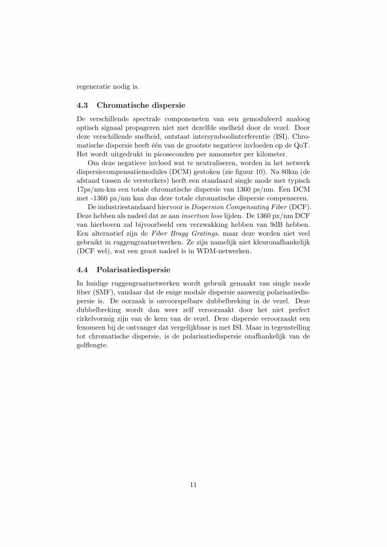
regeneratie nodig is.
4.3 Chromatische dispersie
De verschillende spectrale componeneten van een gemoduleerd analoogoptisch signaal propageren niet met dezelfde snelheid door de vezel. Doordeze verschillende snelheid, ontstaat intersymboolinterferentie (ISI). Chro-matische dispersie heeft een van de grootste negatieve invloeden op de QoT.Het wordt uitgedrukt in picoseconden per nanometer per kilometer.
Om deze negatieve invloed wat te neutraliseren, worden in het netwerkdispersiecompensatiemodules (DCM) gestoken (zie figuur 10). Na 80km (deafstand tussen de versterkers) heeft een standaard single mode met typisch17ps/nm-km een totale chromatische dispersie van 1360 ps/nm. Een DCMmet -1360 px/nm kan dus deze totale chromatische dispersie compenseren.
De industriestandaard hiervoor is Dispersion Compensating Fiber (DCF).Deze hebben als nadeel dat ze aan insertion loss lijden. De 1360 px/nm DCFvan hierboven zal bijvoorbeeld een verzwakking hebben van 9dB hebben.Een alternatief zijn de Fiber Bragg Gratings, maar deze worden niet veelgebruikt in ruggengraatnetwerken. Ze zijn namelijk niet kleuronafhankelijk(DCF wel), wat een groot nadeel is in WDM-netwerken.
4.4 Polarisatiedispersie
In huidige ruggengraatnetwerken wordt gebruik gemaakt van single modefiber (SMF), vandaar dat de enige modale dispersie aanwezig polarisatiedis-persie is. De oorzaak is onvoorspelbare dubbelbreking in de vezel. Dezedubbelbreking wordt dan weer zelf veroorzaakt door het niet perfectcirkelvormig zijn van de kern van de vezel. Deze dispersie veroorzaakt eenfenomeen bij de ontvanger dat vergelijkbaar is met ISI. Maar in tegenstellingtot chromatische dispersie, is de polarisatiedispersie onafhankelijk van degolflengte.
11
5 Huidig onderzoek
De papers die mij geınspireerd hebben tot het schrijven van deze studieop-dracht ( [5] en [6]), maken deel uit van het Europese DICONET10 project.Kort gezegd, wordt de ideale plaatsing van 2R/3R-regeneratoren onderzochtalsook de Routing and Wavelength Assignment (RWA). Deze laatste zalbijvoorbeeld slim gemaakt worden door met de degradatie van het signaalrekening te houden (Impairment Aware RWA). Met hun eigen woorden:
We plan to investigate, design, implement and test newrouting and wavelength assignment algorithms considering asconstraints physical impairments that arise in transparent corenetworks. These algorithms will be incorporated into a noveldynamic network planning tool that would consider dynamic traf-fic characteristics, varying physical impairment and componentcharacteristics and a reconfigurable optical layer. The use ofthis novel planning tool in conjunction with proper extensions tothe control plane of core optical networks that will be designed,implemented and tested by our consortium will make possibleto realize the vision of transparency, while offering efficientresource utilization and strict quality of service guarantees basedon certain service level agreements.
References
[1] An Introduction to Fiber Optics. Cambridge University Press, 1998.
[2] Optical Networks: A Practical Perspective. Morgan Kaufmann, 2002.
[3] Christina Politi et al. Integrated design and operation of a transparentoptical network: A systematic approach to include physical layerawareness and cost function. IEEE Communications Magazine, vol. 45,no. 2, 2007.
[4] Gangxiang Shen et al. Translucent optical networks: The way forward.IEEE Communications Magazine, vol. 45, no. 2, 2007.
[5] Maurice Gagnaire et al. Impairment-aware routing and wavelengthassignment in translucent networks: State of the art. IEEECommunications Magazine, vol. 47, no. 5, 2009.
[6] Siamak Azodolmolky et al. A dynamic impairment-aware networkingsolution for transparent mesh optical networks. IEEE CommunicationsMagazine, vol. 47, no. 5, 2009.
10Ook het Vlaamse IBBT doet mee, met onderzoekers van de universiteit van Gent.
12


![VOLLEDIGE STUDIEOPDRACHT VOOR DE OPMAAK VAN EEN … › sites › default › files › open... · 2017-09-19 · ICubes Vlaams instituut voor archivering [VIA] Voorstelling van het](https://static.fdocuments.nl/doc/165x107/5f0dc6b77e708231d43c0791/volledige-studieopdracht-voor-de-opmaak-van-een-a-sites-a-default-a-files.jpg)