Ss report1
12
Site Surveying Report I Leveling Site Surveying (QSB60103) Mr. Chai Voon Chiet Wong De Vin (0319814) Chin Khang Wei (0320728) Tan You Liang (0320215) Teh Qing Da (0318590) Sim Chia Ting (0320932)
-
Upload
khangwei-chin -
Category
Education
-
view
46 -
download
1
Transcript of Ss report1

Site Surveying Report I Leveling
Site Surveying (QSB60103)
Mr. Chai Voon Chiet
Wong De Vin (0319814)
Chin Khang Wei (0320728)
Tan You Liang (0320215)
Teh Qing Da (0318590)
Sim Chia Ting (0320932)
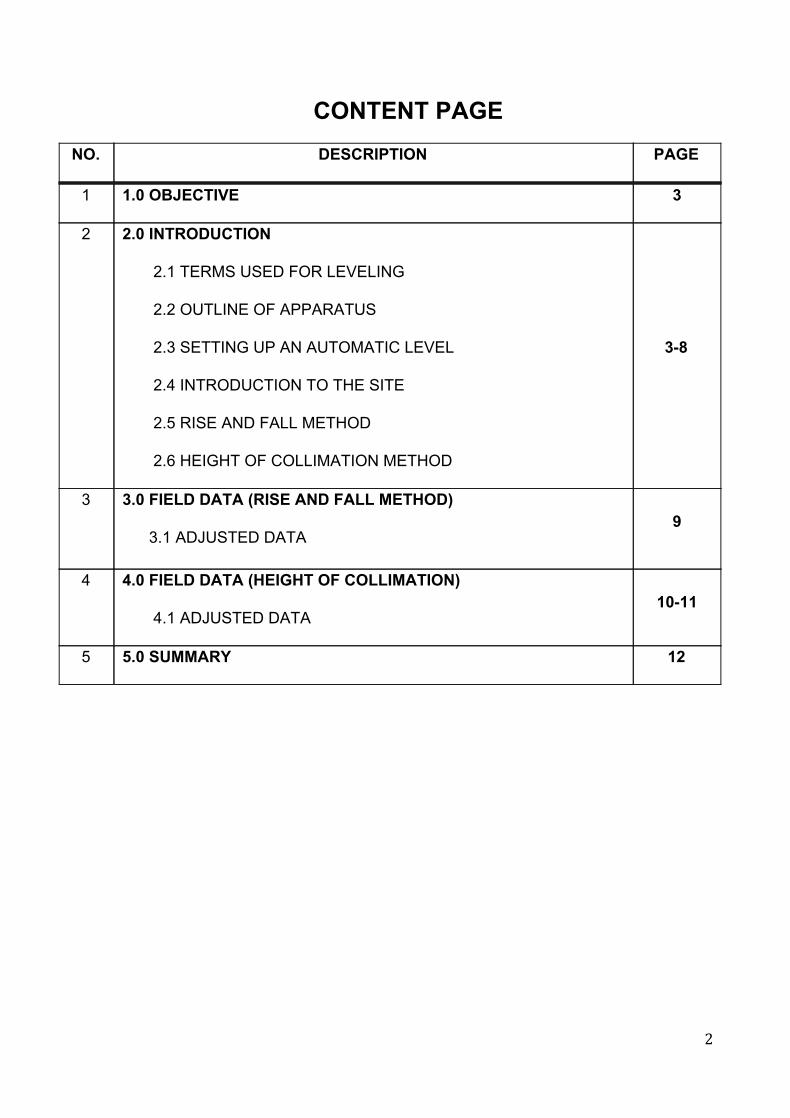
CONTENT PAGE
NO. DESCRIPTION PAGE
1 1.0 OBJECTIVE 3
2 2.0 INTRODUCTION
2.1 TERMS USED FOR LEVELING
2.2 OUTLINE OF APPARATUS
2.3 SETTING UP AN AUTOMATIC LEVEL
2.4 INTRODUCTION TO THE SITE
2.5 RISE AND FALL METHOD
2.6 HEIGHT OF COLLIMATION METHOD
38
3 3.0 FIELD DATA (RISE AND FALL METHOD)
3.1 ADJUSTED DATA
9
4 4.0 FIELD DATA (HEIGHT OF COLLIMATION)
4.1 ADJUSTED DATA
1011
5 5.0 SUMMARY 12
2
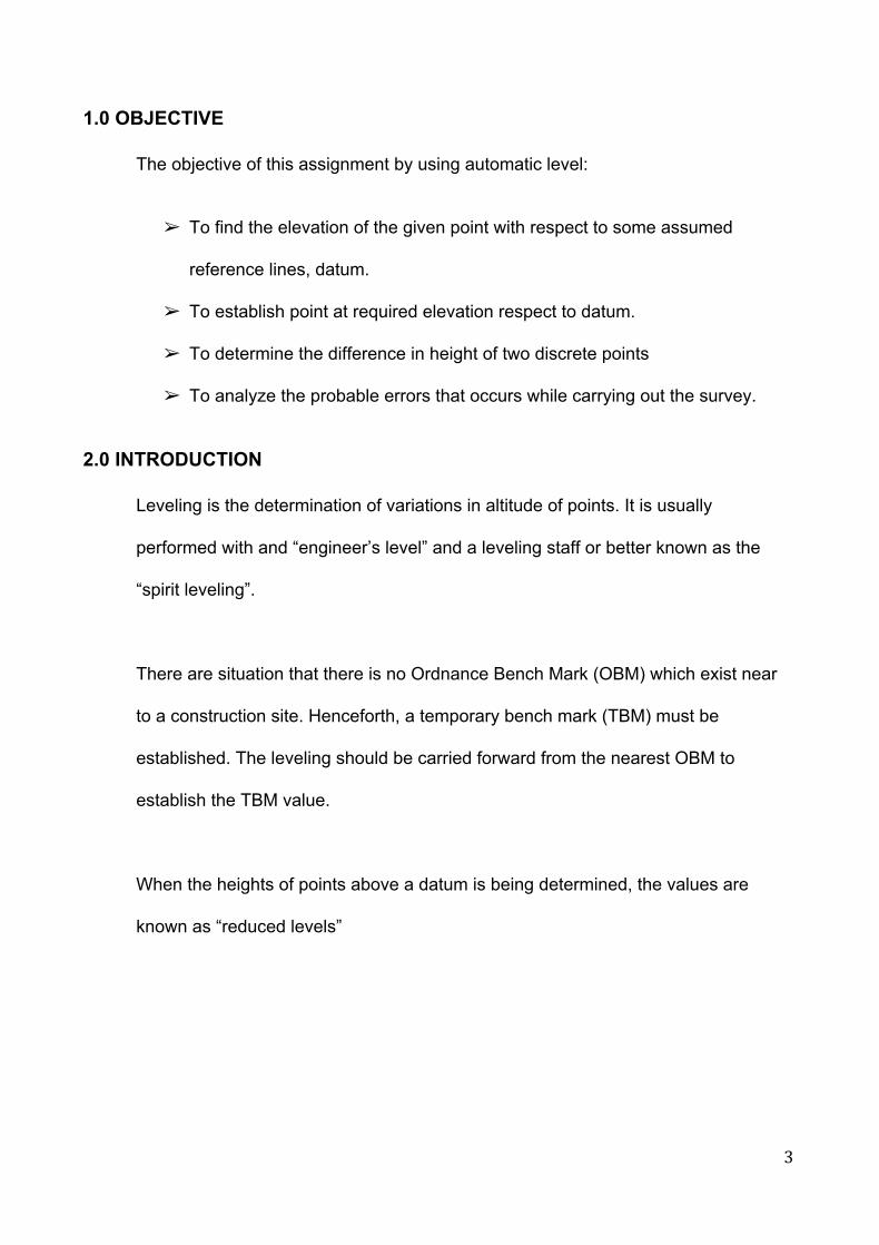
1.0 OBJECTIVE The objective of this assignment by using automatic level:
➢ To find the elevation of the given point with respect to some assumed
reference lines, datum.
➢ To establish point at required elevation respect to datum.
➢ To determine the difference in height of two discrete points
➢ To analyze the probable errors that occurs while carrying out the survey.
2.0 INTRODUCTION
Leveling is the determination of variations in altitude of points. It is usually
performed with and “engineer’s level” and a leveling staff or better known as the
“spirit leveling”.
There are situation that there is no Ordnance Bench Mark (OBM) which exist near
to a construction site. Henceforth, a temporary bench mark (TBM) must be
established. The leveling should be carried forward from the nearest OBM to
establish the TBM value.
When the heights of points above a datum is being determined, the values are
known as “reduced levels”
3
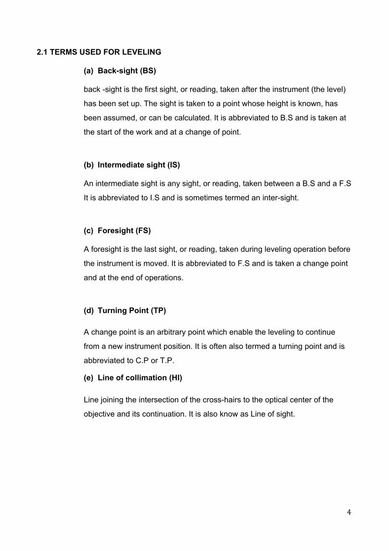
2.1 TERMS USED FOR LEVELING
(a) Backsight (BS)
back sight is the first sight, or reading, taken after the instrument (the level)
has been set up. The sight is taken to a point whose height is known, has
been assumed, or can be calculated. It is abbreviated to B.S and is taken at
the start of the work and at a change of point.
(b) Intermediate sight (IS)
An intermediate sight is any sight, or reading, taken between a B.S and a F.S
It is abbreviated to I.S and is sometimes termed an intersight.
(c) Foresight (FS)
A foresight is the last sight, or reading, taken during leveling operation before
the instrument is moved. It is abbreviated to F.S and is taken a change point
and at the end of operations.
(d) Turning Point (TP)
A change point is an arbitrary point which enable the leveling to continue
from a new instrument position. It is often also termed a turning point and is
abbreviated to C.P or T.P.
(e) Line of collimation (HI)
Line joining the intersection of the crosshairs to the optical center of the
objective and its continuation. It is also know as Line of sight.
4
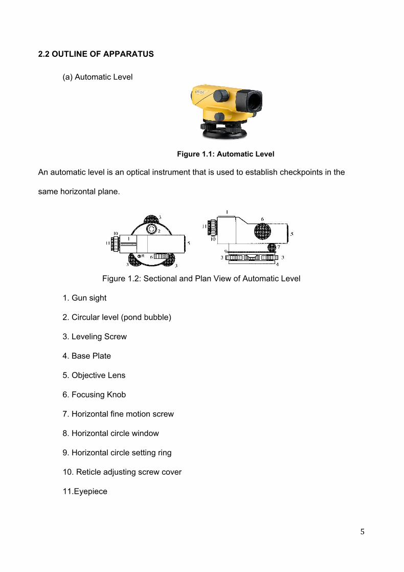
2.2 OUTLINE OF APPARATUS
(a) Automatic Level
Figure 1.1: Automatic Level
An automatic level is an optical instrument that is used to establish checkpoints in the
same horizontal plane.
Figure 1.2: Sectional and Plan View of Automatic Level
1. Gun sight
2. Circular level (pond bubble)
3. Leveling Screw
4. Base Plate
5. Objective Lens
6. Focusing Knob
7. Horizontal fine motion screw
8. Horizontal circle window
9. Horizontal circle setting ring
10. Reticle adjusting screw cover
11.Eyepiece
5
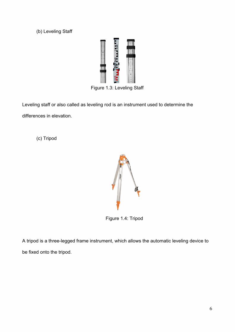
(b) Leveling Staff
Figure 1.3: Leveling Staff
Leveling staff or also called as leveling rod is an instrument used to determine the
differences in elevation.
(c) Tripod
Figure 1.4: Tripod
A tripod is a threelegged frame instrument, which allows the automatic leveling device to
be fixed onto the tripod.
6

2.3 SETTING UP AN AUTOMATIC LEVEL
STEP 1: Set up the tripod stand approximately above the chest height. Ensure that it is
stable and mount at the level on the top by stepping on the tripod leg in order to drive it
onto the ground.
STEP 2: Attach the automatic level onto the tripod stand by screwing it.
STEP 3: Adjust the leveling screws until the spirit bubble pond is move right at the center.
STEP 4: Before taking the reading, use the gun sight to aim in order to make sure that the
automatic level’s focusing range is relatively near to the leveling staff.
STEP 5: Adjust the reticle until the crosshair is clear.
STEP 6: Finetune the objective lens until the leveling staff that you are sighting is clear to
read.
7

2.4 INTRODUCTION TO THE SITE
Figure 1.5: Taylor’s University Staff Car Park
2.5 RISE AND FALL METHOD
It consists in determining the difference of level between consecutive points by
comparing each point after the first with that immediately preceding it.
The difference between their staff reading indicates a rise or a fall according as the staff
reading at the point is smaller or greater than that preceding point.
➢ ARITHMETIC CHECKING:
Σ (BS) – Σ (FS) = ΣRISE – ΣFALL = LAST RL – FIRST RL
2.6 HEIGHT OF COLLIMATION METHOD
It consists of in finding the elevation of the height of collimation for every set up of the
instrument and then obtaining the reduced level (RL) with reference to the respective
height of collimation.
➢ ARITHMETIC CHECKING:
Σ (BS) – Σ (FS) = LAST RL – FIRST RL
8

3.0 FIELD DATA (RISE AND FALL METHOD)
Backsight Intermediate Sight
Foresight Rise Fall Reduce Level
Remarks
0.605 100.000 BM 1
1.429 2.884 2.279 97.721 TP 1
1.336 0.093 97.814 TP 2
1.415 1.444 0.108 97.706 TP 3
1.543 1.485 0.070 97.636 TP 4
1.305 1.260 0.283 97.919 TP 5
1.307 1.346 0.041 97.878 TP 6
1.418 1.573 0.266 97.612 TP 7
1.308 1.245 0.173 97.785 TP 8
2.913 1.445 0.137 97.648 TP 9
1.440 0.552 2.361 100.009 TP 10
1.443 0.003 100.006 BM 1
14.683 14.677 Σ
14.683 100.006 14.677 100.000 0.006 0.006
ERROR DISTRIBUTION
= (100.006 – 100.000) / 10
= (0.006) / 10
=0.0006
3.1 ADJUSTED DATA (RISE AND FALL METHOD)
Backsigh
t Intermediate
Sight Foresight Rise Fall Reduce
Level Adjustment Final
Reduce Level
Remarks
0.605 100.000 BM 1 1.429 2.884 2.279 97.721 0.0006 97.7204 TP 1
1.336 0.093 97.814 0.0006 97.8134 TP 2 1.415 1.444 0.108 97.706 0.0012 97.7048 TP 3 1.543 1.485 0.070 97.636 0.0018 97.6342 TP 4 1.305 1.260 0.283 97.919 0.0024 97.9166 TP 5 1.307 1.346 0.041 97.878 0.0030 97.8750 TP 6 1.418 1.573 0.266 97.612 0.0036 97.6084 TP 7 1.308 1.245 0.173 97.785 0.0042 97.7808 TP 8 2.913 1.445 0.137 97.648 0.0048 97.6432 TP 9 1.440 0.552 2.361 100.009 0.0054 100.0036 TP 10 100.006 0.0060 100.0000 BM 1
9
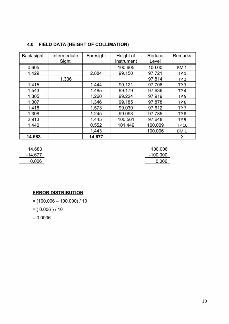
4.0 FIELD DATA (HEIGHT OF COLLIMATION)
Backsight Intermediate Sight
Foresight Height of Instrument
Reduce Level
Remarks
0.605 100.605 100.00 BM 1 1.429 2.884 99.150 97.721 TP 1
1.336 97.814 TP 2 1.415 1.444 99.121 97.706 TP 3 1.543 1.485 99.179 97.636 TP 4 1.305 1.260 99.224 97.919 TP 5 1.307 1.346 99.185 97.878 TP 6 1.418 1.573 99.030 97.612 TP 7 1.308 1.245 99.093 97.785 TP 8 2.913 1.445 100.561 97.648 TP 9 1.440 0.552 101.449 100.009 TP 10 1.443 100.006 BM 1
14.683 14.677 Σ 14.683 100.006 14.677 100.000 0.006 0.006
ERROR DISTRIBUTION
= (100.006 – 100.000) / 10
= ( 0.006 ) / 10
= 0.0006
10
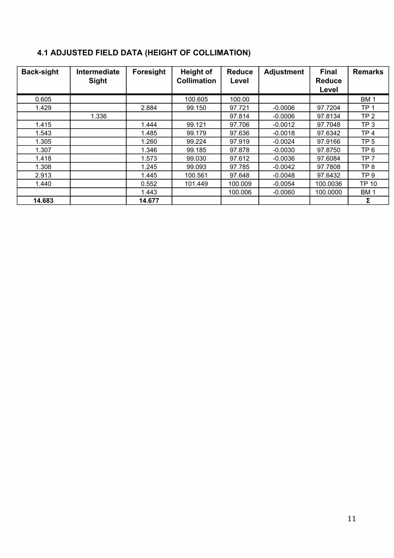
4.1 ADJUSTED FIELD DATA (HEIGHT OF COLLIMATION)
Backsight Intermediate Sight
Foresight Height of Collimation
Reduce Level
Adjustment Final Reduce Level
Remarks
0.605 100.605 100.00 BM 1 1.429 2.884 99.150 97.721 0.0006 97.7204 TP 1
1.336 97.814 0.0006 97.8134 TP 2 1.415 1.444 99.121 97.706 0.0012 97.7048 TP 3 1.543 1.485 99.179 97.636 0.0018 97.6342 TP 4 1.305 1.260 99.224 97.919 0.0024 97.9166 TP 5 1.307 1.346 99.185 97.878 0.0030 97.8750 TP 6 1.418 1.573 99.030 97.612 0.0036 97.6084 TP 7 1.308 1.245 99.093 97.785 0.0042 97.7808 TP 8 2.913 1.445 100.561 97.648 0.0048 97.6432 TP 9 1.440 0.552 101.449 100.009 0.0054 100.0036 TP 10 1.443 100.006 0.0060 100.0000 BM 1
14.683 14.677 Σ
11

5.0 SUMMARY
After the reduced level has been calculated through subtracting or adding the rise and fall.
It is found that our final reduce level is slightly more than the original reduce level which is
100.00cm. This may be cause by some errors that occurred during our leveling process.
Since the errors have occurred, the readings of the reduced levels must be adjusted using
the loop misclosure method.
➢ MAXIMUM ALLOWABLE ERROR OF CLOSURE
± 12 √ k, where k = number of set up points in the situation
± 12 √ 10 = 37.94mm
= 3.79cm > 0.006cm
Since the error loop is acceptable. Therefore , the error can be distributed accordingly to
the number of instrument setups .
In conclusion, we have learnt how to use an auto level and also able to get a correct
measurement even if there are collimation error in the device. Our groupmates have also
been very helpful as this task cannot be carried out by one less person especially under
the scorching hot sun. Also special thanks to our Site Surveying lecturer, Mr. Chai to be
always there in the field to guide us and make sure that we carry out the measurement
correctly.
12