
Research Article Fuzzy Based PC-PUSH in...
16
Research Article Fuzzy Based PC-PUSH in CR-MANETs S. Nejatian, 1,2 S. K. Syed Yusof, 1 N. M. Abdul Lattif, 1 V. Rezaie, 3 and V. Asadpour 4 1 UTM-MIMOS Center of Excellence, Faculty of Electrical Engineering, Universiti Teknologi Malaysia, 81310 Skudai, Johor, Malaysia 2 Department of Electrical Engineering, Faculty of Engineering, Islamic Azad University, Yasuj Branch, Yasuj, Kohgiluyeh and Boyer-Ahmad Province 7591483587, Iran 3 Department of Mathematics, Faculty of Science, Islamic Azad University, Yasuj Branch, Yasuj, Kohgiluyeh and Boyer-Ahmad Province 7591483587, Iran 4 Department of Electrical Engineering, University of North Dakota, Grand Forks, ND 58202, USA Correspondence should be addressed to S. Nejatian; [email protected] Received 29 August 2014; Accepted 22 October 2014; Published 26 November 2014 Academic Editor: Ezzat G. Bakhoum Copyright © 2014 S. Nejatian et al. is is an open access article distributed under the Creative Commons Attribution License, which permits unrestricted use, distribution, and reproduction in any medium, provided the original work is properly cited. In cognitive radio (CR), the secondary user (SU) needs to hand off its ongoing communication to an idle channel in order to avoid interference to the primary user (PU). Spectrum hand off issue becomes challenging in CR mobile ad hoc networks (CR-MANETs) because of the uncertainty in spectrum availability, broad range of spectrum bands and lack of central entity. e purpose of this study is to design a unified spectrum handoff (USH) scheme for CR-MANETs that considers the spectrum heterogeneity and its availability over time and space. A local flow hand off is performed when spectrum hand off cannot be carried out due to the SUs mobility. To improve further USH, preemptive unified spectrum handoff (PUSH) algorithm is proposed in which two different preemptive hand off threshold regions are defined. e PUSH algorithm also predicts the cognitive link availability considering the PU interference boundary. Although the PUSH scheme improves the hand off performance, the number of spectrum hand offs due to the PU activity should be reduced in this scheme. erefore, the PC-PUSH (Power Controller-PUSH) scheme is proposed in which the fuzzy logic is used to improve the PUSH in terms of the number of spectrum handoffs because of the PU activity. e PC-PUSH decreases the interference to the PUs, while reducing the number of spectrum handoffs. e results show that the proposed scheme improves the link maintenance probability, decreases the hand off delay, and reduces the number of spectrum handoffs. 1. Introduction Over the last few decades, the huge success of wireless applications has caused some spectrum bands being heav- ily used, especially unlicensed bands, such as ISM bands. is can be attributed to interference and poor network performance. On the other hand, recent studies by the Federal Communications Commission (FCC) have shown that a large amount of the licensed spectrum bands allocated through static assignment policies remains underutilized and inefficient. In fact, researchers have concluded that the tra- ditional fixed spectrum allocation approach cannot continue to efficiently regulate the spectrum access. To address this situation, wireless devices operating in unlicensed bands can dynamically identify currently unused licensed spectrum bands for data communications and opportunistically access the unoccupied spectrum called spectrum holes or white spaces. Cognitive capability with the enabling technology of cognitive radio (CR) allows wireless devices to use the spectrum holes. CR has the capability of completely changing its transmitter parameters (operating spectrum, modulation, and transmission power) based on interactions with the sur- rounding spectral environment. CR users, called secondary users (SUs) or unlicensed user, sense a wide spectrum range, identify the spectrum holes, and opportunistically access them when primary (or licensed) users (PUs) are idle [1]. PUs have been licensed to use the spectrum band and SUs must access the spectrum in a nonintrusive manner [2]. e latest trend in CR research area has seen an extensive research interest in mobile ad hoc networks (MANETs) to improve the spectrum efficiency by novel design techniques Hindawi Publishing Corporation Mathematical Problems in Engineering Volume 2014, Article ID 926709, 15 pages http://dx.doi.org/10.1155/2014/926709
Transcript of Research Article Fuzzy Based PC-PUSH in...
Research ArticleFuzzy Based PC-PUSH in CR-MANETs
S Nejatian12 S K Syed Yusof1 N M Abdul Lattif1 V Rezaie3 and V Asadpour4
1 UTM-MIMOS Center of Excellence Faculty of Electrical Engineering Universiti Teknologi Malaysia 81310 Skudai Johor Malaysia2 Department of Electrical Engineering Faculty of Engineering Islamic Azad University Yasuj BranchYasuj Kohgiluyeh and Boyer-Ahmad Province 7591483587 Iran
3Department of Mathematics Faculty of Science Islamic Azad University Yasuj Branch YasujKohgiluyeh and Boyer-Ahmad Province 7591483587 Iran
4Department of Electrical Engineering University of North Dakota Grand Forks ND 58202 USA
Correspondence should be addressed to S Nejatian nsamad2liveutmmy
Received 29 August 2014 Accepted 22 October 2014 Published 26 November 2014
Academic Editor Ezzat G Bakhoum
Copyright copy 2014 S Nejatian et al This is an open access article distributed under the Creative Commons Attribution Licensewhich permits unrestricted use distribution and reproduction in any medium provided the original work is properly cited
In cognitive radio (CR) the secondary user (SU) needs to hand off its ongoing communication to an idle channel in order to avoidinterference to the primary user (PU) Spectrum hand off issue becomes challenging in CRmobile ad hoc networks (CR-MANETs)because of the uncertainty in spectrum availability broad range of spectrum bands and lack of central entity The purpose of thisstudy is to design a unified spectrum handoff (USH) scheme for CR-MANETs that considers the spectrum heterogeneity and itsavailability over time and space A local flow hand off is performed when spectrum hand off cannot be carried out due to the SUsmobility To improve further USH preemptive unified spectrum handoff (PUSH) algorithm is proposed in which two differentpreemptive hand off threshold regions are defined The PUSH algorithm also predicts the cognitive link availability consideringthe PU interference boundary Although the PUSH scheme improves the hand off performance the number of spectrum hand offsdue to the PU activity should be reduced in this scheme Therefore the PC-PUSH (Power Controller-PUSH) scheme is proposedin which the fuzzy logic is used to improve the PUSH in terms of the number of spectrum handoffs because of the PU activityThe PC-PUSH decreases the interference to the PUs while reducing the number of spectrum handoffs The results show that theproposed scheme improves the link maintenance probability decreases the hand off delay and reduces the number of spectrumhandoffs
1 Introduction
Over the last few decades the huge success of wirelessapplications has caused some spectrum bands being heav-ily used especially unlicensed bands such as ISM bandsThis can be attributed to interference and poor networkperformance On the other hand recent studies by theFederal Communications Commission (FCC) have shownthat a large amount of the licensed spectrum bands allocatedthrough static assignment policies remains underutilized andinefficient In fact researchers have concluded that the tra-ditional fixed spectrum allocation approach cannot continueto efficiently regulate the spectrum access To address thissituation wireless devices operating in unlicensed bandscan dynamically identify currently unused licensed spectrumbands for data communications and opportunistically access
the unoccupied spectrum called spectrum holes or whitespaces
Cognitive capability with the enabling technology ofcognitive radio (CR) allows wireless devices to use thespectrum holes CR has the capability of completely changingits transmitter parameters (operating spectrum modulationand transmission power) based on interactions with the sur-rounding spectral environment CR users called secondaryusers (SUs) or unlicensed user sense a wide spectrum rangeidentify the spectrum holes and opportunistically accessthemwhen primary (or licensed) users (PUs) are idle [1] PUshave been licensed to use the spectrum band and SUs mustaccess the spectrum in a nonintrusive manner [2]
The latest trend in CR research area has seen an extensiveresearch interest in mobile ad hoc networks (MANETs) toimprove the spectrum efficiency by novel design techniques
Hindawi Publishing CorporationMathematical Problems in EngineeringVolume 2014 Article ID 926709 15 pageshttpdxdoiorg1011552014926709
2 Mathematical Problems in Engineering
that simultaneously address the communication problemsthrough various layers of the protocol stack Enabling theCR technology in MANETs introduces the cognitive radiomobile ad hoc networks (CR-MANETs)
The uncertainty in the availability of spectrum holes iscaused by the random appearance of PUs as well as theunpredictability of the SUs demandThe spectrum holes mayshift over time and over space In a CR system the shifting ofspectrum holes can be defined as spectrum mobility whichis cohesive to spectrum handoff Spectrum handoff refers tothe transfer of an ongoing data transmission of a CR userto another available spectrum band In heterogeneous CRnetworks a channel may be available over vast mutuallyexclusive spectrum bands that present remarkable hetero-geneity in terms of channel transmission range [3]
Spectrum handoff is extremely challenging in CR net-works especially in CR-MANETs because of frequent topo-logic variations limited power limited channel transmis-sion range bandwidth constraints and lack of the centralcontrolling entity [4] On the other hand the availablespectrum bands vary over time and space while they aredistributed nonadjacently over a broad frequency range In aCR-MANET system SU mobility and channel heterogeneitylead to performance degradation and frequent spectrumhandoff during communication Hence the fluctuation of PUactivity and the SU mobility in CR-MANETs have made theissue of maintaining optimal routes more complex
Route failure has strong relationshipwith spectrumhand-offThe route failure can be caused by spectrummobility (PUactivity) SU mobility and channel heterogeneity Accordingto the failure type different route recovery strategies needto be applied Previous works on spectrum handoff in CR-MANETs only consider the effect of PUs activity Thereforea unified spectrum handoff (USH) management for CR-MANETs must be proposed that considers the effects of allof the factors mentioned above In this work a preemptiveunified spectrum handoff (PUSH) method for CR-MANETsis proposed PUSH considers the effects of mentioned factorson handoff initiation and management In PUSH two dif-ferent preemptive handoff threshold regions were introducedand defined A preemptive local flow handoff is performedwhen spectrum handoff cannot be carried out due to theSUsmobilityThe PUSH algorithm also predicts the cognitivelink availability and estimates the maximum link availabilitytime considering the PU interference boundary Althoughthe PUSH scheme improves the handoffmanagement schemeperformance the number of spectrumhandoffs due to the PUactivity should be reduced Therefore the PC-PUSH (PowerController-PUSH) scheme is proposed in which the fuzzylogic is used to improve the performance of the PUSH interms of the number of spectrum handoffs because of the PUactivity
2 Related Works
Song and Xie [5] proposed a proactive spectrum handoffconfiguration based on statistics of observed channel utiliza-tion The network coordination and rendezvous issues are
solved in this spectrum handoff schemewithout using a com-mon control channel The collision among SUs is preventedthrough a distributed channel determination scheme Giup-poni and Perez-Neira [6] proposed a fuzzy based spectrumhandoff decision-making approach employing two fuzzylogic controllers Each SU estimates the distances betweenitself and all the active PUs in the surrounding area using thefirst fuzzy logic controller The other fuzzy logic controllerdetermines whether the SU needs to perform a spectrumhandoff and in some cases power control is used instead ofhandoff Duan and Li proposed a spectrum handoff strategyin which the optimal spectrum band is chosen based on amultiplex criterion considering the estimated transmissiontime the PU presence probability and the spectrum avail-ability time [7] A cooperative spectrum sensing scheme isused to predict the spectrum idleness A geolocation methodis used to perform a spectrum handoff in the space domainThe simulation results indicated that the proposed spec-trumhandoff schemeoutperformed conventionalmethods interms of spectrum handoff delay in a per hop basis Howeverchannel heterogeneity parameters are not considered in thespectrum handoff In [8] an established route from a sourcenode 119878 to a destination node 119863 is considered Differentscenarios which lead to the handoff initiation in this routeare also introduced Considering these events which arenodemobility and spectrummobility the authors introduceda conceptual model for unified handoff management inCR-MANETs Nejatian et al [9] have characterized theavailability of spectrum bands in CR-MANETs The authorsproved that the channel heterogeneity must be considered interms of transmission range because it increases the blockingprobability of spectrum handoff Based on their findings aunified system which considers the spectrum mobility intime and space domain as well as topology changing mustbe investigated
3 Unified Spectrum Handoff (USH) Scheme
In this section first the heterogeneous network architectureis described considering the specifics of the SUs character-istics of the PUs and the channel aspects of the networkThen the USH scheme is introduced that considers thespectrum-aware handoff management based on the inter-actions between network layer and the physical layer Theproposed scheme is integrated with an algorithm to identifyappropriate spectrum bands and calculate the channel avail-ability time based on the channel qualities the spectrum andthe node mobility
31 System Description It is assumed that the SU is equippedwith multiradio multichannel and common control channelsignaling features The maximum number of channels acces-sible by the SU at a time is 119862 The 119862 channels are defined bythe set of T which belong to the PU networkThese channelsare classified into different 119871 types according to their differenttransmission ranges The set of each type is shown by T119897 inwhich |T119897| = 119862119897 which denotes the total number of channelsfor type 119897 and 119862 = 1198621 + 1198622 + sdot sdot sdot + 119862119871 Depending on the PU
Mathematical Problems in Engineering 3
activity any SU can access up to 119862 channels at any positionin time The number of detected channels of type 119897 by a nodeis 119888119897 and the total number of detected channels at a node is119888 = 1198881 + 1198882 + sdot sdot sdot + 119888119871 The transmission range of channels oftype 119897 is 119877119897
32 Analytical Modeling of the USH Scheme To propose theunified spectrum handoff management different scenariosare introduced which cause spectrum handoff initiationthrough an established route in a CR-MANET Suppose that aroute froma source node 119878 to the destination node119863has beenestablished There are three different scenarios that initiatethe spectrum handoff in this route
Assume a pair of SU transmitter-receiver which transmitsand receives using communication channel The activity ofthe PU in the neighbourhood of these nodes may cause thelink between them to be failedThis route failure occurs oncethe PU starts its transmission or when one of the transmitter-receiver nodes enters the coverage area of the PU
The mobility of the CR user can also lead to spectrumhandoff due to spectrum heterogeneity and various channeltransmission ranges Again assume a pair of SU transmitter-receiver which transmits and receives using communicationchannel of type 119897 with transmission distance between themof less than 119877119897 When the SUs move and their distanceexceeds 119877119897 the nodes must change and select another chan-nel opportunistically In this case in order to support thecommunication link the new chosen channel must have atransmission range longer than 119877119897
In some cases route failure occurs when either transmit-ter node or receiver node moves such that no channel cansupport their transmission Before the route failure occurslocal flow handoff is performed A local flow handoff can befrom transmitter node to an intermediate node and finallyjoining receiver node In this scenario the unified localrouting and spectrum handoff management system tries tosolve the problem by finding a node as an intermediate nodewithin the neighbouring area of the damaged links
To analyticallymodel theUSH the parameter119901 is definedas the probability of single channel availability at a node byconsidering the PU activity with an alternating renewal two-state birth-death process with a death rate 120572 and a birth rate120573 The 119875car119888 is defined as the probability of the existence of atleast one idle channel for each hop in a route as follows [9]
119875car119888 =[[[[
[
119871
sum
119894=1
exp (minus1205821205871198772119894minus12) minus exp (minus1205821205871198772
1198942)
1 minus exp (minus1198732)
times (1 minus
119888minussum119894minus1
119895=0119888119895
prod
119896=1
(1 minus (120572119896
120572119896 + 120573119896
)
2
))
]]]]
]
119899minus1
(1)
Once the channel quality declines or PER (packet error rate)increases the probability of successful packet transmission
rate is decreased Therefore the SU decides to change thechannel Considering 119875119894
119864as the PER of channel of type 119894 and
(1) the probability of successful packet routing in a route orbetween 119899 nodes is deduced to be
119901spr119888 =119871
sum
119894=1
119875car119888 (1 minus 119875119894
119864) (2)
The probability of successful packet transmission in a hop orbetween two nodes is also found as
119901spt119888 = 119901spr119888|119899=2 (3)
The parameter 119875119894119864
signifies the rate of dropped packetsbecause of the variable channel conditions caused by factorssuch as fading and shadowing The probability of unsuccess-ful packet transmission in a hop or between two nodes can bestated as
119901uspt119888 = 1 minus 119901spt119888 (4)
To calculate the probability distribution of spectrum handoffand also model the spectrum handoff initiation in CR-MANETs the position case 119863119897minus1119897 is defined as the case inwhich 119877119897minus1 lt 119889 lt 119877119897 where 119889 is the length of the hopHereafter for the sake of indexing convenience the positioncase119863119897minus1119897 is referred to as119863119897 throughout the thesis
Figure 1 shows different Markov chains for spectrumhandoff modelling based on the length of the hops P whichis a stochasticmatrix and describes theMarkov chain over thefinite state space is written as follows
P =
[[[[[[[
[
11987511987911sdot sdot sdot 1198751198791119871minus1
1198751198791119871
sdot sdot sdot 119875119879119894119896sdot sdot sdot 119875119879119894119871
1198751198791198711sdot sdot sdot 119875119879119871119871minus1
119875119879119871119871
]]]]]]]
]
(5)
Here the parameter 119875119879119894119896 illustrates the probability of movingchannel transition state from state 119894 to state 119896 The Markovchains have different numbers of states based on the differentposition cases119863119897 When the length of the hop is less than 1198771or when the spectrum handoff occurs in the position case1198631 the two nodes involved in the current hop can selectone of the available channels of any 119871 types In the positioncase 1198631 the Markov chain is as shown in Figure 1(a) In thecase 1198632 the nodes involved in spectrum handoff can selectone channel among available channels from type 119896 in which119896 = 1 as shown in Figure 1(b) When the distance betweenthe involved nodes in the spectrum handoff is accordingto position case 119863119871 the nodes can only select one channelamong available channels of type 119871 as shown in Figure 1(c)The other situations can be determined based on the claimsabove
Suppose that two nodes are communicating in a channelof type 119896 There are two different conditions where nodescontinue their communication in the current spectrum pool
4 Mathematical Problems in Engineering
T1 T2
TL TLminus1
PT11
P T22
PT12
PT21PT119871119871
PT119871119871minus1
PT119871minus1119871minus
1
PT119871minus1119871
PT1198712
P T2119871
PT1198711
PT1119871
PT119871minus11
PT1119871minus1
PT119871minus12
PT2119871minus1
(a) Case1198631
T2
TL TLminus1
P T22
PT119871119871
PT119871119871minus1
PT119871minus1119871minus
1
PT119871minus1119871
PT1198712
P T2119871
PT119871minus12
PT2119871minus1
(b) Case1198632
TL
PT119871119871
(c) Case119863119871
Figure 1 Markov chains for spectrum handoff modeling based on the SUs distance
These two conditions in the position case of 119863119897 are asfollows
(i) The packet transmission is successful in the currentchannel of type 119896
(ii) The packet transmission is not successful in thecurrent channel of type 119896 but only successful onanother channel of spectrum pool 119896
Thus the probability that the involved nodes in this hop donot switch their channel type 119875119879119896119896 is calculated as
119875119879119896119896 119863119897= 119901spt119888119896 +
119871
prod
119895=1119895 =119896
119901uspt119888119895 (6)
There are also two conditions where two nodes whichare communicating on a channel of type 119898 switch theirchannel type to another channel of type 119896 such that 119896 isin
1 2 119871 119896 = 119898These two conditions in the position case119863119897 are
(i) unsuccessful packet transmission in a channel of type119898 but only successful transmission in channel of type119896
(ii) unsuccessful packet transmission in a channel of type119898 but successful transmission in channel type sets
S119863119897 sube T 10038161003816100381610038161003816S11986311989710038161003816100381610038161003816= 119871119863119897
lt 119871 (7)
Based on the Markov chains there are many possiblechannel type sets for S119863119897 The channel of type 119895 can be
chosen with an identical probability among the availablechannel types in the set of S119863119897 Based on this explanation theprobability that the involved nodes in this hop switch theirchannel type 119875119879119898119896 is
119875119879119898119896119863119897= [
[
119901uspt119888119898 (119901spt119888119896 (119871
prod
119895=1119895 =119898119896
119901uspt119888119895))]
]
+[[
[
119901uspt119888119898 sumS119863119897subeT(( prod
119895=12119894|119879119895isinS119863119897119895 =119898
119901sup119888119895
times prod
119895=12119894|119879119895notinS119863119897119895 =119898
119901uspt119888119895)
times(10038161003816100381610038161003816S11986311989710038161003816100381610038161003816)minus1
)]]
]
(8)
The row vector ΠP119863119897 which is composed of Π119875
119863119897(119879119894) demon-
strates the steady state probability for P119863119897 considering differ-ent hop lengths The value of Π119875
119863119897(119879119894) is calculated using the
equations
ΠP119863119897times P119863119897 = Π
P119863119897
119871
sum
119894=1
Π119875
119863119897(119879119894) = 1 (9)
Mathematical Problems in Engineering 5
Ultimately the steady state probabilities for various hoplengths for channel type 119894 are calculated as below
Π119875(119879119894) =
119871
sum
119897=1
Pr (119877119897minus1 lt 119889 lt 119877119897)Π119875
119863119897(119879119894) (10)
where Pr(119877119897minus1 lt 119889 lt 119877119897) is calculated as [10]
Pr (119877119897minus1 lt 119889 lt 119877119897) = 119865119889 (119877119897) minus 119865119889 (119877119897minus1)
=
exp (minus1205821205871198772119897minus12) minus exp (minus1205821205871198772
1198972)
1 minus exp (minus1198732)
(11)
The spectrum handoff procedure happens when the cur-rent channel can not support the data transmission Howeverthe spectrum handoff will not be initiated on any of theavailable channels due to other circumstances such as lowchannel transmission range as this can lead to transmissionfailureTherefore the probability of spectrum handoff can beformulated as
119875SH =119871
sum
119894=1
Π119875(119879119894)
[
[
119901uspt119888119894 minus119871
prod
119895=1
119901uspt119888119895]
]
(12)
In (12) the termsum119871119894=1Π119875(119879119894)prod
119871
119895=1119901uspt119888119895 is the probability that
all available channels have unsuccessful packet transmissionIn such a case the troubled nodes do not perform spectrumhandoff they perform local flow handoff Therefore theprobability of local flow handoff can be expressed as follows
119875LH =119871
sum
119894=1
Π119875(119879119894)
119871
prod
119895=1
119901uspt119888119895 (13)
Theprobability of successful spectrumhandoff (119875ssh)dependson the probability of successful packet transmission in a hop119901spt119888 The link maintenance probability (119875LM) is defined asthe probability that the link is successfully maintained in ahop or between troubled nodes which is dependent on theprobability of channel availability between two nodes Thusthe link maintenance probability considering only spectrumhandoff can be written as
119875LMSH = 119875SH times 119901spt119888 (14)
When the link maintenance is not successful despite per-forming spectrum handoff local rerouting is performedIn this case the probability of link maintenance can berepresented as
119875LMLH = (119873 minus 1
119873) (1 minus 119875LMSH) 119875LH times 119901spt119888 (15)
Finally the probability of link maintenance considering theintegration of local routing and spectrum handoff manage-ment can be stated as
119875LMUSH = 119875LMSH + 119875LMLH (16)
Table 1 Different parameters and their definitions used in thePUSH algorithm
Symbol DefinitionCSF Channel switching flagLAC List of available and detected channelsHMF Handoff metric flag119879119874 Operation time119905119904 Sensing timeNAC Available channel number (channel ID)RERR Route error requestCSR Channel switching requestCSA Channel switching acknowledgmentHM Handoff metric
4 Preemptive Unified Spectrum Handoff(PUSH) Scheme
In this section the PUSH algorithm is proposed in which twodifferent preemptive handoff threshold regions are definedand the cognitive link availability considering the PU inter-ference boundary is predicted The proposed handoff man-agement scheme adapts to the unpredictable events makinga decision on the SUs data transmission without causing anyinterference with the PUsThe proposed algorithm for PUSHscheme is shown in the form of pseudocode presentation asshown in Pseudocode 1
Table 1 defines the abbreviations and their definitionsused in the pseudocode The decision-making unit initiatesthe handoff based on the handoff threshold When thespectrum handoff cannot be implemented in one hop theLFH will be established to maintain communication
In PUSH PU activity is monitored by spectrum sensingand SUmobility is monitored by life time checking If there isany problem with the SU mobility the HMF is activated andthe algorithm will check the HM Otherwise the algorithmchecks for any available data to send If there is no data tosend the algorithm remains in the event monitoring stageWhen there is data to send the PU activity is checked bythe sensing part The SUs continue their communication onthe current channel until the expiration of the operation time(119879119874) If there is any PU activity on the channel the nextchannel for the handoff will be decided and the spectrumhandoff will be performed When the algorithm moves tocheck HM if the HM is higher than the LHTH only thespectrum handoff will be performed The next channel forspectrum handoff must have a higher transmission rangecompared to the current channel If the HM is lower thanthe LHTH the troubled nodes try to find a suitable node asan intermediate node Should there be no suitable node theglobal flowhandoffwill be performedOtherwise the suitablenode is chosen the next channel will be decided and the localflow handoff and consequently the spectrum handoff will beperformed
6 Mathematical Problems in Engineering
Require CSF = 0 HMF = 0 LAC = 0 LFHREP= CSA =(1) check the HMF(2) if HMF = 1 then(3) go to (42) for checking the119867119872(4) end if(5) if there is no data to send then(6) go back to (2) for checking the119867119872119865(7) end if(8) start scanning radio(9) PU119911lowastONminus = 119904119890119899119904119890 (119888ℎ119886119899119899119890119897 119905119904 119904119908119894119905119888ℎ119894119899119892)
(10) if PU119911lowastON then
(11) defer for 119862ℎ119886119899119899119890119897minus119878119908119894119905119888ℎ119894119899119892minus119863119890119897119886119910(12) for119873119890119909119905minus119862ℎ119886119899119899119890119897minus119863119890119888119894119904119894119900119899 go to (24)(13) CSF = 1(14) go back to (5) to check the availability of data for sending(15) end if(16) if (CSF) then(17) Send notification to upper layers for spectrum handoff(18) adapt channel parameters(19) CSF = 0(20) end if(21) start operation timer (119879119900)(22) transmit data till (119879119900) expires(23) go back to (2)(24) for 119896 = 1 119896 lt 119862 do(25) if PU119896 = ON then(26) NAC = NAC + 1(27) LAC(NAC) = 119896(28) end if(29) end for(30) if LAC = 0 then(31) send RERR packet to the source node(32) else LAC = 0(33) sending CSR sending PU-HREQ(34) go to (36)(35) end if(36) upon receiving CSA then(37) if CSA = 0 then(38) switch to the selected channel(39) HMF = 0(40) go to (16)(41) end if(42) calculate the HM(43) if HM le LHTH then(44) Start the LFHREQ timer broadcast the LFHREQ and go to (49)(45) else HM le SHTH(46) go to (24) for making a decision on the next channel(47) end if(48) upon the LFHREQ timer was expired then(49) if LFHREP = 0 then(50) broadcast the RERR to the source node(51) else LFHREP = 0
(52) find the best candidate node with the max119879PU(53) send the Local route HR to the local source through the best candidate intermediate node(54) send the CSR to the candidate intermediate node(55) go back to (36)(56) end if(57) end
Pseudocode 1
Mathematical Problems in Engineering 7
K
F B
Nodetransmission
Channel
transmissi
on
ldquoSafe channelusagerdquo range
ldquoSafe l
ink
usagerdquo
range
Preemptive
channel handoff
region
Preemptive flow
handoff region
WlinkWchl
range (RT )
range (R l)
Figure 2 Different preemptive handoff regions
41 Channel and Local Flow Handoff Prediction A link isconsidered available if the two nodes associated with the linkare within the transmission range of each other and out ofinterference region of any PU In terms of transmission rangetwo different handoff regions are defined based on differenthandoff types These two regions are the preemptive channelhandoff region and the preemptive local flow handoff regionAs illustrated in Figure 2 the first region is determined basedon the channel transmission range which is different for eachchannel type The second region is determined by the nodetransmission range Because the node transmission rangedepends on the wavelength of the transmission frequencythere is only one preemptive flow handoff region Twodifferent handoff thresholds are also defined related to eacharea The first handoff threshold which is related to thepreemptive channel handoff region is called the spectrumhandoff threshold (SHTH)
The second handoff threshold is the LFH threshold(LHTH) which is related to the preemptive LFH regionThese handoff thresholds are used to initiate the handoff dueto the node mobility and channel quality degradation Asillustrated in Figure 2 nodes 119861 and 119865 are communicatingwith each other When either node 119861 or node 119865 movessuch that the current channel cannot support their com-munication they must vacate the channel and transfer theirtransmission into another channel with a higher transmissionrange In Figure 2 the119882ch119897 is the warning distance for nodescommunicating on a channel of type 119897 The 119905119908119897 which is theinterval from the warning till the communication link breakoff needs to be greater than or equal to the necessary timefor performing the handoff Different handoff thresholds arerelated to the signal power threshold Here the signal powerof hello packets is used to approximate the distance betweenthe transmitter and receiver
42 Channel Usage Time Prediction Using the above pro-posed channel and local flow handoff prediction schemewith samples of the transmitted signal the availability timeis estimated without any movement information Each SUkeeps a neighbour signal information table (NSIT)TheNSITcontains information about the condition of links between SUand its neighbours
Based on [11] at least three packets are required toestimate the channel availability time Suppose that at times1199051 1199052 and 1199053 node 119865 receives the first second and third signalwith respective power 1198751 1198752 and 1198753 from node 119861 The SUregisters the signal power strength and reception time foreach neighbour in the NSIT When node 119865 receives packetsfrom node 119861 it updates its NSIT array such that 1198753 lt 1198752 lt 1198751and 1199051 lt 1199052 lt 1199053
Assume at time 119905 the node 119865 will receive a signal withpower equivalent to the 119875119904 and during time 1199051 to 119905 the nodes119865 and 119861 maintain their speeds and directions Based on [11]the availability time is expressed as follows
119905ava =radic1198872 minus 4119886119888 minus 119887
2119886 (17)
where
119886 = Δ1199052radic1198752119875119904119889 119887 = radic119875119904 ((radic1198751 minus radic1198752) minus Δ1199052
2radic1198752119889)
119888 = Δ1199052radic1198752119875119904 minus Δ1199052radic11987511198752 Δ1199052 = 1199052 minus 1199051 Δ1199053 = 1199053 minus 1199051
119889 =(radic11987511198752Δ1199052 + radic11987521198753Δ1199053 minus radic11987511198753Δ1199053 minus radic11987521198753Δ1199052)
(Δ1199052Δ1199052
3minus Δ1199053Δ119905
2
2)radic11987521198753
(18)
When the 119875119904 is replaced with the 119875CTR119897 the channel availabil-ity time between two communicating nodes for the channelof type 119897 (119905ava119897) is an estimated value
43 PU Interference Awareness and LinkAvailability In termsof the PUs activity a link is considered available when bothtwo nodes associated with this link are out of the interferenceregion of any PU in the network
The PUSH scheme is aware of the PUs interferenceboundary and selects a suitable intermediate nodewith a highlink availability time to handle the transmission in a LFH Topredict the link availability time considering the interferenceboundary of the PUs the information about the distancebetween a mobile SU and each PU can be obtained throughGPS or the path loss model During the communication themovement direction and velocity of mobile nodes can beconsidered constant in CR networks [12] Based on [13] the119889PU which denotes the distance between the SU and the PUcan be expressed as
1198892
PU = 1205721199052+ 120573119905 + 120574 (19)
where 120572 120573 and 120574 are constants and they are calculated usingthree measurement points (119889PU0 119905PU0) (119889PU1 119905PU1) and(119889PU2 119905PU2) If119889PUth shows the radius of the PUs interferenceboundary then the maximum link accessibility period 119879PU
8 Mathematical Problems in Engineering
with the PUs interference avoidance evaluated from 119905PU2 isexpressed as
119879PU =
radic1205732 + 4119889
2
PUth minus 4120572120574 minus 120573
2119886minus 119905PU2 Δ ⩾ 0 Δ ⩾ 120573
infin otherwise(20)
where
Δ = 1205732+ 4120572119889
2
PUth minus 4120572120574 (21)
Considering the link accessibility period with the PUs inter-ference avoidance the most suitable intermediate node is anode with maximum 119879PU
44 Channel Allocation Scheme To give a fair opportunity tothe involved SUs in the longer hops a weight matrixW withthe size of 119871times119871 is proposed in the schemeThis weight matrixconsiders the hop length and the transmission range of theavailable channels which can be expressed as follows
W =
[[[[[[[
[
11
2sdot sdot sdot
1
119871
0 1 sdot sdot sdot1
119871 minus 1
0 0 sdot sdot sdot119871
119871
]]]]]]]
]
(22)
The rows show the various position cases119863119897 based on thehop length and the column shows the available channel type119897 Each element ofW indicates a different location weight andis defined as follows
119908119897119863119897=
0 channel of type 11989710158401198971015840isin 1 119897 minus 1
1 channel of type 1198971
channel typechannel of type 1198971015840
1198971015840isin 119897 + 1 119871
(23)
The hop length changing which shows the SUs mobilityis considered in channel allocation scheme The parameterℎ119897119863119897
is proposed to show the possibility of using the channelof type 119897 detected by both nodes in the current hop and theposition case119863119897 as follows
ℎ119897119863119897=
1 channel of type 1198971015840 1198971015840 isin 119897 1198710 channel of type 1198971015840 1198971015840 isin 1 119897 minus 1
(24)
There are a number119862119897 of channels of type 119897 Each channelof type 119897 is shown by 119862119897119895 The channel 119895 of type 119897 can be usedby the nodes belonging to the current hop when it is availablefor both its member nodes The parameter 120578 is proposedto show the possibility of using the channel 119895 of type 119897 forcommunicating in the current hop
120578119862119897119895=
1 channel 119895 of type 119897 is available for bothbelonging to current hop
0 otherwise(25)
To avoid handing off the data transmission to a channelwith a short availability time the channel availability timemust be greater than a threshold Therefore the parameter120577 is proposed to show the possibility of using the channel oftype 119897 in the current hop
120577119897119863119897=
1 for 119905ava119897119863119897 ge 119905th0 otherwise
(26)
Finally the channel allocationmetric for channel 119895 of type119897 can be derived as
AM119862119897119895 = (120577119897119863119897) sdot (120578119862119897119895) sdot (ℎ119897119863119897) sdot (119908119897119863119897) sdot (119905ava119897119863119897) (27)
Suppose that the set CH119897119863119897 shows the set of channelsof type 119897 detected by both nodes belonging to the currenthop with position case 119863119897 The set CH119863119897 which shows allthe channels of different 119871 types detected by both nodesbelonging to the current hop with position case 119863119897 can beexpressed as
CH119863119897 =119871
⋃
1198971015840=1
CH1198971015840 119863119897 (28)
The set of detected and useable channels for communicationin the current hop with position case119863119897 is defined as follows
CH119863119897usable =119871
⋃
1198971015840=1
[
[
⋃
1198621198971015840119895isinCH1198971015840119863119897
(1198621198971015840119895) sdot (1205781198621198971015840119895
) sdot (ℎ1198971015840 119863119897)]
]
(29)
In the decision part the channel 119895 which maximizes thechannel allocation metric is formulated as below
119895 = arg max AM119862119897119895 119862119897119895 sube CH119863119897usable (30)
45 Handoff Initiation and Connectivity Management Tomaintain end-to-end connectivity topological variationsand channel quality degradation due to node mobility areaddressed using the handoff request (HREQ) packets On theother hand the PU handoff request (PU-HREQ) is used toaddress the variations in spectrum availability because of thePUs activity The single-hop PU-HREQ packet informs theneighbour nodes that the PUs activity has been detected ona special channel On the other hand the HREQ is appliedto inform the next hop node that the current link is breakingdue to node mobility
In terms of PU-HREQ once a SU detects the PUs activityon a special channel for example channel 119862119897119896 the SUdiscards all the entries through channel 119862119897119896 and informs itsneighbours that the channel is busy using a PU-HREQ ThePU-HREQ packet contains the available and detected chan-nels of the current SU The SUs that receive the PU-HREQinvalidate the entries through 119862119897119896 that involve the PU-HREQsource Using the NSIT based on the channel allocationscheme described before the SU that receives the PU-HREQfinds the channel 119895 that maximizes the channel allocation
Mathematical Problems in Engineering 9
metric described by (27)When the optimal channel is foundthe node sends a handoff reply (PU-HREP) back The PU-HREP contains the new channel information to performhandoff and continue the data transmission In terms of thetopological variation due to node mobility or channel qualitydegradation once the SU predicts the handoff it broadcastsa single-hop channel HREQ (CH-HREQ) packet to its nexthop node When the next node receives the CH-HREQpacket it makes a decision using the NSIT by a methodsimilar to the procedure for PU-HREQ
In LFH when a SU as the local source (LS) predicts thepresence of next hop node in the preemptive LFH regionit broadcasts a single-hop local flow HREQ (LFHREQ) con-taining the next hop nodes ID as the local destination (LD)through the CCC LFH is performed to find an intermediatenode (IN) for handling the data transmission responsibilityThe selected node must be located in the transmission rangeof both nodes involved in current hopwith themaximum linkaccessibility period 119879PU A neighbouring node that receivesthe LFHREQ will search its NIT to determine whether theLD is in its NIT If node LD has been registered as a neighbornode in its NIT the IN estimates the 119879PU with all the activePUs in its surrounding area It finds theminimum119879PU amongall the PUs and it sends the LFH reply (LFHREP) packetback to the LS The LFHREP contains the minimum 119879PU ofthe current node The LS compares all the 119879PU informationreceived from its neighbors Then it selects the best node(BN) among candidate nodes through which nodes LS andLD can maintain the longest life time avoiding the PUsinterference Then LS sends a handoff request (HR) tothe local destination through the BN using CCC The HRcontains information such as the ID of the LS the ID of theLD and the channel availability list of the current node Oncethe BN receives the HR then we have the following
(i) The BN compares its own available channels 119862avaBNwith the available channels of the local source 119862avaLSin HREQ The usable channel set in this hop can beexpressed as
CH119863119897usable =119871
⋃
1198971015840=1
[(119862avaBN1198971015840 cap 119862avaLS1198971015840) sdot ℎ1198971015840 119863119897] (31)
(ii) The BN determines the channel 119895 which maximizesthe channel allocation metric from the channel setCH119863119897 usable using (27)
(iii) Let 119895 be the selected channel node BNupdatesHREQwith its own information the ID of node LS the ID ofnode LD and its available channel list
(iv) Send the HREQ to the local destination node LDthrough the common control channel
When the LD node receives the HR similar to the BNit selects a proper channel for its upper hop The localdestination sends the handoff acknowledgment (HA) packetback to the LS The HA message sets up a new route and therouting tables in all three nodes are updated Once the newroute is established the data flowwill be passed along the new
route In the case that the LFH is not possible the global flowhandoff is performed by the source node
Although the PUSH scheme improves the handoff man-agement scheme performance the number of spectrumhandoffs due to the PU activity should be reduced more Inthe next section the PC-PUSH scheme is proposed in whichthe fuzzy logic is used to improve the performance of thePUSH in terms of the number of spectrum handoffs becauseof the PU activity
5 Fuzzy Based PC-PUSH Scheme
Here the PC-PUSH algorithm is proposed In PC-PUSHeach SU is equipped with an FB-PC strategy that is anadaptive decision-making unitThe FB-PC strategy improvesthe spectrum handoff performance of the SU by adaptingto the network conditions traffic changes and consequentlycontrolling the interference to the PUs The proposed PC-PUSH scheme adapts to unpredictable events and makesa decision on the SUs data transmission without causingany interference to the PUs Therefore CR must change itsparameters according to the decision before transmitting thesignalThe changes in pseudocode presentation of PC-PUSHscheme compared to the PUSH scheme are as shown inPseudocode 2
As it can be seen in line 10 of the proposed pseudocodefor the PC-PUSH scheme when the PU activity is detectedthe algorithm will be directed to the decision-making part(line 11) The decision policy which is a fuzzy decisionstrategy qualitatively determines whether SU should switchits ongoing data transmission to another unused channel orit can change its power level in order to avoid interferencewith PU and stay in the current channel While in the PUSHscheme once the occupied band is claimed by PU the SUswitchs its ongoing data transmission to another unusedchannel In the next subsection the FB-PC strategy will beexplained
51 Fuzzy Based (FB) Power Controller (PC) Strategy Theproposed FB-PC strategy tries to keep the transmissionpower of the SU at an acceptable level in order to avoidinterference with PU while ensuring proper signal qualityat the receiving end When the SU decides to stay in thecurrent spectrum band its transmission power is balancedbetween a minimum required transmission power (119875minreq)and a maximum acceptable transmission power (119875maxacp)considering the allowed interference level at the PU Theminimum required transmission power (119875minreq) determinesthe SU transmit power just enough to satisfy the requiredSINR at SU receiver
Same as the general fuzzy logic controller [14] theproposed FB-PC strategy consists of four modules namedas fuzzifier fuzzy rule base inference engine and defuzzi-fier The controlling operation is started by measuring thevariables that show the relevant conditions of the controlledprocess There are two input linguistic variables in FB-PCstrategy
As Figure 3 shows the 119875maxacp as the maximum accept-able transmission power at the SU location and the SINRdiff
10 Mathematical Problems in Engineering
Start scanning radioPU119911lowastONminus = 119904119890119899119904119890 (119888ℎ119886119899119899119890119897 119905119904 119904119908119894119905119888ℎ119894119899119892)
if PU119911lowastON thengo to the Decision Policy
if switching must be done thendefer for 119862ℎ119886119899119899119890119897minus119878119908119894119905119888ℎ119894119899119892minus119863119890119897119886119910for119873119890119909119905minus119862ℎ119886119899119899119890119897minus119863119890119888119894119904119894119900119899 go to (26)CSF = 1go back to (5) to check the availability of data for sending
end ifend if
Pseudocode 2
Knowledge base
Rule base Membership functions
Fuzz
ifier
Infe
renc
e en
gine
Def
uzzi
fier
Maximum acceptable transmission power
calculation
Handoff decision
table
Performance evaluator
SINRreqSINRmeas
Sw
SINRdiff
RPC
Figure 3 Fuzzy based Power Controller strategy
as the difference between required SINR (SINRreq) and themeasured SINR (SINRmeas) at the SU receiver are two inputlinguistic variables In the next step these measurements aretransferred into fuzzy sets (fuzzification) to show the uncer-tainties in measurements Then using these measurementsthe interference engine evaluates the control rules storedin the fuzzy rule base module Finally the results of thisevaluation which can be several fuzzy sets determined onthe universe of discourse of possible actions are converted tocrisp values (defuzzification) Each input linguistic variableis characterized by a term set of three fuzzy sets ldquoLowrdquoldquoMediumrdquo and ldquoHighrdquo
The FB-PC strategy is characterized by two outputsThe first output (Sw) shows whether the channel switchingmust be performed or not The second output (119877PC) which
shows the transmit power control ratio indicates how the SUtransmission power should be modified when the channelswitching is not necessary The term set of 119878119908 outputlinguistic variable consists of three fuzzy sets ldquoYesrdquo ldquoProbablyYesrdquo and ldquoNordquo While the term set of 119877PC output linguisticvariable consists of three fuzzy sets ldquoLowrdquo ldquoMediumrdquo andldquoHighrdquo The fuzzy inference rules can be easily derived fromthese term sets
To calculate the 119875maxacp the path loss model is usedConsider 119868PUlim as a predefined interference temperaturelimit for an active PU which implies that both the SU andPU can use the licensed spectrum band simultaneously butthe SU must guarantee an interference temperature levelperceived by the PU less than 119868PUlim [15] It means that ifthe total interference level originating from noise floor (NF)
Mathematical Problems in Engineering 11
other PUs activities and so on is kept below the 119868PUlim theSU can use the spectrum bands opportunistically Thereforean allowed interference temperature for SU (119868SUmax) to thetarget PU is as follows
119868SUmax = 119868PUlim minus 119868 minus NF (32)
in which 119868 shows the interference from other PUs and NFindicates noise floor power level
Using the path loss model the 119868SUmax is converted to thecorresponding 119875maxacp at a SUrsquos location as follows [16]
119868SUmax = 119875maxacp [1198890
119889PU]
119899
(33)
where 119899 is a number typically between 2 and 4 1198890 showsthe reference distance and 119889PU denotes the distance betweenthe SU and the target PU explained in Section 43 Thereforeconsidering (33) it can be concluded that
119875maxacp = 119868SUmax [1198890
119889PU]
minus119899
(34)
Finally considering (33) and (34) the maximum acceptabletransmission power is calculated as follows
119875maxacp [dB] = 119868SUmax [dB] minus 10 sdot 119899 sdot log10 [1198890
119889PU] [dB]
(35)
6 Results and Discussions
In this section the performance of the proposed unifiedhandoff management is analyzed and evaluated throughextensive simulations considering the various conditions ofthe network traffics and mobility parameters The through-put of the whole system will be analyzed to check for anysignificant improvement by introducing unified spectrumhandoff management scheme Here a patch of NS-2 forcognitive radio cognitive network (CRCN) which supportsvarious functionalities of the cognitive radio networks isused with some modifications for the extensive simulationof the proposed scheme The AODV [17] routing protocol isused for route formation over CR-MANETs
The performance improvement achieved by the proposedmethod is demonstrated using four different versions of thehandoff management schemes that are defined as the spec-trum handoff (SH) the USH the PUSH and the PC-PUSHalgorithm The terminology applied for the simulation studyis described as followsThe first scheme SH only deploys thespectrum handoff while the remaining three schemes deploythe unified spectrum handoff in which the local flow handoffwill be added to the systemOne of these three schemes USHdoes not consider the preemptive handoff threshold whereastwo others PUSH and PC-PUSH consider the preemptivehandoff threshold for the preemptive handoff region andalso consider the PU interference boundary Finally thePC-PUSH performs the FB-PC strategy to avoid spectrumhandoff
The transmission range of the static PUs on their occupiedchannels is set to 200m and the PUs activity is modeled as atwo-stage onoff procedure with an exponential distributionAn average of 40 trial runs is used in which the locationsof the PU nodes are randomly chosen Depending on thesimulation scenario a different number ofmobile SUs are dis-tributed in the network For SUs mobility random waypointmodel is applied with a speed uniformly distributed fromminimal speed 1ms to maximal speed 10ms in which thepause time is set to 00 seconds In some simulation scenariosthe SUs speed is fixed to a predetermined point The sensingtime and operation time are fixed to 01 sec and 09 secrespectivelyThe total number of available channels 119862 = 10 isclassified into 2 different typesThe center carrier frequenciesof available data channels are 200MHz and 800MHz Thetransmission ranges of different channel types and the nodetransmission range are set to 1198771 = 75m 1198772 = 125m and119877119879 = 150m respectively The mobile SUs are distributed ina network within a 2000m times 2000m area Both the 119882ch119897which is the warning distance for the preemptive channelhandoff region for nodes communicating on a channel of type119897 and119882link which is defined as the threshold distance for thepreemptive local flow handoff region are set to 12m Bothchannel usage time and the link life time threshold are set to12 seconds
61 Number of Spectrum Handoffs Link Maintenance andSpectrumHandoff Delay Performance In this subsection theSUs route maintenance probability number of required spec-trum handoffs and spectrum handoff delay are investigated
The probability of unsuccessful link maintenance isdefined as the probability of spectrum handoff blocking(119875hb) Figure 4 evaluates the different handoff managementschemes in terms of the (119875hb) Based on the analytical modelFigure 4(a) compares the probability of unsuccessful rerout-ing (119875usrr) the (119875hbSH) and the (119875hbUSH) considering variousnumbers of SU nodes in the network with a number of hopsequal to 5 Based on this figure the USH scheme outperformsthe SH scheme in terms of link maintenance probabilityThe probability of link maintenance in the USH scheme isalso significantly higher than the probability of successfulrerouting As the number of SUs in the network increasesthe probability of handoff blocking decreases because theprobability of finding the proper nodes which work as therelay to perform local rerouting increases
Figure 4(b) shows the handoff blocking probability basedon both analytical model and real time simulation consid-ering various arrival rates of the PUs in the network Basedon this figure in the analytical model the unified handoffmanagement scheme outperforms the scheme deploying onlyspectrum handoff in terms of link maintenance probabilitywhich is also verified by the simulation results The simu-lation results indicate that the spectrum handoff blockingprobability in the PUSH scheme is lower than the probabilityof the spectrum handoff blocking in the scheme deployingonly spectrum handoffThis is caused by LFH deployment inPUSHMoreover the 119875hbPUSH is lower than the probability ofhandoff blocking in the scheme deploying USH
12 Mathematical Problems in Engineering
2 4 6 8 10 12 14 16 18 200
01
02
03
04
05
06
07
08
09
1Pr
obab
ility
PusrrPhbSHPhbUSH
Number of the SUs in the neighboring areaof the local source SU (N)
(a) Versus number of the SUs
01 02 03 04 05 06 07 08 0901
02
03
04
05
06
07
08
09
1
Arrival rate of PUs
(SH simulation)(USH simulation)(PUSH simulation)
(SH analytical)(USH analytical)
Han
doff
bloc
king
pro
babi
lity
(Phb
)
(b) Versus the arrival rate of the PUs
Figure 4 Comparison of different handoff management schemes performance in terms of (119875hb)
01 02 03 04 05 06 07 08 090
01
02
03
04
05
06
07
08
Arrival rate of PUs-constant SUs speed = 3ms
Prob
abili
ty o
f han
doff
requ
irem
ent
USHPUSHPC-PUSH
(a) Versus the arrival rate of PUs
1 2 3 4 5 6 7 8 9 100
01
02
03
04
05
06
07
08
SUs speed (ms)-constant arrival rate of PUs = 02
Prob
abili
ty o
f han
doff
requ
irem
ent
USHPUSHPC-PUSH
(b) Versus the velocity of SUs
Figure 5 The expected amount of handoff requirements for the SUs
Figure 5 shows the expected amount of handoff require-ment for the SUs To evaluate the effects of the PUrsquos activityand the SUrsquos mobility the PUrsquos arrival rate and SUrsquos velocityvary in Figures 5(a) and 5(b) respectively From this figureit can be stated that the FB-PC strategy reduces the numberof required handoffs in the handoff management scheme sig-nificantly Based on Figure 5(b) rather than the PU activitythe SUrsquos mobility has an important effect on the performanceof the CR network Hence the mobility of SUs must beconsidered in the handoff management schemes
To investigate the effects of the preemptive handoffmanagement and FB PC strategy on the amount of handoffdelay Figure 6 shows the simulation results of the averagespectrum handoff delay under different network conditions
ThePUrsquos arrival rate and SUrsquos velocity vary in Figures 6(a) and6(b) respectively From these figures it can be stated that byusing the preemptive unified handoff management schemethe average spectrum handoff delay is reduced significantlyIt can also be stated that the FB-PC strategy reduces theamount of handoff delay because the number of spectrumhandoffs is decreased and the total handoff delay will bereduced Here the preemptive strategy reduces the numberof spectrum handoffs arising from the SU mobility while theFB-PC strategy reduces the number of spectrum handoffsoriginating from the PU activity
Figure 7 shows the route maintenance probability for theSUs versus the arrival rate of PUs Based on this figure it isstated that the proposed unified handoff approach efficiently
Mathematical Problems in Engineering 13
01 02 03 04 05 06 07 08 090
2
4
6
8
10
12
14
16
18
20
Arrival rate of PUs-constant SUs speed = 3ms
Aver
age s
pect
rum
han
doff
delay
(tim
e slo
t)
PUSHSH
USHPC-PUSH
(a) Versus the arrival rate of PUs
1 2 3 4 5 6 7 8 9 100
2
4
6
8
10
12
14
16
18
20
SUs speed-constant arrival rate of PUs = 02
Aver
age s
pect
rum
han
doff
delay
(tim
e slo
t)
PUSHSH
USHPC-PUSH
(b) Versus the velocity of SUs
Figure 6 Average spectrum handoff delay under different network conditions
01 02 03 04 05 06 07 08 090
01
02
03
04
05
06
07
08
09
1
Arrival rate of PUs (Pon)
Link
mai
nten
ance
pro
babi
lity
of S
Us
PUSHSH
USHPC-PUSH
Figure 7 Route maintenance probability for the SUs versus thearrival rate of PUs
improves the route maintenance probability This figure alsoshows that the proposed PC-PUSH scheme outperformsother handoff management schemes in terms of maintainingthe established routes
62 SU Throughput In this subsection the performanceof different handoff management schemes in terms of SUrsquosthroughput is analyzed and evaluated Figure 8 shows theSU throughput considering different network conditionsFigure 8(a) shows the SU throughput under various numbersof PU channels As the number of PU channels increasesthe SUs throughput increases because more channels canbe exploited by the SUs for data transmissions In thisfigure the FB PC-PUSH scheme outperforms the three otherschemes in terms of SU throughput Figure 8(b) shows theSU throughput versus the arrival rate of PUs This figure
confirms that the PC-PUSH improves the SU throughputperformance for increasing PU arrival rate in comparisonwith both PUSH and USH schemes This is because of theFB PC strategy conducted by the PC-PUSH scheme thatdecreases the number of handoffs increases the probability ofsuccessful link maintenance and also decreases the handoffdelay Furthermore there is an obvious difference in SUsthroughput for the SH and the PUSH protocols as the formerdoes not account for the local flow handoff and also PUactivity regions avoidance
7 Conclusion
Spectrum handoff management is an open issue in CRnetworks It is particularly challenging in CR-MANETs InCR-MANETs the available spectrum bands vary over timeand space while they are distributed nonadjacently overa broad frequency range However in CR-MANETs thefluctuation of PU activity and the SUmobility make the issueof maintaining optimal routes more complex In this work aunified spectrum handoff management scheme is presentedwhere it considers spectrum mobility in the time and spacedomains and considers the network topology variations inCR-MANETs A network architecture that considers theheterogeneous spectrum availability and its variation overtime space and distributed nodes is proposed in whichthe handoff is performed preemptively The proposed PUSHalgorithm predicts the cognitive link availability consideringthe PU interference boundary Although the PUSH schemeimproves the handoff management scheme performancethe number of spectrum handoffs due to the PU activityshould be reduced more Therefore the PC-PUSH (PowerController-PUSH) scheme is proposed in which the fuzzylogic is used to improve the performance of the PUSH interms of the number of spectrum handoffs because of the PUactivity The PC-PUSH decreases the interference with thePUs while reducing the number of spectrum handoffs The
14 Mathematical Problems in Engineering
2 3 4 5 6 7 8 9 100
2
4
6
8
10
12
Number of PU channels
Thro
ughp
ut o
f the
SU
s (Pk
ts)
SHUSH
PUSHPC-PUSH
(a) Versus the numbers of PU channels
01 02 03 04 05 06 07 08 0901
02
03
04
05
06
07
08
09
1
Arrival rate of PUs-constant SUs speed = 3ms
SUs t
hrou
ghpu
t rat
io
PUSHSH
USHPC-PUSH
(b) Versus the arrival rate of PUs
Figure 8 Comparison of the performance of different handoffmanagement schemes in terms of the SUs throughput versus different networkconditions
results of both analytical model and simulation study verifythat the proposed scheme improves the link maintenanceprobability decreases the handoff delay and reduces thenumber of spectrum handoffs
Conflict of Interests
The authors declare that there is no conflict of interestsregarding the publication of this paper
Acknowledgments
The authors would like to thank all those who contributedtoward making this research successful Also they wouldlike to thank all the reviewers for their insightful commentsThe authors wish to express their gratitude to the Ministryof Higher Education (MOHE) and Research ManagementCenter (RMC) of Universiti Teknologi Malaysia (UTM) forthe financial support of this project under GUP ResearchGrant no QJ130000250907H04
References
[1] Y Ding and L Xiao ldquoChannel allocation in multi-channelwireless mesh networksrdquo Computer Communications vol 34no 7 pp 803ndash815 2011
[2] D Lu X Huang W Zhang and J Fan ldquoInterference-awarespectrum handover for cognitive radio networksrdquo WirelessCommunications and Mobile Computing vol 14 no 11 pp1099ndash1112 2014
[3] G Ning J Duan J Su and D Qiu ldquoSpectrum sharing based onspectrum heterogeneity and multi-hop handoff in centralizedcognitive radio networksrdquo in Proceedings of the 20th AnnualWireless and Optical Communications Conference (WOCC rsquo11)pp 1ndash6 April 2011
[4] S Nejatian S K Syed-Yusof N M A Latiff N Fisal and VAsadpour ldquoHandoff management in cognitive radio networks
concepts protocols metrics and challengesrdquo InternationalReview on Computers and Software vol 7 no 6 pp 2993ndash30062012
[5] Y Song and J Xie ldquoProSpect A proactive spectrum handoffframework for cognitive radio Ad hoc networks without com-mon control channelrdquo IEEE Transactions onMobile Computingvol 11 no 7 pp 1127ndash1139 2012
[6] L Giupponi and A I Perez-Neira ldquoFuzzy-based spectrumhandoff in cognitive radio networksrdquo in Proceedings of the 3rdInternational Conference on Cognitive Radio Oriented WirelessNetworks and Communications (CrownCom rsquo08) pp 1ndash6 Sin-gapore May 2008
[7] J Duan and Y Li ldquoAn optimal spectrum handoff scheme forcognitive radio mobile Ad hoc networksrdquoAdvances in Electricaland Computer Engineering vol 11 no 3 pp 11ndash16 2011
[8] S Nejatian S K Syed-Yusof N M Abdul Latiff and VAsadpour ldquoProactive integrated handoff management in CR-MANETs a conceptual modelrdquo in Proceedings of the IEEESymposium on Wireless Technology and Applications (ISWTArsquo12) pp 32ndash37 Bandung Indonesia September 2012
[9] S Nejatian S K Syed-Yusof N Abdul Latiff and V AsadpourldquoCharacterization of spectrummobility and channel availabilityin crmanetsrdquo in Proceedings of the 1st International Conferenceon Advances inMobile Network and Communication (MNC rsquo12)2012
[10] T-C Hou and V O K Li ldquoTransmission range control inmultihop packet radio networksrdquo IEEE Transactions on Com-munications vol 34 no 1 pp 38ndash44 1986
[11] L Qin and T Kunz ldquoIncreasing packet delivery ratio in dsrby link predictionrdquo in Proceedings of the 36th Annual HawaiiInternational Conference pp 23ndash31 2003
[12] Q Guan F R Yu and S Jiang ldquoPrediction-based topologycontrol and routing in cognitive radiomobile ad hoc networksrdquoin Proceedings of the IEEE Conference on Computer Communi-cations Workshops (INFOCOM rsquo10) pp 1ndash6 March 2010
[13] S Jiang D He and J Rao ldquoA prediction-based link availabilityestimation for routing metrics in manetsrdquo IEEEACM Transac-tions on Networking vol 13 no 6 pp 1302ndash1312 2005
Mathematical Problems in Engineering 15
[14] J M Mendel ldquoFuzzy logic systems for engineering a tutorialrdquoProceedings of the IEEE vol 83 no 3 pp 345ndash377 1995
[15] I F Akyildiz W-Y Lee M C Vuran and S Mohanty ldquoNextgenerationdynamic spectrum accesscognitive radio wirelessnetworks a surveyrdquo Computer Networks vol 50 no 13 pp2127ndash2159 2006
[16] T Goff N Abu-Ghazaleh D Phatak and R KahveciogluldquoPreemptive routing in ad hoc networksrdquo Journal of Parallel andDistributed Computing vol 63 no 2 pp 123ndash140 2003
[17] C E Perkins and E M Royer ldquoAd-hoc on-demand distancevector routingrdquo in Proceedings of the 2nd IEEE Workshop onMobile Computing Systems and Applications (WMCSA rsquo99) pp90ndash100 New Orleans La USA February 1999
Submit your manuscripts athttpwwwhindawicom
Hindawi Publishing Corporationhttpwwwhindawicom Volume 2014
MathematicsJournal of
Hindawi Publishing Corporationhttpwwwhindawicom Volume 2014
Mathematical Problems in Engineering
Hindawi Publishing Corporationhttpwwwhindawicom
Differential EquationsInternational Journal of
Volume 2014
Applied MathematicsJournal of
Hindawi Publishing Corporationhttpwwwhindawicom Volume 2014
Probability and StatisticsHindawi Publishing Corporationhttpwwwhindawicom Volume 2014
Journal of
Hindawi Publishing Corporationhttpwwwhindawicom Volume 2014
Mathematical PhysicsAdvances in
Complex AnalysisJournal of
Hindawi Publishing Corporationhttpwwwhindawicom Volume 2014
OptimizationJournal of
Hindawi Publishing Corporationhttpwwwhindawicom Volume 2014
CombinatoricsHindawi Publishing Corporationhttpwwwhindawicom Volume 2014
International Journal of
Hindawi Publishing Corporationhttpwwwhindawicom Volume 2014
Operations ResearchAdvances in
Journal of
Hindawi Publishing Corporationhttpwwwhindawicom Volume 2014
Function Spaces
Abstract and Applied AnalysisHindawi Publishing Corporationhttpwwwhindawicom Volume 2014
International Journal of Mathematics and Mathematical Sciences
Hindawi Publishing Corporationhttpwwwhindawicom Volume 2014
The Scientific World JournalHindawi Publishing Corporation httpwwwhindawicom Volume 2014
Hindawi Publishing Corporationhttpwwwhindawicom Volume 2014
Algebra
Discrete Dynamics in Nature and Society
Hindawi Publishing Corporationhttpwwwhindawicom Volume 2014
Hindawi Publishing Corporationhttpwwwhindawicom Volume 2014
Decision SciencesAdvances in
Discrete MathematicsJournal of
Hindawi Publishing Corporationhttpwwwhindawicom
Volume 2014 Hindawi Publishing Corporationhttpwwwhindawicom Volume 2014
Stochastic AnalysisInternational Journal of
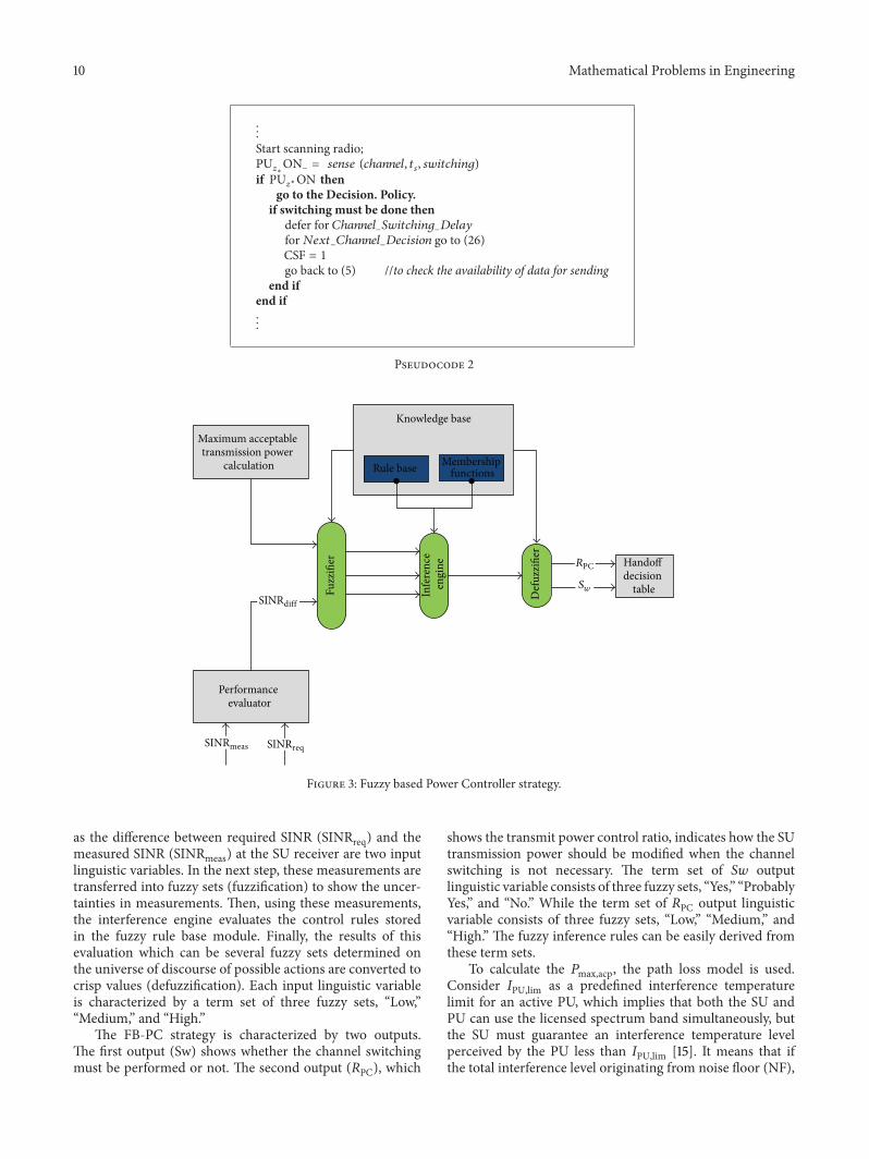
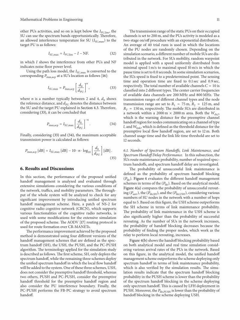
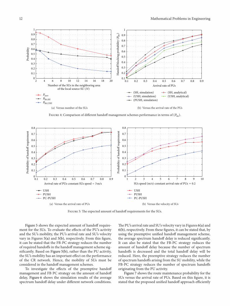
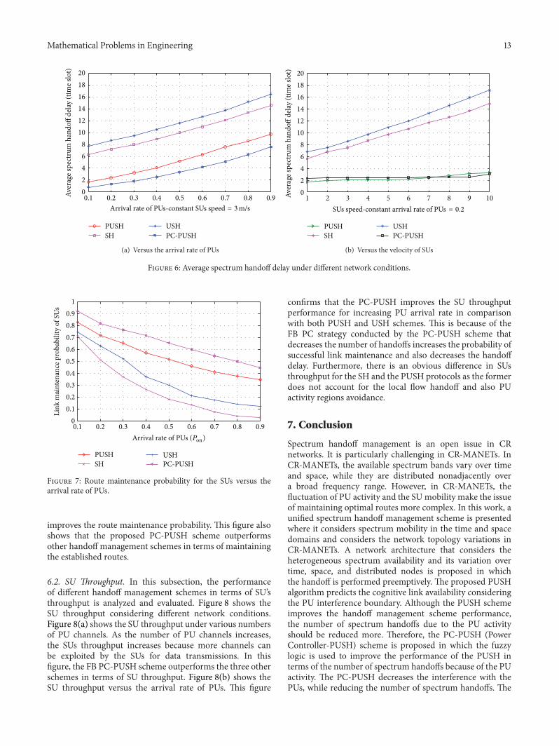
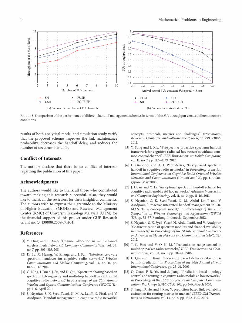
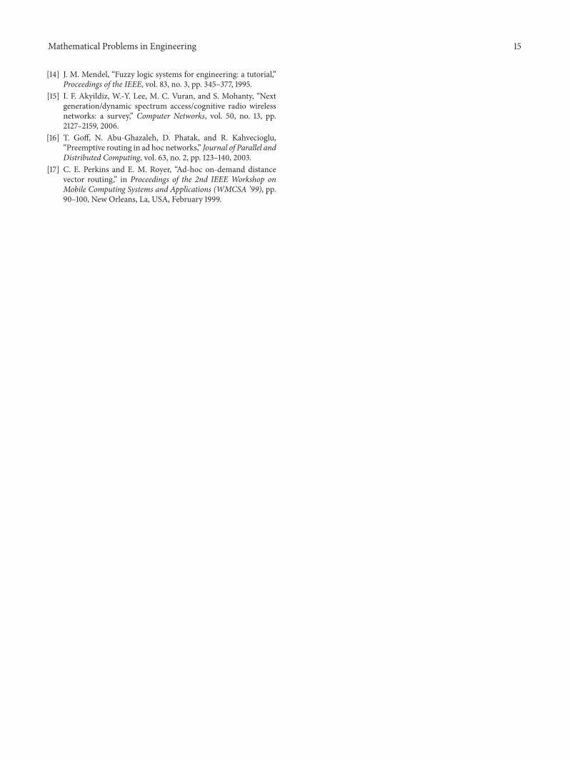